TUNGALOY The most economical solution for drilling! Tungaloy Report No. 409-E2 Indexable drill TDS type NEW Expansion with New chipbreaker NEW

Tung Six Drill
Oct 21, 2015
unique drill , 6 cutting edge , cutting tool
Welcome message from author
This document is posted to help you gain knowledge. Please leave a comment to let me know what you think about it! Share it to your friends and learn new things together.
Transcript
T U N G A LOY
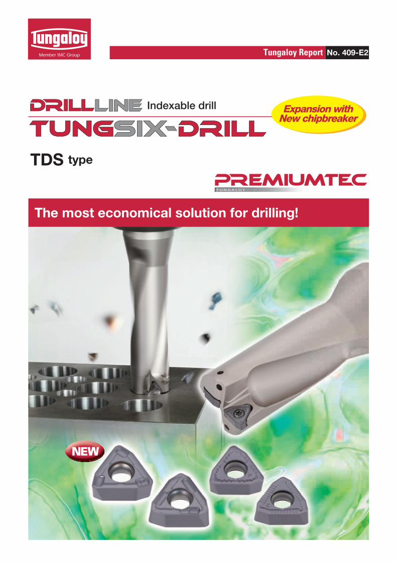
The most economical solution for drilling!
Tungaloy Report No. 409-E2
Indexable drill
TDS type
NEW
Expansion with New chipbreaker
NEW
2
1 2
3
4
6
5
28.2
28.1
28.0
27.9
28.2
28.1
28.0
27.9
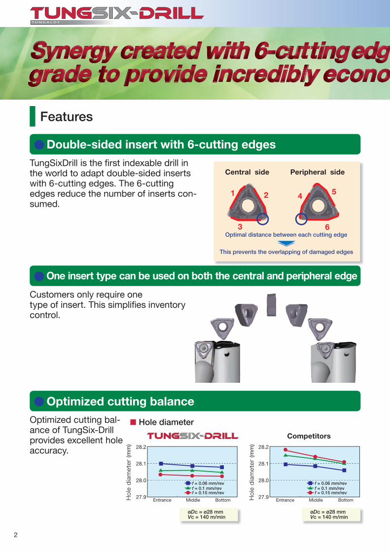
øDc = ø28 mmVc = 140 m/min
øDc = ø28 mmVc = 140 m/min
Hole diameter
Competitors
Entrance EntranceMiddle MiddleBottom Bottom
Double-sided insert with 6-cutting edges
One insert type can be used on both the central and peripheral edge
Optimized cutting balance
Features
TungSixDrill is the fi rst indexable drill in the world to adapt double-sided inserts with 6-cutting edges. The 6-cutting edges reduce the number of inserts con-sumed.
Customers only require onetype of insert. This simplifi es inventory control.
Optimized cutting bal-ance of TungSix-Drill provides excellent hole accuracy.
Central side Peripheral side
Hole diameter (m
m)
Hole diameter (m
m)
Optimal distance between each cutting edge
This prevents the overlapping of damaged edges
f = 0.06 mm/rev f = 0.06 mm/revf = 0.1 mm/rev f = 0.1 mm/revf = 0.15 mm/rev f = 0.15 mm/rev
3
AH9030
AH6030NEW
NEW
AH6030
AH9030
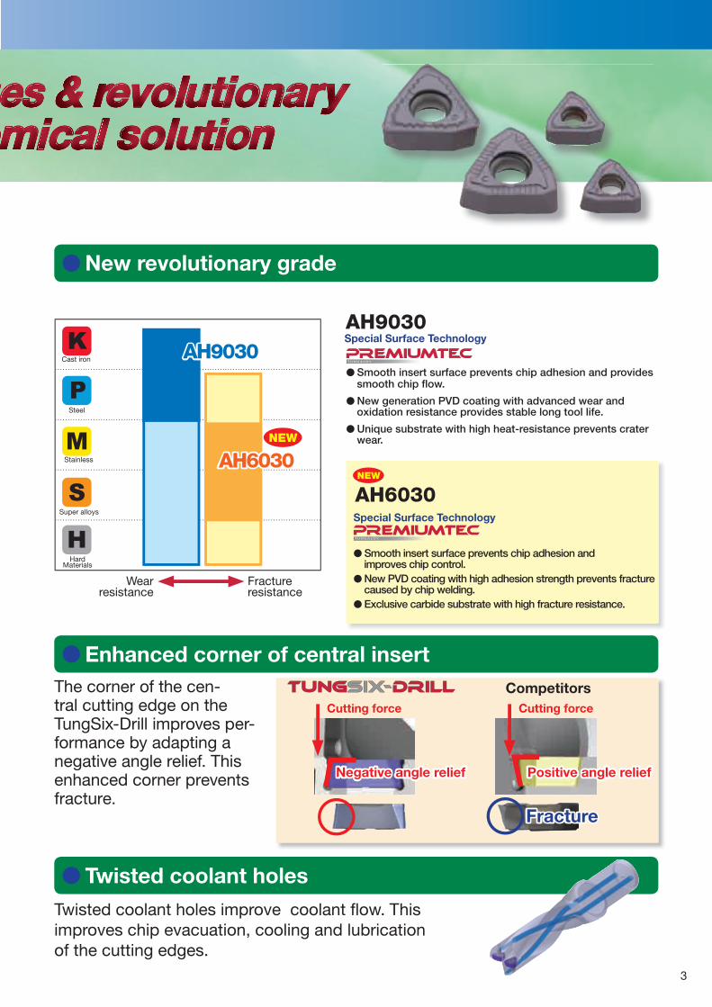
New revolutionary grade
T U N G A LOY
Special Surface Technology
� Smooth insert surface prevents chip adhesion and provides smooth chip fl ow.
� New generation PVD coating with advanced wear and oxidation resistance provides stable long tool life.
� Unique substrate with high heat-resistance prevents crater wear.
Enhanced corner of central insert
Twisted coolant holes
The corner of the cen-tral cutting edge on the TungSix-Drill improves per-formance by adapting a negative angle relief. This enhanced corner prevents fracture.
Twisted coolant holes improve coolant fl ow. This improves chip evacuation, cooling and lubrication of the cutting edges.
Negative angle relief Positive angle relief
Fracture
CompetitorsCutting force Cutting force
T U N G A LOY
Special Surface Technology
� Smooth insert surface prevents chip adhesion and improves chip control.� New PVD coating with high adhesion strength prevents fracture caused by chip welding.� Exclusive carbide substrate with high fracture resistance.
Wear resistance
Fracture resistance
Cast iron
Steel
Stainless
Super alloys
Hard Materials
4
OK
NEW
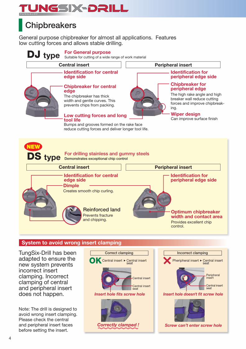
ChipbreakersGeneral purpose chipbreaker for almost all applications. Features low cutting forces and allows stable drilling.
TungSix-Drill has been adapted to ensure the new system prevents incorrect insert clamping. Incorrect clamping of central and peripheral insert does not happen.
System to avoid wrong insert clamping
Note: The drill is designed toavoid wrong insert clamping. Please check the central and peripheral insert faces before setting the insert.
Correct clamping Incorrect clamping
Insert hole fi ts screw hole Insert hole doesn't fi t screw hole
Correctly clamped ! Screw can’t enter screw hole
Central insert Pheripheral insertCentral insert seat
Central insert seat
Central insertPeripheral insert
Central insertseat
Central insertseat
Central insert Peripheral insert
DJ type
The chipbreaker has thickwidth and gentle curves. This prevents chips from packing.
The high rake angle and highbreaker wall reduce cutting forces and improve chipbreak-ing.
Bumps and grooves formed on the rake face reduce cutting forces and deliver longer tool life.
Can improve surface fi nish
Chipbreaker for central edge
Identifi cation for central edge side
Chipbreaker for peripheral edge
Identifi cation forperipheral edge side
Low cutting forces and long tool life
Wiper design
Central insert Peripheral insert
Identifi cation for central edge side
Identifi cation forperipheral edge side
DimpleCreates smooth chip curling.
Prevents fracture and chipping.
Reinforced land
Provides excellent chip control.
Optimum chipbreaker width and contact area
For drilling stainless and gummy steelsDemonstrates exceptional chip controlDS type
For General purposeSuitable for cutting of a wide range of work material
5
4.5
4
3.5
3
2.5
2
1.5
1
0.5
0f = 0.06 f = 0.1 f = 0.15
100 150 200
20 mm
0.1
0.15
0.2
150 200
20 mm
0.08
0.1
DS
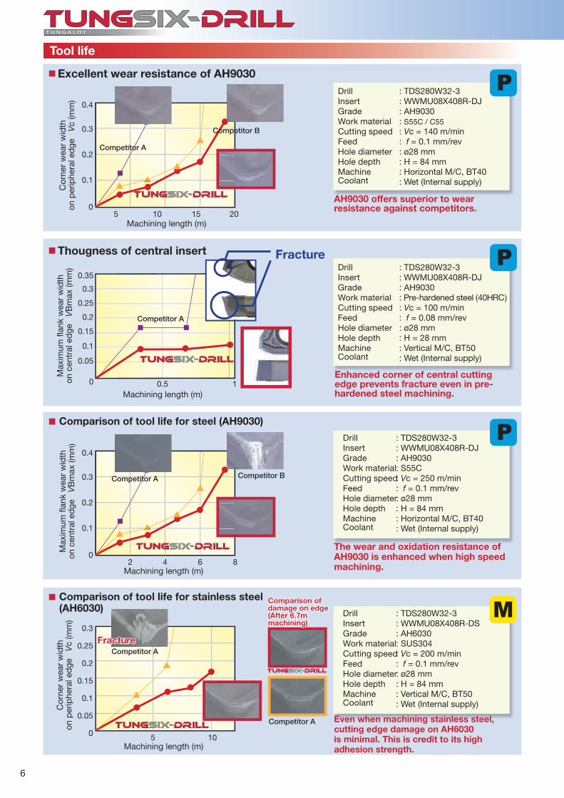
Cutting performance
: TDS280W32-3: WWMU08X408R-DJ: AH9030: S45C / C45: NC lathe: ø28 mm: H = 70 mm: Wet
Fee
d: f
(mm
/rev
)
Cutting speed: Vc (m/min)
Chips are stably controlled in thisrange. The chips created are the ideal shape.
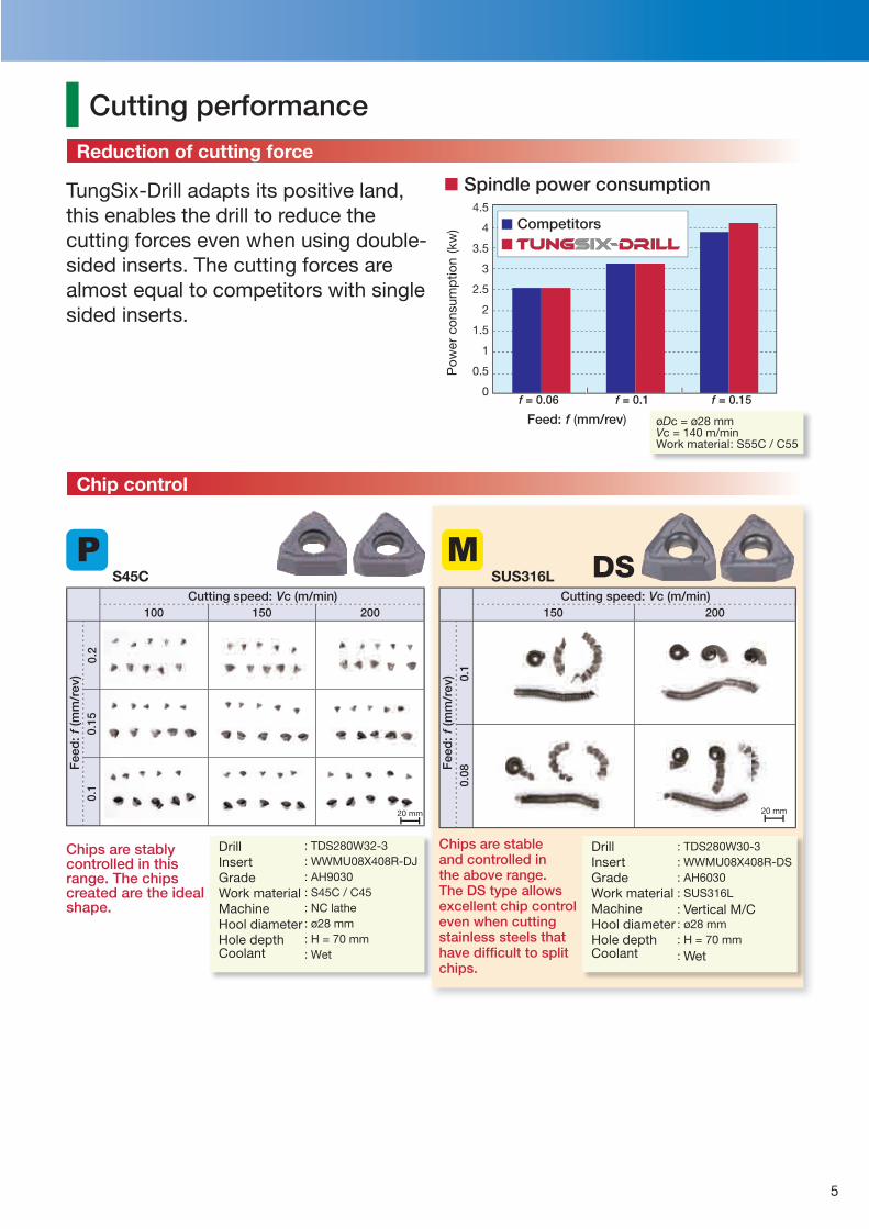
TungSix-Drill adapts its positive land, this enables the drill to reduce the cutting forces even when using double-sided inserts. The cutting forces are almost equal to competitors with single sided inserts.
øDc = ø28 mmVc = 140 m/minWork material: S55C / C55
Spindle power consumption
Pow
er c
onsu
mp
tion
(kw
)
Feed: f (mm/rev)
Competitors
Reduction of cutting force
Chip control
DrillInsertGradeWork materialMachineHool diameterHole depthCoolant
: TDS280W30-3: WWMU08X408R-DS: AH6030: SUS316L: Vertical M/C: ø28 mm: H = 70 mm: Wet
Fee
d: f
(mm
/rev
)
Cutting speed: Vc (m/min)
DrillInsertGradeWork materialMachineHool diameterHole depthCoolant
Chips are stable and controlled in the above range. The DS type allows excellent chip control even when cutting stainless steels that have diffi cult to split chips.
SUS316LS45C
6
0.4
0.3
0.2
0.1
05 10 15 20
0.35
0.3
0.25
0.2
0.15
0.1
0.05
0 0.5 1
0.4
0.3
0.2
0.1
02 4 6 8
0.3
0.25
0.2
0.15
0.1
0.05
0 5 10
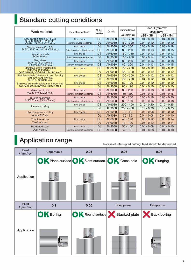
Excellent wear resistance of AH9030
Thougness of central insert
AH9030 offers superior to wear resistance against competitors.
Enhanced corner of central cuttingedge prevents fracture even in pre-hardened steel machining.
Competitor A
Competitor A
Competitor B
Cor
ner
wea
r w
idth
on
per
iphe
ral e
dge
V
c (m
m)
Max
imum
fl an
k w
ear
wid
th
on c
entr
al e
dge
V
Bm
ax (m
m)
Tool life
: TDS280W32-3: WWMU08X408R-DJ: AH9030: S55C / C55: Vc = 140 m/min: f = 0.1 mm/rev: ø28 mm: H = 84 mm: Horizontal M/C, BT40: Wet (Internal supply)
: TDS280W32-3: WWMU08X408R-DJ: AH9030: Pre-hardened steel (40HRC): Vc = 100 m/min: f = 0.08 mm/rev: ø28 mm: H = 28 mm: Vertical M/C, BT50: Wet (Internal supply)
Fracture
DrillInsertGradeWork materialCutting speedFeedHole diameterHole depthMachineCoolant
DrillInsertGradeWork materialCutting speedFeedHole diameterHole depthMachineCoolant
Machining length (m)
Machining length (m)
Competitor A Competitor B
The wear and oxidation resistance of AH9030 is enhanced when high speed machining.Machining length (m)
Max
imum
fl an
k w
ear
wid
th
on c
entr
al e
dge
V
Bm
ax (m
m)
Comparison of tool life for steel (AH9030)
DrillInsertGradeWork materialCutting speedFeedHole diameterHole depthMachineCoolant
: TDS280W32-3: WWMU08X408R-DJ: AH9030: S55C: Vc = 250 m/min: f = 0.1 mm/rev: ø28 mm: H = 84 mm: Horizontal M/C, BT40: Wet (Internal supply)
Competitor A
Even when machining stainless steel, cutting edge damage on AH6030 is minimal. This is credit to its high adhesion strength.Machining length (m)
Cor
ner
wea
r w
idth
on
per
iphe
ral e
dge
V
c (m
m)
Comparison of tool life for stainless steel (AH6030) Drill
InsertGradeWork materialCutting speedFeedHole diameterHole depthMachineCoolant
: TDS280W32-3: WWMU08X408R-DS: AH6030: SUS304: Vc = 200 m/min: f = 0.1 mm/rev: ø28 mm: H = 84 mm: Vertical M/C, BT50: Wet (Internal supply)
Fracture
Comparison of damage on edge(After 6.7m machining)
Competitor A
7
Vc (m/min)øDc (mm)
ø28 - 38 ø39 - 54DS AH6030 160 - 250 0.04 - 0.10 0.04 - 0.10DJ AH9030 160 - 320 0.04 - 0.10 0.04 - 0.10DJ AH9030 80 - 250 0.06 - 0.16 0.08 - 0.18DS AH6030 80 - 250 0.04 - 0.13 0.04 - 0.15DS AH6030 160 - 250 0.04 - 0.12 0.04 - 0.12DJ AH9030 160 - 250 0.06 - 0.14 0.06 - 0.14DJ AH9030 80 - 200 0.06 - 0.16 0.08 - 0.18DS AH6030 80 - 200 0.04 - 0.13 0.04 - 0.15DS AH6030 100 - 200 0.04 - 0.12 0.04 - 0.12
- DJ AH9030 100 - 200 0.04 - 0.12 0.04 - 0.12DS AH6030 100 - 200 0.04 - 0.12 0.04 - 0.12
- DJ AH9030 100 - 200 0.04 - 0.12 0.04 - 0.12DS AH6030 80 - 120 0.04 - 0.10 0.04 - 0.10
- DJ AH9030 80 - 120 0.04 - 0.10 0.04 - 0.10DJ AH9030 80 - 250 0.06 - 0.18 0.08 - 0.20DS AH6030 80 - 200 0.06 - 0.16 0.08 - 0.18DJ AH9030 80 - 200 0.06 - 0.18 0.08 - 0.20DS AH6030 80 - 150 0.06 - 0.16 0.08 - 0.18DS AH6030 200 - 400 0.10 - 0.20 0.10 - 0.25
- DJ AH9030 200 - 400 0.10 - 0.20 0.10 - 0.25DS AH6030 20 - 60 0.04 - 0.08 0.04 - 0.10
- DJ AH9030 20 - 60 0.04 - 0.08 0.04 - 0.10DS AH6030 40 - 120 0.06 - 0.12 0.06 - 0.14
- DJ AH9030 40 - 120 0.06 - 0.12 0.06 - 0.14DJ AH9030 50 - 100 0.04 - 0.08 0.04 - 0.10DS AH6030 40 - 80 0.04 - 0.08 0.04 - 0.10
0.05 0.05 0.05
0.1 0.05
OK
OK
OK
OK
OK OK
Standard cutting conditions
Application range
Work materialsFeed: f (mm/rev)
Cutting Speed
Application
Application
Feedf (mm/rev)
Feedf (mm/rev)
Upper table
Plane surface Slant surface Cross hole Plunging
Boring Round surface Stacked plate Back boring
Low carbon steels (C < 0.3) SS400, SM490, S25C etc. (St42-1, St52-3, C25 etc.)
Carbon steels (C > 0.3)S45C, S55C etc. (C45, C55 etc.)
Low alloy steelsSCM415 etc.
Alloy steelsSCM440, SCr420 etc. (42CrMo4, 20Cr4 etc.)
Stainless steels (Austenitic)SUS304, SUS316 etc.
(X5CrNi18-9, X5CrNiMo17-12-2 etc.)Stainless steels (Martensitic and ferritic)
SUS430, SUS416 etc.(X6Cr17, X20Cr13 etc.)
Stainless steels (Precipitation hardening)SUS630 etc. (X5CrNiCuNb16-4 etc.)
Grey cast ironsFC250 etc. (GG25 etc.)
Ductile cast ironsFCD700 etc. (GGG70 etc.)
In case of Interrupted cutting, feed should be decreased.
Disapprove Disapprove
Grade
First choice
Priority on wear resistance
First choice
Priority on impact resistance
First choice
Priority on wear resistance
First choice
Priority on impact resistance
First choice
First choice
First choice
First choice
Priority on impact resistance
First choice
Priority on impact resistance
First choice
First choice
First choice
First choice
Priority on impact resistance
Chip-breakerSelection criteria
Aluminium alloy
High temperature alloyInconel718 etc
Titanium AlooyTi-6Al-4V etc.
Hardened steelOver 40HRC
8
øDc øDs øD r rs L
TDS280W32-2 ● 28
32 40
56
55
145 1.3 0.6
WWMU08X408R-DJ CSTB-3 T-9D
TDS290W32-2 ● 29 58 148 1.1 0.7
TDS300W32-2 ● 30 60 151 0.8 0.7
TDS310W32-2 ● 31 62 154 0.5 0.7
TDS320W32-2 ● 32 64 157 0.2 0.8
TDS330W40-2 ● 33
40 50
66
65
170 1.7 1.2
WWMU09X510R-DJ CSTB-4 T-15D
TDS340W40-2 ● 34 68 173 1.4 1.2
TDS350W40-2 ● 35 70 176 1.2 1.2
TDS360W40-2 ● 36 72 179 0.9 1.3
TDS370W40-2 ● 37 74 182 0.7 1.3
TDS380W40-2 ● 38 76 185 0.4 1.3
TDS390W40-2 ● 39
40
50
78
65
188 2.2 1.4
WWMU11X512R-DJ CSTB-5 T-20D
TDS400W40-2 ● 40 80 191 1.9 1.4
TDS410W40-2 ● 41 82 194 1.7 1.5
TDS420W40-2 ● 42
55
84 197 1.5 1.6
TDS430W40-2 ● 43 86 200 1.3 1.6
TDS440W40-2 ● 44 88 203 1 1.7
TDS450W40-2 ● 45 90 206 0.7 1.7
TDS460W40-2 ● 46 92 209 0.4 1.8
TDS470W40-2 ● 47
40 55
94
65
212 2.6 1.9
WWMU13X512R-DJ CSTB-5 T-20D
TDS480W40-2 ● 48 96 215 2.4 1.9
TDS490W40-2 ● 49 98 218 2.2 1.9
TDS500W40-2 ● 50 100 221 2 2.0
TDS510W40-2 ● 51 102 224 1.7 2.1
TDS520W40-2 ● 52 104 227 1.5 2.2
TDS530W40-2 ● 53 106 230 1.3 2.3
TDS540W40-2 ● 54 108 233 1 2.4
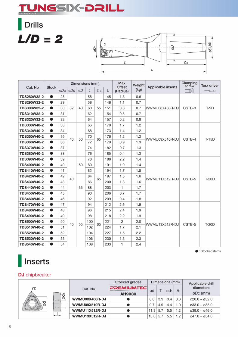
L/D = 2
L
R Rs
øDc
øDsh
6
øD
øDc (mm)AH9030ød T ød1 rε
WWMU08X408R-DJ � 8.0 3.9 3.4 0.8 ø28.0 ~ ø32.0
WWMU09X510R-DJ � 9.7 4.9 4.4 1.0 ø33.0 ~ ø38.0
WWMU11X512R-DJ � 11.3 5.7 5.5 1.2 ø39.0 ~ ø46.0
WWMU13X512R-DJ � 13.0 5.7 5.5 1.2 ø47.0 ~ ø54.0
rε
T
ød1
ød
T U N G A LOY
Drills
Cat. No StockDimensions (mm)
Applicable insertsMax
Offset(Radius)
Weight(kg)
Clamping screw Torx driver
� : Stocked items
Inserts
DJ chipbreaker
Cat. No.
Stocked grades Dimensions (mm) Applicable drilldiameters
9
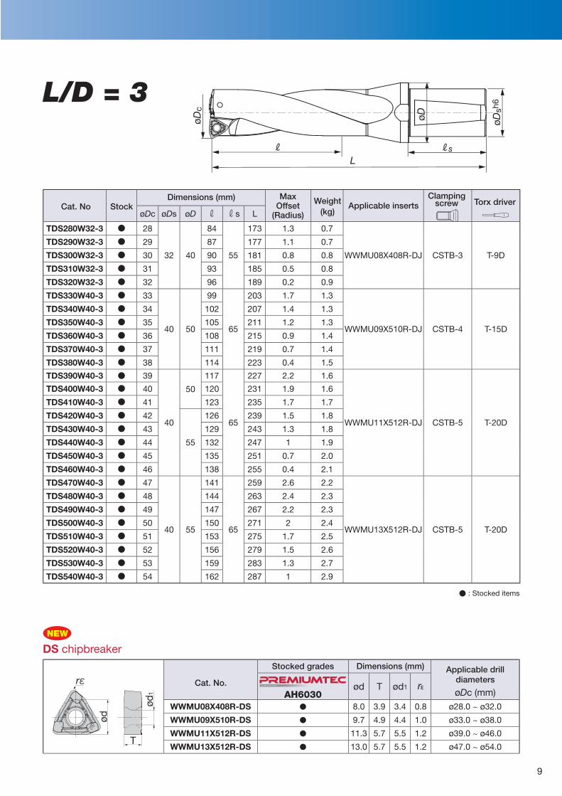
L/D = 3
øDc øDs øD r rs L
TDS280W32-3 ● 28
32 40
84
55
173 1.3 0.7
WWMU08X408R-DJ CSTB-3 T-9D
TDS290W32-3 ● 29 87 177 1.1 0.7
TDS300W32-3 ● 30 90 181 0.8 0.8
TDS310W32-3 ● 31 93 185 0.5 0.8
TDS320W32-3 ● 32 96 189 0.2 0.9
TDS330W40-3 ● 33
40 50
99
65
203 1.7 1.3
WWMU09X510R-DJ CSTB-4 T-15D
TDS340W40-3 ● 34 102 207 1.4 1.3
TDS350W40-3 ● 35 105 211 1.2 1.3
TDS360W40-3 ● 36 108 215 0.9 1.4
TDS370W40-3 ● 37 111 219 0.7 1.4
TDS380W40-3 ● 38 114 223 0.4 1.5
TDS390W40-3 ● 39
40
50
117
65
227 2.2 1.6
WWMU11X512R-DJ CSTB-5 T-20D
TDS400W40-3 ● 40 120 231 1.9 1.6
TDS410W40-3 ● 41 123 235 1.7 1.7
TDS420W40-3 ● 42
55
126 239 1.5 1.8
TDS430W40-3 ● 43 129 243 1.3 1.8
TDS440W40-3 ● 44 132 247 1 1.9
TDS450W40-3 ● 45 135 251 0.7 2.0
TDS460W40-3 ● 46 138 255 0.4 2.1
TDS470W40-3 ● 47
40 55
141
65
259 2.6 2.2
WWMU13X512R-DJ CSTB-5 T-20D
TDS480W40-3 ● 48 144 263 2.4 2.3
TDS490W40-3 ● 49 147 267 2.2 2.3
TDS500W40-3 ● 50 150 271 2 2.4
TDS510W40-3 ● 51 153 275 1.7 2.5
TDS520W40-3 ● 52 156 279 1.5 2.6
TDS530W40-3 ● 53 159 283 1.3 2.7
TDS540W40-3 ● 54 162 287 1 2.9
LR Rs
øDc
øDsh
6
øD
øDc (mm)AH6030ød T ød1 rε
WWMU08X408R-DS � 8.0 3.9 3.4 0.8 ø28.0 ~ ø32.0
WWMU09X510R-DS � 9.7 4.9 4.4 1.0 ø33.0 ~ ø38.0
WWMU11X512R-DS � 11.3 5.7 5.5 1.2 ø39.0 ~ ø46.0
WWMU13X512R-DS � 13.0 5.7 5.5 1.2 ø47.0 ~ ø54.0T
ød1
ød
rεT U N G A LOY
NEW
Cat. No StockDimensions (mm)
Applicable insertsMax
Offset(Radius)
Weight(kg)
Clamping screw Torx driver
� : Stocked items
Cat. No.
Stocked grades Dimensions (mm) Applicable drilldiameters
DS chipbreaker
10
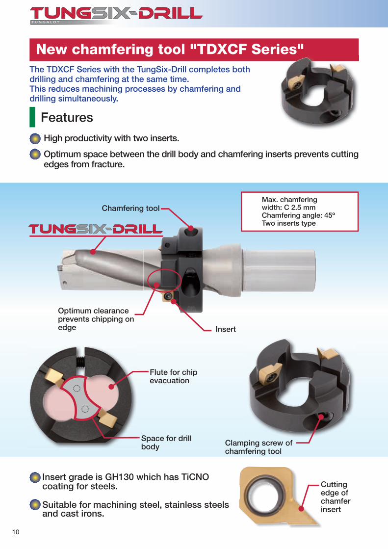
New chamfering tool "TDXCF Series"
Features
High productivity with two inserts.
Optimum space between the drill body and chamfering inserts prevents cutting edges from fracture.
The TDXCF Series with the TungSix-Drill completes both drilling and chamfering at the same time. This reduces machining processes by chamfering anddrilling simultaneously.
Insert grade is GH130 which has TiCNO coating for steels. Cutting
edge of chamfer insert
Clamping screw of chamfering tool
Flute for chip evacuation
Insert
Optimum clearance prevents chipping on edge
Chamfering toolMax. chamfering width: C 2.5 mmChamfering angle: 45ºTwo inserts type
Suitable for machining steel, stainless steels and cast irons.
Space for drill body
11
0.1 0.13
TDXCF
TDXCF
(N·m) (N·m)GH130TDXCF280L30
~
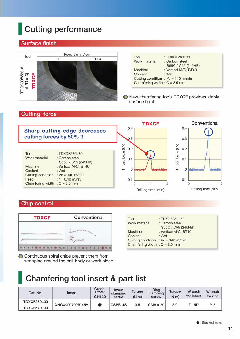
TDXCF540L30XHGX090700R-45A � CSPB-4S 3.5 CM8 x 20 8.0 T-15D P-5
TD
S28
0W25
-3(L
/D =
3)
TD
XC
FCutting performance
: TDXCF280L30: Carbon steel S55C / C55 (245HB) : Vertical M/C, BT40: Wet: Vc = 140 m/min: C = 2.0 mm
Feed: f (mm/rev)Tool
New chamfering tools TDXCF provides stable surface fi nish.
Continuous spiral chips prevent them from wrapping around the drill body or work piece.
ConventionalTh
rust
forc
e (k
N)
Thru
st fo
rce
(kN
)
Drilling time (min) Drilling time (min)
Sharp cutting edge decreases cutting forces by 50% !!
Chamfering tool insert & part list
: TDXCF280L30: Carbon steel S55C / C55 (245HB) : Vertical M/C, BT40: Wet: Vc = 140 m/min: f = 0.10 m/rev: C = 2.0 mm
Surface fi nish
Cutting force
Chip control
Conventional
Tool Work material
Machine CoolantCutting condition Chamfering width
Cat. No. Insert Grade,Stock Insert
clampingscrew
Torque TorqueRingclamping
screwWrench
for insertWrenchfor ring
Tool Work material
Machine CoolantCutting conditionFeed Chamfering width
Tool Work material
Machine CoolantCutting condition Chamfering width
: TDXCF280L30: Carbon steel S55C / C55 (245HB) : Vertical M/C, BT40: Wet: Vc = 140 m/min: C = 2.0 mm
� : Stocked items
12
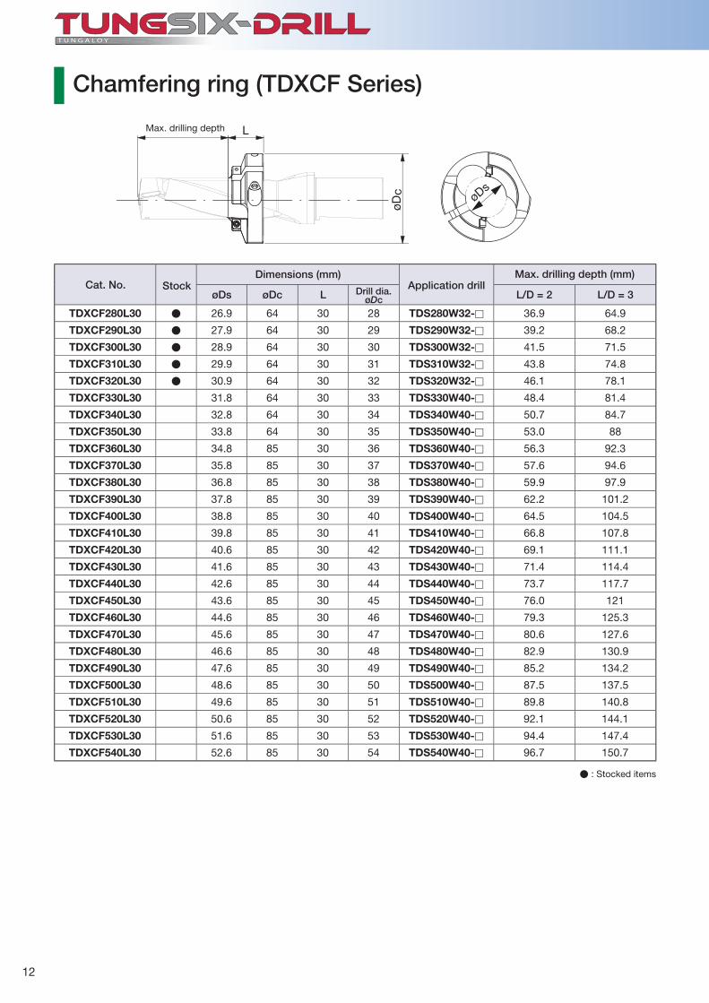
øDs øDc L øDc L/D = 2 L/D = 3
TDXCF280L30 ● 26.9 64 30 28 TDS280W32-� 36.9 64.9
TDXCF290L30 ● 27.9 64 30 29 TDS290W32-� 39.2 68.2
TDXCF300L30 ● 28.9 64 30 30 TDS300W32-� 41.5 71.5
TDXCF310L30 ● 29.9 64 30 31 TDS310W32-� 43.8 74.8
TDXCF320L30 ● 30.9 64 30 32 TDS320W32-� 46.1 78.1
TDXCF330L30 31.8 64 30 33 TDS330W40-� 48.4 81.4
TDXCF340L30 32.8 64 30 34 TDS340W40-� 50.7 84.7
TDXCF350L30 33.8 64 30 35 TDS350W40-� 53.0 88
TDXCF360L30 34.8 85 30 36 TDS360W40-� 56.3 92.3
TDXCF370L30 35.8 85 30 37 TDS370W40-� 57.6 94.6
TDXCF380L30 36.8 85 30 38 TDS380W40-� 59.9 97.9
TDXCF390L30 37.8 85 30 39 TDS390W40-� 62.2 101.2
TDXCF400L30 38.8 85 30 40 TDS400W40-� 64.5 104.5
TDXCF410L30 39.8 85 30 41 TDS410W40-� 66.8 107.8
TDXCF420L30 40.6 85 30 42 TDS420W40-� 69.1 111.1
TDXCF430L30 41.6 85 30 43 TDS430W40-� 71.4 114.4
TDXCF440L30 42.6 85 30 44 TDS440W40-� 73.7 117.7
TDXCF450L30 43.6 85 30 45 TDS450W40-� 76.0 121
TDXCF460L30 44.6 85 30 46 TDS460W40-� 79.3 125.3
TDXCF470L30 45.6 85 30 47 TDS470W40-� 80.6 127.6
TDXCF480L30 46.6 85 30 48 TDS480W40-� 82.9 130.9
TDXCF490L30 47.6 85 30 49 TDS490W40-� 85.2 134.2
TDXCF500L30 48.6 85 30 50 TDS500W40-� 87.5 137.5
TDXCF510L30 49.6 85 30 51 TDS510W40-� 89.8 140.8
TDXCF520L30 50.6 85 30 52 TDS520W40-� 92.1 144.1
TDXCF530L30 51.6 85 30 53 TDS530W40-� 94.4 147.4
TDXCF540L30 52.6 85 30 54 TDS540W40-� 96.7 150.7
øc ø
s
Max. drilling depth
Chamfering ring (TDXCF Series)
� : Stocked items
Cat. No. Stock Application drillDrill dia.
Max. drilling depth (mm)Dimensions (mm)
13
OK
Max
.øD
c +
1.3
Min
.øD
c -0
.3
øøS.s
.
J 2
1
øø
JG
S.s.
2
1
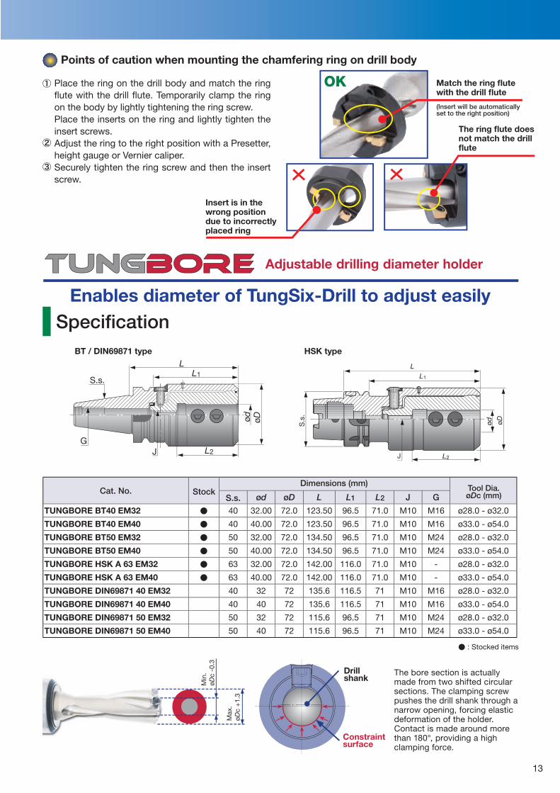
Points of caution when mounting the chamfering ring on drill body
Match the ring fl ute with the drill fl ute
(Insert will be automatically set to the right position)
The ring fl ute does not match the drill fl ute
Insert is in the wrong position due to incorrectly placed ring
Adjustable drilling diameter holder
Enables diameter of TungSix-Drill to adjust easilySpecifi cation
BT / DIN69871 type HSK type
Place the ring on the drill body and match the ring fl ute with the drill fl ute. Temporarily clamp the ring on the body by lightly tightening the ring screw.Place the inserts on the ring and lightly tighten the insert screws.Adjust the ring to the right position with a Presetter, height gauge or Vernier caliper. Securely tighten the ring screw and then the insert screw.
The bore section is actually made from two shifted circular sections. The clamping screw pushes the drill shank through a narrow opening, forcing elastic deformation of the holder. Contact is made around more than 180°, providing a high clamping force.
Drillshank
Constraintsurface
S.s. ød øD L L1 L2 J G
TUNGBORE BT40 EM32 ● 40 32.00 72.0 123.50 96.5 71.0 M10 M16 ø28.0 - ø32.0
TUNGBORE BT40 EM40 ● 40 40.00 72.0 123.50 96.5 71.0 M10 M16 ø33.0 - ø54.0
TUNGBORE BT50 EM32 ● 50 32.00 72.0 134.50 96.5 71.0 M10 M24 ø28.0 - ø32.0
TUNGBORE BT50 EM40 ● 50 40.00 72.0 134.50 96.5 71.0 M10 M24 ø33.0 - ø54.0
TUNGBORE HSK A 63 EM32 ● 63 32.00 72.0 142.00 116.0 71.0 M10 - ø28.0 - ø32.0
TUNGBORE HSK A 63 EM40 ● 63 40.00 72.0 142.00 116.0 71.0 M10 - ø33.0 - ø54.0
TUNGBORE DIN69871 40 EM32 40 32 72 135.6 116.5 71 M10 M16 ø28.0 - ø32.0
TUNGBORE DIN69871 40 EM40 40 40 72 135.6 116.5 71 M10 M16 ø33.0 - ø54.0
TUNGBORE DIN69871 50 EM32 50 32 72 115.6 96.5 71 M10 M24 ø28.0 - ø32.0
TUNGBORE DIN69871 50 EM40 50 40 72 115.6 96.5 71 M10 M24 ø33.0 - ø54.0
Dimensions (mm)Cat. No. Stock
� : Stocked items
Tool Dia.øDc (mm)
14
28 28 29.3 42 42 43.329 29 30.3 43 43 44.330 30 31.3 44 44 45.331 31 32 45 45 46.332 32 32.4 46 46 46.833 33 34.3 47 47 48.334 34 35.3 48 48 49.335 35 36.3 49 49 50.336 36 37.3 50 50 51.337 37 38.3 51 51 52.338 38 38.8 52 52 53.339 39 40.3 53 53 54.340 40 41.3 54 54 55.341 41 42.3
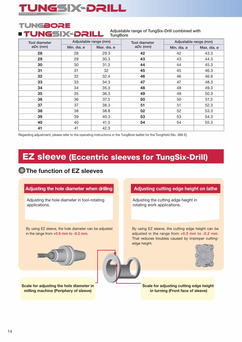
The function of EZ sleeves
Adjusting the hole diameter when drilling
Adjusting the hole diameter in tool-rotating applications.
By using EZ sleeve, the hole diameter can be adjusted in the range from +0.6 mm to -0.2 mm.
Adjusting cutting edge height on lathe
Adjusting the cutting edge height in rotating work applications.
By using EZ sleeve, the cutting edge height can be adjusted in the range from +0.3 mm to -0.2 mm. That reduces troubles caused by improper cutting-edge height.
Scale for adjusting the hole diameter in milling machine (Periphery of sleeve)
Scale for adjusting cutting edge height in turning (Front face of sleeve)
EZ sleeve (Eccentric sleeves for TungSix-Drill)
Adjustable range of TungSix-Drill combined with TungBore
Regarding adjustment, please refer to the operating instructions in the TungBore leafl et for the TungHold (No. 389-E)
Tool diameterøDc (mm)
Adjustable range (mm)
Min. dia. ø Max. dia. øTool diameter
øDc (mm)Adjustable range (mm)
Min. dia. ø Max. dia. ø
15
øD1 øD2 øD3 L1 L2 L3 L4
EZ2025 ● 20 25 46 49 5 32.5 4 +0.4 ~ -0.2 +0.2 ~ -0.15
EZ2532 ● 25 32 51 52 5 38 4 +0.4 ~ -0.2 +0.2 ~ -0.15
EZ3240 ● 32 40 54 62 5 43 4 +0.4 ~ -0.2 +0.2 ~ -0.15
EZ4050 ● 40 50 69 63 5 55 4 +0.6 ~ -0.2 +0.3 ~ -0.2
øD1
øD2
øD3
L1
L2
L3
L4
(+)
(-)
+0.4+0.2
●Ensure that the drilling machine to be used has suffi cient rigidity and motor output.●Not recommended for drilling stacked plates.●Be sure to carry out proper alignment when drilling is to be
performed on a rotating workpiece.
●Before installing the insert in the drill body, remove all foreign
matter from the insert pocket.
●When clamping and unclamping the insert, the center-line of the wrench should be aligned with the center-line of the screw. Misalignment
may result in deformation of the socket of the screw head or the tip of the wrench.●When installing the insert, eliminate all play between the insert
pocket and the bottom face of the
insert.
●Replace the screw before it is ex-cessively deformed or worn out by long term use.
●Be sure to supply cutting fl uid through the tool.●A water soluble emulsifi able type cutting fl uid should be used.●Fluid pressure of 1 MPa or higher and fl uid quantity of 7 l/min or
more are essential. For 4D and 5D type, a fl uid pressure of 1.5 MPa or higher and fl uid quantity of 10 l/min or more is recommended.
Using TungSix-Drill
Cutting fl uid
Cautionary points for setting inserts
Specifi cations
Cautious points
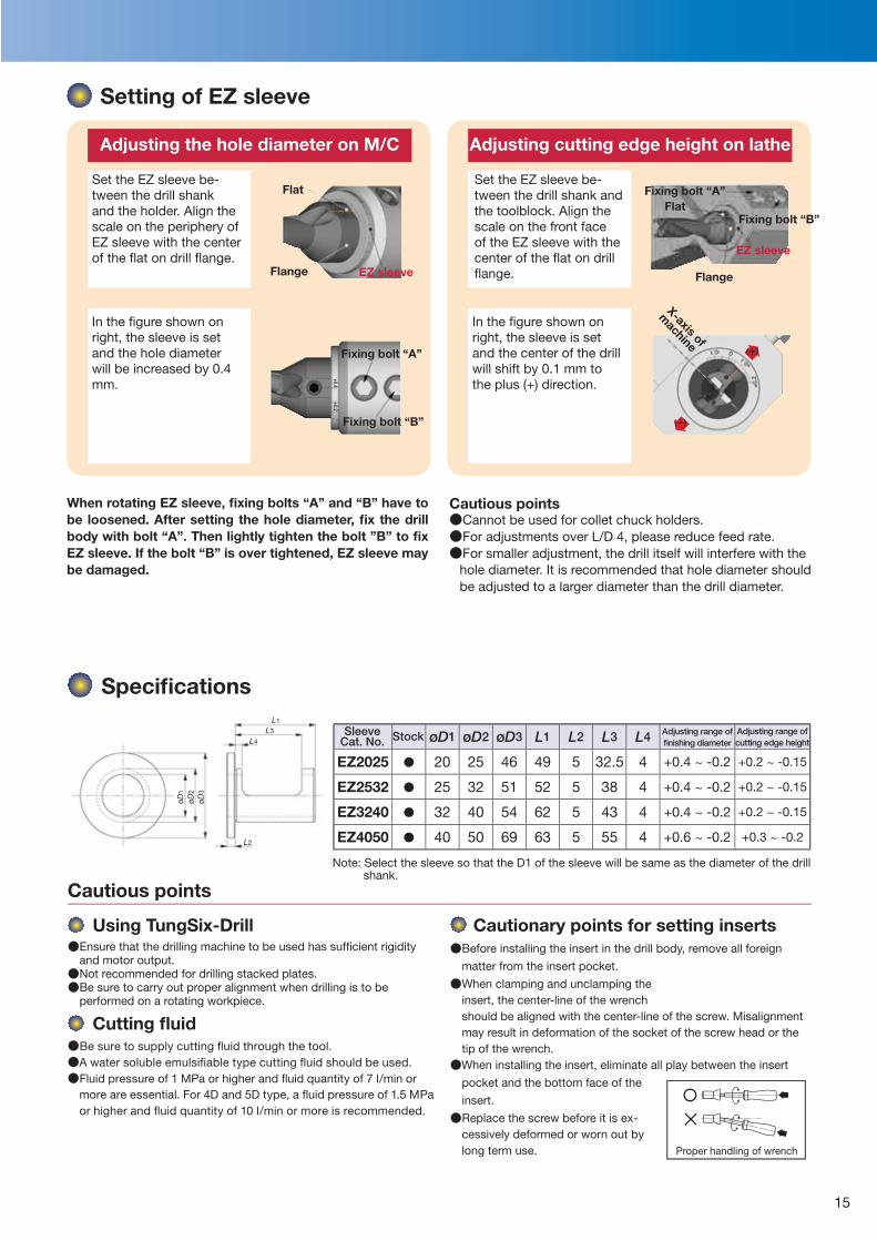
Setting of EZ sleeve
Adjusting the hole diameter on M/C Adjusting cutting edge height on lathe
In the fi gure shown on right, the sleeve is set and the hole diameter will be increased by 0.4 mm.
Set the EZ sleeve be-tween the drill shank and the holder. Align the scale on the periphery of EZ sleeve with the center of the fl at on drill fl ange.
Set the EZ sleeve be-tween the drill shank and the toolblock. Align the scale on the front face of the EZ sleeve with the center of the fl at on drill fl ange.
In the fi gure shown on right, the sleeve is set and the center of the drill will shift by 0.1 mm to the plus (+) direction.
EZ sleeve
Note: Select the sleeve so that the D1 of the sleeve will be same as the diameter of the drill shank.
Proper handling of wrench
Cautious points●Cannot be used for collet chuck holders.●For adjustments over L/D 4, please reduce feed rate.●For smaller adjustment, the drill itself will interfere with the
hole diameter. It is recommended that hole diameter should be adjusted to a larger diameter than the drill diameter.
When rotating EZ sleeve, fi xing bolts “A” and “B” have to be loosened. After setting the hole diameter, fi x the drill body with bolt “A”. Then lightly tighten the bolt ”B” to fi x EZ sleeve. If the bolt “B” is over tightened, EZ sleeve may be damaged.
Fixing bolt “A”
Fixing bolt “B”
X-axis of
machine
Flat
Flange
Fixing bolt “A”Flat
Flange
EZ sleeve
Fixing bolt “B”
Sleeve Stock Cat. No.Adjusting range of fi nishing diameter
Adjusting range of cutting edge height
16
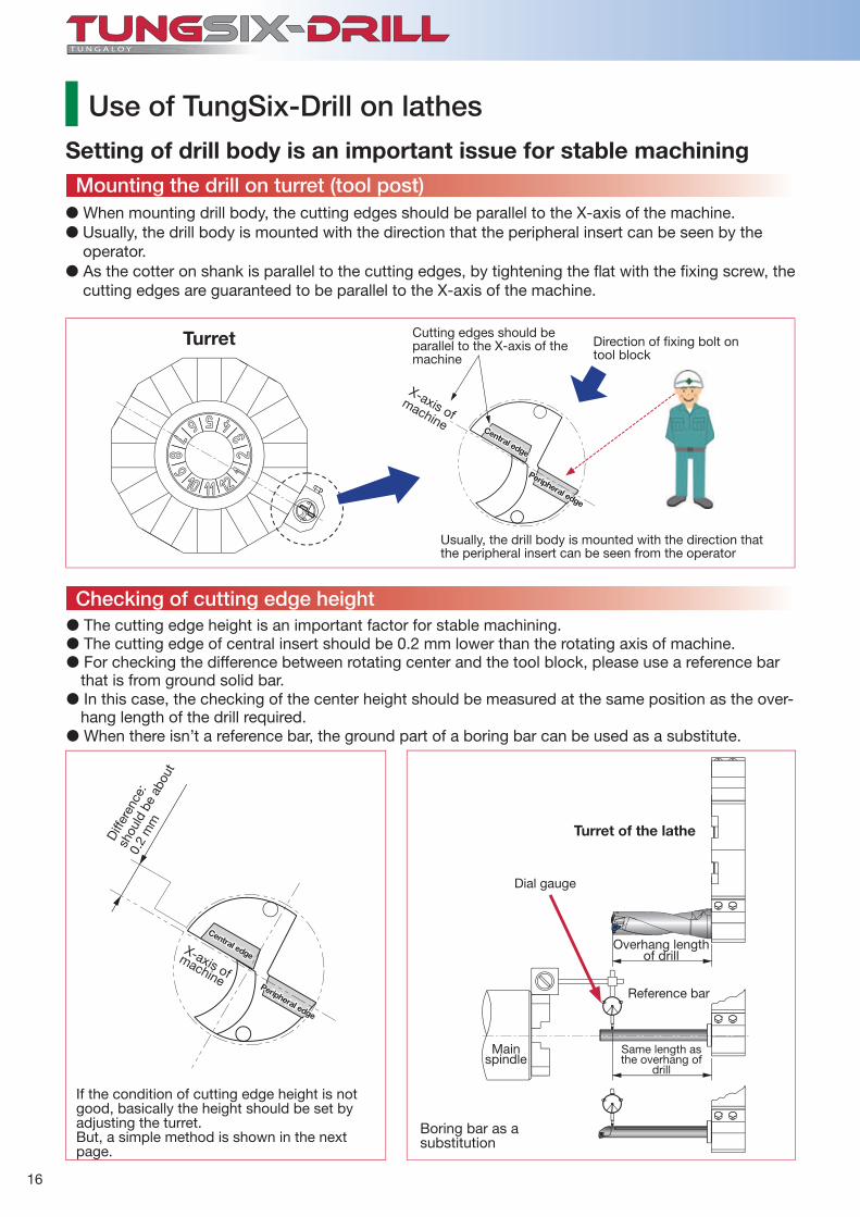
� When mounting drill body, the cutting edges should be parallel to the X-axis of the machine.� Usually, the drill body is mounted with the direction that the peripheral insert can be seen by the
operator.� As the cotter on shank is parallel to the cutting edges, by tightening the fl at with the fi xing screw, the
cutting edges are guaranteed to be parallel to the X-axis of the machine.
Setting of drill body is an important issue for stable machining
Direction of fi xing bolt on tool block
Usually, the drill body is mounted with the direction that the peripheral insert can be seen from the operator
� The cutting edge height is an important factor for stable machining.� The cutting edge of central insert should be 0.2 mm lower than the rotating axis of machine.� For checking the difference between rotating center and the tool block, please use a reference bar
that is from ground solid bar.� In this case, the checking of the center height should be measured at the same position as the over-
hang length of the drill required.� When there isn’t a reference bar, the ground part of a boring bar can be used as a substitute.
Mainspindle
If the condition of cutting edge height is not good, basically the height should be set by adjusting the turret.But, a simple method is shown in the next page.
Dial gauge
Overhang length of drill
Same length as the overhang of
drill
Reference bar
Turret of the lathe
Boring bar as asubstitution
Cutting edges should be parallel to the X-axis of the machine
X-axis of machine Central edge
Peripheral edge
Turret
Diff
eren
ce:
shou
ld b
e ab
out
0.2
mm
Mounting the drill on turret (tool post)
Checking of cutting edge height
Use of TungSix-Drill on lathes
X-axis of machine
Central edge
Peripheral edge
17
1
2 3
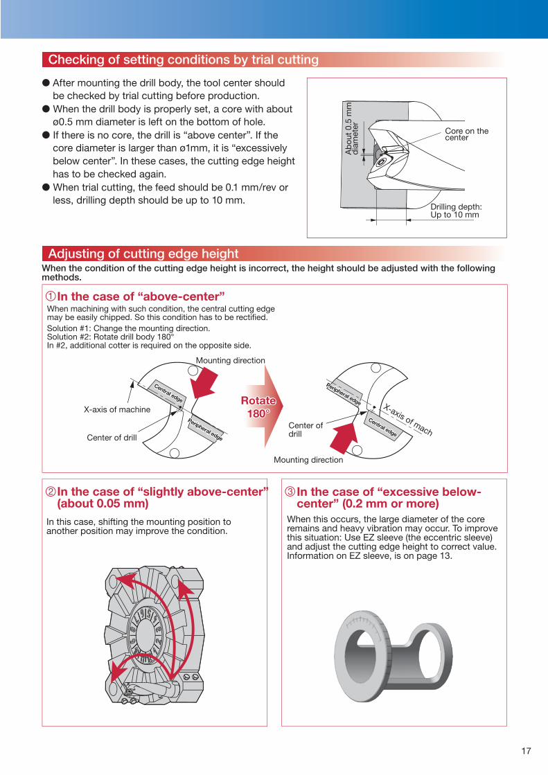
When the condition of the cutting edge height is incorrect, the height should be adjusted with the followingmethods.
When machining with such condition, the central cutting edge may be easily chipped. So this condition has to be rectifi ed.Solution #1: Change the mounting direction. Solution #2: Rotate drill body 180°In #2, additional cotter is required on the opposite side.
In this case, shifting the mounting position to another position may improve the condition.
When this occurs, the large diameter of the core remains and heavy vibration may occur. To improve this situation: Use EZ sleeve (the eccentric sleeve) and adjust the cutting edge height to correct value. Information on EZ sleeve, is on page 13.
In the case of “slightly above-center” (about 0.05 mm)
In the case of “excessive below-center” (0.2 mm or more)
In the case of “above-center”
Core on the center
Drilling depth: Up to 10 mm
Ab
out
0.5
mm
d
iam
eter
Mounting direction
Mounting direction
Center of drill
Rotate 180°
Checking of setting conditions by trial cutting
Adjusting of cutting edge height
� After mounting the drill body, the tool center should be checked by trial cutting before production.
� When the drill body is properly set, a core with about ø0.5 mm diameter is left on the bottom of hole.
� If there is no core, the drill is “above center”. If the core diameter is larger than ø1mm, it is “excessively below center”. In these cases, the cutting edge height has to be checked again.
� When trial cutting, the feed should be 0.1 mm/rev or less, drilling depth should be up to 10 mm.
X-axis of machine X-axis of machCenter of drill
Central edge
Central edge
Peripheral edge
Peripheral edge
18
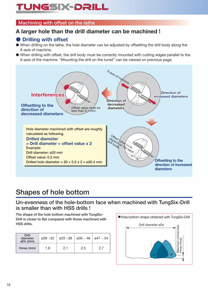
ø28 ~32 ø33 ~38 ø39 ~ 46 ø47 ~ 54
Hmax (mm) 1.8 2.1 2.5 2.7
A larger hole than the drill diameter can be machined !
� When drilling on the lathe, the hole diameter can be adjusted by offsetting the drill body along the X-axis of machine.
� When drilling with offset, the drill body must be correctly mounted with cutting edges parallel to the X-axis of the machine. “Mounting the drill on the turret” can be viewed on previous page.
Offsetting to the direction of decreased diameters
Offsetting to the direction of increased diameters
Hole diameter machined with offset are roughly calculated as following.
Drilled diameter = Drill diameter + offset value x 2Example:Drill diameter: ø20 mmOffset value: 0.2 mmDrilled hole diameter = 20 + 0.2 x 2 = ø20.4 mm
● Drilling with offset
Interferences
Offset value must be less than 0.1 mm.
Direction of increased diameters
Direction of decreased diameters
Un-evenness of the hole-bottom face when machined with TungSix-Drill is smaller than with HSS drills !The shape of the hole bottom machined with TungSix-Drill is closer to fl at compared with those machined with HSS drills.
DrilldiameterøDc (mm)
Drill diameter øDc
Hole bottom shape obtained with TungSix-Drill
Max
imum
une
venn
ess
Hm
ax H
max
Shapes of hole bottom
Machining with offset on the lathe
X-axis of machine
Offset value (+) is
depend on the each
drill body.
Central edge
Central edgePeripheral edge
Peripheral edge
Central edgePeripheral edge

19
TDS280W32-2 TDS420W40-2WWMU08X408R-DJ WWMU08X408R-DS
AH9030 AH9030
193 1200.15 0.2329 18030 80
50
40
30
20
10
0
40
30
20
10
0
TDS390W40-3 TDS280W32-2WWMU11X512R-DJ WWMU08X408R-DJ
AH9030 AH9030
200 1800.15 0.18245 36990 50
120100806040200
6050403020100
Practical examples
Vertical M/C, BT40Wet
Connecting rod
C55
Workpiece typeDrill
InsertGrade
Work material
Cutting speed: Vc (m/min) Feed: f (mm/rev) Feed speed: Vf (mm)
Drilling depth: H (mm) Machine
Coolant
Results
Cut
ting
cond
itio
ns
NC latheWet
Drilling center, BT50Wet
Slewing ring
42CrMo4
Workpiece typeDrill
InsertGrade
Work material
Cutting speed: Vc (m/min) Feed: f (mm/rev) Feed speed: Vf (mm)
Drilling depth: H (mm) Machine
Coolant
Results
Cut
ting
cond
itio
ns
Horizontal M/C, BT40Wet
AH9030 achieves longer tool life even when machining with external coolant supply, due to the high oxidation resistance.
Tool life 1.8
times!
Competitor
Mac
hini
ng le
ngth
(m
/inse
rt)
Tough cutting edge prevents chipping and edge fracture, even when interrupted machining. Increasing in tool life and higher number of insert corners drastically reduce machining cost.
Tool life tripled!
CompetitorM
achi
ning
leng
th
(m/in
sert
)
GGG45
Housing
Valve
Alloy steel
TungSix-Drill allows effi cient drilling with higher speed and feed. The increased number of insert corners significantly reduces insert consumption.
Tool life 1.5
times!
Competitor
Mac
hini
ng le
ngth
(m
/inse
rt)
Improved tool life per corner leads to reduction of insert consumption. DJ chipbreaker allows excellent chip control and stable machining without vibration.
Competitor
Mac
hini
ng le
ngth
(m
/inse
rt) Tool life
2.2 times!
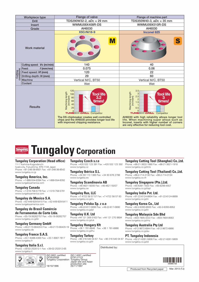
TDS290W32-2, øDc = 29 mm TDS350W40-3, øDc = 35 mmWWMU08X408R-DS WWMU09X510R-DS
AH6030 AH6030
140 400.075 0.06120 2229 60
120100806040200
3.53
2.52
1.51
0.50
Tungaloy Cutting Tool (Shanghai) Co.,Ltd.Phone: +86-21-3632-1880 Fax: +86-21-3621-1918www.tungaloy.co.jp/tcts
Tungaloy Cutting Tool (Thailand) Co.,Ltd.Phone: +66-2-714-3130 Fax: +66-2-714-3134www.tungaloy.co.th
Tungaloy Singapore (Pte.),Ltd.Phone: +65-6391-1833 Fax: +65-6299-4557www.tungaloy.co.jp/tspl
Tungaloy India Pvt. Ltd.Phone: +91-22-6124-8804 Fax: +91-22-6124-8899www.tungaloy.co.jp/in
Tungaloy Korea Co., LtdPhone: +82-2-6393-8930 Fax: +82-2-6393-8952www.tungaloy.co.jp/kr
Tungaloy Malaysia Sdn BhdPhone: +603-7805-3222 Fax: +603-7804-8563www.tungaloy.co.jp/my
Tungaloy Australia Pty LtdPhone: +612-9672-6844 Fax: +612-9672-6866www.tungaloy.co.jp/au
PT. Tungaloy IndonesiaPhone: +62-21-8261-5808 Fax: +62-21-8261-5809www.tungaloy.co.jp/id
Tungaloy Corporation (Head offi ce)11-1 Yoshima-KogyodanchiIwaki-city, Fukushima, 970-1144 JapanPhone: +81-246-36-8501 Fax: +81-246-36-8542www.tungaloy.co.jp
Tungaloy America, Inc.Phone: +1-888-554-8394 Fax: +1-888-554-8392www.tungaloyamerica.com
Tungaloy CanadaPhone: +1-519-758-5779 Fax: +1-519-758-5791www.tungaloyamerica.com
Tungaloy de Mexico S.A.Phone: +52-449-929-5410 Fax: +52-449-929-5411www.tungaloyamerica.com
Tungaloy do Brasil Comérciode Ferramentas de Corte Ltda.Phone: +55-19-38262757 Fax: +55-19-38262757www.tungaloy.co.jp/br
Tungaloy Germany GmbHPhone: +49-2173-90420-0 Fax: +49-2173-90420-19www.tungaloy.de
Tungaloy France S.A.S.Phone: +33-1-6486-4300 Fax: +33-1-6907-7817www.tungaloy.fr
Tungaloy Italia S.r.I.Phone: +39-02-252012-1 Fax: +39-02-252012-65www.tungaloy.it
Tungaloy Czech s.r.oPhone: +420 532 123 391 Fax: +420 532 123 392www.tungaloy.cz
Tungaloy Ibérica S.L.Phone: +34 93 113 1360 Fax: +34 93 876 2798www.tungaloy.es
Tungaloy Scandinavia ABPhone: +46-462119200 Fax: +46-462119207www.tungaloy.se
Tungaloy Rus, LLCPhone: +7 4722 58 57 57 Fax: +7 4722 58 57 83www.tungaloy.co.jp/ru
Tungaloy Polska Sp. z o.oPhone: +48-22-617-0890 Fax: +48-22-617-0890www.tungaloy.co.jp/pl
Tungaloy U.K. LtdPhone:+44 121 309 0163 Fax: +44 121 270 9694 www.tungaloy.co.jp/uk
Tungaloy Hungary KftPhone: +36 1 781-6846 Fax: +36 1 781-6866www.tungaloy.co.jp/hu
Tungaloy TurkeyPhone: +90 216 540 04 67 Fax: +90 216 540 04 87www.tungaloy.co.jp/tr
Produced from Recycled paper
Distributed by:
ISO 9001 certifi ed ISO 14001 certifi edQC00J0056 EC97J1123Tungaloy Corporation Tungaloy Group Japan site and Asian production site18/10/1996 26/11/1997
Mar. 2013 (TJ)
Vertical M/C, BT50Wet
Flange of valve
X5CrNi18-9
Workpiece typeDrill
InsertGrade
Work material
Cutting speed: Vc (m/min) Feed: f (mm/rev) Feed speed: Vf (mm)
Drilling depth: H (mm) Machine
Coolant
Results
Cut
ting
cond
itio
ns
Vertical M/C, BT50Wet
The DS chipbreaker creates well controlled chips and the AH6030 provides longer tool life with improved chipping resistance.
Flange of machine part
Inconel 625
Tool life 3.2
times!
Competitor
Mac
hini
ng le
ngth
(m
/inse
rt)
AH6030 with high reliability allows longer tool life. When machining super alloys such as Inconel, inserts with higher number of corners are very effective for reducing tool cost.
Tool life 3
times!
Competitor
Mac
hini
ng le
ngth
(m
/inse
rt)
Related Documents