Tuneable rough surfaces: A new approach for elaboration of superhydrophobic films Lise-Marie Lacroix, Michae ¨l Lejeune * , Laura Ceriotti, Martin Kormunda, Tarik Meziani, Pascal Colpo, Franc ¸ois Rossi Institute for Health and Consumer Protection (IHCP), Joint Research Centre, European Commission, I-21020 Ispra (VA), Italy Received 4 May 2005; accepted for publication 9 July 2005 Available online 3 August 2005 Abstract The present paper describes the process enabling the production of superhydrophobic surfaces by tailoring their sur- face topography and chemical properties. These surfaces have been developed using a simple plasma based techniques combining plasma etching and plasma polymerization on silicon substrates. These techniques have been chosen because they provide features such as large area processing and high reproducibility. The key step of this process is the mod- ification of the surface topography of the substrate to create high roughness before deposition of fluorocarbon coating. The roughness on silicon wafer is induced by the over-etching of a photoresist layer by a SF 6 plasma treatment. The different layers obtained exhibit contact angles from 102° up to 180° depending of the preparation conditions. The observations of the topology by scanning electron microscopy reveal that the presence of dendrites on the surface of the substrate favors the superhydrophobicity of the films. The variations of the contact angle have been explained using the WenzelÕs or CassieÕs models. Ó 2005 Elsevier B.V. All rights reserved. 1. Introduction The hydrophobic and repelling solid surfaces have found a large utility on our daily lives: kitchen utensils, glass treatment, etc. [1,2]. More specialized applications include for instance selec- tive surfaces for protein and cells based assays [3]. Development of micro and nanostructured sur- faces having a contact angle larger than 150° in mimicking plant surface has retained a lot of atten- tion during the last years. For instance, an advan- tage of these surfaces is the dramatic reduction of surface contamination and oxidation. Further- more, these surfaces are needed for protein and cell patterning for micro-arrays development [4,5]. 0039-6028/$ - see front matter Ó 2005 Elsevier B.V. All rights reserved. doi:10.1016/j.susc.2005.07.006 * Corresponding author. Tel.: +39 0332 785497; fax: +39 0332 785487. E-mail address: [email protected] (M. Lejeune). Surface Science 592 (2005) 182–188 www.elsevier.com/locate/susc

Welcome message from author
This document is posted to help you gain knowledge. Please leave a comment to let me know what you think about it! Share it to your friends and learn new things together.
Transcript
Surface Science 592 (2005) 182–188
www.elsevier.com/locate/susc
Tuneable rough surfaces: A new approachfor elaboration of superhydrophobic films
Lise-Marie Lacroix, Michael Lejeune *, Laura Ceriotti, Martin Kormunda,Tarik Meziani, Pascal Colpo, Francois Rossi
Institute for Health and Consumer Protection (IHCP), Joint Research Centre, European Commission, I-21020 Ispra (VA), Italy
Received 4 May 2005; accepted for publication 9 July 2005Available online 3 August 2005
Abstract
The present paper describes the process enabling the production of superhydrophobic surfaces by tailoring their sur-face topography and chemical properties. These surfaces have been developed using a simple plasma based techniquescombining plasma etching and plasma polymerization on silicon substrates. These techniques have been chosen becausethey provide features such as large area processing and high reproducibility. The key step of this process is the mod-ification of the surface topography of the substrate to create high roughness before deposition of fluorocarbon coating.The roughness on silicon wafer is induced by the over-etching of a photoresist layer by a SF6 plasma treatment. Thedifferent layers obtained exhibit contact angles from 102� up to 180� depending of the preparation conditions. Theobservations of the topology by scanning electron microscopy reveal that the presence of dendrites on the surface ofthe substrate favors the superhydrophobicity of the films. The variations of the contact angle have been explained usingthe Wenzel�s or Cassie�s models.� 2005 Elsevier B.V. All rights reserved.
1. Introduction
The hydrophobic and repelling solid surfaceshave found a large utility on our daily lives:kitchen utensils, glass treatment, etc. [1,2]. Morespecialized applications include for instance selec-
0039-6028/$ - see front matter � 2005 Elsevier B.V. All rights reservdoi:10.1016/j.susc.2005.07.006
* Corresponding author. Tel.: +39 0332 785497; fax: +390332 785487.
E-mail address: [email protected] (M. Lejeune).
tive surfaces for protein and cells based assays[3]. Development of micro and nanostructured sur-faces having a contact angle larger than 150� inmimicking plant surface has retained a lot of atten-tion during the last years. For instance, an advan-tage of these surfaces is the dramatic reduction ofsurface contamination and oxidation. Further-more, these surfaces are needed for proteinand cell patterning for micro-arrays development[4,5].
ed.
L.-M. Lacroix et al. / Surface Science 592 (2005) 182–188 183
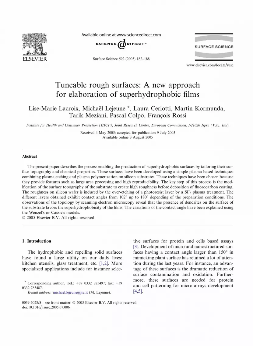
During the past 60 years, numerous works havebeen reported on the study and development ofhydrophobic and superhydrophobic surfaces. Itwas found that hydrophobicity is linked to theuse of an appropriated roughness combined witha low surface energy material. In this aim, theuse of fluorinated compounds is often necessary.Since the study about the hydrophobic propertiesof wax as a function of its roughness [6], severalsimilar studies have been performed on high tech-nological materials such as nanotubes coated byfluoroalkylsilane [7], high porosity materials [8],polymer nanofibers [9] or nanopatterned surfaces[10]. These materials are superhydrophobic i.e.have a contact angle superior to 150�, but theirelaboration presents some disadvantages such ascomplicated deposition techniques, multi-stepsprocesses and low surface coverage. In this paperwe propose an alternative method using a three-step process allowing the deposition of hydropho-bic or superhydrophobic layers on large area. Thekey point of this process is the induction of a highroughness on the silicon substrate using photore-sist overetching before the deposition of fluori-nated carbon layer (Fig. 1). The film compositionhas been studied by Fourier transformation infra-red spectroscopy (FTIR), the topology has beenobserved by scanning electron microscopy (SEM)and the surface energy has been calculated fromcontact angle measurements [11–13]. The differentcontact angles obtained with this deposition tech-nique have been recalculated by using at once the
Fig. 1. Schema of the deposition process, (a) photoresist over-etching bcapacitive C4F8 plasma, (c) final structure.
both formulae developed by Wenzel [14] andCassie [15] as a function of the surface roughnessand its morphology.
2. Experimental method
The method to generate hydrophobic surfacesconsists in 3 steps. First, a 2.3 lm thick photoresistpolymer layer (microposit S1813 supplied by Ship-ley Company [16]) is deposited by spin coating ona silicon wafer. Then, photoresist layers are etchedusing an inductively coupled plasma dischargeusing the magnetic pole enhanced ICP (MaPE-ICP) source described in Refs. [17,18]. The induc-tive mode of the system is used to generate SF6
plasma discharge (10 mTorr pressure) with a400 W r.f. power applied to the coil. During etch-ing, the substrate holder is biased at �60 V by asecondary 13.56 MHz r.f. supply. Etching timewas varied from 1 min to 5 min. FTIR has beenused to study the CFx film structure and to controlthe complete etching of photoresist layer. Afteretching the density of photoresist resin remainingon the Si substrate is lower than the limit densitydetectable by FTIR.
Then, the CFx layer is deposited on etched pho-toresist + Si wafer structure. The CFx thin filmsare deposited using the same plasma reactor butwith the 13.56 MHz r.f. capacitive plasma mode.The plasma is created from a pure octafluoro-cyclobutane (C4F8) gas at the pressure of
y an inductive SF6 plasma, (b) deposition of CFx layer using an
184 L.-M. Lacroix et al. / Surface Science 592 (2005) 182–188
50 mTorr. The power was varied from 10 W to40 W equivalent to a bias of the substrate varyingfrom �40 V to �70 V.
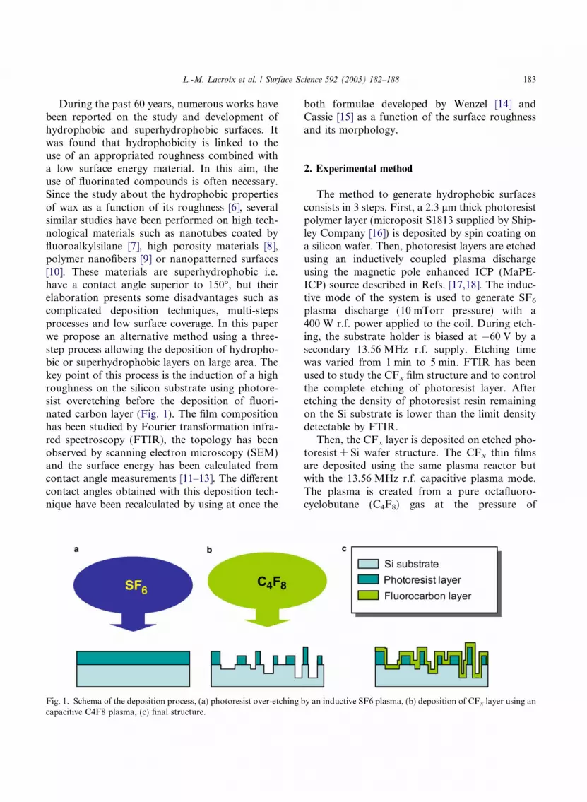
Fig. 2. FTIR of CFx thin films deposited by capacitive plasma.All spectra are normalized by their respective thicknesses.
3. Theoretical background
The water dewetting behavior on rough surfacehas been studied by two models attributed to Wen-zel [14] and Cassie and Baxter [15]. The Wenzel�sapproach assumed that the liquid fills up the roughsurface. So, the contact angle is described by thefollowing equation:
cos h ¼ ðS þ SLÞ=S cos h0; ð1Þwhere h is the contact angle on the rough surface,h 0 is the contact angle on the flat surface of thesame material,S and SL represent respectively thetotal surface and the lateral surface of the rough-ness. The Cassie�s formulation assumes that be-tween the liquid and the surface, there is an airlayer trapped in the valleys of the roughness. Inthis case, the contact between the liquid and thesolid layer is not complete and the contact angleis described by
cos h ¼ ðSH=SÞðcos h0 þ 1Þ � 1; ð2Þwhere h is the contact angle on the rough surface,h 0 is the contact angle on the flat surface of thesame material, SH and S are respectively the con-tact surface with the liquid and the total surface.These two models are rarely compatible [12] anddescribe the behavior of different hydrophobic sur-faces as regards of their chemical compositions,roughness and surface energies. But these two for-mulae suggest a strong effect of the roughness onthe contact angle.
4. Results and discussion
We have started this work with the plasmadeposition of CFx thin films on flat Si substrates.The aim of this preliminary study was to optimizeCFx layer properties i.e. the film presenting thehighest –CF3 content. Indeed, the –CF3 bond isconsidered improving the hydrophobic behaviorof films [19]. Fig. 2 shows the FTIR spectra,
limited to the CFx stretching band, of the filmswith different deposition powers.
The decomposition of the 1100–1400 cm�1 CFx
band is difficult and the contributions are notclearly attributed to the different CFx contribu-tions: –CF, –CF2 or –CF3 [20–24]. However, a glo-bal decrease of the CFx bands with increasingpower is related to the decrease of the CFx density.This result is in good agreement with the workpublished by Yu et al. [25] and Milella et al. [26].So, according to their higher CF densities, thefilms deposited at the lowest power (10 W) seemto be the best candidates for our goal. Moreover,the small peak centered on 980 cm�1, attributedto –CF3 [21–26] and favoring the surface hydro-phobicity, appears only for sample deposited at10 W. Carbon fluorine films deposited at 10 Whave a contact angle and roughness of 105� and3 nm respectively.
This roughness is very low and the 10 W CFx
films can be considered as a flat layer. This samplewill be used as a reference in the results presentedbelow.
The second part of this study is the depositionof CFx layer (80 nm thick) on rough silicon sub-strate. The roughness is created by the over-etching of the photoresist layer i.e. the removalof this layer and partial etching of the Si substrateunderneath. This property is specific to the usedphotoresist. This material is a complex resin
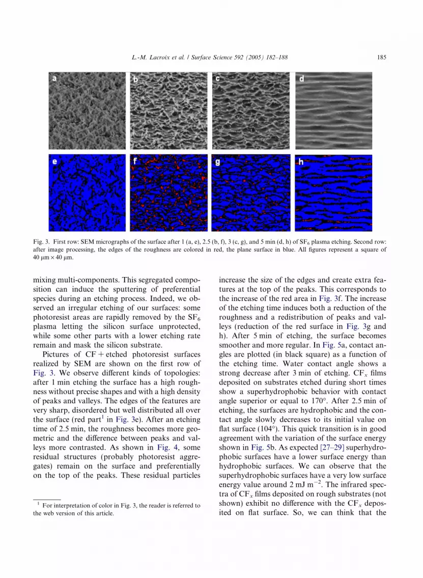
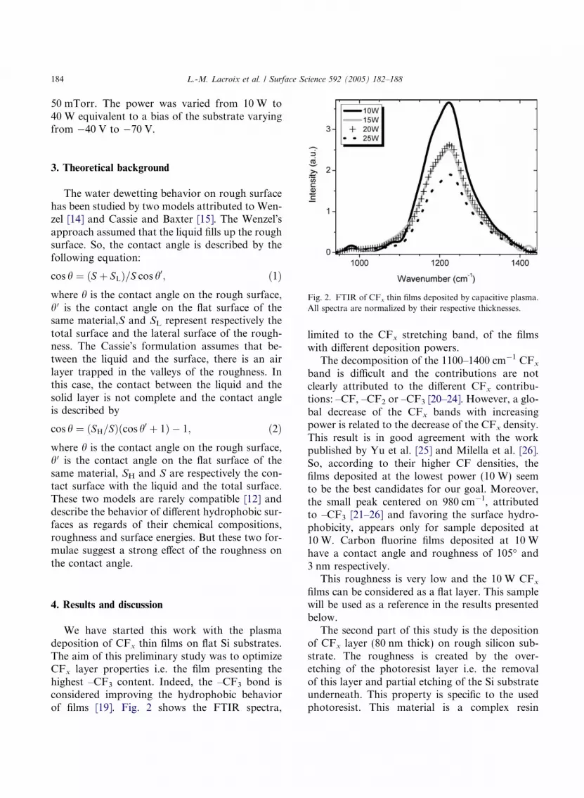
Fig. 3. First row: SEM micrographs of the surface after 1 (a, e), 2.5 (b, f), 3 (c, g), and 5 min (d, h) of SF6 plasma etching. Second row:after image processing, the edges of the roughness are colored in red, the plane surface in blue. All figures represent a square of40 lm · 40 lm.
L.-M. Lacroix et al. / Surface Science 592 (2005) 182–188 185
mixing multi-components. This segregated compo-sition can induce the sputtering of preferentialspecies during an etching process. Indeed, we ob-served an irregular etching of our surfaces: somephotoresist areas are rapidly removed by the SF6
plasma letting the silicon surface unprotected,while some other parts with a lower etching rateremain and mask the silicon substrate.
Pictures of CF + etched photoresist surfacesrealized by SEM are shown on the first row ofFig. 3. We observe different kinds of topologies:after 1 min etching the surface has a high rough-ness without precise shapes and with a high densityof peaks and valleys. The edges of the features arevery sharp, disordered but well distributed all overthe surface (red part1 in Fig. 3e). After an etchingtime of 2.5 min, the roughness becomes more geo-metric and the difference between peaks and val-leys more contrasted. As shown in Fig. 4, someresidual structures (probably photoresist aggre-gates) remain on the surface and preferentiallyon the top of the peaks. These residual particles
1 For interpretation of color in Fig. 3, the reader is referred tothe web version of this article.
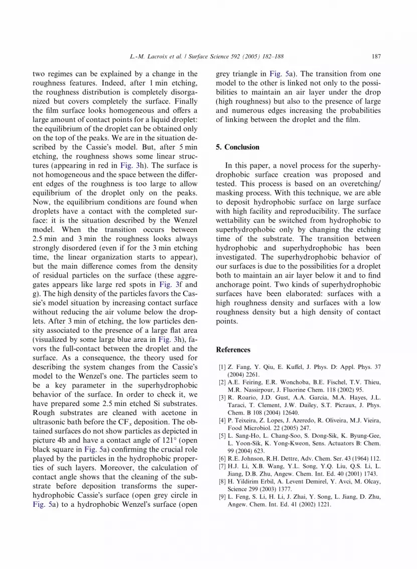
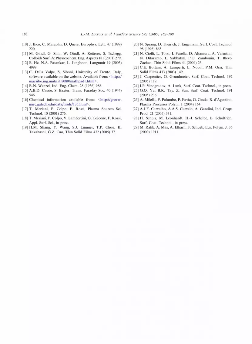
increase the size of the edges and create extra fea-tures at the top of the peaks. This corresponds tothe increase of the red area in Fig. 3f. The increaseof the etching time induces both a reduction of theroughness and a redistribution of peaks and val-leys (reduction of the red surface in Fig. 3g andh). After 5 min of etching, the surface becomessmoother and more regular. In Fig. 5a, contact an-gles are plotted (in black square) as a function ofthe etching time. Water contact angle shows astrong decrease after 3 min of etching. CFx filmsdeposited on substrates etched during short timesshow a superhydrophobic behavior with contactangle superior or equal to 170�. After 2.5 min ofetching, the surfaces are hydrophobic and the con-tact angle slowly decreases to its initial value onflat surface (104�). This quick transition is in goodagreement with the variation of the surface energyshown in Fig. 5b. As expected [27–29] superhydro-phobic surfaces have a lower surface energy thanhydrophobic surfaces. We can observe that thesuperhydrophobic surfaces have a very low surfaceenergy value around 2 mJ m�2. The infrared spec-tra of CFx films deposited on rough substrates (notshown) exhibit no difference with the CFx depos-ited on flat surface. So, we can think that the
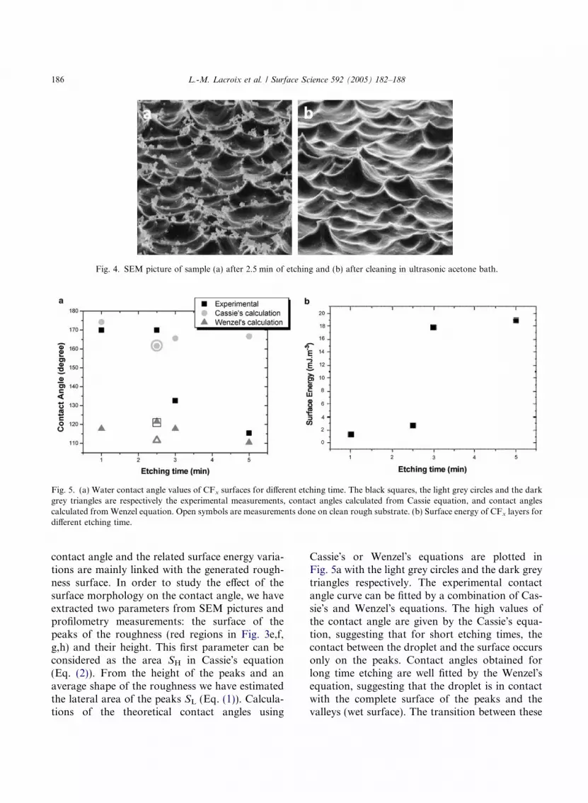
Fig. 4. SEM picture of sample (a) after 2.5 min of etching and (b) after cleaning in ultrasonic acetone bath.
Fig. 5. (a) Water contact angle values of CFx surfaces for different etching time. The black squares, the light grey circles and the darkgrey triangles are respectively the experimental measurements, contact angles calculated from Cassie equation, and contact anglescalculated from Wenzel equation. Open symbols are measurements done on clean rough substrate. (b) Surface energy of CFx layers fordifferent etching time.
186 L.-M. Lacroix et al. / Surface Science 592 (2005) 182–188
contact angle and the related surface energy varia-tions are mainly linked with the generated rough-ness surface. In order to study the effect of thesurface morphology on the contact angle, we haveextracted two parameters from SEM pictures andprofilometry measurements: the surface of thepeaks of the roughness (red regions in Fig. 3e,f,g,h) and their height. This first parameter can beconsidered as the area SH in Cassie�s equation(Eq. (2)). From the height of the peaks and anaverage shape of the roughness we have estimatedthe lateral area of the peaks SL (Eq. (1)). Calcula-tions of the theoretical contact angles using
Cassie�s or Wenzel�s equations are plotted inFig. 5a with the light grey circles and the dark greytriangles respectively. The experimental contactangle curve can be fitted by a combination of Cas-sie�s and Wenzel�s equations. The high values ofthe contact angle are given by the Cassie�s equa-tion, suggesting that for short etching times, thecontact between the droplet and the surface occursonly on the peaks. Contact angles obtained forlong time etching are well fitted by the Wenzel�sequation, suggesting that the droplet is in contactwith the complete surface of the peaks and thevalleys (wet surface). The transition between these
L.-M. Lacroix et al. / Surface Science 592 (2005) 182–188 187
two regimes can be explained by a change in theroughness features. Indeed, after 1 min etching,the roughness distribution is completely disorga-nized but covers completely the surface. Finallythe film surface looks homogeneous and offers alarge amount of contact points for a liquid droplet:the equilibrium of the droplet can be obtained onlyon the top of the peaks. We are in the situation de-scribed by the Cassie�s model. But, after 5 minetching, the roughness shows some linear struc-tures (appearing in red in Fig. 3h). The surface isnot homogeneous and the space between the differ-ent edges of the roughness is too large to allowequilibrium of the droplet only on the peaks.Now, the equilibrium conditions are found whendroplets have a contact with the completed sur-face: it is the situation described by the Wenzelmodel. When the transition occurs between2.5 min and 3 min the roughness looks alwaysstrongly disordered (even if for the 3 min etchingtime, the linear organization starts to appear),but the main difference comes from the densityof residual particles on the surface (these aggre-gates appears like large red spots in Fig. 3f andg). The high density of the particles favors the Cas-sie�s model situation by increasing contact surfacewithout reducing the air volume below the drop-lets. After 3 min of etching, the low particles den-sity associated to the presence of a large flat area(visualized by some large blue area in Fig. 3h), fa-vors the full-contact between the droplet and thesurface. As a consequence, the theory used fordescribing the system changes from the Cassie�smodel to the Wenzel�s one. The particles seem tobe a key parameter in the superhydrophobicbehavior of the surface. In order to check it, wehave prepared some 2.5 min etched Si substrates.Rough substrates are cleaned with acetone inultrasonic bath before the CFx deposition. The ob-tained surfaces do not show particles as depicted inpicture 4b and have a contact angle of 121� (openblack square in Fig. 5a) confirming the crucial roleplayed by the particles in the hydrophobic proper-ties of such layers. Moreover, the calculation ofcontact angle shows that the cleaning of the sub-strate before deposition transforms the super-hydrophobic Cassie�s surface (open grey circle inFig. 5a) to a hydrophobic Wenzel�s surface (open
grey triangle in Fig. 5a). The transition from onemodel to the other is linked not only to the possi-bilities to maintain an air layer under the drop(high roughness) but also to the presence of largeand numerous edges increasing the probabilitiesof linking between the droplet and the film.
5. Conclusion
In this paper, a novel process for the superhy-drophobic surface creation was proposed andtested. This process is based on an overetching/masking process. With this technique, we are ableto deposit hydrophobic surface on large surfacewith high facility and reproducibility. The surfacewettability can be switched from hydrophobic tosuperhydrophobic only by changing the etchingtime of the substrate. The transition betweenhydrophobic and superhydrophobic has beeninvestigated. The superhydrophobic behavior ofour surfaces is due to the possibilities for a dropletboth to maintain an air layer below it and to findanchorage point. Two kinds of superhydrophobicsurfaces have been elaborated: surfaces with ahigh roughness density and surfaces with a lowroughness density but a high density of contactpoints.
References
[1] Z. Fang, Y. Qiu, E. Kuffel, J. Phys. D: Appl. Phys. 37(2004) 2261.
[2] A.E. Feiring, E.R. Wonchoba, B.E. Fischel, T.V. Thieu,M.R. Nassirpour, J. Fluorine Chem. 118 (2002) 95.
[3] R. Roario, J.D. Gust, A.A. Garcia, M.A. Hayes, J.L.Taraci, T. Clement, J.W. Dailey, S.T. Picraux, J. Phys.Chem. B 108 (2004) 12640.
[4] P. Teixeira, Z. Lopes, J. Azeredo, R. Oliveira, M.J. Vieira,Food Microbiol. 22 (2005) 247.
[5] L. Sang-Ho, L. Chang-Soo, S. Dong-Sik, K. Byung-Gee,L. Yoon-Sik, K. Yong-Kweon, Sens. Actuators B: Chem.99 (2004) 623.
[6] R.E. Johnson, R.H. Dettre, Adv. Chem. Ser. 43 (1964) 112.[7] H.J. Li, X.B. Wang, Y.L. Song, Y.Q. Liu, Q.S. Li, L.
Jiang, D.B. Zhu, Angew. Chem. Int. Ed. 40 (2001) 1743.[8] H. Yildirim Erbil, A. Levent Demirel, Y. Avci, M. Olcay,
Science 299 (2003) 1377.[9] L. Feng, S. Li, H. Li, J. Zhai, Y. Song, L. Jiang, D. Zhu,
Angew. Chem. Int. Ed. 41 (2002) 1221.
188 L.-M. Lacroix et al. / Surface Science 592 (2005) 182–188
[10] J. Bico, C. Marzolin, D. Quere, Europhys. Lett. 47 (1999)220.
[11] M. Gindl, G. Sinn, W. Gindl, A. Reiterer, S. Tschegg,Colloids Surf. A: Physicochem. Eng.Aspects 181 (2001) 279.
[12] B. He, N.A. Patankar, L. Junghoon, Langmuir 19 (2003)4999.
[13] C. Della Volpe, S. Siboni, University of Trento, Italy,software available on the website. Available from: <http://macsibo.ing.unitn.it:8080/mathpad1.html>.
[14] R.N. Wenzel, Ind. Eng. Chem. 28 (1936) 988.[15] A.B.D. Cassie, S. Baxter, Trans. Faraday Soc. 40 (1944)
546.[16] Chemical information available from: <http://grover.
mirc.gatech.edu/data/msds/135.html>.[17] T. Meziani, P. Colpo, F. Rossi, Plasma Sources Sci.
Technol. 10 (2001) 276.[18] T. Meziani, P. Colpo, V. Lambertini, G. Ceccone, F. Rossi,
Appl. Surf. Sci., in press.[19] H.M. Shang, Y. Wang, S.J. Limmer, T.P. Chou, K.
Takahashi, G.Z. Cao, Thin Solid Films 472 (2005) 37.
[20] N. Sprang, D. Theirich, J. Engemann, Surf. Coat. Technol.98 (1998) 865.
[21] N. Cioffi, L. Torsi, I. Farella, D. Altamura, A. Valentini,N. Ditaranto, L. Sabbatini, P.G. Zambonin, T. Bleve-Zacheo, Thin Solid Films 44 (2004) 25.
[22] C.E. Bottani, A. Lamperti, L. Nobili, P.M. Ossi, ThinSolid Films 433 (2003) 149.
[23] J. Carpentier, G. Grundmeier, Surf. Coat. Technol. 192(2005) 189.
[24] I.P. Vinogradov, A. Lunk, Surf. Coat. Technol., in press.[25] G.Q. Yu, B.K. Tay, Z. Sun, Surf. Coat. Technol. 191
(2005) 236.[26] A. Milella, F. Palumbo, P. Favia, G. Cicala, R. d�Agostino,
Plasma Processes Polym. 1 (2004) 164.[27] A.J.F. Carvalho, A.A.S. Curvelo, A. Gandini, Ind. Crops
Prod. 21 (2005) 331.[28] H. Schulz, M. Leonhardt, H.-J. Scheibe, B. Schultrich,
Surf. Coat. Technol., in press.[29] M. Rafik, A. Mas, A. Elharfi, F. Schueb, Eur. Polym. J. 36
(2000) 1911.
Related Documents