Installation/Operation/Maintenance Tumble Dryers 25 Pound (11 Kilogram) Capacity 30 Pound (13 Kilogram) Capacity 35 Pound (16 Kilogram) Capacity Stacked 30 Pound (13/13 Kilogram) Capacity Stacked 45 Pound (20/20 Kilogram) Capacity 55 Pound (24 Kilogram) Capacity Starting Serial No. 0602004144 Refer to Page 10 for Model Identification TMB1278C_SVG Original Instructions Keep These Instructions for Future Reference. (If this machine changes ownership, this manual must accompany machine.) www.alliancelaundry.com Part No. 70458301ENR14 July 2017

Welcome message from author
This document is posted to help you gain knowledge. Please leave a comment to let me know what you think about it! Share it to your friends and learn new things together.
Transcript
Installation/Operation/M
aintenanceTumble Dryers
25 Pound (11 Kilogram) Capacity30 Pound (13 Kilogram) Capacity35 Pound (16 Kilogram) Capacity
Stacked 30 Pound (13/13 Kilogram) CapacityStacked 45 Pound (20/20 Kilogram) Capacity
55 Pound (24 Kilogram) CapacityStarting Serial No. 0602004144
Refer to Page 10 for Model Identification
START
25C
HIGHTEMP
MEDTEMP
LOWTEMP
NOHEAT
12
3SELECTTEMP INSERTCOIN PUSH
START
12
3SELECTTEMP INSERTCOIN PUSH
START START
25C
HIGHTEMP
MEDTEMP
LOWTEMP
NOHEAT
TMB1278C_SVG
Original InstructionsKeep These Instructions for Future Reference.(If this machine changes ownership, this manual must accompany machine.)
www.alliancelaundry.com Part No. 70458301ENR14July 2017

Installation must conform with local codes or, in the absence of local codes, with:
In the U.S.A., installation must conform to the latest edition of the American National Standard Z223.1/ NFPA 54 “National Fuel GasCode” and Standard ANSI/NFPA 70 “National Electric Code.”
In Canada, installation must comply with Standards CAN/CSA-B149.1 or Natural Gas and Propane Installation Code and CSA C22.1,latest edition, Canadian Electric Code, Part I.
In Australia and New Zealand, installation must comply with the Gas Installations Standard AS/NZS 5601 Part 1: General Installa-tions.
WARNINGFOR YOUR SAFETY, the information in this manual must be followed to minimize the risk of fire or explosion orto prevent property damage, personal injury or death.
W033
WARNING
• Do not store or use gasoline or other flammable vapors and liquids in the vicinity of this or any other appli-ance.
• WHAT TO DO IF YOU SMELL GAS:• Do not try to light any appliance.• Do not touch any electrical switch; do not use any phone in your building.• Clear the room, building or area of all occupants.• Immediately call your gas supplier from a neighbor’s phone. Follow the gas supplier’s instructions.• If you cannot reach your gas supplier, call the fire department.
• Installation and service must be performed by a qualified installer, service agency or the gas supplier.
W052
IMPORTANT: Information must be obtained from a local gas supplier on instructions to be followed if the usersmells gas. These instructions must be posted in a prominent location. Step-by-step instructions of the abovesafety information must be posted in a prominent location near the tumble dryer for customer use.
IMPORTANT: The installer must fully test the tumble dryer after installation and demonstrate to the owner how tooperate the machine.
WARNINGTo reduce the risk of electric shock, fire, explosion, serious injury or death:• Disconnect electric power to the tumble dryer before servicing.• Close gas shut-off valve to gas tumble dryer before servicing.• Close steam valve to steam tumble dryer before servicing.• Never start the tumble dryer with any guards/panels removed.• Whenever ground wires are removed during servicing, these ground wires must be reconnected to ensure
that the tumble dryer is properly grounded.
W002R1
© Copyright, Alliance Laundry Systems LLC - DO NOT COPY or TRANSMIT
3 Part No. 70458301ENR14
WARNING
• Installation of unit must be performed by a qualified installer.• Install tumble dryer according to manufacturer’s instructions and local codes.• DO NOT install a tumble dryer with flexible plastic venting materials. If flexible metal (foil type) duct is instal-
led, it must be of a specific type identified by the appliance manufacturer as suitable for use with tumbledryer. Refer to section on connecting exhaust system. Flexible venting materials are known to collapse, beeasily crushed, and trap lint. These conditions will obstruct tumble dryer airflow and increase the risk offire.
W752R1
The following information applies to the state of Massachusetts, USA.• This appliance can only be installed by a Massachusetts licensed plumber or gas fitter.• This appliance must be installed with a 36 inch [91 cm] long flexible gas connector.• A “T-Handle” type gas shut-off valve must be installed in the gas supply line to this appliance.• This appliance must not be installed in a bedroom or bathroom.
© Copyright, Alliance Laundry Systems LLC - DO NOT COPY or TRANSMIT
4 Part No. 70458301ENR14
Table of Contents
Introduction........................................................................................... 9Model Identification........................................................................................9Contact Information...................................................................................... 16Manufacturing Date ..................................................................................... 17
................................................................................................................17
Safety Information................................................................................18Explanation of Safety Messages..................................................................... 18Important Safety Instructions......................................................................... 18
Specifications and Dimensions.............................................................. 20Specifications and Dimensions.......................................................................20Cabinet Dimensions – 025, 030, 035 and 055 Series.........................................24Cabinet Dimensions – T30 and T45 Series...................................................... 25Exhaust Outlet Locations – 025, 030, 035 and 055 Series................................. 26Exhaust Outlet Locations – T30 and T45 Series...............................................28Gas Connection Locations – 025, 030, 035 and 055 Series................................29Gas Connection Locations – T30 and T45 Series............................................. 30Electrical Connection Locations – 025, 030, 035 and 055 Series........................31Electrical Connection Locations – T30 and T45 Series..................................... 32Steam Connection Locations – 025, 030 and 035 Series....................................33Steam Connection Locations – T30 Series.......................................................34
Installation........................................................................................... 35Pre-Installation Inspection............................................................................. 35Location Requirements..................................................................................35Position and Level the Tumble Dryer..............................................................36Fifth Leveling Leg........................................................................................ 37Fire Suppression System (Optional Equipment)............................................... 37
Check Local Codes and Permits..................................................................37Water Requirements...................................................................................37Water Connections.....................................................................................38Electrical Requirements............................................................................. 39Auxiliary Alarm........................................................................................ 39
To Reverse the Loading Door (025, 030, 035 and 055 Series)............................39Before Placing Tumble Dryer into Service.......................................................41
Required for CE Models Only.................................................................... 43Installing CE Gas Drying Tumble Dryer..........................................................43
General Information.................................................................................. 43CE Orifices...............................................................................................44Properties of CE Gases.............................................................................. 48
© Copyright 2017, Alliance Laundry Systems LLCAll rights reserved. No part of the contents of this book may be reproduced or transmitted in any form or by any means without the expressedwritten consent of the publisher.
© Copyright, Alliance Laundry Systems LLC - DO NOT COPY or TRANSMIT
5 Part No. 70458301ENR14
Changing Gas Configuration...................................................................... 48Specific Conversion Procedures..................................................................49
Exhaust Requirements..........................................................................52Exhaust Requirements...................................................................................52Layout......................................................................................................... 52Make-Up Air................................................................................................52Venting........................................................................................................ 52
Individual Venting..................................................................................... 54Manifold Venting...................................................................................... 54
Gas Requirements.................................................................................57Gas Requirements.........................................................................................57Gas Supply Pipe Sizing and Looping.............................................................. 59
Low Pressure Gas Pipe Sizes......................................................................60High Pressure Gas Pipe Sizes..................................................................... 62
High Altitude Burner Orifice Sizing............................................................... 63
Electrical Requirements........................................................................71Electrical Requirements.................................................................................71Wiring Diagram............................................................................................71Wiring for Central Pay...................................................................................71Grounding Instructions..................................................................................73
For CE Models Only..................................................................................73Service/Ground Location........................................................................... 73
To Connect Electrical Service To The Tumble Dryer........................................ 77Configuring Your Tumble Dryer for Other Service Voltages..............................77Electrical Connections for T30 and T45 Only.................................................. 78Conversion Instructions.................................................................................79Ferrite Ring Installation (025, 030, 035 and 055 Series Only)............................80Electrical Specifications................................................................................ 81
Steam Requirements.............................................................................93Steam Requirements......................................................................................93Piping Recommendations.............................................................................. 95Installing Steam Trap and Making Condensate Return Connections...................95
Single Drop Timer................................................................................ 96Power-Up Mode........................................................................................... 96Ready Mode.................................................................................................96Start Mode................................................................................................... 96Run Mode.................................................................................................... 96Door Open Mode.......................................................................................... 96End of Cycle Mode....................................................................................... 96Setting Dry Time Dipswitches........................................................................96
Models Through Serial No. 0908xxxxx....................................................... 96Models Starting Serial No. 0909xxxxx........................................................ 96
Resetting Cycle Time to Zero.........................................................................96
© Copyright, Alliance Laundry Systems LLC - DO NOT COPY or TRANSMIT
6 Part No. 70458301ENR14
Dipswitch Settings........................................................................................ 97Topoffs.......................................................................................................100Temperature Selector Switch........................................................................100To Program a Short Test Cycle..................................................................... 100Error Codes................................................................................................ 100
Operating Instructions........................................................................101Operating Instructions................................................................................. 101Emergency Stop Button On CE Models.........................................................101Operating Instructions................................................................................. 101Reversing Operation....................................................................................102Control Instructions.....................................................................................102
Dual Digital Timer Control.......................................................................102Electronic OPL Micro Control.................................................................. 104Single Drop Control.................................................................................105MDC Coin and Card Control.................................................................... 106Quantum Control ....................................................................................106Galaxy 600 Control .................................................................................107LED OPL Control ...................................................................................108UniLinc Control ..................................................................................... 109DX4 Coin Control................................................................................... 110DX4 OPL Control....................................................................................111Diagnostic Microprocessor Control ...........................................................111DMP OPL Models................................................................................... 113DMP Coin...............................................................................................115
Ignition Control Operation and Troubleshooting for Models Starting 3/11/13....117Internal Control Failure............................................................................ 117Troubleshooting.......................................................................................117Proper Electrode Location........................................................................ 118Flame Current Measurement.....................................................................118
Ignition Control Operation for Non-CE Models Through 3/10/13.................... 118Ignition Control Operation for CE Models Through 3/10/13............................119
System Tests........................................................................................... 120Diagnostic LED (DGN LED)/Error Codes................................................. 120
Adjustments........................................................................................121Adjustments............................................................................................... 121Gas Burner Air Shutter................................................................................ 121Airflow Switch .......................................................................................... 122Loading Door Switch.................................................................................. 122Door Strike.................................................................................................123
Maintenance....................................................................................... 124Daily..........................................................................................................124Monthly..................................................................................................... 125Quarterly....................................................................................................125Bi-Annually................................................................................................125Annually.................................................................................................... 125Fire Suppression System (Optional Equipment) Maintenance Test...................125
© Copyright, Alliance Laundry Systems LLC - DO NOT COPY or TRANSMIT
7 Part No. 70458301ENR14
Before You Call for Service................................................................. 127
Removing Tumble Dryer from Service................................................ 128
Disposal of Unit...................................................................................129
China Restriction of hazardous substances (RoHS)............................. 130
© Copyright, Alliance Laundry Systems LLC - DO NOT COPY or TRANSMIT
8 Part No. 70458301ENR14

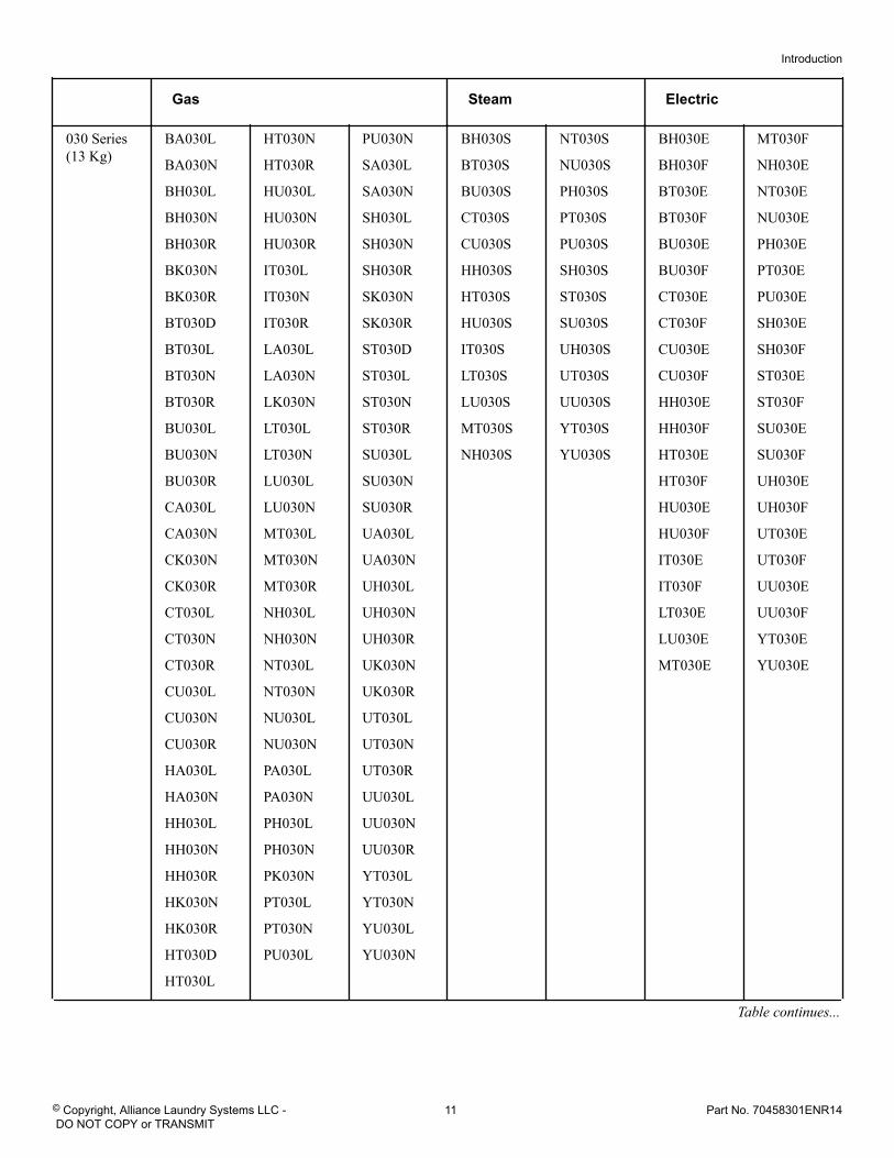
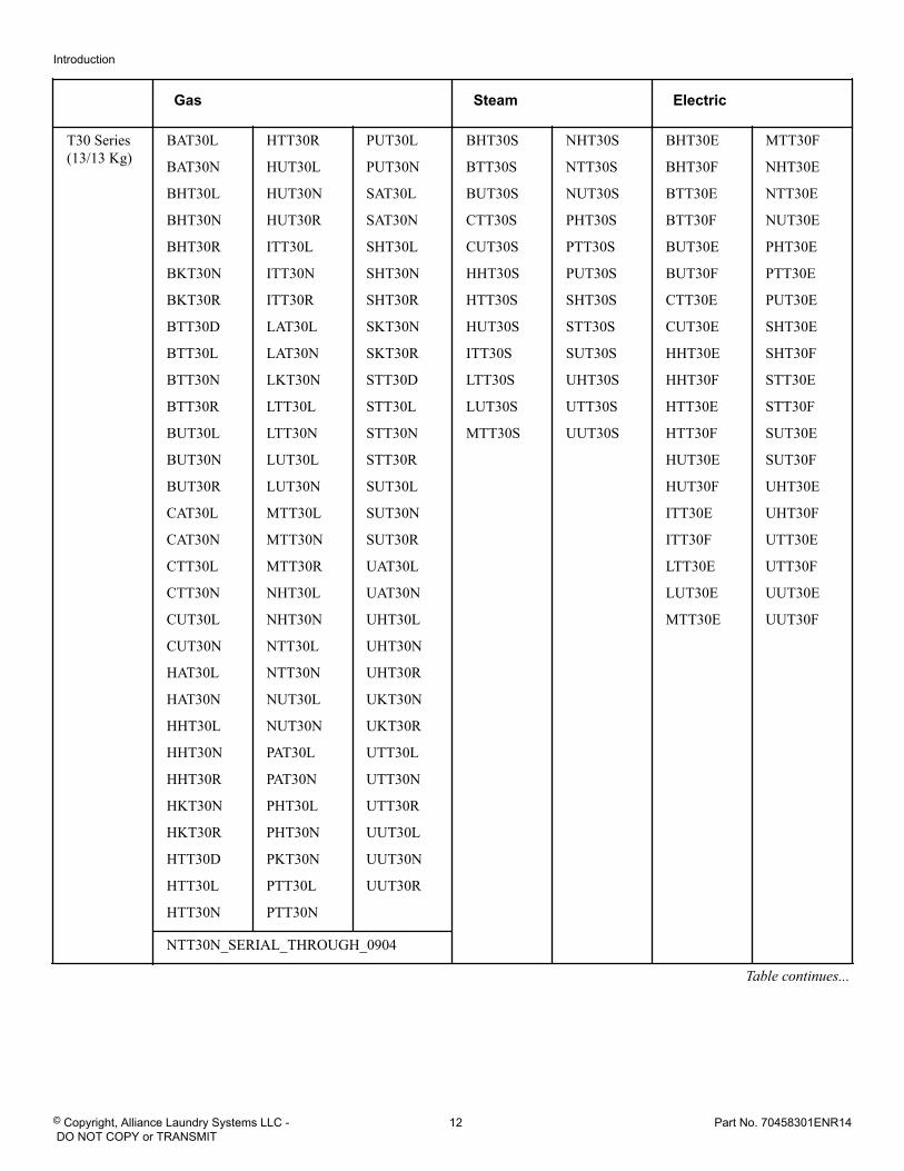
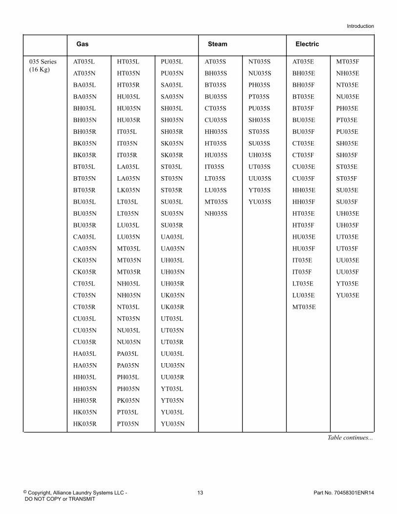
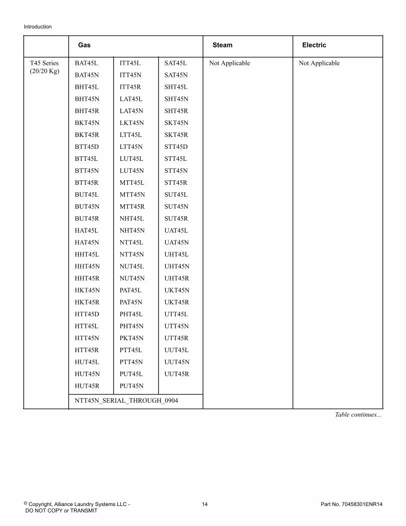
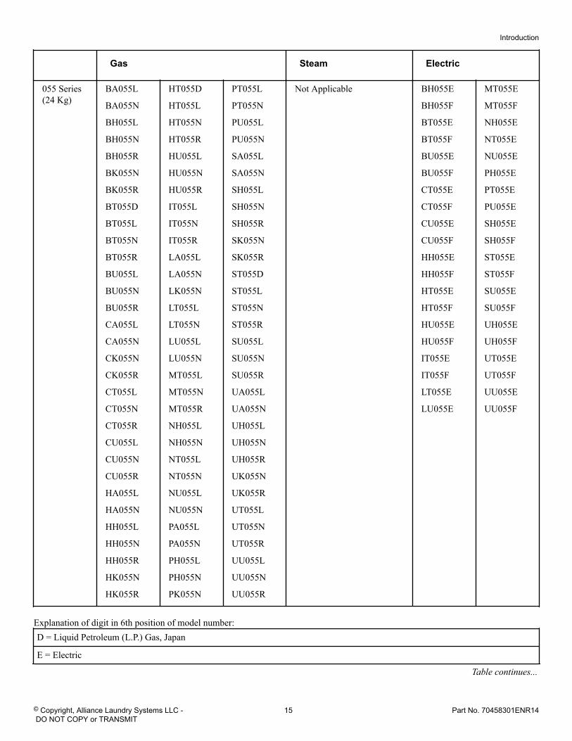
Introduction Model Identification
Information in this manual is applicable to these models. Referto the machine serial plate for the model number.
Introduction
© Copyright, Alliance Laundry Systems LLC - DO NOT COPY or TRANSMIT
9 Part No. 70458301ENR14
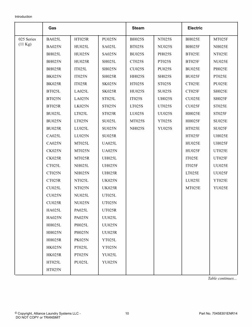
Gas Steam Electric
025 Series(11 Kg)
BA025L
BA025N
BH025L
BH025N
BH025R
BK025N
BK025R
BT025L
BT025N
BT025R
BU025L
BU025N
BU025R
CA025L
CA025N
CK025N
CK025R
CT025L
CT025N
CT025R
CU025L
CU025N
CU025R
HA025L
HA025N
HH025L
HH025N
HH025R
HK025N
HK025R
HT025L
HT025N
HT025R
HU025L
HU025N
HU025R
IT025L
IT025N
IT025R
LA025L
LA025N
LK025N
LT025L
LT025N
LU025L
LU025N
MT025L
MT025N
MT025R
NH025L
NH025N
NT025L
NT025N
NU025L
NU025N
PA025L
PA025N
PH025L
PH025N
PK025N
PT025L
PT025N
PU025L
PU025N
SA025L
SA025N
SH025L
SH025N
SH025R
SK025N
SK025R
ST025L
ST025N
ST025R
SU025L
SU025N
SU025R
UA025L
UA025N
UH025L
UH025N
UH025R
UK025N
UK025R
UT025L
UT025N
UT025R
UU025L
UU025N
UU025R
YT025L
YT025N
YU025L
YU025N
BH025S
BT025S
BU025S
CT025S
CU025S
HH025S
HT025S
HU025S
IT025S
LT025S
LU025S
MT025S
NH025S
NT025S
NU025S
PH025S
PT025S
PU025S
SH025S
ST025S
SU025S
UH025S
UT025S
UU025S
YT025S
YU025S
BH025E
BH025F
BT025E
BT025F
BU025E
BU025F
CT025E
CT025F
CU025E
CU025F
HH025E
HH025F
HT025E
HT025F
HU025E
HU025F
IT025E
IT025F
LT025E
LU025E
MT025E
MT025F
NH025E
NT025E
NU025E
PH025E
PT025E
PU025E
SH025E
SH025F
ST025E
ST025F
SU025E
SU025F
UH025E
UH025F
UT025E
UT025F
UU025E
UU025F
YT025E
YU025E
Table continues...
Introduction
© Copyright, Alliance Laundry Systems LLC - DO NOT COPY or TRANSMIT
10 Part No. 70458301ENR14
Gas Steam Electric
030 Series(13 Kg)
BA030L
BA030N
BH030L
BH030N
BH030R
BK030N
BK030R
BT030D
BT030L
BT030N
BT030R
BU030L
BU030N
BU030R
CA030L
CA030N
CK030N
CK030R
CT030L
CT030N
CT030R
CU030L
CU030N
CU030R
HA030L
HA030N
HH030L
HH030N
HH030R
HK030N
HK030R
HT030D
HT030L
HT030N
HT030R
HU030L
HU030N
HU030R
IT030L
IT030N
IT030R
LA030L
LA030N
LK030N
LT030L
LT030N
LU030L
LU030N
MT030L
MT030N
MT030R
NH030L
NH030N
NT030L
NT030N
NU030L
NU030N
PA030L
PA030N
PH030L
PH030N
PK030N
PT030L
PT030N
PU030L
PU030N
SA030L
SA030N
SH030L
SH030N
SH030R
SK030N
SK030R
ST030D
ST030L
ST030N
ST030R
SU030L
SU030N
SU030R
UA030L
UA030N
UH030L
UH030N
UH030R
UK030N
UK030R
UT030L
UT030N
UT030R
UU030L
UU030N
UU030R
YT030L
YT030N
YU030L
YU030N
BH030S
BT030S
BU030S
CT030S
CU030S
HH030S
HT030S
HU030S
IT030S
LT030S
LU030S
MT030S
NH030S
NT030S
NU030S
PH030S
PT030S
PU030S
SH030S
ST030S
SU030S
UH030S
UT030S
UU030S
YT030S
YU030S
BH030E
BH030F
BT030E
BT030F
BU030E
BU030F
CT030E
CT030F
CU030E
CU030F
HH030E
HH030F
HT030E
HT030F
HU030E
HU030F
IT030E
IT030F
LT030E
LU030E
MT030E
MT030F
NH030E
NT030E
NU030E
PH030E
PT030E
PU030E
SH030E
SH030F
ST030E
ST030F
SU030E
SU030F
UH030E
UH030F
UT030E
UT030F
UU030E
UU030F
YT030E
YU030E
Table continues...
Introduction
© Copyright, Alliance Laundry Systems LLC - DO NOT COPY or TRANSMIT
11 Part No. 70458301ENR14
Gas Steam Electric
T30 Series(13/13 Kg)
BAT30L
BAT30N
BHT30L
BHT30N
BHT30R
BKT30N
BKT30R
BTT30D
BTT30L
BTT30N
BTT30R
BUT30L
BUT30N
BUT30R
CAT30L
CAT30N
CTT30L
CTT30N
CUT30L
CUT30N
HAT30L
HAT30N
HHT30L
HHT30N
HHT30R
HKT30N
HKT30R
HTT30D
HTT30L
HTT30N
HTT30R
HUT30L
HUT30N
HUT30R
ITT30L
ITT30N
ITT30R
LAT30L
LAT30N
LKT30N
LTT30L
LTT30N
LUT30L
LUT30N
MTT30L
MTT30N
MTT30R
NHT30L
NHT30N
NTT30L
NTT30N
NUT30L
NUT30N
PAT30L
PAT30N
PHT30L
PHT30N
PKT30N
PTT30L
PTT30N
PUT30L
PUT30N
SAT30L
SAT30N
SHT30L
SHT30N
SHT30R
SKT30N
SKT30R
STT30D
STT30L
STT30N
STT30R
SUT30L
SUT30N
SUT30R
UAT30L
UAT30N
UHT30L
UHT30N
UHT30R
UKT30N
UKT30R
UTT30L
UTT30N
UTT30R
UUT30L
UUT30N
UUT30R
BHT30S
BTT30S
BUT30S
CTT30S
CUT30S
HHT30S
HTT30S
HUT30S
ITT30S
LTT30S
LUT30S
MTT30S
NHT30S
NTT30S
NUT30S
PHT30S
PTT30S
PUT30S
SHT30S
STT30S
SUT30S
UHT30S
UTT30S
UUT30S
BHT30E
BHT30F
BTT30E
BTT30F
BUT30E
BUT30F
CTT30E
CUT30E
HHT30E
HHT30F
HTT30E
HTT30F
HUT30E
HUT30F
ITT30E
ITT30F
LTT30E
LUT30E
MTT30E
MTT30F
NHT30E
NTT30E
NUT30E
PHT30E
PTT30E
PUT30E
SHT30E
SHT30F
STT30E
STT30F
SUT30E
SUT30F
UHT30E
UHT30F
UTT30E
UTT30F
UUT30E
UUT30F
NTT30N_SERIAL_THROUGH_0904
Table continues...
Introduction
© Copyright, Alliance Laundry Systems LLC - DO NOT COPY or TRANSMIT
12 Part No. 70458301ENR14
Gas Steam Electric
035 Series(16 Kg)
AT035L
AT035N
BA035L
BA035N
BH035L
BH035N
BH035R
BK035N
BK035R
BT035L
BT035N
BT035R
BU035L
BU035N
BU035R
CA035L
CA035N
CK035N
CK035R
CT035L
CT035N
CT035R
CU035L
CU035N
CU035R
HA035L
HA035N
HH035L
HH035N
HH035R
HK035N
HK035R
HT035L
HT035N
HT035R
HU035L
HU035N
HU035R
IT035L
IT035N
IT035R
LA035L
LA035N
LK035N
LT035L
LT035N
LU035L
LU035N
MT035L
MT035N
MT035R
NH035L
NH035N
NT035L
NT035N
NU035L
NU035N
PA035L
PA035N
PH035L
PH035N
PK035N
PT035L
PT035N
PU035L
PU035N
SA035L
SA035N
SH035L
SH035N
SH035R
SK035N
SK035R
ST035L
ST035N
ST035R
SU035L
SU035N
SU035R
UA035L
UA035N
UH035L
UH035N
UH035R
UK035N
UK035R
UT035L
UT035N
UT035R
UU035L
UU035N
UU035R
YT035L
YT035N
YU035L
YU035N
AT035S
BH035S
BT035S
BU035S
CT035S
CU035S
HH035S
HT035S
HU035S
IT035S
LT035S
LU035S
MT035S
NH035S
NT035S
NU035S
PH035S
PT035S
PU035S
SH035S
ST035S
SU035S
UH035S
UT035S
UU035S
YT035S
YU035S
AT035E
BH035E
BH035F
BT035E
BT035F
BU035E
BU035F
CT035E
CT035F
CU035E
CU035F
HH035E
HH035F
HT035E
HT035F
HU035E
HU035F
IT035E
IT035F
LT035E
LU035E
MT035E
MT035F
NH035E
NT035E
NU035E
PH035E
PT035E
PU035E
SH035E
SH035F
ST035E
ST035F
SU035E
SU035F
UH035E
UH035F
UT035E
UT035F
UU035E
UU035F
YT035E
YU035E
Table continues...
Introduction
© Copyright, Alliance Laundry Systems LLC - DO NOT COPY or TRANSMIT
13 Part No. 70458301ENR14
Gas Steam Electric
T45 Series(20/20 Kg)
BAT45L
BAT45N
BHT45L
BHT45N
BHT45R
BKT45N
BKT45R
BTT45D
BTT45L
BTT45N
BTT45R
BUT45L
BUT45N
BUT45R
HAT45L
HAT45N
HHT45L
HHT45N
HHT45R
HKT45N
HKT45R
HTT45D
HTT45L
HTT45N
HTT45R
HUT45L
HUT45N
HUT45R
ITT45L
ITT45N
ITT45R
LAT45L
LAT45N
LKT45N
LTT45L
LTT45N
LUT45L
LUT45N
MTT45L
MTT45N
MTT45R
NHT45L
NHT45N
NTT45L
NTT45N
NUT45L
NUT45N
PAT45L
PAT45N
PHT45L
PHT45N
PKT45N
PTT45L
PTT45N
PUT45L
PUT45N
SAT45L
SAT45N
SHT45L
SHT45N
SHT45R
SKT45N
SKT45R
STT45D
STT45L
STT45N
STT45R
SUT45L
SUT45N
SUT45R
UAT45L
UAT45N
UHT45L
UHT45N
UHT45R
UKT45N
UKT45R
UTT45L
UTT45N
UTT45R
UUT45L
UUT45N
UUT45R
Not Applicable Not Applicable
NTT45N_SERIAL_THROUGH_0904
Table continues...
Introduction
© Copyright, Alliance Laundry Systems LLC - DO NOT COPY or TRANSMIT
14 Part No. 70458301ENR14
Gas Steam Electric
055 Series(24 Kg)
BA055L
BA055N
BH055L
BH055N
BH055R
BK055N
BK055R
BT055D
BT055L
BT055N
BT055R
BU055L
BU055N
BU055R
CA055L
CA055N
CK055N
CK055R
CT055L
CT055N
CT055R
CU055L
CU055N
CU055R
HA055L
HA055N
HH055L
HH055N
HH055R
HK055N
HK055R
HT055D
HT055L
HT055N
HT055R
HU055L
HU055N
HU055R
IT055L
IT055N
IT055R
LA055L
LA055N
LK055N
LT055L
LT055N
LU055L
LU055N
MT055L
MT055N
MT055R
NH055L
NH055N
NT055L
NT055N
NU055L
NU055N
PA055L
PA055N
PH055L
PH055N
PK055N
PT055L
PT055N
PU055L
PU055N
SA055L
SA055N
SH055L
SH055N
SH055R
SK055N
SK055R
ST055D
ST055L
ST055N
ST055R
SU055L
SU055N
SU055R
UA055L
UA055N
UH055L
UH055N
UH055R
UK055N
UK055R
UT055L
UT055N
UT055R
UU055L
UU055N
UU055R
Not Applicable BH055E
BH055F
BT055E
BT055F
BU055E
BU055F
CT055E
CT055F
CU055E
CU055F
HH055E
HH055F
HT055E
HT055F
HU055E
HU055F
IT055E
IT055F
LT055E
LU055E
MT055E
MT055F
NH055E
NT055E
NU055E
PH055E
PT055E
PU055E
SH055E
SH055F
ST055E
ST055F
SU055E
SU055F
UH055E
UH055F
UT055E
UT055F
UU055E
UU055F
Explanation of digit in 6th position of model number:D = Liquid Petroleum (L.P.) Gas, Japan
E = Electric
Table continues...
Introduction
© Copyright, Alliance Laundry Systems LLC - DO NOT COPY or TRANSMIT
15 Part No. 70458301ENR14
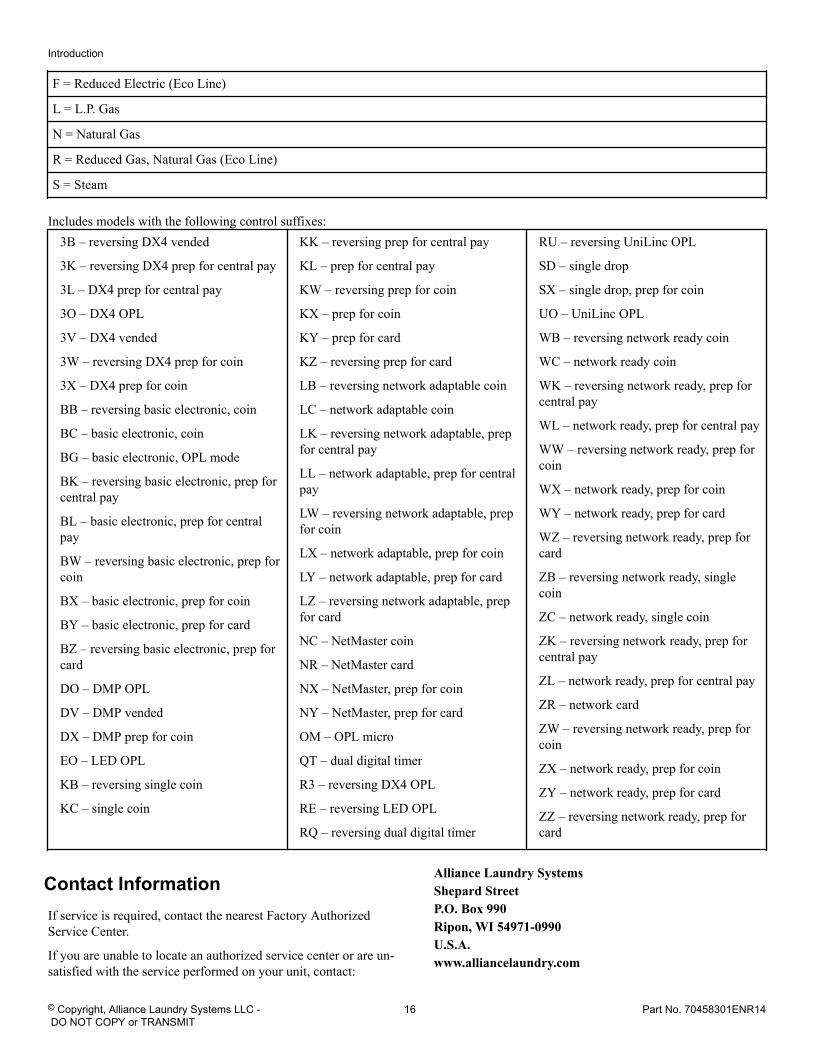
F = Reduced Electric (Eco Line)
L = L.P. Gas
N = Natural Gas
R = Reduced Gas, Natural Gas (Eco Line)
S = Steam
Includes models with the following control suffixes:3B – reversing DX4 vended
3K – reversing DX4 prep for central pay
3L – DX4 prep for central pay
3O – DX4 OPL
3V – DX4 vended
3W – reversing DX4 prep for coin
3X – DX4 prep for coin
BB – reversing basic electronic, coin
BC – basic electronic, coin
BG – basic electronic, OPL mode
BK – reversing basic electronic, prep forcentral pay
BL – basic electronic, prep for centralpay
BW – reversing basic electronic, prep forcoin
BX – basic electronic, prep for coin
BY – basic electronic, prep for card
BZ – reversing basic electronic, prep forcard
DO – DMP OPL
DV – DMP vended
DX – DMP prep for coin
EO – LED OPL
KB – reversing single coin
KC – single coin
KK – reversing prep for central pay
KL – prep for central pay
KW – reversing prep for coin
KX – prep for coin
KY – prep for card
KZ – reversing prep for card
LB – reversing network adaptable coin
LC – network adaptable coin
LK – reversing network adaptable, prepfor central pay
LL – network adaptable, prep for centralpay
LW – reversing network adaptable, prepfor coin
LX – network adaptable, prep for coin
LY – network adaptable, prep for card
LZ – reversing network adaptable, prepfor card
NC – NetMaster coin
NR – NetMaster card
NX – NetMaster, prep for coin
NY – NetMaster, prep for card
OM – OPL micro
QT – dual digital timer
R3 – reversing DX4 OPL
RE – reversing LED OPL
RQ – reversing dual digital timer
RU – reversing UniLinc OPL
SD – single drop
SX – single drop, prep for coin
UO – UniLinc OPL
WB – reversing network ready coin
WC – network ready coin
WK – reversing network ready, prep forcentral pay
WL – network ready, prep for central pay
WW – reversing network ready, prep forcoin
WX – network ready, prep for coin
WY – network ready, prep for card
WZ – reversing network ready, prep forcard
ZB – reversing network ready, singlecoin
ZC – network ready, single coin
ZK – reversing network ready, prep forcentral pay
ZL – network ready, prep for central pay
ZR – network card
ZW – reversing network ready, prep forcoin
ZX – network ready, prep for coin
ZY – network ready, prep for card
ZZ – reversing network ready, prep forcard
Contact InformationIf service is required, contact the nearest Factory AuthorizedService Center.
If you are unable to locate an authorized service center or are un-satisfied with the service performed on your unit, contact:
Alliance Laundry SystemsShepard StreetP.O. Box 990Ripon, WI 54971-0990U.S.A.www.alliancelaundry.com
Introduction
© Copyright, Alliance Laundry Systems LLC - DO NOT COPY or TRANSMIT
16 Part No. 70458301ENR14
Phone: +1 (920) 748-3121
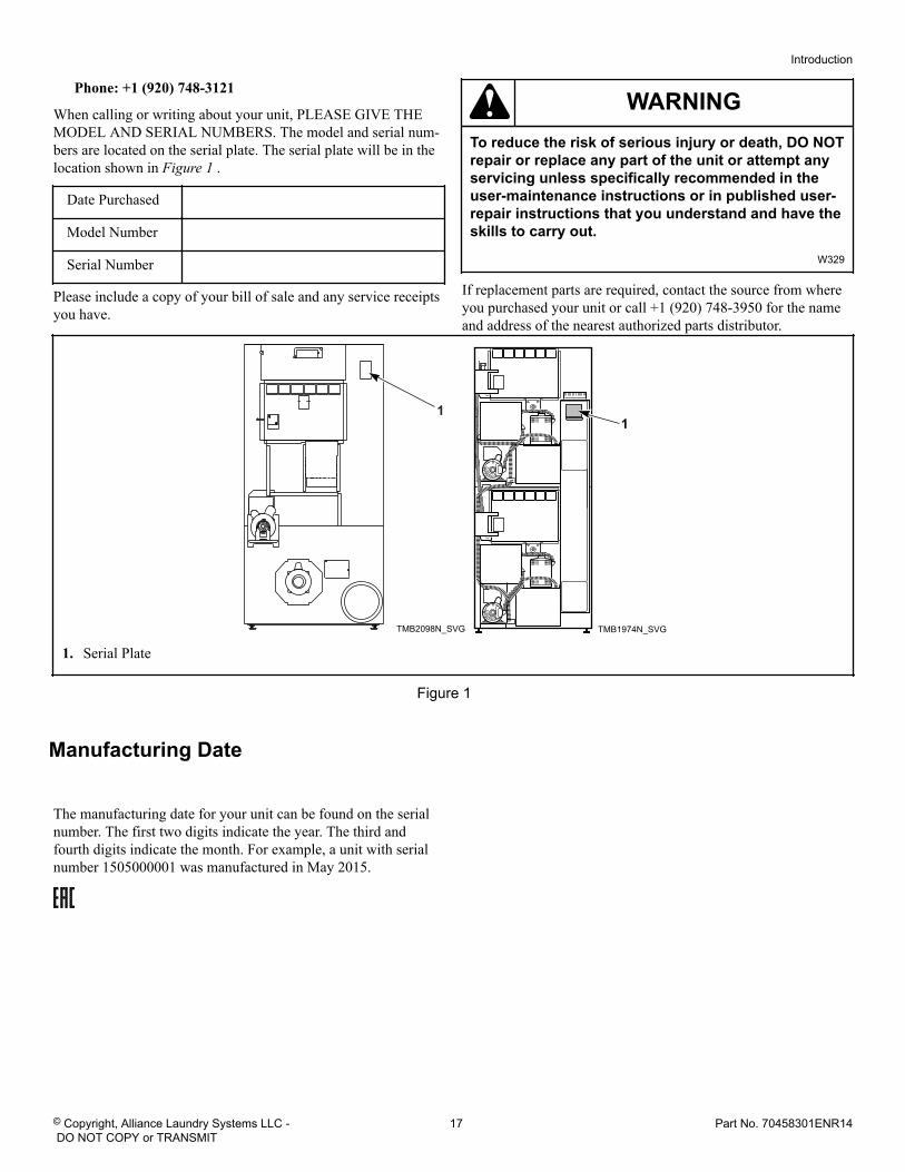
When calling or writing about your unit, PLEASE GIVE THEMODEL AND SERIAL NUMBERS. The model and serial num-bers are located on the serial plate. The serial plate will be in thelocation shown in Figure 1 .
Date Purchased
Model Number
Serial Number
Please include a copy of your bill of sale and any service receiptsyou have.
WARNINGTo reduce the risk of serious injury or death, DO NOTrepair or replace any part of the unit or attempt anyservicing unless specifically recommended in theuser-maintenance instructions or in published user-repair instructions that you understand and have theskills to carry out.
W329
If replacement parts are required, contact the source from whereyou purchased your unit or call +1 (920) 748-3950 for the nameand address of the nearest authorized parts distributor.
TMB2098N_SVG
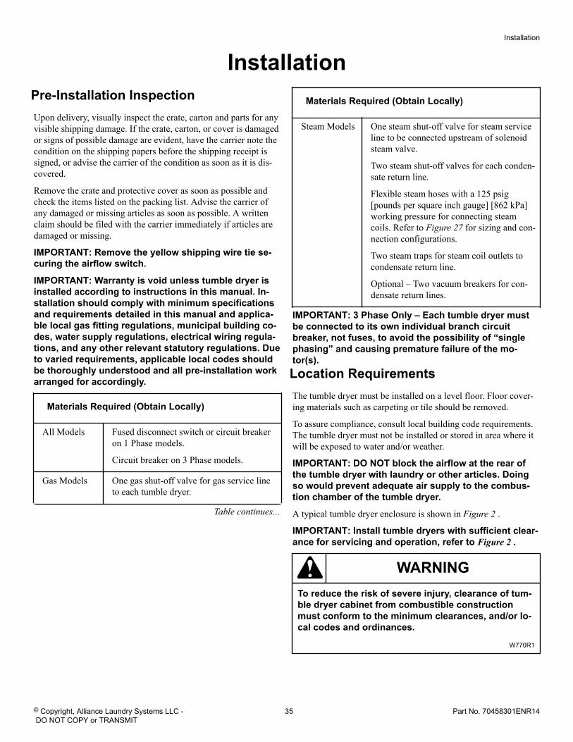
1
TMB1974N_SVG
1
1. Serial Plate
Figure 1
Manufacturing Date
The manufacturing date for your unit can be found on the serialnumber. The first two digits indicate the year. The third andfourth digits indicate the month. For example, a unit with serialnumber 1505000001 was manufactured in May 2015.
Introduction
© Copyright, Alliance Laundry Systems LLC - DO NOT COPY or TRANSMIT
17 Part No. 70458301ENR14
Safety Information Explanation of Safety Messages
Precautionary statements (“DANGER,” “WARNING,” and“CAUTION”), followed by specific instructions, are found in thismanual and on machine decals. These precautions are intendedfor the personal safety of the operator, user, servicer, and thosemaintaining the machine.
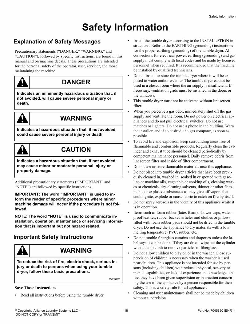
DANGERIndicates an imminently hazardous situation that, ifnot avoided, will cause severe personal injury ordeath.
WARNINGIndicates a hazardous situation that, if not avoided,could cause severe personal injury or death.
CAUTIONIndicates a hazardous situation that, if not avoided,may cause minor or moderate personal injury orproperty damage.
Additional precautionary statements (“IMPORTANT” and“NOTE”) are followed by specific instructions.
IMPORTANT: The word “IMPORTANT” is used to in-form the reader of specific procedures where minormachine damage will occur if the procedure is not fol-lowed.
NOTE: The word “NOTE” is used to communicate in-stallation, operation, maintenance or servicing informa-tion that is important but not hazard related.
Important Safety Instructions
WARNINGTo reduce the risk of fire, electric shock, serious in-jury or death to persons when using your tumbledryer, follow these basic precautions.
W776R1
Save These Instructions
• Read all instructions before using the tumble dryer.
• Install the tumble dryer according to the INSTALLATION in-structions. Refer to the EARTHING (grounding) instructionsfor the proper earthing (grounding) of the tumble dryer. Allconnections for electrical power, earthing (grounding) and gassupply must comply with local codes and be made by licensedpersonnel when required. It is recommended that the machinebe installed by qualified technicians.
• Do not install or store the tumble dryer where it will be ex-posed to water and/or weather. The tumble dryer cannot beused in a closed room where the air supply is insufficient. Ifnecessary, ventilation grids must be installed in the doors orthe windows.
• This tumble dryer must not be activated without lint screenfilter.
• When you perceive a gas odor, immediately shut off the gassupply and ventilate the room. Do not power on electrical ap-pliances and do not pull electrical switches. Do not usematches or lighters. Do not use a phone in the building. Warnthe installer, and if so desired, the gas company, as soon aspossible.
• To avoid fire and explosion, keep surrounding areas free offlammable and combustible products. Regularly clean the cyl-inder and exhaust tube should be cleaned periodically bycompetent maintenance personnel. Daily remove debris fromlint screen filter and inside of filter compartment.
• Do not use or store flammable materials near this appliance.• Do not place into tumble dryer articles that have been previ-
ously cleaned in, washed in, soaked in or spotted with gaso-line or machine oils, vegetable or cooking oils, cleaning wax-es or chemicals, dry-cleaning solvents, thinner or other flam-mable or explosive substances as they give off vapors thatcould ignite, explode or cause fabric to catch on fire by itself.
• Do not spray aerosols in the vicinity of this appliance while itis in operation.
• Items such as foam rubber (latex foam), shower caps, water-proof textiles, rubber backed articles and clothes or pillowsfilled with foam rubber pads should not be dried in the tumbledryer. Do not use the appliance to dry materials with a lowmelting temperature (PVC, rubber, etc.).
• Do not tumble fiberglass curtains and draperies unless the la-bel says it can be done. If they are dried, wipe out the cylinderwith a damp cloth to remove particles of fiberglass.
• Do not allow children to play on or in the washer. Close su-pervision of children is necessary when the washer is usednear children. This appliance is not intended for use by per-sons (including children) with reduced physical, sensory ormental capabilities, or lack of experience and knowledge, un-less they have been given supervision or instruction concern-ing the use of the appliance by a person responsible for theirsafety. This is a safety rule for all appliances.
• Cleaning and user maintenance shall not be made by childrenwithout supervision.
Safety Information
© Copyright, Alliance Laundry Systems LLC - DO NOT COPY or TRANSMIT
18 Part No. 70458301ENR14
• Children less than three years should be kept away unlesscontinuously supervised.
• Do not reach into the tumble dryer if the cylinder is revolving.• Use tumble dryer only for its intended purpose, drying fab-
rics. Always follow the fabric care instructions supplied bythe textile manufacturer and only use the dryer to dry textilesthat have been washed in water. Only insert spin-dried linenin the dryer to avoid damage to dryer.
• Always read and follow manufacturer’s instructions on pack-ages of laundry and cleaning aids. Follow all warnings or pre-cautions. To reduce the risk of poisoning or chemical burns,keep them out of the reach of children at all times (preferablyin a locked cabinet).
• Do not use fabric softeners or products to eliminate static un-less recommended by the manufacturer of the fabric softeneror product.
• Remove laundry immediately after tumble dryer stops.• DO NOT operate the tumble dryer if it is smoking, grinding
or has missing or broken parts or removed guards or panels.DO NOT tamper with the controls or bypass any safety devi-ces.
• Tumble dryer will not operate with the loading door open. DONOT bypass the door safety switch to permit the tumble dryerto operate with the door open. The tumble dryer will stop ro-tating when the door is opened. Do not use the tumble dryer ifit does not stop rotating when the door is opened or startstumbling without pressing the START mechanism. Removethe tumble dryer from use and call for service.
• Tumble dryer will not operate with lint panel open. DO NOTbypass lint panel door safety switch to permit the tumble dry-er to operate with the lint panel door open.
• Do not alter this tumble dryer from factory construction ex-cept as otherwise described in the technical instructions.
• Always clean the lint filter daily. Keep area around the ex-haust opening and adjacent surrounding area free from the ac-cumulation of lint, dust and dirt. The interior of the tumbledryer and the exhaust duct should be cleaned periodically byqualified service personnel.
• Solvent vapors from dry-cleaning machines create acids whendrawn through the heater of the drying unit. These acids arecorrosive to the tumble dryer as well as the laundry load beingdried. Be sure make-up air is free of solvent vapors.
• At the end of each working day, close off all main supplies ofgas, steam and electricity.IMPORTANT: For fire suppression equipped tumbledryers, electricity and water should NOT be turnedoff.
• Do not repair or replace any part of the tumble dryer, or at-tempt any servicing unless specifically recommended in theuser-maintenance instructions or in published user-repair in-structions that the user understands and has the skills to carryout. ALWAYS disconnect and lockout the electrical power tothe tumble dryer before servicing. Disconnect power by shut-ting off appropriate breaker or fuse.
• Activation of the emergency stop switch stops all tumble dry-er control circuit functions, but DOES NOT remove all elec-trical power from tumble dryer.
• Exhaust ductwork should be examined and cleaned annuallyafter installation.
• Before the tumble dryer is removed from service or discarded,remove the door to the drying compartment and the door tothe lint compartment.
• Failure to install, maintain, and/or operate this tumble dryeraccording to the manufacturer’s instructions may result inconditions which can produce bodily injury and/or propertydamage.
NOTE: The WARNINGS and IMPORTANT SAFETY IN-STRUCTIONS appearing in this manual are not meantto cover all possible conditions and situations that mayoccur. Observe and be aware of other labels and pre-cautions that are located on the machine. They are in-tended to provide instruction for safe use of the ma-chine. Common sense, caution and care must be exer-cised when installing, maintaining, or operating thetumble dryer.
Always contact your dealer, distributor, service agent or the man-ufacturer about any problems or conditions you do not under-stand.
Safety Information
© Copyright, Alliance Laundry Systems LLC - DO NOT COPY or TRANSMIT
19 Part No. 70458301ENR14
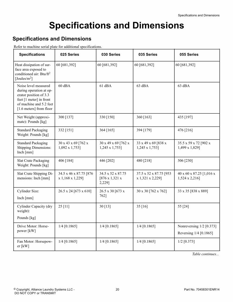
Specifications and Dimensions Specifications and Dimensions
Refer to machine serial plate for additional specifications.
Specifications 025 Series 030 Series 035 Series 055 Series
Heat dissipation of sur-face area exposed toconditioned air: Btu/ft2[Joules/m2]
60 [681,392] 60 [681,392] 60 [681,392] 60 [681,392]
Noise level measuredduring operation at op-erator position of 3.3feet [1 meter] in frontof machine and 5.2 feet[1.6 meters] from floor
60 dBA 61 dBA 63 dBA 63 dBA
Net Weight (approxi-mate): Pounds [kg]
300 [137] 330 [150] 360 [163] 435 [197]
Standard PackagingWeight: Pounds [kg]
332 [151] 364 [165] 394 [179] 476 [216]
Standard PackagingShipping Dimensions:Inch [mm]
30 x 43 x 69 [762 x1,092 x 1,753]
30 x 49 x 69 [762 x1,245 x 1,753]
33 x 49 x 69 [838 x1,245 x 1,753]
35.5 x 59 x 72 [902 x1,499 x 1,829]
Slat Crate PackagingWeight: Pounds [kg]
406 [184] 446 [202] 480 [218] 506 [230]
Slat Crate Shipping Di-mensions: Inch [mm]
34.5 x 46 x 87.75 [876x 1,168 x 1,229]
34.5 x 52 x 87.75[876 x 1,321 x2,229]
37.5 x 52 x 87.75 [953x 1,321 x 2,229]
40 x 60 x 87.25 [1,016 x1,524 x 2,216]
Cylinder Size:
Inch [mm]
26.5 x 24 [673 x 610] 26.5 x 30 [673 x762]
30 x 30 [762 x 762] 33 x 35 [838 x 889]
Cylinder Capacity (dryweight):
Pounds [kg]
25 [11] 30 [13] 35 [16] 55 [24]
Drive Motor: Horse-power [kW]
1/4 [0.1865] 1/4 [0.1865] 1/4 [0.1865] Nonreversing 1/2 [0.373]
Reversing 1/4 [0.1865]
Fan Motor: Horsepow-er [kW]
1/4 [0.1865] 1/4 [0.1865] 1/4 [0.1865] 1/2 [0.373]
Table continues...
Specifications and Dimensions
© Copyright, Alliance Laundry Systems LLC - DO NOT COPY or TRANSMIT
20 Part No. 70458301ENR14
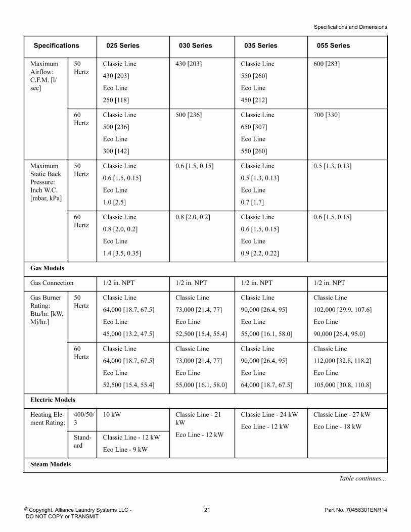
Specifications 025 Series 030 Series 035 Series 055 Series
MaximumAirflow:C.F.M. [l/sec]
50Hertz
Classic Line
430 [203]
Eco Line
250 [118]
430 [203] Classic Line
550 [260]
Eco Line
450 [212]
600 [283]
60Hertz
Classic Line
500 [236]
Eco Line
300 [142]
500 [236] Classic Line
650 [307]
Eco Line
550 [260]
700 [330]
MaximumStatic BackPressure:Inch W.C.[mbar, kPa]
50Hertz
Classic Line
0.6 [1.5, 0.15]
Eco Line
1.0 [2.5]
0.6 [1.5, 0.15] Classic Line
0.5 [1.3, 0.13]
Eco Line
0.7 [1.7]
0.5 [1.3, 0.13]
60Hertz
Classic Line
0.8 [2.0, 0.2]
Eco Line
1.4 [3.5, 0.35]
0.8 [2.0, 0.2] Classic Line
0.6 [1.5, 0.15]
Eco Line
0.9 [2.2, 0.22]
0.6 [1.5, 0.15]
Gas Models
Gas Connection 1/2 in. NPT 1/2 in. NPT 1/2 in. NPT 1/2 in. NPT
Gas BurnerRating:Btu/hr. [kW,Mj/hr.]
50Hertz
Classic Line
64,000 [18.7, 67.5]
Eco Line
45,000 [13.2, 47.5]
Classic Line
73,000 [21.4, 77]
Eco Line
52,500 [15.4, 55.4]
Classic Line
90,000 [26.4, 95]
Eco Line
55,000 [16.1, 58.0]
Classic Line
102,000 [29.9, 107.6]
Eco Line
90,000 [26.4, 95.0]
60Hertz
Classic Line
64,000 [18.7, 67.5]
Eco Line
52,500 [15.4, 55.4]
Classic Line
73,000 [21.4, 77]
Eco Line
55,000 [16.1, 58.0]
Classic Line
90,000 [26.4, 95]
Eco Line
64,000 [18.7, 67.5]
Classic Line
112,000 [32.8, 118.2]
Eco Line
105,000 [30.8, 110.8]
Electric Models
Heating Ele-ment Rating:
400/50/3
10 kW Classic Line - 21kW
Eco Line - 12 kW
Classic Line - 24 kW
Eco Line - 12 kW
Classic Line - 27 kW
Eco Line - 18 kWStand-ard
Classic Line - 12 kW
Eco Line - 9 kW
Steam Models
Table continues...
Specifications and Dimensions
© Copyright, Alliance Laundry Systems LLC - DO NOT COPY or TRANSMIT
21 Part No. 70458301ENR14
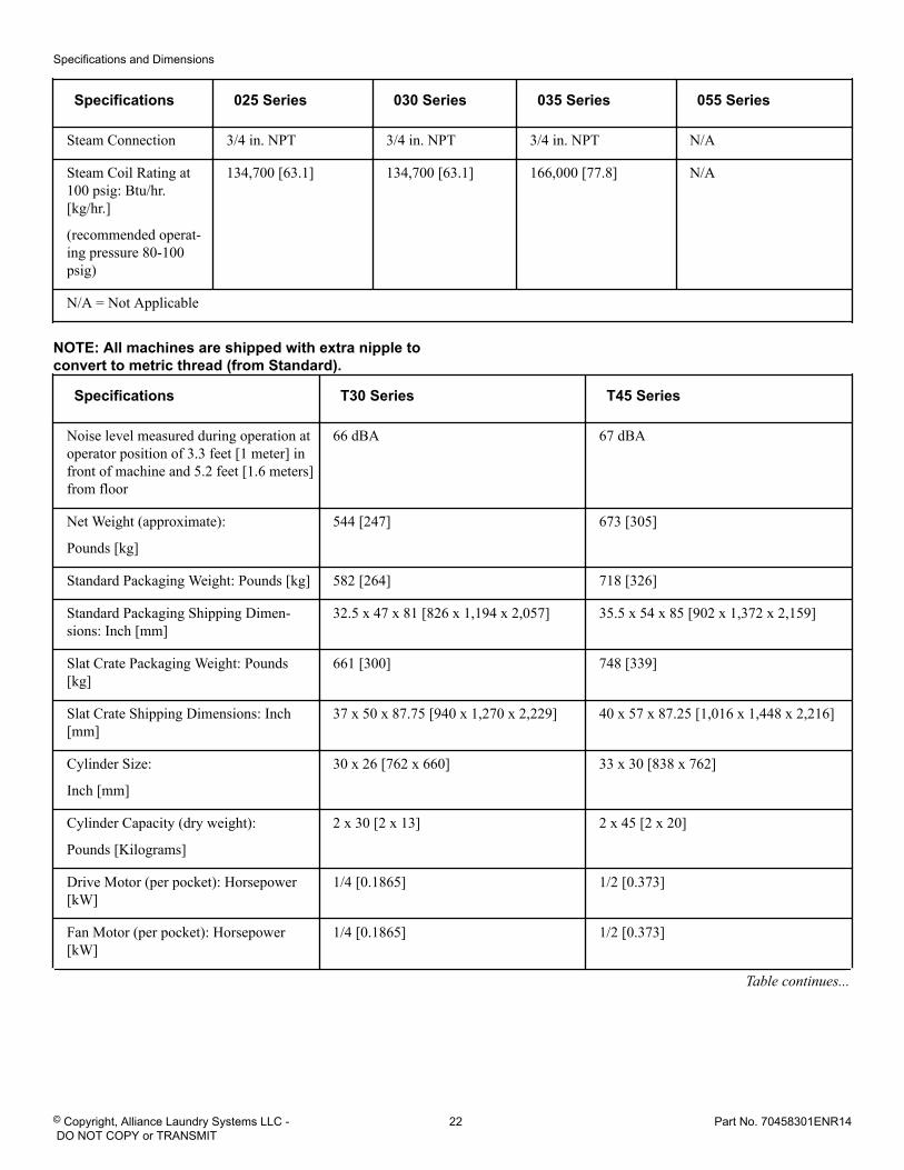
Specifications 025 Series 030 Series 035 Series 055 Series
Steam Connection 3/4 in. NPT 3/4 in. NPT 3/4 in. NPT N/A
Steam Coil Rating at100 psig: Btu/hr.[kg/hr.]
(recommended operat-ing pressure 80-100psig)
134,700 [63.1] 134,700 [63.1] 166,000 [77.8] N/A
N/A = Not Applicable
NOTE: All machines are shipped with extra nipple toconvert to metric thread (from Standard).
Specifications T30 Series T45 Series
Noise level measured during operation atoperator position of 3.3 feet [1 meter] infront of machine and 5.2 feet [1.6 meters]from floor
66 dBA 67 dBA
Net Weight (approximate):
Pounds [kg]
544 [247] 673 [305]
Standard Packaging Weight: Pounds [kg] 582 [264] 718 [326]
Standard Packaging Shipping Dimen-sions: Inch [mm]
32.5 x 47 x 81 [826 x 1,194 x 2,057] 35.5 x 54 x 85 [902 x 1,372 x 2,159]
Slat Crate Packaging Weight: Pounds[kg]
661 [300] 748 [339]
Slat Crate Shipping Dimensions: Inch[mm]
37 x 50 x 87.75 [940 x 1,270 x 2,229] 40 x 57 x 87.25 [1,016 x 1,448 x 2,216]
Cylinder Size:
Inch [mm]
30 x 26 [762 x 660] 33 x 30 [838 x 762]
Cylinder Capacity (dry weight):
Pounds [Kilograms]
2 x 30 [2 x 13] 2 x 45 [2 x 20]
Drive Motor (per pocket): Horsepower[kW]
1/4 [0.1865] 1/2 [0.373]
Fan Motor (per pocket): Horsepower[kW]
1/4 [0.1865] 1/2 [0.373]
Table continues...
Specifications and Dimensions
© Copyright, Alliance Laundry Systems LLC - DO NOT COPY or TRANSMIT
22 Part No. 70458301ENR14
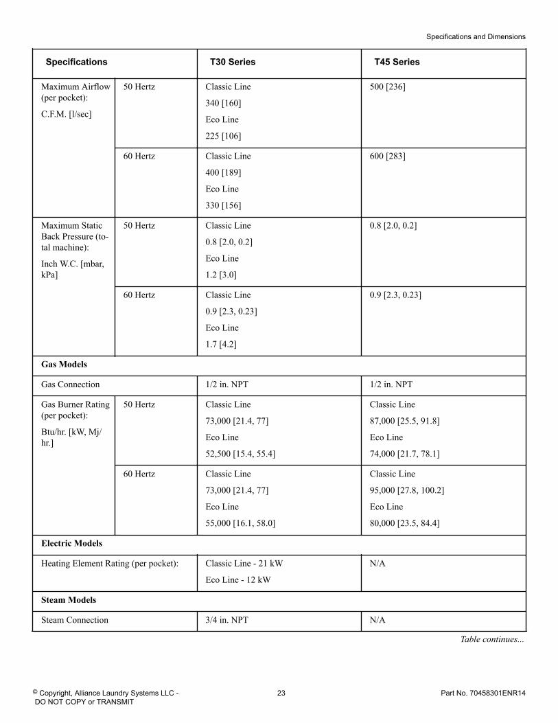
Specifications T30 Series T45 Series
Maximum Airflow(per pocket):
C.F.M. [l/sec]
50 Hertz Classic Line
340 [160]
Eco Line
225 [106]
500 [236]
60 Hertz Classic Line
400 [189]
Eco Line
330 [156]
600 [283]
Maximum StaticBack Pressure (to-tal machine):
Inch W.C. [mbar,kPa]
50 Hertz Classic Line
0.8 [2.0, 0.2]
Eco Line
1.2 [3.0]
0.8 [2.0, 0.2]
60 Hertz Classic Line
0.9 [2.3, 0.23]
Eco Line
1.7 [4.2]
0.9 [2.3, 0.23]
Gas Models
Gas Connection 1/2 in. NPT 1/2 in. NPT
Gas Burner Rating(per pocket):
Btu/hr. [kW, Mj/hr.]
50 Hertz Classic Line
73,000 [21.4, 77]
Eco Line
52,500 [15.4, 55.4]
Classic Line
87,000 [25.5, 91.8]
Eco Line
74,000 [21.7, 78.1]
60 Hertz Classic Line
73,000 [21.4, 77]
Eco Line
55,000 [16.1, 58.0]
Classic Line
95,000 [27.8, 100.2]
Eco Line
80,000 [23.5, 84.4]
Electric Models
Heating Element Rating (per pocket): Classic Line - 21 kW
Eco Line - 12 kW
N/A
Steam Models
Steam Connection 3/4 in. NPT N/A
Table continues...
Specifications and Dimensions
© Copyright, Alliance Laundry Systems LLC - DO NOT COPY or TRANSMIT
23 Part No. 70458301ENR14
Specifications T30 Series T45 Series
Steam Coil Rating at 100 psig (per pock-et):
Btu/hr. [kg/hr.] (recommended operatingpressure 80-100 psig)
111,000 [52] N/A
N/A = Not Applicable
NOTE: All machines are shipped with extra nipple toconvert to metric thread (from Standard).
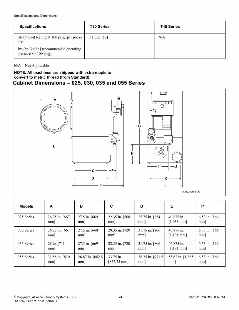
Cabinet Dimensions – 025, 030, 035 and 055 Series
TMB2292N_SVG
JI
K
L
G
H
B
C
D
E
F
A
Models A B C D E F*
025 Series 26.25 in. [667mm]
27.5 in. [669mm]
22.35 in. [568mm]
25.75 in. [654mm]
40.875 in.[1,038 mm]
6.53 in. [166mm]
030 Series 26.25 in. [667mm]
27.5 in. [669mm]
28.35 in. [720mm]
31.75 in. [806mm]
46.875 in.[1,191 mm]
6.53 in. [166mm]
035 Series 28 in. [711mm]
27.5 in. [669mm]
28.35 in. [720mm]
31.75 in. [806mm]
46.875 in.[1,191 mm]
6.53 in. [166mm]
055 Series 31.88 in. [810mm]
26.87 in. [682.5mm]
33.75 in.[857.25 mm]
38.25 in. [971.5mm]
53.62 in. [1,365mm]
6.53 in. [166mm]
Specifications and Dimensions
© Copyright, Alliance Laundry Systems LLC - DO NOT COPY or TRANSMIT
24 Part No. 70458301ENR14
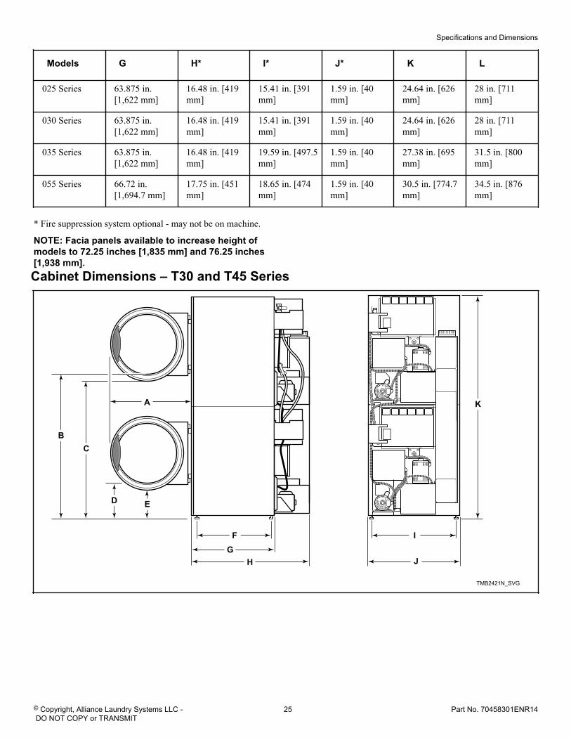
Models G H* I* J* K L
025 Series 63.875 in.[1,622 mm]
16.48 in. [419mm]
15.41 in. [391mm]
1.59 in. [40mm]
24.64 in. [626mm]
28 in. [711mm]
030 Series 63.875 in.[1,622 mm]
16.48 in. [419mm]
15.41 in. [391mm]
1.59 in. [40mm]
24.64 in. [626mm]
28 in. [711mm]
035 Series 63.875 in.[1,622 mm]
16.48 in. [419mm]
19.59 in. [497.5mm]
1.59 in. [40mm]
27.38 in. [695mm]
31.5 in. [800mm]
055 Series 66.72 in.[1,694.7 mm]
17.75 in. [451mm]
18.65 in. [474mm]
1.59 in. [40mm]
30.5 in. [774.7mm]
34.5 in. [876mm]
* Fire suppression system optional - may not be on machine.
NOTE: Facia panels available to increase height ofmodels to 72.25 inches [1,835 mm] and 76.25 inches[1,938 mm].
Cabinet Dimensions – T30 and T45 Series
TMB2421N_SVG
J
I
K
D E
H
FG
A
CB
Specifications and Dimensions
© Copyright, Alliance Laundry Systems LLC - DO NOT COPY or TRANSMIT
25 Part No. 70458301ENR14
Models A B C D E
T30 Series 28 in. [711 mm] 49 in. [1,245 mm] 48.25 in. [1,226mm]
11.4 in. [290 mm] 10.7 in. [272 mm]
T45 Series 31.88 in. [810mm]
50.4 in. [1,280mm]
49.3 in. [1,252mm]
10.3 in. [262 mm] 9.3 in. [236 mm]
Models F G H I J K
T30 Series 25.02 in. [636mm]
28.67 in. [728mm]
42.76 in. [1,086mm]
27.38 in. [695mm]
31.5 in. [800mm]
76.25 in. [1,937mm]
T45 Series 29.37 in. [746mm]
32.7 in. [831mm]
48.62 in. [1,235mm]
30.50 in. [775mm]
34.5 in. [876mm]
81.25 in. [2,064mm]
NOTE: To meet ADA compliance, install a 4 inch [102mm] riser on T30 models only.
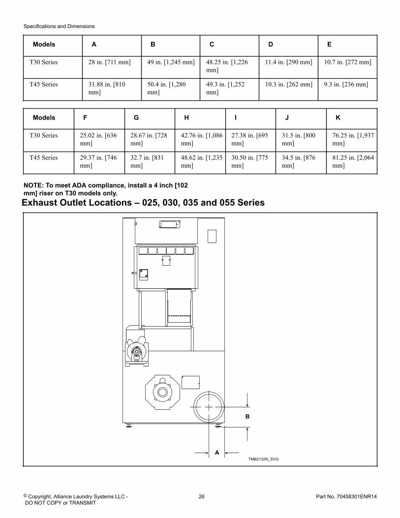
Exhaust Outlet Locations – 025, 030, 035 and 055 Series
TMB2132N_SVGA
B
Specifications and Dimensions
© Copyright, Alliance Laundry Systems LLC - DO NOT COPY or TRANSMIT
26 Part No. 70458301ENR14
Models
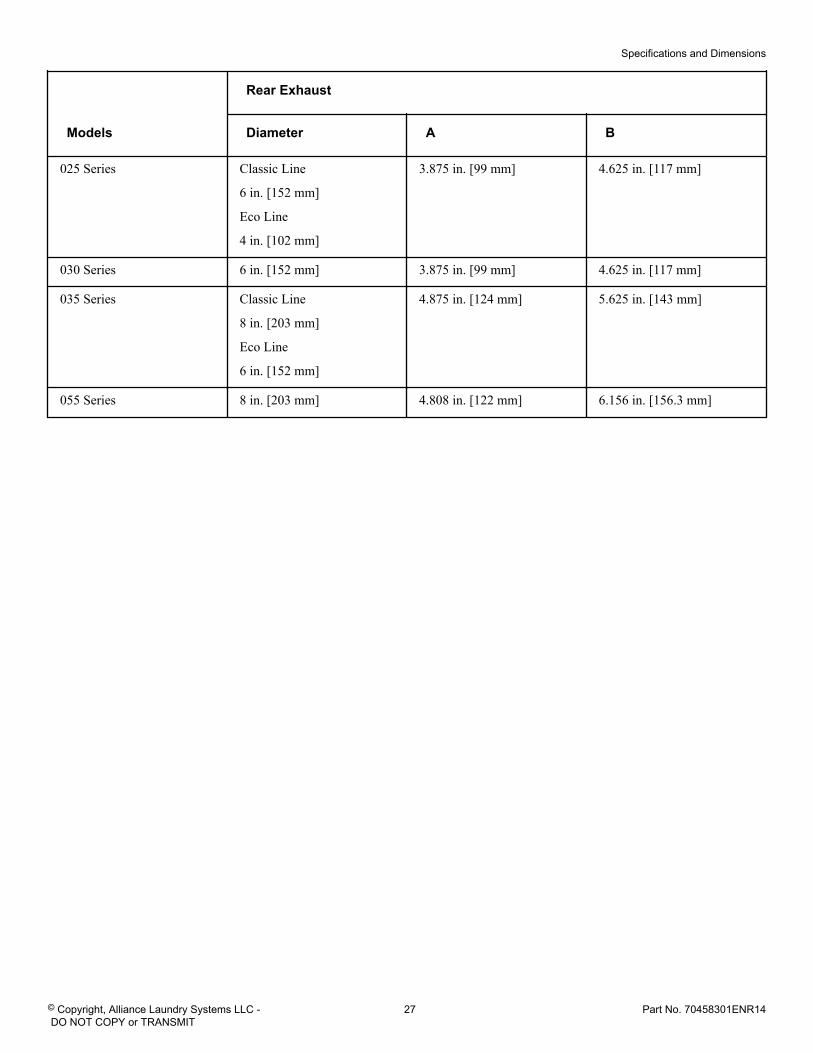
Rear Exhaust
Diameter A B
025 Series Classic Line
6 in. [152 mm]
Eco Line
4 in. [102 mm]
3.875 in. [99 mm] 4.625 in. [117 mm]
030 Series 6 in. [152 mm] 3.875 in. [99 mm] 4.625 in. [117 mm]
035 Series Classic Line
8 in. [203 mm]
Eco Line
6 in. [152 mm]
4.875 in. [124 mm] 5.625 in. [143 mm]
055 Series 8 in. [203 mm] 4.808 in. [122 mm] 6.156 in. [156.3 mm]
Specifications and Dimensions
© Copyright, Alliance Laundry Systems LLC - DO NOT COPY or TRANSMIT
27 Part No. 70458301ENR14
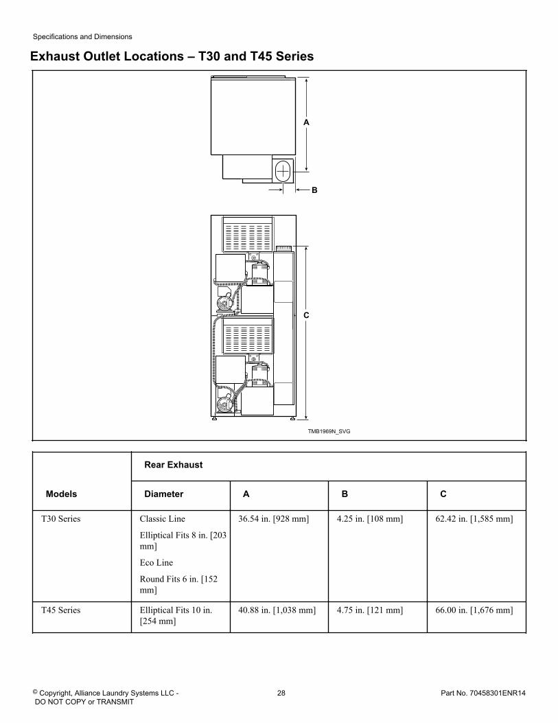
Exhaust Outlet Locations – T30 and T45 Series
TMB1969N_SVG
A
C
B
Models
Rear Exhaust
Diameter A B C
T30 Series Classic Line
Elliptical Fits 8 in. [203mm]
Eco Line
Round Fits 6 in. [152mm]
36.54 in. [928 mm] 4.25 in. [108 mm] 62.42 in. [1,585 mm]
T45 Series Elliptical Fits 10 in.[254 mm]
40.88 in. [1,038 mm] 4.75 in. [121 mm] 66.00 in. [1,676 mm]
Specifications and Dimensions
© Copyright, Alliance Laundry Systems LLC - DO NOT COPY or TRANSMIT
28 Part No. 70458301ENR14
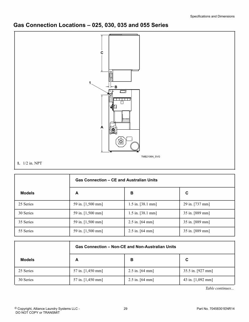
Gas Connection Locations – 025, 030, 035 and 055 Series
TMB2106N_SVG
A
C
B1
1. 1/2 in. NPT
Models
Gas Connection – CE and Australian Units
A B C
25 Series 59 in. [1,500 mm] 1.5 in. [38.1 mm] 29 in. [737 mm]
30 Series 59 in. [1,500 mm] 1.5 in. [38.1 mm] 35 in. [889 mm]
35 Series 59 in. [1,500 mm] 2.5 in. [64 mm] 35 in. [889 mm]
55 Series 59 in. [1,500 mm] 2.5 in. [64 mm] 35 in. [889 mm]
Models
Gas Connection – Non-CE and Non-Australian Units
A B C
25 Series 57 in. [1,450 mm] 2.5 in. [64 mm] 35.5 in. [927 mm]
30 Series 57 in. [1,450 mm] 2.5 in. [64 mm] 43 in. [1,092 mm]
Table continues...
Specifications and Dimensions
© Copyright, Alliance Laundry Systems LLC - DO NOT COPY or TRANSMIT
29 Part No. 70458301ENR14
Models
Gas Connection – Non-CE and Non-Australian Units
A B C
35 Series 57 in. [1,450 mm] 4 in. [101.6 mm] 43 in. [1,092 mm]
55 Series 55.285 in. [1,404 mm] 1.621 in. [41.17 mm] 46.75 in. [1,187.45 mm]
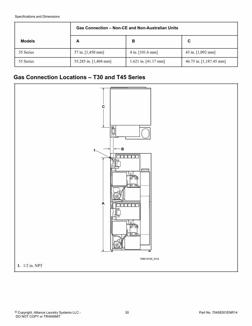
Gas Connection Locations – T30 and T45 Series
TMB1970N_SVG
C
B
A
1
1. 1/2 in. NPT
Specifications and Dimensions
© Copyright, Alliance Laundry Systems LLC - DO NOT COPY or TRANSMIT
30 Part No. 70458301ENR14
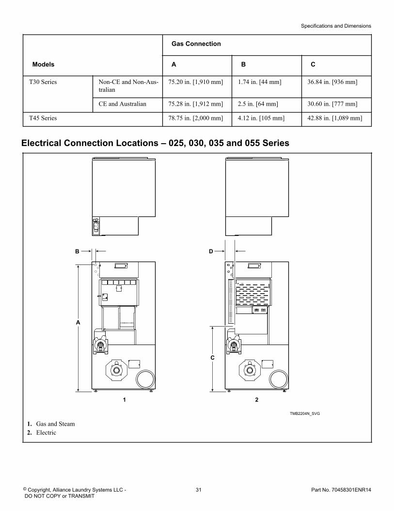
Models
Gas Connection
A B C
T30 Series Non-CE and Non-Aus-tralian
75.20 in. [1,910 mm] 1.74 in. [44 mm] 36.84 in. [936 mm]
CE and Australian 75.28 in. [1,912 mm] 2.5 in. [64 mm] 30.60 in. [777 mm]
T45 Series 78.75 in. [2,000 mm] 4.12 in. [105 mm] 42.88 in. [1,089 mm]
Electrical Connection Locations – 025, 030, 035 and 055 Series
TMB2204N_SVG
B
C
D
A
21
1. Gas and Steam2. Electric
Specifications and Dimensions
© Copyright, Alliance Laundry Systems LLC - DO NOT COPY or TRANSMIT
31 Part No. 70458301ENR14
Models
Electrical Service
Gas and Steam Models Electric Models
A B C D
025/030 Series 62.25 in. [1,581 mm] 2 in. [51 mm] 28 in. [711 mm] 3.25 in. [83 mm]
035 Series 62.25 in. [1,581 mm] 3 in. [76 mm] 28 in. [711 mm] 4.25 in. [108 mm]
055 Series 65.187 in. [1,655.75mm]
1.765 in. [44.83 mm] 32.526 in. [826.16 mm] 6.547 in. [166.3 mm]
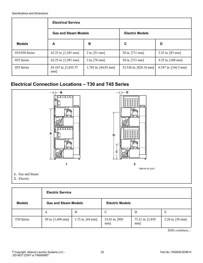
Electrical Connection Locations – T30 and T45 Series
TMB1971N_SVG
E
D
C
B
A
21
1. Gas and Steam2. Electric
Models
Electric Service
Gas and Steam Models Electric Models
A B C D E
T30 Series 59 in. [1,498 mm] 1.75 in. [44 mm] 35.63 in. [905mm]
73.21 in. [1,859mm]
2.28 in. [58 mm]
Table continues...
Specifications and Dimensions
© Copyright, Alliance Laundry Systems LLC - DO NOT COPY or TRANSMIT
32 Part No. 70458301ENR14
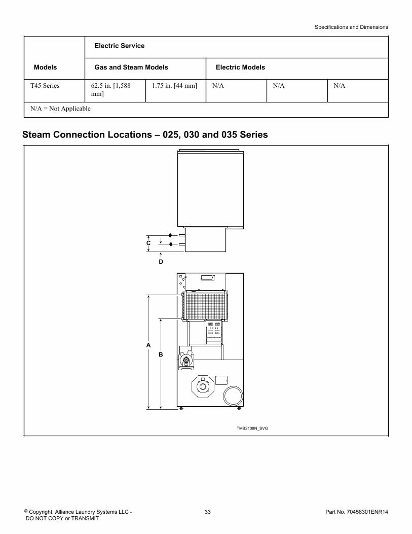
Models
Electric Service
Gas and Steam Models Electric Models
T45 Series 62.5 in. [1,588mm]
1.75 in. [44 mm] N/A N/A N/A
N/A = Not Applicable
Steam Connection Locations – 025, 030 and 035 Series
TMB2108N_SVG
D
C
BA
Specifications and Dimensions
© Copyright, Alliance Laundry Systems LLC - DO NOT COPY or TRANSMIT
33 Part No. 70458301ENR14
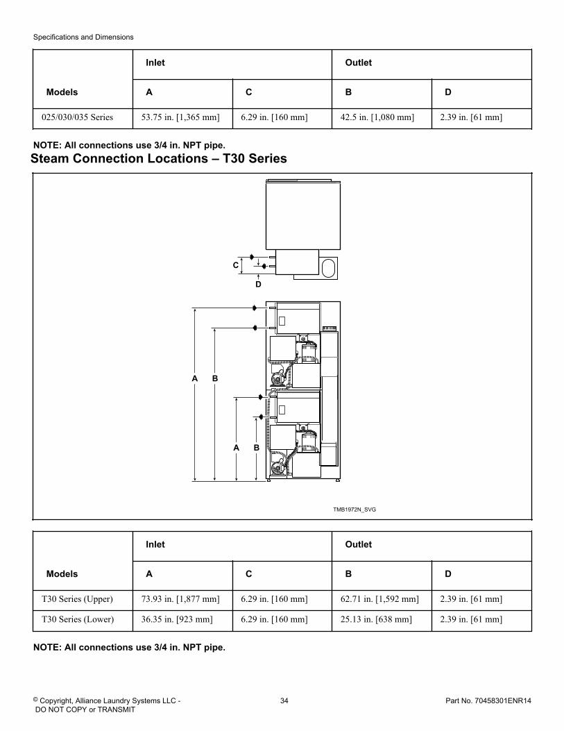
Models
Inlet Outlet
A C B D
025/030/035 Series 53.75 in. [1,365 mm] 6.29 in. [160 mm] 42.5 in. [1,080 mm] 2.39 in. [61 mm]
NOTE: All connections use 3/4 in. NPT pipe. Steam Connection Locations – T30 Series
TMB1972N_SVG
BA
D
C
BA
Models
Inlet Outlet
A C B D
T30 Series (Upper) 73.93 in. [1,877 mm] 6.29 in. [160 mm] 62.71 in. [1,592 mm] 2.39 in. [61 mm]
T30 Series (Lower) 36.35 in. [923 mm] 6.29 in. [160 mm] 25.13 in. [638 mm] 2.39 in. [61 mm]
NOTE: All connections use 3/4 in. NPT pipe.
Specifications and Dimensions
© Copyright, Alliance Laundry Systems LLC - DO NOT COPY or TRANSMIT
34 Part No. 70458301ENR14
Installation Pre-Installation Inspection
Upon delivery, visually inspect the crate, carton and parts for anyvisible shipping damage. If the crate, carton, or cover is damagedor signs of possible damage are evident, have the carrier note thecondition on the shipping papers before the shipping receipt issigned, or advise the carrier of the condition as soon as it is dis-covered.
Remove the crate and protective cover as soon as possible andcheck the items listed on the packing list. Advise the carrier ofany damaged or missing articles as soon as possible. A writtenclaim should be filed with the carrier immediately if articles aredamaged or missing.
IMPORTANT: Remove the yellow shipping wire tie se-curing the airflow switch.
IMPORTANT: Warranty is void unless tumble dryer isinstalled according to instructions in this manual. In-stallation should comply with minimum specificationsand requirements detailed in this manual and applica-ble local gas fitting regulations, municipal building co-des, water supply regulations, electrical wiring regula-tions, and any other relevant statutory regulations. Dueto varied requirements, applicable local codes shouldbe thoroughly understood and all pre-installation workarranged for accordingly.
Materials Required (Obtain Locally)
All Models Fused disconnect switch or circuit breakeron 1 Phase models.
Circuit breaker on 3 Phase models.
Gas Models One gas shut-off valve for gas service lineto each tumble dryer.
Table continues...
Materials Required (Obtain Locally)
Steam Models One steam shut-off valve for steam serviceline to be connected upstream of solenoidsteam valve.
Two steam shut-off valves for each conden-sate return line.
Flexible steam hoses with a 125 psig[pounds per square inch gauge] [862 kPa]working pressure for connecting steamcoils. Refer to Figure 27 for sizing and con-nection configurations.
Two steam traps for steam coil outlets tocondensate return line.
Optional – Two vacuum breakers for con-densate return lines.
IMPORTANT: 3 Phase Only – Each tumble dryer mustbe connected to its own individual branch circuitbreaker, not fuses, to avoid the possibility of “singlephasing” and causing premature failure of the mo-tor(s).
Location RequirementsThe tumble dryer must be installed on a level floor. Floor cover-ing materials such as carpeting or tile should be removed.
To assure compliance, consult local building code requirements.The tumble dryer must not be installed or stored in area where itwill be exposed to water and/or weather.
IMPORTANT: DO NOT block the airflow at the rear ofthe tumble dryer with laundry or other articles. Doingso would prevent adequate air supply to the combus-tion chamber of the tumble dryer.
A typical tumble dryer enclosure is shown in Figure 2 .
IMPORTANT: Install tumble dryers with sufficient clear-ance for servicing and operation, refer to Figure 2 .
WARNINGTo reduce the risk of severe injury, clearance of tum-ble dryer cabinet from combustible constructionmust conform to the minimum clearances, and/or lo-cal codes and ordinances.
W770R1
Installation
© Copyright, Alliance Laundry Systems LLC - DO NOT COPY or TRANSMIT
35 Part No. 70458301ENR14
TMB2497N_SVG
431
6
5
8
27
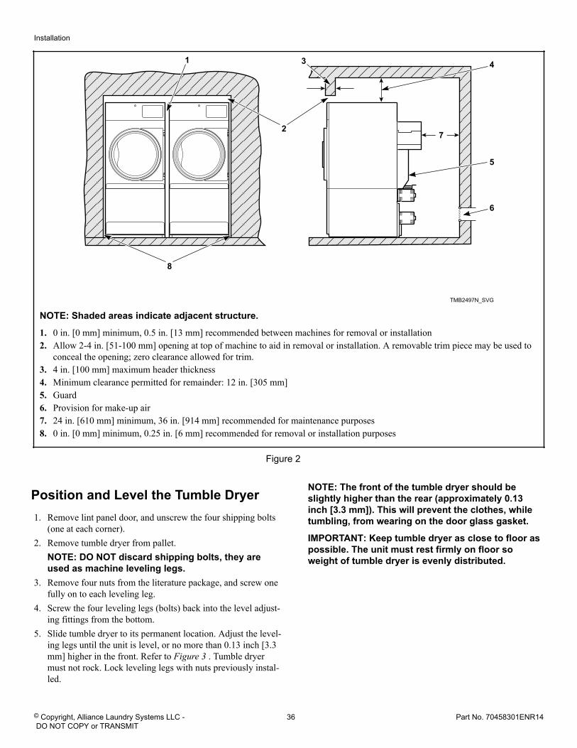
NOTE: Shaded areas indicate adjacent structure.
1. 0 in. [0 mm] minimum, 0.5 in. [13 mm] recommended between machines for removal or installation2. Allow 2-4 in. [51-100 mm] opening at top of machine to aid in removal or installation. A removable trim piece may be used to
conceal the opening; zero clearance allowed for trim.3. 4 in. [100 mm] maximum header thickness4. Minimum clearance permitted for remainder: 12 in. [305 mm]5. Guard6. Provision for make-up air7. 24 in. [610 mm] minimum, 36 in. [914 mm] recommended for maintenance purposes8. 0 in. [0 mm] minimum, 0.25 in. [6 mm] recommended for removal or installation purposes
Figure 2
Position and Level the Tumble Dryer1. Remove lint panel door, and unscrew the four shipping bolts
(one at each corner).2. Remove tumble dryer from pallet.
NOTE: DO NOT discard shipping bolts, they areused as machine leveling legs.
3. Remove four nuts from the literature package, and screw onefully on to each leveling leg.
4. Screw the four leveling legs (bolts) back into the level adjust-ing fittings from the bottom.
5. Slide tumble dryer to its permanent location. Adjust the level-ing legs until the unit is level, or no more than 0.13 inch [3.3mm] higher in the front. Refer to Figure 3 . Tumble dryermust not rock. Lock leveling legs with nuts previously instal-led.
NOTE: The front of the tumble dryer should beslightly higher than the rear (approximately 0.13inch [3.3 mm]). This will prevent the clothes, whiletumbling, from wearing on the door glass gasket.
IMPORTANT: Keep tumble dryer as close to floor aspossible. The unit must rest firmly on floor soweight of tumble dryer is evenly distributed.
Installation
© Copyright, Alliance Laundry Systems LLC - DO NOT COPY or TRANSMIT
36 Part No. 70458301ENR14
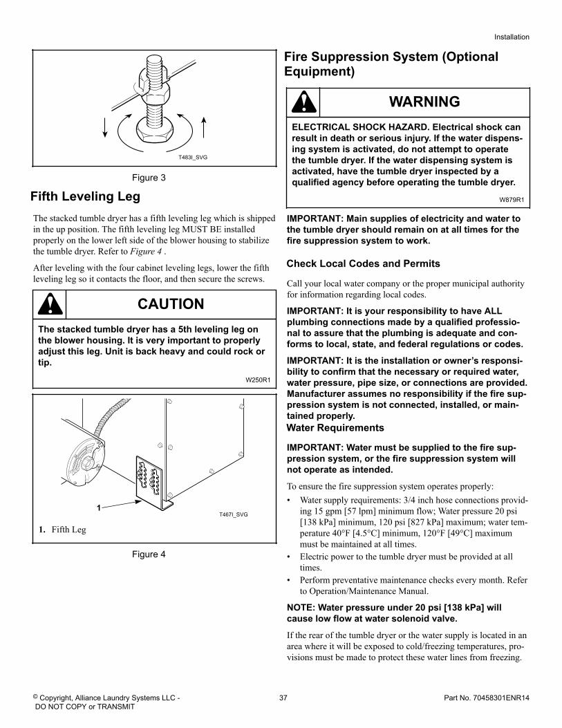
T483I_SVG
Figure 3
Fifth Leveling LegThe stacked tumble dryer has a fifth leveling leg which is shippedin the up position. The fifth leveling leg MUST BE installedproperly on the lower left side of the blower housing to stabilizethe tumble dryer. Refer to Figure 4 .
After leveling with the four cabinet leveling legs, lower the fifthleveling leg so it contacts the floor, and then secure the screws.
CAUTIONThe stacked tumble dryer has a 5th leveling leg onthe blower housing. It is very important to properlyadjust this leg. Unit is back heavy and could rock ortip.
W250R1
T467I_SVG1
1. Fifth Leg
Figure 4
Fire Suppression System (OptionalEquipment)
WARNINGELECTRICAL SHOCK HAZARD. Electrical shock canresult in death or serious injury. If the water dispens-ing system is activated, do not attempt to operatethe tumble dryer. If the water dispensing system isactivated, have the tumble dryer inspected by aqualified agency before operating the tumble dryer.
W879R1
IMPORTANT: Main supplies of electricity and water tothe tumble dryer should remain on at all times for thefire suppression system to work.
Check Local Codes and Permits
Call your local water company or the proper municipal authorityfor information regarding local codes.
IMPORTANT: It is your responsibility to have ALLplumbing connections made by a qualified professio-nal to assure that the plumbing is adequate and con-forms to local, state, and federal regulations or codes.
IMPORTANT: It is the installation or owner’s responsi-bility to confirm that the necessary or required water,water pressure, pipe size, or connections are provided.Manufacturer assumes no responsibility if the fire sup-pression system is not connected, installed, or main-tained properly.
Water Requirements
IMPORTANT: Water must be supplied to the fire sup-pression system, or the fire suppression system willnot operate as intended.
To ensure the fire suppression system operates properly:• Water supply requirements: 3/4 inch hose connections provid-
ing 15 gpm [57 lpm] minimum flow; Water pressure 20 psi[138 kPa] minimum, 120 psi [827 kPa] maximum; water tem-perature 40°F [4.5°C] minimum, 120°F [49°C] maximummust be maintained at all times.
• Electric power to the tumble dryer must be provided at alltimes.
• Perform preventative maintenance checks every month. Referto Operation/Maintenance Manual.
NOTE: Water pressure under 20 psi [138 kPa] willcause low flow at water solenoid valve.
If the rear of the tumble dryer or the water supply is located in anarea where it will be exposed to cold/freezing temperatures, pro-visions must be made to protect these water lines from freezing.
Installation
© Copyright, Alliance Laundry Systems LLC - DO NOT COPY or TRANSMIT
37 Part No. 70458301ENR14
IMPORTANT: Temperature of the water supply must bekept between 40°F and 120°F [4.5°C and 49°C]. If waterin the supply line or water solenoid valve freezes, thefire suppression system will not operate.
IMPORTANT: If temperature sensors inside the tumbledryer register a temperature below 40F° [4.5°C], the firesuppression system control will lock out. This featureprotects against operation of the tumble dryer with apossible frozen water supply. Only when the tempera-ture sensors register a temperature above 40F° [4.5°C]will the machine reset for operation.
IMPORTANT: Flexible supply line/coupling must beused. Solenoid valve failure due to hard plumbing con-nections will void the warranty. It is recommended thata filter or strainer be installed in the water supply line.
Water Connections
Connect machine to a backflow preventer (vacuum breaker) be-fore connecting to the public water main in all countries wherelocal regulations require specific water approval certificates.
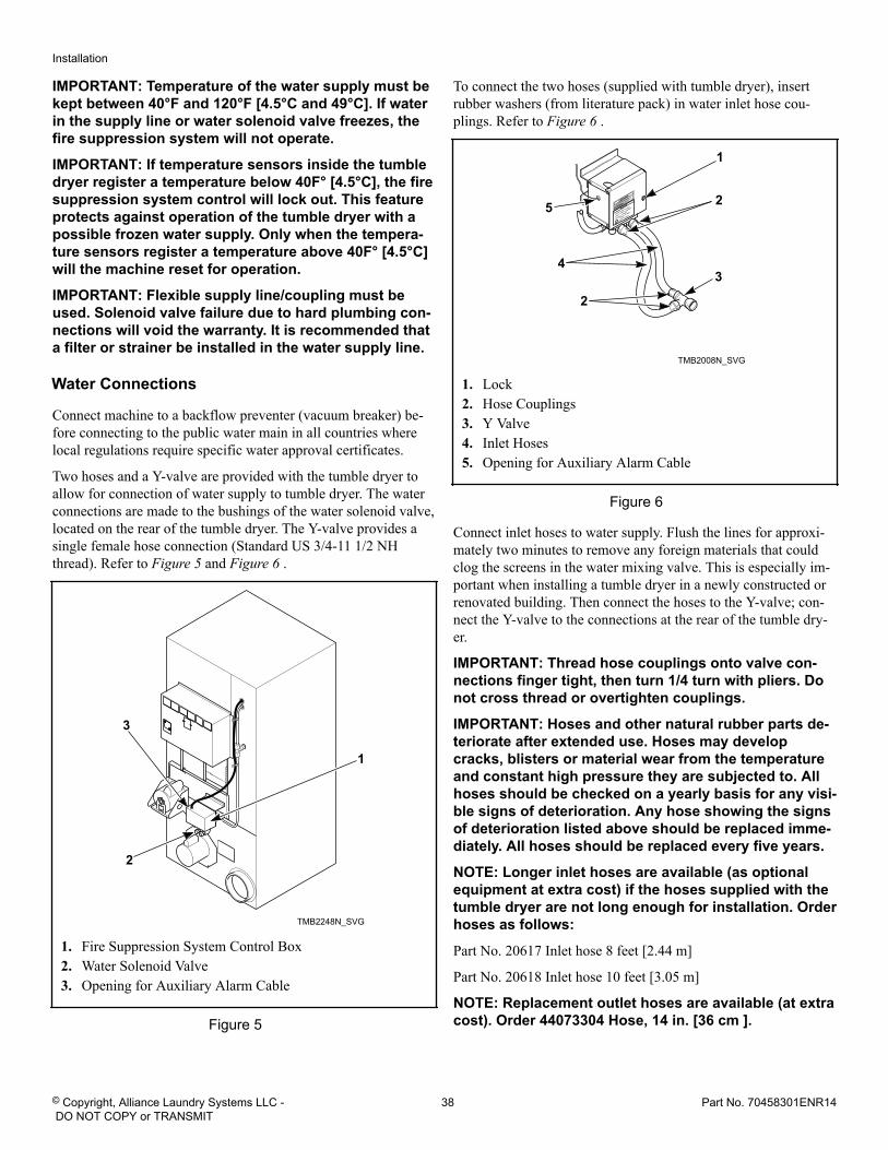
Two hoses and a Y-valve are provided with the tumble dryer toallow for connection of water supply to tumble dryer. The waterconnections are made to the bushings of the water solenoid valve,located on the rear of the tumble dryer. The Y-valve provides asingle female hose connection (Standard US 3/4-11 1/2 NHthread). Refer to Figure 5 and Figure 6 .
TMB2248N_SVG
1
2
3
1. Fire Suppression System Control Box2. Water Solenoid Valve3. Opening for Auxiliary Alarm Cable
Figure 5
To connect the two hoses (supplied with tumble dryer), insertrubber washers (from literature pack) in water inlet hose cou-plings. Refer to Figure 6 .
TMB2008N_SVG
3
2
4
5 2
1
1. Lock2. Hose Couplings3. Y Valve4. Inlet Hoses5. Opening for Auxiliary Alarm Cable
Figure 6
Connect inlet hoses to water supply. Flush the lines for approxi-mately two minutes to remove any foreign materials that couldclog the screens in the water mixing valve. This is especially im-portant when installing a tumble dryer in a newly constructed orrenovated building. Then connect the hoses to the Y-valve; con-nect the Y-valve to the connections at the rear of the tumble dry-er.
IMPORTANT: Thread hose couplings onto valve con-nections finger tight, then turn 1/4 turn with pliers. Donot cross thread or overtighten couplings.
IMPORTANT: Hoses and other natural rubber parts de-teriorate after extended use. Hoses may developcracks, blisters or material wear from the temperatureand constant high pressure they are subjected to. Allhoses should be checked on a yearly basis for any visi-ble signs of deterioration. Any hose showing the signsof deterioration listed above should be replaced imme-diately. All hoses should be replaced every five years.
NOTE: Longer inlet hoses are available (as optionalequipment at extra cost) if the hoses supplied with thetumble dryer are not long enough for installation. Orderhoses as follows:
Part No. 20617 Inlet hose 8 feet [2.44 m]
Part No. 20618 Inlet hose 10 feet [3.05 m]
NOTE: Replacement outlet hoses are available (at extracost). Order 44073304 Hose, 14 in. [36 cm ].
Installation
© Copyright, Alliance Laundry Systems LLC - DO NOT COPY or TRANSMIT
38 Part No. 70458301ENR14
Electrical Requirements
WARNINGElectrical power must be provided to tumble dryer atall times. The fire suppression system will be inoper-ative if the main electrical power supply is discon-nected.
W690R1
No independent external power source or supply connection isnecessary. Power to operate the 24 Volt fire suppression system isfrom the rear junction/contactor box.
Auxiliary Alarm
The fire suppression system provides an auxiliary output signalwhen the system is activated. During tumble dryer installation,you have the option to connect a separate alarm system to thisauxiliary output. Potential uses of the auxiliary output include,but are not limited to: (1) sounds an alarm, (2) activates a build-ing sprinkler system, (3) notifies a fire department, etc. Use of theauxiliary output is not required for the fire suppression system tooperate, but may be used for additional protection.
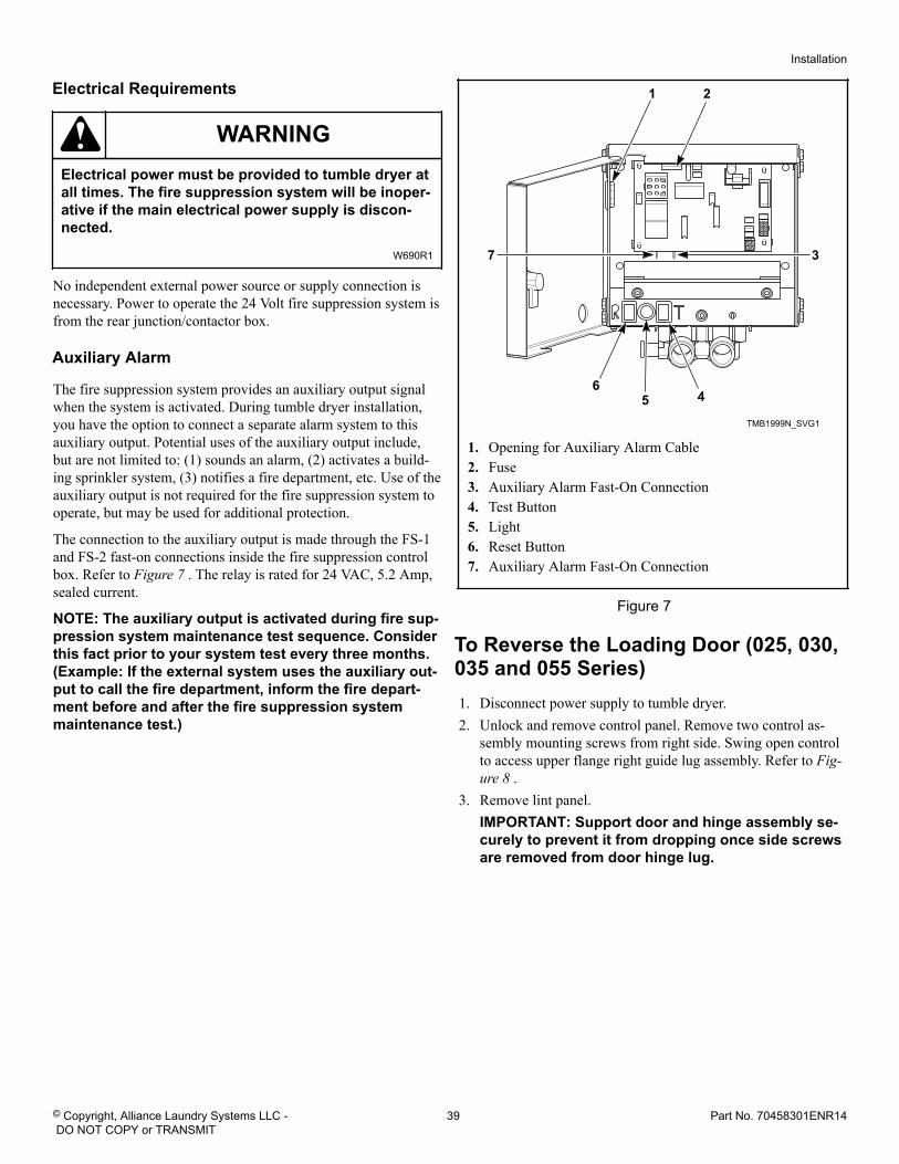
The connection to the auxiliary output is made through the FS-1and FS-2 fast-on connections inside the fire suppression controlbox. Refer to Figure 7 . The relay is rated for 24 VAC, 5.2 Amp,sealed current.
NOTE: The auxiliary output is activated during fire sup-pression system maintenance test sequence. Considerthis fact prior to your system test every three months.(Example: If the external system uses the auxiliary out-put to call the fire department, inform the fire depart-ment before and after the fire suppression systemmaintenance test.)
TMB1999N_SVG1
6
7
5 4
3
1 2
1. Opening for Auxiliary Alarm Cable2. Fuse3. Auxiliary Alarm Fast-On Connection4. Test Button5. Light6. Reset Button7. Auxiliary Alarm Fast-On Connection
Figure 7
To Reverse the Loading Door (025, 030,035 and 055 Series)1. Disconnect power supply to tumble dryer.2. Unlock and remove control panel. Remove two control as-
sembly mounting screws from right side. Swing open controlto access upper flange right guide lug assembly. Refer to Fig-ure 8 .
3. Remove lint panel.IMPORTANT: Support door and hinge assembly se-curely to prevent it from dropping once side screwsare removed from door hinge lug.
Installation
© Copyright, Alliance Laundry Systems LLC - DO NOT COPY or TRANSMIT
39 Part No. 70458301ENR14
TMB2607N_SVG
6
5
4
3
21
1
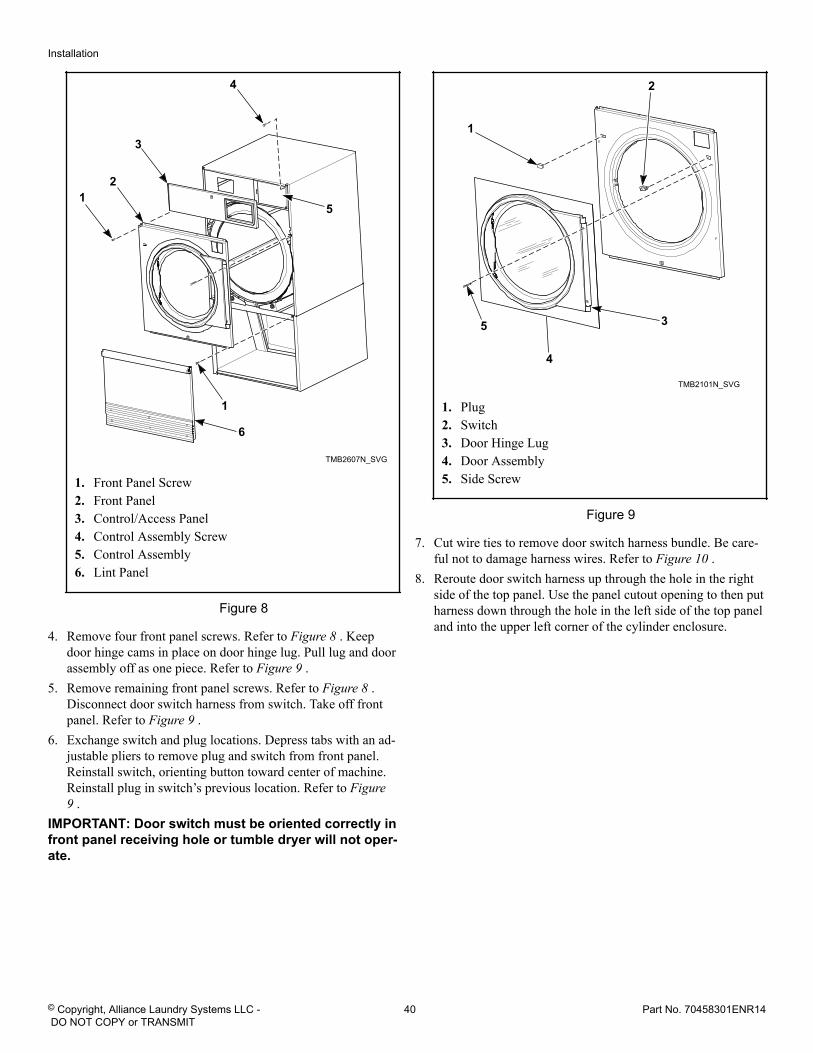
1. Front Panel Screw2. Front Panel3. Control/Access Panel4. Control Assembly Screw5. Control Assembly6. Lint Panel
Figure 8
4. Remove four front panel screws. Refer to Figure 8 . Keepdoor hinge cams in place on door hinge lug. Pull lug and doorassembly off as one piece. Refer to Figure 9 .
5. Remove remaining front panel screws. Refer to Figure 8 .Disconnect door switch harness from switch. Take off frontpanel. Refer to Figure 9 .
6. Exchange switch and plug locations. Depress tabs with an ad-justable pliers to remove plug and switch from front panel.Reinstall switch, orienting button toward center of machine.Reinstall plug in switch’s previous location. Refer to Figure9 .
IMPORTANT: Door switch must be oriented correctly infront panel receiving hole or tumble dryer will not oper-ate.
TMB2101N_SVG
5 3
4
2
1
1. Plug2. Switch3. Door Hinge Lug4. Door Assembly5. Side Screw
Figure 9
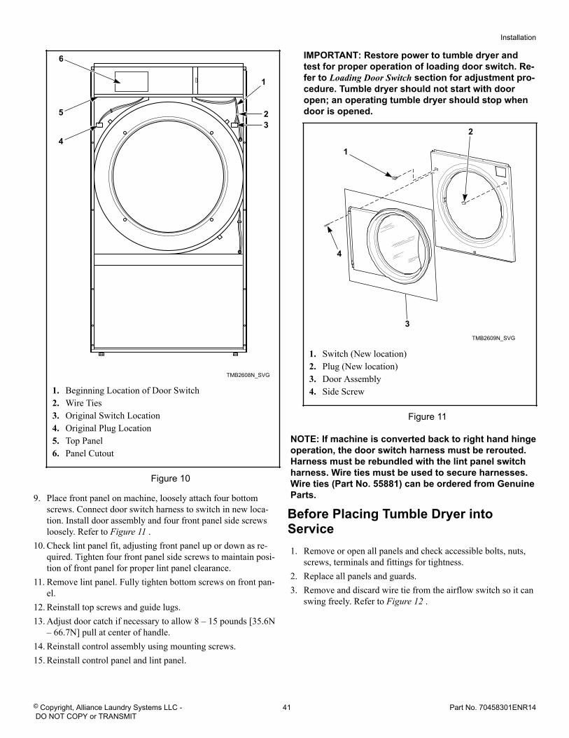
7. Cut wire ties to remove door switch harness bundle. Be care-ful not to damage harness wires. Refer to Figure 10 .
8. Reroute door switch harness up through the hole in the rightside of the top panel. Use the panel cutout opening to then putharness down through the hole in the left side of the top paneland into the upper left corner of the cylinder enclosure.
Installation
© Copyright, Alliance Laundry Systems LLC - DO NOT COPY or TRANSMIT
40 Part No. 70458301ENR14
TMB2608N_SVG
4
5
6
2
1
3
1. Beginning Location of Door Switch2. Wire Ties3. Original Switch Location4. Original Plug Location5. Top Panel6. Panel Cutout
Figure 10
9. Place front panel on machine, loosely attach four bottomscrews. Connect door switch harness to switch in new loca-tion. Install door assembly and four front panel side screwsloosely. Refer to Figure 11 .
10. Check lint panel fit, adjusting front panel up or down as re-quired. Tighten four front panel side screws to maintain posi-tion of front panel for proper lint panel clearance.
11. Remove lint panel. Fully tighten bottom screws on front pan-el.
12. Reinstall top screws and guide lugs.13. Adjust door catch if necessary to allow 8 – 15 pounds [35.6N
– 66.7N] pull at center of handle.14. Reinstall control assembly using mounting screws.15. Reinstall control panel and lint panel.
IMPORTANT: Restore power to tumble dryer andtest for proper operation of loading door switch. Re-fer to Loading Door Switch section for adjustment pro-cedure. Tumble dryer should not start with dooropen; an operating tumble dryer should stop whendoor is opened.
TMB2609N_SVG
4
3
2
1
1. Switch (New location)2. Plug (New location)3. Door Assembly4. Side Screw
Figure 11
NOTE: If machine is converted back to right hand hingeoperation, the door switch harness must be rerouted.Harness must be rebundled with the lint panel switchharness. Wire ties must be used to secure harnesses.Wire ties (Part No. 55881) can be ordered from GenuineParts.
Before Placing Tumble Dryer intoService1. Remove or open all panels and check accessible bolts, nuts,
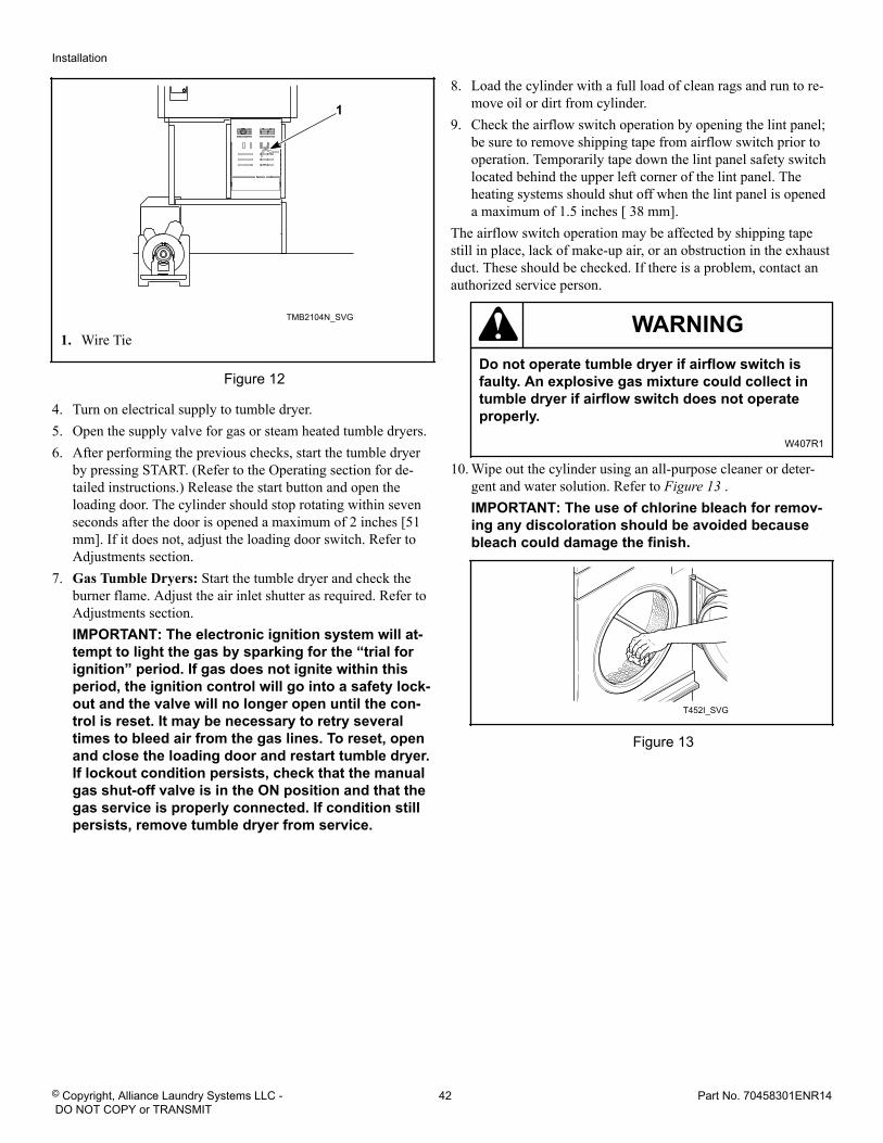
screws, terminals and fittings for tightness.2. Replace all panels and guards.3. Remove and discard wire tie from the airflow switch so it can
swing freely. Refer to Figure 12 .
Installation
© Copyright, Alliance Laundry Systems LLC - DO NOT COPY or TRANSMIT
41 Part No. 70458301ENR14
TMB2104N_SVG
1
1. Wire Tie
Figure 12
4. Turn on electrical supply to tumble dryer.5. Open the supply valve for gas or steam heated tumble dryers.6. After performing the previous checks, start the tumble dryer
by pressing START. (Refer to the Operating section for de-tailed instructions.) Release the start button and open theloading door. The cylinder should stop rotating within sevenseconds after the door is opened a maximum of 2 inches [51mm]. If it does not, adjust the loading door switch. Refer toAdjustments section.
7. Gas Tumble Dryers: Start the tumble dryer and check theburner flame. Adjust the air inlet shutter as required. Refer toAdjustments section.IMPORTANT: The electronic ignition system will at-tempt to light the gas by sparking for the “trial forignition” period. If gas does not ignite within thisperiod, the ignition control will go into a safety lock-out and the valve will no longer open until the con-trol is reset. It may be necessary to retry severaltimes to bleed air from the gas lines. To reset, openand close the loading door and restart tumble dryer.If lockout condition persists, check that the manualgas shut-off valve is in the ON position and that thegas service is properly connected. If condition stillpersists, remove tumble dryer from service.
8. Load the cylinder with a full load of clean rags and run to re-move oil or dirt from cylinder.
9. Check the airflow switch operation by opening the lint panel;be sure to remove shipping tape from airflow switch prior tooperation. Temporarily tape down the lint panel safety switchlocated behind the upper left corner of the lint panel. Theheating systems should shut off when the lint panel is openeda maximum of 1.5 inches [ 38 mm].
The airflow switch operation may be affected by shipping tapestill in place, lack of make-up air, or an obstruction in the exhaustduct. These should be checked. If there is a problem, contact anauthorized service person.
WARNINGDo not operate tumble dryer if airflow switch isfaulty. An explosive gas mixture could collect intumble dryer if airflow switch does not operateproperly.
W407R1
10. Wipe out the cylinder using an all-purpose cleaner or deter-gent and water solution. Refer to Figure 13 .IMPORTANT: The use of chlorine bleach for remov-ing any discoloration should be avoided becausebleach could damage the finish.
T452I_SVG
Figure 13
Installation
© Copyright, Alliance Laundry Systems LLC - DO NOT COPY or TRANSMIT
42 Part No. 70458301ENR14
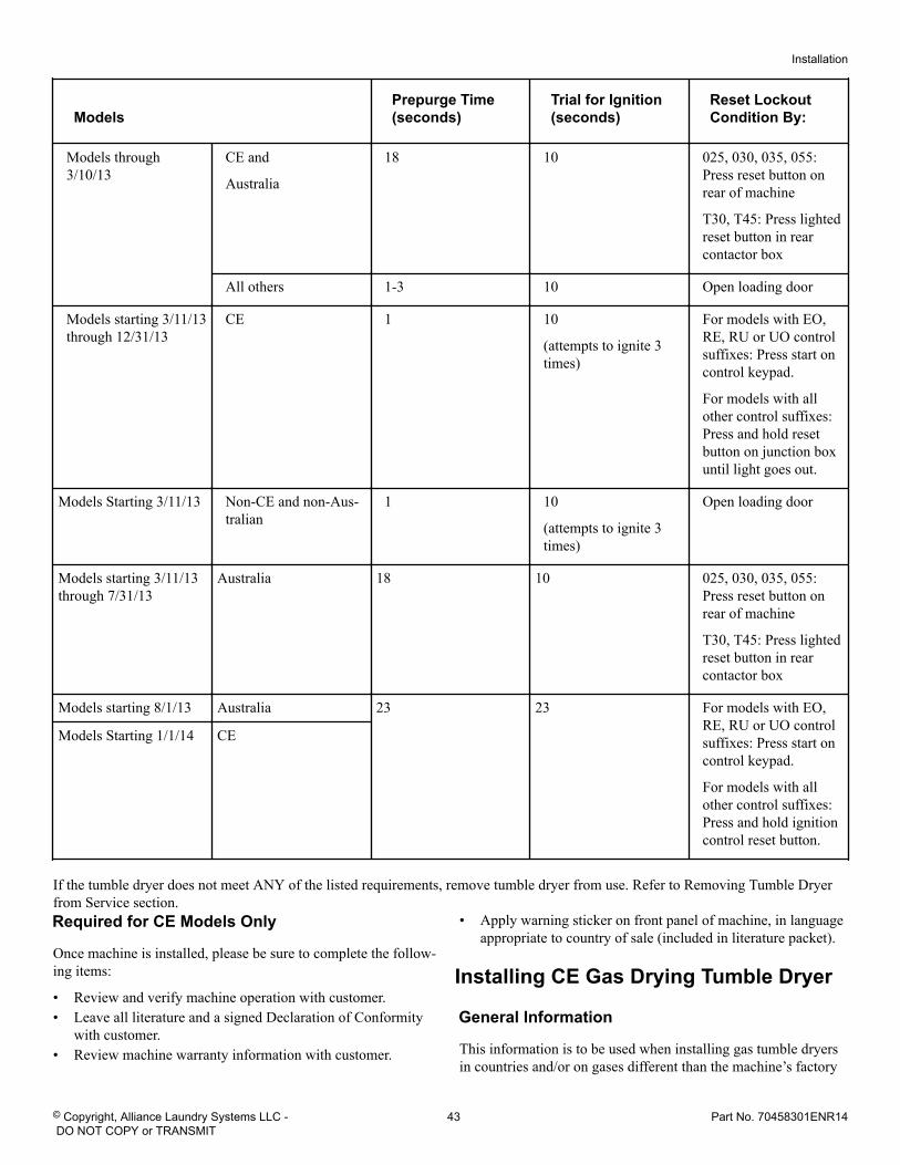
ModelsPrepurge Time(seconds)
Trial for Ignition(seconds)
Reset LockoutCondition By:
Models through3/10/13
CE and
Australia
18 10 025, 030, 035, 055:Press reset button onrear of machine
T30, T45: Press lightedreset button in rearcontactor box
All others 1-3 10 Open loading door
Models starting 3/11/13through 12/31/13
CE 1 10
(attempts to ignite 3times)
For models with EO,RE, RU or UO controlsuffixes: Press start oncontrol keypad.
For models with allother control suffixes:Press and hold resetbutton on junction boxuntil light goes out.
Models Starting 3/11/13 Non-CE and non-Aus-tralian
1 10
(attempts to ignite 3times)
Open loading door
Models starting 3/11/13through 7/31/13
Australia 18 10 025, 030, 035, 055:Press reset button onrear of machine
T30, T45: Press lightedreset button in rearcontactor box
Models starting 8/1/13 Australia 23 23 For models with EO,RE, RU or UO controlsuffixes: Press start oncontrol keypad.
For models with allother control suffixes:Press and hold ignitioncontrol reset button.
Models Starting 1/1/14 CE
If the tumble dryer does not meet ANY of the listed requirements, remove tumble dryer from use. Refer to Removing Tumble Dryerfrom Service section.
Required for CE Models Only
Once machine is installed, please be sure to complete the follow-ing items:
• Review and verify machine operation with customer.• Leave all literature and a signed Declaration of Conformity
with customer.• Review machine warranty information with customer.
• Apply warning sticker on front panel of machine, in languageappropriate to country of sale (included in literature packet).
Installing CE Gas Drying Tumble Dryer
General Information
This information is to be used when installing gas tumble dryersin countries and/or on gases different than the machine’s factory
Installation
© Copyright, Alliance Laundry Systems LLC - DO NOT COPY or TRANSMIT
43 Part No. 70458301ENR14
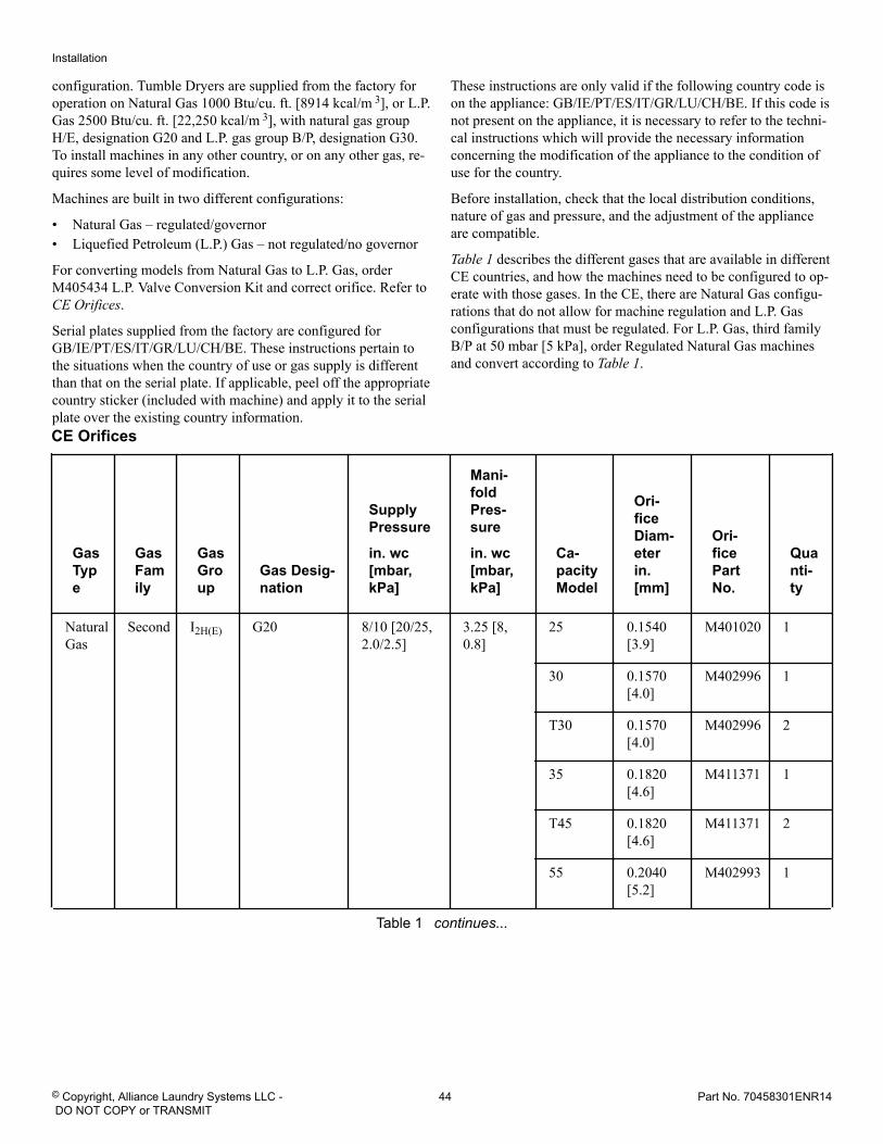
configuration. Tumble Dryers are supplied from the factory foroperation on Natural Gas 1000 Btu/cu. ft. [8914 kcal/m 3], or L.P.Gas 2500 Btu/cu. ft. [22,250 kcal/m 3], with natural gas groupH/E, designation G20 and L.P. gas group B/P, designation G30.To install machines in any other country, or on any other gas, re-quires some level of modification.
Machines are built in two different configurations:
• Natural Gas – regulated/governor• Liquefied Petroleum (L.P.) Gas – not regulated/no governor
For converting models from Natural Gas to L.P. Gas, orderM405434 L.P. Valve Conversion Kit and correct orifice. Refer to CE Orifices.
Serial plates supplied from the factory are configured forGB/IE/PT/ES/IT/GR/LU/CH/BE. These instructions pertain tothe situations when the country of use or gas supply is differentthan that on the serial plate. If applicable, peel off the appropriatecountry sticker (included with machine) and apply it to the serialplate over the existing country information.
These instructions are only valid if the following country code ison the appliance: GB/IE/PT/ES/IT/GR/LU/CH/BE. If this code isnot present on the appliance, it is necessary to refer to the techni-cal instructions which will provide the necessary informationconcerning the modification of the appliance to the condition ofuse for the country.
Before installation, check that the local distribution conditions,nature of gas and pressure, and the adjustment of the applianceare compatible.
Table 1 describes the different gases that are available in differentCE countries, and how the machines need to be configured to op-erate with those gases. In the CE, there are Natural Gas configu-rations that do not allow for machine regulation and L.P. Gasconfigurations that must be regulated. For L.P. Gas, third familyB/P at 50 mbar [5 kPa], order Regulated Natural Gas machinesand convert according to Table 1.
CE Orifices
GasType
GasFamily
GasGroup
Gas Desig-nation
SupplyPressure
in. wc[mbar,kPa]
Mani-foldPres-sure
in. wc[mbar,kPa]
Ca-pacityModel
Ori-ficeDiam-eterin.[mm]
Ori-ficePartNo.
Quanti-ty
NaturalGas
Second I2H(E) G20 8/10 [20/25,2.0/2.5]
3.25 [8,0.8]
25 0.1540[3.9]
M401020 1
30 0.1570[4.0]
M402996 1
T30 0.1570[4.0]
M402996 2
35 0.1820[4.6]
M411371 1
T45 0.1820[4.6]
M411371 2
55 0.2040[5.2]
M402993 1
Table 1 continues...
Installation
© Copyright, Alliance Laundry Systems LLC - DO NOT COPY or TRANSMIT
44 Part No. 70458301ENR14
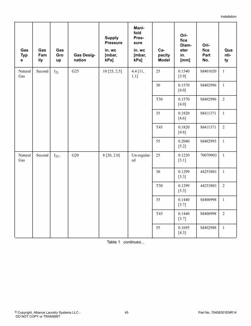
GasType
GasFamily
GasGroup
Gas Desig-nation
SupplyPressure
in. wc[mbar,kPa]
Mani-foldPres-sure
in. wc[mbar,kPa]
Ca-pacityModel
Ori-ficeDiam-eterin.[mm]
Ori-ficePartNo.
Quanti-ty
NaturalGas
Second I2L G25 10 [25, 2.5] 4.4 [11,1.1]
25 0.1540[3.9]
M401020 1
30 0.1570[4.0]
M402996 1
T30 0.1570[4.0]
M402996 2
35 0.1820[4.6]
M411371 1
T45 0.1820[4.6]
M411371 2
55 0.2040[5.2]
M402993 1
NaturalGas
Second I2E+ G20 8 [20, 2.0] Un-regulat-ed
25 0.1220[3.1]
70070903 1
30 0.1299[3.3]
44253801 1
T30 0.1299[3.3]
44253801 2
35 0.1440[3.7]
M400998 1
T45 0.1440[3.7]
M400998 2
55 0.1695[4.3]
M402988 1
Table 1 continues...
Installation
© Copyright, Alliance Laundry Systems LLC - DO NOT COPY or TRANSMIT
45 Part No. 70458301ENR14
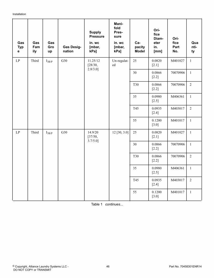
GasType
GasFamily
GasGroup
Gas Desig-nation
SupplyPressure
in. wc[mbar,kPa]
Mani-foldPres-sure
in. wc[mbar,kPa]
Ca-pacityModel
Ori-ficeDiam-eterin.[mm]
Ori-ficePartNo.
Quanti-ty
LP Third I3B/P G30 11.25/12[28/30,2.8/3.0]
Un-regulat-ed
25 0.0820[2.1]
M401027 1
30 0.0866[2.2]
70070906 1
T30 0.0866[2.2]
70070906 2
35 0.0980[2.5]
M406361 1
T45 0.0935[2.4]
M403017 2
55 0.1200[3.0]
M401017 1
LP Third I3B/P G30 14.9/20[37/50,3.7/5.0]
12 [30, 3.0] 25 0.0820[2.1]
M401027 1
30 0.0866[2.2]
70070906 1
T30 0.0866[2.2]
70070906 2
35 0.0980[2.5]
M406361 1
T45 0.0935[2.4]
M403017 2
55 0.1200[3.0]
M401017 1
Table 1 continues...
Installation
© Copyright, Alliance Laundry Systems LLC - DO NOT COPY or TRANSMIT
46 Part No. 70458301ENR14
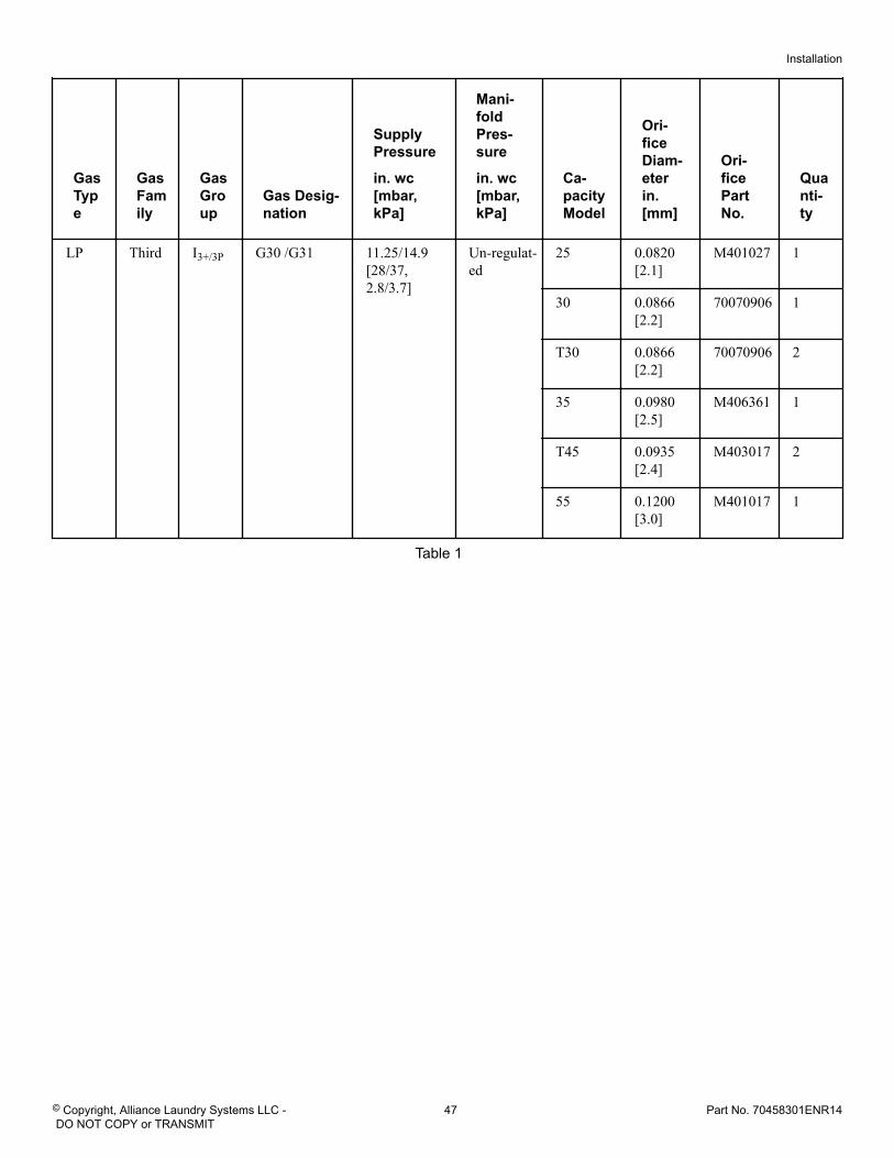
GasType
GasFamily
GasGroup
Gas Desig-nation
SupplyPressure
in. wc[mbar,kPa]
Mani-foldPres-sure
in. wc[mbar,kPa]
Ca-pacityModel
Ori-ficeDiam-eterin.[mm]
Ori-ficePartNo.
Quanti-ty
LP Third I3+/3P G30 /G31 11.25/14.9[28/37,2.8/3.7]
Un-regulat-ed
25 0.0820[2.1]
M401027 1
30 0.0866[2.2]
70070906 1
T30 0.0866[2.2]
70070906 2
35 0.0980[2.5]
M406361 1
T45 0.0935[2.4]
M403017 2
55 0.1200[3.0]
M401017 1
Table 1
Installation
© Copyright, Alliance Laundry Systems LLC - DO NOT COPY or TRANSMIT
47 Part No. 70458301ENR14
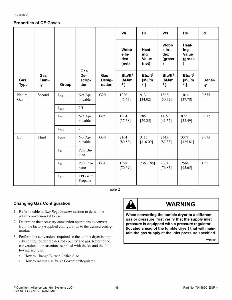
Properties of CE Gases
GasType
GasFami-ly Group
GasDe-scrip-tion
GasDesig-nation
Wi Hi Ws Hs d
Wobbe In-dex(net)
Heat-ingValue(net)
Wobbe In-dex(gross)
Heat-ingValue(gross)
Densi-ty
Btu/ft3
[MJ/m3 ]
Btu/ft3
[MJ/m3 ]
Btu/ft3
[MJ/m3 ]
Btu/ft3
[MJ/m3 ]
NaturalGas
Second I2H,E Not Ap-plicable
G20 1226[45.67]
913[34.02]
1362[50.72]
1014[37.78]
0.555
I2E+ 2H
I2L Not Ap-plicable
G25 1004[37.38]
785[29.25]
1115[41.52]
872[32.49]
0.612
I2E+ 2L
LP Third I3B/P Not Ap-plicable
G30 2164[80.58]
3117[116.09]
2345[87.33]
3378[125.81]
2.075
I3+ Pure Bu-tane
I3+ Pure Pro-pane
G31 1898[70.69]
2363 [88] 2063[76.83]
2568[95.65]
1.55
I3P LPG withPropane
Table 2
Changing Gas Configuration
1. Refer to table in Gas Requirements section to determinewhich conversion kit to use.
2. Determine the necessary conversion operations to convertfrom the factory-supplied configuration to the desired config-uration.
3. Perform the conversions required so the tumble dryer is prop-erly configured for the desired country and gas. Refer to theconversion kit instructions supplied with the kit and the fol-lowing sections:• How to Change Burner Orifice Size• How to Adjust Gas Valve Governor/Regulator
WARNINGWhen converting the tumble dryer to a differentgas or pressure, first verify that the supply inletpressure is equipped with a pressure regulator(located ahead of the tumble dryer) that will main-tain the gas supply at the inlet pressure specified.
W430R1
Installation
© Copyright, Alliance Laundry Systems LLC - DO NOT COPY or TRANSMIT
48 Part No. 70458301ENR14
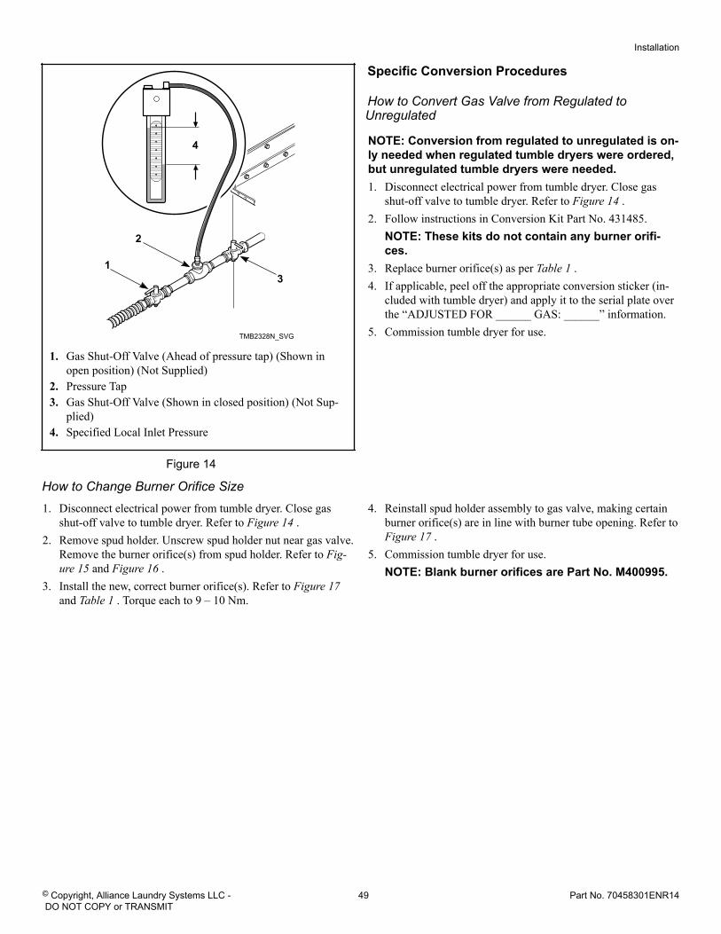
TMB2328N_SVG
4
3
2
1
1. Gas Shut-Off Valve (Ahead of pressure tap) (Shown inopen position) (Not Supplied)
2. Pressure Tap3. Gas Shut-Off Valve (Shown in closed position) (Not Sup-
plied)4. Specified Local Inlet Pressure
Figure 14
Specific Conversion Procedures
How to Convert Gas Valve from Regulated toUnregulated
NOTE: Conversion from regulated to unregulated is on-ly needed when regulated tumble dryers were ordered,but unregulated tumble dryers were needed.1. Disconnect electrical power from tumble dryer. Close gas
shut-off valve to tumble dryer. Refer to Figure 14 .2. Follow instructions in Conversion Kit Part No. 431485.
NOTE: These kits do not contain any burner orifi-ces.
3. Replace burner orifice(s) as per Table 1 .4. If applicable, peel off the appropriate conversion sticker (in-
cluded with tumble dryer) and apply it to the serial plate overthe “ADJUSTED FOR ______ GAS: ______” information.
5. Commission tumble dryer for use.
How to Change Burner Orifice Size1. Disconnect electrical power from tumble dryer. Close gas
shut-off valve to tumble dryer. Refer to Figure 14 .2. Remove spud holder. Unscrew spud holder nut near gas valve.
Remove the burner orifice(s) from spud holder. Refer to Fig-ure 15 and Figure 16 .
3. Install the new, correct burner orifice(s). Refer to Figure 17 and Table 1 . Torque each to 9 – 10 Nm.
4. Reinstall spud holder assembly to gas valve, making certainburner orifice(s) are in line with burner tube opening. Refer to Figure 17 .
5. Commission tumble dryer for use.NOTE: Blank burner orifices are Part No. M400995.
Installation
© Copyright, Alliance Laundry Systems LLC - DO NOT COPY or TRANSMIT
49 Part No. 70458301ENR14
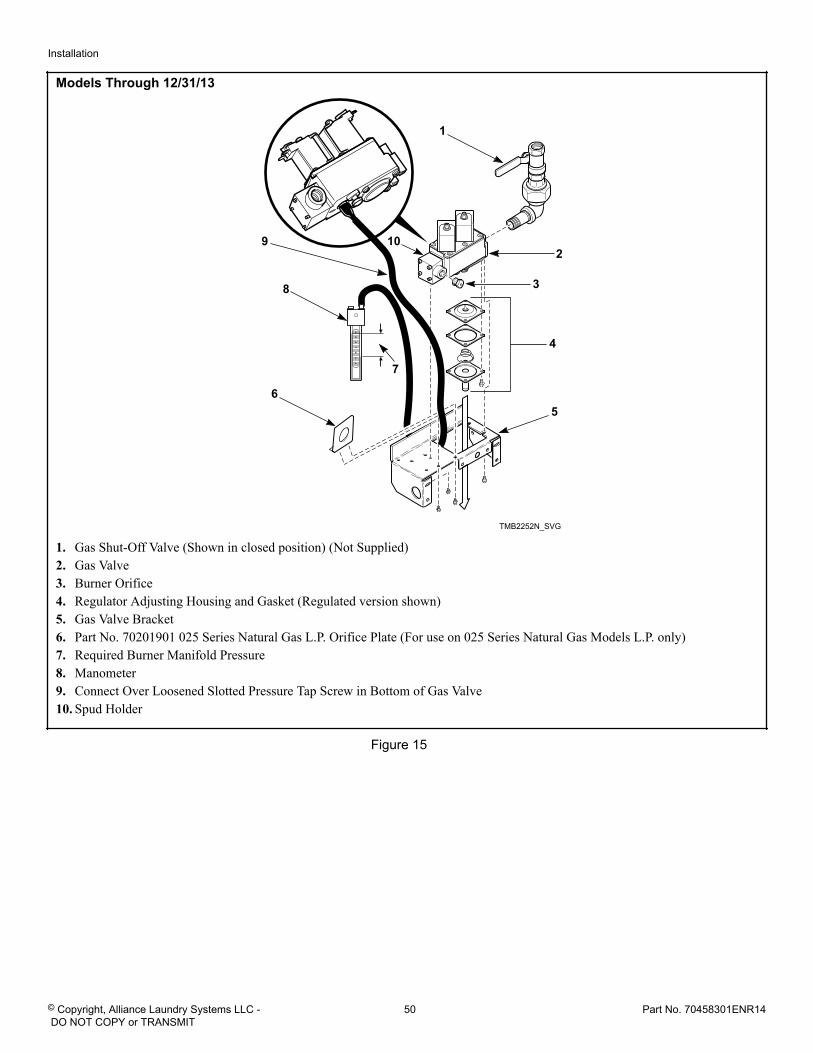
Models Through 12/31/13
TMB2252N_SVG
2
3
4
6
7
8
9 10
5
1
1. Gas Shut-Off Valve (Shown in closed position) (Not Supplied)2. Gas Valve3. Burner Orifice4. Regulator Adjusting Housing and Gasket (Regulated version shown)5. Gas Valve Bracket6. Part No. 70201901 025 Series Natural Gas L.P. Orifice Plate (For use on 025 Series Natural Gas Models L.P. only)7. Required Burner Manifold Pressure8. Manometer9. Connect Over Loosened Slotted Pressure Tap Screw in Bottom of Gas Valve10. Spud Holder
Figure 15
Installation
© Copyright, Alliance Laundry Systems LLC - DO NOT COPY or TRANSMIT
50 Part No. 70458301ENR14
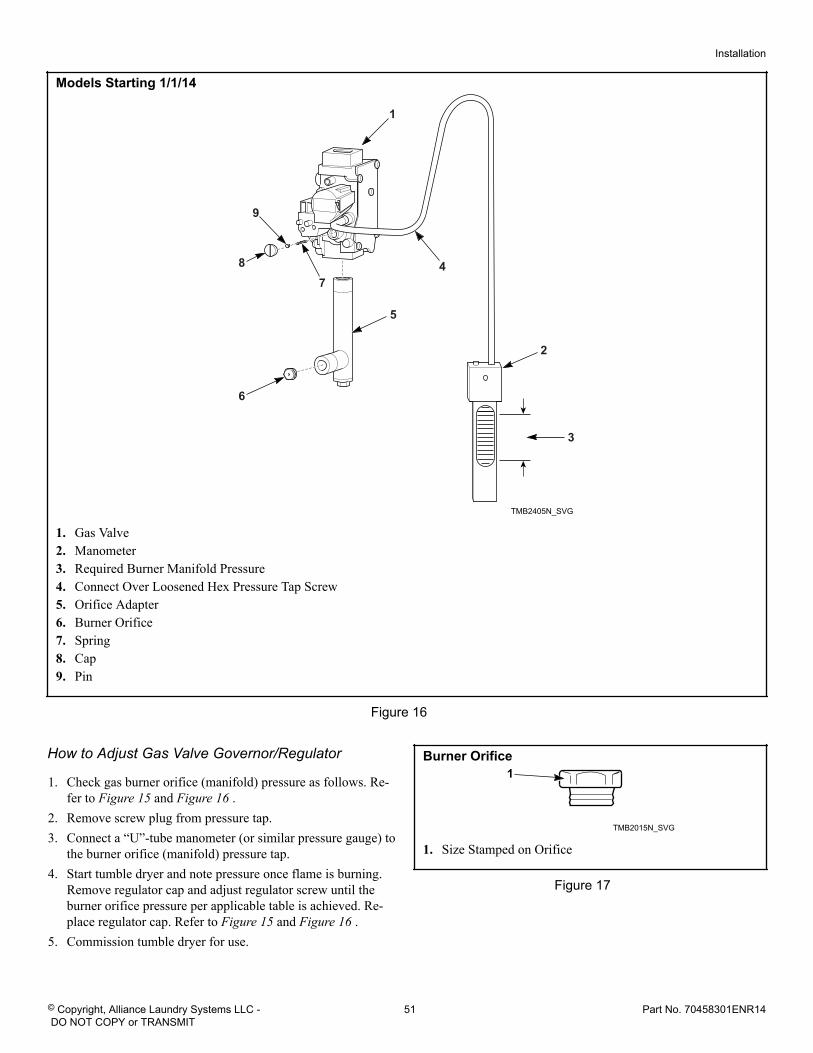
Models Starting 1/1/14
TMB2405N_SVG
1
9
2
47
5
6
8
3
1. Gas Valve2. Manometer3. Required Burner Manifold Pressure4. Connect Over Loosened Hex Pressure Tap Screw5. Orifice Adapter6. Burner Orifice7. Spring8. Cap9. Pin
Figure 16
How to Adjust Gas Valve Governor/Regulator
1. Check gas burner orifice (manifold) pressure as follows. Re-fer to Figure 15 and Figure 16 .
2. Remove screw plug from pressure tap.3. Connect a “U”-tube manometer (or similar pressure gauge) to
the burner orifice (manifold) pressure tap.4. Start tumble dryer and note pressure once flame is burning.
Remove regulator cap and adjust regulator screw until theburner orifice pressure per applicable table is achieved. Re-place regulator cap. Refer to Figure 15 and Figure 16 .
5. Commission tumble dryer for use.
Burner Orifice
TMB2015N_SVG
1
1. Size Stamped on Orifice
Figure 17
Installation
© Copyright, Alliance Laundry Systems LLC - DO NOT COPY or TRANSMIT
51 Part No. 70458301ENR14
Exhaust Requirements Exhaust Requirements
CAUTIONRisk of fire. A clothes dryer produces combustiblelint. Exhaust outdoors. Consult technical instruc-tions for detailed exhaust specifications.
W933
WARNINGTo reduce the risk of fire, DO NOT use plastic or thinfoil ducting to exhaust the tumble dryer.
W773R1
WARNINGTo reduce the risk of fire and accumulation of com-bustible gases, DO NOT exhaust tumble dryer air in-to a window well, gas vent, chimney or enclosed, un-ventilated area such as an attic wall, ceiling, crawlspace under a building, or concealed space of abuilding.
W059R1
LayoutWhenever possible, install tumble dryers along an outside wallwhere duct length can be kept to a minimum, and make-up aircan be easily accessed. Construction must not block the airflow atthe rear of the tumble dryer. Doing so would prevent adequate airsupply to the tumble dryer combustion chamber.
Make-Up AirA tumble dryer is forced air exhausted and requires provisions formake-up air to replace air exhausted by tumble dryer.
IMPORTANT: Do not obstruct flow of combustion andventilation air.
Required Make-Up Air Opening (to the outside) forEach Tumble Dryer, in.2 [ cm2]
Model Opening
025/030 Series 110 [710]
035/055 Series 144 [930]
T30 Series 220 [1,420]
T45 Series 288 [1,860]
Make-up air openings with louvers will restrict airflow. Theopening must be increased to compensate for area taken up andrestrictions created by louvers.
Make-up air openings in rooms containing tumble dryer(s) and/orgas fired hot water heater or other gravity vented appliances mustbe increased sufficiently to prevent downdrafts in any of thevents when all tumble dryers are in operation. Do not locate grav-ity vented appliances between tumble dryer(s) and make-up airopenings. If it is necessary to duct make-up air to tumble dry-er(s), increase area of duct work by 25% to compensate for re-strictions in air movement.
Venting
WARNINGTo reduce the risk of fire due to increased staticpressure, we do not recommend installation of in-line secondary lint filters or lint collectors. If secon-dary systems are mandated, frequently clean thesystem to assure safe operation.
W749
IMPORTANT: Installing in-line filters or lint collectorswill cause increased static pressure. Failure to main-tain the secondary lint system will decrease tumbledryer efficiency and may void machine warranty.
For maximum efficiency and minimum lint accumulation, tumbledryer air must be exhausted to the outdoors by the shortest possi-ble route.
Exhaust Requirements
© Copyright, Alliance Laundry Systems LLC - DO NOT COPY or TRANSMIT
52 Part No. 70458301ENR14
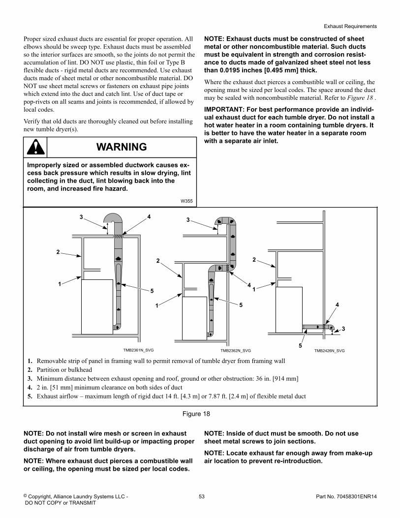
Proper sized exhaust ducts are essential for proper operation. Allelbows should be sweep type. Exhaust ducts must be assembledso the interior surfaces are smooth, so the joints do not permit theaccumulation of lint. DO NOT use plastic, thin foil or Type Bflexible ducts - rigid metal ducts are recommended. Use exhaustducts made of sheet metal or other noncombustible material. DONOT use sheet metal screws or fasteners on exhaust pipe jointswhich extend into the duct and catch lint. Use of duct tape orpop-rivets on all seams and joints is recommended, if allowed bylocal codes.
Verify that old ducts are thoroughly cleaned out before installingnew tumble dryer(s).
WARNINGImproperly sized or assembled ductwork causes ex-cess back pressure which results in slow drying, lintcollecting in the duct, lint blowing back into theroom, and increased fire hazard.
W355
NOTE: Exhaust ducts must be constructed of sheetmetal or other noncombustible material. Such ductsmust be equivalent in strength and corrosion resist-ance to ducts made of galvanized sheet steel not lessthan 0.0195 inches [0.495 mm] thick.
Where the exhaust duct pierces a combustible wall or ceiling, theopening must be sized per local codes. The space around the ductmay be sealed with noncombustible material. Refer to Figure 18 .
IMPORTANT: For best performance provide an individ-ual exhaust duct for each tumble dryer. Do not install ahot water heater in a room containing tumble dryers. Itis better to have the water heater in a separate roomwith a separate air inlet.
TMB2361N_SVG
5
43
2
1
TMB2362N_SVG
5
4
3
2
1
TMB2426N_SVG5
4
3
2
1
1. Removable strip of panel in framing wall to permit removal of tumble dryer from framing wall2. Partition or bulkhead3. Minimum distance between exhaust opening and roof, ground or other obstruction: 36 in. [914 mm]4. 2 in. [51 mm] minimum clearance on both sides of duct5. Exhaust airflow – maximum length of rigid duct 14 ft. [4.3 m] or 7.87 ft. [2.4 m] of flexible metal duct
Figure 18
NOTE: Do not install wire mesh or screen in exhaustduct opening to avoid lint build-up or impacting properdischarge of air from tumble dryers.
NOTE: Where exhaust duct pierces a combustible wallor ceiling, the opening must be sized per local codes.
NOTE: Inside of duct must be smooth. Do not usesheet metal screws to join sections.
NOTE: Locate exhaust far enough away from make-upair location to prevent re-introduction.
Exhaust Requirements
© Copyright, Alliance Laundry Systems LLC - DO NOT COPY or TRANSMIT
53 Part No. 70458301ENR14
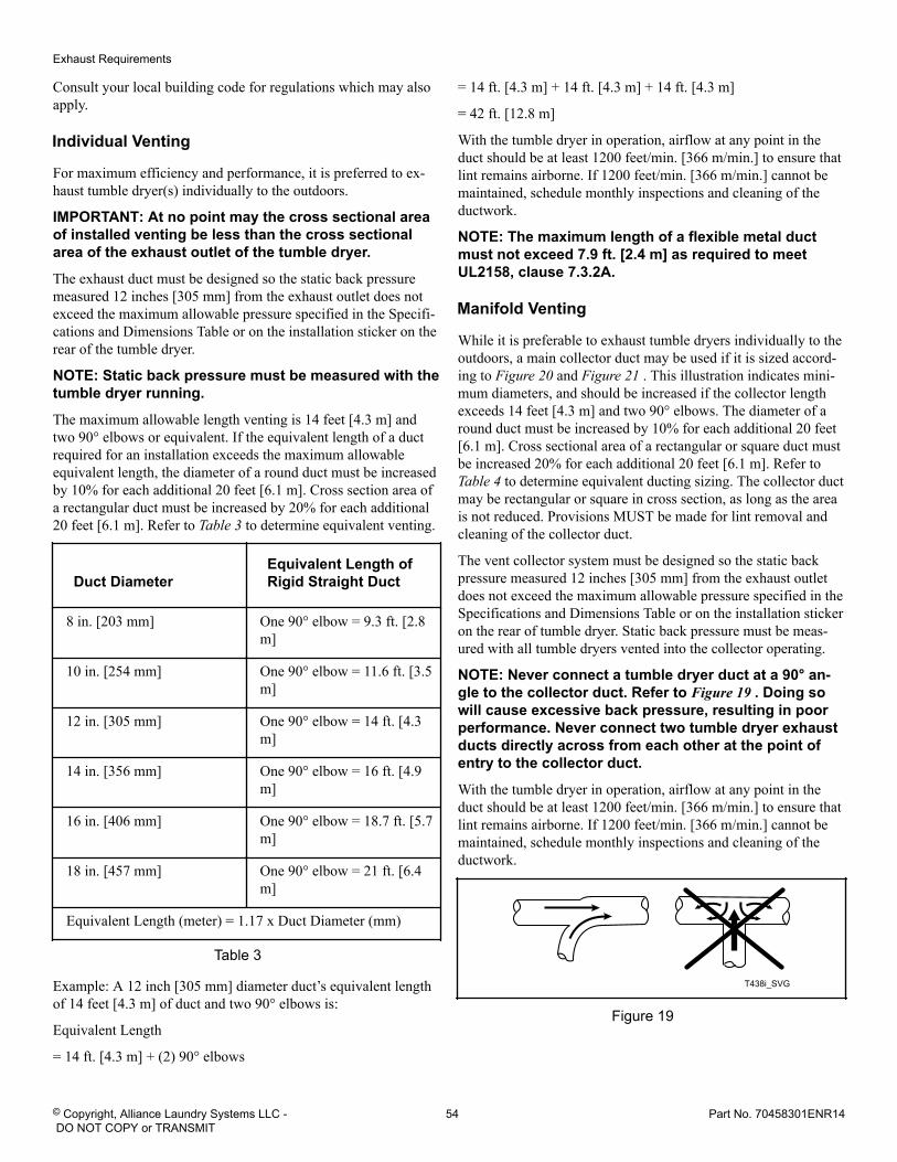
Consult your local building code for regulations which may alsoapply.
Individual Venting
For maximum efficiency and performance, it is preferred to ex-haust tumble dryer(s) individually to the outdoors.
IMPORTANT: At no point may the cross sectional areaof installed venting be less than the cross sectionalarea of the exhaust outlet of the tumble dryer.
The exhaust duct must be designed so the static back pressuremeasured 12 inches [305 mm] from the exhaust outlet does notexceed the maximum allowable pressure specified in the Specifi-cations and Dimensions Table or on the installation sticker on therear of the tumble dryer.
NOTE: Static back pressure must be measured with thetumble dryer running.
The maximum allowable length venting is 14 feet [4.3 m] andtwo 90° elbows or equivalent. If the equivalent length of a ductrequired for an installation exceeds the maximum allowableequivalent length, the diameter of a round duct must be increasedby 10% for each additional 20 feet [6.1 m]. Cross section area ofa rectangular duct must be increased by 20% for each additional20 feet [6.1 m]. Refer to Table 3 to determine equivalent venting.
Duct DiameterEquivalent Length ofRigid Straight Duct
8 in. [203 mm] One 90° elbow = 9.3 ft. [2.8m]
10 in. [254 mm] One 90° elbow = 11.6 ft. [3.5m]
12 in. [305 mm] One 90° elbow = 14 ft. [4.3m]
14 in. [356 mm] One 90° elbow = 16 ft. [4.9m]
16 in. [406 mm] One 90° elbow = 18.7 ft. [5.7m]
18 in. [457 mm] One 90° elbow = 21 ft. [6.4m]
Equivalent Length (meter) = 1.17 x Duct Diameter (mm)
Table 3
Example: A 12 inch [305 mm] diameter duct’s equivalent lengthof 14 feet [4.3 m] of duct and two 90° elbows is:
Equivalent Length
= 14 ft. [4.3 m] + (2) 90° elbows
= 14 ft. [4.3 m] + 14 ft. [4.3 m] + 14 ft. [4.3 m]
= 42 ft. [12.8 m]
With the tumble dryer in operation, airflow at any point in theduct should be at least 1200 feet/min. [366 m/min.] to ensure thatlint remains airborne. If 1200 feet/min. [366 m/min.] cannot bemaintained, schedule monthly inspections and cleaning of theductwork.
NOTE: The maximum length of a flexible metal ductmust not exceed 7.9 ft. [2.4 m] as required to meetUL2158, clause 7.3.2A.
Manifold Venting
While it is preferable to exhaust tumble dryers individually to theoutdoors, a main collector duct may be used if it is sized accord-ing to Figure 20 and Figure 21 . This illustration indicates mini-mum diameters, and should be increased if the collector lengthexceeds 14 feet [4.3 m] and two 90° elbows. The diameter of around duct must be increased by 10% for each additional 20 feet[6.1 m]. Cross sectional area of a rectangular or square duct mustbe increased 20% for each additional 20 feet [6.1 m]. Refer to Table 4 to determine equivalent ducting sizing. The collector ductmay be rectangular or square in cross section, as long as the areais not reduced. Provisions MUST be made for lint removal andcleaning of the collector duct.
The vent collector system must be designed so the static backpressure measured 12 inches [305 mm] from the exhaust outletdoes not exceed the maximum allowable pressure specified in theSpecifications and Dimensions Table or on the installation stickeron the rear of tumble dryer. Static back pressure must be meas-ured with all tumble dryers vented into the collector operating.
NOTE: Never connect a tumble dryer duct at a 90° an-gle to the collector duct. Refer to Figure 19 . Doing sowill cause excessive back pressure, resulting in poorperformance. Never connect two tumble dryer exhaustducts directly across from each other at the point ofentry to the collector duct.
With the tumble dryer in operation, airflow at any point in theduct should be at least 1200 feet/min. [366 m/min.] to ensure thatlint remains airborne. If 1200 feet/min. [366 m/min.] cannot bemaintained, schedule monthly inspections and cleaning of theductwork.
T438i_SVG
Figure 19
Exhaust Requirements
© Copyright, Alliance Laundry Systems LLC - DO NOT COPY or TRANSMIT
54 Part No. 70458301ENR14
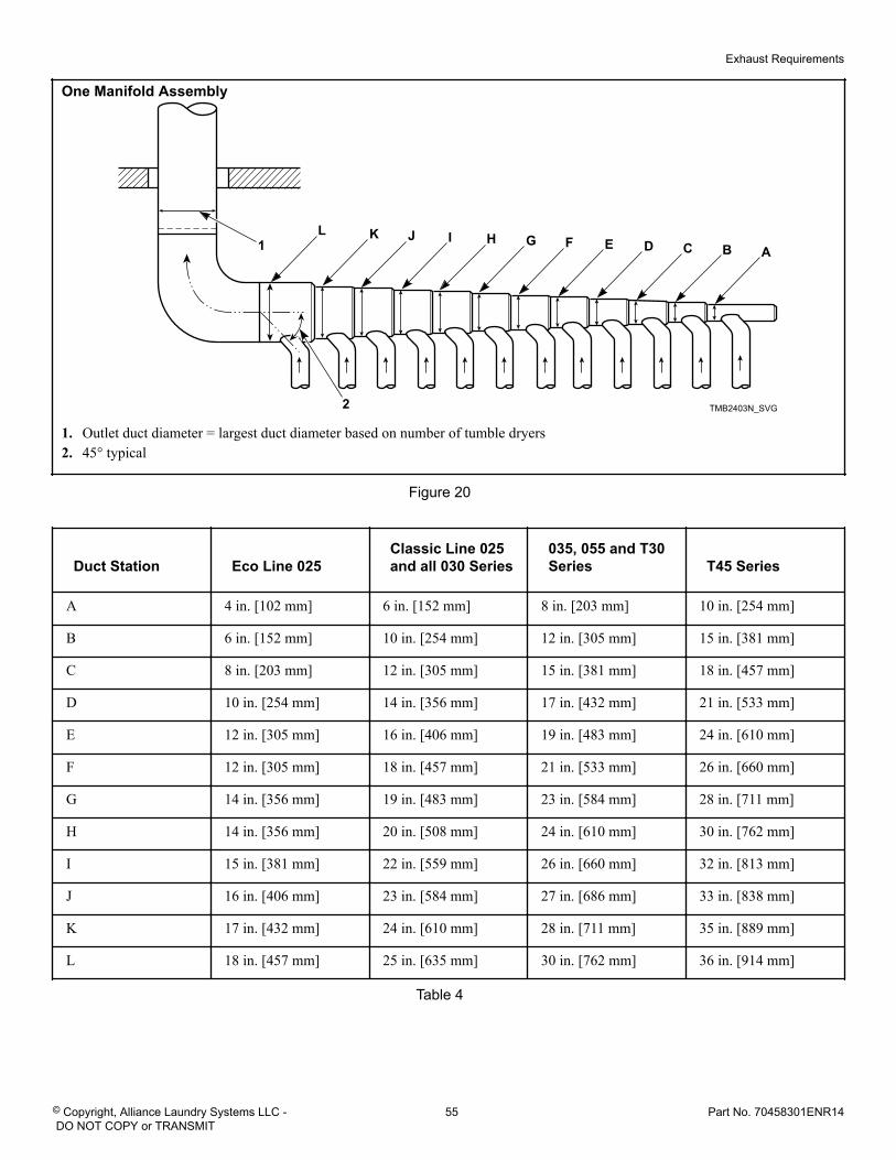
One Manifold Assembly
TMB2403N_SVG
L K J I H G F E D C B A1
2
1. Outlet duct diameter = largest duct diameter based on number of tumble dryers2. 45° typical
Figure 20
Duct Station Eco Line 025Classic Line 025and all 030 Series
035, 055 and T30Series T45 Series
A 4 in. [102 mm] 6 in. [152 mm] 8 in. [203 mm] 10 in. [254 mm]
B 6 in. [152 mm] 10 in. [254 mm] 12 in. [305 mm] 15 in. [381 mm]
C 8 in. [203 mm] 12 in. [305 mm] 15 in. [381 mm] 18 in. [457 mm]
D 10 in. [254 mm] 14 in. [356 mm] 17 in. [432 mm] 21 in. [533 mm]
E 12 in. [305 mm] 16 in. [406 mm] 19 in. [483 mm] 24 in. [610 mm]
F 12 in. [305 mm] 18 in. [457 mm] 21 in. [533 mm] 26 in. [660 mm]
G 14 in. [356 mm] 19 in. [483 mm] 23 in. [584 mm] 28 in. [711 mm]
H 14 in. [356 mm] 20 in. [508 mm] 24 in. [610 mm] 30 in. [762 mm]
I 15 in. [381 mm] 22 in. [559 mm] 26 in. [660 mm] 32 in. [813 mm]
J 16 in. [406 mm] 23 in. [584 mm] 27 in. [686 mm] 33 in. [838 mm]
K 17 in. [432 mm] 24 in. [610 mm] 28 in. [711 mm] 35 in. [889 mm]
L 18 in. [457 mm] 25 in. [635 mm] 30 in. [762 mm] 36 in. [914 mm]
Table 4
Exhaust Requirements
© Copyright, Alliance Laundry Systems LLC - DO NOT COPY or TRANSMIT
55 Part No. 70458301ENR14
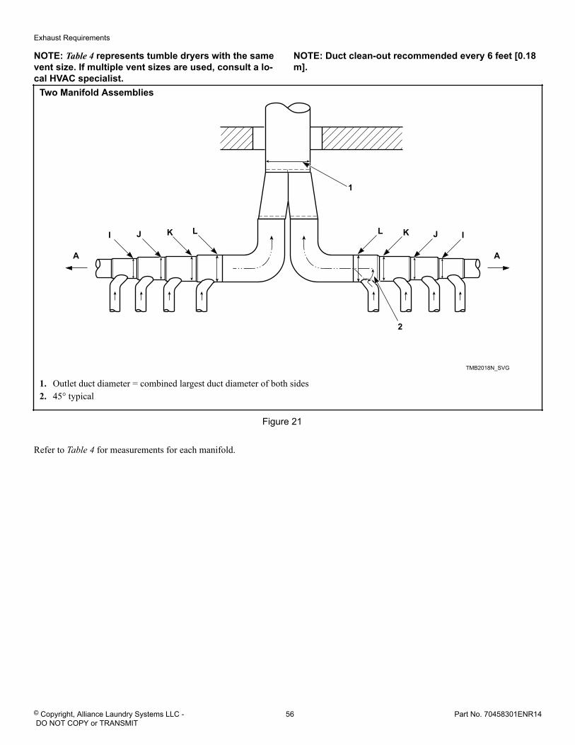
NOTE: Table 4 represents tumble dryers with the samevent size. If multiple vent sizes are used, consult a lo-cal HVAC specialist.
NOTE: Duct clean-out recommended every 6 feet [0.18m].
Two Manifold Assemblies
TMB2018N_SVG
1
2
L LK KJ JI
AA
I
1. Outlet duct diameter = combined largest duct diameter of both sides2. 45° typical
Figure 21
Refer to Table 4 for measurements for each manifold.
Exhaust Requirements
© Copyright, Alliance Laundry Systems LLC - DO NOT COPY or TRANSMIT
56 Part No. 70458301ENR14
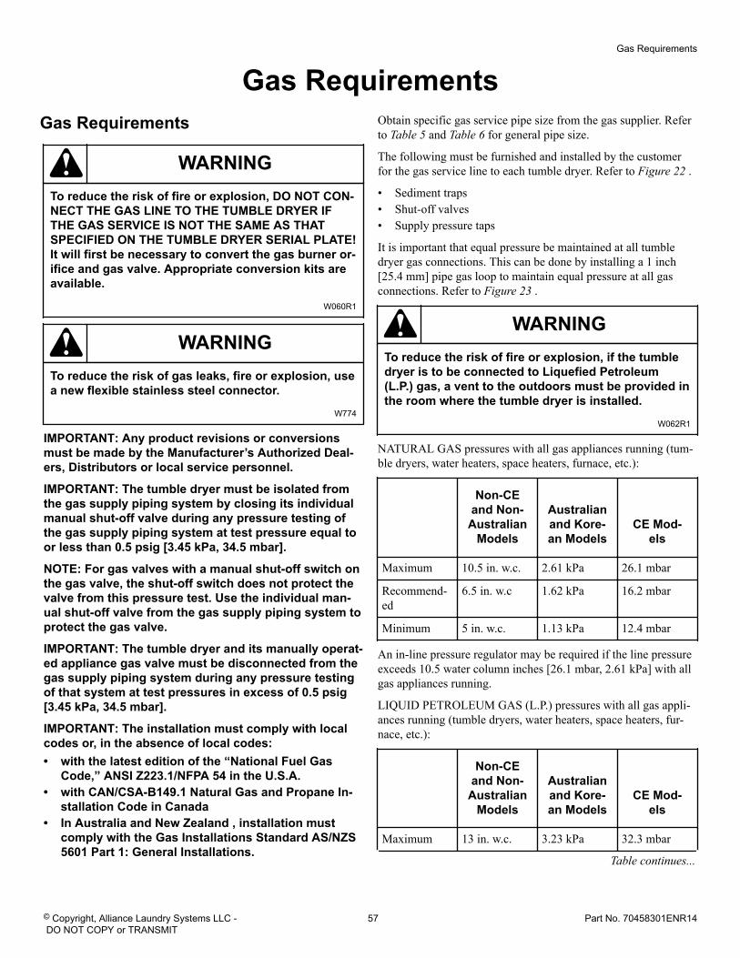
Gas Requirements Gas Requirements
WARNINGTo reduce the risk of fire or explosion, DO NOT CON-NECT THE GAS LINE TO THE TUMBLE DRYER IFTHE GAS SERVICE IS NOT THE SAME AS THATSPECIFIED ON THE TUMBLE DRYER SERIAL PLATE!It will first be necessary to convert the gas burner or-ifice and gas valve. Appropriate conversion kits areavailable.
W060R1
WARNINGTo reduce the risk of gas leaks, fire or explosion, usea new flexible stainless steel connector.
W774
IMPORTANT: Any product revisions or conversionsmust be made by the Manufacturer’s Authorized Deal-ers, Distributors or local service personnel.
IMPORTANT: The tumble dryer must be isolated fromthe gas supply piping system by closing its individualmanual shut-off valve during any pressure testing ofthe gas supply piping system at test pressure equal toor less than 0.5 psig [3.45 kPa, 34.5 mbar].
NOTE: For gas valves with a manual shut-off switch onthe gas valve, the shut-off switch does not protect thevalve from this pressure test. Use the individual man-ual shut-off valve from the gas supply piping system toprotect the gas valve.
IMPORTANT: The tumble dryer and its manually operat-ed appliance gas valve must be disconnected from thegas supply piping system during any pressure testingof that system at test pressures in excess of 0.5 psig[3.45 kPa, 34.5 mbar].
IMPORTANT: The installation must comply with localcodes or, in the absence of local codes:• with the latest edition of the “National Fuel Gas
Code,” ANSI Z223.1/NFPA 54 in the U.S.A.• with CAN/CSA-B149.1 Natural Gas and Propane In-
stallation Code in Canada• In Australia and New Zealand , installation must
comply with the Gas Installations Standard AS/NZS5601 Part 1: General Installations.
Obtain specific gas service pipe size from the gas supplier. Referto Table 5 and Table 6 for general pipe size.
The following must be furnished and installed by the customerfor the gas service line to each tumble dryer. Refer to Figure 22 .
• Sediment traps• Shut-off valves• Supply pressure taps
It is important that equal pressure be maintained at all tumbledryer gas connections. This can be done by installing a 1 inch[25.4 mm] pipe gas loop to maintain equal pressure at all gasconnections. Refer to Figure 23 .
WARNINGTo reduce the risk of fire or explosion, if the tumbledryer is to be connected to Liquefied Petroleum(L.P.) gas, a vent to the outdoors must be provided inthe room where the tumble dryer is installed.
W062R1
NATURAL GAS pressures with all gas appliances running (tum-ble dryers, water heaters, space heaters, furnace, etc.):
Non-CEand Non-
AustralianModels
Australianand Kore-an Models
CE Mod-els
Maximum 10.5 in. w.c. 2.61 kPa 26.1 mbar
Recommend-ed
6.5 in. w.c 1.62 kPa 16.2 mbar
Minimum 5 in. w.c. 1.13 kPa 12.4 mbar
An in-line pressure regulator may be required if the line pressureexceeds 10.5 water column inches [26.1 mbar, 2.61 kPa] with allgas appliances running.
LIQUID PETROLEUM GAS (L.P.) pressures with all gas appli-ances running (tumble dryers, water heaters, space heaters, fur-nace, etc.):
Non-CEand Non-
AustralianModels
Australianand Kore-an Models
CE Mod-els
Maximum 13 in. w.c. 3.23 kPa 32.3 mbar
Table continues...
Gas Requirements
© Copyright, Alliance Laundry Systems LLC - DO NOT COPY or TRANSMIT
57 Part No. 70458301ENR14
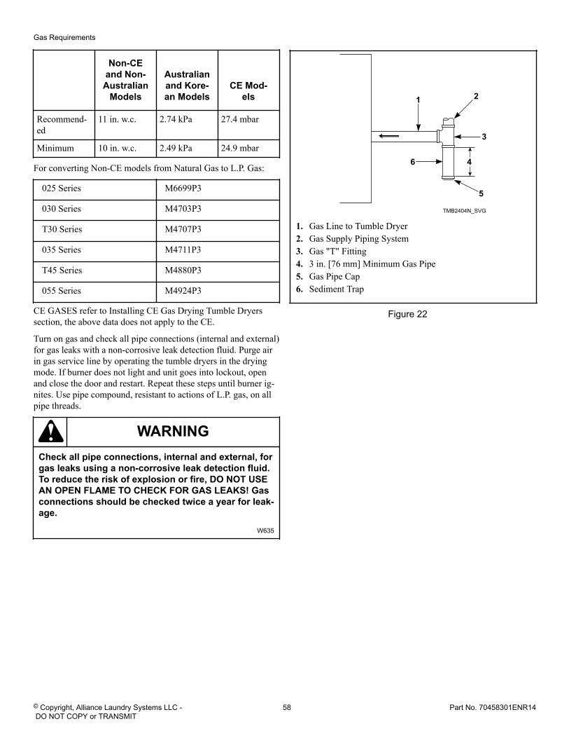
Non-CEand Non-
AustralianModels
Australianand Kore-an Models
CE Mod-els
Recommend-ed
11 in. w.c. 2.74 kPa 27.4 mbar
Minimum 10 in. w.c. 2.49 kPa 24.9 mbar
For converting Non-CE models from Natural Gas to L.P. Gas:
025 Series M6699P3
030 Series M4703P3
T30 Series M4707P3
035 Series M4711P3
T45 Series M4880P3
055 Series M4924P3
CE GASES refer to Installing CE Gas Drying Tumble Dryerssection, the above data does not apply to the CE.
Turn on gas and check all pipe connections (internal and external)for gas leaks with a non-corrosive leak detection fluid. Purge airin gas service line by operating the tumble dryers in the dryingmode. If burner does not light and unit goes into lockout, openand close the door and restart. Repeat these steps until burner ig-nites. Use pipe compound, resistant to actions of L.P. gas, on allpipe threads.
WARNINGCheck all pipe connections, internal and external, forgas leaks using a non-corrosive leak detection fluid.To reduce the risk of explosion or fire, DO NOT USEAN OPEN FLAME TO CHECK FOR GAS LEAKS! Gasconnections should be checked twice a year for leak-age.
W635
TMB2404N_SVG
6
3
4
5
1 2
1. Gas Line to Tumble Dryer2. Gas Supply Piping System3. Gas "T" Fitting4. 3 in. [76 mm] Minimum Gas Pipe5. Gas Pipe Cap6. Sediment Trap
Figure 22
Gas Requirements
© Copyright, Alliance Laundry Systems LLC - DO NOT COPY or TRANSMIT
58 Part No. 70458301ENR14
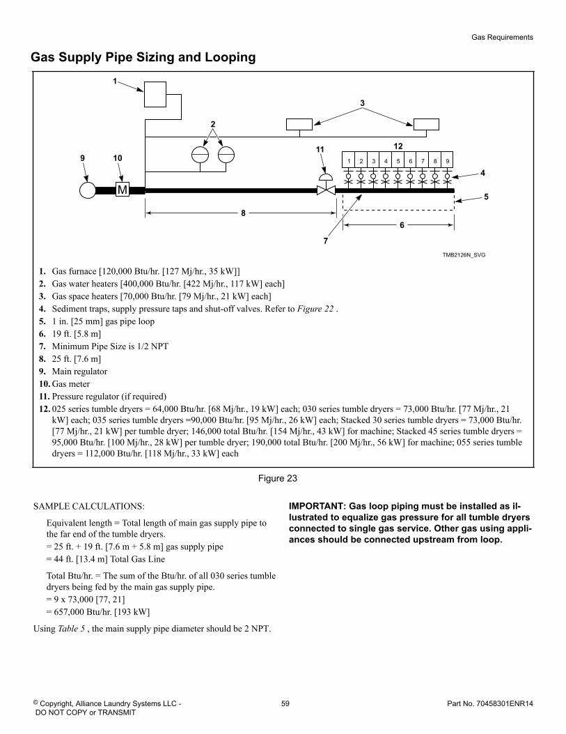
Gas Supply Pipe Sizing and Looping
TMB2126N_SVG
1 2 3 4 5 6 7 8 9
M
68
7
4
5
3
2
1
9 1011 12
1. Gas furnace [120,000 Btu/hr. [127 Mj/hr., 35 kW]]2. Gas water heaters [400,000 Btu/hr. [422 Mj/hr., 117 kW] each]3. Gas space heaters [70,000 Btu/hr. [79 Mj/hr., 21 kW] each]4. Sediment traps, supply pressure taps and shut-off valves. Refer to Figure 22 .5. 1 in. [25 mm] gas pipe loop6. 19 ft. [5.8 m]7. Minimum Pipe Size is 1/2 NPT8. 25 ft. [7.6 m]9. Main regulator10. Gas meter11. Pressure regulator (if required)12. 025 series tumble dryers = 64,000 Btu/hr. [68 Mj/hr., 19 kW] each; 030 series tumble dryers = 73,000 Btu/hr. [77 Mj/hr., 21
kW] each; 035 series tumble dryers =90,000 Btu/hr. [95 Mj/hr., 26 kW] each; Stacked 30 series tumble dryers = 73,000 Btu/hr.[77 Mj/hr., 21 kW] per tumble dryer; 146,000 total Btu/hr. [154 Mj/hr., 43 kW] for machine; Stacked 45 series tumble dryers =95,000 Btu/hr. [100 Mj/hr., 28 kW] per tumble dryer; 190,000 total Btu/hr. [200 Mj/hr., 56 kW] for machine; 055 series tumbledryers = 112,000 Btu/hr. [118 Mj/hr., 33 kW] each
Figure 23
SAMPLE CALCULATIONS:
Equivalent length = Total length of main gas supply pipe tothe far end of the tumble dryers.= 25 ft. + 19 ft. [7.6 m + 5.8 m] gas supply pipe= 44 ft. [13.4 m] Total Gas Line
Total Btu/hr. = The sum of the Btu/hr. of all 030 series tumbledryers being fed by the main gas supply pipe.= 9 x 73,000 [77, 21]= 657,000 Btu/hr. [193 kW]
Using Table 5 , the main supply pipe diameter should be 2 NPT.
IMPORTANT: Gas loop piping must be installed as il-lustrated to equalize gas pressure for all tumble dryersconnected to single gas service. Other gas using appli-ances should be connected upstream from loop.
Gas Requirements
© Copyright, Alliance Laundry Systems LLC - DO NOT COPY or TRANSMIT
59 Part No. 70458301ENR14
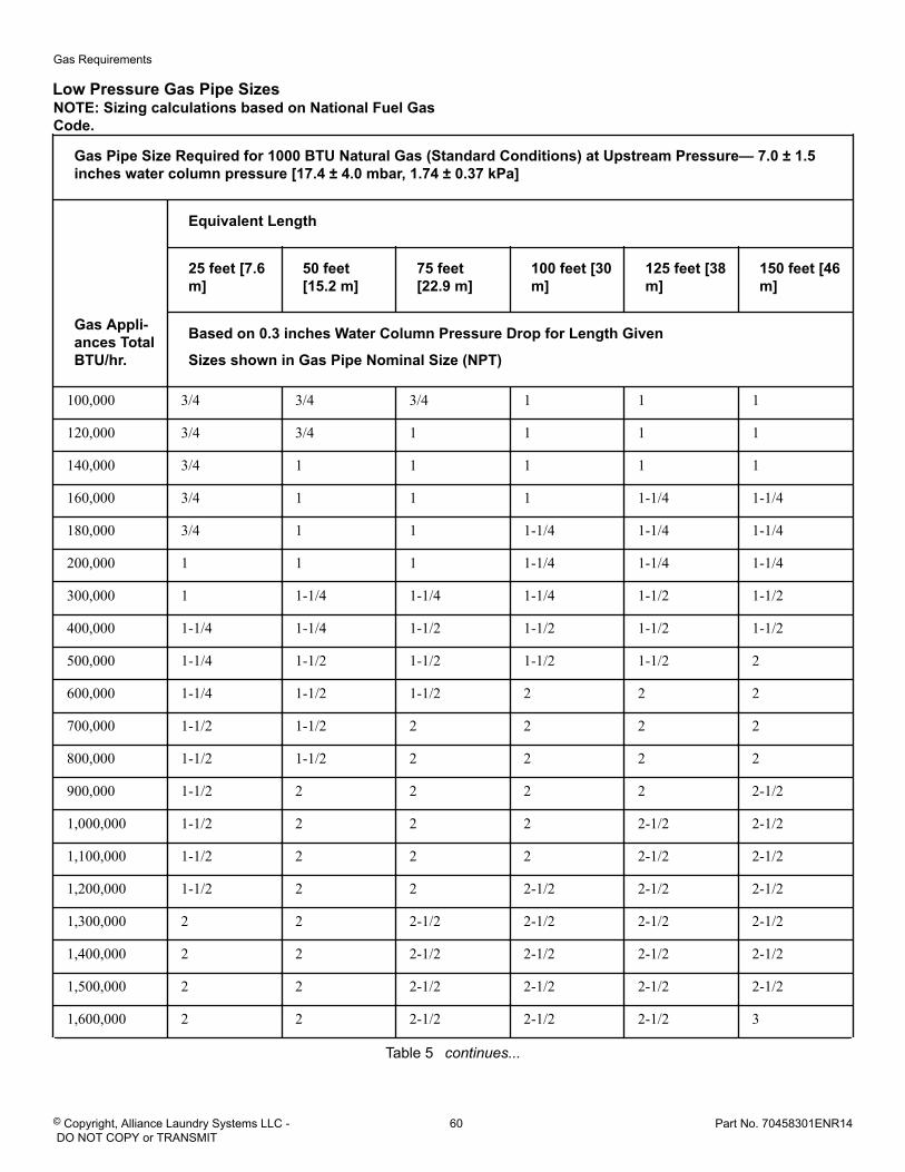
Low Pressure Gas Pipe SizesNOTE: Sizing calculations based on National Fuel GasCode.
Gas Pipe Size Required for 1000 BTU Natural Gas (Standard Conditions) at Upstream Pressure— 7.0 ± 1.5inches water column pressure [17.4 ± 4.0 mbar, 1.74 ± 0.37 kPa]
Gas Appli-ances TotalBTU/hr.
Equivalent Length
25 feet [7.6m]
50 feet[15.2 m]
75 feet[22.9 m]
100 feet [30m]
125 feet [38m]
150 feet [46m]
Based on 0.3 inches Water Column Pressure Drop for Length Given
Sizes shown in Gas Pipe Nominal Size (NPT)
100,000 3/4 3/4 3/4 1 1 1
120,000 3/4 3/4 1 1 1 1
140,000 3/4 1 1 1 1 1
160,000 3/4 1 1 1 1-1/4 1-1/4
180,000 3/4 1 1 1-1/4 1-1/4 1-1/4
200,000 1 1 1 1-1/4 1-1/4 1-1/4
300,000 1 1-1/4 1-1/4 1-1/4 1-1/2 1-1/2
400,000 1-1/4 1-1/4 1-1/2 1-1/2 1-1/2 1-1/2
500,000 1-1/4 1-1/2 1-1/2 1-1/2 1-1/2 2
600,000 1-1/4 1-1/2 1-1/2 2 2 2
700,000 1-1/2 1-1/2 2 2 2 2
800,000 1-1/2 1-1/2 2 2 2 2
900,000 1-1/2 2 2 2 2 2-1/2
1,000,000 1-1/2 2 2 2 2-1/2 2-1/2
1,100,000 1-1/2 2 2 2 2-1/2 2-1/2
1,200,000 1-1/2 2 2 2-1/2 2-1/2 2-1/2
1,300,000 2 2 2-1/2 2-1/2 2-1/2 2-1/2
1,400,000 2 2 2-1/2 2-1/2 2-1/2 2-1/2
1,500,000 2 2 2-1/2 2-1/2 2-1/2 2-1/2
1,600,000 2 2 2-1/2 2-1/2 2-1/2 3
Table 5 continues...
Gas Requirements
© Copyright, Alliance Laundry Systems LLC - DO NOT COPY or TRANSMIT
60 Part No. 70458301ENR14
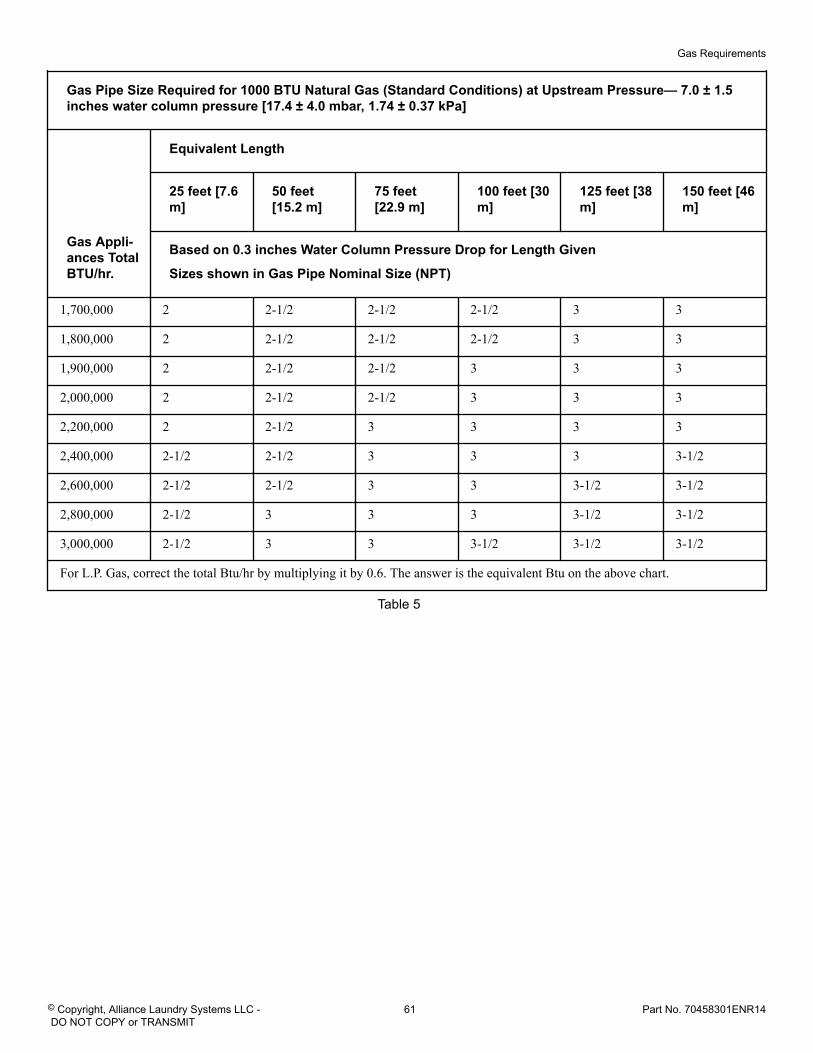
Gas Pipe Size Required for 1000 BTU Natural Gas (Standard Conditions) at Upstream Pressure— 7.0 ± 1.5inches water column pressure [17.4 ± 4.0 mbar, 1.74 ± 0.37 kPa]
Gas Appli-ances TotalBTU/hr.
Equivalent Length
25 feet [7.6m]
50 feet[15.2 m]
75 feet[22.9 m]
100 feet [30m]
125 feet [38m]
150 feet [46m]
Based on 0.3 inches Water Column Pressure Drop for Length Given
Sizes shown in Gas Pipe Nominal Size (NPT)
1,700,000 2 2-1/2 2-1/2 2-1/2 3 3
1,800,000 2 2-1/2 2-1/2 2-1/2 3 3
1,900,000 2 2-1/2 2-1/2 3 3 3
2,000,000 2 2-1/2 2-1/2 3 3 3
2,200,000 2 2-1/2 3 3 3 3
2,400,000 2-1/2 2-1/2 3 3 3 3-1/2
2,600,000 2-1/2 2-1/2 3 3 3-1/2 3-1/2
2,800,000 2-1/2 3 3 3 3-1/2 3-1/2
3,000,000 2-1/2 3 3 3-1/2 3-1/2 3-1/2
For L.P. Gas, correct the total Btu/hr by multiplying it by 0.6. The answer is the equivalent Btu on the above chart.
Table 5
Gas Requirements
© Copyright, Alliance Laundry Systems LLC - DO NOT COPY or TRANSMIT
61 Part No. 70458301ENR14
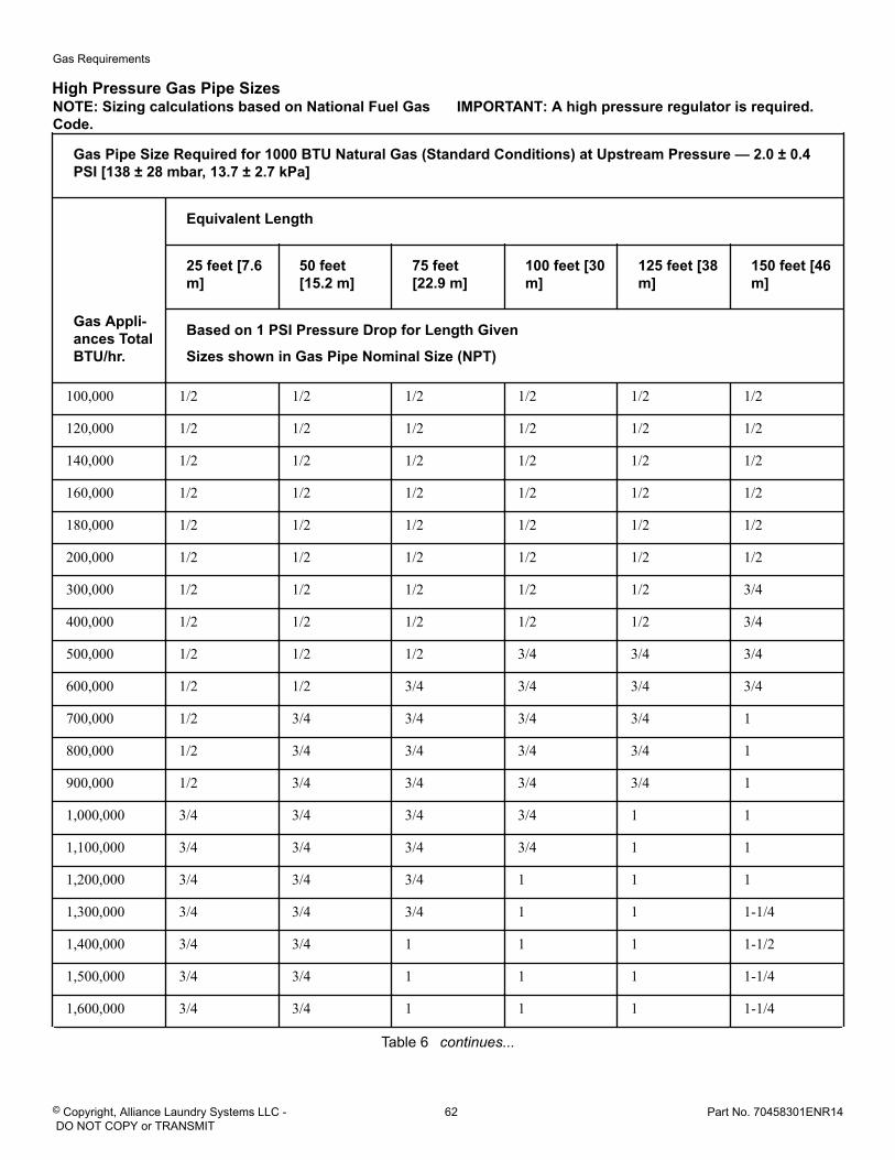
High Pressure Gas Pipe SizesNOTE: Sizing calculations based on National Fuel GasCode.
IMPORTANT: A high pressure regulator is required.
Gas Pipe Size Required for 1000 BTU Natural Gas (Standard Conditions) at Upstream Pressure — 2.0 ± 0.4PSI [138 ± 28 mbar, 13.7 ± 2.7 kPa]
Gas Appli-ances TotalBTU/hr.
Equivalent Length
25 feet [7.6m]
50 feet[15.2 m]
75 feet[22.9 m]
100 feet [30m]
125 feet [38m]
150 feet [46m]
Based on 1 PSI Pressure Drop for Length Given
Sizes shown in Gas Pipe Nominal Size (NPT)
100,000 1/2 1/2 1/2 1/2 1/2 1/2
120,000 1/2 1/2 1/2 1/2 1/2 1/2
140,000 1/2 1/2 1/2 1/2 1/2 1/2
160,000 1/2 1/2 1/2 1/2 1/2 1/2
180,000 1/2 1/2 1/2 1/2 1/2 1/2
200,000 1/2 1/2 1/2 1/2 1/2 1/2
300,000 1/2 1/2 1/2 1/2 1/2 3/4
400,000 1/2 1/2 1/2 1/2 1/2 3/4
500,000 1/2 1/2 1/2 3/4 3/4 3/4
600,000 1/2 1/2 3/4 3/4 3/4 3/4
700,000 1/2 3/4 3/4 3/4 3/4 1
800,000 1/2 3/4 3/4 3/4 3/4 1
900,000 1/2 3/4 3/4 3/4 3/4 1
1,000,000 3/4 3/4 3/4 3/4 1 1
1,100,000 3/4 3/4 3/4 3/4 1 1
1,200,000 3/4 3/4 3/4 1 1 1
1,300,000 3/4 3/4 3/4 1 1 1-1/4
1,400,000 3/4 3/4 1 1 1 1-1/2
1,500,000 3/4 3/4 1 1 1 1-1/4
1,600,000 3/4 3/4 1 1 1 1-1/4
Table 6 continues...
Gas Requirements
© Copyright, Alliance Laundry Systems LLC - DO NOT COPY or TRANSMIT
62 Part No. 70458301ENR14
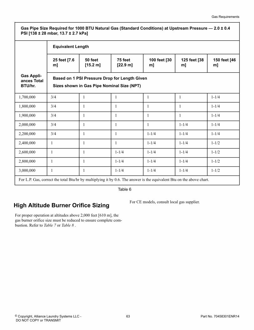
Gas Pipe Size Required for 1000 BTU Natural Gas (Standard Conditions) at Upstream Pressure — 2.0 ± 0.4PSI [138 ± 28 mbar, 13.7 ± 2.7 kPa]
Gas Appli-ances TotalBTU/hr.
Equivalent Length
25 feet [7.6m]
50 feet[15.2 m]
75 feet[22.9 m]
100 feet [30m]
125 feet [38m]
150 feet [46m]
Based on 1 PSI Pressure Drop for Length Given
Sizes shown in Gas Pipe Nominal Size (NPT)
1,700,000 3/4 1 1 1 1 1-1/4
1,800,000 3/4 1 1 1 1 1-1/4
1,900,000 3/4 1 1 1 1 1-1/4
2,000,000 3/4 1 1 1 1-1/4 1-1/4
2,200,000 3/4 1 1 1-1/4 1-1/4 1-1/4
2,400,000 1 1 1 1-1/4 1-1/4 1-1/2
2,600,000 1 1 1-1/4 1-1/4 1-1/4 1-1/2
2,800,000 1 1 1-1/4 1-1/4 1-1/4 1-1/2
3,000,000 1 1 1-1/4 1-1/4 1-1/4 1-1/2
For L.P. Gas, correct the total Btu/hr by multiplying it by 0.6. The answer is the equivalent Btu on the above chart.
Table 6
High Altitude Burner Orifice SizingFor proper operation at altitudes above 2,000 feet [610 m], thegas burner orifice size must be reduced to ensure complete com-bustion. Refer to Table 7 or Table 8 .
For CE models, consult local gas supplier.
Gas Requirements
© Copyright, Alliance Laundry Systems LLC - DO NOT COPY or TRANSMIT
63 Part No. 70458301ENR14
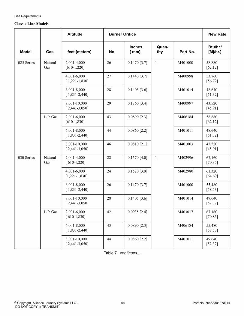
Classic Line Models
Model Gas
Altitude Burner Orifice New Rate
feet [meters] No.inches[ mm]
Quan-tity Part No.
Btu/hr.*[Mj/hr.]
025 Series NaturalGas
2,001-4,000[610-1,220]
26 0.1470 [3.7] 1 M401000 58,880[62.12]
4,001-6,000[ 1,221-1,830]
27 0.1440 [3.7] M400998 53,760[56.72]
6,001-8,000[ 1,831-2,440]
28 0.1405 [3.6] M401014 48,640[51.32]
8,001-10,000[ 2,441-3,050]
29 0.1360 [3.4] M400997 43,520[45.91]
L.P. Gas 2,001-6,000[610-1,830]
43 0.0890 [2.3] M406184 58,880[62.12]
6,001-8,000[ 1,831-2,440]
44 0.0860 [2.2] M401011 48,640[51.32]
8,001-10,000[ 2,441-3,050]
46 0.0810 [2.1] M401003 43,520[45.91]
030 Series NaturalGas
2,001-4,000[ 610-1,220]
22 0.1570 [4.0] 1 M402996 67,160[70.85]
4,001-6,000[1,221-1,830]
24 0.1520 [3.9] M402980 61,320[64.69]
6,001-8,000[ 1,831-2,440]
26 0.1470 [3.7] M401000 55,480[58.53]
8,001-10,000[ 2,441-3,050]
28 0.1405 [3.6] M401014 49,640[52.37]
L.P. Gas 2,001-6,000[ 610-1,830]
42 0.0935 [2.4] M403017 67,160[70.85]
6,001-8,000[ 1,831-2,440]
43 0.0890 [2.3] M406184 55,480[58.53]
8,001-10,000[ 2,441-3,050]
44 0.0860 [2.2] M401011 49,640[52.37]
Table 7 continues...
Gas Requirements
© Copyright, Alliance Laundry Systems LLC - DO NOT COPY or TRANSMIT
64 Part No. 70458301ENR14
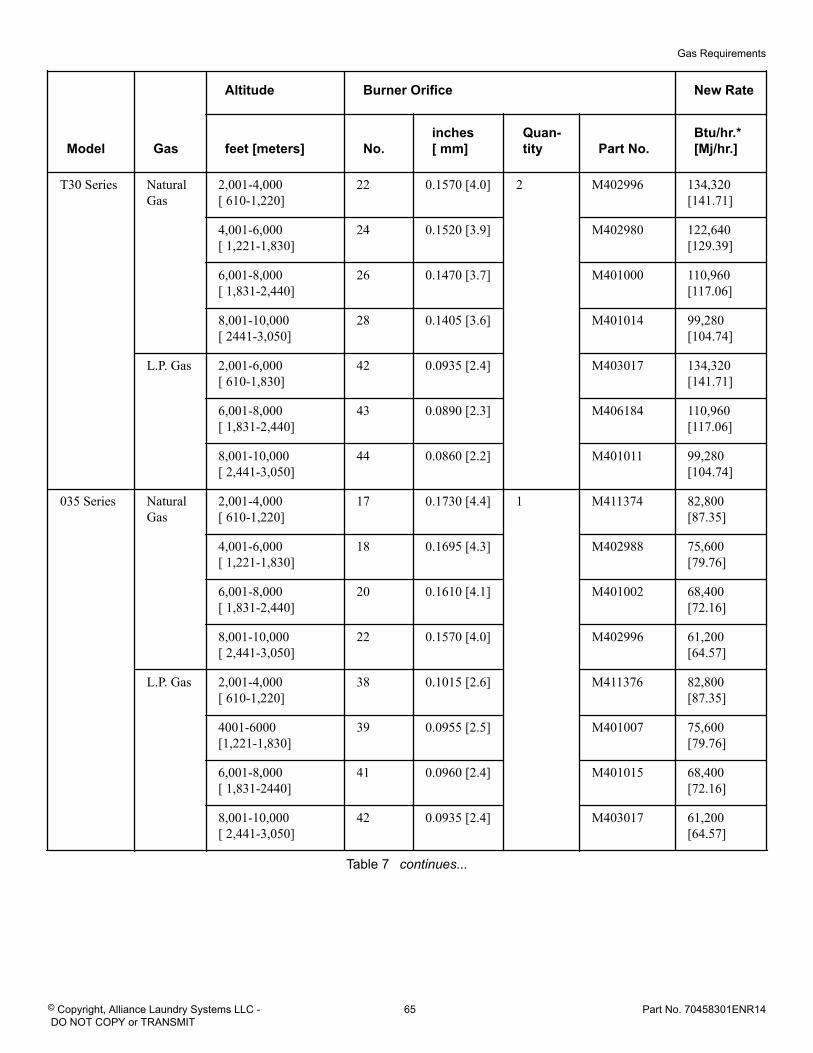
Model Gas
Altitude Burner Orifice New Rate
feet [meters] No.inches[ mm]
Quan-tity Part No.
Btu/hr.*[Mj/hr.]
T30 Series NaturalGas
2,001-4,000[ 610-1,220]
22 0.1570 [4.0] 2 M402996 134,320[141.71]
4,001-6,000[ 1,221-1,830]
24 0.1520 [3.9] M402980 122,640[129.39]
6,001-8,000[ 1,831-2,440]
26 0.1470 [3.7] M401000 110,960[117.06]
8,001-10,000[ 2441-3,050]
28 0.1405 [3.6] M401014 99,280[104.74]
L.P. Gas 2,001-6,000[ 610-1,830]
42 0.0935 [2.4] M403017 134,320[141.71]
6,001-8,000[ 1,831-2,440]
43 0.0890 [2.3] M406184 110,960[117.06]
8,001-10,000[ 2,441-3,050]
44 0.0860 [2.2] M401011 99,280[104.74]
035 Series NaturalGas
2,001-4,000[ 610-1,220]
17 0.1730 [4.4] 1 M411374 82,800[87.35]
4,001-6,000[ 1,221-1,830]
18 0.1695 [4.3] M402988 75,600[79.76]
6,001-8,000[ 1,831-2,440]
20 0.1610 [4.1] M401002 68,400[72.16]
8,001-10,000[ 2,441-3,050]
22 0.1570 [4.0] M402996 61,200[64.57]
L.P. Gas 2,001-4,000[ 610-1,220]
38 0.1015 [2.6] M411376 82,800[87.35]
4001-6000[1,221-1,830]
39 0.0955 [2.5] M401007 75,600[79.76]
6,001-8,000[ 1,831-2440]
41 0.0960 [2.4] M401015 68,400[72.16]
8,001-10,000[ 2,441-3,050]
42 0.0935 [2.4] M403017 61,200[64.57]
Table 7 continues...
Gas Requirements
© Copyright, Alliance Laundry Systems LLC - DO NOT COPY or TRANSMIT
65 Part No. 70458301ENR14
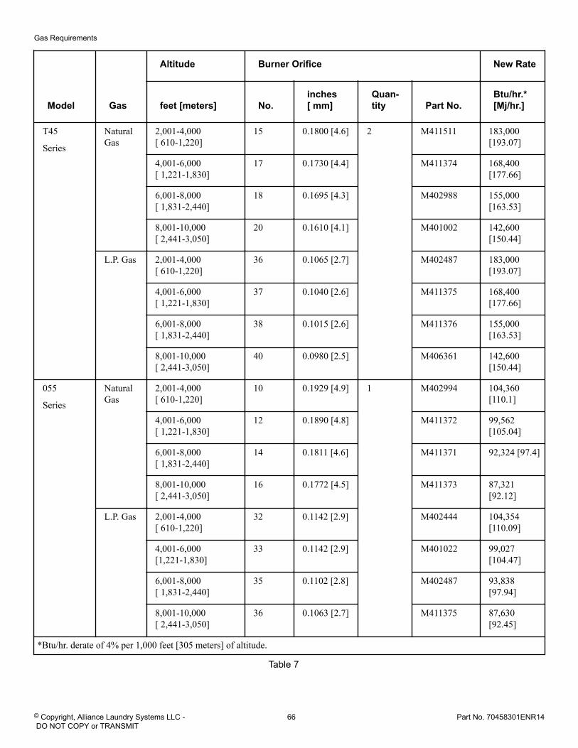
Model Gas
Altitude Burner Orifice New Rate
feet [meters] No.inches[ mm]
Quan-tity Part No.
Btu/hr.*[Mj/hr.]
T45
Series
NaturalGas
2,001-4,000[ 610-1,220]
15 0.1800 [4.6] 2 M411511 183,000[193.07]
4,001-6,000[ 1,221-1,830]
17 0.1730 [4.4] M411374 168,400[177.66]
6,001-8,000[ 1,831-2,440]
18 0.1695 [4.3] M402988 155,000[163.53]
8,001-10,000[ 2,441-3,050]
20 0.1610 [4.1] M401002 142,600[150.44]
L.P. Gas 2,001-4,000[ 610-1,220]
36 0.1065 [2.7] M402487 183,000[193.07]
4,001-6,000[ 1,221-1,830]
37 0.1040 [2.6] M411375 168,400[177.66]
6,001-8,000[ 1,831-2,440]
38 0.1015 [2.6] M411376 155,000[163.53]
8,001-10,000[ 2,441-3,050]
40 0.0980 [2.5] M406361 142,600[150.44]
055
Series
NaturalGas
2,001-4,000[ 610-1,220]
10 0.1929 [4.9] 1 M402994 104,360[110.1]
4,001-6,000[ 1,221-1,830]
12 0.1890 [4.8] M411372 99,562[105.04]
6,001-8,000[ 1,831-2,440]
14 0.1811 [4.6] M411371 92,324 [97.4]
8,001-10,000[ 2,441-3,050]
16 0.1772 [4.5] M411373 87,321[92.12]
L.P. Gas 2,001-4,000[ 610-1,220]
32 0.1142 [2.9] M402444 104,354[110.09]
4,001-6,000[1,221-1,830]
33 0.1142 [2.9] M401022 99,027[104.47]
6,001-8,000[ 1,831-2,440]
35 0.1102 [2.8] M402487 93,838[97.94]
8,001-10,000[ 2,441-3,050]
36 0.1063 [2.7] M411375 87,630[92.45]
*Btu/hr. derate of 4% per 1,000 feet [305 meters] of altitude.
Table 7
Gas Requirements
© Copyright, Alliance Laundry Systems LLC - DO NOT COPY or TRANSMIT
66 Part No. 70458301ENR14
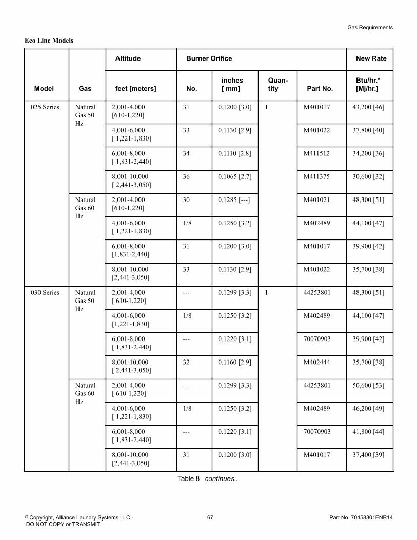
Eco Line Models
Model Gas
Altitude Burner Orifice New Rate
feet [meters] No.inches[ mm]
Quan-tity Part No.
Btu/hr.*[Mj/hr.]
025 Series NaturalGas 50Hz
2,001-4,000[610-1,220]
31 0.1200 [3.0] 1 M401017 43,200 [46]
4,001-6,000[ 1,221-1,830]
33 0.1130 [2.9] M401022 37,800 [40]
6,001-8,000[ 1,831-2,440]
34 0.1110 [2.8] M411512 34,200 [36]
8,001-10,000[ 2,441-3,050]
36 0.1065 [2.7] M411375 30,600 [32]
NaturalGas 60Hz
2,001-4,000[610-1,220]
30 0.1285 [---] M401021 48,300 [51]
4,001-6,000[ 1,221-1,830]
1/8 0.1250 [3.2] M402489 44,100 [47]
6,001-8,000[1,831-2,440]
31 0.1200 [3.0] M401017 39,900 [42]
8,001-10,000[2,441-3,050]
33 0.1130 [2.9] M401022 35,700 [38]
030 Series NaturalGas 50Hz
2,001-4,000[ 610-1,220]
--- 0.1299 [3.3] 1 44253801 48,300 [51]
4,001-6,000[1,221-1,830]
1/8 0.1250 [3.2] M402489 44,100 [47]
6,001-8,000[ 1,831-2,440]
--- 0.1220 [3.1] 70070903 39,900 [42]
8,001-10,000[ 2,441-3,050]
32 0.1160 [2.9] M402444 35,700 [38]
NaturalGas 60Hz
2,001-4,000[ 610-1,220]
--- 0.1299 [3.3] 44253801 50,600 [53]
4,001-6,000[ 1,221-1,830]
1/8 0.1250 [3.2] M402489 46,200 [49]
6,001-8,000[ 1,831-2,440]
--- 0.1220 [3.1] 70070903 41,800 [44]
8,001-10,000[2,441-3,050]
31 0.1200 [3.0] M401017 37,400 [39]
Table 8 continues...
Gas Requirements
© Copyright, Alliance Laundry Systems LLC - DO NOT COPY or TRANSMIT
67 Part No. 70458301ENR14
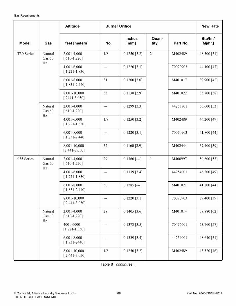
Model Gas
Altitude Burner Orifice New Rate
feet [meters] No.inches[ mm]
Quan-tity Part No.
Btu/hr.*[Mj/hr.]
T30 Series NaturalGas 50Hz
2,001-4,000[ 610-1,220]
1/8 0.1250 [3.2] 2 M402489 48,300 [51]
4,001-6,000[ 1,221-1,830]
--- 0.1220 [3.1] 70070903 44,100 [47]
6,001-8,000[ 1,831-2,440]
31 0.1200 [3.0] M401017 39,900 [42]
8,001-10,000[ 2441-3,050]
33 0.1130 [2.9] M401022 35,700 [38]
NaturalGas 60Hz
2,001-4,000[ 610-1,220]
--- 0.1299 [3.3] 44253801 50,600 [53]
4,001-6,000[ 1,221-1,830]
1/8 0.1250 [3.2] M402489 46,200 [49]
6,001-8,000[ 1,831-2,440]
--- 0.1220 [3.1] 70070903 41,800 [44]
8,001-10,000[2,441-3,050]
32 0.1160 [2.9] M402444 37,400 [39]
035 Series NaturalGas 50Hz
2,001-4,000[ 610-1,220]
29 0.1360 [---] 1 M400997 50,600 [53]
4,001-6,000[ 1,221-1,830]
--- 0.1339 [3.4] 44254001 46,200 [49]
6,001-8,000[ 1,831-2,440]
30 0.1285 [---] M401021 41,800 [44]
8,001-10,000[ 2,441-3,050]
--- 0.1220 [3.1] 70070903 37,400 [39]
NaturalGas 60Hz
2,001-4,000[ 610-1,220]
28 0.1405 [3.6] M401014 58,880 [62]
4001-6000[1,221-1,830]
--- 0.1378 [3.5] 70476601 53,760 [57]
6,001-8,000[ 1,831-2440]
--- 0.1339 [3.4] 44254001 48,640 [51]
8,001-10,000[ 2,441-3,050]
1/8 0.1250 [3.2] M402489 43,520 [46]
Table 8 continues...
Gas Requirements
© Copyright, Alliance Laundry Systems LLC - DO NOT COPY or TRANSMIT
68 Part No. 70458301ENR14
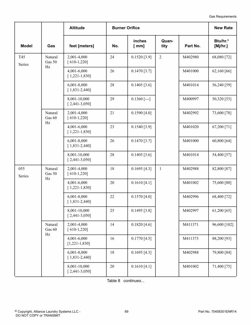
Model Gas
Altitude Burner Orifice New Rate
feet [meters] No.inches[ mm]
Quan-tity Part No.
Btu/hr.*[Mj/hr.]
T45
Series
NaturalGas 50Hz
2,001-4,000[ 610-1,220]
24 0.1520 [3.9] 2 M402980 68,080 [72]
4,001-6,000[ 1,221-1,830]
26 0.1470 [3.7] M401000 62,160 [66]
6,001-8,000[ 1,831-2,440]
28 0.1405 [3.6] M401014 56,240 [59]
8,001-10,000[ 2,441-3,050]
29 0.1360 [---] M400997 50,320 [53]
NaturalGas 60Hz
2,001-4,000[ 610-1,220]
21 0.1590 [4.0] M402992 73,600 [78]
4,001-6,000[ 1,221-1,830]
23 0.1540 [3.9] M401020 67,200 [71]
6,001-8,000[ 1,831-2,440]
26 0.1470 [3.7] M401000 60,800 [64]
8,001-10,000[ 2,441-3,050]
28 0.1405 [3.6] M401014 54,400 [57]
055
Series
NaturalGas 50Hz
2,001-4,000[ 610-1,220]
18 0.1695 [4.3] 1 M402988 82,800 [87]
4,001-6,000[ 1,221-1,830]
20 0.1610 [4.1] M401002 75,600 [80]
6,001-8,000[ 1,831-2,440]
22 0.1570 [4.0] M402996 68,400 [72]
8,001-10,000[ 2,441-3,050]
25 0.1495 [3.8] M402997 61,200 [65]
NaturalGas 60Hz
2,001-4,000[ 610-1,220]
14 0.1820 [4.6] M411371 96,600 [102]
4,001-6,000[1,221-1,830]
16 0.1770 [4.5] M411373 88,200 [93]
6,001-8,000[ 1,831-2,440]
18 0.1695 [4.3] M402988 79,800 [84]
8,001-10,000[ 2,441-3,050]
20 0.1610 [4.1] M401002 71,400 [75]
Table 8 continues...
Gas Requirements
© Copyright, Alliance Laundry Systems LLC - DO NOT COPY or TRANSMIT
69 Part No. 70458301ENR14
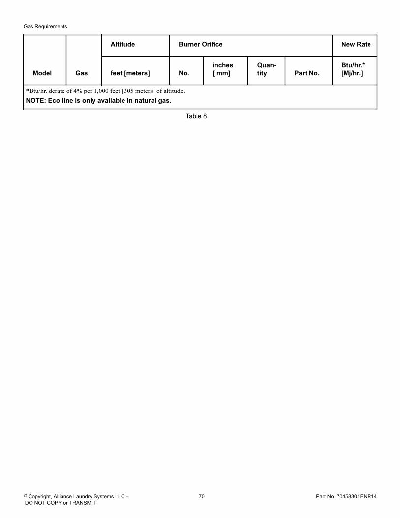
Model Gas
Altitude Burner Orifice New Rate
feet [meters] No.inches[ mm]
Quan-tity Part No.
Btu/hr.*[Mj/hr.]
*Btu/hr. derate of 4% per 1,000 feet [305 meters] of altitude.NOTE: Eco line is only available in natural gas.
Table 8
Gas Requirements
© Copyright, Alliance Laundry Systems LLC - DO NOT COPY or TRANSMIT
70 Part No. 70458301ENR14
Electrical Requirements Electrical Requirements
WARNING
• To reduce the risk of electric shock, disconnectthis appliance from the power supply before at-tempting any user maintenance other than clean-ing the lint trap for dryers. Turning the controls tothe OFF position does not disconnect this appli-ance from the power supply.
• To reduce the risk of fire and electric shock,check with a qualified service person for propergrounding procedures. Improper connection ofthe equipment grounding conductor may result ina risk of electric shock.
• Certain internal parts are intentionally notgrounded and may present a risk of electricshock only during servicing. Service Personnel -Do not contact the following parts while the appli-ance is energized: Input/Output Board and Varia-ble Frequency Drive, including the heat sinks.
• This appliance shall be installed in accordancewith the rules in force, and dryers used only in asufficiently ventilated space. Consult technical in-struction before installation and use of this appli-ance.
W935
CAUTIONTo reduce the risk of injury or component failure, ifelectrical supply is coming from a three phase serv-ice, DO NOT connect a "High Leg" or "Stinger Leg"to a single phase machine. On a three phase ma-chine, if there is a "High Leg" or "Stinger Leg" itshould be connected to L3.
W938
WARNINGThe appliance must not be supplied through an ex-ternal switching device, such as a timer, or connect-ed to a circuit that is regularly switched on and offby a utility.
W943
IMPORTANT: Electrical connections must be made by aqualified electrician using data on serial plate, installa-tion manuals and wiring diagram provided with tumbledryer and according to local codes. Install a circuitbreaker as close to the tumble dryer as possible. Ifmore than one tumble dryer is being installed, a circuitbreaker must be provided for each.
NOTE: Connect tumble dryer to an individual branchcircuit not shared with lighting or other equipment.
NOTE: 3 Phase Tumble Dryers Only - Do not use fusesto avoid the possibility of “single phasing” and caus-ing premature failure of the motors.
WARNINGIn case of servicing (or putting the tumble dryer outof order), disconnect the tumble dryer from the mainsupply by switching off the circuit breaker.
W796
Wiring DiagramNOTE: Wiring diagram location: inside electrical box.
The wiring diagram part number is in the lower portion of theelectrical data on the serial plate.
Wiring for Central PayApplicable for the following control suffixes: 3K, 3L, BK, BL,KK, KL, LK, LL, WK and WL.
System Connections
Connection to central pay systems will be made in the rear jun-tion box of the tumble dryer. For stack models, connection forboth the lower control and upper control will be made in the up-per junction box.
Locate the harness with Black, Blue, Gray and Brown wires. Theupper and lower harness can be identified by a yellow label onthe harness tubing indicating "UPPER" and a white label on theharness tubing indicating "LOWER".
The wire colors will be the same regardless of control type.Splice the after-market central pay system wires to the tumbledryer control wire harness as follows.
Electrical Requirements
© Copyright, Alliance Laundry Systems LLC - DO NOT COPY or TRANSMIT
71 Part No. 70458301ENR14
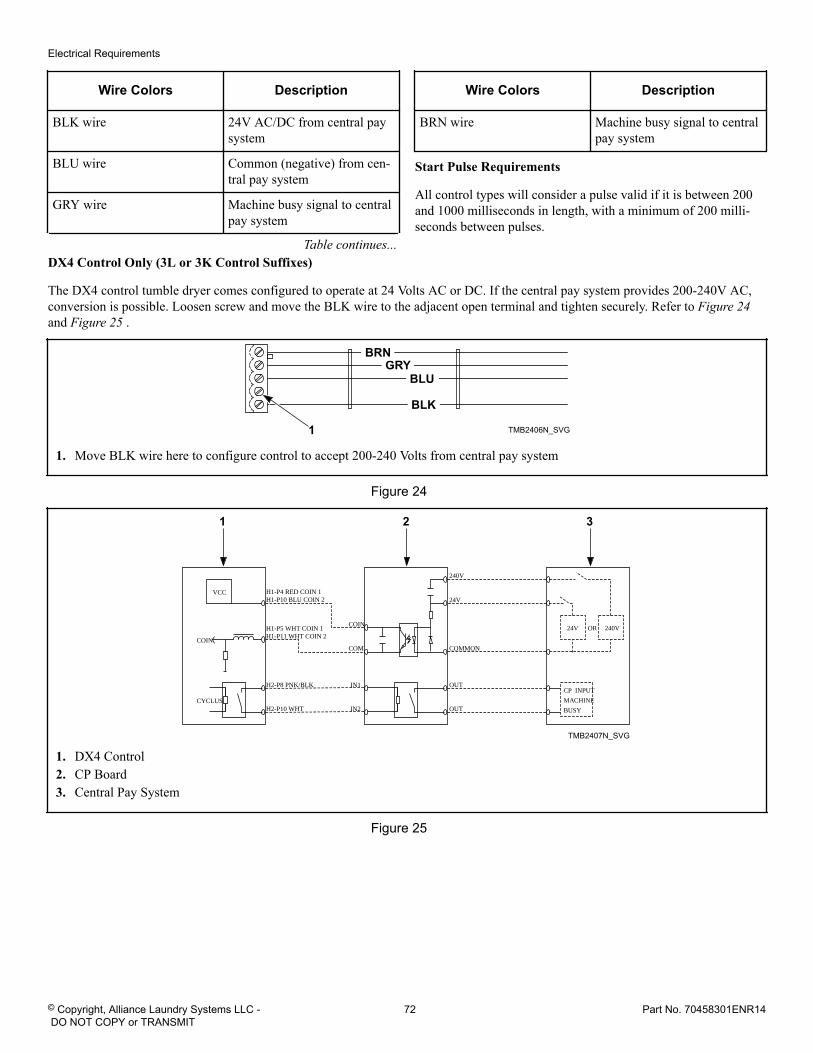
Wire Colors Description
BLK wire 24V AC/DC from central paysystem
BLU wire Common (negative) from cen-tral pay system
GRY wire Machine busy signal to centralpay system
Table continues...
Wire Colors Description
BRN wire Machine busy signal to centralpay system
Start Pulse Requirements
All control types will consider a pulse valid if it is between 200and 1000 milliseconds in length, with a minimum of 200 milli-seconds between pulses.
DX4 Control Only (3L or 3K Control Suffixes)
The DX4 control tumble dryer comes configured to operate at 24 Volts AC or DC. If the central pay system provides 200-240V AC,conversion is possible. Loosen screw and move the BLK wire to the adjacent open terminal and tighten securely. Refer to Figure 24 and Figure 25 .
TMB2406N_SVG
BLK
BLUGRY
BRN
1
1. Move BLK wire here to configure control to accept 200-240 Volts from central pay system
Figure 24
1 2 3
VCC
COIN
COIN
COM
IN1
IN2
24V
24V
CP INPUT
MACHINE
BUSY
240VOR
240V
COMMON
OUT
OUT
H1-P4 RED COIN 1H1-P10 BLU COIN 2
H1-P5 WHT COIN 1H1-P11 WHT COIN 2
H2-P8 PNK/BLK
H2-P10 WHTCYCLUS
TMB2407N_SVG
1. DX4 Control2. CP Board3. Central Pay System
Figure 25
Electrical Requirements
© Copyright, Alliance Laundry Systems LLC - DO NOT COPY or TRANSMIT
72 Part No. 70458301ENR14
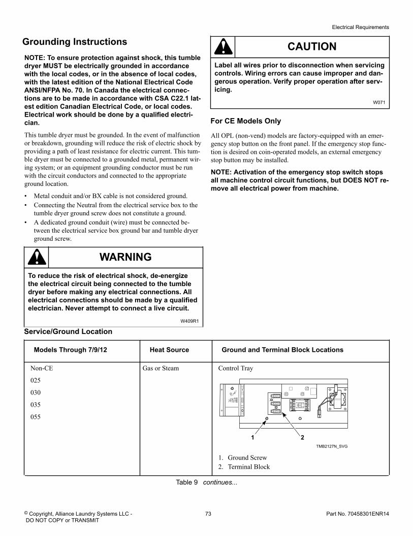
Grounding InstructionsNOTE: To ensure protection against shock, this tumbledryer MUST be electrically grounded in accordancewith the local codes, or in the absence of local codes,with the latest edition of the National Electrical CodeANSI/NFPA No. 70. In Canada the electrical connec-tions are to be made in accordance with CSA C22.1 lat-est edition Canadian Electrical Code, or local codes.Electrical work should be done by a qualified electri-cian.
This tumble dryer must be grounded. In the event of malfunctionor breakdown, grounding will reduce the risk of electric shock byproviding a path of least resistance for electric current. This tum-ble dryer must be connected to a grounded metal, permanent wir-ing system; or an equipment grounding conductor must be runwith the circuit conductors and connected to the appropriateground location.
• Metal conduit and/or BX cable is not considered ground.• Connecting the Neutral from the electrical service box to the
tumble dryer ground screw does not constitute a ground.• A dedicated ground conduit (wire) must be connected be-
tween the electrical service box ground bar and tumble dryerground screw.
WARNINGTo reduce the risk of electrical shock, de-energizethe electrical circuit being connected to the tumbledryer before making any electrical connections. Allelectrical connections should be made by a qualifiedelectrician. Never attempt to connect a live circuit.
W409R1
CAUTIONLabel all wires prior to disconnection when servicingcontrols. Wiring errors can cause improper and dan-gerous operation. Verify proper operation after serv-icing.
W071
For CE Models Only
All OPL (non-vend) models are factory-equipped with an emer-gency stop button on the front panel. If the emergency stop func-tion is desired on coin-operated models, an external emergencystop button may be installed.
NOTE: Activation of the emergency stop switch stopsall machine control circuit functions, but DOES NOT re-move all electrical power from machine.
Service/Ground Location
Models Through 7/9/12 Heat Source Ground and Terminal Block Locations
Non-CE
025
030
035
055
Gas or Steam Control Tray
TMB2127N_SVG
1 2
1. Ground Screw2. Terminal Block
Table 9 continues...
Electrical Requirements
© Copyright, Alliance Laundry Systems LLC - DO NOT COPY or TRANSMIT
73 Part No. 70458301ENR14
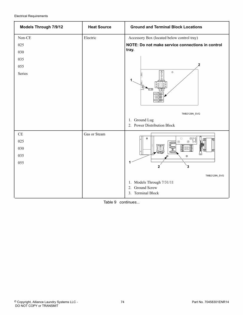
Models Through 7/9/12 Heat Source Ground and Terminal Block Locations
Non-CE
025
030
035
055
Series
Electric Accessory Box (located below control tray)
NOTE: Do not make service connections in controltray.
TMB2128N_SVG
2
1
1. Ground Lug2. Power Distribution Block
CE
025
030
035
055
Gas or Steam
TMB2129N_SVG
2 31
1. Models Through 7/31/112. Ground Screw3. Terminal Block
Table 9 continues...
Electrical Requirements
© Copyright, Alliance Laundry Systems LLC - DO NOT COPY or TRANSMIT
74 Part No. 70458301ENR14
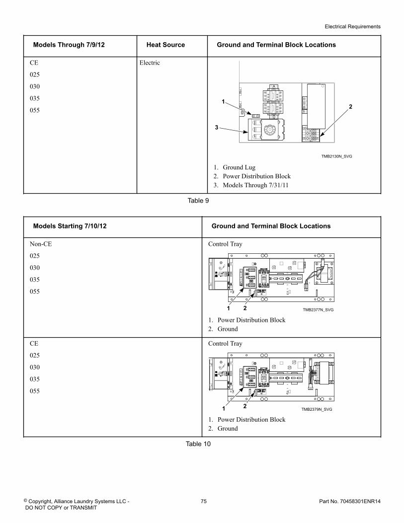
Models Through 7/9/12 Heat Source Ground and Terminal Block Locations
CE
025
030
035
055
Electric
TMB2130N_SVG
21
3
1. Ground Lug2. Power Distribution Block3. Models Through 7/31/11
Table 9
Models Starting 7/10/12 Ground and Terminal Block Locations
Non-CE
025
030
035
055
Control Tray
TMB2377N_SVG21
1. Power Distribution Block2. Ground
CE
025
030
035
055
Control Tray
TMB2379N_SVG21
1. Power Distribution Block2. Ground
Table 10
Electrical Requirements
© Copyright, Alliance Laundry Systems LLC - DO NOT COPY or TRANSMIT
75 Part No. 70458301ENR14
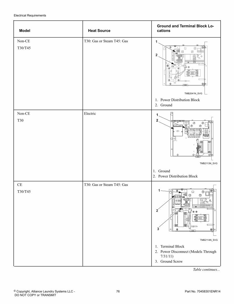
Model Heat SourceGround and Terminal Block Lo-cations
Non-CE
T30/T45
T30: Gas or Steam T45: Gas
TMB2041N_SVG
1
2
1. Power Distribution Block2. Ground
Non-CE
T30
Electric
TMB2113N_SVG
21
1. Ground2. Power Distribution Block
CE
T30/T45
T30: Gas or Steam T45: Gas
TMB2114N_SVG
2
3
1
1. Terminal Block2. Power Disconnect (Models Through
7/31/11)3. Ground Screw
Table continues...
Electrical Requirements
© Copyright, Alliance Laundry Systems LLC - DO NOT COPY or TRANSMIT
76 Part No. 70458301ENR14
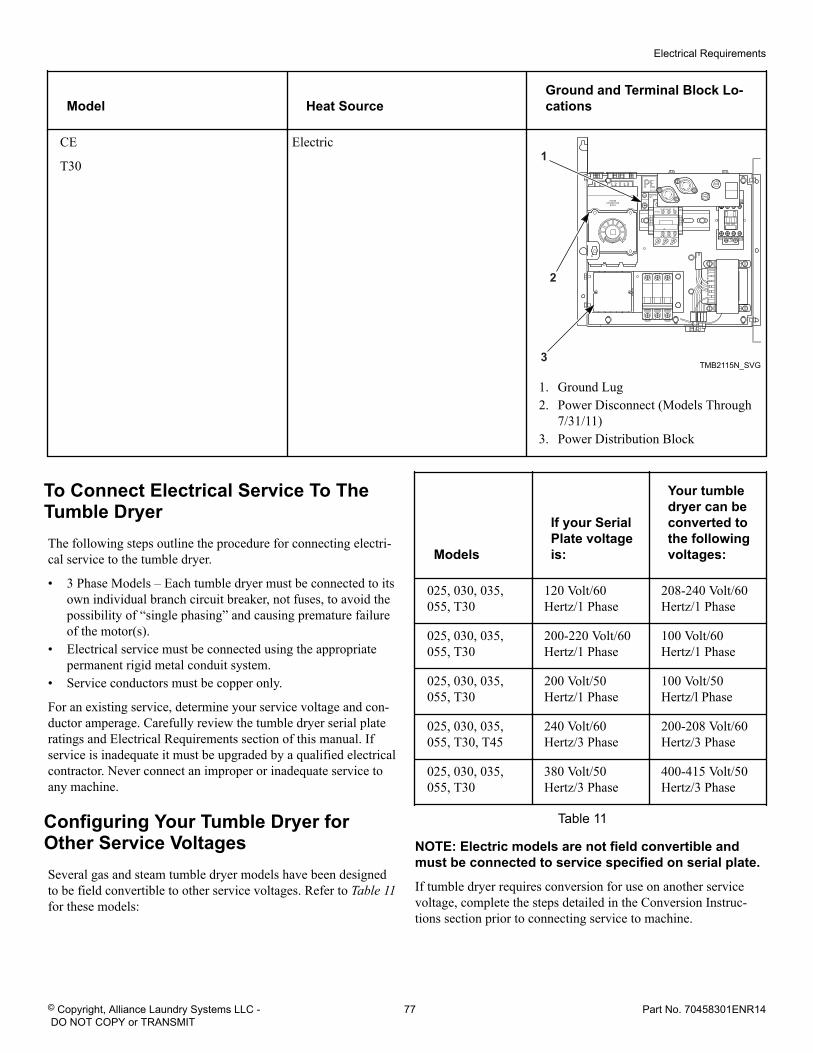
Model Heat SourceGround and Terminal Block Lo-cations
CE
T30
Electric
TMB2115N_SVG
2
3
1
1. Ground Lug2. Power Disconnect (Models Through
7/31/11)3. Power Distribution Block
To Connect Electrical Service To TheTumble DryerThe following steps outline the procedure for connecting electri-cal service to the tumble dryer.
• 3 Phase Models – Each tumble dryer must be connected to itsown individual branch circuit breaker, not fuses, to avoid thepossibility of “single phasing” and causing premature failureof the motor(s).
• Electrical service must be connected using the appropriatepermanent rigid metal conduit system.
• Service conductors must be copper only.
For an existing service, determine your service voltage and con-ductor amperage. Carefully review the tumble dryer serial plateratings and Electrical Requirements section of this manual. Ifservice is inadequate it must be upgraded by a qualified electricalcontractor. Never connect an improper or inadequate service toany machine.
Configuring Your Tumble Dryer forOther Service VoltagesSeveral gas and steam tumble dryer models have been designedto be field convertible to other service voltages. Refer to Table 11 for these models:
Models
If your SerialPlate voltageis:
Your tumbledryer can beconverted tothe followingvoltages:
025, 030, 035,055, T30
120 Volt/60Hertz/1 Phase
208-240 Volt/60Hertz/1 Phase
025, 030, 035,055, T30
200-220 Volt/60Hertz/1 Phase
100 Volt/60Hertz/1 Phase
025, 030, 035,055, T30
200 Volt/50Hertz/1 Phase
100 Volt/50Hertz/l Phase
025, 030, 035,055, T30, T45
240 Volt/60Hertz/3 Phase
200-208 Volt/60Hertz/3 Phase
025, 030, 035,055, T30
380 Volt/50Hertz/3 Phase
400-415 Volt/50Hertz/3 Phase
Table 11
NOTE: Electric models are not field convertible andmust be connected to service specified on serial plate.
If tumble dryer requires conversion for use on another servicevoltage, complete the steps detailed in the Conversion Instruc-tions section prior to connecting service to machine.
Electrical Requirements
© Copyright, Alliance Laundry Systems LLC - DO NOT COPY or TRANSMIT
77 Part No. 70458301ENR14
If tumble dryer does not require conversion or has been convertedaccording to the Conversion Instructions section of this manual,continue with step 1.
NOTE: The wiring diagram is located inside the junc-tion or contactor box.1. For new service, install a circuit breaker of proper voltage and
current rating as close to each tumble dryer as possible.2. Route service conduit from service breaker panel to tumble
dryer service connection box. Conduit routing should not ob-struct access for maintenance or servicing. Refer to Service/Ground Location.
3. Pull conductors through conduit and attach to circuit breakerand ground connection. Secure service ground wire to thegrounding screw or lug. Attach service conductors to appro-priately labeled positions on the terminal block. Make sure allconnections are secure.
4. Complete ferrite installation instructions for all gas and steammodels with OM control suffix.
5. Check electrical service phase sequence (3 Phase models on-ly) as follows:
6. Energize the electrical service and momentarily start the tum-ble dryer. Check the direction of cylinder rotation. If the cyl-inder rotates clockwise as viewed from the front, the phase se-quence is correct. If the cylinder rotates counterclockwise,proceed with step b.
7. Disconnect power to machine, disconnect and reverse the L1and L2 connections on the terminal block.
Electrical Connections for T30 and T45OnlyAll gas and steam tumble dryers require a single service connec-tion to TB1 of the upper unit junction box only. The serial platereflects current draw, breaker/fuse size and conductor amperagerequired for the entire machine.
All electric tumble dryers require separate service connections foreach upper and lower unit. Serial Plate ratings reflect currentdraw, breaker/fuse size and conductor amperage required perunit.
Electrical Requirements
© Copyright, Alliance Laundry Systems LLC - DO NOT COPY or TRANSMIT
78 Part No. 70458301ENR14
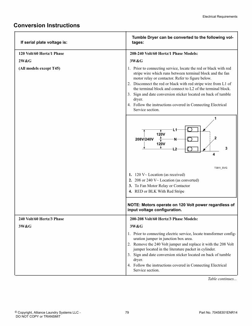
Conversion Instructions
If serial plate voltage is:Tumble Dryer can be converted to the following vol-tages:
120 Volt/60 Hertz/1 Phase
2W&G
(All models except T45)
208-240 Volt/60 Hertz/1 Phase Models:
3W&G
1. Prior to connecting service, locate the red or black with redstripe wire which runs between terminal block and the fanmotor relay or contactor. Refer to figure below.
2. Disconnect the red or black with red stripe wire from L1 ofthe terminal block and connect to L2 of the terminal block.
3. Sign and date conversion sticker located on back of tumbledryer.
4. Follow the instructions covered in Connecting ElectricalService section.
T381I_SVG
120VL1
N
L2
208V/240V
1
2
34
120V
1. 120 V~ Location (as received)2. 208 or 240 V~ Location (as converted)3. To Fan Motor Relay or Contactor4. RED or BLK With Red Stripe
NOTE: Motors operate on 120 Volt power regardless ofinput voltage configuration.
240 Volt/60 Hertz/3 Phase
3W&G
200-208 Volt/60 Hertz/3 Phase Models:
3W&G
1. Prior to connecting electric service, locate transformer config-uration jumper in junction box area.
2. Remove the 240 Volt jumper and replace it with the 208 Voltjumper located in the literature packet in cylinder.
3. Sign and date conversion sticker located on back of tumbledryer.
4. Follow the instructions covered in Connecting ElectricalService section.
Table continues...
Electrical Requirements
© Copyright, Alliance Laundry Systems LLC - DO NOT COPY or TRANSMIT
79 Part No. 70458301ENR14
If serial plate voltage is:Tumble Dryer can be converted to the following vol-tages:
200-220 Volt/60 Hertz/1 Phase
200 Volt/50 Hertz/1 Phase
2W&G
(All models except T45)
100 Volt/60 Hertz/1 Phase INTERNATIONAL Models:
2W&G
100 Volt/50 Hertz/1 Phase INTERNATIONAL Models:
2W&G
1. Prior to connecting electric service, locate transformer config-uration jumper in junction box area.
2. Remove the 208 Volt jumper and replace it with the 100 Voltjumper located in the literature packet from cylinder.
3. Remove small access cover from back of the fan motor. Lo-cate the two internal jumper wires, brown and blue connectedto motor terminals #6 and #2. Move brown wire from termi-nal #6 to terminal #2 and blue wire from terminal #2 to termi-nal #4. Be careful not to confuse light blue motor harnesswire with the dark blue internal jumper.
4. Carefully check motor wire connections with wiring diagramand verify that the motors are configured for low voltage op-eration before replacing covers.
5. Sign and date conversion sticker located on back of tumbledryer.
6. Follow the instructions covered in Connecting ElectricalService section.
380 Volt/50 Hertz/3 Phase
3W&G
(All models except T45)
400-415 Volt/50 Hertz/3 Phase Models:
3W&G
1. Prior to connecting electric service, locate transformer config-uration jumper in junction box area.
2. Remove the 380 Volt jumper and replace it with the 415 Voltjumper located in the literature packet from cylinder.
3. Sign and date conversion sticker located on back of tumbledryer.
4. Follow the instructions covered in Connecting ElectricalService section.
Ferrite Ring Installation (025, 030, 035 and 055 Series Only)Gas and Steam Models with OM Control Suffix Only (Models Through 7/31/11)The ferrite ring provided in the literature packet must be installed over the power leads during connection of electrical service. Theferrite protects the sensitive electronic controls from destructive electrical disturbances which may be present on power lines to themachine. Failure to properly install the ferrite ring may result in damage to the electronic controls and will void control warranty.
To install:1. Immediately after connection of power leads and before ap-
plying power to machine, locate each of the incoming serviceleads including ground.
2. Snap the ferrite ring closed over all the service leads inside ofthe contactor box as shown. It is important that the ferrite ring
be installed inside the contactor box. Refer to Figure 26 . Donot install the ferrite outside of the box or other area. Makesure that service leads are in the center of the ferrite beforeclosing the ring so as not to pinch or damage leads.
Electrical Requirements
© Copyright, Alliance Laundry Systems LLC - DO NOT COPY or TRANSMIT
80 Part No. 70458301ENR14
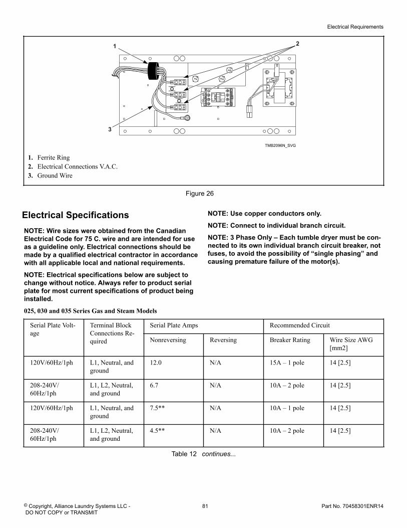
TMB2096N_SVG
1
3
2
1. Ferrite Ring2. Electrical Connections V.A.C.3. Ground Wire
Figure 26
Electrical SpecificationsNOTE: Wire sizes were obtained from the CanadianElectrical Code for 75 C. wire and are intended for useas a guideline only. Electrical connections should bemade by a qualified electrical contractor in accordancewith all applicable local and national requirements.
NOTE: Electrical specifications below are subject tochange without notice. Always refer to product serialplate for most current specifications of product beinginstalled.
NOTE: Use copper conductors only.
NOTE: Connect to individual branch circuit.
NOTE: 3 Phase Only – Each tumble dryer must be con-nected to its own individual branch circuit breaker, notfuses, to avoid the possibility of “single phasing” andcausing premature failure of the motor(s).
025, 030 and 035 Series Gas and Steam Models
Serial Plate Volt-age
Terminal BlockConnections Re-quired
Serial Plate Amps Recommended Circuit
Nonreversing Reversing Breaker Rating Wire Size AWG[mm2]
120V/60Hz/1ph L1, Neutral, andground
12.0 N/A 15A – 1 pole 14 [2.5]
208-240V/60Hz/1ph
L1, L2, Neutral,and ground
6.7 N/A 10A – 2 pole 14 [2.5]
120V/60Hz/1ph L1, Neutral, andground
7.5** N/A 10A – 1 pole 14 [2.5]
208-240V/60Hz/1ph
L1, L2, Neutral,and ground
4.5** N/A 10A – 2 pole 14 [2.5]
Table 12 continues...
Electrical Requirements
© Copyright, Alliance Laundry Systems LLC - DO NOT COPY or TRANSMIT
81 Part No. 70458301ENR14
100V/60Hz/1ph L1, Neutral, andground
11.0 N/A 15A – 1 pole 14 [2.5]
200-220V/60Hz/1ph
L1, Neutral, andground
5.8 N/A 10A – 1 pole 14 [2.5]
100V/50Hz/1ph L1, Neutral, andground
12.1 N/A 20A – 1 pole 12 [4]
200V/50Hz/1ph L1, Neutral, andground
7.5 N/A 10A – 1 pole 14 [2.5]
230-240V/50Hz/1ph
L1, Neutral, andground
7.5 N/A 10A – 1 pole 14 [2.5]
200-208V/60Hz/3ph
L1, L2, L3, andground
3.2 4.0 10A* – 3 pole 14 [2.5]
240V/60Hz/3ph L1, L2, L3, andground
3.2 4.0 10A* – 3 pole 14 [2.5]
200V/50Hz/3ph L1, L2, L3, andground
2.9 3.5 10A* – 3 pole 14 [2.5]
230-240V/50Hz/3ph
L1, L2, L3, andground
3.5 N/A 10A* – 3 pole 14 [2.5]
380V/50 or60Hz/3ph
L1, L2, L3, andground
1.5 2.0 10A* – 3 pole 14 [2.5]
400-415V/50Hz/3ph
L1, L2, L3, andground
1.6 2.0 10A* – 3 pole 14 [2.5]
440V/60Hz/3ph L1, L2, L3, andground
1.6 N/A 10A* – 3 pole 14 [2.5]
460-480V/60Hz/3ph
L1, L2, L3, andground
1.6 2.0 10A* – 3 pole 14 [2.5]
* 3 Phase machines should not have fuses, breakers only.
** Special low Amp blower model, 025 Series only.
N/A = Not Applicable
Table 12
055 Series Gas Models
Serial Plate Volt-age
Terminal BlockConnections Re-quired
Serial Plate Amps RecommendedCircuit
Nonreversing Reversing Breaker Rating Wire Size AWG[mm 2]
Table 13 continues...
Electrical Requirements
© Copyright, Alliance Laundry Systems LLC - DO NOT COPY or TRANSMIT
82 Part No. 70458301ENR14
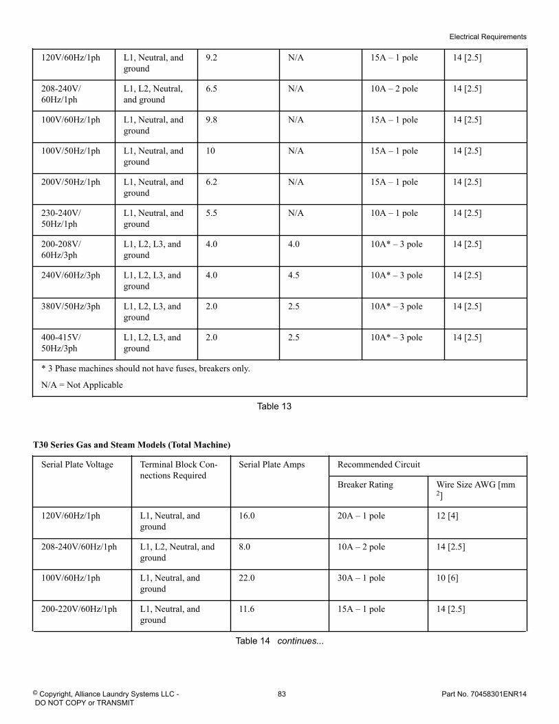
120V/60Hz/1ph L1, Neutral, andground
9.2 N/A 15A – 1 pole 14 [2.5]
208-240V/60Hz/1ph
L1, L2, Neutral,and ground
6.5 N/A 10A – 2 pole 14 [2.5]
100V/60Hz/1ph L1, Neutral, andground
9.8 N/A 15A – 1 pole 14 [2.5]
100V/50Hz/1ph L1, Neutral, andground
10 N/A 15A – 1 pole 14 [2.5]
200V/50Hz/1ph L1, Neutral, andground
6.2 N/A 15A – 1 pole 14 [2.5]
230-240V/50Hz/1ph
L1, Neutral, andground
5.5 N/A 10A – 1 pole 14 [2.5]
200-208V/60Hz/3ph
L1, L2, L3, andground
4.0 4.0 10A* – 3 pole 14 [2.5]
240V/60Hz/3ph L1, L2, L3, andground
4.0 4.5 10A* – 3 pole 14 [2.5]
380V/50Hz/3ph L1, L2, L3, andground
2.0 2.5 10A* – 3 pole 14 [2.5]
400-415V/50Hz/3ph
L1, L2, L3, andground
2.0 2.5 10A* – 3 pole 14 [2.5]
* 3 Phase machines should not have fuses, breakers only.
N/A = Not Applicable
Table 13
T30 Series Gas and Steam Models (Total Machine)
Serial Plate Voltage Terminal Block Con-nections Required
Serial Plate Amps Recommended Circuit
Breaker Rating Wire Size AWG [mm2]
120V/60Hz/1ph L1, Neutral, andground
16.0 20A – 1 pole 12 [4]
208-240V/60Hz/1ph L1, L2, Neutral, andground
8.0 10A – 2 pole 14 [2.5]
100V/60Hz/1ph L1, Neutral, andground
22.0 30A – 1 pole 10 [6]
200-220V/60Hz/1ph L1, Neutral, andground
11.6 15A – 1 pole 14 [2.5]
Table 14 continues...
Electrical Requirements
© Copyright, Alliance Laundry Systems LLC - DO NOT COPY or TRANSMIT
83 Part No. 70458301ENR14
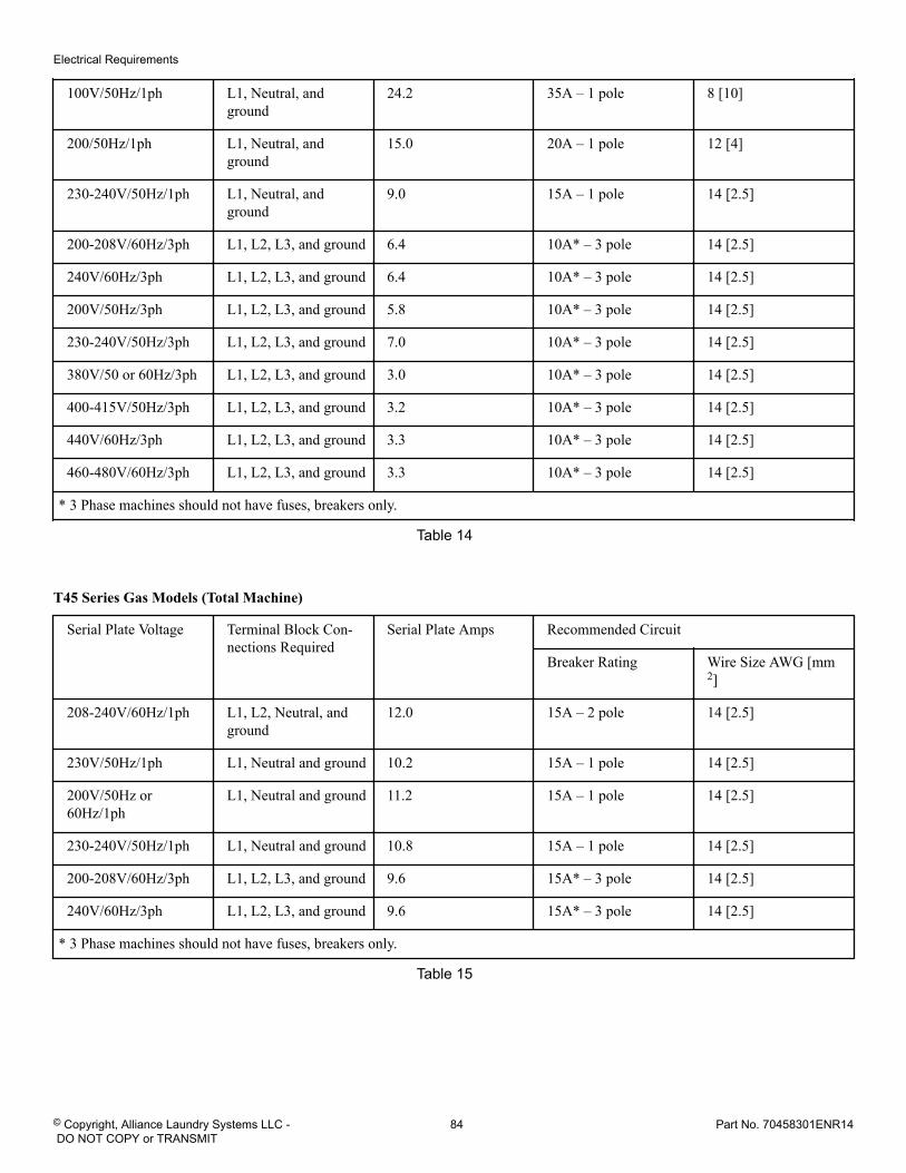
100V/50Hz/1ph L1, Neutral, andground
24.2 35A – 1 pole 8 [10]
200/50Hz/1ph L1, Neutral, andground
15.0 20A – 1 pole 12 [4]
230-240V/50Hz/1ph L1, Neutral, andground
9.0 15A – 1 pole 14 [2.5]
200-208V/60Hz/3ph L1, L2, L3, and ground 6.4 10A* – 3 pole 14 [2.5]
240V/60Hz/3ph L1, L2, L3, and ground 6.4 10A* – 3 pole 14 [2.5]
200V/50Hz/3ph L1, L2, L3, and ground 5.8 10A* – 3 pole 14 [2.5]
230-240V/50Hz/3ph L1, L2, L3, and ground 7.0 10A* – 3 pole 14 [2.5]
380V/50 or 60Hz/3ph L1, L2, L3, and ground 3.0 10A* – 3 pole 14 [2.5]
400-415V/50Hz/3ph L1, L2, L3, and ground 3.2 10A* – 3 pole 14 [2.5]
440V/60Hz/3ph L1, L2, L3, and ground 3.3 10A* – 3 pole 14 [2.5]
460-480V/60Hz/3ph L1, L2, L3, and ground 3.3 10A* – 3 pole 14 [2.5]
* 3 Phase machines should not have fuses, breakers only.
Table 14
T45 Series Gas Models (Total Machine)
Serial Plate Voltage Terminal Block Con-nections Required
Serial Plate Amps Recommended Circuit
Breaker Rating Wire Size AWG [mm2]
208-240V/60Hz/1ph L1, L2, Neutral, andground
12.0 15A – 2 pole 14 [2.5]
230V/50Hz/1ph L1, Neutral and ground 10.2 15A – 1 pole 14 [2.5]
200V/50Hz or60Hz/1ph
L1, Neutral and ground 11.2 15A – 1 pole 14 [2.5]
230-240V/50Hz/1ph L1, Neutral and ground 10.8 15A – 1 pole 14 [2.5]
200-208V/60Hz/3ph L1, L2, L3, and ground 9.6 15A* – 3 pole 14 [2.5]
240V/60Hz/3ph L1, L2, L3, and ground 9.6 15A* – 3 pole 14 [2.5]
* 3 Phase machines should not have fuses, breakers only.
Table 15
Electrical Requirements
© Copyright, Alliance Laundry Systems LLC - DO NOT COPY or TRANSMIT
84 Part No. 70458301ENR14
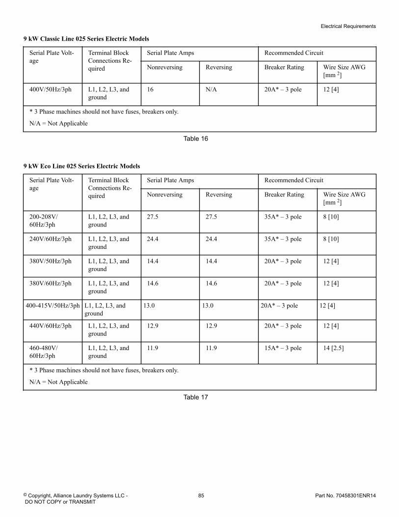
9 kW Classic Line 025 Series Electric Models
Serial Plate Volt-age
Terminal BlockConnections Re-quired
Serial Plate Amps Recommended Circuit
Nonreversing Reversing Breaker Rating Wire Size AWG[mm 2]
400V/50Hz/3ph L1, L2, L3, andground
16 N/A 20A* – 3 pole 12 [4]
* 3 Phase machines should not have fuses, breakers only.
N/A = Not Applicable
Table 16
9 kW Eco Line 025 Series Electric Models
Serial Plate Volt-age
Terminal BlockConnections Re-quired
Serial Plate Amps Recommended Circuit
Nonreversing Reversing Breaker Rating Wire Size AWG[mm 2]
200-208V/60Hz/3ph
L1, L2, L3, andground
27.5 27.5 35A* – 3 pole 8 [10]
240V/60Hz/3ph L1, L2, L3, andground
24.4 24.4 35A* – 3 pole 8 [10]
380V/50Hz/3ph L1, L2, L3, andground
14.4 14.4 20A* – 3 pole 12 [4]
380V/60Hz/3ph L1, L2, L3, andground
14.6 14.6 20A* – 3 pole 12 [4]
400-415V/50Hz/3ph L1, L2, L3, andground
13.0 13.0 20A* – 3 pole 12 [4]
440V/60Hz/3ph L1, L2, L3, andground
12.9 12.9 20A* – 3 pole 12 [4]
460-480V/60Hz/3ph
L1, L2, L3, andground
11.9 11.9 15A* – 3 pole 14 [2.5]
* 3 Phase machines should not have fuses, breakers only.
N/A = Not Applicable
Table 17
Electrical Requirements
© Copyright, Alliance Laundry Systems LLC - DO NOT COPY or TRANSMIT
85 Part No. 70458301ENR14
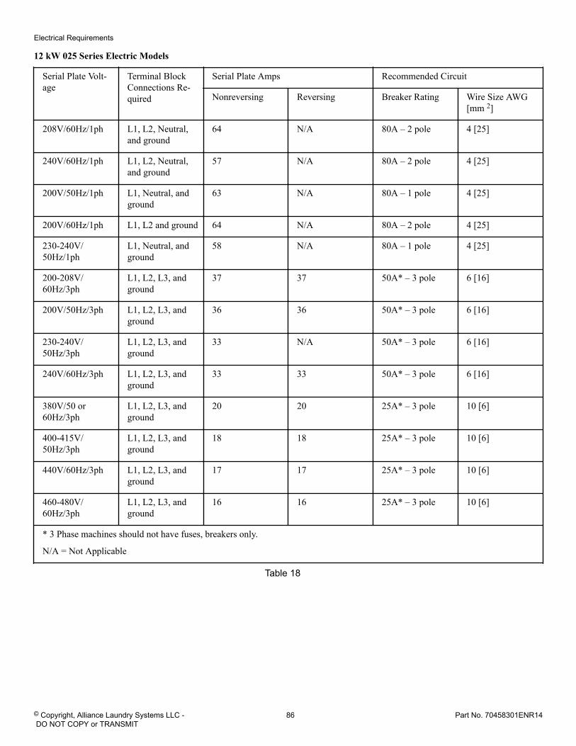
12 kW 025 Series Electric Models
Serial Plate Volt-age
Terminal BlockConnections Re-quired
Serial Plate Amps Recommended Circuit
Nonreversing Reversing Breaker Rating Wire Size AWG[mm 2]
208V/60Hz/1ph L1, L2, Neutral,and ground
64 N/A 80A – 2 pole 4 [25]
240V/60Hz/1ph L1, L2, Neutral,and ground
57 N/A 80A – 2 pole 4 [25]
200V/50Hz/1ph L1, Neutral, andground
63 N/A 80A – 1 pole 4 [25]
200V/60Hz/1ph L1, L2 and ground 64 N/A 80A – 2 pole 4 [25]
230-240V/50Hz/1ph
L1, Neutral, andground
58 N/A 80A – 1 pole 4 [25]
200-208V/60Hz/3ph
L1, L2, L3, andground
37 37 50A* – 3 pole 6 [16]
200V/50Hz/3ph L1, L2, L3, andground
36 36 50A* – 3 pole 6 [16]
230-240V/50Hz/3ph
L1, L2, L3, andground
33 N/A 50A* – 3 pole 6 [16]
240V/60Hz/3ph L1, L2, L3, andground
33 33 50A* – 3 pole 6 [16]
380V/50 or60Hz/3ph
L1, L2, L3, andground
20 20 25A* – 3 pole 10 [6]
400-415V/50Hz/3ph
L1, L2, L3, andground
18 18 25A* – 3 pole 10 [6]
440V/60Hz/3ph L1, L2, L3, andground
17 17 25A* – 3 pole 10 [6]
460-480V/60Hz/3ph
L1, L2, L3, andground
16 16 25A* – 3 pole 10 [6]
* 3 Phase machines should not have fuses, breakers only.
N/A = Not Applicable
Table 18
Electrical Requirements
© Copyright, Alliance Laundry Systems LLC - DO NOT COPY or TRANSMIT
86 Part No. 70458301ENR14
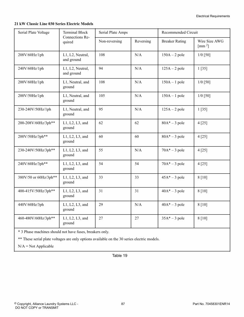
21 kW Classic Line 030 Series Electric Models
Serial Plate Voltage Terminal BlockConnections Re-quired
Serial Plate Amps Recommended Circuit
Non-reversing Reversing Breaker Rating Wire Size AWG[mm 2]
208V/60Hz/1ph L1, L2, Neutral,and ground
108 N/A 150A – 2 pole 1/0 [50]
240V/60Hz/1ph L1, L2, Neutral,and ground
94 N/A 125A – 2 pole 1 [35]
200V/60Hz/1ph L1, Neutral, andground
108 N/A 150A – 1 pole 1/0 [50]
200V/50Hz/1ph L1, Neutral, andground
105 N/A 150A – 1 pole 1/0 [50]
230-240V/50Hz/1ph L1, Neutral, andground
95 N/A 125A – 2 pole 1 [35]
200-208V/60Hz/3ph** L1, L2, L3, andground
62 62 80A* – 3 pole 4 [25]
200V/50Hz/3ph** L1, L2, L3, andground
60 60 80A* – 3 pole 4 [25]
230-240V/50Hz/3ph** L1, L2, L3, andground
55 N/A 70A* – 3 pole 4 [25]
240V/60Hz/3ph** L1, L2, L3, andground
54 54 70A* – 3 pole 4 [25]
380V/50 or 60Hz/3ph** L1, L2, L3, andground
33 33 45A* – 3 pole 8 [10]
400-415V/50Hz/3ph** L1, L2, L3, andground
31 31 40A* – 3 pole 8 [10]
440V/60Hz/3ph L1, L2, L3, andground
29 N/A 40A* – 3 pole 8 [10]
460-480V/60Hz/3ph** L1, L2, L3, andground
27 27 35A* – 3 pole 8 [10]
* 3 Phase machines should not have fuses, breakers only.
** These serial plate voltages are only options available on the 30 series electric models.
N/A = Not Applicable
Table 19
Electrical Requirements
© Copyright, Alliance Laundry Systems LLC - DO NOT COPY or TRANSMIT
87 Part No. 70458301ENR14
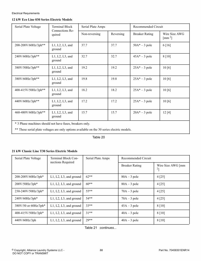
12 kW Eco Line 030 Series Electric Models
Serial Plate Voltage Terminal BlockConnections Re-quired
Serial Plate Amps Recommended Circuit
Non-reversing Reversing Breaker Rating Wire Size AWG[mm 2]
200-208V/60Hz/3ph** L1, L2, L3, andground
37.7 37.7 50A* – 3 pole 6 [16]
240V/60Hz/3ph** L1, L2, L3, andground
32.7 32.7 45A* – 3 pole 8 [10]
380V/50Hz/3ph** L1, L2, L3, andground
19.2 19.2 25A* – 3 pole 10 [6]
380V/60Hz/3ph** L1, L2, L3, andground
19.8 19.8 25A* – 3 pole 10 [6]
400-415V/50Hz/3ph** L1, L2, L3, andground
18.2 18.2 25A* – 3 pole 10 [6]
440V/60Hz/3ph** L1, L2, L3, andground
17.2 17.2 25A* – 3 pole 10 [6]
460-480V/60Hz/3ph** L1, L2, L3, andground
15.7 15.7 20A* – 3 pole 12 [4]
* 3 Phase machines should not have fuses, breakers only.
** These serial plate voltages are only options available on the 30 series electric models.
Table 20
21 kW Classic Line T30 Series Electric Models
Serial Plate Voltage Terminal Block Con-nections Required
Serial Plate Amps Recommended Circuit
Breaker Rating Wire Size AWG [mm2]
200-208V/60Hz/3ph* L1, L2, L3, and ground 62** 80A – 3 pole 4 [25]
200V/50Hz/3ph* L1, L2, L3, and ground 60** 80A – 3 pole 4 [25]
230-240V/50Hz/3ph* L1, L2, L3, and ground 55** 70A – 3 pole 4 [25]
240V/60Hz/3ph* L1, L2, L3, and ground 54** 70A – 3 pole 4 [25]
380V/50 or 60Hz/3ph* L1, L2, L3, and ground 33** 45A – 3 pole 8 [10]
400-415V/50Hz/3ph* L1, L2, L3, and ground 31** 40A – 3 pole 8 [10]
440V/60Hz/3ph L1, L2, L3, and ground 29** 40A – 3 pole 8 [10]
Table 21 continues...
Electrical Requirements
© Copyright, Alliance Laundry Systems LLC - DO NOT COPY or TRANSMIT
88 Part No. 70458301ENR14
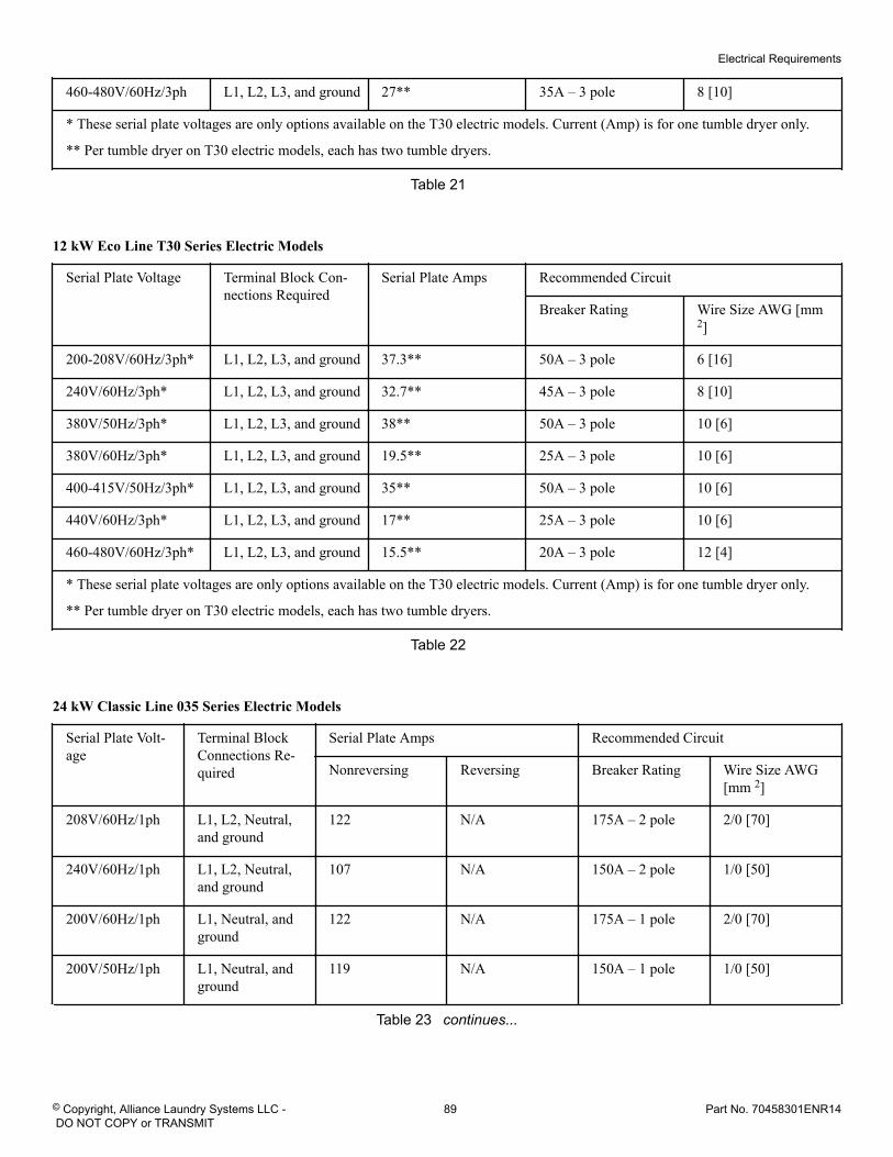
460-480V/60Hz/3ph L1, L2, L3, and ground 27** 35A – 3 pole 8 [10]
* These serial plate voltages are only options available on the T30 electric models. Current (Amp) is for one tumble dryer only.
** Per tumble dryer on T30 electric models, each has two tumble dryers.
Table 21
12 kW Eco Line T30 Series Electric Models
Serial Plate Voltage Terminal Block Con-nections Required
Serial Plate Amps Recommended Circuit
Breaker Rating Wire Size AWG [mm2]
200-208V/60Hz/3ph* L1, L2, L3, and ground 37.3** 50A – 3 pole 6 [16]
240V/60Hz/3ph* L1, L2, L3, and ground 32.7** 45A – 3 pole 8 [10]
380V/50Hz/3ph* L1, L2, L3, and ground 38** 50A – 3 pole 10 [6]
380V/60Hz/3ph* L1, L2, L3, and ground 19.5** 25A – 3 pole 10 [6]
400-415V/50Hz/3ph* L1, L2, L3, and ground 35** 50A – 3 pole 10 [6]
440V/60Hz/3ph* L1, L2, L3, and ground 17** 25A – 3 pole 10 [6]
460-480V/60Hz/3ph* L1, L2, L3, and ground 15.5** 20A – 3 pole 12 [4]
* These serial plate voltages are only options available on the T30 electric models. Current (Amp) is for one tumble dryer only.
** Per tumble dryer on T30 electric models, each has two tumble dryers.
Table 22
24 kW Classic Line 035 Series Electric Models
Serial Plate Volt-age
Terminal BlockConnections Re-quired
Serial Plate Amps Recommended Circuit
Nonreversing Reversing Breaker Rating Wire Size AWG[mm 2]
208V/60Hz/1ph L1, L2, Neutral,and ground
122 N/A 175A – 2 pole 2/0 [70]
240V/60Hz/1ph L1, L2, Neutral,and ground
107 N/A 150A – 2 pole 1/0 [50]
200V/60Hz/1ph L1, Neutral, andground
122 N/A 175A – 1 pole 2/0 [70]
200V/50Hz/1ph L1, Neutral, andground
119 N/A 150A – 1 pole 1/0 [50]
Table 23 continues...
Electrical Requirements
© Copyright, Alliance Laundry Systems LLC - DO NOT COPY or TRANSMIT
89 Part No. 70458301ENR14
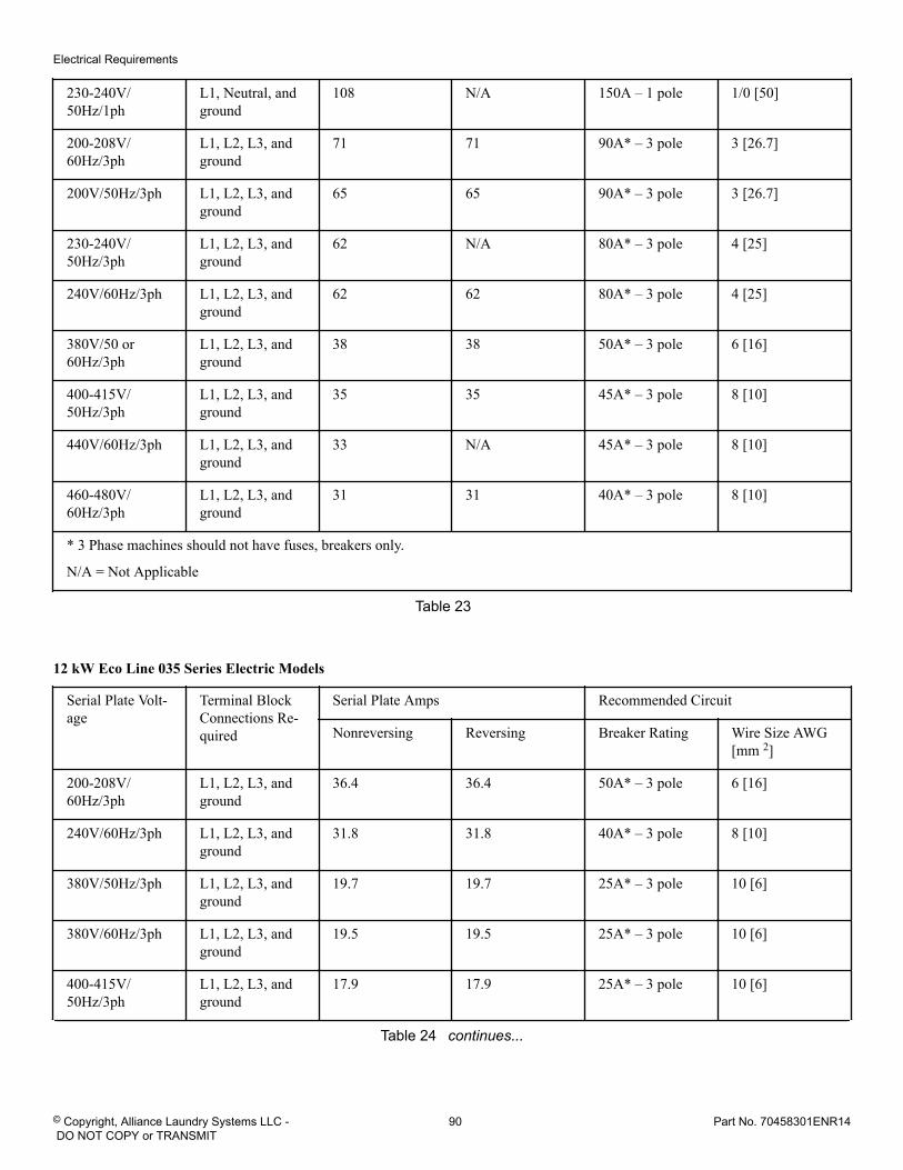
230-240V/50Hz/1ph
L1, Neutral, andground
108 N/A 150A – 1 pole 1/0 [50]
200-208V/60Hz/3ph
L1, L2, L3, andground
71 71 90A* – 3 pole 3 [26.7]
200V/50Hz/3ph L1, L2, L3, andground
65 65 90A* – 3 pole 3 [26.7]
230-240V/50Hz/3ph
L1, L2, L3, andground
62 N/A 80A* – 3 pole 4 [25]
240V/60Hz/3ph L1, L2, L3, andground
62 62 80A* – 3 pole 4 [25]
380V/50 or60Hz/3ph
L1, L2, L3, andground
38 38 50A* – 3 pole 6 [16]
400-415V/50Hz/3ph
L1, L2, L3, andground
35 35 45A* – 3 pole 8 [10]
440V/60Hz/3ph L1, L2, L3, andground
33 N/A 45A* – 3 pole 8 [10]
460-480V/60Hz/3ph
L1, L2, L3, andground
31 31 40A* – 3 pole 8 [10]
* 3 Phase machines should not have fuses, breakers only.
N/A = Not Applicable
Table 23
12 kW Eco Line 035 Series Electric Models
Serial Plate Volt-age
Terminal BlockConnections Re-quired
Serial Plate Amps Recommended Circuit
Nonreversing Reversing Breaker Rating Wire Size AWG[mm 2]
200-208V/60Hz/3ph
L1, L2, L3, andground
36.4 36.4 50A* – 3 pole 6 [16]
240V/60Hz/3ph L1, L2, L3, andground
31.8 31.8 40A* – 3 pole 8 [10]
380V/50Hz/3ph L1, L2, L3, andground
19.7 19.7 25A* – 3 pole 10 [6]
380V/60Hz/3ph L1, L2, L3, andground
19.5 19.5 25A* – 3 pole 10 [6]
400-415V/50Hz/3ph
L1, L2, L3, andground
17.9 17.9 25A* – 3 pole 10 [6]
Table 24 continues...
Electrical Requirements
© Copyright, Alliance Laundry Systems LLC - DO NOT COPY or TRANSMIT
90 Part No. 70458301ENR14
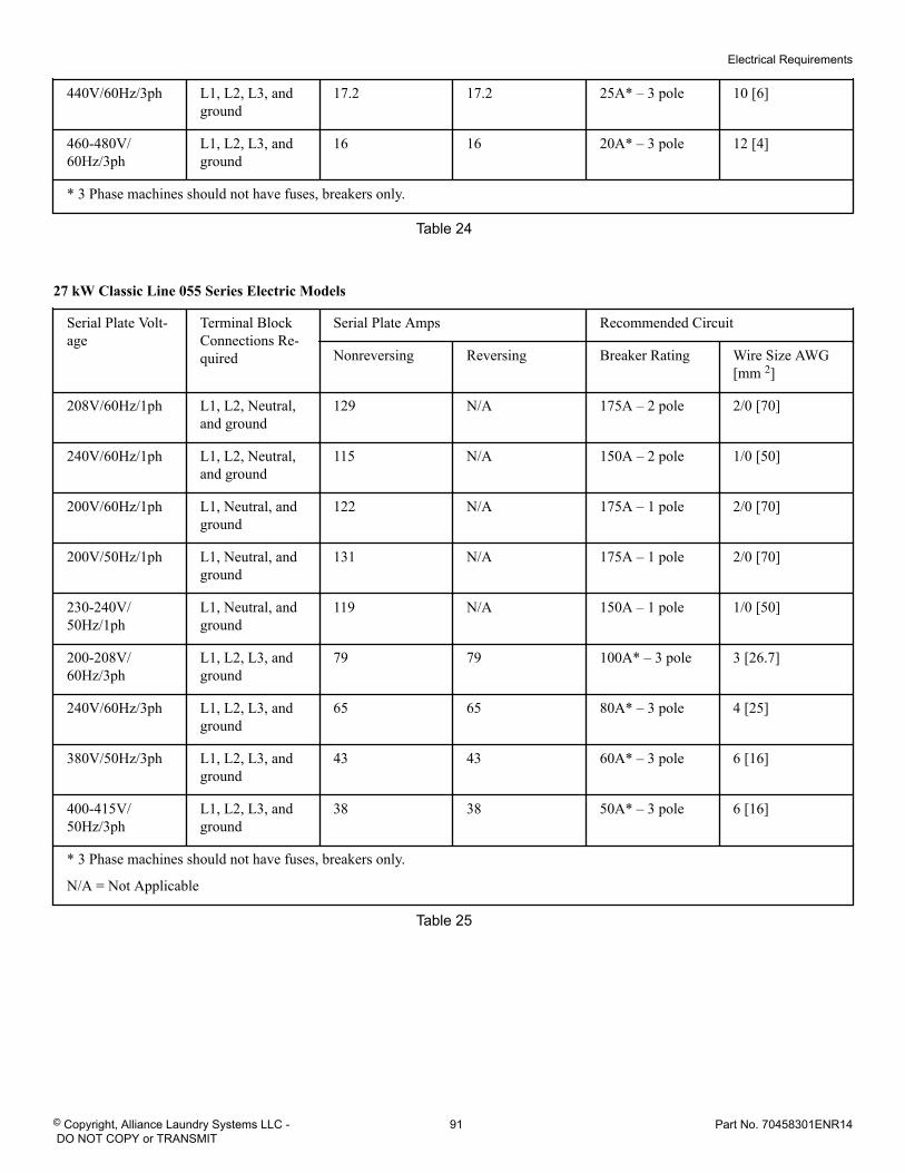
440V/60Hz/3ph L1, L2, L3, andground
17.2 17.2 25A* – 3 pole 10 [6]
460-480V/60Hz/3ph
L1, L2, L3, andground
16 16 20A* – 3 pole 12 [4]
* 3 Phase machines should not have fuses, breakers only.
Table 24
27 kW Classic Line 055 Series Electric Models
Serial Plate Volt-age
Terminal BlockConnections Re-quired
Serial Plate Amps Recommended Circuit
Nonreversing Reversing Breaker Rating Wire Size AWG[mm 2]
208V/60Hz/1ph L1, L2, Neutral,and ground
129 N/A 175A – 2 pole 2/0 [70]
240V/60Hz/1ph L1, L2, Neutral,and ground
115 N/A 150A – 2 pole 1/0 [50]
200V/60Hz/1ph L1, Neutral, andground
122 N/A 175A – 1 pole 2/0 [70]
200V/50Hz/1ph L1, Neutral, andground
131 N/A 175A – 1 pole 2/0 [70]
230-240V/50Hz/1ph
L1, Neutral, andground
119 N/A 150A – 1 pole 1/0 [50]
200-208V/60Hz/3ph
L1, L2, L3, andground
79 79 100A* – 3 pole 3 [26.7]
240V/60Hz/3ph L1, L2, L3, andground
65 65 80A* – 3 pole 4 [25]
380V/50Hz/3ph L1, L2, L3, andground
43 43 60A* – 3 pole 6 [16]
400-415V/50Hz/3ph
L1, L2, L3, andground
38 38 50A* – 3 pole 6 [16]
* 3 Phase machines should not have fuses, breakers only.
N/A = Not Applicable
Table 25
Electrical Requirements
© Copyright, Alliance Laundry Systems LLC - DO NOT COPY or TRANSMIT
91 Part No. 70458301ENR14
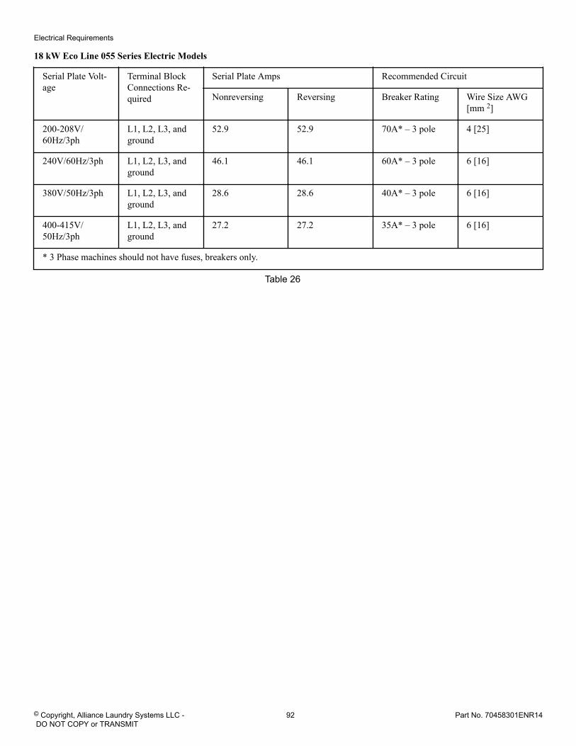
18 kW Eco Line 055 Series Electric Models
Serial Plate Volt-age
Terminal BlockConnections Re-quired
Serial Plate Amps Recommended Circuit
Nonreversing Reversing Breaker Rating Wire Size AWG[mm 2]
200-208V/60Hz/3ph
L1, L2, L3, andground
52.9 52.9 70A* – 3 pole 4 [25]
240V/60Hz/3ph L1, L2, L3, andground
46.1 46.1 60A* – 3 pole 6 [16]
380V/50Hz/3ph L1, L2, L3, andground
28.6 28.6 40A* – 3 pole 6 [16]
400-415V/50Hz/3ph
L1, L2, L3, andground
27.2 27.2 35A* – 3 pole 6 [16]
* 3 Phase machines should not have fuses, breakers only.
Table 26
Electrical Requirements
© Copyright, Alliance Laundry Systems LLC - DO NOT COPY or TRANSMIT
92 Part No. 70458301ENR14
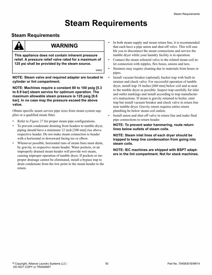
Steam Requirements Steam Requirements
WARNINGThis appliance does not contain inherent pressurerelief. A pressure relief valve rated for a maximum of125 psi shall be provided by the steam source.
W942
NOTE: Steam valve and required adapter are located incylinder or lint compartment.
NOTE: Machines require a constant 80 to 100 psig [5.3to 6.9 bar] steam service for optimum operation. Themaximum allowable steam pressure is 125 psig [8.6bar]. In no case may the pressure exceed the abovevalue.
Obtain specific steam service pipe sizes from steam system sup-plier or a qualified steam fitter.
• Refer to Figure 27 for proper steam pipe configurations.• To prevent condensate draining from headers to tumble dryer,
piping should have a minimum 12 inch [300 mm] rise aboverespective header. Do not make steam connection to headerwith a horizontal or downward facing tee or elbow.
• Whenever possible, horizontal runs of steam lines must drain,by gravity, to respective steam header. Water pockets, or animproperly drained steam header will provide wet steam,causing improper operation of tumble dryer. If pockets or im-proper drainage cannot be eliminated, install a bypass trap todrain condensate from the low point in the steam header to thereturn.
• In both steam supply and steam return line, it is recommendedthat each have a pipe union and shut-off valve. This will ena-ble you to disconnect the steam connections and service thetumble dryer while your laundry facility is in operation.
• Connect the steam solenoid valve to the related steam coil in-let connection with nipples, flex hoses, unions and tees.
• Strainers may require cleaning due to materials from hoses orpipes.
• Install vacuum breaker (optional), bucket trap with built-instrainer and check valve. For successful operation of tumbledryer, install trap 18 inches [460 mm] below coil and as nearto the tumble dryer as possible. Inspect trap carefully for inletand outlet markings and install according to trap manufactur-er's instructions. If steam is gravity returned to boiler, omittrap but install vacuum breaker and check valve in return linenear tumble dryer. Gravity return requires entire returnplumbing be below steam coil outlets.
• Install union and shut-off valve in return line and make finalpipe connections to return header.NOTE: To prevent water hammering, route returnlines below outlets of steam coils.
NOTE: Steam inlet lines of each dryer should betrapped to keep line condensation from going intosteam coils.
NOTE: IEC machines are shipped with BSPT adapt-ers in the lint compartment. Not for stack machines.
Steam Requirements
© Copyright, Alliance Laundry Systems LLC - DO NOT COPY or TRANSMIT
93 Part No. 70458301ENR14
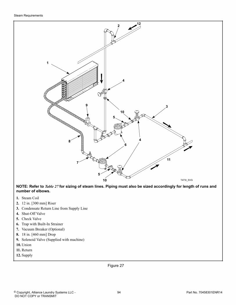
T473I_SVG
9
7
510
4
105
4
2
1
11
86
3
12
NOTE: Refer to Table 27 for sizing of steam lines. Piping must also be sized accordingly for length of runs andnumber of elbows.
1. Steam Coil2. 12 in. [300 mm] Riser3. Condensate Return Line from Supply Line4. Shut-Off Valve5. Check Valve6. Trap with Built-In Strainer7. Vacuum Breaker (Optional)8. 18 in. [460 mm] Drop9. Solenoid Valve (Supplied with machine)10. Union11. Return12. Supply
Figure 27
Steam Requirements
© Copyright, Alliance Laundry Systems LLC - DO NOT COPY or TRANSMIT
94 Part No. 70458301ENR14
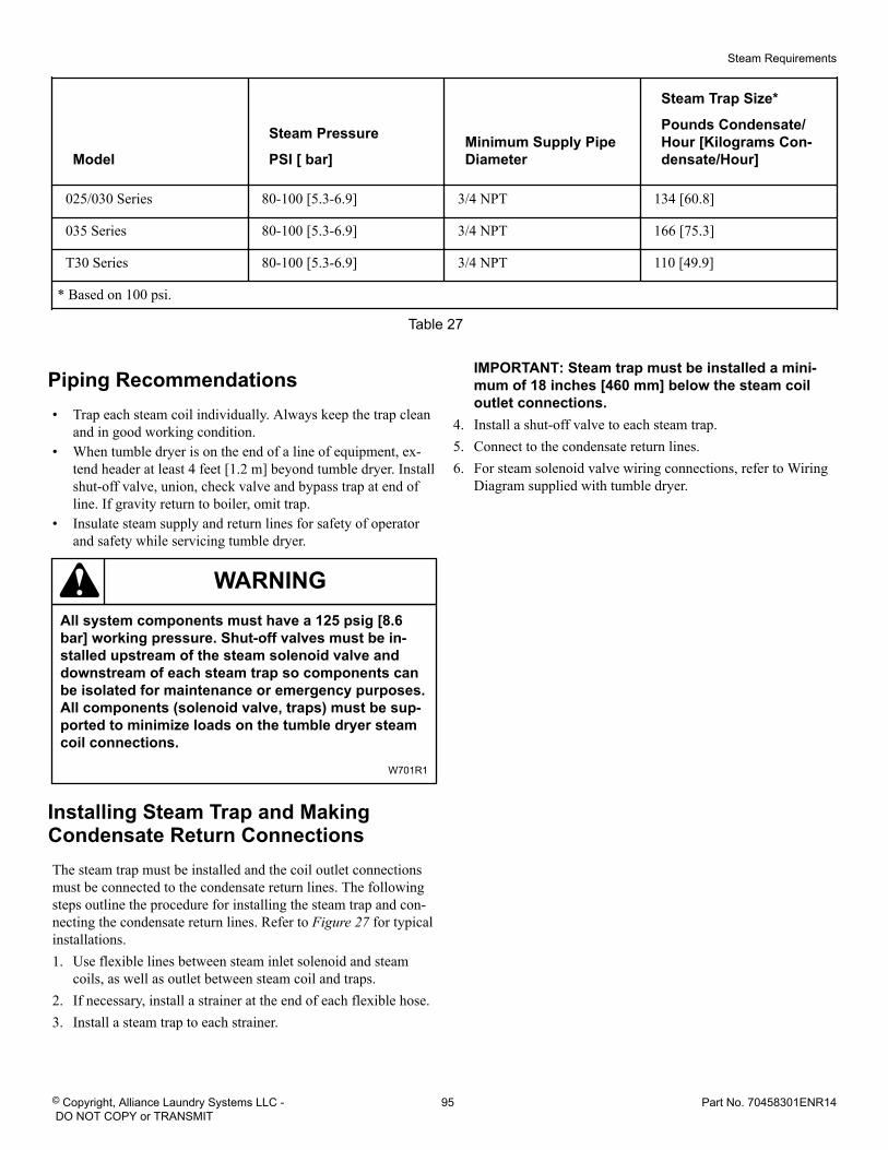
Model
Steam Pressure
PSI [ bar]Minimum Supply PipeDiameter
Steam Trap Size*
Pounds Condensate/Hour [Kilograms Con-densate/Hour]
025/030 Series 80-100 [5.3-6.9] 3/4 NPT 134 [60.8]
035 Series 80-100 [5.3-6.9] 3/4 NPT 166 [75.3]
T30 Series 80-100 [5.3-6.9] 3/4 NPT 110 [49.9]
* Based on 100 psi.
Table 27
Piping Recommendations• Trap each steam coil individually. Always keep the trap clean
and in good working condition.• When tumble dryer is on the end of a line of equipment, ex-
tend header at least 4 feet [1.2 m] beyond tumble dryer. Installshut-off valve, union, check valve and bypass trap at end ofline. If gravity return to boiler, omit trap.
• Insulate steam supply and return lines for safety of operatorand safety while servicing tumble dryer.
WARNINGAll system components must have a 125 psig [8.6bar] working pressure. Shut-off valves must be in-stalled upstream of the steam solenoid valve anddownstream of each steam trap so components canbe isolated for maintenance or emergency purposes.All components (solenoid valve, traps) must be sup-ported to minimize loads on the tumble dryer steamcoil connections.
W701R1
Installing Steam Trap and MakingCondensate Return ConnectionsThe steam trap must be installed and the coil outlet connectionsmust be connected to the condensate return lines. The followingsteps outline the procedure for installing the steam trap and con-necting the condensate return lines. Refer to Figure 27 for typicalinstallations.1. Use flexible lines between steam inlet solenoid and steam
coils, as well as outlet between steam coil and traps.2. If necessary, install a strainer at the end of each flexible hose.3. Install a steam trap to each strainer.
IMPORTANT: Steam trap must be installed a mini-mum of 18 inches [460 mm] below the steam coiloutlet connections.
4. Install a shut-off valve to each steam trap.5. Connect to the condensate return lines.6. For steam solenoid valve wiring connections, refer to Wiring
Diagram supplied with tumble dryer.
Steam Requirements
© Copyright, Alliance Laundry Systems LLC - DO NOT COPY or TRANSMIT
95 Part No. 70458301ENR14
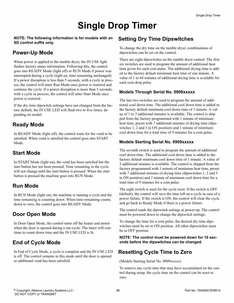
Single Drop TimerNOTE: The following information is for models with anSD control suffix only.
Power-Up ModeWhen power is applied to the tumble dryer, the IN USE lightflashes factory status information. Following this, the controlgoes into READY Mode (light off) or RUN Mode if power wasinterrupted during a cycle (light on, time remaining unchanged).If a power disruption is less than 5 seconds, with a cycle in proc-ess, the control will enter Run Mode once power is restored andcontinue the cycle. If a power disruption is more than 5 seconds,with a cycle in process, the control will enter Start Mode oncepower is restored.
If the dry time dipswitch settings have not changed from the fac-tory default, the IN USE LED will flash two to five times, de-pending on model.
Ready ModeIn READY Mode (light off), the control waits for the vend to besatisfied. When vend is satisfied the control goes into STARTMode.
Start ModeIn START Mode (light on), the vend has been satisfied but thestart button has not been pressed. Time remaining in the cyclewill not change until the start button is pressed. When the startbutton is pressed the machine goes into RUN Mode.
Run ModeIn RUN Mode (light on), the machine is running a cycle and thetime remaining is counting down. When time remaining countsdown to zero, the control goes into READY Mode.
Door Open ModeIn Door Open Mode, the control turns off the heater and motorwhen the door is opened during a run cycle. The timer will con-tinue to count down time and the IN USE LED is lit.
End of Cycle ModeIn End of Cycle Mode, a cycle is complete and the IN USE LEDis off. The control remains in this mode until the door is openedor additional vend has been satisfied.
Setting Dry Time DipswitchesTo change the dry time on the tumble dryer, combinations ofdipswitches can be set on the control.
There are eight dipswitches on the tumble dryer control. The firstsix switches are used to program the amount of additional heattime given for each coin pulse. The additional drying time is add-ed to the factory default minimum heat time of one minute. Avalue of 1 to 64 minutes of additional drying time is available foreach coin drop pulse.
Models Through Serial No. 0908xxxxx
The last two switches are used to program the amount of addi-tional cool down time. The additional cool down time is added tothe factory default minimum cool down time of 1 minute. A val-ue of 1 to 3 additional minutes is available. The control is ship-ped from the factory programmed with 1 minute of minimumheat time, preset with 7 additional minutes of drying time (dips-witches 1, 2 and 3 in ON position) and 1 minute of minimumcool down time for a total time of 9 minutes for a coin pulse.
Models Starting Serial No. 0909xxxxx
The seventh switch is used to program the amount of additionalcool down time. The additional cool down time is added to thefactory default minimum cool down time of 1 minute. A value of3 additional minutes is available. The control is shipped from thefactory programmed with 1 minute of minimum heat time, presetwith 7 additional minutes of drying time (dipswitches 1, 2 and 3in ON position) and 1 minute of minimum cool down time for atotal time of 9 minutes for a coin pulse.
The eight switch is used for the cycle reset. If the switch is OFF(default), the control will save the time left on a cycle in case of apower failure. If the switch is ON, the control will clear the cycleand go back to Ready Mode if there is a power failure.
The control reads the dipswitch settings at power-up. The controlmust be powered down to change the dipswitch settings.
To change the time for a coin pulse, the desired dry time dips-witches must be set to ON position. All other dipswitches mustbe in OFF position.
NOTE: The control must be powered down for 10 sec-onds before the dipswitches can be changed.
Resetting Cycle Time to Zero(Models Starting Serial No. 0909xxxxx)
To remove any cycle time that may have accumulated on the con-trol during setup, the cycle time on the control can be reset tozero.
Single Drop Timer
© Copyright, Alliance Laundry Systems LLC - DO NOT COPY or TRANSMIT
96 Part No. 70458301ENR14
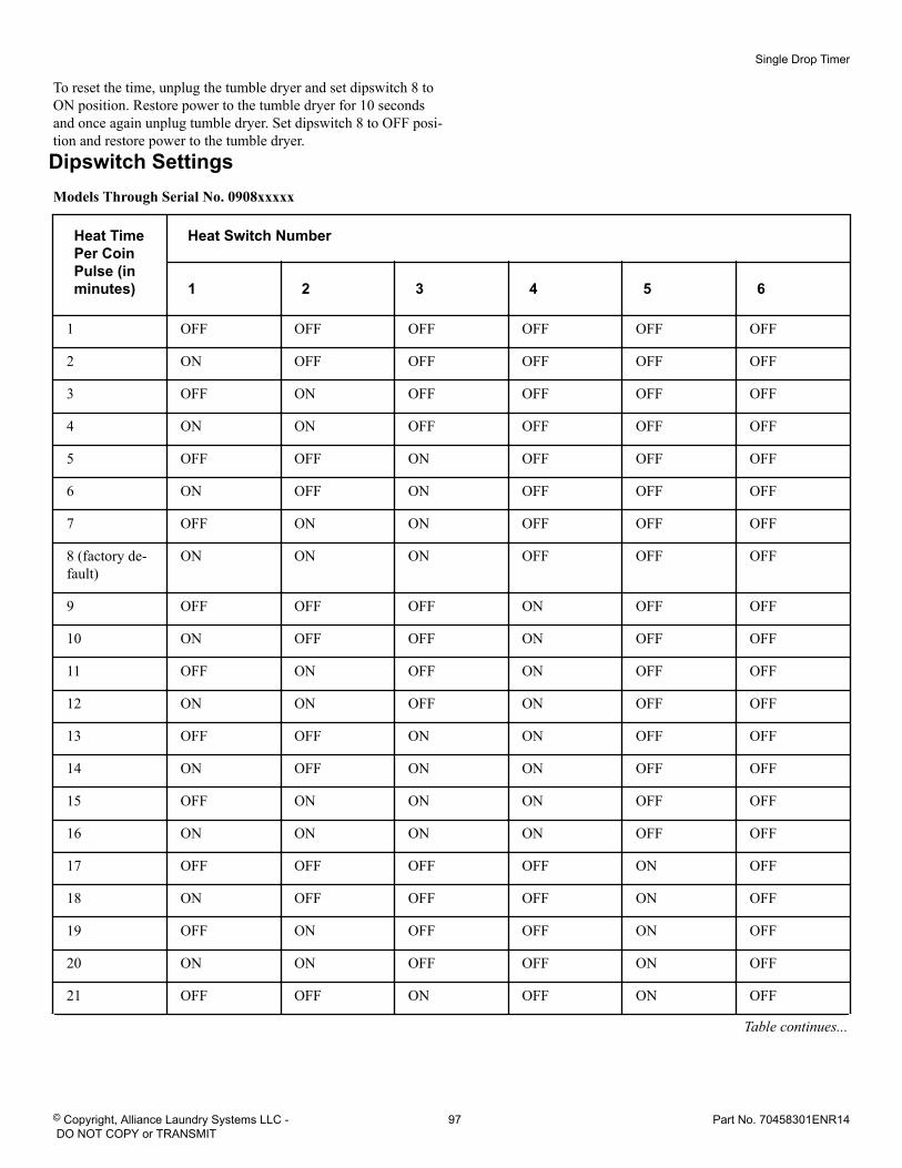
To reset the time, unplug the tumble dryer and set dipswitch 8 toON position. Restore power to the tumble dryer for 10 secondsand once again unplug tumble dryer. Set dipswitch 8 to OFF posi-tion and restore power to the tumble dryer.
Dipswitch SettingsModels Through Serial No. 0908xxxxx
Heat TimePer CoinPulse (inminutes)
Heat Switch Number
1 2 3 4 5 6
1 OFF OFF OFF OFF OFF OFF
2 ON OFF OFF OFF OFF OFF
3 OFF ON OFF OFF OFF OFF
4 ON ON OFF OFF OFF OFF
5 OFF OFF ON OFF OFF OFF
6 ON OFF ON OFF OFF OFF
7 OFF ON ON OFF OFF OFF
8 (factory de-fault)
ON ON ON OFF OFF OFF
9 OFF OFF OFF ON OFF OFF
10 ON OFF OFF ON OFF OFF
11 OFF ON OFF ON OFF OFF
12 ON ON OFF ON OFF OFF
13 OFF OFF ON ON OFF OFF
14 ON OFF ON ON OFF OFF
15 OFF ON ON ON OFF OFF
16 ON ON ON ON OFF OFF
17 OFF OFF OFF OFF ON OFF
18 ON OFF OFF OFF ON OFF
19 OFF ON OFF OFF ON OFF
20 ON ON OFF OFF ON OFF
21 OFF OFF ON OFF ON OFF
Table continues...
Single Drop Timer
© Copyright, Alliance Laundry Systems LLC - DO NOT COPY or TRANSMIT
97 Part No. 70458301ENR14
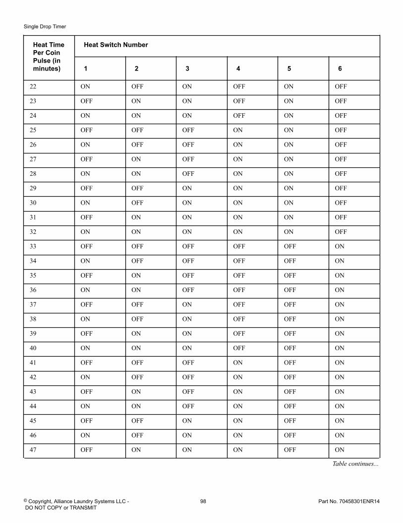
Heat TimePer CoinPulse (inminutes)
Heat Switch Number
1 2 3 4 5 6
22 ON OFF ON OFF ON OFF
23 OFF ON ON OFF ON OFF
24 ON ON ON OFF ON OFF
25 OFF OFF OFF ON ON OFF
26 ON OFF OFF ON ON OFF
27 OFF ON OFF ON ON OFF
28 ON ON OFF ON ON OFF
29 OFF OFF ON ON ON OFF
30 ON OFF ON ON ON OFF
31 OFF ON ON ON ON OFF
32 ON ON ON ON ON OFF
33 OFF OFF OFF OFF OFF ON
34 ON OFF OFF OFF OFF ON
35 OFF ON OFF OFF OFF ON
36 ON ON OFF OFF OFF ON
37 OFF OFF ON OFF OFF ON
38 ON OFF ON OFF OFF ON
39 OFF ON ON OFF OFF ON
40 ON ON ON OFF OFF ON
41 OFF OFF OFF ON OFF ON
42 ON OFF OFF ON OFF ON
43 OFF ON OFF ON OFF ON
44 ON ON OFF ON OFF ON
45 OFF OFF ON ON OFF ON
46 ON OFF ON ON OFF ON
47 OFF ON ON ON OFF ON
Table continues...
Single Drop Timer
© Copyright, Alliance Laundry Systems LLC - DO NOT COPY or TRANSMIT
98 Part No. 70458301ENR14
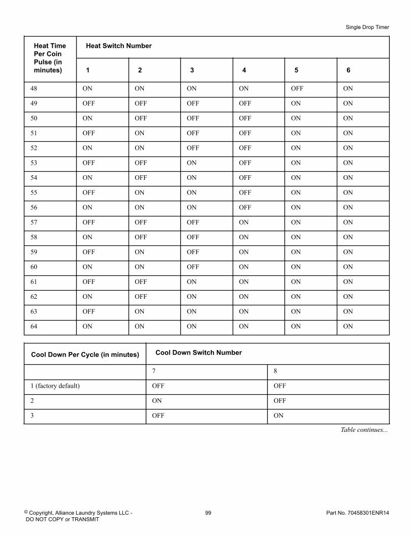
Heat TimePer CoinPulse (inminutes)
Heat Switch Number
1 2 3 4 5 6
48 ON ON ON ON OFF ON
49 OFF OFF OFF OFF ON ON
50 ON OFF OFF OFF ON ON
51 OFF ON OFF OFF ON ON
52 ON ON OFF OFF ON ON
53 OFF OFF ON OFF ON ON
54 ON OFF ON OFF ON ON
55 OFF ON ON OFF ON ON
56 ON ON ON OFF ON ON
57 OFF OFF OFF ON ON ON
58 ON OFF OFF ON ON ON
59 OFF ON OFF ON ON ON
60 ON ON OFF ON ON ON
61 OFF OFF ON ON ON ON
62 ON OFF ON ON ON ON
63 OFF ON ON ON ON ON
64 ON ON ON ON ON ON
Cool Down Per Cycle (in minutes) Cool Down Switch Number
7 8
1 (factory default) OFF OFF
2 ON OFF
3 OFF ON
Table continues...
Single Drop Timer
© Copyright, Alliance Laundry Systems LLC - DO NOT COPY or TRANSMIT
99 Part No. 70458301ENR14
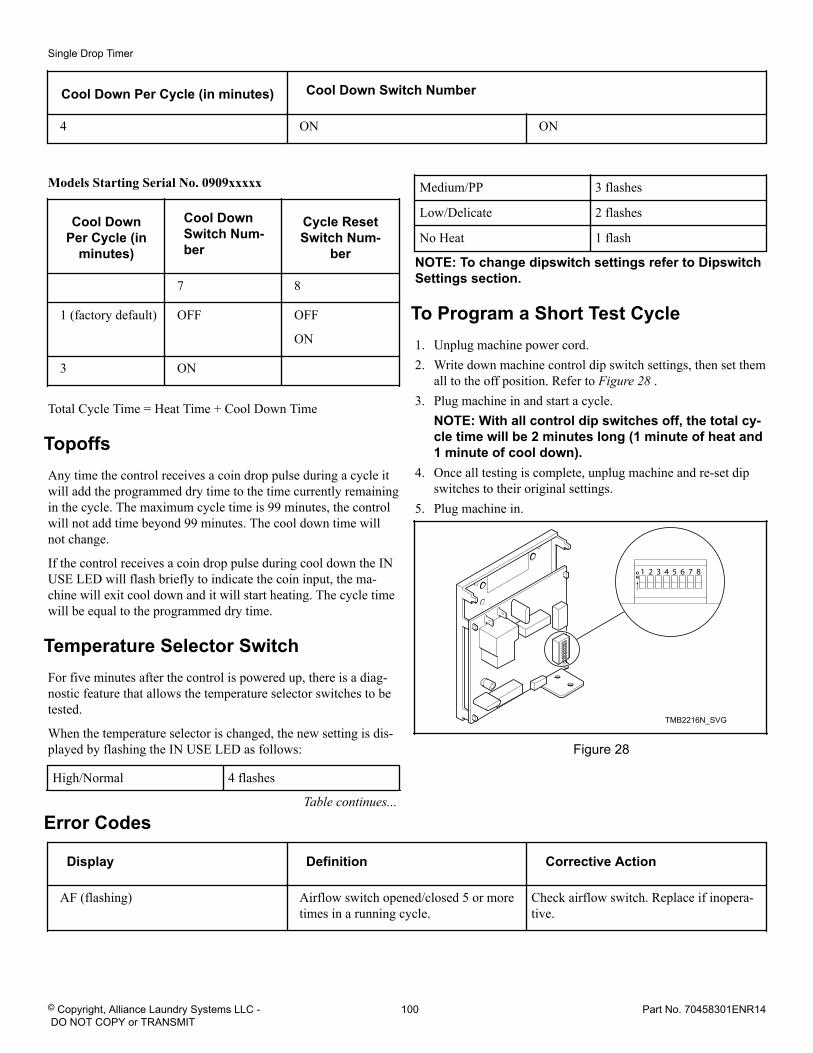
Cool Down Per Cycle (in minutes) Cool Down Switch Number
4 ON ON
Models Starting Serial No. 0909xxxxx
Cool DownPer Cycle (in
minutes)
Cool DownSwitch Num-ber
Cycle ResetSwitch Num-
ber
7 8
1 (factory default) OFF OFF
ON
3 ON
Total Cycle Time = Heat Time + Cool Down Time
TopoffsAny time the control receives a coin drop pulse during a cycle itwill add the programmed dry time to the time currently remainingin the cycle. The maximum cycle time is 99 minutes, the controlwill not add time beyond 99 minutes. The cool down time willnot change.
If the control receives a coin drop pulse during cool down the INUSE LED will flash briefly to indicate the coin input, the ma-chine will exit cool down and it will start heating. The cycle timewill be equal to the programmed dry time.
Temperature Selector SwitchFor five minutes after the control is powered up, there is a diag-nostic feature that allows the temperature selector switches to betested.
When the temperature selector is changed, the new setting is dis-played by flashing the IN USE LED as follows:
High/Normal 4 flashes
Table continues...
Medium/PP 3 flashes
Low/Delicate 2 flashes
No Heat 1 flash
NOTE: To change dipswitch settings refer to DipswitchSettings section.
To Program a Short Test Cycle1. Unplug machine power cord.2. Write down machine control dip switch settings, then set them
all to the off position. Refer to Figure 28 .3. Plug machine in and start a cycle.
NOTE: With all control dip switches off, the total cy-cle time will be 2 minutes long (1 minute of heat and1 minute of cool down).
4. Once all testing is complete, unplug machine and re-set dipswitches to their original settings.
5. Plug machine in.
TMB2216N_SVG
Figure 28
Error Codes
Display Definition Corrective Action
AF (flashing) Airflow switch opened/closed 5 or moretimes in a running cycle.
Check airflow switch. Replace if inopera-tive.
Single Drop Timer
© Copyright, Alliance Laundry Systems LLC - DO NOT COPY or TRANSMIT
100 Part No. 70458301ENR14
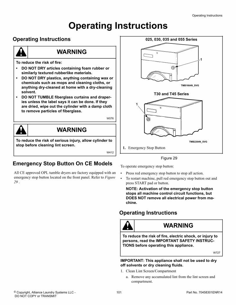
Operating Instructions Operating Instructions
WARNINGTo reduce the risk of fire:• DO NOT DRY articles containing foam rubber or
similarly textured rubberlike materials.• DO NOT DRY plastics, anything containing wax or
chemicals such as mops and cleaning cloths, oranything dry-cleaned at home with a dry-cleaningsolvent.
• DO NOT TUMBLE fiberglass curtains and draper-ies unless the label says it can be done. If theyare dried, wipe out the cylinder with a damp clothto remove particles of fiberglass.
W076
WARNINGTo reduce the risk of serious injury, allow cylinder tostop before cleaning lint screen.
W412
Emergency Stop Button On CE ModelsAll CE approved OPL tumble dryers are factory equipped with anemergency stop button located on the front panel. Refer to Figure29 .
025, 030, 035 and 055 Series
TMB1664N_SVG
1
T30 and T45 Series
TMB2264N_SVG
1
1. Emergency Stop Button
Figure 29
To operate emergency stop button:
• Press red emergency stop button to stop all action.• To restart machine, pull red emergency stop button out and
press START pad or button.NOTE: Activation of the emergency stop buttonstops all machine control circuit functions, butDOES NOT remove all electrical power from ma-chine.
Operating Instructions
WARNINGTo reduce the risk of fire, electric shock, or injury topersons, read the IMPORTANT SAFETY INSTRUC-TIONS before operating this appliance.
W727
IMPORTANT: This appliance shall not be used to dryoff solvents or dry cleaning fluids.1. Clean Lint Screen/Compartment
a. Remove any accumulated lint from the lint screen andcompartment.
Operating Instructions
© Copyright, Alliance Laundry Systems LLC - DO NOT COPY or TRANSMIT
101 Part No. 70458301ENR14
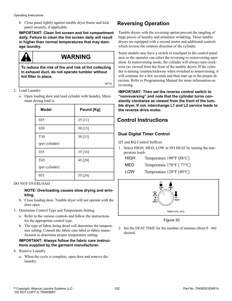
b. Close panel tightly against tumble dryer frame and lockpanel securely, if applicable.
IMPORTANT: Clean lint screen and lint compartmentdaily. Failure to clean the lint screen daily will resultin higher than normal temperatures that may dam-age laundry.
WARNINGTo reduce the risk of fire and risk of lint collectingin exhaust duct, do not operate tumbler withoutlint filter in place.
W772
2. Load Laundrya. Open loading door and load cylinder with laundry. Maxi-
mum drying load is:
Model Pound [Kg]
025 25 [11]
030 30 [13]
T30
(per cylinder)
30 [13]
035 35 [16]
T45
(per cylinder)
45 [20]
055 55 [24]
DO NOT OVERLOAD.
NOTE: Overloading causes slow drying and wrin-kling.
b. Close loading door. Tumble dryer will not operate with thedoor open.
3. Determine Control Type and Temperature Settinga. Refer to the various controls and follow the instructions
for the appropriate control type.b. The type of fabric being dried will determine the tempera-
ture setting. Consult the fabric care label or fabric manu-facturer to determine proper temperature setting.
IMPORTANT: Always follow the fabric care instruc-tions supplied by the garment manufacturer.
4. Remove Laundrya. When the cycle is complete, open door and remove the
laundry.
Reversing OperationTumble dryers with the reversing option prevent the tangling oflarge pieces of laundry and minimize wrinkling. These tumbledryers are equipped with a second motor and additional controlswhich reverse the rotation direction of the cylinder.
Some models may have a switch or touchpad in the control panelarea so the operator can select the reversing or nonreversing oper-ation. In nonreversing mode, the cylinder will always turn clock-wise (as viewed from the front of the tumble dryer). If the cylin-der is turning counterclockwise when switched to nonreversing, itwill continue for a few seconds and then start up in the proper di-rection. Refer to Programming Manual for more information onreversing.
IMPORTANT: Then set the reverse control switch to“nonreversing” and note that the cylinder turns con-stantly clockwise as viewed from the front of the tum-ble dryer. If not, interchange L1 and L2 service leads tothe reverse drive motor.
Control Instructions
Dual Digital Timer Control
QT and RQ Control Suffixes1. Select HIGH, MED, LOW or NO HEAT by turning the tem-
perature knob.HIGH Temperature 190°F [88°C]MED Temperature 170°F [ 77°C]LOW Temperature 120°F [49°C]
TMB2147N_SVG
Figure 30
2. Set the HEAT TIME for the number of minutes (from 0 - 60)desired.
Operating Instructions
© Copyright, Alliance Laundry Systems LLC - DO NOT COPY or TRANSMIT
102 Part No. 70458301ENR14
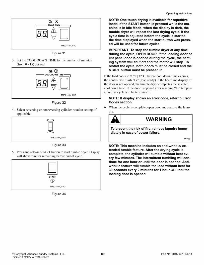
TMB2148N_SVG
Figure 31
3. Set the COOL DOWN TIME for the number of minutes(from 0 - 15) desired.
TMB2149N_SVG
Figure 32
4. Select reversing or nonreversing cylinder rotation setting, ifapplicable.
TMB2145N_SVG
Figure 33
5. Press and release START button to start tumble dryer. Displaywill show minutes remaining before end of cycle.
TMB2150N_SVG
Figure 34
NOTE: One touch drying is available for repetitiveloads. If the START button is pressed while the ma-chine is in Idle Mode, when the display is dark, thetumble dryer will repeat the last drying cycle. If thecycle time is adjusted before the cycle is started,the time displayed when the start button was press-ed will be used for future cycles.
IMPORTANT: To stop the tumble dryer at any timeduring the cycle, OPEN DOOR. If the loading door orlint panel door is opened during the cycle, the heat-ing system will shut off and the motor will stop. Torestart the cycle, both doors must be closed and theSTART button must be pressed in.
If the load cools to 90°F [32°C] before cool down time expires,the control will flash “Lr” (load ready) in the heat time display. Ifthe door is not opened, the tumble dryer completes the selectedcool down time. If the door is opened after reaching “Lr” temper-ature, the cycle will be terminated.
NOTE: If display shows an error code, refer to ErrorCodes section.
6. When the cycle is complete, open door and remove the laun-dry.
WARNINGTo prevent the risk of fire, remove laundry imme-diately in case of power failure.
W779
NOTE: This machine includes an anti-wrinkle/ ex-tended tumble feature. After the drying cycle iscomplete, the cylinder will tumble without heat ev-ery few minutes. The intermittent tumbling will con-tinue for one hour or until the door is opened. Anti-wrinkle feature will tumble the load without heat for30 seconds every 2 minutes for 1 hour OR until theloading door is opened.
Operating Instructions
© Copyright, Alliance Laundry Systems LLC - DO NOT COPY or TRANSMIT
103 Part No. 70458301ENR14
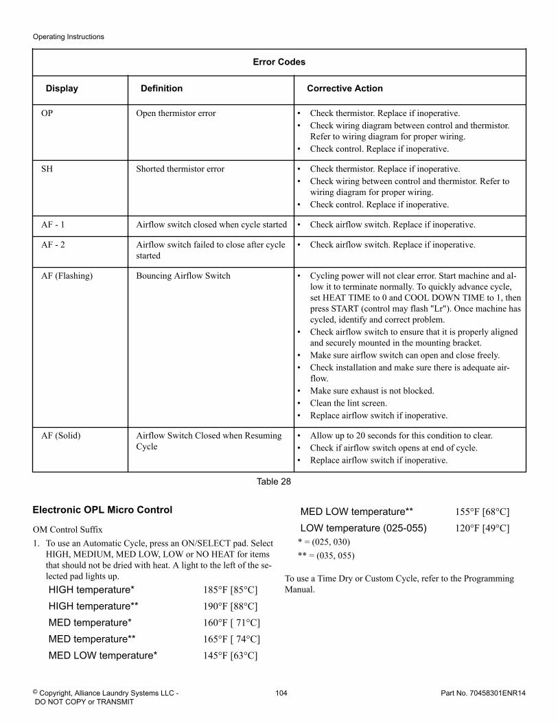
Error Codes
Display Definition Corrective Action
OP Open thermistor error • Check thermistor. Replace if inoperative.• Check wiring diagram between control and thermistor.
Refer to wiring diagram for proper wiring.• Check control. Replace if inoperative.
SH Shorted thermistor error • Check thermistor. Replace if inoperative.• Check wiring between control and thermistor. Refer to
wiring diagram for proper wiring.• Check control. Replace if inoperative.
AF - 1 Airflow switch closed when cycle started • Check airflow switch. Replace if inoperative.
AF - 2 Airflow switch failed to close after cyclestarted
• Check airflow switch. Replace if inoperative.
AF (Flashing) Bouncing Airflow Switch • Cycling power will not clear error. Start machine and al-low it to terminate normally. To quickly advance cycle,set HEAT TIME to 0 and COOL DOWN TIME to 1, thenpress START (control may flash "Lr"). Once machine hascycled, identify and correct problem.
• Check airflow switch to ensure that it is properly alignedand securely mounted in the mounting bracket.
• Make sure airflow switch can open and close freely.• Check installation and make sure there is adequate air-
flow.• Make sure exhaust is not blocked.• Clean the lint screen.• Replace airflow switch if inoperative.
AF (Solid) Airflow Switch Closed when ResumingCycle
• Allow up to 20 seconds for this condition to clear.• Check if airflow switch opens at end of cycle.• Replace airflow switch if inoperative.
Table 28
Electronic OPL Micro Control
OM Control Suffix1. To use an Automatic Cycle, press an ON/SELECT pad. Select
HIGH, MEDIUM, MED LOW, LOW or NO HEAT for itemsthat should not be dried with heat. A light to the left of the se-lected pad lights up.HIGH temperature* 185°F [85°C]HIGH temperature** 190°F [88°C]MED temperature* 160°F [ 71°C]MED temperature** 165°F [ 74°C]MED LOW temperature* 145°F [63°C]
MED LOW temperature** 155°F [68°C]LOW temperature (025-055) 120°F [49°C]
* = (025, 030)** = (035, 055)
To use a Time Dry or Custom Cycle, refer to the ProgrammingManual.
Operating Instructions
© Copyright, Alliance Laundry Systems LLC - DO NOT COPY or TRANSMIT
104 Part No. 70458301ENR14
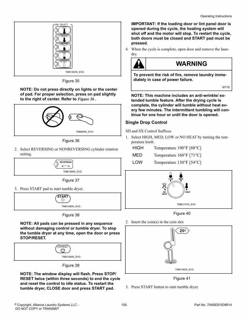
TMB1483N_SVG
Figure 35
NOTE: Do not press directly on lights or the centerof pad. For proper selection, press on pad slightlyto the right of center. Refer to Figure 36 .
TMB806N_SVG
Figure 36
2. Select REVERSING or NONREVERSING cylinder rotationsetting.
TMB1486N_SVG
REVERSING
Figure 37
3. Press START pad to start tumble dryer.
TMB1485N_SVG
Figure 38
NOTE: All pads can be pressed in any sequencewithout damaging control or tumble dryer. To stopthe tumble dryer at any time, open the door or pressSTOP/RESET.
TMB1484N_SVG
Figure 39
NOTE: The window display will flash. Press STOP/RESET twice (within three seconds) to end the cycleand reset the control to idle status. To restart thetumble dryer, CLOSE door and press START pad.
IMPORTANT: If the loading door or lint panel door isopened during the cycle, the heating system willshut off and the motor will stop. To restart the cycle,both doors must be closed and START pad must bepressed.
4. When the cycle is complete, open door and remove the laun-dry.
WARNINGTo prevent the risk of fire, remove laundry imme-diately in case of power failure.
W779
NOTE: This machine includes an anti-wrinkle/ ex-tended tumble feature. After the drying cycle iscomplete, the cylinder will tumble without heat ev-ery few minutes. The intermittent tumbling will con-tinue for one hour or until the door is opened.
Single Drop Control
SD and SX Control Suffixes1. Select HIGH, MED, LOW or NO HEAT by turning the tem-
perature knob.HIGH Temperature 190°F [88°C]MED Temperature 160°F [71°C]LOW Temperature 130°F [54°C]
TMB2147N_SVG
Figure 40
2. Insert the coin(s) in the coin slot.
TMB1492N_SVG
Figure 41
3. Press START button to start tumble dryer.
Operating Instructions
© Copyright, Alliance Laundry Systems LLC - DO NOT COPY or TRANSMIT
105 Part No. 70458301ENR14
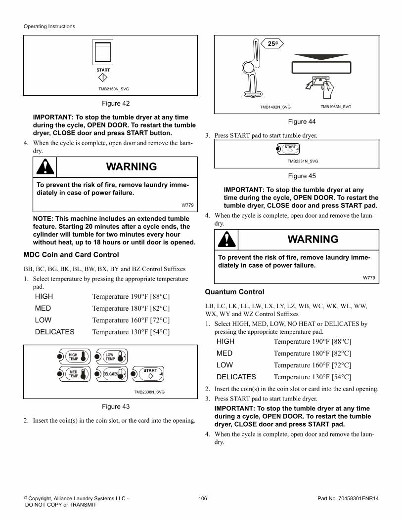
TMB2150N_SVG
Figure 42
IMPORTANT: To stop the tumble dryer at any timeduring the cycle, OPEN DOOR. To restart the tumbledryer, CLOSE door and press START button.
4. When the cycle is complete, open door and remove the laun-dry.
WARNINGTo prevent the risk of fire, remove laundry imme-diately in case of power failure.
W779
NOTE: This machine includes an extended tumblefeature. Starting 20 minutes after a cycle ends, thecylinder will tumble for two minutes every hourwithout heat, up to 18 hours or until door is opened.
MDC Coin and Card Control
BB, BC, BG, BK, BL, BW, BX, BY and BZ Control Suffixes1. Select temperature by pressing the appropriate temperature
pad.HIGH Temperature 190°F [88°C]MED Temperature 180°F [82°C]LOW Temperature 160°F [72°C]DELICATES Temperature 130°F [54°C]
TMB2338N_SVG
Figure 43
2. Insert the coin(s) in the coin slot, or the card into the opening.
TMB1492N_SVG TMB1963N_SVG
Figure 44
3. Press START pad to start tumble dryer.
TMB2331N_SVG
Figure 45
IMPORTANT: To stop the tumble dryer at anytime during the cycle, OPEN DOOR. To restart thetumble dryer, CLOSE door and press START pad.
4. When the cycle is complete, open door and remove the laun-dry.
WARNINGTo prevent the risk of fire, remove laundry imme-diately in case of power failure.
W779
Quantum Control
LB, LC, LK, LL, LW, LX, LY, LZ, WB, WC, WK, WL, WW,WX, WY and WZ Control Suffixes1. Select HIGH, MED, LOW, NO HEAT or DELICATES by
pressing the appropriate temperature pad.HIGH Temperature 190°F [88°C]MED Temperature 180°F [82°C]LOW Temperature 160°F [72°C]DELICATES Temperature 130°F [54°C]
2. Insert the coin(s) in the coin slot or card into the card opening.3. Press START pad to start tumble dryer.
IMPORTANT: To stop the tumble dryer at any timeduring a cycle, OPEN DOOR. To restart the tumbledryer, CLOSE door and press START pad.
4. When the cycle is complete, open door and remove the laun-dry.
Operating Instructions
© Copyright, Alliance Laundry Systems LLC - DO NOT COPY or TRANSMIT
106 Part No. 70458301ENR14
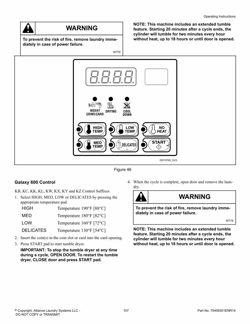
WARNINGTo prevent the risk of fire, remove laundry imme-diately in case of power failure.
W779
NOTE: This machine includes an extended tumblefeature. Starting 20 minutes after a cycle ends, thecylinder will tumble for two minutes every hourwithout heat, up to 18 hours or until door is opened.
DRY576R_SVG
Figure 46
Galaxy 600 Control
KB, KC, KK, KL, KW, KX, KY and KZ Control Suffixes1. Select HIGH, MED, LOW or DELICATES by pressing the
appropriate temperature pad.HIGH Temperature 190°F [88°C]MED Temperature 180°F [82°C]LOW Temperature 160°F [72°C]DELICATES Temperature 130°F [54°C]
2. Insert the coin(s) in the coin slot or card into the card opening.3. Press START pad to start tumble dryer.
IMPORTANT: To stop the tumble dryer at any timeduring a cycle, OPEN DOOR. To restart the tumbledryer, CLOSE door and press START pad.
4. When the cycle is complete, open door and remove the laun-dry.
WARNINGTo prevent the risk of fire, remove laundry imme-diately in case of power failure.
W779
NOTE: This machine includes an extended tumblefeature. Starting 20 minutes after a cycle ends, thecylinder will tumble for two minutes every hourwithout heat, up to 18 hours or until door is opened.
Operating Instructions
© Copyright, Alliance Laundry Systems LLC - DO NOT COPY or TRANSMIT
107 Part No. 70458301ENR14
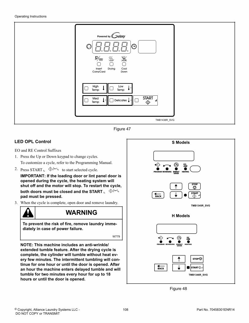
TMB1438R_SVG
Figure 47
LED OPL Control
EO and RE Control Suffixes1. Press the Up or Down keypad to change cycles.
To customize a cycle, refer to the Programming Manual.2. Press START ( ) to start selected cycle.
IMPORTANT: If the loading door or lint panel door isopened during the cycle, the heating system willshut off and the motor will stop. To restart the cycle,both doors must be closed and the START ( )
pad must be pressed.3. When the cycle is complete, open door and remove laundry.
WARNINGTo prevent the risk of fire, remove laundry imme-diately in case of power failure.
W779
NOTE: This machine includes an anti-wrinkle/extended tumble feature. After the drying cycle iscomplete, the cylinder will tumble without heat ev-ery few minutes. The intermittent tumbling will con-tinue for one hour or until the door is opened. Afteran hour the machine enters delayed tumble and willtumble for two minutes every hour for up to 18hours or until the door is opened.
S Models
TMB1345R_SVG
H Models
TMB1346R_SVG
Figure 48
Operating Instructions
© Copyright, Alliance Laundry Systems LLC - DO NOT COPY or TRANSMIT
108 Part No. 70458301ENR14
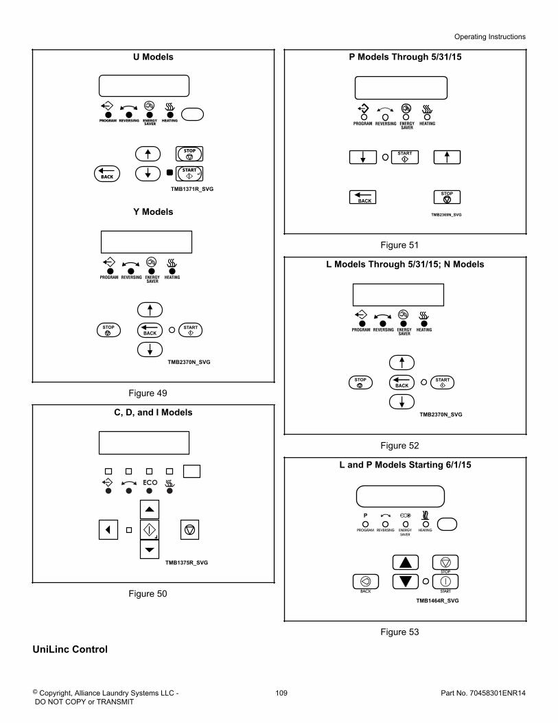
U Models
TMB1371R_SVG
Y Models
TMB2370N_SVG
STARTSTOPBACK
Figure 49
C, D, and I Models
TMB1375R_SVG
Figure 50
P Models Through 5/31/15
START
BACKSTOP
TMB2369N_SVG
Figure 51
L Models Through 5/31/15; N Models
TMB2370N_SVG
STARTSTOPBACK
Figure 52
L and P Models Starting 6/1/15
TMB1464R_SVG
Figure 53
UniLinc Control
Operating Instructions
© Copyright, Alliance Laundry Systems LLC - DO NOT COPY or TRANSMIT
109 Part No. 70458301ENR14
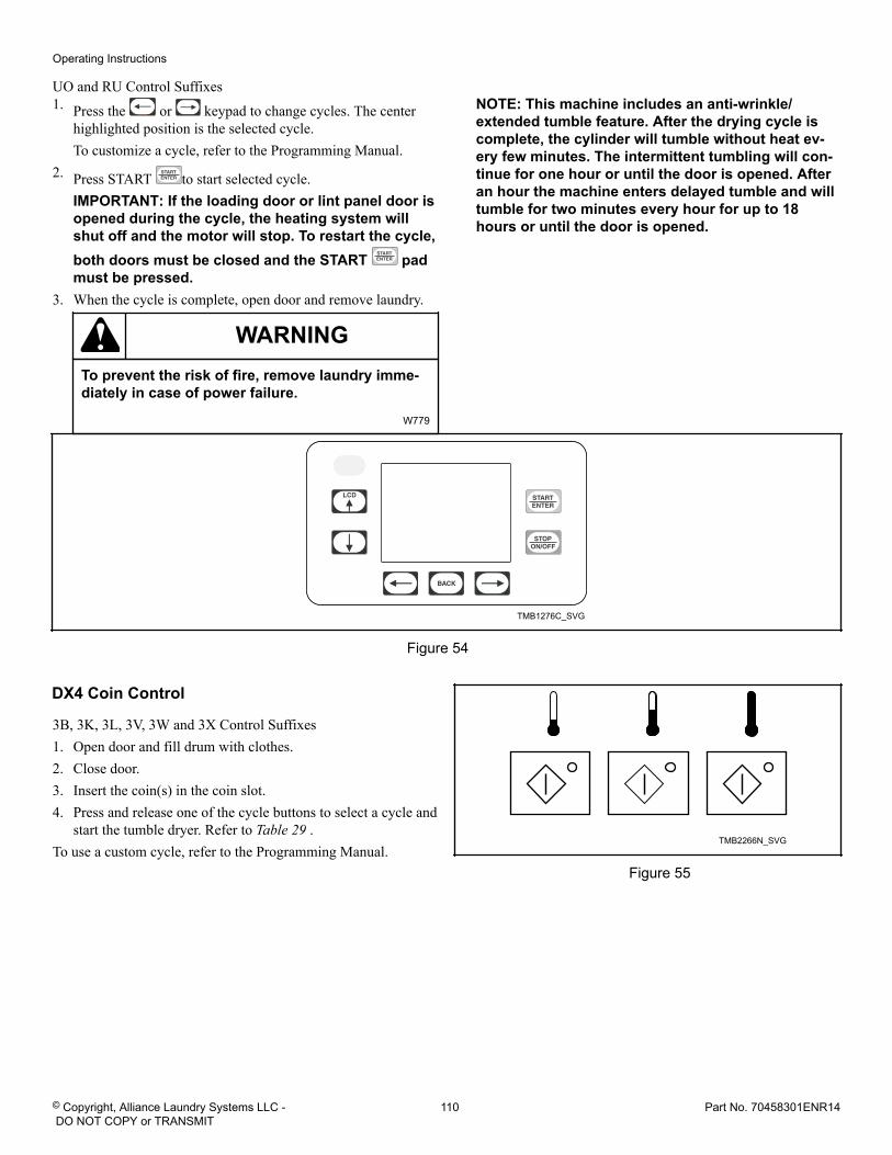
UO and RU Control Suffixes1. Press the or keypad to change cycles. The center
highlighted position is the selected cycle.To customize a cycle, refer to the Programming Manual.
2. Press START to start selected cycle.IMPORTANT: If the loading door or lint panel door isopened during the cycle, the heating system willshut off and the motor will stop. To restart the cycle,both doors must be closed and the START padmust be pressed.
3. When the cycle is complete, open door and remove laundry.
WARNINGTo prevent the risk of fire, remove laundry imme-diately in case of power failure.
W779
NOTE: This machine includes an anti-wrinkle/extended tumble feature. After the drying cycle iscomplete, the cylinder will tumble without heat ev-ery few minutes. The intermittent tumbling will con-tinue for one hour or until the door is opened. Afteran hour the machine enters delayed tumble and willtumble for two minutes every hour for up to 18hours or until the door is opened.
TMB1276C_SVG
Figure 54
DX4 Coin Control
3B, 3K, 3L, 3V, 3W and 3X Control Suffixes1. Open door and fill drum with clothes.2. Close door.3. Insert the coin(s) in the coin slot.4. Press and release one of the cycle buttons to select a cycle and
start the tumble dryer. Refer to Table 29 .To use a custom cycle, refer to the Programming Manual.
TMB2266N_SVG
Figure 55
Operating Instructions
© Copyright, Alliance Laundry Systems LLC - DO NOT COPY or TRANSMIT
110 Part No. 70458301ENR14
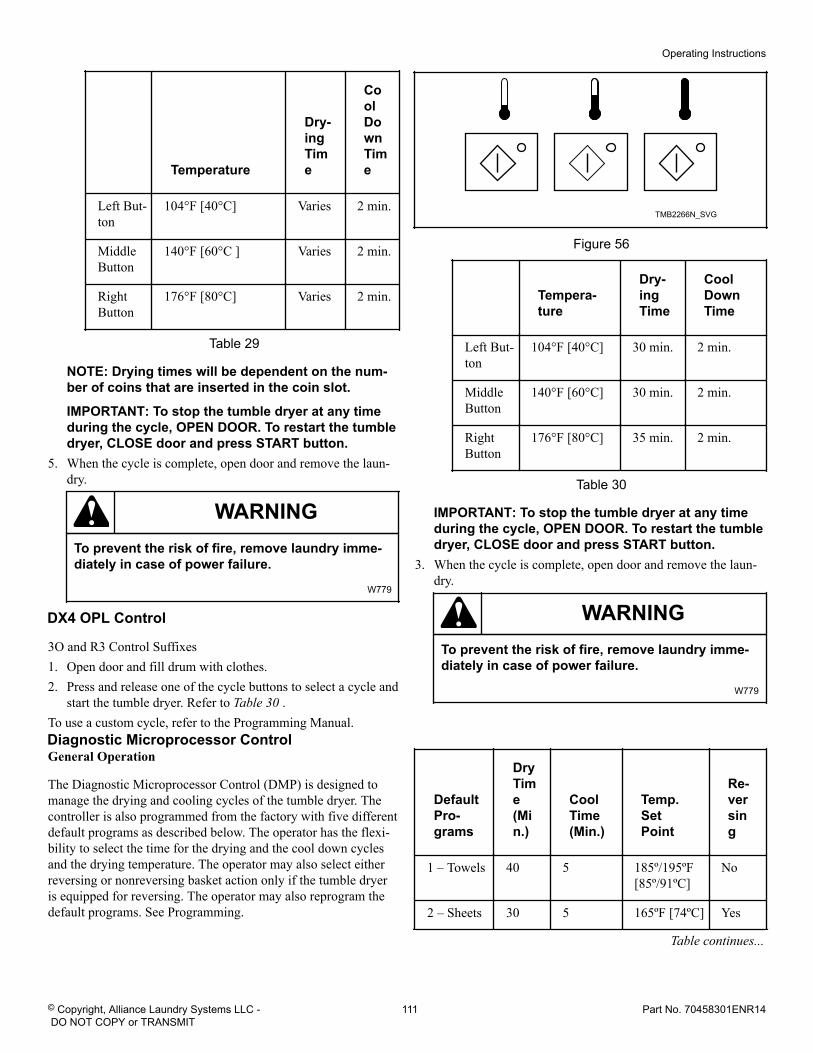
Temperature
Dry-ingTime
CoolDownTime
Left But-ton
104°F [40°C] Varies 2 min.
MiddleButton
140°F [60°C ] Varies 2 min.
RightButton
176°F [80°C] Varies 2 min.
Table 29
NOTE: Drying times will be dependent on the num-ber of coins that are inserted in the coin slot.
IMPORTANT: To stop the tumble dryer at any timeduring the cycle, OPEN DOOR. To restart the tumbledryer, CLOSE door and press START button.
5. When the cycle is complete, open door and remove the laun-dry.
WARNINGTo prevent the risk of fire, remove laundry imme-diately in case of power failure.
W779
DX4 OPL Control
3O and R3 Control Suffixes1. Open door and fill drum with clothes.2. Press and release one of the cycle buttons to select a cycle and
start the tumble dryer. Refer to Table 30 .To use a custom cycle, refer to the Programming Manual.
TMB2266N_SVG
Figure 56
Tempera-ture
Dry-ingTime
CoolDownTime
Left But-ton
104°F [40°C] 30 min. 2 min.
MiddleButton
140°F [60°C] 30 min. 2 min.
RightButton
176°F [80°C] 35 min. 2 min.
Table 30
IMPORTANT: To stop the tumble dryer at any timeduring the cycle, OPEN DOOR. To restart the tumbledryer, CLOSE door and press START button.
3. When the cycle is complete, open door and remove the laun-dry.
WARNINGTo prevent the risk of fire, remove laundry imme-diately in case of power failure.
W779
Diagnostic Microprocessor ControlGeneral Operation
The Diagnostic Microprocessor Control (DMP) is designed tomanage the drying and cooling cycles of the tumble dryer. Thecontroller is also programmed from the factory with five differentdefault programs as described below. The operator has the flexi-bility to select the time for the drying and the cool down cyclesand the drying temperature. The operator may also select eitherreversing or nonreversing basket action only if the tumble dryeris equipped for reversing. The operator may also reprogram thedefault programs. See Programming.
DefaultPro-grams
DryTime(Min.)
CoolTime(Min.)
Temp.SetPoint
Re-versing
1 – Towels 40 5 185º/195ºF[85º/91ºC]
No
2 – Sheets 30 5 165ºF [74ºC] Yes
Table continues...
Operating Instructions
© Copyright, Alliance Laundry Systems LLC - DO NOT COPY or TRANSMIT
111 Part No. 70458301ENR14
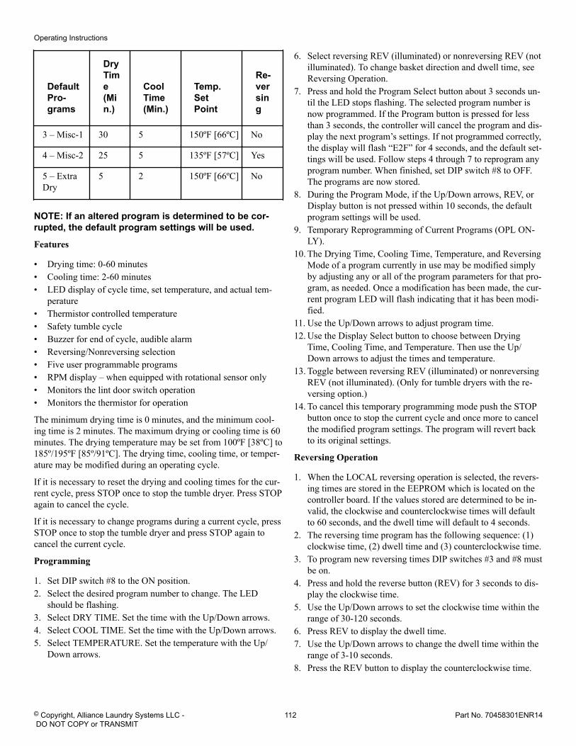
DefaultPro-grams
DryTime(Min.)
CoolTime(Min.)
Temp.SetPoint
Re-versing
3 – Misc-1 30 5 150ºF [66ºC] No
4 – Misc-2 25 5 135ºF [57ºC] Yes
5 – ExtraDry
5 2 150ºF [66ºC] No
NOTE: If an altered program is determined to be cor-rupted, the default program settings will be used.
Features
• Drying time: 0-60 minutes• Cooling time: 2-60 minutes• LED display of cycle time, set temperature, and actual tem-
perature• Thermistor controlled temperature• Safety tumble cycle• Buzzer for end of cycle, audible alarm• Reversing/Nonreversing selection• Five user programmable programs• RPM display – when equipped with rotational sensor only• Monitors the lint door switch operation• Monitors the thermistor for operation
The minimum drying time is 0 minutes, and the minimum cool-ing time is 2 minutes. The maximum drying or cooling time is 60minutes. The drying temperature may be set from 100ºF [38ºC] to185º/195ºF [85º/91ºC]. The drying time, cooling time, or temper-ature may be modified during an operating cycle.
If it is necessary to reset the drying and cooling times for the cur-rent cycle, press STOP once to stop the tumble dryer. Press STOPagain to cancel the cycle.
If it is necessary to change programs during a current cycle, pressSTOP once to stop the tumble dryer and press STOP again tocancel the current cycle.
Programming
1. Set DIP switch #8 to the ON position.2. Select the desired program number to change. The LED
should be flashing.3. Select DRY TIME. Set the time with the Up/Down arrows.4. Select COOL TIME. Set the time with the Up/Down arrows.5. Select TEMPERATURE. Set the temperature with the Up/
Down arrows.
6. Select reversing REV (illuminated) or nonreversing REV (notilluminated). To change basket direction and dwell time, seeReversing Operation.
7. Press and hold the Program Select button about 3 seconds un-til the LED stops flashing. The selected program number isnow programmed. If the Program button is pressed for lessthan 3 seconds, the controller will cancel the program and dis-play the next program’s settings. If not programmed correctly,the display will flash “E2F” for 4 seconds, and the default set-tings will be used. Follow steps 4 through 7 to reprogram anyprogram number. When finished, set DIP switch #8 to OFF.The programs are now stored.
8. During the Program Mode, if the Up/Down arrows, REV, orDisplay button is not pressed within 10 seconds, the defaultprogram settings will be used.
9. Temporary Reprogramming of Current Programs (OPL ON-LY).
10. The Drying Time, Cooling Time, Temperature, and ReversingMode of a program currently in use may be modified simplyby adjusting any or all of the program parameters for that pro-gram, as needed. Once a modification has been made, the cur-rent program LED will flash indicating that it has been modi-fied.
11. Use the Up/Down arrows to adjust program time.12. Use the Display Select button to choose between Drying
Time, Cooling Time, and Temperature. Then use the Up/Down arrows to adjust the times and temperature.
13. Toggle between reversing REV (illuminated) or nonreversingREV (not illuminated). (Only for tumble dryers with the re-versing option.)
14. To cancel this temporary programming mode push the STOPbutton once to stop the current cycle and once more to cancelthe modified program settings. The program will revert backto its original settings.
Reversing Operation
1. When the LOCAL reversing operation is selected, the revers-ing times are stored in the EEPROM which is located on thecontroller board. If the values stored are determined to be in-valid, the clockwise and counterclockwise times will defaultto 60 seconds, and the dwell time will default to 4 seconds.
2. The reversing time program has the following sequence: (1)clockwise time, (2) dwell time and (3) counterclockwise time.
3. To program new reversing times DIP switches #3 and #8 mustbe on.
4. Press and hold the reverse button (REV) for 3 seconds to dis-play the clockwise time.
5. Use the Up/Down arrows to set the clockwise time within therange of 30-120 seconds.
6. Press REV to display the dwell time.7. Use the Up/Down arrows to change the dwell time within the
range of 3-10 seconds.8. Press the REV button to display the counterclockwise time.
Operating Instructions
© Copyright, Alliance Laundry Systems LLC - DO NOT COPY or TRANSMIT
112 Part No. 70458301ENR14
9. Use the Up/Down arrows to change the counterclockwisetime within the range of 30-120 seconds.
10. Press the REV button to save these settings and leave DIPswitch #3 in the ON position and flip DIP switch #8 to theOFF position.
When the DMP controller is retrofitted to an existing tumble dry-er with the reversing feature, off board reversing will be requiredand DIP switch #3 on the DMP must be in the OFF position andthe DMP must be connected to the Reversing Timer Board forproper operation. The DMP settings for clockwise, dwell, andcounterclockwise times are no longer valid when used with theReversing Board. Instead these settings are made on the Revers-ing Timer Board.
Rotation Sensor
The rotation sensor must “read” the key on the basket shaft orpulley. The sensor must be set approximately 1/4 inch from thekey or pulley. Look for the light on the sensor to come on as thekey passes the sensor; this is a correctly operating sensor. If nolight appears, either the sensor is out of range or the key/pulley or
the sensor is bad. In addition, if the light stays on continuously,then the sensor is too close to the component or the sensor is bad.
Safety Tumble/Anti-Wrinkle
At the end of the cool down cycle, the tumble dryer will stop anddisplay “END.” The DMP control will automatically rotate thebasket for 5 seconds every 2 minutes for a total of 20 minutes,until some function of the tumble dryer is activated/deactivatedby the user.
Operational Check for the Board Diagnostics
1. “dor” indicates that the loading or lint door is open.2. Cycle the tumble dryer to check if the buzzer activates.3. “P-F” indicates that the thermistor is short circuited or open
circuited.4. “bbt” indicates a broken belt condition or a faulty rotation
sensor. (Only available on tumble dryers with the rotationsensor.)
5. Hold the START button to display the drum RPM’s; the dis-play will read “r##” where ## are the RPM’s. (Only availableon tumble dryers with the rotation sensor.)
DMP OPL ModelsDO Control Suffix
Operating Instructions
© Copyright, Alliance Laundry Systems LLC - DO NOT COPY or TRANSMIT
113 Part No. 70458301ENR14
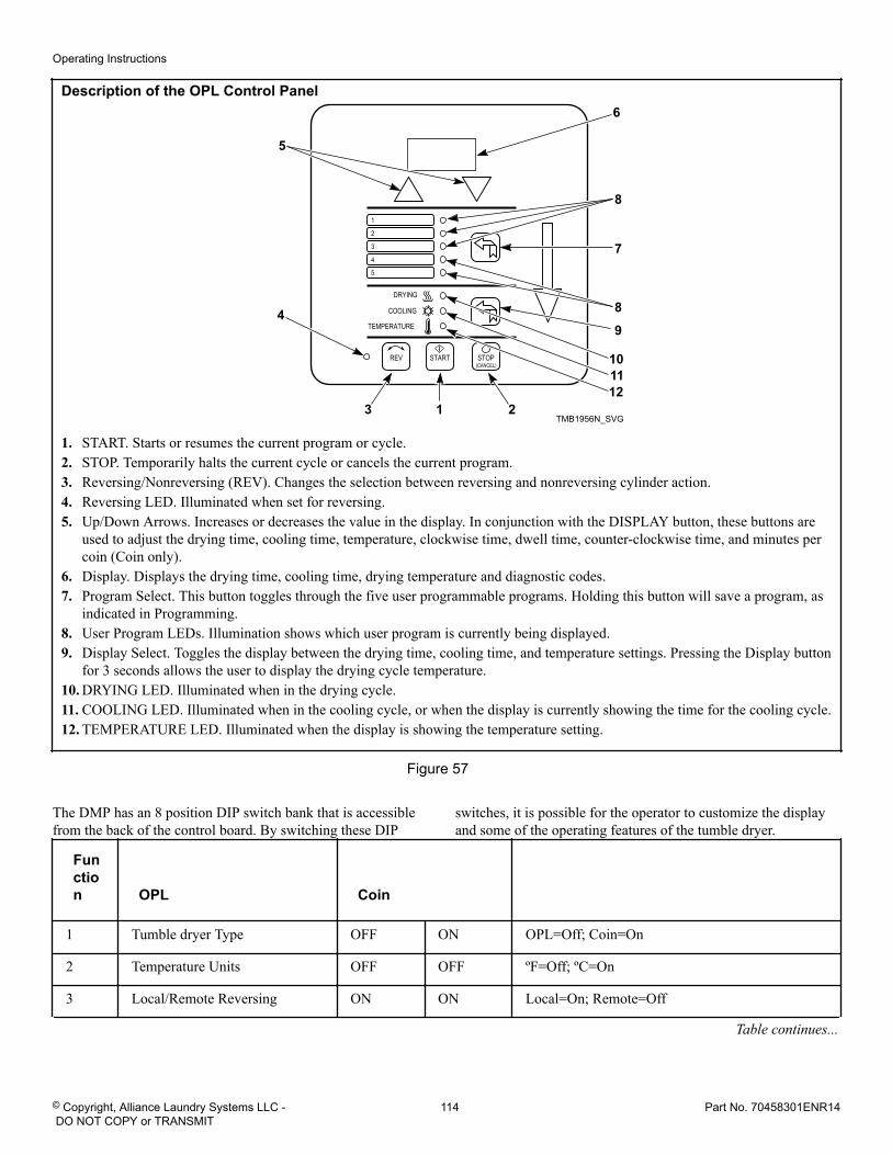
Description of the OPL Control Panel
TMB1956N_SVG
6
8
7
8
213
4
5
101112
9
1. START. Starts or resumes the current program or cycle.2. STOP. Temporarily halts the current cycle or cancels the current program.3. Reversing/Nonreversing (REV). Changes the selection between reversing and nonreversing cylinder action.4. Reversing LED. Illuminated when set for reversing.5. Up/Down Arrows. Increases or decreases the value in the display. In conjunction with the DISPLAY button, these buttons are
used to adjust the drying time, cooling time, temperature, clockwise time, dwell time, counter-clockwise time, and minutes percoin (Coin only).
6. Display. Displays the drying time, cooling time, drying temperature and diagnostic codes.7. Program Select. This button toggles through the five user programmable programs. Holding this button will save a program, as
indicated in Programming.8. User Program LEDs. Illumination shows which user program is currently being displayed.9. Display Select. Toggles the display between the drying time, cooling time, and temperature settings. Pressing the Display button
for 3 seconds allows the user to display the drying cycle temperature.10. DRYING LED. Illuminated when in the drying cycle.11. COOLING LED. Illuminated when in the cooling cycle, or when the display is currently showing the time for the cooling cycle.12. TEMPERATURE LED. Illuminated when the display is showing the temperature setting.
Figure 57
The DMP has an 8 position DIP switch bank that is accessiblefrom the back of the control board. By switching these DIP
switches, it is possible for the operator to customize the displayand some of the operating features of the tumble dryer.
Function OPL Coin
1 Tumble dryer Type OFF ON OPL=Off; Coin=On
2 Temperature Units OFF OFF ºF=Off; ºC=On
3 Local/Remote Reversing ON ON Local=On; Remote=Off
Table continues...
Operating Instructions
© Copyright, Alliance Laundry Systems LLC - DO NOT COPY or TRANSMIT
114 Part No. 70458301ENR14
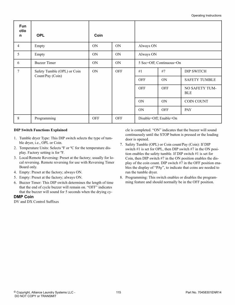
Function OPL Coin
4 Empty ON ON Always ON
5 Empty ON ON Always ON
6 Buzzer Timer ON ON 5 Sec=Off; Continuous=On
7 Safety Tumble (OPL) or CoinCount/Pay (Coin)
ON OFF #1 #7 DIP SWITCH
OFF ON SAFETY TUMBLE
OFF OFF NO SAFETY TUM-BLE
ON ON COIN COUNT
ON OFF PAY
8 Programming OFF OFF Disable=Off; Enable=On
DIP Switch Functions Explained
1. Tumble dryer Type: This DIP switch selects the type of tum-ble dryer, i.e., OPL or Coin.
2. Temperature Units: Selects ºF or ºC for the temperature dis-play. Factory setting is for ºF.
3. Local/Remote Reversing: Preset at the factory; usually for lo-cal reversing. Remote reversing for use with Reversing TimerBoard only.
4. Empty: Preset at the factory; always ON.5. Empty: Preset at the factory; always ON.6. Buzzer Timer: This DIP switch determines the length of time
that the end of cycle buzzer will remain on. “OFF” indicatesthat the buzzer will sound for 5 seconds when the drying cy-
cle is completed. “ON” indicates that the buzzer will soundcontinuously until the STOP button is pressed or the loadingdoor is opened.
7. Safety Tumble (OPL) or Coin count/Pay (Coin): If DIPswitch #1 is set for OPL, then DIP switch #7 in the ON posi-tion enables the safety tumble. If DIP switch #1 is set forCoin, then DIP switch #7 in the ON position enables the dis-play of the coin count. DIP switch #7 in the OFF position ena-bles the display of “PAy”, to indicate that coins are needed torun the tumble dryer.
8. Programming: This switch enables or disables the program-ming feature and should normally be in the OFF position.
DMP CoinDV and DX Control Suffixes
Operating Instructions
© Copyright, Alliance Laundry Systems LLC - DO NOT COPY or TRANSMIT
115 Part No. 70458301ENR14
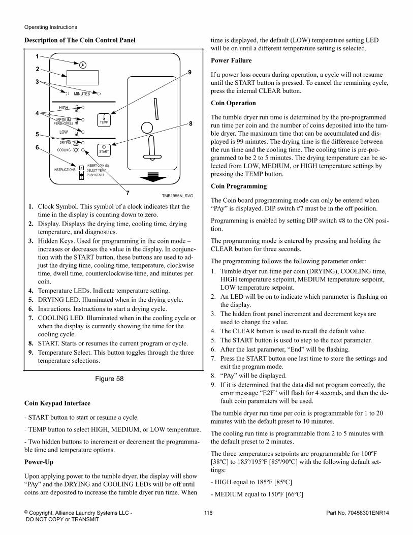
Description of The Coin Control Panel
TMB1955N_SVG
9
8
7
6
5
4
3
1
2
1. Clock Symbol. This symbol of a clock indicates that thetime in the display is counting down to zero.
2. Display. Displays the drying time, cooling time, dryingtemperature, and diagnostics.
3. Hidden Keys. Used for programming in the coin mode –increases or decreases the value in the display. In conjunc-tion with the START button, these buttons are used to ad-just the drying time, cooling time, temperature, clockwisetime, dwell time, counterclockwise time, and minutes percoin.
4. Temperature LEDs. Indicate temperature setting.5. DRYING LED. Illuminated when in the drying cycle.6. Instructions. Instructions to start a drying cycle.7. COOLING LED. Illuminated when in the cooling cycle or
when the display is currently showing the time for thecooling cycle.
8. START. Starts or resumes the current program or cycle.9. Temperature Select. This button toggles through the three
temperature selections.
Figure 58
Coin Keypad Interface
- START button to start or resume a cycle.
- TEMP button to select HIGH, MEDIUM, or LOW temperature.
- Two hidden buttons to increment or decrement the programma-ble time and temperature options.
Power-Up
Upon applying power to the tumble dryer, the display will show“PAy” and the DRYING and COOLING LEDs will be off untilcoins are deposited to increase the tumble dryer run time. When
time is displayed, the default (LOW) temperature setting LEDwill be on until a different temperature setting is selected.
Power Failure
If a power loss occurs during operation, a cycle will not resumeuntil the START button is pressed. To cancel the remaining cycle,press the internal CLEAR button.
Coin Operation
The tumble dryer run time is determined by the pre-programmedrun time per coin and the number of coins deposited into the tum-ble dryer. The maximum time that can be accumulated and dis-played is 99 minutes. The drying time is the difference betweenthe run time and the cooling time. The cooling time is pre-pro-grammed to be 2 to 5 minutes. The drying temperature can be se-lected from LOW, MEDIUM, or HIGH temperature settings bypressing the TEMP button.
Coin Programming
The Coin board programming mode can only be entered when“PAy” is displayed. DIP switch #7 must be in the off position.
Programming is enabled by setting DIP switch #8 to the ON posi-tion.
The programming mode is entered by pressing and holding theCLEAR button for three seconds.
The programming follows the following parameter order:1. Tumble dryer run time per coin (DRYING), COOLING time,
HIGH temperature setpoint, MEDIUM temperature setpoint,LOW temperature setpoint.
2. An LED will be on to indicate which parameter is flashing onthe display.
3. The hidden front panel increment and decrement keys areused to change the value.
4. The CLEAR button is used to recall the default value.5. The START button is used to step to the next parameter.6. After the last parameter, “End” will be flashing.7. Press the START button one last time to store the settings and
exit the program mode.8. “PAy” will be displayed.9. If it is determined that the data did not program correctly, the
error message “E2F” will flash for 4 seconds, and then the de-fault coin parameters will be used.
The tumble dryer run time per coin is programmable for 1 to 20minutes with the default preset to 10 minutes.
The cooling run time is programmable from 2 to 5 minutes withthe default preset to 2 minutes.
The three temperatures setpoints are programmable for 100ºF[38ºC] to 185º/195ºF [85º/90ºC] with the following default set-tings:
- HIGH equal to 185ºF [85ºC]
- MEDIUM equal to 150ºF [66ºC]
Operating Instructions
© Copyright, Alliance Laundry Systems LLC - DO NOT COPY or TRANSMIT
116 Part No. 70458301ENR14
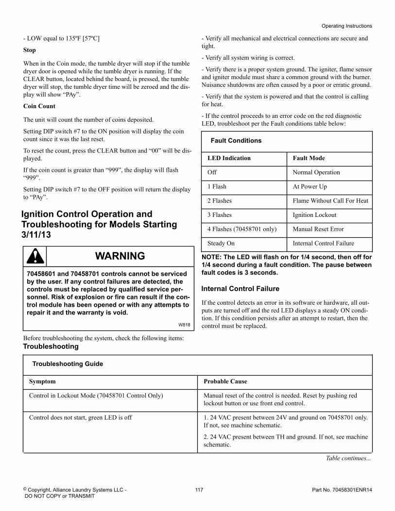
- LOW equal to 135ºF [57ºC]
Stop
When in the Coin mode, the tumble dryer will stop if the tumbledryer door is opened while the tumble dryer is running. If theCLEAR button, located behind the board, is pressed, the tumbledryer will stop, the tumble dryer time will be zeroed and the dis-play will show “PAy”.
Coin Count
The unit will count the number of coins deposited.
Setting DIP switch #7 to the ON position will display the coincount since it was the last reset.
To reset the count, press the CLEAR button and “00” will be dis-played.
If the coin count is greater than “999”, the display will flash“999”.
Setting DIP switch #7 to the OFF position will return the displayto “PAy”.
Ignition Control Operation andTroubleshooting for Models Starting3/11/13
WARNING70458601 and 70458701 controls cannot be servicedby the user. If any control failures are detected, thecontrols must be replaced by qualified service per-sonnel. Risk of explosion or fire can result if the con-trol module has been opened or with any attempts torepair it and the warranty is void.
W818
Before troubleshooting the system, check the following items:
- Verify all mechanical and electrical connections are secure andtight.
- Verify all system wiring is correct.
- Verify there is a proper system ground. The igniter, flame sensorand igniter module must share a common ground with the burner.Nuisance shutdowns are often caused by a poor or erratic ground.
- Verify that the system is powered and that the control is callingfor heat.
- If the control proceeds to an error code on the red diagnosticLED, troubleshoot per the Fault conditions table below:
Fault Conditions
LED Indication Fault Mode
Off Normal Operation
1 Flash At Power Up
2 Flashes Flame Without Call For Heat
3 Flashes Ignition Lockout
4 Flashes (70458701 only) Manual Reset Error
Steady On Internal Control Failure
NOTE: The LED will flash on for 1/4 second, then off for1/4 second during a fault condition. The pause betweenfault codes is 3 seconds.
Internal Control Failure
If the control detects an error in its software or hardware, all out-puts are turned off and the red LED displays a steady ON condi-tion. If this condition persists after an attempt to restart, then thecontrol must be replaced.
Troubleshooting
Troubleshooting Guide
Symptom Probable Cause
Control in Lockout Mode (70458701 Control Only) Manual reset of the control is needed. Reset by pushing redlockout button or use front end control.
Control does not start, green LED is off 1. 24 VAC present between 24V and ground on 70458701 only.If not, see machine schematic.
2. 24 VAC present between TH and ground. If not, see machineschematic.
Table continues...
Operating Instructions
© Copyright, Alliance Laundry Systems LLC - DO NOT COPY or TRANSMIT
117 Part No. 70458301ENR14
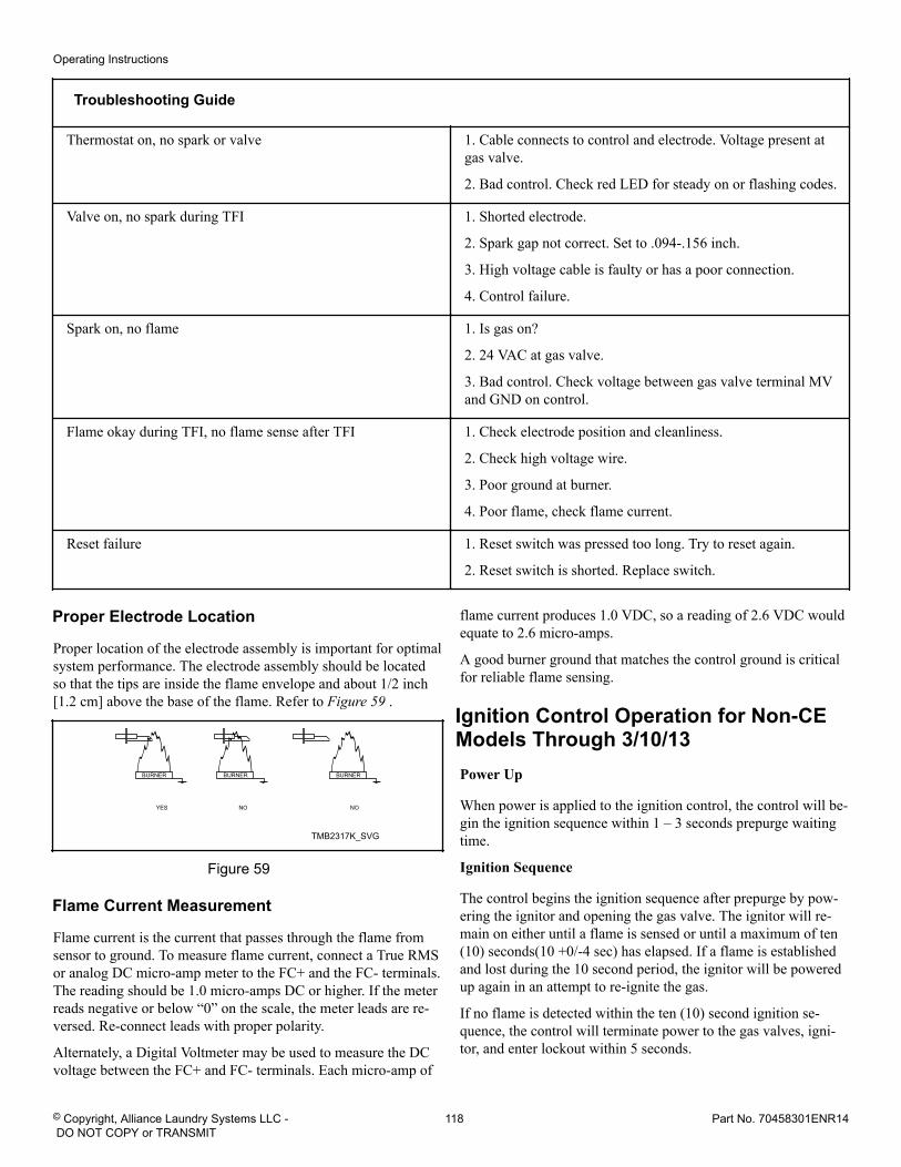
Troubleshooting Guide
Thermostat on, no spark or valve 1. Cable connects to control and electrode. Voltage present atgas valve.
2. Bad control. Check red LED for steady on or flashing codes.
Valve on, no spark during TFI 1. Shorted electrode.
2. Spark gap not correct. Set to .094-.156 inch.
3. High voltage cable is faulty or has a poor connection.
4. Control failure.
Spark on, no flame 1. Is gas on?
2. 24 VAC at gas valve.
3. Bad control. Check voltage between gas valve terminal MVand GND on control.
Flame okay during TFI, no flame sense after TFI 1. Check electrode position and cleanliness.
2. Check high voltage wire.
3. Poor ground at burner.
4. Poor flame, check flame current.
Reset failure 1. Reset switch was pressed too long. Try to reset again.
2. Reset switch is shorted. Replace switch.
Proper Electrode Location
Proper location of the electrode assembly is important for optimalsystem performance. The electrode assembly should be locatedso that the tips are inside the flame envelope and about 1/2 inch[1.2 cm] above the base of the flame. Refer to Figure 59 .
TMB2317K_SVG
Figure 59
Flame Current Measurement
Flame current is the current that passes through the flame fromsensor to ground. To measure flame current, connect a True RMSor analog DC micro-amp meter to the FC+ and the FC- terminals.The reading should be 1.0 micro-amps DC or higher. If the meterreads negative or below “0” on the scale, the meter leads are re-versed. Re-connect leads with proper polarity.
Alternately, a Digital Voltmeter may be used to measure the DCvoltage between the FC+ and FC- terminals. Each micro-amp of
flame current produces 1.0 VDC, so a reading of 2.6 VDC wouldequate to 2.6 micro-amps.
A good burner ground that matches the control ground is criticalfor reliable flame sensing.
Ignition Control Operation for Non-CEModels Through 3/10/13Power Up
When power is applied to the ignition control, the control will be-gin the ignition sequence within 1 – 3 seconds prepurge waitingtime.
Ignition Sequence
The control begins the ignition sequence after prepurge by pow-ering the ignitor and opening the gas valve. The ignitor will re-main on either until a flame is sensed or until a maximum of ten(10) seconds(10 +0/-4 sec) has elapsed. If a flame is establishedand lost during the 10 second period, the ignitor will be poweredup again in an attempt to re-ignite the gas.
If no flame is detected within the ten (10) second ignition se-quence, the control will terminate power to the gas valves, igni-tor, and enter lockout within 5 seconds.
Operating Instructions
© Copyright, Alliance Laundry Systems LLC - DO NOT COPY or TRANSMIT
118 Part No. 70458301ENR14
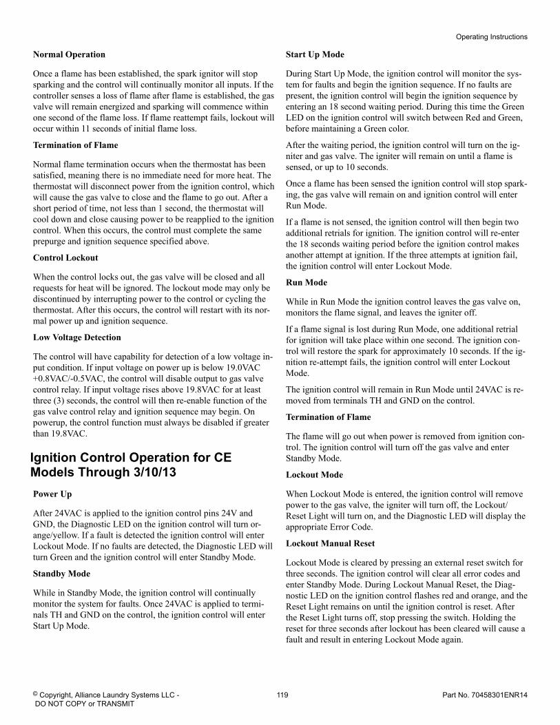
Normal Operation
Once a flame has been established, the spark ignitor will stopsparking and the control will continually monitor all inputs. If thecontroller senses a loss of flame after flame is established, the gasvalve will remain energized and sparking will commence withinone second of the flame loss. If flame reattempt fails, lockout willoccur within 11 seconds of initial flame loss.
Termination of Flame
Normal flame termination occurs when the thermostat has beensatisfied, meaning there is no immediate need for more heat. Thethermostat will disconnect power from the ignition control, whichwill cause the gas valve to close and the flame to go out. After ashort period of time, not less than 1 second, the thermostat willcool down and close causing power to be reapplied to the ignitioncontrol. When this occurs, the control must complete the sameprepurge and ignition sequence specified above.
Control Lockout
When the control locks out, the gas valve will be closed and allrequests for heat will be ignored. The lockout mode may only bediscontinued by interrupting power to the control or cycling thethermostat. After this occurs, the control will restart with its nor-mal power up and ignition sequence.
Low Voltage Detection
The control will have capability for detection of a low voltage in-put condition. If input voltage on power up is below 19.0VAC+0.8VAC/-0.5VAC, the control will disable output to gas valvecontrol relay. If input voltage rises above 19.8VAC for at leastthree (3) seconds, the control will then re-enable function of thegas valve control relay and ignition sequence may begin. Onpowerup, the control function must always be disabled if greaterthan 19.8VAC.
Ignition Control Operation for CEModels Through 3/10/13Power Up
After 24VAC is applied to the ignition control pins 24V andGND, the Diagnostic LED on the ignition control will turn or-ange/yellow. If a fault is detected the ignition control will enterLockout Mode. If no faults are detected, the Diagnostic LED willturn Green and the ignition control will enter Standby Mode.
Standby Mode
While in Standby Mode, the ignition control will continuallymonitor the system for faults. Once 24VAC is applied to termi-nals TH and GND on the control, the ignition control will enterStart Up Mode.
Start Up Mode
During Start Up Mode, the ignition control will monitor the sys-tem for faults and begin the ignition sequence. If no faults arepresent, the ignition control will begin the ignition sequence byentering an 18 second waiting period. During this time the GreenLED on the ignition control will switch between Red and Green,before maintaining a Green color.
After the waiting period, the ignition control will turn on the ig-niter and gas valve. The igniter will remain on until a flame issensed, or up to 10 seconds.
Once a flame has been sensed the ignition control will stop spark-ing, the gas valve will remain on and ignition control will enterRun Mode.
If a flame is not sensed, the ignition control will then begin twoadditional retrials for ignition. The ignition control will re-enterthe 18 seconds waiting period before the ignition control makesanother attempt at ignition. If the three attempts at ignition fail,the ignition control will enter Lockout Mode.
Run Mode
While in Run Mode the ignition control leaves the gas valve on,monitors the flame signal, and leaves the igniter off.
If a flame signal is lost during Run Mode, one additional retrialfor ignition will take place within one second. The ignition con-trol will restore the spark for approximately 10 seconds. If the ig-nition re-attempt fails, the ignition control will enter LockoutMode.
The ignition control will remain in Run Mode until 24VAC is re-moved from terminals TH and GND on the control.
Termination of Flame
The flame will go out when power is removed from ignition con-trol. The ignition control will turn off the gas valve and enterStandby Mode.
Lockout Mode
When Lockout Mode is entered, the ignition control will removepower to the gas valve, the igniter will turn off, the Lockout/Reset Light will turn on, and the Diagnostic LED will display theappropriate Error Code.
Lockout Manual Reset
Lockout Mode is cleared by pressing an external reset switch forthree seconds. The ignition control will clear all error codes andenter Standby Mode. During Lockout Manual Reset, the Diag-nostic LED on the ignition control flashes red and orange, and theReset Light remains on until the ignition control is reset. Afterthe Reset Light turns off, stop pressing the switch. Holding thereset for three seconds after lockout has been cleared will cause afault and result in entering Lockout Mode again.
Operating Instructions
© Copyright, Alliance Laundry Systems LLC - DO NOT COPY or TRANSMIT
119 Part No. 70458301ENR14
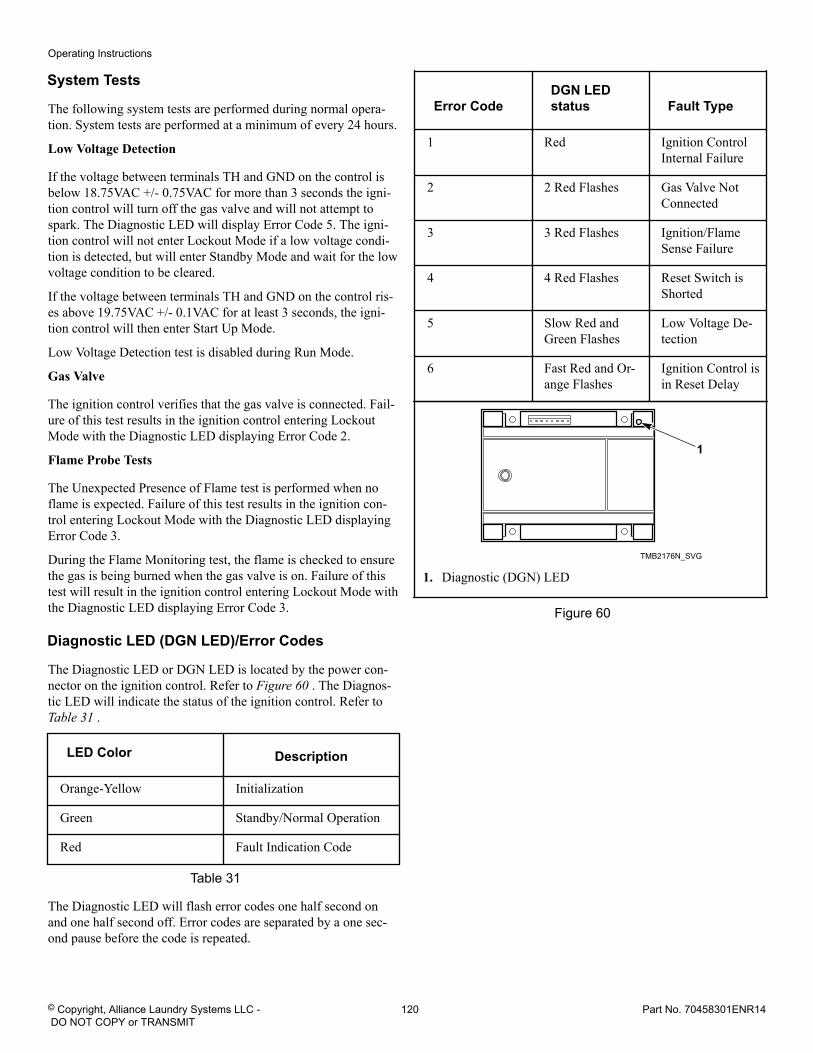
System Tests
The following system tests are performed during normal opera-tion. System tests are performed at a minimum of every 24 hours.
Low Voltage Detection
If the voltage between terminals TH and GND on the control isbelow 18.75VAC +/- 0.75VAC for more than 3 seconds the igni-tion control will turn off the gas valve and will not attempt tospark. The Diagnostic LED will display Error Code 5. The igni-tion control will not enter Lockout Mode if a low voltage condi-tion is detected, but will enter Standby Mode and wait for the lowvoltage condition to be cleared.
If the voltage between terminals TH and GND on the control ris-es above 19.75VAC +/- 0.1VAC for at least 3 seconds, the igni-tion control will then enter Start Up Mode.
Low Voltage Detection test is disabled during Run Mode.
Gas Valve
The ignition control verifies that the gas valve is connected. Fail-ure of this test results in the ignition control entering LockoutMode with the Diagnostic LED displaying Error Code 2.
Flame Probe Tests
The Unexpected Presence of Flame test is performed when noflame is expected. Failure of this test results in the ignition con-trol entering Lockout Mode with the Diagnostic LED displayingError Code 3.
During the Flame Monitoring test, the flame is checked to ensurethe gas is being burned when the gas valve is on. Failure of thistest will result in the ignition control entering Lockout Mode withthe Diagnostic LED displaying Error Code 3.
Diagnostic LED (DGN LED)/Error Codes
The Diagnostic LED or DGN LED is located by the power con-nector on the ignition control. Refer to Figure 60 . The Diagnos-tic LED will indicate the status of the ignition control. Refer to Table 31 .
LED Color Description
Orange-Yellow Initialization
Green Standby/Normal Operation
Red Fault Indication Code
Table 31
The Diagnostic LED will flash error codes one half second onand one half second off. Error codes are separated by a one sec-ond pause before the code is repeated.
Error CodeDGN LEDstatus Fault Type
1 Red Ignition ControlInternal Failure
2 2 Red Flashes Gas Valve NotConnected
3 3 Red Flashes Ignition/FlameSense Failure
4 4 Red Flashes Reset Switch isShorted
5 Slow Red andGreen Flashes
Low Voltage De-tection
6 Fast Red and Or-ange Flashes
Ignition Control isin Reset Delay
TMB2176N_SVG
1
1. Diagnostic (DGN) LED
Figure 60
Operating Instructions
© Copyright, Alliance Laundry Systems LLC - DO NOT COPY or TRANSMIT
120 Part No. 70458301ENR14
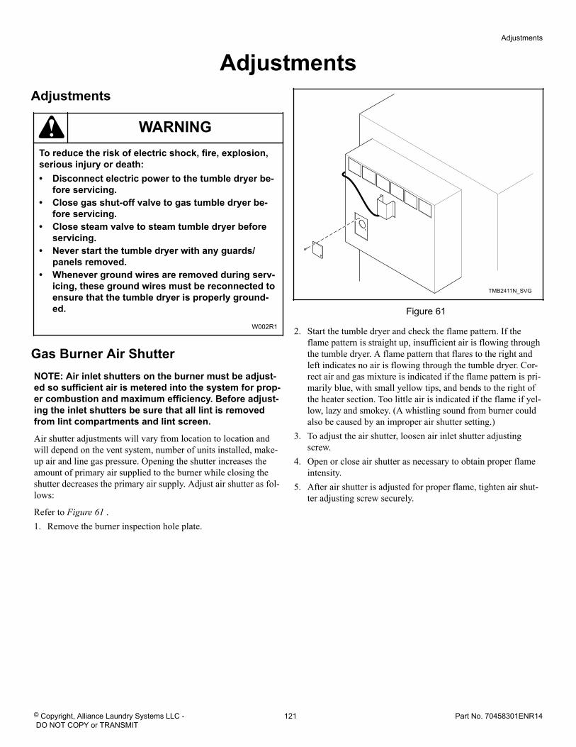
Adjustments Adjustments
WARNINGTo reduce the risk of electric shock, fire, explosion,serious injury or death:• Disconnect electric power to the tumble dryer be-
fore servicing.• Close gas shut-off valve to gas tumble dryer be-
fore servicing.• Close steam valve to steam tumble dryer before
servicing.• Never start the tumble dryer with any guards/
panels removed.• Whenever ground wires are removed during serv-
icing, these ground wires must be reconnected toensure that the tumble dryer is properly ground-ed.
W002R1
Gas Burner Air ShutterNOTE: Air inlet shutters on the burner must be adjust-ed so sufficient air is metered into the system for prop-er combustion and maximum efficiency. Before adjust-ing the inlet shutters be sure that all lint is removedfrom lint compartments and lint screen.
Air shutter adjustments will vary from location to location andwill depend on the vent system, number of units installed, make-up air and line gas pressure. Opening the shutter increases theamount of primary air supplied to the burner while closing theshutter decreases the primary air supply. Adjust air shutter as fol-lows:
Refer to Figure 61 .1. Remove the burner inspection hole plate.
TMB2411N_SVG
Figure 61
2. Start the tumble dryer and check the flame pattern. If theflame pattern is straight up, insufficient air is flowing throughthe tumble dryer. A flame pattern that flares to the right andleft indicates no air is flowing through the tumble dryer. Cor-rect air and gas mixture is indicated if the flame pattern is pri-marily blue, with small yellow tips, and bends to the right ofthe heater section. Too little air is indicated if the flame if yel-low, lazy and smokey. (A whistling sound from burner couldalso be caused by an improper air shutter setting.)
3. To adjust the air shutter, loosen air inlet shutter adjustingscrew.
4. Open or close air shutter as necessary to obtain proper flameintensity.
5. After air shutter is adjusted for proper flame, tighten air shut-ter adjusting screw securely.
Adjustments
© Copyright, Alliance Laundry Systems LLC - DO NOT COPY or TRANSMIT
121 Part No. 70458301ENR14
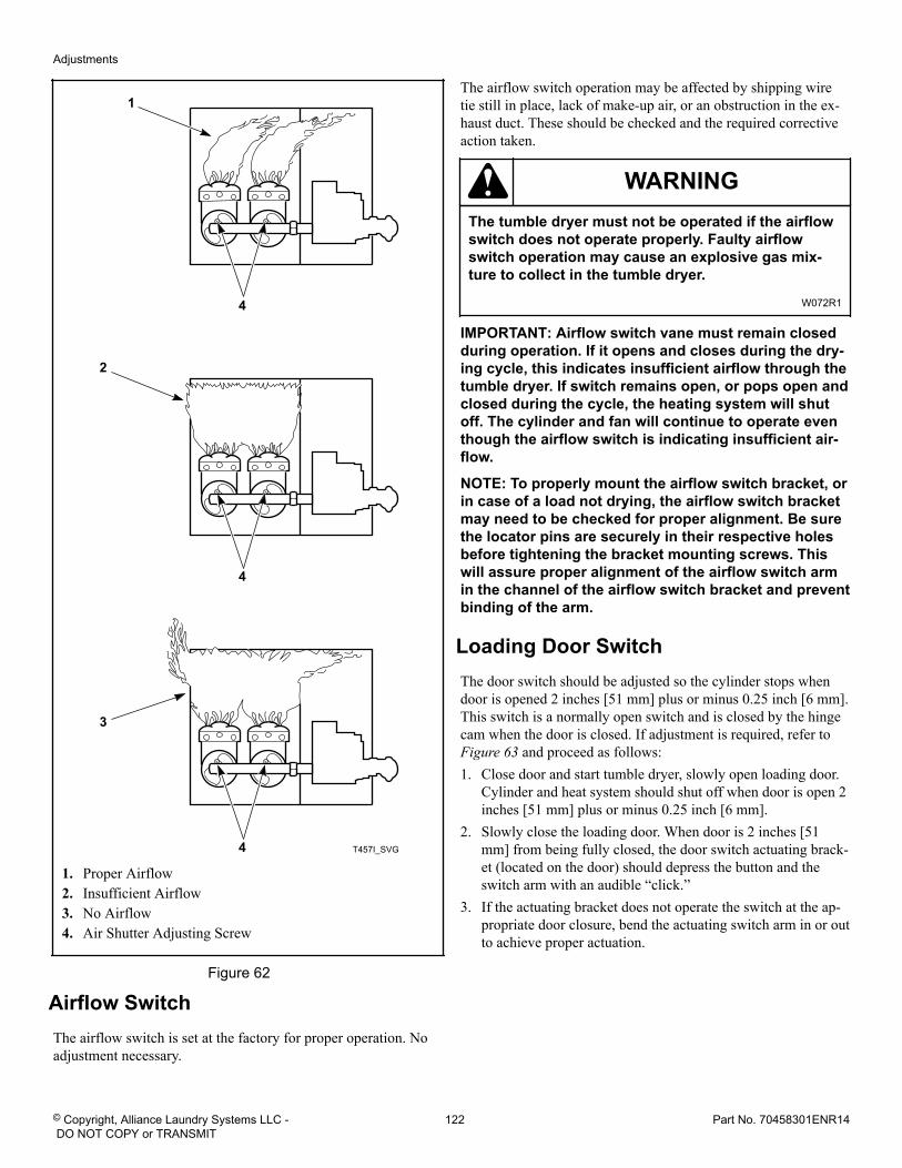
T457I_SVG
4
1
4
2
4
3
1. Proper Airflow2. Insufficient Airflow3. No Airflow4. Air Shutter Adjusting Screw
Figure 62
Airflow SwitchThe airflow switch is set at the factory for proper operation. Noadjustment necessary.
The airflow switch operation may be affected by shipping wiretie still in place, lack of make-up air, or an obstruction in the ex-haust duct. These should be checked and the required correctiveaction taken.
WARNINGThe tumble dryer must not be operated if the airflowswitch does not operate properly. Faulty airflowswitch operation may cause an explosive gas mix-ture to collect in the tumble dryer.
W072R1
IMPORTANT: Airflow switch vane must remain closedduring operation. If it opens and closes during the dry-ing cycle, this indicates insufficient airflow through thetumble dryer. If switch remains open, or pops open andclosed during the cycle, the heating system will shutoff. The cylinder and fan will continue to operate eventhough the airflow switch is indicating insufficient air-flow.
NOTE: To properly mount the airflow switch bracket, orin case of a load not drying, the airflow switch bracketmay need to be checked for proper alignment. Be surethe locator pins are securely in their respective holesbefore tightening the bracket mounting screws. Thiswill assure proper alignment of the airflow switch armin the channel of the airflow switch bracket and preventbinding of the arm.
Loading Door SwitchThe door switch should be adjusted so the cylinder stops whendoor is opened 2 inches [51 mm] plus or minus 0.25 inch [6 mm].This switch is a normally open switch and is closed by the hingecam when the door is closed. If adjustment is required, refer to Figure 63 and proceed as follows:1. Close door and start tumble dryer, slowly open loading door.
Cylinder and heat system should shut off when door is open 2inches [51 mm] plus or minus 0.25 inch [6 mm].
2. Slowly close the loading door. When door is 2 inches [51mm] from being fully closed, the door switch actuating brack-et (located on the door) should depress the button and theswitch arm with an audible “click.”
3. If the actuating bracket does not operate the switch at the ap-propriate door closure, bend the actuating switch arm in or outto achieve proper actuation.
Adjustments
© Copyright, Alliance Laundry Systems LLC - DO NOT COPY or TRANSMIT
122 Part No. 70458301ENR14
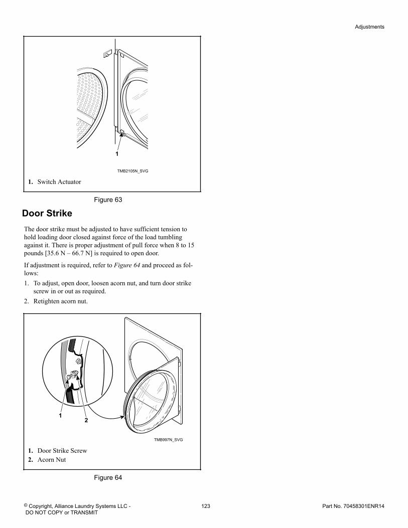
TMB2105N_SVG
1
1. Switch Actuator
Figure 63
Door StrikeThe door strike must be adjusted to have sufficient tension tohold loading door closed against force of the load tumblingagainst it. There is proper adjustment of pull force when 8 to 15pounds [35.6 N – 66.7 N] is required to open door.
If adjustment is required, refer to Figure 64 and proceed as fol-lows:1. To adjust, open door, loosen acorn nut, and turn door strike
screw in or out as required.2. Retighten acorn nut.
TMB997N_SVG
21
1. Door Strike Screw2. Acorn Nut
Figure 64
Adjustments
© Copyright, Alliance Laundry Systems LLC - DO NOT COPY or TRANSMIT
123 Part No. 70458301ENR14
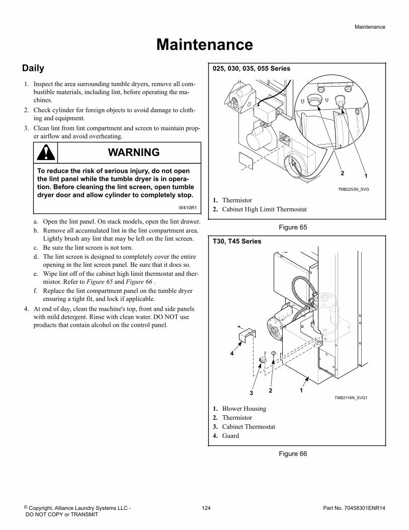
Maintenance Daily
1. Inspect the area surrounding tumble dryers, remove all com-bustible materials, including lint, before operating the ma-chines.
2. Check cylinder for foreign objects to avoid damage to cloth-ing and equipment.
3. Clean lint from lint compartment and screen to maintain prop-er airflow and avoid overheating.
WARNINGTo reduce the risk of serious injury, do not openthe lint panel while the tumble dryer is in opera-tion. Before cleaning the lint screen, open tumbledryer door and allow cylinder to completely stop.
W410R1
a. Open the lint panel. On stack models, open the lint drawer.b. Remove all accumulated lint in the lint compartment area.
Lightly brush any lint that may be left on the lint screen.c. Be sure the lint screen is not torn.d. The lint screen is designed to completely cover the entire
opening in the lint screen panel. Be sure that it does so.e. Wipe lint off of the cabinet high limit thermostat and ther-
mistor. Refer to Figure 65 and Figure 66 .f. Replace the lint compartment panel on the tumble dryer
ensuring a tight fit, and lock if applicable.4. At end of day, clean the machine's top, front and side panels
with mild detergent. Rinse with clean water. DO NOT useproducts that contain alcohol on the control panel.
025, 030, 035, 055 Series
TMB2253N_SVG
12
1. Thermistor2. Cabinet High Limit Thermostat
Figure 65
T30, T45 Series
TMB2116N_SVG1
123
4
1. Blower Housing2. Thermistor3. Cabinet Thermostat4. Guard
Figure 66
Maintenance
© Copyright, Alliance Laundry Systems LLC - DO NOT COPY or TRANSMIT
124 Part No. 70458301ENR14
Monthly1. Remove lint and debris from inside exhaust duct to maintain
proper airflow and avoid overheating.a. Remove external duct and duct access covers, if present.b. Clean inside of duct with a vacuum.c. Clean dampers and make sure they operate freely.d. Replace duct and all access covers before returning tumble
dryer to operation.2. Ensure even lint distribution over lint screen.3. Carefully wipe any accumulated lint off the cabinet high limit
thermostat and thermistor, including perforated cover.4. Clean lint and debris buildup from blower to maintain proper
airflow.
Quarterly1. Use a vacuum to clean air vents on drive motors.2. Use a vacuum to clean lint from rear limit thermostat cover.3. Check and clean steam coils, if applicable.4. Check flow of combustion and ventilation air.5. Check belt tension and condition. Replace worn or cracked
belts.6. Clean the machine's top panel with mild detergent. Rinse with
clean water.7. Models equipped with a fire suppression system: Perform
the fire suppression system maintenance test by pressing thetest button in the control box.
Bi-Annually1. Check mounting hardware for any loose nuts, bolts or screws.2. Check gas connections for leakage.3. Check for loose electrical connections.4. Check steam connections for looseness and leakage.5. Check steam filter. Replace if dirty.6. Remove all front panels and vacuum, including coin drop
mechanisms.7. Check cylinder and front panel seals.8. Inspect cabinet and inner panels for any damage, replace or
repair as needed.9. Clean burner tubes and orifice area of any lint buildup.10. Machines equipped with a fire suppression system: All in-
let and outlet hoses should be checked for any visible signs ofdeterioration. Replace as necessary or every five years.
11. Machines equipped with a heat exchanger kit: Clean theinlet and outlet with a soft brush or clean by using hot waterand, if needed, a mild detergent.
Annually1. Remove burner tubes.
2. Clean burner tubes using water and a brush.3. Remove cylinder. Use a vacuum to clean lint from area
around rear seal and idler assembly and check for wear.
Fire Suppression System (OptionalEquipment) Maintenance TestNOTE: Fire suppression system only available on gasand steam models.
To ensure proper operation, the fire suppression system must betested every three months. If the system test does not perform asindicated:
1. Discontinue use of the tumble dryer.2. Refer to Troubleshooting Manual or contact a qualified serv-
ice person.3. Restore the fire suppression system to proper working order
before using tumble dryer.
Create a maintenance record with a check box for pass, the dateand a signature. Store this record in an area where it will not bedamaged, but is easily accessible to person performing tests.
NOTE: Failure to maintain the fire suppression systemwill void the tumble dryer warranty.
NOTE: The auxiliary output is activated during the firesuppression system maintenance test sequence. Con-sider this fact prior to testing the system every threemonths. (Example – If the external system uses theauxiliary output to call the fire department, inform thefire department before and after the fire suppressionsystem maintenance test.)
CAUTIONClean up any water spilled during testing to avoidpersonal injury.
W487
Maintenance
© Copyright, Alliance Laundry Systems LLC - DO NOT COPY or TRANSMIT
125 Part No. 70458301ENR14
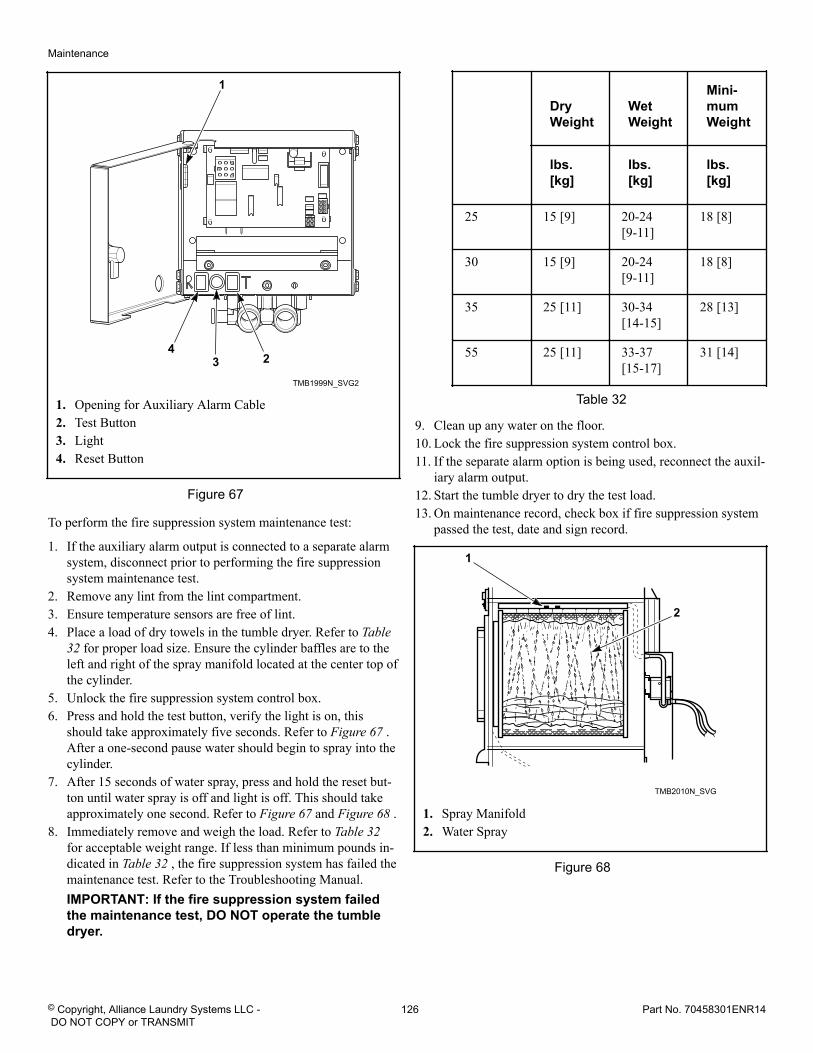
TMB1999N_SVG2
43 2
1
1. Opening for Auxiliary Alarm Cable2. Test Button3. Light4. Reset Button
Figure 67
To perform the fire suppression system maintenance test:
1. If the auxiliary alarm output is connected to a separate alarmsystem, disconnect prior to performing the fire suppressionsystem maintenance test.
2. Remove any lint from the lint compartment.3. Ensure temperature sensors are free of lint.4. Place a load of dry towels in the tumble dryer. Refer to Table
32 for proper load size. Ensure the cylinder baffles are to theleft and right of the spray manifold located at the center top ofthe cylinder.
5. Unlock the fire suppression system control box.6. Press and hold the test button, verify the light is on, this
should take approximately five seconds. Refer to Figure 67 .After a one-second pause water should begin to spray into thecylinder.
7. After 15 seconds of water spray, press and hold the reset but-ton until water spray is off and light is off. This should takeapproximately one second. Refer to Figure 67 and Figure 68 .
8. Immediately remove and weigh the load. Refer to Table 32 for acceptable weight range. If less than minimum pounds in-dicated in Table 32 , the fire suppression system has failed themaintenance test. Refer to the Troubleshooting Manual.IMPORTANT: If the fire suppression system failedthe maintenance test, DO NOT operate the tumbledryer.
DryWeight
WetWeight
Mini-mumWeight
lbs.[kg]
lbs.[kg]
lbs.[kg]
25 15 [9] 20-24[9-11]
18 [8]
30 15 [9] 20-24[9-11]
18 [8]
35 25 [11] 30-34[14-15]
28 [13]
55 25 [11] 33-37[15-17]
31 [14]
Table 32
9. Clean up any water on the floor.10. Lock the fire suppression system control box.11. If the separate alarm option is being used, reconnect the auxil-
iary alarm output.12. Start the tumble dryer to dry the test load.13. On maintenance record, check box if fire suppression system
passed the test, date and sign record.
TMB2010N_SVG
2
1
1. Spray Manifold2. Water Spray
Figure 68
Maintenance
© Copyright, Alliance Laundry Systems LLC - DO NOT COPY or TRANSMIT
126 Part No. 70458301ENR14
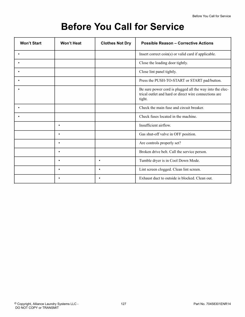
Before You Call for ServiceWon’t Start Won’t Heat Clothes Not Dry Possible Reason – Corrective Actions
• Insert correct coin(s) or valid card if applicable.
• Close the loading door tightly.
• Close lint panel tightly.
• Press the PUSH-TO-START or START pad/button.
• Be sure power cord is plugged all the way into the elec-trical outlet and hard or direct wire connections aretight.
• Check the main fuse and circuit breaker.
• Check fuses located in the machine.
• Insufficient airflow.
• Gas shut-off valve in OFF position.
• Are controls properly set?
• Broken drive belt. Call the service person.
• • Tumble dryer is in Cool Down Mode.
• • Lint screen clogged. Clean lint screen.
• • Exhaust duct to outside is blocked. Clean out.
Before You Call for Service
© Copyright, Alliance Laundry Systems LLC - DO NOT COPY or TRANSMIT
127 Part No. 70458301ENR14
Removing Tumble Dryer from Service1. Turn off electrical supply external to machine.2. Turn off electrical disconnect on machine.3. Turn off gas supply external to machine.4. Turn off manual gas shut-off valve on machine.5. Turn off steam supply external to machine.6. Remove all electric, gas and steam connections.
Removing Tumble Dryer from Service
© Copyright, Alliance Laundry Systems LLC - DO NOT COPY or TRANSMIT
128 Part No. 70458301ENR14
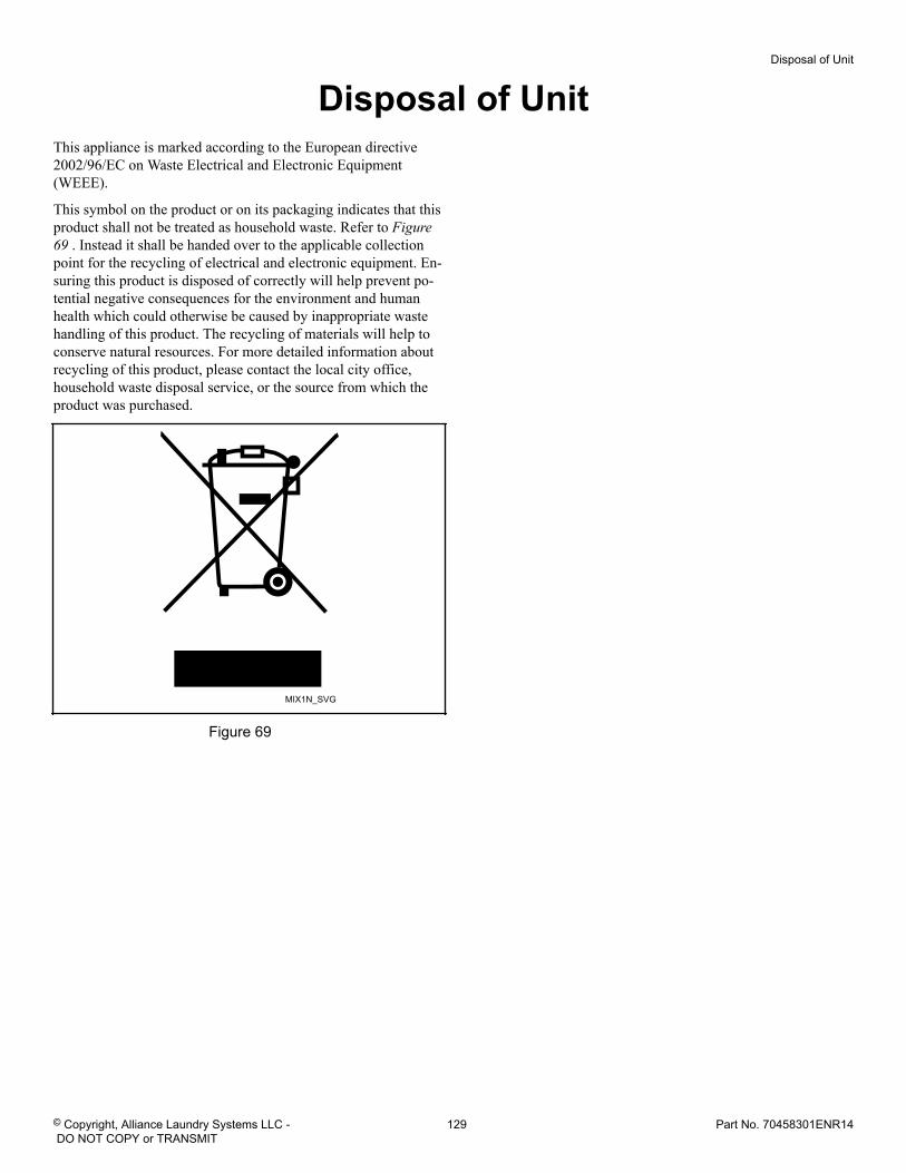
Disposal of UnitThis appliance is marked according to the European directive2002/96/EC on Waste Electrical and Electronic Equipment(WEEE).
This symbol on the product or on its packaging indicates that thisproduct shall not be treated as household waste. Refer to Figure69 . Instead it shall be handed over to the applicable collectionpoint for the recycling of electrical and electronic equipment. En-suring this product is disposed of correctly will help prevent po-tential negative consequences for the environment and humanhealth which could otherwise be caused by inappropriate wastehandling of this product. The recycling of materials will help toconserve natural resources. For more detailed information aboutrecycling of this product, please contact the local city office,household waste disposal service, or the source from which theproduct was purchased.
MIX1N_SVG
Figure 69
Disposal of Unit
© Copyright, Alliance Laundry Systems LLC - DO NOT COPY or TRANSMIT
129 Part No. 70458301ENR14
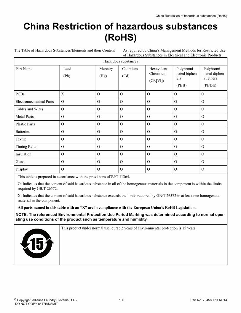
China Restriction of hazardous substances(RoHS)
The Table of Hazardous Substances/Elements and their Content As required by China’s Management Methods for Restricted Useof Hazardous Substances in Electrical and Electronic Products
Hazardous substances
Part Name Lead
(Pb)
Mercury
(Hg)
Cadmium
(Cd)
HexavalentChromium
(CR[VI])
Polybromi-nated biphen-yls
(PBB)
Polybromi-nated diphen-yl ethers
(PBDE)
PCBs X O O O O O
Electromechanical Parts O O O O O O
Cables and Wires O O O O O O
Metal Parts O O O O O O
Plastic Parts O O O O O O
Batteries O O O O O O
Textile O O O O O O
Timing Belts O O O O O O
Insulation O O O O O O
Glass O O O O O O
Display O O O O O O
This table is prepared in accordance with the provisions of SJ/T-11364.
O: Indicates that the content of said hazardous substance in all of the homogenous materials in the component is within the limitsrequired by GB/T 26572.
X: Indicates that the content of said hazardous substance exceeds the limits required by GB/T 26572 in at least one homogenousmaterial in the component.
All parts named in this table with an “X” are in compliance with the European Union’s RoHS Legislation.
NOTE: The referenced Environmental Protection Use Period Marking was determined according to normal oper-ating use conditions of the product such as temperature and humidity.
This product under normal use, durable years of environmental protection is 15 years.
China Restriction of hazardous substances (RoHS)
© Copyright, Alliance Laundry Systems LLC - DO NOT COPY or TRANSMIT
130 Part No. 70458301ENR14
Related Documents


