TRAVELING Feet Meters Turning radius Front tire (curb to curb) 42' 8" 13.0 Over jib 50' 7" 15.4 Tail swing of counterweight 13' 6-1/4" 4.12 Specifications are subject to change without notice. GENERAL DIMENSIONS TT-800XXL-1 80 Ton Capacity (72.6 Metric Tons) HYDRAULIC TRUCK CRANE DIMENSIONS Max. traveling speed 61.5mph (99km/h) 1

Welcome message from author
This document is posted to help you gain knowledge. Please leave a comment to let me know what you think about it! Share it to your friends and learn new things together.
Transcript
TRAVELING
Feet MetersTurning radius
Front tire (curb to curb) 42' 8" 13.0Over jib 50' 7" 15.4
Tail swing of counterweight 13' 6-1/4" 4.12
Specifications are subject to change without notice.
GENERAL DIMENSIONS
TT-800XXL-180 Ton Capacity (72.6 Metric Tons)
HYDRAULIC TRUCK CRANE
DIMENSIONS
Max. traveling speed 61.5mph (99km/h)
1
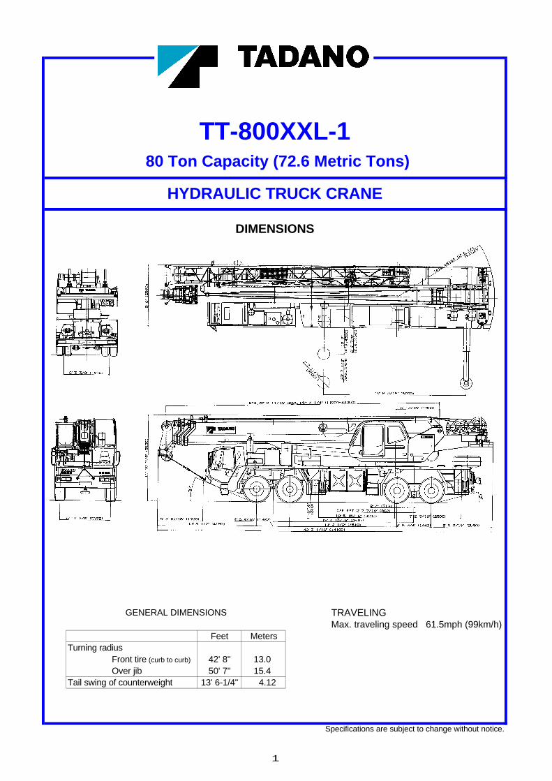
80 Ton Capacity (72.6 Metric Tons)
HYDRAULIC TRUCK CRANE
DIMENSIONS
GENERAL DIMENSIONS Tire : 445/65R22.5(Front)
315/80R22.5(Rear)
Feet Meters
Turning radius
Front tire (curb to curb) 40' 8" 12.4
Over jib 48' 7" 14.8
TT-800XXL
(500)
(R4120)
(MA
X.7
200)
(MID
.480
0)
(MIN
.208
0)
8'6"
(259
0)(
)
23' 7
-1/2
"15
' 9"
6' 9
-7/8
"
19'8-3/16"(6000)( )
1' 7-11/16"
TAIL SWING 13'6-1/4"
(310
)
46'3-1/16"(14100)
MIN.37'8-11/16"~MAX.144'4-1/4"(11500~44000)
11'1
0-7/
8"(3
630)
OFF SET 2'7-7/16"(800)9'2-3/16"(2800)10'5-15/16"(3200)
14'9-1/2"(4510) 4'8-3/4"(1443) 8'5-9/16"(2580)4'6-9/16"(1387)13'8-1/2"(4180)6'3-15/16"(1930)
2'4"(712)
6'13/16"(1850)
13o
19'4-13/16"(5915)
20o
1'3/
16"
6'11-7/8"(2132)
CRANE SPECIFICATIONSWIRE ROPE - Warrington seal wire, extra improved plow steel,
BOOM preformed, independent wire rope core, right regular lay.5-section full power synchronized telescoping boom, 3/4"(19 mm) 6X37 class37.7'~144.4' (11.5m~44m), of round hexagonal box construction with 7-sheaves, 17-5/16" (0.440m) root diameter, at boom head. HOOK BLOCKSThe synchronization system consists of double acting 2-telescope 6.2 ton (5.6 metric ton) - Weighted hook with swivel andcylinders, two extension cables and retraction cable. Hydraulic safety latch, for 3/4"(19mm) wire rope.cylinder fitted with holding valve. Two easily removable wire rope guards, rope dead end provided on both sides of boom head. HYDRAULIC SYSTEMBoom telescope sections are supported by wear pads both vertically and horizontally. Selection of 2 boom telescoping modes. PUMPS - Two variable piston pumps for crane functions.
Tandem gear pump for swing and optional equipment.BOOM ELEVATION - By a double acting hydraulic cylinder Powered by carrier engine. Pump disconnect for crane is
with holding valve. Elevation -2o~80o, combination controls for engaged/ disengaged by rocker switch from carrier cab.hand or foot operation. Boom angle indicator.
CONTROL VALVES - Multiple valves actuated by pilot
JIB - Double stage lattice type, 3.5o, 25o or 45o offset (tilt type). pressure with integral pressure relief valves.Single sheave, 15-5/8"(0.396m) root diameter, at base and top jib head. Stored alongside base boom section. Jib length is RESERVOIR - 185 gallon (700 lit.) capacity. External sight32.5' (9.9m) or 58.1' (17.7m). Assistant cylinders for mounting level gauge.and stowing, controlled at right side of superstructure.Self stowing jib mounting pins. FILTRATION - 26 micron return filter, full flow with bypass
protection, located inside of hydraulic reservoir. Accessible forAUXILIARY LIFTING SHEAVE (SINGLE TOP) (OPTIONAL) - easy replacement.Single sheave, 15-5/8"(0.396m) root diameter. Mounted to mainboom head for single line work (stowable). OIL COOLER - Air cooled fan type.
ANTI-TWO BLOCK - Pendant type over-winding cut out COUNTERWEIGHTdevice with audio-visual (FAILURE lamp/BUZZER) warning Pinned to superstructure frame. system. Two piece : 3,700lbs.(1,678kg) and 4,000lbs.(1,814kg).
Additional optional 8,000lbs.(3,628kg).SWING Hydraulically controlled counterweight.Hydraulic axial piston motor driven through planetary swingspeed reducer. Continuous 360o full circle swing on ball bearingturntable at 1.7rpm. Equipped with manually locked/released CAB AND CONTROLSswing brake. Twin swing System: Free swing or lock swingcontrolled by selector switch on front console. Left side, 1 man type, steel construction with sliding door
access and safety glass windows opening at side. DoorHOIST window is powered control. Windshield glass window and roof
glass window are shatter-resistant. Adjustable control lever MAIN HOIST - Variable speed type with grooved drum driven stands for swing, boom hoist, boom telescoping, auxiliary by hydraulic axial piston motor through winch speed reducer. hoist and main hoist. Control lever stands can change neutral Power load lowering and raising. Equipped with automatic positions and tilt for easy access to cab. Engine throttle knob.brake (neutral brake) and counterbalance valve. Controlled Foot operated controls: boom hoist, boom telescoping andindependently of auxiliary hoist. Equipped with cable follower. engine throttle. Hot water cab heater and air conditioningDrum rotation indicator(OPTIONAL). (OPTIONAL).
DRUM - Grooved 15-3/4"(0.40m) root diameter x 22-3/4" Dash-mounted engine start/stop, monitor lamps, cigarette(0.578m) wide. Wire rope: 797' of 3/4"diameter rope (243m of lighter, telescoping mode I / II switch, low noise mode switch,19mm). Drum capacity: 1,095.5' (333.9m) 7 layers. Maximum line front washer and wiper switch, power window switch, swingpull (permissible): 15,200lbs. (6,880kg)*. Maximum line speed: brake switch, telescoping / auxiliary winch select switch, 585FPM (178m/min). main winch / auxiliary winch selector switch, swing stop
cancel switch, slow elevation stop cancel switch, free swing /AUXILIARY HOIST - Variable speed type with grooved drum lock swing selector switch and ashtray.driven by hydraulic axial piston motor through winch speed Outrigger controls (OPTIONAL).reducer. Power load lowering and raising. Equipped withautomatic brake (neutral brake) and counterbalance valve. Instruments - Hydraulic oil pressure is monitored and displayedControlled independently of main hoist. Equipped with cable on the AML-L display panel.follower. Drum rotation indicator(OPTIONAL).
DRUM - Grooved 15-3/4"(0.40m) root diameter x 22-3/4"(0.578m) wide. Wire rope: 436' of 3/4"diameter rope (133m of19mm). Drum capacity: 1,095.5' (333.9m) 7 layers. Maximum linepull (permissible): 15,200lbs. (6,880kg)*. Maximum line speed:585FPM (178m/min).
* Maximum permissible line pull may be affected by wire rope strength.
2
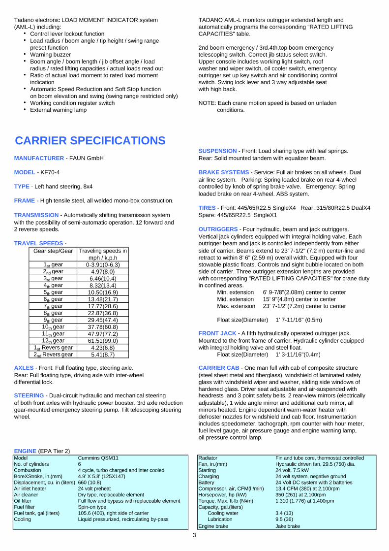
Tadano electronic LOAD MOMENT INDICATOR system TADANO AML-L monitors outrigger extended length and(AML-L) including: automatically programs the corresponding "RATED LIFTING
h Control lever lockout function CAPACITIES" table.h Load radius / boom angle / tip height / swing range
preset function 2nd boom emergency / 3rd,4th,top boom emergency h Warning buzzer telescoping switch. Correct jib status select switch. h Boom angle / boom length / jib offset angle / load Upper console includes working light switch, roof
radius / rated lifting capacities / actual loads read out washer and wiper switch, oil cooler switch, emergencyh Ratio of actual load moment to rated load moment outrigger set up key switch and air conditioning control
indication switch. Swing lock lever and 3 way adjustable seat h Automatic Speed Reduction and Soft Stop function with high back.
on boom elevation and swing (swing range restricted only)h Working condition register switch NOTE: Each crane motion speed is based on unladenh External warning lamp conditions.
CARRIER SPECIFICATIONSSUSPENSION - Front: Load sharing type with leaf springs.
MANUFACTURER - FAUN GmbH Rear: Solid mounted tandem with equalizer beam.
MODEL - KF70-4 BRAKE SYSTEMS - Service: Full air brakes on all wheels. Dualair line system. Parking: Spring loaded brake on rear 4-wheel
TYPE - Left hand steering, 8x4 controlled by knob of spring brake valve. Emergency: Spring loaded brake on rear 4-wheel. ABS system.
FRAME - High tensile steel, all welded mono-box construction.TIRES - Front: 445/65R22.5 SingleX4 Rear: 315/80R22.5 DualX4
TRANSMISSION - Automatically shifting transmission system Spare: 445/65R22.5 SingleX1with the possibility of semi-automatic operation. 12 forward and2 reverse speeds. OUTRIGGERS - Four hydraulic, beam and jack outriggers.
Vertical jack cylinders equipped with integral holding valve. EachTRAVEL SPEEDS - outrigger beam and jack is controlled independently from either
Gear step/Gear Traveling speeds in side of carrier. Beams extend to 23' 7-1/2" (7.2 m) center-line andmph / k.p.h retract to within 8' 6" (2.59 m) overall width. Equipped with four
1st gear 0-3.91(0-6.3) stowable plastic floats. Controls and sight bubble located on both2nd gear 4.97(8.0) side of carrier. Three outrigger extension lengths are provided3rd gear 6.46(10.4) with corresponding "RATED LIFTING CAPACITIES" for crane duty4th gear 8.32(13.4) in confined areas.5th gear 10.50(16.9) Min. extension 6' 9-7/8"(2.08m) center to center6th gear 13.48(21.7) Mid. extension 15' 9"(4.8m) center to center7th gear 17.77(28.6) Max. extension 23' 7-1/2"(7.2m) center to center8th gear 22.87(36.8)9th gear 29.45(47.4) Float size(Diameter) 1' 7-11/16" (0.5m)
10th gear 37.78(60.8)11th gear 47.97(77.2) FRONT JACK - A fifth hydraulically operated outrigger jack.12th gear 61.51(99.0) Mounted to the front frame of carrier. Hydraulic cylinder equipped
1st Revers gear 4.23(6.8) with integral holding valve and steel float.2nd Revers gear 5.41(8.7) Float size(Diameter) 1' 3-11/16"(0.4m)
AXLES - Front: Full floating type, steering axle. CARRIER CAB - One man full with cab of composite structureRear: Full floating type, driving axle with inter-wheel (steel sheet metal and fiberglass), windshield of laminated safety differential lock. glass with windshield wiper and washer, sliding side windows of
hardened glass. Driver seat adjustable and air-suspended withSTEERING - Dual-circuit hydraulic and mechanical steering headrests and 3 point safety belts. 2 rear-view mirrors (electricallyof both front axles with hydraulic power booster. 3rd axle reduction adjustable), 1 wide angle mirror and additional curb mirror, all gear-mounted emergency steering pump. Tilt telescoping steering mirrors heated. Engine dependent warm-water heater withwheel. defroster nozzles for windshield and cab floor. Instrumentation
includes speedometer, tachograph, rpm counter with hour meter,fuel level gauge, air pressure gauge and engine warning lamp,oil pressure control lamp.
ENGINE (EPA Tier 2)Model Cummins QSM11 Radiator Fin and tube core, thermostat controlledNo. of cylinders 6 Fan, in.(mm) Hydraulic driven fan, 29.5 (750) dia.Combustion 4 cycle, turbo charged and inter cooled Starting 24 volt, 7.5 kWBoreXStroke, in.(mm) 4.9' X 5.8' (125X147) Charging 24 volt system, negative groundDisplacement, cu. in (liters) 660 (10.8) Battery 24 Volt DC system with 2 batteriesAir inlet heater 24 volt preheat Compressor, air, CFM(l /min) 13.4 CFM (380) at 2,100rpmAir cleaner Dry type, replaceable element Horsepower, hp (kW) 350 (261) at 2,100rpmOil filter Full flow and bypass with replaceable element Torque, Max. ft-lb (N・m) 1,310 (1,776) at 1,400rpmFuel filter Spin-on type Capacity, gal.(liters)Fuel tank, gal.(liters) 105.6 (400), right side of carrier Cooling water 3.4 (13)Cooling Liquid pressurized, recirculating by-pass Lubrication 9.5 (36)
Engine brake Jake brake
3

FOR SUPERSTRUCTURE FOR CARRIER- 5-section full power synchronized boom 37.7'~144.4' - Cummins QSM11 turbo charged and inter cooled engine
(11.5 m~44 m) with Jake brake.- 32.5'~58.1' (9.9 m~17.7 m) bi-fold lattice jib (tilt type) - ZF Astronic semi-automatic, 12 forward and 2 reverse speeds.
with 3.5o, 25o or 45o pinned offsets and self storing pins. - Front and spare tires 445/65R22.5- Boom hoist foot control - Rear tires 315/80R22.5- Boom telescoping foot control - Inter wheel differential lock- Boom angle indicator - Anti-block system (ABS)- Variable speed main hoist with grooved drum, cable follower - Towing hooks (Front and rear, Eye type)
and 797' of 3/4" cable. - Carrier mounted storage box- Variable speed auxiliary hoist with grooved drum, cable - Trailer coupling device
follower and 436' of 3/4" cable. - Air dryer- Tadano twin swing system - Injection of ether- 360o positive swing lock - ZF - Servocom dual-circuit hydraulic steering system with- Anti-Two block device (overwind cutout) emergency steering pump- Tadano electronic load moment indicator system (AML-L) - Front jack (Fifth jack)
including - Aluminum fenders- Control lever lockout function - Windshield wiper and washer- Load radius / boom angle / tip height / swing range - Roof hatch
preset function - Emergency hammer- Warning buzzer - Electric mirror- Boom angle / boom length / jib offset angle / load radius / - 3 point type seat belt
rated lifting capacities / actual loads read out - Sun visor- Automatic Speed Reduction and Soft Stop function on - Tilt telescoping steering wheel
boom elevation and/or swing (swing range restricted only). - 3 way adjustable air suspension seat- Ratio of actual load moment to rated load moment indication - Windshield of laminated safety glass- Working condition register switch - Side windows of hardened glass- External warning lamp - Air pressure gauge
- Tinted safety glass - Tachograph- Front windshield wiper and washer - Tachometer- Roof window wiper and washer - Hourmeter (Operation from the carrier and superstructure)- Power window (Door of the cab) - Engine temperature indicator- 3 way adjustable cloth seat with armrests, high back and - Fuel level indicator
seat belt - Gearbox display (ZF T/M indicator) - Self centering finger control levers with pilot control - Speedometer- Cab floor mat - Fog lights- Cigarette lighter - Rear fog lights- 6.2 ton (5.6 metric ton) hook with swivel - Reversing signal (Back-up alarm)- Weighted hook storage compartment - Adjustment and heating rearview mirror- Hydraulic oil cooler - High-beam light- 3,700lbs and 4,000lbs two piece removable counterweight - Hazard warning system- Hydraulic circuit for dolly (Elevation, swing and swing brake) - Electric horn- 2 boom telescoping modes - Hot water cab heater with defroster- Low noise mode - FM/AM radio- Control pedals for boom hoist and boom telescoping - Engine over-run buzzer- 3 working lights - Swing brake pressure drop buzzer for dolly- Outrigger extension length detector - Gearbox malfunction buzzer
- Air cleaner dust indicator
FOR SUPERSTRUCTURE FOR CARRIER- Auxiliary lifting sheave (single top) stowable - Rotary beacon- Hot water cab heater and air conditioner (Upper cab)- Hook block tie down front bumper- Mirror for main and auxiliary hoists- Electric fan in cab- Drum rotation indicator (thumper type) main and auxiliary hoist- Non-slip paint- Extension exhaust pipe- Back cover of left side superstructure- Counterweight position indicator- Outrigger controls and sight bubble located in superstructure cab- 8,000lbs removable counterweight
STANDARD EQUIPMENT
OPTIONAL EQUIPMENT
4

HOISTING PERFORMANCELINE SPEEDS AND PULLS DRUM WIRE ROPE CAPACITIES
F.P.M m/min Lbs. kgf Lbs. kgf Feet Meters Feet MetersHigh 378 115 18,200 8,260 15,200 6,880 123.0 37.5 123.0 37.5High 413 126 16,700 7,570 13,900 6,310 134.2 40.9 257.2 78.4High 448 136 15,400 6,990 12,800 5,820 145.3 44.3 402.6 122.7High 482 147 14,300 6,490 11,900 5,410 156.5 47.7 559.1 170.4High 502 157 13,400 6,060 11,100 5,050 167.7 51.1 726.7 221.5High 551 168 12,500 5,680 10,400 4,730 178.8 54.5 905.5 276.0High 585 178 11,800 5,350 9,800 4,460 190.0 57.9 1095.5 333.9
1 Developed by machinery with each layer of wire rope, but not based DRUM DIMENSIONSon rope strength or other limitation in machinery or equipment. Inch mm
2 Line speeds based only on hook block, not loaded. Root diameter 15-3/4" 4003 Seventh layer of wire rope is not recommended for hoisting operations. Length 22-3/4" 5784 Permissible line pull may be affected by wire rope strength. Flange diameter 27-3/8" 695
Main and auxiliary drum grooved lagging
Line speeds2 Line pulls 3/4" (19mm) wire ropeAvailable1 Permissible4 Rope per layer Total wire rope
Main or auxiliary hoist - 15'-3/4" (0.4m) drumWireropelayer
Layer Speed
1st
6th
4th5th
3rd
7th3 7
12nd
6
2345
5

TT-800XXL WORKING RANGE CHART
NOTE : 1.Boom and jib geometry shown are for unloaded condition and
machine standing level on firm supporting surface.
Boom deflection and subsequent radius and boom angle change
must be accounted for when applying load to hook.
Telescoping Mode I
Liftin
g H
eig
ht in
fe
et
Load Radius from Axis of Rotation in Feet
Boom Length in Feet
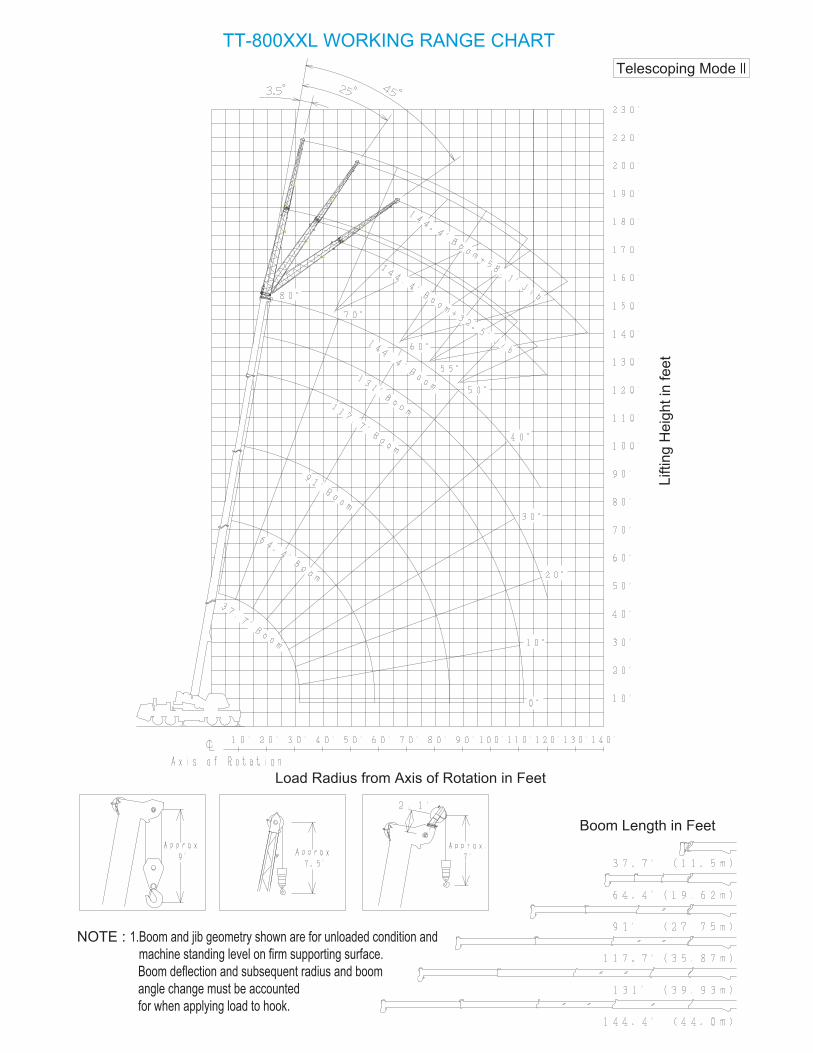
TT-800XXL WORKING RANGE CHART
Telescoping Mode II
Liftin
g H
eig
ht in
fe
et
Load Radius from Axis of Rotation in Feet
NOTE : 1.Boom and jib geometry shown are for unloaded condition and
machine standing level on firm supporting surface.
Boom deflection and subsequent radius and boom
angle change must be accounted
for when applying load to hook.
Boom Length in Feet

TT-800XXL-1 WORKING RANGE CHARTTelescope mode I
6

TT-800XXL-1 WORKING RANGE CHARTTelescope mode II
7

Fig.4
Fig.5
Fig.2
Fig.1
Load Handling Epuipment
Lifting from Main Boom with
80ton,5Sheave Hook Block(See Hook Block for actual weight) 1,850 (lbs.)
Fig.3
Boom Length 37.7' 51' 64.4' 91' 117.7' 131' 144.4'Telescoping Mode
20,100, 14,100 13,300, 8,500, 8,100, 6,500, 6,600, 5,100, 4,800, 4,800,
#1
Aux.Hook(See Hook for actual weight) 330 (lbs.)
Base and/or Top Jib stowed on base boom 0 (lbs.)
Single Top stowed on top boom 0 (lbs.)
Single Top erected but not used 0 (lbs.)
32.5'(9.9m)Base Jib erected but not used (lbs.)
32.5'(9.9m)Base Jib erected but not used +Aux.Hook on Top Jib (lbs.)
(lbs.)
+Aux.Hook on Top Jib (lbs.)
25.6'Top Jib erected but not used Prohibited
25.6'Top Jib stowed on 32.5'Base Jib Prohibited
Boom Length
Boom Length
Telescoping Mode
Telescoping Mode
Telescoping Mode
Boom Length
37.7'
37.7'
37.7'
51'
51'
51'
64.4'
64.4'
64.4'
91'
91'
91'
117.7'
117.7'
117.7'
131'
131'
131'
144.4'
144.4'
144.4'
I, II I III I III II II I, II,
I, II, I, II,
I, II,
I, II,
I, II,
I, II,
I I I II
I I I
I I I
II
II
II
II
II
II
II
II
II
II
II
II
I
I
20,900, 15,000, 14,300, 9,500, 8,800, 7,200, 7,300, 5,800, 5,400
22,300 16,400 11,600 10,200 8,600 8,500 7,000 6,300 6,200
23,500 18,000, 18,000, 13,200, 11,300, 9,700, 9,500, 8,000 7,200 6,900
LOAD HANDLING EQUIPMENTWEIGHT REDUCTIONS FOR AUXILIARY
Fig F F
Capacity deductions are for TADANO supplied
epuipument only.
When liftiog from Jib,deduct total weight of
all load handling devices reeved on Main Boom nose
directly from Jib capacity. (#2)
Note
*
*
Correct state of Jib, equipped or removed, should be
inputted into the LOAD MOMENT INDICATOR(AML-L)
by Jib state key switch.
#1.
#2. The winch which is lifting load should be defined
in the LOAD MOMENT INDICATOR(AML-L)
by main winch/auxiliary winch selector switch.
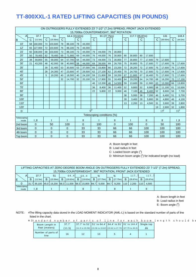
TT-800XXL-1 RATED LIFTING CAPACITIES (IN POUNDS)
A 37.7 51 131 144.4
B C (11.5m) C (15.56m) C C C C C C C (39.93m) C (44.0m)
10' 68 160,000 74 103,600 78 88,100 78 44,000
12' 65 127,900 72 103,600 76 88,100 76 44,000
15' 60 108,000 68 103,600 73 88,100 73 44,000 79 44,000 79 30,800
20' 50 79,400 62 79,400 69 71,900 69 44,000 76 44,000 76 30,800 80 30,800 80 17,600
25' 38 59,800 55 59,000 64 57,700 64 44,000 73 44,000 73 30,800 77 30,800 77 17,600 79 17,600
30' 21 43,200 48 42,000 58 40,900 58 44,000 69 39,000 69 26,700 75 30,800 75 17,600 77 17,600 78 17,600
35' 39 31,400 53 30,600 53 37,000 66 33,800 66 23,200 72 28,200 72 17,600 75 17,600 76 17,600
40' 28 24,300 47 23,600 47 29,500 62 27,100 62 20,400 70 24,700 70 17,600 73 17,600 74 17,600
45' 5 19,200 40 18,500 40 24,100 59 21,800 59 18,200 67 21,800 67 16,400 70 17,600 72 17,600
50' 32 14,700 32 20,100 55 17,900 55 16,400 64 19,200 64 14,700 68 16,200 70 17,100
60' 46 12,200 46 14,500 59 13,600 59 11,900 63 13,300 66 13,800
70' 36 8,400 36 11,400 52 9,800 52 9,900 58 11,100 61 10,500
80' 22 5,800 22 9,000 46 7,100 46 8,400 52 8,600 56 7,700
90' 38 5,000 38 7,200 46 6,400 51 5,700
100' 28 3,400 28 5,800 39 4,800 46 4,100
110' 13 2,200 13 4,500 31 3,600 39 2,800
120' 19 2,600 32 1,800
D
Telescoping mode
2nd boom
3rd boom
4th boom
Top boom
A: Boom length in feetB: Load radius in feetC: Loaded boom angle (o)D: Minimum boom angle (o) for indicated length (no load)
A 37.7' 51 64.4 117.7 117.7
E B (11.5m) B (15.56m) B (19.62m) B (19.62m) B (27.75m) B (27.75m) B (35.87m) B (35.87m)
0 31.7 39,100 45.0 19,200 58.3 11,000 58.3 15,800 84.7 5,000 84.7 8,200 110 2,200 110 4,500Telescoping mode
A: Boom length in feetB: Load radius in feetE: Boom angle (o)
NOTE: ・The lifting capacity data stored in the LOAD MOMENT INDICATOR (AML-L) is based on the standard number of parts of line listed in the chart. ・Standard number of parts of line for each boom length should be according to the following table.
Jib
1
(15.56 to 19.62)
37.7'
(11.5)
16
37.7' to 51'
(11.5 to 15.56)
12
51' to 64.4'
10
Boom Length inFeet (meters)
Number of parts ofline
5
64.4' to 91'
4
(19.62 to 27.75) (27.75 to 44.0)
91' to 144.4' Single top
15,700lbs COUNTERWEIGHT, 360o ROTATION, FRONT JACK EXTENDED
0o32o
64.4 91 91
III I II I
ON OUTRIGGERS FULLY EXTENDED 23' 7-1/2'' (7.2m) SPREAD, FRONT JACK EXTENDED15,700lbs COUNTERWEIGHT, 360o ROTATION
Telescoping conditions (%)
64.4 (19.62m) 91 (27.75m) 117.7 (35.87m)
19o
100 100
I III II II I ,II
100 10066 66 100 100
50 100
10066100 0
100
100100
0
33
66
66 66
3333
0 0 330 0 33
I I II
0 0 3350 100 0
I ,II
I ,II0000
LIFTING CAPACITIES AT ZERO DEGREE BOOM ANGLE ON OUTRIGGERS FULLY EXTENDED 23' 7-1/2'' (7.2m) SPREAD,
I II
8
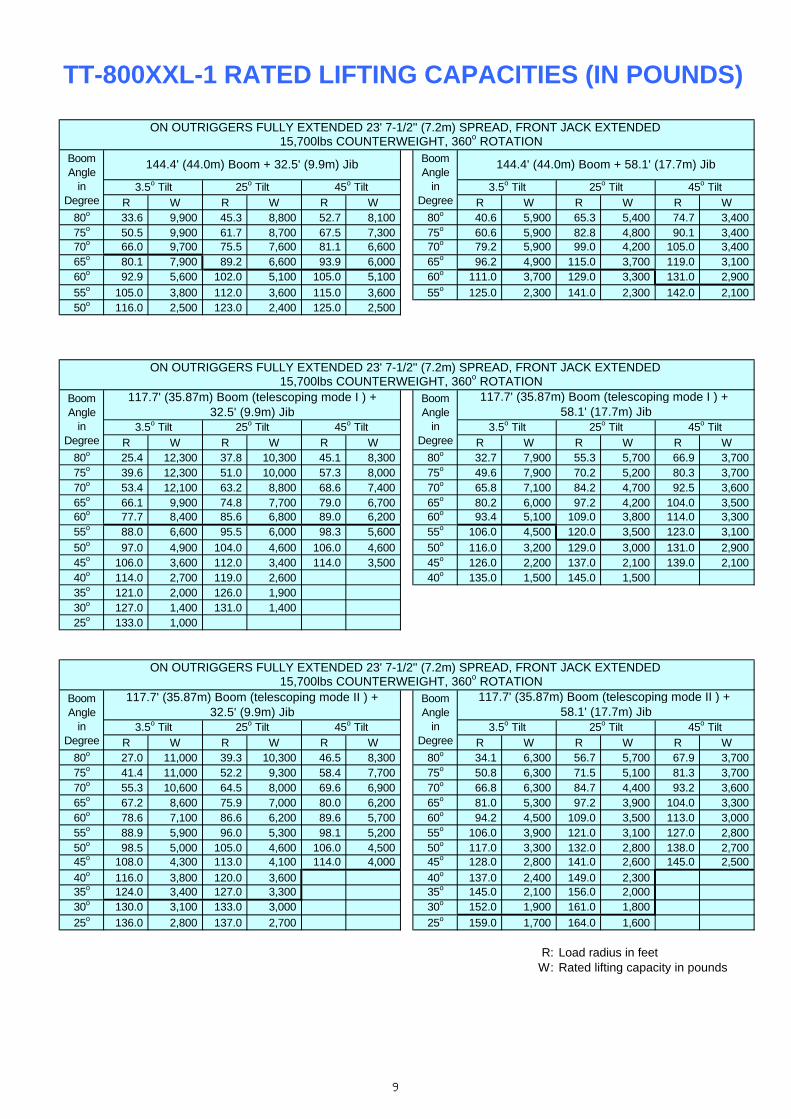
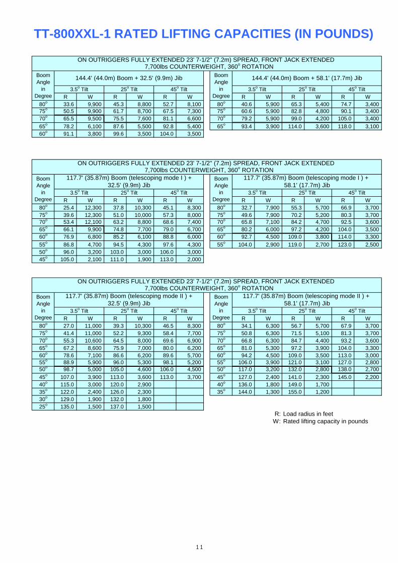
R W R W R W R W R W R W80o 33.6 9,900 45.3 8,800 52.7 8,100 80o 40.6 5,900 65.3 5,400 74.7 3,40075o 50.5 9,900 61.7 8,700 67.5 7,300 75o 60.6 5,900 82.8 4,800 90.1 3,40070o 66.0 9,700 75.5 7,600 81.1 6,600 70o 79.2 5,900 99.0 4,200 105.0 3,40065o 80.1 7,900 89.2 6,600 93.9 6,000 65o 96.2 4,900 115.0 3,700 119.0 3,10060o 92.9 5,600 102.0 5,100 105.0 5,100 60o 111.0 3,700 129.0 3,300 131.0 2,900
55o 105.0 3,800 112.0 3,600 115.0 3,600 55o 125.0 2,300 141.0 2,300 142.0 2,10050o 116.0 2,500 123.0 2,400 125.0 2,500
R W R W R W R W R W R W80o 25.4 12,300 37.8 10,300 45.1 8,300 80o 32.7 7,900 55.3 5,700 66.9 3,70075o 39.6 12,300 51.0 10,000 57.3 8,000 75o 49.6 7,900 70.2 5,200 80.3 3,70070o 53.4 12,100 63.2 8,800 68.6 7,400 70o 65.8 7,100 84.2 4,700 92.5 3,60065o 66.1 9,900 74.8 7,700 79.0 6,700 65o 80.2 6,000 97.2 4,200 104.0 3,50060o 77.7 8,400 85.6 6,800 89.0 6,200 60o 93.4 5,100 109.0 3,800 114.0 3,30055o 88.0 6,600 95.5 6,000 98.3 5,600 55o 106.0 4,500 120.0 3,500 123.0 3,100
50o 97.0 4,900 104.0 4,600 106.0 4,600 50o 116.0 3,200 129.0 3,000 131.0 2,90045o 106.0 3,600 112.0 3,400 114.0 3,500 45o 126.0 2,200 137.0 2,100 139.0 2,10040o 114.0 2,700 119.0 2,600 40o 135.0 1,500 145.0 1,50035o 121.0 2,000 126.0 1,90030o 127.0 1,400 131.0 1,40025o 133.0 1,000
R W R W R W R W R W R W80o 27.0 11,000 39.3 10,300 46.5 8,300 80o 34.1 6,300 56.7 5,700 67.9 3,70075o 41.4 11,000 52.2 9,300 58.4 7,700 75o 50.8 6,300 71.5 5,100 81.3 3,70070o 55.3 10,600 64.5 8,000 69.6 6,900 70o 66.8 6,300 84.7 4,400 93.2 3,60065o 67.2 8,600 75.9 7,000 80.0 6,200 65o 81.0 5,300 97.2 3,900 104.0 3,30060o 78.6 7,100 86.6 6,200 89.6 5,700 60o 94.2 4,500 109.0 3,500 113.0 3,00055o 88.9 5,900 96.0 5,300 98.1 5,200 55o 106.0 3,900 121.0 3,100 127.0 2,80050o 98.5 5,000 105.0 4,600 106.0 4,500 50o 117.0 3,300 132.0 2,800 138.0 2,70045o 108.0 4,300 113.0 4,100 114.0 4,000 45o 128.0 2,800 141.0 2,600 145.0 2,500
40o 116.0 3,800 120.0 3,600 40o 137.0 2,400 149.0 2,30035o 124.0 3,400 127.0 3,300 35o 145.0 2,100 156.0 2,00030o 130.0 3,100 133.0 3,000 30o 152.0 1,900 161.0 1,800
25o 136.0 2,800 137.0 2,700 25o 159.0 1,700 164.0 1,600
R: Load radius in feetW: Rated lifting capacity in pounds
TT-800XXL-1 RATED LIFTING CAPACITIES (IN POUNDS)
117.7' (35.87m) Boom (telescoping mode I ) +32.5' (9.9m) Jib
BoomAngle
inDegree
3.5o Tilt3.5o Tilt 25o Tilt
3.5o Tilt
117.7' (35.87m) Boom (telescoping mode I ) + 58.1' (17.7m) Jib
BoomAngle
inDegree
45o Tilt
ON OUTRIGGERS FULLY EXTENDED 23' 7-1/2'' (7.2m) SPREAD, FRONT JACK EXTENDED 15,700lbs COUNTERWEIGHT, 360o ROTATION
25o Tilt 45o Tilt45o Tilt
ON OUTRIGGERS FULLY EXTENDED 23' 7-1/2'' (7.2m) SPREAD, FRONT JACK EXTENDED 15,700lbs COUNTERWEIGHT, 360o ROTATION
144.4' (44.0m) Boom + 58.1' (17.7m) Jib
25o Tilt25o Tilt
BoomAngle
inDegree
45o Tilt
BoomAngle
inDegree
144.4' (44.0m) Boom + 32.5' (9.9m) Jib
3.5o Tilt
ON OUTRIGGERS FULLY EXTENDED 23' 7-1/2'' (7.2m) SPREAD, FRONT JACK EXTENDED 15,700lbs COUNTERWEIGHT, 360o ROTATION
BoomAngle
inDegree
BoomAngle
inDegree
3.5o Tilt 25o Tilt
117.7' (35.87m) Boom (telescoping mode II ) +32.5' (9.9m) Jib
117.7' (35.87m) Boom (telescoping mode II ) + 58.1' (17.7m) Jib
45o Tilt 3.5o Tilt 25o Tilt 45o Tilt
9

TT-800XXL-1 RATED LIFTING CAPACITIES (IN POUNDS)
A 37.7 51 131 144.4
B C (11.5m) C (15.56m) C C C C C C C (39.93m) C (44.0m)
10' 68 159,400 74 103,600 78 88,100 78 44,000
12' 65 127,900 72 103,600 76 88,100 76 44,000
15' 60 105,600 68 103,600 73 88,100 73 44,000 79 44,000 79 30,800
20' 50 77,300 62 76,600 69 71,900 69 44,000 76 44,000 76 30,800 80 30,800 80 17,600
25' 38 51,700 55 50,100 64 48,900 64 44,000 73 44,000 73 30,800 77 30,800 77 17,600 79 17,600
30' 21 36,500 48 35,300 58 34,200 58 41,100 69 38,300 69 26,700 75 30,800 75 17,600 77 17,600 78 17,600
35' 39 26,000 53 25,200 53 31,500 66 28,800 66 23,200 72 28,200 72 17,600 75 17,600 76 17,600
40' 28 19,800 47 19,000 47 24,900 62 22,400 62 20,400 70 23,900 70 17,600 73 17,600 74 17,600
45' 5 15,300 40 14,600 40 20,100 59 17,800 59 18,200 67 19,200 67 16,400 70 17,600 72 17,600
50' 32 11,200 32 16,600 55 14,400 55 16,400 64 15,700 64 14,700 68 16,200 70 16,500
60' 46 9,400 46 12,900 59 10,800 59 11,900 63 12,200 66 11,400
70' 36 6,000 36 9,400 52 7,300 52 9,900 58 8,900 61 8,100
80' 22 3,600 22 6,900 46 4,900 46 7,400 52 6,400 56 5,600
90' 38 3,100 38 5,500 46 4,600 51 3,800
100' 28 1,700 28 4,100 39 3,100 46 2,400
110' 13 3,000 31 2,000
D
Telescoping mode
2nd boom
3rd boom
4th boom
Top boom
A: Boom length in feetB: Load radius in feetC: Loaded boom angle (o)D: Minimum boom angle (o) for indicated length (no load)
A 37.7' 51 64.4 117.7
E B (11.5m) B (15.56m) B (19.62m) B (19.62m) B (27.75m) B (27.75m) B (35.87m)
0 31.7 32,900 45.0 15,300 58.3 7,800 58.3 12,900 84.7 2,900 84.7 6,100 110 3,000Telescoping mode
A: Boom length in feetB: Load radius in feetE: Boom angle (o)
NOTE: ・The lifting capacity data stored in the LOAD MOMENT INDICATOR (AML-L) is based on the standard number of parts of line listed in the chart. ・Standard number of parts of line for each boom length should be according to the following table.
0o28o 0o
I ,II
I ,II0000
LIFTING CAPACITIES AT ZERO DEGREE BOOM ANGLE ON OUTRIGGERS FULLY EXTENDED 23' 7-1/2'' (7.2m) SPREAD,
II
I I II
0 0 3350 100 0
0 0 330 0 33
100
100100
0
33
66
66 66
3333
100
10066100 0
66 100 100
50
100
I III II II I ,II
100 10066
II I
ON OUTRIGGERS FULLY EXTENDED 23' 7-1/2'' (7.2m) SPREAD, FRONT JACK EXTENDED7,700lbs COUNTERWEIGHT, 360o ROTATION
Telescoping conditions (%)
64.4 (19.62m) 91 (27.75m) 117.7 (35.87m)
31o
100
Single top
7,700lbs COUNTERWEIGHT, 360o ROTATION, FRONT JACK EXTENDED
46o
64.4 91 91
III I
4
64.4' to 91'
(19.62 to 27.75) (27.75 to 44.0)
91' to 144.4'
10
Boom Length inFeet (meters)
Number of parts ofline
5
Jib
1
(15.56 to 19.62)
37.7'
(11.5)
16
37.7' to 51'
(11.5 to 15.56)
12
51' to 64.4'
10
R W R W R W R W R W R W80o 33.6 9,900 45.3 8,800 52.7 8,100 80o 40.6 5,900 65.3 5,400 74.7 3,40075o 50.5 9,900 61.7 8,700 67.5 7,300 75o 60.6 5,900 82.8 4,800 90.1 3,40070o 65.5 9,500 75.5 7,600 81.1 6,600 70o 79.2 5,900 99.0 4,200 105.0 3,400
65o 78.2 6,100 87.6 5,500 92.8 5,400 65o 93.4 3,900 114.0 3,600 118.0 3,10060o 91.1 3,800 99.6 3,500 104.0 3,500
R W R W R W R W R W R W80o 25.4 12,300 37.8 10,300 45.1 8,300 80o 32.7 7,900 55.3 5,700 66.9 3,70075o 39.6 12,300 51.0 10,000 57.3 8,000 75o 49.6 7,900 70.2 5,200 80.3 3,70070o 53.4 12,100 63.2 8,800 68.6 7,400 70o 65.8 7,100 84.2 4,700 92.5 3,60065o 66.1 9,900 74.8 7,700 79.0 6,700 65o 80.2 6,000 97.2 4,200 104.0 3,50060o 76.9 6,800 85.2 6,100 88.8 6,000 60o 92.7 4,500 109.0 3,800 114.0 3,300
55o 86.8 4,700 94.5 4,300 97.6 4,300 55o 104.0 2,900 119.0 2,700 123.0 2,50050o 96.0 3,200 103.0 3,000 106.0 3,00045o 105.0 2,100 111.0 1,900 113.0 2,000
R W R W R W R W R W R W80o 27.0 11,000 39.3 10,300 46.5 8,300 80o 34.1 6,300 56.7 5,700 67.9 3,70075o 41.4 11,000 52.2 9,300 58.4 7,700 75o 50.8 6,300 71.5 5,100 81.3 3,70070o 55.3 10,600 64.5 8,000 69.6 6,900 70o 66.8 6,300 84.7 4,400 93.2 3,60065o 67.2 8,600 75.9 7,000 80.0 6,200 65o 81.0 5,300 97.2 3,900 104.0 3,30060o 78.6 7,100 86.6 6,200 89.6 5,700 60o 94.2 4,500 109.0 3,500 113.0 3,00055o 88.9 5,900 96.0 5,300 98.1 5,200 55o 106.0 3,900 121.0 3,100 127.0 2,80050o 98.7 5,000 105.0 4,600 106.0 4,500 50o 117.0 3,200 132.0 2,800 138.0 2,700
45o 107.0 3,900 113.0 3,600 113.0 3,700 45o 127.0 2,400 141.0 2,300 145.0 2,20040o 115.0 3,000 120.0 2,900 40o 136.0 1,800 149.0 1,70035o 122.0 2,400 126.0 2,300 35o 144.0 1,300 155.0 1,20030o 129.0 1,900 132.0 1,80025o 135.0 1,500 137.0 1,500
R: Load radius in feetW: Rated lifting capacity in pounds
TT-800XXL-1 RATED LIFTING CAPACITIES (IN POUNDS)
45o Tilt 3.5o Tilt 25o Tilt 45o Tilt
ON OUTRIGGERS FULLY EXTENDED 23' 7-1/2'' (7.2m) SPREAD, FRONT JACK EXTENDED 7,700lbs COUNTERWEIGHT, 360o ROTATION
BoomAngle
inDegree
BoomAngle
inDegree
3.5o Tilt 25o Tilt
117.7' (35.87m) Boom (telescoping mode II ) +32.5' (9.9m) Jib
117.7' (35.87m) Boom (telescoping mode II ) + 58.1' (17.7m) Jib
ON OUTRIGGERS FULLY EXTENDED 23' 7-1/2'' (7.2m) SPREAD, FRONT JACK EXTENDED 7,700lbs COUNTERWEIGHT, 360o ROTATION
144.4' (44.0m) Boom + 58.1' (17.7m) Jib
25o Tilt25o Tilt
BoomAngle
inDegree
45o Tilt
BoomAngle
inDegree
144.4' (44.0m) Boom + 32.5' (9.9m) Jib
3.5o Tilt 3.5o Tilt
117.7' (35.87m) Boom (telescoping mode I ) + 58.1' (17.7m) Jib
BoomAngle
inDegree
45o Tilt
ON OUTRIGGERS FULLY EXTENDED 23' 7-1/2'' (7.2m) SPREAD, FRONT JACK EXTENDED 7,700lbs COUNTERWEIGHT, 360o ROTATION
25o Tilt 45o Tilt45o Tilt
117.7' (35.87m) Boom (telescoping mode I ) +32.5' (9.9m) Jib
BoomAngle
inDegree
3.5o Tilt3.5o Tilt 25o Tilt
11
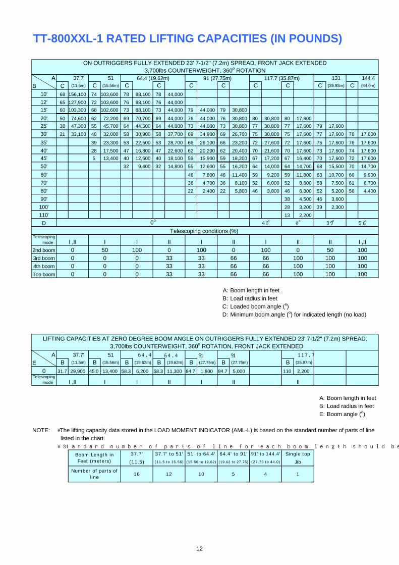
TT-800XXL-1 RATED LIFTING CAPACITIES (IN POUNDS)
A 37.7 51 131 144.4
B C (11.5m) C (15.56m) C C C C C C C (39.93m) C (44.0m)
10' 68 156,100 74 103,600 78 88,100 78 44,000
12' 65 127,900 72 103,600 76 88,100 76 44,000
15' 60 103,300 68 102,600 73 88,100 73 44,000 79 44,000 79 30,800
20' 50 74,600 62 72,200 69 70,700 69 44,000 76 44,000 76 30,800 80 30,800 80 17,600
25' 38 47,300 55 45,700 64 44,500 64 44,000 73 44,000 73 30,800 77 30,800 77 17,600 79 17,600
30' 21 33,100 48 32,000 58 30,900 58 37,700 69 34,900 69 26,700 75 30,800 75 17,600 77 17,600 78 17,600
35' 39 23,300 53 22,500 53 28,700 66 26,100 66 23,200 72 27,600 72 17,600 75 17,600 76 17,600
40' 28 17,500 47 16,800 47 22,600 62 20,200 62 20,400 70 21,600 70 17,600 73 17,600 74 17,600
45' 5 13,400 40 12,600 40 18,100 59 15,900 59 18,200 67 17,200 67 16,400 70 17,600 72 17,600
50' 32 9,400 32 14,800 55 12,600 55 16,200 64 14,000 64 14,700 68 15,500 70 14,700
60' 46 7,800 46 11,400 59 9,200 59 11,800 63 10,700 66 9,900
70' 36 4,700 36 8,100 52 6,000 52 8,600 58 7,500 61 6,700
80' 22 2,400 22 5,800 46 3,800 46 6,300 52 5,200 56 4,400
90' 38 4,500 46 3,600
100' 28 3,200 39 2,300
110' 13 2,200
D
Telescoping mode
2nd boom
3rd boom
4th boom
Top boom
A: Boom length in feetB: Load radius in feetC: Loaded boom angle (o)D: Minimum boom angle (o) for indicated length (no load)
A 37.7' 51 64.4 117.7
E B (11.5m) B (15.56m) B (19.62m) B (19.62m) B (27.75m) B (27.75m) B (35.87m)
0 31.7 29,900 45.0 13,400 58.3 6,200 58.3 11,300 84.7 1,800 84.7 5,000 110 2,200Telescoping mode
A: Boom length in feetB: Load radius in feetE: Boom angle (o)
NOTE: ・The lifting capacity data stored in the LOAD MOMENT INDICATOR (AML-L) is based on the standard number of parts of line listed in the chart. ・Standard number of parts of line for each boom length should be according to the following table.
Jib
1
(15.56 to 19.62)
37.7'
(11.5)
16
37.7' to 51'
(11.5 to 15.56)
12
51' to 64.4'
10
Boom Length inFeet (meters)
Number of parts ofline
5 4
64.4' to 91'
(19.62 to 27.75) (27.75 to 44.0)
91' to 144.4' Single top
3,700lbs COUNTERWEIGHT, 360o ROTATION, FRONT JACK EXTENDED
56o
64.4 91 91
III I II I
ON OUTRIGGERS FULLY EXTENDED 23' 7-1/2'' (7.2m) SPREAD, FRONT JACK EXTENDED3,700lbs COUNTERWEIGHT, 360o ROTATION
Telescoping conditions (%)
64.4 (19.62m) 91 (27.75m) 117.7 (35.87m)
39o
100 100
I III II II I ,II
100 10066
100
10066100 0
66 100 100
50
100
100100
0
33
66
66 66
3333
100 0
0 0 330 0 33
II
I I II
0 0 3350
0o46o 0o
I ,II
I ,II0000
LIFTING CAPACITIES AT ZERO DEGREE BOOM ANGLE ON OUTRIGGERS FULLY EXTENDED 23' 7-1/2'' (7.2m) SPREAD,
12

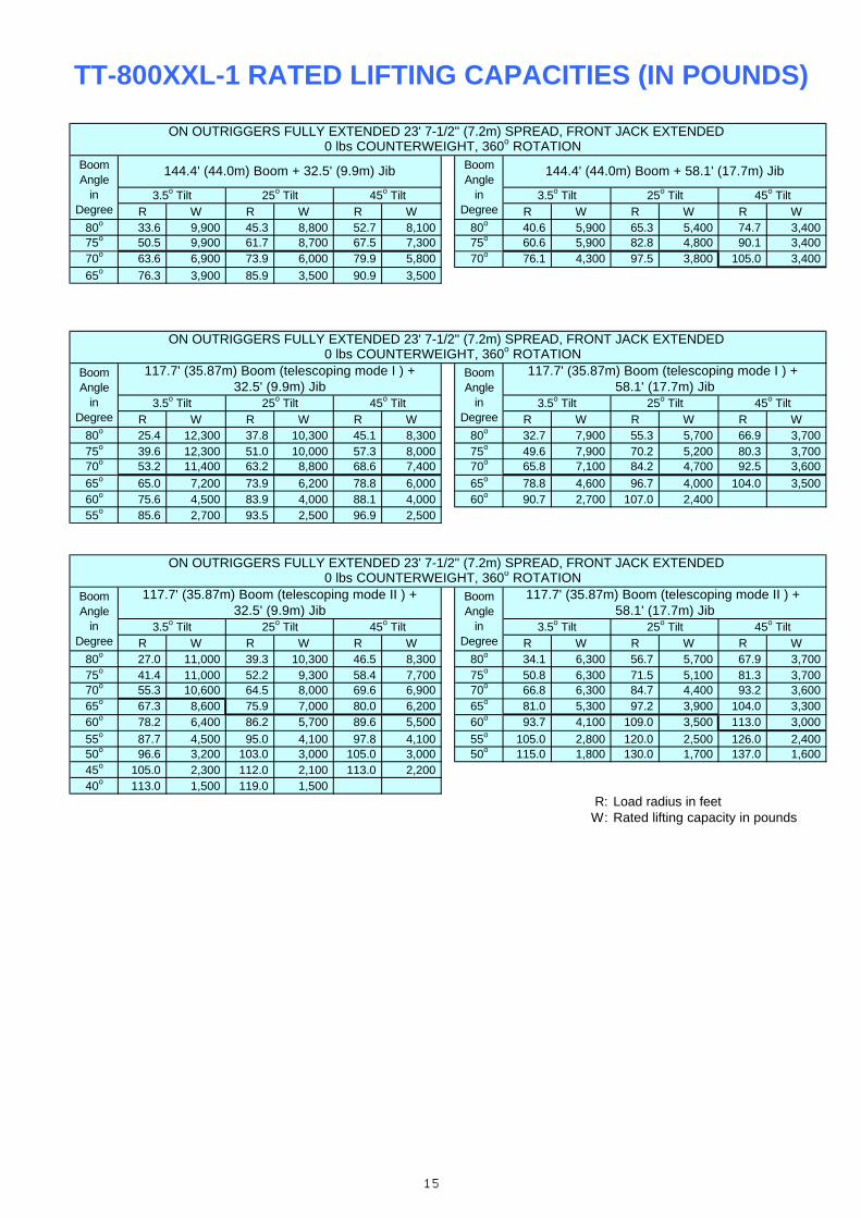
R W R W R W R W R W R W80o 33.6 9,900 45.3 8,800 52.7 8,100 80o 40.6 5,900 65.3 5,400 74.7 3,40075o 50.5 9,900 61.7 8,700 67.5 7,300 75o 60.6 5,900 82.8 4,800 90.1 3,40070o 64.7 8,200 74.7 7,100 80.6 6,600 70o 78.0 5,400 99.0 4,200 105.0 3,400
65o 77.1 5,000 86.6 4,500 91.8 4,40060o 89.6 2,900
R W R W R W R W R W R W80o 25.4 12,300 37.8 10,300 45.1 8,300 80o 32.7 7,900 55.3 5,700 66.9 3,70075o 39.6 12,300 51.0 10,000 57.3 8,000 75o 49.6 7,900 70.2 5,200 80.3 3,70070o 53.4 12,100 63.2 8,800 68.6 7,400 70o 65.8 7,100 84.2 4,700 92.5 3,60065o 65.4 8,500 74.6 7,400 79.0 6,700 65o 80.0 5,600 97.2 4,200 104.0 3,500
60o 76.2 5,600 84.6 5,000 88.5 4,900 60o 91.7 3,500 108.0 3,200 114.0 2,90055o 86.3 3,600 93.9 3,400 97.2 3,40050o 95.7 2,300 103.0 2,100 105.0 2,100
R W R W R W R W R W R W80o 27.0 11,000 39.3 10,300 46.5 8,300 80o 34.1 6,300 56.7 5,700 67.9 3,70075o 41.4 11,000 52.2 9,300 58.4 7,700 75o 50.8 6,300 71.5 5,100 81.3 3,70070o 55.3 10,600 64.5 8,000 69.6 6,900 70o 66.8 6,300 84.7 4,400 93.2 3,60065o 67.2 8,600 75.9 7,000 80.0 6,200 65o 81.0 5,300 97.2 3,900 104.0 3,30060o 78.6 7,100 86.6 6,200 89.6 5,700 60o 94.2 4,500 109.0 3,500 113.0 3,00055o 88.5 5,500 95.8 5,000 98.1 4,900 55o 106.0 3,500 121.0 3,100 127.0 2,80050o 97.5 4,100 104.0 3,800 106.0 3,800 50o 116.0 2,500 131.0 2,300 138.0 2,20045o 106.0 3,000 112.0 2,900 113.0 2,900 45o 126.0 1,700 140.0 1,600 144.0 1,60040o 114.0 2,300 119.0 2,100 40o 135.0 1,10035o 122.0 1,700 126.0 1,60030o 128.0 1,200 132.0 1,200
R: Load radius in feetW: Rated lifting capacity in pounds
TT-800XXL-1 RATED LIFTING CAPACITIES (IN POUNDS)
117.7' (35.87m) Boom (telescoping mode I ) +32.5' (9.9m) Jib
BoomAngle
inDegree
3.5o Tilt3.5o Tilt 25o Tilt
3.5o Tilt
117.7' (35.87m) Boom (telescoping mode I ) + 58.1' (17.7m) Jib
BoomAngle
inDegree
45o Tilt
ON OUTRIGGERS FULLY EXTENDED 23' 7-1/2'' (7.2m) SPREAD, FRONT JACK EXTENDED 3,700lbs COUNTERWEIGHT, 360o ROTATION
25o Tilt 45o Tilt45o Tilt
ON OUTRIGGERS FULLY EXTENDED 23' 7-1/2'' (7.2m) SPREAD, FRONT JACK EXTENDED 3,700lbs COUNTERWEIGHT, 360o ROTATION
144.4' (44.0m) Boom + 58.1' (17.7m) Jib
25o Tilt25o Tilt
BoomAngle
inDegree
45o Tilt
BoomAngle
inDegree
144.4' (44.0m) Boom + 32.5' (9.9m) Jib
3.5o Tilt
ON OUTRIGGERS FULLY EXTENDED 23' 7-1/2'' (7.2m) SPREAD, FRONT JACK EXTENDED 3,700lbs COUNTERWEIGHT, 360o ROTATION
BoomAngle
inDegree
BoomAngle
inDegree
3.5o Tilt 25o Tilt
117.7' (35.87m) Boom (telescoping mode II ) +32.5' (9.9m) Jib
117.7' (35.87m) Boom (telescoping mode II ) + 58.1' (17.7m) Jib
45o Tilt 3.5o Tilt 25o Tilt 45o Tilt
13

TT-800XXL-1 RATED LIFTING CAPACITIES (IN POUNDS)
A 37.7 51 131 144.4
B C (11.5m) C (15.56m) C C C C C C C (39.93m) C (44.0m)
10' 68 152,600 74 103,600 78 88,100 78 44,000
12' 65 127,100 72 103,600 76 88,100 76 44,000
15' 60 100,900 68 100,200 73 88,100 73 44,000 79 44,000 79 30,800
20' 50 68,600 62 66,200 69 64,700 69 44,000 76 44,000 76 30,800 80 30,800 80 17,600
25' 38 43,200 55 41,700 64 40,400 64 44,000 73 44,000 73 30,800 77 30,800 77 17,600 79 17,600
30' 21 30,000 48 28,800 58 27,800 58 34,600 69 31,700 69 26,700 75 30,800 75 17,600 77 17,600 78 17,600
35' 39 20,800 53 20,000 53 26,200 66 23,500 66 23,200 72 25,100 72 17,600 75 17,600 76 17,600
40' 28 15,400 47 14,600 47 20,500 62 18,000 62 20,400 70 19,500 70 17,600 73 17,600 74 17,600
45' 5 11,300 40 10,500 40 16,300 59 13,800 59 17,700 67 15,300 67 16,400 70 17,000 72 16,200
50' 32 7,500 32 13,100 55 10,600 55 14,400 64 12,100 64 14,700 68 13,700 70 12,900
60' 46 6,300 46 9,900 59 7,600 59 10,300 63 9,200 66 8,400
70' 36 3,400 36 6,800 52 4,700 52 7,300 58 6,200 61 5,400
80' 22 4,700 46 5,200 52 4,200
90' 38 3,600 46 2,600
100' 28 2,400
110' 13 1,400
D
Telescoping mode
2nd boom
3rd boom
4th boom
Top boom
A: Boom length in feetB: Load radius in feetC: Loaded boom angle (o)D: Minimum boom angle (o) for indicated length (no load)
A 37.7' 51 64.4
E B (11.5m) B (15.56m) B (19.62m) B (19.62m) B (27.75m)
0 31.7 26,500 45.0 11,300 58.3 4,500 58.3 9,600 84.7 4,000Telescoping mode
A: Boom length in feetB: Load radius in feetE: Boom angle (o)
NOTE: ・The lifting capacity data stored in the LOAD MOMENT INDICATOR (AML-L) is based on the standard number of parts of line listed in the chart. ・Standard number of parts of line for each boom length should be according to the following table.
I ,II
I ,II0000
LIFTING CAPACITIES AT ZERO DEGREE BOOM ANGLE ON OUTRIGGERS FULLY EXTENDED 23' 7-1/2'' (7.2m) SPREAD,
I I II
0 0 3350 100 0
0 0 330 0 33
100
100100
0
33
66
66 66
3333 66
100
10066100 0
66 100 100
50
100 100
I III II II I ,II
100 100
ON OUTRIGGERS FULLY EXTENDED 23' 7-1/2'' (7.2m) SPREAD, FRONT JACK EXTENDED0 lbs COUNTERWEIGHT, 360o ROTATION
Telescoping conditions (%)
64.4 (19.62m) 91 (27.75m) 117.7 (35.87m)
46o52o 13o0o
91
III I II
Number of parts ofline
5 4
64.4' to 91'
(19.62 to 27.75) (27.75 to 44.0)
91' to 144.4'
1
(15.56 to 19.62)
37.7'
(11.5)
16
37.7' to 51'
(11.5 to 15.56)
12
51' to 64.4'
10
36o 0o
JibBoom Length inFeet (meters)
Single top
0 lbs COUNTERWEIGHT, 360o ROTATION, FRONT JACK EXTENDED
61o
64.4
14
R W R W R W R W R W R W80o 33.6 9,900 45.3 8,800 52.7 8,100 80o 40.6 5,900 65.3 5,400 74.7 3,40075o 50.5 9,900 61.7 8,700 67.5 7,300 75o 60.6 5,900 82.8 4,800 90.1 3,40070o 63.6 6,900 73.9 6,000 79.9 5,800 70o 76.1 4,300 97.5 3,800 105.0 3,400
65o 76.3 3,900 85.9 3,500 90.9 3,500
R W R W R W R W R W R W80o 25.4 12,300 37.8 10,300 45.1 8,300 80o 32.7 7,900 55.3 5,700 66.9 3,70075o 39.6 12,300 51.0 10,000 57.3 8,000 75o 49.6 7,900 70.2 5,200 80.3 3,70070o 53.2 11,400 63.2 8,800 68.6 7,400 70o 65.8 7,100 84.2 4,700 92.5 3,600
65o 65.0 7,200 73.9 6,200 78.8 6,000 65o 78.8 4,600 96.7 4,000 104.0 3,50060o 75.6 4,500 83.9 4,000 88.1 4,000 60o 90.7 2,700 107.0 2,40055o 85.6 2,700 93.5 2,500 96.9 2,500
R W R W R W R W R W R W80o 27.0 11,000 39.3 10,300 46.5 8,300 80o 34.1 6,300 56.7 5,700 67.9 3,70075o 41.4 11,000 52.2 9,300 58.4 7,700 75o 50.8 6,300 71.5 5,100 81.3 3,70070o 55.3 10,600 64.5 8,000 69.6 6,900 70o 66.8 6,300 84.7 4,400 93.2 3,60065o 67.3 8,600 75.9 7,000 80.0 6,200 65o 81.0 5,300 97.2 3,900 104.0 3,30060o 78.2 6,400 86.2 5,700 89.6 5,500 60o 93.7 4,100 109.0 3,500 113.0 3,000
55o 87.7 4,500 95.0 4,100 97.8 4,100 55o 105.0 2,800 120.0 2,500 126.0 2,40050o 96.6 3,200 103.0 3,000 105.0 3,000 50o 115.0 1,800 130.0 1,700 137.0 1,60045o 105.0 2,300 112.0 2,100 113.0 2,20040o 113.0 1,500 119.0 1,500
R: Load radius in feetW: Rated lifting capacity in pounds
TT-800XXL-1 RATED LIFTING CAPACITIES (IN POUNDS)
45o Tilt 3.5o Tilt 25o Tilt 45o Tilt
ON OUTRIGGERS FULLY EXTENDED 23' 7-1/2'' (7.2m) SPREAD, FRONT JACK EXTENDED 0 lbs COUNTERWEIGHT, 360o ROTATION
BoomAngle
inDegree
BoomAngle
inDegree
3.5o Tilt 25o Tilt
117.7' (35.87m) Boom (telescoping mode II ) +32.5' (9.9m) Jib
117.7' (35.87m) Boom (telescoping mode II ) + 58.1' (17.7m) Jib
ON OUTRIGGERS FULLY EXTENDED 23' 7-1/2'' (7.2m) SPREAD, FRONT JACK EXTENDED 0 lbs COUNTERWEIGHT, 360o ROTATION
144.4' (44.0m) Boom + 58.1' (17.7m) Jib
25o Tilt25o Tilt
BoomAngle
inDegree
45o Tilt
BoomAngle
inDegree
144.4' (44.0m) Boom + 32.5' (9.9m) Jib
3.5o Tilt 3.5o Tilt
117.7' (35.87m) Boom (telescoping mode I ) + 58.1' (17.7m) Jib
BoomAngle
inDegree
45o Tilt
ON OUTRIGGERS FULLY EXTENDED 23' 7-1/2'' (7.2m) SPREAD, FRONT JACK EXTENDED 0 lbs COUNTERWEIGHT, 360o ROTATION
25o Tilt 45o Tilt45o Tilt
117.7' (35.87m) Boom (telescoping mode I ) +32.5' (9.9m) Jib
BoomAngle
inDegree
3.5o Tilt3.5o Tilt 25o Tilt
15

TT-800XXL-1 RATED LIFTING CAPACITIES (IN POUNDS)
A 37.7 51 131 144.4
B C (11.5m) C (15.56m) C C C C C C C (39.93m) C (44.0m)
10' 68 131,300 74 103,600 78 88,100 78 44,000
12' 65 111,700 72 103,600 76 88,100 76 44,000
15' 60 90,100 68 89,300 73 88,100 73 44,000 79 44,000 79 30,800
20' 50 52,400 62 50,600 69 49,300 69 44,000 76 44,000 76 30,800 80 30,800 80 17,600
25' 38 33,500 55 32,300 64 31,100 64 37,500 73 34,700 73 30,800 77 30,800 77 17,600 79 17,600
30' 21 23,100 48 22,000 58 21,200 58 27,000 69 24,400 69 26,700 75 26,000 75 17,600 77 17,600 78 17,600
35' 39 15,500 53 14,800 53 20,300 66 17,900 66 21,800 72 19,400 72 17,600 75 17,600 76 17,600
40' 28 11,000 47 10,300 47 15,600 62 13,400 62 17,100 70 14,900 70 17,600 73 16,600 74 15,600
45' 5 7,800 40 7,100 40 12,200 59 10,100 59 13,700 67 11,500 67 14,300 70 13,200 72 12,300
50' 32 4,700 32 9,700 55 7,600 55 11,100 64 9,000 64 11,700 68 10,600 70 9,700
60' 46 4,000 46 7,300 59 5,400 59 8,000 63 7,000 66 6,100
70' 36 1,500 36 4,800 52 2,900 52 5,500 58 4,500 61 3,600
80' 22 3,000 46 3,600 52 2,700
90' 38 2,200
D
Telescoping mode
2nd boom
3rd boom
4th boom
Top boom
A: Boom length in feetB: Load radius in feetC: Loaded boom angle (o)D: Minimum boom angle (o) for indicated length (no load)
A 37.7' 51 64.4
E B (11.5m) B (15.56m) B (19.62m) B (19.62m) B (27.75m)
0 31.7 20,400 45.0 7,800 58.3 2,100 58.3 6,800 84.7 2,400Telescoping mode
A: Boom length in feetB: Load radius in feetE: Boom angle (o)
NOTE: ・The lifting capacity data stored in the LOAD MOMENT INDICATOR (AML-L) is based on the standard number of parts of line listed in the chart. ・Standard number of parts of line for each boom length should be according to the following table.
I ,II
I ,II0000
LIFTING CAPACITIES AT ZERO DEGREE BOOM ANGLE ON OUTRIGGERS MID EXTENDED 15' 9'' (4.8m) SPREAD,
I I II
0 0 3350 100 0
0 0 330 0 33
100
100100
0
33
66
66 66
3333
100
10066100 0
66 100 100
50
100
I III II II I ,II
100 10066
II
ON OUTRIGGERS MID EXTENDED 15' 9'' (4.8m) SPREAD, FRONT JACK EXTENDED15,700lbs COUNTERWEIGHT, 360o ROTATION
Telescoping conditions (%)
64.4 (19.62m) 91 (27.75m) 117.7 (35.87m)
52o
100
Single top
15,700lbs COUNTERWEIGHT, SPREAD 360o ROTATION, FRONT JACK EXTENDED
61o
64.4 91
III I
4
64.4' to 91'
(19.62 to 27.75) (27.75 to 44.0)
91' to 144.4'
10
Boom Length inFeet (meters)
Number of parts ofline
5
Jib
1
(15.56 to 19.62)
37.7'
(11.5)
16
37.7' to 51'
(11.5 to 15.56)
12
51' to 64.4'
38o0o36o 0o 52o
16

R W R W R W R W R W R W80o 33.6 9,900 45.3 8,800 52.7 8,100 80o 40.6 5,900 65.3 5,400 74.7 3,40075o 49.7 9,100 60.4 7,600 67.0 7,100 75o 60.0 5,800 82.6 4,800 90.1 3,400
70o 62.1 4,900 72.3 4,300 78.3 4,200 70o 73.8 2,800 94.8 2,500 103.0 2,300
R W R W R W R W R W R W80o 25.4 12,300 37.8 10,300 45.1 8,300 80o 32.7 7,900 55.3 5,700 66.9 3,70075o 39.6 12,300 51.0 10,000 57.3 8,000 75o 49.6 7,900 70.2 5,200 80.3 3,70070o 52.5 8,500 62.5 7,200 68.4 6,800 70o 64.9 5,500 84.0 4,500 92.5 3,600
65o 63.8 5,100 73.1 4,400 78.1 4,300 65o 77.3 3,000 95.0 2,600 103.0 2,40060o 74.5 2,800 83.1 2,500 87.5 2,500
R W R W R W R W R W R W80o 27.0 11,000 39.3 10,300 46.5 8,300 80o 34.1 6,300 56.7 5,700 67.9 3,70075o 41.4 11,000 52.2 9,300 58.4 7,700 75o 50.8 6,300 71.5 5,100 81.3 3,70070o 55.4 10,300 64.5 8,000 69.6 6,900 70o 66.8 6,300 84.7 4,400 93.2 3,60065o 66.1 6,800 75.3 6,000 79.7 5,700 65o 80.0 4,400 97.2 3,800 104.0 3,300
60o 76.7 4,600 85.0 4,100 88.7 4,000 60o 92.0 2,800 108.0 2,500 113.0 2,30055o 86.3 3,100 94.0 2,800 97.3 2,800 55o 103.0 1,700 119.0 1,500 125.0 1,40050o 95.5 2,000 103.0 1,800 105.0 1,80045o 104.0 1,100 110.0 1,000 113.0 1,100
R: Load radius in feetW: Rated lifting capacity in pounds
TT-800XXL-1 RATED LIFTING CAPACITIES (IN POUNDS)
45o Tilt 3.5o Tilt 25o Tilt 45o Tilt
ON OUTRIGGERS MID EXTENDED 15' 9'' (4.8m) SPREAD, FRONT JACK EXTENDED 15,700lbs COUNTERWEIGHT, 360o ROTATION
BoomAngle
inDegree
BoomAngle
inDegree
3.5o Tilt 25o Tilt
117.7' (35.87m) Boom (telescoping mode II ) +32.5' (9.9m) Jib
117.7' (35.87m) Boom (telescoping mode II ) + 58.1' (17.7m) Jib
ON OUTRIGGERS MID EXTENDED 15' 9'' (4.8m) SPREAD, FRONT JACK EXTENDED 15,700lbs COUNTERWEIGHT, 360o ROTATION
144.4' (44.0m) Boom + 58.1' (17.7m) Jib
25o Tilt25o Tilt
BoomAngle
inDegree
45o Tilt
BoomAngle
inDegree
144.4' (44.0m) Boom + 32.5' (9.9m) Jib
3.5o Tilt 3.5o Tilt
117.7' (35.87m) Boom (telescoping mode I ) + 58.1' (17.7m) Jib
BoomAngle
inDegree
45o Tilt
ON OUTRIGGERS MID EXTENDED 15' 9'' (4.8m) SPREAD, FRONT JACK EXTENDED 15,700lbs COUNTERWEIGHT, 360o ROTATION
25o Tilt 45o Tilt45o Tilt
117.7' (35.87m) Boom (telescoping mode I ) +32.5' (9.9m) Jib
BoomAngle
inDegree
3.5o Tilt3.5o Tilt 25o Tilt
17

TT-800XXL-1 RATED LIFTING CAPACITIES (IN POUNDS)
A 37.7 51 131 144.4
B C (11.5m) C (15.56m) C C C C C C C (39.93m) C (44.0m)
10' 68 126,300 74 103,600 78 88,100 78 44,000
12' 65 107,100 72 103,600 76 88,100 76 44,000
15' 60 80,100 68 77,300 73 75,500 73 44,000 79 44,000 79 30,800
20' 50 42,000 62 40,200 69 38,900 69 44,000 76 43,100 76 30,800 80 30,800 80 17,600
25' 38 26,100 55 24,900 64 23,800 64 30,200 73 27,400 73 30,800 77 29,100 77 17,600 79 17,600
30' 21 17,400 48 16,300 58 15,500 58 21,300 69 18,700 69 22,800 75 20,300 75 17,600 77 17,600 78 17,600
35' 39 10,900 53 10,100 53 15,700 66 13,300 66 17,100 72 14,800 72 17,600 75 16,600 76 15,600
40' 28 7,100 47 6,400 47 11,700 62 9,500 62 13,200 70 10,900 70 13,800 73 12,700 74 11,700
45' 5 4,100 40 3,400 40 8,800 59 6,600 59 10,300 67 8,000 67 10,900 70 9,800 72 8,800
50' 32 6,600 55 4,300 55 8,100 64 5,800 64 8,600 68 7,500 70 6,600
60' 46 4,800 59 5,400 63 4,300
70' 36 2,600 52 3,200
80' 46 1,600
D
Telescoping mode
2nd boom
3rd boom
4th boom
Top boom
A: Boom length in feetB: Load radius in feetC: Loaded boom angle (o)D: Minimum boom angle (o) for indicated length (no load)
A 37.7' 51
E B (11.5m) B (15.56m) B (19.62m)
0 31.7 15,100 45.0 4,100 58.3 4,000Telescoping mode
A: Boom length in feetB: Load radius in feetE: Boom angle (o)
NOTE: ・The lifting capacity data stored in the LOAD MOMENT INDICATOR (AML-L) is based on the standard number of parts of line listed in the chart. ・Standard number of parts of line for each boom length should be according to the following table.
Jib
1
(15.56 to 19.62)
37.7'
(11.5)
16
37.7' to 51'
(11.5 to 15.56)
12
51' to 64.4'
10
Boom Length inFeet (meters)
Number of parts ofline
5 4
64.4' to 91'
(19.62 to 27.75) (27.75 to 44.0)
91' to 144.4' Single top
7,700lbs COUNTERWEIGHT, 360o ROTATION
70o
64.4
I II
ON OUTRIGGERS MID EXTENDED 15' 9'' (4.8m) SPREAD, FRONT JACK EXTENDED7,700lbs COUNTERWEIGHT, 360o ROTATION
Telescoping conditions (%)
64.4 (19.62m) 91 (27.75m) 117.7 (35.87m)
63o
100 100
I III II II I ,II
100 10066
100
10066100 0
66 100 100
50
100
100100
0
33
66
66 66
3333
0
0 0 330 0 33
I I II
0 0 3350 100
64o 46o
I ,II
I ,II0000
LIFTING CAPACITIES AT ZERO DEGREE BOOM ANGLE ON OUTRIGGERS MID EXTENDED 15' 9'' (4.8m) SPREAD,
36o40o 55o0o0o
18
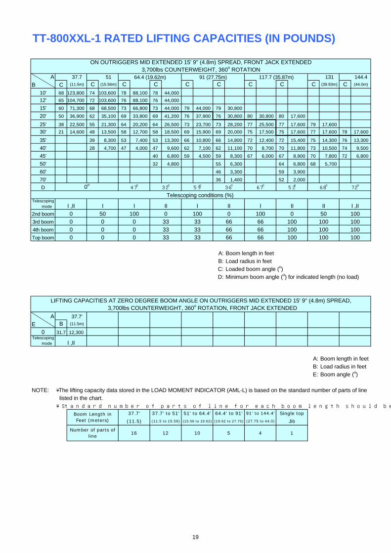
TT-800XXL-1 RATED LIFTING CAPACITIES (IN POUNDS)
A 37.7 51 131 144.4
B C (11.5m) C (15.56m) C C C C C C C (39.93m) C (44.0m)
10' 68 123,800 74 103,600 78 88,100 78 44,000
12' 65 104,700 72 103,600 76 88,100 76 44,000
15' 60 71,300 68 68,500 73 66,800 73 44,000 79 44,000 79 30,800
20' 50 36,900 62 35,100 69 33,800 69 41,200 76 37,900 76 30,800 80 30,800 80 17,600
25' 38 22,500 55 21,300 64 20,200 64 26,500 73 23,700 73 28,200 77 25,500 77 17,600 79 17,600
30' 21 14,600 48 13,500 58 12,700 58 18,500 69 15,900 69 20,000 75 17,500 75 17,600 77 17,600 78 17,600
35' 39 8,300 53 7,400 53 13,300 66 10,800 66 14,800 72 12,400 72 15,400 75 14,300 76 13,300
40' 28 4,700 47 4,000 47 9,600 62 7,100 62 11,100 70 8,700 70 11,800 73 10,500 74 9,500
45' 40 6,800 59 4,500 59 8,300 67 6,000 67 8,900 70 7,800 72 6,800
50' 32 4,800 55 6,300 64 6,800 68 5,700
60' 46 3,300 59 3,900
70' 36 1,400 52 2,000
D
Telescoping mode
2nd boom
3rd boom
4th boom
Top boom
A: Boom length in feetB: Load radius in feetC: Loaded boom angle (o)D: Minimum boom angle (o) for indicated length (no load)
A 37.7'
E B (11.5m)
0 31.7 12,300Telescoping mode
A: Boom length in feetB: Load radius in feetE: Boom angle (o)
NOTE: ・The lifting capacity data stored in the LOAD MOMENT INDICATOR (AML-L) is based on the standard number of parts of line listed in the chart. ・Standard number of parts of line for each boom length should be according to the following table.
67o 52o
I ,II
I ,II0000
LIFTING CAPACITIES AT ZERO DEGREE BOOM ANGLE ON OUTRIGGERS MID EXTENDED 15' 9'' (4.8m) SPREAD,
I I II
0 0 3350 100 0
0 0 330 0 33
100
100100
0
33
66
66 66
3333
100
10066100 0
66 100 100
50
100
I III II II I ,II
100 10066
ON OUTRIGGERS MID EXTENDED 15' 9'' (4.8m) SPREAD, FRONT JACK EXTENDED3,700lbs COUNTERWEIGHT, 360o ROTATION
Telescoping conditions (%)
64.4 (19.62m) 91 (27.75m) 117.7 (35.87m)
68o
100
Single top
3,700lbs COUNTERWEIGHT, 360o ROTATION, FRONT JACK EXTENDED
72o
5 4
64.4' to 91'
(19.62 to 27.75) (27.75 to 44.0)
91' to 144.4'51' to 64.4'
10
Boom Length inFeet (meters)
Number of parts ofline
0o
Jib
1
(15.56 to 19.62)
37.7'
(11.5)
16
37.7' to 51'
(11.5 to 15.56)
12
36o47o 32o 59o
19
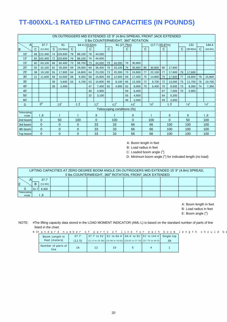
TT-800XXL-1 RATED LIFTING CAPACITIES (IN POUNDS)
A 37.7 51 131 144.4
B C (11.5m) C (15.56m) C C C C C C C (39.93m) C (44.0m)
10' 68 121,400 74 103,600 78 88,100 78 44,000
12' 65 102,400 72 103,600 76 88,100 76 44,000
15' 60 63,100 68 60,400 73 58,700 73 44,000 79 44,000 79 30,800
20' 50 32,100 62 30,300 69 29,000 69 36,400 76 33,100 76 30,800 80 30,800 80 17,600
25' 38 19,100 55 17,900 64 16,800 64 23,200 73 20,300 73 24,800 77 22,100 77 17,600 79 17,600
30' 21 11,600 48 10,500 58 9,300 58 15,800 69 12,900 69 17,400 75 14,800 75 17,600 77 16,800 78 15,800
35' 39 5,600 53 4,700 53 10,800 66 8,100 66 12,300 72 9,700 72 13,000 75 11,700 76 10,700
40' 28 2,400 47 7,400 62 4,900 62 8,900 70 6,400 70 9,500 73 8,300 74 7,300
45' 40 4,900 59 6,400 67 7,000 70 5,900
50' 32 3,100 55 4,600 64 5,200
60' 46 2,000 59 2,600
D
Telescoping mode
2nd boom
3rd boom
4th boom
Top boom
A: Boom length in feetB: Load radius in feetC: Loaded boom angle (o)D: Minimum boom angle (o) for indicated length (no load)
A 37.7'
E B (11.5m)
0 31.7 9,400Telescoping mode
A: Boom length in feetB: Load radius in feetE: Boom angle (o)
NOTE: ・The lifting capacity data stored in the LOAD MOMENT INDICATOR (AML-L) is based on the standard number of parts of line listed in the chart. ・Standard number of parts of line for each boom length should be according to the following table.
46o53o 32o 62o
Jib
1
(15.56 to 19.62)
37.7'
(11.5)
16
37.7' to 51'
(11.5 to 15.56)
12
51' to 64.4'
10
Boom Length inFeet (meters)
Number of parts ofline
5 4
64.4' to 91'
(19.62 to 27.75) (27.75 to 44.0)
91' to 144.4' Single top
0 lbs COUNTERWEIGHT, 360o ROTATION, FRONT JACK EXTENDED
74o
ON OUTRIGGERS MID EXTENDED 15' 9'' (4.8m) SPREAD, FRONT JACK EXTENDED0 lbs COUNTERWEIGHT, 360o ROTATION
Telescoping conditions (%)
64.4 (19.62m) 91 (27.75m) 117.7 (35.87m)
70o
100 100
I III II II I ,II
100 10066
100
10066100 0
66 100 100
50
100
100100
0
33
66
66 66
3333
50 100 0
0 0 330 0 33
0o
I I II
0 0 33
28o 70o 59o
I ,II
I ,II0000
LIFTING CAPACITIES AT ZERO DEGREE BOOM ANGLE ON OUTRIGGERS MID EXTENDED 15' 9'' (4.8m) SPREAD,
20
TT-800XXL-1 RATED LIFTING CAPACITIES (IN POUNDS)
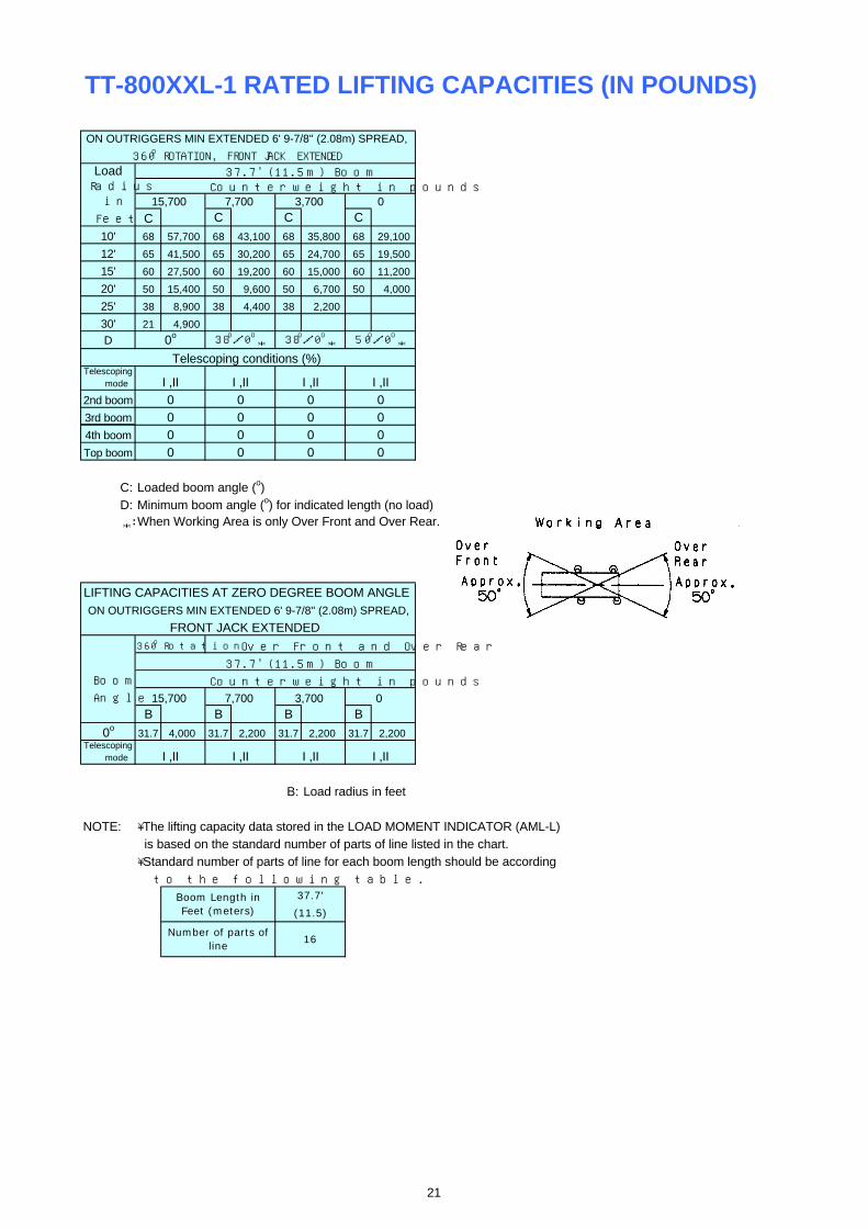
LoadRadius
in
Feet C C C C
10' 68 57,700 68 43,100 68 35,800 68 29,100
12' 65 41,500 65 30,200 65 24,700 65 19,500
15' 60 27,500 60 19,200 60 15,000 60 11,200
20' 50 15,400 50 9,600 50 6,700 50 4,000
25' 38 8,900 38 4,400 38 2,200
30' 21 4,900
D
Telescoping mode
2nd boom
3rd boom
4th boom
Top boom
C: Loaded boom angle (o)D: Minimum boom angle (o) for indicated length (no load)
*: When Working Area is only Over Front and Over Rear.
Boom
Angle
B B B B
0o31.7 4,000 31.7 2,200 31.7 2,200 31.7 2,200
Telescoping mode
B: Load radius in feet
NOTE: ・The lifting capacity data stored in the LOAD MOMENT INDICATOR (AML-L) is based on the standard number of parts of line listed in the chart. ・Standard number of parts of line for each boom length should be according to the following table.
0
0 0
ON OUTRIGGERS MIN EXTENDED 6' 9-7/8'' (2.08m) SPREAD,
000
Counterweight in pounds
0
00
0 0
3,700
0 0
LIFTING CAPACITIES AT ZERO DEGREE BOOM ANGLE
FRONT JACK EXTENDED
Boom Length inFeet (meters)
Number of parts ofline
37.7'
(11.5)
16
38o/0o * 50o/0o
*
ON OUTRIGGERS MIN EXTENDED 6' 9-7/8'' (2.08m) SPREAD,
360o ROTATION, FRONT JACK EXTENDED
15,700 0
37.7' (11.5m) BoomCounterweight in pounds
7,700 3,700
Telescoping conditions (%)
0o 38o/0o *
0 0I ,II I ,II I ,III ,II
0
I ,II I ,II I ,II
360o Rotation Over Front and Over Rear
37.7' (11.5m) Boom
15,700 0
I ,II
7,700
21
WARNING AND OPERATING INSTRUCTIONSFOR LIFTING CAPACITIESGENERAL 10. When making lifts at a load radius not shown, use the next1. RATED LIFTING CAPACITIES apply only to the machine as longer radius to determine allowable capacity.
originally manufactured and normally equipped by TADANO 11. Load per line should not exceed 12,300 lbs. (5,600kg) forLTD. main winch and auxiliary winch.Modifications to the machine or use of optional equipment 12. Check the actual number of parts of line with LOAD MOMENTother than that specified can result in a reduction of capacity. INDICATOR (AML-L) before operation. Maximum lifting
2. Construction equipment can be hazardous if improperly capacity is restricted by the number of parts of line of LOADoperated or maintained. Operation and maintenance of this MOMENT INDICATOR (AML-L). Limited capacity is asmachine must be in compliance with information in the determined from the formula, Single line pull for main winchoperation, safety and maintenance manual supplied with (12,300 lbs.) x number of parts of line.machine. If these manuals are missing, order replacements 13. The boom angle before loading should be greater to accountthrough the distributor. for deflection. For rated lifting capacities, the loaded boom
3. The operator and other personnel associated with this angle and the load radius is for reference only.machine shall fully acquaint themselves with the latest 14. The 37.7' (11.5m) boom length capacities are based on boomAmerican National Standards Institute (ANSI) safety fully retracted. If not fully retracted [less than 51'(15.56m)standards for cranes. boom length], use the rated lifting capacities for the 51' (15.56m)
boom length.SET UP 15. Extension or retraction of the boom with loads may be1. Rated lifting capacities on the chart are the maximum attempted within the limits of the RATED LIFTING CAPACITIES.
allowable crane capacities and are based on the machine The ability to telescope loads is limited by hydraulic pressure,standing level on firm supporting surface under ideal job boom angle, boom length, crane maintenance, etc.conditions. Depending on the nature of the supporting 16. For lifting capacity of single top, reduce the rated liftingsurface, it may be necessary to have structural supports capacities of relevant boom according to a weight reductionsunder the outrigger floats to spread the loads to a larger for auxiliary load handling equipment. Capacities of single top bearing surface. shall not exceed 12,300 lbs. (5,600kg) including main hook.
2. For outrigger operation, outriggers shall be properly extended 17. When base jib or top jib or both jib removing, jib state switchwith tires free of supporting surface before operating crane. select removed. The front jack must be properly extended. 18. When erecting and stowing jib, be sure to retain it by hand or by
3. When operating crane on outriggers fully retracted, do not other means to prevent its free movement.exceed 71o maximum boom angle. Loss of backward stability 19. Use "ANTI-TWO BLOCK" disable switch when erecting andwill occur causing a backward tipping condition. stowing jib and when stowing hook block. While the switch is
pushed, the hoist does not stop, even when overwind conditionOPERATION occurs.1. Rated lifting capacities have been tested to and meet 20. For boom length less than 144.4' (44.0m) and longer than
minimum requirements of SAE J1063-Cantilevered Boom 117.7' (35.87m) with jib, rated lifting capacities are determined Crane Structures Method of Test. by loaded boom angle only in the column headed "144.4'
2. Rated lifting capacities do not exceed 85% of the tipping (44.0m) boom + jib". load on outriggers fully extended as determined by SAE For boom length less than 117.7' (35.87m) with jib, rated lifting J765-Crane Stability Test Code. capacities are determined by loaded boom angle only in the Rated lifting capacities for partially extended outriggers are column headed "117.7' (35.87m) boom + jib". For angles notdetermined from the formula, Rated Lifting Capacities shown, use the next lower loaded boom angle to determine=(Tipping Load - 0.1 x Tip Reaction)/1.25. allowable capacity.
3. Rated lifting capacities above bold lines in the chart are 21. When lifting a load by using jib (aux. winch) and boom (mainbased on crane strength and those below, on its stability. winch) simultaneously, do the following:They are based on actual load radius increased by boom h Enter the operation status as jib operation, not as boomdeflection. operation.
4. The weight of handling device such as hook blocks, slings, h Before starting operation, make sure that mass of load isetc., must be considered as part of the load and must be within rated lifting capacity for jib.deducted from the lifting capacities. 22. Before telescoping the boom, set the telescoping mode
5. Rated lifting capacities are based on freely suspended loads selector switch to MODE I or MODE II with the boomand make no allowance for such factors as the effect of wind, fully retracted. A change of the telescoping mode is notsudden stopping of loads, supporting surface conditions, permissible when the boom has been partially or fully extended.operating speeds, side loads, etc. Side pull on boom or jibis extremely dangerous. DEFINITIONS
6. Rated lifting capacities do not account for wind on lifted load 1. Load Radius: Horizontal distance from a projection of the axisor boom. Rated lifting capacities and boom length shall be of rotation to supporting surface before loading to the center ofappropriately reduced, when wind velocity is above 20 mph the vertical hoist line or tackle with load applied.(9 m/sec.). 2. Loaded Boom Angle: The angle between the boom base
7. Rated lifting capacities at load radius shall not be exceeded. section and the horizontal, after lifting the rated lifting capacityDo not tip the crane to determine allowable loads. at the load radius.
8. Do not operate at boom lengths, radii, or boom angle, where 3. Working Area: Area measured in a circular arc about theno capacities are shown. Crane may overturn without any centerline of rotation.load on the hook. 4. Freely Suspended Load: Load hanging free with no direct
9. When boom length is between values listed, refer to the external force applied except by the hoist line.rated lifting capacities of the next longer and next shorter 5. Side Load: Horizontal side force applied to the lifted load eitherbooms for the same radius. The lesser of the two rated lifting on the ground or in the air.capacities shall be used.
22

WARNING AND OPERATING INSTRUCTIONSFOR USING THE LOAD MOMENT INDICATOR (AML-L)1. When operating crane on outriggers: 3. During crane operation, make sure that the displays on front
h Set Stater switch to "ON" . panel are in accordance with actual operating conditions.h Press the outrigger mode select key to register for the 4. The displayed values of LOAD MOMENT INDICATOR
outrigger operation. Press the set key, then the outrigger (AML-L) are based on freely suspended loads and make nomode indicative symbol changes from flickering to allowance for such factors as the effect of wind, suddenlighting. stopping of loads, supporting surface conditions, operating
h Press the boom mode select key to register the boom speed, side loads, etc. mode, then the boom mode indicative symbol changes For safe operation, it is recommended when extendingfrom lighting to flickering. Each time the boom mode and lowering boom or swinging, lifting loads shall beselect key is pressed, the mode changes. Press the set appropriately reduced.key to select the status that corresponds to the actual 5. LOAD MOMENT INDICATOR (AML-L) is intended as an aidstate of the boom, then the boom mode indicative symbol to the operator. Under no condition should it be relied uponchanges from flickering to lighting. to replace use of capacity charts and operating instruction.
h When erecting and stowing jib, select the status of jib Sole reliance upon LOAD MOMENT INDICATOR (AML-L)set (jib state indicative symbol flicker). aids in place of good operating practice can cause an
2. A swing does not automatically stop even if the crane becomes accident. The operator must exercise caution to assureoverloaded. safety.
TT-800XXL-1 Axle weight distribution chart
Base machine with 105.7gal.(400L)fuel and spare tire,no counterweight.
1. Auxiliary hoist with 436' (133m) of 3/4" (19mm) 640 -2,620 -900 289 -1,1892. 6.2 ton (5.6 metric ton) hook ball -340 50 -132 -154 223. Top jib (25.6') -460 -210 -306 -210 -964. Base jib (32.5') -2,190 270 -872 -993 1215. Spare tire 140 -500 -165 62 -2276. Counterweight 3,700lbs on upper -1,750 5,450 1,680 -794 2,4747. Counterweight 3,700lbs + 4,000lbs on upper -3,640 11,340 3,495 -1,651 5,1468. Counterweight 3,700lbs + 4,000lbs + 8,000lbs on upper -7,420 23,120 7,125 -3,366 10,4919. Counterweight 3,700lbs to carrier deck 2,750 950 1,680 1,248 43210.Counterweight 3,700lbs + 4000lbs to carrier deck 5,720 1,980 3,495 2,596 89911.Counterweight 8,000lbs to carrier deck 5,950 2,050 3,630 2,697 93312.Counterweight 3,700lbs on upper + 4,000lbs to carrier 1,220 6,480 3,495 555 2,940
deck13.Counterweight 3,700lbs + 4,000lbs on upper + 8,000lbs 2,300 13,400 7,125 1,046 6,079
to carrier deckOption: 1. Hot water cab heater and air conditioning in upper cab 20 190 97 9 88
2. Auxiliary lifting sheave 190 -80 50 88 -38
Permissible Axle Load
Permissible axle load
210110
KilogramsGVW Front Rear
PoundsGVW Front Rear
88,820 41,750 47,070 21,35118,93740,288
15,700
-290-1,980
-670-1,920
-360
7,700
3,700
3,700
15,700
7,700
7,7008,000
Rear GVW Front RearPounds Kilograms
GVW
22,000 26,000105,800 48,500 57,300 48,000
Front
23
MEMO
TADANO AMERICA CORPORATION4300 CAMPBELL ROAD, HOUSTON, TEXAS 77041-9116U.S.A.PHONE: (713) 895-9400 EXT.315FAX: (713) 895-0352http://www.tadano-cranes.com/
Form No. GT-800-1-90102/US-02
24
Related Documents