BRAND MODEL Chassis KEYWORD SYMPTOM CURE Sony KV32XBR45 AA-1 CONVERGENCE KV32XBR45 convergence is way off in the horizontal direction Unit has an open R789 a 18 meg 1/2 watt resistor for the Horizontal static convergence. The tech will have to make a resistor out of 3, 6.2 meg resistors. Sony KV32XBR45 AA-1 CONVERGENCE KV32XBR45 Unit has convergence of all vertical lines are displace horizontally. Tech replaced the CRT without authorization. This did not solve the symptom Suggest tech look for R789 and see if it is open It is on the on "C" board. It The value is around 10 meg. There are two different chassis and CRTs used for this model. If they have the older chassis type that requires H stat convergence (CRT board has H stat control) they need to order the older CRT as per the manual. If newer type (No H stat) then the new CRT as per Service Manual supplement -1 is needed. CRT 8-733-743-05 The H Stat is done using the Yoke ring magnets. I have attached the two Service Manual supplements, and the SB325R1. Sony KV32XBR45 AA-1 CONVERGENCE KV32XBR45 Unit has sever Horizontal static convergence error. TV cae to us from another shop where the CRT and flyback was replaced. Customer call us for secont opinion. Suggest tech look for R789 and see if it is open It is on the on "C" board. It The value is around 10 meg. There are two different chassis and CRTs used for this model. If they have the older chassis type that requires H stat convergence (CRT board has H stat control) I have attached the two Service Manual supplements, and the SB325R1. However none of them have show this resistor. We were able to install a resistor in this unit that was a two 10 megs in series. Trimming the value by adding another 10 meg in parallel with one of the other 10 megs. we were able to converge the set. Original part was not available. TSS Logs for Sony Television Products

Welcome message from author
This document is posted to help you gain knowledge. Please leave a comment to let me know what you think about it! Share it to your friends and learn new things together.
Transcript
BR
AN
D
MODEL Chassis KEYWORD SYMPTOM CURE
Son
y
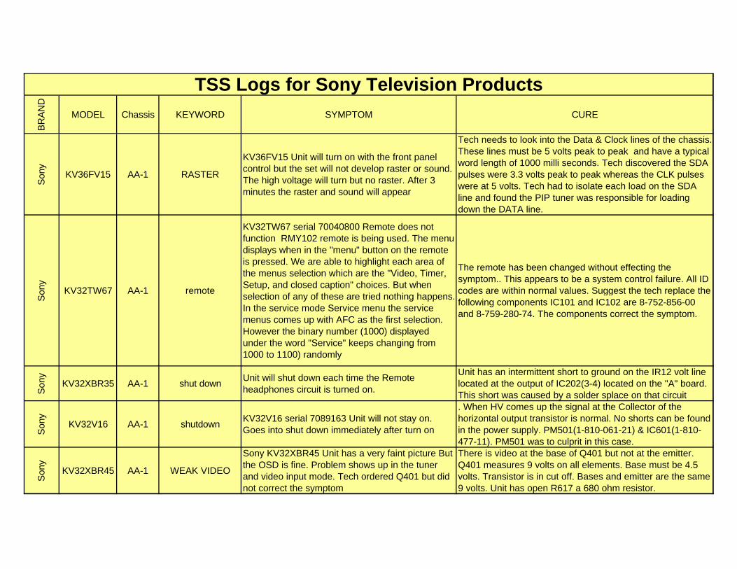
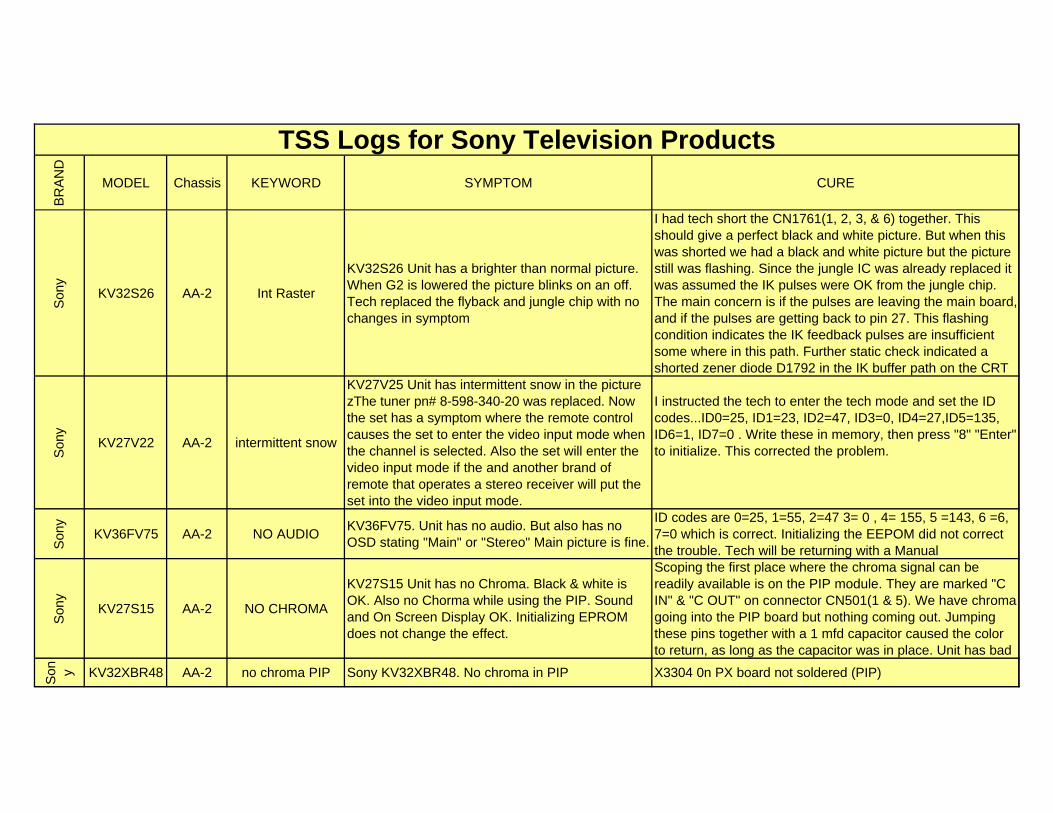
KV32XBR45 AA-1 CONVERGENCEKV32XBR45 convergence is way off in the horizontal direction
Unit has an open R789 a 18 meg 1/2 watt resistor for the Horizontal static convergence. The tech will have to make a resistor out of 3, 6.2 meg resistors.
Son
y
KV32XBR45 AA-1 CONVERGENCE
KV32XBR45 Unit has convergence of all vertical lines are displace horizontally. Tech replaced the CRT without authorization. This did not solve the symptom
Suggest tech look for R789 and see if it is open It is on the on "C" board. It The value is around 10 meg. There are two different chassis and CRTs used for this model. If they have the older chassis type that requires H stat convergence (CRT board has H stat control) they need to order the older CRT as per the manual. If newer type (No H stat) then the new CRT as per Service Manual supplement -1 is needed. CRT 8-733-743-05 The H Stat is done using the Yoke ring magnets. I have attached the two Service Manual supplements, and the SB325R1.
Son
y
KV32XBR45 AA-1 CONVERGENCE
KV32XBR45 Unit has sever Horizontal static convergence error. TV cae to us from another shop where the CRT and flyback was replaced. Customer call us for secont opinion.
Suggest tech look for R789 and see if it is open It is on the on "C" board. It The value is around 10 meg. There are two different chassis and CRTs used for this model. If they have the older chassis type that requires H stat convergence (CRT board has H stat control) I have attached the two Service Manual supplements, and the SB325R1. However none of them have show this resistor. We were able to install a resistor in this unit that was a two 10 megs in series. Trimming the value by adding another 10 meg in parallel with one of the other 10 megs. we were able to converge the set. Original part was not available.
TSS Logs for Sony Television Products
BR
AN
D
MODEL Chassis KEYWORD SYMPTOM CURE
TSS Logs for Sony Television Products
Son
y
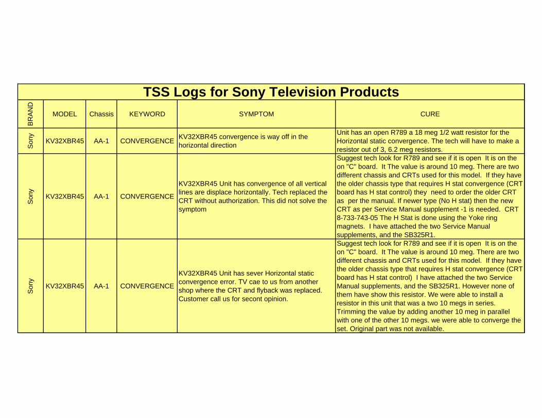
KV32XBR45 AA-1 CONVERGENCEUnit has mis-convergence of red and blue vertical lines. They are displace horizontally. Tech replaced the CRT without correcting the symptom.
R789 open H-state not operational. What I'm finding is a resistor that appears to be open on this "C" board It is R789 The value cannot be read nor is it listed in the ESI software parts list. Trying another value from 10 to 20 megohms. This resistor is in the ground return of the H-stat resistor that is installed in the CRT. Tech needs to try different values to try and make this set converge horizontally. This TV converged with a 10 megohm resistor.
Son
y
KV32XBR45 AA-1 CONVERGENCEUnit has nis-convergence of red & blue vertical lines which are displaced horizontally. Tech replaced the CRT. This did not solve the problem.
Suggest tech look for R789 and see if it is open It is on the on "C" board. The value is around 10 meg. There are two different chassis and CRTs used for this model. If they have the older chassis type that requires H stat convergence (CRT board has H stat control) they need to order the older CRT as per the manual. If newer type (No H stat) then the new CRT as per Service Manual supplement -1 is needed. CRT 8-733-743-05 The H Stat is done using the Yoke ring magnets.
Son
y
KV32TS46 AA-1 dead
Unit was dead. has shorted horizontal output and shorted Q601, & Q602 components in power supply replaced. After replacement unit will turn on but still has no secondary voltage output of power transformer. All relays click but no high voltage. Has sound.
Tech needs to check the condition or RY602. RY602 is the switching relay that turn on and off the set. The relay is "HOT" switched. In other words one side of the relay is connected to power oscillator output that runs nearly 350 vac Peak to Peak at 90Khz. Once the relay is closed this energy is placed across the power output transformer and provides the drive necessary to produce the B+.Measuring the input voltage of the relay to "HOT' ground found it to be 150 volts DC mode. But on the other side of relay we has 3 volts DC mode. Unit has defective RY602 relay.
SO
NY
KV32XBR45 AA-1 GEOMETRYUnit is trying to constantly adjust the vertical height and horizontal size intermittently.
When monitoring the E/W Pin output of the M board the signal was very instable. It was decided to replace IC351 the Jungle IC. This corrected the trouble.
BR
AN
D
MODEL Chassis KEYWORD SYMPTOM CURE
TSS Logs for Sony Television Products
Son
y
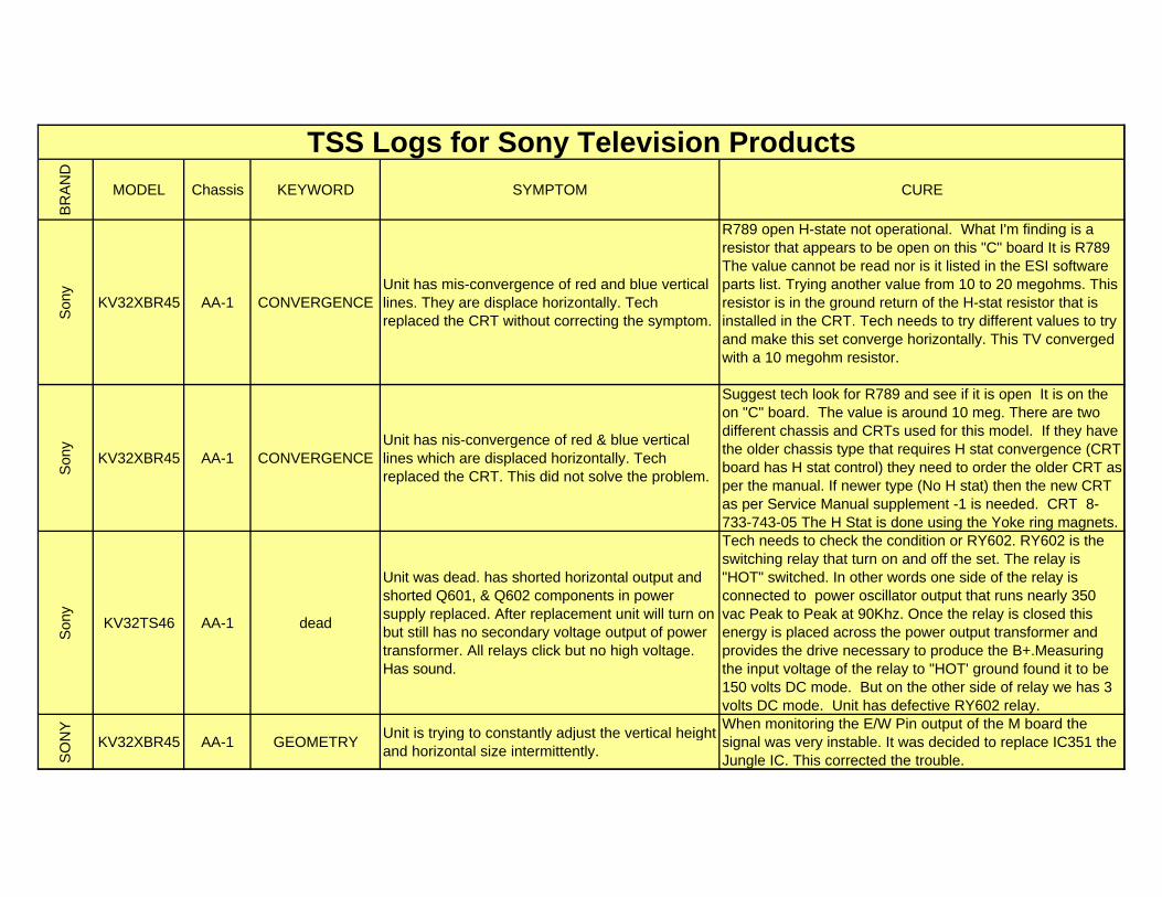
KV32TW77 AA-1 No high voltage
Sony AA-1 chassis. Unit no high voltage or sound. RY602 latched at turn on. Tech replaced the flyback and Q601, Q602, VDR601, VDR602, VDR603 & R607. After theses components were replaced the unit still did not produce secondary B+. Only 3 volts on the collector of the Horizontal output.
Inspected the Power oscillator and discovered that it was running and producing 167 volts DC at the input side of RY602, but a <13 volts on the low side. Jumping RY602 restored High voltage. Unit had a bad RY602 relay in the power supply.
Son
y
KV32XBR37 AA-1 NO RASTERKV32XBR37 serial 80139945. Unit has no raster. Has sound, CRT filaments, and high voltage. Led in front is flashing
Tech may have a IK failure. When bringing up the G2 the raster will appear with full vertical sweep and a purple screen. Not much green. Tech needs to look at the IK buffer collectors on Q771, Q772, & Q773. Normally with beam current there shall be about 1 volt on each collector. With the CRT Socket removed all collectors must drop to "0" volts. Q771 did not. It was 1.2 volts regardless if the tube was connected or not. Tech needs to short Q771(E&B) and see if the collector will drop. It did not. TV will need a replacement Q771. Replacement cured the symptom.
Son
y
KV32XBR85 AA-1 NO RASTERKV32XBR85 Unit has no raster. Has sound and weak OSD. Stand-by light is not flashing.
Unit appears to have a normal IK feed back to the jungle IC. Screen voltages are 670 vdc and the cathode is running at 180 vdc. Unit looks like a defective Jungle IC. Replacing the Jungle IC corected the symptom.
Son
y
KV32XBR250 AA-1 Noise Video
Sony KV32XBR50 This customer has a Goldstar 8mm/VHS dual deck VCR located under this television on the built in shelf. When customer uses the 8mm deck the playback of the tape has corrupted audio, and poor tracking performance when played back on this television
The design of the 8mm format is significantly different from that of the VHS. The 8MM format does not have any stationary heads and completely relies on the signals from the rotary video heads on drum. 4 ATF (Auto Tracking Fix) carriers are recorded on to the tape. Apparently the shielding in the 8 mm VCR, this close proximity to the TV, and the lack of shielding in the Sony TV caused the corruption of the 4 ATF signals. Placing the VCR on the bottom shelf of the TV cabinet corrected the symptom.
BR
AN
D
MODEL Chassis KEYWORD SYMPTOM CURE
TSS Logs for Sony Television Products
Son
y
KV36FV15 AA-1 RASTER
KV36FV15 Unit will turn on with the front panel control but the set will not develop raster or sound. The high voltage will turn but no raster. After 3 minutes the raster and sound will appear
Tech needs to look into the Data & Clock lines of the chassis. These lines must be 5 volts peak to peak and have a typical word length of 1000 milli seconds. Tech discovered the SDA pulses were 3.3 volts peak to peak whereas the CLK pulses were at 5 volts. Tech had to isolate each load on the SDA line and found the PIP tuner was responsible for loading down the DATA line.
Son
y
KV32TW67 AA-1 remote
KV32TW67 serial 70040800 Remote does not function RMY102 remote is being used. The menu displays when in the "menu" button on the remote is pressed. We are able to highlight each area of the menus selection which are the "Video, Timer, Setup, and closed caption" choices. But when selection of any of these are tried nothing happens. In the service mode Service menu the service menus comes up with AFC as the first selection. However the binary number (1000) displayed under the word "Service" keeps changing from 1000 to 1100) randomly
The remote has been changed without effecting the symptom.. This appears to be a system control failure. All ID codes are within normal values. Suggest the tech replace the following components IC101 and IC102 are 8-752-856-00 and 8-759-280-74. The components correct the symptom.
Son
y
KV32XBR35 AA-1 shut downUnit will shut down each time the Remote headphones circuit is turned on.
Unit has an intermittent short to ground on the IR12 volt line located at the output of IC202(3-4) located on the "A" board. This short was caused by a solder splace on that circuit
Son
y
KV32V16 AA-1 shutdownKV32V16 serial 7089163 Unit will not stay on. Goes into shut down immediately after turn on
. When HV comes up the signal at the Collector of the horizontal output transistor is normal. No shorts can be found in the power supply. PM501(1-810-061-21) & IC601(1-810-477-11). PM501 was to culprit in this case.
Son
y
KV32XBR45 AA-1 WEAK VIDEO
Sony KV32XBR45 Unit has a very faint picture But the OSD is fine. Problem shows up in the tuner and video input mode. Tech ordered Q401 but did not correct the symptom
There is video at the base of Q401 but not at the emitter. Q401 measures 9 volts on all elements. Base must be 4.5 volts. Transistor is in cut off. Bases and emitter are the same 9 volts. Unit has open R617 a 680 ohm resistor.
BR
AN
D
MODEL Chassis KEYWORD SYMPTOM CURE
TSS Logs for Sony Television Products
Son
y
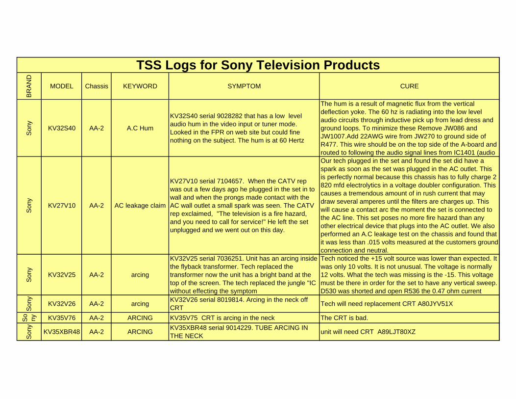
KV32S40 AA-2 A.C Hum
KV32S40 serial 9028282 that has a low level audio hum in the video input or tuner mode. Looked in the FPR on web site but could fine nothing on the subject. The hum is at 60 Hertz
The hum is a result of magnetic flux from the vertical deflection yoke. The 60 hz is radiating into the low level audio circuits through inductive pick up from lead dress and ground loops. To minimize these Remove JW086 and JW1007.Add 22AWG wire from JW270 to ground side of R477. This wire should be on the top side of the A-board and routed to following the audio signal lines from IC1401 (audio
Son
y
KV27V10 AA-2 AC leakage claim
KV27V10 serial 7104657. When the CATV rep was out a few days ago he plugged in the set in to wall and when the prongs made contact with the AC wall outlet a small spark was seen. The CATV rep exclaimed, "The television is a fire hazard, and you need to call for service!" He left the set unplugged and we went out on this day.
Our tech plugged in the set and found the set did have a spark as soon as the set was plugged in the AC outlet. This is perfectly normal because this chassis has to fully charge 2 820 mfd electrolytics in a voltage doubler configuration. This causes a tremendous amount of in rush current that may draw several amperes until the filters are charges up. This will cause a contact arc the moment the set is connected to the AC line. This set poses no more fire hazard than any other electrical device that plugs into the AC outlet. We also performed an A.C leakage test on the chassis and found that it was less than .015 volts measured at the customers ground connection and neutral.
Son
y
KV32V25 AA-2 arcing
KV32V25 serial 7036251. Unit has an arcing inside the flyback transformer. Tech replaced the transformer now the unit has a bright band at the top of the screen. The tech replaced the jungle "IC without effecting the symptom
Tech noticed the +15 volt source was lower than expected. It was only 10 volts. It is not unusual. The voltage is normally 12 volts. What the tech was missing is the -15. This voltage must be there in order for the set to have any vertical sweep. D530 was shorted and open R536 the 0.47 ohm current
Son
y
KV32V26 AA-2 arcingKV32V26 serial 8019814. Arcing in the neck off CRT
Tech will need replacement CRT A80JYV51X
So
ny KV35V76 AA-2 ARCING KV35V75 CRT is arcing in the neck The CRT is bad.
Son
y
KV35XBR48 AA-2 ARCINGKV35XBR48 serial 9014229. TUBE ARCING IN THE NECK
unit will need CRT A89LJT80XZ
BR
AN
D
MODEL Chassis KEYWORD SYMPTOM CURE
TSS Logs for Sony Television Products
Son
y
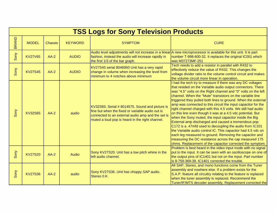
KV27V65 AA-2 AUDIOAudio level adjustments will not increase in a linear fashion, instead the audio will increase rapidly in the first 1/3 of the bar graph.
A new microprocessor is available for this unit. It is part number T-998-600-32. It replaces the original IC001 which was M37273MF-251
Son
y
KV27S45 AA-2 AUDIOKV27S45 serial 8046950 Unit has a very rapid change in volume when increasing the level from minimum to 4 notches above minimum
Tech needs to add a resistor in parallel with R432 to effectively reduce the value of R432. This changes the voltage divider ratio to the volume control circuit and makes the volume circuit more linear in operation.
Son
y
KV32S65 AA-2 audio
KV32S65. Serial # 8014575. Sound and picture is fine but when the fixed or variable audio out is connected to an external audio amp and the set is muted a loud pop is heard in the right channel.
I had the tech try to measure if there was any DC voltages that resided on the Variable audio output connectors. There was "4.5" volts on the Right channel and "0" volts on the left channel. When the "Mute" transistors on the variable line triggered they pulled both lines to ground. When the external amp was connected to this circuit the input capacitor for the right channel charged with this 4.5 volts. We still had audio on this line even though it was at a 4.5 vdc potential. But when the Sony muted, the input capacitor inside the Big External amp discharged and caused a tremendous pop. C172 is a .47mfd used to decoupling the audio from IC101 the Variable audio control IC. This capacitor had 4.5 vdc on each leg measured to ground. Removing the capacitor and measuring the DC resistance across the cap measured 175 ohms. Replacement of the capacitor corrected the symptom.
Son
y
KV27S20 AA-2 AudioSony KV27S20. Unit has a low pitch whine in the left audio channel.
Problem is best heard in the video input mode with no signal put to the input. It can be seen with an oscilloscope on one of the output pins of IC1401 but not on the input. Part number is 8-759-369-39. IC1401 corrected the trouble.
Son
y
KV27S36 AA-2 audioSony KV27S36. Unit has choppy SAP audio. Stereo 0.K.
All SAP, Stereo, and mono functions come from the Tuner assembly and nowhere else. If a problem exists for the S.A.P. feature all circuitry relating to the feature is replaced when the tuner assembly is replaced. Recommend the Tuner/IF/MTS decoder assembly. Replacement corrected the
BR
AN
D
MODEL Chassis KEYWORD SYMPTOM CURE
TSS Logs for Sony Television Products
Son
y
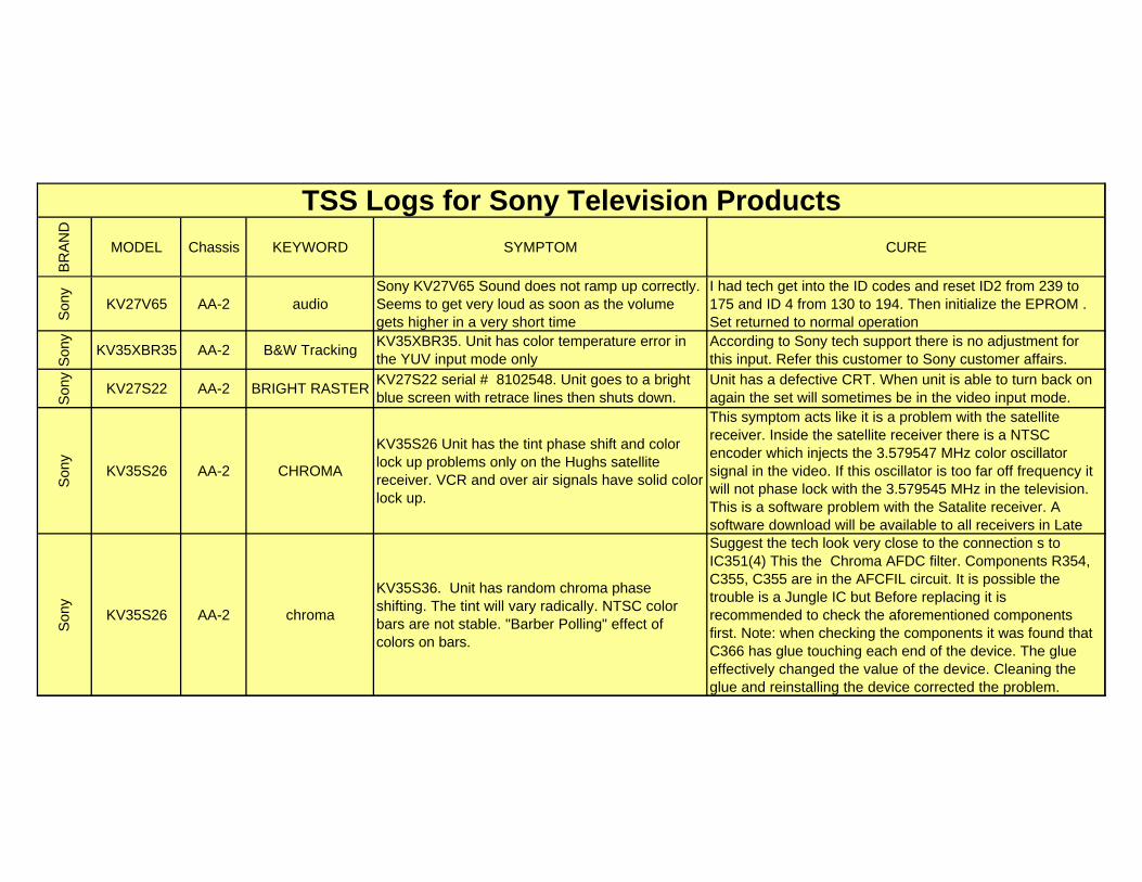
KV27V65 AA-2 audioSony KV27V65 Sound does not ramp up correctly. Seems to get very loud as soon as the volume gets higher in a very short time
I had tech get into the ID codes and reset ID2 from 239 to 175 and ID 4 from 130 to 194. Then initialize the EPROM . Set returned to normal operation
Son
y
KV35XBR35 AA-2 B&W TrackingKV35XBR35. Unit has color temperature error in the YUV input mode only
According to Sony tech support there is no adjustment for this input. Refer this customer to Sony customer affairs.
Son
y
KV27S22 AA-2 BRIGHT RASTERKV27S22 serial # 8102548. Unit goes to a bright blue screen with retrace lines then shuts down.
Unit has a defective CRT. When unit is able to turn back on again the set will sometimes be in the video input mode.
Son
y
KV35S26 AA-2 CHROMA
KV35S26 Unit has the tint phase shift and color lock up problems only on the Hughs satellite receiver. VCR and over air signals have solid color lock up.
This symptom acts like it is a problem with the satellite receiver. Inside the satellite receiver there is a NTSC encoder which injects the 3.579547 MHz color oscillator signal in the video. If this oscillator is too far off frequency it will not phase lock with the 3.579545 MHz in the television. This is a software problem with the Satalite receiver. A software download will be available to all receivers in Late
Son
y
KV35S26 AA-2 chroma
KV35S36. Unit has random chroma phase shifting. The tint will vary radically. NTSC color bars are not stable. "Barber Polling" effect of colors on bars.
Suggest the tech look very close to the connection s to IC351(4) This the Chroma AFDC filter. Components R354, C355, C355 are in the AFCFIL circuit. It is possible the trouble is a Jungle IC but Before replacing it is recommended to check the aforementioned components first. Note: when checking the components it was found that C366 has glue touching each end of the device. The glue effectively changed the value of the device. Cleaning the glue and reinstalling the device corrected the problem.
BR
AN
D
MODEL Chassis KEYWORD SYMPTOM CURE
TSS Logs for Sony Television Products
Son
y KV35XBR200
AA-2 CHROMA
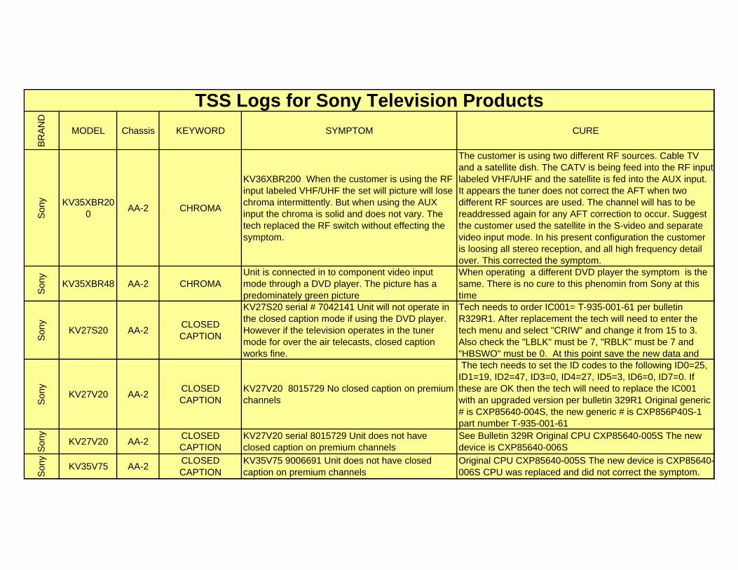
KV36XBR200 When the customer is using the RF input labeled VHF/UHF the set will picture will lose chroma intermittently. But when using the AUX input the chroma is solid and does not vary. The tech replaced the RF switch without effecting the symptom.
The customer is using two different RF sources. Cable TV and a satellite dish. The CATV is being feed into the RF input labeled VHF/UHF and the satellite is fed into the AUX input. It appears the tuner does not correct the AFT when two different RF sources are used. The channel will has to be readdressed again for any AFT correction to occur. Suggest the customer used the satellite in the S-video and separate video input mode. In his present configuration the customer is loosing all stereo reception, and all high frequency detail over. This corrected the symptom.
Son
y
KV35XBR48 AA-2 CHROMAUnit is connected in to component video input mode through a DVD player. The picture has a predominately green picture
When operating a different DVD player the symptom is the same. There is no cure to this phenomin from Sony at this time
Son
y
KV27S20 AA-2CLOSED CAPTION
KV27S20 serial # 7042141 Unit will not operate in the closed caption mode if using the DVD player. However if the television operates in the tuner mode for over the air telecasts, closed caption works fine.
Tech needs to order IC001= T-935-001-61 per bulletin R329R1. After replacement the tech will need to enter the tech menu and select "CRIW" and change it from 15 to 3. Also check the "LBLK" must be 7, "RBLK" must be 7 and "HBSWO" must be 0. At this point save the new data and
Son
y
KV27V20 AA-2CLOSED CAPTION
KV27V20 8015729 No closed caption on premium channels
The tech needs to set the ID codes to the following ID0=25, ID1=19, ID2=47, ID3=0, ID4=27, ID5=3, ID6=0, ID7=0. If these are OK then the tech will need to replace the IC001 with an upgraded version per bulletin 329R1 Original generic # is CXP85640-004S, the new generic # is CXP856P40S-1 part number T-935-001-61
Son
y
KV27V20 AA-2CLOSED CAPTION
KV27V20 serial 8015729 Unit does not have closed caption on premium channels
See Bulletin 329R Original CPU CXP85640-005S The new device is CXP85640-006S
Son
y
KV35V75 AA-2CLOSED CAPTION
KV35V75 9006691 Unit does not have closed caption on premium channels
Original CPU CXP85640-005S The new device is CXP85640-006S CPU was replaced and did not correct the symptom.
BR
AN
D
MODEL Chassis KEYWORD SYMPTOM CURE
TSS Logs for Sony Television Products
Son
y
KV27V20 AA-2CLOSED CAPTION
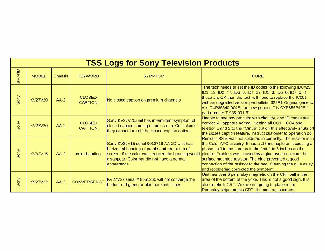
No closed caption on premium channels
The tech needs to set the ID codes to the following ID0=25, ID1=19, ID2=47, ID3=0, ID4=27, ID5=3, ID6=0, ID7=0. If these are OK then the tech will need to replace the IC001 with an upgraded version per bulletin 329R1 Original generic # is CXP85640-004S, the new generic # is CXP856P40S-1 part number T-935-001-61
Son
y
KV27V20 AA-2CLOSED CAPTION
Sony KV27V20.unit has intermittent symptom of closed caption coming up on screen. Cust claims they cannot turn off the closed caption option.
Unable to see any problem with circuitry, and ID codes are correct. All appears normal. Setting all CC1 ~ CC4 and teletext 1 and 2 to the "Minus" option this effectively shuts off the closes caption feature. Instruct customer to operation od
Son
y
KV32V15 AA-2 color banding
Sony KV32V15 serial 9013716 AA-2D Unit has horizontal banding of purple and red at top of screen. If the color was reduced the banding would disappear. Color bar did not have a normal appearance
Resistor R354 was not soldered in correctly. The resistor is in the Color AFC circuitry. It had a .15 ms ripple on it causing a phase shift in the chroma in the first 4 to 5 inches on the picture. Problem was caused by a glue used to secure the surface mounted resistor. The glue prevented a good connection of the resistor to the pad. Cleaning the glue away and resoldering corrected the symptom.
Son
y
KV27V22 AA-2 CONVERGENCEKV27V22 serial # 8051260 will not converge the bottom red green or blue horizontal lines
Unit has over 6 permaloy magnetic on the CRT bell in the area of the bottom of the yoke. This is not a good sign. It is also a rebuilt CRT. We are not going to place more Permaloy strips on this CRT. It needs replacement.
BR
AN
D
MODEL Chassis KEYWORD SYMPTOM CURE
TSS Logs for Sony Television Products
Son
y
KV32S40 AA-2 dead
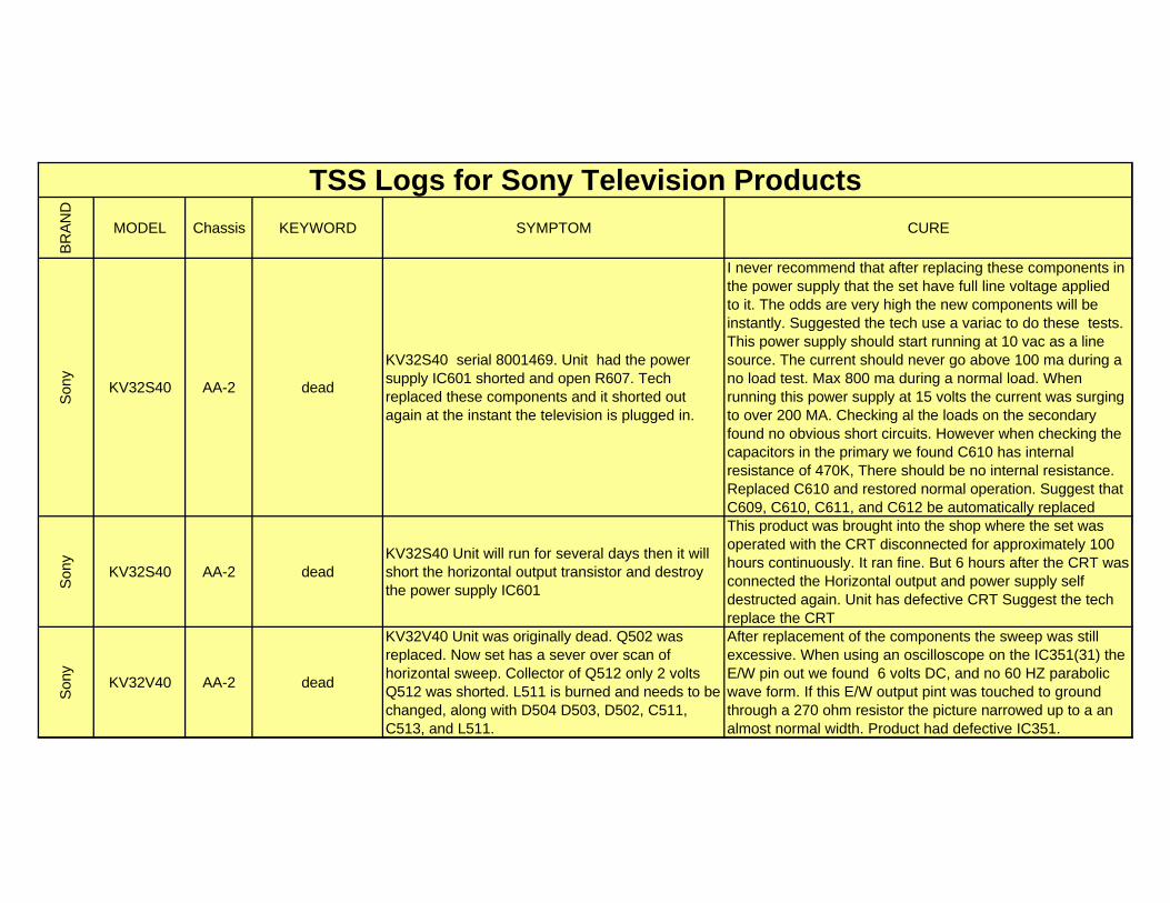
KV32S40 serial 8001469. Unit had the power supply IC601 shorted and open R607. Tech replaced these components and it shorted out again at the instant the television is plugged in.
I never recommend that after replacing these components in the power supply that the set have full line voltage applied to it. The odds are very high the new components will be instantly. Suggested the tech use a variac to do these tests. This power supply should start running at 10 vac as a line source. The current should never go above 100 ma during a no load test. Max 800 ma during a normal load. When running this power supply at 15 volts the current was surging to over 200 MA. Checking al the loads on the secondary found no obvious short circuits. However when checking the capacitors in the primary we found C610 has internal resistance of 470K, There should be no internal resistance. Replaced C610 and restored normal operation. Suggest that C609, C610, C611, and C612 be automatically replaced
Son
y
KV32S40 AA-2 deadKV32S40 Unit will run for several days then it will short the horizontal output transistor and destroy the power supply IC601
This product was brought into the shop where the set was operated with the CRT disconnected for approximately 100 hours continuously. It ran fine. But 6 hours after the CRT was connected the Horizontal output and power supply self destructed again. Unit has defective CRT Suggest the tech replace the CRT
Son
y
KV32V40 AA-2 dead
KV32V40 Unit was originally dead. Q502 was replaced. Now set has a sever over scan of horizontal sweep. Collector of Q512 only 2 volts Q512 was shorted. L511 is burned and needs to be changed, along with D504 D503, D502, C511, C513, and L511.
After replacement of the components the sweep was still excessive. When using an oscilloscope on the IC351(31) the E/W pin out we found 6 volts DC, and no 60 HZ parabolic wave form. If this E/W output pint was touched to ground through a 270 ohm resistor the picture narrowed up to a an almost normal width. Product had defective IC351.
BR
AN
D
MODEL Chassis KEYWORD SYMPTOM CURE
TSS Logs for Sony Television Products
Son
y
KV32XBR48 AA-2 dead
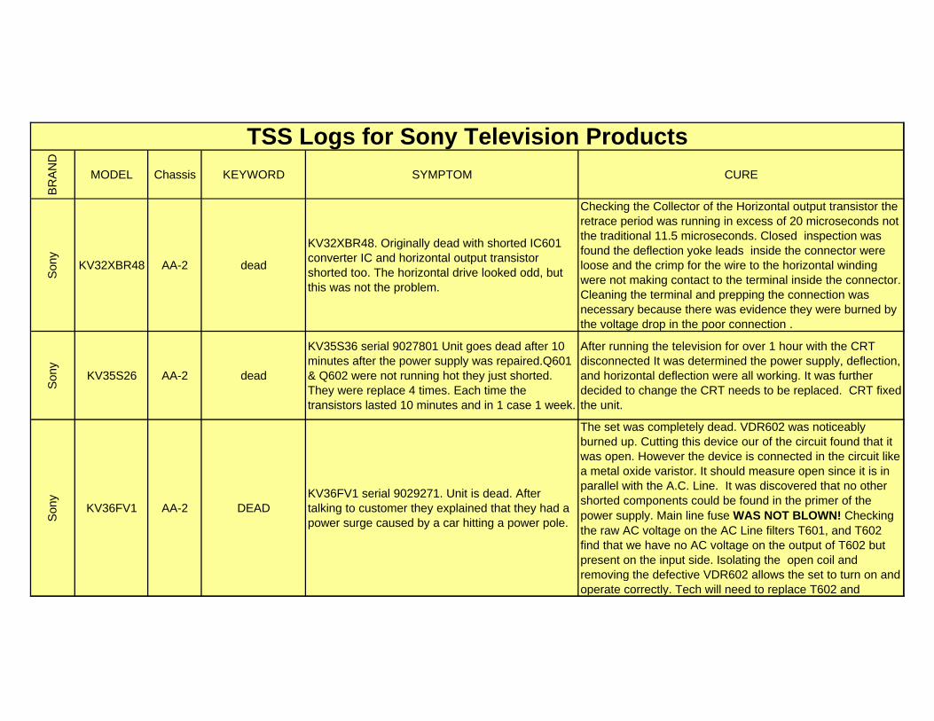
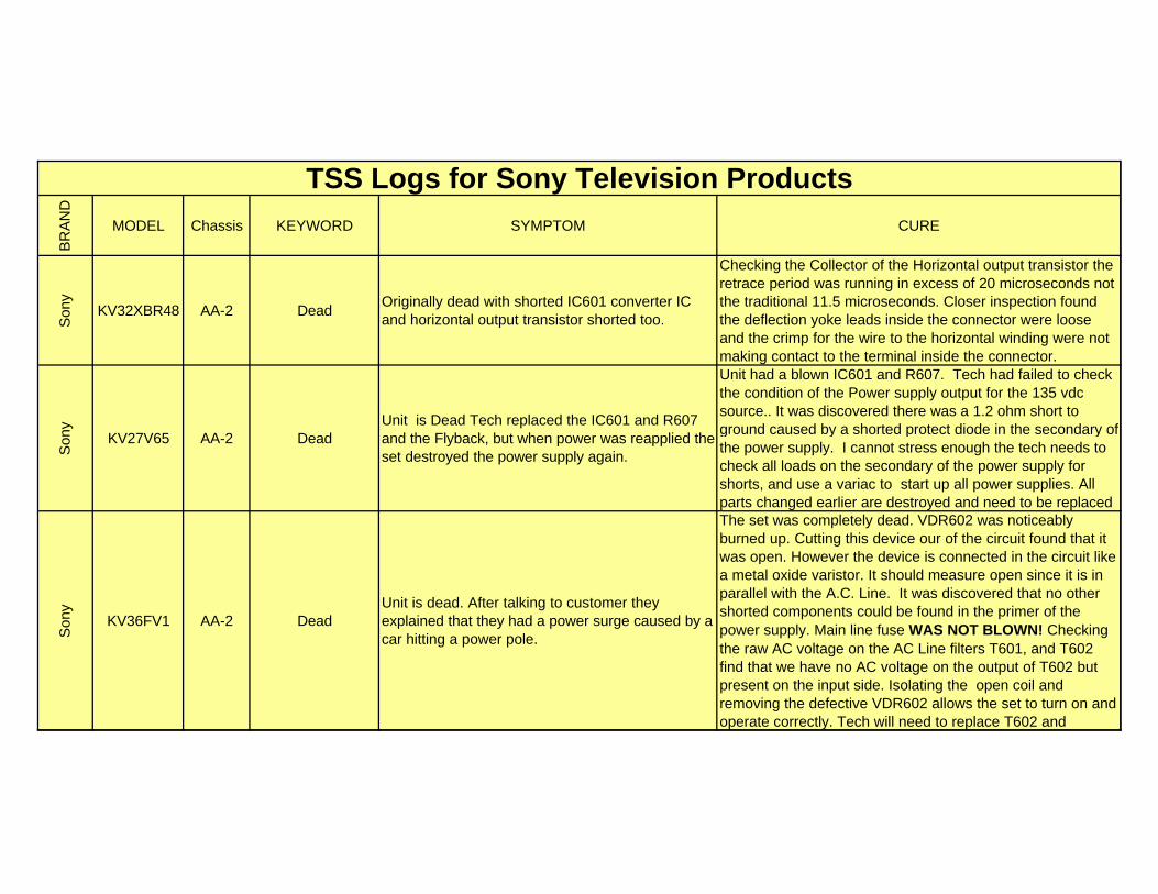
KV32XBR48. Originally dead with shorted IC601 converter IC and horizontal output transistor shorted too. The horizontal drive looked odd, but this was not the problem.
Checking the Collector of the Horizontal output transistor the retrace period was running in excess of 20 microseconds not the traditional 11.5 microseconds. Closed inspection was found the deflection yoke leads inside the connector were loose and the crimp for the wire to the horizontal winding were not making contact to the terminal inside the connector. Cleaning the terminal and prepping the connection was necessary because there was evidence they were burned by the voltage drop in the poor connection .
Son
y
KV35S26 AA-2 dead
KV35S36 serial 9027801 Unit goes dead after 10 minutes after the power supply was repaired.Q601 & Q602 were not running hot they just shorted. They were replace 4 times. Each time the transistors lasted 10 minutes and in 1 case 1 week.
After running the television for over 1 hour with the CRT disconnected It was determined the power supply, deflection, and horizontal deflection were all working. It was further decided to change the CRT needs to be replaced. CRT fixed the unit.
Son
y
KV36FV1 AA-2 DEADKV36FV1 serial 9029271. Unit is dead. After talking to customer they explained that they had a power surge caused by a car hitting a power pole.
The set was completely dead. VDR602 was noticeably burned up. Cutting this device our of the circuit found that it was open. However the device is connected in the circuit like a metal oxide varistor. It should measure open since it is in parallel with the A.C. Line. It was discovered that no other shorted components could be found in the primer of the power supply. Main line fuse WAS NOT BLOWN! Checking the raw AC voltage on the AC Line filters T601, and T602 find that we have no AC voltage on the output of T602 but present on the input side. Isolating the open coil and removing the defective VDR602 allows the set to turn on and operate correctly. Tech will need to replace T602 and
BR
AN
D
MODEL Chassis KEYWORD SYMPTOM CURE
TSS Logs for Sony Television Products
Son
y
KV32XBR48 AA-2 DeadOriginally dead with shorted IC601 converter IC and horizontal output transistor shorted too.
Checking the Collector of the Horizontal output transistor the retrace period was running in excess of 20 microseconds not the traditional 11.5 microseconds. Closer inspection found the deflection yoke leads inside the connector were loose and the crimp for the wire to the horizontal winding were not making contact to the terminal inside the connector.
Son
y
KV27V65 AA-2 DeadUnit is Dead Tech replaced the IC601 and R607 and the Flyback, but when power was reapplied the set destroyed the power supply again.
Unit had a blown IC601 and R607. Tech had failed to check the condition of the Power supply output for the 135 vdc source.. It was discovered there was a 1.2 ohm short to ground caused by a shorted protect diode in the secondary of the power supply. I cannot stress enough the tech needs to check all loads on the secondary of the power supply for shorts, and use a variac to start up all power supplies. All parts changed earlier are destroyed and need to be replaced
Son
y
KV36FV1 AA-2 DeadUnit is dead. After talking to customer they explained that they had a power surge caused by a car hitting a power pole.
The set was completely dead. VDR602 was noticeably burned up. Cutting this device our of the circuit found that it was open. However the device is connected in the circuit like a metal oxide varistor. It should measure open since it is in parallel with the A.C. Line. It was discovered that no other shorted components could be found in the primer of the power supply. Main line fuse WAS NOT BLOWN! Checking the raw AC voltage on the AC Line filters T601, and T602 find that we have no AC voltage on the output of T602 but present on the input side. Isolating the open coil and removing the defective VDR602 allows the set to turn on and operate correctly. Tech will need to replace T602 and
BR
AN
D
MODEL Chassis KEYWORD SYMPTOM CURE
TSS Logs for Sony Television Products
Son
y
KV36FV1 AA-2 FOCUS
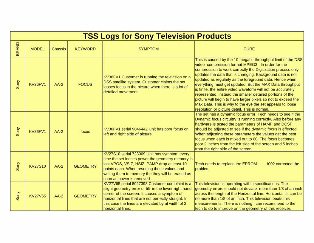
KV36FV1 Customer is running the television on a DSS satellite system. Customer claims the set looses focus in the picture when there is a lot of detailed movement.
This is caused by the 10 megabit throughput limit of the DSS video compression format MPEG3. In order for the compression to work correctly the Digitization process only updates the data that is changing. Background data is not updated as regularly as the foreground data. Hence when everything must get updated. But the MAX Data throughput is finite. the entire video waveform will not be accurately represented, instead the smaller detailed portions of the picture will begin to have larger pixels so not to exceed the Max Data. This is why to the eye the set appears to loose resolution or picture detail. This is normal.
Son
y
KV36FV1 AA-2 focusKV36FV1 serial 9046442 Unit has poor focus on left and right side of picture
The set has a dynamic focus error. Tech needs to see if the Dynamic focus circuitry is running correctly. Also before any hardware is tested the parameters of HAMP and DCSF should be adjusted to see if the dynamic focus is effected. When adjusting these parameters the values get the best focus when each is mixed out to 60. The focus becomes poor 2 inches from the left side of the screen and 5 inches from the right side of the screen.
Son
y
KV27S10 AA-2 GEOMETRY
KV27S10 serial 723009 Unit has symptom every time the set looses power the geometry memory is lost VPOS, VSIZ, HSIZ. PAMP drop at least 10 points each. When resetting these values and writing them to memory the they will be erased as soon as power is removed
Tech needs to replace the EPROM……. I002 corrected the problem
Son
y
KV27V65 AA-2 GEOMETRY
KV27V65 serial 8027393 Customer complaint is a slight geometry error or tilt in the lower right hand corner of the screen. It causes a symptom of horizontal lines that are not perfectly straight. In this case the lines are elevated by at width of 2 horizontal lines.
This television is operating within specifications. The geometry errors should not deviate more than 1/8 of an inch across the length of the Horizontal line. Horizontal tilt can be no more than 1/8 of an inch. This television beats this measurements. There is nothing I can recommend to the tech to do to improve on the geometry of this receiver.
BR
AN
D
MODEL Chassis KEYWORD SYMPTOM CURE
TSS Logs for Sony Television Products
Son
y
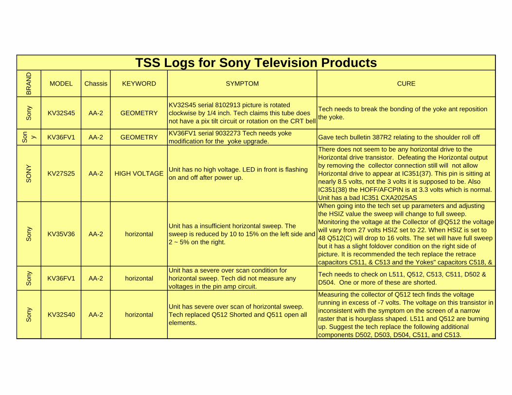
KV32S45 AA-2 GEOMETRYKV32S45 serial 8102913 picture is rotated clockwise by 1/4 inch. Tech claims this tube does not have a pix tilt circuit or rotation on the CRT bell
Tech needs to break the bonding of the yoke ant reposition the yoke.
Son y KV36FV1 AA-2 GEOMETRY
KV36FV1 serial 9032273 Tech needs yoke modification for the yoke upgrade.
Gave tech bulletin 387R2 relating to the shoulder roll off
SO
NY
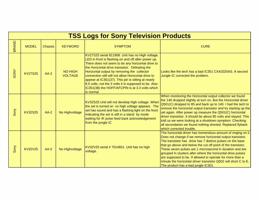
KV27S25 AA-2 HIGH VOLTAGEUnit has no high voltage. LED in front is flashing on and off after power up.
There does not seem to be any horizontal drive to the Horizontal drive transistor. Defeating the Horizontal output by removing the collector connection still will not allow Horizontal drive to appear at IC351(37). This pin is sitting at nearly 8.5 volts, not the 3 volts it is supposed to be. Also IC351(38) the HOFF/AFCPIN is at 3.3 volts which is normal. Unit has a bad IC351 CXA2025AS
Son
y
KV35V36 AA-2 horizontalUnit has a insufficient horizontal sweep. The sweep is reduced by 10 to 15% on the left side and 2 ~ 5% on the right.
When going into the tech set up parameters and adjusting the HSIZ value the sweep will change to full sweep. Monitoring the voltage at the Collector of @Q512 the voltage will vary from 27 volts HSIZ set to 22. When HSIZ is set to 48 Q512(C) will drop to 16 volts. The set will have full sweep but it has a slight foldover condition on the right side of picture. It is recommended the tech replace the retrace capacitors C511, & C513 and the Yokes" capacitors C518, &
Son
y
KV36FV1 AA-2 horizontalUnit has a severe over scan condition for horizontal sweep. Tech did not measure any voltages in the pin amp circuit.
Tech needs to check on L511, Q512, C513, C511, D502 & D504. One or more of these are shorted.
Son
y
KV32S40 AA-2 horizontalUnit has severe over scan of horizontal sweep. Tech replaced Q512 Shorted and Q511 open all elements.
Measuring the collector of Q512 tech finds the voltage running in excess of -7 volts. The voltage on this transistor in inconsistent with the symptom on the screen of a narrow raster that is hourglass shaped. L511 and Q512 are burning up. Suggest the tech replace the following additional components D502, D503, D504, C511, and C513.
BR
AN
D
MODEL Chassis KEYWORD SYMPTOM CURE
TSS Logs for Sony Television Products
Son
y
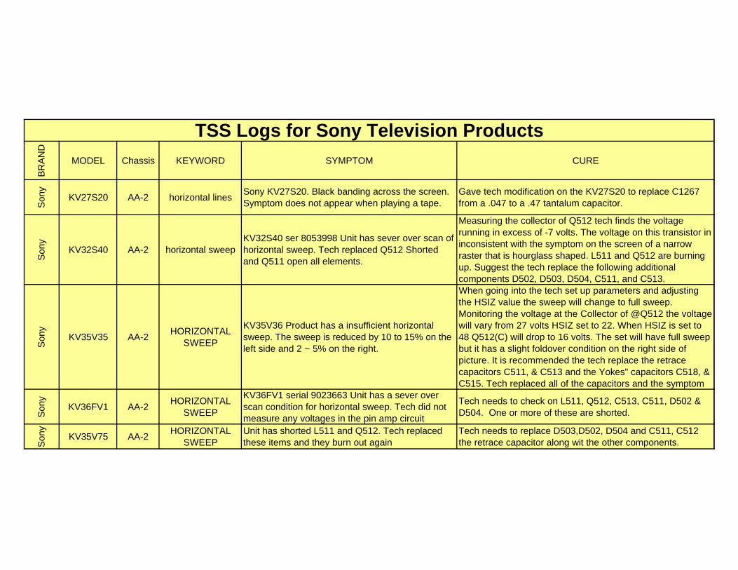
KV27S20 AA-2 horizontal linesSony KV27S20. Black banding across the screen. Symptom does not appear when playing a tape.
Gave tech modification on the KV27S20 to replace C1267 from a .047 to a .47 tantalum capacitor.
Son
y
KV32S40 AA-2 horizontal sweepKV32S40 ser 8053998 Unit has sever over scan of horizontal sweep. Tech replaced Q512 Shorted and Q511 open all elements.
Measuring the collector of Q512 tech finds the voltage running in excess of -7 volts. The voltage on this transistor in inconsistent with the symptom on the screen of a narrow raster that is hourglass shaped. L511 and Q512 are burning up. Suggest the tech replace the following additional components D502, D503, D504, C511, and C513.
Son
y
KV35V35 AA-2HORIZONTAL
SWEEP
KV35V36 Product has a insufficient horizontal sweep. The sweep is reduced by 10 to 15% on the left side and 2 ~ 5% on the right.
When going into the tech set up parameters and adjusting the HSIZ value the sweep will change to full sweep. Monitoring the voltage at the Collector of @Q512 the voltage will vary from 27 volts HSIZ set to 22. When HSIZ is set to 48 Q512(C) will drop to 16 volts. The set will have full sweep but it has a slight foldover condition on the right side of picture. It is recommended the tech replace the retrace capacitors C511, & C513 and the Yokes" capacitors C518, & C515. Tech replaced all of the capacitors and the symptom
Son
y
KV36FV1 AA-2HORIZONTAL
SWEEP
KV36FV1 serial 9023663 Unit has a sever over scan condition for horizontal sweep. Tech did not measure any voltages in the pin amp circuit
Tech needs to check on L511, Q512, C513, C511, D502 & D504. One or more of these are shorted.
Son
y
KV35V75 AA-2HORIZONTAL
SWEEPUnit has shorted L511 and Q512. Tech replaced these items and they burn out again
Tech needs to replace D503,D502, D504 and C511, C512 the retrace capacitor along wit the other components.
BR
AN
D
MODEL Chassis KEYWORD SYMPTOM CURE
TSS Logs for Sony Television Products
Son
y
KV32S26 AA-2 Int Raster
KV32S26 Unit has a brighter than normal picture. When G2 is lowered the picture blinks on an off. Tech replaced the flyback and jungle chip with no changes in symptom
I had tech short the CN1761(1, 2, 3, & 6) together. This should give a perfect black and white picture. But when this was shorted we had a black and white picture but the picture still was flashing. Since the jungle IC was already replaced it was assumed the IK pulses were OK from the jungle chip. The main concern is if the pulses are leaving the main board, and if the pulses are getting back to pin 27. This flashing condition indicates the IK feedback pulses are insufficient some where in this path. Further static check indicated a shorted zener diode D1792 in the IK buffer path on the CRT
Son
y
KV27V22 AA-2 intermittent snow
KV27V25 Unit has intermittent snow in the picture zThe tuner pn# 8-598-340-20 was replaced. Now the set has a symptom where the remote control causes the set to enter the video input mode when the channel is selected. Also the set will enter the video input mode if the and another brand of remote that operates a stereo receiver will put the set into the video input mode.
I instructed the tech to enter the tech mode and set the ID codes...ID0=25, ID1=23, ID2=47, ID3=0, ID4=27,ID5=135, ID6=1, ID7=0 . Write these in memory, then press "8" "Enter" to initialize. This corrected the problem.
Son
y
KV36FV75 AA-2 NO AUDIOKV36FV75. Unit has no audio. But also has no OSD stating "Main" or "Stereo" Main picture is fine.
ID codes are 0=25, 1=55, 2=47 3= 0 , 4= 155, 5 =143, 6 =6, 7=0 which is correct. Initializing the EEPOM did not correct the trouble. Tech will be returning with a Manual
Son
y
KV27S15 AA-2 NO CHROMA
KV27S15 Unit has no Chroma. Black & white is OK. Also no Chorma while using the PIP. Sound and On Screen Display OK. Initializing EPROM does not change the effect.
Scoping the first place where the chroma signal can be readily available is on the PIP module. They are marked "C IN" & "C OUT" on connector CN501(1 & 5). We have chroma going into the PIP board but nothing coming out. Jumping these pins together with a 1 mfd capacitor caused the color to return, as long as the capacitor was in place. Unit has bad
Son y KV32XBR48 AA-2 no chroma PIP Sony KV32XBR48. No chroma in PIP X3304 0n PX board not soldered (PIP)
BR
AN
D
MODEL Chassis KEYWORD SYMPTOM CURE
TSS Logs for Sony Television Products
SO
NY
KV27S25 AA-2NO HIGH VOLTAGE
KV27S25 serial 811908. Unit has no High voltage. LED in front is flashing on and off after power up. There does not seem to be any horizontal drive to the Horizontal drive transistor. Defeating the Horizontal output by removing the collector connection still will not allow Horizontal drive to appear at IC351(37). This pin is sitting at nearly 8.5 volts, not the 3 volts it is supposed to be. Also IC351(38) the HOFF/AFCPIN is at 3.3 volts which is normal
Looks like the tech has a bad IC351 CXA2025AS. A second Jungle IC corrected the problem.
Son
y
KV32S25 AA-2 No Highvoltage
KV32S25 Unit will not develop high voltage. When the set is turned on no high voltage appears. The set has sound and has a flashing light on the front indicating the set is still in a stand by mode waiting for IK pulse feed back acknowledgement from the jungle IC
When monitoring the Horizontal output collector we found the 140 dropped slightly at turn on. But the Horizontal driver Q501(C) dropped to 85 and back up to 140. I had the tech to remove the horizontal output transistor and try starting up the set again. After power up measure the Q501(C) horizontal driver transistor. It should be about 85 volts and stayed. This told us we were looking at a shutdown symptom. Checking all secondaries we found nothing shorted. Replaced flyback which corrected trouble.
Son
y
KV32V25 AA-2 No HighvoltageKV32V25 serial # 7014651. Unit has no high voltage.
The horizontal driver has tremendous amount of ringing on it. Does not change if we remove horizontal output transistor. The transistor has drive has 7 distinct pulses on the base that go above and below the cut off point of the transistor. These seven pulses are 1 microsecond in duration and are grouped in clusters after where the horizontal drive pulses are supposed to be. If allowed to operate for more than a minute the horizontal driver transistor Q502 will short C to E. The product has a bad jungle IC301
BR
AN
D
MODEL Chassis KEYWORD SYMPTOM CURE
TSS Logs for Sony Television Products
Son
y
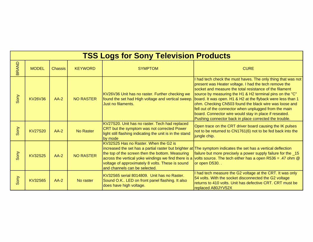
KV26V36 AA-2 NO RASTERKV26V36 Unit has no raster. Further checking we found the set had High voltage and vertical sweep. Just no filaments.
I had tech check the must haves. The only thing that was not present was Heater voltage. I had the tech remove the socket and measure the total resistance of the filament source by measuring the H1 & H2 terminal pins on the "C" board. It was open. H1 & H2 at the flyback were less than 1 ohm. Checking CN503 found the black wire was loose and fell out of the connector when unplugged from the main board. Connector wire would stay in place if reseated. Pushing connector back in place corrected the trouble.
Son
y
KV27S20 AA-2 No Raster
KV27S20. Unit has no raster. Tech had replaced CRT but the symptom was not corrected Power light still flashing indicating the unit is in the stand by mode
Open trace on the CRT driver board causing the IK pulses not to be returned to CN1761(6) not to be fed back into the jungle chip.
Son
y
KV32S25 AA-2 NO RASTER
KV32S25 Has no Raster. When the G2 is increased the set has a partial raster but brighter at the top of the screen then the bottom. Measuring across the vertical yoke windings we find there is a voltage of approximately 8 volts. These is sound and channels can be selected.
The symptom indicates the set has a vertical deflection failure but more precisely a power supply failure for the _15 volts source. The tech either has a open R536 = .47 ohm @ or open D530. .
Son
y
KV32S65 AA-2 No rasterKV32S65 serial 8014809. Unit has no Raster. Sound O.K.. LED on front panel flashing. It also does have high voltage.
I had tech measure the G2 voltage at the CRT. It was only 54 volts. With the socket disconnected the G2 voltage returns to 410 volts. Unit has defective CRT. CRT must be replaced A80JYV52X
BR
AN
D
MODEL Chassis KEYWORD SYMPTOM CURE
TSS Logs for Sony Television Products
Son
y
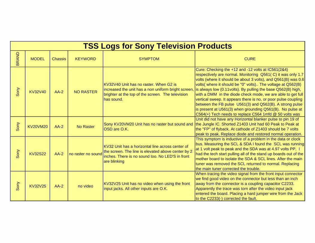
KV32V40 AA-2 NO RASTER
KV32V40 Unit has no raster. When G2 is increased the unit has a non uniform bright screen, brighter at the top of the screen. The television has sound.
Cure: Checking the +12 and -12 volts at IC561(2&4) respectively are normal. Monitoring Q561( C) it was only 1.7 volts (where it should be about 3 volts), and Q561(B) was 0.6 volts( where it should be "0" volts).. The voltage at Q562(B) is always low (0.11volts). By pulling the base Q562(B) high, with a DMM in the diode check mode, we are able to get full vertical sweep. It appears there is no, or poor pulse coupling between the FB pulse U561(3) and Q562(B). A strong pulse is present at U561(3) when grounding Q561(B). No pulse at C564(+) Tech needs to replace C564 1mfd @ 50 volts was
Son
y
KV20VM20 AA-2 No RasterSony KV20VM20 Unit has no raster but sound and OSD are O.K.
Unit did not have any Horizontal blanker pulse to pin 19 of the Jungle IC. Shorted Z1403 Unit had 60 Peak to Peak at the "FP" of flyback. At cathode of Z1403 should be 7 volts peak to peak. Replace diode and restored normal operation.
Son
y
KV32S22 AA-2 no raster no sound
KV32 Unit has a horizontal line across center of the screen. The line is elevated above center by 2 inches. There is no sound too. No LED'S in front are blinking
This symptom is inductive of a problem in the data or clock bus. Measuring the SCL & SDA I found the SCL was running at 1 volt peak to peak and the SDA was at 4.97 volts PP. I had the tech start pulling all of the stand up boards out of the mother board to isolate the SDA & SCL lines. After the main tuner was removed the SCL returned to normal. Replacing the main tuner corrected the trouble.
Son
y
KV32V25 AA-2 no videoKV32V25 Unit has no video when using the front input jacks. All other inputs are O.K.
When tracing the video signal from the front input connector we find good video on the connector but less than an inch away from the connector is a coupling capacitor C2233. Apparently the trace was torn after the video input jack entered the board. Placing a hard jumper wire from the Jack to the C2233(-) corrected the fault.
BR
AN
D
MODEL Chassis KEYWORD SYMPTOM CURE
TSS Logs for Sony Television Products
Son
y
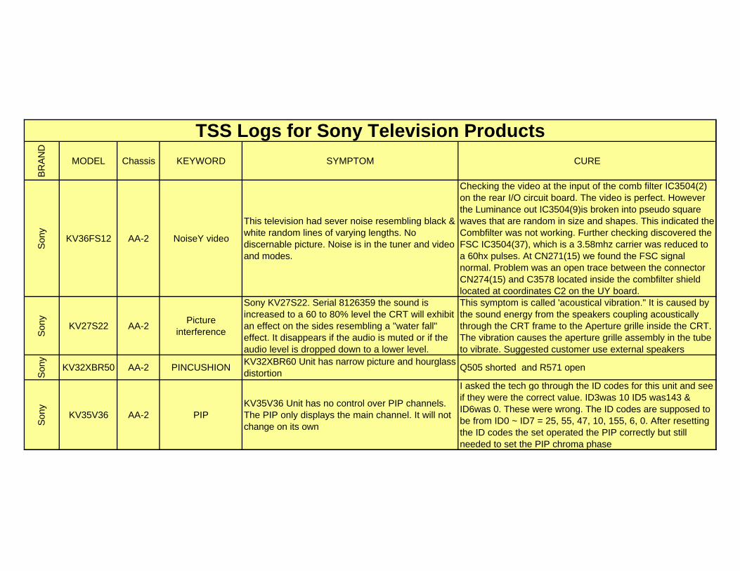
KV36FS12 AA-2 NoiseY video
This television had sever noise resembling black & white random lines of varying lengths. No discernable picture. Noise is in the tuner and video and modes.
Checking the video at the input of the comb filter IC3504(2) on the rear I/O circuit board. The video is perfect. However the Luminance out IC3504(9)is broken into pseudo square waves that are random in size and shapes. This indicated the Combfilter was not working. Further checking discovered the FSC IC3504(37), which is a 3.58mhz carrier was reduced to a 60hx pulses. At CN271(15) we found the FSC signal normal. Problem was an open trace between the connector CN274(15) and C3578 located inside the combfilter shield located at coordinates C2 on the UY board.
Son
y
KV27S22 AA-2Picture
interference
Sony KV27S22. Serial 8126359 the sound is increased to a 60 to 80% level the CRT will exhibit an effect on the sides resembling a "water fall" effect. It disappears if the audio is muted or if the audio level is dropped down to a lower level.
This symptom is called 'acoustical vibration." It is caused by the sound energy from the speakers coupling acoustically through the CRT frame to the Aperture grille inside the CRT. The vibration causes the aperture grille assembly in the tube to vibrate. Suggested customer use external speakers
Son
y
KV32XBR50 AA-2 PINCUSHIONKV32XBR60 Unit has narrow picture and hourglass distortion
Q505 shorted and R571 open
Son
y
KV35V36 AA-2 PIPKV35V36 Unit has no control over PIP channels. The PIP only displays the main channel. It will not change on its own
I asked the tech go through the ID codes for this unit and see if they were the correct value. ID3was 10 ID5 was143 & ID6was 0. These were wrong. The ID codes are supposed to be from ID0 ~ ID7 = 25, 55, 47, 10, 155, 6, 0. After resetting the ID codes the set operated the PIP correctly but still needed to set the PIP chroma phase
BR
AN
D
MODEL Chassis KEYWORD SYMPTOM CURE
TSS Logs for Sony Television Products
Son
y
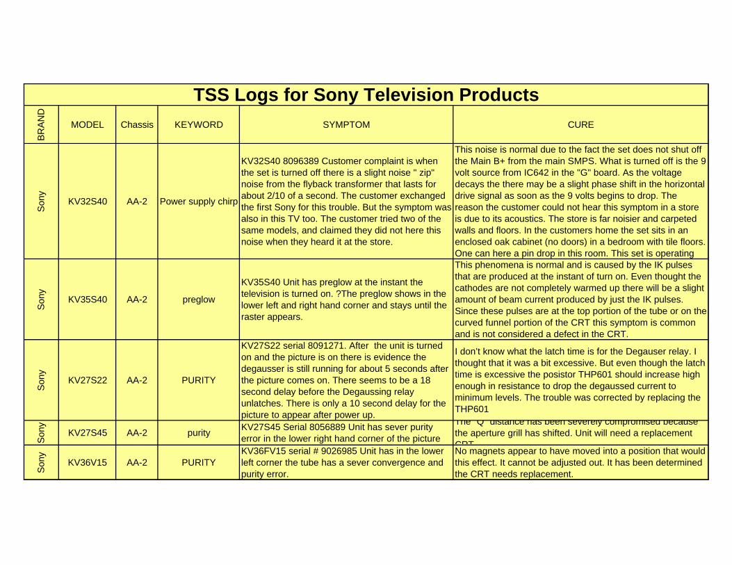
KV32S40 AA-2 Power supply chirp
KV32S40 8096389 Customer complaint is when the set is turned off there is a slight noise " zip" noise from the flyback transformer that lasts for about 2/10 of a second. The customer exchanged the first Sony for this trouble. But the symptom was also in this TV too. The customer tried two of the same models, and claimed they did not here this noise when they heard it at the store.
This noise is normal due to the fact the set does not shut off the Main B+ from the main SMPS. What is turned off is the 9 volt source from IC642 in the "G" board. As the voltage decays the there may be a slight phase shift in the horizontal drive signal as soon as the 9 volts begins to drop. The reason the customer could not hear this symptom in a store is due to its acoustics. The store is far noisier and carpeted walls and floors. In the customers home the set sits in an enclosed oak cabinet (no doors) in a bedroom with tile floors. One can here a pin drop in this room. This set is operating
Son
y
KV35S40 AA-2 preglow
KV35S40 Unit has preglow at the instant the television is turned on. ?The preglow shows in the lower left and right hand corner and stays until the raster appears.
This phenomena is normal and is caused by the IK pulses that are produced at the instant of turn on. Even thought the cathodes are not completely warmed up there will be a slight amount of beam current produced by just the IK pulses. Since these pulses are at the top portion of the tube or on the curved funnel portion of the CRT this symptom is common and is not considered a defect in the CRT.
Son
y
KV27S22 AA-2 PURITY
KV27S22 serial 8091271. After the unit is turned on and the picture is on there is evidence the degausser is still running for about 5 seconds after the picture comes on. There seems to be a 18 second delay before the Degaussing relay unlatches. There is only a 10 second delay for the picture to appear after power up.
I don’t know what the latch time is for the Degauser relay. I thought that it was a bit excessive. But even though the latch time is excessive the posistor THP601 should increase high enough in resistance to drop the degaussed current to minimum levels. The trouble was corrected by replacing the THP601
Son
y
KV27S45 AA-2 purityKV27S45 Serial 8056889 Unit has sever purity error in the lower right hand corner of the picture
The "Q" distance has been severely compromised because the aperture grill has shifted. Unit will need a replacement CRT
Son
y
KV36V15 AA-2 PURITYKV36FV15 serial # 9026985 Unit has in the lower left corner the tube has a sever convergence and purity error.
No magnets appear to have moved into a position that would this effect. It cannot be adjusted out. It has been determined the CRT needs replacement.
BR
AN
D
MODEL Chassis KEYWORD SYMPTOM CURE
TSS Logs for Sony Television Products
Son
y
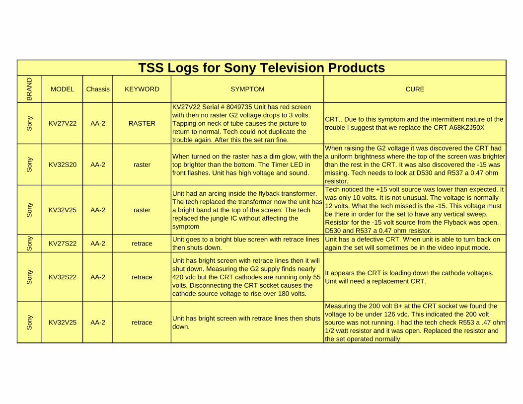
KV27V22 AA-2 RASTER
KV27V22 Serial # 8049735 Unit has red screen with then no raster G2 voltage drops to 3 volts. Tapping on neck of tube causes the picture to return to normal. Tech could not duplicate the trouble again. After this the set ran fine.
CRT.. Due to this symptom and the intermittent nature of the trouble I suggest that we replace the CRT A68KZJ50X
Son
y
KV32S20 AA-2 rasterWhen turned on the raster has a dim glow, with the top brighter than the bottom. The Timer LED in front flashes. Unit has high voltage and sound.
When raising the G2 voltage it was discovered the CRT had a uniform brightness where the top of the screen was brighter than the rest in the CRT. It was also discovered the -15 was missing. Tech needs to look at D530 and R537 a 0.47 ohm resistor.
Son
y
KV32V25 AA-2 raster
Unit had an arcing inside the flyback transformer. The tech replaced the transformer now the unit has a bright band at the top of the screen. The tech replaced the jungle IC without affecting the symptom
Tech noticed the +15 volt source was lower than expected. It was only 10 volts. It is not unusual. The voltage is normally 12 volts. What the tech missed is the -15. This voltage must be there in order for the set to have any vertical sweep. Resistor for the -15 volt source from the Flyback was open. D530 and R537 a 0.47 ohm resistor.
Son
y
KV27S22 AA-2 retraceUnit goes to a bright blue screen with retrace lines then shuts down.
Unit has a defective CRT. When unit is able to turn back on again the set will sometimes be in the video input mode.
Son
y
KV32S22 AA-2 retrace
Unit has bright screen with retrace lines then it will shut down. Measuring the G2 supply finds nearly 420 vdc but the CRT cathodes are running only 55 volts. Disconnecting the CRT socket causes the cathode source voltage to rise over 180 volts.
It appears the CRT is loading down the cathode voltages. Unit will need a replacement CRT.
Son
y
KV32V25 AA-2 retraceUnit has bright screen with retrace lines then shuts down.
Measuring the 200 volt B+ at the CRT socket we found the voltage to be under 126 vdc. This indicated the 200 volt source was not running. I had the tech check R553 a .47 ohm 1/2 watt resistor and it was open. Replaced the resistor and the set operated normally
BR
AN
D
MODEL Chassis KEYWORD SYMPTOM CURE
TSS Logs for Sony Television Products
Son
y
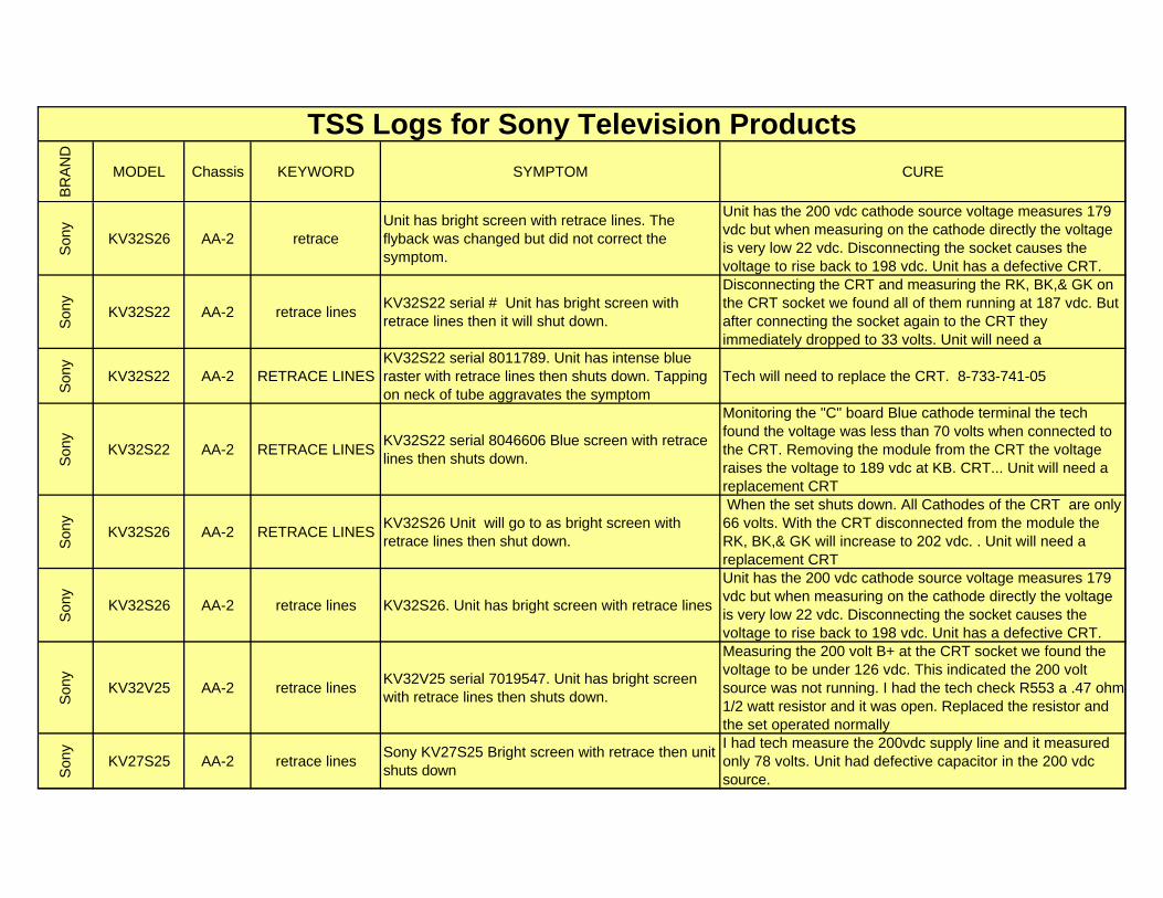
KV32S26 AA-2 retraceUnit has bright screen with retrace lines. The flyback was changed but did not correct the symptom.
Unit has the 200 vdc cathode source voltage measures 179 vdc but when measuring on the cathode directly the voltage is very low 22 vdc. Disconnecting the socket causes the voltage to rise back to 198 vdc. Unit has a defective CRT.
Son
y
KV32S22 AA-2 retrace linesKV32S22 serial # Unit has bright screen with retrace lines then it will shut down.
Disconnecting the CRT and measuring the RK, BK,& GK on the CRT socket we found all of them running at 187 vdc. But after connecting the socket again to the CRT they immediately dropped to 33 volts. Unit will need a
Son
y
KV32S22 AA-2 RETRACE LINESKV32S22 serial 8011789. Unit has intense blue raster with retrace lines then shuts down. Tapping on neck of tube aggravates the symptom
Tech will need to replace the CRT. 8-733-741-05
Son
y
KV32S22 AA-2 RETRACE LINESKV32S22 serial 8046606 Blue screen with retrace lines then shuts down.
Monitoring the "C" board Blue cathode terminal the tech found the voltage was less than 70 volts when connected to the CRT. Removing the module from the CRT the voltage raises the voltage to 189 vdc at KB. CRT... Unit will need a replacement CRT
Son
y
KV32S26 AA-2 RETRACE LINESKV32S26 Unit will go to as bright screen with retrace lines then shut down.
When the set shuts down. All Cathodes of the CRT are only 66 volts. With the CRT disconnected from the module the RK, BK,& GK will increase to 202 vdc. . Unit will need a replacement CRT
Son
y
KV32S26 AA-2 retrace lines KV32S26. Unit has bright screen with retrace lines
Unit has the 200 vdc cathode source voltage measures 179 vdc but when measuring on the cathode directly the voltage is very low 22 vdc. Disconnecting the socket causes the voltage to rise back to 198 vdc. Unit has a defective CRT.
Son
y
KV32V25 AA-2 retrace linesKV32V25 serial 7019547. Unit has bright screen with retrace lines then shuts down.
Measuring the 200 volt B+ at the CRT socket we found the voltage to be under 126 vdc. This indicated the 200 volt source was not running. I had the tech check R553 a .47 ohm 1/2 watt resistor and it was open. Replaced the resistor and the set operated normally
Son
y
KV27S25 AA-2 retrace linesSony KV27S25 Bright screen with retrace then unit shuts down
I had tech measure the 200vdc supply line and it measured only 78 volts. Unit had defective capacitor in the 200 vdc source.
BR
AN
D
MODEL Chassis KEYWORD SYMPTOM CURE
TSS Logs for Sony Television Products
Son
y
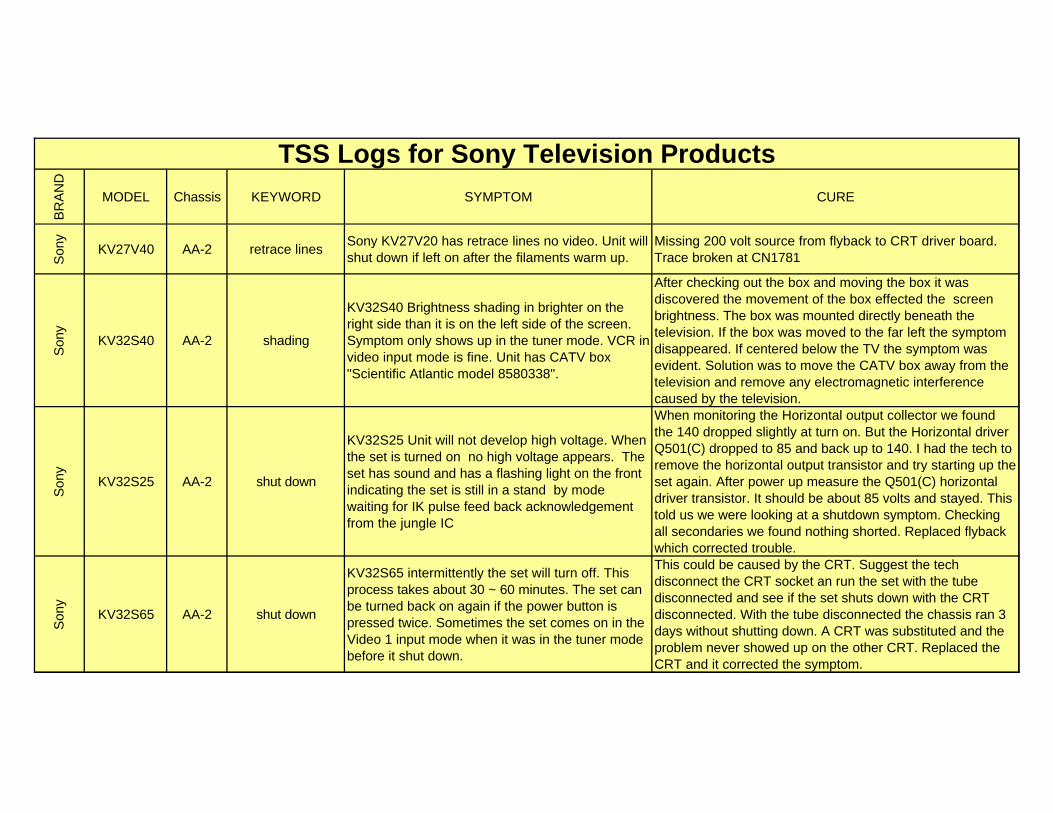
KV27V40 AA-2 retrace linesSony KV27V20 has retrace lines no video. Unit will shut down if left on after the filaments warm up.
Missing 200 volt source from flyback to CRT driver board. Trace broken at CN1781
Son
y
KV32S40 AA-2 shading
KV32S40 Brightness shading in brighter on the right side than it is on the left side of the screen. Symptom only shows up in the tuner mode. VCR in video input mode is fine. Unit has CATV box "Scientific Atlantic model 8580338".
After checking out the box and moving the box it was discovered the movement of the box effected the screen brightness. The box was mounted directly beneath the television. If the box was moved to the far left the symptom disappeared. If centered below the TV the symptom was evident. Solution was to move the CATV box away from the television and remove any electromagnetic interference caused by the television.
Son
y
KV32S25 AA-2 shut down
KV32S25 Unit will not develop high voltage. When the set is turned on no high voltage appears. The set has sound and has a flashing light on the front indicating the set is still in a stand by mode waiting for IK pulse feed back acknowledgement from the jungle IC
When monitoring the Horizontal output collector we found the 140 dropped slightly at turn on. But the Horizontal driver Q501(C) dropped to 85 and back up to 140. I had the tech to remove the horizontal output transistor and try starting up the set again. After power up measure the Q501(C) horizontal driver transistor. It should be about 85 volts and stayed. This told us we were looking at a shutdown symptom. Checking all secondaries we found nothing shorted. Replaced flyback which corrected trouble.
Son
y
KV32S65 AA-2 shut down
KV32S65 intermittently the set will turn off. This process takes about 30 ~ 60 minutes. The set can be turned back on again if the power button is pressed twice. Sometimes the set comes on in the Video 1 input mode when it was in the tuner mode before it shut down.
This could be caused by the CRT. Suggest the tech disconnect the CRT socket an run the set with the tube disconnected and see if the set shuts down with the CRT disconnected. With the tube disconnected the chassis ran 3 days without shutting down. A CRT was substituted and the problem never showed up on the other CRT. Replaced the CRT and it corrected the symptom.
BR
AN
D
MODEL Chassis KEYWORD SYMPTOM CURE
TSS Logs for Sony Television Products
Son
y
KV35V36 AA-2 Shut down
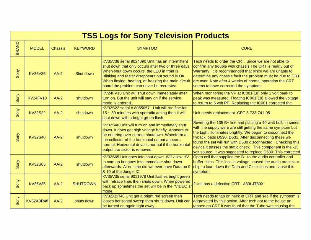
KV35V36 serial 9024090 Unit has an intermittent shut down that only occurs after two or three days. When shut down occurs, the LED in front is Blinking and raster disappears but sound is OK. When flexing, heating, or freezing the main circuit board the problem can never be recreated.
Tech needs to order the CRT. Since we are not able to confirm any trouble with chassis The CRT is nearly out of Warranty. It is recommended that since we are unable to determine any chassis fault the problem must be due to CRT arc over. Note after 4 weeks of normal operation the CRT seems to have corrected the symptom.
Son
y
KV24FV10 AA-2 shutdownKV24FV10 Unit will shut down immediately after turn on. But the unit will stay on if the service mode is entered..
When monitoring the VP at IC001(18) only 1 volt peak to peak was measured. Floating IC001(18) allowed the voltage to return to 5 volt PP. Replacing the IC001 corrected the
Son
y
KV32S22 AA-2 shutdownKV32S22 serial # 8055057. Unit will run fine for 15 ~ 30 minutes with sporadic arcing then it will shut down with a bright green flash
Unit needs replacement CRT 8-733-741-05.
Son
y
KV32S40 AA-2 shutdown
KV32S40 Unit will turn on and immediately shut down. It does get high voltage briefly. Appears to be entering over current shutdown. Waveform at the collector of the horizontal output appears normal. Horizontal drive is normal if the horizontal output transistor is removed.
Severing the 135 B+ line and placing a 40 watt bulb in series with the supply were are still getting the same symptom but the Light illuminates brightly. We began to disconnect the flyback loads D530, D531. After disconnecting these we found the set will run with D530 disconnected . Checking this device it passes the static check. This component is the -15 volt source. It was suggested to replace D530. This corrected
Son
y
KV32S65 AA-2 shutdown
KV32S65 Unit goes into shut down. Will allow HV to com up but goes into immediate shut down afterwards. At no time did we ever have Data on 9 & 10 of the Jungle IC
Open coil that supplied the B+ to the audio controller and buffer chips. This loss in voltage caused the audio processor chip to load down the Data and Clock lines and cause this symptom.
Son
y
KV35V35 AA-2 SHUTDOWN
KV35V35 serial 9011978 Unit flashes bright green with retrace lines then shuts down. When powered back up sometimes the set will be in the "VIDEO 1" mode.
?Unit has a defective CRT. A89LJT80X
Son
y
KV32XBR48 AA-2 shuts downKV32XBR48 Unit get a bright red screen then looses horizontal sweep then shuts down. Unit can be turned on again right away
Tech needs to tap on neck of CRT and see if the symptom is aggravated by this action. After tech got to the house an tapped on CRT it was founf that the Tube was causing the
BR
AN
D
MODEL Chassis KEYWORD SYMPTOM CURE
TSS Logs for Sony Television Products
Son
y
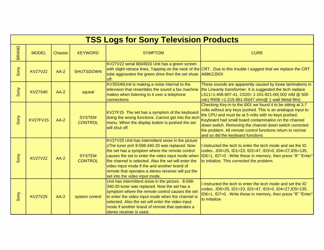
KV27V22 AA-2 SHUTSDOWN
KV27V22 serial 8004933 Unit has a green screen with slight retrace lines, Tapping on the neck of the tube aggravates the green drive then the set shuts off.
CRT.. Due to this trouble I suggest that we replace the CRT A68KZJ50X
Son
y
KV27S40 AA-2 squeal
KV35S40Unit is making a noise internal to the television that resembles the sound a fax machine makes when listening to it over a telephone connections
These sounds are apparently caused by loose laminations in the Linearity transformer. It is suggested the tech replace L511=1-406-607-41, C520= 1-101-821-00(.002 mfd @ 500 vdc) R506 =1-215-861-00(47 ohm@ 1 watt Metal film)
Son
y
KV27FV15 AA-2SYSTEM
CONTROL
KV27F15 The set has a symptom of the keyboard doing the wrong functions. Cannot get into the tech menu. When the display button is pushed the set will shut off.
Checking Key-in to the I001 we found it to be sitting at 3.7 volts without any keys pushed. This is an analogue input to the CPU and must be at 5 volts with no keys pushed. Keyboard had small board contamination on the channel down switch. Removing the channel down switch corrected the problem. All remote control functions return to normal and so did the keyboard functions
Son
y
KV27V22 AA-2SYSTEM
CONTROL
KV27V25 Unit has intermittent snow in the picture zThe tuner pn# 8-598-340-20 was replaced. Now the set has a symptom where the remote control causes the set to enter the video input mode when the channel is selected. Also the set will enter the video input mode if the and another brand of remote that operates a stereo receiver will put the set into the video input mode.
I instructed the tech to enter the tech mode and set the ID codes...ID0=25, ID1=23, ID2=47, ID3=0, ID4=27,ID5=135, ID6=1, ID7=0 . Write these in memory, then press "8" "Enter" to initialize. This corrected the problem.
Son
y
KV27V25 AA-2 system control
Unit has intermittent snow in the picture. 8-598-340-20 tuner was replaced. Now the set has a symptom where the remote control causes the set to enter the video input mode when the channel is selected. Also the set will enter the video input mode if another brand of remote that operates a stereo receiver is used.
I instructed the tech to enter the tech mode and set the ID codes...ID0=25, ID1=23, ID2=47, ID3=0, ID4=27,ID5=135, ID6=1, ID7=0 . Write these in memory, then press "8" "Enter" to initialize.
BR
AN
D
MODEL Chassis KEYWORD SYMPTOM CURE
TSS Logs for Sony Television Products
Son
y
KV36FS10 AA-2 System control
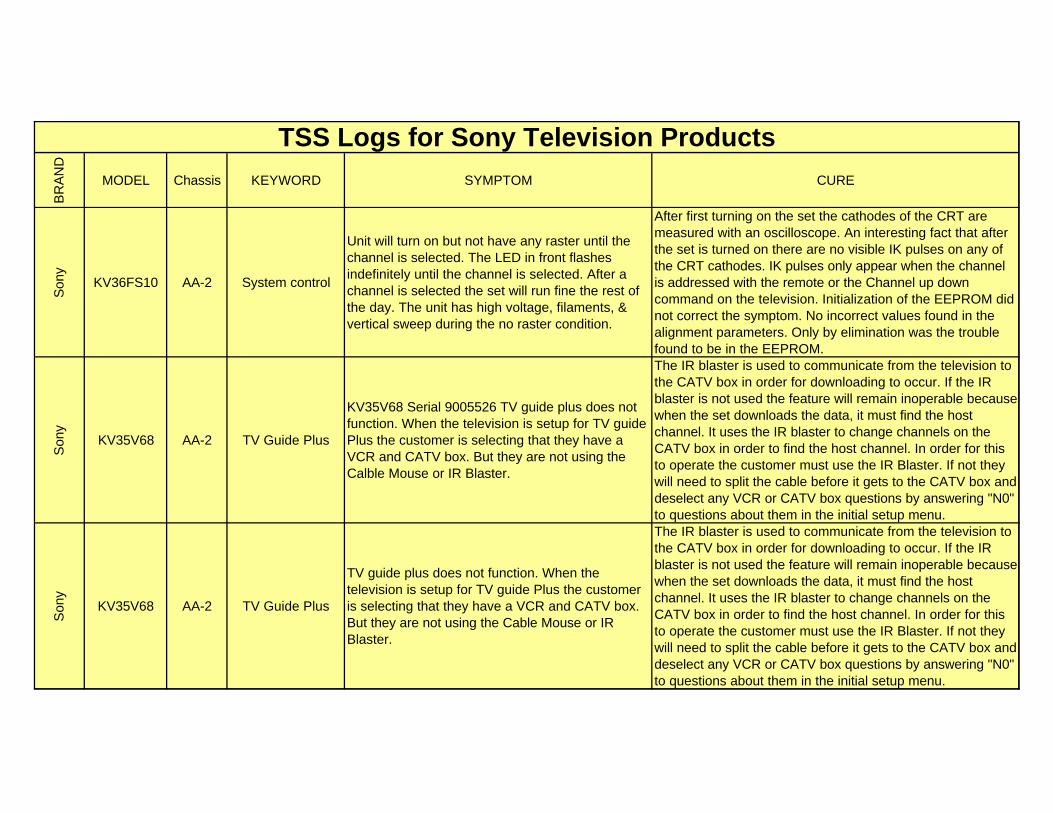
Unit will turn on but not have any raster until the channel is selected. The LED in front flashes indefinitely until the channel is selected. After a channel is selected the set will run fine the rest of the day. The unit has high voltage, filaments, & vertical sweep during the no raster condition.
After first turning on the set the cathodes of the CRT are measured with an oscilloscope. An interesting fact that after the set is turned on there are no visible IK pulses on any of the CRT cathodes. IK pulses only appear when the channel is addressed with the remote or the Channel up down command on the television. Initialization of the EEPROM did not correct the symptom. No incorrect values found in the alignment parameters. Only by elimination was the trouble found to be in the EEPROM.
Son
y
KV35V68 AA-2 TV Guide Plus
KV35V68 Serial 9005526 TV guide plus does not function. When the television is setup for TV guide Plus the customer is selecting that they have a VCR and CATV box. But they are not using the Calble Mouse or IR Blaster.
The IR blaster is used to communicate from the television to the CATV box in order for downloading to occur. If the IR blaster is not used the feature will remain inoperable because when the set downloads the data, it must find the host channel. It uses the IR blaster to change channels on the CATV box in order to find the host channel. In order for this to operate the customer must use the IR Blaster. If not they will need to split the cable before it gets to the CATV box and deselect any VCR or CATV box questions by answering "N0" to questions about them in the initial setup menu.
Son
y
KV35V68 AA-2 TV Guide Plus
TV guide plus does not function. When the television is setup for TV guide Plus the customer is selecting that they have a VCR and CATV box. But they are not using the Cable Mouse or IR Blaster.
The IR blaster is used to communicate from the television to the CATV box in order for downloading to occur. If the IR blaster is not used the feature will remain inoperable because when the set downloads the data, it must find the host channel. It uses the IR blaster to change channels on the CATV box in order to find the host channel. In order for this to operate the customer must use the IR Blaster. If not they will need to split the cable before it gets to the CATV box and deselect any VCR or CATV box questions by answering "N0" to questions about them in the initial setup menu.
BR
AN
D
MODEL Chassis KEYWORD SYMPTOM CURE
TSS Logs for Sony Television Products
Son
y
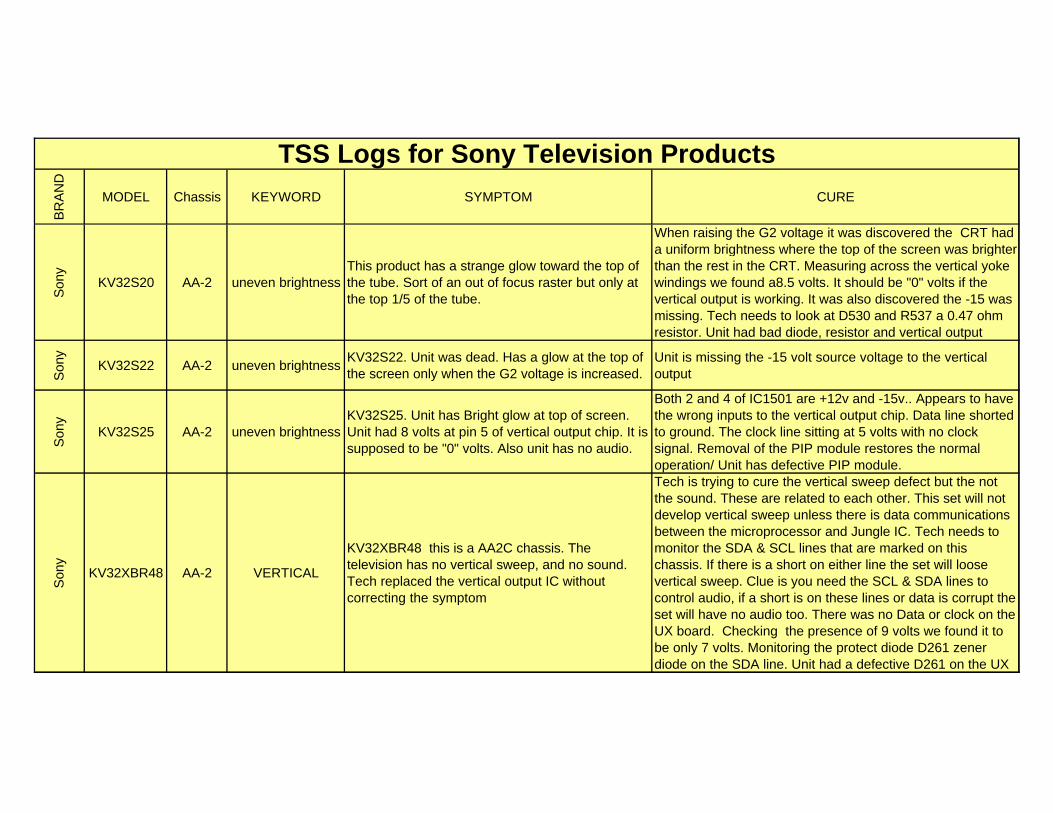
KV32S20 AA-2 uneven brightnessThis product has a strange glow toward the top of the tube. Sort of an out of focus raster but only at the top 1/5 of the tube.
When raising the G2 voltage it was discovered the CRT had a uniform brightness where the top of the screen was brighter than the rest in the CRT. Measuring across the vertical yoke windings we found a8.5 volts. It should be "0" volts if the vertical output is working. It was also discovered the -15 was missing. Tech needs to look at D530 and R537 a 0.47 ohm resistor. Unit had bad diode, resistor and vertical output
Son
y
KV32S22 AA-2 uneven brightnessKV32S22. Unit was dead. Has a glow at the top of the screen only when the G2 voltage is increased.
Unit is missing the -15 volt source voltage to the vertical output
Son
y
KV32S25 AA-2 uneven brightnessKV32S25. Unit has Bright glow at top of screen. Unit had 8 volts at pin 5 of vertical output chip. It is supposed to be "0" volts. Also unit has no audio.
Both 2 and 4 of IC1501 are +12v and -15v.. Appears to have the wrong inputs to the vertical output chip. Data line shorted to ground. The clock line sitting at 5 volts with no clock signal. Removal of the PIP module restores the normal operation/ Unit has defective PIP module.
Son
y
KV32XBR48 AA-2 VERTICAL
KV32XBR48 this is a AA2C chassis. The television has no vertical sweep, and no sound. Tech replaced the vertical output IC without correcting the symptom
Tech is trying to cure the vertical sweep defect but the not the sound. These are related to each other. This set will not develop vertical sweep unless there is data communications between the microprocessor and Jungle IC. Tech needs to monitor the SDA & SCL lines that are marked on this chassis. If there is a short on either line the set will loose vertical sweep. Clue is you need the SCL & SDA lines to control audio, if a short is on these lines or data is corrupt the set will have no audio too. There was no Data or clock on the UX board. Checking the presence of 9 volts we found it to be only 7 volts. Monitoring the protect diode D261 zener diode on the SDA line. Unit had a defective D261 on the UX
BR
AN
D
MODEL Chassis KEYWORD SYMPTOM CURE
TSS Logs for Sony Television Products
Son
y
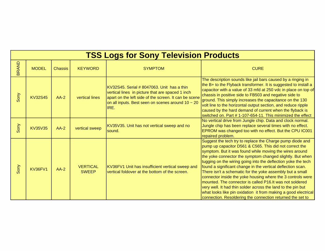
KV32S45 AA-2 vertical lines
KV32S45. Serial # 8047063. Unit has a thin vertical lines in picture that are spaced 1 inch apart on the left side of the screen. It can be scene on all inputs. Best seen on scenes around 10 ~ 20 IRE.
The description sounds like jail bars caused by a ringing in the B+ to the Flyback transformer. It is suggested to install a capacitor with a value of 33 mfd at 250 vdc in place on top of chassis in positive side to FB503 and negative side to ground. This simply increases the capacitance on the 130 volt line to the horizontal output section, and reduce ripple caused by the hard demand of current when the flyback is switched on. Part # 1-107-654-11. This minimized the effect
Son
y
KV35V35 AA-2 vertical sweepKV35V35. Unit has not vertical sweep and no sound.
No vertical drive from Jungle chip. Data and clock normal. Jungle chip has been replace several times with no effect. EPROM was changed too with no effect. But the CPU IC001 repaired problem.
Son
y
KV36FV1 AA-2VERTICAL
SWEEPKV36FV1 Unit has insufficient vertical sweep and vertical foldover at the bottom of the screen.
Suggest the tech try to replace the Charge pump diode and pump up capacitor D561 & C565. This did not correct the symptom. But it was found while moving the wires around the yoke connector the symptom changed slightly. But when tugging on the wiring going into the deflection yoke the tech found a significant change in the vertical deflection scan. There isn't a schematic for the yoke assembly but a small connector inside the yoke housing where the 3 controls were mounted. The connector is called P16.It was not soldered very well. It had thin solder across the land to the pin but what looks like pin oxidation it from making a good electrical connection. Resoldering the connection returned the set to
BR
AN
D
MODEL Chassis KEYWORD SYMPTOM CURE
TSS Logs for Sony Television Products
Son
y
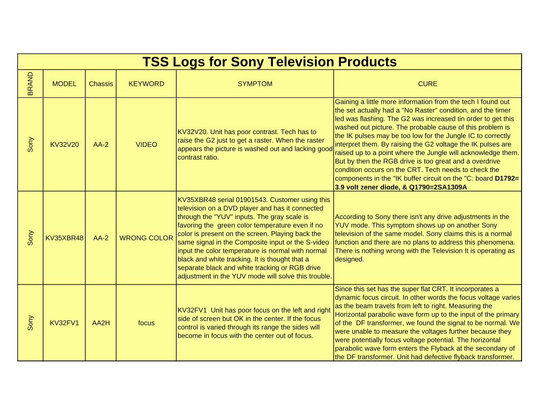
KV32V20 AA-2 VIDEO
KV32V20. Unit has poor contrast. Tech has to raise the G2 just to get a raster. When the raster appears the picture is washed out and lacking good contrast ratio.
Gaining a little more information from the tech I found out the set actually had a "No Raster" condition, and the timer led was flashing. The G2 was increased tin order to get this washed out picture. The probable cause of this problem is the IK pulses may be too low for the Jungle IC to correctly interpret them. By raising the G2 voltage the IK pulses are raised up to a point where the Jungle will acknowledge them. But by then the RGB drive is too great and a overdrive condition occurs on the CRT. Tech needs to check the components in the "IK buffer circuit on the "C: board D1792= 3.9 volt zener diode, & Q1790=2SA1309A
Son
y
KV35XBR48 AA-2 WRONG COLOR
KV35XBR48 serial 01901543. Customer using this television on a DVD player and has it connected through the "YUV" inputs. The gray scale is favoring the green color temperature even if no color is present on the screen. Playing back the same signal in the Composite input or the S-video input the color temperature is normal with normal black and white tracking. It is thought that a separate black and white tracking or RGB drive adjustment in the YUV mode will solve this trouble.
According to Sony there isn't any drive adjustments in the YUV mode. This symptom shows up on another Sony television of the same model. Sony claims this is a normal function and there are no plans to address this phenomena. There is nothing wrong with the Television It is operating as designed.
Son
y
KV32FV1 AA2H focus
KV32FV1 Unit has poor focus on the left and right side of screen but OK in the center. If the focus control is varied through its range the sides will become in focus with the center out of focus.
Since this set has the super flat CRT. It incorporates a dynamic focus circuit. In other words the focus voltage varies as the beam travels from left to right. Measuring the Horizontal parabolic wave form up to the input of the primary of the DF transformer, we found the signal to be normal. We were unable to measure the voltages further because they were potentially focus voltage potential. The horizontal parabolic wave form enters the Flyback at the secondary of the DF transformer. Unit had defective flyback transformer.

BR
AN
D
MODEL Chassis KEYWORD SYMPTOM CURE
TSS Logs for Sony Television Products
Son
y
KV32XBR200 AA2H GEOMETRY
KV32XBR200 serial # 9008075 .Unit has just had the new CRT with the attached yoke replaced today to correct the Shoulder Roll off symptom as described in Bulletin 387. However the new tube and yoke did not solve the vertical pincushion symptom
Bulletin 387 did not mention a plate which was in the old deflection yoke. The missing THL plate needed to be removed from the old yoke and placed in the same slot in the new yoke . After following the new bulletin 387R1 we were able converge the set.
Son
y
KV32XBR200 AA2H GEOMETRY
KV32XBR200 serial # 9018039 .Unit has "Shoulder Roll Off" symptom as described in Bulletin 387. Tech will be ordering new yoke and needs the part number
We have changed several yokes so far as of 4-2-99 WITH LIMITED SUCCESS. Performing a complete setup of purity, convergence and geometry setting corrects most of the geometry errors. However this set will not be perfect.
Son
y
KV32XBR200 AA2H GEOMETRY
KV32XBR200 Unit has just had the new CRT with the attached yoke replaced today to correct the Shoulder Roll off symptom as described in Bulletin 387. However the new tube and yoke did not get installed. Instead we are going to contact Sony
Bulletin 387 did not mention a THL plate which needed to be adjusted was in the old deflection yoke. After following the new bulletin 387R1 we were able converge the set. Also the new tube needed 3 magnetic on the bell of the tube to correct a purity error and converge the lower right hand corner.
Son
y
KV32XBR200 AA2H GEOMETRY
KV32XBR200 Unit has just had the new CRT with the attached yoke replaced today to correct the Shoulder Roll off symptom as described in Bulletin 387R2. However the new tube and yoke did not solve the vertical pincushion symptom
See bulletin #387R1
Son
y
KV36FV1 AA2H GEOMETRYKV36FV1 serial . Unit has shoulder roll off on the screen.
Gave tech bulletin #387 for the yoke upgrade
Son
y
KV32XBR200 AA2HNO HIGH VOLTAGE
KV32XBR200 9015636 Unit will click on then it will turn off again. Does not get high voltage.
Unit has b+ to horizontal output but no horizontal drive. If the Horizontal output is removed the set will produce the necessary drive signals. Collector of H. driver Q501(C) measures 85 with Horizontal output removed. Unit appears to have a shorted Flyback or a problem in the horizontal output section that caused the OCP circuit to attack. Product had a defective Flyback transformer.
BR
AN
D
MODEL Chassis KEYWORD SYMPTOM CURE
TSS Logs for Sony Television Products
Son
y
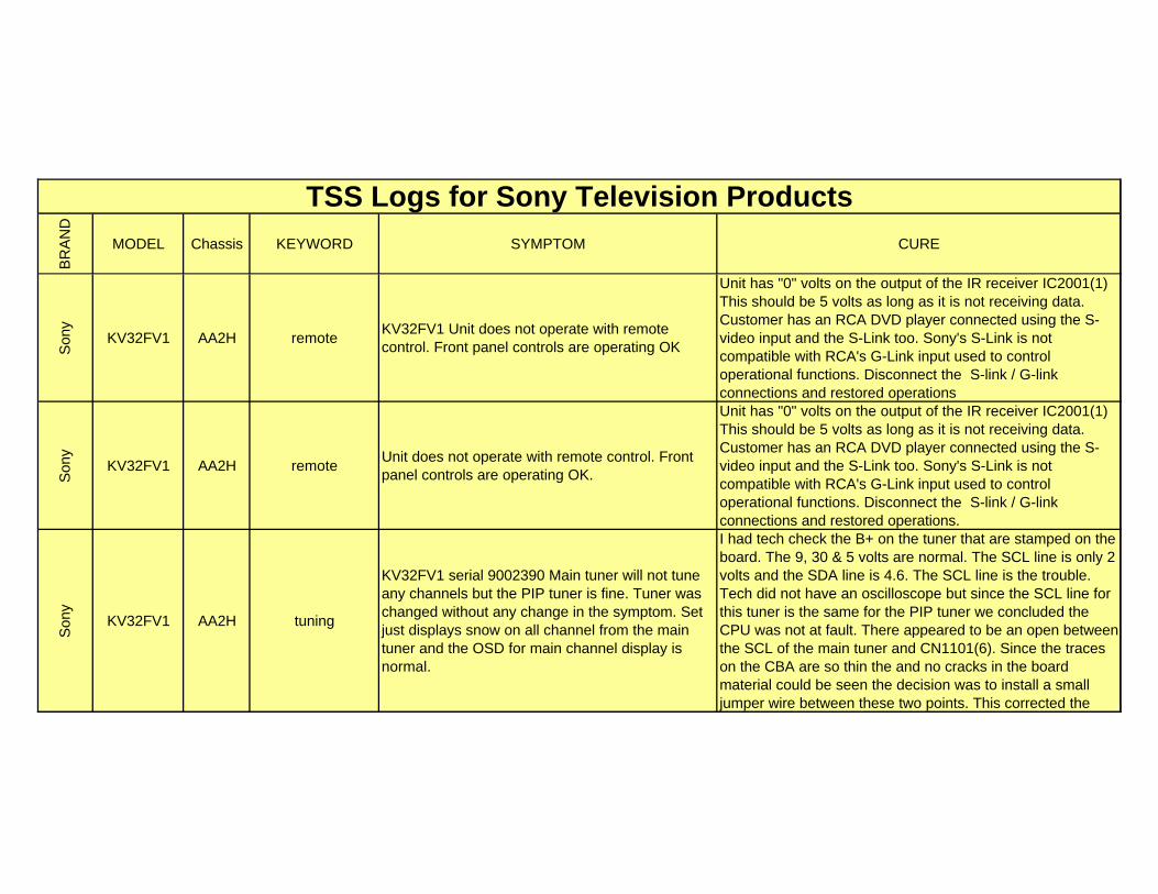
KV32FV1 AA2H remoteKV32FV1 Unit does not operate with remote control. Front panel controls are operating OK
Unit has "0" volts on the output of the IR receiver IC2001(1) This should be 5 volts as long as it is not receiving data. Customer has an RCA DVD player connected using the S-video input and the S-Link too. Sony's S-Link is not compatible with RCA's G-Link input used to control operational functions. Disconnect the S-link / G-link connections and restored operations
Son
y
KV32FV1 AA2H remoteUnit does not operate with remote control. Front panel controls are operating OK.
Unit has "0" volts on the output of the IR receiver IC2001(1) This should be 5 volts as long as it is not receiving data. Customer has an RCA DVD player connected using the S-video input and the S-Link too. Sony's S-Link is not compatible with RCA's G-Link input used to control operational functions. Disconnect the S-link / G-link connections and restored operations.
Son
y
KV32FV1 AA2H tuning
KV32FV1 serial 9002390 Main tuner will not tune any channels but the PIP tuner is fine. Tuner was changed without any change in the symptom. Set just displays snow on all channel from the main tuner and the OSD for main channel display is normal.
I had tech check the B+ on the tuner that are stamped on the board. The 9, 30 & 5 volts are normal. The SCL line is only 2 volts and the SDA line is 4.6. The SCL line is the trouble. Tech did not have an oscilloscope but since the SCL line for this tuner is the same for the PIP tuner we concluded the CPU was not at fault. There appeared to be an open between the SCL of the main tuner and CN1101(6). Since the traces on the CBA are so thin the and no cracks in the board material could be seen the decision was to install a small jumper wire between these two points. This corrected the
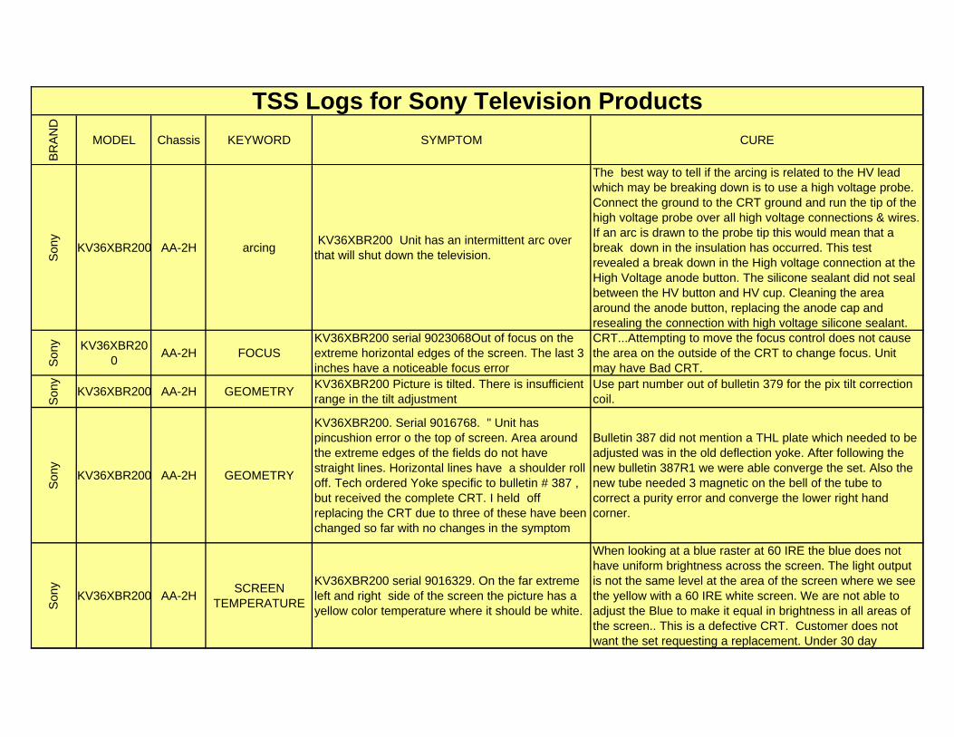
BR
AN
D
MODEL Chassis KEYWORD SYMPTOM CURE
TSS Logs for Sony Television Products
Son
y
KV36XBR200 AA-2H arcing KV36XBR200 Unit has an intermittent arc over that will shut down the television.
The best way to tell if the arcing is related to the HV lead which may be breaking down is to use a high voltage probe. Connect the ground to the CRT ground and run the tip of the high voltage probe over all high voltage connections & wires. If an arc is drawn to the probe tip this would mean that a break down in the insulation has occurred. This test revealed a break down in the High voltage connection at the High Voltage anode button. The silicone sealant did not seal between the HV button and HV cup. Cleaning the area around the anode button, replacing the anode cap and resealing the connection with high voltage silicone sealant.
Son
y KV36XBR200
AA-2H FOCUSKV36XBR200 serial 9023068Out of focus on the extreme horizontal edges of the screen. The last 3 inches have a noticeable focus error
CRT...Attempting to move the focus control does not cause the area on the outside of the CRT to change focus. Unit may have Bad CRT.
Son
y
KV36XBR200 AA-2H GEOMETRYKV36XBR200 Picture is tilted. There is insufficient range in the tilt adjustment
Use part number out of bulletin 379 for the pix tilt correction coil.
Son
y
KV36XBR200 AA-2H GEOMETRY
KV36XBR200. Serial 9016768. " Unit has pincushion error o the top of screen. Area around the extreme edges of the fields do not have straight lines. Horizontal lines have a shoulder roll off. Tech ordered Yoke specific to bulletin # 387 , but received the complete CRT. I held off replacing the CRT due to three of these have been changed so far with no changes in the symptom
Bulletin 387 did not mention a THL plate which needed to be adjusted was in the old deflection yoke. After following the new bulletin 387R1 we were able converge the set. Also the new tube needed 3 magnetic on the bell of the tube to correct a purity error and converge the lower right hand corner.
Son
y
KV36XBR200 AA-2HSCREEN
TEMPERATURE
KV36XBR200 serial 9016329. On the far extreme left and right side of the screen the picture has a yellow color temperature where it should be white.
When looking at a blue raster at 60 IRE the blue does not have uniform brightness across the screen. The light output is not the same level at the area of the screen where we see the yellow with a 60 IRE white screen. We are not able to adjust the Blue to make it equal in brightness in all areas of the screen.. This is a defective CRT. Customer does not want the set requesting a replacement. Under 30 day
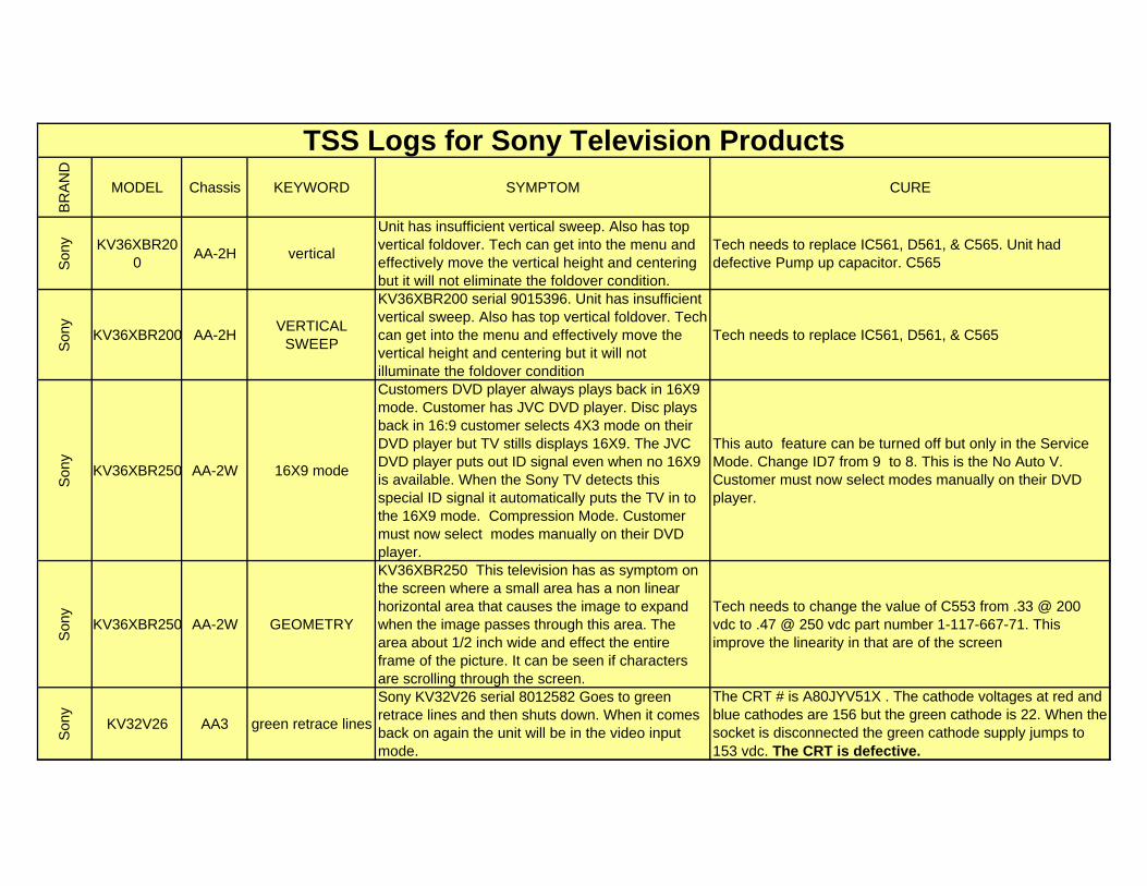
BR
AN
D
MODEL Chassis KEYWORD SYMPTOM CURE
TSS Logs for Sony Television Products
Son
y KV36XBR200
AA-2H vertical
Unit has insufficient vertical sweep. Also has top vertical foldover. Tech can get into the menu and effectively move the vertical height and centering but it will not eliminate the foldover condition.
Tech needs to replace IC561, D561, & C565. Unit had defective Pump up capacitor. C565
Son
y
KV36XBR200 AA-2HVERTICAL
SWEEP
KV36XBR200 serial 9015396. Unit has insufficient vertical sweep. Also has top vertical foldover. Tech can get into the menu and effectively move the vertical height and centering but it will not illuminate the foldover condition
Tech needs to replace IC561, D561, & C565
Son
y
KV36XBR250 AA-2W 16X9 mode
Customers DVD player always plays back in 16X9 mode. Customer has JVC DVD player. Disc plays back in 16:9 customer selects 4X3 mode on their DVD player but TV stills displays 16X9. The JVC DVD player puts out ID signal even when no 16X9 is available. When the Sony TV detects this special ID signal it automatically puts the TV in to the 16X9 mode. Compression Mode. Customer must now select modes manually on their DVD player.
This auto feature can be turned off but only in the Service Mode. Change ID7 from 9 to 8. This is the No Auto V. Customer must now select modes manually on their DVD player.
Son
y
KV36XBR250 AA-2W GEOMETRY
KV36XBR250 This television has as symptom on the screen where a small area has a non linear horizontal area that causes the image to expand when the image passes through this area. The area about 1/2 inch wide and effect the entire frame of the picture. It can be seen if characters are scrolling through the screen.
Tech needs to change the value of C553 from .33 @ 200 vdc to .47 @ 250 vdc part number 1-117-667-71. This improve the linearity in that are of the screen
Son
y
KV32V26 AA3 green retrace lines
Sony KV32V26 serial 8012582 Goes to green retrace lines and then shuts down. When it comes back on again the unit will be in the video input mode.
The CRT # is A80JYV51X . The cathode voltages at red and blue cathodes are 156 but the green cathode is 22. When the socket is disconnected the green cathode supply jumps to 153 vdc. The CRT is defective.
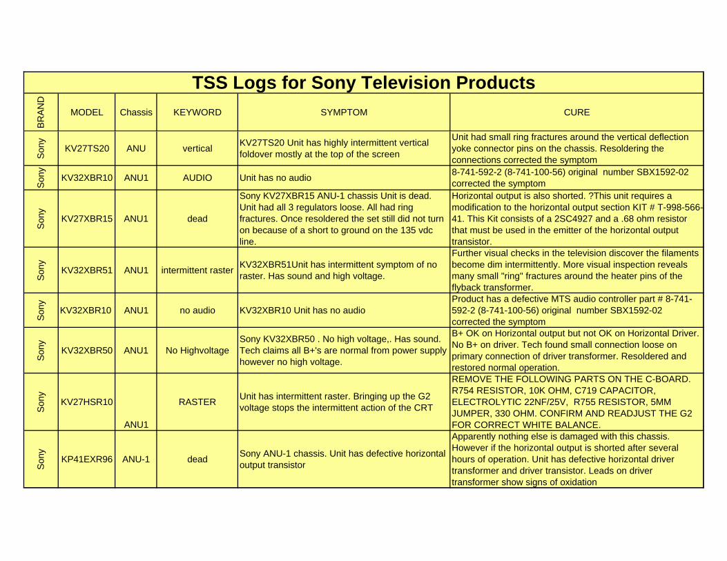
BR
AN
D
MODEL Chassis KEYWORD SYMPTOM CURE
TSS Logs for Sony Television Products
Son
y
KV27TS20 ANU verticalKV27TS20 Unit has highly intermittent vertical foldover mostly at the top of the screen
Unit had small ring fractures around the vertical deflection yoke connector pins on the chassis. Resoldering the connections corrected the symptom
Son
y
KV32XBR10 ANU1 AUDIO Unit has no audio8-741-592-2 (8-741-100-56) original number SBX1592-02 corrected the symptom
Son
y
KV27XBR15 ANU1 dead
Sony KV27XBR15 ANU-1 chassis Unit is dead. Unit had all 3 regulators loose. All had ring fractures. Once resoldered the set still did not turn on because of a short to ground on the 135 vdc line.
Horizontal output is also shorted. ?This unit requires a modification to the horizontal output section KIT # T-998-566-41. This Kit consists of a 2SC4927 and a .68 ohm resistor that must be used in the emitter of the horizontal output transistor.
Son
y
KV32XBR51 ANU1 intermittent rasterKV32XBR51Unit has intermittent symptom of no raster. Has sound and high voltage.
Further visual checks in the television discover the filaments become dim intermittently. More visual inspection reveals many small "ring" fractures around the heater pins of the flyback transformer.
Son
y
KV32XBR10 ANU1 no audio KV32XBR10 Unit has no audioProduct has a defective MTS audio controller part # 8-741-592-2 (8-741-100-56) original number SBX1592-02 corrected the symptom
Son
y
KV32XBR50 ANU1 No HighvoltageSony KV32XBR50 . No high voltage,. Has sound. Tech claims all B+'s are normal from power supply however no high voltage.
B+ OK on Horizontal output but not OK on Horizontal Driver. No B+ on driver. Tech found small connection loose on primary connection of driver transformer. Resoldered and restored normal operation.
Son
y
KV27HSR10
ANU1
RASTERUnit has intermittent raster. Bringing up the G2 voltage stops the intermittent action of the CRT
REMOVE THE FOLLOWING PARTS ON THE C-BOARD. R754 RESISTOR, 10K OHM, C719 CAPACITOR, ELECTROLYTIC 22NF/25V, R755 RESISTOR, 5MM JUMPER, 330 OHM. CONFIRM AND READJUST THE G2 FOR CORRECT WHITE BALANCE.
Son
y
KP41EXR96 ANU-1 deadSony ANU-1 chassis. Unit has defective horizontal output transistor
Apparently nothing else is damaged with this chassis. However if the horizontal output is shorted after several hours of operation. Unit has defective horizontal driver transformer and driver transistor. Leads on driver transformer show signs of oxidation
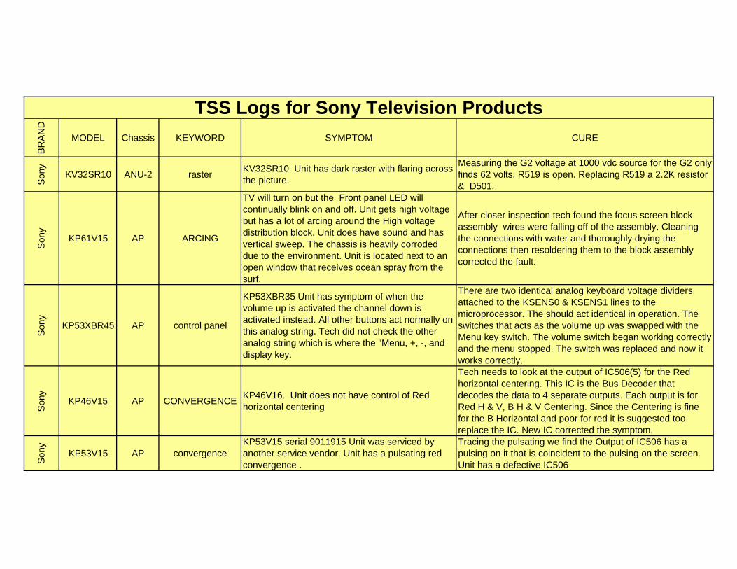
BR
AN
D
MODEL Chassis KEYWORD SYMPTOM CURE
TSS Logs for Sony Television Products
Son
y
KV32SR10 ANU-2 rasterKV32SR10 Unit has dark raster with flaring across the picture.
Measuring the G2 voltage at 1000 vdc source for the G2 only finds 62 volts. R519 is open. Replacing R519 a 2.2K resistor & D501.
Son
y
KP61V15 AP ARCING
TV will turn on but the Front panel LED will continually blink on and off. Unit gets high voltage but has a lot of arcing around the High voltage distribution block. Unit does have sound and has vertical sweep. The chassis is heavily corroded due to the environment. Unit is located next to an open window that receives ocean spray from the surf.
After closer inspection tech found the focus screen block assembly wires were falling off of the assembly. Cleaning the connections with water and thoroughly drying the connections then resoldering them to the block assembly corrected the fault.
Son
y
KP53XBR45 AP control panel
KP53XBR35 Unit has symptom of when the volume up is activated the channel down is activated instead. All other buttons act normally on this analog string. Tech did not check the other analog string which is where the "Menu, +, -, and display key.
There are two identical analog keyboard voltage dividers attached to the KSENS0 & KSENS1 lines to the microprocessor. The should act identical in operation. The switches that acts as the volume up was swapped with the Menu key switch. The volume switch began working correctly and the menu stopped. The switch was replaced and now it works correctly.
Son
y
KP46V15 AP CONVERGENCEKP46V16. Unit does not have control of Red horizontal centering
Tech needs to look at the output of IC506(5) for the Red horizontal centering. This IC is the Bus Decoder that decodes the data to 4 separate outputs. Each output is for Red H & V, B H & V Centering. Since the Centering is fine for the B Horizontal and poor for red it is suggested too replace the IC. New IC corrected the symptom.
Son
y
KP53V15 AP convergenceKP53V15 serial 9011915 Unit was serviced by another service vendor. Unit has a pulsating red convergence .
Tracing the pulsating we find the Output of IC506 has a pulsing on it that is coincident to the pulsing on the screen. Unit has a defective IC506
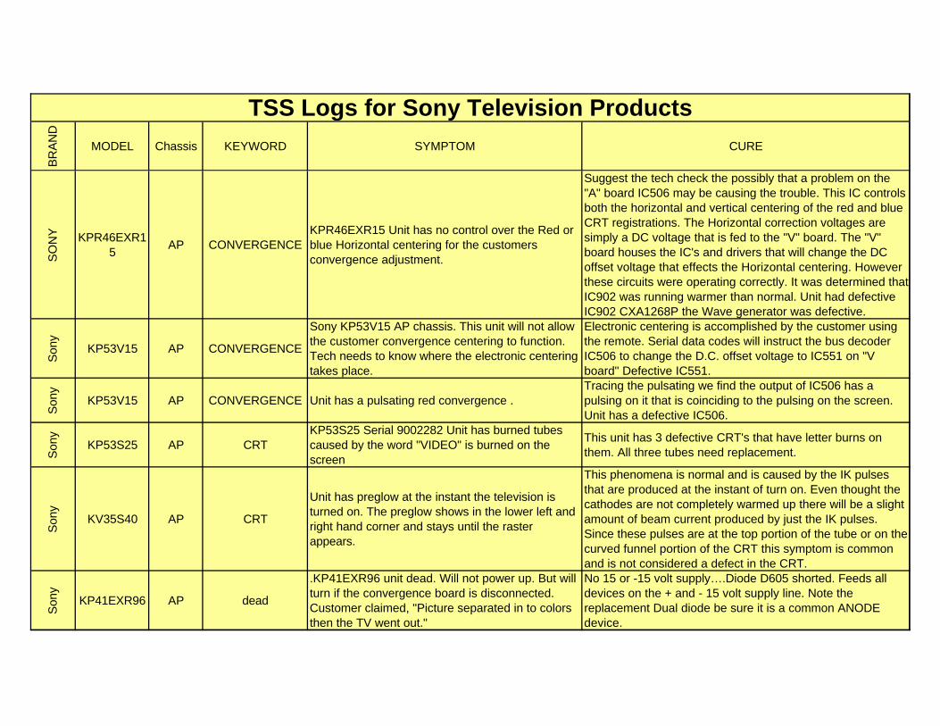
BR
AN
D
MODEL Chassis KEYWORD SYMPTOM CURE
TSS Logs for Sony Television Products
SO
NY KPR46EXR1
5AP CONVERGENCE
KPR46EXR15 Unit has no control over the Red or blue Horizontal centering for the customers convergence adjustment.
Suggest the tech check the possibly that a problem on the "A" board IC506 may be causing the trouble. This IC controls both the horizontal and vertical centering of the red and blue CRT registrations. The Horizontal correction voltages are simply a DC voltage that is fed to the "V" board. The "V" board houses the IC's and drivers that will change the DC offset voltage that effects the Horizontal centering. However these circuits were operating correctly. It was determined that IC902 was running warmer than normal. Unit had defective IC902 CXA1268P the Wave generator was defective.
Son
y
KP53V15 AP CONVERGENCE
Sony KP53V15 AP chassis. This unit will not allow the customer convergence centering to function. Tech needs to know where the electronic centering takes place.
Electronic centering is accomplished by the customer using the remote. Serial data codes will instruct the bus decoder IC506 to change the D.C. offset voltage to IC551 on "V board" Defective IC551.
Son
y
KP53V15 AP CONVERGENCE Unit has a pulsating red convergence . Tracing the pulsating we find the output of IC506 has a pulsing on it that is coinciding to the pulsing on the screen. Unit has a defective IC506.
Son
y
KP53S25 AP CRTKP53S25 Serial 9002282 Unit has burned tubes caused by the word "VIDEO" is burned on the screen
This unit has 3 defective CRT's that have letter burns on them. All three tubes need replacement.
Son
y
KV35S40 AP CRT
Unit has preglow at the instant the television is turned on. The preglow shows in the lower left and right hand corner and stays until the raster appears.
This phenomena is normal and is caused by the IK pulses that are produced at the instant of turn on. Even thought the cathodes are not completely warmed up there will be a slight amount of beam current produced by just the IK pulses. Since these pulses are at the top portion of the tube or on the curved funnel portion of the CRT this symptom is common and is not considered a defect in the CRT.
Son
y
KP41EXR96 AP dead
.KP41EXR96 unit dead. Will not power up. But will turn if the convergence board is disconnected. Customer claimed, "Picture separated in to colors then the TV went out."
No 15 or -15 volt supply….Diode D605 shorted. Feeds all devices on the + and - 15 volt supply line. Note the replacement Dual diode be sure it is a common ANODE device.
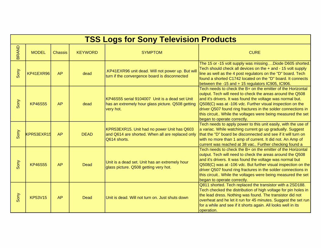
BR
AN
D
MODEL Chassis KEYWORD SYMPTOM CURE
TSS Logs for Sony Television Products
Son
y
KP41EXR96 AP dead.KP41EXR96 unit dead. Will not power up. But will turn if the convergence board is disconnected
The 15 or -15 volt supply was missing….Diode D605 shorted. Tech should check all devices on the + and - 15 volt supply line as well as the 4 post regulators on the "D" board. Tech found a shorted C1742 located on the "D" board. It connects between the -15 and + 15 regulators IC905, IC906.
Son
y
KP46S55 AP deadKP46S55 serial 9104007 Unit is a dead set Unit has an extremely hour glass picture. Q508 getting very hot.
Tech needs to check the B+ on the emitter of the Horizontal output. Tech will need to check the areas around the Q508 and it's drivers. It was found the voltage was normal but. Q508(C) was at -106 vdc. Further visual inspection on the driver Q507 found ring fractures in the solder connections in this circuit.. While the voltages were being measured the set began to operate correctly.
Son
y
KPR53EXR15 AP DEADKPR53EXR15. Unit had no power Unit has Q603 and Q614 are shorted. When all are replaced only Q614 shorts.
Tech needs to apply power to this unit easily, with the use of a variac. While watching current go up gradually. Suggest that the "D" board be disconnected and see if it will turn on with no more than 1 amp of current. It did not. An Amp of current was reached at 38 vac.. Further checking found a
Son
y
KP46S55 AP DeadUnit is a dead set. Unit has an extremely hour glass picture. Q508 getting very hot.
Tech needs to check the B+ on the emitter of the Horizontal output. Tech will need to check the areas around the Q508 and it's drivers. It was found the voltage was normal but Q508(C) was at -106 vdc. But further visual inspection on the driver Q507 found ring fractures in the solder connections in this circuit.. While the voltages were being measured the set began to operate correctly.
Son
y
KP53V15 AP Dead Unit is dead. Will not turn on. Just shuts down
Q811 shorted. Tech replaced the transistor with a 2SD188. Tech checked the distribution of high voltage for pin holes in the lead dress. Nothing was found. The transistor did not overheat and he let it run for 45 minutes. Suggest the set run for a while and see if it shorts again. All looks well in its operation.
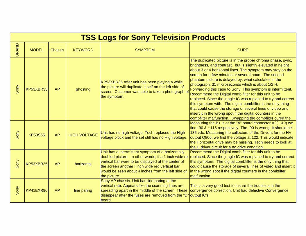
BR
AN
D
MODEL Chassis KEYWORD SYMPTOM CURE
TSS Logs for Sony Television Products
Son
y
KP53XBR35 AP ghosting
KP53XBR35 After unit has been playing a while the picture will duplicate it self on the left side of screen. Customer was able to take a photograph of the symptom,
The duplicated picture is in the proper chroma phase, sync, brightness, and contrast. but is slightly elevated in height about 3 or 4 horizontal lines. The symptom may stay on the screen for a few minutes or several hours. The second phantom picture is delayed by, what calculates in the photograph, 31 microseconds which is about 1/2 H. Forwarding this case to Sony. This symptom is intermittent. Recommend the Digital comb filter for this unit to be replaced. Since the jungle IC was replaced to try and correct this symptom with. The digital combfilter is the only thing that could cause the storage of several lines of video and insert it in the wrong spot if the digital counters in the combfilter malfunction. Swapping the combfilter cured the
Son
y
KP53S55 AP HIGH VOLTAGEUnit has no high voltage, Tech replaced the High voltage block and the set still has no High voltage.
Measuring the B+ 's at the "A" board connector A2(1 &9) we find -90 & +115 respectively. The -90 is wrong. It should be -135 vdc. Measuring the collectors of the Drivers for the HV output Q806, we find the voltage at 122. This would indicate the Horizontal drive may be missing. Tech needs to look at the H driver circuit for a no drive condition.
Son
y
KP53XBR35 AP horizontal
Unit has a intermittent symptom of a horizontally doubled picture. In other words, if a 1 inch wide re vertical bar were to be displayed at the center of the screen another I inch wide red vertical bar would be seen about 4 inches from the left side of the picture.
Recommend the Digital comb filter for this unit to be replaced. Since the jungle IC was replaced to try and correct this symptom. The digital combfilter is the only thing that could cause the storage of several lines of video and insert it in the wrong spot if the digital counters in the combfilter malfunction.
Son
y
KP41EXR96 AP line paring
Sony AP chassis. Unit has line paring at the vertical rate. Appears like the scanning lines are spreading apart in the middle of the screen. These disappear after the fuses are removed from the "D" board.
This is a very good test to insure the trouble is in the convergence correction. Unit had defective Convergence output IC's
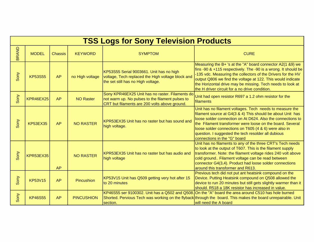
BR
AN
D
MODEL Chassis KEYWORD SYMPTOM CURE
TSS Logs for Sony Television Products
Son
y
KP53S55 AP no High voltageKP53S55 Serial 9003661. Unit has no high voltage, Tech replaced the High voltage block and the set still has no High voltage.
Measuring the B+ 's at the "A" board connector A2(1 &9) we fins -90 & +115 respectively. The -90 is a wrong. It should be -135 vdc. Measuring the collectors of the Drivers for the HV output Q806 we find the voltage at 122. This would indicate the Horizontal drive may be missing. Tech needs to look at the H driver circuit for a no drive condition.
Son
y
KPR46EX25 AP NO RasterSony KPR46EX25 Unit has no raster. Filaments do not warm up. No pulses to the filament pulses to CRT but filaments are 200 volts above ground.
Unit had open resistor R697 a 1.2 ohm resistor for the filaments
Son
y
KP53EX35 AP NO RASTERKPR53EX35 Unit has no raster but has sound and high voltage.
Unit has no filament voltages. Tech needs to measure the filament source at G4(3 & 4) This should be about Unit has loose solder connection on At D624. Also the connections to the Filament transformer were loose on the board. Several loose solder connections on T605 (4 & 6) were also in question. I suggested the tech resolder all dubious connections in the "G" board
Son
y
KPR53EX35
AP
NO RASTERKPR53EX35 Unit has no raster but has audio and high voltage
Unit has no filaments to any of the three CRT's Tech needs to look at the output of T607. This is the filament supply transformer. Note: the filament voltage rides 240 volt above cold ground.. Filament voltage can be read between connector G4(3,4). Product had loose solder connections around this transformer and R613.
Son
y
KP53V15 AP PincushionKP53V15 Unit has Q509 getting very hot after 15 to 20 minutes
Previous tech did not put ant heatsink compound on the Device. Putting Heatsink compound on Q508 allowed the device to run 20 minutes but still gets slightly warmer than it should. R518 a 18K resistor has increased in value.
Son
y
KP46S55 AP PINCUSHIONKP46S55 ser 9100302. Unit has a Q502 and Q508. Shorted. Pervious Tech was working on the flyback section.
On the "A" board the area around C510 has hole burned through the board. This makes the board unrepairable. Unit will need the A board
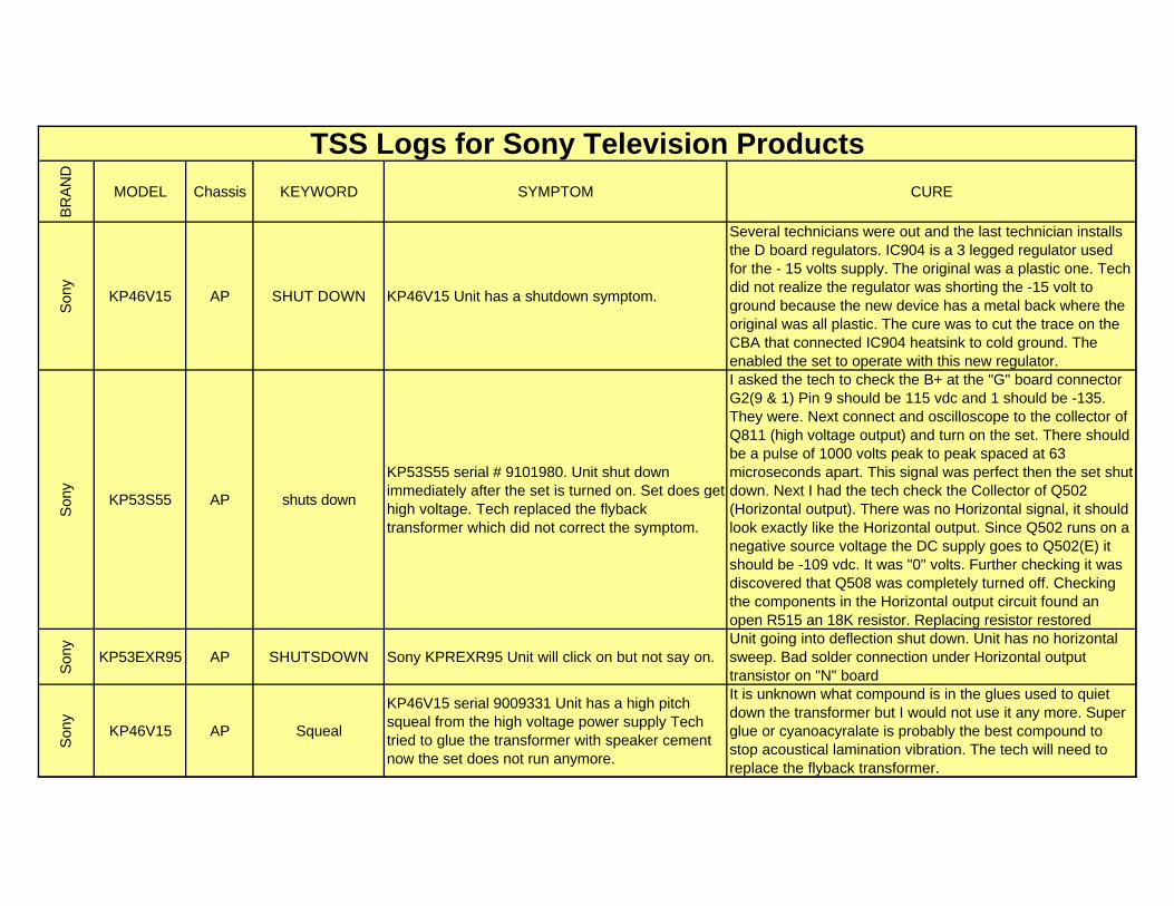
BR
AN
D
MODEL Chassis KEYWORD SYMPTOM CURE
TSS Logs for Sony Television Products
Son
y
KP46V15 AP SHUT DOWN KP46V15 Unit has a shutdown symptom.
Several technicians were out and the last technician installs the D board regulators. IC904 is a 3 legged regulator used for the - 15 volts supply. The original was a plastic one. Tech did not realize the regulator was shorting the -15 volt to ground because the new device has a metal back where the original was all plastic. The cure was to cut the trace on the CBA that connected IC904 heatsink to cold ground. The enabled the set to operate with this new regulator.
Son
y
KP53S55 AP shuts down
KP53S55 serial # 9101980. Unit shut down immediately after the set is turned on. Set does get high voltage. Tech replaced the flyback transformer which did not correct the symptom.
I asked the tech to check the B+ at the "G" board connector G2(9 & 1) Pin 9 should be 115 vdc and 1 should be -135. They were. Next connect and oscilloscope to the collector of Q811 (high voltage output) and turn on the set. There should be a pulse of 1000 volts peak to peak spaced at 63 microseconds apart. This signal was perfect then the set shut down. Next I had the tech check the Collector of Q502 (Horizontal output). There was no Horizontal signal, it should look exactly like the Horizontal output. Since Q502 runs on a negative source voltage the DC supply goes to Q502(E) it should be -109 vdc. It was "0" volts. Further checking it was discovered that Q508 was completely turned off. Checking the components in the Horizontal output circuit found an open R515 an 18K resistor. Replacing resistor restored
Son
y
KP53EXR95 AP SHUTSDOWN Sony KPREXR95 Unit will click on but not say on. Unit going into deflection shut down. Unit has no horizontal sweep. Bad solder connection under Horizontal output transistor on "N" board
Son
y
KP46V15 AP Squeal
KP46V15 serial 9009331 Unit has a high pitch squeal from the high voltage power supply Tech tried to glue the transformer with speaker cement now the set does not run anymore.
It is unknown what compound is in the glues used to quiet down the transformer but I would not use it any more. Super glue or cyanoacyralate is probably the best compound to stop acoustical lamination vibration. The tech will need to replace the flyback transformer.
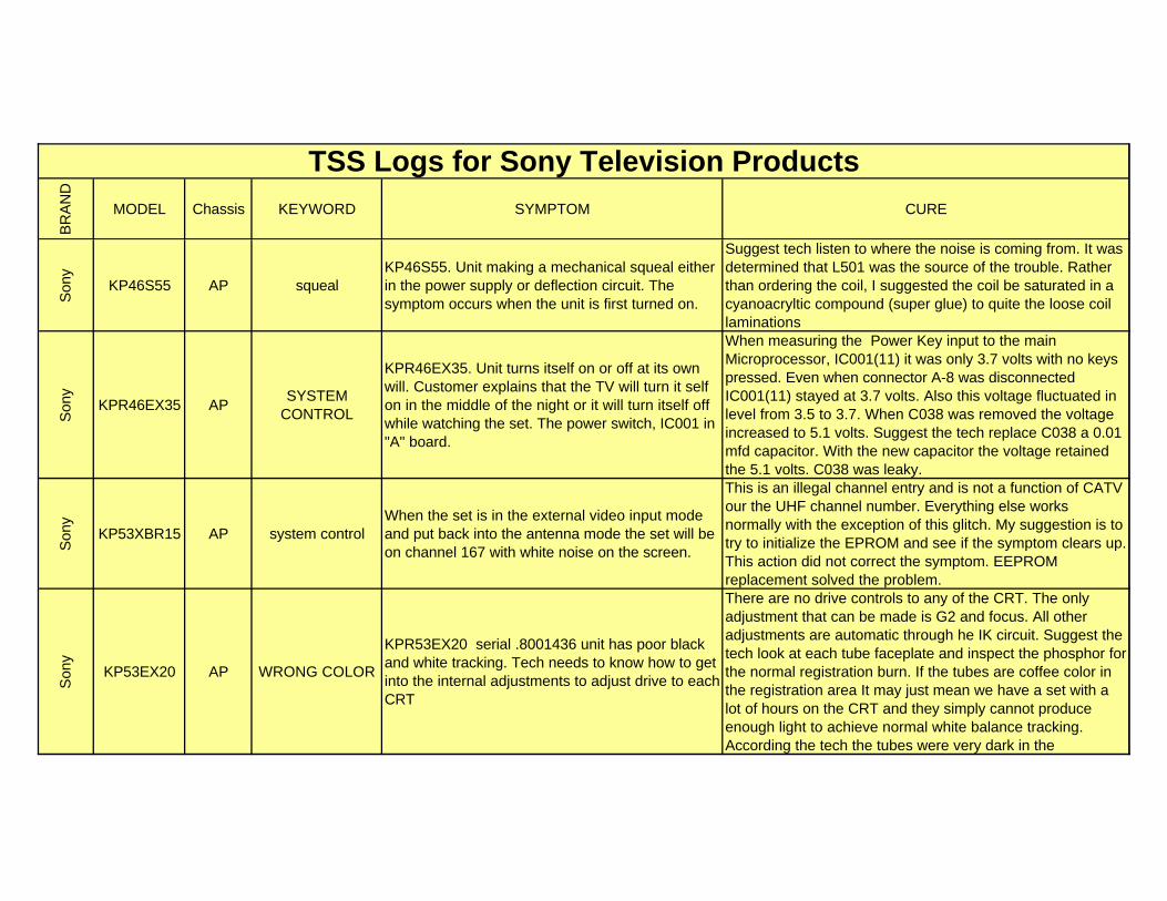
BR
AN
D
MODEL Chassis KEYWORD SYMPTOM CURE
TSS Logs for Sony Television Products
Son
y
KP46S55 AP squealKP46S55. Unit making a mechanical squeal either in the power supply or deflection circuit. The symptom occurs when the unit is first turned on.
Suggest tech listen to where the noise is coming from. It was determined that L501 was the source of the trouble. Rather than ordering the coil, I suggested the coil be saturated in a cyanoacryltic compound (super glue) to quite the loose coil laminations
Son
y
KPR46EX35 APSYSTEM
CONTROL
KPR46EX35. Unit turns itself on or off at its own will. Customer explains that the TV will turn it self on in the middle of the night or it will turn itself off while watching the set. The power switch, IC001 in "A" board.
When measuring the Power Key input to the main Microprocessor, IC001(11) it was only 3.7 volts with no keys pressed. Even when connector A-8 was disconnected IC001(11) stayed at 3.7 volts. Also this voltage fluctuated in level from 3.5 to 3.7. When C038 was removed the voltage increased to 5.1 volts. Suggest the tech replace C038 a 0.01 mfd capacitor. With the new capacitor the voltage retained the 5.1 volts. C038 was leaky.
Son
y
KP53XBR15 AP system controlWhen the set is in the external video input mode and put back into the antenna mode the set will be on channel 167 with white noise on the screen.
This is an illegal channel entry and is not a function of CATV our the UHF channel number. Everything else works normally with the exception of this glitch. My suggestion is to try to initialize the EPROM and see if the symptom clears up. This action did not correct the symptom. EEPROM replacement solved the problem.
Son
y
KP53EX20 AP WRONG COLOR
KPR53EX20 serial .8001436 unit has poor black and white tracking. Tech needs to know how to get into the internal adjustments to adjust drive to each CRT
There are no drive controls to any of the CRT. The only adjustment that can be made is G2 and focus. All other adjustments are automatic through he IK circuit. Suggest the tech look at each tube faceplate and inspect the phosphor for the normal registration burn. If the tubes are coffee color in the registration area It may just mean we have a set with a lot of hours on the CRT and they simply cannot produce enough light to achieve normal white balance tracking. According the tech the tubes were very dark in the
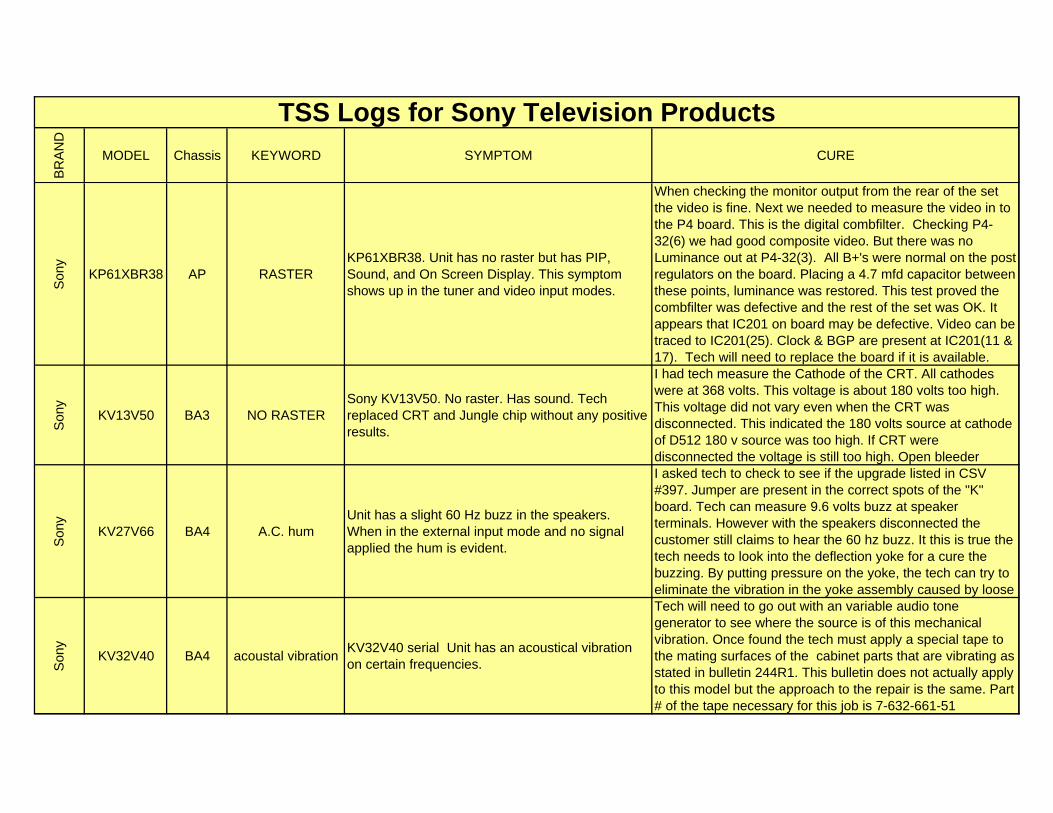
BR
AN
D
MODEL Chassis KEYWORD SYMPTOM CURE
TSS Logs for Sony Television Products
Son
y
KP61XBR38 AP RASTERKP61XBR38. Unit has no raster but has PIP, Sound, and On Screen Display. This symptom shows up in the tuner and video input modes.
When checking the monitor output from the rear of the set the video is fine. Next we needed to measure the video in to the P4 board. This is the digital combfilter. Checking P4-32(6) we had good composite video. But there was no Luminance out at P4-32(3). All B+'s were normal on the post regulators on the board. Placing a 4.7 mfd capacitor between these points, luminance was restored. This test proved the combfilter was defective and the rest of the set was OK. It appears that IC201 on board may be defective. Video can be traced to IC201(25). Clock & BGP are present at IC201(11 & 17). Tech will need to replace the board if it is available.
Son
y
KV13V50 BA3 NO RASTERSony KV13V50. No raster. Has sound. Tech replaced CRT and Jungle chip without any positive results.
I had tech measure the Cathode of the CRT. All cathodes were at 368 volts. This voltage is about 180 volts too high. This voltage did not vary even when the CRT was disconnected. This indicated the 180 volts source at cathode of D512 180 v source was too high. If CRT were disconnected the voltage is still too high. Open bleeder
Son
y
KV27V66 BA4 A.C. humUnit has a slight 60 Hz buzz in the speakers. When in the external input mode and no signal applied the hum is evident.
I asked tech to check to see if the upgrade listed in CSV #397. Jumper are present in the correct spots of the "K" board. Tech can measure 9.6 volts buzz at speaker terminals. However with the speakers disconnected the customer still claims to hear the 60 hz buzz. It this is true the tech needs to look into the deflection yoke for a cure the buzzing. By putting pressure on the yoke, the tech can try to eliminate the vibration in the yoke assembly caused by loose
Son
y
KV32V40 BA4 acoustal vibrationKV32V40 serial Unit has an acoustical vibration on certain frequencies.
Tech will need to go out with an variable audio tone generator to see where the source is of this mechanical vibration. Once found the tech must apply a special tape to the mating surfaces of the cabinet parts that are vibrating as stated in bulletin 244R1. This bulletin does not actually apply to this model but the approach to the repair is the same. Part # of the tape necessary for this job is 7-632-661-51
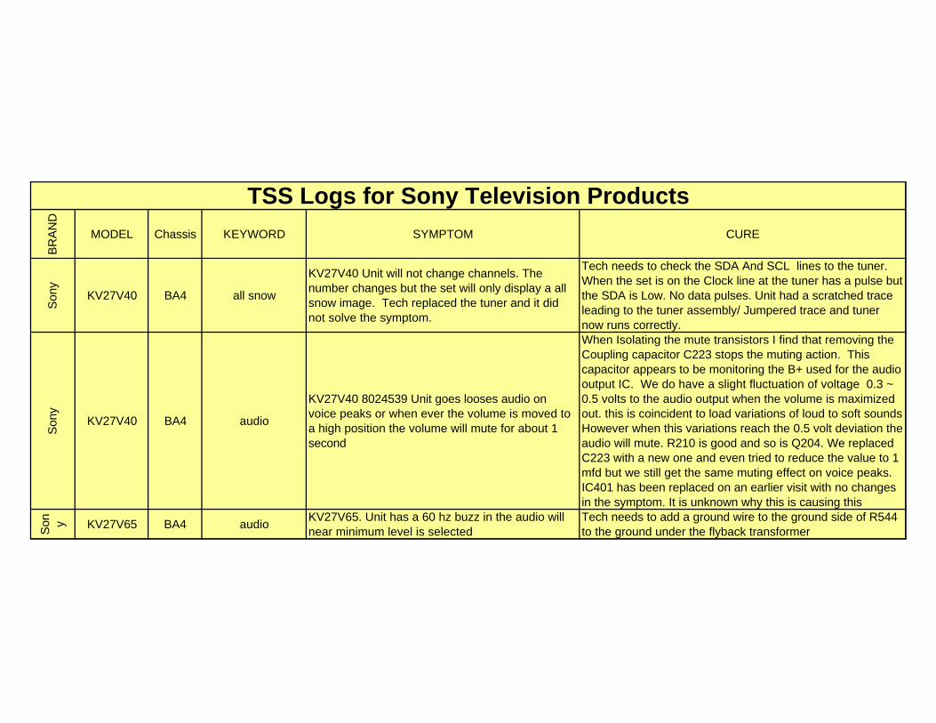
BR
AN
D
MODEL Chassis KEYWORD SYMPTOM CURE
TSS Logs for Sony Television Products
Son
y
KV27V40 BA4 all snow
KV27V40 Unit will not change channels. The number changes but the set will only display a all snow image. Tech replaced the tuner and it did not solve the symptom.
Tech needs to check the SDA And SCL lines to the tuner. When the set is on the Clock line at the tuner has a pulse but the SDA is Low. No data pulses. Unit had a scratched trace leading to the tuner assembly/ Jumpered trace and tuner now runs correctly.
Son
y
KV27V40 BA4 audio
KV27V40 8024539 Unit goes looses audio on voice peaks or when ever the volume is moved to a high position the volume will mute for about 1 second
When Isolating the mute transistors I find that removing the Coupling capacitor C223 stops the muting action. This capacitor appears to be monitoring the B+ used for the audio output IC. We do have a slight fluctuation of voltage 0.3 ~ 0.5 volts to the audio output when the volume is maximized out. this is coincident to load variations of loud to soft sounds However when this variations reach the 0.5 volt deviation the audio will mute. R210 is good and so is Q204. We replaced C223 with a new one and even tried to reduce the value to 1 mfd but we still get the same muting effect on voice peaks. IC401 has been replaced on an earlier visit with no changes in the symptom. It is unknown why this is causing this
Son y KV27V65 BA4 audio
KV27V65. Unit has a 60 hz buzz in the audio will near minimum level is selected
Tech needs to add a ground wire to the ground side of R544 to the ground under the flyback transformer
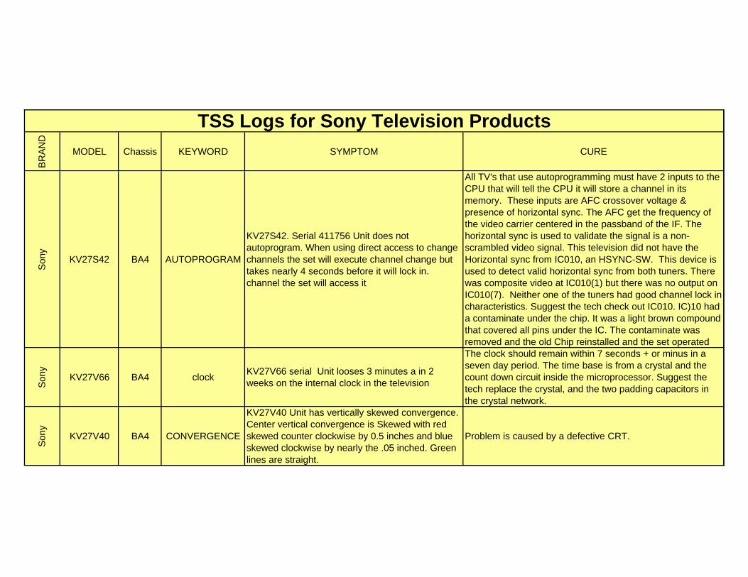
BR
AN
D
MODEL Chassis KEYWORD SYMPTOM CURE
TSS Logs for Sony Television Products
Son
y
KV27S42 BA4 AUTOPROGRAM
KV27S42. Serial 411756 Unit does not autoprogram. When using direct access to change channels the set will execute channel change but takes nearly 4 seconds before it will lock in. channel the set will access it
All TV's that use autoprogramming must have 2 inputs to the CPU that will tell the CPU it will store a channel in its memory. These inputs are AFC crossover voltage & presence of horizontal sync. The AFC get the frequency of the video carrier centered in the passband of the IF. The horizontal sync is used to validate the signal is a non-scrambled video signal. This television did not have the Horizontal sync from IC010, an HSYNC-SW. This device is used to detect valid horizontal sync from both tuners. There was composite video at IC010(1) but there was no output on IC010(7). Neither one of the tuners had good channel lock in characteristics. Suggest the tech check out IC010. IC)10 had a contaminate under the chip. It was a light brown compound that covered all pins under the IC. The contaminate was removed and the old Chip reinstalled and the set operated
Son
y
KV27V66 BA4 clockKV27V66 serial Unit looses 3 minutes a in 2 weeks on the internal clock in the television
The clock should remain within 7 seconds + or minus in a seven day period. The time base is from a crystal and the count down circuit inside the microprocessor. Suggest the tech replace the crystal, and the two padding capacitors in the crystal network.
Son
y
KV27V40 BA4 CONVERGENCE
KV27V40 Unit has vertically skewed convergence. Center vertical convergence is Skewed with red skewed counter clockwise by 0.5 inches and blue skewed clockwise by nearly the .05 inched. Green lines are straight.
Problem is caused by a defective CRT.
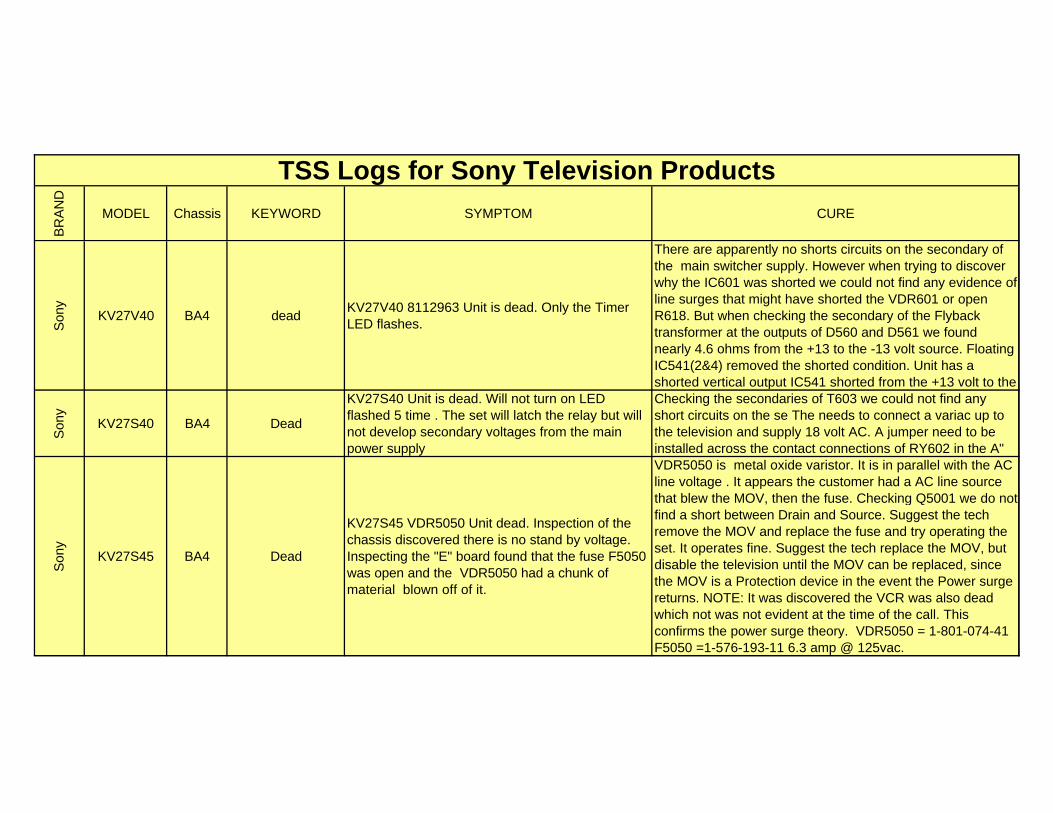
BR
AN
D
MODEL Chassis KEYWORD SYMPTOM CURE
TSS Logs for Sony Television Products
Son
y
KV27V40 BA4 deadKV27V40 8112963 Unit is dead. Only the Timer LED flashes.
There are apparently no shorts circuits on the secondary of the main switcher supply. However when trying to discover why the IC601 was shorted we could not find any evidence of line surges that might have shorted the VDR601 or open R618. But when checking the secondary of the Flyback transformer at the outputs of D560 and D561 we found nearly 4.6 ohms from the +13 to the -13 volt source. Floating IC541(2&4) removed the shorted condition. Unit has a shorted vertical output IC541 shorted from the +13 volt to the
Son
y
KV27S40 BA4 Dead
KV27S40 Unit is dead. Will not turn on LED flashed 5 time . The set will latch the relay but will not develop secondary voltages from the main power supply
Checking the secondaries of T603 we could not find any short circuits on the se The needs to connect a variac up to the television and supply 18 volt AC. A jumper need to be installed across the contact connections of RY602 in the A"
Son
y
KV27S45 BA4 Dead
KV27S45 VDR5050 Unit dead. Inspection of the chassis discovered there is no stand by voltage. Inspecting the "E" board found that the fuse F5050 was open and the VDR5050 had a chunk of material blown off of it.
VDR5050 is metal oxide varistor. It is in parallel with the AC line voltage . It appears the customer had a AC line source that blew the MOV, then the fuse. Checking Q5001 we do not find a short between Drain and Source. Suggest the tech remove the MOV and replace the fuse and try operating the set. It operates fine. Suggest the tech replace the MOV, but disable the television until the MOV can be replaced, since the MOV is a Protection device in the event the Power surge returns. NOTE: It was discovered the VCR was also dead which not was not evident at the time of the call. This confirms the power surge theory. VDR5050 = 1-801-074-41 F5050 =1-576-193-11 6.3 amp @ 125vac.
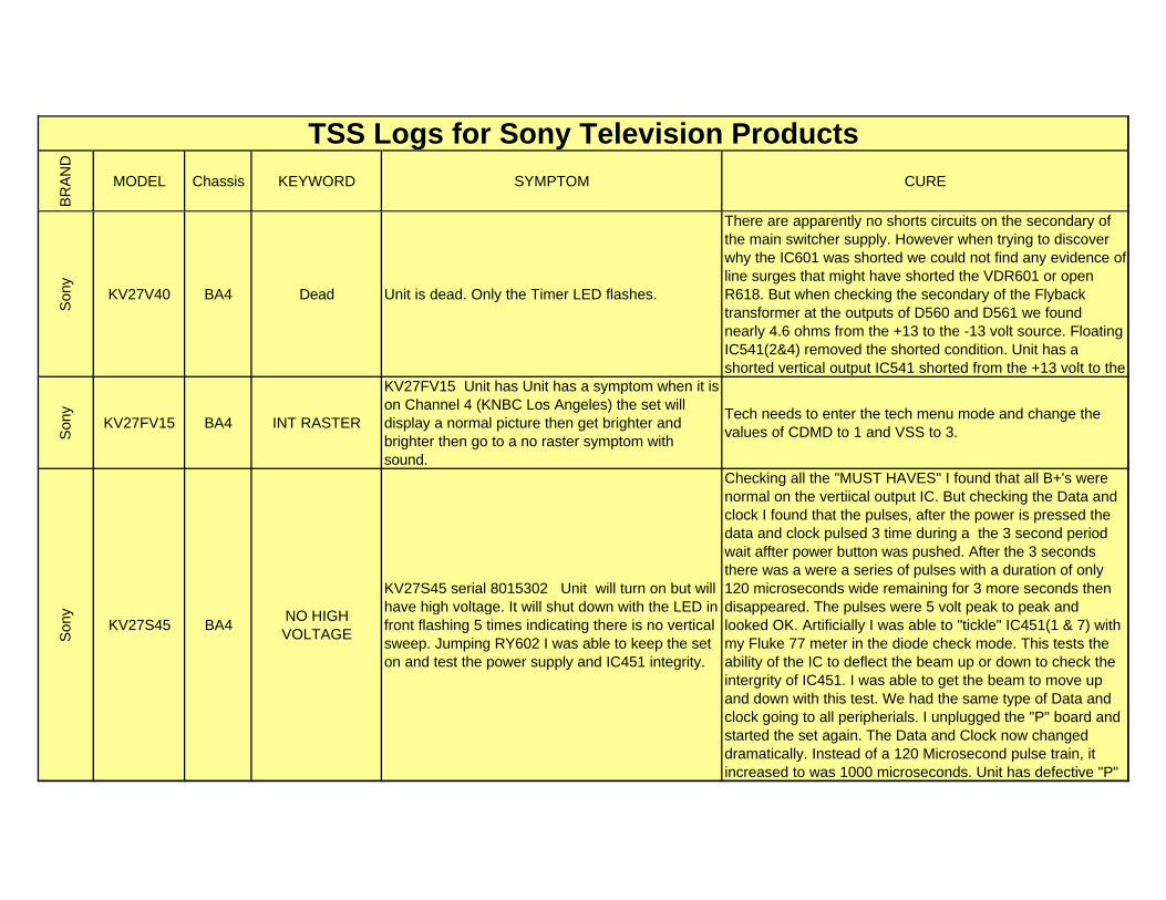
BR
AN
D
MODEL Chassis KEYWORD SYMPTOM CURE
TSS Logs for Sony Television Products
Son
y
KV27V40 BA4 Dead Unit is dead. Only the Timer LED flashes.
There are apparently no shorts circuits on the secondary of the main switcher supply. However when trying to discover why the IC601 was shorted we could not find any evidence of line surges that might have shorted the VDR601 or open R618. But when checking the secondary of the Flyback transformer at the outputs of D560 and D561 we found nearly 4.6 ohms from the +13 to the -13 volt source. Floating IC541(2&4) removed the shorted condition. Unit has a shorted vertical output IC541 shorted from the +13 volt to the
Son
y
KV27FV15 BA4 INT RASTER
KV27FV15 Unit has Unit has a symptom when it is on Channel 4 (KNBC Los Angeles) the set will display a normal picture then get brighter and brighter then go to a no raster symptom with sound.
Tech needs to enter the tech menu mode and change the values of CDMD to 1 and VSS to 3.
Son
y
KV27S45 BA4NO HIGH VOLTAGE
KV27S45 serial 8015302 Unit will turn on but will have high voltage. It will shut down with the LED in front flashing 5 times indicating there is no vertical sweep. Jumping RY602 I was able to keep the set on and test the power supply and IC451 integrity.
Checking all the "MUST HAVES" I found that all B+'s were normal on the vertiical output IC. But checking the Data and clock I found that the pulses, after the power is pressed the data and clock pulsed 3 time during a the 3 second period wait affter power button was pushed. After the 3 seconds there was a were a series of pulses with a duration of only 120 microseconds wide remaining for 3 more seconds then disappeared. The pulses were 5 volt peak to peak and looked OK. Artificially I was able to "tickle" IC451(1 & 7) with my Fluke 77 meter in the diode check mode. This tests the ability of the IC to deflect the beam up or down to check the intergrity of IC451. I was able to get the beam to move up and down with this test. We had the same type of Data and clock going to all peripherials. I unplugged the "P" board and started the set again. The Data and Clock now changed dramatically. Instead of a 120 Microsecond pulse train, it increased to was 1000 microseconds. Unit has defective "P"
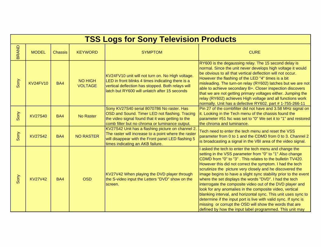
BR
AN
D
MODEL Chassis KEYWORD SYMPTOM CURE
TSS Logs for Sony Television Products
Son
y
KV24FV10 BA4NO HIGH VOLTAGE
KV24FV10 unit will not turn on. No High voltage. LED in front blinks 4 times indicating there is a vertical deflection has stopped. Both relays will latch but RY600 will unlatch after 15 seconds
RY600 is the degaussing relay. The 15 second delay is normal. Since the unit never develops high voltage it would be obvious to all that vertical deflection will not occur. However the flashing of the LED "4" times is a bit misleading. The turn-on relay (RY602) latches but we are not able to achieve secondary B+. Closer inspection discovers that we are not getting primary voltages either. Jumping the relay (RY602) achieves High voltage and all functions work normally. Unit has a defective RY602. part # 1-755-266-11
Son
y
KV27S40 BA4 No Raster
Sony KV27S40 serial 8070786 No raster. Has OSD and Sound. Timer LED not flashing. Tracing the video signal found that it was getting to the comb filter but no chroma or luminance output.
Pin 27 of the combfilter did not have and 3.58 MHz signal on it. Looking in the Tech menu of the chassis found the parameter #51 fsc was set to "0" We set it to "1" and restored the chroma and luminance.
Son
y
KV27S42 BA4 NO RASTER
KV27S42 Unit has a flashing picture on channel 2. The raster will increase to a point where the raster will disappear with the Front panel LED flashing 5 times indicating an AKB failure.
Tech need to enter the tech menu and reset the VSS parameter from 0 to 1 and the CDMD from 0 to 3. Channel 2 is broadcasting a signal in the VBI area of the video signal.
Son
y
KV27V42 BA4 OSDKV27V42 When playing the DVD player through the S-video input the Letters "DVD" show on the screen.
I asked the tech to enter the tech menu and change the setting in the VSS parameter from "0" to "1" Also change CDMD from "0" to "3" . This relates to the bulletin TV420. However this did not correct the symptom. I had the tech scrutinize the picture very closely and he discovered the image begins to have a slight sync stability prior to the event where the set displays the words "DVD". I had the tech interrogate the composite video out of the DVD player and look for any anomalies in the composite video, vertical blanking interval, and horizontal sync. This unit uses sync to determine if the input port is live with valid sync. If sync is missing or corrupt the OSD will show the words that are defined by how the input label programmed. This unit may
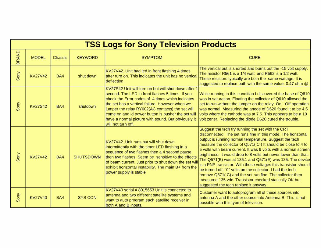
BR
AN
D
MODEL Chassis KEYWORD SYMPTOM CURE
TSS Logs for Sony Television Products
Son
y
KV27V42 BA4 shut downKV27V42. Unit had led in front flashing 4 times after turn on. This indicates the unit has no vertical deflection.
The vertical out is shorted and burns out the -15 volt supply. The resistor R561 is a 1/4 watt and R562 is a 1/2 watt. These resistors typically are both the same wattage. It is suggested to replace both with the same value. 0.47 ohm @
Son
y
KV27S42 BA4 shutdown
KV27S42 Unit will turn on but will shut down after 1 second. The LED in front flashes 5 times. If you check the Error codes of 4 times which indicates the set has a vertical failure. However when we jumper the relay RY602(AC contacts) the set will come on and id power button is pusher the set will have a normal picture with sound. But obviously it will not turn off.
While running in this condition I discovered the base of Q610 was in saturation. Floating the collector of Q610 allowed the set to run without the jumper on the relay. On - Off operation was normal. Measuring the anode of D620 found it to be 4.5 volts where the cathode was at 7.5. This appears to be a 10 volt zener. Replacing the diode D620 cured the trouble.
Son
y
KV27V42 BA4 SHUTSDOWN
KV27V42. Unit runs but will shut down intermittently with the timer LED flashing in a sequence of two flashes then a 4 second pause, then two flashes. Seem be sensitive to the effects of beam current. Just prior to shut down the set will exhibit horizontal instability. The main B+ from the power supply is stable
Suggest the tech try running the set with the CRT disconnected. The set runs fine in this mode. The horizontal output is running normal temperature. Suggest the tech measure the collector of Q571( C ) It should be close to 4 to 5 volts with beam current. It was 9 volts with a normal screen brightness. It would drop to 8 volts but never lower than that. The Q571(B) was at 135.1 and Q571(E) was 135. The device is a PNP transistor. With these voltages this transistor should be turned off. "0" volts on the collector. I had the tech remove Q571( C) and the set ran fine. The collector then measured 135 vdc. Transistor checked statically OK but suggested the tech replace it anyway
Son
y
KV27V40 BA4 SYS CON
KV27V40 serial # 8015653 Unit is connected to antenna and two different satellite systems and want to auto program each satellite receiver in both A and B inputs.
Customer want to autoprogram all of these sources into antenna A and the other source into Antenna B. This is not possible with this type of television.
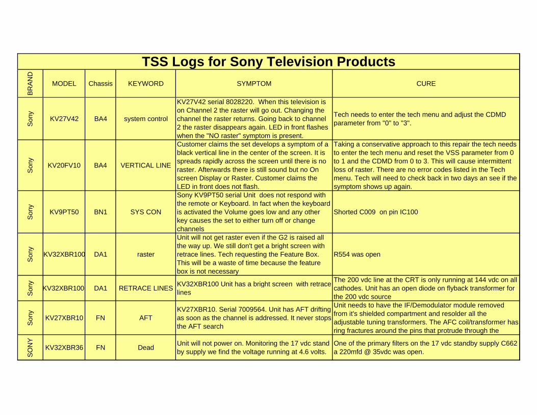
BR
AN
D
MODEL Chassis KEYWORD SYMPTOM CURE
TSS Logs for Sony Television Products
Son
y
KV27V42 BA4 system control
KV27V42 serial 8028220. When this television is on Channel 2 the raster will go out. Changing the channel the raster returns. Going back to channel 2 the raster disappears again. LED in front flashes when the "NO raster" symptom is present.
Tech needs to enter the tech menu and adjust the CDMD parameter from "0" to "3".
Son
y
KV20FV10 BA4 VERTICAL LINE
Customer claims the set develops a symptom of a black vertical line in the center of the screen. It is spreads rapidly across the screen until there is no raster. Afterwards there is still sound but no On screen Display or Raster. Customer claims the LED in front does not flash.
Taking a conservative approach to this repair the tech needs to enter the tech menu and reset the VSS parameter from 0 to 1 and the CDMD from 0 to 3. This will cause intermittent loss of raster. There are no error codes listed in the Tech menu. Tech will need to check back in two days an see if the symptom shows up again.
Son
y
KV9PT50 BN1 SYS CON
Sony KV9PT50 serial Unit does not respond with the remote or Keyboard. In fact when the keyboard is activated the Volume goes low and any other key causes the set to either turn off or change channels
Shorted C009 on pin IC100
Son
y
KV32XBR100 DA1 raster
Unit will not get raster even if the G2 is raised all the way up. We still don't get a bright screen with retrace lines. Tech requesting the Feature Box. This will be a waste of time because the feature box is not necessary
R554 was open
Son
y
KV32XBR100 DA1 RETRACE LINESKV32XBR100 Unit has a bright screen with retrace lines
The 200 vdc line at the CRT is only running at 144 vdc on all cathodes. Unit has an open diode on flyback transformer for the 200 vdc source
Son
y
KV27XBR10 FN AFTKV27XBR10. Serial 7009564. Unit has AFT drifting as soon as the channel is addressed. It never stops the AFT search
Unit needs to have the IF/Demodulator module removed from it's shielded compartment and resolder all the adjustable tuning transformers. The AFC coil/transformer has ring fractures around the pins that protrude through the
SO
NY
KV32XBR36 FN DeadUnit will not power on. Monitoring the 17 vdc stand by supply we find the voltage running at 4.6 volts.
One of the primary filters on the 17 vdc standby supply C662 a 220mfd @ 35vdc was open.
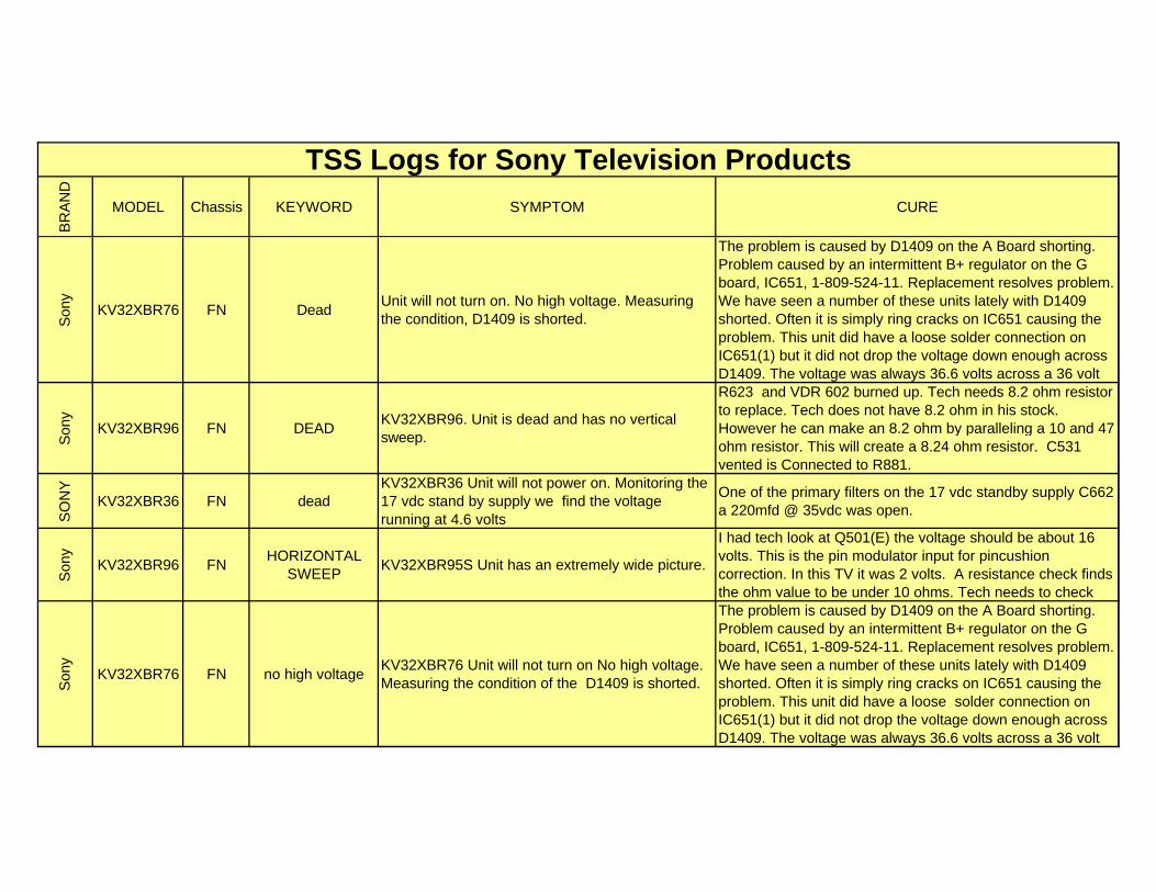
BR
AN
D
MODEL Chassis KEYWORD SYMPTOM CURE
TSS Logs for Sony Television Products
Son
y
KV32XBR76 FN DeadUnit will not turn on. No high voltage. Measuring the condition, D1409 is shorted.
The problem is caused by D1409 on the A Board shorting. Problem caused by an intermittent B+ regulator on the G board, IC651, 1-809-524-11. Replacement resolves problem. We have seen a number of these units lately with D1409 shorted. Often it is simply ring cracks on IC651 causing the problem. This unit did have a loose solder connection on IC651(1) but it did not drop the voltage down enough across D1409. The voltage was always 36.6 volts across a 36 volt
Son
y
KV32XBR96 FN DEADKV32XBR96. Unit is dead and has no vertical sweep.
R623 and VDR 602 burned up. Tech needs 8.2 ohm resistor to replace. Tech does not have 8.2 ohm in his stock. However he can make an 8.2 ohm by paralleling a 10 and 47 ohm resistor. This will create a 8.24 ohm resistor. C531 vented is Connected to R881.
SO
NY
KV32XBR36 FN deadKV32XBR36 Unit will not power on. Monitoring the 17 vdc stand by supply we find the voltage running at 4.6 volts
One of the primary filters on the 17 vdc standby supply C662 a 220mfd @ 35vdc was open.
Son
y
KV32XBR96 FNHORIZONTAL
SWEEPKV32XBR95S Unit has an extremely wide picture.
I had tech look at Q501(E) the voltage should be about 16 volts. This is the pin modulator input for pincushion correction. In this TV it was 2 volts. A resistance check finds the ohm value to be under 10 ohms. Tech needs to check
Son
y
KV32XBR76 FN no high voltageKV32XBR76 Unit will not turn on No high voltage. Measuring the condition of the D1409 is shorted.
The problem is caused by D1409 on the A Board shorting. Problem caused by an intermittent B+ regulator on the G board, IC651, 1-809-524-11. Replacement resolves problem. We have seen a number of these units lately with D1409 shorted. Often it is simply ring cracks on IC651 causing the problem. This unit did have a loose solder connection on IC651(1) but it did not drop the voltage down enough across D1409. The voltage was always 36.6 volts across a 36 volt
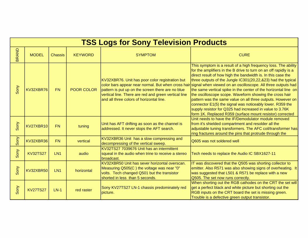
BR
AN
D
MODEL Chassis KEYWORD SYMPTOM CURE
TSS Logs for Sony Television Products
Son
y
KV32XBR76 FN POOR COLOR
KV32XBR76. Unit has poor color registration but color bars appear near normal. But when cross hair pattern is put up on the screen there are no blue vertical line. There are red and green vertical line and all three colors of horizontal line.
This symptom is a result of a high frequency loss. The ability for the amplifiers in the B drive to turn on an off rapidly is a direct result of how high the bandwidth is. In this case the three outputs of the Jungle IC301(20,22,&23) had the typical signal when viewed on an oscilloscope. All three outputs had the same vertical spike in the center of the horizontal line on the oscilloscope scope. Waveform showing the cross hair pattern was the same value on all three outputs. However on connector E1(5) the signal was noticeably lower. R359 the supply resistor for Q325 had increased in value to 3.76K form 1K. Replaced R359 (surface mount resistor) corrected
Son
y
KV27XBR10 FN tuningUnit has AFT drifting as soon as the channel is addressed. It never stops the AFT search.
Unit needs to have the IF/Demodulator module removed from it's shielded compartment and resolder all the adjustable tuning transformers. The AFC coil/transformer has ring fractures around the pins that protrude through the
Son
y
KV32XBR36 FN verticalKV32XBR36 Unit has a slow compressing and decompressing of the vertical sweep.
Q605 was not soldered well
Son
y
KV32TS27 LN1 audioKV32TS27 7039676 Unit has an intermittent squeal in the audio when trine to receive a stereo broadcast.
Tech needs to replace the Audio IC SBX1627-11
Son
y
KV32XBR50 LN1 horizontal
KV32XBR50 Unit has sever horizontal overscan. Measuring Q505(C ) the voltage was near "0" volts. Tech changed Q501 but the transistor shorted in less than 5 seconds.
IT was discovered that the Q505 was shorting collector to emitter. Also R571 was also showing signs of overheating. It was suggested that L501 & R571 be replace with a new Q505. The set now runs correctly.
Son
y
KV27TS27 LN-1 red rasterSony KV27TS27 LN-1 chassis predominately red picture.
When shorting out the RGB cathodes on the CRT the set will get a perfect black and white picture but shorting out the RGB inputs on the CRT board the set is missing green. Trouble is a defective green output transistor.
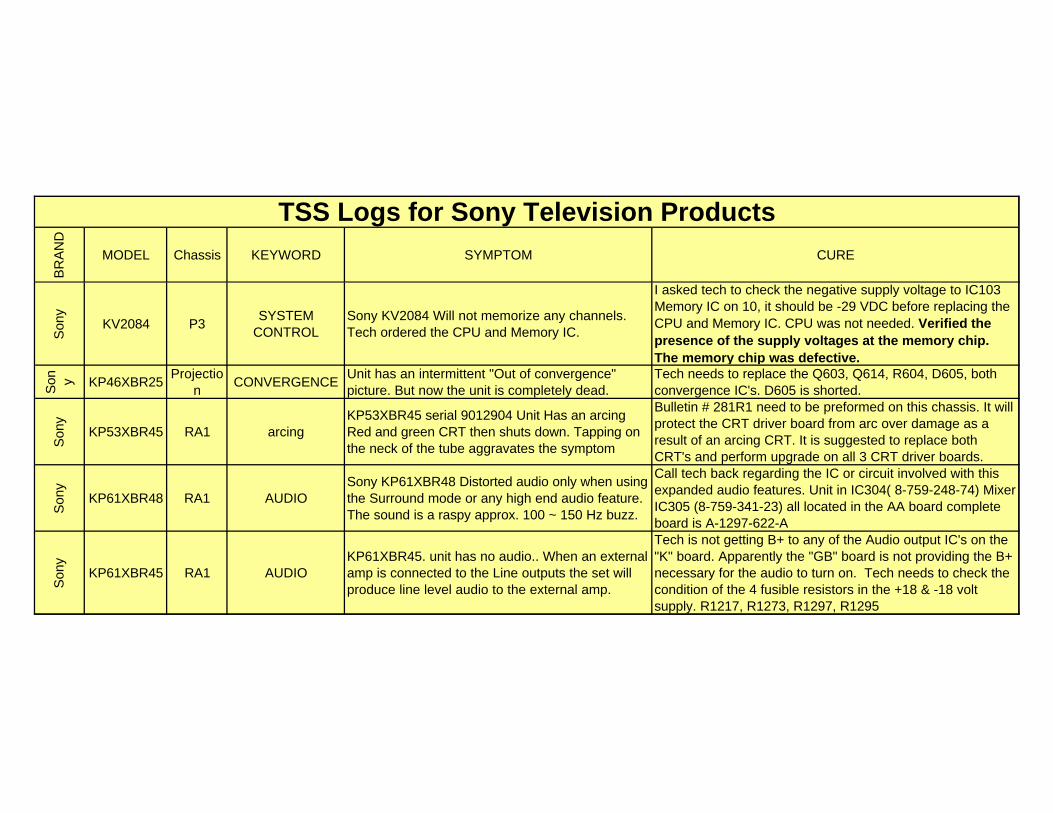
BR
AN
D
MODEL Chassis KEYWORD SYMPTOM CURE
TSS Logs for Sony Television Products
Son
y
KV2084 P3SYSTEM
CONTROLSony KV2084 Will not memorize any channels. Tech ordered the CPU and Memory IC.
I asked tech to check the negative supply voltage to IC103 Memory IC on 10, it should be -29 VDC before replacing the CPU and Memory IC. CPU was not needed. Verified the presence of the supply voltages at the memory chip. The memory chip was defective.
Son y KP46XBR25
Projection
CONVERGENCEUnit has an intermittent "Out of convergence" picture. But now the unit is completely dead.
Tech needs to replace the Q603, Q614, R604, D605, both convergence IC's. D605 is shorted.
Son
y
KP53XBR45 RA1 arcingKP53XBR45 serial 9012904 Unit Has an arcing Red and green CRT then shuts down. Tapping on the neck of the tube aggravates the symptom
Bulletin # 281R1 need to be preformed on this chassis. It will protect the CRT driver board from arc over damage as a result of an arcing CRT. It is suggested to replace both CRT's and perform upgrade on all 3 CRT driver boards.
Son
y
KP61XBR48 RA1 AUDIOSony KP61XBR48 Distorted audio only when using the Surround mode or any high end audio feature. The sound is a raspy approx. 100 ~ 150 Hz buzz.
Call tech back regarding the IC or circuit involved with this expanded audio features. Unit in IC304( 8-759-248-74) Mixer IC305 (8-759-341-23) all located in the AA board complete board is A-1297-622-A
Son
y
KP61XBR45 RA1 AUDIOKP61XBR45. unit has no audio.. When an external amp is connected to the Line outputs the set will produce line level audio to the external amp.
Tech is not getting B+ to any of the Audio output IC's on the "K" board. Apparently the "GB" board is not providing the B+ necessary for the audio to turn on. Tech needs to check the condition of the 4 fusible resistors in the +18 & -18 volt supply. R1217, R1273, R1297, R1295
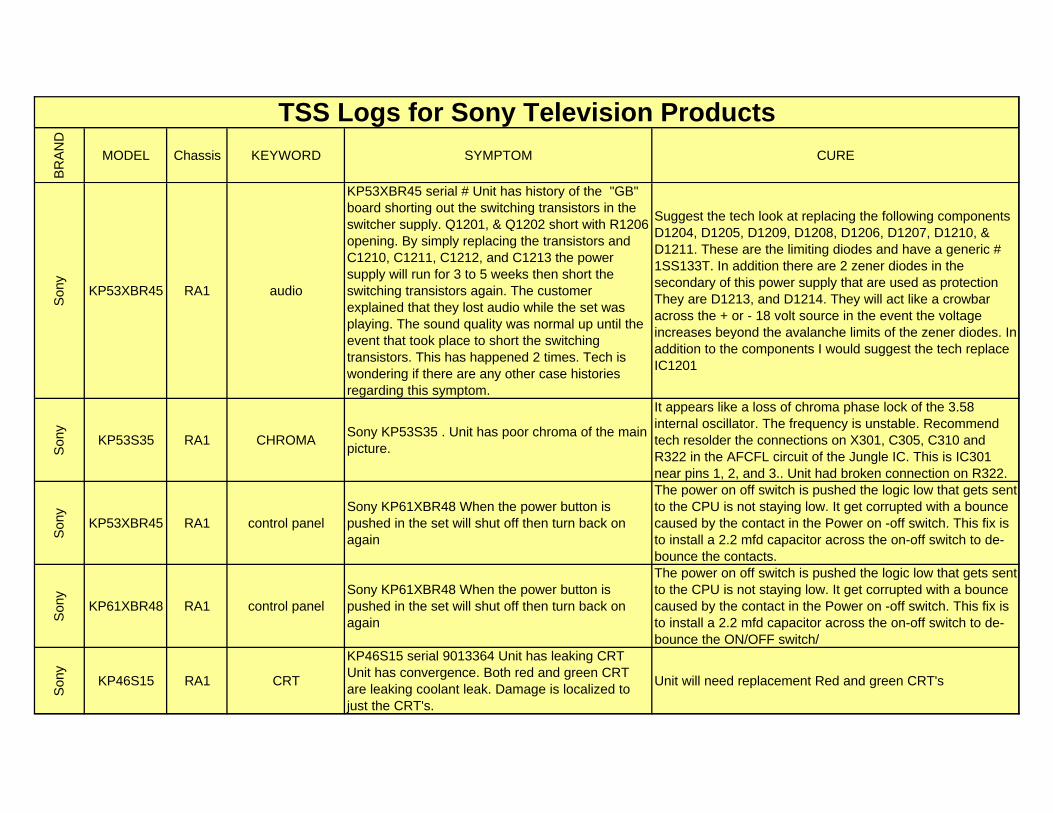
BR
AN
D
MODEL Chassis KEYWORD SYMPTOM CURE
TSS Logs for Sony Television Products
Son
y
KP53XBR45 RA1 audio
KP53XBR45 serial # Unit has history of the "GB" board shorting out the switching transistors in the switcher supply. Q1201, & Q1202 short with R1206 opening. By simply replacing the transistors and C1210, C1211, C1212, and C1213 the power supply will run for 3 to 5 weeks then short the switching transistors again. The customer explained that they lost audio while the set was playing. The sound quality was normal up until the event that took place to short the switching transistors. This has happened 2 times. Tech is wondering if there are any other case histories regarding this symptom.
Suggest the tech look at replacing the following components D1204, D1205, D1209, D1208, D1206, D1207, D1210, & D1211. These are the limiting diodes and have a generic # 1SS133T. In addition there are 2 zener diodes in the secondary of this power supply that are used as protection They are D1213, and D1214. They will act like a crowbar across the + or - 18 volt source in the event the voltage increases beyond the avalanche limits of the zener diodes. In addition to the components I would suggest the tech replace IC1201
Son
y
KP53S35 RA1 CHROMASony KP53S35 . Unit has poor chroma of the main picture.
It appears like a loss of chroma phase lock of the 3.58 internal oscillator. The frequency is unstable. Recommend tech resolder the connections on X301, C305, C310 and R322 in the AFCFL circuit of the Jungle IC. This is IC301 near pins 1, 2, and 3.. Unit had broken connection on R322.
Son
y
KP53XBR45 RA1 control panelSony KP61XBR48 When the power button is pushed in the set will shut off then turn back on again
The power on off switch is pushed the logic low that gets sent to the CPU is not staying low. It get corrupted with a bounce caused by the contact in the Power on -off switch. This fix is to install a 2.2 mfd capacitor across the on-off switch to de-bounce the contacts.
Son
y
KP61XBR48 RA1 control panelSony KP61XBR48 When the power button is pushed in the set will shut off then turn back on again
The power on off switch is pushed the logic low that gets sent to the CPU is not staying low. It get corrupted with a bounce caused by the contact in the Power on -off switch. This fix is to install a 2.2 mfd capacitor across the on-off switch to de-bounce the ON/OFF switch/
Son
y
KP46S15 RA1 CRT
KP46S15 serial 9013364 Unit has leaking CRT Unit has convergence. Both red and green CRT are leaking coolant leak. Damage is localized to just the CRT's.
Unit will need replacement Red and green CRT's
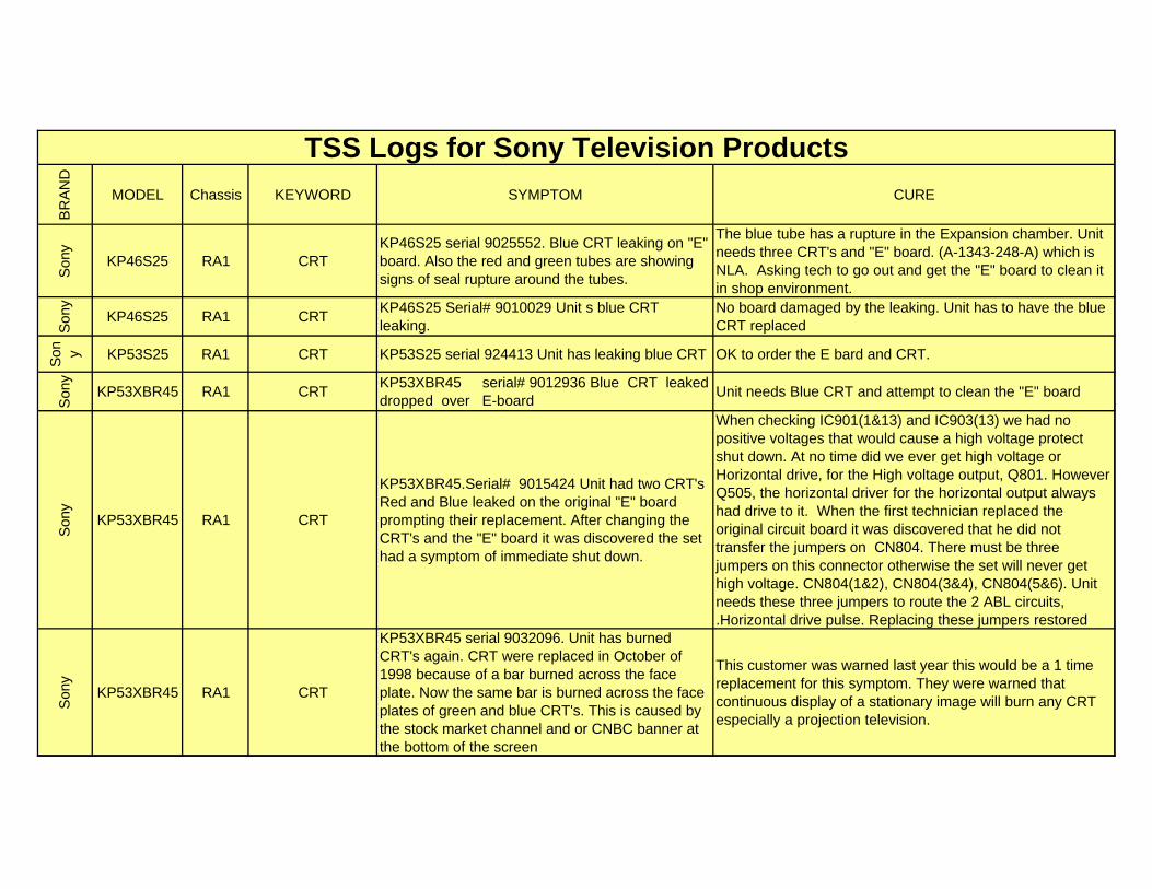
BR
AN
D
MODEL Chassis KEYWORD SYMPTOM CURE
TSS Logs for Sony Television Products
Son
y
KP46S25 RA1 CRTKP46S25 serial 9025552. Blue CRT leaking on "E" board. Also the red and green tubes are showing signs of seal rupture around the tubes.
The blue tube has a rupture in the Expansion chamber. Unit needs three CRT's and "E" board. (A-1343-248-A) which is NLA. Asking tech to go out and get the "E" board to clean it in shop environment.
Son
y
KP46S25 RA1 CRTKP46S25 Serial# 9010029 Unit s blue CRT leaking.
No board damaged by the leaking. Unit has to have the blue CRT replaced
Son y KP53S25 RA1 CRT KP53S25 serial 924413 Unit has leaking blue CRT OK to order the E bard and CRT.
Son
y
KP53XBR45 RA1 CRTKP53XBR45 serial# 9012936 Blue CRT leaked dropped over E-board
Unit needs Blue CRT and attempt to clean the "E" board
Son
y
KP53XBR45 RA1 CRT
KP53XBR45.Serial# 9015424 Unit had two CRT's Red and Blue leaked on the original "E" board prompting their replacement. After changing the CRT's and the "E" board it was discovered the set had a symptom of immediate shut down.
When checking IC901(1&13) and IC903(13) we had no positive voltages that would cause a high voltage protect shut down. At no time did we ever get high voltage or Horizontal drive, for the High voltage output, Q801. However Q505, the horizontal driver for the horizontal output always had drive to it. When the first technician replaced the original circuit board it was discovered that he did not transfer the jumpers on CN804. There must be three jumpers on this connector otherwise the set will never get high voltage. CN804(1&2), CN804(3&4), CN804(5&6). Unit needs these three jumpers to route the 2 ABL circuits, .Horizontal drive pulse. Replacing these jumpers restored
Son
y
KP53XBR45 RA1 CRT
KP53XBR45 serial 9032096. Unit has burned CRT's again. CRT were replaced in October of 1998 because of a bar burned across the face plate. Now the same bar is burned across the face plates of green and blue CRT's. This is caused by the stock market channel and or CNBC banner at the bottom of the screen
This customer was warned last year this would be a 1 time replacement for this symptom. They were warned that continuous display of a stationary image will burn any CRT especially a projection television.
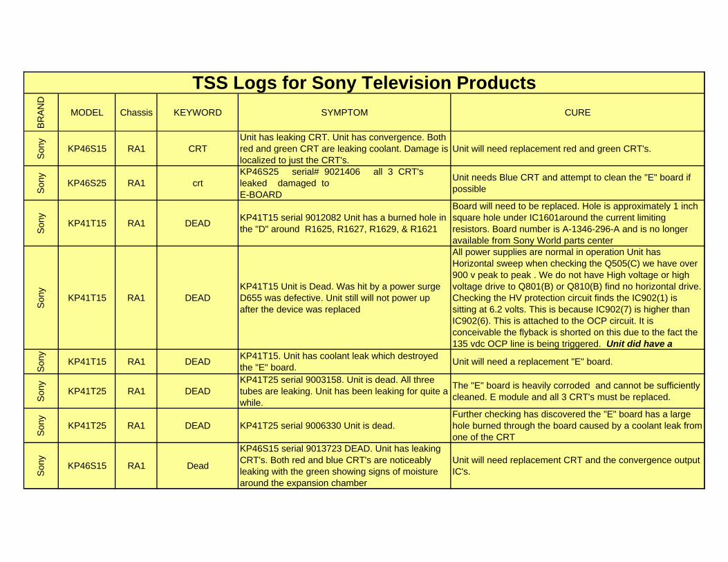
BR
AN
D
MODEL Chassis KEYWORD SYMPTOM CURE
TSS Logs for Sony Television Products
Son
y
KP46S15 RA1 CRTUnit has leaking CRT. Unit has convergence. Both red and green CRT are leaking coolant. Damage is localized to just the CRT's.
Unit will need replacement red and green CRT's.
Son
y
KP46S25 RA1 crtKP46S25 serial# 9021406 all 3 CRT's leaked damaged toE-BOARD
Unit needs Blue CRT and attempt to clean the "E" board if possible
Son
y
KP41T15 RA1 DEADKP41T15 serial 9012082 Unit has a burned hole in the "D" around R1625, R1627, R1629, & R1621
Board will need to be replaced. Hole is approximately 1 inch square hole under IC1601around the current limiting resistors. Board number is A-1346-296-A and is no longer available from Sony World parts center
Son
y
KP41T15 RA1 DEADKP41T15 Unit is Dead. Was hit by a power surge D655 was defective. Unit still will not power up after the device was replaced
All power supplies are normal in operation Unit has Horizontal sweep when checking the Q505(C) we have over 900 v peak to peak . We do not have High voltage or high voltage drive to Q801(B) or Q810(B) find no horizontal drive. Checking the HV protection circuit finds the IC902(1) is sitting at 6.2 volts. This is because IC902(7) is higher than IC902(6). This is attached to the OCP circuit. It is conceivable the flyback is shorted on this due to the fact the 135 vdc OCP line is being triggered. Unit did have a
Son
y
KP41T15 RA1 DEADKP41T15. Unit has coolant leak which destroyed the "E" board.
Unit will need a replacement "E" board.
Son
y
KP41T25 RA1 DEADKP41T25 serial 9003158. Unit is dead. All three tubes are leaking. Unit has been leaking for quite a while.
The "E" board is heavily corroded and cannot be sufficiently cleaned. E module and all 3 CRT's must be replaced.
Son
y
KP41T25 RA1 DEAD KP41T25 serial 9006330 Unit is dead.Further checking has discovered the "E" board has a large hole burned through the board caused by a coolant leak from one of the CRT
Son
y
KP46S15 RA1 Dead
KP46S15 serial 9013723 DEAD. Unit has leaking CRT's. Both red and blue CRT's are noticeably leaking with the green showing signs of moisture around the expansion chamber
Unit will need replacement CRT and the convergence output IC's.
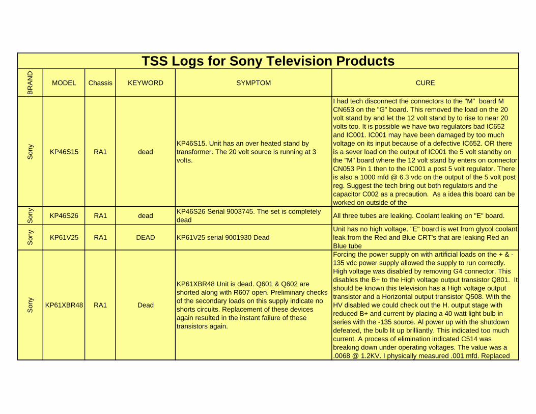
BR
AN
D
MODEL Chassis KEYWORD SYMPTOM CURE
TSS Logs for Sony Television Products
Son
y
KP46S15 RA1 deadKP46S15. Unit has an over heated stand by transformer. The 20 volt source is running at 3 volts.
I had tech disconnect the connectors to the "M" board M CN653 on the "G" board. This removed the load on the 20 volt stand by and let the 12 volt stand by to rise to near 20 volts too. It is possible we have two regulators bad IC652 and IC001. IC001 may have been damaged by too much voltage on its input because of a defective IC652. OR there is a sever load on the output of IC001 the 5 volt standby on the "M" board where the 12 volt stand by enters on connector CN053 Pin 1 then to the IC001 a post 5 volt regulator. There is also a 1000 mfd @ 6.3 vdc on the output of the 5 volt post reg. Suggest the tech bring out both regulators and the capacitor C002 as a precaution. As a idea this board can be worked on outside of the
Son
y
KP46S26 RA1 deadKP46S26 Serial 9003745. The set is completely dead
All three tubes are leaking. Coolant leaking on "E" board.
Son
y
KP61V25 RA1 DEAD KP61V25 serial 9001930 DeadUnit has no high voltage. "E" board is wet from glycol coolant leak from the Red and Blue CRT's that are leaking Red an Blue tube
Son
y
KP61XBR48 RA1 Dead
KP61XBR48 Unit is dead. Q601 & Q602 are shorted along with R607 open. Preliminary checks of the secondary loads on this supply indicate no shorts circuits. Replacement of these devices again resulted in the instant failure of these transistors again.
Forcing the power supply on with artificial loads on the + & - 135 vdc power supply allowed the supply to run correctly. High voltage was disabled by removing G4 connector. This disables the B+ to the High voltage output transistor Q801. It should be known this television has a High voltage output transistor and a Horizontal output transistor Q508. With the HV disabled we could check out the H. output stage with reduced B+ and current by placing a 40 watt light bulb in series with the -135 source. Al power up with the shutdown defeated, the bulb lit up brilliantly. This indicated too much current. A process of elimination indicated C514 was breaking down under operating voltages. The value was a .0068 @ 1.2KV. I physically measured .001 mfd. Replaced
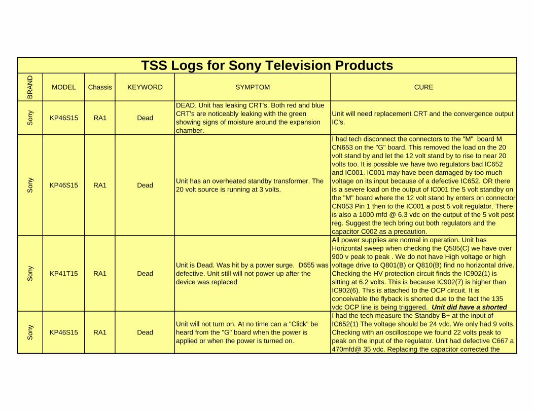
BR
AN
D
MODEL Chassis KEYWORD SYMPTOM CURE
TSS Logs for Sony Television Products
Son
y
KP46S15 RA1 Dead
DEAD. Unit has leaking CRT's. Both red and blue CRT's are noticeably leaking with the green showing signs of moisture around the expansion chamber.
Unit will need replacement CRT and the convergence output IC's.
Son
y
KP46S15 RA1 DeadUnit has an overheated standby transformer. The 20 volt source is running at 3 volts.
I had tech disconnect the connectors to the "M" board M CN653 on the "G" board. This removed the load on the 20 volt stand by and let the 12 volt stand by to rise to near 20 volts too. It is possible we have two regulators bad IC652 and IC001. IC001 may have been damaged by too much voltage on its input because of a defective IC652. OR there is a severe load on the output of IC001 the 5 volt standby on the "M" board where the 12 volt stand by enters on connector CN053 Pin 1 then to the IC001 a post 5 volt regulator. There is also a 1000 mfd @ 6.3 vdc on the output of the 5 volt post reg. Suggest the tech bring out both regulators and the capacitor C002 as a precaution.
Son
y
KP41T15 RA1 DeadUnit is Dead. Was hit by a power surge. D655 was defective. Unit still will not power up after the device was replaced
All power supplies are normal in operation. Unit has Horizontal sweep when checking the Q505(C) we have over 900 v peak to peak . We do not have High voltage or high voltage drive to Q801(B) or Q810(B) find no horizontal drive. Checking the HV protection circuit finds the IC902(1) is sitting at 6.2 volts. This is because IC902(7) is higher than IC902(6). This is attached to the OCP circuit. It is conceivable the flyback is shorted due to the fact the 135 vdc OCP line is being triggered. Unit did have a shorted
Son
y
KP46S15 RA1 DeadUnit will not turn on. At no time can a "Click" be heard from the "G" board when the power is applied or when the power is turned on.
I had the tech measure the Standby B+ at the input of IC652(1) The voltage should be 24 vdc. We only had 9 volts. Checking with an oscilloscope we found 22 volts peak to peak on the input of the regulator. Unit had defective C667 a 470mfd@ 35 vdc. Replacing the capacitor corrected the
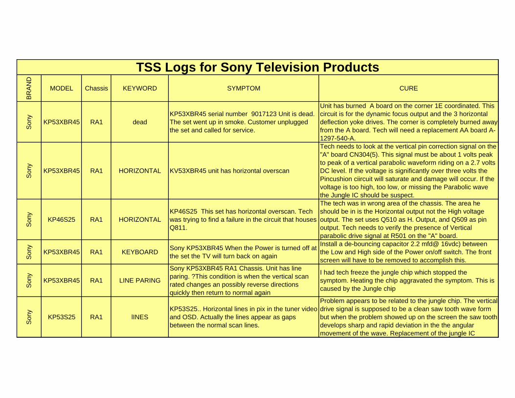
BR
AN
D
MODEL Chassis KEYWORD SYMPTOM CURE
TSS Logs for Sony Television Products
Son
y
KP53XBR45 RA1 deadKP53XBR45 serial number 9017123 Unit is dead. The set went up in smoke. Customer unplugged the set and called for service.
Unit has burned A board on the corner 1E coordinated. This circuit is for the dynamic focus output and the 3 horizontal deflection yoke drives. The corner is completely burned away from the A board. Tech will need a replacement AA board A-1297-540-A.
Son
y
KP53XBR45 RA1 HORIZONTAL KV53XBR45 unit has horizontal overscan
Tech needs to look at the vertical pin correction signal on the "A" board CN304(5). This signal must be about 1 volts peak to peak of a vertical parabolic waveform riding on a 2.7 volts DC level. If the voltage is significantly over three volts the Pincushion ciircuit will saturate and damage will occur. If the voltage is too high, too low, or missing the Parabolic wave the Jungle IC should be suspect.
Son
y
KP46S25 RA1 HORIZONTALKP46S25 This set has horizontal overscan. Tech was trying to find a failure in the circuit that houses Q811.
The tech was in wrong area of the chassis. The area he should be in is the Horizontal output not the High voltage output. The set uses Q510 as H. Output, and Q509 as pin output. Tech needs to verify the presence of Vertical parabolic drive signal at R501 on the "A" board.
Son
y
KP53XBR45 RA1 KEYBOARDSony KP53XBR45 When the Power is turned off at the set the TV will turn back on again
Install a de-bouncing capacitor 2.2 mfd@ 16vdc) between the Low and High side of the Power on/off switch. The front screen will have to be removed to accomplish this.
Son
y
KP53XBR45 RA1 LINE PARING
Sony KP53XBR45 RA1 Chassis. Unit has line paring. ?This condition is when the vertical scan rated changes an possibly reverse directions quickly then return to normal again
I had tech freeze the jungle chip which stopped the symptom. Heating the chip aggravated the symptom. This is caused by the Jungle chip
Son
y
KP53S25 RA1 lINESKP53S25.. Horizontal lines in pix in the tuner video and OSD. Actually the lines appear as gaps between the normal scan lines.
Problem appears to be related to the jungle chip. The vertical drive signal is supposed to be a clean saw tooth wave form but when the problem showed up on the screen the saw tooth develops sharp and rapid deviation in the the angular movement of the wave. Replacement of the jungle IC
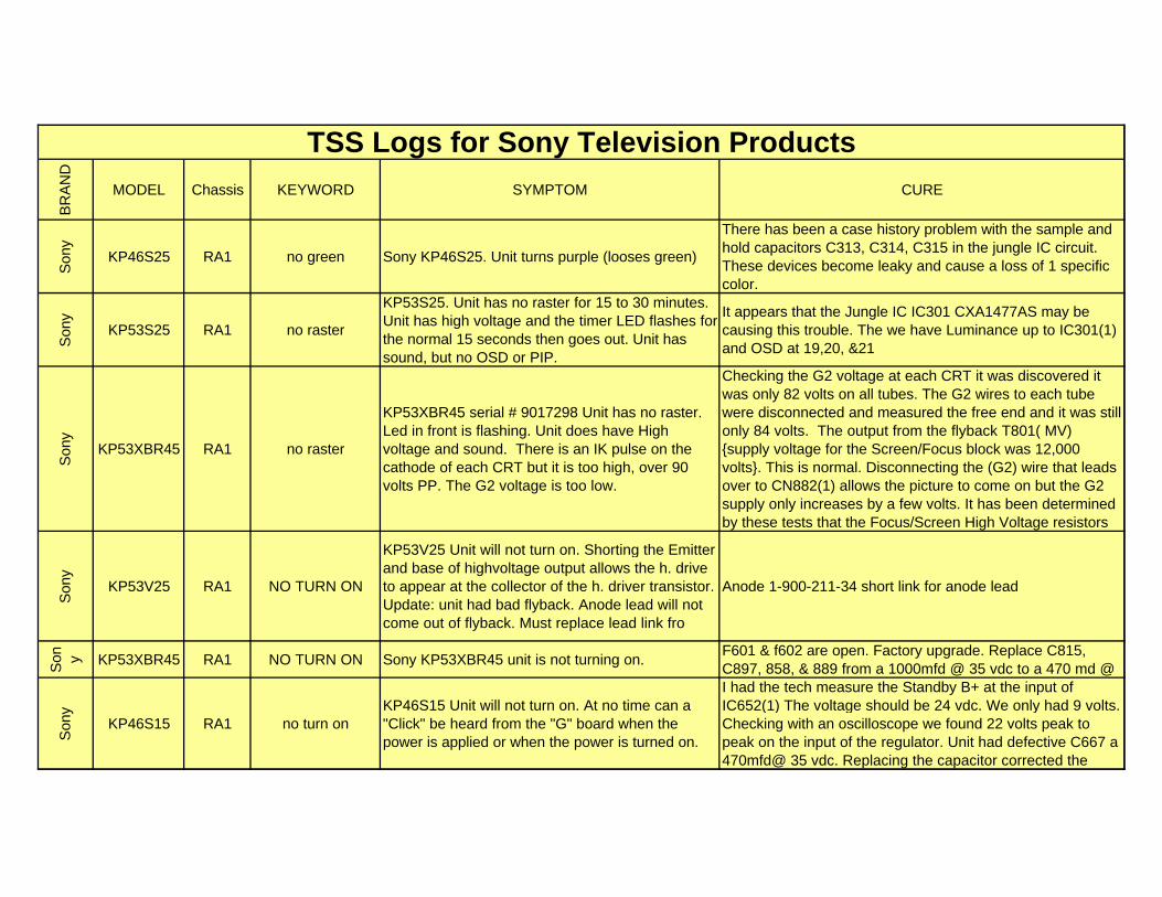
BR
AN
D
MODEL Chassis KEYWORD SYMPTOM CURE
TSS Logs for Sony Television Products
Son
y
KP46S25 RA1 no green Sony KP46S25. Unit turns purple (looses green)
There has been a case history problem with the sample and hold capacitors C313, C314, C315 in the jungle IC circuit. These devices become leaky and cause a loss of 1 specific color.
Son
y
KP53S25 RA1 no raster
KP53S25. Unit has no raster for 15 to 30 minutes. Unit has high voltage and the timer LED flashes for the normal 15 seconds then goes out. Unit has sound, but no OSD or PIP.
It appears that the Jungle IC IC301 CXA1477AS may be causing this trouble. The we have Luminance up to IC301(1) and OSD at 19,20, &21
Son
y
KP53XBR45 RA1 no raster
KP53XBR45 serial # 9017298 Unit has no raster. Led in front is flashing. Unit does have High voltage and sound. There is an IK pulse on the cathode of each CRT but it is too high, over 90 volts PP. The G2 voltage is too low.
Checking the G2 voltage at each CRT it was discovered it was only 82 volts on all tubes. The G2 wires to each tube were disconnected and measured the free end and it was still only 84 volts. The output from the flyback T801( MV) {supply voltage for the Screen/Focus block was 12,000 volts}. This is normal. Disconnecting the (G2) wire that leads over to CN882(1) allows the picture to come on but the G2 supply only increases by a few volts. It has been determined by these tests that the Focus/Screen High Voltage resistors
Son
y
KP53V25 RA1 NO TURN ON
KP53V25 Unit will not turn on. Shorting the Emitter and base of highvoltage output allows the h. drive to appear at the collector of the h. driver transistor. Update: unit had bad flyback. Anode lead will not come out of flyback. Must replace lead link fro
Anode 1-900-211-34 short link for anode lead
Son y KP53XBR45 RA1 NO TURN ON Sony KP53XBR45 unit is not turning on.
F601 & f602 are open. Factory upgrade. Replace C815, C897, 858, & 889 from a 1000mfd @ 35 vdc to a 470 md @
Son
y
KP46S15 RA1 no turn onKP46S15 Unit will not turn on. At no time can a "Click" be heard from the "G" board when the power is applied or when the power is turned on.
I had the tech measure the Standby B+ at the input of IC652(1) The voltage should be 24 vdc. We only had 9 volts. Checking with an oscilloscope we found 22 volts peak to peak on the input of the regulator. Unit had defective C667 a 470mfd@ 35 vdc. Replacing the capacitor corrected the
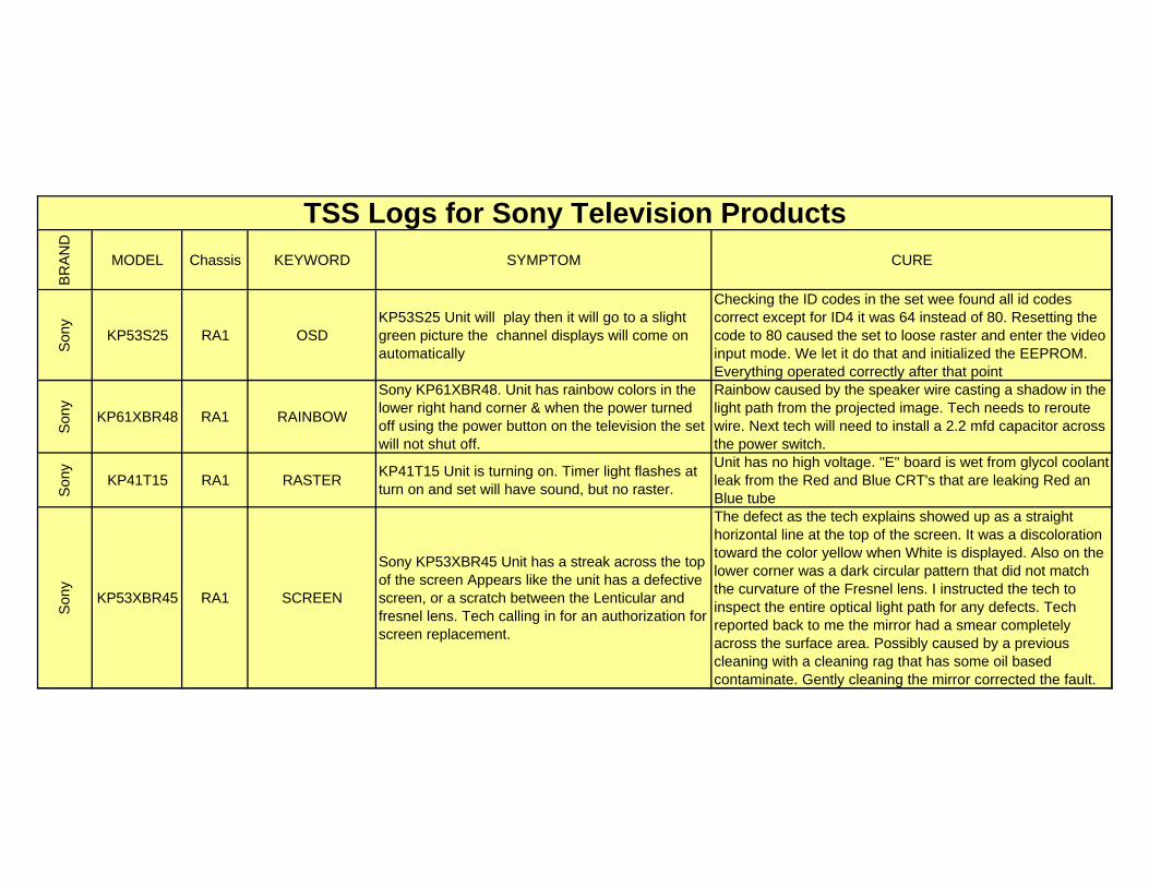
BR
AN
D
MODEL Chassis KEYWORD SYMPTOM CURE
TSS Logs for Sony Television Products
Son
y
KP53S25 RA1 OSDKP53S25 Unit will play then it will go to a slight green picture the channel displays will come on automatically
Checking the ID codes in the set wee found all id codes correct except for ID4 it was 64 instead of 80. Resetting the code to 80 caused the set to loose raster and enter the video input mode. We let it do that and initialized the EEPROM. Everything operated correctly after that point
Son
y
KP61XBR48 RA1 RAINBOW
Sony KP61XBR48. Unit has rainbow colors in the lower right hand corner & when the power turned off using the power button on the television the set will not shut off.
Rainbow caused by the speaker wire casting a shadow in the light path from the projected image. Tech needs to reroute wire. Next tech will need to install a 2.2 mfd capacitor across the power switch.
Son
y
KP41T15 RA1 RASTERKP41T15 Unit is turning on. Timer light flashes at turn on and set will have sound, but no raster.
Unit has no high voltage. "E" board is wet from glycol coolant leak from the Red and Blue CRT's that are leaking Red an Blue tube
Son
y
KP53XBR45 RA1 SCREEN
Sony KP53XBR45 Unit has a streak across the top of the screen Appears like the unit has a defective screen, or a scratch between the Lenticular and fresnel lens. Tech calling in for an authorization for screen replacement.
The defect as the tech explains showed up as a straight horizontal line at the top of the screen. It was a discoloration toward the color yellow when White is displayed. Also on the lower corner was a dark circular pattern that did not match the curvature of the Fresnel lens. I instructed the tech to inspect the entire optical light path for any defects. Tech reported back to me the mirror had a smear completely across the surface area. Possibly caused by a previous cleaning with a cleaning rag that has some oil based contaminate. Gently cleaning the mirror corrected the fault.
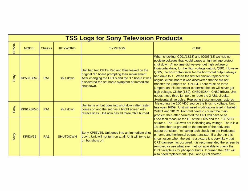
BR
AN
D
MODEL Chassis KEYWORD SYMPTOM CURE
TSS Logs for Sony Television Products
Son
y
KP53XBR45 RA1 shut down
Unit had two CRT's Red and Blue leaked on the original "E" board prompting their replacement. After changing the CRT's and the "E" board it was discovered the set had a symptom of immediate shut down.
When checking IC901(1&13) and IC903(13) we had no positive voltages that would cause a high voltage protect shut down. At no time did we ever get high voltage or Horizontal drive, for the High voltage output, Q801. However Q505, the horizontal driver for the horizontal output always had drive to it. When the first technician replaced the original circuit board it was discovered that he did not transfer the jumpers on CN804. There must be three jumpers on this connector otherwise the set will never get high voltage. CN804(1&2), CN804(3&4), CN804(5&6). Unit needs these three jumpers to route the 2 ABL circuits, .Horizontal drive pulse. Replacing these jumpers restored
Son
y
KP61XBR45 RA1 shut downUnit turns on but goes into shut down after raster comes on and the set has a bright screen with retrace lines. Unit now has all three CRT burned
Measuring the 200 VDC source the finds no voltage, Unit has open R859. Unit will need modification listed in bulletin 291R1 and 281R1 Tech will need to correct the main problem then after corrected the CRT will have to be
Son
y
KP53V35 RA1 SHUTDOWNSony KP53V35. Unit goes into an immediate shut down. Unit will not turn on at all. Unit will try to turn on but shuts off.
I had tech measure the B+ at the +135 and the -135 VDC sources. The -135 was not indicating any voltage. There is a 18 ohm short to ground on the emitter of the horizontal output transistor. I'm having tech check into the Horizontal pin amp and horizontal output transistor. If a short in this circuit occur when the set ha a picture it is very likely that CRT damage has occurred. It is recommended the screen be removed or use what ever method available to check the CRT faceplates for phosphor burns. If burned the CRT will also need replacement. Q510 and Q509 shorted
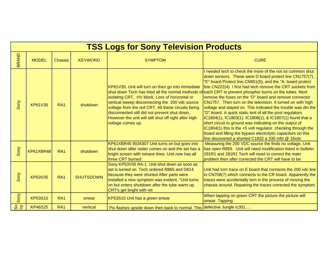
BR
AN
D
MODEL Chassis KEYWORD SYMPTOM CURE
TSS Logs for Sony Television Products
Son
y
KP61V35 RA1 shutdown
KP61V35. Unit will turn on then go into immediate shut down Tech has tried all the normal methods of isolating CRT, HV block, Loss of horizontal or vertical sweep disconnecting the 200 vdc source voltage from the red CRT. All these circuits being disconnected still did not prevent shut down.. However the unit will still shut off right after high voltage comes up.
I needed tech to check the more of the not so common shut down sensors. These were D board protect line CN1757(7) , "E" board Protect line CN851(5), and the "A: board protect line CN222(4) I first had tech remove the CRT sockets from each CRT to prevent phosphor burns on the tubes. Next remove the fuses on the "D" board and remove connector CN1757. Then turn on the television. It turned on with high voltage and stayed on. This indicated the trouble was din the "D" board. A quick static test of all the post regulators IC1804(1), IC1803(1), IC1808(1), & IC1807(1) found that a short circuit to ground was indicating on the output of IC1804(1) this is the +5 volt regulator. checking through the board and lifting the bypass electrolytic capacitors on this line discovered a shorted C1832 a 330 mfd @ 16vdc
Son
y
KP61XBR48 RA1 shutdown
KP61XBR45 9034307 Unit turns on but goes into shut down after raster comes on and the set has a bright screen with retrace lines. Unit now has all three CRT burned
Measuring the 200 VDC source the finds no voltage, Unit has open R859. Unit will need modification listed in bulletin 291R1 and 281R1 Tech will need to correct the main problem then after corrected the CRT will have to be
Son
y
KP53V35 RA1 SHUTSDOWN
Sony KP53V35 RA-1. Unit shut down as soon as set is turned on. Tech ordered R865 and D814 because they were shorted After parts were installed a new symptom was evident. "Unit turns on but enters shutdown after the tube warm up. CRT's get bright with ret
Unit had torn trace on E board that connects the 200 vdc line to CN708(7) which connects to the CR board. Apparently the traces were accidentally torn in the process of moving the chassis around. Repairing the traces corrected the symptom.
Son
y
KP53S15 RA1 smear KP53S15 Unit has a green smearWhen tapping on green CRT the picture the picture will smear. Tapping
So
ny KP46S25 RA1 vertical Pix flashes upside down then back to normal. This take defective Jungle ic301….
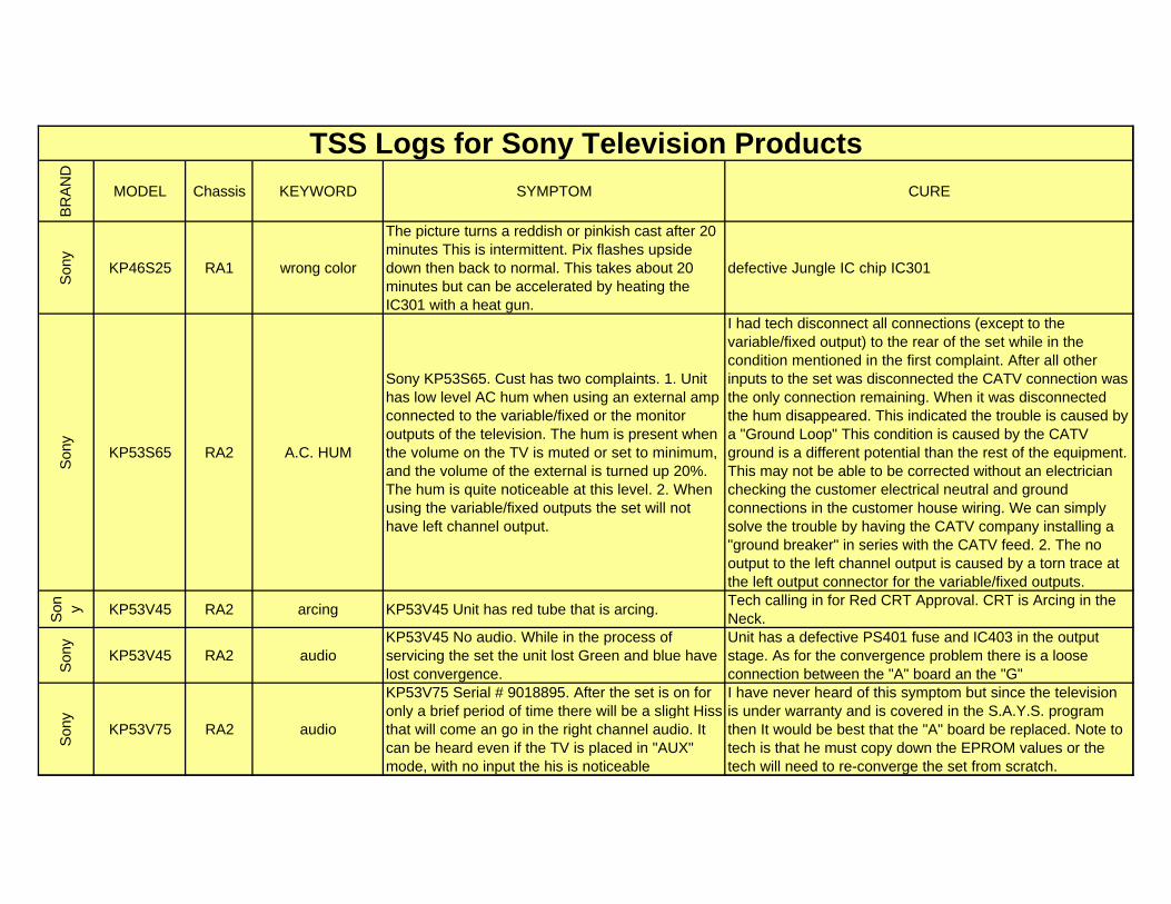
BR
AN
D
MODEL Chassis KEYWORD SYMPTOM CURE
TSS Logs for Sony Television Products
Son
y
KP46S25 RA1 wrong color
The picture turns a reddish or pinkish cast after 20 minutes This is intermittent. Pix flashes upside down then back to normal. This takes about 20 minutes but can be accelerated by heating the IC301 with a heat gun.
defective Jungle IC chip IC301
Son
y
KP53S65 RA2 A.C. HUM
Sony KP53S65. Cust has two complaints. 1. Unit has low level AC hum when using an external amp connected to the variable/fixed or the monitor outputs of the television. The hum is present when the volume on the TV is muted or set to minimum, and the volume of the external is turned up 20%. The hum is quite noticeable at this level. 2. When using the variable/fixed outputs the set will not have left channel output.
I had tech disconnect all connections (except to the variable/fixed output) to the rear of the set while in the condition mentioned in the first complaint. After all other inputs to the set was disconnected the CATV connection was the only connection remaining. When it was disconnected the hum disappeared. This indicated the trouble is caused by a "Ground Loop" This condition is caused by the CATV ground is a different potential than the rest of the equipment. This may not be able to be corrected without an electrician checking the customer electrical neutral and ground connections in the customer house wiring. We can simply solve the trouble by having the CATV company installing a "ground breaker" in series with the CATV feed. 2. The no output to the left channel output is caused by a torn trace at the left output connector for the variable/fixed outputs.
Son y KP53V45 RA2 arcing KP53V45 Unit has red tube that is arcing.
Tech calling in for Red CRT Approval. CRT is Arcing in the Neck.
Son
y
KP53V45 RA2 audioKP53V45 No audio. While in the process of servicing the set the unit lost Green and blue have lost convergence.
Unit has a defective PS401 fuse and IC403 in the output stage. As for the convergence problem there is a loose connection between the "A" board an the "G"
Son
y
KP53V75 RA2 audio
KP53V75 Serial # 9018895. After the set is on for only a brief period of time there will be a slight Hiss that will come an go in the right channel audio. It can be heard even if the TV is placed in "AUX" mode, with no input the his is noticeable
I have never heard of this symptom but since the television is under warranty and is covered in the S.A.Y.S. program then It would be best that the "A" board be replaced. Note to tech is that he must copy down the EPROM values or the tech will need to re-converge the set from scratch.
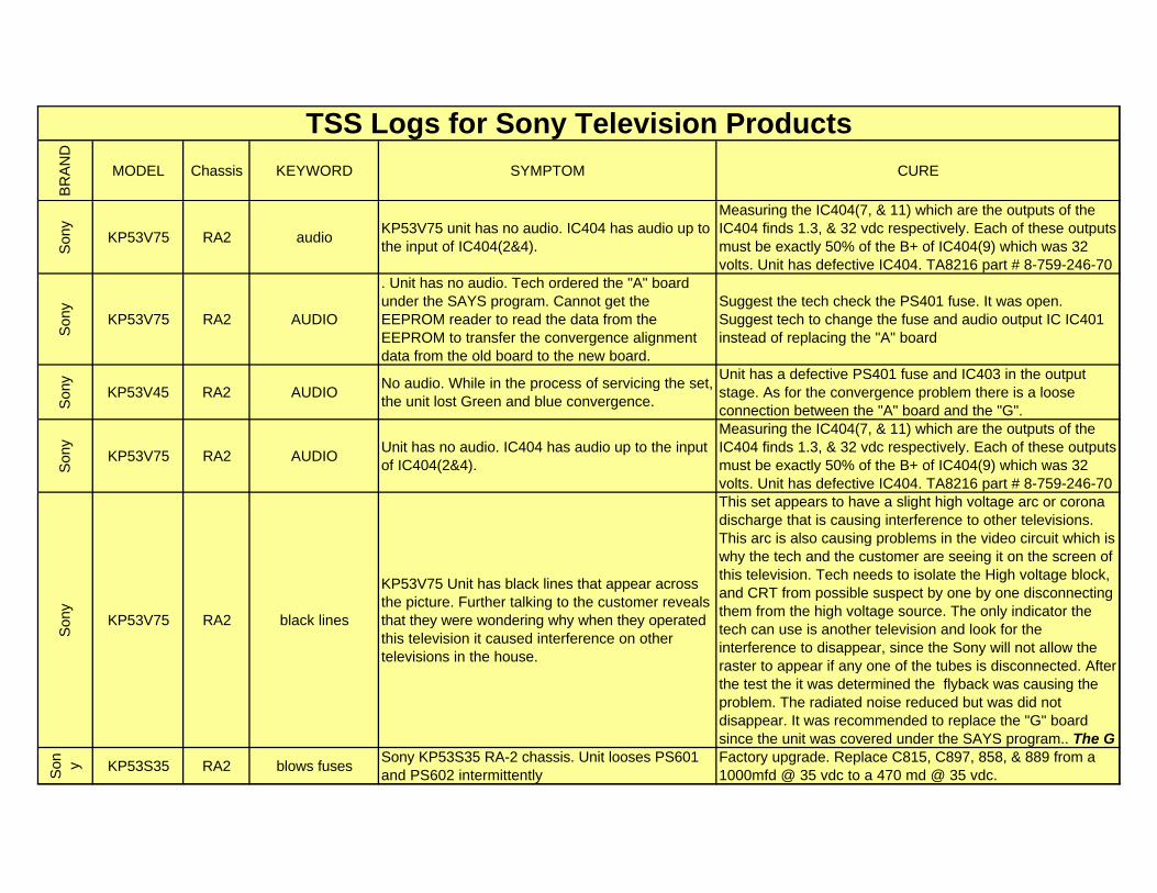
BR
AN
D
MODEL Chassis KEYWORD SYMPTOM CURE
TSS Logs for Sony Television Products
Son
y
KP53V75 RA2 audioKP53V75 unit has no audio. IC404 has audio up to the input of IC404(2&4).
Measuring the IC404(7, & 11) which are the outputs of the IC404 finds 1.3, & 32 vdc respectively. Each of these outputs must be exactly 50% of the B+ of IC404(9) which was 32 volts. Unit has defective IC404. TA8216 part # 8-759-246-70
Son
y
KP53V75 RA2 AUDIO
. Unit has no audio. Tech ordered the "A" board under the SAYS program. Cannot get the EEPROM reader to read the data from the EEPROM to transfer the convergence alignment data from the old board to the new board.
Suggest the tech check the PS401 fuse. It was open. Suggest tech to change the fuse and audio output IC IC401 instead of replacing the "A" board
Son
y
KP53V45 RA2 AUDIONo audio. While in the process of servicing the set, the unit lost Green and blue convergence.
Unit has a defective PS401 fuse and IC403 in the output stage. As for the convergence problem there is a loose connection between the "A" board and the "G".
Son
y
KP53V75 RA2 AUDIOUnit has no audio. IC404 has audio up to the input of IC404(2&4).
Measuring the IC404(7, & 11) which are the outputs of the IC404 finds 1.3, & 32 vdc respectively. Each of these outputs must be exactly 50% of the B+ of IC404(9) which was 32 volts. Unit has defective IC404. TA8216 part # 8-759-246-70
Son
y
KP53V75 RA2 black lines
KP53V75 Unit has black lines that appear across the picture. Further talking to the customer reveals that they were wondering why when they operated this television it caused interference on other televisions in the house.
This set appears to have a slight high voltage arc or corona discharge that is causing interference to other televisions. This arc is also causing problems in the video circuit which is why the tech and the customer are seeing it on the screen of this television. Tech needs to isolate the High voltage block, and CRT from possible suspect by one by one disconnecting them from the high voltage source. The only indicator the tech can use is another television and look for the interference to disappear, since the Sony will not allow the raster to appear if any one of the tubes is disconnected. After the test the it was determined the flyback was causing the problem. The radiated noise reduced but was did not disappear. It was recommended to replace the "G" board since the unit was covered under the SAYS program.. The G
Son y KP53S35 RA2 blows fuses
Sony KP53S35 RA-2 chassis. Unit looses PS601 and PS602 intermittently
Factory upgrade. Replace C815, C897, 858, & 889 from a 1000mfd @ 35 vdc to a 470 md @ 35 vdc.
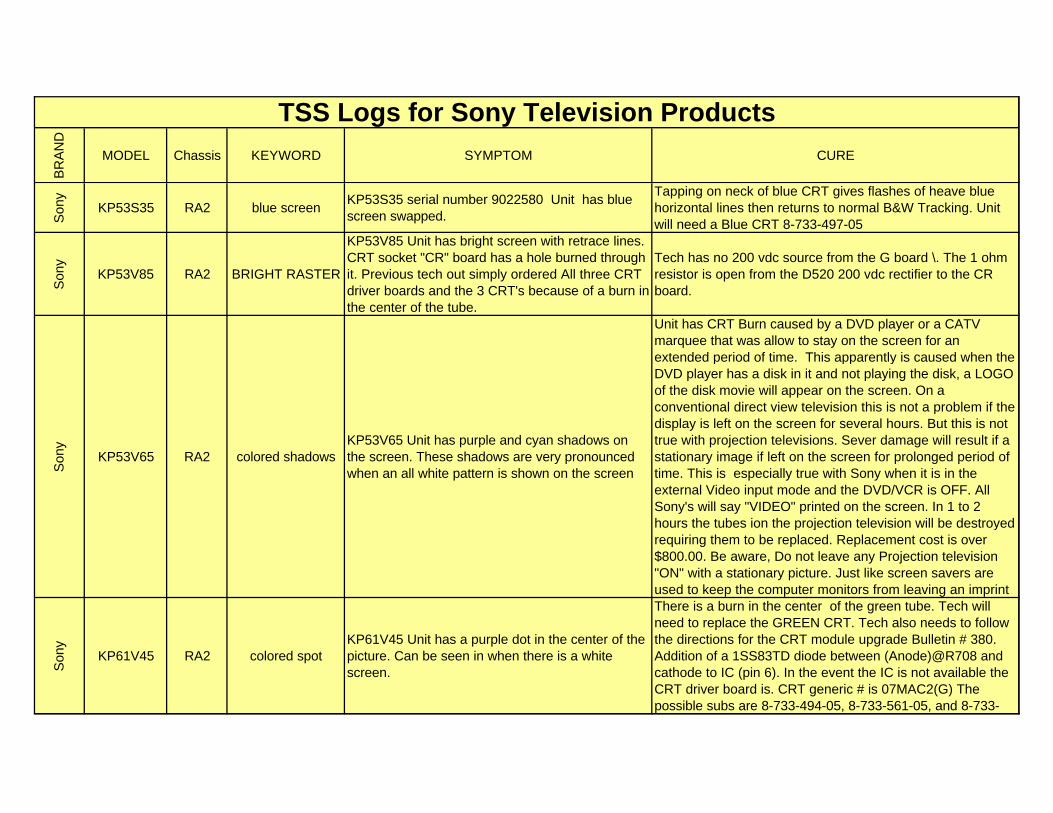
BR
AN
D
MODEL Chassis KEYWORD SYMPTOM CURE
TSS Logs for Sony Television Products
Son
y
KP53S35 RA2 blue screenKP53S35 serial number 9022580 Unit has blue screen swapped.
Tapping on neck of blue CRT gives flashes of heave blue horizontal lines then returns to normal B&W Tracking. Unit will need a Blue CRT 8-733-497-05
Son
y
KP53V85 RA2 BRIGHT RASTER
KP53V85 Unit has bright screen with retrace lines. CRT socket "CR" board has a hole burned through it. Previous tech out simply ordered All three CRT driver boards and the 3 CRT's because of a burn in the center of the tube.
Tech has no 200 vdc source from the G board \. The 1 ohm resistor is open from the D520 200 vdc rectifier to the CR board.
Son
y
KP53V65 RA2 colored shadowsKP53V65 Unit has purple and cyan shadows on the screen. These shadows are very pronounced when an all white pattern is shown on the screen
Unit has CRT Burn caused by a DVD player or a CATV marquee that was allow to stay on the screen for an extended period of time. This apparently is caused when the DVD player has a disk in it and not playing the disk, a LOGO of the disk movie will appear on the screen. On a conventional direct view television this is not a problem if the display is left on the screen for several hours. But this is not true with projection televisions. Sever damage will result if a stationary image if left on the screen for prolonged period of time. This is especially true with Sony when it is in the external Video input mode and the DVD/VCR is OFF. All Sony's will say "VIDEO" printed on the screen. In 1 to 2 hours the tubes ion the projection television will be destroyed requiring them to be replaced. Replacement cost is over $800.00. Be aware, Do not leave any Projection television "ON" with a stationary picture. Just like screen savers are used to keep the computer monitors from leaving an imprint
Son
y
KP61V45 RA2 colored spotKP61V45 Unit has a purple dot in the center of the picture. Can be seen in when there is a white screen.
There is a burn in the center of the green tube. Tech will need to replace the GREEN CRT. Tech also needs to follow the directions for the CRT module upgrade Bulletin # 380. Addition of a 1SS83TD diode between (Anode)@R708 and cathode to IC (pin 6). In the event the IC is not available the CRT driver board is. CRT generic # is 07MAC2(G) The possible subs are 8-733-494-05, 8-733-561-05, and 8-733-
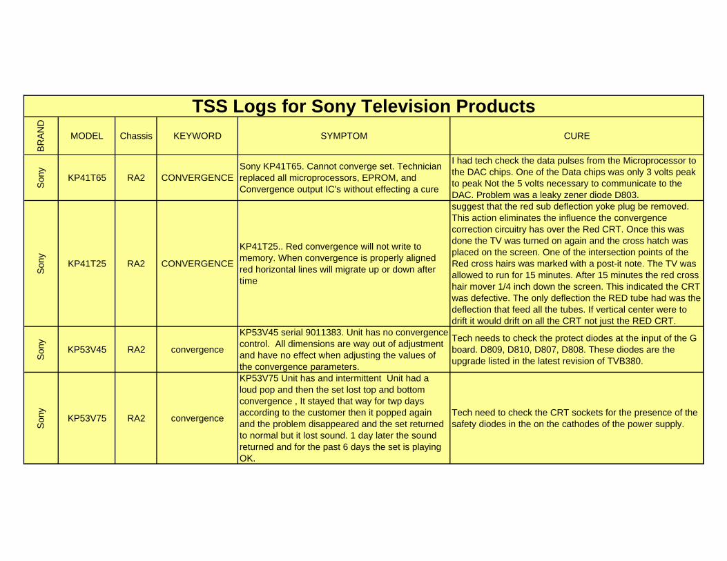
BR
AN
D
MODEL Chassis KEYWORD SYMPTOM CURE
TSS Logs for Sony Television Products
Son
y
KP41T65 RA2 CONVERGENCESony KP41T65. Cannot converge set. Technician replaced all microprocessors, EPROM, and Convergence output IC's without effecting a cure
I had tech check the data pulses from the Microprocessor to the DAC chips. One of the Data chips was only 3 volts peak to peak Not the 5 volts necessary to communicate to the DAC. Problem was a leaky zener diode D803.
Son
y
KP41T25 RA2 CONVERGENCE
KP41T25.. Red convergence will not write to memory. When convergence is properly aligned red horizontal lines will migrate up or down after time
suggest that the red sub deflection yoke plug be removed. This action eliminates the influence the convergence correction circuitry has over the Red CRT. Once this was done the TV was turned on again and the cross hatch was placed on the screen. One of the intersection points of the Red cross hairs was marked with a post-it note. The TV was allowed to run for 15 minutes. After 15 minutes the red cross hair mover 1/4 inch down the screen. This indicated the CRT was defective. The only deflection the RED tube had was the deflection that feed all the tubes. If vertical center were to drift it would drift on all the CRT not just the RED CRT.
Son
y
KP53V45 RA2 convergence
KP53V45 serial 9011383. Unit has no convergence control. All dimensions are way out of adjustment and have no effect when adjusting the values of the convergence parameters.
Tech needs to check the protect diodes at the input of the G board. D809, D810, D807, D808. These diodes are the upgrade listed in the latest revision of TVB380.
Son
y
KP53V75 RA2 convergence
KP53V75 Unit has and intermittent Unit had a loud pop and then the set lost top and bottom convergence , It stayed that way for twp days according to the customer then it popped again and the problem disappeared and the set returned to normal but it lost sound. 1 day later the sound returned and for the past 6 days the set is playing OK.
Tech need to check the CRT sockets for the presence of the safety diodes in the on the cathodes of the power supply.
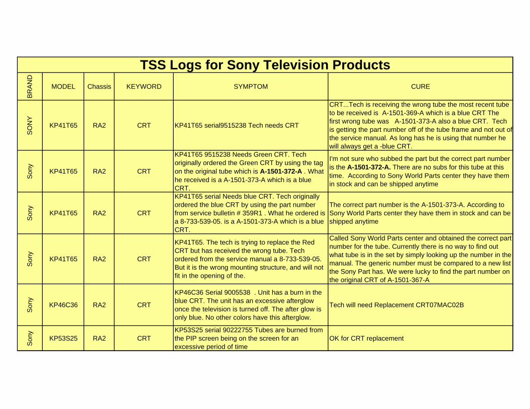
BR
AN
D
MODEL Chassis KEYWORD SYMPTOM CURE
TSS Logs for Sony Television Products
SO
NY
KP41T65 RA2 CRT KP41T65 serial9515238 Tech needs CRT
CRT...Tech is receiving the wrong tube the most recent tube to be received is A-1501-369-A which is a blue CRT The first wrong tube was A-1501-373-A also a blue CRT. Tech is getting the part number off of the tube frame and not out of the service manual. As long has he is using that number he will always get a -blue CRT.
Son
y
KP41T65 RA2 CRT
KP41T65 9515238 Needs Green CRT. Tech originally ordered the Green CRT by using the tag on the original tube which is A-1501-372-A . What he received is a A-1501-373-A which is a blue CRT.
I'm not sure who subbed the part but the correct part number is the A-1501-372-A. There are no subs for this tube at this time. According to Sony World Parts center they have them in stock and can be shipped anytime
Son
y
KP41T65 RA2 CRT
KP41T65 serial Needs blue CRT. Tech originally ordered the blue CRT by using the part number from service bulletin # 359R1 . What he ordered is a 8-733-539-05. is a A-1501-373-A which is a blue CRT.
The correct part number is the A-1501-373-A. According to Sony World Parts center they have them in stock and can be shipped anytime
Son
y
KP41T65 RA2 CRT
KP41T65. The tech is trying to replace the Red CRT but has received the wrong tube. Tech ordered from the service manual a 8-733-539-05. But it is the wrong mounting structure, and will not fit in the opening of the.
Called Sony World Parts center and obtained the correct part number for the tube. Currently there is no way to find out what tube is in the set by simply looking up the number in the manual. The generic number must be compared to a new list the Sony Part has. We were lucky to find the part number on the original CRT of A-1501-367-A
Son
y
KP46C36 RA2 CRT
KP46C36 Serial 9005538 . Unit has a burn in the blue CRT. The unit has an excessive afterglow once the television is turned off. The after glow is only blue. No other colors have this afterglow.
Tech will need Replacement CRT07MAC02B
Son
y
KP53S25 RA2 CRTKP53S25 serial 90222755 Tubes are burned from the PIP screen being on the screen for an excessive period of time
OK for CRT replacement
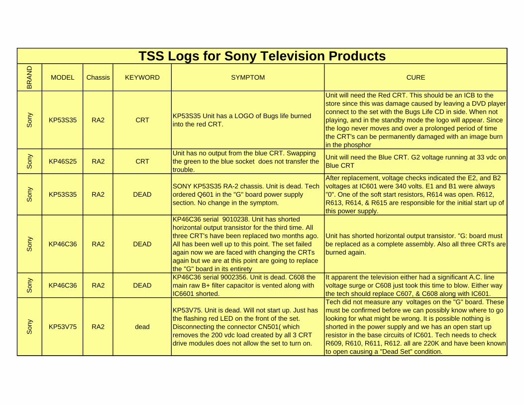
BR
AN
D
MODEL Chassis KEYWORD SYMPTOM CURE
TSS Logs for Sony Television Products
Son
y
KP53S35 RA2 CRTKP53S35 Unit has a LOGO of Bugs life burned into the red CRT.
Unit will need the Red CRT. This should be an ICB to the store since this was damage caused by leaving a DVD player connect to the set with the Bugs Life CD in side. When not playing, and in the standby mode the logo will appear. Since the logo never moves and over a prolonged period of time the CRT's can be permanently damaged with an image burn in the phosphor
Son
y
KP46S25 RA2 CRTUnit has no output from the blue CRT. Swapping the green to the blue socket does not transfer the trouble.
Unit will need the Blue CRT. G2 voltage running at 33 vdc on Blue CRT
Son
y
KP53S35 RA2 DEADSONY KP53S35 RA-2 chassis. Unit is dead. Tech ordered Q601 in the "G" board power supply section. No change in the symptom.
After replacement, voltage checks indicated the E2, and B2 voltages at IC601 were 340 volts. E1 and B1 were always "0". One of the soft start resistors, R614 was open. R612, R613, R614, & R615 are responsible for the initial start up of this power supply.
Son
y
KP46C36 RA2 DEAD
KP46C36 serial 9010238. Unit has shorted horizontal output transistor for the third time. All three CRT's have been replaced two months ago. All has been well up to this point. The set failed again now we are faced with changing the CRTs again but we are at this point are going to replace the "G" board in its entirety
Unit has shorted horizontal output transistor. "G: board must be replaced as a complete assembly. Also all three CRTs are burned again.
Son
y
KP46C36 RA2 DEADKP46C36 serial 9002356. Unit is dead. C608 the main raw B+ filter capacitor is vented along with IC6601 shorted.
It apparent the television either had a significant A.C. line voltage surge or C608 just took this time to blow. Either way the tech should replace C607, & C608 along with IC601.
Son
y
KP53V75 RA2 dead
KP53V75. Unit is dead. Will not start up. Just has the flashing red LED on the front of the set. Disconnecting the connector CN501( which removes the 200 vdc load created by all 3 CRT drive modules does not allow the set to turn on.
Tech did not measure any voltages on the "G" board. These must be confirmed before we can possibly know where to go looking for what might be wrong. It is possible nothing is shorted in the power supply and we has an open start up resistor in the base circuits of IC601. Tech needs to check R609, R610, R611, R612. all are 220K and have been known to open causing a "Dead Set" condition.
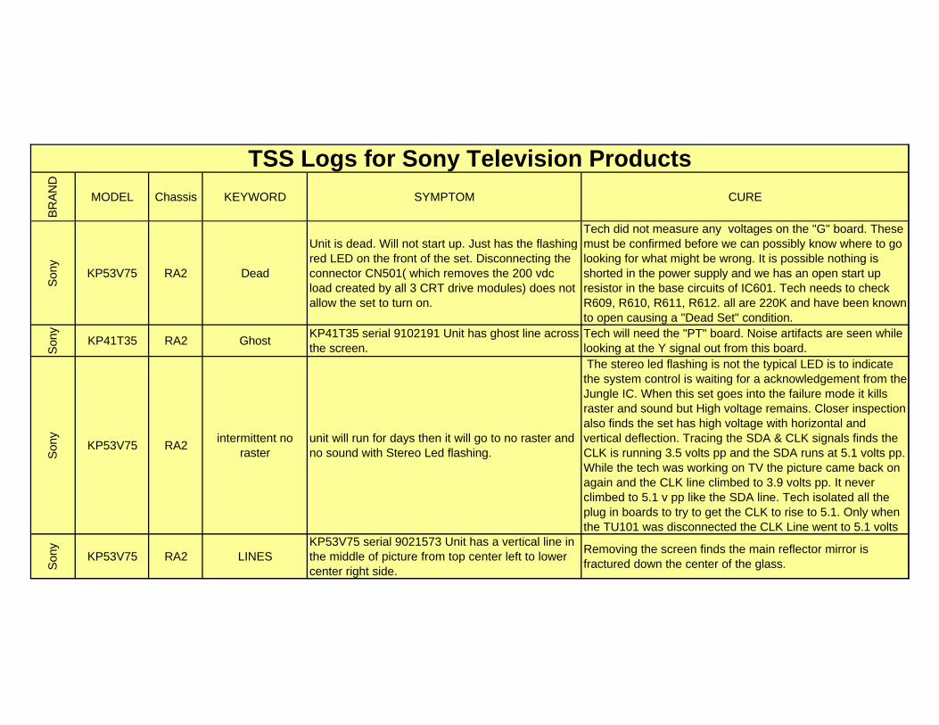
BR
AN
D
MODEL Chassis KEYWORD SYMPTOM CURE
TSS Logs for Sony Television Products
Son
y
KP53V75 RA2 Dead
Unit is dead. Will not start up. Just has the flashing red LED on the front of the set. Disconnecting the connector CN501( which removes the 200 vdc load created by all 3 CRT drive modules) does not allow the set to turn on.
Tech did not measure any voltages on the "G" board. These must be confirmed before we can possibly know where to go looking for what might be wrong. It is possible nothing is shorted in the power supply and we has an open start up resistor in the base circuits of IC601. Tech needs to check R609, R610, R611, R612. all are 220K and have been known to open causing a "Dead Set" condition.
Son
y
KP41T35 RA2 GhostKP41T35 serial 9102191 Unit has ghost line across the screen.
Tech will need the "PT" board. Noise artifacts are seen while looking at the Y signal out from this board.
Son
y
KP53V75 RA2intermittent no
rasterunit will run for days then it will go to no raster and no sound with Stereo Led flashing.
The stereo led flashing is not the typical LED is to indicate the system control is waiting for a acknowledgement from the Jungle IC. When this set goes into the failure mode it kills raster and sound but High voltage remains. Closer inspection also finds the set has high voltage with horizontal and vertical deflection. Tracing the SDA & CLK signals finds the CLK is running 3.5 volts pp and the SDA runs at 5.1 volts pp. While the tech was working on TV the picture came back on again and the CLK line climbed to 3.9 volts pp. It never climbed to 5.1 v pp like the SDA line. Tech isolated all the plug in boards to try to get the CLK to rise to 5.1. Only when the TU101 was disconnected the CLK Line went to 5.1 volts
Son
y
KP53V75 RA2 LINESKP53V75 serial 9021573 Unit has a vertical line in the middle of picture from top center left to lower center right side.
Removing the screen finds the main reflector mirror is fractured down the center of the glass.
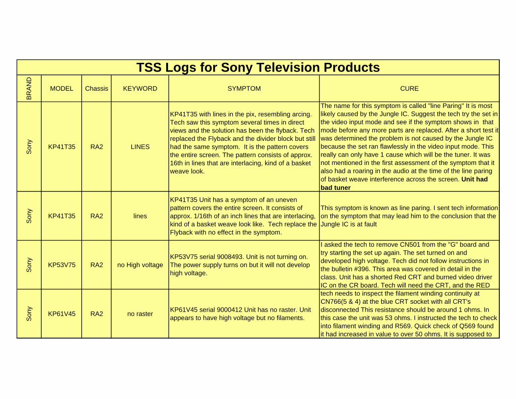
BR
AN
D
MODEL Chassis KEYWORD SYMPTOM CURE
TSS Logs for Sony Television Products
Son
y
KP41T35 RA2 LINES
KP41T35 with lines in the pix, resembling arcing. Tech saw this symptom several times in direct views and the solution has been the flyback. Tech replaced the Flyback and the divider block but still had the same symptom. It is the pattern covers the entire screen. The pattern consists of approx. 16th in lines that are interlacing, kind of a basket weave look.
The name for this symptom is called "line Paring" It is most likely caused by the Jungle IC. Suggest the tech try the set in the video input mode and see if the symptom shows in that mode before any more parts are replaced. After a short test it was determined the problem is not caused by the Jungle IC because the set ran flawlessly in the video input mode. This really can only have 1 cause which will be the tuner. It was not mentioned in the first assessment of the symptom that it also had a roaring in the audio at the time of the line paring of basket weave interference across the screen. Unit had bad tuner
Son
y
KP41T35 RA2 lines
KP41T35 Unit has a symptom of an uneven pattern covers the entire screen. It consists of approx. 1/16th of an inch lines that are interlacing, kind of a basket weave look like. Tech replace the Flyback with no effect in the symptom.
This symptom is known as line paring. I sent tech information on the symptom that may lead him to the conclusion that the Jungle IC is at fault
Son
y
KP53V75 RA2 no High voltageKP53V75 serial 9008493. Unit is not turning on. The power supply turns on but it will not develop high voltage.
I asked the tech to remove CN501 from the "G" board and try starting the set up again. The set turned on and developed high voltage. Tech did not follow instructions in the bulletin #396. This area was covered in detail in the class. Unit has a shorted Red CRT and burned video driver IC on the CR board. Tech will need the CRT, and the RED
Son
y
KP61V45 RA2 no rasterKP61V45 serial 9000412 Unit has no raster. Unit appears to have high voltage but no filaments.
tech needs to inspect the filament winding continuity at CN766(5 & 4) at the blue CRT socket with all CRT's disconnected This resistance should be around 1 ohms. In this case the unit was 53 ohms. I instructed the tech to check into filament winding and R569. Quick check of Q569 found it had increased in value to over 50 ohms. It is supposed to
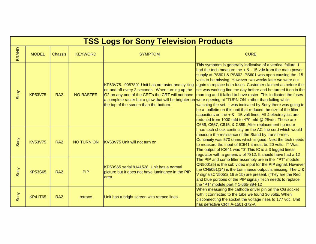
BR
AN
D
MODEL Chassis KEYWORD SYMPTOM CURE
TSS Logs for Sony Television Products
Son
y
KP53V75 RA2 NO RASTER
KP53V75. 9057801 Unit has no raster and cycling on and off every 2 seconds.. When turning up the G2 on any one of the CRT's the CRT will not have a complete raster but a glow that will be brighter on the top of the screen than the bottom.
This symptom is generally indicative of a vertical failure. I had the tech measure the + & - 15 vdc from the main power supply at PS601 & PS602. PS601 was open causing the -15 volts to be missing. However two weeks later we were out again to replace both fuses. Customer claimed as before the set was working fine the day before and he turned it on in the morning and it failed to have raster. This indicated the fuses were opening at "TURN ON" rather than failing while watching the set. It was indicated by Sony there was going to be a bulletin on this unit that reduced the size of the filter capacitors on the + & - 15 volt lines, All 4 electrolytics are reduced from 1000 mfd to 470 mfd @ 25vdc. These are C656, C657, C815, & C889. After replacement no more
Son
y
KV53V75 RA2 NO TURN ON KV53V75 Unit will not turn on.
I had tech check continuity on the AC line cord which would measure the resistance of the Stand by transformer. Continuity was 570 ohms which is good. Next the tech needs to measure the input of IC641 it must be 20 volts. IT Was. The output of IC641 was "0" This IC is a 3 legged linear regulator with a generic # of 7812. It should have had a 12
Son
y
KP53S65 RA2 PIPKP53S65 serial 9141528. Unit has a normal picture but it does not have luminance in the PIP area.
The PIP and comb filter assembly are in the "PT" module. CN5001(5) is the sub video input for the PIP signal. However the CN5051(14) is the Luminance output is missing. The U & V signalsCN5051( 16 & 15) are present. (They are the Red and blue portions of the PIP signal) Tech needs to replace the "PT" module part # 1-665-394-12
Son
y
KP41T65 RA2 retrace Unit has a bright screen with retrace lines.
When measuring the cathode driver pin on the CG socket with it connected to the tube we found 36 volts. When disconnecting the socket the voltage rises to 177 vdc. Unit has defective CRT A-1501-372-A
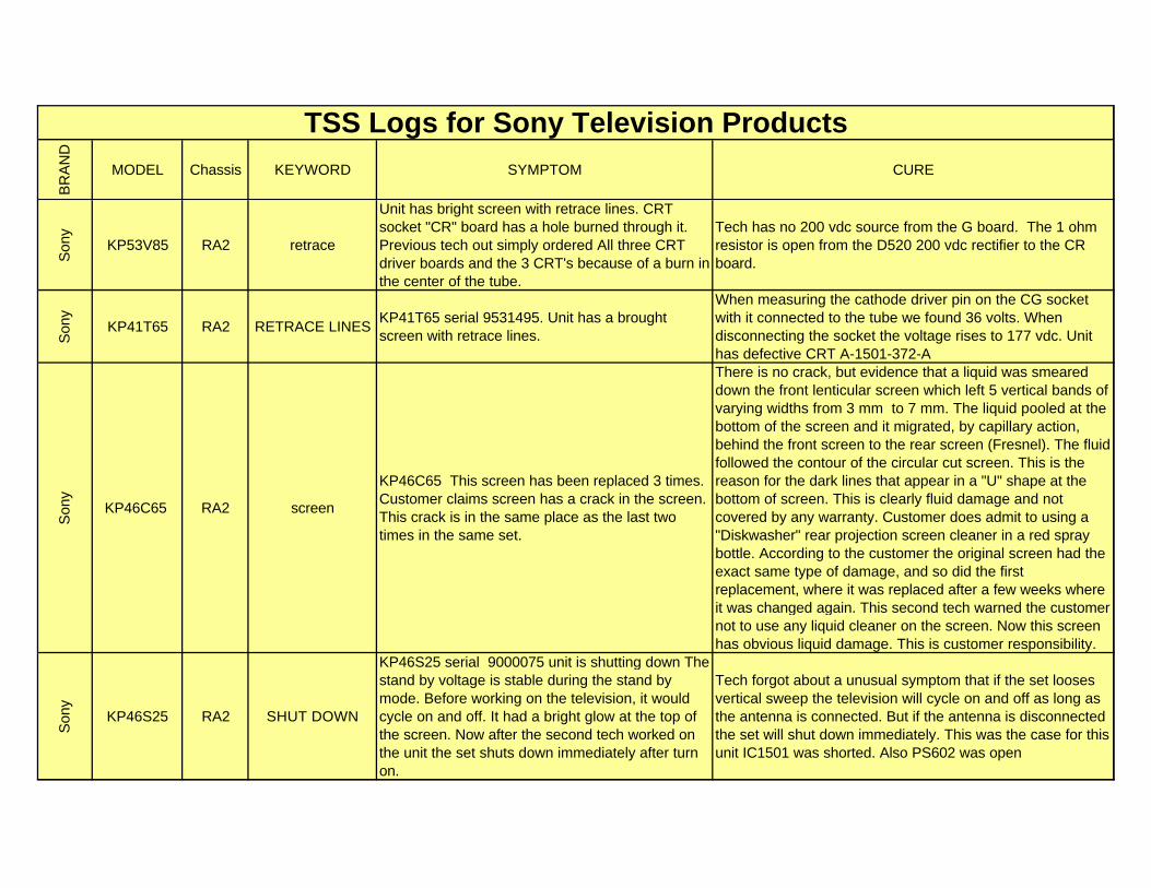
BR
AN
D
MODEL Chassis KEYWORD SYMPTOM CURE
TSS Logs for Sony Television Products
Son
y
KP53V85 RA2 retrace
Unit has bright screen with retrace lines. CRT socket "CR" board has a hole burned through it. Previous tech out simply ordered All three CRT driver boards and the 3 CRT's because of a burn in the center of the tube.
Tech has no 200 vdc source from the G board. The 1 ohm resistor is open from the D520 200 vdc rectifier to the CR board.
Son
y
KP41T65 RA2 RETRACE LINESKP41T65 serial 9531495. Unit has a brought screen with retrace lines.
When measuring the cathode driver pin on the CG socket with it connected to the tube we found 36 volts. When disconnecting the socket the voltage rises to 177 vdc. Unit has defective CRT A-1501-372-A
Son
y
KP46C65 RA2 screen
KP46C65 This screen has been replaced 3 times. Customer claims screen has a crack in the screen. This crack is in the same place as the last two times in the same set.
There is no crack, but evidence that a liquid was smeared down the front lenticular screen which left 5 vertical bands of varying widths from 3 mm to 7 mm. The liquid pooled at the bottom of the screen and it migrated, by capillary action, behind the front screen to the rear screen (Fresnel). The fluid followed the contour of the circular cut screen. This is the reason for the dark lines that appear in a "U" shape at the bottom of screen. This is clearly fluid damage and not covered by any warranty. Customer does admit to using a "Diskwasher" rear projection screen cleaner in a red spray bottle. According to the customer the original screen had the exact same type of damage, and so did the first replacement, where it was replaced after a few weeks where it was changed again. This second tech warned the customer not to use any liquid cleaner on the screen. Now this screen has obvious liquid damage. This is customer responsibility.
Son
y
KP46S25 RA2 SHUT DOWN
KP46S25 serial 9000075 unit is shutting down The stand by voltage is stable during the stand by mode. Before working on the television, it would cycle on and off. It had a bright glow at the top of the screen. Now after the second tech worked on the unit the set shuts down immediately after turn on.
Tech forgot about a unusual symptom that if the set looses vertical sweep the television will cycle on and off as long as the antenna is connected. But if the antenna is disconnected the set will shut down immediately. This was the case for this unit IC1501 was shorted. Also PS602 was open
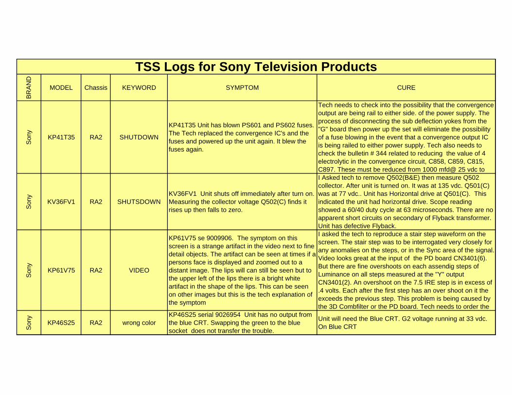
BR
AN
D
MODEL Chassis KEYWORD SYMPTOM CURE
TSS Logs for Sony Television Products
Son
y
KP41T35 RA2 SHUTDOWN
KP41T35 Unit has blown PS601 and PS602 fuses. The Tech replaced the convergence IC's and the fuses and powered up the unit again. It blew the fuses again.
Tech needs to check into the possibility that the convergence output are being rail to either side. of the power supply. The process of disconnecting the sub deflection yokes from the "G" board then power up the set will eliminate the possibility of a fuse blowing in the event that a convergence output IC is being railed to either power supply. Tech also needs to check the bulletin # 344 related to reducing the value of 4 electrolytic in the convergence circuit, C858, C859, C815, C897. These must be reduced from 1000 mfd@ 25 vdc to
Son
y
KV36FV1 RA2 SHUTSDOWNKV36FV1 Unit shuts off immediately after turn on. Measuring the collector voltage Q502(C) finds it rises up then falls to zero.
I Asked tech to remove Q502(B&E) then measure Q502 collector. After unit is turned on. It was at 135 vdc. Q501(C) was at 77 vdc.. Unit has Horizontal drive at Q501(C). This indicated the unit had horizontal drive. Scope reading showed a 60/40 duty cycle at 63 microseconds. There are no apparent short circuits on secondary of Flyback transformer. Unit has defective Flyback.
Son
y
KP61V75 RA2 VIDEO
KP61V75 se 9009906. The symptom on this screen is a strange artifact in the video next to fine detail objects. The artifact can be seen at times if a persons face is displayed and zoomed out to a distant image. The lips will can still be seen but to the upper left of the lips there is a bright white artifact in the shape of the lips. This can be seen on other images but this is the tech explanation of the symptom
I asked the tech to reproduce a stair step waveform on the screen. The stair step was to be interrogated very closely for any anomalies on the steps, or in the Sync area of the signal. Video looks great at the input of the PD board CN3401(6). But there are fine overshoots on each assendig steps of Luminance on all steps measured at the "Y" output CN3401(2). An overshoot on the 7.5 IRE step is in excess of .4 volts. Each after the first step has an over shoot on it the exceeds the previous step. This problem is being caused by the 3D Combfilter or the PD board. Tech needs to order the
Son
y
KP46S25 RA2 wrong colorKP46S25 serial 9026954 Unit has no output from the blue CRT. Swapping the green to the blue socket does not transfer the trouble.
Unit will need the Blue CRT. G2 voltage running at 33 vdc. On Blue CRT
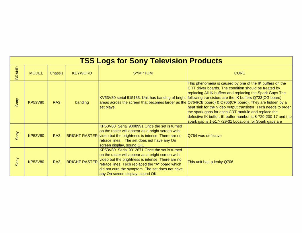
BR
AN
D
MODEL Chassis KEYWORD SYMPTOM CURE
TSS Logs for Sony Television Products
Son
y
KP53V80 RA3 bandingKV53V80 serial 915183. Unit has banding of bright areas across the screen that becomes larger as the set plays.
This phenomena is caused by one of the IK buffers on the CRT driver boards. The condition should be treated by replacing All IK buffers and replacing the Spark Gaps The following transistors are the IK buffers Q733{CG board} Q764{CB board} & Q706{CR board). They are hidden by a heat sink for the Video output transistor. Tech needs to order the spark gaps for each CRT module and replace the defective IK buffer. IK buffer number is 8-729-200-17 and the spark gap is 1-517-729-31 Locations for Spark gaps are
Son
y
KP53V80 RA3 BRIGHT RASTER
KP53V80 Serial 9008991 Once the set is turned on the raster will appear as a bright screen with video but the brightness is intense. There are no retrace lines. . The set does not have any On screen display, sound OK.
Q764 was defective
Son
y
KP53V80 RA3 BRIGHT RASTER
KP53V80 Serial 9012671 Once the set is turned on the raster will appear as a bright screen with video but the brightness is intense. There are no retrace lines. Tech replaced the "A" board which did not cure the symptom. The set does not have any On screen display, sound OK.
This unit had a leaky Q706
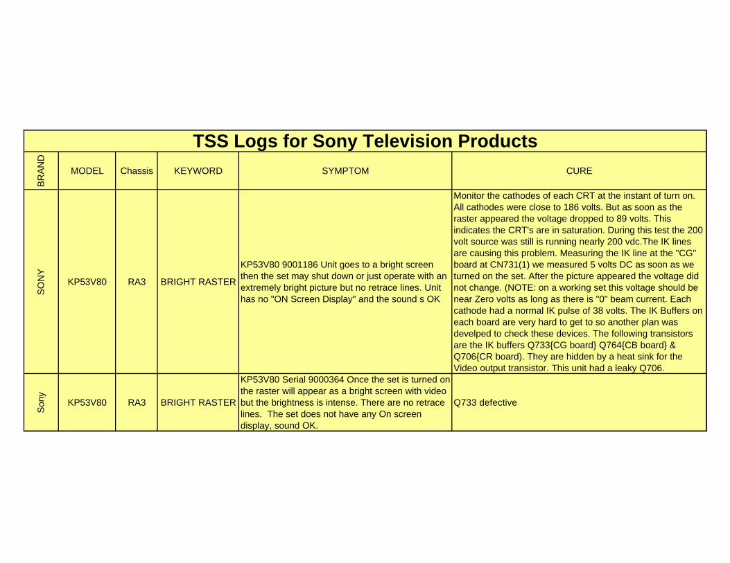
BR
AN
D
MODEL Chassis KEYWORD SYMPTOM CURE
TSS Logs for Sony Television Products
SO
NY
KP53V80 RA3 BRIGHT RASTER
KP53V80 9001186 Unit goes to a bright screen then the set may shut down or just operate with an extremely bright picture but no retrace lines. Unit has no "ON Screen Display" and the sound s OK
Monitor the cathodes of each CRT at the instant of turn on. All cathodes were close to 186 volts. But as soon as the raster appeared the voltage dropped to 89 volts. This indicates the CRT's are in saturation. During this test the 200 volt source was still is running nearly 200 vdc.The IK lines are causing this problem. Measuring the IK line at the "CG" board at CN731(1) we measured 5 volts DC as soon as we turned on the set. After the picture appeared the voltage did not change. (NOTE: on a working set this voltage should be near Zero volts as long as there is "0" beam current. Each cathode had a normal IK pulse of 38 volts. The IK Buffers on each board are very hard to get to so another plan was develped to check these devices. The following transistors are the IK buffers Q733{CG board} Q764{CB board} & Q706{CR board). They are hidden by a heat sink for the Video output transistor. This unit had a leaky Q706.
Son
y
KP53V80 RA3 BRIGHT RASTER
KP53V80 Serial 9000364 Once the set is turned on the raster will appear as a bright screen with video but the brightness is intense. There are no retrace lines. The set does not have any On screen display, sound OK.
Q733 defective
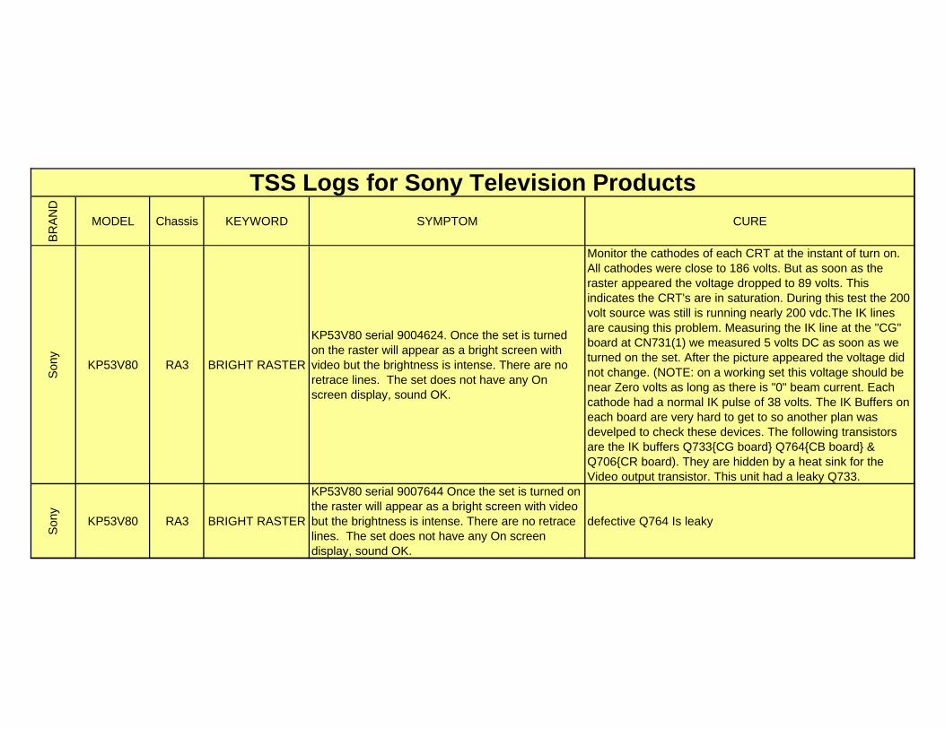
BR
AN
D
MODEL Chassis KEYWORD SYMPTOM CURE
TSS Logs for Sony Television Products
Son
y
KP53V80 RA3 BRIGHT RASTER
KP53V80 serial 9004624. Once the set is turned on the raster will appear as a bright screen with video but the brightness is intense. There are no retrace lines. The set does not have any On screen display, sound OK.
Monitor the cathodes of each CRT at the instant of turn on. All cathodes were close to 186 volts. But as soon as the raster appeared the voltage dropped to 89 volts. This indicates the CRT's are in saturation. During this test the 200 volt source was still is running nearly 200 vdc.The IK lines are causing this problem. Measuring the IK line at the "CG" board at CN731(1) we measured 5 volts DC as soon as we turned on the set. After the picture appeared the voltage did not change. (NOTE: on a working set this voltage should be near Zero volts as long as there is "0" beam current. Each cathode had a normal IK pulse of 38 volts. The IK Buffers on each board are very hard to get to so another plan was develped to check these devices. The following transistors are the IK buffers Q733{CG board} Q764{CB board} & Q706{CR board). They are hidden by a heat sink for the Video output transistor. This unit had a leaky Q733.
Son
y
KP53V80 RA3 BRIGHT RASTER
KP53V80 serial 9007644 Once the set is turned on the raster will appear as a bright screen with video but the brightness is intense. There are no retrace lines. The set does not have any On screen display, sound OK.
defective Q764 Is leaky
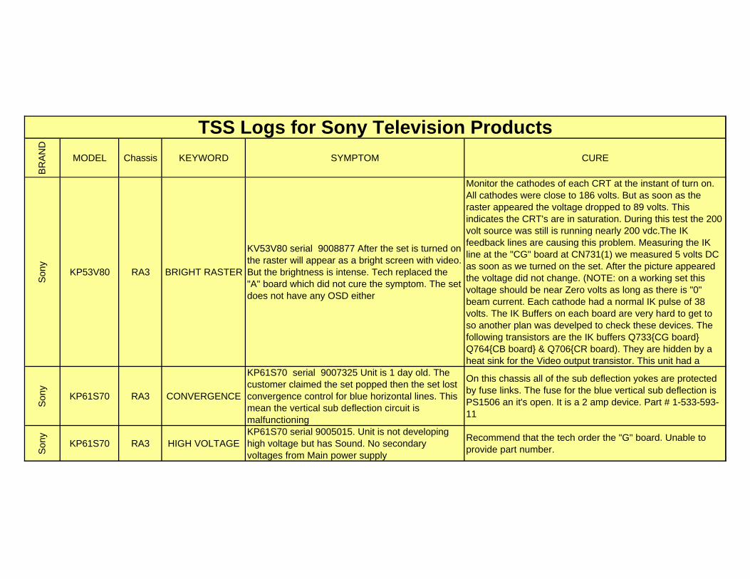
BR
AN
D
MODEL Chassis KEYWORD SYMPTOM CURE
TSS Logs for Sony Television Products
Son
y
KP53V80 RA3 BRIGHT RASTER
KV53V80 serial 9008877 After the set is turned on the raster will appear as a bright screen with video. But the brightness is intense. Tech replaced the "A" board which did not cure the symptom. The set does not have any OSD either
Monitor the cathodes of each CRT at the instant of turn on. All cathodes were close to 186 volts. But as soon as the raster appeared the voltage dropped to 89 volts. This indicates the CRT's are in saturation. During this test the 200 volt source was still is running nearly 200 vdc.The IK feedback lines are causing this problem. Measuring the IK line at the "CG" board at CN731(1) we measured 5 volts DC as soon as we turned on the set. After the picture appeared the voltage did not change. (NOTE: on a working set this voltage should be near Zero volts as long as there is "0" beam current. Each cathode had a normal IK pulse of 38 volts. The IK Buffers on each board are very hard to get to so another plan was develped to check these devices. The following transistors are the IK buffers Q733{CG board} Q764{CB board} & Q706{CR board). They are hidden by a heat sink for the Video output transistor. This unit had a
Son
y
KP61S70 RA3 CONVERGENCE
KP61S70 serial 9007325 Unit is 1 day old. The customer claimed the set popped then the set lost convergence control for blue horizontal lines. This mean the vertical sub deflection circuit is malfunctioning
On this chassis all of the sub deflection yokes are protected by fuse links. The fuse for the blue vertical sub deflection is PS1506 an it's open. It is a 2 amp device. Part # 1-533-593-11
Son
y
KP61S70 RA3 HIGH VOLTAGEKP61S70 serial 9005015. Unit is not developing high voltage but has Sound. No secondary voltages from Main power supply
Recommend that the tech order the "G" board. Unable to provide part number.
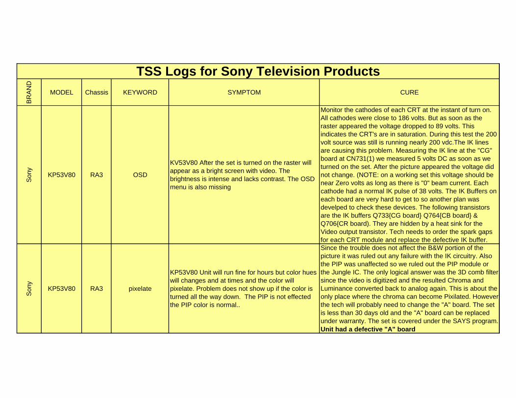
BR
AN
D
MODEL Chassis KEYWORD SYMPTOM CURE
TSS Logs for Sony Television Products
Son
y
KP53V80 RA3 OSD
KV53V80 After the set is turned on the raster will appear as a bright screen with video. The brightness is intense and lacks contrast. The OSD menu is also missing
Monitor the cathodes of each CRT at the instant of turn on. All cathodes were close to 186 volts. But as soon as the raster appeared the voltage dropped to 89 volts. This indicates the CRT's are in saturation. During this test the 200 volt source was still is running nearly 200 vdc.The IK lines are causing this problem. Measuring the IK line at the "CG" board at CN731(1) we measured 5 volts DC as soon as we turned on the set. After the picture appeared the voltage did not change. (NOTE: on a working set this voltage should be near Zero volts as long as there is "0" beam current. Each cathode had a normal IK pulse of 38 volts. The IK Buffers on each board are very hard to get to so another plan was develped to check these devices. The following transistors are the IK buffers Q733{CG board} Q764{CB board} & Q706{CR board). They are hidden by a heat sink for the Video output transistor. Tech needs to order the spark gaps for each CRT module and replace the defective IK buffer.
Son
y
KP53V80 RA3 pixelate
KP53V80 Unit will run fine for hours but color hues will changes and at times and the color will pixelate. Problem does not show up if the color is turned all the way down. The PIP is not effected the PIP color is normal..
Since the trouble does not affect the B&W portion of the picture it was ruled out any failure with the IK circuitry. Also the PIP was unaffected so we ruled out the PIP module or the Jungle IC. The only logical answer was the 3D comb filter since the video is digitized and the resulted Chroma and Luminance converted back to analog again. This is about the only place where the chroma can become Pixilated. However the tech will probably need to change the "A" board. The set is less than 30 days old and the "A" board can be replaced under warranty. The set is covered under the SAYS program. Unit had a defective "A" board
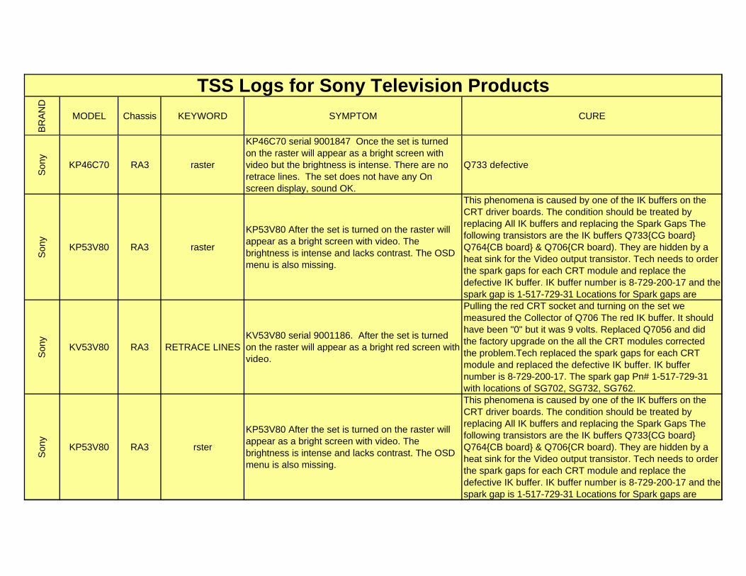
BR
AN
D
MODEL Chassis KEYWORD SYMPTOM CURE
TSS Logs for Sony Television Products
Son
y
KP46C70 RA3 raster
KP46C70 serial 9001847 Once the set is turned on the raster will appear as a bright screen with video but the brightness is intense. There are no retrace lines. The set does not have any On screen display, sound OK.
Q733 defective
Son
y
KP53V80 RA3 raster
KP53V80 After the set is turned on the raster will appear as a bright screen with video. The brightness is intense and lacks contrast. The OSD menu is also missing.
This phenomena is caused by one of the IK buffers on the CRT driver boards. The condition should be treated by replacing All IK buffers and replacing the Spark Gaps The following transistors are the IK buffers Q733{CG board} Q764{CB board} & Q706{CR board). They are hidden by a heat sink for the Video output transistor. Tech needs to order the spark gaps for each CRT module and replace the defective IK buffer. IK buffer number is 8-729-200-17 and the spark gap is 1-517-729-31 Locations for Spark gaps are
Son
y
KV53V80 RA3 RETRACE LINESKV53V80 serial 9001186. After the set is turned on the raster will appear as a bright red screen with video.
Pulling the red CRT socket and turning on the set we measured the Collector of Q706 The red IK buffer. It should have been "0" but it was 9 volts. Replaced Q7056 and did the factory upgrade on the all the CRT modules corrected the problem.Tech replaced the spark gaps for each CRT module and replaced the defective IK buffer. IK buffer number is 8-729-200-17. The spark gap Pn# 1-517-729-31 with locations of SG702, SG732, SG762.
Son
y
KP53V80 RA3 rster
KP53V80 After the set is turned on the raster will appear as a bright screen with video. The brightness is intense and lacks contrast. The OSD menu is also missing.
This phenomena is caused by one of the IK buffers on the CRT driver boards. The condition should be treated by replacing All IK buffers and replacing the Spark Gaps The following transistors are the IK buffers Q733{CG board} Q764{CB board} & Q706{CR board). They are hidden by a heat sink for the Video output transistor. Tech needs to order the spark gaps for each CRT module and replace the defective IK buffer. IK buffer number is 8-729-200-17 and the spark gap is 1-517-729-31 Locations for Spark gaps are
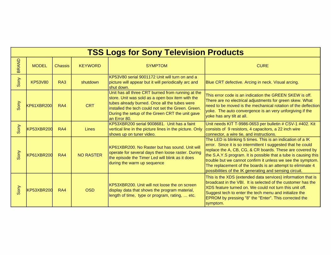
BR
AN
D
MODEL Chassis KEYWORD SYMPTOM CURE
TSS Logs for Sony Television Products
Son
y
KP53V80 RA3 shutdownKP53V80 serial 9001172 Unit will turn on and a picture will appear but it will periodically arc and shut down.
Blue CRT defective. Arcing in neck. Visual arcing.
Son
y
KP61XBR200 RA4 CRT
Unit has all three CRT burned from running at the store. Unit was sold as a open box item with the tubes already burned. Once all the tubes were installed the tech could not set the Green. Green. During the setup of the Green CRT the unit gave an Error 80.
This error code is an indication the GREEN SKEW is off. There are no electrical adjustments for green skew. What need to be moved is the mechanical rotation of the deflection yoke. The auto convergence is an very unforgiving if the yoke has any tilt at all.
Son
y
KP53XBR200 RA4 LinesKP53XBR200 serial 9008681. Unit has a faint vertical line in the picture lines in the picture. Only shows up on tuner video.
Unit needs KIT T-9986-0653 per bulletin # CSV-1 #402. Kit consists of 9 resistors, 4 capacitors, a 22 inch wire connector, a wire tie, and instructions.
Son
y
KP61XBR200 RA4 NO RASTER
KP61XBR200. No Raster but has sound. Unit will operate for several days then loose raster. During the episode the Timer Led will blink as it does during the warm up sequence
The LED is blinking 5 times. This is an indication of a IK error. Since it is so intermittent I suggested that he could replace the A, CB, CG, & CR boards. These are covered by the S.A.Y.S program. It is possible that a tube is causing this trouble but we cannot confirm it unless we see the symptom. The replacement of the boards is an attempt to eliminate 4 possibilities of the IK generating and sensing circuit.
Son
y
KP53XBR200 RA4 OSDKP53XBR200. Unit will not loose the on screen display data that shows the program material, length of time, type or program, rating, … etc.
This is the XDS (extended data services) information that is broadcast in the VBI. It is selected of the customer has the XDS feature turned on. We could not turn this unit off. Suggest tech to enter the tech menu and initialize the EPROM by pressing "8" the "Enter". This corrected the symptom.
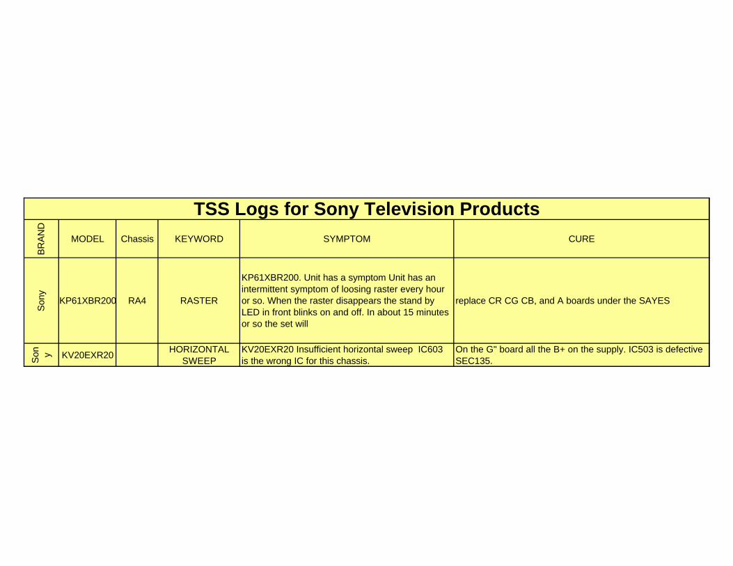
BR
AN
D
MODEL Chassis KEYWORD SYMPTOM CURE
TSS Logs for Sony Television Products
Son
y
KP61XBR200 RA4 RASTER
KP61XBR200. Unit has a symptom Unit has an intermittent symptom of loosing raster every hour or so. When the raster disappears the stand by LED in front blinks on and off. In about 15 minutes or so the set will
replace CR CG CB, and A boards under the SAYES
Son y KV20EXR20
HORIZONTAL SWEEP
KV20EXR20 Insufficient horizontal sweep IC603 is the wrong IC for this chassis.
On the G" board all the B+ on the supply. IC503 is defective SEC135.
Related Documents