UNDERSTANDING, ACCELERATED FLUID MECHANICS SYSTEMS FROM TSI A COMPLETE PORTFOLIO OF SOLUTIONS FOR FLUID MECHANICS RESEARCH

Welcome message from author
This document is posted to help you gain knowledge. Please leave a comment to let me know what you think about it! Share it to your friends and learn new things together.
Transcript
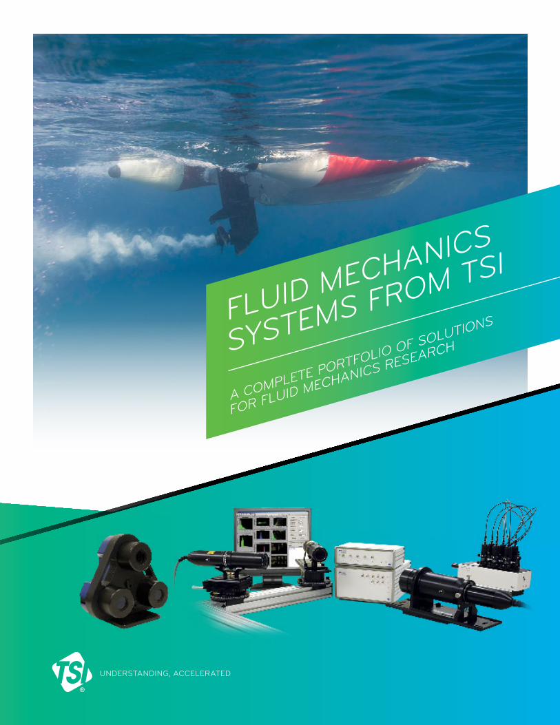
UNDERSTANDING, ACCELERATED
FLUID MECHANICS
SYSTEMS FROM TSI
A COMPLETE PORTFOLIO OF SOLUTIONS
FOR FLUID MECHANICS RESEARCH
3
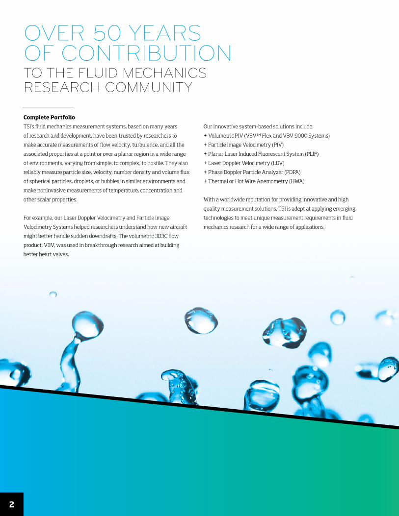
OVER 50 YEARSOF CONTRIBUTIONTO THE FLUID MECHANICSRESEARCH COMMUNITY
Complete Portfolio
TSI’s fluid mechanics measurement systems, based on many years
of research and development, have been trusted by researchers to
make accurate measurements of flow velocity, turbulence, and all the
associated properties at a point or over a planar region in a wide range
of environments, varying from simple, to complex, to hostile. They also
reliably measure particle size, velocity, number density and volume flux
of spherical particles, droplets, or bubbles in similar environments and
make noninvasive measurements of temperature, concentration and
other scalar properties.
For example, our Laser Doppler Velocimetry and Particle Image
Velocimetry Systems helped researchers understand how new aircraft
might better handle sudden downdrafts. The volumetric 3D3C flow
product, V3V, was used in breakthrough research aimed at building
better heart valves.
Our innovative system-based solutions include:
+ Volumetric PIV (V3V™ Flex and V3V 9000 Systems)
+ Particle Image Velocimetry (PIV)
+ Planar Laser Induced Fluorescent System (PLIF)
+ Laser Doppler Velocimetry (LDV)
+ Phase Doppler Particle Analyzer (PDPA)
+ Thermal or Hot Wire Anemometry (HWA)
With a worldwide reputation for providing innovative and high
quality measurement solutions, TSI is adept at applying emerging
technologies to meet unique measurement requirements in fluid
mechanics research for a wide range of applications.
2

PIV measurement of Lifted flame from Stanford University, USA
Spray droplet diameter distribution in an acoustic driven flow
Cutting Edge Research
The Fluid Mechanics division of TSI has worked to develop superior fluid flow and
particle measurement instrumentation for the global research community for
over 50 years. During this time TSI has been at the forefront of developing
state-of-the-art systems to meet researcher’s advanced measurement
requirements in the following areas:
+ Hydrodynamics
+ Aerodynamics
+ Fundamental Flow and Particle Research
+ Turbulence
+ Spray Diagnostics
+ Bio-locomotion studies
+ Biomedical studies
+ Combustion studies
+ Multi-phase Flow
+ Flow studies in micro channels
3
34
SOLUTIONS FOR
UNIQUE FLUID FLOW MEASUREMENT APPLICATIONS
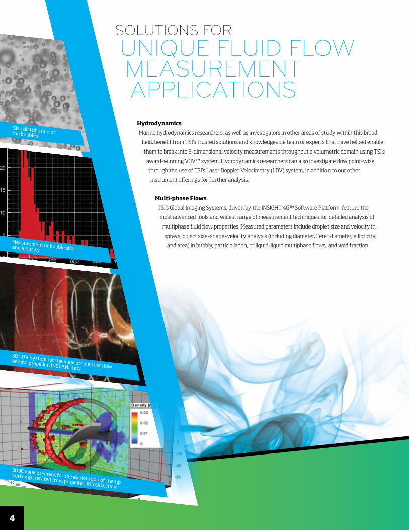
Hydrodynamics
Marine hydrodynamics researchers, as well as investigators in other areas of study within this broad
field, benefit from TSI’s trusted solutions and knowledgeable team of experts that have helped enable
them to break into 3-dimensional velocity measurements throughout a volumetric domain using TSI’s
award-winning V3V™ system. Hydrodynamics researchers can also investigate flow point-wise
through the use of TSI’s Laser Doppler Velocimetry (LDV) system, in addition to our other
instrument offerings for further analysis.
Multi-phase Flows
TSI’s Global Imaging Systems, driven by the INSIGHT 4G™ Software Platform, feature the
most advanced tools and widest range of measurement techniques for detailed analysis of
multiphase fluid flow properties. Measured parameters include droplet size and velocity in
sprays, object size–shape–velocity analysis (including diameter, Feret diameter, ellipticity,
and area) in bubbly, particle laden, or liquid-liquid multiphase flows, and void fraction.
Size distribution of the bubbles
Measurement of bubble size and velocity
3D LDV System for the measurement of flow behind propeller, INSEAN, Italy
3D3C measurement for the exploration of the tip vortex generated from propeller, INSEAN, Italy
Diam
eter
Cou
nt
0
240
480
720
960
1200
Diameter (um)
Diameter Histogram
0 25 50 75 100
5
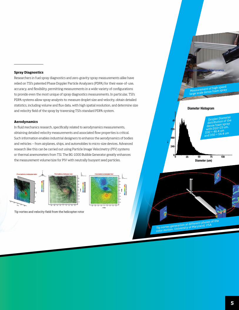
Spray Diagnostics
Researchers in fuel spray diagnostics and zero-gravity spray measurements alike have
relied on TSI’s patented Phase Doppler Particle Analyzers (PDPA) for their ease-of-use,
accuracy, and flexibility, permitting measurements in a wide variety of configurations
to provide even the most unique of spray diagnostics measurements. In particular, TSI’s
PDPA systems allow spray analysts to: measure droplet size and velocity, obtain detailed
statistics, including volume and flux data, with high spatial resolution, and determine size
and velocity field of the spray by traversing TSI’s standard PDPA system.
Aerodynamics
In fluid mechanics research, specifically related to aerodynamics measurements,
obtaining detailed velocity measurements and associated flow properties is critical.
Such information enables industrial designers to enhance the aerodynamics of bodies
and vehicles — from airplanes, ships, and automobiles to micro-size devices. Advanced
research like this can be carried out using Particle Image Velocimetry (PIV) systems
or thermal anemometers from TSI. The BG-1000 Bubble Generator greatly enhances
the measurement volume/size for PIV with neutrally buoyant seed particles.
Tip vortex and velocity field from the helicopter rotor
Tip vortex generation at different phases of the
rotor motion, University of Maryland, USA
Droplet Diameter
distribution of the
dense foam spray
with D10=23 um,
D32 = 46.4 um
and D50 = 54.4 um
Measurement of high speed
large scale dense foam spray
36
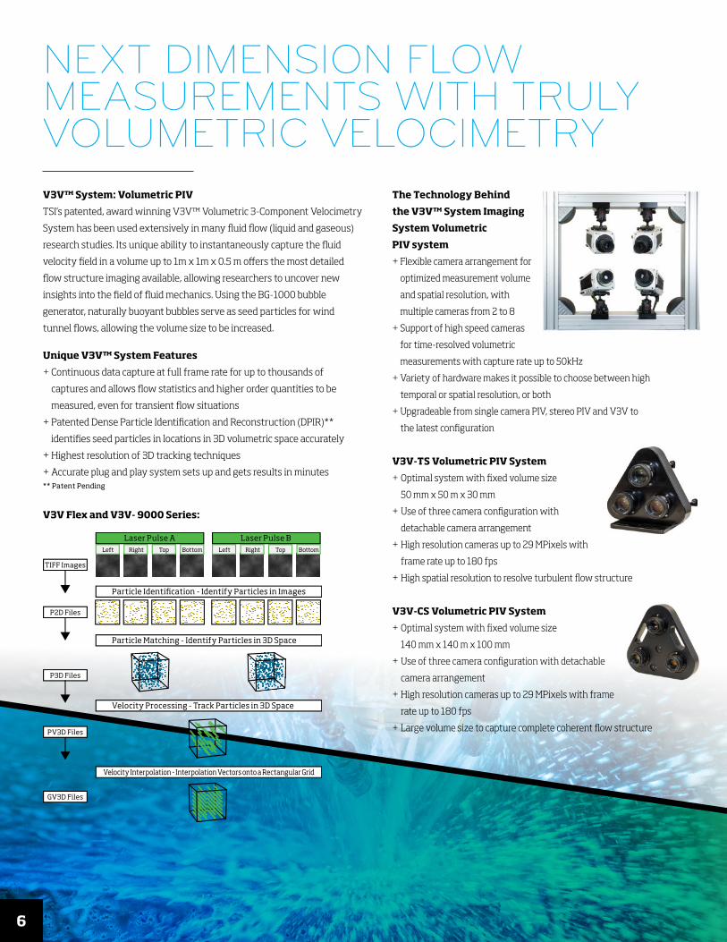
Left Right Top Bottom
Laser Pulse ALeft Right Top Bottom
Laser Pulse B
Particle Identi�cation - Identify Particles in Images
TIFF Images
P2D Files
Particle Matching - Identify Particles in 3D Space
Velocity Processing - Track Particles in 3D Space
P3D Files
Velocity Interpolation - Interpolation Vectors onto a Rectangular Grid
PV3D Files
GV3D Files
V3V™ System: Volumetric PIV
TSI’s patented, award winning V3V™ Volumetric 3-Component Velocimetry
System has been used extensively in many fluid flow (liquid and gaseous)
research studies. Its unique ability to instantaneously capture the fluid
velocity field in a volume up to 1m x 1m x 0.5 m offers the most detailed
flow structure imaging available, allowing researchers to uncover new
insights into the field of fluid mechanics. Using the BG-1000 bubble
generator, naturally buoyant bubbles serve as seed particles for wind
tunnel flows, allowing the volume size to be increased.
Unique V3V™ System Features
+ Continuous data capture at full frame rate for up to thousands of
captures and allows flow statistics and higher order quantities to be
measured, even for transient flow situations
+ Patented Dense Particle Identification and Reconstruction (DPIR)**
identifies seed particles in locations in 3D volumetric space accurately
+ Highest resolution of 3D tracking techniques
+ Accurate plug and play system sets up and gets results in minutes ** Patent Pending
V3V Flex and V3V- 9000 Series:
The Technology Behind
the V3V™ System Imaging
System Volumetric
PIV system
+ Flexible camera arrangement for
optimized measurement volume
and spatial resolution, with
multiple cameras from 2 to 8
+ Support of high speed cameras
for time-resolved volumetric
measurements with capture rate up to 50kHz
+ Variety of hardware makes it possible to choose between high
temporal or spatial resolution, or both
+ Upgradeable from single camera PIV, stereo PIV and V3V to
the latest configuration
V3V-TS Volumetric PIV System
+ Optimal system with fixed volume size
50 mm x 50 m x 30 mm
+ Use of three camera configuration with
detachable camera arrangement
+ High resolution cameras up to 29 MPixels with
frame rate up to 180 fps
+ High spatial resolution to resolve turbulent flow structure
V3V-CS Volumetric PIV System
+ Optimal system with fixed volume size
140 mm x 140 m x 100 mm
+ Use of three camera configuration with detachable
camera arrangement
+ High resolution cameras up to 29 MPixels with frame
rate up to 180 fps
+ Large volume size to capture complete coherent flow structure
NEXT DIMENSION FLOW MEASUREMENTS WITH TRULY VOLUMETRIC VELOCIMETRY
7
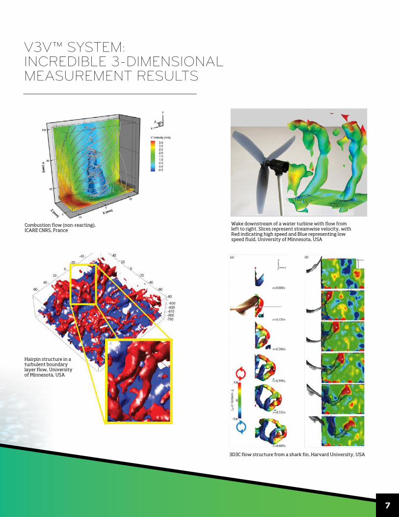
Combustion flow (non-reacting), ICARE CNRS, France
Wake downstream of a water turbine with flow from left to right. Slices represent streamwise velocity, with Red indicating high speed and Blue representing low speed fluid, University of Minnesota, USA
3D3C flow structure from a shark fin, Harvard University, USA
V3V™ SYSTEM: INCREDIBLE 3-DIMENSIONAL MEASUREMENT RESULTS
Hairpin structure in a turbulent boundary layer flow, University of Minnesota, USA
8
GLOBAL VELOCITY MEASUREMENTSFROM LARGE TUNNELS TO MICRO CHANNELS
Particle Image Velocimetry
Particle Image Velocimetry (PIV) is an optical imaging technique used to measure
velocity at thousands of points in a flow field simultaneously. The measurements
are made in “Planar slices” of the flow field to give two components or three
components of velocity. This technique provides accurate results with very high
spatial resolution, while TSI’s time-resolved PIV system allows for high temporal
resolution of the velocity field.
Unique PIV Systems
The PIV technique can be applied to measure flow fields in many
environments, from microchannels to large scale wind tunnels, and for 2D to
3D with high spatial and temporal resolution. Example systems include:
+ 2D PIV
+ Stereo PIV
+ Time Resolved-PIV (TR-PIV)
+ Micro PIV*
+ Tow Tank PIV (planar or volumetric)
How it Works: PIV
+ Use of small tracer particles to follow fluid flow
+ Images of particle positions, illuminated by a pulsed laser,
are captured at separate times
+ Particle displacements are calculated across Δt, the time between
laser pulses, to determine velocity
+ Measurement at many points at one instant of time
+ Instantaneous vector fields are produced while time averaged
statistics are obtained by averaging many image fields
*US Patent #6653651
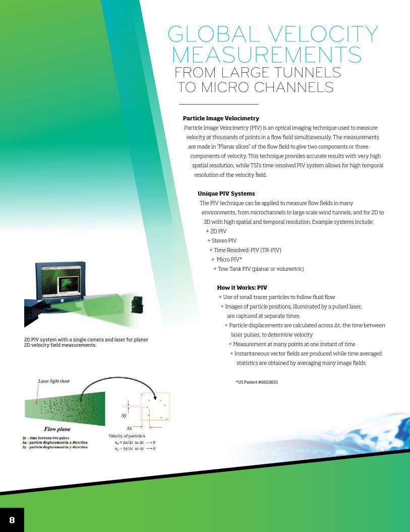
2D PIV system with a single camera and laser for planer 2D velocity field measurements.
9
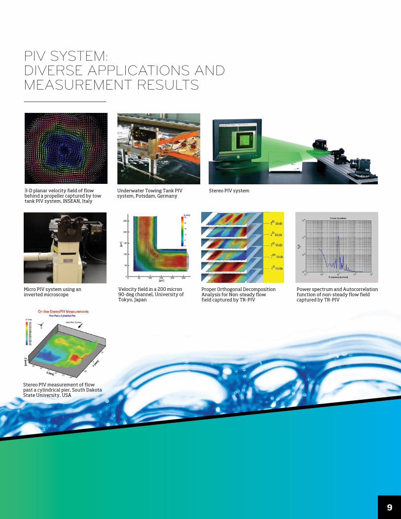
3-D planar velocity field of flow behind a propeller captured by tow tank PIV system, INSEAN, Italy
Underwater Towing Tank PIV system, Potsdam, Germany
Micro PIV system using an inverted microscope
Stereo PIV system
Power spectrum and Autocorrelation function of non-steady flow field captured by TR-PIV
Stereo PIV measurement of flow past a cylindrical pier, South Dakota State University, USA
Proper Orthogonal Decomposition Analysis for Non-steady flow field captured by TR-PIV
Velocity field in a 200 micron 90-deg channel, University of Tokyo, Japan
PIV SYSTEM: DIVERSE APPLICATIONS AND MEASUREMENT RESULTS
10
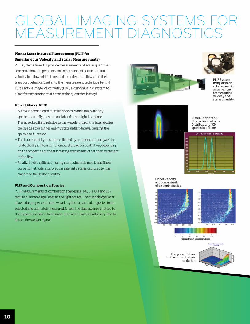
Planar Laser Induced Fluorescence (PLIF for
Simultaneous Velocity and Scalar Measurements)
PLIF systems from TSI provide measurements of scalar quantities:
concentration, temperature and combustion, in addition to fluid
velocity in a flow which is needed to understand flows and their
transport behavior. Similar to the measurement technique behind
TSI’s Particle Image Velocimetry (PIV), extending a PIV system to
allow for measurement of some scalar quantities is easy!
How it Works: PLIF
+ A flow is seeded with miscible species, which mix with any
species naturally present, and absorb laser light in a plane
+ The absorbed light, relative to the wavelength of the laser, excites
the species to a higher energy state until it decays, causing the
species to fluoresce
+ The fluorescent light is then collected by a camera and analyzed to
relate the light intensity to temperature or concentration, depending
on the properties of the fluorescing species and other species present
in the flow
+ Finally, in-situ calibration using multipoint ratio metric and linear
curve fit methods, interpret the intensity scales captured by the
camera to the scalar quantity
PLIF and Combustion Species
PLIF measurements of combustion species (i.e. NO, CH, OH and CO)
require a Tunable Dye laser as the light source. The tunable dye laser
allows the proper excitation wavelength of a particular species to be
selected and ultimately measured. Often, the fluorescence emitted by
this type of species is faint so an intensified camera is also required to
detect the weaker signal.
3D representation of the concentration
of the jet
PLIF System using dichoric color separation arrangement for measuring velocity and scalar quantity
Distribution of the CH species in a flame; Distribution of OH species in a flame
Plot of velocity and concentration of an impinging jet
GLOBAL IMAGING SYSTEMS FOR MEASUREMENT DIAGNOSTICS
11
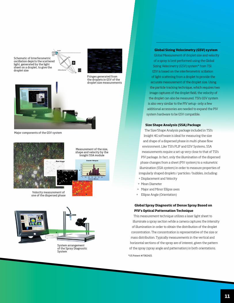
Global Sizing Velocimetry (GSV) system
Global Measurement of droplet size and velocity
of a spray is best performed using the Global
Sizing Velocimetry (GSV) system* from TSI.
GSV is based on the interferometric scillation
of light scattering from a droplet to provide the
accurate measurement of the droplet size. Using
the particle tracking technique, which requires two
image captures of the droplet field, the velocity of
the droplet can also be measured. TSI’s GSV system
is also very similar to the PIV setup- only a few
additional accessories are needed to expand the PIV
system hardware to be GSV compatible.
Size Shape Analysis (SSA) Package
The Size/Shape Analysis package included in TSI’s
Insight 4G software is ideal for measuring the size
and shape of a dispersed phase in multi-phase flow
environment. Like TSI’s PLIF and GSV Systems, SSA
measurements require a set up very close to that of TSI’s
PIV package. In fact, only the illumination of the dispersed
phase changes from a sheet (PIV system) to a volumetric
illumination (SSA system) in order to measure properties of
irregularly shaped droplets / particles / bubbles, including:
+ Displacement and Velocity
+ Mean Diameter
+ Major and Minor Ellipse axes
+ Ellipse Angle (Orientation)
Global Spray Diagnostic of Dense Spray Based on
PIV’s Optical Patternation Technique
This measurement technique utilizes a laser light sheet to
illuminate a spray section while a camera captures the intensity
of illumination in order to obtain the distribution of the droplet
concentration. The concentration is representative of the size or
mass distribution. Typically measurements in the vertical and
horizontal sections of the spray are of interest, given the pattern
of the spray (spray angle and patternation) in both orientations.
*US Patent #7362421
Major components of the GSV system
Velocity measurement of one of the dispersed phase
Measurement of the size, shape and velocity by the
Insight SSA module
Schematic of Interferometric oscillation depicts the scattered light, generated by the light sheet on a droplet, to give the droplet size
Fringes generated from the droplets in GSV of the droplet size measurements
System arrangement of the Spray Diagnostic System
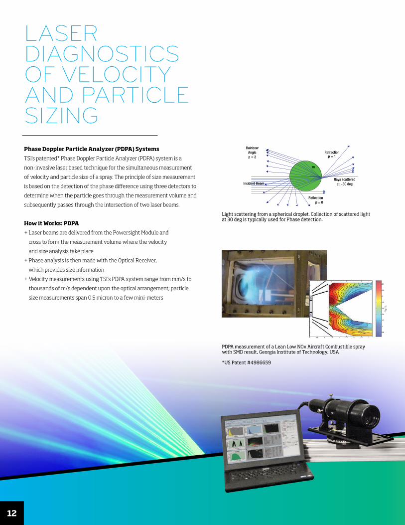
Light scattering from a spherical droplet. Collection of scattered light at 30 deg is typically used for Phase detection.
Refractionp = 1
Rays scatteredat ~30 deg
Reflectionp = 0
Incident Beam
RainbowAnglep = 2
m
12
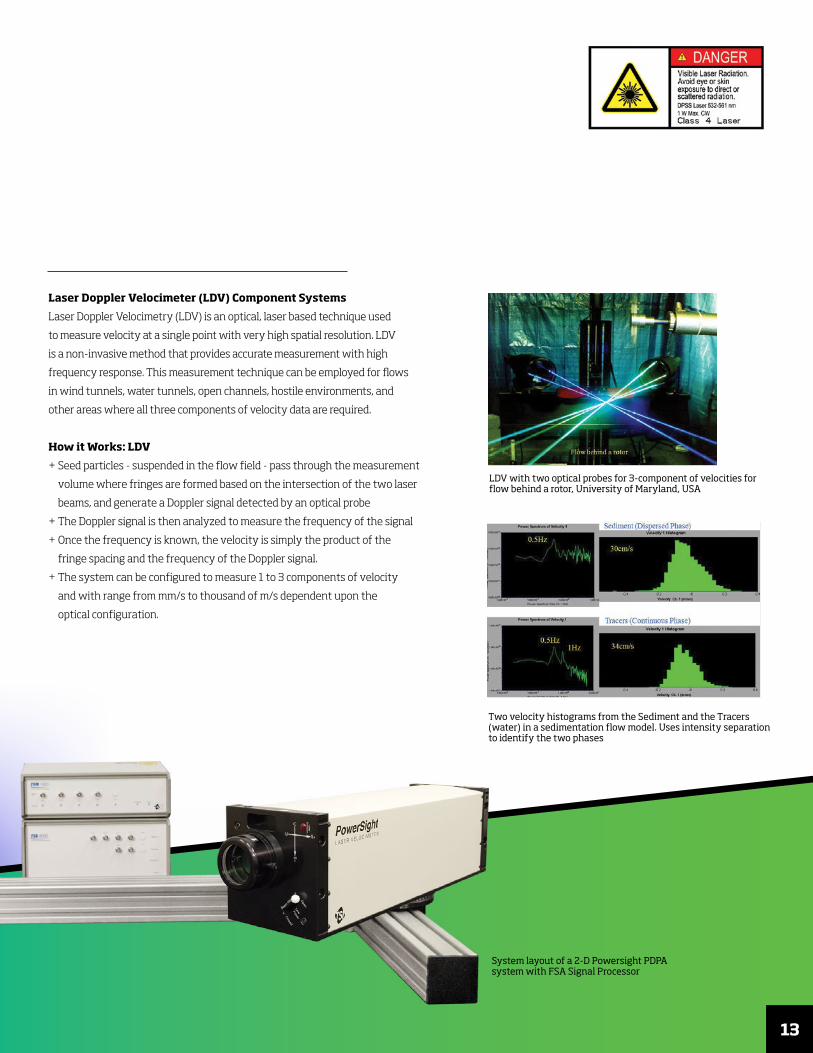
PDPA measurement of a Lean Low NOx Aircraft Combustible spray with SMD result, Georgia Institute of Technology, USA
*US Patent #4986659
LASER DIAGNOSTICS OF VELOCITY AND PARTICLE SIZINGPhase Doppler Particle Analyzer (PDPA) Systems
TSI’s patented* Phase Doppler Particle Analyzer (PDPA) system is a
non-invasive laser based technique for the simultaneous measurement
of velocity and particle size of a spray. The principle of size measurement
is based on the detection of the phase difference using three detectors to
determine when the particle goes through the measurement volume and
subsequently passes through the intersection of two laser beams.
How it Works: PDPA
+ Laser beams are delivered from the Powersight Module and
cross to form the measurement volume where the velocity
and size analysis take place
+ Phase analysis is then made with the Optical Receiver,
which provides size information
+ Velocity measurements using TSI’s PDPA system range from mm/s to
thousands of m/s dependent upon the optical arrangement; particle
size measurements span 0.5 micron to a few mini-meters
Two velocity histograms from the Sediment and the Tracers (water) in a sedimentation flow model. Uses intensity separation to identify the two phases
LDV with two optical probes for 3-component of velocities for flow behind a rotor, University of Maryland, USA
13
Laser Doppler Velocimeter (LDV) Component Systems
Laser Doppler Velocimetry (LDV) is an optical, laser based technique used
to measure velocity at a single point with very high spatial resolution. LDV
is a non-invasive method that provides accurate measurement with high
frequency response. This measurement technique can be employed for flows
in wind tunnels, water tunnels, open channels, hostile environments, and
other areas where all three components of velocity data are required.
How it Works: LDV
+ Seed particles - suspended in the flow field - pass through the measurement
volume where fringes are formed based on the intersection of the two laser
beams, and generate a Doppler signal detected by an optical probe
+ The Doppler signal is then analyzed to measure the frequency of the signal
+ Once the frequency is known, the velocity is simply the product of the
fringe spacing and the frequency of the Doppler signal.
+ The system can be configured to measure 1 to 3 components of velocity
and with range from mm/s to thousand of m/s dependent upon the
optical configuration.
System layout of a 2-D Powersight PDPA system with FSA Signal Processor

314
THERMAL ANEMOMETRY FOR TURBULENT FLOW DIAGNOSTICS
Thermal Anemometers
Thermal anemometry is a technique requiring a sensor to measure velocity at a single point with high
accuracy and high frequency response. A typical thermal anemometry system has two major components,
the Control circuit and the sensor. There are also two types of Control circuits, one is the Constant
Temperature Anemometer (for velocity measurements), and the other is the Constant Current
Anemometer (for temperature measurements).
There are many different types of sensors, wire or film, for 1D, 2D, and 3D velocity components,
and for gaseous and liquid lows.
The thermal anemometry system is an excellent tool for turbulent flow because of its high frequency
response to measure the fluctuation of the flow and there are many versions of sensors used in
different flow environments. 1D, 2D and 3D sensors for gaseous and liquid flows are offered. There
are also the sensor type, wire or film sensor, to match the required frequency response of the flow.
Proper selection of the sensor is critical to the success of the measurement. Typical velocity range
for a thermal anemometry system is from a few cm/s to hundreds of m/s.
Features and Benefits
+ Single Point measurement with sensor for velocity range from cm/s to hundreds of m/s
+ Sensor calibration for velocity output
+ Good spatial resolution and high frequency response
+ 1, 2 and 3 components of velocity with proper sensor type
+ Even time sampling with high sampling rate
+ Power spectrum and statistics of flows are measured m/s
How it Works: Thermal Anemometry
+ Thermal Anemometry requires that a sensor be heated to a specific high temperature
+ When the sensor is exposed to a flow, it is cooled and the amount of current
needed to maintain its original temperature is an indication of the velocity
around the sensor
+ A calibration is performed to relate voltage to velocity
Calibration Voltages
0 .50 1.00 1.50 2.00 2.50 3.00 3.50 4.00 4.50 5.00 5.50-5
-4
-3
-2
-1
0
1
2
3
4
5
System layout with the control circuit of anemometer, sensor and software
Typical calibration curve to relate the voltage output from the anemometer and the velocity

15
Picture of the different sensors, 1D, 2D and 3D sensorsConfiguration of the various sensor types
Orientation of the sensor to the flow measurement
A typical result for a 3D sensor Power spectrum plot of a typical measurement from a wire sensor in a wind tunnel flow
Specifications are subject to change without notice.
TSI and the TSI logo are registered trademarks of TSI Incorporated.
TSI Incorporated - Visit our website www.tsi.com for more information.
USA Tel: +1 800 874 2811UK Tel: +44 149 4 459200France Tel: +33 1 41 19 21 99Germany Tel: +49 241 523030
India Tel: +91 80 67877200 China Tel: +86 10 8219 7688 Singapore Tel: +65 6595 6388
Printed in U.S.A.P/N 5001460 Rev D ©2019 TSI Incorporated
FLUID MECHANICSFAMILY BROCHURE
About TSI
TSI designs and manufactures innovative precision instruments to
measure flow, turbulence, temperature, particulate and many other key
parameters. TSI serves the needs of industry, governments, research
institutions, and universities, with applications ranging from pure
research to primary manufacturing. Every TSI instrument is backed
by our unique blend of technical expertise and outstanding quality.
TSI's world-wide presence provides technical application support to
make sure you get the help needed to resolve your research problems.
Our work culture gets employees out from behind desks and into the
field. We hold customer-training sessions, sponsor workshops and
conduct product demonstrations, serve on standards committees
relating to product usage, and participate in a wide variety of
technical conferences.
TSI researchers and engineers have granted more than 100 patents
and have a proven record of developing instruments that are the finest,
often the only, and always the best of their kind. Our staff and products
are involved in current global issues such as diesel exhaust reduction,
biohazard protection, homeland security, environmental pollution,
workspace comfort and facility monitoring. Data provided by our
instruments are used in monitoring and research applications destined
to have long-term impact on humankind and the world around us.
Quality
TSI Inc. is ISO 9001:2015 registered meaning TSI’s production, service,
calibration, and checkout procedures comply with the requirements
of ISO 9001 and are audited against those criteria.
Related Documents