© 2007 – 2010, Cisco Systems, Inc. All rights reserved. Cisco Public TSHOOT v6 Chapter 8 1 Chapter 8: Troubleshooting Converged Networks CCNP TSHOOT: Maintaining and Troubleshooting IP Networks

Welcome message from author
This document is posted to help you gain knowledge. Please leave a comment to let me know what you think about it! Share it to your friends and learn new things together.
Transcript
© 2007 – 2010, Cisco Systems, Inc. All rights reserved. Cisco PublicTSHOOT v6 Chapter 8
1
Chapter 8:Troubleshooting Converged Networks
CCNP TSHOOT: Maintaining and Troubleshooting IP Networks
Chapter 82© 2007 – 2010, Cisco Systems, Inc. All rights reserved. Cisco Public
Troubleshooting Wireless Issues in a Converged Network
Chapter 83© 2007 – 2010, Cisco Systems, Inc. All rights reserved. Cisco Public
The focus of this section is on the readiness of the wired network to support wireless deployments and the impact of wireless traffic and services on the rest of the network.
The Cisco Unified Wireless Network is composed of five interconnected element:• Client devices• Access points• Network unification• World-class network management• Mobility services
Section Overview
Chapter 84© 2007 – 2010, Cisco Systems, Inc. All rights reserved. Cisco Public
Designing/troubleshooting a wireless network that integrates into a campus network requires several factors to be considered:• Is the wireless network based on the autonomous model or will it be
based on its counterpart, the split MAC model (using lightweight access points and wireless controllers)?
• What are the switch capabilities and requirements in terms of PoE, trunking, wireless local-area network (WLAN)-to-VLAN mapping, security, and QoS?
• How will the Lightweight Access Point Protocol (LWAPP) be handled?• What type of roaming will the network support?
Common Wireless Integration Issues
Chapter 85© 2007 – 2010, Cisco Systems, Inc. All rights reserved. Cisco Public
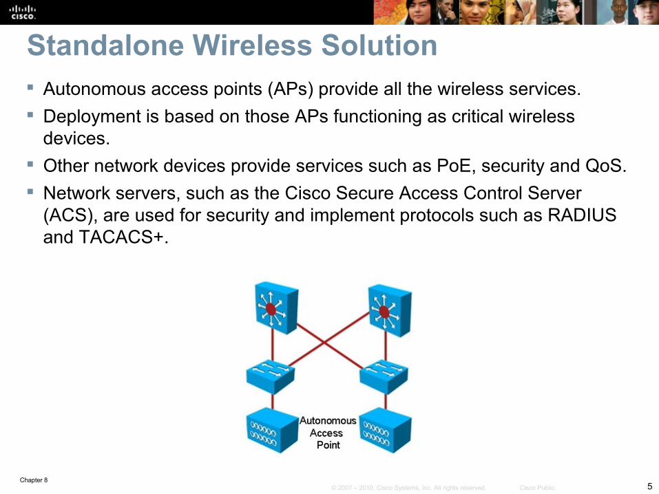
Autonomous access points (APs) provide all the wireless services. Deployment is based on those APs functioning as critical wireless
devices. Other network devices provide services such as PoE, security and QoS. Network servers, such as the Cisco Secure Access Control Server
(ACS), are used for security and implement protocols such as RADIUS and TACACS+.
Standalone Wireless Solution
Chapter 86© 2007 – 2010, Cisco Systems, Inc. All rights reserved. Cisco Public
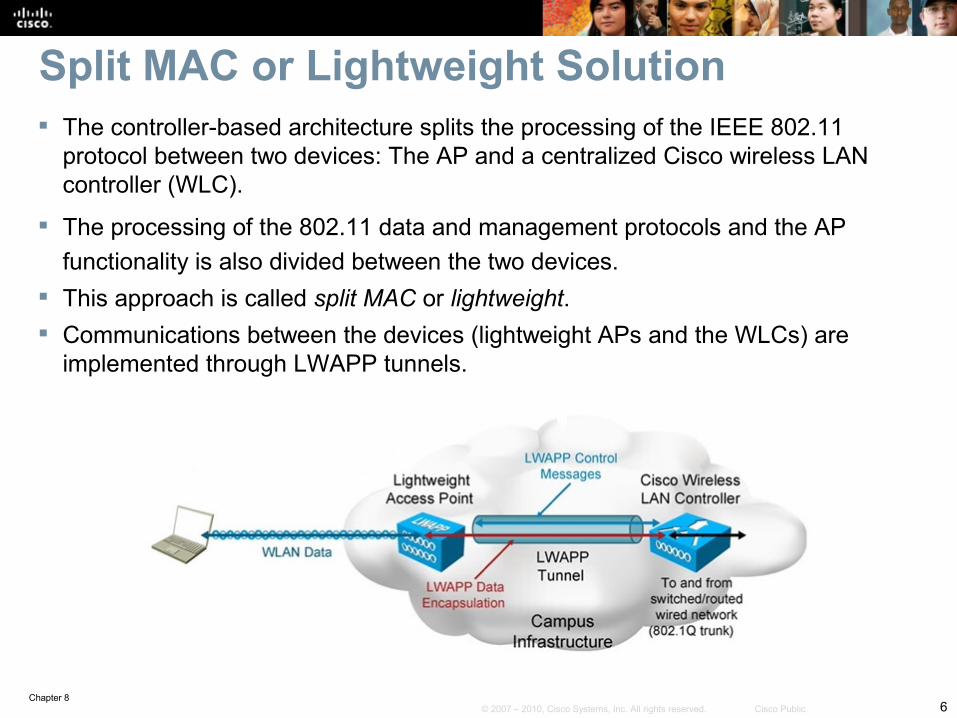
The controller-based architecture splits the processing of the IEEE 802.11 protocol between two devices: The AP and a centralized Cisco wireless LAN controller (WLC).
The processing of the 802.11 data and management protocols and the AP functionality is also divided between the two devices.
This approach is called split MAC or lightweight. Communications between the devices (lightweight APs and the WLCs) are
implemented through LWAPP tunnels.
Split MAC or Lightweight Solution
Chapter 87© 2007 – 2010, Cisco Systems, Inc. All rights reserved. Cisco Public
Some common wireless integration issues include:Traffic flow from client to WAP - Even if there is radio frequency (RF) connectivity between the AP and the client, there can still be a problem at the side where traffic flows from the client, through the AP, to the rest of the network.WLC issues - In a controller-based solution, the boundary between the wireless and the wired network is the Cisco WLC because traffic is tunneled between the AP and the WLC. Filtering issues - If any filters are configured on either the Ethernet side or the radio side of the AP, disable them temporarily, until you resolve connectivity issues.
Wireless Integration Issues – Cont.
Chapter 88© 2007 – 2010, Cisco Systems, Inc. All rights reserved. Cisco Public
Some common wireless integration issues include:IP addressing issues – IP addressing typically needs to be investigated, especially in roaming scenarios. QoS issues - Maintaining QoS markings consistently across wireless-to-wired boundaries is important.Other potential issues – Can be related to the network services typically provided by the switches that are connected to APs (such as POE).
Wireless Integration Issues – Cont.
Chapter 89© 2007 – 2010, Cisco Systems, Inc. All rights reserved. Cisco Public
Wireless Integration Issue Tools Use an appropriate troubleshooting approach (top-down, bottom-
up, divide-and-conquer, etc.). Use your knowledge of switching during information gathering.
Issues may be related to trunking, VLANs, and switch port configuration.
Use a design tool such as the Cisco Power Calculator for POE issues.
Useful wireless troubleshooting commands: • show vlan• show interfaces status• show interfaces trunk• show interfaces switchport • show access-lists• show cdp neighbors
Chapter 810© 2007 – 2010, Cisco Systems, Inc. All rights reserved. Cisco Public
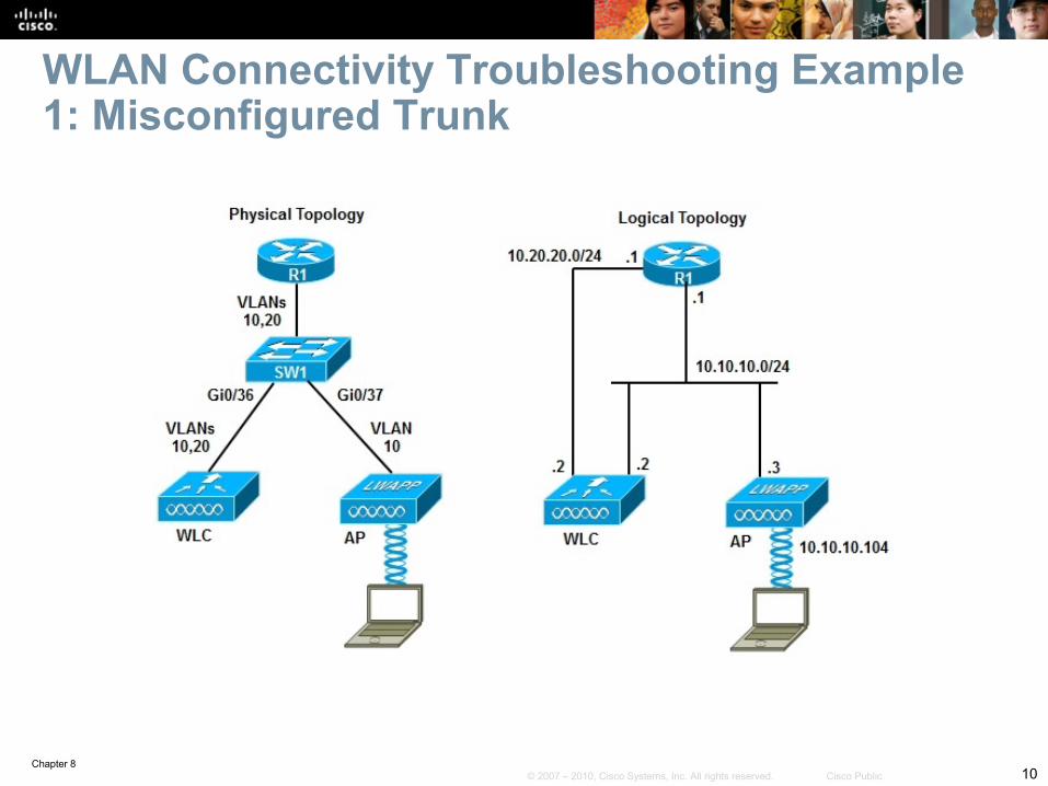
WLAN Connectivity Troubleshooting Example 1: Misconfigured Trunk
Chapter 811© 2007 – 2010, Cisco Systems, Inc. All rights reserved. Cisco Public
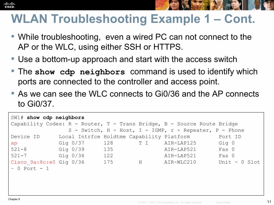
While troubleshooting, even a wired PC can not connect to the AP or the WLC, using either SSH or HTTPS.
Use a bottom-up approach and start with the access switch The show cdp neighbors command is used to identify which
ports are connected to the controller and access point. As we can see the WLC connects to Gi0/36 and the AP connects
to Gi0/37.SW1# show cdp neighborsCapability Codes: R - Router, T - Trans Bridge, B - Source Route Bridge S - Switch, H - Host, I - IGMP, r - Repeater, P - PhoneDevice ID Local Intrfce Holdtme Capability Platform Port IDap Gig 0/37 128 T I AIR-LAP125 Gig 0521-8 Gig 0/39 135 AIR-LAP521 Fas 0521-7 Gig 0/34 122 AIR-LAP521 Fas 0Cisco_9a:8c:e0 Gig 0/36 175 H AIR-WLC210 Unit - 0 Slot – 0 Port - 1
WLAN Troubleshooting Example 1 – Cont.
Chapter 812© 2007 – 2010, Cisco Systems, Inc. All rights reserved. Cisco Public
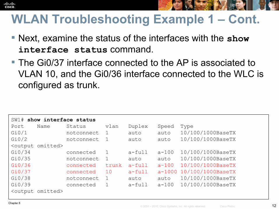
Next, examine the status of the interfaces with the show interface status command.
The Gi0/37 interface connected to the AP is associated to VLAN 10, and the Gi0/36 interface connected to the WLC is configured as trunk.
SW1# show interface statusPort Name Status vlan Duplex Speed TypeGi0/1 notconnect 1 auto auto 10/100/1000BaseTXGi0/2 notconnect 1 auto auto 10/100/1000BaseTX<output omitted>Gi0/34 connected 1 a-full a-100 10/100/1000BaseTXGi0/35 notconnect 1 auto auto 10/100/1000BaseTXGi0/36 connected trunk a-full a-100 10/100/1000BaseTXGi0/37 connected 10 a-full a-1000 10/100/1000BaseTXGi0/38 notconnect 1 auto auto 10/100/1000BaseTXGi0/39 connected 1 a-full a-100 10/100/1000BaseTX<output omitted>
WLAN Troubleshooting Example 1 – Cont.
Chapter 813© 2007 – 2010, Cisco Systems, Inc. All rights reserved. Cisco Public
The AP has a static IP address and the WLC and the AP should be on the same VLAN, but the WLC is not seeing registration requests from the AP.
The static IP address on the AP rules out DHCP preventing the AP from initiating an LWAPP request.
The Layer 1 and Layer 2 status of the interfaces are operational for both the wired and wireless side, for both the AP and the WLC.
WLAN Troubleshooting Example 1 – Cont.
Chapter 814© 2007 – 2010, Cisco Systems, Inc. All rights reserved. Cisco Public
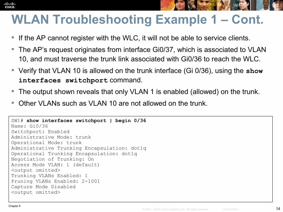
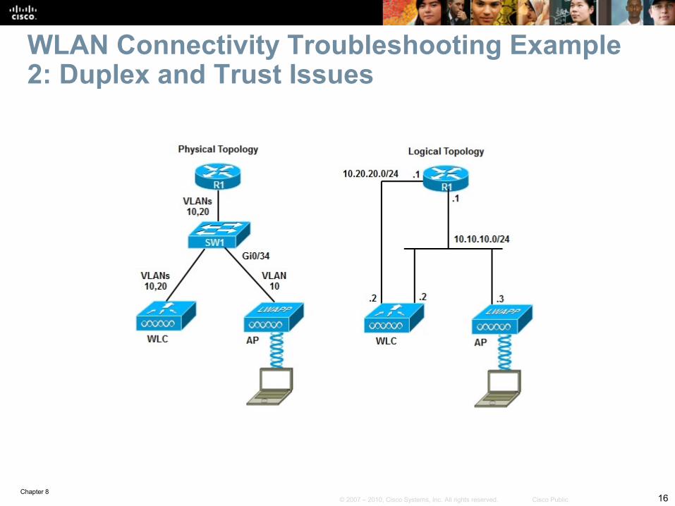
If the AP cannot register with the WLC, it will not be able to service clients. The AP’s request originates from interface Gi0/37, which is associated to VLAN
10, and must traverse the trunk link associated with Gi0/36 to reach the WLC. Verify that VLAN 10 is allowed on the trunk interface (Gi 0/36), using the show interfaces switchport command.
The output shown reveals that only VLAN 1 is enabled (allowed) on the trunk. Other VLANs such as VLAN 10 are not allowed on the trunk.
SW1# show interfaces switchport | begin 0/36Name: Gi0/36Switchport: EnabledAdministrative Mode: trunkOperational Mode: trunkAdministrative Trunking Encapsulation: dot1qOperational Trunking Encapsulation: dot1qNegotiation of Trunking: OnAccess Mode VLAN: 1 (default)<output omitted>Trunking VLANs Enabled: 1Pruning VLANs Enabled: 2-1001Capture Mode Disabled<output omitted>
WLAN Troubleshooting Example 1 – Cont.
Chapter 815© 2007 – 2010, Cisco Systems, Inc. All rights reserved. Cisco Public
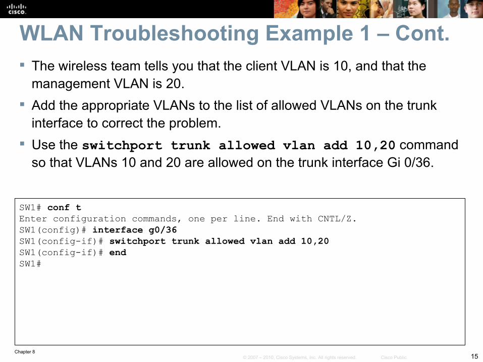
The wireless team tells you that the client VLAN is 10, and that the management VLAN is 20.
Add the appropriate VLANs to the list of allowed VLANs on the trunk interface to correct the problem.
Use the switchport trunk allowed vlan add 10,20 command so that VLANs 10 and 20 are allowed on the trunk interface Gi 0/36.
SW1# conf tEnter configuration commands, one per line. End with CNTL/Z.SW1(config)# interface g0/36SW1(config-if)# switchport trunk allowed vlan add 10,20SW1(config-if)# endSW1#
WLAN Troubleshooting Example 1 – Cont.
Chapter 816© 2007 – 2010, Cisco Systems, Inc. All rights reserved. Cisco Public
WLAN Connectivity Troubleshooting Example 2: Duplex and Trust Issues
Chapter 817© 2007 – 2010, Cisco Systems, Inc. All rights reserved. Cisco Public
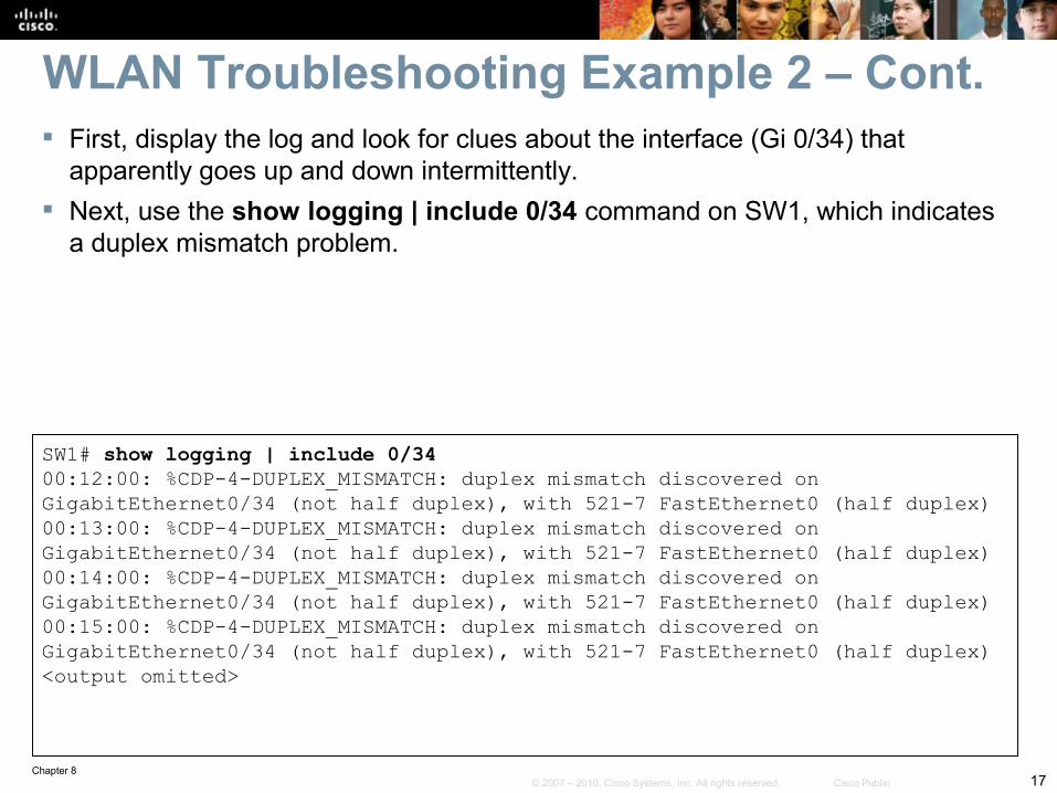
First, display the log and look for clues about the interface (Gi 0/34) that apparently goes up and down intermittently.
Next, use the show logging | include 0/34 command on SW1, which indicates a duplex mismatch problem.
SW1# show logging | include 0/3400:12:00: %CDP-4-DUPLEX_MISMATCH: duplex mismatch discovered onGigabitEthernet0/34 (not half duplex), with 521-7 FastEthernet0 (half duplex)00:13:00: %CDP-4-DUPLEX_MISMATCH: duplex mismatch discovered onGigabitEthernet0/34 (not half duplex), with 521-7 FastEthernet0 (half duplex)00:14:00: %CDP-4-DUPLEX_MISMATCH: duplex mismatch discovered onGigabitEthernet0/34 (not half duplex), with 521-7 FastEthernet0 (half duplex)00:15:00: %CDP-4-DUPLEX_MISMATCH: duplex mismatch discovered onGigabitEthernet0/34 (not half duplex), with 521-7 FastEthernet0 (half duplex)<output omitted>
WLAN Troubleshooting Example 2 – Cont.
Chapter 818© 2007 – 2010, Cisco Systems, Inc. All rights reserved. Cisco Public
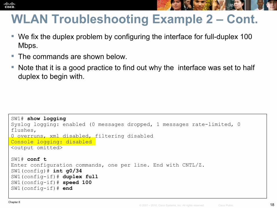
We fix the duplex problem by configuring the interface for full-duplex 100 Mbps.
The commands are shown below. Note that it is a good practice to find out why the interface was set to half
duplex to begin with.
SW1# show loggingSyslog logging: enabled (0 messages dropped, 1 messages rate-limited, 0 flushes,0 overruns, xml disabled, filtering disabledConsole logging: disabled<output omitted>
SW1# conf tEnter configuration commands, one per line. End with CNTL/Z.SW1(config)# int g0/34SW1(config-if)# duplex fullSW1(config-if)# speed 100SW1(config-if)# end
WLAN Troubleshooting Example 2 – Cont.
Chapter 819© 2007 – 2010, Cisco Systems, Inc. All rights reserved. Cisco Public
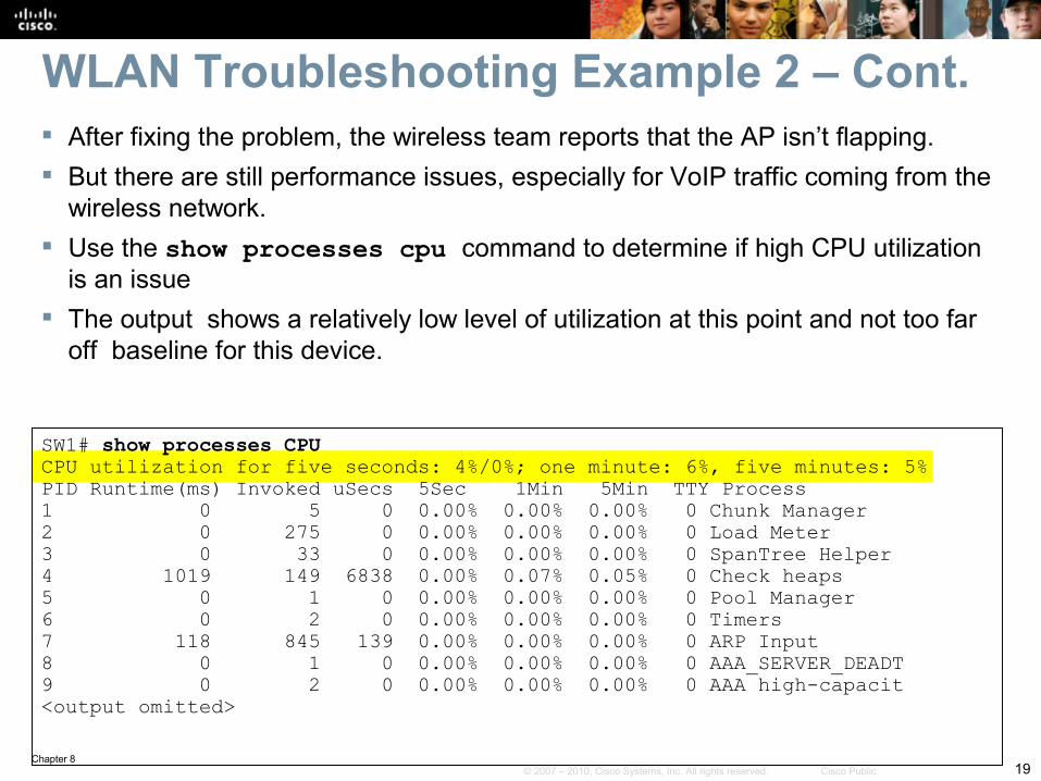
After fixing the problem, the wireless team reports that the AP isn’t flapping. But there are still performance issues, especially for VoIP traffic coming from the
wireless network. Use the show processes cpu command to determine if high CPU utilization
is an issue The output shows a relatively low level of utilization at this point and not too far
off baseline for this device.
SW1# show processes CPUCPU utilization for five seconds: 4%/0%; one minute: 6%, five minutes: 5%PID Runtime(ms) Invoked uSecs 5Sec 1Min 5Min TTY Process1 0 5 0 0.00% 0.00% 0.00% 0 Chunk Manager2 0 275 0 0.00% 0.00% 0.00% 0 Load Meter3 0 33 0 0.00% 0.00% 0.00% 0 SpanTree Helper4 1019 149 6838 0.00% 0.07% 0.05% 0 Check heaps5 0 1 0 0.00% 0.00% 0.00% 0 Pool Manager6 0 2 0 0.00% 0.00% 0.00% 0 Timers7 118 845 139 0.00% 0.00% 0.00% 0 ARP Input8 0 1 0 0.00% 0.00% 0.00% 0 AAA_SERVER_DEADT9 0 2 0 0.00% 0.00% 0.00% 0 AAA high-capacit<output omitted>
WLAN Troubleshooting Example 2 – Cont.
Chapter 820© 2007 – 2010, Cisco Systems, Inc. All rights reserved. Cisco Public
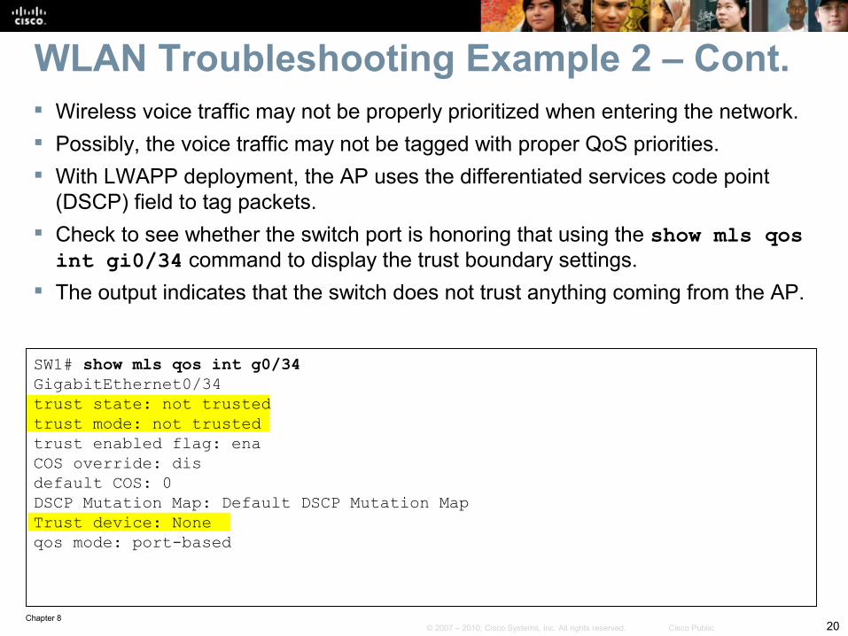
Wireless voice traffic may not be properly prioritized when entering the network. Possibly, the voice traffic may not be tagged with proper QoS priorities. With LWAPP deployment, the AP uses the differentiated services code point
(DSCP) field to tag packets. Check to see whether the switch port is honoring that using the show mls qos int gi0/34 command to display the trust boundary settings.
The output indicates that the switch does not trust anything coming from the AP.
SW1# show mls qos int g0/34GigabitEthernet0/34trust state: not trustedtrust mode: not trustedtrust enabled flag: enaCOS override: disdefault COS: 0DSCP Mutation Map: Default DSCP Mutation MapTrust device: Noneqos mode: port-based
WLAN Troubleshooting Example 2 – Cont.
Chapter 821© 2007 – 2010, Cisco Systems, Inc. All rights reserved. Cisco Public
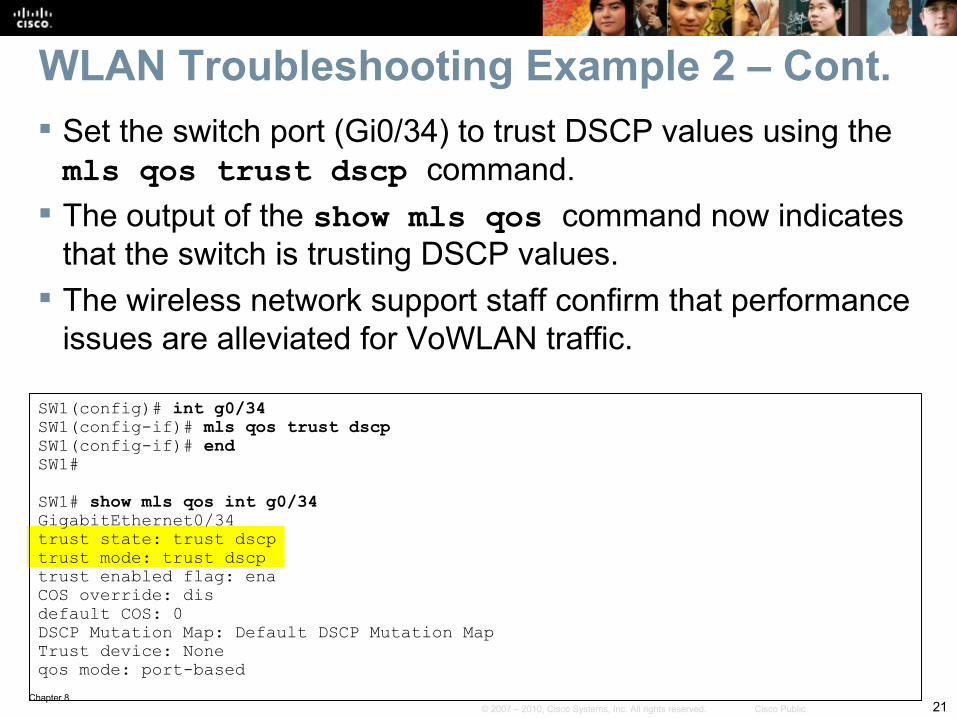
Set the switch port (Gi0/34) to trust DSCP values using the mls qos trust dscp command.
The output of the show mls qos command now indicates that the switch is trusting DSCP values.
The wireless network support staff confirm that performance issues are alleviated for VoWLAN traffic.
SW1(config)# int g0/34SW1(config-if)# mls qos trust dscpSW1(config-if)# endSW1#
SW1# show mls qos int g0/34GigabitEthernet0/34trust state: trust dscptrust mode: trust dscptrust enabled flag: enaCOS override: disdefault COS: 0DSCP Mutation Map: Default DSCP Mutation MapTrust device: Noneqos mode: port-based
WLAN Troubleshooting Example 2 – Cont.
Chapter 822© 2007 – 2010, Cisco Systems, Inc. All rights reserved. Cisco Public
WLAN Connectivity Troubleshooting Example 3: LWAPP Denied by New Security
Chapter 823© 2007 – 2010, Cisco Systems, Inc. All rights reserved. Cisco Public
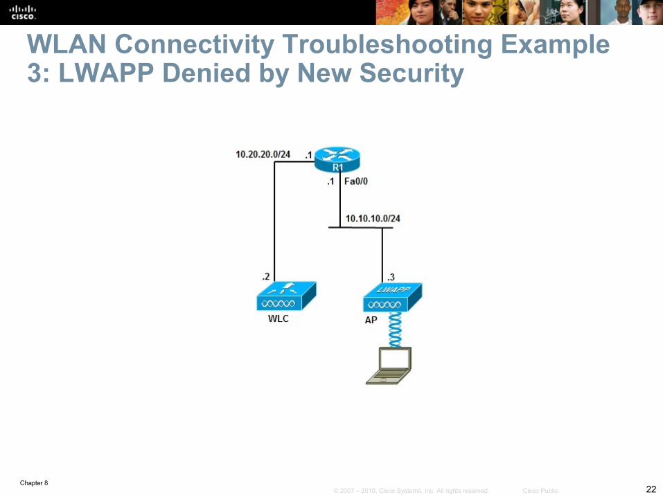
Based on a recent change in security policy, Cisco IOS firewall services were installed on R1.
R1 is performing inter-VLAN routing and the reported symptom points to the possibility of LWAPP traffic being denied by the firewall.
Cisco IOS Software allows the firewall to be configured using one of two methods:• The classical Cisco IOS firewall• The zone-based policy firewall
WLAN Troubleshooting Example 3 - Cont.
Chapter 824© 2007 – 2010, Cisco Systems, Inc. All rights reserved. Cisco Public
R1# show ip interface Fa0/0FastEthernet0/0 is up, line protocol is upInbound access list is FIREWALL<output omitted>
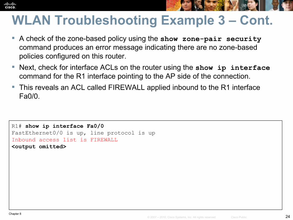
WLAN Troubleshooting Example 3 – Cont. A check of the zone-based policy using the show zone-pair security
command produces an error message indicating there are no zone-based policies configured on this router.
Next, check for interface ACLs on the router using the show ip interface command for the R1 interface pointing to the AP side of the connection.
This reveals an ACL called FIREWALL applied inbound to the R1 interface Fa0/0.
Chapter 825© 2007 – 2010, Cisco Systems, Inc. All rights reserved. Cisco Public
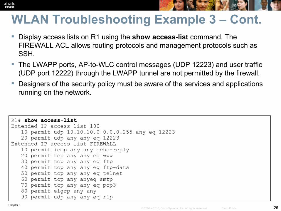
R1# show access-listExtended IP access list 100 10 permit udp 10.10.10.0 0.0.0.255 any eq 12223 20 permit udp any any eq 12223Extended IP access list FIREWALL 10 permit icmp any any echo-reply 20 permit tcp any any eq www 30 permit tcp any any eq ftp 40 permit tcp any any eq ftp-data 50 permit tcp any any eq telnet 60 permit tcp any anyeq smtp 70 permit tcp any any eq pop3 80 permit eigrp any any 90 permit udp any any eq rip
WLAN Troubleshooting Example 3 – Cont. Display access lists on R1 using the show access-list command. The
FIREWALL ACL allows routing protocols and management protocols such as SSH.
The LWAPP ports, AP-to-WLC control messages (UDP 12223) and user traffic (UDP port 12222) through the LWAPP tunnel are not permitted by the firewall.
Designers of the security policy must be aware of the services and applications running on the network.
Chapter 826© 2007 – 2010, Cisco Systems, Inc. All rights reserved. Cisco Public
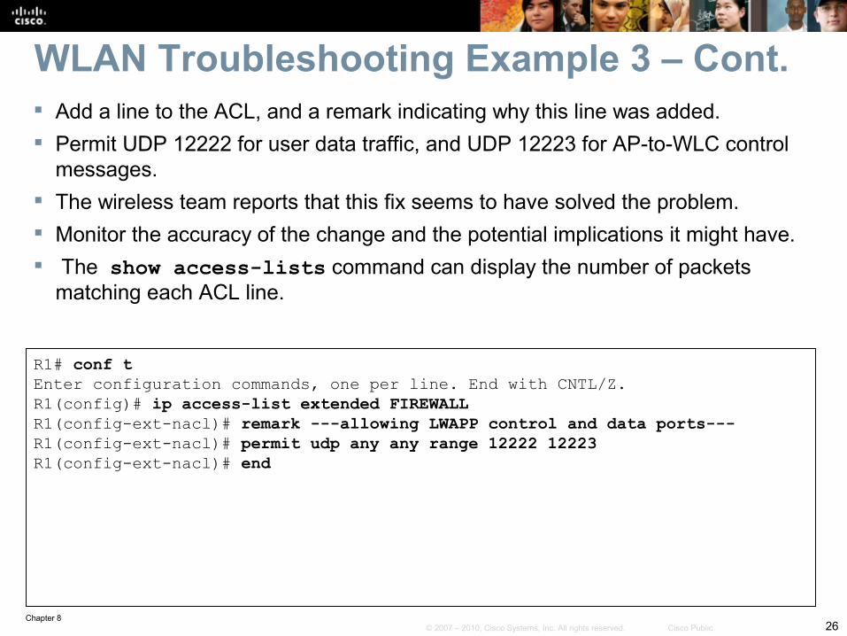
R1# conf tEnter configuration commands, one per line. End with CNTL/Z.R1(config)# ip access-list extended FIREWALLR1(config-ext-nacl)# remark ---allowing LWAPP control and data ports---R1(config-ext-nacl)# permit udp any any range 12222 12223R1(config-ext-nacl)# end
WLAN Troubleshooting Example 3 – Cont. Add a line to the ACL, and a remark indicating why this line was added. Permit UDP 12222 for user data traffic, and UDP 12223 for AP-to-WLC control
messages. The wireless team reports that this fix seems to have solved the problem. Monitor the accuracy of the change and the potential implications it might have. The show access-lists command can display the number of packets
matching each ACL line.
Chapter 827© 2007 – 2010, Cisco Systems, Inc. All rights reserved. Cisco Public
WLAN Connectivity Troubleshooting Example 4: DHCP Issues
Chapter 828© 2007 – 2010, Cisco Systems, Inc. All rights reserved. Cisco Public
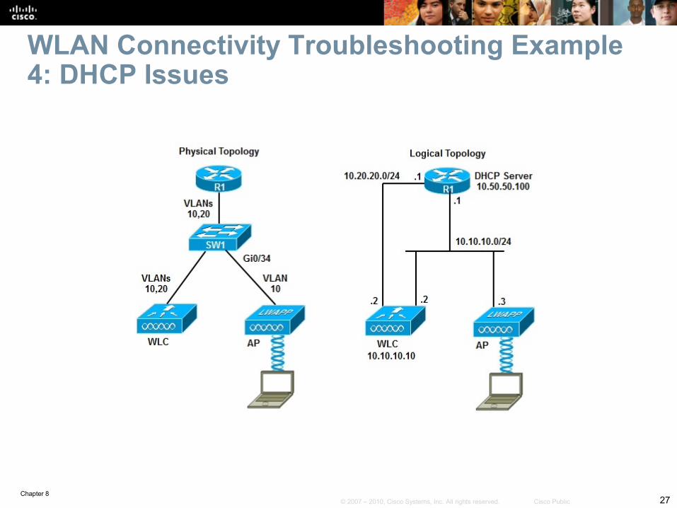
The wireless team states that none of the APs can register to the WLC.
All APs are DHCP clients but are not able to obtain their IP address from the DHCP server (which is R1 at address 10.50.50.100).
APs must first obtain an IP address lease from the DHCP server.
After the APs have obtained an IP address, they can register with the WLC.
Starting with the DHCP server, enter the show ip dhcp server statistics command.
WLAN Troubleshooting Example 4 - Cont.
Chapter 829© 2007 – 2010, Cisco Systems, Inc. All rights reserved. Cisco Public
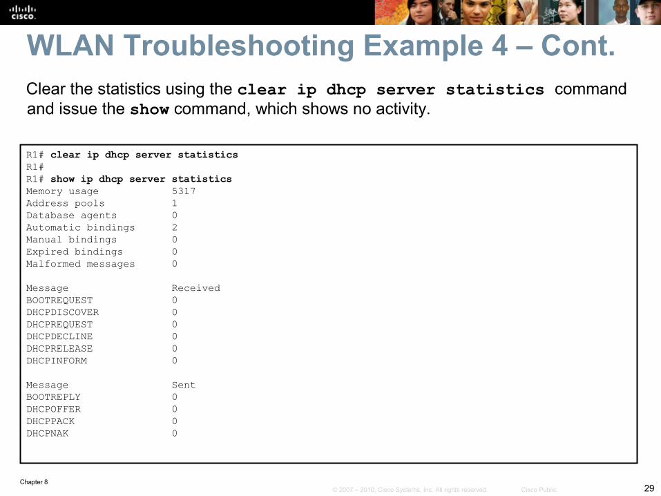
R1# clear ip dhcp server statisticsR1#R1# show ip dhcp server statisticsMemory usage 5317Address pools 1Database agents 0Automatic bindings 2Manual bindings 0Expired bindings 0Malformed messages 0
Message ReceivedBOOTREQUEST 0DHCPDISCOVER 0DHCPREQUEST 0DHCPDECLINE 0DHCPRELEASE 0DHCPINFORM 0
Message SentBOOTREPLY 0DHCPOFFER 0DHCPPACK 0DHCPNAK 0
Clear the statistics using the clear ip dhcp server statistics command and issue the show command, which shows no activity.
WLAN Troubleshooting Example 4 – Cont.
Chapter 830© 2007 – 2010, Cisco Systems, Inc. All rights reserved. Cisco Public
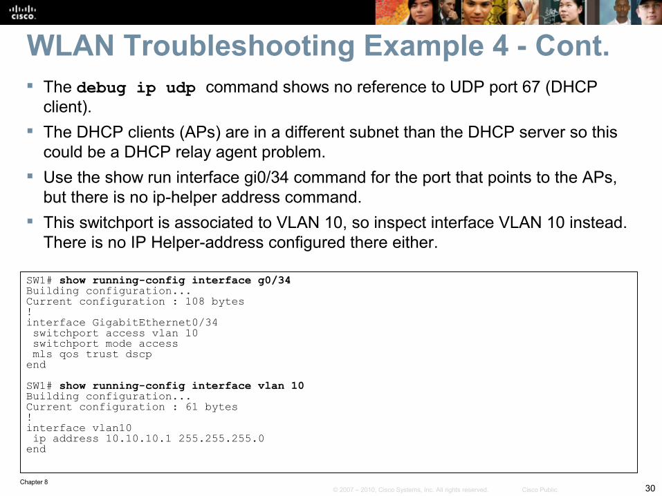
WLAN Troubleshooting Example 4 - Cont. The debug ip udp command shows no reference to UDP port 67 (DHCP
client). The DHCP clients (APs) are in a different subnet than the DHCP server so this
could be a DHCP relay agent problem. Use the show run interface gi0/34 command for the port that points to the APs,
but there is no ip-helper address command. This switchport is associated to VLAN 10, so inspect interface VLAN 10 instead.
There is no IP Helper-address configured there either.
SW1# show running-config interface g0/34Building configuration...Current configuration : 108 bytes!interface GigabitEthernet0/34 switchport access vlan 10 switchport mode access mls qos trust dscpendSW1# show running-config interface vlan 10Building configuration...Current configuration : 61 bytes!interface vlan10 ip address 10.10.10.1 255.255.255.0end
Chapter 831© 2007 – 2010, Cisco Systems, Inc. All rights reserved. Cisco Public
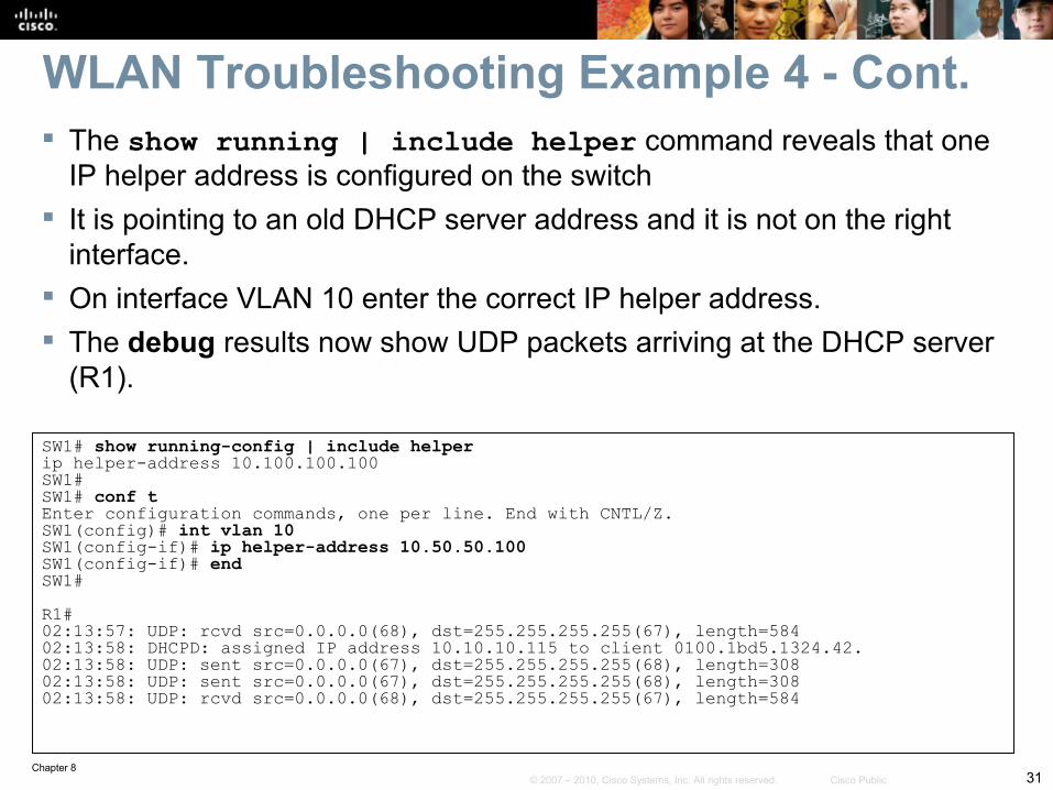
WLAN Troubleshooting Example 4 - Cont. The show running | include helper command reveals that one
IP helper address is configured on the switch It is pointing to an old DHCP server address and it is not on the right
interface. On interface VLAN 10 enter the correct IP helper address. The debug results now show UDP packets arriving at the DHCP server
(R1).
SW1# show running-config | include helperip helper-address 10.100.100.100SW1#SW1# conf tEnter configuration commands, one per line. End with CNTL/Z.SW1(config)# int vlan 10SW1(config-if)# ip helper-address 10.50.50.100SW1(config-if)# endSW1#R1#02:13:57: UDP: rcvd src=0.0.0.0(68), dst=255.255.255.255(67), length=58402:13:58: DHCPD: assigned IP address 10.10.10.115 to client 0100.1bd5.1324.42.02:13:58: UDP: sent src=0.0.0.0(67), dst=255.255.255.255(68), length=30802:13:58: UDP: sent src=0.0.0.0(67), dst=255.255.255.255(68), length=30802:13:58: UDP: rcvd src=0.0.0.0(68), dst=255.255.255.255(67), length=584
Chapter 832© 2007 – 2010, Cisco Systems, Inc. All rights reserved. Cisco Public
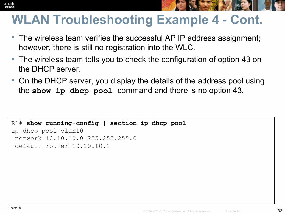
WLAN Troubleshooting Example 4 - Cont. The wireless team verifies the successful AP IP address assignment;
however, there is still no registration into the WLC. The wireless team tells you to check the configuration of option 43 on
the DHCP server. On the DHCP server, you display the details of the address pool using
the show ip dhcp pool command and there is no option 43.
R1# show running-config | section ip dhcp poolip dhcp pool vlan10 network 10.10.10.0 255.255.255.0 default-router 10.10.10.1
Chapter 833© 2007 – 2010, Cisco Systems, Inc. All rights reserved. Cisco Public
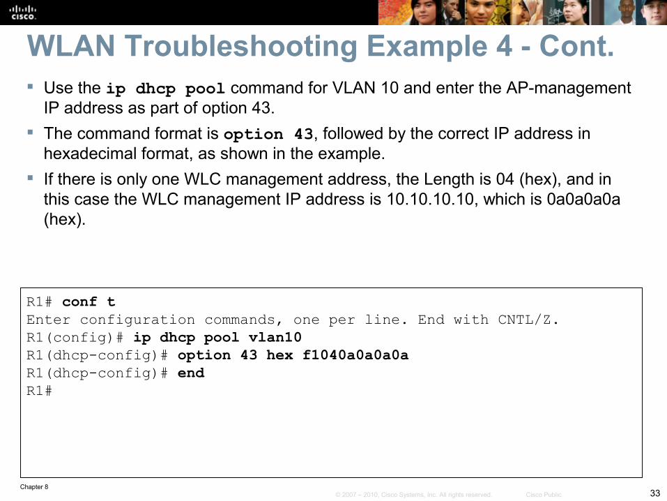
Use the ip dhcp pool command for VLAN 10 and enter the AP-management IP address as part of option 43.
The command format is option 43, followed by the correct IP address in hexadecimal format, as shown in the example.
If there is only one WLC management address, the Length is 04 (hex), and in this case the WLC management IP address is 10.10.10.10, which is 0a0a0a0a (hex).
R1# conf tEnter configuration commands, one per line. End with CNTL/Z.R1(config)# ip dhcp pool vlan10R1(dhcp-config)# option 43 hex f1040a0a0a0aR1(dhcp-config)# endR1#
WLAN Troubleshooting Example 4 - Cont.
Chapter 834© 2007 – 2010, Cisco Systems, Inc. All rights reserved. Cisco Public
Troubleshooting Unified Communications Issues in aConverged Network
Chapter 835© 2007 – 2010, Cisco Systems, Inc. All rights reserved. Cisco Public
The focus of this section is convergence, an integral part of most networks.
It deals with the readiness of a campus network to support converged services, such as unified communications or IP telephony.
IP telephony services provided over the campus infrastructure require data and voice to coexist.
Types of traffic are differentiated and delay-sensitive voice traffic is prioritized using QoS policies to mark and qualify traffic as it traverses the campus switch blocks.
VLANs are used to keep voice traffic separate from data traffic. The routing and switching must providing a reliable, efficient, and
secure transport for signaling traffic and the gateway traffic to forward calls to the PSTN or WAN destinations.
Section Overview
Chapter 836© 2007 – 2010, Cisco Systems, Inc. All rights reserved. Cisco Public
Unified Communications Integration Issues
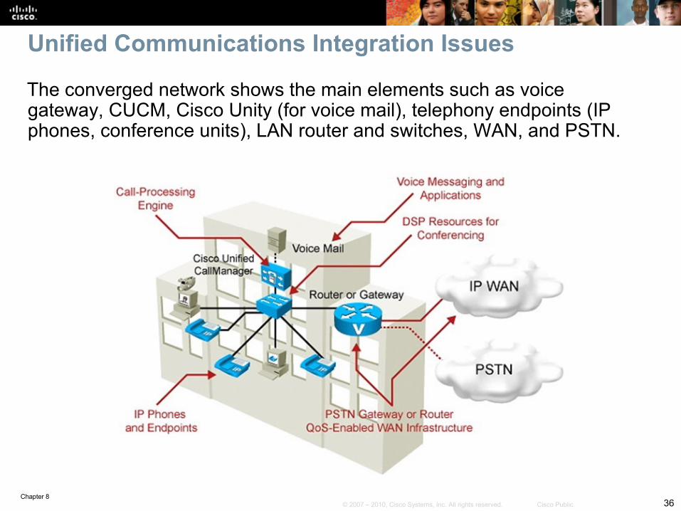
The converged network shows the main elements such as voice gateway, CUCM, Cisco Unity (for voice mail), telephony endpoints (IP phones, conference units), LAN router and switches, WAN, and PSTN.
Chapter 837© 2007 – 2010, Cisco Systems, Inc. All rights reserved. Cisco Public
These can involve multiple components of the network, multiple layers of the OSI model, multiple integrated technologies and potentially, multiple operations and support teams within an organization. • Quality of service: Bandwidth, delay, jitter, packet loss, network QoS
readiness, trust boundaries, switch QoS• High availability: STP/RSTP, HSRP/GLBP/VRRP• Security: Traffic segregation (voice versus data VLANs),
firewalling/filtering• Provisioning and management: PoE, DHCP, TFTP, NTP, CDP,
trunking, VLANs
Unified Communications Design
Chapter 838© 2007 – 2010, Cisco Systems, Inc. All rights reserved. Cisco Public
Unified Communications ComponentsIn addition to QoS and VLAN management issues, the Unified Communications network requires specific components that might become additional sources of problems. These are services that use the underlying VLAN and switching infrastructure:Power (PoE) must be readily available to endpoints.Repositories of firmware and configuration files through TFTP Time synchronization (Network Time Protocol [NTP]) for cryptographic authenticationCisco Discovery Protocol (CDP) to facilitate the IP phone booting processDHCP must be accessible to provide IP information for the phone
Chapter 839© 2007 – 2010, Cisco Systems, Inc. All rights reserved. Cisco Public
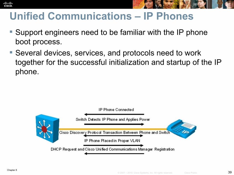
Unified Communications – IP Phones Support engineers need to be familiar with the IP phone
boot process. Several devices, services, and protocols need to work
together for the successful initialization and startup of the IP phone.
Chapter 840© 2007 – 2010, Cisco Systems, Inc. All rights reserved. Cisco Public
The following is the IP phone boot process : Step 1. The IP phone powers on. Step 2. The phone performs a power-on self-test, or POST. Step 3. The phone boots. Step 4. The phone uses CDP to learn the voice VLAN. Step 5. The phone initializes the IP stack. Step 6. The IP phone sends DHCP broadcasts. Step 7. The DHCP server selects a free IP address from the pool and
sends it, along with the other parameters, including option 150. Step 8. The IP phone initializes, applying the IP configuration to the IP
stack. Step 9. The IP phone requests a configuration file from the TFTP server
defined in Option 150.
IP Phone Boot Process
Chapter 841© 2007 – 2010, Cisco Systems, Inc. All rights reserved. Cisco Public
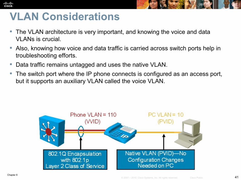
VLAN Considerations The VLAN architecture is very important, and knowing the voice and data
VLANs is crucial. Also, knowing how voice and data traffic is carried across switch ports help in
troubleshooting efforts. Data traffic remains untagged and uses the native VLAN. The switch port where the IP phone connects is configured as an access port,
but it supports an auxiliary VLAN called the voice VLAN.
Chapter 842© 2007 – 2010, Cisco Systems, Inc. All rights reserved. Cisco Public
IP phones might become out of sync in terms of digital certificate verification if network services are not available, misconfigured, or simply not reachable.
An IP phone might not obtain the right amount of power, if CDP is missing.
A misconfigured DHCP server might prevent IP phones from obtaining their configuration files if option 150 is not enabled.
QoS architectures might render voice traffic useless. Security controls might interfere with control protocols and could also
filter required signaling protocols, crucial in VoIP operations. Protocols and ports in standard IP telephony deployments include:
• Real-Time Transport Protocol (RTP) and its UDP port ranges• Session Initiation Protocol (SIP) on TCP port 5060• H323 on TCP port 1720.
Troubleshooting Scenarios
Chapter 843© 2007 – 2010, Cisco Systems, Inc. All rights reserved. Cisco Public
On most Cisco IOS devices, MQC is used to configure QoS.
MQC allows you to configure policies once and apply them to multiple interfaces and different devices.
MQC syntax is not platform specific. It decouples the traffic classification components from the
policy components. You can apply the same policy to different traffic classes
without having to create it multiple times.
Modular QoS CLI (MQC)
Chapter 844© 2007 – 2010, Cisco Systems, Inc. All rights reserved. Cisco Public
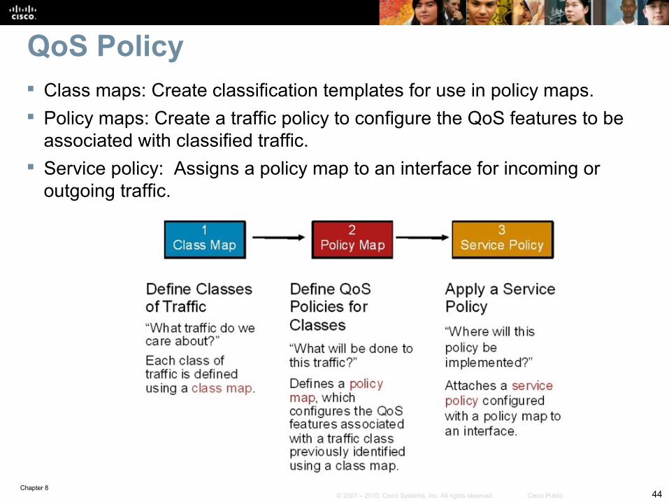
Class maps: Create classification templates for use in policy maps. Policy maps: Create a traffic policy to configure the QoS features to be
associated with classified traffic. Service policy: Assigns a policy map to an interface for incoming or
outgoing traffic.
QoS Policy
Chapter 845© 2007 – 2010, Cisco Systems, Inc. All rights reserved. Cisco Public
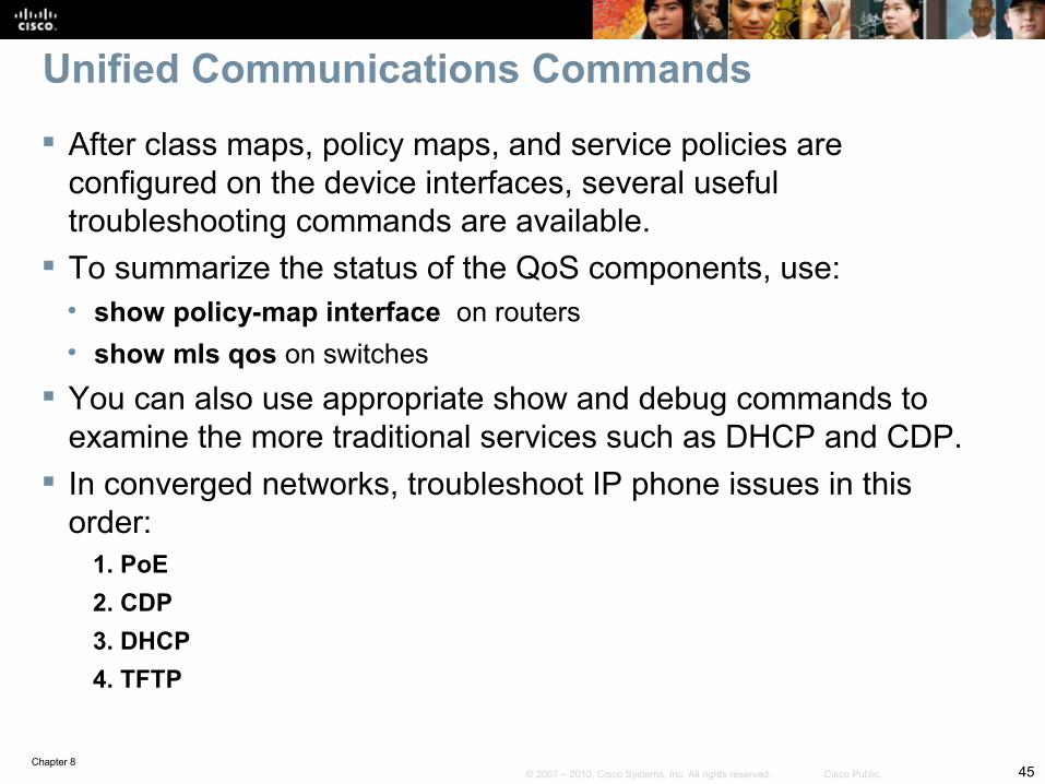
After class maps, policy maps, and service policies are configured on the device interfaces, several useful troubleshooting commands are available.
To summarize the status of the QoS components, use:• show policy-map interface on routers• show mls qos on switches
You can also use appropriate show and debug commands to examine the more traditional services such as DHCP and CDP.
In converged networks, troubleshoot IP phone issues in this order:
1. PoE2. CDP3. DHCP4. TFTP
Unified Communications Commands
Chapter 846© 2007 – 2010, Cisco Systems, Inc. All rights reserved. Cisco Public
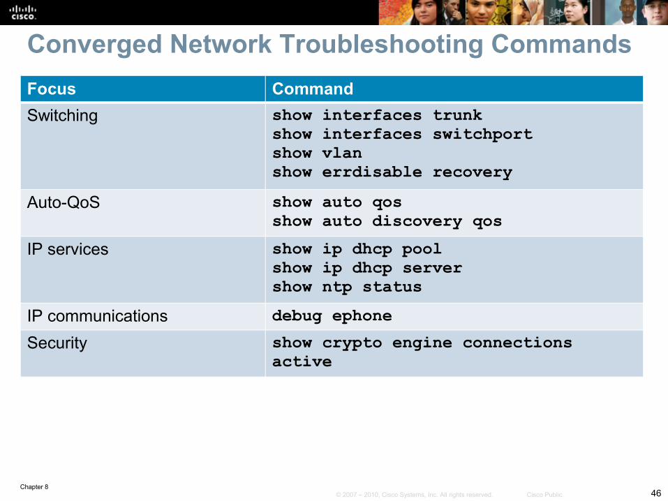
Focus CommandSwitching show interfaces trunk
show interfaces switchportshow vlanshow errdisable recovery
Auto-QoS show auto qosshow auto discovery qos
IP services show ip dhcp poolshow ip dhcp servershow ntp status
IP communications debug ephoneSecurity show crypto engine connections
active
Converged Network Troubleshooting Commands
Chapter 847© 2007 – 2010, Cisco Systems, Inc. All rights reserved. Cisco Public
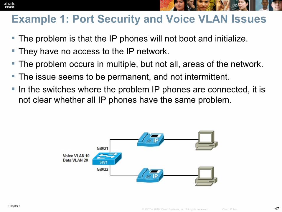
The problem is that the IP phones will not boot and initialize. They have no access to the IP network. The problem occurs in multiple, but not all, areas of the network. The issue seems to be permanent, and not intermittent. In the switches where the problem IP phones are connected, it is
not clear whether all IP phones have the same problem.
Example 1: Port Security and Voice VLAN Issues
Chapter 848© 2007 – 2010, Cisco Systems, Inc. All rights reserved. Cisco Public
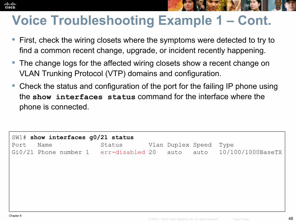
First, check the wiring closets where the symptoms were detected to try to find a common recent change, upgrade, or incident recently happening.
The change logs for the affected wiring closets show a recent change on VLAN Trunking Protocol (VTP) domains and configuration.
Check the status and configuration of the port for the failing IP phone using the show interfaces status command for the interface where the phone is connected.
SW1# show interfaces g0/21 statusPort Name Status Vlan Duplex Speed TypeGi0/21 Phone number 1 err-disabled 20 auto auto 10/100/1000BaseTX
Voice Troubleshooting Example 1 – Cont.
Chapter 849© 2007 – 2010, Cisco Systems, Inc. All rights reserved. Cisco Public
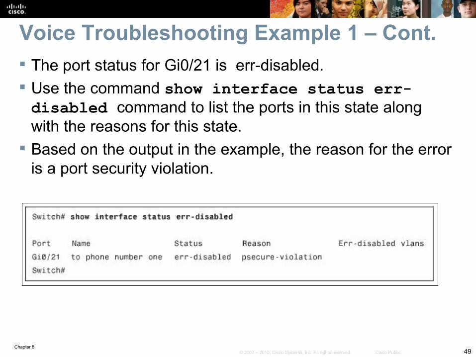
The port status for Gi0/21 is err-disabled. Use the command show interface status err-disabled command to list the ports in this state along with the reasons for this state.
Based on the output in the example, the reason for the error is a port security violation.
Voice Troubleshooting Example 1 – Cont.
Chapter 850© 2007 – 2010, Cisco Systems, Inc. All rights reserved. Cisco Public
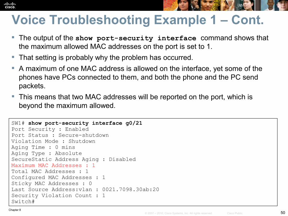
The output of the show port-security interface command shows that the maximum allowed MAC addresses on the port is set to 1.
That setting is probably why the problem has occurred. A maximum of one MAC address is allowed on the interface, yet some of the
phones have PCs connected to them, and both the phone and the PC send packets.
This means that two MAC addresses will be reported on the port, which is beyond the maximum allowed.
SW1# show port-security interface g0/21Port Security : EnabledPort Status : Secure-shutdownViolation Mode : ShutdownAging Time : 0 minsAging Type : AbsoluteSecureStatic Address Aging : DisabledMaximum MAC Addresses : 1Total MAC Addresses : 1Configured MAC Addresses : 1Sticky MAC Addresses : 0Last Source Address:vlan : 0021.7098.30ab:20Security Violation Count : 1Switch#
Voice Troubleshooting Example 1 – Cont.
Chapter 851© 2007 – 2010, Cisco Systems, Inc. All rights reserved. Cisco Public
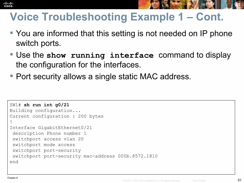
You are informed that this setting is not needed on IP phone switch ports.
Use the show running interface command to display the configuration for the interfaces.
Port security allows a single static MAC address.
SW1# sh run int g0/21Building configuration...Current configuration : 200 bytes!Interface GigabitEthernet0/21 description Phone number 1 switchport access vlan 20 switchport mode access switchport port-security switchport port-security mac-address 000b.8572.1810end
Voice Troubleshooting Example 1 – Cont.
Chapter 852© 2007 – 2010, Cisco Systems, Inc. All rights reserved. Cisco Public
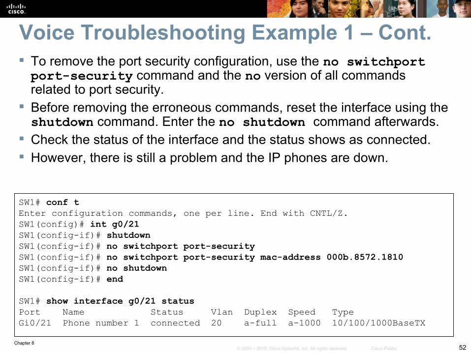
Voice Troubleshooting Example 1 – Cont. To remove the port security configuration, use the no switchport port-security command and the no version of all commands related to port security.
Before removing the erroneous commands, reset the interface using the shutdown command. Enter the no shutdown command afterwards.
Check the status of the interface and the status shows as connected. However, there is still a problem and the IP phones are down.
SW1# conf tEnter configuration commands, one per line. End with CNTL/Z. SW1(config)# int g0/21SW1(config-if)# shutdownSW1(config-if)# no switchport port-securitySW1(config-if)# no switchport port-security mac-address 000b.8572.1810SW1(config-if)# no shutdownSW1(config-if)# endSW1# show interface g0/21 statusPort Name Status Vlan Duplex Speed TypeGi0/21 Phone number 1 connected 20 a-full a-1000 10/100/1000BaseTX
Chapter 853© 2007 – 2010, Cisco Systems, Inc. All rights reserved. Cisco Public
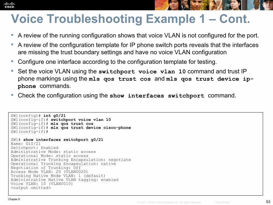
A review of the running configuration shows that voice VLAN is not configured for the port. A review of the configuration template for IP phone switch ports reveals that the interfaces
are missing the trust boundary settings and have no voice VLAN configuration Configure one interface according to the configuration template for testing. Set the voice VLAN using the switchport voice vlan 10 command and trust IP
phone markings using the mls qos trust cos and mls qos trust device ip-phone commands.
Check the configuration using the show interfaces switchport command.
SW1(config)# int g0/21SW1(config-if)# switchport voice vlan 10SW1(config-if)# mls qos trust cosSW1(config-if)# mls qos trust device cisco-phoneSW1(config-if)#SW1# show interfaces switchport g0/21Name: Gi0/21Switchport: EnabledAdministrative Mode: static accessOperational Mode: static accessAdministrative Trunking Encapsulation: negotiateOperational Trunking Encapsulation: nativeNegotiation of Trunking: OffAccess Mode VLAN: 20 (VLAN0020)Trunking Native Mode VLAN: 1 (default)Administrative Native VLAN tagging: enabledVoice VLAN: 10 (VLAN0010)<output omitted>
Voice Troubleshooting Example 1 – Cont.
Chapter 854© 2007 – 2010, Cisco Systems, Inc. All rights reserved. Cisco Public
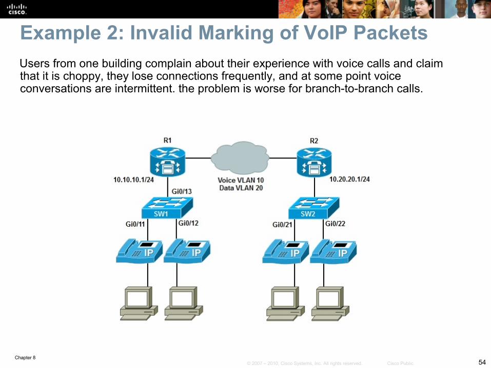
Users from one building complain about their experience with voice calls and claim that it is choppy, they lose connections frequently, and at some point voice conversations are intermittent. the problem is worse for branch-to-branch calls.
Example 2: Invalid Marking of VoIP Packets
Chapter 855© 2007 – 2010, Cisco Systems, Inc. All rights reserved. Cisco Public
To gathering measurable information, ask the following questions:• How often do you observe the reported symptoms?• Is there a particular time of the day in which they commonly occur?• Is the perceived quality the same when calling internal extension
numbers and as it is when calling outside numbers?• How often are you unable to obtain a dial tone? For how long does
this condition remain?• Which locations of the network are experiencing the problem
(building/branch)?• Are the problematic devices connected to the same wiring closet?
A comparison to baseline QoS metrics shows that end-to-end delay for voice traffic has doubled across the campus.
Voice Troubleshooting Example 2 – Cont.
Chapter 856© 2007 – 2010, Cisco Systems, Inc. All rights reserved. Cisco Public
Voice Troubleshooting Example 2 – Cont. A comparison to baseline QoS metrics shows that end-to-
end delay for voice traffic has doubled across the campus. Packet-loss percentages are close to baseline at about 1
percent. The latency numbers show that a QoS issue exists. The policy trend in this campus is to push QoS settings
toward the distribution and access layers. Check the access switch first, and then move up to the
distribution layer switch or router, trying to confirm the QoS settings.
Chapter 857© 2007 – 2010, Cisco Systems, Inc. All rights reserved. Cisco Public
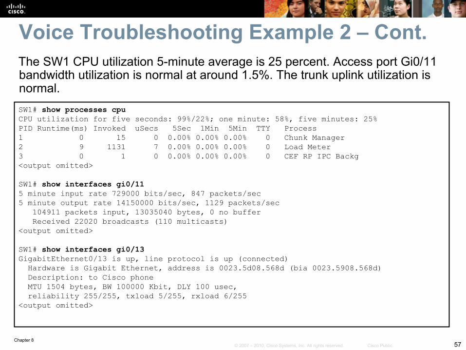
SW1# show processes cpuCPU utilization for five seconds: 99%/22%; one minute: 58%, five minutes: 25%PID Runtime(ms) Invoked uSecs 5Sec 1Min 5Min TTY Process1 0 15 0 0.00% 0.00% 0.00% 0 Chunk Manager2 9 1131 7 0.00% 0.00% 0.00% 0 Load Meter3 0 1 0 0.00% 0.00% 0.00% 0 CEF RP IPC Backg<output omitted>
SW1# show interfaces gi0/115 minute input rate 729000 bits/sec, 847 packets/sec5 minute output rate 14150000 bits/sec, 1129 packets/sec 104911 packets input, 13035040 bytes, 0 no buffer Received 22020 broadcasts (110 multicasts)<output omitted>
SW1# show interfaces gi0/13GigabitEthernet0/13 is up, line protocol is up (connected) Hardware is Gigabit Ethernet, address is 0023.5d08.568d (bia 0023.5908.568d) Description: to Cisco phone MTU 1504 bytes, BW 100000 Kbit, DLY 100 usec, reliability 255/255, txload 5/255, rxload 6/255<output omitted>
The SW1 CPU utilization 5-minute average is 25 percent. Access port Gi0/11 bandwidth utilization is normal at around 1.5%. The trunk uplink utilization is normal.
Voice Troubleshooting Example 2 – Cont.
Chapter 858© 2007 – 2010, Cisco Systems, Inc. All rights reserved. Cisco Public
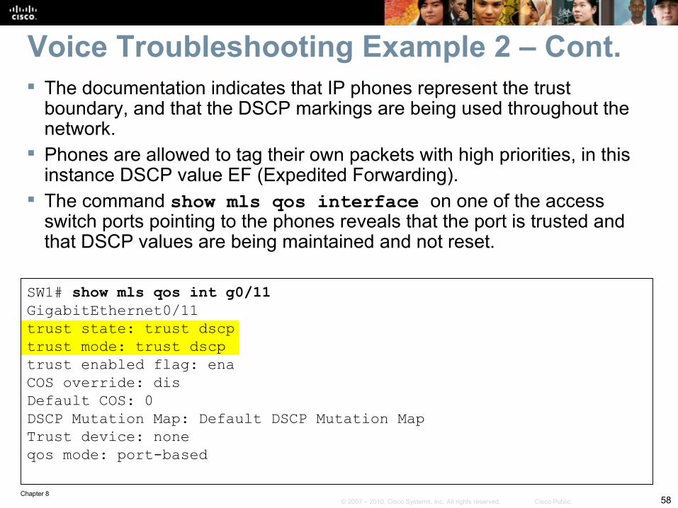
The documentation indicates that IP phones represent the trust boundary, and that the DSCP markings are being used throughout the network.
Phones are allowed to tag their own packets with high priorities, in this instance DSCP value EF (Expedited Forwarding).
The command show mls qos interface on one of the access switch ports pointing to the phones reveals that the port is trusted and that DSCP values are being maintained and not reset.
SW1# show mls qos int g0/11GigabitEthernet0/11trust state: trust dscptrust mode: trust dscptrust enabled flag: enaCOS override: disDefault COS: 0DSCP Mutation Map: Default DSCP Mutation MapTrust device: noneqos mode: port-based
Voice Troubleshooting Example 2 – Cont.
Chapter 859© 2007 – 2010, Cisco Systems, Inc. All rights reserved. Cisco Public
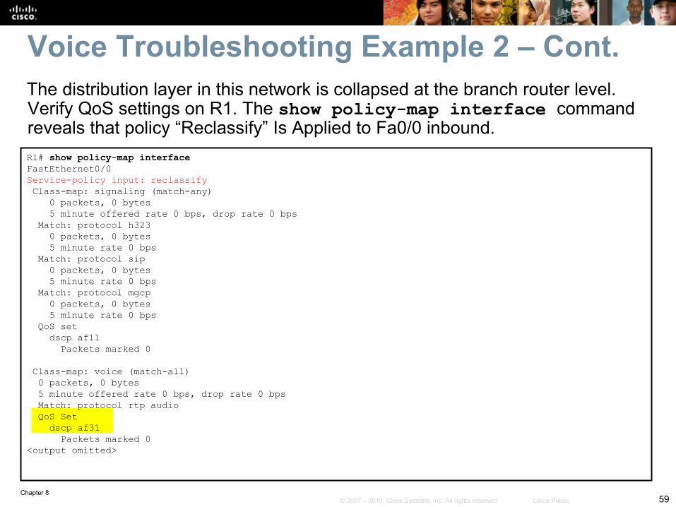
R1# show policy-map interfaceFastEthernet0/0Service-policy input: reclassify Class-map: signaling (match-any) 0 packets, 0 bytes 5 minute offered rate 0 bps, drop rate 0 bps Match: protocol h323 0 packets, 0 bytes 5 minute rate 0 bps Match: protocol sip 0 packets, 0 bytes 5 minute rate 0 bps Match: protocol mgcp 0 packets, 0 bytes 5 minute rate 0 bps QoS set dscp af11 Packets marked 0
Class-map: voice (match-all) 0 packets, 0 bytes 5 minute offered rate 0 bps, drop rate 0 bps Match: protocol rtp audio QoS Set dscp af31 Packets marked 0<output omitted>
The distribution layer in this network is collapsed at the branch router level. Verify QoS settings on R1. The show policy-map interface command reveals that policy “Reclassify” Is Applied to Fa0/0 inbound.
Voice Troubleshooting Example 2 – Cont.
Chapter 860© 2007 – 2010, Cisco Systems, Inc. All rights reserved. Cisco Public
The reclassify policy attached to the R1 Fa0/0 interface reclassifies and re-marks packets coming into this interface.
The “QoS Set” section within the VOICE class tells us that VOICE traffic is being classified and tagged with the DSCP value AF31.
Voice traffic is typically classified with DSCP value EF, the highest priority.
The voice traffic class is being reclassified into a lower priority and is being incorrectly marked down.
The impact of this improper remarking is that QoS policies such as bandwidth reservation, priority queuing, and preferred path selection are not enforced.
Voice traffic is suffering because of the identified voice remarking mistake.
Once this error is fixed, the VOICE problems are solved.
Voice Troubleshooting Example 2 – Cont.
Chapter 861© 2007 – 2010, Cisco Systems, Inc. All rights reserved. Cisco Public
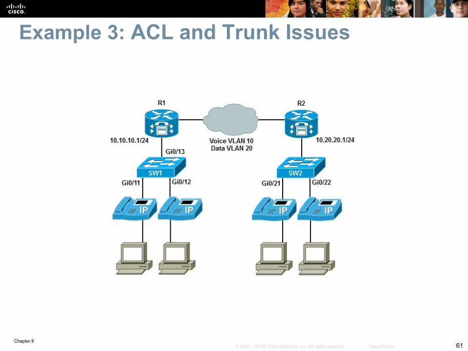
Example 3: ACL and Trunk Issues

Chapter 862© 2007 – 2010, Cisco Systems, Inc. All rights reserved. Cisco Public
Voice Troubleshooting Example 3 – Cont. A recent security audit has resulted in new security policies being
put in place. The IP phones are not able to initialize and obtain their base
configuration. Those settings are obtained from configuration files stored in the
TFTP server, which is the local branch router. The local branch router is also serving as a call agent, performing
call routing, Call Admission Control (CAC), and other IP telephony functions.
Due to the recent change in security policy, Cisco IOS firewall services were installed in some key routers of the network.
The reported symptom is that the IP phones cannot initialize and obtain their settings, or make calls.
A check of SW1 and R1 shows no zone based policies or ACLs.
Chapter 863© 2007 – 2010, Cisco Systems, Inc. All rights reserved. Cisco Public
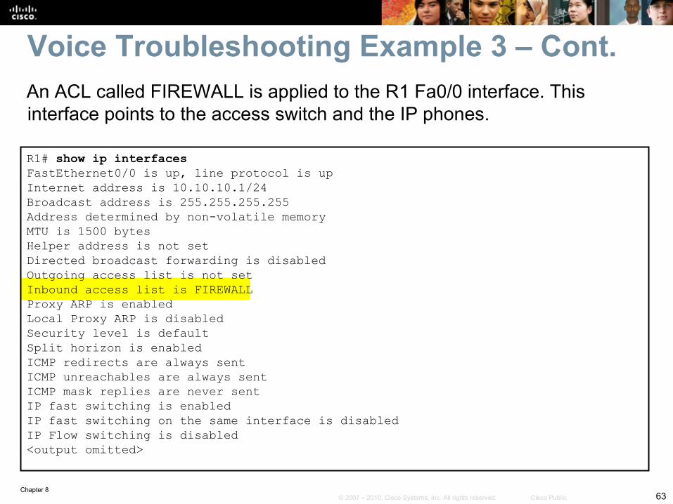
R1# show ip interfacesFastEthernet0/0 is up, line protocol is upInternet address is 10.10.10.1/24Broadcast address is 255.255.255.255Address determined by non-volatile memoryMTU is 1500 bytesHelper address is not setDirected broadcast forwarding is disabledOutgoing access list is not setInbound access list is FIREWALLProxy ARP is enabledLocal Proxy ARP is disabledSecurity level is defaultSplit horizon is enabledICMP redirects are always sentICMP unreachables are always sentICMP mask replies are never sentIP fast switching is enabledIP fast switching on the same interface is disabledIP Flow switching is disabled<output omitted>
An ACL called FIREWALL is applied to the R1 Fa0/0 interface. This interface points to the access switch and the IP phones.
Voice Troubleshooting Example 3 – Cont.
Chapter 864© 2007 – 2010, Cisco Systems, Inc. All rights reserved. Cisco Public
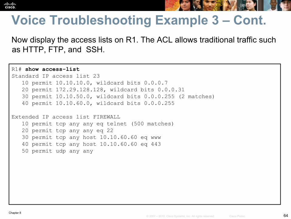
R1# show access-listStandard IP access list 23 10 permit 10.10.10.0, wildcard bits 0.0.0.7 20 permit 172.29.128.128, wildcard bits 0.0.0.31 30 permit 10.10.50.0, wildcard bits 0.0.0.255 (2 matches) 40 permit 10.10.60.0, wildcard bits 0.0.0.255
Extended IP access list FIREWALL 10 permit tcp any any eq telnet (500 matches) 20 permit tcp any any eq 22 30 permit tcp any host 10.10.60.60 eq www 40 permit tcp any host 10.10.60.60 eq 443 50 permit udp any any
Voice Troubleshooting Example 3 – Cont.Now display the access lists on R1. The ACL allows traditional traffic such as HTTP, FTP, and SSH.
Chapter 865© 2007 – 2010, Cisco Systems, Inc. All rights reserved. Cisco Public
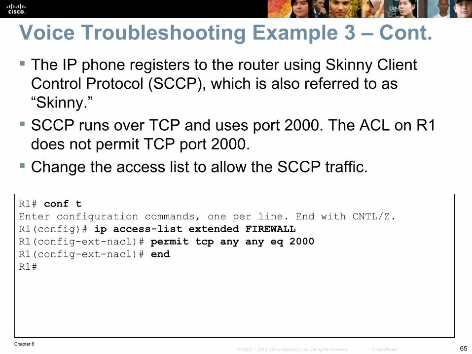
R1# conf tEnter configuration commands, one per line. End with CNTL/Z.R1(config)# ip access-list extended FIREWALLR1(config-ext-nacl)# permit tcp any any eq 2000R1(config-ext-nacl)# endR1#
Voice Troubleshooting Example 3 – Cont. The IP phone registers to the router using Skinny Client
Control Protocol (SCCP), which is also referred to as “Skinny.”
SCCP runs over TCP and uses port 2000. The ACL on R1 does not permit TCP port 2000.
Change the access list to allow the SCCP traffic.
Chapter 866© 2007 – 2010, Cisco Systems, Inc. All rights reserved. Cisco Public
R1# debug ephone registerEPHONE registration debugging is enabledR1#
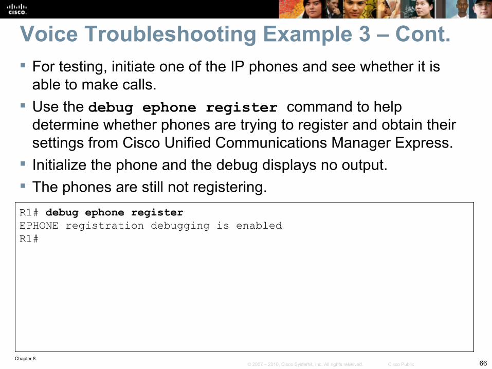
Voice Troubleshooting Example 3 – Cont. For testing, initiate one of the IP phones and see whether it is
able to make calls. Use the debug ephone register command to help
determine whether phones are trying to register and obtain their settings from Cisco Unified Communications Manager Express.
Initialize the phone and the debug displays no output. The phones are still not registering.
Chapter 867© 2007 – 2010, Cisco Systems, Inc. All rights reserved. Cisco Public
SW1# show interface trunkPort Mode Encapsulation Status Native vlanGi0/13 on 802.1q trunking 50Port Vlans allowed on trunkGi0/13 1,50,60<output omitted>
SW1# conf tEnter configuration commands, one per line. End with CNTL/Z.SW1(config)# int Gi0/13SW1(config-if)# switchport trunk allowed vlan add 10SW1(config-if)# end
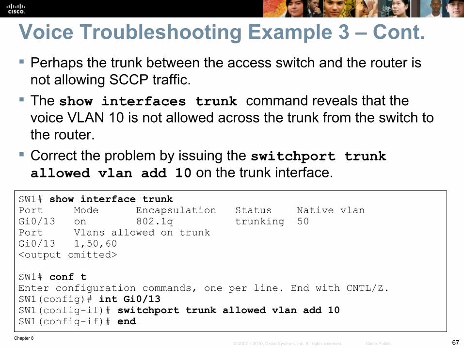
Voice Troubleshooting Example 3 – Cont. Perhaps the trunk between the access switch and the router is
not allowing SCCP traffic. The show interfaces trunk command reveals that the
voice VLAN 10 is not allowed across the trunk from the switch to the router.
Correct the problem by issuing the switchport trunk allowed vlan add 10 on the trunk interface.
Chapter 868© 2007 – 2010, Cisco Systems, Inc. All rights reserved. Cisco Public
*Sep 1 17:22:37.155: ephone-1[0/1][SEP0023331B9090]:ButtonTemplate buttonCount=2totalButtonCount=2 buttonOffset=0*Sep 1 17:22:37.155: ephone-1[0/1][SEP0023331B9090]:Configured 0 speed dial buttons*Sep 1 17:22:37.159: ephone-1[0/1]:StationSoftKeyTemplateReqMessage*Sep 1 17:22:37.159: ephone-1[0/1]:StationSoftKeyTemplateReqMessage*Sep 1 17:22:37.171: ephone-1[0/1]:StationSoftKeySetReqMessage*Sep 1 17:22:37.171: ephone-1[0/1]:StationSoftKeySetReqMessage*Sep 1 17:22:37.175: ephone-1[0/1][SEP0023331B9090]:StationLineStatReqMessage fromephone line 2*Sep 1 17:22:37.175: ephone-1[0/1][SEP0023331B9090]:StationLineStatReqMessage fromephone line 2 Invalid DN -1*Sep 1 17:22:37.175: ephone-1[0/1][SEP0023331B9090]:StationLineStatResMessage sentto ephone (1 of 2)*Sep 1 17:22:37.175: ephone-1[0/1][SEP0023331B9090]:StationLineStatReqMessage fromephone line 1*Sep 1 17:22:37.179: ephone-1[0/1]:StationLineStatReqMessage ephone line 1 DN 1 =1000 desc = 1000 label =
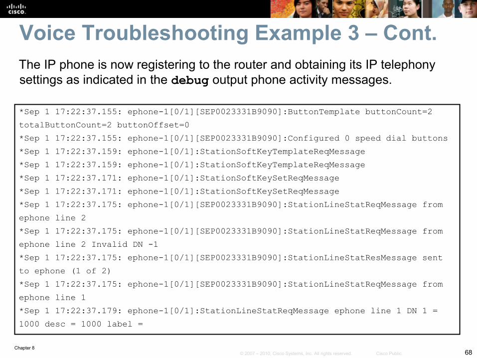
The IP phone is now registering to the router and obtaining its IP telephony settings as indicated in the debug output phone activity messages.
Voice Troubleshooting Example 3 – Cont.
Chapter 869© 2007 – 2010, Cisco Systems, Inc. All rights reserved. Cisco Public
Troubleshooting Video Issues in a Converged Network
Chapter 870© 2007 – 2010, Cisco Systems, Inc. All rights reserved. Cisco Public
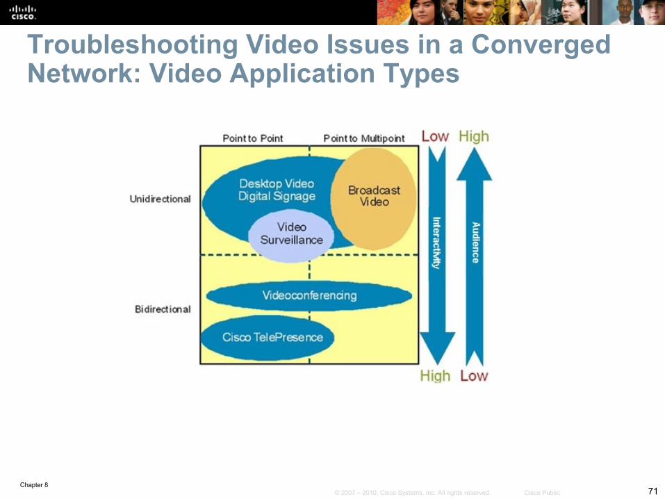
This section addresses the challenge of troubleshooting the network infrastructure supporting video and rich media traffic.
Several media-rich applications are available for enterprises:• High-definition room-based interactive video such as Cisco TelePresence• Standard-definition desktop collaboration applications such as Cisco
Unified Videoconferencing Systems. Streaming and broadcast types of video applications include:
• Digital signage• Video on demand (VoD)• Video surveillance.
Video applications have different characteristics in terms of:• Interactivity• Network traffic volume• Audience• Requirements for underlying network infrastructure and services.
Section Overview
Chapter 871© 2007 – 2010, Cisco Systems, Inc. All rights reserved. Cisco Public
Troubleshooting Video Issues in a Converged Network: Video Application Types
Chapter 872© 2007 – 2010, Cisco Systems, Inc. All rights reserved. Cisco Public
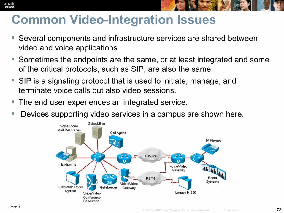
Common Video-Integration Issues Several components and infrastructure services are shared between
video and voice applications. Sometimes the endpoints are the same, or at least integrated and some
of the critical protocols, such as SIP, are also the same. SIP is a signaling protocol that is used to initiate, manage, and
terminate voice calls but also video sessions. The end user experiences an integrated service. Devices supporting video services in a campus are shown here.
Chapter 873© 2007 – 2010, Cisco Systems, Inc. All rights reserved. Cisco Public
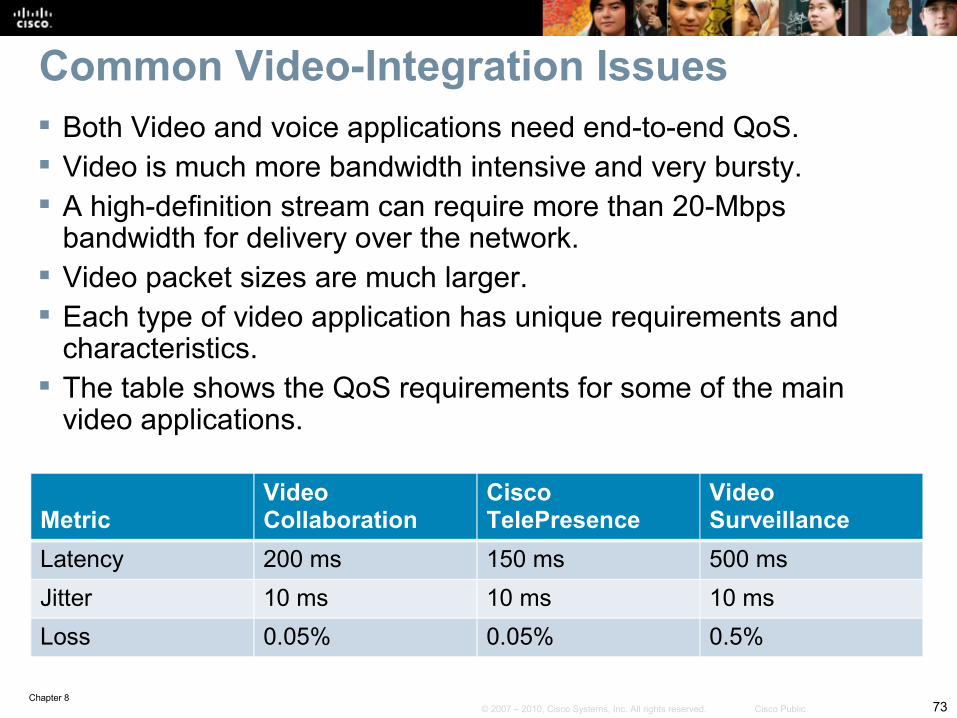
Common Video-Integration Issues Both Video and voice applications need end-to-end QoS. Video is much more bandwidth intensive and very bursty. A high-definition stream can require more than 20-Mbps
bandwidth for delivery over the network. Video packet sizes are much larger. Each type of video application has unique requirements and
characteristics. The table shows the QoS requirements for some of the main
video applications.
MetricVideo Collaboration
CiscoTelePresence
Video Surveillance
Latency 200 ms 150 ms 500 msJitter 10 ms 10 ms 10 msLoss 0.05% 0.05% 0.5%
Chapter 874© 2007 – 2010, Cisco Systems, Inc. All rights reserved. Cisco Public
Video applications require high availability and millisecond-level network service recovery.
Video traffic cannot accept unpredictable or large network recovery timeouts. Convergence targets will be higher, and packet loss due to network outage must
be minimal. Redundancy design, convergence of routing protocols and spanning tree are
extremely critical. Building a multicast-aware network is another important consideration. Security in a video-enabled network, similar to voice deployments, might need to
permit protocols such as:• SIP• H.323• SCCP (Skinny)• RTP• RTCP• Possibly others
Common Video-Integration Issues – Cont.
Chapter 875© 2007 – 2010, Cisco Systems, Inc. All rights reserved. Cisco Public
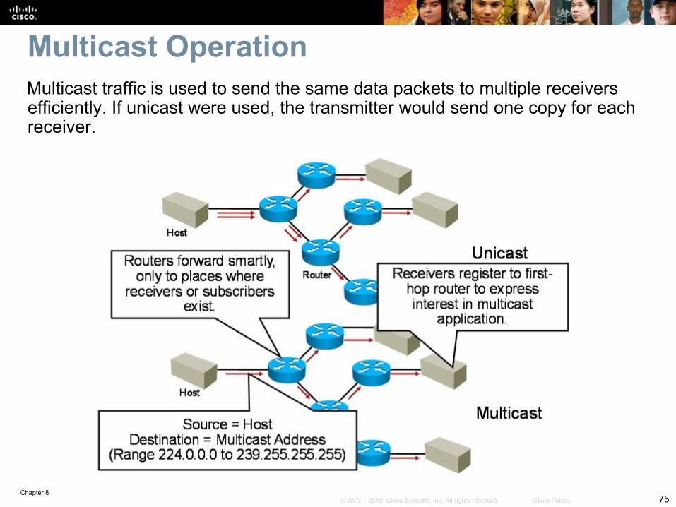
Multicast traffic is used to send the same data packets to multiple receivers efficiently. If unicast were used, the transmitter would send one copy for each receiver.
Multicast Operation
Chapter 876© 2007 – 2010, Cisco Systems, Inc. All rights reserved. Cisco Public
The sender sends only one copy of a single data packet addressed to a group of receivers.
Multicast groups IP addresses that use the Class D address space. Class D addresses are denoted by the high-order 4 bits of the address set to
1110. This results in the range of addresses 224.0.0.0 through 239.255.255.255.
Downstream multicast routers replicate and forward the data packet to all those branches where subscribers exist.
Receivers express their interest in multicast traffic by registering at their first-hop router.
This model and resulting protocols saves reduces resource utilization on routers and switches and improves QoS and the user experience.
There are two main protocols involved:• Protocol Independent Multicast (PIM) – routers advertise multicast receivers• Internet Group Management Protocol (IGMP) – receivers subscribe to and leave
groups
Multicast Operation – Cont.
Chapter 877© 2007 – 2010, Cisco Systems, Inc. All rights reserved. Cisco Public
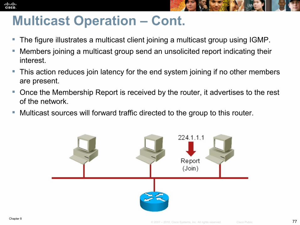
Multicast Operation – Cont. The figure illustrates a multicast client joining a multicast group using IGMP. Members joining a multicast group send an unsolicited report indicating their
interest. This action reduces join latency for the end system joining if no other members
are present. Once the Membership Report is received by the router, it advertises to the rest
of the network. Multicast sources will forward traffic directed to the group to this router.
Chapter 878© 2007 – 2010, Cisco Systems, Inc. All rights reserved. Cisco Public
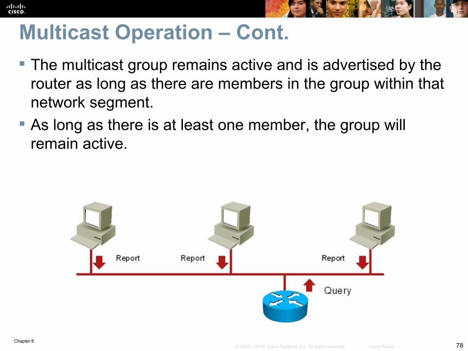
Multicast Operation – Cont. The multicast group remains active and is advertised by the
router as long as there are members in the group within that network segment.
As long as there is at least one member, the group will remain active.
Chapter 879© 2007 – 2010, Cisco Systems, Inc. All rights reserved. Cisco Public
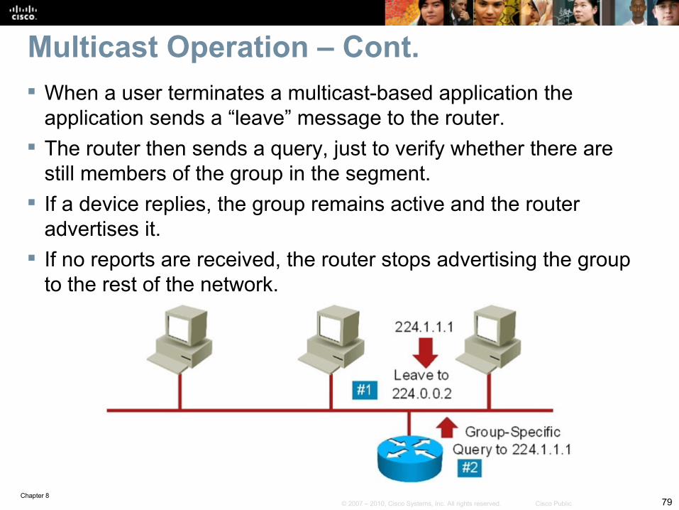
Multicast Operation – Cont. When a user terminates a multicast-based application the
application sends a “leave” message to the router. The router then sends a query, just to verify whether there are
still members of the group in the segment. If a device replies, the group remains active and the router
advertises it. If no reports are received, the router stops advertising the group
to the rest of the network.
Chapter 880© 2007 – 2010, Cisco Systems, Inc. All rights reserved. Cisco Public
Troubleshooting Video Integration Issues Common video-integration issues include the following:
• Excessive bandwidth utilization• Poor quality (lack of QoS)• Security issues (filtering of key protocols, and stateful requirements)• Multicast issues
QoS is a common problem due to the bursty nature of video traffic Video traffic tends to monopolize the available bandwidth but is also delay-
sensitive. Network security can interfere with video traffic. Firewalls, ACLs, and other
security controls can get in the way of protocols such as RTP, RTCP, SIP, H.323, and others.
Multicast configuration, if enabled in the network, is always a source of potential issues.• Common IGMP problems are related to group filtering, where routers might not accept
join request from certain multicast group addresses.• Another potential multicast issue is related to differences in IGMP versions between the
router and the hosts sending multicast traffic.
Chapter 881© 2007 – 2010, Cisco Systems, Inc. All rights reserved. Cisco Public
Video-Integration Troubleshooting Example 1: Performance Issues Due to STP Topology
Chapter 882© 2007 – 2010, Cisco Systems, Inc. All rights reserved. Cisco Public
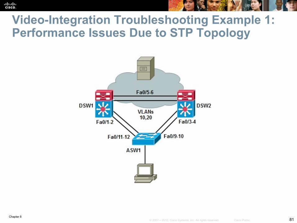
Users are complaining about “poor” performance of their video application.
In the switched network in the figure the video clients reside in two VLANS, 10 and 20, implemented in the access switch.
The access switch is serviced by two distribution switches that connect the clients to the campus network, where the video server resides.
The distribution switches have recently been upgraded to a new version of Cisco IOS Software.
After the change, users started complaining about the poor performance.
The exact symptoms, as told by the users of the application is choppy video, long download and buffering times, and that streaming video stops every few seconds for the application to buffer video frames.
Video Troubleshooting Example 1 – Cont.
Chapter 883© 2007 – 2010, Cisco Systems, Inc. All rights reserved. Cisco Public
Video Troubleshooting Example 1 – Cont.
ASW1# show interfaces statusPort Name Status vlan Duplex Speed TypeFa0/1 disabled 1 auto auto 10/100BaseTXFa0/2 disabled 1 auto auto 10/100BaseTXFa0/3 connected 10 a-full a-100 10/100BaseTXFa0/4 disabled 1 auto auto 10/100BaseTXFa0/5 disabled 1 auto auto 10/100BaseTXFa0/6 disabled 1 auto auto 10/100BaseTXFa0/7 disabled 1 auto auto 10/100BaseTXFa0/8 disabled 1 auto auto 10/100BaseTXFa0/9 To DSW2 connected trunk a-full a-100 10/100BaseTXFa0/10 To DSW2 connected trunk a-full a-100 10/100BaseTXFa0/11 To DSW1 connected trunk a-full a-100 10/100BaseTXFa0/12 To DSW1 connected trunk a-full a-100 10/100BaseTXFa0/13 disabled 1 auto auto 10/100BaseTX<output omitted>
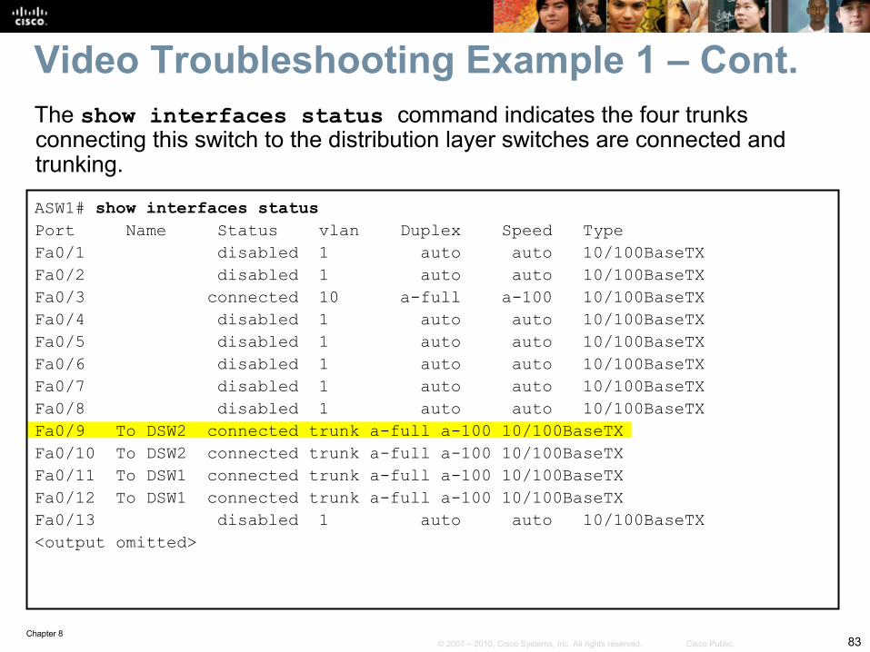
The show interfaces status command indicates the four trunks connecting this switch to the distribution layer switches are connected and trunking.
Chapter 884© 2007 – 2010, Cisco Systems, Inc. All rights reserved. Cisco Public
ASW1# show interfaces fa0/9 switchportName: Fa0/9Switchport: EnabledAdministrative Mode: trunkOperational Mode: trunk (member of bundle Po1)Administrative Trunking Encapsulation: dot1qOperational Trunking Encapsulation: dot1qNegotiation of Trunking: onAccess Mode VLAN: 1 (default)Trunking Native Mode VLAN: 1 (default)Trunking Native Mode VLAN: 1 (default)Administrative Native VLAN tagging: enabledVoice VLAN: none<output omitted>Operational private-vlan: noneTrunking VLANs Enabled: ALLPruning VLANs Enabled: 2-1001Capture Mode DisabledCapture VLANs Allowed: ALL
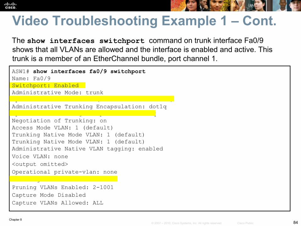
The show interfaces switchport command on trunk interface Fa0/9 shows that all VLANs are allowed and the interface is enabled and active. This trunk is a member of an EtherChannel bundle, port channel 1.
Video Troubleshooting Example 1 – Cont.
Chapter 885© 2007 – 2010, Cisco Systems, Inc. All rights reserved. Cisco Public
ASW1# show etherchannel summaryFlags: D - down P - in port-channel I - stand-alone s - suspended H - Hot-standby (LACP only) R - Layer3 S - Layer2 U - in use f - failed to allocate aggregator w - waiting to be aggregated d - default port
Number of channel-groups in use: 2Number of aggregators: 2
Group Port-channel Protocol Ports-----------------------------------------------------1 Po1(SU) - Fa0/9(P) Fa0/10(P)2 Po2(SU) - Fa0/11(P) Fa0/12(P)
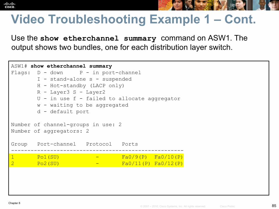
Video Troubleshooting Example 1 – Cont.Use the show etherchannel summary command on ASW1. The output shows two bundles, one for each distribution layer switch.
Chapter 886© 2007 – 2010, Cisco Systems, Inc. All rights reserved. Cisco Public
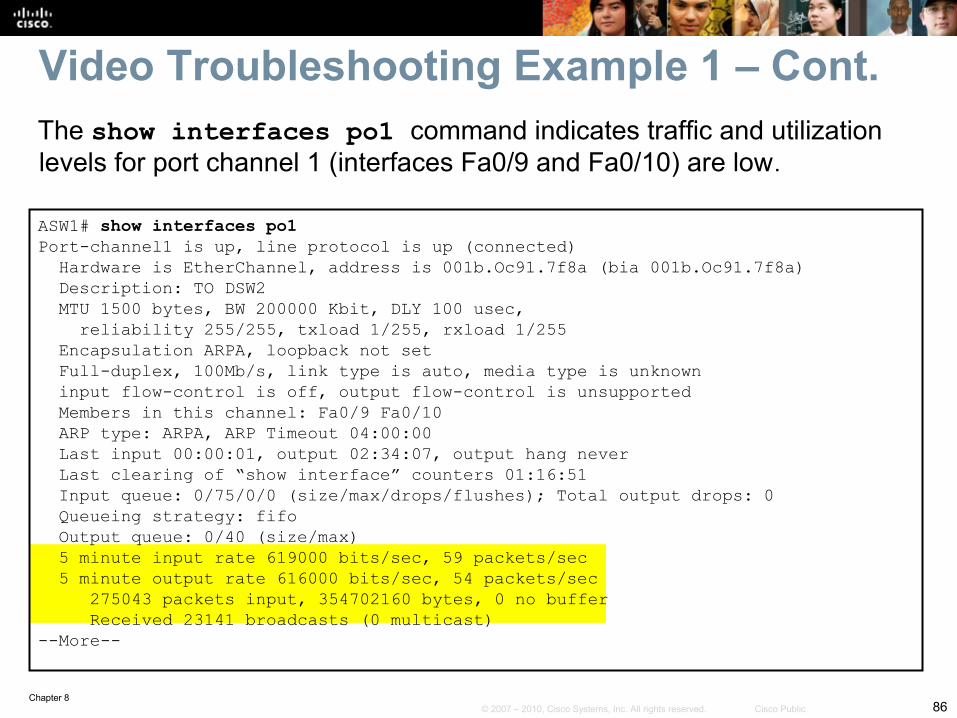
ASW1# show interfaces po1Port-channel1 is up, line protocol is up (connected) Hardware is EtherChannel, address is 001b.Oc91.7f8a (bia 001b.Oc91.7f8a) Description: TO DSW2 MTU 1500 bytes, BW 200000 Kbit, DLY 100 usec, reliability 255/255, txload 1/255, rxload 1/255 Encapsulation ARPA, loopback not set Full-duplex, 100Mb/s, link type is auto, media type is unknown input flow-control is off, output flow-control is unsupported Members in this channel: Fa0/9 Fa0/10 ARP type: ARPA, ARP Timeout 04:00:00 Last input 00:00:01, output 02:34:07, output hang never Last clearing of “show interface” counters 01:16:51 Input queue: 0/75/0/0 (size/max/drops/flushes); Total output drops: 0 Queueing strategy: fifo Output queue: 0/40 (size/max) 5 minute input rate 619000 bits/sec, 59 packets/sec 5 minute output rate 616000 bits/sec, 54 packets/sec 275043 packets input, 354702160 bytes, 0 no buffer Received 23141 broadcasts (0 multicast)--More--
The show interfaces po1 command indicates traffic and utilization levels for port channel 1 (interfaces Fa0/9 and Fa0/10) are low.
Video Troubleshooting Example 1 – Cont.
Chapter 887© 2007 – 2010, Cisco Systems, Inc. All rights reserved. Cisco Public
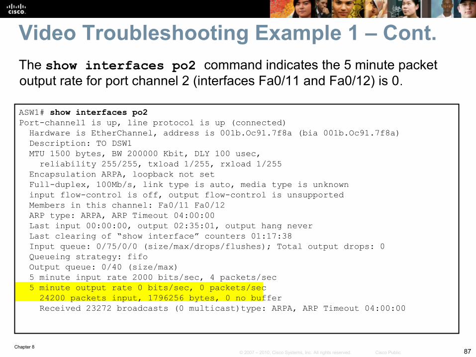
ASW1# show interfaces po2Port-channel1 is up, line protocol is up (connected) Hardware is EtherChannel, address is 001b.Oc91.7f8a (bia 001b.Oc91.7f8a) Description: TO DSW1 MTU 1500 bytes, BW 200000 Kbit, DLY 100 usec, reliability 255/255, txload 1/255, rxload 1/255 Encapsulation ARPA, loopback not set Full-duplex, 100Mb/s, link type is auto, media type is unknown input flow-control is off, output flow-control is unsupported Members in this channel: Fa0/11 Fa0/12 ARP type: ARPA, ARP Timeout 04:00:00 Last input 00:00:00, output 02:35:01, output hang never Last clearing of “show interface” counters 01:17:38 Input queue: 0/75/0/0 (size/max/drops/flushes); Total output drops: 0 Queueing strategy: fifo Output queue: 0/40 (size/max) 5 minute input rate 2000 bits/sec, 4 packets/sec 5 minute output rate 0 bits/sec, 0 packets/sec 24200 packets input, 1796256 bytes, 0 no buffer Received 23272 broadcasts (0 multicast)type: ARPA, ARP Timeout 04:00:00
Video Troubleshooting Example 1 – Cont.The show interfaces po2 command indicates the 5 minute packet output rate for port channel 2 (interfaces Fa0/11 and Fa0/12) is 0.
Chapter 888© 2007 – 2010, Cisco Systems, Inc. All rights reserved. Cisco Public
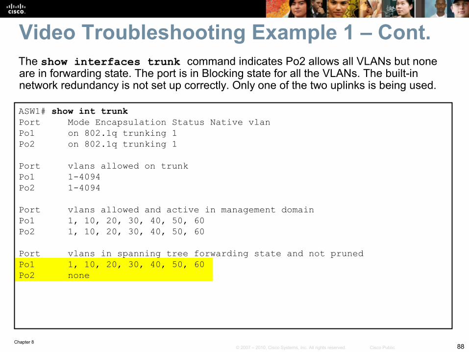
ASW1# show int trunkPort Mode Encapsulation Status Native vlanPo1 on 802.1q trunking 1Po2 on 802.1q trunking 1
Port vlans allowed on trunkPo1 1-4094Po2 1-4094
Port vlans allowed and active in management domainPo1 1, 10, 20, 30, 40, 50, 60Po2 1, 10, 20, 30, 40, 50, 60
Port vlans in spanning tree forwarding state and not prunedPo1 1, 10, 20, 30, 40, 50, 60Po2 none
The show interfaces trunk command indicates Po2 allows all VLANs but none are in forwarding state. The port is in Blocking state for all the VLANs. The built-in network redundancy is not set up correctly. Only one of the two uplinks is being used.
Video Troubleshooting Example 1 – Cont.
Chapter 889© 2007 – 2010, Cisco Systems, Inc. All rights reserved. Cisco Public
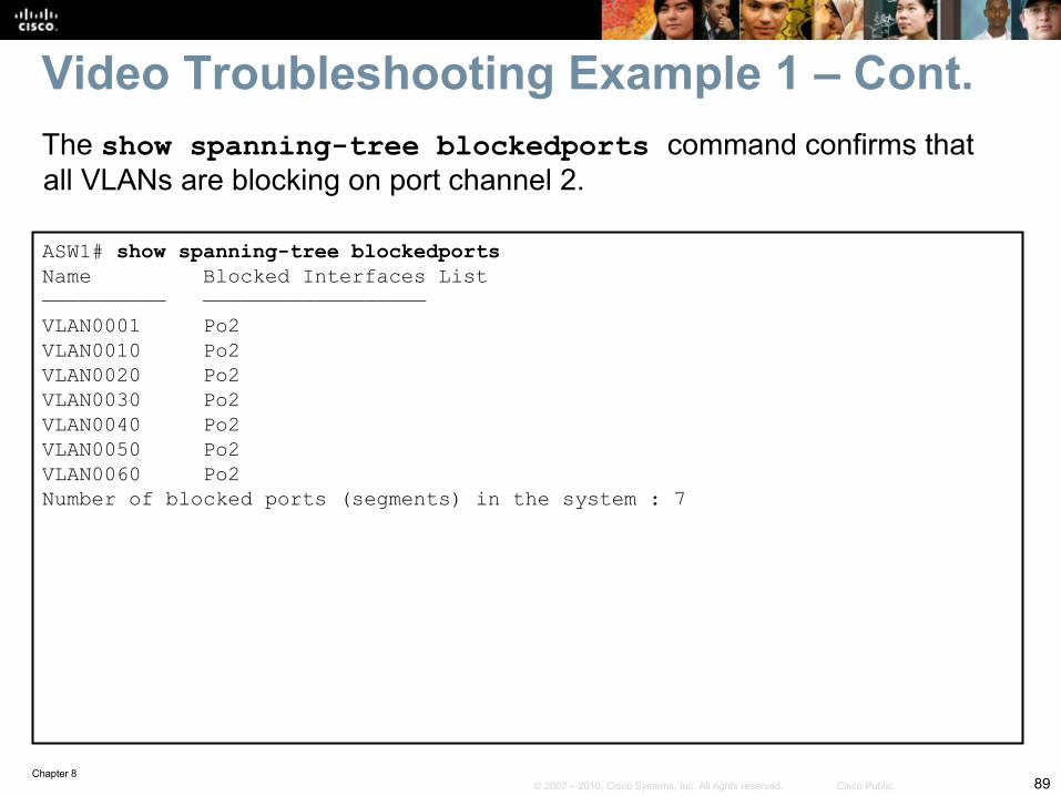
ASW1# show spanning-tree blockedportsName Blocked Interfaces List—————————— ——————————————————VLAN0001 Po2VLAN0010 Po2VLAN0020 Po2VLAN0030 Po2VLAN0040 Po2VLAN0050 Po2VLAN0060 Po2Number of blocked ports (segments) in the system : 7
Video Troubleshooting Example 1 – Cont.The show spanning-tree blockedports command confirms that all VLANs are blocking on port channel 2.
Chapter 890© 2007 – 2010, Cisco Systems, Inc. All rights reserved. Cisco Public
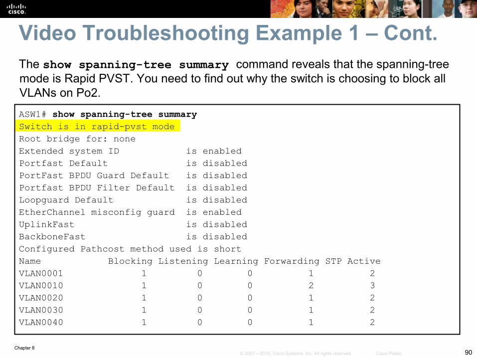
Video Troubleshooting Example 1 – Cont.The show spanning-tree summary command reveals that the spanning-tree mode is Rapid PVST. You need to find out why the switch is choosing to block all VLANs on Po2.
ASW1# show spanning-tree summarySwitch is in rapid-pvst modeRoot bridge for: noneExtended system ID is enabledPortfast Default is disabledPortFast BPDU Guard Default is disabledPortfast BPDU Filter Default is disabledLoopguard Default is disabledEtherChannel misconfig guard is enabledUplinkFast is disabledBackboneFast is disabledConfigured Pathcost method used is shortName Blocking Listening Learning Forwarding STP ActiveVLAN0001 1 0 0 1 2VLAN0010 1 0 0 2 3VLAN0020 1 0 0 1 2VLAN0030 1 0 0 1 2VLAN0040 1 0 0 1 2
Chapter 891© 2007 – 2010, Cisco Systems, Inc. All rights reserved. Cisco Public
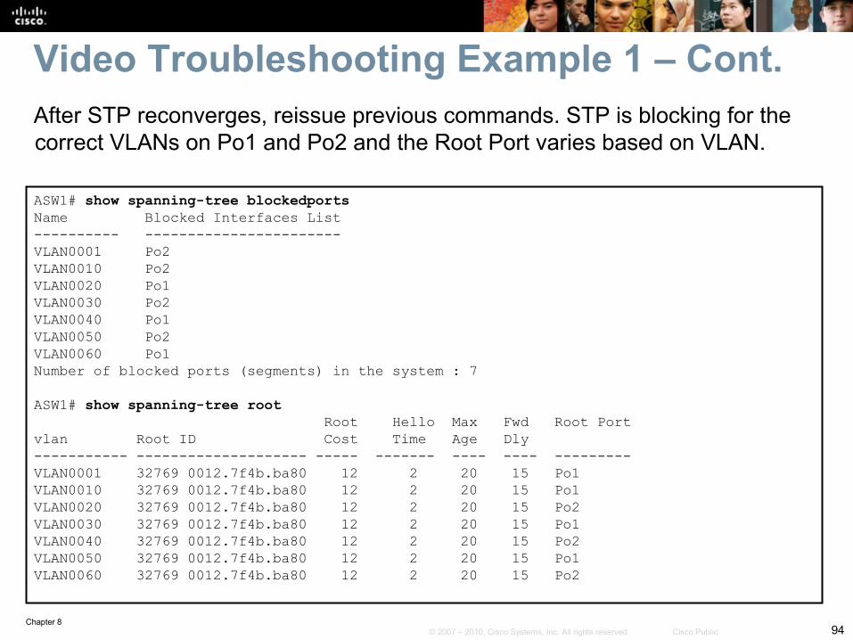
ASW1# show spanning-tree root Root Hello Max Fwd Root Portvlan Root ID Cost Time Age Dly----------- -------------------- ----- ------- ---- ---- ---------VLAN0001 32769 0012.7f4b.ba80 12 2 20 15 Po1VLAN0010 32769 0012.7f4b.ba80 12 2 20 15 Po1VLAN0020 32769 0012.7f4b.ba80 12 2 20 15 Po1VLAN0030 32769 0012.7f4b.ba80 12 2 20 15 Po1VLAN0040 32769 0012.7f4b.ba80 12 2 20 15 Po1VLAN0050 32769 0012.7f4b.ba80 12 2 20 15 Po1 VLAN0060 32769 0012.7f4b.ba80 12 2 20 15 Po1
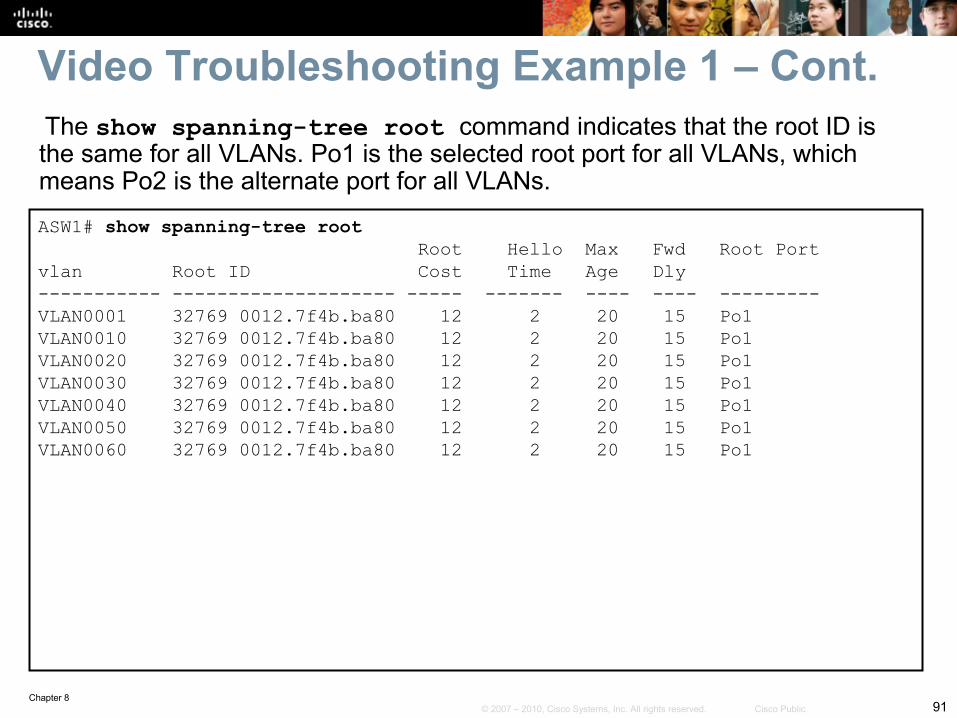
Video Troubleshooting Example 1 – Cont. The show spanning-tree root command indicates that the root ID is the same for all VLANs. Po1 is the selected root port for all VLANs, which means Po2 is the alternate port for all VLANs.
Chapter 892© 2007 – 2010, Cisco Systems, Inc. All rights reserved. Cisco Public
DSW1# show spanning-tree root Root Hello Max Fwd Root Portvlan Root ID Cost Time Age Dly----------- -------------------- ----- ------- ---- ---- ---------VLAN0001 32769 0012.7f4b.ba80 0 2 20 15 VLAN0010 32769 0012.7f4b.ba80 0 2 20 15 VLAN0020 32769 0012.7f4b.ba80 0 2 20 15 VLAN0030 32769 0012.7f4b.ba80 0 2 20 15 VLAN0040 32769 0012.7f4b.ba80 0 2 20 15 VLAN0050 32769 0012.7f4b.ba80 0 2 20 15 VLAN0060 32769 0012.7f4b.ba80 0 2 20 15
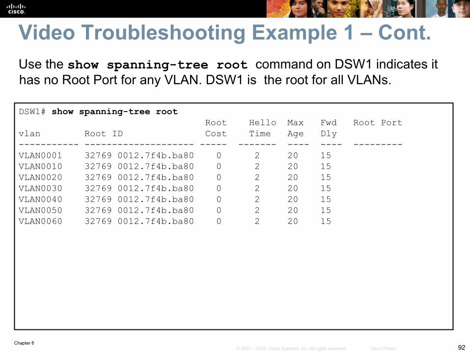
Video Troubleshooting Example 1 – Cont.Use the show spanning-tree root command on DSW1 indicates it has no Root Port for any VLAN. DSW1 is the root for all VLANs.
Chapter 893© 2007 – 2010, Cisco Systems, Inc. All rights reserved. Cisco Public
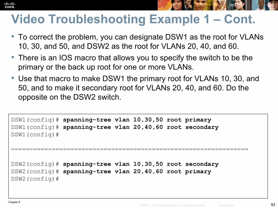
Video Troubleshooting Example 1 – Cont. To correct the problem, you can designate DSW1 as the root for VLANs
10, 30, and 50, and DSW2 as the root for VLANs 20, 40, and 60. There is an IOS macro that allows you to specify the switch to be the
primary or the back up root for one or more VLANs. Use that macro to make DSW1 the primary root for VLANs 10, 30, and
50, and to make it secondary root for VLANs 20, 40, and 60. Do the opposite on the DSW2 switch.
DSW1(config)# spanning-tree vlan 10,30,50 root primaryDSW1(config)# spanning-tree vlan 20,40,60 root secondaryDSW1(config)#
================================================================
DSW2(config)# spanning-tree vlan 10,30,50 root secondaryDSW2(config)# spanning-tree vlan 20,40,60 root primaryDSW2(config)#
Chapter 894© 2007 – 2010, Cisco Systems, Inc. All rights reserved. Cisco Public
ASW1# show spanning-tree blockedportsName Blocked Interfaces List---------- -----------------------VLAN0001 Po2VLAN0010 Po2VLAN0020 Po1VLAN0030 Po2VLAN0040 Po1VLAN0050 Po2VLAN0060 Po1Number of blocked ports (segments) in the system : 7
ASW1# show spanning-tree root Root Hello Max Fwd Root Portvlan Root ID Cost Time Age Dly----------- -------------------- ----- ------- ---- ---- ---------VLAN0001 32769 0012.7f4b.ba80 12 2 20 15 Po1VLAN0010 32769 0012.7f4b.ba80 12 2 20 15 Po1VLAN0020 32769 0012.7f4b.ba80 12 2 20 15 Po2VLAN0030 32769 0012.7f4b.ba80 12 2 20 15 Po1VLAN0040 32769 0012.7f4b.ba80 12 2 20 15 Po2VLAN0050 32769 0012.7f4b.ba80 12 2 20 15 Po1 VLAN0060 32769 0012.7f4b.ba80 12 2 20 15 Po2
Video Troubleshooting Example 1 – Cont.After STP reconverges, reissue previous commands. STP is blocking for the correct VLANs on Po1 and Po2 and the Root Port varies based on VLAN.
Chapter 895© 2007 – 2010, Cisco Systems, Inc. All rights reserved. Cisco Public
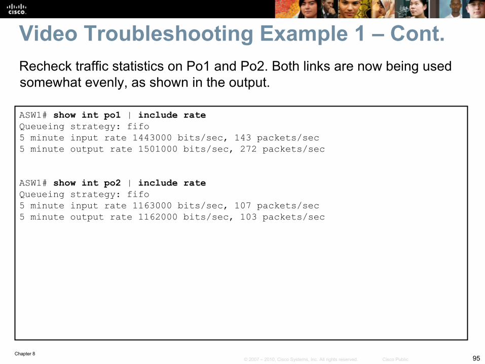
ASW1# show int po1 | include rateQueueing strategy: fifo5 minute input rate 1443000 bits/sec, 143 packets/sec5 minute output rate 1501000 bits/sec, 272 packets/sec
ASW1# show int po2 | include rateQueueing strategy: fifo5 minute input rate 1163000 bits/sec, 107 packets/sec5 minute output rate 1162000 bits/sec, 103 packets/sec
Video Troubleshooting Example 1 – Cont.Recheck traffic statistics on Po1 and Po2. Both links are now being used somewhat evenly, as shown in the output.
Chapter 896© 2007 – 2010, Cisco Systems, Inc. All rights reserved. Cisco Public
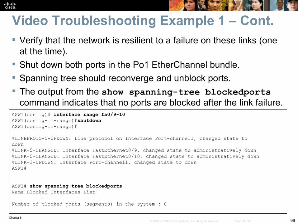
Verify that the network is resilient to a failure on these links (one at the time).
Shut down both ports in the Po1 EtherChannel bundle. Spanning tree should reconverge and unblock ports. The output from the show spanning-tree blockedports
command indicates that no ports are blocked after the link failure.ASW1(config)# interface range fa0/9-10ASW1(config-if-range)#shutdownASW1(config-if-range)#
%LINEPROTO-5-UPDOWN: Line protocol on Interface Port-channel1, changed state todown%LINK-5-CHANGED: Interface FastEthernet0/9, changed state to administratively down%LINK-5-CHANGED: Interface FastEthernet0/10, changed state to administratively down%LINK-3-UPDOWN: Interface Port-channel1, changed state to downASW1#
ASW1# show spanning-tree blockedportsName Blocked Interfaces List——————————- ——————————————————Number of blocked ports (segments) in the system : 0
Video Troubleshooting Example 1 – Cont.
Chapter 897© 2007 – 2010, Cisco Systems, Inc. All rights reserved. Cisco Public
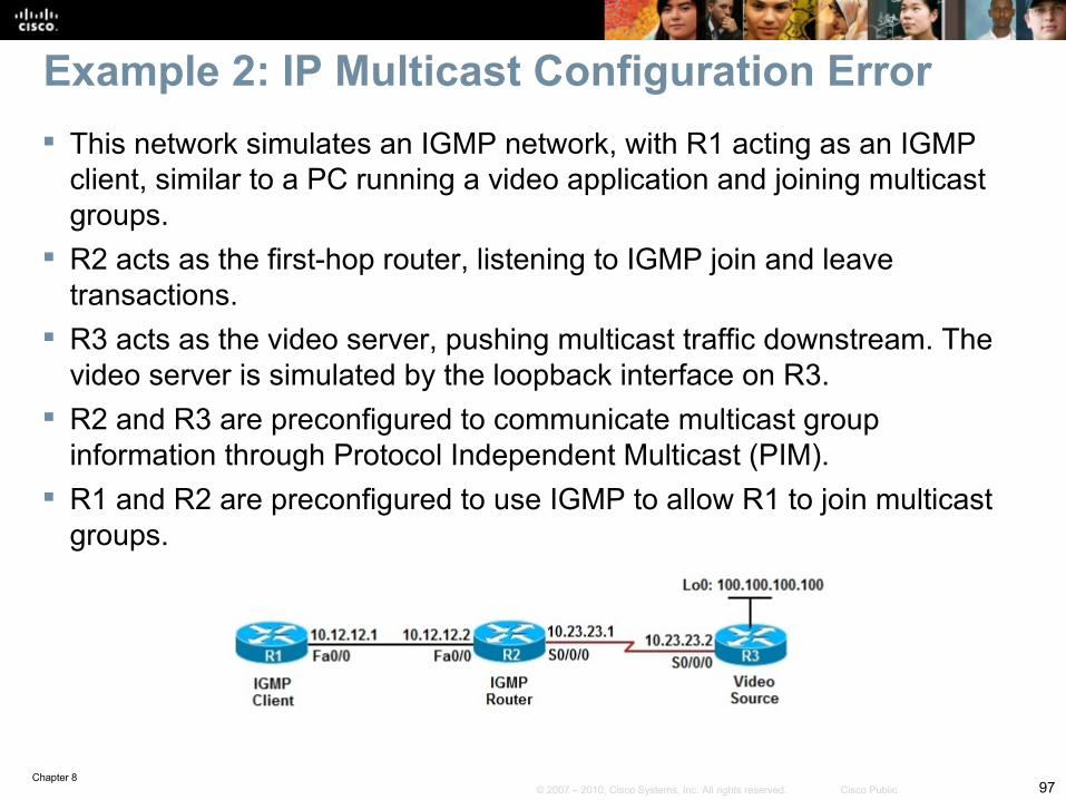
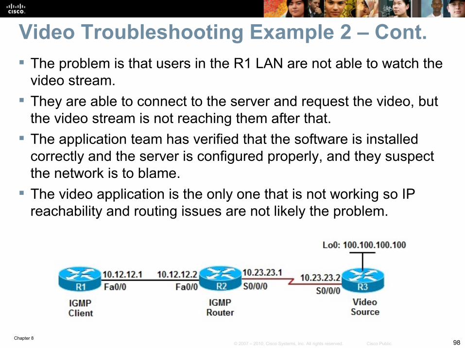
This network simulates an IGMP network, with R1 acting as an IGMP client, similar to a PC running a video application and joining multicast groups.
R2 acts as the first-hop router, listening to IGMP join and leave transactions.
R3 acts as the video server, pushing multicast traffic downstream. The video server is simulated by the loopback interface on R3.
R2 and R3 are preconfigured to communicate multicast group information through Protocol Independent Multicast (PIM).
R1 and R2 are preconfigured to use IGMP to allow R1 to join multicast groups.
Example 2: IP Multicast Configuration Error
Chapter 898© 2007 – 2010, Cisco Systems, Inc. All rights reserved. Cisco Public
Video Troubleshooting Example 2 – Cont. The problem is that users in the R1 LAN are not able to watch the
video stream. They are able to connect to the server and request the video, but
the video stream is not reaching them after that. The application team has verified that the software is installed
correctly and the server is configured properly, and they suspect the network is to blame.
The video application is the only one that is not working so IP reachability and routing issues are not likely the problem.
Chapter 899© 2007 – 2010, Cisco Systems, Inc. All rights reserved. Cisco Public
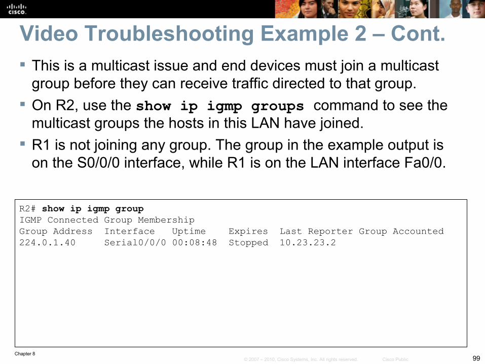
Video Troubleshooting Example 2 – Cont. This is a multicast issue and end devices must join a multicast
group before they can receive traffic directed to that group. On R2, use the show ip igmp groups command to see the
multicast groups the hosts in this LAN have joined. R1 is not joining any group. The group in the example output is
on the S0/0/0 interface, while R1 is on the LAN interface Fa0/0.
R2# show ip igmp groupIGMP Connected Group MembershipGroup Address Interface Uptime Expires Last Reporter Group Accounted224.0.1.40 Serial0/0/0 00:08:48 Stopped 10.23.23.2
Chapter 8100© 2007 – 2010, Cisco Systems, Inc. All rights reserved. Cisco Public
R2# show ip igmp membershipFlags: A - aggregate, T - tracked L - Local, S - static, V - virtual, R - Reported through v3 I - v3lite, U - Urd, M - SSM (S,G) channel 1,2,3 - The version of IGMP the group is in
Channel/Group-Flags: / - Filtering entry (Exclude mode (S,G), Include mode (*,G)Reporter: <mac-or-ip-address> - last reporter if group is not explicitly tracked <n>/<m> - <n> reporter in include mode, <m> reporter in exclude
Channel/Group Reporter Uptime Exp Flags Interface*.224.0.1.40 10.23.23.2 00:09:24 stop 2LA Se0/0/0
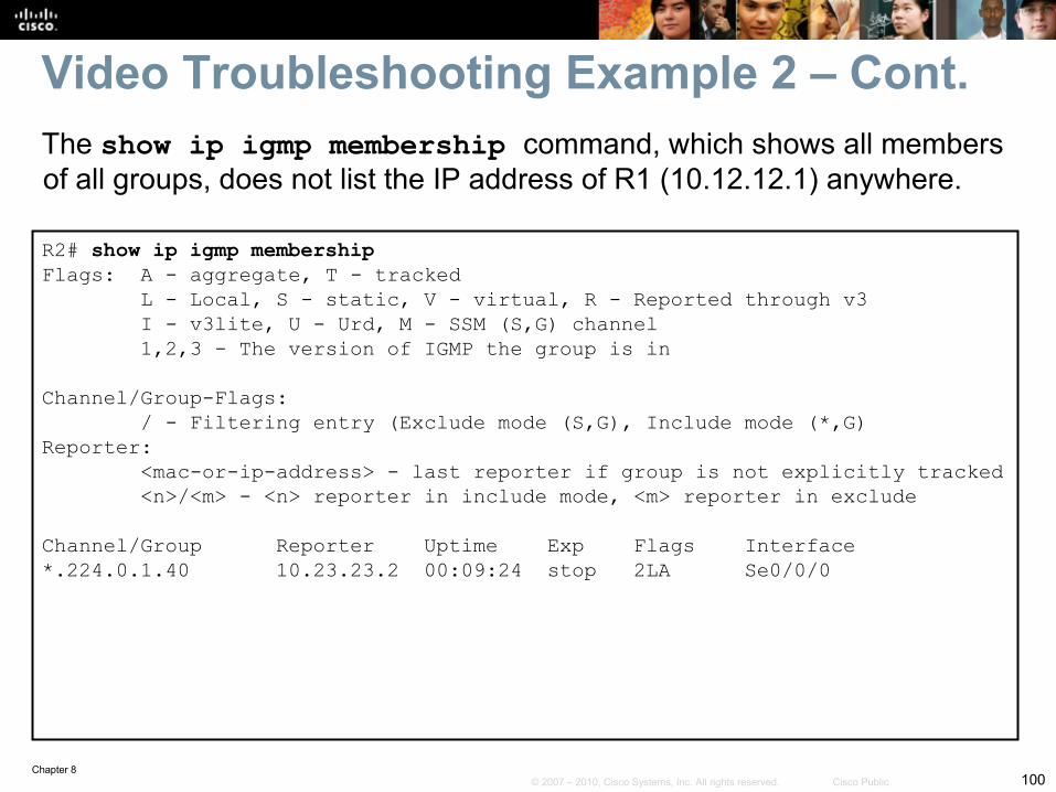
Video Troubleshooting Example 2 – Cont.The show ip igmp membership command, which shows all members of all groups, does not list the IP address of R1 (10.12.12.1) anywhere.
Chapter 8101© 2007 – 2010, Cisco Systems, Inc. All rights reserved. Cisco Public
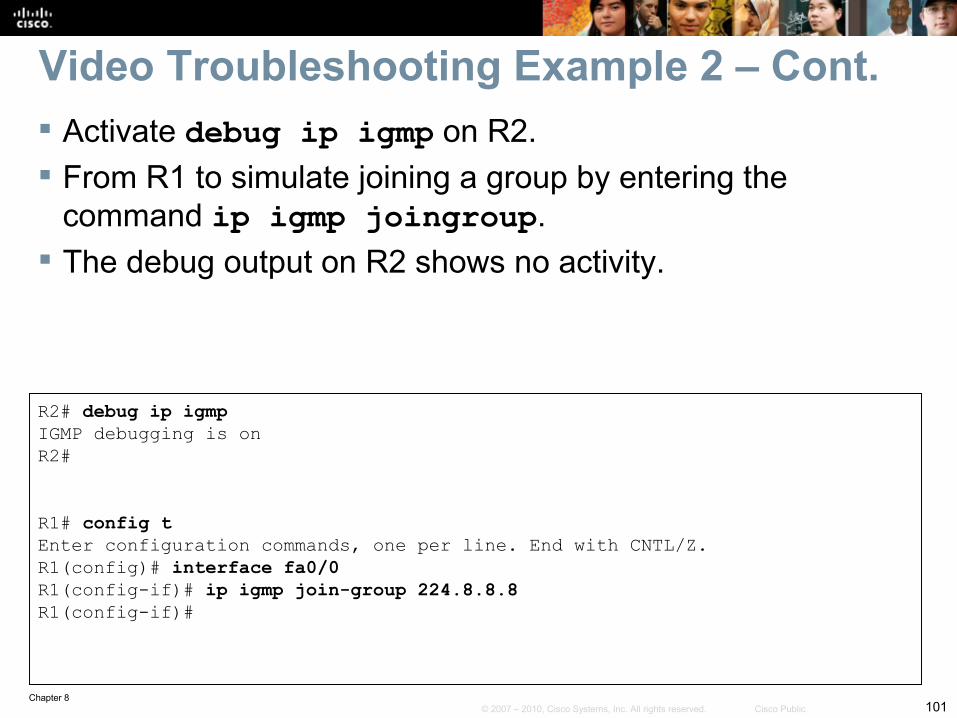
Video Troubleshooting Example 2 – Cont. Activate debug ip igmp on R2. From R1 to simulate joining a group by entering the
command ip igmp joingroup. The debug output on R2 shows no activity.
R2# debug ip igmpIGMP debugging is onR2#
R1# config tEnter configuration commands, one per line. End with CNTL/Z.R1(config)# interface fa0/0R1(config-if)# ip igmp join-group 224.8.8.8R1(config-if)#
Chapter 8102© 2007 – 2010, Cisco Systems, Inc. All rights reserved. Cisco Public
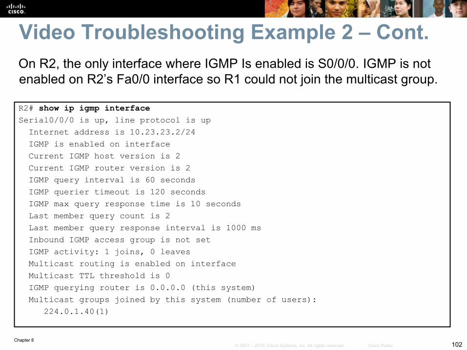
R2# show ip igmp interfaceSerial0/0/0 is up, line protocol is up Internet address is 10.23.23.2/24 IGMP is enabled on interface Current IGMP host version is 2 Current IGMP router version is 2 IGMP query interval is 60 seconds IGMP querier timeout is 120 seconds IGMP max query response time is 10 seconds Last member query count is 2 Last member query response interval is 1000 ms Inbound IGMP access group is not set IGMP activity: 1 joins, 0 leaves Multicast routing is enabled on interface Multicast TTL threshold is 0 IGMP querying router is 0.0.0.0 (this system) Multicast groups joined by this system (number of users): 224.0.1.40(1)
On R2, the only interface where IGMP Is enabled is S0/0/0. IGMP is not enabled on R2’s Fa0/0 interface so R1 could not join the multicast group.
Video Troubleshooting Example 2 – Cont.
Chapter 8103© 2007 – 2010, Cisco Systems, Inc. All rights reserved. Cisco Public
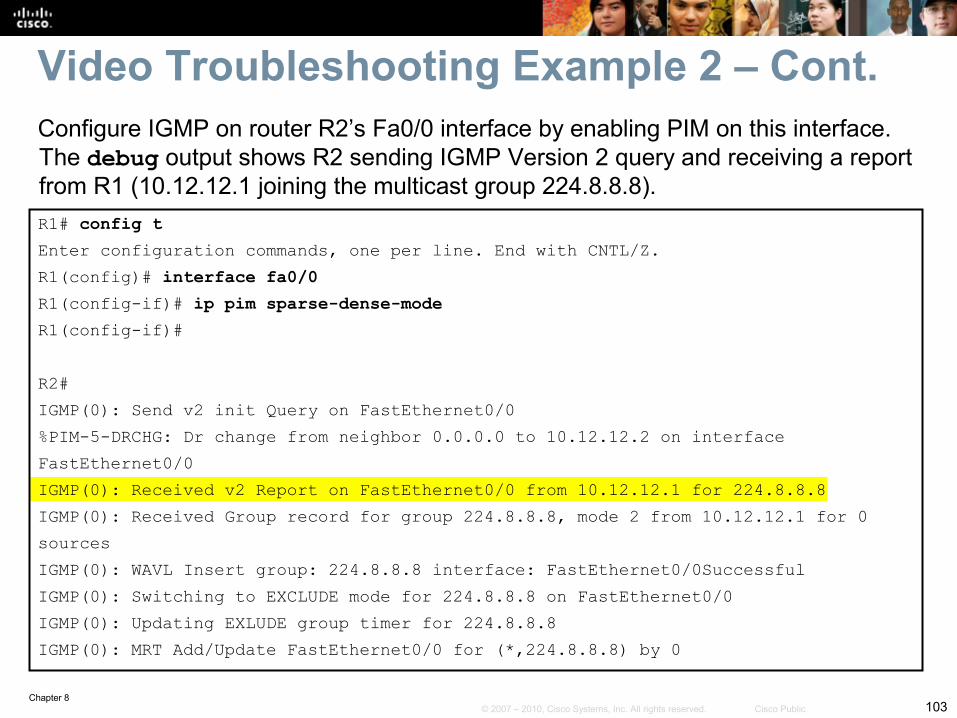
R1# config tEnter configuration commands, one per line. End with CNTL/Z.R1(config)# interface fa0/0R1(config-if)# ip pim sparse-dense-modeR1(config-if)#
R2#IGMP(0): Send v2 init Query on FastEthernet0/0%PIM-5-DRCHG: Dr change from neighbor 0.0.0.0 to 10.12.12.2 on interfaceFastEthernet0/0IGMP(0): Received v2 Report on FastEthernet0/0 from 10.12.12.1 for 224.8.8.8IGMP(0): Received Group record for group 224.8.8.8, mode 2 from 10.12.12.1 for 0sourcesIGMP(0): WAVL Insert group: 224.8.8.8 interface: FastEthernet0/0SuccessfulIGMP(0): Switching to EXCLUDE mode for 224.8.8.8 on FastEthernet0/0IGMP(0): Updating EXLUDE group timer for 224.8.8.8IGMP(0): MRT Add/Update FastEthernet0/0 for (*,224.8.8.8) by 0
Video Troubleshooting Example 2 – Cont.Configure IGMP on router R2’s Fa0/0 interface by enabling PIM on this interface. The debug output shows R2 sending IGMP Version 2 query and receiving a report from R1 (10.12.12.1 joining the multicast group 224.8.8.8).
Chapter 8104© 2007 – 2010, Cisco Systems, Inc. All rights reserved. Cisco Public
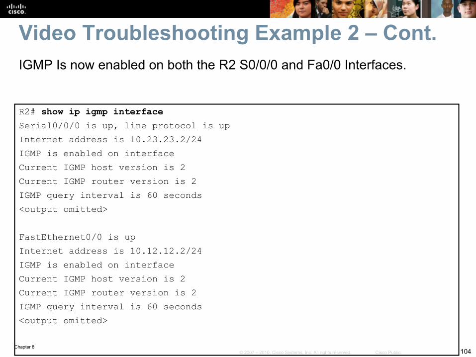
R2# show ip igmp interfaceSerial0/0/0 is up, line protocol is upInternet address is 10.23.23.2/24IGMP is enabled on interfaceCurrent IGMP host version is 2Current IGMP router version is 2IGMP query interval is 60 seconds<output omitted>
FastEthernet0/0 is upInternet address is 10.12.12.2/24IGMP is enabled on interfaceCurrent IGMP host version is 2Current IGMP router version is 2IGMP query interval is 60 seconds<output omitted>
Video Troubleshooting Example 2 – Cont.IGMP Is now enabled on both the R2 S0/0/0 and Fa0/0 Interfaces.
Chapter 8105© 2007 – 2010, Cisco Systems, Inc. All rights reserved. Cisco Public
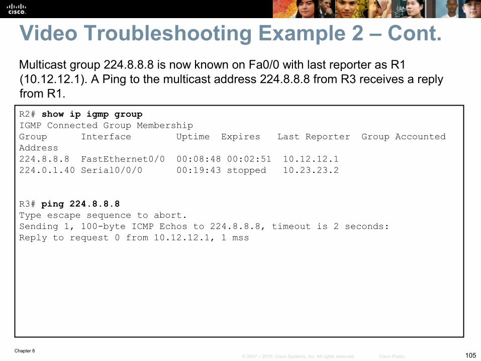
R2# show ip igmp groupIGMP Connected Group MembershipGroup Interface Uptime Expires Last Reporter Group AccountedAddress224.8.8.8 FastEthernet0/0 00:08:48 00:02:51 10.12.12.1224.0.1.40 Serial0/0/0 00:19:43 stopped 10.23.23.2
R3# ping 224.8.8.8Type escape sequence to abort.Sending 1, 100-byte ICMP Echos to 224.8.8.8, timeout is 2 seconds:Reply to request 0 from 10.12.12.1, 1 mss
Multicast group 224.8.8.8 is now known on Fa0/0 with last reporter as R1 (10.12.12.1). A Ping to the multicast address 224.8.8.8 from R3 receives a reply from R1.
Video Troubleshooting Example 2 – Cont.
Chapter 8106© 2007 – 2010, Cisco Systems, Inc. All rights reserved. Cisco Public
Some useful switch troubleshooting commands to support wireless LANS are:• show interfaces switchport• show interfaces status• show interfaces trunk• show interface interface switchport• show access-lists
Chapter 8 Summary: WLAN – Cont.
Chapter 8107© 2007 – 2010, Cisco Systems, Inc. All rights reserved. Cisco Public
Related Documents