(210–VI–NEH, August 2007) Technical Supplement 14L Use of Articulating Concrete Block Revetment Systems for Stream Restoration and Stabilization Projects

Welcome message from author
This document is posted to help you gain knowledge. Please leave a comment to let me know what you think about it! Share it to your friends and learn new things together.
Transcript
(210–VI–NEH, August 2007)
Technical Supplement 14L
Use of Articulating Concrete Block Revetment Systems for Stream Restoration and Stabilization Projects

Part 654 National Engineering Handbook
Use of Articulating Concrete Block Revetment Systems for Stream Restoration and Stabilization Projects
Technical Supplement 14L
(210–VI–NEH, August 2007)
Advisory Note
Techniques and approaches contained in this handbook are not all-inclusive, nor universally applicable. Designing stream restorations requires appropriate training and experience, especially to identify conditions where various approaches, tools, and techniques are most applicable, as well as their limitations for design. Note also that prod-uct names are included only to show type and availability and do not constitute endorsement for their specific use.
Cover photo: Manufactured concrete blocks are available in a variety of thicknesses and configurations and can be used to stabilize the streambed or streambanks.
Issued August 2007
(210–VI–NEH, August 2007) TS14L–iii
Contents
Technical Supplement 14L
Use of Articulating Concrete Block Revetment Systems for Stream Restoration and Stabilization Projects
Purpose TS14L–1
Introduction TS14L–1
Applications TS14L–1
Materials TS14L–6
Blocks .............................................................................................................. TS14L–6
Connections .................................................................................................... TS14L–6
Geotextiles ...................................................................................................... TS14L–6
Granular filter ................................................................................................. TS14L–6
Performance testing and evaluation ............................................................ TS14L–9
Design procedure TS14L–11
Factor of safety ............................................................................................ TS14L–11
Blocks ............................................................................................................ TS14L–11
Filter .............................................................................................................. TS14L–11
Specifying ACB revetment systems TS14L–14
Blocks ............................................................................................................ TS14L–14
Connections .................................................................................................. TS14L–14
Geotextile ...................................................................................................... TS14L–14
Testing .......................................................................................................... TS14L–14
Design ............................................................................................................ TS14L–14
Installation TS14L–14
Subgrade preparation .................................................................................. TS14L–14
Geotextile placement .................................................................................. TS14L–16
Placement of the ACB ................................................................................. TS14L–16
Termination................................................................................................... TS14L–16
Anchor penetrations .................................................................................... TS14L–16
Filling ............................................................................................................. TS14L–16
ACB example calculations TS14L–19
Conclusion TS14L–21
Part 654 National Engineering Handbook
Use of Articulating Concrete Block Revetment Systems for Stream Restoration and Stabilization Projects
Technical Supplement 14L
(210–VI–NEH, August 2007)TS14L–iv
Tables Table TS14L–1 Steel cable specifications TS14L–8
Table TS14L–2 Polyester cable specifications TS14L–8
Table TS14L–3 Design equations for ACB revetment systems TS14L–13
Table TS14L–4 Block physical requirements TS14L–15
Table TS14L–5 NRCS specifications for woven geotextiles TS14L–15
Table TS14L–6 NRCS specifications for nonwoven geotextiles TS14L–15
Figures Figure TS14L–1 Armoring the entire cross section TS14L–2
Figure TS14L–2 Armoring the toe and lower slope cross section TS14L–2
Figure TS14L–3 Armoring the toe and slide slope cross section TS14L–3
Figure TS14L–4 Streambed grade stabilization profile TS14L–3
Figure TS14L–5 Armoring of pipe/culvert outlets profile TS14L–4
Figure TS14L–6 Scour protection around bridge piers plan TS14L–5
Figure TS14L–7 Examples of ACB blocks TS14L–7
Figure TS14L–8 Steel cables TS14L–8
Figure TS14L–9 Polyester cables TS14L–8
Figure TS14L–10 ACB section with a geotextile filter and TS14L–8combination geotextile and granular filter
Figure TS14L–11 ACBs in combination with granular and TS14L–9geotextile filter
Figure TS14L–12 Schematic of a typical laboratory test flume TS14L–9for ACB performance testing
(210–VI–NEH, August 2007)
Part 654 National Engineering Handbook
Use of Articulating Concrete Block Revetment Systems for Stream Restoration and Stabilization Projects
Technical Supplement 14L
TS14L–v
Figure TS14L–13 Forces on an ACB revetment system during TS14L–10performance test
Figure TS14L–14 Forces on a protruding block TS14L–10
Figure TS14L–15 Block on a side slope with design variables TS14L–12
Figure TS14L–16 Block moment arms TS14L–12
Figure TS14L–17 Granular filter encapsulation by a geotextile TS14L–17
Figure TS14L–18 Spreader bar for placement of cabled mats TS14L–17
Figure TS14L–19 Hand placement of ACB blocks TS14L–17
Figure TS14L–20 ACB termination trench TS14L–18
Figure TS14L–21 Filling ACBs with top soil TS14L–18
Figure TS14L–22 ACB revetment system 1 year after TS14L–18completion
Figure TS14L–23 ACB revetment system 2 years after TS14L–18completion

(210–VI–NEH, August 2007) TS14L–1
Technical Supplement 14L
Use of Articulating Concrete Block Revetment Systems for Stream Restoration and Stabilization Projects
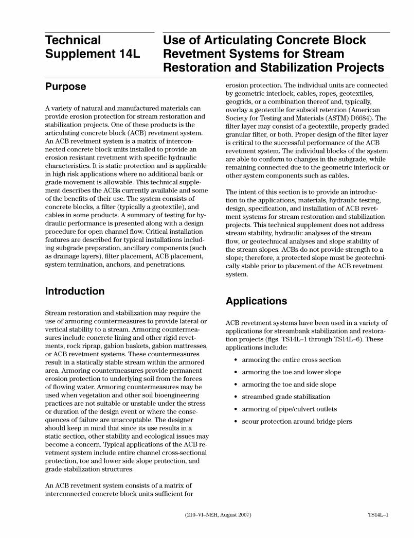
Purpose
A variety of natural and manufactured materials can provide erosion protection for stream restoration and stabilization projects. One of these products is the articulating concrete block (ACB) revetment system. An ACB revetment system is a matrix of intercon-nected concrete block units installed to provide an erosion resistant revetment with specific hydraulic characteristics. It is static protection and is applicable in high risk applications where no additional bank or grade movement is allowable. This technical supple-ment describes the ACBs currently available and some of the benefits of their use. The system consists of concrete blocks, a filter (typically a geotextile), and cables in some products. A summary of testing for hy-draulic performance is presented along with a design procedure for open channel flow. Critical installation features are described for typical installations includ-ing subgrade preparation, ancillary components (such as drainage layers), filter placement, ACB placement, system termination, anchors, and penetrations.
Introduction
Stream restoration and stabilization may require the use of armoring countermeasures to provide lateral or vertical stability to a stream. Armoring countermea-sures include concrete lining and other rigid revet-ments, rock riprap, gabion baskets, gabion mattresses, or ACB revetment systems. These countermeasures result in a statically stable stream within the armored area. Armoring countermeasures provide permanent erosion protection to underlying soil from the forces of flowing water. Armoring countermeasures may be used when vegetation and other soil bioengineering practices are not suitable or unstable under the stress or duration of the design event or where the conse-quences of failure are unacceptable. The designer should keep in mind that since its use results in a static section, other stability and ecological issues may become a concern. Typical applications of the ACB re-vetment system include entire channel cross-sectional protection, toe and lower side slope protection, and grade stabilization structures.
An ACB revetment system consists of a matrix of interconnected concrete block units sufficient for
erosion protection. The individual units are connected by geometric interlock, cables, ropes, geotextiles, geogrids, or a combination thereof and, typically, overlay a geotextile for subsoil retention (American Society for Testing and Materials (ASTM) D6684). The filter layer may consist of a geotextile, properly graded granular filter, or both. Proper design of the filter layer is critical to the successful performance of the ACB revetment system. The individual blocks of the system are able to conform to changes in the subgrade, while remaining connected due to the geometric interlock or other system components such as cables.
The intent of this section is to provide an introduc-tion to the applications, materials, hydraulic testing, design, specification, and installation of ACB revet-ment systems for stream restoration and stabilization projects. This technical supplement does not address stream stability, hydraulic analyses of the stream flow, or geotechnical analyses and slope stability of the stream slopes. ACBs do not provide strength to a slope; therefore, a protected slope must be geotechni-cally stable prior to placement of the ACB revetment system.
Applications
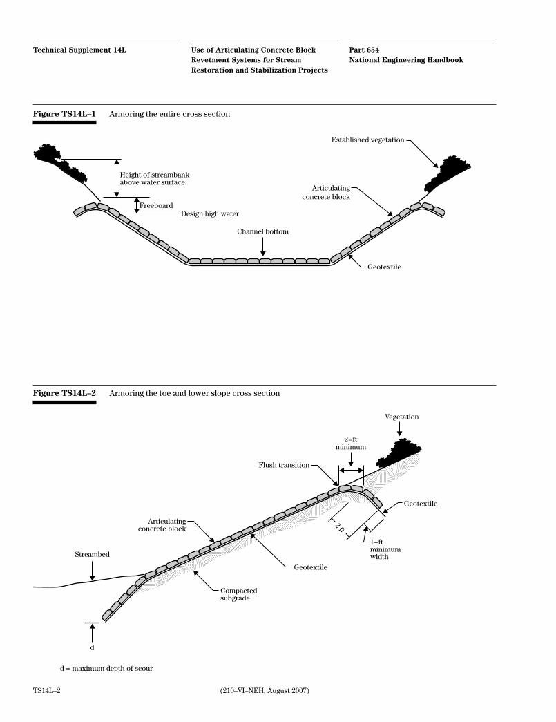
ACB revetment systems have been used in a variety of applications for streambank stabilization and restora-tion projects (figs. TS14L–1 through TS14L–6). These applications include:
• armoring the entire cross section
• armoring the toe and lower slope
• armoring the toe and side slope
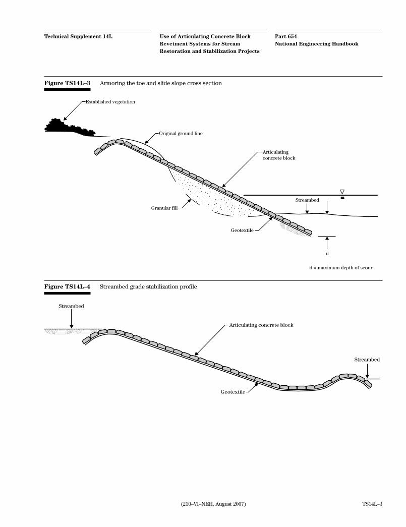
• streambed grade stabilization
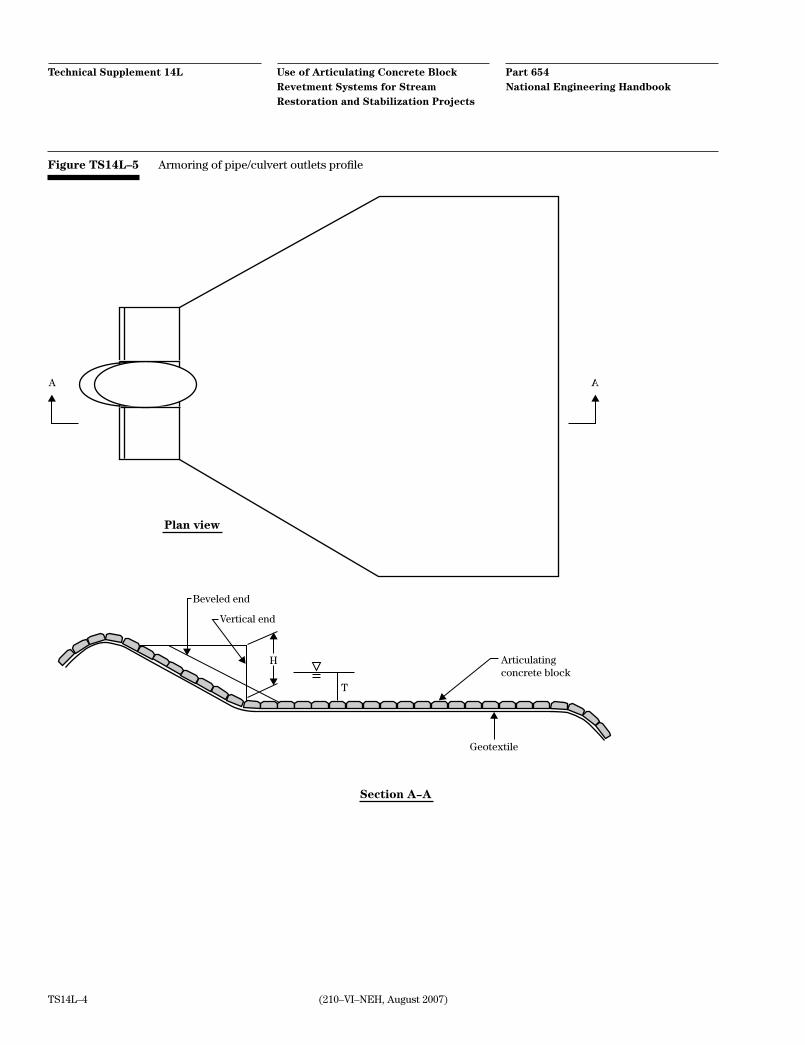
• armoring of pipe/culvert outlets
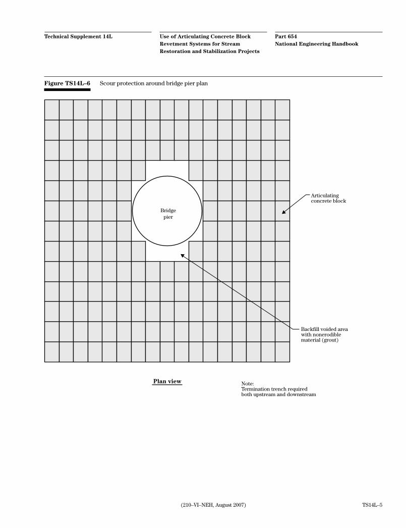
• scour protection around bridge piers
Part 654 National Engineering Handbook
Use of Articulating Concrete Block Revetment Systems for Stream Restoration and Stabilization Projects
Technical Supplement 14L
(210–VI–NEH, August 2007)TS14L–2
Figure TS14L–1 Armoring the entire cross section
Height of streambankabove water surface
FreeboardDesign high water
Channel bottom
Articulatingconcrete block
Geotextile
Established vegetation
Figure TS14L–2 Armoring the toe and lower slope cross section
Compactedsubgrade
Geotextile
Geotextile
2−ftminimum
Streambed
Flush transition
Vegetation
Articulatingconcrete block
2 ft
1−ftminimumwidth
d
d = maximum depth of scour
(210–VI–NEH, August 2007)
Part 654 National Engineering Handbook
Use of Articulating Concrete Block Revetment Systems for Stream Restoration and Stabilization Projects
Technical Supplement 14L
TS14L–3
Figure TS14L–3 Armoring the toe and slide slope cross section
Established vegetation
Original ground line
Articulatingconcrete block
d
d = maximum depth of scour
Geotextile
Streambed
Granular fill
Figure TS14L–4 Streambed grade stabilization profile
Articulating concrete block
Streambed
Geotextile
Streambed
Part 654 National Engineering Handbook
Use of Articulating Concrete Block Revetment Systems for Stream Restoration and Stabilization Projects
Technical Supplement 14L
(210–VI–NEH, August 2007)TS14L–4
Figure TS14L–5 Armoring of pipe/culvert outlets profile
A A
Plan view
Beveled end
Vertical end
Geotextile
T
H
Section A−A
Articulatingconcrete block
(210–VI–NEH, August 2007)
Part 654 National Engineering Handbook
Use of Articulating Concrete Block Revetment Systems for Stream Restoration and Stabilization Projects
Technical Supplement 14L
TS14L–5
Backfill voided areawith nonerodiblematerial (grout)
Bridgepier
Plan view
Articulatingconcrete block
Note:Termination trench required both upstream and downstream
Figure TS14L–6 Scour protection around bridge pier plan
Part 654 National Engineering Handbook
Use of Articulating Concrete Block Revetment Systems for Stream Restoration and Stabilization Projects
Technical Supplement 14L
(210–VI–NEH, August 2007)TS14L–6
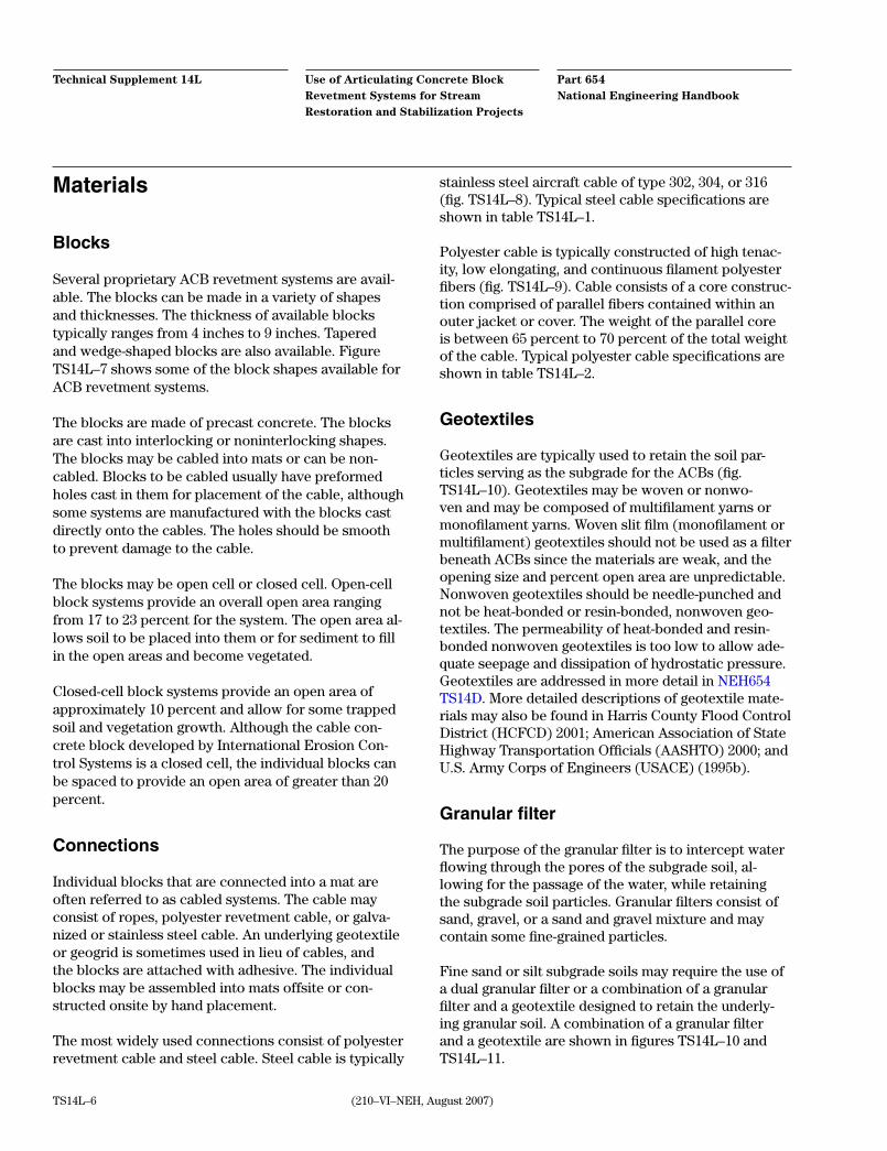
Materials
Blocks
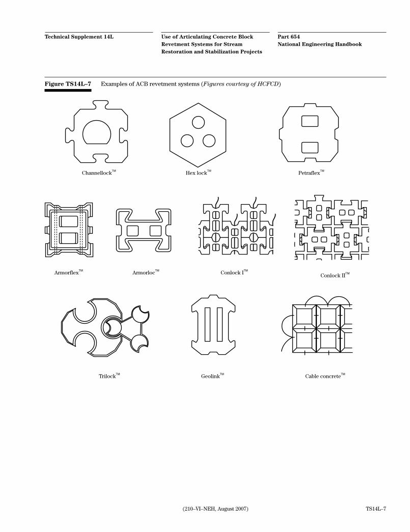
Several proprietary ACB revetment systems are avail-able. The blocks can be made in a variety of shapes and thicknesses. The thickness of available blocks typically ranges from 4 inches to 9 inches. Tapered and wedge-shaped blocks are also available. Figure TS14L–7 shows some of the block shapes available for ACB revetment systems.
The blocks are made of precast concrete. The blocks are cast into interlocking or noninterlocking shapes. The blocks may be cabled into mats or can be non-cabled. Blocks to be cabled usually have preformed holes cast in them for placement of the cable, although some systems are manufactured with the blocks cast directly onto the cables. The holes should be smooth to prevent damage to the cable.
The blocks may be open cell or closed cell. Open-cell block systems provide an overall open area ranging from 17 to 23 percent for the system. The open area al-lows soil to be placed into them or for sediment to fill in the open areas and become vegetated.
Closed-cell block systems provide an open area of approximately 10 percent and allow for some trapped soil and vegetation growth. Although the cable con-crete block developed by International Erosion Con-trol Systems is a closed cell, the individual blocks can be spaced to provide an open area of greater than 20 percent.
Connections
Individual blocks that are connected into a mat are often referred to as cabled systems. The cable may consist of ropes, polyester revetment cable, or galva-nized or stainless steel cable. An underlying geotextile or geogrid is sometimes used in lieu of cables, and the blocks are attached with adhesive. The individual blocks may be assembled into mats offsite or con-structed onsite by hand placement.
The most widely used connections consist of polyester revetment cable and steel cable. Steel cable is typically
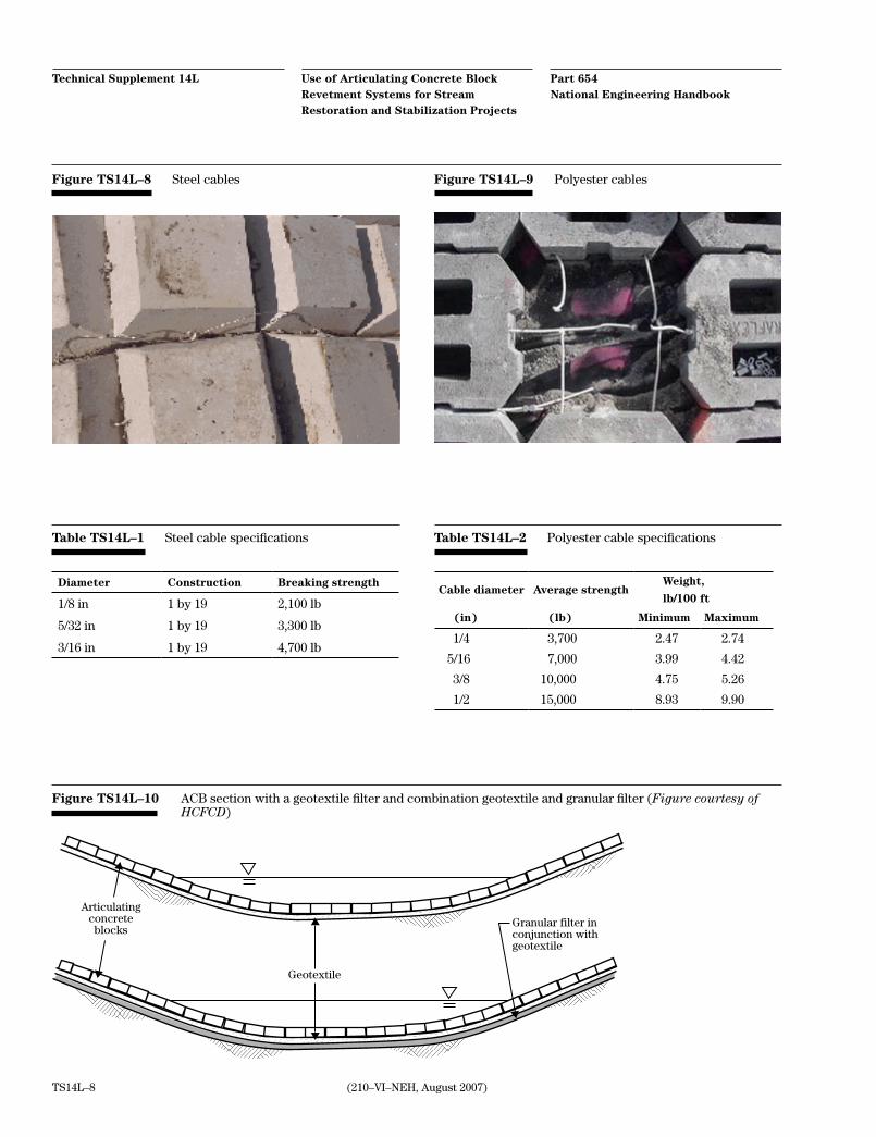
stainless steel aircraft cable of type 302, 304, or 316 (fig. TS14L–8). Typical steel cable specifications are shown in table TS14L–1.
Polyester cable is typically constructed of high tenac-ity, low elongating, and continuous filament polyester fibers (fig. TS14L–9). Cable consists of a core construc-tion comprised of parallel fibers contained within an outer jacket or cover. The weight of the parallel core is between 65 percent to 70 percent of the total weight of the cable. Typical polyester cable specifications are shown in table TS14L–2.
Geotextiles
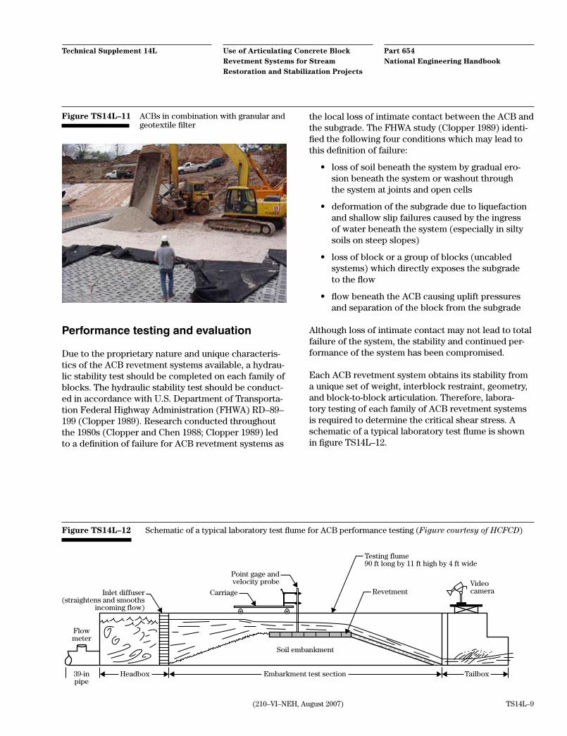
Geotextiles are typically used to retain the soil par-ticles serving as the subgrade for the ACBs (fig. TS14L–10). Geotextiles may be woven or nonwo-ven and may be composed of multifilament yarns or monofilament yarns. Woven slit film (monofilament or multifilament) geotextiles should not be used as a filter beneath ACBs since the materials are weak, and the opening size and percent open area are unpredictable. Nonwoven geotextiles should be needle-punched and not be heat-bonded or resin-bonded, nonwoven geo-textiles. The permeability of heat-bonded and resin-bonded nonwoven geotextiles is too low to allow ade-quate seepage and dissipation of hydrostatic pressure. Geotextiles are addressed in more detail in NEH654 TS14D. More detailed descriptions of geotextile mate-rials may also be found in Harris County Flood Control District (HCFCD) 2001; American Association of State Highway Transportation Officials (AASHTO) 2000; and U.S. Army Corps of Engineers (USACE) (1995b).
Granular filter
The purpose of the granular filter is to intercept water flowing through the pores of the subgrade soil, al-lowing for the passage of the water, while retaining the subgrade soil particles. Granular filters consist of sand, gravel, or a sand and gravel mixture and may contain some fine-grained particles.
Fine sand or silt subgrade soils may require the use of a dual granular filter or a combination of a granular filter and a geotextile designed to retain the underly-ing granular soil. A combination of a granular filter and a geotextile are shown in figures TS14L–10 and TS14L–11.
(210–VI–NEH, August 2007)
Part 654 National Engineering Handbook
Use of Articulating Concrete Block Revetment Systems for Stream Restoration and Stabilization Projects
Technical Supplement 14L
TS14L–7
Figure TS14L–7 Examples of ACB revetment systems (Figures courtesy of HCFCD)
Channellock
Armorflex Armorloc Conlock I Conlock II
Cable concreteGeolinkTrilock
Hex lock Petraflex
Part 654 National Engineering Handbook
Use of Articulating Concrete Block Revetment Systems for Stream Restoration and Stabilization Projects
Technical Supplement 14L
(210–VI–NEH, August 2007)TS14L–8
Figure TS14L–8 Steel cables
Table TS14L–1 Steel cable specifications
Diameter Construction Breaking strength
1/8 in 1 by 19 2,100 lb
5/32 in 1 by 19 3,300 lb
3/16 in 1 by 19 4,700 lb
Figure TS14L–9 Polyester cables
Table TS14L–2 Polyester cable specifications
Cable diameter Average strengthWeight,
lb/100 ft
(in) (lb) Minimum Maximum
1/4 3,700 2.47 2.74
5/16 7,000 3.99 4.42
3/8 10,000 4.75 5.26
1/2 15,000 8.93 9.90
Articulatingconcreteblocks
Geotextile
Granular filter inconjunction withgeotextile
Figure TS14L–10 ACB section with a geotextile filter and combination geotextile and granular filter (Figure courtesy of HCFCD)
(210–VI–NEH, August 2007)
Part 654 National Engineering Handbook
Use of Articulating Concrete Block Revetment Systems for Stream Restoration and Stabilization Projects
Technical Supplement 14L
TS14L–9
Figure TS14L–11 ACBs in combination with granular and geotextile filter
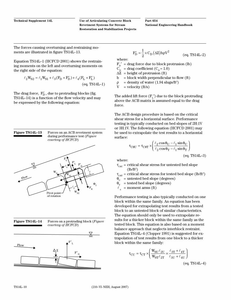
Figure TS14L–12 Schematic of a typical laboratory test flume for ACB performance testing (Figure courtesy of HCFCD)
TailboxEmbarkment test sectionHeadbox39-inpipe
Flowmeter
Carriage
Soil embankment
Inlet diffuser(straightens and smooths
incoming flow)
Point gage andvelocity probe
Testing flume90 ft long by 11 ft high by 4 ft wide
RevetmentVideocamera
Performance testing and evaluation
Due to the proprietary nature and unique characteris-tics of the ACB revetment systems available, a hydrau-lic stability test should be completed on each family of blocks. The hydraulic stability test should be conduct-ed in accordance with U.S. Department of Transporta-tion Federal Highway Administration (FHWA) RD–89–199 (Clopper 1989). Research conducted throughout the 1980s (Clopper and Chen 1988; Clopper 1989) led to a definition of failure for ACB revetment systems as
the local loss of intimate contact between the ACB and the subgrade. The FHWA study (Clopper 1989) identi-fied the following four conditions which may lead to this definition of failure:
• loss of soil beneath the system by gradual ero-sion beneath the system or washout through the system at joints and open cells
• deformation of the subgrade due to liquefaction and shallow slip failures caused by the ingress of water beneath the system (especially in silty soils on steep slopes)
• loss of block or a group of blocks (uncabled systems) which directly exposes the subgrade to the flow
• flow beneath the ACB causing uplift pressures and separation of the block from the subgrade
Although loss of intimate contact may not lead to total failure of the system, the stability and continued per-formance of the system has been compromised.
Each ACB revetment system obtains its stability from a unique set of weight, interblock restraint, geometry, and block-to-block articulation. Therefore, labora-tory testing of each family of ACB revetment systems is required to determine the critical shear stress. A schematic of a typical laboratory test flume is shown in figure TS14L–12.
Part 654 National Engineering Handbook
Use of Articulating Concrete Block Revetment Systems for Stream Restoration and Stabilization Projects
Technical Supplement 14L
(210–VI–NEH, August 2007)TS14L–10
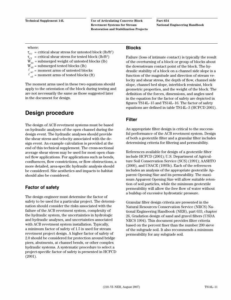
The forces causing overturning and restraining mo-ments are illustrated in figure TS14L–13.
Equation TS14L–1 (HCFCD 2001) shows the restrain-ing moments on the left and overturning moments on the right side of the equation:
2 2 1 1 3 4W W F F F FS S D D L L= + + ′ + + ′( ) ( ) (eq. TS14L–1)
The drag force, ′FD , due to protruding blocks (fig. TS14L–14) is a function of the flow velocity and may be expressed by the following equation:
′ = × ( )F C Z b VD D1
22∆ ρ
(eq. TS14L–2)where:F
D′ = drag force due to block protrusion (lb)
CD = drag coefficient (C
D ≈ 1.0)
∆Z = height of protrusion (ft)b = block width perpendicular to flow (ft)ρ = density of water (1.94 slugs/ft3)V = velocity (ft/s)
The added lift force (FL′) due to the block protruding
above the ACB matrix is assumed equal to the drag force.
The ACB design procedure is based on the critical shear stress for a horizontal surface. Performance testing is typically conducted on bed slopes of 2H:1V or 3H:1V. The following equation (HCFCD 2001) may be used to extrapolate the test results to a horizontal surface:
τ τ
θ θθ θθ θC U C T
U U
T T= ×
−−
2 1
2 1
cos sin
cos sin
(eq. TS14L–3)where:τ
CθU = critical shear stress for untested bed slope
(lb/ft2)τ
CθT = critical shear stress for tested bed slope (lb/ft2)
θU
= untested bed slope (degrees)θ
T = tested bed slope (degrees)
x
= moment arms (ft)
Performance testing is also typically conducted on one block within the same family. An equation has been developed for extrapolating test results from a tested block to an untested block of similar characteristics. The equation should only be used to extrapolate re-sults for a thicker block within the same family as the tested block. This equation is also based on a moment balance approach that neglects interblock restraint. Equation TS14L–4 (Clopper 1991) is suggested for ex-trapolation of test results from one block to a thicker block within the same family:
τ τCU CT
SU U
ST T
T T
U U
W
W= × ×
++
2
2
3 4
3 4
(eq. TS14L–4)
l3
l2
l4
FL
F'L F'
D
FR
Φ2
WS1
WS2Pivot point
of rotation
WD
Flow l1
Figure TS14L–13 Forces on an ACB revetment system during performance test (Figure courtesy of HCFCD)
Z
F ′L
F ′D
Flow
Figure TS14L–14 Forces on a protruding block (Figure courtesy of HCFCD)
(210–VI–NEH, August 2007)
Part 654 National Engineering Handbook
Use of Articulating Concrete Block Revetment Systems for Stream Restoration and Stabilization Projects
Technical Supplement 14L
TS14L–11
where:τ
CU = critical shear stress for untested block (lb/ft2)
τCT
= critical shear stress for tested block (lb/ft2)W
SU = submerged weight of untested blocks (lb)
WST
= submerged tested blocks (lb)
xU = moment arms of untested blocks
xT
= moment arms of tested blocks (ft)
The moment arms used in these two equations should apply to the orientation of the block during testing and are not necessarily the same as those suggested later in the document for design.
Design procedure
The design of ACB revetment systems must be based on hydraulic analyses of the open channel during the design event. The hydraulic analyses should provide the shear stress and velocity associated with the de-sign event. An example calculation is provided at the end of this technical supplement. The cross-sectional average shear stress may be used for most open chan-nel flow applications. For applications such as bends, confluences, flow constrictions, or flow obstructions, a more detailed, area-specific hydraulic analysis should be considered. Site aesthetics and impacts to habitat should also be considered.
Factor of safety
The design engineer must determine the factor of safety to be used for a particular project. The determi-nation should consider the risks associated with the failure of the ACB revetment system, complexity of the hydraulic system, the uncertainties in hydrologic and hydraulic analyses, and uncertainties associated with ACB revetment system installation. Typically, a minimum factor of safety of 1.5 is used for stream revetment project design. A higher factor of safety of 2.0 should be considered for protection around bridge piers, abutments, at channel bends, or other complex hydraulic systems. A systematic procedure to select a project-specific factor of safety is presented in HCFCD (2001).
Blocks
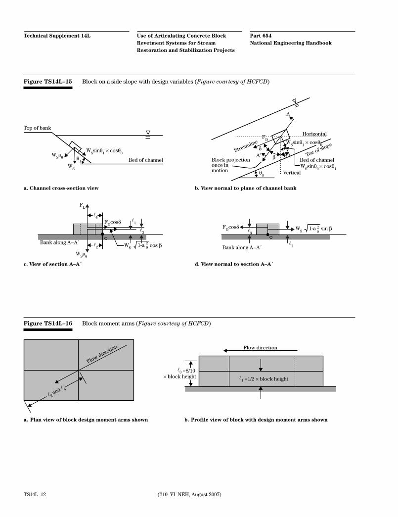
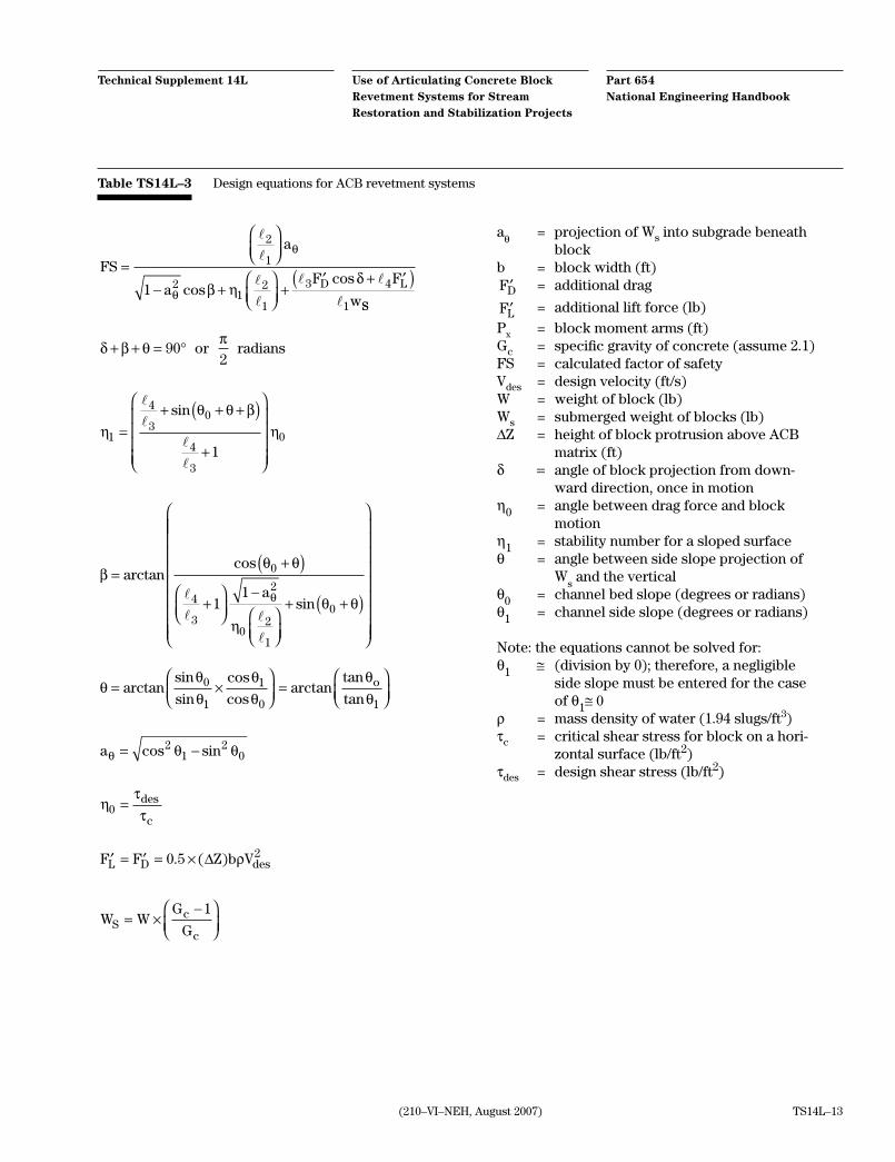
Failure (loss of intimate contact) is typically the result of the overturning of a block or group of blocks about the downstream contact point of the block. The hy-draulic stability of a block on a channel side slope is a function of the magnitude and direction of stream ve-locity and shear stress, the depth of flow, channel side slope, channel bed slope, interblock restraint, block geometric properties, and the weight of the block. The definition of the forces, dimensions, and angles used in the equation for the factor of safety are depicted in figures TS14L–15 and TS14L–16. The factor of safety equations are defined in table TS14L–3 (HCFCD 2001).
Filter
An appropriate filter design is critical to the success-ful performance of the ACB revetment system. Design of both a geotextile filter and a granular filter includes determining criteria for filtering and permeability.
References available for design of a geotextile filter include HCFCD (2001); U.S. Department of Agricul-ture Soil Conservation Service (SCS) (1991); AASHTO (2000), and USACE (1995b). Each of the references includes an analysis of the appropriate geotextile Ap-parent Opening Size and its permeability. The maxi-mum Apparent Opening Size will allow suitable reten-tion of soil particles, while the minimum geotextile permeability will allow the free flow of water without a buildup of excessive hydrostatic pressure.
Granular filter design criteria are presented in the Natural Resources Conservation Service (NRCS) Na-tional Engineering Handbook (NEH), part 633, chapter 26, Gradation design of sand and gravel filters (USDA NRCS 1994). This document provides filter criteria based on the percent finer than the number 200 sieve of the subgrade soil. It also recommends a minimum permeability for any subgrade soil.
Part 654 National Engineering Handbook
Use of Articulating Concrete Block Revetment Systems for Stream Restoration and Stabilization Projects
Technical Supplement 14L
(210–VI–NEH, August 2007)TS14L–12
Figure TS14L–15 Block on a side slope with design variables (Figure courtesy of HCFCD)
l2
l4
l1
l1
l3
l3
Top of bank
a. Channel cross-section view
WSsinθ
1 × cosθ
0
WS
θ1
WSaθ
Bed of channel Block projectiononce in motion
b. View normal to plane of channel bank
WSsinθ
1 × cosθ
0
HorizontalF
D
A
WSsinθ
0 × cosθ
1θ
0
Α' θβ
δ
Vertical
Toe of slopeStreamline
Bed of channel
Bank along A−A´Bank along A−A´
c. View of section A–A´ d. View normal to section A–A´
WS
1-a cos β
FL
FD
cosδF
Dcosδ
WSaθ
2θ
2θ
WS
1-a sin β
Figure TS14L–16 Block moment arms (Figure courtesy of HCFCD)
l 4
l 2
l1
l3
Flow direction
and
Flow direction
=1/2 × block height× block height=8/10
a. Plan view of block design moment arms shown b. Profile view of block with design moment arms shown
(210–VI–NEH, August 2007)
Part 654 National Engineering Handbook
Use of Articulating Concrete Block Revetment Systems for Stream Restoration and Stabilization Projects
Technical Supplement 14L
TS14L–13
Table TS14L–3 Design equations for ACB revetment systems
FS
a
aF F
wD L
=
− +
+′ + ′( )
2
1
21
2
1
3 4
11
θ
θ β ηδ
coscos
SS
δ β θπ
+ + = °902
or radians
ηθ θ β
η1
4
30
4
3
01
=+ + +( )
+
sin
aθ = projection of Ws into subgrade beneath block
b = block width (ft)′FD = additional drag
′FL = additional lift force (lb)Px = block moment arms (ft)Gc = specific gravity of concrete (assume 2.1)FS = calculated factor of safetyVdes = design velocity (ft/s)W = weight of block (lb)Ws = submerged weight of blocks (lb)∆Z = height of block protrusion above ACB
matrix (ft)δ = angle of block projection from down-
ward direction, once in motionη0 = angle between drag force and block
motionη1 = stability number for a sloped surfaceθ = angle between side slope projection of
Ws and the vertical
θ0 = channel bed slope (degrees or radians)θ1 = channel side slope (degrees or radians)
Note: the equations cannot be solved for:θ1 ≅ (division by 0); therefore, a negligible
side slope must be entered for the case of θ1≅0
ρ = mass density of water (1.94 slugs/ft3)τc = critical shear stress for block on a hori-
zontal surface (lb/ft2)τdes = design shear stress (lb/ft2)
βθ θ
ηθ θθ
=+( )
+
−
+ +( )
arctancos
sin
0
4
3
2
02
1
011
a
θθθ
θθ
θθ
= ×
=
arctansin
sin
cos
cosarctan
tan
tan0
1
1
0 1
o
aθ θ θ= −cos sin21
20
′ = ′ = ×F F Z b VL D des0 5 2. ( )∆ ρ
W WG
GSc
c= ×
−
1
ηττ0 = des
c
Part 654 National Engineering Handbook
Use of Articulating Concrete Block Revetment Systems for Stream Restoration and Stabilization Projects
Technical Supplement 14L
(210–VI–NEH, August 2007)TS14L–14
Specifying ACB revetment systems
Blocks
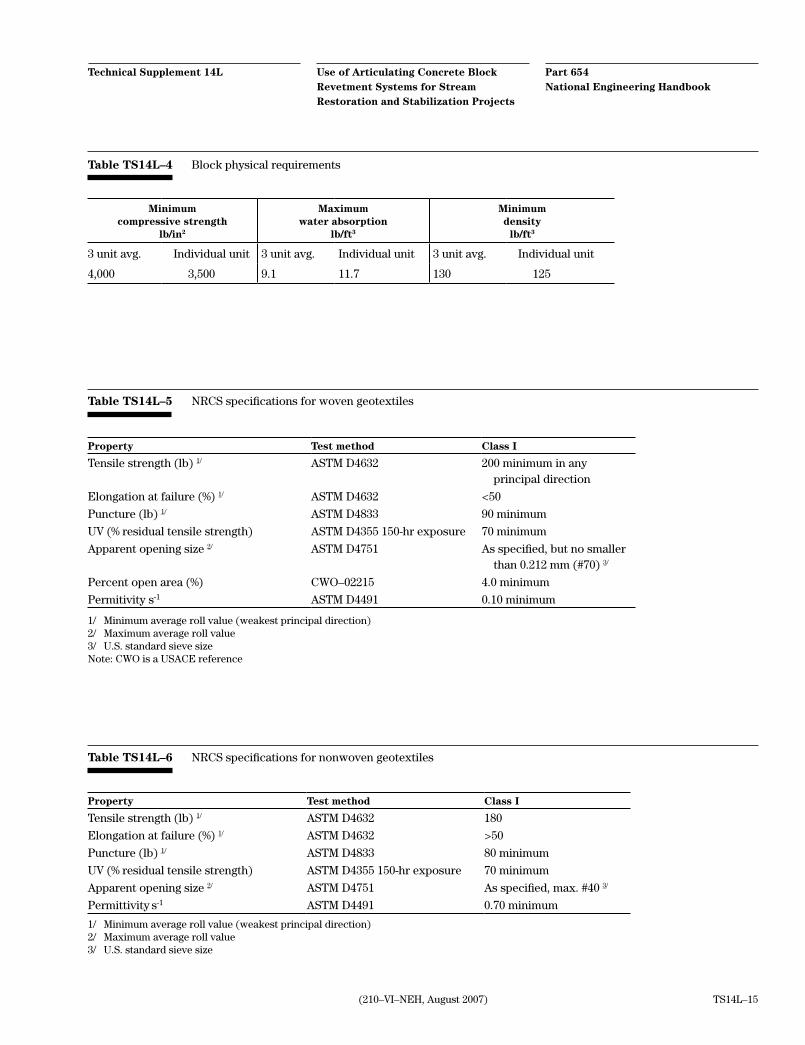
The blocks should meet the physical requirements of ASTM D6684, Standard Specification for Materials and Manufacture of Articulating Concrete Block Revet-ment Systems. Table TS14L–4 presents the physical requirements in specified in ASTM D6684.
In areas subject to freeze-thaw, the number of freeze/ thaw cycles and the corresponding weight loss crite-rion should be specified. Some specifications require 100 freeze-thaw cycles, with no more than 1 percent weight loss as determined on five block samples. The minimum percent open area should also be specified.
Connections
If a cabled system is desired, the cable specifications recommended in this paper should be considered. If the blocks will be adhered to a geotextile, the geotex-tile should meet the geotextile specifications described in the following section.
Geotextile
The NRCS has developed national construction and material specifications for geotextiles. These are included in NEH, part 642, Specifications for Con-struction Contracts. Additional material is covered in NEH654 TS14D. The NRCS specifications are broken into woven and nonwoven geotextiles and into various classes. Class I geotextiles are typically specified for erosion protection systems. The class I material prop-erties included in the NRCS material specifications are shown in tables TS14L–5 and TS14L–6.
Testing
A hydraulic stability test conducted in accordance with FHWA RD–89–199 on the proposed ACB revet-ment system family should be specified. The stream-bed slope of the project should be no steeper than the slope used in the hydraulic stability test. If the ACB
revetment system is tested with system restraints (such as mechanical anchors) or ancillary components (such as a synthetic or granular drainage medium), these features should also be incorporated into the field installations.
Design
The project-specific design criteria should be specified to allow each ACB revetment system manufacturer to calculate which product should be supplied. The fol-lowing project conditions should be specified:
• design velocity (ft/s)
• design shear stress (lb/ft2)
• bed slope (ft/ft)
• side slope (H:V) (ft/ft)
• maximum allowable block-to-block placement tolerance (in)
• minimum required factor of safety
Installation
Detailed specifications are required for the installa-tion of ACB revetment systems. Detailed construc-tion specifications for earthwork (including subgrade preparation) and placement of the geotextile are available from the NRCS, USACE, HCFCD, and other organizations. Specifications for ACB installation are available from the USACE, HCFCD, ACB manufactur-ers, and other organizations, as well. An ASTM Stan-dard Practice for the installation of ACB revetment systems is under development. General installation considerations are listed.
Subgrade preparation
The ACB revetment system should be placed on un-disturbed in situ soils or properly compacted fill. The subgrade for ACB placement should be graded smooth to ensure that intimate contact is achieved between the soil surface and the geotextile.
(210–VI–NEH, August 2007)
Part 654 National Engineering Handbook
Use of Articulating Concrete Block Revetment Systems for Stream Restoration and Stabilization Projects
Technical Supplement 14L
TS14L–15
Property Test method Class I
Tensile strength (lb) 1/ ASTM D4632 200 minimum in any principal direction
Elongation at failure (%) 1/ ASTM D4632 <50
Puncture (lb) 1/ ASTM D4833 90 minimum
UV (% residual tensile strength) ASTM D4355 150-hr exposure 70 minimum
Apparent opening size 2/ ASTM D4751 As specified, but no smaller than 0.212 mm (#70) 3/
Percent open area (%) CWO–02215 4.0 minimum
Permitivity s-1 ASTM D4491 0.10 minimum
1/ Minimum average roll value (weakest principal direction)2/ Maximum average roll value 3/ U.S. standard sieve sizeNote: CWO is a USACE reference
Table TS14L–5 NRCS specifications for woven geotextiles
Property Test method Class I
Tensile strength (lb) 1/ ASTM D4632 180
Elongation at failure (%) 1/ ASTM D4632 >50
Puncture (lb) 1/ ASTM D4833 80 minimum
UV (% residual tensile strength) ASTM D4355 150-hr exposure 70 minimum
Apparent opening size 2/ ASTM D4751 As specified, max. #40 3/
Permittivity s-1 ASTM D4491 0.70 minimum
1/ Minimum average roll value (weakest principal direction)2/ Maximum average roll value3/ U.S. standard sieve size
Table TS14L–6 NRCS specifications for nonwoven geotextiles
Table TS14L–4 Block physical requirements
Minimum compressive strength
lb/in2
Maximum water absorption
lb/ft3
Minimum density
lb/ft3
3 unit avg. Individual unit 3 unit avg. Individual unit 3 unit avg. Individual unit
4,000 3,500 9.1 11.7 130 125
Part 654 National Engineering Handbook
Use of Articulating Concrete Block Revetment Systems for Stream Restoration and Stabilization Projects
Technical Supplement 14L
(210–VI–NEH, August 2007)TS14L–16
Geotextile placement
The geotextile should be laid flat and smooth, so that it is in intimate contact with the subgrade. The geotex-tile must be free of tension, folds, and wrinkles. The geotextile should be placed immediately prior to ACB placement.
The joints should overlap a minimum of 18 inches in dry installations and 3 feet in below water installa-tions. The geotextile joints should be shingled so that the upstream or upslope geotextile overlaps the adja-cent downstream or downslope geotextile.
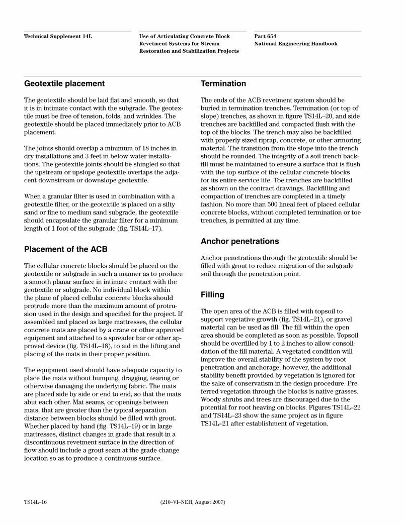
When a granular filter is used in combination with a geotextile filter, or the geotextile is placed on a silty sand or fine to medium sand subgrade, the geotextile should encapsulate the granular filter for a minimum length of 1 foot of the subgrade (fig. TS14L–17).
Placement of the ACB
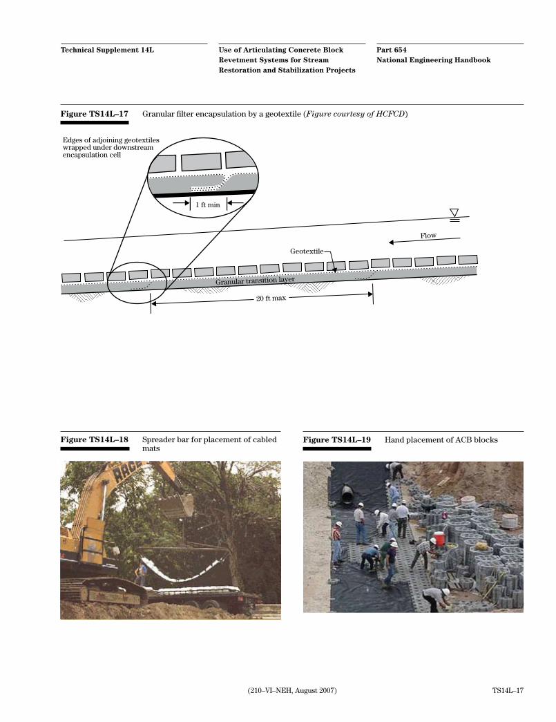
The cellular concrete blocks should be placed on the geotextile or subgrade in such a manner as to produce a smooth planar surface in intimate contact with the geotextile or subgrade. No individual block within the plane of placed cellular concrete blocks should protrude more than the maximum amount of protru-sion used in the design and specified for the project. If assembled and placed as large mattresses, the cellular concrete mats are placed by a crane or other approved equipment and attached to a spreader bar or other ap-proved device (fig. TS14L–18), to aid in the lifting and placing of the mats in their proper position.
The equipment used should have adequate capacity to place the mats without bumping, dragging, tearing or otherwise damaging the underlying fabric. The mats are placed side by side or end to end, so that the mats abut each other. Mat seams, or openings between mats, that are greater than the typical separation distance between blocks should be filled with grout. Whether placed by hand (fig. TS14L–19) or in large mattresses, distinct changes in grade that result in a discontinuous revetment surface in the direction of flow should include a grout seam at the grade change location so as to produce a continuous surface.
Termination
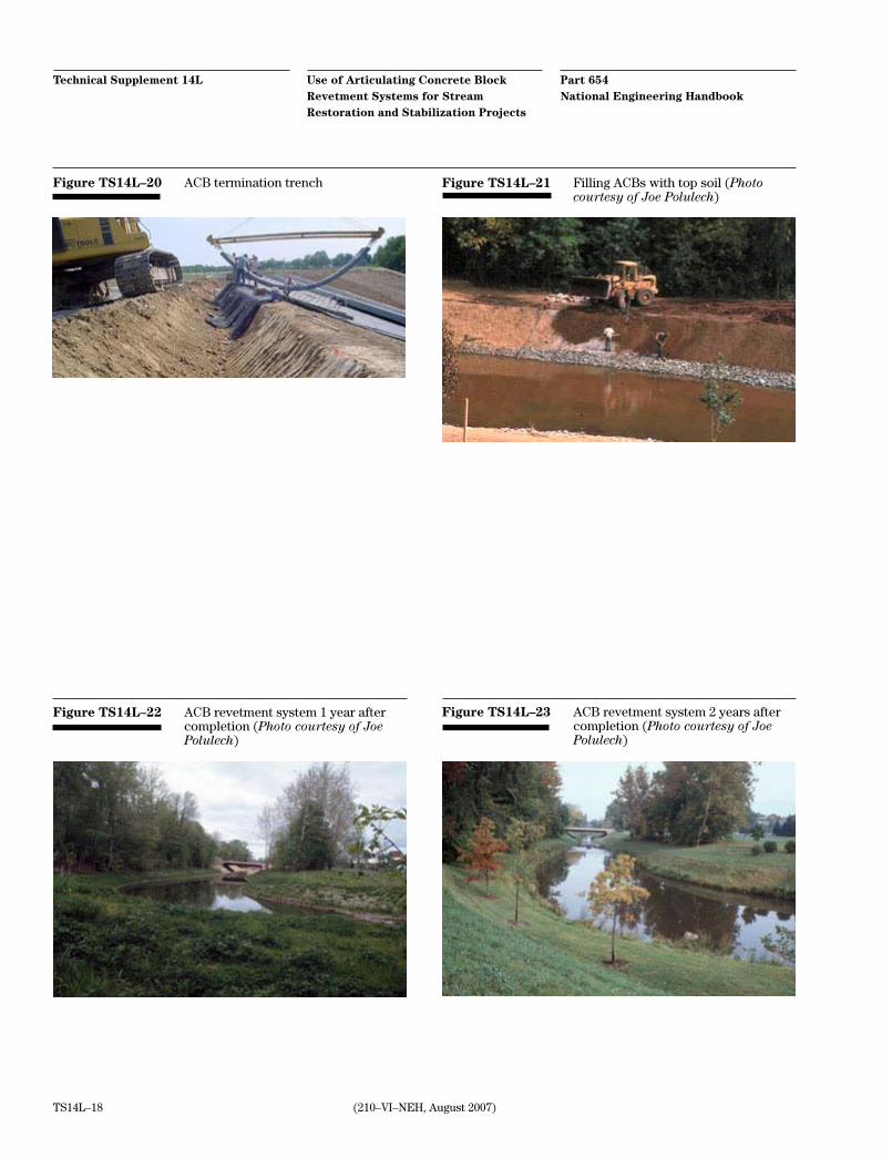
The ends of the ACB revetment system should be buried in termination trenches. Termination (or top of slope) trenches, as shown in figure TS14L–20, and side trenches are backfilled and compacted flush with the top of the blocks. The trench may also be backfilled with properly sized riprap, concrete, or other armoring material. The transition from the slope into the trench should be rounded. The integrity of a soil trench back-fill must be maintained to ensure a surface that is flush with the top surface of the cellular concrete blocks for its entire service life. Toe trenches are backfilled as shown on the contract drawings. Backfilling and compaction of trenches are completed in a timely fashion. No more than 500 lineal feet of placed cellular concrete blocks, without completed termination or toe trenches, is permitted at any time.
Anchor penetrations
Anchor penetrations through the geotextile should be filled with grout to reduce migration of the subgrade soil through the penetration point.
Filling
The open area of the ACB is filled with topsoil to support vegetative growth (fig. TS14L–21), or gravel material can be used as fill. The fill within the open area should be completed as soon as possible. Topsoil should be overfilled by 1 to 2 inches to allow consoli-dation of the fill material. A vegetated condition will improve the overall stability of the system by root penetration and anchorage; however, the additional stability benefit provided by vegetation is ignored for the sake of conservatism in the design procedure. Pre-ferred vegetation through the blocks is native grasses. Woody shrubs and trees are discouraged due to the potential for root heaving on blocks. Figures TS14L–22 and TS14L–23 show the same project as in figure TS14L–21 after establishment of vegetation.
(210–VI–NEH, August 2007)
Part 654 National Engineering Handbook
Use of Articulating Concrete Block Revetment Systems for Stream Restoration and Stabilization Projects
Technical Supplement 14L
TS14L–17
Figure TS14L–18 Spreader bar for placement of cabled mats
Figure TS14L–19 Hand placement of ACB blocks
Figure TS14L–17 Granular filter encapsulation by a geotextile (Figure courtesy of HCFCD)
Edges of adjoining geotextileswrapped under downstreamencapsulation cell
Granular transition layer
1 ft min
Geotextile
Flow
20 ft max
Part 654 National Engineering Handbook
Use of Articulating Concrete Block Revetment Systems for Stream Restoration and Stabilization Projects
Technical Supplement 14L
(210–VI–NEH, August 2007)TS14L–18
Figure TS14L–20 ACB termination trench Figure TS14L–21 Filling ACBs with top soil (Photo courtesy of Joe Polulech)
Figure TS14L–22 ACB revetment system 1 year after completion (Photo courtesy of Joe Polulech)
Figure TS14L–23 ACB revetment system 2 years after completion (Photo courtesy of Joe Polulech)
(210–VI–NEH, August 2007)
Part 654 National Engineering Handbook
Use of Articulating Concrete Block Revetment Systems for Stream Restoration and Stabilization Projects
Technical Supplement 14L
TS14L–19
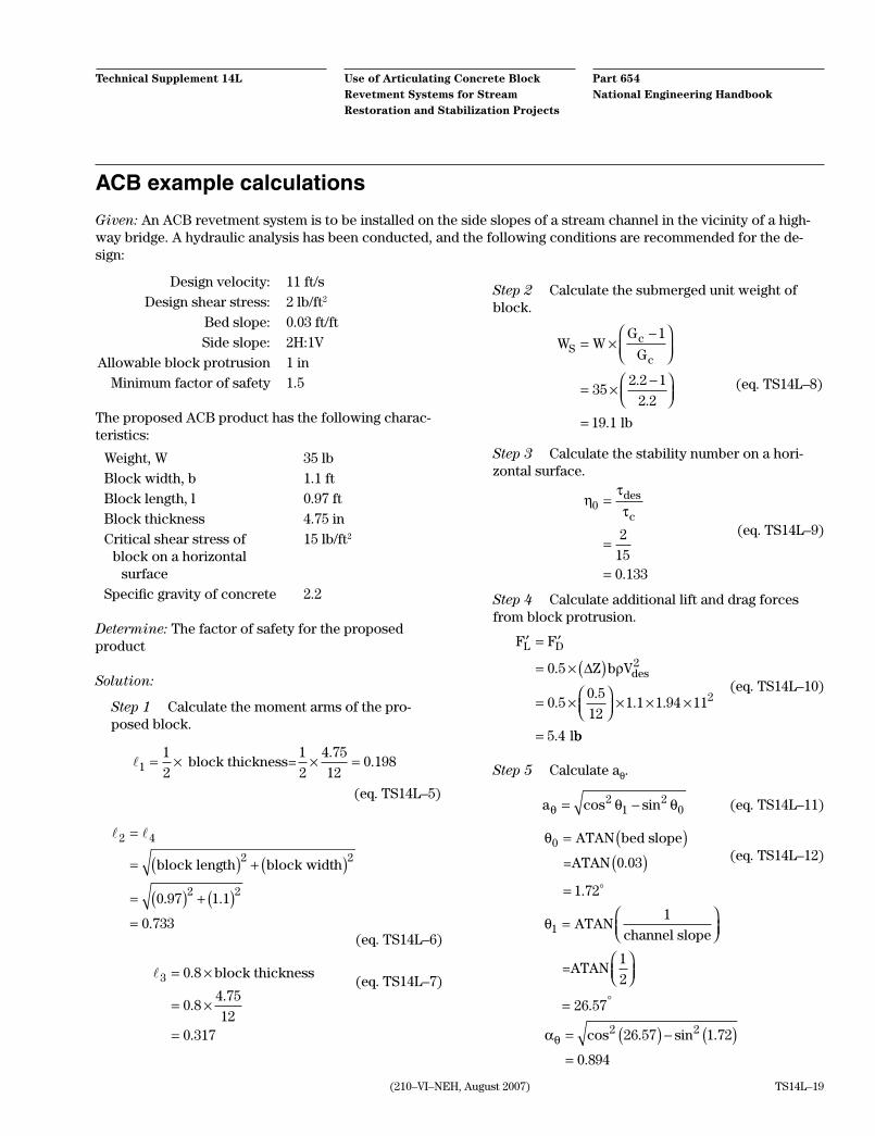
ACB example calculations
Given: An ACB revetment system is to be installed on the side slopes of a stream channel in the vicinity of a high-way bridge. A hydraulic analysis has been conducted, and the following conditions are recommended for the de-sign:
Step 2 Calculate the submerged unit weight of block.
W WG
GSc
c= ×
−
= ×−
=
1
352 2 1
2 2
19 1
.
.
. lb
(eq. TS14L–8)
Step 3 Calculate the stability number on a hori-zontal surface.
ηττ0
2
150 133
=
=
=
des
c
.
(eq. TS14L–9)
Step 4 Calculate additional lift and drag forces from block protrusion.
′ = ′
= × ∆( )= ×
× × ×
=
F F
Z b V
L D
des0 5
0 50 5
121 1 1 94 11
5 4
2
2
.
..
. .
.
ρ
lbb
(eq. TS14L–10)
Step 5 Calculate aθ.
aθ θ θ= −cos sin2
12
0 (eq. TS14L–11)
θ0
1 72
= ( )( )
=
ATAN bed slope
=ATAN 0.03
.
(eq. TS14L–12)
θ1
26 57
=
= °
ATAN1
channel slope
=ATAN1
2
.
αθ = ( ) − ( )
=
cos . sin .
.
2 226 57 1 72
0 894
Design velocity: 11 ft/s Design shear stress: 2 lb/ft2
Bed slope: 0.03 ft/ft Side slope: 2H:1V Allowable block protrusion 1 in Minimum factor of safety 1.5
The proposed ACB product has the following charac-teristics:
Weight, W 35 lbBlock width, b 1.1 ftBlock length, l 0.97 ftBlock thickness 4.75 inCritical shear stress of 15 lb/ft2
block on a horizontal surface
Specific gravity of concrete 2.2
Determine: The factor of safety for the proposed product
Solution:
Step 1 Calculate the moment arms of the pro-posed block.
11
2
1
2
4 75
120 198= × × = block thickness=
..
(eq. TS14L–5)
2 4
2 2
2 20 97 1 1
0 733
=
= ( ) + ( )= ( ) + ( )=
block length block width
. .
. (eq. TS14L–6)
3 0 8
0 812
0 317
= ×
= ×
=
.
.
.
block thickness
4.75 (eq. TS14L–7)
Part 654 National Engineering Handbook
Use of Articulating Concrete Block Revetment Systems for Stream Restoration and Stabilization Projects
Technical Supplement 14L
(210–VI–NEH, August 2007)TS14L–20
Step 8 Calculate stability number for a sloped surface η
1.
ηθ θ β
η1
4
30
4
3
01
0 7330 317
1 72
=+ + +( )
+
=+
sin
.
.sin . + +( )
+
=
3 43 17 82
0 7330 317
10 133
0 109
. .
.
.
.
. (eq. TS14L–16)
Step 9 Calculate angle between drag force and block motion, δ.
δ β θ+ + = 90
(eq. TS14L–17)
So,
δ β θ= − −
= − −
=
90
90 17 82 3 43
68 75
. .
.
(eq. TS14L–18)
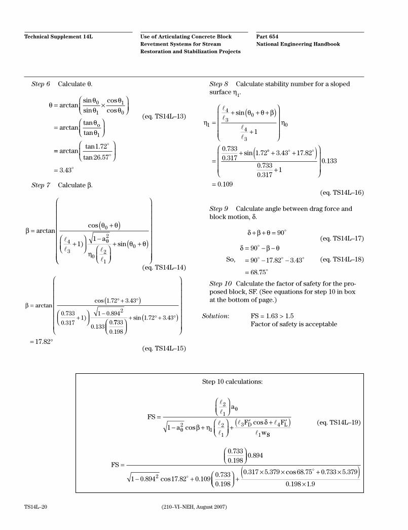
Step 10 Calculate the factor of safety for the pro-posed block, SF. (See equations for step 10 in box at the bottom of page.)
Solution: FS = 1.63 > 1.5 Factor of safety is acceptable
Step 6 Calculate θ.
θθθ
θθ
θθ
= ×
=
arctansin
sin
cos
cos
arctantan
tan
0
1
1
0
1
o
==
=
arctantan .
tan .
.
1 72
26 57
3 43
(eq. TS14L–13)
Step 7 Calculate β.
βθ θ
ηθ θθ
=+( )
+
−
+ +( )
arctancos
) sin
0
4
3
2
02
1
011
a
(eq. TS14L–14)
β =° + °
+−
( )
arctancos . .
.
.)
.
..
1 72 3 43
0 733
0 3171
1 0 894
0 1330
2
7733
0 198
1 72 3 43
17 82
.
sin . .
.
( )
= °
+ ° + °
(eq. TS14L–15)
FS =
− +
0 7330 198
0 894
1 0 894 17 82 0 1090 7330 198
2
.
..
. cos . ...
+× × + ×( )
×
0 317 5 379 68 75 0 733 5 379
0 198 1 9
. . cos . . .
. .
FS
a
aF F
wD L
=
− +
+′ + ′( )
2
1
21
2
1
3 4
11
θ
θ β ηδ
coscos
SS
Step 10 calculations:
(eq. TS14L–19)
(210–VI–NEH, August 2007)
Part 654 National Engineering Handbook
Use of Articulating Concrete Block Revetment Systems for Stream Restoration and Stabilization Projects
Technical Supplement 14L
TS14L–21
If the critical shear stress is determined from an ACB hydraulic test with system restraints (such as me-chanical anchors) or ancillary components (such as a synthetic or granular drainage medium), the restraints or components should be incorporated into the instal-lation.
Conclusion
ACB revetment systems provide a viable product for armoring countermeasures to be used in stream resto-ration and stabilization, particularly in open channels that have high velocities and shear stresses and in ap-plications where the operational boundaries are fixed or limited and no further erosion can be tolerated. An ACB revetment system is also useful in arresting lateral stream migration and local vertical instability. Its use has distinct advantages, not only in terms of accepted design techniques, but also in established contracting and construction procedures.
The blocks must be tested in accordance with the pro-cedures identified in this technical supplement and the associated references. Design should follow the design procedures as shown here. ACBs should be considered as a system and include all the restraints and compo-nents in the hydraulic stability testing. The use of a properly designed geotextile or granular filter is criti-cal to the successful performance of the ACB revet-ment system. As with all armoring countermeasures, proper subgrade preparation, placement of geotextile or granular filter, and block installation are also essen-tial to the proper functioning and performance of the system during the design event.
The decision to use an ACB revetment system for sta-bilization must include considerations for costs, per-formance requirements, maintenance, aesthetic char-acteristics, ecological habitat and functions, upstream and downstream effects, and the dynamics of fluvial geomorphology of the system.
As described, some ACB systems provide the flexibil-ity of including grass in topsoil-filled block openings to provide additional erosion control. Since the use of woody vegetation is discouraged because of its poten-tial damage to the block installation and maintenance costs, the prospect of reestablishing a fully functioning riparian zone is minimal. Where connection of people back to the stream is an important consideration, however, ACBs can provide a foundation for grassed greenways to be established along stabilized channels.

Blank
Related Documents