ETSI TS 148 020 V4.0.0 (2001-03) Technical Specification Digital cellular telecommunications system (Phase 2+); Rate adaption on the Base Station System - Mobile-services Switching Centre (BSS - MSC) interface (3GPP TS 48.020 version 4.0.0 Release 4) GLOBAL SYSTEM FOR MOBILE COMMUNICATIONS R

Welcome message from author
This document is posted to help you gain knowledge. Please leave a comment to let me know what you think about it! Share it to your friends and learn new things together.
Transcript
ETSI TS 148 020 V4.0.0 (2001-03)Technical Specification
Digital cellular telecommunications system (Phase 2+);Rate adaption on the Base Station System - Mobile-services
Switching Centre (BSS - MSC) interface(3GPP TS 48.020 version 4.0.0 Release 4)
GLOBAL SYSTEM FORMOBILE COMMUNICATIONS
R

1
ETSI
ETSI TS 148 020 V4.0.0 (2001-03)3GPP TS 48.020 version 4.0.0 Release 4
ReferenceRTS/TSGN-0348020Uv4
KeywordsGSM
ETSI
650 Route des LuciolesF-06921 Sophia Antipolis Cedex - FRANCE
Tel.: +33 4 92 94 42 00 Fax: +33 4 93 65 47 16
Siret N° 348 623 562 00017 - NAF 742 CAssociation à but non lucratif enregistrée à laSous-Préfecture de Grasse (06) N° 7803/88
Important notice
Individual copies of the present document can be downloaded from:http://www.etsi.org
The present document may be made available in more than one electronic version or in print. In any case of existing orperceived difference in contents between such versions, the reference version is the Portable Document Format (PDF).
In case of dispute, the reference shall be the printing on ETSI printers of the PDF version kept on a specific network drivewithin ETSI Secretariat.
Users of the present document should be aware that the document may be subject to revision or change of status.Information on the current status of this and other ETSI documents is available at http://www.etsi.org/tb/status/
If you find errors in the present document, send your comment to:[email protected]
Copyright Notification
No part may be reproduced except as authorized by written permission.The copyright and the foregoing restriction extend to reproduction in all media.
© European Telecommunications Standards Institute 2001.
All rights reserved.

2
ETSI
ETSI TS 148 020 V4.0.0 (2001-03)3GPP TS 48.020 version 4.0.0 Release 4
Intellectual Property RightsIPRs essential or potentially essential to the present document may have been declared to ETSI. The informationpertaining to these essential IPRs, if any, is publicly available for ETSI members and non-members, and can be foundin ETSI SR 000 314: "Intellectual Property Rights (IPRs); Essential, or potentially Essential, IPRs notified to ETSI inrespect of ETSI standards", which is available from the ETSI Secretariat. Latest updates are available on the ETSI Webserver (http://www.etsi.org/ipr).
Pursuant to the ETSI IPR Policy, no investigation, including IPR searches, has been carried out by ETSI. No guaranteecan be given as to the existence of other IPRs not referenced in ETSI SR 000 314 (or the updates on the ETSI Webserver) which are, or may be, or may become, essential to the present document.
ForewordThis Technical Specification (TS) has been produced by the ETSI 3rd Generation Partnership Project (3GPP).
The present document may refer to technical specifications or reports using their 3GPP identities, UMTS identities orGSM identities. These should be interpreted as being references to the corresponding ETSI deliverables.
The cross reference between GSM, UMTS, 3GPP and ETSI identities can be found under www.etsi.org/key .

ETSI
ETSI TS 148 020 V4.0.0 (2001-03)33GPP TS 48.020 version 4.0.0 Release 4
Contents
Foreword............................................................................................................................................................ 5
1 Scope ....................................................................................................................................................... 6
2 References, abbreviations and definitions ............................................................................................... 6 2.1 References ................................................................................................................................................................6 2.2 Abbreviations ...........................................................................................................................................................7 2.3 Definitions................................................................................................................................................................7
3 General approach..................................................................................................................................... 7
4 The RA0 Function ................................................................................................................................... 7
5 The RA1 Function ................................................................................................................................... 7
6 The RA1’’ Function ................................................................................................................................ 8
7 Split/Combine and Padding Functions .................................................................................................... 8 7.1 Data Frame distribution into the channels by the Split/Combine function...............................................................8 7.2 Substream numbering...............................................................................................................................................8 7.3 Initial Substream Synchronisation for Transparent Services ...................................................................................8 7.4 Frame Synchronisation and Action on loss of Synchronisation...............................................................................8 7.5 Network Independent Clocking ...............................................................................................................................8 7.6 Padding.....................................................................................................................................................................8
8 The EDGE Multiplexing Function .......................................................................................................... 8
9 The RA1/RA1' Function.......................................................................................................................... 9 9.1 Radio Interface rate of 12 kbit/s .............................................................................................................................10 9.2 Radio Interface rate of 6 kbit/s ...............................................................................................................................10 9.3 Radio Interface rate of 3.6 kbit/s ............................................................................................................................10 9.4 Synchronisation......................................................................................................................................................10 9.5 Idle frames..............................................................................................................................................................10
10 THE RA1'/RAA' FUNCTION............................................................................................................... 10 10.1 Radio Interface rate of 14,5 kbit/s ....................................................................................................................11 10.2 Synchronisation ................................................................................................................................................11 10.3 Idle frames........................................................................................................................................................11
11 THE RAA' FUNCTION........................................................................................................................ 11 11.1 Coding of A-TRAU frame................................................................................................................................11 11.2 Framing Pattern Substitution in A-TRAU frame..............................................................................................12 11.2.1 FPS encoding....................................................................................................................................................12 11.3 A-TRAU Synchronisation Pattern....................................................................................................................14
12 THE RAA'' FUNCTION ....................................................................................................................... 14
13 The RA2 Function ................................................................................................................................. 14
14 The A-interface Multiplexing Function................................................................................................. 14
15 Support of non-transparent bearer services ........................................................................................... 15 15.1 TCH/F9.6 and TCH/F4.8 kbit/s channel codings .............................................................................................15 15.1.1 Alignment .........................................................................................................................................................16 15.1.2 Support of Discontinuous Transmission (DTX)...............................................................................................16 15.1.3 Order of Transmission......................................................................................................................................16 15.2 TCH/F14.4, TCH/F28.8, and TCH/F43.2 channel codings ..............................................................................16 15.2.1 Alignment .........................................................................................................................................................17 15.2.2 Support of Discontinuous Transmission (DTX)...............................................................................................17
16 Support of transparent bearer services................................................................................................... 17 16.1 TCH/F9.6 and TCH/F4.8 channel codings .......................................................................................................17 16.1.1 User rate adaptation on the A interface, AIUR less than or equal to 38,4 kbit/s ..............................................17

ETSI
ETSI TS 148 020 V4.0.0 (2001-03)43GPP TS 48.020 version 4.0.0 Release 4
16.1.2 User rate Adaptation on the A-interface, AIUR greater than 38,4 kbit/s..........................................................18 16.1.3 Relation between AIUR and the number of channels.......................................................................................19 16.1.4 Handling of status bits X, SA, SB ....................................................................................................................19 16.1.5 Handling of bits E1 to E7 .................................................................................................................................19 16.2 TCH/F14.4, TCH/F28.8, and TCH/F32.0 channel codings ..............................................................................20 16.2.1 User rate adaptation on the A interface, AIUR less than or equal to 56 kbit/s .................................................20 16.2.2 User Rate Adaptation on the A-interface, AIUR greater than 56 kbit/s ...........................................................20 16.2.3 Relation between AIUR and the number of channels.......................................................................................20 16.2.4 Handling of status bits X and SB......................................................................................................................20
17 Frame Formats....................................................................................................................................... 21
Annex A (informative): Frame Pattern Substitution ......................................................................... 25
A.1 Special cases.......................................................................................................................................... 25
A.2 False Z sequence detection.................................................................................................................... 26
Annex B (informative): Change History.............................................................................................. 27
ETSI
ETSI TS 148 020 V4.0.0 (2001-03)53GPP TS 48.020 version 4.0.0 Release 4
Foreword This Technical Specification has been produced by the 3rd Generation Partnership Project (3GPP).
The contents of the present document are subject to continuing work within the TSG and may change following formal TSG approval. Should the TSG modify the contents of the present document, it is re-released by the TSG with an identifying change of release date and an increase in version number as follows:
Version x.y.z
where:
x the first digit:
1 presented to TSG for information;
2 presented to TSG for approval;
3 or greater indicates TSG approved document under change control.
y the second digit is incremented for all changes of substance, i.e. technical enhancements, corrections, updates, etc.
z the third digit is incremented when editorial only changes have been incorporated in the document.

ETSI
ETSI TS 148 020 V4.0.0 (2001-03)63GPP TS 48.020 version 4.0.0 Release 4
1 Scope The present document defines rate adaptation functions to be used in GSM PLMN Base Station Systems (BSS) transcoders and IWF for adapting radio interface data rates to the 64 kbit/s used at the A-interface in accordance with 3GPP TS 03.10.
The number of Base Station System - Mobile-services Switching Centre (BSS - MSC) traffic channels supporting data rate adaptation may be limited. In this case some channels may not support data rate adaptation. Those that do, shall conform to this specification.
NOTE: This specification should be considered together with 3GPP TS 04.21 to give a complete description of PLMN rate adaptation.
2 References, abbreviations and definitions
2.1 References The following documents contain provisions which, through reference in this text, constitute provisions of the present document.
• References are either specific (identified by date of publication, edition number, version number, etc.) or non-specific.
• For a specific reference, subsequent revisions do not apply.
• For a non-specific reference, the latest version applies. In the case of a reference to a 3GPP document (including a GSM document), a non-specific reference implicitly refers to the latest version of that document in the same Release as the present document.
[1] 3GPP TS 01.04: "Digital cellular telecommunications system (Phase 2+); Abbreviations and acronyms".
[2] 3GPP TS 02.34: “Digital cellular telecommunications system (Phase2+): High Speed Circuit Switched Data (HSCSD) - Stage1"
[3] 3GPP TS 03.10: "Digital cellular telecommunications system (Phase 2+); GSM Public Land Mobile Network (PLMN) connection types".
[4] 3GPP TS 03.34: “Digital cellular telecommunications system (Phase 2+): High Speed Circuit Switched Data (HSCSD) - Stage2".
[5] 3GPP TS 04.21: "Digital cellular telecommunications system (Phase 2+); Rate adaption on the Mobile Station - Base Station System (MS - BSS) interface".
[6] 3GPP TS 24.022: "3rd Generation Partnership Project; Technical Specification Group Core Network; Radio Link Protocol (RLP) for Circuit Switched Bearer and Teleservices".
[7] 3GPP TS 05.03: "Digital cellular telecommunications system (Phase 2+); Channel coding".
[8] 3GPP TS 27.001: "3rd Generation Partnership Project; Technical Specification Group Core Network; General on Terminal Adaptation Functions (TAF) for Mobile Stations (MS)".
[9] 3GPP TS 08.08: "Digital cellular telecommunications system (Phase 2+); Mobile Switching Centre - Base Station System (MSC - BSS) interface; Layer 3 specification".
[10] 3GPP TS 29.007: "3rd Generation Partnership Project; Technical Specification Group Core Network; General requirements on interworking between the Public Land Mobile Network (PLMN) and the Integrated Services Digital Network (ISDN) or Public Switched Telephone Network (PSTN)".
ETSI
ETSI TS 148 020 V4.0.0 (2001-03)73GPP TS 48.020 version 4.0.0 Release 4
[11] ITU-T Recommendation V.110: "Support of data terminal equipment’s (DTEs) with V-Series interfaces by an integrated services digital network".
[12] ITU-T Recommendation I.460:-Multiplexing, rate adaption and support of existing interfaces.
2.2 Abbreviations For the purposes of the present document, the following abbreviations apply:
FPS Frame Pattern Substitution FSI Frame Start Identifier ZSP Zero Sequence Position
2.3 Definitions For the purposes of the present document, the following terms and definitions apply.
Substream: Stream of data with explicit or implicit numbering between splitter and combine functions.
Channel: A physical full rate channel on the radio interface (TCH/F) independent of the contents.
A interface circuit: The 8 bits that constitute one 64 kbps circuit on the A interface.
A interface subcircuit: One specific bit position or one specific pair of bit positions within the A interface circuit.
EDGE channel: A general term referring to channels based on 8PSK modulation; i.e. TCH/F28.8, TCH/F32.0, and TCH/F43.2.
3 General approach 3GPP TS 03.10 (clause 6) defines the PLMN connection types necessary to support the GSM PLMN data and telematic services.
Within the BSS , transcoder and IWF, there are several data rate adaptation functions which are combined as shown in 3GPP TS 03.10 as part of a connection type.
These functions are RA0, RA1, RA1/RA1' , RA1’’ , RAA", RA1'/RAA', RAA' and RA2. The RA2 function is equivalent to that described in ITU-T Recommendation V.110. In addition, splitting/combining, padding and inband numbering functions as defined in 3GPP TS 04.21 and multiplexing as defined herein are used in cases where more than one channel is allowed.
The RA1/RA1' and RA1'/RAA' are relay functions used as indicated in 3GPP TS 03.10.
The BSS uses the information contained in the ASSIGNMENT REQUEST message on the A-interface (see 3GPP TS 08.08) to set the "E bits" and to map the "D bits" as shown below, as well as to choose the correct channel coding.
4 The RA0 Function The RA0 function is specified in 3GPP TS 04.21
5 The RA1 Function For connections where only one channel is allowed used on the radio interface, the specification in 3GPP TS 04.21 for adaptation of synchronous data rates up to and including 9,6 kbit/s to intermediate rates 8 or 16 kbit/s shall apply.
For connection where more than one channel are used on the radio interface, rate adaptation shall apply on the corresponding substreams as specified in 3GPP TS 04.21 for AIUR of 4,8 kbit/s or 9,6 kbit/s.
ETSI
ETSI TS 148 020 V4.0.0 (2001-03)83GPP TS 48.020 version 4.0.0 Release 4
6 The RA1’’ Function The RA1’’ function is specified in 3GPP TS 04.21. The RA1’’ function is only applicable in BSS for AIUR higher than 38,4 kbit/s.
7 Split/Combine and Padding Functions The Split/Combine-function in the IWF shall be used in cases when up to and including 4substreams are used.
The Split/Combine-function in the BSS shall be used only when more than four substreams are used.
7.1 Data Frame distribution into the channels by the Split/Combine function
Described in 3GPP TS 04.21
7.2 Substream numbering Described in 3GPP TS 04.21
7.3 Initial Substream Synchronisation for Transparent Services Described in 3GPP TS 04.21
7.4 Frame Synchronisation and Action on loss of Synchronisation
When in the IWF, the Split/Combine function is responsible for controlling the initial frame synchronisation procedure and re-synchronisation procedure as described in 3GPP TS 29.007.
7.5 Network Independent Clocking NIC is specified in 3GPP TS 04.21
7.6 Padding Padding is specified in 3GPP TS 04.21
8 The EDGE Multiplexing Function In EDGE configurations where the number of radio interface channels and number of channels or substreams used between BTS and MSC do not match, a multiplexing function described below shall be used at BTS to perform data multiplexing/demultiplexing between the radio interface and network channel configurations. A similar functionshall be used also at MS as described in 04.21.
The EDGE multiplexing function is located between the radio interface and RA1’/RAA’ function.
ETSI
ETSI TS 148 020 V4.0.0 (2001-03)93GPP TS 48.020 version 4.0.0 Release 4
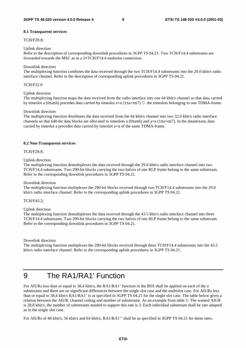
8.1 Transparent services
TCH/F28.8;
Uplink direction Refer to the description of corresponding downlink procedures in 3GPP TS 04.21. Two TCH/F14.4 substreams are forwarded towards the MSC as in a 2×TCH/F14.4 multislot connection.
Downlink direction The multiplexing function combines the data received through the two TCH/F14.4 substreams into the 29.0 kbit/s radio interface channel. Refer to the description of corresponding uplink procedures in 3GPP TS 04.21.
TCH/F32.0
Uplink direction The multiplexing function maps the data received from the radio interface into one 64 kbit/s channel so that data carried by timeslot a (0≤a≤6) precedes data carried by timeslot a+n (1≤a+n≤7) the timeslots belonging to one TDMA-frame.
Downlink direction The multiplexing function distributes the data received from the 64 kbit/s channel into two 32.0 kbit/s radio interface channels so that 640-bit data blocks are allocated to timeslots a (0≤a≤6) and a+n (1≤a+n≤7). In the datastream, data carried by timeslot a precedes data carried by timeslot a+n of the same TDMA-frame.
8.2 Non-Transparent services
TCH/F28.8;
Uplink direction The multiplexing function demultiplexes the data received through the 29.0 kbit/s radio interface channel into two TCH/F14.4 substreams. Two 290-bit blocks carrying the two halves of one RLP frame belong to the same substream. Refer to the corresponding downlink procedures in 3GPP TS 04.21.
Downlink direction The multiplexing function multiplexes the 290-bit blocks received through two TCH/F14.4 substreams into the 29.0 kbit/s radio interface channel. Refer to the corresponding uplink procedures in 3GPP TS 04.21.
TCH/F43.2;
Uplink direction The multiplexing function demultiplexes the data received through the 43.5 kbit/s radio interface channel into three TCH/F14.4 substreams. Two 290-bit blocks carrying the two halves of one RLP frame belong to the same substream. Refer to the corresponding downlink procedures in 3GPP TS 04.21.
Downlink direction The multiplexing function multiplexes the 290-bit blocks received through three TCH/F14.4 substreams into the 43.5 kbit/s radio interface channel. Refer to the corresponding uplink procedures in 3GPP TS 04.21.
9 The RA1/RA1’ Function For AIURs less than or equal to 38,4 kbit/s, the RA1/RA1’ function in the BSS shall be applied on each of the n substreams and there are no significant differences between the single slot case and the multislot case. For AIURs less than or equal to 38,4 kbit/s RA1/RA1’ is as specified in 3GPP TS 04.21 for the single slot case. The table below gives a relation between the AIUR, channel coding and number of substreams. As an example from table 1: The wanted AIUR is 28,8 kbit/s, the number of substreams needed to support this rate is 3. Each individual substream shall be rate adapted as in the single slot case.
For AIURs of 48 kbit/s, 56 kbit/s and 64 kbit/s, RA1/RA1’’ shall be as specified in 3GPP TS 04.21 for these rates.
ETSI
ETSI TS 148 020 V4.0.0 (2001-03)103GPP TS 48.020 version 4.0.0 Release 4
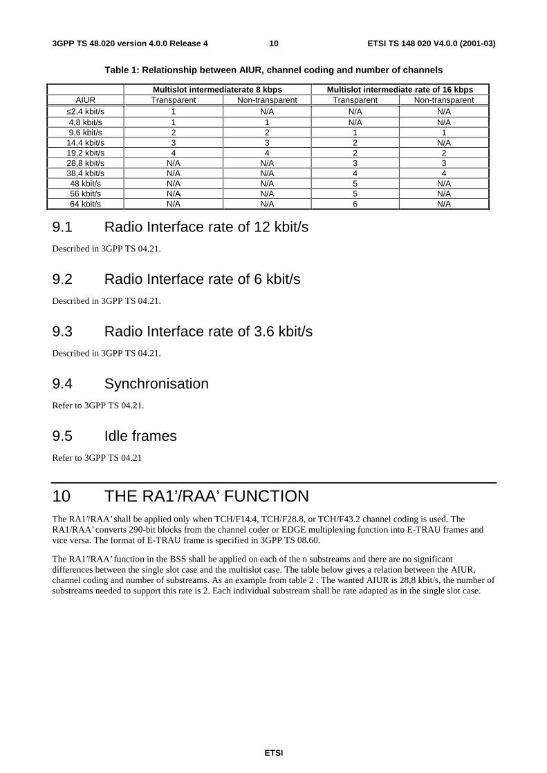
Table 1: Relationship between AIUR, channel coding and number of channels
Multislot intermediaterate 8 kbps Multislot intermediate rate of 16 kbps AIUR Transparent Non-transparent Transparent Non-transparent
≤2,4 kbit/s 1 N/A N/A N/A 4,8 kbit/s 1 1 N/A N/A 9,6 kbit/s 2 2 1 1
14,4 kbit/s 3 3 2 N/A 19,2 kbit/s 4 4 2 2 28,8 kbit/s N/A N/A 3 3 38,4 kbit/s N/A N/A 4 4 48 kbit/s N/A N/A 5 N/A 56 kbit/s N/A N/A 5 N/A 64 kbit/s N/A N/A 6 N/A
9.1 Radio Interface rate of 12 kbit/s Described in 3GPP TS 04.21.
9.2 Radio Interface rate of 6 kbit/s Described in 3GPP TS 04.21.
9.3 Radio Interface rate of 3.6 kbit/s Described in 3GPP TS 04.21.
9.4 Synchronisation Refer to 3GPP TS 04.21.
9.5 Idle frames Refer to 3GPP TS 04.21
10 THE RA1’/RAA’ FUNCTION The RA1’/RAA’ shall be applied only when TCH/F14.4, TCH/F28.8, or TCH/F43.2 channel coding is used. The RA1/RAA’ converts 290-bit blocks from the channel coder or EDGE multiplexing function into E-TRAU frames and vice versa. The format of E-TRAU frame is specified in 3GPP TS 08.60.
The RA1’/RAA’ function in the BSS shall be applied on each of the n substreams and there are no significant differences between the single slot case and the multislot case. The table below gives a relation between the AIUR, channel coding and number of substreams. As an example from table 2 : The wanted AIUR is 28,8 kbit/s, the number of substreams needed to support this rate is 2. Each individual substream shall be rate adapted as in the single slot case.

ETSI
ETSI TS 148 020 V4.0.0 (2001-03)113GPP TS 48.020 version 4.0.0 Release 4
Table 2 Relationship between AIUR, channel coding and number of channels.
AIUR Transparent Non-transparent 14,4 kbit/s 1 1 28,8 kbit/s 2 2 38,4 kbit/s 3 N/A 43,2 kbit/s N/A 3 48 kbit/s 4 N/A 56 kbit/s 4 N/A 57,6 kbit/s N/A 4 64 kbit/s 5 N/A
10.1 Radio Interface rate of 14,5 kbit/s See 3GPP TS 08.60.
10.2 Synchronisation See 3GPP TS 08.60.
10.3 Idle frames See 3GPP TS 08.60.
11 THE RAA’ FUNCTION The RAA’ function shall be applied only when TCH/F14.4, TCH/F28.8, or TCH/F43.2 channels are used.
The RAA’ converts E-TRAU frame into A-TRAU frame and vice versa.
The format of the E-TRAU frame is specified in 3GPP TS 08.60.
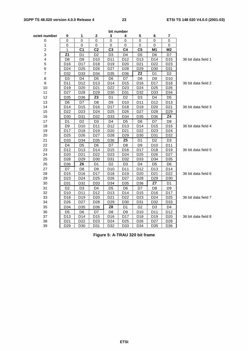
11.1 Coding of A-TRAU frame The format of the A-TRAU frame is given in Figure 5.
An A-TRAU frame carries eight 36 bit-data frames.
C Bits
Table 3
C1 C2 C3 C4 Date Rate 0 1 1 1 14,4 kbit/s 0 1 1 0 14.4 kbit/s idle
(IWF to BSS only)
Table 4
C5 BSS to IWF Frame Type
note 1
IWF to BSS UFE (Uplink Frame Error)
1 idle framing error 0 data no framing error
NOTE 1: Bit C5 corresponds to bit C6 of the E-TRAU frame as defined in 3GPP TS 08.60.

ETSI
ETSI TS 148 020 V4.0.0 (2001-03)123GPP TS 48.020 version 4.0.0 Release 4
M Bits
Transparent data
M1 and M2 are as defined in 3GPP TS 04.21.
Non transparent data
See subclause 15.2 of this GSM TS.
Z bits
Bits Zi are used for Framing Pattern Substitution.
See subclause 11.2.
11.2 Framing Pattern Substitution in A-TRAU frame The Framing Pattern Substitution is used in each of the eight 36 bit data fields of the A-TRAU frame (see Figure 5) to avoid transmitting a sequence of eight zeroes (called Z sequence in the following).
The purposes of FPS is to avoid erroneous synchronisation to the A-TRAU due to sixteen zeroes occurring accidentally in the data bits and to avoid erroneous synchronisation to V.110. The synchronisation pattern of two consecutive V.110 frames cannot be found within a stream of A TRAU frames.
11.2.1 FPS encoding
A Zero Sequence Position (ZSP) field is used to account for the occurrence of eight zeroes in the 36 bit data field.
NOTE: A sequence of eight zeroes is considered as a block (e.g. a stream of eleven consecutive zeroes produces only one ZSP and not four ZSPs).
The ZSP field is defined as follows:
Table 5
1 2 3 4 5 6 7 8 1 C A0 A1 A2 A3 A4 1
The meaning of the different bits of the ZSP field is :
C : Continuation bit. ’0’ means that there is another ZSP in the data field. ’1’ means that there is no other ZSP.
A0-A4 :address of the next Z sequence (eight zeroes) to be inserted. The address ‘00001’ corresponds to the bit D1, the value ‘11101’ to the bit D29, (A0 is the msb, A4 is the lsb).
NOTE: a Z sequence substitution cannot occur at bit D30..D36 (as it is 8 bit long)
1 : locking bit prevent the false occurrence of a Z sequence.
The Framing Pattern Substitution is applied in each of the eight 36 bit data field (see Figure 5).
Bit Zi indicates whether FPS is used in the ith 36 bit data field (i=1 to 8). The coding of the Zi bit is the following:
Table 6
Zi (i=1..8) meaning 1 no substitution 0 at least one substitution
If Zi bit indicates no substitution, the output data bits of FPS are equal to the input data bits.
If Zi indicates at least one substitution, the bits D1-D8 contain the first ZSP.
ETSI
ETSI TS 148 020 V4.0.0 (2001-03)133GPP TS 48.020 version 4.0.0 Release 4
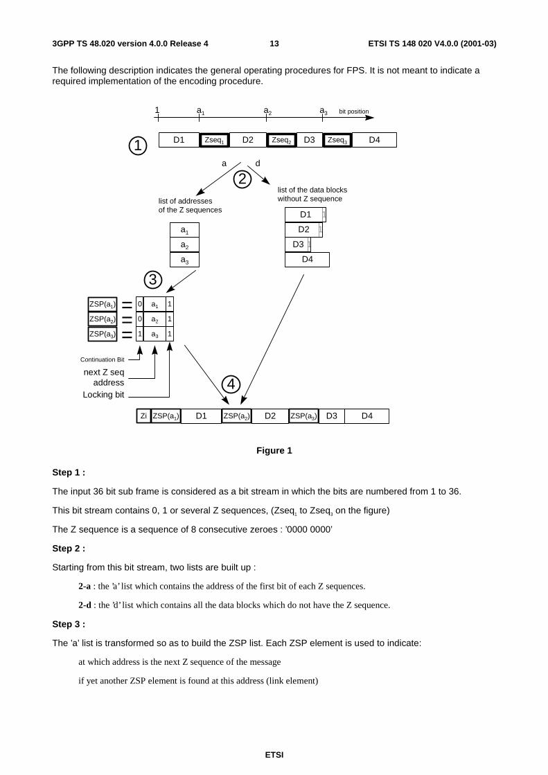
The following description indicates the general operating procedures for FPS. It is not meant to indicate a required implementation of the encoding procedure.
1 a1 a2 bit positiona3
list of addressesof the Z sequences
list of the data blockswithout Z sequence
a1
a2
a3
1D1
1D2
1D3
D4
1
a1 10
a2 10
a3 11
ZSP(a1)
ZSP(a2)
ZSP(a3)
===
2
3
D2 D3 D4D1ZSP(a1) ZSP(a2) ZSP(a3)Zi
4
D2 D3 D4D1 Zseq1 Zseq2 Zseq3
Continuation Bit
next Z seqaddress
a d
Locking bit
Figure 1
Step 1 :
The input 36 bit sub frame is considered as a bit stream in which the bits are numbered from 1 to 36.
This bit stream contains 0, 1 or several Z sequences, (Zseq1 to Zseq3 on the figure)
The Z sequence is a sequence of 8 consecutive zeroes : ’0000 0000’
Step 2 :
Starting from this bit stream, two lists are built up :
2-a : the ’a’ list which contains the address of the first bit of each Z sequences.
2-d : the ’d’ list which contains all the data blocks which do not have the Z sequence.
Step 3 :
The ’a’ list is transformed so as to build the ZSP list. Each ZSP element is used to indicate:
at which address is the next Z sequence of the message
if yet another ZSP element is found at this address (link element)

ETSI
ETSI TS 148 020 V4.0.0 (2001-03)143GPP TS 48.020 version 4.0.0 Release 4
Step 4 :
The output 37 bit sub frame is built from:
the Zi field which indicates whether the original message has been transformed or not with this technique. In the example given in Figure 1, Zi shall be set to ’0’ to indicate that at least one FPS has occurred.
the ZSP and D elements interleaved.
As the ZSP elements have exactly the same length as the Z sequence, the sub frame length is only increased by one (the Zi bit), whatever the number of frame pattern substitutions may be.
For special cases, refer to annex A.
11.3 A-TRAU Synchronisation Pattern The frame synchronisation is obtained by means of the first two octets in each frame, with all bits coded binary "0" and the first bit in octet no 2 coded binary "1". The following 17 bit alignment pattern is used to achieve frame synchronisation :
00000000 00000000 1XXXXXXX XXXXXXXX XXXXXXXX XXXXXXXX XXXXXXXX XXXXXXXX XXXXXXXX XXXXXXXX XXXXXXXX XXXXXXXX XXXXXXXX XXXXXXXX XXXXXXXX XXXXXXXX XXXXXXXX XXXXXXXX XXXXXXXX XXXXXXXX XXXXXXXX XXXXXXXX XXXXXXXX XXXXXXXX XXXXXXXX XXXXXXXX XXXXXXXX XXXXXXXX XXXXXXXX XXXXXXXX XXXXXXXX XXXXXXXX XXXXXXXX XXXXXXXX XXXXXXXX XXXXXXXX XXXXXXXX XXXXXXXX XXXXXXXX XXXXXXXX
12 THE RAA’’ FUNCTION On the IWF side of the A interface, the RAA" function shall convert between the A-TRAU format and a synchronous stream. FPS shall be performed by this function as well, see subclause 11.2. In transparent operation, the RAA" function shall handle the M1 and M2 bits as specified for the RA1’ function in 3GPP TS 04.21.
In non-transparent operation, the RAA" function shall map between the A-TRAU format and 290 bit blocks consisting of M1, M2 and 288 bits making up half of an RLP frame, see subclause 15.2 of this GSM TS.
13 The RA2 Function Described in 3GPP TS 04.21. The RA2 function shall be applied only for single slot operations.
14 The A-interface Multiplexing Function The multiplexing function shall be applied only for AIUR up to and including 57.6 kbit/s for multislot operations.
The multiplexing function is based on the ITU-T I.460. The multiplexing function is used to combine n (n=2 to 4) substreams of multislot intermediate rate of 8 kbit/s or n substreams of multislot intermediate rate of 16 kbit/s on one 64 kbit/s stream by using subcircuits in each octet to each substream such that:
i) An 8 kbit/s substream is allowed to occupy subcircuits with positions 1,3,5 or 7 of each octet of the 64 kbit/s stream; a 16 kbit/s stream occupies bit positions (1,2) or (3,4) or (5,6) or (7,8).
ii) The order of the bits at each substream is identical before and after multiplexing.
iii) All unused bit positions shall be set to binary “1".
iv) For transparent multislot configurations the lowest allowed subcircuits are always used.
v) For non-transparent multislot configurations, the lowest allowed subcircuits shall be used at call set up and after change of channel configuration except at downgrading. At downgrading any of the used subcircuits may be released in uplink direction. Always, the released subcircuit(s) in downlink direction shall be the same as the
ETSI
ETSI TS 148 020 V4.0.0 (2001-03)153GPP TS 48.020 version 4.0.0 Release 4
released subcircuit(s) in uplink direction. At a possible subsequent upgrading, the lowest available bit positions shall be used for the added substreams.
NOTE: The rules given here are almost identical to those of I.460, Section ‘Fixed format multiplexing’, except for the rule i) is stricter in that 8 kbit/s substreams cannot occupy any positions, iv) and v) are added.
15 Support of non-transparent bearer services
15.1 TCH/F9.6 and TCH/F4.8 kbit/s channel codings In the case of non-transparent services the RA1/RA1' function shall perform the same mapping as that described for transparent services, using 12 and 6 kbit/s radio interface data rates, with the following modification.
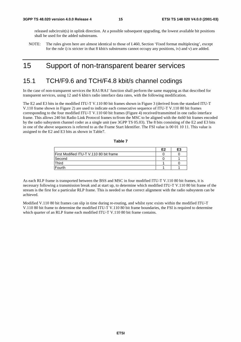
The E2 and E3 bits in the modified ITU-T V.110 80 bit frames shown in Figure 3 (derived from the standard ITU-T V.110 frame shown in Figure 2) are used to indicate each consecutive sequence of ITU-T V.110 80 bit frames corresponding to the four modified ITU-T V.110 60 bit frames (Figure 4) received/transmitted in one radio interface frame. This allows 240 bit Radio Link Protocol frames to/from the MSC to be aligned with the 4x60 bit frames encoded by the radio subsystem channel coder as a single unit (see 3GPP TS 05.03). The 8 bits consisting of the E2 and E3 bits in one of the above sequences is referred to as the Frame Start Identifier. The FSI value is 00 01 10 11. This value is assigned to the E2 and E3 bits as shown in Table7.
Table 7
E2 E3 First Modified ITU-T V.110 80 bit frame 0 0 Second 0 1 Third 1 0 Fourth 1 1
As each RLP frame is transported between the BSS and MSC in four modified ITU-T V.110 80 bit frames, it is necessary following a transmission break and at start up, to determine which modified ITU-T V.110 80 bit frame of the stream is the first for a particular RLP frame. This is needed so that correct alignment with the radio subsystem can be achieved.
Modified V.110 80 bit frames can slip in time during re-routing, and whilst sync exists within the modified ITU-T V.110 80 bit frame to determine the modified ITU-T V.110 80 bit frame boundaries, the FSI is required to determine which quarter of an RLP frame each modified ITU-T V.110 80 bit frame contains.
ETSI
ETSI TS 148 020 V4.0.0 (2001-03)163GPP TS 48.020 version 4.0.0 Release 4
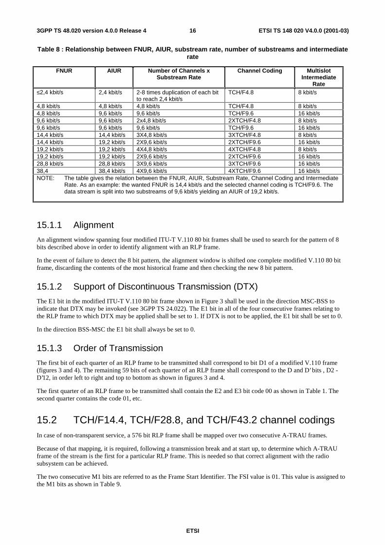
Table 8 : Relationship between FNUR, AIUR, substream rate, number of substreams and intermediate rate
FNUR AIUR Number of Channels x Substream Rate
Channel Coding Multislot Intermediate
Rate ≤2,4 kbit/s 2,4 kbit/s 2-8 times duplication of each bit
to reach 2,4 kbit/s TCH/F4.8 8 kbit/s
4,8 kbit/s 4,8 kbit/s 4,8 kbit/s TCH/F4.8 8 kbit/s 4,8 kbit/s 9,6 kbit/s 9,6 kbit/s TCH/F9.6 16 kbit/s 9,6 kbit/s 9,6 kbit/s 2x4,8 kbit/s 2XTCH/F4.8 8 kbit/s 9,6 kbit/s 9,6 kbit/s 9,6 kbit/s TCH/F9.6 16 kbit/s 14,4 kbit/s 14,4 kbit/s 3X4,8 kbit/s 3XTCH/F4.8 8 kbit/s 14,4 kbit/s 19,2 kbit/s 2X9,6 kbit/s 2XTCH/F9.6 16 kbit/s 19,2 kbit/s 19,2 kbit/s 4X4,8 kbit/s 4XTCH/F4.8 8 kbit/s 19,2 kbit/s 19,2 kbit/s 2X9,6 kbit/s 2XTCH/F9.6 16 kbit/s 28,8 kbit/s 28,8 kbit/s 3X9,6 kbit/s 3XTCH/F9.6 16 kbit/s 38,4 38,4 kbit/s 4X9,6 kbit/s 4XTCH/F9.6 16 kbit/s NOTE: The table gives the relation between the FNUR, AIUR, Substream Rate, Channel Coding and Intermediate
Rate. As an example: the wanted FNUR is 14,4 kbit/s and the selected channel coding is TCH/F9.6. The data stream is split into two substreams of 9,6 kbit/s yielding an AIUR of 19,2 kbit/s.
15.1.1 Alignment
An alignment window spanning four modified ITU-T V.110 80 bit frames shall be used to search for the pattern of 8 bits described above in order to identify alignment with an RLP frame.
In the event of failure to detect the 8 bit pattern, the alignment window is shifted one complete modified V.110 80 bit frame, discarding the contents of the most historical frame and then checking the new 8 bit pattern.
15.1.2 Support of Discontinuous Transmission (DTX)
The E1 bit in the modified ITU-T V.110 80 bit frame shown in Figure 3 shall be used in the direction MSC-BSS to indicate that DTX may be invoked (see 3GPP TS 24.022). The E1 bit in all of the four consecutive frames relating to the RLP frame to which DTX may be applied shall be set to 1. If DTX is not to be applied, the E1 bit shall be set to 0.
In the direction BSS-MSC the E1 bit shall always be set to 0.
15.1.3 Order of Transmission
The first bit of each quarter of an RLP frame to be transmitted shall correspond to bit D1 of a modified V.110 frame (figures 3 and 4). The remaining 59 bits of each quarter of an RLP frame shall correspond to the D and D’ bits , D2 - D’12, in order left to right and top to bottom as shown in figures 3 and 4.
The first quarter of an RLP frame to be transmitted shall contain the E2 and E3 bit code 00 as shown in Table 1. The second quarter contains the code 01, etc.
15.2 TCH/F14.4, TCH/F28.8, and TCH/F43.2 channel codings In case of non-transparent service, a 576 bit RLP frame shall be mapped over two consecutive A-TRAU frames.
Because of that mapping, it is required, following a transmission break and at start up, to determine which A-TRAU frame of the stream is the first for a particular RLP frame. This is needed so that correct alignment with the radio subsystem can be achieved.
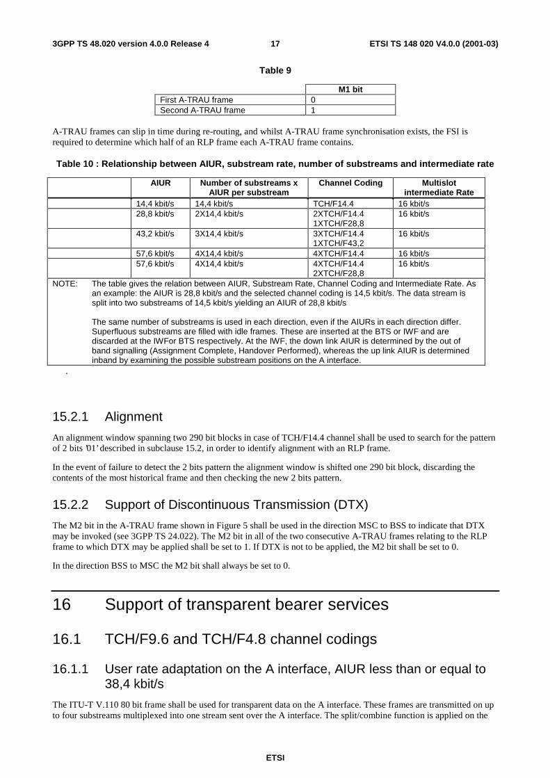
The two consecutive M1 bits are referred to as the Frame Start Identifier. The FSI value is 01. This value is assigned to the M1 bits as shown in Table 9.
ETSI
ETSI TS 148 020 V4.0.0 (2001-03)173GPP TS 48.020 version 4.0.0 Release 4
Table 9
M1 bit First A-TRAU frame 0 Second A-TRAU frame 1
A-TRAU frames can slip in time during re-routing, and whilst A-TRAU frame synchronisation exists, the FSI is required to determine which half of an RLP frame each A-TRAU frame contains.
Table 10 : Relationship between AIUR, substream rate, number of substreams and intermediate rate
AIUR Number of substreams x AIUR per substream
Channel Coding Multislot intermediate Rate
14,4 kbit/s 14,4 kbit/s TCH/F14.4 16 kbit/s 28,8 kbit/s 2X14,4 kbit/s
2XTCH/F14.4 1XTCH/F28,8
16 kbit/s
43,2 kbit/s 3X14,4 kbit/s
3XTCH/F14.4 1XTCH/F43,2
16 kbit/s
57,6 kbit/s 4X14,4 kbit/s 4XTCH/F14.4 16 kbit/s 57,6 kbit/s 4X14,4 kbit/s
4XTCH/F14.4 2XTCH/F28,8
16 kbit/s
NOTE: The table gives the relation between AIUR, Substream Rate, Channel Coding and Intermediate Rate. As an example: the AIUR is 28,8 kbit/s and the selected channel coding is 14,5 kbit/s. The data stream is split into two substreams of 14,5 kbit/s yielding an AIUR of 28,8 kbit/s
The same number of substreams is used in each direction, even if the AIURs in each direction differ. Superfluous substreams are filled with idle frames. These are inserted at the BTS or IWF and are discarded at the IWFor BTS respectively. At the IWF, the down link AIUR is determined by the out of band signalling (Assignment Complete, Handover Performed), whereas the up link AIUR is determined inband by examining the possible substream positions on the A interface.
.
15.2.1 Alignment
An alignment window spanning two 290 bit blocks in case of TCH/F14.4 channel shall be used to search for the pattern of 2 bits ’01’ described in subclause 15.2, in order to identify alignment with an RLP frame.
In the event of failure to detect the 2 bits pattern the alignment window is shifted one 290 bit block, discarding the contents of the most historical frame and then checking the new 2 bits pattern.
15.2.2 Support of Discontinuous Transmission (DTX)
The M2 bit in the A-TRAU frame shown in Figure 5 shall be used in the direction MSC to BSS to indicate that DTX may be invoked (see 3GPP TS 24.022). The M2 bit in all of the two consecutive A-TRAU frames relating to the RLP frame to which DTX may be applied shall be set to 1. If DTX is not to be applied, the M2 bit shall be set to 0.
In the direction BSS to MSC the M2 bit shall always be set to 0.
16 Support of transparent bearer services
16.1 TCH/F9.6 and TCH/F4.8 channel codings
16.1.1 User rate adaptation on the A interface, AIUR less than or equal to 38,4 kbit/s
The ITU-T V.110 80 bit frame shall be used for transparent data on the A interface. These frames are transmitted on up to four substreams multiplexed into one stream sent over the A interface. The split/combine function is applied on the
ETSI
ETSI TS 148 020 V4.0.0 (2001-03)183GPP TS 48.020 version 4.0.0 Release 4
substreams as specified in clause 5 of this GSM TS. The relation between the AIUR and the number of channels is specified in table11.
The 64 kbit/s consists of octets, bits 1 through 8, with bit 1 transmitted first.
For a 9 600 bit/s radio interface user rate the V.110 frame is carried with a 16 kbits/s stream which occupies bit positions (1,2).
For radio interface user rates of either 4 800 bit/s, 2 400 bit/s, 1 200 bit/s or 300 bit/s the V.110 frame is carried with a 8 kbits/s stream which occupies bit position (1). For user rates < 1 200bit/s asynchronous characters are padded with additional stop elements by the RA0 function (in the MSC/IWF) to fit into 600 bit/s synchronous RA1 rate prior to rate adaptation to 64 kbits/s.
No use of 4 kbit/s stream is foreseen.
In a given V.110 frame on the A interface:
- for 9 600 bit/s there is no repetition of bits D within the 16 kbit/s stream ;
- for 4 800 bit/s there is no repetition of bits D within the 8 kbit/s stream ;
- for 2 400 bit/s each bit D is repeated twice within the 8 kbit/s stream (D1 D1 D2 D2 etc) ;
- for 1 200 bit/s each bit D is repeated four times within the 8 kbit/s stream (D1 D1 D1 D1 D2 D2 D2 D2 etc) ;
- for 600 bit/s each bit D is repeated eight times within the 8kbit/s stream (D1 D1 D1 D1 D1 D1 D1 D1 D2 D2 D2 D2 D2 D2 D2 D2 etc);
16.1.2 User rate Adaptation on the A-interface, AIUR greater than 38,4 kbit/s
For AIUR of 48 kbit/s, 56 kbit/s and 64 kbit/s one stream consisting of ITU-T V.110 32 bit frames or 64 bit frames, as specified in 3GPP TS 04.21 shall be transmitted over the A-interface. Splitting/Combining which occurs in the BSS, is as specified in 3GPP TS 04.21.
Table 11 gives the relation between the User Rate, Substream Rate Channel Coding and the Intermediate Rate.

ETSI
ETSI TS 148 020 V4.0.0 (2001-03)193GPP TS 48.020 version 4.0.0 Release 4
16.1.3 Relation between AIUR and the number of channels
Table11: Relationship between the AIUR, substream rate, channel coding, intermediate rate and number of channels
AIUR Number of channels x Substream Rate
Channel Coding (Multislot) intermediate Rate (Note1)
≤2,4 kbit/s 2-8 times duplication of each bit to reach 4,8 kbit/s
TCH/F4.8 8 kbit/s
4,8 kbit/s 4,8 kbit/s TCH/F4.8 8 kbit/s
9,6 kbit/s 2X4,8 kbit/s 2XTCH/F4.8 8 kbit/s
9,6 kbit/s 9,6 kbit/s TCH/F9.6 16 kbit/s
14,4 kbit/s 3X4,8 kbit/s 3XTCH/F4.8 8 kbit/s
14,4 kbit/s 2X9,6 kbit/s w/ padding 2XTCH/F9.6 16 kbit/s
19,2 kbit/s 4X4,8 kbit/s 4XTCH/F4.8 8 kbit/s
19,2 kbit/s 2X9,6 kbit/s 2XTCH/F9.6 16 kbit/s
28,8 kbit/s 3x9,6 kbit/s 3XTCH/F9.6 16 kbit/s
38,4 kbit/s 4X9,6 kbit/s 4XTCH/F9.6 16 kbit/s
48 kbit/s 5X9,6 kbit/s 5XTCH/F9.6 64 kbit/s
56 kbit/s 5X11,2 kbit/s 5XTCH/F9.6 64 kbit/s
64 kbit/s 66x11,2 kbit/s w/padd. 6XTCH/F9.6 64 kbit/s
NOTE: For AIURs ≤ 38,4 kbit/s this column indicates the multislot intermediate rate: for higher AIURs it indicates the intermediate rate.
16.1.4 Handling of status bits X, SA, SB
In the single slot case, status bit SA shall be coded repeatedly as S1, S3, S6, S8, and SB is coded repeatedly as S4 and S9 in Figure 2. In the multislot case, status bit SA is coded repeatedly as S6, S8 and SB is coded as S9 in figures 2, 5 and 6.
The handling of the status bits shall comply with the synchronisation procedures for transparent services which are as described in 3GPP TS 29.007 (MSC), 3GPP TS 04.21 (BSS), 3GPP TS 27.001 (MS).
16.1.5 Handling of bits E1 to E7
Bits E1 to E3 shall be used according to 04.21.
Bits E4 to E7 may be used for network independent clocking as indicated in 3GPP TS 04.21.
ETSI
ETSI TS 148 020 V4.0.0 (2001-03)203GPP TS 48.020 version 4.0.0 Release 4
16.2 TCH/F14.4, TCH/F28.8, and TCH/F32.0 channel codings
16.2.1 User rate adaptation on the A interface, AIUR less than or equal to 56 kbit/s
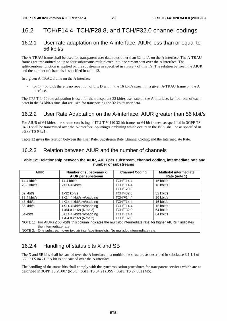
The A-TRAU frame shall be used for transparent user data rates other than 32 kbit/s on the A interface. The A-TRAU frames are transmitted on up to four substreams multiplexed into one stream sent over the A interface. The split/combine function is applied on the substreams as specified in clause 7 of this TS. The relation between the AIUR and the number of channels is specified in table 12.
In a given A-TRAU frame on the A interface:
- for 14 400 bit/s there is no repetition of bits D within the 16 kbit/s stream in a given A-TRAU frame on the A interface.
The ITU-T I.460 rate adaptation is used for the transparent 32 kbit/s user rate on the A interface, i.e. four bits of each octet in the 64 kbit/s time slot are used for transporting the 32 kbit/s user data.
16.2.2 User Rate Adaptation on the A-interface, AIUR greater than 56 kbit/s
For AIUR of 64 kbit/s one stream consisting of ITU-T V.110 32 bit frames or 64 bit frames, as specified in 3GPP TS 04.21 shall be transmitted over the A-interface. Splitting/Combining which occurs in the BSS, shall be as specified in 3GPP TS 04.21.
Table 12 gives the relation between the User Rate, Substream Rate Channel Coding and the Intermediate Rate.
16.2.3 Relation between AIUR and the number of channels
Table 12: Relationship between the AIUR, AIUR per substream, channel coding, intermediate rate and number of substreams
AIUR Number of substreams x AIUR per substream
Channel Coding Multislot intermediate Rate (note 1)
14,4 kbit/s 14,4 kbit/s TCH/F14.4 16 kbit/s 28,8 kbit/s 2X14,4 kbit/s TCH/F14.4
TCH/F28.8 16 kbit/s
32 kbit/s 1x32 kbit/s TCH/F32.0 32 kbit/s 38,4 kbit/s 3X14,4 kbit/s w/padding TCH/F14.4 16 kbit/s 48 kbit/s 4X14,4 kbit/s w/padding TCH/F14.4 16 kbit/s 56 kbit/s 4X14,4 kbit/s w/padding
1x64.0 kbit/s (Note 2) TCH/F14.4 TCH/F32.0
16 kbit/s 64 kbit/s
64kbit/s 5X14,4 kbit/s w/padding 1x64.0 kbit/s (Note 2)
TCH/F14.4 TCH/F32.0
64 kbit/s
NOTE 1: For AIURs ≤ 56 kbit/s this column indicates the multislot intermediate rate: for higher AIURs it indicates the intermediate rate.
NOTE 2: One substream over two air interface timeslots. No multislot intermediate rate.
16.2.4 Handling of status bits X and SB
The X and SB bits shall be carried over the A interface in a multiframe structure as described in subclause 8.1.1.1 of 3GPP TS 04.21. SA bit is not carried over the A interface.
The handling of the status bits shall comply with the synchronisation procedures for transparent services which are as described in 3GPP TS 29.007 (MSC), 3GPP TS 04.21 (BSS), 3GPP TS 27.001 (MS).

ETSI
ETSI TS 148 020 V4.0.0 (2001-03)213GPP TS 48.020 version 4.0.0 Release 4
17 Frame Formats Octet Bit number No.
0 1 2 3 4 5 6 7 0 0 0 0 0 0 0 0 0 1 1 D1 D2 D3 D4 D5 D6 S1 2 1 D7 D8 D9 D10 D11 D12 X 3 1 D13 D14 D15 D16 D17 D18 S3 4 1 D19 D20 D21 D22 D23 D24 S4 5 1 E1 E2 E3 E4 E5 E6 E7 6 1 D25 D26 D27 D28 D29 D30 S6 7 1 D31 D32 D33 D34 D35 D36 X 8 1 D37 D38 D39 D40 D41 D42 S8 9 1 D43 D44 D45 D46 D47 D48 S9
Figure 2: The ITU-T V.110 80 bit frame for Transparent Data

ETSI
ETSI TS 148 020 V4.0.0 (2001-03)223GPP TS 48.020 version 4.0.0 Release 4
octet bit number no. 0 1 2 3 4 5 6 7
0 0 0 0 0 0 0 0 0 1 1 D1 D2 D3 D4 D5 D6 D’1 2 1 D7 D8 D9 D10 D11 D12 D’2 3 1 D13 D14 D15 D16 D17 D18 D’3 4 1 D19 D20 D21 D22 D23 D24 D’4 5 1 E1 E2 E3 D’5 D’6 D’7 D’8 6 1 D25 D26 D27 D28 D29 D30 D’9 7 1 D31 D32 D33 D34 D35 D36 D’10 8 1 D37 D38 D39 D40 D41 D42 D’11 9 1 D43 D44 D45 D46 D47 D48 D’12
Figure 3: The modified ITU-T V.110 80 bit frame for Non-Transparent Data
D1 D2 D3 D4 D5 D6 D’1 D7 D8 D9 D10 D11 D12 D’2
D13 D14 D15 D16 D17 D18 D’3 D19 D20 D21 D22 D23 D24 D’4 D’5 D’6 D’7 D’8 D25 D26 D27 D28 D29 D30 D’9 D31 D32 D33 D34 D35 D36 D’10 D37 D38 D39 D40 D41 D42 D’11 D43 D44 D45 D46 D47 D48 D’12
Figure 4: Modified ITU-T V.110 60 bit frame for Non-Transparent Data
ETSI
ETSI TS 148 020 V4.0.0 (2001-03)233GPP TS 48.020 version 4.0.0 Release 4
bit number octet number 0 1 2 3 4 5 6 7
0 0 0 0 0 0 0 0 0 1 0 0 0 0 0 0 0 0 2 1 C1 C2 C3 C4 C5 M1 M2 3 Z1 D1 D2 D3 D4 D5 D6 D7 4 D8 D9 D10 D11 D12 D13 D14 D15 36 bit data field 1 5 D16 D17 D18 D19 D20 D21 D22 D23 6 D24 D25 D26 D27 D28 D29 D30 D31 7 D32 D33 D34 D35 D36 Z2 D1 D2 8 D3 D4 D5 D6 D7 D8 D9 D10 9 D11 D12 D13 D14 D15 D16 D17 D18 36 bit data field 2
10 D19 D20 D21 D22 D23 D24 D25 D26 11 D27 D28 D29 D30 D31 D32 D33 D34 12 D35 D36 Z3 D1 D2 D3 D4 D5 13 D6 D7 D8 D9 D10 D11 D12 D13 14 D14 D15 D16 D17 D18 D19 D20 D21 36 bit data field 3 15 D22 D23 D24 D25 D26 D27 D28 D29 16 D30 D31 D32 D33 D34 D35 D36 Z4 17 D1 D2 D3 D4 D5 D6 D7 D8 18 D9 D10 D11 D12 D13 D14 D15 D16 36 bit data field 4 19 D17 D18 D19 D20 D21 D22 D23 D24 20 D25 D26 D27 D28 D29 D30 D31 D32 21 D33 D34 D35 D36 Z5 D1 D2 D3 22 D4 D5 D6 D7 D8 D9 D10 D11 23 D12 D13 D14 D15 D16 D17 D18 D19 36 bit data field 5 24 D20 D21 D22 D23 D24 D25 D26 D27 25 D28 D29 D30 D31 D32 D33 D34 D35 26 D36 Z6 D1 D2 D3 D4 D5 D6 27 D7 D8 D9 D10 D11 D12 D13 D14 28 D15 D16 D17 D18 D19 D20 D21 D22 36 bit data field 6 29 D23 D24 D25 D26 D27 D28 D29 D30 30 D31 D32 D33 D34 D35 D36 Z7 D1 31 D2 D3 D4 D5 D6 D7 D8 D9 32 D10 D11 D12 D13 D14 D15 D16 D17 33 D18 D19 D20 D21 D22 D23 D24 D25 36 bit data field 7 34 D26 D27 D28 D29 D30 D31 D32 D33 35 D34 D35 D36 Z8 D1 D2 D3 D4 36 D5 D6 D7 D8 D9 D10 D11 D12 37 D13 D14 D15 D16 D17 D18 D19 D20 36 bit data field 8 38 D21 D22 D23 D24 D25 D26 D27 D28 39 D29 D30 D31 D32 D33 D34 D35 D36
Figure 5: A-TRAU 320 bit frame
ETSI
ETSI TS 148 020 V4.0.0 (2001-03)243GPP TS 48.020 version 4.0.0 Release 4
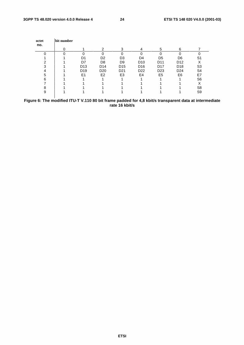
octet bit number no. 0 1 2 3 4 5 6 7
0 0 0 0 0 0 0 0 0 1 1 D1 D2 D3 D4 D5 D6 S1 2 1 D7 D8 D9 D10 D11 D12 X 3 1 D13 D14 D15 D16 D17 D18 S3 4 1 D19 D20 D21 D22 D23 D24 S4 5 1 E1 E2 E3 E4 E5 E6 E7 6 1 1 1 1 1 1 1 S6 7 1 1 1 1 1 1 1 X 8 1 1 1 1 1 1 1 S8 9 1 1 1 1 1 1 1 S9
Figure 6: The modified ITU-T V.110 80 bit frame padded for 4,8 kbit/s transparent data at intermediate rate 16 kbit/s
ETSI
ETSI TS 148 020 V4.0.0 (2001-03)253GPP TS 48.020 version 4.0.0 Release 4
Annex A (informative): Frame Pattern Substitution
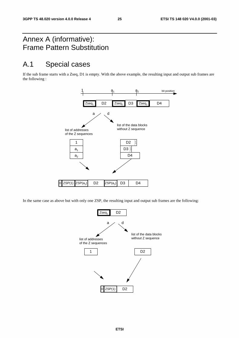
A.1 Special cases If the sub frame starts with a Zseq, D1 is empty. With the above example, the resulting input and output sub frames are the following :
1 a1 a2 bit position
list of addressesof the Z sequences
list of the data blockswithout Z sequence
1
a1
a2
1D2
1D3
D4
D2 D3 D4ZSP(1) ZSP(a1) ZSP(a2)0
D2 D3 D4Zseq1 Zseq2 Zseq3
a d
In the same case as above but with only one ZSP, the resulting input and output sub frames are the following:
list of addressesof the Z sequences
list of the data blockswithout Z sequence
1 D2
D2ZSP(1)0
D2Zseq1
a d
ETSI
ETSI TS 148 020 V4.0.0 (2001-03)263GPP TS 48.020 version 4.0.0 Release 4
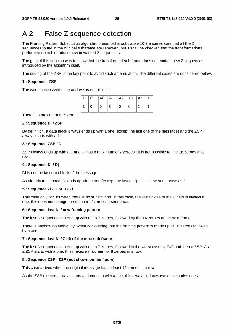
A.2 False Z sequence detection The Framing Pattern Substitution algorithm presented in subclause 10.2 ensures sure that all the Z sequences found in the original sub frame are removed, but it shall be checked that the transformations performed do not introduce new unwanted Z sequences.
The goal of this subclause is to show that the transformed sub frame does not contain new Z sequences introduced by the algorithm itself.
The coding of the ZSP is the key point to avoid such an emulation. The different cases are considered below.
1 : Sequence ZSP
The worst case is when the address is equal to 1 :
1 C A0 A1 A2 A3 A4 1
1 0 0 0 0 0 1 1
There is a maximum of 5 zeroes.
2 : Sequence Di / ZSP.
By definition, a data block always ends up with a one (except the last one of the message) and the ZSP always starts with a 1.
3 : Sequence ZSP / Di
ZSP always ends up with a 1 and Di has a maximum of 7 zeroes : it is not possible to find 16 zeroes in a row.
4 : Sequence Di / Dj
Di is not the last data block of the message.
As already mentioned, Di ends up with a one (except the last one) : this is the same case as 3.
5 : Sequence Zi / D or D / Zi
This case only occurs when there is no substitution. In this case, the Zi bit close to the D field is always a one: this does not change the number of zeroes in sequence.
6 : Sequence last Di / new framing pattern
The last D sequence can end up with up to 7 zeroes, followed by the 16 zeroes of the next frame.
There is anyhow no ambiguity, when considering that the framing pattern is made up of 16 zeroes followed by a one.
7 : Sequence last Di / Z bit of the next sub frame
The last D sequence can end up with up to 7 zeroes, followed in the worst case by Z=0 and then a ZSP. As a ZSP starts with a one, this makes a maximum of 8 zeroes in a row.
8 : Sequence ZSP / ZSP (not shown on the figure)
This case arrives when the original message has at least 16 zeroes in a row.
As the ZSP element always starts and ends up with a one, this always induces two consecutive ones.
ETSI
ETSI TS 148 020 V4.0.0 (2001-03)273GPP TS 48.020 version 4.0.0 Release 4
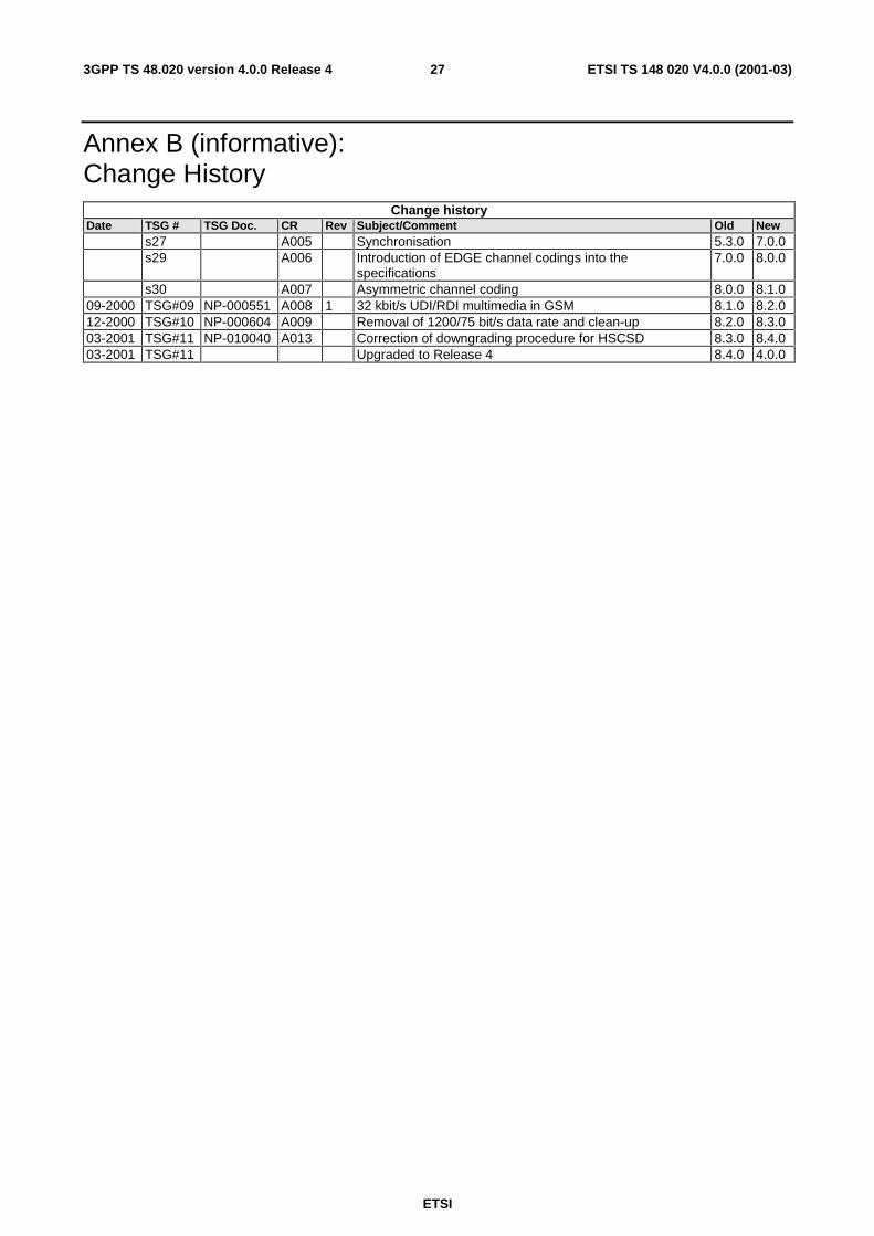
Annex B (informative): Change History
Change history Date TSG # TSG Doc. CR Rev Subject/Comment Old New s27 A005 Synchronisation 5.3.0 7.0.0 s29 A006 Introduction of EDGE channel codings into the
specifications 7.0.0 8.0.0
s30 A007 Asymmetric channel coding 8.0.0 8.1.0 09-2000 TSG#09 NP-000551 A008 1 32 kbit/s UDI/RDI multimedia in GSM 8.1.0 8.2.0 12-2000 TSG#10 NP-000604 A009 Removal of 1200/75 bit/s data rate and clean-up 8.2.0 8.3.0 03-2001 TSG#11 NP-010040 A013 Correction of downgrading procedure for HSCSD 8.3.0 8.4.0 03-2001 TSG#11 Upgraded to Release 4 8.4.0 4.0.0

28
ETSI
ETSI TS 148 020 V4.0.0 (2001-03)3GPP TS 48.020 version 4.0.0 Release 4
History
Document history
V4.0.0 March 2001 Publication
Related Documents