ETSI TS 1 Digital cellular telec Multiplexing and m (3GPP TS 45.0 TECHNICAL SPECIFICATION 145 002 V12.4.0 (201 communications system (Pha multiple access on the radio 002 version 12.4.0 Release 1 N GLOBAL SYST MOBILE COMMU 15-04) ase 2+); o path 12) TEM FOR UNICATIONS R

Welcome message from author
This document is posted to help you gain knowledge. Please leave a comment to let me know what you think about it! Share it to your friends and learn new things together.
Transcript

ETSI TS 1
Digital cellular telecoMultiplexing and m
(3GPP TS 45.0
TECHNICAL SPECIFICATION
145 002 V12.4.0 (2015
communications system (Pha multiple access on the radio.002 version 12.4.0 Release 12
ION
GLOBAL SYSTMOBILE COMMUN
15-04)
hase 2+); io path 12)
STEM FOR UNICATIONS
R

ETSI
ETSI TS 145 002 V12.4.0 (2015-04)13GPP TS 45.002 version 12.4.0 Release 12
Reference RTS/TSGG-0145002vc40
Keywords GSM
ETSI
650 Route des Lucioles F-06921 Sophia Antipolis Cedex - FRANCE
Tel.: +33 4 92 94 42 00 Fax: +33 4 93 65 47 16
Siret N° 348 623 562 00017 - NAF 742 C
Association à but non lucratif enregistrée à la Sous-Préfecture de Grasse (06) N° 7803/88
Important notice
The present document can be downloaded from: http://www.etsi.org/standards-search
The present document may be made available in electronic versions and/or in print. The content of any electronic and/or print versions of the present document shall not be modified without the prior written authorization of ETSI. In case of any
existing or perceived difference in contents between such versions and/or in print, the only prevailing document is the print of the Portable Document Format (PDF) version kept on a specific network drive within ETSI Secretariat.
Users of the present document should be aware that the document may be subject to revision or change of status. Information on the current status of this and other ETSI documents is available at
http://portal.etsi.org/tb/status/status.asp
If you find errors in the present document, please send your comment to one of the following services: https://portal.etsi.org/People/CommiteeSupportStaff.aspx
Copyright Notification
No part may be reproduced or utilized in any form or by any means, electronic or mechanical, including photocopying and microfilm except as authorized by written permission of ETSI.
The content of the PDF version shall not be modified without the written authorization of ETSI. The copyright and the foregoing restriction extend to reproduction in all media.
© European Telecommunications Standards Institute 2015.
All rights reserved.
DECTTM, PLUGTESTSTM, UMTSTM and the ETSI logo are Trade Marks of ETSI registered for the benefit of its Members. 3GPPTM and LTE™ are Trade Marks of ETSI registered for the benefit of its Members and
of the 3GPP Organizational Partners. GSM® and the GSM logo are Trade Marks registered and owned by the GSM Association.
ETSI
ETSI TS 145 002 V12.4.0 (2015-04)23GPP TS 45.002 version 12.4.0 Release 12
Intellectual Property Rights IPRs essential or potentially essential to the present document may have been declared to ETSI. The information pertaining to these essential IPRs, if any, is publicly available for ETSI members and non-members, and can be found in ETSI SR 000 314: "Intellectual Property Rights (IPRs); Essential, or potentially Essential, IPRs notified to ETSI in respect of ETSI standards", which is available from the ETSI Secretariat. Latest updates are available on the ETSI Web server (http://ipr.etsi.org).
Pursuant to the ETSI IPR Policy, no investigation, including IPR searches, has been carried out by ETSI. No guarantee can be given as to the existence of other IPRs not referenced in ETSI SR 000 314 (or the updates on the ETSI Web server) which are, or may be, or may become, essential to the present document.
Foreword This Technical Specification (TS) has been produced by ETSI 3rd Generation Partnership Project (3GPP).
The present document may refer to technical specifications or reports using their 3GPP identities, UMTS identities or GSM identities. These should be interpreted as being references to the corresponding ETSI deliverables.
The cross reference between GSM, UMTS, 3GPP and ETSI identities can be found under http://webapp.etsi.org/key/queryform.asp.
Modal verbs terminology In the present document "shall", "shall not", "should", "should not", "may", "need not", "will", "will not", "can" and "cannot" are to be interpreted as described in clause 3.2 of the ETSI Drafting Rules (Verbal forms for the expression of provisions).
"must" and "must not" are NOT allowed in ETSI deliverables except when used in direct citation.

ETSI
ETSI TS 145 002 V12.4.0 (2015-04)33GPP TS 45.002 version 12.4.0 Release 12
Contents
Intellectual Property Rights ................................................................................................................................ 2
Foreword ............................................................................................................................................................. 2
Modal verbs terminology .................................................................................................................................... 2
Foreword ............................................................................................................................................................. 7
1 Scope ........................................................................................................................................................ 8
1.1 References .......................................................................................................................................................... 8
1.2 Abbreviations ..................................................................................................................................................... 9
1.3 Restrictions ......................................................................................................................................................... 9
2 General ..................................................................................................................................................... 9
3 Logical channels ....................................................................................................................................... 9
3.1 General ............................................................................................................................................................... 9
3.2 Traffic channels .................................................................................................................................................. 9
3.2.1 General .......................................................................................................................................................... 9
3.2.2 Speech traffic channels ............................................................................................................................... 10
3.2.3 Circuit switched data traffic channels ......................................................................................................... 10
3.2.4 Packet data traffic channels (PDTCH) ........................................................................................................ 11
3.3 Control channels ............................................................................................................................................... 11
3.3.1 General ........................................................................................................................................................ 11
3.3.2 Broadcast channels ..................................................................................................................................... 12
3.3.2.1 Frequency correction channels (FCCH and CFCCH) ........................................................................... 12
3.3.2.2 Synchronization channels ...................................................................................................................... 12
3.3.2.2.1 Synchronization channel (SCH) ...................................................................................................... 12
3.3.2.2.2 COMPACT synchronization channel (CSCH) ................................................................................ 12
3.3.2.3 Broadcast control channel (BCCH) ....................................................................................................... 13
3.3.2.4 Packet Broadcast Control Channels ...................................................................................................... 13
3.3.2.4.1 Packet Broadcast Control Channel (PBCCH) ................................................................................. 13
3.3.2.4.2 COMPACT Packet Broadcast Control Channel (CPBCCH) ........................................................... 14
3.3.3 Common control type channels .................................................................................................................. 14
3.3.3.1 Common control type channels, known when combined as a common control channel (CCCH) ........ 14
3.3.3.2 Packet Common control channels ......................................................................................................... 14
3.3.3.2.1 Packet Common Control Channels (PCCCH) ................................................................................. 14
3.3.3.2.2 COMPACT Common Control Channels (CPCCCH) ...................................................................... 15
3.3.3.2.3 MBMS Common Control Channels ................................................................................................ 15
3.3.4 Dedicated control channels ......................................................................................................................... 15
3.3.4.1 Circuit switched dedicated control channels ......................................................................................... 15
3.3.4.2 Packet dedicated control channels ......................................................................................................... 16
3.3.5 Cell Broadcast Channel (CBCH) ................................................................................................................ 16
3.3.6 CTS control channels .................................................................................................................................. 16
3.3.6.1 CTS beacon channel (BCH) .................................................................................................................. 16
3.3.6.2 CTS paging channel (CTSPCH) ........................................................................................................... 16
3.3.6.3 CTS access request channel (CTSARCH) ............................................................................................ 16
3.3.6.4 CTS access grant channel (CTSAGCH) ............................................................................................... 16
3.4 Combination of channels .................................................................................................................................. 17
4 The physical resource ............................................................................................................................. 17
4.1 General ............................................................................................................................................................. 17
4.2 Radio frequency channels................................................................................................................................. 17
4.2.1 Cell allocation and mobile allocation.......................................................................................................... 17
4.2.2 Downlink and uplink .................................................................................................................................. 17
4.3 Timeslots, TDMA frames, and time groups ..................................................................................................... 17
4.3.1 General ........................................................................................................................................................ 17
4.3.2 Timeslot number ......................................................................................................................................... 18
4.3.3 TDMA frame number ................................................................................................................................. 18
4.3.4 Time group.................................................................................................................................................. 18

ETSI
ETSI TS 145 002 V12.4.0 (2015-04)43GPP TS 45.002 version 12.4.0 Release 12
5 Physical channels ................................................................................................................................... 18
5.1 General ............................................................................................................................................................. 18
5.2 Bursts ................................................................................................................................................................ 18
5.2.1 General ........................................................................................................................................................ 18
5.2.2 Types of burst and burst timing .................................................................................................................. 19
5.2.3 Normal burst (NB) ...................................................................................................................................... 19
5.2.3a Higher symbol rate burst (HB) ................................................................................................................... 26
5.2.4 Frequency correction burst (FB) ................................................................................................................. 29
5.2.5 Synchronization Burst (SB) ........................................................................................................................ 30
5.2.6 Dummy burst .............................................................................................................................................. 30
5.2.7 Access burst (AB) ....................................................................................................................................... 31
5.2.8 Guard period ............................................................................................................................................... 31
5.3 Physical channels and bursts ............................................................................................................................ 31
5.4 Radio frequency channel sequence .................................................................................................................. 31
5.5 Timeslot and TDMA frame sequence .............................................................................................................. 32
5.6 Parameters for channel definition and assignment ........................................................................................... 32
5.6.1 General ........................................................................................................................................................ 32
5.6.2 General parameters ..................................................................................................................................... 32
5.6.3 Specific parameters ..................................................................................................................................... 32
6 Mapping of logical channels onto physical channels ............................................................................. 33
6.1 General ............................................................................................................................................................. 33
6.2 Mapping in frequency of logical channels onto physical channels .................................................................. 33
6.2.1 General ........................................................................................................................................................ 33
6.2.2 Parameters................................................................................................................................................... 33
6.2.3 Hopping sequence generation ..................................................................................................................... 34
6.2.4 Specific cases .............................................................................................................................................. 35
6.2.5 Change in the frequency allocation of a base transceiver station................................................................ 36
6.2.6 Frequency assignment in CTS .................................................................................................................... 36
6.2.7 Mapping restrictions in downlink multi-carrier configurations .................................................................. 36
6.3 Mapping in time of logical channels onto physical channels ........................................................................... 37
6.3.1 Mapping in time of circuit switched logical channels onto physical channels ........................................... 37
6.3.1.1 General .................................................................................................................................................. 37
6.3.1.2 Key to the mapping table of clause 7 .................................................................................................... 37
6.3.1.3 Mapping of BCCH data ........................................................................................................................ 38
6.3.1.4 Mapping of SID Frames ........................................................................................................................ 40
6.3.2 Mapping in time of packet logical channels onto physical channels .......................................................... 40
6.3.2.1 General .................................................................................................................................................. 40
6.3.2.2 Mapping of the uplink channels ............................................................................................................ 41
6.3.2.2.1 Mapping of uplink packet traffic channel (PDTCH/U) and PACCH/U .......................................... 41
6.3.2.2.1.1 BTTI configuration .................................................................................................................... 41
6.3.2.2.1.2 RTTI configuration .................................................................................................................... 42
6.3.2.2.2 Mapping of the Packet Timing Advance Control Channel (PTCCH/U) ......................................... 43
6.3.2.2.3 Mapping of the uplink PCCCH i.e. PRACH ................................................................................... 43
6.3.2.2.3a Mapping of the COMPACT uplink CPCCCH i.e. CPRACH .......................................................... 43
6.3.2.2.4 Mapping of the MBMS uplink MPRACH ....................................................................................... 43
6.3.2.3 Mapping of the downlink channels ....................................................................................................... 44
6.3.2.3.1 Mapping of the (PDTCH/D) and PACCH/D ................................................................................... 44
6.3.2.3.2 Mapping of the PTCCH/D ............................................................................................................... 44
6.3.2.3.3 Mapping of the PBCCH .................................................................................................................. 44
6.3.2.3.3a Mapping of the COMPACT CPBCCH ............................................................................................ 44
6.3.2.3.4 Mapping of the PCCCH .................................................................................................................. 44
6.3.2.3.4a Mapping of the COMPACT CPCCCH ............................................................................................ 45
6.3.2.4 Mapping of PBCCH data ...................................................................................................................... 45
6.3.2.4a Mapping of COMPACT CPBCCH data ............................................................................................... 46
6.3.3 Mapping in time of CTS control channels onto physical channels ............................................................. 46
6.3.3.1 CTSBCH timeslot assignment .............................................................................................................. 46
6.3.3.2 CTSPCH, CTSARCH and CTSAGCH timeslot assignment ................................................................ 48
6.4 Permitted channel combinations ....................................................................................................................... 48
6.4.1 Permitted channel combinations onto a basic physical channel.................................................................. 48
6.4.2 Multislot configurations .............................................................................................................................. 52
6.4.2.1 Multislot configurations for circuit switched connections in A/Gb mode ............................................. 52

ETSI
ETSI TS 145 002 V12.4.0 (2015-04)53GPP TS 45.002 version 12.4.0 Release 12
6.4.2.2 Multislot configurations for packet switched connections in A/Gb mode ............................................. 53
6.4.2.3 Multislot configurations for dual transfer mode in A/Gb mode ............................................................. 56
6.4.2.3a Multislot configurations for MBMS in A/Gb mode .............................................................................. 57
6.4.2.4 Multislot configurations for DBPSCH in Iu mode ................................................................................ 58
6.4.2.4.1 TCHs assigned ................................................................................................................................. 58
6.4.2.4.2 PDTCHs assigned ............................................................................................................................ 58
6.4.2.4.3 TCHs and PDTCHs assigned .......................................................................................................... 58
6.4.2.5 void ....................................................................................................................................................... 58
6.4.2.6 Multislot configurations for SBPSCH in Iu mode ................................................................................. 58
6.4.2.7 Multislot configurations for dual transfer mode in Iu mode .................................................................. 58
6.5 Operation of channels and channel combinations ............................................................................................ 59
6.5.1 General ........................................................................................................................................................ 59
6.5.2 Determination of CCCH_GROUP and PAGING_GROUP for MS in idle mode ...................................... 61
6.5.3 Determination of specific paging multiframe and paging block index ....................................................... 62
6.5.4 Short Message Service Cell Broadcast (SMSCB) ...................................................................................... 62
6.5.5 Voice group and voice broadcast call notifications .................................................................................... 62
6.5.6 Determination of PCCCH_GROUP and PAGING_GROUP for MS in GPRS attached mode .................. 62
6.5.7 Determination of CTS_PAGING_GROUP and specific paging 52-multiframe for MS in CTS mode ...... 64
6.5.8 Determination of single carrier fallback group ........................................................................................... 64
7 Mapping tables ....................................................................................................................................... 65
8 Flexible layer one ................................................................................................................................... 89
8.1 General ............................................................................................................................................................. 89
8.2 Transport channels ........................................................................................................................................... 89
8.3 Mapping of transport channels onto physical channels .................................................................................... 89
8.3.1 General ........................................................................................................................................................ 89
8.3.2 Mapping in frequency of transport channels onto physical channels ......................................................... 89
8.3.3 Mapping in time of transport channels onto physical channels .................................................................. 89
8.3.4 Permitted channel combinations onto a basic physical subchannel ............................................................ 92
8.3.5 Multislot configurations .............................................................................................................................. 93
8.3.5.1 Multislot configurations for DBPSCHs assigned .................................................................................. 93
8.3.5.2 Multislot configurations for dual transfer mode in Iu mode ................................................................. 93
Annex A (normative): Phase 2 mobiles in a Phase 1 infrastructure ................................................ 94
A.1 Scope ...................................................................................................................................................... 94
A.2 Implementation options for TCH channels ............................................................................................ 94
A.2.1 C0 filling on the TCH ....................................................................................................................................... 94
A.2.1.1 A dummy burst with (BN61, BN62, BN86) = training sequence bits of normal bursts ............................. 94
A.2.1.2 A dummy burst with the "C0 filling training sequence............................................................................... 94
A.2.1.3 A dummy burst with ( BN61, BN62, BN86) mapped from the TSC bits of normal bursts according to the table................................................................................................................................................... 94
A.2.1.4 Partial SID information ............................................................................................................................... 94
A.2.2 Half burst filling ............................................................................................................................................... 94
A.2.2.1 Partial SID information from any associated SID frame; or ....................................................................... 95
A.2.2.2 The mixed bits of the dummy bursts (encrypted or not encrypted) ............................................................ 95
A.2.3 Dummy burst Stealing flag ............................................................................................................................... 95
A.2.4 Half burst Filling Stealing flag ......................................................................................................................... 95
A.2.5 Allowed combinations ...................................................................................................................................... 95
A.3 Idle Channels .......................................................................................................................................... 95
Annex B (normative): Multislot capability ........................................................................................ 96
B.1 MS classes for multislot capability ........................................................................................................ 96
B.2 Constraints imposed by the service selected .......................................................................................... 98
B.3 Network requirements for supporting MS multislot classes .................................................................. 98
B.4 Multislot capabilities for dual carrier mobile stations .......................................................................... 100
B.5 Multislot capabilities when EFTA is used............................................................................................ 102

ETSI
ETSI TS 145 002 V12.4.0 (2015-04)63GPP TS 45.002 version 12.4.0 Release 12
B.6 Multislot capabilities for Downlink Multi Carrier mobile stations ...................................................... 103
Annex C (informative): CTSBCH Timeslot shifting example .......................................................... 104
Annex D (informative): COMPACT multiframe structure examples ............................................. 105
Annex E (informative): Example illustrations of neighbour cell measurements for downlink dual carrier MS ............................................................................................ 113
Annex F (informative): Illustration of mapping restrictions in Downlink Multi Carrier ............. 114
Annex G (informative): Change history ............................................................................................. 117
History ............................................................................................................................................................ 121

ETSI
ETSI TS 145 002 V12.4.0 (2015-04)73GPP TS 45.002 version 12.4.0 Release 12
Foreword This Technical Specification has been produced by the 3rd Generation Partnership Project (3GPP).
The contents of the present document are subject to continuing work within the TSG and may change following formal TSG approval. Should the TSG modify the contents of the present document, it will be re-released by the TSG with an identifying change of release date and an increase in version number as follows:
Version x.y.z
where:
x the first digit:
1 presented to TSG for information;
2 presented to TSG for approval;
3 or greater indicates TSG approved document under change control.
y the second digit is incremented for all changes of substance, i.e. technical enhancements, corrections, updates, etc.
z the third digit is incremented when editorial only changes have been incorporated in the document.

ETSI
ETSI TS 145 002 V12.4.0 (2015-04)83GPP TS 45.002 version 12.4.0 Release 12
1 Scope The present document defines the physical channels of the radio sub-system required to support the logical channels. For the Flexible Layer One, it defines the physical channels of the radio sub-system required to support the transport channels. It includes a description of the logical channels, transport channels and the definition of frequency hopping, TDMA frames, timeslots and bursts.
1.1 References The following documents contain provisions which, through reference in this text, constitute provisions of the present document.
• References are either specific (identified by date of publication, edition number, version number, etc.) or non-specific.
• For a specific reference, subsequent revisions do not apply.
• For a non-specific reference, the latest version applies. In the case of a reference to a 3GPP document (including a GSM document), a non-specific reference implicitly refers to the latest version of that document in the same Release as the present document.
[1] 3GPP TR 21.905: "Vocabulary for 3GPP Specifications ".
[2] 3GPP TS 23.003: "Numbering, addressing and identification".
[3] 3GPP TS 23.034: 'High Speed Circuit Switched Data (HSCSD) – Stage 2'.
[4] 3GPP TS 43.052: "GSM Cordless Telephony System (CTS), Phase 1; Lower layers of the CTS Radio Interface; Stage 2".
[5] 3GPP TS 43.059: 'Functional stage 2 description of Location Services (LCS) in GERAN'.
[6] 3GPP TS 43.064: "General Packet Radio Service (GPRS); Overall description of the GPRS Radio Interface; Stage 2".
[7] 3GPP TS 43.246: "Multimedia Broadcast Multicast Service (MBMS) in the GERAN; Stage 2".
[8] 3GPP TS 44.003: "Mobile Station - Base Station System (MS - BSS) interface Channel structures and access capabilities".
[9] 3GPP TS 44.006: "Mobile Station - Base Station System (MS - BSS) interface Data Link (DL) layer specification".
[10] 3GPP TS 44.018: "Mobile radio interface layer 3 specification, Radio Resource Control Protocol".
[11] 3GPP TS 44.060: "General Packet Radio Service (GPRS); Mobile Station (MS) - Base Station System (BSS interface; Radio Link Control (RLC) and Medium Access Control (MAC) Layer Specification".
[12] 3GPP TS 44.056: "GSM Cordless Telephony System (CTS), Phase 1; CTS radio interface layer 3 specification".
[13] 3GPP TS 45.003: "Channel coding".
[14] 3GPP TS 45.004: "Modulation".
[15] 3GPP TS 45.005: "Radio transmission and reception".
[16] 3GPP TS 45.008: "Radio subsystem link control".
[17] 3GPP TS 45.010: "Radio subsystem synchronization".
[18] 3GPP TS 45.056: "GSM Cordless Telephony System (CTS), Phase 1; CTS-FP radio subsystem".

ETSI
ETSI TS 145 002 V12.4.0 (2015-04)93GPP TS 45.002 version 12.4.0 Release 12
[19] 3GPP TR 45.902: 'Flexible Layer One'.
[20] 3GPP TS 46.031: 'Discontinuous Transmission (DTX) for full rate speech traffic channels'.
1.2 Abbreviations Abbreviations used in the present document are listed in 3GPP TR 21.905. In addition to abbreviations in 3GPP TR 21.905, the following abbreviations are applied:
BTTI Basic Transmission Time Interval FANR Fast Ack/Nack Reporting RTTI Reduced Transmission Time Interval TTI Transmission Time Interval
1.3 Restrictions Independently of what is stated elsewhere in this and other 3GPP specifications, mobile station support for PBCCH and PCCCH is optional for A/Gb-mode of operation. The network shall never enable PBCCH and PCCCH.
2 General The radio subsystem is required to support a certain number of logical channels that can be separated into two categories as defined in 3GPP TS 44.003:
i) the traffic channels (TCH's);
ii) the control channels.
More information is given about these logical channels in clause 3 which also defines a number of special channels used by the radio sub-system.
Clause 4 of this document describes the physical resource available to the radio sub-system, clause 5 defines physical channels based on that resource and clause 6 specifies how the logical channels shall be mapped onto physical channels. Figure 1 depicts this process.
With the Flexible Layer One (FLO), the radio subsystem is required to support transport channels (see 3GPP TR 45.902). Clause 8 of this document describes the mapping and multiplexing principles that are specific to FLO. Because FLO offers transport channels instead of logical channels, any reference to logical channels, with the exception of SACCH, does not apply to FLO. Otherwise, and unless otherwise stated, the multiplexing principles described in this document are equally applicable to FLO (e.g. physical resource and physical channels).
3 Logical channels
3.1 General This subclause describes the logical channels that are supported by the radio subsystem.
3.2 Traffic channels
3.2.1 General
Traffic channels (TCH's) are intended to carry either encoded speech or user data in circuit switched mode. Five general forms of traffic channel are defined:
i) Full rate traffic channel (TCH/F). This channel carries information at a gross rate of 22,8 kbit/s.

ETSI
ETSI TS 145 002 V12.4.0 (2015-04)103GPP TS 45.002 version 12.4.0 Release 12
ii) Half rate traffic channel (TCH/H). This channel carries information at a gross rate of 11,4 kbit/s.
iii) Enhanced circuit switched full rate traffic channel (E-TCH/F). This channel carries information at a gross rate of 69,6 kbit/s including the stealing symbols.
iv) 8-PSK full rate traffic channel (O-TCH/F). This channel carries information at a gross rate of 68,4 kbit/s.
v) 8-PSK half rate traffic channel (O-TCH/H). This channel carries information at a gross rate of 34,2 kbit/s.
Packet data traffic channels (PDTCH's) are intended to carry user data in packet switched mode. For the purpose of this EN, any reference to traffic channel does not apply to PDTCH unless explicitly stated.
All traffic channels are bi-directional unless otherwise stated. Unidirectional downlink full rate channels, TCH/FD, are defined as the downlink part of the corresponding TCH/F.
Multiple full rate channels can be assigned to the same MS. This is referred to as multislot configurations, which is defined in subclause 6.4.2.1.
Multiple packet data traffic channels can be assigned to the same MS or, in the case of point-to-multipoint transmission, a group of MSs. This is referred to as multislot packet configurations, as defined in subclause 6.4.2.2 and subclause 6.4.2.3a.
A combination of a half rate traffic channel and a half rate packet data traffic channel on the same basic physical channel can be assigned to the same MS as defined in subclause 6.4.2.3.
A combination of a traffic channel and one or more full rate packet data traffic channels can be assigned to the same MS.
A pair of speech traffic channels along with their associated control channels sharing the same timeslot number (see subclause 4.3), ARFCN (see subclause 6.2.3) and TDMA frame number (see subclause 4.3) is referred to as a VAMOS pair. The speech traffic channels along with their associated control channels in a VAMOS pair are said to be in VAMOS mode and are referred to as VAMOS subchannels.
In case of speech traffic channels in VAMOS mode, up to 4 speech traffic channels can be mapped on the same basic physical channel both in downlink and uplink (see subclause 6.4.1).
The specific traffic channels available in the categories of speech and user data are defined in the subclauses following.
3.2.2 Speech traffic channels
The following traffic channels are defined to carry encoded speech:
i) full rate traffic channel for speech (TCH/FS);
ii) half rate traffic channel for speech (TCH/HS);
iii) enhanced full rate traffic channel for speech (TCH/EFS);
iv) adaptive full rate traffic channel for speech (TCH/AFS);
v) adaptive half rate traffic channel for speech (TCH/AHS);
vi) adaptive full rate traffic channel for wideband speech (TCH/WFS);
vii) adaptive half rate 8PSK traffic channel for speech (O-TCH/AHS);
viii) adaptive full rate 8PSK traffic channel for wideband speech (O-TCH/WFS);
ix) adaptive half rate 8PSK traffic channel for wideband speech (O-TCH/WHS).
3.2.3 Circuit switched data traffic channels
The following traffic channels are defined to carry user data:
i) full rate traffic channel for 9,6 kbit/s user data (TCH/F9.6);

ETSI
ETSI TS 145 002 V12.4.0 (2015-04)113GPP TS 45.002 version 12.4.0 Release 12
ii) full rate traffic channel for 4,8 kbit/s user data (TCH/F4.8);
iii) half rate traffic channel for 4,8 kbit/s user data (TCH/H4.8);
iv) half rate traffic channel for ≤ 2,4 kbit/s user data (TCH/H2.4);
v) full rate traffic channel for ≤ 2,4 kbit/s user data (TCH/F2.4);
vi) full rate traffic channel for 14,4 kbit/s user data (TCH/F14.4);
vii) enhanced circuit switched full rate traffic channel for 28,8 kbit/s user data (E-TCH/F28.8);
viii) enhanced circuit switched full rate traffic channel for 32,0 kbit/s user data (E-TCH/F32.0);
ix) enhanced circuit switched full rate traffic channel for 43.2 kbit/s user data (E-TCH/F43.2).
3.2.4 Packet data traffic channels (PDTCH)
A PDTCH/F corresponds to the resource assigned to a single MS or, in the case of point-to-multipoint transmission, to multiple MSs for user data transmission. In BTTI configuration, a PDTCH/F is mapped onto one physical channel (see subclause 6.3.2.1). Due to the dynamic multiplexing onto the same physical channel of different logical channels (see subclause 6.3.2), a PDTCH/F in BTTI configuration carries information at an instantaneous bit rate ranging from 0 to a maximum value dependent on the modulation and on the symbol rate, as given in the following table.
Modulation Maximum instantaneous bit rate (kbit/s) when using the normal symbol rate (see 3GPP TS 45.004)
Maximum instantaneous bit rate (kbit/s) when using the higher symbol rate (see 3GPP TS 45.004)
GMSK 22,8 -
QPSK - 55,2
8-PSK 69,6 -
16QAM 92,8 110,4
32QAM 116,0 138,0
In RTTI configuration, a PDTCH/F is mapped onto two physical channels, i.e. a PDCH-pair (see subclause 6.3.2.1). A PDTCH/F in RTTI configuration carries information at an instantaneous bit rate ranging from 0 to a maximum value which is double the corresponding value for that modulation and the symbol rate.
A PDTCH/H corresponds to the resource assigned to a single MS on half a physical channel for user data transmission. The maximum instantaneous bit rate for a PDTCH/H is half that for a PDTCH/F. A PDTCH/H is only possible in BTTI configuration if FANR is not activated (see 3GPP TS 44.060).
All packet data traffic channels are uni-directional, either uplink (PDTCH/U), for a mobile originated packet transfer or downlink (PDTCH/D) for a mobile terminated packet transfer.
In the case of point-to-multipoint transmission, a PDTCH/D can be used for communication with multiple MSs.
3.3 Control channels
3.3.1 General
Control channels are intended to carry signalling or synchronization data. Four categories of control channel are defined: broadcast, common, dedicated and CTS control channels. Specific channels within these categories are defined in the subclauses following.

ETSI
ETSI TS 145 002 V12.4.0 (2015-04)123GPP TS 45.002 version 12.4.0 Release 12
3.3.2 Broadcast channels
3.3.2.1 Frequency correction channels (FCCH and CFCCH)
The frequency correction channel carries information for frequency correction of the mobile station. It is required only for the operation of the radio sub-system. Different mapping is used for FCCH and COMPACT CFCCH (see clause 7).
3.3.2.2 Synchronization channels
The synchronization channel carries information for frame synchronization of the mobile station and identification of a base transceiver station. It is required only for the operation of the radio sub-system. Different channels are used for SCH and COMPACT CSCH.
3.3.2.2.1 Synchronization channel (SCH)
Specifically the synchronization channel (SCH) shall contain two encoded parameters:
a) Base transceiver station identity code (BSIC): 6 bits (before channel coding) consists of 3 bits of PLMN colour code with range 0 to 7 and 3 bits of BS colour code with range 0 to 7 as defined in 3GPP TS 23.003.
b) Reduced TDMA frame number (RFN): 19 bits (before channel coding) =
T1 (11 bits) range 0 to 2047 = FN div ( 26 x 51)
T2 (5 bits) range 0 to 25 = FN mod 26
T3 ' (3 bits) range 0 to 4 = (T3 - 1) div 10
where
T3 (6 bits) range 0 to 50 = FN mod 51
and
FN = TDMA frame number as defined in subclause 4.3.3.
3GPP TS 44.006 and 3GPP TS 44.018 specify the precise bit ordering, 3GPP TS 45.003 the channel coding of the above parameters and 3GPP TS 45.010 defines how the TDMA frame number can be calculated from T1, T2, and T3'.
3.3.2.2.2 COMPACT synchronization channel (CSCH)
The COMPACT packet synchronization channel CSCH shall contain two encoded parameters:
a) Base transceiver station identity code (BSIC): 6 bits (before channel coding) consists of 3 bits of PLMN colour code with range 0 to 7 and 3 bits BS colour code with range 0 to 7 as defined in 3GPP TS 23.003.
b) Reduced TDMA frame number (RFN): 19 bits (before channel coding) =
R1 (10 bits) range 0 to 1023 = FN div (51 x 52)
R2 (6 bits) range 0 to 50 = (FN div 52) mod 51
TG (2 bits) range 0 to 3
Reserved (1 bit)
where
FN = TDMA frame number as defined in subclause 4.3.3
and
TG = time group as defined in subclause 4.3.4.

ETSI
ETSI TS 145 002 V12.4.0 (2015-04)133GPP TS 45.002 version 12.4.0 Release 12
3GPP TS 44.006 and 3GPP TS 44.018 specify the precise bit ordering, 3GPP TS 45.003 the channel coding of the above parameters and 3GPP TS 45.010 defines how the TDMA frame number can be calculated from R1 and R2.
3.3.2.3 Broadcast control channel (BCCH)
The broadcast control channel broadcasts general information on a base transceiver station per base transceiver station basis. Of the many parameters contained in the BCCH, the use of the following parameters, as defined in 3GPP TS 44.018 are referred to in subclause 6.5:
a) CCCH_CONF which indicates the organization of the common control channels:
From this parameter, the number of common control channels (BS_CC_CHANS) and whether or not CCCH or SDCCH are combined (BS_CCCH_SDCCH_COMB = true or false) are derived as follows:
CCCH_CONF BS_CC_CHANS BS_CCCH_SDCCH_COMB
000 1 false
001 1 true
010 2 false
100 3 false
110 4 false
b) BS_AG_BLKS_RES which indicates the number of blocks on each common control channel reserved for
access grant messages:
3 bits (before channel coding) range 0 to 7.
c) BS_PA_MFRMS which indicates the number of 51-multiframes between transmission of paging messages to mobiles of the same paging group:
3 bits (before channel coding) range 2 to 9.
d) support of GPRS
The BCCH shall indicate whether or not packet switched traffic is supported. If packet switched traffic is supported and if the PBCCH exists, then the BCCH shall broadcast the position of the packet data channel (PDCH), as defined in subclause 6.3.2.1, carrying the PBCCH. (See sub-clause 1.3).
3.3.2.4 Packet Broadcast Control Channels
3.3.2.4.1 Packet Broadcast Control Channel (PBCCH)
The PBCCH broadcasts parameters used by the MS to access the network for packet transmission operation. In addition to those parameters the PBCCH reproduces the information transmitted on the BCCH to allow circuit switched operation, such that a MS in GPRS attached mode monitors the PBCCH only, if it exists. The existence of the PBCCH in the cell is indicated on the BCCH. (See sub-clause 1.3). In the absence of PBCCH, the BCCH shall be used to broadcast information for packet operation.
Of the many parameters contained in the PBCCH, the use of the following parameters, as defined in 3GPP TS 44.060 are referred to in subclauses 6.5 and 6.3.2:
a) BS_PBCCH_BLKS (1,...,4) indicates the number of blocks allocated to the PBCCH in the multiframe (see subclause 6.3.2.3.3).
b) BS_PCC_CHANS indicates the number of physical channels carrying PCCCHs including the physical channel carrying the PBCCH
c) BS_PAG_BLKS_RES indicates the number of blocks on each PDCH carrying PCCCH per multiframe where neither PPCH nor PBCCH should appear (see subclause 6.3.2.3.4). The BS_PAG_BLKS_RES value shall fulfil the condition : BS_PAG_BLKS_RES <= 12 - BS_PBCCH_BLKS - 1.

ETSI
ETSI TS 145 002 V12.4.0 (2015-04)143GPP TS 45.002 version 12.4.0 Release 12
d) BS_PRACH_BLKS indicates the number of blocks reserved in a fixed way to the PRACH channel on any PDCH carrying PCCCH (see subclause 6.3.2.2.3).
The PBCCH channel of a cell shall be allocated on the same frequency band (see 3GPP TS 45.005) as the BCCH channel of that cell.
3.3.2.4.2 COMPACT Packet Broadcast Control Channel (CPBCCH)
The CPBCCH is a stand-alone packet control channel for COMPACT. The CPBCCH broadcasts parameters used by the MS to access the network for packet transmission operation.
Of the many parameters contained in the CPBCCH, the use of the following parameters, as defined in 3GPP TS 44.060 are referred to in subclauses 6.5 and 6.3.3:
a) BS_PBCCH_BLKS (1,…,4) indicates the number of blocks allocated to the CPBCCH in the multiframe (see subclause 6.3.2.3.3a).
b) BS_PCC_CHANS indicates the number of radio frequency channels per cell carrying CPCCCHs including the radio frequency channel carrying the CPBCCH.
c) BS_PAG_BLKS_RES indicates the number of blocks on each radio frequency channel carrying CPCCCH per multiframe where neither CPPCH nor CPBCCH should appear (see subclause 6.3.2.3.4a). BS_PAG_BLKS_RES cannot be greater than 8.
d) BS_PRACH_BLKS indicates the number of blocks reserved in a fixed way to the CPRACH channel on any radio frequency channel carrying CPCCCH (see subclause 6.3.2.2.3a).
e) NIB_CCCH_0, NIB_CCCH_1, NIB_CCCH_2, and NIB_CCCH_3 indicate the number of downlink blocks per multiframe designated as idle to protect CPBCCH and CPCCCH blocks for non-serving time groups (see subclause 6.5.1).
f) LARGE_CELL_OP indicates which type of cell size is used: nominal or large.
3.3.3 Common control type channels
3.3.3.1 Common control type channels, known when combined as a common control channel (CCCH)
i) Paging channel (PCH): Downlink only, used to page mobiles.
ii) Random access channel (RACH): Uplink only, used to request assignment of a SDCCH.
iii) Access grant channel (AGCH): Downlink only, used to assign a SDCCH or directly a TCH.
iv) Notification channel (NCH): Downlink only, used to notify mobile stations of voice group and voice broadcast calls.
3.3.3.2 Packet Common control channels
3.3.3.2.1 Packet Common Control Channels (PCCCH)
i) Packet Paging channel (PPCH): Downlink only, used to page MS.
ii) Packet Random access channel (PRACH): Uplink only, used to request assignment of one or several PDTCHs (for uplink or downlink direction).
iii) Packet Access grant channel (PAGCH): Downlink only, used to assign one or several PDTCH.
If a PCCCH is not allocated, the information for packet switched operation is transmitted on the CCCH. If a PCCCH is allocated, it may transmit information for circuit switched operation. (See sub-clause 1.3).
The PCCCH channel of a cell shall be allocated on the same frequency band (see 3GPP TS 45.005) as the BCCH channel of that cell.

ETSI
ETSI TS 145 002 V12.4.0 (2015-04)153GPP TS 45.002 version 12.4.0 Release 12
3.3.3.2.2 COMPACT Common Control Channels (CPCCCH)
i) Packet Paging channel (CPPCH): Downlink only, used to page MS.
ii) Packet Random access channel (CPRACH): Uplink only, used to request assignment of one or several PDTCHs (for uplink or downlink direction).
iii) Packet Access grant channel (CPAGCH): Downlink only, used to assign one or several PDTCH.
3.3.3.2.3 MBMS Common Control Channels
i) MBMS Packet Random access channel (MPRACH): Uplink only, used during the initial counting procedure for MBMS (see 3GPP TS 44.060).
3.3.4 Dedicated control channels
3.3.4.1 Circuit switched dedicated control channels
i) Slow, TCH/F or E-TCH/F associated, control channel (SACCH/TF).
ii) Fast, TCH/F associated, control channel (FACCH/F).
iii) Slow, TCH/H or O-TCH/H associated, control channel (SACCH/TH).
iv) Fast, TCH/H associated, control channel (FACCH/H).
v) Stand alone dedicated control channel (SDCCH/8).
vi) Slow, SDCCH/8 associated, control channel (SACCH/C8)
vii) Stand alone dedicated control channel, combined with CCCH (SDCCH/4).
viii) Slow, SDCCH/4 associated, control channel (SACCH/C4).
ix) slow, TCH/F, O-TCH/F or E-TCH/F associated, control channel for multislot configurations (SACCH/M).
x) slow, TCH/F associated, control channel for CTS (SACCH/CTS).
xi) Fast, E-TCH/F associated, control channel (E-FACCH/F).
xii) Inband, E-TCH/F associated, control channel (E-IACCH/F).
xiii) Slow, TCH/F or O-TCH/F associated, control channel for enhanced power control (SACCH/TPF).
xiv) Slow, TCH/F or O-TCH/F associated, control channel for enhanced power control in multislot configurations (SACCH/MP).
xv) Slow, TCH/H or O-TCH/H associated, control channel for enhanced power control (SACCH/TPH).
xvi) Enhanced power control, TCH/F or O-TCH/F associated channel (EPCCH/F).
xvii) Enhanced power control, TCH/F or O-TCH/F associated channel in multislot configurations (EPCCH/M).
xviii) Enhanced power control, TCH/H or O-TCH/H associated channel (EPCCH/H);
xix) Fast, O-TCH/H associated, control channel (O-FACCH/H);
xx) Fast, O-TCH/F associated, control channel (O-FACCH/F).
All associated control channels have the same direction (bi-directional or unidirectional) as the channels they are associated to. The unidirectional SACCH/MD, SACCH/MPD and EPCCH/MD are defined as the downlink part of SACCH/M, SACCH/MP and EPCCH/M respectively.

ETSI
ETSI TS 145 002 V12.4.0 (2015-04)163GPP TS 45.002 version 12.4.0 Release 12
3.3.4.2 Packet dedicated control channels
i) The Packet Associated Control channel (PACCH): The PACCH is bi-directional. For description purposes PACCH/U is used for the uplink and PACCH/D for the downlink. The PACCH shall be transmitted using the same configuration (BTTI or RTTI) of the PDTCH that it is associated with.
ii) Packet Timing advance control channel uplink (PTCCH/U): Used to transmit random access bursts to allow estimation of the timing advance for one MS in packet transfer mode.
iii) Packet Timing advance control channel downlink (PTCCH/D): Used to transmit timing advance updates for several MS. One PTCCH/D is paired with several PTCCH/U's.
3.3.5 Cell Broadcast Channel (CBCH)
The CBCH, downlink only, is used to carry the short message service cell broadcast (SMSCB). The CBCH uses the same physical channel as the SDCCH.
3.3.6 CTS control channels
Four types of CTS control channels are defined:
3.3.6.1 CTS beacon channel (BCH)
The BCH is used to provide frequency and synchronization information in the downlink. It is made up of a pair of CTSBCH-SB (Synchronization burst) and CTSBCH-FB (Frequency correction burst).
The CTSBCH-FB carries information for frequency correction of the mobile station. It is required only for the operation of the radio sub-system.
The CTSBCH-SB carries signalling information and identification of a CTS-FP. Specifically the CTSBCH-SB shall contain five encoded parameters:
a) status of the CTS-FP radio resources : 1 bit (before channel coding;
b) flag indicating the presence of CTSPCH in the next 52-multiframe : 1 bit (before channel coding);
c) flag indicating whether the CTS-FP is currently performing timeslot shifting on CTSBCH: 1 bit (before channel coding);
d) CTS control channels (except CTSBCH) timeslot number for the next 52-multiframe (TNC): 3 bits (before channel coding);
e) CTS-FP beacon identity (FPBI) : 19 bits (before channel coding), as defined in 3GPP TS 23.003.
3GPP TS 44.056 specifies the precise bit ordering and 3GPP TS 45.003 the channel coding of the above parameters.
3.3.6.2 CTS paging channel (CTSPCH)
Downlink only, used to broadcast information for paging.
3.3.6.3 CTS access request channel (CTSARCH)
Uplink only, used to request assignment of a dedicated RR connection.
3.3.6.4 CTS access grant channel (CTSAGCH)
Downlink only, used to grant a dedicated RR connection.

ETSI
ETSI TS 145 002 V12.4.0 (2015-04)173GPP TS 45.002 version 12.4.0 Release 12
3.4 Combination of channels Only certain combinations of channels are allowed as defined in 3GPP TS 44.003. Subclause 6.4 lists the combinations in relation to basic physical channels.
4 The physical resource
4.1 General The physical resource available to the radio sub-system is an allocation of part of the radio spectrum. This resource is partitioned both in frequency and time. Frequency is partitioned by radio frequency channels (RFCHs) divided into bands as defined in 3GPP TS 45.005. Time is partitioned by timeslots, TDMA frames, and (for COMPACT) time groups and 52-multiframe number as defined in subclause 4.3 of this EN.
4.2 Radio frequency channels
4.2.1 Cell allocation and mobile allocation
3GPP TS 45.005 defines radio frequency channels (RFCHs), and allocates numbers to all the radio frequency channels available to the system. Each cell is allocated a subset of these channels, defined as the cell allocation (CA). One radio frequency channel of the cell allocation shall be used to carry synchronization information and the BCCH, this shall be known as BCCH carrier. The subset of the cell allocation, allocated to a particular mobile, shall be known as the mobile allocation (MA).
For COMPACT, one radio frequency channel of the cell allocation shall be used to carry synchronization information and the CPBCCH, this shall be known as the primary COMPACT carrier. All other radio frequency channels of the cell allocation shall be known as secondary COMPACT carriers.
4.2.2 Downlink and uplink
The downlink comprises radio frequency channels used in the base transceiver station to Mobile Station direction.
The uplink comprises radio frequency channels used in the mobile station to base transceiver station direction.
4.3 Timeslots, TDMA frames, and time groups
4.3.1 General
A timeslot shall have a duration of 3/5 200 seconds (≈ 577 µs). Eight timeslots shall form a TDMA frame (≈ 4,62 ms in duration).
At the base transceiver station the TDMA frames on all of the radio frequency channels in the downlink shall be aligned. The same shall apply to the uplink (see 3GPP TS 45.010).
At the base transceiver station the start of a TDMA frame on the uplink is delayed by the fixed period of 3 timeslots from the start of the TDMA frame on the downlink (see figure 2).
At the mobile station this delay will be variable to allow adjustment for signal propagation delay. The process of adjusting this advance is known as adaptive frame alignment and is detailed in 3GPP TS 45.010.
The staggering of TDMA frames used in the downlink and uplink is in order to allow the same timeslot number to be used in the downlink and uplink whilst avoiding the requirement for the mobile station to transmit and receive simultaneously. The period includes time for adaptive frame alignment, transceiver tuning and receive/transmit switching (see figure 4).

ETSI
ETSI TS 145 002 V12.4.0 (2015-04)183GPP TS 45.002 version 12.4.0 Release 12
4.3.2 Timeslot number
The timeslots within a TDMA frame shall be numbered from 0 to 7 and a particular timeslot shall be referred to by its timeslot number (TN).
4.3.3 TDMA frame number
TDMA frames shall be numbered by a frame number (FN). The frame number shall be cyclic and shall have a range of 0 to FN_MAX where FN_MAX = (26 x 51 x 2048) -1 = 2715647 as defined in 3GPP TS 45.010. For COMPACT, FN_MAX = (52 x 51 x 1024) -1 = 2715647. The frame number shall be incremented at the end of each TDMA frame.
The complete cycle of TDMA frame numbers from 0 to FN_MAX is defined as a hyperframe. A hyperframe consists of 2048 superframes where a superframe is defined as 26 x 51 TDMA frames. For COMPACT, a hyperframe consists of 1024 superframes where a superframe is defined as 52 x 51 TDMA frames. A 26-multiframe, comprising 26 TDMA frames, is used to support traffic and associated control channels and a 51- multiframe, comprising 51 TDMA frames, is used to support broadcast, common control and stand alone dedicated control (and their associated control) channels. Hence a superframe may be considered as 51 traffic/associated control multiframes or 26 broadcast/common control multiframes. A 52-multiframe, comprising two 26-multiframes, is used to support packet data traffic and control channels.
The need for a hyperframe of a substantially longer period than a superframe arises from the requirements of the encryption process which uses FN as an input parameter.
4.3.4 Time group
Used for COMPACT, time groups shall be numbered from 0 to 3 and a particular time group shall be referred to by its time group number (TG) (see subclause 3.3.2.2.2). At block B0 and frame number (FN) mod 208 = 0, time group numbers (TG) are associated with timeslot numbers (TN) as follows:
TG TN 0 1 1 3 2 5 3 7
For COMPACT, a cell is assigned one time group number (TG) on a primary COMPACT carrier. This is known as the serving time group. Other cells may be assigned other time groups on the same carrier.
5 Physical channels
5.1 General A physical channel uses a combination of frequency and time division multiplexing and is defined as a sequence of radio frequency channels and time slots. The complete definition of a particular physical channel consists of a description in the frequency domain, and a description in the time domain.
The description in the frequency domain is addressed in subclause 5.4; the description in the time domain is addressed in subclause 5.5.
5.2 Bursts
5.2.1 General
A burst is a period of RF carrier which is modulated by a data stream. A burst therefore represents the physical content of a timeslot.

ETSI
ETSI TS 145 002 V12.4.0 (2015-04)193GPP TS 45.002 version 12.4.0 Release 12
5.2.2 Types of burst and burst timing
A timeslot is divided into 156,25 normal symbol periods or 187,5 reduced symbol periods (see 3GPP TS 45.010).
The modulating rate is assumed to be the normal symbol rate (see 3GPP TS 45.004) unless otherwise stated.
For GMSK modulation (see 3GPP TS 45.004) a symbol is equivalent to a bit. A particular bit period within a timeslot is referenced by a bit number (BN), with the first bit period being numbered 0, and the last (1/4) bit period being numbered 156.
For AQPSK modulation (see 3GPP TS 45.004) one symbol corresponds to a pair of bits mapped as described in 3GPP TS 45.004. Each bit in the bit pair belongs to a different VAMOS subchannel in the VAMOS pair. A particular bit period within a timeslot is referenced by a bit number (BN), with the first bit being numbered 0, and the last (1/2) bit being numbered 312. The bit pairs are mapped to the symbols as described in 3GPP TS 45.004. The AQPSK modulation is used only at the normal symbol rate and only in the downlink.
For 8PSK modulation (see 3GPP TS 45.004) one symbol corresponds to three bits. A particular bit period within a timeslot is referenced by a bit number (BN), with the first bit being numbered 0, and the last (3/4) bit being numbered 468. The bits are mapped to symbols in ascending order according to 3GPP TS 45.004.
For 16QAM modulation (see 3GPP TS 45.004) one symbol corresponds to four bits. A particular bit period within a timeslot is referenced by a bit number (BN), with the first bit being numbered 0, and the last bit being numbered 624. When the modulating rate is the higher symbol rate, the last bit is numbered 749. The bits are mapped to symbols in ascending order according to 3GPP TS 45.004.
For 32QAM modulation (see 3GPP TS 45.004) one symbol corresponds to five bits. A particular bit period within a timeslot is referenced by a bit number (BN), with the first bit being numbered 0, and the last (1/4) bit being numbered 781. When the modulating rate is the higher symbol rate, the last (1/2) bit is numbered 937. The bits are mapped to symbols in ascending order according to 3GPP TS 45.004.
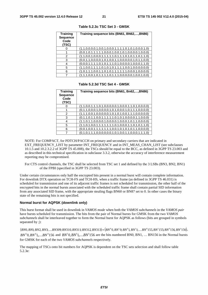
For QPSK modulation (see 3GPP TS 45.004) one symbol corresponds to two bits. A particular bit period within a timeslot is referenced by a bit number (BN), with the first bit being numbered 0, and the last bit being numbered 374. The bits are mapped to symbols in ascending order according to 3GPPTS45.004. QPSK modulation is used only at the higher symbol rate.
In the subclauses following, the transmission timing of a burst within a timeslot is defined in terms of bit number. The bit with the lowest bit number is transmitted first.
Different types of burst exist in the system. One characteristic of a burst is its useful duration. This document, in the subclauses following, defines full bursts of 147 normal symbol periods useful duration, full bursts of 176 reduced symbol periods useful duration (see 3GPP TS 45.010), and a short burst of 87 normal symbol periods useful duration. The useful part of a burst is defined as beginning from half way through symbol number 0. The definition of the useful part of a burst needs to be considered in conjunction with the requirements placed on the phase and amplitude characteristics of a burst as specified in 3GPP TS 45.004 and 45.005.
The period between bursts appearing in successive timeslots is termed the guard period. Subclause 5.2.8 details constraints which relate to the guard period.
5.2.3 Normal burst (NB)
Normal burst for GMSK

ETSI
ETSI TS 145 002 V12.4.0 (2015-04)203GPP TS 45.002 version 12.4.0 Release 12
Bit Number (BN) Length of field Contents of field Definition
0 - 2 3 tail bits (below)
3 - 60 58 encrypted bits (e0 . e57) 45.003
61 - 86 26 training sequence bits (below)
87 - 144 58 encrypted bits (e58 . e115) 45.003
145 - 147 3 tail bits (below)
148 - 156 8,25 guard period (bits) subclause 5.2.8)
- where the "tail bits" are defined as modulating bits with states as follows:
(BN0, BN1, BN2) = (0, 0, 0) and
(BN145, BN146, BN147) = (0, 0, 0)
- where the "training sequence bits" are defined as modulating bits with states as given in one of the TSC sets defined in table 5.2.3a, 5.2.3b, 5.2.3c and 5.2.3d, according to the training sequence code, TSC. The choice of the TSC set from which the training sequence bits are selected is described in 3GPP TS 44.018. For BCCH and CCCH, the TSC must be equal to the BCC, as defined in 3GPP TS 23.003 and shall be selected from the TSC Set 1. In networks supporting E-OTD Location services (see 3GPP TS 43.059), the use of normal bursts on BCCH frequencies with TSC from the TSC Set 2, TSC set 3 or TSC set 4 might degrade E-OTD Location service performance.
Table 5.2.3a TSC Set 1 - GMSK
Training Sequence
Code (TSC)
Training sequence bits (BN61, BN62,…,BN86)
0 (0,0,1,0,0,1,0,1,1,1,0,0,0,0,1,0,0,0,1,0,0,1,0,1,1,1) 1 (0,0,1,0,1,1,0,1,1,1,0,1,1,1,1,0,0,0,1,0,1,1,0,1,1,1) 2 (0,1,0,0,0,0,1,1,1,0,1,1,1,0,1,0,0,1,0,0,0,0,1,1,1,0) 3 (0,1,0,0,0,1,1,1,1,0,1,1,0,1,0,0,0,1,0,0,0,1,1,1,1,0) 4 (0,0,0,1,1,0,1,0,1,1,1,0,0,1,0,0,0,0,0,1,1,0,1,0,1,1) 5 (0,1,0,0,1,1,1,0,1,0,1,1,0,0,0,0,0,1,0,0,1,1,1,0,1,0) 6 (1,0,1,0,0,1,1,1,1,1,0,1,1,0,0,0,1,0,1,0,0,1,1,1,1,1) 7 (1,1,1,0,1,1,1,1,0,0,0,1,0,0,1,0,1,1,1,0,1,1,1,1,0,0)
Table 5.2.3b TSC Set 2 - GMSK
Training Sequence
Code (TSC)
Training sequence bits (BN61, BN62,…,BN86)
0 (0,1,1,0,0,0,1,0,0,0,1,0,0,1,0,0,1,1,1,1,0,1,0,1,1,1) 1 (0,1,0,1,1,1,1,0,1,0,0,1,1,0,1,1,1,0,1,1,1,0,0,0,0,1) 2 (0,1,0,0,0,0,0,1,0,1,1,0,0,0,1,1,1,0,1,1,1,0,1,1,0,0) 3 (0,0,1,0,1,1,0,1,1,1,0,1,1,1,0,0,1,1,1,1,0,1,0,0,0,0) 4 (0,1,1,1,0,1,0,0,1,1,1,1,0,1,0,0,1,1,1,0,1,1,1,1,1,0) 5 (0,1,0,0,0,0,0,1,0,0,1,1,0,1,0,1,0,0,1,1,1,1,0,0,1,1) 6 (0,0,0,1,0,0,0,0,1,1,0,1,0,0,0,0,1,1,0,1,1,1,0,1,0,1) 7 (0,1,0,0,0,1,0,1,1,1,0,0,1,1,1,1,1,1,0,0,1,0,1,0,0,1)
ETSI
ETSI TS 145 002 V12.4.0 (2015-04)213GPP TS 45.002 version 12.4.0 Release 12
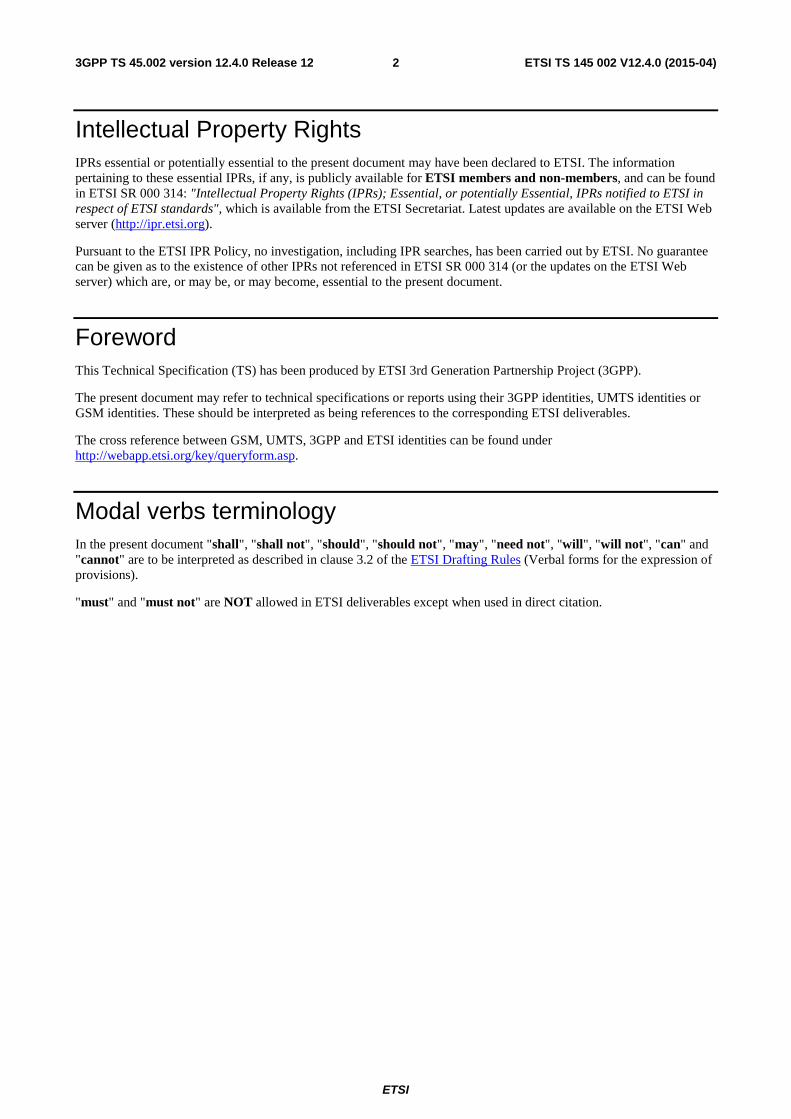
Table 5.2.3c TSC Set 3 - GMSK
Training Sequence
Code (TSC)
Training sequence bits (BN61, BN62,…,BN86)
0 (1,1,0,0,0,0,1,0,0,1,0,0,0,1,1,1,1,0,1,0,1,0,0,0,1,0) 1 (0,0,1,0,1,1,1,1,1,0,0,0,1,0,0,1,0,1,0,0,0,0,1,0,0,0) 2 (1,1,0,0,1,0,0,0,1,1,1,1,1,0,1,1,1,0,1,0,1,1,0,1,1,0) 3 (0,0,1,1,0,0,0,0,1,0,1,0,0,1,1,0,0,0,0,0,1,0,1,1,0,0) 4 (0,0,0,1,1,1,1,0,1,0,1,1,1,0,1,0,0,0,0,1,0,0,0,1,1,0) 5 (1,1,0,0,1,1,1,1,0,1,0,1,0,1,1,1,1,0,0,1,0,0,0,0,0,0) 6 (1,0,1,1,1,0,0,1,1,0,1,0,1,1,1,1,1,1,0,0,0,1,0,0,0,0) 7 (1,1,1,0,0,1,0,1,1,1,1,0,1,1,1,0,0,0,0,0,1,0,0,1,0,0)
Table 5.2.3d TSC Set 4 - GMSK
Training Sequence
Code (TSC)
Training sequence bits (BN61, Bn62,…,BN86)
0 (1,1,0,0,1,1,1,0,1,0,0,0,0,0,1,0,0,0,1,1,0,1,0,0,0,0) 1 (0,1,1,0,0,0,1,0,0,0,0,1,0,1,0,0,0,1,0,1,1,1,0,0,0,0) 2 (1,1,1,0,0,1,0,0,0,0,0,1,0,1,0,1,0,0,1,1,1,0,0,0,0,0) 3 (0,1,1,0,1,1,0,0,1,1,1,1,1,0,1,0,1,0,0,0,0,1,1,0,0,0) 4 (1,1,0,1,1,0,0,0,0,1,0,0,0,0,1,0,0,0,1,0,1,1,0,0,0,0) 5 (1,1,0,1,0,0,1,1,1,1,1,1,1,0,1,0,0,0,1,1,0,1,0,1,1,0) 6 (0,0,1,0,0,1,1,1,1,1,1,1,0,0,1,0,1,0,1,0,1,1,0,0,0,0) 7 (0,1,0,1,1,1,0,0,0,0,0,0,1,0,1,0,0,1,1,0,0,0,1,1,1,0)
NOTE: For COMPACT, for PDTCH/PACCH on primary and secondary carriers that are indicated in EXT_FREQUENCY_LIST by parameter INT_FREQUENCY and in INT_MEAS_CHAN_LIST (see subclauses 10.1.5 and 10.2.3.2.2 of 3GPP TS 45.008), the TSCs should be equal to the BCC, as defined in 3GPP TS 23.003 and as described in this technical specification in subclause 3.3.2, otherwise the accuracy of interference measurement reporting may be compromised.
For CTS control channels, the TSC shall be selected from TSC set 1 and defined by the 3 LSBs (BN3, BN2, BN1) of the FPBI (specified in 3GPP TS 23.003).
Under certain circumstances only half the encrypted bits present in a normal burst will contain complete information. For downlink DTX operation on TCH-FS and TCH-HS, when a traffic frame (as defined in 3GPP TS 46.031) is scheduled for transmission and one of its adjacent traffic frames is not scheduled for transmission, the other half of the encrypted bits in the normal bursts associated with the scheduled traffic frame shall contain partial SID information from any associated SID frame, with the appropriate stealing flags BN60 or BN87 set to 0. In other cases the binary state of the remaining bits is not specified.
Normal burst for AQPSK (downlink only)
This burst format shall be used in downlink in VAMOS mode when both the VAMOS subchannels in the VAMOS pair have bursts scheduled for transmission. The bits from the pair of Normal bursts for GMSK from the two VAMOS subchannels shall be interleaved together to form the Normal burst for AQPSK as follows (bits are grouped in symbols separated by ;):
( ) ( )156,156;155,155....;1,1;0,0313,312;311,310;309....;3,2;1,0 10101010 BNBNBNBNBNBNBNBNBNBNBNBNBNBNBNBNBN = ,
156.....,1,0 000 BNBNBN and 156.....,1,0 111 BNBNBN are the bits numbered BN0, BN1, … BN156 in the Normal bursts
for GMSK for each of the two VAMOS subchannels respectively.
The mapping of TSCs onto bit numbers for AQPSK is dependent on the TSC sets selection and shall follow table 5.2.3e:

ETSI
ETSI TS 145 002 V12.4.0 (2015-04)223GPP TS 45.002 version 12.4.0 Release 12
Table 5.2.3e. Mapping of TSC sets onto bit numbers depending on TSC set selection for AQPSK
TSC set selected BN0 BN1
1 2 3 4
NOTE: If the TSC sets are not selected from the combinations listed above any mapping of TSCs onto bit numbers can be selected.
Normal burst for 8PSK
Bit Number (BN) Length of field (bits)
Contents of field Definition
0 – 8 9 tail bits (below)
9 – 182 174 encrypted bits (e0 . e173) 45.003
183 – 260 78 training sequence bits (below)
261 – 434 174 encrypted bits (e174 . e347) 45.003
435 – 443 9 tail bits (below)
444 - 468 24.75 guard period subclause 5.2.8
- where the "tail bits" are defined as modulating bits with states as follows (bits are grouped in symbols separated
by ;):
(BN0, BN1 .. BN8) = (1,1,1;1,1,1;1,1,1) and
(BN435, BN436 .. BN443) = (1,1,1;1,1,1;1,1,1)
- where the "training sequence bits" are defined as modulating bits with states as given in table 5.2.3f or table 5.2.3g, depending on if the TSC is assigned from TSC Set 1 or TSC Set 2, according to the training sequence code, TSC. The choice of the TSC set from which the training sequence bits are selected is described in 3GPP TS 44.018 and in 3GPP TS 44.060. . In networks supporting E-OTD Location services (see 3GPP TS 43.059), the use of normal bursts on BCCH frequencies with TSC from the TSC Set 2 might degrade E-OTD Location service performance.

ETSI
ETSI TS 145 002 V12.4.0 (2015-04)233GPP TS 45.002 version 12.4.0 Release 12
Table 5.2.3f TSC Set 1 – 8PSK
Training Sequence
Code (TSC)
Training sequence bits (BN183, B184,…,BN260)
0 (1,1,1;1,1,1;0,0,1;1,1,1;1,1,1;0,0,1;1,1,1;0,0,1;0,0,1;0,0,1;1,1,1;1,1,1;1,1,1; 1,1,1;0,0,1;1,1,1;1,1,1;1,1,1;0,0,1;1,1,1;1,1,1;0,0,1;1,1,1;0,0,1;0,0,1;0,0,1)
1 (1,1,1;1,1,1;0,0,1;1,1,1;0,0,1;0,0,1;1,1,1;0,0,1;0,0,1;0,0,1;1,1,1;0,0,1;0,0,1; 0,0,1;0,0,1;1,1,1;1,1,1;1,1,1;0,0,1;1,1,1;0,0,1;0,0,1;1,1,1;0,0,1;0,0,1;0,0,1)
2 (1,1,1;0,0,1;1,1,1;1,1,1;1,1,1;1,1,1;0,0,1;0,0,1;0,0,1;1,1,1;0,0,1;0,0,1;0,0,1; 1,1,1;0,0,1;1,1,1;1,1,1;0,0,1;1,1,1;1,1,1;1,1,1;1,1,1;0,0,1;0,0,1;0,0,1;1,1,1)
3 (1,1,1;0,0,1;1,1,1;1,1,1;1,1,1;0,0,1;0,0,1;0,0,1;0,0,1;1,1,1;0,0,1;0,0,1;1,1,1; 0,0,1;1,1,1;1,1,1;1,1,1;0,0,1;1,1,1;1,1,1;1,1,1;0,0,1;0,0,1;0,0,1;0,0,1;1,1,1)
4 (1,1,1;1,1,1;1,1,1;0,0,1;0,0,1;1,1,1;0,0,1;1,1,1;0,0,1;0,0,1;0,0,1;1,1,1;1,1,1; 0,0,1;1,1,1;1,1,1;1,1,1;1,1,1;1,1,1;0,0,1;0,0,1;1,1,1;0,0,1;1,1,1;0,0,1;0,0,1)
5 (1,1,1;0,0,1;1,1,1;1,1,1;0,0,1;0,0,1;0,0,1;1,1,1;0,0,1;1,1,1;0,0,1;0,0,1;1,1,1; 1,1,1;1,1,1;1,1,1;1,1,1;0,0,1;1,1,1;1,1,1;0,0,1;0,0,1;0,0,1;1,1,1;0,0,1;1,1,1)
6 (0,0,1;1,1,1;0,0,1;1,1,1;1,1,1;0,0,1;0,0,1;0,0,1;0,0,1;0,0,1;1,1,1;0,0,1;0,0,1; 1,1,1;1,1,1;1,1,1;0,0,1;1,1,1;0,0,1;1,1,1;1,1,1;0,0,1;0,0,1;0,0,1;0,0,1;0,0,1)
7 (0,0,1;0,0,1;0,0,1;1,1,1;0,0,1;0,0,1;0,0,1;0,0,1;1,1,1;1,1,1;1,1,1;0,0,1;1,1,1; 1,1,1;0,0,1;1,1,1;0,0,1;0,0,1;0,0,1;1,1,1;0,0,1;0,0,1;0,0,1;0,0,1;1,1,1;1,1,1)
Table 5.2.3g TSC Set 2 – 8PSK
Training Sequence
Code (TSC)
Training sequence bits (BN183, B184,…,BN260)
0 (1,1,1;1,1,1;1,1,1;1,1,1;1,1,1;0,0,1;1,1,1;0,0,1;0,0,1;1,1,1;1,1,1;1,1,1;1,1,1; 0,0,1;1,1,1;0,0,1;1,1,1;1,1,1;0,0,1;0,0,1;0,0,1;1,1,1;0,0,1;0,0,1;0,0,1;1,1,1)
1 (1,1,1;0,0,1;0,0,1;0,0,1;0,0,1;1,1,1;0,0,1;0,0,1;1,1,1;0,0,1;1,1,1;0,0,1;0,0,1; 0,0,1;0,0,1;0,0,1;1,1,1;1,1,1;0,0,1;0,0,1;1,1,1;0,0,1;0,0,1;1,1,1;1,1,1;1,1,1)
2 (0,0,1;1,1,1;0,0,1;1,1,1;1,1,1;0,0,1;0,0,1;0,0,1;1,1,1;0,0,1;1,1,1;0,0,1;0,0,1; 0,0,1;0,0,1;0,0,1;1,1,1;0,0,1;1,1,1;0,0,1;1,1,1;1,1,1;0,0,1;0,0,1;1,1,1;1,1,1)
3 (1,1,1;1,1,1;0,0,1;1,1,1;0,0,1;0,0,1;0,0,1;1,1,1;0,0,1;0,0,1;0,0,1;0,0,1;1,1,1; 0,0,1;0,0,1;0,0,1;0,0,1;1,1,1;1,1,1;0,0,1;1,1,1;0,0,1;0,0,1;0,0,1;1,1,1;1,1,1)
4 (1,1,1;0,0,1;0,0,1;0,0,1;0,0,1;1,1,1;0,0,1;1,1,1;1,1,1;0,0,1;0,0,1;1,1,1;1,1,1; 1,1,1;1,1,1;1,1,1;0,0,1;1,1,1;0,0,1;0,0,1;1,1,1;1,1,1;1,1,1;0,0,1;1,1,1;1,1,1)
5 (1,1,1;0,0,1;1,1,1;0,0,1;0,0,1;0,0,1;0,0,1;1,1,1;0,0,1;1,1,1;0,0,1;0,0,1;0,0,1; 1,1,1;0,0,1;0,0,1;1,1,1;1,1,1;1,1,1;1,1,1;0,0,1;1,1,1;1,1,1;0,0,1;1,1,1;1,1,1)
6 (0,0,1;0,0,1;0,0,1;0,0,1;0,0,1;1,1,1;0,0,1;1,1,1;0,0,1;0,0,1;1,1,1;0,0,1;1,1,1; 1,1,1;1,1,1;0,0,1;0,0,1;0,0,1;1,1,1;0,0,1;0,0,1;0,0,1;1,1,1;0,0,1;1,1,1;1,1,1)
7 (0,0,1;0,0,1;0,0,1;0,0,1;0,0,1;0,0,1;0,0,1;1,1,1;1,1,1;0,0,1;1,1,1;0,0,1;1,1,1; 0,0,1;0,0,1;1,1,1;1,1,1;0,0,1;1,1,1;1,1,1;1,1,1;1,1,1;1,1,1;0,0,1;0,0,1;1,1,1)
Normal burst for 16QAM
Bit Number (BN) Length of field (bits)
Contents of field Definition
0 – 11 12 tail bits (below)
12 – 243 232 encrypted bits (e0 . e231) 45.003
244 – 347 104 training sequence bits (below)
348 – 579 232 encrypted bits (e232 . e463) 45.003
580 – 591 12 tail bits (below)
592 - 624 33 guard period subclause 5.2.8

ETSI
ETSI TS 145 002 V12.4.0 (2015-04)243GPP TS 45.002 version 12.4.0 Release 12
- where the "tail bits" are defined as modulating bits with states as follows (bits are grouped in symbols separated by ;):
(BN0, BN1 .. BN11) = (0,0,0,1; 0,1,1,0; 0,1,1,0) and
(BN580, BN581 .. BN591) = (0,0,0,1; 0,1,1,0; 0,1,1,0)
- where the "training sequence bits" are defined as modulating bits with states as given in the table 5.2.3h or 5.2.3i, depending on if the TSC is assigned from TSC Set 1 or TSC Set 2, according to the training sequence code, TSC. The choice of the TSC set from which the training sequence bits are selected is described in 3GPP TS 44.018 and in 3GPP TS 44.060.. In networks supporting E-OTD Location services (see 3GPP TS 43.059), the use of 16QAM modulation on BCCH frequencies might degrade E-OTD Location service performance.
Table 5.2.3h TSC Set 1 – 16QAM
Training Sequence
Code (TSC)
Training sequence bits (BN244, BN245,…,BN347)
0 (1,1,1,1;1,1,1,1;0,0,1,1;1,1,1,1;1,1,1,1;0,0,1,1;1,1,1,1;0,0,1,1;0,0,1,1;0,0,1,1;1,1,1,1;1,1,1,1;1,1,1,1; 1,1,1,1;0,0,1,1;1,1,1,1;1,1,1,1;1,1,1,1;0,0,1,1;1,1,1,1;1,1,1,1;0,0,1,1;1,1,1,1;0,0,1,1;0,0,1,1;0,0,1,1)
1 (1,1,1,1;1,1,1,1;0,0,1,1;1,1,1,1;0,0,1,1;0,0,1,1;1,1,1,1;0,0,1,1;0,0,1,1;0,0,1,1;1,1,1,1;0,0,1,1;0,0,1,1; 0,0,1,1;0,0,1,1;1,1,1,1;1,1,1,1;1,1,1,1;0,0,1,1;1,1,1,1;0,0,1,1;0,0,1,1;1,1,1,1;0,0,1,1;0,0,1,1;0,0,1,1)
2 (1,1,1,1;0,0,1,1;1,1,1,1;1,1,1,1;1,1,1,1;1,1,1,1;0,0,1,1;0,0,1,1;0,0,1,1;1,1,1,1;0,0,1,1;0,0,1,1;0,0,1,1; 1,1,1,1;0,0,1,1;1,1,1,1;1,1,1,1;0,0,1,1;1,1,1,1;1,1,1,1;1,1,1,1;1,1,1,1;0,0,1,1;0,0,1,1;0,0,1,1;1,1,1,1)
3 (1,1,1,1;0,0,1,1;1,1,1,1;1,1,1,1;1,1,1,1;0,0,1,1;0,0,1,1;0,0,1,1;0,0,1,1;1,1,1,1;0,0,1,1;0,0,1,1;1,1,1,1; 0,0,1,1;1,1,1,1;1,1,1,1;1,1,1,1;0,0,1,1;1,1,1,1;1,1,1,1;1,1,1,1;0,0,1,1;0,0,1,1;0,0,1,1;0,0,1,1;1,1,1,1)
4 (1,1,1,1;1,1,1,1;1,1,1,1;0,0,1,1;0,0,1,1;1,1,1,1;0,0,1,1;1,1,1,1;0,0,1,1;0,0,1,1;0,0,1,1;1,1,1,1;1,1,1,1; 0,0,1,1;1,1,1,1;1,1,1,1;1,1,1,1;1,1,1,1;1,1,1,1;0,0,1,1;0,0,1,1;1,1,1,1;0,0,1,1;1,1,1,1;0,0,1,1;0,0,1,1)
5 (1,1,1,1;0,0,1,1;1,1,1,1;1,1,1,1;0,0,1,1;0,0,1,1;0,0,1,1;1,1,1,1;0,0,1,1;1,1,1,1;0,0,1,1;0,0,1,1;1,1,1,1; 1,1,1,1;1,1,1,1;1,1,1,1;1,1,1,1;0,0,1,1;1,1,1,1;1,1,1,1;0,0,1,1;0,0,1,1;0,0,1,1;1,1,1,1;0,0,1,1;1,1,1,1)
6 (0,0,1,1;1,1,1,1;0,0,1,1;1,1,1,1;1,1,1,1;0,0,1,1;0,0,1,1;0,0,1,1;0,0,1,1;0,0,1,1;1,1,1,1;0,0,1,1;0,0,1,1; 1,1,1,1;1,1,1,1;1,1,1,1;0,0,1,1;1,1,1,1;0,0,1,1;1,1,1,1;1,1,1,1;0,0,1,1;0,0,1,1;0,0,1,1;0,0,1,1;0,0,1,1)
7 (0,0,1,1;0,0,1,1;0,0,1,1;1,1,1,1;0,0,1,1;0,0,1,1;0,0,1,1;0,0,1,1;1,1,1,1;1,1,1,1;1,1,1,1;0,0,1,1;1,1,1,1; 1,1,1,1;0,0,1,1;1,1,1,1;0,0,1,1;0,0,1,1;0,0,1,1;1,1,1,1;0,0,1,1;0,0,1,1;0,0,1,1;0,0,1,1;1,1,1,1;1,1,1,1)
Table 5.2.3i TSC Set 2 – 16QAM
Training Sequence
Code (TSC)
Training sequence bits (BN244, BN245,…,BN347)
0 (0,0,1,1;1,1,1,1;1,1,1,1;1,1,1,1;0,0,1,1;1,1,1,1;0,0,1,1;0,0,1,1;0,0,1,1;1,1,1,1;0,0,1,1;0,0,1,1;0,0,1,1; 0,0,1,1;1,1,1,1;1,1,1,1;0,0,1,1;1,1,1,1;0,0,1,1;1,1,1,1;0,0,1,1;0,0,1,1;1,1,1,1;1,1,1,1;1,1,1,1;1,1,1,1)
1 (0,0,1,1;0,0,1,1;0,0,1,1;1,1,1,1;1,1,1,1;1,1,1,1;0,0,1,1;0,0,1,1;0,0,1,1;0,0,1,1;1,1,1,1;0,0,1,1;0,0,1,1; 1,1,1,1;1,1,1,1;0,0,1,1;1,1,1,1;1,1,1,1;1,1,1,1;1,1,1,1;0,0,1,1;1,1,1,1;0,0,1,1;1,1,1,1;1,1,1,1;1,1,1,1)
2 (0,0,1,1;1,1,1,1;1,1,1,1;0,0,1,1;0,0,1,1;0,0,1,1;1,1,1,1;0,0,1,1;0,0,1,1;1,1,1,1;0,0,1,1;1,1,1,1;0,0,1,1; 0,0,1,1;1,1,1,1;1,1,1,1;0,0,1,1;0,0,1,1;0,0,1,1;0,0,1,1;0,0,1,1;1,1,1,1;0,0,1,1;1,1,1,1;0,0,1,1;1,1,1,1)
3 (1,1,1,1;1,1,1,1;0,0,1,1;0,0,1,1;0,0,1,1;1,1,1,1;0,0,1,1;0,0,1,1;0,0,1,1;1,1,1,1;0,0,1,1;0,0,1,1;1,1,1,1; 0,0,1,1;1,1,1,1;0,0,1,1;0,0,1,1;0,0,1,1;0,0,1,1;1,1,1,1;1,1,1,1;1,1,1,1;1,1,1,1;0,0,1,1;1,1,1,1;1,1,1,1)
4 (0,0,1,1;1,1,1,1;0,0,1,1;1,1,1,1;1,1,1,1;0,0,1,1;1,1,1,1;0,0,1,1;0,0,1,1;0,0,1,1;0,0,1,1;1,1,1,1;1,1,1,1; 0,0,1,1;0,0,1,1;1,1,1,1;0,0,1,1;1,1,1,1;0,0,1,1;0,0,1,1;0,0,1,1;1,1,1,1;0,0,1,1;0,0,1,1;1,1,1,1;1,1,1,1)
5 (1,1,1,1;1,1,1,1;1,1,1,1;0,0,1,1;0,0,1,1;1,1,1,1;0,0,1,1;1,1,1,1;0,0,1,1;0,0,1,1;1,1,1,1;1,1,1,1;0,0,1,1; 0,0,1,1;0,0,1,1;0,0,1,1;0,0,1,1;0,0,1,1;1,1,1,1;0,0,1,1;1,1,1,1;0,0,1,1;1,1,1,1;0,0,1,1;0,0,1,1;1,1,1,1)
6 (1,1,1,1;1,1,1,1;1,1,1,1;1,1,1,1;0,0,1,1;0,0,1,1;1,1,1,1;0,0,1,1;1,1,1,1;1,1,1,1;1,1,1,1;1,1,1,1;0,0,1,1; 1,1,1,1;0,0,1,1;1,1,1,1;1,1,1,1;1,1,1,1;0,0,1,1;0,0,1,1;1,1,1,1;1,1,1,1;0,0,1,1;0,0,1,1;0,0,1,1;1,1,1,1)
7 (1,1,1,1;0,0,1,1;1,1,1,1;0,0,1,1;0,0,1,1;1,1,1,1;1,1,1,1;1,1,1,1;1,1,1,1;1,1,1,1;0,0,1,1;1,1,1,1;1,1,1,1; 1,1,1,1;0,0,1,1;1,1,1,1;0,0,1,1;1,1,1,1;0,0,1,1;0,0,1,1;1,1,1,1;1,1,1,1;0,0,1,1;0,0,1,1;0,0,1,1;1,1,1,1)

ETSI
ETSI TS 145 002 V12.4.0 (2015-04)253GPP TS 45.002 version 12.4.0 Release 12
Normal burst for 32QAM
Bit Number (BN) Length of field (bits)
Contents of field Definition
0 – 14 15 tail bits (below)
15 – 304 290 encrypted bits (e0 . e289) 45.003
305 – 434 130 training sequence bits (below)
435 – 724 290 encrypted bits (e290 . e579) 45.003
725 – 739 15 tail bits (below)
740 - 781 41.25 guard period Subclause 5.2.8
- where the "tail bits" are defined as modulating bits with states as follows (bits are grouped in symbols separated
by ;):
(BN0, BN1 .. BN14) = (1,1,1,1,0; 0,1,1,1,0; 0,1,1,1,0) and
(BN725, BN726 .. BN739) = (1,1,1,1,0; 0,1,1,1,0; 0,1,1,1,0)
- where the "training sequence bits" are defined as modulating bits with states as given in table 5.2.3j or 5.2.3k, depending on if the TSC is assigned from TSC Set 1 or TSC Set 2, according to the training sequence code, TSC. The choice of the TSC set from which the training sequence bits are selected is described in 3GPP TS 44.018 and in 3GPP TS 44.060. In networks supporting E-OTD Location services (see 3GPP TS 43.059), the use of 32QAM modulation on BCCH frequencies might degrade E-OTD Location service performance.
Table 5.2.3j TSC Set 1 – 32QAM
Training Sequence
Code (TSC)
Training sequence bits (BN305, BN306,…,BN434)
0 (0,0,0,0,0;0,0,0,0,0;1,0,0,1,0;0,0,0,0,0;0,0,0,0,0;1,0,0,1,0;0,0,0,0,0;1,0,0,1,0;1,0,0,1,0;1,0,0,1,0; 0,0,0,0,0;0,0,0,0,0;0,0,0,0,0;0,0,0,0,0;1,0,0,1,0;0,0,0,0,0;0,0,0,0,0;0,0,0,0,0;1,0,0,1,0;0,0,0,0,0;
0,0,0,0,0;1,0,0,1,0;0,0,0,0,0;1,0,0,1,0;1,0,0,1,0;1,0,0,1,0) 1 (0,0,0,0,0;0,0,0,0,0;1,0,0,1,0;0,0,0,0,0;1,0,0,1,0;1,0,0,1,0;0,0,0,0,0;1,0,0,1,0;1,0,0,1,0;1,0,0,1,0;
0,0,0,0,0;1,0,0,1,0;1,0,0,1,0;1,0,0,1,0;1,0,0,1,0;0,0,0,0,0;0,0,0,0,0;0,0,0,0,0;1,0,0,1,0;0,0,0,0,0; 1,0,0,1,0;1,0,0,1,0;0,0,0,0,0;1,0,0,1,0;1,0,0,1,0;1,0,0,1,0)
2 (0,0,0,0,0;1,0,0,1,0;0,0,0,0,0;0,0,0,0,0;0,0,0,0,0;0,0,0,0,0;1,0,0,1,0;1,0,0,1,0;1,0,0,1,0;0,0,0,0,0; 1,0,0,1,0;1,0,0,1,0;1,0,0,1,0;0,0,0,0,0;1,0,0,1,0;0,0,0,0,0;0,0,0,0,0;1,0,0,1,0;0,0,0,0,0;0,0,0,0,0;
0,0,0,0,0;0,0,0,0,0;1,0,0,1,0;1,0,0,1,0;1,0,0,1,0;0,0,0,0,0) 3 (0,0,0,0,0;1,0,0,1,0;0,0,0,0,0;0,0,0,0,0;0,0,0,0,0;1,0,0,1,0;1,0,0,1,0;1,0,0,1,0;1,0,0,1,0;0,0,0,0,0;
1,0,0,1,0;1,0,0,1,0;0,0,0,0,0;1,0,0,1,0;0,0,0,0,0;0,0,0,0,0;0,0,0,0,0;1,0,0,1,0;0,0,0,0,0;0,0,0,0,0; 0,0,0,0,0;1,0,0,1,0;1,0,0,1,0;1,0,0,1,0;1,0,0,1,0;0,0,0,0,0)
4 (0,0,0,0,0;0,0,0,0,0;0,0,0,0,0;1,0,0,1,0;1,0,0,1,0;0,0,0,0,0;1,0,0,1,0;0,0,0,0,0;1,0,0,1,0;1,0,0,1,0; 1,0,0,1,0;0,0,0,0,0;0,0,0,0,0;1,0,0,1,0;0,0,0,0,0;0,0,0,0,0;0,0,0,0,0;0,0,0,0,0;0,0,0,0,0;1,0,0,1,0;
1,0,0,1,0;0,0,0,0,0;1,0,0,1,0;0,0,0,0,0;1,0,0,1,0;1,0,0,1,0) 5 (0,0,0,0,0;1,0,0,1,0;0,0,0,0,0;0,0,0,0,0;1,0,0,1,0;1,0,0,1,0;1,0,0,1,0;0,0,0,0,0;1,0,0,1,0;0,0,0,0,0;
1,0,0,1,0;1,0,0,1,0;0,0,0,0,0;0,0,0,0,0;0,0,0,0,0;0,0,0,0,0;0,0,0,0,0;1,0,0,1,0;0,0,0,0,0;0,0,0,0,0; 1,0,0,1,0;1,0,0,1,0;1,0,0,1,0;0,0,0,0,0;1,0,0,1,0;0,0,0,0,0)
6 (1,0,0,1,0;0,0,0,0,0;1,0,0,1,0;0,0,0,0,0;0,0,0,0,0;1,0,0,1,0;1,0,0,1,0;1,0,0,1,0;1,0,0,1,0;1,0,0,1,0; 0,0,0,0,0;1,0,0,1,0;1,0,0,1,0;0,0,0,0,0;0,0,0,0,0;0,0,0,0,0;1,0,0,1,0;0,0,0,0,0;1,0,0,1,0;0,0,0,0,0;
0,0,0,0,0;1,0,0,1,0;1,0,0,1,0;1,0,0,1,0;1,0,0,1,0;1,0,0,1,0) 7 (1,0,0,1,0;1,0,0,1,0;1,0,0,1,0;0,0,0,0,0;1,0,0,1,0;1,0,0,1,0;1,0,0,1,0;1,0,0,1,0;0,0,0,0,0;0,0,0,0,0;
0,0,0,0,0;1,0,0,1,0;0,0,0,0,0;0,0,0,0,0;1,0,0,1,0;0,0,0,0,0;1,0,0,1,0;1,0,0,1,0;1,0,0,1,0;0,0,0,0,0; 1,0,0,1,01,0,0,1,0;1,0,0,1,0;1,0,0,1,0;0,0,0,0,0;0,0,0,0,0)
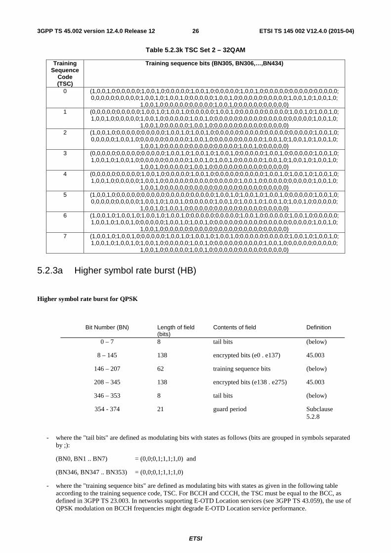
ETSI
ETSI TS 145 002 V12.4.0 (2015-04)263GPP TS 45.002 version 12.4.0 Release 12
Table 5.2.3k TSC Set 2 – 32QAM
Training Sequence
Code (TSC)
Training sequence bits (BN305, BN306,…,BN434)
0 (1,0,0,1,0;0,0,0,0,0;1,0,0,1,0;0,0,0,0,0;1,0,0,1,0;0,0,0,0,0;1,0,0,1,0;0,0,0,0,0;0,0,0,0,0;0,0,0,0,0; 0,0,0,0,0;0,0,0,0,0;1,0,0,1,0;1,0,0,1,0;0,0,0,0,0;1,0,0,1,0;0,0,0,0,0;0,0,0,0,0;1,0,0,1,0;1,0,0,1,0;
1,0,0,1,0;0,0,0,0,0;0,0,0,0,0;1,0,0,1,0;0,0,0,0,0;0,0,0,0,0) 1 (0,0,0,0,0;0,0,0,0,0;1,0,0,1,0;1,0,0,1,0;0,0,0,0,0;1,0,0,1,0;0,0,0,0,0;0,0,0,0,0;1,0,0,1,0;1,0,0,1,0;
1,0,0,1,0;0,0,0,0,0;1,0,0,1,0;0,0,0,0,0;1,0,0,1,0;0,0,0,0,0;0,0,0,0,0;0,0,0,0,0;0,0,0,0,0;1,0,0,1,0; 1,0,0,1,0;0,0,0,0,0;1,0,0,1,0;0,0,0,0,0;0,0,0,0,0;0,0,0,0,0)
2 (1,0,0,1,0;0,0,0,0,0;0,0,0,0,0;1,0,0,1,0;1,0,0,1,0;0,0,0,0,0;0,0,0,0,0;0,0,0,0,0;0,0,0,0,0;1,0,0,1,0; 0,0,0,0,0;1,0,0,1,0;0,0,0,0,0;0,0,0,0,0;1,0,0,1,0;0,0,0,0,0;0,0,0,0,0;1,0,0,1,0;1,0,0,1,0;1,0,0,1,0;
1,0,0,1,0;0,0,0,0,0;0,0,0,0,0;0,0,0,0,0;1,0,0,1,0;0,0,0,0,0) 3 (0,0,0,0,0;0,0,0,0,0;0,0,0,0,0;1,0,0,1,0;1,0,0,1,0;1,0,0,1,0;0,0,0,0,0;1,0,0,1,0;0,0,0,0,0;1,0,0,1,0;
1,0,0,1,0;1,0,0,1,0;0,0,0,0,0;0,0,0,0,0;1,0,0,1,0;1,0,0,1,0;0,0,0,0,0;1,0,0,1,0;1,0,0,1,0;1,0,0,1,0; 1,0,0,1,0;0,0,0,0,0;1,0,0,1,0;0,0,0,0,0;0,0,0,0,0;0,0,0,0,0)
4 (0,0,0,0,0;0,0,0,0,0;1,0,0,1,0;0,0,0,0,0;1,0,0,1,0;0,0,0,0,0;0,0,0,0,0;1,0,0,1,0;1,0,0,1,0;1,0,0,1,0; 1,0,0,1,0;0,0,0,0,0;1,0,0,1,0;0,0,0,0,0;0,0,0,0,0;0,0,0,0,0;1,0,0,1,0;0,0,0,0,0;0,0,0,0,0;1,0,0,1,0;
1,0,0,1,0;0,0,0,0,0;0,0,0,0,0;0,0,0,0,0;0,0,0,0,0;0,0,0,0,0) 5 (1,0,0,1,0;0,0,0,0,0;0,0,0,0,0;0,0,0,0,0;0,0,0,0,0;1,0,0,1,0;1,0,0,1,0;1,0,0,1,0;0,0,0,0,0;1,0,0,1,0;
0,0,0,0,0;0,0,0,0,0;1,0,0,1,0;1,0,0,1,0;0,0,0,0,0;1,0,0,1,0;1,0,0,1,0;1,0,0,1,0;1,0,0,1,0;0,0,0,0,0; 1,0,0,1,0;1,0,0,1,0;0,0,0,0,0;0,0,0,0,0;0,0,0,0,0;0,0,0,0,0)
6 (1,0,0,1,0;1,0,0,1,0;1,0,0,1,0;1,0,0,1,0;0,0,0,0,0;0,0,0,0,0;1,0,0,1,0;0,0,0,0,0;1,0,0,1,0;0,0,0,0,0; 1,0,0,1,0;1,0,0,1,0;0,0,0,0,0;1,0,0,1,0;1,0,0,1,0;0,0,0,0,0;0,0,0,0,0;0,0,0,0,0;0,0,0,0,0;1,0,0,1,0;
1,0,0,1,0;0,0,0,0,0;0,0,0,0,0;0,0,0,0,0;0,0,0,0,0;0,0,0,0,0) 7 (1,0,0,1,0;1,0,0,1,0;0,0,0,0,0;1,0,0,1,0;1,0,0,1,0;1,0,0,1,0;0,0,0,0,0;0,0,0,0,0;1,0,0,1,0;1,0,0,1,0;
1,0,0,1,0;1,0,0,1,0;1,0,0,1,0;0,0,0,0,0;1,0,0,1,0;0,0,0,0,0;0,0,0,0,0;1,0,0,1,0;0,0,0,0,0;0,0,0,0,0; 1,0,0,1,0;0,0,0,0,0;1,0,0,1,0;0,0,0,0,0;0,0,0,0,0;0,0,0,0,0)
5.2.3a Higher symbol rate burst (HB)
Higher symbol rate burst for QPSK
Bit Number (BN) Length of field (bits)
Contents of field Definition
0 – 7 8 tail bits (below)
8 – 145 138 encrypted bits (e0 . e137) 45.003
146 – 207 62 training sequence bits (below)
208 – 345 138 encrypted bits (e138 . e275) 45.003
346 – 353 8 tail bits (below)
354 - 374 21 guard period Subclause 5.2.8
- where the "tail bits" are defined as modulating bits with states as follows (bits are grouped in symbols separated
by ;):
(BN0, BN1 .. BN7) = (0,0;0,1;1,1;1,0) and
(BN346, BN347 .. BN353) = (0,0;0,1;1,1;1,0)
- where the "training sequence bits" are defined as modulating bits with states as given in the following table according to the training sequence code, TSC. For BCCH and CCCH, the TSC must be equal to the BCC, as defined in 3GPP TS 23.003. In networks supporting E-OTD Location services (see 3GPP TS 43.059), the use of QPSK modulation on BCCH frequencies might degrade E-OTD Location service performance.

ETSI
ETSI TS 145 002 V12.4.0 (2015-04)273GPP TS 45.002 version 12.4.0 Release 12
Training Training sequence symbols Sequence (BN146, BN147 .. BN207) Code (TSC) 0 (0,0;1,1;0,0;0,0;1,1;0,0;0,0;0,0;1,1;0,0;1,1;1,1;1,1;1,1;1,1;1,1;1,1;0,0;0,0;1,1;0
,0;1,1;1,1;1,1;1,1;0,0;0,0;1,1;1,1;1,1;0,0) 1 (1,1;1,1;1,1;0,0;0,0;1,1;1,1;0,0;0,0;0,0;1,1;1,1;1,1;1,1;1,1;0,0;1,1;0,0;1,1;1,1;0
,0;1,1;0,0;0,0;0,0;1,1;0,0;0,0;1,1;0,0;0,0) 2 (1,1;0,0;0,0;1,1;1,1;1,1;0,0;1,1;1,1;1,1;0,0;0,0;1,1;0,0;1,1;1,1;0,0;1,1;1,1;1,1;1
,1;1,1;0,0;0,0;0,0;1,1;0,0;1,1;0,0;0,0;0,0) 3 (0,0;0,0;0,0;0,0;1,1;1,1;1,1;0,0;0,0;0,0;0,0;0,0;0,0;1,1;0,0;0,0;1,1;1,1;1,1;0,0;1
,1;0,0;1,1;1,1;0,0;0,0;1,1;0,0;1,1;0,0;0,0) 4 (1,1;0,0;1,1;0,0;0,0;1,1;1,1;1,1;0,0;0,0;0,0;1,1;1,1;0,0;1,1;1,1;0,0;0,0;1,1;0,0;1
,1;1,1;1,1;1,1;1,1;1,1;1,1;0,0;1,1;0,0;0,0) 5 (0,0;0,0;1,1;0,0;1,1;0,0;0,0;1,1;1,1;0,0;1,1;0,0;1,1;1,1;1,1;0,0;0,0;1,1;0,0;0,0;0
,0;0,0;0,0;0,0;1,1;1,1;1,1;0,0;0,0;0,0;0,0) 6 (1,1;0,0;1,1;1,1;1,1;1,1;1,1;1,1;0,0;1,1;1,1;0,0;1,1;0,0;0,0;0,0;1,1;1,1;1,1;0,0;1
,1;1,1;0,0;0,0;0,0;1,1;1,1;1,1;0,0;1,1;0,0) 7 (1,1;0,0;1,1;1,1;1,1;1,1;1,1;0,0;1,1;1,1;0,0;1,1;0,0;1,1;1,1;1,1;0,0;0,0;0,0;0,0;1
,1;1,1;0,0;1,1;1,1;1,1;0,0;1,1;1,1;0,0;0,0) Higher symbol rate burst for 16QAM
Bit Number (BN) Length of field (bits)
Contents of field Definition
0 – 15 16 tail bits (below)
16 – 291 276 encrypted bits (e0 . e275) 45.003
292 – 415 124 training sequence bits (below)
416 – 691 276 encrypted bits (e276 . e551) 45.003
692 – 707 16 tail bits (below)
708 - 749 42 guard period Subclause 5.2.8
- where the "tail bits" are defined as modulating bits with states as follows (bits are grouped in symbols separated
by ;):
(BN0, BN1 .. BN15) = (0,0,0,1; 0,1,1,0; 0,1,1,0; 1,1,0,1) and
(BN692, BN693 .. BN707) = (0,0,0,1; 0,1,1,0; 0,1,1,0; 1,1,0,1)
- where the "training sequence bits" are defined as modulating bits with states as given in the following table according to the training sequence code, TSC. For BCCH and CCCH, the TSC must be equal to the BCC, as defined in 3GPP TS 23.003. In networks supporting E-OTD Location services (see 3GPP TS 43.059), the use of 16QAM modulation on BCCH frequencies might degrade E-OTD Location service performance.

ETSI
ETSI TS 145 002 V12.4.0 (2015-04)283GPP TS 45.002 version 12.4.0 Release 12
Training Training sequence symbols Sequence (BN292, BN293 .. BN415) Code (TSC) 0 (0,0,1,1;1,1,1,1;0,0,1,1;0,0,1,1;1,1,1,1;0,0,1,1;0,0,1,1;0,0,1,1;1,1,1,1;0,0,1,1;1,
1,1,1;1,1,1,1;1,1,1,1;1,1,1,1;1,1,1,1;1,1,1,1;1,1,1,1;0,0,1,1;0,0,1,1;1,1,1,1;0,0,1,1;1,1,1,1;1,1,1,1;1,1,1,1;1,1,1,1;0,0,1,1;0,0,1,1;1,1,1,1;1,1,1,1;1,1,1,1;0,0,1,1)
1 (1,1,1,1;1,1,1,1;1,1,1,1;0,0,1,1;0,0,1,1;1,1,1,1;1,1,1,1;0,0,1,1;0,0,1,1;0,0,1,1;1,1,1,1;1,1,1,1;1,1,1,1;1,1,1,1;1,1,1,1;0,0,1,1;1,1,1,1;0,0,1,1;1,1,1,1;1,1,1,1;0,0,1,1;1,1,1,1;0,0,1,1;0,0,1,1;0,0,1,1;1,1,1,1;0,0,1,1;0,0,1,1;1,1,1,1;0,0,1,1;0,0,1,1)
2 (1,1,1,1;0,0,1,1;0,0,1,1;1,1,1,1;1,1,1,1;1,1,1,1;0,0,1,1;1,1,1,1;1,1,1,1;1,1,1,1;0,0,1,1;0,0,1,1;1,1,1,1;0,0,1,1;1,1,1,1;1,1,1,1;0,0,1,1;1,1,1,1;1,1,1,1;1,1,1,1;1,1,1,1;1,1,1,1;0,0,1,1;0,0,1,1;0,0,1,1;1,1,1,1;0,0,1,1;1,1,1,1;0,0,1,1;0,0,1,1;0,0,1,1)
3 (0,0,1,1;0,0,1,1;0,0,1,1;0,0,1,1;1,1,1,1;1,1,1,1;1,1,1,1;0,0,1,1;0,0,1,1;0,0,1,1;0,0,1,1;0,0,1,1;0,0,1,1;1,1,1,1;0,0,1,1;0,0,1,1;1,1,1,1;1,1,1,1;1,1,1,1;0,0,1,1;1,1,1,1;0,0,1,1;1,1,1,1;1,1,1,1;0,0,1,1;0,0,1,1;1,1,1,1;0,0,1,1;1,1,1,1;0,0,1,1;0,0,1,1)
4 (1,1,1,1;0,0,1,1;1,1,1,1;0,0,1,1;0,0,1,1;1,1,1,1;1,1,1,1;1,1,1,1;0,0,1,1;0,0,1,1;0,0,1,1;1,1,1,1;1,1,1,1;0,0,1,1;1,1,1,1;1,1,1,1;0,0,1,1;0,0,1,1;1,1,1,1;0,0,1,1;1,1,1,1;1,1,1,1;1,1,1,1;1,1,1,1;1,1,1,1;1,1,1,1;1,1,1,1;0,0,1,1;1,1,1,1;0,0,1,1;0,0,1,1)
5 (0,0,1,1;0,0,1,1;1,1,1,1;0,0,1,1;1,1,1,1;0,0,1,1;0,0,1,1;1,1,1,1;1,1,1,1;0,0,1,1;1,1,1,1;0,0,1,1;1,1,1,1;1,1,1,1;1,1,1,1;0,0,1,1;0,0,1,1;1,1,1,1;0,0,1,1;0,0,1,1;0,0,1,1;0,0,1,1;0,0,1,1;0,0,1,1;1,1,1,1;1,1,1,1;1,1,1,1;0,0,1,1;0,0,1,1;0,0,1,1;0,0,1,1)
6 (1,1,1,1;0,0,1,1;1,1,1,1;1,1,1,1;1,1,1,1;1,1,1,1;1,1,1,1;1,1,1,1;0,0,1,1;1,1,1,1;1,1,1,1;0,0,1,1;1,1,1,1;0,0,1,1;0,0,1,1;0,0,1,1;1,1,1,1;1,1,1,1;1,1,1,1;0,0,1,1;1,1,1,1;1,1,1,1;0,0,1,1;0,0,1,1;0,0,1,1;1,1,1,1;1,1,1,1;1,1,1,1;0,0,1,1;1,1,1,1;0,0,1,1)
7 (1,1,1,1;0,0,1,1;1,1,1,1;1,1,1,1;1,1,1,1;1,1,1,1;1,1,1,1;0,0,1,1;1,1,1,1;1,1,1,1;0,0,1,1;1,1,1,1;0,0,1,1;1,1,1,1;1,1,1,1;1,1,1,1;0,0,1,1;0,0,1,1;0,0,1,1;0,0,1,1;1,1,1,1;1,1,1,1;0,0,1,1;1,1,1,1;1,1,1,1;1,1,1,1;0,0,1,1;1,1,1,1;1,1,1,1;0,0,1,1;0,0,1,1)
Higher symbol rate burst for 32QAM
Bit Number (BN) Length of field (bits)
Contents of field Definition
0 – 19 20 tail bits (below)
20 – 364 345 encrypted bits (e0 . e344) 45.003
365 – 519 155 training sequence bits (below)
520 – 864 345 encrypted bits (e345 . e689) 45.003
865 – 884 20 tail bits (below)
885 - 937 52.5 guard period Subclause 5.2.8
- where the "tail bits" are defined as modulating bits with states as follows (bits are grouped in symbols separated
by ;):
(BN0, BN1 .. BN19) = (1,1,1,1,0; 1,1,1,1,0; 0,1,1,1,0; 0,1,1,1,0) and
(BN865, BN866 .. BN884) = (1,1,1,1,0; 1,1,1,1,0; 0,1,1,1,0; 0,1,1,1,0)
- where the "training sequence bits" are defined as modulating bits with states as given in the following table according to the training sequence code, TSC. For BCCH and CCCH, the TSC must be equal to the BCC, as

ETSI
ETSI TS 145 002 V12.4.0 (2015-04)293GPP TS 45.002 version 12.4.0 Release 12
defined in 3GPP TS 23.003. In networks supporting E-OTD Location services (see 3GPP TS 43.059), the use of 32QAM modulation on BCCH frequencies might degrade E-OTD Location service performance.
Training Training sequence symbols Sequence (BN365, BN366 .. BN519) Code (TSC) 0 (1,0,0,1,0;0,0,0,0,0;1,0,0,1,0;1,0,0,1,0;0,0,0,0,0;1,0,0,1,0;1,0,0,1,0;1,0,0,1,0;0,
0,0,0,0;1,0,0,1,0;0,0,0,0,0;0,0,0,0,0;0,0,0,0,0;0,0,0,0,0;0,0,0,0,0;0,0,0,0,0;0,0,0,0,0;1,0,0,1,0;1,0,0,1,0;0,0,0,0,0;1,0,0,1,0;0,0,0,0,0;0,0,0,0,0;0,0,0,0,0;0,0,0,0,0;1,0,0,1,0;1,0,0,1,0;0,0,0,0,0;0,0,0,0,0;0,0,0,0,0;1,0,0,1,0)
1 (0,0,0,0,0;0,0,0,0,0;0,0,0,0,0;1,0,0,1,0;1,0,0,1,0;0,0,0,0,0;0,0,0,0,0;1,0,0,1,0;1,0,0,1,0;1,0,0,1,0;0,0,0,0,0;0,0,0,0,0;0,0,0,0,0;0,0,0,0,0;0,0,0,0,0;1,0,0,1,0;0,0,0,0,0;1,0,0,1,0;0,0,0,0,0;0,0,0,0,0;1,0,0,1,0;0,0,0,0,0;1,0,0,1,0;1,0,0,1,0;1,0,0,1,0;0,0,0,0,0;1,0,0,1,0;1,0,0,1,0;0,0,0,0,0;1,0,0,1,0;1,0,0,1,0)
2 (0,0,0,0,0;1,0,0,1,0;1,0,0,1,0;0,0,0,0,0;0,0,0,0,0;0,0,0,0,0;1,0,0,1,0;0,0,0,0,0;0,0,0,0,0;0,0,0,0,0;1,0,0,1,0;1,0,0,1,0;0,0,0,0,0;1,0,0,1,0;0,0,0,0,0;0,0,0,0,0;1,0,0,1,0;0,0,0,0,0;0,0,0,0,0;0,0,0,0,0;0,0,0,0,0;0,0,0,0,0;1,0,0,1,0;1,0,0,1,0;1,0,0,1,0;0,0,0,0,0;1,0,0,1,0;0,0,0,0,0;1,0,0,1,0;1,0,0,1,0;1,0,0,1,0)
3 (1,0,0,1,0;1,0,0,1,0;1,0,0,1,0;1,0,0,1,0;0,0,0,0,0;0,0,0,0,0;0,0,0,0,0;1,0,0,1,0;1,0,0,1,0;1,0,0,1,0;1,0,0,1,0;1,0,0,1,0;1,0,0,1,0;0,0,0,0,0;1,0,0,1,0;1,0,0,1,0;0,0,0,0,0;0,0,0,0,0;0,0,0,0,0;1,0,0,1,0;0,0,0,0,0;1,0,0,1,0;0,0,0,0,0;0,0,0,0,0;1,0,0,1,0;1,0,0,1,0;0,0,0,0,0;1,0,0,1,0;0,0,0,0,0;1,0,0,1,0;1,0,0,1,0)
4 (0,0,0,0,0;1,0,0,1,0;0,0,0,0,0;1,0,0,1,0;1,0,0,1,0;0,0,0,0,0;0,0,0,0,0;0,0,0,0,0;1,0,0,1,0;1,0,0,1,0;1,0,0,1,0;0,0,0,0,0;0,0,0,0,0;1,0,0,1,0;0,0,0,0,0;0,0,0,0,0;1,0,0,1,0;1,0,0,1,0;0,0,0,0,0;1,0,0,1,0;0,0,0,0,0;0,0,0,0,0;0,0,0,0,0;0,0,0,0,0;0,0,0,0,0;0,0,0,0,0;0,0,0,0,0;1,0,0,1,0;0,0,0,0,0;1,0,0,1,0;1,0,0,1,0)
5 (1,0,0,1,0;1,0,0,1,0;0,0,0,0,0;1,0,0,1,0;0,0,0,0,0;1,0,0,1,0;1,0,0,1,0;0,0,0,0,0;0,0,0,0,0;1,0,0,1,0;0,0,0,0,0;1,0,0,1,0;0,0,0,0,0;0,0,0,0,0;0,0,0,0,0;1,0,0,1,0;1,0,0,1,0;0,0,0,0,0;1,0,0,1,0;1,0,0,1,0;1,0,0,1,0;1,0,0,1,0;1,0,0,1,0;1,0,0,1,0;0,0,0,0,0;0,0,0,0,0;0,0,0,0,0;1,0,0,1,0;1,0,0,1,0;1,0,0,1,0;1,0,0,1,0)
6 (0,0,0,0,0;1,0,0,1,0;0,0,0,0,0;0,0,0,0,0;0,0,0,0,0;0,0,0,0,0;0,0,0,0,0;0,0,0,0,0;1,0,0,1,0;0,0,0,0,0;0,0,0,0,0;1,0,0,1,0;0,0,0,0,0;1,0,0,1,0;1,0,0,1,0;1,0,0,1,0;0,0,0,0,0;0,0,0,0,0;0,0,0,0,0;1,0,0,1,0;0,0,0,0,0;0,0,0,0,0;1,0,0,1,0;1,0,0,1,0;1,0,0,1,0;0,0,0,0,0;0,0,0,0,0;0,0,0,0,0;1,0,0,1,0;0,0,0,0,0;1,0,0,1,0)
7 (0,0,0,0,0;1,0,0,1,0;0,0,0,0,0;0,0,0,0,0;0,0,0,0,0;0,0,0,0,0;0,0,0,0,0;1,0,0,1,0;0,0,0,0,0;0,0,0,0,0;1,0,0,1,0;0,0,0,0,0;1,0,0,1,0;0,0,0,0,0;0,0,0,0,0;0,0,0,0,0;1,0,0,1,0;1,0,0,1,0;1,0,0,1,0;1,0,0,1,0;0,0,0,0,0;0,0,0,0,0;1,0,0,1,0;0,0,0,0,0;0,0,0,0,0;0,0,0,0,0;1,0,0,1,0;0,0,0,0,0;0,0,0,0,0;1,0,0,1,0;1,0,0,1,0)
5.2.4 Frequency correction burst (FB)
Bit Number length Contents Definition (BN) of field of field
0 - 2 3 tail bits (below) 3 - 144 142 fixed bits (below)
145 - 147 3 tail bits (below) (148 - 156 8,25 guard period (bits) subclause 5.2.8)
- where the "tail bits" are defined as modulating bits with states as follows:
(BN0, BN1, BN2) = (0, 0, 0) and
(BN145, BN146, BN147) = (0, 0, 0)
- where the "fixed bits" are defined as modulating bits with states as follows:
(BN3, BN4 .. BN144) = (0, 0 .. 0)
except for COMPACT frequency correction bursts where states are as follows: (BN3, BN4, BN5, BN6 .. BN143, BN144) = (1, 0, 1, 0, ... 1, 0)

ETSI
ETSI TS 145 002 V12.4.0 (2015-04)303GPP TS 45.002 version 12.4.0 Release 12
NOTE: This burst is equivalent to unmodulated carrier with a +1 625/24 kHz frequency offset, above the nominal carrier frequency or for COMPACT, a -1 625/24 kHz frequency offset, below the nominal carrier frequency.
5.2.5 Synchronization Burst (SB)
Bit Number Length Contents Definition (BN) of field of field
0 - 2 3 tail bits (below) 3 - 41 39 encrypted bits (e0 . e38) 45.003
42 - 105 64 extended training sequence bits (below) 106 - 144 39 encrypted bits (e39 .. e77) 45.003 145 - 147 3 tail bits (below)
(148 - 156 8,25 guard period (bits) subclause 5.2.8)
- where the "tail bits" are defined as modulating bits with states as follows:
(BN0, BN1, BN2) = (0, 0, 0) and
(BN145, BN146, BN147) = (0, 0, 0)
- where the "extended training sequence bits" are defined as modulating bits with states as follows:
(BN42, BN43 .. BN105) = (1, 0, 1, 1, 1, 0, 0, 1, 0, 1, 1, 0, 0, 0, 1, 0, 0, 0, 0, 0, 0, 1, 0, 0, 0, 0, 0, 0, 1, 1, 1, 1, 0, 0, 1, 0, 1, 1, 0, 1, 0, 1, 0, 0, 0, 1, 0, 1, 0, 1, 1, 1, 0, 1, 1, 0, 0, 0, 0, 1, 1, 0, 1, 1)
except for CTS synchronization bursts where states are as follows: (BN42, BN43 .. BN105) = (1, 1, 1, 0, 1, 1, 1, 0, 0, 1, 1, 0, 1, 0, 1, 1, 0, 0, 1, 0, 1, 0, 0, 0, 0, 0, 1, 1, 1, 1, 1, 0, 1, 1, 1, 1, 0, 1, 0, 0, 0, 1, 1, 1, 1, 1, 1, 0, 1, 1, 0, 0, 1, 0, 1, 1, 0, 0, 0, 1, 0, 1, 0, 1) except for COMPACT synchronization bursts furthermore, where states are as follows: (BN42, BN43 .. BN105) = (1, 1, 1, 0, 1, 1, 0, 0, 0, 0, 1, 1, 0, 1, 1, 1, 0, 1, 0, 1, 0, 0, 0, 1, 0, 1, 0, 1, 1, 0, 1, 0, 0, 1, 1, 1, 1, 0, 0, 0, 0, 0, 0, 1, 0, 0, 0, 0, 0, 0, 1, 0, 0, 0, 1, 1, 0, 1, 0, 0, 1, 1, 1, 0)
5.2.6 Dummy burst
Bit Number Length Contents Definition (BN) of field of field
0 - 2 3 tail bits (below) 3 - 144 142 mixed bits (below)
145 - 147 3 tail bits (below) (148 - 156 8,25 guard period (bits) subclause 5.2.8)
- where the "tail bits" are defined as modulating bits with states as follows:
(BN0, BN1, BN2) = (0, 0, 0) and
(BN145, BN146, BN147) = (0, 0, 0)
- where the "mixed bits" are defined as modulating bits with states as follows:
(BN3, BN4 .. BN144) = (1, 1, 1, 1, 1, 0, 1, 1, 0, 1, 1, 1, 0, 1, 1, 0, 0, 0, 0, 0, 1, 0, 1, 0, 0, 1, 0, 0, 1, 1, 1, 0, 0, 0, 0, 0, 1, 0, 0, 1, 0, 0, 0, 1, 0, 0, 0, 0, 0, 0, 0, 1, 1, 1, 1, 1, 0, 0, 0, 1, 1, 1, 0, 0, 0, 1, 0, 1, 1, 1, 0, 0, 0, 1, 0, 1, 1, 1, 0, 0, 0, 1, 0, 1
0, 1, 1, 1, 0, 1, 0, 0, 1, 0, 1, 0, 0, 0, 1, 1, 0, 0, 1, 1, 0, 0, 1, 1, 1, 0, 0, 1, 1, 1, 1, 0, 1, 0, 0, 1, 1, 1, 1, 1, 0, 0, 0, 1, 0, 0, 1, 0, 1, 1, 1, 1, 1, 0, 1, 0, 1, 0)
ETSI
ETSI TS 145 002 V12.4.0 (2015-04)313GPP TS 45.002 version 12.4.0 Release 12
5.2.7 Access burst (AB)
Bit Number Length Contents Definition (BN) of field of field
0 - 7 8 extended tail bits (below) 8 - 48 41 synch. sequence bits (below)
49 - 84 36 encrypted bits (e0..e35) 45.003 85 - 87 3 tail bits (below)
(88 - 156 68,25 extended guard period (bits) subclause 5.2.8)
- where the "extended tail bits" are defined as modulating bits with the following states:
(BN0, BN1, BN2 .. BN7) = (0, 0, 1, 1, 1, 0, 1, 0)
- where the "tail bits" are defined as modulating bits with the following states:
(BN85, BN86, BN87) = (0, 0, 0)
- where the "synch. sequence bits" are defined as modulating bits with the following states, unless explicitly stated otherwise (see 3GPP TS 44.060):
(BN8, BN9 .. BN48) = (0, 1, 0, 0, 1, 0, 1, 1, 0, 1, 1, 1, 1, 1, 1, 1, 1, 0, 0, 1, 1, 0, 0, 1, 1, 0, 1, 0, 1, 0, 1, 0, 0, 0, 1, 1, 1, 1, 0, 0, 0)
in case alternative training (synchronization) sequence "TS1" is used, the "synch. sequence bits" shall be defined as modulating bits with the following states:
(BN8, BN9 .. BN48) = (0, 1, 0, 1, 0, 1, 0, 0, 1, 1, 1, 1, 1, 0, 0, 0, 1, 0, 0, 0, 0, 1, 1, 0, 0, 0, 1, 0, 1, 1, 1, 1, 0, 0, 1, 0, 0, 1, 1, 0, 1)
in case alternative training (synchronization) sequence "TS2" is used, the "synch. sequence bits" shall be defined as modulating bits with the following states:
(BN8, BN9 .. BN48) = (1, 1, 1, 0, 1, 1, 1, 1, 0, 0, 1, 0, 0, 1, 1, 1, 0, 1, 0, 1, 0, 1, 1, 0, 0, 0, 0, 0, 1, 1, 0, 1, 1, 0, 1, 1, 1, 0, 1, 1, 1)
5.2.8 Guard period
The guard period is provided because it is required for the MSs that transmission be attenuated for the period between bursts with the necessary ramp up and down occurring during the guard periods as defined in 3GPP TS 45.005. A base transceiver station is not required to have a capability to ramp down and up between adjacent bursts, but is required to have a capability to ramp down and up for non-used time-slots, as defined in 3GPP TS 45.005. In any case where the amplitude of transmission is ramped up and down, then by applying an appropriate modulation bit stream interference to other RF channels can be minimized.
In some cases, there is more than one option for the duration of the guard period. The actual duration of the guard period between bursts with different symbol rates is defined in 3GPP TS 45.010.
5.3 Physical channels and bursts The description of a physical channel will be made in terms of timeslots and TDMA frames and not in terms of bursts. This is because there is not a one to one mapping between a particular physical channel, and the use of a particular burst.
5.4 Radio frequency channel sequence The radio frequency channel sequence is determined by a function that, in a given cell, with a given set of general parameters, (see subclause 5.6.2), with a given timeslot number (TN), a given mobile radio frequency channel
ETSI
ETSI TS 145 002 V12.4.0 (2015-04)323GPP TS 45.002 version 12.4.0 Release 12
allocation (MA) and a given mobile allocation index offset (MAIO), maps the TDMA frame number (FN) to a radio frequency channel.
In a given cell there is therefore, for a physical channel assigned to a particular mobile, a unique correspondence between radio frequency channel and TDMA frame number.
The detailed hopping generation algorithm is given in subclause 6.2.
5.5 Timeslot and TDMA frame sequence A given physical channel shall always use the same timeslot number in every TDMA frame. Therefore a timeslot sequence is defined by:
i) a timeslot number (TN); and
ii) a TDMA frame number sequence.
The detailed definitions of TDMA frame number sequences are given in clause 7.
The physical channels where the TDMA frame number sequence is 0,1. . FN_MAX (where FN_MAX is defined in subclause 4.3.3) are called "basic physical channels".
5.6 Parameters for channel definition and assignment
5.6.1 General
This subclause describes the set of parameters necessary to describe fully the mapping of any logical channel onto a physical channel. These parameters may be divided into general parameters, that are characteristic of a particular base transceiver station, and specific parameters, that are characteristic of a given physical channel.
5.6.2 General parameters
These are:
i) the set of radio frequency channels used in the cell (CA), together with the identification of the BCCH carrier.
ii) the TDMA frame number (FN), which can be derived from the reduced TDMA frame number (RFN) which is in the form T1, T2, T3', see 3.3.2.
These parameters are broadcast (or derived from parameters broadcast) in the BCCH and SCH.
For COMPACT, these are:
i) the set of radio frequency channels used in the cell (CA), together with the identification of the COMPACT CPBCCH carrier (primary COMPACT carrier).
ii) the TDMA frame number (FN), which can be derived from the reduced TDMA frame number (RFN) which is in the form R1 and R2, see 3.3.2.
iii) the time group number (TG)
These parameters are broadcast (or derived from parameters broadcast) in the COMPACT CPBCCH and CSCH.
5.6.3 Specific parameters
These parameters define a particular physical channel in a base transceiver station. They are:
o) the training sequence Code (TSC);
i) the timeslot number (TN);
ii) the mobile radio frequency channel allocation (MA);

ETSI
ETSI TS 145 002 V12.4.0 (2015-04)333GPP TS 45.002 version 12.4.0 Release 12
iii) the mobile allocation index offset (MAIO);
iv) the hopping sequence number (HSN);
v) the type of logical channel;
vi) the sub-channel number (SCN).
The last two parameters allow the determination of the frame sequence.
6 Mapping of logical channels onto physical channels
6.1 General The detailed mapping of logical channels onto physical channels is defined in the following sections. Subclause 6.2 defines the mapping from TDMA frame number (FN) to radio frequency channel (RFCH). Subclause 6.3 defines the mapping of the physical channel onto TDMA frame number. Subclause 6.4 lists the permitted channel combinations and subclause 6.5 defines the operation of channels and channel combinations.
In case of VAMOS subchannels, the mapping of the logical channels onto the physical channels in uplink and downlink is done as defined for the corresponding TCH channels in subclauses 6.2 and 6.3. In downlink if 2 VAMOS subchannels have bursts scheduled for transmission on a given timeslot in a given TDMA frame and on a given ARFCN, then the bits from the 2 VAMOS subchannels are mapped on to AQPSK symbols (see subclause 5.2.3).
6.2 Mapping in frequency of logical channels onto physical channels
6.2.1 General
The parameters used in the function which maps TDMA frame number onto radio frequency channel are defined in subclause 6.2.2. The definition of the actual mapping function, or as it is termed, hopping sequence generation is given in subclause 6.2.3. In CTS, the specific mapping in frequency depends on the start condition defined by the parameters given in subclause 6.2.2. The hopping sequence generation for CTS is given in subclause 6.2.3.
6.2.2 Parameters
The following parameters are required in the mapping from TDMA frame number to radio frequency channel for a given assigned channel.
General parameters of the BTS, specific to one BTS, and broadcast in the BCCH and SCH:
i) CA: Cell allocation of radio frequency channels.
ii) FN: TDMA frame number, broadcast in the SCH, in form T1, T2, T3' (see subclause 3.3.2). For COMPACT, FN is broadcast in the CSCH, in form R1, R2 (see subclause 3.2.2).
Specific parameters of the channel, defined in the channel assignment message:
i) MA: Mobile allocation of radio frequency channels, defines the set of radio frequency channels to be used in the mobiles hopping sequence. The MA contains N radio frequency channels, where 1 ≤ N ≤ 64.
For COMPACT, the reduced MA (see 3GPP TS 44.060) shall be used for a fixed amount of data blocks, see section 6.2.4.
ii) MAIO: Mobile allocation index offset.(0 to N-1, 6 bits).
For COMPACT, MAIO_2 shall be used for the data blocks using the reduced MA.

ETSI
ETSI TS 145 002 V12.4.0 (2015-04)343GPP TS 45.002 version 12.4.0 Release 12
iii) HSN: Hopping sequence (generator) number (0 to 63, 6 bits).
In CTS, the following parameters are required in the mapping to radio frequency channel for a CTS-FP and CTS-MS pair. They are given by the CTS-FP to the CTS-MS during the non-hopping access procedure :
i) VA: the vector a defines the elements which are used from the shift register to generate the codeword. The vector a shall be randomly chosen upon up to 16 non-repeating integer elements where 0 ≤ ai < 16 and ai ≠ aj for i ≠ j.
ii) VV: the elements of vector v are added modulo 2 to the codeword from the shift register. For vector v, up to 16 binary elements shall be chosen randomly.
NOTE: The length of the vectors a and v is dependent on the number of frequencies used for the hopping and can be truncated according to the number of frequencies used (see vi) below).
iii) CSR: current shift register contents. In order that a CTS-MS is able to synchronize on a running hopping sequence the CTS-FP transmits the CSR.
iv) TFHC1: value of counter TFHC1.
v) TFHC2: value of counter TFHC2.
vi) TFH carrier list (see 3GPP TS 45.056): ordered list of frequencies, with 1st freq referenced by the frequency index 1, 2nd frequency referenced by the frequency index 2, etc.
The number of frequencies in the TFH carrier list, NF shall be computed. The number of elements to be taken from the vectors a and v shall be determined by the function ⎡log2NF⎤
vii) VC: the vector c is the base sequence to map the codeword. It shall be randomly chosen upon NF non-repeating integer elements: c = {c0, c1, ... , cNF-1}, 0 ≤ ci < NF and ci ≠ cj for i ≠ j.
6.2.3 Hopping sequence generation
For a given set of parameters, the index to an absolute radio frequency channel number (ARFCN) within the mobile allocation (MAI from 0 to N-1, where MAI=0 represents the lowest ARFCN in the mobile allocation, ARFCN is in the range 0 to 1023 and the frequency value can be determined according to 3GPP TS 45.005), is obtained with the following algorithm:
if HSN = 0 (cyclic hopping) then:
MAI, integer (0 .. N-1) : MAI = (FN + MAIO) modulo N
else:
M, integer (0 .. 152) : M = T2 + RNTABLE((HSN xor T1R) + T3)
S, integer (0 .. N-1) : M' = M modulo (2 ^ NBIN)
T' = T3 modulo (2 ^ NBIN)
if M' < N then:
S = M'
else:
S = (M'+T') modulo N
MAI, integer (0 .. N-1) : MAI = (S + MAIO) modulo N
NOTE: Due to the procedure used by the mobile for measurement reporting when DTX is used, the use of cyclic hopping where (N)mod 13 = 0 should be avoided.
where:

ETSI
ETSI TS 145 002 V12.4.0 (2015-04)353GPP TS 45.002 version 12.4.0 Release 12
T1R: time parameter T1, reduced modulo 64 (6 bits)
T3: time parameter, from 0 to 50 (6 bits)
T2: time parameter, from 0 to 25 (5 bits)
NBIN: number of bits required to represent N = INTEGER(log2(N)+1)
^: raised to the power of
xor: bit-wise exclusive or of 8 bit binary operands
RNTABLE: Table of 114 integer numbers, defined below:
Address Contents 000...009: 48, 98, 63, 1, 36, 95, 78, 102, 94, 73, 010...019: 0, 64, 25, 81, 76, 59, 124, 23, 104, 100, 020...029: 101, 47, 118, 85, 18, 56, 96, 86, 54, 2, 030...039: 80, 34, 127, 13, 6, 89, 57, 103, 12, 74, 040...049: 55, 111, 75, 38, 109, 71, 112, 29, 11, 88, 050...059: 87, 19, 3, 68, 110, 26, 33, 31, 8, 45, 060...069: 82, 58, 40, 107, 32, 5, 106, 92, 62, 67, 070...079: 77, 108, 122, 37, 60, 66, 121, 42, 51, 126, 080...089: 117, 114, 4, 90, 43, 52, 53, 113, 120, 72, 090...099: 16, 49, 7, 79, 119, 61, 22, 84, 9, 97, 100...109: 91, 15, 21, 24, 46, 39, 93, 105, 65, 70, 110...113: 125, 99, 17, 123,
The hopping sequence generation algorithm is represented diagrammatically in figure 6.
This algorithm applies also to COMPACT, whereby the parameters T1, T2 and T3 shall be calculated from FN.
In CTS, the general structure of the hopping sequence generation algorithm is shown in figure 6a, with the example of vector a = (a0, a1, a2, a3) = (5, 8, 2, 11) and NF = 9. It consists of a 16 bit linear feedback shift register and two counters. The shift register in the CTS-FP shall be initialized with a random number which shall not be zero. The counter TFHC1 counts modulo NF the number of TDMA frames. The overflow of this counter causes a shift in the shift register. The counter TFHC2 counts modulo NF the number of shifts.
The elements which are used from the shift register to generate the codeword are defined by the vector a. The codeword is built using a modulo 2 addition of these elements and the elements of vector v . Before mapping the codeword into a sequence, the value of the counter TFHC2 is added modulo NF. The mapping is done by a modulo NF addition to the base sequence c. This results in a sequence containing NF elements, each element representing one frequency index in the TFH list. The value of counter TFHC1 points to the current frequency index to use.
6.2.4 Specific cases
On the RFCH carrying a BCCH (C0), frequency hopping is not permitted on any timeslot supporting a BCCH according to table 3 of clause 7. A non-hopping radio frequency channel sequence is characterized by a mobile allocation consisting of only one radio frequency channel, i.e. with N=1, MAIO=0. In this instance sequence generation is unaffected by the value of the value HSN.
For COMPACT, frequency hopping is not permitted on CPBCCH or CPCCCH for a specific amount of N_CCCH_NH blocks according to the ordered list described in subclause 6.3.2.1. If CPCCCH is defined as frequency hopping, those blocks use MAI = MAIO.
For COMPACT, on other frequency hopping channels, the reduced MA and MAIO_2 shall be used for a specific amount of N_CCCH_NH blocks according to the ordered list described in subclause 6.3.2.1.
For COMPACT, in case the optional information elements reduced MA and MAIO_2 are not present in the assignment message and the MA and MAIO information elements are present in the assignment message, then the MS shall hop in all allocated time slots according to the MA and MAIO.

ETSI
ETSI TS 145 002 V12.4.0 (2015-04)363GPP TS 45.002 version 12.4.0 Release 12
6.2.5 Change in the frequency allocation of a base transceiver station
The consequence of adding or removing a number of radio frequency channels in a base transceiver station is a modification of the cell allocation (CA) and the mobile allocation (MA). In order to achieve this without disruption to mobile stations with currently assigned channels it is necessary to send a message to all mobiles with assigned channels. The message, as defined in 3GPP TS 44.018, will contain a new cell allocation (if necessary), mobile allocation and a time (in the form of a TDMA frame number) at which the change is to occur. A new cell allocation may not be necessary if channels are only being removed, and not added.
6.2.6 Frequency assignment in CTS
The CTSBCH (CTSBCH-FB and CTSBCH-SB) shall always be mapped on the CTSBCH RF channel (designated as C0 in table 8 of clause 7).
The CTSPCH, CTSARCH and CTSAGCH shall be mapped on the predefined set of carriers called TFH carrier list (designated by C0... Cn in Clause 7 Table 8) by the CTS frequency hopping algorithm specified in subclauses 6.2.2 and 6.2.3. However, the CTSARCH and CTSAGCH shall be mapped on the CTSBCH RF channel for the specific case of the non-hopping access procedure specified in 3GPP TS 44.056; the block TDMA frame mapping for these exceptions is specified in clause 7 table 8. The methods for the determination of the CTSBCH RF channel and the TFH carrier list are defined in 3GPP TS 45.056.
The TCH, FACCH and SACCH used for a CTS dedicated connection shall always be mapped on the TFH carrier list (C0..Cn) by the CTS frequency hopping algorithm. However, one exception is specified in the case of the CTS enrolment and attachment of a CTS-MS (see 3GPP TS 44.056), where a non-hopping access procedure is used; in these particular cases, the dedicated connection shall be used in non-hopping mode and the TCH, FACCH and SACCH shall be mapped on the CTSBCH RF channel (C0).
6.2.7 Mapping restrictions in downlink multi-carrier configurations
In DLMC configurations, restrictions of the mapping in frequency of logical channels onto physical channels may apply. The restrictions apply on a radio block basis to the carriers that are not selected. In case one or more of the assigned carriers belong to a group of selected carriers in a certain radio block period, the mobile shall monitor the assigned PDCHs on these carriers.
Which carriers that are selected is determined in each radio block period. I.e. all carriers where PDCHs are assigned during the radio block period are included in the carrier selection method. The carrier selection method is thus independent on the number of PDCHs assigned to any given carrier.
Whether or not any restrictions apply is dependent on the maximum DLMC carrier frequency spacing supported by the mobile station (see 3GPP TS 45.005) and the ARFCNs used by the assigned carriers during a given radio block period.
The method that determines which carriers belong to the group of selected carriers is defined below. All carriers with assigned numbers (see 3GPP TS 44.060) in the returned interval, selected_min to selected_max, belong to the group of selected carriers in the applicable radio block period.
In case carriers are assigned in two frequency bands, the method applies separately to each frequency band.
In case of non-contiguous intra-band reception, the method shall be first called with 2 * max_sep as the last argument to check if all carriers can be received. If this is the case, nothing more needs to be done. Otherwise the method shall be called twice with max_sep as the last argument, excluding the carriers selected by the first call (by different arfcn and num_carriers parameters) in the second call.
The method is exemplified in Annex F.
CARRIER_SELECTION (arfcn, num_tdma_frames, num_carriers, max_sep) selected_min = selected_max = anchor = 1 while anchor <= num_carriers current_min = current_max = anchor for i = 1 to num_tdma_frames min_arfcn[i] = max_arfcn[i] = arfcn[i][anchor] for candidate = anchor + 1 to num_carriers for i = 1 to num_tdma_frames if max(max_arfcn[i], arfcn[i][candidate]) - min(min_arfcn[i], arfcn[i][candidate]) > max_sep i = num_tdma_frames + 1
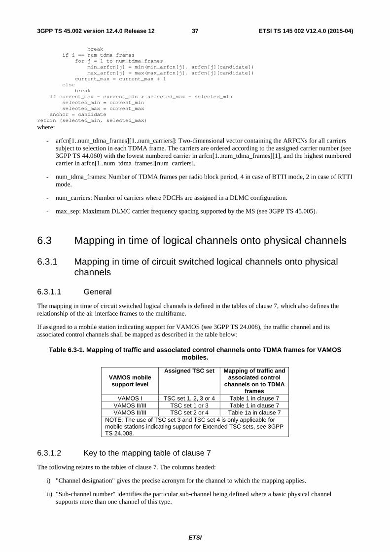
ETSI
ETSI TS 145 002 V12.4.0 (2015-04)373GPP TS 45.002 version 12.4.0 Release 12
break if i == num_tdma_frames for j = 1 to num_tdma_frames min_arfcn[j] = min(min_arfcn[j], arfcn[j][candidate]) max_arfcn[j] = max(max_arfcn[j], arfcn[j][candidate]) current_max = current_max + 1 else break if current_max - current_min > selected_max - selected_min selected_min = current_min selected_max = current_max anchor = candidate return (selected_min, selected_max)
where:
- arfcn[1..num_tdma_frames][1..num_carriers]: Two-dimensional vector containing the ARFCNs for all carriers subject to selection in each TDMA frame. The carriers are ordered according to the assigned carrier number (see 3GPP TS 44.060) with the lowest numbered carrier in arfcn[1..num_tdma_frames][1], and the highest numbered carrier in arfcn[1..num_tdma_frames][num_carriers].
- num_tdma_frames: Number of TDMA frames per radio block period, 4 in case of BTTI mode, 2 in case of RTTI mode.
- num_carriers: Number of carriers where PDCHs are assigned in a DLMC configuration.
- max_sep: Maximum DLMC carrier frequency spacing supported by the MS (see 3GPP TS 45.005).
6.3 Mapping in time of logical channels onto physical channels
6.3.1 Mapping in time of circuit switched logical channels onto physical channels
6.3.1.1 General
The mapping in time of circuit switched logical channels is defined in the tables of clause 7, which also defines the relationship of the air interface frames to the multiframe.
If assigned to a mobile station indicating support for VAMOS (see 3GPP TS 24.008), the traffic channel and its associated control channels shall be mapped as described in the table below:
Table 6.3-1. Mapping of traffic and associated control channels onto TDMA frames for VAMOS mobiles.
VAMOS mobile support level
Assigned TSC set Mapping of traffic and associated control
channels on to TDMA frames
VAMOS I TSC set 1, 2, 3 or 4 Table 1 in clause 7 VAMOS II/III TSC set 1 or 3 Table 1 in clause 7 VAMOS II/III TSC set 2 or 4 Table 1a in clause 7
NOTE: The use of TSC set 3 and TSC set 4 is only applicable for mobile stations indicating support for Extended TSC sets, see 3GPP TS 24.008.
6.3.1.2 Key to the mapping table of clause 7
The following relates to the tables of clause 7. The columns headed:
i) "Channel designation" gives the precise acronym for the channel to which the mapping applies.
ii) "Sub-channel number" identifies the particular sub-channel being defined where a basic physical channel supports more than one channel of this type.

ETSI
ETSI TS 145 002 V12.4.0 (2015-04)383GPP TS 45.002 version 12.4.0 Release 12
iii) "Direction" defines whether the mapping given applies identically to downlink and uplink (D&U), or to downlink (D) or uplink (U) only.
iv) "Allowable timeslots assignments" defines whether the channel can be supported on, or assigned to, any of the timeslots, or only on specific timeslots.
v) "Allowable RF channel assignments" defines whether the channel can use any or all of the radio frequency channels in the cell allocation (CA), or only the BCCH carrier (C0). It should be noted that any allocated channel Cx within CA could be any radio frequency channel, and that no ordering of radio frequency channel number is implied. For example, allocated channel C0 need not have the lowest radio frequency channel number of the allocation.
vi) "Burst type" defines which type of burst as defined in clause 5.2 is to be used for the physical channel.
vii) "Repeat length in TDMA frames" defines how many TDMA frames occur before the mapping for the interleaved blocks repeats itself e.g. 51.
viii) "Interleaved block TDMA frame mapping" defines, within the parentheses, the TDMA frames used by each interleaved block (e.g. 0..3). The numbers given equate to the TDMA frame number (FN) modulo the number of TDMA frames per repeat length; Therefore, the frame is utilized when:
TDMA frame mapping number = (FN)mod repeat length given
Where there is more than one block shown, each block is given a separate designation e.g. B0, B1. Where diagonal interleaving is employed then all of the TDMA frames included in the block are given, and hence the same TDMA frame number can appear more than once (see 3GPP TS 45.003). Also, for E-TCH/F28.8, E-TCH/F32.0 and E-TCH/F43.2, the same frame number appears for the inband signalling message and for several interleaved blocks. It should be noted that the frame mapping for the SACCH/T channel differs according to the timeslot assigned in order to lower the peak processing requirements of the BSS.
6.3.1.3 Mapping of BCCH data
In order to facilitate the MS operation, it is necessary to transmit some System Information messages in defined multiframes and defined blocks within one multiframe, as follows (where TC = (FN DIV 51) mod (8)). Also for some System Information messages, the position where they are transmitted is contained in other System Information messages:

ETSI
ETSI TS 145 002 V12.4.0 (2015-04)393GPP TS 45.002 version 12.4.0 Release 12
System Information Message Sent when TC = Allocation Type 1 0 BCCH Norm Type 2 1 BCCH Norm
Type 2 bis 5 BCCH Norm Type 2 ter 5 or 4 BCCH Norm
Type 2 quater 5 or 4 or 5
BCCH Norm
BCCH Ext Type 2n 4
or 4
BCCH Norm
BCCH Ext Type 3 2 and 6 BCCH Norm Type 4 3 and 7 BCCH Norm Type 7 7 BCCH Ext Type 8 3 BCCH Ext Type 9 4 BCCH Norm
Type 13 4 or 0
BCCH norm
BCCH Ext Type 13 alt 4
or 0
BCCH norm
BCCH Ext Type 15 4
or 1
BCCH Norm
BCCH Ext Type 16 6 BCCH Ext Type 17 2 BCCH Ext Type 18 Not fixed Not fixed Type 19 Not Fixed Not Fixed Type 20 Not fixed Not fixed Type 21 4
or 4
BCCH Norm
BCCH Ext Type 22 2 and 6 BCCH Ext Type 23 1 or 5 BCCH Ext
This subclause defines requirements on minimum scheduling: the network may send any System Information message when sending of a specific System Information message is not required. The following rules apply:
i) BCCH Ext may share the resource with PCH and AGCH (see subclause 6.5.1).
ii) System Information Type 1 needs to be sent if frequency hopping is in use or when the NCH is present in a cell. If the MS finds another message on BCCH Norm when TC = 0, it can assume that System Information Type 1 is not in use.
iii) System information type 2 bis or 2 ter messages are sent if needed, as determined by the system operator. If only one of them is needed, it is sent when TC = 5. If both are needed, 2bis is sent when TC = 5 and 2ter is sent at least once within any of 4 consecutive occurrences of TC = 4. A SI 2 message will be sent at least every time TC = 1. System information type 2 quater is sent if needed, as determined by the system operator. If sent on BCCH Norm, it shall be sent when TC = 5 if neither of 2bis and 2ter are used, otherwise it shall be sent at least once within any of 4 consecutive occurrences of TC = 4. If sent on BCCH Ext, it is sent at least once within any of 4 consecutive occurrences of TC = 5.
iv) The definitions of BCCH Norm and BCCH Ext are given in table 3 of clause 7.
v) Use of System Information type 7 and 8 is not always necessary. It is necessary if System Information type 4 does not contain all information needed for cell selection and reselection.
vi) System Information type 9 is sent in those blocks with TC = 4 which are specified in system information type 3 as defined in 3GPP TS 44.018.
vii) System Information type 13 is only related to the GPRS service. System Information Type 13 need only be sent if GPRS support is indicated in one or more of System Information Type 3 or 4 or 7 or 8 messages. These messages also indicate if the message is sent on the BCCH Norm or if the message is transmitted on the BCCH

ETSI
ETSI TS 145 002 V12.4.0 (2015-04)403GPP TS 45.002 version 12.4.0 Release 12
Ext. In the case that the message is sent on the BCCH Norm, it is sent at least once within any of 4 consecutive occurrences of TC=4.
viii) System Information type 16 and 17 are only related to the SoLSA service. They should not be sent in a cell where network sharing is used (see rule xv).
ix) System Information type 18 and 20 are sent in order to transmit non-GSM broadcast information. The frequency with which they are sent is determined by the system operator. System Information type 9 identifies the scheduling of System Information type 18 and 20 messages.
x) System Information Type 19 is sent if COMPACT neighbours exist. If System Information Type 19 is present, then its scheduling shall be indicated in System Information Type 9.
xi) System Information Type 15 is broadcast if dynamic ARFCN mapping is used in the PLMN. If sent on BCCH Norm, it is sent at least once within any of 4 consecutive occurrences of TC = 4. If sent on BCCH Ext, it is sent at least once within any of 4 consecutive occurrences of TC = 1.
xii) System Information type 13 alt is only related to the GERAN Iu mode. System Information Type 13 alt need only be sent if GERAN Iu mode support is indicated in one or more of System Information Type 3 or 4 or 7 or 8 messages and SI 13 is not broadcast. These messages also indicate if the message is sent on the BCCH Norm or if the message is transmitted on the BCCH Ext. In the case that the message is sent on the BCCH Norm, it is sent at least once within any of 4 consecutive occurrences of TC = 4.
xiii) System Information Type 2n is optionally sent on BCCH Norm or BCCH Ext if needed, as determined by the system operator. In the case that the message is sent on the BCCH Norm, it is sent at least once within any of 4 consecutive occurrences of TC = 4. If the message is sent on BCCH Ext, it is sent at least once within any of 2 consecutive occurrences of TC = 4.
xiv) System Information Type 21 is optionally sent on BCCH Norm or BCCH Ext, as determined by the system operator. If Extended Access Barring is in use in the cell then this message is sent at least once within any of 4 consecutive occurrences of TC = 4 regardless if it is sent on BCCH Norm or BCCH Ext. If BCCH Ext is used in a cell then this message shall only be sent on BCCH Ext.
xv) System Information Type 22 is sent if network sharing is in use in the cell. It should not be sent in a cell where SoLSA is used (see rule viii). System Information Type 22 instances shall be sent on BCCH Ext within any occurrence of TC =2 and TC=6.
xvi) System Information Type 23 is sent if network sharing is in use in the cell, according to System Information Type 22 indication. System Information Type 23 instances shall be sent on BCCH Ext at least twice within any of 4 consecutive occurrences of either TC=1 or TC=5.
All the allowable timeslot assignments in a frame (see table 3 of clause 7) shall contain the same information.
6.3.1.4 Mapping of SID Frames
When the DTX mode of operation is active, it is required to transmit Silence Descriptor (SID) information, or equivalent dummy information, during the SACCH/T block period (104 TDMA frames). As the SID frames do not constitute a logical channel and their use is specific to DTX operation, the mapping of SID frames onto the TDMA frames is specified in 3GPP TS 45.008.
6.3.2 Mapping in time of packet logical channels onto physical channels
6.3.2.1 General
A physical channel allocated to carry packet logical channels is called a packet data channel (PDCH). A PDCH shall carry packet logical channels only.
In RTTI configuration, physical channels are paired, forming PDCH-pairs. The two physical channels shall have the same parameters (see subclause 5.6.3) except for the timeslot number (TN). The two PDCHs constituting a PDCH-pair shall be located on the same carrier. The two PDCHs constituting a PDCH-pair need not be contiguous. In each direction, physical channels shall be assigned so that PDCH-pairs do not partially overlap.
ETSI
ETSI TS 145 002 V12.4.0 (2015-04)413GPP TS 45.002 version 12.4.0 Release 12
On a given PDCH, PDTCHs in both BTTI configuration and RTTI configuration (assigned to different MSs) may be carried. Alternatively, both PDCHs forming a PDCH-pair may be assigned to only carry PDTCHs in RTTI configuration.
Packet switched logical channels are mapped dynamically onto a 52-multiframe.
- For a PDCH/F in BTTI configuration the 52-multiframe consists of 12 blocks of 4 consecutive frames, 2 idle frames and 2 frames used for the PTCCH (see 3GPP TS 45.010), as shown in Figure 9. Table 6 in clause 7, indicates the frame numbers for each of the blocks (B0...B11) transmitted in the multiframe. The ordered list of block is defined as B0, B6, B3, B9, B1, B7, B4, B10, B2, B8, B5, B11.
- For PDCH/H, the 52-multiframe consists of 6 blocks of 4 frames each, and two idle frames. Table 6 in clause 7 indicates the frame numbers for each of the blocks (B0…B5) transmitted in the multiframe.
- For a PDCH-pair in RTTI configuration the 52-multiframe consists of 24 RTTI blocks of 2 consecutive frames, plus 2 idle frames and 2 frames used for the PTCCH (see 3GPP TS 45.010) on each PDCH of the PDCH-pair, as shown in Figure 9a. Table 6 in clause 7 indicates the frame numbers for each of the 24 RTTI blocks (B0a, B0b, ...B11a, B11b) transmitted in the 52-multiframe.
A block allocated to a given logical channel comprises one radio block, or in the case of uplink only, 4 random access bursts. The type of channel may vary on a block-by-block basis.
In the downlink direction, the logical channel type shall be indicated by the message type contained in the block header part.
In the uplink part for channels other than PACCH transmitted as access bursts or PRACH or CPRACH, the logical channel type shall be indicated by the message type contained in the block header part. For PACCH transmitted as access bursts, the logical channel type is indicated by the corresponding polling message on the downlink (see 3GPP TS 44.060). For the PRACH or CPRACH case the logical channel type is indicated by the USF (see 3GPP TS 44.060), set on the downlink on a block by block basis.
For COMPACT, timeslot mapping and rotation of the control channels is used such that control channels belonging to a serving time group are rotated over odd timeslot numbers as follows: 7, 5, 3, 1, 7, 5 … . The rotation occurs between frame numbers (FN) mod 52 = 3 and 4. The mapping of the control channels on timeslot numbers is defined by the following formula:
- for 0 ≤ FN mod 52 ≤ 3, TN = ((6 x ((FN div 52) mod 4)) + 1 + (2 x TG)) mod 8;
- for 4 ≤ FN mod 52 ≤ 51, TN = ((6 x ((FN div 52) mod 4)) + 7 + (2 x TG)) mod 8.
Packet switched logical channels PDTCH, PACCH, and PTCCH are never rotated.
6.3.2.2 Mapping of the uplink channels
6.3.2.2.1 Mapping of uplink packet traffic channel (PDTCH/U) and PACCH/U
6.3.2.2.1.1 BTTI configuration
The PDCH's where the MS may expect occurrence of its PDTCH/U(s) or PACCH/U for a mobile originated transfer is indicated in resource assignment messages (see 3GPP TS 44.060). PACCH/U shall be allocated respecting the resources assigned to the MS and the MS multislot class. For each PDCH assigned to the MS, an Uplink State Flag (R0... R7) is given to the MS.
The occurrence of the PDTCH/U and/or the PACCH/U at given block(s) Bx (where Bx = B0...Bn; n=5 for the PDTCH/HU and n=11 for the PDTCH/FU) in the 52-multiframe structure for a given MS on a given PDCH shall be indicated by the value of the Uplink State Flag (USF) contained in the header of the preceding block transmitted in the downlink of the same PDCH (or in the case of shifted USF on the downlink of a PDCH with a relationship to the uplink PDCH as defined in 3GPP TS 44.060), that is to say B(x-1) in the same multiframe if x≥1 or B(n) in the previous multiframe if x=0. If the USF in block B(x-1) indicates that block B(x) shall be used by an MS for which the USF_GRANULARITY is set to 1 (corresponding to 4 blocks) in the last assignment message, that MS shall also use the three following blocks. The USF corresponding to the last three blocks shall be set to an unused value. The MS may transmit a PDTCH block or a PACCH block on any of the uplink blocks used by the MS. The occurrence of the PACCH/U associated to a PDTCH/D shall be indicated by the network by polling the MS (see 3GPP TS 44.060).

ETSI
ETSI TS 145 002 V12.4.0 (2015-04)423GPP TS 45.002 version 12.4.0 Release 12
NOTE 1: This subclause specifies how the network shall signal that the MS is allowed to use the uplink. The operation of the MS is specified in 3GPP TS 44.060. In particular cases of extended dynamic allocation or exclusive allocation, the MS may not need to monitor the USF on all the downlink timeslots corresponding to the assigned uplink PDCHs.
NOTE 2: The PDCH/HU is only assigned in exclusive allocation (see 3GPP TS 44.060).
NOTE 3: A MS using packet uplink traffic channels mapped to the same physical channel than an uplink PCCCH in extended dynamic allocation MAC mode is not required to check if allocated uplink PDTCH/U or PACCH/U blocks also belong to the PRACH.
In a dual carrier or a DLMC configuration, the uplink block(s) shall be allocated on the corresponding physical channel on which the USF or poll (see 3GPP TS 44.060) is received. Uplink blocks shall not be allocated on physical channels having different frequency domain descriptions (see subclause 5.4) simultaneously in the same block period.
For COMPACT, USF_GRANULARITY should be set to 0 (corresponding to 1 block) for dynamic allocation for the following cases:
i) for odd timeslot numbers (TN) 1, 3, 5, and 7 in nominal and large cells;
ii) for even timeslot numbers (TN) 0, 2, 4, and 6 in large cells.
6.3.2.2.1.2 RTTI configuration
The PDCH-pairs where the MS may expect occurrence of its PDTCH/U(s) or PACCH/U for a mobile originated transfer are indicated in resource assignment messages (see 3GPP TS 44.060). PACCH/U shall be allocated respecting the resources assigned to the MS and the MS multislot class.
For each PDCH-pair assigned to the MS, one or two USFs (R0... R7) are given to the MS. For each assigned uplink PDCH-pair the network may signal in resource assignment messages a 'corresponding downlink PDCH-pair' where the USF is monitored. The timeslot numbers of the PDCHs constituting the corresponding downlink PDCH-pair may be different from those of the PDCHs constituting the uplink PDCH-pair. If no indication is provided, the corresponding downlink PDCH-pair shall be the one with the same timeslot numbers as the uplink PDCH-pair.
For an assigned uplink PDCH-pair, for the transmission of the USF the network can use one of two modes:
- BTTI USF mode: USFs are sent in a basic radio block period, i.e. a USF is mapped on four bursts transmitted on one of the PDCHs of a downlink PDCH-pair during four consecutive TDMA frames;
- RTTI USF mode: a USF is sent in a reduced radio block period, i.e. a USF is mapped on four bursts transmitted on both PDCHs of a downlink PDCH-pair during two consecutive TDMA frames.
The network shall signal the USF mode in the resource assignment messages (see 3GPP TS 44.060). The USF mode shall be the same for all the uplink PDCH-pairs assigned to one mobile station. Also, on a given downlink PDCH-pair, all USFs shall be sent with the same USF mode.
If the BTTI USF mode is used, for each PDCH-pair assigned to the MS the network shall give two USFs (R0... R7) to the MS, one for each PDCH of the corresponding downlink PDCH-pair. If the RTTI USF mode is used, for each PDCH-pair assigned the network shall give to the MS one Uplink State Flag (R0... R7) to the MS.
When a given downlink PDCH is configured to provide USFs for PDTCHs operating in RTTI configuration (as part of a corresponding downlink PDCH-pair) and PDTCHs operating in BTTI configuration, the BTTI USF mode shall be used on both PDCHs of the corresponding downlink PDCH-pair to schedule uplink blocks for mobile stations using RTTI configuration. Additionally, if any of the downlink PDTCHs mapped onto either PDCH of a corresponding PDCH-pair operates in BTTI configuration, the BTTI USF mode shall be used on both PDCHs. In this case, if x≥1, the first uplink RTTI radio block Bxa shall be allocated by the USF contained in block B(x-1) of the downlink PDCH having the lowest TN and the second uplink RTTI radio block Bxb shall be allocated by the USF contained in block B(x-1) of the highest numbered PDCH TN of the 'corresponding downlink PDCH-pair' to the uplink PDCH-pair (see Figure 9a and 3GPP TS 44.060). If x=0 the corresponding USFs will be carried within block B11 of the previous 52-multiframe. In case of dual carrier or a DLMC configuration in the downlink, this same relationship between USFs and uplink RTTI radio blocks shall apply. If the USF_GRANULARITY is set to 1 (corresponding to 4 blocks) in the last assignment message, the MS shall also use the next three consecutive RTTI radio blocks of sub-index a or sub-index b (according to the PDCH in which the USF was received), see 3GPP TS 44.060. The USF corresponding to the last three blocks shall be set to an unused value.

ETSI
ETSI TS 145 002 V12.4.0 (2015-04)433GPP TS 45.002 version 12.4.0 Release 12
When on a downlink PDCH belonging to a PDCH-pair a USF is sent scheduling an uplink block belonging to an MS in BTTI configuration, the USF on the other PDCH of the 'corresponding PDCH-pair' shall also schedule an uplink block belonging to an MS in BTTI configuration.
When both PDCHs of a corresponding downlink PDCH-pair are configured to provide USFs for uplink PDTCHs all operating in RTTI configuration, and when all the downlink PDTCHs mapped onto both PDCHs operate in RTTI configuration, the RTTI USF mode shall be used on both PDCHs. In this case, if x≥1, the uplink RTTI radio block Bxa shall be allocated by the USF contained in RTTI block B(x-1)b and uplink RTTI radio block Bxb shall be allocated by the USF contained in RTTI block Bxa of the 'corresponding downlink PDCH-pair' to the uplink PDCH-pair (see Figure 9a and 3GPP TS 44.060). If x=0 the USFs will be carried within RTTI block B11b of the previous 52-multiframe and B0a respectively. If the USF_GRANULARITY is set to 1 (corresponding to 4 blocks) in the last assignment message, the MS shall also use the next three consecutive RTTI radio blocks, see 3GPP TS 44.060. The USF corresponding to the last three blocks shall be set to an unused value.
The MS may transmit a PDTCH block or a PACCH block on any of the uplink blocks allocated to the MS. The occurrence of the PACCH/U associated to a PDTCH/D shall be indicated by the network by polling the MS (see 3GPP TS 44.060).
6.3.2.2.2 Mapping of the Packet Timing Advance Control Channel (PTCCH/U)
The PDCH carrying the PTCCH/U of one MS is defined in the resource assignment message (see 3GPP TS 44.060). PTCCH/U shall be mapped to one of the time slots where PDTCH(s) are allocated to the MS. PTCCH/U shall be allocated respecting the resources assigned to the MS and the MS multislot class. An MS shall be allocated a sub-channel of the PTCCH/U (0...15) as defined in table 6 of clause 7, where the sub-channel number is equal to the Timing Advance Index (TAI) indicated in the resource allocation message (see 3GPP TS 44.060).
In a dual carrier or a DLMC configuration, an MS shall be assigned a PTCCH/U sub-channel on a physical channel having one frequency domain description (see subclause 5.4) only.
In RTTI configuration, an MS shall be assigned a PTCCH/U on only one of the physical channels comprising an uplink PDCH-pair (see subclause 6.3.2.1).
6.3.2.2.3 Mapping of the uplink PCCCH i.e. PRACH
The mapping of the PRACH is defined in table 6 of clause 7, where the possible blocks are indicated. The PRACH is dynamically allocated in groups of four PRACH blocks By (y=4x+i, i=0 ,.., 3) corresponding to one PDCH block Bx (x=0,...,11), indicated by USF=FREE in the same way as defined for PDTCH/U (see subclause 6.3.2.2.1).
Optionally, a subset of the blocks Bx can be allocated to PRACH in a fixed way. The number of allocated blocks is indicated by the parameter BS_PRACH_BLKS broadcast on the PBCCH, where BS_PRACH_BLKS=0...12. The blocks are allocated according to the ordered list defined in subclause 6.3.2.1. The blocks shall also be indicated by the USF=FREE. The MS may choose to use the BS_PRACH_BLKS or USF to determine the fixed allocated part of PRACH.
6.3.2.2.3a Mapping of the COMPACT uplink CPCCCH i.e. CPRACH
The CPRACH is dynamically or fixed allocated in the same way as defined for PRACH (see subclause 6.3.2.2.3. USF should be set equal to FREE for downlink block B0 on a serving time group when 4 time groups are assigned. Uplink blocks (other than block B1 on a serving time group) that are preceded by CPBCCH and CPCCCH blocks should be prioritized for use as CPRACH.
See Annex D for examples based on sixteen prioritized CPRACH blocks.
6.3.2.2.4 Mapping of the MBMS uplink MPRACH
The mapping of the MPRACH is defined in table 6 of clause 7, where the possible blocks are indicated. The MPRACH is dynamically allocated in groups of four MPRACH blocks By (y=4x+i, i=0 ,.., 3) corresponding to one PDCH block Bx (x=0,...,11), indicated by a value of the USF, in the same way as defined for PDTCH/U (see subclause 6.3.2.2.1). The value of the USF is signalled in the MBMS notification message (see 3GPP TS 44.060).

ETSI
ETSI TS 145 002 V12.4.0 (2015-04)443GPP TS 45.002 version 12.4.0 Release 12
6.3.2.3 Mapping of the downlink channels
6.3.2.3.1 Mapping of the (PDTCH/D) and PACCH/D
The PDCH(s) in BTTI configuration or the PDCH-pair(s) in RTTI configuration where the MS may expect occurrence of its PDTCH/D(s) for a mobile terminated transfer or its PACCH/D, for both mobile originated and mobile terminated transfer, are indicated in resource assignment messages (see 3GPP TS 44.060). PDTCH/D and PACCH/D can be mapped dynamically on all blocks except those used for PBCCH (see subclause 6.3.2.3.3). The logical channel type shall be indicated in the block header. The mobile owner of the PDTCH/D or PACCH/D shall be indicated by the TFI (Temporary Flow Identity) (see 3GPP TS 44.060).
If PDTCH/D is mapped on blocks, which may be used for PCCCH and where paging may appear, the network shall only use coding schemes CS-1 to CS-4.
NOTE: This restriction is needed to avoid the expiry of the downlink signalling counter (DSC) for non-EGPRS capable mobile stations in case the network uses MCS-1 to MCS-9. CS-1 should be favoured, as it provides the strongest error protection.
6.3.2.3.2 Mapping of the PTCCH/D
The PTCCH/D is mapped as defined in table 6 of clause 7. The PTCCH/D carries signalling messages including timing advance information for MSs sharing the PTCCH/U on the same PDCH.
In a dual carrier or a DLMC configuration, an MS shall be assigned a PTCCH/D channel on a physical channel having one frequency domain description (see subclause 5.4) only.
In RTTI configuration, an MS shall be assigned a PTCCH/D on only one of the physical channels comprising a downlink PDCH-pair (see subclause 6.3.2.1). When only an uplink PDTCH is assigned to the MS, the PTCCH shall be assigned on one of the PDCHs comprising the 'corresponding downlink PDCH-pair' for the uplink PDTCH (see subclause 6.3.2.2.1.2).
6.3.2.3.3 Mapping of the PBCCH
The PBCCH is mapped onto one PDCH only, indicated in the BCCH. The PBCCH is mapped on BS_PBCCH_BLKS blocks (where 1≤BS_PBCCH_BLKS≤4) per multiframe, according to the ordered list described in subclause 6.3.2.1. The blocks allocated are specified in table 6 of clause 7. The parameter BS_PBCCH_BLKS is broadcast on PBCCH in block B0 (see subclause 3.3.2.4).
6.3.2.3.3a Mapping of the COMPACT CPBCCH
The CPBCCH is mapped onto a primary COMPACT carrier on the time group indicated by TG on CSCH (see subclause 3.3.2.2). This time group is known as the serving time group and rotates over odd timeslot numbers (see subclause 6.3.2.1). The CPBCCH is mapped on BS_PBCCH_BLKS blocks (where 1≤BS_PBCCH_BLKS≤4) per multiframe, according to the ordered list described in subclause 6.3.2.1. The blocks allocated are specified in table 9 of clause 7. The parameters BS_PBCCH_BLKS is broadcast on CPBCCH in block B0 (see subclause 3.3.2.4).
See Annex D for examples based on one CPBCCH block.
When USF=FREE in downlink block B0 on a serving time group, the CPRACH is allocated in uplink block B1 after timeslot rotation. When USF has any other value in downlink block B0 on a serving time group, the uplink allocation of B1 is valid for the same timeslot, irrespective of timeslot rotation.
6.3.2.3.4 Mapping of the PCCCH
The PCCCH and its different logical channels (PAGCH, PPCH) can be mapped dynamically and are identified by the message header. The configuration is partly fixed by some parameters broadcast by the PBCCH and defined in subclause 3.3.2.4:
a) BS_PBCCH_BLKS, that defines the number of PBCCH blocks per multiframe, according to the ordered list described in subclause 6.3.2.1, on the PDCH that carries PBCCH;

ETSI
ETSI TS 145 002 V12.4.0 (2015-04)453GPP TS 45.002 version 12.4.0 Release 12
b) BS_PAG_BLKS_RES, that defines the number of blocks in addition to BS_PBCCH_BLKS, according to the ordered list described in subclause 6.3.2.1, where PPCH shall not occur on every PDCH that carries PCCCH.
PCCCH (except PPCH) can be mapped on all blocks except those used for PBCCH.
If PBCCH is allocated on timeslot k, PCCCHs shall be allocated only on timeslots n where n>k-4 and 0≤n≤7 in order to provide time for the MS to switch from PBCCH to PCCCH.
6.3.2.3.4a Mapping of the COMPACT CPCCCH
The CPCCCH and its different logical channels (CPAGCH, CPPCH) can be mapped dynamically and are identified by the message header. The configuration is partly fixed by some parameters broadcast by the CPBCCH and defined in subclause 3.3.2.4:
a) BS_PBCCH_BLKS, that defines the number of CPBCCH blocks per multiframe, according to the ordered list described in subclause 6.3.2.1, on the radio frequency channel that carries CPBCCH;
b) BS_PAG_BLKS_RES, that defines the number of blocks in addition to BS_PBCCH_BLKS, where CPPCH shall not occur on every radio frequency channel that carries CPCCCH. These blocks without CPPCH are allocated after CPPCH blocks according to the ordered list described in subclause 6.3.2.1.
CPCCCH (except CPPCH) can be mapped on all blocks except those used for CPBCCH.
For primary COMPACT carriers, CPCCCHs shall be allocated on the same time group as CPBCCH. CPCCCHs on secondary COMPACT carrier(s) shall be allocated on same time group as for primary COMPACT carrier.
See Annex D for examples based on three CPCCCH blocks.
6.3.2.4 Mapping of PBCCH data
In order to facilitate the MS operation, the network is required to transmit certain types of Packet System Information (PSI) messages in specific multiframes and specific PBCCH blocks within the multiframes. The occurrence of the PSI1 message is defined by TC = (FN DIV 52) mod PSI1_REPEAT_PERIOD, where PSI1_REPEAT_PERIOD (range 1 - 16) is indicated in the SI13 message on BCCH, the PSI 1 message on PBCCH and, if present, in the Neighbour Cell parameters in PSI3 and PSI3bis messages sent on serving cell PBCCH.
The PSI1 message is transmitted at TC = 0 according to rule i) and ii) below.
The PSI messages other than the PSI1 message are divided into two groups of PSI messages. One group of PSI messages is transmitted with a low repetition rate and a second group is transmitted with a high repetition rate.
The number of PSI message instances sent with high repetition rate is indicated by the parameter PSI_COUNT_HR (range 0 to 16) in the PSI1 message. The PSI messages in this group are sent according to rule iii) below.
The number of PSI message instances sent with low repetition rate is indicated by the parameter PSI_COUNT_LR (range 0 to 63) in the PSI1 message. The PSI messages in this group are sent according to rule iv) below.
The following rules apply:
i) PSI1 shall be sent in block B0 when TC = 0;
ii) if the value of the parameter BS_PBCCH_BLKS is greater than 1, the PSI1 shall also be sent in block B6 when TC = 0;
iii) the PSI messages in the group sent with high repetition rate shall be sent in a sequence determined by the network and starting at TC = 0, using the PBCCH blocks within each multiframe, in the order of occurrence, which are not occupied according to rule i) or ii). The sequence of these PSI messages shall be repeated starting at each occurrence of TC = 0;
iv) the PSI messages in the group sent with low repetition rate shall be sent in a sequence determined by the network and continuously repeated, using the PBCCH blocks within each multiframe, in the order of occurrence, which are not occupied according to rules i) to iii) . The sequence of these PSI messages shall be restarting at FN = 0.

ETSI
ETSI TS 145 002 V12.4.0 (2015-04)463GPP TS 45.002 version 12.4.0 Release 12
If there are multiple instances of a particular type of PSI message (see 3GPP TS 44.060), they shall all be sent within same group of PSI messages according to either rule iii) or iv) above. They shall be sent in a single sequence in the ascending order of the message instance number of that type of PSI message.
The same PSI message shall not occur twice within the lists defined by PSI_COUNT_LR and PSI_COUNT_HR
A full set of Packet System Information messages contains one consistent set of the messages included in PSI_COUNT_LR and one consistent set of the messages included in PSI_COUNT_HR plus the PSI1 message.
NOTE: The parameters BS_PBCCH_BLKS and PSI1_REPEAT_PERIOD_shall be selected by the network such that all PSI message present in the cell can be sent according to rules i) to iv) above. It is the responsibility of the network to optimise the broadcast of the PSI messages so that the MS can find the important parameters for cell re-selection and access as fast as possible without unnecessary power consumption. The PSI mapping scheme information can be utilised by the MS to estimate the actual minimum cell reselection time.
6.3.2.4a Mapping of COMPACT CPBCCH data
See subclause 6.3.2.4, with the exception that the CPBCCH is a stand-alone packet control channel for COMPACT.
6.3.3 Mapping in time of CTS control channels onto physical channels
The mapping in time of CTS control channels is defined in table 8 of clause 7, which also defines the relationship of the air interface TDMA frames to the multiframe.
The timeslot assignment of the CTS control channel is defined hereafter.
6.3.3.1 CTSBCH timeslot assignment
For the CTSBCH, a procedure of timeslot shifting from one 52-multiframe to another is defined. The usage of this procedure is mandatory in CTS idle mode and optional in CTS dedicated mode. When the shifting procedure is not applied, the CTSBCH timeslot number shall be equal to the TNC broadcast in the current 52-multiframe CTSBCH-SB.
The following parameters are required for the timeslot shifting procedure.
Parameters broadcast in the CTSBCH-SB:
a) TNI: initial timeslot number (0 to 7, 3 bits), defined by the three LSBs (BN3, BN2, BN1) of the FPBI (specified in 3GPP TS 23.003);
b) TNSCN: timeslot number series couple number (0 to 31, 5 bits), defined by the 5 bits (BN8, ..., BN4) of the FPBI. Defines the couple of timeslot number circular series (TNSTNSCN,0, TNSTNSCN,1) to be used to form the timeslot shifting sequence. See timeslot number series (TNS) definition in table below.

ETSI
ETSI TS 145 002 V12.4.0 (2015-04)473GPP TS 45.002 version 12.4.0 Release 12
Table 1 (subclause 6.3.3): TNSi,j definition
TNSCN TNSTNSCN,0 TNSTNSCN,1 TNSCN TNSTNSCN,0 TNSTNSCN,1 0 ( 0, 1, 2, 4, 7, 5, 6, 3 ), ( 0, 3, 5, 7, 6, 2, 1, 4 ) 16 ( 0, 1, 5, 6, 7, 4, 3, 2 ), ( 0, 4, 7, 6, 2, 5, 1, 3 ) 1 ( 0, 1, 2, 5, 3, 6, 7, 4 ), ( 0, 4, 1, 5, 7, 6, 3, 2 ) 17 ( 0, 2, 1, 3, 6, 7, 5, 4 ), ( 0, 3, 7, 4, 1, 5, 6, 2 ) 2 ( 0, 1, 2, 6, 5, 3, 7, 4 ), ( 0, 3, 6, 7, 5, 2, 4, 1 ) 18 ( 0, 2, 1, 5, 6, 7, 4, 3 ), ( 0, 4, 7, 5, 1, 3, 6, 2 ) 3 ( 0, 1, 2, 6, 7, 5, 4, 3 ), ( 0, 3, 7, 4, 6, 2, 5, 1 ) 19 ( 0, 2, 3, 4, 7, 6, 5, 1 ), ( 0, 3, 1, 5, 2, 6, 7, 4 ) 4 ( 0, 1, 3, 2, 5, 6, 7, 4 ), ( 0, 4, 7, 6, 2, 1, 5, 3 ) 20 ( 0, 2, 3, 6, 7, 5, 1, 4 ), ( 0, 4, 7, 6, 3, 5, 2, 1 ) 5 ( 0, 1, 3, 6, 7, 5, 2, 4 ), ( 0, 3, 7, 4, 2, 6, 5, 1 ) 21 ( 0, 2, 3, 7, 5, 6, 4, 1 ), ( 0, 3, 6, 2, 1, 5, 7, 4 ) 6 ( 0, 1, 4, 2, 5, 6, 7, 3 ), ( 0, 2, 6, 3, 7, 5, 4, 1 ) 22 ( 0, 2, 4, 7, 3, 6, 5, 1 ), ( 0, 3, 5, 6, 7, 4, 1, 2 ) 7 ( 0, 1, 4, 2, 5, 7, 6, 3 ), ( 0, 4, 7, 3, 5, 6, 2, 1 ) 23 ( 0, 2, 5, 3, 6, 7, 4, 1 ), ( 0, 3, 7, 6, 5, 1, 2, 4 ) 8 ( 0, 1, 4, 2, 6, 5, 7, 3 ), ( 0, 2, 1, 5, 3, 6, 7, 4 ) 24 ( 0, 2, 5, 3, 7, 6, 4, 1 ), ( 0, 3, 5, 1, 2, 6, 7, 4 ) 9 ( 0, 1, 4, 5, 7, 3, 6, 2 ), ( 0, 3, 7, 6, 5, 2, 4, 1 ) 25 ( 0, 2, 6, 3, 1, 5, 7, 4 ), ( 0, 3, 4, 7, 6, 5, 1, 2 )
10 ( 0, 1, 4, 6, 5, 7, 3, 2 ), ( 0, 4, 7, 5, 1, 2, 6, 3 ) 26 ( 0, 2, 6, 5, 1, 4, 7, 3 ), ( 0, 4, 5, 7, 6, 3, 1, 2 ) 11 ( 0, 1, 4, 7, 3, 5, 6, 2 ), ( 0, 4, 2, 1, 5, 7, 6, 3 ) 27 ( 0, 2, 6, 5, 3, 7, 4, 1 ), ( 0, 3, 6, 7, 5, 1, 2, 4 ) 12 ( 0, 1, 4, 7, 6, 3, 5, 2 ), ( 0, 4, 2, 1, 5, 6, 7, 3 ) 28 ( 0, 3, 5, 1, 2, 6, 7, 4 ), ( 0, 4, 7, 6, 5, 2, 3, 1 ) 13 ( 0, 1, 5, 2, 4, 7, 6, 3 ), ( 0, 3, 7, 5, 1, 4, 6, 2 ) 29 ( 0, 3, 5, 2, 6, 7, 4, 1 ), ( 0, 4, 7, 3, 6, 5, 1, 2 ) 14 ( 0, 1, 5, 2, 6, 4, 7, 3 ), ( 0, 3, 4, 5, 7, 6, 2, 1 ) 30 ( 0, 3, 6, 7, 4, 2, 5, 1 ), ( 0, 4, 1, 2, 6, 5, 7, 3 ) 15 ( 0, 1, 5, 6, 2, 4, 7, 3 ), ( 0, 3, 7, 6, 4, 5, 2, 1 ) 31 ( 0, 3, 7, 5, 6, 2, 4, 1 ), ( 0, 4, 7, 6, 3, 5, 1, 2 )
Parameters sent on a dedicated connection during the CTS-MS attachment:
a) TNSCO : TNS couple order (1 bit), defines together with TNSCN the ordered couple (TNS1, TNS2).
if TNSCO = 0 then (TNS1, TNS2) = (TNSTNSCN,0, TNSTNSCN,1)
if TNSCO = 1 then (TNS1, TNS2) = (TNSTNSCN,1, TNSTNSCN,0)
b) parameters to be used to form the timeslot shifting sequence.
x0 : 0 to 7, 3 bits
x1 : 0 to 7, 3 bits
x2 : 0 to 7, 3 bits
x3 : 0 to 7, 3 bits
For a given set of parameters, a unique timeslot shifting sequence of length of 8 x 51 52-multiframes is defined. The shifting sequence is repeated 128 times over the duration of a GSM hyperframe. It is divided into 8 sets of 51 52-multiframes. The structure of a set is explicitly shown on figure below :
TNS1segment
3
TNS2segment
TNS1segm.
TNS2segment
TNS1segm.
TNS2segm.
TNS1segment
TNS2segment
TNS1segm.
TNS2segment
TNS1segm.
50 0(FN div 52) mod 51 = 0
CTSBCH-SBCTSBCH-FB
51 25FN mod 52 = 0
Figure 1 (subclause 6.3.3): Structure of timeslot shifting sequence
A set is formed by interleaving segments of TNS1 and TNS2. The mapping of TNS1 and TNS2 segments onto a set is defined by the parameters x0, x1, x2, x3 as follows :
for (FN div 52) mod 51 = 0 to 7 a TNS1 segment is used

ETSI
ETSI TS 145 002 V12.4.0 (2015-04)483GPP TS 45.002 version 12.4.0 Release 12
for (FN div 52) mod 51 = 8 to 7+x3 a TNS2 segment is used
for (FN div 52) mod 51 = 8+x3 to 7+x3+x2 a TNS1 segment is used
for (FN div 52) mod 51 = 8+x3+x2 to 7+x3+x2+x1 a TNS2 segment is used
for (FN div 52) mod 51 = 8+x3+x2+x1 to 7+x3+x2+x1+x0 a TNS1 segment is used
for (FN div 52) mod 51 = 8+x3+x2+x1+x0 to 15+x3+x2+x1+x0 a TNS2 segment is used
for (FN div 52) mod 51 = 16+x3+x2+x1+x0 to 23+x3+x2+x1 a TNS1 segment is used
for (FN div 52) mod 51 = 24+x3+x2+x1 to 31+x3+x2 a TNS2 segment is used
for (FN div 52) mod 51 = 32+x3+x2 to 39+x3 a TNS1 segment is used
for (FN div 52) mod 51 = 40+x3 to 47 a TNS2 segment is used
for (FN div 52) mod 51 = 48 to 50 a TNS1 segment is used
The TNS1 and TNS2 segments are extracted from TNS1 and TNS2 according to the following rules :
a) The first CTSBCH TN used in a shifting sequence shall be the TNI.
b) Two consecutive CTSBCH TN shall be separated by single circular shifts along TNS1 and TNS2.
c) When changing from a TNSi segment to a TNSj segment, the last timeslot obtained from TNSi shall be followed by its immediate successor in TNSj.
NOTE: The first timeslot of a set is obtained by three circular shifts in TNS1 with regard to the first timeslot of the previous set.
An example of the mapping of TNS1 and TNS2 onto the first set of the generated shifting sequence is given in annex C.
6.3.3.2 CTSPCH, CTSARCH and CTSAGCH timeslot assignment
For the CTSPCH, CTSARCH and CTSAGCH, the timeslot shall be assigned by the CTS-FP for each 52-multiframe. The timeslot number used for CTSPCH, CTSARCH and CTSAGCH shall be the TNC broadcast in the previous 52-multiframe CTSBCH-SB.
6.4 Permitted channel combinations
6.4.1 Permitted channel combinations onto a basic physical channel
The following are the permitted ways, as defined by 3GPP TS 44.003, in which channels can be combined onto basic physical channels for one or several MSs.
The following definitions are used in the list of combinations below.
Combination designation
Channel combination
SUB_TA TCH/H + FACCH/H + SACCH/TH
SUB_T TCH/H
SUB_PA PDTCH/H + PACCH/H
SUB_TE TCH/H + FACCH/H + SACCH/TPH + EPCCH/H
SUB_OTA O-TCH/H + O-FACCH/H + SACCH/TH
SUB_OT O-TCH/H

ETSI
ETSI TS 145 002 V12.4.0 (2015-04)493GPP TS 45.002 version 12.4.0 Release 12
SUB_OTE O-TCH/H + O-FACCH/H + SACCH/TPH + EPCCH/H
Numbers appearing in parenthesis after channel designations indicate sub-channel numbers. (0..n) shall be interpreted as subchannel 0, 1,…,n-1 and n. Channels and sub-channels need not necessarily be assigned.
i) TCH/F + FACCH/F + SACCH/TF
ii) O-TCH/F + O-FACCH/F + SACCH/TF
iii)
iv) FCCH + SCH + BCCH + CCCH
v) FCCH + SCH + BCCH + CCCH + SDCCH/4(0..3) + SACCH/C4(0..3)
vi) BCCH + CCCH
vii) SDCCH/8(0 .7) + SACCH/C8(0 . 7)
viii) TCH/F + FACCH/F + SACCH/M
ix) TCH/F + SACCH/M
x) TCH/FD + SACCH/MD
xi) PBCCH + PCCCH + PDTCH/F + PACCH/F + PTCCH/F
xii) PCCCH + PDTCH/F + PACCH/F + PTCCH/F
xiii) PDTCH/F + PACCH/F + PTCCH/F
xiv) CTSBCH + CTSPCH + CTSARCH + CTSAGCH
xv) CTSPCH + CTSARCH + CTSAGCH
xvi) CTSBCH
xvii) CTSBCH + TCH/F + FACCH/F + SACCH/CTS
xviii) E-TCH/F + E-IACCH/F + E-FACCH/F + SACCH/TF
xix) E-TCH/F + E-IACCH/F + E-FACCH/F + SACCH/M
xx) E-TCH/F + E-IACCH/F + SACCH/M
xxi) E-TCH/FD + E-IACCH/F + SACCH/MD
xxii) CFCCH + CSCH + CPBCCH + CPCCCH + PDTCH/F + PACCH/F + PTCCH/F
xxiii) CPCCCH + PDTCH/F + PACCH/F + PTCCH/F
xxiv) O-TCH/F + O-FACCH/F + SACCH/TPF + EPCCH/F
xxv) TCH/F + FACCH/F + SACCH/TPF + EPCCH/F
xxvi) TCH/F + FACCH/F + SACCH/MP + EPCCH/M
xxvii) TCH/F + SACCH/MP + EPCCH/M
xxviii) TCH/FD + SACCH/MPD + EPCCH/MD
xxix) PDTCH/F + PACCH/F + SACCH/TF
xxx) PDTCH/F + PACCH/F + SACCH/TPF + EPCCH/F
xxxi) PDTCH/F + PACCH/F + SACCH/M
xxxii) PDTCH/FD + PACCH/FD + SACCH/MD

ETSI
ETSI TS 145 002 V12.4.0 (2015-04)503GPP TS 45.002 version 12.4.0 Release 12
xxxiii) PDTCH + PACCH/F + SACCH/M + EPCCH/M
xxxiv) PDTCH + PACCH/F + SACCH/M + EPCCH/MD
xxxv) PRACH + PDTCH/U + PACCH/U + PTCCH/U + MPRACH
xxxvi) PDTCH/U + PACCH/U + PTCCH/U + MPRACH
The following combinations of half rate channels are allowed on a basic physical channel for a single mobile, where the second half rate channel need not be assigned:
a1) SUB_TA + SUB_T (Lm + Lm configuration)
a2) SUB_TA + SUB_OT (Lm + Lm configuration)
a3) SUB_TA + SUB_PA (DTM single slot)
a4) SUB_TE + SUB_T (Lm + Lm configuration)
a5) SUB_TE + SUB_OT (Lm + Lm configuration)
a6) SUB_TE + SUB_PA (DTM single slot)
a7) SUB_OTA + SUB_OT (Lm + Lm configuration)
a8) SUB_OTA + SUB_T (Lm + Lm configuration)
a9) SUB_OTA + SUB_PA (DTM single slot)
a10) SUB_OTE + SUB_OT (Lm + Lm configuration)
a11) SUB_OTE + SUB_T (Lm + Lm configuration)
a12) SUB_OTE + SUB_PA (DTM single slot)
The following combinations of half rate channels are allowed on a basic physical channel for two mobiles:
b1) SUB_TA + SUB_TA
b2) SUB_TA + SUB_TE
b3) SUB_TA + SUB_OTA
b4) SUB_TA + SUB_OTE
b5) SUB_TE + SUB_TE
b6) SUB_TE + SUB_OTA
b7) SUB_TE + SUB_OTE
b8) SUB_OTA + SUB_OTA
b9) SUB_OTA + SUB_OTE
b10) SUB_OTE + SUB_OTE
The following combinations of full rate channels are allowed on a basic physical channel capable of VAMOS for two mobiles in VAMOS mode (where the 2 full rate channels constitute a VAMOS pair):
c11) i) + i)
c12) i) + xxv)
c13) xxv) + xxv)
The following combinations of full rate and half rate channels are allowed on a basic physical channel capable of VAMOS for three mobiles in VAMOS mode (where the half rate channel on sub-channel number 0 and the full rate

ETSI
ETSI TS 145 002 V12.4.0 (2015-04)513GPP TS 45.002 version 12.4.0 Release 12
channel constitute one VAMOS pair whilst the half rate channel on sub-channel number 1 and the full rate channel constitute a different VAMOS pair on the same basic physical channel capable of VAMOS)
d1) SUB_TA + SUB_TA + i)
d2) SUB_TA + SUB_TA + xxv)
d3) SUB_TA + SUB_TE + i)
d4) SUB_TA + SUB_TE + xxv)
d5) SUB_TE + SUB_TE + i)
d6) SUB_TE + SUB_TE + xxv)
The following combinations of half rate channels are allowed on a basic physical channel capable of VAMOS for 3 mobiles of which 2 are in VAMOS mode (where the pair of half rate channels sharing the same sub-channel number constitutes the VAMOS pair whilst the other half rate channel is not in VAMOS mode)
e1) SUB_TA + SUB_TA + SUB_TA
e2) SUB_TA + SUB_TA + SUB_TE
e3) SUB_TE + SUB_TE + SUB_TA
e4) SUB_TE + SUB_TE + SUB_TE
The following combinations of half rate channels are allowed on a basic physical channel capable of VAMOS for four mobiles in VAMOS mode (where the pair of half rate channels on the sub-channel number 0 constitutes one VAMOS pair and the other pair of half rate channels on the sub-channel number 1 constitutes the other VAMOS pair):
f1) SUB_TA + SUB_TA + SUB_TA + SUB_TA
f2) SUB_TA + SUB_TA + SUB_TA + SUB_TE
f3) SUB_TA + SUB_TA + SUB_TE + SUB_TE
f4) SUB_TA + SUB_TE + SUB_TE + SUB_TE
f5) SUB_TE + SUB_TE + SUB_TE + SUB_TE
NOTE 0: CCCH = PCH+ RACH + AGCH + NCH.
PCCCH = PPCH+PRACH+PAGCH
CPCCCH = CPPCH + CPRACH + CPAGCH
NOTE 1: Where the SMSCB is supported, the CBCH replaces SDCCH number 2 in cases v) and vii) above.
NOTE 2: A combined CCCH/SDCCH allocation (case v) above) may only be used when no other CCCH channel is allocated.
NOTE 3: Combinations viii), ix), x), xix), xx), xxi), xxix), xxx), xxxi) and xxxii) are used without EPC in multislot configurations as defined in subclause 6.4.2.
NOTE 4: Combinations xiv), xv), xvi) and xvii) shall be used in CTS; combinations xiv), xvi) and xvii) shall be mutually exclusive; combinations xiv) and xv) shall also be mutually exclusive.
NOTE 5: Combinations xxii) and xxiii) shall be used for COMPACT on serving time groups.
NOTE 6: Combinations i), ii), xiii), xxv), xxiv) or any of a1) to a12) shall be used for single timeslot operation in DTM.
NOTE 7: A unidirectional TCH combination i), viii), ix) or x) may be combined with the corresponding E-TCH combination xviii), xix), xx) or xxi) respectively in the other direction.

ETSI
ETSI TS 145 002 V12.4.0 (2015-04)523GPP TS 45.002 version 12.4.0 Release 12
NOTE 8: Combinations xxvi), xxvii), xxviii) , xxxii), xxxiii) and xxxiv) are used with EPC in multislot configurations as defined in subclause 6.4.2.
NOTE 9: The basic physical channel onto which channels can be combined according to combinations i), ii), viii), ix), x), xviii), xix), xx), xxi), xxiv), xxv), xxvi), xxvii), xxviii), xxix), xxx), xxxi), xxxii), xxxiii) and xxxiv) is referred to as dedicated basic physical subchannel full rate (DBPSCH/F) in Iu mode.
NOTE 10: The basic physical channel onto which channels can be combined according to combinations xi), xii) and xiii) is referred to as shared basic physical subchannel full rate (SBPSCH/F) in Iu mode.
NOTE 11: The part of the basic physical channel onto which channels can be combined according to combinations SUB_TA, SUB_T, SUB_PA, SUB_TE, SUB_OTA, SUB_OT, SUB_OTE is referred to as dedicated basic physical subchannel half rate (DBPSCH/H) in Iu mode.
NOTE 12: The part of the basic physical channel onto which channels can be combined according to combination SUB_PA is referred to as shared basic physical subchannel half rate (SBPSCH/H) in Iu mode.
NOTE 13: The parts of the basic physical channel onto which SDCCH and SACCH can be combined according to combination v) are referred to as dedicated basic physical subchannels for SDCCH/4 and SACCH/C4 (DBPSCH/S4) in Iu mode.
NOTE 14: The parts of the basic physical channel onto which SDCCH and SACCH can be combined according to combination vii) are referred to as dedicated basic physical subchannels for SDCCH/8 and SACCH/C8 (DBPSCH/S8) in Iu mode.
NOTE 15: Combinations xxxv) and xxxvi) are used only for MBMS.
NOTE 16: In RTTI configuration only combination xiii) shall be used.
6.4.2 Multislot configurations
A multislot configuration consists of multiple circuit or packet switched traffic channels together with associated control channels, assigned to the same MS or, in the case of point-to-multipoint transmission, a group of MSs.
The multislot configuration occupies up to 8 basic physical channels, with different timeslots numbers (TN) but with the same frequency parameters (ARFCN or MA, MAIO and HSN) and the training sequence with the same training sequence code (TSC) which may be selected from different TSC Sets in case of multislot configurations for dual transfer mode in A/Gb mode (see subclause 6.4.2.3). For a mobile station supporting the extended TSC set, up to two training sequences may be used on the same timeslot number with the same frequency parameters for packet switched traffic channels. In this case the training sequences are chosen from different TSC sets.
6.4.2.1 Multislot configurations for circuit switched connections in A/Gb mode
In A/Gb mode, two types of multislot configurations exist, symmetric and asymmetric. The symmetric case consists of only bi-directional channels. The asymmetric case consists of both bi-directional and unidirectional downlink channels.
The occupied physical channels shall consist of the following channel combinations as defined in subclause 6.4.1.
one main channel of type viii) or xix) +
x secondary channels of type ix) or xx) +
y secondary channels of type x) or xxi)
When in EPC mode (see 3GPP TS 45.008) the occupied physical channels shall consist of the following channel combinations as defined in subclause 6.4.1.
one main channel of type xxvi) +
x secondary channels of type xxvii) +
y secondary channels of type xxviii)
where 0<= x <= 7, y = 0 for symmetric multislot configuration

ETSI
ETSI TS 145 002 V12.4.0 (2015-04)533GPP TS 45.002 version 12.4.0 Release 12
0<= x <= 6, 1 <= y <= 7, x+y <= 7 for asymmetric multislot configuration
The main channel is the bi-directional channel that carries the main signalling (FACCH and SACCH) for the multislot configuration. The position of the main channel is indicated by the assignment message (3GPP TS 44.018). Secondary channels may be added or removed without changing the main channel.
The assignment of channels to a Multislot Configuration must always consider the multislot capability of the MS, as defined by the multislot class described in annex B.
There is no limitation in this TS to the possible TCH types (see subclause 3.2) which may be used in a Multislot Configuration.
High Speed Circuit Switched Data (HSCSD) is one case of multislot configuration. The full rate traffic channels of a HSCSD configuration shall convey the same user bit rate (see subclause 3.2.3).
NOTE: For the maximum number of timeslots to be used for a HSCSD, see 3GPP TS 23.034.
6.4.2.2 Multislot configurations for packet switched connections in A/Gb mode
In A/Gb mode, an MS may be assigned several PDTCH/Us or PDTCH/Ds for one mobile originated or one mobile terminated communication respectively, mapped onto a corresponding number of PDCHs in BTTI configuration or a corresponding number of PDCH-pairs in RTTI configuration. The total number of assigned uplink PDCHs and downlink PDTCHs shall not exceed the total number of uplink and downlink timeslots that can be used by the MS per TDMA frame (i.e., the parameter "Sum" specified in Annex B). In this context "assignment" refers to the list of PDCH given in the assignment message and that may dynamically carry the PDTCHs for that specific MS. Alternatively, for a multislot class type 1 MS supporting Flexible Timeslot Assignment (see 3GPP TS 24.008) the network may assign a total number of uplink and downlink PDCHs exceeding the parameter "Sum" specified in Annex B, provided that the number of assigned downlink PDCHs shall not exceed the number of downlink timeslots that can be used by the MS per TDMA frame (i.e., the parameter "Rx" specified in Annex B) and the number of assigned uplink PDCHs shall not exceed the number of uplink timeslots that can be used by the MS per TDMA frame (i.e., the parameter "Tx" specified in Annex B). In this case, the network shall ensure that, in each radio block period, the total number of uplink and downlink PDCHs that have been allocated to the MS does not exceed the total number of uplink and downlink timeslots that can be used by the MS per TDMA frame (i.e., the parameter "Sum" specified in Annex B). Alternatively, when Enhanced Flexible Timeslot Assignment, EFTA, is used (see 3GPP TS 24.008) the network shall follow the same procedure as for Flexible Timeslot Assignment as described above with the exception that, during any given radio block period, the total number of uplink and downlink PDCHs that have been allocated to the MS may exceed the total number of uplink and downlink timeslots defined by the parameter "Sum" specified in Annex B.
NOTE 1: In the downlink, a PDCH is "allocated" to an MS in a radio block period if the network transmits an RLC/MAC block for the MS on that PDCH during that radio block period.
In RTTI configuration, PDCHs shall be assigned in pairs.
If there are m timeslots assigned for reception and n timeslots assigned for transmission:
– For a multislot class type 1 MS, there shall be Min(m,n,2) reception and transmission timeslots with the same TN;
– For a multislot class type 2 MS, there shall be Min(m,n) reception and transmission timeslots with the same TN.
In the case of downlink dual carrier or DLMC configurations, if timeslots with the same timeslot number are assigned on more than one carrier, in calculating the value of m they shall be counted as one timeslot.
The mapping of PACCH onto the assigned downlink PDCHs or the allocated uplink PDCHs is specified in 3GPP TS 44.060.
For multislot class type 1 MS, Table 6.4.2.2.1 lists the number of timeslots (in a dual carrier configuration or a DLMC configuration the numbe of timeslots apply on a per radio frequency basis) that are possible to assign (provided that it is supported by the MS according to its multislot class) for different medium access modes (see 3GPP TS 44.060). It also indicates if the network (or the MS in case of EFTA) shall apply Tra or Tta (see annex B), and if Shifted USF operation

ETSI
ETSI TS 145 002 V12.4.0 (2015-04)543GPP TS 45.002 version 12.4.0 Release 12
shall apply (see 3GPP TS 44.060). Additionally, it indicates which configurations can also be used for allocation (provided that they are compatible with the number of timeslots assigned to the MS).
NOTE 2: In case of extended dynamic allocation, the MS needs to support USF monitoring on the downlink PDCHs corresponding to (i.e. with the same timeslot number as) all assigned uplink PDCHs as defined in 3GPP TS 44.060.
In a dual carrier or a DLMC configuration, all the downlink timeslots on all radio frequency channels shall be assigned within a window of size "d" and all the uplink timeslots on all radio frequency channels shall be assigned within a window of size "u" where "d" and "u" are defined in Table 6.4.2.2.1.
In a dual carrier configuration the maximum number of timeslots that may be assigned (uplink and downlink) depends on the multislot class of the MS (or the Equivalent multislot class if different from the Signalled multislot class as described in B.4) and the multislot capability reduction for downlink dual carrier.
In a DLMC configuration the maximum number of timeslots that may be assigned (uplink and downlink) depends on the multislot class of the MS and the supported Maximum Number of Downlink Timeslots, see 3GPP TS 24.008.
The maximum number of radio frequency channels on which downlink timeslots may be assigned in a DLMC configuration is dependent on the supported Maximum Number of Downlink Carriers, see 3GPP TS 24.008.
In a dual carrier or a DLMC configuration, Shifted USF operation shall be determined per carrier according to the number of downlink and uplink timeslots assigned on each carrier

ETSI
ETSI TS 145 002 V12.4.0 (2015-04)553GPP TS 45.002 version 12.4.0 Release 12
Table 6.4.2.2.1: Multislot configurations for packet switched connections in A/Gb mode
Medium access mode No of Slots (Note 0)
Tra shall apply
Tta shall apply
Applicable Multislot classes (see Note 7)
Note
Downlink, any mode d = 1-6 Yes - 1-12, 19-45 d = 7-8 No - 24-29 1,2 Uplink, Dynamic u = 1-2 Yes - 1-12, 19-45 10
u = 2 - Yes 12, 36-39 11 u = 3 Yes 12, 37-39 9 u = 2-3 Yes - 31-34, 41-45 9 Uplink, Ext. Dynamic u = 1-3 Yes - 1-12, 19-45 u = 4 - Yes 12, 22-23,
27-29 2
u = 4 Yes - 33-34, 38-39, 43-45
2
u = 5 Yes - 34, 39 2,3,5 u = 5 - Yes 44-45 2,4 u = 4 Yes - 30-39 12 u = 4 - Yes 40-45 12 u = 5 Yes - 30-39 5, 12 u = 5 - Yes 40-45 5, 12 u = 6 - Yes 45 2,4,5 Down + up, Dynamic d+u = 2-5, u < 3
Yes - 1-12, 19-45 10
d+u = 6, u<3 Yes - 30-45 2,3 d+u = 7, u<3 - Yes 40-45 2,4 d = 2, u = 3 Yes - 32-34, 42-45 9 d+u = 5, u = 2 – 3
- Yes 12,36-39 9
d+u = 6, u = 3-4 Yes - 32-34,37-39,42-45
2,3,9
d+u = 7, u = 3-4 - Yes 42-45 2,4,9 d = 4, u = 4 Yes - 33-34,38-
39,43-45 2,3,8,9
d = 4, u = 5 - Yes 44-45 2,4,8,9 d+u = 8-10, u<3 Yes - 30-45 12 Down + up, Ext. Dynamic d+u = 2-4 Yes - 1-12, 19-45 d+u = 5, d > 1 Yes - 8-12, 19-45 d+u = 6-7, u<4 Yes - 10-12 8 d = 1, u = 4 - Yes 12, 22-23,
27-29 2
d>1, u = 4 - Yes 12 2,8 d = 1, u = 4 Yes - 33-34, 38-39,
43-45 2,6
d+u = 6, d>1 Yes - 30-45 2,3 d = 1, u = 5 Yes - 34,39 2,3,5 d+u = 7-9, u<5 Yes - 31-34, 36-39 2,3,8 d=2-5, u = 5 Yes - 34,39 2,3,5,8 d = 1, u = 5 - Yes 44-45 2,4 d+u = 7, d>1 - Yes 40-45 2,4 d = 1, u = 6 - Yes 45 2,4,5 d+u = 8-11, u<6 - Yes 41-45 2,4,8 d=2-6, u = 6 - Yes 45 2,4,5,8 d=6-8, u=1-4 Yes - 30-39 12 d=6-8, u=5 Yes - 34,39 5,12 d=7-8, u=1-4 - Yes 40-45 12 d=7-8, u=5-6 - Yes 44-45 5,12

ETSI
ETSI TS 145 002 V12.4.0 (2015-04)563GPP TS 45.002 version 12.4.0 Release 12
Note 0 If the downlink timeslots assigned (allocated) to the mobile station are not contiguous, d shall also include the number of downlink timeslots not assigned (allocated) to the mobile station that are located between assigned (allocated) downlink timeslots. Similarly, if the uplink timeslots assigned (allocated) to the mobile station are not contiguous, u shall also include the number of uplink timeslots not assigned (allocated) to the mobile station that are located between assigned (allocated) uplink timeslots.
Note 1 Normal measurements are not possible (see 3GPP TS 45.008). Note 2 Normal BSIC decoding is not possible (see 3GPP TS 45.008) except e.g. in case of a
downlink dual carrier capable MS operating in single carrier mode using its second receiver for BSIC decoding.
Note 3 TA offset required for multislot classes 35-39. Note 4 TA offset required for multislot classes 40-45. Note 5 Shifted USF operation shall apply (see 3GPP TS 44.060). Note 6 The network may fallback to a lower multislot class and may not apply Tra. A multislot class
38 or 39 MS shall in this case use Tta for timing advance values below 31. Note 7 For dual carrier operation the Applicable Multislot class is the Signalled multislot class or
the Equivalent multislot class (if different from the Signalled multislot class) as defined in Table B.2. For EFTA operation the Applicable Multislot class is the Signalled multislot class.
Note 8 These configurations can only be used for assignment to an MS supporting Flexible Timeslot Assignment (see 3GPP TS 24.008). For allocation additional restrictions apply.
Note 9 These configurations can be used only in RTTI configuration. Note 10 These configurations can be used in RTTI configurations only when the timeslots of the
corresponding downlink PDCH-pair are contiguous. Note 11 These configurations can be used only in RTTI configurations when the timeslots of the
corresponding downlink PDCH-pair are not contiguous. Note 12 These configurations can only be used for assignment to an MS for which Enhanced
Flexible Timeslot Assignment with extended receive capability is used (see Annex B.5 and 3GPP TS 44.060). Whether normal measurements (see 3GPP TS 45.008) and/or normal BSIC decoding (see 3GPP TS 45.008) are possible will be dependent on the allocation or on the use of a second receiver for this purpose.
For multislot class type 2 MS, all assignments according to its multislot class are possible independent of the MAC mode.
The occupied physical channels shall consist of a combination of configurations xi, xii and xiii as defined in subclause 6.4.1. For COMPACT, the occupied physical channels shall consist of a combination of configurations xiii), xxii), and xxiii), as defined in subclause 6.4.1.
The network shall leave a gap of at least one radio block period between the old and the new configuration, when the assignment is changed and PDCHs with the lowest numbered timeslot are not the same in the old and new configuration. For multislot class type 1 MS, the gap shall be left in both uplink and downlink when the lowest numbered timeslot for the combined uplink and downlink configuration is changed. For multislot class type 2 MS, the gap shall be left in the link (uplink and/or downlink) where the lowest numbered timeslot has been changed.
6.4.2.3 Multislot configurations for dual transfer mode in A/Gb mode
For DTM in A/Gb mode, a multislot configuration consists of a single traffic channel (TCH, O-TCH or E-TCH) and one or more packet data traffic channels (PDTCH) together with associated control channels assigned to the same mobile station. The mix of full and half rate packet data channels is not allowed in the uplink. This mix is only defined for the downlink direction and only supported by mobile stations indicating Extended GPRS DTM Multi Slot Class or Extended EGPRS DTM Multi Slot Class capability (see 3GPP TS 24.008). The PDTCH/H is only allowed on the time slot assigned for half rate circuit switched connection.
Note: In the case of extended dynamic allocation, the MS needs to support USF monitoring on the downlink PDCHs corresponding to (i.e. with the same timeslot number as) all assigned uplink PDCHs, as defined in 3GPP TS 44.060. This also restricts multislot configurations where USF monitoring is not possible for all assigned uplink PDCHs because of the presence of the dedicated channel. As an exception, if the mobile station indicates support of DTM high multislot class capability, the network may assign a multislot configuration where USF monitoring is not possible for all assigned uplink PDCHs because of the presence of the dedicated channel. In this case, the mobile station behaves as described in 3GPP TS 44.060.
ETSI
ETSI TS 145 002 V12.4.0 (2015-04)573GPP TS 45.002 version 12.4.0 Release 12
A mobile station indicating support of Flexible Timeslot Assignment (see 3GPP TS 24.008) shall support Flexible Timeslot Assignment while in dual transfer mode. A mobile station indicating support of Enhanced Flexible Timeslot Assignment (see 3GPP TS 24.008) shall support Enhanced Flexible Timeslot Assignment while in dual transfer mode.
The network shall leave a gap of at least one radio block between the old and the new configuration, when the assignment is changed and PDCHs with the lowest numbered timeslot are not the same in the old and new configuration. For multislot class type 1 MS, the gap shall be left in both uplink and downlink when the lowest numbered timeslot for the combined uplink and downlink configuration is changed.
A mobile station indicating support for VAMOS I, VAMOS II or VAMOS III (see 3GPP TS 24.008) shall support VAMOS mode of operation while in dual transfer mode. In case of DTM in A/Gb mode the training sequence for the packet data traffic channels (PDTCH) together with associated control channels shall have the same training sequence code (TSC) as the TSC of the traffic channel together with the associated control channels and shall be selected from TSC Set 1. In case the mobile station indicates support for extended TSC sets, the TSC shall be selected from TSC set 1 or TSC set 2, except for GMSK modulation where the TSC is selected from TSC set 1 or TSC set 3.
6.4.2.3a Multislot configurations for MBMS in A/Gb mode
In A/Gb mode, the network may assign several PDTCH/Ds for one broadcast/multicast session (see 3GPP TS 44.060). The total number of assigned PDTCH/Ds for one broadcast/multicast session shall not exceed 5 (4 if the MS must listen to the (P)BCCH and (P)CCCH in addition to the timeslots allocated for MBMS data transfer). In this context 'assignment' refers to the list of PDCHs given in the assignment message and that may dynamically carry the PDTCHs. The PACCH/D may be mapped onto any of the assigned PDCHs.
An MBMS capable mobile station shall be capable of receiving one or more broadcast/multicast sessions on up to 5 contiguous timeslots within a TDMA frame (4 if the MS must listen to the (P)BCCH and (P)CCCH in addition to the timeslots assigned for MBMS data transfer). If the timeslots are not contiguous, the number of downlink timeslots not listened to by the mobile station that are located between downlink timeslots that are listened to shall also be included in this number.
NOTE 1: When receiving multiple broadcast/multicast sessions, the number of sessions that the mobile station can simultaneously receive depends on the radio resources assignment for the corresponding MBMS radio bearers.
As an exception in the case where the mobile station needs to listen to the (P)BCCH and (P)CCCH in addition to the timeslots assigned for MBMS data transfer, if PBCCH is present in the cell and BS_PCC_CHANS=1, the total number of PDTCH/Ds assigned for one broadcast/multicast session may equal 5 (including the PDTCH/D carried on the PDCH where PBCCH/PCCCH is mapped on). An MBMS capable mobile station shall then be capable of receiving one or more broadcast/multicast sessions on up to 5 contiguous timeslots within a TDMA frame, and in addition listen to the (P)BCCH and (P)CCCH, if the following conditions are met:
- the PDCH where PBCCH/PCCCH is mapped on is adjacent to the other PDCHs assigned for the MBMS radio bearer(s); and
- the same frequency parameters apply over the 5 PDCHs.
Additionally, up to one uplink timeslot per broadcast/multicast session may be assigned for PACCH/U. The timeslot allocated for transmission shall have the same TN as one of the timeslots used for reception. A multislot class type 1 MS receiving more than one broadcast/multicast session may transmit on up to two uplink timeslots, depending on the radio resources assigned for the MBMS radio bearers. The number (m) of timeslots listened to by the mobile station for the reception of one or more broadcast/multicast sessions and the number (n) of timeslots used by the mobile station for the transmission on PACCH/U within a TDMA frame shall be such that the sum of m and n does not exceed 6 (5 in case the mobile station needs to listen to the (P)BCCH and (P)CCCH in addition to the timeslots assigned for MBMS data transfer and the exception described in this sub-clause does not apply).
While in broadcast/multicast receive mode, an MBMS-capable MS shall be capable of receiving, in addition to the timeslots assigned for data transfer, on at least one further timeslot in order to read the BCCH and CCCH or the PBCCH and PCCCH (with the exception described in this sub-clause, where the timeslot carrying the PBCCH and PCCCH is one of the timeslots assigned for data transfer). This requirement does however not apply when the network transmits system information and paging messages on the PACCH of the MBMS radio bearer (see sub-clause 6.5.1, item xxii). The maximum number of timeslots that an MS is required to receive upon within a TDMA frame is 5, and the timeslots shall be assigned within a window of maximum size Rx=6. The number of PDTCH/Ds assigned and their TN shall be such that an MS receiving a given broadcast/multicast session shall be able to read the BCCH and CCCH or

ETSI
ETSI TS 145 002 V12.4.0 (2015-04)583GPP TS 45.002 version 12.4.0 Release 12
the PBCCH and PCCCH without interrupting the reception of the broadcast/multicast session and the transmission on the uplink timeslot, if assigned, unless system information and paging messages are sent on the PACCH of the MBMS radio bearer. Depending on the number of CCCH or PCCCH allocated in the cell, the network may need to restrict the number of PDTCH/Ds assigned to one broadcast/multicast session.
For an MBMS capable mobile station, the minimum requirements shall be Rx=6, Tx=2, Sum=6, Tta=Ttb=Tra=Trb=1.
6.4.2.4 Multislot configurations for DBPSCH in Iu mode
6.4.2.4.1 TCHs assigned
For a multislot class type 1 MS supporting MBMS, the values of Ttb and Tra shall be equal to 1 (i.e. multislot classes 31-34, 41-45, see Annex B).
NOTE 2: Multislot classes 30 and 40 are not included since the corresponding mobile stations cannot transmit on up to two uplink timeslots.
6.4.2.4.2 PDTCHs assigned
In Iu mode, two types of multislot configurations exist, symmetric and asymmetric. The symmetric case consists of only bi-directional basic physical subchannels. The asymmetric case consists of both bi-directional and unidirectional downlink basic physical subchannels.
The occupied physical channels shall consist of the following channel combinations as defined in subclause 6.4.1.
x channels of type xxxi) +
y channels of type xxxii)
When in EPC mode (see 3GPP TS 45.008) the occupied physical channels shall consist of the following channel combinations as defined in subclause 6.4.1.
x channels of type xxxiii) +
y channels of type xxxiv)
where 1<= x <= 8, y = 0 for symmetric multislot configuration
1<= x <= 7, 1 <= y <= 7, x+y <= 8 for asymmetric multislot configuration
The assignment of channels to a Multislot Configuration must always consider the multislot capability of the MS, as defined by the multislot class described in annex B.
6.4.2.4.3 TCHs and PDTCHs assigned
Multislot configurations for DBPSCH may consist of a mixed assignment of TCHs and PDTCHs. The multislot configurations for TCH and PDTCH on DBPSCH in Iu mode are defined in sections 6.4.2.4.1 and 6.4.2.4.2.
6.4.2.5 void
6.4.2.6 Multislot configurations for SBPSCH in Iu mode
The multislot configurations for SBPSCH in Iu mode are equivalent to the multislot configurations for packet switched connections in A/Gb mode, which are defined in section 6.4.2.2.
6.4.2.7 Multislot configurations for dual transfer mode in Iu mode
For dual transfer mode in Iu mode, a multislot configuration comprises one or more DBPSCHs and one or more SBPSCH/F. The mobile station shall support every combination of these basic physical subchannels consistent with its multislot capability signalled to the GERAN (See TS 44.118).

ETSI
ETSI TS 145 002 V12.4.0 (2015-04)593GPP TS 45.002 version 12.4.0 Release 12
The network shall leave a gap of at least one radio block between the old and the new configuration, when the assignment is changed and SBPSCHs with the lowest numbered timeslot are not the same in the old and new configuration. For multislot class type 1 MS, the gap shall be left in both uplink and downlink when the lowest numbered timeslot for the combined uplink and downlink configuration is changed.
6.5 Operation of channels and channel combinations
6.5.1 General
i) A base transceiver station must transmit a burst in every timeslot of every TDMA frame in the downlink of radio frequency channel C0 of the cell allocation (to allow mobiles to make power measurements of the radio frequency channels supporting the BCCH, see 3GPP TS 45.008). In order to achieve this requirement a dummy burst is defined in subclause 5.2.6 which shall be transmitted by the base transceiver station on all timeslots of all TDMA frames of radio frequency channel C0 for which no other channel requires a burst to be transmitted.
ii) Timeslot number 0 of radio frequency channel C0 of the cell allocation must support either channel combinations iv) or v) in subclause 6.4.1. No other timeslot or allocated channel from the cell allocation is allowed to support channel combinations iv) or v) in subclause 6.4.1.
iii) The parameter BS_CC_CHANS in the BCCH defines the number of basic physical channels supporting common control channels (CCCHs). All shall use timeslots on radio frequency channel C0 of the cell allocation. The first CCCH shall use timeslot number 0, the second timeslot number 2, the third timeslot number 4 and the fourth timeslot number 6. Each CCCH carries its own CCCH_GROUP of mobiles in idle mode. Mobiles in a specific CCCH_GROUP will listen for paging messages and make random accesses only on the specific CCCH to which the CCCH_GROUP belongs. The method by which a mobile determines the CCCH_GROUP to which it belongs is defined in subclause 6.5.2.
iv) The parameter BS_CCCH_SDCCH_COMB in the BCCH (see subclause 3.3.2) defines whether the common control channels defined are combined with SDCCH/4(0.3) + SACCH/C4(0.3) onto the same basic physical channel. If they are combined then the number of available random access channel blocks (access grant channel blocks and paging channel blocks; see following), are reduced as defined in table 5 of clause 7.
v) The PCH, AGCH, NCH and BCCH Ext may share the same TDMA frame mapping (considered modulo 51) when combined onto a basic physical channel. The channels are shared on a block by block basis, and information within each block, when de-interleaved and decoded allows a mobile to determine whether the block contains paging messages, notification message, system information messages or access grants. However, to ensure a mobile satisfactory access to the system a variable number of the available blocks in each 51-multiframe can be reserved for access grants and system information messages, only. The number of blocks not used for paging (BS_AG_BLKS_RES) starting from, and including block number 0 is broadcast in the BCCH (see subclause 3.3.2). As above the number of paging blocks per 51-multiframe considered to be "available" shall be reduced by the number of blocks reserved for access grant messages.
If system information messages are sent on BCCH Ext, BS_AG_BLKS_RES shall be set to a value greater than zero.
Table 5 of clause 7 defines the access grant blocks and paging blocks available per 51-multiframe.
vi) Another parameter in the BCCH, BS_PA_MFRMS indicates the number of 51-multiframes between transmissions of paging messages to mobiles in idle mode of the same paging group. The "available" paging blocks per CCCH are then those "available" per 51-multiframe on that CCCH (determined by the two above parameters) multiplied by BS_PA_MFRMS. Mobiles are normally only required to monitor every Nth block of their paging channel, where N equals the number of "available" blocks in total (determined by the above BCCH parameters) on the paging channel of the specific CCCH which their CCCH_GROUP is required to monitor. Other paging modes (e.g. page reorganize or paging overload conditions described in 3GPP TS 44.018) may require the mobile to monitor paging blocks more frequently than this. All the mobiles listening to a particular paging block are defined as being in the same PAGING_GROUP. The method by which a particular mobile determines to which particular PAGING_GROUP it belongs and hence which particular block of the available blocks on the paging channel is to be monitored is defined in subclause 6.5.2.
vii) An MS which has its membership of at least one voice group or voice broadcast call group set to the active state shall, in addition to monitoring the paging blocks as described above, monitor the notification channel,

ETSI
ETSI TS 145 002 V12.4.0 (2015-04)603GPP TS 45.002 version 12.4.0 Release 12
NCH. This logical channel is always mapped onto contiguous blocks reserved for access grants, in a position and number as given by the parameter NCP, defined in 3GPP TS 44.018, broadcast on the BCCH. The channel may be present when a cell supports voice group or voice broadcast calls. The coding of the various structural parameters described above in this subclause is not changed. Information within a block, when deinterleaved and decoded, allows the MS to determine whether the block contains access grant messages or notification messages.
viii) In presence of PCCCH, the parameter BS_PCC_CHANS in the PBCCH defines the number of physical channels for packet data (PDCH) carrying PCCCH. The (P)BCCH shall in addition indicate the physical description of those channels. Each PCCCH carries its own PCCCH_GROUP of MSs in GPRS attached mode. MS in a specific PCCCH_GROUP will listen for paging messages and make random accesses only on the specific PCCCH to which the PCCCH_GROUP belongs. The method by which an MS determines the PCCCH_GROUP to which it belongs is defined in subclause 6.5.6.
ix) In CTS, the CTSBCH (CTSBCH-SB and CTSBCH-FB) shall always be transmitted by the CTS-FP according to the rules defined in Clause 6 and table 8 of clause 7.
In CTS idle mode, a CTS-MS shall be assigned a CTS_PAGING_GROUP, as specified in subclause 6.5.7. Several CTS-MS can be assigned the same CTS_PAGING_GROUP. The CTS-MS shall determine the specific 52-multiframe where a paging block may be sent to it according to the rule defined in subclause 6.5.7, and shall listen to the CTSBCH of the previous 52-multiframe. In this 52-multiframe, the CTS-MS shall decode the CTSBCH-SB information bits : if the flag indicating the presence of a CTSPCH in the next 52-multiframe is properly set (see 3GPP TS 44.056), the CTS-MS shall listen to the next CTSPCH and read the paging block. With this method, it is not necessary to maintain on the physical channel the CTSPCH : the CTSPCH shall only be transmitted when a paging message shall be addressed to one or several CTS-MS in a CTS paging group.
When using the CTSARCH, the CTS-MS shall send two bursts on the CTSARCH: these two bursts shall be sent on two successive frames and shall fulfil the mapping defined in table 8 of clause 7, with the requirement of the first burst being sent in a TDMA frame with even FN. They shall contain the same access request message, which is specified in 3GPP TS 44.056. The first sent burst can be used by the CTS-FP to assess the path loss between the CTS-MS and itself, in order to effectively decode the second burst.
x) For COMPACT, the base transceiver station shall transmit a burst in a PDCH allocated to carry CPBCCH, in all TDMA Frames where CPBCCH, CFCCH, CSCH is allocated or where CPPCH can appear. In TDMA Frames where CPPCH can appear on the physical channel where CPBCCH is allocated, the base transceiver station shall transmit a dummy block in case no block is required to be transmitted.
xi) For COMPACT, a base station does not transmit a burst in every timeslot of every TDMA frame in the downlink of the COMPACT control carrier (i.e., discontinuous transmission is used).
xii) For COMPACT, inter base station time synchronization is required. Timeslot number (TN) = i (i = 0 to 7) and frame number (FN) with FN mod 208 =0 shall occur at the same time in all cells.
xiii) For the primary COMPACT carrier, timeslot numbers (TN) 1, 3, 5, and 7 shall support channel combination xxii) in subclause 6.4.1. TNs 0, 2, 4, and 6 shall support channel combination xiii).
xiv) For the secondary COMPACT carrier(s) carrying CPCCCH, timeslot numbers (TN) 1, 3, 5, and 7 shall support channel combination xxiii) in subclause 6.4.1. TNs 0, 2, 4, and 6 shall support channel combination xiii). CPCCCHs on secondary COMPACT carrier(s) shall be allocated on same time group as for primary COMPACT carrier.
xv) For the secondary COMPACT carrier(s) not carrying CPCCCH, timeslot numbers (TN) 0 through 7 shall support channel combination xiii) in subclause 6.4.1.
xvi) For COMPACT, BS_PAG_BLKS_RES shall be less than or equal to 8 and less than or equal to 10-BS_PBCCH_BLKS.
xvii) For COMPACT, CFCCH, CSCH, CPBCCH, and CPCCCH are rotated as described in subclause 6.3.2.1. PDTCH, PACCH, and PTCCH do not rotate.
xviii) For COMPACT, the parameters NIB_CCCH_0, NIB_CCCH_1, NIB_CCCH_2, and NIB_CCCH_3 shall not be broadcast for a serving time group.

ETSI
ETSI TS 145 002 V12.4.0 (2015-04)613GPP TS 45.002 version 12.4.0 Release 12
xix) For the COMPACT, NIB_CCCH_0, NIB_CCCH_1, NIB_CCCH_2, and NIB_CCCH_3 blocks shall be idle for non-serving time groups and rotate in accordance with the non-serving time groups.
The downlink position of the NIB_CCCH idle blocks is based on the ordered list as defined in subclause 6.3.2.1. The MS shall ignore these downlink idle blocks and shall interpret this action as not having detected an assigned USF value on an assigned PDCH.
xx) For COMPACT large cells, NIB_CCCH_0, NIB_CCCH_1, NIB_CCCH_2, and NIB_CCCH_3 blocks shall be idle on timeslots immediately preceding and succeeding non-serving time groups and rotate in accordance with the non-serving time groups. The MS shall ignore these downlink idle blocks and shall interpret this action as not having detected an assigned USF value on an assigned PDCH.
The downlink position of the NIB_CCCH idle blocks is based on the ordered list as defined in subclause 6.3.2.1.
xxi) For COMPACT, the MS attempts uplink random access on its designated serving time group (TG) by monitoring for USF=FREE in every downlink block.
For dynamic allocation, while in the uplink transfer state, the MS monitors all of the downlink non-idle blocks of its assigned PDCH for uplink assignments. The MS shall ignore downlink idle blocks and shall interpret this action as not having detected an assigned USF value on an assigned PDCH.
USF should be set equal to FREE for downlink non-idle blocks B0 on timeslot numbers (TN) 1, 3, 5, and 7.
xxii) While in broadcast/multicast receive mode (see 3GPP TS 45.008), the MS shall continue to monitor system information either on the BCCH or, if present, on the PBCCH unless the network has indicated that system information and paging messages are sent on the PACCH for the MBMS radio bearer the MS listens to. If the network has not indicated that system information and paging messages are sent on the PACCH, or if the MS does not have an MS_ID, the MS shall additionally read paging messages either from the CCCH or, if the PBCCH is present, from the PCCCH. The MS shall then monitor the same paging group as in packet idle mode, i.e. shall determine the paging blocks to monitor using the methods described in subclause 6.5.2 or subclause 6.5.6. If the location of the MBMS radio bearer with respect to the control channels does not allow the mobile station to satisfy this requirement, the mobile station shall not read those radio blocks of the MBMS radio bearer that would prevent the monitoring of its paging group on the paging channel(s).
xxiii) For a mobile in DLMC configuration, fallback to reception of a single carrier, irrespective of the number of assigned carriers, is performed with regular periodicity. The periodicity is based on BS_PA_MFRMS, which indicates the number of 52-multiframes between two fallback periods. A mobile belongs to a particular single carrier fallback group which identifies a specific basic radio block period, or in case of RTTI mode two consecutive reduced radio block periods, within the set of 'available' single carrier fallback blocks, during which it performs single carrier fallback. The single carrier fallback applies to all assigned PDCHs (or PDCH pairs, in case of RTTI mode) on the carrier where single carrier fallback is performed.
The method by which a particular mobile determines to which single carrier fallback group it belongs is defined in subclause 6.5.8. Single carrier fallback is performed on the carrier where the PTCCH is assigned. In case no PTCCH is assigned the single carrier fallback is performed on the carrier with the lowest number (see 3GPP TS 44.060 for numbering of carriers). Irrespective of which carrier is used, the single carrier fallback applies to all assigned PDCHs (in BTTI configuration)/PDCH-pairs (in RTTI configuration) on that carrier. In case of inter-band reception, the single carrier fallback only applies in one frequency band.
6.5.2 Determination of CCCH_GROUP and PAGING_GROUP for MS in idle mode
CCCH_GROUP (0 .. BS_CC_CHANS-1) = ((IMSI mod 1000) mod (BS_CC_CHANS x N)) div N
PAGING_GROUP (0 .. N-1) = ((IMSI mod 1000) mod (BS_CC_CHANS x N)) mod N
where
N = number of paging blocks "available" on one CCCH = (number of paging blocks "available" in a 51-multiframe on one CCCH) x BS_PA_MFRMS.
IMSI = International Mobile Subscriber Identity, as defined in 3GPP TS 23.003.

ETSI
ETSI TS 145 002 V12.4.0 (2015-04)623GPP TS 45.002 version 12.4.0 Release 12
mod = Modulo.
div = Integer division.
6.5.3 Determination of specific paging multiframe and paging block index
The required 51-multiframe occurs when:
PAGING_GROUP div (N div BS_PA_MFRMS) = (FN div 51) mod (BS_PA_MFRMS)
The index to the required paging block of the "available" blocks in the 51-multiframe:
Paging block index = PAGING_GROUP mod (N div BS_PA_MFRMS)
where the index is then used with the look-up table 5 of clause 7 to determine the actual paging channel interleaved block to be monitored.
In GPRS non-DRX mode, the MS shall listen to all blocks of the CCCH channel.
6.5.4 Short Message Service Cell Broadcast (SMSCB)
When a short message service cell broadcast (SMSCB) message is to be sent, the message shall be sent on one of the two cell broadcast channels (CBCH): the basic and the extended cell broadcast channel in four consecutive multiframes using the block defined in table 3 of clause 7. The multiframes used for the basic cell broadcast channel shall be those in which TB = 0,1,2 and 3. The multiframes used for the extended cell broadcast channel shall be those in which TB = 4, 5, 6 and 7 where:
TB = (FN DIV 51)mod(8)
The SMSCB header shall be sent in the multiframe in which TB = 0 for the basic, and TB = 4 for the extended cell broadcast channel. When SMSCB is in use, this is indicated within the BCCH data (see 3GPP TS 44.018), and the parameter BS_AG_BLKS_RES shall be set to one or greater. When the CBCH is mapped onto a CCCH+SDCCH/4 channel, use of SMSCB does not place any constraint on the value of BS_AG_BLKS_RES.
NOTE 1: The MS reading of the extended CBCH is occasionally interrupted by MS idle mode procedures.
NOTE 2: For a certain network configuration the MS reading of the primary CBCH is occasionally interrupted by MS idle mode procedures when the MS is GPRS attached and in packet idle mode.
6.5.5 Voice group and voice broadcast call notifications
When mobile stations are to be alerted on a voice group or voice broadcast call, notification messages shall be sent on the notification channel (NCH), using the blocks defined in subclause 6.5.1.
When the NCH is in use, the parameter BS_AG_BLKS_RES shall be set to a value not lower than the number of blocks used for the NCH, see subclause 6.5.1 vii).
6.5.6 Determination of PCCCH_GROUP and PAGING_GROUP for MS in GPRS attached mode
If PCCCH is present, then it shall be used in the GPRS attached mode for paging and access. It shall also be used by an MS performing the GPRS attach procedure for access and monitoring of network response. In absence of PCCCH, CCCH shall be used for paging and access. If the determination of the specific paging multiframe and paging block index as specified in this subclause is not supported on CCCH by both the MS and the BTS, the method defined in subclause 6.5.2 and 6.5.3 shall be used. This is negotiated at GPRS attach.
PCCCH_GROUP (0 .. KC-1) = ((IMSI mod 1000) mod (KC* N)) div N
PAGING_GROUP (0 ... M-1) = ( ( (IMSI mod1000) div(KC*N) ) * N +

ETSI
ETSI TS 145 002 V12.4.0 (2015-04)633GPP TS 45.002 version 12.4.0 Release 12
(IMSI mod 1000) mod N + Max((m * M) div SPLIT_PG_CYCLE, m)) mod M for m = 0, ... , Min(M, SPLIT_PG_CYCLE) -1
where
KC = number of (P)CCCH in the cell =
BS_PCC_CHANS for PCCCH BS_CC_CHANS for CCCH
M = number of paging blocks "available" on one (P)CCCH = (12 - BS_PAG_BLKS_RES - BS_PBCCH_BLKS) * 64 for PCCCH (9 - BS_AG_BLKS_RES) * 64 for CCCH not combined (3 - BS_AG_BLKS_RES) * 64 for CCCH + SDCCH combined
N=
1 for PCCCH
(9 - BS_AG_BLKS_RES)*BS_PA_MFRMS for CCCH not combined (3 - BS_AG_BLKS_RES)*BS_PA_MFRMS for CCCH/SDCCH combined
SPLIT_PG_CYCLE is an MS specific parameter negotiated at GPRS attach (see 3GPP TS 44.060)
IMSI = International Mobile Subscriber Identity, as defined in 3GPP TS 23.003.
mod = Modulo.
div = Integer division.
The MS shall receive paging and perform access on a single (P)CCCH identified by the PCCCH_GROUP parameter (see subclause 6.5.1).
In non-DRX mode, depending whether there is or not PCCCH channel(s) in the cell, the MS shall listen :
- to all M blocks per multiframe where paging may appear on a PCCCH channel, or
- to all blocks on a CCCH channel.
In DRX mode, the MS shall listen to the blocks corresponding to its paging group as defined by the different PAGING_GROUP values.
The required multiframe occurs when:
PAGING_GROUP div (M div 64) = (FN div MFL) mod 64
where
MFL = multiframe length = 51 for CCCH or 52 for PCCCH
The index to the required paging block of the "available" blocks in the multiframe:
Paging block index = PAGING_GROUP mod (M div 64)
where the index is then used with look-up tables of clause 7 to determine the actual PPCH block to be monitored. Table 5 is used for CCCH and table 7 for PCCCH.
For CCCH, if SPLIT_PG_CYCLE>32 is negotiated, SPLIT_PG_CYCLE=32 shall be used, in order to provide the MS enough time for BSIC and System Information decoding.
NOTE: On BCCH, the operator should limit DRX_TIMER_MAX (see 3GPP TS 44.060) to 4 seconds of the same reason.

ETSI
ETSI TS 145 002 V12.4.0 (2015-04)643GPP TS 45.002 version 12.4.0 Release 12
6.5.7 Determination of CTS_PAGING_GROUP and specific paging 52-multiframe for MS in CTS mode
CTS_PAGING_GROUP = (CTS-MSI mod N)
where:
CTS-MSI = CTS Mobile Subscriber Identity as defined in 3GPP TS 23.003
N = number of CTS paging groups defined in the CTS-FP and given to the CTS-MS during the attachment procedure (see 3GPP TS 44.056).
The required 52-multiframe where a paging message may be sent to the CTS-MS occurs when:
(FN div 52) mod N = CTS_PAGING_GROUP
6.5.8 Determination of single carrier fallback group
For a mobile in DLMC configuration the single carrier fallback group is determined by:
SINGLE_CARRIER_FALLBACK_GROUP (0 .. N-1) = (TLLI mod 1000) mod N
The specific 52-multiframe during which an MS applies single carrier fallback occurs when:
SINGLE_CARRIER_FALLBACK_GROUP div (N div BS_PA_MFRMS) = (FN div 52) mod (BS_PA_MFRMS)
The required single carrier fallback block index is the specific basic radio block period (in case of RTTI configuration, the basic radio block period corresponds to two consecutive RTTI radio block periods) in the specific 52-multiframe during which an MS applies single carrier fallback and occurs when:
Single carrier fallback block index = SINGLE_CARRIER_FALLBACK_GROUP mod (N div BS_PA_MFRMS)
where
N = number of single carrier fallback blocks "available" on one PDTCH = (number of single carrier fallback blocks "available" in a 52-multiframe on one PDTCH) x BS_PA_MFRMS.
Number of single carrier fallback blocks "available" in a 52-multiframe on one PDTCH = 12.
TLLI = Temporary Logical Link Identity, as defined in 3GPP TS 23.003.
mod = Modulo.
div = Integer division.

ETSI
ETSI TS 145 002 V12.4.0 (2015-04)653GPP TS 45.002 version 12.4.0 Release 12
7 Mapping tables
Table 1 : Mapping of logical channels onto physical channels (see subclauses 6.3, 6.4, 6.5)
Channel Sub-channel Direction Allowable time slot Allowable RF channel Burst Repeat length Interleaved block designation number assignments assignments type in TDMA frames TDMA frame mapping
TCH/FS, TCH/EFS, TCH/AFS, TCH/F2.4, TCH/WFS & O-TCH/WFS D&U2 0 ... 7 C0 ... Cn NB1 13 B0(0...7),B1(4...11),B2(8...11,0...3)
TCH/HS, TCH/AHS, O-TCH/AHS & O-TCH/WHS 0 D&U2 0 ... 7 C0 ... Cn NB1 13 B0(0,2,4,6),B1(4,6,8,10),B2(8,10,0,2) 1 B0(1,3,5,7),B1(5,7,9,11),B2(9,11,1,3)
FACCH/F & O-FACCH/F D&U 0 ... 7 C0 ... Cn NB1 13 B0(0...7),B1(4...11),B2(8...11,0...3)
FACCH/H & O-FACCH/H 0 U 0 ... 7 C0 ... Cn NB1 26 B0(0,2,4,6,8,10),B1(8,10,13,15,17,19),B2(17,19,21,23,0,2) FACCH/H & O-FACCH/H 0 D 0 ... 7 C0 ... Cn NB1 26 B0(4,6,8,10,13,15),B1(13,15,17,19,21,23),B2(21,23,0,2,4,6) FACCH/H & O-FACCH/H 1 U 0 ... 7 C0 ... Cn NB1 26 B0(1,3,5,7,9,11),B1(9,11,14,16,18,20),B2(18,20,22,24,1,3) FACCH/H & O-FACCH/H 1 D 0 ... 7 C0 ... Cn NB1 26 B0(5,7,9,11,14,16),B1(14,16,18,20,22,24),B2(22,24,1,3,5,7)
E-FACCH/F D&U 0 … 7 C0 … Cn NB1 13 B0(0...3),B1(4...7),B2(8...11)
E-IACCH/F D&U 0 ... 7 C0 ... Cn 26 B0(0 ... 3)B1(4 ... 7)B2(8 ... 11)B3(13 ... 16)
B4(17 ... 20)B5(21 ... 24)
SACCH/TF & SACCH/TPF D&U2 0 C0 ... Cn NB3 104 B(12, 38, 64, 90) NOTE 1: SACCH/TF & SACCH/TPF D&U2 1 C0 ... Cn NB3 104 B(25, 51, 77, 103) An Access Burst (AB) is used SACCH/TF & SACCH/TPF D&U2 2 C0 ... Cn NB3 104 B(38, 64, 90, 12) on the uplink during handover SACCH/TF & SACCH/TPF D&U2 3 C0 ... Cn NB3 104 B(51, 77, 103, 25) and on channels used for voice SACCH/TF & SACCH/TPF D&U2 4 C0 ... Cn NB3 104 B(64, 90, 12, 38) group calls when a request to SACCH/TF & SACCH/TPF D&U2 5 C0 ... Cn NB3 104 B(77, 103, 25, 51) talk is made. SACCH/TF & SACCH/TPF D&U2 6 C0 ... Cn NB3 104 B(90, 12, 38, 64)
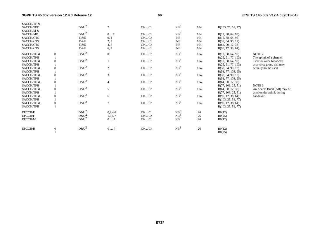
ETSI
ETSI TS 145 002 V12.4.0 (2015-04)663GPP TS 45.002 version 12.4.0 Release 12
SACCH/TF & SACCH/TPF D&U2 7 C0 ... Cn NB3 104 B(103, 25, 51, 77) SACCH/M & SACCH/MP D&U2 0 ... 7 C0 ... Cn NB3 104 B(12, 38, 64, 90) SACCH/CTS D&U 0, 1 C0 ... Cn NB 104 B(12, 38, 64, 90) SACCH/CTS D&U 2, 3 C0 ... Cn NB 104 B(38, 64, 90, 12) SACCH/CTS D&U 4, 5 C0 ... Cn NB 104 B(64, 90, 12, 38) SACCH/CTS D&U 6, 7 C0 ... Cn NB 104 B(90, 12, 38, 64)
SACCH/TH & 0 D&U2 0 C0 ... Cn NB3 104 B(12, 38, 64, 90) NOTE 2: SACCH/TPH 1 B(25, 51, 77, 103) The uplink of a channel SACCH/TH & 0 D&U2 1 C0 ... Cn NB3 104 B(12, 38, 64, 90) used for voice broadcast SACCH/TPH 1 B(25, 51, 77, 103) or a voice group call may SACCH/TH & 0 D&U2 2 C0 ... Cn NB3 104 B(38, 64, 90, 12) actually not be used. SACCH/TPH 1 B(51, 77, 103, 25) SACCH/TH & 0 D&U2 3 C0 ... Cn NB3 104 B(38, 64, 90, 12) SACCH/TPH 1 B(51, 77, 103, 25) SACCH/TH & 0 D&U2 4 C0 ... Cn NB3 104 B(64, 90, 12, 38) SACCH/TPH 1 B(77, 103, 25, 51) NOTE 3: SACCH/TH & 0 D&U2 5 C0 ... Cn NB3 104 B(64, 90, 12, 38) An Access Burst (AB) may be SACCH/TPH 1 B(77, 103, 25, 51) used on the uplink during SACCH/TH & 0 D&U2 6 C0 ... Cn NB3 104 B(90, 12, 38, 64) handover. SACCH/TPH 1 B(103, 25, 51, 77) SACCH/TH & 0 D&U2 7 C0 ... Cn NB3 104 B(90, 12, 38, 64) SACCH/TPH 1 B(103, 25, 51, 77)
EPCCH/F D&U2 0,2,4,6 C0 ... Cn NB3 26 B0(12) EPCCH/F D&U2 1,3,5,7 C0 ... Cn NB3 26 B0(25) EPCCH/M D&U2 0 … 7 C0 ... Cn NB3 26 B0(12)
EPCCH/H 0 D&U2 0 … 7 C0 ... Cn NB3 26 B0(12) 1 B0(25)

ETSI
ETSI TS 145 002 V12.4.0 (2015-04)673GPP TS 45.002 version 12.4.0 Release 12
Table 1a: Mapping of logical channels onto physical channels (see subclause 6.3.1.1)
Channel Sub-channel Direction Allowable time slot Allowable RF channel Burst Repeat length Interleaved block designation number assignments assignments type in TDMA frames TDMA frame mapping
TCH/FS, TCH/EFS, TCH/AFS, TCH/WFS D&U2 0, 2, 4, 6 C0 ... Cn NB1 26 B0(0...7),B1(4...11),B2(8...12,14...16),B3(12,14…20), B4(17…24),B5(21..24,0..3)
TCH/FS, TCH/EFS, TCH/AFS, TCH/WFS D&U2 1, 3 , 5, 7 C0 ... Cn NB1 26 B0(0...7),B1(4...11),B2(8...11,13...16),B3(13…20), B4(17…23,25),B5(21..23,25,0..3)
TCH/HS, TCH/AHS 0 D&U2 0 ... 7 C0 ... Cn NB1 26 B0(0, 2, 4, 6),B1(4, 6, 8, 10),B2(8, 10, 12, 15), B3(12, 15, 17,19),B4(17, 19, 21, 23),B5(21, 23, 0, 2) 1 B0(1, 3, 5, 7),B1(5, 7, 9, 11),B2(9, 11, 14, 16), B3(14, 16, 18, 20),B4(18, 20, 22, 25),B5(22, 25, 1, 3)
FACCH/F D&U 0,2,4,6 C0 ... Cn NB1 26 B0(0...7),B1(4...11),B2(8...12,14...16),B3(12,14…20), B4(17…24) ,B5(21..24,0..3)
FACCH/F D&U 1,3,5,7 C0 ... Cn NB1 26 B0(0...7),B1(4...11),B2(8...11,13...16),B3(13…20), B4(17…23,25) ,B5(21..23,25,0..3)
FACCH/H 0 U 0 ... 7 C0 ... Cn NB1 26 B0(0,2,4,6,8,10),B1(8,10,12, 15,17,19),B2(17,19,21,23,0,2) FACCH/H 0 D 0 ... 7 C0 ... Cn NB1 26 B0(4,6,8,10,12, 15),B1(12,15,17,19,21,23),B2(21,23,0,2,4,6) FACCH/H 1 U 0 ... 7 C0 ... Cn NB1 26 B0(1,3,5,7,9,11),B1(9,11,14,16,18,20),B2(18,20,22,25,1,3) FACCH/H 1 D 0 ... 7 C0 ... Cn NB1 26 B0(5,7,9,11,14,16),B1(14,16,18,20,22,25),B2(22,25,1,3,5,7)
SACCH/TF & SACCH/TPF D&U2 0 C0 ... Cn NB3 104 B(13, 39, 65, 91) SACCH/TF & SACCH/TPF D&U2 1 C0 ... Cn NB3 104 B(24, 50, 76, 102) SACCH/TF & SACCH/TPF D&U2 2 C0 ... Cn NB3 104 B(39, 65, 91, 13) SACCH/TF & SACCH/TPF D&U2 3 C0 ... Cn NB3 104 B(50, 76, 102, 24) SACCH/TF & SACCH/TPF D&U2 4 C0 ... Cn NB3 104 B(65, 91, 13, 39) SACCH/TF & SACCH/TPF D&U2 5 C0 ... Cn NB3 104 B(76, 102, 24, 50) SACCH/TF & SACCH/TPF D&U2 6 C0 ... Cn NB3 104 B(91, 13, 39, 65) SACCH/TF & SACCH/TPF D&U2 7 C0 ... Cn NB3 104 B(102, 24, 50, 76) SACCH/M & SACCH/MP D&U2 0 ... 7 C0 ... Cn NB3 104 B(13, 39, 65, 91) SACCH/CTS D&U 0, 1 C0 ... Cn NB 104 B(13, 39, 65, 91) SACCH/CTS D&U 2, 3 C0 ... Cn NB 104 B(39, 65, 91, 13) SACCH/CTS D&U 4, 5 C0 ... Cn NB 104 B(65, 91, 13, 39)

ETSI
ETSI TS 145 002 V12.4.0 (2015-04)683GPP TS 45.002 version 12.4.0 Release 12
SACCH/CTS D&U 6, 7 C0 ... Cn NB 104 B(91, 13, 39, 65)
SACCH/TH & 0 D&U2 0 C0 ... Cn NB3 104 B(13, 39, 65, 91) SACCH/TPH 1 B(24, 50, 76, 102) SACCH/TH & 0 D&U2 1 C0 ... Cn NB3 104 B(13, 39, 65, 91) SACCH/TPH 1 B(24, 50, 76, 102) SACCH/TH & 0 D&U2 2 C0 ... Cn NB3 104 B(39, 65, 91, 13) SACCH/TPH 1 B(50, 76, 102, 24) SACCH/TH & 0 D&U2 3 C0 ... Cn NB3 104 B(39, 65, 91, 13) SACCH/TPH 1 B(50, 76, 102, 24) SACCH/TH & 0 D&U2 4 C0 ... Cn NB3 104 B(65, 91, 13, 39) SACCH/TPH 1 B(76, 102, 24, 50) SACCH/TH & 0 D&U2 5 C0 ... Cn NB3 104 B(65, 91, 13, 39) SACCH/TPH 1 B(76, 102, 24, 50) SACCH/TH & 0 D&U2 6 C0 ... Cn NB3 104 B(91, 13, 39, 65) SACCH/TPH 1 B(102, 24, 50, 76) SACCH/TH & 0 D&U2 7 C0 ... Cn NB3 104 B(91, 13, 39, 65) SACCH/TPH 1 B(102, 24, 50, 76)
EPCCH/F D&U2 0,2,4,6 C0 ... Cn NB3 26 B0(13) EPCCH/F D&U2 1,3,5,7 C0 ... Cn NB3 26 B0(24) EPCCH/M D&U2 0 … 7 C0 ... Cn NB3 26 B0(13)
EPCCH/H 0 D&U2 0 … 7 C0 ... Cn NB3 26 B0(13) 1 B0(24) NOTE 1: An Access Burst (AB) is used on the uplink during handover and on channels used for voice group calls when a request to talk is made.
NOTE 2: The uplink of a channel used for voice broadcast or a voice group call may actually not be used.
NOTE 3: An Access Burst (AB) may be used on the uplink during handover.
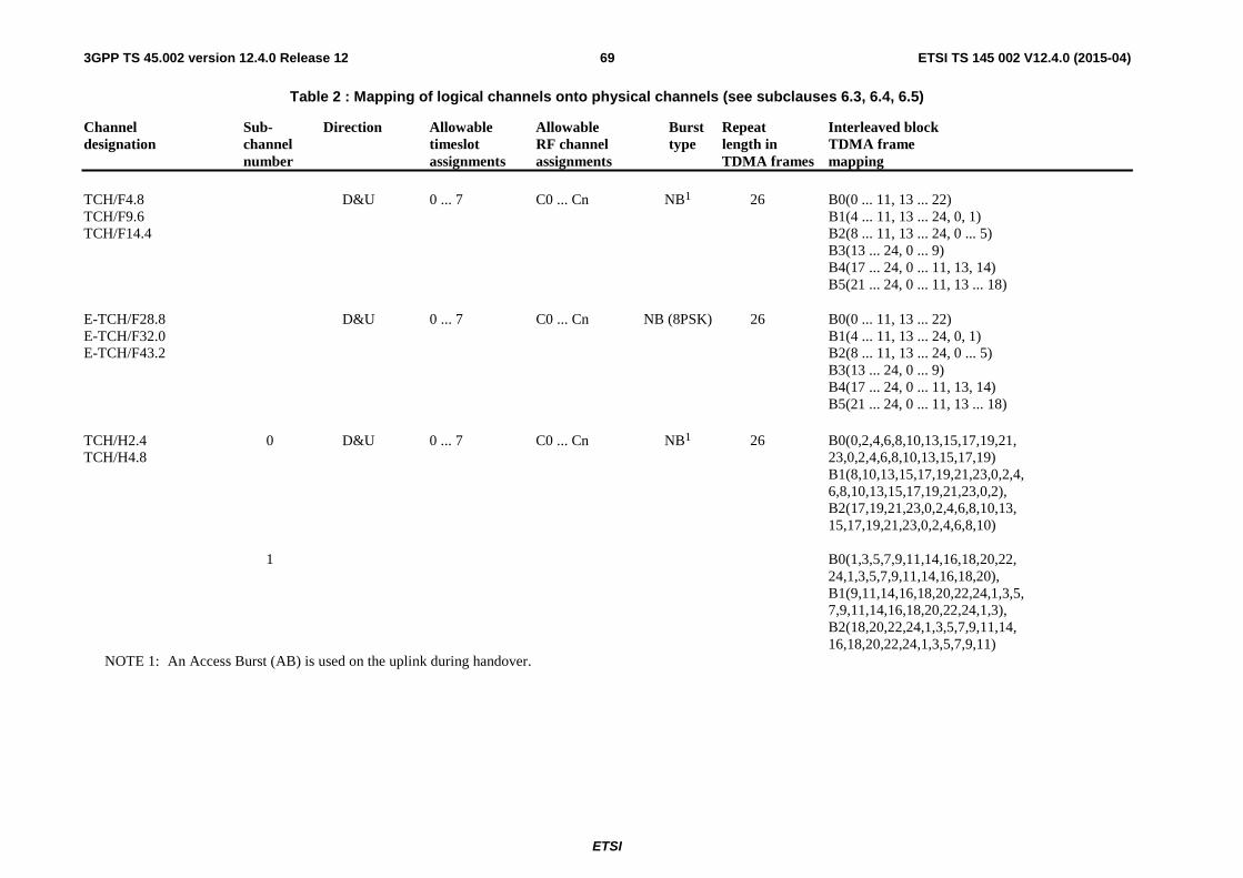
ETSI
ETSI TS 145 002 V12.4.0 (2015-04)693GPP TS 45.002 version 12.4.0 Release 12
Table 2 : Mapping of logical channels onto physical channels (see subclauses 6.3, 6.4, 6.5)
Channel Sub- Direction Allowable Allowable Burst Repeat Interleaved block designation channel timeslot RF channel type length in TDMA frame number assignments assignments TDMA frames mapping
TCH/F4.8 D&U 0 ... 7 C0 ... Cn NB1 26 B0(0 ... 11, 13 ... 22) TCH/F9.6 B1(4 ... 11, 13 ... 24, 0, 1) TCH/F14.4 B2(8 ... 11, 13 ... 24, 0 ... 5) B3(13 ... 24, 0 ... 9) B4(17 ... 24, 0 ... 11, 13, 14) B5(21 ... 24, 0 ... 11, 13 ... 18)
E-TCH/F28.8 D&U 0 ... 7 C0 ... Cn NB (8PSK) 26 B0(0 ... 11, 13 ... 22) E-TCH/F32.0 B1(4 ... 11, 13 ... 24, 0, 1) E-TCH/F43.2 B2(8 ... 11, 13 ... 24, 0 ... 5) B3(13 ... 24, 0 ... 9) B4(17 ... 24, 0 ... 11, 13, 14) B5(21 ... 24, 0 ... 11, 13 ... 18)
TCH/H2.4 0 D&U 0 ... 7 C0 ... Cn NB1 26 B0(0,2,4,6,8,10,13,15,17,19,21, TCH/H4.8 23,0,2,4,6,8,10,13,15,17,19) B1(8,10,13,15,17,19,21,23,0,2,4, 6,8,10,13,15,17,19,21,23,0,2), B2(17,19,21,23,0,2,4,6,8,10,13, 15,17,19,21,23,0,2,4,6,8,10) 1 B0(1,3,5,7,9,11,14,16,18,20,22, 24,1,3,5,7,9,11,14,16,18,20), B1(9,11,14,16,18,20,22,24,1,3,5, 7,9,11,14,16,18,20,22,24,1,3), B2(18,20,22,24,1,3,5,7,9,11,14, 16,18,20,22,24,1,3,5,7,9,11)
NOTE 1: An Access Burst (AB) is used on the uplink during handover.

ETSI
ETSI TS 145 002 V12.4.0 (2015-04)703GPP TS 45.002 version 12.4.0 Release 12
Table 3 : Mapping of logical channels onto physical channels (see subclauses 6.3, 6.4, 6.5)
Channel Sub- Direction Allowable Allowable Burst Repeat Interleaved block designation channel timeslot RF channel type length in TDMA frame number assignments assignments TDMA frames mapping
FCCH D 0 C0 FB 51 B0(0),B1(10),B2(20),B3(30),B4(40)
SCH D 0 C0 SB 51 B0(1),B1(11),B2(21),B3(31),B4(41)
BCCH Norm D 0,2,4,6 C0 NB 51 B(2..5)
BCCH Ext D 0,2,4,6 C0 NB 51 B(6...9)
PCH D 0,2,4,6 C0 NB 51 B0(6..9),B1(12..15),B2(16..19) AGCH B3(22..25),B4(26..29),B5(32..35), B6(36..39),B7(42..45),B8(46..49)
NCH D 0 C0 NB 51 B0(6..9),B1(12..15),B2(16..19) B3(22..25),B4(26..29),B5(32..35), B6(36..39)
RACH U 0,2,4,6 C0 AB 51 B0(0),B1(1)..B50(50)
CBCH(SDCCH/4) D 0 C0 NB 51 B(32..35)
CBCH(SDCCH/8) D 0 ... 3 C0 ... Cn NB 51 B(8..11)
SDCCH/4 0 D 0 C0 NB1 51 B(22..25) U B(37..40) 1 D B(26..29) U B(41..44) 2 D B(32..35) U B(47..50) 3 D B(36..39) U B(0..3)
SACCH/C4 0 D 0 C0 NB3 102 B(42..45) U B(57..60) 1 D B(46..49) U B(61..64) 2 D B(93..96) U B(6..9) 3 D B(97..100) U B(10..13)
NOTE 1: An Access Burst (AB) is used on the uplink during handover.
NOTE 3: An Access Burst (AB) may be used on the uplink during handover.

ETSI
ETSI TS 145 002 V12.4.0 (2015-04)713GPP TS 45.002 version 12.4.0 Release 12
Table 4 : Mapping of logical channels onto physical channels (see subclauses 6.3, 6.4, 6.5)
Channel Sub- Direction Allowable Allowable Burst Repeat Interleaved block designation channel timeslot RF channel type length in TDMA frame number assignments assignments TDMA frames mapping
SDCCH/8 0 D 0 ... 7 C0 ... Cn NB1 51 B (0 ... 3) U B (15 ... 18) 1 D B (4 ... 7) U B (19 ... 22) 2 D B (8 ... 11) U B (23 ... 26) 3 D B (12 ... 15) U B (27 ... 30) 4 D B (16 ... 19) U B (31 ... 34) 5 D B (20 ... 23) U B (35 ... 38) 6 D B (24 ... 27) U B (39 ... 42) 7 D B (28 ... 31) U B (43 ... 46)
SACCH/C8 0 D 0 ... 7 C0 ... Cn NB3 102 B (32 ... 35) U B (47 ... 50) 1 D B (36 ... 39) U B (51 ... 54) 2 D B (40 ... 43) U B (55 ... 58) 3 D B (44 ... 47) U B (59 ... 62) 4 D B (83 ... 86) U B (98 ... 101) 5 D B (87 ... 90) U B (0 ... 3) 6 D B (91 ... 94) U B (4 ... 7) 7 D B (95 ... 98) U B (8 ... 11)
NOTE 1: An Access Burst (AB) is used on the uplink during handover.
NOTE 3: An Access Burst (AB) may be used on the uplink during handover.

ETSI
ETSI TS 145 002 V12.4.0 (2015-04)723GPP TS 45.002 version 12.4.0 Release 12
Table 5 : Mapping of logical channels onto physical channels (see subclauses 6.3, 6.4, 6.5)
BS_CCCH_SDCCH_COMB Random access channel blocks available Access grant blocks available (NOTE: Some access grant blocks may also be used for the NCH) BS_AG_BLKS_RES Number of paging blocks available per 51-multiframe Paging channel blocks available (Paging block index = 0, 1, 2, 3, 4, 5, 6, 7, 8) False B0, B1 ... B50 B0, B1 ... B8 0 9 B0, B1, B2, B3, B4, B5, B6, B7, B8 False 1 8 B1, B2, B3, B4, B5, B6, B7, B8 False 2 7 B2, B3, B4, B5, B6, B7, B8 False 3 6 B3, B4, B5, B6, B7, B8 False 4 5 B4, B5, B6, B7, B8 False 5 4 B5, B6, B7, B8 False 6 3 B6, B7, B8 False 7 2 B7, B8 True B4, B5, B14, B15 ... B36, B45, B46 B0, B1, B2 0 3 B0, B1, B2 True 1 2 B1, B2 True 2 1 B2
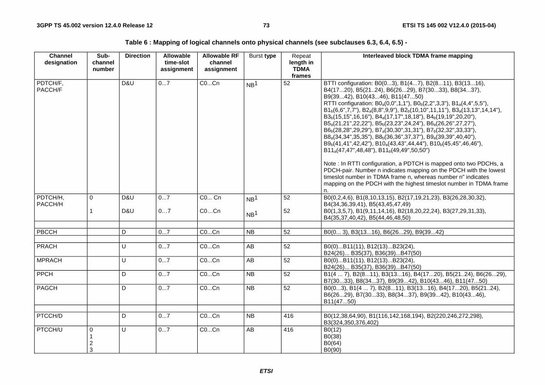
ETSI
ETSI TS 145 002 V12.4.0 (2015-04)733GPP TS 45.002 version 12.4.0 Release 12
Table 6 : Mapping of logical channels onto physical channels (see subclauses 6.3, 6.4, 6.5) -
Channel designation
Sub-channel number
Direction Allowable time-slot
assignment
Allowable RF channel
assignment
Burst type Repeat length in
TDMA frames
Interleaved block TDMA frame mapping
PDTCH/F, PACCH/F
D&U 0...7 C0...Cn NB1 52 BTTI configuration: B0(0...3), B1(4...7), B2(8...11), B3(13...16), B4(17...20), B5(21..24), B6(26...29), B7(30...33), B8(34...37), B9(39...42), B10(43...46), B11(47...50) RTTI configuration: B0a(0,0",1,1"), B0b(2,2",3,3"), B1a(4,4",5,5"), B1b(6,6",7,7"), B2a(8,8",9,9"), B2b(10,10",11,11"), B3a(13,13",14,14"), B3b(15,15",16,16"), B4a(17,17",18,18"), B4b(19,19",20,20"), B5a(21,21",22,22"), B5b(23,23",24,24"), B6a(26,26",27,27"), B6b(28,28",29,29"), B7a(30,30",31,31"), B7b(32,32",33,33"), B8a(34,34",35,35"), B8b(36,36",37,37"), B9a(39,39",40,40"), B9b(41,41",42,42"), B10a(43,43",44,44"), B10b(45,45",46,46"), B11a(47,47",48,48"), B11b(49,49",50,50") Note : In RTTI configuration, a PDTCH is mapped onto two PDCHs, a PDCH-pair. Number n indicates mapping on the PDCH with the lowest timeslot number in TDMA frame n, whereas number n" indicates mapping on the PDCH with the highest timeslot number in TDMA frame n.
PDTCH/H, PACCH/H
0 1
D&U D&U
0...7 0…7
C0... Cn C0…Cn
NB1
NB1
52 52
B0(0,2,4,6), B1(8,10,13,15), B2(17,19,21,23), B3(26,28,30,32), B4(34,36,39,41), B5(43,45,47,49) B0(1,3,5,7), B1(9,11,14,16), B2(18,20,22,24), B3(27,29,31,33), B4(35,37,40,42), B5(44,46,48,50)
PBCCH D 0...7 C0...Cn NB 52 B0(0... 3), B3(13...16), B6(26...29), B9(39...42) PRACH U 0...7 C0...Cn AB 52 B0(0)...B11(11), B12(13)...B23(24),
B24(26)... B35(37), B36(39)...B47(50) MPRACH U 0...7 C0...Cn AB 52 B0(0)...B11(11), B12(13)...B23(24),
B24(26)... B35(37), B36(39)...B47(50) PPCH D 0...7 C0...Cn NB 52 B1(4 ... 7), B2(8...11), B3(13...16), B4(17...20), B5(21..24), B6(26...29),
B7(30...33), B8(34...37), B9(39...42), B10(43...46), B11(47...50) PAGCH D 0...7 C0...Cn NB 52 B0(0...3), B1(4 ... 7), B2(8...11), B3(13...16), B4(17...20), B5(21..24),
B6(26...29), B7(30...33), B8(34...37), B9(39...42), B10(43...46), B11(47...50)
PTCCH/D D 0...7 C0...Cn NB 416 B0(12,38,64,90), B1(116,142,168,194), B2(220,246,272,298),
B3(324,350,376,402) PTCCH/U 0
1 2 3
U 0...7 C0...Cn AB 416 B0(12) B0(38) B0(64) B0(90)

ETSI
ETSI TS 145 002 V12.4.0 (2015-04)743GPP TS 45.002 version 12.4.0 Release 12
4 5 6 7 8 9 10 11 12 13 14 15
B0(116) B0(142) B0(168) B0(194) B0(220) B0(246) B0(272) B0(298) B0(324) B0(350) B0(376) B0(402)
NOTE 1: An Access Burst (AB) may be used on the uplink as polling response.

ETSI
ETSI TS 145 002 V12.4.0 (2015-04)753GPP TS 45.002 version 12.4.0 Release 12
Table 7 : Mapping of logical channels onto physical channels (see subclauses 6.3, 6.4, 6.5)
Non-COMPACT : BS_PAG_BLKS_RES + BS_PBCCH_BLKS Number of paging blocks available per 52-multiframe Paging channel blocks available for 52-multiframe (Paging block index = 0, 1, 2, 3, 4, 5, 6, 7, 8, 9, 10) 1 11 B1, B2, B3, B4, B5, B6, B7, B8, B9, B10, B11 2 10 B1, B2, B3, B4, B5, B7, B8, B9, B10, B11 3 9 B1, B2, B4, B5, B7, B8, B9, B10, B11 4 8 B1, B2, B4, B5, B7, B8, B10, B11 5 7 B2, B4, B5, B7, B8, B10, B11 6 6 B2, B4, B5, B8, B10, B11 7 5 B2, B5, B8, B10, B11 8 4 B2, B5, B8, B11 9 3 B5, B8, B11 10 2 B5, B11 11 1 B11

ETSI
ETSI TS 145 002 V12.4.0 (2015-04)763GPP TS 45.002 version 12.4.0 Release 12
Table 7a : Mapping of logical channels onto physical channels (see subclauses 6.3, 6.4, 6.5)
COMPACT :
BS_PBCCH_BLKS = 1 BS_PBCCH_BLKS = 2 BS_PAG_ BLKS_RES
Paging channel blocks available for 52-multiframe (Paging block index = 0, 1, 2, 3, 4, 5, 6, 7, 8, 9, 10)
Paging channel blocks available for 52-multiframe (Paging block index = 0, 1, 2, 3, 4, 5, 6, 7, 8, 9, 10)
0 1 2 3 4 5 6 7 8
B1, B2, B3, B4, B5, B6, B7, B8, B9, B10, B11 B1, B2, B3, B4, B5, B6, B7, B8, B9, B10 B1, B2, B3, B4, B6, B7, B8, B9, B10 B1, B2, B3, B4, B6, B7, B9, B10 B1, B3, B4, B6, B7, B9, B10 B1, B3, B4, B6, B7, B9 B1, B3, B6, B7, B9 B1, B3, B6, B9 B3, B6, B9
B1, B2, B3, B4, B5, B7, B8, B9, B10, B11 B1, B2, B3, B4, B5, B7, B8, B9, B10 B1, B2, B3, B4, B7, B8, B9, B10 B1, B2, B3, B4, B7, B9, B10 B1, B3, B4, B7, B9, B10 B1, B3, B4, B7, B9 B1, B3, B7, B9 B1, B3, B9 B3, B9
BS_PBCCH_BLKS = 3 BS_PBCCH_BLKS = 4 BS_PAG_ BLKS_RES
Paging channel blocks available for 52-multiframe (Paging block index = 0, 1, 2, 3, 4, 5, 6, 7, 8, 9, 10)
Paging channel blocks available for 52-multiframe (Paging block index = 0, 1, 2, 3, 4, 5, 6, 7, 8, 9, 10)
0 1 2 3 4 5 6 7 8
B1, B2, B4, B5, B7, B8, B9, B10, B11 B1, B2, B4, B5, B7, B8, B9, B10 B1, B2, B4, B7, B8, B9, B10 B1, B2, B4, B7, B9, B10 B1, B4, B7, B9, B10 B1, B4, B7, B9 B1, B7, B9 B1, B9 -
B1, B2, B4, B5, B7, B8, B10, B11 B1, B2, B4, B5, B7, B8, B10 B1, B2, B4, B7, B8, B10 B1, B2, B4, B7, B10 B1, B4, B7, B10 B1, B4, B7 B1, B7 - -
NOTE: In COMPACT, BS_PAG_BLKS_RES shall be less than or equal to 8 and less than or equal to 10 BS_PBCCH_BLKS.

ETSI
ETSI TS 145 002 V12.4.0 (2015-04)773GPP TS 45.002 version 12.4.0 Release 12
Table 8 : Mapping of logical channels onto physical channels (see subclauses 6.3, 6.4, 6.5)
Channel designation
Sub-channel number
Direction Allowable time-slot
assignment
Allowable RF channel
assignment
Burst type Repeat length in
TDMA frames
Interleaved block TDMA frame mapping
CTSBCH-FB D 0...7 C0 FB 52 B(25) CTSBCH-SB D 0...7 C0 SB 52 B(51) CTSPCH D 0...7 C0…Cn NB 52 B(2...5) CTSARCH U 0...7 C0
C0…Cn SB 52 B0(2)…B7(9)
B8(10)…B13(15) CTSAGCH D 0...7 C0
C0…Cn NB 52 B0(16..19)
B1(20..23) NOTE 1: In CTS, C0 shall be interpreted as CTSBCH RF channel and C0…Cn as the RF channels of the TFH carrier list (refer to 3GPP TS 45.056).
NOTE 2: For the precise specification of the timeslot assignment, refer to subclause 6.3.3.1 and 6.3.3.2.
Table 9 : Mapping of COMPACT logical channels onto physical channels (see subclauses 6.3, 6.4, and 6.5)
Channel Designation
Sub- Channel Number
Direction Allowable Timeslot
Alignment
Allowable RF Channel
Assignment
Burst Type
Repeat Length in
TDMA Frames
Interleaved Block TDMA Frame Mapping
CFCCH D 1, 3, 5, 7 C0 … Cn FB 52 B0 (25) CSCH D 1, 3, 5, 7 C0 … Cn SB 52 B0 (51) CPBCCH D 1, 3, 5, 7 C0 … Cn NB 52 B0 (0 … 3), B6 (26 … 29), B3 (13 … 16), B9 (39 … 42) CPRACH U 1, 3, 5, 7 C0 … Cn AB 52 B0 (0) … B11 (11), B12 (13) … B23 (24), B24 (26) … B35
(37), B36 (39) … B47 (50)
CPAGCH, CPPCH
D 1, 3, 5, 7 C0 … Cn NB 52 B1 (4 … 7), B2 (8 … 11), B3 (13 … 16), B4 (17 … 20), B5 (21 … 24), B6 (26 … 29), B7 (30 … 33), B8 (34 … 37), B9 (39 … 42), B10 (43 … 46), B11 (47 … 50)

ETSI
ETSI TS 145 002 V12.4.0 (2015-04)783GPP TS 45.002 version 12.4.0 Release 12
USER
CHANNELS
USER
CHANNELS
CONTROL
ENTITIES
CONTROL
ENTITIES
MAPPING
MAPPING
LOGICALCHANNELS
Traffic= TCH (Bm or Lm)
Control andSignalling
= CCH (Dm)
LOGICALCHANNELS
Traffic= TCH (Bm or Lm)
Control andSignalling
= CCH (Dm)
(Air interface)
PHYSICALRESOURCE
Frequency(RF Channels)
Time(Timeslots)
L A N D N E T W O R K M O B I L E
PHYSICALCHANNELS
( Timslotnumber,
TDMA framesequence
RF Channelsequence )
PHYSICALCHANNELS
( Timslotnumber,
TDMA framesequence
RF Channelsequence )
Figure 1: Mapping of logical channels onto physical channels based on the physical resource

ETSI
ETSI TS 145 002 V12.4.0 (2015-04)793GPP TS 45.002 version 12.4.0 Release 12
0 1 2 3 4 5 6 7 0 1 2 3 4 5 6 7 0 1 2 3 4 5 6 7 0 1 2 3 4 5 6 7
0 1 2 3 4 5 6 7 0 1 2 3 4 5 6 7 0 1 2 3 4 5 6 7 0 1 2 3 4 5 6 7
0 1 2 3 4 5 6 7 0 1 2 3 4 5 6 7 0 1 2 3 4 5 6 7 0 1 2 3 4 5 6 7
0 1 2 3 4 5 6 7 0 1 2 3 4 5 6 7 0 1 2 3 4 5 6 7 0 1 2 3 4 5 6 7
0 1 2 3 4 5 6 7 0 1 2 3 4 5 6 7 0 1 2 3 4 5 6 7 0 1 2 3 4 5 6 7
0 1 2 3 4 5 6 7 0 1 2 3 4 5 6 7 0 1 2 3 4 5 6 7 0 1 2 3 4 5 6 7
0 1 2 3 4 5 6 7 0 1 2 3 4 5 6 7 0 1 2 3 4 5 6 7 0 1 2 3 4 5 6 7
0 1 2 3 4 5 6 7 0 1 2 3 4 5 6 7 0 1 2 3 4 5 6 7 0 1 2 3 4 5 6 7
Downlink(BTS -> MS)
0 1 2 3
3210
TDMA frame number
TDMA frame number
Timeslot number
Uplink(MS -> BTS)
Delay
RF
channels
Figure 2: The structure imposed on the physical resource: Timeslots, TDMA Frames and Radio Frequency channels (in this example the cell has an allocation of 4 RF Channels pairs

ETSI
ETSI TS 145 002 V12.4.0 (2015-04)803GPP TS 45.002 version 12.4.0 Release 12
TDMA frame
Timeslot
Encrypted bits58
Encrypted bits58
Fixed bits142
Extended training sequence64
Encrypted bits39
Encrypted bits39
Trainingsequence
26
Trainingsequence
26
Mixed bits58
Mixed bits58
Synch sequence bits41
Encrypted bits36
= Tail bits3
= Extendedtail bits
8
68.25bit periods
8.25bit periods
ACCESS BURST
DUMMY BURST
Guard period
SYNCHRONIZATION BURST
FREQUENCY CORRECTION BURST
NORMAL BURST
Figure 3: Timeslot and format of bursts

ETSI
ETSI TS 145 002 V12.4.0 (2015-04)813GPP TS 45.002 version 12.4.0 Release 12
c1c0
c2
0 1 2 3 4 5 6 7
0 1 2 3 4
10 2 3 4 5 6 7
0 1
5 6 7
2 3 4 5 6 7
c0'c1'c2'
d0
e0
Rx
Tx
Rx
Monitor
Tx
Monitor
Downlink (serving cell)
Uplink (serving cell)
Downlink (adjacent cells)
= Rx -> Tx | Tx -> Rx | Rx -> Rx | + new L.O. frequency if required.
(This example of a physical channel is non-hopping using timeslot 0 of every TDMA frame)
Figure 4: Mobile Station usage of physical channel timeslots (For a full-rate hopping traffic channel assigned timeslot 3)

ETSI
ETSI TS 145 002 V12.4.0 (2015-04)823GPP TS 45.002 version 12.4.0 Release 12
Physical channel
Physical channel
TDMA frame
c0
c1
c2
c3
c4
Allocated
RF
channels
Timeslots
>197.6 kb/s
>197.6 kb/s
>197.6 kb/s
>197.6 kb/s
>197.6 kb/s
24.7 kb/s
12.35 kb/s
~
~
(This example of a physical channel is hopping using 3 of every other TDMA frame)
Figure 5: Example of two different physical channels

ETSI
ETSI TS 145 002 V12.4.0 (2015-04)833GPP TS 45.002 version 12.4.0 Release 12
FNT1 (0...2047)
HSN(0...63)
FNT3 (0...50)
MAIO(0...N-1)
MA(m0...mN-1)
FNT2 (0...25)
Representin 7 bits
5 bits
T1R =T1 MOD 64
11 bits
6 bits
6 bits
Exclusive OR
6 bits
Addition
7 bits
Look-up table
6 bits
7 bits
7 bits
Addition
8 bits
M' = M MOD 2^NBIN
NBIN bits
M' < N YN
S = M'S = (M' + T) MOD N
T =T3 MOD 2^NBIN
NBIN bits
NBIN bits
MAI = (S + MAIO) MOD N
NBIN bits
ARFCN = MA (MAI)
NBIN bits
where NBIN = INTEGER((Log base 2 of N) + 1)MOD = MODULO
^ = raised to the power of
ARFCN
Figure 6: Block diagram of the frequency hopping algorithm when HSN ≠ 0

ETSI
ETSI TS 145 002 V12.4.0 (2015-04)843GPP TS 45.002 version 12.4.0 Release 12
Figure 6a: General structure of hopping sequence generation for CTS
NOTE: Example with vector a = (a0, a1, a2, a3) = (5, 8, 2, 11).
a2 a0 a1 a3
b0 b1 b2 b3 b4 b5 b6 b7 b8 b9 b10 b11 b12 b13 b14 b15
Add mod 2
⊕Add mod 2
⊕
⊕
⊕
⊕⊕⊕⊕
Add mod 2
⊕
modified codeword
v2v1v0 v3
Countermod NFTFHC2
Countermod NFTFHC1
Add mod NF
Add mod NF
Shift register clock
TDMA frame clockc
TFHC1

ETSI
ETSI TS 145 002 V12.4.0 (2015-04)853GPP TS 45.002 version 12.4.0 Release 12
TCHFS 2
TCHFS 3
TCHFS 4
TCHFS 5
TCHFS 6
TCHFS 7
TCHFS 8
TCHFS 9
TCHFS 10
TCHFS 11
SACCH FS
TCHFS 13
TCHFS 14
TCHFS 15
TCHFS 16
TCHFS 17
TCHFS 18
TCHFS 19
TCHFS 20
TCHFS 21
TCHFS 22
TCHFS 23
TCHFS 24 25
TCHFS 0
TCHFS 1 12
IDLE
0 1 2 3 4 5 6 7 8 9 10 11 12 13 14 15 16 17 18 19 20 21 22 23 24 25
0 1 2 3 4 5 6 7 8 9 10 11 12 13 14 15 16 17 18 19 20 21 22 23 24 25
TCH/HS
23
TCH/HS
21
TCH/HS
19
TCH/HS
17
TCH/HS
15
TCH/HS
13
TCH/HS
10
TCH/HS
8
TCH/HS
6
TCH/HS
4
TCH/HS
2
TCH/HS
0
SACCH HS 12
TCH/HS
24
TCH/HS
22
TCH/HS
20
TCH/HS
18
TCH/HS
16
TCH/HS
14
TCH/HS
11
TCH/HS
9
TCH/HS
7
TCH/HS
5
TCH/HS
3
TCH/HS
1
SACCH HS 25
Figure 7a: TDMA frame mapping for TCH/FS + SACCH/FS
Subchannel 0
Subchannel 1
Figure 7b: TDMA frame mapping for TCH/HS + SACCH/HS sub-channels 0 and 1

ETSI
ETSI TS 145 002 V12.4.0 (2015-04)863GPP TS 45.002 version 12.4.0 Release 12
Figure 7c: TDMA frame mapping for TCH/FS + SACCH/FS for VAMOS II and VAMOS III MS when assigned a training sequence in TSC Set 2 or Set 4
0 1 2 3 4 5 6 7 8 9 10 11 12 13 14 15 16 17 18 19 20 21 22 23 24 25
TCH/HS
23
TCH/HS
21
TCH/HS
19
TCH/HS
17
TCH/HS
15
TCH/HS
13
TCH/HS
10
TCH/HS
86
TCH/HS
4
TCH/HS
2
TCH/HS
0 12
TCH/HS
24
TCH/HS
22
TCH/HS
2018
TCH/HS
16
TCH/HS
14
TCH/HS
11
TCH/HS
9
TCH/HS
7
TCH/HS
5
TCH/HS
3
TCH/HS
1 25
Subchannel 1
SACCH
HS
TCH/HS
Subchannel 0
TCH/HSSACCH
HS
Figure 7d: TDMA frame mapping for TCH/HS + SACCH/HS sub-channels 0 and 1 for VAMOS II and VAMOS III MS when assigned a training sequence in TSC Set 2 or Set 4
Figure 7: Example of a TDMA frame mapping for traffic channels
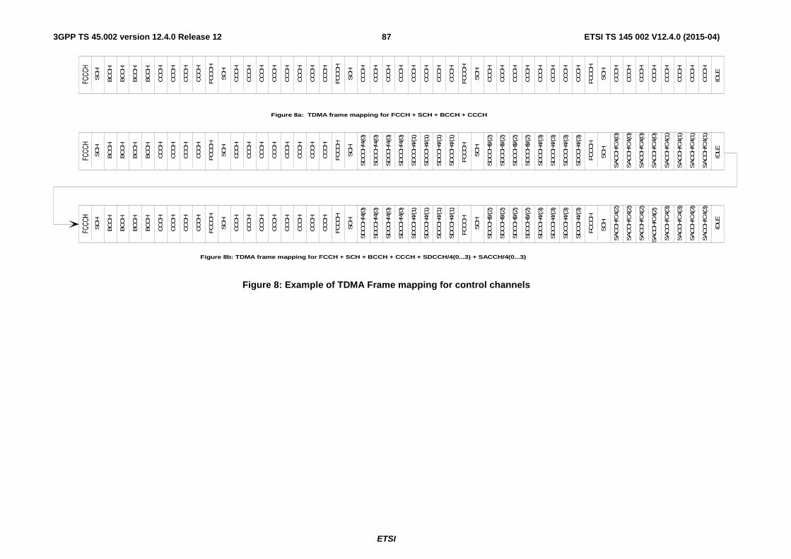
ETSI
ETSI TS 145 002 V12.4.0 (2015-04)873GPP TS 45.002 version 12.4.0 Release 12
Figure 8b: TDMA frame mapping for FCCH + SCH + BCCH + CCCH + SDCCH/4(0...3) + SACCH/4(0...3)
IDLE
CCCH
BCCH
SCH
BCCH
BCCH
BCCH
CCCH
CCCH
CCCH
FCCCH
SCH
CCCH
CCCH
CCCH
CCCH
CCCH
CCCH
CCCH
CCCH
FCCCH
SCH
SDCCH/4
(0)
SDCCH4/
(1)
SDCCH$/
(2)
SDCCH4/
(3)
SACCH/C
4(3)
IDLE
CCCH
BCCH
SCH
BCCH
BCCH
BCCH
CCCH
CCCH
CCCH
FCCCH
SCH
CCCH
CCCH
CCCH
CCCH
CCCH
CCCH
CCCH
CCCH
FCCCH
SCH
SDCCH/4
(0)
SDCCH/4
(0)
SDCCH/4
(0)
SDCCH4/
(1)
SDCCH4/
(1)
SDCCH4/
(1)
FCCCH
SCH
SDCCH$/
(2)
SDCCH$/
(2)
SDCCH$/
(2)
SDCCH4/
(3)
SDCCH4/
(3)
SDCCH4/
(3)
FCCCH
SCH
IDLE
CCCH
BCCH
SCH
BCCH
BCCH
BCCH
CCCH
CCCH
CCCH
FCCCH
SCH
CCCH
CCCH
CCCH
CCCH
CCCH
CCCH
CCCH
CCCH
FCCCH
SCH
SDCCH/4
(0)
SDCCH4/
(1)
SDCCH$/
(2)
SDCCH4/
(3)
SDCCH/4
(0)
SDCCH/4
(0)
SDCCH/4
(0)
SDCCH4/
(1)
SDCCH4/
(1)
SDCCH4/
(1)
FCCCH
SCH
SDCCH$/
(2)
SDCCH$/
(2)
SDCCH$/
(2)
SDCCH4/
(3)
SDCCH4/
(3)
SDCCH4/
(3)
FCCCH
SCH
SACCH/C
4(2)
SACCH/C
4(1)
SACCH/C
4(0)
SACCH/C
4(2)
SACCH/C
4(2)
SACCH/C
4(2)
SACCH/C
4(3)
SACCH/C
4(3)
SACCH/C
4(3)
SACCH/C
4(0)
SACCH/C
4(0)
SACCH/C
4(0)
SACCH/C
4(1)
SACCH/C
4(1)
SACCH/C
4(1)
CCCH
CCCH
CCCH
CCCH
CCCH
CCCH
CCCH
CCCH
FCCCH
SCH
CCCH
CCCH
CCCH
CCCH
CCCH
CCCH
CCCH
CCCH
FCCCH
SCH
CCCH
CCCH
CCCH
CCCH
CCCH
CCCH
CCCH
CCCH
Figure 8a: TDMA frame mapping for FCCH + SCH + BCCH + CCCH
Figure 8: Example of TDMA Frame mapping for control channels

ETSI
ETSI TS 145 002 V12.4.0 (2015-04)883GPP TS 45.002 version 12.4.0 Release 12
52 TDMA Frames
X = Idle frame T = Frame used for PTCCH
B0 - B11 = Radio blocks
Figure 9: 52- multiframe for PDCHs in BTTI configuration
Figure 9a: 52- multiframe for PDCH-pairs in RTTI configuration
52 TDMA Frames
Downlink
Uplink
P G G B
A A AA A A A A A A A A A AX X
X X X X X X X X X X X X X X X X X X X X X X X X X BX X X
X X X X X X X XX X X X X X X X X X X X X X X X X X X X X X X X X X X X
X XX X X XX X X X
A : TDMA frame for CTSARCH B : TDMA frame for CTSBCH P : TDMA frame for CTSPCH G : TDMA frame for CTSAGCH X : Idle frame
Figure 10: 52-multiframe for CTS
B0 B1 B2 T B3 B4 B5 X B6 B7 B8 T B9 B10 B11 X
X = Idle frameT = Frame used for PTCCH
B0 = BTTI radio blockB0a – B11b = RTTI radio blocks
PDCH1
PDCH2B0a B0b B1a B1b B2a B2b
TT
B3a B3b B4a B4b B5a B5bXX
B6a B6b B7a B7b B8a B8bTT
B9a B9b B10a B10b B11a B11bXX
52 TDMA Frames
B0

ETSI
ETSI TS 145 002 V12.4.0 (2015-04)893GPP TS 45.002 version 12.4.0 Release 12
8 Flexible layer one
8.1 General With FLO, the physical layer offers transport channels to upper layers. In each direction, one or several transport channels can be processed and multiplexed together by the same coding and multiplexing unit. The detailed functions of the coding and multiplexing unit are defined in 3GPP TS 45.003.
8.2 Transport channels The offered transport channels are Dedicated CHannels (DCHs). DCHs are unidirectional and used to carry user or control data on DBPSCH. Depending on the channel mode of the DBPSCH on which they are used, two general forms of DCH are defined:
i) Full rate DCH (DCH/F). This channel carries information at a maximum gross rate of 68.5 kbit/s and shall only be used on DBPSCH/F.
ii) Half rate DCH (DCH/H). This channel carries information at a maximum gross rate of 34.1 kbit/s and shall only be used on DBPSCH/H.
8.3 Mapping of transport channels onto physical channels
8.3.1 General
The detailed mapping of transport channels onto physical channels is defined in the following sections. Subclause 8.3.2 defines the mapping from TDMA frame number (FN) to radio frequency channel (RFCH). Subclause 8.3.3 defines the mapping of the physical channel onto TDMA frame number. Subclause 8.3.4 lists the permitted channel combinations and subclause 8.3.5 defines the multislot configurations.
8.3.2 Mapping in frequency of transport channels onto physical channels
The mapping from TDMA frame number (FN) to radio frequency channel (RFCH) is done as specified in subclause 6.2.
8.3.3 Mapping in time of transport channels onto physical channels
For each DBPSCH using FLO, every transmission time interval (TTI), one or several DCHs are processed and multiplexed together by the same coding and multiplexing unit. The single output data block from the coding and multiplexing unit is called a radio packet and it shall be mapped onto one and only one DBPSCH. The radio packet is then interleaved on bursts according to the channel mode and interleaving scheme chosen by layer 3 (see 3GPP TR 45.902 and 3GPP TS 44.118).
The mapping in time of radio packets is defined in table 8.3.3 below where the columns headed:
i) 'DBPSCH configuration' defines the configuration of the DBPSCH in terms of channel mode (full rate or half rate) and interleaving scheme (4 bursts rectangular, 8 bursts diagonal or 4 bursts diagonal).
ii) 'Sub-channel number' identifies the particular sub-channel being defined where a DBPSCH supports more than one channel of this type.
iii) 'Direction' defines whether the mapping given applies identically to downlink and uplink (D&U), or to downlink (D) or uplink (U) only.
iv) 'Allowable timeslots assignments' defines whether FLO can be supported on, or assigned to, any of the timeslots, or only on specific timeslots.
v) 'Allowable RF channel assignments' defines whether FLO can use any or all of the radio frequency channels in the cell allocation (CA), or only the BCCH carrier (C0). It should be noted that any allocated channel Cx

ETSI
ETSI TS 145 002 V12.4.0 (2015-04)903GPP TS 45.002 version 12.4.0 Release 12
within CA could be any radio frequency channel, and that no ordering of radio frequency channel number is implied. For example, allocated channel C0 need not have the lowest radio frequency channel number of the allocation.
vi) 'Burst type' defines which type of burst as defined in clause 5.2 is to be used for the physical channel.
vii) 'Repeat length in TDMA frames' defines how many TDMA frames occur before the mapping for the interleaved radio packets repeats itself.
viii) 'Interleaved radio packet TDMA frame mapping' defines, within the parentheses, the TDMA frames used by each interleaved radio packet (e.g. 0..3). The numbers given equate to the TDMA frame number (FN) modulo the number of TDMA frames per repeat length; Therefore, the frame is utilized when:
TDMA frame mapping number = (FN)mod (repeat length)
Where there is more than one radio packet shown, each radio packet is given a separate designation e.g. B0, B1. Where diagonal interleaving is employed then all of the TDMA frames included in the radio packet are given, and hence the same TDMA frame number can appear more than once (see 3GPP TS 45.003).
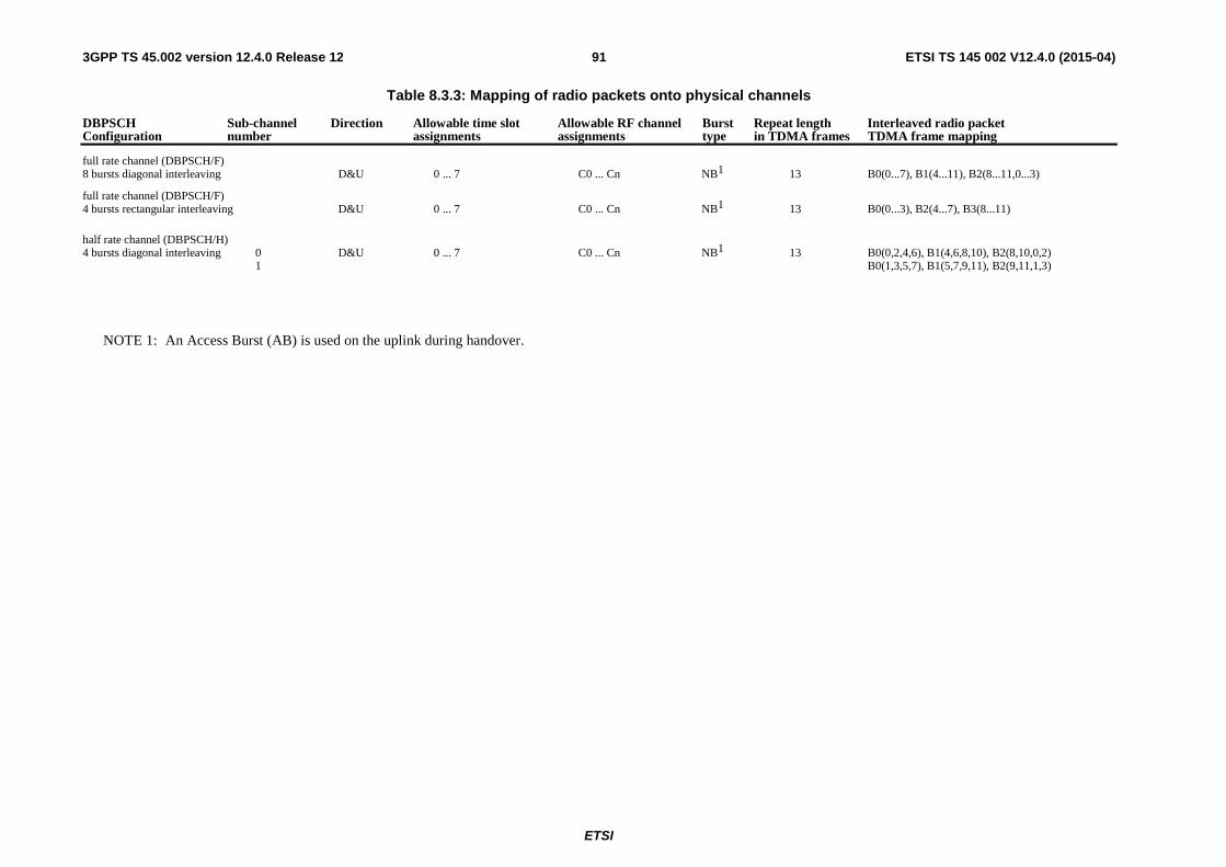
ETSI
ETSI TS 145 002 V12.4.0 (2015-04)913GPP TS 45.002 version 12.4.0 Release 12
Table 8.3.3: Mapping of radio packets onto physical channels
DBPSCH Sub-channel Direction Allowable time slot Allowable RF channel Burst Repeat length Interleaved radio packet Configuration number assignments assignments type in TDMA frames TDMA frame mapping
full rate channel (DBPSCH/F) 8 bursts diagonal interleaving D&U 0 ... 7 C0 ... Cn NB1 13 B0(0...7), B1(4...11), B2(8...11,0...3)
full rate channel (DBPSCH/F) 4 bursts rectangular interleaving D&U 0 ... 7 C0 ... Cn NB1 13 B0(0...3), B2(4...7), B3(8...11)
half rate channel (DBPSCH/H) 4 bursts diagonal interleaving 0 D&U 0 ... 7 C0 ... Cn NB1 13 B0(0,2,4,6), B1(4,6,8,10), B2(8,10,0,2) 1 B0(1,3,5,7), B1(5,7,9,11), B2(9,11,1,3)
NOTE 1: An Access Burst (AB) is used on the uplink during handover.

ETSI
ETSI TS 145 002 V12.4.0 (2015-04)923GPP TS 45.002 version 12.4.0 Release 12
8.3.4 Permitted channel combinations onto a basic physical subchannel
Four principles regulate the channel combinations with FLO:
- DCHs shall only be mapped on DBPSCH.
- On the same DBPSCH, a maximum of 8 DCHs may be allocated.
- In the same radio packet, a maximum of 4 DCHs may be processed and multiplexed together by the coding and multiplexing unit.
- With the exception of the SACCH, logical channels and transport channels shall not be mapped onto the same DBPSCH.
The following are the permitted ways in which channels can be combined onto one DBPSCH/F for one MS:
f1) DCH/F(s) + SACCH/TF
f2) DCH/F(s) + SACCH/M
f3) DCH/F(s) + SACCH/MD
f4) DCH/F(s) + SACCH/TPF + EPCCH/F
f5) DCH/F(s) + SACCH/MP + EPCCH/M
f6) DCH/F(s) + SACCH/MPD + EPCCH/MD
NOTE 1: the number of DCHs may be different in uplink and downlink.
NOTE 2: Combinations f2) and f3) are used without EPC in multislot configurations as defined in subclause 8.3.5.
NOTE 3: Combinations f5) and f6) are used with EPC in multislot configurations as defined in subclause 8.3.5.
The following definitions are used in the list of half rate combinations below.
Combination designation
Channel combination
SUB_FA DCH/H(s) + SACCH/TH
SUB_FE DCH/H(s) + SACCH/TPH + EPCCH/H
The following are the permitted ways in which channels can be combined onto one basic physical channel for two MSs on two DBPSCH/H:
g1) SUB_FA + SUB_FA
g2) SUB_FA + SUB_FE
g3) SUB_FE + SUB_FE
g4) SUB_TA + SUB_FA
g5) SUB_TA + SUB_FE
g6) SUB_TE + SUB_FA
g7) SUB_TE + SUB_FE
g8) SUB_OTA + SUB_FA
g9) SUB_OTA + SUB_FE

ETSI
ETSI TS 145 002 V12.4.0 (2015-04)933GPP TS 45.002 version 12.4.0 Release 12
g10) SUB_OTE + SUB_FA
g11) SUB_OTE + SUB_FE
8.3.5 Multislot configurations
8.3.5.1 Multislot configurations for DBPSCHs assigned
A multislot configuration consists of multiple DBPSCH/F assigned to the same MS. The multislot configuration occupies up to 8 basic physical channels, with different timeslots numbers (TN) but with the same frequency parameters (ARFCN or MA, MAIO and HSN) and the same training sequence (TSC).
Two types of multislot configurations exist, symmetric and asymmetric. The symmetric case consists of only bi-directional channels. The asymmetric case consists of both bi-directional and unidirectional downlink channels.
The occupied physical channels shall consist of the following channel combinations as defined in subclause 8.3.4.
x channels of type f2) +
y channels of type f3)
When in EPC mode (see 3GPP TS 45.008) the occupied physical channels shall consist of the following channel combinations as defined in subclause 8.3.4.
x channels of type f5) +
y channels of type f6)
where 1<= x <= 8, y = 0 for symmetric multislot configuration
1<= x <= 7, 1 <= y <= 7, x+y <= 8 for asymmetric multislot configuration
The assignment of channels to a Multislot Configuration must always consider the multislot capability of the MS, as defined by the multislot class described in annex B.
8.3.5.2 Multislot configurations for dual transfer mode in Iu mode
The multislot configuration for dual transfer mode in Iu mode is the same as in 6.4.2.7. The only difference is that FLO is used on the assigned DBPSCHs.

ETSI
ETSI TS 145 002 V12.4.0 (2015-04)943GPP TS 45.002 version 12.4.0 Release 12
Annex A (normative): Phase 2 mobiles in a Phase 1 infrastructure
A.1 Scope Phase 2 mobiles are required to behave properly in a Phase 1 networks, when downlink DTX is used in conjunction with frequency hopping.
A.2 Implementation options for TCH channels
A.2.1 C0 filling on the TCH When the TCH is active, and no associated traffic frame is scheduled for transmission, the following options apply for filling the burst on the C0 radio frequency channel.
A.2.1.1 A dummy burst with (BN61, BN62, BN86) = training sequence bits of normal bursts
A.2.1.2 A dummy burst with the "C0 filling training sequence
(BN61, BN62, BN86) = (0,1,1,1,0,0,0,1,0,1,1,1,0,0,0,1,0,1,1,1,0,0,0,1,0,1).
A.2.1.3 A dummy burst with ( BN61, BN62, BN86) mapped from the TSC bits of normal bursts according to the table
TSC from TSC set 1 for other bursts on TCH
Dummy bursts (BN61, BN62 BN86)
Corresponding TSC from TSC set 1
0 (0,1,0,0,0,0,1,1,1,0,1,1,1,0,1,0,0,1,0,0,0,0,1,1,1,0) 2 1 (0,1,0,0,1,1,1,0,1,0,1,1,0,0,0,0,0,1,0,0,1,1,1,0,1,0) 5 2 (0,0,1,0,0,1,0,1,1,1,0,0,0,0,1,0,0,0,1,0,0,1,0,1,1,1) 0 3 (0,0,0,1,1,0,1,0,1,1,1,0,0,1,0,0,0,0,0,1,1,0,1,0,1,1) 4 4 (0,1,0,0,1,1,1,0,1,0,1,1,0,0,0,0,0,1,0,0,1,1,1,0,1,0) 5 5 (0,1,0,0,0,0,1,1,1,0,1,1,1,0,1,0,0,1,0,0,0,0,1,1,1,0) 2 6 (0,1,0,0,0,1,1,1,1,0,1,1,0,1,0,0,0,1,0,0,0,1,1,1,1,0) 3 7 (0,1,0,0,1,1,1,0,1,0,1,1,0,0,0,0,0,1,0,0,1,1,1,0,1,0) 5
A.2.1.4 Partial SID information
The BTS transmits bursts containing parts of the SID frames provided by the speech encoder. The bits transmitted in such bursts on C0 carrier contain the same bits that would have been transmitted in those bursts in those if the associated traffic frames were scheduled for transmission.
A.2.2 Half burst filling For downlink DTX, when a given traffic frame is scheduled for transmission and one of its adjacent traffic frames is not scheduled for transmission, half of the "encrypted bits" belonging to the normal bursts associated with the scheduled traffic frame need to be filled. These bits are referred to as "half burst filling bits". These half bursts filling bits contain either.

ETSI
ETSI TS 145 002 V12.4.0 (2015-04)953GPP TS 45.002 version 12.4.0 Release 12
A.2.2.1 Partial SID information from any associated SID frame; or
A.2.2.2 The mixed bits of the dummy bursts (encrypted or not encrypted)
A.2.3 Dummy burst Stealing flag The dummy burst stealing flag are set to either 1 or 0.
A.2.4 Half burst Filling Stealing flag BN60 or BN87 corresponding to the "encrypted bits" of a filled half burst, defined as the "half burst filling stealing flag", are jointly set to a value of either 1 or 0.
A.2.5 Allowed combinations Table A.2.5.1 below provides the allowed combinations for phase 1 networks supporting downlink DTX in conjunction with frequency hopping.
Table A.2.5.1: Possible combinations for networks supporting downlink DT in conjunction with frequency hopping
Combination C0 filling on the TCH Half Burst filling Dummy Bursts Stealing
Flag
Half Burst Filling Stealing Flag
1 Dummy bursts with (BN61-BN86) equal to the bits of the TSC of the
other normal bursts (A 2.1.1)
not defined 0 0
2 Dummy burst with "C0 filling training sequence" (A 2.1.2)
Partial SID information
(A 2.2.1)
0 0
3 Dummy burst with (BN61, BN62....BN86) mapped from the
TSC bits of normal bursts (A 2.1.3)
Partial SID information
(A 2.2.1)
0 0
4 Partial SID information (A 2.1.4)
Partial SID information
(A 2.2.1)
1 1
5 Dummy burst with "C0 filling training sequence" (A 2.1.2)
Dummy burst mixed bits
(A 2.2.2)
1 1
6 (for DCS 1 800 only)
Partial SID information (A 2.1.4)
Partial SID information
(A 2.2.1)
0 0
A.3 Idle Channels When a channel is idle, a dummy burst may be transmitted on C0 frequency channel with any options described in subclauses A 2.1.1, A 2.1.2, A 2.1.3.

ETSI
ETSI TS 145 002 V12.4.0 (2015-04)963GPP TS 45.002 version 12.4.0 Release 12
Annex B (normative): Multislot capability
B.1 MS classes for multislot capability When an MS supports the use of multiple timeslots it shall belong to a multislot class as defined below:
Table B.1
Multislot class
Maximum number of slots Minimum number of slots Type
Rx Tx Sum Tta Ttb Tra Trb 1 1 1 2 3 2 4 2 1 2 2 1 3 3 2 3 1 1 3 2 2 3 3 2 3 1 1 4 3 1 4 3 1 3 1 1 5 2 2 4 3 1 3 1 1 6 3 2 4 3 1 3 1 1 7 3 3 4 3 1 3 1 1 8 4 1 5 3 1 2 1 1 9 3 2 5 3 1 2 1 1
10 4 2 5 3 1 2 1 1 11 4 3 5 3 1 2 1 1 12 4 4 5 2 1 2 1 1 13 3 3 NA NA a) 3 a) 2 14 4 4 NA NA a) 3 a) 2 15 5 5 NA NA a) 3 a) 2 16 6 6 NA NA a) 2 a) 2 17 7 7 NA NA a) 1 0 2 18 8 8 NA NA 0 0 0 2 19 6 2 NA 3 b) 2 c) 1 20 6 3 NA 3 b) 2 c) 1 21 6 4 NA 3 b) 2 c) 1 22 6 4 NA 2 b) 2 c) 1 23 6 6 NA 2 b) 2 c) 1 24 8 2 NA 3 b) 2 d) 1 25 8 3 NA 3 b) 2 d) 1 26 8 4 NA 3 b) 2 d) 1 27 8 4 NA 2 b) 2 d) 1 28 8 6 NA 2 b) 2 d) 1 29 8 8 NA 2 b) 2 d) 1 30 5 1 6 2 1 1 1 1 31 5 2 6 2 1 1 1 1 32 5 3 6 2 1 1 1 1 33 5 4 6 2 1 1 1 1 34 5 5 6 2 1 1 1 1 35 5 1 6 2 1 1+to 1 1 36 5 2 6 2 1 1+to 1 1 37 5 3 6 2 1 1+to 1 1 38 5 4 6 2 1 1+to 1 1 39 5 5 6 2 1 1+to 1 1 40 6 1 7 1 1 1 to 1 41 6 2 7 1 1 1 to 1 42 6 3 7 1 1 1 to 1 43 6 4 7 1 1 1 to 1 44 6 5 7 1 1 1 to 1 45 6 6 7 1 1 1 to 1
a) = 1 with frequency hopping.

ETSI
ETSI TS 145 002 V12.4.0 (2015-04)973GPP TS 45.002 version 12.4.0 Release 12
= 0 without frequency hopping.
b) = 1 with frequency hopping or change from Rx to Tx.
= 0 without frequency hopping and no change from Rx to Tx.
c) = 1 with frequency hopping or change from Tx to Rx.
= 0 without frequency hopping and no change from Tx to Rx.
d) = 1 change from Tx to Rx, or, with frequency hopping and the MS is either assigned a downlink dual carrier or DLMC configuration, or, the MS does not support fast downlink frequency switching (see 3GPP TS 24.008).
= 0 no change from Tx to Rx and either without frequency hopping or the MS is not assigned a downlink dual carrier configuration and supports fast downlink frequency switching (see 3GPP TS 24.008).
to = 31 symbol periods (this can be provided by a TA offset, i.e. a minimum TA value).
Type 1 MS are not required to transmit and receive at the same time.
Type 2 MS are required to be able to transmit and receive at the same time.
For HSCSD, only multislot classes 1 - 18 are recognised. An MS with a higher multislot class number shall indicate a suitable multislot class less than 19 for HSCSD applications (see 3GPP TS 44.018).
Rx:
Rx describes the maximum number of receive timeslots that the MS can use per TDMA frame. The MS must be able to support all integer values of receive TS from 0 to Rx (depending on the services supported by the MS). The receive TS need not be contiguous. For type 1 MS, the receive TS shall be assigned within window of size Rx, and no transmit TS shall occur between receive TS within a TDMA frame.
Tx:
Tx describes the maximum number of transmit timeslots that the MS can use per TDMA frame. The MS must be able to support all integer values of transmit TS from 0 to Tx (depending on the services supported by the MS). The transmit TS need not be contiguous. For type 1 MS, the transmit TS shall be assigned within window of size Tx, and no receive TS shall occur between transmit TS within a TDMA frame.
Sum:
Sum is the total number of uplink (u) and downlink (d) TS that can actually be used by the MS per TDMA frame. The MS must be able to support all combinations of integer values of d <= Rx and u <= Tx TS where 1 <= d + u <= Sum (depending on the services supported by the MS). Sum is not applicable to all classes.
Tta:
Tta relates to the time needed for the MS to perform adjacent cell signal level measurement and get ready to transmit.
For type 1 MS it is the minimum number of timeslots that will be allowed between the end of the previous transmit or receive TS and the next transmit TS when measurement is to be performed between. It should be noted that, in practice, the minimum time allowed may be reduced by amount of timing advance.
For type 1 MS that supports extended TA, the parameter Tta is increased by 1 if TA > 63 and there is a change from RX to TX.
For type 2 MS it is not applicable.
For circuit switched multislot configurations as defined in subclause 6.4.2.1, Tta is not applicable.
Ttb:
Ttb relates to the time needed for the MS to get ready to transmit. This minimum requirement will only be used when adjacent cell power measurements are not required by the service selected.

ETSI
ETSI TS 145 002 V12.4.0 (2015-04)983GPP TS 45.002 version 12.4.0 Release 12
For type 1 MS it is the minimum number of timeslots that will be allowed between the end of the last previous receive TS and the first next transmit TS or between the previous transmit TS and the next transmit TS when the frequency is changed in between. It should be noted that, in practice, the minimum time allowed may be reduced by the amount of the timing advance.
For type 1 MS that supports extended TA, the parameter Ttb = 2 if TA > 63 and there is a change from RX to TX.
For type 2 MS it is the minimum number of timeslots that will be allowed between the end of the last transmit burst in a TDMA frame and the first transmit burst in the next TDMA frame.
Tra:
Tra relates to the time needed for the MS to perform adjacent cell signal level measurement and get ready to
receive.
For type 1 MS it is the minimum number of timeslots that will be allowed between the previous transmit or receive TS and the next receive TS when measurement is to be performed between.
For type 2 MS it is the minimum number of timeslots that will be allowed between the end of the last receive burst in a TDMA frame and the first receive burst in the next TDMA frame.
An MS, except for multislot class 30 – 45, shall be able to decode SCH from a neighbour cell, independent of its relative timing, using an idle frame in combination with Tra from the preceding frame.
Trb:
Trb relates to the time needed for the MS to get ready to receive. This minimum requirement will only be used
when adjacent cell power measurements are not required by the service selected.
For type 1 MS it is the minimum number of timeslots that will be allowed between the previous transmit TS and the next receive TS or between the previous receive TS and the next receive TS when the frequency is changed in between.
For type 2 MS it is the minimum number of timeslots that will be allowed between the end of the last receive burst in a TDMA frame and the first receive burst in the next TDMA frame.
B.2 Constraints imposed by the service selected The service selected will impose certain restrictions on the allowed combinations of transmit and receive timeslots. Such restrictions are not imposed by this annex but should be derived from the description of the services. For example, in the case of circuit switched data the TS numbers used in the uplink will be a subset of those used in the downlink.
The service selected will determine whether or not adjacent cell power measurements are required and therefore whether Tra or Trb is allowed for.
B.3 Network requirements for supporting MS multislot classes
The multislot class of the MS will limit the combinations and configurations allowed when supporting multislot communication.
GSM 400 network may support extended cell coverage utilising timing advance values greater than 63. This has an effect that the time for MS to change from RX to TX will be very short for distant MS. It is necessary for the network to decide whether requested or current multislot configuration can be supported by distant MS. If actual TA is great enough it may be necessary for network to downgrade requested resources or it may be necessary for network to downgrade current resources.

ETSI
ETSI TS 145 002 V12.4.0 (2015-04)993GPP TS 45.002 version 12.4.0 Release 12
It is necessary for the network to decide whether the MS needs to perform adjacent cell power measurement for the type of multislot communication intended and whether the service imposes any other constraints before the full restrictions on TS assignments can be resolved. This is best shown by example:
For a multislot class 5 MS in circuit switched configuration (adjacent cell power measurements required) five basic configurations of channels are possible which can occur in six different positions in the TDMA frame. The service itself may determine that asymmetry must be downlink biased, in which case the last two solutions would not be allowed.
Rx
Tx
Rx=2
Tt=1 Tx=2
Rx
Tx
Rx=2
Tt=1
Tx<2
Rx
Tx
Rx<2 Tt>1 Tx=2
These five combinations can be repeated at the six other positions that can be fitted
within the same TDMA frame
Rx
Tx
Rx=2 Tt>1
Tx<2
Tra>3
Tra=3 Tra=3
Tra=3
Rx
Tx
Rx<2 Tx=2 Tra>3
Tt=1
All possible timeslots used Downlink biased assymetry
Alternative downlink biased assymetry Uplink biased assymetry(not prohibited by multislot class)
Alternative uplink biased assymetry(not prohibited by multislot class)
Figure B.1
For a multislot class 13 MS when adjacent cell power measurements are not required and the service does not constrain the transmit and receive timeslots to use the same timeslot number. Many configurations of channels are possible so long as the 5 constraints of the MS are catered for. [Currently services envisaged only allow for the last example here.]

ETSI
ETSI TS 145 002 V12.4.0 (2015-04)1003GPP TS 45.002 version 12.4.0 Release 12
Rx
Tx
Rx=3
Tx=3
Rx
Tx
Trb=1 Tt
=1
There is no requirement for relative timingof Tx timeslots in relation to Rx timeslots
Many configurations are possible
Rx
Tx
Rx
Tx
Rx
Tx
This configuration could be used forHSCSD or GPRS
Figure B.2
B.4 Multislot capabilities for dual carrier mobile stations For mobile stations supporting downlink dual carrier, the multislot capability applicable to dual carrier operation is dependent on the (DTM) EGPRS (high) multislot class (see subclause B.1), on the Multislot Capability Reduction for Downlink Dual Carrier field (see 3GPP TS 24.008) and, if provided, on the Alternative EFTA multislot class field (see subclause B.5) and on the EFTA Multislot Capability Reduction for Downlink Dual Carrier field (see 3GPP TS 24.008) as signalled by the mobile station as defined in Table B.2. Only mobile stations of multislot classes listed in Table B.2 can support downlink dual carrier.

ETSI
ETSI TS 145 002 V12.4.0 (2015-04)1013GPP TS 45.002 version 12.4.0 Release 12
Table B.2
Signalled multislot
class
Alternative EFTA
multislot class
Maximum Number of downlink timeslots
Equivalent multislot class when
"Multislot Capability Reduction for Downlink Dual
Carrier" IE indicates reduction of:
Note
0 or 1 timeslots
2 or more timeslots
8 - 10 30 8 - 10 - 10 31 10 - 11 - 10 32 11 - 12 - 10 33 12 - 30 - 10 - - - 31 - 10 - - - 32 - 10 - - - 33 - 10 - - - 34 - 10 - - - 35 - 10 - - - 36 - 10 - - - 37 - 10 - - - 38 - 10 - - - 39 - 10 - - - 40 - 12 - - - 41 - 12 - - - 42 - 12 - - - 43 - 12 - - - 44 - 12 - - - 45 - 12 - - -
30-39 None 10 - - 0 40-45 None 12 - - 0 30-39 1 12 - - 0 30-45 2 14 - - 0 30-45 3 16 - - 0
Note 0 These configurations can only be used for assignment to an MS supporting Enhanced Flexible Timeslot
Assignment (see 3GPP TS 24.008).
The values of Rx", Tx" and Sum" and Rx_Sum apply for downlink dual carrier configurations.
If the MS has not indicated support for Enhanced Flexible Timeslot Assignment (see 3GPP TS 24.008), then Rx", Tx" and Sum" correspond to Rx, Tx and Sum for the Equivalent multislot class (see Table B.2) and the values of Tta, Ttb, Tra and Trb of the equivalent multislot class shall then apply as indicated by Table B.2; if no equivalent multislot class is specified then Rx", Tx" and Sum" correspond to Rx, Tx and Sum respectively for the signalled multislot class and the switching times Tta, Ttb, Tra and Trb of the signalled multislot class shall apply.
If the MS has indicated support for Enhanced Flexible Timeslot Assignment (see 3GPP TS 24.008), then Rx", Tx" and Sum", Tta, Ttb, Tra and Trb all correspond to Rx, Tx, Sum, Tta, Ttb, Tra and Trb respectively as defined in subclause B.5.
Possible switching and measurement timings for downlink dual carrier MSs that have a higher equivalent multislot class compared to the signalled multislot class are illustrated in Annex E.
Rx_Sum is given by the Maximum Number of downlink timeslots as specified in Table B.2 minus the number of timeslots indicated in the Multislot Capability Reduction for Downlink Dual Carrier field (see 3GPP TS 24.008).If the resultant Rx_Sum is lower than the value given by the field Sum in Table B.1 for the signalled multislot class (or the equivalent multislot class if different from signalled multislot class) (see Table B.2), then Rx_Sum shall be assumed to be equal to Sum from Table B.1 for that multislot class.
If the MS has indicated support for Enhanced Flexible Timeslot Assignment (see 3GPP TS 24.008), then Rx_Sum_EFTA is given by the Maximum Number of downlink timeslots as specified in Table B.2 minus the number of timeslots indicated in the EFTA Multislot Capability Reduction for Downlink Dual Carrier field (see 3GPP TS 24.008). If the resultant Rx_Sum_EFTA is lower than or equal to the value given by the field Rx in Table B.1 either for the indicated alternative EFTA multislot class, or for the signalled (DTM) EGPRS (high) multislot class if no alternative

ETSI
ETSI TS 145 002 V12.4.0 (2015-04)1023GPP TS 45.002 version 12.4.0 Release 12
EFTA multislot class is indicated, then Rx_Sum_EFTA shall be assumed to be equal to Rx + 1 from Table B.1 for that multislot class.
NOTE: The Equivalent multislot class and corresponding switching times (where different from the signalled multislot class) apply only for dual carrier assignments. For assignments which use only one carrier, the signalled multislot class (and corresponding switching times as specified in Table B.1) apply.
Rx":
Rx" describes the maximum number of receive timeslots that the MS can use per radio frequency channel per TDMA frame. The MS must be able to support all integer values of receive TS from 0 to Rx" (depending on the services supported by the MS) on each radio frequency channel. The receive TS need not be contiguous. For type 1 MS, all the receive TS (on both radio frequency channels) shall be allocated within a window of size Rx", and no transmit TS shall occur between receive TS within a TDMA frame.
Tx":
Tx" describes the maximum number of transmit timeslots that the MS can use per TDMA frame.The MS must be able to support all integer values of transmit TS from 0 to Tx" (depending on the services supported by the MS). The transmit TS need not be contiguous. For type 1 MS, the transmit TS shall be allocated within window of size Tx", and no receive TS shall occur between transmit TS within a TDMA frame.
NOTE: All transmit timeslots are allocated on the same uplink radio frequency channel within a radio block period.
Sum":
Sum" is the total number of uplink TS and downlink TS (on either radio frequency channel) that can be used by the MS per TDMA frame. The MS must be able to support all combinations of integer values of 1 <= d1 <= Rx", 1 <= d2 <= Rx" and u <= Tx" TS where 1 <= d1 + u <= Sum" and 1 <= d2 + u <= Sum" (depending on the services supported by the MS).
Rx_Sum:
Rx_Sum is the total number of downlink TS (on both radio frequency channels) that can be received by the MS per TDMA frame when not using Enhanced Flexible Timeslot Assignment, EFTA. The MS must be able to support all combinations of integer values of d1 and d2 where 1 <= d1 +d2 <= Rx_Sum (depending on the services supported by the MS).
Rx_Sum_EFTA:
Rx_Sum_EFTA is the total number of downlink TS (on both radio frequency channels) that can be received by the MS per TDMA frame when using Enhanced Flexible Timeslot Assignment, EFTA. The MS must be able to support all combinations of integer values of d1 and d2 where 1 <= d1 +d2 <= Rx_Sum_EFTA (depending on the services supported by the MS).
NOTE: Both d1 and d2 need to be different from 0 in order for Sum", Rx_Sum and Rx_Sum_EFTA to apply.
B.5 Multislot capabilities when EFTA is used For mobile stations supporting Enhanced Flexible Timeslot Assignment, EFTA, the multislot capability parameters applicable to EFTA operation in a single carrier configuration are dependent on the signalled (DTM) EGPRS high multislot class (see subclause B.1) and on the Alternative EFTA multislot class (see Table B.3) indicated by the mobile station in the MS Radio Access Capability IE (see 3GPP TS 24.008).
The multislot capability parameters Rx and Tx shall be derived as follows:
- If no Alternative EFTA multislot class is given then Rx and Tx of the signalled multislot class shall apply.
- If an Alternative EFTA multislot class is given then Tx of the signalled multislot class shall apply whereas Rx of the Alternative EFTA multislot class shall apply.
The multislot capability parameters Sum, Tta, Ttb, Tra and Trb shall be derived as follows:

ETSI
ETSI TS 145 002 V12.4.0 (2015-04)1033GPP TS 45.002 version 12.4.0 Release 12
- If an Alternative EFTA multislot class is given and the mobile station is assigned a multislot configuration comprising a number of downlink timeslots higher than the Rx value corresponding to the signalled multislot class and the mobile station is not transmitting in a given radio block period, then Trb and Tra as given in Table B.3 shall apply for the considered radio block period. Sum, Tta and Ttb are not applicable during the considered radio block period.
- In all other cases, Sum, Tta, Ttb, Tra and Trb of the signalled multislot class shall apply.
Only mobile stations with (DTM) EGPRS high multislot classes 30-45 can support EFTA.
Table B.3
Alternative EFTA multislot class Rx Tra Trb (Note 2) Alternative EFTA multislot class 1 6 1 c) Alternative EFTA multislot class 2 7 1 c) Alternative EFTA multislot class 3 8 1 (Note 1) d)
NOTE 1: Tra not applicable for multislot configurations with d=8 timeslots. NOTE 2: c) and d) are as defined in subclause B.1.
Whether normal measurements (see 3GPP TS 45.008) and/or normal BSIC decoding (see 3GPP TS 45.008) are possible will be dependent on the allocation or on the use of a second receiver for this purpose.
The multislot capability parameters applicable to EFTA operation in a downlink dual carrier configuration are in addition dependent on the EFTA Multislot Capability Reduction for Downlink Dual Carrier field (see subclause B.4).
B.6 Multislot capabilities for Downlink Multi Carrier mobile stations
For mobile stations supporting DLMC configurations (see 3GPP TS 44.060), the multislot capability applicable to DLMC operation is dependent on the EGPRS (high) multislot class (see subclause B.1), on the Maximum number of downlink timeslots field (see 3GPP TS 24.008) and, if provided, on the Alternative EFTA multislot class field (see subclause B.5) as signalled by the mobile station as defined in Table B.2. Only mobile stations of multislot classes listed in Table B.2 can support DLMC. The equivalent multislot class does not apply for a mobile station supporting DLMC.
The values of Rx" and Tx" as defined in subclause B.4 apply for DLMC configurations.
The values of Sum"" and Rx_Sum"" apply for downlink DLMC configurations as defined below.
If the MS has not indicated support for Enhanced Flexible Timeslot Assignment (see 3GPP TS 24.008), then Rx", Tx" and Sum"" correspond to Rx, Tx and Sum for the signalled multislot class and the switching times Tta, Ttb, Tra and Trb of the signalled multislot class shall apply.
If the MS has indicated support for Enhanced Flexible Timeslot Assignment (see 3GPP TS 24.008), then Rx", Tx" and Sum"", Tta, Ttb, Tra and Trb all correspond to Rx, Tx, Sum, Tta, Ttb, Tra and Trb respectively as defined in subclause B.5.Rx_Sum" is given by the Maximum Number of downlink timeslots indicated by the MS (see 3GPP TS 24.008) and applies irrespective of whether EFTA operation is used or not.
Sum"":
Sum"" is the total number of uplink TS and downlink TS (on either radio frequency channel) that can be used by the MS per TDMA frame. The MS must be able to support all combinations of integer values of 1 <= dX <= Rx", and u <= Tx" TS where 1 <= dX + u <= Sum" (depending on the services supported by the MS). dX can be either of [d1, d2 …., d15, d16] depending on the maximum number of carriers supported by the MS, see 3GPP TS 24.008.
Rx_Sum":
Rx_Sum" is the total number of downlink TS (assigned across, at most, the maximum number of carriers, ����, supported by the mobile, see 3GPP TS24.008), that can be received by the MS per TDMA frame. The MS must be able to support all combinations of integer values of dX where 1 <= ∑ ��
����
��� <= Rx_Sum" (depending on
the services supported by the MS).

ETSI
ETSI TS 145 002 V12.4.0 (2015-04)1043GPP TS 45.002 version 12.4.0 Release 12
Annex C (informative): CTSBCH Timeslot shifting example With the following parameters :
- TNI = 4
- TNSCN = 9
TNSCO = 1 i.e. (TNS1 = TNS9,1 = (0, 3, 7, 6, 5, 2, 4, 1) and TNS2 = TNS9,0 = (0, 1, 4, 5, 7, 3, 6, 2)
- x0 = 2
- x1 = 3
- x2 = 5
- x3 = 4
and the timeslot shifting algorithm defined in section 6.3.3, the CTSBCH TN used in set 0 of the shifting sequence is :
(FN div 52) mod 51 0 1 2 3 4 5 6 7 8 9 10 11 12 13 14 15 16 17 TNS used 1 1 1 1 1 1 1 1 2 2 2 2 1 1 1 1 1 2 CTSBCH TN 4 1 0 3 7 6 5 2 0 1 4 5 2 4 1 0 3 6 (FN div 52) mod 51 18 19 20 21 22 23 24 25 26 27 28 29 30 31 32 33 34 35 TNS used 2 2 1 1 2 2 2 2 2 2 2 2 1 1 1 1 1 1 CTSBCH TN 2 0 3 7 3 6 2 0 1 4 5 7 6 5 2 4 1 0 (FN div 52) mod 51 36 37 38 39 40 41 42 43 44 45 46 47 48 49 50 TNS used 2 2 2 2 2 1 1 1 2 2 2 2 1 1 1 CTSBCH TN 1 4 5 7 3 7 6 5 7 3 6 2 4 1 0
For the next sets, same mechanism applies, with
set 1 beginning with CTSBCH TN = 3
set 2 beginning with CTSBCH TN = 5
set 3 beginning with CTSBCH TN = 1
set 4 beginning with CTSBCH TN = 7
set 5 beginning with CTSBCH TN = 2
set 6 beginning with CTSBCH TN = 0
set 7 beginning with CTSBCH TN = 6

ETSI
ETSI TS 145 002 V12.4.0 (2015-04)1053GPP TS 45.002 version 12.4.0 Release 12
Annex D (informative): COMPACT multiframe structure examples In the figures, the 52-multiframe number (MFN) shall have a range of 0 to 3 and can be calculated from the TDMA frame number (FN) as follows:
MFN = (FN div 52) mod 4
For COMPACT, timeslot mapping and rotation of the control channels is used such that control channels belonging to a serving time group are rotated over odd timeslot numbers as follows: 7, 5, 3, 1, 7, 5, … . The rotation occurs between frame numbers (FN) mod 52 = 3 and 4. The timeslot mapping and rotation of the control channels in this manner allows the mobile station to measure the received signal level from surrounding cells in its normal measurement window. Since the rotation repeats itself every 208 frames, the 52-multiframe number (MFN) allows the mobile station to determine its location in the time group rotation during selection and re-selection.
The following relates to Figures D.1 through D.7:
i) B(x)y = time group y uses CPBCCH in block x;
ii) C(x)y = time group y uses CPCCCH in block x;
iii) PTCCH = PTCCH as norma;
iv) CFCCHy = time group y uses CFCCH;
v) CSCHy = time group y uses CSCH;
vi) IDLE = idle burst;
vii) Xy = block designated as idle for time group y;
viii) Empty = used for traffic as normal.

ETSI
ETSI TS 145 002 V12.4.0 (2015-04)1063GPP TS 45.002 version 12.4.0 Release 12
Frames 0-51 of a 208-multiframe Frames 0-51 of a 208-multiframe Frames 0-51 of a 208-multiframe Frames 0-51 of a 208-multiframe MFN = 0 MFN = 0 MFN = 0 MFN = 0 TG = 0 TG = 1 TG = 2 TG = 3
TS FN
0 1 2 3 4 5 6 7 TS FN
0 1 2 3 4 5 6 7 TS FN
0 1 2 3 4 5 6 7 TS FN
0 1 2 3 4 5 6 7
0 B(0)0 X1 X2 X3 0 X0 B(0)1 X2 X3 0 X0 X1 B(0)2 X3 0 X0 X1 X2 B(0)3 1 B(0)0 X1 X2 X3 1 X0 B(0)1 X2 X3 1 X0 X1 B(0)2 X3 1 X0 X1 X2 B(0)3 2 B(0)0 X1 X2 X3 2 X0 B(0)1 X2 X3 2 X0 X1 B(0)2 X3 2 X0 X1 X2 B(0)3 3 B(0)0 X1 X2 X3 3 X0 B(0)1 X2 X3 3 X0 X1 B(0)2 X3 3 X0 X1 X2 B(0)3 4 4 4 4 5 5 5 5 6 6 6 6 7 7 7 7 8 8 8 8 9 9 9 9
10 10 10 10 11 11 11 11 12 PTCCH 12 PTCCH 12 PTCCH 12 PTCCH 13 X1 X2 X3 C(3)0 13 C(3)1 X2 X3 X0 13 X1 C(3)2 X3 X0 13 X1 X2 C(3)3 X0 14 X1 X2 X3 C(3)0 14 C(3)1 X2 X3 X0 14 X1 C(3)2 X3 X0 14 X1 X2 C(3)3 X0 15 X1 X2 X3 C(3)0 15 C(3)1 X2 X3 X0 15 X1 C(3)2 X3 X0 15 X1 X2 C(3)3 X0 16 X1 X2 X3 C(3)0 16 C(3)1 X2 X3 X0 16 X1 C(3)2 X3 X0 16 X1 X2 C(3)3 X0 17 17 17 17 18 18 18 18 19 19 19 19 20 20 20 20 21 21 21 21 22 22 22 22 23 23 23 23 24 24 24 24 25 IDLE CFCCH0 25 ID CFCCH1 IDLE 25 IDLE CFCCH2 IDLE 25 IDLE CFCCH3 IDLE 26 X1 X2 X3 C(6)0 26 C(6)1 X2 X3 X0 26 X1 C(6)2 X3 X0 26 X1 X2 C(6)3 X0 27 X1 X2 X3 C(6)0 27 C(6)1 X2 X3 X0 27 X1 C(6)2 X3 X0 27 X1 X2 C(6)3 X0 28 X1 X2 X3 C(6)0 28 C(6)1 X2 X3 X0 28 X1 C(6)2 X3 X0 28 X1 X2 C(6)3 X0 29 X1 X2 X3 C(6)0 29 C(6)1 X2 X3 X0 29 X1 C(6)2 X3 X0 29 X1 X2 C(6)3 X0 30 30 30 30 31 31 31 31 32 32 32 32 33 33 33 33 34 34 34 34 35 35 35 35 36 36 36 36 37 37 37 37 38 PTCCH 38 PTCCH 38 PTCCH 38 PTCCH 39 X1 X2 X3 C(9)0 39 C(9)1 X2 X3 X0 39 X1 C(9)2 X3 X0 39 X1 X2 C(9)3 X0 40 X1 X2 X3 C(9)0 40 C(9)1 X2 X3 X0 40 X1 C(9)2 X3 X0 40 X1 X2 C(9)3 X0 41 X1 X2 X3 C(9)0 41 C(9)1 X2 X3 X0 41 X1 C(9)2 X3 X0 41 X1 X2 C(9)3 X0 42 X1 X2 X3 C(9)0 42 C(9)1 X2 X3 X0 42 X1 C(9)2 X3 X0 42 X1 X2 C(9)3 X0 43 43 43 43 44 44 44 44 45 45 45 45 46 46 46 46 47 47 47 47 48 48 48 48 49 49 49 49 50 50 50 50 51 IDLE CSCH0 51 ID CSCH1 IDLE 51 IDLE CSCH2 IDLE 51 IDLE CSCH3 IDLE
Figure D.1: COMPACT downlink 52-multiframe structure using 4 time groups for nominal cells (based on an assignment of 1 CPBCCH and 3 CPCCCHs with NIB_CCCH_0 = NIB_CCCH_1 = NIB_CCCH_2 =
NIB_CCCH_3 = 4). NIB_CCCH is not broadcast for serving cell time group
NOTE: For uplink 52-multiframe structure (based on an assignment of 16 prioritized CPRACHs, see subclause 6.3.2.2.3a), replace B( ) by R( ) where R( ) denotes CPRACH, move down one block, and rotate according to subclause 6.3.2.1. Replace C( ) by R( ) and move down one block. CPRACH in general can be mapped as PRACH in table 6 of clause 7.

ETSI
ETSI TS 145 002 V12.4.0 (2015-04)1073GPP TS 45.002 version 12.4.0 Release 12
Frames 0-51 of a 208-multiframe Frames 0-51 of a 208-multiframe Frames 0-51 of a 208-multiframe MFN = 0 MFN = 0 MFN = 0 TG = 0 TG = 1 TG = 2
TS FN
0 1 2 3 4 5 6 7 TS FN
0 1 2 3 4 5 6 7 TS FN
0 1 2 3 4 5 6 7
0 B(0)0 X1 X2 0 X0 B(0)1 X2 0 X0 X1 B(0)2 1 B(0)0 X1 X2 1 X0 B(0)1 X2 1 X0 X1 B(0)2 2 B(0)0 X1 X2 2 X0 B(0)1 X2 2 X0 X1 B(0)2 3 B(0)0 X1 X2 3 X0 B(0)1 X2 3 X0 X1 B(0)2 4 4 4 5 5 5 6 6 6 7 7 7 8 8 8 9 9 9
10 10 10 11 11 11 12 PTCCH 12 PTCCH 12 PTCCH 13 X1 X2 C(3)0 13 C(3)1 X2 X0 13 X1 C(3)2 X0 14 X1 X2 C(3)0 14 C(3)1 X2 X0 14 X1 C(3)2 X0 15 X1 X2 C(3)0 15 C(3)1 X2 X0 15 X1 C(3)2 X0 16 X1 X2 C(3)0 16 C(3)1 X2 X0 16 X1 C(3)2 X0 17 17 17 18 18 18 19 19 19 20 20 20 21 21 21 22 22 22 23 23 23 24 24 24 25 IDLE CFCCH0 25 ID CFCCH1 IDLE 25 IDLE CFCCH2 IDLE 26 X1 X2 C(6)0 26 C(6)1 X2 X0 26 X1 C(6)2 X0 27 X1 X2 C(6)0 27 C(6)1 X2 X0 27 X1 C(6)2 X0 28 X1 X2 C(6)0 28 C(6)1 X2 X0 28 X1 C(6)2 X0 29 X1 X2 C(6)0 29 C(6)1 X2 X0 29 X1 C(6)2 X0 30 30 30 31 31 31 32 32 32 33 33 33 34 34 34 35 35 35 36 36 36 37 37 37 38 PTCCH 38 PTCCH 38 PTCCH 39 X1 X2 C(9)0 39 C(9)1 X2 X0 39 X1 C(9)2 X0 40 X1 X2 C(9)0 40 C(9)1 X2 X0 40 X1 C(9)2 X0 41 X1 X2 C(9)0 41 C(9)1 X2 X0 41 X1 C(9)2 X0 42 X1 X2 C(9)0 42 C(9)1 X2 X0 42 X1 C(9)2 X0 43 43 43 44 44 44 45 45 45 46 46 46 47 47 47 48 48 48 49 49 49 50 50 50 51 IDLE CSCH0 51 ID CSCH1 IDLE 51 IDLE CSCH2 IDLE
Figure D.2: COMPACT downlink 52-multiframe structure using 3 time groups for nominal cells (based on an assignment of 1 CPBCCH and 3 CPCCCHs with NIB_CCCH_0 = NIB_CCCH_1 = NIB_CCCH_2 =
4, NIB_CCCH_3 = 0). NIB_CCCHis not broadcast for serving cell time group
NOTE: For uplink 52-multiframe structure (based on an assignment of 16 prioritized CPRACHs, see subclause 6.3.2.2.3a), replace B( ) by R( ) where R( ) denotes CPRACH, move down one block, and rotate according to subclause 6.3.2.1. Replace C( ) by R( ) and move down one block. CPRACH in general can be mapped as PRACH in table 6 of clause 7.

ETSI
ETSI TS 145 002 V12.4.0 (2015-04)1083GPP TS 45.002 version 12.4.0 Release 12
Frames 0-51 of a 208-multiframe Frames 0-51 of a 208-multiframe Frames 0-51 of a 208-multiframe Frames 0-51 of a 208-multiframe MFN = 0 MFN = 0 MFN = 0 MFN = 0 TG = 0 TG = 1 TG = 2 TG = 3
TS FN
0 1 2 3 4 5 6 7 TS FN
0 1 2 3 4 5 6 7 TS FN
0 1 2 3 4 5 6 7 TS FN
0 1 2 3 4 5 6 7
0 X3 B(0)0 X1 X1 X2 X2 X3 X3 0 X0 X0 X0 B(0)1 X2 X2 X3 X3 0 X0 X0 X1 X1 X1 B(0)2 X3 X3 0 X0 X0 X1 X1 X2 X2 X2 B(0)3 1 X3 B(0)0 X1 X1 X2 X2 X3 X3 1 X0 X0 X0 B(0)1 X2 X2 X3 X3 1 X0 X0 X1 X1 X1 B(0)2 X3 X3 1 X0 X0 X1 X1 X2 X2 X2 B(0)3 2 X3 B(0)0 X1 X1 X2 X2 X3 X3 2 X0 X0 X0 B(0)1 X2 X2 X3 X3 2 X0 X0 X1 X1 X1 B(0)2 X3 X3 2 X0 X0 X1 X1 X2 X2 X2 B(0)3 3 X3 B(0)0 X1 X1 X2 X2 X3 X3 3 X0 X0 X0 B(0)1 X2 X2 X3 X3 3 X0 X0 X1 X1 X1 B(0)2 X3 X3 3 X0 X0 X1 X1 X2 X2 X2 B(0)3 4 4 4 4 5 5 5 5 6 6 6 6 7 7 7 7 8 8 8 8 9 9 9 9
10 10 10 10 11 11 11 11 12 PTCCH 12 PTCCH 12 PTCCH 12 PTCCH 13 X1 X1 X2 X2 X3 X3 X3 C(3)0 13 X0 C(3)1 X2 X2 X3 X3 X0 X0 13 X1 X1 X1 C(3)2 X3 X3 X0 X0 13 X1 X1 X2 X2 X2 C(3)3 X0 X0 14 X1 X1 X2 X2 X3 X3 X3 C(3)0 14 X0 C(3)1 X2 X2 X3 X3 X0 X0 14 X1 X1 X1 C(3)2 X3 X3 X0 X0 14 X1 X1 X2 X2 X2 C(3)3 X0 X0 15 X1 X1 X2 X2 X3 X3 X3 C(3)0 15 X0 C(3)1 X2 X2 X3 X3 X0 X0 15 X1 X1 X1 C(3)2 X3 X3 X0 X0 15 X1 X1 X2 X2 X2 C(3)3 X0 X0 16 X1 X1 X2 X2 X3 X3 X3 C(3)0 16 X0 C(3)1 X2 X2 X3 X3 X0 X0 16 X1 X1 X1 C(3)2 X3 X3 X0 X0 16 X1 X1 X2 X2 X2 C(3)3 X0 X0 17 17 17 17 18 18 18 18 19 19 19 19 20 20 20 20 21 21 21 21 22 22 22 22 23 23 23 23 24 24 24 24 25 IDLE CFCCH0 25 ID CFCCH1 IDLE 25 IDLE CFCCH2 IDLE 25 IDLE CFCCH3 IDLE 26 X1 X1 X2 X2 X3 X3 X3 C(6)0 26 X0 C(6)1 X2 X2 X3 X3 X0 X0 26 X1 X1 X1 C(6)2 X3 X3 X0 X0 26 X1 X1 X2 X2 X2 C(6)3 X0 X0 27 X1 X1 X2 X2 X3 X3 X3 C(6)0 27 X0 C(6)1 X2 X2 X3 X3 X0 X0 27 X1 X1 X1 C(6)2 X3 X3 X0 X0 27 X1 X1 X2 X2 X2 C(6)3 X0 X0 28 X1 X1 X2 X2 X3 X3 X3 C(6)0 28 X0 C(6)1 X2 X2 X3 X3 X0 X0 28 X1 X1 X1 C(6)2 X3 X3 X0 X0 28 X1 X1 X2 X2 X2 C(6)3 X0 X0 29 X1 X1 X2 X2 X3 X3 X3 C(6)0 29 X0 C(6)1 X2 X2 X3 X3 X0 X0 29 X1 X1 X1 C(6)2 X3 X3 X0 X0 29 X1 X1 X2 X2 X2 C(6)3 X0 X0 30 30 30 30 31 31 31 31 32 32 32 32 33 33 33 33 34 34 34 34 35 35 35 35 36 36 36 36 37 37 37 37 38 PTCCH 38 PTCCH 38 PTCCH 38 PTCCH 39 X1 X1 X2 X2 X3 X3 X3 C(9)0 39 X0 C(9)1 X2 X2 X3 X3 X0 X0 39 X1 X1 X1 C(9)2 X3 X3 X0 X0 39 X1 X1 X2 X2 X2 C(9)3 X0 X0 40 X1 X1 X2 X2 X3 X3 X3 C(9)0 40 X0 C(9)1 X2 X2 X3 X3 X0 X0 40 X1 X1 X1 C(9)2 X3 X3 X0 X0 40 X1 X1 X2 X2 X2 C(9)3 X0 X0 41 X1 X1 X2 X2 X3 X3 X3 C(9)0 41 X0 C(9)1 X2 X2 X3 X3 X0 X0 41 X1 X1 X1 C(9)2 X3 X3 X0 X0 41 X1 X1 X2 X2 X2 C(9)3 X0 X0 42 X1 X1 X2 X2 X3 X3 X3 C(9)0 42 X0 C(9)1 X2 X2 X3 X3 X0 X0 42 X1 X1 X1 C(9)2 X3 X3 X0 X0 42 X1 X1 X2 X2 X2 C(9)3 X0 X0 43 43 43 43 44 44 44 44 45 45 45 45 46 46 46 46 47 47 47 47 48 48 48 48 49 49 49 49 50 50 50 50 51 IDLE CSCH0 51 ID CSCH1 IDLE 51 IDLE CSCH2 IDLE 51 IDLE CSCH3 IDLE
Figure D.3: COMPACT downlink 52-multiframe structure using 4 time groups for large cells (based on an assignment of 1 CPBCCH and 3 CPCCCHs with NIB_CCCH_0 = NIB_CCCH_1 = NIB_CCCH_2 =
NIB_CCCH_3 = 4). NIB_CCCH is not broadcast for serving cell time group
NOTE: For uplink 52-multiframe structure (based on an assignment of 16 prioritized CPRACHs, see subclause 6.3.2.2.3a), replace B( ) by R( ) where R( ) denotes CPRACH, move down one block, and rotate according to subclause 6.3.2.1. Replace C( ) by R( ) and move down one block. CPRACH in general can be mapped as PRACH in table 6 of clause 7.
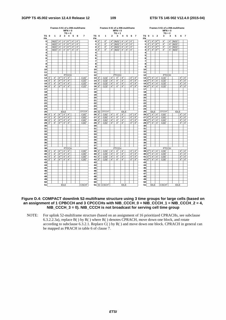
ETSI
ETSI TS 145 002 V12.4.0 (2015-04)1093GPP TS 45.002 version 12.4.0 Release 12
Frames 0-51 of a 208-multiframe Frames 0-51 of a 208-multiframe Frames 0-51 of a 208-multiframe MFN = 0 MFN = 0 MFN = 0 TG = 0 TG = 1 TG = 2
TS FN
0 1 2 3 4 5 6 7 TS FN
0 1 2 3 4 5 6 7 TS FN
0 1 2 3 4 5 6 7
0 B(0)0 X1 X1 X12 X2 X2 0 X0 X0 X0 B(0)1 X2 X2 X2 0 X0 X0 X01 X1 X1 B(0)2 1 B(0)0 X1 X1 X12 X2 X2 1 X0 X0 X0 B(0)1 X2 X2 X2 1 X0 X0 X01 X1 X1 B(0)2 2 B(0)0 X1 X1 X12 X2 X2 2 X0 X0 X0 B(0)1 X2 X2 X2 2 X0 X0 X01 X1 X1 B(0)2 3 B(0)0 X1 X1 X12 X2 X2 3 X0 X0 X0 B(0)1 X2 X2 X2 3 X0 X0 X01 X1 X1 B(0)2 4 4 4 5 5 5 6 6 6 7 7 7 8 8 8 9 9 9
10 10 10 11 11 11 12 PTCCH 12 PTCCH 12 PTCCH 13 X1 X1 X12 X2 X2 C(3)0 13 X0 C(3)1 X2 X2 X2 X0 X0 13 X01 X1 X1 C(3)2 X0 X0 14 X1 X1 X12 X2 X2 C(3)0 14 X0 C(3)1 X2 X2 X2 X0 X0 14 X01 X1 X1 C(3)2 X0 X0 15 X1 X1 X12 X2 X2 C(3)0 15 X0 C(3)1 X2 X2 X2 X0 X0 15 X01 X1 X1 C(3)2 X0 X0 16 X1 X1 X12 X2 X2 C(3)0 16 X0 C(3)1 X2 X2 X2 X0 X0 16 X01 X1 X1 C(3)2 X0 X0 17 17 17 18 18 18 19 19 19 20 20 20 21 21 21 22 22 22 23 23 23 24 24 24 25 IDLE CFCCH0 25 ID CFCCH1 IDLE 25 IDLE CFCCH2 IDLE 26 X1 X1 X12 X2 X2 C(6)0 26 X0 C(6)1 X2 X2 X2 X0 X0 26 X01 X1 X1 C(6)2 X0 X0 27 X1 X1 X12 X2 X2 C(6)0 27 X0 C(6)1 X2 X2 X2 X0 X0 27 X01 X1 X1 C(6)2 X0 X0 28 X1 X1 X12 X2 X2 C(6)0 28 X0 C(6)1 X2 X2 X2 X0 X0 28 X01 X1 X1 C(6)2 X0 X0 29 X1 X1 X12 X2 X2 C(6)0 29 X0 C(6)1 X2 X2 X2 X0 X0 29 X01 X1 X1 C(6)2 X0 X0 30 30 30 31 31 31 32 32 32 33 33 33 34 34 34 35 35 35 36 36 36 37 37 37 38 PTCCH 38 PTCCH 38 PTCCH 39 X1 X1 X12 X2 X2 C(9)0 39 X0 C(9)1 X2 X2 X2 X0 X0 39 X01 X1 X1 C(9)2 X0 X0 40 X1 X1 X12 X2 X2 C(9)0 40 X0 C(9)1 X2 X2 X2 X0 X0 40 X01 X1 X1 C(9)2 X0 X0 41 X1 X1 X12 X2 X2 C(9)0 41 X0 C(9)1 X2 X2 X2 X0 X0 41 X01 X1 X1 C(9)2 X0 X0 42 X1 X1 X12 X2 X2 C(9)0 42 X0 C(9)1 X2 X2 X2 X0 X0 42 X01 X1 X1 C(9)2 X0 X0 43 43 43 44 44 44 45 45 45 46 46 46 47 47 47 48 48 48 49 49 49 50 50 50 51 IDLE CSCH0 51 ID CSCH1 IDLE 51 IDLE CSCH2 IDLE
Figure D.4: COMPACT downlink 52-multiframe structure using 3 time groups for large cells (based on an assignment of 1 CPBCCH and 3 CPCCCHs with NIB_CCCH_0 = NIB_CCCH_1 = NIB_CCCH_2 = 4,
NIB_CCCH_3 = 0). NIB_CCCH is not broadcast for serving cell time group
NOTE: For uplink 52-multiframe structure (based on an assignment of 16 prioritized CPRACHs, see subclause 6.3.2.2.3a), replace B( ) by R( ) where R( ) denotes CPRACH, move down one block, and rotate according to subclause 6.3.2.1. Replace C( ) by R( ) and move down one block. CPRACH in general can be mapped as PRACH in table 6 of clause 7.

ETSI
ETSI TS 145 002 V12.4.0 (2015-04)1103GPP TS 45.002 version 12.4.0 Release 12
Frames 0-51 of a 208-multiframe Frames 52-103 of a 208-multiframe Frames 104-155 of a 208-multiframe Frames 156-207 of a 208-multiframe MFN = 0 MFN = 1 MFN = 2 MFN = 3
TS FN
0 1 2 3 4 5 6 7 TS FN
0 1 2 3 4 5 6 7 TS FN
0 1 2 3 4 5 6 7 TS FN
0 1 2 3 4 5 6 7
0 B(0)0 X1 X2 X3 52 X1 X2 X3 B(0)0 104 X2 X3 B(0)0 X1 156 X3 B(0)0 X1 X2 1 B(0)0 X1 X2 X3 53 X1 X2 X3 B(0)0 105 X2 X3 B(0)0 X1 157 X3 B(0)0 X1 X2 2 B(0)0 X1 X2 X3 54 X1 X2 X3 B(0)0 106 X2 X3 B(0)0 X1 158 X3 B(0)0 X1 X2 3 B(0)0 X1 X2 X3 55 X1 X2 X3 B(0)0 107 X2 X3 B(0)0 X1 159 X3 B(0)0 X1 X2 4 56 108 160 5 57 109 161 6 58 110 162 7 59 111 163 8 60 112 164 9 61 113 165
10 62 114 166 11 63 115 167 12 PTCCH 64 PTCCH 116 PTCCH 168 PTCCH 13 X1 X2 X3 C(3)0 65 X2 X3 C(3)0 X1 117 X3 C(3)0 X1 X2 169 C(3)0 X1 X2 X3 14 X1 X2 X3 C(3)0 66 X2 X3 C(3)0 X1 118 X3 C(3)0 X1 X2 170 C(3)0 X1 X2 X3 15 X1 X2 X3 C(3)0 67 X2 X3 C(3)0 X1 119 X3 C(3)0 X1 X2 171 C(3)0 X1 X2 X3 16 X1 X2 X3 C(3)0 68 X2 X3 C(3)0 X1 120 X3 C(3)0 X1 X2 172 C(3)0 X1 X2 X3 17 69 121 173 18 70 122 174 19 71 123 175 20 72 124 176 21 73 125 177 22 74 126 178 23 75 127 179 24 76 128 180 25 IDLE CFCCH0 77 IDLE CFCCH1 IDLE 129 IDLE CFCCH2 IDLE 181 ID CFCCH3 IDLE 26 X1 X2 X3 C(6)0 78 X2 X3 C(6)0 X1 130 X3 C(6)0 X1 X2 182 C(6)0 X1 X2 X3 27 X1 X2 X3 C(6)0 79 X2 X3 C(6)0 X1 131 X3 C(6)0 X1 X2 183 C(6)0 X1 X2 X3 28 X1 X2 X3 C(6)0 80 X2 X3 C(6)0 X1 132 X3 C(6)0 X1 X2 184 C(6)0 X1 X2 X3 29 X1 X2 X3 C(6)0 81 X2 X3 C(6)0 X1 133 X3 C(6)0 X1 X2 185 C(6)0 X1 X2 X3 30 82 134 186 31 83 135 187 32 84 136 188 33 85 137 189 34 86 138 190 35 87 139 191 36 88 140 192 37 89 141 193 38 PTCCH 90 PTCCH 142 PTCCH 194 PTCCH 39 X1 X2 X3 C(9)0 91 X2 X3 C(9)0 X1 143 X3 C(9)0 X1 X2 195 C(9)0 X1 X2 X3 40 X1 X2 X3 C(9)0 92 X2 X3 C(9)0 X1 144 X3 C(9)0 X1 X2 196 C(9)0 X1 X2 X3 41 X1 X2 X3 C(9)0 93 X2 X3 C(9)0 X1 145 X3 C(9)0 X1 X2 197 C(9)0 X1 X2 X3 42 X1 X2 X3 C(9)0 94 X2 X3 C(9)0 X1 146 X3 C(9)0 X1 X2 198 C(9)0 X1 X2 X3 43 95 147 199 44 96 148 200 45 97 149 201 46 98 150 202 47 99 151 203 48 100 152 204 49 101 153 205 50 102 154 206 51 IDLE CSCH0 103 IDLE CSCH1 IDLE 155 IDLE CSCH2 IDLE 207 ID CSCH3 IDLE
Figure D.5: Example of COMPACT downlink timeslot mapping and rotation of control channels using
4 time groups for nominal cells (based on an assignment of 1 CPBCCH and 3 CPCCCHs with NIB_CCCH_0 = NIB_CCCH_1 = NIB_CCCH_2 = NIB_CCCH_3 = 4). TG = 0 is illustrated. NIB_CCCH is
not broadcast for serving cell time group
NOTE: For uplink 52-multiframe structure (based on an assignment of 16 prioritized CPRACHs, see subclause 6.3.2.2.3a), replace B( ) by R( ) where R( ) denotes CPRACH, move down one block, and rotate according to subclause 6.3.2.1. Replace C( ) by R( ) and move down one block. CPRACH in general can be mapped as PRACH in table 6 of clause 7.
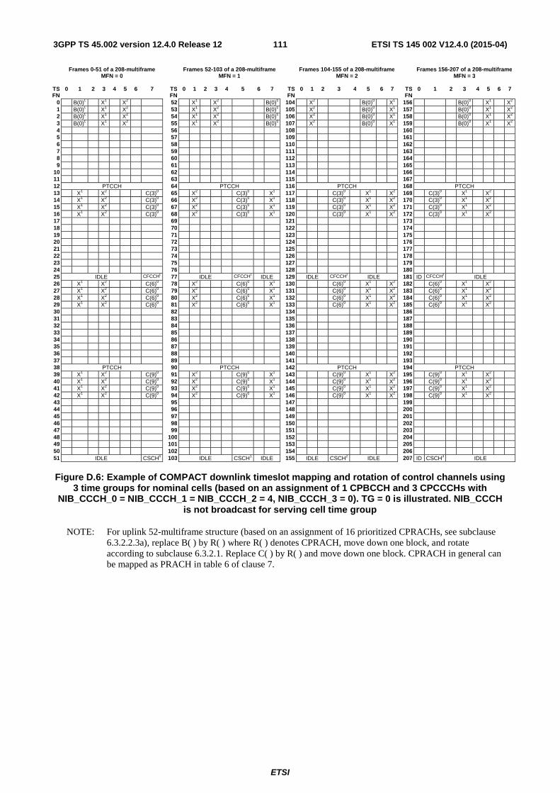
ETSI
ETSI TS 145 002 V12.4.0 (2015-04)1113GPP TS 45.002 version 12.4.0 Release 12
Frames 0-51 of a 208-multiframe Frames 52-103 of a 208-multiframe Frames 104-155 of a 208-multiframe Frames 156-207 of a 208-multiframe MFN = 0 MFN = 1 MFN = 2 MFN = 3
TS FN
0 1 2 3 4 5 6 7 TS FN
0 1 2 3 4 5 6 7 TS FN
0 1 2 3 4 5 6 7 TS FN
0 1 2 3 4 5 6 7
0 B(0)0 X1 X2 52 X1 X2 B(0)0 104 X2 B(0)0 X1 156 B(0)0 X1 X2 1 B(0)0 X1 X2 53 X1 X2 B(0)0 105 X2 B(0)0 X1 157 B(0)0 X1 X2 2 B(0)0 X1 X2 54 X1 X2 B(0)0 106 X2 B(0)0 X1 158 B(0)0 X1 X2 3 B(0)0 X1 X2 55 X1 X2 B(0)0 107 X2 B(0)0 X1 159 B(0)0 X1 X2 4 56 108 160 5 57 109 161 6 58 110 162 7 59 111 163 8 60 112 164 9 61 113 165
10 62 114 166 11 63 115 167 12 PTCCH 64 PTCCH 116 PTCCH 168 PTCCH 13 X1 X2 C(3)0 65 X2 C(3)0 X1 117 C(3)0 X1 X2 169 C(3)0 X1 X2 14 X1 X2 C(3)0 66 X2 C(3)0 X1 118 C(3)0 X1 X2 170 C(3)0 X1 X2 15 X1 X2 C(3)0 67 X2 C(3)0 X1 119 C(3)0 X1 X2 171 C(3)0 X1 X2 16 X1 X2 C(3)0 68 X2 C(3)0 X1 120 C(3)0 X1 X2 172 C(3)0 X1 X2 17 69 121 173 18 70 122 174 19 71 123 175 20 72 124 176 21 73 125 177 22 74 126 178 23 75 127 179 24 76 128 180 25 IDLE CFCCH0 77 IDLE CFCCH1 IDLE 129 IDLE CFCCH2 IDLE 181 ID CFCCH3 IDLE 26 X1 X2 C(6)0 78 X2 C(6)0 X1 130 C(6)0 X1 X2 182 C(6)0 X1 X2 27 X1 X2 C(6)0 79 X2 C(6)0 X1 131 C(6)0 X1 X2 183 C(6)0 X1 X2 28 X1 X2 C(6)0 80 X2 C(6)0 X1 132 C(6)0 X1 X2 184 C(6)0 X1 X2 29 X1 X2 C(6)0 81 X2 C(6)0 X1 133 C(6)0 X1 X2 185 C(6)0 X1 X2 30 82 134 186 31 83 135 187 32 84 136 188 33 85 137 189 34 86 138 190 35 87 139 191 36 88 140 192 37 89 141 193 38 PTCCH 90 PTCCH 142 PTCCH 194 PTCCH 39 X1 X2 C(9)0 91 X2 C(9)0 X1 143 C(9)0 X1 X2 195 C(9)0 X1 X2 40 X1 X2 C(9)0 92 X2 C(9)0 X1 144 C(9)0 X1 X2 196 C(9)0 X1 X2 41 X1 X2 C(9)0 93 X2 C(9)0 X1 145 C(9)0 X1 X2 197 C(9)0 X1 X2 42 X1 X2 C(9)0 94 X2 C(9)0 X1 146 C(9)0 X1 X2 198 C(9)0 X1 X2 43 95 147 199 44 96 148 200 45 97 149 201 46 98 150 202 47 99 151 203 48 100 152 204 49 101 153 205 50 102 154 206 51 IDLE CSCH0 103 IDLE CSCH1 IDLE 155 IDLE CSCH2 IDLE 207 ID CSCH3 IDLE
Figure D.6: Example of COMPACT downlink timeslot mapping and rotation of control channels using
3 time groups for nominal cells (based on an assignment of 1 CPBCCH and 3 CPCCCHs with NIB_CCCH_0 = NIB_CCCH_1 = NIB_CCCH_2 = 4, NIB_CCCH_3 = 0). TG = 0 is illustrated. NIB_CCCH
is not broadcast for serving cell time group
NOTE: For uplink 52-multiframe structure (based on an assignment of 16 prioritized CPRACHs, see subclause 6.3.2.2.3a), replace B( ) by R( ) where R( ) denotes CPRACH, move down one block, and rotate according to subclause 6.3.2.1. Replace C( ) by R( ) and move down one block. CPRACH in general can be mapped as PRACH in table 6 of clause 7.

ETSI
ETSI TS 145 002 V12.4.0 (2015-04)1123GPP TS 45.002 version 12.4.0 Release 12
Frames 0-51 of a 208-multiframe Frames 52-103 of a 208-multiframe Frames 104-155 of a 208-multiframe Frames 156-207 of a 208-multiframe MFN = 0 MFN = 1 MFN = 2 MFN = 3
TS FN
0 1 2 3 4 5 6 7 TS FN
0 1 2 3 4 5 6 7 TS FN
0 1 2 3 4 5 6 7 TS FN
0 1 2 3 4 5 6 7
0 B(0)0 X1 X2 X3 52 X1 X2 X3 B(0)0 104 X2 X3 B(0)0 X1 156 X3 B(0)0 X1 X2 1 B(0)0 X1 X2 X3 53 X1 X2 X3 B(0)0 105 X2 X3 B(0)0 X1 157 X3 B(0)0 X1 X2 2 B(0)0 X1 X2 X3 54 X1 X2 X3 B(0)0 106 X2 X3 B(0)0 X1 158 X3 B(0)0 X1 X2 3 B(0)0 X1 X2 X3 55 X1 X2 X3 B(0)0 107 X2 X3 B(0)0 X1 159 X3 B(0)0 X1 X2 4 X1 56 X1 108 X1 160 X1 5 X1 57 X1 109 X1 161 X1 6 X1 58 X1 110 X1 162 X1 7 X1 59 X1 111 X1 163 X1 8 60 112 164 9 61 113 165
10 62 114 166 11 63 115 167 12 PTCCH 64 PTCCH 116 PTCCH 168 PTCCH 13 X1 X2 X3 C(3)0 65 X2 X3 C(3)0 X1 117 X3 C(3)0 X1 X2 169 C(3)0 X1 X2 X3 14 X1 X2 X3 C(3)0 66 X2 X3 C(3)0 X1 118 X3 C(3)0 X1 X2 170 C(3)0 X1 X2 X3 15 X1 X2 X3 C(3)0 67 X2 X3 C(3)0 X1 119 X3 C(3)0 X1 X2 171 C(3)0 X1 X2 X3 16 X1 X2 X3 C(3)0 68 X2 X3 C(3)0 X1 120 X3 C(3)0 X1 X2 172 C(3)0 X1 X2 X3 17 69 121 173 18 70 122 174 19 71 123 175 20 72 124 176 21 73 125 177 22 74 126 178 23 75 127 179 24 76 128 180 25 IDLE CFCCH0 77 IDLE CFCCH1 IDLE 129 IDLE CFCCH2 IDLE 181 ID CFCCH3 IDLE 26 X1 X2 X3 C(6)0 78 X2 X3 C(6)0 X1 130 X3 C(6)0 X1 X2 182 C(6)0 X1 X2 X3 27 X1 X2 X3 C(6)0 79 X2 X3 C(6)0 X1 131 X3 C(6)0 X1 X2 183 C(6)0 X1 X2 X3 28 X1 X2 X3 C(6)0 80 X2 X3 C(6)0 X1 132 X3 C(6)0 X1 X2 184 C(6)0 X1 X2 X3 29 X1 X2 X3 C(6)0 81 X2 X3 C(6)0 X1 133 X3 C(6)0 X1 X2 185 C(6)0 X1 X2 X3 30 82 134 186 31 83 135 187 32 84 136 188 33 85 137 189 34 86 138 190 35 87 139 191 36 88 140 192 37 89 141 193 38 PTCCH 90 PTCCH 142 PTCCH 194 PTCCH 39 X1 X2 X3 C(9)0 91 X2 X3 C(9)0 X1 143 X3 C(9)0 X1 X2 195 C(9)0 X1 X2 X3 40 X1 X2 X3 C(9)0 92 X2 X3 C(9)0 X1 144 X3 C(9)0 X1 X2 196 C(9)0 X1 X2 X3 41 X1 X2 X3 C(9)0 93 X2 X3 C(9)0 X1 145 X3 C(9)0 X1 X2 197 C(9)0 X1 X2 X3 42 X1 X2 X3 C(9)0 94 X2 X3 C(9)0 X1 146 X3 C(9)0 X1 X2 198 C(9)0 X1 X2 X3 43 95 147 199 44 96 148 200 45 97 149 201 46 98 150 202 47 99 151 203 48 100 152 204 49 101 153 205 50 102 154 206 51 IDLE CSCH0 103 IDLE CSCH1 IDLE 155 IDLE CSCH2 IDLE 207 ID CSCH3 IDLE
Figure D.7: Example of COMPACT downlink timeslot mapping and rotation of control channels using
4 time groups for nominal cells (based on an assignment of 1 CPBCCH and 3 CPCCCHs with NIB_CCCH_0 = NIB_CCCH_2 = NIB_CCCH_3 = 4, NIB_CCCH_1 = 5). TG = 0 is illustrated. NIB_CCCH
is not broadcast for serving cell time group
NOTE: For uplink 52-multiframe structure (based on an assignment of 16 prioritized CPRACHs, see subclause 6.3.2.2.3a), replace B( ) by R( ) where R( ) denotes CPRACH, move down one block, and rotate according to subclause 6.3.2.1. Replace C( ) by R( ) and move down one block. CPRACH in general can be mapped as PRACH in table 6 of clause 7.

ETSI
ETSI TS 145 002 V12.4.0 (2015-04)1133GPP TS 45.002 version 12.4.0 Release 12
Annex E (informative): Example illustrations of neighbour cell measurements for downlink dual carrier MS Figure E.1 illustrates possible switching and measurement timings for downlink dual carrier MSs that have a higher equivalent multislot class compared to the signalled multislot class (see subclause B.4).
tune tune
tune tune rx
t rb =1
tx rx
t tb =1
rx rx rx mon
rx receive path 1
transmit path
timing advance
tuner 1
tuner 2 - receive path 2
t ra =2
tune tune
tune tune
rx
t ra =2
tx
rx mon
rx
zero timing advance
rx
rx
rx mon
receive path 1
transmit path tuner 1
tuner 2 - receive path 2
Maximum timing advance
Zero timing advance
Figure E.1

ETSI
ETSI TS 145 002 V12.4.0 (2015-04)1143GPP TS 45.002 version 12.4.0 Release 12
Annex F (informative): Illustration of mapping restrictions in Downlink Multi Carrier The mapping restrictions for DLMC described in subclause 6.2.7 can be illustrated by the following example with 5 carriers assigned in BTTI mode:
max_sep: 22 (corresponding to a supported DLMC - Maximum BW of 5 MHz, see 3GPP TS 45.005).
num_tdma_frames: 4.
num_carriers: 5.
arfcn[1..num_tdma_frames][1..num_carriers]: see the table below.
TDMA frame index
(i)
arfcn[i][1] arfcn[i][2] arfcn[i][3] arfcn[i][4] arfcn[i][5]
1 1 10 19 37 23
2 46 1 10 28 23
3 37 46 1 19 23
4 1 10 19 37 23
Contiguous reception:
Step 1: Set carrier 1 as the anchor, and test whether carrier 2 can be selected. As shown in the table below, carrier separation is not satisfied for one or more of the 4 TDMA frames (in this case not satisfied for the second TDMA frame), hence carrier 2 is not selected. Carrier selection for the current anchor stops. The selected group of carriers for anchor carrier 1 is {1}. Since this is the first group of carriers selected, it is set as the currently selected group of carriers.
TDMA frame index
(i)
arfcn[i][1] arfcn[i][2] min
arfcn max arfcn
delta arfcn
delta arfcn <=
max_sep?
1 1 10 1 10 9 Yes
2 46 1 1 46 45 No
3 37 46 37 46 9 Yes
4 1 10 1 10 9 Yes
Step 2: Set carrier 2 as the anchor, and test whether carrier 3 can be selected. As shown in the table below, carrier separation is not satisfied for one or more of the 4 TDMA frames (in this case not satisfied for the third TDMA frame), hence carrier 3 is not selected. Carrier selection for the current anchor stops. The selected group of carriers for anchor carrier 2 is {2}. Since the size of this group of carriers is not greater than the currently selected group of carriers (i.e. {1}), the latter is not changed.

ETSI
ETSI TS 145 002 V12.4.0 (2015-04)1153GPP TS 45.002 version 12.4.0 Release 12
TDMA frame index
(i)
arfcn[i][2] arfcn[i][3] min
arfcn max arfcn
delta arfcn
delta arfcn <=
max_sep?
1 10 19 10 19 9 Yes
2 1 10 1 10 9 Yes
3 46 1 1 46 45 No
4 10 19 1 10 9 Yes
Step 3: Set carrier 3 as the anchor, and test whether carrier 4 can be selected. As shown in the table below, carrier separation is satisfied for all 4 TDMA frames, hence carrier 4 is selected.
TDMA frame index
(i)
arfcn[i][3] arfcn[i][4] min
arfcn max arfcn
delta arfcn
delta arfcn <=
max_sep?
1 19 37 19 37 18 Yes
2 10 28 10 28 18 Yes
3 1 19 1 19 18 Yes
4 19 37 19 37 18 Yes
Step 4: Test whether carrier 5 can be selected. As shown in the table below, carrier separation is satisfied for all 4 TDMA frames, hence carrier 5 is selected. Since there are no more carriers to be processed, carrier selection for the current anchor stops. The selected group of carriers for anchor carrier 3 is {3, 4, 5}. Since the size of this group of carriers is greater than the currently selected group of carriers (i.e. {1}), the latter is changed to {3, 4, 5}.
TDMA frame index
(i)
arfcn[i][3] arfcn[i][4] arfcn[i][5] min
arfcn max arfcn
delta arfcn
delta arfcn <=
max_sep?
1 19 37 23 19 37 18 Yes
2 10 28 23 10 28 18 Yes
3 1 19 23 1 23 22 Yes
4 19 37 23 19 37 18 Yes
Step 5: Since there are no more carriers to be processed, the carrier selection method stops. The finally selected group of carriers is {3, 4, 5}.
Non-contiguous reception:
Step 1: Perform the steps for contiguous reception with max_sep=2x22=44. The finally selected group of carriers in this step is {3, 4, 5}, i.e. not all carriers can be selected.

ETSI
ETSI TS 145 002 V12.4.0 (2015-04)1163GPP TS 45.002 version 12.4.0 Release 12
Step 2: Perform the steps for contiguous reception with max_sep=22. The finally selected group of carriers in this step is {3, 4, 5}.
Step 3: Perform the steps for contiguous reception with max_sep=22, num_carriers=5-3=2, and arfcn excluding vectors for carrier 3, carrier 4 and carrier 5. The finally selected group of carriers in this step is {1}.
Step 4: The carrier selection method stops. The finally selected group of carriers is {3, 4, 5}+{1}={3,4,5,1}.
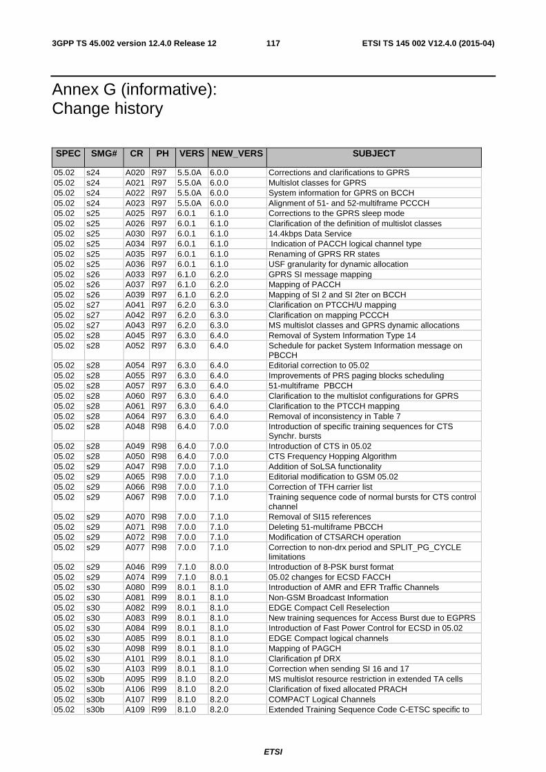
ETSI
ETSI TS 145 002 V12.4.0 (2015-04)1173GPP TS 45.002 version 12.4.0 Release 12
Annex G (informative): Change history
SPEC SMG# CR PH VERS NEW_VERS SUBJECT
05.02 s24 A020 R97 5.5.0A 6.0.0 Corrections and clarifications to GPRS 05.02 s24 A021 R97 5.5.0A 6.0.0 Multislot classes for GPRS 05.02 s24 A022 R97 5.5.0A 6.0.0 System information for GPRS on BCCH 05.02 s24 A023 R97 5.5.0A 6.0.0 Alignment of 51- and 52-multiframe PCCCH 05.02 s25 A025 R97 6.0.1 6.1.0 Corrections to the GPRS sleep mode 05.02 s25 A026 R97 6.0.1 6.1.0 Clarification of the definition of multislot classes 05.02 s25 A030 R97 6.0.1 6.1.0 14.4kbps Data Service 05.02 s25 A034 R97 6.0.1 6.1.0 Indication of PACCH logical channel type 05.02 s25 A035 R97 6.0.1 6.1.0 Renaming of GPRS RR states 05.02 s25 A036 R97 6.0.1 6.1.0 USF granularity for dynamic allocation 05.02 s26 A033 R97 6.1.0 6.2.0 GPRS SI message mapping 05.02 s26 A037 R97 6.1.0 6.2.0 Mapping of PACCH 05.02 s26 A039 R97 6.1.0 6.2.0 Mapping of SI 2 and SI 2ter on BCCH 05.02 s27 A041 R97 6.2.0 6.3.0 Clarification on PTCCH/U mapping 05.02 s27 A042 R97 6.2.0 6.3.0 Clarification on mapping PCCCH 05.02 s27 A043 R97 6.2.0 6.3.0 MS multislot classes and GPRS dynamic allocations 05.02 s28 A045 R97 6.3.0 6.4.0 Removal of System Information Type 14 05.02 s28 A052 R97 6.3.0 6.4.0 Schedule for packet System Information message on
PBCCH 05.02 s28 A054 R97 6.3.0 6.4.0 Editorial correction to 05.02 05.02 s28 A055 R97 6.3.0 6.4.0 Improvements of PRS paging blocks scheduling 05.02 s28 A057 R97 6.3.0 6.4.0 51-multiframe PBCCH 05.02 s28 A060 R97 6.3.0 6.4.0 Clarification to the multislot configurations for GPRS 05.02 s28 A061 R97 6.3.0 6.4.0 Clarification to the PTCCH mapping 05.02 s28 A064 R97 6.3.0 6.4.0 Removal of inconsistency in Table 7 05.02 s28 A048 R98 6.4.0 7.0.0 Introduction of specific training sequences for CTS
Synchr. bursts 05.02 s28 A049 R98 6.4.0 7.0.0 Introduction of CTS in 05.02 05.02 s28 A050 R98 6.4.0 7.0.0 CTS Frequency Hopping Algorithm 05.02 s29 A047 R98 7.0.0 7.1.0 Addition of SoLSA functionality 05.02 s29 A065 R98 7.0.0 7.1.0 Editorial modification to GSM 05.02 05.02 s29 A066 R98 7.0.0 7.1.0 Correction of TFH carrier list 05.02 s29 A067 R98 7.0.0 7.1.0 Training sequence code of normal bursts for CTS control
channel 05.02 s29 A070 R98 7.0.0 7.1.0 Removal of SI15 references 05.02 s29 A071 R98 7.0.0 7.1.0 Deleting 51-multiframe PBCCH 05.02 s29 A072 R98 7.0.0 7.1.0 Modification of CTSARCH operation 05.02 s29 A077 R98 7.0.0 7.1.0 Correction to non-drx period and SPLIT_PG_CYCLE
limitations 05.02 s29 A046 R99 7.1.0 8.0.0 Introduction of 8-PSK burst format 05.02 s29 A074 R99 7.1.0 8.0.1 05.02 changes for ECSD FACCH 05.02 s30 A080 R99 8.0.1 8.1.0 Introduction of AMR and EFR Traffic Channels 05.02 s30 A081 R99 8.0.1 8.1.0 Non-GSM Broadcast Information 05.02 s30 A082 R99 8.0.1 8.1.0 EDGE Compact Cell Reselection 05.02 s30 A083 R99 8.0.1 8.1.0 New training sequences for Access Burst due to EGPRS 05.02 s30 A084 R99 8.0.1 8.1.0 Introduction of Fast Power Control for ECSD in 05.02 05.02 s30 A085 R99 8.0.1 8.1.0 EDGE Compact logical channels 05.02 s30 A098 R99 8.0.1 8.1.0 Mapping of PAGCH 05.02 s30 A101 R99 8.0.1 8.1.0 Clarification pf DRX 05.02 s30 A103 R99 8.0.1 8.1.0 Correction when sending SI 16 and 17 05.02 s30b A095 R99 8.1.0 8.2.0 MS multislot resource restriction in extended TA cells 05.02 s30b A106 R99 8.1.0 8.2.0 Clarification of fixed allocated PRACH 05.02 s30b A107 R99 8.1.0 8.2.0 COMPACT Logical Channels 05.02 s30b A109 R99 8.1.0 8.2.0 Extended Training Sequence Code C-ETSC specific to

ETSI
ETSI TS 145 002 V12.4.0 (2015-04)1183GPP TS 45.002 version 12.4.0 Release 12
SPEC SMG# CR PH VERS NEW_VERS SUBJECT
COMPACT synchronization bursts only 05.02 s30b A110 R99 8.1.0 8.2.0 Support of Slow Frequency Hopping for COMPACT 05.02 s30b A111 R99 8.1.0 8.2.0 Synchronization of 52-multiframes in EGPRS COMPACT 05.02 s30b A114 R99 8.1.0 8.2.0 Bi-directional channels in case of multi slot 05.02 s30b A117 R99 8.1.0 8.2.0 Clarification of multislot configuration 05.02 s30b A119 R99 8.1.0 8.2.0 Training Sequence to support LCS and specification of 8-
PSK modulated normal bursts for compatibility with future releases, mirror CR to R'98
05.02 s30b A120 R99 8.1.0 8.2.0 Compact FCCH 05.02 s31 A123 R99 8.2.0 8.3.0 PTCCH block numbering 05.02 s31 A126 R99 8.2.0 8.3.0 Correction of BS_PRACH_BLKS range 05.02 s31 A127 R99 8.2.0 8.3.0 COMPACT interference measurements 05.02 s31 A128 R99 8.2.0 8.3.0 Timegroup rotation and NIB Clarification 05.02 s31 A129 R99 8.2.0 8.3.0 Clarifications in 05.02 05.02 s31 A133 R99 8.2.0 8.3.0 USF Handling in COMPACT 05.02 s31 A138 R99 8.2.0 8.3.0 Correction to non-DRX mode 05.02 s31 A142 R99 8.2.0 8.3.0 GPRS & SMS-CB interworking 05.02 s31 A143 R99 8.2.0 8.3.0 Complete Frequency Hopping on COMPACT 05.02 s31b A148 R99 8.3.0 8.4.0 New measurement order – Idle mode 05.02 s31b A147 R99 8.3.0 8.4.0 Clarification of PBCCH message scheduling 05.02 s31b A157 R99 8.3.0 8.4.0 FCCH decoding problem for multislot MS 05.02 s31b A144 R99 8.3.0 8.4.0 Correction of Figure D.4 05.02 s31b A149 R99 8.3.0 8.4.0 Correction of NIB parameters 05.02 s32 A158 R99 8.4.0 8.5.0 Clarification of COMPACT frequency hopping parameters 05.02 s32 A159 R99 8.4.0 8.5.0 Class A Dual Transfer Mode (DTM) GERAN# September 2000 - 3GPP GERAN 05.02 G01 A162 8.5.0 8.6.0 DTM (R99) 05.02 G01 A163 8.5.0 8.6.0 Corrections to COMPACT (R99) 05.02 G01 A165 8.5.0 8.6.0 Editorial corrections related to COMPACT (R99) GERAN# September 2000 - 3GPP GERAN#1 05.02 G01 A161 8.6.0 4.0.0 NCH clarification (Release 4) 4.0.0 4.0.1 Oct 2000: References corrected. November 2000 - 3GPP GERAN#2 45.002 G02 002 1 4.0.1 4.1.0 Clarification of mapping of PDTCH and PCCCH 45.002 G02 003 4.0.1 4.1.0 Editorial corrections 45.002 G02 004 1 4.0.1 4.1.0 Possible multislot configurations for GPRS 4.1.0 4.1.1 Front page layout correction January 2001 - 3GPP GERAN#3 45.002 G03 005 4.1.1 4.2.0 Possible multislot configurations for GPRS 45.002 G03 006 4.1.1 4.2.0 Clarification of the monitored GPRS control channels
during GPRS attachment
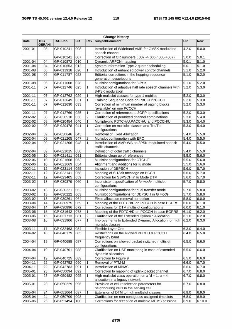
ETSI
ETSI TS 145 002 V12.4.0 (2015-04)1193GPP TS 45.002 version 12.4.0 Release 12
Change history Date TSG
GERAN# TSG Doc. CR Rev Subject/Comment Old New
2001-01 03 GP-010241 008 Introduction of Wideband AMR for GMSK modulated speech channel
4.2.0 5.0.0
GP-010241 007 Correction of CR numbers ( 007 -> 006 / 008->007) 5.0.0 5.0.1 2001-04 04 GP-010872 010 1 Dynamic ARFCN mapping 5.0.1 5.1.0 2001-04 04 GP-010653 012 System Information Type 2 quater scheduling 5.0.1 5.1.0 2001-08 06 GP-011918 020 1 Introduction of enhanced power control channels 5.1.0 5.2.0 2001-08 06 GP-011787 022 Editorial corrections in the hopping sequence
generation descriptions 5.1.0 5.2.0
2001-08 06 GP-011608 028 Multislot configurations for 8-PSK 5.1.0 5.2.0 2001-11 07 GP-012746 025 1 Introduction of adaptive half rate speech channels with
8-PSK modulation 5.2.0 5.3.0
2001-11 07 GP-012762 029 1 High multislot classes for type 1 mobiles 5.2.0 5.3.0 2001-11 07 GP-012649 031 1 Training Sequence Code on PBCCH/PCCCH 5.2.0 5.3.0 2001-11 07 GP-012630 033 Correction of minimum number of paging blocks
"available" on one PCCCH 5.2.0 5.3.0
2001-11 07 GP-012769 035 1 Correction of references to 3GPP specifications 5.2.0 5.3.0 2002-02 08 GP-020510 036 2 Clarification of permitted channel combinations 5.3.0 5.4.0 2002-02 08 GP-020454 040 1 Multiplexing PDTCH/U,PACCH/U and PCCCH/U 5.3.0 5.4.0 2002-02 08 GP-020478 041 1 Correction on multislot classes and Tra/Tta
configurations 5.3.0 5.4.0
2002-04 09 GP-020646 043 Removal of Fixed Allocation 5.4.0 5.5.0 2002-04 09 GP-021205 047 2 Multislot configuration with EPC 5.4.0 5.5.0 2002-04 09 GP-021206 048 1 Introduction of AMR-WB on 8PSK modulated speech
traffic channels 5.4.0 5.5.0
2002-04 09 GP-021015 050 Definition of octal traffic channels 5.4.0 5.5.0 2002-06 10 GP-021411 051 Editorial clean up of references 5.5.0 5.6.0 2002-06 10 GP-021668 053 Multislot configurations for OTCH/F 5.5.0 5.6.0 2002-06 10 GP-021669 054 Alignment and additions for Iu mode 5.5.0 5.6.0 2002-11 12 GP-023114 055 Inclusion of DBPSCH 5.6.0 5.7.0 2002-11 12 GP-023141 058 Mapping of SI13alt message on BCCH 5.6.0 5.7.0 2002-11 12 GP-023405 059 Correction for SBPSCH in Iu Mode DTM 5.6.0 5.7.0 2003-02 13 GP-030379 060 1 Inconsistent specification of Iu-mode multislot
configurations 5.7.0 5.8.0
2003-02 13 GP-030221 062 Multislot configurations for dual transfer mode 5.7.0 5.8.0 2003-02 13 GP-030222 063 Multislot configurations for DBPSCH in Iu mode 5.7.0 5.8.0 2003-02 13 GP-030261 064 Fixed allocation removal correction 5.8.0 6.0.0 2003-04 14 GP-030975 069 1 Mapping of the PDTCH/D on PCCCH in case EGPRS 6.0.0 6.1.0 2003-04 14 GP-030896 072 Corrections for DTM multislot configurations 6.0.0 6.1.0 2003-06 15 GP-031642 078 1 Mapping of the PDTCH/D on PCCCH in case EGPRS 6.1.0 6.2.0 2003-06 15 GP-031713 081 2 Clarification of the Extended Dynamic Allocation 6.1.0 6.2.0 2003-08 16 GP-031906 077 1 Improvements to Extended Dynamic Allocation for high
multislot classes 6.2.0 6.3.0
2003-11 17 GP-032463 084 Flexible Layer One 6.3.0 6.4.0 2004-02 18 GP-040179 085 Restrictions on the allowed PBCCH & PCCCH
frequency band 6.4.0 6.5.0
2004-04 19 GP-040698 087 Corrections on allowed packet switched multislot configurations
6.5.0 6.6.0
2004-04 19 GP-040701 088 Clarification on USF monitoring in case of extended dynamic allocation
6.5.0 6.6.0
2004-04 19 GP-040725 089 Correction to Figure 9 6.5.0 6.6.0 2004-11 22 GP-042752 090 1 Removal of PTM-M 6.6.0 6.7.0 2004-11 22 GP-042783 091 1 Introduction of MBMS 6.6.0 6.7.0 2005-01 23 GP-050094 092 Correction to mapping of uplink packet channel 6.7.0 6.8.0 2005-01 23 GP-050482 095 1 High multislot class operation on a 'd = 1, u = 4'
allocation in a legacy network 6.7.0 6.8.0
2005-01 23 GP-050229 096 Provision of cell reselection parameters for neighbouring cells in the serving cell
6.7.0 6.8.0
2005-04 24 GP-051064 097 1 Extension of DTM to high multislot classes 6.8.0 6.9.0 2005-04 24 GP-050709 098 Clarification on non-contiguous assigned timeslots 6.8.0 6.9.0 2005-06 25 GP-051494 100 Corrections for reception of multiple MBMS sessions 6.9.0 6.10.0

ETSI
ETSI TS 145 002 V12.4.0 (2015-04)1203GPP TS 45.002 version 12.4.0 Release 12
2005-09 26 GP-052236 0102 1 Correction to multislot classes allowed for MBMS 6.10.0 6.11.0 2005-11 27 GP-052847 0103 1 MBMS transfer mode 6.11.0 6.12.0 2005-11 27 GP-052849 0106 Correction on the transmission of SI1 6.11.0 6.12.0 2006-04 29 GP-060921 0107 1 Correction of Title of Clause 7 and correspondings 6.12.0 7.0.0 2006-06 30 GP-061338 0108 1 Correction of terminology: "allocation" vs. "assignment" 7.0.0 7.1.0 2006-11 32 GP-062442 0113 3 Introduction of Downlink Dual Carrier 7.1.0 7.2.0 2007-02 33 GP-070368 0112 3 Flexible timeslot assignment 7.2.0 7.3.0 2007-02 33 GP-070465 0116 1 Clarification of multislot capabilities for non-DCDL
assignments 7.2.0 7.3.0
2007-05 34 GP-070790 0118 Editorial corrections 7.3.0 7.4.0 2007-08 35 GP-071515 0117 5 Introduction of RTTI 7.4.0 7.5.0 2007-08 35 GP-071256 0121 Introduction of RED HOT and HUGE 7.4.0 7.5.0 2007-08 35 GP-071271 0122 Clarification on timeslot configurations for dual carrier in
the downlink 7.4.0 7.5.0
2007-11 36 GP-071674 0124 Miscellaneous corrections on Reduced Latency 7.5.0 7.6.0 2007-11 36 GP-071694 0125 Correction on System Information Type 1 scheduling
rules 7.5.0 7.6.0
2007-11 36 GP-071956 0126 1 Tail-symbols for EGPRS2 7.5.0 7.6.0 2008-05 38 GP-080783 0127 1 Clarification on guard period 7.6.0 7.7.0 2008-05 38 GP-080874 0128 3 Corrections on Multislot configurations for packet
switched connections in A/Gb mode 7.6.0 7.7.0
2008-05 38 GP-080662 0130 Reduced Latency terminology alignments 7.6.0 7.7.0 2008-12 40 Version for Release 8 7.7.0 8.0.0 2009-05 42 GP-091040 0138 1 Enhanced Flexible Timeslot Assignment 8.0.0 9.0.0 2009-09 43 GP-091686 0140 1 Introduction of VAMOS multiplexing and multiple
access 9.0.0 9.1.0
2009-11 44 GP-092348 0142 1 Removal of mandatory support for P-channels by mobile stations in A/Gb mode
9.1.0 9.2.0
2010-03 45 GP-100600 0137 5 Introduction of Shifted SACCH mapping for VAMOS 9.2.0 9.3.0 2010-03 45 GP-100340 0143 Clarification of DTM Support for EFTA 9.2.0 9.3.0 2010-03 45 GP-100577 0144 1 Interpretation of Multislot Class Parameters for EFTA 9.2.0 9.3.0 2010-09 47 GP-101557 0146 1 Shifted USF for EFTA 9.3.0 9.4.0 2010-09 47 GP-101407 0147 DCDL for EFTA 9.3.0 9.4.0 2010-09 47 GP-101549 0148 1 TSC allocation for VAMOS in case of DTM 9.3.0 9.4.0 2011-03 49 GP-110465 0152 1 Clarification of Shifted USF operation in combination
with Dual Carrier DL 9.4.0 9.5.0
2011-03 49 GP-110454 0153 1 Clarification of Shifted USF in combination with EFTA 9.4.0 9.5.0 2011-03 49 GP-110480 0154 1 Clarifications for support of 8 DL TS operation in EFTA
assignment 9.4.0 9.5.0
2011-03 49 GP-110236 0149 1 Introduction of fast downlink frequency switching capability
9.5.0 10.0.0
2011-05 50 GP-110965 0155 3 Realizing Extended Access Barring 10.0.0 10.1.0 2011-09 51 GP-111190 0158 Applicability of reduced switching times for fast
downlink frequency switching 10.1.0 10.2.0
2012-03 53 GP-120150 0162 2 Alternative EFTA multislot classes and multislot capabilities applicability for EFTA
10.2.0 10.3.0
2012-08 55 GP-121129 0159 5 Introduction of SI22 message for Network Sharing 10.3.0 11.0.0 2012-11 56 GP-121387 0163 1 Introduction of inter RAT mobility on PLMN basis for
Network Sharing 11.0.0 11.1.0
2013-03 57 GP-130273 0166 2 Corrections to multislot capabilities for dual carrier mobile stations
11.1.0 11.2.0
2013-08 59 GP-130881 0172 2 Clarification of VAMOS II mapping of associated control channels
11.2.0 11.3.0
2013-08 59 GP-130738 0176 Measurements and BSIC decoding for EFTA multislot configurations
11.2.0 11.3.0
2013-08 59 GP-130863 0173 1 Introduction of VAMOS III MS 11.3.0 12.0.0 2013-11 60 GP-131052 0168 7 Introduction of Downlink Multi Carrier 12.0.0 12.1.0 2014-08 63 GP-140554 0178 Correction to pseudo code indentation 12.1.0 12.2.0 2014-11 64 GP-140946 0177 4 Introduction of extended TSC sets 12.2.0 12.3.0 2015-03 65 GP-150124 0181 Extended TSC sets correction 12.3.0 12.4.0

ETSI
ETSI TS 145 002 V12.4.0 (2015-04)1213GPP TS 45.002 version 12.4.0 Release 12
History
Document history
V12.2.0 October 2014 Publication
V12.3.0 January 2015 Publication
V12.4.0 April 2015 Publication
Related Documents