ETSI TS 144 056 V10.0.0 (2011-03) Technical Specification Digital cellular telecommunications system (Phase 2+); GSM Cordless Telephony System (CTS), Phase 1; CTS radio interface layer 3 specification (3GPP TS 44.056 version 10.0.0 Release 10) GLOBAL SYSTEM FOR MOBILE COMMUNICATIONS R

Welcome message from author
This document is posted to help you gain knowledge. Please leave a comment to let me know what you think about it! Share it to your friends and learn new things together.
Transcript
ETSI TS 144 056 V10.0.0 (2011-03)
Technical Specification
Digital cellular telecommunications system (Phase 2+);GSM Cordless Telephony System (CTS), Phase 1;
CTS radio interface layer 3 specification (3GPP TS 44.056 version 10.0.0 Release 10)
GLOBAL SYSTEM FOR MOBILE COMMUNICATIONS
R
ETSI
ETSI TS 144 056 V10.0.0 (2011-03)13GPP TS 44.056 version 10.0.0 Release 10
Reference RTS/TSGC-0144056va00
Keywords GSM
ETSI
650 Route des Lucioles F-06921 Sophia Antipolis Cedex - FRANCE
Tel.: +33 4 92 94 42 00 Fax: +33 4 93 65 47 16
Siret N° 348 623 562 00017 - NAF 742 C
Association à but non lucratif enregistrée à la Sous-Préfecture de Grasse (06) N° 7803/88
Important notice
Individual copies of the present document can be downloaded from: http://www.etsi.org
The present document may be made available in more than one electronic version or in print. In any case of existing or perceived difference in contents between such versions, the reference version is the Portable Document Format (PDF).
In case of dispute, the reference shall be the printing on ETSI printers of the PDF version kept on a specific network drive within ETSI Secretariat.
Users of the present document should be aware that the document may be subject to revision or change of status. Information on the current status of this and other ETSI documents is available at
http://portal.etsi.org/tb/status/status.asp
If you find errors in the present document, please send your comment to one of the following services: http://portal.etsi.org/chaircor/ETSI_support.asp
Copyright Notification
No part may be reproduced except as authorized by written permission. The copyright and the foregoing restriction extend to reproduction in all media.
© European Telecommunications Standards Institute 2011.
All rights reserved.
DECTTM, PLUGTESTSTM, UMTSTM, TIPHONTM, the TIPHON logo and the ETSI logo are Trade Marks of ETSI registered for the benefit of its Members.
3GPPTM is a Trade Mark of ETSI registered for the benefit of its Members and of the 3GPP Organizational Partners. LTE™ is a Trade Mark of ETSI currently being registered
for the benefit of its Members and of the 3GPP Organizational Partners. GSM® and the GSM logo are Trade Marks registered and owned by the GSM Association.

ETSI
ETSI TS 144 056 V10.0.0 (2011-03)23GPP TS 44.056 version 10.0.0 Release 10
Intellectual Property Rights IPRs essential or potentially essential to the present document may have been declared to ETSI. The information pertaining to these essential IPRs, if any, is publicly available for ETSI members and non-members, and can be found in ETSI SR 000 314: "Intellectual Property Rights (IPRs); Essential, or potentially Essential, IPRs notified to ETSI in respect of ETSI standards", which is available from the ETSI Secretariat. Latest updates are available on the ETSI Web server (http://webapp.etsi.org/IPR/home.asp).
Pursuant to the ETSI IPR Policy, no investigation, including IPR searches, has been carried out by ETSI. No guarantee can be given as to the existence of other IPRs not referenced in ETSI SR 000 314 (or the updates on the ETSI Web server) which are, or may be, or may become, essential to the present document.
Foreword This Technical Specification (TS) has been produced by ETSI 3rd Generation Partnership Project (3GPP).
The present document may refer to technical specifications or reports using their 3GPP identities, UMTS identities or GSM identities. These should be interpreted as being references to the corresponding ETSI deliverables.
The cross reference between GSM, UMTS, 3GPP and ETSI identities can be found under http://webapp.etsi.org/key/queryform.asp.
ETSI
ETSI TS 144 056 V10.0.0 (2011-03)33GPP TS 44.056 version 10.0.0 Release 10
Contents
Intellectual Property Rights ................................................................................................................................ 2
Foreword ............................................................................................................................................................. 2
Foreword ............................................................................................................................................................. 9
1 Scope ...................................................................................................................................................... 10
1.1 Scope of the Technical Specification ............................................................................................................... 10
1.2 Application to the interface structures .............................................................................................................. 10
1.3 Structure of layer 3 procedures ......................................................................................................................... 10
1.4 Test procedures ................................................................................................................................................ 10
1.5 Use of logical channels ..................................................................................................................................... 10
1.6 Overview of control procedures ....................................................................................................................... 11
1.6.1 List of procedures ....................................................................................................................................... 11
1.7 Applicability of implementations ..................................................................................................................... 12
2 References .............................................................................................................................................. 12
3 Definitions, abbreviations and Random values ...................................................................................... 16
3.1 Definitions ........................................................................................................................................................ 16
3.2 Abbreviations ................................................................................................................................................... 16
3.3 Random values ................................................................................................................................................. 16
4 Overview/General .................................................................................................................................. 16
4.1 Overview .......................................................................................................................................................... 16
4.1.1 General ........................................................................................................................................................ 16
4.1.2 Services provided to upper layers ............................................................................................................... 17
4.1.2.1 CTS-Idle mode ...................................................................................................................................... 17
4.1.2.2 Dedicated mode ..................................................................................................................................... 17
4.1.3 Services required from data link and physical layers .................................................................................. 17
4.1.4 Change of dedicated channels ..................................................................................................................... 17
4.1.4.1 Change of dedicated channels using SAPI = 0 ...................................................................................... 18
4.1.4.2 Change of dedicated channels using other SAPIs than 0 ...................................................................... 18
4.1.4.3 Sequenced message transfer operation .................................................................................................. 18
4.1.4.3.1 Variables and sequence numbers ..................................................................................................... 18
4.1.4.3.1.1 Send state variable V(SD) .......................................................................................................... 18
4.1.4.3.1.2 Send sequence number N(SD) ................................................................................................... 18
4.1.4.3.2 Procedures for the initiation, transfer execution and termination of the sequenced message transfer operation ............................................................................................................................. 19
4.1.4.3.2.1 Initiation ..................................................................................................................................... 19
4.1.4.3.2.2 Transfer Execution ..................................................................................................................... 19
4.1.4.3.2.3 Termination ................................................................................................................................ 19
4.1.5 Procedure for Service Request and Contention Resolution ........................................................................ 19
4.2 Idle mode procedures ....................................................................................................................................... 19
4.2.1 Mobile Station side ..................................................................................................................................... 19
4.2.1.1 CTSBCH and CTSPCH monitoring ...................................................................................................... 19
4.2.1.2 Alive check response............................................................................................................................. 20
4.2.2 CTS-FP side ................................................................................................................................................ 20
4.2.2.1 CTSBCH information broadcasting ...................................................................................................... 20
4.2.2.2 CTSPCH information broadcasting ...................................................................................................... 20
4.2.2.3 Alive check ........................................................................................................................................... 20
4.2.2.4 Hunting ................................................................................................................................................. 21
4.2.2.5 Connectionless group alerting ............................................................................................................... 22
4.2.2.5 CTS system information broadcasting .................................................................................................. 23
4.3 RR connection establishment ........................................................................................................................... 23
4.3.1 RR connection establishment initiated by the mobile station ..................................................................... 23
4.3.1.1 Entering the dedicated mode: immediate assignment procedure .......................................................... 23
4.3.1.1.1 Permission to access the CTS-FP .................................................................................................... 24
4.3.1.1.2 Initiation of the immediate assignment procedure ........................................................................... 24
ETSI
ETSI TS 144 056 V10.0.0 (2011-03)43GPP TS 44.056 version 10.0.0 Release 10
4.3.1.1.3 Answer from the CTS-FP ................................................................................................................ 24
4.3.1.1.3.1 On receipt of a CTS ACCESS REQUEST message ........................................................................ 24
4.3.1.1.3.2 Assignment rejection ....................................................................................................................... 24
4.3.1.1.4 Assignment completion ................................................................................................................... 24
4.3.1.1.4.1 Early classmark sending .................................................................................................................. 25
4.3.1.1.5 Abnormal cases ............................................................................................................................... 25
4.3.2 Paging procedure for RR connection establishment ................................................................................... 25
4.3.2.1 Paging initiation by the CTS-FP ........................................................................................................... 25
4.3.2.2 Paging response ..................................................................................................................................... 25
4.3.2.3 Abnormal cases ..................................................................................................................................... 25
4.4 Procedures in dedicated mode .......................................................................................................................... 26
4.4.1 SACCH procedures..................................................................................................................................... 26
4.4.1.1 General .................................................................................................................................................. 26
4.4.1.2 Measurement report .............................................................................................................................. 26
4.4.2 Transfer of messages and link layer service provision ............................................................................... 26
4.4.3 Intracell handover procedure ...................................................................................................................... 27
4.4.3.1 Intracell handover initiation .................................................................................................................. 27
4.4.3.2 Intracell handover completion ............................................................................................................... 27
4.4.3.3 Abnormal cases ..................................................................................................................................... 27
4.4.4 Intercell handover procedure ...................................................................................................................... 28
4.4.5 Frequency hopping definition procedure .................................................................................................... 28
4.4.6 Channel mode modify procedure ................................................................................................................ 28
4.4.6.1 Normal channel mode modify procedure .............................................................................................. 28
4.4.6.1.1 Initiation of the channel mode modify procedure ............................................................................ 28
4.4.6.1.2 Completion of channel mode modify procedure ............................................................................. 28
4.4.6.1.3 Abnormal cases ............................................................................................................................... 28
4.4.7 Ciphering mode setting procedure .............................................................................................................. 29
4.4.7.1 Ciphering mode setting initiation .......................................................................................................... 29
4.4.7.2 Ciphering mode setting completion ...................................................................................................... 29
4.4.8 [Reserved: Additional channel assignment procedure] ............................................................................... 29
4.4.9 [Reserved: Partial channel release procedure] ............................................................................................ 30
4.4.10 Classmark change procedure ...................................................................................................................... 30
4.4.11 Classmark interrogation procedure ............................................................................................................. 30
4.4.12 [Reserved] ................................................................................................................................................... 30
4.4.13 RR connection release procedure ................................................................................................................ 30
4.4.13.1 Normal release procedure ..................................................................................................................... 30
4.4.13.1.1 Channel release procedure initiation ............................................................................................... 30
4.4.13.1.2 Abnormal case ................................................................................................................................. 30
4.4.13.2 Radio link fai2lure in dedicated mode .................................................................................................. 31
4.4.13.2.1 Mobile side ...................................................................................................................................... 31
4.4.13.2.2 CTS-FP side .................................................................................................................................... 31
4.4.13.3 RR connection abortion in dedicated mode .......................................................................................... 31
4.4.14 Receiving CTS RR STATUS message by a CTS-RR entity ...................................................................... 31
4.4.15 CTS RR parameters update ......................................................................................................................... 31
5 Elementary procedures for Mobility Management ................................................................................. 32
5.1 General ............................................................................................................................................................. 32
5.1.1 Type of CTS-MM procedures ..................................................................................................................... 32
5.1.2 CTS-MM sublayer states ............................................................................................................................ 33
5.1.2.1 CTS-MM sublayer states in the mobile station ..................................................................................... 33
5.1.2.1.1 Main states ....................................................................................................................................... 33
5.1.2.1.2 Substates of the CTS-MM IDLE state ............................................................................................. 33
5.1.2.2 CTS-MM sublayer states in the fixed part ............................................................................................ 34
5.2 CTS-MM common procedures ......................................................................................................................... 34
5.2.1 CTS detach procedure ................................................................................................................................. 34
5.2.1.1 CTS detach initiation by the mobile station .......................................................................................... 34
5.2.1.2 CTS detach procedure in the fixed part ................................................................................................. 34
5.2.1.3 CTS detach completion by the mobile station ....................................................................................... 34
5.2.1.4 Abnormal cases ..................................................................................................................................... 35
5.2.2 CTS de-enrolment procedure ...................................................................................................................... 35
5.2.2.1 CTS de-enrolment initiation by the fixed part ....................................................................................... 35
5.2.2.2 CTS de-enrolment procedure in the mobile station ............................................................................... 35
ETSI
ETSI TS 144 056 V10.0.0 (2011-03)53GPP TS 44.056 version 10.0.0 Release 10
5.2.2.3 Abnormal cases ..................................................................................................................................... 35
5.2.3 CTS mutual authentication procedure......................................................................................................... 35
5.2.3.1 CTS authentication initiation by the fixed part ..................................................................................... 35
5.2.3.2 CTS authentication response by the mobile station .............................................................................. 36
5.2.3.3 CTS authentication processing by the fixed part ................................................................................... 36
5.2.3.4 CTS authentication completion by the mobile station .......................................................................... 36
5.2.3.5 Unsuccessful authentication .................................................................................................................. 36
5.2.3.6 Abnormal cases ..................................................................................................................................... 36
5.2.4 CTSMSI update procedure ......................................................................................................................... 37
5.2.4.1 CTSMSI update initiation by the fixed part .......................................................................................... 37
5.2.4.2 CTSMSI update response by the mobile station ................................................................................... 37
5.2.4.3 CTSMSI update completion in the fixed part ....................................................................................... 37
5.2.4.4 Abnormal cases ..................................................................................................................................... 37
5.3 CTS-MM specific procedures .......................................................................................................................... 38
5.3.1 CTS enrolment procedure ........................................................................................................................... 38
5.3.1.1 CTS enrolment initiation by the mobile station .................................................................................... 38
5.3.1.2 CTS enrolment completion by the fixed part ........................................................................................ 38
5.3.1.3 CTS enrolment completion by the mobile station ................................................................................. 38
5.3.1.4 Unsuccessful enrolment ........................................................................................................................ 38
5.3.1.5 Abnormal cases ..................................................................................................................................... 38
5.3.2 CTS attach procedure.................................................................................................................................. 38
5.3.2.1 CTS attach initiation by the mobile station ........................................................................................... 39
5.3.2.2 CTS attach completion by the fixed part ............................................................................................... 39
5.3.2.3 CTS attach completion by the mobile station ....................................................................................... 39
5.3.2.4 CTS attach rejection treatment by the mobile station ........................................................................... 39
5.3.2.5 Abnormal cases ..................................................................................................................................... 39
5.3.3 CTS re-attach procedure ............................................................................................................................. 39
5.3.3.1 CTS re-attach initiation by the mobile station ....................................................................................... 40
5.3.3.2 CTS re-attach completion by the fixed part .......................................................................................... 40
5.3.3.3 Abnormal cases ..................................................................................................................................... 40
5.3.4 CTS periodic attach update procedure ........................................................................................................ 40
5.3.4.1 CTS periodic attach update procedure behaviour in the fixed part ....................................................... 40
5.3.4.2 Abnormal cases ..................................................................................................................................... 40
6 Elementary procedures for circuit-switched Call Control ...................................................................... 41
6.1 Overview .......................................................................................................................................................... 41
6.1.1 General ........................................................................................................................................................ 41
6.2 Hook flash procedure ....................................................................................................................................... 41
6.2.1 Hook flash request by the mobile station .................................................................................................... 41
6.2.2 Hook flash response by the fixed part ......................................................................................................... 41
6.2.3 Stop hook flash request by the mobile station ............................................................................................ 41
6.2.4 Stop hook flash response by fixed part ....................................................................................................... 42
6.3 Internal call procedure ...................................................................................................................................... 42
7 Examples of structured procedures ........................................................................................................ 42
7.1 General ............................................................................................................................................................. 42
7.1.1 CTS paging request ..................................................................................................................................... 42
7.1.2 CTS immediate assignment ........................................................................................................................ 42
7.1.3 CTS mutual authentication ......................................................................................................................... 43
7.2 Abnormal cases ................................................................................................................................................ 43
7.3 Selected examples ............................................................................................................................................ 43
7.3.1 Enrolment ................................................................................................................................................... 43
7.3.1.1 Enrolment with CTS-MS identity authentication done only by the CTS-FP ........................................ 44
7.3.1.2 Enrolment with CTS MS authentication done by CTS operator ........................................................... 45
7.3.2 Attachment .................................................................................................................................................. 46
7.3.3 Detachment ................................................................................................................................................. 46
7.3.4 De-enrolment .............................................................................................................................................. 47
7.3.5 Mobile originating call establishment ......................................................................................................... 47
8 Handling of unknown, unforeseen, and erroneous protocol data ........................................................... 48
8.1 General ............................................................................................................................................................. 48
8.2 Message too short ............................................................................................................................................. 49
8.3 Unknown or unforeseen transaction identifier ................................................................................................. 49
ETSI
ETSI TS 144 056 V10.0.0 (2011-03)63GPP TS 44.056 version 10.0.0 Release 10
8.4 Unknown or unforeseen message type ............................................................................................................. 49
8.5 Non-semantical mandatory information element errors ................................................................................... 50
8.5.1 Radio resource management ....................................................................................................................... 50
8.5.2 Mobility management ................................................................................................................................. 50
8.5.3 Call control ................................................................................................................................................. 50
8.6 Unknown and unforeseen IEs in the non-imperative message part .................................................................. 51
8.6.1 IEIs unknown in the message ..................................................................................................................... 51
8.6.2 Out of sequence IEs .................................................................................................................................... 51
8.6.3 Repeated IEs ............................................................................................................................................... 51
8.7 Non-imperative message part errors ................................................................................................................. 51
8.7.1 Syntactically incorrect optional IEs ............................................................................................................ 51
8.7.2 Conditional IE errors .................................................................................................................................. 51
8.8 Messages with semantically incorrect contents ................................................................................................ 52
9 Message functional definitions and contents .......................................................................................... 52
9.1 Messages for Radio Resources management .................................................................................................... 53
9.1.1 CTS access request ..................................................................................................................................... 53
9.1.2 CTS AFA monitoring command ................................................................................................................. 54
9.1.3 CTS AFA monitoring enquiry .................................................................................................................... 55
9.1.4 CTS AFA monitoring report ....................................................................................................................... 55
9.1.5 CTS BCCH detection command ................................................................................................................. 55
9.1.6 CTS BCCH detection enquiry .................................................................................................................... 56
9.1.7 CTS BCCH detection report ....................................................................................................................... 56
9.1.8 CTS beacon channel synchronisation burst information............................................................................. 57
9.1.9 CTS channel mode modify ......................................................................................................................... 57
9.1.10 CTS channel mode modify acknowledge ................................................................................................... 58
9.1.11 CTS channel release.................................................................................................................................... 58
9.1.12 CTS ciphering mode command .................................................................................................................. 58
9.1.13 CTS ciphering mode complete.................................................................................................................... 59
9.1.14 CTS classmark change ................................................................................................................................ 59
9.1.15 CTS classmark enquiry ............................................................................................................................... 59
9.1.16 CTS frequency hopping definition .............................................................................................................. 59
9.1.16.1 Reference time ...................................................................................................................................... 60
9.1.17 CTS group alerting request ......................................................................................................................... 60
9.1.17.1 Rest Octets ............................................................................................................................................ 60
9.1.18 CTS hunting request ................................................................................................................................... 61
9.1.18.1 Rest Octets ............................................................................................................................................ 61
9.1.19 CTS immediate assignment ........................................................................................................................ 61
9.1.20 CTS immediate assignment extended ......................................................................................................... 62
9.1.21 CTS immediate assignment reject .............................................................................................................. 62
9.1.21.1 Use of Indexes ....................................................................................................................................... 63
9.1.21.2 Filling of the message ........................................................................................................................... 63
9.1.22 CTS intracell handover command .............................................................................................................. 63
9.1.23 CTS intracell handover complete ................................................................................................................ 64
9.1.24 CTS intracell handover failure .................................................................................................................... 64
9.1.25 CTS measurement report ............................................................................................................................ 65
9.1.25.1 Measurement results.............................................................................................................................. 65
9.1.26 CTS OFO measurement command ............................................................................................................. 65
9.1.27 CTS OFO measurement enquiry ................................................................................................................. 66
9.1.28 CTS OFO Measurement report ................................................................................................................... 66
9.1.29 CTS paging request ..................................................................................................................................... 67
9.1.29.1 Paging type ............................................................................................................................................ 67
9.1.30 CTS paging response .................................................................................................................................. 67
9.1.30.1 Ciphering Key Sequence ....................................................................................................................... 68
9.1.31 CTS system information type 1 .................................................................................................................. 68
9.1.31.1 Starting Time......................................................................................................................................... 68
9.1.32 CTS system information type 2 .................................................................................................................. 69
9.1.33 CTS system information type 3 .................................................................................................................. 69
9.1.34 CTS RR parameters update ......................................................................................................................... 69
9.2 Messages for mobility management ................................................................................................................. 70
9.2.1 CTS attach request ...................................................................................................................................... 70
9.2.2 CTS attach accept ....................................................................................................................................... 71
ETSI
ETSI TS 144 056 V10.0.0 (2011-03)73GPP TS 44.056 version 10.0.0 Release 10
9.2.3 CTS attach reject ......................................................................................................................................... 71
9.2.4 CTS detachment indication ......................................................................................................................... 72
9.2.5 CTS enrolment request ............................................................................................................................... 72
9.2.6 CTS enrolment accept ................................................................................................................................. 73
9.2.7 CTS enrolment reject .................................................................................................................................. 73
9.2.8 CTS de-enrolment indication ...................................................................................................................... 74
9.2.9 CTS MS authentication request .................................................................................................................. 74
9.2.10 CTS MS authentication response ................................................................................................................ 75
9.2.11 CTS FP authentication response ................................................................................................................. 75
9.2.12 CTS MS authentication reject ..................................................................................................................... 76
9.2.13 CTSMSI update command .......................................................................................................................... 76
9.2.14 CTSMSI update complete ........................................................................................................................... 77
10 General message format and information elements coding.................................................................... 77
10.1 Overview .......................................................................................................................................................... 77
10.2 Protocol Discriminator ..................................................................................................................................... 77
10.3 Sub-Protocol Discriminator and transaction identifier ..................................................................................... 77
10.3.1 Sub-Protocol Discriminator ........................................................................................................................ 77
10.3.2 Transaction identifier .................................................................................................................................. 77
10.4 Message Type ................................................................................................................................................... 77
10.5 Other information elements .............................................................................................................................. 79
10.5.1 Common information elements. .................................................................................................................. 79
10.5.1.1 Mobile Identity ...................................................................................................................................... 79
10.5.2 Radio Resource management information elements ................................................................................... 79
10.5.2.1 CTSMSI ................................................................................................................................................ 79
10.5.2.2 TFH General Parameters ....................................................................................................................... 80
10.5.2.3 TFH Current Parameters ....................................................................................................................... 80
10.5.2.4 CTS Channel Description ..................................................................................................................... 81
10.5.2.5 CTS Access Request Reference ............................................................................................................ 82
10.5.2.6 CTS L1 information .............................................................................................................................. 82
10.5.2.7 Information Transfert Capability .......................................................................................................... 83
10.5.2.8 BCD Display ......................................................................................................................................... 83
10.5.2.9 AFA Interference Level ........................................................................................................................ 83
10.5.2.10 AFA Monitoring Cycles ........................................................................................................................ 84
10.5.2.11 OFO Measurement Results ................................................................................................................... 84
10.5.2.12 Paging type ............................................................................................................................................ 85
10.5.2.13 CTS selection parameters ...................................................................................................................... 85
10.5.2.14 CTS RR parameters............................................................................................................................... 86
10.5.2.15 Timeslot shifting parameters ................................................................................................................. 87
10.5.3 Mobility management information elements .............................................................................................. 87
10.5.3.1 Authentication parameter RIMS ........................................................................................................... 87
10.5.3.2 Authentication parameter RIFP ............................................................................................................. 88
10.5.3.3 Authentication parameter CH................................................................................................................ 88
10.5.3.4 Authentication parameter XRES ........................................................................................................... 89
10.5.3.5 Authentication parameter Kax .............................................................................................................. 89
10.5.3.6 Fixed part Identity ................................................................................................................................. 90
10.5.3.7 CTS mobile group list ........................................................................................................................... 91
10.5.3.8 Following attach request ....................................................................................................................... 91
10.5.3.9 Access right identity .............................................................................................................................. 92
10.5.3.10 TC3252 ................................................................................................................................................. 92
10.5.3.11 Attach type ............................................................................................................................................ 93
10.5.4 Call control information elements .............................................................................................................. 93
10.5.4.1 Called party BCD number ..................................................................................................................... 93
10.5.4.2 Calling party BCD number ................................................................................................................... 93
10.5.4.3 Keypad facility ...................................................................................................................................... 94
11 List of system parameters ....................................................................................................................... 94
11.1 Timers and counters for radio resource management ....................................................................................... 94
11.1.1 Timers on the MS side ................................................................................................................................ 94
11.1.2 Timers on the CTS-FP side ......................................................................................................................... 95
11.1.3 Other parameters ......................................................................................................................................... 95
11.2 Timers of mobility management ...................................................................................................................... 95
ETSI
ETSI TS 144 056 V10.0.0 (2011-03)83GPP TS 44.056 version 10.0.0 Release 10
11.2.1 Timers on the MS side ................................................................................................................................ 95
11.2.2 Timers on the CTS-FP side ......................................................................................................................... 96
11.2.3 Other parameters ......................................................................................................................................... 96
11.3 Timers of circuit-switched call control ............................................................................................................. 96
Annex A (informative): Default Codings of Information Elements ................................................... 97
A.1 Common information elements .............................................................................................................. 97
A.2 Radio Resource management information elements .............................................................................. 97
A.3 Mobility management information elements .......................................................................................... 98
A.4 Call control information elements .......................................................................................................... 99
Annex B (informative): Change history ............................................................................................. 100
History ............................................................................................................................................................ 101
ETSI
ETSI TS 144 056 V10.0.0 (2011-03)93GPP TS 44.056 version 10.0.0 Release 10
Foreword This Technical Specification has been produced by the 3rd Generation Partnership Project (3GPP).
The contents of the present document are subject to continuing work within the TSG and may change following formal TSG approval. Should the TSG modify the contents of the present document, it will be re-released by the TSG with an identifying change of release date and an increase in version number as follows:
Version x.y.z
where:
x the first digit:
1 presented to TSG for information;
2 presented to TSG for approval;
3 or greater indicates TSG approved document under change control.
y the second digit is incremented for all changes of substance, i.e. technical enhancements, corrections, updates, etc.
z the third digit is incremented when editorial only changes have been incorporated in the document.
ETSI
ETSI TS 144 056 V10.0.0 (2011-03)103GPP TS 44.056 version 10.0.0 Release 10
1 Scope The present document specifies the procedures used at the CTS radio interface (Reference Point Um*, see GSM 03.56) for Call Control (CC), Mobility Management (MM), Radio Resource (RR).
When the notations for "further study" or "FS" or "FFS" are present in the present document they mean that the indicated text is not a normative portion of the present document.
These procedures are defined in terms of messages exchanged over the control channels of the radio interface. The CTS control channels are described in GSM 03.52.
The structured functions and procedures of this protocol and the relationship with other layers and entities are described in general terms in GSM 04.07.
1.1 Scope of the Technical Specification The procedures currently described in the present document are for the call control of circuit-switched connections, mobility management and radio resource management for circuit-switched services over the CTS radio interface.
GSM 04.10 contains functional procedures for support of supplementary services.
GSM 04.11 contains functional procedures for support of point-to-point short message services.
NOTE: "layer 3" includes the functions and protocols described in the present document. The terms "data link layer" and "layer 2" are used interchangeably to refer to the layer immediately below layer 3.
1.2 Application to the interface structures The layer 3 procedures apply to the interface structures defined in GSM 04.03. They use the functions and services provided by layer 2 defined in GSM 04.05 and GSM 04.06. GSM 04.07 gives the general description of layer 3 including procedures, messages format and error handling.
1.3 Structure of layer 3 procedures A building block method is used to describe the layer 3 procedures.
The basic building blocks are "elementary procedures" provided by the protocol control entities of the three sublayers, i.e. radio resource management, mobility management and connection management sublayer.
Complete layer 3 transactions consist of specific sequences of elementary procedures. The term "structured procedure" is used for these sequences.
1.4 Test procedures Test procedures of the GSM-CTS radio interface signalling are described in GSM 11.10 and GSM 11.56 series.
1.5 Use of logical channels The logical control channels are defined in GSM 03.52. In the following those control channels are considered which carry signalling information or specific types of user packet information: [to be completed]:
i) CTS Beacon CHannel (CTSBCH): downlink only, used to broadcast Cell specific information and fixed part identification information;
ii) CTS Paging CHannel (CTSPCH): downlink only, used to send page requests to Mobile Stations (MSs);
iii) CTS Access Random CHannel (CTSARCH): uplink only, used to request a Dedicated Control CHannel;
ETSI
ETSI TS 144 056 V10.0.0 (2011-03)113GPP TS 44.056 version 10.0.0 Release 10
iv) CTS-Access Grant CHannel (CTSAGCH): downlink only, used to allocate a Dedicated Control CHannel;
v) Fast Associated Control CHannel (FACCH): bi-directional, associated with a Traffic CHannel;
vi) Slow Associated Control CHannel (SACCH): bi-directional, associated with a Traffic CHannel;
Two service access points are defined on signalling layer 2 which are discriminated by their Service Access Point Identifiers (SAPI) (see GSM 04.06):
i) SAPI 0: supports the transfer of signalling information including user-user information;
ii) SAPI 3: supports the transfer of user short messages.
Layer 3 selects the service access point, the logical control channel and the mode of operation of layer 2 (acknowledged, unacknowledged or random access, see GSM 04.05 and GSM 04.06) as required for each individual message.
1.6 Overview of control procedures
1.6.1 List of procedures
The following procedures are specified in the present document:
a) Clause 4 specifies elementary procedures for Radio Resource management:
- Idle mode procedures (subclause 4.2):
- alive check procedure (subclauses 4.2.1.2 and 4.2.2.3);
- BCH information broadcasting (subclause 4.2.2.1);
- CCH information broadcasting (subclause 4.2.2.2);
- hunting (subclause 4.2.2.4);
- connectionless group alerting (subclause 4.2.2.5).
- RR connection establishment (subclause 4.3):
- entering the dedicated mode : immediate assignment procedure (subclause 4.3.1.1);
- paging procedure for RR connection establishment (subclause 4.3.2).
- Procedures in dedicated mode (subclause 4.4):
- intracell change of channels (subclause 4.4.4);
- channel mode change procedure (subclause 4.4.6);
- ciphering mode setting procedure (subclause 4.4.7).
- RR connection release (subclause 4.4.13).
b) Clause 5 specifies elementary procedures for CTS-Mobility Management:
- mobility management common procedures (subclause 5.2):
- CTS attach procedure (subclause 5.2.1);
- CTS periodic attach updating procedure (subclause 5.2.2);
- CTS detach procedure (subclause 5.2.3);
- CTS de-enrolment procedure (subclause 5.2.4);
- CTS mutual authentication procedure (subclause 5.2.5);
ETSI
ETSI TS 144 056 V10.0.0 (2011-03)123GPP TS 44.056 version 10.0.0 Release 10
- CTS-MSI update procedure (subclause 5.2.6).
- mobility management specific procedures (subclause 5.3):
- CTS enrolment procedure (subclause 5.3.1);
- CTS de-enrolment procedure (subclause 5.3.2).
c) Clause 6 specifies CTS specific elementary procedure for circuit switched Call Control:
- signalling procedures during the active state:
- hook flash procedure (subclause 6.1.2).
The elementary procedures can be combined to form structured procedures. Examples of such structured procedures are given in clause 7. This part of the Technical Specification is only provided for guidance to assist implementations.
Clause 8 specifies actions to be taken on various error conditions and also provides rules to ensure compatibility with future enhancements of the protocol.
1.7 Applicability of implementations The applicability of procedures of the present document for the mobile station is dependent on the services and functions which are to be supported by a mobile station.
2 References The following documents contain provisions which, through reference in this text, constitute provisions of the present document.
• References are either specific (identified by date of publication, edition number, version number, etc.) or non-specific.
• For a specific reference, subsequent revisions do not apply.
• For a non-specific reference, the latest version applies. In the case of a reference to a 3GPP document (including a GSM document), a non-specific reference implicitly refers to the latest version of that document in the same Release as the present document.
[1] GSM 01.02: "Digital cellular telecommunications system (Phase 2+); General description of a GSM Public Land Mobile Network (PLMN)".
[2] GSM 01.04: "Digital cellular telecommunications system (Phase 2+); Abbreviations and acronyms".
[3] GSM 02.02: "Digital cellular telecommunications system (Phase 2+); Bearer Services (BS) supported by a GSM Public Land Mobile Network (PLMN)".
[4] GSM 02.03: "Digital cellular telecommunications system (Phase 2+); Teleservices supported by a GSM Public Land Mobile Network (PLMN)".
[5] GSM 02.09: "Digital cellular telecommunications system (Phase 2+); Security aspects".
[6] GSM 02.11: "Digital cellular telecommunications system (Phase 2+); Service accessibility".
[7] GSM 02.17: "Digital cellular telecommunications system (Phase 2+); Subscriber Identity Modules (SIM); Functional characteristics".
[8] GSM 02.40: "Digital cellular telecommunications system (Phase 2+); Procedures for call progress indications".
[9] GSM 03.01: "Digital cellular telecommunications system (Phase 2+); Network functions".
ETSI
ETSI TS 144 056 V10.0.0 (2011-03)133GPP TS 44.056 version 10.0.0 Release 10
[10] GSM 03.03: "Digital cellular telecommunications system (Phase 2+); Numbering, addressing and identification".
[11] GSM 03.13: "Digital cellular telecommunications system (Phase 2+); Discontinuous Reception (DRX) in the GSM system".
[12] GSM 03.14: "Digital cellular telecommunications system (Phase 2+); Support of Dual Tone Multi-Frequency signalling (DTMF) via the GSM system".
[13] GSM 03.20: "Digital cellular telecommunications system (Phase 2+); Security related network functions".
[14] GSM 03.22: "Digital cellular telecommunications system (Phase 2+); Functions related to Mobile Station (MS) in idle mode and group receive mode".
[15] GSM 04.02: "Digital cellular telecommunications system (Phase 2+); GSM Public Land Mobile Network (PLMN) access reference configuration".
[16] GSM 04.03: "Digital cellular telecommunications system (Phase 2+); Mobile Station - Base Station System (MS - BSS) interface; Channel structures and access capabilities".
[17] GSM 04.04: "Digital cellular telecommunications system (Phase 2+); Layer 1; General requirements".
[18] GSM 04.05: "Digital cellular telecommunications system (Phase 2+); Data Link (DL) layer; General aspects".
[19] GSM 04.06: "Digital cellular telecommunications system (Phase 2+); Mobile Station - Base Station System (MS - BSS) interface; Data Link (DL) layer specification".
[20] GSM 04.07: "Digital cellular telecommunications system (Phase 2+); Mobile radio interface signalling layer 3; General aspects".
[21] GSM 04.10: "Digital cellular telecommunications system (Phase 2+); Mobile radio interface layer 3; Supplementary services specification; General aspects".
[22] GSM 04.11: "Digital cellular telecommunications system (Phase 2+); Point-to-Point (PP) Short Message Service (SMS) support on mobile radio interface".
[23] GSM 04.12: "Digital cellular telecommunications system (Phase 2+); Short Message Service Cell Broadcast (SMSCB) support on the mobile radio interface".
[24] GSM 04.80: "Digital cellular telecommunications system (Phase 2+); Mobile radio interface layer 3 supplementary services specification; Formats and coding".
[25] GSM 04.81: "Digital cellular telecommunications system (Phase 2+); Line identification supplementary services; Stage 3".
[26] GSM 04.82: "Digital cellular telecommunications system (Phase 2+); Call Forwarding (CF) supplementary services; Stage 3".
[27] GSM 04.83: "Digital cellular telecommunications system (Phase 2+); Call Waiting (CW) and Call Hold (HOLD) supplementary services; Stage 3".
[28] GSM 04.84: "Digital cellular telecommunications system (Phase 2+); MultiParty (MPTY) supplementary services; Stage 3".
[29] GSM 04.85: "Digital cellular telecommunications system (Phase 2+); Closed User Group (CUG) supplementary services; Stage 3".
[30] GSM 04.86: "Digital cellular telecommunications system (Phase 2+); Advice of Charge (AoC) supplementary services; Stage 3".
[31] GSM 04.88: "Digital cellular telecommunications system (Phase 2+); Call Barring (CB) supplementary services; Stage 3".
ETSI
ETSI TS 144 056 V10.0.0 (2011-03)143GPP TS 44.056 version 10.0.0 Release 10
[32] GSM 05.02: "Digital cellular telecommunications system (Phase 2+); Multiplexing and multiple access on the radio path".
[33] GSM 05.05: "Digital cellular telecommunications system (Phase 2+); Radio transmission and reception".
[34] GSM 05.08: "Digital cellular telecommunications system (Phase 2+); Radio subsystem link control".
[35] GSM 05.10: "Digital cellular telecommunications system (Phase 2+); Radio subsystem synchronisation".
[36] GSM 07.01: "Digital cellular telecommunications system (Phase 2+); General on Terminal Adaptation Functions (TAF) for Mobile Stations (MS)".
[37] GSM 09.02: "Digital cellular telecommunications system (Phase 2+); Mobile Application Part (MAP) specification".
[38] GSM 09.07: "Digital cellular telecommunications system (Phase 2+); General requirements on interworking between the Public Land Mobile Network (PLMN) and the Integrated Services Digital Network (ISDN) or Public Switched Telephone Network (PSTN)".
[39] GSM 11.10: "Digital cellular telecommunications system (Phase 2+); Mobile Station (MS) conformance specification".
[40] GSM 11.21: "Digital cellular telecommunications system (Phase 2+); Base Station System (BSS) equipment specification".
[41] ISO/IEC 646 (1991): "Information technology - ISO 7-bit coded character set for information interchange".
[42] ISO/IEC 6429: "Information technology - Control functions for coded character sets".
[43] ISO 8348 (1987) (Addendum 2): "Information processing systems - Data communications - Network service definition".
[44] ITU-T Recommendation E.163: "Numbering plan for the international telephone service".
[45] ITU-T Recommendation E.164: "The international public telecommunication numbering plan".
[46] ITU-T Recommendation E.212: "The international identification plan for mobile terminals and mobile users".
[47] ITU-T Recommendation F.69 (1993): "The international telex service - Service and operational provisions of telex destination codes and telex network identification codes".
[48] ITU-T Recommendation I.330: "ISDN numbering and addressing principles".
[49] ITU-T Recommendation I.440 (1989): "ISDN user-network interface data link layer - General aspects".
[50] ITU-T Recommendation I.450 (1989): "ISDN user-network interface layer 3 - General aspects".
[51] ITU-T Recommendation I.500 (1993): "General structure of the ISDN interworking recommendations".
[52] ITU-T Recommendation T.50: "International Reference Alphabet (IRA) (Formerly International Alphabet No. 5 or IA5) - Information technology - 7-bit coded character set for information interchange".
[53] ITU-T Recommendation Q.931: "ISDN user-network interface layer 3 specification for basic control".
[54] ITU-T Recommendation V.21: "300 bits per second duplex modem standardized for use in the general switched telephone network".
ETSI
ETSI TS 144 056 V10.0.0 (2011-03)153GPP TS 44.056 version 10.0.0 Release 10
[55] ITU-T Recommendation V.22: "1200 bits per second duplex modem standardized for use in the general switched telephone network and on point-to-point 2-wire leased telephone-type circuits".
[56] ITU-T Recommendation V.22bis: "2400 bits per second duplex modem using the frequency division technique standardized for use on the general switched telephone network and on point-to-point 2-wire leased telephone-type circuits".
[57] ITU-T Recommendation V.23: "600/1200-baud modem standardized for use in the general switched telephone network".
[58] ITU-T Recommendation V.26ter: "2400 bits per second duplex modem using the echo cancellation technique standardized for use on the general switched telephone network and on point-to-point 2-wire leased telephone-type circuits".
[59] ITU-T Recommendation V.32: "A family of 2-wire, duplex modems operating at data signalling rates of up to 9600 bit/s for use on the general switched telephone network and on leased telephone-type circuits".
[60] ITU-T Recommendation V.110: "Support by an ISDN of data terminal equipments with V-Series type interfaces".
[61] ITU-T Recommendation V.120: "Support by an ISDN of data terminal equipment with V-Series type interfaces with provision for statistical multiplexing".
[62] ITU-T Recommendation X.21: "Interface between Data Terminal Equipment and Data Circuit-terminating Equipment for synchronous operation on public data networks".
[63] ITU-T Recommendation X.25: "Interface between Data Terminal Equipment (DTE) and Data Circuit-terminating Equipment (DCE) for terminals operating in the packet mode and connected to public data networks by dedicated circuit".
[64] ITU-T Recommendation X.28: "DTE/DCE interface for a start-stop mode Data Terminal Equipment accessing the Packet Assembly/Disassembly facility (PAD) in a public data network situated in the same country".
[65] ITU-T Recommendation X.30: "Support of X.21, X.21 bis and X.20 bis based Data Terminal Equipments (DTEs) by an Integrated Services Digital Network (ISDN)".
[66] ITU-T Recommendation X.31: "Support of packet mode terminal equipment by an ISDN".
[67] ITU-T Recommendation X.32: "Interface between Data Terminal Equipment (DTE) and Data Circuit-terminating Equipment (DCE) for terminals operating in the packet mode and accessing a packet-switched public data network through a public switched telephone network or an integrated services digital network or a circuit-switched public data network".
[68] ITU-T Recommendation X.75 (1988): "Packet-switched signalling system between public networks providing data transmission services".
[69] ITU-T Recommendation X.121: "International numbering plan for public data networks".
[70] ETSI ETS 300 102-1: "Integrated Services Digital Network (ISDN); User-network interface layer 3; Specifications for basic call control".
[71] ETSI ETS 300 102-2: "Integrated Services Digital Network (ISDN); User-network interface layer 3; Specifications for basic call control; Specification Description Language (SDL) diagrams".
[72] ISO/IEC 10646: "Information technology - Universal Multiple-Octet Coded Character Set (UCS)".
[73] GSM 02.56: "Digital cellular telecommunications system (Phase 2+); GSM Cordless Telephony System (CTS), Phase 1; Service description; Stage 1".
[74] GSM 03.56: "Digital cellular telecommunications system (Phase 2+); GSM Cordless Telephony System (CTS), Phase 1; CTS Architecture Description; Stage 2".
ETSI
ETSI TS 144 056 V10.0.0 (2011-03)163GPP TS 44.056 version 10.0.0 Release 10
[75] GSM 03.52: "Digital cellular telecommunications system (Phase 2+); GSM Cordless Telephony System (CTS), Phase 1; Lower Layers of the CTS Radio Interface; Stage 2".
[76] GSM 04.08: "Digital cellular telecommunications system (Phase 2+); Mobile radio interface; Layer 3 specification".
3 Definitions, abbreviations and Random values
3.1 Definitions For the purposes of the present document, the terms and definitions given in GSM 04.08 and the following apply:
CTS-idle mode: in this mode, the mobile station is not allocated any dedicated channel; it listens to the BCH and to the CCH when requested
NOTE: In CTS-RR connected mode, main DCCH means FACCH.4 CTS-Radio Resource management procedures
3.2 Abbreviations For the purposes of the present document, the abbreviations given in GSM 01.04 apply.
3.3 Random values In a number of places in the present document, it is mentioned that some value must take a "random" value, in a given range, or more generally with some statistical distribution.
It is required that there is a low probability that two equipment's in the same conditions (including the case of two equipment's of the same type from the same manufacturer) will choose the same value. Moreover, it is required that, if it happens that two equipment's in similar conditions choose the same value, the probability of their choices being identical at the next occasion is the same as if their first choices had been different.
The meaning of such a specification is that any statistical test for these values, done on a series of similar events, will obtain a result statistically compatible with the specified distribution. This shall hold even in the cases where the tests are conducted with a subset of possible events, with some common parameters. Moreover, basic tests of independence of the values within the series shall pass.
Data against which correlation with the values shall not be found are the protocol state, or the IMSI, or identities or other unrelated information broadcast by the network, or the current TDMA frame number.
4 Overview/General
4.1 Overview
4.1.1 General
CTS-Radio Resource management procedures include the functions related to the management of the common transmission resources, e.g. the physical channels and the data link connections on control channels.
The general purpose of CTS-Radio Resource procedures is to establish, maintain and release RR connections that allow a point-to-point dialogue between the CTS-FP and a mobile station. Moreover, Radio Resource management procedures at the CTS-MS side include the reception of the uni-directional CTSBCH and CTSPCH when no RR connection is established. This permits automatic cell selection/reselection.
ETSI
ETSI TS 144 056 V10.0.0 (2011-03)173GPP TS 44.056 version 10.0.0 Release 10
4.1.2 Services provided to upper layers
A CTS-RR connection is a physical connection used by the two peer entities to support the upper layers' exchange of information flows.
4.1.2.1 CTS-Idle mode
In CTS-idle mode no CTS-RR connection exists.
The RR procedures include (on the mobile station side) those for automatic cell selection/reselection. The RR entity indicates to upper layers the unavailability of a CTSBCH/CTSPCH and the cell change when decided by the RR entity. Upper layers are advised of the CTSBCH broadcast information when a new cell has been selected, or when a relevant part of this information changes.
In Idle mode, upper layers can require the establishment of an CTS-RR connection.
In Idle-mode, RR procedures provide the following service:
- alive check (CTS-FP side);
- hunting;
- connectionless group alerting;
- CTS system information broadcasting.
Connectionless group alerting is a point-to-multipoint unidirectional transmission on the CTSPCH. It can only be initiated by the CTS-FP.
4.1.2.2 Dedicated mode
In dedicated mode, the CTS-RR connection is a physical point-to-point bi-directional connection, and includes a SAPI 0 data link connection operating in multiframe mode on the main DCCH. If dedicated mode is established, RR procedures provide the following services:
- establishment/release of multiframe mode on data link layer connections other than SAPI 0, on the main DCCH or on the SACCH associated with the channel carrying the main signalling link;
- transfer of messages on any data link layer connection;
- indication of temporary unavailability of transmission (suspension, resuming);
- indication of loss of CTS-RR connection;
- setting/change of the transmission mode on the physical channels, including change of type of channel, change of the coding/decoding/transcoding mode and setting of ciphering;
- release of an CTS-RR connection.
4.1.3 Services required from data link and physical layers
The CTS-RR sublayer uses the services provided by the data link layer as defined in GSM 04.05.
Moreover, the RR sublayer directly uses services provided by the physical layer such as CTSBCH searching, as defined in GSM 04.04.
4.1.4 Change of dedicated channels
NOTE: for this version of the protocol, no intra-cell handover is to be defined.
ETSI
ETSI TS 144 056 V10.0.0 (2011-03)183GPP TS 44.056 version 10.0.0 Release 10
4.1.4.1 Change of dedicated channels using SAPI = 0
In case a change of dedicated channels is required using a dedicated assignment procedure, the RR sublayer will request the data link layer to suspend multiple frame operation before the mobile station leaves the old channel. When the channel change has been completed, layer 3 will request the data link layer to resume multiple frame operation again. The layer 2 suspend/resume procedures are described in GSM 04.05 and 04.06.
These procedures are specified in such a way that a loss of a layer 3 message cannot occur on the radio interface. However, messages sent from the mobile station to the CTS-FP may be duplicated by the data link layer if a message has been transmitted but not yet completely acknowledged before the mobile station leaves the old channel (see GSM 04.06).
As the RR sublayer is controlling the channel change, a duplication of RR messages does not occur. However, there are some procedures for which a duplication is possible, e.g. DTMF procedures. For all upper layer procedures using the transport service of the RR sub-layer (e.g. MM and CM procedures), the request messages sent by the mobile station contain a sequence number in order to allow the CTS-FP to detect duplicated messages, which are then ignored by the CTS-FP. The procedures for sequenced transmission on layer 3 are described in subclause 4.1.4.2.
4.1.4.2 Change of dedicated channels using other SAPIs than 0
For SAPIs other than 0, the data link procedures described in GSM 04.06 do not provide any guarantee against message loss or duplication.
Therefore, if an application uses a SAPI other than 0 and if this application is sensitive to message loss or duplication, then it has to define its own protection mechanism. No general protection mechanism is provided by the protocol defined in the present document.
4.1.4.3 Sequenced message transfer operation
Upper layer messages sent using the RR sub-layer transport service from the mobile station to the CTS-FP can be duplicated by the data link layer in the following case:
- a channel change of dedicated channels is required (assignment procedure) and the last layer 2 frame has not been acknowledged by the peer data link layer before the mobile station leaves the old channel.
In this case, the mobile station does not know whether the CTS-FP has received the message correctly. Therefore, the mobile station has to send the message again after the new dedicated channel is established (see GSM 04.06).
The CTS-FP must be able to detect the duplicated received message. Therefore, each concerned upper layer message must be marked with a send sequence number.
For historical reasons (see GSM 04.08), messages sent with the CC, SS and MM PDs share the same sequence numbering.
4.1.4.3.1 Variables and sequence numbers
4.1.4.3.1.1 Send state variable V(SD)
The RR sublayer of the mobile station shall have one associated send state variable V(SD) ("Send Duplicated") for each upper layer message flow. The send state variable denotes the sequence number of the next in sequence numbered message in the flow to be transmitted. The value of the corresponding send state variable shall be incremented by one with each numbered message transmission. Arithmetic operations on V(SD) are performed modulo 2.
4.1.4.3.1.2 Send sequence number N(SD)
At the time when such a message to be numbered is designated for transmission, the value of N(SD) for the message to be transferred is set equal to the value of the send state variable V(SD). See GSM 04.07.
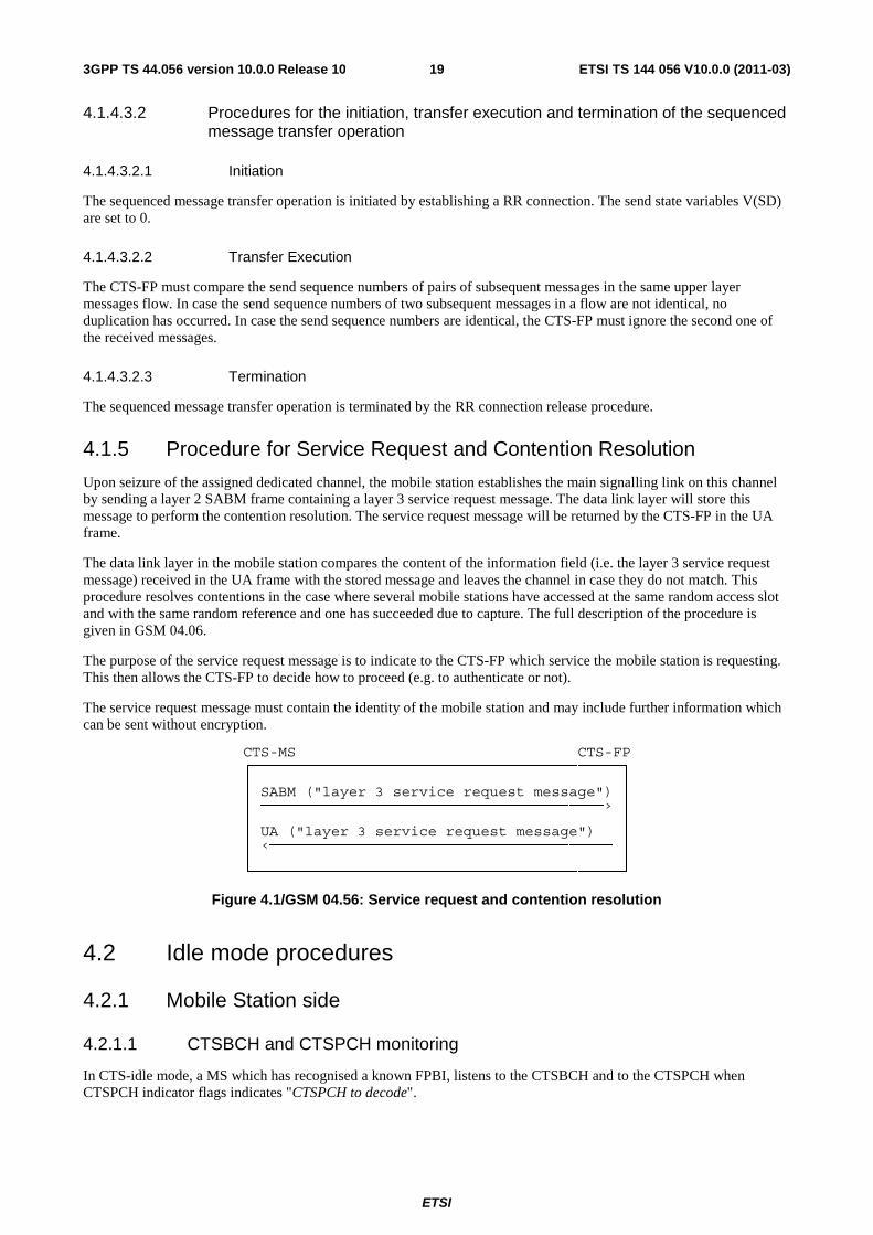
ETSI
ETSI TS 144 056 V10.0.0 (2011-03)193GPP TS 44.056 version 10.0.0 Release 10
4.1.4.3.2 Procedures for the initiation, transfer execution and termination of the sequenced message transfer operation
4.1.4.3.2.1 Initiation
The sequenced message transfer operation is initiated by establishing a RR connection. The send state variables V(SD) are set to 0.
4.1.4.3.2.2 Transfer Execution
The CTS-FP must compare the send sequence numbers of pairs of subsequent messages in the same upper layer messages flow. In case the send sequence numbers of two subsequent messages in a flow are not identical, no duplication has occurred. In case the send sequence numbers are identical, the CTS-FP must ignore the second one of the received messages.
4.1.4.3.2.3 Termination
The sequenced message transfer operation is terminated by the RR connection release procedure.
4.1.5 Procedure for Service Request and Contention Resolution
Upon seizure of the assigned dedicated channel, the mobile station establishes the main signalling link on this channel by sending a layer 2 SABM frame containing a layer 3 service request message. The data link layer will store this message to perform the contention resolution. The service request message will be returned by the CTS-FP in the UA frame.
The data link layer in the mobile station compares the content of the information field (i.e. the layer 3 service request message) received in the UA frame with the stored message and leaves the channel in case they do not match. This procedure resolves contentions in the case where several mobile stations have accessed at the same random access slot and with the same random reference and one has succeeded due to capture. The full description of the procedure is given in GSM 04.06.
The purpose of the service request message is to indicate to the CTS-FP which service the mobile station is requesting. This then allows the CTS-FP to decide how to proceed (e.g. to authenticate or not).
The service request message must contain the identity of the mobile station and may include further information which can be sent without encryption.
CTS-MS CTS-FP ┌──────────────────────────────────────────┐ │ │ │ SABM ("layer 3 service request message") │ │ ───────────────────────────────────────› │ │ │ │ UA ("layer 3 service request message") │ │ ‹─────────────────────────────────────── │ │ │ └──────────────────────────────────────────┘
Figure 4.1/GSM 04.56: Service request and contention resolution
4.2 Idle mode procedures
4.2.1 Mobile Station side
4.2.1.1 CTSBCH and CTSPCH monitoring
In CTS-idle mode, a MS which has recognised a known FPBI, listens to the CTSBCH and to the CTSPCH when CTSPCH indicator flags indicates "CTSPCH to decode".
ETSI
ETSI TS 144 056 V10.0.0 (2011-03)203GPP TS 44.056 version 10.0.0 Release 10
4.2.1.2 Alive check response
When the CTSPCH contains an CTS ALIVE CHECK REQUEST message, the addressed CTS-MS shall send a CTS ALIVE CHECK RESPONSE message. A CTS ALIVE CHECK RESPONSE message shall be send by the CTS-MS in response to each CTS ALIVE CHECK REQUEST message received with the corresponding CTSMSI.
The CTS ALIVE CHECK RESPONSE messages are sent on the CTSARCH and contain as parameters:
- an establishment cause which corresponds to "attachment update" given by the RR entity in response to a CTS ALIVE CHECK REQUEST message;
- the CTS-MS Mobile Subscriber Identity.
4.2.2 CTS-FP side
4.2.2.1 CTSBCH information broadcasting
FPBI and CTS-FP status are regularly broadcast by the CTS-FP on the CTSBCH. Based on this information, the CTS-MS is able to decide whether it may gain access to the CTS-FP.
The information broadcast may be grouped in the following classes:
- information giving unique identification of the current CTS-FP cell;
- information describing the Training Sequence Code to be used in dedicated mode;
- information describing the Radio Resource availability at the CTS-FP side;
- information describing the presence of a Paging Channel;
- information describing the timeslot number to be used by the CTSCCH except CTSBCH (i.e. CTSARCH, CTSPCH and CTSAGCH);
- information describing the shifting status of the CTSBCH.
4.2.2.2 CTSPCH information broadcasting
In pure idle mode, the Paging Channel is not used. The CTS-FP shall set the CTSPCH indicator flag to "no CTSPCH" value.
4.2.2.3 Alive check
The CTS-FP initiates the alive check procedure by broadcasting a CTS PAGING REQUEST message with an indication of Alive Check, and start timer TC3101. The CTSPCH indicator flag shall be set to "CTSPCH to decode" and the CTSBCH-SB Status field shall be set to idle. The alive check procedure shall not be triggered if the CTS-FP is in a busy state (no radio resources available); i.e. CTS-FP RR layer shall reject upper layer alive check procedure initiation request.
When receiving a CTS PAGING REQUEST with an indication of Alive Check, the CTS-MS shall send 2 CTS ACCESS REQUEST messages.
When receiving a valid CTS ACCESS REQUEST, the CTS-FP shall stop timer TC3101.
The CTS-FP RR sublayer shall end the alive check procedure when:
- a CTS ACCESS REQUEST with a valid cause has been received from the polled CTS-MS; or
-- timer TC3101 expires; or
- an end of alive check procedure is triggered by the upper layer; or
- a paging procedure requiring a new PAGING REQUEST message to be started; or
- a busy state occurs (i.e. no more radio resource available).
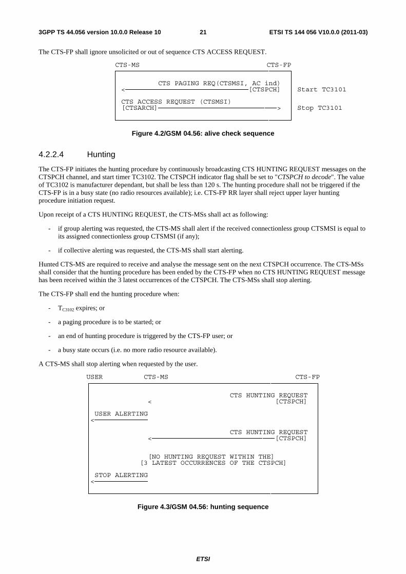
ETSI
ETSI TS 144 056 V10.0.0 (2011-03)213GPP TS 44.056 version 10.0.0 Release 10
The CTS-FP shall ignore unsolicited or out of sequence CTS ACCESS REQUEST.
CTS-MS CTS-FP ┌──────────────────────────────────────────┐ │ │ │ CTS PAGING REQ(CTSMSI, AC ind) │
│ <──────────────────────────────[CTSPCH] │ Start TC3101 │ │ │ CTS ACCESS REQUEST (CTSMSI) │
│ [CTSARCH]─────────────────────────────> │ Stop TC3101 │ │ └──────────────────────────────────────────┘
Figure 4.2/GSM 04.56: alive check sequence
4.2.2.4 Hunting
The CTS-FP initiates the hunting procedure by continuously broadcasting CTS HUNTING REQUEST messages on the CTSPCH channel, and start timer TC3102. The CTSPCH indicator flag shall be set to "CTSPCH to decode". The value of TC3102 is manufacturer dependant, but shall be less than 120 s. The hunting procedure shall not be triggered if the CTS-FP is in a busy state (no radio resources available); i.e. CTS-FP RR layer shall reject upper layer hunting procedure initiation request.
Upon receipt of a CTS HUNTING REQUEST, the CTS-MSs shall act as following:
- if group alerting was requested, the CTS-MS shall alert if the received connectionless group CTSMSI is equal to its assigned connectionless group CTSMSI (if any);
- if collective alerting was requested, the CTS-MS shall start alerting.
Hunted CTS-MS are required to receive and analyse the message sent on the next CTSPCH occurrence. The CTS-MSs shall consider that the hunting procedure has been ended by the CTS-FP when no CTS HUNTING REQUEST message has been received within the 3 latest occurrences of the CTSPCH. The CTS-MSs shall stop alerting.
The CTS-FP shall end the hunting procedure when:
- TC3102 expires; or
- a paging procedure is to be started; or
- an end of hunting procedure is triggered by the CTS-FP user; or
- a busy state occurs (i.e. no more radio resource available).
A CTS-MS shall stop alerting when requested by the user.
USER CTS-MS CTS-FP ┌───────────────────────────────────────────────────────┐ │ │ │ CTS HUNTING REQUEST │ │ <──────────────────────────────[CTSPCH] │ │ │ │ USER ALERTING │ │<───────────── │ │ │ │ CTS HUNTING REQUEST │ │ <──────────────────────────────[CTSPCH] │ │ │ │ │ │ [NO HUNTING REQUEST WITHIN THE] │ │ [3 LATEST OCCURRENCES OF THE CTSPCH] │ │ │ │ STOP ALERTING │ │<───────────── │ │ │ └───────────────────────────────────────────────────────┘
Figure 4.3/GSM 04.56: hunting sequence
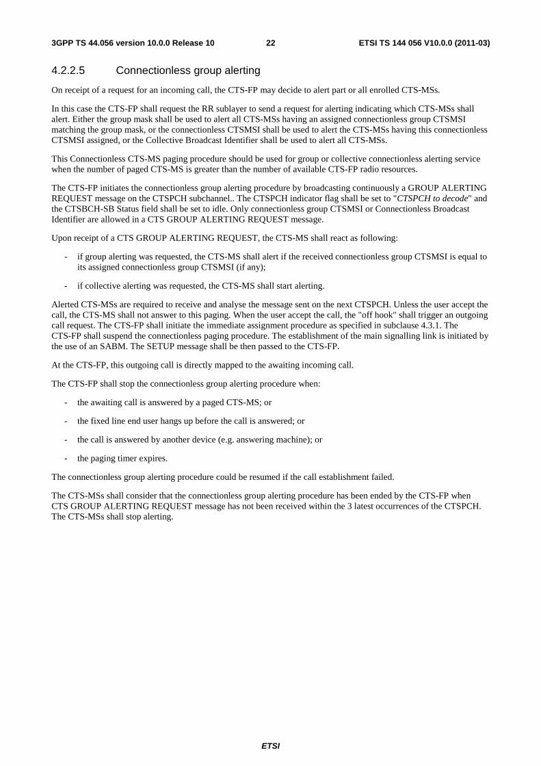
ETSI
ETSI TS 144 056 V10.0.0 (2011-03)223GPP TS 44.056 version 10.0.0 Release 10
4.2.2.5 Connectionless group alerting
On receipt of a request for an incoming call, the CTS-FP may decide to alert part or all enrolled CTS-MSs.
In this case the CTS-FP shall request the RR sublayer to send a request for alerting indicating which CTS-MSs shall alert. Either the group mask shall be used to alert all CTS-MSs having an assigned connectionless group CTSMSI matching the group mask, or the connectionless CTSMSI shall be used to alert the CTS-MSs having this connectionless CTSMSI assigned, or the Collective Broadcast Identifier shall be used to alert all CTS-MSs.
This Connectionless CTS-MS paging procedure should be used for group or collective connectionless alerting service when the number of paged CTS-MS is greater than the number of available CTS-FP radio resources.
The CTS-FP initiates the connectionless group alerting procedure by broadcasting continuously a GROUP ALERTING REQUEST message on the CTSPCH subchannel.. The CTSPCH indicator flag shall be set to "CTSPCH to decode" and the CTSBCH-SB Status field shall be set to idle. Only connectionless group CTSMSI or Connectionless Broadcast Identifier are allowed in a CTS GROUP ALERTING REQUEST message.
Upon receipt of a CTS GROUP ALERTING REQUEST, the CTS-MS shall react as following:
- if group alerting was requested, the CTS-MS shall alert if the received connectionless group CTSMSI is equal to its assigned connectionless group CTSMSI (if any);
- if collective alerting was requested, the CTS-MS shall start alerting.
Alerted CTS-MSs are required to receive and analyse the message sent on the next CTSPCH. Unless the user accept the call, the CTS-MS shall not answer to this paging. When the user accept the call, the "off hook" shall trigger an outgoing call request. The CTS-FP shall initiate the immediate assignment procedure as specified in subclause 4.3.1. The CTS-FP shall suspend the connectionless paging procedure. The establishment of the main signalling link is initiated by the use of an SABM. The SETUP message shall be then passed to the CTS-FP.
At the CTS-FP, this outgoing call is directly mapped to the awaiting incoming call.
The CTS-FP shall stop the connectionless group alerting procedure when:
- the awaiting call is answered by a paged CTS-MS; or
- the fixed line end user hangs up before the call is answered; or
- the call is answered by another device (e.g. answering machine); or
- the paging timer expires.
The connectionless group alerting procedure could be resumed if the call establishment failed.
The CTS-MSs shall consider that the connectionless group alerting procedure has been ended by the CTS-FP when CTS GROUP ALERTING REQUEST message has not been received within the 3 latest occurrences of the CTSPCH. The CTS-MSs shall stop alerting.
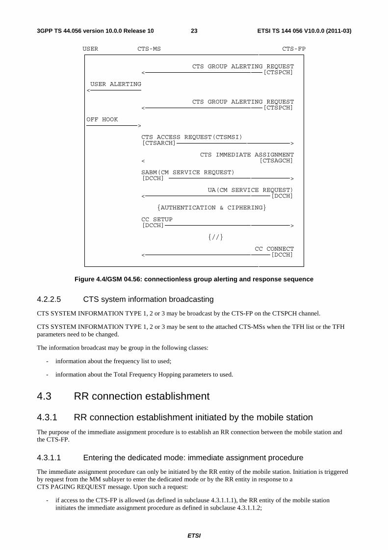
ETSI
ETSI TS 144 056 V10.0.0 (2011-03)233GPP TS 44.056 version 10.0.0 Release 10
USER CTS-MS CTS-FP ┌───────────────────────────────────────────────────────┐ │ │ │ CTS GROUP ALERTING REQUEST │ │ <──────────────────────────────[CTSPCH] │ │ │ │ USER ALERTING │ │<───────────── │ │ │ │ CTS GROUP ALERTING REQUEST │ │ <──────────────────────────────[CTSPCH] │ │ │ │OFF HOOK │ │─────────────> │ │ │ │ CTS ACCESS REQUEST(CTSMSI) │ │ [CTSARCH]─────────────────────────────> │ │ │ │ CTS IMMEDIATE ASSIGNMENT │ │ <─────────────────────────────[CTSAGCH] │ │ │ │ SABM(CM SERVICE REQUEST) │ │ [DCCH] ───────────────────────────────> │ │ │ │ UA(CM SERVICE REQUEST) │ │ <────────────────────────────────[DCCH] │ │ │ │ {AUTHENTICATION & CIPHERING} │ │ │ │ CC SETUP │ │ [DCCH]────────────────────────────────> │ │ │ │ {//} │ │ │ │ CC CONNECT │ │ <────────────────────────────────[DCCH] │ │ │ └───────────────────────────────────────────────────────┘
Figure 4.4/GSM 04.56: connectionless group alerting and response sequence
4.2.2.5 CTS system information broadcasting
CTS SYSTEM INFORMATION TYPE 1, 2 or 3 may be broadcast by the CTS-FP on the CTSPCH channel.
CTS SYSTEM INFORMATION TYPE 1, 2 or 3 may be sent to the attached CTS-MSs when the TFH list or the TFH parameters need to be changed.
The information broadcast may be group in the following classes:
- information about the frequency list to used;
- information about the Total Frequency Hopping parameters to used.
4.3 RR connection establishment
4.3.1 RR connection establishment initiated by the mobile station
The purpose of the immediate assignment procedure is to establish an RR connection between the mobile station and the CTS-FP.
4.3.1.1 Entering the dedicated mode: immediate assignment procedure
The immediate assignment procedure can only be initiated by the RR entity of the mobile station. Initiation is triggered by request from the MM sublayer to enter the dedicated mode or by the RR entity in response to a CTS PAGING REQUEST message. Upon such a request:
- if access to the CTS-FP is allowed (as defined in subclause 4.3.1.1.1), the RR entity of the mobile station initiates the immediate assignment procedure as defined in subclause 4.3.1.1.2;
ETSI
ETSI TS 144 056 V10.0.0 (2011-03)243GPP TS 44.056 version 10.0.0 Release 10
- otherwise, it rejects the request.
The request from the MM sublayer to establish an RR connection specifies an establishment cause. Similarly, the request from the RR entity to establish a RR connection in response to a paging message specifies one of the establishment causes "answer to paging".
4.3.1.1.1 Permission to access the CTS-FP
Access to the CTS-FP is allowed to any enrolled CTS-MS when the CTSBCH status field indicates idle. CTS-MS shall not try to access the CTS-FP when the status field indicates busy and it shall continue to decode CTSBCH and if needed CTSPCH or CTSAGCH.
4.3.1.1.2 Initiation of the immediate assignment procedure
The RR entity of the CTS-MS initiates the immediate assignment procedure by scheduling the sending on the CTSARCH and leaving idle mode. It then send maximally MCTS + 1 CTS ACCESS REQUEST messages on the CTSARCH.
The CTS ACCESS REQUEST messages are sent on the non-hopping CTSARCH for the enrolment and attachment MM-procedures and on the hopping CTSARCH for the other cases. They contain as parameters:
- an establishment cause which corresponds to the establishment causes given by the MM sublayer or which corresponds to one of the establishment causes "answer to paging" given by the RR entity in response to a CTS PAGING REQUEST message;
- the CTS-MS Mobile Subscriber Identity.
After sending the first CTS ACCESS REQUEST, the CTS-MS shall start listening continuously to the CTSAGCH. After having sent MCTS + 1 CTS ACCESS REQUEST messages, the CTS-RR entity of the CTS-MS shall start timer TC3150. At expiry of this timer, the immediate assignment procedure is aborted. If the immediate assignment procedure was triggered by a request from the CTS-MM sublayer, a access failure is indicated to the CTS-MM sublayer.
4.3.1.1.3 Answer from the CTS-FP
4.3.1.1.3.1 On receipt of a CTS ACCESS REQUEST message
The CTS-FP may allocate a dedicated channel to the CTS-MS by sending an CTS IMMEDIATE ASSIGNMENT message in unacknowledged mode. Timer TC3103 is then started by the CTS-RR layer of the CTS-FP.
The CTS IMMEDIATE ASSIGNMENT message contains:
- the access request reference (cause, CTSMSI);
- the description of the dedicated channel;
- optionally the multiframe number reference.
4.3.1.1.3.2 Assignment rejection
If no channel is available for assignment, the CTS-FP may send to the CTS-MS a CTS IMMEDIATE ASSIGNMENT REJECT in unacknowledged mode in the CTSAGCH channel. This message contains an access request reference and a wait indication.
4.3.1.1.4 Assignment completion
The immediate assignment procedure is terminated on the CTS-FP side when the main signalling link is established. Timer TC3103 is stopped and the MM sublayer on the CTS-FP side is informed that the RR entity has entered the dedicated mode.
On the mobile station side, the procedure is terminated when the establishment of the main signalling link is confirmed. The MM sublayer is informed that the RR entity has entered the dedicated mode.
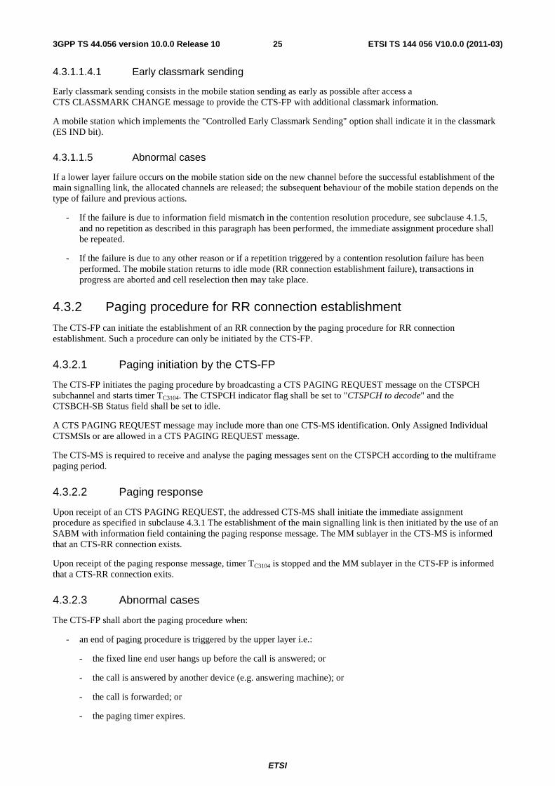
ETSI
ETSI TS 144 056 V10.0.0 (2011-03)253GPP TS 44.056 version 10.0.0 Release 10
4.3.1.1.4.1 Early classmark sending
Early classmark sending consists in the mobile station sending as early as possible after access a CTS CLASSMARK CHANGE message to provide the CTS-FP with additional classmark information.
A mobile station which implements the "Controlled Early Classmark Sending" option shall indicate it in the classmark (ES IND bit).
4.3.1.1.5 Abnormal cases
If a lower layer failure occurs on the mobile station side on the new channel before the successful establishment of the main signalling link, the allocated channels are released; the subsequent behaviour of the mobile station depends on the type of failure and previous actions.
- If the failure is due to information field mismatch in the contention resolution procedure, see subclause 4.1.5, and no repetition as described in this paragraph has been performed, the immediate assignment procedure shall be repeated.
- If the failure is due to any other reason or if a repetition triggered by a contention resolution failure has been performed. The mobile station returns to idle mode (RR connection establishment failure), transactions in progress are aborted and cell reselection then may take place.
4.3.2 Paging procedure for RR connection establishment
The CTS-FP can initiate the establishment of an RR connection by the paging procedure for RR connection establishment. Such a procedure can only be initiated by the CTS-FP.
4.3.2.1 Paging initiation by the CTS-FP
The CTS-FP initiates the paging procedure by broadcasting a CTS PAGING REQUEST message on the CTSPCH subchannel and starts timer TC3104. The CTSPCH indicator flag shall be set to "CTSPCH to decode" and the CTSBCH-SB Status field shall be set to idle.
A CTS PAGING REQUEST message may include more than one CTS-MS identification. Only Assigned Individual CTSMSIs or are allowed in a CTS PAGING REQUEST message.
The CTS-MS is required to receive and analyse the paging messages sent on the CTSPCH according to the multiframe paging period.
4.3.2.2 Paging response
Upon receipt of an CTS PAGING REQUEST, the addressed CTS-MS shall initiate the immediate assignment procedure as specified in subclause 4.3.1 The establishment of the main signalling link is then initiated by the use of an SABM with information field containing the paging response message. The MM sublayer in the CTS-MS is informed that an CTS-RR connection exists.
Upon receipt of the paging response message, timer TC3104 is stopped and the MM sublayer in the CTS-FP is informed that a CTS-RR connection exits.
4.3.2.3 Abnormal cases
The CTS-FP shall abort the paging procedure when:
- an end of paging procedure is triggered by the upper layer i.e.:
- the fixed line end user hangs up before the call is answered; or
- the call is answered by another device (e.g. answering machine); or
- the call is forwarded; or
- the paging timer expires.
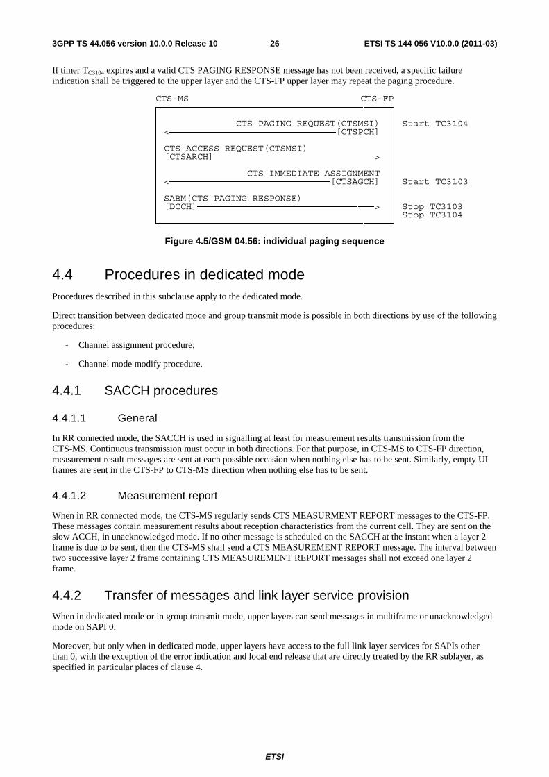
ETSI
ETSI TS 144 056 V10.0.0 (2011-03)263GPP TS 44.056 version 10.0.0 Release 10
If timer TC3104 expires and a valid CTS PAGING RESPONSE message has not been received, a specific failure indication shall be triggered to the upper layer and the CTS-FP upper layer may repeat the paging procedure.
CTS-MS CTS-FP ┌──────────────────────────────────────────┐ │ │
│ CTS PAGING REQUEST(CTSMSI) │ Start TC3104 │ <──────────────────────────────[CTSPCH] │ │ │ │ CTS ACCESS REQUEST(CTSMSI) │ │ [CTSARCH]─────────────────────────────> │ │ │ │ CTS IMMEDIATE ASSIGNMENT │
│ <─────────────────────────────[CTSAGCH] │ Start TC3103 │ │ │ SABM(CTS PAGING RESPONSE) │
│ [DCCH]────────────────────────────────> │ Stop TC3103 │ │ Stop TC3104
└──────────────────────────────────────────┘
Figure 4.5/GSM 04.56: individual paging sequence
4.4 Procedures in dedicated mode Procedures described in this subclause apply to the dedicated mode.
Direct transition between dedicated mode and group transmit mode is possible in both directions by use of the following procedures:
- Channel assignment procedure;
- Channel mode modify procedure.
4.4.1 SACCH procedures
4.4.1.1 General
In RR connected mode, the SACCH is used in signalling at least for measurement results transmission from the CTS-MS. Continuous transmission must occur in both directions. For that purpose, in CTS-MS to CTS-FP direction, measurement result messages are sent at each possible occasion when nothing else has to be sent. Similarly, empty UI frames are sent in the CTS-FP to CTS-MS direction when nothing else has to be sent.
4.4.1.2 Measurement report
When in RR connected mode, the CTS-MS regularly sends CTS MEASURMENT REPORT messages to the CTS-FP. These messages contain measurement results about reception characteristics from the current cell. They are sent on the slow ACCH, in unacknowledged mode. If no other message is scheduled on the SACCH at the instant when a layer 2 frame is due to be sent, then the CTS-MS shall send a CTS MEASUREMENT REPORT message. The interval between two successive layer 2 frame containing CTS MEASUREMENT REPORT messages shall not exceed one layer 2 frame.
4.4.2 Transfer of messages and link layer service provision
When in dedicated mode or in group transmit mode, upper layers can send messages in multiframe or unacknowledged mode on SAPI 0.
Moreover, but only when in dedicated mode, upper layers have access to the full link layer services for SAPIs other than 0, with the exception of the error indication and local end release that are directly treated by the RR sublayer, as specified in particular places of clause 4.
ETSI
ETSI TS 144 056 V10.0.0 (2011-03)273GPP TS 44.056 version 10.0.0 Release 10
4.4.3 Intracell handover procedure
In dedicated mode, an intracell change of channel can be requested by upper layers for changing the channel type, or decided by the RR sublayer, e.g. for an internal handover. This change may be performed through the dedicated channel assignment procedure.
The purpose of the channel assignment procedure is to completely modify the physical channel configuration of the mobile station without frequency redefinition or change in synchronisation while staying in the same CTS-cell.
This procedure shall not be used for changing between dependent configurations, i.e. those sharing Radio Resource for the main signalling link. An example of dependent channels is a full rate channel and one of the corresponding half rate channels. In multislot operation however, it is allowed to use the same timeslots before and after the assignment, as long as the main signalling link has been changed. The only procedures provided for changing between dependent configurations for the main signalling link are the additional assignment and the partial release procedures.
The channel assignment procedure happens only in dedicated mode. This procedure cannot be used in the idle mode; in this case the immediate assignment procedure is used.
The channel assignment procedure includes:
- the suspension of normal operation except for RR management (layer 3);
- the release of the main signalling link, and of the other data links as defined in subclause 4.1.4, and the disconnection of TCHs if any;
- the deactivation of previously assigned channels (layer 1);
- the activation of the new channels and their connection if applicable;
- the triggering of the establishment of the data link connections for SAPI = 0.
The channel assignment procedure is always initiated by the CTS-FP.
4.4.3.1 Intracell handover initiation
The CTS-FP initiates the intracell handover procedure by sending a CTS INTRACELL HANDOVER COMMAND message to the CTS-MS on the main signalling link. The CTS-FP then starts timer TC3105. When sending this message on the CTS-FP side, and receiving it on the CTS-MS side, all transmission of signalling layer message except for those RR messages needed for this procedure and for abnormal cases is suspended until resumption is indicated.
Upon receipt of the CTS INTRACELL HANDOVER COMMAND message, the CTS-MS initiates a local end release of link layer connections, disconnects the physical channels, commands the switching to the assigned channel and initiates the establishment of lower layer connections.
The CTS-MS shall wait up to the starting time before accessing the channel. If the starting time has already elapsed, the CTS-MS shall access the channel as an immediate reaction to the reception of the message.
4.4.3.2 Intracell handover completion
After the main signalling link is successfully established, the CTS-MS returns a CTS INTRACELL HANDOVER COMPLETE message specifying cause "normal event'' to the CTS-FP on the main DCCH.
The sending of this message on the CTS-MS side and its receipt on the CTS-FP side allow the resumption of the transmission of signalling layer messages other than those belonging to RR management.
At the receipt of the CTS INTRACELL HANDOVER, the CTS-FP releases the previously allocated resources and stops timer TC3105.
4.4.3.3 Abnormal cases
If the CTS INTRACELL HANDOVER COMMAND instruct the CTS-MS to use a parameter that it is not capable of, then the CTS-MS shall return a CTS INTRACELL HANDOVER FAILURE message, and the CTS-MS shall remain on the current channel(s) and use the old channel description or channel mode.

ETSI
ETSI TS 144 056 V10.0.0 (2011-03)283GPP TS 44.056 version 10.0.0 Release 10
When receiving a CTS INTRACELL HANDOVER FAILURE message, the CTS-FP stops TC3105.
On the CTS-FP side, if timer TC3105 elapses before either the CTS INTRACELL HANDOVER COMPLETE message has been receive on the new channel or a CTS INTRACELL HANDOVER FAILURE message is received or the CTS-MS has re-established the call, the old and the new channels are released and all contexts related to the connection with that CTS-MS are cleared.
4.4.4 Intercell handover procedure
Intercell handover is a CTS phase 2 issue.
4.4.5 Frequency hopping definition procedure
This procedure is used by the CTS-FP to update the Total Frequency Hopping List and Total Frequency Hopping parameters in the MS. The CTS-FP send a CTS FREQUENCY HOPPING DEFINITION message containing the new parameters together with a reference time indication. The TFH parameters are split in general static parameters and current dynamic parameters which are valid for a given TDMA frame number. The values indicated by the current parameters IE are those used by the TFH algorithm at the frame number indicated by the reference time. These parameters shall be used after the RR connection is released when the MS is returning in idle mode.
4.4.6 Channel mode modify procedure
In dedicated mode, higher layers can request the setting of the channel mode.
The channel mode modify procedure allows the CTS-FP to request the mobile station to set the channel mode for one channel or one channel set. The channel mode covers the coding, decoding and transcoding mode used on the indicated channel.
This procedure is always initiated by the CTS-FP.
NOTE: Direct transitions between full rate speech coder version 1 and full rate speech coder version 2 (and vice versa) may cause unpleasant audio bursts.
4.4.6.1 Normal channel mode modify procedure
4.4.6.1.1 Initiation of the channel mode modify procedure
The FP initiates the procedure by sending a message CTS CHANNEL MODE MODIFY to the CTS-MS. This message contains:
- a channel description of the channel(s) on which the specified mode shall be applied; and
- the mode to be used on that channel.
4.4.6.1.2 Completion of channel mode modify procedure
When it has received the CTS CHANNEL MODE MODIFY message, the CTS-MS sets the mode for the indicated channel, and if that is in a multislot configuration, the whole channel set and then replies by a CTS CHANNEL MODE MODIFY ACKNOWLEDGE message indicating the ordered channel mode.
This applies whether the mode commanded by the CTS CHANNEL MODE MODIFY message is different from the one used by the CTS-MS or whether it is already in use.
4.4.6.1.3 Abnormal cases
No specific action for a lower layer failure is specified in this subclause. If the mobile station does not support the indicated mode, it shall retain the old mode and return the associated channel mode information in CTS CHANNEL MODE MODIFY message.
ETSI
ETSI TS 144 056 V10.0.0 (2011-03)293GPP TS 44.056 version 10.0.0 Release 10
4.4.7 Ciphering mode setting procedure
In dedicated mode, the ciphering mode setting procedure is used by the FP to set the ciphering mode, i.e. whether or not the transmission is ciphered, and if so which algorithm to use. The procedure shall only be used to change from "not ciphered" mode to "ciphered" mode, or vice-versa, or to pass a CTS CIPHERING MODE COMMAND message to the mobile station while remaining in the "not ciphered" mode. The ciphering mode setting procedure is always triggered by the FP and it only applies to dedicated resources.
4.4.7.1 Ciphering mode setting initiation
The CTS-FP initiates the ciphering mode setting procedure by sending a CTS CIPHERING MODE COMMAND message to the mobile station on the main signalling link, indicating whether ciphering shall be used or not, and if yes which algorithm to use.
The new mode is applied for reception on the CTS-FP side after the message has been sent.
4.4.7.2 Ciphering mode setting completion
Whenever the CTS-MS receives a CTS CIPHERING MODE COMMAND message, it shall, if a SIM is present and considered valid by the mobile equipment and the ciphering key sequence number stored on the SIM indicates that a CTS ciphering key is available, load the ciphering key stored on the SIM into the ME. A valid CTS CIPHERING MODE COMMAND message is defined to be one of the following:
- one that indicates "start ciphering" and is received by the mobile station in the "not ciphered" mode;
- one that indicates "no ciphering" and is received by the MS in the "not ciphered" mode; or
- one that indicates "no ciphering" and is received by the mobile station in the "ciphered" mode.
Other CTS CIPHERING MODE COMMAND messages shall be regarded as erroneous, an CTS RR STATUS message with cause "Protocol error unspecified" shall be returned, and no further action taken.
Upon receipt of the CTS CIPHERING MODE COMMAND message indicating ciphering, the mobile station shall start transmission and reception in the indicated mode.
When the appropriate action on the CTS CIPHERING MODE COMMAND has been taken, the mobile station sends back a CTS CIPHERING MODE COMPLETE message. If the "cipher response" field of the cipher response information element in the CTS CIPHERING MODE COMMAND message specified "IMEI must be included" the mobile station shall include its IMEISV in the CTS CIPHERING MODE COMPLETE message.
Upon receipt of the CTS CIPHERING MODE COMPLETE message or any other correct layer 2 frame which was sent in the new mode, the CTS-FP starts transmission in the new mode.
CTS-MS CTS-FP
CTS CIPH MOD CMD <──────────────────────────
<──── start reception start ────> in new mode transmission and ÷ reception in new mode ÷
CTS CIPH MOD COM ──────────────────────────>
<───── start trans- mission in new mode
Figure 4.6/GSM 04.56: Ciphering mode setting sequence
4.4.8 [Reserved: Additional channel assignment procedure]
This is a CTS phase 2 issue.
ETSI
ETSI TS 144 056 V10.0.0 (2011-03)303GPP TS 44.056 version 10.0.0 Release 10
4.4.9 [Reserved: Partial channel release procedure]
This is a CTS phase 2 issue.
4.4.10 Classmark change procedure
In dedicated mode, this procedure allows the mobile station to indicate to the CTS-FP a change of characteristics reflected in the classmark (e.g. due to addition of power amplification). Furthermore, a mobile station which implements the "controlled early classmark sending" option may also send a CTS CLASSMARK CHANGE message as described in subclause 4.3.1.1.4, even if no change of characteristics has occurred.
The mobile station sends a CTS CLASSMARK CHANGE message to the CTS-FP. This message contains the new mobile station classmark 2 information element. It may also contain a Classmark 3 Information Element. There is no acknowledgement from the CTS-FP at layer 3.
4.4.11 Classmark interrogation procedure
This procedure allows the CTS-FP to request additional classmark information from the mobile station (e.g. if the information initially sent by the mobile station is not sufficient for CTS-FP decisions).
The CTS-FP initiate the classmark interrogation procedure by sending a CTS CLASSMARK ENQUIRY message to the CTS-MS on the main DCCH.
on receipt of the CTS CLASSMARK ENQUIRY message, the CTS-MS sends a CTS CLASSMARK CHANGE message to the CTS-FP on the main DCCH.
4.4.12 [Reserved]
4.4.13 RR connection release procedure
4.4.13.1 Normal release procedure
The release of the RR connection can be requested by upper layers.
The purpose of this procedure is to deactivate all the dedicated channels in use for this RR connection. When the channels are released, the mobile station returns to the idle mode. The channel release procedure can be used in a variety of cases, including TCH release after a call release, and DCCH release when a dedicated channel allocated for signalling is released.
In dedicated mode, the channel release procedure is always initiated by the CTS-FP.
4.4.13.1.1 Channel release procedure initiation
The CTS-FP initiates the channel release procedure by sending a CTS CHANNEL RELEASE message to the CTS-MS on the main DCCH, starts timer TC3106 and deactivates the SACCH.
On receipt of a CTS CHANNEL RELEASE message, the CTS-MS starts timer TC3151 and disconnect the main signalling link. When TC3151 times out or when the disconnection is confirmed, the CTS-MS deactivates all signalling link, considers the RR connection as released, and returns to idle mode.
On CTS-FP side, when the main signalling link is disconnected, the CTS-FP stops timer TC3106 and starts timer TC3107. When timer TC3107 times out, the CTS-FP deactivates the channels. If timer TC3106 times out, the CTS-FP deactivates the channels.
4.4.13.1.2 Abnormal case
Abnormal cases are taken into account in the main part of the description of the procedure.

ETSI
ETSI TS 144 056 V10.0.0 (2011-03)313GPP TS 44.056 version 10.0.0 Release 10
4.4.13.2 Radio link fai2lure in dedicated mode
The main part of these procedures concerns the "normal" cases, i.e. those without any occurrence of loss of communication means. A separate paragraph at the end of the description of each procedure treats the cases of loss of communication, called a radio link failure. In dedicated mode, in most of the cases the reaction of the mobile station or the CTS-FP is the same. Those reactions are described in this subclause to avoid repetitions.
A radio link failure can be detected by several ways:
1) by analysis of reception at layer 1, as specified in GSM 05.08 and subclause 4.4.1.1;
2) by a data link layer failure as specified in GSM 04.06, on the main signalling link. A data link failure on any other data link shall not be considered as a radio link failure;
3) when a lower layer failure happens while the mobile station attempts to connect back to the old channels in a channel assignment procedure or handover procedure;
4) in some cases where timers are started to detect the lack of answer from the other party, as described in clause 3.
The two first cases are known by the term "lower layer failure".
4.4.13.2.1 Mobile side
When a radio link failure is detected by the mobile station:
- the MS shall perform a local end release on all signalling links unless otherwise specified;
- the mobile station shall deactivate all channels;
- the RR sublayer of the mobile station shall indicate an RR connection failure to the MM sublayer unless otherwise specified.
NOTE: Upper layers may decide on a re-establishment (see subclause 5.5.4).
4.4.13.2.2 CTS-FP side
When a radio link failure has been detected, an indication is passed to the upper sublayer on CTS-FP side.
The CTS-FP should release the connection except when otherwise specified, either with the channel release procedure as specified in subclause 4.4.13.1 or with the following procedure. The CTS-FP start timer TC3106 and deactivates the SACCH and hence stops transmission on the SACCH. When timer TC3106 expires, the CTS-FP can regard the channel as released.
NOTE: The CTS-FP The network should maintain for a while the transaction context in order to allow call re-establishment.
4.4.13.3 RR connection abortion in dedicated mode
The mobile station aborts the RR connection by initiating a normal release of the main signalling link, performing local end releases on all other signalling links and disconnecting all traffic channels, if any.
4.4.14 Receiving CTS RR STATUS message by a CTS-RR entity
If the CTS-RR entity of the mobile station receives a CTS RR STATUS message no transition and no specific action shall be taken as seen from the radio interface, i.e. local actions are possible.
The actions to be taken on receiving a CTS RR STATUS message in the CTS-FP are defined in GSM 04.08. See also clause 8.
4.4.15 CTS RR parameters update
This procedure allows the CTS-FP to provide mandatory parameters to the mobile station. It shall be initiated during enrolment and attachment MM-procedures.
ETSI
ETSI TS 144 056 V10.0.0 (2011-03)323GPP TS 44.056 version 10.0.0 Release 10
The CTS-FP sends the CTS RR PARAMETERS UPDATE message containing the relevant parameters.
5 Elementary procedures for Mobility Management
5.1 General This subclause describes the procedures used for mobility management at the CTS radio interface (Reference Point Um*).
The general purpose of CTS Mobility Management sublayer is to support the mobility of the mobile stations, such as informing the fixed part of its presence and providing user identity confidentiality. The CTS-MM sublayer provides also connection management services to the different entities of the upper Connection Management (CM) sublayer.
All the CTS-MM procedures can only be performed if a CTS-RR connection has been established between the mobile station and the fixed part. If no CTS-RR connection is currently established, the CTS-MM sublayer has to initiate such establishment.
Depending of the CTS-MM procedure, they can be initiated either by the mobile station or by the fixed part or even indifferently by one of the two parties.
The CTS-FP may also start all mobility management procedures defined in GSM 04.08, including:
- the GSM authentication procedure;
- the GSM identity request procedure.
The messages defined in GSM 04.08 shall be used for these procedures.
5.1.1 Type of CTS-MM procedures
Depending on how they can be initiated, two types of CTS-MM procedures can be distinguished:
(i) CTS-MM common procedures:
A CTS-MM common procedure can always be initiated whilst a CTS-RR connection exists. The procedures belonging to this type are:
- Initiated by the fixed part:
- CTS mutual authentication procedure;
- CTSMSI update procedure;
- CTS de-enrolment procedure.
- Initiated by the mobile station
- CTS detach procedure.
(ii) CTS-MM specific procedures:
A CTS-MM specific procedure can only be initiated if no other MM specific procedure is running or no MM connection exists. The procedures belonging to this type are:
- Initiated by the mobile station:
- CTS enrolment procedure;
- CTS attach procedure;
- CTS re-attach procedure.
- Initiated by the fixed part:
ETSI
ETSI TS 144 056 V10.0.0 (2011-03)333GPP TS 44.056 version 10.0.0 Release 10
- CTS periodic attach update procedure.
These running procedures do not preclude from running procedures defined in the CTS supervising system layer 3 specification.
5.1.2 CTS-MM sublayer states
5.1.2.1 CTS-MM sublayer states in the mobile station
An additional machine describes the states related to the CTS.
5.1.2.1.1 Main states
1. WAIT FOR CTS-RR ACTIVE
The CTS-MM sublayer has requested activation of the CTS-RR sublayer.
2. WAIT FOR CTS-RR CONNECTION (ENROLMENT OR ATTACH)
The CTS-MM sublayer has requested CTS-RR connection establishment for starting the enrolment procedure or the attach one.
3. ATTACH INITIATED
The attach procedure has been started and the CTS-MM awaits a response from the fixed part. The timer TC3250 is running.
4. ENROLMENT INITIATED
The enrolment procedure has been started and the CTS-MM awaits a response from the fixed part. The timer TC3254 is running.
5. ATTACH REJECTED
The attach procedure has been rejected and CTS-RR connection release is awaited. The timer TC3256 is running.
6. ENROLMENT REJECTED
The enrolment procedure has been rejected and CTS-RR connection release is awaited.
7. AUTHENTICATION INITIATED
The mutual authentication procedure has been started by the fixed part.
8. CTS-MM IDLE
There is no MM procedure running and no RR connection exist. This is a compound state.
5.1.2.1.2 Substates of the CTS-MM IDLE state
8.1 NORMAL SERVICE
The mobile station is attached to a fixed part and it is reachable.
8.2 FP SEARCH
The mobile station is searching for fixed parts on which the mobile station is enrolled.

ETSI
ETSI TS 144 056 V10.0.0 (2011-03)343GPP TS 44.056 version 10.0.0 Release 10
8.3 NO FP AVAILABLE
No fixed part can be selected. This state is entered after a first intensive search failed. Fixed parts are searched at a low rhythm. No CTS services are offered.
5.1.2.2 CTS-MM sublayer states in the fixed part
1. IDLE
The CTS-MM sublayer is not active.
2. WAIT FOR CTS-RR CONNECTION
The CTS-MM sublayer has requested activation of the CTS-RR sublayer.
3. CTS-MM CONNECTION ACTIVE
The CTS-MM sublayer has a CTS-RR connection to a mobile station. One or more MM connections are active.
4. CTS AUTHENTICATION INITIATED
The authentication procedure has been started by the fixed part.
5. CTS DE-ENROLMENT INITIATED
The de-enrolment procedure has been started by the fixed part.
6. CTS CIPHERING MODE INITIATED
The cipher mode setting procedure has been requested to the CTS-RR-sublayer.
5.2 CTS-MM common procedures
5.2.1 CTS detach procedure
The purpose of the CTS detach procedure is to detach a mobile station from a fixed part. The mobile station may launch the detach procedure during the CTS mode deactivation (e.g. at the power off, when the SIM is extracted, when the mobile station is set in GSM mode only).
The CTS detach procedure is always initiated by the mobile station.
5.2.1.1 CTS detach initiation by the mobile station
The mobile station initiates the CTS detach procedure by sending a CTS DETACH INDICATION to the fixed part. The mobile station then starts timer TC3253.
If no RR connection exists, the MM sublayer within the mobile station will request the RR sublayer to establish a RR connection. If a RR connection exists, the MM sublayer will release locally any ongoing MM connections before the CTS DETACH INDICATION message is sent.
5.2.1.2 CTS detach procedure in the fixed part
On reception of a CTS DETACH INDICATION, the fixed part shall consider the mobile station as detached. No response is returned to the mobile station. After reception of the CTS DETACH INDICATION message, the fixed part shall release locally any ongoing MM connections, and start the normal RR connection release procedure.
5.2.1.3 CTS detach completion by the mobile station
Timer TC3253 is stopped when the RR connection is released. The mobile station should, if possible, delay the local release of the channel to allow a normal release from the fixed part until TC3253. If this is not possible (e.g. detach at power down) the RR sublayer on the mobile side should be aborted.
ETSI
ETSI TS 144 056 V10.0.0 (2011-03)353GPP TS 44.056 version 10.0.0 Release 10
5.2.1.4 Abnormal cases
If establishment of an RR connection is not possible, or the RR connection is lost, the CTS detach procedure is aborted by the mobile station.
5.2.2 CTS de-enrolment procedure
The purpose of the CTS de-enrolment procedure is to inform a CTS MS that it is no more enrolled on this CTS-FP.
The CTS de-enrolment procedure is always launched by the fixed part.
This procedure shall be launched when the mobile station has no more right to be enrolled (e.g. expiration of validity period, de-enrolment requested by the CTS operator). Any reference to this mobile station should be removed in the fixed part.
5.2.2.1 CTS de-enrolment initiation by the fixed part
The fixed part initiates the CTS de-enrolment procedure by sending a CTS DE-ENROLMENT INDICATION to the mobile station. Then the fixed part will request the RR sublayer to release the RR connection.
5.2.2.2 CTS de-enrolment procedure in the mobile station
On reception of a CTS DE-ENROLMENT INDICATION, the CTS-MS shall remove the corresponding CTS-FP of the list of the fixed parts on which the mobile station is enrolled.
The mobile station should inform the user that it is no more enrolled on this CTS-FP.
5.2.2.3 Abnormal cases
If establishment of an RR connection is not possible, or the RR connection is lost, the CTS de-enrolment procedure is aborted by the fixed part. Nevertheless, any reference to the corresponding mobile station should be removed in the fixed part.
5.2.3 CTS mutual authentication procedure
The purpose of the CTS mutual authentication procedure is:
- to permit the fixed part to check whether the identity provided by the mobile station is acceptable or not (see GSM 03.20 annex E);
- to permit the mobile station to check whether the identity provided by the fixed part is acceptable or not (see GSM 03.20 annex E);
- to agree on required parameters between the fixed part and mobile station to calculate a new ciphering key (see GSM 03.20 annex E).
The authentication procedure uses the CTSMSI if it is available. If it is not available or if the authentication fails using this identity, the authentication procedure shall be started again using the IMSI.
The CTS authentication procedure is always initiated by the CTS-FP on the radio interface.
This procedure shall be used each time an enrolment procedure or an attach procedure is started.
5.2.3.1 CTS authentication initiation by the fixed part
The fixed part initiates the CTS authentication procedure by sending a CTS MS AUTHENTICATION REQUEST message to the CTS-MS and starts the timer TC3211.
The CTS MS AUTHENTICATION REQUEST message specifies the authentication parameter.

ETSI
ETSI TS 144 056 V10.0.0 (2011-03)363GPP TS 44.056 version 10.0.0 Release 10
5.2.3.2 CTS authentication response by the mobile station
The mobile station shall be ready to respond upon a CTS MS AUTHENTICATION REQUEST message at any time whilst a CTS-RR connection exists.
On reception of a CTS MS AUTHENTICATION REQUEST from the fixed part, the mobile station shall send a CTS MS AUTHENTICATION RESPONSE and starts the timer TC3260.
The CTS MS AUTHENTICATION RESPONSE message specifies the authentication parameter CH2 and the authentication parameter SRES1.
5.2.3.3 CTS authentication processing by the fixed part
On reception of the CTS MS AUTHENTICATION RESPONSE from the mobile station, the fixed part shall stop the timer TC3211 and shall check the validity of the response (see GSM 03.20 annex E).
The fixed part shall respond with a CTS FP AUTHENTICATION RESPONSE message. This message specifies the authentication parameter SRES2.
5.2.3.4 CTS authentication completion by the mobile station
On reception of the CTS FP AUTHENTICATION RESPONSE from the fixed part, the mobile station shall stop the timer TC3260 and shall check the validity of the response (see GSM 03.20 annex E).
5.2.3.5 Unsuccessful authentication
If mobile station authentication fails, i.e. the response given by the mobile station is not valid, the fixed part may distinguish between the two different ways of identification: IMSI or CTSMSI. If the mobile station identifies itself using the CTSMSI, the fixed part may request the IMSI using the identity request procedure and may start a new mutual authentication procedure using the IMSI.
If the fixed part does not start a new authentication procedure, it shall sent a CTS MS AUTHENTICATION REJECT message to the mobile station. After having sent this message, the fixed part shall release any ongoing MM connections and shall initiate the RR connection release procedure. If fixed part authentication fails, i.e. the response given by the fixed part is not valid, the mobile station may abort the RR connection. In this case, the CTS-MS shall abort any MM ongoing procedure.
5.2.3.6 Abnormal cases
Fixed part side
(a) CTS-RR connection failure
Upon a detection of a CTS-RR connection failure before the CTS MS AUTHENTICATION RESPONSE is received, the fixed part shall release all MM connections (if any) and abort any ongoing MM specific procedure.
(b) Expiry of timer TC3211
The mutual authentication procedure is supervised on the fixed part by the timer TC3211. At expiry of this timer the fixed part may release the CTS-RR connection. In this case the fixed part shall abort the mutual authentication procedure and any ongoing MM specific procedure, release all MM connections if any, and initiate the CTS-RR connection release procedure described in subclause 4.4.13.
Mobile station side
(a) CTS-RR connection failure
Upon a detection of a CTS-RR connection failure before the CTS FP AUTHENTICATION RESPONSE is received, the mobile station shall release all MM connections (if any) and abort any ongoing MM specific procedure.
ETSI
ETSI TS 144 056 V10.0.0 (2011-03)373GPP TS 44.056 version 10.0.0 Release 10
(b) Expiry of timer TC3260
The mutual authentication procedure is supervised on the mobile station by the timer TC3260. At expiry of this timer the mobile station may abort the CTS-RR connection. In this case the mobile station shall abort the mutual authentication procedure and any ongoing MM specific procedure, release all MM connections if any, and initiate the CTS-RR connection release procedure described in subclause 4.4.13.
5.2.4 CTSMSI update procedure
The purpose of the CTSMSI update procedure is to provide identity confidentiality, i.e. to protect a user against being identified and located by an intruder (see GSM 03.20 annex E).
The CTSMSI update procedure is always initiated by the CTS-FP on the radio interface.
The structure of the CTSMSI is specified in GSM 03.03. The CTSMSI has significance only for a specific CTS-FP.
The CTSMSI update procedure shall be performed after each access to the fixed part done by a mobile station
5.2.4.1 CTSMSI update initiation by the fixed part
The fixed part initiates the CTSMSI update procedure by sending a CTSMSI UPDATE COMMAND message to the CTS-MS and starts the timer TC3202.
The CTSMSI UPDATE COMMAND message specifies the new CTSMSI of the mobile station. The CTSMSI UPDATE COMMAND message shall be sent to the mobile station using a CTS-RR connection in ciphering mode (see GSM 03.20 annex E).
5.2.4.2 CTSMSI update response by the mobile station
Upon receipt of the CTSMSI UPDATE COMMAND message the mobile station stores the new CTSMSI related to the corresponding fixed part in the SIM.
The mobile station sends a CTSMSI UPDATE COMPLETE message to the fixed part.
5.2.4.3 CTSMSI update completion in the fixed part
Upon receipt of the CTSMSI UPDATE COMPLETE message the fixed part stops the timer TC3202 and considers the new CTSMSI as valid.
5.2.4.4 Abnormal cases
Mobile station side:
Any CTS-RR connection failure after storage of the new CTSMSI value in the SIM does not have any impact on this storage.
Fixed part side
(a) CTS-RR connection failure:
If the CTS-RR connection is lost before the CTSMSI UPDATE COMPLETE message is received, all MM connections (if any) shall be released and both the old and the new CTSMSIs should be maintained in order to be able to recover from unsuccessful CTSMSI update.
(b) No response from the mobile station (expiry of timer TC3202)
The fixed part should maintain the old and the new CTSMSI in order to be able to recover from unsuccessful CTSMSI update.

ETSI
ETSI TS 144 056 V10.0.0 (2011-03)383GPP TS 44.056 version 10.0.0 Release 10
5.3 CTS-MM specific procedures
5.3.1 CTS enrolment procedure
The purpose of the CTS enrolment procedure is:
- to define an association between a certain CTS-MS and a certain CTS-FP;
- to ensure the rights of the CTS-MS to use CTS services on this CTS-FP.
The CTS enrolment procedure is always initiated by the mobile station.
The user shall provide the CTS-PIN (see GSM 03.20 annex E) on the mobile station and shall take a physical action on the CTS-FP.
5.3.1.1 CTS enrolment initiation by the mobile station
The mobile station initiates the CTS enrolment procedure by sending a CTS ENROLMENT REQUEST message to the CTS-FP. The mobile station shall start the timer TC3254.
5.3.1.2 CTS enrolment completion by the fixed part
After mutual authentication, the fixed part shall request the mobile station identity to perform the verification of its rights to use CTS services on this fixed part. This verification is done either locally by the fixed part or by the CTS operator via the Cf interface (see GSM 03.20 annex E). Upon these rights are verified, the CTS-FP shall enrol the CTS-MS and shall send a CTS ENROLMENT ACCEPT to the mobile station. The CTS ENROLMENT ACCEPT contains the identity of the fixed part (IFPSI or IFPEI), and the first CTSMSI value of the mobile station.
5.3.1.3 CTS enrolment completion by the mobile station
On reception of a CTS ENROLMENT ACCEPT, the CTS-MS shall stop the timer TC3254 and enters in CTS MM IDLE state.
5.3.1.4 Unsuccessful enrolment
If the mobile station has not the rights to be enrolled, the fixed part shall send a CTS ENROLMENT REJECT message to the mobile station. This message contains a reject cause and the identity of the fixed part.
On reception of a CTS ENROLMENT REJECT, the CTS-MS shall stop the timer TC3254 and enters in ENROLMENT REJECTED state.
5.3.1.5 Abnormal cases
(a) CTS-RR connection failure
If the CTS-RR connection is lost before the CTS ENROLMENT ACCEPT message is received, the enrolment procedure has failed. A new enrolment attempt may be done by the user.
(b) No response from the fixed part (expiry of timer TC3254)
The mobile station should warn the mobile station user. A new enrolment attempt may be done by the user.
5.3.2 CTS attach procedure
The purpose of the CTS attach procedure is to attach the corresponding mobile station to a specific fixed part. Before performing the attach procedure, the corresponding mobile station has to be enrolled on this fixed part.
The attach procedure is always initiated by the mobile station.
ETSI
ETSI TS 144 056 V10.0.0 (2011-03)393GPP TS 44.056 version 10.0.0 Release 10
5.3.2.1 CTS attach initiation by the mobile station
The mobile station initiates the CTS attach procedure by sending a CTS ATTACH REQUEST message to the CTS-FP and starts the timer TC3250.
The CTS ATTACH REQUEST message specifies the CTSMSI, and the classmark of the mobile station.
5.3.2.2 CTS attach completion by the fixed part
If the mobile identity corresponds to an enrolled mobile station on the CTS-FP, the fixed part shall send a CTS ATTACH ACCEPT to the mobile station.
If the mobile station sends its CTSMSI as identity and it does not correspond to any enrolled mobile station, the fixed part could use the identity request procedure (see GSM 04.08) to obtain the IMSI of the mobile station. If the IMSI corresponds to an enrolled mobile station, the fixed part shall complete the attachment as described before.
The fixed part shall send a CTS ATTACH REJECT with its identity (IFPSI or IFPEI) when the mobile shall not be attached:
- the mobile station is not enrolled on this fixed part: the reject cause shall be #4 (IMSI unknown in VLR);
- the fixed part is not able to complete all the operations it has to perform at mobile station attachment (e.g. FMC registration).
5.3.2.3 CTS attach completion by the mobile station
On reception of a CTS ATTACH ACCEPT, the mobile station shall stop the timer TC3250 and shall start the timer TC3252.
The CTS-MS enters in CTS MM IDLE state.
5.3.2.4 CTS attach rejection treatment by the mobile station
On reception of a CTS ATTACH REJECT, the mobile station shall verify if the CTS-FP identity (IFPSI or IFPEI) is the expected one and shall stop the timer TC3250.
If the fixed part identity is the expected one and the reject cause is equal to #4 (IMSI unknown in VLR), the mobile station shall not re-attempt to attach automatically to the same fixed part. The CTS-MS should inform the user that it is no more enrolled on this fixed part.
If the fixed part identity is the expected one and the reject cause is different of #4, the mobile station shall not attempt to attach to any fixed part having the same FPBI before expiration of the timer TC3257.
If the fixed part identity is not the expected one, the mobile station shall start the timer TC3256. The mobile shall not attempt to attach to any fixed part having the same FPBI before expiration of the timer TC3256. This does not forbid attachment attempts to fixed parts having an other FPBI.
5.3.2.5 Abnormal cases
(a) CTS-RR connection failure:
Upon a detection of a CTS-RR connection failure before the CTS ATTACH ACCEPT is received, the mobile station shall abort the ongoing attach procedure and shall stop the timer TC3250.
(b) No response from the fixed part (expiry of TC3250 timer):
The mobile station shall start the timer TC3251. The mobile station shall not re-attempt to attach again to the same fixed part before expiry of timer TC3251.
5.3.3 CTS re-attach procedure
The purpose of the CTS re-attach procedure is to inform the presence of a mobile station to the fixed part on which it is attached.

ETSI
ETSI TS 144 056 V10.0.0 (2011-03)403GPP TS 44.056 version 10.0.0 Release 10
The CTS re-attach procedure is always started by the mobile station.
This procedure is started at expiry of the timer TC3252.
5.3.3.1 CTS re-attach initiation by the mobile station
The mobile station initiates the CTS re-attach procedure by sending a CTS ATTACH REQUEST message with an indication of re-attachment to the CTS-FP and starts the timer TC3255.
5.3.3.2 CTS re-attach completion by the fixed part
On reception of a CTS ATTACH REQUEST message with an indication of re-attachment, the fixed part shall respond with a CTS ATTACH ACCEPT and shall start again the CTS periodic attach update procedure (see subclause 5.3.4).
5.3.3.3 Abnormal cases
(a) RR connection failure:
Upon a detection of a RR connection failure before the CTS ATTACH ACCEPT is received, the mobile station shall consider to be detached from the fixed part.
(b) RR not available:
If no radio resource is currently available on the fixed part (STATUS field set to busy in the BCH-SB), the timer TC3252 shall be started again with its initial value.
(c) Expiry of timer TC3255
The mobile station shall be considered to be detached of the corresponding fixed part.
5.3.4 CTS periodic attach update procedure
The purpose of the CTS periodic attach update procedure is to verify the presence of the attached mobile stations.
The CTS periodic attach update procedure is started by the fixed part when it enters the MM IDLE state.
5.3.4.1 CTS periodic attach update procedure behaviour in the fixed part
At the begin of this procedure, the timer TC3201 is started.
At expiry of TC3201, the MM sublayer shall trigger the RR sublayer to launch the alive check procedure (see subclause 4.2.2.3) with the CTSMSI corresponding to the mobile.
The fixed part can trigger up to NC320 times the alive check procedure using the same CTSMSI. At the next expiry of TC3201, the fixed part shall launch the CTSMSI update procedure instead of the alive check.
5.3.4.2 Abnormal cases
After alive check triggering done by MM, the following abnormal cases may occur:
(a) RR not available
The fixed part shall start again the timer TC3201 with its initial value.
ETSI
ETSI TS 144 056 V10.0.0 (2011-03)413GPP TS 44.056 version 10.0.0 Release 10
(b) No response from the mobile station
The fixed part shall considered that the mobile station is detached.
6 Elementary procedures for circuit-switched Call Control
6.1 Overview
6.1.1 General
This subclause describes the Call Control (CC) protocol, which is one of the protocols of the Connection Management (CM) sublayer (see GSM 04.07).
As a general rule, the CC protocol on the CTS radio interface Um* is the same as the one used in the GSM radio interface Um. However, several specific procedures are introduced: the hook flash procedure and the internal call procedure.
6.2 Hook flash procedure The hook flash is used for the control of some fixed-line supplementary services, associated with DTMF tones.
The mobile station shall be capable of transmitting hook flash request with the same conditions as the ones required for DTMF transmission but only on the Um* interface. The hook flash itself is generated by the CTS-FP on the fixed line. As a general rule, the hook flash procedure is the same procedure as the one used to perform DTMF transmission except that a specific keypad value is used. The DTMF protocol control procedure is defined in GSM 04.08.
6.2.1 Hook flash request by the mobile station
A user may cause a hook flash to be generated e.g. by depression of a key in the mobile station. The relevant action is interpreted by the mobile station as a requirement for a hook flash to be sent in a START DTMF message on an established FACCH.
6.2.2 Hook flash response by the fixed part
Upon receiving the START DTMF message indicating "hook flash", the fixed part shall generate a hook flash on the fixed line and shall return a START DTMF ACKNOWLEDGE message to the mobile station indicating successful initiation of the procedure.
If the fixed line can not accept the hook flash (e.g. ISDN), a START DTMF REJECT message shall be sent to the mobile station.
6.2.3 Stop hook flash request by the mobile station
When the user indicates that the hook flash generation should cease e.g. by releasing the key the mobile station will send a STOP DTMF message to the fixed part.

ETSI
ETSI TS 144 056 V10.0.0 (2011-03)423GPP TS 44.056 version 10.0.0 Release 10
6.2.4 Stop hook flash response by fixed part
After receiving the STOP DTMF message the fixed part returns a STOP DTMF ACKNOWLEDGE message to the mobile station when it has finished to generate the hook flash on the fixed line.
NOTE 1: The Fixed Part may implement the time limit option where the hook flash duration is controlled by the Fixed Part irrespective of the receipt of a stop hook flash request from the mobile station. The maximum duration of the hook flash to be generated on the fixed line is outside the scope of the present document and may be determined by specific regulations.
NOTE 2: The Fixed Part shall ensure that the minimum length of hook flash and minimum gap between hook flash and tones according to specific regulations are fulfilled.
6.3 Internal call procedure To perform a internal call, the same procedure as the one used to perform a normal call shall be used except that the internal numbering plan is used.
7 Examples of structured procedures Clause 7 is informative.
7.1 General Clause 7 contains examples of how the fixed part may group together the elementary procedures (i.e. the procedures defined in clauses 3 to 5) in order to provide normal service.
7.1.1 CTS paging request
The paging procedure is used to page a mobile station to which a connection shall be established.
Upon receipt of a CTS PAGING REQUEST message the addressed mobile station initiates the immediate assignment procedure.
Mobile Station Fixed Part
CTS PAGING REQUEST <───────────────────────────────────────
Figure 7.1/GSM 04.56: CTS paging request
7.1.2 CTS immediate assignment
The CTS immediate assignment procedure is always initiated by the mobile station. It may be triggered by a CTS paging request or by a mobile originating service request.
The mobile station sends a CTS ACCESS REQUEST message on the Access Request Channel. The fixed part responds with a CTS IMMEDIATE ASSIGNMENT message on the CTS Access Grant Channel.
Mobile Station Fixed Part
CTS ACCESS REQUEST ───────────────────────────────────────>
CTS IMMEDIATE ASSIGNMENT
<───────────────────────────────────────
Figure 7.2/GSM 04.56: CTS immediate assignment
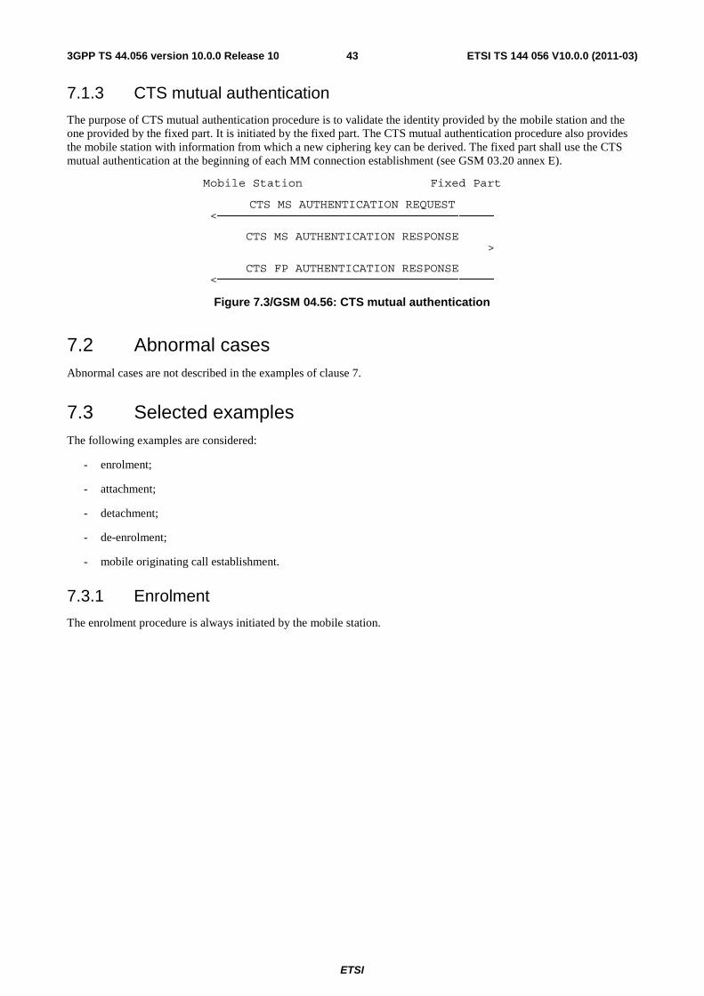
ETSI
ETSI TS 144 056 V10.0.0 (2011-03)433GPP TS 44.056 version 10.0.0 Release 10
7.1.3 CTS mutual authentication
The purpose of CTS mutual authentication procedure is to validate the identity provided by the mobile station and the one provided by the fixed part. It is initiated by the fixed part. The CTS mutual authentication procedure also provides the mobile station with information from which a new ciphering key can be derived. The fixed part shall use the CTS mutual authentication at the beginning of each MM connection establishment (see GSM 03.20 annex E).
Mobile Station Fixed Part
CTS MS AUTHENTICATION REQUEST <───────────────────────────────────────
CTS MS AUTHENTICATION RESPONSE
───────────────────────────────────────>
CTS FP AUTHENTICATION RESPONSE <───────────────────────────────────────
Figure 7.3/GSM 04.56: CTS mutual authentication
7.2 Abnormal cases Abnormal cases are not described in the examples of clause 7.
7.3 Selected examples The following examples are considered:
- enrolment;
- attachment;
- detachment;
- de-enrolment;
- mobile originating call establishment.
7.3.1 Enrolment
The enrolment procedure is always initiated by the mobile station.

ETSI
ETSI TS 144 056 V10.0.0 (2011-03)443GPP TS 44.056 version 10.0.0 Release 10
7.3.1.1 Enrolment with CTS-MS identity authentication done only by the CTS-FP
Mobile Station Fixed Part
+── ──+ │ CTS ACCESS REQUEST \ RR connection \ ───────────────────────────────────────> │ establishment
│ CTS IMMEDIATE ASSIGNMENT │ (MO) │ <─────────────────────────────────────── │ +── ──+ +── ──+ │ CTS ENROLMENT REQUEST │
│ ───────────────────────────────────────> │ Service request │ │ +── ──+ +── ──+
│ CTS MS AUTHENTICATION REQUEST │ Mutual │ <─────────────────────────────────────── │ authentication
│ CTS MS AUTHENTICATION RESPONSE │ │ ───────────────────────────────────────> │ │ CTS FP AUTHENTICATION RESPONSE │ │ <─────────────────────────────────────── │ +── ──+ +── ──+
│ CTS CIPHERING MODE COMMAND │ Ciphering │ <─────────────────────────────────────── │ mode setting
│ CTS CIPHERING MODE COMPLETE │ │ ───────────────────────────────────────> │ +── ──+ +── ──+
│ IDENTITY REQUEST │ MS identity │ <─────────────────────────────────────── │ │ IDENTITY RESPONSE │ │ ───────────────────────────────────────> │ +── ──+ +── ──+ │ CTS ENROLMENT ACCEPT │ │ <─────────────────────────────────────── │ +── ──+
+── ──+ │ CTS CHANNEL RELEASE │ │ <─────────────────────────────────────── │ +── ──+
Figure 7.4/GSM 04.56: CTS enrolment
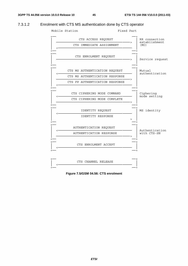
ETSI
ETSI TS 144 056 V10.0.0 (2011-03)453GPP TS 44.056 version 10.0.0 Release 10
7.3.1.2 Enrolment with CTS MS authentication done by CTS operator
Mobile Station Fixed Part
+── ──+ │ CTS ACCESS REQUEST │ RR connection │ ───────────────────────────────────────> │ establishment
│ CTS IMMEDIATE ASSIGNMENT │ (MO) │ <─────────────────────────────────────── │ +── ──+ +── ──+ │ CTS ENROLMENT REQUEST │
│ ───────────────────────────────────────> │ Service request │ │ +── ──+ +── ──+
│ CTS MS AUTHENTICATION REQUEST │ Mutual │ <─────────────────────────────────────── │ authentication
│ CTS MS AUTHENTICATION RESPONSE │ │ ───────────────────────────────────────> │ │ CTS FP AUTHENTICATION RESPONSE │ │ <─────────────────────────────────────── │ +── ──+ +── ──+
│ CTS CIPHERING MODE COMMAND │ Ciphering │ <─────────────────────────────────────── │ mode setting
│ CTS CIPHERING MODE COMPLETE │ │ ───────────────────────────────────────> │ +── ──+ +── ──+
│ IDENTITY REQUEST │ MS identity │ <─────────────────────────────────────── │ │ IDENTITY RESPONSE │ │ ───────────────────────────────────────> │ +── ──+ +── ──+ │ AUTHENTICATION REQUEST │
│ <─────────────────────────────────────── │ Authentication │ AUTHENTICATION RESPONSE │ with CTS-SN
│ ───────────────────────────────────────> │ +── ──+ +── ──+ │ CTS ENROLMENT ACCEPT │ │ <─────────────────────────────────────── │ +── ──+
+── ──+ │ CTS CHANNEL RELEASE │ │ <─────────────────────────────────────── │ +── ──+
Figure 7.5/GSM 04.56: CTS enrolment
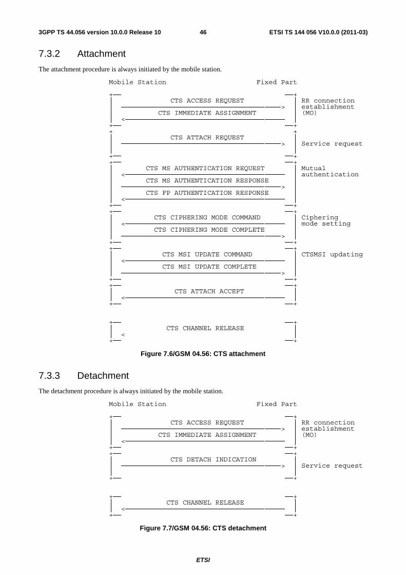
ETSI
ETSI TS 144 056 V10.0.0 (2011-03)463GPP TS 44.056 version 10.0.0 Release 10
7.3.2 Attachment
The attachment procedure is always initiated by the mobile station.
Mobile Station Fixed Part
+── ──+ │ CTS ACCESS REQUEST │ RR connection │ ───────────────────────────────────────> │ establishment
│ CTS IMMEDIATE ASSIGNMENT │ (MO) │ <─────────────────────────────────────── │ +── ──+ +── ──+ │ CTS ATTACH REQUEST │
│ ───────────────────────────────────────> │ Service request │ │ +── ──+ +── ──+
│ CTS MS AUTHENTICATION REQUEST │ Mutual │ <─────────────────────────────────────── │ authentication
│ CTS MS AUTHENTICATION RESPONSE │ │ ───────────────────────────────────────> │ │ CTS FP AUTHENTICATION RESPONSE │ │ <─────────────────────────────────────── │ +── ──+ +── ──+
│ CTS CIPHERING MODE COMMAND │ Ciphering │ <─────────────────────────────────────── │ mode setting
│ CTS CIPHERING MODE COMPLETE │ │ ───────────────────────────────────────> │ +── ──+ +── ──+
│ CTS MSI UPDATE COMMAND │ CTSMSI updating │ <─────────────────────────────────────── │ │ CTS MSI UPDATE COMPLETE │ │ ───────────────────────────────────────> │ +── ──+ +── ──+ │ CTS ATTACH ACCEPT │ │ <─────────────────────────────────────── │ +── ──+
+── ──+ │ CTS CHANNEL RELEASE │ │ <─────────────────────────────────────── │ +── ──+
Figure 7.6/GSM 04.56: CTS attachment
7.3.3 Detachment
The detachment procedure is always initiated by the mobile station.
Mobile Station Fixed Part
+── ──+ │ CTS ACCESS REQUEST │ RR connection │ ───────────────────────────────────────> │ establishment
│ CTS IMMEDIATE ASSIGNMENT │ (MO) │ <─────────────────────────────────────── │ +── ──+ +── ──+ │ CTS DETACH INDICATION │
│ ───────────────────────────────────────> │ Service request │ │ +── ──+
+── ──+ │ CTS CHANNEL RELEASE │ │ <─────────────────────────────────────── │ +── ──+
Figure 7.7/GSM 04.56: CTS detachment
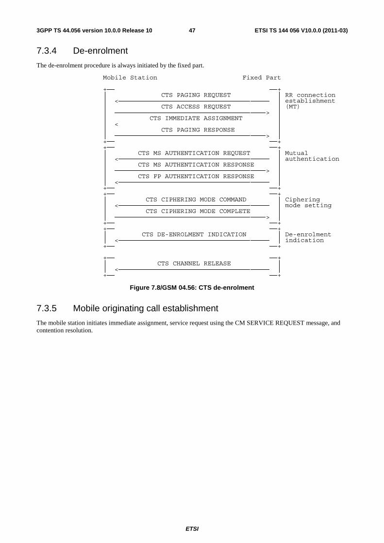
ETSI
ETSI TS 144 056 V10.0.0 (2011-03)473GPP TS 44.056 version 10.0.0 Release 10
7.3.4 De-enrolment
The de-enrolment procedure is always initiated by the fixed part.
Mobile Station Fixed Part
+── ──+ │ CTS PAGING REQUEST │ RR connection │ <─────────────────────────────────────── │ establishment
│ CTS ACCESS REQUEST │ (MT) │ ───────────────────────────────────────> │ │ CTS IMMEDIATE ASSIGNMENT │ │ <─────────────────────────────────────── │ │ CTS PAGING RESPONSE │ │ ───────────────────────────────────────> │ +── ──+ +── ──+
│ CTS MS AUTHENTICATION REQUEST │ Mutual │ <─────────────────────────────────────── │ authentication
│ CTS MS AUTHENTICATION RESPONSE │ │ ───────────────────────────────────────> │ │ CTS FP AUTHENTICATION RESPONSE │ │ <─────────────────────────────────────── │ +── ──+ +── ──+
│ CTS CIPHERING MODE COMMAND │ Ciphering │ <─────────────────────────────────────── │ mode setting
│ CTS CIPHERING MODE COMPLETE │ │ ───────────────────────────────────────> │ +── ──+ +── ──+
│ CTS DE-ENROLMENT INDICATION │ De-enrolment │ <─────────────────────────────────────── │ indication
+── ──+
+── ──+ │ CTS CHANNEL RELEASE │ │ <─────────────────────────────────────── │ +── ──+
Figure 7.8/GSM 04.56: CTS de-enrolment
7.3.5 Mobile originating call establishment
The mobile station initiates immediate assignment, service request using the CM SERVICE REQUEST message, and contention resolution.
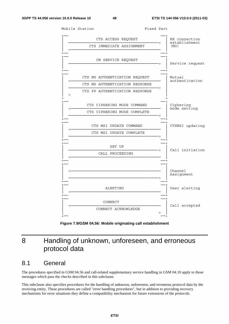
ETSI
ETSI TS 144 056 V10.0.0 (2011-03)483GPP TS 44.056 version 10.0.0 Release 10
Mobile Station Fixed Part
+── ──+ │ CTS ACCESS REQUEST │ RR connection │ ───────────────────────────────────────> │ establishment
│ CTS IMMEDIATE ASSIGNMENT │ (MO) │ <─────────────────────────────────────── │ +── ──+ +── ──+ │ CM SERVICE REQUEST │
│ ───────────────────────────────────────> │ Service request │ │ +── ──+ +── ──+
│ CTS MS AUTHENTICATION REQUEST │ Mutual │ <─────────────────────────────────────── │ authentication
│ CTS MS AUTHENTICATION RESPONSE │ │ ───────────────────────────────────────> │ │ CTS FP AUTHENTICATION RESPONSE │ │ <─────────────────────────────────────── │ +── ──+ +── ──+
│ CTS CIPHERING MODE COMMAND │ Ciphering │ <─────────────────────────────────────── │ mode setting
│ CTS CIPHERING MODE COMPLETE │ │ ───────────────────────────────────────> │ +── ──+ +── ──+
│ CTS MSI UPDATE COMMAND │ CTSMSI updating │ <─────────────────────────────────────── │ │ CTS MSI UPDATE COMPLETE │ │ ───────────────────────────────────────> │ +── ──+ +── ──+ │ SET UP │
│ ───────────────────────────────────────> │ Call initiation │ CALL PROCEEDING │ │ <─────────────────────────────────────── │ +── ──+ +── ──+ │ │
│ <─────────────────────────────────────── │ Channel │ │ Assignment
│ ───────────────────────────────────────> │ +── ──+ +── ──+
│ ALERTING │ User alerting │ <─────────────────────────────────────── │ +── ──+ +── ──+ │ CONNECT │
│ <─────────────────────────────────────── │ Call accepted │ CONNECT ACKNOWLEDGE │ │ ───────────────────────────────────────> │ +── ──+
Figure 7.9/GSM 04.56: Mobile originating call establishment
8 Handling of unknown, unforeseen, and erroneous protocol data
8.1 General The procedures specified in GSM 04.56 and call-related supplementary service handling in GSM 04.10 apply to those messages which pass the checks described in this subclause.
This subclause also specifies procedures for the handling of unknown, unforeseen, and erroneous protocol data by the receiving entity. These procedures are called "error handling procedures", but in addition to providing recovery mechanisms for error situations they define a compatibility mechanism for future extensions of the protocols.
ETSI
ETSI TS 144 056 V10.0.0 (2011-03)493GPP TS 44.056 version 10.0.0 Release 10
Error handling concerning the value part of the Facility IE and of the SS Version Indicator IE are not in the scope of the present document. It is defined in GSM 04.10 and the GSM 04.8x series.
Subclauses 8.1 to 8.8 shall be applied in order of precedence.
Most error handling procedures are mandatory for the CTS-MS.
Detailed error handling procedures in the CTS-FP are implementation dependent and may vary. However, when extensions of this protocol are developed, CTS-FP will be assumed to have the error handling that is indicated in this subclause as mandatory ("shall") and that is indicated as strongly recommended ("should"). Subclauses 8.2, 8.3, 8.4, 8.5 and 8.7.2 do not apply to the error handling in the CTS-FP applied to the receipt of initial layer 3 message: If the CTS-FP diagnoses an error described in one of these subclauses in the initial layer 3 message received from the CTS-MS, it shall either:
- try to recognise the classmark and then take further implementation dependent actions; or
- release the RR-connection.
Also, the error handling of the CTS-FP is only considered as mandatory or strongly recommended when certain thresholds for errors are not reached during a dedicated connection.
In this subclause the following terminology is used:
- An IE is defined to be syntactically incorrect in a message if it contains at least one value defined as "reserved" in clause 10, or if its value part violates rules of clause 10. However it is not a syntactical error that a type 4 IE specifies in its length indicator a greater length than defined in clause 10.
- A message is defined to have semantically incorrect contents if it contains information which, possibly dependent on the state of the receiver, is in contradiction to the resources of the receiver and/or to the procedural part (i.e. clauses 4 and 5) of GSM 04.58, GSM 04.10, or relevant GSM 04.8X series.
8.2 Message too short When a message is received that is too short to contain a complete message type information element, that message shall be ignored, see GSM 04.07.
8.3 Unknown or unforeseen transaction identifier See GSM 04.08 clause 8.3. The CTS-FP shall act as the "network", whereas it is stated so.
8.4 Unknown or unforeseen message type If a CTS-MS receives a message with message type not defined for the PD and SPD or not implemented by the receiver in unacknowledged mode, it shall ignore the message.
If a CTS-MS receives a message with message type not defined for the PD and SPD or not implemented by the receiver in acknowledged mode, it shall return a status message (STATUS, CTS RR STATUS or MM STATUS depending on the protocol discriminator and sub-protocol discriminator) with cause # 97 "message type non-existent or not implemented".
If the CTS-FP receives an RR message or MM message with message type not defined for the PD or not implemented by the receiver in a protocol state where reception of an unsolicited message with the given PD from the CTS-MS is not foreseen in the protocol, the CTS-FP actions are implementation dependent. Otherwise, if the CTS-FP receives a message with message type not defined for the PD and the SPD or not implemented by the receiver, it shall ignore the message except that it should return a status message (STATUS, CTS RR STATUS or MM STATUS depending on the protocol discriminator and Sub-Protocol Discriminator) with cause #97 "message type non-existent or not implemented".
NOTE: A message type not defined for the PD and SPD in the given direction is regarded by the receiver as a message type not defined for the PD and SPD, see GSM 04.07 [20].
ETSI
ETSI TS 144 056 V10.0.0 (2011-03)503GPP TS 44.056 version 10.0.0 Release 10
If the CTS-MS receives a message not compatible with the protocol state, the CTS-MS shall ignore the message except for the fact that, if an RR connection exists, it returns a status message (STATUS, CTS RR STATUS or MM STATUS depending on the protocol discriminator and sub-protocol discriminator) with cause #98 "Message type not compatible with protocol state".
If the CTS-FP receives a message not compatible with the protocol state, the CTS-FP actions are implementation dependent.
8.5 Non-semantical mandatory information element errors When on receipt of a message:
- an "imperative message part" error; or
- a "missing mandatory IE" error;
is diagnosed or when a message containing:
- a syntactically incorrect mandatory IE; or
- an IE unknown in the message, but encoded as "comprehension required" (see subclause 10.5); or
- an out of sequence IE encoded as "comprehension required" (see subclause 10.5)
is received,
- the CTS-MS station shall proceed as follows:
If the message is not one of the messages listed in subclauses 8.5.1, 8.5.2, and 8.5.3, the CTS-MS shall ignore the message except for the fact that, if an RR connection exists, it shall return a status message (STATUS, CTS RR STATUS or MM STATUS depending on the protocol discriminator and sub-protocol discriminator) with cause # 96 "invalid mandatory information".
- the CTS-FP shall proceed as follows:
When the message is not one of the messages listed in subclause 8.5.3 b), c), d) or e), the CTS-FP shall either
- try to treat the message (the exact further actions are implementation dependent); or
- ignore the message except that it should return a status message (STATUS, CTS RR STATUS, or MM STATUS depending on the protocol discriminator and sub-protocol discriminator) with cause # 96 "invalid mandatory information".
8.5.1 Radio resource management
For the CTS-MS the following procedures shall apply:
- If the message is a CTS CHANNEL RELEASE message, the actions taken shall be the same as specified in subclause 4.4.13 "RR connection release".
8.5.2 Mobility management
No exceptional cases are described for mobility management messages.
8.5.3 Call control
See GSM 04.08 subclause 8.5.3.
ETSI
ETSI TS 144 056 V10.0.0 (2011-03)513GPP TS 44.056 version 10.0.0 Release 10
8.6 Unknown and unforeseen IEs in the non-imperative message part
8.6.1 IEIs unknown in the message
The CTS-MS shall ignore all IEs unknown in a message which are not encoded as "comprehension required".
The CTS-FP shall take the same approach.
8.6.2 Out of sequence IEs
The CTS-MS shall ignore all out of sequence IEs in a message which are not encoded as "comprehension required".
The CTS-FP should take the same approach.
8.6.3 Repeated IEs
If an information element with format T, TV, or TLV is repeated in a message in which repetition of the information element is not specified in clause 9 of the present document, only the contents of the information element appearing first shall be handled and all subsequent repetitions of the information element shall be ignored. When repetition of information elements is specified, only the contents of specified repeated information elements shall be handled. If the limit on repetition of information elements is exceeded, the contents of information elements appearing first up to the limit of repetitions shall be handled and all subsequent repetitions of the information element shall be ignored.
The CTS-FP should follow the same procedures.
8.7 Non-imperative message part errors This category includes:
- syntactically incorrect optional IEs;
- conditional IE errors.
8.7.1 Syntactically incorrect optional IEs
The CTS-MS shall treat all optional IEs that are syntactically incorrect in a message as not present in the message.
The CTS-FP shall take the same approach.
8.7.2 Conditional IE errors
When the CTS-MS upon receipt of a message diagnoses a "missing conditional IE" error or an "unexpected conditional IE" error or when it receives a message containing at least one syntactically incorrect conditional IE, it shall ignore the message except for the fact that, if an RR connection exists, it shall return a status message (STATUS, CTS RR STATUS, or MM STATUS depending on the PD and SPD) with cause value # 100 "conditional IE error".
When the CTS-FP receives a message and diagnose a "missing conditional IE" error or an "unexpected conditional IE" error or when it receives a message containing at least one syntactically incorrect conditional IE, the CTS-FP shall either:
- try to treat the message (the exact further actions are implementation dependent); or
- ignore the message except that it should return a status message (STATUS, CTS RR STATUS or MM STATUS depending on the protocol discriminator and sub-protocol discriminator) with cause # 100 "conditional IE error".
ETSI
ETSI TS 144 056 V10.0.0 (2011-03)523GPP TS 44.056 version 10.0.0 Release 10
8.8 Messages with semantically incorrect contents When a message with semantically incorrect contents is received, the foreseen reactions of the procedural part of GSM 04.56 (i.e. of clauses 5, 5, 6) are performed. If however no such reactions are specified, the CTS-MS shall ignore the message except for the fact that, if an RR connection exists, it returns a status message (STATUS, CTS RR STATUS, or MM STATUS depending on the PD and SPD) with cause value # 95 "semantically incorrect message".
The CTS-FP should follow the same procedure except that a status message is not normally transmitted.
Semantic checking of the Facility information element value part (defined in GSM 04.80) is the subject of the technical specifications GSM 04.10 and the GSM 04.8x series.
9 Message functional definitions and contents This subclause defines the structure of the messages of those layer 3 protocols defined in GSM 04.56. These are standard L3 messages as defined in GSM 04.07 with the exception of those sent on the SCH, ARCH.
Each definition given in the present subclause includes:
a) a brief description of the message direction and use, including whether the message has:
1. Local significance, i.e. relevant only on the originating or terminating access;
2. Access significance, i.e. relevant in the originating and terminating access, but not in the CTS-FP;
3. Dual significance, i.e. relevant in either the originating or terminating access and in the network; or
4. Global significance, i.e. relevant in the originating and terminating access and in the network.
b) a table listing the information elements known in the message and their order of their appearance in the message. All information elements that may be repeated are explicitly indicated. (V and LV formatted IEs, which compose the imperative part of the message, occur before T, TV, and TLV formatted IEs which compose the non-imperative part of the message, see GSM 04.07.) In a (maximal) sequence of consecutive information elements with half octet length, the first information element with half octet length occupies bits 1 to 4 of octet N, the second bits 5 to 8 of octet N, the third bits 1 to 4 of octet N+1 etc. Such a sequence always has an even number of elements.
For each information element the table indicates:
1. the information element identifier, in hexadecimal notation, if the IE has format T, TV, or TLV. Usually, there is a default IEI for an information element type; default IEIs of different IE types of the same protocol are different. If the IEI has half octet length, it is specified by a notation representing the IEI as a hexadecimal digit followed by a "-" (example: B-).
NOTE: The same IEI may be used for different information element types in different messages of the same protocol.
2. the name of the information element (which may give an idea of the semantics of the element). The name of the information element (usually written in italics) followed by "IE" or "information element" is used in GSM 04.08 as reference to the information element within a message.
3. the name of the type of the information element (which indicates the coding of the value part of the IE), and generally, the referenced subclause of clause 10 of GSM 04.08 describing the value part of the information element.
4. the presence requirement indication (M, C, or O) for the IE as defined in GSM 04.07.
5. The format of the information element (T, V, TV, LV, TLV) as defined in GSM 04.07.
6. The length of the information element (or permissible range of lengths), in octets, in the message, where "?" means that the maximum length of the IE is only constrained by link layer protocol, and in the case of the Facility IE by possible further conditions specified in GSM 04.10. This indication is non-normative.
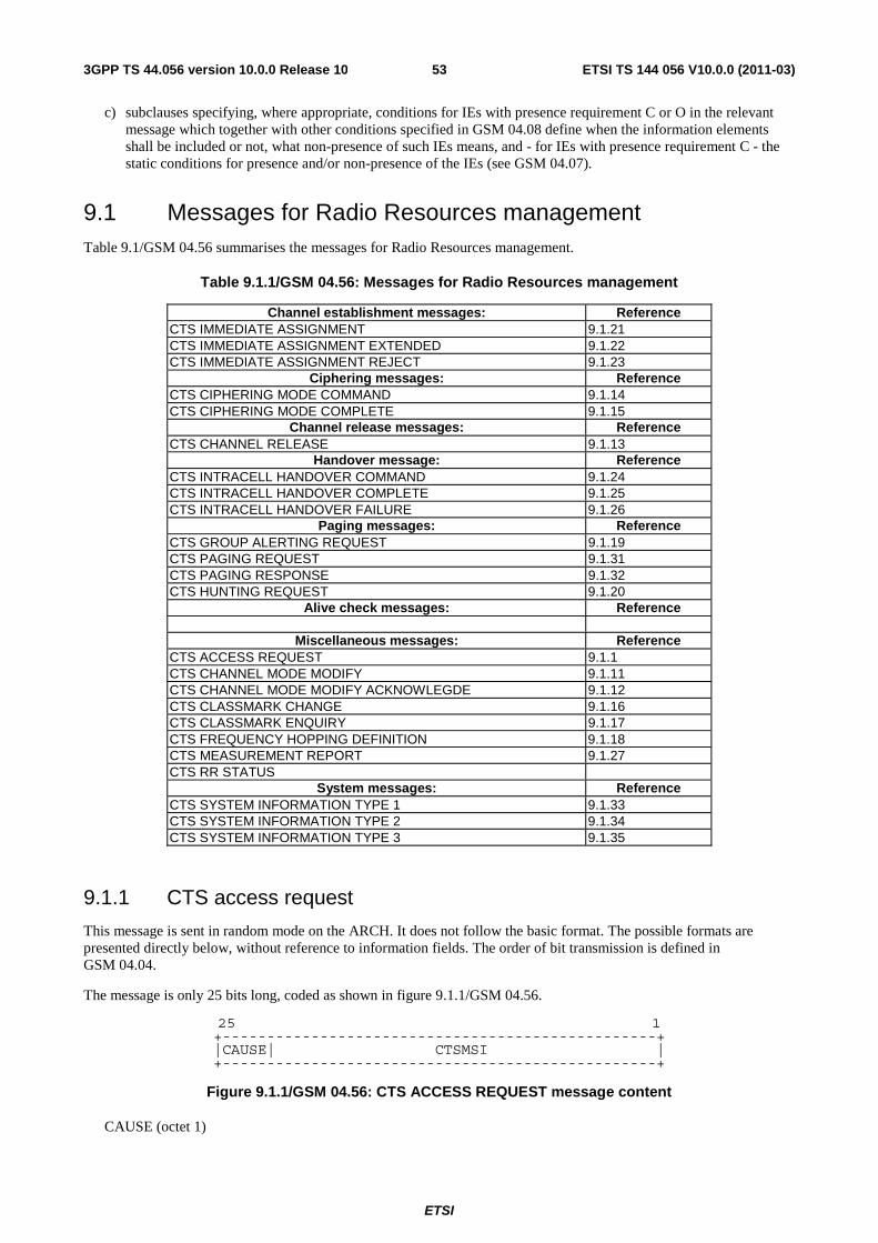
ETSI
ETSI TS 144 056 V10.0.0 (2011-03)533GPP TS 44.056 version 10.0.0 Release 10
c) subclauses specifying, where appropriate, conditions for IEs with presence requirement C or O in the relevant message which together with other conditions specified in GSM 04.08 define when the information elements shall be included or not, what non-presence of such IEs means, and - for IEs with presence requirement C - the static conditions for presence and/or non-presence of the IEs (see GSM 04.07).
9.1 Messages for Radio Resources management Table 9.1/GSM 04.56 summarises the messages for Radio Resources management.
Table 9.1.1/GSM 04.56: Messages for Radio Resources management
Channel establishment messages: Reference CTS IMMEDIATE ASSIGNMENT 9.1.21 CTS IMMEDIATE ASSIGNMENT EXTENDED 9.1.22 CTS IMMEDIATE ASSIGNMENT REJECT 9.1.23
Ciphering messages: Reference CTS CIPHERING MODE COMMAND 9.1.14 CTS CIPHERING MODE COMPLETE 9.1.15
Channel release messages: Reference CTS CHANNEL RELEASE 9.1.13
Handover message: Reference CTS INTRACELL HANDOVER COMMAND 9.1.24 CTS INTRACELL HANDOVER COMPLETE 9.1.25 CTS INTRACELL HANDOVER FAILURE 9.1.26
Paging messages: Reference CTS GROUP ALERTING REQUEST 9.1.19 CTS PAGING REQUEST 9.1.31 CTS PAGING RESPONSE 9.1.32 CTS HUNTING REQUEST 9.1.20
Alive check messages: Reference
Miscellaneous messages: Reference CTS ACCESS REQUEST 9.1.1 CTS CHANNEL MODE MODIFY 9.1.11 CTS CHANNEL MODE MODIFY ACKNOWLEGDE 9.1.12 CTS CLASSMARK CHANGE 9.1.16 CTS CLASSMARK ENQUIRY 9.1.17 CTS FREQUENCY HOPPING DEFINITION 9.1.18 CTS MEASUREMENT REPORT 9.1.27 CTS RR STATUS
System messages: Reference CTS SYSTEM INFORMATION TYPE 1 9.1.33 CTS SYSTEM INFORMATION TYPE 2 9.1.34 CTS SYSTEM INFORMATION TYPE 3 9.1.35
9.1.1 CTS access request
This message is sent in random mode on the ARCH. It does not follow the basic format. The possible formats are presented directly below, without reference to information fields. The order of bit transmission is defined in GSM 04.04.
The message is only 25 bits long, coded as shown in figure 9.1.1/GSM 04.56.
25 1 +-------------------------------------------------+ |CAUSE| CTSMSI | +-------------------------------------------------+
Figure 9.1.1/GSM 04.56: CTS ACCESS REQUEST message content
CAUSE (octet 1)
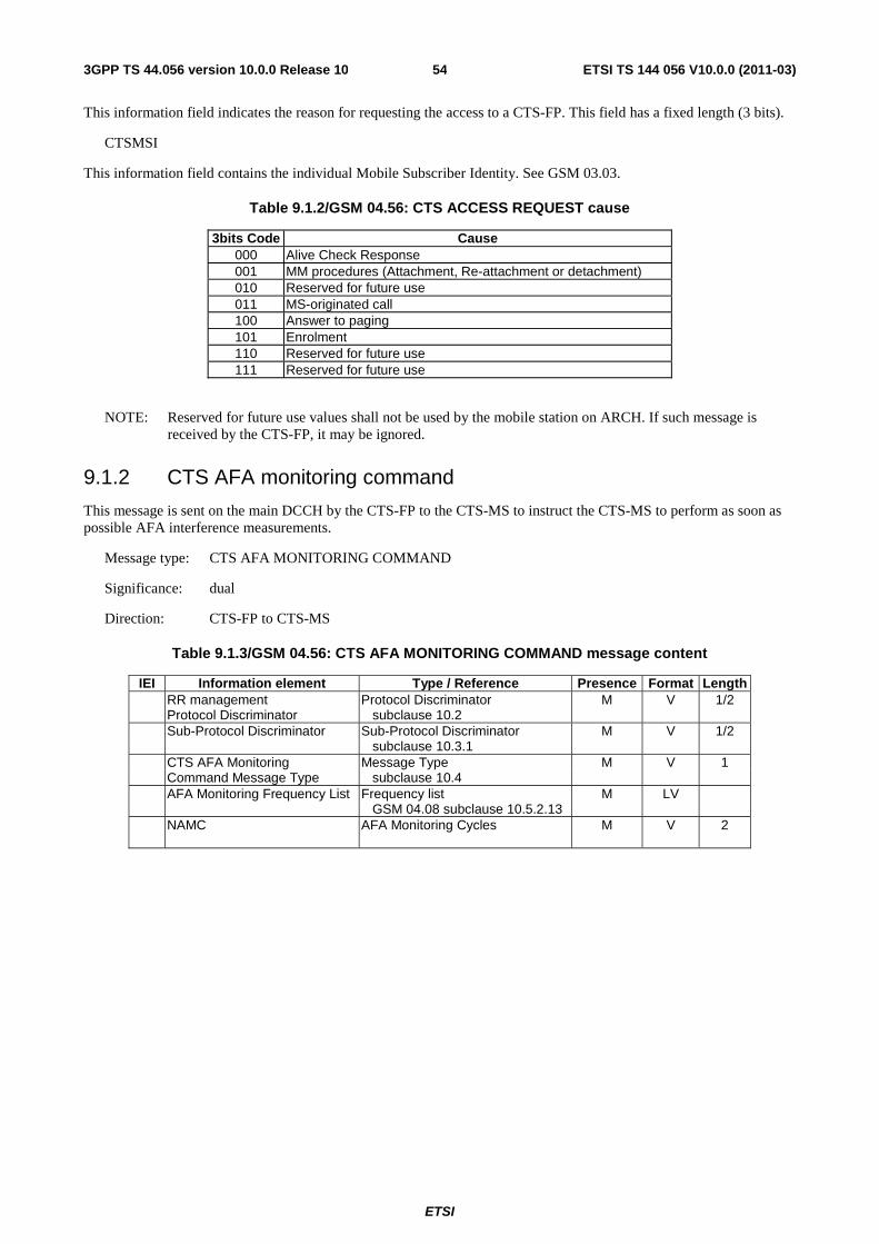
ETSI
ETSI TS 144 056 V10.0.0 (2011-03)543GPP TS 44.056 version 10.0.0 Release 10
This information field indicates the reason for requesting the access to a CTS-FP. This field has a fixed length (3 bits).
CTSMSI
This information field contains the individual Mobile Subscriber Identity. See GSM 03.03.
Table 9.1.2/GSM 04.56: CTS ACCESS REQUEST cause
3bits Code Cause 000 Alive Check Response 001 MM procedures (Attachment, Re-attachment or detachment) 010 Reserved for future use 011 MS-originated call 100 Answer to paging 101 Enrolment 110 Reserved for future use 111 Reserved for future use
NOTE: Reserved for future use values shall not be used by the mobile station on ARCH. If such message is received by the CTS-FP, it may be ignored.
9.1.2 CTS AFA monitoring command
This message is sent on the main DCCH by the CTS-FP to the CTS-MS to instruct the CTS-MS to perform as soon as possible AFA interference measurements.
Message type: CTS AFA MONITORING COMMAND
Significance: dual
Direction: CTS-FP to CTS-MS
Table 9.1.3/GSM 04.56: CTS AFA MONITORING COMMAND message content
IEI Information element Type / Reference Presence Format Length RR management Protocol Discriminator M V 1/2 Protocol Discriminator subclause 10.2 Sub-Protocol Discriminator Sub-Protocol Discriminator M V 1/2 subclause 10.3.1 CTS AFA Monitoring Message Type M V 1 Command Message Type subclause 10.4 AFA Monitoring Frequency List Frequency list
GSM 04.08 subclause 10.5.2.13 M LV
NAMC
AFA Monitoring Cycles M V 2
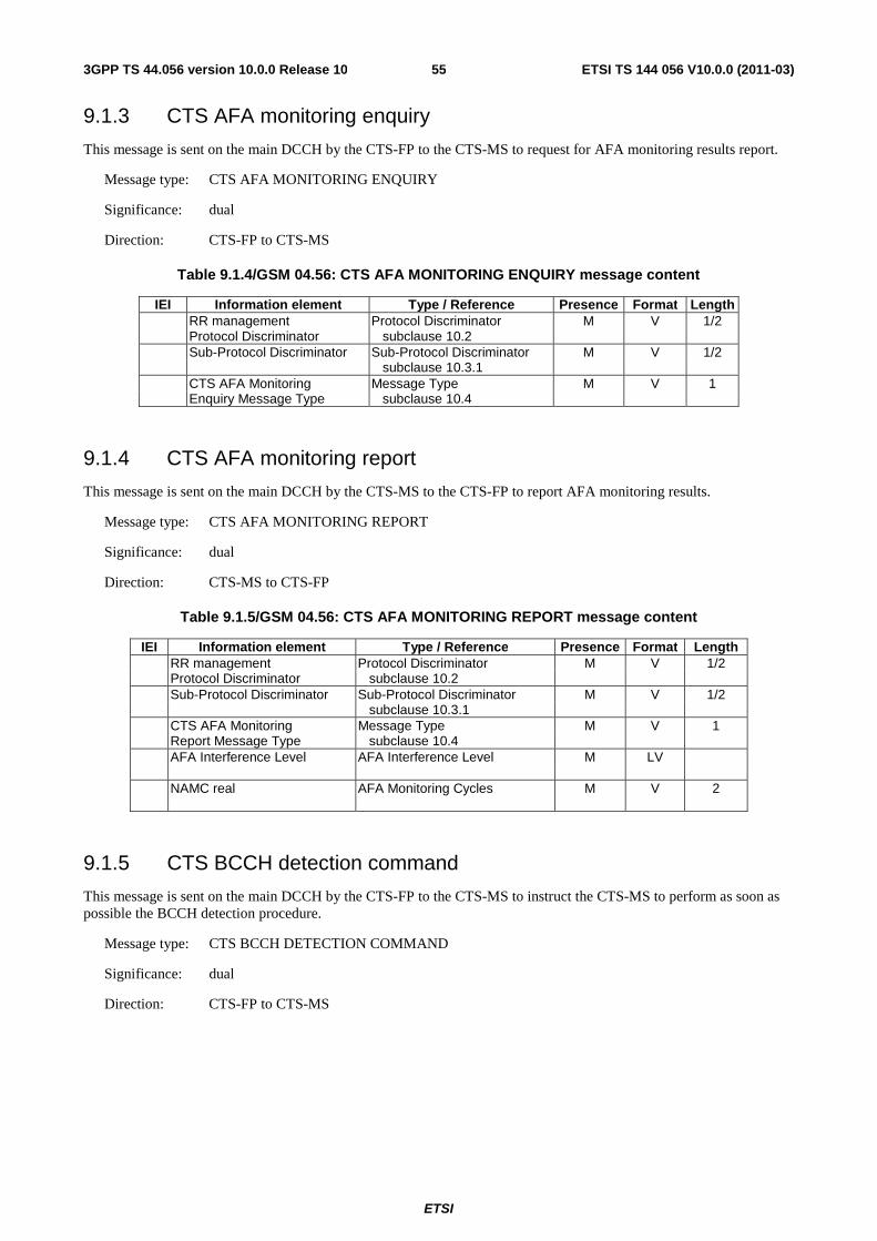
ETSI
ETSI TS 144 056 V10.0.0 (2011-03)553GPP TS 44.056 version 10.0.0 Release 10
9.1.3 CTS AFA monitoring enquiry
This message is sent on the main DCCH by the CTS-FP to the CTS-MS to request for AFA monitoring results report.
Message type: CTS AFA MONITORING ENQUIRY
Significance: dual
Direction: CTS-FP to CTS-MS
Table 9.1.4/GSM 04.56: CTS AFA MONITORING ENQUIRY message content
IEI Information element Type / Reference Presence Format Length RR management Protocol Discriminator M V 1/2 Protocol Discriminator subclause 10.2 Sub-Protocol Discriminator Sub-Protocol Discriminator M V 1/2 subclause 10.3.1 CTS AFA Monitoring Message Type M V 1 Enquiry Message Type subclause 10.4
9.1.4 CTS AFA monitoring report
This message is sent on the main DCCH by the CTS-MS to the CTS-FP to report AFA monitoring results.
Message type: CTS AFA MONITORING REPORT
Significance: dual
Direction: CTS-MS to CTS-FP
Table 9.1.5/GSM 04.56: CTS AFA MONITORING REPORT message content
IEI Information element Type / Reference Presence Format Length RR management Protocol Discriminator M V 1/2 Protocol Discriminator subclause 10.2 Sub-Protocol Discriminator Sub-Protocol Discriminator M V 1/2 subclause 10.3.1 CTS AFA Monitoring Message Type M V 1 Report Message Type subclause 10.4 AFA Interference Level AFA Interference Level M LV NAMC real
AFA Monitoring Cycles M V 2
9.1.5 CTS BCCH detection command
This message is sent on the main DCCH by the CTS-FP to the CTS-MS to instruct the CTS-MS to perform as soon as possible the BCCH detection procedure.
Message type: CTS BCCH DETECTION COMMAND
Significance: dual
Direction: CTS-FP to CTS-MS

ETSI
ETSI TS 144 056 V10.0.0 (2011-03)563GPP TS 44.056 version 10.0.0 Release 10
Table 9.1.7/GSM 04.56: CTS BCCH DETECTION COMMAND message content
IEI Information element Type / Reference Presence Format Length RR management Protocol Discriminator M V 1/2 Protocol Discriminator subclause 10.2 Sub-Protocol Discriminator Sub-Protocol Discriminator M V 1/2 subclause 10.3.1 CTS BCCH Detection Message Type M V 1 Command Message Type subclause 10.4 BCCH Detection Frequency list M LV Frequency List GSM 04.08 subclause 10.5.2.13
9.1.6 CTS BCCH detection enquiry
This message is sent on the main DCCH by the CTS-FP to the CTS-MS to request for a BCCH detection report.
Message type: CTS BCCH DETECTION ENQUIRY
Significance: dual
Direction: CTS-FP to CTS-MS
Table 9.1.8/GSM 04.56: CTS BCCH DETECTION ENQUIRY message content
IEI Information element Type / Reference Presence Format Length RR management Protocol Discriminator M V 1/2 Protocol Discriminator subclause 10.2 Sub-Protocol Discriminator Sub-Protocol Discriminator M V 1/2 subclause 10.3.1 CTS BCCH Detection Message Type M V 1 Enquiry Message Type subclause 10.4
9.1.7 CTS BCCH detection report
This message is sent on the main DCCH by the CTS-MS to the CTS-FP to report the table of BCCH detection status.
Message type: CTS BCCH DETECTION REPORT
Significance: dual
Direction: CTS-MS to CTS-FP
Table 9.1.9/GSM 04.56: CTS BCCH DETECTION REPORT message content
IEI Information element Type / Reference Presence Format Length RR management Protocol Discriminator M V 1/2 Protocol Discriminator subclause 10.2 Sub-Protocol Discriminator Sub-Protocol Discriminator M V 1/2 subclause 10.3.1 CTS BCCH Detection Message Type M V 1 Report Message Type subclause 10.4 BCCH Detection Status BCCH Detection Status M LV
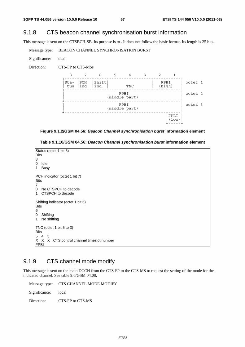
ETSI
ETSI TS 144 056 V10.0.0 (2011-03)573GPP TS 44.056 version 10.0.0 Release 10
9.1.8 CTS beacon channel synchronisation burst information
This message is sent on the CTSBCH-SB. Its purpose is to . It does not follow the basic format. Its length is 25 bits.
Message type: BEACON CHANNEL SYNCHRONISATION BURST
Significance: dual
Direction: CTS-FP to CTS-MSs
8 7 6 5 4 3 2 1 +-----------------------------------------------+
|Sta- |PCH |Shift| | FPBI | octet 1 | tus |ind. |ind. | TNC | (high) | +-----------------------------------------------|
| FPBI | octet 2 | (middle part) | +-----------------------------------------------|
| FPBI | octet 3 | (middle part) | +-----------------------------------------------| |FPBI | |(low)| +-----+
Figure 9.1.2/GSM 04.56: Beacon Channel synchronisation burst information element
Table 9.1.10/GSM 04.56: Beacon Channel synchronisation burst information element
Status (octet 1 bit 8) Bits 8 0 Idle 1 Busy PCH indicator (octet 1 bit 7) Bits 7 0 No CTSPCH to decode 1 CTSPCH to decode Shifting indicator (octet 1 bit 6) Bits 6 0 Shifting 1 No shifting TNC (octet 1 bit 5 to 3) Bits 5 4 3 X X X CTS control channel timeslot number FPBI
9.1.9 CTS channel mode modify
This message is sent on the main DCCH from the CTS-FP to the CTS-MS to request the setting of the mode for the indicated channel. See table 9.6/GSM 04.08.
Message type: CTS CHANNEL MODE MODIFY
Significance: local
Direction: CTS-FP to CTS-MS

ETSI
ETSI TS 144 056 V10.0.0 (2011-03)583GPP TS 44.056 version 10.0.0 Release 10
9.1.10 CTS channel mode modify acknowledge
This message is sent on the main DCCH from the CTS-MS to the CTS-FP to indicate the successful or unsuccessful execution of a channel mode modify request. See table 9.7/GSM 04.08.
Message type: CTS CHANNEL MODE MODIFY ACKNOWLEDGE
Significance: local
Direction: CTS-FP to CTS-MS
9.1.11 CTS channel release
This message is sent on the main DCCH from the CTS-FP to the CTS-MS to initiate deactivation of the dedicated channel. . See table 9.1.11/GSM 04.56.
Message type: CTS CHANNEL RELEASE
Significance: dual
Direction: CTS-FP to CTS-MS
Table 9.1.11/GSM 04.56: CTS CHANNEL RELEASE message content
IEI Information element Type / Reference Presence Format Length RR management Protocol Discriminator M V 1/2 Protocol Discriminator subclause 10.2 Sub-Protocol Discriminator Sub-Protocol Discriminator M V 1/2 subclause 10.3.1 CTS Channel Release Message Type M V 1 Message Type subclause 10.4 RR Cause RR Cause M V 1 GSM 04.08 subclause 10.5.2.31
9.1.12 CTS ciphering mode command
This message is sent on the main DCCH from the CTS-FP to the CTS-MS to indicate that the CTS-FP has started deciphering and that enciphering and deciphering shall be started in the mobile station, or to indicate that ciphering will not be performed. See table 9.1.12/GSM 04.56.
Message type: CTS CIPHERING MODE COMMAND
Significance: dual
Direction: CTS-FP to CST-MS
Table 9.1.12/GSM 04.56: CTS CIPHERING MODE COMMAND message content
IEI Information element Type / Reference Presence Format Length RR management Protocol Discriminator M V 1/2 Protocol Discriminator subclause 10.2 Sub-Protocol Discriminator Sub-Protocol Discriminator M V 1/2 subclause 10.3.1 CTS Cipher Mode Command Message Type M V 1 Message Type subclause 10.4 Ciphering Mode Setting Cipher Mode Setting M V 1/2 GSM 04.08 subclause 10.5.2.9 Cipher Response Cipher Response M V 1/2 GSM 04.08 subclause 10.5.2.10
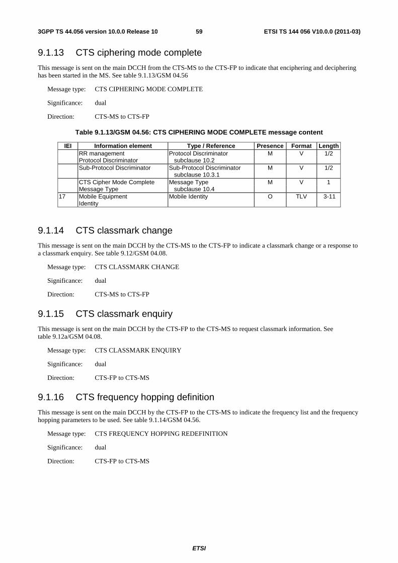
ETSI
ETSI TS 144 056 V10.0.0 (2011-03)593GPP TS 44.056 version 10.0.0 Release 10
9.1.13 CTS ciphering mode complete
This message is sent on the main DCCH from the CTS-MS to the CTS-FP to indicate that enciphering and deciphering has been started in the MS. See table 9.1.13/GSM 04.56
Message type: CTS CIPHERING MODE COMPLETE
Significance: dual
Direction: CTS-MS to CTS-FP
Table 9.1.13/GSM 04.56: CTS CIPHERING MODE COMPLETE message content
IEI Information element Type / Reference Presence Format Length RR management Protocol Discriminator M V 1/2 Protocol Discriminator subclause 10.2 Sub-Protocol Discriminator Sub-Protocol Discriminator M V 1/2 subclause 10.3.1 CTS Cipher Mode Complete Message Type M V 1 Message Type subclause 10.4 17 Mobile Equipment Mobile Identity O TLV 3-11 Identity
9.1.14 CTS classmark change
This message is sent on the main DCCH by the CTS-MS to the CTS-FP to indicate a classmark change or a response to a classmark enquiry. See table 9.12/GSM 04.08.
Message type: CTS CLASSMARK CHANGE
Significance: dual
Direction: CTS-MS to CTS-FP
9.1.15 CTS classmark enquiry
This message is sent on the main DCCH by the CTS-FP to the CTS-MS to request classmark information. See table 9.12a/GSM 04.08.
Message type: CTS CLASSMARK ENQUIRY
Significance: dual
Direction: CTS-FP to CTS-MS
9.1.16 CTS frequency hopping definition
This message is sent on the main DCCH by the CTS-FP to the CTS-MS to indicate the frequency list and the frequency hopping parameters to be used. See table 9.1.14/GSM 04.56.
Message type: CTS FREQUENCY HOPPING REDEFINITION
Significance: dual
Direction: CTS-FP to CTS-MS
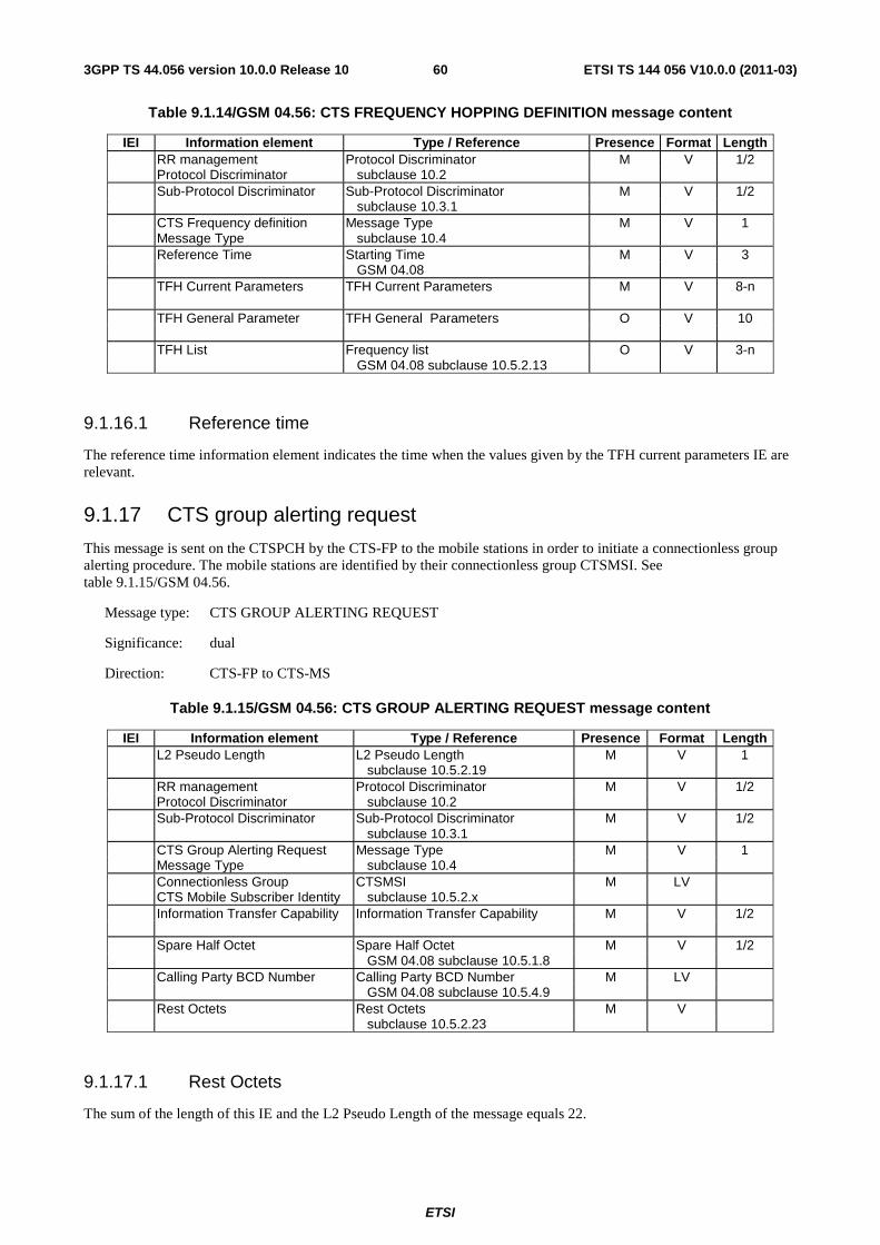
ETSI
ETSI TS 144 056 V10.0.0 (2011-03)603GPP TS 44.056 version 10.0.0 Release 10
Table 9.1.14/GSM 04.56: CTS FREQUENCY HOPPING DEFINITION message content
IEI Information element Type / Reference Presence Format Length RR management Protocol Discriminator M V 1/2 Protocol Discriminator subclause 10.2 Sub-Protocol Discriminator Sub-Protocol Discriminator M V 1/2 subclause 10.3.1 CTS Frequency definition Message Type M V 1 Message Type subclause 10.4 Reference Time Starting Time M V 3 GSM 04.08 TFH Current Parameters TFH Current Parameters M V 8-n TFH General Parameter TFH General Parameters O V 10 TFH List Frequency list O V 3-n GSM 04.08 subclause 10.5.2.13
9.1.16.1 Reference time
The reference time information element indicates the time when the values given by the TFH current parameters IE are relevant.
9.1.17 CTS group alerting request
This message is sent on the CTSPCH by the CTS-FP to the mobile stations in order to initiate a connectionless group alerting procedure. The mobile stations are identified by their connectionless group CTSMSI. See table 9.1.15/GSM 04.56.
Message type: CTS GROUP ALERTING REQUEST
Significance: dual
Direction: CTS-FP to CTS-MS
Table 9.1.15/GSM 04.56: CTS GROUP ALERTING REQUEST message content
IEI Information element Type / Reference Presence Format Length L2 Pseudo Length L2 Pseudo Length M V 1 subclause 10.5.2.19 RR management Protocol Discriminator M V 1/2 Protocol Discriminator subclause 10.2 Sub-Protocol Discriminator Sub-Protocol Discriminator M V 1/2 subclause 10.3.1 CTS Group Alerting Request Message Type M V 1 Message Type subclause 10.4 Connectionless Group CTSMSI M LV CTS Mobile Subscriber Identity subclause 10.5.2.x Information Transfer Capability Information Transfer Capability M V 1/2 Spare Half Octet Spare Half Octet M V 1/2 GSM 04.08 subclause 10.5.1.8 Calling Party BCD Number Calling Party BCD Number M LV GSM 04.08 subclause 10.5.4.9 Rest Octets Rest Octets M V subclause 10.5.2.23
9.1.17.1 Rest Octets
The sum of the length of this IE and the L2 Pseudo Length of the message equals 22.
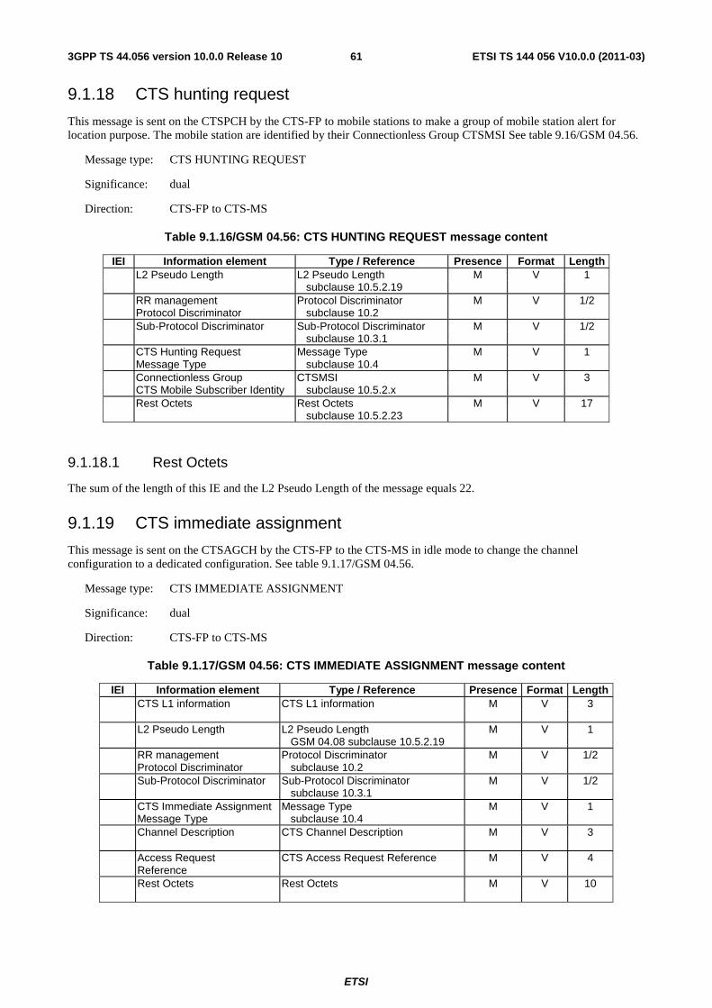
ETSI
ETSI TS 144 056 V10.0.0 (2011-03)613GPP TS 44.056 version 10.0.0 Release 10
9.1.18 CTS hunting request
This message is sent on the CTSPCH by the CTS-FP to mobile stations to make a group of mobile station alert for location purpose. The mobile station are identified by their Connectionless Group CTSMSI See table 9.16/GSM 04.56.
Message type: CTS HUNTING REQUEST
Significance: dual
Direction: CTS-FP to CTS-MS
Table 9.1.16/GSM 04.56: CTS HUNTING REQUEST message content
IEI Information element Type / Reference Presence Format Length L2 Pseudo Length L2 Pseudo Length M V 1 subclause 10.5.2.19 RR management Protocol Discriminator M V 1/2 Protocol Discriminator subclause 10.2 Sub-Protocol Discriminator Sub-Protocol Discriminator M V 1/2 subclause 10.3.1 CTS Hunting Request Message Type M V 1 Message Type subclause 10.4 Connectionless Group CTSMSI M V 3 CTS Mobile Subscriber Identity subclause 10.5.2.x Rest Octets Rest Octets M V 17 subclause 10.5.2.23
9.1.18.1 Rest Octets
The sum of the length of this IE and the L2 Pseudo Length of the message equals 22.
9.1.19 CTS immediate assignment
This message is sent on the CTSAGCH by the CTS-FP to the CTS-MS in idle mode to change the channel configuration to a dedicated configuration. See table 9.1.17/GSM 04.56.
Message type: CTS IMMEDIATE ASSIGNMENT
Significance: dual
Direction: CTS-FP to CTS-MS
Table 9.1.17/GSM 04.56: CTS IMMEDIATE ASSIGNMENT message content
IEI Information element Type / Reference Presence Format Length CTS L1 information CTS L1 information M V 3 L2 Pseudo Length L2 Pseudo Length M V 1 GSM 04.08 subclause 10.5.2.19 RR management Protocol Discriminator M V 1/2 Protocol Discriminator subclause 10.2 Sub-Protocol Discriminator Sub-Protocol Discriminator M V 1/2 subclause 10.3.1 CTS Immediate Assignment Message Type M V 1 Message Type subclause 10.4 Channel Description CTS Channel Description M V 3 Access Request CTS Access Request Reference M V 4 Reference Rest Octets Rest Octets M V 10
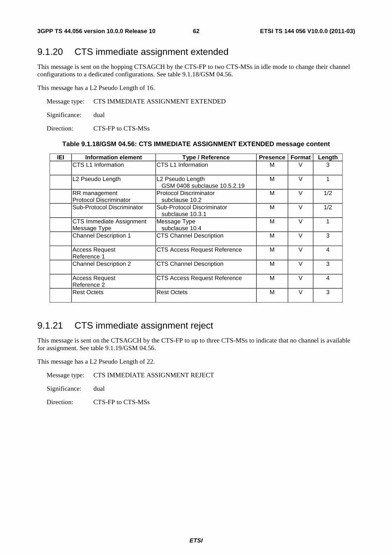
ETSI
ETSI TS 144 056 V10.0.0 (2011-03)623GPP TS 44.056 version 10.0.0 Release 10
9.1.20 CTS immediate assignment extended
This message is sent on the hopping CTSAGCH by the CTS-FP to two CTS-MSs in idle mode to change their channel configurations to a dedicated configurations. See table 9.1.18/GSM 04.56.
This message has a L2 Pseudo Length of 16.
Message type: CTS IMMEDIATE ASSIGNMENT EXTENDED
Significance: dual
Direction: CTS-FP to CTS-MSs
Table 9.1.18/GSM 04.56: CTS IMMEDIATE ASSIGNMENT EXTENDED message content
IEI Information element Type / Reference Presence Format Length CTS L1 Information CTS L1 Information M V 3 L2 Pseudo Length L2 Pseudo Length M V 1 GSM 0408 subclause 10.5.2.19 RR management Protocol Discriminator M V 1/2 Protocol Discriminator subclause 10.2 Sub-Protocol Discriminator Sub-Protocol Discriminator M V 1/2 subclause 10.3.1 CTS Immediate Assignment Message Type M V 1 Message Type subclause 10.4 Channel Description 1 CTS Channel Description M V 3 Access Request CTS Access Request Reference M V 4 Reference 1 Channel Description 2 CTS Channel Description M V 3 Access Request CTS Access Request Reference M V 4 Reference 2 Rest Octets Rest Octets M V 3
9.1.21 CTS immediate assignment reject
This message is sent on the CTSAGCH by the CTS-FP to up to three CTS-MSs to indicate that no channel is available for assignment. See table 9.1.19/GSM 04.56.
This message has a L2 Pseudo Length of 22.
Message type: CTS IMMEDIATE ASSIGNMENT REJECT
Significance: dual
Direction: CTS-FP to CTS-MSs
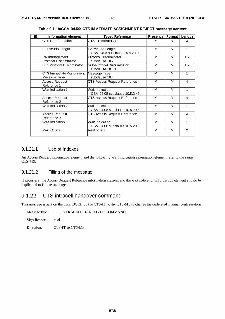
ETSI
ETSI TS 144 056 V10.0.0 (2011-03)633GPP TS 44.056 version 10.0.0 Release 10
Table 9.1.19/GSM 04.56: CTS IMMEDIATE ASSIGNMENT REJECT message content
IEI Information element Type / Reference Presence Format Length CTS L1 information CTS L1 information M V 3 L2 Pseudo Length L2 Pseudo Length M V 1 GSM 0408 subclause 10.5.2.19 RR management Protocol Discriminator M V 1/2 Protocol Discriminator subclause 10.2 Sub-Protocol Discriminator Sub-Protocol Discriminator M V 1/2 subclause 10.3.1 CTS Immediate Assignment Message Type M V 1 Message Type subclause 10.4 Access Request CTS Access Request Reference M V 4 Reference 1 Wait Indication 1 Wait Indication M V 1 GSM 04.08 subclause 10.5.2.43 Access Request CTS Access Request Reference M V 4 Reference 2 Wait Indication 2 Wait Indication M V 1 GSM 04.08 subclause 10.5.2.43 Access Request CTS Access Request Reference M V 4 Reference 3 Wait Indication 3 Wait Indication M V 1 GSM 04.08 subclause 10.5.2.43 Rest Octets Rest octets M V 2
9.1.21.1 Use of Indexes
An Access Request information element and the following Wait Indication information element refer to the same CTS-MS.
9.1.21.2 Filling of the message
If necessary, the Access Request Reference information element and the wait indication information element should be duplicated to fill the message
9.1.22 CTS intracell handover command
This message is sent on the main DCCH by the CTS-FP to the CTS-MS to change the dedicated channel configuration
Message type: CTS INTRACELL HANDOVER COMMAND
Significance: dual
Direction: CTS-FP to CTS-MS
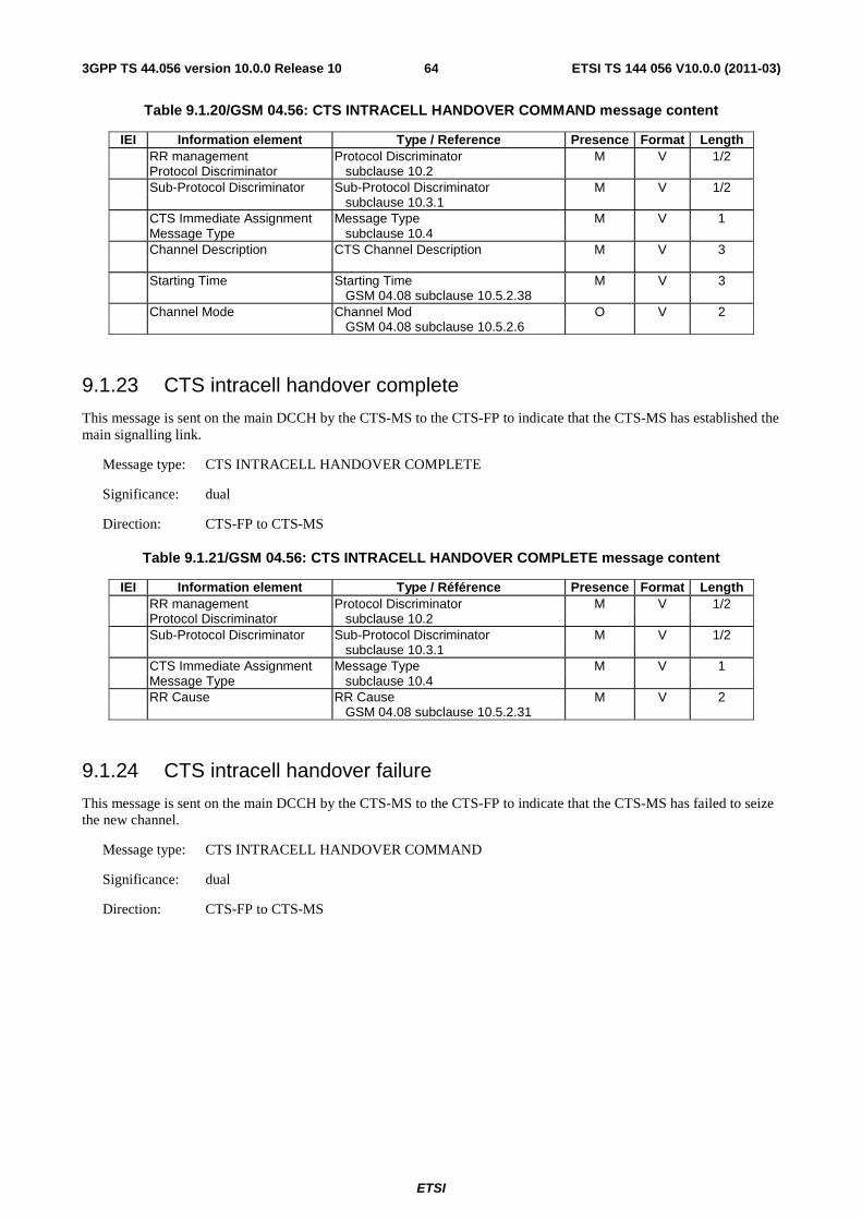
ETSI
ETSI TS 144 056 V10.0.0 (2011-03)643GPP TS 44.056 version 10.0.0 Release 10
Table 9.1.20/GSM 04.56: CTS INTRACELL HANDOVER COMMAND message content
IEI Information element Type / Reference Presence Format Length RR management Protocol Discriminator M V 1/2 Protocol Discriminator subclause 10.2 Sub-Protocol Discriminator Sub-Protocol Discriminator M V 1/2 subclause 10.3.1 CTS Immediate Assignment Message Type M V 1 Message Type subclause 10.4 Channel Description CTS Channel Description M V 3 Starting Time Starting Time M V 3 GSM 04.08 subclause 10.5.2.38 Channel Mode Channel Mod O V 2 GSM 04.08 subclause 10.5.2.6
9.1.23 CTS intracell handover complete
This message is sent on the main DCCH by the CTS-MS to the CTS-FP to indicate that the CTS-MS has established the main signalling link.
Message type: CTS INTRACELL HANDOVER COMPLETE
Significance: dual
Direction: CTS-FP to CTS-MS
Table 9.1.21/GSM 04.56: CTS INTRACELL HANDOVER COMPLETE message content
IEI Information element Type / Référence Presence Format Length RR management Protocol Discriminator M V 1/2 Protocol Discriminator subclause 10.2 Sub-Protocol Discriminator Sub-Protocol Discriminator M V 1/2 subclause 10.3.1 CTS Immediate Assignment Message Type M V 1 Message Type subclause 10.4 RR Cause RR Cause M V 2 GSM 04.08 subclause 10.5.2.31
9.1.24 CTS intracell handover failure
This message is sent on the main DCCH by the CTS-MS to the CTS-FP to indicate that the CTS-MS has failed to seize the new channel.
Message type: CTS INTRACELL HANDOVER COMMAND
Significance: dual
Direction: CTS-FP to CTS-MS
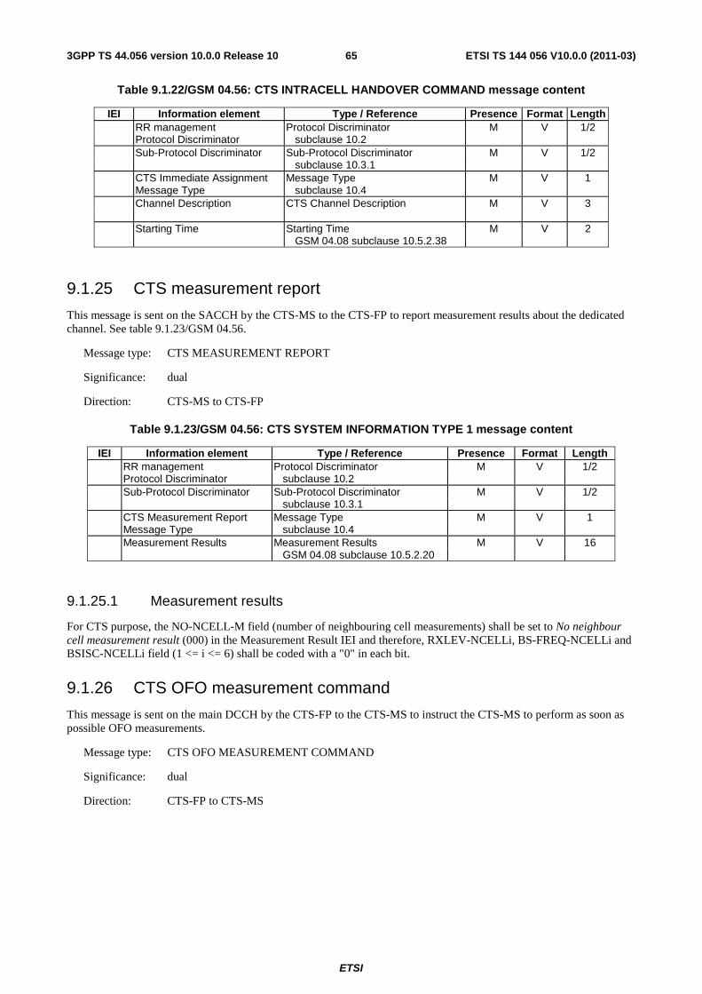
ETSI
ETSI TS 144 056 V10.0.0 (2011-03)653GPP TS 44.056 version 10.0.0 Release 10
Table 9.1.22/GSM 04.56: CTS INTRACELL HANDOVER COMMAND message content
IEI Information element Type / Reference Presence Format Length RR management Protocol Discriminator M V 1/2 Protocol Discriminator subclause 10.2 Sub-Protocol Discriminator Sub-Protocol Discriminator M V 1/2 subclause 10.3.1 CTS Immediate Assignment Message Type M V 1 Message Type subclause 10.4 Channel Description CTS Channel Description M V 3 Starting Time Starting Time M V 2 GSM 04.08 subclause 10.5.2.38
9.1.25 CTS measurement report
This message is sent on the SACCH by the CTS-MS to the CTS-FP to report measurement results about the dedicated channel. See table 9.1.23/GSM 04.56.
Message type: CTS MEASUREMENT REPORT
Significance: dual
Direction: CTS-MS to CTS-FP
Table 9.1.23/GSM 04.56: CTS SYSTEM INFORMATION TYPE 1 message content
IEI Information element Type / Reference Presence Format Length RR management Protocol Discriminator M V 1/2 Protocol Discriminator subclause 10.2 Sub-Protocol Discriminator Sub-Protocol Discriminator M V 1/2 subclause 10.3.1 CTS Measurement Report Message Type M V 1 Message Type subclause 10.4 Measurement Results Measurement Results M V 16 GSM 04.08 subclause 10.5.2.20
9.1.25.1 Measurement results
For CTS purpose, the NO-NCELL-M field (number of neighbouring cell measurements) shall be set to No neighbour cell measurement result (000) in the Measurement Result IEI and therefore, RXLEV-NCELLi, BS-FREQ-NCELLi and BSISC-NCELLi field (1 <= i <= 6) shall be coded with a "0" in each bit.
9.1.26 CTS OFO measurement command
This message is sent on the main DCCH by the CTS-FP to the CTS-MS to instruct the CTS-MS to perform as soon as possible OFO measurements.
Message type: CTS OFO MEASUREMENT COMMAND
Significance: dual
Direction: CTS-FP to CTS-MS
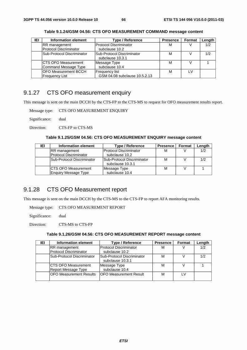
ETSI
ETSI TS 144 056 V10.0.0 (2011-03)663GPP TS 44.056 version 10.0.0 Release 10
Table 9.1.24/GSM 04.56: CTS OFO MEASUREMENT COMMAND message content
IEI Information element Type / Reference Presence Format Length RR management Protocol Discriminator M V 1/2 Protocol Discriminator subclause 10.2 Sub-Protocol Discriminator Sub-Protocol Discriminator M V 1/2 subclause 10.3.1 CTS OFO Measurement Message Type M V 1 Command Message Type subclause 10.4 OFO Measurement BCCH Frequency list M LV Frequency List GSM 04.08 subclause 10.5.2.13
9.1.27 CTS OFO measurement enquiry
This message is sent on the main DCCH by the CTS-FP to the CTS-MS to request for OFO measurement results report.
Message type: CTS OFO MEASUREMENT ENQUIRY
Significance: dual
Direction: CTS-FP to CTS-MS
Table 9.1.25/GSM 04.56: CTS OFO MEASUREMENT ENQUIRY message content
IEI Information element Type / Reference Presence Format Length RR management Protocol Discriminator M V 1/2 Protocol Discriminator subclause 10.2 Sub-Protocol Discriminator Sub-Protocol Discriminator M V 1/2 subclause 10.3.1 CTS OFO Measurement Message Type M V 1 Enquiry Message Type subclause 10.4
9.1.28 CTS OFO Measurement report
This message is sent on the main DCCH by the CTS-MS to the CTS-FP to report AFA monitoring results.
Message type: CTS OFO MEASUREMENT REPORT
Significance: dual
Direction: CTS-MS to CTS-FP
Table 9.1.26/GSM 04.56: CTS OFO MEASUREMENT REPORT message content
IEI Information element Type / Reference Presence Format Length RR management Protocol Discriminator M V 1/2 Protocol Discriminator subclause 10.2 Sub-Protocol Discriminator Sub-Protocol Discriminator M V 1/2 subclause 10.3.1 CTS OFO Measurement Message Type M V 1 Report Message Type subclause 10.4 OFO Measurement Results OFO Measurement Result M LV
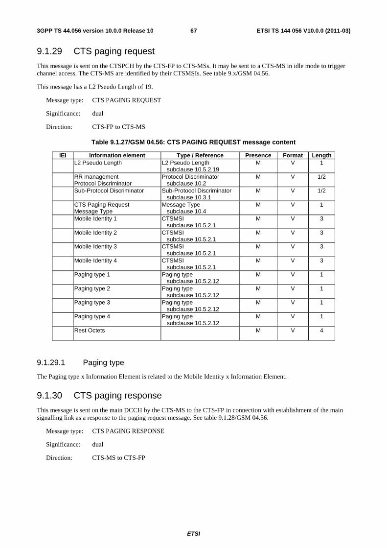
ETSI
ETSI TS 144 056 V10.0.0 (2011-03)673GPP TS 44.056 version 10.0.0 Release 10
9.1.29 CTS paging request
This message is sent on the CTSPCH by the CTS-FP to CTS-MSs. It may be sent to a CTS-MS in idle mode to trigger channel access. The CTS-MS are identified by their CTSMSIs. See table 9.x/GSM 04.56.
This message has a L2 Pseudo Length of 19.
Message type: CTS PAGING REQUEST
Significance: dual
Direction: CTS-FP to CTS-MS
Table 9.1.27/GSM 04.56: CTS PAGING REQUEST message content
IEI Information element Type / Reference Presence Format Length L2 Pseudo Length L2 Pseudo Length M V 1 subclause 10.5.2.19 RR management Protocol Discriminator M V 1/2 Protocol Discriminator subclause 10.2 Sub-Protocol Discriminator Sub-Protocol Discriminator M V 1/2 subclause 10.3.1 CTS Paging Request Message Type M V 1 Message Type subclause 10.4 Mobile Identity 1 CTSMSI M V 3 subclause 10.5.2.1 Mobile Identity 2 CTSMSI M V 3 subclause 10.5.2.1 Mobile Identity 3 CTSMSI M V 3 subclause 10.5.2.1 Mobile Identity 4 CTSMSI M V 3 subclause 10.5.2.1 Paging type 1 Paging type M V 1 subclause 10.5.2.12 Paging type 2 Paging type M V 1 subclause 10.5.2.12 Paging type 3 Paging type M V 1 subclause 10.5.2.12 Paging type 4 Paging type M V 1 subclause 10.5.2.12 Rest Octets M V 4
9.1.29.1 Paging type
The Paging type x Information Element is related to the Mobile Identity x Information Element.
9.1.30 CTS paging response
This message is sent on the main DCCH by the CTS-MS to the CTS-FP in connection with establishment of the main signalling link as a response to the paging request message. See table 9.1.28/GSM 04.56.
Message type: CTS PAGING RESPONSE
Significance: dual
Direction: CTS-MS to CTS-FP
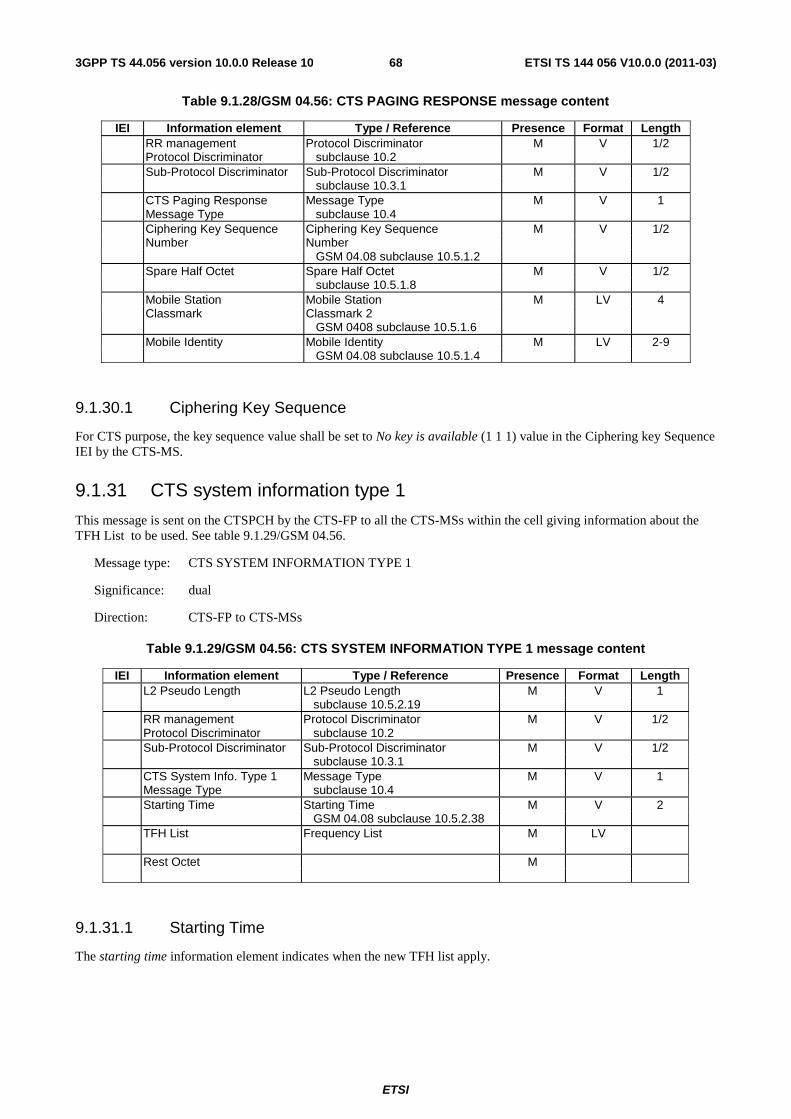
ETSI
ETSI TS 144 056 V10.0.0 (2011-03)683GPP TS 44.056 version 10.0.0 Release 10
Table 9.1.28/GSM 04.56: CTS PAGING RESPONSE message content
IEI Information element Type / Reference Presence Format Length RR management Protocol Discriminator M V 1/2 Protocol Discriminator subclause 10.2 Sub-Protocol Discriminator Sub-Protocol Discriminator M V 1/2 subclause 10.3.1 CTS Paging Response Message Type M V 1 Message Type subclause 10.4 Ciphering Key Sequence Ciphering Key Sequence M V 1/2 Number Number GSM 04.08 subclause 10.5.1.2 Spare Half Octet Spare Half Octet M V 1/2 subclause 10.5.1.8 Mobile Station Mobile Station M LV 4 Classmark Classmark 2 GSM 0408 subclause 10.5.1.6 Mobile Identity Mobile Identity M LV 2-9 GSM 04.08 subclause 10.5.1.4
9.1.30.1 Ciphering Key Sequence
For CTS purpose, the key sequence value shall be set to No key is available (1 1 1) value in the Ciphering key Sequence IEI by the CTS-MS.
9.1.31 CTS system information type 1
This message is sent on the CTSPCH by the CTS-FP to all the CTS-MSs within the cell giving information about the TFH List to be used. See table 9.1.29/GSM 04.56.
Message type: CTS SYSTEM INFORMATION TYPE 1
Significance: dual
Direction: CTS-FP to CTS-MSs
Table 9.1.29/GSM 04.56: CTS SYSTEM INFORMATION TYPE 1 message content
IEI Information element Type / Reference Presence Format Length L2 Pseudo Length L2 Pseudo Length M V 1 subclause 10.5.2.19 RR management Protocol Discriminator M V 1/2 Protocol Discriminator subclause 10.2 Sub-Protocol Discriminator Sub-Protocol Discriminator M V 1/2 subclause 10.3.1 CTS System Info. Type 1 Message Type M V 1 Message Type subclause 10.4 Starting Time Starting Time M V 2 GSM 04.08 subclause 10.5.2.38 TFH List Frequency List M LV Rest Octet M
9.1.31.1 Starting Time
The starting time information element indicates when the new TFH list apply.
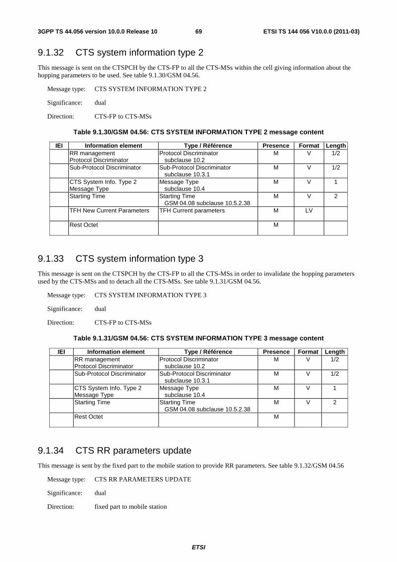
ETSI
ETSI TS 144 056 V10.0.0 (2011-03)693GPP TS 44.056 version 10.0.0 Release 10
9.1.32 CTS system information type 2
This message is sent on the CTSPCH by the CTS-FP to all the CTS-MSs within the cell giving information about the hopping parameters to be used. See table 9.1.30/GSM 04.56.
Message type: CTS SYSTEM INFORMATION TYPE 2
Significance: dual
Direction: CTS-FP to CTS-MSs
Table 9.1.30/GSM 04.56: CTS SYSTEM INFORMATION TYPE 2 message content
IEI Information element Type / Référence Presence Format Length RR management Protocol Discriminator M V 1/2 Protocol Discriminator subclause 10.2 Sub-Protocol Discriminator Sub-Protocol Discriminator M V 1/2 subclause 10.3.1 CTS System Info. Type 2 Message Type M V 1 Message Type subclause 10.4 Starting Time Starting Time M V 2 GSM 04.08 subclause 10.5.2.38 TFH New Current Parameters TFH Current parameters M LV Rest Octet M
9.1.33 CTS system information type 3
This message is sent on the CTSPCH by the CTS-FP to all the CTS-MSs in order to invalidate the hopping parameters used by the CTS-MSs and to detach all the CTS-MSs. See table 9.1.31/GSM 04.56.
Message type: CTS SYSTEM INFORMATION TYPE 3
Significance: dual
Direction: CTS-FP to CTS-MSs
Table 9.1.31/GSM 04.56: CTS SYSTEM INFORMATION TYPE 3 message content
IEI Information element Type / Référence Presence Format Length RR management Protocol Discriminator M V 1/2 Protocol Discriminator subclause 10.2 Sub-Protocol Discriminator Sub-Protocol Discriminator M V 1/2 subclause 10.3.1 CTS System Info. Type 2 Message Type M V 1 Message Type subclause 10.4 Starting Time Starting Time M V 2 GSM 04.08 subclause 10.5.2.38 Rest Octet M
9.1.34 CTS RR parameters update
This message is sent by the fixed part to the mobile station to provide RR parameters. See table 9.1.32/GSM 04.56
Message type: CTS RR PARAMETERS UPDATE
Significance: dual
Direction: fixed part to mobile station
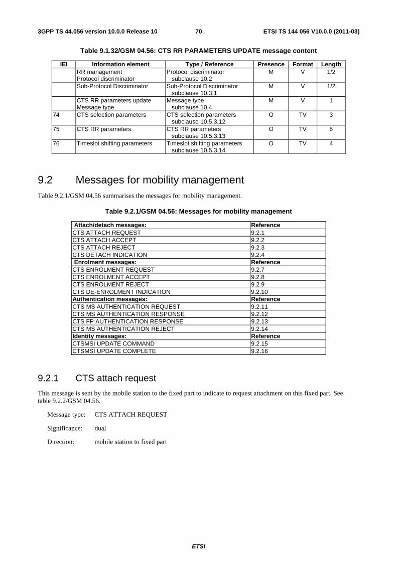
ETSI
ETSI TS 144 056 V10.0.0 (2011-03)703GPP TS 44.056 version 10.0.0 Release 10
Table 9.1.32/GSM 04.56: CTS RR PARAMETERS UPDATE message content
IEI Information element Type / Reference Presence Format Length RR management Protocol discriminator M V 1/2 Protocol discriminator subclause 10.2 Sub-Protocol Discriminator Sub-Protocol Discriminator M V 1/2 subclause 10.3.1 CTS RR parameters update Message type M V 1 Message type subclause 10.4 74 CTS selection parameters CTS selection parameters O TV 3 subclause 10.5.3.12 75 CTS RR parameters CTS RR parameters O TV 5 subclause 10.5.3.13 76 Timeslot shifting parameters Timeslot shifting parameters O TV 4 subclause 10.5.3.14
9.2 Messages for mobility management Table 9.2.1/GSM 04.56 summarises the messages for mobility management.
Table 9.2.1/GSM 04.56: Messages for mobility management
Attach/detach messages: Reference CTS ATTACH REQUEST 9.2.1 CTS ATTACH ACCEPT 9.2.2 CTS ATTACH REJECT 9.2.3 CTS DETACH INDICATION 9.2.4 Enrolment messages: Reference CTS ENROLMENT REQUEST 9.2.7 CTS ENROLMENT ACCEPT 9.2.8 CTS ENROLMENT REJECT 9.2.9 CTS DE-ENROLMENT INDICATION 9.2.10 Authentication messages: Reference CTS MS AUTHENTICATION REQUEST 9.2.11 CTS MS AUTHENTICATION RESPONSE 9.2.12 CTS FP AUTHENTICATION RESPONSE 9.2.13 CTS MS AUTHENTICATION REJECT 9.2.14 Identity messages: Reference CTSMSI UPDATE COMMAND 9.2.15 CTSMSI UPDATE COMPLETE 9.2.16
9.2.1 CTS attach request
This message is sent by the mobile station to the fixed part to indicate to request attachment on this fixed part. See table 9.2.2/GSM 04.56.
Message type: CTS ATTACH REQUEST
Significance: dual
Direction: mobile station to fixed part

ETSI
ETSI TS 144 056 V10.0.0 (2011-03)713GPP TS 44.056 version 10.0.0 Release 10
Table 9.2.2/GSM 04.56: CTS ATTACH REQUEST message content
IEI Information element Type / Reference Presence Format Length CTS mobility management Protocol discriminator M V 1/2 Protocol discriminator subclause 10.2 Sub-Protocol Discriminator Sub-Protocol Discriminator M V 1/2 subclause 10.3.1 CTS attach request Message type M V 1 Message type subclause 10.4 CTS Ciphering Key Sequence Ciphering Key Sequence M V 1/2 Number Number GSM 04.08 subclause 10.5.1.2 Attach type Attach type M V 1/2 subclause 10.5.3.11 Mobile Station Mobile Station M V 1 Classmark Classmark 1 GSM 04.08 subclause 10.5.1.5 Mobile identity Mobile identity M LV 2 - 9 subclause 10.5.1.1
9.2.2 CTS attach accept
This message is sent by the fixed part to the mobile station to indicate that the requested attachment has been accepted. See table 9.2.3/GSM 04.56
Message type: CTS ATTACH ACCEPT
Significance: dual
Direction: fixed part to mobile station
Table 9.2.3/GSM 04.56: CTS ATTACH ACCEPT message content
IEI Information element Type / Reference Presence Format Length CTS mobility management Protocol discriminator M V 1/2 protocol discriminator subclause 10.2 Sub-Protocol Discriminator Sub-Protocol Discriminator M V 1/2 subclause 10.3.1 CTS attach accept Message type M V 1 message type subclause 10.4 TC3252 TC3252 M V 1 subclause 10.5.3.10 01 CTS mobile group list CTS mobile group list O TLV 5 - 26 subclause 10.5.3.7 02 Access right identity Access right identity O TV 4 subclause 10.5.3.9 A1 Follow on proceed Follow on proceed O T 1 GSM 04.08 subclause 10.5.3.7
9.2.3 CTS attach reject
This message is sent by the fixed part to the mobile station to indicate that the requested attachment has been rejected. See table 9.2.4/GSM 04.56.
Message type: CTS ATTACH REJECT
Significance: dual
Direction: fixed part to mobile station
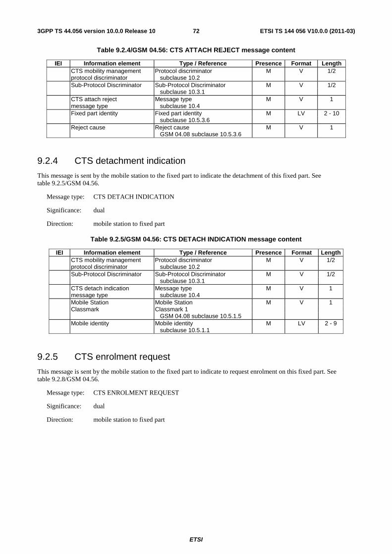
ETSI
ETSI TS 144 056 V10.0.0 (2011-03)723GPP TS 44.056 version 10.0.0 Release 10
Table 9.2.4/GSM 04.56: CTS ATTACH REJECT message content
IEI Information element Type / Reference Presence Format Length CTS mobility management Protocol discriminator M V 1/2 protocol discriminator subclause 10.2 Sub-Protocol Discriminator Sub-Protocol Discriminator M V 1/2 subclause 10.3.1 CTS attach reject Message type M V 1 message type subclause 10.4 Fixed part identity Fixed part identity M LV 2 - 10 subclause 10.5.3.6 Reject cause Reject cause M V 1 GSM 04.08 subclause 10.5.3.6
9.2.4 CTS detachment indication
This message is sent by the mobile station to the fixed part to indicate the detachment of this fixed part. See table 9.2.5/GSM 04.56.
Message type: CTS DETACH INDICATION
Significance: dual
Direction: mobile station to fixed part
Table 9.2.5/GSM 04.56: CTS DETACH INDICATION message content
IEI Information element Type / Reference Presence Format Length CTS mobility management Protocol discriminator M V 1/2 protocol discriminator subclause 10.2 Sub-Protocol Discriminator Sub-Protocol Discriminator M V 1/2 subclause 10.3.1 CTS detach indication Message type M V 1 message type subclause 10.4 Mobile Station Mobile Station M V 1 Classmark Classmark 1 GSM 04.08 subclause 10.5.1.5 Mobile identity Mobile identity M LV 2 - 9 subclause 10.5.1.1
9.2.5 CTS enrolment request
This message is sent by the mobile station to the fixed part to indicate to request enrolment on this fixed part. See table 9.2.8/GSM 04.56.
Message type: CTS ENROLMENT REQUEST
Significance: dual
Direction: mobile station to fixed part
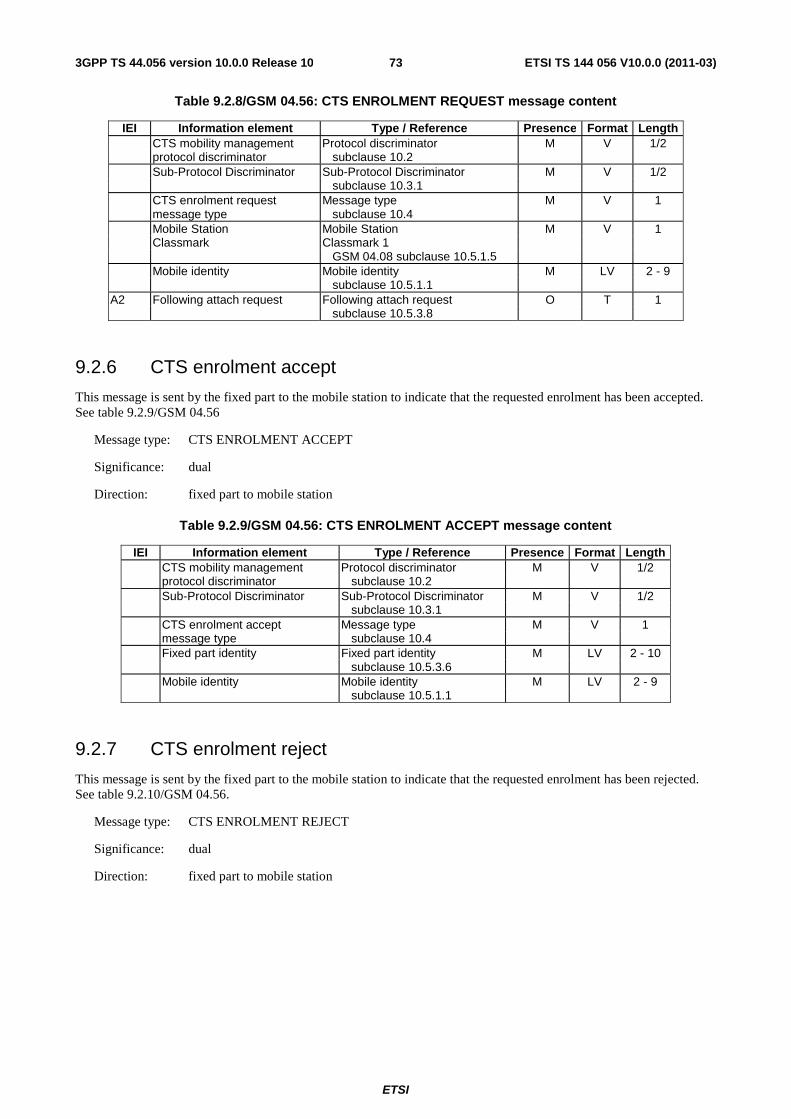
ETSI
ETSI TS 144 056 V10.0.0 (2011-03)733GPP TS 44.056 version 10.0.0 Release 10
Table 9.2.8/GSM 04.56: CTS ENROLMENT REQUEST message content
IEI Information element Type / Reference Presence Format Length CTS mobility management Protocol discriminator M V 1/2 protocol discriminator subclause 10.2 Sub-Protocol Discriminator Sub-Protocol Discriminator M V 1/2 subclause 10.3.1 CTS enrolment request Message type M V 1 message type subclause 10.4 Mobile Station Mobile Station M V 1 Classmark Classmark 1 GSM 04.08 subclause 10.5.1.5 Mobile identity Mobile identity M LV 2 - 9 subclause 10.5.1.1 A2 Following attach request Following attach request O T 1 subclause 10.5.3.8
9.2.6 CTS enrolment accept
This message is sent by the fixed part to the mobile station to indicate that the requested enrolment has been accepted. See table 9.2.9/GSM 04.56
Message type: CTS ENROLMENT ACCEPT
Significance: dual
Direction: fixed part to mobile station
Table 9.2.9/GSM 04.56: CTS ENROLMENT ACCEPT message content
IEI Information element Type / Reference Presence Format Length CTS mobility management Protocol discriminator M V 1/2 protocol discriminator subclause 10.2 Sub-Protocol Discriminator Sub-Protocol Discriminator M V 1/2 subclause 10.3.1 CTS enrolment accept Message type M V 1 message type subclause 10.4 Fixed part identity Fixed part identity M LV 2 - 10 subclause 10.5.3.6 Mobile identity Mobile identity M LV 2 - 9 subclause 10.5.1.1
9.2.7 CTS enrolment reject
This message is sent by the fixed part to the mobile station to indicate that the requested enrolment has been rejected. See table 9.2.10/GSM 04.56.
Message type: CTS ENROLMENT REJECT
Significance: dual
Direction: fixed part to mobile station
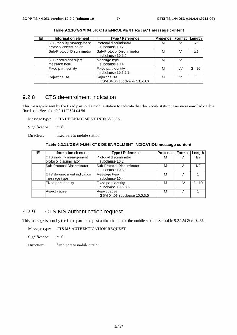
ETSI
ETSI TS 144 056 V10.0.0 (2011-03)743GPP TS 44.056 version 10.0.0 Release 10
Table 9.2.10/GSM 04.56: CTS ENROLMENT REJECT message content
IEI Information element Type / Reference Presence Format Length CTS mobility management Protocol discriminator M V 1/2 protocol discriminator subclause 10.2 Sub-Protocol Discriminator Sub-Protocol Discriminator M V 1/2 subclause 10.3.1 CTS enrolment reject Message type M V 1 message type subclause 10.4 Fixed part identity Fixed part identity M LV 2 - 10 subclause 10.5.3.6 Reject cause Reject cause M V 1 GSM 04.08 subclause 10.5.3.6
9.2.8 CTS de-enrolment indication
This message is sent by the fixed part to the mobile station to indicate that the mobile station is no more enrolled on this fixed part. See table 9.2.11/GSM 04.56.
Message type: CTS DE-ENROLMENT INDICATION
Significance: dual
Direction: fixed part to mobile station
Table 9.2.11/GSM 04.56: CTS DE-ENROLMENT INDICATION message content
IEI Information element Type / Reference Presence Format Length CTS mobility management Protocol discriminator M V 1/2 protocol discriminator subclause 10.2 Sub-Protocol Discriminator Sub-Protocol Discriminator M V 1/2 subclause 10.3.1 CTS de-enrolment indication Message type M V 1 message type subclause 10.4 Fixed part identity Fixed part identity M LV 2 - 10 subclause 10.5.3.6 Reject cause Reject cause M V 1 GSM 04.08 subclause 10.5.3.6
9.2.9 CTS MS authentication request
This message is sent by the fixed part to request authentication of the mobile station. See table 9.2.12/GSM 04.56.
Message type: CTS MS AUTHENTICATION REQUEST
Significance: dual
Direction: fixed part to mobile station
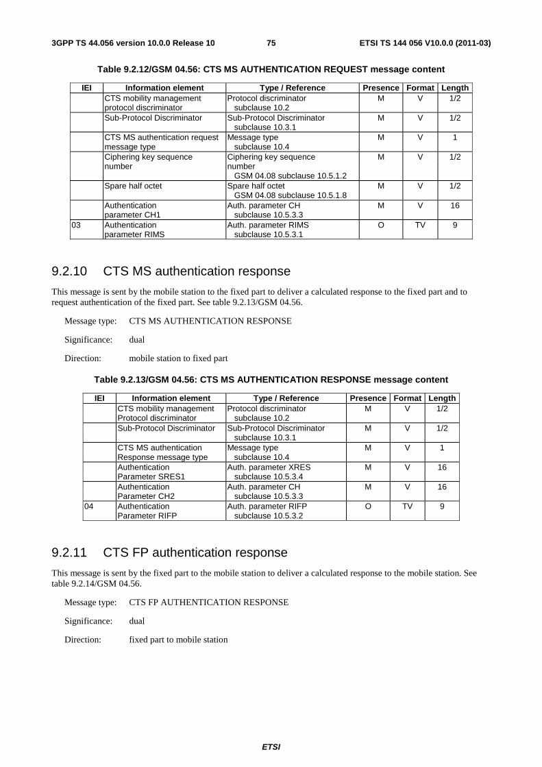
ETSI
ETSI TS 144 056 V10.0.0 (2011-03)753GPP TS 44.056 version 10.0.0 Release 10
Table 9.2.12/GSM 04.56: CTS MS AUTHENTICATION REQUEST message content
IEI Information element Type / Reference Presence Format Length CTS mobility management Protocol discriminator M V 1/2 protocol discriminator subclause 10.2 Sub-Protocol Discriminator Sub-Protocol Discriminator M V 1/2 subclause 10.3.1 CTS MS authentication request Message type M V 1 message type subclause 10.4 Ciphering key sequence Ciphering key sequence M V 1/2 number number GSM 04.08 subclause 10.5.1.2 Spare half octet Spare half octet M V 1/2 GSM 04.08 subclause 10.5.1.8 Authentication Auth. parameter CH M V 16 parameter CH1 subclause 10.5.3.3 03 Authentication Auth. parameter RIMS O TV 9 parameter RIMS subclause 10.5.3.1
9.2.10 CTS MS authentication response
This message is sent by the mobile station to the fixed part to deliver a calculated response to the fixed part and to request authentication of the fixed part. See table 9.2.13/GSM 04.56.
Message type: CTS MS AUTHENTICATION RESPONSE
Significance: dual
Direction: mobile station to fixed part
Table 9.2.13/GSM 04.56: CTS MS AUTHENTICATION RESPONSE message content
IEI Information element Type / Reference Presence Format Length CTS mobility management Protocol discriminator M V 1/2 Protocol discriminator subclause 10.2 Sub-Protocol Discriminator Sub-Protocol Discriminator M V 1/2 subclause 10.3.1 CTS MS authentication Message type M V 1 Response message type subclause 10.4 Authentication Auth. parameter XRES M V 16 Parameter SRES1 subclause 10.5.3.4 Authentication Auth. parameter CH M V 16 Parameter CH2 subclause 10.5.3.3 04 Authentication Auth. parameter RIFP O TV 9 Parameter RIFP subclause 10.5.3.2
9.2.11 CTS FP authentication response
This message is sent by the fixed part to the mobile station to deliver a calculated response to the mobile station. See table 9.2.14/GSM 04.56.
Message type: CTS FP AUTHENTICATION RESPONSE
Significance: dual
Direction: fixed part to mobile station
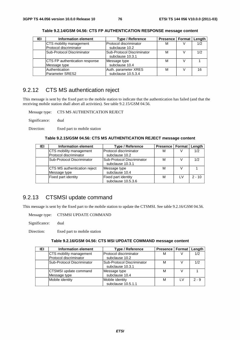
ETSI
ETSI TS 144 056 V10.0.0 (2011-03)763GPP TS 44.056 version 10.0.0 Release 10
Table 9.2.14/GSM 04.56: CTS FP AUTHENTICATION RESPONSE message content
IEI Information element Type / Reference Presence Format Length CTS mobility management Protocol discriminator M V 1/2 Protocol discriminator subclause 10.2 Sub-Protocol Discriminator Sub-Protocol Discriminator M V 1/2 subclause 10.3.1 CTS FP authentication response Message type M V 1 Message type subclause 10.4 Authentication Auth. parameter XRES M V 16 Parameter SRES2 subclause 10.5.3.4
9.2.12 CTS MS authentication reject
This message is sent by the fixed part to the mobile station to indicate that the authentication has failed (and that the receiving mobile station shall abort all activities). See table 9.2.15/GSM 04.56.
Message type: CTS MS AUTHENTICATION REJECT
Significance: dual
Direction: fixed part to mobile station
Table 9.2.15/GSM 04.56: CTS MS AUTHENTICATION REJECT message content
IEI Information element Type / Reference Presence Format Length CTS mobility management Protocol discriminator M V 1/2 Protocol discriminator subclause 10.2 Sub-Protocol Discriminator Sub-Protocol Discriminator M V 1/2 subclause 10.3.1 CTS MS authentication reject Message type M V 1 Message type subclause 10.4 Fixed part identity Fixed part identity M LV 2 - 10 subclause 10.5.3.6
9.2.13 CTSMSI update command
This message is sent by the fixed part to the mobile station to update the CTSMSI. See table 9.2.16/GSM 04.56.
Message type: CTSMSI UPDATE COMMAND
Significance: dual
Direction: fixed part to mobile station
Table 9.2.16/GSM 04.56: CTS MSI UPDATE COMMAND message content
IEI Information element Type / Reference Presence Format Length CTS mobility management Protocol discriminator M V 1/2 Protocol discriminator subclause 10.2 Sub-Protocol Discriminator Sub-Protocol Discriminator M V 1/2 subclause 10.3.1 CTSMSI update command Message type M V 1 Message type subclause 10.4 Mobile identity Mobile identity M LV 2 - 9 subclause 10.5.1.1

ETSI
ETSI TS 144 056 V10.0.0 (2011-03)773GPP TS 44.056 version 10.0.0 Release 10
9.2.14 CTSMSI update complete
This message is sent by the mobile station to the fixed part to indicate that the update of the CTSMSI has taken place. See table 9.2.17/GSM 04.56.
Message type: CTSMSI UPDATE COMPLETE
Significance: dual
Direction: mobile station to fixed part
Table 9.2.17/GSM 04.56: CTSMSI UPDATE COMPLETE message content
IEI Information element Type / Reference Presence Format Length CTS mobility management Protocol discriminator M V 1/2 Protocol discriminator subclause 10.2 Sub-Protocol Discriminator Sub-Protocol Discriminator M V 1/2 subclause 10.3.1 CTSMSI update complete Message type M V 1 Message type subclause 10.4
10 General message format and information elements coding
The figures and text in this clause describe the Information Elements contents.
10.1 Overview See corresponding subclause in GSM 04.08.
10.2 Protocol Discriminator The Protocol Discriminator (PD) and its use are defined in GSM 04.07 [20].
10.3 Sub-Protocol Discriminator and transaction identifier
10.3.1 Sub-Protocol Discriminator
Bits 5 to 8 of the first octet of every CTS Radio Resource management and CTS Mobility Management message contains the Sub-Protocol Discriminator. The Sub-Protocol Discriminator (SPD) and its use are defined in GSM 04.07.
10.3.2 Transaction identifier
See GSM 04.08.
10.4 Message Type The message type IE and its use are defined in GSM 04.07 [20]. Tables 10.1/GSM 04.56, and 10.1/GSM 04.08 define the value part of the message type IE used in the Radio Resource management protocol, the Mobility Management protocol, the Call Control protocol, and Session management protocol.
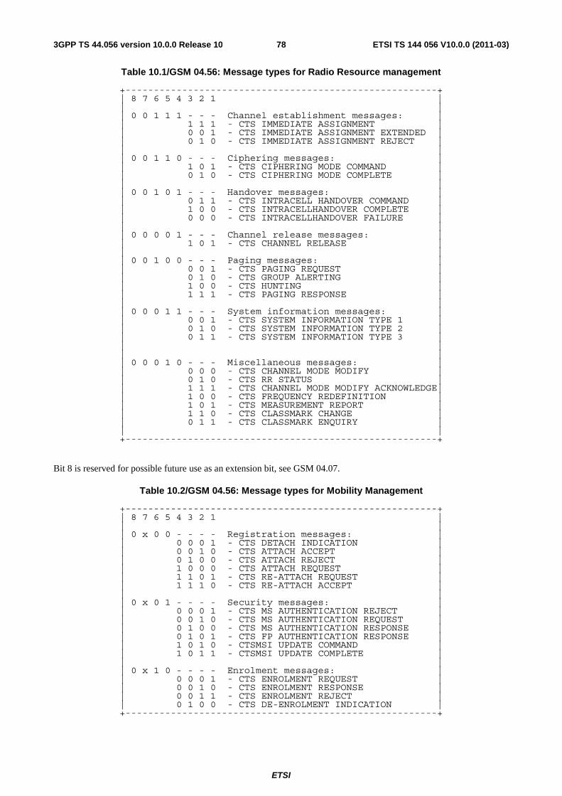
ETSI
ETSI TS 144 056 V10.0.0 (2011-03)783GPP TS 44.056 version 10.0.0 Release 10
Table 10.1/GSM 04.56: Message types for Radio Resource management
+-------------------------------------------------------+ | 8 7 6 5 4 3 2 1 | | | | 0 0 1 1 1 - - - Channel establishment messages: | | 1 1 1 - CTS IMMEDIATE ASSIGNMENT | | 0 0 1 - CTS IMMEDIATE ASSIGNMENT EXTENDED | | 0 1 0 - CTS IMMEDIATE ASSIGNMENT REJECT | | | | 0 0 1 1 0 - - - Ciphering messages: | | 1 0 1 - CTS CIPHERING MODE COMMAND | | 0 1 0 - CTS CIPHERING MODE COMPLETE | | | | 0 0 1 0 1 - - - Handover messages: | | 0 1 1 - CTS INTRACELL HANDOVER COMMAND | | 1 0 0 - CTS INTRACELLHANDOVER COMPLETE | | 0 0 0 - CTS INTRACELLHANDOVER FAILURE | | | | 0 0 0 0 1 - - - Channel release messages: | | 1 0 1 - CTS CHANNEL RELEASE | | | | 0 0 1 0 0 - - - Paging messages: | | 0 0 1 - CTS PAGING REQUEST | | 0 1 0 - CTS GROUP ALERTING | | 1 0 0 - CTS HUNTING | | 1 1 1 - CTS PAGING RESPONSE | | | | 0 0 0 1 1 - - - System information messages: | | 0 0 1 - CTS SYSTEM INFORMATION TYPE 1 | | 0 1 0 - CTS SYSTEM INFORMATION TYPE 2 | | 0 1 1 - CTS SYSTEM INFORMATION TYPE 3 | | | | | | 0 0 0 1 0 - - - Miscellaneous messages: | | 0 0 0 - CTS CHANNEL MODE MODIFY | | 0 1 0 - CTS RR STATUS | | 1 1 1 - CTS CHANNEL MODE MODIFY ACKNOWLEDGE| | 1 0 0 - CTS FREQUENCY REDEFINITION | | 1 0 1 - CTS MEASUREMENT REPORT | | 1 1 0 - CTS CLASSMARK CHANGE | | 0 1 1 - CTS CLASSMARK ENQUIRY | | | +-------------------------------------------------------+
Bit 8 is reserved for possible future use as an extension bit, see GSM 04.07.
Table 10.2/GSM 04.56: Message types for Mobility Management
+-------------------------------------------------------+ | 8 7 6 5 4 3 2 1 | | | | 0 x 0 0 - - - - Registration messages: | | 0 0 0 1 - CTS DETACH INDICATION | | 0 0 1 0 - CTS ATTACH ACCEPT | | 0 1 0 0 - CTS ATTACH REJECT | | 1 0 0 0 - CTS ATTACH REQUEST | | 1 1 0 1 - CTS RE-ATTACH REQUEST | | 1 1 1 0 - CTS RE-ATTACH ACCEPT | | | | 0 x 0 1 - - - - Security messages: | | 0 0 0 1 - CTS MS AUTHENTICATION REJECT | | 0 0 1 0 - CTS MS AUTHENTICATION REQUEST | | 0 1 0 0 - CTS MS AUTHENTICATION RESPONSE | | 0 1 0 1 - CTS FP AUTHENTICATION RESPONSE | | 1 0 1 0 - CTSMSI UPDATE COMMAND | | 1 0 1 1 - CTSMSI UPDATE COMPLETE | | | | 0 x 1 0 - - - - Enrolment messages: | | 0 0 0 1 - CTS ENROLMENT REQUEST | | 0 0 1 0 - CTS ENROLMENT RESPONSE | | 0 0 1 1 - CTS ENROLMENT REJECT | | 0 1 0 0 - CTS DE-ENROLMENT INDICATION | +-------------------------------------------------------+
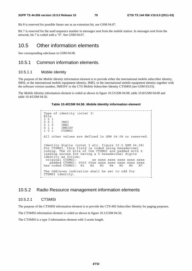
ETSI
ETSI TS 144 056 V10.0.0 (2011-03)793GPP TS 44.056 version 10.0.0 Release 10
Bit 8 is reserved for possible future use as an extension bit, see GSM 04.07.
Bit 7 is reserved for the send sequence number in messages sent from the mobile station. In messages sent from the network, bit 7 is coded with a "0". See GSM 04.07.
10.5 Other information elements See corresponding subclause in GSM 04.08.
10.5.1 Common information elements.
10.5.1.1 Mobile Identity
The purpose of the Mobile Identity information element is to provide either the international mobile subscriber identity, IMSI, or the international mobile equipment identity, IMEI, or the international mobile equipment identity together with the software version number, IMEISV or the CTS Mobile Subscriber Identity CTSMSI (see GSM 03.03).
The Mobile Identity information element is coded as shown in figure 10.5/GSM 04.08, table 10.8/GSM 04.08 and table 10.4/GSM 04.56.
Table 10.4/GSM 04.56: Mobile Identity information element
+--------------------------------------------------------+ | Type of identity (octet 3) | | Bits | | 3 2 1 | | 0 0 1 IMSI | | 0 1 0 IMEI | | 0 1 1 IMEISV | | 1 0 1 CTSMSI | | | | All other values are defined in GSM 04.08 or reserved. | | | | | | Identity digits (octet 3 etc. figure 10.5 GSM 04.08) | | For CTSMSI, this field is coded using hexadecimal | | coding. The 22 bits of the CTSMSI are padded with 6 | | leading zeroes for having a 5 hexadecimal digits | | identity as follow: | | original CTSMSI: xx xxxx xxxx xxxx xxxx xxxx | | padded CTSMSI: 0000 00xx xxxx xxxx xxxx xxxx xxxx | | hex coded CTSMSI: H1 H2 H3 H4 H5 H6 H7 | | | | The Odd/even indication shall be set to odd for | | CTSMSI identity. | +--------------------------------------------------------+
10.5.2 Radio Resource management information elements
10.5.2.1 CTSMSI
The purpose of the CTSMSI information element is to provide the CTS-MS Subscriber Identity for paging purposes.
The CTSMSI information element is coded as shown in figure 10.1/GSM 04.56.
The CTSMSI is a type 3 information element with 3 octets length.
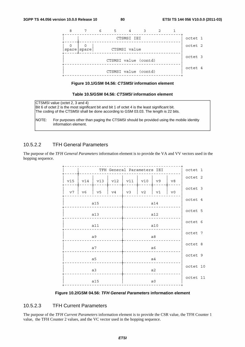
ETSI
ETSI TS 144 056 V10.0.0 (2011-03)803GPP TS 44.056 version 10.0.0 Release 10
8 7 6 5 4 3 2 1 +-----------------------------------------------+
| | CTSMSI IEI | octet 1 +-----┼-----------------------------------------|
| 0 │ 0 | | octet 2 |spare│spare| CTSMSI value | +-----┴-----------------------------------------|
| | octet 3 | CTSMSI value (contd) | +-----------------------------------------------|
| | octet 4 | CTSMSI value (contd) | +-----------------------------------------------+
Figure 10.1/GSM 04.56: CTSMSI information element
Table 10.5/GSM 04.56: CTSMSI information element
CTSMSI value (octet 2, 3 and 4) Bit 6 of octet 2 is the most significant bit and bit 1 of octet 4 is the least significant bit. The coding of the CTSMSI shall be done according to GSM 03.03. The length is 22 bits. NOTE: For purposes other than paging the CTSMSI should be provided using the mobile identity
information element.
10.5.2.2 TFH General Parameters
The purpose of the TFH General Parameters information element is to provide the VA and VV vectors used in the hopping sequence.
+-----------------------------------------------+ | | TFH General Parameters IEI | octet 1
+-----┼-----------------------------------------| | | | | | | | | | octet 2
| v15 | v14 | v13 | v12 | v11 | v10 | v9 | v8 | +-----┼-----┼-----┼-----┼-----┼-----┼-----┼-----|
| | | | | | | | | octet 3 | v7 | v6 | v5 | v4 | v3 | v2 | v1 | v0 | +-----------------------┼-----------------------|
| | | octet 4 | a15 | a14 | +-----------------------┼-----------------------|
| | | octet 5 | a13 | a12 | +-----------------------┼-----------------------|
| | | octet 6 | a11 | a10 | +-----------------------┼-----------------------|
| | | octet 7 | a9 | a8 | +-----------------------┼-----------------------|
| | | octet 8 | a7 | a6 | +-----------------------┼-----------------------|
| | | octet 9 | a5 | a4 | +-----------------------┼-----------------------|
| | | octet 10 | a3 | a2 | +-----------------------┼-----------------------|
| | | octet 11 | a15 | a0 | +-----------------------------------------------+
Figure 10.2/GSM 04.56: TFH General Parameters information element
10.5.2.3 TFH Current Parameters
The purpose of the TFH Current Parameters information element is to provide the CSR value, the TFH Counter 1 value, the TFH Counter 2 values, and the VC vector used in the hopping sequence.
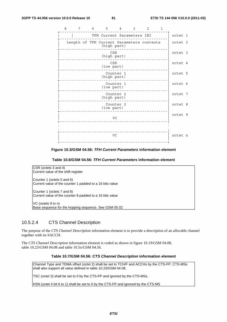
ETSI
ETSI TS 144 056 V10.0.0 (2011-03)813GPP TS 44.056 version 10.0.0 Release 10
8 7 6 5 4 3 2 1 +-----------------------------------------------+
| | TFH Current Parameters IEI | octet 1 +-----------------------------------------------|
| Length of TFH Current Parameters contents | octet 2 | (high part) | +-----------------------------------------------|
| CSR | octet 3 | (high part) | +-----------------------------------------------|
| CSR | octet 4 | (low part) | +-----------------------------------------------|
| Counter 1 | octet 5 | (high part) | +-----------------------------------------------|
| Counter 1 | octet 6 | (low part) | +-----------------------------------------------|
| Counter 2 | octet 7 | (high part) | +-----------------------------------------------|
| Counter 2 | octet 8 | (low part) | +-----------------------------------------------|
| | octet 9 | VC | +-----------------------------------------------| . . . . +-----------------------------------------------|
| VC | octet n | | +-----------------------------------------------+
Figure 10.3/GSM 04.56: TFH Current Parameters information element
Table 10.6/GSM 04.56: TFH Current Parameters information element
CSR (octets 3 and 4) Current value of the shift register Counter 1 (octets 5 and 6) Current value of the counter 1 padded to a 16 bits value Counter 1 (octets 7 and 8) Current value of the counter 8 padded to a 16 bits value VC (octets 9 to n) Base sequence for the hopping sequence. See GSM 05.02
10.5.2.4 CTS Channel Description
The purpose of the CTS Channel Description information element is to provide a description of an allocable channel together with its SACCH.
The CTS Channel Description information element is coded as shown in figure 10.19/GSM 04.08, table 10.23/GSM 04.08 and table 10.5x/GSM 04.56.
Table 10.7/GSM 04.56: CTS Channel Description information element
Channel Type and TDMA offset (octet 2) shall be set to TCH/F and ACCHs by the CTS-FP. CTS-MSs shall also support all value defined in table 10.23/GSM 04.08. TSC (octet 3) shall be set to 0 by the CTS-FP and ignored by the CTS-MSs. HSN (octet 4 bit 6 to 1) shall be set to 0 by the CTS-FP and ignored by the CTS-MS
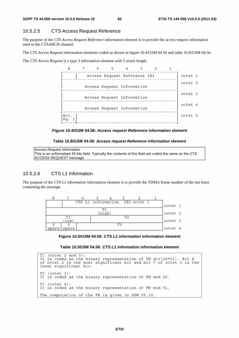
ETSI
ETSI TS 144 056 V10.0.0 (2011-03)823GPP TS 44.056 version 10.0.0 Release 10
10.5.2.5 CTS Access Request Reference
The purpose of the CTS Access Request Reference information element is to provide the access request information used in the CTSARCH channel.
The CTS Access Request information elements coded as shown in figure 10.4/GSM 04.56 and table 10.8/GSM 04.56.
The CTS Access Request is a type 3 information element with 5 octets length.
8 7 6 5 4 3 2 1 +-----------------------------------------------+
│ │ Access Request Reference IEI │ octet 1 +-----┴-----------------------------------------│
│ │ octet 2 │ Access Request Information │ +-----------------------------------------------│
│ │ octet 3 │ Access Request Information │ +-----------------------------------------------│
│ │ octet 4 │ Access Request Information │ +-----------------------------------------------│
│Acc. │ │ octet 5 │Rq. I│ │ +-----┴-----------------------------------------+
Figure 10.4/GSM 04.56: Access request Reference information element
Table 10.8/GSM 04.08: Access request Reference information element
Access Request Information This is an unformatted 25 bits field. Typically the contents of this field are coded the same as the CTS ACCESS REQUEST message.
10.5.2.6 CTS L1 information
The purpose of the CTS L1 information information element is to provide the TDMA frame number of the last burst containing the message.
8 7 6 5 4 3 2 1 CTS L1 information IEI octet 1
octet 1 T1
(high) octet 2 T1
(low)T2
octet 3 0
spare 0
spareT3
octet 4
Figure 10.5/GSM 04.56: CTS L1 information information element
Table 10.5GSM 04.56: CTS L1 information information element
T1 (octet 2 and 3): It is coded as the binary representation of FN div(26*51). Bit 8 of octet 2 is the most significant bit and bit 7 of octet 3 is the least significant bit. T2 (octet 3): It is coded as the binary representation of FN mod 26. T3 (octet 4): It is coded as the binary representation of FN mod 51. The computation of the FN is given in GSM 05.10.
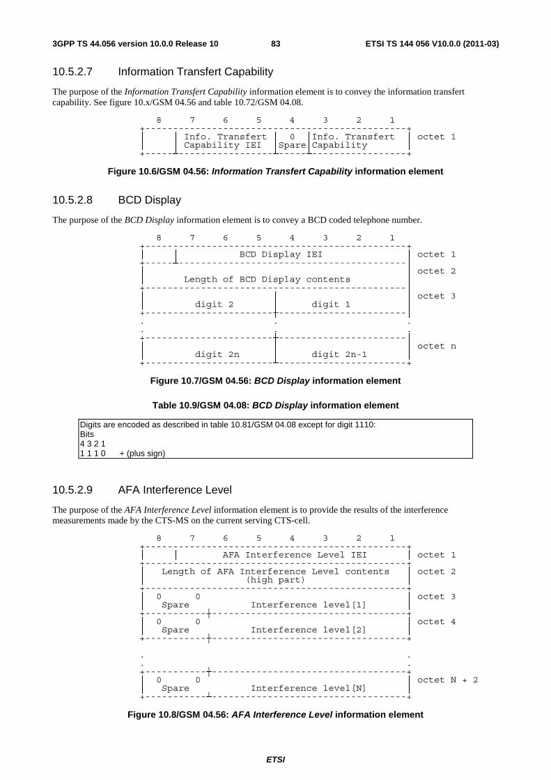
ETSI
ETSI TS 144 056 V10.0.0 (2011-03)833GPP TS 44.056 version 10.0.0 Release 10
10.5.2.7 Information Transfert Capability
The purpose of the Information Transfert Capability information element is to convey the information transfert capability. See figure 10.x/GSM 04.56 and table 10.72/GSM 04.08.
8 7 6 5 4 3 2 1 +-----------------------------------------------+
│ │ Info. Transfert │ 0 │Info. Transfert │ octet 1 │ │ Capability IEI │Spare│Capability │ +-----┴-----------------┴-----┴-----------------+
Figure 10.6/GSM 04.56: Information Transfert Capability information element
10.5.2.8 BCD Display
The purpose of the BCD Display information element is to convey a BCD coded telephone number.
8 7 6 5 4 3 2 1 +-----------------------------------------------+
│ │ BCD Display IEI │ octet 1 +-----┴-----------------------------------------│
│ │ octet 2 │ Length of BCD Display contents │ +-----------------------------------------------│
│ │ │ octet 3 │ digit 2 │ digit 1 │ +-----------------------┼-----------------------│ . . . . . . +-----------------------┼-----------------------│
│ │ │ octet n │ digit 2n │ digit 2n-1 │ +-----------------------┴-----------------------+
Figure 10.7/GSM 04.56: BCD Display information element
Table 10.9/GSM 04.08: BCD Display information element
Digits are encoded as described in table 10.81/GSM 04.08 except for digit 1110: Bits 4 3 2 1 1 1 1 0 + (plus sign)
10.5.2.9 AFA Interference Level
The purpose of the AFA Interference Level information element is to provide the results of the interference measurements made by the CTS-MS on the current serving CTS-cell.
8 7 6 5 4 3 2 1 +-----------------------------------------------+
│ │ AFA Interference Level IEI │ octet 1 +-----------------------------------------------+
│ Length of AFA Interference Level contents │ octet 2 │ (high part) │ +-----------------------------------------------+
│ 0 0 │ │ octet 3 │ Spare │ Interference level[1] │ +-----------┼-----------------------------------+
│ 0 0 │ │ octet 4 │ Spare │ Interference level[2] │ +-----------┼-----------------------------------+
. . . . +-----------┼-----------------------------------+
│ 0 0 │ │ octet N + 2 │ Spare │ Interference level[N] │ +-----------┴-----------------------------------+
Figure 10.8/GSM 04.56: AFA Interference Level information element
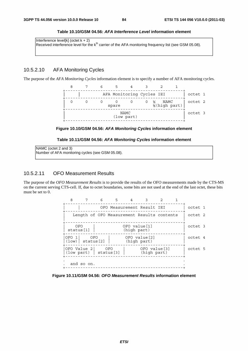
ETSI
ETSI TS 144 056 V10.0.0 (2011-03)843GPP TS 44.056 version 10.0.0 Release 10
Table 10.10/GSM 04.56: AFA Interference Level information element
Interference level[k] (octet k + 2) Received interference level for the kth carrier of the AFA monitoring frequency list (see GSM 05.08).
10.5.2.10 AFA Monitoring Cycles
The purpose of the AFA Monitoring Cycles information element is to specify a number of AFA monitoring cycles.
8 7 6 5 4 3 2 1 +-----------------------------------------------+
│ │ AFA Monitoring Cycles IEI │ octet 1 +-----------------------------------------------+
│ 0 0 0 0 0 0 ½ NAMC │ octet 2 │ spare ½(high part)│ +-----------------------------------------------+
│ NAMC │ octet 3 │ (low part) │ +-----------------------------------------------+
Figure 10.10/GSM 04.56: AFA Monitoring Cycles information element
Table 10.11/GSM 04.56: AFA Monitoring Cycles information element
NAMC (octet 2 and 3) Number of AFA monitoring cycles (see GSM 05.08).
10.5.2.11 OFO Measurement Results
The purpose of the OFO Measurement Results is to provide the results of the OFO measurements made by the CTS-MS on the current serving CTS-cell. If, due to octet boundaries, some bits are not used at the end of the last octet, these bits must be set to 0.
8 7 6 5 4 3 2 1 +-----------------------------------------------+
| | OFO Measurement Result IEI | octet 1 +-----------------------------------------------+
| Length of OFO Measurement Results contents | octet 2 | | +-----------------------------------------------+
| OFO | OFO value[1] | octet 3 | status[1] | (high part) | +-----------------------------------------------+
|OFO 1| OFO | OFO value[2] | octet 4 |(low)| status[2] | (high part) | +-----------------------------------------------+
|OFO Value 2| OFO | OFO value[3] | octet 5 |(low part) | status[3] | (high part) | +-----------------------------------------------+ . . . and so on. . +-----------------------------------------------+
Figure 10.11/GSM 04.56: OFO Measurement Results information element
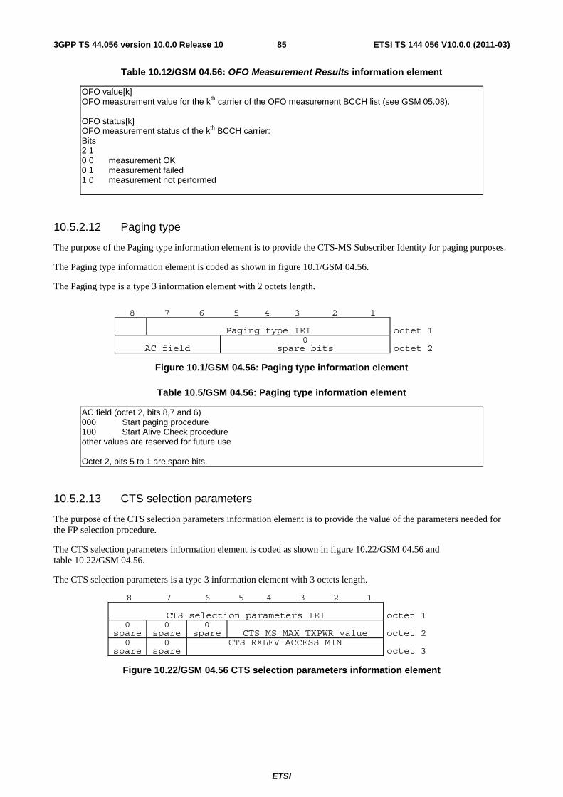
ETSI
ETSI TS 144 056 V10.0.0 (2011-03)853GPP TS 44.056 version 10.0.0 Release 10
Table 10.12/GSM 04.56: OFO Measurement Results information element
OFO value[k] OFO measurement value for the kth carrier of the OFO measurement BCCH list (see GSM 05.08). OFO status[k] OFO measurement status of the kth BCCH carrier: Bits 2 1 0 0 measurement OK 0 1 measurement failed 1 0 measurement not performed
10.5.2.12 Paging type
The purpose of the Paging type information element is to provide the CTS-MS Subscriber Identity for paging purposes.
The Paging type information element is coded as shown in figure 10.1/GSM 04.56.
The Paging type is a type 3 information element with 2 octets length.
8 7 6 5 4 3 2 1
Paging type IEI octet 1
AC field 0
spare bits octet 2
Figure 10.1/GSM 04.56: Paging type information element
Table 10.5/GSM 04.56: Paging type information element
AC field (octet 2, bits 8,7 and 6) 000 Start paging procedure 100 Start Alive Check procedure other values are reserved for future use Octet 2, bits 5 to 1 are spare bits.
10.5.2.13 CTS selection parameters
The purpose of the CTS selection parameters information element is to provide the value of the parameters needed for the FP selection procedure.
The CTS selection parameters information element is coded as shown in figure 10.22/GSM 04.56 and table 10.22/GSM 04.56.
The CTS selection parameters is a type 3 information element with 3 octets length.
8 7 6 5 4 3 2 1
CTS selection parameters IEI octet 1 0
spare 0
spare0
spare CTS MS MAX TXPWR value octet 2 0
spare 0
spareCTS RXLEV ACCESS MIN
octet 3
Figure 10.22/GSM 04.56 CTS selection parameters information element
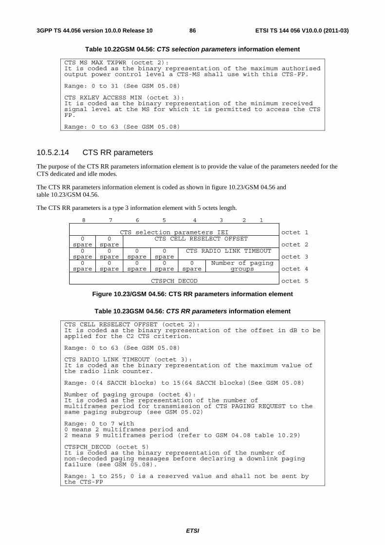
ETSI
ETSI TS 144 056 V10.0.0 (2011-03)863GPP TS 44.056 version 10.0.0 Release 10
Table 10.22GSM 04.56: CTS selection parameters information element
CTS MS MAX TXPWR (octet 2): It is coded as the binary representation of the maximum authorised output power control level a CTS-MS shall use with this CTS-FP. Range: 0 to 31 (See GSM 05.08) CTS RXLEV ACCESS MIN (octet 3): It is coded as the binary representation of the minimum received signal level at the MS for which it is permitted to access the CTS FP. Range: 0 to 63 (See GSM 05.08)
10.5.2.14 CTS RR parameters
The purpose of the CTS RR parameters information element is to provide the value of the parameters needed for the CTS dedicated and idle modes.
The CTS RR parameters information element is coded as shown in figure 10.23/GSM 04.56 and table 10.23/GSM 04.56.
The CTS RR parameters is a type 3 information element with 5 octets length.
8 7 6 5 4 3 2 1
CTS selection parameters IEI octet 1
0 spare
0 spare
CTS CELL RESELECT OFFSET octet 2
0 spare
0 spare
0 spare
0 spare
CTS RADIO LINK TIMEOUT octet 3
0 spare
0 spare
0 spare
0 spare
0spare
Number of paging groups
octet 4
CTSPCH DECOD octet 5
Figure 10.23/GSM 04.56: CTS RR parameters information element
Table 10.23GSM 04.56: CTS RR parameters information element
CTS CELL RESELECT OFFSET (octet 2): It is coded as the binary representation of the offset in dB to be applied for the C2 CTS criterion. Range: 0 to 63 (See GSM 05.08) CTS RADIO LINK TIMEOUT (octet 3): It is coded as the binary representation of the maximum value of the radio link counter. Range: 0(4 SACCH blocks) to 15(64 SACCH blocks)(See GSM 05.08) Number of paging groups (octet 4): It is coded as the representation of the number of multiframes period for transmission of CTS PAGING REQUEST to the same paging subgroup (see GSM 05.02) Range: 0 to 7 with 0 means 2 multiframes period and 2 means 9 multiframes period (refer to GSM 04.08 table 10.29) CTSPCH_DECOD (octet 5) It is coded as the binary representation of the number of non-decoded paging messages before declaring a downlink paging failure (see GSM 05.08). Range: 1 to 255; 0 is a reserved value and shall not be sent by the CTS-FP
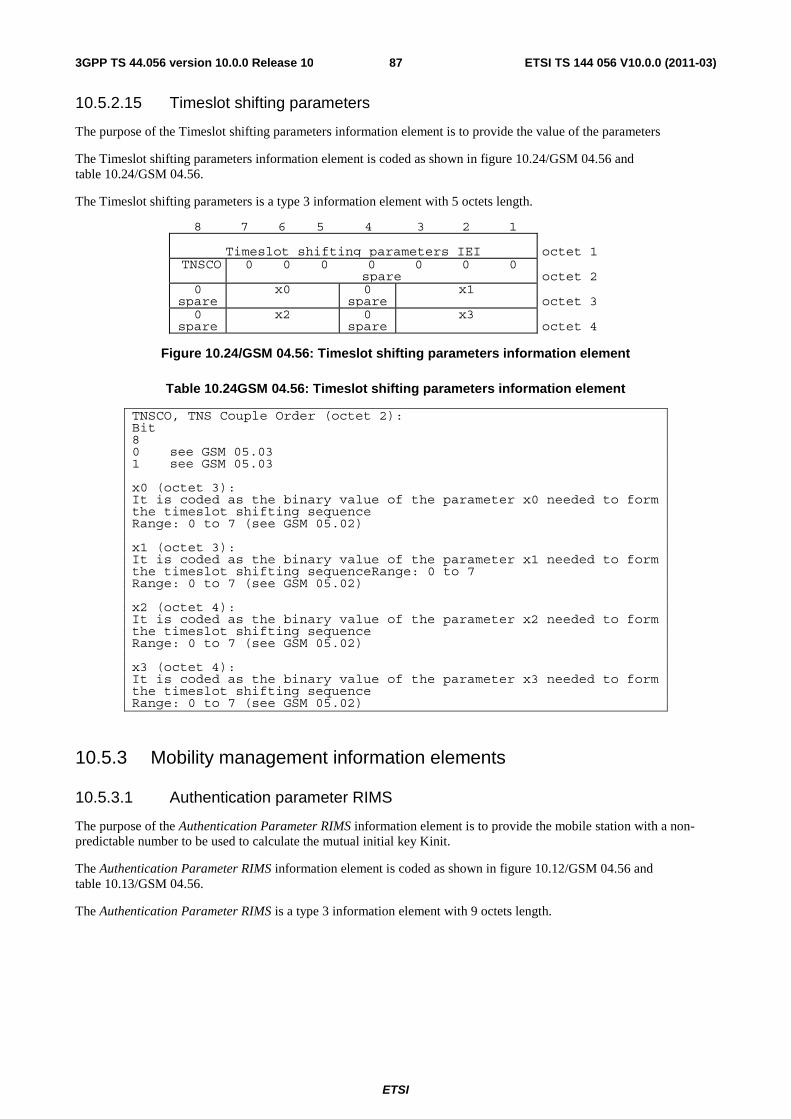
ETSI
ETSI TS 144 056 V10.0.0 (2011-03)873GPP TS 44.056 version 10.0.0 Release 10
10.5.2.15 Timeslot shifting parameters
The purpose of the Timeslot shifting parameters information element is to provide the value of the parameters
The Timeslot shifting parameters information element is coded as shown in figure 10.24/GSM 04.56 and table 10.24/GSM 04.56.
The Timeslot shifting parameters is a type 3 information element with 5 octets length.
8 7 6 5 4 3 2 1
Timeslot shifting parameters IEI octet 1 TNSCO 0 0 0 0 0 0 0
spare octet 2 0
spare x0 0
sparex1
octet 3 0
spare x2 0
sparex3
octet 4
Figure 10.24/GSM 04.56: Timeslot shifting parameters information element
Table 10.24GSM 04.56: Timeslot shifting parameters information element
TNSCO, TNS Couple Order (octet 2): Bit 8 0 see GSM 05.03 1 see GSM 05.03 x0 (octet 3): It is coded as the binary value of the parameter x0 needed to form the timeslot shifting sequence Range: 0 to 7 (see GSM 05.02) x1 (octet 3): It is coded as the binary value of the parameter x1 needed to form the timeslot shifting sequenceRange: 0 to 7 Range: 0 to 7 (see GSM 05.02) x2 (octet 4): It is coded as the binary value of the parameter x2 needed to form the timeslot shifting sequence Range: 0 to 7 (see GSM 05.02) x3 (octet 4): It is coded as the binary value of the parameter x3 needed to form the timeslot shifting sequence Range: 0 to 7 (see GSM 05.02)
10.5.3 Mobility management information elements
10.5.3.1 Authentication parameter RIMS
The purpose of the Authentication Parameter RIMS information element is to provide the mobile station with a non-predictable number to be used to calculate the mutual initial key Kinit.
The Authentication Parameter RIMS information element is coded as shown in figure 10.12/GSM 04.56 and table 10.13/GSM 04.56.
The Authentication Parameter RIMS is a type 3 information element with 9 octets length.

ETSI
ETSI TS 144 056 V10.0.0 (2011-03)883GPP TS 44.056 version 10.0.0 Release 10
8 7 6 5 4 3 2 1 +-----------------------------------------------+
| Authentication parameter RIMS IEI | octet 1 +-----------------------------------------------+ | |
| RIMS value | octet 2 : :
| | octet 9 | | +-----------------------------------------------+
Figure 10.12/GSM 04.56: Authentication Parameter RIMS information element
Table 10.13/GSM 04.56: Authentication Parameter RIMS information element
+-----------------------------------------------------+ | RIMS value (octet 2, 3,... and 9) | | The RIMS value consists of 64 bits. Bit 8 of octet | | 2 is the most significant bit while bit 1 of octet | | 9 is the least significant bit. | +-----------------------------------------------------+
10.5.3.2 Authentication parameter RIFP
The purpose of the Authentication Parameter RIFP information element is to provide the fixed part with a non-predictable number to be used to calculate the mutual initial key Kinit.
The Authentication Parameter RIFP information element is coded as shown in figure 10.13/GSM 04.56 and table 10.14/GSM 04.56.
The Authentication Parameter RIFP is a type 3 information element with 9 octets length.
8 7 6 5 4 3 2 1 +-----------------------------------------------+
| Authentication parameter RIFP IEI | octet 1 +-----------------------------------------------+ | |
| RIFP value | octet 2 : :
| | octet 9 | | +-----------------------------------------------+
Figure 10.13/GSM 04.56: Authentication Parameter RIFP information element
Table 10.14/GSM 04.56: Authentication Parameter RIFP information element
+-----------------------------------------------------+ | RIFP value (octet 2, 3,... and 9) | | The RIFP value consists of 64 bits. Bit 8 of octet | | 2 is the most significant bit while bit 1 of octet | | 9 is the least significant bit. | +-----------------------------------------------------+
10.5.3.3 Authentication parameter CH
The purpose of the Authentication Parameter CH information element is to provide the mobile station or the fixed part with a non-predictable number to be used to calculate the authentication response signature XRES and the ciphering key Kc.
The Authentication Parameter CH information element is coded as shown in figure 10.14/GSM 04.56 and table 10.15/GSM 04.56.
The Authentication Parameter CH is a type 3 information element with 17 octets length.
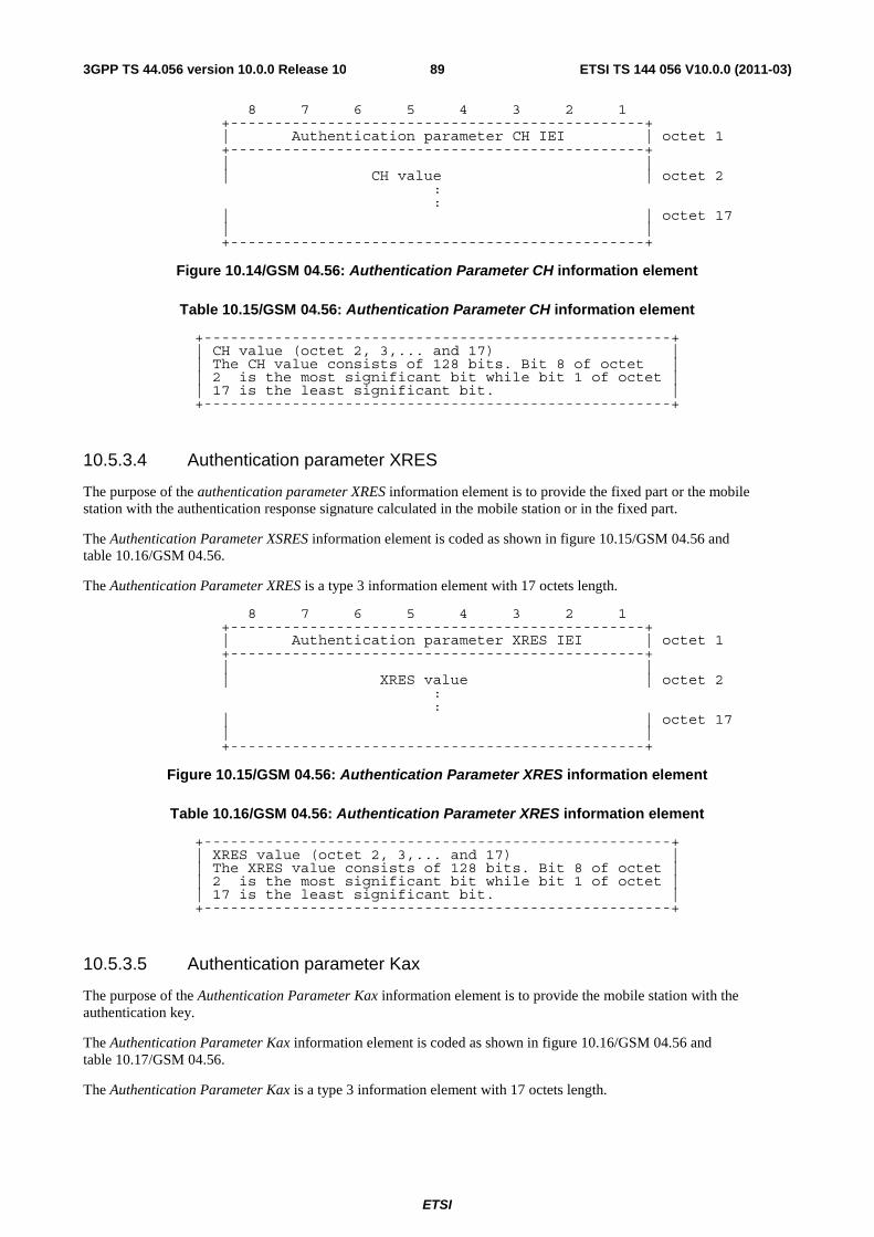
ETSI
ETSI TS 144 056 V10.0.0 (2011-03)893GPP TS 44.056 version 10.0.0 Release 10
8 7 6 5 4 3 2 1 +-----------------------------------------------+
| Authentication parameter CH IEI | octet 1 +-----------------------------------------------+ | |
| CH value | octet 2 : :
| | octet 17 | | +-----------------------------------------------+
Figure 10.14/GSM 04.56: Authentication Parameter CH information element
Table 10.15/GSM 04.56: Authentication Parameter CH information element
+-----------------------------------------------------+ | CH value (octet 2, 3,... and 17) | | The CH value consists of 128 bits. Bit 8 of octet | | 2 is the most significant bit while bit 1 of octet | | 17 is the least significant bit. | +-----------------------------------------------------+
10.5.3.4 Authentication parameter XRES
The purpose of the authentication parameter XRES information element is to provide the fixed part or the mobile station with the authentication response signature calculated in the mobile station or in the fixed part.
The Authentication Parameter XSRES information element is coded as shown in figure 10.15/GSM 04.56 and table 10.16/GSM 04.56.
The Authentication Parameter XRES is a type 3 information element with 17 octets length.
8 7 6 5 4 3 2 1 +-----------------------------------------------+
| Authentication parameter XRES IEI | octet 1 +-----------------------------------------------+ | |
| XRES value | octet 2 : :
| | octet 17 | | +-----------------------------------------------+
Figure 10.15/GSM 04.56: Authentication Parameter XRES information element
Table 10.16/GSM 04.56: Authentication Parameter XRES information element
+-----------------------------------------------------+ | XRES value (octet 2, 3,... and 17) | | The XRES value consists of 128 bits. Bit 8 of octet | | 2 is the most significant bit while bit 1 of octet | | 17 is the least significant bit. | +-----------------------------------------------------+
10.5.3.5 Authentication parameter Kax
The purpose of the Authentication Parameter Kax information element is to provide the mobile station with the authentication key.
The Authentication Parameter Kax information element is coded as shown in figure 10.16/GSM 04.56 and table 10.17/GSM 04.56.
The Authentication Parameter Kax is a type 3 information element with 17 octets length.

ETSI
ETSI TS 144 056 V10.0.0 (2011-03)903GPP TS 44.056 version 10.0.0 Release 10
8 7 6 5 4 3 2 1 +-----------------------------------------------+
| Authentication parameter Kax IEI | octet 1 +-----------------------------------------------+ | |
| Kax value | octet 2 : :
| | octet 17 | | +-----------------------------------------------+
Figure 10.16/GSM 04.56: Authentication Parameter Kax information element
Table 10.17/GSM 04.56: Authentication Parameter Kax information element
+-----------------------------------------------------+ | Kax value (octet 2, 3,... and 17) | | The Kax value consists of 128 bits. Bit 8 of octet | | 2 is the most significant bit while bit 1 of octet | | 17 is the least significant bit. | +-----------------------------------------------------+
10.5.3.6 Fixed part Identity
The purpose of the Fixed part Identity information element is to provide either the international fixed part subscriber identity, IFPSI or the international fixed part equipment identity, IFPEI.
The IFPSI shall not exceed 15 digits, the IFPEI is composed of 16 digits (see GSM 03.03).
The Fixed part Identity information element is coded as shown in figure 10.17/GSM 04.56 and table 10.18/GSM 04.56.
The Fixed part Identity is a type 4 information element with a minimum length of 3 octets and 11 octets length maximal.
8 7 6 5 4 3 2 1 +-----------------------------------------------+
| | Fixed part Identity IEI | octet 1 +-----------------------------------------------+ | |
| Length of fixed part identity contents | octet 2 +-----------------------------------------------+ | |odd/ | |
| Identity digit 1 |even | Type of identity| octet 3 | |indic| | +-----------------------+-----------------------+ | | |
| Identity digit p+1 | Identity digit p | octet 4* +-----------------------------------------------+
Figure 10.17/GSM 04.56: Fixed part Identity information element
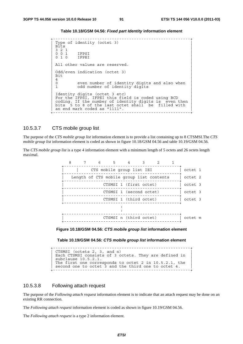
ETSI
ETSI TS 144 056 V10.0.0 (2011-03)913GPP TS 44.056 version 10.0.0 Release 10
Table 10.18/GSM 04.56: Fixed part Identity information element
+--------------------------------------------------------+ | Type of identity (octet 3) | | Bits | | 3 2 1 | | 0 0 1 IFPSI | | 0 1 0 IFPEI | | | | All other values are reserved. | | | | Odd/even indication (octet 3) | | Bit | | 4 | | 0 even number of identity digits and also when | | 1 odd number of identity digits | | | | Identity digits (octet 3 etc) | | For the IFPSI, IFPEI this field is coded using BCD | | coding. If the number of identity digits is even then | | bits 5 to 8 of the last octet shall be filled with | | an end mark coded as "1111". | +--------------------------------------------------------+
10.5.3.7 CTS mobile group list
The purpose of the CTS mobile group list information element is to provide a list containing up to 8 CTSMSI.The CTS mobile group list information element is coded as shown in figure 10.18/GSM 04.56 and table 10.19/GSM 04.56.
The CTS mobile group list is a type 4 information element with a minimum length of 5 octets and 26 octets length maximal.
8 7 6 5 4 3 2 1 +-----------------------------------------------+
| | CTS mobile group list IEI | octet 1 +-----------------------------------------------+
| Length of CTS mobile group list contents | octet 2 +-----------------------------------------------+
| CTSMSI 1 (first octet) | octet 3 +-----------------------------------------------+
| CTSMSI 1 (second octet) | octet 3 +-----------------------------------------------+
| CTSMSI 1 (third octet) | octet 3 +-----------------------------------------------+
: :
+-----------------------------------------------+ | CTSMSI n (third octet) | octet m
+-----------------------------------------------+
Figure 10.18/GSM 04.56: CTS mobile group list information element
Table 10.19/GSM 04.56: CTS mobile group list information element
+--------------------------------------------------------+ | CTSMSI (octets 2, 3, and n) | | Each CTSMSI consists of 3 octets. They are defined in | | subclause 10.5.2.1. | | The first one corresponds to octet 2 in 10.5.2.1, the | | second one to octet 3 and the third one to octet 4. | +--------------------------------------------------------+
10.5.3.8 Following attach request
The purpose of the Following attach request information element is to indicate that an attach request may be done on an existing RR connection.
The Following attach request information element is coded as shown in figure 10.19/GSM 04.56.
The Following attach request is a type 2 information element.
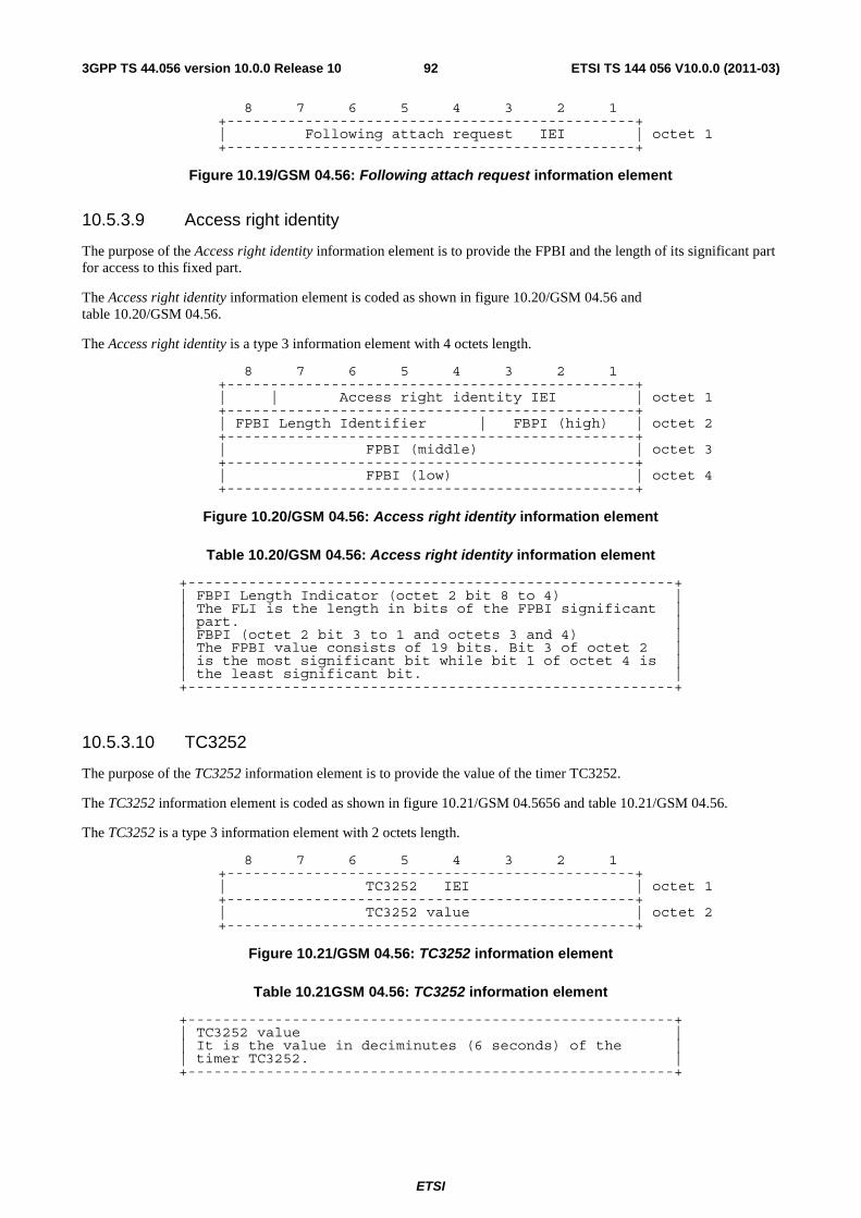
ETSI
ETSI TS 144 056 V10.0.0 (2011-03)923GPP TS 44.056 version 10.0.0 Release 10
8 7 6 5 4 3 2 1 +-----------------------------------------------+
| Following attach request IEI | octet 1 +-----------------------------------------------+
Figure 10.19/GSM 04.56: Following attach request information element
10.5.3.9 Access right identity
The purpose of the Access right identity information element is to provide the FPBI and the length of its significant part for access to this fixed part.
The Access right identity information element is coded as shown in figure 10.20/GSM 04.56 and table 10.20/GSM 04.56.
The Access right identity is a type 3 information element with 4 octets length.
8 7 6 5 4 3 2 1 +-----------------------------------------------+
| | Access right identity IEI | octet 1 +-----------------------------------------------+
| FPBI Length Identifier | FBPI (high) | octet 2 +-----------------------------------------------+
| FPBI (middle) | octet 3 +-----------------------------------------------+
| FPBI (low) | octet 4 +-----------------------------------------------+
Figure 10.20/GSM 04.56: Access right identity information element
Table 10.20/GSM 04.56: Access right identity information element
+--------------------------------------------------------+ | FBPI Length Indicator (octet 2 bit 8 to 4) | | The FLI is the length in bits of the FPBI significant | | part. | | FBPI (octet 2 bit 3 to 1 and octets 3 and 4) | | The FPBI value consists of 19 bits. Bit 3 of octet 2 | | is the most significant bit while bit 1 of octet 4 is | | the least significant bit. | +--------------------------------------------------------+
10.5.3.10 TC3252
The purpose of the TC3252 information element is to provide the value of the timer TC3252.
The TC3252 information element is coded as shown in figure 10.21/GSM 04.5656 and table 10.21/GSM 04.56.
The TC3252 is a type 3 information element with 2 octets length.
8 7 6 5 4 3 2 1 +-----------------------------------------------+
| TC3252 IEI | octet 1 +-----------------------------------------------+
| TC3252 value | octet 2 +-----------------------------------------------+
Figure 10.21/GSM 04.56: TC3252 information element
Table 10.21GSM 04.56: TC3252 information element
+--------------------------------------------------------+ | TC3252 value | | It is the value in deciminutes (6 seconds) of the | | timer TC3252. | +--------------------------------------------------------+
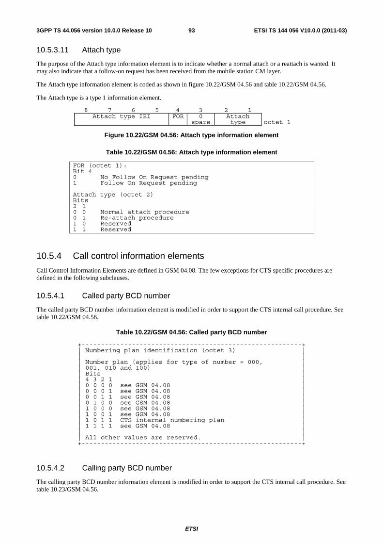
ETSI
ETSI TS 144 056 V10.0.0 (2011-03)933GPP TS 44.056 version 10.0.0 Release 10
10.5.3.11 Attach type
The purpose of the Attach type information element is to indicate whether a normal attach or a reattach is wanted. It may also indicate that a follow-on request has been received from the mobile station CM layer.
The Attach type information element is coded as shown in figure 10.22/GSM 04.56 and table 10.22/GSM 04.56.
The Attach type is a type 1 information element.
8 7 6 5 4 3 2 1Attach type IEI FOR 0
spareAttachtype octet 1
Figure 10.22/GSM 04.56: Attach type information element
Table 10.22/GSM 04.56: Attach type information element
FOR (octet 1): Bit 4 0 No Follow On Request pending 1 Follow On Request pending Attach type (octet 2) Bits 2 1 0 0 Normal attach procedure 0 1 Re-attach procedure 1 0 Reserved 1 1 Reserved
10.5.4 Call control information elements
Call Control Information Elements are defined in GSM 04.08. The few exceptions for CTS specific procedures are defined in the following subclauses.
10.5.4.1 Called party BCD number
The called party BCD number information element is modified in order to support the CTS internal call procedure. See table 10.22/GSM 04.56.
Table 10.22/GSM 04.56: Called party BCD number
+---------------------------------------------------------+ | Numbering plan identification (octet 3) | | | | Number plan (applies for type of number = 000, | | 001, 010 and 100) | | Bits | | 4 3 2 1 | | 0 0 0 0 see GSM 04.08 | | 0 0 0 1 see GSM 04.08 | | 0 0 1 1 see GSM 04.08 | | 0 1 0 0 see GSM 04.08 | | 1 0 0 0 see GSM 04.08 | | 1 0 0 1 see GSM 04.08 | | 1 0 1 1 CTS internal numbering plan | | 1 1 1 1 see GSM 04.08 | | | | All other values are reserved. | +---------------------------------------------------------+
10.5.4.2 Calling party BCD number
The calling party BCD number information element is modified in order to support the CTS internal call procedure. See table 10.23/GSM 04.56.
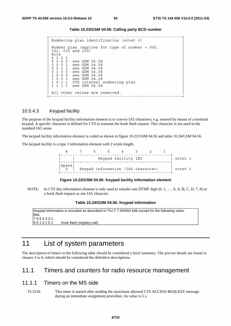
ETSI
ETSI TS 144 056 V10.0.0 (2011-03)943GPP TS 44.056 version 10.0.0 Release 10
Table 10.23/GSM 04.56: Calling party BCD number
+---------------------------------------------------------+ | Numbering plan identification (octet 3) | | | | Number plan (applies for type of number = 000, | | 001, 010 and 100) | | Bits | | 4 3 2 1 | | 0 0 0 0 see GSM 04.08 | | 0 0 0 1 see GSM 04.08 | | 0 0 1 1 see GSM 04.08 | | 0 1 0 0 see GSM 04.08 | | 1 0 0 0 see GSM 04.08 | | 1 0 0 1 see GSM 04.08 | | 1 0 1 1 CTS internal numbering plan | | 1 1 1 1 see GSM 04.08 | | | | All other values are reserved. | +---------------------------------------------------------+
10.5.4.3 Keypad facility
The purpose of the keypad facility information element is to convey IA5 characters, e.g. entered by means of a terminal keypad. A specific character is defined for CTS to transmit the hook flash request. This character is not used in the standard IA5 sense.
The keypad facility information element is coded as shown in figure 10.22/GSM 04.56 and table 10.24/GSM 04.56.
The keypad facility is a type 3 information element with 2 octets length.
8 7 6 5 4 3 2 1 +-----------------------------------------------+
| | Keypad facility IEI | octet 1 +-----+-----------------------------------------+ |Spare| |
| 0 | Keypad information (IA5 character) | octet 2 +-----------------------------------------------+
Figure 10.22/GSM 04.56: Keypad facility information element
NOTE: In CTS this information element is only used to transfer one DTMF digit (0, 1, ... , 9, A, B, C, D, *, #) or a hook flash request as one IA5 character.
Table 10.24/GSM 04.56: Keypad information
Keypad information is encoded as described in ITU-T T.50/ISO 646 except for the following value: Bits 7 6 5 4 3 2 1 0 0 1 0 1 0 1 hook flash (registry call)
11 List of system parameters The description of timers in the following table should be considered a brief summary. The precise details are found in clauses 3 to 6, which should be considered the definitive descriptions.
11.1 Timers and counters for radio resource management
11.1.1 Timers on the MS side
TC3150 This timer is started after sending the maximum allowed CTS ACCESS REQUEST message during an immediate assignment procedure. Its value is 5 s.
ETSI
ETSI TS 144 056 V10.0.0 (2011-03)953GPP TS 44.056 version 10.0.0 Release 10
TC3151 This timer is used to delay the channel deactivation (see GSM 04.08 11.1.1 T3110).
11.1.2 Timers on the CTS-FP side
TC3101 This timer is started when the CTS-FP send a CTS PAGING REQUEST(CTSMSI, AliveCheck flag) for an Alive check procedure, and stopped when receiving a valid CTS ACCESS REQUEST. Its value is manufacturer dependent.
TC3102 Hunting maximal duration timer. Its value is manufacturer dependent, but should be less than 120 s.
TC3103 This timer is started when a channel is allocated with a CTS IMMEDIATE ASSIGN message. It is stopped when the CTS-MS has correctly seized the channels. Its value is manufacturer dependent, but should be greater than 1 s.
TC3104 This timer is started when the CTS-FP has sent a CTS PAGING REQUEST message and is stopped when the CTS-FP has received the CTS PAGING RESPONSE. Its value is manufacturer dependent.
TC3105 This timer is started when the CTS-FP has sent a CTS INTRACELL HANDOVER COMMAND message and is stopped when the CTS-MS has correctly seized the new channel. Its value is manufacturer dependent.
TC3106 See GSM 04.08 11.1.2 T3109
TC3107 See GSM 04.08 11.1.2 T3111
11.1.3 Other parameters
MCTS The maximum number of retransmission for the CTS ACCESS REQUEST message. Its value is 7.
11.2 Timers of mobility management
11.2.1 Timers on the MS side
TC3250 This timer is started when the mobile station has sent a CTS ATTACH REQUEST message and it is normally stopped when the mobile station receives a CTS ATTACH COMPLETE message or a CTS ATTACH REJECT message. At its expiry, the mobile station shall start TC3251. Its value is 20 s.
TC3251 This timer is started when the timer TC3250 expires. Its value is 5 minutes.
TC3252 This timer is started when the mobile station enters the CTS MM IDLE state and it is normally stopped when the mobile station leaves this state. At its expiry, the mobile station shall start the CTS re-attach procedure. Its value is provided by the fixed part during the CTS attach procedure and is greater than TC3201 + NC300 * TC3101 and should be less than TC3201 + 2* NC300 * TC3101.
TC3253 This timer is started when the mobile station has sent a CTS DETACH INDICATION message and it is normally stopped when the RR connection is released. Its value is 5 s.
TC3254 This timer is started when the mobile station has sent a CTS ENROLMENT REQUEST message and it is normally stopped when a CTS ENROLMENT ACCEPT message is received. Its value is 45 s.
TC3255 This timer is started when the mobile station has sent a CTS RE-ATTACH REQUEST message and it is normally stopped when a CTS RE-ATTACH RESPONSE message is received. Its value is 5 s.
ETSI
ETSI TS 144 056 V10.0.0 (2011-03)963GPP TS 44.056 version 10.0.0 Release 10
TC3256 This timer is started when the mobile station has received a CTS ATTACH REJECT with a fixed part identity. At its expiry, the mobile station may re-attempt an attachment on a fixed part having the same FPBI. Its value is 10 minutes.
TC3257 This timer is started when the mobile station has received a CTS ATTACH REJECT from the expected fixed part with a cause different of NOT ENROLLED. At its expiry, the mobile station may re-attempt an attachment on that fixed part. Its value is 5 minutes.
TC3260 This timer is started when the mobile station has sent a CTS MS AUTHENTICATION RESPONSE message and it is normally stopped when a CTS FP AUTHENTICATION RESPONSE message is received. Its value is 5 s.
11.2.2 Timers on the CTS-FP side
TC3201 This timer is started when the fixed part enters the MM IDLE state and it is normally stopped when the fixed part leaves the MM IDLE state. At its expiry, the MM sublayer shall trigger the alive check procedure. Its value is manufacturer dependent, but greater than 15 s.
TC3202 This timer is started when the fixed part has sent a CTSMSI UPDATE COMMAND message and it is normally stopped when a CTSMSI UDPATE COMPLETE message is received. Its value is 5 s.
TC3211 This timer is started when the fixed part has sent a CTS MS AUTHENTICATION REQUEST message and it is normally stopped when a CTS MS AUTHENTICATION RESPONSE message is received. Its value is 5 s.
11.2.3 Other parameters
NC320 The maximum number of alive check procedures allowed before changing the CTSMSI. Its value is manufacturer dependent.
11.3 Timers of circuit-switched call control See GSM 04.08, subclause 11.3

ETSI
ETSI TS 144 056 V10.0.0 (2011-03)973GPP TS 44.056 version 10.0.0 Release 10
Annex A (informative): Default Codings of Information Elements The information in this annex does NOT define the value of any IEI for any particular message. This annex exists to aid the design of new messages.
A.1 Common information elements For the common information elements types listed below, the default coding of information element identifier bits is summarised in table A.1/GSM 04.56.
Table A.1/GSM 04.56: Default information element identifier coding for common information elements
Reference subclause 8 7 6 5 4 3 2 1 1 : : : - - - - Type 1 info elements 1 1 1 - - - - Reserved 0 : : : : : : : Type 3 & 4 info elements 0 0 1 0 1 1 1 Mobile Identity 0 1 0 0 0 0 0 Mobile Station classmark 3 All other values are reserved
10.5.1.1 GSM 04.08 10.5.1.3
A.2 Radio Resource management information elements For the Radio Resource management information elements listed below, the default coding of the information element identifier bits is summarised in table A.2/GSM 04.56.
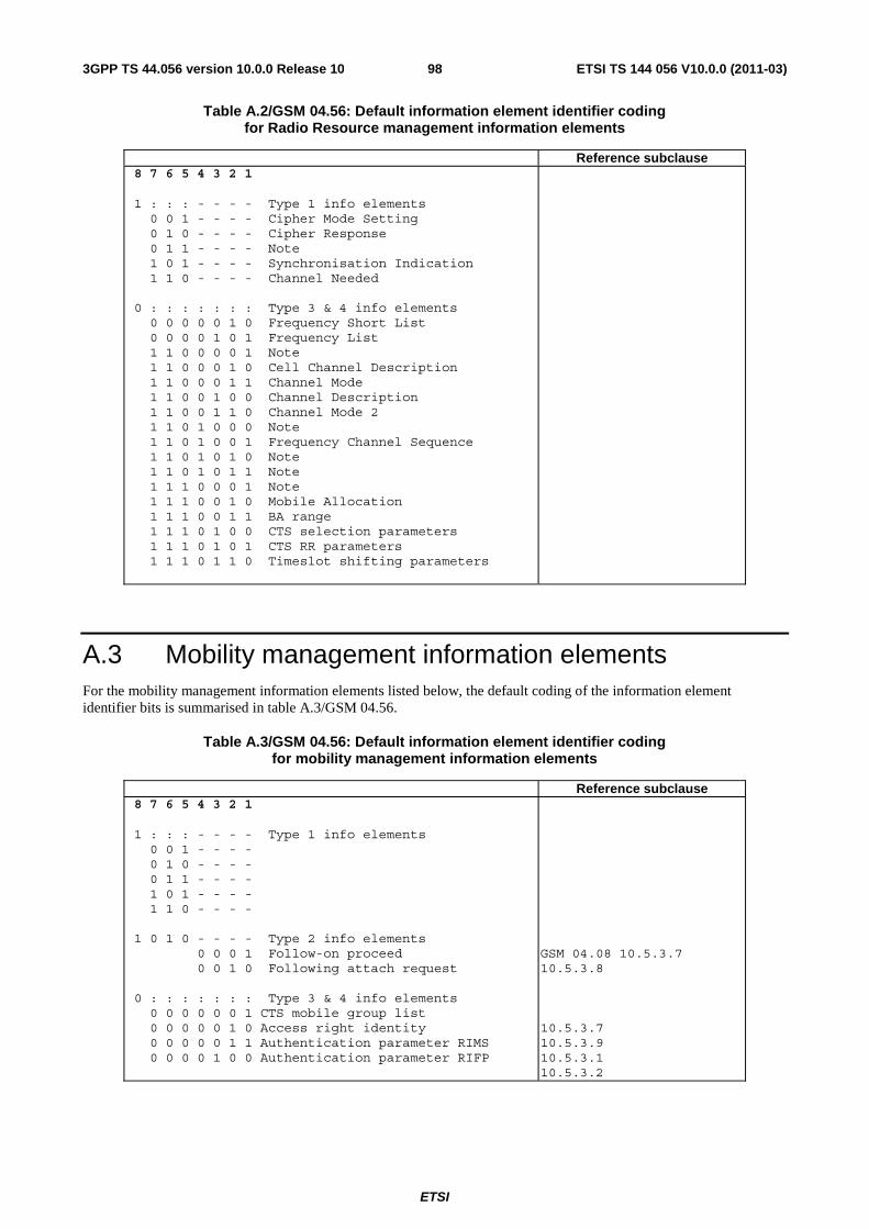
ETSI
ETSI TS 144 056 V10.0.0 (2011-03)983GPP TS 44.056 version 10.0.0 Release 10
Table A.2/GSM 04.56: Default information element identifier coding for Radio Resource management information elements
Reference subclause 8 7 6 5 4 3 2 1 1 : : : - - - - Type 1 info elements 0 0 1 - - - - Cipher Mode Setting 0 1 0 - - - - Cipher Response 0 1 1 - - - - Note 1 0 1 - - - - Synchronisation Indication 1 1 0 - - - - Channel Needed 0 : : : : : : : Type 3 & 4 info elements 0 0 0 0 0 1 0 Frequency Short List 0 0 0 0 1 0 1 Frequency List 1 1 0 0 0 0 1 Note 1 1 0 0 0 1 0 Cell Channel Description 1 1 0 0 0 1 1 Channel Mode 1 1 0 0 1 0 0 Channel Description 1 1 0 0 1 1 0 Channel Mode 2 1 1 0 1 0 0 0 Note 1 1 0 1 0 0 1 Frequency Channel Sequence 1 1 0 1 0 1 0 Note 1 1 0 1 0 1 1 Note 1 1 1 0 0 0 1 Note 1 1 1 0 0 1 0 Mobile Allocation 1 1 1 0 0 1 1 BA range 1 1 1 0 1 0 0 CTS selection parameters 1 1 1 0 1 0 1 CTS RR parameters 1 1 1 0 1 1 0 Timeslot shifting parameters
A.3 Mobility management information elements For the mobility management information elements listed below, the default coding of the information element identifier bits is summarised in table A.3/GSM 04.56.
Table A.3/GSM 04.56: Default information element identifier coding for mobility management information elements
Reference subclause 8 7 6 5 4 3 2 1 1 : : : - - - - Type 1 info elements 0 0 1 - - - - 0 1 0 - - - - 0 1 1 - - - - 1 0 1 - - - - 1 1 0 - - - - 1 0 1 0 - - - - Type 2 info elements 0 0 0 1 Follow-on proceed 0 0 1 0 Following attach request 0 : : : : : : : Type 3 & 4 info elements 0 0 0 0 0 0 1 CTS mobile group list 0 0 0 0 0 1 0 Access right identity 0 0 0 0 0 1 1 Authentication parameter RIMS 0 0 0 0 1 0 0 Authentication parameter RIFP
GSM 04.08 10.5.3.7 10.5.3.8 10.5.3.7 10.5.3.9 10.5.3.1 10.5.3.2

ETSI
ETSI TS 144 056 V10.0.0 (2011-03)993GPP TS 44.056 version 10.0.0 Release 10
A.4 Call control information elements For the call control information elements listed below, the default coding of the information element identifiers is defined in table A.4/GSM 04. 08.
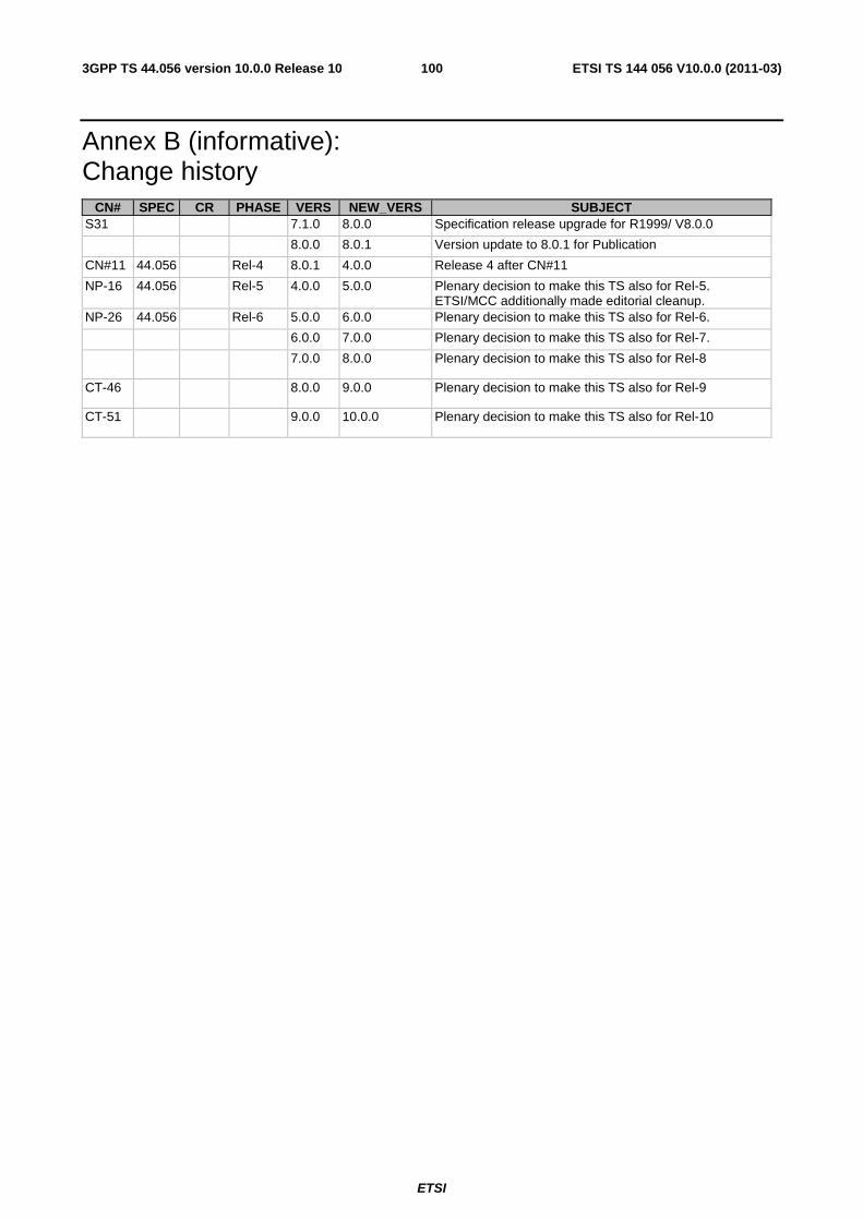
ETSI
ETSI TS 144 056 V10.0.0 (2011-03)1003GPP TS 44.056 version 10.0.0 Release 10
Annex B (informative): Change history
CN# SPEC CR PHASE VERS NEW_VERS SUBJECT S31 7.1.0 8.0.0 Specification release upgrade for R1999/ V8.0.0
8.0.0 8.0.1 Version update to 8.0.1 for Publication
CN#11 44.056 Rel-4 8.0.1 4.0.0 Release 4 after CN#11
NP-16 44.056 Rel-5 4.0.0 5.0.0 Plenary decision to make this TS also for Rel-5. ETSI/MCC additionally made editorial cleanup.
NP-26 44.056 Rel-6 5.0.0 6.0.0 Plenary decision to make this TS also for Rel-6.
6.0.0 7.0.0 Plenary decision to make this TS also for Rel-7.
7.0.0 8.0.0 Plenary decision to make this TS also for Rel-8
CT-46 8.0.0 9.0.0 Plenary decision to make this TS also for Rel-9
CT-51 9.0.0 10.0.0 Plenary decision to make this TS also for Rel-10

ETSI
ETSI TS 144 056 V10.0.0 (2011-03)1013GPP TS 44.056 version 10.0.0 Release 10
History
Document history
V10.0.0 March 2011 Publication
Related Documents