ETSI TS 138 213 V15.5.0 (2019-05) 5G; NR; Physical layer procedures for control (3GPP TS 38.213 version 15.5.0 Release 15) TECHNICAL SPECIFICATION

Welcome message from author
This document is posted to help you gain knowledge. Please leave a comment to let me know what you think about it! Share it to your friends and learn new things together.
Transcript

ETSI TS 138 213 V15.5.0 (2019-05)
5G; NR;
Physical layer procedures for control (3GPP TS 38.213 version 15.5.0 Release 15)
TECHNICAL SPECIFICATION

ETSI
ETSI TS 138 213 V15.5.0 (2019-05)13GPP TS 38.213 version 15.5.0 Release 15
Reference RTS/TSGR-0138213vf50
Keywords 5G
ETSI
650 Route des Lucioles F-06921 Sophia Antipolis Cedex - FRANCE
Tel.: +33 4 92 94 42 00 Fax: +33 4 93 65 47 16
Siret N° 348 623 562 00017 - NAF 742 C
Association à but non lucratif enregistrée à la Sous-Préfecture de Grasse (06) N° 7803/88
Important notice
The present document can be downloaded from: http://www.etsi.org/standards-search
The present document may be made available in electronic versions and/or in print. The content of any electronic and/or print versions of the present document shall not be modified without the prior written authorization of ETSI. In case of any
existing or perceived difference in contents between such versions and/or in print, the prevailing version of an ETSI deliverable is the one made publicly available in PDF format at www.etsi.org/deliver.
Users of the present document should be aware that the document may be subject to revision or change of status. Information on the current status of this and other ETSI documents is available at
https://portal.etsi.org/TB/ETSIDeliverableStatus.aspx
If you find errors in the present document, please send your comment to one of the following services: https://portal.etsi.org/People/CommiteeSupportStaff.aspx
Copyright Notification
No part may be reproduced or utilized in any form or by any means, electronic or mechanical, including photocopying and microfilm except as authorized by written permission of ETSI.
The content of the PDF version shall not be modified without the written authorization of ETSI. The copyright and the foregoing restriction extend to reproduction in all media.
© ETSI 2019.
All rights reserved.
DECTTM, PLUGTESTSTM, UMTSTM and the ETSI logo are trademarks of ETSI registered for the benefit of its Members. 3GPPTM and LTETM are trademarks of ETSI registered for the benefit of its Members and
of the 3GPP Organizational Partners. oneM2M™ logo is a trademark of ETSI registered for the benefit of its Members and
of the oneM2M Partners. GSM® and the GSM logo are trademarks registered and owned by the GSM Association.

ETSI
ETSI TS 138 213 V15.5.0 (2019-05)23GPP TS 38.213 version 15.5.0 Release 15
Intellectual Property Rights Essential patents
IPRs essential or potentially essential to normative deliverables may have been declared to ETSI. The information pertaining to these essential IPRs, if any, is publicly available for ETSI members and non-members, and can be found in ETSI SR 000 314: "Intellectual Property Rights (IPRs); Essential, or potentially Essential, IPRs notified to ETSI in respect of ETSI standards", which is available from the ETSI Secretariat. Latest updates are available on the ETSI Web server (https://ipr.etsi.org/).
Pursuant to the ETSI IPR Policy, no investigation, including IPR searches, has been carried out by ETSI. No guarantee can be given as to the existence of other IPRs not referenced in ETSI SR 000 314 (or the updates on the ETSI Web server) which are, or may be, or may become, essential to the present document.
Trademarks
The present document may include trademarks and/or tradenames which are asserted and/or registered by their owners. ETSI claims no ownership of these except for any which are indicated as being the property of ETSI, and conveys no right to use or reproduce any trademark and/or tradename. Mention of those trademarks in the present document does not constitute an endorsement by ETSI of products, services or organizations associated with those trademarks.
Foreword This Technical Specification (TS) has been produced by ETSI 3rd Generation Partnership Project (3GPP).
The present document may refer to technical specifications or reports using their 3GPP identities, UMTS identities or GSM identities. These should be interpreted as being references to the corresponding ETSI deliverables.
The cross reference between GSM, UMTS, 3GPP and ETSI identities can be found under http://webapp.etsi.org/key/queryform.asp.
Modal verbs terminology In the present document "shall", "shall not", "should", "should not", "may", "need not", "will", "will not", "can" and "cannot" are to be interpreted as described in clause 3.2 of the ETSI Drafting Rules (Verbal forms for the expression of provisions).
"must" and "must not" are NOT allowed in ETSI deliverables except when used in direct citation.

ETSI
ETSI TS 138 213 V15.5.0 (2019-05)33GPP TS 38.213 version 15.5.0 Release 15
Contents Intellectual Property Rights ................................................................................................................................ 2
Foreword ............................................................................................................................................................. 2
Modal verbs terminology .................................................................................................................................... 2
Foreword ............................................................................................................................................................. 5
1 Scope ........................................................................................................................................................ 6
2 References ................................................................................................................................................ 6
3 Definitions, symbols and abbreviations ................................................................................................... 6
3.1 Definitions .......................................................................................................................................................... 6
3.2 Symbols .............................................................................................................................................................. 6
3.3 Abbreviations ..................................................................................................................................................... 7
4 Synchronization procedures ..................................................................................................................... 9
4.1 Cell search .......................................................................................................................................................... 9
4.2 Transmission timing adjustments ..................................................................................................................... 10
4.3 Timing for secondary cell activation / deactivation.......................................................................................... 11
5 Radio link monitoring ............................................................................................................................ 11
6 Link recovery procedures ....................................................................................................................... 13
7 Uplink Power control ............................................................................................................................. 14
7.1 Physical uplink shared channel ........................................................................................................................ 14
7.1.1 UE behaviour .............................................................................................................................................. 14
7.2 Physical uplink control channel ........................................................................................................................ 19
7.2.1 UE behaviour .............................................................................................................................................. 20
7.3 Sounding reference signals ............................................................................................................................... 24
7.3.1 UE behaviour .............................................................................................................................................. 24
7.4 Physical random access channel ....................................................................................................................... 26
7.5 Prioritizations for transmission power reductions ............................................................................................ 27
7.6 Dual connectivity ............................................................................................................................................. 28
7.6.1 EN-DC ........................................................................................................................................................ 28
7.6.1A NE-DC ........................................................................................................................................................ 28
7.6.2 NR-DC ........................................................................................................................................................ 29
7.7 Power headroom report .................................................................................................................................... 29
7.7.1 Type 1 PH report ........................................................................................................................................ 30
7.7.2 Type 2 PH report ........................................................................................................................................ 31
7.7.3 Type 3 PH report ........................................................................................................................................ 31
8 Random access procedure ...................................................................................................................... 32
8.1 Random access preamble ................................................................................................................................. 32
8.2 Random access response .................................................................................................................................. 34
8.3 PUSCH scheduled by RAR UL grant............................................................................................................... 35
8.4 PDSCH with UE contention resolution identity ............................................................................................... 37
9 UE procedure for reporting control information .................................................................................... 37
9.1 HARQ-ACK codebook determination ............................................................................................................. 38
9.1.1 CBG-based HARQ-ACK codebook determination .................................................................................... 39
9.1.2 Type-1 HARQ-ACK codebook determination ........................................................................................... 39
9.1.2.1 Type-1 HARQ-ACK codebook in physical uplink control channel ...................................................... 40
9.1.2.2 Type-1 HARQ-ACK codebook in physical uplink shared channel....................................................... 44
9.1.3 Type-2 HARQ-ACK codebook determination ........................................................................................... 45
9.1.3.1 Type-2 HARQ-ACK codebook in physical uplink control channel ...................................................... 45
9.1.3.2 Type-2 HARQ-ACK codebook in physical uplink shared channel....................................................... 50
9.2 UCI reporting in physical uplink control channel ............................................................................................ 51
9.2.1 PUCCH Resource Sets................................................................................................................................ 51
9.2.2 PUCCH Formats for UCI transmission ...................................................................................................... 53
9.2.3 UE procedure for reporting HARQ-ACK ................................................................................................... 54
ETSI
ETSI TS 138 213 V15.5.0 (2019-05)43GPP TS 38.213 version 15.5.0 Release 15
9.2.4 UE procedure for reporting SR ................................................................................................................... 57
9.2.5 UE procedure for reporting multiple UCI types ......................................................................................... 57
9.2.5.1 UE procedure for multiplexing HARQ-ACK or CSI and SR in a PUCCH .......................................... 62
9.2.5.2 UE procedure for multiplexing HARQ-ACK/SR/CSI in a PUCCH ..................................................... 63
9.2.6 PUCCH repetition procedure ...................................................................................................................... 66
9.3 UCI reporting in physical uplink shared channel ............................................................................................. 67
10 UE procedure for receiving control information .................................................................................... 71
10.1 UE procedure for determining physical downlink control channel assignment ............................................... 71
10.2 PDCCH validation for DL SPS and UL grant Type 2 ...................................................................................... 80
11 UE-group common signalling ................................................................................................................ 81
11.1 Slot configuration ............................................................................................................................................. 81
11.1.1 UE procedure for determining slot format .................................................................................................. 84
11.2 Interrupted transmission indication .................................................................................................................. 90
11.3 Group TPC commands for PUCCH/PUSCH ................................................................................................... 91
11.4 SRS switching .................................................................................................................................................. 92
12 Bandwidth part operation ....................................................................................................................... 92
13 UE procedure for monitoring Type0-PDCCH CSS sets ........................................................................ 94
Annex A: Change history .................................................................................................................... 104
History ............................................................................................................................................................ 105
ETSI
ETSI TS 138 213 V15.5.0 (2019-05)53GPP TS 38.213 version 15.5.0 Release 15
Foreword This Technical Specification has been produced by the 3rd Generation Partnership Project (3GPP).
The contents of the present document are subject to continuing work within the TSG and may change following formal TSG approval. Should the TSG modify the contents of the present document, it will be re-released by the TSG with an identifying change of release date and an increase in version number as follows:
Version x.y.z
where:
x the first digit:
1 presented to TSG for information;
2 presented to TSG for approval;
3 or greater indicates TSG approved document under change control.
y the second digit is incremented for all changes of substance, i.e. technical enhancements, corrections, updates, etc.
z the third digit is incremented when editorial only changes have been incorporated in the document.
ETSI
ETSI TS 138 213 V15.5.0 (2019-05)63GPP TS 38.213 version 15.5.0 Release 15
1 Scope The present document specifies and establishes the characteristics of the physical layer procedures for control operations in 5G-NR.
2 References The following documents contain provisions which, through reference in this text, constitute provisions of the present document.
[1] 3GPP TR 21.905: "Vocabulary for 3GPP Specifications"
[2] 3GPP TS 38.201: "NR; Physical Layer – General Description"
[3] 3GPP TS 38.202: "NR; Services provided by the physical layer"
[4] 3GPP TS 38.211: "NR; Physical channels and modulation"
[5] 3GPP TS 38.212: "NR; Multiplexing and channel coding"
[6] 3GPP TS 38.214: "NR; Physical layer procedures for data"
[7] 3GPP TS 38.215: "NR; Physical layer measurements"
[8-1] 3GPP TS 38.101-1: "NR; User Equipment (UE) radio transmission and reception; Part 1: Range 1 Standalone"
[8-2] 3GPP TS 38.101-2: "NR; User Equipment (UE) radio transmission and reception; Part 2: Range 2 Standalone"
[8-3] 3GPP TS 38.101-3: "NR; User Equipment (UE) radio transmission and reception; Part 3: Range 1 and Range 2 Interworking operation with other radios"
[9] 3GPP TS 38.104: "NR; Base Station (BS) radio transmission and reception"
[10] 3GPP TS 38.133: "NR; Requirements for support of radio resource management"
[11] 3GPP TS 38.321: "NR; Medium Access Control (MAC) protocol specification"
[12] 3GPP TS 38.331: "NR; Radio Resource Control (RRC); Protocol specification"
[13] 3GPP TS 36.213: "Evolved Universal Terrestrial Radio Access (E-UTRA); Physical layer procedures"
3 Definitions, symbols and abbreviations
3.1 Definitions For the purposes of the present document, the terms and definitions given in [1, TR 21.905] and the following apply. A term defined in the present document takes precedence over the definition of the same term, if any, in [1, TR 21.905]. A parameter referenced in italics is provided by higher layers.
3.2 Symbols For the purposes of the present document, the following symbols apply:
ETSI
ETSI TS 138 213 V15.5.0 (2019-05)73GPP TS 38.213 version 15.5.0 Release 15
3.3 Abbreviations For the purposes of the present document, the abbreviations given in TR 21.905 [1] and the following apply. An abbreviation defined in the present document takes precedence over the definition of the same abbreviation, if any, in [1, TR 21.905].
BPRE Bits per resource element BWP Bandwidth part CB Code block CBG Code block group CCE Control channel element CORESET Control resource set CP Cyclic prefix CRC Cyclic redundancy check CSI Channel state information CSS Common search space DAI Downlink assignment index DC Dual connectivity DCI Downlink control information DL Downlink DL-SCH Downlink shared channel EPRE Energy per resource element EN-DC E-UTRA NR dual connectivity with MCG using E-UTRA and SCG using NR FR1 Frequency range 1 FR2 Frequency range 2 GSCN Global synchronization channel number HARQ-ACK Hybrid automatic repeat request acknowledgement MCG Master cell group MCS Modulation and coding scheme NE-DC E-UTRA NR dual connectivity with MCG using NR and SCG using E-UTRA NR-DC NR NR dual connectivity PBCH Physical broadcast channel PCell Primary cell PDCCH Physical downlink control channel PDSCH Physical downlink shared channel PRACH Physical random access channel PRB Physical resource block PRG Physical resource block group PSCell Primary secondary cell PSS Primary synchronization signal PUCCH Physical uplink control channel PUCCH-SCell PUCCH SCell PUSCH Physical uplink shared channel QCL Quasi co-location RB Resource block RE Resource element RLM Radio link monitoring RRM Radio resource management RS Reference signal RSRP Reference signal received power SCG Secondary cell group SCS Subcarrier spacing SFN System frame number SLIV Start and length indicator value SPS Semi-persistent scheduling SR Scheduling request SRI SRS resource indicator SRS Sounding reference signal SSS Secondary synchronization signal TA Timing advance TAG Timing advance group
ETSI
ETSI TS 138 213 V15.5.0 (2019-05)83GPP TS 38.213 version 15.5.0 Release 15
TCI Transmission Configuration Indicator UCI Uplink control information UE User equipment UL Uplink UL-SCH Uplink shared channel USS UE-specific search space
ETSI
ETSI TS 138 213 V15.5.0 (2019-05)93GPP TS 38.213 version 15.5.0 Release 15
4 Synchronization procedures
4.1 Cell search Cell search is the procedure for a UE to acquire time and frequency synchronization with a cell and to detect the physical layer Cell ID of the cell.
A UE receives the following synchronization signals (SS) in order to perform cell search: the primary synchronization signal (PSS) and secondary synchronization signal (SSS) as defined in [4, TS 38.211].
A UE assumes that reception occasions of a physical broadcast channel (PBCH), PSS, and SSS are in consecutive symbols, as defined in [4, TS 38.211], and form a SS/PBCH block. The UE assumes that SSS, PBCH DM-RS, and PBCH data have same EPRE. The UE may assume that the ratio of PSS EPRE to SSS EPRE in a SS/PBCH block is either 0 dB or 3 dB. If the UE has not been provided dedicated higher layer parameters, the UE may assume that the ratio of PDCCH DMRS EPRE to SSS EPRE is within -8 dB and 8 dB when the UE monitors PDCCHs for a DCI format 1_0 with CRC scrambled by SI-RNTI, P-RNTI, or RA-RNTI.
For a half frame with SS/PBCH blocks, the first symbol indexes for candidate SS/PBCH blocks are determined according to the SCS of SS/PBCH blocks as follows, where index 0 corresponds to the first symbol of the first slot in a half-frame.
- Case A - 15 kHz SCS: the first symbols of the candidate SS/PBCH blocks have indexes of { } n⋅+148,2 . For
carrier frequencies smaller than or equal to 3 GHz, 1,0=n . For carrier frequencies within FR1 larger than 3
GHz, 3,2,1,0=n .
- Case B - 30 kHz SCS: the first symbols of the candidate SS/PBCH blocks have indexes { } n⋅+ 2820,16,8,4 . For
carrier frequencies smaller than or equal to 3 GHz, 0=n . For carrier frequencies within FR1 larger than 3 GHz, 1,0=n .
- Case C - 30 kHz SCS: the first symbols of the candidate SS/PBCH blocks have indexes { } n⋅+148,2 .
- For paired spectrum operation
- For carrier frequencies smaller than or equal to 3 GHz, 1,0=n . For carrier frequencies within FR1 larger
than 3 GHz, 3,2,1,0=n .
- For unpaired spectrum operation
- For carrier frequencies smaller than or equal to 2.4 GHz, 1,0=n . For carrier frequencies within FR1
larger than 2.4 GHz, 3,2,1,0=n .
- Case D - 120 kHz SCS: the first symbols of the candidate SS/PBCH blocks have indexes { } n⋅+ 2820,16,8,4 .
For carrier frequencies within FR2, 18,17,16,15,13,12,11,10,8,7,6,5,3,2,1,0=n .
- Case E - 240 kHz SCS: the first symbols of the candidate SS/PBCH blocks have indexes { } n⋅+ 5644,40,36,32,20,16,12,8 . For carrier frequencies within FR2, 8,7,6,5,3,2,1,0=n .
From the above cases, if the SCS of SS/PBCH blocks is not provided by subcarrierSpacing, the applicable cases for a cell depend on a respective frequency band, as provided in [8-1, TS 38.101-1] and [8-2, TS 38.101-2]. A same case applies for all SS/PBCH blocks on the cell. If a 30 kHz SS/PBCH block SCS is indicated by subcarrierSpacing, Case B applies for frequency bands with only 15 kHz SS/PBCH block SCS as specified in [8-1, TS 38.101-1], and the case specified for 30 kHz SS/PBCH block SCS in [8-1, TS 38.101-1] applies for frequency bands with 30 kHz SS/PBCH block SCS or both 15 kHz and 30 kHz SS/PBCH block SCS as specified in [8-1, TS 38.101-1]. For a UE configured to operate with carrier aggregation over a set of cells in a frequency band of FR2 or with frequency-contiguous carrier aggregation over a set of cells in a frequency band of FR1, if the UE is provided SCS values by subcarrierSpacing for receptions of SS/PBCH blocks on any cells from the set of cells, the UE expects the SCS values to be same.
The candidate SS/PBCH blocks in a half frame are indexed in an ascending order in time from 0 to 1max −L . A UE
determines the 2 LSB bits, for 4max =L , or the 3 LSB bits, for 4max >L , of a SS/PBCH block index per half frame from
ETSI
ETSI TS 138 213 V15.5.0 (2019-05)103GPP TS 38.213 version 15.5.0 Release 15
a one-to-one mapping with an index of the DM-RS sequence transmitted in the PBCH. For 64max =L , the UE
determines the 3 MSB bits of the SS/PBCH block index per half frame from PBCH payload bits 765 ,, +++ AAA aaa as
described in [5, TS 38.212].
A UE can be provided per serving cell by ssb-periodicityServingCell a periodicity of the half frames for reception of the SS/PBCH blocks for the serving cell. If the UE is not configured a periodicity of the half frames for receptions of the SS/PBCH blocks, the UE assumes a periodicity of a half frame. A UE assumes that the periodicity is same for all SS/PBCH blocks in the serving cell.
For initial cell selection, a UE may assume that half frames with SS/PBCH blocks occur with a periodicity of 2 frames.
Upon detection of a SS/PBCH block, the UE determines from MIB that a CORESET for Type0-PDCCH CSS set, as described in Subclause 13, is present if 23SSB ≤k [4, TS 38.211] for FR1 or if 11SSB ≤k for FR2. The UE determines
from MIB that a CORESET for Type0-PDCCH CSS set is not present if 23SSB >k for FR1 or if 11SSB >k for FR2; the
CORESET for Type0-PDCCH CSS set may be provided by PDCCH-ConfigCommon.
For a serving cell without transmission of SS/PBCH blocks, a UE acquires time and frequency synchronization with the serving cell based on receptions of SS/PBCH blocks on the PCell, or on the PSCell, of the cell group for the serving cell.
4.2 Transmission timing adjustments A UE can be provided a value TA_offsetN of a timing advance offset for a serving cell by n-TimingAdvanceOffset for the
serving cell. If the UE is not provided n-TimingAdvanceOffset for a serving cell, the UE determines a default value
TA_offsetN of the timing advance offset for the serving cell as described in [10, TS 38.133].
If a UE is configured with two UL carriers for a serving cell, a same timing advance offset value TA_offsetN applies to
both carriers.
Upon reception of a timing advance command for a TAG, the UE adjusts uplink timing for PUSCH/SRS/PUCCH transmission on all the serving cells in the TAG based on a value TA_offsetN that the UE expects to be same for all the
serving cells in the TAG and based on the received timing advance command where the uplink timing for PUSCH/SRS/PUCCH transmissions is the same for all the serving cells in the TAG.
For a SCS of 152 ⋅μ kHz, the timing advance command for a TAG indicates the change of the uplink timing relative to
the current uplink timing for the TAG in multiples of μ26416 cT⋅⋅ . The start timing of the random access preamble is
described in [4, TS 38.211].
In case of random access response, a timing advance command [11, TS 38.321], AT , for a TAG indicates TAN values
by index values of AT = 0, 1, 2, ..., 3846, where an amount of the time alignment for the TAG with SCS of 152 ⋅μ kHz
is μ26416ATA ⋅⋅= TN . TAN is defined in [4, TS 38.211] and is relative to the SCS of the first uplink transmission
from the UE after the reception of the random access response.
In other cases, a timing advance command [11, TS 38.321], AT , for a TAG indicates adjustment of a current TAN
value, TA_oldN , to the new TAN value, TA_newN , by index values of AT = 0, 1, 2,..., 63, where for a SCS of 152 ⋅μ kHz,
( ) μ2641631ATA_oldTA_new ⋅⋅−+= TNN .
If a UE has multiple active UL BWPs, as described in Subclause 12, in a same TAG, including UL BWPs in two UL carriers of a serving cell, the timing advance command value is relative to the largest SCS of the multiple active UL BWPs. The applicable TA_newN value for an UL BWP with lower SCS may be rounded to align with the timing
advance granularity for the UL BWP with the lower SCS while satisfying the timing advance accuracy requirements in [10, TS38.133].
Adjustment of an TAN value by a positive or a negative amount indicates advancing or delaying the uplink
transmission timing for the TAG by a corresponding amount, respectively.
ETSI
ETSI TS 138 213 V15.5.0 (2019-05)113GPP TS 38.213 version 15.5.0 Release 15
For a timing advance command received on uplink slot n and for a transmission other than a PUSCH scheduled by a RAR UL grant as described in Subclause 8.3, the corresponding adjustment of the uplink transmission timing applies
from the beginning of uplink slot 1++ kn where ( ) sfmaxTA,T,2T,1subframe,slot 5.0 TNNNNk +++⋅= μ , T,1N is a time
duration in msec of 1N symbols corresponding to a PDSCH reception time for UE processing capability 1 when
additional PDSCH DM-RS is configured, T,2N is a time duration in msec of 2N symbols corresponding to a PUSCH
preparation time for UE processing capability 1 [6, TS 38.214], maxTA,N is the maximum timing advance value in msec
that can be provided by a TA command field of 12 bits, μsubframe,slotN is the number of slots per subframe, and sfT is the
subframe duration of 1 msec. 1N and 2N are determined with respect to the minimum SCS among the SCSs of all
configured UL BWPs for all uplink carriers in the TAG and of all configured DL BWPs for the corresponding downlink carriers. Slot n and μsubframe,
slotN are determined with respect to the minimum SCS among the SCSs of all configured UL
BWPs for all uplink carriers in the TAG. maxTA,N is determined with respect to the minimum SCS among the SCSs of all
configured UL BWPs for all uplink carriers in the TAG and for all configured initial active UL BWPs provided by initialuplinkBWP. The uplink slot n is the last slot among uplink slot(s) overlapping with the slot(s) of PDSCH reception assuming ��� = 0, where the PDSCH provides the timing advance command and ��� is defined in [4, TS 38.211].
If a UE changes an active UL BWP between a time of a timing advance command reception and a time of applying a corresponding adjustment for the uplink transmission timing, the UE determines the timing advance command value based on the SCS of the new active UL BWP. If the UE changes an active UL BWP after applying an adjustment for the uplink transmission timing, the UE assumes a same absolute timing advance command value before and after the active UL BWP change.
If the received downlink timing changes and is not compensated or is only partly compensated by the uplink timing adjustment without timing advance command as described in [10, TS 38.133], the UE changes TAN accordingly.
If two adjacent slots overlap due to a TA command, the latter slot is reduced in duration relative to the former slot.
4.3 Timing for secondary cell activation / deactivation When a UE receives an activation command [11, TS 38.321] in a PDSCH for a secondary cell in slot n, the UE applies the corresponding actions in [11, TS 38.321] no later than the minimum requirement defined in [10, TS 38.133] and no
earlier than slot kn + , except for the following:
- the actions related to CSI reporting on a serving cell that is active in slot kn +
- the actions related to the sCellDeactivationTimer associated with the secondary cell [11, TS 38.321] that the UE applies in slot kn +
- the actions related to CSI reporting on a serving cell which is not active in slot kn + that the UE applies in the
earliest slot after kn + in which the serving cell is active.
The value of k is 13 subframe,slot1 +⋅+ μNk where 1k is a number of slots for a PUCCH transmission with HARQ-ACK
information for the PDSCH reception and is indicated by the PDSCH-to-HARQ-timing-indicator field in the DCI
format scheduling the PDSCH reception as described in Subclause 9.2.3 and μsubframe,slotN is a number of slots per
subframe for the SCS configuration μ of the PUCCH transmission.
If a UE receives a deactivation command [11, TS 38.321] for a secondary cell or the sCellDeactivationTimer associated with the secondary cell expires in slot n , the UE applies the corresponding actions in [11, TS 38.321] no later than the minimum requirement defined in [10, TS 38.133], except for the actions related to CSI reporting on a serving cell which
is active which the UE applies in slot kn + .
5 Radio link monitoring The downlink radio link quality of the primary cell is monitored by a UE for the purpose of indicating out-of-sync/in-sync status to higher layers. The UE is not required to monitor the downlink radio link quality in DL BWPs other than the active DL BWP, as described in Subclause 12, on the primary cell. If the active DL BWP is the initial DL BWP and
ETSI
ETSI TS 138 213 V15.5.0 (2019-05)123GPP TS 38.213 version 15.5.0 Release 15
for SS/PBCH block and CORESET multiplexing pattern 2 or 3, as described in Subclause 13, the UE is expected to perform RLM using the associated SS/PBCH block when the associated SS/PBCH block index is provided by RadioLinkMonitoringRS.
If the UE is configured with a SCG, as described in [12, TS 38.331], and the parameter rlf-TimersAndConstants is provided by higher layers and is not set to release, the downlink radio link quality of the PSCell of the SCG is monitored by the UE for the purpose of indicating out-of-sync/in-sync status to higher layers. The UE is not required to monitor the downlink radio link quality in DL BWPs other than the active DL BWP on the PSCell.
A UE can be configured for each DL BWP of a SpCell [11, TS 38.321] with a set of resource indexes, through a corresponding set of RadioLinkMonitoringRS, for radio link monitoring by failureDetectionResources. The UE is provided either a CSI-RS resource configuration index, by csi-RS-Index, or a SS/PBCH block index, by ssb-Index. The UE can be configured with up to RLMLR −N RadioLinkMonitoringRS for link recovery procedures, as decribed in
Subclause 6, and for radio link monitoring. From the RLMLR −N RadioLinkMonitoringRS, up to RLMN
RadioLinkMonitoringRS can be used for radio link monitoring depending on a maximum number maxL of candidate
SS/PBCH blocks per half frame as described in Subclause 4.1, and up to two RadioLinkMonitoringRS can be used for link recovery procedures.
If the UE is not provided RadioLinkMonitoringRS and the UE is provided for PDCCH receptions TCI states that include one or more of a CSI-RS
- the UE uses for radio link monitoring the RS provided for the active TCI state for PDCCH reception if the active TCI state for PDCCH reception includes only one RS
- if the active TCI state for PDCCH reception includes two RS, the UE expects that one RS has QCL-TypeD [6, TS 38.214] and the UE uses the RS with QCL-TypeD for radio link monitoring; the UE does not expect both RS to have QCL-TypeD
- the UE is not required to use for radio link monitoring an aperiodic or semi-persistent RS
- For 4max =L , the UE selects the RLMN RS provided for active TCI states for PDCCH receptions in CORESETs
associated with the search space sets in an order from the shortest monitoring periodicity. If more than one CORESETs are associated with search space sets having same monitoring periodicity, the UE determines the order of the CORESET from the highest CORESET index as described in Subclause 10.1.
A UE does not expect to use more than RLMN RadioLinkMonitoringRS for radio link monitoring when the UE is not
provided RadioLinkMonitoringRS.
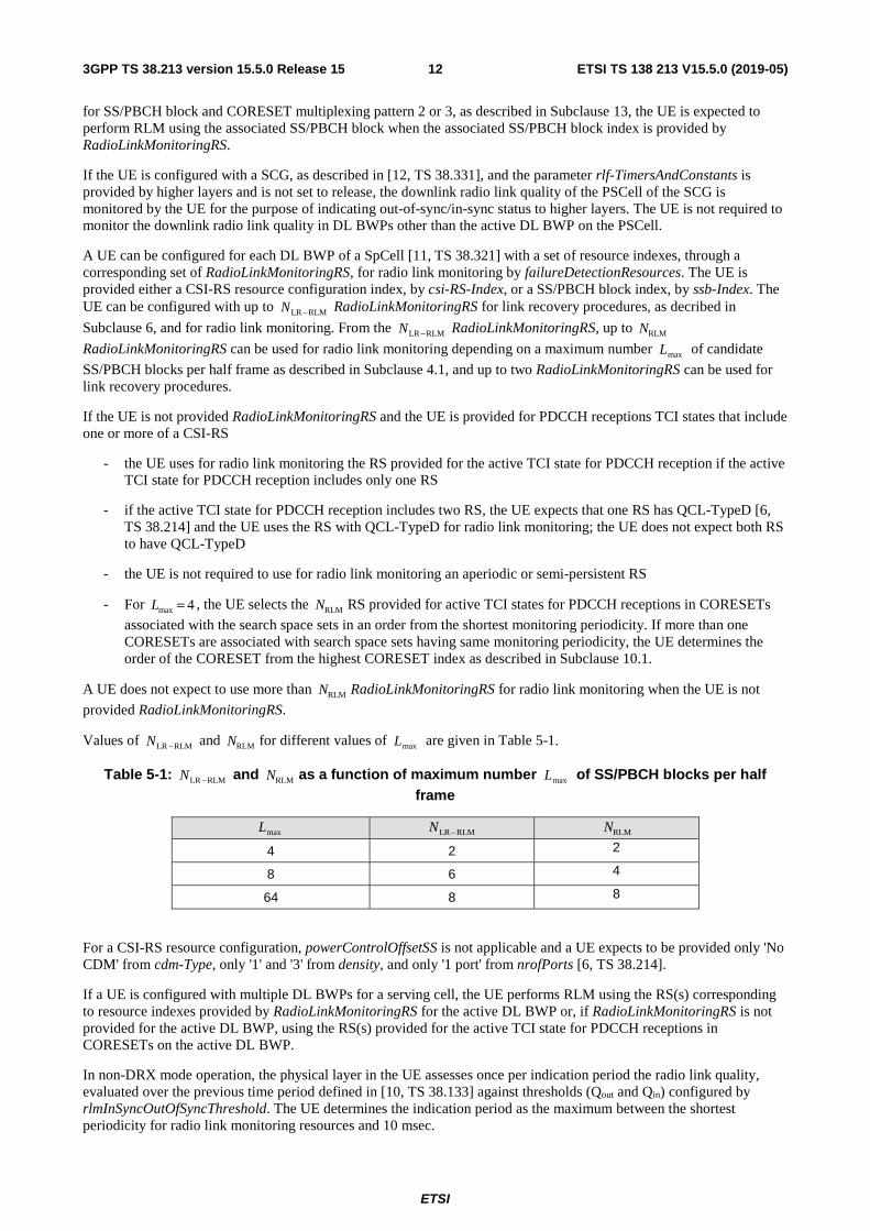
Values of RLMLR −N and RLMN for different values of maxL are given in Table 5-1.
Table 5-1: RLMLR −N and RLMN as a function of maximum number maxL of SS/PBCH blocks per half frame
maxL RLMLR −N RLMN
4 2 2
8 6 4
64 8 8
For a CSI-RS resource configuration, powerControlOffsetSS is not applicable and a UE expects to be provided only 'No CDM' from cdm-Type, only '1' and '3' from density, and only '1 port' from nrofPorts [6, TS 38.214].
If a UE is configured with multiple DL BWPs for a serving cell, the UE performs RLM using the RS(s) corresponding to resource indexes provided by RadioLinkMonitoringRS for the active DL BWP or, if RadioLinkMonitoringRS is not provided for the active DL BWP, using the RS(s) provided for the active TCI state for PDCCH receptions in CORESETs on the active DL BWP.
In non-DRX mode operation, the physical layer in the UE assesses once per indication period the radio link quality, evaluated over the previous time period defined in [10, TS 38.133] against thresholds (Qout and Qin) configured by rlmInSyncOutOfSyncThreshold. The UE determines the indication period as the maximum between the shortest periodicity for radio link monitoring resources and 10 msec.
ETSI
ETSI TS 138 213 V15.5.0 (2019-05)133GPP TS 38.213 version 15.5.0 Release 15
In DRX mode operation, the physical layer in the UE assesses once per indication period the radio link quality, evaluated over the previous time period defined in [10, TS 38.133], against thresholds (Qout and Qin) provided by rlmInSyncOutOfSyncThreshold. The UE determines the indication period as the maximum between the shortest periodicity for radio link monitoring resources and the DRX period.
The physical layer in the UE indicates, in frames where the radio link quality is assessed, out-of-sync to higher layers when the radio link quality is worse than the threshold Qout for all resources in the set of resources for radio link monitoring. When the radio link quality is better than the threshold Qin for any resource in the set of resources for radio link monitoring, the physical layer in the UE indicates, in frames where the radio link quality is assessed, in-sync to higher layers.
6 Link recovery procedures A UE can be provided, for a serving cell, a set 0q of periodic CSI-RS resource configuration indexes by
failureDetectionResources and a set 1q of periodic CSI-RS resource configuration indexes and/or SS/PBCH block
indexes by candidateBeamRSList for radio link quality measurements on the serving cell. If the UE is not provided failureDetectionResources, the UE determines the set 0q to include periodic CSI-RS resource configuration indexes
with same values as the RS indexes in the RS sets indicated by TCI-state for respective CORESETs that the UE uses for monitoring PDCCH and, if there are two RS indexes in a TCI state, the set 0q includes RS indexes with QCL-TypeD
configuration for the corresponding TCI states. The UE expects the set 0q to include up to two RS indexes. The UE
expects single port RS in the set 0q .
The thresholds Qout,LR and Qin,LR correspond to the default value of rlmInSyncOutOfSyncThreshold, as described in [10, TS 38.133] for Qout, and to the value provided by rsrp-ThresholdSSB, respectively.
The physical layer in the UE assesses the radio link quality according to the set 0q of resource configurations against
the threshold Qout,LR. For the set 0q , the UE assesses the radio link quality only according to periodic CSI-RS resource
configurations or SS/PBCH blocks that are quasi co-located, as described in [6, TS 38.214], with the DM-RS of PDCCH receptions monitored by the UE. The UE applies the Qin,LR threshold to the L1-RSRP measurement obtained from a SS/PBCH block. The UE applies the Qin,LR threshold to the L1-RSRP measurement obtained for a CSI-RS resource after scaling a respective CSI-RS reception power with a value provided by powerControlOffsetSS.
In non-DRX mode operation, the physical layer in the UE provides an indication to higher layers when the radio link quality for all corresponding resource configurations in the set 0q that the UE uses to assess the radio link quality is
worse than the threshold Qout,LR. The physical layer informs the higher layers when the radio link quality is worse than the threshold Qout,LR with a periodicity determined by the maximum between the shortest periodicity among the periodic CSI-RS configurations and/or SS/PBCH blocks in the set 0q that the UE uses to assess the radio link quality and 2
msec. In DRX mode operation, the physical layer provides an indication to higher layers when the radio link quality is worse than the threshold Qout,LR with a periodicity determined as described in [10, TS 38.133].
Upon request from higher layers, the UE provides to higher layers the periodic CSI-RS configuration indexes and/or SS/PBCH block indexes from the set 1q and the corresponding L1-RSRP measurements that are larger than or equal to
the Qin,LR threshold.
A UE can be provided a CORESET through a link to a search space set provided by recoverySearchSpaceId, as described in Subclause 10.1, for monitoring PDCCH in the CORESET. If the UE is provided recoverySearchSpaceId, the UE does not expect to be provided another search space set for monitoring PDCCH in the CORESET associated with the search space set provided by recoverySearchSpaceId.
The UE may receive by PRACH-ResourceDedicatedBFR, a configuration for PRACH transmission as described in Subclause 8.1. For PRACH transmission in slot n and according to antenna port quasi co-location parameters
associated with periodic CSI-RS resource configuration or with SS/PBCH block associated with index newq provided
by higher layers [11, TS 38.321], the UE monitors PDCCH in a search space set provided by recoverySearchSpaceId for detection of a DCI format with CRC scrambled by C-RNTI or MCS-C-RNTI starting from slot 4+n within a window configured by BeamFailureRecoveryConfig. For PDCCH monitoring in a search space set provided by recoverySearchSpaceId and for corresponding PDSCH reception, the UE assumes the same antenna port quasi-
collocation parameters as the ones associated with index newq until the UE receives by higher layers an activation for a
TCI state or any of the parameters TCI-StatesPDCCH-ToAddlist and/or TCI-StatesPDCCH-ToReleaseList. After the UE
ETSI
ETSI TS 138 213 V15.5.0 (2019-05)143GPP TS 38.213 version 15.5.0 Release 15
detects a DCI format with CRC scrambled by C-RNTI or MCS-C-RNTI in the search space set provided by recoverySearchSpaceId, the UE continues to monitor PDCCH candidates in the search space set provided by recoverySearchSpaceId until the UE receives a MAC CE activation command for a TCI state or TCI-StatesPDCCH-ToAddlist and/or TCI-StatesPDCCH-ToReleaseList.
After 28 symbols from a last symbol of a first PDCCH reception in a search space set provided by recoverySearchSpaceId for which the UE detects a DCI format with CRC scrambled by C-RNTI or MCS-C-RNTI and until the UE receives an activation command for PUCCH-Spatialrelationinfo [11, TS 38.321] or is provided PUCCH-Spatialrelationinfo for PUCCH resource(s), the UE transmits a PUCCH on a same cell as the PRACH transmission using
- a same spatial filter as for the last PRACH transmission
- a power determined as described in Subclause 7.2.1 with 0=uq , newqqd = , and 0=l
After 28 symbols from a last symbol of a first PDCCH reception in a search space set provided by recoverySearchSpaceId where a UE detects a DCI format with CRC scrambled by C-RNTI or MCS-C-RNTI, the UE
assumes same antenna port quasi-collocation parameters as the ones associated with index newq for PDCCH
monitoring in a CORESET with index 0.
7 Uplink Power control Uplink power control determines a power for PUSCH, PUCCH, SRS, and PRACH transmissions.
A UE does not expect to simultaneously maintain more than four pathloss estimates per serving cell for all PUSCH/PUCCH/SRS transmissions as described in Subcaluses 7.1.1, 7.2.1, and 7.3.1.
A PUSCH/PUCCH/SRS/PRACH transmission occasion i is defined by a slot index μs,fn within a frame with system
frame number SFN, a first symbol S within the slot, and a number of consecutive symbols L.
7.1 Physical uplink shared channel
For a PUSCH transmission on active UL BWP b, as described in Subclause 12, of carrier f of serving cell c , a UE
first calculates a linear value ),,,(ˆ,,,PUSCH lqjiP dcfb of the transmit power ),,,(,,,PUSCH lqjiP dcfb , with parameters as
defined in Subclause 7.1.1. If the PUSCH transmission is scheduled by a DCI format 0_1 and when txConfig in PUSCH-Config is set to 'codebook', the UE scales the linear value by the ratio of the number of antenna ports with a non-zero PUSCH transmission power to the maximum number of SRS ports supported by the UE in one SRS resource. The UE splits the power equally across the antenna ports on which the UE transmits the PUSCH with non-zero power.
7.1.1 UE behaviour
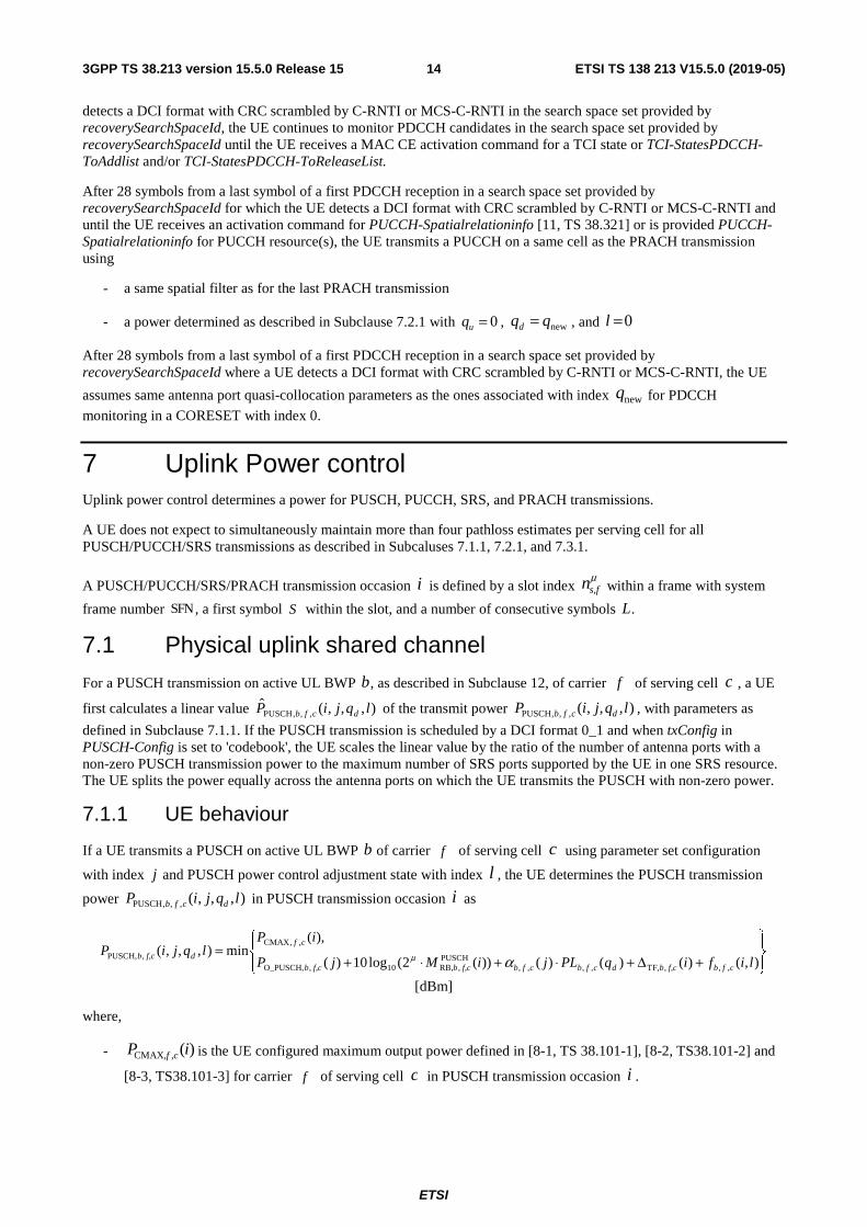
If a UE transmits a PUSCH on active UL BWP b of carrier f of serving cell c using parameter set configuration
with index j and PUSCH power control adjustment state with index l , the UE determines the PUSCH transmission
power ),,,(,,,PUSCH lqjiP dcfb in PUSCH transmission occasion i as
+Δ+⋅+⋅+=
),()()()())(2(log10)(
),(min),,,(
,,,TF,,,,,PUSCH
,RB,10,O_PUSCH,
,,CMAX
,PUSCH,lifiqPLjiMjP
iPlqjiP
cfbf,cbdcfbcfbf,cbf,cb
cf
df,cb αμ
[dBm]
where,
- )(, CMAX, iP cf is the UE configured maximum output power defined in [8-1, TS 38.101-1], [8-2, TS38.101-2] and
[8-3, TS38.101-3] for carrier f of serving cell c in PUSCH transmission occasion i .
ETSI
ETSI TS 138 213 V15.5.0 (2019-05)153GPP TS 38.213 version 15.5.0 Release 15
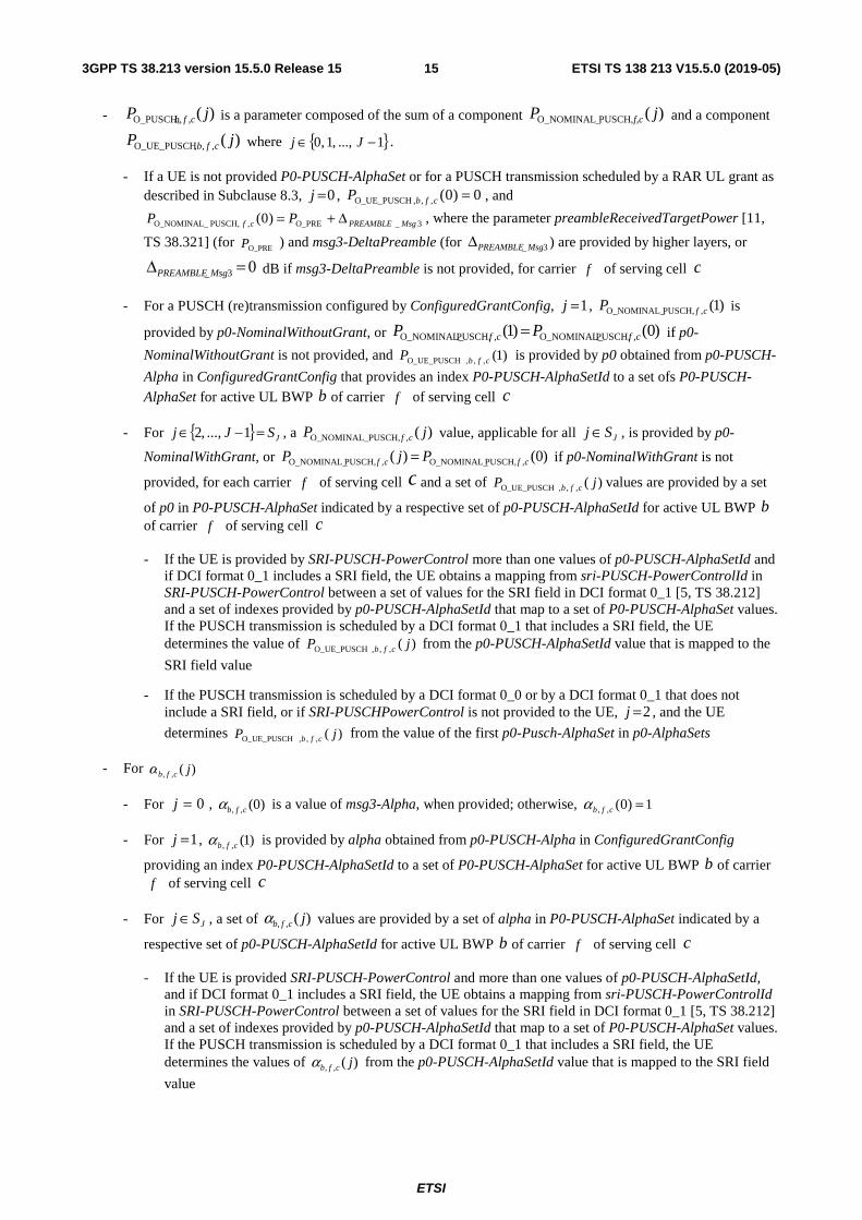
- )(,,O_PUSCH, jP cfb is a parameter composed of the sum of a component )(PUSCH, O_NOMINAL_ jP f,c and a component
)(,,,O_UE_PUSCH jP cfb where { }1...,,1,0 −∈ Jj .
- If a UE is not provided P0-PUSCH-AlphaSet or for a PUSCH transmission scheduled by a RAR UL grant as described in Subclause 8.3, 0=j , 0)0(,,,O_UE_PUSCH =cfbP , and
3_O_PRE,PUSCH,O_NOMINAL_ )0( MsgPREAMBLEcf PP Δ+= , where the parameter preambleReceivedTargetPower [11,
TS 38.321] (for O_PREP ) and msg3-DeltaPreamble (for 3_ MsgPREAMBLEΔ ) are provided by higher layers, or
03_ =Δ MsgPREAMBLE dB if msg3-DeltaPreamble is not provided, for carrier f of serving cell c
- For a PUSCH (re)transmission configured by ConfiguredGrantConfig, 1=j , )1(,PUSCH,O_NOMINAL_ cfP is
provided by p0-NominalWithoutGrant, or )0()1( ,PUSCH,O_NOMINAL_,PUSCH,O_NOMINAL_ cfcf PP = if p0-
NominalWithoutGrant is not provided, and )1(,,,O_UE_PUSCH cfbP is provided by p0 obtained from p0-PUSCH-
Alpha in ConfiguredGrantConfig that provides an index P0-PUSCH-AlphaSetId to a set ofs P0-PUSCH-
AlphaSet for active UL BWP b of carrier f of serving cell c
- For { } JSJj =−∈ 1...,,2 , a )(,PUSCH, O_NOMINAL_ jP cf value, applicable for all JSj ∈ , is provided by p0-
NominalWithGrant, or )0()( ,PUSCH,O_NOMINAL_,PUSCH,O_NOMINAL_ cfcf PjP = if p0-NominalWithGrant is not
provided, for each carrier f of serving cell c and a set of )(,,,O_UE_PUSCH jP cfb values are provided by a set
of p0 in P0-PUSCH-AlphaSet indicated by a respective set of p0-PUSCH-AlphaSetId for active UL BWP b of carrier f of serving cell c
- If the UE is provided by SRI-PUSCH-PowerControl more than one values of p0-PUSCH-AlphaSetId and if DCI format 0_1 includes a SRI field, the UE obtains a mapping from sri-PUSCH-PowerControlId in SRI-PUSCH-PowerControl between a set of values for the SRI field in DCI format 0_1 [5, TS 38.212] and a set of indexes provided by p0-PUSCH-AlphaSetId that map to a set of P0-PUSCH-AlphaSet values. If the PUSCH transmission is scheduled by a DCI format 0_1 that includes a SRI field, the UE determines the value of )(,,,O_UE_PUSCH jP cfb from the p0-PUSCH-AlphaSetId value that is mapped to the
SRI field value
- If the PUSCH transmission is scheduled by a DCI format 0_0 or by a DCI format 0_1 that does not include a SRI field, or if SRI-PUSCHPowerControl is not provided to the UE, 2=j , and the UE
determines )(,,,O_UE_PUSCH jP cfb from the value of the first p0-Pusch-AlphaSet in p0-AlphaSets
- For )(,, jcfbα
- For 0=j , )0(,, cfbα is a value of msg3-Alpha, when provided; otherwise, 1)0(,, =cfbα
- For 1=j , )1(,, cfbα is provided by alpha obtained from p0-PUSCH-Alpha in ConfiguredGrantConfig
providing an index P0-PUSCH-AlphaSetId to a set of P0-PUSCH-AlphaSet for active UL BWP b of carrier f of serving cell c
- For JSj ∈ , a set of )(,, jcfbα values are provided by a set of alpha in P0-PUSCH-AlphaSet indicated by a
respective set of p0-PUSCH-AlphaSetId for active UL BWP b of carrier f of serving cell c
- If the UE is provided SRI-PUSCH-PowerControl and more than one values of p0-PUSCH-AlphaSetId, and if DCI format 0_1 includes a SRI field, the UE obtains a mapping from sri-PUSCH-PowerControlId in SRI-PUSCH-PowerControl between a set of values for the SRI field in DCI format 0_1 [5, TS 38.212] and a set of indexes provided by p0-PUSCH-AlphaSetId that map to a set of P0-PUSCH-AlphaSet values. If the PUSCH transmission is scheduled by a DCI format 0_1 that includes a SRI field, the UE determines the values of )(,, jcfbα from the p0-PUSCH-AlphaSetId value that is mapped to the SRI field
value
ETSI
ETSI TS 138 213 V15.5.0 (2019-05)163GPP TS 38.213 version 15.5.0 Release 15
- If the PUSCH transmission is scheduled by a DCI format 0_0 or by a DCI format 0_1 that does not include a SRI field, or if SRI-PUSCH-PowerControl is not provided to the UE, 2=j , and the UE
determines )(,, jcfbα from the value of the first p0-PUSCH-AlphaSet in p0-AlphaSets
- )(PUSCH,,RB, iM cfb is the bandwidth of the PUSCH resource assignment expressed in number of resource blocks for
PUSCH transmission occasion i on active UL BWP b of carrier f of serving cell c and μ is a SCS
configuration defined in [4, TS 38.211]
- )(,, dcfb qPL is a downlink pathloss estimate in dB calculated by the UE using reference signal (RS) index for
the active DL BWP, as described in Subclause 12, of serving cell c
- If the UE is not provided PUSCH-PathlossReferenceRS or before the UE is provided dedicated higher layer parameters, the UE calculates )(,, dcfb qPL using a RS resource from the SS/PBCH block that the UE uses to
obtain MIB
- If the UE is configured with a number of RS resource indexes, up to the value of maxNrofPUSCH-PathlossReferenceRSs, and a respective set of RS configurations for the number of RS resource indexes by PUSCH-PathlossReferenceRS, the set of RS resource indexes can include one or both of a set of SS/PBCH block indexes, each provided by ssb-Index when a value of a corresponding pusch-PathlossReferenceRS-Id maps to a SS/PBCH block index, and a set of CSI-RS resource indexes, each provided by csi-RS-Index when a value of a corresponding pusch-PathlossReferenceRS-Id maps to a CSI-RS resource index. The UE identifies a RS resource index dq in the set of RS resource indexes to correspond either to a SS/PBCH block
index or to a CSI-RS resource index as provided by pusch-PathlossReferenceRS-Id in PUSCH-PathlossReferenceRS
- If the PUSCH transmission is scheduled by a RAR UL grant as described in Subclause 8.3, the UE uses the same RS resource index dq as for a corresponding PRACH transmission
- If the UE is provided SRI-PUSCH-PowerControl and more than one values of PUSCH-PathlossReferenceRS-Id, the UE obtains a mapping from sri-PUSCH-PowerControlId in SRI-PUSCH-PowerControl between a set of values for the SRI field in DCI format 0_1 and a set of PUSCH-PathlossReferenceRS-Id values. If the PUSCH transmission is scheduled by a DCI format 0_1 that includes a SRI field, the UE determines the RS resource index dq from the value of PUSCH-PathlossReferenceRS-Id
that is mapped to the SRI field value where the RS resource is either on serving cell c or, if provided, on a serving cell indicated by a value of pathlossReferenceLinking
- If the PUSCH transmission is scheduled by a DCI format 0_0, and if the UE is provided a spatial setting by
PUCCH-Spatialrelationinfo for a PUCCH resource with a lowest index for active UL BWP b of each carrier f and serving cell c , as described in Subclause 9.2.2, the UE uses the same RS resource index dq as for a
PUCCH transmission in the PUCCH resource with the lowest index
- If the PUSCH transmission is scheduled by a DCI format 0_0 and if the UE is not provided a spatial setting for a PUCCH transmission, or by a DCI format 0_1 that does not include a SRI field, or if SRI-PUSCH-PowerControl is not provided to the UE, the UE determines a RS resource index dq with a respective
PUSCH-PathlossReferenceRS-Id value being equal to zero where the RS resource is either on serving cell c or, if provided, on a serving cell indicated by a value of pathlossReferenceLinking
- For a PUSCH transmission configured by ConfiguredGrantConfig, if rrc-ConfiguredUplinkGrant is included in ConfiguredGrantConfig , a RS resource index dq is provided by a value of pathlossReferenceIndex
included in rrc-ConfiguredUplinkGrant where the RS resource is either on serving cell c or, if provided, on a serving cell indicated by a value of pathlossReferenceLinking
- For a PUSCH transmission configured by ConfiguredGrantConfig that does not include rrc-ConfiguredUplinkGrant, the UE determines a RS resource index dq from a value of PUSCH-
PathlossReferenceRS-Id that is mapped to a SRI field value in a DCI format activating the PUSCH transmission. If the DCI format activating the PUSCH transmission does not include a SRI field, the UE determines a RS resource index dq with a respective PUSCH-PathlossReferenceRS-Id value being equal to
dq
ETSI
ETSI TS 138 213 V15.5.0 (2019-05)173GPP TS 38.213 version 15.5.0 Release 15
zero where the RS resource is either on serving cell c or, if provided, on a serving cell indicated by a value of pathlossReferenceLinking
)(, dcf qPL = referenceSignalPower – higher layer filtered RSRP, where referenceSignalPower is provided by
higher layers and RSRP is defined in [7, TS 38.215] for the reference serving cell and the higher layer filter configuration provided by QuantityConfig is defined in [12, TS 38.331] for the reference serving cell
If the UE is not configured periodic CSI-RS reception, referenceSignalPower is provided by ss-PBCH-BlockPower. If the UE is configured periodic CSI-RS reception, referenceSignalPower is provided either by ss-PBCH-BlockPower or by powerControlOffsetSS providing an offset of the CSI-RS transmission power relative to the SS/PBCH block transmission power [6, TS 38.214]. If powerControlOffsetSS is not provided to the UE, the UE assumes an offset of 0 dB.
- ( )( )PUSCHoffset
KBPRE10,,,TF 12log10)( s β⋅−=Δ ⋅icfb for 25.1=SK and 0)(,,,TF =Δ icfb for 0=SK where SK is provided
by deltaMCS for each UL BWP b of each carrier f and serving cell c . If the PUSCH transmission is over
more than one layer [6, TS 38.214], 0)(,,,TF =Δ icfb . BPRE and PUSCHoffsetβ , for active UL BWP b of each carrier
f and each serving cell c , are computed as below
- RE
1
0
BPRE NKr
C
r
−
== for PUSCH with UL-SCH data and
PUSCH
m offsetBPRE Q R β= ⋅ for CSI transmission in a
PUSCH without UL-SCH data, where
- C is a number of transmitted code blocks, rK is a size for code block r , and REN is a number of
resource elements determined as −
=
⋅=1)(
0
RBdatasc,
PUSCH,,RB,RE
PUSCH,,symb,
),()(iN
jcfb
cfb
jiNiMN , where )(PUSCH,,symb, iN cfb is a number
of symbols for PUSCH transmission occasion i on active UL BWP b of carrier f of serving cell c ,
),(RBdatasc, jiN is a number of subcarriers excluding DM-RS subcarriers and phase-tracking RS samples [4,
TS 38.211] in PUSCH symbol j , )(0 PUSCH,,symb, iNj cfb<≤ , and C , rK are defined in [5, TS 38.212]
- 1PUSCHoffset =β when the PUSCH includes UL-SCH data and CSI,1
offsetPUSCHoffset ββ = , as described in Subclause 9.3,
when the PUSCH includes CSI and does not include UL-SCH data
- mQ is the modulation order and R is the target code rate, as described in [6, TS 38.214], provided by the
DCI format scheduling the PUSCH transmission that includes CSI and does not include UL-SCH data
- For the PUSCH power control adjustment state ),(,, lif cfb for active UL BWP b of carrier f of serving cell
c in PUSCH transmission occasion i
- ),(,,PUSCH, licfbδ is a TPC command value included in a DCI format 0_0 or DCI format 0_1 that schedules the
PUSCH transmission occasion i on active UL BWP b of carrier f of serving cell c or jointly coded with
other TPC commands in a DCI format 2_2 with CRC scrambled by TPC-PUSCH-RNTI, as described in Subclause 11.3
- { }1,0∈l if the UE is configured with twoPUSCH-PC-AdjustmentStates and if the UE is not
configured with twoPUSCH-PC-AdjustmentStates or if the PUSCH transmission is scheduled by a RAR UL grant as described in Subclause 8.3
- For a PUSCH (re)transmission configured by ConfiguredGrantConfig, the value of { }1,0∈l is
provided to the UE by powerControlLoopToUse
- If the UE is provided SRI-PUSCH-PowerControl, the UE obtains a mapping between a set of values
for the SRI field in DCI format 0_1 and the l value(s) provided by sri-PUSCH-ClosedLoopIndex. If the PUSCH transmission is scheduled by a DCI format 0_1 and if DCI format 0_1 includes a SRI field, the UE determines the l value that is mapped to the SRI field value
0=l
ETSI
ETSI TS 138 213 V15.5.0 (2019-05)183GPP TS 38.213 version 15.5.0 Release 15
- If the PUSCH transmission is scheduled by a DCI format 0_0 or by a DCI format 0_1 that does not include a SRI field, or if a SRI-PUSCH-PowerControl is not provided to the UE, 0=l
- If the UE obtains one TPC command from a DCI format 2_2 with CRC scrambled by a TPC-PUSCH-
RNTI, the l value is provided by the closed loop indicator field in DCI format 2_2
- ( )
−
=+−=
1
0,,PUSCH,0,,,, ),(),(),(
iD
mcfbcfbcfb lmliiflif
C
δ is the PUSCH power control adjustment state l for active
UL BWP b of carrier f of serving cell c and PUSCH transmission occasion i if the UE is not provided
tpc-Accumulation, where
- The cfb ,,PUSCH,δ values are given in Table 7.1.1-1
- ( )
−
=
1
0,,PUSCH, ),(
iD
mcfb lm
C
δ is a sum of TPC command values in a set iD of TPC command values with
cardinality ( )iDC that the UE receives between 1)( 0PUSCH −− iiK symbols before PUSCH transmission
occasion 0ii − and )(PUSCH iK symbols before PUSCH transmission occasion i on active UL BWP b of
carrier f of serving cell c for PUSCH power control adjustment state l , where 00 >i is the smallest
integer for which )( 0PUSCH iiK − symbols before PUSCH transmission occasion 0ii − is earlier than
)(PUSCH iK symbols before PUSCH transmission occasion i
- If a PUSCH transmission is scheduled by a DCI format 0_0 or DCI format 0_1, )(PUSCH iK is a number of
symbols for active UL BWP b of carrier f of serving cell c after a last symbol of a corresponding
PDCCH reception and before a first symbol of the PUSCH transmission
- If a PUSCH transmission is configured by ConfiguredGrantConfig, )(PUSCH iK is a number of minPUSCH,K
symbols equal to the product of a number of symbols per slot, slotsymbN , and the minimum of the values
provided by k2 in PUSCH-ConfigCommon for active UL BWP b of carrier f of serving cell c
- If the UE has reached maximum power for active UL BWPb of carrier f of serving cell c at PUSCH
transmission occasion 0ii − and ( )
0),(1
0,,PUSCH, ≥
−
=
iD
mcfb lm
C
δ , then ),(),( 0,,,, liiflif cfbcfb −=
- If UE has reached minimum power for active UL BWP b of carrier f of serving cell c at PUSCH
transmission occasion 0ii − and ( )
0),(1
0,,PUSCH, ≤
−
=
iD
mcfb lm
C
δ , then ),(),( 0,,,, liiflif cfbcfb −=
- A UE resets accumulation of a PUSCH power control adjustment state l for active UL BWP b of carrier
f of serving cell c to iklkf cfb ,...,1,0,0),(,, ==
- If a configuration for a corresponding )(,,,O_UE_PUSCH jP cfb value is provided by higher layers
- If a configuration for a corresponding )(,, jcfbα value is provided by higher layers
- If 1>j and the PUSCH transmission is scheduled by a DCI format 0_1 that includes a SRI field, and
the UE is provided higher SRI-PUSCH-PowerControl, the UE determines the value of l from the value of j based on an indication by the SRI field for a sri-PUSCH-PowerControlId value associated
with the sri-P0-PUSCH-AlphaSetId value corresponding to j and with the sri-PUSCH-
ClosedLoopIndex value corresponding to l
- If 1>j and the PUSCH transmission is scheduled by a DCI format 0_0 or by a DCI format 0_1 that
does not include a SRI field or the UE is not provided SRI-PUSCH-PowerControl, 0=l
ETSI
ETSI TS 138 213 V15.5.0 (2019-05)193GPP TS 38.213 version 15.5.0 Release 15
- If 1=j , l is provided by the value of powerControlLoopToUse
- ),(),( ,,PUSCH,,, lilif cfbcfb δ= is the PUSCH power control adjustment state for active UL BWP b of carrier f
of serving cell c and PUSCH transmission occasion i if the UE is provided tpc-Accumulation, where
- cfb ,,PUSCH,δ absolute values are given in Table 7.1.1-1
- If the UE receives a random access response message in response to a PRACH transmission on active UL
BWP b of carrier f of serving cell c as desctibed in subcaluse 8
- cfbmsgcfbrampupcfb Plf ,,,2,,,,, ),0( δ+Δ= , where 0=l and
- cfbmsg ,,,2δ is a TPC command value indicated in the random access response grant of the random
access response message corresponding to the PRACH transmission on active UL BWP b of carrier f in the serving cell c , and
-
Δ
+Δ+⋅++
⋅−
=Δ cfbestedrampuprequ
cfbmsgcfb
ccfbcfb
cfb
cfcfbrampup PPLP
M
PP ,,,
,,,2,,,TF
,,,,,O_PUSCH
PUSCH,,RB,10
,,CMAX,,, ,
)0(
)0()0(
))0(2(log10
,0maxmin
δα
μ
and cfbestedrampuprequP ,,,Δ is provided by higher layers and corresponds to the total power ramp-up
requested by higher layers from the first to the last random access preamble for carrier f in the
serving cell c , )0(PUSCH,,RB, cfbM is the bandwidth of the PUSCH resource assignment expressed in number
of resource blocks for the first PUSCH transmission on active UL BWP b of carrier f of serving
cell c , and is the power adjustment of first PUSCH transmission on active UL BWP b
of carrier f of serving cell c .
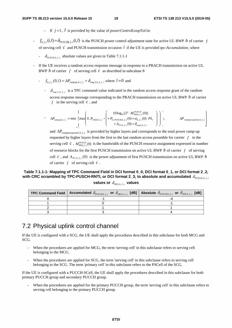
Table 7.1.1-1: Mapping of TPC Command Field in DCI format 0_0, DCI format 0_1, or DCI format 2_2, with CRC scrambled by TPC-PUSCH-RNTI, or DCI format 2_3, to absolute and accumulated cfb ,,PUSCH,δ
values or cfb ,,SRS,δ values
TPC Command Field Accumulated cfb ,,PUSCH,δ or cfb ,,SRS,δ [dB] Absolute or [dB]
0 -1 -4 1 0 -1 2 1 1 3 3 4
7.2 Physical uplink control channel If the UE is configured with a SCG, the UE shall apply the procedures described in this subclause for both MCG and SCG.
- When the procedures are applied for MCG, the term 'serving cell' in this subclause refers to serving cell belonging to the MCG.
- When the procedures are applied for SCG, the term 'serving cell' in this subclause refers to serving cell belonging to the SCG. The term 'primary cell' in this subclause refers to the PSCell of the SCG.
If the UE is configured with a PUCCH-SCell, the UE shall apply the procedures described in this subclause for both primary PUCCH group and secondary PUCCH group.
- When the procedures are applied for the primary PUCCH group, the term 'serving cell' in this subclause refers to serving cell belonging to the primary PUCCH group.
)0(,,, cfbTFΔ
cfb ,,PUSCH,δ cfb ,,SRS,δ
ETSI
ETSI TS 138 213 V15.5.0 (2019-05)203GPP TS 38.213 version 15.5.0 Release 15
- When the procedures are applied for the secondary PUCCH group, the term 'serving cell' in this subclause refers to serving cell belonging to the secondary PUCCH group. The term 'primary cell' in this subclause refers to the PUCCH-SCell of the secondary PUCCH group.
7.2.1 UE behaviour
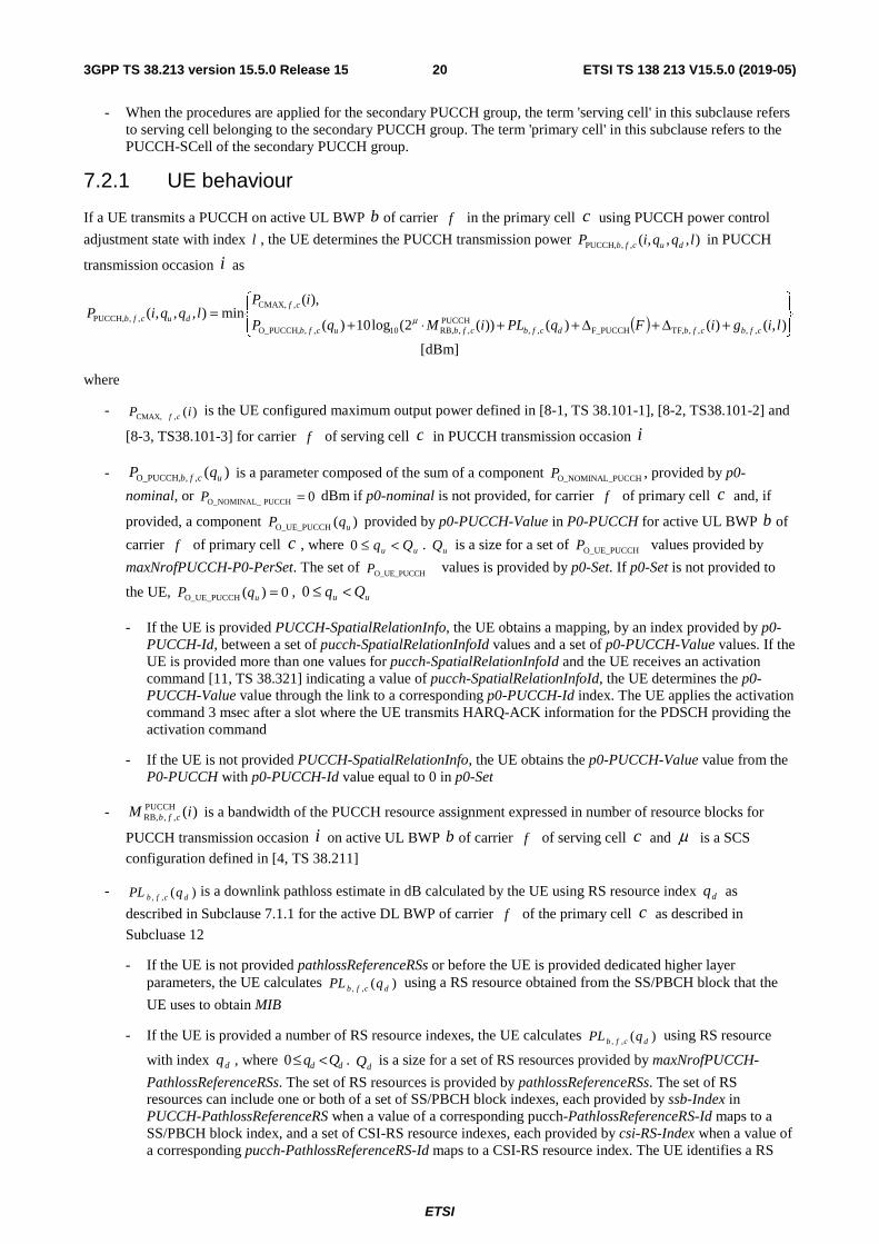
If a UE transmits a PUCCH on active UL BWP b of carrier f in the primary cell c using PUCCH power control
adjustment state with index l , the UE determines the PUCCH transmission power ),,,(,,PUCCH, lqqiP ducfb in PUCCH
transmission occasion i as
( )
+Δ+Δ++⋅+=
),()()())(2(log10)(
),(min),,,(
,,,,TF,F_PUCCH,,PUCCH
,,RB,10,,O_PUCCH,
,,CMAX
,,PUCCH,ligiFqPLiMqP
iPlqqiP
cfbcfbdcfbcfbucfb
cf
ducfb μ
[dBm]
where
- )(, CMAX, iP cf is the UE configured maximum output power defined in [8-1, TS 38.101-1], [8-2, TS38.101-2] and
[8-3, TS38.101-3] for carrier f of serving cell c in PUCCH transmission occasion i
- )(,,O_PUCCH, ucfb qP is a parameter composed of the sum of a component PUCCH O_NOMINAL_P , provided by p0-
nominal, or 0PUCCH O_NOMINAL_ =P dBm if p0-nominal is not provided, for carrier f of primary cell c and, if
provided, a component )(O_UE_PUCCH uqP provided by p0-PUCCH-Value in P0-PUCCH for active UL BWP b of
carrier f of primary cell c , where uu Qq <≤0 . uQ is a size for a set of O_UE_PUCCHP values provided by
maxNrofPUCCH-P0-PerSet. The set of O_UE_PUCCHP values is provided by p0-Set. If p0-Set is not provided to
the UE, 0)(O_UE_PUCCH =uqP , uu Qq <≤0
- If the UE is provided PUCCH-SpatialRelationInfo, the UE obtains a mapping, by an index provided by p0-PUCCH-Id, between a set of pucch-SpatialRelationInfoId values and a set of p0-PUCCH-Value values. If the UE is provided more than one values for pucch-SpatialRelationInfoId and the UE receives an activation command [11, TS 38.321] indicating a value of pucch-SpatialRelationInfoId, the UE determines the p0-PUCCH-Value value through the link to a corresponding p0-PUCCH-Id index. The UE applies the activation command 3 msec after a slot where the UE transmits HARQ-ACK information for the PDSCH providing the activation command
- If the UE is not provided PUCCH-SpatialRelationInfo, the UE obtains the p0-PUCCH-Value value from the P0-PUCCH with p0-PUCCH-Id value equal to 0 in p0-Set
- )(PUCCH,,RB, iM cfb is a bandwidth of the PUCCH resource assignment expressed in number of resource blocks for
PUCCH transmission occasion i on active UL BWP b of carrier f of serving cell c and μ is a SCS
configuration defined in [4, TS 38.211]
- )(,, dcfb qPL is a downlink pathloss estimate in dB calculated by the UE using RS resource index dq as
described in Subclause 7.1.1 for the active DL BWP of carrier f of the primary cell c as described in
Subcluase 12
- If the UE is not provided pathlossReferenceRSs or before the UE is provided dedicated higher layer parameters, the UE calculates )(,, dcfb qPL using a RS resource obtained from the SS/PBCH block that the
UE uses to obtain MIB
- If the UE is provided a number of RS resource indexes, the UE calculates )(,, dcfb qPL using RS resource
with index dq , where dd Qq <≤0 . dQ is a size for a set of RS resources provided by maxNrofPUCCH-
PathlossReferenceRSs. The set of RS resources is provided by pathlossReferenceRSs. The set of RS resources can include one or both of a set of SS/PBCH block indexes, each provided by ssb-Index in PUCCH-PathlossReferenceRS when a value of a corresponding pucch-PathlossReferenceRS-Id maps to a SS/PBCH block index, and a set of CSI-RS resource indexes, each provided by csi-RS-Index when a value of a corresponding pucch-PathlossReferenceRS-Id maps to a CSI-RS resource index. The UE identifies a RS
ETSI
ETSI TS 138 213 V15.5.0 (2019-05)213GPP TS 38.213 version 15.5.0 Release 15
resource in the set of RS resources to correspond either to a SS/PBCH block index or to a CSI-RS resource index as provided by pucch-PathlossReferenceRS-Id in PUCCH-PathlossReferenceRS
- If the UE is provided pathlossReferenceRSs and PUCCH-SpatialRelationInfo, the UE obtains a mapping, by indexes provided by corresponding values of pucch-PathlossReferenceRS-Id, between a set of pucch-SpatialRelationInfoId values and a set of referencesignal values provided by PUCCH-PathlossReferenceRS. If the UE is provided more than one values for pucch-SpatialRelationInfoId and the UE receives an activation command [11, TS 38.321] indicating a value of pucch-SpatialRelationInfoId, the UE determines the referencesignal value in PUCCH-PathlossReferenceRS through the link to a corresponding pucch-PathlossReferenceRS-Id index. The UE applies the activation command 3 msec after a slot where the UE transmits HARQ-ACK information for the PDSCH providing the activation command
- If PUCCH-SpatialRelationInfo includes servingCellId indicating a serving cell, the UE receives the RS for resource index dq on the active DL BWP of the serving cell
- If the UE is provided pathlossReferenceRSs and is not provided PUCCH-SpatialRelationInfo, the UE obtains the referencesignal value in PUCCH-PathlossReferenceRS from the pucch-PathlossReferenceRS-Id with index 0 in PUCCH-PathlossReferenceRS where the RS resource is either on a same serving cell or, if provided, on a serving cell indicated by a value of pathlossReferenceLinking
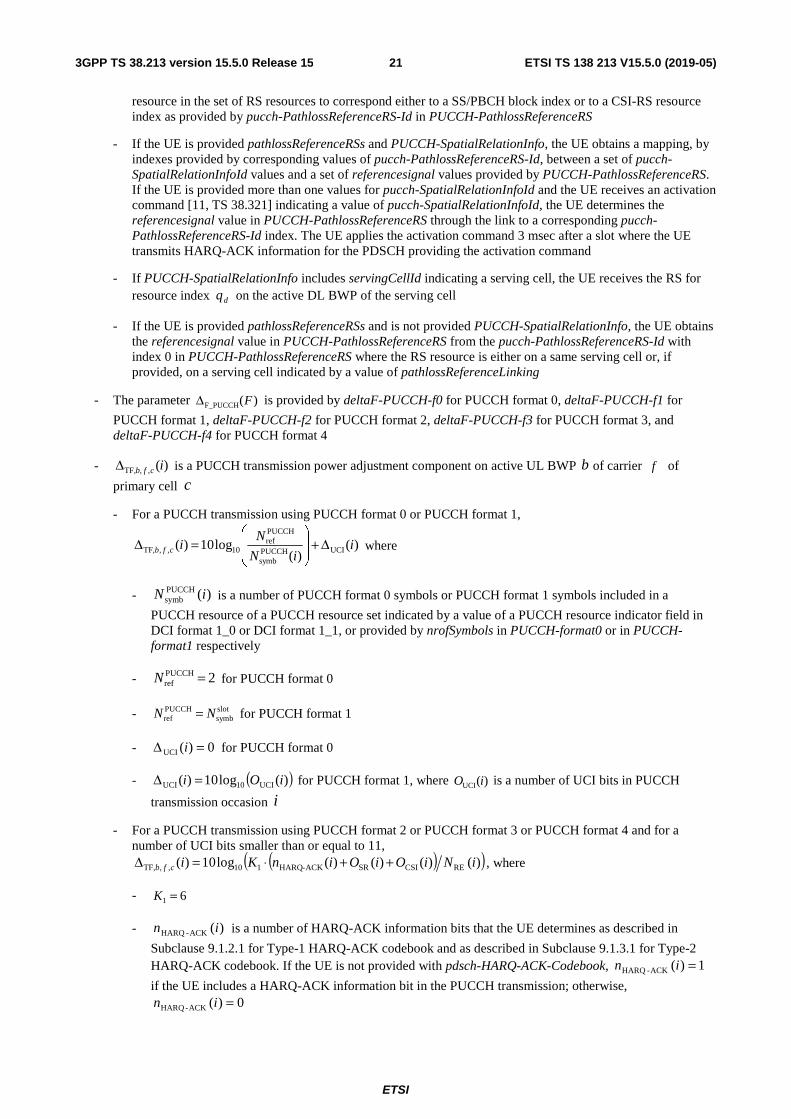
- The parameter )(F_PUCCH FΔ is provided by deltaF-PUCCH-f0 for PUCCH format 0, deltaF-PUCCH-f1 for
PUCCH format 1, deltaF-PUCCH-f2 for PUCCH format 2, deltaF-PUCCH-f3 for PUCCH format 3, and deltaF-PUCCH-f4 for PUCCH format 4
- )(,,TF, icfbΔ is a PUCCH transmission power adjustment component on active UL BWP b of carrier f of
primary cell c
- For a PUCCH transmission using PUCCH format 0 or PUCCH format 1,
)()(
log10)( UCIPUCCHsymb
PUCCHref
10,,TF, iiN
Nicfb Δ+
=Δ where
- )(PUCCHsymb iN is a number of PUCCH format 0 symbols or PUCCH format 1 symbols included in a
PUCCH resource of a PUCCH resource set indicated by a value of a PUCCH resource indicator field in DCI format 1_0 or DCI format 1_1, or provided by nrofSymbols in PUCCH-format0 or in PUCCH-format1 respectively
- 2PUCCHref =N for PUCCH format 0
- slotsymb
PUCCHref NN = for PUCCH format 1
- 0)(UCI =Δ i for PUCCH format 0
- ( ))(log10)( UCI10UCI iOi =Δ for PUCCH format 1, where )(UCI iO is a number of UCI bits in PUCCH
transmission occasion i
- For a PUCCH transmission using PUCCH format 2 or PUCCH format 3 or PUCCH format 4 and for a number of UCI bits smaller than or equal to 11,
( )( ))()()()(log10)( RECSISRACK-HARQ110,,TF, iNiOiOinKicfb ++⋅=Δ , where
- 61 =K
- )(ACK-HARQ in is a number of HARQ-ACK information bits that the UE determines as described in
Subclause 9.1.2.1 for Type-1 HARQ-ACK codebook and as described in Subclause 9.1.3.1 for Type-2 HARQ-ACK codebook. If the UE is not provided with pdsch-HARQ-ACK-Codebook, 1)(ACK-HARQ =in
if the UE includes a HARQ-ACK information bit in the PUCCH transmission; otherwise, 0)(ACK-HARQ =in
ETSI
ETSI TS 138 213 V15.5.0 (2019-05)223GPP TS 38.213 version 15.5.0 Release 15
- )(SR iO is a number of SR information bits that the UE determines as described in Subclause 9.2.5.1
- )(CSI iO is a number of CSI information bits that the UE determines as described in Subclause 9.2.5.2
- )(RE iN is a number of resource elements determined as )()()()( PUCCH,,UCI,-symb
RBctrlsc,
PUCCH,,RB,RE iNiNiMiN cfbcfb ⋅⋅= ,
where )(RBctrlsc, iN is a number of subcarriers per resource block excluding subcarriers used for DM-RS
transmission, and )(PUCCH,,UCI,-symb iN cfb is a number of symbols excluding symbols used for DM-RS
transmission, as defined in Subclause 9.2.5.2, for PUCCH transmission occasion i on active UL BWP b of carrier f of serving cell c
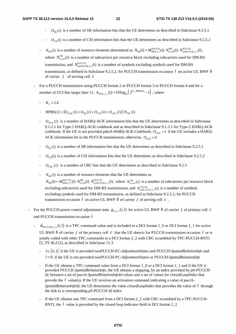
- For a PUCCH transmission using PUCCH format 2 or PUCCH format 3 or PUCCH format 4 and for a
number of UCI bits larger than 11, ( )12log10)( )BPRE(K10,,,TF
2 −=Δ ⋅ icfb i , where
- 4.22 =K
- ( ) )()()()()()BPRE( RECRCCSISRACK iNiOiOiOiOi +++=
- )(ACK iO is a number of HARQ-ACK information bits that the UE determines as described in Subclause
9.1.2.1 for Type-1 HARQ-ACK codebook and as described in Subclause 9.1.3.1 for Type-2 HARQ-ACK codebook. If the UE is not provided pdsch-HARQ-ACK-Codebook, 1ACK =O if the UE includes a HARQ-
ACK information bit in the PUCCH transmission; otherwise, 0ACK =O
- )(SR iO is a number of SR information bits that the UE determines as described in Subclause 9.2.5.1
- )(CSI iO is a number of CSI information bits that the UE determines as described in Subclause 9.2.5.2
- )(CRC iO is a number of CRC bits that the UE determines as described in Subclause 9.2.5
- )(RE iN is a number of resource elements that the UE determines as
)()()()( PUCCH,,UCI,-symb
RBctrlsc,
PUCCH,,RB,RE iNiNiMiN cfbcfb ⋅⋅= , where )(RB
ctrlsc, iN is a number of subcarriers per resource block
excluding subcarriers used for DM-RS transmission, and )(PUCCH,,UCI,-symb iN cfb is a number of symbols
excluding symbols used for DM-RS transmission, as defined in Subclause 9.2.5.2, for PUCCH
transmission occasion i on active UL BWP b of carrier f of serving cell c .
- For the PUCCH power control adjustment state ),(,, lig cfb for active UL BWP b of carrier f of primary cell c
and PUCCH transmission occasion i
- ),(,,PUCCH, licfbδ is a TPC command value and is included in a DCI format 1_0 or DCI format 1_1 for active
UL BWP b of carrier f of the primary cell c that the UE detects for PUCCH transmission occasion i or is
jointly coded with other TPC commands in a DCI format 2_2 with CRC scrambled by TPC-PUCCH-RNTI [5, TS 36.212], as described in Subclause 11.3
- { }1,0∈l if the UE is provided twoPUCCH-PC-AdjustmentStates and PUCCH-SpatialRelationInfo and
if the UE is not provided twoPUCCH-PC-AdjustmentStates or PUCCH-SpatialRelationInfo
- If the UE obtains a TPC command value from a DCI format 1_0 or a DCI format 1_1 and if the UE is provided PUCCH-SpatialRelationInfo, the UE obtains a mapping, by an index provided by p0-PUCCH-Id, between a set of pucch-SpatialRelationInfoId values and a set of values for closedLoopIndex that provide the l value(s). If the UE receives an activation command indicating a value of pucch-
SpatialRelationInfoId, the UE determines the value closedLoopIndex that provides the value of l through the link to a corresponding p0-PUCCH-Id index
- If the UE obtains one TPC command from a DCI format 2_2 with CRC scrambled by a TPC-PUCCH-
RNTI, the l value is provided by the closed loop indicator field in DCI format 2_2
0=l
ETSI
ETSI TS 138 213 V15.5.0 (2019-05)233GPP TS 38.213 version 15.5.0 Release 15
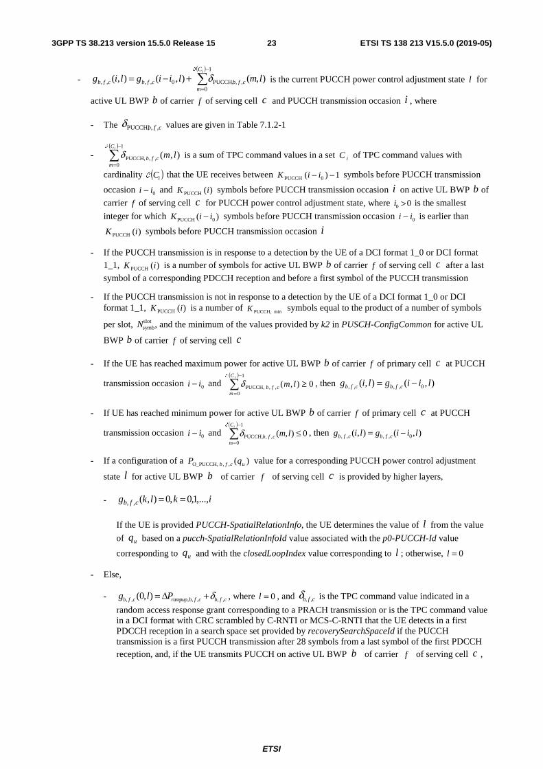
- ( )
−
=+−=
1
0,,PUCCH,0,,,, ),(),(),(
iC
mcfbcfbcfb lmliiglig
C
δ is the current PUCCH power control adjustment state l for
active UL BWP b of carrier f of serving cell c and PUCCH transmission occasion i , where
- The cfb ,,PUCCH,δ values are given in Table 7.1.2-1
- ( )
−
=
1
0,,PUCCH, ),(
iC
mcfb lm
C
δ is a sum of TPC command values in a set iC of TPC command values with
cardinality ( )iCC that the UE receives between 1)( 0PUCCH −− iiK symbols before PUCCH transmission
occasion 0ii − and )(PUCCH iK symbols before PUCCH transmission occasion i on active UL BWP b of
carrier f of serving cell c for PUCCH power control adjustment state, where 00 >i is the smallest
integer for which )( 0PUCCH iiK − symbols before PUCCH transmission occasion 0ii − is earlier than
)(PUCCH iK symbols before PUCCH transmission occasion i
- If the PUCCH transmission is in response to a detection by the UE of a DCI format 1_0 or DCI format 1_1, )(PUCCH iK is a number of symbols for active UL BWP b of carrier f of serving cell c after a last
symbol of a corresponding PDCCH reception and before a first symbol of the PUCCH transmission
- If the PUCCH transmission is not in response to a detection by the UE of a DCI format 1_0 or DCI format 1_1, )(PUCCH iK is a number of minPUCCH,K symbols equal to the product of a number of symbols
per slot, slotsymbN , and the minimum of the values provided by k2 in PUSCH-ConfigCommon for active UL
BWP b of carrier f of serving cell c
- If the UE has reached maximum power for active UL BWP b of carrier f of primary cell c at PUCCH
transmission occasion 0ii − and ( )
0),(1
0,,PUCCH, ≥
−
=
iC
mcfb lm
C
δ , then ),(),( 0,,,, liiglig cfbcfb −=
- If UE has reached minimum power for active UL BWP b of carrier f of primary cell c at PUCCH
transmission occasion 0ii − and ( )
0),(1
0,,PUCCH, ≤
−
=
iC
mcfb lm
C
δ , then ),(),( 0,,,, liiglig cfbcfb −=
- If a configuration of a )(,,O_PUCCH, ucfb qP value for a corresponding PUCCH power control adjustment
state l for active UL BWP b of carrier f of serving cell c is provided by higher layers,
- iklkg cfb ,...,1,0,0),(,, ==
If the UE is provided PUCCH-SpatialRelationInfo, the UE determines the value of l from the value
of uq based on a pucch-SpatialRelationInfoId value associated with the p0-PUCCH-Id value
corresponding to uq and with the closedLoopIndex value corresponding to l ; otherwise, 0=l
- Else,
- , , , , , , ,(0, )b f c rampup b f c b f cg l P δ= Δ + , where 0=l , and , ,b f cδ is the TPC command value indicated in a
random access response grant corresponding to a PRACH transmission or is the TPC command value in a DCI format with CRC scrambled by C-RNTI or MCS-C-RNTI that the UE detects in a first PDCCH reception in a search space set provided by recoverySearchSpaceId if the PUCCH transmission is a first PUCCH transmission after 28 symbols from a last symbol of the first PDCCH reception, and, if the UE transmits PUCCH on active UL BWP b of carrier f of serving cell c ,

ETSI
ETSI TS 138 213 V15.5.0 (2019-05)243GPP TS 38.213 version 15.5.0 Release 15
, , _ , , , , , _ , , , , ,, , ,
, , ,
0,max
( ( ) ( ) )=min CMAX f c O PUCCH b f c b f c d F PUCCH TF b f c b f crampup b f c
rampuprequested b f c
P P PL q FP
P
δ − + + Δ + Δ +Δ Δ
;
otherwise,
( )
Δ
+−=Δ
cfbestedrampuprequ
dcfbcfbcfcfbrampup
P
qPLPPP
,,,
,,,,,O_PUCCH,,CMAX,,,
,)(
,0max
min where cfbestedrampuprequP ,,,Δ is
provided by higher layers and corresponds to the total power ramp-up requested by higher layers from the first to the last preamble for active UL BWP b of carrier f of primary cell c , and
( )FF_PUCCHΔ corresponds to PUCCH format 0 or PUCCH format 1
Table 7.2.1-1: Mapping of TPC Command Field in DCI format 1_0 or DCI format 1_1 or DCI format 2_2 with CRC scrambled by TPC-PUCCH-RNTI to accumulated cfb ,,PUCCH,δ values
TPC Command Field Accumulated cfb ,,PUCCH,δ [dB]
0 -1 1 0 2 1 3 3
7.3 Sounding reference signals
For SRS, a UE splits a linear value ),,(ˆ,,,SRS lqiP scfb of the transmit power ),,(,,,SRS lqiP scfb on active UL BWP b of
carrier f of serving cell c equally across the configured antenna ports for SRS.
7.3.1 UE behaviour
If a UE transmits SRS on active UL BWP b of carrier f of serving cell c using SRS power control adjustment
state with index l , the UE determines the SRS transmission power ),,(,,,SRS lqiP scfb in SRS transmission occasion i as
+⋅+⋅+=
),()()())(2(log10)(
),(min),,(
,,,,,,,SRS,,SRS,10,,O_SRS,
,,CMAX
,SRS,lihqPLqiMqP
iPlqiP
cfbdcfbscfbcfbscfb
cf
sf,cb αμ [dBm]
where,
- )(, CMAX, iP cf is the UE configured maximum output power defined in [8, TS 38.101-1], [8-2, TS38.101-2] and
[TS 38.101-3] for carrier f of serving cell c in SRS transmission occasion i
- )(,,O_SRS, scfb qP is provided by p0 for active UL BWP b of carrier f of serving cell c and SRS resource set
sq provided by SRS-ResourceSet and SRS-ResourceSetId; if p0 is not provided,
)0()( ,PUSCH,O_NOMINAL_,,O_SRS, cfscfb PqP =
- )(,,SRS, iM cfb is a SRS bandwidth expressed in number of resource blocks for SRS transmission occasion i on
active UL BWP b of carrier f of serving cell c and μ is a SCS configuration defined in [4, TS 38.211]
- )(,,,SRS scfb qα is provided by alpha for active UL BWP b of carrier f of serving cell c and SRS resource set
sq
ETSI
ETSI TS 138 213 V15.5.0 (2019-05)253GPP TS 38.213 version 15.5.0 Release 15
- )(,, dcfb qPL is a downlink pathloss estimate in dB calculated by the UE using RS resource index dq as
described in Subclause 7.1.1 for the active DL BWP of serving cell c and SRS resource set sq [6, TS 38.214].
The RS resource index dq is provided by pathlossReferenceRS associated with the SRS resource set sq and is
either a ssb-Index providing a SS/PBCH block index or a csi-RS-Index providing a CSI-RS resource index
- If the UE is not provided pathlossReferenceRS or before the UE is provided dedicated higher layer parameters, the UE calculates )(,, dcfb qPL using a RS resource obtained from the SS/PBCH block that the
UE uses to obtain MIB
- If the UE is provided pathlossReferenceLinking, the RS resource is on a serving cell indicated by a value of pathlossReferenceLinking
- For the SRS power control adjustment state for active UL BWP b of carrier f of serving cell c and SRS
transmission occasion i
- ),(),( ,,,, liflih cfbcfb = , where ),(,, lif cfb is the current PUSCH power control adjustment state as described
in Subclause 7.1.1, if srs-PowerControlAdjustmentStates indicates a same power control adjustment state for SRS transmissions and PUSCH transmissions; or
- ( )
−
=+−=
1
0,,SRS,,,,, )()1()(
iS
mcfbcfbcfb mihih
C
δ if the UE is not configured for PUSCH transmissions on active UL
BWP b of carrier f of serving cell c, or if srs-PowerControlAdjustmentStates indicates separate power
control adjustment states between SRS transmissions and PUSCH transmissions, and if tpc-Accumulation is not provided, where
- The cfb ,,SRS,δ values are given in Table 7.1.1-1
- SRS, , , ( )b f c mδ is jointly coded with other TPC commands in a PDCCH with DCI format 2_3, as
described in Subclause 11.4
- ( )
−
=
1
0,,SRS, )(
iS
mcfb m
C
δ is a sum of TPC command values in a set iS of TPC command values with cardinality
( )iSC that the UE receives between 1)( 0SRS −−iiK symbols before SRS transmission occasion 0ii − and
)(SRS iK symbols before SRS transmission occasion i on active UL BWP b of carrier f of serving cell
c for SRS power control adjustment state, where 00 >i is the smallest integer for which )( 0SRS iiK −
symbols before SRS transmission occasion 0ii − is earlier than )(SRS iK symbols before SRS transmission
occasion i
- if the SRS transmission is aperiodic, )(SRS iK is a number of symbols for active UL BWP b of carrier f
of serving cell c after a last symbol of a corresponding PDCCH triggering the SRS transmission and before a first symbol of the SRS transmission
- if the SRS transmission is semi-persistent or periodic, )(SRS iK is a number of minSRS,K symbols equal to
the product of a number of symbols per slot, slotsymbN , and the minimum of the values provided by k2 in
PUSCH-ConfigCommon for active UL BWP b of carrier f of serving cell c
- If the UE has reached maximum power for active UL BWP b of carrier f of serving cell c at SRS
transmission occasion 0ii − and ( )
0)(1
0,,SRS, ≥
−
=
iS
mcfb m
C
δ , then )()( 0,,,, iihih cfbcfb −=
- If UE has reached minimum power for active UL BWP b of carrier f of serving cell c at SRS
transmission occasion 0ii − and ( )
0)(1
0,,SRS, ≤
−
=
iS
mcfb m
C
δ , then )()( 0,,,, iihih cfbcfb −=
ETSI
ETSI TS 138 213 V15.5.0 (2019-05)263GPP TS 38.213 version 15.5.0 Release 15
- If a configuration for a )(,,O_SRS, scfb qP value or for a )(,,,SRS scfb qα value for a corresponding SRS
power control adjustment state l for active UL BWP b of carrier f of serving cell c is provided by
higher layers
- , , ( ) 0, 0,1,...,b f ch k k i= =
- Else
- , , , , , 2, , ,(0)
b f c rampup b f c msg b f ch P δ= Δ +
where
cfbmsg ,,,2δ is the TPC command value indicated in the random access response grant corresponding to
the random access preamble that the UE transmitted on active UL BWP b of carrier f of the
serving cell c, and
( )
Δ
⋅+⋅+−=Δ
cfbestedrampuprequ
dcfbscfbcfbscfbcfcfbrampup
P
qPLqiMqPPP
,,,
,,,,,SRS,,SRS,10,,O_SRS,,,CMAX,,,
,)()())(2(log10)(
,0max
min αμ ;
where cfbestedrampuprequP ,,,Δ is provided by higher layers and corresponds to the total power ramp-up
requested by higher layers from the first to the last preamble for active UL BWP b of carrier f of
serving cell c.
- , , SRS, , ,( ) ( )
b f c b f ch i iδ= if the UE is not configured for PUSCH transmissions on active UL BWP b of carrier f
of serving cell c, or if srs-PowerControlAdjustmentStates indicates separate power control adjustment states between SRS transmissions and PUSCH transmissions, and tpc-Accumulation is provided, and the UE detects a DCI format 2_3 minSRS,K symbols before a first symbol of SRS transmission occasion i , where
absolute values of cfb ,,SRS,δ are provided in Table 7.1.1-1
- if srs-PowerControlAdjustmentStates indicates a same power control adjustment state for SRS transmissions
and PUSCH transmissions, the update of the power control adjustment state for SRS transmission occasion i occurs at the beginning of each SRS resource in the SRS resource set sq ; otherwise, the update of the power
control adjustment state SRS transmission occasion i occurs at the beginning of the first transmitted SRS resource in the SRS resource set sq .
7.4 Physical random access channel A UE determines a transmission power for a physical random access channel (PRACH), )(,,PRACH, iP cfb , on active UL
BWP b of carrier f of serving cell c based on DL RS for serving cell c in transmission occasion i as
{ }cfbf,ccfcfb PLPiPiP ,,target,PRACH,,,CMAX,,PRACH, ),(min)( += [dBm],
where )(CMAX, iP f,c is the UE configured maximum output power defined in [8-1, TS 38.101-1], [8-2, TS38.101-2] and
[38.101-3] for carrier f of serving cell c within transmission occasion i , f,cP target,PRACH, is the PRACH target reception
power PREAMBLE_RECEIVED_TARGET_POWER provided by higher layers [11, TS 38.321] for the active UL BWP b of carrier f of serving cell c, and cfbPL ,, is a pathloss for the active UL BWP b of carrier f based on the DL RS
associated with the PRACH transmission on the active DL BWP of serving cell c and calculated by the UE in dB as referenceSignalPower – higher layer filtered RSRP in dBm, where RSRP is defined in [7, TS 38.215] and the higher layer filter configuration is defined in [12, TS 38.331]. If the active DL BWP is the initial DL BWP and for SS/PBCH
ETSI
ETSI TS 138 213 V15.5.0 (2019-05)273GPP TS 38.213 version 15.5.0 Release 15
block and CORESET multiplexing pattern 2 or 3, as described in Subclause 13, the UE determines cfbPL ,, based on the
SS/PBCH block associated with the PRACH transmission.
If a PRACH transmission from a UE is not in response to a detection of a PDCCH order by the UE, or is in response to a detection of a PDCCH order by the UE that triggers a contention based random access procedure, or is associated with a link recovery procedure where a corresponding index newq is associated with a SS/PBCH block, as described in
Subclause 6, referenceSignalPower is provided by ss-PBCH-BlockPower.
If a PRACH transmission from a UE is in response to a detection of a PDCCH order by the UE that triggers a non-contention based random access procedure and depending on the DL RS that the DM-RS of the PDCCH order is quasi-collocated with as described in Subclause 10.1, referenceSignalPower is provided by ss-PBCH-BlockPower or, if the UE is configured resources for a periodic CSI-RS reception or the PRACH transmission is associated with a link recovery procedure where a corresponding index newq is associated with a periodic CSI-RS configuration as described
in Subclause 6, referenceSignalPower is obtained by ss-PBCH-BlockPower and powerControlOffsetSS where powerControlOffsetSS provides an offset of CSI-RS transmission power relative to SS/PBCH block transmission power [6, TS 38.214]. If powerControlOffsetSS is not provided to the UE, the UE assumes an offset of 0 dB. If the active TCI state for the PDCCH that provides the PDCCH order includes two RS, the UE expects that one RS has QCL-TypeD properties and the UE uses the one RS when applying a value provided by powerControlOffsetSS.
If within a random access response window, as described in Subclause 8.2, the UE does not receive a random access response that contains a preamble identifier corresponding to the preamble sequence transmitted by the UE, the UE determines a transmission power for a subsequent PRACH transmission, if any, as described in [11, TS 38.321].
If prior to a PRACH retransmission, a UE changes the spatial domain transmission filter, Layer 1 notifies higher layers to suspend the power ramping counter as described in [11, TS 38.321].
If due to power allocation to PUSCH/PUCCH/PRACH/SRS transmissions as described in Subclause 7.5, or due to power allocation in EN-DC or NE-DC operation as described in Subclause 7.6.1 or Subclause 7.6.1A, respectively, the UE does not transmit a PRACH in a transmission occasion, Layer 1 notifies higher layers to suspend the corresponding power ramping counter. If due to power allocation to PUSCH/PUCCH/PRACH/SRS transmissions as described in Subclause 7.5, or due to power allocation in EN-DC or NE-DC operation as described in Subclause 7.6.1 or Subclause 7.6.1A, respectively, the UE transmits a PRACH with reduced power in a transmission occasion, Layer 1 may notify higher layers to suspend the corresponding power ramping counter.
7.5 Prioritizations for transmission power reductions For single cell operation with two uplink carriers or for operation with carrier aggregation, if a total UE transmit power
for a PUSCH or PUCCH or PRACH or SRS transmission in a respective transmission occasion i would exceed
)(CMAX iP , where )(CMAX iP is the linear value of )(CMAX iP in transmission occasion i as defined in [8-1, TS 38.101-1]
and [8-2, TS38.101-2], the UE allocates power to PUSCH/PUCCH/PRACH/SRS transmissions according to the following priority order (in descending order) so that the total UE transmit power is smaller than or equal to )(CMAX iP in
every symbol of transmission occasion i . When determining a total transmit power in a symbol of transmission
occasion i , the UE does not include power for transmissions starting after the symbol of transmission occasion i . The total UE transmit power in a symbol of a slot is defined as the sum of the linear values of UE transmit powers for PUSCH, PUCCH, PRACH, and SRS in the symbol of the slot.
- PRACH transmission on the PCell
- PUCCH transmission with HARQ-ACK information and/or SR or PUSCH transmission with HARQ-ACK information
- PUCCH transmission with CSI or PUSCH transmission with CSI
- PUSCH transmission without HARQ-ACK information or CSI
- SRS transmission, with aperiodic SRS having higher priority than semi-persistent and/or periodic SRS, or PRACH transmission on a serving cell other than the PCell
In case of same priority order and for operation with carrier aggregation, the UE prioritizes power allocation for transmissions on the primary cell of the MCG or the SCG over transmissions on a secondary cell and prioritizes power allocation for transmissions on the PCell over transmissions on the PSCell. In case of same priority order and for operation with two UL carriers, the UE prioritizes power allocation for transmissions on the carrier where the UE is
ETSI
ETSI TS 138 213 V15.5.0 (2019-05)283GPP TS 38.213 version 15.5.0 Release 15
configured to transmit PUCCH. If PUCCH is not configured for any of the two UL carriers, the UE prioritizes power allocation for transmissions on the non-supplementary UL carrier.
7.6 Dual connectivity
7.6.1 EN-DC
If a UE is configured with a MCG using E-UTRA radio access and with a SCG using NR radio access, the UE is configured a maximum power LTEP for transmissions on the MCG by p-MaxEUTRA and a maximum power NRP for
transmissions in FR1 on the SCG by p-NR. The UE determines a transmission power for the MCG as described in [13, TS 36.213] using LTEP as the maximum transmission power. The UE determines transmission power for the SCG in
FR1 as described Subclauses 7.1 through 7.5 using NRP as the maximum transmission power. The UE determines
transmission power for the SCG in FR2 as described Subclauses 7.1 through 7.5.
A UE does not expect to be configured for operation with shortened TTI and/or processing time [13, TS 36.213] on a cell that is included in an EN-DC configuration.
If a UE is configured with DC-ENTotalNRLTE
ˆˆˆ PPP >+ , where LTEP is the linear value of LTEP ,
NRP is the linear value of NRP ,
and DC-ENTotalP is the linear value of a configured maximum transmission power for EN-DC operation as defined in [8-3,
TS 38.101-3] for FR1, the UE determines a transmission power for the SCG as follows.
- If the UE is configured with reference TDD configuration for E-UTRA (by tdm-PatternConfig-r15 in [13, TS 36.213])
- If the UE does not indicate a capability for dynamic power sharing between E-UTRA and NR for EN-DC, the UE does not expect to transmit in a slot on the SCG in FR1 when a corresponding subframe on the MCG is an UL subframe in the reference TDD configuration.
- If the UE indicates a capability for dynamic power sharing between E-UTRA and NR for EN-DC and
- if UE transmission(s) in subframe 1i of the MCG overlap in time with UE transmission(s) in slot 2i of the
SCG in FR1, and
- if ( ) ( ) DC-ENTotal2SCG1MCG
ˆˆˆ PiPiP >+ in any portion of slot 2i of the SCG,
the UE reduces transmission power in any portion of slot 2i of the SCG so that ( ) ( ) DC-ENTotal2SCG1MCG
ˆˆˆ PiPiP ≤+ in
any portion of slot 2i , where ( )1MCGˆ iP and ( )2SCG
ˆ iP are the linear values of the total UE transmission powers in
subframe 1i of the MCG and in slot 2i of the SCG in FR1, respectively. The UE is not required to transmit in
any portion of slot 2i of the SCG if ( )2SCGˆ iP would need to be reduced by more than the value provided by
XSCALE in order for ( ) ( ) DC-ENTotal2SCG1MCG
ˆˆˆ PiPiP ≤+ in any portion of slot 2i of the SCG. The UE is required to
transmit in slot 2i of the SCG if ( )2SCGˆ iP would not need to be reduced by more than the value provided by
XSCALE in order for ( ) ( ) DC-ENTotal2SCG1MCG
ˆˆˆ PiPiP ≤+ in all portions of slot 2i .
- If the UE does not indicate a capability for dynamic power sharing between E-UTRA and NR for EN-DC, the UE expects to be configured with reference TDD configuration for E-UTRA (by tdm-PatternConfig-r15 in [13, TS 36.213]).
7.6.1A NE-DC
If a UE is configured with a MCG using NR radio access and with a SCG using E-UTRA radio access, the UE is configured a maximum power NRP for transmissions in FR1 on the MCG by p-NR and a maximum power LTEP for
transmissions on the SCG by p-MaxEUTRA. The UE determines transmission power for the MCG in FR1 as described Subclauses 7.1 through 7.5 using NRP as the maximum transmission power for NRCMAX PP ≤ . The UE determines
transmission power for the MCG in FR2 as described Subclauses 7.1 through 7.5.
If the UE is not provided TDD-UL-DL-ConfigurationCommon for the MCG, the UE determines a transmission power for the SCG as described in [13, TS 36.213] using LTEP as the maximum transmission power.
ETSI
ETSI TS 138 213 V15.5.0 (2019-05)293GPP TS 38.213 version 15.5.0 Release 15
If at least one symbol of slot 1i of the MCG that is indicated as uplink or flexible by TDD-UL-DL-
ConfigurationCommon or TDD-UL-DL-ConfigDedicated overlaps with subframe 2i of the SCG
- for subframe 2i , the UE determines a transmission power for the SCG as described in [13, TS 36.213] using
LTEP as the maximum transmission power
otherwise
- the UE determines a transmission power for the SCG as described in [13, TS 36.213] using CMAXP as the
maximum transmission power
If a UE is configured with NE-DCLTE NR Total
ˆ ˆ ˆP P P+ > , where LTEP is the linear value of LTEP ,
NRP is the linear value of
NRP , and NE-DCTotalP is the linear value of a configured maximum transmission power for NE-DC operation as defined in
[8-3, TS 38.101-3] for FR1, the UE determines a transmission power for the MCG as follows
- If the UE is configured with reference TDD configuration for E-UTRA (by tdm-PatternConfig-r15 in [13, TS 36.213])
- If the UE does not indicate a capability for dynamic power sharing between E-UTRA and NR for NE-DC, the UE does not expect to transmit in a slot on the MCG in FR1 when a corresponding subframe on the SCG is an UL subframe in the reference TDD configuration.
- If the UE indicates a capability for dynamic power sharing between E-UTRA and NR for NE-DC and
- if the UE transmission(s) in slot 1i of the MCG in FR1 overlap in time with UE transmission(s) in subframe
2i of the SCG, and
- if ( ) ( ) NE-DCMCG 1 SCG 2 Total
ˆ ˆ ˆP i P i P+ > in any portion of slot 1i of the MCG,
the UE reduces transmission power in any portion of slot 1i of the MCG so that ( ) ( ) NE-DCMCG 1 SCG 2 Totalˆ ˆ ˆP i P i P+ ≤
in all portions of slot 1i , where ( )1MCGˆ iP and ( )2SCG
ˆ iP are the linear values of the total UE transmission powers
in slot 1i of the MCG in FR1 and in subframe 2i of the SCG, respectively.
- If the UE does not indicate a capability for dynamic power sharing between E-UTRA and NR for NE-DC, the UE expects to be configured with reference TDD configuration for E-UTRA (by tdm-PatternConfig-r15 in [13, TS 36.213]).
7.6.2 NR-DC
If a UE is configured with a MCG using NR radio access in FR1 or in FR2 and with a SCG using NR radio access in FR2 or in FR1, respectively, the UE performs transmission power control independently per cell group as described in Subclauses 7.1 through 7.5.
7.7 Power headroom report The types of UE power headroom reports are the following. A Type 1 UE power headroom PH that is valid for
PUSCH transmission occasion i on active UL BWP b of carrier f of serving cell c . A Type 3 UE power headroom
PH that is valid for SRS transmission occasion i on active UL BWP b of carrier f of serving cell c .
A UE determines whether a power headroom report for an activated serving cell [11, TS 38.321] is based on an actual transmission or a reference format based on the higher layer signalling of configured grant and downlink control information the UE received until and including the PDCCH monitoring occasion where the UE detects the first DCI format 0_0 or DCI format 0_1 scheduling an initial transmission of a transport block since a power headroom report was triggered if the power headroom report is reported on a PUSCH triggered by the first DCI. Otherwise, a UE determines whether a power headroom report is based on an actual transmission or a reference format based on the higher layer signalling of configured grant and downlink control information the UE received until the first uplink symbol of a configured PUSCH transmission minus T'proc,2=Tproc,2 where Tproc,2 is determined according to [6, TS 38.214] assuming d2,1 = 1, d2,2=0, and with µDL corresponding to the subcarrier spacing of the active downlink BWP of

ETSI
ETSI TS 138 213 V15.5.0 (2019-05)303GPP TS 38.213 version 15.5.0 Release 15
the scheduling cell for a configured grant if the power headroom report is reported on the PUSCH using the configured grant.
If a UE
- is configured with two UL carriers for a serving cell, and
- determines a Type 1 power headroom report and a Type 3 power headroom report for the serving cell
the UE
- provides the Type 1 power headroom report if both the Type 1 and Type 3 power headroom reports are based on respective actual transmissions or on respective reference transmissions
- provides the power headroom report that is based on a respective actual transmission if either the Type 1 report or the Type 3 report is based on a respective reference transmission
If a UE is configured with a SCG and if phr-ModeOtherCG for a CG indicates 'virtual' then, for power headroom reports transmitted on the CG, the UE computes PH assuming that the UE does not transmit PUSCH/PUCCH on any serving cell of the other CG.
If the UE is configured with a SCG,
- For computing power headroom for cells belonging to MCG, the term 'serving cell' in this subclause refers to serving cell belonging to the MCG.
- For computing power headroom for cells belonging to SCG, the term 'serving cell' in this subclause refers to serving cell belonging to the SCG. The term 'primary cell' in this subclause refers to the PSCell of the SCG.
If the UE is configured with a PUCCH-SCell,
- For computing power headroom for cells belonging to primary PUCCH group, the term 'serving cell' in this subclause refers to serving cell belonging to the primary PUCCH group.
- For computing power headroom for cells belonging to secondary PUCCH group, the term 'serving cell' in this subclause refers to serving cell belonging to the secondary PUCCH group. The term 'primary cell' in this subclause refers to the PUCCH-SCell of the secondary PUCCH group.
7.7.1 Type 1 PH report
If a UE determines that a Type 1 power headroom report for an activated serving cell is based on an actual PUSCH
transmission then, for PUSCH transmission occasion i on active UL BWP b of carrier f of serving cell c , the UE
computes the Type 1 power headroom report as
{ }),()()()())(2(log10)()(),,,( ,,,,TF,,,,,PUSCH
,,RB,10,,O_PUSCH,,,CMAX,,type1, lifiqPLjiMjPiPlqjiPH cfbcfbdcfbcfbcfbcfbcfdcfb +Δ+⋅+⋅+−= αμ [dB]
where ( )iP cf ,,CMAX , )(,,O_PUSCH, jP cfb , )(PUSCH,,RB, iM cfb , )(,, jcfbα , )(,, dcfb qPL , )(,,TF, icfbΔ and ),(,, lif cfb are defined in
Subclause 7.1.1.
If a UE is configured with multiple cells for PUSCH transmissions, where a SCS configuration 1μ on active UL BWP
1b of carrier 1f of serving cell 1c is smaller than a SCS configuration 2μ on active UL BWP 2b of carrier 2f of
serving cell 2c , and if the UE provides a Type 1 power headroom report in a PUSCH transmission in a slot on active
UL BWP 1b that overlaps with multiple slots on active UL BWP 2b , the UE provides a Type 1 power headroom
report for the first PUSCH, if any, on the first slot of the multiple slots on active UL BWP 2b that fully overlaps with
the slot on active UL BWP 1b .
If a UE is configured with multiple cells for PUSCH transmissions, the UE does not consider for computation of a Type 1 power headroom report in a first PUSCH transmission that includes an initial transmission of transport block on active
UL BWP 1b of carrier 1f of serving cell 1c , a second PUSCH transmission on active UL BWP 2b of carrier 2f of
serving cell 2c that overlaps with the first PUSCH transmission if
ETSI
ETSI TS 138 213 V15.5.0 (2019-05)313GPP TS 38.213 version 15.5.0 Release 15
- the second PUSCH transmission is scheduled by a DCI format 0_0 or a DCI format 0_1 in a PDCCH received in a second PDCCH monitoring occasion, and
- the second PDCCH monitoring occasion is after a first PDCCH monitoring occasion where the UE detects the earliest DCI format 0_0 or DCI format 0_1 scheduling an initial transmission of a transport block after a power headroom report was triggered
or
- the second PUSCH transmission is after the first uplink symbol of the first PUSCH transmission minus T'proc,2=Tproc,2 where Tproc,2 is determined according to [6, TS 38.214] assuming d2,1 =1, d2,2=0, and with µDL corresponding to the subcarrier spacing of the active downlink BWP of the scheduling cell for a configured grant if the first PUSCH transmission is on a configured grant after a power headroom report was triggered.
If the UE determines that a Type 1 power headroom report for an activated serving cell is based on a reference PUSCH transmission then, for PUSCH transmission occasion i on active UL BWP b of carrier f of serving cell c , the UE
computes the Type 1 power headroom report as
{ }),()()()()(~
),,,( ,,,,,,,,O_PUSCH,,,CMAX,,type1, lifqPLjjPiPlqjiPH cfbdcfbcfbcfbcfdcfb +⋅+−= α [dB]
where )(~
,,CMAX iP cf is computed assuming MPR=0 dB, A-MPR=0 dB, P-MPR=0 dB. ΔTC = 0 dB. MPR, A-MPR, P-MPR
and ΔTC are defined in [8-1, TS 38.101-1], [8-2, TS38.101-2] and [8-3, TS 38.101-3]. The remaining parameters are
defined in Subclause 7.1.1 where )(,,O_PUSCH, jP cfb and )(,, jcfbα are obtained using )0(PUSCH, O_NOMINAL_ f,cP and p0-
PUSCH-AlphaSetId = 0, )(,, dcfb qPL is obtained using PathlossReferenceRS-Id = 0, and 0=l .
If a UE is configured with two UL carriers for a serving cell and the UE determines a Type 1 power headroom report for the serving cell based on a reference PUSCH transmission, the UE computes a Type 1 power headroom report for the serving cell assuming a reference PUSCH transmission on the UL carrier provided by pusch-Config. If the UE is provided pusch-Config for both UL carriers, the UE computes a Type 1 power headroom report for the serving cell assuming a reference PUSCH transmission on the UL carrier provided by pucch-Config. If pucch-Config is not provided to the UE for any of the two UL carriers, the UE computes a Type 1 power headroom report for the serving cell assuming a reference PUSCH transmission on the non-supplementary UL carrier.
7.7.2 Type 2 PH report
This subclause is reserved.
7.7.3 Type 3 PH report
If a UE determines that a Type 3 power headroom report for an activated serving cell is based on an actual SRS
transmission then, for SRS transmission occasion i on active UL BWP b of carrier f of serving cell c and if the
UE is not configured for PUSCH transmissions on carrier f of serving cell c , the UE computes a Type 3 power
headroom report as
{ })()()())(2(log10)()(),( ,,,,,,,SRS,,SRS,10,,O_SRS,,,CMAX,,type3, ihqPLqiMqPiPqiPH cfbdcfbscfbcfbscfbcfscfb +⋅+⋅+−= αμ
[dB]
where ( )CMAX , ,f c iP , )(,,O_SRS, scfb qP , )(,,SRS, iM cfb , )(,,,SRS scfb qα , )(,, dcfb qPL and )(,, ih cfb are defined in Subclause
7.3.1.
If the UE determines that a Type 3 power headroom report for an activated serving cell is based on a reference SRS transmission then, for SRS transmission occasion i on UL BWP b of carrier f of serving cell c , and if the UE is
not configured for PUSCH transmissions on UL BWP b of carrier f of serving cell c , the UE computes a Type 3
power headroom report as
{ })()()()()(~
),( ,,,,,,,SRS,,O_SRS,,,CMAX,,type3, ihqPLqqPiPqiPH cfbdcfbscfbscfbcfscfb +⋅+−= α [dB]
ETSI
ETSI TS 138 213 V15.5.0 (2019-05)323GPP TS 38.213 version 15.5.0 Release 15
where sq is a SRS resource set corresponding to SRS-ResourceSetId = 0 for UL BWP b and )(,,O_SRS, scfb qP ,
)(,,SRS scf qα , )(,, dcfb qPL and )(,, ih cfb are defined in Subclause 7.3.1 with corresponding values obtained from SRS-
ResourceSetId = 0 for UL BWP b . )(~
,,CMAX iP cf is computed assuming MPR=0 dB, A-MPR=0 dB, P-MPR=0 dB
and ΔTC =0 dB. MPR, A-MPR, P-MPR and ΔTC are defined in [8-1, TS 38.101-1], [8-2, TS38.101-2] and [8-3, TS 38.101-3].
If a UE is configured with two UL carriers for a serving cell and the UE determines a Type 3 power headroom report for the serving cell based on a reference SRS transmission, the UE computes a Type 3 power headroom report for the serving cell assuming a reference SRS transmission on the UL carrier provided by pucch-Config. If pucch-Config is not provided to the UE for any of the two UL carriers, the UE computes a Type 3 power headroom report for the serving cell assuming a reference SRS transmission on the non-supplementary UL carrier.
8 Random access procedure Prior to initiation of the physical random access procedure, Layer 1 receives from higher layers a set of SS/PBCH block indexes and provides to higher layers a corresponding set of RSRP measurements.
Prior to initiation of the physical random access procedure, Layer 1 receives the following information from the higher layers:
- Configuration of physical random access channel (PRACH) transmission parameters (PRACH preamble format, time resources, and frequency resources for PRACH transmission).
- Parameters for determining the root sequences and their cyclic shifts in the PRACH preamble sequence set
(index to logical root sequence table, cyclic shift ( CSN ), and set type (unrestricted, restricted set A, or restricted
set B)).
From the physical layer perspective, the L1 random access procedure includes the transmission of random access preamble (Msg1) in a PRACH, random access response (RAR) message with a PDCCH/PDSCH (Msg2), and when applicable, the transmission of a PUSCH scheduled by a RAR UL grant, and PDSCH for contention resolution.
If a random access procedure is initiated by a PDCCH order to the UE, a PRACH transmission is with a same SCS as a PRACH transmission initiated by higher layers.
If a UE is configured with two UL carriers for a serving cell and the UE detects a PDCCH order, the UE uses the UL/SUL indicator field value from the detected PDCCH order to determine the UL carrier for the corresponding PRACH transmission.
8.1 Random access preamble Physical random access procedure is triggered upon request of a PRACH transmission by higher layers or by a PDCCH order. A configuration by higher layers for a PRACH transmission includes the following:
- A configuration for PRACH transmission [4, TS 38.211].
- A preamble index, a preamble SCS, targetPRACH,P , a corresponding RA-RNTI, and a PRACH resource.
A PRACH is transmitted using the selected PRACH format with transmission power )(,,PRACH, iP cfb , as described in
Subclause 7.4, on the indicated PRACH resource.
A UE is provided a number N of SS/PBCH blocks associated with one PRACH occasion and a number R of contention based preambles per SS/PBCH block per valid PRACH occasion by ssb-perRACH-OccasionAndCB-PreamblesPerSSB. If 1<N , one SS/PBCH block is mapped to N1 consecutive valid PRACH occasions and R
contention based preambles with consecutive indexes associated with the SS/PBCH block per valid PRACH occasion start from preamble index 0. If 1≥N , R contention based preambles with consecutive indexes associated with
SS/PBCH block n , 10 −≤≤ Nn , per valid PRACH occasion start from preamble index NNn totalpreamble⋅ where
totalpreambleN is provided by totalNumberOfRA-Preambles and is an integer multiple of N .

ETSI
ETSI TS 138 213 V15.5.0 (2019-05)333GPP TS 38.213 version 15.5.0 Release 15
For link recovery, a UE is provided N SS/PBCH blocks associated with one PRACH occasion by ssb-perRACH-Occasion in BeamFailureRecoveryConfig. If 1<N , one SS/PBCH block is mapped to N1 consecutive valid PRACH
occasions. If 1≥N , all consecutive N SS/PBCH blocks are associated with one PRACH occasion.
SS/PBCH block indexes provided by ssb-PositionsInBurst in SIB1 or in ServingCellConfigCommon are mapped to valid PRACH occasions in the following order where the parameters are described in [4, TS 38.211].
- First, in increasing order of preamble indexes within a single PRACH occasion
- Second, in increasing order of frequency resource indexes for frequency multiplexed PRACH occasions
- Third, in increasing order of time resource indexes for time multiplexed PRACH occasions within a PRACH slot
- Fourth, in increasing order of indexes for PRACH slots
An association period, starting from frame 0, for mapping SS/PBCH blocks to PRACH occasions is the smallest value
in the set determined by the PRACH configuration period according Table 8.1-1 such that SSBTxN SS/PBCH blocks are
mapped at least once to the PRACH occasions within the association period, where a UE obtains SSBTxN from the value
of ssb-PositionsInBurst in SIB1 or in ServingCellConfigCommon. If after an integer number of SS/PBCH blocks to PRACH occasions mapping cycles within the association period there is a set of PRACH occasions that are not mapped
to SSBTxN SS/PBCH blocks, no SS/PBCH blocks are mapped to the set of PRACH occasions. An association pattern
period includes one or more association periods and is determined so that a pattern between PRACH occasions and SS/PBCH blocks repeats at most every 160 msec. PRACH occasions not associated with SS/PBCH blocks after an integer number of association periods, if any, are not used for PRACH transmissions.
For a PRACH transmission triggered by a PDCCH order, the PRACH mask index field [5, TS 38.212], if the value of the random access preamble index field is not zero, indicates the PRACH occasion for the PRACH transmission where the PRACH occasions are associated with the SS/PBCH block index indicated by the SS/PBCH block index field of the PDCCH order. The PRACH occasions are mapped consecutively per corresponding SS/PBCH block index. The indexing of the PRACH occasion indicated by the mask index value is reset per mapping cycle of consecutive PRACH occasions per SS/PBCH block index. The UE selects for a PRACH transmission the PRACH occasion indicated by PRACH mask index value for the indicated SS/PBCH block index in the first available mapping cycle.
For the indicated preamble index, the ordering of the PRACH occasions is
- First, in increasing order of frequency resource indexes for frequency multiplexed PRACH occasions
- Second, in increasing order of time resource indexes for time multiplexed PRACH occasions within a PRACH slot
- Third, in increasing order of indexes for PRACH slots
For a PRACH transmission triggered upon request by higher layers, a value of ra-OccasionList [12, TS 38.331], if the value of the random access preamble index field is not zero, indicates a list of PRACH occasions for the PRACH transmission where the PRACH occasions are associated with a CSI-RS index indicated by csi-RS. The indexing of the PRACH occasions indicated by ra-OccasionList is reset per association pattern period.
Table 8.1-1: Mapping between PRACH configuration period and SS/PBCH block to PRACH occasion association period
PRACH configuration period (msec) Association period (number of PRACH configuration periods)
10 {1, 2, 4, 8, 16} 20 {1, 2, 4, 8} 40 {1, 2, 4} 80 {1, 2}
160 {1}
For paired spectrum all PRACH occasions are valid. For unpaired spectrum, if a UE is not provided TDD-UL-DL-ConfigurationCommon, a PRACH occasion in a PRACH slot is valid if it does not precede a SS/PBCH block in the

ETSI
ETSI TS 138 213 V15.5.0 (2019-05)343GPP TS 38.213 version 15.5.0 Release 15
PRACH slot and starts at least gapN symbols after a last SS/PBCH block reception symbol, where gapN is provided in
Table 8.1-2.
If a UE is provided TDD-UL-DL-ConfigurationCommon, a PRACH occasion in a PRACH slot is valid if
- it is within UL symbols, or
- it does not precede a SS/PBCH block in the PRACH slot and starts at least gapN symbols after a last downlink
symbol and at least gapN symbols after a last SS/PBCH block transmission symbol, where gapN is provided in
Table 8.1-2.
For preamble format B4 [4, TS 38.211], .
Table 8.1-2: gapN values for different preamble SCS μ
Preamble SCS gapN
1.25 kHz or 5 kHz 0 15 kHz or 30 kHz or 60 kHz or 120 kHz 2
If a random access procedure is initiated by a PDCCH order, the UE, if requested by higher layers, transmits a PRACH in the selected PRACH occasion, as described in [11, TS 38.321], for which a time between the last symbol of the PDCCH order reception and the first symbol of the PRACH transmission is larger than or equal to
DelayngBWPSwitchiT,2 Δ+Δ+N msec, where T,2N is a time duration of 2N symbols corresponding to a PUSCH preparation
time for UE processing capability 1 [6, TS 38.214], 0ngBWPSwitchi =Δ if the active UL BWP does not change and
ngBWPSwitchiΔ is defined in [10, TS 38.133] otherwise, and 5.0Delay =Δ msec for FR1 and 25.0Delay =Δ msec for FR2.
For a PRACH transmission using 1.25 kHz or 5 kHz SCS, the UE determines 2N assuming SCS configuration 0=μ .
For single cell operation or for operation with carrier aggregation in a same frequency band, a UE does not transmit PRACH and PUSCH/PUCCH/SRS in a same slot or when a gap between the first or last symbol of a PRACH transmission in a first slot is separated by less than N symbols from the last or first symbol, respectively, of a PUSCH/PUCCH/SRS transmission in a second slot where 2=N for 0=μ or 1=μ , 4=N for 2=μ or 3=μ , and μ is
the SCS configuration for the active UL BWP.
8.2 Random access response In response to a PRACH transmission, a UE attempts to detect a DCI format 1_0 with CRC scrambled by a corresponding RA-RNTI during a window controlled by higher layers [11, TS 38.321]. The window starts at the first symbol of the earliest CORESET the UE is configured to receive PDCCH for Type1-PDCCH CSS set, as defined in Subclause 10.1, that is at least one symbol, after the last symbol of the PRACH occasion corresponding to the PRACH transmission, where the symbol duration corresponds to the SCS for Type1-PDCCH CSS set as defined in Subclause 10.1. The length of the window in number of slots, based on the SCS for Type1-PDCCH CSS set, is provided by ra-ResponseWindow.
If the UE detects the DCI format 1_0 with CRC scrambled by the corresponding RA-RNTI and a transport block in a corresponding PDSCH within the window, the UE passes the transport block to higher layers. The higher layers parse the transport block for a random access preamble identity (RAPID) associated with the PRACH transmission. If the higher layers identify the RAPID in RAR message(s) of the transport block, the higher layers indicate an uplink grant to the physical layer. This is referred to as random access response (RAR) UL grant in the physical layer.
If the UE does not detect the DCI format 1_0 with CRC scrambled by the corresponding RA-RNTI within the window, or if the UE does not correctly receive the transport block in the corresponding PDSCH within the window, or if the higher layers do not identify the RAPID associated with the PRACH transmission from the UE, the higher layers can indicate to the physical layer to transmit a PRACH. If requested by higher layers, the UE is expected to transmit a PRACH no later than 75.0T,1 +N msec after the last symbol of the window, or the last symbol of the PDSCH reception,
where T,1N is a time duration of 1N symbols corresponding to a PDSCH reception time for UE processing capability 1
when additional PDSCH DM-RS is configured.
0gap =N
ETSI
ETSI TS 138 213 V15.5.0 (2019-05)353GPP TS 38.213 version 15.5.0 Release 15
If the UE detects a DCI format 1_0 with CRC scrambled by the corresponding RA-RNTI and receives a transport block in a corresponding PDSCH, the UE may assume same DM-RS antenna port quasi co-location properties, as described in [6, TS 38.214], as for a SS/PBCH block or a CSI-RS resource the UE used for PRACH association, as described in Subclause 8.1, regardless of whether or not the UE is provided TCI-State for the CORESET where the UE receives the PDCCH with the DCI format 1_0. If the UE attempts to detect the DCI format 1_0 with CRC scrambled by the corresponding RA-RNTI in response to a PRACH transmission initiated by a PDCCH order that triggers a non-contention based random access procedure for the SpCell [11, TS 38.321], the UE may assume that the PDCCH that includes the DCI format 1_0 and the PDCCH order have same DM-RS antenna port quasi co-location properties. If the UE attempts to detect the DCI format 1_0 with CRC scrambled by the corresponding RA-RNTI in response to a PRACH transmission initiated by a PDCCH order that triggers a non-contention based random access procedure for a secondary cell, the UE may assume the DM-RS antenna port quasi co-location properties of the CORESET associated with the Type1-PDCCH CSS set for receiving the PDCCH that includes the DCI format 1_0.
A RAR UL grant schedules a PUSCH transmission from the UE. The contents of the RAR UL grant, starting with the MSB and ending with the LSB, are given in Table 8.2-1.
If the value of the frequency hopping flag is 0, the UE transmits the PUSCH without frequency hopping; otherwise, the UE transmits the PUSCH with frequency hopping.
The UE determines the MCS of the PUSCH transmission from the first sixteen indexes of the applicable MCS index table for PUSCH as described in [6, TS 38.214].
The TPC command value cfbmsg ,,,2δ is used for setting the power of the PUSCH transmission, as described in Subclause
7.1.1, and is interpreted according to Table 8.2-2.
The CSI request field is reserved.
Table 8.2-1: Random Access Response Grant Content field size
RAR grant field Number of bits Frequency hopping flag 1 PUSCH frequency resource allocation 14 PUSCH time resource allocation 4 MCS 4 TPC command for PUSCH 3 CSI request 1
Table 8.2-2: TPC Command cfbmsg ,,,2δ for PUSCH
TPC Command Value (in dB) 0 -6 1 -4 2 -2 3 0 4 2 5 4 6 6 7 8
Unless the UE is configured a SCS, the UE receives subsequent PDSCH using same SCS as for the PDSCH reception providing the RAR message.
If the UE does not detect the DCI format with CRC scrambled by the corresponding RA-RNTI or the UE does not correctly receive a corresponding transport block within the window, the UE procedure is as described in [11, TS 38.321].
8.3 PUSCH scheduled by RAR UL grant An active UL BWP, as described in Subclause 12 and in [4, TS 38.211], for a PUSCH transmission scheduled by a RAR UL grant is indicated by higher layers. For determining the frequency domain resource allocation for the PUSCH transmission within the active UL BWP
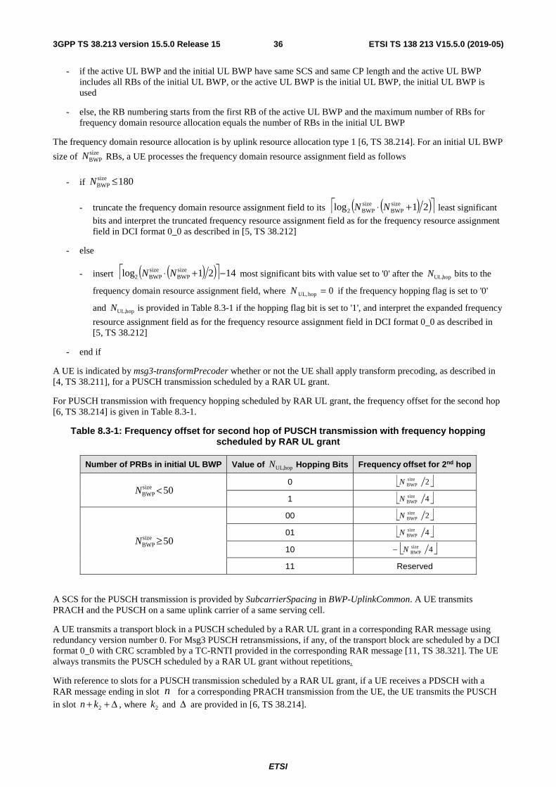
ETSI
ETSI TS 138 213 V15.5.0 (2019-05)363GPP TS 38.213 version 15.5.0 Release 15
- if the active UL BWP and the initial UL BWP have same SCS and same CP length and the active UL BWP includes all RBs of the initial UL BWP, or the active UL BWP is the initial UL BWP, the initial UL BWP is used
- else, the RB numbering starts from the first RB of the active UL BWP and the maximum number of RBs for frequency domain resource allocation equals the number of RBs in the initial UL BWP
The frequency domain resource allocation is by uplink resource allocation type 1 [6, TS 38.214]. For an initial UL BWP
size of sizeBWPN RBs, a UE processes the frequency domain resource assignment field as follows
- if 180sizeBWP ≤N
- truncate the frequency domain resource assignment field to its ( )( ) 21log sizeBWP
sizeBWP2 +⋅ NN least significant
bits and interpret the truncated frequency resource assignment field as for the frequency resource assignment field in DCI format 0_0 as described in [5, TS 38.212]
- else
- insert ( )( ) 1421log sizeBWP
sizeBWP2 −+⋅ NN most significant bits with value set to '0' after the hopUL,N bits to the
frequency domain resource assignment field, where 0hopUL, =N if the frequency hopping flag is set to '0'
and hopUL,N is provided in Table 8.3-1 if the hopping flag bit is set to '1', and interpret the expanded frequency
resource assignment field as for the frequency resource assignment field in DCI format 0_0 as described in [5, TS 38.212]
- end if
A UE is indicated by msg3-transformPrecoder whether or not the UE shall apply transform precoding, as described in [4, TS 38.211], for a PUSCH transmission scheduled by a RAR UL grant.
For PUSCH transmission with frequency hopping scheduled by RAR UL grant, the frequency offset for the second hop [6, TS 38.214] is given in Table 8.3-1.
Table 8.3-1: Frequency offset for second hop of PUSCH transmission with frequency hopping scheduled by RAR UL grant
Number of PRBs in initial UL BWP Value of hopUL,N Hopping Bits Frequency offset for 2nd hop
50sizeBWP <N
0 2sizeBWPN
1 4sizeBWPN
50sizeBWP ≥N
00 2sizeBWPN
01 4sizeBWPN
10 4sizeBWPN−
11 Reserved
A SCS for the PUSCH transmission is provided by SubcarrierSpacing in BWP-UplinkCommon. A UE transmits PRACH and the PUSCH on a same uplink carrier of a same serving cell.
A UE transmits a transport block in a PUSCH scheduled by a RAR UL grant in a corresponding RAR message using redundancy version number 0. For Msg3 PUSCH retransmissions, if any, of the transport block are scheduled by a DCI format 0_0 with CRC scrambled by a TC-RNTI provided in the corresponding RAR message [11, TS 38.321]. The UE always transmits the PUSCH scheduled by a RAR UL grant without repetitions.
With reference to slots for a PUSCH transmission scheduled by a RAR UL grant, if a UE receives a PDSCH with a RAR message ending in slot n for a corresponding PRACH transmission from the UE, the UE transmits the PUSCH in slot Δ++ 2kn , where 2k and Δ are provided in [6, TS 38.214].

ETSI
ETSI TS 138 213 V15.5.0 (2019-05)373GPP TS 38.213 version 15.5.0 Release 15
The UE may assume a minimum time between the last symbol of a PDSCH reception conveying a RAR message with a RAR UL grant and the first symbol of a corresponding PUSCH transmission scheduled by the RAR UL grant is equal to 5.0T,2T,1 ++ NN msec, where T,1N is a time duration of 1N symbols corresponding to a PDSCH reception time for
UE processing capability 1 when additional PDSCH DM-RS is configured, T,2N is a time duration of 2N symbols
corresponding to a PUSCH preparation time for UE processing capability 1 [6, TS 38.214] and, for determining the minimum time, the UE considers that 1N and 2N correspond to the smaller of the SCS configurations for the PDSCH
and the PUSCH.
8.4 PDSCH with UE contention resolution identity In response to a PUSCH transmission scheduled by a RAR UL grant when a UE has not been provided a C-RNTI, the UE attempts to detect a DCI format 1_0 with CRC scrambled by a corresponding TC-RNTI scheduling a PDSCH that includes a UE contention resolution identity [11, TS 38.321]. In response to the PDSCH reception with the UE contention resolution identity, the UE transmits HARQ-ACK information in a PUCCH. The PUCCH transmission is within a same active UL BWP as the PUSCH transmission. A minimum time between the last symbol of the PDSCH reception and the first symbol of the corresponding PUCCH transmission with the HARQ-ACK information is equal to
5.0T,1 +N msec. T,1N is a time duration of 1N symbols corresponding to a PDSCH reception time for UE processing
capability 1 when additional PDSCH DM-RS is configured.
When detecting a DCI format in response to a PUSCH transmission scheduled by a RAR UL grant, as described in [11, TS 38.321], or corresponding PUSCH retransmission scheduled by a DCI format 0_0 with CRC scrambled by a TC-RNTI provided in the corresponding RAR message [11, TS 38.321], the UE may assume the PDCCH carrying the DCI format has the same DM-RS antenna port quasi co-location properties, as described in [6, TS 38.214], as for a SS/PBCH block the UE used for PRACH association, as described in Subclause 8.1, regardless of whether or not the UE is provided TCI-State for the CORESET where the UE receives the PDCCH with the DCI format.
9 UE procedure for reporting control information If a UE is configured with a SCG, the UE shall apply the procedures described in this subclause for both MCG and SCG.
- When the procedures are applied for MCG, the terms 'secondary cell', 'secondary cells' , 'serving cell', 'serving cells' in this clause refer to secondary cell, secondary cells, serving cell, serving cells belonging to the MCG respectively.
- When the procedures are applied for SCG, the terms 'secondary cell', 'secondary cells', 'serving cell', 'serving cells' in this clause refer to secondary cell, secondary cells (not including PSCell), serving cell, serving cells belonging to the SCG respectively. The term 'primary cell' in this clause refers to the PSCell of the SCG.
If the UE is configured with a PUCCH-SCell, the UE shall apply the procedures described in this clause for both primary PUCCH group and secondary PUCCH group
- When the procedures are applied for the primary PUCCH group, the terms 'secondary cell', 'secondary cells' , 'serving cell', 'serving cells' in this clause refer to secondary cell, secondary cells, serving cell, serving cells belonging to the primary PUCCH group respectively.
- When the procedures are applied for secondary PUCCH group, the terms 'secondary cell', 'secondary cells', 'serving cell', 'serving cells' in this clause refer to secondary cell, secondary cells (not including the PUCCH-SCell), serving cell, serving cells belonging to the secondary PUCCH group respectively. The term 'primary cell' in this clause refers to the PUCCH-SCell of the secondary PUCCH group.
If a UE would transmit on a serving cell a PUSCH without UL-SCH that overlaps with a PUCCH transmission on a serving cell that includes positive SR information, the UE does not transmit the PUSCH.
If a UE would transmit CSI reports on overlapping physical channels, the UE applies the priority rules described in TS 38 .214 for the multiplexing of CSI reports.
If a UE has overlapping resources for PUCCH transmissions in a slot and at least one of the PUCCH transmissions is with repetitions over multiple slots, the UE first follows the procedures described in Subclause 9.2.6 for resolving the overlapping among the resources for the PUCCH transmissions.

ETSI
ETSI TS 138 213 V15.5.0 (2019-05)383GPP TS 38.213 version 15.5.0 Release 15
If a UE
- would multiplex UCI in a PUCCH transmission that overlaps with a PUSCH transmission, and
- the PUSCH and PUCCH transmissions fulfill the conditions in Subclause 9.2.5 for UCI multiplexing,
the UE
- multiplexes only HARQ-ACK information, if any, from the UCI in the PUSCH transmission and does not transmit the PUCCH if the UE multiplexes aperiodic or semi-persistent CSI reports in the PUSCH;
- multiplexes only HARQ-ACK information and CSI reports, if any, from the UCI in the PUSCH transmission and does not transmit the PUCCH if the UE does not multiplex aperiodic or semi-persistent CSI reports in the PUSCH.
A UE does not expect to multiplex in a PUSCH transmission in one slot with SCS configuration 1μ UCI of same type
that the UE would transmit in PUCCHs in different slots with SCS configuration 2μ if 21 μμ < .
A UE does not expect to detect a DCI format scheduling a PDSCH reception or a SPS PDSCH release and indicating a resource for a PUCCH transmission with corresponding HARQ-ACK information in a slot if the UE previously detects a DCI format scheduling a PUSCH transmission in the slot and if the UE multiplexes HARQ-ACK information in the PUSCH transmission.
If a UE multiplexes aperiodic CSI in a PUSCH and the UE would multiplex UCI that includes HARQ-ACK information in a PUCCH that overlaps with the PUSCH and the timing conditions for overlapping PUCCHs and PUSCHs in Subclause 9.2.5 are fulfilled, the UE multiplexes only the HARQ-ACK information in the PUSCH and does not transmit the PUCCH.
If a UE transmits multiple PUSCHs in a slot on respective serving cells that include first PUSCHs that are scheduled by DCI format(s) 0_0 or DCI format(s) 0_1 and second PUSCHs configured by respective ConfiguredGrantConfig or semiPersistentOnPUSCH, and the UE would multiplex UCI in one of the multiple PUSCHs, and the multiple PUSCHs fulfil the conditions in Subclause 9.2.5 for UCI multiplexing, the UE multiplexes the UCI in a PUSCH from the first PUSCHs.
If a UE transmits multiple PUSCHs in a slot on respective serving cells and the UE would multiplex UCI in one of the multiple PUSCHs and the UE does not multiplex aperiodic CSI in any of the multiple PUSCHs, the UE multiplexes the UCI in a PUSCH of the serving cell with the smallest ServCellIndex subject to the conditions in Subclause 9.2.5 for UCI multiplexing being fulfilled. If the UE transmits more than one PUSCHs in the slot on the serving cell with the smallest ServCellIndex that fulfil the conditions in Subclause 9.2.5 for UCI multiplexing, the UE multiplexes the UCI in the earliest PUSCH that the UE transmits in the slot.
If a UE transmits a PUSCH over multiple slots and the UE would transmit a PUCCH with HARQ-ACK and/or CSI information over a single slot and in a slot that overlaps with the PUSCH transmission in one or more slots of the multiple slots, and the PUSCH transmission in the one or more slots fulfills the conditions in Subclause 9.2.5 for multiplexing the HARQ-ACK and/or CSI information, the UE multiplexes the HARQ-ACK and/or CSI information in the PUSCH transmission in the one or more slots. The UE does not multiplex HARQ-ACK and/or CSI information in the PUSCH transmission in a slot from the multiple slots if the UE would not transmit a single-slot PUCCH with HARQ-ACK and/or CSI information in the slot in case the PUSCH transmission was absent.
If the PUSCH transmission over the multiple slots is scheduled by a DCI format 0_1, the same value of a DAI field is applicable for multiplexing HARQ-ACK information in the PUSCH transmission in any slot from the multiple slots where the UE multiplexes HARQ-ACK information.
A HARQ-ACK information bit value of 0 represents a negative acknowledgement (NACK) while a HARQ-ACK information bit value of 1 represents a positive acknowledgement (ACK).
9.1 HARQ-ACK codebook determination If a UE receives a PDSCH without receiving a corresponding PDCCH, or if the UE receives a PDCCH indicating a SPS PDSCH release, the UE generates one corresponding HARQ-ACK information bit.
If a UE is not provided PDSCH-CodeBlockGroupTransmission, the UE generates one HARQ-ACK information bit per transport block.
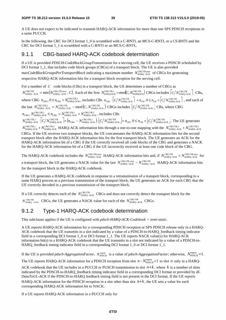
ETSI
ETSI TS 138 213 V15.5.0 (2019-05)393GPP TS 38.213 version 15.5.0 Release 15
A UE does not expect to be indicated to transmit HARQ-ACK information for more than one SPS PDSCH receptions in a same PUCCH.
In the following, the CRC for DCI format 1_0 is scrambled with a C-RNTI, an MCS-C-RNTI, or a CS-RNTI and the CRC for DCI format 1_1 is scrambled with a C-RNTI or an MCS-C-RNTI,.
9.1.1 CBG-based HARQ-ACK codebook determination
If a UE is provided PDSCH-CodeBlockGroupTransmission for a serving cell, the UE receives a PDSCH scheduled by DCI format 1_1, that includes code block groups (CBGs) of a transport block. The UE is also provided
maxCodeBlockGroupsPerTransportBlock indicating a maximum number of CBGs for generating
respective HARQ-ACK information bits for a transport block reception for the serving cell.
For a number of C code blocks (CBs) in a transport block, the UE determines a number of CBGs as
( )CNN ,min maxCBG/TB,ACKHARQ
CBG/TBACKHARQ −− = . Each of the first ( )CBG/TB
ACK-HARQCBG/TB,1
ACKHARQ ,mod NCN =− CBGs includes CBG/TBACK-HARQNC CBs,
where CBG CBG/TB,1ACKHARQCBGCBG 0, −<≤ Nnn , includes CBs CBG/TB
ACK-HARQCBCBCBG/TB
ACK-HARQCBG 0, NCnnNCn <≤+⋅ , and each of
the last ( )CBG/TBACK-HARQ
CBG/TBACK-HARQ
CBG/TB,2ACKHARQ ,mod NCNN −=− CBGs includes CBG/TB
ACK-HARQNC CBs, where CBG CBG/TB,2
ACKHARQCBG/TB,1
ACKHARQCBGCBG/TB,1
ACKHARQCBG, −−− +<≤ NNnNn , includes CBs
( ) CBG/TBACK-HARQCBCB
CBG/TBACK-HARQ
CBG/TB,1ACKHARQCBG
CBG/TBACK-HARQ
CBG/TB,1ACKHARQ 0, NCnnNCNnNCN <≤+⋅−+⋅ −− . The UE generates
CBG/TB,2ACKHARQ
CBG/TB,1ACKHARQ −− + NN HARQ-ACK information bits through a one-to-one mapping with the CBG/TB,2
ACKHARQCBG/TB,1
ACKHARQ −− + NN
CBGs. If the UE receives two transport blocks, the UE concatenates the HARQ-ACK information bits for the second transport block after the HARQ-ACK information bits for the first transport block. The UE generates an ACK for the HARQ-ACK information bit of a CBG if the UE correctly received all code blocks of the CBG and generates a NACK for the HARQ-ACK information bit of a CBG if the UE incorrectly received at least one code block of the CBG.
The HARQ-ACK codebook includes the maxCBG/TB,ACKHARQ−N HARQ-ACK information bits and, if maxCBG/TB,
ACKHARQCBG/TB
ACKHARQ −− < NN for
a transport block, the UE generates a NACK value for the last CBG/TBACKHARQ
maxCBG/TB,ACKHARQ −− − NN HARQ-ACK information bits
for the transport block in the HARQ-ACK codebook.
If the UE generates a HARQ-ACK codebook in response to a retransmission of a transport block, corresponding to a same HARQ process as a previous transmission of the transport block, the UE generates an ACK for each CBG that the UE correctly decoded in a previous transmission of the transport block.
If a UE correctly detects each of the CBG/TBACKHARQ−N CBGs and does not correctly detect the transport block for the
CBG/TBACKHARQ −N CBGs, the UE generates a NACK value for each of the CBG/TB
ACKHARQ−N CBGs.
9.1.2 Type-1 HARQ-ACK codebook determination
This subclause applies if the UE is configured with pdsch-HARQ-ACK-Codebook = semi-static.
A UE reports HARQ-ACK information for a corresponding PDSCH reception or SPS PDSCH release only in a HARQ-ACK codebook that the UE transmits in a slot indicated by a value of a PDSCH-to-HARQ_feedback timing indicator field in a corresponding DCI format 1_0 or DCI format 1_1. The UE reports NACK value(s) for HARQ-ACK information bit(s) in a HARQ-ACK codebook that the UE transmits in a slot not indicated by a value of a PDSCH-to-HARQ_feedback timing indicator field in a corresponding DCI format 1_0 or DCI format 1_1.
If the UE is provided pdsch-AggregationFactor, repeatPDSCHN is a value of pdsch-AggregationFactor; otherwise, 1repeat
PDSCH =N .
The UE reports HARQ-ACK information for a PDSCH reception from slot 1repeatPDSCH +− Nn to slot n only in a HARQ-
ACK codebook that the UE includes in a PUCCH or PUSCH transmission in slot kn+ , where k is a number of slots indicated by the PDSCH-to-HARQ_feedback timing indicator field in a corresponding DCI format or provided by dl-DataToUL-ACK if the PDSCH-to-HARQ feedback timing field is not present in the DCI format. If the UE reports
HARQ-ACK information for the PDSCH reception in a slot other than slot kn+ , the UE sets a value for each corresponding HARQ-ACK information bit to NACK.
If a UE reports HARQ-ACK information in a PUCCH only for
maxCBG/TB,ACKHARQ−N
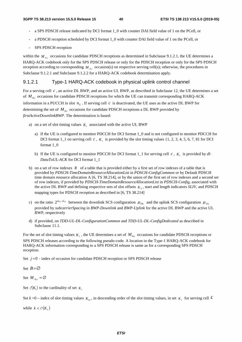
ETSI
ETSI TS 138 213 V15.5.0 (2019-05)403GPP TS 38.213 version 15.5.0 Release 15
- a SPS PDSCH release indicated by DCI format 1_0 with counter DAI field value of 1 on the PCell, or
- a PDSCH reception scheduled by DCI format 1_0 with counter DAI field value of 1 on the PCell, or
- SPS PDSCH reception
within the cAM , occasions for candidate PDSCH receptions as determined in Subclause 9.1.2.1, the UE determines a
HARQ-ACK codebook only for the SPS PDSCH release or only for the PDSCH reception or only for the SPS PDSCH reception according to corresponding cAM , occasion(s) on respective serving cell(s); otherwise, the procedures in
Subclause 9.1.2.1 and Subclause 9.1.2.2 for a HARQ-ACK codebook determination apply.
9.1.2.1 Type-1 HARQ-ACK codebook in physical uplink control channel
For a serving cell c , an active DL BWP, and an active UL BWP, as described in Subclause 12, the UE determines a set of cAM , occasions for candidate PDSCH receptions for which the UE can transmit corresponding HARQ-ACK
information in a PUCCH in slot Un . If serving cell c is deactivated, the UE uses as the active DL BWP for
determining the set of cAM , occasions for candidate PDSCH receptions a DL BWP provided by
firstActiveDownlinkBWP. The determination is based:
a) on a set of slot timing values 1K associated with the active UL BWP
a) If the UE is configured to monitor PDCCH for DCI format 1_0 and is not configured to monitor PDCCH for DCI format 1_1 on serving cell c , 1K is provided by the slot timing values {1, 2, 3, 4, 5, 6, 7, 8} for DCI
format 1_0
b) If the UE is configured to monitor PDCCH for DCI format 1_1 for serving cell c , 1K is provided by dl-
DataToUL-ACK for DCI format 1_1
b) on a set of row indexes R of a table that is provided either by a first set of row indexes of a table that is provided by PDSCH-TimeDomainResourceAllocationList in PDSCH-ConfigCommon or by Default PDSCH time domain resource allocation A [6, TS 38.214], or by the union of the first set of row indexes and a second set of row indexes, if provided by PDSCH-TimeDomainResourceAllocationList in PDSCH-Config, associated with the active DL BWP and defining respective sets of slot offsets
0K , start and length indicators SLIV, and PDSCH
mapping types for PDSCH reception as described in [6, TS 38.214]
c) on the ratio ULDL -2 μμ between the downlink SCS configuration DLμ and the uplink SCS configuration ULμ
provided by subcarrierSpacing in BWP-Downlink and BWP-Uplink for the active DL BWP and the active UL BWP, respectively
d) if provided, on TDD-UL-DL-ConfigurationCommon and TDD-UL-DL-ConfigDedicated as described in Subclause 11.1.
For the set of slot timing values 1K , the UE determines a set of cAM , occasions for candidate PDSCH receptions or
SPS PDSCH releases according to the following pseudo-code. A location in the Type-1 HARQ-ACK codebook for HARQ-ACK information corresponding to a SPS PDSCH release is same as for a corresponding SPS PDSCH reception.
Set 0=j - index of occasion for candidate PDSCH reception or SPS PDSCH release
Set ∅=B
Set ∅=cAM ,
Set ( )1KC to the cardinality of set 1K
Set k =0 – index of slot timing values kK ,1 , in descending order of the slot timing values, in set 1K for serving cell c
while ( )1Kk C<

ETSI
ETSI TS 138 213 V15.5.0 (2019-05)413GPP TS 38.213 version 15.5.0 Release 15
if ( )( ) 01,2max,1-mod DLUL -1U =+ μμ
,kKn
Set 0D =n – index of a DL slot within an UL slot
while ( )1,2max ULDL -D
μμ<n
Set R to the set of rows
Set ( )RC to the cardinality of R
Set 0=r – index of row in set R
if slot Un starts at a same time as or after a slot for an active DL BWP change on serving cell c or an active
UL BWP change on the PCell and slot ( ) D-
,1UULDL2 nKn k +⋅− μμ is before the slot for the active DL BWP
change on serving cell c or the active UL BWP change on the PCell
continue;
else
while ( )Rr C<
if the UE is provided TDD-UL-DL-ConfigurationCommon, or TDD-UL-DL-ConfigDedicated and, for
each slot from slot ( ) 12 repeatPDSCHD
-,1U
ULDL +−+⋅− NnKn kμμ to slot ( ) D
-,1U
ULDL2 nKn k +⋅− μμ , at
least one symbol of the PDSCH time resource derived by row r is configured as UL where kK ,1 is
the k-th slot timing value in set 1K ,
rRR \= ;
end if
1+= rr ;
end while
if the UE does not indicate a capability to receive more than one unicast PDSCH per slot and ∅≠R ,
jMM cAcA U,, = ;
1+= jj ;
The UE does not expect to receive SPS PDSCH release and unicast PDSCH in a same slot;
else
Set ( )RC to the cardinality of R
Set m to the smallest last OFDM symbol index, as determined by the SLIV, among all rows of R
while ∅≠R
Set 0=r
while ( )Rr C<
if mS ≤ for start OFDM symbol index S for row r
jbDnkr =,, ; - index of occasion for candidate PDSCH reception or SPS PDSCH release
associated with row r
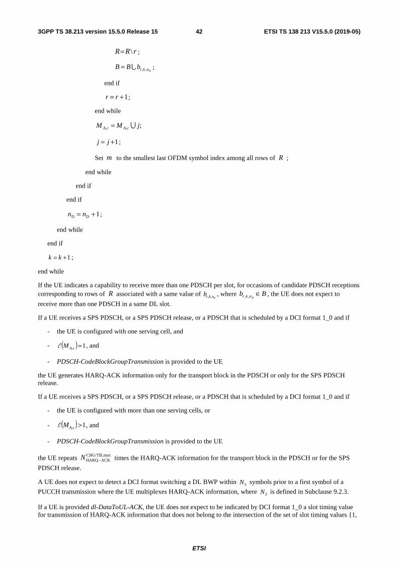
ETSI
ETSI TS 138 213 V15.5.0 (2019-05)423GPP TS 38.213 version 15.5.0 Release 15
rRR \= ;
DnkrbBB ,,U= ;
end if
1+= rr ;
end while
;,, jMM cAcA U=
1+= jj ;
Set m to the smallest last OFDM symbol index among all rows of R ;
end while
end if
end if
1DD += nn ;
end while
end if
1+= kk ;
end while
If the UE indicates a capability to receive more than one PDSCH per slot, for occasions of candidate PDSCH receptions corresponding to rows of R associated with a same value of
Dnkrb ,, , where BbDnkr ∈,, , the UE does not expect to
receive more than one PDSCH in a same DL slot.
If a UE receives a SPS PDSCH, or a SPS PDSCH release, or a PDSCH that is scheduled by a DCI format 1_0 and if
- the UE is configured with one serving cell, and
- ( ) 1, =cAMC , and
- PDSCH-CodeBlockGroupTransmission is provided to the UE
the UE generates HARQ-ACK information only for the transport block in the PDSCH or only for the SPS PDSCH release.
If a UE receives a SPS PDSCH, or a SPS PDSCH release, or a PDSCH that is scheduled by a DCI format 1_0 and if
- the UE is configured with more than one serving cells, or
- ( ) 1, >cAMC , and
- PDSCH-CodeBlockGroupTransmission is provided to the UE
the UE repeats maxCBG/TB,ACKHARQ−N times the HARQ-ACK information for the transport block in the PDSCH or for the SPS
PDSCH release.
A UE does not expect to detect a DCI format switching a DL BWP within 3N symbols prior to a first symbol of a
PUCCH transmission where the UE multiplexes HARQ-ACK information, where 3N is defined in Subclause 9.2.3.
If a UE is provided dl-DataToUL-ACK, the UE does not expect to be indicated by DCI format 1_0 a slot timing value for transmission of HARQ-ACK information that does not belong to the intersection of the set of slot timing values {1,

ETSI
ETSI TS 138 213 V15.5.0 (2019-05)433GPP TS 38.213 version 15.5.0 Release 15
2, 3, 4, 5, 6, 7, 8} and the set of slot timing values provided by dl-DataToUL-ACK for the active DL BWP of a corresponding serving cell.
If an occasion for a candidate PDSCH reception can be in response to a PDCCH with DCI format 1_1 and if maxNrofCodeWordsScheduledByDCI indicates reception of two transport blocks, when the UE receives a PDSCH with one transport block, the HARQ-ACK information is associated with the first transport block and the UE generates a NACK for the second transport block if harq-ACK-SpatialBundlingPUCCH is not provided and generates HARQ-ACK information with value of ACK for the second transport block if harq-ACK-SpatialBundlingPUCCH is provided.
A UE determines ACK
O
ACKACKACKooo
110~,...,~ ,~
− HARQ-ACK information bits, for a total number of ACKO HARQ-ACK
information bits, of a HARQ-ACK codebook for transmission in a PUCCH according to the following pseudo-code. In the following pseudo-code, if the UE does not receive a transport block or a CBG, due to the UE not detecting a corresponding DCI format 1_0 or DCI format 1_1, the UE generates a NACK value for the transport block or the CBG. The cardinality of the set cAM , defines a total number cM of occasions for PDSCH reception or SPS PDSCH release
for serving cell c corresponding to the HARQ-ACK information bits.
Set 0=c – serving cell index: lower indexes correspond to lower RRC indexes of corresponding cell
Set 0=j - HARQ-ACK information bit index
Set DLcellsN to the number of serving cells configured by higher layers for the UE
while DLcellsNc <
Set 0=m – index of occasion for candidate PDSCH reception or SPS PDSCH release
while cMm <
if harq-ACK-SpatialBundlingPUCCH is not provided, PDSCH-CodeBlockGroupTransmission is not provided, and the UE is configured by maxNrofCodeWordsScheduledByDCI with reception of two transport blocks for the active DL BWP of serving cell c ,
ACKjo~ = HARQ-ACK information bit corresponding to a first transport block of this cell;
1+= jj ;
ACKjo~ = HARQ-ACK information bit corresponding to a second transport block of this cell;
1+= jj ;
elseif harq-ACK-SpatialBundlingPUCCH is provided, and the UE is configured by maxNrofCodeWordsScheduledByDCI with reception of two transport blocks for the active DL BWP of serving cell c ,
ACKjo~ = binary AND operation of the HARQ-ACK information bits corresponding to first and second
transport blocks of this cell - if the UE receives one transport block, the UE assumes ACK for the second transport block;
1+= jj ;
elseif PDSCH-CodeBlockGroupTransmission is provided, and maxCBG/TB,ACK,HARQ cN − CBGs are indicated by
maxCodeBlockGroupsPerTransportBlock for serving cell c ,
Set 0CBG =n - CBG index
while maxCBG/TB,ACK,HARQCBG cNn −<
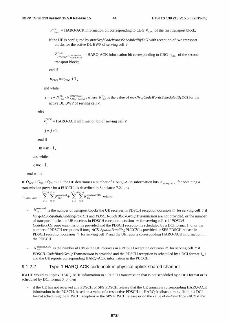
ETSI
ETSI TS 138 213 V15.5.0 (2019-05)443GPP TS 38.213 version 15.5.0 Release 15
ACKnjo
CBG
~+ = HARQ-ACK information bit corresponding to CBG CBGn of the first transport block;
if the UE is configured by maxNrofCodeWordsScheduledByDCI with reception of two transport blocks for the active DL BWP of serving cell c
ACK
Nnj co maxCBG/TB,
ACK,HARQCBG
~−++ = HARQ-ACK information bit corresponding to CBG CBGn of the second
transport block;
end if
1CBGCBG += nn ;
end while
CBG/TBmax,ACKNARQ
DLTB, cc NNjj −⋅+= , where DL
TB,cN is the value of maxNrofCodeWordsScheduledByDCI for the
active DL BWP of serving cell c ;
else
ACKjo~ = HARQ-ACK information bit of serving cell c ;
1+= jj ;
end if
1+= mm ;
end while
1+=cc ;
end while
If 11CSISRACK ≤++ OOO , the UE determines a number of HARQ-ACK information bits ACK-HARQn for obtaining a
transmission power for a PUCCH, as described in Subclause 7.2.1, as
−
=
−
=
−
=
−
=+=
1
0
1
0
CBGreceived,,
1
0
1
0
received,ACK-HARQ
DLcells
DLcells N
c
M
mcm
N
c
M
mcm
cc
NNn where
- received
,cmN is the number of transport blocks the UE receives in PDSCH reception occasion m for serving cell c if
harq-ACK-SpatialBundlingPUCCH and PDSCH-CodeBlockGroupTransmission are not provided, or the number of transport blocks the UE receives in PDSCH reception occasion m for serving cell c if PDSCH-CodeBlockGroupTransmission is provided and the PDSCH reception is scheduled by a DCI format 1_0, or the number of PDSCH receptions if harq-ACK-SpatialBundlingPUCCH is provided or SPS PDSCH release in PDSCH reception occasion m for serving cell c and the UE reports corresponding HARQ-ACK information in the PUCCH.
- CBGreceived,,cmN is the number of CBGs the UE receives in a PDSCH reception occasion m for serving cell c if
PDSCH-CodeBlockGroupTransmission is provided and the PDSCH reception is scheduled by a DCI format 1_1 and the UE reports corresponding HARQ-ACK information in the PUCCH.
9.1.2.2 Type-1 HARQ-ACK codebook in physical uplink shared channel
If a UE would multiplex HARQ-ACK information in a PUSCH transmission that is not scheduled by a DCI format or is scheduled by DCI format 0_0, then
- if the UE has not received any PDSCH or SPS PDSCH release that the UE transmits corresponding HARQ-ACK information in the PUSCH, based on a value of a respective PDSCH-to-HARQ feedback timing field in a DCI format scheduling the PDSCH reception or the SPS PDSCH release or on the value of dl-DataToUL-ACK if the
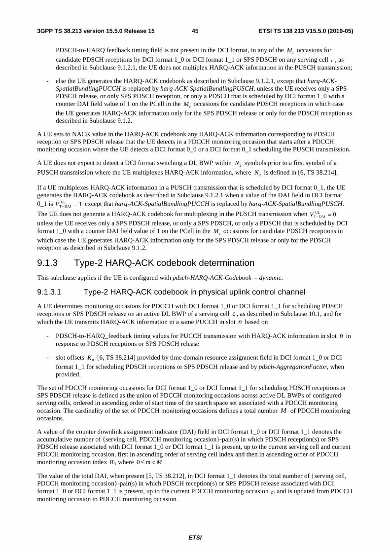
ETSI
ETSI TS 138 213 V15.5.0 (2019-05)453GPP TS 38.213 version 15.5.0 Release 15
PDSCH-to-HARQ feedback timing field is not present in the DCI format, in any of the cM occasions for
candidate PDSCH receptions by DCI format 1_0 or DCI format 1_1 or SPS PDSCH on any serving cell c , as described in Subclause 9.1.2.1, the UE does not multiplex HARQ-ACK information in the PUSCH transmission;
- else the UE generates the HARQ-ACK codebook as described in Subclause 9.1.2.1, except that harq-ACK-SpatialBundlingPUCCH is replaced by harq-ACK-SpatialBundlingPUSCH, unless the UE receives only a SPS PDSCH release, or only SPS PDSCH reception, or only a PDSCH that is scheduled by DCI format 1_0 with a counter DAI field value of 1 on the PCell in the cM occasions for candidate PDSCH receptions in which case
the UE generates HARQ-ACK information only for the SPS PDSCH release or only for the PDSCH reception as described in Subclause 9.1.2.
A UE sets to NACK value in the HARQ-ACK codebook any HARQ-ACK information corresponding to PDSCH reception or SPS PDSCH release that the UE detects in a PDCCH monitoring occasion that starts after a PDCCH monitoring occasion where the UE detects a DCI format 0_0 or a DCI format 0_1 scheduling the PUSCH transmission.
A UE does not expect to detect a DCI format switching a DL BWP within 2N symbols prior to a first symbol of a
PUSCH transmission where the UE multiplexes HARQ-ACK information, where 2N is defined in [6, TS 38.214].
If a UE multiplexes HARQ-ACK information in a PUSCH transmission that is scheduled by DCI format 0_1, the UE generates the HARQ-ACK codebook as described in Subclause 9.1.2.1 when a value of the DAI field in DCI format 0_1 is 1UL
DAIT =−V except that harq-ACK-SpatialBundlingPUCCH is replaced by harq-ACK-SpatialBundlingPUSCH.
The UE does not generate a HARQ-ACK codebook for multiplexing in the PUSCH transmission when 0ULDAIT =−V
unless the UE receives only a SPS PDSCH release, or only a SPS PDSCH, or only a PDSCH that is scheduled by DCI format 1_0 with a counter DAI field value of 1 on the PCell in the cM occasions for candidate PDSCH receptions in
which case the UE generates HARQ-ACK information only for the SPS PDSCH release or only for the PDSCH reception as described in Subclause 9.1.2.
9.1.3 Type-2 HARQ-ACK codebook determination
This subclause applies if the UE is configured with pdsch-HARQ-ACK-Codebook = dynamic.
9.1.3.1 Type-2 HARQ-ACK codebook in physical uplink control channel
A UE determines monitoring occasions for PDCCH with DCI format 1_0 or DCI format 1_1 for scheduling PDSCH receptions or SPS PDSCH release on an active DL BWP of a serving cell c , as described in Subclause 10.1, and for which the UE transmits HARQ-ACK information in a same PUCCH in slot n based on
- PDSCH-to-HARQ_feedback timing values for PUCCH transmission with HARQ-ACK information in slot n in response to PDSCH receptions or SPS PDSCH release
- slot offsets 0K [6, TS 38.214] provided by time domain resource assignment field in DCI format 1_0 or DCI
format 1_1 for scheduling PDSCH receptions or SPS PDSCH release and by pdsch-AggregationFactor, when provided.
The set of PDCCH monitoring occasions for DCI format 1_0 or DCI format 1_1 for scheduling PDSCH receptions or SPS PDSCH release is defined as the union of PDCCH monitoring occasions across active DL BWPs of configured serving cells, ordered in ascending order of start time of the search space set associated with a PDCCH monitoring occasion. The cardinality of the set of PDCCH monitoring occasions defines a total number M of PDCCH monitoring occasions.
A value of the counter downlink assignment indicator (DAI) field in DCI format 1_0 or DCI format 1_1 denotes the accumulative number of {serving cell, PDCCH monitoring occasion}-pair(s) in which PDSCH reception(s) or SPS PDSCH release associated with DCI format 1_0 or DCI format 1_1 is present, up to the current serving cell and current PDCCH monitoring occasion, first in ascending order of serving cell index and then in ascending order of PDCCH monitoring occasion index m, where Mm <≤0 .
The value of the total DAI, when present [5, TS 38.212], in DCI format 1_1 denotes the total number of {serving cell, PDCCH monitoring occasion}-pair(s) in which PDSCH reception(s) or SPS PDSCH release associated with DCI format 1_0 or DCI format 1_1 is present, up to the current PDCCH monitoring occasion m and is updated from PDCCH monitoring occasion to PDCCH monitoring occasion.
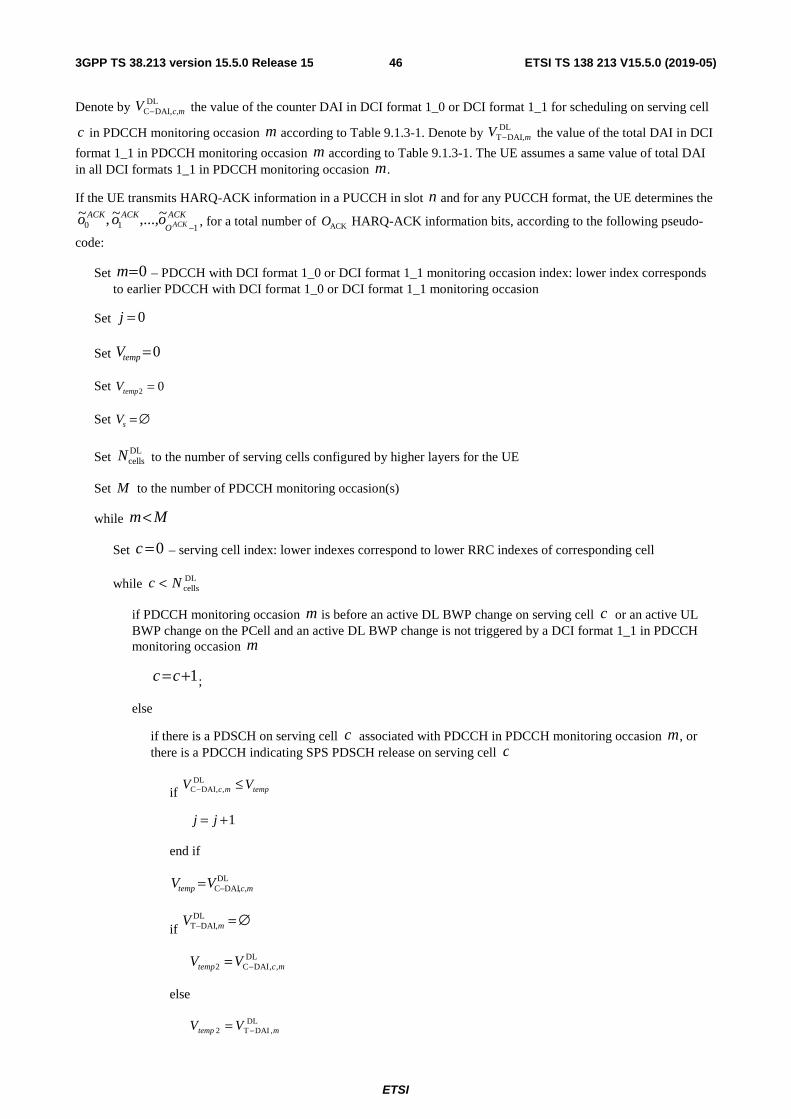
ETSI
ETSI TS 138 213 V15.5.0 (2019-05)463GPP TS 38.213 version 15.5.0 Release 15
Denote by DLDAI,C c,mV − the value of the counter DAI in DCI format 1_0 or DCI format 1_1 for scheduling on serving cell
c in PDCCH monitoring occasion m according to Table 9.1.3-1. Denote by DLDAI,T mV − the value of the total DAI in DCI
format 1_1 in PDCCH monitoring occasion m according to Table 9.1.3-1. The UE assumes a same value of total DAI in all DCI formats 1_1 in PDCCH monitoring occasion m.
If the UE transmits HARQ-ACK information in a PUCCH in slot n and for any PUCCH format, the UE determines the ACK
O
ACKACKACKooo
110~,...,~ ,~
− , for a total number of ACKO HARQ-ACK information bits, according to the following pseudo-
code:
Set 0=m – PDCCH with DCI format 1_0 or DCI format 1_1 monitoring occasion index: lower index corresponds to earlier PDCCH with DCI format 1_0 or DCI format 1_1 monitoring occasion
Set 0=j
Set 0=tempV
Set 02 =tempV
Set ∅=sV
Set DLcellsN to the number of serving cells configured by higher layers for the UE
Set M to the number of PDCCH monitoring occasion(s)
while Mm<
Set 0=c – serving cell index: lower indexes correspond to lower RRC indexes of corresponding cell
while DLcellsNc <
if PDCCH monitoring occasion m is before an active DL BWP change on serving cell c or an active UL BWP change on the PCell and an active DL BWP change is not triggered by a DCI format 1_1 in PDCCH monitoring occasion m
1+=cc ;
else
if there is a PDSCH on serving cell c associated with PDCCH in PDCCH monitoring occasion m, or there is a PDCCH indicating SPS PDSCH release on serving cell c
if tempmc VV ≤−DL
,,DAIC
1+= jj
end if
DL,,DAIC mctemp VV −=
if ∅=−
DL,DAIT mV
DL,,DAIC2 mctemp VV −=
else
DL,DAIT2 mtemp VV −=

ETSI
ETSI TS 138 213 V15.5.0 (2019-05)473GPP TS 38.213 version 15.5.0 Release 15
end if
if harq-ACK-SpatialBundlingPUCCH is not provided and m is a monitoring occasion for PDCCH with DCI format 1_0 or DCI format 1_1 and the UE is configured by maxNrofCodeWordsScheduledByDCI with reception of two transport blocks for at least one configured DL BWP of at least one serving cell,
( )ACK
Vj DLmcDAIC
o128 ,,
~−+ −
= HARQ-ACK information bit corresponding to the first transport block of this cell
( )ACK
Vj DLmcDAIC
o1128 ,,
~+−+ −
= HARQ-ACK information bit corresponding to the second transport block of this
cell
( ) ( ){ }1128,128 DL,,DAIC
DL,,DAIC +−+−+= −− mcmcss VjVjVV U
elseif harq-ACK-SpatialBundlingPUCCH is provided to the UE and m is a monitoring occasion for PDCCH with DCI format 1_1 and the UE is configured by maxNrofCodeWordsScheduledByDCI with reception of two transport blocks in at least one configured DL BWP of a serving cell,
ACKVj mc
o14 DL
,,DAIC
~−+ −
= binary AND operation of the HARQ-ACK information bits corresponding to the
first and second transport blocks of this cell
{ }14 DL,,DAIC −+= − mcss VjVV U
else
ACK
Vj DLmcDAIC
o14 ,,
~−+ −
= HARQ-ACK information bit of this cell
{ }14 DL,,DAIC −+= − mcss VjVV U
end if
end if
1+=cc
end if
end while
1+= mm
end while
if temptemp VV <2
1+= jj
end if
if harq-ACK-SpatialBundlingPUCCH is not provided to the UE and the UE is configured by maxNrofCodeWordsScheduledByDCI with reception of two transport blocks for at least one configured DL BWP of a serving cell,
( )242 tempACK VjO +⋅⋅=
else
24 tempACK VjO +⋅=
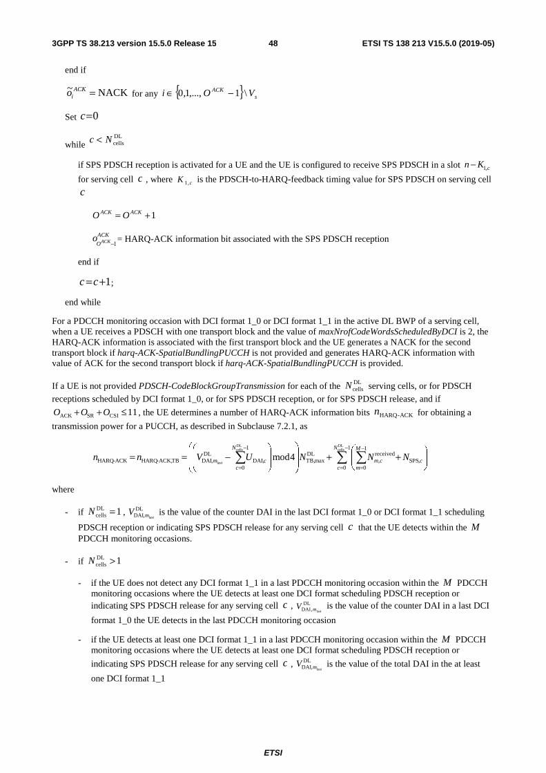
ETSI
ETSI TS 138 213 V15.5.0 (2019-05)483GPP TS 38.213 version 15.5.0 Release 15
end if
NACK~ =ACKio for any { } s
ACK VOi \1,...,1,0 −∈
Set 0=c
while DLcellsNc <
if SPS PDSCH reception is activated for a UE and the UE is configured to receive SPS PDSCH in a slot cKn ,1−
for serving cell c , where cK ,1 is the PDSCH-to-HARQ-feedback timing value for SPS PDSCH on serving cell
c
1+= ACKACK OO
ACK
OACKo1−= HARQ-ACK information bit associated with the SPS PDSCH reception
end if
1+=cc ;
end while
For a PDCCH monitoring occasion with DCI format 1_0 or DCI format 1_1 in the active DL BWP of a serving cell, when a UE receives a PDSCH with one transport block and the value of maxNrofCodeWordsScheduledByDCI is 2, the HARQ-ACK information is associated with the first transport block and the UE generates a NACK for the second transport block if harq-ACK-SpatialBundlingPUCCH is not provided and generates HARQ-ACK information with value of ACK for the second transport block if harq-ACK-SpatialBundlingPUCCH is provided.
If a UE is not provided PDSCH-CodeBlockGroupTransmission for each of the DLcellsN serving cells, or for PDSCH
receptions scheduled by DCI format 1_0, or for SPS PDSCH reception, or for SPS PDSCH release, and if
11CSISRACK ≤++ OOO , the UE determines a number of HARQ-ACK information bits ACK-HARQn for obtaining a
transmission power for a PUCCH, as described in Subclause 7.2.1, as
−
=
−
=
−
=
++
−==
1
0
1
0SPS
received,
DLmaxTB,
1
0DAI,
DL,DAITBACK,-HARQACK-HARQ
DLcells
DLcells
last4mod
N
c
M
m,ccm
N
ccm NNNUVnn
where
- if 1DLcells =N , DL
,DAI lastmV is the value of the counter DAI in the last DCI format 1_0 or DCI format 1_1 scheduling
PDSCH reception or indicating SPS PDSCH release for any serving cell c that the UE detects within the M PDCCH monitoring occasions.
- if 1DLcells >N
- if the UE does not detect any DCI format 1_1 in a last PDCCH monitoring occasion within the M PDCCH monitoring occasions where the UE detects at least one DCI format scheduling PDSCH reception or indicating SPS PDSCH release for any serving cell c , DL
,DAI lastmV is the value of the counter DAI in a last DCI
format 1_0 the UE detects in the last PDCCH monitoring occasion
- if the UE detects at least one DCI format 1_1 in a last PDCCH monitoring occasion within the M PDCCH monitoring occasions where the UE detects at least one DCI format scheduling PDSCH reception or
indicating SPS PDSCH release for any serving cell c , DL,DAI lastmV is the value of the total DAI in the at least
one DCI format 1_1

ETSI
ETSI TS 138 213 V15.5.0 (2019-05)493GPP TS 38.213 version 15.5.0 Release 15
- 0DL,DAI last
=mV if the UE does not detect any DCI format 1_0 or DCI format 1_1 scheduling PDSCH reception or
indicating SPS PDSCH release for any serving cell c in any of the M PDCCH monitoring occasions.
- cUDAI, is the total number of DCI format 1_0 and DCI format 1_1 scheduling PDSCH receptions or indicating
SPS PDSCH release that the UE detects within the M PDCCH monitoring occasions for serving cell c .
0DAI, =cU if the UE does not detect any DCI format 1_0 or DCI format 1_1 scheduling PDSCH reception or
indicating SPS PDSCH release for serving cell c in any of the M PDCCH monitoring occasions.
- 2DLmaxTB, =N if the value of maxNrofCodeWordsScheduledByDCI is 2 for any serving cell c and harq-ACK-
SpatialBundlingPUCCH is not provided; otherwise, 1DLmaxTB, =N .
- received,cmN is the number of transport blocks the UE receives in a PDSCH scheduled by DCI format 1_0 or DCI
format 1_1 that the UE detects in PDCCH monitoring occasion m for serving cell c if harq-ACK-SpatialBundlingPUCCH is not provided, or the number of PDSCH scheduled by DCI format 1_0 and DCI format 1_1 that the UE detects in PDCCH monitoring occasion m for serving cell c if harq-ACK-SpatialBundlingPUCCH is provided, or the number of DCI format 1_0 that the UE detects and indicate SPS PDSCH release in PDCCH monitoring occasion m for serving cell c .
- ,cNSPS is the number of SPS PDSCH receptions by the UE on serving cell c for which the UE transmits
corresponding HARQ-ACK information in the same PUCCH as for HARQ-ACK information corresponding to PDSCH receptions within the M PDCCH monitoring occasions.
If a UE
- is provided PDSCH-CodeBlockGroupTransmission for CBGDL,
cellsN serving cells; and
- is not provided PDSCH-CodeBlockGroupTransmission, for TBDL,cellsN serving cells where
DLcells
CBGDL,cells
TBDL,cells NNN =+
the UE determines the ACK
O
ACKACKACKooo
110~,...,~ ,~
− according to the previous pseudo-code with the following modifications
- DLcellsN is used for the determination of a first HARQ-ACK sub-codebook for SPS PDSCH release, SPS PDSCH
reception, and for TB-based PDSCH receptions scheduled by DCI formats 1_0 on the CBGDL,cellsN serving cells
and by DCI formats 1_0 and DCI formats 1_1 on the TBDL,cellsN serving cells
- DLcellsN is replaced by CBGDL,
cellsN for the determination of a second HARQ-ACK sub-codebook corresponding to
the CBGDL,cellsN serving cells for CBG-based PDSCH receptions scheduled by DCI format 1_1, and
- Instead of generating one HARQ-ACK information bit per transport block for a serving cell from the CBGDL,
cellsN serving cells, the UE generates maxCBG/TB,maxACK,HARQ −N HARQ-ACK information bits, where
maxCBG/TB,maxACK,HARQ−N is the maximum value of maxCBG/TB,
ACK,HARQDLTB, cc NN −⋅ across all CBGDL,
cellsN serving cells and DLTB,cN is
the value of maxNrofCodeWordsScheduledByDCI for serving cell c . If for a serving cell c it is maxCBG/TB,
maxACK,HARQmaxCBG/TB,
ACK,HARQDLTB, −− <⋅ NNN cc , the UE generates NACK for the last
maxCBG/TB,ACK,HARQ
DLTB,
maxCBG/TB,maxACK,HARQ cc NNN −− ⋅− HARQ-ACK information bits for serving cell c
- The pseudo-code operation when harq-ACK-SpatialBundlingPUCCH is provided is not applicable
- The counter DAI value and the total DAI value apply separately for each HARQ-ACK sub-codebook
- The UE generates the HARQ-ACK codebook by appending the second HARQ-ACK sub-codebook to the first HARQ-ACK sub-codebook

ETSI
ETSI TS 138 213 V15.5.0 (2019-05)503GPP TS 38.213 version 15.5.0 Release 15
If 11CSISRACK ≤++ OOO , the UE also determines CBGACK,-HARQTBACK,-HARQACK-HARQ nnn += for obtaining a
PUCCH transmission power, as described in Subclause 7.2.1, with
−
=
−
=−
−
=+
−=
1
0
1
0
CBGreceived,,
maxCBG/TB,maxACK,HARQ
1
0
CBGDAI,
DL,DAICBGACK,-HARQ
DLcells
DL,CBGcells
last4mod
N
c
M
mcm
N
ccm NNUVn
where
- if 1DLcells =N , DL
,DAI lastmV is the value of the counter DAI in the last DCI format 1_1 scheduling CBG-based
PDSCH reception for any serving cell c that the UE detects within the M PDCCH monitoring occasions
- if 1DLcells >N , DL
,DAI lastmV is the value of the total DAI in the last DCI format 1_1 scheduling CBG-based
PDSCH reception for any serving cell c that the UE detects within the M PDCCH monitoring occasions
- 0DL,DAI last
=mV if the UE does not detect any DCI format 1_1 scheduling CBG-based PDSCH reception for
any serving cell c in any of the M PDCCH monitoring occasions
- CBGDAI,cU is the total number of DCI format 1_1 scheduling CBG-based PDSCH receptions that the UE detects
within the M PDCCH monitoring occasions for serving cell c . 0CBGDAI, =cU if the UE does not detect any
DCI format 1_1 scheduling CBG-based PDSCH reception for serving cell c in any of the M PDCCH monitoring occasions
- CBGreceived,,cmN is the number of CBGs the UE receives in a PDSCH scheduled by DCI format 1_1 that the UE
detects in PDCCH monitoring occasion m for serving cell c and the UE reports corresponding HARQ-ACK information in the PUCCH
Table 9.1.3-1: Value of counter DAI in DCI format 1_0 and of counter DAI or total DAI DCI format 1_1
DAI MSB, LSB
DLDAIC−V or DL
DAIT−V Number of {serving cell, PDCCH monitoring occasion}-pair(s) in which PDSCH transmission(s) associated with PDCCH or PDCCH indicating
SPS PDSCH release is present, denoted as Y and 1≥Y 0,0 1 ( ) 114mod1 =+−Y
0,1 2 ( ) 214mod1 =+−Y
1,0 3 ( ) 314mod1 =+−Y
1,1 4 ( ) 414mod1 =+−Y
9.1.3.2 Type-2 HARQ-ACK codebook in physical uplink shared channel
If a UE would multiplex HARQ-ACK information in a PUSCH transmission that is not scheduled by a DCI format or is scheduled by DCI format 0_0, then
- if the UE has not received any PDCCH within the monitoring occasions for DCI format 1_0 or DCI format 1_1 for scheduling PDSCH receptions or SPS PDSCH release on any serving cell c and the UE does not have HARQ-ACK information in response to a SPS PDSCH reception to multiplex in the PUSCH, as described in Subclause 9.1.3.1, the UE does not multiplex HARQ-ACK information in the PUSCH transmission;
- else, the UE generates the HARQ-ACK codebook as described in Subclause 9.1.3.1, except that harq-ACK-SpatialBundlingPUCCH is replaced by harq-ACK-SpatialBundlingPUSCH.
If a UE multiplexes HARQ-ACK information in a PUSCH transmission that is scheduled by DCI format 0_1, the UE generates the HARQ-ACK codebook as described in Subclause 9.1.3.1, with the following modifications:

ETSI
ETSI TS 138 213 V15.5.0 (2019-05)513GPP TS 38.213 version 15.5.0 Release 15
- For the pseudo-code for the HARQ-ACK codebook generation in Subclause 9.1.3.1, after the completion of the
c and m loops, the UE sets ULDAI2 VVtemp = where UL
DAIV is the value of the DAI field in DCI format 0_1
according to Table 9.1.3-2
- For the case of first and second HARQ-ACK sub-codebooks, DCI format 0_1 includes a first DAI field corresponding to the first HARQ-ACK sub-codebook and a second DAI field corresponding to the second HARQ-ACK sub-codebook
- harq-ACK-SpatialBundlingPUCCH is replaced by harq-ACK-SpatialBundlingPUSCH.
If a UE is not provided PDSCH-CodeBlockGroupTransmission and the UE is scheduled for a PUSCH transmission by
DCI format 0_1 with DAI field value 4ULDAIT =−V and the UE has not received any PDCCH within the monitoring
occasions for PDCCH with DCI format 1_0 or DCI format 1_1 for scheduling PDSCH receptions or SPS PDSCH
release on any serving cell c and the UE does not have HARQ-ACK information in response to a SPS PDSCH reception to multiplex in the PUSCH, as described in Subclause 9.1.3.1, the UE does not multiplex HARQ-ACK information in the PUSCH transmission.
If a UE is provided PDSCH-CodeBlockGroupTransmission and the UE is scheduled for a PUSCH transmission by DCI
format 0_1 with first DAI field value 4ULDAIT =−V or with second DAI field value 4UL
DAIT =−V and the UE has not received
any PDCCH within the monitoring occasions for PDCCH with DCI format 1_0 or with DCI format 1_1, respectively,
for scheduling PDSCH receptions or SPS PDSCH release on any serving cell c and the UE does not have HARQ-ACK information in response to a SPS PDSCH reception to multiplex in the PUSCH, as described in Subclause 9.1.3.1, the UE does not multiplex HARQ-ACK information for the first sub-codebook or for the second sub-codebook, respectively, in the PUSCH transmission.
Table 9.1.3-2: Value of DAI in DCI format 0_1
DAI MSB, LSB
ULDAIT−V
Number of {serving cell, PDCCH monitoring occasion}-pair(s) in which PDSCH transmission(s) associated with PDCCH or PDCCH indicating
SPS PDSCH release is present, denoted as X and 1≥X 0,0 1 ( ) 114mod1 =+−X
0,1 2 ( ) 214mod1 =+−X
1,0 3 ( ) 314mod1 =+−X
1,1 4 ( ) 414mod1 =+−X
9.2 UCI reporting in physical uplink control channel UCI types reported in a PUCCH include HARQ-ACK information, SR, and CSI. UCI bits include HARQ-ACK information bits, if any, SR information bits, if any, and CSI bits, if any. The HARQ-ACK information bits correspond to a HARQ-ACK codebook as described in Subclause 9.1.
A UE may transmit one or two PUCCHs on a serving cell in different symbols within a slot of slotsymbN symbols as defined
in [4, TS 38.211]. When the UE transmits two PUCCHs in a slot, at least one of the two PUCCHs uses PUCCH format 0 or PUCCH format 2.
For the determination of the number of PRBs in Subclauses 9.2.3, 9.2.5.1 and 9.2.5.2, a UE assumes 11 CRC bits if a number of respective UCI bits is larger than or equal to 360; otherwise, the UE determines a number of CRC bits based on the number of respective UCI bits as described in [5, TS 38.212].
9.2.1 PUCCH Resource Sets
If a UE does not have dedicated PUCCH resource configuration, provided by PUCCH-ResourceSet in PUCCH-Config, a PUCCH resource set is provided by pucch-ResourceCommon through an index to a row of Table 9.2.1-1 for
transmission of HARQ-ACK information on PUCCH in an initial UL BWP of sizeBWPN PRBs. The PUCCH resource set
includes sixteen resources, each corresponding to a PUCCH format, a first symbol, a duration, a PRB offset offsetBWPRB ,
and a cyclic shift index set for a PUCCH transmission. The UE transmits a PUCCH using frequency hopping. An orthogonal cover code with index 0 is used for a PUCCH resource with PUCCH format 1 in Table 9.2.1-1. The UE
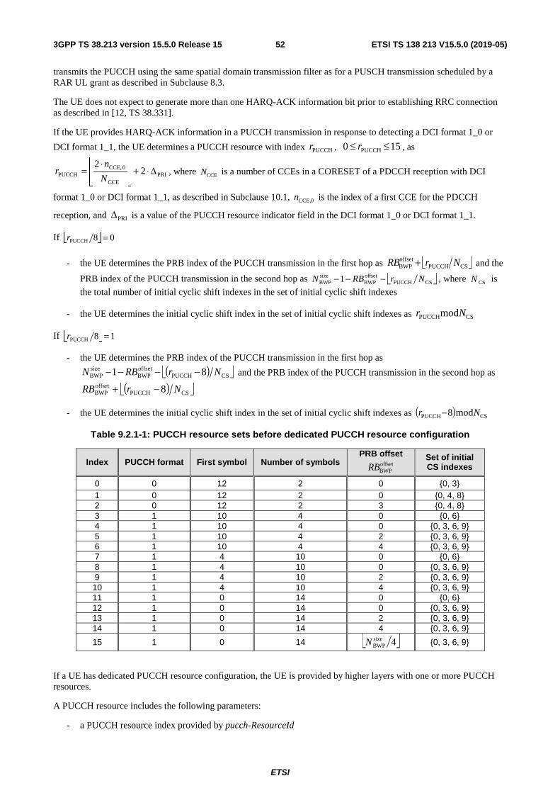
ETSI
ETSI TS 138 213 V15.5.0 (2019-05)523GPP TS 38.213 version 15.5.0 Release 15
transmits the PUCCH using the same spatial domain transmission filter as for a PUSCH transmission scheduled by a RAR UL grant as described in Subclause 8.3.
The UE does not expect to generate more than one HARQ-ACK information bit prior to establishing RRC connection as described in [12, TS 38.331].
If the UE provides HARQ-ACK information in a PUCCH transmission in response to detecting a DCI format 1_0 or
DCI format 1_1, the UE determines a PUCCH resource with index PUCCHr , 150 PUCCH ≤≤ r , as
PRICCE
0CCE,PUCCH 2
2Δ⋅+
⋅=
N
nr , where CCEN is a number of CCEs in a CORESET of a PDCCH reception with DCI
format 1_0 or DCI format 1_1, as described in Subclause 10.1, 0CCE,n is the index of a first CCE for the PDCCH
reception, and PRIΔ is a value of the PUCCH resource indicator field in the DCI format 1_0 or DCI format 1_1.
If 08PUCCH =r
- the UE determines the PRB index of the PUCCH transmission in the first hop as CSPUCCHoffsetBWP NrRB + and the
PRB index of the PUCCH transmission in the second hop as CSPUCCHoffsetBWP
sizeBWP 1 NrRBN −−− , where CSN is
the total number of initial cyclic shift indexes in the set of initial cyclic shift indexes
- the UE determines the initial cyclic shift index in the set of initial cyclic shift indexes as CSPUCCHmodNr
If 18PUCCH =r
- the UE determines the PRB index of the PUCCH transmission in the first hop as
( ) CSPUCCHoffsetBWP
sizeBWP 81 NrRBN −−−− and the PRB index of the PUCCH transmission in the second hop as
( ) CSPUCCHoffsetBWP 8 NrRB −+
- the UE determines the initial cyclic shift index in the set of initial cyclic shift indexes as ( ) CSPUCCH mod8 Nr −
Table 9.2.1-1: PUCCH resource sets before dedicated PUCCH resource configuration
Index PUCCH format First symbol Number of symbols PRB offset
Set of initial CS indexes
0 0 12 2 0 {0, 3} 1 0 12 2 0 {0, 4, 8} 2 0 12 2 3 {0, 4, 8} 3 1 10 4 0 {0, 6} 4 1 10 4 0 {0, 3, 6, 9} 5 1 10 4 2 {0, 3, 6, 9} 6 1 10 4 4 {0, 3, 6, 9} 7 1 4 10 0 {0, 6} 8 1 4 10 0 {0, 3, 6, 9} 9 1 4 10 2 {0, 3, 6, 9} 10 1 4 10 4 {0, 3, 6, 9} 11 1 0 14 0 {0, 6} 12 1 0 14 0 {0, 3, 6, 9} 13 1 0 14 2 {0, 3, 6, 9} 14 1 0 14 4 {0, 3, 6, 9}
15 1 0 14 {0, 3, 6, 9}
If a UE has dedicated PUCCH resource configuration, the UE is provided by higher layers with one or more PUCCH resources.
A PUCCH resource includes the following parameters:
- a PUCCH resource index provided by pucch-ResourceId
offsetBWPRB
4sizeBWPN

ETSI
ETSI TS 138 213 V15.5.0 (2019-05)533GPP TS 38.213 version 15.5.0 Release 15
- an index of the first PRB prior to frequency hopping or for no frequency hopping by startingPRB
- an index of the first PRB after frequency hopping by secondHopPRB;
- an indication for intra-slot frequency hopping by intraSlotFrequencyHopping
- a configuration for a PUCCH format, from PUCCH format 0 through PUCCH format 4, provided by format
If the format indicates PUCCH-format0, the PUCCH format configured for a PUCCH resource is PUCCH format 0, where the PUCCH resource also includes an index for an initial cyclic shift provided by initialCyclicShift, a number of symbols for a PUCCH transmission provided by nrofSymbols, a first symbol for the PUCCH transmission provided by startingSymbolIndex.
If the format indicates PUCCH-format1, the PUCCH format configured for a PUCCH resource is PUCCH format 1, where the PUCCH resource also includes an index for an initial cyclic shift provided by initialCyclicShift, a number of symbols for a PUCCH transmission provided by nrofSymbols, a first symbol for the PUCCH transmission provided by startingSymbolIndex, and an index for an orthogonal cover code by timeDomainOCC.
If the format indicates PUCCH-format2 or PUCCH-format3, the PUCCH format configured for a PUCCH resource is PUCCH format 2 or PUCCH format 3, respectively, where the PUCCH resource also includes a number of PRBs provided by nrofPRBs, a number of symbols for a PUCCH transmission provided by nrofSymbols, and a first symbol for the PUCCH transmission provided by startingSymbolIndex.
If the format indicates PUCCH-format4, the PUCCH format configured for a PUCCH resource is PUCCH format 4, where the PUCCH resource also includes a number of symbols for a PUCCH transmission provided by nrofSymbols, a length for an orthogonal cover code by occ-Length, an index for an orthogonal cover code by occ-Index, and a first symbol for the PUCCH transmission provided by startingSymbolIndex.
A UE can be configured up to four sets of PUCCH resources. A PUCCH resource set is provided by PUCCH-ResourceSet and is associated with a PUCCH resource set index provided by pucch-ResourceSetId, with a set of PUCCH resource indexes provided by resourceList that provides a set of pucch-ResourceId used in the PUCCH resource set, and with a maximum number of UCI information bits the UE can transmit using a PUCCH resource in the PUCCH resource set provided by maxPayloadMinus1. For the first PUCCH resource set, the maximum number of UCI information bits is 2. A maximum number of PUCCH resource indexes for a set of PUCCH resources is provided by maxNrofPUCCH-ResourcesPerSet. The maximum number of PUCCH resources in the first PUCCH resource set is 32 and the maximum number of PUCCH resources in the other PUCCH resource sets is 8.
If the UE transmits UCIO UCI information bits, that include HARQ-ACK information bits, the UE determines a PUCCH
resource set to be
- a first set of PUCCH resources with pucch-ResourceSetId = 0 if 2UCI ≤O including 1 or 2 HARQ-ACK
information bits and a positive or negative SR on one SR transmission occasion if transmission of HARQ-ACK information and SR occurs simultaneously, or
- a second set of PUCCH resources with pucch-ResourceSetId = 1, if provided by higher layers, if 2UCI2 NO ≤<
where 2N is equal to maxPayloadMinus1 if maxPayloadMinus1 is provided for the PUCCH resource set with
pucch-ResourceSetId = 1; otherwise 2N is equal to 1706, or
- a third set of PUCCH resources with pucch-ResourceSetId = 2, if provided by higher layers, if 3UCI2 NON ≤<
where 3N is equal to maxPayloadMinus1 if maxPayloadMinus1 is provided for the PUCCH resource set with
pucch-ResourceSetId = 2; otherwise 3N is equal to 1706, or
- a fourth set of PUCCH resources with pucch-ResourceSetId = 3, if provided by higher layers, if
1706UCI3 ≤< ON .
9.2.2 PUCCH Formats for UCI transmission
If a UE is not transmitting PUSCH, and the UE is transmitting UCI, the UE transmits UCI in a PUCCH using
- PUCCH format 0 if
ETSI
ETSI TS 138 213 V15.5.0 (2019-05)543GPP TS 38.213 version 15.5.0 Release 15
- the transmission is over 1 symbol or 2 symbols,
- the number of HARQ-ACK information bits with positive or negative SR (HARQ-ACK/SR bits) is 1 or 2
- PUCCH format 1 if
- the transmission is over 4 or more symbols,
- the number of HARQ-ACK/SR bits is 1 or 2
- PUCCH format 2 if
- the transmission is over 1 symbol or 2 symbols,
- the number of UCI bits is more than 2
- PUCCH format 3 if
- the transmission is over 4 or more symbols,
- the number of UCI bits is more than 2,
- the PUCCH resource does not include an orthogonal cover code
- PUCCH format 4 if
- the transmission is over 4 or more symbols,
- the number of UCI bits is more than 2,
- the PUCCH resource includes an orthogonal cover code
A spatial setting for a PUCCH transmission is provided by PUCCH-SpatialRelationInfo if the UE is configured with a single value for pucch-SpatialRelationInfoId; otherwise, if the UE is provided multiple values for PUCCH-SpatialRelationInfo, the UE determines a spatial setting for the PUCCH transmission as described in [11, TS 38.321]. The UE applies corresponding actions in [11, TS 38.321] and a corresponding setting for a spatial domain filter to transmit PUCCH 3 msec after the slot where the UE transmits HARQ-ACK information with ACK value corresponding to a PDSCH reception providing the PUCCH-SpatialRelationInfo
- If PUCCH-SpatialRelationInfo provides ssb-Index, the UE transmits the PUCCH using a same spatial domain filter as for a reception of a SS/PBCH block with index provided by ssb-Index for a same serving cell or, if servingCellId is provided, for a serving cell indicated by servingCellId
- else if PUCCH-SpatialRelationInfo provides csi-RS-Index, the UE transmits the PUCCH using a same spatial domain filter as for a reception of a CSI-RS with resource index provided by csi-RS-Index for a same serving cell or, if servingCellId is provided, for a serving cell indicated by servingCellId
- else PUCCH-SpatialRelationInfo provides srs, the UE transmits the PUCCH using a same spatial domain filter as for a transmission of a SRS with resource index provided by resource for a same serving cell and/or active UL BWP or, if servingCellId and/or uplinkBWP are provided, for a serving cell indicated by servingCellId and/or for an UL BWP indicated by uplinkBWP
A number of DMRS symbols for a PUCCH transmission using PUCCH format 3 or 4 is provided by additionalDMRS.
Use of π/2-PBSK, instead of QPSK, for a PUCCH transmission using PUCCH format 3 or 4 is indicated by pi2BPSK.
9.2.3 UE procedure for reporting HARQ-ACK
A UE does not expect to transmit more than one PUCCH with HARQ-ACK information in a slot.
For DCI format 1_0, the PDSCH-to-HARQ-timing-indicator field values map to {1, 2, 3, 4, 5, 6, 7, 8}. For DCI format 1_1, if present, the PDSCH-to-HARQ-timing-indicator field values map to values for a set of number of slots provided by dl-DataToUL-ACK as defined in Table 9.2.3-1.
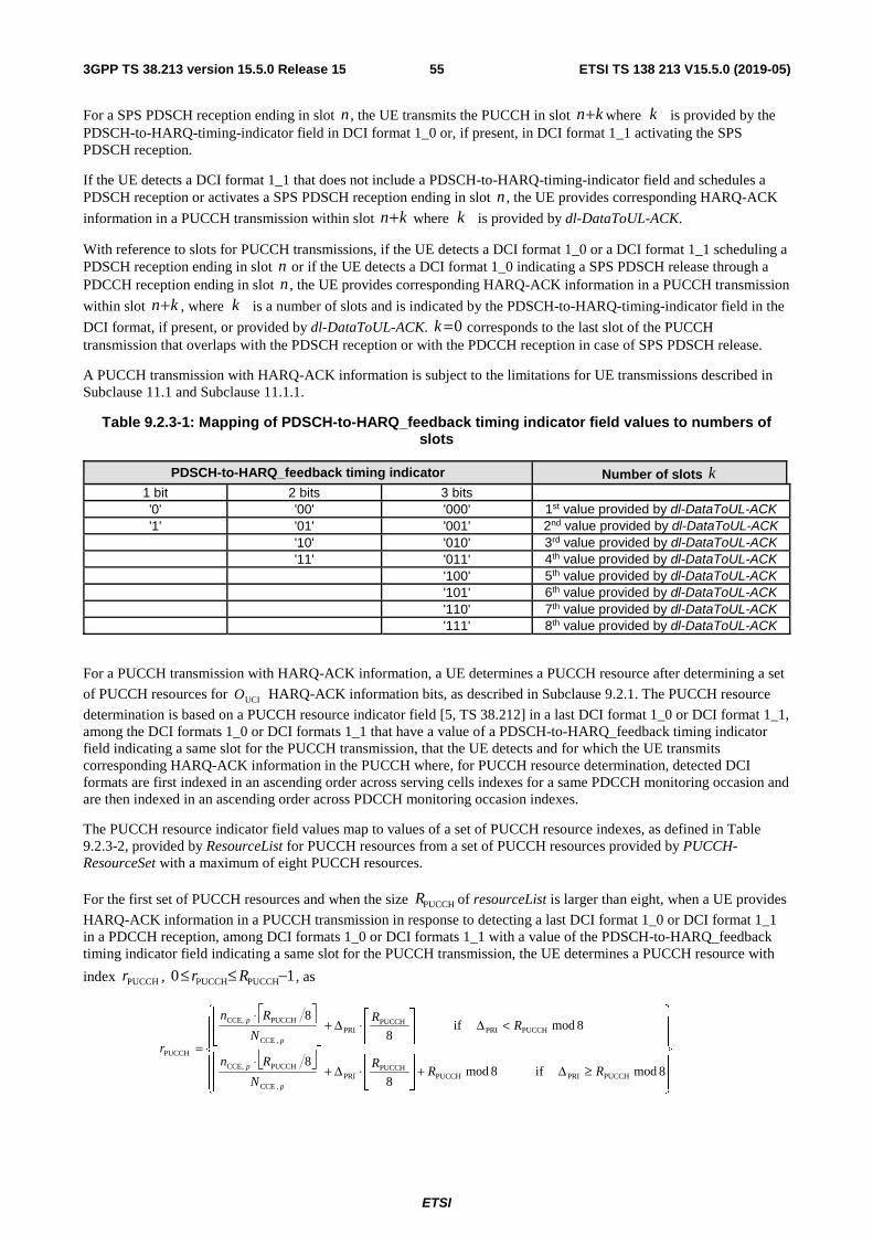
ETSI
ETSI TS 138 213 V15.5.0 (2019-05)553GPP TS 38.213 version 15.5.0 Release 15
For a SPS PDSCH reception ending in slot n , the UE transmits the PUCCH in slot kn+ where k is provided by the PDSCH-to-HARQ-timing-indicator field in DCI format 1_0 or, if present, in DCI format 1_1 activating the SPS PDSCH reception.
If the UE detects a DCI format 1_1 that does not include a PDSCH-to-HARQ-timing-indicator field and schedules a PDSCH reception or activates a SPS PDSCH reception ending in slot n , the UE provides corresponding HARQ-ACK
information in a PUCCH transmission within slot kn+ where k is provided by dl-DataToUL-ACK.
With reference to slots for PUCCH transmissions, if the UE detects a DCI format 1_0 or a DCI format 1_1 scheduling a PDSCH reception ending in slot n or if the UE detects a DCI format 1_0 indicating a SPS PDSCH release through a PDCCH reception ending in slot n , the UE provides corresponding HARQ-ACK information in a PUCCH transmission
within slot kn+ , where k is a number of slots and is indicated by the PDSCH-to-HARQ-timing-indicator field in the
DCI format, if present, or provided by dl-DataToUL-ACK. 0=k corresponds to the last slot of the PUCCH transmission that overlaps with the PDSCH reception or with the PDCCH reception in case of SPS PDSCH release.
A PUCCH transmission with HARQ-ACK information is subject to the limitations for UE transmissions described in Subclause 11.1 and Subclause 11.1.1.
Table 9.2.3-1: Mapping of PDSCH-to-HARQ_feedback timing indicator field values to numbers of slots
PDSCH-to-HARQ_feedback timing indicator Number of slots k 1 bit 2 bits 3 bits '0' '00' '000' 1st value provided by dl-DataToUL-ACK '1' '01' '001' 2nd value provided by dl-DataToUL-ACK '10' '010' 3rd value provided by dl-DataToUL-ACK '11' '011' 4th value provided by dl-DataToUL-ACK '100' 5th value provided by dl-DataToUL-ACK '101' 6th value provided by dl-DataToUL-ACK '110' 7th value provided by dl-DataToUL-ACK '111' 8th value provided by dl-DataToUL-ACK
For a PUCCH transmission with HARQ-ACK information, a UE determines a PUCCH resource after determining a set
of PUCCH resources for UCIO HARQ-ACK information bits, as described in Subclause 9.2.1. The PUCCH resource
determination is based on a PUCCH resource indicator field [5, TS 38.212] in a last DCI format 1_0 or DCI format 1_1, among the DCI formats 1_0 or DCI formats 1_1 that have a value of a PDSCH-to-HARQ_feedback timing indicator field indicating a same slot for the PUCCH transmission, that the UE detects and for which the UE transmits corresponding HARQ-ACK information in the PUCCH where, for PUCCH resource determination, detected DCI formats are first indexed in an ascending order across serving cells indexes for a same PDCCH monitoring occasion and are then indexed in an ascending order across PDCCH monitoring occasion indexes.
The PUCCH resource indicator field values map to values of a set of PUCCH resource indexes, as defined in Table 9.2.3-2, provided by ResourceList for PUCCH resources from a set of PUCCH resources provided by PUCCH-ResourceSet with a maximum of eight PUCCH resources.
For the first set of PUCCH resources and when the size PUCCHR of resourceList is larger than eight, when a UE provides
HARQ-ACK information in a PUCCH transmission in response to detecting a last DCI format 1_0 or DCI format 1_1 in a PDCCH reception, among DCI formats 1_0 or DCI formats 1_1 with a value of the PDSCH-to-HARQ_feedback timing indicator field indicating a same slot for the PUCCH transmission, the UE determines a PUCCH resource with
index PUCCHr , 10 PUCCHPUCCH −≤≤ Rr , as
≥Δ+
⋅Δ+
⋅
<Δ
⋅Δ+
⋅
=
8modif8mod8
8
8modif8
8
PUCCHPRIPUCCHPUCCH
PRI,CCE
PUCCHCCE,
PUCCHPRIPUCCH
PRI,CCE
PUCCHCCE,
PUCCH
RRR
N
Rn
RR
N
Rn
r
p
p
p
p
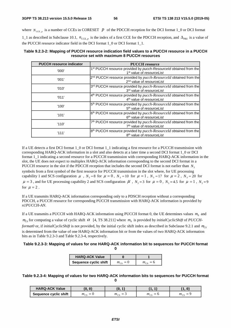
ETSI
ETSI TS 138 213 V15.5.0 (2019-05)563GPP TS 38.213 version 15.5.0 Release 15
where pN ,CCE is a number of CCEs in CORESET p of the PDCCH reception for the DCI format 1_0 or DCI format
1_1 as described in Subclause 10.1, pnCCE, is the index of a first CCE for the PDCCH reception, and PRIΔ is a value of
the PUCCH resource indicator field in the DCI format 1_0 or DCI format 1_1.
Table 9.2.3-2: Mapping of PUCCH resource indication field values to a PUCCH resource in a PUCCH resource set with maximum 8 PUCCH resources
PUCCH resource indicator PUCCH resource
'000' 1st PUCCH resource provided by pucch-ResourceId obtained from the
1st value of resourceList
'001' 2nd PUCCH resource provided by pucch-ResourceId obtained from the 2nd value of resourceList
'010' 3rd PUCCH resource provided by pucch-ResourceId obtained from the 3rd value of resourceList
'011' 4th PUCCH resource provided by pucch-ResourceId obtained from the 4th value of resourceList
'100' 5th PUCCH resource provided by pucch-ResourceId obtained from the 5th value of resourceList
'101' 6th PUCCH resource provided by pucch-ResourceId obtained from the 6th value of resourceList
'110' 7th PUCCH resource provided by pucch-ResourceId obtained from the 7th value of resourceList
'111' 8th PUCCH resource provided by pucch-ResourceId obtained from the 8th value of resourceList
If a UE detects a first DCI format 1_0 or DCI format 1_1 indicating a first resource for a PUCCH transmission with corresponding HARQ-ACK information in a slot and also detects at a later time a second DCI format 1_0 or DCI format 1_1 indicating a second resource for a PUCCH transmission with corresponding HARQ-ACK information in the slot, the UE does not expect to multiplex HARQ-ACK information corresponding to the second DCI format in a PUCCH resource in the slot if the PDCCH reception that includes the second DCI format is not earlier than 3N
symbols from a first symbol of the first resource for PUCCH transmission in the slot where, for UE processing capability 1 and SCS configuration μ , 83 =N for 0=μ , 103 =N for 1=μ , 173 =N for 2=μ , 203 =N for
3=μ , and for UE processing capability 2 and SCS configuration μ , 33 =N for 0=μ , 5.43 =N for 1=μ , 93 =N
for 2=μ .
If a UE transmits HARQ-ACK information corresponding only to a PDSCH reception without a corresponding PDCCH, a PUCCH resource for corresponding PUCCH transmission with HARQ-ACK information is provided by n1PUCCH-AN.
If a UE transmits a PUCCH with HARQ-ACK information using PUCCH format 0, the UE determines values 0m and
CSm for computing a value of cyclic shift α [4, TS 38.211] where 0m is provided by initialCyclicShift of PUCCH-
format0 or, if initialCyclicShift is not provided, by the initial cyclic shift index as described in Subclause 9.2.1 and CSm
is determined from the value of one HARQ-ACK information bit or from the values of two HARQ-ACK information bits as in Table 9.2.3-3 and Table 9.2.3-4, respectively.
Table 9.2.3-3: Mapping of values for one HARQ-ACK information bit to sequences for PUCCH format 0
HARQ-ACK Value 0 1 Sequence cyclic shift 0CS =m 6CS =m
Table 9.2.3-4: Mapping of values for two HARQ-ACK information bits to sequences for PUCCH format 0
HARQ-ACK Value {0, 0} {0, 1} {1, 1} {1, 0} Sequence cyclic shift 0CS =m 3CS =m 6CS =m 9CS =m

ETSI
ETSI TS 138 213 V15.5.0 (2019-05)573GPP TS 38.213 version 15.5.0 Release 15
If a UE transmits a PUCCH with HARQ-ACK information using PUCCH format 1, the UE is provided a value for 0m
by initialCyclicShift of PUCCH-format1.
If a UE transmits a PUCCH with ACKO HARQ-ACK information bits and CRCO bits using PUCCH format 2 or PUCCH
format 3 in a PUCCH resource that includes PUCCHRBM PRBs, the UE determines a number of PRBs PUCCH
minRB,M for the
PUCCH transmission to be the minimum number of PRBs, that is smaller than or equal to a number of PRBs PUCCHRBM
provided respectively by nrofPRBs of PUCCH-format2 or nrofPRBs of PUCCH-format3 and start from the first PRB
from the number of PRBs, that results to ( ) rQNNMOO m ⋅⋅⋅⋅≤+ PUCCHUCI-symb
RBctrlsc,
PUCCHminRB,CRCACK and, if 1PUCCH
RB >M ,
( ) ( ) rQNNMOO m ⋅⋅⋅⋅−>+ PUCCHUCI-symb
RBctrlsc,
PUCCHminRB,CRCACK 1 , where
RBctrlsc,N , PUCCH
UCI-symbN , mQ , and r are defined in Subclause
9.2.5.2. If ( ) ( ) rQNNMOO m ⋅⋅⋅⋅−>+ PUCCHUCI-symb
RBctrlsc,
PUCCHRBCRCACK 1 , the UE transmits the PUCCH over PUCCH
RBM PRBs.
9.2.4 UE procedure for reporting SR
A UE is configured by higher layer paremater SchedulingRequestResourceConfig a set of configurations for SR in a PUCCH transmission using either PUCCH format 0 or PUCCH format 1.
The UE is configured a PUCCH resource by SchedulingRequestResourceId providing a PUCCH format 0 resource or a PUCCH format 1 resource as described in Subclause 9.2.1. The UE is also configured a periodicity YPERIODICITSR in
symbols or slots and an offset OFFSETSR in slots by periodicityAndOffset for a PUCCH transmission conveying SR. If
YPERIODICITSR is larger than one slot, the UE determines a SR transmission occasion in a PUCCH to be in a slot with
number μs,fn [4, TS 38.211] in a frame with number fn if ( ) 0mod YPERIODICITOFFSET
frame,slot =−+⋅ SRSRnNn s,ff
μμ .
If YPERIODICITSR is one slot, the UE expects that 0OFFSET =SR and every slot is a SR transmission occasion in a PUCCH.
If YPERIODICITSR is smaller than one slot, the UE determines a SR transmission occasion in a PUCCH to start in a symbol
with index l [4, TS 38.211] if ( ) 0modmod YPERIODICITYPERIODICIT0 =− SRSRll where 0l is the value of
startingSymbolIndex.
If the UE determines that, for a SR transmission occasion in a PUCCH, the number of symbols available for the PUCCH transmission in a slot is smaller than the value provided by nrofSymbols, the UE does not transmit the PUCCH in the slot.
SR transmission occasions in a PUCCH are subject to the limitations for UE transmissions described in Subclause 11.1 and Subclause 11.1.1.
The UE transmits a PUCCH in the PUCCH resource for the corresponding SR configuration only when the UE transmits a positive SR. For a positive SR transmission using PUCCH format 0, the UE transmits the PUCCH as described in [4, TS 38.211] by obtaining 0m as described for HARQ-ACK information in Subclause 9.2.3 and by
setting 0cs =m . For a positive SR transmission using PUCCH format 1, the UE transmits the PUCCH as described in [4,
TS 38.211] by setting 0)0( =b .
9.2.5 UE procedure for reporting multiple UCI types
This Subclause is applicable to the case that a UE has overlapping resources for PUCCH transmissions or for PUCCH and PUSCH transmissions and each PUCCH transmission is over a single slot without repetition. Any case that a PUCCH transmission is with repetitions over multiple slots is described in Subclause 9.2.6. If a UE is configured with multiple PUCCH resources in a slot to transmit CSI reports
- if the UE is not provided multi-CSI-PUCCH-ResourceList or if PUCCH resources for transmissions of CSI reports do not overlap in the slot, the UE determines a first resource corresponding to a CSI report with the highest priority [6, TS 38.214]
- if the first resource includes PUCCH format 2, and if there are remaining resources in the slot that do not overlap with the first resource, the UE determines a CSI report with the highest priority, among the CSI reports with corresponding resources from the remaining resources, and a corresponding second resource as an additional resource for CSI reporting

ETSI
ETSI TS 138 213 V15.5.0 (2019-05)583GPP TS 38.213 version 15.5.0 Release 15
- if the first resource includes PUCCH format 3 or PUCCH format 4, and if there are remaining resources in the slot that include PUCCH format 2 and do not overlap with the first resource, the UE determines a CSI report with the highest priority, among the CSI reports with corresponding resources from the remaining resources, and a corresponding second resource as an additional resource for CSI reporting
- if the UE is provided multi-CSI-PUCCH-ResourceList and if any of the multiple PUCCH resources overlap, the UE multiplexes all CSI reports in a resource from the resources provided by multi-CSI-PUCCH-ResourceList, as described in Subclause 9.2.5.2.
A UE multiplexes HARQ-ACK information, with or without SR, and CSI resport(s) in a same PUCCH if the UE is provided simultaneousHARQ-ACK-CSI; otherwise, the UE drops the CSI report(s) and includes only HARQ-ACK information, with or without SR, in the PUCCH. If the UE would transmit multiple PUCCHs in a slot that include HARQ-ACK information and CSI report(s), the UE expects to be provided a same configuration for simultaneousHARQ-ACK-CSI each of PUCCH formats 2, 3, and 4.
If a UE would multiplex CSI reports that include Part 2 CSI reports in a PUCCH resource, the UE determines the PUCCH resource and a number of PRBs for the PUCCH resource or a number of Part 2 CSI reports assuming that each of the CSI reports indicates rank 1.
If a UE would transmit multiple overlapping PUCCHs in a slot or overlapping PUCCH(s) and PUSCH(s) in a slot and, when applicable as described in Subclauses 9.2.5.1 and 9.2.5.2, the UE is configured to multiplex different UCI types in one PUCCH, and at least one of the multiple overlapping PUCCHs or PUSCHs is in response to a DCI format detection by the UE, the UE multiplexes all corresponding UCI types if the following conditions are met. If one of the PUCCH transmissions or PUSCH transmissions is in response to a DCI format detection by the UE, the UE expects that the first symbol 0S of the earliest PUCCH or PUSCH, among a group overlapping PUCCHs and PUSCHs in the slot, satisfies
the following timeline conditions
- 0S is not before a symbol with CP starting after ( ) ( ) CTdNT ⋅⋅⋅+⋅++= −μκ 2144204811,11mux
proc,1 after a last
symbol of any corresponding PDSCH, where μ corresponds to the smallest SCS configuration among the SCS
configuration of the PDCCH scheduling the PDSCH, the SCS configuration of the PDSCH, and the smallest SCS configuration for the group of overlapping PUCCHs and PUSCHs where the UE transmits HARQ-ACK information in response to the reception of the PDSCH
- 0S is not before a symbol with CP starting after ( ) ( ) CTNT ⋅⋅⋅+⋅+= −μκ 214420481muxreleaseproc, after a last symbol
of any corresponding SPS PDSCH release, where N is described in Subclause 10.2 and μ corresponds to the
smallest SCS configuration among the SCS configuration of the PDCCH providing the SPS PDSCH release and the smallest SCS configuration for the group of overlapping PUCCHs or overlapping PUCCHs and PUSCHs where the UE transmits HARQ-ACK information in response to the detection of the SPS PDSCH release
- if there is no aperiodic CSI report multiplexed in a PUSCH in the group of overlapping PUCCHs and PUSCHs,
0S is not before a symbol with CP starting after ( ) ( )( )2,21,22mux
proc,2 ,214420481max dTdNT C⋅⋅⋅+⋅++= −μκ
after a last symbol of
- a PDCCH with the DCI format scheduling the PUSCH, and
- any PDCCH scheduling a PDSCH or SPS PDSCH release with corresponding HARQ-ACK information in an overlapping PUCCH in the slot
where μ corresponds to the smallest SCS configuration among the SCS configuration of the PDCCHs and the
smallest SCS of the overlapping PUCCHs and PUSCHs, and 02,21,2 == dd if there is no overlapping PUSCH
- if there is an aperiodic CSI report multiplexed in a PUSCH in the group of overlapping PUCCHs and PUSCHs,
0S is not before a symbol with CP starting after ( ) ( )( )2,2mux
CSIproc, ,21442048max dTdZT C⋅⋅⋅+⋅+= −μκ after a
last symbol of
- a PDCCH with the DCI format scheduling the PUSCH, and
- any PDCCH scheduling a PDSCH or SPS PDSCH release with corresponding HARQ-ACK information in an overlapping PUCCH in the slot
ETSI
ETSI TS 138 213 V15.5.0 (2019-05)593GPP TS 38.213 version 15.5.0 Release 15
where μ corresponds to the smallest SCS configuration among the SCS configuration of the PDCCHs, the
smallest SCS configuration for the group of the overlapping PUCCHs and PUSCHs, and the smallest SCS
configuration of aperiodic CSI-RS associated with the DCI format scheduling the PUSCH, and 2=d for
1,0=μ , 3=d for 2=μ and 4=d for 3=μ
- 1N , 2N , 1,1d , 1,2d , 2,2d , and Z are defined in [6, TS 38.214], and κ and CT are defined in [4, TS 38.211].
If a UE would transmit multiple overlapping PUCCHs in a slot or overlapping PUCCH(s) and PUSCH(s) in a slot, one of the PUCCHs includes HARQ-ACK information in response to an SPS PDSCH reception, and any PUSCH is not in response to a DCI format detection, the UE expects that the first symbol 0S of the earliest PUCCH or PUSCH satisfies
the first of the previous timeline conditions with the exception that components associated to a SCS configuration for a PDCCH scheduling a PDSCH or a PUSCH are absent from the timeline conditions.
A UE does not expect a PUCCH or a PUSCH that is in response to a DCI format detection to overlap with any other PUCCH or PUSCH that does not satisfy the above timing conditions.
If there is one or more aperiodic CSI reports multiplexed on PUSCHs in the group of overlapping PUCCHs and PUSCHs and if symbol 0S is before symbol mux
refZ' that is a next uplink symbol with CP starting after
( ) ( ) CTdZZ' ⋅⋅⋅+⋅+= −μκ 21442048'muxCSIproc, after the end of the last symbol of
- the last symbol of aperiodic CSI-RS resource for channel measurements, and
- the last symbol of aperiodic CSI-IM used for interference measurements, and
- the last symbol of aperiodic NZP CSI-RS for interference measurements, when aperiodic CSI-RS is used for channel measurement for triggered CSI report n
the UE is not required to update the CSI report for the triggered CSI report n . Z' is defined in [6, TS 38.214] and μ
corresponds to the smallest SCS configuration among the SCS configurations of the PDCCHs scheduling the PUSCHs, the smallest SCS configuration of aperiodic CSI-RSs associated with DCI formats provided by the PDCCHs triggering
the aperiodic CSI reports, and the smallest SCS configuration of the overlapping PUCCHs and PUSCHs and 2=d for 1,0=μ , 3=d for 2=μ and 4=d for 3=μ .
If a UE would transmit multiple PUCCHs in a slot that include HARQ-ACK information, SR, and CSI reports and any PUCCH with HARQ-ACK information in the slot satisfies the above timing conditions and does not overlap with any other PUCCH or PUSCH in the slot that does not satisfy the above timing conditions, the UE multiplexes HARQ-ACK information, SR, and CSI reports and determines corresponding PUCCH(s) for transmission in the slot according to the following pseudo-code. If the multiple PUCCHs do not include HARQ-ACK information and do not overlap with any PUSCH transmission by the UE in response to a DCI format detection by the UE, the timing conditions do not apply.
If
- a UE is not provided multi-CSI-PUCCH-ResourceList, and
- a resource for a PUCCH transmission with HARQ-ACK information in response to SPS PDSCH reception and/or a resource for a PUCCH associated with a SR occasion overlap in time with two resources for respective PUCCH transmissions with two CSI reports, and
- there is no resource for a PUCCH transmission with HARQ-ACK information in response to a DCI format detection that overlaps in time with any of the previous resources, and
- the following pseudo code results to the UE attempting to determine a single PUCCH resource from the HARQ-ACK and/or the SR resource and the two PUCCH resources with CSI reports
the UE
- multiplexes the HARQ-ACK information and/or the SR in the resource for the PUCCH transmission with the CSI report having the higher priority, and
- does not transmit the PUCCH with the CSI report having the lower priority
Set Q to the set of resources for transmission of corresponding PUCCHs in a single slot without repetitions where
ETSI
ETSI TS 138 213 V15.5.0 (2019-05)603GPP TS 38.213 version 15.5.0 Release 15
- a resource with earlier first symbol is placed before a resource with later first symbol
- for two resources with same first symbol, the resource with longer duration is placed before the resource with shorter duration
- for two resources with same first symbol and same duration, the placement is arbitrary
- the above three steps for the set Q are according to a subsequent pseudo-code for a function ( )Qorder
- a resource for negative SR transmission that does not overlap with a resource for HARQ-ACK or CSI transmission is excluded from set Q
- if the UE is not provided simultaneousHARQ-ACK-CSI and resources for transmission of HARQ-ACK information include PUCCH format 0 or PUCCH format 2, resources that include PUCCH format 2, or PUCCH format 3, or PUCCH format 4 for transmission of CSI reports are excluded from the set Q if they overlap with
any resource from the resources for transmission of HARQ-ACK information
- if the UE is not provided simultaneousHARQ-ACK-CSI and at least one of the resources for transmission of HARQ-ACK information includes PUCCH format 1, PUCCH format 3, or PUCCH format 4
- resources that include PUCCH format 3 or PUCCH format 4 for transmission of CSI reports are excluded from the set Q
- resources that include PUCCH format 2 for transmission of CSI reports are excluded from the set Q if they
overlap with any resource from the resources for transmission of HARQ-ACK information
Set ( )QC to the cardinality of Q
Set )0,( jQ to be the first symbol of resource )( jQ in the slot
Set ( ))( jQL to be the number of symbols of resource )( jQ in the slot
Set 0=j - index of first resource in set Q
Set 0=o - counter of overlapped resources
while ( ) 1−≤ Qj C
if ( ) 1−< Qj C and resource )( ojQ − overlaps with resource )1( +jQ
1+=oo
1+= jj
else
if 0>o
determine a single resource for multiplexing UCI associated with resources { })(),...,1(),( jQojQojQ +−− as
described in Subclauses 9.2.5.1 and 9.2.5.2
set the index of the single resource to
{ })1(),...,1(),(\ −+−−= jQojQojQQQ
0=j % start from the beginning after reordering unmerged resources at next step
0=o
( )Qorder % function that re-orders resources in current set Q
j
ETSI
ETSI TS 138 213 V15.5.0 (2019-05)613GPP TS 38.213 version 15.5.0 Release 15
Set ( )QC to the cardinality of Q
else
1+= jj
end if
end if
end while
The function ( )Qorder performs the following pseudo-code
{
0=k
while ( ) 1−< Qk C % the next two while loops are to re-order the unmerged resources
0=l
while ( ) kQl −−< 1C
if )0,1()0,( +> lQlQ OR ( ) ( )( ))1()( & )0,1()0,( +<+= lQLlQLlQlQ
)(temp lQ=
)1()( += lQlQ
temp)1( =+lQ
end if
1+=ll
end while
1+=kk
end while
}
For each PUCCH resource in the set Q that satisfies the aforementioned timing conditions, when applicable,
- the UE transmits a PUCCH using the PUCCH resource if the PUCCH resource does not overlap in time with a PUSCH transmission after multiplexing UCI following the procedures described in Subclauses 9.2.5.1 and 9.2.5.2
- the UE multiplexes HARQ-ACK information and/or CSI reports in a PUSCH if the PUCCH resource overlaps in time with a PUSCH transmission, as described in Subclause 9.3, and does not transmit SR. In case the PUCCH resource overlaps in time with multiple PUSCH transmissions, the PUSCH for multiplexing HARQ-ACK information and/or CSI is selected as described in Subclause 9. If the PUSCH transmission by the UE is not in response to a DCI format detection and the UE multiplexes only CSI reports, the timing conditions are not applicable
- the UE does not expect the resource to overlap with a second resource of a PUCCH transmission over multiple slots if the resource is obtained from a group of resources that do not overlap with the second resource.
Subclauses 9.2.5.1 and 9.2.5.2 assume the following
- resources for transmissions of UCI types, prior to multiplexing or dropping, overlap in a slot
ETSI
ETSI TS 138 213 V15.5.0 (2019-05)623GPP TS 38.213 version 15.5.0 Release 15
- multiplexing conditions of corresponding UCI types in a single PUCCH are satisfied, and
- the UE does not transmit any time-overlapping PUSCH in a same frequency band in the slot.
9.2.5.1 UE procedure for multiplexing HARQ-ACK or CSI and SR in a PUCCH
In the following, a UE is configured to transmit K PUCCHs for respective K SRs in a slot, as determined by a set of schedulingRequestResourceId, with SR transmission occasions that would overlap with a transmission of a PUCCH with HARQ-ACK information from the UE in the slot or with a transmission of a PUCCH with CSI report(s) from the UE in the slot.
If a UE would transmit a PUCCH with positive SR and at most two HARQ-ACK information bits in a resource using PUCCH format 0, the UE transmits the PUCCH in the resource using PUCCH format 0 in PRB(s) for HARQ-ACK information as described in Subclause 9.2.3. The UE determines a value of 0m and CSm for computing a value of
cyclic shift α [4, TS 38.211] where 0m is provided by initialcyclicshift of PUCCH-format0, and CSm is determined
from the value of one HARQ-ACK information bit or from the values of two HARQ-ACK information bits as in Table 9.2.5-1 and Table 9.2.5-2, respectively.
If the UE would transmit negative SR and a PUCCH with at most two HARQ-ACK information bits in a resource using PUCCH format 0, the UE transmits the PUCCH in the resource using PUCCH format 0 for HARQ-ACK information as described in Subclause 9.2.3.
Table 9.2.5-1: Mapping of values for one HARQ-ACK information bit and positive SR to sequences for PUCCH format 0
HARQ-ACK Value 0 1 Sequence cyclic shift 3CS =m 9CS =m
Table 9.2.5-2: Mapping of values for two HARQ-ACK information bits and positive SR to sequences for PUCCH format 0
HARQ-ACK Value {0, 0} {0, 1} {1, 1} {1, 0} Sequence cyclic shift 1CS =m 4CS =m 7CS =m 10CS =m
If a UE would transmit positive or negative SR in a resource using PUCCH format 0 and HARQ-ACK information bits in a resource using PUCCH format 1 in a slot, the UE transmits only a PUCCH with the HARQ-ACK information bits in the resource using PUCCH format 1.
If the UE would transmit positive SR in a first resource using PUCCH format 1 and at most two HARQ-ACK information bits in a second resource using PUCCH format 1 in a slot, the UE transmits a PUCCH with HARQ-ACK information bits in the first resource using PUCCH format 1 as described in Subclause 9.2.3. If a UE would transmit negative SR in a resource using PUCCH format 1 and at most two HARQ-ACK information bits in a resource using PUCCH format 1 in a slot, the UE transmits a PUCCH in the resource using PUCCH format 1 for HARQ-ACK information as described in Subclause 9.2.3.
If a UE would transmit a PUCCH with ACKO HARQ-ACK information bits in a resource using PUCCH format 2 or
PUCCH format 3 or PUCCH format 4 in a slot, as described in Subclause 9.2.3, ( ) 1log 2 +K bits representing a
negative or positive SR, in ascending order of the values of schedulingRequestResourceId, are appended to the HARQ-
ACK information bits and the UE transmits the combined ( ) 1log2ACKUCI ++= KOO UCI bits in a PUCCH using a
resource with PUCCH format 2 or PUCCH format 3 or PUCCH format 4 that the UE determines as described in Subclauses 9.2.1 and 9.2.3. An all-zero value for the ( ) 1log 2 +K bits represents a negative SR value across all K
SRs.
If a UE would transmit a PUCCH with CSIO CSI report bits in a resource using PUCCH format 2 or PUCCH format 3 or
PUCCH format 4 in a slot, ( ) 1log 2 +K bits representing corresponding negative or positive SR, in ascending order of
the values of schedulingRequestResourceId, are prepended to the CSI information bits as described in Subclause 9.2.5.2
and the UE transmits a PUCCH with the combined ( ) CSI2UCI 1log OKO ++= UCI bits in a resource using the PUCCH
ETSI
ETSI TS 138 213 V15.5.0 (2019-05)633GPP TS 38.213 version 15.5.0 Release 15
format 2 or PUCCH format 3 or PUCCH format 4 for CSI reporting. An all-zero value for the ( ) 1log2 +K bits
represents a negative SR value across all K SRs.
If a UE transmits a PUCCH with ACKO HARQ-ACK information bits, ( ) 1log2SR += KO SR bits, and CRCO CRC bits
using PUCCH format 2 or PUCCH format 3 in a PUCCH resource that includes PUCCHRBM PRBs, the UE determines a
number of PRBs PUCCHminRB,M for the PUCCH transmission to be the minimum number of PRBs, that is smaller than or
equal to a number of PRBs provided respectively by nrofPRBs in PUCCH-format2 or nrofPRBs in PUCCH-format3 and starts from the first PRB from the number of PRBs, that results to
( ) rQNNMOOO m ⋅⋅⋅⋅≤++ PUCCHUCI-symb
RBctrlsc,
PUCCHminRB,CRCSRACK and, if 1PUCCH
RB >M ,
( ) ( ) rQNNMOOO m ⋅⋅⋅⋅−>++ PUCCHUCI-symb
RBctrlsc,
PUCCHminRB,CRCSRACK 1 , where RB
ctrlsc,N , PUCCHUCI-symbN , mQ , and r are defined in
Subclause 9.2.5.2. If ( ) ( ) rQNNMOOO m ⋅⋅⋅⋅−>++ PUCCHUCI-symb
RBctrlsc,
PUCCHRBCRCSRACK 1 , the UE transmits the PUCCH over the
PUCCHRBM PRBs.
9.2.5.2 UE procedure for multiplexing HARQ-ACK/SR/CSI in a PUCCH
For a transmission occasion of a single CSI report, a PUCCH resource is provided by pucch-CSI-ResourceList. For a transmission occasion of multiple CSI reports, corresponding PUCCH resources can be provided by multi-CSI-PUCCH-ResourceList.
If a UE is provided only one PUCCH resource set for transmission of HARQ-ACK information in response to PDSCH reception scheduled by a DCI format or in response to a SPS PDSCH release, the UE does not expect to be provided simultaneousHARQ-ACK-CSI.
A UE is configured by maxCodeRate a code rate for multiplexing HARQ-ACK, SR, and CSI report(s) in a PUCCH transmission using PUCCH format 2, PUCCH format 3, or PUCCH format 4.
If a UE transmits CSI reports using PUCCH format 2, the UE transmits only wideband CSI for each CSI report [6, TS 38.214]. In the following, a Part 1 CSI report refers either to a CSI report with only wideband CSI or to a Part 1 CSI report with wideband CSI and sub-band CSI.
Denote as
- ACKO a total number of HARQ-ACK information bits, if any
- SRO a total number of SR bits. 0SR =O if there is no scheduling request bit; otherwise, ( ) 1log2SR += KO as
described in Subclause 9.2.5.1
- ( )=
+=totalCSI
1,part2-CSI,part1-CSICSI
N
nnn OOO , where nO ,part1-CSI is a number of Part 1 CSI report bits for CSI report with
priority value n , nO ,part2-CSI is a number of Part 2 CSI report bits, if any, for CSI report with priority value n
[6, TS 38.214], and totalCSIN is a number of CSI reports that include overlapping CSI reports
- part2-CSICRC,part1-CSICRC,CRC OOO += , where part1-CSICRC,O is a number of CRC bits, if any, for encoding HARQ-
ACK, SR and Part 1 CSI report bits and part2-CSICRC,O is a number of CRC bits, if any, for encoding Part 2 CSI
report bits
In the following
- r is a code rate given by maxCodeRate as in Table 9.2.5.2-1.
- PUCCHRBM is a number of PRBs for PUCCH format 2, or PUCCH format 3, or PUCCH format 4, respectively,
where PUCCHRBM is provided by nrofPRBs in PUCCH-format2 for PUCCH format 2 or by nrofPRBs in PUCCH-
format3 for PUCCH format 3, and 1PUCCHRB =M for PUCCH format 4

ETSI
ETSI TS 138 213 V15.5.0 (2019-05)643GPP TS 38.213 version 15.5.0 Release 15
- 4RBsc
RBsc,ctrl −= NN for PUCCH format 2, RB
scRB
ctrlsc, NN = for PUCCH format 3, and PUCCH,4SF
RBsc
RBctrlsc, NNN = for
PUCCH format 4, where RBscN is a number of subcarriers per resource block [4, TS 38.211]
- PUCCHUCI-symbN is equal to a number of PUCCH symbols PUCCH,2
symbN for PUCCH format 2 provided by nrofSymbols in
PUCCH-format2. For PUCCH format 3 or for PUCCH format 4, PUCCHUCI-symbN is equal to a number of PUCCH
symbols PUCCH,3symbN for PUCCH format 3 or equal to a number of PUCCH symbols PUCCH,4
symbN for PUCCH format
4 provided by nrofSymbols in PUCCH-format3 or nrofSymbols in PUCCH-format4, respectively, after excluding a number of symbols used for DM-RS transmission for PUCCH format 3 or for PUCCH format 4, respectively [4, TS 38.211]
- 1=mQ if pi/2-BPSK is the modulation scheme and 2=mQ if QPSK is the modulation scheme as indicated by
pi2BPSK for PUCCH format 3 or PUCCH format 4. For PUCCH format 2, 2=mQ
If a UE has one or more CSI reports and zero or more HARQ-ACK/SR information bits to transmit in a PUCCH where the HARQ-ACK, if any, is in response to a PDSCH reception without a corresponding PDCCH
- if any of the CSI reports are overlapping and the UE is provided by multi-CSI-PUCCH-ResourceList with 2≤J PUCCH resources in a slot, for PUCCH format 2 and/or PUCCH format 3 and/or PUCCH format 4, as described in Subclause 9.2.1, where the resources are indexed according to an ascending order for the product of a number of corresponding REs, modulation order mQ , and configured code rate r ;
- if ( ) ( )0
PUCCHUCI-symb
RBctrlsc,
PUCCHRBCRCCSISRACK rQNNMOOOO m ⋅⋅⋅⋅≤+++ , the UE uses PUCCH format 2 resource
0 , or the PUCCH format 3 resource 0 , or the PUCCH format 4 resource 0
- else if ( ) ( )jm rQNNMOOOO ⋅⋅⋅⋅>+++ PUCCH
UCI-symbRB
ctrlsc,PUCCHRBCRCCSISRACK and
( ) ( )1
PUCCHUCI-symb
RBctrlsc,
PUCCHRBCRCCSISRACK +
⋅⋅⋅⋅≤+++jm rQNNMOOOO , 10 −<≤ Jj , the UE transmits a
PUCCH conveying HARQ-ACK information, SR and CSI report(s) in a respective PUCCH where the UE uses the PUCCH format 2 resource 1+j , or the PUCCH format 3 resource 1+j , or the PUCCH format
4 resource 1+j
- else the UE uses the PUCCH format 2 resource 1−J , or the PUCCH format 3 resource 1−J , or the PUCCH
format 4 resource 1−J and the UE selects reportedCSIN CSI report(s) for transmission together with HARQ-
ACK information and SR, when any, in ascending priority value as described in [6, TS 38.214]
- else, the UE transmits the CRCCSISRACK OOOO +++ bits in a PUCCH resource provided by pucch-CSI-
ResourceList and determined as described in Subclause 9.2.5
If a UE has HARQ-ACK, SR and wideband or sub-band CSI reports to transmit and the UE determines a PUCCH resource with PUCCH format 2, or the UE has HARQ-ACK, SR and wideband CSI reports [6, TS 38.214] to transmit and the UE determines a PUCCH resource with PUCCH format 3 or PUCCH format 4, where
- the UE determines the PUCCH resource using the PUCCH resource indicator field [5, TS 38.212] in a last DCI format 1_0 or DCI format 1_1, from DCI formats 1_0 or DCI formats 1_1 that have a value of a PDSCH-to-HARQ_feedback timing indicator field indicating a same slot for the PUCCH transmission, from a PUCCH resource set provided to the UE for HARQ-ACK transmission, and
- the UE determines the PUCCH resource set as described in Subclause 9.2.1 and Subclause 9.2.3 for UCIO UCI
bits
and
- if ( ) rQNNMOOOO m ⋅⋅⋅⋅≤+++ −PUCCH
UCI-symbRB
ctrlsc,PUCCHRBpart1-CSICRC,part1CSISRACK , the UE transmits the HARQ-ACK,
SR, and CSI reports bits by selecting the minimum number PUCCHminRB,M of the PUCCH
RBM PRBs satisfying

ETSI
ETSI TS 138 213 V15.5.0 (2019-05)653GPP TS 38.213 version 15.5.0 Release 15
( ) rQNNMOOOO m ⋅⋅⋅⋅≤+++ PUCCHUCI-symb
RBctrlsc,
PUCCHminRB,part1-CSICRC,part1-CSISRACK as described in Subclauses 9.2.3 and
9.2.5.1;
- else, the UE selects reportedCSIN CSI report(s), from the
totalCSIN CSI reports, for transmission together with HARQ-
ACK and SR in ascending priority value [6, TS 38.214], where the value of reportedCSIN satisfies
rQNNMOOOO mN
N
nn ⋅⋅⋅⋅≤
+++
=
PUCCHUCI-symb
RBctrlsc,
PUCCHRBpart1,-CSICRC,
1,part1-CSISRACK
reported
CSI
and
rQNNMOOOO mN
N
nn ⋅⋅⋅⋅>
+++ +
+
=
PUCCHUCI-symb
RBctrlsc,
PUCCHRB1part1,-CSICRC,
1
1,part1-CSISRACK
reported
CSI
, where NO part1,-CSICRC, is a
number of CRC bits corresponding to =
++reported
CSI
1,part1-CSISRACK
N
nnOOO UCI bits, and 1part1,-CSICRC, +NO is a number
of CRC bits corresponding to +
=++
1
1,part1-CSISRACK
reported
CSIN
nnOOO UCI bits.
If a UE has HARQ-ACK, SR and sub-band CSI reports to transmit and the UE determines a PUCCH resource with PUCCH format 3 or PUCCH format 4, where
- the UE determines the PUCCH resource using the PUCCH resource indicator field [5, TS 38.212] in a last DCI format 1_0 or DCI format 1_1, from DCI formats 1_0 or DCI formats 1_1 that have a value of a PDSCH-to-HARQ_feedback timing indicator field indicating a same slot for the PUCCH transmission, from a PUCCH resource set provided to the UE for HARQ-ACK transmission, and
- the UE determines the PUCCH resource set as described in Subclause 9.2.1 and Subclause 9.2.3 for UCIO UCI
bits
and
- if , the UE transmits the HARQ-ACK, SR and the
totalCSIN CSI report bits by selecting the minimum number PUCCH
minRB,M of PRBs from the PUCCHRBM PRBs satisfying
( ) rQNNMOOOO m ⋅⋅⋅⋅≤+++ PUCCHUCI-symb
RBctrlsc,
PUCCHminRB,CRCCSISRACK as described in Subclauses 9.2.3 and 9.2.5.1
- else,
- if for 0reportedpart2-CSI >N Part 2 CSI report priority value(s), it is
( ) rQrQOOOONNMOO mm
N
nnN
N
nn ⋅⋅
⋅
+++−⋅⋅≤+
==part1-CSICRC,
1,part1-CSISRACK
PUCCHUCI-symb
RBctrlsc,
PUCCHRBpart2,-CSICRC,
1,part2-CSI
totalCSI
reportedpart2-CSI
and
( ) rQrQOOOONNMOO mm
N
nn
N
nn ⋅⋅
⋅
+++−⋅⋅>+
=+
+
=part1-CSICRC,
1,part1-CSISRACK
PUCCHUCI-symb
RBctrlsc,
PUCCHRB1Npart2,-CSICRC,
1
1,part2-CSI
totalCSI
reportedpart2-CSI
,
the UE selects the first reportedpart2-CSIN Part 2 CSI reports, according to respective priority value(s) [6, TS 38.214],
for transmission together with the HARQ-ACK, SR and totalCSIN Part 1 CSI reports , where nO ,part1-CSI is the
number of Part 1 CSI report bits for the thn CSI report and nO ,part2-CSI is the number of Part 2 CSI report bits
( ) rQNNMOOOO m ⋅⋅⋅⋅≤+++ PUCCHUCI-symb
RBctrlsc,
PUCCHRBCRCCSISRACK
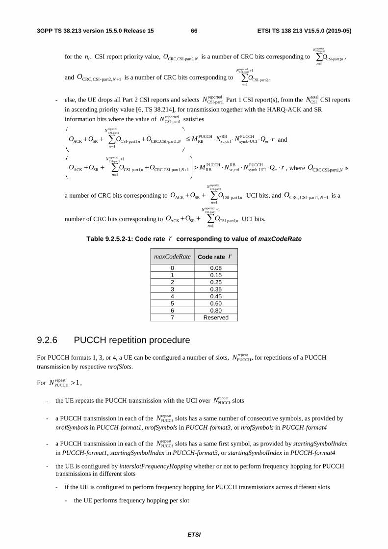
ETSI
ETSI TS 138 213 V15.5.0 (2019-05)663GPP TS 38.213 version 15.5.0 Release 15
for the thn CSI report priority value, NO part2,-CSICRC, is a number of CRC bits corresponding to =
reportedpart2-CSI
1,part2-CSI
N
nnO ,
and 1part2,-CSICRC, +NO is a number of CRC bits corresponding to +
=
1
1,part2-CSI
reportedpart2-CSIN
nnO
- else, the UE drops all Part 2 CSI reports and selects reportedpart1-CSIN Part 1 CSI report(s), from the total
CSIN CSI reports
in ascending priority value [6, TS 38.214], for transmission together with the HARQ-ACK and SR
information bits where the value of reportedpart1-CSIN satisfies
rQNNMOOOO mN
N
nn ⋅⋅⋅⋅≤
+++
=
PUCCHUCI-symb
RBctrlsc,
PUCCHRBpart1,-CSICRC,
1,part1-CSISRACK
reported
part1-CSI
and
rQNNMOOOO mN
N
nn ⋅⋅⋅⋅>
+++ +
+
=
PUCCHUCI-symb
RBctrlsc,
PUCCHRB1part1,-CSICRC,
1
1,part1-CSISRACK
reported
part1-CSI
, where NO part1,-CSICRC, is
a number of CRC bits corresponding to =
++reported
part1-CSI
1,part1-CSISRACK
N
nnOOO UCI bits, and 1part1,-CSICRC, +NO is a
number of CRC bits corresponding to +
=++
1
1,part1-CSISRACK
reportedpart1-CSI
N
nnOOO UCI bits.
Table 9.2.5.2-1: Code rate r corresponding to value of maxCodeRate
maxCodeRate Code rate r
0 0.08 1 0.15 2 0.25 3 0.35 4 0.45 5 0.60 6 0.80 7 Reserved
9.2.6 PUCCH repetition procedure
For PUCCH formats 1, 3, or 4, a UE can be configured a number of slots, repeatPUCCHN , for repetitions of a PUCCH
transmission by respective nrofSlots.
For 1repeatPUCCH >N ,
- the UE repeats the PUCCH transmission with the UCI over repeatPUCCHN slots
- a PUCCH transmission in each of the repeatPUCCHN slots has a same number of consecutive symbols, as provided by
nrofSymbols in PUCCH-format1, nrofSymbols in PUCCH-format3, or nrofSymbols in PUCCH-format4
- a PUCCH transmission in each of the repeatPUCCHN slots has a same first symbol, as provided by startingSymbolIndex
in PUCCH-format1, startingSymbolIndex in PUCCH-format3, or startingSymbolIndex in PUCCH-format4
- the UE is configured by interslotFrequencyHopping whether or not to perform frequency hopping for PUCCH transmissions in different slots
- if the UE is configured to perform frequency hopping for PUCCH transmissions across different slots
- the UE performs frequency hopping per slot

ETSI
ETSI TS 138 213 V15.5.0 (2019-05)673GPP TS 38.213 version 15.5.0 Release 15
- the UE transmits the PUCCH starting from a first PRB, provided by startingPRB, in slots with even number and starting from the second PRB, provided by secondHopPRB, in slots with odd number. The slot indicated to the UE for the first PUCCH transmission has number 0 and each subsequent slot until the
UE transmits the PUCCH in repeatPUCCHN slots is counted regardless of whether or not the UE transmits the
PUCCH in the slot
- the UE does not expect to be configured to perform frequency hopping for a PUCCH transmission within a slot
- If the UE is not configured to perform frequency hopping for PUCCH transmissions across different slots and if the UE is configured to perform frequency hopping for PUCCH transmissions within a slot, the frequency hopping pattern between the first PRB and the second PRB is same within each slot
If the UE determines that, for a PUCCH transmission in a slot, the number of symbols available for the PUCCH transmission is smaller than the value provided by nrofSymbols for the corresponding PUCCH format, the UE does not transmit the PUCCH in the slot.
A SS/PBCH block symbol is a symbol indicated to a UE by ssb-PositionsInBurst in SIB1 or ssb-PositionsInBurst in ServingCellConfigCommon.
For unpaired spectrum, the UE determines the repeatPUCCHN slots for a PUCCH transmission starting from a slot indicated to
the UE as described in Subclause 9.2.3 and having
- an UL symbol, as described in Subclause 11.1, or flexible symbol that is not SS/PBCH block symbol provided by startingSymbolIndex in PUCCH-format1, or in PUCCH-format3, or in PUCCH-format4 as a first symbol, and
- consecutive UL symbols, as described in Subclause 11.1, or flexible symbols that are not SS/PBCH block symbols, starting from the first symbol, equal to or larger than a number of symbols provided by nrofsymbols in PUCCH-format1, or in PUCCH-format3, or in PUCCH-format4
For paired spectrum, the UE determines the repeatPUCCHN slots for a PUCCH transmission as the repeat
PUCCHN consecutive slots
starting from a slot indicated to the UE as described in Subclause 9.2.3.
If a UE would transmit a PUCCH over a first number 1repeatPUCCH>N of slots and the UE would transmit a PUSCH over a
second number of slots, and the PUCCH transmission would overlap with the PUSCH transmission in one or more slots, and the conditions in Subclause 9.2.5 for multiplexing the UCI in the PUSCH are satisfied in the overlapping slots, the UE transmits the PUCCH and does not transmit the PUSCH in the overlapping slots.
A UE does not multiplex different UCI types in a PUCCH transmission with repetitions over 1repeatPUCCH>N slots. If a UE
would transmit a first PUCCH over more than one slot and at least a second PUCCH over one or more slots, and the transmissions of the first PUCCH and the second PUCCH would overlap in a number of slots then, for the number of slots and with UCI type priority of HARQ-ACK > SR > CSI with higher priority > CSI with lower priority
- the UE does not expect the first PUCCH and any of the second PUCCHs to start at a same slot and include a UCI type with same priority
- if the first PUCCH and any of the second PUCCHs include a UCI type with same priority, the UE transmits the PUCCH starting at an earlier slot and does not transmit the PUCCH starting at a later slot
- if the first PUCCH and any of the second PUCCHs do not include a UCI type with same priority, the UE transmits the PUCCH that includes the UCI type with higher priority and does not transmit the PUCCHs that include the UCI type with lower priority
A UE does not expect a PUCCH that is in response to a DCI format detection to overlap with any other PUCCH that does not satisfy the corresponding timing conditions in Subclause 9.2.5.
If a UE would transmit a PUCCH over repeatPUCCHN slots and the UE does not transmit the PUCCH in a slot from the repeat
PUCCHN
slots due to overlapping with another PUCCH transmission in the slot, the UE counts the slot in the number of repeatPUCCHN
slots.
ETSI
ETSI TS 138 213 V15.5.0 (2019-05)683GPP TS 38.213 version 15.5.0 Release 15
9.3 UCI reporting in physical uplink shared channel Offset values are defined for a UE to determine a number of resources for multiplexing HARQ-ACK information and for multiplexing CSI reports in a PUSCH. The offset values are signalled to a UE either by a DCI format scheduling the PUSCH transmission or by higher layers.
If DCI format 0_0, or DCI format 0_1 that does not include a beta_offset indicator field, schedules the PUSCH
transmission from the UE, the UE applies the ACKHARQoffset
−β , 1-CSIoffsetβ , and 2-CSI
offsetβ values that are configured by higher
layers for the corresponding HARQ-ACK information, Part 1 CSI reports and Part 2 CSI reports.
HARQ-ACK information offsets ACKHARQoffset
−β are configured to values according to Table 9.3-1. The betaOffsetACK-
Index1, betaOffsetACK-Index2, and betaOffsetACK-Index3 respectively provide indexes ACKHARQoffset,0
−I , ACKHARQoffset,1
−I , and ACKHARQ
offset,2−I for the UE to use if the UE multiplexes up to 2 HARQ-ACK information bits, more than 2 and up to 11
HARQ-ACK information bits, and more than 11 bits in the PUSCH, respectively.
Part 1 CSI report and Part 2 CSI report offsets 1-CSIoffsetβ and 2-CSI
offsetβ , respectively, are configured to values according to
Table 9.3-2. The betaOffsetCSI-Part1-Index1 and betaOffsetCSI-Part2-Index1 respectively provide indexes 1-CSIoffset,0I and
2-CSIoffset,0I for the UE to use if the UE multiplexes up to 11 bits for Part 1 CSI reports or Part 2 CSI reports in the PUSCH.
The betaOffsetCSI-Part1-Index2 and betaOffsetCSI-Part2-Index2 respectively provide indexes 1-CSIoffset,1I or 2-CSI
offset,1I for the
UE to use if the UE multiplexes more than 11 bits for Part 1 CSI reports or Part 2 CSI reports in the PUSCH.
If a DCI format 0_1 schedules the PUSCH transmission from the UE and if DCI format 0_1 includes a beta_offset indicator field, as configured by uci-OnPUSCH, the UE is provided by each of {betaOffsetACK-Index1,
betaOffsetACK-Index2, betaOffsetACK-Index3} a set of four ACKHARQoffset
−I indexes, by each of {betaOffsetCSI-Part1-
Index1, betaOffsetCSI-Part1-Index2} a set of four 1-CSIoffsetI indexes and by each of {betaOffsetCSI-Part2-Index1,
betaOffsetCSI-Part2-Index2} a set of four 2-CSIoffsetI indexes from Table 9.3-1 and 9.3-2, respectively, for multiplexing
HARQ-ACK information, Part 1 CSI reports, and Part 2 CSI reports, respectively, in the PUSCH transmission. The
beta_offset indicator field indicates a ACKHARQoffset
−I value, a 1-CSIoffsetI value and a 2-CSI
offsetI value from the respective sets of
values, with the mapping defined in Table 9.3-3.
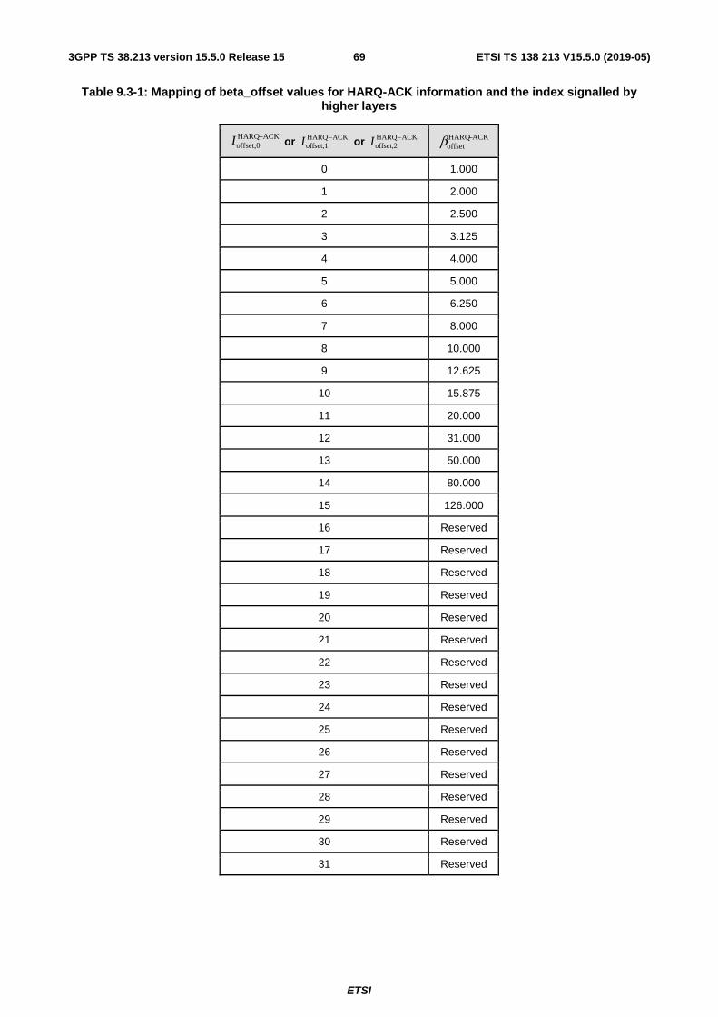
ETSI
ETSI TS 138 213 V15.5.0 (2019-05)693GPP TS 38.213 version 15.5.0 Release 15
Table 9.3-1: Mapping of beta_offset values for HARQ-ACK information and the index signalled by higher layers
ACKHARQoffset,0
−I or ACKHARQoffset,1
−I or ACKHARQoffset,2
−I ACKHARQoffset
−β
0 1.000
1 2.000
2 2.500
3 3.125
4 4.000
5 5.000
6 6.250
7 8.000
8 10.000
9 12.625
10 15.875
11 20.000
12 31.000
13 50.000
14 80.000
15 126.000
16 Reserved
17 Reserved
18 Reserved
19 Reserved
20 Reserved
21 Reserved
22 Reserved
23 Reserved
24 Reserved
25 Reserved
26 Reserved
27 Reserved
28 Reserved
29 Reserved
30 Reserved
31 Reserved

ETSI
ETSI TS 138 213 V15.5.0 (2019-05)703GPP TS 38.213 version 15.5.0 Release 15
Table 9.3-2: Mapping of beta_offset values for CSI and the index signalled by higher layers
1-CSIoffset,0I or 2-CSI
offset,1I 2-CSIoffset,0I or 2-CSI
offset,1I
1-CSIoffsetβ
2-CSIoffsetβ
0 1.125
1 1.250
2 1.375
3 1.625
4 1.750
5 2.000
6 2.250
7 2.500
8 2.875
9 3.125
10 3.500
11 4.000
12 5.000
13 6.250
14 8.000
15 10.000
16 12.625
17 15.875
18 20.000
19 Reserved
20 Reserved
21 Reserved
22 Reserved
23 Reserved
24 Reserved
25 Reserved
26 Reserved
27 Reserved
28 Reserved
29 Reserved
30 Reserved
31 Reserved
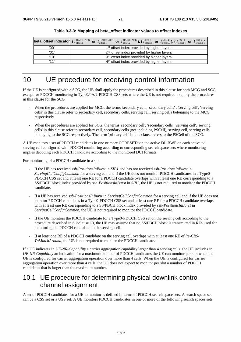
ETSI
ETSI TS 138 213 V15.5.0 (2019-05)713GPP TS 38.213 version 15.5.0 Release 15
Table 9.3-3: Mapping of beta_offset indicator values to offset indexes
beta_offset indicator ( ACKHARQoffset,0
−I or ACKHARQoffset,1
−I or ACKHARQoffset,2
−I ), ( 1-CSIoffset,0I or 2-CSI
offset,0I ), ( 1-CSIoffset,1I or 2-CSI
offset,1I )
'00' 1st offset index provided by higher layers '01' 2nd offset index provided by higher layers '10' 3rd offset index provided by higher layers '11' 4th offset index provided by higher layers
10 UE procedure for receiving control information If the UE is configured with a SCG, the UE shall apply the procedures described in this clause for both MCG and SCG except for PDCCH monitoring in Type0/0A/2-PDCCH CSS sets where the UE is not required to apply the procedures in this clause for the SCG
- When the procedures are applied for MCG, the terms 'secondary cell', 'secondary cells' , 'serving cell', 'serving cells' in this clause refer to secondary cell, secondary cells, serving cell, serving cells belonging to the MCG respectively.
- When the procedures are applied for SCG, the terms 'secondary cell', 'secondary cells', 'serving cell', 'serving cells' in this clause refer to secondary cell, secondary cells (not including PSCell), serving cell, serving cells belonging to the SCG respectively. The term 'primary cell' in this clause refers to the PSCell of the SCG.
A UE monitors a set of PDCCH candidates in one or more CORESETs on the active DL BWP on each activated serving cell configured with PDCCH monitoring according to corresponding search space sets where monitoring implies decoding each PDCCH candidate according to the monitored DCI formats.
For monitoring of a PDCCH candidate in a slot
- If the UE has received ssb-PositionsInBurst in SIB1 and has not received ssb-PositionsInBurst in ServingCellConfigCommon for a serving cell and if the UE does not monitor PDCCH candidates in a Type0-PDCCH CSS set and at least one RE for a PDCCH candidate overlaps with at least one RE corresponding to a SS/PBCH block index provided by ssb-PositionsInBurst in SIB1, the UE is not required to monitor the PDCCH candidate.
- If a UE has received ssb-PositionsInBurst in ServingCellConfigCommon for a serving cell and if the UE does not monitor PDCCH candidates in a Type0-PDCCH CSS set and at least one RE for a PDCCH candidate overlaps with at least one RE corresponding to a SS/PBCH block index provided by ssb-PositionsInBurst in ServingCellConfigCommon, the UE is not required to monitor the PDCCH candidate.
- If the UE monitors the PDCCH candidate for a Type0-PDCCH CSS set on the serving cell according to the procedure described in Subclause 13, the UE may assume that no SS/PBCH block is transmitted in REs used for monitoring the PDCCH candidate on the serving cell.
- If at least one RE of a PDCCH candidate on the serving cell overlaps with at least one RE of lte-CRS-ToMatchAround, the UE is not required to monitor the PDCCH candidate.
If a UE indicates in UE-NR-Capability a carrier aggregation capability larger than 4 serving cells, the UE includes in UE-NR-Capability an indication for a maximum number of PDCCH candidates the UE can monitor per slot when the UE is configured for carrier aggregation operation over more than 4 cells. When the UE is configured for carrier aggregation operation over more than 4 cells, the UE does not expect to monitor per slot a number of PDCCH candidates that is larger than the maximum number.
10.1 UE procedure for determining physical downlink control channel assignment
A set of PDCCH candidates for a UE to monitor is defined in terms of PDCCH search space sets. A search space set can be a CSS set or a USS set. A UE monitors PDCCH candidates in one or more of the following search spaces sets

ETSI
ETSI TS 138 213 V15.5.0 (2019-05)723GPP TS 38.213 version 15.5.0 Release 15
- a Type0-PDCCH CSS set configured by pdcch-ConfigSIB1 in MIB or by searchSpaceSIB1 in PDCCH-ConfigCommon or by searchSpaceZero in PDCCH-ConfigCommon for a DCI format with CRC scrambled by a SI-RNTI on the primary cell of the MCG
- a Type0A-PDCCH CSS set configured by searchSpaceOtherSystemInformation in PDCCH-ConfigCommon for a DCI format with CRC scrambled by a SI-RNTI on the primary cell of the MCG
- a Type1-PDCCH CSS set configured by ra-SearchSpace in PDCCH-ConfigCommon for a DCI format with CRC scrambled by a RA-RNTI or a TC-RNTI on the primary cell
- a Type2-PDCCH CSS set configured by pagingSearchSpace in PDCCH-ConfigCommon for a DCI format with CRC scrambled by a P-RNTI on the primary cell of the MCG
- a Type3-PDCCH CSS set configured by SearchSpace in PDCCH-Config with searchSpaceType = common for DCI formats with CRC scrambled by INT-RNTI, SFI-RNTI, TPC-PUSCH-RNTI, TPC-PUCCH-RNTI, or TPC-SRS-RNTI and, only for the primary cell, C-RNTI, MCS-C-RNTI, or CS-RNTI(s), and
- a USS set configured by SearchSpace in PDCCH-Config with searchSpaceType = ue-Specific for DCI formats with CRC scrambled by C-RNTI, MCS-C-RNTI, SP-CSI-RNTI, or CS-RNTI(s).
For a DL BWP, if a UE is not provided searchSpace-SIB1 for Type0-PDCCH CSS set by PDCCH-ConfigCommon, the UE does not monitor PDCCH candidates for a Type0-PDCCH CSS set on the DL BWP. The Type0-PDCCH CSS set is defined by the CCE aggregation levels and the number of PDCCH candidates per CCE aggregation level given in Table 10.1-1. If the active DL BWP and the initial DL BWP have same SCS and same CP length and the active DL BWP includes all RBs of the CORESET with index 0, or the active DL BWP is the initial DL BWP, the CORESET configured for Type0-PDCCH CSS set has CORESET index 0 and the Type0-PDCCH CSS set has search space set index 0.
For a DL BWP, if a UE is not provided a CORESET for Type0A-PDCCH CSS set, the corresponding CORESET is same as the CORESET for Type0-PDCCH CSS set. For a DL BWP, if the UE is not provided searchSpaceOtherSystemInformation for Type0A-PDCCH CSS set, the UE does not monitor PDCCH for Type0A-PDCCH CSS set on the DL BWP. The CCE aggregation levels and the number of PDCCH candidates per CCE aggregation level for Type0A-PDCCH CSS set are given in Table 10.1-1.
For a DL BWP and a Type1-PDCCH CSS set, a UE is provided a configuration for a search space by ra-SearchSpace. If a UE is not provided by higher layers a CORESET for Type1-PDCCH CSS set on the DL BWP, the CORESET for Type1-PDCCH CSS set is same as the CORESET for Type0-PDCCH CSS set. If the UE has not been provided a Type3-PDCCH CSS set or a USS set and the UE has received a C-RNTI, the UE monitors PDCCH candidates for DCI format 0_0 and DCI format 1_0 with CRC scrambled by the C-RNTI in the Type1-PDCCH CSS set.
For a DL BWP, if a UE is not provided a CORESET for Type2-PDCCH CSS set, the corresponding CORESET is same as the CORESET for Type0-PDCCH CSS set on the DL BWP. If a UE is not provided pagingSearchSpace for Type2-PDCCH CSS set, the UE does not monitor PDCCH for Type2-PDCCH CSS set on the DL BWP. The CCE aggregation levels and the number of PDCCH candidates per CCE aggregation level for Type2-PDCCH CSS set are given in Table 10.1-1.
If a UE is provided a zero value for searchSpaceID in PDCCH-ConfigCommon for a Type0/0A/2-PDCCH CSS set, the UE determines monitoring occasions for PDCCH candidates of the Type0/0A/2-PDCCH CSS set as described in Subclause 13. For DCI formats with CRC scrambled by a C-RNTI, the UE monitors corresponding PDCCH candidates only at monitoring occasions associated with a SS/PBCH block, where the SS/PBCH block is determined by the most recent of
- a MAC CE activation command indicating a TCI state of the active BWP that includes a CORESET with index 0, as described in [6, TS 38.214], where the TCI-state includes a CSI-RS which is quasi-co-located with the SS/PBCH block, or
- a random access procedure that is not initiated by a PDCCH order that triggers a non-contention based random access procedure
If a UE monitors PDCCH candidates for DCI formats with CRC scrambled by a C-RNTI and the UE is provided a non-zero value for searchSpaceID in PDCCH-ConfigCommon for a Type0/0A/2-PDCCH CSS set, the UE determines monitoring occasions for PDCCH candidates of the Type0/0A/2-PDCCH CSS set based on the search space set associated with the value of searchSpaceID.
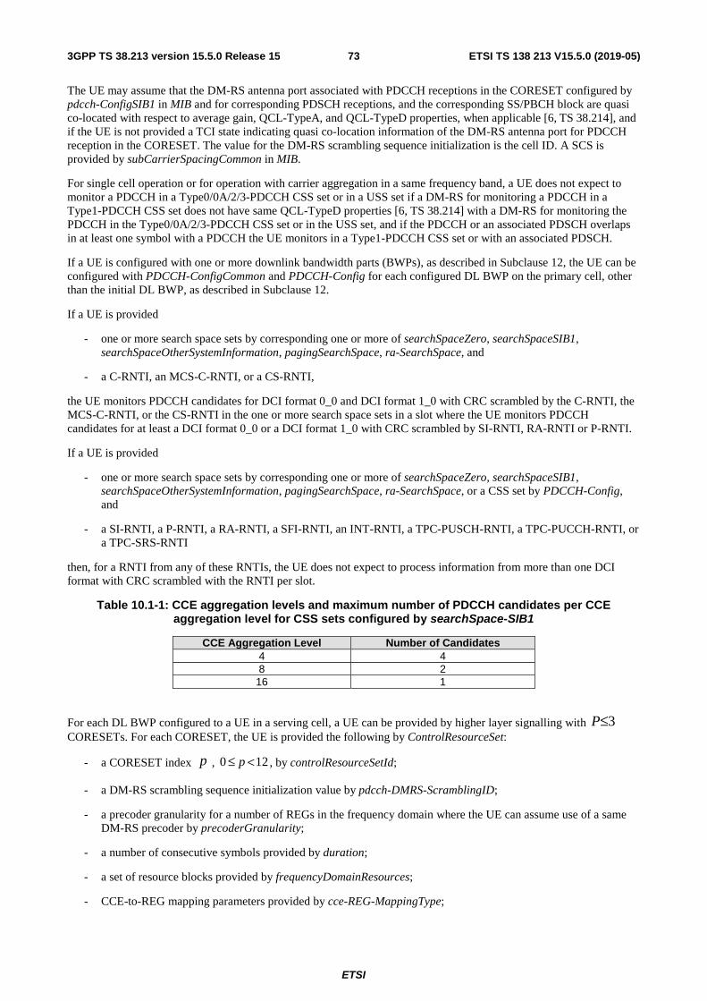
ETSI
ETSI TS 138 213 V15.5.0 (2019-05)733GPP TS 38.213 version 15.5.0 Release 15
The UE may assume that the DM-RS antenna port associated with PDCCH receptions in the CORESET configured by pdcch-ConfigSIB1 in MIB and for corresponding PDSCH receptions, and the corresponding SS/PBCH block are quasi co-located with respect to average gain, QCL-TypeA, and QCL-TypeD properties, when applicable [6, TS 38.214], and if the UE is not provided a TCI state indicating quasi co-location information of the DM-RS antenna port for PDCCH reception in the CORESET. The value for the DM-RS scrambling sequence initialization is the cell ID. A SCS is provided by subCarrierSpacingCommon in MIB.
For single cell operation or for operation with carrier aggregation in a same frequency band, a UE does not expect to monitor a PDCCH in a Type0/0A/2/3-PDCCH CSS set or in a USS set if a DM-RS for monitoring a PDCCH in a Type1-PDCCH CSS set does not have same QCL-TypeD properties [6, TS 38.214] with a DM-RS for monitoring the PDCCH in the Type0/0A/2/3-PDCCH CSS set or in the USS set, and if the PDCCH or an associated PDSCH overlaps in at least one symbol with a PDCCH the UE monitors in a Type1-PDCCH CSS set or with an associated PDSCH.
If a UE is configured with one or more downlink bandwidth parts (BWPs), as described in Subclause 12, the UE can be configured with PDCCH-ConfigCommon and PDCCH-Config for each configured DL BWP on the primary cell, other than the initial DL BWP, as described in Subclause 12.
If a UE is provided
- one or more search space sets by corresponding one or more of searchSpaceZero, searchSpaceSIB1, searchSpaceOtherSystemInformation, pagingSearchSpace, ra-SearchSpace, and
- a C-RNTI, an MCS-C-RNTI, or a CS-RNTI,
the UE monitors PDCCH candidates for DCI format 0_0 and DCI format 1_0 with CRC scrambled by the C-RNTI, the MCS-C-RNTI, or the CS-RNTI in the one or more search space sets in a slot where the UE monitors PDCCH candidates for at least a DCI format 0_0 or a DCI format 1_0 with CRC scrambled by SI-RNTI, RA-RNTI or P-RNTI.
If a UE is provided
- one or more search space sets by corresponding one or more of searchSpaceZero, searchSpaceSIB1, searchSpaceOtherSystemInformation, pagingSearchSpace, ra-SearchSpace, or a CSS set by PDCCH-Config, and
- a SI-RNTI, a P-RNTI, a RA-RNTI, a SFI-RNTI, an INT-RNTI, a TPC-PUSCH-RNTI, a TPC-PUCCH-RNTI, or a TPC-SRS-RNTI
then, for a RNTI from any of these RNTIs, the UE does not expect to process information from more than one DCI format with CRC scrambled with the RNTI per slot.
Table 10.1-1: CCE aggregation levels and maximum number of PDCCH candidates per CCE aggregation level for CSS sets configured by searchSpace-SIB1
CCE Aggregation Level Number of Candidates 4 4 8 2
16 1
For each DL BWP configured to a UE in a serving cell, a UE can be provided by higher layer signalling with 3≤P CORESETs. For each CORESET, the UE is provided the following by ControlResourceSet:
- a CORESET index p , 120 <≤ p , by controlResourceSetId;
- a DM-RS scrambling sequence initialization value by pdcch-DMRS-ScramblingID;
- a precoder granularity for a number of REGs in the frequency domain where the UE can assume use of a same DM-RS precoder by precoderGranularity;
- a number of consecutive symbols provided by duration;
- a set of resource blocks provided by frequencyDomainResources;
- CCE-to-REG mapping parameters provided by cce-REG-MappingType;
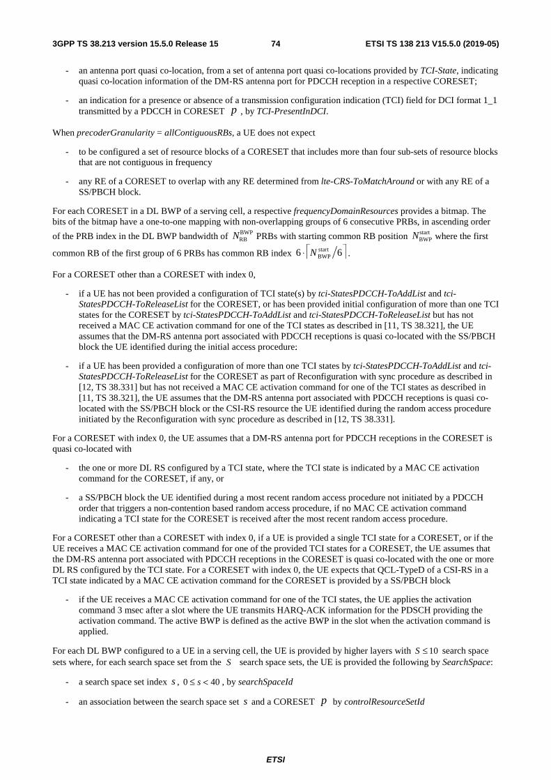
ETSI
ETSI TS 138 213 V15.5.0 (2019-05)743GPP TS 38.213 version 15.5.0 Release 15
- an antenna port quasi co-location, from a set of antenna port quasi co-locations provided by TCI-State, indicating quasi co-location information of the DM-RS antenna port for PDCCH reception in a respective CORESET;
- an indication for a presence or absence of a transmission configuration indication (TCI) field for DCI format 1_1 transmitted by a PDCCH in CORESET p , by TCI-PresentInDCI.
When precoderGranularity = allContiguousRBs, a UE does not expect
- to be configured a set of resource blocks of a CORESET that includes more than four sub-sets of resource blocks that are not contiguous in frequency
- any RE of a CORESET to overlap with any RE determined from lte-CRS-ToMatchAround or with any RE of a SS/PBCH block.
For each CORESET in a DL BWP of a serving cell, a respective frequencyDomainResources provides a bitmap. The bits of the bitmap have a one-to-one mapping with non-overlapping groups of 6 consecutive PRBs, in ascending order
of the PRB index in the DL BWP bandwidth of BWPRBN PRBs with starting common RB position start
BWPN where the first
common RB of the first group of 6 PRBs has common RB index 66 startBWPN⋅ .
For a CORESET other than a CORESET with index 0,
- if a UE has not been provided a configuration of TCI state(s) by tci-StatesPDCCH-ToAddList and tci-StatesPDCCH-ToReleaseList for the CORESET, or has been provided initial configuration of more than one TCI states for the CORESET by tci-StatesPDCCH-ToAddList and tci-StatesPDCCH-ToReleaseList but has not received a MAC CE activation command for one of the TCI states as described in [11, TS 38.321], the UE assumes that the DM-RS antenna port associated with PDCCH receptions is quasi co-located with the SS/PBCH block the UE identified during the initial access procedure;
- if a UE has been provided a configuration of more than one TCI states by tci-StatesPDCCH-ToAddList and tci-StatesPDCCH-ToReleaseList for the CORESET as part of Reconfiguration with sync procedure as described in [12, TS 38.331] but has not received a MAC CE activation command for one of the TCI states as described in [11, TS 38.321], the UE assumes that the DM-RS antenna port associated with PDCCH receptions is quasi co-located with the SS/PBCH block or the CSI-RS resource the UE identified during the random access procedure initiated by the Reconfiguration with sync procedure as described in [12, TS 38.331].
For a CORESET with index 0, the UE assumes that a DM-RS antenna port for PDCCH receptions in the CORESET is quasi co-located with
- the one or more DL RS configured by a TCI state, where the TCI state is indicated by a MAC CE activation command for the CORESET, if any, or
- a SS/PBCH block the UE identified during a most recent random access procedure not initiated by a PDCCH order that triggers a non-contention based random access procedure, if no MAC CE activation command indicating a TCI state for the CORESET is received after the most recent random access procedure.
For a CORESET other than a CORESET with index 0, if a UE is provided a single TCI state for a CORESET, or if the UE receives a MAC CE activation command for one of the provided TCI states for a CORESET, the UE assumes that the DM-RS antenna port associated with PDCCH receptions in the CORESET is quasi co-located with the one or more DL RS configured by the TCI state. For a CORESET with index 0, the UE expects that QCL-TypeD of a CSI-RS in a TCI state indicated by a MAC CE activation command for the CORESET is provided by a SS/PBCH block
- if the UE receives a MAC CE activation command for one of the TCI states, the UE applies the activation command 3 msec after a slot where the UE transmits HARQ-ACK information for the PDSCH providing the activation command. The active BWP is defined as the active BWP in the slot when the activation command is applied.
For each DL BWP configured to a UE in a serving cell, the UE is provided by higher layers with 10≤S search space sets where, for each search space set from the S search space sets, the UE is provided the following by SearchSpace:
- a search space set index s , 400 <≤ s , by searchSpaceId
- an association between the search space set s and a CORESET p by controlResourceSetId
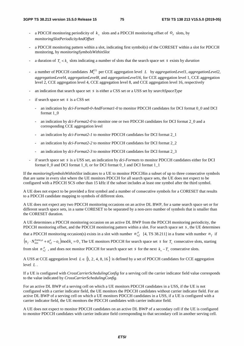
ETSI
ETSI TS 138 213 V15.5.0 (2019-05)753GPP TS 38.213 version 15.5.0 Release 15
- a PDCCH monitoring periodicity of sk slots and a PDCCH monitoring offset of so slots, by
monitoringSlotPeriodicityAndOffset
- a PDCCH monitoring pattern within a slot, indicating first symbol(s) of the CORESET within a slot for PDCCH monitoring, by monitoringSymbolsWithinSlot
- a duration of ss kT < slots indicating a number of slots that the search space set s exists by duration
- a number of PDCCH candidates )(LsM per CCE aggregation level L by aggregationLevel1, aggregationLevel2,
aggregationLevel4, aggregationLevel8, and aggregationLevel16, for CCE aggregation level 1, CCE aggregation level 2, CCE aggregation level 4, CCE aggregation level 8, and CCE aggregation level 16, respectively
- an indication that search space set s is either a CSS set or a USS set by searchSpaceType
- if search space set s is a CSS set
- an indication by dci-Format0-0-AndFormat1-0 to monitor PDCCH candidates for DCI format 0_0 and DCI format 1_0
- an indication by dci-Format2-0 to monitor one or two PDCCH candidates for DCI format 2_0 and a corresponding CCE aggregation level
- an indication by dci-Format2-1 to monitor PDCCH candidates for DCI format 2_1
- an indication by dci-Format2-2 to monitor PDCCH candidates for DCI format 2_2
- an indication by dci-Format2-3 to monitor PDCCH candidates for DCI format 2_3
- if search space set s is a USS set, an indication by dci-Formats to monitor PDCCH candidates either for DCI format 0_0 and DCI format 1_0, or for DCI format 0_1 and DCI format 1_1
If the monitoringSymbolsWithinSlot indicates to a UE to monitor PDCCHin a subset of up to three consecutive symbols that are same in every slot where the UE monitors PDCCH for all search space sets, the UE does not expect to be configured with a PDCCH SCS other than 15 kHz if the subset includes at least one symbol after the third symbol.
A UE does not expect to be provided a first symbol and a number of consecutive symbols for a CORESET that results to a PDCCH candidate mapping to symbols of different slots.
A UE does not expect any two PDCCH monitoring occasions on an active DL BWP, for a same search space set or for different search space sets, in a same CORESET to be separated by a non-zero number of symbols that is smaller than the CORESET duration.
A UE determines a PDCCH monitoring occasion on an active DL BWP from the PDCCH monitoring periodicity, the PDCCH monitoring offset, and the PDCCH monitoring pattern within a slot. For search space set s , the UE determines
that a PDCCH monitoring occasion(s) exists in a slot with number μs,fn [4, TS 38.211] in a frame with number fn if
( ) 0mod,frameslot =−+⋅ sss,ff konNn μμ . The UE monitors PDCCH for search space set s for sT consecutive slots, starting
from slot μs,fn , and does not monitor PDCCH for search space set s for the next ss Tk − consecutive slots.
A USS at CCE aggregation level { }16,8,4,2,1∈L is defined by a set of PDCCH candidates for CCE aggregation
level L .
If a UE is configured with CrossCarrierSchedulingConfig for a serving cell the carrier indicator field value corresponds to the value indicated by CrossCarrierSchedulingConfig.
For an active DL BWP of a serving cell on which a UE monitors PDCCH candidates in a USS, if the UE is not configured with a carrier indicator field, the UE monitors the PDCCH candidates without carrier indicator field. For an active DL BWP of a serving cell on which a UE monitors PDCCH candidates in a USS, if a UE is configured with a carrier indicator field, the UE monitors the PDCCH candidates with carrier indicator field.
A UE does not expect to monitor PDCCH candidates on an active DL BWP of a secondary cell if the UE is configured to monitor PDCCH candidates with carrier indicator field corresponding to that secondary cell in another serving cell.
ETSI
ETSI TS 138 213 V15.5.0 (2019-05)763GPP TS 38.213 version 15.5.0 Release 15
For the active DL BWP of a serving cell on which the UE monitors PDCCH candidates, the UE monitors PDCCH candidates at least for the same serving cell.
For a search space set s associated with CORESET p , the CCE indexes for aggregation level L corresponding to
PDCCH candidate CInsm , of the search space set in slot μ
s,fn for an active DL BWP of a serving cell corresponding to
carrier indicator field value CIn are given by
iLNnML
NmYL pCIL
s
pns
npCI +
+
⋅⋅
+⋅ ,CCE)(max,
,CCE,
,mod
fs,μ
where
for any CSS, 0fs,,
=μnpY ;
for a USS, ( ) DYAYnppnp
mod1,, s,fs,f −⋅= μμ , 0RNTI1, ≠=− nYp , 39827=pA for 03mod =p , 39829=pA for 13mod =p ,
39839=pA for 23mod =p , and 65537=D ;
1,,0 −= Li L ;
pN ,CCE is the number of CCEs, numbered from 0 to 1,CCE −pN , in CORESET p ;
CIn is the carrier indicator field value if the UE is configured with a carrier indicator field by
CrossCarrierSchedulingConfig for the serving cell on which PDCCH is monitored; otherwise, including for any CSS, 0=CIn ;
1...,,0 )(,, −= Lnsns CICI
Mm , where )(,Lns CI
M is the number of PDCCH candidates the UE is configured to monitor for
aggregation level L of a search space set s for a serving cell corresponding to CIn ;
for any CSS, )(0,
)(max,
Ls
Ls MM = ;
for a USS, )(max,L
sM is the maximum of )(,Lns CI
M over all configured CIn values for a CCE aggregation level L of search
space set s ;
the RNTI value used for RNTIn is the C-RNTI.
A UE that
- is configured for operation with carrier aggregation, and
- indicates support of search space sharing through searchSpaceSharingCA-UL or through searchSpaceSharingCA-DL, and
- has a PDCCH candidate with CCE aggregation level L in CORESET p for a DCI format 0_1 or a DCI format
1_1 having a first size and associated with serving cell 2,CIn ,
can receive a corresponding PDCCH through a PDCCH candidate with CCE aggregation level L in CORESET p for
a DCI format 0_1 or a DCI format 1_1, respectively, having a second size and associated with serving cell 1,CIn if the
first size and the second size are same.
A UE expects to monitor PDCCH candidates for up to 4 sizes of DCI formats that include up to 3 sizes of DCI formats with CRC scrambled by C-RNTI per serving cell. The UE counts a number of sizes for DCI formats per serving cell based on a number of configured PDCCH candidates in respective search space sets for the corresponding active DL BWP.
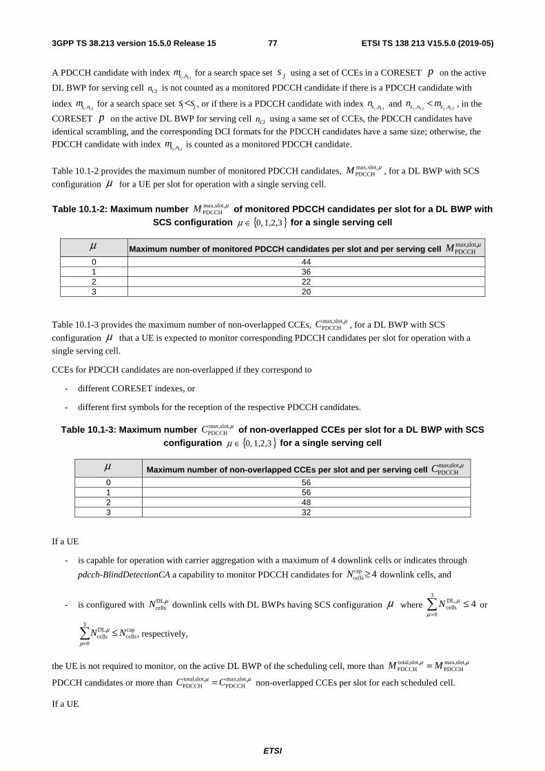
ETSI
ETSI TS 138 213 V15.5.0 (2019-05)773GPP TS 38.213 version 15.5.0 Release 15
A PDCCH candidate with index CIj nsm , for a search space set js using a set of CCEs in a CORESET p on the active
DL BWP for serving cell CIn is not counted as a monitored PDCCH candidate if there is a PDCCH candidate with
index CIi nsm , for a search space set ji ss < , or if there is a PDCCH candidate with index
CIj nsn , and CIjCIj nsns mn ,, < , in the
CORESET p on the active DL BWP for serving cell CIn using a same set of CCEs, the PDCCH candidates have
identical scrambling, and the corresponding DCI formats for the PDCCH candidates have a same size; otherwise, the PDCCH candidate with index
CIj nsm , is counted as a monitored PDCCH candidate.
Table 10.1-2 provides the maximum number of monitored PDCCH candidates, μslot,max,PDCCHM , for a DL BWP with SCS
configuration μ for a UE per slot for operation with a single serving cell.
Table 10.1-2: Maximum number μslot,max,PDCCHM of monitored PDCCH candidates per slot for a DL BWP with
SCS configuration { }1,2,3 0,∈μ for a single serving cell
μ Maximum number of monitored PDCCH candidates per slot and per serving cell μslot,max,
PDCCHM 0 44 1 36 2 22 3 20
Table 10.1-3 provides the maximum number of non-overlapped CCEs, μslot,max,PDCCHC , for a DL BWP with SCS
configuration μ that a UE is expected to monitor corresponding PDCCH candidates per slot for operation with a
single serving cell.
CCEs for PDCCH candidates are non-overlapped if they correspond to
- different CORESET indexes, or
- different first symbols for the reception of the respective PDCCH candidates.
Table 10.1-3: Maximum number μslot,max,PDCCHC of non-overlapped CCEs per slot for a DL BWP with SCS
configuration { }1,2,3 0,∈μ for a single serving cell
μ Maximum number of non-overlapped CCEs per slot and per serving cell μslot,max,
PDCCHC 0 56 1 56 2 48 3 32
If a UE
- is capable for operation with carrier aggregation with a maximum of 4 downlink cells or indicates through
pdcch-BlindDetectionCA a capability to monitor PDCCH candidates for 4capcells ≥N downlink cells, and
- is configured with μDL,cellsN downlink cells with DL BWPs having SCS configuration μ where 4
3
0
DL,cells ≤
=μ
μN or
capcells
3
0
DL,cells NN ≤
=μ
μ , respectively,
the UE is not required to monitor, on the active DL BWP of the scheduling cell, more than μμ slot,max,PDCCH
slot,total,PDCCH MM =
PDCCH candidates or more than μμ slot,max,PDCCH
slot,total,PDCCH CC = non-overlapped CCEs per slot for each scheduled cell.
If a UE

ETSI
ETSI TS 138 213 V15.5.0 (2019-05)783GPP TS 38.213 version 15.5.0 Release 15
- indicates through pdcch-BlindDetectionCA a capability to monitor PDCCH candidates for 4capcells ≥N downlink
cells, and
- is configured with μDL,cellsN downlink cells with DL BWPs having SCS configuration μ , where cap
cells
3
0
DL,cells NN >
=μ
μ ,
a DL BWP of an activated cell is the active DL BWP of the activated cell, and a DL BWP of a deactivated cell is the DL BWP with index provided by firstActiveDownlinkBWP-Id for the deactivated cell
the UE is not required to monitor more than
⋅⋅=
=
3
0
DL,cells
DL,cells
slot,max,PDCCH
capcells
slot,total,PDCCH
j
jNNMNM μμμ PDCCH candidates or
more than
⋅⋅=
=
3
0
DL,cells
DL,cells
slot,max,PDCCH
capcells
slot,total,PDCCH
j
jNNCNC μμμ non-overlapped CCEs per slot on the active DL BWP(s) of
scheduling cell(s) from the μDL,cellsN downlink cells.
For each scheduled cell, the UE is not required to monitor on the active DL BWP with SCS configuration μ of the
scheduling cell more than ( )μμ slot,total,PDCCH
slot,max,PDCCH ,min MM PDCCH candidates or more than ( )μμ slot,total,
PDCCHslot,max,
PDCCH ,min CC non-
overlapped CCEs per slot.
A UE does not expect to be configured CSS sets that result to corresponding total, or per scheduled cell, numbers of monitored PDCCH candidates and non-overlapped CCEs per slot that exceed the corresponding maximum numbers per slot.
For same cell scheduling or for cross-carrier scheduling where a scheduling cell and scheduled cell(s) have DL BWPs with same SCS configuration μ , a UE does not expect a number of PDCCH candidates, and a number of
corresponding non-overlapped CCEs per slot on a secondary cell to be larger than the corresponding numbers that the UE is capable of monitoring on the secondary cell per slot.
For cross-carrier scheduling, the number of monitored PDCCH candidates and the number of non-overlapped CCEs per slot are separately counted for each scheduled cell.
For all search space sets within a slot n , denote by cssS a set of CSS sets with cardinality of cssI and by ussS a set of
USS sets with cardinality of ussJ . The location of USS sets js , uss0 Jj <≤ , in ussS is according to an ascending order
of the search space set index.
Denote by )()(css
LiSM , css0 Ii <≤ , the number of configured PDCCH candidates for CSS set )(css iS and by )(
)(uss
LjSM ,
uss0 Jj <≤ , the number of configured PDCCH candidates for USS set )(uss jS .
For the CSS sets, a UE monitors −
==
L
LiS
I
i
MM )()(
1
0
CSSPDCCH css
css
PDCCH candidates requiring a total of CSSPDCCHC non-
overlapping CCEs in a slot.
The UE allocates monitored PDCCH candidates to USS sets for the primary cell having an active DL BWP with SCS configuration μ in slot n according to the following pseudocode. A UE does not expect to monitor PDCCH in a
USS set without monitored PDCCH candidates.
Denote by ))(( ussCCE jSV the set of non-overlapping CCEs for search space set )(uss jS and by ( )))(( ussCCE jSVC the
cardinality of ))(( ussCCE jSV where the non-overlapping CCEs for search space set )(uss jS are determined considering
the monitored PDCCH candidates for the CSS sets and the monitored PDCCH candidates for all search space sets )(uss kS , jk ≤≤0 .
Set ( ) cssPDCCH
slot,total,PDCCH
slot,max,PDCCH
ussPDCCH ,min MMMM −= μμ
Set ( ) cssPDCCH
slot,total,PDCCH
slot,max,PDCCH
ussPDCCH ,min CCCC −= μμ
ETSI
ETSI TS 138 213 V15.5.0 (2019-05)793GPP TS 38.213 version 15.5.0 Release 15
Set 0=j
while ussPDCCH
)()(uss
MML
LjS ≤ AND ( ) uss
PDCCHussCCE ))(( CjSV ≤C
allocate L
LjSM )()(uss
monitored PDCCH candidates to USS set )(uss jS
−=L
LjSMMM )()(
ussPDCCH
ussPDCCH uss
;
( )))(( ussCCEussPDCCH
ussPDCCH jSVCC C−= ;
1+= jj ;
end while
If a UE
- is configured for single cell operation or for operation with carrier aggregation in a same frequency band, and
- monitors PDCCH candidates in overlapping PDCCH monitoring occasions in multiple CORESETs that have same or different QCL-TypeD properties on active DL BWP(s) of one or more cells
the UE monitors PDCCHs only in a CORESET, and in any other CORESET from the multiple CORESETs having same QCL-TypeD properties as the CORESET, on the active DL BWP of a cell from the one or more cells
- the CORESET corresponds to the CSS set with the lowest index in the cell with the lowest index containing CSS, if any; otherwise, to the USS set with the lowest index in the cell with lowest index
- the lowest USS set index is determined over all USS sets with at least one PDCCH candidate in overlapping PDCCH monitoring occasions
- for the purpose of determining the CORESET, a SS/PBCH block is considered to have different QCL-TypeD properties than a CSI-RS
- for the purpose of determining the CORESET, a first CSI-RS associated with a SS/PBCH block in a first cell and a second CSI-RS in a second cell that is also associated with the SS/PBCH block are assumed to have same QCL-TypeD properties
- the allocation of non-overlapping CCEs and of PDCCH candidates for PDCCH monitoring is according to all search space sets associated with the multiple CORESETs on the active DL BWP(s) of the one or more cells
- the number of active TCI states is determined from the multiple CORESETs
If a UE
- is configured for single cell operation or for operation with carrier aggregation in a same frequency band, and
- monitors PDCCH candidates in overlapping PDCCH monitoring occasions in multiple CORESETs where none of the CORESETs has TCI-states with 'QCL-TypeD',
the UE is required to monitor PDCCH candidates in overlapping PDCCH monitoring occasions for search space sets associated with different CORESETs.
For a scheduled cell and at any time, a UE expects to have received at most 16 PDCCHs for DCI formats 1_0 or 1_1 with CRC scrambled by C-RNTI, CS-RNTI, or MCS-RNTI scheduling 16 PDSCH receptions for which the UE has not received any corresponding PDSCH symbol and at most 16 PDCCHs for DCI formats 0_0 or 0_1 with CRC scrambled by C-RNTI, CS-RNTI, or MCS-RNTI scheduling 16 PUSCH transmissions for which the UE has not transmitted any corresponding PUSCH symbol.
ETSI
ETSI TS 138 213 V15.5.0 (2019-05)803GPP TS 38.213 version 15.5.0 Release 15
If a UE indicates through pdcch-BlindDetectionCA a capability to monitor PDCCH candidates for 4capcells ≥N downlink
cells and the UE is configured with 4DLcells >N downlink cells or 4UL
cells >N uplink cells, the UE expects to have
respectively received at most capcells16 N⋅ PDCCHs for
- DCI formats 1_0 or 1_1 with CRC scrambled by a C-RNTI, or a CS-RNTI, or a MCS-RNTI scheduling capcells16 N⋅ PDSCH receptions for which the UE has not received any corresponding PDSCH symbol over all DL
cellsN
downlink cells
- DCI formats 0_0 or 0_1 with CRC scrambled by a C-RNTI, or a CS-RNTI, or a MCS-RNTI scheduling capcells16 N⋅ PUSCH transmissions for which the UE has not transmitted any corresponding PUSCH symbol over
all ULcellsN uplink cells
If a UE
- is configured to monitor a first PDCCH candidate for a DCI format 0_0 and a DCI format 1_0 from a CSS set and a second PDCCH candidate for a DCI format 0_0 and a DCI format 1_0 from a USS set in a CORESET with index zero on an active DL BWP, and
- the DCI formats 0_0/1_0 associated with the first PDCCH candidate and the DCI formats 0_0/1_0 associated with the second PDCCH candidate have same size, and
- the UE receives the first PDCCH candidate and the second PDCCH candidate over a same set of CCEs, and
- the first PDCCH candidate and the second PDCCH candidate have identical scrambling, and
- the DCI formats 0_0/1_0 for the first PDCCH candidate and the DCI formats 0_0/1_0 for the second PDCCH candidate have CRC scrambled by either C-RNTI, or MCS-C-RNTI, or CS-RNTI
the UE decodes only the DCI formats 0_0/1_0 associated with the first PDCCH candidate.
If a UE detects a DCI format with inconsistent information, the UE discards all the information in the DCI format.
A UE configured with a bandwidth part indicator in DCI formats 0_1 or 1_1 determines, in case of an active DL BWP or of an active UL BWP change, the DCI information applicable to the new active DL BWP or UL BWP, respectively, as described in Subclause 12.
For unpaired spectrum operation, if a UE is not configured for PUSCH/PUCCH transmission on serving cell 2c , the
UE does not expect to monitor PDCCH on serving cell 1c if the PDCCH overlaps in time with SRS transmission
(including any interruption due to uplink or downlink RF retuning time [10, TS 38.133]) on serving cell 2c and if the
UE is not capable of simultaneous reception and transmission on serving cell 1c and serving cell 2c .
If a UE is provided resourceblocks and symbolsInResourceBlock in RateMatchPattern, or if the UE is additionally provided periodicityAndPattern in RateMatchPattern, the UE can determine a set of RBs in symbols of a slot that are not available for PDSCH reception as described in [6, TS 38.214]. If a PDCCH candidate in a slot is mapped to one or more REs that overlap with REs of any RB in the set of RBs in symbols of the slot, the UE does not expect to monitor the PDCCH candidate.
10.2 PDCCH validation for DL SPS and UL grant Type 2 A UE validates, for scheduling activation or scheduling release, a DL SPS assignment PDCCH or configured UL grant Type 2 PDCCH if
- the CRC of a corresponding DCI format is scrambled with a CS-RNTI provided by cs-RNTI, and
- the new data indicator field for the enabled transport block is set to '0'.
Validation of the DCI format is achieved if all fields for the DCI format are set according to Table 10.2-1 or Table 10.2-2.
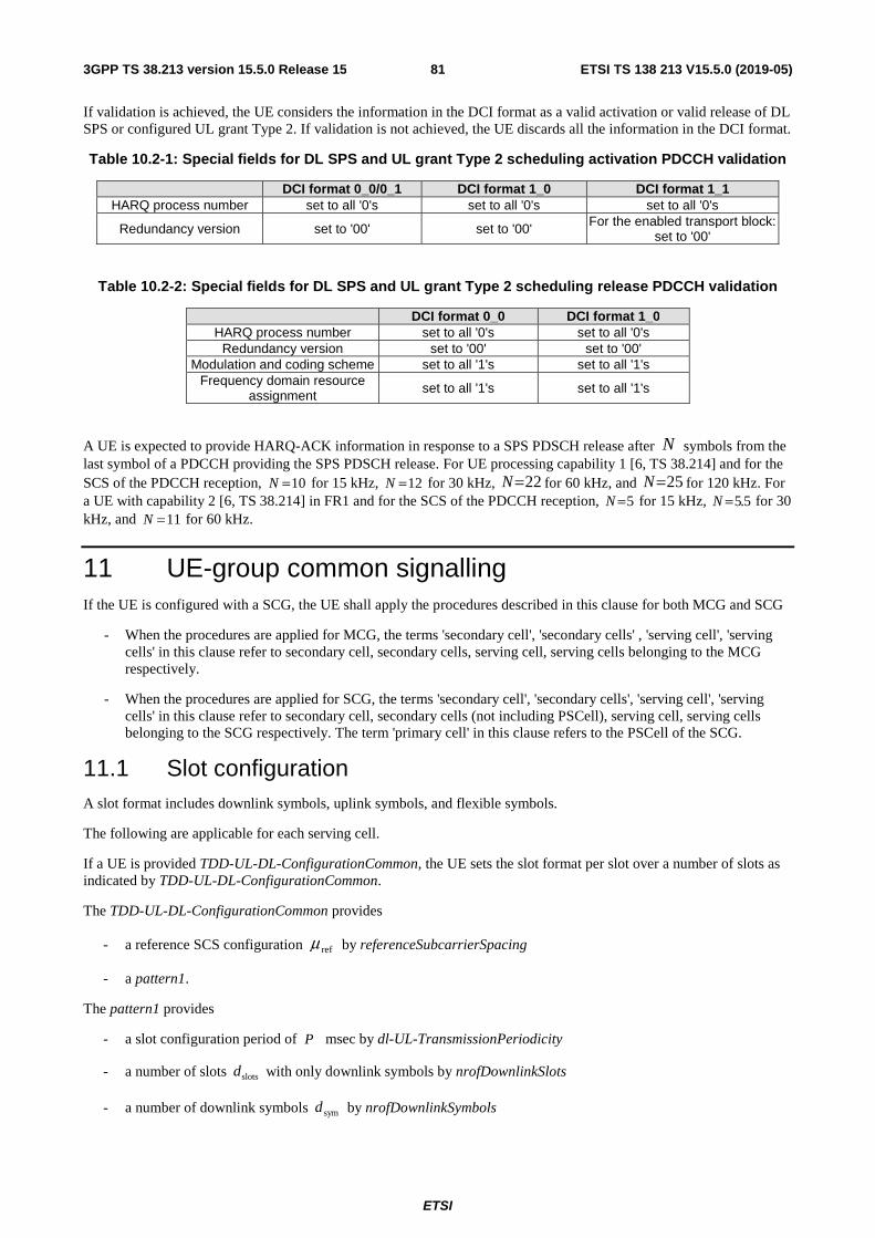
ETSI
ETSI TS 138 213 V15.5.0 (2019-05)813GPP TS 38.213 version 15.5.0 Release 15
If validation is achieved, the UE considers the information in the DCI format as a valid activation or valid release of DL SPS or configured UL grant Type 2. If validation is not achieved, the UE discards all the information in the DCI format.
Table 10.2-1: Special fields for DL SPS and UL grant Type 2 scheduling activation PDCCH validation
DCI format 0_0/0_1 DCI format 1_0 DCI format 1_1 HARQ process number set to all '0's set to all '0's set to all '0's
Redundancy version set to '00' set to '00' For the enabled transport block: set to '00'
Table 10.2-2: Special fields for DL SPS and UL grant Type 2 scheduling release PDCCH validation
DCI format 0_0 DCI format 1_0 HARQ process number set to all '0's set to all '0's
Redundancy version set to '00' set to '00' Modulation and coding scheme set to all '1's set to all '1's
Frequency domain resource assignment set to all '1's set to all '1's
A UE is expected to provide HARQ-ACK information in response to a SPS PDSCH release after N symbols from the last symbol of a PDCCH providing the SPS PDSCH release. For UE processing capability 1 [6, TS 38.214] and for the SCS of the PDCCH reception, 10=N for 15 kHz, 12=N for 30 kHz, 22=N for 60 kHz, and 25=N for 120 kHz. For a UE with capability 2 [6, TS 38.214] in FR1 and for the SCS of the PDCCH reception, 5=N for 15 kHz, 5.5=N for 30 kHz, and 11=N for 60 kHz.
11 UE-group common signalling If the UE is configured with a SCG, the UE shall apply the procedures described in this clause for both MCG and SCG
- When the procedures are applied for MCG, the terms 'secondary cell', 'secondary cells' , 'serving cell', 'serving cells' in this clause refer to secondary cell, secondary cells, serving cell, serving cells belonging to the MCG respectively.
- When the procedures are applied for SCG, the terms 'secondary cell', 'secondary cells', 'serving cell', 'serving cells' in this clause refer to secondary cell, secondary cells (not including PSCell), serving cell, serving cells belonging to the SCG respectively. The term 'primary cell' in this clause refers to the PSCell of the SCG.
11.1 Slot configuration A slot format includes downlink symbols, uplink symbols, and flexible symbols.
The following are applicable for each serving cell.
If a UE is provided TDD-UL-DL-ConfigurationCommon, the UE sets the slot format per slot over a number of slots as indicated by TDD-UL-DL-ConfigurationCommon.
The TDD-UL-DL-ConfigurationCommon provides
- a reference SCS configuration refμ by referenceSubcarrierSpacing
- a pattern1.
The pattern1 provides
- a slot configuration period of P msec by dl-UL-TransmissionPeriodicity
- a number of slots slotsd with only downlink symbols by nrofDownlinkSlots
- a number of downlink symbols symd by nrofDownlinkSymbols
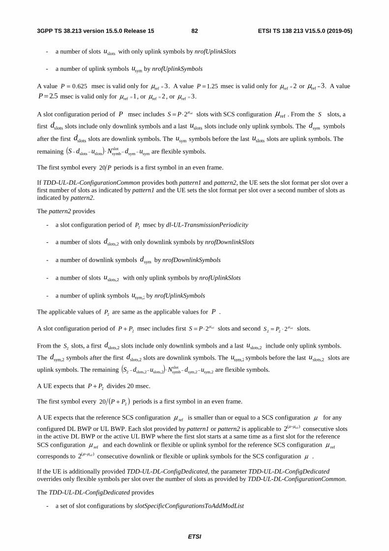
ETSI
ETSI TS 138 213 V15.5.0 (2019-05)823GPP TS 38.213 version 15.5.0 Release 15
- a number of slots slotsu with only uplink symbols by nrofUplinkSlots
- a number of uplink symbols symu by nrofUplinkSymbols
A value 625.0=P msec is valid only for 3ref =μ . A value 25.1=P msec is valid only for 2ref =μ or 3ref =μ . A value
5.2=P msec is valid only for 1ref =μ , or 2ref =μ , or 3ref =μ .
A slot configuration period of P msec includes ref2μ⋅= PS slots with SCS configuration refμ . From the S slots, a
first slotsd slots include only downlink symbols and a last slotsu slots include only uplink symbols. The symd symbols
after the first slotsd slots are downlink symbols. The symu symbols before the last slotsu slots are uplink symbols. The
remaining ( ) symsymslotsymbslotsslots udNudS −−−− ⋅ are flexible symbols.
The first symbol every P20 periods is a first symbol in an even frame.
If TDD-UL-DL-ConfigurationCommon provides both pattern1 and pattern2, the UE sets the slot format per slot over a first number of slots as indicated by pattern1 and the UE sets the slot format per slot over a second number of slots as indicated by pattern2.
The pattern2 provides
- a slot configuration period of 2P msec by dl-UL-TransmissionPeriodicity
- a number of slots slots,2d with only downlink symbols by nrofDownlinkSlots
- a number of downlink symbols symd by nrofDownlinkSymbols
- a number of slots slots,2u with only uplink symbols by nrofUplinkSlots
- a number of uplink symbols sym,2u by nrofUplinkSymbols
The applicable values of 2P are same as the applicable values for P .
A slot configuration period of 2PP + msec includes first ref2μ⋅= PS slots and second ref222μ⋅= PS slots.
From the 2S slots, a first slots,2d slots include only downlink symbols and a last slots,2u include only uplink symbols.
The sym,2d symbols after the first slots,2d slots are downlink symbols. The sym,2u symbols before the last slots,2u slots are
uplink symbols. The remaining ( ) sym,2sym,2slotsymbslots,2slots,22 udNudS −−−− ⋅ are flexible symbols.
A UE expects that 2PP + divides 20 msec.
The first symbol every ( )220 PP + periods is a first symbol in an even frame.
A UE expects that the reference SCS configuration refμ is smaller than or equal to a SCS configuration μ for any
configured DL BWP or UL BWP. Each slot provided by pattern1 or pattern2 is applicable to )( ref2 μμ− consecutive slots in the active DL BWP or the active UL BWP where the first slot starts at a same time as a first slot for the reference SCS configuration refμ and each downlink or flexible or uplink symbol for the reference SCS configuration refμ
corresponds to )( ref2 μμ− consecutive downlink or flexible or uplink symbols for the SCS configuration μ .
If the UE is additionally provided TDD-UL-DL-ConfigDedicated, the parameter TDD-UL-DL-ConfigDedicated overrides only flexible symbols per slot over the number of slots as provided by TDD-UL-DL-ConfigurationCommon.
The TDD-UL-DL-ConfigDedicated provides
- a set of slot configurations by slotSpecificConfigurationsToAddModList
ETSI
ETSI TS 138 213 V15.5.0 (2019-05)833GPP TS 38.213 version 15.5.0 Release 15
- for each slot configuration from the set of slot configurations
- a slot index for a slot provided by slotIndex
- a set of symbols for a slot by symbols where
- if symbols = allDownlink, all symbols in the slot are downlink
- if symbols = allUplink, all symbols in the slot are uplink
- if symbols = explicit, nrofDownlinkSymbols provides a number of downlink first symbols in the slot and nrofUplinkSymbols provides a number of uplink last symbols in the slot. If nrofDownlinkSymbols is not provided, there are no downlink first symbols in the slot and if nrofUplinkSymbols is not provided, there are no uplink last symbols in the slot. The remaining symbols in the slot are flexible
For each slot having a corresponding index provided by slotIndex, the UE applies a format provided by a corresponding symbols. The UE does not expect TDD-UL-DL-ConfigDedicated to indicate as uplink or as downlink a symbol that TDD-UL-DL-ConfigurationCommon indicates as a downlink or as an uplink symbol, respectively.
For each slot configuration provided by TDD-UL-DL-ConfigDedicated, a reference SCS configuration is the reference
SCS configuration provided by TDD-UL-DL-ConfigurationCommon.
A slot configuration period and a number of downlink symbols, uplink symbols, and flexible symbols in each slot of the slot configuration period are determined from TDD-UL-DL-ConfigurationCommonTDD and TDD-UL-DL-ConfigDedicated and are common to each configured BWP.
A UE considers symbols in a slot indicated as downlink by TDD-UL-DL-ConfigurationCommon, or TDD-UL-DL-ConfigDedicated to be available for receptions and considers symbols in a slot indicated as uplink by TDD-UL-DL-ConfigurationCommon, or by TDD-UL-DL-ConfigDedicated to be available for transmissions.
If a UE is not configured to monitor PDCCH for DCI format 2-0, for a set of symbols of a slot that are indicated as flexible by TDD-UL-DL-ConfigurationCommon or TDD-UL-DL-ConfigDedicated, or when TDD-UL-DL-ConfigurationCommon and TDD-UL-DL-ConfigDedicated are not provided to the UE
- the UE receives PDSCH or CSI-RS in the set of symbols of the slot if the UE receives a corresponding indication by a DCI format 1_0, DCI format 1_1, or DCI format 0_1
- the UE transmits PUSCH, PUCCH, PRACH, or SRS in the set of symbols of the slot if the UE receives a corresponding indication by a DCI format 0_0, DCI format 0_1, DCI format 1_0, DCI format 1_1, or DCI format 2_3
For operation on a single carrier in unpaired spectrum, if a UE is configured by higher layers to receive a PDCCH, or a PDSCH, or a CSI-RS in a set of symbols of a slot, the UE receives the PDCCH, the PDSCH, or the CSI-RS if the UE does not detect a DCI format 0_0, DCI format 0_1, DCI format 1_0, DCI format 1_1, or DCI format 2_3 that indicates to the UE to transmit a PUSCH, a PUCCH, a PRACH, or a SRS in at least one symbol of the set of symbols of the slot; otherwise, the UE does not receive the PDCCH, or the PDSCH, or the CSI-RS in the set of symbols of the slot.
For operation on a single carrier in unpaired spectrum, if a UE is configured by higher layers to transmit SRS, or PUCCH, or PUSCH, or PRACH in a set of symbols of a slot and the UE detects a DCI format 1_0, DCI format 1_1, or DCI format 0_1 indicating to the UE to receive CSI-RS or PDSCH in a subset of symbols from the set of symbols, then
- the UE does not expect to cancel the transmission in symbols from the subset of symbols that occur, relative to a last symbol of a CORESET where the UE detects the DCI format 1_0 or the DCI format 1_1 or the DCI format 0_1, after a number of symbols that is smaller than the PUSCH preparation time proc,2T for the corresponding
UE processing capability [6, TS 38.214] assuming 12,1 =d
- the UE cancels the PUCCH, or PUSCH, or PRACH transmission in remaining symbols from the set of symbols and cancels the SRS transmission in remaining symbols from the subset of symbols
A PUSCH preparation time throughout Subclause 11.1 is as described in [6, TS 38.214].
For a set of symbols of a slot that are indicated to a UE as uplink by TDD-UL-DL-ConfigurationCommon, or TDD-UL-DL-ConfigDedicated, the UE does not receive PDCCH, PDSCH, or CSI-RS in the set of symbols of the slot.
refμ

ETSI
ETSI TS 138 213 V15.5.0 (2019-05)843GPP TS 38.213 version 15.5.0 Release 15
For a set of symbols of a slot that are indicated to a UE as downlink by TDD-UL-DL-ConfigurationCommon, or TDD-UL-DL-ConfigDedicated, the UE does not transmit PUSCH, PUCCH, PRACH, or SRS in the set of symbols of the slot.
For a set of symbols of a slot that are indicated to a UE as flexible by TDD-UL-DL-ConfigurationCommon, or TDD-UL-DL-ConfigDedicated, the UE does not expect to receive both dedicated configuring transmission from the UE in the set of symbols of the slot and dedicated configuring reception by the UE in the set of symbols of the slot.
For operation on a single carrier in unpaired spectrum, for a set of symbols of a slot that are indicated to a UE by ssb-PositionsInBurst in SIB1 or ssb-PositionsInBurst in ServingCellConfigCommon, for reception of SS/PBCH blocks, the UE does not transmit PUSCH, PUCCH, PRACH in the slot if a transmission would overlap with any symbol from the set of symbols and the UE does not transmit SRS in the set of symbols of the slot. The UE does not expect the set of symbols of the slot to be indicated as uplink by TDD-UL-DL-ConfigurationCommon, or TDD-UL-DL-ConfigDedicated, when provided to the UE.
For a set of symbols of a slot corresponding to a valid PRACH occasion and gapN symbols before the valid PRACH
occasion, as described in Sublcause 8.1, the UE does not receive PDCCH for Type1-PDCCH CSS set, PDSCH, or CSI-RS in the slot if a reception would overlap with any symbol from the set of symbols. The UE does not expect the set of symbols of the slot to be indicated as downlink by TDD-UL-DL-ConfigurationCommon or TDD-UL-DL-ConfigDedicated.
For a set of symbols of a slot indicated to a UE by pdcch-ConfigSIB1 in MIB for a CORESET for Type0-PDCCH CSS set, the UE does not expect the set of symbols to be indicated as uplink by TDD-UL-DL-ConfigurationCommon, or TDD-UL-DL-ConfigDedicated.
If a UE is scheduled by a DCI format 1_1 to receive PDSCH over multiple slots, and if TDD-UL-DL-ConfigurationCommon, or TDD-UL-DL-ConfigDedicated, indicate that, for a slot from the multiple slots, at least one symbol from a set of symbols where the UE is scheduled PDSCH reception in the slot is an uplink symbol, the UE does not receive the PDSCH in the slot.
If a UE is scheduled by a DCI format 0_1 to transmit PUSCH over multiple slots, and if TDD-UL-DL-ConfigurationCommon, or TDD-UL-DL-ConfigDedicated, indicates that, for a slot from the multiple slots, at least one symbol from a set of symbols where the UE is scheduled PUSCH transmission in the slot is a downlink symbol, the UE does not transmit the PUSCH in the slot.
11.1.1 UE procedure for determining slot format
This subclause applies for a serving cell that is included in a set of serving cells configured to a UE by slotFormatCombToAddModList and slotFormatCombToReleaseList.
If a UE is configured by higher layers with parameter SlotFormatIndicator, the UE is provided a SFI-RNTI by sfi-RNTI and with a payload size of DCI format 2_0 by dci-PayloadSize.
The UE is also provided in one or more serving cells with a configuration for a search space set s and a corresponding
CORESET p for monitoring )(,
SFILspM PDCCH candidates for DCI format 2_0 with a CCE aggregation level of SFIL
CCEs as described in Subclause 10.1. The )(,
SFILspM PDCCH candidates are the first )(
,SFILspM PDCCH candidates for CCE
aggregation level SFIL for search space set s in CORESET p .
For each serving cell in the set of serving cells, the UE can be provided:
- an identity of the serving cell by servingCellId
- a location of a SFI-index field in DCI format 2_0 by positionInDCI
- a set of slot format combinations by slotFormatCombinations, where each slot format combination in the set of slot format combinations includes
- one or more slot formats indicated by a respective slotFormats for the slot format combination, and
- a mapping for the slot format combination provided by slotFormats to a corresponding SFI-index field value in DCI format 2_0 provided by slotFormatCombinationId
ETSI
ETSI TS 138 213 V15.5.0 (2019-05)853GPP TS 38.213 version 15.5.0 Release 15
- for unpaired spectrum operation, a reference SCS configuration SFIμ by subcarrierSpacing and, when a
supplementary UL carrier is configured for the serving cell, a reference SCS configuration SULSFI,μ by
subcarrierSpacing2 for the supplementary UL carrier
- for paired spectrum operation, a reference SCS configuration DL SFI,μ for a DL BWP by subcarrierSpacing and a
reference SCS configuration ULSFI,μ for an UL BWP by subcarrierSpacing2
A SFI-index field value in a DCI format 2_0 indicates to a UE a slot format for each slot in a number of slots for each DL BWP or each UL BWP starting from a slot where the UE detects the DCI format 2_0. The number of slots is equal to or larger than a PDCCH monitoring periodicity for DCI format 2_0. The SFI-index field includes
( ) { }1,1xmaxSFIindelogmax 2 + bits where maxSFIindex is the maximum value of the values provided by
corresponding slotFormatCombinationId. A slot format is identified by a corresponding format index as provided in Table 11.1.1-1 where 'D' denotes a downlink symbol, 'U' denotes an uplink symbol, and 'F' denotes a flexible symbol.
If a PDCCH monitoring periodicity for DCI format 2_0, provided to a UE for the search space set s by monitoringSlotPeriodicityAndOffset, is smaller than a duration of a slot format combination the UE obtains at a PDCCH monitoring occasion for DCI format 2_0 by a corresponding SFI-index field value, and the UE detects more than one DCI formats 2_0 indicating a slot format for a slot, the UE expects each of the more than one DCI formats 2_0 to indicate a same format for the slot.
A UE does not expect to be configured to monitor PDCCH for DCI format 2_0 on a second serving cell that uses larger SCS than the serving cell.

ETSI
ETSI TS 138 213 V15.5.0 (2019-05)863GPP TS 38.213 version 15.5.0 Release 15
Table 11.1.1-1: Slot formats for normal cyclic prefix
Format Symbol number in a slot 0 1 2 3 4 5 6 7 8 9 10 11 12 13
0 D D D D D D D D D D D D D D 1 U U U U U U U U U U U U U U 2 F F F F F F F F F F F F F F 3 D D D D D D D D D D D D D F 4 D D D D D D D D D D D D F F 5 D D D D D D D D D D D F F F 6 D D D D D D D D D D F F F F 7 D D D D D D D D D F F F F F 8 F F F F F F F F F F F F F U 9 F F F F F F F F F F F F U U 10 F U U U U U U U U U U U U U 11 F F U U U U U U U U U U U U 12 F F F U U U U U U U U U U U 13 F F F F U U U U U U U U U U 14 F F F F F U U U U U U U U U 15 F F F F F F U U U U U U U U 16 D F F F F F F F F F F F F F 17 D D F F F F F F F F F F F F 18 D D D F F F F F F F F F F F 19 D F F F F F F F F F F F F U 20 D D F F F F F F F F F F F U 21 D D D F F F F F F F F F F U 22 D F F F F F F F F F F F U U 23 D D F F F F F F F F F F U U 24 D D D F F F F F F F F F U U 25 D F F F F F F F F F F U U U 26 D D F F F F F F F F F U U U 27 D D D F F F F F F F F U U U 28 D D D D D D D D D D D D F U 29 D D D D D D D D D D D F F U 30 D D D D D D D D D D F F F U 31 D D D D D D D D D D D F U U 32 D D D D D D D D D D F F U U 33 D D D D D D D D D F F F U U 34 D F U U U U U U U U U U U U 35 D D F U U U U U U U U U U U 36 D D D F U U U U U U U U U U 37 D F F U U U U U U U U U U U 38 D D F F U U U U U U U U U U 39 D D D F F U U U U U U U U U 40 D F F F U U U U U U U U U U 41 D D F F F U U U U U U U U U 42 D D D F F F U U U U U U U U 43 D D D D D D D D D F F F F U 44 D D D D D D F F F F F F U U 45 D D D D D D F F U U U U U U 46 D D D D D F U D D D D D F U 47 D D F U U U U D D F U U U U 48 D F U U U U U D F U U U U U 49 D D D D F F U D D D D F F U 50 D D F F U U U D D F F U U U 51 D F F U U U U D F F U U U U 52 D F F F F F U D F F F F F U 53 D D F F F F U D D F F F F U 54 F F F F F F F D D D D D D D 55 D D F F F U U U D D D D D D
56 – 254 Reserved
255 UE determines the slot format for the slot based on TDD-UL-DL-ConfigurationCommon, or TDD-
UL-DL-ConfigDedicated and, if any, on detected DCI formats
ETSI
ETSI TS 138 213 V15.5.0 (2019-05)873GPP TS 38.213 version 15.5.0 Release 15
For unpaired spectrum operation for a UE on a serving cell, the UE is provided by subcarrierSpacing a reference SCS configuration SFIμ for each slot format in a combination of slot formats indicated by a SFI-index field value in DCI
format 2_0. The UE expects that for a reference SCS configuration SFIμ and for an active DL BWP or an active UL
BWP with SCS configuration μ , it is SFIμμ ≥ . Each slot format in the combination of slot formats indicated by the
SFI-index field value in DCI format 2_0 is applicable to )( SFI2 μμ − consecutive slots in the active DL BWP or the active UL BWP where the first slot starts at a same time as a first slot for the reference SCS configuration SFIμ and each
downlink or flexible or uplink symbol for the reference SCS configuration SFIμ corresponds to )( SFI2 μμ − consecutive
downlink or flexible or uplink symbols for the SCS configuration μ .
For paired spectrum operation for a UE on a serving cell, the SFI-index field in DCI format 2_0 indicates a combination of slot formats that includes a combination of slot formats for a reference DL BWP and a combination of slot formats for a reference UL BWP of the serving cell. The UE is provided by subcarrierSpacing a reference SCS configuration
DL SFI,μ for the combination of slot formats indicated by the SFI-index field value in DCI format 2_0 for the reference
DL BWP of the serving cell. The UE is provided by subcarrierSpacing2 a reference SCS configuration ULSFI,μ for the
combination of slot formats indicated by the SFI-index field value in DCI format 2_0 for the reference UL BWP of the
serving cell. If ULSFI,DL SFI, μμ ≥ and for each 12 )( ULSFI,DL SFI, +−μμ values provided by a value of slotFormats, where the
value of slotFormats is determined by a value of slotFormatCombinationId in slotFormatCombination and the value of
slotFormatCombinationId is set by the value of the SFI-index field value in DCI format 2_0, the first )( ULSFI,DL SFI,2 μμ − values for the combination of slot formats are applicable to the reference DL BWP and the next value is applicable to
the reference UL BWP. If ULSFI,DL SFI, μμ < and for each 12 )( DL SFI, ULSFI, +−μμ values provided by slotFormats, the first value
for the combination of slot formats is applicable to the reference DL BWP and the next )( DL SFI, ULSFI,2 μμ − values are applicable to the reference UL BWP.
The UE is provided a reference SCS configuration DL SFI,μ so that for an active DL BWP with SCS configuration DLμ ,
it is DL SFI,DL μμ ≥ . The UE is provided a reference SCS configuration ULSFI,μ so that for an active UL BWP with SCS
configuration ULμ , it is ULSFI,UL μμ ≥ . Each slot format for a combination of slot formats indicated by the SFI-index
field value in DCI format 2_0 for the reference DL BWP, by indicating a value for slotFormatCombinationId that is
mapped to a value of slotFormats in slotFormatCombination, is applicable to )( DL SFI,DL2 μμ − consecutive slots for the active DL BWP where the first slot starts at a same time as a first slot in the reference DL BWP and each downlink or
flexible symbol for the reference SCS configuration DL SFI,μ corresponds to )( DL SFI,DL2 μμ − consecutive downlink or flexible
symbols for the SCS configuration DLμ . Each slot format for the combination of slot formats for the reference UL BWP
is applicable to )( ULSFI,UL2 μμ − consecutive slots for the active UL BWP where the first slot starts at a same time as a first slot in the reference UL BWP and each uplink or flexible symbol for the reference SCS configuration ULSFI,μ
corresponds to )( ULSFI,UL2 μμ − consecutive uplink or flexible symbols for the SCS configuration ULμ .
For unpaired spectrum operation with a second UL carrier for a UE on a serving cell, the SFI-index field value in DCI format 2_0 indicates a combination of slot formats that includes a combination of slot formats for a reference first UL carrier of the serving cell and a combination of slot formats for a reference second UL carrier of the serving cell. The UE is provided by subcarrierSpacing a reference SCS configuration SFIμ for the combination of slot formats indicated
by the SFI-index field in DCI format 2_0 for the reference first UL carrier of the serving cell. The UE is provided by subcarrierSpacing2 a reference SCS configuration SUL SFI,μ for the combination of slot formats indicated by the SFI-
index field value in DCI format 2_0 for the reference second UL carrier of the serving cell. For each 12 )( SUL SFI,SFI +−μμ
values of slotFormats, the first )( SUL SFI,SFI2 μμ − values for the combination of slot formats are applicable to the reference first UL carrier and the next value is applicable to the reference second UL carrier.
The UE expects to be provided a reference SCS configuration SUL SFI,μ so that for an active UL BWP in the second UL
carrier with SCS configuration SULμ , it is SUL SFI,SUL μμ ≥ . Each slot format for a combination of slot formats indicated
by the SFI-index field in DCI format 2_0 for the reference first UL carrier is applicable to )( SFI2 μμ − consecutive slots for the active DL BWP and the active UL BWP in the first UL carrier where the first slot starts at a same time as a first slot in the reference first UL carrier. Each slot format for the combination of slot formats for the reference second UL

ETSI
ETSI TS 138 213 V15.5.0 (2019-05)883GPP TS 38.213 version 15.5.0 Release 15
carrier is applicable to )( SUL SFI,SUL2 μμ − consecutive slots for the active UL BWP in the second UL carrier where the first slot starts at a same time as a first slot in the reference second UL carrier.
If a BWP in the serving cell is configured with 2=μ and with extended CP, the UE expects 0SFI =μ , 1SFI =μ , or
2SFI =μ . A format for a slot with extended CP is determined from a format for a slot with normal CP. A UE
determines an extended CP symbol to be a downlink/uplink/flexible symbol if the overlapping normal CP symbols that are downlink/uplink/flexible symbols, respectively. A UE determines an extended CP symbol to be a flexible symbol if one of the overlapping normal CP symbols is flexible. A UE determines an extended CP symbol to be a flexible symbol if the pair of the overlapping normal CP symbols includes a downlink and an uplink symbol.
A reference SCS configuration SFIμ , or DL SFI,μ , or ULSFI,μ , or SUL SFI,μ is either 0, or 1, or 2 for FR1 and is either 2 or 3
for FR2.
For a set of symbols of a slot, a UE does not expect to detect a DCI format 2_0 with an SFI-index field value indicating the set of symbols of the slot as uplink and to detect a DCI format 1_0, a DCI format 1_1, or DCI format 0_1 indicating to the UE to receive PDSCH or CSI-RS in the set of symbols of the slot.
For a set of symbols of a slot, a UE does not expect to detect a DCI format 2_0 with an SFI-index field value indicating the set of symbols in the slot as downlink and to detect a DCI format 0_0, DCI format 0_1, DCI format 1_0, DCI format 1_1, DCI format 2_3, or a RAR UL grant indicating to the UE to transmit PUSCH, PUCCH, PRACH, or SRS in the set of symbols of the slot.
For a set of symbols of a slot that are indicated as downlink/uplink by TDD-UL-DL-ConfigurationCommon, or TDD-UL-DL-ConfigDedicated, the UE does not expect to detect a DCI format 2_0 with an SFI-index field value indicating the set of symbols of the slot as uplink/downlink, respectively, or as flexible.
For a set of symbols of a slot indicated to a UE by ssb-PositionsInBurst in SIB1 or ssb-PositionsInBurst in ServingCellConfigCommon for reception of SS/PBCH blocks, the UE does not expect to detect a DCI format 2_0 with an SFI-index field value indicating the set of symbols of the slot as uplink.
For a set of symbols of a slot indicated to a UE by prach-ConfigurationIndex in RACH-ConfigCommon for PRACH transmissions, the UE does not expect to detect a DCI format 2_0 with an SFI-index field value indicating the set of symbols of the slot as downlink.
For a set of symbols of a slot indicated to a UE by pdcch-ConfigSIB1 in MIB for a CORESET for Type0-PDCCH CSS set, the UE does not expect to detect a DCI format 2_0 with an SFI-index field value indicating the set of symbols of the slot as uplink.
For a set of symbols of a slot indicated to a UE as flexible by TDD-UL-DL-ConfigurationCommon and TDD-UL-DL-ConfigDedicated, or when TDD-UL-DL-ConfigurationCommon and TDD-UL-DL-ConfigDedicated are not provided to the UE, and if the UE detects a DCI format 2_0 providing a format for the slot using a slot format value other than 255
- if one or more symbols from the set of symbols are symbols in a CORESET configured to the UE for PDCCH monitoring, the UE receives PDCCH in the CORESET only if an SFI-index field value in DCI format 2_0 indicates that the one or more symbols are downlink symbols
- if an SFI-index field value in DCI format 2_0 indicates the set of symbols of the slot as flexible and the UE detects a DCI format 1_0, DCI format 1_1, or DCI format 0_1indicating to the UE to receive PDSCH or CSI-RS in the set of symbols of the slot, the UE receives PDSCH or CSI-RS in the set of symbols of the slot
- if an SFI-index field value in DCI format 2_0 indicates the set of symbols of the slot as flexible and the UE detects a DCI format 0_0, DCI format 0_1, DCI format 1_0, DCI format 1_1, DCI format 2_3, or a RAR UL grant indicating to the UE to transmit PUSCH, PUCCH, PRACH, or SRS in the set of symbols of the slot the UE transmits the PUSCH, PUCCH, PRACH, or SRS in the set of symbols of the slot
- if an SFI-index field value in DCI format 2_0 indicates the set of symbols of the slot as flexible, and the UE does not detect a DCI format 1_0, DCI format 1_1, or DCI format 0_1 indicating to the UE to receive PDSCH or CSI-RS, or the UE does not detect a DCI format 0_0, DCI format 0_1, DCI format 1_0, DCI format 1_1, DCI format 2_3, or a RAR UL grant indicating to the UE to transmit PUSCH, PUCCH, PRACH, or SRS in the set of symbols of the slot, the UE does not transmit or receive in the set of symbols of the slot

ETSI
ETSI TS 138 213 V15.5.0 (2019-05)893GPP TS 38.213 version 15.5.0 Release 15
- if the UE is configured by higher layers to receive PDSCH or CSI-RS in the set of symbols of the slot, the UE receives the PDSCH or the CSI-RS in the set of symbols of the slot only if an SFI-index field value in DCI format 2_0 indicates the set of symbols of the slot as downlink
- if the UE is configured by higher layers to transmit PUCCH, or PUSCH, or PRACH in the set of symbols of the slot, the UE transmits the PUCCH, or the PUSCH, or the PRACH in the slot only if an SFI-index field value in DCI format 2_0 indicates the set of symbols of the slot as uplink
- if the UE is configured by higher layers to transmit SRS in the set of symbols of the slot, the UE transmits the SRS only in a subset of symbols from the set of symbols of the slot indicated as uplink symbols by an SFI-index field value in DCI format 2_0
- a UE does not expect to detect an SFI-index field value in DCI format 2_0 indicating the set of symbols of the slot as downlink and also detect a DCI format 0_0, DCI format 0_1, DCI format 1_0, DCI format 1_1, DCI format 2_3, or a RAR UL grant indicating to the UE to transmit SRS, PUSCH, PUCCH, or PRACH, in one or more symbols from the set of symbols of the slot
- a UE does not expect to detect an SFI-index field value in DCI format 2_0 indicating the set of symbols of the slot as downlink or flexible if the set of symbols of the slot includes symbols corresponding to any repetition of a PUSCH transmission activated by an UL Type 2 grant PDCCH as described in Subclause 10.2
- a UE does not expect to detect an SFI-index field value in DCI format 2_0 indicating the set of symbols of the slot as uplink and also detect a DCI format 1_0 or DCI format 1_1 or DCI format 0_1 indicating to the UE to receive PDSCH or CSI-RS in one or more symbols from the set of symbols of the slot
If a UE is configured by higher layers to receive a CSI-RS or a PDSCH in a set of symbols of a slot and the UE detects a DCI format 2_0 with a slot format value other than 255 that indicates a slot format with a subset of symbols from the set of symbols as uplink or flexible, or the UE detects a DCI format 0_0, DCI format 0_1, DCI format 1_0, DCI format 1_1, or DCI format 2_3 indicating to the UE to transmit PUSCH, PUCCH, SRS, or PRACH in at least one symbol in the set of the symbols, the UE cancels the CSI-RS reception in the set of symbols of the slot or cancels the PDSCH reception in the slot.
If a UE is configured by higher layers to transmit SRS, or PUCCH, or PUSCH, or PRACH in a set of symbols of a slot and the UE detects a DCI format 2_0 with a slot format value other than 255 that indicates a slot format with a subset of symbols from the set of symbols as downlink or flexible, or the UE detects a DCI format 1_0, DCI format 1_1, or DCI format 0_1 indicating to the UE to receive CSI-RS or PDSCH in a subset of symbols from the set of symbols, then
- the UE does not expect to cancel the transmission in symbols from the subset of symbols that occur, relative to a last symbol of a CORESET where the UE detects the DCI format 2_0 or the DCI format 1_0 or the DCI format 1_1 or the DCI format 0_1, after a number of symbols that is smaller than the PUSCH preparation time proc,2T for
the corresponding PUSCH processing capability [6, TS 38.214]
- the UE cancels the PUCCH, or PUSCH, or PRACH transmission in remaining symbols from the set of symbols and cancels the SRS transmission in remaining symbols from the subset of symbols.
A PUSCH preparation time throughout Subclause 11.1.1 is as described in [6, TS 38.214].
A UE assumes that flexible symbols in a CORESET configured to the UE for PDCCH monitoring are downlink symbols if the UE does not detect an SFI-index field value in DCI format 2_0 indicating the set of symbols of the slot as flexible or uplink and the UE does not detect a DCI format 0_0, DCI format 0_1, DCI format 1_0, DCI format 1_1, or DCI format 2_3 indicating to the UE to transmit SRS, PUSCH, PUCCH, or PRACH in the set of symbols.
For a set of symbols of a slot that are indicated as flexible by TDD-UL-DL-ConfigurationCommon, and TDD-UL-DL-ConfigDedicated, or when TDD-UL-DL-ConfigurationCommon, and TDD-UL-DL-ConfigDedicated are not provided to the UE, and if the UE does not detect a DCI format 2_0 providing a slot format for the slot
- the UE receives PDSCH or CSI-RS in the set of symbols of the slot if the UE receives a corresponding indication by a DCI format 1_0, DCI format 1_1, or DCI format 0_1
- the UE transmits PUSCH, PUCCH, PRACH, or SRS in the set of symbols of the slot if the UE receives a corresponding indication by a DCI format 0_0, DCI format 0_1, DCI format 1_0, DCI format 1_1, or DCI format 2_3
- the UE receives PDCCH as described in Subclause 10.1
ETSI
ETSI TS 138 213 V15.5.0 (2019-05)903GPP TS 38.213 version 15.5.0 Release 15
- if the UE is configured by higher layers to receive PDSCH or CSI-RS in the set of symbols of the slot, the UE does not receive the PDSCH or the CSI-RS in the set of symbols of the slot
- if the UE is configured by higher layers to transmit SRS, or PUCCH, or PUSCH, or PRACH in the set of symbols of the slot, the UE
- does not transmit the PUCCH, or the PUSCH, or the PRACH in the slot and does not transmit the SRS in symbols from the set of symbols in the slot, if any, starting from a symbol that is a number of symbols equal to the PUSCH preparation time N2 for the corresponding PUSCH timing capability after a last symbol of a CORESET where the UE is configured to monitor PDCCH for DCI format 2_0
- does not expect to cancel the transmission of the SRS, or the PUCCH, or the PUSCH, or the PRACH in symbols from the set of symbols in the slot, if any, starting before a symbol that is a number of symbols equal to the PUSCH preparation time N2 for the corresponding PUSCH timing capability after a last symbol of a CORESET where the UE is configured to monitor PDCCH for DCI format 2_0
For unpaired spectrum operation for a UE on a cell in a frequency band of FR1, and when the scheduling restrictions due to RRM measurements [10, TS 38.133] are not applicable, if the UE detects a DCI format 0_0, DCI format 0_1, DCI format 1_0, DCI format 1_1, or DCI format 2_3 indicating to the UE to transmit in a set of symbols, the UE is not required to perform RRM measurements [10, TS 38.133] based on a SS/PBCH block or CSI-RS reception on a different cell in the frequency band if the SS/PBCH block or CSI-RS reception includes at least one symbol from the set of symbols.
11.2 Interrupted transmission indication If a UE is provided DownlinkPreemption, the UE is configured with an INT-RNTI provided by int-RNTI for monitoring PDCCH conveying DCI format 2_1 [5, TS 38.212]. The UE is additionally configured with
- a set of serving cells by INT-ConfigurationPerServingCell that includes a set of serving cell indexes provided by corresponding servingCellId and a corresponding set of locations for fields in DCI format 2_1 by positionInDCI
- an information payload size for DCI format 2_1 by dci-PayloadSize
- an indication granularity for time-frequency resources by timeFrequencySet
If a UE detects a DCI format 2_1 for a serving cell from the configured set of serving cells, the UE may assume that no transmission to the UE is present in PRBs and in symbols that are indicated by the DCI format 2_1, from a set of PRBs and a set of symbols of the last monitoring period. The indication by the DCI format 2_1 is not applicable to receptions of SS/PBCH blocks.
The set of PRBs is equal to the active DL BWP as defined in Subclause 12 and includes INTB PRBs.
If a UE detects a DCI format 2_1 in a PDCCH transmitted in a CORESET in a slot, the set of symbols is the last INT2INT
slotsymb
μμ −⋅⋅TN symbols prior to the first symbol of the CORESET in the slot where INTT is the PDCCH
monitoring periodicity provided by the value of monitoringSlotPeriodicityAndOffset, as described in Subclause 10.1, slotsymbN is the number of symbols per slot, μ is the SCS configuration for a serving cell with mapping to a respective
field in the DCI format 2_1, INTμ is the SCS configuration of the DL BWP where the UE receives the PDCCH with the
DCI format 2_1. If the UE is provided TDD-UL-DL-ConfigurationCommon, symbols indicated as uplink by TDD-UL-
DL-ConfigurationCommon are excluded from the last INT2INTslotsymb
μμ −⋅⋅TN symbols prior to the first symbol of the
CORESET in the slot. The resulting set of symbols includes a number of symbols that is denoted as INTN .
The UE does not expect to be provided values of μ , INTμ , and INTT resulting to a value of INT2INTslotsymb
μμ −⋅⋅TN that is
not an integer. The UE does not expect to be configured by monitoringSymbolsWithinSlot with more than one PDCCH monitoring occasion for DCI format 2_1 in a slot.
A UE is provided the indication granularity for the set of PRBs and for the set of symbols by timeFrequencySet.
If the value of timeFrequencySet is 0, 14 bits of a field in DCI format 2_1 have a one-to-one mapping with 14 groups of consecutive symbols from the set of symbols where each of the first 1414INTINT ⋅− NN symbol groups includes
14INTN symbols, each of the last 141414 INTINT ⋅+− NN symbol groups includes 14INTN symbols, a bit value
ETSI
ETSI TS 138 213 V15.5.0 (2019-05)913GPP TS 38.213 version 15.5.0 Release 15
of 0 indicates transmission to the UE in the corresponding symbol group and a bit value of 1 indicates no transmission to the UE in the corresponding symbol group.
If the value of timeFrequencySet is 1, 7 pairs of bits of a field in the DCI format 2_1 have a one-to-one mapping with 7 groups of consecutive symbols where each of the first 77INTINT ⋅− NN symbol groups includes 7INTN symbols,
each of the last 777 INTINT ⋅+− NN symbol groups includes 7INTN symbols, a first bit in a pair of bits for a
symbol group is applicable to the subset of first 2INTB PRBs from the set of INTB PRBs, a second bit in the pair of
bits for the symbol group is applicable to the subset of last 2INTB PRBs from the set of INTB PRBs, a bit value of 0
indicates transmission to the UE in the corresponding symbol group and subset of PRBs, and a bit value of 1 indicates no transmission to the UE in the corresponding symbol group and subset of PRBs.
11.3 Group TPC commands for PUCCH/PUSCH For PUCCH transmission on a serving cell, a UE can be provided
- a TPC-PUCCH-RNTI for a DCI format 2_2 by tpc-PUCCH-RNTI
- a field in DCI format 2_2 is a TPC command of 2 bits mapping to cfb ,,PUCCH,δ values as described in
Subclause 7.2.1
- an index for a location in DCI format 2_2 of a first bit for a TPC command field for the PCell, or the SpCell for EN-DC operation, or for a carrier of the PCell by tpc-IndexPCell
- an index for a location in DCI format 2_2 of a first bit for a TPC command field for the PUCCH-SCell or for a carrier for the PUCCH-SCell by tpc-IndexPUCCH-Scell
- a mapping for the PUCCH power control adjustment state { }1,0∈l , by a corresponding {0, 1} value of a closed
loop index field that is appended to the TPC command field in DCI format 2_2 if the UE indicates a capability to support two PUCCH power control adjustment states by twoDifferentTPC-Loop-PUCCH, and if the UE is configured for two PUCCH power control adjustment states by twoPUCCH-PC-AdjustmentStates
The UE is also provided on a serving cell with a configuration for a search space set s and a corresponding CORESET p for monitoring PDCCH candidates for DCI format 2_2 with CRC scrambled by a TPC-PUCCH-RNTI as described
in Subclause 10.1.
For PUSCH transmission on a serving cell, a UE can be provided
- a TPC-PUSCH-RNTI for a DCI format 2_2 by tpc-PUSCH-RNTI
- a field in DCI format 2_2 is a TPC command of 2 bits mapping to cfb ,,PUCCH,δ values as described in
Subclause 7.1.1
- an index for a location in DCI format 2_2 of a first bit for a TPC command field for an uplink carrier of the serving cell by tpc-Index
- an index for a location in DCI format 2_2 of a first bit for a TPC command field for a supplementary uplink carrier of the serving cell by tpc-IndexSUL
- an index of the serving cell by targetCell. If targetCell is not provided, the serving cell is the cell of the PDCCH reception for DCI format 2_2
- a mapping for the PUSCH power control adjustment state { }1,0∈l , by a corresponding {0, 1} value of a closed
loop index field that is appended to the TPC command field for the uplink carrier or for the supplementary uplink carrier of the serving cell in DCI format 2_2 if the UE indicates a capability to support two PUSCH power control adjustment states, by twoDifferentTPC-Loop-PUSCH, and if the UE is configured for two PUSCH power control adjustment states by twoPUSCH-PC-AdjustmentStates
The UE is also provided for the serving cell of the PDCCH reception for DCI format 2_2 with a configuration for a search space set s and a corresponding CORESET p for monitoring PDCCH candidates for DCI format 2_2 with
CRC scrambled by a TPC-PUSCH-RNTI as described in Subclause 10.1.

ETSI
ETSI TS 138 213 V15.5.0 (2019-05)923GPP TS 38.213 version 15.5.0 Release 15
11.4 SRS switching DCI format 2_3 is applicable for uplink carrier(s) of serving cells where a UE is not configured for PUSCH/PUCCH transmission or for uplink carrier(s) of a serving cell where srs-PowerControlAdjustmentStates indicates a separate power control adjustment state between SRS transmissions and PUSCH transmissions.
A UE configured by higher layers with parameter SRS-CarrierSwitching is provided
- a TPC-SRS-RNTI for a DCI format 2_3 by tpc-SRS-RNTI
- an index of a serving cell where the UE interrupts transmission in order to transmit SRS on one or more other serving cells by srs-SwitchFromServCellIndex
- an indication of an uplink carrier where the UE interrupts transmission in order to transmit SRS on one or more other serving cells by srs-SwitchFromCarrier
- a DCI format 2_3 field configuration type by typeA or typeB
- for typeA, an index for a set of serving cells is provided by cc-SetIndex, indexes of serving cells in the set of serving cells are provided by cc-IndexInOneCC-Set, and a DCI format 2_3 field includes a TPC command for each serving cell from the set of serving cells and can also include a SRS request for SRS transmission on the set of serving cells
- for typeB, DCI format 2_3 field includes a TPC command for a serving cell index and can also include a SRS request for SRS transmission on the serving cell
- an indication for a serving cell for whether or not a field in DCI format 2_3 includes a SRS request by fieldTypeFormat2-3 where a value of 0/1 indicates absence/presence of the SRS request – a mapping for a 2 bit SRS request to SRS resource sets is as provided in [6, TS 38.214]
- an index for a location in DCI format 2_3 of a first bit for a field for a non-supplementary uplink carrier of the serving cell by startingBitOfFormat2-3
- an index for a location in DCI format 2_3 of a first bit for a field for a supplementary uplink carrier of the serving cell by startingBitOfFormat2-3SUL-v1530
12 Bandwidth part operation If the UE is configured with a SCG, the UE shall apply the procedures described in this clause for both MCG and SCG
- When the procedures are applied for MCG, the terms 'secondary cell', 'secondary cells' , 'serving cell', 'serving cells' in this clause refer to secondary cell, secondary cells, serving cell, serving cells belonging to the MCG respectively.
- When the procedures are applied for SCG, the terms 'secondary cell', 'secondary cells', 'serving cell', 'serving cells' in this clause refer to secondary cell, secondary cells (not including PSCell), serving cell, serving cells belonging to the SCG respectively. The term 'primary cell' in this clause refers to the PSCell of the SCG.
A UE configured for operation in bandwidth parts (BWPs) of a serving cell, is configured by higher layers for the serving cell a set of at most four bandwidth parts (BWPs) for receptions by the UE (DL BWP set) in a DL bandwidth by parameter BWP-Downlink and a set of at most four BWPs for transmissions by the UE (UL BWP set) in an UL bandwidth by parameter BWP-Uplink.
If a UE is not provided initialDownlinkBWP, an initial active DL BWP is defined by a location and number of contiguous PRBs, starting from a PRB with the lowest index and ending at a PRB with the highest index among PRBs of a CORESET for Type0-PDCCH CSS set, and a SCS and a cyclic prefix for PDCCH reception in the CORESET for Type0-PDCCH CSS set; otherwise, the initial active DL BWP is provided by initialDownlinkBWP. For operation on the primary cell or on a secondary cell, a UE is provided an initial active UL BWP by initialuplinkBWP. If the UE is configured with a supplementary UL carrier, the UE can be provided an initial active UL BWP on the supplementary UL carrier by initialUplinkBWP in supplementaryUplink.
ETSI
ETSI TS 138 213 V15.5.0 (2019-05)933GPP TS 38.213 version 15.5.0 Release 15
If a UE has dedicated BWP configuration, the UE can be provided by firstActiveDownlinkBWP-Id a first active DL BWP for receptions and by firstActiveUplinkBWP-Id a first active UL BWP for transmissions on a carrier of the primary cell.
For each DL BWP or UL BWP in a set of DL BWPs or UL BWPs, respectively, the UE is provided the following parameters for the serving cell as defined in [4, TS 38.211] or [6, TS 38.214]:
- a SCS by subcarrierSpacing
- a cyclic prefix by cyclicPrefix
- a common RB startcarrierstartBWP RBON += and a number of contiguous RBs RB
sizeBWP LN = provided by
locationAndBandwidth that indicates an offset startRB and a length RBL as RIV according to [6, TS 38.214],
setting 275sizeBWP =N , and a value carrierO provided by offsetToCarrier for the subcarrierSpacing
- an index in the set of DL BWPs or UL BWPs by respective bwp-Id
- a set of BWP-common and a set of BWP-dedicated parameters by bwp-Common and bwp-Dedicated [12, TS 38.331]
For unpaired spectrum operation, a DL BWP from the set of configured DL BWPs with index provided by bwp-Id is linked with an UL BWP from the set of configured UL BWPs with index provided by bwp-Id when the DL BWP index and the UL BWP index are same. For unpaired spectrum operation, a UE does not expect to receive a configuration where the center frequency for a DL BWP is different than the center frequency for an UL BWP when the bwp-Id of the DL BWP is same as the bwp-Id of the UL BWP.
For each DL BWP in a set of DL BWPs of the PCell, or of the PUCCH-SCell, a UE can be configured CORESETs for every type of CSS sets and for USS as described in Subclause 10.1. The UE does not expect to be configured without a CSS set on the PCell, or on the PUCCH-SCell, of the MCG in the active DL BWP.
If a UE is provided controlResourceSetZero and searchSpaceZero in PDCCH-ConfigSIB1 or PDCCH-ConfigCommon, the UE determines a CORESET for a search space set from controlResourcesetZero as described in Subclause 13 and for Tables 13-1 through 13-10, and determines corresponding PDCCH monitoring occasions as described in Subclause 13 and for Tables 13-11 through 13-15. If the active DL BWP is not the initial DL BWP, the UE determines PDCCH monitoring occasions for the search space set only if the CORESET bandwidth is within the active DL BWP and the active DL BWP has same SCS configuration and same cyclic prefix as the initial DL BWP.
For each UL BWP in a set of UL BWPs of the PCell or of the PUCCH-SCell, the UE is configured resource sets for PUCCH transmissions as described in Subclause 9.2.1.
A UE receives PDCCH and PDSCH in a DL BWP according to a configured SCS and CP length for the DL BWP. A UE transmits PUCCH and PUSCH in an UL BWP according to a configured SCS and CP length for the UL BWP.
If a bandwidth part indicator field is configured in DCI format 1_1, the bandwidth part indicator field value indicates the active DL BWP, from the configured DL BWP set, for DL receptions as described in [5, TS 38.212]. If a bandwidth part indicator field is configured in DCI format 0_1, the bandwidth part indicator field value indicates the active UL BWP, from the configured UL BWP set, for UL transmissions as described in [5, TS 38.212]. If a bandwidth part indicator field is configured in DCI format 0_1 or DCI format 1_1 and indicates an UL BWP or a DL BWP different from the active UL BWP or DL BWP, respectively, the UE shall
- for each information field in the received DCI format 0_1 or DCI format 1_1
- if the size of the information field is smaller than the one required for the DCI format 0_1 or DCI format 1_1 interpretation for the UL BWP or DL BWP that is indicated by the bandwidth part indicator, respectively, the UE prepends zeros to the information field until its size is the one required for the interpretation of the information field for the UL BWP or DL BWP prior to interpreting the DCI format 0_1 or DCI format 1_1 information fields, respectively
- if the size of the information field is larger than the one required for the DCI format 0_1 or DCI format 1_1 interpretation for the UL BWP or DL BWP that is indicated by the bandwidth part indicator, respectively, the UE uses a number of least significant bits of DCI format 0_1 or DCI format 1_1 equal to the one required for the UL BWP or DL BWP indicated by bandwidth part indicator prior to interpreting the DCI format 0_1 or DCI format 1_1 information fields, respectively
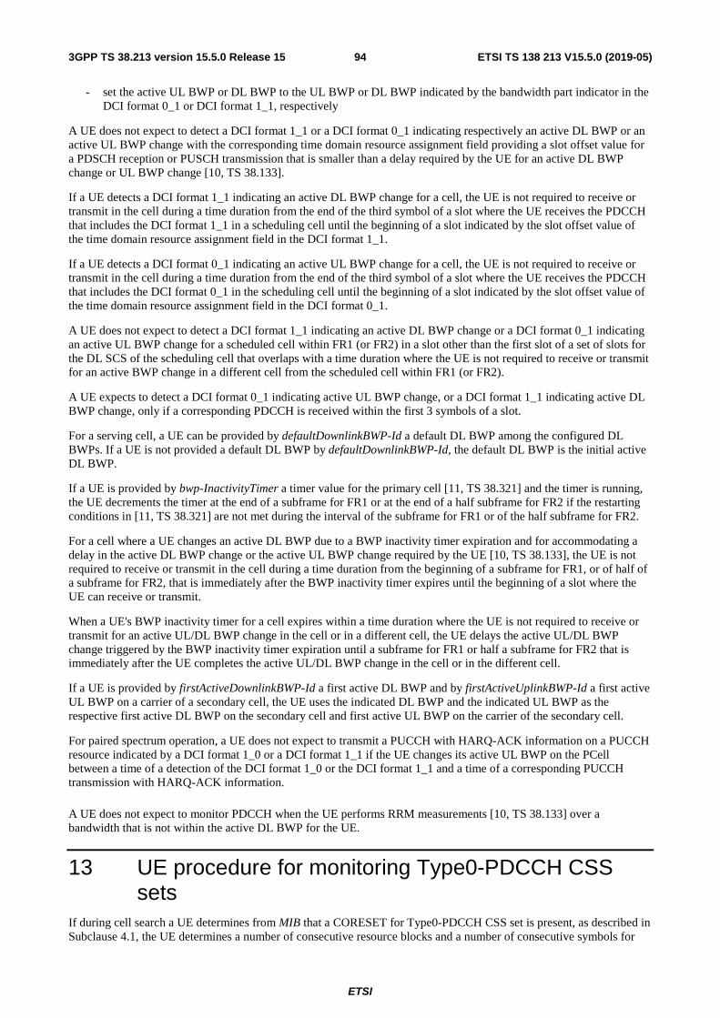
ETSI
ETSI TS 138 213 V15.5.0 (2019-05)943GPP TS 38.213 version 15.5.0 Release 15
- set the active UL BWP or DL BWP to the UL BWP or DL BWP indicated by the bandwidth part indicator in the DCI format 0_1 or DCI format 1_1, respectively
A UE does not expect to detect a DCI format 1_1 or a DCI format 0_1 indicating respectively an active DL BWP or an active UL BWP change with the corresponding time domain resource assignment field providing a slot offset value for a PDSCH reception or PUSCH transmission that is smaller than a delay required by the UE for an active DL BWP change or UL BWP change [10, TS 38.133].
If a UE detects a DCI format 1_1 indicating an active DL BWP change for a cell, the UE is not required to receive or transmit in the cell during a time duration from the end of the third symbol of a slot where the UE receives the PDCCH that includes the DCI format 1_1 in a scheduling cell until the beginning of a slot indicated by the slot offset value of the time domain resource assignment field in the DCI format 1_1.
If a UE detects a DCI format 0_1 indicating an active UL BWP change for a cell, the UE is not required to receive or transmit in the cell during a time duration from the end of the third symbol of a slot where the UE receives the PDCCH that includes the DCI format 0_1 in the scheduling cell until the beginning of a slot indicated by the slot offset value of the time domain resource assignment field in the DCI format 0_1.
A UE does not expect to detect a DCI format 1_1 indicating an active DL BWP change or a DCI format 0_1 indicating an active UL BWP change for a scheduled cell within FR1 (or FR2) in a slot other than the first slot of a set of slots for the DL SCS of the scheduling cell that overlaps with a time duration where the UE is not required to receive or transmit for an active BWP change in a different cell from the scheduled cell within FR1 (or FR2).
A UE expects to detect a DCI format 0_1 indicating active UL BWP change, or a DCI format 1_1 indicating active DL BWP change, only if a corresponding PDCCH is received within the first 3 symbols of a slot.
For a serving cell, a UE can be provided by defaultDownlinkBWP-Id a default DL BWP among the configured DL BWPs. If a UE is not provided a default DL BWP by defaultDownlinkBWP-Id, the default DL BWP is the initial active DL BWP.
If a UE is provided by bwp-InactivityTimer a timer value for the primary cell [11, TS 38.321] and the timer is running, the UE decrements the timer at the end of a subframe for FR1 or at the end of a half subframe for FR2 if the restarting conditions in [11, TS 38.321] are not met during the interval of the subframe for FR1 or of the half subframe for FR2.
For a cell where a UE changes an active DL BWP due to a BWP inactivity timer expiration and for accommodating a delay in the active DL BWP change or the active UL BWP change required by the UE [10, TS 38.133], the UE is not required to receive or transmit in the cell during a time duration from the beginning of a subframe for FR1, or of half of a subframe for FR2, that is immediately after the BWP inactivity timer expires until the beginning of a slot where the UE can receive or transmit.
When a UE's BWP inactivity timer for a cell expires within a time duration where the UE is not required to receive or transmit for an active UL/DL BWP change in the cell or in a different cell, the UE delays the active UL/DL BWP change triggered by the BWP inactivity timer expiration until a subframe for FR1 or half a subframe for FR2 that is immediately after the UE completes the active UL/DL BWP change in the cell or in the different cell.
If a UE is provided by firstActiveDownlinkBWP-Id a first active DL BWP and by firstActiveUplinkBWP-Id a first active UL BWP on a carrier of a secondary cell, the UE uses the indicated DL BWP and the indicated UL BWP as the respective first active DL BWP on the secondary cell and first active UL BWP on the carrier of the secondary cell.
For paired spectrum operation, a UE does not expect to transmit a PUCCH with HARQ-ACK information on a PUCCH resource indicated by a DCI format 1_0 or a DCI format 1_1 if the UE changes its active UL BWP on the PCell between a time of a detection of the DCI format 1_0 or the DCI format 1_1 and a time of a corresponding PUCCH transmission with HARQ-ACK information.
A UE does not expect to monitor PDCCH when the UE performs RRM measurements [10, TS 38.133] over a bandwidth that is not within the active DL BWP for the UE.
13 UE procedure for monitoring Type0-PDCCH CSS sets
If during cell search a UE determines from MIB that a CORESET for Type0-PDCCH CSS set is present, as described in Subclause 4.1, the UE determines a number of consecutive resource blocks and a number of consecutive symbols for

ETSI
ETSI TS 138 213 V15.5.0 (2019-05)953GPP TS 38.213 version 15.5.0 Release 15
the CORESET of the Type0-PDCCH CSS set from the four most significant bits of pdcch-ConfigSIB1, as described in Tables 13-1 through 13-10, and determines PDCCH monitoring occasions from the four least significant bits of pdcch-ConfigSIB1, included in MIB, as described in Tables 13-11 through 13-15.
CSFN and Cn are the SFN and slot index
within a frame of the CORESET based on SCS of the CORESET and iSSB,SFN and inSSB, are the SFN and slot index
based on SCS of the CORESET, respectively, where the SS/PBCH block with index i overlaps in time with system
frame iSSB,SFN and slot inSSB, . The symbols of the CORESET associated with pdcch-ConfigSIB1 in MIB or with
searchSpaceSIB1 in PDCCH-ConfigCommon have normal cyclic prefix.
The offset in Tables 13-1 through 13-10 is defined with respect to the SCS of the CORESET for Type0-PDCCH CSS set, provided by subCarrierSpacingCommon, from the smallest RB index of the CORESET for Type0-PDCCH CSS set to the smallest RB index of the common RB overlapping with the first RB of the corresponding SS/PBCH block. In
Tables 13-7, 13-8, and 13-10 SSBk is defined in [4, TS 38.211].
For the SS/PBCH block and CORESET multiplexing pattern 1, a UE monitors PDCCH in the Type0-PDCCH CSS set
over two consecutive slots starting from slot 0n . For SS/PBCH block with index i , the UE determines an index of slot
0n as ( ) μμ ,frameslot0 mod2 NMiOn ⋅+⋅= located in a frame with system frame number (SFN) CSFN satisfying
02modSFNC = if ( ) 02mod2 ,frameslot =⋅+⋅ μμ NMiO or in a frame with SFN satisfying 12modSFNC = if
( ) 12mod2 ,frameslot =⋅+⋅ μμ NMiO . M and O are provided by Tables 13-11 and 13-12, and { }1,2,3 0,∈μ based on
the SCS for PDCCH receptions in the CORESET [4, TS 38.211]. The index for the first symbol of the CORESET in slot Cn is the first symbol index provided by Tables 13-11 and 13-12.
For the SS/PBCH block and CORESET multiplexing patterns 2 and 3, a UE monitors PDCCH in the Type0-PDCCH CSS set over one slot with Type0-PDCCH CSS set periodicity equal to the periodicity of SS/PBCH block. For the SS/PBCH block and CORESET multiplexing patterns 2 and 3, if the active DL BWP is the initial DL BWP, the UE is expected to be able to perform radio link monitoring, as described in Subclause 5, and measurements for radio resource management [10, TS 38.133] using a SS/PBCH block that provides a CORESET for Type0-PDCCH CSS set. For a
SS/PBCH block with index i , the UE determines the slot index Cn and CSFN based on parameters provided by Tables
13-13 through 13-15.
Table 13-1: Set of resource blocks and slot symbols of CORESET for Type0-PDCCH search space set when {SS/PBCH block, PDCCH} SCS is {15, 15} kHz for frequency bands with minimum channel
bandwidth 5 MHz or 10 MHz
Index SS/PBCH block and CORESET multiplexing pattern
Number of RBs CORESETRBN
Number of Symbols CORESETsymbN Offset (RBs)
0 1 24 2 0 1 1 24 2 2 2 1 24 2 4 3 1 24 3 0 4 1 24 3 2 5 1 24 3 4 6 1 48 1 12 7 1 48 1 16 8 1 48 2 12 9 1 48 2 16
10 1 48 3 12 11 1 48 3 16 12 1 96 1 38 13 1 96 2 38 14 1 96 3 38 15 Reserved
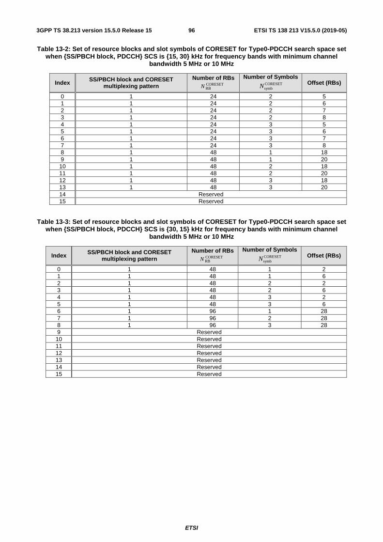
ETSI
ETSI TS 138 213 V15.5.0 (2019-05)963GPP TS 38.213 version 15.5.0 Release 15
Table 13-2: Set of resource blocks and slot symbols of CORESET for Type0-PDCCH search space set when {SS/PBCH block, PDCCH} SCS is {15, 30} kHz for frequency bands with minimum channel
bandwidth 5 MHz or 10 MHz
Index SS/PBCH block and CORESET multiplexing pattern
Number of RBs CORESETRBN
Number of Symbols CORESETsymbN Offset (RBs)
0 1 24 2 5 1 1 24 2 6 2 1 24 2 7 3 1 24 2 8 4 1 24 3 5 5 1 24 3 6 6 1 24 3 7 7 1 24 3 8 8 1 48 1 18 9 1 48 1 20 10 1 48 2 18 11 1 48 2 20 12 1 48 3 18 13 1 48 3 20 14 Reserved 15 Reserved
Table 13-3: Set of resource blocks and slot symbols of CORESET for Type0-PDCCH search space set when {SS/PBCH block, PDCCH} SCS is {30, 15} kHz for frequency bands with minimum channel
bandwidth 5 MHz or 10 MHz
Index SS/PBCH block and CORESET multiplexing pattern
Number of RBs CORESETRBN
Number of Symbols CORESETsymbN Offset (RBs)
0 1 48 1 2 1 1 48 1 6 2 1 48 2 2 3 1 48 2 6 4 1 48 3 2 5 1 48 3 6 6 1 96 1 28 7 1 96 2 28 8 1 96 3 28 9 Reserved
10 Reserved 11 Reserved 12 Reserved 13 Reserved 14 Reserved 15 Reserved

ETSI
ETSI TS 138 213 V15.5.0 (2019-05)973GPP TS 38.213 version 15.5.0 Release 15
Table 13-4: Set of resource blocks and slot symbols of CORESET for Type0-PDCCH search space set when {SS/PBCH block, PDCCH} SCS is {30, 30} kHz for frequency bands with minimum channel
bandwidth 5 MHz or 10 MHz
Index SS/PBCH block and CORESET multiplexing pattern
Number of RBs CORESETRBN
Number of Symbols CORESETsymbN Offset (RBs)
0 1 24 2 0 1 1 24 2 1 2 1 24 2 2 3 1 24 2 3 4 1 24 2 4 5 1 24 3 0 6 1 24 3 1 7 1 24 3 2 8 1 24 3 3 9 1 24 3 4
10 1 48 1 12 11 1 48 1 14 12 1 48 1 16 13 1 48 2 12 14 1 48 2 14 15 1 48 2 16
Table 13-5: Set of resource blocks and slot symbols of CORESET for Type0-PDCCH search space set when {SS/PBCH block, PDCCH} SCS is {30, 15} kHz for frequency bands with minimum channel
bandwidth 40MHz
Index SS/PBCH block and CORESET multiplexing pattern
Number of RBs CORESETRBN
Number of Symbols CORESETsymbN
Offset (RBs)
0 1 48 1 4 1 1 48 2 4 2 1 48 3 4 3 1 96 1 0 4 1 96 1 56 5 1 96 2 0 6 1 96 2 56 7 1 96 3 0 8 1 96 3 56 9 Reserved 10 Reserved 11 Reserved 12 Reserved 13 Reserved 14 Reserved 15 Reserved
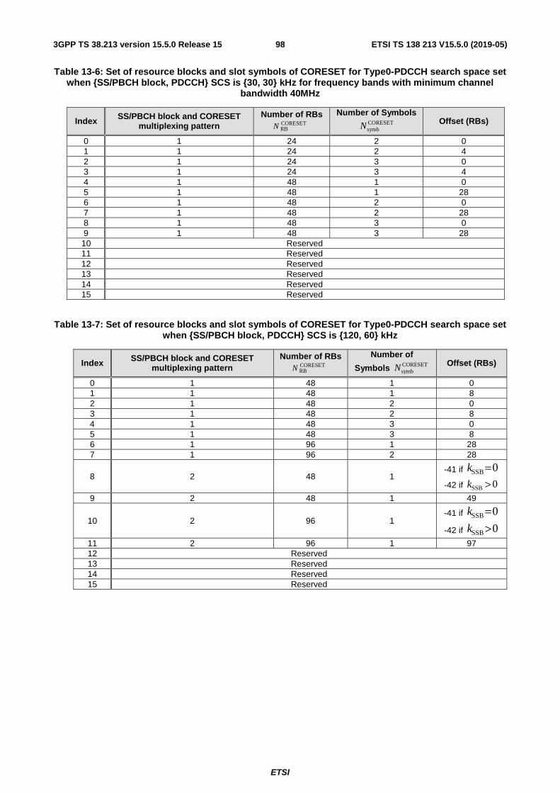
ETSI
ETSI TS 138 213 V15.5.0 (2019-05)983GPP TS 38.213 version 15.5.0 Release 15
Table 13-6: Set of resource blocks and slot symbols of CORESET for Type0-PDCCH search space set when {SS/PBCH block, PDCCH} SCS is {30, 30} kHz for frequency bands with minimum channel
bandwidth 40MHz
Index SS/PBCH block and CORESET multiplexing pattern
Number of RBs CORESETRBN
Number of Symbols CORESETsymbN Offset (RBs)
0 1 24 2 0 1 1 24 2 4 2 1 24 3 0 3 1 24 3 4 4 1 48 1 0 5 1 48 1 28 6 1 48 2 0 7 1 48 2 28 8 1 48 3 0 9 1 48 3 28 10 Reserved 11 Reserved 12 Reserved 13 Reserved 14 Reserved 15 Reserved
Table 13-7: Set of resource blocks and slot symbols of CORESET for Type0-PDCCH search space set when {SS/PBCH block, PDCCH} SCS is {120, 60} kHz
Index SS/PBCH block and CORESET multiplexing pattern
Number of RBs CORESETRBN
Number of
Symbols CORESETsymbN Offset (RBs)
0 1 48 1 0 1 1 48 1 8 2 1 48 2 0 3 1 48 2 8 4 1 48 3 0 5 1 48 3 8 6 1 96 1 28 7 1 96 2 28
8 2 48 1 -41 if 0SSB =k
-42 if 0SSB >k
9 2 48 1 49
10 2 96 1 -41 if 0SSB =k
-42 if 0SSB >k
11 2 96 1 97 12 Reserved 13 Reserved 14 Reserved 15 Reserved

ETSI
ETSI TS 138 213 V15.5.0 (2019-05)993GPP TS 38.213 version 15.5.0 Release 15
Table 13-8: Set of resource blocks and slot symbols of CORESET for Type0-PDCCH search space set when {SS/PBCH block, PDCCH} SCS is {120, 120} kHz
Index SS/PBCH block and CORESET multiplexing pattern
Number of RBs CORESETRBN
Number of
Symbols CORESETsymbN Offset (RBs)
0 1 24 2 0 1 1 24 2 4 2 1 48 1 14 3 1 48 2 14
4 3 24 2 -20 if 0SSB =k
-21 if 0SSB >k
5 3 24 2 24
6 3 48 2 -20 if 0SSB =k
-21 if 0SSB >k
7 3 48 2 48 8 Reserved 9 Reserved 10 Reserved 11 Reserved 12 Reserved 13 Reserved 14 Reserved 15 Reserved
Table 13-9: Set of resource blocks and slot symbols of CORESET for Type0-PDCCH search space set when {SS/PBCH block, PDCCH} SCS is {240, 60} kHz
Index SS/PBCH block and CORESET multiplexing pattern
Number of RBs CORESETRBN
Number of Symbols CORESETsymbN Offset (RBs)
0 1 96 1 0 1 1 96 1 16 2 1 96 2 0 3 1 96 2 16 4 Reserved 5 Reserved 6 Reserved 7 Reserved 8 Reserved 9 Reserved 10 Reserved 11 Reserved 12 Reserved 13 Reserved 14 Reserved 15 Reserved
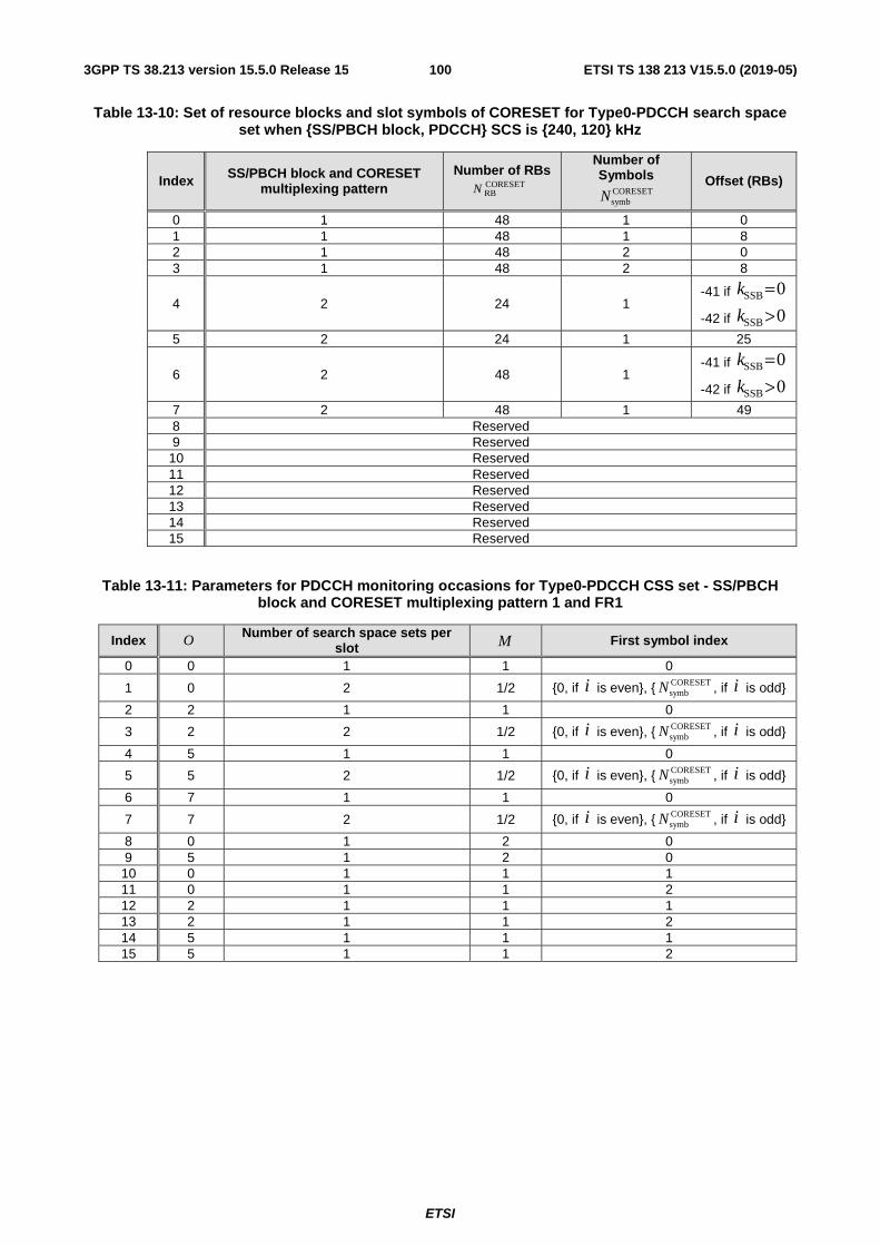
ETSI
ETSI TS 138 213 V15.5.0 (2019-05)1003GPP TS 38.213 version 15.5.0 Release 15
Table 13-10: Set of resource blocks and slot symbols of CORESET for Type0-PDCCH search space set when {SS/PBCH block, PDCCH} SCS is {240, 120} kHz
Index SS/PBCH block and CORESET multiplexing pattern
Number of RBs CORESETRBN
Number of Symbols
CORESETsymbN
Offset (RBs)
0 1 48 1 0 1 1 48 1 8 2 1 48 2 0 3 1 48 2 8
4 2 24 1 -41 if 0SSB =k
-42 if 0SSB >k
5 2 24 1 25
6 2 48 1 -41 if 0SSB =k
-42 if 0SSB >k
7 2 48 1 49 8 Reserved 9 Reserved
10 Reserved 11 Reserved 12 Reserved 13 Reserved 14 Reserved 15 Reserved
Table 13-11: Parameters for PDCCH monitoring occasions for Type0-PDCCH CSS set - SS/PBCH block and CORESET multiplexing pattern 1 and FR1
Index O Number of search space sets per slot M First symbol index
0 0 1 1 0
1 0 2 1/2 {0, if i is even}, { CORESETsymbN , if i is odd}
2 2 1 1 0
3 2 2 1/2 {0, if i is even}, { CORESETsymbN , if i is odd}
4 5 1 1 0
5 5 2 1/2 {0, if i is even}, { CORESETsymbN , if i is odd}
6 7 1 1 0
7 7 2 1/2 {0, if i is even}, { CORESETsymbN , if i is odd}
8 0 1 2 0 9 5 1 2 0 10 0 1 1 1 11 0 1 1 2 12 2 1 1 1 13 2 1 1 2 14 5 1 1 1 15 5 1 1 2

ETSI
ETSI TS 138 213 V15.5.0 (2019-05)1013GPP TS 38.213 version 15.5.0 Release 15
Table 13-12: Parameters for PDCCH monitoring occasions for Type0-PDCCH CSS set - SS/PBCH block and CORESET multiplexing pattern 1 and FR2
Index O Number of search space sets per
slot M First symbol index
0 0 1 1 0 1 0 2 1/2 {0, if i is even}, {7, if i is odd} 2 2.5 1 1 0 3 2.5 2 1/2 {0, if i is even}, {7, if i is odd} 4 5 1 1 0 5 5 2 1/2 {0, if i is even}, {7, if i is odd}
6 0 2 1/2 {0, if i is even}, { CORESETsymbN , if i is odd}
7 2.5 2 1/2 {0, if i is even}, { CORESETsymbN , if i is odd}
8 5 2 1/2 {0, if i is even}, { CORESETsymbN , if i is odd}
9 7.5 1 1 0 10 7.5 2 1/2 {0, if i is even}, {7, if i is odd}
11 7.5 2 1/2 {0, if i is even}, { CORESETsymbN , if i is odd}
12 0 1 2 0 13 5 1 2 0 14 Reserved 15 Reserved
Table 13-13: PDCCH monitoring occasions for Type0-PDCCH CSS set - SS/PBCH block and CORESET multiplexing pattern 2 and {SS/PBCH block, PDCCH} SCS {120, 60} kHz
Index PDCCH monitoring occasions (SFN and slot number) First symbol index (k = 0, 1, … 15)
0 iSSB,C SFNSFN =
inn SSB,C =
0, 1, 6, 7 for
ki 4= , 14 += ki , 24 += ki , 34 += ki 1 Reserved 2 Reserved 3 Reserved 4 Reserved 5 Reserved 6 Reserved 7 Reserved 8 Reserved 9 Reserved 10 Reserved 11 Reserved 12 Reserved 13 Reserved 14 Reserved 15 Reserved

ETSI
ETSI TS 138 213 V15.5.0 (2019-05)1023GPP TS 38.213 version 15.5.0 Release 15
Table 13-14: PDCCH monitoring occasions for Type0-PDCCH CSS set - SS/PBCH block and CORESET multiplexing pattern 2 and {SS/PBCH block, PDCCH} SCS {240, 120} kHz
Index PDCCH monitoring occasions (SFN and slot number)
First symbol index (k = 0, 1, …, 7)
0 iSSB,C SFNSFN =
inn SSB,C = or 1SSB,C −= inn
0, 1, 2, 3, 0, 1 in ki 8= , 18 += ki , 28 += ki , 38 += ki ,
68 += ki , 78 += ki ( inn SSB,C = )
12, 13 in 48 += ki , 58 += ki ( 1SSB,C −= inn )
1 Reserved 2 Reserved 3 Reserved 4 Reserved 5 Reserved 6 Reserved 7 Reserved 8 Reserved 9 Reserved 10 Reserved 11 Reserved 12 Reserved 13 Reserved 14 Reserved 15 Reserved
Table 13-15: PDCCH monitoring occasions for Type0-PDCCH CSS set - SS/PBCH block and CORESET multiplexing pattern 3 and {SS/PBCH block, PDCCH} SCS {120, 120} kHz
Index PDCCH monitoring occasions (SFN and slot number) First symbol index (k = 0, 1, … 15)
0 iSSB,C SFNSFN =
inn SSB,C =
4, 8, 2, 6 in
ki 4= , 14 += ki , 24 += ki , 34 += ki 1 Reserved 2 Reserved 3 Reserved 4 Reserved 5 Reserved 6 Reserved 7 Reserved 8 Reserved 9 Reserved 10 Reserved 11 Reserved 12 Reserved 13 Reserved 14 Reserved 15 Reserved
If a UE detects a first SS/PBCH block and determines that a CORESET for Type0-PDCCH CSS set is not present, and for 2924 SSB ≤≤ k for FR1 or for 1312 SSB ≤≤ k for FR2, the UE may determine the nearest (in the corresponding
frequency direction) global synchronization channel number (GSCN) of a second SS/PBCH block having a CORESET
for an associated Type0-PDCCH CSS set as OffsetGSCN
ReferenceGSCN NN + . Reference
GSCNN is the GSCN of the first SS/PBCH block and OffsetGSCNN is a GSCN offset provided by Table 13-16 for FR1 and Table 13-17 for FR2. If the UE detects the second
SS/PBCH block and the second SS/PBCH block does not provide a CORESET for Type0-PDCCH CSS set, as described in Subclause 4.1, the UE may ignore the information related to GSCN of SS/PBCH block locations for performing cell search.
If a UE detects a SS/PBCH block and determines that a CORESET for Type0-PDCCH CSS set is not present, and for
31SSB =k for FR1 or for 15SSB =k for FR2, the UE determines that there is no SS/PBCH block having an associated
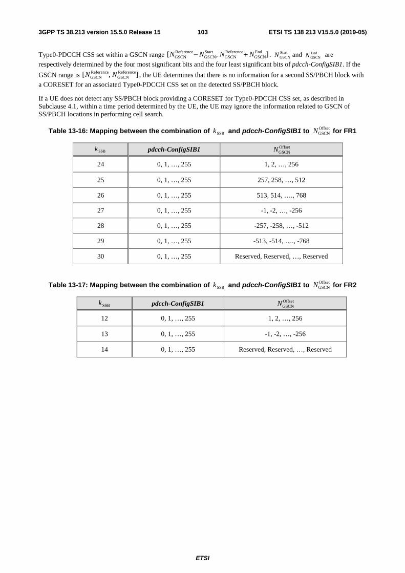
ETSI
ETSI TS 138 213 V15.5.0 (2019-05)1033GPP TS 38.213 version 15.5.0 Release 15
Type0-PDCCH CSS set within a GSCN range ],[ EndGSCN
ReferenceGSCN
StartGSCN
ReferenceGSCN NNNN +− . Start
GSCNN and EndGSCNN are
respectively determined by the four most significant bits and the four least significant bits of pdcch-ConfigSIB1. If the
GSCN range is ],[ ReferenceGSCN
ReferenceGSCN NN , the UE determines that there is no information for a second SS/PBCH block with
a CORESET for an associated Type0-PDCCH CSS set on the detected SS/PBCH block.
If a UE does not detect any SS/PBCH block providing a CORESET for Type0-PDCCH CSS set, as described in Subclause 4.1, within a time period determined by the UE, the UE may ignore the information related to GSCN of SS/PBCH locations in performing cell search.
Table 13-16: Mapping between the combination of SSBk and pdcch-ConfigSIB1 to OffsetGSCNN for FR1
SSBk pdcch-ConfigSIB1 OffsetGSCNN
24 0, 1, …, 255 1, 2, …, 256
25 0, 1, …, 255 257, 258, …, 512
26 0, 1, …, 255 513, 514, …., 768
27 0, 1, …, 255 -1, -2, …, -256
28 0, 1, …, 255 -257, -258, …, -512
29 0, 1, …, 255 -513, -514, …., -768
30 0, 1, …, 255 Reserved, Reserved, …, Reserved
Table 13-17: Mapping between the combination of SSBk and pdcch-ConfigSIB1 to OffsetGSCNN for FR2
SSBk pdcch-ConfigSIB1 OffsetGSCNN
12 0, 1, …, 255 1, 2, …, 256
13 0, 1, …, 255 -1, -2, …, -256
14 0, 1, …, 255 Reserved, Reserved, …, Reserved
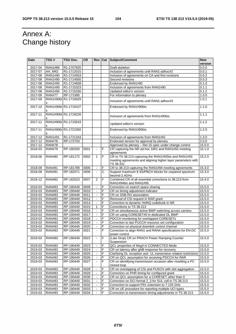
ETSI
ETSI TS 138 213 V15.5.0 (2019-05)1043GPP TS 38.213 version 15.5.0 Release 15
Annex A: Change history
Date TSG # TSG Doc. CR Rev Cat Subject/Comment New version
2017-04 RAN1#89 R1-1707925 Draft skeleton 0.0.0 2017-07 AH_NR2 R1-1712015 Inclusion of agreements until RAN1-adhoc#2 0.0.1 2017-08 RAN1#90 R1-1714553 Inclusion of agreements on CA and first revisions 0.0.2 2017-08 RAN1#90 R1-1714565 Second revisions 0.0.3 2017-08 RAN1#90 R1-1714658 Endorsed by RAN1#90 0.1.0 2017-08 RAN1#90 R1-1715323 Inclusion of agreements from RAN1#90 0.1.1 2017-08 RAN1#90 R1-1715330 Updated editor's version 0.1.2 2017-09 RAN#77 RP-171995 For information to plenary 1.0.0 2017-09 RAN1#90bi
s R1-1716929 Inclusion of agreements until RAN1-adhoc#3 1.0.1
2017-10 RAN1#90bis
R1-1719107 Endorsed by RAN1#90bis 1.1.0
2017-11 RAN1#90bis
R1-1719226 Inclusion of agreements from RAN1#90bis 1.1.1
2017-11 RAN1#90bis
R1-1719243 Updated editor's version 1.1.2
2017-11 RAN1#90bis
R1-1721050 Endorsed by RAN1#90bis 1.2.0
2017-12 RAN1#91 R1-1721343 Inclusion of agreements from RAN1#91 1.3.0 2017-12 RAN#78 RP-172703 Endorsed version for approval by plenary 2.0.0 2017-12 RAN#78 Approved by plenary – Rel-15 spec under change control 15.0.0 2018-03 RAN#79 RP-180200 0001 - F CR capturing the NR ad-hoc 1801 and RAN1#92 meeting
agreements 15.1.0
2018-06 RAN#80 RP-181172 0002 1 F CR to TS 38.213 capturing the RAN1#92bis and RAN1#93 meeting agreements and aligning higher layer parameters with TS 38.331
15.2.0
2018-09 RAN#81 RP-181789 0005 - F CR to 38.213 capturing the RAN1#94 meeting agreements 15.3.0 2018-09 RAN#81 RP-182071 0006 - C Support maximum 8 SS/PBCH blocks for unpaired spectrum
beyond 2.4GHz 15.3.0
2018-12 RAN#82 RP-182523 0007 2 F Combined CR of all essential corrections to 38.213 from RAN1#94bis and RAN1#95.
15.4.0
2019-03 RAN#83 RP-190449 0009 - F Correction on search space sharing 15.5.0 2019-03 RAN#83 RP-190449 0010 - F CR on timing adjustment indicator 15.5.0 2019-03 RAN#83 RP-190449 0011 - F CR on SSB-RO association 15.5.0 2019-03 RAN#83 RP-190449 0012 - F Removal of CSI request in RAR grant 15.5.0 2019-03 RAN#83 RP-190449 0014 - F Correction to dynamic HARQ codebook in NR 15.5.0 2019-03 RAN#83 RP-190449 0015 1 F Correcttions to TS 38.213 15.5.0 2019-03 RAN#83 RP-190449 0016 - F CR on simultaneous active BWP switching across carriers 15.5.0 2019-03 RAN#83 RP-190449 0017 - F CR on using CORESET#0 in dedicated DL BWP 15.5.0 2019-03 RAN#83 RP-190449 0018 - F PDCCH monitoring for overlapped CORESETs 15.5.0 2019-03 RAN#83 RP-190449 0019 - F Correction to last PUCCH resource set configuration 15.5.0 2019-03 RAN#83 RP-190449 0020 - F Correction on physical downlink control channel 15.5.0 2019-03 RAN#83 RP-190449 0021 - F Correction to align RAN1 and RAN4 specifications for EN-DC
power control 15.5.0
2019-03 RAN#83 RP-190449 0022 - F (Late Drop) CR on PRACH Power Ramping Counter Suspension
15.5.0
2019-03 RAN#83 RP-190449 0023 - F QCL properties of Msg4 in CONNECTED Mode 15.5.0 2019-03 RAN#83 RP-190449 0024 - F CR on latency after gNB response for recovery 15.5.0 2019-03 RAN#83 RP-190449 0025 - F Clarifying DL reception and UL transmision related restrictions 15.5.0 2019-03 RAN#83 RP-190449 0026 - F CR on QCL assumption for receiving PDCCH for RAR 15.5.0 2019-03 RAN#83 RP-190449 0027 - F CR on identifying transmission occasion after resetting a PC
closed loop 15.5.0
2019-03 RAN#83 RP-190449 0028 - F CR on overlapping of CSI and PUSCH with slot aggregation 15.5.0 2019-03 RAN#83 RP-190449 0029 - F Correction on PHR timing for configured grant 15.5.0 2019-03 RAN#83 RP-190449 0030 - F CR on QCL assumption for a CORESET other than 0 15.5.0 2019-03 RAN#83 RP-190449 0031 - F Correction on DCI format 2_3 for SUL cell in TS 38.213 15.5.0 2019-03 RAN#83 RP-190449 0032 - F Correction to support FR1 extension to 7.125 GHz 15.5.0 2019-03 RAN#83 RP-190449 0033 - F CR on UE procedure for reporting multiple UCI types 15.5.0 2019-03 RAN#83 RP-190449 0034 - F Correction to transmission timing adjustments in TS 38.213 15.5.0
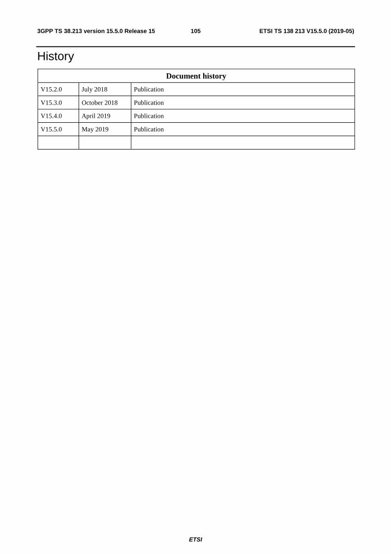
ETSI
ETSI TS 138 213 V15.5.0 (2019-05)1053GPP TS 38.213 version 15.5.0 Release 15
History
Document history
V15.2.0 July 2018 Publication
V15.3.0 October 2018 Publication
V15.4.0 April 2019 Publication
V15.5.0 May 2019 Publication
Related Documents