ETSI TS 136 508 V11.3.0 (2014-02) LTE; Evolved Universal Terrestrial Radio Access (E-UTRA) and Evolved Packet Core (EPC); Common test environments for User Equipment (UE) conformance testing (3GPP TS 36.508 version 11.3.0 Release 11) Technical Specification

Welcome message from author
This document is posted to help you gain knowledge. Please leave a comment to let me know what you think about it! Share it to your friends and learn new things together.
Transcript

ETSI TS 136 508 V11.3.0 (2014-02)
LTE; Evolved Universal Terrestrial Radio Access (E-UTRA) and
Evolved Packet Core (EPC); Common test environments for User Equipment (UE)
conformance testing (3GPP TS 36.508 version 11.3.0 Release 11)
Technical Specification

ETSI
ETSI TS 136 508 V11.3.0 (2014-02)13GPP TS 36.508 version 11.3.0 Release 11
Reference RTS/TSGR-0536508vb30
Keywords LTE
ETSI
650 Route des Lucioles F-06921 Sophia Antipolis Cedex - FRANCE
Tel.: +33 4 92 94 42 00 Fax: +33 4 93 65 47 16
Siret N° 348 623 562 00017 - NAF 742 C
Association à but non lucratif enregistrée à la Sous-Préfecture de Grasse (06) N° 7803/88
Important notice
Individual copies of the present document can be downloaded from: http://www.etsi.org
The present document may be made available in more than one electronic version or in print. In any case of existing or perceived difference in contents between such versions, the reference version is the Portable Document Format (PDF).
In case of dispute, the reference shall be the printing on ETSI printers of the PDF version kept on a specific network drive within ETSI Secretariat.
Users of the present document should be aware that the document may be subject to revision or change of status. Information on the current status of this and other ETSI documents is available at http://portal.etsi.org/tb/status/status.asp
If you find errors in the present document, please send your comment to one of the following services: http://portal.etsi.org/chaircor/ETSI_support.asp
Copyright Notification
No part may be reproduced except as authorized by written permission. The copyright and the foregoing restriction extend to reproduction in all media.
© European Telecommunications Standards Institute 2014.
All rights reserved.
DECTTM, PLUGTESTSTM, UMTSTM and the ETSI logo are Trade Marks of ETSI registered for the benefit of its Members. 3GPPTM and LTE™ are Trade Marks of ETSI registered for the benefit of its Members and
of the 3GPP Organizational Partners. GSM® and the GSM logo are Trade Marks registered and owned by the GSM Association.

ETSI
ETSI TS 136 508 V11.3.0 (2014-02)23GPP TS 36.508 version 11.3.0 Release 11
Intellectual Property Rights IPRs essential or potentially essential to the present document may have been declared to ETSI. The information pertaining to these essential IPRs, if any, is publicly available for ETSI members and non-members, and can be found in ETSI SR 000 314: "Intellectual Property Rights (IPRs); Essential, or potentially Essential, IPRs notified to ETSI in respect of ETSI standards", which is available from the ETSI Secretariat. Latest updates are available on the ETSI Web server (http://ipr.etsi.org).
Pursuant to the ETSI IPR Policy, no investigation, including IPR searches, has been carried out by ETSI. No guarantee can be given as to the existence of other IPRs not referenced in ETSI SR 000 314 (or the updates on the ETSI Web server) which are, or may be, or may become, essential to the present document.
Foreword This Technical Specification (TS) has been produced by ETSI 3rd Generation Partnership Project (3GPP).
The present document may refer to technical specifications or reports using their 3GPP identities, UMTS identities or GSM identities. These should be interpreted as being references to the corresponding ETSI deliverables.
The cross reference between GSM, UMTS, 3GPP and ETSI identities can be found under http://webapp.etsi.org/key/queryform.asp.

ETSI
ETSI TS 136 508 V11.3.0 (2014-02)33GPP TS 36.508 version 11.3.0 Release 11
Contents
Intellectual Property Rights ................................................................................................................................ 2
Foreword ............................................................................................................................................................. 2
Foreword ........................................................................................................................................................... 15
Introduction ...................................................................................................................................................... 15
1 Scope ...................................................................................................................................................... 16
2 References .............................................................................................................................................. 16
3 Definitions, symbols and abbreviations ................................................................................................. 18
3.1 Definitions ........................................................................................................................................................ 18
3.2 Symbols ............................................................................................................................................................ 18
3.3 Abbreviations ................................................................................................................................................... 19
4 Common test environment ..................................................................................................................... 19
4.1 Environmental conditions ................................................................................................................................. 19
4.1.1 Temperature ................................................................................................................................................ 19
4.1.2 Voltage ........................................................................................................................................................ 20
4.2 Common requirements of test equipment ......................................................................................................... 20
4.2.1 General functional requirements ................................................................................................................. 20
4.2.2 Minimum functional requirements ............................................................................................................. 21
4.2.2.1 Supported Cell Configuration ............................................................................................................... 21
4.2.2.1.1 Supported Channels ......................................................................................................................... 21
4.2.2.2 Support of Tcell timing offset ................................................................................................................. 22
4.3 Reference test conditions .................................................................................................................................. 22
4.3.1 Test frequencies .......................................................................................................................................... 22
4.3.1.1 FDD Mode Test frequencies ................................................................................................................. 24
4.3.1.1.1 FDD reference test frequencies for operating band 1 ...................................................................... 24
4.3.1.1.1A FDD reference test frequencies for CA in operating band 1............................................................ 24
4.3.1.1.2 FDD reference test frequencies for operating band 2 ...................................................................... 24
4.3.1.1.3 FDD reference test frequencies for operating band 3 ...................................................................... 25
4.3.1.1.4 FDD reference test frequencies for operating band 4 ...................................................................... 25
4.3.1.1.5 FDD reference test frequencies for operating band 5 ...................................................................... 26
4.3.1.1.6 FDD reference test frequencies for operating band 6 ...................................................................... 26
4.3.1.1.7 FDD reference test frequencies for operating band 7 ...................................................................... 26
4.3.1.1.7A FDD reference test frequencies for CA in operating band 7............................................................ 27
4.3.1.1.8 FDD reference test frequencies for operating band 8 ...................................................................... 27
4.3.1.1.9 FDD reference test frequencies for operating band 9 ...................................................................... 27
4.3.1.1.10 FDD reference test frequencies for operating band 10 .................................................................... 28
4.3.1.1.11 FDD reference test frequencies for operating band 11 .................................................................... 28
4.3.1.1.12 FDD reference test frequencies for operating band 12 .................................................................... 28
4.3.1.1.13 FDD reference test frequencies for operating band 13 .................................................................... 28
4.3.1.1.14 FDD reference test frequencies for operating band 14 .................................................................... 29
4.3.1.1.15 FDD reference test frequencies for operating band 15 .................................................................... 29
4.3.1.1.16 FDD reference test frequencies for operating band 16 .................................................................... 29
4.3.1.1.17 FDD reference test frequencies for operating band 17 .................................................................... 29
4.3.1.1.18 FDD reference test frequencies for operating band 18 .................................................................... 29
4.3.1.1.19 FDD reference test frequencies for operating band 19 .................................................................... 30
4.3.1.1.20 FDD reference test frequencies for operating band 20 .................................................................... 30
4.3.1.1.21 FDD reference test frequencies for operating band 21 .................................................................... 30
4.3.1.1.22 FDD reference test frequencies for operating band 22 .................................................................... 31
4.3.1.1.23 FDD reference test frequencies for operating band 23 .................................................................... 31
4.3.1.1.24 FDD reference test frequencies for operating band 24 .................................................................... 31
4.3.1.1.25 FDD reference test frequencies for operating band 25 .................................................................... 31
4.3.1.1.26 FDD reference test frequencies for operating band 26 .................................................................... 32
4.3.1.1.27 FDD reference test frequencies for operating band 27 .................................................................... 32
4.3.1.1.28 FDD reference test frequencies for operating band 28 .................................................................... 33

ETSI
ETSI TS 136 508 V11.3.0 (2014-02)43GPP TS 36.508 version 11.3.0 Release 11
4.3.1.1.29 FDD reference test frequencies for CA in operating band 29 .......................................................... 33
4.3.1.1.31 FDD reference test frequencies for operating band 31 .................................................................... 34
4.3.1.2 TDD Mode Test frequencies ................................................................................................................. 34
4.3.1.2.1 TDD reference test frequencies for Operating Band 33 .................................................................. 34
4.3.1.2.2 TDD reference test frequencies for Operating Band 34 .................................................................. 34
4.3.1.2.3 TDD reference test frequencies for Operating Band 35 .................................................................. 35
4.3.1.2.4 TDD reference test frequencies for Operating Band 36 .................................................................. 35
4.3.1.2.5 TDD reference test frequencies for Operating Band 37 .................................................................. 35
4.3.1.2.6 TDD reference test frequencies for Operating Band 38 .................................................................. 36
4.3.1.2.6A TDD reference test frequencies for CA in operating band 38 ......................................................... 36
4.3.1.2.7 TDD reference test frequencies for Operating Band 39 .................................................................. 36
4.3.1.2.8 TDD reference test frequencies for Operating Band 40 .................................................................. 37
4.3.1.2.8A TDD reference test frequencies for CA in operating band 40 ......................................................... 37
4.3.1.2.9 TDD reference test frequencies for Operating Band 41 .................................................................. 37
4.3.1.2.9A TDD reference test frequencies for CA in operating band 41 ......................................................... 38
4.3.1.2.10 TDD reference test frequencies for Operating Band 42 .................................................................. 38
4.3.1.2.11 TDD reference test frequencies for Operating Band 43 .................................................................. 39
4.3.1.2.12 TDD reference test frequencies for Operating Band 44 .................................................................. 39
4.3.1.3 HRPD Test frequencies ......................................................................................................................... 39
4.3.1.3.1 HRPD test frequencies for Band Class 0 ......................................................................................... 39
4.3.1.3.2 HRPD test frequencies for Band Class 1 ......................................................................................... 39
4.3.1.3.3 HRPD test frequencies for Band Class 3 ......................................................................................... 40
4.3.1.3.4 HRPD test frequencies for Band Class 4 ......................................................................................... 40
4.3.1.3.5 HRPD test frequencies for Band Class 6 ......................................................................................... 40
4.3.1.3.6 HRPD test frequencies for Band Class 10 ....................................................................................... 40
4.3.1.3.7 HRPD test frequencies for Band Class 15 ....................................................................................... 40
4.3.1.4 1xRTT Test frequencies ........................................................................................................................ 41
4.3.1.4.1 1xRTT test frequencies for Band Class 0 ........................................................................................ 41
4.3.1.4.2 1xRTT test frequencies for Band Class 1 ........................................................................................ 41
4.3.1.4.3 1xRTT test frequencies for Band Class 3 ........................................................................................ 41
4.3.1.4.4 1xRTT test frequencies for Band Class 4 ........................................................................................ 41
4.3.1.4.5 1xRTT test frequencies for Band Class 6 ........................................................................................ 41
4.3.1.4.6 1xRTT test frequencies for Band Class 10 ...................................................................................... 42
4.3.1.4.7 1xRTT test frequencies for Band Class 15 ...................................................................................... 42
4.3.2 Radio conditions ......................................................................................................................................... 42
4.3.2.1 Normal propagation condition .............................................................................................................. 42
4.3.3 Physical channel allocations ....................................................................................................................... 42
4.3.3.1 Antennas ............................................................................................................................................... 42
4.3.3.2 Downlink physical channels and physical signals ................................................................................. 42
4.3.3.3 Mapping of downlink physical channels and signals to physical resources .......................................... 43
4.3.3.4 Uplink physical channels and physical signals ..................................................................................... 46
4.3.3.5 Mapping of uplink physical channels and signals to physical resources ............................................... 46
4.3.4 Signal levels ................................................................................................................................................ 46
4.3.4.1 Downlink signal levels .......................................................................................................................... 46
4.3.4.2 Uplink signal levels ............................................................................................................................... 46
4.3.5 Standard test signals.................................................................................................................................... 46
4.3.5.1 Downlink test signals ............................................................................................................................ 46
4.3.5.2 Uplink test signals ................................................................................................................................. 46
4.3.6 Physical layer parameters ........................................................................................................................... 47
4.3.6.1 Downlink physical layer parameters ..................................................................................................... 47
4.3.6.1.1 Physical layer parameters for DCI format 0 .................................................................................... 47
4.3.6.1.2 Physical layer parameters for DCI format 1 .................................................................................... 48
4.3.6.1.3 Physical layer parameters for DCI format 1A ................................................................................. 48
4.3.6.1.3A Physical layer parameters for DCI format 1B ................................................................................. 49
4.3.6.1.4 Physical layer parameters for DCI format 1C ................................................................................. 49
4.3.6.1.5 Physical layer parameters for DCI format 2 .................................................................................... 50
4.3.6.1.6 Physical layer parameters for DCI format 2A ................................................................................. 51
4.4 Reference system configurations ...................................................................................................................... 51
4.4.1 Simulated network scenarios ...................................................................................................................... 51
4.4.1.1 Single cell network scenarios ................................................................................................................ 51
4.4.1.2 E-UTRA single mode multi cell network scenarios .............................................................................. 52
4.4.1.3 E-UTRA dual mode multi cell network scenarios ................................................................................ 52

ETSI
ETSI TS 136 508 V11.3.0 (2014-02)53GPP TS 36.508 version 11.3.0 Release 11
4.4.1.4 3GPP Inter-RAT network scenarios ...................................................................................................... 52
4.4.1.5 3GPP2 Inter-RAT network scenarios .................................................................................................... 52
4.4.1.6 WLAN Inter-RAT network scenarios ................................................................................................... 52
4.4.2 Simulated cells ............................................................................................................................................ 52
4.4.3 Common parameters for simulated E-UTRA cells ..................................................................................... 55
4.4.3.1 Common configurations of system information blocks ........................................................................ 55
4.4.3.1.1 Combinations of system information blocks ................................................................................... 55
4.4.3.1.2 Scheduling of system information blocks ........................................................................................ 58
4.4.3.2 Common contents of system information messages ............................................................................. 62
- MasterInformationBlock ....................................................................................................................... 62
- SystemInformation ................................................................................................................................ 62
- SystemInformationBlockType1 .............................................................................................................. 63
4.4.3.3 Common contents of system information blocks .................................................................................. 64
- SystemInformationBlockType2 .............................................................................................................. 64
- SystemInformationBlockType3 .............................................................................................................. 65
- SystemInformationBlockType4 .............................................................................................................. 66
- SystemInformationBlockType5 .............................................................................................................. 66
- SystemInformationBlockType6 .............................................................................................................. 69
- SystemInformationBlockType7 .............................................................................................................. 70
- SystemInformationBlockType8 .............................................................................................................. 72
- SystemInformationBlockType9 .............................................................................................................. 74
- SystemInformationBlockType10 ............................................................................................................ 75
- SystemInformationBlockType11 ............................................................................................................ 76
- SystemInformationBlockType12 ............................................................................................................ 78
SystemInformationBlockType13 ............................................................................................................ 79
- SystemInformationBlockType15 ............................................................................................................ 80
4.4.3.4 Channel-bandwidth-dependent parameters in system information blocks ............................................ 80
4.4.4 Common parameters for simulated UTRA cells ......................................................................................... 81
4.4.4.1 Common contents of system information blocks for UTRA cells ........................................................ 82
- System Information Block type 19 ........................................................................................................ 82
4.4.4.2 UTRA SIB scheduling for inter EUTRA - UTRA test .......................................................................... 83
4.4.4.3 UTRA SIB scheduling for inter EUTRA – UTRA - GERAN test ........................................................ 83
4.4.5 Common parameters for simulated GERAN cells ...................................................................................... 84
4.4.6 Common parameters for simulated CDMA2000 cells ................................................................................ 86
4.4.7 Default parameters specific for simulated cells .......................................................................................... 86
4.4.7.1 Common contents of HRPD Overhead messages ................................................................................. 86
4.4.7.2 Common contents of 1XRTT Overhead messages ............................................................................... 90
4.4.7.2.1 Configuration sequence number ...................................................................................................... 90
4.4.7.2.2 Over Head messages ........................................................................................................................ 91
4.5 Generic procedures ........................................................................................................................................... 98
4.5.1 UE test states............................................................................................................................................... 98
4.5.2 UE Registration (State 2) .......................................................................................................................... 101
4.5.2.1 Initial conditions ................................................................................................................................. 101
4.5.2.2 Definition of system information messages ........................................................................................ 101
4.5.2.3 Procedure ............................................................................................................................................ 102
4.5.2.4 Specific message contents ................................................................................................................... 104
4.5.2A UE Registration, UE Test Mode Activated (State 2A) ............................................................................. 105
4.5.2A.1 Initial conditions ................................................................................................................................. 105
4.5.2A.2 Definition of system information messages ........................................................................................ 105
4.5.2A.3 Procedure ............................................................................................................................................ 106
4.5.2A.4 Specific message contents ................................................................................................................... 107
4.5.2B UE Registration, pre-registration on HRPD (State 2B) ............................................................................ 108
4.5.2B.1 Initial conditions ................................................................................................................................. 108
4.5.2B.2 Definition of system information messages ........................................................................................ 108
4.5.2B.3 Procedure ............................................................................................................................................ 109
4.5.2B.4 Specific message contents ................................................................................................................... 113
4.5.2C UE Registration, pre-registration on 1xRTT (State 2C) ........................................................................... 114
4.5.2C.1 Initial conditions ................................................................................................................................. 114
4.5.2C.2 Definition of system information messages ........................................................................................ 114
4.5.2C.3 Procedure ............................................................................................................................................ 116
4.5.2C.4 Specific message contents ................................................................................................................... 116
4.5.3 Generic Radio Bearer Establishment (State 3).......................................................................................... 121

ETSI
ETSI TS 136 508 V11.3.0 (2014-02)63GPP TS 36.508 version 11.3.0 Release 11
4.5.3.1 Initial conditions ................................................................................................................................. 121
4.5.3.2 Definition of system information messages ........................................................................................ 121
4.5.3.3 Procedure ............................................................................................................................................ 122
4.5.3.4 Specific message contents ................................................................................................................... 123
4.5.3A Generic Radio Bearer Establishment, UE Test Mode Activated (State 3A) ............................................. 123
4.5.3A.1 Initial conditions ................................................................................................................................. 123
4.5.3A.2 Definition of system information messages ........................................................................................ 123
4.5.3A.3 Procedure ............................................................................................................................................ 123
4.5.3A.4 Specific message contents ................................................................................................................... 123
4.5.3B Generic Radio Bearer Establishment, pre-registered on HRPD (State 3B) .............................................. 124
4.5.3B.1 Initial conditions ................................................................................................................................. 124
4.5.3B.2 Definition of system information messages ........................................................................................ 124
4.5.3B.3 Procedure ............................................................................................................................................ 124
4.5.3B.4 Specific message contents ................................................................................................................... 124
4.5.3C Generic Radio Bearer Establishment, pre-registered on 1xRTT (State 3C) ............................................. 124
4.5.3C.1 Initial conditions ................................................................................................................................. 124
4.5.3C.2 Definition of system information messages ........................................................................................ 124
4.5.3C.3 Procedure ............................................................................................................................................ 124
4.5.3C.4 Specific message contents ................................................................................................................... 124
4.5.4 Loopback Activation (State 4) .................................................................................................................. 125
4.5.4.1 Initial conditions ................................................................................................................................. 125
4.5.4.2 Definition of system information messages ........................................................................................ 125
4.5.4.3 Procedure ............................................................................................................................................ 125
4.5.4.4 Specific message contents ................................................................................................................... 125
4.5.5 HRPD registration (State H2) ................................................................................................................... 125
4.5.5.1 Initial conditions ................................................................................................................................. 125
4.5.5.2 Definition of system information messages ........................................................................................ 125
4.5.5.3 Procedure ............................................................................................................................................ 126
4.5.5.4 Specific message contents ................................................................................................................... 126
4.5.5A HRPD registration, pre-registration on E-UTRAN (State H2A) .............................................................. 126
4.5.5A.1 Initial conditions ................................................................................................................................. 126
4.5.5A.2 Definition of system information messages ........................................................................................ 126
4.5.5A.3 Procedure ............................................................................................................................................ 126
4.5.5A.4 Specific message contents ................................................................................................................... 126
4.5.6 HRPD session establishment (State H3) ................................................................................................... 126
4.5.6.1 Initial conditions ................................................................................................................................. 126
4.5.6.2 Definition of system information messages ........................................................................................ 126
4.5.6.3 Procedure ............................................................................................................................................ 127
4.5.6.4 Specific message contents ................................................................................................................... 127
4.5.6A HRPD session establishment, pre-registered on E-UTRAN (State H3A) ................................................. 127
4.5.6A.1 Initial conditions ................................................................................................................................. 127
4.5.6A.2 Definition of system information messages ........................................................................................ 127
4.5.6A.3 Procedure ............................................................................................................................................ 127
4.5.6A.4 Specific message contents ................................................................................................................... 127
4.5A Other generic procedures ................................................................................................................................ 127
4.5A.1 Procedure for IP address allocation in the U-plane ................................................................................... 127
4.5A.2 Tracking area updating procedure............................................................................................................. 128
4.5A.3 Procedure for IMS signalling .................................................................................................................... 129
4.5A.4 Generic Test Procedure for IMS Emergency call establishment in EUTRA: Normal Service ................. 130
4.5A.4.1 Initial conditions ................................................................................................................................. 130
4.5A.4.2 Definition of system information messages ........................................................................................ 130
4.5A.4.3 Procedure ............................................................................................................................................ 130
4.5A.4.4 Specific message contents ................................................................................................................... 132
4.5A.5 Generic Test Procedure for IMS Emergency call establishment in EUTRA: Limited Service ................. 133
4.5A.5.1 Initial conditions ................................................................................................................................. 133
4.5A.5.2 Definition of system information messages ........................................................................................ 133
4.5A.5.3 Procedure ............................................................................................................................................ 134
4.5A.5.4 Specific message contents ................................................................................................................... 136
4.5A.6 Generic Test Procedure for IMS MO speech call establishment in E-UTRA ........................................... 138
4.5A.6.1 Initial conditions ................................................................................................................................. 138
4.5A.6.2 Definition of system information messages ........................................................................................ 138
4.5A.6.3 Procedure ............................................................................................................................................ 139

ETSI
ETSI TS 136 508 V11.3.0 (2014-02)73GPP TS 36.508 version 11.3.0 Release 11
4.5A.6.4 Specific message contents ................................................................................................................... 140
4.5A.7 Generic Test Procedure for IMS MT Speech call establishment in E-UTRA .......................................... 140
4.5A.7.1 Initial conditions ................................................................................................................................. 140
4.5A.7.2 Definition of system information messages ........................................................................................ 140
4.5A.7.3 Procedure ............................................................................................................................................ 141
4.5A.7.4 Specific message contents ................................................................................................................... 141
4.5A.8 Generic Test Procedure for IMS MO video call establishment in E-UTRA ............................................. 142
4.5A.8.1 Initial conditions ................................................................................................................................. 142
4.5A.8.2 Definition of system information messages ........................................................................................ 142
4.5A.8.3 Procedure ............................................................................................................................................ 143
4.5A.8.4 Specific message contents ................................................................................................................... 144
4.5A.9 Generic Test Procedure for IMS MT video call establishment in E-UTRA ............................................. 144
4.5A.9.1 Initial conditions ................................................................................................................................. 144
4.5A.9.2 Definition of system information messages ........................................................................................ 144
4.5A.9.3 Procedure ............................................................................................................................................ 145
4.5A.9.4 Specific message contents ................................................................................................................... 145
4.5A.10 Generic Test Procedure for IMS MO speech and aSRVCC in E-UTRA .................................................. 146
4.5A.10.1 Initial conditions ................................................................................................................................. 146
4.5A.10.2 Definition of system information messages ........................................................................................ 146
4.5A.10.3 Procedure ............................................................................................................................................ 147
4.5A.10.4 Specific message contents ................................................................................................................... 148
4.5A.11 Generic Test Procedure for IMS MO add video establishment in E-UTRA ............................................. 148
4.5A.11.1 Initial conditions ................................................................................................................................. 148
4.5A.11.2 Definition of system information messages ........................................................................................ 148
4.5A.11.3 Procedure ............................................................................................................................................ 148
4.5A.11.4 Specific message contents ................................................................................................................... 149
4.5A.12 Generic Test Procedure for IMS MT add video establishment in E-UTRA ............................................. 149
4.5A.12.1 Initial conditions ................................................................................................................................. 149
4.5A.12.2 Definition of system information messages ........................................................................................ 149
4.5A.12.3 Procedure ............................................................................................................................................ 149
4.5A.12.4 Specific message contents ................................................................................................................... 150
4.5A.14 Generic Test Procedure for IMS XCAP establishment in EUTRA .......................................................... 150
4.5A.14.1 Initial conditions ................................................................................................................................. 150
4.5A.14.2 Definition of system information messages ........................................................................................ 151
4.5A.14.3 Procedure ............................................................................................................................................ 151
4.5A.14.4 Specific message contents ................................................................................................................... 152
4.6 Default RRC message and information elements contents ............................................................................. 153
4.6.1 Contents of RRC messages ....................................................................................................................... 153
– CounterCheck ...................................................................................................................................... 153
– CounterCheckResponse ....................................................................................................................... 154
– CSFBParametersRequestCDMA2000 ................................................................................................. 154
– CSFBParametersResponseCDMA2000 .............................................................................................. 154
– DLInformationTransfer ....................................................................................................................... 155
– HandoverFromEUTRAPreparationRequest ....................................................................................... 155
- LoggedMeasurementConfiguration .................................................................................................... 156
– MBMSCountingRequest ...................................................................................................................... 157
– MBMSCountingResponse .................................................................................................................... 157
– MBMSInterestIndication ..................................................................................................................... 158
– MBSFNAreaConfiguration ................................................................................................................. 158
– MeasurementReport ............................................................................................................................ 159
– MobilityFromEUTRACommand .......................................................................................................... 159
– Paging ................................................................................................................................................. 160
– RRCConnectionReconfiguration ......................................................................................................... 161
– RRCConnectionReconfigurationComplete .......................................................................................... 162
– RRCConnectionReestablishment ......................................................................................................... 163
– RRCConnectionReestablishmentComplete ......................................................................................... 163
– RRCConnectionReestablishmentReject ............................................................................................... 163
– RRCConnectionReestablishmentRequest ............................................................................................ 164
– RRCConnectionReject ......................................................................................................................... 164
– RRCConnectionRelease ...................................................................................................................... 164
– RRCConnectionRequest ...................................................................................................................... 165
– RRCConnectionSetup .......................................................................................................................... 165

ETSI
ETSI TS 136 508 V11.3.0 (2014-02)83GPP TS 36.508 version 11.3.0 Release 11
– RRCConnectionSetupComplete ........................................................................................................... 165
– SecurityModeCommand ...................................................................................................................... 166
– SecurityModeComplete ....................................................................................................................... 166
– SecurityModeFailure........................................................................................................................... 166
– UECapabilityEnquiry .......................................................................................................................... 167
– UECapabilityInformation ................................................................................................................... 168
– UEInformationRequest ........................................................................................................................ 173
– UEInformationResponse ..................................................................................................................... 174
- ULHandoverPreparationTransfer ...................................................................................................... 174
– ULInformationTransfer ....................................................................................................................... 175
– UEAssistanceInformation ................................................................................................................... 175
4.6.2 System information blocks ....................................................................................................................... 175
4.6.3 Radio resource control information elements ........................................................................................... 176
– BCCH-Config-DEFAULT .................................................................................................................. 176
– CQI-ReportAperiodic-r10-DEFAULT ................................................................................................ 176
– CQI-ReportConfig-DEFAULT ........................................................................................................... 177
– CQI-ReportConfig-r10-DEFAULT .................................................................................................... 177
– CQI-ReportConfigSCell-r10-DEFAULT ............................................................................................ 180
– CQI-ReportPeriodic-r10-DEFAULT .................................................................................................. 180
– CSI-RS-ConfigNZP-r11-DEFAULT .................................................................................................. 181
– CSI-RS-ConfigZP-r11-DEFAULT ..................................................................................................... 181
– DMRS-Config-r11-DEFAULT ........................................................................................................... 181
– DRB-ToAddModList-RECONFIG ..................................................................................................... 182
– EPDCCH-Config-r11-DEFAULT ...................................................................................................... 183
– PCCH-Config-DEFAULT .................................................................................................................. 183
– PHICH-Config-DEFAULT ................................................................................................................. 184
– PDSCH-ConfigCommon-DEFAULT ................................................................................................. 184
– PDSCH-ConfigDedicated-DEFAULT ................................................................................................ 184
– PDSCH-ConfigDedicated-v1130-DEFAULT ..................................................................................... 185
– PhysicalConfigDedicatedSCell-r10-DEFAULT ................................................................................. 185
– PRACH-Config-DEFAULT ............................................................................................................... 186
– PRACH-ConfigSIB-DEFAULT ......................................................................................................... 186
– PUCCH-ConfigCommon-DEFAULT ................................................................................................. 187
– PUCCH-ConfigDedicated-DEFAULT ............................................................................................... 187
– PUCCH-ConfigDedicated-v1020-DEFAULT .................................................................................... 188
– PUCCH-ConfigDedicated-v1130-DEFAULT .................................................................................... 189
– PUSCH-ConfigCommon-DEFAULT ................................................................................................. 189
– PUSCH-ConfigDedicated-DEFAULT ................................................................................................ 190
– PUSCH-ConfigDedicated-v1130-DEFAULT ..................................................................................... 190
– RACH-ConfigCommon-DEFAULT ................................................................................................... 191
– Rach-ConfigDedicated-DEFAULT .................................................................................................... 192
– RadioResourceConfigCommon-DEFAULT ....................................................................................... 192
– RadioResourceConfigCommonSCell-r10-DEFAULT ........................................................................ 193
– RadioResourceConfigCommonSIB-DEFAULT ................................................................................. 194
– RadioResourceConfigDedicated-SRB1 .............................................................................................. 195
– RadioResourceConfigDedicated-SRB2-DRB(n,m) ............................................................................ 196
– RadioResourceConfigDedicated-DRB(n,m) ....................................................................................... 197
– RadioResourceConfigDedicated-HO-TO-EUTRA(n,m) .................................................................... 198
- RadioResourceConfigDedicated-AM-DRB-ADD(bid) ...................................................................... 199
- RadioResourceConfigDedicated-UM-DRB-ADD(bid) ...................................................................... 199
- RadioResourceConfigDedicated- DRB-REL(bid) .............................................................................. 200
– RadioResourceConfigDedicated-SCell_AddMod ............................................................................... 200
– RadioResourceConfigDedicated-HO .................................................................................................. 200
– RadioResourceConfigDedicatedSCell-r10-DEFAULT ...................................................................... 201
– RLC-Config-DRB-AM-RECONFIG .................................................................................................. 201
– RLC-Config-DRB-UM-RECONFIG .................................................................................................. 201
– RLC-Config-SRB-AM-RECONFIG ................................................................................................... 202
– SCellToAddMod-r10-DEFAULT ....................................................................................................... 202
– SCellToRelease-r10-DEFAULT ......................................................................................................... 202
– SchedulingRequest-Config-DEFAULT .............................................................................................. 203
– SoundingRS-UL-ConfigCommon-DEFAULT ................................................................................... 203
– SoundingRS-UL-ConfigDedicated-DEFAULT .................................................................................. 204

ETSI
ETSI TS 136 508 V11.3.0 (2014-02)93GPP TS 36.508 version 11.3.0 Release 11
– SoundingRS-UL-ConfigDedicatedAperiodic-r10-DEFAULT ........................................................... 204
– SRB-ToAddModList-RECONFIG ...................................................................................................... 205
– TDD-Config-DEFAULT ..................................................................................................................... 205
– TPC-PDCCH-Config-DEFAULT ....................................................................................................... 205
– UplinkPowerControlCommon-DEFAULT ......................................................................................... 206
– UplinkPowerControlCommonSCell-r10-DEFAULT .......................................................................... 206
– UplinkPowerControlCommon-v1020-DEFAULT .............................................................................. 207
– UplinkPowerControlDedicated-DEFAULT ........................................................................................ 207
– UplinkPowerControlDedicated-v1020-DEFAULT ............................................................................ 207
– UplinkPowerControlDedicated-v1130-DEFAULT ............................................................................ 208
– UplinkPowerControlDedicatedSCell-r10-DEFAULT ........................................................................ 208
- RadioResourceConfigDedicated-DRB-Mod ....................................................................................... 208
- RadioResourceConfigDedicated-PCell-PATTERN ............................................................................ 209
- OtherConfig-r9 .................................................................................................................................... 209
4.6.4 Security control information elements ...................................................................................................... 210
– SecurityConfigHO-DEFAULT ........................................................................................................... 210
– SecurityConfigSMC-DEFAULT ........................................................................................................ 210
4.6.5 Mobility control information elements ..................................................................................................... 211
– MobilityControlInfo-HO ..................................................................................................................... 211
4.6.6 Measurement information elements .......................................................................................................... 212
- MeasConfig-DEFAULT ..................................................................................................................... 212
- MeasGapConfig-GP1 .......................................................................................................................... 212
- MeasGapConfig-GP2 .......................................................................................................................... 213
– MeasObjectCDMA2000-GENERIC ................................................................................................... 213
– ReportConfigToAddModList_DEFAULT .......................................................................................... 214
– MeasIdToAddModList_DEFAULT .................................................................................................... 214
- MeasObjectEUTRA-GENERIC.......................................................................................................... 214
- MeasObjectGERAN-GENERIC ......................................................................................................... 215
- MeasObjectUTRA-GENERIC ............................................................................................................ 215
- QuantityConfig-DEFAULT ................................................................................................................ 216
- ReportConfigEUTRA-A1 ................................................................................................................... 217
- ReportConfigEUTRA-A2 ................................................................................................................... 217
- ReportConfigEUTRA-A3 ................................................................................................................... 218
- ReportConfigEUTRA-A4 ................................................................................................................... 219
- ReportConfigEUTRA-A5 ................................................................................................................... 220
- ReportConfigEUTRA-A6 ................................................................................................................... 221
- ReportConfigEUTRA-PERIODICAL ................................................................................................ 221
- ReportConfigInterRAT-B1-GERAN .................................................................................................. 222
- ReportConfigInterRAT-B1-UTRA ..................................................................................................... 223
- ReportConfigInterRAT-B2-CDMA2000 ............................................................................................ 224
- ReportConfigInterRAT-B2-GERAN .................................................................................................. 225
- ReportConfigInterRAT-B2-UTRA ..................................................................................................... 226
- ReportConfigInterRAT-PERIODICAL .............................................................................................. 227
4.6.7 Other information elements ...................................................................................................................... 227
– RRC-TransactionIdentifier-DL ........................................................................................................... 227
– RRC-TransactionIdentifier-UL ........................................................................................................... 227
4.6.8 Channel-bandwidth-dependent parameters ............................................................................................... 227
4.7 Default NAS message and information element contents .............................................................................. 228
4.7.1 Security protected NAS messages ............................................................................................................ 228
4.7.2 Contents of EMM messages ..................................................................................................................... 230
- ATTACH ACCEPT ............................................................................................................................ 230
- ATTACH COMPLETE ...................................................................................................................... 232
- ATTACH REJECT ............................................................................................................................. 232
- ATTACH REQUEST.......................................................................................................................... 233
- AUTHENTICATION FAILURE ........................................................................................................ 234
- AUTHENTICATION REJECT .......................................................................................................... 234
- AUTHENTICATION REQUEST ....................................................................................................... 235
- AUTHENTICATION RESPONSE ..................................................................................................... 235
- CS SERVICE NOTIFICATION ......................................................................................................... 236
- DETACH ACCEPT (UE originating detach)...................................................................................... 236
- DETACH ACCEPT (UE terminated detach) ...................................................................................... 236
- DETACH REQUEST (UE originating detach) ................................................................................... 237

ETSI
ETSI TS 136 508 V11.3.0 (2014-02)103GPP TS 36.508 version 11.3.0 Release 11
- DETACH REQUEST (UE terminated detach) ................................................................................... 237
- DOWNLINK NAS TRANSPORT ...................................................................................................... 238
- EMM INFORMATION ...................................................................................................................... 238
- EMM STATUS ................................................................................................................................... 238
- EXTENDED SERVICE REQUEST ................................................................................................... 239
- GUTI REALLOCATION COMMAND ............................................................................................. 239
- GUTI REALLOCATION COMPLETE ............................................................................................. 240
- IDENTITY REQUEST ....................................................................................................................... 240
- IDENTITY RESPONSE ..................................................................................................................... 240
- SECURITY MODE COMMAND ...................................................................................................... 241
- SECURITY MODE COMPLETE ...................................................................................................... 242
- SECURITY MODE REJECT ............................................................................................................. 242
- SERVICE REJECT ............................................................................................................................. 242
- SERVICE REQUEST ......................................................................................................................... 243
- TRACKING AREA UPDATE ACCEPT ........................................................................................... 244
- TRACKING AREA UPDATE COMPLETE ...................................................................................... 246
- TRACKING AREA UPDATE REJECT ............................................................................................ 246
- TRACKING AREA UPDATE REQUEST ......................................................................................... 247
- UPLINK NAS TRANSPORT ............................................................................................................. 248
4.7.3 Contents of ESM messages ....................................................................................................................... 248
- ACTIVATE DEDICATED EPS BEARER CONTEXT ACCEPT ..................................................... 248
- ACTIVATE DEDICATED EPS BEARER CONTEXT REJECT ...................................................... 249
- ACTIVATE DEDICATED EPS BEARER CONTEXT REQUEST .................................................. 250
- ACTIVATE DEFAULT EPS BEARER CONTEXT ACCEPT ......................................................... 251
- ACTIVATE DEFAULT EPS BEARER CONTEXT REJECT .......................................................... 251
- ACTIVATE DEFAULT EPS BEARER CONTEXT REQUEST ....................................................... 252
- BEARER RESOURCE ALLOCATION REJECT ............................................................................. 255
- BEARER RESOURCE ALLOCATION REQUEST .......................................................................... 255
- BEARER RESOURCE MODIFICATION REJECT .......................................................................... 256
- BEARER RESOURCE MODIFICATION REQUEST ...................................................................... 256
- DEACTIVATE EPS BEARER CONTEXT ACCEPT ....................................................................... 257
- DEACTIVATE EPS BEARER CONTEXT REQUEST..................................................................... 257
- ESM INFORMATION REQUEST ..................................................................................................... 258
- ESM INFORMATION RESPONSE ................................................................................................... 258
- ESM STATUS .................................................................................................................................... 259
- MODIFY EPS BEARER CONTEXT ACCEPT ................................................................................. 259
- MODIFY EPS BEARER CONTEXT REJECT .................................................................................. 260
- MODIFY EPS BEARER CONTEXT REQUEST .............................................................................. 261
- NOTIFICATION ................................................................................................................................ 262
- PDN CONNECTIVITY REJECT ....................................................................................................... 262
- PDN CONNECTIVITY REQUEST ................................................................................................... 263
- PDN DISCONNECT REJECT ........................................................................................................... 264
- PDN DISCONNECT REQUEST ........................................................................................................ 264
4.7A Default TC message and information element contents ................................................................................. 264
- ACTIVATE TEST MODE ................................................................................................................. 265
- ACTIVATE TEST MODE COMPLETE ............................................................................................ 265
- CLOSE UE TEST LOOP .................................................................................................................... 266
- CLOSE UE TEST LOOP COMPLETE .............................................................................................. 266
- DEACTIVATE TEST MODE ............................................................................................................ 267
- DEACTIVATE TEST MODE COMPLETE ...................................................................................... 267
- OPEN UE TEST LOOP ...................................................................................................................... 267
- OPEN UE TEST LOOP COMPLETE ................................................................................................ 267
- UE TEST LOOP MODE C MBMS PACKET COUNTER REQUEST ............................................. 268
- UE TEST LOOP MODE C MBMS PACKET COUNTER RESPONSE ........................................... 268
4.7B Default UTRA message and information element contents ........................................................................... 269
4.7B.1 UTRA RRC messages .............................................................................................................................. 269
– HANDOVER TO UTRAN COMMAND ........................................................................................... 269
– HANDOVER FROM UTRAN COMMAND ..................................................................................... 280
– MEASUREMENT CONTROL........................................................................................................... 280
– MEASUREMENT REPORT .............................................................................................................. 282
– PHYSICAL CHANNEL RECONFIGURATION .............................................................................. 283
– PHYSICAL CHANNEL RECONFIGURATION COMPLETE ........................................................ 284
ETSI
ETSI TS 136 508 V11.3.0 (2014-02)113GPP TS 36.508 version 11.3.0 Release 11
– RRC CONNECTION REQUEST ....................................................................................................... 284
– SECURITY MODE COMMAND ...................................................................................................... 285
– SECURITY MODE COMPLETE ...................................................................................................... 285
– UTRAN MOBILITY INFORMATION .............................................................................................. 286
– UTRAN MOBILITY INFORMATION CONFIRM ........................................................................... 286
4.7B.2 UTRA NAS messages .............................................................................................................................. 286
4.7C Default DS-MIPv6 message and information element contents ..................................................................... 294
4.7C.1 IKEv2 messages ........................................................................................................................................ 294
- IKEv2 IKE_SA_INIT Request............................................................................................................ 294
- IKE_SA_INIT Response ..................................................................................................................... 296
- IKE_AUTH_Request .......................................................................................................................... 297
- IKE_AUTH Response ......................................................................................................................... 299
4.7C.2 Messages used to perform DS-MIPv6 registration and deregistration ...................................................... 302
- Router Advertisement ......................................................................................................................... 302
- Binding Update ................................................................................................................................... 303
- Binding Acknowledgement ................................................................................................................. 304
- Binding Revocation Indication............................................................................................................ 305
- Binding Revocation Acknowledgement .............................................................................................. 306
4.7D Default GERAN message and information element contents ........................................................................ 307
4.7D.1 GPRS message .................................................................................................................................................... 307
– PS HANDOVER COMMAND ........................................................................................................... 307
4.8 Reference radio bearer configurations ............................................................................................................ 308
4.8.1 General ...................................................................................................................................................... 308
4.8.2 SRB and DRB parameters and combinations ........................................................................................... 308
4.8.2.1 SRB and DRB parameters ................................................................................................................... 308
4.8.2.1.1 SRB configurations ....................................................................................................................... 308
4.8.2.1.2 DRB PDCP configurations ............................................................................................................ 308
4.8.2.1.3 DRB RLC configurations .............................................................................................................. 309
4.8.2.1.4 DRB Logical Channel configurations ........................................................................................... 310
4.8.2.1.5 MAC configurations ...................................................................................................................... 311
4.8.2.1.6 Physical Layer configurations ....................................................................................................... 313
4.8.2.1.7 DRB configurations ....................................................................................................................... 316
4.8.2.2 SRB and DRB combinations ............................................................................................................... 316
4.8.2.2.1 Combinations on DL-SCH and UL-SCH ...................................................................................... 316
4.8.3 UTRA reference radio parameters and combinations ............................................................................... 316
4.8.4 GERAN reference PDP context parameters ............................................................................................. 317
4.9 Common test USIM, CSIM and ISIM parameters ......................................................................................... 317
4.9.1 General ...................................................................................................................................................... 317
4.9.1.1 Definitions ........................................................................................................................................... 317
4.9.1.2 Definition of the test algorithm for authentication .............................................................................. 317
4.9.1.2.1 Authentication and key derivation in the test USIM, CSIM and ISIM and SS ............................. 317
4.9.1.2.2 Generation of re-synchronization parameters in the USIM, CSIM and ISIM ............................... 318
4.9.1.2.3 Using the authentication test algorithm for UE conformance testing ............................................ 318
4.9.2 Default parameters for the test USIM, CSIM and ISIM ........................................................................... 318
4.9.3 Default settings for the Elementary Files (EFs) ........................................................................................ 318
4.9.3.1 Modified contents of the USIM Elementary Files .............................................................................. 318
4.9.3.2 Modified contents of the CSIM Elementary Files ............................................................................... 319
5 Test environment for RF test ................................................................................................................ 331
5.1 Requirements of test equipment ..................................................................................................................... 331
5.2 RF Reference system configurations .............................................................................................................. 331
5.2.1 Common parameters for simulated E-UTRA cells ................................................................................... 331
5.2.1.1 Combinations of system information blocks ....................................................................................... 331
5.2.1.2 Scheduling of system information blocks ........................................................................................... 331
5.2.1.3 Common contents of system information messages ........................................................................... 332
5.2A Generic RF procedures ................................................................................................................................... 333
5.2A.1 UE RF test states ....................................................................................................................................... 333
5.2A.2 Generic Default Radio Bearer Establishment, UE Test Mode Activated (State 3A-RF) .......................... 333
5.2A.2.1 Initial conditions ................................................................................................................................. 333
5.2A.2.2 Definition of system information messages ........................................................................................ 334
5.2A.2.3 Procedure ............................................................................................................................................ 334
5.2A.2.4 Specific message contents ................................................................................................................... 334

ETSI
ETSI TS 136 508 V11.3.0 (2014-02)123GPP TS 36.508 version 11.3.0 Release 11
5.2A.3 Loopback Activation without looped data (State 4A-RF) ........................................................................ 334
5.2A.3.1 Initial conditions ................................................................................................................................. 334
5.2A.3.2 Definition of system information messages ........................................................................................ 334
5.2A.3.3 Procedure ............................................................................................................................................ 335
5.2A.3.4 Specific message contents ................................................................................................................... 335
5.2A.4 Procedure to configure SCC ..................................................................................................................... 335
5.2 A.41. Specific message contents ................................................................................................................... 335
5.2A.4.1.1 Exceptions for all CA tests ............................................................................................................ 336
5.2A.4.1.2 Exceptions for UL CA tests ........................................................................................................... 337
5.3 Default RRC message and information elements contents ............................................................................. 338
5.3.1 Radio resource control information elements ........................................................................................... 338
5.4 Default NAS message and information elements contents ............................................................................. 339
5.5 Reference radio bearer configurations ............................................................................................................ 339
5.5.1 SRB and DRB parameters ........................................................................................................................ 339
5.5.1.1 MAC configurations............................................................................................................................ 339
5.5.1.2 Physical Layer configurations ............................................................................................................. 340
5.5.1.3 SRB and DRB combinations ............................................................................................................... 340
5.5.1.3.1 Combinations on DL-SCH and UL-SCH ...................................................................................... 340
6 Test environment for Signalling test .................................................................................................... 341
6.1 Requirements of test equipment ..................................................................................................................... 341
6.2 Reference test conditions ................................................................................................................................ 341
6.2.1 Physical channel allocations ..................................................................................................................... 341
6.2.1.1 Antennas ............................................................................................................................................. 341
6.2.1.2 Downlink physical channels and physical signals ............................................................................... 341
6.2.1.3 Mapping of downlink physical channels and signals to physical resources ........................................ 342
6.2.1.4 Uplink physical channels and physical signals ................................................................................... 342
6.2.1.5 Mapping of uplink physical channels and signals to physical resources ............................................. 342
6.2.2 Signal levels .............................................................................................................................................. 342
6.2.2.1 Downlink signal levels ........................................................................................................................ 342
6.2.2.2 Measurement accuracy and side conditions ........................................................................................ 343
6.2.3 Default test frequencies ............................................................................................................................ 344
6.2.3.1 Test frequencies for signalling test ...................................................................................................... 345
6.2.3.2 Test frequencies for CA signalling test ............................................................................................... 346
6.3 Reference system configurations .................................................................................................................... 349
6.3.1 Default parameter specific for simulated cells .......................................................................................... 349
6.3.1.1 Intra-frequency neighbouring cell list in SIB4 for E-UTRA cells ...................................................... 349
6.3.1.2 Inter-frequency carrier frequency list in SIB5 for E-UTRA cells ....................................................... 350
6.3.1.3 UTRA carrier frequency list in SIB6 for E-UTRA cells ..................................................................... 351
6.3.1.4 GERAN carrier frequency group list in SIB7 for E-UTRA cells ........................................................ 351
6.3.1.5 CDMA2000 HRPD carrier frequency list in SIB8 for E-UTRA cells ................................................ 351
6.3.1.6 CDMA2000 1xRTT carrier frequency list in SIB8 for E-UTRA cells ............................................... 352
6.3.1.7 E-UTRA carrier frequency list in SIB19 for UTRA cells ................................................................... 352
6.3.2 Default configurations for NAS test cases ................................................................................................ 352
6.3.2.1 Simulated network scenarios for NAS test cases ................................................................................ 352
6.3.2.2 Simulated NAS cells ........................................................................................................................... 353
6.3.2.3 Broadcast system information ............................................................................................................. 354
6.3.2.3.1 Intra-frequency neighbouring cell list in SIB4 for E-UTRA NAS cells ........................................ 354
6.3.2.3.2 Inter-frequency carrier frequency list in SIB5 for E-UTRA NAS cells ......................................... 354
6.3.3 Cell configurations .................................................................................................................................... 355
6.3.3.1 Full cell configuration ......................................................................................................................... 355
6.3.3.2 Minimum uplink cell configuration .................................................................................................... 355
6.3.3.3 Broadcast only cell configuration ....................................................................................................... 356
6.3.3.3A Virtual cell configuration .................................................................................................................... 356
6.3.3.4 Application of different cell configurations ........................................................................................ 356
6.3.4 SCell configurations ................................................................................................................................. 356
6.4 Generic procedures ......................................................................................................................................... 357
6.4.1 Initial UE states and setup procedures ...................................................................................................... 357
6.4.1.1 Initial UE states and setup procedures ................................................................................................ 357
6.4.1.2 Dedicated Bearer Establishment (to state 5) ....................................................................................... 357
6.4.1.2.1 Initial conditions ............................................................................................................................ 357
6.4.1.2.2 Definition of system information messages................................................................................... 358

ETSI
ETSI TS 136 508 V11.3.0 (2014-02)133GPP TS 36.508 version 11.3.0 Release 11
6.4.1.2.3 Procedure ....................................................................................................................................... 358
6.4.1.2.4 Specific message contents ............................................................................................................. 358
6.4.1.3 Loopback Activation (to state 6) ......................................................................................................... 358
6.4.1.3.1 Initial conditions ............................................................................................................................ 358
6.4.1.3.2 Definition of system information messages................................................................................... 358
6.4.1.3.3 Procedure ....................................................................................................................................... 359
6.4.1.3.4 Specific message contents ............................................................................................................. 359
6.4.2 Test procedures ......................................................................................................................................... 359
6.4.2.1 Introduction ......................................................................................................................................... 359
6.4.2.2 Test procedure to check RRC_IDLE state .......................................................................................... 359
6.4.2.3 Test procedure to check RRC_CONNECTED state ........................................................................... 360
6.4.2.4 Test procedure Paging (for NAS testing) ............................................................................................ 360
6.4.2.5 Test procedure for no response to paging (for NAS testing) ............................................................... 360
6.4.2.6 Test procedure to check that a dedicated EPS bearer context is active (for NAS testing) .................. 361
6.4.2.7 Test procedure to check that UE is camped on a new E-UTRAN cell ................................................ 361
6.4.2.7A Test procedure to check that UE is camped on E-UTRAN cell upon mobility from another RAT .... 362
6.4.2.8 Test procedure to check that UE is camped on a new UTRAN cell .................................................... 365
6.4.2.9 Test procedure to check that UE is camped on a new GERAN cell .................................................... 366
6.4.2.10 Test procedure to check that UE performs tracking area updating procedure without ISR and security reconfiguration after successful completion of handover from UTRA ................................. 367
6.4.3 Reference test procedures for TTCN development ................................................................................... 369
6.4.3.1 UE triggered establishment of a dedicated EPS bearer context .......................................................... 370
6.4.3.2 UE triggered establishment of a default EPS bearer context associated with an additional PDN ....... 371
6.4.3.3 UE triggered modification of an EPS bearer context .......................................................................... 373
6.4.3.4 UE triggered deletion of an EPS bearer context .................................................................................. 374
6.4.3.5 UE triggered CS call ........................................................................................................................... 375
6.4.3.6 UE triggered MO SMS over SGs ........................................................................................................ 376
6.4.3.7 CS fallback to UTRAN procedures (LAI of UTRAN cell same as the LAI received in combined Attach procedure in EUTRA cell) ....................................................................................................... 376
6.4.3.7.1 CS fallback to UTRAN with redirection / MT call (PS bearers not established) .......................... 377
6.4.3.7.2 CS fallback to UTRAN with redirection / MO call (PS bearers not established) .......................... 378
6.4.3.7.3 CS fallback to UTRAN with redirection / MT call (PS bearer established) .................................. 379
6.4.3.7.4 CS fallback to UTRAN with redirection / MO call (PS bearer established) ................................. 379
6.4.3.7.5 CS fallback to UTRAN with Handover / MT call ......................................................................... 380
6.4.3.7.5.1 Specific message contents ........................................................................................................................... 381
6.4.3.7.6 CS fallback to UTRAN with Handover / MO call ......................................................................... 382
6.4.3.7.6.1 Specific message contents ........................................................................................................ 383
6.4.3.7.7 CS fallback to UTRAN with Handover / emergency call .............................................................. 384
6.4.3.7.7.1 Specific message contents ........................................................................................................ 385
6.4.3.8 CS fallback to GERAN procedures (LAI of GERAN cell same as the LAI received in combined Attach procedure in EUTRA cell) ....................................................................................................... 385
6.4.3.8.1 CS fallback to GERAN with redirection or CCO / MT call (DTM not supported) ....................... 386
6.4.3.8.2 CS fallback to GERAN with redirection or CCO / MO call (DTM not supported) ...................... 387
6.4.3.8.3 CS fallback to GERAN with PS Handover / MT call (EDTM not supported) .............................. 387
6.4.3.8.4 CS fallback to GERAN with PS Handover / MO call (EDTM not supported) .............................. 387
6.4.3.8.5 CS fallback to GERAN with PS Handover / MT call (EDTM supported) .................................... 387
6.4.3.9 SRVCC Handover to UTRA ............................................................................................................... 387
6.4.3.9.1 Specific message contents ............................................................................................................. 388
6.4.3A Test case postambles ................................................................................................................................. 388
6.4.3A.1 Introduction ......................................................................................................................................... 388
6.4.3A.2 Reference end states ............................................................................................................................ 389
6.5 Default RRC message and information element contents .............................................................................. 391
6.5.1 Measurement information elements .......................................................................................................... 391
- MeasConfig-DEFAULT ..................................................................................................................... 391
- MeasGapConfig-GP1 .......................................................................................................................... 392
- MeasGapConfig-GP2 .......................................................................................................................... 392
6.6 Default NAS message and information element contents .............................................................................. 392
6.6.1 Reference default EPS bearer contexts ..................................................................................................... 392
6.6.2 Reference dedicated EPS bearer contexts ................................................................................................. 393
6.6A Default SMS over SGs message and information element contents ............................................................... 398
6.6A.1 CM-sublayer messages ............................................................................................................................. 398
- CP-ACK .............................................................................................................................................. 398

ETSI
ETSI TS 136 508 V11.3.0 (2014-02)143GPP TS 36.508 version 11.3.0 Release 11
- CP-DATA ........................................................................................................................................... 398
6.6A.2 Short Message Relay Layer (SM-RL) messages ...................................................................................... 399
- RP-ACK RPDU .................................................................................................................................. 399
- RP-DATA RPDU ................................................................................................................................ 399
6.6A.3 Short Message Transfer Layer (SM-TL) messages .................................................................................. 400
- SMS-DELIVER .................................................................................................................................. 400
- SMS-SUBMIT .................................................................................................................................... 400
6.6B Reference radio bearer configurations ............................................................................................................ 401
6.6B.1 SRB and DRB parameters and combinations ........................................................................................... 401
6.6B.1.1 SRB and DRB parameters ................................................................................................................... 401
6.6B.1.1.1 Physical Layer configurations ....................................................................................................... 401
6.7 Timer Tolerances ............................................................................................................................................ 401
7 Test environment for RRM tests .......................................................................................................... 402
7.1 Requirements of test equipment ..................................................................................................................... 402
7.2 RRM Reference system configurations .......................................................................................................... 402
7.2.1 Common parameters for simulated E-UTRA cells ................................................................................... 402
7.2.1.1 Combinations of system information blocks ....................................................................................... 402
7.2.1.2 Scheduling of system information blocks ........................................................................................... 402
7.2.1.3 Common contents of system information messages ........................................................................... 402
7.2.2 Common parameters for simulated GERAN cells .................................................................................... 404
7.2.2.1 Mapping of GERAN cells ................................................................................................................... 404
7.2A Generic RRM procedures ............................................................................................................................... 404
7.2A.1 UE RRM test states ................................................................................................................................... 404
7.2A.2 UE Registration, UE Test Mode Activated (State 2A) ............................................................................. 404
7.2A.3 Generic Default Radio Bearer Establishment, UE Test Mode Activated (State 3A-RF) .......................... 405
7.2A.4 Generic Default Radio Bearer Establishment, UE Test Mode Activated, pre-registration on HRPD (State 3B-RF) ............................................................................................................................................ 405
7.2A.4.1 Initial conditions ................................................................................................................................. 405
7.2A.4.2 Definition of system information messages ........................................................................................ 405
7.2A.4.3 Procedure ............................................................................................................................................ 405
7.2A.4.4 Specific message contents ................................................................................................................... 405
7.2A.5 Procedure to configure SCC ..................................................................................................................... 406
7.2B Other generic RRM procedures ...................................................................................................................... 406
7.2B.1 Tracking area updating procedure............................................................................................................. 406
7.3 Default RRC message and information elements contents ............................................................................. 407
7.3.1 Contents of RRC messages ....................................................................................................................... 407
7.3.2 Radio resource control information elements ........................................................................................... 407
7.3.3 Measurement information elements .......................................................................................................... 408
7.4 Default NAS message and information elements contents ............................................................................. 408
7.5 Reference radio bearer configurations ............................................................................................................ 408
7.5.1 SRB and DRB parameters ........................................................................................................................ 408
7.5.1.1 MAC configurations............................................................................................................................ 408
Annex A (informative): Connection Diagrams .................................................................................. 409
Annex B (informative): Change history ............................................................................................. 468
History ............................................................................................................................................................ 487

ETSI
ETSI TS 136 508 V11.3.0 (2014-02)153GPP TS 36.508 version 11.3.0 Release 11
Foreword This Technical Specification has been produced by the 3rd Generation Partnership Project (3GPP).
The contents of the present document are subject to continuing work within the TSG and may change following formal TSG approval. Should the TSG modify the contents of the present document, it will be re-released by the TSG with an identifying change of release date and an increase in version number as follows:
Version x.y.z
where:
x the first digit:
1 presented to TSG for information;
2 presented to TSG for approval;
3 or greater indicates TSG approved document under change control.
y the second digit is incremented for all changes of substance, i.e. technical enhancements, corrections, updates, etc.
z the third digit is incremented when editorial only changes have been incorporated in the document.
Introduction The definition of the Conformance Tests for UE in E-UTRAN will be a complex task as the complete test suite covers RF, EMC and Protocol aspects of the UE.
Each test requires a Test Environment to be defined in which the UE has to operate to defined standards, constraints and performance. The overall task can be simplified if there are a number of well defined and agreed Common Test Environments where every one can be used for a number of tests. Hence the present document defines testing conditions that are common to several tests avoiding the need to duplicate the same information for every single test.
The present document defines default values for a variety of common areas. Where values are not specified in test cases, the defaults in the present document will apply. If specified, the test case values will take precedence.
ETSI
ETSI TS 136 508 V11.3.0 (2014-02)163GPP TS 36.508 version 11.3.0 Release 11
1 Scope The present document contains definitions of reference conditions and test signals, default parameters, reference radio bearer configurations used in radio bearer interoperability testing, common radio bearer configurations for other test purposes, common requirements for test equipment and generic set-up procedures for use in conformance tests for the 3rd Generation E-UTRAN User Equipment (UE).
2 References The following documents contain provisions which, through reference in this text, constitute provisions of the present document.
• References are either specific (identified by date of publication, edition number, version number, etc.) or non-specific.
• For a specific reference, subsequent revisions do not apply.
• For a non-specific reference, the latest version applies. In the case of a reference to a 3GPP document (including a GSM document), a non-specific reference implicitly refers to the latest version of that document in the same Release as the present document.
[1] 3GPP TR 21.905: "Vocabulary for 3GPP Specifications".
[2] 3GPP TS 23.003: "Numbering, addressing and identification".
[3] 3GPP TS 23.122: "Non-Access-Stratum functions related to Mobile Station (MS) in idle mode".
[4] 3GPP TS 24.008: "Mobile radio interface Layer 3 specification; Core network protocols; Stage 3".
[5] 3GPP TS 34.108: "Common Test Environments for User Equipment (UE); Conformance testing".
[6] 3GPP TS 34.109: "Terminal logical test interface; Special conformance testing functions".
[7] 3GPP TS 34.123-1: "User Equipment (UE) conformance specification; Part 1: Protocol conformance specification".
[8] 3GPP TS 34.123-2: "User Equipment (UE) conformance specification; Part 2: Implementation conformance statement (ICS) specification".
[9] 3GPP TS 34.123-3: "User Equipment (UE) conformance specification; Part 3: Abstract test suites (ATSs)".
[10] 3GPP TS 36.300: "Evolved Universal Terrestrial Radio Access (E-UTRA) and Evolved Universal Terrestrial Radio Access Network (E-UTRAN); Overall description; Stage 2".
[11] 3GPP TS 36.302: "Evolved Universal Terrestrial Radio Access (E-UTRA); Services provided by the physical layer".
[12] 3GPP TS 36.304: "Evolved Universal Terrestrial Radio Access (E-UTRA); User Equipment (UE) procedures in idle mode".
[13] 3GPP TS 36.306: "Evolved Universal Terrestrial Radio Access (E-UTRA); User Equipment (UE) radio access capabilities".
[14] 3GPP TS 36.321: "Evolved Universal Terrestrial Radio Access (E-UTRA); Medium Access Control (MAC) protocol specification".
[15] 3GPP TS 36.322: "Evolved Universal Terrestrial Radio Access (E-UTRA); Radio Link Control (RLC) protocol specification".

ETSI
ETSI TS 136 508 V11.3.0 (2014-02)173GPP TS 36.508 version 11.3.0 Release 11
[16] 3GPP TS 36.323: "Evolved Universal Terrestrial Radio Access (E-UTRA); Packet Data Convergence Protocol (PDCP) specification".
[17] 3GPP TS 36.331: "Evolved Universal Terrestrial Radio Access (E-UTRA); Radio Resource Control (RRC); Protocol Specification".
[18] 3GPP TS 36. 523-1: "Evolved Universal Terrestrial Radio Access (E-UTRA) and Evolved Packet Core (EPC); User Equipment (UE) conformance specification; Part 1: Protocol conformance specification".
[19] 3GPP TS 36.523-2: "Evolved Universal Terrestrial Radio Access (E-UTRA) and Evolved Packet Core (EPC); User Equipment (UE) conformance specification; Part 2: Implementation Conformance Statement (ICS) proforma specification".
[20] 3GPP TS 36.523-3: "Evolved Universal Terrestrial Radio Access (E-UTRA) and Evolved Packet Core (EPC); User Equipment (UE) conformance specification; Part 3: Abstract Test Suites (ATS)".
[21] 3GPP TS 36.521-1: "Evolved Universal Terrestrial Radio Access (E-UTRA); User Equipment (UE) conformance specification; Radio transmission and reception; Part 1: conformance testing".
[22] 3GPP TS 36.521-2: "Evolved Universal Terrestrial Radio Access (E-UTRA); User Equipment (UE) conformance specification; Radio transmission and reception; Part 2: Implementation Conformance Statement (ICS)".
[23] 3GPP TR 24.801: "3GPP System Architecture Evolution; CT WG1 aspects".
[24] 3GPP TS 23.401: "General Packet Radio Service(GPRS) enhancements for Evolved Universal Terrestrial Access Network (E-UTRAN) access".
[25] 3GPP TS 51.010-1: "Mobile Station (MS) conformance specification; Part 1: Conformance specification ".
[26] ISO/IEC 9646 (all parts): "Information technology - Open Systems Interconnection - Conformance testing methodology and framework".
[27] 3GPP TS 36.101: "Evolved Universal Terrestrial Radio Access (E-UTRA); User Equipment (UE) radio transmission and reception".
[28] 3GPP TS 24.301: "Non-Access-Stratum (NAS) protocol for Evolved Packet System (EPS); Stage 3".
[29] 3GPP TS 36.213: "Evolved Universal Terrestrial Radio Access (E-UTRA); Physical layer procedures".
[30] 3GPP TS 36.104: "Evolved Universal Terrestrial Radio Access (E-UTRA); Base Station (BS) radio transmission and reception".
[31] 3GPP TS 33.401: "3GPP System Architecture Evolution (SAE); Security architecture".
[32] 3GPP TS 31.101: "UICC-terminal interface; Physical and logical characteristics".
[33] 3GPP TS 31.102: "Characteristics of the Universal Subscriber Identity Module (USIM) application".
[34] 3GPP TS 36.521-3: "Evolved Universal Terrestrial Radio Access (E-UTRA); User Equipment (UE) conformance specification; Radio transmission and reception; Part 3: Radio Resource Management conformance testing".
[35] 3GPP TS 36.211: "Evolved Universal Terrestrial Radio Access (E-UTRA); Physical channels and modulation".
[36] 3GPP2 TSG-C C.S0038-B v1.0: "Signalling Conformance Specification for High Rate Packet Data Air Interface".

ETSI
ETSI TS 136 508 V11.3.0 (2014-02)183GPP TS 36.508 version 11.3.0 Release 11
[37] 3GPP2 TSG-C C.S0043-A v1.0: "Signalling Conformance Test Specification for cdma2000 Spread Spectrum Systems".
[38] 3GPP TS 36.509: "Evolved Universal Terrestrial Radio Access (E-UTRA); Special conformance testing functions for User Equipment (UE)"
[39] 3GPP TS 36.133: "Evolved Universal Terrestrial Radio Access (E-UTRA); Requirements for support of radio resource management"
[40] 3GPP TS 24.229: "IP multimedia call control protocol based on Session Initiation Protocol (SIP) and Session Description Protocol (SDP); Stage 3"
[41] 3GPP TS 23.402: “Architecture enhancements for non-3GPP accesses”
[42] 3GPP2 X.S0057-0-B v1.0 “E-UTRAN - eHRPD Connectivity and Interworking: Core Network Aspects”
[43] 3GPP TS 34.229-1: "Internet Protocol (IP) multimedia call control protocol based on Session Initiation Protocol (SIP) and Session Description Protocol (SDP); User Equipment (UE) conformance specification; Part 1: Protocol conformance specification ".
[44] 3GPP2 C.S0024-B v3.0: "cdma2000 High Rate Packet Data Air Interface Specification".
[45] 3GPP TS 31.103: "Characteristics of the IP Multimedia Services Identity Module (ISIM) application".
[46] 3GPP TS 34.229-1: "Internet Protocol (IP) multimedia call control protocol based on Session Initiation Protocol (SIP) and Session Description Protocol (SDP); User Equipment (UE) conformance specification; Part 1: Protocol conformance specification".
[47] 3GPP TS 34.229-3: "Internet Protocol (IP) multimedia call control protocol based on Session Initiation Protocol (SIP) and Session Description Protocol (SDP); User Equipment (UE) conformance specification; Part 3: Abstract Test Suite (ATS)".
[48] 3GPP2 C.S0065-B v2.0: "cdma2000 Application on UICC for Spread Spectrum Systems".
[49] 3GPP2 C.S0005-F v1.0: "Upper Layer (Layer 3) Signalling Standard for cdma2000 Spread Spectrum Systems – Release A, Addendum 2".
[50] 3GPP TS 34.121-1: "User Equipment (UE) conformance specification; Radio transmission and reception (FDD);Part 1: Conformance specification ".
[51] 3GPP TS 34.122: "Terminal conformance specification; Radio transmission and reception (TDD)".
3 Definitions, symbols and abbreviations
3.1 Definitions For the purposes of the present document, the terms and definitions given in TR 21.905 [1] apply, unless specified below:
B: a value followed by "B" is a binary value.
H: a value followed by "H" is a hexadecimal value.
3.2 Symbols For the purposes of the present document, the following symbols apply:
NDL Downlink EARFCN

ETSI
ETSI TS 136 508 V11.3.0 (2014-02)193GPP TS 36.508 version 11.3.0 Release 11
NRB Transmission bandwidth configuration, expressed in units of resource blocks NRB_agg Aggregated Transmission Bandwidth Configuration. The number of the aggregated RBs within the
fully allocated Aggregated Channel bandwidth. NUL Uplink EARFCN
3.3 Abbreviations For the purposes of the present document, the abbreviations specified in TR 21.905 [1] apply, with any additional abbreviations specified below:
1xRTT 1x Radio Transmission Technology CA Carrier Aggregation CC Component Carrier DRB (user) Data Radio Bearer EARFCN E-UTRA Absolute Radio Frequency Channel Number ECM EPS Connection Management EMM EPS Mobility Management ENB Evolved Node B EPRE Energy Per Resource Element ESM EPS Session Management HRPD High Rate Packet Data MAC Media Access Control OFDM Orthogonal Frequency Division Multiplexing RBs Resource Blocks ROHC Robust Header Compression SS System Simulator TH Temperature High TL Temperature Low VH Higher extreme Voltage VL Lower extreme Voltage xCH_RA xCH-to-RS EPRE ratio for the channel xCH in all transmitted OFDM symbols not containing RS xCH_RB xCH-to-RS EPRE ratio for the channel xCH in all transmitted OFDM symbols containing RS
4 Common test environment
4.1 Environmental conditions The requirements in this clause apply to all types of UE(s).
4.1.1 Temperature
The UE shall fulfil all the requirements in the full temperature range of:
Table 4.1.1-1: Temperature Test Environment
+15°C to +35°C for normal conditions (with relative humidity up to 75 %) -10°C to +55°C for extreme conditions (see IEC publications 68-2-1 and 68-2-2)
Outside this temperature range the UE, if powered on, shall not make ineffective use of the radio frequency spectrum. In no case shall the UE exceed the transmitted levels as defined in TS 36.101 [27] for extreme operation.
The normative reference for this requirement is TS 36.101 [27] Annex E.1.
Some tests are performed also in extreme temperature conditions. These test conditions are denoted as TL (temperature
low, -10°C) and TH (temperature high, +55°C).
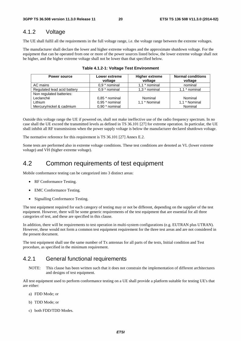
ETSI
ETSI TS 136 508 V11.3.0 (2014-02)203GPP TS 36.508 version 11.3.0 Release 11
4.1.2 Voltage
The UE shall fulfil all the requirements in the full voltage range, i.e. the voltage range between the extreme voltages.
The manufacturer shall declare the lower and higher extreme voltages and the approximate shutdown voltage. For the equipment that can be operated from one or more of the power sources listed below, the lower extreme voltage shall not be higher, and the higher extreme voltage shall not be lower than that specified below.
Table 4.1.2-1: Voltage Test Environment
Power source Lower extreme voltage
Higher extreme voltage
Normal conditions voltage
AC mains 0,9 * nominal 1,1 * nominal nominal Regulated lead acid battery 0,9 * nominal 1,3 * nominal 1,1 * nominal Non regulated batteries: Leclanché Lithium Mercury/nickel & cadmium
0,85 * nominal 0,95 * nominal 0,90 * nominal
Nominal
1,1 * Nominal
Nominal
1,1 * Nominal Nominal
Outside this voltage range the UE if powered on, shall not make ineffective use of the radio frequency spectrum. In no case shall the UE exceed the transmitted levels as defined in TS 36.101 [27] for extreme operation. In particular, the UE shall inhibit all RF transmissions when the power supply voltage is below the manufacturer declared shutdown voltage.
The normative reference for this requirement is TS 36.101 [27] Annex E.2.
Some tests are performed also in extreme voltage conditions. These test conditions are denoted as VL (lower extreme voltage) and VH (higher extreme voltage).
4.2 Common requirements of test equipment Mobile conformance testing can be categorized into 3 distinct areas:
• RF Conformance Testing.
• EMC Conformance Testing.
• Signalling Conformance Testing.
The test equipment required for each category of testing may or not be different, depending on the supplier of the test equipment. However, there will be some generic requirements of the test equipment that are essential for all three categories of test, and these are specified in this clause.
In addition, there will be requirements to test operation in multi-system configurations (e.g. EUTRAN plus UTRAN). However, these would not form a common test equipment requirement for the three test areas and are not considered in the present document.
The test equipment shall use the same number of Tx antennas for all parts of the tests, Initial condition and Test procedure, as specified in the minimum requirement.
4.2.1 General functional requirements
NOTE: This clause has been written such that it does not constrain the implementation of different architectures and designs of test equipment.
All test equipment used to perform conformance testing on a UE shall provide a platform suitable for testing UE's that are either:
a) FDD Mode; or
b) TDD Mode; or
c) both FDD/TDD Modes.
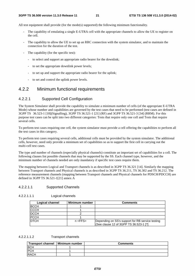
ETSI
ETSI TS 136 508 V11.3.0 (2014-02)213GPP TS 36.508 version 11.3.0 Release 11
All test equipment shall provide (for the mode(s) supported) the following minimum functionality.
- The capability of emulating a single E-UTRA cell with the appropriate channels to allow the UE to register on the cell.
- The capability to allow the UE to set up an RRC connection with the system simulator, and to maintain the connection for the duration of the test.
- The capability (for the specific test):
- to select and support an appropriate radio bearer for the downlink;
- to set the appropriate downlink power levels;
- to set up and support the appropriate radio bearer for the uplink;
- to set and control the uplink power levels.
4.2.2 Minimum functional requirements
4.2.2.1 Supported Cell Configuration
The System Simulator shall provide the capability to simulate a minimum number of cells (of the appropriate E-UTRA Mode) whose number and capabilities are governed by the test cases that need to be performed (test cases are defined in 3GPP TS 36.523-1 [18](Signalling), 3GPP TS 36.521-1 [21] (RF) and 3GPP TS 36.521-3 [34] (RRM). For this purpose test cases can be split into two different categories: Tests that require only one cell and Tests that require several cells.
To perform test cases requiring one cell, the system simulator must provide a cell offering the capabilities to perform all the test cases in this category.
To perform test cases requiring several cells, additional cells must be provided by the system simulator. The additional cells, however, need only provide a minimum set of capabilities so as to support the first cell in carrying out the multi-cell test cases.
The type and number of channels (especially physical channels) constitute an important set of capabilities for a cell. The following clauses list possible channels that may be supported by the SS. Each channel type, however, and the minimum number of channels needed are only mandatory if specific test cases require them.
The mapping between Logical and Transport channels is as described in 3GPP TS 36.321 [14]. Similarly the mapping between Transport channels and Physical channels is as described in 3GPP TS 36.211, TS 36.302 and TS 36.212. The reference measurement channels (mapping between Transport channels and Physical channels for PDSCH/PDCCH) are defined in 3GPP TS 36.521-1[21] annex A
4.2.2.1.1 Supported Channels
4.2.2.1.1.1 Logical channels
Logical channel Minimum number Comments BCCH 1 CCCH 1 DCCH 2 PCCH 1 DTCH n <FFS> Depending on SS's support for RB service testing
(See clause 12 of 3GPP TS 36.523-1 [?]
4.2.2.1.1.2 Transport channels
Transport channel Minimum number Comments BCH 1 PCH 1 RACH 1

ETSI
ETSI TS 136 508 V11.3.0 (2014-02)223GPP TS 36.508 version 11.3.0 Release 11
DL-SCH n <FFS> UL-SCH n <FFS>
4.2.2.1.1.3 Physical channels
Physical channel Minimum number Comments PBCH 1 Physical Broadcast Channel PCFICH 1 The physical control format indicator channel carries information about the
number of OFDM symbols used for transmission of PDCCHs in a subframe PDCCH 1 The physical downlink control channel carries scheduling assignments and
other control information. PDSCH 1 Physical Downlink Shared Channel PHICH [1] The PHICH carries the hybrid-ARQ ACK/NAK PUCCH 1 The physical uplink control channel carries uplink control information PUSCH 1 Physical Uplink Shared Channel PRACH 1 Physical Random Access Channel
4.2.2.1.1.4 Physical signals
Physical signal Minimum number Comments Demodulation reference signal
NA UL
Sounding Reference signal
NA UL TBD, if applicable
Cell-specific Reference Signal
NA DL
UE-specific reference signal
NA DL
Primary synchronisation signal
NA DL
Secondary synchronisation signal
NA DL
4.2.2.2 Support of Tcell timing offset
The timing offset in terms of frame start timing between any pair of TDD cells shall be < [3us]. For FDD cells there is no such restriction.
4.3 Reference test conditions This clause contains the reference test conditions, which apply to all test cases unless otherwise specified.
4.3.1 Test frequencies
The test frequencies are based on the E-UTRA frequency bands defined in the core specifications.
The raster spacing is 100 KHz.
E-UTRA/FDD is designed to operate in paired bands of 3GPP TS 36.101 [27]. The reference test frequencies for the RF and Signalling test environment for each of the operating bands are defined in sub clause 4.3.1.1.
E-UTRA/TDD is designed to operate in unpaired bands of 3GPP TS 36.101 [27]. The reference test frequencies for the RF and Signalling test environment for each of the operating bands are defined in sub clause 4.3.1.2.
For non-CA Signalling testing, E-UTRA frequency to be tested is mid range and E-UTRA channel bandwidth to be tested is 5MHz for all operating bands for all test cases as the default configuration unless specific channel bandwidth is specified for the operating band below:

ETSI
ETSI TS 136 508 V11.3.0 (2014-02)233GPP TS 36.508 version 11.3.0 Release 11
For Band 11, 13, 18 and 20, channel bandwidth to be tested is 10 MHz as the default configuration.
For Band 38, 39, 40 and 41, channel bandwidth to be tested is 20 MHz as the default configuration.
For CA Signalling testing with two component carriers, E-UTRA frequencies to be tested are according to sub clause 6.2.3.2 and the E-UTRA channel bandwidth combination is according to Table 4.3.1-1.
Table 4.3.1-1: Default E-UTRA channel bandwidth combinations for CA Signalling testing with two component carriers
CA configuration (Band(s),BW Class,BW
Combination Set)
CA Channel Bandwidth combination
carrier 1 + carrier 2 [MHz + MHz]
Comment
Intra-band contiguous and Bandwidth Class C
20+20 This channel bandwidth combination is used for all Intra-band contiguous CA configurations using Bandwidth Class C unless specific channel bandwidth combination is specified for a CA configuration or CA Bandwidth Combination Set by specific entries in this table below.
Inter-band CA and CA Bandwidth Class Combination A-A
10 + 10 This channel bandwidth combination is used for all Inter-band contiguous CA configurations using Bandwidth Class Combination A-A unless specific channel bandwidth combination is specified for a CA configuration or CA Bandwidth Combination Set by specific entries in this table below.
CA_1A-19A 15 + 10 This channel bandwidth combination is used for Inter-band contiguous CA configuration CA_1A-19A.
CA_1A-21A 15 + 15 This channel bandwidth combination is used for Inter-band contiguous CA configuration CA_1A-21A.
For RF testing, E-UTRA frequencies to be tested are low range, mid range and high range for all supported operating bands by default. E-UTRA channel bandwidths to be tested are lowest bandwidth, 5MHz bandwidth and highest bandwidth for all supported operating bands by default. Actual test configurations are specified case by case and stated in test case itself as the initial conditions.
The lowest bandwidth, 5MHz bandwidth and highest bandwidth are selected from the combined table which includes nominal and additional channel bandwidth.
In the case 5MHz bandwidth is not supported by the UE, E-UTRA channel bandwidth to be tested is only lowest bandwidth and highest bandwidth.
If channel bandwidth to be tested is equal to the lowest or highest channel bandwidth, then the same channel bandwidth is not required to be tested twice.
In addition to the default channel bandwidths to be tested specified above, for Bands 2, 4, 18, 19, 20 and 25, an industry requirement of testing in 10MHz channel bandwidth is allowed for test cases in chapters 6 and 7 in TS 36.521-1 [21].
Editor’s note: For RF testing, an industry requirement of testing in 10MHz channel bandwidth is requested for Bands 2, 4, 18, 19, 20 and 25 for test cases in chapters 6 and 7 in TS 36.521-1[21], changing the existing test points to address this is being discussed in RAN5 and will be considered pending technical justification.
For A-GNSS testing in TS 37.571-1, the E-UTRA frequency and channel bandwidth to be tested follow the same rules as for Signalling testing above.

ETSI
ETSI TS 136 508 V11.3.0 (2014-02)243GPP TS 36.508 version 11.3.0 Release 11
4.3.1.1 FDD Mode Test frequencies
4.3.1.1.1 FDD reference test frequencies for operating band 1
Table 4.3.1.1.1-1: Test frequencies for E-UTRA channel bandwidth for operating band 1
Test Frequency ID Bandwidth [MHz]
NUL Frequency of Uplink [MHz]
NDL Frequency of Downlink [MHz]
Low Range
5 18025 1922.5 25 2112.5 10 18050 1925 50 2115 15 18075 1927.5 75 2117.5 20 18100 1930 100 2120
Mid Range 5/10/15/20 18300 1950 300 2140
High Range
5 18575 1977.5 575 2167.5 10 18550 1975 550 2165 15 18525 1972.5 525 2162.5 20 18500 1970 500 2160
4.3.1.1.1A FDD reference test frequencies for CA in operating band 1
Table 4.3.1.1.1A-1: Test frequencies for CA_1C
Test Frequency CC Combination / NRB_agg
CC NRB NUL Frequency of Uplink [MHz]
NDL Frequency of Downlink [MHz]
Low Range 75 + 75
PCC 75 18075 1927.5 75 2117.5 SCC 75 18225 1942.5 225 2132.5
100 + 100 PCC 100 18100 1930 100 2120 SCC 100 18298 1949.8 298 2139.8
Mid Range 75 + 75
PCC 75 18225 1942.5 225 2132.5 SCC 75 18375 1957.5 375 2147.5
100 + 100 PCC 100 18200 1940 200 2130 SCC 100 18398 1959.8 398 2149.8
High Range 75 + 75
PCC 75 18375 1957.5 375 2147.5 SCC 75 18525 1972.5 525 2162.5
100 + 100 PCC 100 18302 1950.2 302 2140.2 SCC 100 18500 1970 500 2160
4.3.1.1.2 FDD reference test frequencies for operating band 2
Table 4.3.1.1.2-1: Test frequencies for E-UTRA channel bandwidth for operating band 2
Test Frequency ID
Bandwidth [MHz]
NUL Frequency of Uplink [MHz]
NDL Frequency of Downlink
[MHz]
Low Range
1.4 18607 1850.7 607 1930.7 3 18615 1851.5 615 1931.5 5 18625 1852.5 625 1932.5
10 18650 1855 650 1935 15 [1] 18675 1857.5 675 1937.5 20 [1] 18700 1860 700 1940
Mid Range 1.4/3/5/10 15 [1]/20 [1] 18900 1880 900 1960
High Range
1.4 19193 1909.3 1193 1989.3 3 19185 1908.5 1185 1988.5 5 19175 1907.5 1175 1987.5
10 19150 1905 1150 1985 15 [1] 19125 1902.5 1125 1982.5 20 [1] 19100 1900 1100 1980

ETSI
ETSI TS 136 508 V11.3.0 (2014-02)253GPP TS 36.508 version 11.3.0 Release 11
NOTE 1: Bandwidth for which a relaxation of the specified UE receiver sensitivity requirement (TS 36.101 [27] Clause 7.3) is allowed.
4.3.1.1.3 FDD reference test frequencies for operating band 3
Table 4.3.1.1.3-1: Test frequencies for E-UTRA channel bandwidth for operating band 3
Test Frequency ID
Bandwidth [MHz]
NUL Frequency of Uplink [MHz]
NDL Frequency of Downlink [MHz]
Low Range
1.4 19207 1710.7 1207 1805.7 3 19215 1711.5 1215 1806.5 5 19225 1712.5 1225 1807.5 10 19250 1715 1250 1810
15 [1] 19275 1717.5 1275 1812.5 20 [1] 19300 1720 1300 1815
Mid Range 1.4/3/5/10 15 [1]/20 [1] 19575 1747.5 1575 1842.5
High Range
1.4 19943 1784.3 1943 1879.3 3 19935 1783.5 1935 1878.5 5 19925 1782.5 1925 1877.5 10 19900 1780 1900 1875
15 [1] 19875 1777.5 1875 1872.5 20 [1] 19850 1775 1850 1870
NOTE 1: Bandwidth for which a relaxation of the specified UE receiver sensitivity requirement (TS 36.101 [27] Clause 7.3) is allowed.
4.3.1.1.4 FDD reference test frequencies for operating band 4
Table 4.3.1.1.4-1: Test frequencies for E-UTRA channel bandwidth for operating band 4
Test Frequency ID Bandwidth [MHz]
NUL Frequency of Uplink [MHz]
NDL Frequency of Downlink
[MHz]
Low Range
1.4 19957 1710.7 1957 2110.7 3 19965 1711.5 1965 2111.5 5 19975 1712.5 1975 2112.5
10 20000 1715 2000 2115 15 20025 1717.5 2025 2117.5 20 20050 1720 2050 2120
Mid Range 1.4/3/5/10/15/20 20175 1732.5 2175 2132.5
High Range
1.4 20393 1754.3 2393 2154.3 3 20385 1753.5 2385 2153.5 5 20375 1752.5 2375 2152.5
10 20350 1750 2350 2150 15 20325 1747.5 2325 2147.5 20 20300 1745 2300 2145

ETSI
ETSI TS 136 508 V11.3.0 (2014-02)263GPP TS 36.508 version 11.3.0 Release 11
4.3.1.1.5 FDD reference test frequencies for operating band 5
Table 4.3.1.1.5-1: Test frequencies for E-UTRA channel bandwidth for operating band 5
Test Frequency ID Bandwidth [MHz]
NUL Frequency of Uplink [MHz]
NDL Frequency of Downlink
[MHz]
Low Range
1.4 20407 824.7 2407 869.7 3 20415 825.5 2415 870.5 5 20425 826.5 2425 871.5
10 [1] 20450 829 2450 874
Mid Range 1.4/3/5 10 [1] 20525 836.5 2525 881.5
High Range
1.4 20643 848.3 2643 893.3 3 20635 847.5 2635 892.5 5 20625 846.5 2625 891.5
10 [1] 20600 844 2600 889 NOTE 1: Bandwidth for which a relaxation of the specified UE receiver sensitivity requirement
(TS 36.101 [27] Clause 7.3) is allowed.
4.3.1.1.6 FDD reference test frequencies for operating band 6
Table 4.3.1.1.6-1: Test frequencies for E-UTRA channel bandwidth for operating band 6
Test Frequency ID Bandwidth [MHz]
NUL Frequency of Uplink [MHz]
NDL Frequency of Downlink
[MHz]
Low Range 5 20675 832.5 2675 877.5 10 [1] 20700 835 2700 880
Mid Range 5 10 [1] 20700 835 2700 880
High Range 5 20725 837.5 2725 882.5 10 [1] 20700 835 2700 880
NOTE 1: Bandwidth for which a relaxation of the specified UE receiver sensitivity requirement (TS 36.101 [27] Clause 7.3) is allowed.
NOTE: For Band VI testing, the Mobile Country Code shall be set to (MCC = '442/443').
4.3.1.1.7 FDD reference test frequencies for operating band 7
Table 4.3.1.1.7-1: Test frequencies for E-UTRA channel bandwidth for operating band 7
Test Frequency ID Bandwidth [MHz]
NUL Frequency of Uplink [MHz]
NDL Frequency of Downlink
[MHz]
Low Range
5 20775 2502.5 2775 2622.5 10 20800 2505 2800 2625 15 20825 2507.5 2825 2627.5
20 [1] 20850 2510 2850 2630
Mid Range 5/10/15 20 [1] 21100 2535 3100 2655
High Range
5 21425 2567.5 3425 2687.5 10 21400 2565 3400 2685 15 21375 2562.5 3375 2682.5
20 [1] 21350 2560 3350 2680 NOTE 1: Bandwidth for which a relaxation of the specified UE receiver sensitivity requirement
(TS 36.101 [27] Clause 7.3) is allowed.

ETSI
ETSI TS 136 508 V11.3.0 (2014-02)273GPP TS 36.508 version 11.3.0 Release 11
4.3.1.1.7A FDD reference test frequencies for CA in operating band 7
Table 4.3.1.1.1A-1: Test frequencies for CA_7C
Test Frequency
CC Combination / NRB_agg
CC NRB NUL Frequency of Uplink [MHz]
NDL Frequency of Downlink [MHz]
Low Range 75 + 75
PCC 75 20825 2507.5 2825 2627.5 SCC 75 20975 2522.5 2975 2642.5
100 + 100 PCC 100 20850 2510 2850 2630 SCC 100 21048 2529.8 3048 2649.8
Mid Range 75 + 75
PCC 75 21025 2527.5 3025 2647.5 SCC 75 21175 2542.5 3175 2662.5
100 + 100 PCC 100 21000 2525 3000 2645 SCC 100 21198 2544.8 3198 2664.8
High Range 75 + 75
PCC 75 21225 2547.5 3225 2667.5 SCC 75 21375 2562.5 3375 2682.5
100 + 100 PCC 100 21152 2540.2 3152 2660.2 SCC 100 21350 2560 3350 2680
4.3.1.1.8 FDD reference test frequencies for operating band 8
Table 4.3.1.1.8-1: Test frequencies for E-UTRA channel bandwidth for operating band 8
Test Frequency ID Bandwidth [MHz]
NUL Frequency of Uplink [MHz]
NDL Frequency of Downlink
[MHz]
Low Range
1.4 21457 880.7 3457 925.7 3 21465 881.5 3465 926.5 5 21475 882.5 3475 927.5
10 [1] 21500 885 3500 930
Mid Range 1.4/3/5 10 [1] 21625 897.5 3625 942.5
High Range
1.4 21793 914.3 3793 959.3 3 21785 913.5 3785 958.5 5 21775 912.5 3775 957.5
10 [1] 21750 910 3750 955 NOTE 1: Bandwidth for which a relaxation of the specified UE receiver sensitivity requirement
(TS 36.101 [27] Clause 7.3) is allowed.
4.3.1.1.9 FDD reference test frequencies for operating band 9
Table 4.3.1.1.9-1: Test frequencies for E-UTRA channel bandwidth for operating band 9
Test Frequency ID Bandwidth [MHz]
NUL Frequency of Uplink [MHz]
NDL Frequency of Downlink
[MHz]
Low Range
5 21825 1752.4 3825 1847.4 10 21850 1754.9 3850 1849.9
15 [1] 21875 1757.4 3875 1852.4 20 [1] 21900 1759.9 3900 1854.9
Mid Range 5/10 15 [1]/20 [1] 21975 1767.4 3975 1862.4
High Range
5 22125 1782.4 4125 1877.4 10 22100 1779.9 4100 1874.9
15 [1] 22075 1777.4 4075 1872.4 20 [1] 22050 1774.9 4050 1869.9
NOTE 1: Bandwidth for which a relaxation of the specified UE receiver sensitivity requirement (TS 36.101 [27] Clause 7.3) is allowed.
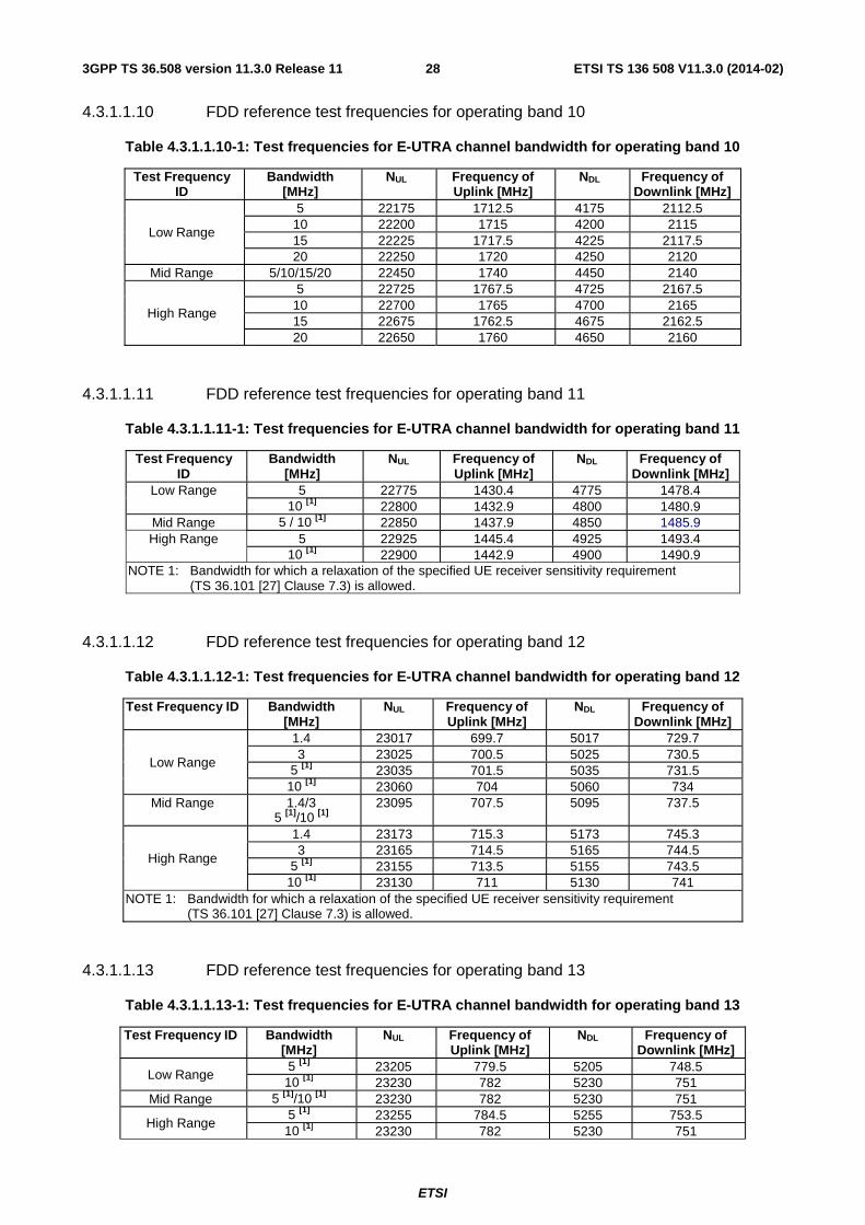
ETSI
ETSI TS 136 508 V11.3.0 (2014-02)283GPP TS 36.508 version 11.3.0 Release 11
4.3.1.1.10 FDD reference test frequencies for operating band 10
Table 4.3.1.1.10-1: Test frequencies for E-UTRA channel bandwidth for operating band 10
Test Frequency ID
Bandwidth [MHz]
NUL Frequency of Uplink [MHz]
NDL Frequency of Downlink [MHz]
Low Range
5 22175 1712.5 4175 2112.5 10 22200 1715 4200 2115 15 22225 1717.5 4225 2117.5 20 22250 1720 4250 2120
Mid Range 5/10/15/20 22450 1740 4450 2140
High Range
5 22725 1767.5 4725 2167.5 10 22700 1765 4700 2165 15 22675 1762.5 4675 2162.5 20 22650 1760 4650 2160
4.3.1.1.11 FDD reference test frequencies for operating band 11
Table 4.3.1.1.11-1: Test frequencies for E-UTRA channel bandwidth for operating band 11
Test Frequency ID
Bandwidth [MHz]
NUL Frequency of Uplink [MHz]
NDL Frequency of Downlink [MHz]
Low Range 5 22775 1430.4 4775 1478.4 10 [1] 22800 1432.9 4800 1480.9
Mid Range 5 / 10 [1] 22850 1437.9 4850 1485.9 High Range 5 22925 1445.4 4925 1493.4
10 [1] 22900 1442.9 4900 1490.9 NOTE 1: Bandwidth for which a relaxation of the specified UE receiver sensitivity requirement
(TS 36.101 [27] Clause 7.3) is allowed.
4.3.1.1.12 FDD reference test frequencies for operating band 12
Table 4.3.1.1.12-1: Test frequencies for E-UTRA channel bandwidth for operating band 12
Test Frequency ID Bandwidth [MHz]
NUL Frequency of Uplink [MHz]
NDL Frequency of Downlink [MHz]
Low Range
1.4 23017 699.7 5017 729.7 3 23025 700.5 5025 730.5
5 [1] 23035 701.5 5035 731.5 10 [1] 23060 704 5060 734
Mid Range 1.4/3 5 [1]/10 [1]
23095 707.5 5095 737.5
High Range
1.4 23173 715.3 5173 745.3 3 23165 714.5 5165 744.5
5 [1] 23155 713.5 5155 743.5 10 [1] 23130 711 5130 741
NOTE 1: Bandwidth for which a relaxation of the specified UE receiver sensitivity requirement (TS 36.101 [27] Clause 7.3) is allowed.
4.3.1.1.13 FDD reference test frequencies for operating band 13
Table 4.3.1.1.13-1: Test frequencies for E-UTRA channel bandwidth for operating band 13
Test Frequency ID Bandwidth [MHz]
NUL Frequency of Uplink [MHz]
NDL Frequency of Downlink [MHz]
Low Range 5 [1] 23205 779.5 5205 748.5 10 [1] 23230 782 5230 751
Mid Range 5 [1]/10 [1] 23230 782 5230 751
High Range 5 [1] 23255 784.5 5255 753.5 10 [1] 23230 782 5230 751
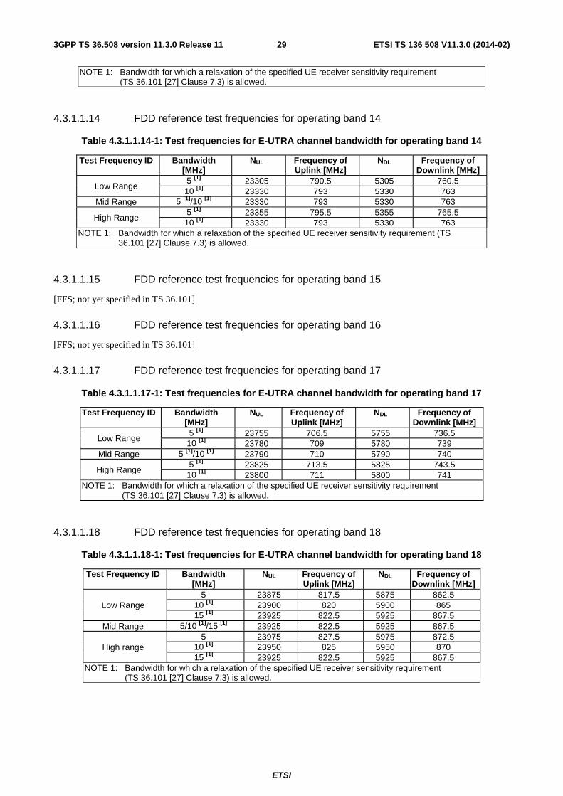
ETSI
ETSI TS 136 508 V11.3.0 (2014-02)293GPP TS 36.508 version 11.3.0 Release 11
NOTE 1: Bandwidth for which a relaxation of the specified UE receiver sensitivity requirement (TS 36.101 [27] Clause 7.3) is allowed.
4.3.1.1.14 FDD reference test frequencies for operating band 14
Table 4.3.1.1.14-1: Test frequencies for E-UTRA channel bandwidth for operating band 14
Test Frequency ID Bandwidth [MHz]
NUL Frequency of Uplink [MHz]
NDL Frequency of Downlink [MHz]
Low Range 5 [1] 23305 790.5 5305 760.5 10 [1] 23330 793 5330 763
Mid Range 5 [1]/10 [1] 23330 793 5330 763
High Range 5 [1] 23355 795.5 5355 765.5 10 [1] 23330 793 5330 763
NOTE 1: Bandwidth for which a relaxation of the specified UE receiver sensitivity requirement (TS 36.101 [27] Clause 7.3) is allowed.
4.3.1.1.15 FDD reference test frequencies for operating band 15
[FFS; not yet specified in TS 36.101]
4.3.1.1.16 FDD reference test frequencies for operating band 16
[FFS; not yet specified in TS 36.101]
4.3.1.1.17 FDD reference test frequencies for operating band 17
Table 4.3.1.1.17-1: Test frequencies for E-UTRA channel bandwidth for operating band 17
Test Frequency ID Bandwidth [MHz]
NUL Frequency of Uplink [MHz]
NDL Frequency of Downlink [MHz]
Low Range 5 [1] 23755 706.5 5755 736.5 10 [1] 23780 709 5780 739
Mid Range 5 [1]/10 [1] 23790 710 5790 740
High Range 5 [1] 23825 713.5 5825 743.5 10 [1] 23800 711 5800 741
NOTE 1: Bandwidth for which a relaxation of the specified UE receiver sensitivity requirement (TS 36.101 [27] Clause 7.3) is allowed.
4.3.1.1.18 FDD reference test frequencies for operating band 18
Table 4.3.1.1.18-1: Test frequencies for E-UTRA channel bandwidth for operating band 18
Test Frequency ID Bandwidth [MHz]
NUL Frequency of Uplink [MHz]
NDL Frequency of Downlink [MHz]
Low Range 5 23875 817.5 5875 862.5
10 [1] 23900 820 5900 865 15 [1] 23925 822.5 5925 867.5
Mid Range 5/10 [1]/15 [1] 23925 822.5 5925 867.5
High range 5 23975 827.5 5975 872.5
10 [1] 23950 825 5950 870 15 [1] 23925 822.5 5925 867.5
NOTE 1: Bandwidth for which a relaxation of the specified UE receiver sensitivity requirement (TS 36.101 [27] Clause 7.3) is allowed.
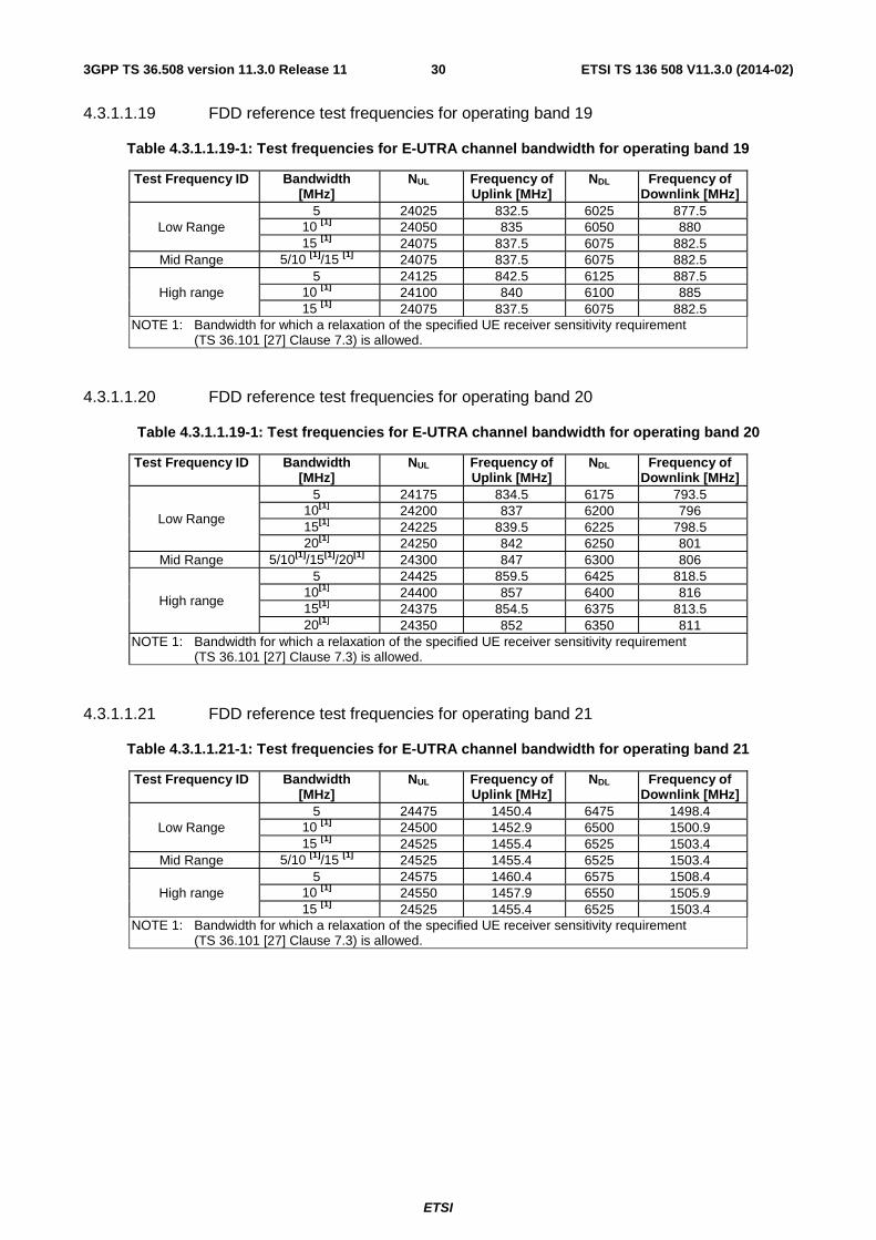
ETSI
ETSI TS 136 508 V11.3.0 (2014-02)303GPP TS 36.508 version 11.3.0 Release 11
4.3.1.1.19 FDD reference test frequencies for operating band 19
Table 4.3.1.1.19-1: Test frequencies for E-UTRA channel bandwidth for operating band 19
Test Frequency ID Bandwidth [MHz]
NUL Frequency of Uplink [MHz]
NDL Frequency of Downlink [MHz]
Low Range 5 24025 832.5 6025 877.5
10 [1] 24050 835 6050 880 15 [1] 24075 837.5 6075 882.5
Mid Range 5/10 [1]/15 [1] 24075 837.5 6075 882.5
High range 5 24125 842.5 6125 887.5
10 [1] 24100 840 6100 885 15 [1] 24075 837.5 6075 882.5
NOTE 1: Bandwidth for which a relaxation of the specified UE receiver sensitivity requirement (TS 36.101 [27] Clause 7.3) is allowed.
4.3.1.1.20 FDD reference test frequencies for operating band 20
Table 4.3.1.1.19-1: Test frequencies for E-UTRA channel bandwidth for operating band 20
Test Frequency ID Bandwidth [MHz]
NUL Frequency of Uplink [MHz]
NDL Frequency of Downlink [MHz]
Low Range
5 24175 834.5 6175 793.5 10[1] 24200 837 6200 796 15[1] 24225 839.5 6225 798.5 20[1] 24250 842 6250 801
Mid Range 5/10[1]/15[1]/20[1] 24300 847 6300 806
High range
5 24425 859.5 6425 818.5 10[1] 24400 857 6400 816 15[1] 24375 854.5 6375 813.5 20[1] 24350 852 6350 811
NOTE 1: Bandwidth for which a relaxation of the specified UE receiver sensitivity requirement (TS 36.101 [27] Clause 7.3) is allowed.
4.3.1.1.21 FDD reference test frequencies for operating band 21
Table 4.3.1.1.21-1: Test frequencies for E-UTRA channel bandwidth for operating band 21
Test Frequency ID Bandwidth [MHz]
NUL Frequency of Uplink [MHz]
NDL Frequency of Downlink [MHz]
Low Range 5 24475 1450.4 6475 1498.4
10 [1] 24500 1452.9 6500 1500.9 15 [1] 24525 1455.4 6525 1503.4
Mid Range 5/10 [1]/15 [1] 24525 1455.4 6525 1503.4
High range 5 24575 1460.4 6575 1508.4
10 [1] 24550 1457.9 6550 1505.9 15 [1] 24525 1455.4 6525 1503.4
NOTE 1: Bandwidth for which a relaxation of the specified UE receiver sensitivity requirement (TS 36.101 [27] Clause 7.3) is allowed.
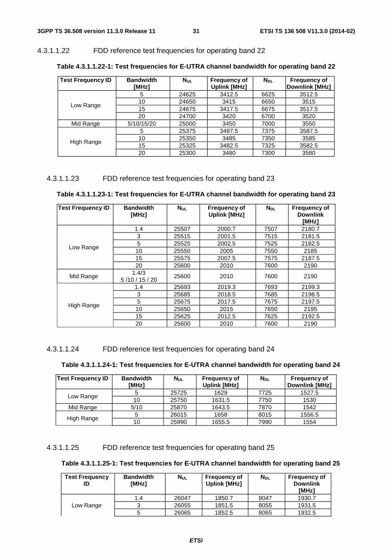
ETSI
ETSI TS 136 508 V11.3.0 (2014-02)313GPP TS 36.508 version 11.3.0 Release 11
4.3.1.1.22 FDD reference test frequencies for operating band 22
Table 4.3.1.1.22-1: Test frequencies for E-UTRA channel bandwidth for operating band 22
Test Frequency ID Bandwidth [MHz]
NUL Frequency of Uplink [MHz]
NDL Frequency of Downlink [MHz]
Low Range
5 24625 3412.5 6625 3512.5 10 24650 3415 6650 3515 15 24675 3417.5 6675 3517.5 20 24700 3420 6700 3520
Mid Range 5/10/15/20 25000 3450 7000 3550
High Range
5 25375 3487.5 7375 3587.5 10 25350 3485 7350 3585 15 25325 3482.5 7325 3582.5 20 25300 3480 7300 3580
4.3.1.1.23 FDD reference test frequencies for operating band 23
Table 4.3.1.1.23-1: Test frequencies for E-UTRA channel bandwidth for operating band 23
Test Frequency ID Bandwidth [MHz]
NUL Frequency of Uplink [MHz]
NDL Frequency of Downlink
[MHz]
Low Range
1.4 25507 2000.7 7507 2180.7 3 25515 2001.5 7515 2181.5 5 25525 2002.5 7525 2182.5
10 25550 2005 7550 2185 15 25575 2007.5 7575 2187.5 20 25600 2010 7600 2190
Mid Range 1.4/3 5 /10 / 15 / 20
25600 2010 7600 2190
High Range
1.4 25693 2019.3 7693 2199.3 3 25685 2018.5 7685 2198.5 5 25675 2017.5 7675 2197.5 10 25650 2015 7650 2195 15 25625 2012.5 7625 2192.5 20 25600 2010 7600 2190
4.3.1.1.24 FDD reference test frequencies for operating band 24
Table 4.3.1.1.24-1: Test frequencies for E-UTRA channel bandwidth for operating band 24
Test Frequency ID Bandwidth [MHz]
NUL Frequency of Uplink [MHz]
NDL Frequency of Downlink [MHz]
Low Range 5 25725 1629 7725 1527.5 10 25750 1631.5 7750 1530
Mid Range 5/10 25870 1643.5 7870 1542
High Range 5 26015 1658 8015 1556.5 10 25990 1655.5 7990 1554
4.3.1.1.25 FDD reference test frequencies for operating band 25
Table 4.3.1.1.25-1: Test frequencies for E-UTRA channel bandwidth for operating band 25
Test Frequency ID
Bandwidth [MHz]
NUL Frequency of Uplink [MHz]
NDL Frequency of Downlink
[MHz]
Low Range 1.4 26047 1850.7 8047 1930.7 3 26055 1851.5 8055 1931.5 5 26065 1852.5 8065 1932.5

ETSI
ETSI TS 136 508 V11.3.0 (2014-02)323GPP TS 36.508 version 11.3.0 Release 11
10 26090 1855 8090 1935 15 [1] 26115 1857.5 8115 1937.5 20 [1] 26140 1860 8140 1940
Mid Range 1.4/3/5/10 15 [1]/20 [1] 26365 1882,5 8365 1962.5
High Range
1.4 26683 1914.3 8683 1994.3 3 26675 1913.5 8675 1993.5 5 26665 1912.5 8665 1992.5
10 26640 1910 8640 1990 15 [1] 26615 1907.5 8615 1987.5 20 [1] 26590 1905 8590 1985
NOTE 1: Bandwidth for which a relaxation of the specified UE receiver sensitivity requirement (TS 36.101 [27] Clause 7.3) is allowed.
4.3.1.1.26 FDD reference test frequencies for operating band 26
Table 4.3.1.1.26-1: Test frequencies for E-UTRA channel bandwidth for operating band 26
Test Frequency ID
Bandwidth [MHz]
NUL Frequency of Uplink [MHz]
NDL Frequency of Downlink
[MHz]
Low Range
1.4 26697 814.7 8697 859.7 3 26705 815.5 8705 860.5 5 26715 816.5 8715 861.5
10[1] 26750 820 8750 865 15 [1] 26775 822.5 8775 867.5
Mid Range 1.4/3/5/10[1] 15 [1] 26865 831.5 8865 876.5
High Range
1.4 27033 848.3 9033 893.3 3 27025 847.5 9025 892.5 5 27015 846.5 9015 891.5
10[1] 26990 844 8990 889 15 [1] 26965 841.5 8965 886.5
NOTE 1: Bandwidth for which a relaxation of the specified UE receiver sensitivity requirement (TS 36.101 [27] Clause 7.3) is allowed.
4.3.1.1.27 FDD reference test frequencies for operating band 27
Table 4.3.1.1.27-1: Test frequencies for E-UTRA channel bandwidth for operating band 27
Test Frequency ID Bandwidth [MHz]
NUL Frequency of Uplink [MHz]
NDL Frequency of Downlink
[MHz]
Low Range
1.4 27047 807.7 9047 852.7 3 27055 808.5 9055 853.5 5 27065 809.5 9065 854.5
10 [1] 27090 812 9090 857 Mid Range 1.4/3/5/10 [1] 27125 815.5 9125 860.5
High Range
1.4 27203 823.3 9203 868.3 3 27195 822.5 9195 867.5 5 27185 821.5 9185 866.5
10 [1] 27160 819 9160 864 NOTE 1: Bandwidth for which a relaxation of the specified UE receiver sensitivity requirement
(TS 36.101 [27] Clause 7.3) is allowed.

ETSI
ETSI TS 136 508 V11.3.0 (2014-02)333GPP TS 36.508 version 11.3.0 Release 11
4.3.1.1.28 FDD reference test frequencies for operating band 28
Table 4.3.1.1.28-1: Test frequencies for E-UTRA channel bandwidth for operating band 28 at lower duplexer
Test Frequency ID
Bandwidth [MHz]
NUL Frequency of Uplink [MHz]
NDL Frequency of Downlink
[MHz]
Low Range
3 27225 704.5 9225 759.5 5 27235 705.5 9235 760.5
10[1] 27260 708 9260 763 15[1] 27285 710.5 9285 765.5 20[1] 27310 713 9310 768
Mid Range 3/5/10[1]/15[1]/20[1] 27360 718 9360 773
High Range
3 27495 731.5 9495 786.5 5 27485 730.5 9485 785.5
10[1] 27460 728 9460 783 15[1] 27435 725.5 9435 780.5 20[1] 27410 723 9410 778
NOTE 1: Bandwidth for which a relaxation of the specified UE receiver sensitivity requirement (TS 36.101 [27] Clause 7.3) is allowed.
Table 4.3.1.1.28-2: Test frequencies for E-UTRA channel bandwidth for operating band 28 at upper duplexer
Test Frequency ID
Bandwidth [MHz]
NUL Frequency of Uplink [MHz]
NDL Frequency of Downlink
[MHz]
Low Range
3 27375 719.5 9375 774.5 5 27385 720.5 9385 775.5
10[1] 27410 723 9410 778 15[1] 27435 725.5 9435 780.5 20[1] 27460 728 9460 783
Mid Range 3/5/10[1]/15[1]/20[1] 27510 733 9510 788
High Range
3 27645 746.5 9645 801.5 5 27635 745.5 9635 800.5
10[1] 27610 743 9610 798 15[1] 27585 740.5 9585 795.5 20[1] 27560 738 9560 793
NOTE 1: Bandwidth for which a relaxation of the specified UE receiver sensitivity requirement (TS 36.101 [27] Clause 7.3) is allowed.
4.3.1.1.29 FDD reference test frequencies for CA in operating band 29
Table 4.3.1.1.29-1: Test frequencies for E-UTRA channel bandwidth for operating band 29
Test Frequency ID Bandwidth [MHz]
NUL Frequency of Uplink [MHz]
NDL Frequency of Downlink [MHz]
Low Range
3 NA[1] NA 9675 718.5 5 NA[1] NA 9685 719.5
10 NA[1] NA 9710 722
Mid Range 3 5 /10
NA[1] NA 9715 722.5
High Range 3 NA[1] NA 9755 726.5 5 NA[1] NA 9745 725.5
10 NA[1] NA 9720 723 NOTE 1: Restricted to E-UTRA operation when carrier aggregation is configured.The downlink operating
band is paired with the uplink operating band (external) of the carrier aggregation configuration that is supporting the configured Pcell.

ETSI
ETSI TS 136 508 V11.3.0 (2014-02)343GPP TS 36.508 version 11.3.0 Release 11
4.3.1.1.31 FDD reference test frequencies for operating band 31
Table 4.3.1.1.31-1: Test frequencies for E-UTRA channel bandwidth for operating band 31
Test Frequency ID Bandwidth [MHz]
NUL Frequency of Uplink [MHz]
NDL Frequency of Downlink
[MHz]
Low Range 1.4 27767 453.2 9877 463.2 3[1] 27775 454 9885 464 5[1] 27785 455 9895 465
Mid Range 1.4/3[1]/ 5[1] 27785 455 9895 465
High Range 1.4 27803 456.8 9913 466.8 3[1] 27795 456 9905 466 5[1] 27785 455 9895 465
NOTE 1: Bandwidth for which a relaxation of the specified UE receiver sensitivity requirement (TS 36.101 [27] Clause 7.3) is allowed.
4.3.1.2 TDD Mode Test frequencies
4.3.1.2.1 TDD reference test frequencies for Operating Band 33
Table 4.3.1.2.1-1: Test frequencies for E-UTRA channel bandwidth for operating band 33
Test Frequency ID Bandwidth [MHz]
EARFCN Frequency (UL and DL) [MHz]
Low Range
5 36025 1902.5 10 36050 1905 15 36075 1907.5 20 36100 1910
Mid Range 5/10/15/20 36100 1910
High Range
5 36175 1917.5 10 36150 1915 15 36125 1912.5 20 36100 1910
4.3.1.2.2 TDD reference test frequencies for Operating Band 34
Table 4.3.1.2.2-1: Test frequencies for E-UTRA channel bandwidth for operating band 34
Test Frequency ID Bandwidth [MHz]
EARFCN Frequency (UL and DL) [MHz]
Low Range 5 36225 2012.5
10 36250 2015 15 36275 2017.5
Mid Range 5/10/15 36275 2017.5
High Range 5 36325 2022.5
10 36300 2020 15 36275 2017.5

ETSI
ETSI TS 136 508 V11.3.0 (2014-02)353GPP TS 36.508 version 11.3.0 Release 11
4.3.1.2.3 TDD reference test frequencies for Operating Band 35
Table 4.3.1.2.3-1: Test frequencies for E-UTRA channel bandwidth for operating band 35
Test Frequency ID Bandwidth [MHz]
EARFCN [MHz]
Frequency (UL and DL) [MHz]
Low Range
1.4 36357 1850.7 3 36365 1851.5 5 36375 1852.5 10 36400 1855 15 36425 1857.5 20 36450 1860
Mid Range 1.4/3/5/10/15/20 36650 1880
High Range
1.4 36943 1909.3 3 36935 1908.5 5 36925 1907.5 10 36900 1905 15 36875 1902.5 20 36850 1900
4.3.1.2.4 TDD reference test frequencies for Operating Band 36
Table 4.3.1.2.4-1: Test frequencies for E-UTRA channel bandwidth for operating band 36
Test Frequency ID Bandwidth [MHz]
EARFCN [MHz]
Frequency (UL and DL) [MHz]
Low Range
1.4 36957 1930.7 3 36965 1931.5 5 36975 1932.5
10 37000 1935 15 37025 1937.5 20 37050 1940
Mid Range 1.4/3/5/10/15/20 37250 1960
High Range
1.4 37543 1989.3 3 37535 1988.5 5 37525 1987.5
10 37500 1985 15 37475 1982.5 20 37450 1980
4.3.1.2.5 TDD reference test frequencies for Operating Band 37
Table 4.3.1.2.5-1: Test frequencies for E-UTRA channel bandwidth for operating band 37
Test Frequency ID Bandwidth [MHz]
EARFCN [MHz]
Frequency (UL and DL) [MHz]
Low Range
5 37575 1912.5 10 37600 1915 15 37625 1917.5 20 37650 1920
Mid Range 5/10/15/20 37650 1920
High Range
5 37725 1927.5 10 37700 1925 15 37675 1922.5 20 37650 1920

ETSI
ETSI TS 136 508 V11.3.0 (2014-02)363GPP TS 36.508 version 11.3.0 Release 11
4.3.1.2.6 TDD reference test frequencies for Operating Band 38
Table 4.3.1.2.6-1: Test frequencies for E-UTRA channel bandwidth for operating band 38
Test Frequency ID Bandwidth [MHz] EARFCN Frequency (UL and DL)
[MHz]
Low Range
5 37775 2572.5 10 37800 2575 15 37825 2577.5 20 37850 2580
Mid Range 5/10/15/20 38000 2595
High Range
5 38225 2617.5 10 38200 2615 15 38175 2612.5 20 38150 2610
4.3.1.2.6A TDD reference test frequencies for CA in operating band 38
Table 4.3.1.2.6A-1: Test frequencies for CA_38C
Test Frequency ID CC Combination / NRB_agg
CC NRB EARFCN Frequency (UL and DL) [MHz]
Low Range 75 + 75
PCC 75 37825 2577.5 SCC 75 37975 2592.5
100 + 100 PCC 100 37850 2580 SCC 100 38048 2599.8
Mid Range 75 + 75
PCC 75 37925 2587.5 SCC 75 38075 2602.5
100 + 100 PCC 100 37900 2585 SCC 100 38098 2604.8
High Range 75 + 75
PCC 75 38025 2597.5 SCC 75 38175 2612.5
100 + 100 PCC 100 37952 2590.2 SCC 100 38150 2610
4.3.1.2.7 TDD reference test frequencies for Operating Band 39
Table 4.3.1.2.7-1: Test frequencies for E-UTRA channel bandwidth for operating band 39
Test Frequency ID Bandwidth [MHz]
EARFCN Frequency (UL and DL) [MHz]
Low Range
5 38275 1882.5 10 38300 1885 15 38325 1887.5 20 38350 1890
Mid Range 5/10/15/20 38450 1900
High Range
5 38625 1917.5 10 38600 1915 15 38575 1912.5 20 38550 1910

ETSI
ETSI TS 136 508 V11.3.0 (2014-02)373GPP TS 36.508 version 11.3.0 Release 11
4.3.1.2.8 TDD reference test frequencies for Operating Band 40
Table 4.3.1.2.8-1: Test frequencies for E-UTRA channel bandwidth for operating band 40
Test Frequency ID Bandwidth [MHz]
EARFCN Frequency (UL and DL) [MHz]
Low Range 5 38675 2302.5 10 38700 2305 15 38725 2307.5 20 38750 2310
Mid Range 5/10/15/20 39150 2350 High Range 5 39625 2397.5
10 39600 2395 15 39575 2392.5 20 39550 2390
4.3.1.2.8A TDD reference test frequencies for CA in operating band 40
Table 4.3.1.2.8A-1: Test frequencies for CA_40C
Test Frequency ID CC Combination / NRB_agg
CC NRB EARFCN Frequency (UL and DL) [MHz]
Low Range
50 + 100 PCC 100 38750 2310 SCC 50 38894 2324.4
50 + 100 PCC 50 38700 2305
SCC 100 38844 2319.4
75 + 75 PCC 75 38725 2307.5 SCC 75 38875 2322.5
100 + 100 PCC 100 38750 2310 SCC 100 38948 2329.8
Mid Range
50 + 100 PCC 100 39100 2345 SCC 50 39244 2359.4
50 + 100 PCC 50 39050 2340
SCC 100 39194 2354.4
75 + 75 PCC 75 39075 2342.5 SCC 75 39225 2357.5
100 + 100 PCC 100 39050 2340 SCC 100 39248 2359.8
High Range
50 + 100 PCC 100 39456 2380.6 SCC 50 39600 2395
50 + 100 PCC 50 39406 2375.6
SCC 100 39550 2390
75 + 75 PCC 75 39425 2377.5 SCC 75 39575 2392.5
100 + 100 PCC 100 39352 2370.2 SCC 100 39550 2390
4.3.1.2.9 TDD reference test frequencies for Operating Band 41
Table 4.3.1.2.9-1: Test frequencies for E-UTRA channel bandwidth for operating band 41
Test Frequency ID Bandwidth [MHz]
EARFCN Frequency (UL and DL) [MHz]
Low Range 5 39675 2498.5 10 39700 2501 15 39725 2503.5 20 39750 2506
Mid Range 5/10/15/20 40620 2593 High Range 5 41565 2687.5
10 41540 2685

ETSI
ETSI TS 136 508 V11.3.0 (2014-02)383GPP TS 36.508 version 11.3.0 Release 11
15 41515 2682.5 20 41490 2680
4.3.1.2.9A TDD reference test frequencies for CA in operating band 41
Table 4.3.1.2.9A-1: Test frequencies for CA_41C
Test Frequency ID CC Combination / NRB_agg
CC NRB EARFCN Frequency (UL and DL) [MHz]
Low Range
100 + 50 PCC 100 39750 2506 SCC 50 39894 2520.4
50 + 100 PCC 50 39700 2501
SCC 100 39844 2515.4
75 + 75 PCC 75 39725 2503.5 SCC 75 39875 2518.5
100 + 75 PCC 100 39750 2506 SCC 75 39921 2523.1
75 + 100 PCC 75 39725 2503.5
SCC 100 39896 2520.6
100 + 100 PCC 100 39750 2506 SCC 100 39948 2525.8
Mid Range
100 + 50 PCC 100 40570 2588 SCC 50 40714 2602.4
50 + 100 PCC 50 40520 2583
SCC 100 40664 2597.4
75 + 75 PCC 75 40545 2585.5 SCC 75 40695 2600.5
100 + 75 PCC 100 40545 2585.5 SCC 75 40716 2602.6
75 + 100 PCC 75 40520 2583
SCC 100 40691 2600.1
100 + 100 PCC 100 40520 2583 SCC 100 40718 2602.8
High Range
100 + 50 PCC 100 41396 2670.6 SCC 50 41540 2685
50 + 100 PCC 50 41346 2665.6
SCC 100 41490 2680
75 + 75 PCC 75 41365 2667.5 SCC 75 41515 2682.5
100 + 75 PCC 100 41344 2665.4 SCC 75 41515 2682.5
75 + 100 PCC 75 41319 2662.9
SCC 100 41490 2680
100 + 100 PCC 100 41292 2660.2 SCC 100 41490 2680
4.3.1.2.10 TDD reference test frequencies for Operating Band 42
Table 4.3.1.2.10-1: Test frequencies for E-UTRA channel bandwidth for operating band 42
Test Frequency ID Bandwidth [MHz]
EARFCN Frequency (UL and DL) [MHz]
Low Range 5 41615 3402.5 10 41640 3405 15 41665 3407.5 20 41690 3410
Mid Range 5/10/15/20 42590 3500 High Range 5 43565 3597.5
10 43540 3595 15 43515 3592.5

ETSI
ETSI TS 136 508 V11.3.0 (2014-02)393GPP TS 36.508 version 11.3.0 Release 11
20 43490 3590
4.3.1.2.11 TDD reference test frequencies for Operating Band 43
Table 4.3.1.2.11-1: Test frequencies for E-UTRA channel bandwidth for operating band 43
Test Frequency ID Bandwidth [MHz]
EARFCN Frequency (UL and DL) [MHz]
Low Range 5 43615 3602.5 10 43640 3605 15 43665 3607.5 20 43690 3610
Mid Range 5/10/15/20 44590 3700 High Range 5 45565 3797.5
10 45540 3795 15 45515 3792.5 20 45490 3790
4.3.1.2.12 TDD reference test frequencies for Operating Band 44
Table 4.3.1.2.12-1: Test frequencies for E-UTRA channel bandwidth for operating band 44
Test Frequency ID Bandwidth [MHz]
EARFCN Frequency (UL and DL) [MHz]
Low Range 3 45605 704.5 5 45615 705.5 10 45640 708 15 45665 710.5 20 45690 713
Mid Range 3/5/10/15/20 46090 753 High Range 3 46575 801.5
5 46565 800.5 10 46540 798 15 46515 795.5 20 46490 793
4.3.1.3 HRPD Test frequencies
4.3.1.3.1 HRPD test frequencies for Band Class 0
Table 4.3.1.3.1-1: Test frequencies for HRPD in Band Class 0
Test Frequency ID Bandwidth [MHz]
Channel Number
Frequency of Uplink [MHz]
Frequency of Downlink [MHz]
Low Range 1.23 1013 824.70 869.70 Mid Range 1.23 356 835.68 880.68 High Range 1.23 779 848.37 893.37
4.3.1.3.2 HRPD test frequencies for Band Class 1
Table 4.3.1.3.2-1: Test frequencies for HRPD in Band Class 1
Test Frequency ID Bandwidth [MHz]
Channel Number
Frequency of Uplink [MHz]
Frequency of Downlink [MHz]
Low Range 1.25 25 1851.25 1931.25 Mid Range 1.25 600 1880.00 1960.00 High Range 1.25 1175 1908.75 1988.75

ETSI
ETSI TS 136 508 V11.3.0 (2014-02)403GPP TS 36.508 version 11.3.0 Release 11
4.3.1.3.3 HRPD test frequencies for Band Class 3
Table 4.3.1.3.3-1: Test frequencies for HRPD in Band Class 3
Test Frequency ID Bandwidth [MHz]
Channel Number
Frequency of Uplink [MHz]
Frequency of Downlink [MHz]
Low Range 1.25 1120 888.00 833.00 Mid Range 1.25 872 898.90 843.90 High Range 1.25 76 915.95 860.95
4.3.1.3.4 HRPD test frequencies for Band Class 4
Table 4.3.1.3.4-1: Test frequencies for HRPD in Band Class 4
Test Frequency ID Bandwidth [MHz]
Channel Number
Frequency of Uplink [MHz]
Frequency of Downlink [MHz]
Low Range 1.25 100 1755.00 1845.00 Mid Range 1.25 300 1765.00 1855.00 High Range 1.25 525 1776.25 1866.25
4.3.1.3.5 HRPD test frequencies for Band Class 6
Table 4.3.1.3.5-1: Test frequencies for HRPD in Band Class 6
Test Frequency ID Bandwidth [MHz]
Channel Number
Frequency of Uplink [MHz]
Frequency of Downlink [MHz]
Low Range 1.25 125 1926.25 2116.25 Mid Range 1.25 200 1930.00 2120.00 High Range 1.25 350 1937.50 2127.50
4.3.1.3.6 HRPD test frequencies for Band Class 10
Table 4.3.1.3.6-1: Test frequencies for HRPD in Band Class 10
Test Frequency ID Bandwidth [MHz]
Channel Number
Frequency of Uplink [MHz]
Frequency of Downlink [MHz]
Low Range 1.25 100 808.50 853.50 Mid Range 1.25 500 821.00 866.00 High Range 1.25 820 898.50 937.50
4.3.1.3.7 HRPD test frequencies for Band Class 15
Table 4.3.1.3.7-1: Test frequencies for HRPD in Band Class 15
Test Frequency ID Bandwidth [MHz]
Channel Number
Frequency of Uplink [MHz]
Frequency of Downlink [MHz]
Low Range 1.25 75 1713.75 2113.75 Mid Range 1.25 450 1732.50 2132.50 High Range 1.25 800 1750.00 2150.00
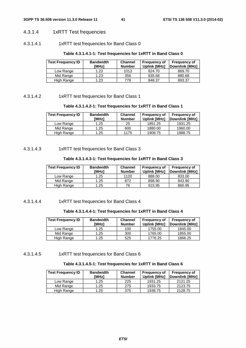
ETSI
ETSI TS 136 508 V11.3.0 (2014-02)413GPP TS 36.508 version 11.3.0 Release 11
4.3.1.4 1xRTT Test frequencies
4.3.1.4.1 1xRTT test frequencies for Band Class 0
Table 4.3.1.4.1-1: Test frequencies for 1xRTT in Band Class 0
Test Frequency ID Bandwidth [MHz]
Channel Number
Frequency of Uplink [MHz]
Frequency of Downlink [MHz]
Low Range 1.23 1013 824.70 869.70 Mid Range 1.23 356 835.68 880.68 High Range 1.23 779 848.37 893.37
4.3.1.4.2 1xRTT test frequencies for Band Class 1
Table 4.3.1.4.2-1: Test frequencies for 1xRTT in Band Class 1
Test Frequency ID Bandwidth [MHz]
Channel Number
Frequency of Uplink [MHz]
Frequency of Downlink [MHz]
Low Range 1.25 25 1851.25 1931.25 Mid Range 1.25 600 1880.00 1960.00 High Range 1.25 1175 1908.75 1988.75
4.3.1.4.3 1xRTT test frequencies for Band Class 3
Table 4.3.1.4.3-1: Test frequencies for 1xRTT in Band Class 3
Test Frequency ID Bandwidth [MHz]
Channel Number
Frequency of Uplink [MHz]
Frequency of Downlink [MHz]
Low Range 1.25 1120 888.00 833.00 Mid Range 1.25 872 898.90 843.90 High Range 1.25 76 915.95 860.95
4.3.1.4.4 1xRTT test frequencies for Band Class 4
Table 4.3.1.4.4-1: Test frequencies for 1xRTT in Band Class 4
Test Frequency ID Bandwidth [MHz]
Channel Number
Frequency of Uplink [MHz]
Frequency of Downlink [MHz]
Low Range 1.25 100 1755.00 1845.00 Mid Range 1.25 300 1765.00 1855.00 High Range 1.25 525 1776.25 1866.25
4.3.1.4.5 1xRTT test frequencies for Band Class 6
Table 4.3.1.4.5-1: Test frequencies for 1xRTT in Band Class 6
Test Frequency ID Bandwidth [MHz]
Channel Number
Frequency of Uplink [MHz]
Frequency of Downlink [MHz]
Low Range 1.25 225 1931.25 2121.25 Mid Range 1.25 275 1933.75 2123.75 High Range 1.25 375 1938.75 2128.75

ETSI
ETSI TS 136 508 V11.3.0 (2014-02)423GPP TS 36.508 version 11.3.0 Release 11
4.3.1.4.6 1xRTT test frequencies for Band Class 10
Table 4.3.1.4.6-1: Test frequencies for 1xRTT in Band Class 10
Test Frequency ID Bandwidth [MHz]
Channel Number
Frequency of Uplink [MHz]
Frequency of Downlink [MHz]
Low Range 1.25 100 808.50 853.50 Mid Range 1.25 500 821.00 866.00 High Range 1.25 820 898.50 937.50
4.3.1.4.7 1xRTT test frequencies for Band Class 15
Table 4.3.1.4.7-1: Test frequencies for 1xRTT in Band Class 15
Test Frequency ID Bandwidth [MHz]
Channel Number
Frequency of Uplink [MHz]
Frequency of Downlink [MHz]
Low Range 1.25 75 1713.75 2113.75 Mid Range 1.25 450 1732.50 2132.50 High Range 1.25 800 1750.00 2150.00
4.3.2 Radio conditions
4.3.2.1 Normal propagation condition
The downlink connection between the System Simulator and the UE is without Additive White Gaussian Noise, and has no fading or multipath effects.
The uplink connection between the UE and System Simulator is without Additive White Gaussian Noise, and has no fading or multipath effects.
4.3.3 Physical channel allocations
4.3.3.1 Antennas
If the UE has two Rx antennas, the same downlink signal is applied to each one. Both UE Rx antennas shall be connected unless otherwise stated in the test case.
If the UE has one Rx antenna, the downlink signal is applied to it.
4.3.3.2 Downlink physical channels and physical signals
The Downlink Physical channels and Physical signals used and their relative powers are specified for single SS Tx antenna in table 4.3.3.2-1 and for two SS Tx antennas in table 4.3.3.2-2. The details of downlink power allocation for PDSCH channel are described in TS 36.213 [29] clause 5.2.
Table 4.3.3.2-1: Power allocation for OFDM symbols and reference signals, single SS Tx antenna
Physical Channel EPRE Ratio PBCH PBCH_RA = 0 dB
PBCH_RB = 0 dB PSS PSS_RA = 0 dB SSS SSS_RA = 0 dB PCFICH PCFICH_RB = 0 dB PDCCH PDCCH_RA = 0 dB
PDCCH_RB = 0 dB PDSCH PDSCH_RA = 0 dB
PDSCH_RB = 0 dB PHICH PHICH_RB = 0 dB
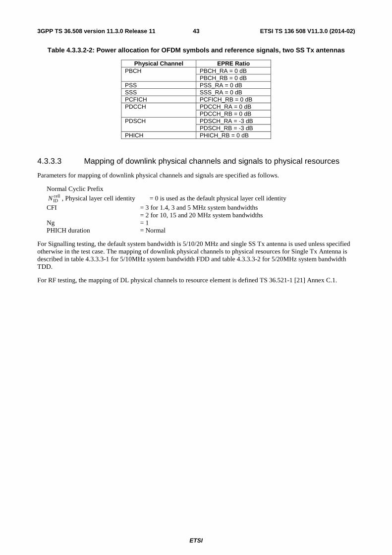
ETSI
ETSI TS 136 508 V11.3.0 (2014-02)433GPP TS 36.508 version 11.3.0 Release 11
Table 4.3.3.2-2: Power allocation for OFDM symbols and reference signals, two SS Tx antennas
Physical Channel EPRE Ratio PBCH PBCH_RA = 0 dB
PBCH_RB = 0 dB PSS PSS_RA = 0 dB SSS SSS_RA = 0 dB PCFICH PCFICH_RB = 0 dB PDCCH PDCCH_RA = 0 dB
PDCCH_RB = 0 dB PDSCH PDSCH_RA = -3 dB
PDSCH_RB = -3 dB PHICH PHICH_RB = 0 dB
4.3.3.3 Mapping of downlink physical channels and signals to physical resources
Parameters for mapping of downlink physical channels and signals are specified as follows.
Normal Cyclic Prefix cellIDN , Physical layer cell identity = 0 is used as the default physical layer cell identity
CFI = 3 for 1.4, 3 and 5 MHz system bandwidths = 2 for 10, 15 and 20 MHz system bandwidths Ng = 1 PHICH duration = Normal
For Signalling testing, the default system bandwidth is 5/10/20 MHz and single SS Tx antenna is used unless specified otherwise in the test case. The mapping of downlink physical channels to physical resources for Single Tx Antenna is described in table 4.3.3.3-1 for 5/10MHz system bandwidth FDD and table 4.3.3.3-2 for 5/20MHz system bandwidth TDD.
For RF testing, the mapping of DL physical channels to resource element is defined TS 36.521-1 [21] Annex C.1.

ETSI
ETSI TS 136 508 V11.3.0 (2014-02)443GPP TS 36.508 version 11.3.0 Release 11
Table 4.3.3.3-1: Mapping of DL Physical Channels to Resource Elements for Single SS Tx Antenna and 5/10 MHz System Bandwidth (FDD)
Physical channel
Time Domain Location Frequency Domain Location Note
PBCH Symbols 0 to 3 of slot 1 of subframe 0 of each radio frame
Occupies 72 subcarriers centred on the DC subcarrier
Mapping rule is specified in TS36.211 [35] sub clause 6.6.4
PSS Symbol 6 of slot 0 and 10 of each radio frame
Occupies 62 subcarriers centred on the DC subcarrier. Additional 10 subcarriers (5 on each side) adjacent to the centred 62 subcarriers are reserved.
Mapping rule is specified in TS36.211 [35] sub clause 6.11.1.2
SSS Symbol 5 of slots 0 and 10 of each radio frame
Occupies 62 subcarriers centred on the DC subcarrier. Additional 10 subcarriers (5 on each side) adjacent to the centred 62 subcarriers are reserved.
Mapping rule is specified in TS36.211 [35] sub clause 6.11.2.2
PCFICH Symbol 0 of each subframe Maps into 4 REGs uniformly spread in the frequency domain over the whole system bandwidth.
Mapping rule is specified in TS36.211 [35] sub clause 6.7.4 - CELL_ID = 0
PHICH Symbol 0 of each subframe Each PHICH group maps into 3 REGs in the frequency domain on the REGs not assigned to PCFICH over the whole system bandwidth,
Mapping rule is specified in TS36.211 [35] sub clause 6.9.3 - CELL_ID = 0 - Number of PHICH groups = 4(BW=5 MHz)/7(BW=10MHz)
PDCCH Symbols 0, 1, 2 of each subframe (BW=5MHz)
The remaining REGs not allocated to both PCFICH and PHICH are used for PDCCH
Mapping rule is specified in TS36.211 [35] sub clause 6.8.5 - CFI = 3 (BW=5MHz)
Symbols 0, 1 of each subframe (BW=10MHz)
Mapping rule is specified in TS36.211 [35] sub clause 6.8.5 - CFI = 2(BW=10MHz)
PDSCH All remaining OFDM symbols of each subframe not allocated to PDCCH
For Subframe 0, REs not allocated to RS, PSS, SSS and PBCH is allocated to PDSCH For Subframe 5, REs not allocated to RS, PSS and SSS is allocated to PDSCH For other subframes, REs not allocated to RS is allocated to PDSCH
NOTE: In case a single cell-specific RS is configured, cell-specific RS shall be assume to be present on antenna ports 0 and 1 for the purpose of mapping a symbol-quadruplet to a REG (resource element group). (See TS 36.211 [35] sub clause 6.2.4)

ETSI
ETSI TS 136 508 V11.3.0 (2014-02)453GPP TS 36.508 version 11.3.0 Release 11
Table 4.3.3.3-2: Mapping of DL Physical Channels to Resource Elements for Single SS Tx Antenna and 5/20 MHz System Bandwidth (TDD)
Physical channel
Time Domain Location Frequency Domain Location
Note
PBCH Symbols 0 to 3 of slot 1 of subframe 0 of each radio frame
Occupies 72 subcarriers centred on the DC subcarrier
Mapping rule is specified in TS36.211 [35] subclause 6.6.4
PSS Symbol 2 of slot 2 and 12 of each radio frame
Occupies 62 subcarriers centred on the DC subcarrier. Additional 10 subcarriers (5 on each side) adjacent to the centred 62 subcarriers are reserved.
Mapping rule is specified in TS36.211 [35] subclause 6.11.1.2
SSS Symbol 6 of slots 1 and 11 of each radio frame
Occupies 62 subcarriers centred on the DC subcarrier. Additional 10 subcarriers (5 on each side) adjacent to the centred 62 subcarriers are reserved.
Mapping rule is specified in TS36.211 [35] subclause 6.11.2.2
PCFICH Symbol 0 of each downlink subframe and Special subframe
Maps into 4 REGs uniformly spread in the frequency domain over the whole system bandwidth.
Mapping rule is specified in TS36.211 [35] subclause 6.7.4 - CELL_ID = 0
PHICH Symbol 0 of each downlink subframe and Special subframe
Each PHICH group maps into 3 REGs in the frequency domain on the REGs not assigned to PCFICH over the whole system bandwidth,
Mapping rule is specified in TS36.211 [35] subclause 6.9.3 - CELL_ID = 0 - Number of PHICH groups = 4(BW=5MHz)/13(BW=20MHz)
PDCCH Symbols 0, 1 of subframe 1, 6 and Symbols 0, 1, 2 of other downlink subframes (BW=5MHz)
The remaining REGs not allocated to both PCFICH and PHICH are used for PDCCH
Mapping rule is specified in TS36.211 [35] subclause 6.8.5 - CFI = 3 (BW=5MHz)
Symbols 0, 1 of subframe 1, 6 and Symbols 0, 1 of other downlink subframes (BW=20MHz)
Mapping rule is specified in TS36.211 [35] subclause 6.8.5 - CFI = 2 (BW=20MHz)
PDSCH All remaining OFDM symbols of each downlink subframe and DwPTS not allocated to PDCCH
For Subframe 0, REs not allocated to RS, SSS and PBCH is allocated to PDSCH For Subframe 5, REs not allocated to RS and SSS is allocated to PDSCH For Subframe 1 and 6, REs not allocated to RS, PSS, GP and UpPTS is allocated to PDSCH For other downlink subframes, REs not allocated to RS is allocated to PDSCH
NOTE 1: In case a single cell-specific RS is configured, cell-specific RS shall be assume to be present on antenna ports 0 and 1 for the purpose of mapping a symbol-quadruplet to a REG (resource element group). (See TS 36.211 [35] subclause 6.2.4)
NOTE 2: In case the default TDD configuration for subframe assignment and special subframe patterns (see subclause 4.6.3)

ETSI
ETSI TS 136 508 V11.3.0 (2014-02)463GPP TS 36.508 version 11.3.0 Release 11
4.3.3.4 Uplink physical channels and physical signals
[FFS].
4.3.3.5 Mapping of uplink physical channels and signals to physical resources
[FFS].
4.3.4 Signal levels
4.3.4.1 Downlink signal levels
The downlink power settings in table 4.3.4.1-1 are used unless otherwise specified in a test case.
Table 4.3.4.1-1: Default Downlink power levels
Unit Channel bandwidth 1.4 MHz 3 MHz 5 MHz 10 MHz 15 MHz 20 MHz
Number of RBs 6 15 25 50 75 100
Channel BW Power dBm -66 -62 -60 -57 -55 -54
RS EPRE dBm/15kHz -85 -85 -85 -85 -85 -85
Note 1: The channel bandwidth powers are informative, based on -85dBm/15kHz RS_EPRE, then scaled according to the number of RBs and rounded to the nearest integer dBm value. Full RE allocation with no boost or deboost is assumed.
Note 2: The power level is specified at each UE Rx antenna.
It is [FFS] whether there is a requirement to specify constant power throughout all OFDM symbols, and if so how unallocated Resource elements should be treated.
The default signal level uncertainty is +/-3dB at each test port, for any level specified. If the uncertainty value is critical for the test purpose a tighter uncertainty is specified for the related test case in TS 36.521-1 [21] Annex F or in TS 36.521-3 [34] Annex F
4.3.4.2 Uplink signal levels
[FFS]
4.3.5 Standard test signals
4.3.5.1 Downlink test signals
[FFS]
4.3.5.2 Uplink test signals
[FFS]

ETSI
ETSI TS 136 508 V11.3.0 (2014-02)473GPP TS 36.508 version 11.3.0 Release 11
4.3.6 Physical layer parameters
4.3.6.1 Downlink physical layer parameters
4.3.6.1.1 Physical layer parameters for DCI format 0
Default physical layer parameters for DCI format 0 are specified in table 4.3.6.1.1-1.
Table 4.3.6.1.1-1: Physical layer parameters for DCI format 0
Parameter Value Value in binary Flag for format 0/format 1A differentiation format 0 "0" Hopping flag w/o Hopping "0" Resource block assignment and hopping resource allocation Depending on test parameters - Modulation and coding scheme and redundancy version Depending on test parameters -
New data indicator
Set for every data transmission/retransmission according to the rules specified in TS 36.321
-
TPC command for scheduled PUSCH 0 dB (accumulated TPC) "01" Cyclic shift for DM RS 0 "000"
UL index (TDD only)
2 bits as defined in sections 5.1.1.1 and 8 of TS 36.213. This field is present only for TDD configuration 0
-
Downlink Assignment Index (TDD only)
2 bits as defined in Table 7.3-X in TS 36.213. It represents the total number of PDSCH subframes with and without PDCCH and PDCCH indicating downlink SPS release in the window. This field is present only for TDD configuration 1-6
-
CQI request w/o aperiodic CQI "0"

ETSI
ETSI TS 136 508 V11.3.0 (2014-02)483GPP TS 36.508 version 11.3.0 Release 11
4.3.6.1.2 Physical layer parameters for DCI format 1
Default physical layer parameters for DCI format 1 are specified in table 4.3.6.1.2-1.
Table 4.3.6.1.2-1: Physical layer parameters for DCI format 1
Parameter Value Value in binary Resource allocation header Resource allocation type 0 "0" Resource block assignment Depending on test parameters - Modulation and coding scheme Depending on test parameters -
HARQ process number Depending on test parameters, 3bits for FDD, 4 bits for TDD.
-
New data indicator
Set for every data transmission/retransmission according to the rules specified in TS 36.321
-
Redundancy version Depending on test parameters "00" TPC command for PUCCH 0 dB (accumulated TPC) "01"
Downlink Assignment Index (TDD only)
2 bits as defined in Table 7.3-X in TS 36.213. It represents the number of PDSCH with PDCCH and PDCCH indicating downlink SPS release in the window up to the present subframe. This is present for all the uplink-downlink configurations and only applies to uplink -downlink configuration 1-6
-
4.3.6.1.3 Physical layer parameters for DCI format 1A
Default physical layer parameters for DCI format 1A are specified in table 4.3.6.1.3-1.
Table 4.3.6.1.3-1: Physical layer parameters for DCI format 1A
Parameter Value Value in binary Flag for format 0/format 1A differentiation format 1A "1" Localized/Distributed VRB assignment flag Localized VRB assignment "0" Resource block assignment Depending on test parameters - Modulation and coding scheme Depending on test parameters -
HARQ process number Depending on test parameters, 3bits for FDD, 4 bits for TDD. -
New data indicator
Set for every data transmission/retransmission according to the rules specified in TS 36.321
-
Redundancy version Depending on test parameters "00" TPC command for PUCCH 0 dB (accumulated TPC) "01"
Downlink Assignment Index (TDD only)
2 bits as defined in Table 7.3-X in TS 36.213. It represents the number of PDSCH with PDCCH and PDCCH indicating downlink SPS release in the window up to the present subframe. This is present for all the uplink-downlink configurations and only applies to uplink -downlink configuration 1-6
-
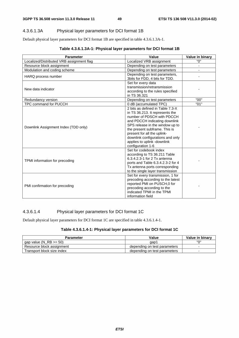
ETSI
ETSI TS 136 508 V11.3.0 (2014-02)493GPP TS 36.508 version 11.3.0 Release 11
4.3.6.1.3A Physical layer parameters for DCI format 1B
Default physical layer parameters for DCI format 1B are specified in table 4.3.6.1.3A-1.
Table 4.3.6.1.3A-1: Physical layer parameters for DCI format 1B
Parameter Value Value in binary Localized/Distributed VRB assignment flag Localized VRB assignment "0" Resource block assignment Depending on test parameters - Modulation and coding scheme Depending on test parameters -
HARQ process number Depending on test parameters, 3bits for FDD, 4 bits for TDD.
-
New data indicator
Set for every data transmission/retransmission according to the rules specified in TS 36.321
-
Redundancy version Depending on test parameters "00" TPC command for PUCCH 0 dB (accumulated TPC) "01"
Downlink Assignment Index (TDD only)
2 bits as defined in Table 7.3-X in TS 36.213. It represents the number of PDSCH with PDCCH and PDCCH indicating downlink SPS release in the window up to the present subframe. This is present for all the uplink-downlink configurations and only applies to uplink -downlink configuration 1-6
-
TPMI information for precoding
Set for codebook index according to TS 36.211 Table 6.3.4.2.3-1 for 2 Tx antenna ports and Table 6.3.4.2.3-2 for 4 Tx antenna ports corresponding to the single layer transmission
-
PMI confirmation for precoding
Set for every transmission, 1 for precoding according to the latest reported PMI on PUSCH,0 for precoding according to the indicated TPMI in the TPMI information field
-
4.3.6.1.4 Physical layer parameters for DCI format 1C
Default physical layer parameters for DCI format 1C are specified in table 4.3.6.1.4-1.
Table 4.3.6.1.4-1: Physical layer parameters for DCI format 1C
Parameter Value Value in binary gap value (N_RB >= 50) gap1 "0" Resource block assignment depending on test parameters - Transport block size index depending on test parameters -
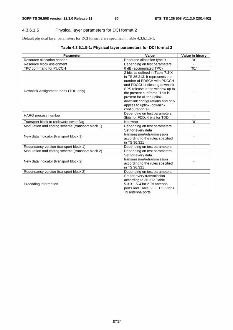
ETSI
ETSI TS 136 508 V11.3.0 (2014-02)503GPP TS 36.508 version 11.3.0 Release 11
4.3.6.1.5 Physical layer parameters for DCI format 2
Default physical layer parameters for DCI format 2 are specified in table 4.3.6.1.5-1.
Table 4.3.6.1.5-1: Physical layer parameters for DCI format 2
Parameter Value Value in binary Resource allocation header Resource allocation type 0 "0" Resource block assignment Depending on test parameters - TPC command for PUCCH 0 dB (accumulated TPC) "01"
Downlink Assignment Index (TDD only)
2 bits as defined in Table 7.3-X in TS 36.213. It represents the number of PDSCH with PDCCH and PDCCH indicating downlink SPS release in the window up to the present subframe. This is present for all the uplink-downlink configurations and only applies to uplink -downlink configuration 1-6
-
HARQ process number Depending on test parameters, 3bits for FDD, 4 bits for TDD. -
Transport block to codeword swap flag No swap "0" Modulation and coding scheme (transport block 1) Depending on test parameters -
New data indicator (transport block 1)
Set for every data transmission/retransmission according to the rules specified in TS 36.321
-
Redundancy version (transport block 1) Depending on test parameters - Modulation and coding scheme (transport block 2) Depending on test parameters -
New data indicator (transport block 2)
Set for every data transmission/retransmission according to the rules specified in TS 36.321
-
Redundancy version (transport block 2) Depending on test parameters -
Precoding information
Set for every transmission according to 36.212 Table 5.3.3.1.5-4 for 2 Tx antenna ports and Table 5.3.3.1.5-5 for 4 Tx antenna ports
-

ETSI
ETSI TS 136 508 V11.3.0 (2014-02)513GPP TS 36.508 version 11.3.0 Release 11
4.3.6.1.6 Physical layer parameters for DCI format 2A
Default physical layer parameters for DCI format 2A are specified in table 4.3.6.1.6-1.
Table 4.3.6.1.6-1: Physical layer parameters for DCI format 2A
Parameter Value Value in binary Resource allocation header Resource allocation type 0 "0" Resource block assignment depending on test parameters - TPC command for PUCCH 0 dB (accumulated TPC) "01"
Downlink Assignment Index (TDD only)
2 bits as defined in Table 7.3-X in TS 36.213. It represents the number of PDSCH with PDCCH and PDCCH indicating downlink SPS release in the window up to the present subframe. This is present for all the uplink-downlink configurations and only applies to uplink -downlink configuration 1-6
-
HARQ process number depending on test parameters, 3bits for FDD, and 4 bits for TDD.
-
Transport block to codeword swap flag No swap "0" Modulation and coding scheme (transport block 1) depending on test parameters -
New data indicator (transport block 1)
Set for every data transmission/retransmission according to the rules specified in TS 36.321
-
Redundancy version (transport block 1) depending on test parameters - Modulation and coding scheme (transport block 2) depending on test parameters -
New data indicator (transport block 2)
Set for every data transmission/retransmission according to the rules specified in TS 36.321
-
Redundancy version (transport block 2) depending on test parameters -
Precoding information
N/A for 2 Tx antenna ports. For 4 Tx antenna ports, set for every transmission according to 36.212 Table 5.3.3.1.5A-2
-
4.4 Reference system configurations The reference system configurations specified in this sub clause apply to all test cases unless otherwise specified.
4.4.1 Simulated network scenarios
The UE will eventually have to operate in either single mode networks (FDD or TDD), dual mode networks (FDD+TDD), or inter-RAT networks ((FDD or TDD) + (UTRA FDD, UTRA TDD, GSM, HRPD or 1xRTT)).
Simulated network scenarios to be tested are listed in this sub clause.
NOTE 1: The number of cells specified does not necessarily correspond to the maximum number of resources to be configured simultaneously in test equipment. Please refer to Table 6.1-1 for such information.
NOTE 2: For NAS test cases see sub clause 6.3.2.
4.4.1.1 Single cell network scenarios
For FDD and TDD basic single cell environment, Cell 1 is used.

ETSI
ETSI TS 136 508 V11.3.0 (2014-02)523GPP TS 36.508 version 11.3.0 Release 11
4.4.1.2 E-UTRA single mode multi cell network scenarios
For FDD or TDD basic intra-frequency multi cell environment, Cell 1, Cell 2 and Cell 4 are used.
For FDD or TDD basic inter-frequency multi cell environment, Cell 1, Cell 3 and Cell 6 are used.
For FDD or TDD basic inter-band cell environment, Cell 1 and Cell 10 are used.
For FDD or TDD multi tracking area intra-frequency multi cell environment, Cell 1 and Cell 11 are used.
For FDD or TDD multi tracking area inter-frequency multi cell environment, Cell 1 and Cell 23 are used.
For FDD or TDD multi PLMN inter-frequency multi cell environment, Cell 1, Cell 12, Cell 13 and Cell 14 are used.
4.4.1.3 E-UTRA dual mode multi cell network scenarios
For FDD and TDD basic multi cell environment, Cell 1, Cell 10 and Cell 31 are used.
For FDD and TDD multi PLMN multi cell environment, Cell 1, Cell 28, Cell 29 and Cell 30 are used.
In addition, E-UTRA single mode multi cell network scenarios defined in clause 4.4.1.2 are combined with the dual mode scenarios defined in this clause when additional intra or inter-frequency cells are used.
4.4.1.4 3GPP Inter-RAT network scenarios
For FDD and TDD basic inter-RAT cell environment with UTRA FDD or UTRA TDD, Cell 1 and Cell 5 are used.
For FDD and TDD inter-RAT cell environment with multi UTRA FDD or UTRA TDD cells, Cell 1 and Cell 7, Cell 8 and Cell 9 is used.
For FDD and TDD inter-RAT cell environment with GERAN, Cell 1 and Cell 24 are used.
For FDD and TDD inter-RAT cell environment with multi GERAN cells, Cell 1 and Cell 25, Cell 26 are used.
For FDD and TDD inter-RAT cell environment with (UTRA FDD or UTRA TDD) and GERAN, Cell 1, Cell 5 and Cell 24 are used.
4.4.1.5 3GPP2 Inter-RAT network scenarios
For FDD and TDD inter-RAT cell environment with HRPD, Cell 1 and Cell 15 are used.
For FDD and TDD inter-RAT cell environment with multi HRPD cells, Cell 1 and Cell 15, Cell 16 and Cell 17 are used.
For FDD and TDD inter-RAT cell environment with 1xRTT, Cell 1 and Cell 19 are used.
For FDD and TDD inter-RAT cell environment with multi 1xRTT cells, Cell 1 and Cell 19, Cell 20 and Cell 21 are used.
4.4.1.6 WLAN Inter-RAT network scenarios
For FDD and TDD inter-RAT cell environment with WLAN, Cell 1 and Cell 27 are used.
4.4.2 Simulated cells
NOTE: For NAS test cases see subclause 6.3.2.
NOTE: Test frequency and range defined in table 4.4.2-1 do not apply to 36.521-1 test cases.
Test frequencies and simulated cells are defined in table 4.4.2-1. For E-UTRA cells, f1 is the default test frequency. For UTRA cells, f8 is the default test frequency. For GERAN cells, f11 is the default test frequency. For CDMA2000 HRPD cells, f14 is the default test frequency. For CDMA 2000 1xRTT cells, f17 is the default test frequency. For WLAN cells, f20 is the default test frequency.

ETSI
ETSI TS 136 508 V11.3.0 (2014-02)533GPP TS 36.508 version 11.3.0 Release 11
Default parameters for simulated cells are specified in table 4.4.2-1A and table 4.4.2-2.
Common parameters for simulated cells are specified in subclauses 4.4.3 to 4.4.6A.
Other cell specific parameters are specified in subclause 4.4.7.
Table 4.4.2-1: Definition of test frequencies and simulated cells
Test frequency
RAT Operating band Range Simulated cells
f1 E-UTRA Operating band under test Mid (Note 1, Note 5)
Cell 1, Cell 2, Cell 4, Cell 11 (Note 4)
f2 E-UTRA Operating band under test High (Note 1, Note 6)
Cell 3, Cell 12, Cell 23
f3 E-UTRA Operating band under test Low (Note 1, Note 7)
Cell 6, Cell 13
f4 E-UTRA Operating band under test (Note 1) Cell 14 f5 E-UTRA Operating band for inter-band cells Mid
(Note 1) Cell 10, Cell 30, Cell 31
f6 E-UTRA Operating band for inter-band cells High (Note 1)
Cell 28, Cell 29
f7 E-UTRA Operating band for inter-band cells Low (Note 1)
f8 UTRA Operating band for UTRA cells Mid (Note 2)
Cell 5, Cell 7
f9 UTRA Operating band for UTRA cells High (Note 2)
Cell 8
f10 UTRA Operating band for UTRA cells Low (Note 2)
Cell 9
f11 GERAN Operating band for GERAN cells Mid (Note 3)
Cell 24
f12 GERAN Operating band for GERAN cells High (Note 3)
Cell 25
f13 GERAN Operating band for GERAN cells Low (Note 3)
Cell 26
f14 CDMA2000 HRPD
Operating band for CDMA2000 HRPD cells
Mid Cell 15, Cell 16
f15 CDMA2000 HRPD
Operating band for CDMA2000 HRPD cells
High Cell 17
f16 CDMA2000 HRPD
Operating band for CDMA2000 HRPD cells
Low Cell 18
f17 CDMA2000 1xRTT
Operating band for CDMA2000 1xRTT cells
Mid Cell 19, Cell 20
f18 CDMA2000 1xRTT
Operating band for CDMA2000 1xRTT cells
High Cell 21
f19 CDMA2000 1xRTT
Operating band for CDMA2000 1xRTT cells
Low Cell 22
f20 WLAN Operating band for WLAN cells FFS Cell 27 Note 1: For signalling test, see clause 6.2.3. Note 2: See TS 34.108 [5] clause 5.1. Note 3: For signalling test, see clause 6.3.1.4. For RRM test, see clause 7.2.2.1. Note 4: For signalling test, simultaneous co-existence of Cell 2 with Cell 11 is not allowed. Note 5: For RRM test with intra-band contiguous CA, both PCC and SCC are “Mid”, with the test frequencies
specified in clauses 4.3.1.1.xA for FDD and 4.3.1.2.xA for TDD Note 6: For RRM test with intra-band contiguous CA, both PCC and SCC are “High”, with the test frequencies
specified in clauses 4.3.1.1.xA for FDD and 4.3.1.2.xA for TDD Note 7: For RRM test with intra-band contiguous CA, both PCC and SCC are “Low”, with the test frequencies
specified in clauses 4.3.1.1.xA for FDD and 4.3.1.2.xA for TDD.

ETSI
ETSI TS 136 508 V11.3.0 (2014-02)543GPP TS 36.508 version 11.3.0 Release 11
Table 4.4.2-1A: Default E-UTRA parameters for simulated cells
cell ID E-UTRAN Cell Identifier Physical layer cell identity
rootSequenceIndex FDD
rootSequenceIndex TDD
eNB Identifier Cell Identity Cell 1 '0000 0000 0000 0000
0001'B '0000 0000'B 0 22 0
Cell 2 '0000 0000 0000 0000 0001'B
'0000 0010'B 2 86 8
Cell 3 '0000 0000 0000 0000 0010'B
'0000 0011'B 3 22 0
Cell 4 '0000 0000 0000 0000 0011'B
'0000 0100'B 4 150 16
Cell 6 '0000 0000 0000 0000 0100'B
'0000 0110'B 6 22 0
Cell 10 '0000 0000 0000 0000 0101'B
'0000 1010'B 10 22 0
Cell 11 '0000 0000 0000 0000 0110'B
'0000 1011'B 11 214 24
Cell 12 '0000 0000 0000 0000 0010'B
'0000 1100'B 12 86 8
Cell 13 '0000 0000 0000 0000 0100'B
'0000 1101'B 13 86 8
Cell 14 '0000 0000 0000 0000 0111'B
'0000 1110'B 14 22 0
Cell 23 '0000 0000 0000 0000 0110'B
'0001 0111'B 23 150 16
Cell 28 '0000 0000 0000 0000 0010'B
'0001 1100'B 28 86 8
Cell 29 '0000 0000 0000 0000 0100'B
'0001 1101'B 29 86 8
Cell 30 '0000 0000 0000 0000 0111'B
'0001 1110'B 30 22 0
Cell 31 '0000 0000 0000 0000 0110'B
'0001 1111'B 31 214 24
Table 4.4.2-2: Default NAS parameters for simulated cells
cell ID Tracking Area TA# list (Note 1)
GUTI (Note 2) TA# PLMN TAC MME Identifier M-TMSI
MCC MNC MME Group ID MME Code Cell 1 TAI-1 (Note 3) 1 TAI-1 32769 1 Arbitrarily
selected according to TS 23.003
subclause 2.8 [2].
Cell 2 TAI-1 (Note 3) 1 TAI-1 32769 1 Cell 3 TAI-1 (Note 3) 1 TAI-1 32769 1 Cell 4 TAI-1 (Note 3) 1 TAI-1 32769 1 Cell 6 TAI-1 (Note 3) 1 TAI-1 32769 1 Cell 10 TAI-1 (Note 3) 1 TAI-1 32769 1 Cell 11 TAI-2 (Note 3) 2 TAI-2 32769 1 Cell 23 TAI-2 (Note 3) 2 TAI-2 32769 1 Cell 12, Cell 28
TAI-3 002 11 1 TAI-3 32769 1
Cell 13, Cell 29
TAI-4 003 21 1 TAI-4 32769 1
Cell 14, Cell 30
TAI-5 004 31 1 TAI-5 32769 1
Cell 31 TAI-2 (Note 3) 2 TAI-2 32769 1 Note 1: The value(s) in the column TA# list indicates TAI(s) included in the response messages of the
registration procedure (ATTACH ACCEPT or TRACKING AREA UPDATE ACCEPT) when the UE performs the registration procedure on a corresponding cell.
Note 2: The value in the column GUTI indicates GUTI included in the response messages of the registration procedure (ATTACH ACCEPT or TRACKING AREA UPDATE ACCEPT) when the UE performs the registration procedure on a corresponding cell.
Note 3: Set to the same Mobile Country Code and Mobile Network Code stored in EFIMSI on the test USIM card (subclause 4.9.3).

ETSI
ETSI TS 136 508 V11.3.0 (2014-02)553GPP TS 36.508 version 11.3.0 Release 11
Table 4.4.2-3: Default HRPD parameters for simulated cells
Cell ID SectorID ColorCode Pilot PN Offset CountryCode Cell 15 Set according to PIXIT
parameter Set according to PIXIT parameter
50 (Note 1)
Cell 16 Set according to PIXIT parameter
Set according to PIXIT parameter
100 (Note 1)
Cell 17 Set according to PIXIT parameter
Set according to PIXIT parameter
150 (Note 1)
Cell 18 Set according to PIXIT parameter
Set according to PIXIT parameter
200 (Note 1)
Note 1: Set to the same Mobile Country Code stored in EFIMSI on the test USIM card (subclause 4.9.3).
Table 4.4.2-4: Default 1XRTT parameters for simulated cells
Cell ID SID NID BASE_ID Pilot PN Offset REG_ZONE MCC IMSI_11_12 Cell 19 200 Set
according to PIXIT parameter
Set according to PIXIT parameter
50 1 Note 1
Note 2
Cell 20 200 Set according to PIXIT parameter
Set according to PIXIT parameter
100 1 Note 1
Note 2
Cell 21 200 Set according to PIXIT parameter
Set according to PIXIT parameter
150 2 Note 1
Note 2
Cell 22 200 Set according to PIXIT parameter
Set according to PIXIT parameter
200 3 Note 1
Note 2
Note 1: Set to the same Mobile Country Code stored in EFIMSI on the test USIM card (subclause 4.9.3). Note 2: Set to the same Mobile Network Code stored in EFIMSI on the test USIM card (subclause 4.9.3).
Table 4.4.2-5: Neighbouring cell list for 1XRTT cells
Cell ID Intra Frequency Inter Frequency Cells Cell 19 cell 20 Cell 21 cell 22 X Cell 20 cell 19 Cell 21 cell 22 X Cell 21 X cell 19 cell 20 cell 22 Cell 22 X cell 19 cell 20 cell 21
4.4.3 Common parameters for simulated E-UTRA cells
The parameters specified in this sub clause apply to all simulated E-UTRA cells unless otherwise specified.
4.4.3.1 Common configurations of system information blocks
4.4.3.1.1 Combinations of system information blocks
The combination of system information blocks required by a test case depends on the test case scenario. In this clause, the following combinations of system information blocks are defined.
Combination 1 is the default combination which applies to the following test case scenarios:
- E-UTRA FDD single cell scenario
- E-UTRA TDD single cell scenario
- E-UTRA FDD intra-frequency multi cell scenario

ETSI
ETSI TS 136 508 V11.3.0 (2014-02)563GPP TS 36.508 version 11.3.0 Release 11
- E-UTRA TDD intra-frequency multi cell scenario
- E-UTRA FDD and E-UTRA TDD dual mode multi cell roaming scenario
Combination 2 applies to the following test case scenarios:
- E-UTRA FDD intra-frequency multi cell scenario with neighbouring cell related information
- E-UTRA TDD intra-frequency multi cell scenario with neighbouring cell related information
Combination 3 applies to the following test case scenarios:
- E-UTRA FDD inter-frequency multi cell scenario
- E-UTRA TDD inter-frequency multi cell scenario
- E-UTRA FDD inter-band multi cell scenario
- E-UTRA TDD inter-band multi cell scenario
- E-UTRA FDD and E-UTRA TDD dual mode multi cell non-roaming scenario
- E-UTRA FDD intra-band carrier aggregation component carriers cell scenario
- E-UTRA FDD inter-band carrier aggregation component carriers cell scenario
- E-UTRA TDD intra-band carrier aggregation component carriers cell scenario
Combination 4 applies to the following test case scenarios:
- 3GPP inter-RAT E-UTRA FDD + UTRA FDD multi cell scenario
- 3GPP inter-RAT E-UTRA TDD + UTRA LCR TDD multi cell scenario
- 3GPP inter-RAT E-UTRA TDD + UTRA FDD multi cell scenario
Combination 5 applies to the following test case scenarios:
- 3GPP inter-RAT E-UTRA FDD + GERAN multi cell scenario
- 3GPP inter-RAT E-UTRA TDD + GERAN multi cell scenario
Combination 6 applies to the following test case scenarios:
- 3GPP2 inter-RAT E-UTRA FDD + HRPD multi cell scenario
- 3GPP2 inter-RAT E-UTRA TDD + HRPD multi cell scenario
- 3GPP2 inter-RAT E-UTRA FDD + 1xRTT multi cell scenario
- 3GPP2 inter-RAT E-UTRA TDD + 1xRTT multi cell scenario
Editor’s note: 3GPP2 Inter-RAT multi cell scenarios with E-UTRA + HRPD + 1xRTT are FFS.
Combination 7 applies to the following test case scenarios:
- E-UTRA FDD + home eNB multi cell scenario
- E-UTRA TDD + home eNB multi cell scenario
Combination 8 applies to the following test case scenarios:
- E-UTRA FDD ETWS single cell scenario
- E-UTRA TDD ETWS single cell scenario
Combination 9 applies to the following test case scenarios:
- E-UTRA FDD inter-frequency + 3GPP inter-RAT UTRA multi-cell scenario

ETSI
ETSI TS 136 508 V11.3.0 (2014-02)573GPP TS 36.508 version 11.3.0 Release 11
- E-UTRA TDD inter-frequency + 3GPP inter-RAT UTRA multi-cell scenario
Combination 10 applies to the following test case scenarios:
- 3GPP inter-RAT E-UTRA FDD + UTRA FDD + GERAN multi cell scenario
- 3GPP inter-RAT E-UTRA TDD + UTRA LCR TDD + GERAN multi cell scenario.
Combination 10a applies to the following test case scenarios:
- E-UTRA FDD inter-frequency + 3GPP inter-RAT E-UTRA FDD + UTRA FDD + GERAN multi cell scenario
- E-UTRA TDD inter-frequency + 3GPP inter-RAT E-UTRA TDD + UTRA LCR TDD + GERAN multi cell scenario
Combination 11 applies to the following test case scenarios:
- 3GPP inter-RAT E-UTRA FDD + UTRA FDD + home eNB multi cell scenario
- 3GPP inter-RAT E-UTRA TDD + UTRA LCR TDD + home eNB multi cell scenario
Combination 12 applies to the following test case scenarios:
- E-UTRA FDD inter-frequency + GERAN cell scenario
- E-UTRA TDD inter-frequency + GERAN cell scenario
Combination 13 applies to the following test case scenarios:
- E-UTRA FDD inter-frequency + home eNB
- E-UTRA TDD inter-frequency + home eNB
Combination 14 applies to the following test case scenarios:
- 3GPP inter-RAT E-UTRA FDD + GERAN + home eNB multi cell scenario
- 3GPP inter-RAT E-UTRA TDD + GERAN + home eNB multi cell scenario
Combination 15 applies to the following test case scenarios:
- 3GPP E-UTRA FDD single cell scenario+ MBMS
- 3GPP E-UTRA TDD single cell scenario+ MBMS
- 3GPP E-UTRA FDD intra-frequency multi cell scenario + MBMS
- 3GPP E-UTRA TDD intra-frequency multi cell scenario + MBMS
Combination 16 applies to the following test case scenarios:
- 3GPP E-UTRA FDD intra-frequency multi cell scenario with neighbouring cell related information + MBMS
- 3GPP E-UTRA TDD intra-frequency multi cell scenario with neighbouring cell related information + MBMS
Combination 17 applies to the following test case scenarios:
- 3GPP E-UTRA FDD + CMAS single cell scenario
- 3GPP E-UTRA TDD + CMAS single cell scenario
Combination 18 applies to the following test case scenarios:
- 3GPP E-UTRA FDD + MBMS inter-frequency multi cell scenario (non-MBMS cell broadcasting SIB15)
- 3GPP E-UTRA TDD + MBMS inter-frequency multi cell scenario (non-MBMS cell broadcasting SIB15)
Combination 19 applies to the following test case scenarios:

ETSI
ETSI TS 136 508 V11.3.0 (2014-02)583GPP TS 36.508 version 11.3.0 Release 11
- 3GPP E-UTRA FDD + MBMS intra-frequency multi cell scenario (MBMS cell broadcasting SIB15)
- 3GPP E-UTRA TDD + MBMS intra-frequency multi cell scenario (MBMS cell broadcasting SIB15)
Combination 20 applies to the following test case scenarios:
- 3GPP E-UTRA FDD + MBMS inter-frequency multi cell scenario (MBMS cell broadcasting SIB15)
- 3GPP E-UTRA TDD + MBMS inter-frequency multi cell scenario (MBMS cell broadcasting SIB15)
- 3GPP E-UTRA FDD + MBMS inter-band multi cell scenario (MBMS cell broadcasting SIB15)
- 3GPP E-UTRA TDD + MBMS inter-band multi cell scenario (MBMS cell broadcasting SIB15)
Table 4.4.3.1.1-1: Combinations of system information blocks
System information block type Combination
No. SIB
2 SIB
3 SIB
4 SIB
5 SIB
6 SIB
7 SIB
8 SIB
9 SIB10
SIB11
SIB12
SIB13
SIB 15
1 X X 2 X X X 3 X X X 4 X X X 5 X X X 6 X X X 7 X X X X 8 X X X X 9 X X X X 10 X X X X
10a X X X X X 11 X X X X X 12 X X X X 13 X X X X X 14 X X X X X 15 X X X 16 X X X X 17 X X X 18 X X X X 19 X X X X X 20 X X X X X
4.4.3.1.2 Scheduling of system information blocks
The scheduling configurations for combinations of system information blocks are defined in the following tables.
Table 4.4.3.1.2-1: Scheduling for combination 1
Scheduling Information No.
Periodicity [radio frames]
Mapping of system information blocks
1 16 SIB2 2 See sub clause 4.4.3.4 SIB3
Table 4.4.3.1.2-2: Scheduling for combination 2
Scheduling Information No.
Periodicity [radio frames]
Mapping of system information blocks
1 16 SIB2 2 See sub clause 4.4.3.4 SIB3 3 See sub clause 4.4.3.4 SIB4

ETSI
ETSI TS 136 508 V11.3.0 (2014-02)593GPP TS 36.508 version 11.3.0 Release 11
Table 4.4.3.1.2-3: Scheduling for combination 3
Scheduling Information No.
Periodicity [radio frames]
Mapping of system information blocks
1 16 SIB2 2 See sub clause 4.4.3.4 SIB3 3 See sub clause 4.4.3.4 SIB5
Table 4.4.3.1.2-4: Scheduling for combination 4
Scheduling Information No.
Periodicity [radio frames]
Mapping of system information blocks
1 16 SIB2 2 See sub clause 4.4.3.4 SIB3 3 See sub clause 4.4.3.4 SIB6
Table 4.4.3.1.2-5: Scheduling for combination 5
Scheduling Information No.
Periodicity [radio frames]
Mapping of system information blocks
1 16 SIB2 2 See sub clause 4.4.3.4 SIB3 3 See sub clause 4.4.3.4 SIB7
Table 4.4.3.1.2-6: Scheduling for combination 6
Scheduling Information No.
Periodicity [radio frames]
Mapping of system information blocks
1 16 SIB2 2 See sub clause 4.4.3.4 SIB3 3 See sub clause 4.4.3.4 SIB8
Table 4.4.3.1.2-7: Scheduling for combination 7
Scheduling Information No.
Periodicity [radio frames]
Mapping of system information blocks
1 16 SIB2 2 See sub clause 4.4.3.4 SIB3 3 See sub clause 4.4.3.4 SIB4 4 See sub clause 4.4.3.4 SIB9
Table 4.4.3.1.2-8: Scheduling for combination 8
Scheduling Information No.
Periodicity [radio frames]
Mapping of system information blocks
1 16 SIB2 2 See sub clause 4.4.3.4 SIB3 3 See sub clause 4.4.3.4 SIB11 4 See sub clause 4.4.3.4 SIB10
Table 4.4.3.1.2-9: Scheduling for combination 9
Scheduling Information No.
Periodicity [radio frames]
Mapping of system information blocks
1 16 SIB2 2 See sub clause 4.4.3.4 SIB3 3 See sub clause 4.4.3.4 SIB5, SIB6

ETSI
ETSI TS 136 508 V11.3.0 (2014-02)603GPP TS 36.508 version 11.3.0 Release 11
Table 4.4.3.1.2-10: Scheduling for combination 10
Scheduling Information No.
Periodicity [radio frames]
Mapping of system information blocks
1 16 SIB2 2 See sub clause 4.4.3.4 SIB3 3 See sub clause 4.4.3.4 SIB6 4 See sub clause 4.4.3.4 SIB7
Table 4.4.3.1.2-10a: Scheduling for combination 10a
Scheduling Information No.
Periodicity [radio frames]
Mapping of system information blocks
1 16 SIB2 2 See sub clause 4.4.3.4 SIB3 3 See sub clause 4.4.3.4 SIB5, SIB6 4 See sub clause 4.4.3.4 SIB7
Table 4.4.3.1.2-11: Scheduling for combination 11
Scheduling Information No.
Periodicity [radio frames]
Mapping of system information blocks
1 16 SIB2 2 See sub clause 4.4.3.4 SIB3 3 See sub clause 4.4.3.4 SIB4 4 See sub clause 4.4.3.4 SIB6 5 See sub clause 4.4.3.4 SIB9
Table 4.4.3.1.2-12: Scheduling for combination 12
Scheduling Information No.
Periodicity [radio frames]
Mapping of system information blocks
1 16 SIB2 2 See sub clause 4.4.3.4 SIB3 3 See sub clause 4.4.3.4 SIB5 4 See sub clause 4.4.3.4 SIB7
Table 4.4.3.1.2-13: Scheduling for combination 13
Scheduling Information No.
Periodicity [radio frames]
Mapping of system information blocks
1 16 SIB2 2 See sub clause 4.4.3.4 SIB3 3 See sub clause 4.4.3.4 SIB4 4 See sub clause 4.4.3.4 SIB5
Table 4.4.3.1.2-14: Scheduling for combination 14
Scheduling Information No.
Periodicity [radio frames]
Mapping of system information blocks
1 16 SIB2 2 See sub clause 4.4.3.4 SIB3 3 See sub clause 4.4.3.4 SIB4 4 See sub clause 4.4.3.4 SIB7 5 See sub clause 4.4.3.4 SIB9

ETSI
ETSI TS 136 508 V11.3.0 (2014-02)613GPP TS 36.508 version 11.3.0 Release 11
Table 4.4.3.1.2-15: Scheduling for combination 15
Scheduling Information No.
Periodicity [radio frames]
Mapping of system information blocks
1 16 SIB2 2 See sub clause 4.4.3.4 SIB3 3 See sub clause 4.4.3.4 SIB13
Table 4.4.3.1.2-16: Scheduling for combination 16
Scheduling Information No.
Periodicity [radio frames]
Mapping of system information blocks
1 16 SIB2 2 See sub clause 4.4.3.4 SIB3 3 See sub clause 4.4.3.4 SIB4 4 See sub clause 4.4.3.4 SIB13
Table 4.4.3.1.2-17: Scheduling for combination 17
Scheduling Information No.
Periodicity [radio frames]
Mapping of system information blocks
1 16 SIB2 2 See sub clause 4.4.3.4 SIB3 3 See sub clause 4.4.3.4 SIB12
Table 4.4.3.1.2-18: Scheduling for combination 18
Scheduling Information No.
Periodicity [radio frames]
Mapping of system information blocks
1 16 SIB2 2 See sub clause 4.4.3.4 SIB3 3 See sub clause 4.4.3.4 SIB5 4 See sub clause 4.4.3.4 SIB15
Table 4.4.3.1.2-19: Scheduling for combination 19
Scheduling Information No.
Periodicity [radio frames]
Mapping of system information blocks
1 16 SIB2 2 See sub clause 4.4.3.4 SIB3 3 See sub clause 4.4.3.4 SIB4 4 See sub clause 4.4.3.4 SIB13 5 See sub clause 4.4.3.4 SIB15
Table 4.4.3.1.2-20: Scheduling for combination 20
Scheduling Information No.
Periodicity [radio frames]
Mapping of system information blocks
1 16 SIB2 2 See sub clause 4.4.3.4 SIB3 3 See sub clause 4.4.3.4 SIB5 4 See sub clause 4.4.3.4 SIB13 5 See sub clause 4.4.3.4 SIB15

ETSI
ETSI TS 136 508 V11.3.0 (2014-02)623GPP TS 36.508 version 11.3.0 Release 11
4.4.3.2 Common contents of system information messages
- MasterInformationBlock
The MasterInformationBlock includes the system information transmitted on BCH.
Table 4.4.3.2-1: MasterInformationBlock
Derivation Path: 36.331 clause 6.2.2 Information Element Value/remark Comment Condition
MasterInformationBlock ::= SEQUENCE { dl-Bandwidth Downlink system
bandwidth under test.
phich-Config SEQUENCE {} PHICH-Config-DEFAULT See subclause 4.6.3
systemFrameNumber A valid value as defined in TS 36.331 [17]
spare '0000 0000 00'B }
- SystemInformation
The SystemInformation message is used to convey one or more System Information Blocks. All the SIBs included are transmitted with the same periodicity.
Table 4.4.3.2-2: SystemInformation
Derivation Path: 36.331 clause 6.2.2 Information Element Value/remark Comment Condition
SystemInformation ::= SEQUENCE { criticalExtensions CHOICE { systemInformation-r8 SEQUENCE { sib-TypeAndInfo SEQUENCE (SIZE (1..maxSIB)) OF CHOICE {}
See subclause 4.4.3.1
criticalExtensionsFuture SEQUENCE {} Not present } } }

ETSI
ETSI TS 136 508 V11.3.0 (2014-02)633GPP TS 36.508 version 11.3.0 Release 11
- SystemInformationBlockType1
SystemInformationBlockType1 contains information relevant when evaluating if a UE is allowed to access a cell and defines the scheduling of other system information.
Table 4.4.3.2-3: SystemInformationBlockType1
Derivation Path: 36.331 clause 6.2.2 Information Element Value/remark Comment Condition
SystemInformationBlockType1 ::= SEQUENCE {
cellAccessRelatedInfo SEQUENCE { plmn-IdentityList SEQUENCE (SIZE (1..6)) OF SEQUENCE {
1 entry
plmn-Identity[1] SEQUENCE { mcc SEQUENCE (SIZE (3)) OF MCC-NMC-Digit
See table 4.4.2-2 For NAS test cases, see table 6.3.2.2-1.
mnc SEQUENCE (SIZE (2..3)) OF MCC-NMC-Digit
See table 4.4.2-2 For NAS test cases, see table 6.3.2.2-1.
} cellReservedForOperatorUse[1] notReserved } trackingAreaCode See table 4.4.2-2 For NAS test cases, see table
6.3.2.2-1.
cellIdentity Cell ID for the simulated cell
cellBarred notBarred intraFreqReselection notAllowed csg-Indication FALSE csg-Identity Not present } cellSelectionInfo SEQUENCE { q-RxLevMin -70 (-140 dBm) For RF/RRM test cases -106 dBm For signalling test cases q-RxLevMinOffset Not present } p-Max Not present freqBandIndicator Operating band
under test.
schedulingInfoList SEQUENCE (SIZE (1..maxSI-Message)) OF SEQUENCE {}
See subclause 4.4.3.1
tdd-Config SEQUENCE {} Not present FDD tdd-Config SEQUENCE {} TDD-Config-
DEFAULT See subclause 4.6.3 TDD
si-WindowLength ms20 To allow sufficient number of retransmissions.
systemInfoValueTag 0 nonCriticalExtension SEQUENCE { lateNonCriticalExtension Not present nonCriticalExtension SEQUENCE { ims-EmergencySupport-r9 True Support IMS emergency call in
limited service mode.
cellSelectionInfo-v920 SEQUENCE {} Not present cellSelectionInfo-v920 SEQUENCE { QBASED q-QualMin-r9 -20 (-20dB) q-QualMinOffset-r9 Not present } nonCriticalExtension Not present } } }
Condition Explanation

ETSI
ETSI TS 136 508 V11.3.0 (2014-02)643GPP TS 36.508 version 11.3.0 Release 11
FDD FDD cell environment TDD TDD cell environment QBASED This condition applies to Quality based cell (re)selection signalling test cases.
4.4.3.3 Common contents of system information blocks
- SystemInformationBlockType2
The IE SystemInformationBlockType2 contains radio resource configuration information that is common for all UEs.
Table 4.4.3.3-1: SystemInformationBlockType2
Derivation Path: 36.331 clause 6.3.1 Information Element Value/remark Comment Condition
SystemInformationBlockType2 ::= SEQUENCE {
ac-BarringInfo SEQUENCE {} Not present radioResourceConfigCommon SEQUENCE {}
RadioResourceConfigCommonSIB-DEFAULT
See subclause 4.6.3
ue-TimersAndConstants SEQUENCE { t300 ms1000 Typical value in real network t301 ms1000 Typical value in real network t310 ms1000 Typical value in real network n310 n1 t311 ms10000 Typical value in real network n311 n1 } freqInfo SEQUENCE { ul-CarrierFreq Not present Default UL EARFCN applies ul-Bandwidth Not Present additionalSpectrumEmission 1 (NS_01) A-MPR doesn’t apply by
default. See TS 36.101 table 6.2.4-1.
} mbsfn-SubframeConfiguration Not present mbsfn-SubframeConfiguration SEQUENCE { MBMS radioframeAllocationPeriod n4 radioframeAllocationOffset 1 FDD 0 TDD subframeAllocation CHOICE{ oneFrame ‘100000’ FDD ‘000010’ TDD } } timeAlignmentTimerCommon sf750 ‘sf750’ is applicable to the
widest range of mobility (up to about 360km/h).
}
Condition Explanation MBMS MBMS cell environment FDD FDD cell environment TDD TDD cell environment

ETSI
ETSI TS 136 508 V11.3.0 (2014-02)653GPP TS 36.508 version 11.3.0 Release 11
- SystemInformationBlockType3
The IE SystemInformationBlockType3 contains cell re-selection information common for intra-frequency, inter-frequency and/or inter-RAT cell re-selection (i.e. applicable for more than one type of cell re-selection but not necessarily all) as well as intra-frequency cell re-selection information other than neighbouring cell related.
Table 4.4.3.3-2: SystemInformationBlockType3
Derivation Path: 36.331 clause 6.3.1 Information Element Value/remark Comment Condition
SystemInformationBlockType3 ::= SEQUENCE { cellReselectionInfoCommon SEQUENCE { q-Hyst dB0 To reduce
interference between intra-frequency multiple cells
speedStateReselectionPars SEQUENCE {} Not present } cellReselectionServingFreqInfo SEQUENCE { s-NonIntraSearch Not present threshServingLow 0 (0 dB) Typical value in
real network
cellReselectionPriority 4 A middle value in the range has been selected.
} intraFreqCellReselectionInfo SEQUENCE { q-RxLevMin -70 (-140 dBm) For RF/RRM test
cases
-106 dBm For signalling test cases
p-Max Not present s-IntraSearch Not present allowedMeasBandwidth Not present The downlink
bandwidth of the serving cell applies.
presenceAntennaPort1 FALSE TRUE At least two cell-
specific antenna ports are used in all neighbouring cells.
All neighCells with port1
neighCellConfig '01'B (No MBSFN subframes are present in all neighbour cells)
MBSFN doesn’t apply by default.
t-ReselectionEUTRA 0 Typical value in real network
t-ReselectionEUTRA-SF Not present } lateNonCriticalExtension { s-IntraSearch-v920 SEQUENCE {} Not present s-NonIntraSearch-v920 SEQUENCE {} Not present q-QualMin-r9 Not present -20 (-20dB) QBASED threshServingLowQ-r9 Not present 3 (3dB) QBASED } }
Condition Explanation

ETSI
ETSI TS 136 508 V11.3.0 (2014-02)663GPP TS 36.508 version 11.3.0 Release 11
QBASED See the definition below table 4.4.3.2-3. All neighCells with port1
Used for all neighbouring cells with at least two cell-specific antenna ports
- SystemInformationBlockType4
The IE SystemInformationBlockType4 contains neighbouring cell related information relevant only for intra-frequency cell re-selection. The IE includes cells with specific re-selection parameters as well as blacklisted cells.
Table 4.4.3.3-3: SystemInformationBlockType4
Derivation Path: 36.331 clause 6.3.1 Information Element Value/remark Comment Condition
SystemInformationBlockType4 ::= SEQUENCE { intraFreqNeighCellList SEQUENCE (SIZE (1..maxCellIntra)) OF SEQUENCE {}
Not present Not required unless Qoffset configuration is tested. When Qoffset configuration is tested, see table 6.3.1.1-1.
intraFreqBlackCellList SEQUENCE (SIZE (1..maxCellBlack)) OF SEQUENCE {}
Not present Not required unless Blacklisted cell list configuration is tested. When Blacklisted cell list configuration is tested, see table 6.3.1.1-1.
csg-PhysCellIdRange SEQUENCE {} Not present NonCSG csg-PhysCellIdRange SEQUENCE { CSG start Physical Cell ID of the
cell on which this SIB is transmitted
range Not present The UE shall apply value 1 in case the field is absent, in which case only the physical cell identity value indicated by start applies.
} }
Condition Explanation NonCSG SIB4 transmitted on a non-CSG cell CSG SIB4 transmitted on a CSG cell
- SystemInformationBlockType5
The IE SystemInformationBlockType5 contains information relevant only for inter-frequency cell re-selection i.e. information about other E-UTRA frequencies and inter-frequency neighbouring cells relevant for cell re-selection. The IE includes cell re-selection parameters common for a frequency as well as cell specific re-selection parameters.
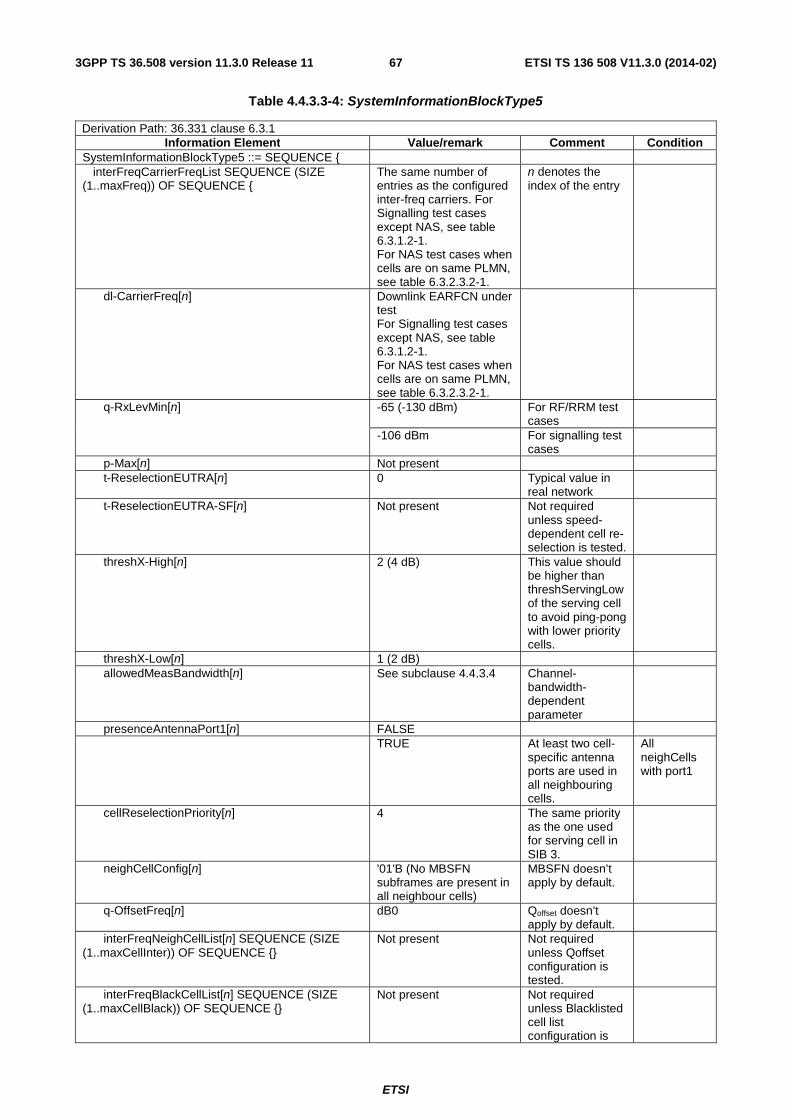
ETSI
ETSI TS 136 508 V11.3.0 (2014-02)673GPP TS 36.508 version 11.3.0 Release 11
Table 4.4.3.3-4: SystemInformationBlockType5
Derivation Path: 36.331 clause 6.3.1 Information Element Value/remark Comment Condition
SystemInformationBlockType5 ::= SEQUENCE { interFreqCarrierFreqList SEQUENCE (SIZE (1..maxFreq)) OF SEQUENCE {
The same number of entries as the configured inter-freq carriers. For Signalling test cases except NAS, see table 6.3.1.2-1. For NAS test cases when cells are on same PLMN, see table 6.3.2.3.2-1.
n denotes the index of the entry
dl-CarrierFreq[n] Downlink EARFCN under test For Signalling test cases except NAS, see table 6.3.1.2-1. For NAS test cases when cells are on same PLMN, see table 6.3.2.3.2-1.
q-RxLevMin[n] -65 (-130 dBm) For RF/RRM test cases
-106 dBm For signalling test cases
p-Max[n] Not present t-ReselectionEUTRA[n] 0 Typical value in
real network
t-ReselectionEUTRA-SF[n] Not present Not required unless speed-dependent cell re-selection is tested.
threshX-High[n] 2 (4 dB) This value should be higher than threshServingLow of the serving cell to avoid ping-pong with lower priority cells.
threshX-Low[n] 1 (2 dB) allowedMeasBandwidth[n] See subclause 4.4.3.4 Channel-
bandwidth-dependent parameter
presenceAntennaPort1[n] FALSE TRUE At least two cell-
specific antenna ports are used in all neighbouring cells.
All neighCells with port1
cellReselectionPriority[n] 4 The same priority as the one used for serving cell in SIB 3.
neighCellConfig[n] '01'B (No MBSFN subframes are present in all neighbour cells)
MBSFN doesn’t apply by default.
q-OffsetFreq[n] dB0 Qoffset doesn’t apply by default.
interFreqNeighCellList[n] SEQUENCE (SIZE (1..maxCellInter)) OF SEQUENCE {}
Not present Not required unless Qoffset configuration is tested.
interFreqBlackCellList[n] SEQUENCE (SIZE (1..maxCellBlack)) OF SEQUENCE {}
Not present Not required unless Blacklisted cell list configuration is
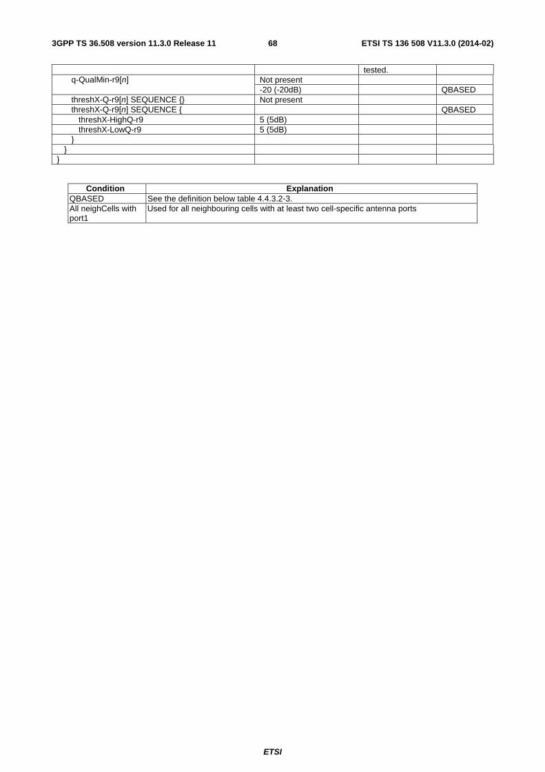
ETSI
ETSI TS 136 508 V11.3.0 (2014-02)683GPP TS 36.508 version 11.3.0 Release 11
tested. q-QualMin-r9[n] Not present -20 (-20dB) QBASED threshX-Q-r9[n] SEQUENCE {} Not present threshX-Q-r9[n] SEQUENCE { QBASED threshX-HighQ-r9 5 (5dB) threshX-LowQ-r9 5 (5dB) } } }
Condition Explanation QBASED See the definition below table 4.4.3.2-3. All neighCells with port1
Used for all neighbouring cells with at least two cell-specific antenna ports

ETSI
ETSI TS 136 508 V11.3.0 (2014-02)693GPP TS 36.508 version 11.3.0 Release 11
- SystemInformationBlockType6
The IE SystemInformationBlockType6 contains information relevant only for inter-RAT cell re-selection i.e. information about UTRA frequencies and UTRA neighbouring cells relevant for cell re-selection. The IE includes cell re-selection parameters common for a frequency.
Table 4.4.3.3-5: SystemInformationBlockType6
Derivation Path: 36.331 clause 6.3.1 Information Element Value/remark Comment Condition
SystemInformationBlockType6 ::= SEQUENCE { carrierFreqListUTRA-FDD SEQUENCE (SIZE (1..maxUTRA-FDD-Carrier)) OF SEQUENCE {}
Not present UTRA-TDD
carrierFreqListUTRA-FDD SEQUENCE (SIZE (1..maxUTRA-FDD-Carrier)) OF SEQUENCE {
The same number of entries as the configured UTRA FDD carriers For Signalling test cases, see table 6.3.1.3-1
n denotes the index of the entry
UTRA-FDD
carrierFreq[n] Downlink UARFCN under test For Signalling test cases, see table 6.3.1.3-1
cellReselectionPriority[n] 3 threshX-High[n] 2 (4 dB) threshX-Low[n] 1 (2 dB) q-RxLevMin[n] -40 (-79 dBm) The same value
as defined in TS 34.108 [5], table 6.1.1.
p-MaxUTRA[n] 21 (21 dBm) The same value as defined in TS 34.108 [5], table 6.1.1.
q-QualMin[n] -24 (-24 dB) The same value as defined in TS 34.108 [5], table 6.1.1.
threshX-Q-r9[n] SEQUENCE {} Not present threshX-Q-r9[n] SEQUENCE { QBASED
threshX-HighQ-r9 9 (9dB) threshX-LowQ-r9 9 (9dB) } } carrierFreqListUTRA-TDD SEQUENCE (SIZE (1..maxUTRA-TDD-Carrier)) OF SEQUENCE {}
Not present UTRA-FDD
carrierFreqListUTRA-TDD SEQUENCE (SIZE (1..maxUTRA-TDD-Carrier)) OF SEQUENCE {
The same number of entries as the configured UTRA TDD carriers For Signalling test cases, see table 6.3.1.3-1
n denotes the index of the entry
UTRA-TDD
carrierFreq[n] Downlink UARFCN under test For Signalling test cases, see table 6.3.1.3-1
cellReselectionPriority[n] 3 threshX-High[n] 2 (4 dB) threshX-Low[n] 1 (2 dB) q-RxLevMin[n] -41 (-81 dBm) The same value
as defined in TS 34.108 [5], table 6.1.6a
p-MaxUTRA[n] 21 (21 dBm) The same value as defined in TS 34.108 [5], table 6.1.6a
}

ETSI
ETSI TS 136 508 V11.3.0 (2014-02)703GPP TS 36.508 version 11.3.0 Release 11
t-ReselectionUTRA 0 Typical value in real network
t-ReselectionUTRA-SF Not present }
Condition Explanation UTRA-FDD UTRA FDD cell environment UTRA-TDD UTRA TDD cell environment QBASED See the definition below table 4.4.3.2-3.
Editor’s note: Need for condition ‘UTRA-FDD-TDD’ where both UTRA FDD cell and UTRA TDD cell exist simultaneously is FFS.
- SystemInformationBlockType7
The IE SystemInformationBlockType7 contains information relevant only for inter-RAT cell re-selection i.e. information about GERAN frequencies relevant for cell re-selection. The IE includes cell re-selection parameters for each frequency.

ETSI
ETSI TS 136 508 V11.3.0 (2014-02)713GPP TS 36.508 version 11.3.0 Release 11
Table 4.4.3.3-6: SystemInformationBlockType7
Derivation Path: 36.331 clause 6.3.1 Information Element Value/remark Comment Condition
SystemInformationBlockType7 ::= SEQUENCE { t-ReselectionGERAN 0 t-ReselectionGERAN-SF Not present carrierFreqsInfoListSEQUENCE (SIZE (1..maxGNFG)) OF SEQUENCE {
The same number of entries as the configured GERAN carriers For RRM test cases, see table 7.2.2.1-1 For Signalling test cases, see table 6.3.1.4-1
n denotes the index of the entry
carrierFreqs [n] SEQUENCE { startingARFCN[n] Set the corresponding
starting ARFCN of the GERAN cells under test. For RRM test cases, see table 7.2.2.1-1 For Signalling test cases, see table 6.3.1.4-1
bandIndicator[n] Set according to the band used for GERAN cells under test
followingARFCNs[n] CHOICE { explicitListOfARFCNs[n] Set the corresponding
ARFCN of GERAN cells under test For RRM test cases, see table 7.2.2.1-1 For Signalling test cases, see table 6.3.1.4-1
} } commonInfo[n] SEQUENCE { cellReselectionPriority[n] 2 ncc-Permitted[n] ‘01000000'B NCC=1 permitted q-RxLevMin[n] 2 p-MaxGERAN[n] 0 threshX-High[n] 2 threshX-Low[n] 2 } } }
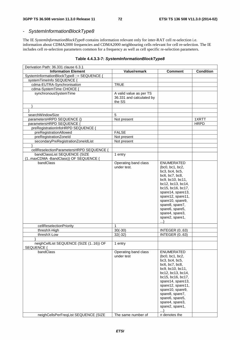
ETSI
ETSI TS 136 508 V11.3.0 (2014-02)723GPP TS 36.508 version 11.3.0 Release 11
- SystemInformationBlockType8
The IE SystemInformationBlockType8 contains information relevant only for inter-RAT cell re-selection i.e. information about CDMA2000 frequencies and CDMA2000 neighbouring cells relevant for cell re-selection. The IE includes cell re-selection parameters common for a frequency as well as cell specific re-selection parameters.
Table 4.4.3.3-7: SystemInformationBlockType8
Derivation Path: 36.331 clause 6.3.1 Information Element Value/remark Comment Condition
SystemInformationBlockType8 ::= SEQUENCE { systemTimeInfo SEQUENCE { cdma-EUTRA-Synchronisation TRUE cdma-SystemTime CHOICE { synchronousSystemTime A valid value as per TS
36.331 and calculated by the SS
} } searchWindowSize 5 parametersHRPD SEQUENCE {} Not present 1XRTT parametersHRPD SEQUENCE { HRPD preRegistrationInfoHRPD SEQUENCE { preRegistrationAllowed FALSE preRegistrationZoneId Not present secondaryPreRegistrationZoneIdList Not present } cellReselectionParametersHRPD SEQUENCE { bandClassList SEQUENCE (SIZE (1..maxCDMA -BandClass)) OF SEQUENCE {
1 entry
bandClass Operating band class under test.
ENUMERATED {bc0, bc1, bc2, bc3, bc4, bc5, bc6, bc7, bc8, bc9, bc10, bc11, bc12, bc13, bc14, bc15, bc16, bc17, spare14, spare13, spare12, spare11, spare10, spare9, spare8, spare7, spare6, spare5, spare4, spare3, spare2, spare1, ...}
cellReselectionPriority 1 threshX-High 30(-30) INTEGER (0..63) threshX-Low 32(-32) INTEGER (0..63) } neighCellList SEQUENCE (SIZE (1..16)) OF SEQUENCE {
1 entry
bandClass Operating band class under test
ENUMERATED {bc0, bc1, bc2, bc3, bc4, bc5, bc6, bc7, bc8, bc9, bc10, bc11, bc12, bc13, bc14, bc15, bc16, bc17, spare14, spare13, spare12, spare11, spare10, spare9, spare8, spare7, spare6, spare5, spare4, spare3, spare2, spare1, ...}
neighCellsPerFreqList SEQUENCE (SIZE The same number of n denotes the

ETSI
ETSI TS 136 508 V11.3.0 (2014-02)733GPP TS 36.508 version 11.3.0 Release 11
(1..16)) OF SEQUENCE { entries as the configured CDMA2000 HRPD frequencies For Signalling test cases, see table 6.3.1.5-1
index of the entry
arfcn[n] ARFCN of the CDMA2000 HRPD frequency For Signalling test cases, see table 6.3.1.5-1
INTEGER (0..2047)
physCellIdList[n] SEQUENCE (SIZE (1..16)) OF {INTEGER (0..maxPNOffset) }
Physical Cell ID List of the CDMA2000 HRPD frequency For Signalling test cases, see table 6.3.1.5-1
INTEGER (0..maxPNOffset)
} } t-ReselectionCDMA2000 0 INTEGER (0..7) t-ReselectionCDMA2000-SF Not Present } } parameters1XRTT SEQUENCE {} Not present HRPD parameters1XRTT SEQUENCE { 1XRTT csfb-RegistrationParam1XRTT SEQUENCE { sid SID under test
For Signalling test cases, see table 4.4.2-4
BIT STRING (SIZE (15))
nid NID under test For Signalling test cases, see table 4.4.2-4
BIT STRING (SIZE (16))
multipleSID FALSE BOOLEAN multipleNID FALSE BOOLEAN homeReg TRUE BOOLEAN foreignSIDReg TRUE BOOLEAN foreignNIDReg TRUE BOOLEAN parameterReg FALSE BOOLEAN powerUpReg TRUE BOOLEAN registrationPeriod ’0000000’ BIT STRING
(SIZE (7))
registrationZone Registration zone under test For Signalling test cases, see table 4.4.2-4
BIT STRING (SIZE (12))
totalZone '001'B BIT STRING (SIZE (3))
zoneTimer '000'B or '001'B BIT STRING (SIZE (3))
} longCodeState1XRTT A valid value, calculated
and updated by the SS BIT STRING (SIZE (42)) OPTIONAL
cellReselectionParameters1XRTT SEQUENCE { bandClassList SEQUENCE (SIZE (1..maxCDMA -BandClass)) OF SEQUENCE {
1 entry
bandClass Operating band class under test
ENUMERATED {bc0, bc1, bc2, bc3, bc4, bc5, bc6, bc7, bc8, bc9, bc10, bc11, bc12, bc13, bc14, bc15, bc16, bc17, spare14, spare13, spare12, spare11, spare10, spare9, spare8, spare7, spare6, spare5, spare4, spare3,

ETSI
ETSI TS 136 508 V11.3.0 (2014-02)743GPP TS 36.508 version 11.3.0 Release 11
spare2, spare1, ...}
cellReselectionPriority 0 threshX-High 30(-30) INTEGER (0..63) threshX-Low 32(-32) INTEGER (0..63) } neighCellList SEQUENCE (SIZE (1..16)) OF SEQUENCE {
1 entry
bandClass Operating band class under test
ENUMERATED {bc0, bc1, bc2, bc3, bc4, bc5, bc6, bc7, bc8, bc9, bc10, bc11, bc12, bc13, bc14, bc15, bc16, bc17, spare14, spare13, spare12, spare11, spare10, spare9, spare8, spare7, spare6, spare5, spare4, spare3, spare2, spare1, ...}
neighCellsPerFreqList SEQUENCE (SIZE (1..16)) OF SEQUENCE {
The same number of entries as the configured CDMA2000 1xRTT frequencies For Signalling test cases, see table 6.3.1.6-1
n denotes the index of the entry
arfcn[n] ARFCN of the CDMA2000 1xRTT frequency For Signalling test cases, see table 6.3.1.6-1
INTEGER (0..2047)
physCellIdList[n] SEQUENCE (SIZE (1..16)) OF {INTEGER (0..maxPNOffset) }
Physical Cell ID List of the CDMA2000 1xRTT frequency For Signalling test cases, see table 6.3.1.6-1
INTEGER (0..maxPNOffset)
} } t-ReselectionCDMA2000 0 INTEGER (0..7) t-ReselectionCDMA2000-SF Not Present } } }
Condition Explanation HRPD CDMA2000 HRPD cell environment 1XRTT CDMA2000 1XRTT cell environment
Editor’s note: Need for condition ‘HRPD-1XRTT’ where both CDMA2000 HRPD cell and CDMA2000 1xRTT cell exist simultaneously is FFS.
- SystemInformationBlockType9
The IE SystemInformationBlockType9 contains a home eNB name (HNB Name).
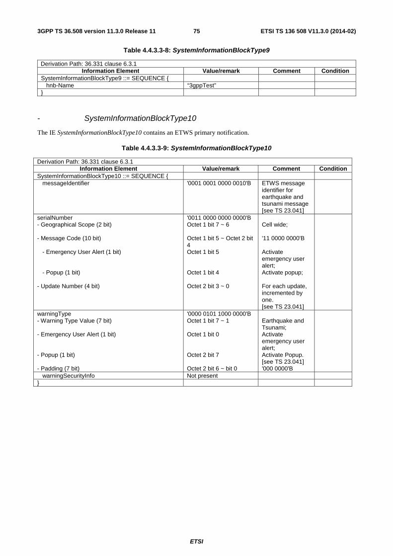
ETSI
ETSI TS 136 508 V11.3.0 (2014-02)753GPP TS 36.508 version 11.3.0 Release 11
Table 4.4.3.3-8: SystemInformationBlockType9
Derivation Path: 36.331 clause 6.3.1 Information Element Value/remark Comment Condition
SystemInformationBlockType9 ::= SEQUENCE { hnb-Name “3gppTest” }
- SystemInformationBlockType10
The IE SystemInformationBlockType10 contains an ETWS primary notification.
Table 4.4.3.3-9: SystemInformationBlockType10
Derivation Path: 36.331 clause 6.3.1 Information Element Value/remark Comment Condition
SystemInformationBlockType10 ::= SEQUENCE { messageIdentifier '0001 0001 0000 0010'B ETWS message
identifier for earthquake and tsunami message [see TS 23.041]
serialNumber - Geographical Scope (2 bit) - Message Code (10 bit) - Emergency User Alert (1 bit) - Popup (1 bit) - Update Number (4 bit)
'0011 0000 0000 0000'B Octet 1 bit 7 ~ 6 Octet 1 bit 5 ~ Octet 2 bit 4 Octet 1 bit 5 Octet 1 bit 4 Octet 2 bit 3 ~ 0
Cell wide; '11 0000 0000'B Activate emergency user alert; Activate popup; For each update, incremented by one. [see TS 23.041]
warningType - Warning Type Value (7 bit) - Emergency User Alert (1 bit) - Popup (1 bit) - Padding (7 bit)
'0000 0101 1000 0000'B Octet 1 bit 7 ~ 1 Octet 1 bit 0 Octet 2 bit 7 Octet 2 bit 6 ~ bit 0
Earthquake and Tsunami; Activate emergency user alert; Activate Popup. [see TS 23.041] '000 0000'B
warningSecurityInfo Not present }

ETSI
ETSI TS 136 508 V11.3.0 (2014-02)763GPP TS 36.508 version 11.3.0 Release 11
- SystemInformationBlockType11
The IE SystemInformationBlockType11 contains an ETWS secondary notification.
Table 4.4.3.3-10: SystemInformationBlockType11 (1st Segment)
Derivation Path: 36.331 clause 6.3.1 Information Element Value/remark Comment Condition
SystemInformationBlockType11 ::= SEQUENCE { messageIdentifier '0001 0001 0000 0010'B ETWS message
identifier for earthquake and tsunami message [see TS 23.041]
serialNumber - Geographical Scope (2 bit) - Message Code (10 bit) - Emergency User Alert (1 bit) - Popup (1 bit) - Update Number (4 bit)
'0011 0000 0000 0000'B Octet 1 bit 7 ~ 6 Octet 1 bit 5 ~ Octet 2 bit 4 Octet 1 bit 5 Octet 1 bit 4 Octet 2 bit 3 ~ 0
Cell wide; '11 0000 0000'B Activate emergency user alert; Activate popup; For each update, incremented by one. [see TS 23.041]
warningMessageSegmentType notLastSegment warningMessageSegmentNumber 0 warningMessageSegment Octetstring of N where N ≥ 1 and
less than 1246. [see TS 23.041]
dataCodingScheme Bitstring (8) ID of the alphabet/coding and the applied language [see TS 23.041]
}

ETSI
ETSI TS 136 508 V11.3.0 (2014-02)773GPP TS 36.508 version 11.3.0 Release 11
Table 4.4.3.3-11: SystemInformationBlockType11 (2nd Segment)
Derivation Path: 36.331 clause 6.3.1 Information Element Value/remark Comment Condition
SystemInformationBlockType11 ::= SEQUENCE { messageIdentifier '0001 0001 0000 0010'B ETWS message
identifier for earthquake and tsunami message [see TS 23.041]
serialNumber - Geographical Scope (2 bit) - Message Code (10 bit) - Emergency User Alert (1 bit) - Popup (1 bit) - Update Number (4 bit)
'0011 0000 0000 0000'B Octet 1 bit 7 ~ 6 Octet 1 bit 5 ~ Octet 2 bit 4 Octet 1 bit 5 Octet 1 bit 4 Octet 2 bit 3 ~ 0
Cell wide; '11 0000 0000'B Activate emergency user alert; Activate popup; For each update, incremented by one. [see TS 23.041]
warningMessageSegmentType notLastSegment warningMessageSegmentNumber 1 warningMessageSegment Octetstring of N where N ≥ 1 and
less than 1246. [see TS 23.041]
dataCodingScheme Not present }
Table 4.4.3.3-12: SystemInformationBlockType11 (3rd Segment)
Derivation Path: 36.331 clause 6.3.1 Information Element Value/remark Comment Condition
SystemInformationBlockType11 ::= SEQUENCE { messageIdentifier '0001 0001 0000 0010'B ETWS message
identifier for earthquake and tsunami message [see TS 23.041]
serialNumber - Geographical Scope (2 bit) - Message Code (10 bit) - Emergency User Alert (1 bit) - Popup (1 bit) - Update Number (4 bit)
'0011 0000 0000 0000'B Octet 1 bit 7 ~ 6 Octet 1 bit 5 ~ Octet 2 bit 4 Octet 1 bit 5 Octet 1 bit 4 Octet 2 bit 3 ~ 0
Cell wide; '11 0000 0000'B Activate emergency user alert; Activate popup; For each update, incremented by one. [see TS 23.041]
warningMessageSegmentType lastSegment warningMessageSegmentNumber 2 warningMessageSegment Octetstring of N where N ≥ 1 and
less than 1246. [see TS 23.041]
dataCodingScheme Not present }

ETSI
ETSI TS 136 508 V11.3.0 (2014-02)783GPP TS 36.508 version 11.3.0 Release 11
- SystemInformationBlockType12
The IE SystemInformationBlockType12contains an CMAS notification.
Table 4.4.3.3-12a: SystemInformationBlockType12 (1st Segment)
Derivation Path: 36.331 clause 6.3.1 Information Element Value/remark Comment Condition
SystemInformationBlockType11 ::= SEQUENCE { messageIdentifier-r9 '0001 0001 0001 0010'B CMAS CBS
Message Identifier for CMAS Presidential Level Alerts (see TS 23.041])
serialNumber-r9 '0011 0000 0000 0000'B warningMessageSegmentType notLastSegment warningMessageSegmentNumber 0 warningMessageSegment Octetstring of N where N ≥ 1 and
less than 1246. (see TS 23.041)
dataCodingScheme '0000 0001'B English (See TS 23.038)
lateNonCriticalExtension Not present }
Table 4.4.3.3-12b: SystemInformationBlockType12 (2nd Segment)
Derivation Path: 36.331 clause 6.3.1 Information Element Value/remark Comment Condition
SystemInformationBlockType11 ::= SEQUENCE { messageIdentifier-r9 '0001 0001 0001 0010'B CMAS CBS
Message Identifier for CMAS Presidential Level Alerts (see TS 23.041)
serialNumber-r9 '0011 0000 0000 0000'B warningMessageSegmentType notLastSegment warningMessageSegmentNumber 1 warningMessageSegment Octetstring of N where N ≥ 1 and
less than 1246. (see TS 23.041)
dataCodingScheme Not present lateNonCriticalExtension Not present }

ETSI
ETSI TS 136 508 V11.3.0 (2014-02)793GPP TS 36.508 version 11.3.0 Release 11
Table 4.4.3.3-12c: SystemInformationBlockType12 (3rd Segment)
Derivation Path: 36.331 clause 6.3.1 Information Element Value/remark Comment Condition
SystemInformationBlockType11 ::= SEQUENCE { messageIdentifier-r9 '0001 0001 0001 0010'B CMAS CBS
Message Identifier for CMAS Presidential Level Alerts (see TS 23.041)
serialNumber-r9 '0011 0000 0000 0000'B warningMessageSegmentType lastSegment warningMessageSegmentNumber 2 warningMessageSegment Octetstring of N where N ≥ 1 and
less than 1246. (see TS 23.041)
dataCodingScheme Not present lateNonCriticalExtension Not present }
SystemInformationBlockType13
The IE SystemInformationBlockType13 contains the information required to acquire the MBMS control information associated with one or more MBSFN areas.
Table 4.4.3.3-13: SystemInformationBlockType13
Derivation Path: 36.331 clause 6.3.1 Information Element Value/remark Comment Condition
SystemInformationBlockType13 ::= SEQUENCE { MBSFN-AreaInfo-r9 SEQUENCE (SIZE(1..maxMBSFN-Area)) OF SEQUENCE {
mbsfn-AreaId-r9 0 non-MBSFNregionLength 1 notificationIndicator-r9 0 mcch-Config-r9 SEQUENCE { mcch-RepetitionPeriod-r9 rf32 mcch-Offset-r9 1 FDD 0 TDD mcch-ModificationPeriod-r9 rf512 sf-AllocInfo-r9 ‘100000’ FDD ‘000010’ TDD signallingMCS-r9 n2 } } MBMS-NotificationConfig-r9 ::= SEQUENCE { notificationRepetitionCoeff-r9 n4 notificationOffset-r9 1 FDD 0 TDD notificationSF-Index-r9 1 Subframe #1 FDD 4 Subframe #8 TDD } }
Condition Explanation FDD FDD cell environment TDD TDD cell environment
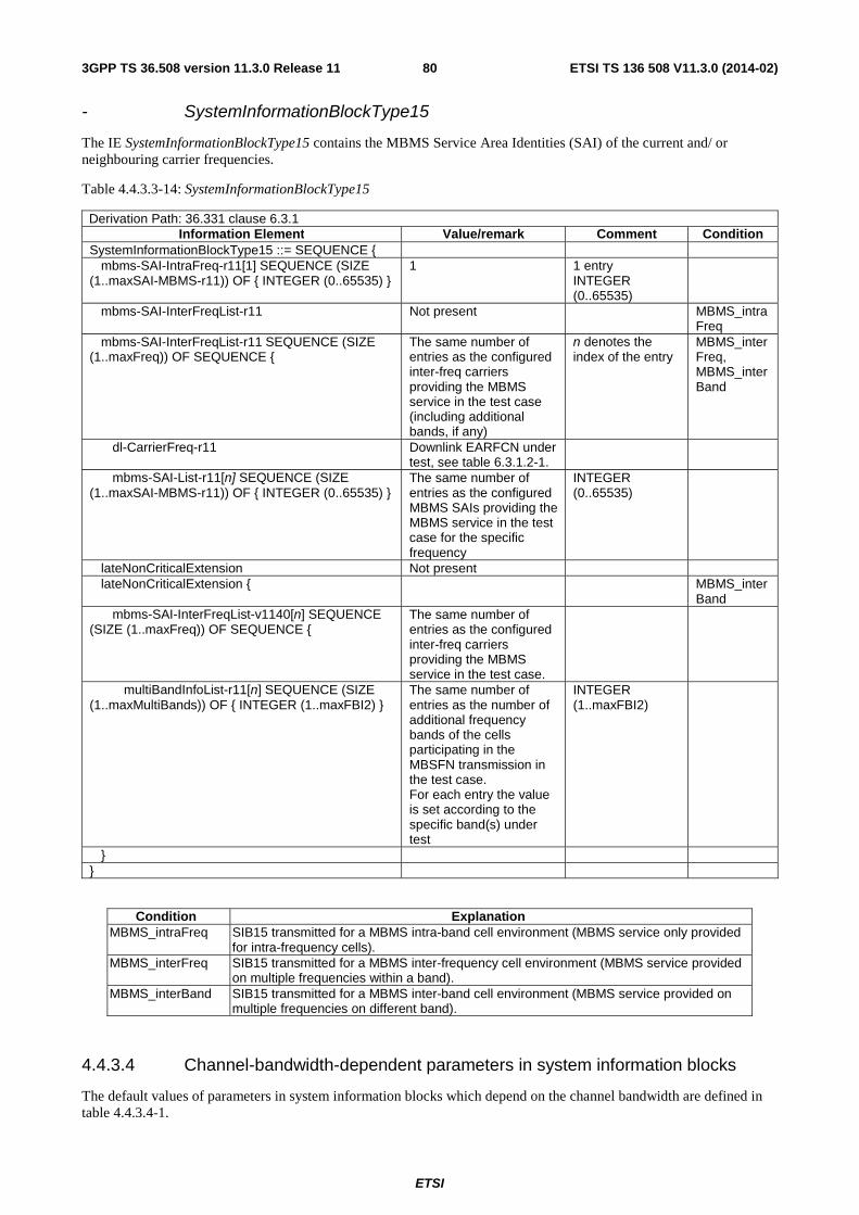
ETSI
ETSI TS 136 508 V11.3.0 (2014-02)803GPP TS 36.508 version 11.3.0 Release 11
- SystemInformationBlockType15
The IE SystemInformationBlockType15 contains the MBMS Service Area Identities (SAI) of the current and/ or neighbouring carrier frequencies.
Table 4.4.3.3-14: SystemInformationBlockType15
Derivation Path: 36.331 clause 6.3.1 Information Element Value/remark Comment Condition
SystemInformationBlockType15 ::= SEQUENCE { mbms-SAI-IntraFreq-r11[1] SEQUENCE (SIZE (1..maxSAI-MBMS-r11)) OF { INTEGER (0..65535) }
1 1 entry INTEGER (0..65535)
mbms-SAI-InterFreqList-r11 Not present MBMS_intraFreq
mbms-SAI-InterFreqList-r11 SEQUENCE (SIZE (1..maxFreq)) OF SEQUENCE {
The same number of entries as the configured inter-freq carriers providing the MBMS service in the test case (including additional bands, if any)
n denotes the index of the entry
MBMS_interFreq, MBMS_interBand
dl-CarrierFreq-r11 Downlink EARFCN under test, see table 6.3.1.2-1.
mbms-SAI-List-r11[n] SEQUENCE (SIZE (1..maxSAI-MBMS-r11)) OF { INTEGER (0..65535) }
The same number of entries as the configured MBMS SAIs providing the MBMS service in the test case for the specific frequency
INTEGER (0..65535)
lateNonCriticalExtension Not present lateNonCriticalExtension { MBMS_inter
Band mbms-SAI-InterFreqList-v1140[n] SEQUENCE (SIZE (1..maxFreq)) OF SEQUENCE {
The same number of entries as the configured inter-freq carriers providing the MBMS service in the test case.
multiBandInfoList-r11[n] SEQUENCE (SIZE (1..maxMultiBands)) OF { INTEGER (1..maxFBI2) }
The same number of entries as the number of additional frequency bands of the cells participating in the MBSFN transmission in the test case. For each entry the value is set according to the specific band(s) under test
INTEGER (1..maxFBI2)
} }
Condition Explanation MBMS_intraFreq SIB15 transmitted for a MBMS intra-band cell environment (MBMS service only provided
for intra-frequency cells). MBMS_interFreq SIB15 transmitted for a MBMS inter-frequency cell environment (MBMS service provided
on multiple frequencies within a band). MBMS_interBand SIB15 transmitted for a MBMS inter-band cell environment (MBMS service provided on
multiple frequencies on different band).
4.4.3.4 Channel-bandwidth-dependent parameters in system information blocks
The default values of parameters in system information blocks which depend on the channel bandwidth are defined in table 4.4.3.4-1.

ETSI
ETSI TS 136 508 V11.3.0 (2014-02)813GPP TS 36.508 version 11.3.0 Release 11
Table 4.4.3.4-1: Channel-bandwidth-dependent parameters
Information Element
Channel bandwidth Comment 1.4 MHz 3 MHz 5 MHz 10 MHz 15 MHz 20MHz
SIB3 periodicity
64 64 32 32 32 32
SIB4 periodicity
128 128 64 64 64 64
SIB5 periodicity
128 128 64 64 64 64
SIB6 periodicity
128 128 64 64 64 64
SIB7 periodicity
128 128 64 64 64 64
SIB8 periodicity
128 128 64 64 64 64
measurementBandwidth in SIB5
mbw6 mbw15 mbw25 mbw50 mbw75 mbw100
SIB9 periodicity
128 128 64 64 64 64
SIB10 periodicity
64 64 32 32 32 32
SIB11 periodicity
64 64 32 32 32 32
SIB12 periodicity
64 64 32 32 32 32
SIB13 periodicity
64 64 32 32 32 32
SIB15 periodicity
64 64 32 32 32 32
4.4.4 Common parameters for simulated UTRA cells
The parameters specified in this subclause apply to all simulated UTRA cells unless otherwise specified.
Default UTRA parameters for simulated cells are specified in table 4.4.4-1 and table 4.4.4-2.
Other parameters are specified in TS 34.108 [5].
Table 4.4.4-1: Default parameters for simulated UTRA cells
cell ID Primary scrambling code for FDD
Cell parameters ID for TDD
Cell 5 100 0 Cell 7 150 4 Cell 8 200 8 Cell 9 250 12
Table 4.4.4-2: Default NAS parameters for simulated UTRA cells
PLMN Location Area Identification
Routing Area Identification
TMSI P-TMSI signature
MCC MNC LA# LAC RA# RAC Cell 5 (Note 1) LAI-1 1 RAI-1 1 Arbitrarily selected
according to TS 23.003
subclause 2.4 [2].
Arbitrarily selected according to TS 23.003
subclause 2.7 [2].
Cell 7 (Note 1) LAI-1 1 RAI-1 1 Cell 8 (Note 1) LAI-1 1 RAI-1 1 Cell 9 (Note 1) LAI-1 1 RAI-1 1
Note 1: Set to the same Mobile Country Code and Mobile Network Code stored in EFIMSI on the test USIM card (subclause 4.9.3).

ETSI
ETSI TS 136 508 V11.3.0 (2014-02)823GPP TS 36.508 version 11.3.0 Release 11
4.4.4.1 Common contents of system information blocks for UTRA cells
- System Information Block type 19
The system information block type 19 contains Inter-RAT frequency and priority information to be used in the cell.
Table 4.4.4.1-1: System Information Block type 19
Derivation Path: 25.331 clause 11.3 Information Element Value/remark Comment Condition
SysInfoType19 ::= SEQUENCE { utra-PriorityInfoList SEQUENCE { utra-ServingCell SEQUENCE { priority 3 s-PrioritySearch1 0 (0dB) s-PrioritySearch2 Not present default value is 0 threshServingLow 0 (0dB) } utran-FDD-FrequencyList SEQUENCE (SIZE(1..maxNumFDDFreqs)) OF SEQUENCE {}
Not present
utran-TDD-FrequencyList SEQUENCE (SIZE(1..maxNumTDDFreqs)) OF SEQUENCE {}
Not present
gsm-PriorityInfoList SEQUENCE (SIZE (1..maxNumGSMCellGroup)) OF SEQUENCE {}
Not present
eutra-FrequencyAndPriorityInfoList SEQUENCE (SIZE (1..maxNumEUTRAFreqs)) OF SEQUENCE
The same number of entries as the configured eutra carriers For Signalling test cases, see table 6.3.1.7-1
n denotes the index of the entry
earfcn[n] Downlink EARFCN under test For Signalling test cases, see table 6.3.1.7-1
measurementBandwidth[n] Set according to EUTRA band ChBw in Table 5.6-1 of TS36.104.
priority[n] 4 qRxLevMinEUTRA[n] -53 (-106 dBm) For signalling test
cases
-70 (-140 dBm) For RF/RRM test cases
threshXhigh[n] 2 (4 dB) threshXlow[n] 1 (2 dB) eutra-blackListedCellList[n] Not present eutraDetection[n] TRUE } v920NonCriticalExtensions SEQUENCE {} Not present v920NonCriticalExtensions SEQUENCE { QBASED sysInfoType19-v920ext SEQUENCE { utra-PriorityInfoList-v920ext SEQUENCE { threshServingLow2 7 (7dB) default value is 0 } eutra-FrequencyAndPriorityInfoList-v920ext (SIZE (1..maxNumEUTRAFreqs)) OF SEQUENCE {
qQualMinEUTRA[n] -20 (-20dB) threshXhigh2[n] 5 (5dB) threshXlow2[n] 5 (5dB) } } nonCriticalExtensions SEQUENCE {} Not present } }
Condition Explanation

ETSI
ETSI TS 136 508 V11.3.0 (2014-02)833GPP TS 36.508 version 11.3.0 Release 11
QBASED See the definition below table 4.4.3.2-3.
4.4.4.2 UTRA SIB scheduling for inter EUTRA - UTRA test
Table 4.4.4.2-1: UTRA SIB schedule
Block Type
MIB SB1 SIB1 SIB2 SIB3 SIB4 SIB5/SIB5bis SIB6 SIB7 SIB11 SIB12 SIB18 SIB19
SIB_REP 8 16 64 64 64 64 64 64 16 64 64 64 64 SEG_
COUNT 1 1 1 1 1 1 4 4 1 3 1 1 2
Table 4.4.4.2-2: UTRA SIB-repeat period
Frame No / SIB_POS 0 2 4 6 8 10 12 14 Block Type MIB SB1 SIB7 SIB6 MIB SIB6 SIB6 SIB6
Frame No / SIB_POS 16 18 20 22 24 26 28 30
Block Type MIB SB1 SIB7/SIB3 SIB1/SIB2 MIB SIB12 SIB19 SIB19
Frame No / SIB_POS 32 34 36 38 40 42 44 46 Block Type MIB SB1 SIB7/SIB18 SIB5/
SIB5bis MIB SIB5/
SIB5bis SIB5/
SIB5bis SIB5/
SIB5bis
Frame No / SIB_POS 48 50 52 54 56 58 60 62 Block Type MIB SB1 SIB7/SIB4 - MIB SIB11 SIB11 SIB11
4.4.4.3 UTRA SIB scheduling for inter EUTRA – UTRA - GERAN test
Table 4.4.4.3-1: UTRA SIB schedule
Block Type MIB SB1 SIB1 SIB2 SIB3 SIB4 SIB5/
SIB5bis SIB7 SIB11 SIB16 SIB18 SIB19
SIB Rep 8 16 128 128 64 64 128 32 128 128 128 128 Max. No of
seg. 1 2 1 1 1 1 4 1 3 8 1 3
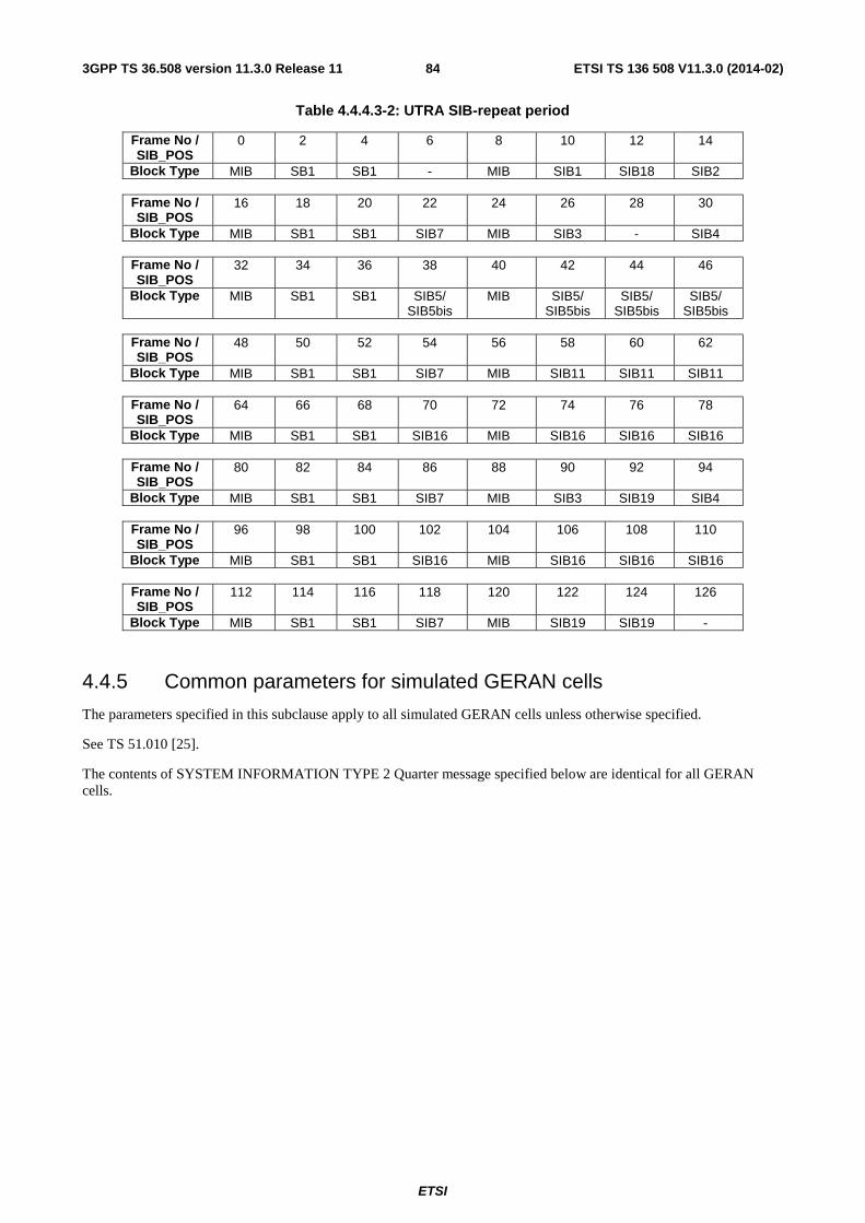
ETSI
ETSI TS 136 508 V11.3.0 (2014-02)843GPP TS 36.508 version 11.3.0 Release 11
Table 4.4.4.3-2: UTRA SIB-repeat period
Frame No / SIB_POS
0 2 4 6 8 10 12 14
Block Type MIB SB1 SB1 - MIB SIB1 SIB18 SIB2
Frame No / SIB_POS
16 18 20 22 24 26 28 30
Block Type MIB SB1 SB1 SIB7 MIB SIB3 - SIB4
Frame No / SIB_POS
32 34 36 38 40 42 44 46
Block Type MIB SB1 SB1 SIB5/ SIB5bis
MIB SIB5/ SIB5bis
SIB5/ SIB5bis
SIB5/ SIB5bis
Frame No / SIB_POS
48 50 52 54 56 58 60 62
Block Type MIB SB1 SB1 SIB7 MIB SIB11 SIB11 SIB11
Frame No / SIB_POS
64 66 68 70 72 74 76 78
Block Type MIB SB1 SB1 SIB16 MIB SIB16 SIB16 SIB16
Frame No / SIB_POS
80 82 84 86 88 90 92 94
Block Type MIB SB1 SB1 SIB7 MIB SIB3 SIB19 SIB4
Frame No / SIB_POS
96 98 100 102 104 106 108 110
Block Type MIB SB1 SB1 SIB16 MIB SIB16 SIB16 SIB16
Frame No / SIB_POS
112 114 116 118 120 122 124 126
Block Type MIB SB1 SB1 SIB7 MIB SIB19 SIB19 -
4.4.5 Common parameters for simulated GERAN cells
The parameters specified in this subclause apply to all simulated GERAN cells unless otherwise specified.
See TS 51.010 [25].
The contents of SYSTEM INFORMATION TYPE 2 Quarter message specified below are identical for all GERAN cells.

ETSI
ETSI TS 136 508 V11.3.0 (2014-02)853GPP TS 36.508 version 11.3.0 Release 11
Table 4.4.5-1: System Information 2 Quater
Derivation Path: 44.018 Table 10.5.2.33b.1 Information Element Value/remark Comment Condit
ion System information 2Quater L2 pseudo length 1 PROTOCOL DISCRIMINATOR ‘0110’B RR management
Protocol
SKIP INDICATOR ‘0000’B MESSAGE TYPE ‘00000111’B SI 2QUATER REST OCTETS BA Indicator 0 3G BA Indicator 0 MP Change Mark 0 SI2Q Index 0 SI2Q Count 0 Measurement_Parameters Description 0 Not Present GPRS_Real Time Difference Description 0 Not Present GPRS_BSIC Description 0 Not Present GPRS_REPORT PRIORITY Description 0 Not Present GPRS_MEASUREMENT_Parameters Description 0 Not Present NC Measurement Parameters 0 Not Present extension length 0 Not Present 3G Neighbour Cell Description 0 Not Present 3G Measurement Parameters Description 0 Not Present GPRS_3G_MEASUREMENT Parameters Description
0 Not Present
Additions in release 5 H 3G Additional Measurement Parameters Description
0 Not Present
3G ADDITIONAL MEASUREMENT Parameters Description 2
0 Not Present
Additions in release 6 H 3G_CCN_ACTIVE 0 Additions in release 7 H 700_REPORTING_OFFSET 0 Not Present 810_REPORTING_OFFSET 0 Not Present Additions in release 8 H Priority and E-UTRAN Parameters Description 1 Present Serving Cell Priority Parameters Description 1 Present
Note : Values as defined from TS 45.008, section 10.4 Table 3
GERAN_PRIORITY 2 THRESH_Priority_Search 15 (always) THRESH_GSM_low 0 H_PRIO 0 T_Reselection 0 3G Priority Parameters Description 0 Not Present E-UTRAN Parameters Description 1 Present E-UTRAN_CCN_ACTIVE 0 CCN not supported E-UTRAN_Start 1 E-UTRAN_Stop 1 E-UTRAN Measurement Parameters Description
0 Not Present
GPRS E-UTRAN Measurement Parameters Description
0 Not Present
Repeated E-UTRAN Neighbour Cells 1 Present {
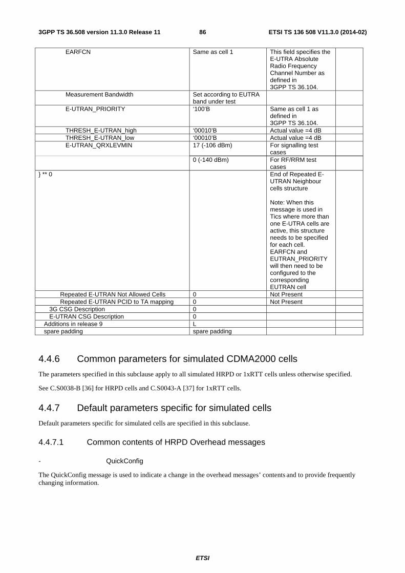
ETSI
ETSI TS 136 508 V11.3.0 (2014-02)863GPP TS 36.508 version 11.3.0 Release 11
EARFCN Same as cell 1 This field specifies the E-UTRA Absolute Radio Frequency Channel Number as defined in 3GPP TS 36.104.
Measurement Bandwidth Set according to EUTRA band under test
E-UTRAN_PRIORITY ‘100’B Same as cell 1 as defined in 3GPP TS 36.104.
THRESH_E-UTRAN_high ‘00010’B Actual value =4 dB THRESH_E-UTRAN_low ‘00010’B Actual value =4 dB E-UTRAN_QRXLEVMIN 17 (-106 dBm) For signalling test
cases
0 (-140 dBm) For RF/RRM test cases
} ** 0 End of Repeated E-UTRAN Neighbour cells structure Note: When this message is used in Tics where more than one E-UTRA cells are active, this structure needs to be specified for each cell. EARFCN and EUTRAN_PRIORITY will then need to be configured to the corresponding EUTRAN cell
Repeated E-UTRAN Not Allowed Cells 0 Not Present Repeated E-UTRAN PCID to TA mapping 0 Not Present 3G CSG Description 0 E-UTRAN CSG Description 0 Additions in release 9 L spare padding spare padding
4.4.6 Common parameters for simulated CDMA2000 cells
The parameters specified in this subclause apply to all simulated HRPD or 1xRTT cells unless otherwise specified.
See C.S0038-B [36] for HRPD cells and C.S0043-A [37] for 1xRTT cells.
4.4.7 Default parameters specific for simulated cells
Default parameters specific for simulated cells are specified in this subclause.
4.4.7.1 Common contents of HRPD Overhead messages
- QuickConfig
The QuickConfig message is used to indicate a change in the overhead messages’ contents and to provide frequently changing information.
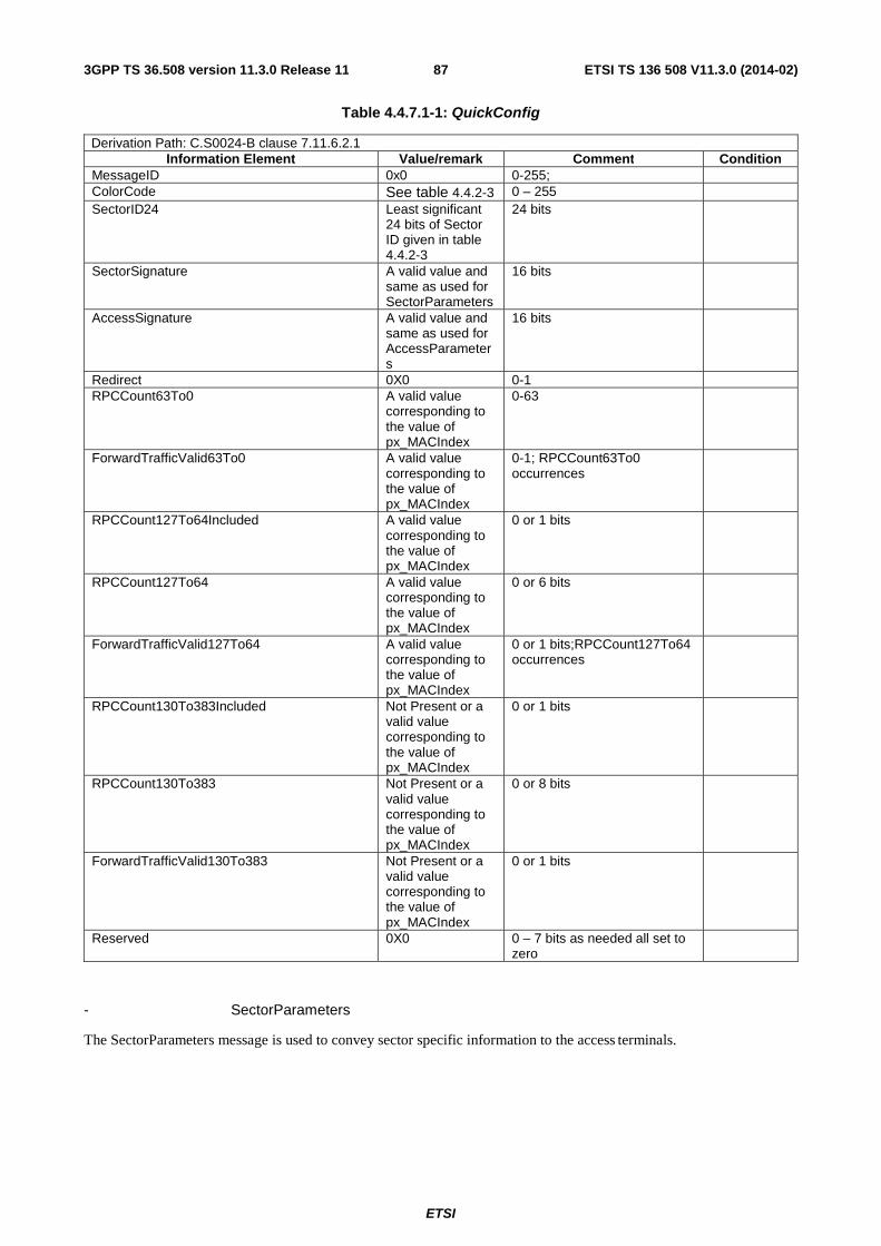
ETSI
ETSI TS 136 508 V11.3.0 (2014-02)873GPP TS 36.508 version 11.3.0 Release 11
Table 4.4.7.1-1: QuickConfig
Derivation Path: C.S0024-B clause 7.11.6.2.1 Information Element Value/remark Comment Condition
MessageID 0x0 0-255; ColorCode See table 4.4.2-3 0 – 255 SectorID24 Least significant
24 bits of Sector ID given in table 4.4.2-3
24 bits
SectorSignature A valid value and same as used for SectorParameters
16 bits
AccessSignature A valid value and same as used for AccessParameters
16 bits
Redirect 0X0 0-1 RPCCount63To0 A valid value
corresponding to the value of px_MACIndex
0-63
ForwardTrafficValid63To0 A valid value corresponding to the value of px_MACIndex
0-1; RPCCount63To0 occurrences
RPCCount127To64Included A valid value corresponding to the value of px_MACIndex
0 or 1 bits
RPCCount127To64 A valid value corresponding to the value of px_MACIndex
0 or 6 bits
ForwardTrafficValid127To64 A valid value corresponding to the value of px_MACIndex
0 or 1 bits;RPCCount127To64 occurrences
RPCCount130To383Included Not Present or a valid value corresponding to the value of px_MACIndex
0 or 1 bits
RPCCount130To383 Not Present or a valid value corresponding to the value of px_MACIndex
0 or 8 bits
ForwardTrafficValid130To383 Not Present or a valid value corresponding to the value of px_MACIndex
0 or 1 bits
Reserved 0X0 0 – 7 bits as needed all set to zero
- SectorParameters
The SectorParameters message is used to convey sector specific information to the access terminals.

ETSI
ETSI TS 136 508 V11.3.0 (2014-02)883GPP TS 36.508 version 11.3.0 Release 11
Table 4.4.7.1-2: SectorParameters
Derivation Path: C.S0024-B clause 7.11.6.2.2 Information Element Value/remark Comment Condition
MessageID 0x01 0-255 CountryCode See table 4.4.2-3 0 – 999;Depends on test case SectorID See table 4.4.2-3 128 bit value SubnetMask 0x40 8 bits SectorSignature Any valid value 16 bits Latitude Any valid value 22 bits Longitude Any valid value 23 bits RouteUpdateRadiusOverhead 0x0 11 bits LeapSeconds 'A valid value,
calculated and updated by the SS'
8 bits
LocalTimeOffset Any valid value 11 bits ReverseLinkSilenceDuration 0x1 or 0x0 2 bits ReverseLinkSilencePeriod 0x1 or 0x0 2 bits ChannelCount 0x1 or 0x0 5 bits Channel 24 bits; ChannelCount
occurrences; Sub-clause 13.1 in 3GPP2 C.S0024-B v3.0
SystemType 0x00 8 bits BandClass Set according to
PIXIT parameter 5 bits; Depends on test case
ChannelNumber Set according to PIXIT parameter
11 bits; Depends on BandClass
NeighborCount 0x0 5 bits No_NeighPNInc
16 NeighPNInc NeighborPilotPN Not Present No_NeighPN
Inc Pilots PN's of
configured cells [FFS]
NeighPNInc
NeighborChannelIncluded 0x0 1 bit; NeighbourCount occurrences
NeighPNInc
Not Present No_NeighPNInc
NeighborChannel Not Present 0 or 24 bits; NeighbourCount occurrences
NeighborSearchWindowSizeIncluded 0x0 1 bit NeighborSearchWindowSize Not Present 0 or 4 bits; NeighbourCount
occurrences
NeighborSearchWindowOffsetIncluded 0x0 1 bit NeighborSearchWindowOffset Not Present 0 or 3 bits; NeighbourCount
occurrences
ExtendedChannelIncluded 0x0 or Not Present
0 or 1 bits; The number of cdma2000 high rate packet data extended channels available to the access terminal on this sector; Note 1;
ExtendedChannelCount Not Present 0 or 5 bits ExtendedChannel Not Present 24 bits; 0 or
ExtendedChannelCount occurrences
AccessHashingChannelMaskIncluded 0x0 or Not Present
0 or 1 bits; AccessHashingChannelMaskLength occurrences of this field and AccessHashingChannelMask if set as AccessHashingChannelMask; Note 1;

ETSI
ETSI TS 136 508 V11.3.0 (2014-02)893GPP TS 36.508 version 11.3.0 Release 11
AccessHashingMaskLength Not Present 0 or 4 bits; 0<=AccessHashingChannelMaskLength<=(ChannelCount + ExtendedChannelCount),
AccessHashingChannelMaskSameAsPrevious Not Present 1 bit; AccessHashingChannelMaskLength occurrences of this field and AccessHashingChannelMask if set as AccessHashingChannelMask
AccessHashingChannelMask Not Present 0 or AccessHashingMaskLength+1
RouteUpdateTriggerCodeIncluded 0x0 or Not Present
0 or 1 bits; Note 1;
RouteUpdateTriggerCode Not Present 0 or 12 bits RouteUpdateTriggerMaxAge Not Present 0 or 4 bits PriorSessionGAUP 0x0 or Not
Present 0 or 1 bits; Note 1;
FPDCHSupportedInclude 0x0 or Not Present
0 or 1 bits; Note 1;
FPDCHSupported Not Present 0 or 1 bits SecondaryColorCodeIncluded 0x0 or Not
Present 0 or 1 bits; Note 1;
SecondaryColorCodeCount Not Present 0 or 3 bits SecondaryColorCode Not Present 8 bits PilotGroupIDLoopIncluded 0x0 or Not
Present 0 or 1 bits; Note 1;
PilotGroupIDIncluded Not Present 0 or 1 bits PilotGroupID Not Present 0 or 3 bits IsSectorMultiCarrierCapable 0x0 or Not
Present 0 or 1 bits; Note 1;
ReverseBandClass Not Present 0 or 5 bits ReverseChannelNumber Not Present 0 or 11 bits Reserved 0X0 0 – 7 bits as needed all set to
zero
Note 1: As no Non reserved fields following this are included, it can be Not Present; If not present, AT assumes as 0x0.
Condition Explanation No_NeighPNInc No neighbour Pilot PN included NeighPNInc Neighbor Pilot PN's included
- AccessParameters
The AccessParameters message is used to convey Access Channel information to the access terminals.

ETSI
ETSI TS 136 508 V11.3.0 (2014-02)903GPP TS 36.508 version 11.3.0 Release 11
Table 4.4.7.1-3: AccessParameters
Derivation Path: C.S0024-B clause 9.4.6.2.6 Information Element Value/remark Comment Condition
MessageID 0x1 0-255 Access Cycle Duration 16 slots or 64
slots 16,12,64,128 slots
Access Signature Any valid value 16 bits Note1.
OpenLoopAdjust Set according to PIXIT parameter for default open loop adjust
8bits(-84 – 115 dB); Actual value is -1 times
ProbeInitialAdjust 0x0(0 dB) 5 bits(-16 – 15 db) ProbeNumStep 0x5 4bits(1 – 15) PowerStep 0x8(4 dB) 4 bits(0 – 7.5 dB) PreambleLength 0x2 3bits(1 – 7) CapsuleLengthMax 0x2 or 0x4 4 bits APersistence 0x0 or 0x1 6 bits; 'NACMPAPersist = 4'
occurrences
APersistence 0x0 or 0x1 6 bits APersistence 0x0 or 0x1 6 bits APersistence 0x0 or 0x1 6 bits Reserved 0X0 0 – 7 bits as needed all set to
zero
Note 1: The value specified is the value to be used when the AccessParameters is being sent first time. At every change of content of AccessParameters message it is incremented by 1.
- Sync
The access network broadcasts the Sync message to convey basic network and timing information
Table 4.4.7.1-4: Sync
Derivation Path: C.S0024-B clause 7.3.6.2.1 Information Element Value/remark Comment Condition
MessageID 0x0 0-255 MaximumRevision 0x1 8 bits ; Clause 1.15 of 3GPP2
C.S0024-B v3.0
MinimumRevision 0x1 8 bits; Clause 1.15 of 3GPP2 C.S0024-B v3.0
Pilot PN Offset See table 4.4.2-3 0 – 511 CDMA System Time A valid value,
calculated and updated by the SS
37 bits
Editor's Note: This section is reserved for cell specific default parameters.
4.4.7.2 Common contents of 1XRTT Overhead messages
4.4.7.2.1 Configuration sequence number
In general, a base station maintains a configuration sequence number CONFIG_SEQ for configuration messages transmitted on the Paging channel and increments by 1 modulo 64 whenever any of the following messages being transmitted are modified:
System Parameters Message
Neighbor List Message (Band Class 0 only)
CDMA Channel List Message
Extended System Parameters Message

ETSI
ETSI TS 136 508 V11.3.0 (2014-02)913GPP TS 36.508 version 11.3.0 Release 11
Extended Neighbor List Message (band classes other than Band Class 0).
For simplicity resaons the System Simulator may use any value for this configuration sequence number CONFIG_SEQ.
4.4.7.2.2 Over Head messages
- CDMA Channel List Message
Table 4.4.7.2.2-1: CDMA Channel List Message
Derivation Path: C.S0005 clause 3.7.2.3.2.4 Information Element Value/remark Comment Condition
PILOT_PN See table 4.4.2-4 9 bits; CONFIG_MSG_SEQ Set to '
CONFIG_SEQ' of base station as per clause 4.4.7.2.1
6 bits;
CDMA_FREQ Set according to PIXIT parameter or as per clause 4.3.1.4
11 bits

ETSI
ETSI TS 136 508 V11.3.0 (2014-02)923GPP TS 36.508 version 11.3.0 Release 11
- System Parameters Message
Table 4.4.7.2.2-2: System Parameters Message
Derivation Path: C.S0005 clause 3.7.2.3.2.1 Information Element Value/remark Comment Condition
PILOT_PN See table 4.4.2-4 9 bits CONFIG_MSG_SEQ Set to '
CONFIG_SEQ' of base station as per clause 4.4.7.2.1
6 bits
SID See table 4.4.2-4 15 bits NID See table 4.4.2-4 16 bits REG_ZONE See table 4.4.2-4 12 bits TOTAL_ZONES 1 3 bits ZONE_TIMER 0 or 1 3 bits; 1 or 2 minutes MULT_SIDS 0 or 1 1 bits; Mobile shall not or shall
store SID_NID_List containing different SID's
MULT_NIDS 0 or 1 1 bits; Mobile shall not or shall store SID_NID_List containing different NID's
BASE_ID See table 4.4.2-4 16 bits BASE_CLASS 1 4 bits BandClass1
_4 0 Not
BandClass1_4
PAGE_CHAN 1 3 bits; Number of Paging Channels
MAX_SLOT_CYCLE_INDEX 1 or 0 3 bits; Maximum Slot Cycle index
HOME_REG 1 1 bits; Home registration enabled
FOR_SID_REG 1 1 bits; SID roamer registration enabled
FOR_NID_REG 1 1 bits; NID roamer registration enabled
POWER_UP_REG 1 1 bits; power-up registration enabled
POWER_DOWN_REG Set according to PIXIT parameter
1 bits; power-down registration enabled as per PIXIT
PARAMETER_REG 0 or 1 1 bits; parameter change registration disabled or enabled
REG_PRD 0 7 bits; registration period; No timer Based Registration
BASE_LAT Any valid value 22 bits; Base Station Latitude BASE_LONG Any valid value 23 bits; Base Station
Longitude
REG_DIST 0 11 bits; Distance based registration disabled
SRCH_WIN_A 8 4 bits; Search Window size for Active Set; 60 PN Chips
SRCH_WIN_N 8 4 bits; Search Window Size for the neighbor set; 60 PN Chips
SRCH_WIN_R 8 4 bits; Search window size for the remaining set; 60 PN Chips
NGHBR_MAX_AGE 0 4 bits; Minimum Neighbour set age
PWR_REP_THRESH 0, 1 or 5 5 bits; Power control reporting threshold
PWR_REP_FRAMES 0, 4 or 7 4 bits; power control reporting frame count; 5 or 28 frames

ETSI
ETSI TS 136 508 V11.3.0 (2014-02)933GPP TS 36.508 version 11.3.0 Release 11
PWR_THRESH_ENABLE 0 1 bits; threshold report mode disabled
PWR_PERIOD_ENABLE 0 1 bits; periodic report mode disabled
PWR_REP_DELAY 0 or 14 5 bits; 0 or 56 frames RESCAN 0 1 bit; re-initialize and re-
acquire the system
T_ADD 28 (-14 dB Ec/Io)
6bits; Pilot detection threshold (-14 dB Ec/Io)
T_DROP 32
6 bits; Pilot drop threshold (-16 dB Ec/Io)
T_COMP
5
4; Active set versus candidate set comparison threshold (2.5 dB)
T_TDROP 3 4 bits; Drop timer value (4 sec) EXT_SYS_PARAMETER 1 1 bit; Extended System
Parameters message present
EXT_NGHBR_LST 1 1 bit; Extended neighbor list not present
BandClass1_3_4
0
Not BandClass1_3_4
GEN_NGHBR_LST 0 1 bit; General neighbor list not sent
GLOBAL_REDIRECT 0 1 bit; Global service redirection message not transmitted
PRI_NGHBR_LST 0 1 bit; Private neighbor list message not transmitted
USER_ZONE_ID 0 1 bit; User zone Identification not transmitted
EXT_GLOBAL_REDIRECT 0 1 bit; Extended global redirection not transmitted
EXT_CHAN_LST 0 1 bit; Extended channel list not sent
Condition Explanation BandClass1_4 If Band Class is 1 or 4 BandClass1_3_4 If Band Class is 1 or 3 or 4
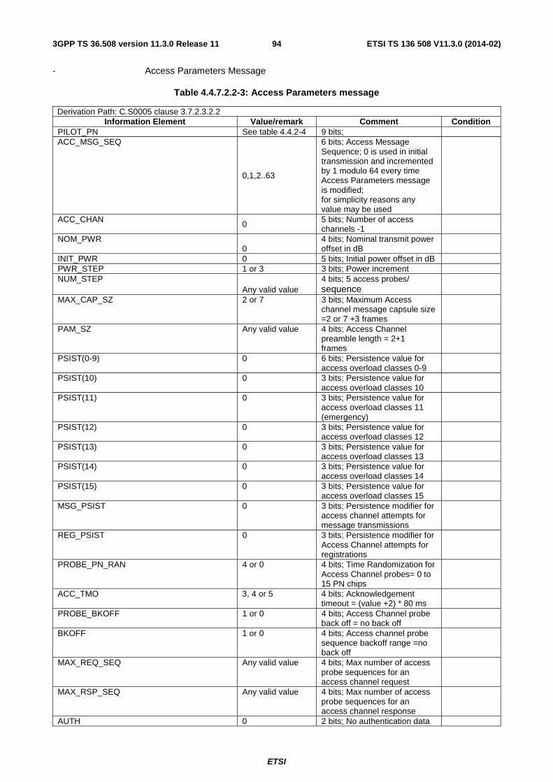
ETSI
ETSI TS 136 508 V11.3.0 (2014-02)943GPP TS 36.508 version 11.3.0 Release 11
- Access Parameters Message
Table 4.4.7.2.2-3: Access Parameters message
Derivation Path: C.S0005 clause 3.7.2.3.2.2 Information Element Value/remark Comment Condition
PILOT_PN See table 4.4.2-4 9 bits; ACC_MSG_SEQ
0,1,2..63
6 bits; Access Message Sequence; 0 is used in initial transmission and incremented by 1 modulo 64 every time Access Parameters message is modified; for simplicity reasons any value may be used
ACC_CHAN 0 5 bits; Number of access channels -1
NOM_PWR 0
4 bits; Nominal transmit power offset in dB
INIT_PWR 0 5 bits; Initial power offset in dB PWR_STEP 1 or 3 3 bits; Power increment NUM_STEP
Any valid value 4 bits; 5 access probes/ sequence
MAX_CAP_SZ 2 or 7 3 bits; Maximum Access channel message capsule size =2 or 7 +3 frames
PAM_SZ Any valid value 4 bits; Access Channel preamble length = 2+1 frames
PSIST(0-9) 0 6 bits; Persistence value for access overload classes 0-9
PSIST(10) 0 3 bits; Persistence value for access overload classes 10
PSIST(11) 0 3 bits; Persistence value for access overload classes 11 (emergency)
PSIST(12) 0 3 bits; Persistence value for access overload classes 12
PSIST(13) 0 3 bits; Persistence value for access overload classes 13
PSIST(14) 0 3 bits; Persistence value for access overload classes 14
PSIST(15) 0 3 bits; Persistence value for access overload classes 15
MSG_PSIST 0 3 bits; Persistence modifier for access channel attempts for message transmissions
REG_PSIST 0 3 bits; Persistence modifier for Access Channel attempts for registrations
PROBE_PN_RAN 4 or 0 4 bits; Time Randomization for Access Channel probes= 0 to 15 PN chips
ACC_TMO 3, 4 or 5 4 bits; Acknowledgement timeout = (value +2) * 80 ms
PROBE_BKOFF 1 or 0 4 bits; Access Channel probe back off = no back off
BKOFF 1 or 0 4 bits; Access channel probe sequence backoff range =no back off
MAX_REQ_SEQ Any valid value 4 bits; Max number of access probe sequences for an access channel request
MAX_RSP_SEQ Any valid value 4 bits; Max number of access probe sequences for an access channel response
AUTH 0 2 bits; No authentication data

ETSI
ETSI TS 136 508 V11.3.0 (2014-02)953GPP TS 36.508 version 11.3.0 Release 11
in access channel messages RAND Not present 0 or 32 bits NOM_PWR_EXT 0 1 bits; Extended nominal
transmit power

ETSI
ETSI TS 136 508 V11.3.0 (2014-02)963GPP TS 36.508 version 11.3.0 Release 11
- Extended System Parameters Message
Table 4.4.7.2.2-4: Extended System Parameters Message
Derivation Path: C.S0005 clause 3.7.2.3.2.13 Information Element Value/remark Comment Condition
PILOT_PN See table 4.4.2-4 9 bits CONFIG_MSG_SEQ Set to '
CONFIG_SEQ' of base station as per clause 4.4.7.2.1
6 bits
DELETE_FOR_TMSI 0 1 bits; Delete foreign TMSI USE_TMSI 0 or 1 1 bits; Use TMSI indicator PREF_MSID_TYPE 3 2 bits; Preferred Access
Channel MSID Type
MCC See table 4.4.2-4 10 bits IMSI_11_12 See table 4.4.2-4 7 bits; 11th and 12th digits of
the IMSI
TMSI_ZONE_LEN 1 or 0 4 bits TMSI_ZONE 1 or Not present 8 bits if present BCAST_INDEX 0 3 bits IMSI_T_SUPPORTED 0 1 bits P_REV 6 8 bits MIN_P_REV 6 8 bits SOFT_SLOPE 0 6 bits ADD_INTERCEPT 0 6 bits; 0 dB DROP_INTERCEPT 0 6 bits; 0 dB PACKET_ZONE_ID 0 8 bits; Packet data service
zone not supported
MAX_NUM_ALT_SO 0 3 bits RESELECT_INCLUDED 0 1 bits; System reselection
parameters not included
EC_THRESH Not present 0 or 5 bits EC_I0_THRESH Not present 0 or 5 bits PILOT_REPORT
1 or 0
1 bits; Pilot Report indicator; the MS reports or does not report additional pilots which have strengths exceeding T_ADD
NGHBR_SET_ENTRY_INFO 0 1 bits ACC_ENT_HO_ORDER Not present 0 or 1 bits NGHBR_SET_ACCESS_INFO 0 1 bits ACCESS_HO Not present 0 or 1 bits ACCESS_HO_MSG_RSP Not present 0 or 1 bits ACCESS_PROBE_HO Not present 0 or 1 bits ACC_HO_LIST_UPD Not present 0 or 1 bits ACC_PROBE_HO_OTHER_MSG Not present 0 or 1 bits MAX_NUM_PROBE_HO Not present 0 or 3 bits NGHBR_SET_SIZE Not present 0 or 6 bits ACCESS_ENTRY_HO Not present 1 bits; Access Entry Handoff
not permitted
ACCESS_HO_ALLOWED Not present 1 bits BROADCAST_GPS_ASST
0 1 bits; Broad cast GPS not supported
QPCH_SUPPORTED 0
1 bits; Quick PCH not supported
NUM_QPCH Not present 0 or 2 bits QPCH_RATE Not present 0 or 1 bits QPCH_POWER_LEVEL_PAGE Not present 0 or 3 bits QPCH_CCI_SUPPORTED Not present 0 or 1 bits QPCH_POWER_LEVEL_CONFIG Not present 0 or 3 bits SDB_SUPPORTED 0 1 bits; Short Data burst not
supported
RLGAIN_TRAFFIC_PILOT 0 6 bits; 0 dB Gain adjustment of Reverse traffic channel

ETSI
ETSI TS 136 508 V11.3.0 (2014-02)973GPP TS 36.508 version 11.3.0 Release 11
REV_PWR_CNTL_DELAY_INCL 0 1 bits REV_PWR_CNTL_DELAY Not present 0 or 2 bits
- Neighbor List Message
Table 4.4.7.2.2-6: Neighbor List Message
This message is sent when EXT_NGHBR_LST in Systems parameter message is set as '0'B i.e. the band class is 0;
Derivation Path: C.S0005 clause 3.7.2.3.2.3 Information Element Value/remark Comment Condition
PILOT_PN See table 4.4.2-4 9 bits CONFIG_MSG_SEQ Set to '
CONFIG_SEQ' of base station as per clause 4.4.7.2.1
6 bits
PILOT_INC 10 or 1
4 bits; Pilot PN Sequence offset index increment = n * 50
NGHBR_CONFIG(n) 0 or Not present NGHBR_PN(n) See table 4.4.2-4
or Not Present 9 bits if present
Note 1: the elements with index n are repeated as per table 4.4.2-5
- Extended Neighbor List Message
Table 4.4.7.2.2-7: Extended Neighbor List Message
This message is sent when EXT_NGHBR_LST in Systems parameter message is set as '1'B i.e. the band class is not 0;
Derivation Path: C.S0005 clause 3.7.2.3.2.14 Information Element Value/remark Comment Condition
PILOT_PN See table 4.4.2-4 9 bits CONFIG_MSG_SEQ Set to '
CONFIG_SEQ' of base station as per clause 4.4.7.2.1
6 bits
PILOT_INC 10 or 1 4 bits; Pilot PN Sequence offset index increment = n * 50
NGHBR_CONFIG(n)
0 or Not present
3 bits if present; Neighbor configuration where neighbor base station has same number of frequencies having paging channels as the current base station;
NGHBR_PN(n) See table 4.4.2-4 or Not present
9 bits if present
SEARCH_PRIORITY(n) 1, 2 or Not present
2 bits if present; Medium search priority
FREQ_INCL(n) 1 1 bit InterFreqCell 0 or Not present NGHBR_BAND(n) Set according to
PIXIT parameter 0 or 5 bits InterFreqCell
Not present NGHBR_FREQ(n) Set according to
PIXIT parameter 0 or 11 bits InterFreqCell
Not Present Note 1: The elements with index n are repeated as per table 4.4.2-5. The SS can transmit up to 7 neighbour intra
frequency cell information. The parameters for the first cell should be set as per table 4.4.2-4.
Condition Explanation

ETSI
ETSI TS 136 508 V11.3.0 (2014-02)983GPP TS 36.508 version 11.3.0 Release 11
InterFreqCell If the configured neighbour cell is on a different frequency compared to the cell in which Extended Neighbour list message is being transmitted
- Sync channel Messages
Table 4.4.7.2.2-8: Sync Channel Message
Derivation Path: C.S0005 clause 3.7.2.3.2.26 Information Element Value/remark Comment Condition
P_REV 6 8 bits; Protocol revision level MIN_P_REV 6 8 bits; Minimum protocol
revision level
SID See table 4.4.2-4 15 bits NID See table 4.4.2-4 16 bits PILOT_PN See table 4.4.2-4 9 bits LC_STATE A valid value,
calculated and updated by the SS
42 bits; Long code State
SYS_TIME A valid value, calculated and updated by the SS
36 bits; System time
LP_SEC A valid value, calculated and updated by the SS
8 bits; The number of leap seconds
LTM_OFF A valid value, calculated and updated by the SS
6 bits; Offset of local time from System time
DAYLT A valid value, calculated and updated by the SS
1 bits; Daylight savings indicator
PRAT 0 2 bits; Paging Channel Data rate=9600 bps
CDMA_FREQ Set according to PIXIT parameter or as per clause 4.3.1.4
11 bits; Frequency assignment
EXT_CDMA_FREQ Set according to PIXIT parameter or as per clause 4.3.1.4
11 bits; Extended frequency assignment
4.5 Generic procedures This clause describes UE test states which can be used in the initial condition of many test cases defined in TS 36.521-1 [21], TS 36.523-1 [18] and TS 36.523-3 [34] or other procedures defined in this specification. This section also defines a set of procedures to bring the UE into these states.
4.5.1 UE test states
NOTE: The need to have a procedure for the transition from State 4/State 3 to State 2 is for further study and it can added if the technical motivation for this procedure can be justified.
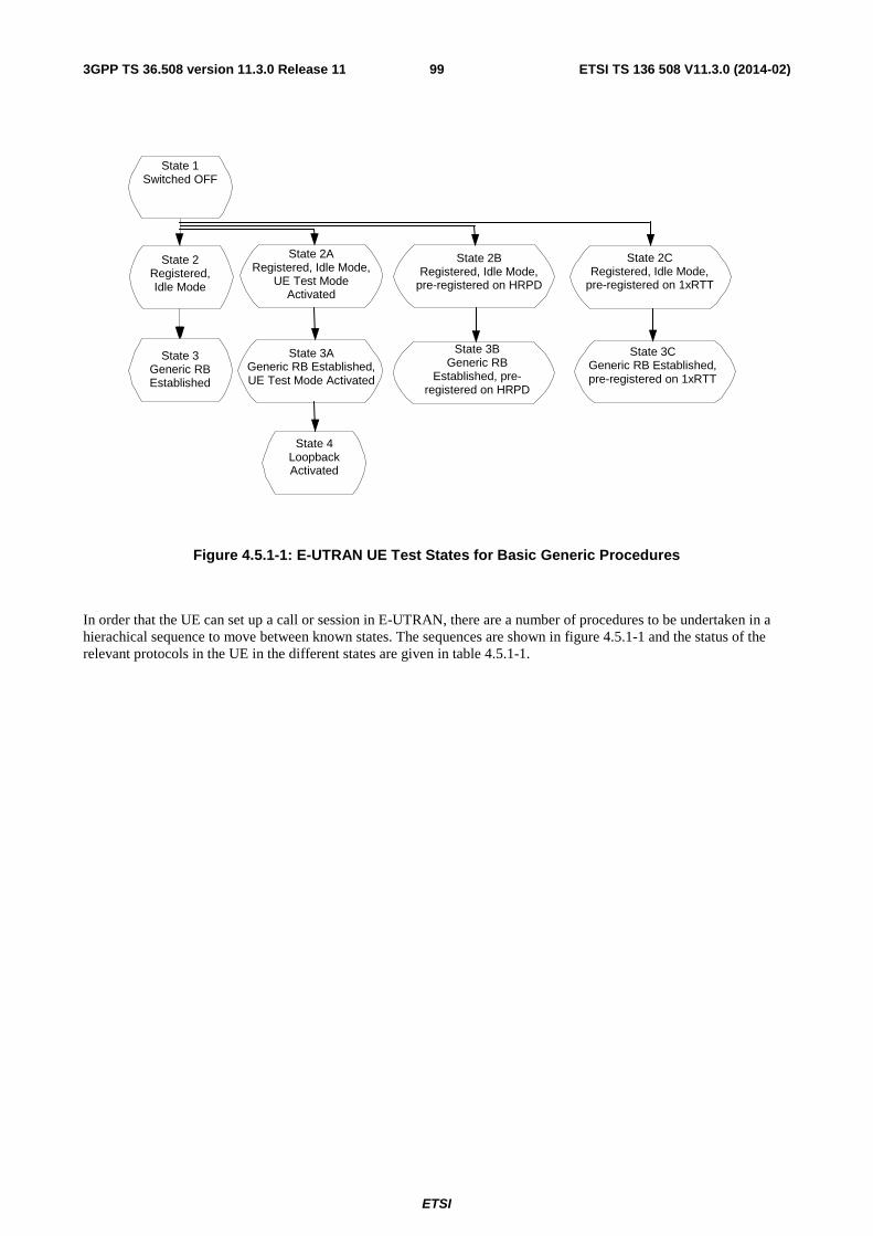
ETSI
ETSI TS 136 508 V11.3.0 (2014-02)993GPP TS 36.508 version 11.3.0 Release 11
State 1 Switched OFF
State 2 Registered, Idle Mode
State 3 Generic RB Established
State 3A Generic RB Established, UE Test Mode Activated
State 2B Registered, Idle Mode,
pre-registered on HRPD
State 3B Generic RB
Established, pre-registered on HRPD
State 2C Registered, Idle Mode,
pre-registered on 1xRTT
State 3C Generic RB Established, pre-registered on 1xRTT
State 4 Loopback Activated
State 2A Registered, Idle Mode,
UE Test Mode Activated
Figure 4.5.1-1: E-UTRAN UE Test States for Basic Generic Procedures
In order that the UE can set up a call or session in E-UTRAN, there are a number of procedures to be undertaken in a hierachical sequence to move between known states. The sequences are shown in figure 4.5.1-1 and the status of the relevant protocols in the UE in the different states are given in table 4.5.1-1.

ETSI
ETSI TS 136 508 V11.3.0 (2014-02)1003GPP TS 36.508 version 11.3.0 Release 11
Table 4.5.1-1: The E-UTRAN UE states
RRC ECM EMM ESM UE Test Mode
State 1 Switched OFF ----- ----- ----- ----- ----- State 2 Registered,
Idle Mode RRC_IDLE ECM-IDLE EMM-REGISTERED 1 default EPS
bearer context active.
Not active
State 2A
Registered, Idle Mode, UE Test Mode Activated
RRC_IDLE ECM-IDLE EMM-REGISTERED 1 default EPS bearer context active.
Active
State 2B
Registered, Idle Mode, pre-registered on HRPD
RRC_IDLE ECM-IDLE EMM-REGISTERED 1 default EPS bearer context active.
Active
State 2C
Registered, Idle Mode, pre-registered on 1xRTT
RRC_IDLE ECM-IDLE EMM-REGISTERED 1 default EPS bearer context active.
Active
State 3 Generic RB Established
RRC_CONNECTED 1 + N (0 ≤ N ≤ 7) data radio bearers configured as specified in the test cases
ECM-CONNECTED EMM-REGISTERED 1 default EPS bearer context active and N (0 ≤ N ≤ 7) dedicated EPS bearers active as specified in the test cases
Not active
State 3A
Generic RB Established, UE Test Mode Activated
RRC_CONNECTED 1 + N (0 ≤ N ≤ 7) data radio bearers configured as specified in the test cases
ECM-CONNECTED EMM-REGISTERED 1 default EPS bearer context active and N (0 ≤ N ≤ 7) dedicated EPS bearers active as specified in the test cases
Active
State 3B
Generic RB Established, pre-registered on HRPD
RRC_CONNECTED 1 + N (0 ≤ N ≤ 7) data radio bearers configured as specified in the test cases
ECM-CONNECTED EMM-REGISTERED 1 default EPS bearer context active and N (0 ≤ N ≤ 7) dedicated EPS bearers active as specified in the test cases
Active
State 3C
Generic RB Established, pre-registered on 1xRTT
RRC_CONNECTED 1 + N (0 ≤ N ≤ 7) data radio bearers configured as specified in the test cases
ECM-CONNECTED EMM-REGISTERED 1 default EPS bearer context active and N (0 ≤ N ≤ 7) dedicated EPS bearers active as specified in the test cases
Active
State 4 Loopback Activated
RRC_CONNECTED 1 + N (0 ≤ N ≤ 7) data radio bearers configured as specified in the test cases
ECM-CONNECTED EMM-REGISTERED 1 default EPS bearer context active and N (0 ≤ N ≤ 7) dedicated EPS bearers active as specified in the test cases
Active
NOTE: Refer to TS 24.301 [28] subclause 5.5.1.1 for more details on the ESM state.
NOTE: Refer to TS 36.509 [38] for details regarding UE test mode and UE Loopback.

ETSI
ETSI TS 136 508 V11.3.0 (2014-02)1013GPP TS 36.508 version 11.3.0 Release 11
State 1 Switched OFF
State H3 QoS Flow Established,
Connected Mode
State H2A HRPD Registered,
Dormant Mode, pre-registered on E-UTRAN
State H3A QoS Flow Established,
Connected Mode pre-registered on E-UTRAN
State H2 HRPD Registered,
Dormant Mode
Figure 4.5.1-2: HRPD UE Test States for Basic Generic Procedures
In order for the UE to set up a session in an HRPD RAN, there is a number of procedures that need to be performed in a certain sequence to move between known UE states. These states and sequences are shown in figure 4.5.1-2. HRPD UE states are described in table 4.5.1-2.
Table 4.5.1-2: Description of HRPD UE states
State Description H2 The UE is registered on the HRPD network, but has no active connection to the network. The Inter-
RAT Idle State Protocol (IR-ISP) is in Monitor State. The UE should be ready to perform a non-optimised cell reselection to E-UTRAN (as per [41] cl. 8 and [42] cl. 14.1).
H3 The UE is registered on the HRPD network, and has an active network connection. The UE should be ready to perform a non-optimised handover to E-UTRAN (as per [41] cl. 8).
H2A Same state as State H2, but the UE is also pre-registered in E-UTRAN. The UE should be ready to perform an optimised cell reselection to E-UTRAN (as per [41] cl. 9.6).
H3A Same state as State H3, but the UE is also pre-registered in E-UTRAN. The UE should be ready to perform an optimised handover to E-UTRAN (as per [41] cl. 9.5).
4.5.2 UE Registration (State 2)
4.5.2.1 Initial conditions
System Simulator:
- 1 cell, default parameters.
- The procedure shall be performed under ideal radio conditions as defined in clause 5
User Equipment:
- The Test UICC shall be inserted. This shall contain either ISIM and USIM applications or only a USIM application on UICC.
4.5.2.2 Definition of system information messages
The default system information messages are used.
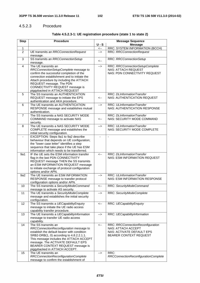
ETSI
ETSI TS 136 508 V11.3.0 (2014-02)1023GPP TS 36.508 version 11.3.0 Release 11
4.5.2.3 Procedure
Table 4.5.2.3-1: UE registration procedure (state 1 to state 2)
Step Procedure Message Sequence U - S Message
1 <-- RRC: SYSTEM INFORMATION (BCCH) 2 UE transmits an RRCConnectionRequest
message. --> RRC: RRCConnectionRequest
3 SS transmits an RRCConnectionSetup message. <--
RRC: RRCConnectionSetup
4 The UE transmits an RRCConnectionSetupComplete message to confirm the successful completion of the connection establishment and to initiate the Attach procedure by including the ATTACH REQUEST message. The PDN CONNECTIVITY REQUEST message is piggybacked in ATTACH REQUEST
--> RRC: RRCConnectionSetupComplete NAS: ATTACH REQUEST NAS: PDN CONNECTIVITY REQUEST
5 The SS transmits an AUTHENTICATION REQUEST message to initiate the EPS authentication and AKA procedure.
<-- RRC: DLInformationTransfer NAS: AUTHENTICATION REQUEST
6 The UE transmits an AUTHENTICATION RESPONSE message and establishes mutual authentication.
--> RRC: ULInformationTransfer NAS: AUTHENTICATION RESPONSE
7 The SS transmits a NAS SECURITY MODE COMMAND message to activate NAS security.
<-- RRC: DLInformationTransfer NAS: SECURITY MODE COMMAND
8 The UE transmits a NAS SECURITY MODE COMPLETE message and establishes the initial security configuration.
--> RRC: ULInformationTransfer NAS: SECURITY MODE COMPLETE
- EXCEPTION: Steps 9a1 to 9a2 describe behaviour that depends on UE configuration; the "lower case letter" identifies a step sequence that take place if the UE has ESM information which needs to be transferred.
- -
9a1 IF the UE sets the ESM information transfer flag in the last PDN CONNECTIVITY REQUEST message THEN the SS transmits an ESM INFORMATION REQUEST message to initiate exchange of protocol configuration options and/or APN.
<-- RRC: DLInformationTransfer NAS: ESM INFORMATION REQUEST
9a2 The UE transmits an ESM INFORMATION RESPONSE message to transfer protocol configuration options and/or APN.
--> RRC: ULInformationTransfer NAS: ESM INFORMATION RESPONSE
10 The SS transmits a SecurityModeCommand message to activate AS security.
<-- RRC: SecurityModeCommand
11 The UE transmits a SecurityModeComplete message and establishes the initial security configuration.
--> RRC: SecurityModeComplete
12 The SS transmits a UECapabilityEnquiry message to initiate the UE radio access capability transfer procedure.
<-- RRC: UECapabilityEnquiry
13 The UE transmits a UECapabilityInformation message to transfer UE radio access capability.
--> RRC: UECapabilityInformation
14 The SS transmits an RRCConnectionReconfiguration message to establish the default bearer with condition SRB2-DRB(1, 0) according to 4.8.2.2.1.1. This message includes the ATTACH ACCEPT message. The ACTIVATE DEFAULT EPS BEARER CONTEXT REQUEST message is piggybacked in ATTACH ACCEPT.
<-- RRC: RRCConnectionReconfiguration NAS: ATTACH ACCEPT NAS: ACTIVATE DEFAULT EPS BEARER CONTEXT REQUEST
15 The UE transmits an RRCConnectionReconfigurationComplete message to confirm the establishment of
--> RRC: RRCConnectionReconfigurationComplete

ETSI
ETSI TS 136 508 V11.3.0 (2014-02)1033GPP TS 36.508 version 11.3.0 Release 11
default bearer. - EXCEPTION: In parallel to the event
described in step 16 below, if initiated by the UE the generic procedure for IP address allocation in the U-plane specified in TS 36.508 subclause 4.5A.1 takes place performing IP address allocation in the U-plane.
- EXCEPTION: In parallel to the event described in step 16 below the generic procedure for IMS signalling in the U-plane specified in TS 36.508 subclause 4.5A.3 takes place if requested by the UE
16 This message includes the ATTACH COMPLETE message. The ACTIVATE DEFAULT EPS BEARER CONTEXT ACCEPT message is piggybacked in ATTACH COMPLETE.
--> RRC: ULInformationTransfer NAS: ATTACH COMPLETE NAS: ACTIVATE DEFAULT EPS BEARER CONTEXT ACCEPT
- EXCEPTION: Steps16a1 to 16a3 describe behaviour that depends on UE configuration; the "lower case letter" identifies a step sequence that takes place if IMS voice not supported and pc_voice_PS_1_CS_2, pc_attach and pc_TAU_connected _in_IMS are set to TRUE. (Note 1)
- -
16a1 The UE transmits a TRACKING AREA UPDATE REQUEST message.
--> RRC: ULInformationTransfer NAS: TRACKING AREA UPDATE REQUEST
16a2 The SS transmits a TRACKING AREA UPDATE ACCEPT message.
<-- RRC: DLInformationTransfer NAS: TRACKING AREA UPDATE ACCEPT
16a3 The UE transmits a TRACKING AREA UPDATE COMPLETE message.
--> RRC: ULInformationTransfer NAS: TRACKING AREA UPDATE COMPLETE
- EXCEPTION: Steps16b1 to 16b6 describe behaviour that depends on UE configuration; the "lower case letter" identifies a step sequence that takes place if IMS voice not supported and pc_voice_PS_1_CS_2, pc_attach and pc_TAU_idle _in_IMS are set to TRUE. (Note 2)
- -
16b1 The SS transmits an RRCConnectionRelease message to release the RRC connection.
<-- RRC: RRCConnectionRelease
16b2 The UE transmits an RRCConnectionRequest message.
--> RRC: RRCConnectionRequest
16b3 The SS transmit an RRCConnectionSetup message.
<-- RRC: RRCConnectionSetup
16b4 The UE transmits an RRCConnectionSetupComplete message including a TRACKING AREA UPDATE REQUEST message.
--> RRC: RRCConnectionSetupComplete NAS: TRACKING AREA UPDATE REQUEST
16b5 The SS transmits a TRACKING AREA UPDATE ACCEPT message.
<-- RRC: DLInformationTransfer NAS: TRACKING AREA UPDATE ACCEPT
16b6 The UE transmits a TRACKING AREA UPDATE COMPLETE message.
--> RRC: ULInformationTransfer NAS: TRACKING AREA UPDATE COMPLETE
17 The SS transmits an RRCConnectionRelease message to release RRC connection and move to RRC_IDLE (State 2).
<-- RRC: RRCConnectionRelease
NOTE 1: The procedure is used with specific message with no IMS voice network support. The UE is configured for voice domain preference IMS PS voice preferred, CS Voice as secondary and to initiate EPS attach. The UE implementation supports TAU in connected mode,
NOTE 2: The procedure is used with specific message withno IMS voice network support. The UE is configured for voice domain preference IMS PS voice preferred, CS Voice as secondary and to initiate EPS attach. The UE implementation supports TAU in idle mode,

ETSI
ETSI TS 136 508 V11.3.0 (2014-02)1043GPP TS 36.508 version 11.3.0 Release 11
4.5.2.4 Specific message contents
All specific message contents shall be referred to clause 4.6 and 4.7 with the exceptions below.
Table 4.5.2.4-1: RRCConnectionRequest (Step 2)
Derivation Path: Table 4.6.1-16 Information Element Value/remark Comment Condition
RRCConnectionRequest ::= SEQUENCE { criticalExtensions CHOICE { rrcConnectionRequest-r8 SEQUENCE { ue-Identity Any allowed value } } }
Table 4.5.2.4-2: UECapabilityInformation (Step 13)
Derivation Path: Table 4.6.1-23 Information Element Value/remark Comment Condition
UECapabilityInformation ::= SEQUENCE { criticalExtensions CHOICE { c1 CHOICE{ ueCapabilityInformation-r8 Any allowed value } } }
Table 4.5.2.4-3: ACTIVATE DEFAULT EPS BEARER CONTEXT REQUEST (Step 14)
Derivation Path: Table 4.7.3-6 Information Element Value/remark Comment Condition
PDN address IPv4_address_only
Length of PDN address contents 5 octets PDN type value ‘001’B IPv4 PDN address information IPv4 address The SS provides a
valid IPv4 address NOT IPv4-DHCP
0.0.0.0 DHCPv4 is to be used to allocate the IPv4 address
IPv4-DHCP
ESM cause IF "PDN type" IE in step 4 is 'IPv4v6' THEN '00110010'B ELSE Not present
"PDN type IPv4 only allowed"
NOTE: The default message contents specified in table 4.7.3-6 apply unless the condition IPv4_address_only in table 4.5.2.4-3 is true.
Condition Explanation IPv4_address_only This condition applies if the test case preamble description indicates that the UE is
allocated an IPv4 address. IPv4-DHCP If in the last PDN CONNECTIVITY REQUEST or ESM INFORMATION RESPONSE sent
prior to this message, the IE Protocol configuration options contains a configuration protocol option = '000B00H' ("IPv4 address allocation via DHCPv4", length of contents = 0). Note 1: This condition is used in conjunction with IPv4 or IPv4v6 as indicated in the
"PDN address row" just above. Note 2: If both messages, PDN CONNECTIVITY REQUEST and ESM INFORMATION
RESPONSE, are received and contain a Protocol configuration options IE then the IE from the message which is received later shall be used.

ETSI
ETSI TS 136 508 V11.3.0 (2014-02)1053GPP TS 36.508 version 11.3.0 Release 11
Table 4.5.2.4-4: TRACKING AREA UPDATE REQUEST (Steps 16a1 and 16b4)
Derivation Path: 36.508 Table 4.7.2-27 with condition combined_TA_LA
Table 4.5.2.4-5: TRACKING AREA UPDATE ACCEPT (Steps 16a2 and 16b5)
Derivation Path: 36.508 Table 4.7.2-24 with condition combined_TA_LA
4.5.2A UE Registration, UE Test Mode Activated (State 2A)
4.5.2A.1 Initial conditions
System Simulator:
- 1 cell, default parameters.
- The procedure shall be performed under ideal radio conditions as defined in clause 5
User Equipment:
- The Test USIM shall be inserted.
4.5.2A.2 Definition of system information messages
The default system information messages are used.

ETSI
ETSI TS 136 508 V11.3.0 (2014-02)1063GPP TS 36.508 version 11.3.0 Release 11
4.5.2A.3 Procedure
Table 4.5.2A.3-1: UE registration with test mode activation procedure (state 1 to state 2A)
Step Procedure Message Sequence U - S Message
1 to 9a2
Same procedure for steps 1 to 9a2 as specified in the procedure in clause 4.5.2.3
- -
10 The SS transmits an ACTIVATE TEST MODE message to activate UE radio bearer test mode procedure.
<-- RRC: DLInformationTransfer TC: ACTIVATE TEST MODE
11 The UE transmits an ACTIVATE TEST MODE COMPLETE message.
--> RRC: ULInformationTransfer TC: ACTIVATE TEST MODE COMPLETE
12 The SS transmits a SecurityModeCommand message to activate AS security.
<-- RRC: SecurityModeCommand
13 The UE transmits a SecurityModeComplete message and establishes the initial security configuration.
--> RRC: SecurityModeComplete
14 The SS transmits a UECapabilityEnquiry message to initiate the UE radio access capability transfer procedure.
<-- RRC: UECapabilityEnquiry
15 The UE transmits a UECapabilityInformation message to transfer UE radio access capability.
--> RRC: UECapabilityInformation
16 The SS transmits an RRCConnectionReconfiguration message to establish the default bearer with condition SRB2-DRB(1, 0) according to 4.8.2.2.1.1. This message includes the ATTACH ACCEPT message. The ACTIVATE DEFAULT EPS BEARER CONTEXT REQUEST message is piggybacked in ATTACH ACCEPT.
<-- RRC: RRCConnectionReconfiguration NAS: ATTACH ACCEPT NAS: ACTIVATE DEFAULT EPS BEARER CONTEXT REQUEST
17 The UE transmits an RRCConnectionReconfigurationComplete message to confirm the establishment of default bearer.
--> RRC: RRCConnectionReconfigurationComplete
- EXCEPTION: In parallel to the event described in step 18 below the generic procedure for IP address allocation in the U-plane specified in TS 36.508 subclause 4.5A.1 takes place performing IP address allocation in the U-plane if requested by the UE.
- EXCEPTION: In parallel to the event described in step 18 below the generic procedure for IMS signalling in the U-plane specified in TS 36.508 subclause 4.5A.3 takes place if requested by the UE
18 This message includes the ATTACH COMPLETE message. The ACTIVATE DEFAULT EPS BEARER CONTEXT ACCEPT message is piggybacked in ATTACH COMPLETE.
--> RRC: ULInformationTransfer NAS: ATTACH COMPLETE NAS: ACTIVATE DEFAULT EPS BEARER CONTEXT ACCEPT
- EXCEPTION: Steps18a1 to 18a3 describe behaviour that depends on UE configuration; the "lower case letter" identifies a step sequence that takes place if IMS voice not supported and pc_voice_PS_1_CS_2, pc_attach and pc_TAU_connected_in_IMS are set to TRUE (Note 1).
- -
18a1 The UE transmits a TRACKING AREA UPDATE REQUEST message.
--> RRC: ULInformationTransfer NAS: TRACKING AREA UPDATE REQUEST
18a2 The SS transmits a TRACKING AREA UPDATE ACCEPT message.
<-- RRC: DLInformationTransfer NAS: TRACKING AREA UPDATE ACCEPT
18a3 The UE transmits a TRACKING AREA --> RRC: ULInformationTransfer

ETSI
ETSI TS 136 508 V11.3.0 (2014-02)1073GPP TS 36.508 version 11.3.0 Release 11
UPDATE COMPLETE message. NAS: TRACKING AREA UPDATE COMPLETE
- EXCEPTION: Steps18b1 to 18b6 describe behaviour that depends on UE configuration; the “lower case letter” identifies a step sequence that takes place if IMS voice not supported and pc_voice_PS_1_CS_2, pc_attach and pc_TAU_idle_in_IMS are set to TRUE (Note 2).
- -
18b1 The SS transmits an RRCConnectionRelease message to release the RRC connection.
<-- RRC: RRCConnectionRelease
18b2 The UE transmits an RRCConnectionRequest message.
--> RRC: RRCConnectionRequest
18b3 The SS transmit an RRCConnectionSetup message.
<-- RRC: RRCConnectionSetup
18b4 The UE transmits an RRCConnectionSetupComplete message including a TRACKING AREA UPDATE REQUEST message.
--> RRC: RRCConnectionSetupComplete NAS: TRACKING AREA UPDATE REQUEST
18b5 The SS transmits a TRACKING AREA UPDATE ACCEPT message.
<-- RRC: DLInformationTransfer NAS: TRACKING AREA UPDATE ACCEPT
18b6 The UE transmits a TRACKING AREA UPDATE COMPLETE message.
--> RRC: ULInformationTransfer NAS: TRACKING AREA UPDATE COMPLETE
19 The SS transmits an RRCConnectionRelease message to release RRC connection and move to RRC_IDLE (State 2A).
<-- RRC: RRCConnectionRelease
NOTE 1: The procedure is used with specific message with no IMS voice network support. The UE is configured for voice domain preference IMS PS voice preferred, CS Voice as secondary and to initiate EPS attach. The UE implementation supports TAU in connected mode,
NOTE 2: The procedure is used with specific message with no IMS voice network support. The UE is configured for voice domain preference IMS PS voice preferred, CS Voice as secondary and to initiate EPS attach. The UE implementation supports TAU in idle mode,
4.5.2A.4 Specific message contents
All specific message contents shall be referred to clause 4.6, 4.7 and 4.7A with the exceptions below.
Table 4.5.2A.4-1: RRCConnectionRequest (Step 2)
Derivation Path: Table 4.6.1-16 Information Element Value/remark Comment Condition
RRCConnectionRequest ::= SEQUENCE { criticalExtensions CHOICE { rrcConnectionRequest-r8 SEQUENCE { ue-Identity Any allowed value } } }
Table 4.5.2A.4-2: UECapabilityInformation (Step 15)
Derivation Path: Table 4.6.1-23 Information Element Value/remark Comment Condition
UECapabilityInformation ::= SEQUENCE { criticalExtensions CHOICE { c1 CHOICE{ ueCapabilityInformation-r8 Any allowed value } } }

ETSI
ETSI TS 136 508 V11.3.0 (2014-02)1083GPP TS 36.508 version 11.3.0 Release 11
Table 4.5.2A.4-3: TRACKING AREA UPDATE REQUEST (Steps 18a1 and 18b4)
Derivation Path: 36.508 Table 4.7.2-27 with condition combined_TA_LA
Table 4.5.2A.4-4: TRACKING AREA UPDATE ACCEPT (Steps 18a2 and 18b5)
Derivation Path: 36.508 Table 4.7.2-24 with condition combined_TA_LA
4.5.2B UE Registration, pre-registration on HRPD (State 2B)
4.5.2B.1 Initial conditions
System Simulator:
- Cell 1
- Cell 1 is transmitting SystemInformationBlockType8
User Equipment:
- The Test USIM shall be inserted.
4.5.2B.2 Definition of system information messages
Table 4.5.2B.2-1: SystemInformationBlockType1 for cell 1 (Steps 1-41, Table 4.5.2B.3-2)
Derivation Path: 36.508 Table 4.4.3.2-3 Information Element Value/remark Comment Condition
SystemInformationBlockType1 ::= SEQUENCE { schedulingInformation ::= SEQUENCE (SIZE (1..maxSI-Message)) OF SEQUENCE {}
Combination 6 in TS 36.508 section 4.4.3.1
SIB2, SIB3 and SIB 8 are transmitted
}

ETSI
ETSI TS 136 508 V11.3.0 (2014-02)1093GPP TS 36.508 version 11.3.0 Release 11
Table 4.5.2B.2-2: SystemInformationBlockType8 for cell 1 (Steps 1-41, Table 4.5.2B.3-2)
Derivation Path: 36.508 Table 4.4.3.3-7, condition HRPD Information Element Value/remark Comment Condition
SystemInformationBlockType8 ::= SEQUENCE { parametersHRPD SEQUENCE { preRegistrationInfoHRPD SEQUENCE { preRegistrationAllowed TRUE preRegistrationZoneId ColorCode secondaryPreRegistrationZoneIdList SEQUENCE (SIZE (1..2)) OF SEQUENCE {
Not present
PreRegistrationZoneIdHRPD Not present } } cellReselectionParametersHRPD SEQUENCE { bandClassList SEQUENCE (SIZE (1..maxCDMA -BandClass)) OF SEQUENCE {
1 entry
bandClass Band Class of frequency under test
ENUMERATED {bc0, bc1, bc2, bc3, bc4, bc5, bc6, bc7, bc8, bc9, bc10, bc11, bc12, bc13, bc14, bc15, bc16, bc17, spare14, spare13, spare12, spare11, spare10, spare9, spare8, spare7, spare6, spare5, spare4, spare3, spare2, spare1, ...}
cellReselectionPriority 3 threshX-High 30(-30) INTEGER (0..63) threshX-Low 32(-32) INTEGER (0..63) } neighCellList SEQUENCE (SIZE (1..16)) OF SEQUENCE {
1 entry
bandClass Band Class of frequency under test
ENUMERATED {bc0, bc1, bc2, bc3, bc4, bc5, bc6, bc7, bc8, bc9, bc10, bc11, bc12, bc13, bc14, bc15, bc16, bc17, spare14, spare13, spare12, spare11, spare10, spare9, spare8, spare7, spare6, spare5, spare4, spare3, spare2, spare1, ...}
} } t-ReselectionCDMA2000 3 INTEGER (0..7) } } }
4.5.2B.3 Procedure
Table 4.5.2B.3-1 shows the cell power levels during the procedure.
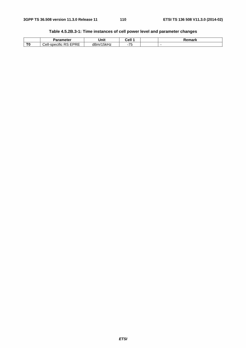
ETSI
ETSI TS 136 508 V11.3.0 (2014-02)1103GPP TS 36.508 version 11.3.0 Release 11
Table 4.5.2B.3-1: Time instances of cell power level and parameter changes
Parameter Unit Cell 1 Remark T0 Cell-specific RS EPRE dBm/15kHz -75 -
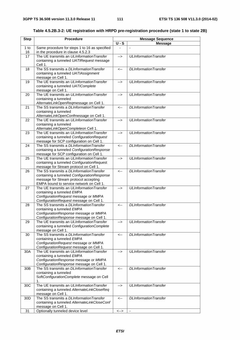
ETSI
ETSI TS 136 508 V11.3.0 (2014-02)1113GPP TS 36.508 version 11.3.0 Release 11
Table 4.5.2B.3-2: UE registration with HRPD pre-registration procedure (state 1 to state 2B)
Step Procedure Message Sequence U - S Message
1 to 16
Same procedure for steps 1 to 16 as specified in the procedure in clause 4.5.2.3
- -
17 The UE transmits an ULInformationTransfer containing a tunneled UATIRequest message Cell 1.
--> ULInformationTransfer
18 The SS transmits a DLInformationTransfer containing a tunneled UATIAssignment message on Cell 1.
<-- DLInformationTransfer
19 The UE transmits an ULInformationTransfer containing a tunneled UATIComplete message on Cell 1.
--> ULInformationTransfer
20 The UE transmits an ULInformationTransfer containing a tunneled AlternateLinkOpenReqmessage on Cell 1.
--> ULInformationTransfer
21 The SS transmits a DLInformationTransfer containing a tunneled AlternateLinkOpenConfmessage on Cell 1.
<-- DLInformationTransfer
22 The UE transmits an ULInformationTransfer containing a tunneled AlternateLinkOpenCompleteon Cell 1.
--> ULInformationTransfer
23 The UE transmits an ULInformationTransfer containing a tunneled ConfigurationRequest message for SCP configuration on Cell 1.
--> ULInformationTransfer
24 The SS transmits a DLInformationTransfer containing a tunneled ConfigurationResponse message for SCP configuration on Cell 1.
<-- DLInformationTransfer
25 The UE transmits an ULInformationTransfer containing a tunneled ConfigurationRequest message for Stream protocol on Cell 1.
--> ULInformationTransfer
26 The SS transmits a DLInformationTransfer containing a tunneled ConfigurationResponse message for Stream protocol accepting EMPA bound to service network on Cell 1.
<-- DLInformationTransfer
27 The UE transmits an ULInformationTransfer containing a tunneled EMPA ConfigurationRequest message or MMPA ConfigurationRequest message on Cell 1.
--> ULInformationTransfer
28 The SS transmits a DLInformationTransfer containing a tunneled EMPA ConfigurationResponse message or MMPA ConfigurationResponse message on Cell 1.
<-- DLInformationTransfer
29 The UE transmits an ULInformationTransfer containing a tunneled ConfigurationComplete message on Cell 1.
--> ULInformationTransfer
30 The SS transmits a DLInformationTransfer containing a tunneled EMPA ConfigurationRequest message or MMPA ConfigurationRequest message on Cell 1.
<-- DLInformationTransfer
30A The UE transmits an ULInformationTransfer containing a tunneled EMPA ConfigurationResponse message or MMPA ConfigurationResponse message on Cell 1.
--> ULInformationTransfer
30B The SS transmits an DLInformationTransfer containing a tunneled SoftConfigurationComplete message on Cell 1.
<-- DLInformationTransfer
30C The UE transmits an ULInformationTransfer containing a tunneled AlternateLinkCloseReq message on Cell 1.
--> ULInformationTransfer
30D The SS transmits a DLInformationTransfer containing a tunneled AlternateLinkCloseConf message on Cell 1.
<-- DLInformationTransfer
31 Optionally tunneled device level <--> -

ETSI
ETSI TS 136 508 V11.3.0 (2014-02)1123GPP TS 36.508 version 11.3.0 Release 11
authentication may take place on Cell 1. 32 Optionally tunneled Location Update
procedure may take place if the SS is configured to support it.
<--> -
32A The UE transmits an ULInformationTransfer containing a tunneled AlternateLinkOpenReq message on Cell 1.
--> ULInformationTransfer
32B The SS transmits a DLInformationTransfer containing a tunneled AlternateLinkOpenConf message on Cell 1.
<-- DLInformationTransfer
32C The UE transmits an ULInformationTransfer containing a tunneled AlternateLinkOpenComplete message on Cell 1.
--> ULInformationTransfer
33 Tunneled PPP LCP negotiation is performed between the UE and the SS. EAP-AKA’ is selected as the authentication protocol.
<--> -
33A After entering PPP LCP Open State, optionally tunneled PPP Version Capability Indicaiton and/or Max PPP Inactivity Timer negotiation may take place.
<-> -
34 Tunneled EAP-AKA’ is performed between the UE and the SS.
<--> -
35 The UE transmits an ULInformationTransfer containing a tunneled VSNCP Configure-Request message, including a PDN-ID, PDN Type, APN, PDN Address, Protocol Configuration Options, and Attach Type = “handover”. The Address Allocation Preference option contained in the Protocol Configuration Options indicates whether the UE wants to perform the IP address allocation during the attach procedure or deferred IP address allocation. PDN Type indicates the UE’s IP capability (IPv4, IPv6 or IPv4/v6)
--> ULInformationTransfer
36 The SS transmits a DLInformationTransfer containing a tunneled VSNCP Configure-Ack message.
<-- DLInformationTransfer
37 The SS transmits a DLInformationTransfer containing a tunneled VSNCP Configure-Request message including the PDN-ID configuration option.
<-- DLInformationTransfer
38 The UE transmits an ULInformationTransfer containing a tunneled VSNCP Configure-Ack message.
--> ULInformationTransfer
39 Optionally deferred IP address allocation using tunnelled IETF messages can take place depending on the Address Allocation Preference indicated by the UE at Step 35.
<-->
39A The UE transmits an ULInformationTransfer containing a tunneled AlternateLinkCloseReq message on Cell 1.
--> ULInformationTransfer
39B The SS transmits a DLInformationTransfer containing a tunneled AlternateLinkCloseConf message on Cell 1.
<-- DLInformationTransfer
40 Void. 41 The SS transmits an RRCConnectionRelease
message on Cell 1. <-- RRCConnectionRelease
Note 1: The sequence in steps 17-40 lists important eHRPD procedures. More protocol negotiations can happen based on UE capability and SS emulation.
Note 2: Message contents of tunnelled CDMA2000 messages (steps 17-40) are not checked in terms of conformance testing.
NOTE: If step 31 is performed, an alternative link establishement procedure is also performed.

ETSI
ETSI TS 136 508 V11.3.0 (2014-02)1133GPP TS 36.508 version 11.3.0 Release 11
4.5.2B.4 Specific message contents
All specific message contents shall be referred to clause 4.6, 4.7 and 4.7A with the exceptions below.
Table 4.5.2B.4-1: RRCConnectionRequest (Step 2, Table 4.5.2B.3-2)
Derivation Path: Table 4.6.1-16 Information Element Value/remark Comment Condition
RRCConnectionRequest ::= SEQUENCE { criticalExtensions CHOICE { rrcConnectionRequest-r8 SEQUENCE { ue-Identity Any allowed value } } }
Table 4.5.2B.4-2: UECapabilityInformation (Step13, Table 4.5.2B.3-2)
Derivation Path: Table 4.6.1-23 Information Element Value/remark Comment Condition
UECapabilityInformation ::= SEQUENCE { criticalExtensions CHOICE { c1 CHOICE{ ueCapabilityInformation-r8 Any allowed value } } }
Table 4.5.2B.4-3: UATI Request message (Step 17, Table 4.5.2B.3-2)
Field Value/remark Comment Condition SAPState ‘0’B SAP Header SessionConfigurationToken 16 bits, Set by UE ConnectionLayerFormat 1 bit, Set by UE ATI Record 34 bits, RATI set by UE Reserved ‘0000’B MessageID ‘00000000’B UATI Request TransactionID 8 bits, Set by UE
Table 4.5.2B.4-4: UATI Assignment message (Step 18, Table 4.5.2B.3-2)
Field Value/remark Comment Condition SAPState ‘1’B SAP Header SessionConfigurationToken ‘0’ ConnectionLayerFormat 1 bit, Set by SS ATI Record 34 bits, RATI set in UATI
Request
Reserved ‘0000’B MessageID ‘00000001’B UATI Assignment MessageSequence 8 bits, Set by SS Reserved1 ‘0000000’B SubnetIncluded ‘1’B UATISubnetMask ‘1101000’B UATI104 104 bits, Set by SS UATIColorCode 8 bits, Set to ColorCode UATI024 24 bits, Set by SS UpperOldUATILength ‘0000’B Reserved2 ‘0000’B

ETSI
ETSI TS 136 508 V11.3.0 (2014-02)1143GPP TS 36.508 version 11.3.0 Release 11
4.5.2C UE Registration, pre-registration on 1xRTT (State 2C)
4.5.2C.1 Initial conditions
System Simulator:
- Cell 1
- Cell 1 is transmitting SystemInformationBlockType8
User Equipment:
- The Test USIM shall be inserted.
- The UE is switched OFF.
4.5.2C.2 Definition of system information messages
Table 4.5.2C.2-1: SystemInformationBlockType1 for cell 1 (Steps 1-19, Table 4.5.2C.3-2)
Derivation Path: 36.508 Table 4.4.3.2-3 Information Element Value/remark Comment Condition
SystemInformationBlockType1 ::= SEQUENCE { schedulingInformation ::= SEQUENCE (SIZE (1..maxSI-Message)) OF SEQUENCE {}
Combination 6 in TS 36.508 section 4.4.3.1
SIB2, SIB3 and SIB 8 are transmitted
}

ETSI
ETSI TS 136 508 V11.3.0 (2014-02)1153GPP TS 36.508 version 11.3.0 Release 11
Table 4.5.2C.2-2: SystemInformationBlockType8 for cell 1 (Steps 1-19, Table 4.5.2C.3-2)
Derivation Path: 36.508 Table 4.4.3.3-7, condition 1XRTT Information Element Value/remark Comment Condition
SystemInformationBlockType8 ::= SEQUENCE { parameters1XRTT SEQUENCE { csfb-RegistrationParam1XRTT SEQUENCE { Sid SID under test
For Signalling test cases, see table 4.4.2-4
BIT STRING (SIZE (15))
Nid NID under test For Signalling test cases, see table 4.4.2-4
BIT STRING (SIZE (16))
multipleSID TRUE BOOLEAN multipleNID TRUE BOOLEAN homeReg TRUE BOOLEAN foreignSIDReg TRUE BOOLEAN foreignNIDReg TRUE BOOLEAN parameterReg TRUE BOOLEAN powerUpReg TRUE BOOLEAN registrationPeriod ’0000000’ BIT STRING
(SIZE (7))
registrationZone Registration zone under test For Signalling test cases, see table 4.4.2-4
BIT STRING (SIZE (12))
totalZone '001'B BIT STRING (SIZE (3))
zoneTimer '000'B or '001'B BIT STRING (SIZE (3))
} longCodeState1XRTT A valid value, calculated
and updated by the SS BIT STRING (SIZE (42)) OPTIONAL
cellReselectionParameters1XRTT SEQUENCE { bandClassList SEQUENCE (SIZE (1..maxCDMA -BandClass)) OF SEQUENCE {
1 entry
bandClass Band Class of frequency under test
ENUMERATED {bc0, bc1, bc2, bc3, bc4, bc5, bc6, bc7, bc8, bc9, bc10, bc11, bc12, bc13, bc14, bc15, bc16, bc17, spare14, spare13, spare12, spare11, spare10, spare9, spare8, spare7, spare6, spare5, spare4, spare3, spare2, spare1, ...}
cellReselectionPriority 3 threshX-High 30(-30) INTEGER (0..63) threshX-Low 32(-32) INTEGER (0..63) } } csfb-RegistrationParam1XRTT-v920{ powerDownReg-r9 TRUE } } }
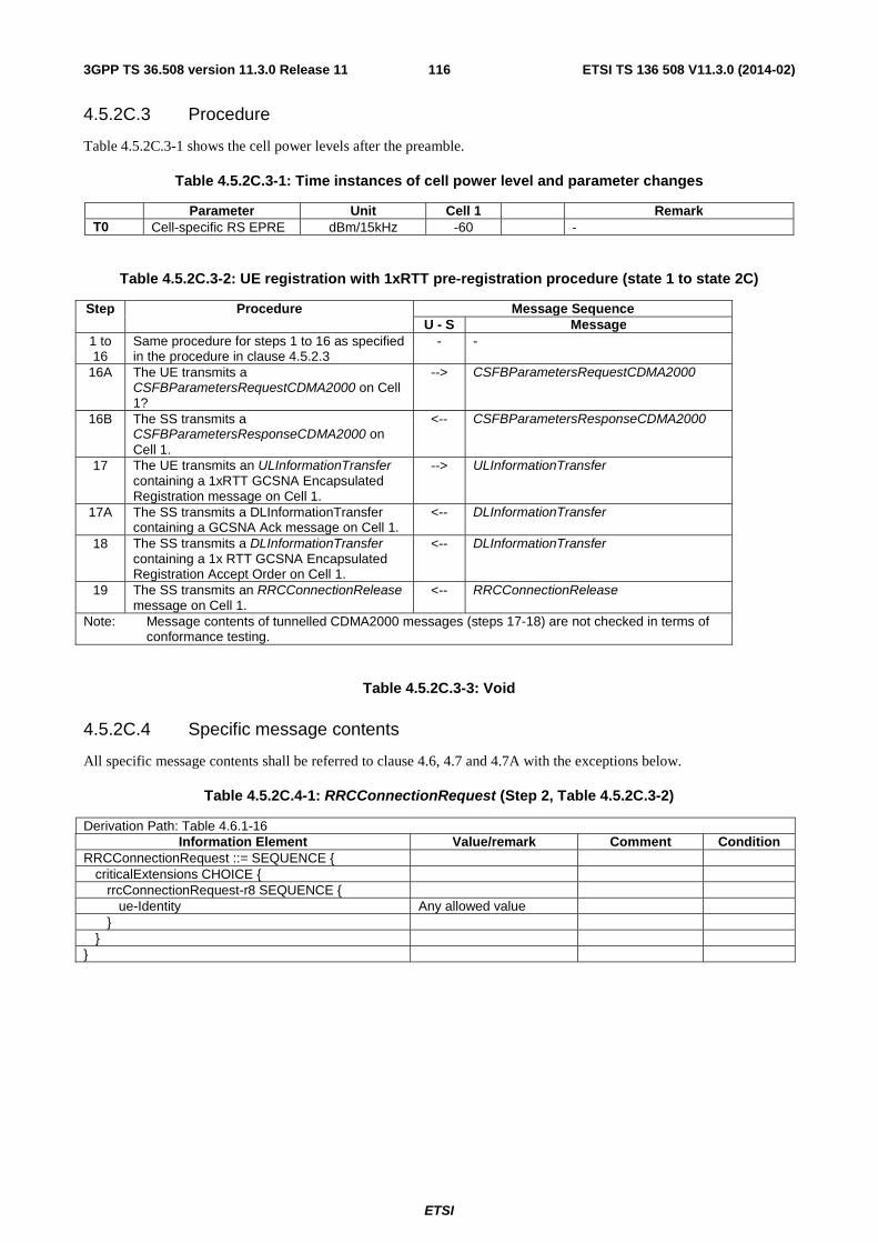
ETSI
ETSI TS 136 508 V11.3.0 (2014-02)1163GPP TS 36.508 version 11.3.0 Release 11
4.5.2C.3 Procedure
Table 4.5.2C.3-1 shows the cell power levels after the preamble.
Table 4.5.2C.3-1: Time instances of cell power level and parameter changes
Parameter Unit Cell 1 Remark T0 Cell-specific RS EPRE dBm/15kHz -60 -
Table 4.5.2C.3-2: UE registration with 1xRTT pre-registration procedure (state 1 to state 2C)
Step Procedure Message Sequence U - S Message
1 to 16
Same procedure for steps 1 to 16 as specified in the procedure in clause 4.5.2.3
- -
16A The UE transmits a CSFBParametersRequestCDMA2000 on Cell 1?
--> CSFBParametersRequestCDMA2000
16B The SS transmits a CSFBParametersResponseCDMA2000 on Cell 1.
<-- CSFBParametersResponseCDMA2000
17 The UE transmits an ULInformationTransfer containing a 1xRTT GCSNA Encapsulated Registration message on Cell 1.
--> ULInformationTransfer
17A The SS transmits a DLInformationTransfer containing a GCSNA Ack message on Cell 1.
<-- DLInformationTransfer
18 The SS transmits a DLInformationTransfer containing a 1x RTT GCSNA Encapsulated Registration Accept Order on Cell 1.
<-- DLInformationTransfer
19 The SS transmits an RRCConnectionRelease message on Cell 1.
<-- RRCConnectionRelease
Note: Message contents of tunnelled CDMA2000 messages (steps 17-18) are not checked in terms of conformance testing.
Table 4.5.2C.3-3: Void
4.5.2C.4 Specific message contents
All specific message contents shall be referred to clause 4.6, 4.7 and 4.7A with the exceptions below.
Table 4.5.2C.4-1: RRCConnectionRequest (Step 2, Table 4.5.2C.3-2)
Derivation Path: Table 4.6.1-16 Information Element Value/remark Comment Condition
RRCConnectionRequest ::= SEQUENCE { criticalExtensions CHOICE { rrcConnectionRequest-r8 SEQUENCE { ue-Identity Any allowed value } } }

ETSI
ETSI TS 136 508 V11.3.0 (2014-02)1173GPP TS 36.508 version 11.3.0 Release 11
Table 4.5.2C.4-2: UECapabilityInformation (Step 13, Table 4.5.2C.3-2)
Derivation Path: Table 4.6.1-23 Information Element Value/remark Comment Condition
UECapabilityInformation ::= SEQUENCE { criticalExtensions CHOICE { c1 CHOICE{ ueCapabilityInformation-r8 Any allowed value } } }
Table 4.5.2C.4-3: Void
Table 4.5.2C.4-4: Void
Table 4.5.2C.4-5: CSFBParametersResponseCDMA2000 (Step 16B, Table 4.5.2C.3-2)
Derivation Path: 36.508 Table 4.6.1-2 Information Element Value/remark Comment Condition
CSFBParametersResponseCDMA2000 ::= SEQUENCE {
criticalExtensions CHOICE { csfbParametersResponseCDMA2000-r8 SEQUENCE {
Rand Random Challenge Data set by SS
mobilityParameters Set according to Table 4.5.2C.4-6
} } }

ETSI
ETSI TS 136 508 V11.3.0 (2014-02)1183GPP TS 36.508 version 11.3.0 Release 11
Table 4.5.2C.4-6: mobilityParameters (CDMA2000Parameters) (Step 16B, Table 4.5.2C.3-2)
Information Element Value/remark Comment Condition RecordType ‘00000000’B SIDIncluded ‘1’B SID The same as SIB8 NIDIncluded ‘1’B NID The same as SIB8 REG_ZONEIncluded ‘1’B REG_ZONE The same as SIB8 TOTAL_ZONESIncluded ‘1’B TOTAL_ZONES The same as SIB8 ZONE_TIMERIncluded ‘1’B ZONE_TIMER The same as SIB8 PACKET_ZONE_IDIncluded ‘0’B PACKET_ZONE_ID Not present PZIDHystParametersIncluded ‘0’B PZ_HYST_ENABLED Not present PZ_HYST_INFO_INCL Not present PZ_HYST_LIST_LEN Not present PZ_HYST_ACT_TIMER Not present PZ_HYST_TIMER_MUL Not present PZ_HYST_TIMER_EXP Not present P_REVIncluded ‘1’B P_REV ’00000110’B MIN_P_REVIncluded ‘1’B MIN_P_REV ’00000110’B ‘0’B NEG_SLOT_CYCLE_INDEX_SUPIncluded NEG_SLOT_CYCLE_INDEX_SUP Not present ENCRYPT_MODEIncluded ‘0’B ENCRYPT_MODE Not present ENC_SUPPORTEDIncluded ‘0’B ENC_SUPPORTED Not present SIG_ENCRYPT_SUPIncluded ‘0’B SIG_ENCRYPT_SUP Not present MSG_INTEGRITY_SUPIncluded ‘0’B MSG_INTEGRITY_SUP Not present SIG_INTEGRITY_SUP_INCLIncluded ‘0’B SIG_INTEGRITY_SUP_INCL Not present SIG_INTEGRITY_SUPIncluded ‘0’B SIG_INTEGRITY_SUP Not present AUTHIncluded ‘1’B AUTH ‘00’B MAX_NUM_ALT_SOIncluded ‘1’B MAX_NUM_ALT_SO ‘000’B USE_SYNC_IDIncluded ‘0’B USE_SYNC_ID Not present MS_INIT_POS_LOC_SUP_INDIncluded ‘0’B MS_INIT_POS_LOC_SUP_IND Not present MOB_QOSIncluded ‘0’B MOB_QOS Not present BAND_CLASS_INFO_REQIncluded ‘0’B BAND_CLASS_INFO_REQ Not present BAND_CLASSIncluded ‘1’B BAND_CLASS ‘00000’B BYPASS_REG_INDIncluded ‘0’B BYPASS_REG_IND Not present ‘0’B ALT_BAND_CLASSIncluded ALT_BAND_CLASS Not present MAX_ADD_SERV_INSTANCEIncluded ‘0’B MAX_ADD_SERV_INSTANCE Not present HOME_REGIncluded ‘1’B HOME_REG The same as SIB8 FOR_SID_REGIncluded ‘1’B FOR_SID_REG The same as SIB8

ETSI
ETSI TS 136 508 V11.3.0 (2014-02)1193GPP TS 36.508 version 11.3.0 Release 11
FOR_NID_REGIncluded ‘1’B FOR_NID_REG The same as SIB8 POWER_UP_REGIncluded ‘1’B POWER_UP_REG The same as SIB8 POWER_DOWN_REGIncluded ‘1’B POWER_DOWN_REG The same as SIB8 PARAMETER_REGIncluded ‘1’B PARAMETER_REG The same as SIB8 REG_PRDIncluded ‘1’B REG_PRD The same as SIB8 REG_DISTIncluded ‘0’B REG_DIST Not present PREF_MSID_TYPEIncluded ‘1’B PREF_MSID_TYPE ’11’B EXT_PREF_MSID_TYPEIncluded ‘0’B EXT_PREF_MSID_TYPE Not present MEID_REQDIncluded ‘0’B MEID_REQD Not present MCCIncluded ‘1’B MCC See the Table 4.4.2-4
Note 1, Note 2
IMSI_11_12Included ‘1’B IMSI_11_12 See the Table 4.4.2-4
Note 1, Note 2
IMSI_T_SUPPORTEDIncluded ‘1’B IMSI_T_SUPPORTED ’0’B RECONNECT_MSG_INDIncluded ‘0’B RECONNECT_MSG_IND Not present RER_MODE_SUPPORTEDIncluded ‘0’B RER_MODE_SUPPORTED Not present TKZ_MODE_SUPPORTEDIncluded ‘0’B TKZ_MODE_SUPPORTED Not present TKZ_IDIncluded ‘0’B TKZ_ID Not present PILOT_REPORTIncluded PILOT_REPORT ‘0’B PILOT_REPORT Not present SDB_SUPPORTEDIncluded ‘0’B SDB_SUPPORTED Not present AUTO_FCSO_ALLOWEDIncluded ‘0’B AUTO_FCSO_ALLOWED Not present SDB_IN_RCNM_INDIncluded ‘0’B SDB_IN_RCNM_IND Not present FPC_FCH_Included ‘1’B FPC_FCH_INIT_SETPT_RC3 ’00011000’B FPC_FCH_INIT_SETPT_RC4 ’00011000’B FPC_FCH_INIT_SETPT_RC5 ’00011000’B FPC_FCH_INIT_SETPT_RC11 ’00000000’B FPC_FCH_INIT_SETPT_RC12 ’00000000’B T_ADD_Included ‘0’B T_ADD Not present PILOT_INC_Included ‘1’B PILOT_INC ’0010’B RAND_Included ‘0’B RAND Not present LP_SEC_Included ‘1’B LP_SEC ‘00000000’B LTM_OFF_Included ‘1’B LTM_OFF ‘000000’B DAYLT_Included ‘1’B DAYLT ‘0’B GCSNAL2AckTimer_Included ‘1’B GCSNAL2AckTimer ‘00000001’B GCSNASequenceContextTimer_Incl uded
‘1’B
GCSNASequenceContextTimer ‘00000101’B

ETSI
ETSI TS 136 508 V11.3.0 (2014-02)1203GPP TS 36.508 version 11.3.0 Release 11
Table 4.5.2C.4-7: ULInformationTransfer (Step 17, Table 4.5.2C.3-2)
Derivation Path: 36.508 Table 4.6.1-25 Information Element Value/remark Comment Condition
ULInformationTransfer ::= SEQUENCE { criticalExtensions CHOICE { c1 CHOICE { ulInformationTransfer-r8 SEQUENCE { dedicatedInformationType CHOICE { dedicatedInfoCDMA2000-1XRTT Set according to Table
4.5.2C.4-8
} } } } }
Table 4.5.2C.4-8: 1xRTT GCSNA Encapsulated Registration message (Step 17, Table 4.5.2C.3-2)
Information Element Value/remark Comment Condition MessageID ‘00000001’B GCSNA1xCircuitS
ervice message
GCSNAOption ‘00000001’B AlternativeGCSNAOption_INCL ‘0’B IWSIDIncl ‘0’B AckRequired ‘1’B StopDupDetect ‘0’B MessageSequence Set by UE NumTLACEncapsulated1xL3PDU ‘00’B Reserved ‘0000’B 1xLogicalChannel ‘0’B 1xProtocolRevision ’00000110’B MsgType ‘00000001’B Registration
message
NumTLACHeaderRecords ‘0001’B TLACHeaderRecordType ‘0000’B TLACHeaderRecordLength 8 bits, Set by UE MSID_TYPE ‘011’B MSID_LEN 4 bits, Set by UE MSID Variable, Set by UE Reserved ‘0000000’B 1xL3PDULength 16 bits, Set by UE REG_TYPE ‘0001’B Power up
registration
SLOT_CYCLE_INDEX ‘010’B MOB_P_REV 8 bits, Set by UE SCM 8 bits, Set by UE MOB_TERM ‘1’B RETURN_CAUSE ‘1’B QPCH_SUPPORTED ‘1’B ENHANCED_RC ‘1’B UZID_INCL ‘0’B

ETSI
ETSI TS 136 508 V11.3.0 (2014-02)1213GPP TS 36.508 version 11.3.0 Release 11
Table 4.5.2C.4-9: 1xRTT CS Registration Accept Order (Step 18, Table 4.5.2C.3-2)
Information Element Value/remark Comment Condition MessageID ‘00000001’B GCSNAOption ‘00000001’B AlternativeGCSNAOption_INCL ‘0’B IWSIDIncl ‘0’B AckRequired ‘0’B StopDupDetect ‘0’B MessageSequence 6 bits, Set by SS NumTLACEncapsulated1xL3PDU ‘00’B Reserved ‘0000’B 1xLogicalChannel ‘0’B 1xProtocolRevision ’00000110’B MsgType ‘00000111’B Order message NumTLACHeaderRecords ‘0000’B Reserved ‘000’B 1xL3PDULength 16 bits, Set by SS ORDER ‘011011’B Registration
Accept Order
ADD_RECORD_LEN ‘001’B ORDQ ‘00000000’B
4.5.3 Generic Radio Bearer Establishment (State 3)
Editor note: The default parameter and system information will depend on progress in Clause 4.4, once it is finalised RAN5 can refer to them accordingly.
4.5.3.1 Initial conditions
System Simulator:
- Parameters are set to the default parameters for the basic single cell environment, as defined in subclause 4.4, unless otherwise specified in the test case.
User Equipment:
- The UE shall be in Registered, Idle Mode state (State 2).
4.5.3.2 Definition of system information messages
The default system information messages are used.

ETSI
ETSI TS 136 508 V11.3.0 (2014-02)1223GPP TS 36.508 version 11.3.0 Release 11
4.5.3.3 Procedure
The establishment of generic radio bearer connection is assumed to always be mobile terminated.
Table 4.5.3.3-1: Generic Radio Bearer establishment procedure (state 2 to state 3)
Step Procedure Message Sequence U - S Message
1 <-- RRC: SYSTEM INFORMATION (BCCH) 2 SS sends a Paging message to the UE on the
appropriate paging block, and including the UE identity in one entry of the IE pagingRecordLists.
<-- RRC: Paging (PCCH)
3 UE transmits an RRCConnectionRequest message.
--> RRC: RRCConnectionRequest
4 SS transmit an RRCConnectionSetup message. <--
RRC: RRCConnectionSetup
5 The UE transmits an RRCConnectionSetupComplete message to confirm the successful completion of the connection establishment and to initiate the session management procedure by including the SERVICE REQUEST message. (State3)
--> RRC: RRCConnectionSetupComplete NAS: SERVICE REQUEST
6 The SS transmits a SecurityModeCommand message to activate AS security.
<-- RRC: SecurityModeCommand
7 The UE transmits a SecurityModeComplete message and establishes the initial security configuration.
--> RRC: SecurityModeComplete
8 The SS configures a new data radio bearer, associated with the default EPS bearer context. IF the test case using state 3 as an initial state is using N additional data radio bearers (0 ≤ N ≤ 7), the RRCConnectionReconfiguration message contains the configuration of these additional data radio bearers in the drb-ToAddModify IE and one ACTIVATE DEDICATED EPS BEARER CONTEXT REQUEST message per additional data radio bearer. The RRCConnectionReconfiguration message is using condition SRB2-DRB(1+n, m) where n and m are the number of DRBs associated with dedicated EPS bearer contexts and configured respectively with RLC-AM and RLC-UM (n+m = N).
<-- RRC: RRCConnectionReconfiguration NAS: ACTIVATE DEDICATED EPS BEARER CONTEXT REQUEST ... ACTIVATE DEDICATED EPS BEARER CONTEXT REQUEST
- EXCEPTION: the steps 9 and 10a1 to 10a3 (if present) happen in any order.
- -
9 The UE transmits an RRCConnectionReconfigurationComplete message to confirm the establishment of the new data radio bearer, associated with the default EPS bearer context.
--> RRC: RRCConnectionReconfigurationComplete
10a1 IF N ≥ 1 (see step 8), the UE transmits an ACTIVATE DEDICATED EPS BEARER CONTEXT ACCEPT message matching with the 1st ACTIVATE DEDICATED EPS BEARER CONTEXT REQUEST message included in step 8.
--> RRC: ULInformationTransfer NAS: ACTIVATE DEDICATED EPS BEARER CONTEXT ACCEPT
10a2 IF N ≥ 2 (see step 8), the UE transmits an ACTIVATE DEDICATED EPS BEARER CONTEXT ACCEPT message matching with the 2nd ACTIVATE DEDICATED EPS BEARER CONTEXT REQUEST message included in step 8.
--> RRC: ULInformationTransfer NAS: ACTIVATE DEDICATED EPS BEARER CONTEXT ACCEPT
10a3 IF N ≥ 3 (see step 8), the UE transmits an ACTIVATE DEDICATED EPS BEARER
--> RRC: ULInformationTransfer NAS: ACTIVATE DEDICATED EPS
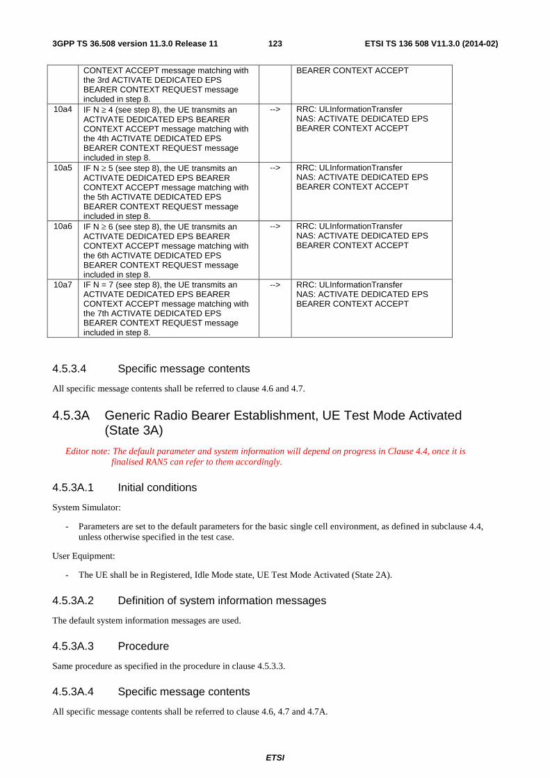
ETSI
ETSI TS 136 508 V11.3.0 (2014-02)1233GPP TS 36.508 version 11.3.0 Release 11
CONTEXT ACCEPT message matching with the 3rd ACTIVATE DEDICATED EPS BEARER CONTEXT REQUEST message included in step 8.
BEARER CONTEXT ACCEPT
10a4 IF N ≥ 4 (see step 8), the UE transmits an ACTIVATE DEDICATED EPS BEARER CONTEXT ACCEPT message matching with the 4th ACTIVATE DEDICATED EPS BEARER CONTEXT REQUEST message included in step 8.
--> RRC: ULInformationTransfer NAS: ACTIVATE DEDICATED EPS BEARER CONTEXT ACCEPT
10a5 IF N ≥ 5 (see step 8), the UE transmits an ACTIVATE DEDICATED EPS BEARER CONTEXT ACCEPT message matching with the 5th ACTIVATE DEDICATED EPS BEARER CONTEXT REQUEST message included in step 8.
--> RRC: ULInformationTransfer NAS: ACTIVATE DEDICATED EPS BEARER CONTEXT ACCEPT
10a6 IF N ≥ 6 (see step 8), the UE transmits an ACTIVATE DEDICATED EPS BEARER CONTEXT ACCEPT message matching with the 6th ACTIVATE DEDICATED EPS BEARER CONTEXT REQUEST message included in step 8.
--> RRC: ULInformationTransfer NAS: ACTIVATE DEDICATED EPS BEARER CONTEXT ACCEPT
10a7 IF N = 7 (see step 8), the UE transmits an ACTIVATE DEDICATED EPS BEARER CONTEXT ACCEPT message matching with the 7th ACTIVATE DEDICATED EPS BEARER CONTEXT REQUEST message included in step 8.
--> RRC: ULInformationTransfer NAS: ACTIVATE DEDICATED EPS BEARER CONTEXT ACCEPT
4.5.3.4 Specific message contents
All specific message contents shall be referred to clause 4.6 and 4.7.
4.5.3A Generic Radio Bearer Establishment, UE Test Mode Activated (State 3A)
Editor note: The default parameter and system information will depend on progress in Clause 4.4, once it is finalised RAN5 can refer to them accordingly.
4.5.3A.1 Initial conditions
System Simulator:
- Parameters are set to the default parameters for the basic single cell environment, as defined in subclause 4.4, unless otherwise specified in the test case.
User Equipment:
- The UE shall be in Registered, Idle Mode state, UE Test Mode Activated (State 2A).
4.5.3A.2 Definition of system information messages
The default system information messages are used.
4.5.3A.3 Procedure
Same procedure as specified in the procedure in clause 4.5.3.3.
4.5.3A.4 Specific message contents
All specific message contents shall be referred to clause 4.6, 4.7 and 4.7A.

ETSI
ETSI TS 136 508 V11.3.0 (2014-02)1243GPP TS 36.508 version 11.3.0 Release 11
4.5.3B Generic Radio Bearer Establishment, pre-registered on HRPD (State 3B)
Editor note: The default parameter and system information will depend on progress in Clause 4.4, once it is finalised RAN5 can refer to them accordingly.
4.5.3B.1 Initial conditions
System Simulator:
- Parameters are set to the default parameters for the basic single cell environment, as defined in subclause 4.4, unless otherwise specified in the test case.
User Equipment:
- The UE shall be in Registered, Idle Mode state, pre-registered on HRPD (State 2B).
4.5.3B.2 Definition of system information messages
The default system information messages are used.
4.5.3B.3 Procedure
Same procedure as specified in the procedure in clause 4.5.3.3.
4.5.3B.4 Specific message contents
All specific message contents shall be referred to clause 4.6, 4.7 and 4.7A.
4.5.3C Generic Radio Bearer Establishment, pre-registered on 1xRTT (State 3C)
Editor note: The default parameter and system information will depend on progress in Clause 4.4, once it is finalised RAN5 can refer to them accordingly.
4.5.3C.1 Initial conditions
System Simulator:
- Parameters are set to the default parameters for the basic single cell environment, as defined in subclause 4.4, unless otherwise specified in the test case.
User Equipment:
- The UE shall be in Registered, Idle Mode state, pre-registered on 1xRTT (State 2C).
4.5.3C.2 Definition of system information messages
The default system information messages are used.
4.5.3C.3 Procedure
Same procedure as specified in the procedure in clause 4.5.3.3.
4.5.3C.4 Specific message contents
All specific message contents shall be referred to clause 4.6, 4.7 and 4.7A.

ETSI
ETSI TS 136 508 V11.3.0 (2014-02)1253GPP TS 36.508 version 11.3.0 Release 11
4.5.4 Loopback Activation (State 4)
4.5.4.1 Initial conditions
System Simulator:
- Parameters are set to the default parameters for the basic single cell environment, as defined in subclause 4.4, unless otherwise specified in the test case.
User Equipment:
- The UE shall be in Generic RB Establishment state, UE Test Mode Activated (State 3A).
4.5.4.2 Definition of system information messages
The default system information messages are used.
4.5.4.3 Procedure
Table 4.5: 4.3-1: Loopback activation procedure (state 3A to state 4)
Step Procedure Direction Message Sequence UE - SS Message
1 The SS transmits a CLOSE UE TEST LOOP message to enter the UE test loop mode.
<-- RRC: DLInformationTransfer TC: CLOSE UE TEST LOOP
2 The UE transmits a CLOSE UE TEST LOOP COMPLETE message to confirm that loopback entities for the radio bearer(s) have been created and loop back is activated (State 4).
--> RRC: ULInformationTransfer TC: CLOSE UE TEST LOOP COMPLETE
4.5.4.4 Specific message contents
All specific message contents shall be referred to clause 4.6 and 4.7A.
4.5.5 HRPD registration (State H2)
Editor's note: The default parameter and system information will depend on progress in Clause 4.4, once it is finalised RAN5 can refer to them accordingly.
4.5.5.1 Initial conditions
System Simulator:
- Cell 1 and Cell 15.
- Cell 1 has a lower reselection priority than Cell 15.
- Cell 15 is transmitting default overhead messages.
User Equipment:
- The Test USIM shall be inserted (State 1).
4.5.5.2 Definition of system information messages
The default overhead messages as specified in clause 4.4 are used.

ETSI
ETSI TS 136 508 V11.3.0 (2014-02)1263GPP TS 36.508 version 11.3.0 Release 11
4.5.5.3 Procedure
Editor note: procedure needs to be specified.
4.5.5.4 Specific message contents
Editor's note: message contents need to be specified where necessary.
4.5.5A HRPD registration, pre-registration on E-UTRAN (State H2A)
Editor's note: The default parameter and system information will depend on progress in Clause 4.4, once it is finalised RAN5 can refer to them accordingly.
4.5.5A.1 Initial conditions
System Simulator:
- Cell 1 and Cell 15.
- Cell 1 has a lower reselection priority than Cell 15.
- Cell 15 is transmitting default overhead messages.
User Equipment:
- The Test USIM shall be inserted (State 1).
4.5.5A.2 Definition of system information messages
The default overhead messages as specified in clause 4.4 are used.
4.5.5A.3 Procedure
Editor's note: procedure needs to be specified.
4.5.5A.4 Specific message contents
Editor's note: message contents need to be specified where necessary.
4.5.6 HRPD session establishment (State H3)
Editor's note: The default parameter and system information will depend on progress in Clause 4.4, once it is finalised RAN5 can refer to them accordingly.
4.5.6.1 Initial conditions
System Simulator:
- Parameters are set to the default parameters for the basic single cell environment, as defined in subclause 4.4, unless otherwise specified in the test case.
User Equipment:
- The UE shall be in HRPD Registered, Dormant Mode state (State H2).
4.5.6.2 Definition of system information messages
The default overhead messages as specified in clause 4.4 are used.

ETSI
ETSI TS 136 508 V11.3.0 (2014-02)1273GPP TS 36.508 version 11.3.0 Release 11
4.5.6.3 Procedure
Editor's note: procedure needs to be specified.
4.5.6.4 Specific message contents
Editor's note: message contents need to be specified where necessary.
4.5.6A HRPD session establishment, pre-registered on E-UTRAN (State H3A)
Editor's note: The default parameter and system information will depend on progress in Clause 4.4, once it is finalised RAN5 can refer to them accordingly.
4.5.6A.1 Initial conditions
System Simulator:
- Parameters are set to the default parameters for the basic single cell environment, as defined in subclause 4.4, unless otherwise specified in the test case.
User Equipment:
- The UE shall be in HRPD Registered, Dormant Mode, pre-registered on E-UTRAN state (State H2A).
4.5.6A.2 Definition of system information messages
The default overhead messages as specified in clause 4.4 are used.
4.5.6A.3 Procedure
Same procedure as specified in the procedure in clause 4.5.6.3
4.5.6A.4 Specific message contents
Editor's note: message contents need to be specified where necessary.
4.5A Other generic procedures
4.5A.1 Procedure for IP address allocation in the U-plane
The purpose of this procedure is to allow the successful completion of IP address allocation if it is initiated by the UE therefore the result from the execution of the Procedure for IP address allocation in the U-plane shall not lead to assignment of a verdict.
Depending on the UE configuration there may be unpredictable delay in the start of the procedure. A guarding time of 1.2 sec is suggested within which the procedure is expected to start. If the timer expires then the test procedure, from which the Procedure for IP address allocation in the U-plane is called, shall advance to the next specified step.
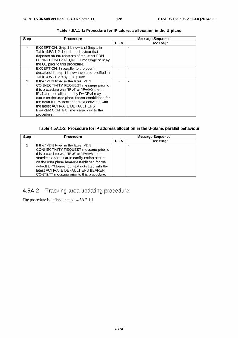
ETSI
ETSI TS 136 508 V11.3.0 (2014-02)1283GPP TS 36.508 version 11.3.0 Release 11
Table 4.5A.1-1: Procedure for IP address allocation in the U-plane
Step Procedure Message Sequence U - S Message - EXCEPTION: Step 1 below and Step 1 in
Table 4.5A.1-2 describe behaviour that depends on the contents of the latest PDN CONNECTIVITY REQUEST message sent by the UE prior to this procedure.
- -
- EXCEPTION: In parallel to the event described in step 1 below the step specified in Table 4.5A.1-2 may take place.
- -
1 If the "PDN type" in the latest PDN CONNECTIVITY REQUEST message prior to this procedure was 'IPv4' or 'IPv4v6' then, IPv4 address allocation by DHCPv4 may occur on the user plane bearer established for the default EPS bearer context activated with the latest ACTIVATE DEFAULT EPS BEARER CONTEXT message prior to this procedure.
- -
Table 4.5A.1-2: Procedure for IP address allocation in the U-plane, parallel behaviour
Step Procedure Message Sequence U - S Message
1 If the "PDN type" in the latest PDN CONNECTIVITY REQUEST message prior to this procedure was 'IPv6' or 'IPv4v6' then stateless address auto configuration occurs on the user plane bearer established for the default EPS bearer context activated with the latest ACTIVATE DEFAULT EPS BEARER CONTEXT message prior to this procedure.
- -
4.5A.2 Tracking area updating procedure
The procedure is defined in table 4.5A.2.1-1.
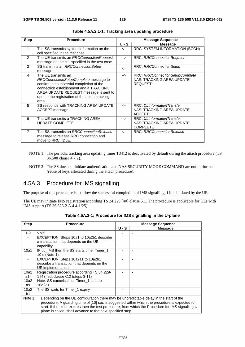
ETSI
ETSI TS 136 508 V11.3.0 (2014-02)1293GPP TS 36.508 version 11.3.0 Release 11
Table 4.5A.2.1-1: Tracking area updating procedure
Step Procedure Message Sequence U - S Message
1 The SS transmits system information on the cell specified in the test case.
<-- RRC: SYSTEM INFORMATION (BCCH)
2 The UE transmits an RRCConnectionRequest message on the cell specified in the test case.
--> RRC: RRCConnectionRequest
3 SS transmits an RRCConnectionSetup message. <--
RRC: RRCConnectionSetup
4 The UE transmits an RRCConnectionSetupComplete message to confirm the successful completion of the connection establishment and a TRACKING AREA UPDATE REQUEST message is sent to update the registration of the actual tracking area.
--> RRC: RRCConnectionSetupComplete NAS: TRACKING AREA UPDATE REQUEST
5 SS responds with TRACKING AREA UPDATE ACCEPT message.
<-- RRC: DLInformationTransfer NAS: TRACKING AREA UPDATE ACCEPT
6 The UE transmits a TRACKING AREA UPDATE COMPLETE
--> RRC: ULInformationTransfer NAS: TRACKING AREA UPDATE COMPLETE
7 The SS transmits an RRCConnectionRelease message to release RRC connection and move to RRC_IDLE.
<-- RRC: RRCConnectionRelease
NOTE 1: The periodic tracking area updating timer T3412 is deactivated by default during the attach procedure (TS 36.508 clause 4.7.2).
NOTE 2: The SS does not initiate authentication and NAS SECURITY MODE COMMAND are not performed (reuse of keys allocated during the attach procedure).
4.5A.3 Procedure for IMS signalling
The purpose of this procedure is to allow the successful completion of IMS signalling if it is initiated by the UE.
The UE may initiate IMS registration according TS 24.229 [40] clause 5.1. The procedure is applicable for UEs with IMS support (TS 36.523-2 A.4.4-1/25).
Table 4.5A.3-1: Procedure for IMS signalling in the U-plane
Step Procedure Message Sequence U - S Message
1-9 Void - - - EXCEPTION: Steps 10a1 to 10a2b1 describe
a transaction that depends on the UE capability
10a1 IF pc_IMS then the SS starts timer Timer_1 = 10 s (Note 1)
- -
- EXCEPTION: Steps 10a2a1 to 10a2b1 describe a transaction that depends on the UE implementation
- -
10a2a1-
10a2a9
Registration procedure according TS 34.229-1 [43] subclause C.2 (steps 3-11) Note: SS cancels timer Timer_1 at step 10a2a1.
- -
10a2b1
The SS waits for Timer_1 expiry - -
Note 1: Depending on the UE configuration there may be unpredictable delay in the start of the procedure. A guarding time of [10] sec is suggested within which the procedure is expected to start. If the timer expires then the test procedure, from which the Procedure for IMS signalling U-plane is called, shall advance to the next specified step

ETSI
ETSI TS 136 508 V11.3.0 (2014-02)1303GPP TS 36.508 version 11.3.0 Release 11
4.5A.4 Generic Test Procedure for IMS Emergency call establishment in EUTRA: Normal Service
4.5A.4.1 Initial conditions
System Simulator:
- Parameters are set to the default parameters for the basic single cell environment, as defined in subclause 4.4, unless otherwise specified in the test case.
User Equipment:
- The UE shall be in Registered, Idle Mode state (State 2).
4.5A.4.2 Definition of system information messages
The default system information messages are used.
4.5A.4.3 Procedure
The establishment of IMS emergency call is assumed to always be mobile originated.

ETSI
ETSI TS 136 508 V11.3.0 (2014-02)1313GPP TS 36.508 version 11.3.0 Release 11
Table 4.5A.4.3-1: EUTRA/EPS signalling for IMS Emergency Call
St Procedure Message Sequence U - S Message
1 Make the UE attempt an IMS emergency call - - 2 The UE transmits an RRCConnectionRequest message
with ' establishmentCause' set to 'emergency'. --> RRCConnectionRequest
3 SS transmit an RRCConnectionSetup message. <-- RRC: RRCConnectionSetup 4 The UE transmits an RRCConnectionSetupComplete
message to confirm the successful completion of the connection establishment and to initiate the session management procedure by including the SERVICE REQUEST message.
--> RRC: RRCConnectionSetupComplete NAS: SERVICE REQUEST
5 The SS transmits a SecurityModeCommand message to activate AS security.
<-- RRC: SecurityModeCommand
6 The UE transmits a SecurityModeComplete message and establishes the initial security configuration.
--> RRC: SecurityModeComplete
7 The SS configures a new data radio bearer, associated with the default EPS bearer context. The RRCConnectionReconfiguration message is using condition SRB2-DRB(1, 0). The DRB associated with default EPS bearer context obtained during the attach procedure is established
<-- RRC: RRCConnectionReconfiguration
8 The UE transmits an RRCConnectionReconfigurationComplete message to confirm the establishment of the new data radio bearer, associated with the default EPS bearer context.
--> RRC: RRCConnectionReconfigurationComplete
9 The UE transmits a PDN CONNECTIVITY REQUEST message to request an additional PDN, with 'Request type' set to 'emergency ('0100'B )'.
--> PDN CONNECTIVITY REQUEST
10 The SS configures a new data radio bearer, associated with the default EPS bearer context. RRCConnectionReconfiguration message contains the ACTIVATE DEFAULT EPS BEARER CONTEXT REQUEST message. EPS bearer context #2 (QCI 5) according to table 6.6.1-1: Reference default EPS bearer context is used. Note: The APN is set to the test APN defined for emergency bearer services.
<-- RRC: RRCConnectionReconfiguration NAS: ACTIVATE DEFAULT EPS BEARER CONTEXT REQUEST
- EXCEPTION: In parallel to the events described in steps 11 to 15 below, the behaviour in table 4.5A.4.3-2 occurs. (Optional IP address allocation followed by IMS emergency registration and IMS emergency speech call establishment)
- -
11 The UE transmits an RRCConnectionReconfigurationComplete message to confirm the establishment of the new data radio bearer, associated with the default EPS bearer for emergency call.
--> RRC: RRCConnectionReconfigurationComplete
12 The UE transmits an ACTIVATE DEFAULT EPS BEARER CONTEXT ACCEPT message.
--> RRC: ULInformationTransfer NAS:ACTIVATE DEFAULT EPS BEARER CONTEXT ACCEPT
13 The SS configures a new RLC-UM data radio bearer, associated with the dedicated EPS bearer context. RRCConnectionReconfiguration message contains the ACTIVATE DEDICATED EPS BEARER CONTEXT REQUEST message. EPS bearer context #4 (QCI 1) according to table 6.6.2-1: Reference dedicated EPS bearer contexts is used. Note: the same PDN address is applicable because the linked EPS bearer ID refers to the default EBC allocated in step 10
<-- RRC: RRCConnectionReconfiguration NAS: ACTIVATE DEDICATED EPS BEARER CONTEXT REQUEST
14 The UE transmits an RRCConnectionReconfigurationComplete message to confirm the establishment of the new data radio bearer, associated with the default EPS bearer for emergency IMS signalling.
--> RRC: RRCConnectionReconfigurationComplete

ETSI
ETSI TS 136 508 V11.3.0 (2014-02)1323GPP TS 36.508 version 11.3.0 Release 11
15 The UE transmits an ACTIVATE DEDICATED EPS BEARER CONTEXT ACCEPT message.
--> RRC: ULInformationTransfer NAS:ACTIVATE DEDICATED EPS BEARER CONTEXT ACCEPT
Table 4.5A.4.3-2: Parallel behaviour
St Procedure Message Sequence U - S Message - EXCEPTION: Step 1 describes behaviour that
depends on the UE behaviour. - -
1 If initiated by the UE the generic procedure for IP address allocation in the U-plane specified in TS 36.508 subclause 4.5A.1 takes place performing IP address allocation in the U-plane.
- -
2-5 Steps 1-4 expected sequence defined in annex C.20 of TS 34.229-1 [35]. Emergency registration procedure is performed.
- -
6-10
Steps 1-5 defined in annex C.22 of TS 34.229-1 [35]. IMS Emergency call for EPS is established.
- -
4.5A.4.4 Specific message contents
All specific message contents shall be referred to clause 4.6 and 4.7 with the exceptions below.
Table 4.5A.4.4-1: Message ACTIVATE DEFAULT EPS BEARER CONTEXT REQUEST (step 10, Table 4.5A.4.3-1)
Derivation path: Table 4.7.3-6 and table 4.6.1-8 with condition AM-DRB-ADD(2) Information Element Value/Remark Comment Condition
Access point name APN-1 SS uses the test APN defined for emergency bearer services
EPS QoS According to reference default EPS bearer context #2 – in table 6.6.1-1
SS defines an additional dedicated EPS QoS
Table 4.5A.4.4-3: Message ACTIVATE DEDICATED EPS BEARER CONTEXT REQUEST (step 13, Table 4.5A.4.3-1)
Derivation path: Table 4.7.3-3 and table 4.6.1-8 with condition UM-DRB-ADD(3) Information Element Value/Remark Comment Condition
Linked EPS bearer identity Default EBId-2 (same value like in table 4.5A.4.4-1)
EPS QoS According to reference dedicated EPS bearer context #1 - in table 6.6.2-1
SS defines an additional dedicated EPS QoS
TFT According to reference dedicated EPS bearer context #1 - in table 6.6.2-1

ETSI
ETSI TS 136 508 V11.3.0 (2014-02)1333GPP TS 36.508 version 11.3.0 Release 11
4.5A.5 Generic Test Procedure for IMS Emergency call establishment in EUTRA: Limited Service
4.5A.5.1 Initial conditions
System Simulator:
- Parameters are set to the default parameters for the basic single cell environment, as defined in subclause 4.4, unless otherwise specified in the test case.
User Equipment:
- The UE is switched on and camped on the cell in EMM-DEREGISTERED.LIMITED-SERVICE state.
4.5A.5.2 Definition of system information messages
The default system information messages are used.
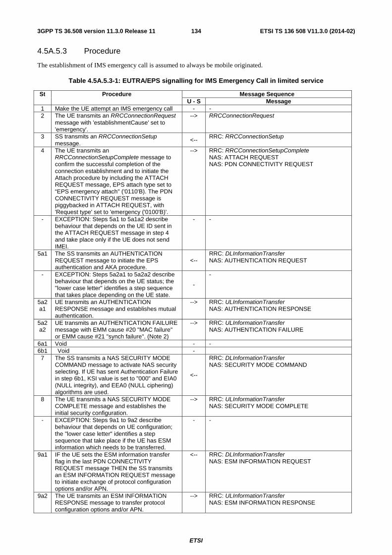
ETSI
ETSI TS 136 508 V11.3.0 (2014-02)1343GPP TS 36.508 version 11.3.0 Release 11
4.5A.5.3 Procedure
The establishment of IMS emergency call is assumed to always be mobile originated.
Table 4.5A.5.3-1: EUTRA/EPS signalling for IMS Emergency Call in limited service
St Procedure Message Sequence U - S Message
1 Make the UE attempt an IMS emergency call - - 2 The UE transmits an RRCConnectionRequest
message with 'establishmentCause' set to 'emergency'.
--> RRCConnectionRequest
3 SS transmits an RRCConnectionSetup message.
<-- RRC: RRCConnectionSetup
4 The UE transmits an RRCConnectionSetupComplete message to confirm the successful completion of the connection establishment and to initiate the Attach procedure by including the ATTACH REQUEST message, EPS attach type set to “EPS emergency attach" ('0110'B). The PDN CONNECTIVITY REQUEST message is piggybacked in ATTACH REQUEST, with 'Request type' set to 'emergency ('0100'B)'.
--> RRC: RRCConnectionSetupComplete NAS: ATTACH REQUEST NAS: PDN CONNECTIVITY REQUEST
- EXCEPTION: Steps 5a1 to 5a1a2 describe behaviour that depends on the UE ID sent in the ATTACH REQUEST message in step 4 and take place only if the UE does not send IMEI.
- -
5a1 The SS transmits an AUTHENTICATION REQUEST message to initiate the EPS authentication and AKA procedure.
<-- RRC: DLInformationTransfer NAS: AUTHENTICATION REQUEST
- EXCEPTION: Steps 5a2a1 to 5a2a2 describe behaviour that depends on the UE status; the "lower case letter" identifies a step sequence that takes place depending on the UE state.
-
-
5a2a1
UE transmits an AUTHENTICATION RESPONSE message and establishes mutual authentication.
--> RRC: ULInformationTransfer NAS: AUTHENTICATION RESPONSE
5a2a2
UE transmits an AUTHENTICATION FAILURE message with EMM cause #20 "MAC failure" or EMM cause #21 "synch failure". (Note 2)
--> RRC: ULInformationTransfer NAS: AUTHENTICATION FAILURE
6a1 Void - - 6b1 Void -
7 The SS transmits a NAS SECURITY MODE COMMAND message to activate NAS security selecting. If UE has sent Authentication Failure in step 6b1, KSI value is set to "000" and EIA0 (NULL integrity), and EEA0 (NULL ciphering) algorithms are used.
<--
RRC: DLInformationTransfer NAS: SECURITY MODE COMMAND
8 The UE transmits a NAS SECURITY MODE COMPLETE message and establishes the initial security configuration.
--> RRC: ULInformationTransfer NAS: SECURITY MODE COMPLETE
- EXCEPTION: Steps 9a1 to 9a2 describe behaviour that depends on UE configuration; the "lower case letter" identifies a step sequence that take place if the UE has ESM information which needs to be transferred.
- -
9a1 IF the UE sets the ESM information transfer flag in the last PDN CONNECTIVITY REQUEST message THEN the SS transmits an ESM INFORMATION REQUEST message to initiate exchange of protocol configuration options and/or APN.
<-- RRC: DLInformationTransfer NAS: ESM INFORMATION REQUEST
9a2 The UE transmits an ESM INFORMATION RESPONSE message to transfer protocol configuration options and/or APN.
--> RRC: ULInformationTransfer NAS: ESM INFORMATION RESPONSE

ETSI
ETSI TS 136 508 V11.3.0 (2014-02)1353GPP TS 36.508 version 11.3.0 Release 11
10 The SS transmits a SecurityModeCommand message to activate AS security. If UE has sent Authentication Failure in step 5a2a2, or authentication was not performed, then, eia0 (NULL integrity), and eea0 (NULL ciphering) algorithms are used.
<-- RRC: SecurityModeCommand
11 The UE transmits a SecurityModeComplete message and establishes the initial security configuration.
--> RRC: SecurityModeComplete
12 The SS transmits a UECapabilityEnquiry message to initiate the UE radio access capability transfer procedure.
<-- RRC: UECapabilityEnquiry
13 The UE transmits a UECapabilityInformation message to transfer UE radio access capability.
--> RRC: UECapabilityInformation
14 The SS transmits an RRCConnectionReconfiguration message to establish the default bearer with condition SRB2-DRB(1, 0). The DRB associated with default EPS bearer context #2 (QCI 5) according to table 6.6.1-1: Reference default EPS bearer contexts, obtained during the attach procedure, is established. This message includes the ATTACH ACCEPT message with EPS attach result set to “EPS only" ('001'B). The ACTIVATE DEFAULT EPS BEARER CONTEXT REQUEST message is piggybacked in ATTACH ACCEPT. Note: The APN is set to the test APN defined for emergency bearer services
<-- RRC: RRCConnectionReconfiguration NAS: ATTACH ACCEPT NAS: ACTIVATE DEFAULT EPS BEARER CONTEXT REQUEST
- EXCEPTION: In parallel to the events described in steps 15 to 19 below, the behaviour in table 4.5A.5.3-2 occurs. (Optional IP address allocation followed by IMS emergency speech call establishment)
- -
15 The UE transmits an RRCConnectionReconfigurationComplete message to confirm the establishment of default bearer.
--> RRC: RRCConnectionReconfigurationComplete
16 This message includes the ATTACH COMPLETE message. The ACTIVATE DEFAULT EPS BEARER CONTEXT ACCEPT message is piggybacked in ATTACH COMPLETE.
--> RRC: ULInformationTransfer NAS: ATTACH COMPLETE NAS: ACTIVATE DEFAULT EPS BEARER CONTEXT ACCEPT
17 The SS configures a new RLC-UM data radio bearer, associated with the dedicated EPS bearer context. RRCConnectionReconfiguration message contains the ACTIVATE DEDICATED EPS BEARER CONTEXT REQUEST message. EPS bearer context #4 (QCI 1) according to table 6.6.2-1: Reference dedicated EPS bearer contexts is used. Note: the same PDN address is applicable because the linked EPS bearer ID refers to the default EBC allocated in step 10
<-- RRC: RRCConnectionReconfiguration NAS: ACTIVATE DEDICATED EPS BEARER CONTEXT REQUEST
18 The UE transmits an RRCConnectionReconfigurationComplete message to confirm the establishment of the new data radio bearer, associated with the default EPS bearer for emergency IMS signalling.
--> RRC: RRCConnectionReconfigurationComplete
19 The UE transmits an ACTIVATE DEDICATED EPS BEARER CONTEXT ACCEPT message.
--> RRC: ULInformationTransfer NAS:ACTIVATE DEDICATED EPS BEARER CONTEXT ACCEPT
Note 1: Void

ETSI
ETSI TS 136 508 V11.3.0 (2014-02)1363GPP TS 36.508 version 11.3.0 Release 11
Note 2: EMM cause #26 "non-EPS authentication unacceptable" is not expected to happen as SS will not set the "separation bit" in the AMF field of AUTN as 0
Table 4.5A.5.3-2: Parallel behaviour
St Procedure Message Sequence U - S Message - EXCEPTION: Step 1 describes behaviour that
depends on the UE behaviour. - -
1 If initiated by the UE the generic procedure for IP address allocation in the U-plane specified in TS 36.508 subclause 4.5A.1 takes place performing IP address allocation in the U-plane.
- -
2-6 Steps 1-5 defined in annex C.22 of TS 34.229-1 [35]. IMS Emergency call for EPS is established.
- -
4.5A.5.4 Specific message contents
All specific message contents shall be referred to clause 4.6 and 4.7 with the exceptions below.
Table 4.5A.5.4-1: SECURITY MODE COMMAND (step 7, Table 4.5A.5.3-1)
Derivation Path: Table 4.7.2-19 Information Element Value/remark Comment Condition
Type of integrity protection algorithm Set according to PIXIT parameter for default integrity protection algorithm
NOT NullAlgorithmUsed
EIA0 NullAlgorithmUsed
Type of ciphering algorithm Set according to PIXIT parameter for default ciphering algorithm
NOT NullAlgorithmUsed
EEA0 NullAlgorithmUsed
NAS key set identifier NAS key set identifier The valid NAS key set
identifier. NOT
NullAlgorithmUsed
'000'B NullAlgorithmUsed
TSC '0'B native security context (for KSIASME)
Spare half octet '0000'B
Condition Explanation NullAlgorithmUsed UE has sent Authentication Failure in step 5a2a2, or authentication was not performed,
then Table 4.5A.5.3-1: EUTRA/EPS signalling for IMS Emergency Call in limited service.

ETSI
ETSI TS 136 508 V11.3.0 (2014-02)1373GPP TS 36.508 version 11.3.0 Release 11
Table 4.5A.5.4-2: SecurityModeCommand (step 10, Table 4.5A.5.3-1)
Derivation Path: Table 4.6.1-19 Information Element Value/remark Comment Condition
SecurityModeCommand ::= SEQUENCE { rrc-TransactionIdentifier RRC-
TransactionIdentifier-DL
criticalExtensions CHOICE { c1 CHOICE{ securityModeCommand-r8 SEQUENCE { securityConfigSMC SecurityConfigSMC-
LimitedService Table 4.5A.5.4-3
nonCriticalExtension SEQUENCE {} Not present } } } }
Table 4.5A.5.4-3: SecurityConfigSMC-LimitedService (Table 4.5A.5.4-2)
Derivation Path: Table 4.6.4-2 Information Element Value/remark Comment Condition
SecurityConfigSMC- LimitedService ::= SEQUENCE { securityAlgorithmConfig SEQUENCE { cipheringAlgorithm Set according to PIXIT
parameter for default ciphering algorithm
NOT NullAlgorithmUsed
eea0 NullAlgorithmUsed
integrityProtAlgorithm Set according to PIXIT parameter for default integrity protection algorithm
NOT NullAlgorithmUsed
eia0 NullAlgorithmUsed
}
Condition Explanation NullAlgorithmUsed UE has sent Authentication Failure in step 5a2a2, or authentication was not performed,
then Table 4.5A.5.3-1: EUTRA/EPS signalling for IMS Emergency Call in limited service.
Table 4.5A.5.4-4: Message ACTIVATE DEDICATED EPS BEARER CONTEXT REQUEST (step 17, Table 4.5A.5.3-1)
Derivation path: Table 4.7.3-3 and table 4.6.1-8 with condition UM-DRB-ADD(3) Information Element Value/Remark Comment Condition
Linked EPS bearer identity Default EBId-2 (same value as in table 4.5A.5.4-4)
EPS QoS See Reference dedicated EPS bearer context #4 in table 6.6.2-1
TFT See Reference dedicated EPS bearer context #4 in table 6.6.2-1

ETSI
ETSI TS 136 508 V11.3.0 (2014-02)1383GPP TS 36.508 version 11.3.0 Release 11
Table 4.5A.5.4-5: Message ACTIVATE DEDICATED EPS BEARER CONTEXT REQUEST (step 14, Table 4.5A.5.3-1)
Derivation path: Table 4.7.3-6 and table 4.6.1-8 with condition AM-DRB-ADD(2) Information Element Value/Remark Comment Condition
Access point name APN-1 SS uses the test APN defined for emergency bearer services
EPS QoS According to reference default EPS bearer context #2 – in table 6.6.1-1
SS defines an additional dedicated EPS bearer
4.5A.6 Generic Test Procedure for IMS MO speech call establishment in E-UTRA
4.5A.6.1 Initial conditions
System Simulator:
- Parameters are set to the default parameters for the basic single cell environment, as defined in subclause 4.4, unless otherwise specified in the test case.
User Equipment:
- The UE shall be in Registered, Idle Mode state (State 2).
4.5A.6.2 Definition of system information messages
The default system information messages are used.

ETSI
ETSI TS 136 508 V11.3.0 (2014-02)1393GPP TS 36.508 version 11.3.0 Release 11
4.5A.6.3 Procedure
Table 4.5A.6.3-1: EUTRA/EPS signalling for IMS MO speech call
St Procedure Message Sequence U - S Message
1 Make the UE attempt an IMS speech call - - 2 The UE transmits an RRCConnectionRequest message
with ' establishmentCause' set to ' mo-Data '. --> RRCConnectionRequest
3 SS transmit an RRCConnectionSetup message. <-- RRC: RRCConnectionSetup 4 The UE transmits an RRCConnectionSetupComplete
message to confirm the successful completion of the connection establishment and to initiate the session management procedure by including the SERVICE REQUEST message.
--> RRC: RRCConnectionSetupComplete NAS: SERVICE REQUEST
5 The SS transmits a SecurityModeCommand message to activate AS security.
<-- RRC: SecurityModeCommand
6 The UE transmits a SecurityModeComplete message and establishes the initial security configuration.
--> RRC: SecurityModeComplete
7 The SS configures a new data radio bearer, associated with the default EPS bearer context. The RRCConnectionReconfiguration message is using condition SRB2-DRB(1, 0). The DRB associated with default EPS bearer context obtained during the attach procedure is established
<-- RRC: RRCConnectionReconfiguration
- EXCEPTION: In parallel to the events described in steps 8 below, the behaviour in table 4.5A.6.3-2 occurs. (IMS MTSI MO speech call establishment)
- -
8 The UE transmits an RRCConnectionReconfigurationComplete message to confirm the establishment of the new data radio bearer, associated with the default EPS bearer context.
--> RRC: RRCConnectionReconfigurationComplete
9-11 Steps 3-4 expected sequence defined in annex C.21 of TS 34.229-1 [35]. MTSI MO speech call for EPS.
- -
12 The SS configures a new RLC-UM data radio bearer with condition DRB (0,1), associated with the dedicated EPS bearer context. RRCConnectionReconfiguration message contains the ACTIVATE DEDICATED EPS BEARER CONTEXT REQUEST message. EPS bearer context #4 (QCI 1) according to table 6.6.2-1: Reference dedicated EPS bearer contexts.
<-- RRC: RRCConnectionReconfiguration NAS: ACTIVATE DEDICATED EPS BEARER CONTEXT REQUEST
- EXCEPTION: In parallel to the events described in steps 13-14 below, the behaviour in table 4.5A.6.3-3 occurs. (IMS MTSI MO speech call establishment)
- -
13 The UE transmits an RRCConnectionReconfigurationComplete message to confirm the establishment of the new data radio bearer, associated with the dedicated EPS bearer.
--> RRC: RRCConnectionReconfigurationComplete
14 The UE transmits an ACTIVATE DEDICATED EPS BEARER CONTEXT ACCEPT message.
--> RRC: ULInformationTransfer NAS:ACTIVATE DEDICATED EPS BEARER CONTEXT ACCEPT
Table 4.5A.6.3-2: Parallel behaviour
St Procedure Message Sequence U - S Message
1 Step 2 expected sequence defined in annex C.21 of TS 34.229-1 [35]. UE sends INVITE.
- -
ETSI
ETSI TS 136 508 V11.3.0 (2014-02)1403GPP TS 36.508 version 11.3.0 Release 11
Table 4.5A.6.3-3: Parallel behaviour
St Procedure Message Sequence U - S Message
1-8 Steps 5-13 expected sequence defined in annex C.21 of TS 34.229-1 [35]. MTSI MO speech call for EPS.
- -
4.5A.6.4 Specific message contents
All specific message contents shall be referred to clause 4.6 and 4.7.
4.5A.7 Generic Test Procedure for IMS MT Speech call establishment in E-UTRA
4.5A.7.1 Initial conditions
System Simulator:
- Parameters are set to the default parameters for the basic single cell environment, as defined in subclause 4.4, unless otherwise specified in the test case.
User Equipment:
- The UE shall be in Registered, Idle Mode state (State 2).
4.5A.7.2 Definition of system information messages
The default system information messages are used.

ETSI
ETSI TS 136 508 V11.3.0 (2014-02)1413GPP TS 36.508 version 11.3.0 Release 11
4.5A.7.3 Procedure
Table 4.5A.7.3-1: EUTRA/EPS signalling for IMS MT speech call
St Procedure Message Sequence U - S Message
1 SS sends a Paging message to the UE on the appropriate paging block, and including the UE identity in one entry of the IE pagingRecordLists.
<-- RRC: Paging (PCCH)
2 The UE transmits an RRCConnectionRequest message with ' establishmentCause' set to 'mt-Access'.
--> RRCConnectionRequest
3 SS transmit an RRCConnectionSetup message. <-- RRC: RRCConnectionSetup 4 The UE transmits an RRCConnectionSetupComplete
message to confirm the successful completion of the connection establishment and to initiate the session management procedure by including the SERVICE REQUEST message.
--> RRC: RRCConnectionSetupComplete NAS: SERVICE REQUEST
5 The SS transmits a SecurityModeCommand message to activate AS security.
<-- RRC: SecurityModeCommand
6 The UE transmits a SecurityModeComplete message and establishes the initial security configuration.
--> RRC: SecurityModeComplete
7 The SS configures a new data radio bearer, associated with the default EPS bearer context. The RRCConnectionReconfiguration message is using condition SRB2-DRB(1, 0). The DRB associated with default EPS bearer context obtained during the attach procedure is established
<-- RRC: RRCConnectionReconfiguration
8 The UE transmits an RRCConnectionReconfigurationComplete message to confirm the establishment of the new data radio bearer, associated with the default EPS bearer context.
--> RRC: RRCConnectionReconfigurationComplete
9-12 Steps 1-4 expected sequence defined in annex C.11 of TS 34.229-1 [35]. MTSI MT speech call.
- -
13 The SS configures a new RLC-UM data radio bearer with condition DRB (0,1), associated with the dedicated EPS bearer context. RRCConnectionReconfiguration message contains the ACTIVATE DEDICATED EPS BEARER CONTEXT REQUEST message.
<-- RRC: RRCConnectionReconfiguration NAS: ACTIVATE DEDICATED EPS BEARER CONTEXT REQUEST
14 The UE transmits an RRCConnectionReconfigurationComplete message to confirm the establishment of the new data radio bearer, associated with the dedicated EPS bearer.
--> RRC: RRCConnectionReconfigurationComplete
15 The UE transmits an ACTIVATE DEDICATED EPS BEARER CONTEXT ACCEPT message.
--> RRC: ULInformationTransfer NAS:ACTIVATE DEDICATED EPS BEARER CONTEXT ACCEPT
16-22
Steps 5-11 expected sequence defined in annex C.11 of TS 34.229-1 [35]. MTSI MT speech.
- -
23A Step 11A expected sequence defined in annex C.11 of TS 34.229-1 [35]. MTSI MT speech.
- -
23-24
Steps 12-13 expected sequence defined in annex C.11 of TS 34.229-1 [35]. MTSI MT speech.
- -
25-26
Steps 14-15 expected sequence defined in annex C.11 of TS 34.229-1 [35]. MTSI MT speech.
- -
4.5A.7.4 Specific message contents
All specific message contents shall be referred to clause 4.6 and 4.7.
ETSI
ETSI TS 136 508 V11.3.0 (2014-02)1423GPP TS 36.508 version 11.3.0 Release 11
4.5A.8 Generic Test Procedure for IMS MO video call establishment in E-UTRA
4.5A.8.1 Initial conditions
System Simulator:
- Parameters are set to the default parameters for the basic single cell environment, as defined in subclause 4.4, unless otherwise specified in the test case.
User Equipment:
- The UE shall be in Registered, Idle Mode state (State 2).
4.5A.8.2 Definition of system information messages
The default system information messages are used.

ETSI
ETSI TS 136 508 V11.3.0 (2014-02)1433GPP TS 36.508 version 11.3.0 Release 11
4.5A.8.3 Procedure
Table 4.5A.8.3-1: EUTRA/EPS signalling for IMS MO video call
St Procedure Message Sequence U - S Message
1 Make the UE attempt an IMS video call - - 2 The UE transmits an RRCConnectionRequest message
with ' establishmentCause' set to ' mo-Data '. --> RRCConnectionRequest
3 SS transmit an RRCConnectionSetup message. <-- RRC: RRCConnectionSetup 4 The UE transmits an RRCConnectionSetupComplete
message to confirm the successful completion of the connection establishment and to initiate the session management procedure by including the SERVICE REQUEST message.
--> RRC: RRCConnectionSetupComplete NAS: SERVICE REQUEST
5 The SS transmits a SecurityModeCommand message to activate AS security.
<-- RRC: SecurityModeCommand
6 The UE transmits a SecurityModeComplete message and establishes the initial security configuration.
--> RRC: SecurityModeComplete
7 The SS configures a new data radio bearer, associated with the default EPS bearer context. The RRCConnectionReconfiguration message is using condition SRB2-DRB(1, 0). The DRB associated with default EPS bearer context obtained during the attach procedure is established
<-- RRC: RRCConnectionReconfiguration
- EXCEPTION: In parallel to the events described in steps 8 below, the behaviour in table 4.5A.8.3-2 occurs. (IMS MTSI MO video call establishment)
- -
8 The UE transmits an RRCConnectionReconfigurationComplete message to confirm the establishment of the new data radio bearer, associated with the default EPS bearer context.
--> RRC: RRCConnectionReconfigurationComplete
9-11 Steps 3-4 expected sequence defined in annex C.25 of TS 34.229-1 [35]. MTSI MO video call for EPS.
- -
12 The SS configures two new RLC-UM data radio bearers with condition DRB (0,2), associated with the dedicated EPS bearer context. RRCConnectionReconfiguration message contains one ACTIVATE DEDICATED EPS BEARER CONTEXT REQUEST message per additional data radio bearer. One EPS bearer context #4 (QCI 1) and one EPS bearer context #3 (QCI 2) according table 6.6.2-1: Reference dedicated EPS bearer contexts.
<-- RRC: RRCConnectionReconfiguration NAS: ACTIVATE DEDICATED EPS BEARER CONTEXT REQUEST ACTIVATE DEDICATED EPS BEARER CONTEXT REQUEST
- EXCEPTION: In parallel to the events described in steps 13-14 below, the behaviour in table 4.5A.8.3-3 occurs. (IMS MTSI MO video call establishment).
- -
13 The UE transmits an RRCConnectionReconfigurationComplete message to confirm the establishment of the new data radio bearer, associated with the dedicated EPS bearer. EPS bearer context #4 (QCI 1) according table to 6.6.2-1: Reference dedicated EPS bearer contexts.
--> RRC: RRCConnectionReconfigurationComplete
14 The UE transmits an ACTIVATE DEDICATED EPS BEARER CONTEXT ACCEPT message for the first bearer.
--> RRC: ULInformationTransfer NAS:ACTIVATE DEDICATED EPS BEARER CONTEXT ACCEPT
15 The UE transmits an ACTIVATE DEDICATED EPS BEARER CONTEXT ACCEPT message for the second bearer.
--> RRC: ULInformationTransfer NAS:ACTIVATE DEDICATED EPS BEARER CONTEXT ACCEPT
Table 4.5A.8.3-2: Parallel behaviour
St Procedure Message Sequence U - S Message
1 Step 2 expected sequence defined in annex C.25 of TS 34.229-1 [35]. UE sends INVITE.
- -
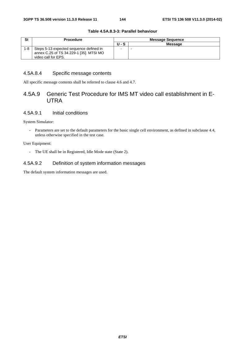
ETSI
ETSI TS 136 508 V11.3.0 (2014-02)1443GPP TS 36.508 version 11.3.0 Release 11
Table 4.5A.8.3-3: Parallel behaviour
St Procedure Message Sequence U - S Message
1-8 Steps 5-13 expected sequence defined in annex C.25 of TS 34.229-1 [35]. MTSI MO video call for EPS.
- -
4.5A.8.4 Specific message contents
All specific message contents shall be referred to clause 4.6 and 4.7.
4.5A.9 Generic Test Procedure for IMS MT video call establishment in E-UTRA
4.5A.9.1 Initial conditions
System Simulator:
- Parameters are set to the default parameters for the basic single cell environment, as defined in subclause 4.4, unless otherwise specified in the test case.
User Equipment:
- The UE shall be in Registered, Idle Mode state (State 2).
4.5A.9.2 Definition of system information messages
The default system information messages are used.
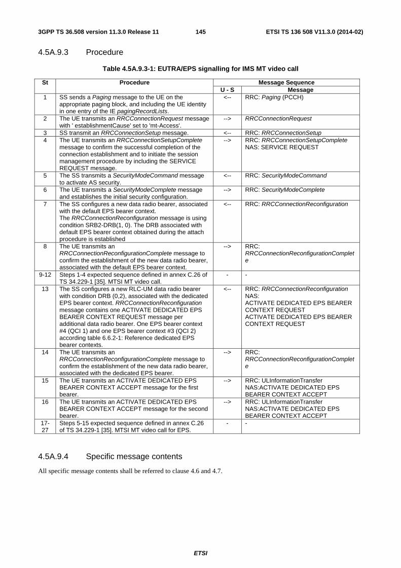
ETSI
ETSI TS 136 508 V11.3.0 (2014-02)1453GPP TS 36.508 version 11.3.0 Release 11
4.5A.9.3 Procedure
Table 4.5A.9.3-1: EUTRA/EPS signalling for IMS MT video call
St Procedure Message Sequence U - S Message
1 SS sends a Paging message to the UE on the appropriate paging block, and including the UE identity in one entry of the IE pagingRecordLists.
<-- RRC: Paging (PCCH)
2 The UE transmits an RRCConnectionRequest message with ' establishmentCause' set to 'mt-Access'.
--> RRCConnectionRequest
3 SS transmit an RRCConnectionSetup message. <-- RRC: RRCConnectionSetup 4 The UE transmits an RRCConnectionSetupComplete
message to confirm the successful completion of the connection establishment and to initiate the session management procedure by including the SERVICE REQUEST message.
--> RRC: RRCConnectionSetupComplete NAS: SERVICE REQUEST
5 The SS transmits a SecurityModeCommand message to activate AS security.
<-- RRC: SecurityModeCommand
6 The UE transmits a SecurityModeComplete message and establishes the initial security configuration.
--> RRC: SecurityModeComplete
7 The SS configures a new data radio bearer, associated with the default EPS bearer context. The RRCConnectionReconfiguration message is using condition SRB2-DRB(1, 0). The DRB associated with default EPS bearer context obtained during the attach procedure is established
<-- RRC: RRCConnectionReconfiguration
8 The UE transmits an RRCConnectionReconfigurationComplete message to confirm the establishment of the new data radio bearer, associated with the default EPS bearer context.
--> RRC: RRCConnectionReconfigurationComplete
9-12 Steps 1-4 expected sequence defined in annex C.26 of TS 34.229-1 [35]. MTSI MT video call.
- -
13 The SS configures a new RLC-UM data radio bearer with condition DRB (0,2), associated with the dedicated EPS bearer context. RRCConnectionReconfiguration message contains one ACTIVATE DEDICATED EPS BEARER CONTEXT REQUEST message per additional data radio bearer. One EPS bearer context #4 (QCI 1) and one EPS bearer context #3 (QCI 2) according table 6.6.2-1: Reference dedicated EPS bearer contexts.
<-- RRC: RRCConnectionReconfiguration NAS: ACTIVATE DEDICATED EPS BEARER CONTEXT REQUEST ACTIVATE DEDICATED EPS BEARER CONTEXT REQUEST
14 The UE transmits an RRCConnectionReconfigurationComplete message to confirm the establishment of the new data radio bearer, associated with the dedicated EPS bearer.
--> RRC: RRCConnectionReconfigurationComplete
15 The UE transmits an ACTIVATE DEDICATED EPS BEARER CONTEXT ACCEPT message for the first bearer.
--> RRC: ULInformationTransfer NAS:ACTIVATE DEDICATED EPS BEARER CONTEXT ACCEPT
16 The UE transmits an ACTIVATE DEDICATED EPS BEARER CONTEXT ACCEPT message for the second bearer.
--> RRC: ULInformationTransfer NAS:ACTIVATE DEDICATED EPS BEARER CONTEXT ACCEPT
17-27
Steps 5-15 expected sequence defined in annex C.26 of TS 34.229-1 [35]. MTSI MT video call for EPS.
- -
4.5A.9.4 Specific message contents
All specific message contents shall be referred to clause 4.6 and 4.7.

ETSI
ETSI TS 136 508 V11.3.0 (2014-02)1463GPP TS 36.508 version 11.3.0 Release 11
4.5A.10 Generic Test Procedure for IMS MO speech and aSRVCC in E-UTRA
4.5A.10.1 Initial conditions
System Simulator:
- Parameters are set to the default parameters for the basic single cell environment, as defined in subclause 4.4, unless otherwise specified in the test case.
User Equipment:
- The UE shall be in Registered, Idle Mode state (State 2).
4.5A.10.2 Definition of system information messages
The default system information messages are used.

ETSI
ETSI TS 136 508 V11.3.0 (2014-02)1473GPP TS 36.508 version 11.3.0 Release 11
4.5A.10.3 Procedure
Table 4.5A.10.3-1: EUTRA/EPS signalling for IMS MO speech to alerting state
St Procedure Message Sequence U - S Message
1 Make the UE attempt an IMS speech call - - 2 The UE transmits an RRCConnectionRequest message
with ' establishmentCause' set to ' mo-Data '. --> RRCConnectionRequest
3 SS transmit an RRCConnectionSetup message. <-- RRC: RRCConnectionSetup 4 The UE transmits an RRCConnectionSetupComplete
message to confirm the successful completion of the connection establishment and to initiate the session management procedure by including the SERVICE REQUEST message.
--> RRC: RRCConnectionSetupComplete NAS: SERVICE REQUEST
5 The SS transmits a SecurityModeCommand message to activate AS security.
<-- RRC: SecurityModeCommand
6 The UE transmits a SecurityModeComplete message and establishes the initial security configuration.
--> RRC: SecurityModeComplete
7 The SS configures a new data radio bearer, associated with the default EPS bearer context. The RRCConnectionReconfiguration message is using condition SRB2-DRB(1, 0). The DRB associated with default EPS bearer context obtained during the attach procedure is established
<-- RRC: RRCConnectionReconfiguration
- EXCEPTION: In parallel to the events described in steps 8 below, the behaviour in table 4.5A.10.3-2 occurs. Initiate MTSI MO speech.
- -
8 The UE transmits an RRCConnectionReconfigurationComplete message to confirm the establishment of the new data radio bearer, associated with the default EPS bearer context.
--> RRC: RRCConnectionReconfigurationComplete
9-11 Steps 3-4 expected sequence defined in annex C.21 of TS 34.229-1 [35]. MTSI MO speech call for EPS.
- -
12 The SS configures a new RLC-UM data radio bearer with condition DRB (0,1), associated with the dedicated EPS bearer context. RRCConnectionReconfiguration message contains the ACTIVATE DEDICATED EPS BEARER CONTEXT REQUEST message. EPS bearer context #4 (QCI 1) according to table 6.6.2-1: Reference dedicated EPS bearer contexts.
<-- RRC: RRCConnectionReconfiguration NAS: ACTIVATE DEDICATED EPS BEARER CONTEXT REQUEST
EXCEPTION: In parallel to the events described in steps 13-14 below, the behaviour in table 4.5A.10.3-3 occurs. MTSI MO speech call to alerting state.
- -
13 The UE transmits an RRCConnectionReconfigurationComplete message to confirm the establishment of the new data radio bearer, associated with the dedicated EPS bearer.
--> RRC: RRCConnectionReconfigurationComplete
14 The UE transmits an ACTIVATE DEDICATED EPS BEARER CONTEXT ACCEPT message.
--> RRC: ULInformationTransfer NAS:ACTIVATE DEDICATED EPS BEARER CONTEXT ACCEPT
Table 4.5A.10.3-2: Parallel behaviour
St Procedure Message Sequence U - S Message
1 Step 2 expected sequence defined in annex C.21 of TS 34.229-1 [35]. UE sends INVITE.
- -

ETSI
ETSI TS 136 508 V11.3.0 (2014-02)1483GPP TS 36.508 version 11.3.0 Release 11
Table 4.5A.10.3-3: Parallel behaviour
St Procedure Message Sequence U - S Message
1-7 Steps 5-11 expected sequence defined in annex C.21 of TS 34.229-1 [35]. MTSI MO speech call to alerting state for EPS.
- -
4.5A.10.4 Specific message contents
All specific message contents shall be referred to clause 4.6 and 4.7.
4.5A.11 Generic Test Procedure for IMS MO add video establishment in E-UTRA
4.5A.11.1 Initial conditions
System Simulator:
- Parameters are set to the default parameters for the basic single cell environment, as defined in subclause 4.4, unless otherwise specified in the test case.
User Equipment:
- The UE shall execute 4.5A.6.
4.5A.11.2 Definition of system information messages
The default system information messages are used.
4.5A.11.3 Procedure
Table 4.5A.11.3-1: EUTRA/EPS signalling for IMS MO add video
St Procedure Message Sequence U - S Message
1 Make the UE attempt add IMS video to the voice call. - - 2-4 Steps 2-4 expected sequence defined in expected
sequence test case 17.1.4 of TS 34.229-1 [35]. MO Speech, add video remove video.
- -
5 The SS configures a new RLC-UM data radio bearer with condition DRB (0,1), associated with the dedicated EPS bearer context. RRCConnectionReconfiguration message contains the ACTIVATE DEDICATED EPS BEARER CONTEXT REQUEST message. EPS bearer context #3 (QCI 2) according to table 6.6.2-1: Reference dedicated EPS bearer contexts.
<-- RRC: RRCConnectionReconfiguration NAS: ACTIVATE DEDICATED EPS BEARER CONTEXT REQUEST
- EXCEPTION: In parallel to the events described in steps 6-7 below, the behaviour in table 4.5A.11.3-2 occurs. (IMS MTSI MO video call establishment).
- -
6 The UE transmits an RRCConnectionReconfigurationComplete message to confirm the establishment of the new data radio bearer, associated with the dedicated EPS bearer. EPS bearer context #3 (QCI 2) according table to 6.6.2-1: Reference dedicated EPS bearer contexts.
--> RRC: RRCConnectionReconfigurationComplete
7 The UE transmits an ACTIVATE DEDICATED EPS BEARER CONTEXT ACCEPT message for the first bearer.
--> RRC: ULInformationTransfer NAS:ACTIVATE DEDICATED EPS BEARER CONTEXT ACCEPT
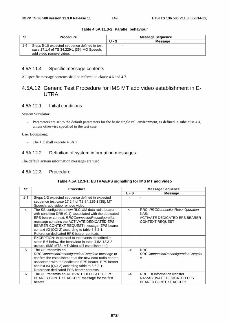
ETSI
ETSI TS 136 508 V11.3.0 (2014-02)1493GPP TS 36.508 version 11.3.0 Release 11
Table 4.5A.11.3-2: Parallel behaviour
St Procedure Message Sequence U - S Message
1-6 Steps 5-10 expected sequence defined in test case 17.1.4 of TS 34.229-1 [35]. MO Speech, add video remove video.
- -
4.5A.11.4 Specific message contents
All specific message contents shall be referred to clause 4.6 and 4.7.
4.5A.12 Generic Test Procedure for IMS MT add video establishment in E-UTRA
4.5A.12.1 Initial conditions
System Simulator:
- Parameters are set to the default parameters for the basic single cell environment, as defined in subclause 4.4, unless otherwise specified in the test case.
User Equipment:
- The UE shall execute 4.5A.7.
4.5A.12.2 Definition of system information messages
The default system information messages are used.
4.5A.12.3 Procedure
Table 4.5A.12.3-1: EUTRA/EPS signalling for IMS MT add video
St Procedure Message Sequence U - S Message
1-3 Steps 1-3 expected sequence defined in expected sequence test case 17.2.4 of TS 34.229-1 [35]. MT Speech, add video remove video.
- -
4 The SS configures a new RLC-UM data radio bearer with condition DRB (0,1), associated with the dedicated EPS bearer context. RRCConnectionReconfiguration message contains the ACTIVATE DEDICATED EPS BEARER CONTEXT REQUEST message. EPS bearer context #3 (QCI 2) according to table 6.6.2-1: Reference dedicated EPS bearer contexts.
<-- RRC: RRCConnectionReconfiguration NAS: ACTIVATE DEDICATED EPS BEARER CONTEXT REQUEST
- EXCEPTION: In parallel to the events described in steps 5-6 below, the behaviour in table 4.5A.12.3-2 occurs. (IMS MTSI MT video call establishment).
- -
5 The UE transmits an RRCConnectionReconfigurationComplete message to confirm the establishment of the new data radio bearer, associated with the dedicated EPS bearer. EPS bearer context #3 (QCI 2) according table to 6.6.2-1: Reference dedicated EPS bearer contexts.
--> RRC: RRCConnectionReconfigurationComplete
6 The UE transmits an ACTIVATE DEDICATED EPS BEARER CONTEXT ACCEPT message for the first bearer.
--> RRC: ULInformationTransfer NAS:ACTIVATE DEDICATED EPS BEARER CONTEXT ACCEPT

ETSI
ETSI TS 136 508 V11.3.0 (2014-02)1503GPP TS 36.508 version 11.3.0 Release 11
Table 4.5A.12.3-2: Parallel behaviour
St Procedure Message Sequence U - S Message
1-6 Steps 4-9 expected sequence defined in test case 17.1.4 of TS 34.229-1 [35]. MT Speech, add video remove video.
- -
4.5A.12.4 Specific message contents
All specific message contents shall be referred to clause 4.6 and 4.7.
4.5A.13 Procedure for MT release of IMS call
4.5A.13.1 Initial conditions
System Simulator:
- Parameters are set to the default parameters for the basic single cell environment, as defined in subclause 4.4, unless otherwise specified in the test case.
User Equipment:
- The UE shall execute 4.5A.7.
4.5A.13.2 Definition of system information messages
The default system information messages are used.
4.5A.13.3 Procedure
Table 4.5A.13.3-1: Procedure for MT release of an IMS call
Step Procedure Message Sequence U - S Message
1 The SS releases the call with BYE. <-- BYE
2 The UE sends 200 OK for BYE. --> 200 OK
4.5A.13.4 Specific message contents
BYE (Step 1 in Table 4.5A.13.3-1)
Use the default message “BYE” in 34.229 annex A.2.8.
200 OK for BYE (Step 2 in Table 4.5A.13.3-1)
Use the default message “200 OK for other requests than REGISTER or SUBSCRIBE” in 34.229 annex A.3.1.
4.5A.14 Generic Test Procedure for IMS XCAP establishment in EUTRA
4.5A.14.1 Initial conditions
System Simulator:
- Parameters are set to the default parameters for the basic single cell environment, as defined in subclause 4.4, unless otherwise specified in the test case.

ETSI
ETSI TS 136 508 V11.3.0 (2014-02)1513GPP TS 36.508 version 11.3.0 Release 11
User Equipment:
- The UE shall be in Registered, Idle Mode state (State 2).
4.5A.14.2 Definition of system information messages
The default system information messages are used.
4.5A.14.3 Procedure
Table 4.5A.14.3-1: EUTRA/EPS signalling for XCAP
St Procedure Message Sequence U - S Message
1 Make the UE attempt XCAP signalling. - - 2 The UE transmits an RRCConnectionRequest message
with ' establishmentCause' set to 'mo-Data '. --> RRCConnectionRequest
3 SS transmit an RRCConnectionSetup message. <-- RRC: RRCConnectionSetup 4 The UE transmits an RRCConnectionSetupComplete
message to confirm the successful completion of the connection establishment and to initiate the session management procedure by including the SERVICE REQUEST message.
--> RRC: RRCConnectionSetupComplete NAS: SERVICE REQUEST
5 The SS transmits a SecurityModeCommand message to activate AS security.
<-- RRC: SecurityModeCommand
6 The UE transmits a SecurityModeComplete message and establishes the initial security configuration.
--> RRC: SecurityModeComplete
7 The SS configures a new data radio bearer, associated with the default EPS bearer context. The RRCConnectionReconfiguration message is using condition SRB2-DRB(1, 0). The DRB associated with default EPS bearer context obtained during the attach procedure is established
<-- RRC: RRCConnectionReconfiguration
8 The UE transmits an RRCConnectionReconfigurationComplete message to confirm the establishment of the new data radio bearer, associated with the default EPS bearer context.
--> RRC: RRCConnectionReconfigurationComplete
9 The UE transmits a PDN CONNECTIVITY REQUEST message to request an additional PDN, with 'Request type' set to 'initial request ('0001'B )'.
--> PDN CONNECTIVITY REQUEST
10 The SS configures a new data radio bearer, associated with the default EPS bearer context. RRCConnectionReconfiguration message contains the ACTIVATE DEFAULT EPS BEARER CONTEXT REQUEST message.
<-- RRC: RRCConnectionReconfiguration NAS: ACTIVATE DEFAULT EPS BEARER CONTEXT REQUEST
- EXCEPTION: In parallel to the events described in steps 11 to 12 below, the behaviour in table 4.5A.14.3-2 occurs. (Optional IP address allocation followed by activation and deactivation of Supplementary Services).
- -
11 The UE transmits an RRCConnectionReconfigurationComplete message to confirm the establishment of the new data radio bearer,
--> RRC: RRCConnectionReconfigurationComplete
12 The UE transmits an ACTIVATE DEFAULT EPS BEARER CONTEXT ACCEPT message.
--> RRC: ULInformationTransfer NAS:ACTIVATE DEFAULT EPS BEARER CONTEXT ACCEPT

ETSI
ETSI TS 136 508 V11.3.0 (2014-02)1523GPP TS 36.508 version 11.3.0 Release 11
Table 4.5A.14.3-2: Parallel behaviour
St Procedure Message Sequence U - S Message - EXCEPTION: Step 1 describes behaviour that
depends on the UE behaviour. - -
1 If initiated by the UE the generic procedure for IP address allocation in the U-plane specified in TS 36.508 subclause 4.5A.1 takes place performing IP address allocation in the U-plane.
- -
2-9 Steps 2-9 expected sequence defined in annex C.29.1 of TS 34.229-1 [35]. Procedures for activation and deactivation of Supplementary Services.
- -
4.5A.14.4 Specific message contents
All specific message contents shall be referred to clause 4.6 and 4.7 with the exceptions below.
Table 4.5A.14.4-1: PDN CONNECTIVITY REQUEST (step 9, Table 4.5A.14.3-1
Derivation Path: Table 4.7.3-20 Information Element Value/remark Comment Condition
Access point name Any allowed value The UE includes the APN to be used for XCAP.
Table 4.5A.14.4-2: Message ACTIVATE DEFAULT EPS BEARER CONTEXT REQUEST (step 10, Table 4.5A.13.3-1)
Derivation path: Table 4.7.3-6 and table 4.6.1-8 with condition AM-DRB-ADD(2) Information Element Value/Remark Comment Condition
EPS bearer identity 7 SS assigns an additional EPS Bearer Id different from default EPS Bearer Id between 5 and 15
Procedure transaction identity PTI-1 SS re-uses the particular PTI defined by UE for this present additional PDN connectivity request procedure
Access point name The SS use the value received in step 9.

ETSI
ETSI TS 136 508 V11.3.0 (2014-02)1533GPP TS 36.508 version 11.3.0 Release 11
Table 4.5A.14.4-3: Message ACTIVATE DEFAULT EPS BEARER CONTEXT ACCEPT (step 12, Table 4.5A.14.3-1)
Derivation path: Table 4.7.3-4 Information Element Value/Remark Comment Condition
EPS bearer identity 7 Same value as in ACTIVATE DEFAULT EPS BEARER CONTEXT REQUEST
Procedure transaction identity 0 No procedure transaction identity assigned
4.6 Default RRC message and information elements contents This clause contains the default values of common RRC messages and information elements, which unless indicated otherwise in specific clauses of TS 36.521-1 [21], TS 36.521-3 [34], TS 36.523-1 [18] and other clauses in this specification. All the messages and information elements are listed in alphabetical order.
4.6.1 Contents of RRC messages
– CounterCheck
Table 4.6.1-0a: CounterCheck
Derivation Path: 36.331 clause 6.2.2 Information Element Value/remark Comment Condition
CounterCheck ::= SEQUENCE { rrc-TransactionIdentifier RRC-
TransactionIdentifier-DL
criticalExtensions CHOICE { c1 CHOICE { counterCheck-r8 SEQUENCE { drb-CountMSB-InfoList Set according to specific
message content
nonCriticalExtension SEQUENCE {} Not present } } } }

ETSI
ETSI TS 136 508 V11.3.0 (2014-02)1543GPP TS 36.508 version 11.3.0 Release 11
– CounterCheckResponse
Table 4.6.1-0b: CounterCheckResponse
Derivation Path: 36.331 clause 6.2.2 Information Element Value/remark Comment Condition
CounterCheckResponse ::= SEQUENCE { rrc-TransactionIdentifier RRC-
TransactionIdentifier-UL
criticalExtensions CHOICE { counterCheckResponse-r8 SEQUENCE { drb-CountInfoList Set according to specific
message content
nonCriticalExtension SEQUENCE {} Not checked } } }
– CSFBParametersRequestCDMA2000
Table 4.6.1-1: CSFBParametersRequestCDMA2000
Derivation Path: 36.331 clause 6.2.2 Information Element Value/remark Comment Condition
CSFBParametersRequestCDMA2000 ::= SEQUENCE {
criticalExtensions CHOICE { csfbParametersRequestCDMA2000-r8 SEQUENCE {
nonCriticalExtension SEQUENCE {} Not checked } } }
– CSFBParametersResponseCDMA2000
Table 4.6.1-2: CSFBParametersResponseCDMA2000
Derivation Path: 36.331 clause 6.2.2 Information Element Value/remark Comment Condition
CSFBParametersResponseCDMA2000 ::= SEQUENCE {
rrc-TransactionIdentifier RRC-TransactionIdentifier-DL
criticalExtensions CHOICE { csfbParametersResponseCDMA2000-r8 SEQUENCE {
rand Set according to specific message content
mobilityParameters Set according to specific message content
nonCriticalExtension SEQUENCE {} Not present } } }

ETSI
ETSI TS 136 508 V11.3.0 (2014-02)1553GPP TS 36.508 version 11.3.0 Release 11
– DLInformationTransfer
Table 4.6.1-3: DLInformationTransfer
Derivation Path: 36.331 clause 6.2.2 Information Element Value/remark Comment Condition
DLInformationTransfer ::= SEQUENCE { rrc-TransactionIdentifier RRC-
TransactionIdentifier-DL
criticalExtensions CHOICE { c1 CHOICE { dlInformationTransfer-r8 SEQUENCE { dedicatedInfoType CHOICE { dedicatedInfoNAS Set according to specific
message content
} nonCriticalExtension SEQUENCE {} Not present } } } }
– HandoverFromEUTRAPreparationRequest
Table 4.6.1-4: HandoverFromEUTRAPreparationRequest
Derivation Path: 36.331 clause 6.2.2 Information Element Value/remark Comment Condition
HandoverFromEUTRAPreparationRequest ::= SEQUENCE {
rrc-TransactionIdentifier RRC-TransactionIdentifier-DL
criticalExtensions CHOICE { c1 CHOICE { handoverFromEUTRAPreparationRequest-r8 SEQUENCE {
cdma2000-Type type1XRTT rand A random value,
generated by the SS
mobilityParameters Set according to specific message content
nonCriticalExtension SEQUENCE {} Not present } } } }

ETSI
ETSI TS 136 508 V11.3.0 (2014-02)1563GPP TS 36.508 version 11.3.0 Release 11
- LoggedMeasurementConfiguration
Table 4.6.1-4.0A: LoggedMeasurementConfiguration
Derivation Path: 36.331 clause 6.2.2 Information Element Value/remark Comment Condition
LoggedMeasurementConfiguration-r10 ::= SEQUENCE {
criticalExtensions CHOICE { c1 CHOICE { loggedMeasurementConfiguration-r10 SEQUENCE {
traceReference-r10 SEQUENCE { plmn-Identity-r10 SEQUENCE {
mcc SEQUENCE (SIZE (3)) OF MCC-NMC-Digit
See table 4.4.2-2
mnc SEQUENCE (SIZE (2..3)) OF MCC-NMC-Digit
See table 4.4.2-2
} traceId-r10 ‘0EF’H OCTET STRING
(SIZE (3))
} traceRecordingSessionRef-r10 ‘1A’H OCTET STRING
(SIZE (2))
tce-Id-r10 ‘5’H OCTET STRING (SIZE (1))
absoluteTimeInfo-r10 Set to value corresponding to the absolute time when the message is sent
BIT STRING (SIZE (48)), see TS 36.331 clause 6.3.6 for format.
areaConfiguration-r10 Not present loggingDuration-r10 min120 ENUMERATED {
min10, min20, min40, min60, min90, min120, spare2, spare1}
loggingInterval-r10 ms10240 ENUMERATED { ms1280, ms2560, ms5120, ms10240, ms20480, ms30720, ms40960, ms61440}
nonCriticalExtension SEQUENCE {} Not present } } } }

ETSI
ETSI TS 136 508 V11.3.0 (2014-02)1573GPP TS 36.508 version 11.3.0 Release 11
– MBMSCountingRequest
Table 4.6.1-4AA: MBMSCountingRequest
Derivation Path: 36.331 clause 6.2.2 Information Element Value/remark Comment Condition
MBMSCountingRequest-r10 ::= SEQUENCE { CountingRequestList-r10 SEQUENCE (SIZE (1.. maxServiceCount)) OF SEQUENCE {
tmgi-r10 SEQUENCE { plmn-Id-r9 CHOICE{ plmn-Index-r9 1 } serviceId-r9 ‘000000’O MBMS service ID
(TS 24.008 clause 10.5.6.13), OCTET STRING (SIZE (3))
} }
lateNonCriticalExtension Not present nonCriticalExtension SEQUENCE {} Not present }
– MBMSCountingResponse
Table 4.6.1-4AB: MBMSCountingResponse
Derivation Path: 36.331 clause 6.2.2 Information Element Value/remark Comment Condition
criticalExtensions CHOICE { c1 CHOICE{ countingResponse-r10 OF SEQUENCE { mbsfn-AreaIndex-r10 Not present countingResponseList-r10 SEQUENCE (SIZE (1... maxServiceCount)) OF SEQUENCE {
countingResponseService-r10 0 } lateNonCriticalExtension Not present nonCriticalExtension SEQUENCE {} Not present } } }

ETSI
ETSI TS 136 508 V11.3.0 (2014-02)1583GPP TS 36.508 version 11.3.0 Release 11
– MBMSInterestIndication
Table 4.6.1-4AC: MBMSInterestIndication
Derivation Path: 36.331 clause 6.2.2 Information Element Value/remark Comment Condition
criticalExtensions CHOICE { c1 CHOICE{ interestIndication-r11 OF SEQUENCE { mbms-FreqList-r11[n] SEQUENCE (SIZE (1..maxFreqMBMS-r11)) OF { INTEGER (0..maxEARFCN2) }
The number of entries is set according to specific message content.
INTEGER (0..maxEARFCN2)
mbms-Priority-r11 Not checked ENUMERATED {true}
lateNonCriticalExtension Not present nonCriticalExtension SEQUENCE {} Not present } } }
– MBSFNAreaConfiguration
Table 4.6.1-4A: MBSFNAreaConfiguration
Derivation Path: 36.331 clause 6.2.2 Information Element Value/remark Comment Condition
MBSFNAreaConfiguration-r9 ::= SEQUENCE { commonSF-Alloc-r9 SEQUENCE (SIZE (1..maxMBSFN-Allocations)) OF SEQUENCE {
radioframeAllocationPeriod n4 radioframeAllocationOffset 1 FDD 0 TDD subframeAllocation CHOICE { oneFrame ‘100000’ FDD ‘000010’ TDD } } commonSF-AllocPeriod-r9 rf8 pmch-InfoList-r9 SEQUENCE (SIZE (0..maxPMCH-PerMBSFN)) OF SEQUENCE {
pmch-Config-r9 SEQUENCE { sf-AllocEnd-r9 1 dataMCS-r9 0 mch-SchedulingPeriod-r9 rf8 } mbms-SessionInfoList-r9 SEQUENCE (SIZE (0..maxSessionPerPMCH)) OF SEQUENCE {
MBMS-SessionInfo-r9 SEQUENCE { tmgi-r9 SEQUENCE { plmn-Id-r9 CHOICE{ plmn-Index-r9 1 } } serviceId-r9 ‘000000’ } sessionId-r9 Not present logicalChannelIdentity-r9 1 } } }

ETSI
ETSI TS 136 508 V11.3.0 (2014-02)1593GPP TS 36.508 version 11.3.0 Release 11
– MeasurementReport
Table 4.6.1-5: MeasurementReport
Derivation Path: 36.331 clause 6.2.2 Information Element Value/remark Comment Condition
MeasurementReport ::= SEQUENCE { criticalExtensions CHOICE { c1 CHOICE { measurementReport-r8 SEQUENCE { measResults Set according to specific
message content
nonCriticalExtension SEQUENCE {} Not checked } } } }
– MobilityFromEUTRACommand
Table 4.6.1-6: MobilityFromEUTRACommand
Derivation Path: 36.331 clause 6.2.2 Information Element Value/remark Comment Condition
MobilityFromEUTRACommand ::= SEQUENCE { rrc-TransactionIdentifier RRC-
TransactionIdentifier-DL
criticalExtensions CHOICE { c1 CHOICE { mobilityFromEUTRACommand-r8 SEQUENCE {
csFallbackIndicator Set according to specific message content
purpose CHOICE { Set according to specific message content
handover cellChangeOrder } nonCriticalExtension SEQUENCE {} Not present } } } }

ETSI
ETSI TS 136 508 V11.3.0 (2014-02)1603GPP TS 36.508 version 11.3.0 Release 11
– Paging
Table 4.6.1-7: Paging
Derivation Path: 36.331 clause 6.2.2 Information Element Value/remark Comment Condition
Paging ::= SEQUENCE { pagingRecordList SEQUENCE (SIZE (1..maxPageRec)) OF SEQUENCE {
1 entry
ue-Identity[1] CHOICE { s-TMSI Set to the value of the S-
TMSI of the UE
} cn-Domain[1] ps } systemInfoModification Not present etws-Indication Not present nonCriticalExtension SEQUENCE {} Not present }

ETSI
ETSI TS 136 508 V11.3.0 (2014-02)1613GPP TS 36.508 version 11.3.0 Release 11
– RRCConnectionReconfiguration
Table 4.6.1-8: RRCConnectionReconfiguration
Derivation Path: 36.331 clause 6.2.2 Information Element Value/remark Comment Condition
RRCConnectionReconfiguration ::= SEQUENCE { rrc-TransactionIdentifier RRC-
TransactionIdentifier-DL
criticalExtensions CHOICE { c1 CHOICE{ rrcConnectionReconfiguration-r8 SEQUENCE { measConfig Not present MeasConfig-DEFAULT MEAS mobilityControlInfo Not present MobilityControlInfo-HO HO, HO-TO-
EUTRA dedicatedInfoNASList Not present Set according to specific
message content SRB2-
DRB(n, m) DRB(n, m) SRB1-SRB2-DRB(n,m) AM-DRB-ADD(bid) UM-DRB-ADD(bid) DRB-REL(bid) DRB-Mod
radioResourceConfigDedicated Not present RadioResourceConfigDe
dicated-SRB2-DRB(n, m) SRB2-
DRB(n, m) RadioResourceConfigDe
dicated-DRB(n, m) DRB(n, m)
RadioResourceConfigDedicated-AM-DRB-ADD(bid)
AM-DRB-ADD(bid)
RadioResourceConfigDedicated-UM-DRB-ADD(bid)
UM-DRB-ADD(bid)
RadioResourceConfigDedicated-DRB-REL(bid)
DRB-REL(bid)
RadioResourceConfigDedicated-HO
HO
RadioResourceConfigDedicated-HO-TO-EUTRA(n, m)
HO-TO-EUTRA(n,m)
RadioResourceConfigDedicated-DRB-Mod
DRB-Mod
RadioResourceConfigDedicated-SCell_AddMod
SCell_AddMod
RadioResourceConfigDedicated-PCell-PATTERN
PCell-PATTERN
securityConfigHO Not present SecurityConfigHO-
DEFAULT HO, HO-TO-
EUTRA nonCriticalExtension SEQUENCE { lateNonCriticalExtension Not present nonCriticalExtension SEQUENCE { otherConfig-r9 Not present otherConfig-r9 OtherConfig-r9 OtherConfig fullConfig-r9 Not present nonCriticalExtension SEQUENCE { sCellToReleaseList-r10 Not present

ETSI
ETSI TS 136 508 V11.3.0 (2014-02)1623GPP TS 36.508 version 11.3.0 Release 11
sCellToAddModList-r10 Not present sCellToAddModList-r10 SEQUENCE (SIZE (1..maxSCell-r10)) OF SEQUENCE {
1 entry SCell_AddMod
sCellToAddMod[1] SCellToAddMod-r10-DEFAULT
} nonCriticalExtension Not present } } } } } } }
Condition Explanation SRB2-DRB(n,m) Establishment of a SRB and DRB combination with n x AM DRB and m x UM DRB (including
establishment of SRB2) DRB(n,m) Establishment of additional n x AM DRB:s and m x UM DRB:s (SRB2 should already be
established) AM-DRB-ADD(bid) Establishment of a single additional AM DRB with bearer identity bid (SRB2 should already
be established) UM-DRB-ADD(bid) Establishment of a single additional UM DRB with bearer identity bid (SRB2 should already
be established) DRB-REL(bid) Release of the DRB with bearer identity bid HO Intra LTE handover MEAS A measurement is configured HO-TO-EUTRA(n,m) Inter-RAT handover to E-UTRA including the establishment of a SRB1, SRB2 and n x AM
DRB plus m x UM DRB DRB-Mod Modification of already established DRB ID 2 and is used for sending Modify EPS Bearer
Context Request message (SRB2 should already be established) SCell_AddMod Addition or modification of SCell PCell-PATTERN eICIC Serving Cell Pattern OtherConfig Other Configuration is configured
– RRCConnectionReconfigurationComplete
Table 4.6.1-9: RRCConnectionReconfigurationComplete
Derivation Path: 36.331 clause 6.2.2 Information Element Value/remark Comment Condition
RRCConnectionReconfigurationComplete ::= SEQUENCE {
rrc-TransactionIdentifier RRC-TransactionIdentifier-UL
criticalExtensions CHOICE { rrcConnectionReconfigurationComplete-r8 SEQUENCE {
nonCriticalExtension SEQUENCE {} Not checked } } }
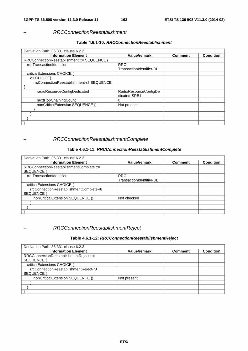
ETSI
ETSI TS 136 508 V11.3.0 (2014-02)1633GPP TS 36.508 version 11.3.0 Release 11
– RRCConnectionReestablishment
Table 4.6.1-10: RRCConnectionReestablishment
Derivation Path: 36.331 clause 6.2.2 Information Element Value/remark Comment Condition
RRCConnectionReestablishment ::= SEQUENCE { rrc-TransactionIdentifier RRC-
TransactionIdentifier-DL
criticalExtensions CHOICE { c1 CHOICE{ rrcConnectionReestablishment-r8 SEQUENCE {
radioResourceConfigDedicated RadioResourceConfigDedicated-SRB1
nextHopChainingCount 0 nonCriticalExtension SEQUENCE {} Not present } } } }
– RRCConnectionReestablishmentComplete
Table 4.6.1-11: RRCConnectionReestablishmentComplete
Derivation Path: 36.331 clause 6.2.2 Information Element Value/remark Comment Condition
RRCConnectionReestablishmentComplete ::= SEQUENCE {
rrc-TransactionIdentifier RRC-TransactionIdentifier-UL
criticalExtensions CHOICE { rrcConnectionReestablishmentComplete-r8 SEQUENCE {
nonCriticalExtension SEQUENCE {} Not checked } } }
– RRCConnectionReestablishmentReject
Table 4.6.1-12: RRCConnectionReestablishmentReject
Derivation Path: 36.331 clause 6.2.2 Information Element Value/remark Comment Condition
RRCConnectionReestablishmentReject ::= SEQUENCE {
criticalExtensions CHOICE { rrcConnectionReestablishmentReject-r8 SEQUENCE {
nonCriticalExtension SEQUENCE {} Not present } } }
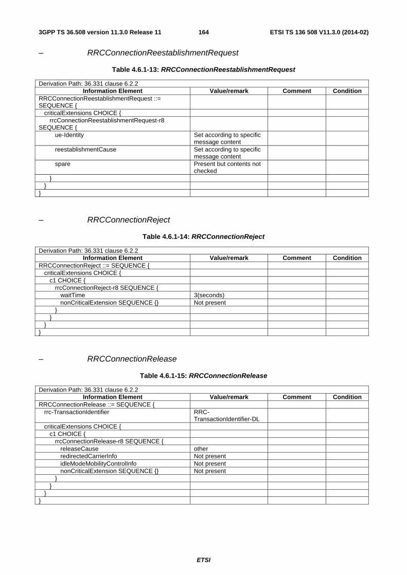
ETSI
ETSI TS 136 508 V11.3.0 (2014-02)1643GPP TS 36.508 version 11.3.0 Release 11
– RRCConnectionReestablishmentRequest
Table 4.6.1-13: RRCConnectionReestablishmentRequest
Derivation Path: 36.331 clause 6.2.2 Information Element Value/remark Comment Condition
RRCConnectionReestablishmentRequest ::= SEQUENCE {
criticalExtensions CHOICE { rrcConnectionReestablishmentRequest-r8 SEQUENCE {
ue-Identity Set according to specific message content
reestablishmentCause Set according to specific message content
spare Present but contents not checked
} } }
– RRCConnectionReject
Table 4.6.1-14: RRCConnectionReject
Derivation Path: 36.331 clause 6.2.2 Information Element Value/remark Comment Condition
RRCConnectionReject ::= SEQUENCE { criticalExtensions CHOICE { c1 CHOICE { rrcConnectionReject-r8 SEQUENCE { waitTime 3(seconds) nonCriticalExtension SEQUENCE {} Not present } } } }
– RRCConnectionRelease
Table 4.6.1-15: RRCConnectionRelease
Derivation Path: 36.331 clause 6.2.2 Information Element Value/remark Comment Condition
RRCConnectionRelease ::= SEQUENCE { rrc-TransactionIdentifier RRC-
TransactionIdentifier-DL
criticalExtensions CHOICE { c1 CHOICE { rrcConnectionRelease-r8 SEQUENCE { releaseCause other redirectedCarrierInfo Not present idleModeMobilityControlInfo Not present nonCriticalExtension SEQUENCE {} Not present } } } }

ETSI
ETSI TS 136 508 V11.3.0 (2014-02)1653GPP TS 36.508 version 11.3.0 Release 11
– RRCConnectionRequest
Table 4.6.1-16: RRCConnectionRequest
Derivation Path: 36.331 clause 6.2.2 Information Element Value/remark Comment Condition
RRCConnectionRequest ::= SEQUENCE { criticalExtensions CHOICE { rrcConnectionRequest-r8 SEQUENCE { ue-Identity CHOICE { s-TMSI Any allowed value } establishmentCause Present but contents not
checked
spare Present but contents not checked
} } }
– RRCConnectionSetup
Table 4.6.1-17: RRCConnectionSetup
Derivation Path: 36.331 clause 6.2.2 Information Element Value/remark Comment Condition
RRCConnectionSetup ::= SEQUENCE { rrc-TransactionIdentifier RRC-
TransactionIdentifier-DL
criticalExtensions CHOICE { c1 CHOICE { rrcConnectionSetup-r8 SEQUENCE { radioResourceConfigDedicated RadioResourceConfigDe
dicated-SRB1
nonCriticalExtension SEQUENCE {} Not present } } } }
– RRCConnectionSetupComplete
Table 4.6.1-18: RRCConnectionSetupComplete
Derivation Path: 36.331 clause 6.2.2 Information Element Value/remark Comment Condition
RRCConnectionSetupComplete ::= SEQUENCE { rrc-TransactionIdentifier RRC-
TransactionIdentifier-UL
criticalExtensions CHOICE { c1 CHOICE { rrcConnectionSetupComplete-r8 SEQUENCE { selectedPLMN-Identity 1 registeredMME Not checked dedicatedInfoNAS Present but contents not
checked
nonCriticalExtension SEQUENCE {} Not checked } } } }

ETSI
ETSI TS 136 508 V11.3.0 (2014-02)1663GPP TS 36.508 version 11.3.0 Release 11
– SecurityModeCommand
Table 4.6.1-19: SecurityModeCommand
Derivation Path: 36.331 clause 6.2.2 Information Element Value/remark Comment Condition
SecurityModeCommand ::= SEQUENCE { rrc-TransactionIdentifier RRC-
TransactionIdentifier-DL
criticalExtensions CHOICE { c1 CHOICE{ securityModeCommand-r8 SEQUENCE { securityConfigSMC SecurityConfigSMC-
DEFAULT
nonCriticalExtension SEQUENCE {} Not present } } } }
– SecurityModeComplete
Table 4.6.1-20: SecurityModeComplete
Derivation Path: 36.331 clause 6.2.2 Information Element Value/remark Comment Condition
SecurityModeComplete ::= SEQUENCE { rrc-TransactionIdentifier RRC-
TransactionIdentifier-UL
criticalExtensions CHOICE { securityModeComplete-r8 SEQUENCE { nonCriticalExtension SEQUENCE {} Not checked } } }
– SecurityModeFailure
Table 4.6.1-21: SecurityModeFailure
Derivation Path: 36.331 clause 6.2.2 Information Element Value/remark Comment Condition
SecurityModeFailure ::= SEQUENCE { rrc-TransactionIdentifier RRC-
TransactionIdentifier-UL
criticalExtensions CHOICE { securityModeFailure-r8 SEQUENCE { nonCriticalExtension SEQUENCE {} Not checked } } }
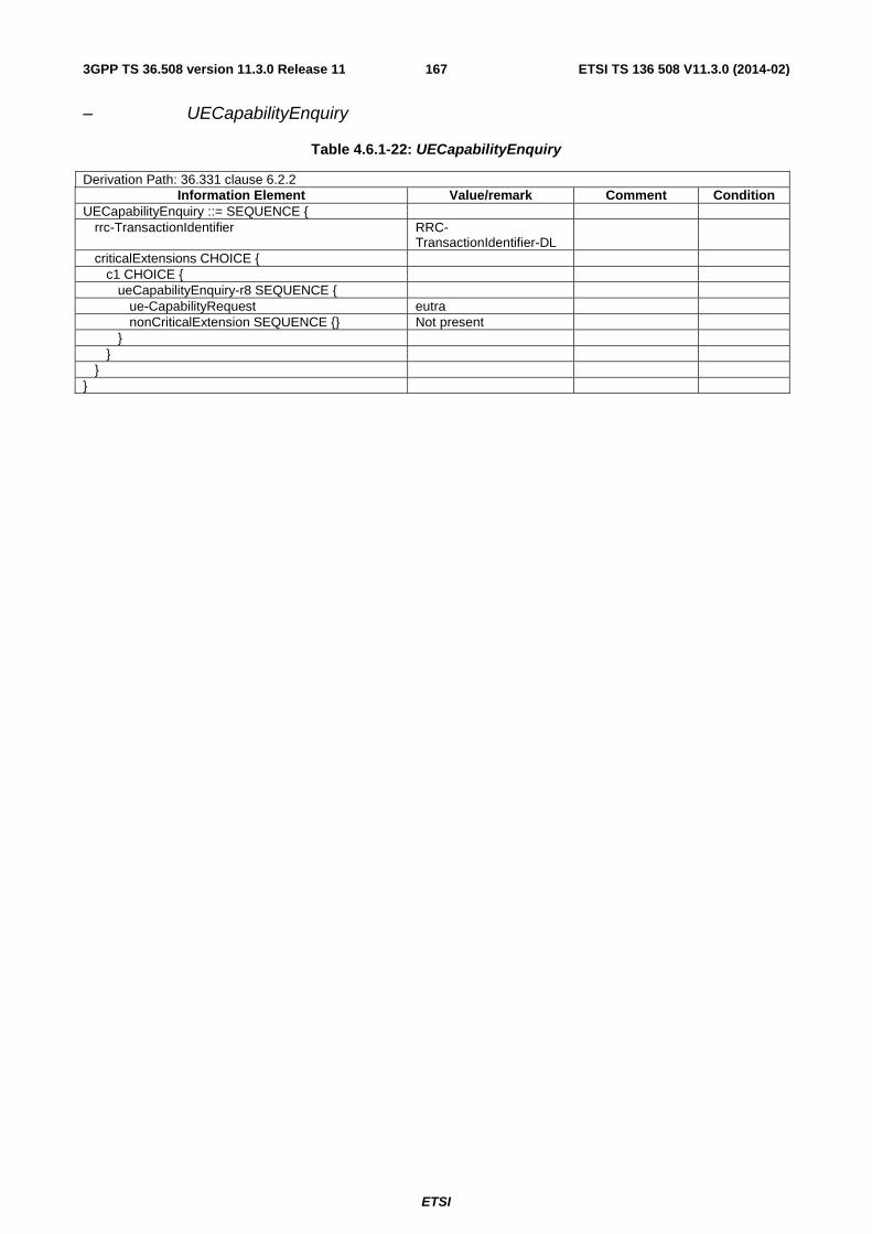
ETSI
ETSI TS 136 508 V11.3.0 (2014-02)1673GPP TS 36.508 version 11.3.0 Release 11
– UECapabilityEnquiry
Table 4.6.1-22: UECapabilityEnquiry
Derivation Path: 36.331 clause 6.2.2 Information Element Value/remark Comment Condition
UECapabilityEnquiry ::= SEQUENCE { rrc-TransactionIdentifier RRC-
TransactionIdentifier-DL
criticalExtensions CHOICE { c1 CHOICE { ueCapabilityEnquiry-r8 SEQUENCE { ue-CapabilityRequest eutra nonCriticalExtension SEQUENCE {} Not present } } } }

ETSI
ETSI TS 136 508 V11.3.0 (2014-02)1683GPP TS 36.508 version 11.3.0 Release 11
– UECapabilityInformation
Table 4.6.1-23: UECapabilityInformation
Derivation Path: 36.331 clause 6.2.2 Information Element Value/remark Comment Condition
UECapabilityInformation ::= SEQUENCE { rrc-TransactionIdentifier RRC-
TransactionIdentifier-UL
criticalExtensions CHOICE { c1 CHOICE{ ueCapabilityInformation-r8 SEQUENCE { ue-CapabilityRAT-ContainerList SEQUENCE (SIZE (1..maxRAT-Capabilities)) OF SEQUENCE {
1 entry
rat-Type Set according to specific message content
ueCapabilityRAT-Container ue-EUTRA-Capability SEQUENCE { accessStratumRelease Same as indicated in TC
applicability of 36.523-2
ue-Category Not checked pdcp-Parameters SEQUENCE { supportedROHC-Profiles SEQUENCE {
profile0x0001 Not checked profile0x0001 true ROHC profile0x0002 Not checked profile0x0002 true ROHC profile0x0003 Not checked profile0x0004 Not checked profile0x0006 Not checked profile0x0101 Not checked profile0x0102 Not checked profile0x0103 Not checked profile0x0104 Not checked } maxNumberROHC-ContextSessions Not checked } phyLayerParameters Not checked rf-Parameters Not checked measParameters Not checked featureGroupIndicators -- FGI 1 Not checked -- FGI 2 Not checked -- FGI 3 Not checked -- FGI 4 Not checked -- FGI 5 Not checked -- FGI 6 Not checked -- FGI 7 Not checked -- FGI 8 Not checked -- FGI 9 Not checked -- FGI 10 Not checked -- FGI 11 Not checked -- FGI 12 Not checked -- FGI 13 Not checked -- FGI 14 Not checked -- FGI 15 Not checked -- FGI 16 Not checked -- FGI 17 Not checked -- FGI 18 Not checked -- FGI 19 Not checked -- FGI 20 Not checked -- FGI 21 Not checked -- FGI 22 Not checked -- FGI 23 Not checked

ETSI
ETSI TS 136 508 V11.3.0 (2014-02)1693GPP TS 36.508 version 11.3.0 Release 11
-- FGI 24 Not checked -- FGI 25 Not checked -- FGI 26 Not checked -- FGI 27 Not checked -- FGI 28 Not checked -- FGI 29 Not checked -- FGI 30 Not checked
-- FGI 31 Not checked -- FGI 32 ‘0’B (Undefined)
interRAT-Parameters SEQUENCE { utraFDD Not checked utraTDD128 Not checked utraTDD384 Not checked utraTDD768 Not checked geran Not checked cdma2000-HRPD Not checked cdma2000-1xRTT Not checked cdma2000-1xRTT Not checked } nonCriticalExtension SEQUENCE { phyLayerParameters-v920 Not checked interRAT-ParametersGERAN-v920 Not checked interRAT-ParametersUTRA-v920 Not checked interRAT-ParametersCDMA2000-v920
Not checked
deviceType-r9 Not checked csg-ProximityIndicationParameters-r9 Not checked neighCellSI-AcquisitionParameters-r9 Not checked son-Parameters-r9 Not checked nonCriticalExtension SEQUENCE { lateNonCriticalExtension SEQUENCE {
featureGroupIndRel9Add-r9 -- FGI 33 Not checked -- FGI 34 Not checked -- FGI 35 Not checked -- FGI 36 Not checked -- FGI 37 Not checked -- FGI 38 Not checked -- FGI 39 Not checked -- FGI 40 Not checked -- FGI 41 Not checked -- FGI 42-64 ‘0’B (Undefined) fdd-Add-UE-EUTRA-Capabilities-r9 SEQUENCE {
phyLayerParameters-r9 Not checked featureGroupIndicators-r9 BITSTRING 32 -- FGI 1F Not checked -- FGI 2F Not checked -- FGI 3F Not checked FDD = TDD -- FGI 4F Not checked -- FGI 5F Not checked FDD = TDD -- FGI 6F Not checked FDD = TDD -- FGI 7F Not checked FDD = TDD -- FGI 8F Not checked -- FGI 9F Not checked -- FGI 10F Not checked -- FGI 11F Not checked -- FGI 12F Not checked -- FGI 13F Not checked FDD = TDD -- FGI 14F Not checked FDD = TDD -- FGI 15F Not checked -- FGI 16F Not checked FDD = TDD -- FGI 17F Not checked FDD = TDD -- FGI 18F Not checked FDD = TDD

ETSI
ETSI TS 136 508 V11.3.0 (2014-02)1703GPP TS 36.508 version 11.3.0 Release 11
-- FGI 19F Not checked -- FGI 20F Not checked FDD = TDD -- FGI 21F Not checked FDD = TDD -- FGI 22F Not checked -- FGI 23F Not checked -- FGI 24F Not checked -- FGI 25F Not checked FDD = TDD -- FGI 26F Not checked -- FGI 27F Not checked -- FGI 28F Not checked -- FGI 29F Not checked -- FGI 30F Not checked FDD = TDD -- FGI 31F Not checked FDD = TDD -- FGI 32F ‘0’B (Undefined) if
present
featureGroupIndRel9Add-r9 BITSTRING 32 -- FGI 33F Not checked -- FGI 34F Not checked -- FGI 35F Not checked -- FGI 36F Not checked -- FGI 37F Not checked -- FGI 38F Not checked -- FGI 39F Not checked -- FGI 40F Not checked -- FGI 41F Not checked -- FGI 42F-64F ‘0’B (Undefined) if
present
interRAT-ParametersGERAN-r9
Not checked
interRAT-ParametersUTRA-r9 Not checked interRAT-ParametersGERAN-r9
Not checked
interRAT-ParametersCDMA2000-r9
Not checked
neighCellSI-AcquisitionParameters-r9
Not checked
} tdd-Add-UE-EUTRA-Capabilities-r9 SEQUENCE {
phyLayerParameters-r9 Not checked featureGroupIndicators-r9 BITSTRING 32 -- FGI 1T Not checked -- FGI 2T Not checked -- FGI 3T Not checked FDD = TDD -- FGI 4T Not checked -- FGI 5T Not checked FDD = TDD -- FGI 6T Not checked FDD = TDD -- FGI 7T Not checked FDD = TDD -- FGI 8T Not checked -- FGI 9T Not checked -- FGI 10T Not checked -- FGI 11T Not checked -- FGI 12T Not checked -- FGI 13T Not checked FDD = TDD -- FGI 14T Not checked FDD = TDD -- FGI 15T Not checked -- FGI 16T Not checked FDD = TDD -- FGI 17T Not checked FDD = TDD -- FGI 18T Not checked FDD = TDD -- FGI 19T Not checked -- FGI 20T Not checked FDD = TDD -- FGI 21T Not checked FDD = TDD -- FGI 22T Not checked -- FGI 23T Not checked -- FGI 24T Not checked -- FGI 25T Not checked FDD = TDD

ETSI
ETSI TS 136 508 V11.3.0 (2014-02)1713GPP TS 36.508 version 11.3.0 Release 11
-- FGI 26T Not checked -- FGI 27T Not checked -- FGI 28T Not checked -- FGI 29T Not checked -- FGI 30T Not checked FDD = TDD -- FGI 31T Not checked FDD = TDD -- FGI 32T ‘0’B (Undefined) if
present
featureGroupIndRel9Add-r9 BITSTRING 32 -- FGI 33T Not checked -- FGI 34T Not checked -- FGI 35T Not checked -- FGI 36T Not checked -- FGI 37T Not checked -- FGI 38T Not checked -- FGI 39T Not checked -- FGI 40T Not checked -- FGI 41T Not checked -- FGI 42T-64T ‘0’B (Undefined) if
present
interRAT-ParametersGERAN-r9
Not checked
interRAT-ParametersUTRA-r9 Not checked interRAT-ParametersGERAN-r9
Not checked
interRAT-ParametersCDMA2000-r9
Not checked
neighCellSI-AcquisitionParameters-r9
Not checked
} nonCriticalExtension SEQUENCE {
Not checked
interRAT-ParametersUTRA-v9c0
Not checked
nonCriticalExtension SEQUENCE {
phyLayerParameters-v9d0 Not checked nonCriticalExtension SEQUENCE {
rf-Parameters-v9e0 Not checked nonCriticalExtension SEQUENCE {}
Not checked
} } } } nonCriticalExtension SEQUENCE { ue-Category-v1020 Not checked
phyLayerParameters-v1020 Not checked
rf-Parameters-v1020 Not checked
measParameters-v1020 Not checked
featureGroupIndRel10-r10 BITSTRING 32
-- FGI 101 Not checked -- FGI 102 Not checked -- FGI 103 Not checked -- FGI 104 Not checked -- FGI 105 Not checked -- FGI 106 Not checked -- FGI 107 Not checked -- FGI 108 Not checked -- FGI 109 Not checked -- FGI 110 Not checked

ETSI
ETSI TS 136 508 V11.3.0 (2014-02)1723GPP TS 36.508 version 11.3.0 Release 11
-- FGI 111 Not checked -- FGI 112 Not checked -- FGI 113 Not checked -- FGI 114 Not checked -- FGI 115 Not checked -- FGI 116 Not checked -- FGI 117-132 ‘0’B (Undefined) if
present
interRAT-ParametersCDMA2000-v1020
Not checked
ue-BasedNetwPerfMeasParameters-r10
Not checked
interRAT-ParametersUTRA-TDD-v1020
Not checked
nonCriticalExtension SEQUENCE {
Not checked
fdd-Add-UE-EUTRA-Capabilities-v1060
Not checked
tdd-Add-UE-EUTRA-Capabilities-v1060
Not checked
rf-Parameters-v1060 Not checked nonCriticalExtension SEQUENCE {
rf-Parameters-v1090 Not checked nonCriticalExtension SEQUENCE {
pdcp-Parameters-v1130 Not checked phyLayerParameters-v1130 Not checked rf-Parameters-v1130 Not checked measParameters-v1130 Not checked interRAT-ParametersCDMA2000-v1130
Not checked
otherParameters-r11 Not checked fdd-Add-UE-EUTRA-Capabilities-v1130
Not checked
tdd-Add-UE-EUTRA-Capabilities-v1130
Not checked
nonCriticalExtension SEQUENCE {}
Not checked
} } } } } } } } nonCriticalExtension SEQUENCE {} Not checked } } } }
Condition Explanation ROHC Support of ROHC profile0x0001 and ROHC profile0x0002 (TS 36.523-2 table A.4.4-
1/40 and A.4.4-1/41). FDD = TDD UE is not allowed to signal different values for FDD and TDD, is not checked per
default

ETSI
ETSI TS 136 508 V11.3.0 (2014-02)1733GPP TS 36.508 version 11.3.0 Release 11
– UEInformationRequest
Table 4.6.1-23A: UEInformationRequest
Derivation Path: 36.331 clause 6.2.2 Information Element Value/remark Comment Condition
UEInformationRequest-r9 ::= SEQUENCE { rrc-TransactionIdentifier RRC-
TransactionIdentifier-DL
criticalExtensions CHOICE { c1 CHOICE{ ueInformationRequest-r9 SEQUENCE { rach-ReportReq-r9 FALSE rlf-ReportReq-r9 FALSE TRUE RLF report nonCriticalExtension SEQUENCE { lateNonCriticalExtension Not present nonCriticalExtension SEQUENCE {} Not present nonCriticalExtension SEQUENCE { Logged
MDT, ConEstFail
logMeasReportReq-r10 true Logged MDT
Not present nonCriticalExtension SEQUENCE {} Not present nonCriticalExtension SEQUENCE { connEstFailReportReq-r11 true ConEstFail Not present nonCriticalExtension SEQUENCE {} Not present } } } } } } }
Condition Explanation Logged MDT Used for Logged MDT test cases ConEstFail Used for RRC connection establishment failure report related test cases RLF report Used for Radio Link Failure Logging test cases

ETSI
ETSI TS 136 508 V11.3.0 (2014-02)1743GPP TS 36.508 version 11.3.0 Release 11
– UEInformationResponse
Table 4.6.1-23B: UEInformationResponse
Derivation Path: 36.331 clause 6.2.2 Information Element Value/remark Comment Condition
UEInformationResponse-r9 ::= SEQUENCE { rrc-TransactionIdentifier RRC-
TransactionIdentifier-UL
criticalExtensions CHOICE { c1 CHOICE{ ueInformationResponse-r9 SEQUENCE { rach-Report-r9 SEQUENCE {} Not checked rlf-Report-r9 SEQUENCE {} Not checked nonCriticalExtension SEQUENCE { lateNonCriticalExtension Not checked nonCriticalExtension SEQUENCE { logMeasReport-r10 SEQUENCE {} Not checked nonCriticalExtension SEQUENCE { Not checked } } } } } }
- ULHandoverPreparationTransfer
Table 4.6.1-24: ULHandoverPreparationTransfer
Derivation Path: 36.331 clause 6.2.2 Information Element Value/remark Comment Condition
ULHandoverPreparationTransfer ::= SEQUENCE { criticalExtensions CHOICE { c1 CHOICE { ulHandoverPreparationTransfer-r8 SEQUENCE {
cdma2000-Type type1XRTT meid Set to the 56 bit
CDMA2000 mobile identification number of the UE
dedicatedInfo Set according to specific message content
nonCriticalExtension SEQUENCE {} Not checked } } } }

ETSI
ETSI TS 136 508 V11.3.0 (2014-02)1753GPP TS 36.508 version 11.3.0 Release 11
– ULInformationTransfer
Table 4.6.1-25: ULInformationTransfer
Derivation Path: 36.331 clause 6.2.2 Information Element Value/remark Comment Condition
ULInformationTransfer ::= SEQUENCE { criticalExtensions CHOICE { c1 CHOICE { ulInformationTransfer-r8 SEQUENCE { dedicatedInfoType CHOICE { dedicatedInfoNAS Present but contents not
checked
} nonCriticalExtension SEQUENCE {} Not checked } } } }
– UEAssistanceInformation
Table 4.6.1-26: UEAssistanceInformation
Derivation Path: 36.331, Clause 6.2.2 Information Element Value/remark Comment Condition
UEAssistanceInformation-r11 ::= SEQUENCE { criticalExtensions CHOICE { c1 CHOICE{ UEAssistanceInformation-r11-IEs SEQUENCE { powerPreferenceIndication-r11 lowPowerConsumption Low_Powe
r powerPreferenceIndication-r11 normal Normal laterNonCriticalExtension Not Present nonCriticalExtension SEQUENCE {} Not Present } } } }
Condition Explanation Low_Power The UE indicates that it prefers a configuration primarily optimised for power saving Normal The UE indicates that it does not prefer a configuration primarily optimised for power saving
4.6.2 System information blocks
See subclause 4.4.3.3 in this document.

ETSI
ETSI TS 136 508 V11.3.0 (2014-02)1763GPP TS 36.508 version 11.3.0 Release 11
4.6.3 Radio resource control information elements
Table 4.6.3-0A: Void
Table 4.6.3-0B: Void
– BCCH-Config-DEFAULT
Table 4.6.3-1: BCCH-Config-DEFAULT
Derivation Path: 36.331 clause 6.3.2 Information Element Value/remark Comment Condition
BCCH-Config-DEFAULT::= SEQUENCE { modificationPeriodCoeff n4 To provide reliable
delivery of SI change notifications.
}
– CQI-ReportAperiodic-r10-DEFAULT
Table 4.6.3-1A: CQI-ReportAperiodic-r10-DEFAULT
Derivation Path: 36.331 clause 6.3.2 Information Element Value/remark Comment Condition
CQI-ReportAperiodic-r10 ::=CHOICE { setup SEQUENCE { cqi-ReportModeAperiodic-r10 rm30 aperiodicCSI-Trigger-r10 Not present } }
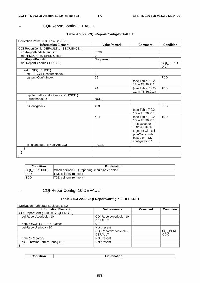
ETSI
ETSI TS 136 508 V11.3.0 (2014-02)1773GPP TS 36.508 version 11.3.0 Release 11
– CQI-ReportConfig-DEFAULT
Table 4.6.3-2: CQI-ReportConfig-DEFAULT
Derivation Path: 36.331 clause 6.3.2 Information Element Value/remark Comment Condition
CQI-ReportConfig-DEFAULT ::= SEQUENCE { cqi-ReportModeAperiodic rm30 nomPDSCH-RS-EPRE-Offset 0 cqi-ReportPeriodic Not present cqi-ReportPeriodic CHOICE { CQI_PERIO
DIC setup SEQUENCE { cqi-PUCCH-ResourceIndex 0 cqi-pmi-ConfigIndex 25
(see Table 7.2.2-1A in TS 36.213)
FDD
24 (see Table 7.2.2-1C in TS 36.213)
TDD
cqi-FormatIndicatorPeriodic CHOICE { widebandCQI NULL } ri-ConfigIndex 483
(see Table 7.2.2-1B in TS 36.213)
FDD
484 (see Table 7.2.2-1B in TS 36.213) This value for TDD is selected together with cqi-pmi-ConfigIndex based on TDD configuration 1.
TDD
simultaneousAckNackAndCQI FALSE } } }
Condition Explanation CQI_PERIODIC When periodic CQI reporting should be enabled FDD FDD cell environment TDD TDD cell environment
– CQI-ReportConfig-r10-DEFAULT
Table 4.6.3-2AA: CQI-ReportConfig-r10-DEFAULT
Derivation Path: 36.331 clause 6.3.2 Information Element Value/remark Comment Condition
CQI-ReportConfig-r10 ::= SEQUENCE { cqi-ReportAperiodic-r10 CQI-ReportAperiodic-r10-
DEFAULT
nomPDSCH-RS-EPRE-Offset 0 cqi-ReportPeriodic-r10 Not present CQI-ReportPeriodic-r10-
DEFAULT CQI_PERI
ODIC pmi-RI-Report-r9 Not present csi-SubframePatternConfig-r10 Not present }
Condition Explanation

ETSI
ETSI TS 136 508 V11.3.0 (2014-02)1783GPP TS 36.508 version 11.3.0 Release 11
CQI_PERIODIC When periodic CQI reporting should be enabled
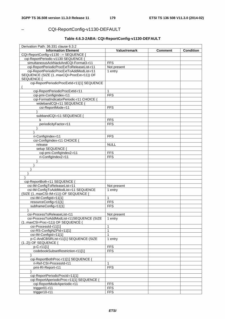
ETSI
ETSI TS 136 508 V11.3.0 (2014-02)1793GPP TS 36.508 version 11.3.0 Release 11
– CQI-ReportConfig-v1130-DEFAULT
Table 4.6.3-2ABA: CQI-ReportConfig-v1130-DEFAULT
Derivation Path: 36.331 clause 6.3.2 Information Element Value/remark Comment Condition
CQI-ReportConfig-v1130 ::= SEQUENCE { cqi-ReportPeriodic-v1130 SEQUENCE { simultaneousAckNackAndCQI-Format3-r11 FFS cqi-ReportPeriodicProcExtToReleaseList-r11 Not present cqi-ReportPeriodicProcExtToAddModList-r11 SEQUENCE (SIZE (1..maxCQI-ProcExt-r11)) OF SEQUENCE {
1 entry
cqi-ReportPeriodicProcExtId-r11[1] SEQUENCE {
cqi-ReportPeriodicProcExtId-r11 1 cqi-pmi-ConfigIndex-r11 FFS cqi-FormatIndicatorPeriodic-r11 CHOICE { widebandCQI-r11 SEQUENCE { csi-ReportMode-r11 FFS } subbandCQI-r11 SEQUENCE { k FFS periodicityFactor-r11 FFS } } ri-ConfigIndex-r11 FFS csi-ConfigIndex-r11 CHOICE { release NULL setup SEQUENCE { cqi-pmi-ConfigIndex2-r11 FFS ri-ConfigIndex2-r11 FFS } } } } } cqi-ReportBoth-r11 SEQUENCE { csi-IM-ConfigToReleaseList-r11 Not present csi-IM-ConfigToAddModList-r11 SEQUENCE (SIZE (1..maxCSI-IM-r11)) OF SEQUENCE {
1 entry
csi-IM-ConfigId-r11[1] 1 resourceConfig-r11[1] FFS subframeConfig-r11[1] FFS } csi-ProcessToReleaseList-r11 Not present csi-ProcessToAddModList-r11SEQUENCE (SIZE (1..maxCSI-Proc-r11)) OF SEQUENCE {
1 entry
csi-ProcessId-r11[1] 1 csi-RS-ConfigNZPId-r11[1] 1 csi-IM-ConfigId-r11[1] 1 p-C-AndCBSRList-r11[1] SEQUENCE (SIZE (1..2)) OF SEQUENCE {
1 entry
p-C-r11[1] FFS codebookSubsetRestriction-r11[1] FFS } cqi-ReportBothProc-r11[1] SEQUENCE { ri-Ref-CSI-ProcessId-r11 1 pmi-RI-Report-r11 FFS } cqi-ReportPeriodicProcId-r11[1] cqi-ReportAperiodicProc-r11[1] SEQUENCE { cqi-ReportModeAperiodic-r11 FFS trigger01-r11 FFS trigger10-r11 FFS
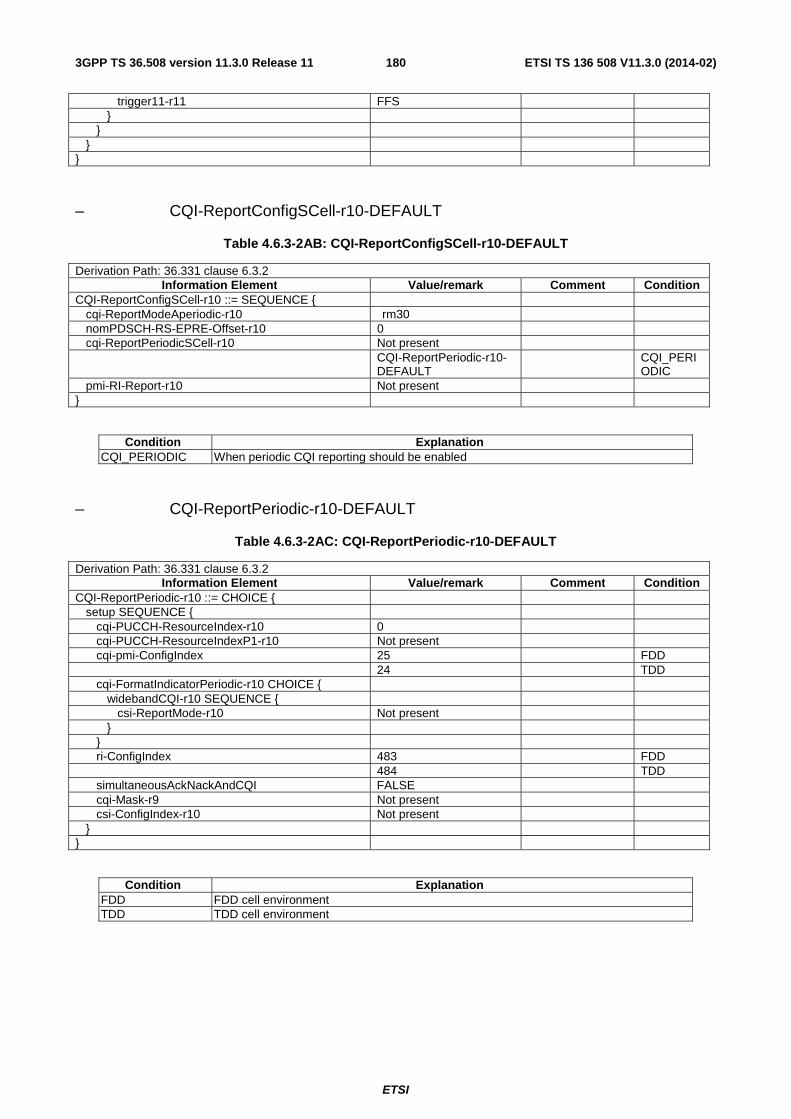
ETSI
ETSI TS 136 508 V11.3.0 (2014-02)1803GPP TS 36.508 version 11.3.0 Release 11
trigger11-r11 FFS } } } }
– CQI-ReportConfigSCell-r10-DEFAULT
Table 4.6.3-2AB: CQI-ReportConfigSCell-r10-DEFAULT
Derivation Path: 36.331 clause 6.3.2 Information Element Value/remark Comment Condition
CQI-ReportConfigSCell-r10 ::= SEQUENCE { cqi-ReportModeAperiodic-r10 rm30 nomPDSCH-RS-EPRE-Offset-r10 0 cqi-ReportPeriodicSCell-r10 Not present CQI-ReportPeriodic-r10-
DEFAULT CQI_PERI
ODIC pmi-RI-Report-r10 Not present }
Condition Explanation CQI_PERIODIC When periodic CQI reporting should be enabled
– CQI-ReportPeriodic-r10-DEFAULT
Table 4.6.3-2AC: CQI-ReportPeriodic-r10-DEFAULT
Derivation Path: 36.331 clause 6.3.2 Information Element Value/remark Comment Condition
CQI-ReportPeriodic-r10 ::= CHOICE { setup SEQUENCE { cqi-PUCCH-ResourceIndex-r10 0 cqi-PUCCH-ResourceIndexP1-r10 Not present cqi-pmi-ConfigIndex 25 FDD 24 TDD cqi-FormatIndicatorPeriodic-r10 CHOICE { widebandCQI-r10 SEQUENCE { csi-ReportMode-r10 Not present } } ri-ConfigIndex 483 FDD 484 TDD simultaneousAckNackAndCQI FALSE cqi-Mask-r9 Not present csi-ConfigIndex-r10 Not present } }
Condition Explanation FDD FDD cell environment TDD TDD cell environment

ETSI
ETSI TS 136 508 V11.3.0 (2014-02)1813GPP TS 36.508 version 11.3.0 Release 11
Table 4.6.3-2AD: Void
Table 4.6.3-2AE: Void
– CSI-RS-ConfigNZP-r11-DEFAULT
Table 4.6.3-2AF: CSI-RS-ConfigNZP-r11-DEFAULT
Derivation Path: 36.331 clause 6.3.2 Information Element Value/remark Comment Condition
CSI-RS-ConfigNZP-r11 ::= SEQUENCE { csi-RS-ConfigNZPId-r11 1 antennaPortsCount-r11 FFS resourceConfig-r11 FFS subframeConfig-r11 FFS scramblingIdentity-r11 FFS qcl-CRS-Info-r11 SEQUENCE { qcl-ScramblingIdentity-r11 FFS crs-PortsCount-r11 FFS mbsfn-SubframeConfigList-r11 CHOICE { release NULL setup SEQUENCE { subframeConfigList FFS } } } }
– CSI-RS-ConfigZP-r11-DEFAULT
Table 4.6.3-2AG: CSI-RS-ConfigZP-r11-DEFAULT
Derivation Path: 36.331 clause 6.3.2 Information Element Value/remark Comment Condition
CSI-RS-ConfigZP-r11 ::= SEQUENCE { csi-RS-ConfigZPId-r11 1 resourceConfigList-r11 FFS subframeConfig-r11 FFS }
– DMRS-Config-r11-DEFAULT
Table 4.6.3-2AH: DMRS-Config-r11-DEFAULT
Derivation Path: 36.331 clause 6.3.2 Information Element Value/remark Comment Condition
DMRS-Config-r11 ::= CHOICE { release NULL setup SEQUENCE { scramblingIdentity-r11 FFS scramblingIdentity2-r11 FFS } }

ETSI
ETSI TS 136 508 V11.3.0 (2014-02)1823GPP TS 36.508 version 11.3.0 Release 11
– DRB-ToAddModList-RECONFIG
Table 4.6.3-2A: DRB-ToAddModList-RECONFIG
Derivation Path: 36.331 clause 6.3.2 Information Element Value/remark Comment Condition
DRB-ToAddModList ::= SEQUENCE (SIZE (1..maxDRB)) OF SEQUENCE {
2 Entries
eps-BearerIdentity[1] Not present drb-Identity[1] 1 pdcp-Config[1] Not present rlc-Config[1] RLC-Config-DRB-AM-
RECONFIG
logicalChannelIdentity[1] Not present logicalChannelConfig[1] Not present eps-BearerIdentity[2] Not present drb-Identity[2] 2 pdcp-Config[2] Not present rlc-Config[2] RLC-Config-DRB-AM-
RECONFIG
logicalChannelIdentity[2] Not present logicalChannelConfig[2] Not present }

ETSI
ETSI TS 136 508 V11.3.0 (2014-02)1833GPP TS 36.508 version 11.3.0 Release 11
– EPDCCH-Config-r11-DEFAULT
Table 4.6.3-2B: EPDCCH-Config-r11-DEFAULT
Derivation Path: 36.331 clause 6.3.2 Information Element Value/remark Comment Condition
EPDCCH-Config-r11 ::= SEQUENCE{ config-r11 CHOICE { release NULL setup SEQUENCE { subframePatternConfig-r11 CHOICE { release NULL setup SEQUENCE { subframePattern-r11 CHOICE { subframePatternFDD-r10 FFS FDD subframePatternTDD-r10 CHOICE { TDD subframeConfig1-5-r10 FFS subframeConfig0-r10 FFS subframeConfig6-r10 FFS } } } } startSymbol-r11 FFS setConfigToReleaseList-r11 Not present setConfigToAddModList-r11 SEQUENCE { 1 entry setConfigId-r11[1] FFS transmissionType-r11[1] FFS resourceBlockAssignment-r11[1] SEQUENCE{
numberPRB-Pairs-r11 FFS resourceBlockAssignment-r11 FFS } dmrs-ScramblingSequenceInt-r11[1] FFS pucch-ResourceStartOffset-r11[1] FFS re-MappingQCL-ConfigListId-r11[1] FFS } } } }
Condition Explanation FDD FDD cell environment TDD TDD cell environment
– PCCH-Config-DEFAULT
Table 4.6.3-3: PCCH-Config-DEFAULT
Derivation Path: 36.331 clause 6.3.2 Information Element Value/remark Comment Condition
PCCH-Config-DEFAULT::= SEQUENCE { defaultPagingCycle rf128 Typical value in
real network.
nB oneT }

ETSI
ETSI TS 136 508 V11.3.0 (2014-02)1843GPP TS 36.508 version 11.3.0 Release 11
– PHICH-Config-DEFAULT
Table 4.6.3-4: PHICH-Config-DEFAULT
Derivation Path: 36.331 clause 6.3.2 Information Element Value/remark Comment Condition
PHICH-Config-DEFAULT ::= SEQUENCE { phich-Duration normal phich-Resource one Ng=1 has been
selected to ensure enough PHICH resources from the real network point of view.
}
– PDSCH-ConfigCommon-DEFAULT
Table 4.6.3-5: PDSCH-ConfigCommon-DEFAULT
Derivation Path: 36.331 clause 6.3.2 Information Element Value/remark Comment Condition
PDSCH-ConfigCommon-DEFAULT ::= SEQUENCE { referenceSignalPower 18 (dBm) p-b 0 ( AB ρρ / = 1) 1TX
1 ( AB ρρ / = 1) 2TX
}
Condition Explanation 1TX 1 SS Tx antenna environment 2TX 2 SS Tx antenna environment
– PDSCH-ConfigDedicated-DEFAULT
Table 4.6.3-6: PDSCH-ConfigDedicated-DEFAULT
Derivation Path: 36.331 clause 6.3.2 Information Element Value/remark Comment Condition
PDSCH-ConfigDedicated-DEFAULT ::= SEQUENCE {
p-a dB-3 for signalling test cases; dB0 for others
dB-3 for signalling test cases to reduce interference from PDSCH of intra-frequency neighbour cells
1TX
dB-3 2TX }
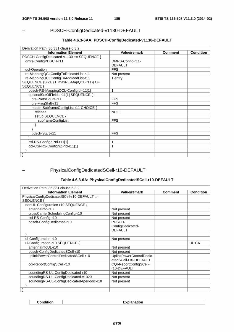
ETSI
ETSI TS 136 508 V11.3.0 (2014-02)1853GPP TS 36.508 version 11.3.0 Release 11
– PDSCH-ConfigDedicated-v1130-DEFAULT
Table 4.6.3-6AA: PDSCH-ConfigDedicated-v1130-DEFAULT
Derivation Path: 36.331 clause 6.3.2 Information Element Value/remark Comment Condition
PDSCH-ConfigDedicated-v1130 ::= SEQUENCE { dmrs-ConfigPDSCH-r11 DMRS-Config-r11-
DEFAULT
qcl-Operation FFS re-MappingQCLConfigToReleaseList-r11 Not present re-MappingQCLConfigToAddModList-r11 SEQUENCE (SIZE (1..maxRE-MapQCL-r11)) OF SEQUENCE {
1 entry
pdsch-RE-MappingQCL-ConfigId-r11[1] 1 optionalSetOfFields-r11[1] SEQUENCE { crs-PortsCount-r11 FFS crs-FreqShift-r11 FFS mbsfn-SubframeConfigList-r11 CHOICE { release NULL setup SEQUENCE { subframeConfigList FFS } } pdsch-Start-r11 FFS } csi-RS-ConfigZPId-r11[1] 1 qcl-CSI-RS-ConfigNZPId-r11[1] 1 } }
– PhysicalConfigDedicatedSCell-r10-DEFAULT
Table 4.6.3-6A: PhysicalConfigDedicatedSCell-r10-DEFAULT
Derivation Path: 36.331 clause 6.3.2 Information Element Value/remark Comment Condition
PhysicalConfigDedicatedSCell-r10-DEFAULT ::= SEQUENCE {
nonUL-Configuration-r10 SEQUENCE { antennaInfo-r10 Not present crossCarrierSchedulingConfig-r10 Not present csi-RS-Config-r10 Not present pdsch-ConfigDedicated-r10 PDSCH-
ConfigDedicated-DEFAULT
} ul-Configuration-r10 Not present ul-Configuration-r10 SEQUENCE { UL CA antennaInfoUL-r10 Not present pusch-ConfigDedicatedSCell-r10 Not present uplinkPowerControlDedicatedSCell-r10 UplinkPowerControlDedic
atedSCell-r10-DEFAULT
cqi-ReportConfigSCell-r10 CQI-ReportConfigSCell-r10-DEFAULT
soundingRS-UL-ConfigDedicated-r10 Not present soundingRS-UL-ConfigDedicated-v1020 Not present soundingRS-UL-ConfigDedicatedAperiodic-r10 Not present } }
Condition Explanation
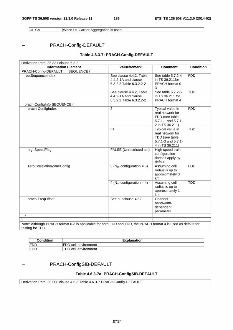
ETSI
ETSI TS 136 508 V11.3.0 (2014-02)1863GPP TS 36.508 version 11.3.0 Release 11
UL CA When UL Carrier Aggregation is used.
– PRACH-Config-DEFAULT
Table 4.6.3-7: PRACH-Config-DEFAULT
Derivation Path: 36.331 clause 6.3.2 Information Element Value/remark Comment Condition
PRACH-Config-DEFAULT ::= SEQUENCE { rootSequenceIndex See clause 4.4.2, Table
4.4.2-1A and clause 6.3.2.2 Table 6.3.2.2-2
See table 5.7.2-4 in TS 36.211for PRACH format 0-3
FDD
See clause 4.4.2, Table 4.4.2-1A and clause 6.3.2.2 Table 6.3.2.2-2
See table 5.7.2-5 in TS 36.211 for PRACH format 4
TDD
prach-ConfigInfo SEQUENCE { prach-ConfigIndex 3 Typical value in
real network for FDD (see table 5.7.1-1 and 5.7.1-2 in TS 36.211)
FDD
51 Typical value in real network for TDD (see table 5.7.1-3 and 5.7.1-4 in TS 36.211)
TDD
highSpeedFlag FALSE (Unrestricted set) High speed train configuration doesn’t apply by default.
zeroCorrelationZoneConfig 5 (Ncs configuration = 5) Assuming cell radius is up to approximately 3 km.
FDD
4 (Ncs configuration = 4) Assuming cell radius is up to approximately 1 km.
TDD
prach-FreqOffset See subclause 4.6.8 Channel-bandwidth-dependent parameter
} } Note: Although PRACH format 0-3 is applicable for both FDD and TDD, the PRACH format 4 is used as default for testing for TDD.
Condition Explanation FDD FDD cell environment TDD TDD cell environment
– PRACH-ConfigSIB-DEFAULT
Table 4.6.3-7a: PRACH-ConfigSIB-DEFAULT
Derivation Path: 36.508 clause 4.6.3 Table 4.6.3-7 PRACH-Config-DEFAULT

ETSI
ETSI TS 136 508 V11.3.0 (2014-02)1873GPP TS 36.508 version 11.3.0 Release 11
– PUCCH-ConfigCommon-DEFAULT
Table 4.6.3-8: PUCCH-ConfigCommon-DEFAULT
Derivation Path: 36.331 clause 6.3.2 Information Element Value/remark Comment Condition
PUCCH-ConfigCommon-DEFAULT ::= SEQUENCE { deltaPUCCH-Shift ds2 Assuming typical
values of the maximum delay spread
nRB-CQI See subclause 4.6.8 Channel-bandwidth-dependent parameter
nCS-AN 6 n1PUCCH-AN 0 }
– PUCCH-ConfigDedicated-DEFAULT
Table 4.6.3-9: PUCCH-ConfigDedicated-DEFAULT
Derivation Path: 36.331 clause 6.3.2 Information Element Value/remark Comment Condition
PUCCH-ConfigDedicated-DEFAULT ::= SEQUENCE {
ackNackRepetition CHOICE { release NULL } tddAckNackFeedbackMode Not present FDD multiplexing Multiplexing is
selected as default to align with RAN4’s assumptions in RF tests.
TDD
}
Condition Explanation FDD FDD cell environment TDD TDD cell environment

ETSI
ETSI TS 136 508 V11.3.0 (2014-02)1883GPP TS 36.508 version 11.3.0 Release 11
– PUCCH-ConfigDedicated-v1020-DEFAULT
Table 4.6.3-9A: PUCCH-ConfigDedicated-v1020-DEFAULT
Derivation Path: 36.331 clause 6.3.2 Information Element Value/remark Comment Condition
PUCCH-ConfigDedicated-v1020 ::= SEQUENCE { pucch-Format-r10 CHOICE { channelSelection-r10 SEQUENCE { n1PUCCH-AN-CS-r10 CHOICE { setup SEQUENCE { n1PUCCH-AN-CS-List-r10 SEQUENCE{ 1 FDD N1PUCCH-AN-CS-r10 4 101 102 103 104 } n1PUCCH-AN-CS-List-r10 SEQUENCE{ 2 2TX AND
FDD, TDD
N1PUCCH-AN-CS-r10 4 101 102 103 104 N1PUCCH-AN-CS-r10 4 105 106 107 108 } } } } } twoAntennaPortActivatedPUCCH-Format1a1b-r10 Not present simultaneousPUCCH-PUSCH-r10 Not present n1PUCCH-AN-RepP1-r10 Not present }
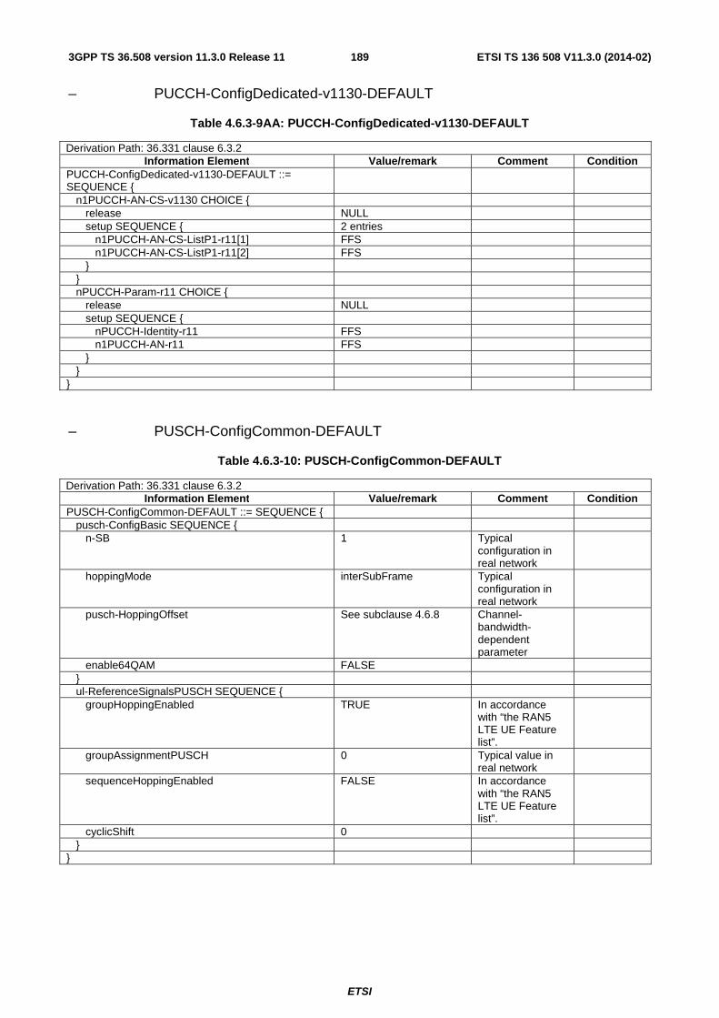
ETSI
ETSI TS 136 508 V11.3.0 (2014-02)1893GPP TS 36.508 version 11.3.0 Release 11
– PUCCH-ConfigDedicated-v1130-DEFAULT
Table 4.6.3-9AA: PUCCH-ConfigDedicated-v1130-DEFAULT
Derivation Path: 36.331 clause 6.3.2 Information Element Value/remark Comment Condition
PUCCH-ConfigDedicated-v1130-DEFAULT ::= SEQUENCE {
n1PUCCH-AN-CS-v1130 CHOICE { release NULL setup SEQUENCE { 2 entries n1PUCCH-AN-CS-ListP1-r11[1] FFS n1PUCCH-AN-CS-ListP1-r11[2] FFS } } nPUCCH-Param-r11 CHOICE { release NULL setup SEQUENCE { nPUCCH-Identity-r11 FFS n1PUCCH-AN-r11 FFS } } }
– PUSCH-ConfigCommon-DEFAULT
Table 4.6.3-10: PUSCH-ConfigCommon-DEFAULT
Derivation Path: 36.331 clause 6.3.2 Information Element Value/remark Comment Condition
PUSCH-ConfigCommon-DEFAULT ::= SEQUENCE { pusch-ConfigBasic SEQUENCE { n-SB 1 Typical
configuration in real network
hoppingMode interSubFrame Typical configuration in real network
pusch-HoppingOffset See subclause 4.6.8 Channel-bandwidth-dependent parameter
enable64QAM FALSE } ul-ReferenceSignalsPUSCH SEQUENCE { groupHoppingEnabled TRUE In accordance
with “the RAN5 LTE UE Feature list”.
groupAssignmentPUSCH 0 Typical value in real network
sequenceHoppingEnabled FALSE In accordance with “the RAN5 LTE UE Feature list”.
cyclicShift 0 } }

ETSI
ETSI TS 136 508 V11.3.0 (2014-02)1903GPP TS 36.508 version 11.3.0 Release 11
– PUSCH-ConfigDedicated-DEFAULT
Table 4.6.3-11: PUSCH-ConfigDedicated-DEFAULT
Derivation Path: 36.331 clause 6.3.2 Information Element Value/remark Comment Condition
PUSCH-ConfigDedicated-DEFAULT ::= SEQUENCE {
betaOffset-ACK-Index 9 betaOffset-RI-Index 6 betaOffset-CQI-Index 6 }
Table 4.6.3-11A: Void
– PUSCH-ConfigDedicated-v1130-DEFAULT
Table 4.6.3-11AA: PUSCH-ConfigDedicated-v1130-DEFAULT
Derivation Path: 36.331 clause 6.3.2 Information Element Value/remark Comment Condition
PUSCH-ConfigDedicated-v1130-DEFAULT ::= SEQUENCE {
pusch-DMRS-r11 CHOICE { release NULL setup SEQUENCE { nPUSCH-Identity-r11 FFS nDMRS-CSH-Identity-r11 FFS } } }

ETSI
ETSI TS 136 508 V11.3.0 (2014-02)1913GPP TS 36.508 version 11.3.0 Release 11
– RACH-ConfigCommon-DEFAULT
Table 4.6.3-12: RACH-ConfigCommon-DEFAULT
Derivation Path: 36.331 clause 6.3.2 Information Element Value/remark Comment Condition
RACH-ConfigCommon-DEFAULT ::= SEQUENCE { preambleInfo SEQUENCE {
numberOfRA-Preambles n52 Assuming the number of dedicated preambles is 12.
preamblesGroupAConfig SEQUENCE {} Not present } powerRampingParameters SEQUENCE { powerRampingStep dB2 preambleInitialReceivedTargetPower dBm-104 (default) Thermal noise = -
113 dBm NF = 5 dB IoT = 6 dB Required SNR = -8 dB (See table 8.4.2-1 in TS 36.104 [30]) -> -110 dB (default value is acceptable)
} ra-SupervisionInfo SEQUENCE { preambleTransMax n6 Under the
condition of Case 1 in RAN1 simulation assumptions, an UE with pathloss of CDF = 90% reaches the maximum transmit power in 4 successive retransmissions. 6 has been selected considering the margin of 2.
ra-ResponseWindowSize sf10 The maximum value is preferable.
mac-ContentionResolutionTimer sf48 Allows for a sufficient number of msg3 retransmissions.
} maxHARQ-Msg3Tx 4 Under the
condition of Target SIR = 2 dB, the probability of 2 transmissions is less than 1%. 4 has been selected considering the margin of 2.
}

ETSI
ETSI TS 136 508 V11.3.0 (2014-02)1923GPP TS 36.508 version 11.3.0 Release 11
– Rach-ConfigDedicated-DEFAULT
Table 4.6.3-12A: Rach-ConfigDedicated-DEFAULT
Derivation Path: 36.331 clause 6.3.2 Information Element Value/remark Comment Condition
Rach-ConfigDedicated-DEFAULT ::= SEQUENCE { ra-PreambleIndex 52 ra-PRACH-MaskIndex 0 }
– RadioResourceConfigCommon-DEFAULT
Table 4.6.3-13: RadioResourceConfigCommon-DEFAULT
Derivation Path: 36.331 clause 6.3.2 Information Element Value/remark Comment Condition
RadioResourceConfigCommon-DEFAULT ::= SEQUENCE {
rach-ConfigCommon RACH-ConfigCommon-DEFAULT
prach-Config PRACH-Config-DEFAULT
pdsch-ConfigCommon Not present PDSCH-ConfigCommon-DEFAULT
FullConfig, HO-to-EUTRA
pusch-ConfigCommon PUSCH-ConfigCommon-DEFAULT
phich-Config Not present PHICH-Config-DEFAULT FullConfig,
HO-to-EUTRA
pucch-ConfigCommon Not present SAME-BW PUCCH-ConfigCommon-
DEFAULT DIFF-BW,
FullConfig, HO-to-EUTRA
soundingRSUL-ConfigCommon SoundingRS-UL-ConfigCommon-DEFAULT
uplinkPowerControlCommon Not present UplinkPowerControlCommon-DEFAULT
FullConfig, HO-to-EUTRA
antennaInfoCommon Not present antennaInfoCommon SEQUENCE { 2TX antennaPortsCount an2 } antennaInfoCommon SEQUENCE { FullConfig,
HO-to-EUTRA
antennaPortsCount an1 } p-Max Not present tdd-Config Not present FDD TDD-Config-DEFAULT TDD ul-CyclicPrefixLength len1 uplinkPowerControlCommon-v1020 UplinkPowerControlCom
mon-v1020-DEFAULT CA
Not present }
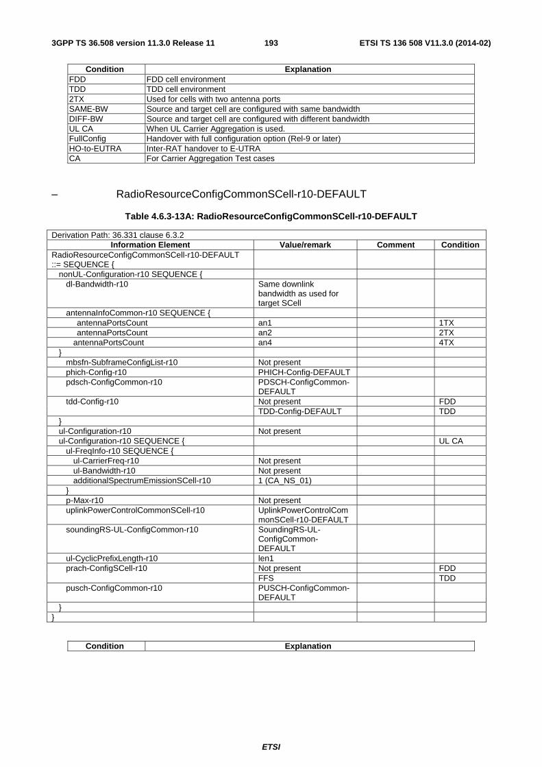
ETSI
ETSI TS 136 508 V11.3.0 (2014-02)1933GPP TS 36.508 version 11.3.0 Release 11
Condition Explanation FDD FDD cell environment TDD TDD cell environment 2TX Used for cells with two antenna ports SAME-BW Source and target cell are configured with same bandwidth DIFF-BW Source and target cell are configured with different bandwidth UL CA When UL Carrier Aggregation is used. FullConfig Handover with full configuration option (Rel-9 or later) HO-to-EUTRA Inter-RAT handover to E-UTRA CA For Carrier Aggregation Test cases
– RadioResourceConfigCommonSCell-r10-DEFAULT
Table 4.6.3-13A: RadioResourceConfigCommonSCell-r10-DEFAULT
Derivation Path: 36.331 clause 6.3.2 Information Element Value/remark Comment Condition
RadioResourceConfigCommonSCell-r10-DEFAULT ::= SEQUENCE {
nonUL-Configuration-r10 SEQUENCE { dl-Bandwidth-r10 Same downlink
bandwidth as used for target SCell
antennaInfoCommon-r10 SEQUENCE { antennaPortsCount an1 1TX antennaPortsCount an2 2TX antennaPortsCount an4 4TX } mbsfn-SubframeConfigList-r10 Not present phich-Config-r10 PHICH-Config-DEFAULT pdsch-ConfigCommon-r10 PDSCH-ConfigCommon-
DEFAULT
tdd-Config-r10 Not present FDD TDD-Config-DEFAULT TDD } ul-Configuration-r10 Not present ul-Configuration-r10 SEQUENCE { UL CA ul-FreqInfo-r10 SEQUENCE { ul-CarrierFreq-r10 Not present ul-Bandwidth-r10 Not present additionalSpectrumEmissionSCell-r10 1 (CA_NS_01) } p-Max-r10 Not present uplinkPowerControlCommonSCell-r10 UplinkPowerControlCom
monSCell-r10-DEFAULT
soundingRS-UL-ConfigCommon-r10 SoundingRS-UL-ConfigCommon-DEFAULT
ul-CyclicPrefixLength-r10 len1 prach-ConfigSCell-r10 Not present FDD FFS TDD pusch-ConfigCommon-r10 PUSCH-ConfigCommon-
DEFAULT
} }
Condition Explanation
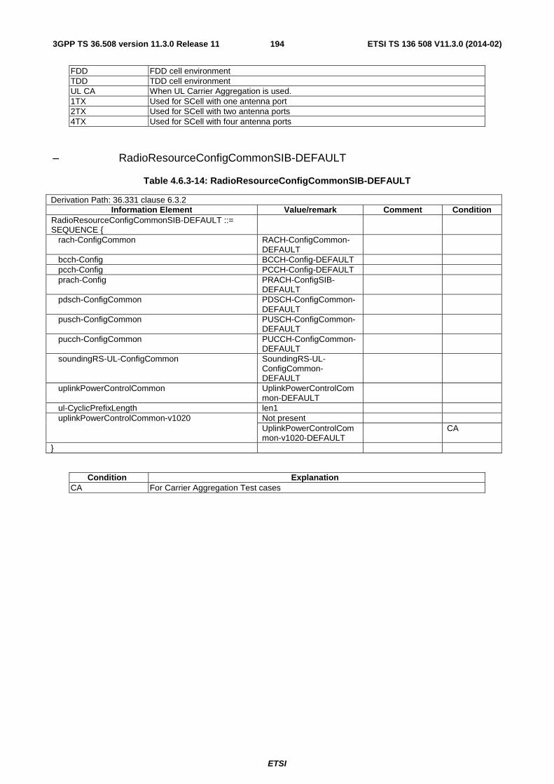
ETSI
ETSI TS 136 508 V11.3.0 (2014-02)1943GPP TS 36.508 version 11.3.0 Release 11
FDD FDD cell environment TDD TDD cell environment UL CA When UL Carrier Aggregation is used. 1TX Used for SCell with one antenna port 2TX Used for SCell with two antenna ports 4TX Used for SCell with four antenna ports
– RadioResourceConfigCommonSIB-DEFAULT
Table 4.6.3-14: RadioResourceConfigCommonSIB-DEFAULT
Derivation Path: 36.331 clause 6.3.2 Information Element Value/remark Comment Condition
RadioResourceConfigCommonSIB-DEFAULT ::= SEQUENCE {
rach-ConfigCommon RACH-ConfigCommon-DEFAULT
bcch-Config BCCH-Config-DEFAULT pcch-Config PCCH-Config-DEFAULT prach-Config PRACH-ConfigSIB-
DEFAULT
pdsch-ConfigCommon PDSCH-ConfigCommon-DEFAULT
pusch-ConfigCommon PUSCH-ConfigCommon-DEFAULT
pucch-ConfigCommon PUCCH-ConfigCommon-DEFAULT
soundingRS-UL-ConfigCommon SoundingRS-UL-ConfigCommon-DEFAULT
uplinkPowerControlCommon UplinkPowerControlCommon-DEFAULT
ul-CyclicPrefixLength len1 uplinkPowerControlCommon-v1020 Not present UplinkPowerControlCom
mon-v1020-DEFAULT CA
}
Condition Explanation CA For Carrier Aggregation Test cases

ETSI
ETSI TS 136 508 V11.3.0 (2014-02)1953GPP TS 36.508 version 11.3.0 Release 11
– RadioResourceConfigDedicated-SRB1
Table 4.6.3-15: RadioResourceConfigDedicated-SRB1
Derivation Path: 36.331 clause 6.3.2 Information Element Value/remark Comment Condition
RadioResourceConfigDedicated-SRB1 ::= SEQUENCE {
srb-ToAddModList SEQUENCE (SIZE (1..2)) OF SEQUENCE {}
1 entry, with value SRB-ToAddMod-DEFAULT using condition SRB1
drb-ToAddModList Not present drb-ToReleaseList Not present mac-MainConfig CHOICE { explicitValue MAC-MainConfig-SRB See subclause
4.8.2
} sps-Config Not present physicalConfigDedicated PhysicalConfigDedicated
-DEFAULT using condition SRB1
See subclause 4.8.2
}

ETSI
ETSI TS 136 508 V11.3.0 (2014-02)1963GPP TS 36.508 version 11.3.0 Release 11
– RadioResourceConfigDedicated-SRB2-DRB(n,m)
Table 4.6.3-16: RadioResourceConfigDedicated-SRB2-DRB(n,m)
Derivation Path: 36.331 clause 6.3.2 Information Element Value/remark Comment Condition
RadioResourceConfigDedicated-SRB2-DRB(n, m) ::= SEQUENCE {
n is the number of AM RLC DRBs (1..N) m is the number of UM RLC DRBs (0..M)
srb-ToAddModList SEQUENCE (SIZE (1..2)) OF SEQUENCE {
1 entry
srb-ToAddMod[1] SRB-ToAddMod-DEFAULT using condition SRB2
See subclause 4.8.2
} drb-ToAddModList SEQUENCE (SIZE (1..maxDRB)) OF SEQUENCE {
n+m entries
drb-ToAddMod[k, k=1..n] DRB-ToAddMod-DEFAULT (k) using condition AM
n AM RLC DRBs See subclause 4.8.2
drb-ToAddMod[k, k=n+1..n+m] DRB-ToAddMod-DEFAULT (k) using condition UM
m UM RLC DRBs See subclause 4.8.2
m>0
} drb-ToReleaseList Not present mac-MainConfig CHOICE { explicitValue MAC-MainConfig-RBC
using condition DRX_L (note)
See subclause 4.8.2
m=0
MAC-MainConfig-RBC using condition DRX_S (note)
See subclause 4.8.2
m>0
} sps-Config Not present physicalConfigDedicated PhysicalConfigDedicated
- DEFAULT using condition RBC
See subclause 4.8.2
} NOTE: In cases where no RLC-UM bearer is configured, large DRX Cycle length is used. In cases where at least one
RLC-UM bearer is configured, small DRX Cycle length is used.
Condition Explanation m=0 m is equal to zero m>0 m is greater than zero

ETSI
ETSI TS 136 508 V11.3.0 (2014-02)1973GPP TS 36.508 version 11.3.0 Release 11
– RadioResourceConfigDedicated-DRB(n,m)
Table 4.6.3-17: RadioResourceConfigDedicated-DRB(n,m)
Derivation Path: 36.331 clause 6.3.2 Information Element Value/remark Comment Condition
RadioResourceConfigDedicated-DRB(n, m) ::= SEQUENCE {
n is the number of AM RLC DRBs (0..N) m is the number of UM RLC DRBs (0..M)
srb-ToAddModList Not present drb-ToAddModList SEQUENCE (SIZE (1..maxDRB)) OF SEQUENCE {
n+m entries BID is the total number of established DRBs in the UE, before applying the contents of this IE
drb-ToAddMod[k, k=BID+1..BID+n] DRB-ToAddMod-DEFAULT (k) using condition AM
n AM RLC DRBs See subclause 4.8.2
n>0
drb-ToAddMod[k, k= BID+1+n.. BID+n+m] DRB-ToAddMod-DEFAULT (k) using condition UM
m UM RLC DRBs See subclause 4.8.2
m>0
} drb-ToReleaseList Not present mac-MainConfig Not present (note) m=0 mac-MainConfig CHOICE { m>0 explicitValue MAC-MainConfig-RBC
using condition DRX_S (note)
See subclause 4.8.2
} sps-Config Not present physicalConfigDedicated Not present } NOTE: In cases where no RLC-UM bearer is added, existing DRX configuration is used without modification. In
cases where at least one RLC-UM bearer is added, small DRX Cycle length is used.
Condition Explanation n>0 n is greater than zero m=0 m is equal to zero m>0 m is greater than zero

ETSI
ETSI TS 136 508 V11.3.0 (2014-02)1983GPP TS 36.508 version 11.3.0 Release 11
– RadioResourceConfigDedicated-HO-TO-EUTRA(n,m)
Table 4.6.3-18: RadioResourceConfigDedicated-HO-TO-EUTRA(n,m)
Derivation Path: 36.331 clause 6.3.2 Information Element Value/remark Comment Condition
RadioResourceConfigDedicated-HO-TO-EUTRA(n, m) ::= SEQUENCE {
n is the number of AM RLC DRBs (1..N) m is the number of UM RLC DRBs (0..M)
srb-ToAddModList SEQUENCE (SIZE (1..2)) OF SEQUENCE {
2 entries
srb-ToAddMod[1] SRB-ToAddMod-DEFAULT using condition SRB1
See subclause 4.8.2
srb-ToAddMod[2] SRB-ToAddMod-DEFAULT using condition SRB2
See subclause 4.8.2
} drb-ToAddModList SEQUENCE (SIZE (1..maxDRB)) OF SEQUENCE {
n+m entries
drb-ToAddMod[k, k=1..n] DRB-ToAddMod-DEFAULT (k) using condition AM
n AM RLC DRBs See subclause 4.8.2
drb-ToAddMod[k, k=n+1..n+m] DRB-ToAddMod-DEFAULT (k) using condition UM
m UM RLC DRBs See subclause 4.8.2
m>0
} drb-ToReleaseList Not present mac-MainConfig CHOICE { explicitValue MAC-MainConfig-RBC
using condition DRX_L (note)
See subclause 4.8.2
m=0
MAC-MainConfig-RBC using condition DRX_S (note)
See subclause 4.8.2
m>0
} sps-Config Not present physicalConfigDedicated PhysicalConfigDedicated
- DEFAULT using condition RBC
See subclause 4.8.2
} NOTE: In cases where no RLC-UM bearer is configured, large DRX Cycle length is used. In cases where at least one
RLC-UM bearer is configured, small DRX Cycle length is used.
Condition Explanation m=0 m is equal to zero m>0 m is greater than zero
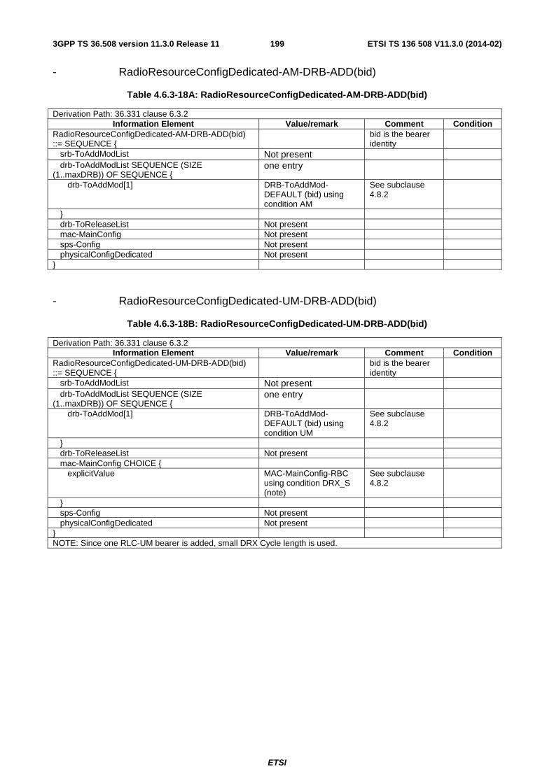
ETSI
ETSI TS 136 508 V11.3.0 (2014-02)1993GPP TS 36.508 version 11.3.0 Release 11
- RadioResourceConfigDedicated-AM-DRB-ADD(bid)
Table 4.6.3-18A: RadioResourceConfigDedicated-AM-DRB-ADD(bid)
Derivation Path: 36.331 clause 6.3.2 Information Element Value/remark Comment Condition
RadioResourceConfigDedicated-AM-DRB-ADD(bid) ::= SEQUENCE {
bid is the bearer identity
srb-ToAddModList Not present drb-ToAddModList SEQUENCE (SIZE (1..maxDRB)) OF SEQUENCE {
one entry
drb-ToAddMod[1] DRB-ToAddMod-DEFAULT (bid) using condition AM
See subclause 4.8.2
} drb-ToReleaseList Not present mac-MainConfig Not present sps-Config Not present physicalConfigDedicated Not present }
- RadioResourceConfigDedicated-UM-DRB-ADD(bid)
Table 4.6.3-18B: RadioResourceConfigDedicated-UM-DRB-ADD(bid)
Derivation Path: 36.331 clause 6.3.2 Information Element Value/remark Comment Condition
RadioResourceConfigDedicated-UM-DRB-ADD(bid) ::= SEQUENCE {
bid is the bearer identity
srb-ToAddModList Not present drb-ToAddModList SEQUENCE (SIZE (1..maxDRB)) OF SEQUENCE {
one entry
drb-ToAddMod[1] DRB-ToAddMod-DEFAULT (bid) using condition UM
See subclause 4.8.2
} drb-ToReleaseList Not present mac-MainConfig CHOICE { explicitValue MAC-MainConfig-RBC
using condition DRX_S (note)
See subclause 4.8.2
} sps-Config Not present physicalConfigDedicated Not present } NOTE: Since one RLC-UM bearer is added, small DRX Cycle length is used.

ETSI
ETSI TS 136 508 V11.3.0 (2014-02)2003GPP TS 36.508 version 11.3.0 Release 11
- RadioResourceConfigDedicated- DRB-REL(bid)
Table 4.6.3-18C: RadioResourceConfigDedicated-DRB-REL(bid)
Derivation Path: 36.331 clause 6.3.2 Information Element Value/remark Comment Condition
RadioResourceConfigDedicated-DRB-REL(bid) ::= SEQUENCE {
bid is the bearer identity
srb-ToAddModList Not present drb-ToAddModList Not present drb-ToReleaseList SEQUENCE (SIZE (1..maxDRB)) OF
one entry
drb-Identity[1] bid mac-MainConfig Not present sps-Config Not present physicalConfigDedicated Not present }
– RadioResourceConfigDedicated-SCell_AddMod
Table 4.6.3-19AAA: RadioResourceConfigDedicated-SCell_AddMod
Derivation Path: 36.331 clause 6.3.2 Information Element Value/remark Comment Condition
RadioResourceConfigDedicated-SCell_AddMod ::= SEQUENCE {
srb-ToAddModList Not present drb-ToAddModList Not present drb-ToReleaseList Not present mac-MainConfig MAC-MainConfig-RBC
using condition SCell_AddMod
See subclause 4.8.2
sps-Config Not present physicalConfigDedicated PhysicalConfigDedicated-
DEFAULT using condition SCell_AddMod
See subclause 4.8.2
}
– RadioResourceConfigDedicated-HO
Table 4.6.3-19: RadioResourceConfigDedicated-HO
Derivation Path: 36.331 clause 6.3.2 Information Element Value/remark Comment Condition
RadioResourceConfigDedicated-HO ::= SEQUENCE {
srb-ToAddModList Not present drb-ToAddModList Not present drb-ToReleaseList Not present mac-MainConfig Not present sps-Config Not present physicalConfigDedicated PhysicalConfigDedicated-
DEFAULT using condition RBC-HO
See subclause 4.8.2
}

ETSI
ETSI TS 136 508 V11.3.0 (2014-02)2013GPP TS 36.508 version 11.3.0 Release 11
– RadioResourceConfigDedicatedSCell-r10-DEFAULT
Table 4.6.3-19AA: RadioResourceConfigDedicatedSCell-r10-DEFAULT
Derivation Path: 36.331 clause 6.3.2 Information Element Value/remark Comment Condition
RadioResourceConfigDedicatedSCell-r10 ::= SEQUENCE {
physicalConfigDedicatedSCell-r10 PhysicalConfigDedicatedSCell-r10-DEFAULT
}
– RLC-Config-DRB-AM-RECONFIG
Table 4.6.3-19A: RLC-Config-DRB-AM-RECONFIG
Derivation Path: 36.508 table 4.8.2.1.3.2-1: RLC-Config-DRB-AM Information Element Value/remark Comment Condition
RLC-Config-DRB-AM-RECONFIG ::= CHOICE { am SEQUENCE { ul-AM-RLC SEQUENCE { t-PollRetransmit ms855 pollPDU p64 pollByte kB250 maxRetxThreshold t8 } dl-AM-RLC SEQUENCE { t-Reordering ms85 t-StatusProhibit ms50 } } }
– RLC-Config-DRB-UM-RECONFIG
Table 4.6.3-19B: RLC-Config-DRB-UM-RECONFIG
Derivation Path: 36.508 table 4.8.2.1.3.1-1: RLC-Config-DRB-UM Information Element Value/remark Comment Condition
RLC-Config-DRB-UM-RECONFIG ::= CHOICE { um-Bi-Directional SEQUENCE { ul-UM-RLC SEQUENCE { sn-FieldLength Size10 } dl-UM-RLC SEQUENCE { sn-FieldLength Size10 t-Reordering ms55 } } }

ETSI
ETSI TS 136 508 V11.3.0 (2014-02)2023GPP TS 36.508 version 11.3.0 Release 11
– RLC-Config-SRB-AM-RECONFIG
Table 4.6.3-19C: RLC-Config-SRB-AM-RECONFIG
Derivation Path: 36.331 clause 6.3.2, 9.2.1 Information Element Value/remark Comment Condition
RLC-Config-SRB-AM-RECONFIG ::= CHOICE { am SEQUENCE { ul-AM-RLC SEQUENCE { t-PollRetransmit ms50 pollPDU pInfinity Default pollByte kBinfinity Default maxRetxThreshold t6 } dl-AM-RLC SEQUENCE { t-Reordering ms40 t –StatusProhibit ms0 Default } } }
– SCellToAddMod-r10-DEFAULT
Table 4.6.3-19D: SCellToAddMod-r10-DEFAULT
Derivation Path: 36.331 clause 6.2.2 Information Element Value/remark Comment Condition
SCellToAddMod-r10 ::= SEQUENCE { sCellIndex-r10 Set according to specific
message content
cellIdentification-r10 SEQUENCE { physCellId-r10 Set according to specific
message content
dl-CarrierFreq-r10 Set according to specific message content
} radioResourceConfigCommonSCell-r10 RadioResourceConfigCo
mmonSCell-r10-DEFAULT
radioResourceConfigDedicatedSCell-r10 RadioResourceConfigDedicatedSCell-r10-DEFAULT
... }
– SCellToRelease-r10-DEFAULT
Table 4.6.3-19E: SCellToRelease-r10-DEFAULT
Derivation Path: 36.331 clause 6.2.2 Information Element Value/remark Comment Condition
sCellToReleaseList-r10 SEQUENCE (SIZE (1..maxSCell-r10) OF SEQUENCE {
sCellIndex-r10[1] 1 }
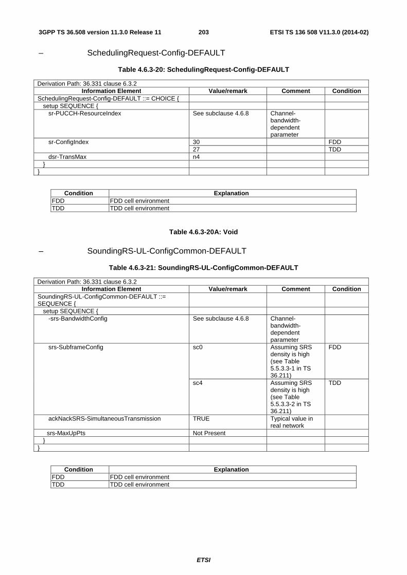
ETSI
ETSI TS 136 508 V11.3.0 (2014-02)2033GPP TS 36.508 version 11.3.0 Release 11
– SchedulingRequest-Config-DEFAULT
Table 4.6.3-20: SchedulingRequest-Config-DEFAULT
Derivation Path: 36.331 clause 6.3.2 Information Element Value/remark Comment Condition
SchedulingRequest-Config-DEFAULT ::= CHOICE { setup SEQUENCE { sr-PUCCH-ResourceIndex See subclause 4.6.8 Channel-
bandwidth-dependent parameter
sr-ConfigIndex 30 FDD 27 TDD
dsr-TransMax n4 } }
Condition Explanation FDD FDD cell environment TDD TDD cell environment
Table 4.6.3-20A: Void
– SoundingRS-UL-ConfigCommon-DEFAULT
Table 4.6.3-21: SoundingRS-UL-ConfigCommon-DEFAULT
Derivation Path: 36.331 clause 6.3.2 Information Element Value/remark Comment Condition
SoundingRS-UL-ConfigCommon-DEFAULT ::= SEQUENCE {
setup SEQUENCE { -srs-BandwidthConfig See subclause 4.6.8 Channel-
bandwidth-dependent parameter
srs-SubframeConfig sc0 Assuming SRS density is high (see Table 5.5.3.3-1 in TS 36.211)
FDD
sc4 Assuming SRS density is high (see Table 5.5.3.3-2 in TS 36.211)
TDD
ackNackSRS-SimultaneousTransmission TRUE Typical value in real network
srs-MaxUpPts Not Present } }
Condition Explanation FDD FDD cell environment TDD TDD cell environment

ETSI
ETSI TS 136 508 V11.3.0 (2014-02)2043GPP TS 36.508 version 11.3.0 Release 11
– SoundingRS-UL-ConfigDedicated-DEFAULT
Table 4.6.3-22: SoundingRS-UL-ConfigDedicated-DEFAULT
Derivation Path: 36.331 clause 6.3.2 Information Element Value/remark Comment Condition
SoundingRS-UL-ConfigDedicated-DEFAULT ::= CHOICE {
setup SEQUENCE { srs-Bandwidth bw0 bw0 used with no
frequency hopping. bw3 used with frequency hopping
srs-HoppingBandwidth hbw0 freqDomainPosition 0 duration TRUE srs-ConfigIndex 20 See Table 8.2-1 in
TS 36.213 FDD
31 INTEGER (0..1023) See Table 8.2-2 in TS 36.213
TDD
transmissionComb 0 cyclicShift cs0 } }
Condition Explanation FDD FDD cell environment TDD TDD cell environment
Table 4.6.3-22AA: Void
– SoundingRS-UL-ConfigDedicatedAperiodic-r10-DEFAULT
Table 4.6.3-22AB: SoundingRS-UL-ConfigDedicatedAperiodic-r10-DEFAULT
Derivation Path: 36.331 clause 6.3.2 Information Element Value/remark Comment Condition
SoundingRS-UL-ConfigDedicatedAperiodic-r10 ::= CHOICE {
setup SEQUENCE { srs-ConfigIndexAp-r10 10 srs-ConfigApDCI-Format4-r10 Not present srs-ActivateAp-r10 Not present } }

ETSI
ETSI TS 136 508 V11.3.0 (2014-02)2053GPP TS 36.508 version 11.3.0 Release 11
– SRB-ToAddModList-RECONFIG
Table 4.6.3-22A: SRB-ToAddModList-RECONFIG
Derivation Path: 36.331 clause 6.3.2 Information Element Value/remark Comment Condition
SRB-ToAddModList ::= SEQUENCE (SIZE (1..2)) OF SEQUENCE {
2 Entries
srb-Identity[1] 1 rlc-Config[1] CHOICE { explicitValue RLC-Config-SRB-AM-
RECONFIG
logicalChannelConfig[1] CHOICE { defaultValue NULL } srb-Identity[2] 2 rlc-Config[2] CHOICE { explicitValue RLC-Config-SRB-AM-
RECONFIG
} logicalChannelConfig[2] CHOICE { defaultValue NULL } }
– TDD-Config-DEFAULT
Table 4.6.3-23: TDD-Config-DEFAULT
Derivation Path: 36.331 clause 6.3.2 Information Element Value/remark Comment Condition
TDD-Config-DEFAULT ::= SEQUENCE { subframeAssignment sa1 specialSubframePatterns Ssp6 }
– TPC-PDCCH-Config-DEFAULT
Table 4.6.3-24: TPC-PDCCH-Config-DEFAULT
Derivation Path: 36.331 clause 6.3.2 Information Element Value/remark Comment Condition
TPC-PDCCH-Config-DEFAULT ::= CHOICE { setup SEQUENCE { tpc-RNTI ‘03FF’H PUCCH ‘01FA’H PUSCH tpc-Index CHOICE { indexOfFormat3 1 } } }
Condition Explanation PUCCH For PUCCH PUSCH For PUSCH

ETSI
ETSI TS 136 508 V11.3.0 (2014-02)2063GPP TS 36.508 version 11.3.0 Release 11
– UplinkPowerControlCommon-DEFAULT
Table 4.6.3-25: UplinkPowerControlCommon-DEFAULT
Derivation Path: 36.331 clause 6.3.2 Information Element Value/remark Comment Condition
UplinkPowerControlCommon-DEFAULT ::= SEQUENCE {
p0-NominalPUSCH -85 (-85 dBm) Typical value in real network
alpha al08 (0.8) Typical value in real network
p0-NominalPUCCH -117 (-117 dBm) Thermal noise = -121 dBm NF = 5 dB IoT = 6 dB Required SNR = -7.5 dB (1-bit A/N) -> -117 dB
deltaFList-PUCCH SEQUENCE { deltaF-PUCCH-Format1 deltaF0 In accordance
with RAN1 simulation results
deltaF-PUCCH-Format1b deltaF3 In accordance with RAN1 simulation results
deltaF-PUCCH-Format2 deltaF0 In accordance with RAN1 simulation results
deltaF-PUCCH-Format2a deltaF0 In accordance with RAN1 simulation results
deltaF-PUCCH-Format2b deltaF0 In accordance with RAN1 simulation results
} deltaPreambleMsg3 4 }
– UplinkPowerControlCommonSCell-r10-DEFAULT
Table 4.6.3-25A: UplinkPowerControlCommonSCell-r10-DEFAULT
Derivation Path: 36.331 clause 6.3.2 Information Element Value/remark Comment Condition
UplinkPowerControlCommonSCell-r10 ::= SEQUENCE {
p0-NominalPUSCH-r10 -85 (-85 dBm) alpha-r10 al08 (0.8) }

ETSI
ETSI TS 136 508 V11.3.0 (2014-02)2073GPP TS 36.508 version 11.3.0 Release 11
– UplinkPowerControlCommon-v1020-DEFAULT
Table 4.6.3-25AA: UplinkPowerControlCommon-v1020-DEFAULT
Derivation Path: 36.331 clause 6.3.2 Information Element Value/remark Comment Condition
UplinkPowerControlCommon-v1020-DEFAULT ::= SEQUENCE {
deltaF-PUCCH-Format3-r10 deltaF0 RM coding deltaF4 Dual RM
coding deltaF-PUCCH-Format1bCS-r10 deltaF1 }
Condition Explanation RM coding Used for Reed-Muller coding Dual RM coding Used for Dual Reed-Muller coding
– UplinkPowerControlDedicated-DEFAULT
Table 4.6.3-26: UplinkPowerControlDedicated-DEFAULT
Derivation Path: 36.331 clause 6.3.2 Information Element Value/remark Comment Condition
UplinkPowerControlDedicated-DEFAULT ::= SEQUENCE {
p0-UE-PUSCH 0 deltaMCS-Enabled en0 accumulationEnabled TRUE p0-UE-PUCCH 0 pSRS-Offset 3 (-6 dB) filterCoefficient fc4 }
– UplinkPowerControlDedicated-v1020-DEFAULT
Table 4.6.3-26A: UplinkPowerControlDedicated-v1020-DEFAULT
Derivation Path: 36.331 clause 6.3.2 Information Element Value/remark Comment Condition
UplinkPowerControlDedicated-v1020 ::= SEQUENCE {
deltaTxD-OffsetListPUCCH-r10 Not Present deltaTxD-OffsetListPUCCH-r10 SEQUENCE { TxD deltaTxD-OffsetPUCCH-Format1-r10 dB0 deltaTxD-OffsetPUCCH-Format1a1b-r10 dB0 deltaTxD-OffsetPUCCH-Format22a2b-r10 dB0 deltaTxD-OffsetPUCCH-Format3-r10 dB0 } pSRS-OffsetAp-r10 0 SRSAp
Not present }
Condition Explanation TxD When PUCCH Transmission Diversity is performed. SRSAp Aperiodic SRS configured

ETSI
ETSI TS 136 508 V11.3.0 (2014-02)2083GPP TS 36.508 version 11.3.0 Release 11
– UplinkPowerControlDedicated-v1130-DEFAULT
Table 4.6.3-26BA: UplinkPowerControlDedicated-v1130-DEFAULT
Derivation Path: 36.331 clause 6.3.2 Information Element Value/remark Comment Condition
UplinkPowerControlDedicated-v1130 -DEFAULT ::= SEQUENCE {
pSRS-Offset-v1130 FFS pSRS-OffsetAp-v1130 FFS deltaTxD-OffsetListPUCCH-v1130 = SEQUENCE {
deltaTxD-OffsetPUCCH-Format1bCS-r11 FFS } }
– UplinkPowerControlDedicatedSCell-r10-DEFAULT
Table 4.6.3-26B: UplinkPowerControlDedicatedSCell-r10-DEFAULT
Derivation Path: 36.331 clause 6.3.2 Information Element Value/remark Comment Condition
UplinkPowerControlDedicatedSCell-r10 ::= SEQUENCE {
p0-UE-PUSCH-r10 0 deltaMCS-Enabled-r10 en0 accumulationEnabled-r10 TRUE pSRS-Offset-r10 7 pSRS-OffsetAp-r10 7 filterCoefficient-r10 fc4 pathlossReferenceLinking-r10 sCell }
- RadioResourceConfigDedicated-DRB-Mod
Table 4.6.3-27: RadioResourceConfigDedicated-DRB-Mod
Derivation Path: 36.331 clause 6.3.2 Information Element Value/remark Comment Condition
RadioResourceConfigDedicated-DRB ::= SEQUENCE {
srb-ToAddModList Not present drb-ToAddModList DRB-ToAddModList-
RECONFIG
} drb-ToReleaseList Not present mac-MainConfig Not present sps-Config Not present physicalConfigDedicated Not present }

ETSI
ETSI TS 136 508 V11.3.0 (2014-02)2093GPP TS 36.508 version 11.3.0 Release 11
- RadioResourceConfigDedicated-PCell-PATTERN
Table 4.6.3-28: RadioResourceConfigDedicated-PCell-PATTERN
Derivation Path: 36.331 clause 6.3.2 Information Element Value/remark Comment Condition
measSubframePatternPCell ::= CHOICE { MeasSubframePattern-r10 ::= CHOICE { subframePatternFDD-r10 ‘00110011001100110011
00110011001100110011’B
subframePatternTDD-r10 FFS } }
- OtherConfig-r9
Table 4.6.3-29: OtherConfig-r9
Derivation Path: 36.331 clause 6.3.6 Information Element Value/remark Comment Condition
OtherConfig-r9 ::= SEQUENCE { reportProximityConfig-r9 ::= SEQUENCE { proximityIndicationEUTRA-r9 Not Present proximityIndicationUTRA-r9 Not Present } IDC-Config-r11 SEQUENCE { idc-Indication-r11 Not Present autonomouseDenialParameters-r11 ::= SEQUENCE {
autonomousDenialSubframes-r11 Not Present autonomousDenialValidity-r11 Not Present } } PowerPrefIndicationConfig-r11 CHOICE { Release NULL Release setup SEQUENCE { Setup powerPrefIndicationTimer-r11 s30 } } ObtainLocationConfig-r11 ::= SEQUENCE { obtainLocation-r11 Not present } }
Condition Explanation Setup The UE is allowed to send power preference indications. Release The UE is not allowed to send power preference indications

ETSI
ETSI TS 136 508 V11.3.0 (2014-02)2103GPP TS 36.508 version 11.3.0 Release 11
4.6.4 Security control information elements
– SecurityConfigHO-DEFAULT
Table 4.6.4-1: SecurityConfigHO-DEFAULT
Derivation Path: 36.331 clause 6.2,2, 6.3.3 Information Element Value/remark Comment Condition
SecurityConfigHO-DEFAULT ::= SEQUENCE { handoverType CHOICE { intraLTE SEQUENCE { securityAlgorithmConfig Not present keyChangeIndicator FALSE nextHopChainingCount 0 } } }
– SecurityConfigSMC-DEFAULT
Table 4.6.4-2: SecurityConfigSMC-DEFAULT
Derivation Path: 36.331 clause 6.2,2, 6.3.3 Information Element Value/remark Comment Condition
SecurityConfigSMC-DEFAULT ::= SEQUENCE { securityAlgorithmConfig SEQUENCE { cipheringAlgorithm Set according to PIXIT
parameter for default ciphering algorithm
For SIG
eea0 For RF integrityProtAlgorithm Set according to PIXIT
parameter for default integrity protection algorithm
For SIG
spare1 or eia0-v920 This IE is set to one of the algorithms supported by the UE as indicated in the IE "UE network capability" in the ATTACH REQUEST message.
For RF
eia1
eia2
} }
Condition Explanation For SIG Used for signalling test cases For RF Used for RF/RRM test cases

ETSI
ETSI TS 136 508 V11.3.0 (2014-02)2113GPP TS 36.508 version 11.3.0 Release 11
4.6.5 Mobility control information elements
– MobilityControlInfo-HO
Table 4.6.5-1: MobilityControlInfo-HO
Derivation Path: 36.331 clause 6.3.4 Information Element Value/remark Comment Condition
MobilityControlInfo-HO ::= SEQUENCE { targetPhysCellId Set according to specific
message content
carrierFreq Set according to specific message content
carrierBandwidth Not present SAME-BW carrierBandwidth SEQUENCE { DIFF-BW dl-Bandwidth Same downlink
bandwidth as used for target cell
ul-Bandwidth Not present } additionalSpectrumEmission Not present
1 HO-to-EUTRA
t304 ms1000 newUE-Identity SS arbitrarily selects a
value between ‘003C’H and ‘FFF2’H.
radioResourceConfigCommon RadioResourceConfigCommon-DEFAULT
rach-ConfigDedicated Not present Rach-ConfigDedicated-DEFAULT
FullConfig, HO-to-EUTRA
}
Condition Explanation SAME-BW Source and target cell are configured with same bandwidth DIFF-BW Source and target cell are configured with different bandwidth

ETSI
ETSI TS 136 508 V11.3.0 (2014-02)2123GPP TS 36.508 version 11.3.0 Release 11
4.6.6 Measurement information elements
- MeasConfig-DEFAULT
Table 4.6.6-1: MeasConfig-DEFAULT
Derivation Path: 36.331, clause 6.3.5 Information Element Value/remark Comment Condition
MeasConfig-DEFAULT ::= SEQUENCE { measObjectToRemoveList Not present measObjectToAddModList Not present MeasObjectEUTRA-
GENERIC eICIC
reportConfigToRemoveList Not present reportConfigToAddModList Not present ReportConfigToAddModL
ist_DEFAULT eICIC
measIdToRemoveList Not present measIdToAddModList Not present MeasIdToAddModList_D
EFAULT eICIC
quantityConfig Not present quantityConfig QuantityConfig-
DEFAULT UTRAN,
GERAN, CDMA2000
measGapConfig Not present MeasGapConfig-GP1 INTER-
FREQ, UTRAN
MeasGapConfig-GP2 GERAN, INTER-RAT
s-Measure Not present preRegistrationInfoHRPD Not present speedStatePars Not present } Note: For signalling test, table 6.5.1-1 is applied.
Condition Explanation INTER-FREQ For E-UTRA inter-freq measurements UTRAN For inter-RAT measurements with UTRAN GERAN For inter-RAT measurements with GERAN CDMA2000 For inter-RAT measurements with CDMA2000 INTER-RAT For inter-RAT measurements with UTRAN and GERAN eICIC For eICIC measurements
- MeasGapConfig-GP1
Table 4.6.6-1A: MeasGapConfig-GP1
Derivation Path: 36.331, clause 6.3.5 Information Element Value/remark Comment Condition
MeasGapConfig-GP1 ::= CHOICE { setup SEQUENCE { gapOffset CHOICE { gp0 0 TGRP = 40 ms } } }
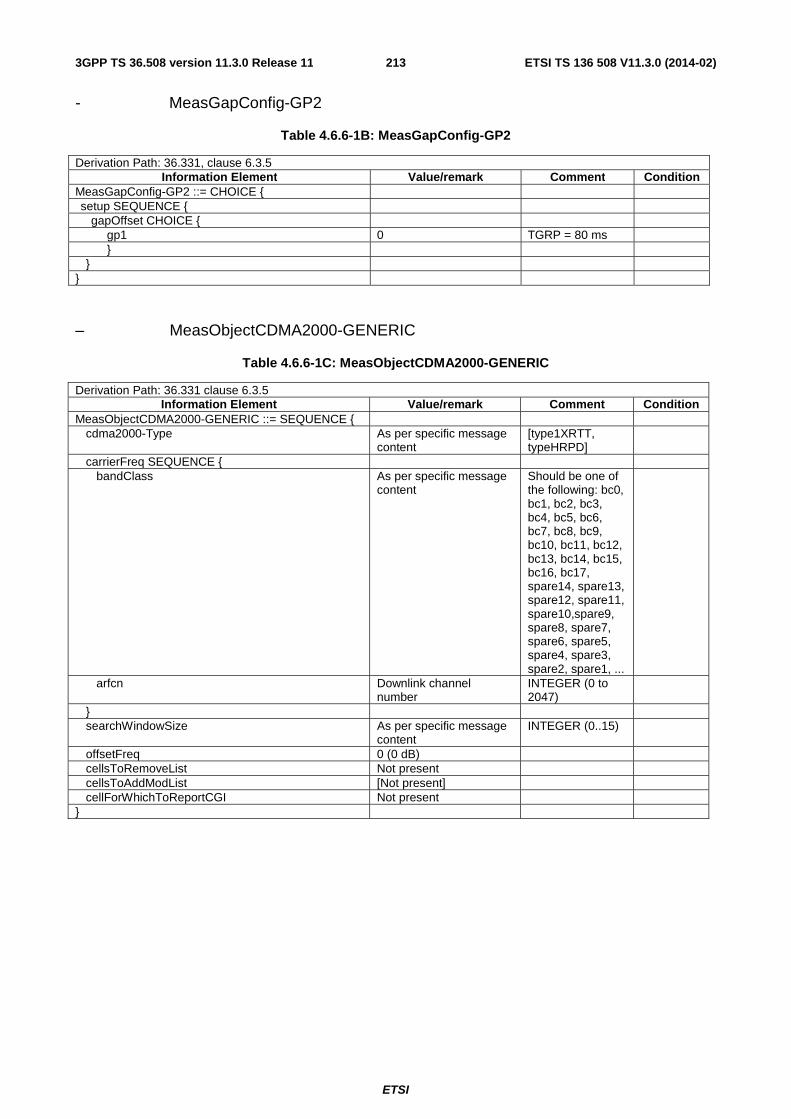
ETSI
ETSI TS 136 508 V11.3.0 (2014-02)2133GPP TS 36.508 version 11.3.0 Release 11
- MeasGapConfig-GP2
Table 4.6.6-1B: MeasGapConfig-GP2
Derivation Path: 36.331, clause 6.3.5 Information Element Value/remark Comment Condition
MeasGapConfig-GP2 ::= CHOICE { setup SEQUENCE { gapOffset CHOICE { gp1 0 TGRP = 80 ms } } }
– MeasObjectCDMA2000-GENERIC
Table 4.6.6-1C: MeasObjectCDMA2000-GENERIC
Derivation Path: 36.331 clause 6.3.5 Information Element Value/remark Comment Condition
MeasObjectCDMA2000-GENERIC ::= SEQUENCE { cdma2000-Type As per specific message
content [type1XRTT, typeHRPD]
carrierFreq SEQUENCE { bandClass As per specific message
content Should be one of the following: bc0, bc1, bc2, bc3, bc4, bc5, bc6, bc7, bc8, bc9, bc10, bc11, bc12, bc13, bc14, bc15, bc16, bc17, spare14, spare13, spare12, spare11, spare10,spare9, spare8, spare7, spare6, spare5, spare4, spare3, spare2, spare1, ...
arfcn Downlink channel number
INTEGER (0 to 2047)
} searchWindowSize As per specific message
content INTEGER (0..15)
offsetFreq 0 (0 dB) cellsToRemoveList Not present cellsToAddModList [Not present] cellForWhichToReportCGI Not present }
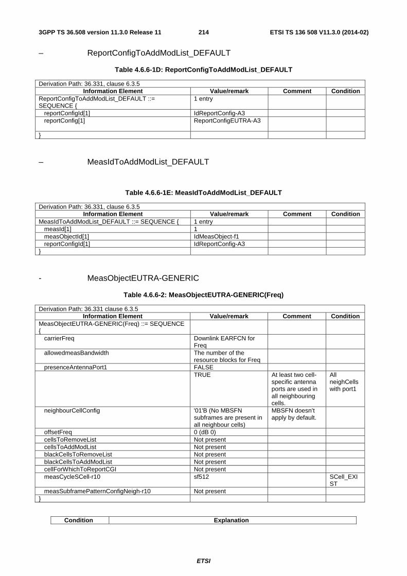
ETSI
ETSI TS 136 508 V11.3.0 (2014-02)2143GPP TS 36.508 version 11.3.0 Release 11
– ReportConfigToAddModList_DEFAULT
Table 4.6.6-1D: ReportConfigToAddModList_DEFAULT
Derivation Path: 36.331, clause 6.3.5 Information Element Value/remark Comment Condition
ReportConfigToAddModList_DEFAULT ::= SEQUENCE {
1 entry
reportConfigId[1] IdReportConfig-A3 reportConfig[1] ReportConfigEUTRA-A3
}
– MeasIdToAddModList_DEFAULT
Table 4.6.6-1E: MeasIdToAddModList_DEFAULT
Derivation Path: 36.331, clause 6.3.5 Information Element Value/remark Comment Condition
MeasIdToAddModList_DEFAULT ::= SEQUENCE { 1 entry measId[1] 1 measObjectId[1] IdMeasObject-f1 reportConfigId[1] IdReportConfig-A3 }
- MeasObjectEUTRA-GENERIC
Table 4.6.6-2: MeasObjectEUTRA-GENERIC(Freq)
Derivation Path: 36.331 clause 6.3.5 Information Element Value/remark Comment Condition
MeasObjectEUTRA-GENERIC(Freq) ::= SEQUENCE {
carrierFreq Downlink EARFCN for Freq
allowedmeasBandwidth The number of the resource blocks for Freq
presenceAntennaPort1 FALSE TRUE At least two cell-
specific antenna ports are used in all neighbouring cells.
All neighCells with port1
neighbourCellConfig '01'B (No MBSFN subframes are present in all neighbour cells)
MBSFN doesn’t apply by default.
offsetFreq 0 (dB 0) cellsToRemoveList Not present cellsToAddModList Not present blackCellsToRemoveList Not present blackCellsToAddModList Not present cellForWhichToReportCGI Not present measCycleSCell-r10 sf512 SCell_EXI
ST measSubframePatternConfigNeigh-r10 Not present }
Condition Explanation

ETSI
ETSI TS 136 508 V11.3.0 (2014-02)2153GPP TS 36.508 version 11.3.0 Release 11
SCell_EXIST When SCell exists on the carrier frequency indicated by carrierFreq All neighCells with port1
Used for all neighbouring cells with at least two cell-specific antenna ports
- MeasObjectGERAN-GENERIC
Table 4.6.6-2A: MeasObjectGERAN-GENERIC(Freq)
Derivation Path: 36.331 clause 6.3.5 Information Element Value/remark Comment Condition
MeasObjectGERAN-GENERIC(Freq) ::= SEQUENCE {
carrierFreqs SEQUENCE { startingARFCN Downlink GERAN
ARFCN of Freq
bandIndicator Set according to the band used for GERAN cells under test
followingARFCNs CHOICE { explicitListOfARFCNs Set the corresponding
ARFCN of GERAN cells under test
} } offsetFreq 0 (dB 0) ncc-Permitted ‘01000000'B NCC=1 permitted cellForWhichToReportCGI Not present }
- MeasObjectUTRA-GENERIC
Table 4.6.6-3: MeasObjectUTRA-GENERIC(Freq)
Derivation Path: 36.331 clause 6.3.5 Information Element Value/remark Comment Condition
MeasObjectUTRA-GENERIC(Freq) ::= SEQUENCE { carrierFreq Downlink UARFCN of
Freq
offsetFreq 0 (dB 0) cellsToRemoveList Not present cellsToAddModList Not present For UTRA, the
neighbouring cell list needs to be provided in specific test cases.
cellForWhichToReportCGI Not present }

ETSI
ETSI TS 136 508 V11.3.0 (2014-02)2163GPP TS 36.508 version 11.3.0 Release 11
- QuantityConfig-DEFAULT
Table 4.6.6-3A: QuantityConfig-DEFAULT
Derivation Path: 36.331, clause 6.3.5 Information Element Value/remark Comment Condition
QuantityConfig-DEFAULT ::= SEQUENCE { quantityConfigEUTRA SEQUENCE { filterCoefficientRSRP Not present DEFAULT fc4 filterCoefficientRSRQ Not present DEFAULT fc4 } quantityConfigUTRA SEQUENCE {} Not present quantityConfigUTRA SEQUENCE { UTRAN measQuantityUTRA-FDD cpich-EcN0 measQuantityUTRA-FDD cpich-RSCP For signalling test
cases
measQuantityUTRA-TDD pccpch-RSCP filterCoefficient Not present DEFAULT fc4 } quantityConfigGERAN SEQUENCE {} Not present quantityConfigGERAN SEQUENCE { GERAN measQuantityGERAN rssi filterCoefficient Not present DEFAULT fc2 } quantityConfigCDMA2000 SEQUENCE {} Not present quantityConfigCDMA2000 SEQUENCE { CDMA2000 measQuantityCDMA2000 [FFS] } }
Condition Explanation UTRAN For inter-RAT measurements with UTRAN GERAN For inter-RAT measurements with GERAN CDMA2000 For inter-RAT measurements with CDMA2000

ETSI
ETSI TS 136 508 V11.3.0 (2014-02)2173GPP TS 36.508 version 11.3.0 Release 11
- ReportConfigEUTRA-A1
Table 4.6.6-4: ReportConfigEUTRA-A1(Thres)
Derivation Path: 36.331 clause 6.3.5 Information Element Value/remark Comment Condition
ReportConfigEUTRA-A1(Thres) ::= SEQUENCE { triggerType CHOICE { event SEQUENCE { eventId CHOICE { eventA1 SEQUENCE { a1-Threshold CHOICE { threshold-RSRP Thres+140 Thres is actual
threshold value in dBm
} } } hysteresis 0 (0 dB) timeToTrigger ms256 } } triggerQuantity rsrp reportQuantity both maxReportCells 1 reportInterval ms1024 reportAmount r1 }
- ReportConfigEUTRA-A2
Table 4.6.6-5: ReportConfigEUTRA-A2(Thres)
Derivation Path: 36.331 clause 6.3.5 Information Element Value/remark Comment Condition
ReportConfigEUTRA-A2(Thres) ::= SEQUENCE { triggerType CHOICE { event SEQUENCE { eventId CHOICE { eventA2 SEQUENCE { a2-Threshold CHOICE { threshold-RSRP Thres+140 Thres is actual
threshold value in dBm
} } } hysteresis 0 (0 dB) timeToTrigger ms320 } } triggerQuantity rsrp reportQuantity both maxReportCells 1 reportInterval ms1024 reportAmount r1 }

ETSI
ETSI TS 136 508 V11.3.0 (2014-02)2183GPP TS 36.508 version 11.3.0 Release 11
- ReportConfigEUTRA-A3
Table 4.6.6-6: ReportConfigEUTRA-A3
Derivation Path: 36.331 clause 6.3.5 Information Element Value/remark Comment Condition
ReportConfigEUTRA-A3 ::= SEQUENCE { triggerType CHOICE { event SEQUENCE { eventId CHOICE { eventA3 SEQUENCE { a3-Offset 0 (0 dB) To reduce
interference between intra-frequency multiple cells
reportOnLeave FALSE } } hysteresis 0 (0 dB) timeToTrigger ms640 } } triggerQuantity rsrp reportQuantity both maxReportCells 1 reportInterval ms1024 reportAmount r1 }

ETSI
ETSI TS 136 508 V11.3.0 (2014-02)2193GPP TS 36.508 version 11.3.0 Release 11
- ReportConfigEUTRA-A4
Table 4.6.6-6AA: ReportConfigEUTRA-A4(Thres)
Derivation Path: 36.331 clause 6.3.5 Information Element Value/remark Comment Condition
ReportConfigEUTRA-A4 ::= SEQUENCE { triggerType CHOICE { event SEQUENCE { eventId CHOICE { eventA4 SEQUENCE { a4-Threshold CHOICE{ threshold-RSRP Thres + 140 Thres is actual
threshold value in dBm
Not RSRQ
threshold-RSRQ Thres * 2 + 40 Thres is actual threshold value in dB
RSRQ
} } } hysteresis 0 (0 dB) timeToTrigger ms0 } } triggerQuantity rsrp Not RSRQ rsrq RSRQ reportQuantity both maxReportCells 1 reportInterval ms1024 reportAmount r1 si-RequestForHO-r9 Not Present ue-RxTxTimeDiffPeriodical-r9 Not Present }
Condition Explanation RSRQ When RSRQ based measurement is applied

ETSI
ETSI TS 136 508 V11.3.0 (2014-02)2203GPP TS 36.508 version 11.3.0 Release 11
- ReportConfigEUTRA-A5
Table 4.6.6-6AB: ReportConfigEUTRA-A5(Thres1, Thres2)
Derivation Path: 36.331 clause 6.3.5 Information Element Value/remark Comment Condition
ReportConfigEUTRA-A5 ::= SEQUENCE { triggerType CHOICE { event SEQUENCE { eventId CHOICE { eventA5 SEQUENCE { a5-Threshold1 CHOICE{ threshold-RSRP Thres1 + 140 Thres1 is actual
threshold value in dBm
Not RSRQ
threshold-RSRQ Thres1 * 2 + 40 Thres1 is actual threshold value in dB
RSRQ
} a5-Threshold2 CHOICE{ threshold-RSRP Thres2 + 140 Thres2 is actual
threshold value in dBm
Not RSRQ
threshold-RSRQ Thres2 * 2 + 40 Thres2 is actual threshold value in dB
RSRQ
} } } hysteresis 0 (0 dB) timeToTrigger ms0 } } triggerQuantity rsrp Not RSRQ rsrq RSRQ reportQuantity both maxReportCells 1 reportInterval ms1024 reportAmount r1 si-RequestForHO-r9 Not Present ue-RxTxTimeDiffPeriodical-r9 Not Present }
Condition Explanation RSRQ See the definition below table 4.6.6-6AA.

ETSI
ETSI TS 136 508 V11.3.0 (2014-02)2213GPP TS 36.508 version 11.3.0 Release 11
- ReportConfigEUTRA-A6
Table 4.6.6-6A: ReportConfigEUTRA-A6
Derivation Path: 36.331 clause 6.3.5 Information Element Value/remark Comment Condition
ReportConfigEUTRA-A6 ::= SEQUENCE { triggerType CHOICE { event SEQUENCE { eventId CHOICE { eventA6-r10 SEQUENCE { a6-Offset-r10 0 (0 dB) a6-ReportOnLeave-r10 FALSE } } hysteresis 0 (0 dB) timeToTrigger ms640 } } triggerQuantity rsrp reportQuantity both maxReportCells 1 reportInterval ms1024 reportAmount r1 si-RequestForHO-r9 Not Present ue-RxTxTimeDiffPeriodical-r9 Not Present includeLocationInfo-r10 Not Present reportAddNeighMeas-r10 Not Present }
- ReportConfigEUTRA-PERIODICAL
Table 4.6.6-7: ReportConfigEUTRA-PERIODICAL
Derivation Path: 36.331 clause 6.3.5 Information Element Value/remark Comment Condition
ReportConfigEUTRA-PERIODICAL ::= SEQUENCE { triggerType CHOICE { periodical SEQUENCE { purpose reportStrongestCells } } triggerQuantity rsrp reportQuantity both maxReportCells 1 reportInterval ms1024 reportAmount infinity }

ETSI
ETSI TS 136 508 V11.3.0 (2014-02)2223GPP TS 36.508 version 11.3.0 Release 11
- ReportConfigInterRAT-B1-GERAN
Table 4.6.6-7A: ReportConfigInterRAT-B1-GERAN(GERAN-Thres)
Derivation Path: 36.331 clause 6.3.5 Information Element Value/remark Comment Condition
ReportConfigInterRAT-B1-GERAN(GERAN-Thres) ::= SEQUENCE {
triggerType CHOICE { event SEQUENCE { eventId CHOICE { eventB1 SEQUENCE { b1-Threshold CHOICE { b1-ThresholdGERAN (GERAN-Thres + 110) GERAN-Thres is
actual value in dBm
} } } hysteresis 0 INTEGER(0..30) timeToTrigger ms0 } } maxReportCells 6 In line with RAN4
requirement
reportInterval ms1024 reportAmount r1 }
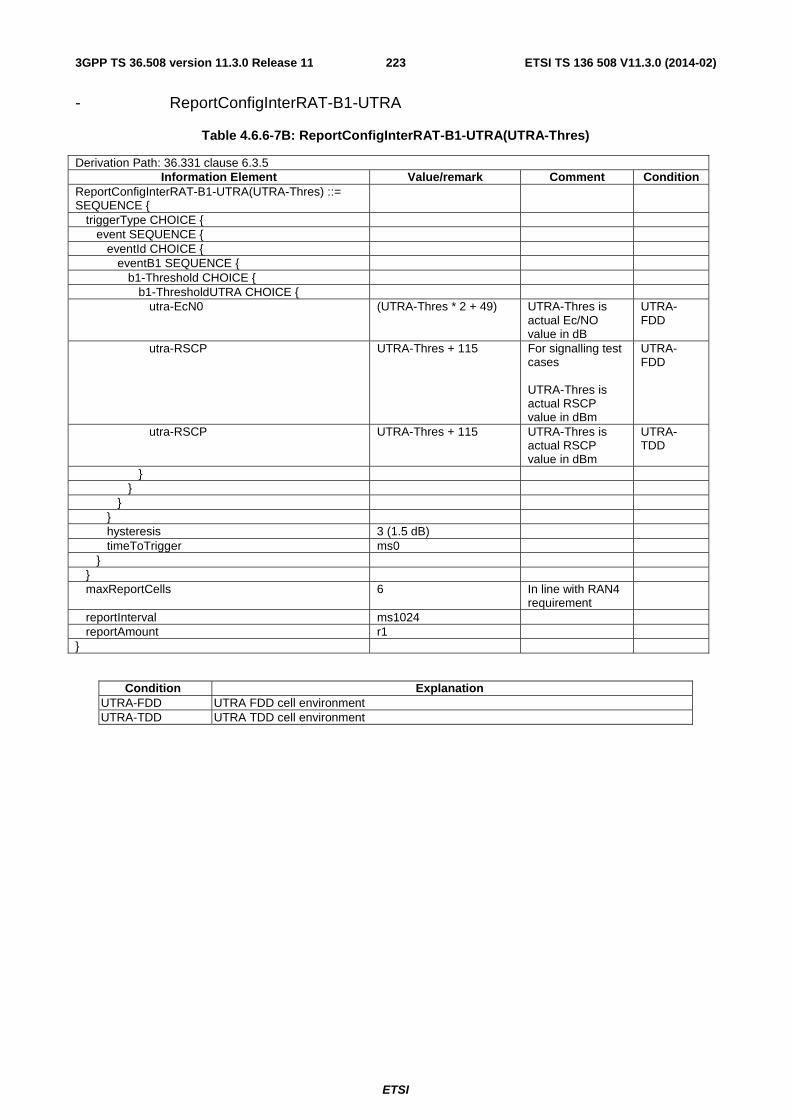
ETSI
ETSI TS 136 508 V11.3.0 (2014-02)2233GPP TS 36.508 version 11.3.0 Release 11
- ReportConfigInterRAT-B1-UTRA
Table 4.6.6-7B: ReportConfigInterRAT-B1-UTRA(UTRA-Thres)
Derivation Path: 36.331 clause 6.3.5 Information Element Value/remark Comment Condition
ReportConfigInterRAT-B1-UTRA(UTRA-Thres) ::= SEQUENCE {
triggerType CHOICE { event SEQUENCE { eventId CHOICE { eventB1 SEQUENCE { b1-Threshold CHOICE { b1-ThresholdUTRA CHOICE { utra-EcN0 (UTRA-Thres * 2 + 49) UTRA-Thres is
actual Ec/NO value in dB
UTRA-FDD
utra-RSCP UTRA-Thres + 115 For signalling test cases UTRA-Thres is actual RSCP value in dBm
UTRA-FDD
utra-RSCP UTRA-Thres + 115 UTRA-Thres is actual RSCP value in dBm
UTRA-TDD
} } } } hysteresis 3 (1.5 dB) timeToTrigger ms0 } } maxReportCells 6 In line with RAN4
requirement
reportInterval ms1024 reportAmount r1 }
Condition Explanation UTRA-FDD UTRA FDD cell environment UTRA-TDD UTRA TDD cell environment

ETSI
ETSI TS 136 508 V11.3.0 (2014-02)2243GPP TS 36.508 version 11.3.0 Release 11
- ReportConfigInterRAT-B2-CDMA2000
Table 4.6.6-7C: ReportConfigInterRAT-B2-CDMA2000(EUTRA-Thres, CDMA2000-Thres)
Derivation Path: 36.331 clause 6.3.5 Information Element Value/remark Comment Condition
ReportConfigInterRAT-B2-CDMA2000(EUTRA-Thres, CDMA2000-Thres) ::= SEQUENCE {
triggerType CHOICE { event SEQUENCE { eventId CHOICE { eventB2 SEQUENCE { b2-Threshold1 CHOICE { threshold-RSRP EUTRA-Thres+140 EUTRA-Thres is
actual threshold value in dBm
} b2-Threshold2 CHOICE { b2-Threshold2CDMA2000 [30 (-15 dB)] Integer (0..63) } } } hysteresis [2 (1 dB)] INTEGER(0..30) timeToTrigger ms0 } } maxReportCells [8] reportInterval [ms2048] Range: ms120,
ms240, ms480, ms640, ms1024, ms2048, ms5120, ms10240, min1, min6, min12, min30, min60, spare3, spare2, spare1
reportAmount [r1] Range: r1, r2, r4, r8, r16, r32, r64, infinity
}

ETSI
ETSI TS 136 508 V11.3.0 (2014-02)2253GPP TS 36.508 version 11.3.0 Release 11
Table 4.6.6-7D: void
- ReportConfigInterRAT-B2-GERAN
Table 4.6.6-7E: ReportConfigInterRAT-B2-GERAN(EUTRA-Thres, GERAN-Thres)
Derivation Path: 36.331 clause 6.3.5 Information Element Value/remark Comment Condition
ReportConfigInterRAT-B2-GERAN(EUTRA-Thres, GERAN-Thres) ::= SEQUENCE {
triggerType CHOICE { event SEQUENCE { eventId CHOICE { eventB2 SEQUENCE { b2-Threshold1 CHOICE { threshold-RSRP EUTRA-Thres+140 EUTRA-Thres is
actual threshold value in dBm
} b2-Threshold2 CHOICE { b2-Threshold2GERAN GERAN-Thres + 110 GERAN-Thres is
actual value in dBm
} } } hysteresis 0 INTEGER(0..30) timeToTrigger ms0 } } maxReportCells 6 In line with RAN4
requirement
reportInterval ms1024 reportAmount r1 }

ETSI
ETSI TS 136 508 V11.3.0 (2014-02)2263GPP TS 36.508 version 11.3.0 Release 11
- ReportConfigInterRAT-B2-UTRA
Table 4.6.6-8: ReportConfigInterRAT-B2-UTRA(EUTRA-Thres, UTRA-Thres)
Derivation Path: 36.331 clause 6.3.5 Information Element Value/remark Comment Condition
ReportConfigInterRAT-B2-UTRA(EUTRA-Thres, UTRA-Thres) ::= SEQUENCE {
triggerType CHOICE { event SEQUENCE { eventId CHOICE { eventB2 SEQUENCE { b2-Threshold1 CHOICE { threshold-RSRP EUTRA-Thres+140 EUTRA-Thres is
actual threshold value in dBm
} b2-Threshold2 CHOICE { b2-Threshold2UTRA CHOICE { utra-EcN0 UTRA-Thres * 2 + 49 UTRA-Thres is
actual Ec/NO value in dB
UTRA-FDD
utra-RSCP UTRA-Thres + 115 For signalling test cases UTRA-Thres is actual RSCP value in dBm
UTRA-FDD
utra-RSCP UTRA-Thres + 115 UTRA-Thres is actual RSCP value in dBm
UTRA-TDD
} } } } hysteresis 3 (1.5 dB) timeToTrigger ms0 } } maxReportCells 6 In line with RAN4
requirement
reportInterval ms1024 reportAmount r1 }
Condition Explanation UTRA-FDD UTRA FDD cell environment UTRA-TDD UTRA TDD cell environment

ETSI
ETSI TS 136 508 V11.3.0 (2014-02)2273GPP TS 36.508 version 11.3.0 Release 11
- ReportConfigInterRAT-PERIODICAL
Table 4.6.6-9: ReportConfigInterRAT-PERIODICAL
Derivation Path: 36.331 clause 6.3.5 Information Element Value/remark Comment Condition
ReportConfigInterRAT-PERIODICAL ::= SEQUENCE {
triggerType CHOICE { periodical SEQUENCE { purpose reportStrongestCells } } maxReportCells 1 reportInterval ms1024 reportAmount infinity }
4.6.7 Other information elements
– RRC-TransactionIdentifier-DL
Table 4.6.7-1: RRC-TransactionIdentifier-DL
Derivation Path: 36.331 clause 6.3.6 Information Element Value/remark Comment Condition
RRC-TransactionIdentifier-DL ::= 0..3
– RRC-TransactionIdentifier-UL
Table 4.6.7-2: RRC-TransactionIdentifier-UL
Derivation Path: 36.331 clause 6.3.6 Information Element Value/remark Comment Condition
RRC-TransactionIdentifier-UL ::= 0..3 The same value as the value of RRC-TransactionIdentifier-DL in the downlink message initiating the procedure
4.6.8 Channel-bandwidth-dependent parameters
The default values of parameters which depend on the channel bandwidth are defined in table 4.6.8-1.

ETSI
ETSI TS 136 508 V11.3.0 (2014-02)2283GPP TS 36.508 version 11.3.0 Release 11
Table 4.6.8-1: Channel-bandwidth-dependent parameters
Information Element
Channel bandwidth Comment 1.4 MHz 3 MHz 5 MHz 10 MHz 15 MHz 20MHz
Prach-FrequencyOffset
0 1 2 4 6 8 Typical value in real network
nRB-CQI 0 0 2 4 6 8 Selected based on typical maximum number of UEs.
Pusch-HoppingOffset
0 2 4 8 12 16 Typical value in real network
sr-PUCCH-ResourceIndex
FFS FFS 20 41 62 84
srs-BandwidthConfig
FFS FFS bw3 (mSRS,b,
Nb) = (20, 1), (4, 5), (4, 1), (4,
1)
bw2 (mSRS,b,
Nb) = (40, 1), (20, 2), (4, 5), (4,
1)
bw2 (mSRS,b,
Nb) = (60, 1), (20, 3), (4, 5), (4,
1)
bw2 (mSRS,b,
Nb) = (80, 1), (40, 2), (20, 2), (4,
5)
Selected in accordance with pucch-ResourceSize.
4.7 Default NAS message and information element contents This clause contains the default values of common NAS messages and information elements, which apply to all test cases unless otherwise specified. All the messages and information elements are listed in alphabetical order.
4.7.1 Security protected NAS messages
In subclauses 4.7.2 and 4.7.3 in this document, all the NAS messages are described in the plain NAS message format.
When a NAS message is security protected, the message shall be contained by SECURITY PROTECTED NAS MESSAGE unless contained by another NAS message.
The default contents of SECURITY PROTECTED NAS MESSAGE message are defined in table 4.7.1-1.
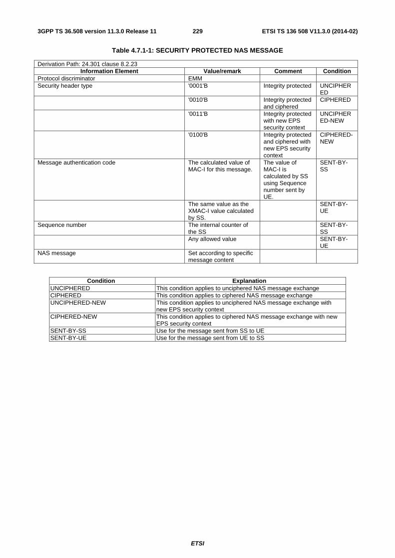
ETSI
ETSI TS 136 508 V11.3.0 (2014-02)2293GPP TS 36.508 version 11.3.0 Release 11
Table 4.7.1-1: SECURITY PROTECTED NAS MESSAGE
Derivation Path: 24.301 clause 8.2.23 Information Element Value/remark Comment Condition
Protocol discriminator EMM Security header type '0001'B Integrity protected UNCIPHER
ED '0010'B Integrity protected
and ciphered CIPHERED
'0011'B Integrity protected with new EPS security context
UNCIPHERED-NEW
'0100'B Integrity protected and ciphered with new EPS security context
CIPHERED-NEW
Message authentication code The calculated value of MAC-I for this message.
The value of MAC-I is calculated by SS using Sequence number sent by UE.
SENT-BY-SS
The same value as the XMAC-I value calculated by SS.
SENT-BY-UE
Sequence number The internal counter of the SS
SENT-BY-SS
Any allowed value SENT-BY-UE
NAS message Set according to specific message content
Condition Explanation UNCIPHERED This condition applies to unciphered NAS message exchange CIPHERED This condition applies to ciphered NAS message exchange UNCIPHERED-NEW This condition applies to unciphered NAS message exchange with
new EPS security context CIPHERED-NEW This condition applies to ciphered NAS message exchange with new
EPS security context SENT-BY-SS Use for the message sent from SS to UE SENT-BY-UE Use for the message sent from UE to SS

ETSI
ETSI TS 136 508 V11.3.0 (2014-02)2303GPP TS 36.508 version 11.3.0 Release 11
4.7.2 Contents of EMM messages
- ATTACH ACCEPT
This message is sent by the SS to the UE.
Table 4.7.2-1: ATTACH ACCEPT
Derivation Path: 24.301 clause 8.2.1 Information Element Value/remark Comment Condition
Protocol discriminator EMM Security header type '0000'B Plain NAS
message, not security protected
Attach accept message identity '0100 0010'B Attach accept EPS attach result '0001'B EPS only EPS_only '0010'B combined
EPS/IMSI attach combined_EPS_IMSI
Spare half octet '0000'B T3412 value Timer value '0 0000'B Unit '111'B value indicates
that the timer is deactivated.
TAI list Length of tracking area identity list contents '0000 0110'B 6 octets Partial tracking area identity list 1 Number of elements '0 0000'B 1 element Type of list '00'B list of TACs
belonging to one PLMN, with non-consecutive TAC values
MCC See table 4.4.2-2 in this document
For NAS test cases, see table 6.3.2.2-1.
MNC See table 4.4.2-2 in this document
For NAS test cases, see table 6.3.2.2-1.
TAC 1 See table 4.4.2-2 in this document
For NAS test cases, see table 6.3.2.2-1.
ESM message container ACTIVATE DEFAULT EPS BEARER CONTEXT REQUEST message to activate the default bearer
GUTI Length of EPS mobile identity contents '0000 1011'B 11 octets Type of identity '110'B GUTI Odd/even indication '0'B even number of
identity digits and also when the GUTI is used
MCC See table 4.4.2-2 in this document
For NAS test cases, see table 6.3.2.2-1.
MNC See table 4.4.2-2 in this document
For NAS test cases, see table 6.3.2.2-1.
MME Group ID See table 4.4.2-2 in this document
For NAS test cases, see table 6.3.2.2-1.
MME Code See table 4.4.2-2 in this document
For NAS test cases, see table 6.3.2.2-1.

ETSI
ETSI TS 136 508 V11.3.0 (2014-02)2313GPP TS 36.508 version 11.3.0 Release 11
M-TMSI See table 4.4.2-2 in this document
For NAS test cases, see table 6.3.2.2-1.
Location area identification Not present EPS_only Location area identification combined_E
PS_IMSI MCC MCC of the EUTRA cell from which this message is sent
MNC MCC of the EUTRA cell from which this message is sent
LAC 1 MS identity Not present EPS_only MS identity combined_E
PS_IMSI Length of mobile identity contents '0000 0101'B 5 octets Type of identity '100'B TMSI/P-TMSI/M-
TMSI Odd/even indication '0'B even number of
identity digits and also when the TMSI/P-TMSI or TMGI and optional MBMS Session Identity is used
TMSI TMSI-1 EMM cause Not present T3402 value Not present T3423 value Not present Equivalent PLMNs Not present Emergency number list Not present EPS network feature support '0000 0001'B IMS voice over PS
session in S1 mode supported
EPS network feature support '0000 0011'B IMS voice over PS session in S1 mode supported, emergency bearer services in S1 mode supported
Rel-9
Additional update result Not present Additional update result ‘10’ B “SMS only” additional_u
pdate_result_SMS
T3412 extended value Not present Rel-10
Condition Explanation EPS_only This condition applies if the UE is configured to initiate EPS attach or
if explicitly specified. combined_EPS_IMSI This condition applies if the UE is configured to initiate combined
EPS/IMSI attach or if explicitly specified. additional_update_result_SMS If the UE requested "SMS only" in the Additional update type IE and
combined_EPS_IMSI condition applies
NOTE: This message is always sent within SECURITY PROTECTED NAS MESSAGE message.

ETSI
ETSI TS 136 508 V11.3.0 (2014-02)2323GPP TS 36.508 version 11.3.0 Release 11
- ATTACH COMPLETE
This message is sent by the UE to the SS.
Table 4.7.2-2: ATTACH COMPLETE
Derivation Path: 24.301 clause 8.2.2 Information Element Value/remark Comment Condition
Protocol discriminator EMM Security header type '0000'B Plain NAS
message, not security protected
Attach complete message identity '0100 0011'B Attach complete ESM message container ACTIVATE DEFAULT
EPS BEARER CONTEXT ACCEPT message
NOTE: This message is always sent within SECURITY PROTECTED NAS MESSAGE message.
- ATTACH REJECT
This message is sent by the SS to the UE.
Table 4.7.2-3: ATTACH REJECT
Derivation Path: 24.301 clause 8.2.3 Information Element Value/remark Comment Condition
Protocol discriminator EMM Security header type '0000'B Plain NAS
message, not security protected
Attach reject message identity '0100 0100'B Attach reject EMM cause Set according to specific
message content.
ESM message container Set according to specific message content.
NOTE: If this message includes the EMM cause set to #25, it is sent within SECURITY PROTECTED NAS MESSAGE message. Otherwise this message is sent without integrity protection.

ETSI
ETSI TS 136 508 V11.3.0 (2014-02)2333GPP TS 36.508 version 11.3.0 Release 11
- ATTACH REQUEST
This message is sent by the UE to the SS.
Table 4.7.2-4: ATTACH REQUEST
Derivation Path: 24.301 clause 8.2.4 Information Element Value/remark Comment Condition
Protocol discriminator EMM Security header type '0000'B Plain NAS
message, not security protected
Attach request message identity '0100 0001'B Attach request EPS attach type '0001'B EPS attach EPS_only '0010'B combined
EPS/IMSI attach combined_EPS_IMSI
NAS key set identifier Any allowed value Old GUTI or IMSI Any allowed value UE network capability Any allowed value ESM message container PDN CONNECTIVITY
REQUEST message to request PDN connectivity to the default PDN
Old P-TMSI signature Not present or any allowed value
Additional GUTI Not present or any allowed value
Last visited registered TAI Not present or any allowed value
DRX parameter Not present or any allowed value
MS network capability Not present or any allowed value
Old location area identification Not present or any allowed value
TMSI status Not present or any allowed value
Mobile station classmark 2 Not present or any allowed value
Mobile station classmark 3 Not present or any allowed value
Supported Codecs Not present or any allowed value
Additional update type Not present EPS_only Additional update type Not present or any
allowed value combined_E
PS_IMSI Old GUTI type Not present or any
allowed value
Condition Explanation EPS_only See the definition below table 4.7.2-1. combined_EPS_IMSI See the definition below table 4.7.2-1.
NOTE: This message is sent integrity protected when a valid security context exists and without integrity protection otherwise.

ETSI
ETSI TS 136 508 V11.3.0 (2014-02)2343GPP TS 36.508 version 11.3.0 Release 11
- AUTHENTICATION FAILURE
This message is sent by the UE to the SS.
Table 4.7.2-5: AUTHENTICATION FAILURE
Derivation Path: 24.301 clause 8.2.5 Information Element Value/remark Comment Condition
Protocol discriminator EMM Security header type '0000'B Plain NAS
message, not security protected
Authentication failure message type '0101 1100'B Authentication failure
EMM cause '0001 0100'B Mac failure Authentication failure parameter Not present See TS 24.301
[28] subclause 8.2.5.2
NOTE: The security protection of this message is the same as the previous AUTHENTICATION REQUEST message.
- AUTHENTICATION REJECT
This message is sent by the SS to the UE.
Table 4.7.2-6: AUTHENTICATION REJECT
Derivation Path: 24.301 clause 8.2.6 Information Element Value/remark Comment Condition
Protocol discriminator EMM Security header type '0000'B Plain NAS
message, not security protected
Authentication reject message type '0101 0100'B Authentication reject
NOTE: This message is sent without integrity protection.

ETSI
ETSI TS 136 508 V11.3.0 (2014-02)2353GPP TS 36.508 version 11.3.0 Release 11
- AUTHENTICATION REQUEST
This message is sent by the SS to the UE.
Table 4.7.2-7: AUTHENTICATION REQUEST
Derivation Path: 24.301 clause 8.2.7 Information Element Value/remark Comment Condition
Protocol discriminator EMM Security header type '0000'B Plain NAS
message, not security protected
Authentication request message type '0101 0010'B Authentication request
NAS key set identifierASME NAS key set identifier An arbitrarily selected
value between '000'B and '110'B, different from the valid NAS key set identifier of the UE if such a value exists.
TSC '0'B native security context (for KSIASME)
Spare half octet '0000'B Authentication parameter RAND (EPS challenge) An arbitrarily selected
128 bits value
Authentication parameter AUTN (EPS challenge) See TS 24.301 [28] subclause 9.9.3.2
NOTE: Within a test execution this message is sent without integrity protection before NAS security mode control procedure has been successfully completed; and sent integrity protected and ciphered within SECURITY PROTECTED NAS MESSAGE message after NAS security mode control procedure has been successfully completed. SS does not maintain information for NAS security mode control procedure after a TC is completed.
- AUTHENTICATION RESPONSE
This message is sent by the UE to the SS.
Table 4.7.2-8: AUTHENTICATION RESPONSE
Derivation Path: 24.301 clause 8.2.8 Information Element Value/remark Comment Condition
Protocol discriminator EMM Security header type '0000'B Plain NAS
message, not security protected
Authentication response message type '0101 0011'B Authentication response
Authentication response parameter See TS 24.301 [28] subclause 9.9.3.4
NOTE: When sent in response to an AUTHENTICATION REQUEST message which is not integrity protected and not ciphered, the AUTHENTICATION RESPONSE message may be sent integrity protected when a valid security context exists and without integrity protection otherwise.

ETSI
ETSI TS 136 508 V11.3.0 (2014-02)2363GPP TS 36.508 version 11.3.0 Release 11
- CS SERVICE NOTIFICATION
This message is sent by the SS to the UE.
Table 4.7.2-8A: CS SERVICE NOTIFICATION
Derivation Path: 24.301 clause 8.2.9 Information Element Value/remark Comment Condition
Protocol discriminator EMM Security header type '0000'B Plain NAS
message, not security protected
CS service notification message identity '01100100'B CS Service notification
Paging identity ‘1’B TMSI CLI Not present SS Code Not present LCS indicator Not present LCS client identity Not present
NOTE: This message is always sent within SECURITY PROTECTED NAS MESSAGE message.
- DETACH ACCEPT (UE originating detach)
This message is sent by the SS to the UE.
Table 4.7.2-9: DETACH ACCEPT
Derivation Path: 24.301 clause 8.2.10.1 Information Element Value/remark Comment Condition
Protocol discriminator EMM Security header type '0000'B Plain NAS
message, not security protected
Detach accept message identity '0100 0110'B Detach accept
NOTE: This message is sent using the same security protection as in the previous DETACH REQUEST message received from the UE.
- DETACH ACCEPT (UE terminated detach)
This message is sent by the UE to the SS.
Table 4.7.2-10: DETACH ACCEPT
Derivation Path: 24.301 clause 8.2.10.2 Information Element Value/remark Comment Condition
Protocol discriminator EMM Security header type '0000'B Plain NAS
message, not security protected
Detach accept message identity '0100 0110'B Detach accept
NOTE: This message is sent without integrity protection before NAS security mode control procedure has been successfully completed and sent within SECURITY PROTECTED NAS MESSAGE message after NAS security mode control procedure has been successfully completed.
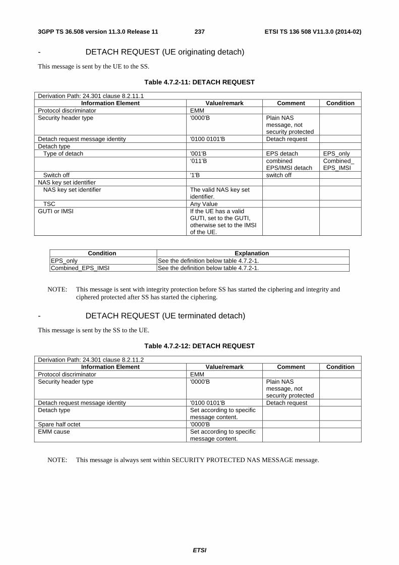
ETSI
ETSI TS 136 508 V11.3.0 (2014-02)2373GPP TS 36.508 version 11.3.0 Release 11
- DETACH REQUEST (UE originating detach)
This message is sent by the UE to the SS.
Table 4.7.2-11: DETACH REQUEST
Derivation Path: 24.301 clause 8.2.11.1 Information Element Value/remark Comment Condition
Protocol discriminator EMM Security header type '0000'B Plain NAS
message, not security protected
Detach request message identity '0100 0101'B Detach request Detach type Type of detach '001'B EPS detach EPS_only ‘011’B combined
EPS/IMSI detach Combined_EPS_IMSI
Switch off '1'B switch off NAS key set identifier NAS key set identifier The valid NAS key set
identifier.
TSC Any Value GUTI or IMSI If the UE has a valid
GUTI, set to the GUTI, otherwise set to the IMSI of the UE.
Condition Explanation EPS_only See the definition below table 4.7.2-1. Combined_EPS_IMSI See the definition below table 4.7.2-1.
NOTE: This message is sent with integrity protection before SS has started the ciphering and integrity and ciphered protected after SS has started the ciphering.
- DETACH REQUEST (UE terminated detach)
This message is sent by the SS to the UE.
Table 4.7.2-12: DETACH REQUEST
Derivation Path: 24.301 clause 8.2.11.2 Information Element Value/remark Comment Condition
Protocol discriminator EMM Security header type '0000'B Plain NAS
message, not security protected
Detach request message identity '0100 0101'B Detach request Detach type Set according to specific
message content.
Spare half octet '0000'B EMM cause Set according to specific
message content.
NOTE: This message is always sent within SECURITY PROTECTED NAS MESSAGE message.

ETSI
ETSI TS 136 508 V11.3.0 (2014-02)2383GPP TS 36.508 version 11.3.0 Release 11
- DOWNLINK NAS TRANSPORT
This message is sent by the SS to the UE.
Table 4.7.2-12A: DOWNLINK NAS TRANSPORT
Derivation Path: 24.301 clause 8.2.12 Information Element Value/remark Comment Condition
Protocol discriminator EMM Security header type '0000'B Plain NAS
message, not security protected
Downlink NAS transport message identity '0110 0010'B Downlink NAS transport
NAS message container Set according to specific message content
NOTE: This message is always sent within SECURITY PROTECTED NAS MESSAGE message.
- EMM INFORMATION
This message is sent by the SS to the UE.
Table 4.7.2-13: EMM INFORMATION
Derivation Path: 24.301 clause 8.2.13 Information Element Value/remark Comment Condition
Protocol discriminator EMM Security header type '0000'B Plain NAS
message, not security protected
EMM information message identity '0110 0001'B EMM information Full name for network Set according to specific
message content.
Short name for network Set according to specific message content.
Local time zone Set according to specific message content.
Universal time and local time zone Set according to specific message content.
Network daylight saving time Set according to specific message content.
NOTE: This message is always sent within SECURITY PROTECTED NAS MESSAGE message.
- EMM STATUS
This message is sent by the UE or by the SS.
Table 4.7.2-14: EMM STATUS
Derivation Path: 24.301 clause 8.2.14 Information Element Value/remark Comment Condition
Protocol discriminator EMM Security header type '0000'B Plain NAS
message, not security protected
EMM status message identity '0110 0000'B EMM status EMM cause Set according to specific
message content.
NOTE: This message is always sent within SECURITY PROTECTED NAS MESSAGE message.

ETSI
ETSI TS 136 508 V11.3.0 (2014-02)2393GPP TS 36.508 version 11.3.0 Release 11
- EXTENDED SERVICE REQUEST
This message is sent by the UE to the SS.
Table 4.7.2-14A: EXTENDED SERVICE REQUEST
Derivation Path: 24.301 clause 8.2.15 Information Element Value/remark Comment Condition
Protocol discriminator EMM Security header type '0000'B Plain NAS
message, not security protected
Extended service request message identity '0100 1100'B Extended service request
Service type '0001'B mobile terminating CS fallback or 1xCS fallback
NAS key set identifier NAS key set identifier The valid NAS key set
identifier.
TSC '0'B native security context (for KSIASME)
M-TMSI If the UE has a valid M-TMSI, set to the M-TMSI, otherwise set to the IMSI of the UE.
CSFB response ’001’B CS fallback accepted by the UE
NOTE: This message is always sent within SECURITY PROTECTED NAS MESSAGE message.
- GUTI REALLOCATION COMMAND
This message is sent by the SS to the UE.
Table 4.7.2-15: GUTI REALLOCATION COMMAND
Derivation Path: 24.301 clause 8.2.16 Information Element Value/remark Comment Condition
Protocol discriminator EMM Security header type '0000'B Plain NAS
message, not security protected
GUTI reallocation command message identity '0101 0000'B GUTI reallocation command
GUTI Set according to specific message content.
TAI list Set according to specific message content.
NOTE: This message is always sent within SECURITY PROTECTED NAS MESSAGE message.
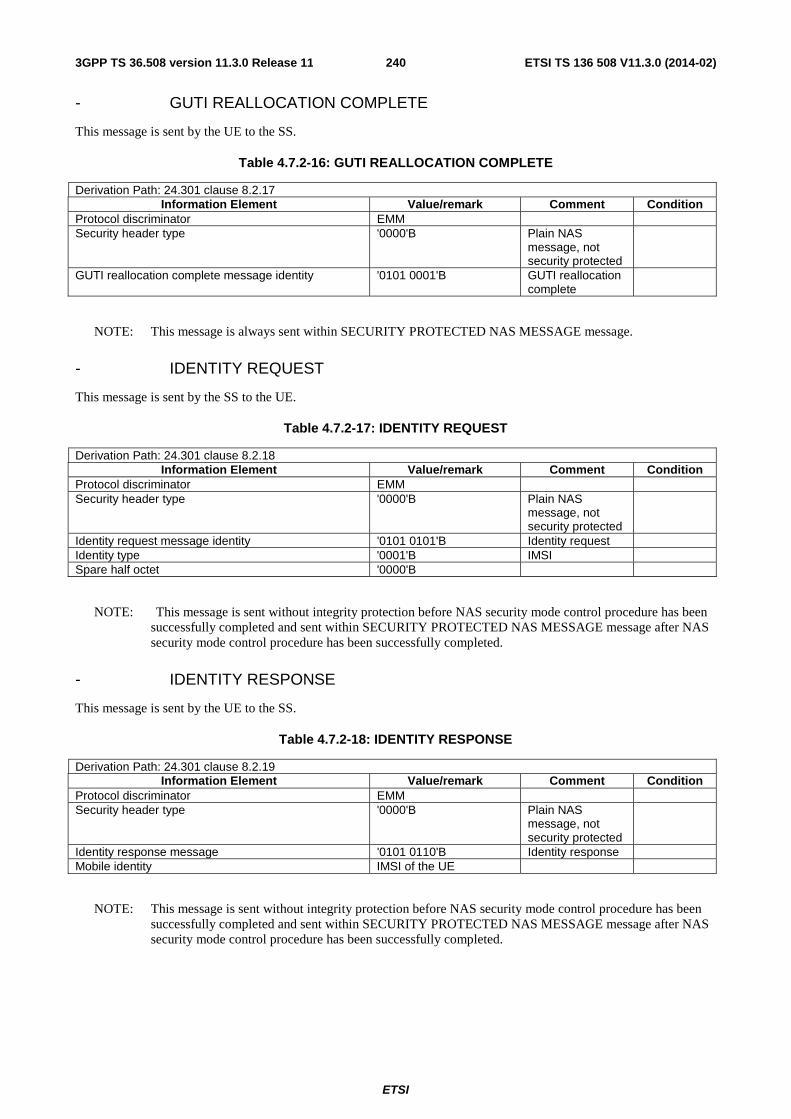
ETSI
ETSI TS 136 508 V11.3.0 (2014-02)2403GPP TS 36.508 version 11.3.0 Release 11
- GUTI REALLOCATION COMPLETE
This message is sent by the UE to the SS.
Table 4.7.2-16: GUTI REALLOCATION COMPLETE
Derivation Path: 24.301 clause 8.2.17 Information Element Value/remark Comment Condition
Protocol discriminator EMM Security header type '0000'B Plain NAS
message, not security protected
GUTI reallocation complete message identity '0101 0001'B GUTI reallocation complete
NOTE: This message is always sent within SECURITY PROTECTED NAS MESSAGE message.
- IDENTITY REQUEST
This message is sent by the SS to the UE.
Table 4.7.2-17: IDENTITY REQUEST
Derivation Path: 24.301 clause 8.2.18 Information Element Value/remark Comment Condition
Protocol discriminator EMM Security header type '0000'B Plain NAS
message, not security protected
Identity request message identity '0101 0101'B Identity request Identity type '0001'B IMSI Spare half octet '0000'B
NOTE: This message is sent without integrity protection before NAS security mode control procedure has been successfully completed and sent within SECURITY PROTECTED NAS MESSAGE message after NAS security mode control procedure has been successfully completed.
- IDENTITY RESPONSE
This message is sent by the UE to the SS.
Table 4.7.2-18: IDENTITY RESPONSE
Derivation Path: 24.301 clause 8.2.19 Information Element Value/remark Comment Condition
Protocol discriminator EMM Security header type '0000'B Plain NAS
message, not security protected
Identity response message '0101 0110'B Identity response Mobile identity IMSI of the UE
NOTE: This message is sent without integrity protection before NAS security mode control procedure has been successfully completed and sent within SECURITY PROTECTED NAS MESSAGE message after NAS security mode control procedure has been successfully completed.

ETSI
ETSI TS 136 508 V11.3.0 (2014-02)2413GPP TS 36.508 version 11.3.0 Release 11
- SECURITY MODE COMMAND
This message is sent by the SS to the UE.
Table 4.7.2-19: SECURITY MODE COMMAND
Derivation Path: 24.301 clause 8.2.20 Information Element Value/remark Comment Condition
Protocol discriminator EMM Security header type '0000'B Plain NAS
message, not security protected
Security mode command message identity '0101 1101'B Security mode command
Selected NAS security algorithms Type of integrity protection algorithm Set according to PIXIT
parameter for default integrity protection algorithm
For SIG
0(reserved or eia0) This IE is set to one of the algorithms supported by the UE as indicated in the IE "UE network capability" in the ATTACH REQUEST message.
For RF
eia1
eia2
Type of ciphering algorithm Set according to PIXIT parameter for default ciphering algorithm
For SIG
eea0 For RF NAS key set identifier NAS key set identifier The valid NAS key set
identifier.
TSC '0'B native security context (for KSIASME)
Spare half octet '0000'B Replayed UE security capabilities Set according to the
received UE security capabilities
IMEISV request Not present Replayed nonceUE Not present NonceMME Not present
Condition Explanation For SIG Used for signalling test cases For RF Used for RF/RRM test cases
NOTE: This message is always sent integrity protected with new EPS security context.

ETSI
ETSI TS 136 508 V11.3.0 (2014-02)2423GPP TS 36.508 version 11.3.0 Release 11
- SECURITY MODE COMPLETE
This message is sent by the UE to the SS.
Table 4.7.2-20: SECURITY MODE COMPLETE
Derivation Path: 24.301 clause 8.2.21 Information Element Value/remark Comment Condition
Protocol discriminator EMM Security header type '0000'B Plain NAS
message, not security protected
Security mode complete message identity '0101 1110'B Security mode complete
IMEISV Not present
NOTE: This message is always sent within SECURITY PROTECTED NAS MESSAGE message with new EPS security context.
- SECURITY MODE REJECT
This message is sent by the UE to the SS.
Table 4.7.2-21: SECURITY MODE REJECT
Derivation Path: 24.301 clause 8.2.22 Information Element Value/remark Comment Condition
Protocol discriminator EMM Security header type '0000'B Plain NAS
message, not security protected
Security mode reject message identity '0101 1111'B Security mode reject
EMM cause The value is set according to specific message content.
NOTE: This message is sent without integrity protection before NAS security mode control procedure has been successfully completed and sent within SECURITY PROTECTED NAS MESSAGE message after NAS security mode control procedure has been successfully completed.
- SERVICE REJECT
This message is sent by the SS to the UE.
Table 4.7.2-22: SERVICE REJECT
Derivation Path: 24.301 clause 8.2.24 Information Element Value/remark Comment Condition
Protocol discriminator EMM Security header type '0000'B Plain NAS
message, not security protected
Service reject message identity '0100 1110'B Service reject EMM cause Set according to specific
message content.
T3442 value Not present
NOTE: If this message includes the EMM cause set to #25, it is sent within SECURITY PROTECTED NAS MESSAGE message. Otherwise this message is sent without integrity protection.
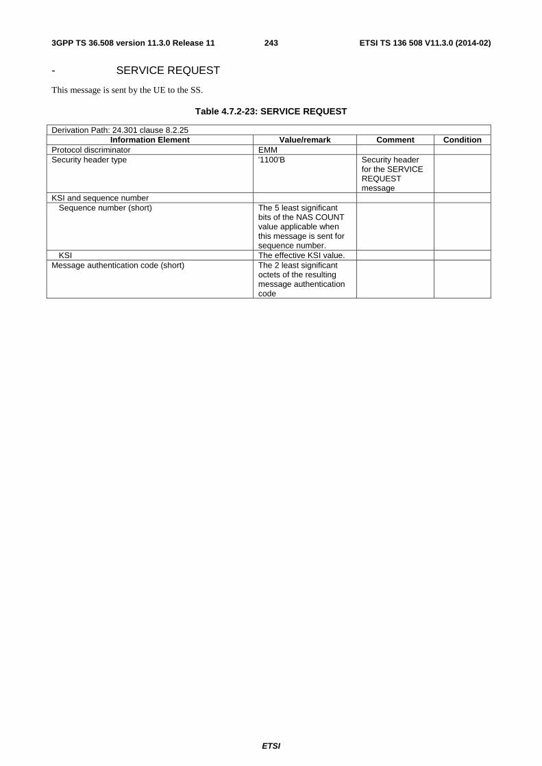
ETSI
ETSI TS 136 508 V11.3.0 (2014-02)2433GPP TS 36.508 version 11.3.0 Release 11
- SERVICE REQUEST
This message is sent by the UE to the SS.
Table 4.7.2-23: SERVICE REQUEST
Derivation Path: 24.301 clause 8.2.25 Information Element Value/remark Comment Condition
Protocol discriminator EMM Security header type '1100'B Security header
for the SERVICE REQUEST message
KSI and sequence number Sequence number (short) The 5 least significant
bits of the NAS COUNT value applicable when this message is sent for sequence number.
KSI The effective KSI value. Message authentication code (short) The 2 least significant
octets of the resulting message authentication code
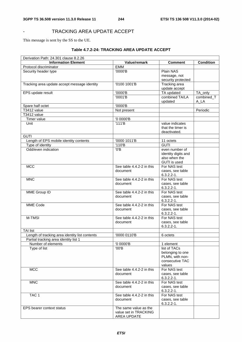
ETSI
ETSI TS 136 508 V11.3.0 (2014-02)2443GPP TS 36.508 version 11.3.0 Release 11
- TRACKING AREA UPDATE ACCEPT
This message is sent by the SS to the UE.
Table 4.7.2-24: TRACKING AREA UPDATE ACCEPT
Derivation Path: 24.301 clause 8.2.26 Information Element Value/remark Comment Condition
Protocol discriminator EMM Security header type '0000'B Plain NAS
message, not security protected
Tracking area update accept message identity '0100 1001'B Tracking area update accept
EPS update result '0000'B TA updated TA_only '0001'B combined TA/LA
updated combined_TA_LA
Spare half octet '0000'B T3412 value Not present Periodic T3412 value Timer value '0 0000'B Unit '111'B value indicates
that the timer is deactivated.
GUTI Length of EPS mobile identity contents '0000 1011'B 11 octets Type of identity '110'B GUTI Odd/even indication '0'B even number of
identity digits and also when the GUTI is used
MCC See table 4.4.2-2 in this document
For NAS test cases, see table 6.3.2.2-1.
MNC See table 4.4.2-2 in this document
For NAS test cases, see table 6.3.2.2-1.
MME Group ID See table 4.4.2-2 in this document
For NAS test cases, see table 6.3.2.2-1.
MME Code See table 4.4.2-2 in this document
For NAS test cases, see table 6.3.2.2-1.
M-TMSI See table 4.4.2-2 in this document
For NAS test cases, see table 6.3.2.2-1.
TAI list Length of tracking area identity list contents '0000 0110'B 6 octets Partial tracking area identity list 1 Number of elements '0 0000'B 1 element Type of list '00'B list of TACs
belonging to one PLMN, with non-consecutive TAC values
MCC See table 4.4.2-2 in this document
For NAS test cases, see table 6.3.2.2-1.
MNC See table 4.4.2-2 in this document
For NAS test cases, see table 6.3.2.2-1.
TAC 1 See table 4.4.2-2 in this document
For NAS test cases, see table 6.3.2.2-1.
EPS bearer context status The same value as the value set in TRACKING AREA UPDATE

ETSI
ETSI TS 136 508 V11.3.0 (2014-02)2453GPP TS 36.508 version 11.3.0 Release 11
REQUEST message Location area identification Not present TA_only Location area identification combined_T
A_LA MCC MCC of the EUTRA cell from which this message is sent
MNC MCC of the EUTRA cell from which this message is sent
LAC 1 MS identity Not present TA_only MS identity combined_T
A_LA Length of mobile identity contents '0000 0101'B 5 octets Type of identity '100'B TMSI/P-TMSI/M-
TMSI Odd/even indication '0'B even number of
identity digits and also when the TMSI/P-TMSI or TMGI and optional MBMS Session Identity is used
TMSI TMSI-1 EMM cause Not present T3402 value Not present T3423 value Not present Equivalent PLMNs Not present Emergency number list Not present EPS network feature support 0000 0001'B IMS voice over PS
session in S1 mode supported
Additional update result Not present Additional update result ‘10’ B “SMS only” TAU_additio
nal_update_result_SMS
T3412 extended value Not present Rel-10
Condition Explanation TA_only This condition applies if the UE is configured to initiate EPS attach or
if explicitly specified. combined_TA_LA This condition applies if the UE is configured to initiate combined
EPS/IMSI attach or if explicitly specified. Periodic This condition applies if in the last TRACKING AREA UPDATE
REQUEST sent prior to this message, the EPS update type Value = '011'B (periodic updating).
TAU_additional_update_result_SMS If the UE requested "SMS only" in the Additional update type IE and combined_TA_LA.
NOTE: This message is always sent within SECURITY PROTECTED NAS MESSAGE message.

ETSI
ETSI TS 136 508 V11.3.0 (2014-02)2463GPP TS 36.508 version 11.3.0 Release 11
- TRACKING AREA UPDATE COMPLETE
This message is sent by the UE to the SS.
Table 4.7.2-25: TRACKING AREA UPDATE COMPLETE
Derivation Path: 24.301 clause 8.2.27 Information Element Value/remark Comment Condition
Protocol discriminator EMM Security header type '0000'B Plain NAS
message, not security protected
Tracking area update complete message identity '0100 1010'B Tracking area update complete
NOTE: This message is always sent within SECURITY PROTECTED NAS MESSAGE message.
- TRACKING AREA UPDATE REJECT
This message is sent by the SS to the UE.
Table 4.7.2-26: TRACKING AREA UPDATE REJECT
Derivation Path: 24.301 clause 8.2.28 Information Element Value/remark Comment Condition
Protocol discriminator EMM Security header type '0000'B Plain NAS
message, not security protected
Tracking area update reject message identity '0100 1011'B Tracking area update reject
EMM cause Set according to specific message content.
NOTE: If this message includes the EMM cause set to #25, it is sent within SECURITY PROTECTED NAS MESSAGE message. Otherwise this message is sent without integrity protection.

ETSI
ETSI TS 136 508 V11.3.0 (2014-02)2473GPP TS 36.508 version 11.3.0 Release 11
- TRACKING AREA UPDATE REQUEST
This message is sent by the UE to the SS.
Table 4.7.2-27: TRACKING AREA UPDATE REQUEST
Derivation Path: 24.301 clause 8.2.29 Information Element Value/remark Comment Condition
Protocol discriminator EMM Security header type '0000'B Plain NAS
message, not security protected
Tracking area update request message identity '0100 1000'B Tracking area update request
EPS update type EPS update type Value '000'B TA updating TA_only '001'B Combined TA/LA
updating combined_TA_LA
"Active" flag '0'B No bearer establishment requested
NAS key set identifier NAS key set identifier The valid NAS key set
identifier of the UE
TSC '0'B native security context (for KSIASME)
Old GUTI Any allowed value Non-current native NAS key set identifier Not present GPRS ciphering key sequence number Not present Old P-TMSI signature Not present Additional GUTI Not present NonceUE Not present UE network capability Not present or any
allowed value
Last visited registered TAI Not present or any allowed value
DRX parameter Not present or any allowed value
UE radio capability information update needed Not present or any allowed value
EPS bearer context status Not present or (octet 3 = '00100000'B and octet 4 = '00000000'B)
MS network capability Not present or any allowed value
Old location area identification Not present or any allowed value
TMSI status Not present or any allowed value
Mobile station classmark 2 Not present or any allowed value
Mobile station classmark 3 Not present or any allowed value
Supported Codecs Not present or any allowed value
Additional update type Not present TA_only Additional update type Not present or any
allowed value combined_T
A_LA Old GUTI type Not present or any
allowed value
Condition Explanation

ETSI
ETSI TS 136 508 V11.3.0 (2014-02)2483GPP TS 36.508 version 11.3.0 Release 11
TA_only See the definition below table 4.7.2-24. combined_TA_LA See the definition below table 4.7.2-24.
NOTE: This message is always sent within SECURITY PROTECTED NAS MESSAGE message.
- UPLINK NAS TRANSPORT
This message is sent by the UE to the SS.
Table 4.7.2-27A: UPLINK NAS TRANSPORT
Derivation Path: 24.301 clause 8.2.30 Information Element Value/remark Comment Condition
Protocol discriminator EMM Security header type '0000'B Plain NAS
message, not security protected
Uplink NAS transport message identity '0100 0011'B Uplink NAS transport
NAS message container Set according to specific message content
NOTE: This message is always sent within SECURITY PROTECTED NAS MESSAGE message.
4.7.3 Contents of ESM messages
- ACTIVATE DEDICATED EPS BEARER CONTEXT ACCEPT
This message is sent by the UE to the SS.
Table 4.7.3-1: ACTIVATE DEDICATED EPS BEARER CONTEXT ACCEPT
Derivation Path: 24.301 clause 8.3.1 Information Element Value/remark Comment Condition
Protocol discriminator ESM EPS bearer identity The same value as the
value set in ACTIVATE DEDICATED EPS BEARER CONTEXT REQUEST message
Procedure transaction identity '0000 0000'B No procedure transaction identity assigned
Activate dedicated EPS bearer context accept message identity
'1100 0110'B Activate dedicated EPS bearer context accept
Protocol configuration options Not present or any allowed value
NOTE: This message is always sent within SECURITY PROTECTED NAS MESSAGE message.

ETSI
ETSI TS 136 508 V11.3.0 (2014-02)2493GPP TS 36.508 version 11.3.0 Release 11
- ACTIVATE DEDICATED EPS BEARER CONTEXT REJECT
This message is sent by UE to the SS.
Table 4.7.3-2: ACTIVATE DEDICATED EPS BEARER CONTEXT REJECT
Derivation Path: 24.301 clause 8.3.2 Information Element Value/remark Comment Condition
Protocol discriminator ESM EPS bearer identity The same value as the
value set in ACTIVATE DEDICATED EPS BEARER CONTEXT REQUEST message.
Procedure transaction identity '0000 0000'B No procedure transaction identity assigned
Activate dedicated EPS bearer context reject message identity
'1100 0111'B Activate dedicated EPS bearer context reject
ESM cause The value is set according to specific message content.
Protocol configuration options Not present
NOTE: This message is always sent within SECURITY PROTECTED NAS MESSAGE message.
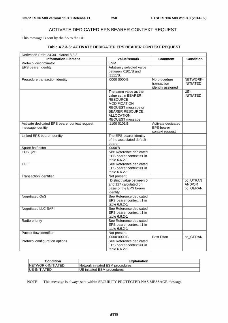
ETSI
ETSI TS 136 508 V11.3.0 (2014-02)2503GPP TS 36.508 version 11.3.0 Release 11
- ACTIVATE DEDICATED EPS BEARER CONTEXT REQUEST
This message is sent by the SS to the UE.
Table 4.7.3-3: ACTIVATE DEDICATED EPS BEARER CONTEXT REQUEST
Derivation Path: 24.301 clause 8.3.3 Information Element Value/remark Comment Condition
Protocol discriminator ESM EPS bearer identity Arbitrarily selected value
between '0101'B and '1111'B.
Procedure transaction identity '0000 0000'B No procedure transaction identity assigned
NETWORK-INITIATED
The same value as the value set in BEARER RESOURCE MODIFICATION REQUEST message or BEARER RESOURCE ALLOCATION REQUEST message
UE-INITIATED
Activate dedicated EPS bearer context request message identity
'1100 0101'B Activate dedicated EPS bearer context request
Linked EPS bearer identity The EPS bearer identity of the associated default bearer
Spare half octet '0000'B EPS QoS See Reference dedicated
EPS bearer context #1 in table 6.6.2-1
TFT See Reference dedicated EPS bearer context #1 in table 6.6.2-1
Transaction identifier Not present Distinct value between 0
and 127 calculated on basis of the EPS bearer identity.
pc_UTRAN AND/OR pc_GERAN
Negotiated QoS See Reference dedicated EPS bearer context #1 in table 6.6.2-1
Negotiated LLC SAPI See Reference dedicated EPS bearer context #1 in table 6.6.2-1
Radio priority See Reference dedicated EPS bearer context #1 in table 6.6.2-1
Packet flow Identifier Not present '0000 0000'B Best Effort pc_GERAN Protocol configuration options See Reference dedicated
EPS bearer context #1 in table 6.6.2-1
Condition Explanation NETWORK-INITIATED Network initiated ESM procedures UE-INITIATED UE initiated ESM procedures
NOTE: This message is always sent within SECURITY PROTECTED NAS MESSAGE message.
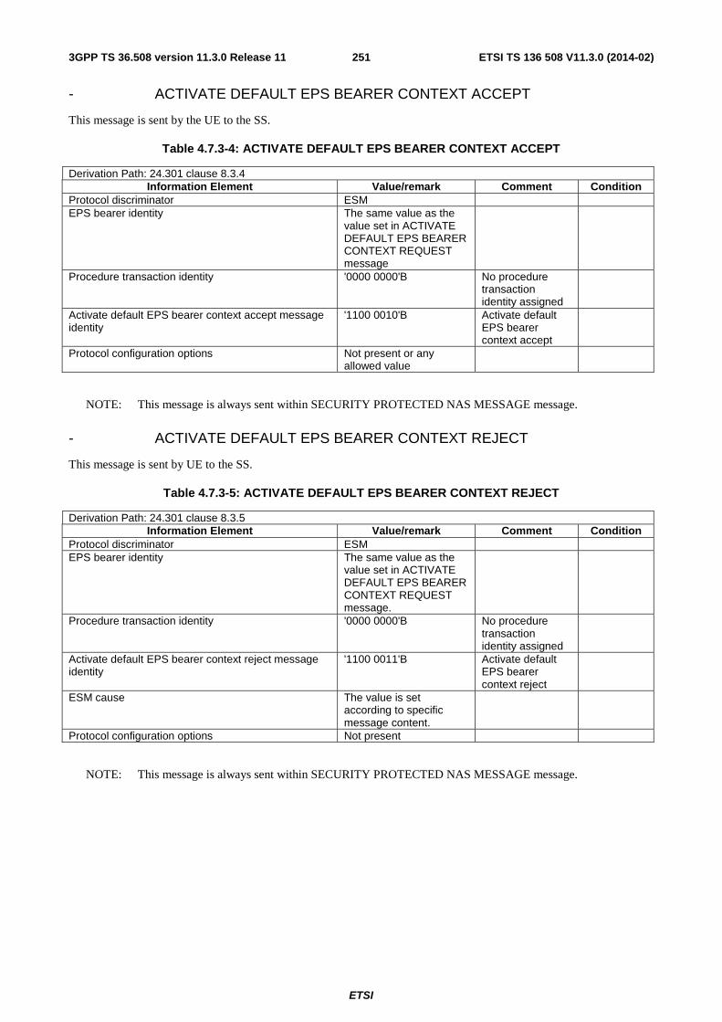
ETSI
ETSI TS 136 508 V11.3.0 (2014-02)2513GPP TS 36.508 version 11.3.0 Release 11
- ACTIVATE DEFAULT EPS BEARER CONTEXT ACCEPT
This message is sent by the UE to the SS.
Table 4.7.3-4: ACTIVATE DEFAULT EPS BEARER CONTEXT ACCEPT
Derivation Path: 24.301 clause 8.3.4 Information Element Value/remark Comment Condition
Protocol discriminator ESM EPS bearer identity The same value as the
value set in ACTIVATE DEFAULT EPS BEARER CONTEXT REQUEST message
Procedure transaction identity '0000 0000'B No procedure transaction identity assigned
Activate default EPS bearer context accept message identity
'1100 0010'B Activate default EPS bearer context accept
Protocol configuration options Not present or any allowed value
NOTE: This message is always sent within SECURITY PROTECTED NAS MESSAGE message.
- ACTIVATE DEFAULT EPS BEARER CONTEXT REJECT
This message is sent by UE to the SS.
Table 4.7.3-5: ACTIVATE DEFAULT EPS BEARER CONTEXT REJECT
Derivation Path: 24.301 clause 8.3.5 Information Element Value/remark Comment Condition
Protocol discriminator ESM EPS bearer identity The same value as the
value set in ACTIVATE DEFAULT EPS BEARER CONTEXT REQUEST message.
Procedure transaction identity '0000 0000'B No procedure transaction identity assigned
Activate default EPS bearer context reject message identity
'1100 0011'B Activate default EPS bearer context reject
ESM cause The value is set according to specific message content.
Protocol configuration options Not present
NOTE: This message is always sent within SECURITY PROTECTED NAS MESSAGE message.

ETSI
ETSI TS 136 508 V11.3.0 (2014-02)2523GPP TS 36.508 version 11.3.0 Release 11
- ACTIVATE DEFAULT EPS BEARER CONTEXT REQUEST
This message is sent by the SS to the UE.
Table 4.7.3-6: ACTIVATE DEFAULT EPS BEARER CONTEXT REQUEST
Derivation Path: 24.301 clause 8.3.6 Information Element Value/remark Comment Condition
Protocol discriminator ESM EPS bearer identity An arbitrarily selected
value between '0101'B and '1111'B.
Procedure transaction identity The same value as the value set in the latest PDN CONNECTIVITY REQUEST message sent prior to this message.
Activate default EPS bearer context request message identity
'1100 0001'B Activate default EPS bearer context request
EPS QoS See Reference default EPS bearer context #1 in table 6.6.1-1
NOT IMS APN
EPS QoS See Reference default EPS bearer context #2 in table 6.6.1-1
IMS APN
Access point name The SS defines a Default APN or, if the UE transmits an ESM INFORMATION RESPONSE message providing an APN, the SS shall use this value
NOT IMS APN
Access point name IMS.apn.epc.mnc<MNC>.mcc<MCC>.3gppnetwork.org The <MNC> and <MCC> are set to the same values as in IMSI.
IMS APN
PDN address IPv4 Length of PDN address contents 5 octets PDN type value ‘001’B IPv4 PDN address information IPv4 address The SS provides a
valid IPv4 address NOT IPv4-DHCP
0.0.0.0 DHCPv4 is to be used to allocate the IPv4 address
IPv4-DHCP
PDN address IPv6 Length of PDN address contents 9 octets PDN type value ‘010’B IPv6 PDN address information IPv6 interface identifier The SS provides a
valid IPv6 interface identifier
PDN address IPv4v6 Length of PDN address contents 13 octets PDN type value ‘011’B IPv4v6 PDN address information (Octets 4 to 11) IPv6 interface identifier The SS provides a
valid IPv6 interface identifier
PDN address information (Octets 12 to 15) IPv4 address The SS provides a valid IPv4 address
NOT IPv4-DHCP
0.0.0.0 DHCPv4 is to be used to allocate the IPv4 address
IPv4-DHCP
Transaction identifier Not present Distinct value between 0
and 127 calculated on pc_UTRAN
AND/OR
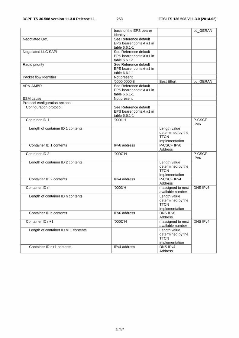
ETSI
ETSI TS 136 508 V11.3.0 (2014-02)2533GPP TS 36.508 version 11.3.0 Release 11
basis of the EPS bearer identity.
pc_GERAN
Negotiated QoS See Reference default EPS bearer context #1 in table 6.6.1-1
Negotiated LLC SAPI See Reference default EPS bearer context #1 in table 6.6.1-1
Radio priority See Reference default EPS bearer context #1 in table 6.6.1-1
Packet flow Identifier Not present '0000 0000'B Best Effort pc_GERAN APN-AMBR See Reference default
EPS bearer context #1 in table 6.6.1-1
ESM cause Not present Protocol configuration options Configuration protocol See Reference default
EPS bearer context #1 in table 6.6.1-1
Container ID 1 ‘0001’H P-CSCF IPv6
Length of container ID 1 contents Length value determined by the TTCN implementation
Container ID 1 contents IPv6 address P-CSCF IPv6 Address
Container ID 2 ‘000C’H P-CSCF IPv4
Length of container ID 2 contents Length value determined by the TTCN implementation
Container ID 2 contents IPv4 address P-CSCF IPv4 Address
Container ID n ‘0003’H n assigned to next available number
DNS IPv6
Length of container ID n contents Length value determined by the TTCN implementation
Container ID n contents IPv6 address DNS IPv6 Address
Container ID n+1 ‘000D’H n assigned to next available number
DNS IPv4
Length of container ID n+1 contents Length value determined by the TTCN implementation
Container ID n+1 contents IPv4 address DNS IPv4 Address
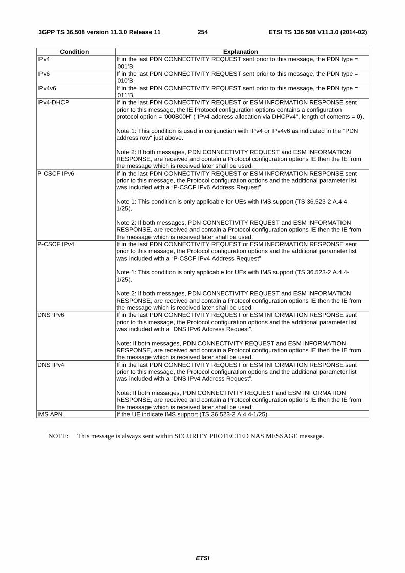
ETSI
ETSI TS 136 508 V11.3.0 (2014-02)2543GPP TS 36.508 version 11.3.0 Release 11
Condition Explanation IPv4 If in the last PDN CONNECTIVITY REQUEST sent prior to this message, the PDN type =
'001'B IPv6 If in the last PDN CONNECTIVITY REQUEST sent prior to this message, the PDN type =
'010'B IPv4v6 If in the last PDN CONNECTIVITY REQUEST sent prior to this message, the PDN type =
'011'B IPv4-DHCP If in the last PDN CONNECTIVITY REQUEST or ESM INFORMATION RESPONSE sent
prior to this message, the IE Protocol configuration options contains a configuration protocol option = '000B00H' ("IPv4 address allocation via DHCPv4", length of contents = 0). Note 1: This condition is used in conjunction with IPv4 or IPv4v6 as indicated in the "PDN address row" just above. Note 2: If both messages, PDN CONNECTIVITY REQUEST and ESM INFORMATION RESPONSE, are received and contain a Protocol configuration options IE then the IE from the message which is received later shall be used.
P-CSCF IPv6 If in the last PDN CONNECTIVITY REQUEST or ESM INFORMATION RESPONSE sent prior to this message, the Protocol configuration options and the additional parameter list was included with a “P-CSCF IPv6 Address Request” Note 1: This condition is only applicable for UEs with IMS support (TS 36.523-2 A.4.4-1/25). Note 2: If both messages, PDN CONNECTIVITY REQUEST and ESM INFORMATION RESPONSE, are received and contain a Protocol configuration options IE then the IE from the message which is received later shall be used.
P-CSCF IPv4 If in the last PDN CONNECTIVITY REQUEST or ESM INFORMATION RESPONSE sent prior to this message, the Protocol configuration options and the additional parameter list was included with a “P-CSCF IPv4 Address Request” Note 1: This condition is only applicable for UEs with IMS support (TS 36.523-2 A.4.4-1/25). Note 2: If both messages, PDN CONNECTIVITY REQUEST and ESM INFORMATION RESPONSE, are received and contain a Protocol configuration options IE then the IE from the message which is received later shall be used.
DNS IPv6 If in the last PDN CONNECTIVITY REQUEST or ESM INFORMATION RESPONSE sent prior to this message, the Protocol configuration options and the additional parameter list was included with a “DNS IPv6 Address Request”. Note: If both messages, PDN CONNECTIVITY REQUEST and ESM INFORMATION RESPONSE, are received and contain a Protocol configuration options IE then the IE from the message which is received later shall be used.
DNS IPv4 If in the last PDN CONNECTIVITY REQUEST or ESM INFORMATION RESPONSE sent prior to this message, the Protocol configuration options and the additional parameter list was included with a “DNS IPv4 Address Request”. Note: If both messages, PDN CONNECTIVITY REQUEST and ESM INFORMATION RESPONSE, are received and contain a Protocol configuration options IE then the IE from the message which is received later shall be used.
IMS APN If the UE indicate IMS support (TS 36.523-2 A.4.4-1/25).
NOTE: This message is always sent within SECURITY PROTECTED NAS MESSAGE message.
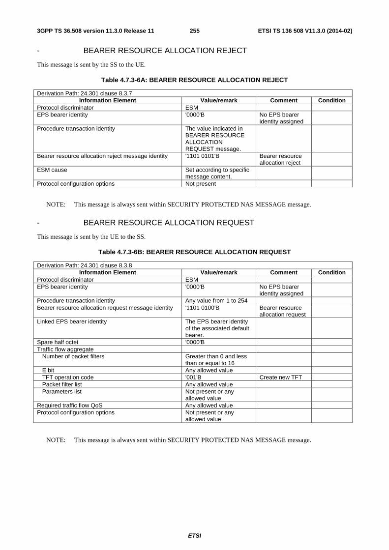
ETSI
ETSI TS 136 508 V11.3.0 (2014-02)2553GPP TS 36.508 version 11.3.0 Release 11
- BEARER RESOURCE ALLOCATION REJECT
This message is sent by the SS to the UE.
Table 4.7.3-6A: BEARER RESOURCE ALLOCATION REJECT
Derivation Path: 24.301 clause 8.3.7 Information Element Value/remark Comment Condition
Protocol discriminator ESM EPS bearer identity '0000'B No EPS bearer
identity assigned
Procedure transaction identity The value indicated in BEARER RESOURCE ALLOCATION REQUEST message.
Bearer resource allocation reject message identity '1101 0101'B Bearer resource allocation reject
ESM cause Set according to specific message content.
Protocol configuration options Not present
NOTE: This message is always sent within SECURITY PROTECTED NAS MESSAGE message.
- BEARER RESOURCE ALLOCATION REQUEST
This message is sent by the UE to the SS.
Table 4.7.3-6B: BEARER RESOURCE ALLOCATION REQUEST
Derivation Path: 24.301 clause 8.3.8 Information Element Value/remark Comment Condition
Protocol discriminator ESM EPS bearer identity '0000'B No EPS bearer
identity assigned
Procedure transaction identity Any value from 1 to 254 Bearer resource allocation request message identity '1101 0100'B Bearer resource
allocation request
Linked EPS bearer identity The EPS bearer identity of the associated default bearer.
Spare half octet '0000'B Traffic flow aggregate Number of packet filters Greater than 0 and less
than or equal to 16
E bit Any allowed value TFT operation code '001'B Create new TFT Packet filter list Any allowed value Parameters list Not present or any
allowed value
Required traffic flow QoS Any allowed value Protocol configuration options Not present or any
allowed value
NOTE: This message is always sent within SECURITY PROTECTED NAS MESSAGE message.

ETSI
ETSI TS 136 508 V11.3.0 (2014-02)2563GPP TS 36.508 version 11.3.0 Release 11
- BEARER RESOURCE MODIFICATION REJECT
This message is sent by the SS to the UE.
Table 4.7.3-7: BEARER RESOURCE MODIFICATION REJECT
Derivation Path: 24.301 clause 8.3.9 Information Element Value/remark Comment Condition
Protocol discriminator ESM EPS bearer identity '0000'B No EPS bearer
identity assigned
Procedure transaction identity The value indicated in BEARER RESOURCE MODIFICATION REQUEST message.
Bearer resource modification reject message identity '1101 0111'B Bearer resource modification reject
ESM cause Set according to specific message content.
Protocol configuration options Not present
NOTE: This message is always sent within SECURITY PROTECTED NAS MESSAGE message.
- BEARER RESOURCE MODIFICATION REQUEST
This message is sent by the UE to the SS.
Table 4.7.3-8: BEARER RESOURCE MODIFICATION REQUEST
Derivation Path: 24.301 clause 8.3.10 Information Element Value/remark Comment Condition
Protocol discriminator ESM EPS bearer identity '0000'B No EPS bearer
identity assigned
Procedure transaction identity Any value from 1 to 254 Bearer resource modification request message identity
'1101 0110'B Bearer resource modification request
EPS bearer identity for packet filter The EPS bearer identity of the associated dedicated EPS bearer related with packet filter.
Spare half octet '0000'B Traffic flow aggregate Any allowed value Traffic flow aggregate RELEASE-
REQUESTED
Number of packet filters Greater than 0 and less than or equal to 16
E bit Any allowed value TFT operation code '101'B Delete packet
filters from existing TFT
Packet filter list Any allowed value Parameters list Not present or any
allowed value
Required traffic flow QoS Not present or any allowed value
ESM cause Not present '0010 0100'B Regular
deactivation RELEASE-REQUESTED
Protocol configuration options Not present or any allowed value
Condition Explanation

ETSI
ETSI TS 136 508 V11.3.0 (2014-02)2573GPP TS 36.508 version 11.3.0 Release 11
RELEASE-REQUESTED UE requests the release of bearer resources.
NOTE: This message is always sent within SECURITY PROTECTED NAS MESSAGE message.
Table 4.7.3-9: (Void)
Table 4.7.3-10: (Void)
- DEACTIVATE EPS BEARER CONTEXT ACCEPT
This message is sent by the UE to the SS.
Table 4.7.3-11: DEACTIVATE EPS BEARER CONTEXT ACCEPT
Derivation Path: 24.301 clause 8.3.9 Information Element Value/remark Comment Condition
Protocol discriminator ESM EPS bearer identity The same value as the
value set in DEACTIVATE EPS BEARER CONTEXT REQUEST message.
Procedure transaction identity '0000 0000'B No procedure transaction identity assigned
Deactivate EPS bearer context accept message identity
'1100 1110'B Deactivate EPS bearer context accept
Protocol configuration options Not present or any allowed value
NOTE: This message is always sent within SECURITY PROTECTED NAS MESSAGE message.
- DEACTIVATE EPS BEARER CONTEXT REQUEST
This message is sent by the SS to the UE.
Table 4.7.3-12: DEACTIVATE EPS BEARER CONTEXT REQUEST
Derivation Path: 24.301 clause 8.3.10 Information Element Value/remark Comment Condition
Protocol discriminator ESM EPS bearer identity Set according to specific
message content.
Procedure transaction identity '0000 0000'B No procedure transaction identity assigned
NETWORK-INITIATED
The same value as the value set in PDN DISCONNECT REQUEST message or BEARER RESOURCE MODIFICATION REQUEST message.
UE-INITIATED
Deactivate EPS bearer context request message identity
'1100 1101'B Deactivate EPS bearer context request
ESM cause Set according to specific message content.
Protocol configuration options Not present
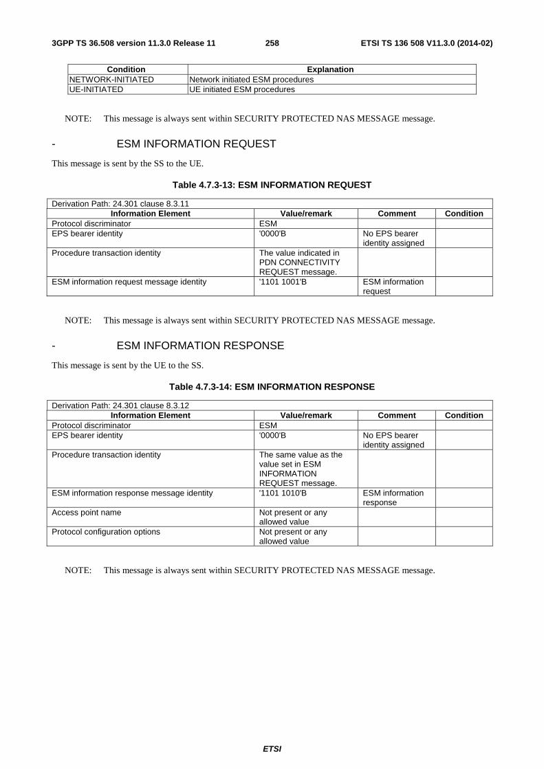
ETSI
ETSI TS 136 508 V11.3.0 (2014-02)2583GPP TS 36.508 version 11.3.0 Release 11
Condition Explanation NETWORK-INITIATED Network initiated ESM procedures UE-INITIATED UE initiated ESM procedures
NOTE: This message is always sent within SECURITY PROTECTED NAS MESSAGE message.
- ESM INFORMATION REQUEST
This message is sent by the SS to the UE.
Table 4.7.3-13: ESM INFORMATION REQUEST
Derivation Path: 24.301 clause 8.3.11 Information Element Value/remark Comment Condition
Protocol discriminator ESM EPS bearer identity '0000'B No EPS bearer
identity assigned
Procedure transaction identity The value indicated in PDN CONNECTIVITY REQUEST message.
ESM information request message identity '1101 1001'B ESM information request
NOTE: This message is always sent within SECURITY PROTECTED NAS MESSAGE message.
- ESM INFORMATION RESPONSE
This message is sent by the UE to the SS.
Table 4.7.3-14: ESM INFORMATION RESPONSE
Derivation Path: 24.301 clause 8.3.12 Information Element Value/remark Comment Condition
Protocol discriminator ESM EPS bearer identity '0000'B No EPS bearer
identity assigned
Procedure transaction identity The same value as the value set in ESM INFORMATION REQUEST message.
ESM information response message identity '1101 1010'B ESM information response
Access point name Not present or any allowed value
Protocol configuration options Not present or any allowed value
NOTE: This message is always sent within SECURITY PROTECTED NAS MESSAGE message.

ETSI
ETSI TS 136 508 V11.3.0 (2014-02)2593GPP TS 36.508 version 11.3.0 Release 11
- ESM STATUS
This message is sent by the UE or by the SS.
Table 4.7.3-15: ESM STATUS
Derivation Path: 24.301 clause 8.3.13 Information Element Value/remark Comment Condition
Protocol discriminator ESM EPS bearer identity Set according to specific
message content.
Procedure transaction identity '0000 0000'B No procedure transaction identity assigned
ESM status message identity '1110 1000'B ESM status ESM cause Set according to specific
message content.
NOTE: This message is always sent within SECURITY PROTECTED NAS MESSAGE message.
- MODIFY EPS BEARER CONTEXT ACCEPT
This message is sent by the UE to the SS.
Table 4.7.3-16: MODIFY EPS BEARER CONTEXT ACCEPT
Derivation Path: 24.301 clause 8.3.14 Information Element Value/remark Comment Condition
Protocol discriminator ESM EPS bearer identity The same value as the
value set in MODIFY EPS BEARER CONTEXT REQUEST message.
Procedure transaction identity '0000 0000'B No procedure transaction identity assigned
Modify EPS bearer context accept message identity '1100 1010'B Modify EPS bearer context accept
Protocol configuration options Not present or any allowed value
NOTE: This message is always sent within SECURITY PROTECTED NAS MESSAGE message.

ETSI
ETSI TS 136 508 V11.3.0 (2014-02)2603GPP TS 36.508 version 11.3.0 Release 11
- MODIFY EPS BEARER CONTEXT REJECT
This message is sent by the UE to the SS.
Table 4.7.3-17: MODIFY EPS BEARER CONTEXT REJECT
Derivation Path: 24.301 clause 8.3.15 Information Element Value/remark Comment Condition
Protocol discriminator ESM EPS bearer identity The same value as the
value set in MODIFY EPS BEARER CONTEXT REQUEST message.
Procedure transaction identity '0000 0000'B No procedure transaction identity assigned
Modify EPS bearer context reject message identity '1100 1011'B Modify EPS bearer context reject
ESM cause The value is set according to specific message content.
Protocol configuration options Not present
NOTE: This message is always sent within SECURITY PROTECTED NAS MESSAGE message.

ETSI
ETSI TS 136 508 V11.3.0 (2014-02)2613GPP TS 36.508 version 11.3.0 Release 11
- MODIFY EPS BEARER CONTEXT REQUEST
This message is sent by the SS to the UE.
Table 4.7.3-18: MODIFY EPS BEARER CONTEXT REQUEST
Derivation Path: 24.301 clause 8.3.16 Information Element Value/remark Comment Condition
Protocol discriminator ESM EPS bearer identity Set according to specific
message content.
Procedure transaction identity '0000 0000'B No procedure transaction identity assigned
NETWORK-INITIATED
The same value as the value set in BEARER RESOURCE MODIFICATION REQUEST message or BEARER RESOURCE ALLOCATION REQUEST message.
UE-INITIATED
Modify EPS bearer context request message identity '1100 1001'B Modify EPS bearer context request
New EPS QoS Use the same value as used in Activate EPS Bearer Context Request message
TFT According to reference dedicated EPS bearer context #2 except for TFT operation code which is set to ‘100’B and TFT identifier is set to ‘00110000’B..
New QoS Not Present. Negotiated LLC SAPI Not Present. Radio priority Not Present. Packet flow Identifier Not Present. '0000 0000'B Best Effort pc_GERAN APN-AMBR Not Present. Protocol configuration options Not present
Condition Explanation NETWORK-INITIATED Network initiated ESM procedures UE-INITIATED UE initiated ESM procedures
NOTE: This message is always sent within SECURITY PROTECTED NAS MESSAGE message.

ETSI
ETSI TS 136 508 V11.3.0 (2014-02)2623GPP TS 36.508 version 11.3.0 Release 11
- NOTIFICATION
This message is sent by the SS to the UE.
Table 4.7.3-18A: NOTIFICATION
Derivation Path: 24.301 clause 8.3.18A Information Element Value/remark Comment Condition
Protocol discriminator ESM EPS bearer identity '0000'B No EPS bearer
identity assigned
The same value as the value set in ACTIVATE DEFAULT EPS BEARER CONTEXT REQUEST message for IMS signalling.
SRVCC-HO-CANCELLED
Procedure transaction identity '0000 0000'B No procedure transaction identity assigned
Notification message identity '1101 1011'B Notification Notification indicator '0000 0001'B SRVCC handover
cancelled, IMS session re-establishment required
SRVCC-HO-CANCELLED
Condition Explanation SRVCC-HO-CANCELLED Used if SRVCC handover is cancelled.
NOTE: This message is always sent within SECURITY PROTECTED NAS MESSAGE message.
- PDN CONNECTIVITY REJECT
This message is sent by the SS to the UE.
Table 4.7.3-19: PDN CONNECTIVITY REJECT
Derivation Path: 24.301 clause 8.3.17 Information Element Value/remark Comment Condition
Protocol discriminator ESM EPS bearer identity '0000'B No EPS bearer
identity assigned
Procedure transaction identity The same value as the value set in PDN CONNECTIVITY REQUEST message.
PDN connectivity reject message identity '1101 0001'B PDN connectivity reject
ESM cause The value is set according to specific message content.
Protocol configuration options Not present
NOTE: This message is sent without integrity protection before NAS security mode control procedure has been successfully completed and sent within SECURITY PROTECTED NAS MESSAGE message after NAS security mode control procedure has been successfully completed.
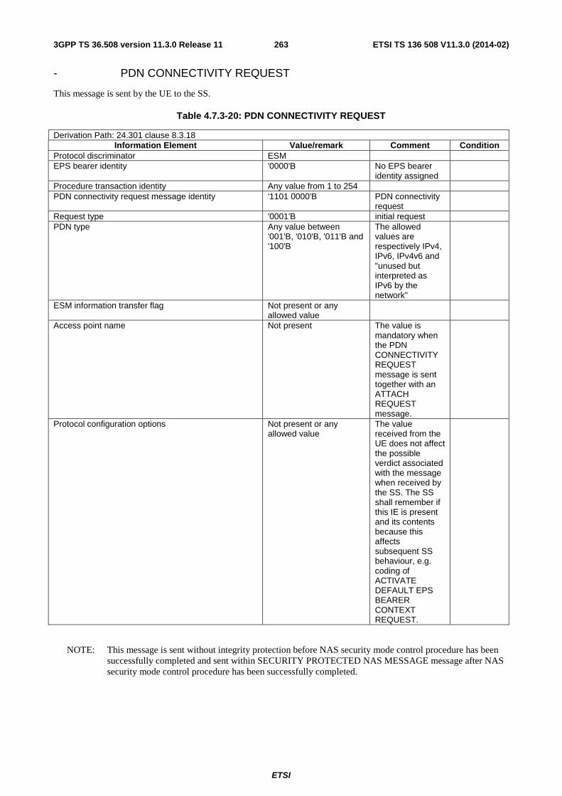
ETSI
ETSI TS 136 508 V11.3.0 (2014-02)2633GPP TS 36.508 version 11.3.0 Release 11
- PDN CONNECTIVITY REQUEST
This message is sent by the UE to the SS.
Table 4.7.3-20: PDN CONNECTIVITY REQUEST
Derivation Path: 24.301 clause 8.3.18 Information Element Value/remark Comment Condition
Protocol discriminator ESM EPS bearer identity '0000'B No EPS bearer
identity assigned
Procedure transaction identity Any value from 1 to 254 PDN connectivity request message identity '1101 0000'B PDN connectivity
request
Request type '0001'B initial request PDN type Any value between
'001'B, '010'B, '011'B and '100'B
The allowed values are respectively IPv4, IPv6, IPv4v6 and "unused but interpreted as IPv6 by the network"
ESM information transfer flag Not present or any allowed value
Access point name Not present The value is mandatory when the PDN CONNECTIVITY REQUEST message is sent together with an ATTACH REQUEST message.
Protocol configuration options Not present or any allowed value
The value received from the UE does not affect the possible verdict associated with the message when received by the SS. The SS shall remember if this IE is present and its contents because this affects subsequent SS behaviour, e.g. coding of ACTIVATE DEFAULT EPS BEARER CONTEXT REQUEST.
NOTE: This message is sent without integrity protection before NAS security mode control procedure has been successfully completed and sent within SECURITY PROTECTED NAS MESSAGE message after NAS security mode control procedure has been successfully completed.

ETSI
ETSI TS 136 508 V11.3.0 (2014-02)2643GPP TS 36.508 version 11.3.0 Release 11
- PDN DISCONNECT REJECT
This message is sent by the SS to the UE.
Table 4.7.3-21: PDN DISCONNECT REJECT
Derivation Path: 24.301 clause 8.3.19 Information Element Value/remark Comment Condition
Protocol discriminator ESM EPS bearer identity '0000'B No EPS bearer
identity assigned
Procedure transaction identity The value indicated in PDN DISCONNECT REQUEST message.
PDN disconnect reject message identity '1101 0011'B PDN disconnect reject
ESM cause Set according to specific message content.
Protocol configuration options Not present
NOTE: This message is always sent within SECURITY PROTECTED NAS MESSAGE message.
- PDN DISCONNECT REQUEST
This message is sent by the UE to the SS.
Table 4.7.3-22: PDN DISCONNECT REQUEST
Derivation Path: 24.301 clause 8.3.20 Information Element Value/remark Comment Condition
Protocol discriminator ESM EPS bearer identity '0000'B No EPS bearer
identity assigned
Procedure transaction identity Any value from 1 to 254 PDN disconnect request message identity '1101 0010'B PDN disconnect
request
Linked EPS bearer identity The EPS bearer identity of the associated default bearer.
Spare half octet '0000'B Protocol configuration options Not present or any
allowed value
NOTE: This message is always sent within SECURITY PROTECTED NAS MESSAGE message.
4.7A Default TC message and information element contents This clause contains the default values of common TC (Test Control, see [38]) messages and information elements, which apply to all test cases unless otherwise specified. All the messages and information elements are listed in alphabetical order.

ETSI
ETSI TS 136 508 V11.3.0 (2014-02)2653GPP TS 36.508 version 11.3.0 Release 11
- ACTIVATE TEST MODE
This message is sent by the SS to the UE embedded in a RRC DLInformationTransfer message.
Table 4.7A-1: ACTIVATE TEST MODE
Derivation Path: 36.509 clause 6.5 Information Element Value/remark Comment Condition
Protocol discriminator 1 1 1 1 Skip indicator 0 0 0 0 Message type 1 0 0 0 0 1 0 0 UE test loop mode 0 0 0 0 0 0 0 0 UE test loop mode A UE TEST
LOOP MODE A (default)
UE test loop mode 0 0 0 0 0 0 0 1 UE test loop mode B UE TEST LOOP MODE B
UE test loop mode 0 0 0 0 0 0 1 0 UE test loop mode C UE TEST LOOP MODE C
Condition Explanation UE TEST LOOP MODE A UE test loop function configured for UE test loop mode A operation. UE TEST LOOP MODE B UE test loop function configured for UE test loop mode B operation. UE TEST LOOP MODE C UE test loop function configured for UE test loop mode C operation.
- ACTIVATE TEST MODE COMPLETE
This message is sent by the UE to the SS embedded in a RRC ULInformationTransfer message.
Table 4.7A-2: ACTIVATE TEST MODE COMPLETE
Derivation Path: 36.509 clause 6.6 Information Element Value/remark Comment Condition
Protocol discriminator 1 1 1 1 Skip indicator 0 0 0 0 Message type 1 0 0 0 0 1 0 1
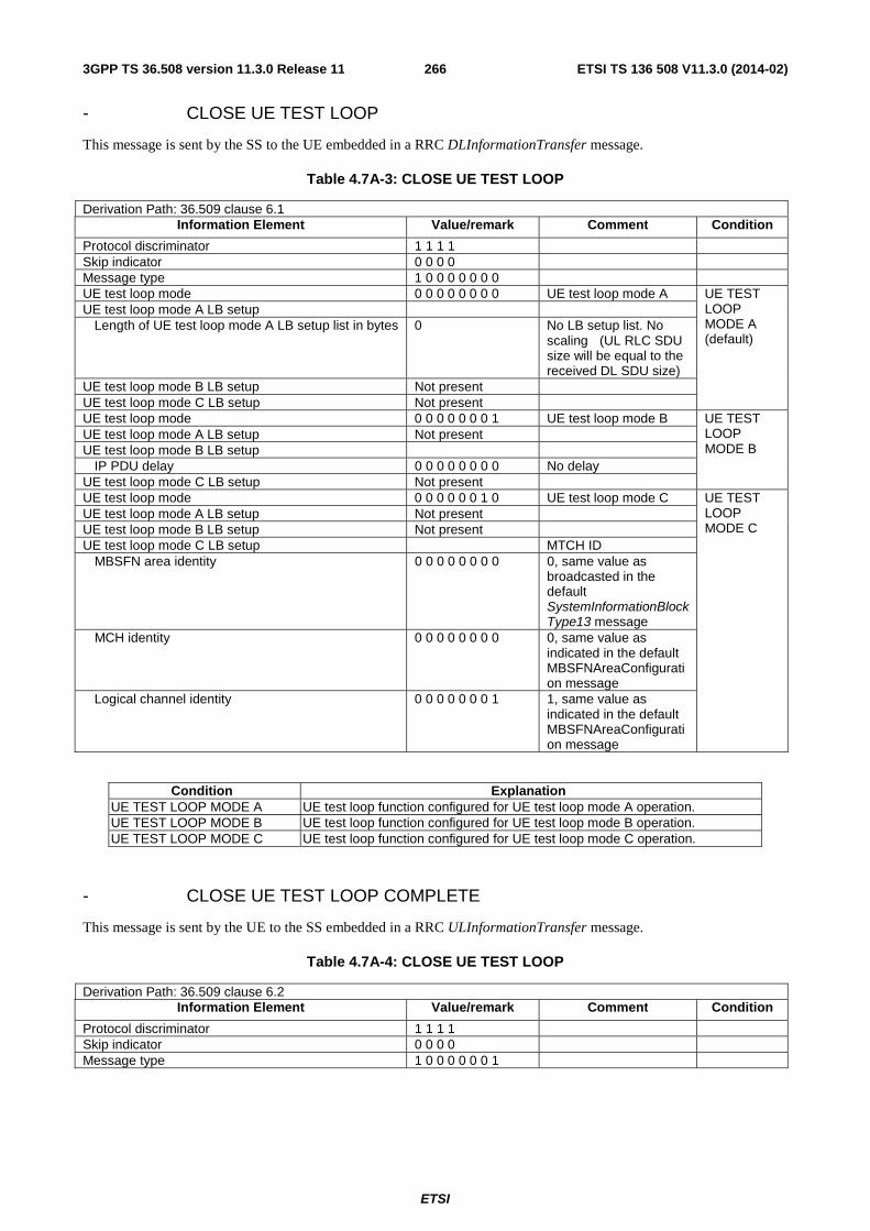
ETSI
ETSI TS 136 508 V11.3.0 (2014-02)2663GPP TS 36.508 version 11.3.0 Release 11
- CLOSE UE TEST LOOP
This message is sent by the SS to the UE embedded in a RRC DLInformationTransfer message.
Table 4.7A-3: CLOSE UE TEST LOOP
Derivation Path: 36.509 clause 6.1 Information Element Value/remark Comment Condition
Protocol discriminator 1 1 1 1 Skip indicator 0 0 0 0 Message type 1 0 0 0 0 0 0 0 UE test loop mode 0 0 0 0 0 0 0 0 UE test loop mode A UE TEST
LOOP MODE A (default)
UE test loop mode A LB setup Length of UE test loop mode A LB setup list in bytes 0 No LB setup list. No
scaling (UL RLC SDU size will be equal to the received DL SDU size)
UE test loop mode B LB setup Not present UE test loop mode C LB setup Not present UE test loop mode 0 0 0 0 0 0 0 1 UE test loop mode B UE TEST
LOOP MODE B
UE test loop mode A LB setup Not present UE test loop mode B LB setup IP PDU delay 0 0 0 0 0 0 0 0 No delay UE test loop mode C LB setup Not present UE test loop mode 0 0 0 0 0 0 1 0 UE test loop mode C UE TEST
LOOP MODE C
UE test loop mode A LB setup Not present UE test loop mode B LB setup Not present UE test loop mode C LB setup MTCH ID MBSFN area identity 0 0 0 0 0 0 0 0 0, same value as
broadcasted in the default SystemInformationBlockType13 message
MCH identity 0 0 0 0 0 0 0 0 0, same value as indicated in the default MBSFNAreaConfiguration message
Logical channel identity 0 0 0 0 0 0 0 1 1, same value as indicated in the default MBSFNAreaConfiguration message
Condition Explanation UE TEST LOOP MODE A UE test loop function configured for UE test loop mode A operation. UE TEST LOOP MODE B UE test loop function configured for UE test loop mode B operation. UE TEST LOOP MODE C UE test loop function configured for UE test loop mode C operation.
- CLOSE UE TEST LOOP COMPLETE
This message is sent by the UE to the SS embedded in a RRC ULInformationTransfer message.
Table 4.7A-4: CLOSE UE TEST LOOP
Derivation Path: 36.509 clause 6.2 Information Element Value/remark Comment Condition
Protocol discriminator 1 1 1 1 Skip indicator 0 0 0 0 Message type 1 0 0 0 0 0 0 1

ETSI
ETSI TS 136 508 V11.3.0 (2014-02)2673GPP TS 36.508 version 11.3.0 Release 11
- DEACTIVATE TEST MODE
This message is sent by the SS to the UE embedded in a RRC DLInformationTransfer message.
Table 4.7A-5: DEACTIVATE TEST MODE
Derivation Path: 36.509 clause 6.7 Information Element Value/remark Comment Condition
Protocol discriminator 1 1 1 1 Skip indicator 0 0 0 0 Message type 1 0 0 0 0 1 1 0
- DEACTIVATE TEST MODE COMPLETE
This message is sent by the UE to the SS embedded in a RRC ULInformationTransfer message.
Table 4.7A-6: DEACTIVATE TEST MODE COMPLETE
Derivation Path: 36.509 clause 6.8 Information Element Value/remark Comment Condition
Protocol discriminator 1 1 1 1 Skip indicator 0 0 0 0 Message type 1 0 0 0 0 1 1 1
- OPEN UE TEST LOOP
This message is sent by the SS to the UE embedded in a RRC DLInformationTransfer message.
Table 4.7A-7: OPEN UE TEST LOOP
Derivation Path: 36.509 clause 6.3 Information Element Value/remark Comment Condition
Protocol discriminator 1 1 1 1 Skip indicator 0 0 0 0 Message type 1 0 0 0 0 0 1 0
- OPEN UE TEST LOOP COMPLETE
This message is sent by the UE to the SS embedded in a RRC ULInformationTransfer message.
Table 4.7A-8: OPEN UE TEST LOOP COMPLETE
Derivation Path: 36.509 clause 6.4 Information Element Value/remark Comment Condition
Protocol discriminator 1 1 1 1 Skip indicator 0 0 0 0 Message type 1 0 0 0 0 0 1 1

ETSI
ETSI TS 136 508 V11.3.0 (2014-02)2683GPP TS 36.508 version 11.3.0 Release 11
- UE TEST LOOP MODE C MBMS PACKET COUNTER REQUEST
This message is sent by the SS to the UE embedded in a RRC DLInformationTransfer message.
Table 4.7A-9: UE TEST LOOP MODE C MBMS PACKET COUNTER REQUEST
Derivation Path: 36.509 clause 6.10 Information Element Value/remark Comment Condition
Protocol discriminator 1 1 1 1 Skip indicator 0 0 0 0 Message type 1 0 0 0 1 0 0 1
- UE TEST LOOP MODE C MBMS PACKET COUNTER RESPONSE
This message is sent by the UE to the SS embedded in a RRC ULInformationTransfer message.
Table 4.7A-10: UE TEST LOOP MODE C MBMS PACKET COUNTER RESPONSE
Derivation Path: 36.509 clause 6.11 Information Element Value/remark Comment Condition
Protocol discriminator 1 1 1 1 Skip indicator 0 0 0 0 Message type 1 0 0 0 1 0 1 1 MBMS Packet Counter Value

ETSI
ETSI TS 136 508 V11.3.0 (2014-02)2693GPP TS 36.508 version 11.3.0 Release 11
4.7B Default UTRA message and information element contents
4.7B.1 UTRA RRC messages
– HANDOVER TO UTRAN COMMAND
Table 4.7B.1-1: HANDOVER TO UTRAN COMMAND
Derivation Path: 25.331, clause 10.2.16a Information Element Value/remark Comment Condition
New U-RNTI U-RNTI-Short - SRNC identity 0000 0000 0001B - S-RNTI-2 00 0000 0001B Ciphering algorithm UEA0 or UEA1. The
indicated algorithm must be one of the algorithms supported by the UE.
RNC support for change of UE capability FALSE New H-RNTI Not present UTRA FDD
PS RB, UTRA TDD PS RB, UTRA Speech, UTRA PS RB + Speech, UTRA Speech + Packet RAB Setup after Speech RAB Setup in CELL_DCH
'1010 1010 1010 1010' UTRA HSDPA RB, UTRA HSUPA/HSDPA RB
New Primary E-RNTI Not present UTRA FDD PS RB, UTRA TDD PS RB, UTRA HSDPA RB, UTRA Speech, UTRA PS RB + Speech. ,UTRA Speech + Packet RAB Setup after Speech RAB Setup in CELL_DCH
'1010 1010 1010 1010' UTRA HSUPA/H

ETSI
ETSI TS 136 508 V11.3.0 (2014-02)2703GPP TS 36.508 version 11.3.0 Release 11
SDPA RB New Secondary E-RNTI Not present Default configuration for CELL_FACH Not present CHOICE specification mode Complete specification - Signalling RB information to setup List Same as the
corresponding IE in the RRC CONNECTION SETUP message (Transition to CELL_DCH or HS-PDSCH in CELL_FACH) using condition A1 in TS 34.108 clause 9.1.1 for UTRA-FDD. Same as the corresponding IE in the RRC CONNECTION SETUP message in TS 34.108 clause 9.1.2 for UTRA-TDD.
UTRA FDD PS RB, UTRA HSDPA RB, UTRA Speech, UTRA PS RB + Speech, ,UTRA Speech + Packet RAB Setup after Speech RAB Setup in CELL_DCH
Same as the corresponding IE in the RRC CONNECTION SETUP message in TS 34.108 clause 9.2.2
UTRA TDD PS RB
Same as the corresponding IE in the RRC CONNECTION SETUP message (Transition to CELL_DCH or HS-PDSCH in CELL_FACH) using condition A3 in TS 34.108 clause 9.1.1 for UTRA-FDD. Same as the corresponding IE in the RRC CONNECTION SETUP (Transition to CELL_DCH) (1.28 Mcps TDD option) message in TS 34.108 clause 9.1.2 for UTRA-TDD.
UTRA HSUPA/HSDPA RB
- RAB information to setup list Same as the corresponding IE in the RADIO BEARER SETUP message using condition A2 in TS 34.108 clause 9.1.1 for UTRA-FDD. Same as the corresponding IE in the RADIO BEARER SETUP message (1.28 Mcps TDD) using condition A2 in TS 34.108 clause 9.1.2 for UTRA-TDD.
UTRA Speech, UTRA PS RB + Speech, UTRA Speech + Packet RAB Setup after Speech RAB Setup in CELL_DCH
Same as the corresponding IE in the RADIO BEARER SETUP message using condition A3 in TS 34.108 clause 9.1.1 for UTRA-FDD. Same as the
UTRA FDD PS RB, UTRA PS RB + Speech

ETSI
ETSI TS 136 508 V11.3.0 (2014-02)2713GPP TS 36.508 version 11.3.0 Release 11
corresponding IE in the RADIO BEARER SETUP message (1.28 Mcps TDD) using condition A3 in TS 34.108 clause 9.1.2 for UTRA-TDD.
Same as the corresponding IE in the RADIO BEARER SETUP message using condition A11 in TS 34.108 clause 9.1.1 for UTRA-FDD. Same as the corresponding IE in the RADIO BEARER SETUP message (1.28 Mcps TDD) using condition A11 in TS 34.108 clause 9.1.2 for UTRA-TDD.
UTRA Speech + Packet RAB Setup after Speech RAB Setup in CELL_DCH
Same as the corresponding IE in the RADIO BEARER SETUP message (1.28 Mcps TDD) using condition A3 in TS 34.108 clause 9.2.2 for UTRA-TDD.
UTRA TDD PS RB
Same as the corresponding IE in the RADIO BEARER SETUP message using condition A10 in TS 34.108 clause 9.1.1 for UTRA-FDD. Same as the corresponding IE in the RADIO BEARER SETUP message (1.28 Mcps TDD) using condition A10 in TS 34.108 clause 9.1.2 for UTRA-TDD.
UTRA HSDPA RB
Same as the corresponding IE in the RADIO BEARER SETUP message using condition A14 in TS 34.108 clause 9.1.1 for UTRA-FDD. Same as the corresponding IE in the RADIO BEARER SETUP message (1.28 Mcps TDD) using condition A13 in TS 34.108 clause 9.1.2 for UTRA-TDD.
UTRA HSUPA/HSDPA RB
- UL Transport channel information common for all transport channels
Same as the corresponding IE in the RADIO BEARER SETUP message using condition A2 in TS 34.108 clause 9.1.1 for UTRA-FDD Same as the corresponding IE in the RADIO BEARER SETUP message (1.28 Mcps TDD) using condition A2 in TS 34.108 clause 9.1.2 for UTRA-TDD
UTRA Speech, UTRA PS RB + Speech, UTRA Speech + Packet RAB Setup after Speech RAB Setup in CELL_DCH
Same as the UTRA FDD

ETSI
ETSI TS 136 508 V11.3.0 (2014-02)2723GPP TS 36.508 version 11.3.0 Release 11
corresponding IE in the RADIO BEARER SETUP message using condition A3 in TS 34.108 clause 9.1.1 UTRA-FDD. Same as the corresponding IE in the RADIO BEARER SETUP message (1.28 Mcps TDD) using condition A3 in TS 34.108 clause 9.2.2 UTRA-TDD.
PS RB, UTRA TDD PS RB
Same as the corresponding IE in the RADIO BEARER SETUP message using condition A10 in TS 34.108 clause 9.1.1 for UTRA-FDD. Same as the corresponding IE in the RADIO BEARER SETUP message (1.28 Mcps TDD) using condition A10 in TS 34.108 clause 9.1.2 for UTRA-TDD.
UTRA HSDPA RB
Same content as the corresponding IE in the RADIO BEARER SETUP message using condition A14 in TS 34.108 clause 9.1.1 for UTRA-FDD. Same content as the corresponding IE in the RADIO BEARER SETUP message (1.28 Mcps TDD) using condition A13 in TS 34.108 clause 9.1.2 for UTRA-TDD.
UTRA HSUPA/HSDPA RB
- Added or Reconfigured UL TrCH information Same as the corresponding IE in the RADIO BEARER SETUP message using condition A2 in TS 34.108 clause 9.1.1 for UTRA-FDD. Same as the corresponding IE in the RADIO BEARER SETUP message (1.28 Mcps TDD) using condition A2 in TS 34.108 clause 9.1.2 for UTRA-TDD
UTRA Speech, UTRA PS RB + Speech, UTRA Speech + Packet RAB Setup after Speech RAB Setup in CELL_DCH
Same as the corresponding IE in the RADIO BEARER SETUP message using condition A3 in TS 34.108 clause 9.1.1
UTRA FDD PS RB
Same as the corresponding IE in the RADIO BEARER SETUP message using condition A10 in TS 34.108 clause 9.1.1 for UTRA-FDD. Same as the corresponding IE in the RADIO BEARER SETUP
UTRA HSDPA RB

ETSI
ETSI TS 136 508 V11.3.0 (2014-02)2733GPP TS 36.508 version 11.3.0 Release 11
message (1.28 Mcps TDD) using condition A10 in TS 34.108 clause 9.1.2 for UTRA-TDD.
Same as the corresponding IE in the RADIO BEARER SETUP message using condition A11 in TS 34.108 clause 9.1.1 for UTRA-FDD. Same as the corresponding IE in the RADIO BEARER SETUP message (1.28 Mcps TDD) using condition A11 in TS 34.108 clause 9.1.2 for UTRA-TDD.
UTRA Speech + Packet RAB Setup after Speech RAB Setup in CELL_DCH
Same as the corresponding IE in the RADIO BEARER SETUP message using condition A14 in TS 34.108 clause 9.1.1 for UTRA-FDD. Same as the corresponding IE in the RADIO BEARER SETUP message (1.28 Mcps TDD) using condition A13 in TS 34.108 clause 9.1.2 for UTRA-TDD.
UTRA HSUPA/HSDPA RB
- Added or Reconfigured UL TrCH information 2 Entries UTRA TDD PS RB
- Added or Reconfigured UL TrCH information[1] Same as the corresponding IE in the RRC CONNECTION SETUP message (1.28 Mcps TDD) in TS 34.108 clause 9.2.2.
UTRA TDD PS RB
- Added or Reconfigured UL TrCH information[2] Same as the corresponding IE in the RADIO BEARER SETUP message (1.28 Mcps TDD) using condition A3 in TS 34.108 clause 9.2.2.
UTRA TDD PS RB
- DL Transport channel information common for all transport channels
Same as the corresponding IE in the RADIO BEARER SETUP message using condition A2 in TS 34.108 clause 9.1.1 for UTRA-FDD. Same as the corresponding IE in the RADIO BEARER SETUP message (1.28 Mcps TDD) using condition A2 in TS 34.108 clause 9.1.2 for UTRA-TDD.
UTRA Speech, UTRA PS RB + Speech, UTRA Speech + Packet RAB Setup after Speech RAB Setup in CELL_DCH
Same as the corresponding IE in the RADIO BEARER SETUP message using condition A3 in TS 34.108 clause 9.1.1
UTRA FDD PS RB
Same as the corresponding IE in the
UTRA TDD PS RB

ETSI
ETSI TS 136 508 V11.3.0 (2014-02)2743GPP TS 36.508 version 11.3.0 Release 11
RADIO BEARER SETUP message (1.28 Mcps TDD) using condition A3 in TS 34.108 clause 9.2.2.
Same as the corresponding IE in the RADIO BEARER SETUP message using condition A10 in TS 34.108 clause 9.1.1 for UTRA-FDD. Same as the corresponding IE in the RADIO BEARER SETUP message (1.28 Mcps TDD) using condition A10 in TS 34.108 clause 9.1.2 for UTRAT-TDD.
UTRA HSDPA RB
Same content as the corresponding IE in the RADIO BEARER SETUP message using condition A14 in TS 34.108 clause 9.1.1 for UTRA-FDD. Same as the corresponding IE in the RADIO BEARER SETUP message (1.28 Mcps TDD) using condition A13 in TS 34.108 clause 9.1.2 for UTRA-TDD.
UTRA HSUPA/HSDPA RB
- Added or Reconfigured DL TrCH information Same as the corresponding IE in the RADIO BEARER SETUP message using condition A2 in TS 34.108 clause 9.1.1 for UTRA-FDD. Same as the corresponding IE in the RADIO BEARER SETUP message (1.28 Mcps TDD) using condition A2 in TS 34.108 clause 9.1.2 for UTRA-TDD.
UTRA Speech, UTRA PS RB + Speech, UTRA Speech + Packet RAB Setup after Speech RAB Setup in CELL_DCH
Same as the corresponding IE in the RADIO BEARER SETUP message using condition A3 in TS 34.108 clause 9.1.1
UTRA FDD PS RB
Same as the corresponding IE in the RADIO BEARER SETUP message using condition A11 in TS 34.108 clause 9.1.1 for UTRA-FDD. Same as the corresponding IE in the RADIO BEARER SETUP message (1.28 Mcps TDD) using condition A11 in TS 34.108 clause 9.1.2 for UTRA-TDD.
UTRA Speech + Packet RAB Setup after Speech RAB Setup in CELL_DCH
Same as the corresponding IE in the RADIO BEARER SETUP
UTRA HSDPA RB
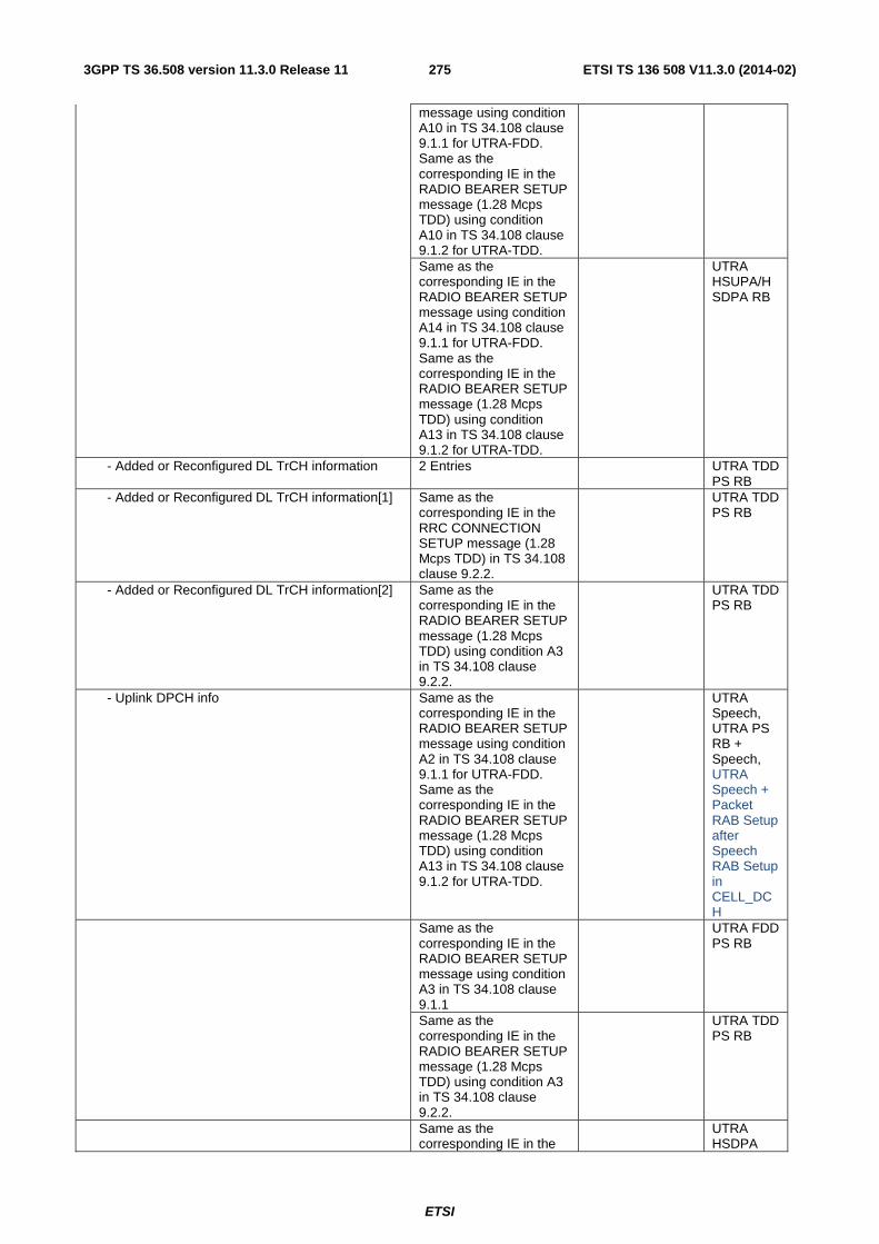
ETSI
ETSI TS 136 508 V11.3.0 (2014-02)2753GPP TS 36.508 version 11.3.0 Release 11
message using condition A10 in TS 34.108 clause 9.1.1 for UTRA-FDD. Same as the corresponding IE in the RADIO BEARER SETUP message (1.28 Mcps TDD) using condition A10 in TS 34.108 clause 9.1.2 for UTRA-TDD.
Same as the corresponding IE in the RADIO BEARER SETUP message using condition A14 in TS 34.108 clause 9.1.1 for UTRA-FDD. Same as the corresponding IE in the RADIO BEARER SETUP message (1.28 Mcps TDD) using condition A13 in TS 34.108 clause 9.1.2 for UTRA-TDD.
UTRA HSUPA/HSDPA RB
- Added or Reconfigured DL TrCH information 2 Entries UTRA TDD PS RB
- Added or Reconfigured DL TrCH information[1] Same as the corresponding IE in the RRC CONNECTION SETUP message (1.28 Mcps TDD) in TS 34.108 clause 9.2.2.
UTRA TDD PS RB
- Added or Reconfigured DL TrCH information[2] Same as the corresponding IE in the RADIO BEARER SETUP message (1.28 Mcps TDD) using condition A3 in TS 34.108 clause 9.2.2.
UTRA TDD PS RB
- Uplink DPCH info Same as the corresponding IE in the RADIO BEARER SETUP message using condition A2 in TS 34.108 clause 9.1.1 for UTRA-FDD. Same as the corresponding IE in the RADIO BEARER SETUP message (1.28 Mcps TDD) using condition A13 in TS 34.108 clause 9.1.2 for UTRA-TDD.
UTRA Speech, UTRA PS RB + Speech, UTRA Speech + Packet RAB Setup after Speech RAB Setup in CELL_DCH
Same as the corresponding IE in the RADIO BEARER SETUP message using condition A3 in TS 34.108 clause 9.1.1
UTRA FDD PS RB
Same as the corresponding IE in the RADIO BEARER SETUP message (1.28 Mcps TDD) using condition A3 in TS 34.108 clause 9.2.2.
UTRA TDD PS RB
Same as the corresponding IE in the
UTRA HSDPA

ETSI
ETSI TS 136 508 V11.3.0 (2014-02)2763GPP TS 36.508 version 11.3.0 Release 11
RADIO BEARER SETUP message using condition A10 in TS 34.108 clause 9.1.1 for UTRA-FDD. Same as the corresponding IE in the RADIO BEARER SETUP message (1.28 Mcps TDD) using condition A10 in TS 34.108 clause 9.1.2 for UTRA-TDD.
RB
Same as the corresponding IE in the RADIO BEARER SETUP message using condition A14 in TS 34.108 clause 9.1.1 for UTRA-FDD. Same as the corresponding IE in the RADIO BEARER SETUP message (1.28 Mcps TDD) using condition A13 in TS 34.108 clause 9.1.2 for UTRA-TDD.
UTRA HSUPA/HSDPA RB
- E-DCH Info Not present UTRA FDD PS RB, UTRA TDD PS RB, UTRA HSDPA RB, UTRA Speech, UTRA PS RB + Speech, UTRA Speech + Packet RAB Setup after Speech RAB Setup in CELL_DCH
Same as the corresponding IE in the RADIO BEARER SETUP message using condition A14 in TS 34.108 clause 9.1.1 for UTRA-FDD. Same as the corresponding IE in the RADIO BEARER SETUP message (1.28 Mcps TDD) using condition A13 in TS 34.108 clause 9.1.2 for UTRA-TDD.
UTRA HSUPA/HSDPA RB
- Downlink HS-PDSCH Information Not present UTRA FDD PS RB, UTRA TDD PS RB, UTRA Speech, UTRA PS RB + Speech, UTRA

ETSI
ETSI TS 136 508 V11.3.0 (2014-02)2773GPP TS 36.508 version 11.3.0 Release 11
Speech + Packet RAB Setup after Speech RAB Setup in CELL_DCH
Same as the corresponding IE in the RADIO BEARER SETUP message using condition A10 in TS 34.108 clause 9.1.1 for UTRA-FDD. Same as the corresponding IE in the RADIO BEARER SETUP message (1.28 Mcps TDD) using condition A10 in TS 34.108 clause 9.1.2 for UTRA-TDD.
UTRA HSDPA RB
Same as the corresponding IE in the RADIO BEARER SETUP message using condition A14 in TS 34.108 clause 9.1.1 for UTRA-FDD. Same as the corresponding IE in the RADIO BEARER SETUP message (1.28 Mcps TDD) using condition A13 in TS 34.108 clause 9.1.2 for UTRA-TDD.
UTRA HSUPA/HSDPA RB
- Downlink information common for all radio links Same as the corresponding IE in the RADIO BEARER SETUP message using condition A2 in TS 34.108 clause 9.1.1 for UTRA-FDD. Same as the corresponding IE in the RADIO BEARER SETUP message (1.28 Mcps TDD) using condition A2 in TS 34.108 clause 9.1.2 for UTRA-TDD.
UTRA Speech, UTRA PS RB + Speech, UTRA Speech + Packet RAB Setup after Speech RAB Setup in CELL_DCH
Same as the corresponding IE in the RADIO BEARER SETUP message using condition A4 in TS 34.108 clause 9.1.1
UTRA FDD PS RB
Same as the corresponding IE in the RADIO BEARER SETUP message (1.28 Mcps TDD) using condition A3 in TS 34.108 clause 9.2.2.
UTRA TDD PS RB
Same as the corresponding IE in the RADIO BEARER SETUP message using condition A10 in TS 34.108 clause
UTRA HSDPA RB

ETSI
ETSI TS 136 508 V11.3.0 (2014-02)2783GPP TS 36.508 version 11.3.0 Release 11
9.1.1 for UTRA-FDD. Same as the corresponding IE in the RADIO BEARER SETUP message (1.28 Mcps TDD) using condition A10 in TS 34.108 clause 9.1.2 for UTRA-TDD.
Same as the corresponding IE in the RADIO BEARER SETUP message using condition A14 in TS 34.108 clause 9.1.1 for UTRA-FDD. Same as the corresponding IE in the RADIO BEARER SETUP message (1.28 Mcps TDD) using condition A13 in TS 34.108 clause 9.1.2 for UTRA-TDD.
UTRA HSUPA/HSDPA RB
- Downlink information for each radio link list Same as the corresponding IE in the RADIO BEARER SETUP message using condition A2 in TS 34.108 clause 9.1.1 for UTRA-FDD. Same as the corresponding IE in the RADIO BEARER SETUP message (1.28 Mcps TDD) using condition A2 in TS 34.108 clause 9.1.2 for UTRA-TDD.
UTRA Speech, UTRA PS RB + Speech, UTRA Speech + Packet RAB Setup after Speech RAB Setup in CELL_DCH
Same as the corresponding IE in the RADIO BEARER SETUP message using condition A3 in TS 34.108 clause 9.1.1
UTRA FDD PS RB
Same as the corresponding IE in the RADIO BEARER SETUP message (1.28 Mcps TDD) using condition A3 in TS 34.108 clause 9.2.2.
UTRA TDD PS RB
Same as the corresponding IE in the RADIO BEARER SETUP message using condition A10 in TS 34.108 clause 9.1.1 for UTRA-FDD. Same as the corresponding IE in the RADIO BEARER SETUP message (1.28 Mcps TDD) using condition A10 in TS 34.108 clause 9.1.2 for UTRA-TDD.
UTRA HSDPA RB
Same as the corresponding IE in the RADIO BEARER SETUP message using condition A14 in TS 34.108 clause 9.1.1 for UTRA-FDD.
UTRA HSUPA/HSDPA RB

ETSI
ETSI TS 136 508 V11.3.0 (2014-02)2793GPP TS 36.508 version 11.3.0 Release 11
Same as the corresponding IE in the RADIO BEARER SETUP message (1.28 Mcps TDD) using condition A13 in TS 34.108 clause 9.1.2 for UTRA-TDD.
Frequency info Set according to the frequency of the target UTRA cell.
Multi-frequency Info Not present Maximum allowed UL TX power 21dBm
Condition Explanation UTRA Speech Establishment of the UTRA reference configuration as specified in Table 4.8.3-1 using
the condition “UTRA Speech”. UTRA FDD PS RB Establishment of the UTRA FDD reference configuration as specified in Table 4.8.3-1
using the condition “UTRA FDD PS RB”. UTRA TDD PS RB Establishment of the UTRA TDD reference configuration as specified in Table 4.8.3-1
using the condition “UTRA TDD PS RB”. UTRA HSDPA RB Establishment of the UTRA reference configuration as specified in Table 4.8.3-1 using
the condition “UTRA HSDPA RB”. UTRA HSUPA/HSDPA RB
Establishment of the UTRA reference configuration as specified in Table 4.8.3-1 using the condition “UTRA HSUPA/HSDPA RB”.
UTRA PS RB + Speech
Establishment of the UTRA reference configuration as specified in Table 4.8.3-1 using the condition “UTRA PS RB + Speech”.
UTRA Speech + Packet RAB Setup after Speech RAB Setup in CELL_DCH
Establishment of the UTRA reference configuration as specified in Table 4.8.3-1 using the condition “UTRA Speech + Packet RAB Setup after Speech RAB Setup in Cell DCH”.

ETSI
ETSI TS 136 508 V11.3.0 (2014-02)2803GPP TS 36.508 version 11.3.0 Release 11
– HANDOVER FROM UTRAN COMMAND
Table 4.7B.1-2: HANDOVER FROM UTRAN COMMAND
Derivation Path: 25.331, clause 10.2.15 Information Element Value/remark Comment Condition
Message Type Integrity check info - Message authentication code SS calculates the value
of MAC-I for this message and writes to this IE. The first/ leftmost bit of the bit string contains the most significant bit of the MAC-I.
- RRC Message sequence number SS provides the value of this IE, from its internal counter.
SR-VCC Info Not present Activation time Now RAB Info - RAB identity 0000 0101B
The first/ leftmost bit of the bit string contains the most significant bit of the RAB identity.
- CN domain identity PS domain - NAS Synchronization Indicator Not present - Re-establishment timer Use T315 Inter-system message - CHOICE System type E-UTRA - E-UTRA message RRCConnectionReconfig
uration using condition HO-TO-EUTRA(1,0)
See Table 4.6.1-8
– MEASUREMENT CONTROL
Table 4.7B.1-3: MEASUREMENT CONTROL
Derivation Path: 25.331, clause 10.2.17 Information Element Value/remark Comment Condition
Message Type RRC transaction identifier Arbitrarily selects an
unused integer between 0 to 3
Integrity check info - Message authentication code SS calculates the value of
MAC-I for this message and writes to this IE. The first/ leftmost bit of the bit string contains the most significant bit of the MAC-I.
- RRC message sequence number SS provides the value of this IE, from its internal counter.
Measurement Identity 3 Measurement Command Setup Measurement Reporting Mode - Measurement Report Transfer Mode Acknowledged mode RLC - Periodical Reporting/Event Trigger Reporting Mode
Event trigger
Additional measurement list Not present

ETSI
ETSI TS 136 508 V11.3.0 (2014-02)2813GPP TS 36.508 version 11.3.0 Release 11
CHOICE Measurement type Inter-RAT measurement - CHOICE Inter-RAT measurement objects E-UTRA frequency list - CHOICE E-UTRA frequency removal Remove no frequencies - New frequencies - E-UTRA carrier frequency Downlink EARFCN of E-
UTRA Cell
- Measurement bandwidth Same downlink system bandwidth as used for E-UTRA Cell
- Blacklisted cells list Not present - Inter-RAT measurement quantity - Measurement quantity for UTRAN quality estimate
- Filter coefficient 0 - CHOICE mode FDD FDD_UTRA - Measurement quantity CPICH Ec/N0 - Measurement quantity CPICH RSCP For signalling tests
cases.
- CHOICE mode TDD TDD_UTRA - Measurement quantity Primary CCPCH RSCP - CHOICE system E-UTRA - Measurement quantity RSRP - Filter coefficient 0 - Inter-RAT reporting quantity - UTRAN estimated quality FALSE - CHOICE system E-UTRA - Reporting quantity both - Reporting cell status Not present - CHOICE report criteria Inter-RAT measurement
reporting criteria
- Parameters required for each event 1 entry - Inter-RAT event identity Set according to
specific test.
- Threshold own system -66 dB - W 0 - Threshold other system -55 (-80 dBm) When
measurement quantity is RSRP, range should be (-115..-19), the actual value = Threshold other system - 25 [dBm]
- Hysteresis 0 - Time to trigger 10 ms - Reporting cell status - CHOICE reported cell Report cells within active
set or within virtual active set or of the other RAT
- Maximum number of reported cells
2
- Idle Interval Information Not present CELL_DCH measurement occasion info LCR LCR_TDD_U
TRA - cellDCHMeasOccasionSequence 1 entry
- Pattern sequence identifier 0 - Status Flag activate - Measurement purpose '00001' - Measurement occasion pattern sequence parameters
- k 3 - Offset 0 - M_Length 1 - Timeslot Bitmap Not Present DPCH Compressed mode status info FDD_UTRA - TGPS reconfiguration CFN (Current CFN + (250 –

ETSI
ETSI TS 136 508 V11.3.0 (2014-02)2823GPP TS 36.508 version 11.3.0 Release 11
TTI/10msec)) mod 256 - Transmission gap pattern sequence 1 entry - TGPSI 1 - TGPS Status Flag activate - TGCFN (Current CFN + (252 –
TTI/10msec)) mod 256
DPCH Compressed mode status info Not present TDD_UTRA
Condition Explanation FDD_UTRA FDD UTRA cell environment TDD_UTRA TDD UTRA cell environment
– MEASUREMENT REPORT
Table 4.7B.1-4: MEASUREMENT REPORT
Derivation Path: 25.331, clause 10.2.19 Information Element Value/remark Comment Condition
Message Type Integrity check info - Message authentication code This IE is checked to see
if it is present. The value is compared against the XMAC-I value computed by SS. The first/ leftmost bit of the bit string contains the most significant bit of the MAC-I.
- RRC Message sequence number This IE is checked to see if it is present. The value is used by SS to compute the XMAC-I value.
Activation time (256+CFN-(CFN MOD 8 + 8)) MOD 256
Measurement identity 3 Measured Results Not present Measured results on RACH Not present Additional measured results Not present Event results Not present Inter-RAT cell info indication Not present E-UTRA Measured Results - E-UTRA measured results list 1 entry - E-UTRA Carrier Frequency - Measured E-UTRA cells 1 entry - Physical Cell Identity PhysicalCellIdentity of E-
UTRA Cell
- RSRP Set according to specific test.
- RSRQ Set according to specific test.
E-UTRA Event Results - Inter-RAT event identity Set according to
specific test.
- E-UTRA events results list 1 entry - E-UTRA Carrier Frequency Downlink EARFCN of E-
UTRA Cell
- Reported cells 1 entry - Physical Cell Identity PhysicalCellIdentity of E-
UTRA Cell

ETSI
ETSI TS 136 508 V11.3.0 (2014-02)2833GPP TS 36.508 version 11.3.0 Release 11
– PHYSICAL CHANNEL RECONFIGURATION
Table 4.7B.1-5: PHYSICAL CHANNEL RECONFIGURATION
Derivation Path: 25.331, clause 10.2.22 Information Element Value/remark Comment Condition
Message Type RRC transaction identifier Arbitrarily selects an
unused integer between 0 to 3
Integrity check info - Message authentication code SS calculates the value of
MAC-I for this message and writes to this IE. The first/ leftmost bit of the bit string contains the most significant bit of the MAC-I.
- RRC message sequence number SS provides the value of this IE, from its internal counter.
Integrity protection mode info Not Present Ciphering mode info Not Present Activation time Not Present Delay restriction flag Not Present New U-RNTI Not Present New C-RNTI Not Present New H-RNTI Not Present New Primary E-RNTI Not Present New Secondary E-RNTI Not Present RRC State indicator CELL_DCH UE Mobility State Indicator Not Present UTRAN DRX cycle length coefficient Not Present CN information info Not Present URA identity Not Present RNC support for change of UE capability Not Present Reconfiguration in response to requested change of UE capability
Not Present
Downlink counter synchronization info Not Present Frequency info Not Present DTX-DRX timing information Not Present DTX-DRX Information Not Present HS-SCCH less Information Not Present MIMO parameters Not Present HARQ Info Not Present Maximum allowed UL TX power Not Present CHOICE channel requirement Not Present E-DCH Info Not Present Downlink HS-PDSCH Information Not Present Downlink information common for all radio links - Downlink DPCH info common for all RL Not Present - DPCH compressed mode info Not Present TDD - DPCH compressed mode info FDD - TGPSI 1 - TGPS Status Flag Deactivate - TGCFN Not Present - Transmission gap pattern sequence configuration parameters
- TGMP E-UTRA measurement - TGPRC Infinity - TGSN 8 - TGL1 10 - TGL2 Not Present - TGD undefined - TGPL1 12 - TGPL2 Not Present
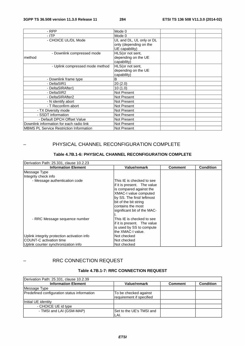
ETSI
ETSI TS 136 508 V11.3.0 (2014-02)2843GPP TS 36.508 version 11.3.0 Release 11
- RPP Mode 0 - ITP Mode 0 - CHOICE UL/DL Mode UL and DL, UL only or DL
only (depending on the UE capability)
- Downlink compressed mode method
HLS(or not sent, depending on the UE capability)
- Uplink compressed mode method HLS(or not sent, depending on the UE capability)
- Downlink frame type B - DeltaSIR1 20 (2.0) - DeltaSIRAfter1 10 (1.0) - DeltaSIR2 Not Present - DeltaSIRAfter2 Not Present - N identify abort Not Present - T Reconfirm abort Not Present - TX Diversity mode Not Present - SSDT information Not Present - Default DPCH Offset Value Not Present Downlink information for each radio link Not Present MBMS PL Service Restriction Information Not Present
– PHYSICAL CHANNEL RECONFIGURATION COMPLETE
Table 4.7B.1-6: PHYSICAL CHANNEL RECONFIGURATION COMPLETE
Derivation Path: 25.331, clause 10.2.23 Information Element Value/remark Comment Condition
Message Type Integrity check info - Message authentication code This IE is checked to see
if it is present. The value is compared against the XMAC-I value computed by SS. The first/ leftmost bit of the bit string contains the most significant bit of the MAC-I.
- RRC Message sequence number This IE is checked to see if it is present. The value is used by SS to compute the XMAC-I value.
Uplink integrity protection activation info Not checked COUNT-C activation time Not checked Uplink counter synchronization info Not checked
– RRC CONNECTION REQUEST
Table 4.7B.1-7: RRC CONNECTION REQUEST
Derivation Path: 25.331, clause 10.2.39 Information Element Value/remark Comment Condition
Message Type Predefined configuration status information To be checked against
requirement if specified
Initial UE identity - CHOICE UE id type - TMSI and LAI (GSM-MAP) Set to the UE's TMSI and
LAI.
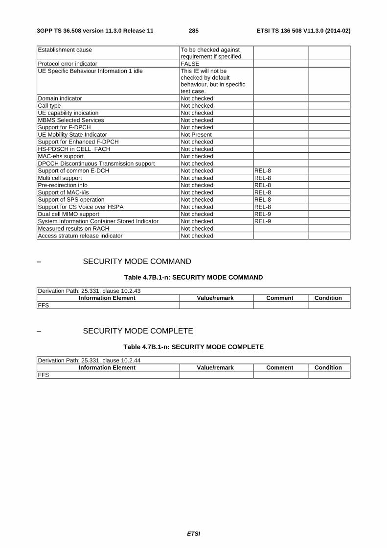
ETSI
ETSI TS 136 508 V11.3.0 (2014-02)2853GPP TS 36.508 version 11.3.0 Release 11
Establishment cause To be checked against requirement if specified
Protocol error indicator FALSE UE Specific Behaviour Information 1 idle This IE will not be
checked by default behaviour, but in specific test case.
Domain indicator Not checked Call type Not checked UE capability indication Not checked MBMS Selected Services Not checked Support for F-DPCH Not checked UE Mobility State Indicator Not Present Support for Enhanced F-DPCH Not checked HS-PDSCH in CELL_FACH Not checked MAC-ehs support Not checked DPCCH Discontinuous Transmission support Not checked Support of common E-DCH Not checked REL-8 Multi cell support Not checked REL-8 Pre-redirection info Not checked REL-8 Support of MAC-i/is Not checked REL-8 Support of SPS operation Not checked REL-8 Support for CS Voice over HSPA Not checked REL-8 Dual cell MIMO support Not checked REL-9 System Information Container Stored Indicator Not checked REL-9 Measured results on RACH Not checked Access stratum release indicator Not checked
– SECURITY MODE COMMAND
Table 4.7B.1-n: SECURITY MODE COMMAND
Derivation Path: 25.331, clause 10.2.43 Information Element Value/remark Comment Condition
FFS
– SECURITY MODE COMPLETE
Table 4.7B.1-n: SECURITY MODE COMPLETE
Derivation Path: 25.331, clause 10.2.44 Information Element Value/remark Comment Condition
FFS

ETSI
ETSI TS 136 508 V11.3.0 (2014-02)2863GPP TS 36.508 version 11.3.0 Release 11
– UTRAN MOBILITY INFORMATION
Table 4.7B.1-n: UTRAN MOBILITY INFORMATION
Derivation Path: 34.108 clause 9.1.1 (UTRAN MOBILITY INFORMATION message) Information Element Value/remark Comment Condition
UTRAN MOBILITY INFORMATION CN information info - PLMN identity Not present - CN common GSM-MAP NAS system information - GSM-MAP NAS system information 00 01H - CN domain related information - CN domain identity PS - CN domain specific NAS system information - GSM-MAP NAS system information 01 00H - CN domain specific DRX cycle length coefficient
7
- CN domain identity CS - CN domain specific NAS system information - GSM-MAP NAS system information 1E 01H - CN domain specific DRX cycle length coefficient
7
– UTRAN MOBILITY INFORMATION CONFIRM
Table 4.7B.1-n: UTRAN MOBILITY INFORMATION CONFIRM
Derivation Path: 34.108 clause 9.1.1 (UTRAN MOBILITY INFORMATION CONFIRM message)
4.7B.2 UTRA NAS messages
This section contains default message contents for UTRA NAS messages.
In 3GPP TS 36.523-1 [18]:
- UTRA NAS messages are defined as exceptions, IE by IE, to the messages defined in this section;
- UTRA NAS messages not defined in this section are specified completely.
The following messages are not specified in this section:
- AUTHENTICATION REQUEST (CS)
- AUTHENTICATION RESPONSE (CS)
- DETACH REQUEST (CS & PS)
- DETACH ACCEPT (CS & PS)
- IDENTITY REQUEST (CS & PS)
- IDENTITY RESPONSE (CS & PS)
- P-TMSI REALLOCATION COMMAND (PS)
- P-TMSI REALLOCATION COMPLETE (PS)
- SERVICE REQUEST (PS)

ETSI
ETSI TS 136 508 V11.3.0 (2014-02)2873GPP TS 36.508 version 11.3.0 Release 11
Table 4.7B.2-1: ROUTING AREA UPDATE REQUEST
Derivation path: 24.008 table 9.4.14 Information Element Value/Remark Comment Condition
Update type 000 'RA updating' or 001 'combined RA/LA updating' 010 ‘combined RA/LA updating with IMSI attach’
In NMO I, depending on capability and domain preference for voice and SMS, the UE may initiate either PS only or CS/PS registration procedures.
GPRS ciphering key sequence number Any allowed value Old routing area identification Any allowed value MS Radio Access capability Any allowed value The checking of
this IE is expected to be covered in UMTS test cases.
Old P-TMSI signature Not present or any allowed value
For test cases where no "UE" statement indicates that a P-TMSI signature was previously registered, whether or not the UE includes this IE depends on previous USIM contents.
Requested READY timer value Not present or any allowed value
The checking of this IE is expected to be covered in UMTS test cases.
DRX parameter Not present or any allowed value
The checking of this IE is expected to be covered in UMTS test cases.
TMSI status 0 'no valid TMSI available' or not present
P-TMSI Not present or any allowed value
MS network capability Any allowed value The checking of this IE is expected to be covered in UMTS test cases.
PDP context status Any allowed value The checking of this IE is expected to be covered in UMTS test cases.
PS LCS Capability Not present or any allowed value
The checking of this IE is expected to be covered in UMTS test cases.
MBMS context status Not present UE network capability Any allowed value (must
be present) No detailed checking by default but should be aligned with PICS
Additional mobile identity Not present or any allowed value
Additional old routing area identification Not present or any allowed value
Mobile station classmark 2 Not present or any This IE shall be
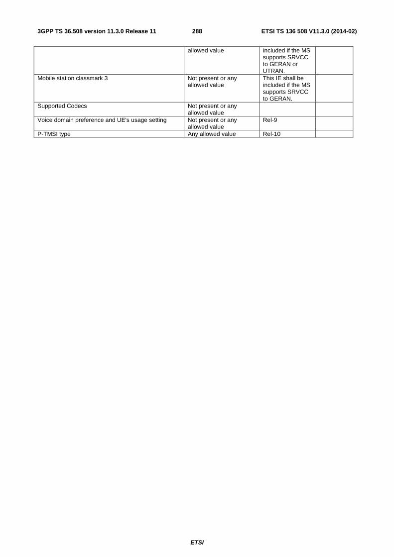
ETSI
ETSI TS 136 508 V11.3.0 (2014-02)2883GPP TS 36.508 version 11.3.0 Release 11
allowed value included if the MS supports SRVCC to GERAN or UTRAN.
Mobile station classmark 3 Not present or any allowed value
This IE shall be included if the MS supports SRVCC to GERAN.
Supported Codecs Not present or any allowed value
Voice domain preference and UE's usage setting Not present or any allowed value
Rel-9
P-TMSI type Any allowed value Rel-10

ETSI
ETSI TS 136 508 V11.3.0 (2014-02)2893GPP TS 36.508 version 11.3.0 Release 11
Table 4.7B.2-2: ROUTING AREA UPDATE ACCEPT
Derivation path: 24.008 table 9.4.15 Information Element Value/Remark Comment Condition
Force to standby 0 'Force to standby not indicated'
Update result 000 'RA updated' IF the UE indicated 000 'RA updating' in the previous RAU request message
001 'combined RA/LA updated'
IF the UE indicated 001 'combined RA/LA updating' in the previous RAU request message
Periodic RA update timer 111 (deactivated) Routing area identification 1 Value in table
4.4.4-2 for simulated UTRA cells.
P-TMSI signature Arbitrary value Allocated P-TMSI Arbitrary value 2 most significant
bits = 11 to indicate SGSN
MS identity Not present Is never present in case of RA only procedure, and RA/LA procedures do not necessarily change TMSI
List of Receive N PDU Numbers Not present Realistic network value
Negotiated READY timer value Not present GMM cause Not present T3302 value Not present Cell Notification Not present This IE is for A/Gb
mode only.
Equivalent PLMNs Not present PDP context status Same value as the one
received in the RAU request message
Network feature support Not present Emergency Number List Not present MBMS context status Not present Requested MS Information Not present T3319 value Not present T3323 value Not present

ETSI
ETSI TS 136 508 V11.3.0 (2014-02)2903GPP TS 36.508 version 11.3.0 Release 11
Table 4.7B.2-3: ROUTING AREA UPDATE COMPLETE
Derivation path: 24.008 table 9.4.16 Information Element Value/Remark Comment Condition
List of Receive N PDU Numbers Not present Inter RAT handover information Not present E-UTRAN inter RAT handover information Not present
Table 4.7B.2-4: LOCATION UPDATING REQUEST
Derivation path: 24.008 table 9.2.17 Information Element Value/Remark Comment Condition
Location updating type Any allowed value Ciphering key sequence number Any allowed value Location area identification Any allowed value Mobile station classmark Any allowed value Mobile identity Any allowed value Mobile station classmark for UMTS Any allowed value Additional update parameters Not present or any
allowed value
Table 4.7B.2-5: LOCATION UPDATING ACCEPT
Derivation path: 24.008 table 9.2.15 Information Element Value/Remark Comment Condition
Location area identification 1 Mobile identity TMSI Arbitrary value 2 most significant
bits = 00 to indicate VLR
Follow on proceed Present This IE is unncessary in non-CS fallback test cases.
CTS permission Absent Equivalent PLMNs Absent Emergency Number List Absent

ETSI
ETSI TS 136 508 V11.3.0 (2014-02)2913GPP TS 36.508 version 11.3.0 Release 11
Table 4.7B.2-6: ATTACH REQUEST
Derivation path: 24.008 table 9.4.1 Information Element Value/Remark Comment Condition
MS network capability Any allowed value Attach type 001 'GPRS attach' or
011 'Combiner GPRS/IMS attach'
GPRS ciphering key sequence number Any allowed value DRX parameter Any allowed value P-TMSI or IMSI Any allowed value Old routing area identification Any allowed value MS Radio Access capability Any allowed value Old P-TMSI signature Not present or any
allowed value
Requested READY timer value Not present or any allowed value
TMSI status 0 'no valid TMSI available' or not present
PS LCS Capability Not present or any allowed value
Mobile station classmark 2 Not present or any allowed value
Mobile station classmark 3 Not present or any allowed value
Supported Codecs Not present or any allowed value
UE network capability Any allowed value (must be present)
Additional mobile identity Not present or any allowed value
Additional old routing area identification Not present or any allowed value
Voice domain preference and UE's usage setting Not present or any allowed value
Rel-9
P-TMSI type Not present or any allowed value
Rel-10

ETSI
ETSI TS 136 508 V11.3.0 (2014-02)2923GPP TS 36.508 version 11.3.0 Release 11
Table 4.7B.2-7: ATTACH ACCEPT
Derivation path: 24.008 table 9.4.2 Information Element Value/Remark Comment Condition
Attach result 001 'GPRS only attached' IF the UE indicated 001 'GPRS attach' in the previous attach request message
011 'combined GPRS/IMSI attached'
IF the UE indicated 011 'Combined GPRS/IMSI attach' in the previous attach request message
Force to standby 000 'Force to standby not indicated'
Periodic RA update timer 111 (deactivated) Radio priority for SMS 100 'priority level 4
(lowest)'
Radio priority for TOM8 100 'priority level 4 (lowest)'
Routing area identification 1 P-TMSI signature Arbitrary value Negotiated READY timer value Not present Allocated P-TMSI Arbitrary value 2 most significant
bits = 11 to indicate SGSN
MS identity Not present IF the UE indicated 001 'GPRS attach' in the previous attach request message
Arbitrary value 2 most significant bits = 00 to indicate VLR
IF the UE indicated 011 'Combined GPRS/IMSI attach' in the previous attach request message
GMM cause Not present T3302 value Not present Cell Notification Not present Equivalent PLMNs Not present Network feature support Not present Emergency Number List Not present Requested MS Information Not present T3319 value Not present T3323 value Not present

ETSI
ETSI TS 136 508 V11.3.0 (2014-02)2933GPP TS 36.508 version 11.3.0 Release 11
Table 4.7B.2-8: ATTACH COMPLETE
Derivation path: 24.008 table 9.4.3 Information Element Value/Remark Comment Condition
Inter RAT handover information Not present E-UTRAN inter RAT handover information Not present
Table 4.7B.2-9: AUTHENTICATION AND CIPHERING REQUEST
Derivation path: 24.008 table 9.4.9 Information Element Value/Remark Comment Condition
Ciphering algorithm Any allowed value IMEISV request 000 ‘IMEISV not
requested’
Force to standby 000 'Force to standby not indicated'
A&C reference number Any allowed value
Table 4.7B.2-10: AUTHENTICATION AND CIPHERING RESPONSE
Derivation path: 24.008 table 9.4.10 Information Element Value/Remark Comment Condition
A&C reference number Arbitrary value Spare half octet 0000
Table 4.7B.2-11: TMSI REALLOCATION COMMAND
Derivation path: 24.008 table 9.2.20 Information Element Value/Remark Comment Condition
Location area identification Any allowed value Mobile identity Any allowed value
Table 4.7B.2-12: TMSI REALLOCATION COMPLETE
Derivation path: 24.008 table 9.2.21
Table 4.7B.2-13: CM SERVICE REQUEST
Derivation path: 24.008 table 9.2.11 Information Element Value/Remark Comment Condition
CM service type Any allowed value Ciphering key sequence number
Any allowed value
Mobile station classmark
Any allowed value
Mobile identity Any allowed value Priority Not present or any
allowed value
Additional update parameters Not present or any allowed value

ETSI
ETSI TS 136 508 V11.3.0 (2014-02)2943GPP TS 36.508 version 11.3.0 Release 11
4.7C Default DS-MIPv6 message and information element contents
4.7C.1 IKEv2 messages
- IKEv2 IKE_SA_INIT Request
This message is sent by the UE to the SS.
Table 4.7C.1-1: Message IKE_SA_INIT Request
Field Value/remark Comment Condition
IKE Header Initiator’s IKE_SA SPI Set by the UE Responder’s IKE_SA SPI 0 First message jn
IKE_SA_INIT exchange
Next Payload ‘00100001’B SA Exchange Type ‘00100010’B IKE_SA_INIT Security Association Payload Next Payload ’00100010’B KE More proposal ‘00000010’B Proposal # ‘00000001’B First cryptographic
suite (section 6.5 of TS 33.234)
Protocol ID ‘00000001’B IKE SPI size ‘00000000’B Number of transforms ‘00000010’B More transform ‘00000011’B This is the
transform for confidentiality
Transform type ‘00000001’B Encryption Transform ID ‘00000011’B 3DES in CBC
mode (ENCR_3DES)
More transform ‘00000011’B This is the transform for prf
Transform type ‘00000010’B PRF Transform ID ‘00000010’B PRF_HMAC_SHA
1 (HMAC-SHA1)
More transform ‘00000011’B This is the transform for integrity
Transform type ‘00000011’B Integrity Transform ID ‘00000010’B HMAC-SHA1-96
(AUTH_HMAC_SHA1_96)
Last transform ‘00000000’B This is the transform for DH
Transform type ‘00000100’B DH Transform ID ‘00000010’B Diffie-Hellman
group 2 (1024-bit MODP)
Last proposal ‘00000000’B Proposal # ‘00000010’B Second
cryptographic suite (section 6.5 of TS 33.234)
Protocol ID ‘00000001’B IKE SPI size ‘00000000’B Number of transforms ‘00000010’B More transform ‘00000011’B This is the
transform for

ETSI
ETSI TS 136 508 V11.3.0 (2014-02)2953GPP TS 36.508 version 11.3.0 Release 11
confidentiality Transform type ‘00000001’B Encryption Transform ID ‘00001011’B AES with 128-bit
keys in CBC mode (ENCR_AES_CBC)
More transform ‘00000011’B This is the transform for prf
Transform type ‘00000010’B PRF Transform ID ‘00000100’B PRF_AES128_XC
BC_ AES-XCBC-PRF-128
More transform ‘00000011’B This is the transform for integrity
Transform type ‘00000011’B Integrity Transform ID ‘00000101’B AES-XCBC-MAC-
96 (AUTH_ AES-XCBC -96)
Last transform ‘00000000’B This is the transform for DH
Transform type ‘00000100’B DH Transform ID ‘00000010’B Diffie-Hellman
group 2 (1024-bit MODP)
Key Exchange Payload Next Payload ‘00101000’B Nonce DH Group # ‘0000000000000010’B DH group 2 Key Exchange data Set by the UE Nonce Payload Next Payload
‘00101001’B Notify UE IKE INIT HA
Nonce data Random number set by the UE
REDIRECT_SUPPORTED Notify Payload UE IKE INIT HA
Next Payload ‘00000000’B No Next Payload UE IKE INIT HA
Protocol ID ‘00000000’B Notification is not specific to a particular security association
UE IKE INIT HA
SPI size ‘00000000’B SPI field not present
UE IKE INIT HA
Notify Message Type '0100000000010110'B REDIRECT_SUPPORTED
UE IKE INIT HA
REDIRECT_FROM Notify Payload UE IKE INIT HA Redirected
Next Payload ‘00000000’B No next payload UE IKE INIT HA Redirected
Protocol ID ‘00000000’B Notification is not specific to a particular security association
UE IKE INIT HA Redirected
SPI size ‘00000000’B SPI field not present
UE IKE INIT HA Redirected
Notify Message Type '0100000000010110'B REDIRECT_FROM
UE IKE INIT HA Redirected
GW Ident Type Any allowed value (IPv6 or IPv4 or HA FQDN)
Set depending on how the UE has discovered the HA in the preamble
UE IKE INIT HA Redirected
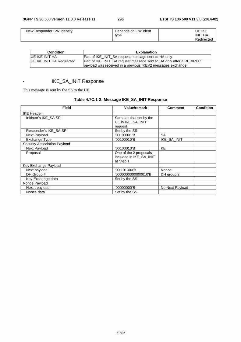
ETSI
ETSI TS 136 508 V11.3.0 (2014-02)2963GPP TS 36.508 version 11.3.0 Release 11
New Responder GW Identity Depends on GW Ident type
UE IKE INIT HA Redirected
Condition Explanation UE IKE INIT HA Part of IKE_INIT_SA request message sent to HA only UE IKE INIT HA Redirected Part of IKE_INIT_SA request message sent to HA only after a REDIRECT
payload was received in a previous IKEV2 messages exchange
- IKE_SA_INIT Response
This message is sent by the SS to the UE.
Table 4.7C.1-2: Message IKE_SA_INIT Response
Field Value/remark Comment Condition
IKE Header Initiator’s IKE_SA SPI Same as that set by the
UE in IKE_SA_INIT request
Responder’s IKE_SA SPI Set by the SS Next Payload ‘00100001’B SA Exchange Type ‘00100010’B IKE_SA_INIT Security Association Payload Next Payload ’00100010’B KE Proposal One of the 2 proposals
included in IKE_SA_INIT at Step 1
Key Exchange Payload Next payload ‘00 101000’B Nonce DH Group # ‘0000000000000010’B DH group 2 Key Exchange data Set by the SS Nonce Payload Next t payload ‘00000000’B No Next Payload Nonce data Set by the SS

ETSI
ETSI TS 136 508 V11.3.0 (2014-02)2973GPP TS 36.508 version 11.3.0 Release 11
- IKE_AUTH_Request
This message is sent by the UE to the SS.
Table 4.7C.1-3: Message IKE_AUTH Request
Field Value/remark Comment Condition
IKE Header Initiator’s IKE_SA SPI Same as that set by the
UE in IKE_INIT_SA Request
Responder’s IKE_SA SPI Same as that set by the SS in IKE_INIT_SA Response
Next Payload ‘00101110’B E Exchange Type ‘00100011’B IKE_AUTH Encrypted Payload Next Payload ‘00100011’B IDi UE IKE
AUTH1 Initialization Vector Random value set by the
UE UE IKE
AUTH1 Encrypted IKE Payloads UE IKE
AUTH1 Identification – Initiator Payload UE IKE
AUTH1 Next Payload ‘00101111’B CP UE IKE
AUTH1 ID Type 00000010B UE IKE
AUTH1 ID Set to MN-NAI UE IKE
AUTH1 Configuration Payload UE IKE
AUTH1 Next Payload ‘00100001’B SA UE IKE
AUTH1 CFG Type ‘00000001’B Request UE IKE
AUTH1 Configuration Attribute ‘00010000’B MIP6_HOME_PR
EFIX attribute UE IKE AUTH1 HA
Length ‘0000000000000000’B UE IKE AUTH1 HA
Security Association Payload UE IKE AUTH1
Next Payload ‘00101100’B TSi UE IKE AUTH1
Proposals Any set of allowed values UE IKE AUTH1
Traffic Selector – Initiator Payload UE IKE AUTH1
Next Payload ‘00101100’B TSr UE IKE AUTH1
Traffic selector data Any allowed set of values UE IKE AUTH1
Traffic Selector – Responder Payload UE IKE AUTH1
Next Payload ‘00100100’B IDr UE IKE AUTH1
Traffic selector data Any allowed set of values UE IKE AUTH1
Identification – Responder Payload UE IKE AUTH1
Next Payload ‘00000000’B No Next Payload UE IKE AUTH1
ID Type ‘00000010’B UE IKE AUTH1
ID APN UE IKE
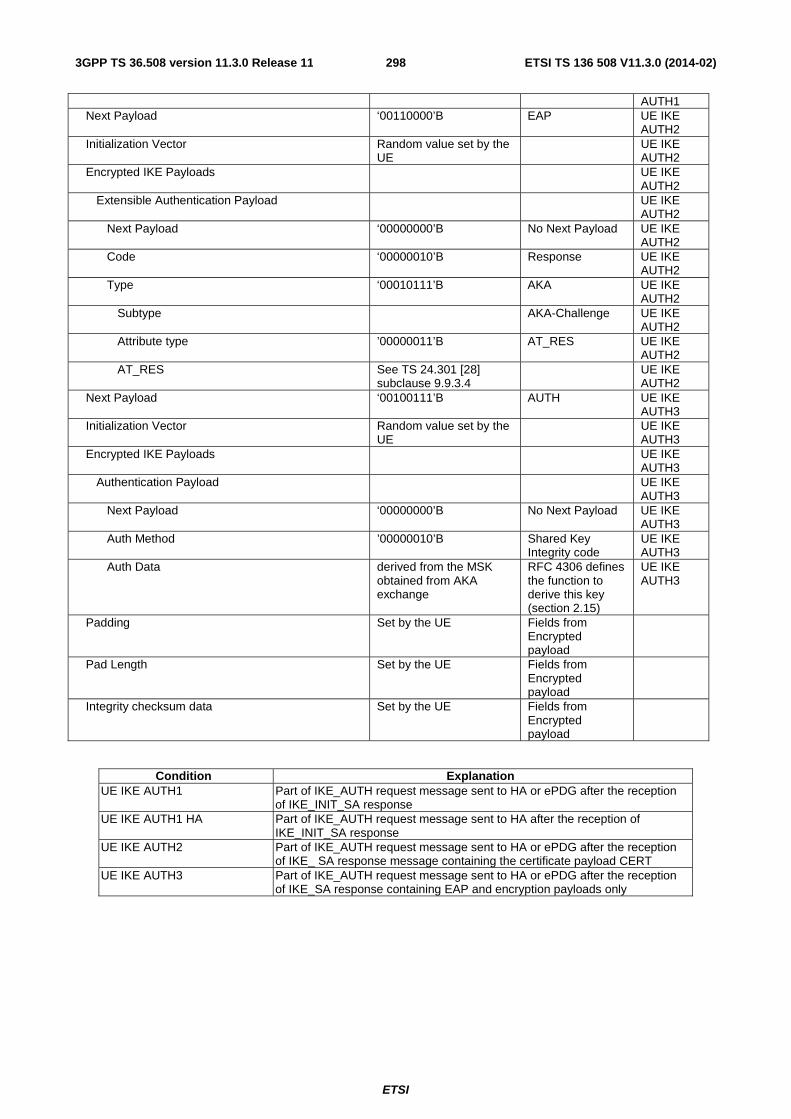
ETSI
ETSI TS 136 508 V11.3.0 (2014-02)2983GPP TS 36.508 version 11.3.0 Release 11
AUTH1 Next Payload ‘00110000’B EAP UE IKE
AUTH2 Initialization Vector Random value set by the
UE UE IKE
AUTH2 Encrypted IKE Payloads UE IKE
AUTH2 Extensible Authentication Payload UE IKE
AUTH2 Next Payload ‘00000000’B No Next Payload UE IKE
AUTH2 Code ‘00000010’B Response UE IKE
AUTH2 Type ‘00010111’B AKA UE IKE
AUTH2 Subtype AKA-Challenge UE IKE
AUTH2 Attribute type ’00000011’B AT_RES UE IKE
AUTH2 AT_RES See TS 24.301 [28]
subclause 9.9.3.4 UE IKE
AUTH2 Next Payload ‘00100111’B AUTH UE IKE
AUTH3 Initialization Vector Random value set by the
UE UE IKE
AUTH3 Encrypted IKE Payloads UE IKE
AUTH3 Authentication Payload UE IKE
AUTH3 Next Payload ‘00000000’B No Next Payload UE IKE
AUTH3 Auth Method ’00000010’B Shared Key
Integrity code UE IKE AUTH3
Auth Data derived from the MSK obtained from AKA exchange
RFC 4306 defines the function to derive this key (section 2.15)
UE IKE AUTH3
Padding Set by the UE Fields from Encrypted payload
Pad Length Set by the UE Fields from Encrypted payload
Integrity checksum data Set by the UE Fields from Encrypted payload
Condition Explanation UE IKE AUTH1 Part of IKE_AUTH request message sent to HA or ePDG after the reception
of IKE_INIT_SA response UE IKE AUTH1 HA Part of IKE_AUTH request message sent to HA after the reception of
IKE_INIT_SA response UE IKE AUTH2 Part of IKE_AUTH request message sent to HA or ePDG after the reception
of IKE_ SA response message containing the certificate payload CERT UE IKE AUTH3 Part of IKE_AUTH request message sent to HA or ePDG after the reception
of IKE_SA response containing EAP and encryption payloads only

ETSI
ETSI TS 136 508 V11.3.0 (2014-02)2993GPP TS 36.508 version 11.3.0 Release 11
- IKE_AUTH Response
This message is sent by the SS to the UE.
Table 4.7C.1-4: Message IKE_AUTH Response
Field Value/remark Comment Condition
IKE Header Initiator’s IKE_SA SPI Same as that set by the
UE in IKE_SA_INIT request
Responder’s IKE_SA SPI Same as that set by the SS in IKE_SA_INIT response
Next Payload ‘00101110’B E Exchange Type ‘00100011’B IKE_AUTH Encrypted Payload Next Payload ‘00100100’B IDr SS IKE
AUTH1 Initialization Vector Set by the SS SS IKE
AUTH1 Encrypted IKE Payloads SS IKE
AUTH1 Identification – Responder Payload SS IKE
AUTH1 Next Payload ‘00100101’B CERT SS IKE
AUTH1 ID Type ‘00000010’B SS IKE
AUTH1 ID APN SS IKE
AUTH1 Certificate Payload SS IKE
AUTH1 Next Payload ‘00110000’B EAP SS IKE
AUTH1 Cert encoding ’00000100’B X.509 certificate -
signature SS IKE AUTH1
Certificate data Set by the SS DER encoded X.509 certificate
SS IKE AUTH1
Extensible Authentication Payload SS IKE AUTH1
Next Payload ‘00000000’B No Next Payload SS IKE AUTH1
Code ‘00000001’B Request SS IKE AUTH1
Type ‘00010111’B AKA SS IKE AUTH1
Subtype AKA-Challenge SS IKE AUTH1
Attribute type ’00000001’B AT_RAND SS IKE AUTH1
AT_RAND An arbitrarily selected 128 bits value
SS IKE AUTH1
Attribute Type ‘00000010’B AT_AUTN SS IKE AUTH1
AT_AUTN See TS 24.301 [28] subclause 9.9.3.2
SS IKE AUTH1
Next Payload ‘00110000’B EAP SS IKE AUTH2
Initialization Vector Set by the SS SS IKE AUTH2
Encrypted IKE Payloads SS IKE AUTH2
Extensible Authentication Payload SS IKE AUTH2
Next Payload ‘00000000’B No Next Payload SS IKE

ETSI
ETSI TS 136 508 V11.3.0 (2014-02)3003GPP TS 36.508 version 11.3.0 Release 11
AUTH2 Code ‘00000011’B Success SS IKE
AUTH2 Next Payload ‘00101111’B CP SS IKE
AUTH3 Auth Method ’00000010’B Shared Key
Integrity code SS IKE AUTH3
Auth Data derived from the MSK obtained from AKA exchange
RFC 4306 defines the function to derive this key (section 2.15)
SS IKE AUTH3
Configuration Payload SS IKE AUTH3
Next Payload ‘00100001’B SA SS IKE AUTH3
CFG Type ‘00000010’B Reply SS IKE AUTH3
Configuration Attribute ‘00010000’B MIP6_HOME_PREFIX attribute
SS IKE AUTH3 HA
Length ‘0000000000010101’B SS IKE AUTH3 HA
Prefix lifetime Any allowed value SS IKE AUTH3 HA
Home Prefix IPv6 prefix – 16 bytes SS IKE AUTH3 HA
Prefix length ‘10000000’B Prefix length must be 64
SS IKE AUTH3 HA
Notify Payload SS IKE AUTH3 HA redirect
Next Payload ‘00100001’B SA SS IKE AUTH3 HA redirect
Protocol ID ‘00000000’B Notification is not specific to a particular security association
SS IKE AUTH3 HA redirect
SPI Size ‘00000000’B SPI field not present
SS IKE AUTH3 HA redirect
Notify Message Type Length ‘0100000000010111’B REDIRECT SS IKE AUTH3 HA redirect
GW Ident Type ‘00000101’B SS IKE AUTH3 HA redirect
New Responder GW Identity IPv6 address of the HA to relocate
SS IKE AUTH3 HA redirect
GW Ident Type ‘00000001’B SS IKE AUTH3 HA redirect
New Responder GW Identity IPv4 address of the HA to relocate
Optional SS IKE AUTH3 HA redirect
Security Association Payload SS IKE AUTH3
Next Payload ‘00101101’ TSi SS IKE AUTH3
Proposal One of the 2 proposals included in IKE_AUTH Request at Step 3
SS IKE AUTH3
Traffic Selector – Initiator Payload SS IKE AUTH3
Next Payload ‘00101100’B TSr SS IKE AUTH3
Traffic Selector data Any allowed set of values SS IKE

ETSI
ETSI TS 136 508 V11.3.0 (2014-02)3013GPP TS 36.508 version 11.3.0 Release 11
AUTH3 Traffic Selector – Responder Payload SS IKE
AUTH3 Next Payload ‘00000000’B No Next Payload SS IKE
AUTH3 Padding Set by the SS Fields from
Encryption payload
Pad Length Set by the SS Fields from Encryption payload
Integrity checksum data Set by the SS Fields from Encryption payload
Condition Explanation SS IKE AUTH1 Part of IKE_AUTH request message sent to the UE as part of the first
IKE_AUTH Response message SS IKE AUTH2 Part of IKE_AUTH request message sent to the UE as part of the second
IKE_AUTH Response message SS IKE AUTH3 Part of IKE_AUTH request message sent to the UE as part of the third
IKE_AUTH Response message SS IKE AUTH3 HA Part of IKE_AUTH request message sent to the UE as part of the third
IKE_AUTH Response message when the UE interacts with HA SS IKE AUTH3 HA_redirect Part of IKE_AUTH request message sent to the UE as part of the third
IKE_AUTH Response message when the UE interacts with HA and the UE gets redirected

ETSI
ETSI TS 136 508 V11.3.0 (2014-02)3023GPP TS 36.508 version 11.3.0 Release 11
4.7C.2 Messages used to perform DS-MIPv6 registration and deregistration
- Router Advertisement
This message is sent by the SS to the UE.
Table 4.7C.2-1: Message Router Advertisement
Field Value/remark Comment Condition
Type ‘10000110’B Code ‘00000000’B Checksum Set by SS ICMP checksum Cur Hop Limit ‘00000000’B Unspecified M Set by the SS O Set by the SS Depends on
access network specific settings
H ‘0’B Prf Set by the SS Depends on
access network specific settings
Prf Set by the SS Depends on access network specific settings
P Set by the SS Depends on access network specific settings
Reserved ‘00000’B Router Lifetime Set by the SS Reachable Time Set by the SS Retrans Timer Set by the SS type ‘00000011’B Prefix Information
Option
Length ‘00000100’B Prefix length Set by the SS L ‘1’B A Set by the SS Valid Lifetime Set by the SS Preferred Lifetime Set by the SS Prefix Set as per specific
message content

ETSI
ETSI TS 136 508 V11.3.0 (2014-02)3033GPP TS 36.508 version 11.3.0 Release 11
- Binding Update
This message is sent by the UE to the SS.
Table 4.7C.2-2: Message Binding Update
Information Element Value/remark Comment Condition
IPv4 Source Address UE IPv4 CoA (IPv4 address acquired by UE during network attachment)
UE IPv4
IPv4 Destination Address IPv4 of Home Agent discovered during preamble
UE IPv4
UDP header UE IPv4 Source Port Set by UE UE IPv4 Destination port ‘0001000001011111’B UE IPv4 IPv6 Source Address UE IPv6 CoA (IPv6
address acquired by the UE during network attachment)
IPv6 visited
IPv6 Home Address configured by the UE from Home Network Prefix assigned to UE during preamble
UE IPv6-home, UE IPv4
IPv6 Destination Address IPv6 of Home Agent discovered during preamble
Destination Header IPv6 Home Address configured by the UE from Home Network Prefix assigned to the UE during preamble
IPv6 visited
Payload Proto ‘00111011’B MH Type ‘00000101’B Binding Update
message
Sequence Number Any allowed value Lifetime Any allowed non-zero
value IPv6
visited ‘0000000000000000’B UE IPv6-
home A ‘1’B H ‘1’B L Not checked K ‘1’B M ’0’B R ’1’B P ‘0’B F ’0’B IPv4 Home Address option Set to the value "0.0.0.0"
to request allocation for the UE. The "P" flag is set to '0'B. The Prefix Length is set to the requested prefix length of '32'.
Optional
Alternate Care-of Address option Same IPv6 address as that inserted in the IP Source Address field
UE IPv6-visited
Condition Explanation

ETSI
ETSI TS 136 508 V11.3.0 (2014-02)3043GPP TS 36.508 version 11.3.0 Release 11
UE IPv4 UE is in an IPv4 visited network (see RFC 5555) UE IPv6-home UE is in an IPv6 home network (see RFC 5555) UE IPv6-visited UE is in an IPv6 visited network (see RFC 5555)
- Binding Acknowledgement
This message is sent by the SS to the UE.
Table 4.7C.2-3: Message Binding Acknowledgement
Information Element Value/remark Comment Condition
IPv4 Source Address IPv4 Home Agent address
UE IPv4
IPv4 Destination Address Same value as UE IPv4 CoA in IP Source Address from Binding Update
UE IPv4
UDP header UE IPv4 Source Port ‘0001000001011111’B UE IPv4 Destination port Same as Source port in
Binding Update UE IPv4
IPv6 Source Address IPv6 Home Agent address
IPv6 Destination Address Same value as UE IPv6 CoA in IP Source Address from Binding Update
UE IPv6-visited
IPv6 Home Address UE IPv6-home, UE IPv4
Routing Header Same value as UE IPv6 Home Address in Destination Header from Binding Update
UE IPv6-visited
Payload Proto ‘00111011’B MH Type ‘00000110’B Binding
Acknowledgement message
Status ‘00000000’B Binding Update accepted
K Set by the SS R ‘1’B P ‘0’B Sequence Number Same value as that sent
by the UE in the Binding Update
Lifetime ‘0000000010010110’B 10 min UE IPv6-visited, UE IPv4
‘0000000000000000’B UE IPv6-home
IPv4 Address Acknowledgement option IPv4 Home Address allocated to the UE
Present if IPv4 Home Address option was included by the UE in Binding Update
Binding Refresh Advice option ‘0000000010010110’B 10 min
Condition Explanation UE IPv4 UE is in an IPv4 visited network (see RFC 5555) UE IPv6-home UE is in an IPv6 home network (see RFC 5555) UE IPv6-visited UE is in an IPv6 visited network (see RFC 5555)

ETSI
ETSI TS 136 508 V11.3.0 (2014-02)3053GPP TS 36.508 version 11.3.0 Release 11
- Binding Revocation Indication
This message is sent by the SS to the UE.
Table 4.7C.2-4: Binding Revocation Indication
Field Value/remark Comment Condition
IPv4 Header UE IPv4 IPv4 Source Address UE IPv4 Home Agent
address UE IPv4
UDP header UE IPv4 Source Port Set by SS UE IPv4 Destination port ‘0001000001011111’B UE IPv4 IPv6 Header IPv6 Source Address IPv6 Home Agent
address
IPv6 Destination Address IPv6 Home Address configured by UE from Home Network Prefix assigned to UE during preamble
UE IPv4
IPv6 CoA UE IPv6-visited
Routing Header IPv6 Home Address configured by the UE from Home Network Prefix assigned to the UE during preamble
UE IPv6-visited
B.R. Type ‘00000001’B B.R.I Sequence Number Set by the SS Revocation Trigger ‘00000001’B P ‘0’B G ‘0’B V ‘0’B
Condition Explanation UE IPv4 UE is in an IPv4 visited network (see RFC 5555) UE IPv6-visited UE is in an IPv6 visited network (see RFC 5555)

ETSI
ETSI TS 136 508 V11.3.0 (2014-02)3063GPP TS 36.508 version 11.3.0 Release 11
- Binding Revocation Acknowledgement
This message is sent by the UE to the SS.
Table 4.7C.2-5: Binding Revocation Acknowledgement
Information Element Value/remark Comment Condition
IPv4 Header UE IPv4 IPv4 Source Address IPv4 CoA UE IPv4 IPv4 Destination Address UE IPv4 Home Agent
Address UE IPv4
UDP header UDP header UE IPv4 Source Port ‘0001000001011111’B Source Port UE IPv4 Destination port Same as Source port in
Binding Revocation Destination port UE IPv4
IPv6 Header IPv6 Source Address IPv6 Home Address
configured by UE UE IPv4
IPv6 CoA UE IPv6-visited
IPv6 Destination Address IPv6 of Home Agent address
IPv6 Destination Address
Destination Header IPv6 Home Address configured by the UE
UE IPv6-visited
B.R. Type ‘00000010’B B.R.A Sequence Number Same value as
Sequence Number sent by the SS in Binding Revocation
Status ‘00000000’B Success P '0’B G '0’B V '0’B
Condition Explanation UE IPv4 UE is in an IPv4 visited network (see RFC 5555) UE IPv6-visited UE is in an IPv6 visited network (see RFC 5555)

ETSI
ETSI TS 136 508 V11.3.0 (2014-02)3073GPP TS 36.508 version 11.3.0 Release 11
4.7D Default GERAN message and information element contents
4.7D.1 GPRS message
– PS HANDOVER COMMAND
Table 4.7D.1-1: PS HANDOVER COMMAND
Derivation Path: 44.060 clause 11.2.43.1 Information Element Value/remark Comment Condition
PAGE_MODE Default Global TFI TFI of mobile station
uplink TBF
CONTAINER_ID 00 PS Handover to A/Gb Mode Payload 00 PS Handover RR
Info
PS Handover RR Info flag 00 PS Handover Radio Resources IE Present Handover Reference 0 ARFCN default ARFCN for BCCH
of GERAN cell
SI 00 Non-synchronized NCI 0 BSIC BSIC of GERAN cell 0 <CCN_ACTIVE> not present 0 <3G_CCN_ACTIVE> not present 0 <CCN Support Description> not present Frequency Parameters default PDTCH of
GERAN cell
NETWORK_CONTROL_ORDER 2 0 <Global Packet Timing Advance> not present EXTENDED_DYNAMIC_ALLOCATION 0 RLC_RESET 1 RLC is reset 0 <PO> not present 0 <Uplink Control Timeslot> not present 0 GPRS mode Uplink TBF assignment
for default PDTCH of GERAN cell
0 <NAS Container for PS Handover IE> not present

ETSI
ETSI TS 136 508 V11.3.0 (2014-02)3083GPP TS 36.508 version 11.3.0 Release 11
4.8 Reference radio bearer configurations
4.8.1 General
4.8.2 SRB and DRB parameters and combinations
4.8.2.1 SRB and DRB parameters
4.8.2.1.1 SRB configurations
Table 4.8.2.1.1-1: SRB-ToAddMod-DEFAULT
Derivation Path: 36.331 clause 6.3.2 Information Element Value/remark Comment Condition
SRB-ToAddMod-DEFAULT ::= SEQUENCE { srb-Identity 1 SRB1 2 SRB2 rlc-Config CHOICE { defaultValue } logicalChannelConfig CHOICE { defaultValue } }
4.8.2.1.2 DRB PDCP configurations
4.8.2.1.2.1 DRB PDCP configurations for UM RLC
Table 4.8.2.1.2.1-1: PDCP-Config-DRB-UM
Derivation Path: 36.331 clause 6.3.2 Information Element Value/remark Comment Condition
PDCP-Config-DRB-UM ::= SEQUENCE { discardTimer ms100 Suitable for real
time services
rlc-AM SEQUENCE {} Not present rlc-UM SEQUENCE { pdcp-SN-Size Len12bits } headerCompression CHOICE { notUsed NULL } }
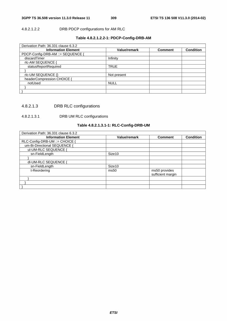
ETSI
ETSI TS 136 508 V11.3.0 (2014-02)3093GPP TS 36.508 version 11.3.0 Release 11
4.8.2.1.2.2 DRB PDCP configurations for AM RLC
Table 4.8.2.1.2.2-1: PDCP-Config-DRB-AM
Derivation Path: 36.331 clause 6.3.2 Information Element Value/remark Comment Condition
PDCP-Config-DRB-AM ::= SEQUENCE { discardTimer Infinity rlc-AM SEQUENCE { statusReportRequired TRUE } rlc-UM SEQUENCE {} Not present headerCompression CHOICE { notUsed NULL } }
4.8.2.1.3 DRB RLC configurations
4.8.2.1.3.1 DRB UM RLC configurations
Table 4.8.2.1.3.1-1: RLC-Config-DRB-UM
Derivation Path: 36.331 clause 6.3.2 Information Element Value/remark Comment Condition
RLC-Config-DRB-UM ::= CHOICE { um-Bi-Directional SEQUENCE { ul-UM-RLC SEQUENCE { sn-FieldLength Size10 } dl-UM-RLC SEQUENCE { sn-FieldLength Size10 t-Reordering ms50 ms50 provides
sufficient margin
} } }

ETSI
ETSI TS 136 508 V11.3.0 (2014-02)3103GPP TS 36.508 version 11.3.0 Release 11
4.8.2.1.3.2 DRB AM RLC configurations
Table 4.8.2.1.3.2-1: RLC-Config-DRB-AM
Derivation Path: 36.331 clause 6.3.2 Information Element Value/remark Comment Condition
RLC-Config-DRB-AM ::= CHOICE { am SEQUENCE { ul-AM-RLC SEQUENCE { t-PollRetransmit ms80 pollPDU p128 pollByte kB125 maxRetxThreshold t4 } dl-AM-RLC SEQUENCE { t-Reordering ms80 Is sufficient for 5
HARQ transmissions
t-StatusProhibit Ms60 Should be equal to or smaller than t-PollRetransmit.
} } }
4.8.2.1.4 DRB Logical Channel configurations
Table 4.8.2.1.4-1: LogicalChannelConfig-DRB
Derivation Path: 36.331 clause 6.3.2 Information Element Value/remark Comment Condition
LogicalChannelConfig-DRB ::= SEQUENCE { ul-SpecificParameters SEQUENCE { priority 6 HI 13 LO prioritisedBitRate kBps0 PBR is disabled. bucketSizeDuration ms100 logicalChannelGroup 1 HI 2 LO } }
Condition Explanation HI Used for DRBs with high logical channel priority LO Used for DRBs with low logical channel priority

ETSI
ETSI TS 136 508 V11.3.0 (2014-02)3113GPP TS 36.508 version 11.3.0 Release 11
4.8.2.1.5 MAC configurations
Table 4.8.2.1.5-1: MAC-MainConfig-RBC
Derivation Path: 36.331 clause 6.3.2 Information Element Value/remark Comment Condition
MAC-MainConfig-RBC ::= SEQUENCE { ul-SCH-Config Not present SCell_AddM
od ul-SCH-Config SEQUENCE { maxHARQ-Tx n5 periodicBSR-Timer sf20 Infinity no_periodi
c_BSR_or_PHR
retxBSR-Timer sf320 sf10240 no_periodi
c_BSR_or_PHR
ttiBundling FALSE } drx-Config Not present NOT
pc_FeatrGrp_5 or SCell_AddMod
drx-Config CHOICE { pc_FeatrGrp_5 AND DRX_S
setup SEQUENCE { onDurationTimer psf2 drx-InactivityTimer psf100 drx-RetransmissionTimer psf16 longDRX-CycleStartOffset CHOICE { sf40 typical value
in real network for real-time services.
sf40 4 For SIG 0 For RF
} shortDRX Not present } } drx-Config CHOICE { pc_FeatrGrp
_5 AND DRX_L
setup SEQUENCE { onDurationTimer psf6 drx-InactivityTimer psf1920 drx-RetransmissionTimer psf16 longDRX-CycleStartOffset CHOICE { sf1280 typical
value in real network for best-effort services.
sf1280 4 For SIG 0 For RF
} shortDRX Not present } } timeAlignmentTimerDedicated sf750 phr-Config CHOICE { no_periodi
c_BSR_or_PHR
release NULL }

ETSI
ETSI TS 136 508 V11.3.0 (2014-02)3123GPP TS 36.508 version 11.3.0 Release 11
phr-Config Not present SCell_AddMod
phr-Config CHOICE { setup SEQUENCE { periodicPHR-Timer sf500 prohibitPHR-Timer sf200 dl-PathlossChange dB3 } } sr-ProhibitTimer-r9 Not present mac-MainConfig-v1020 Not present mac-MainConfig-v1020SEQUENCE { SCell_AddM
od sCellDeactivationTimer-r10 rf32 extendedBSR-Sizes-r10 setup extendedPHR-r10 setup } }
Condition Explanation DRX_S Used for DRX configuration with small DRX cycle length DRX_L Used for DRX configuration with large DRX cycle length no_periodic_BSR_or_PHR Used to disable BSR and PHR For SIG Used for DRX configuration in Protocol testing For RF Used for DRX configuration in RRM testing SCell_AddMod Addition or modification of SCell
Table 4.8.2.1.5-2: MAC-MainConfig-SRB
Derivation Path: 36.331 clause 6.3.2 Information Element Value/remark Comment Condition
MAC-MainConfig-SRB ::= SEQUENCE { ul-SCH-Config SEQUENCE { maxHARQ-Tx n5 periodicBSR-Timer sf20 retxBSR-Timer sf320 ttiBundling FALSE } drx-Config CHOICE { release NULL } timeAlignmentTimerDedicated sf750 phr-Config CHOICE { setup SEQUENCE { periodicPHR-Timer sf500 prohibitPHR-Timer sf200 dl-PathlossChange dB3 } } }

ETSI
ETSI TS 136 508 V11.3.0 (2014-02)3133GPP TS 36.508 version 11.3.0 Release 11
4.8.2.1.6 Physical Layer configurations
Table 4.8.2.1.6-1: PhysicalConfigDedicated-DEFAULT
Derivation Path: 36.331 clause 6.3.2 Information Element Value/remark Comment Condition
PhysicalConfigDedicated-DEFAULT ::= SEQUENCE { pdsch-ConfigDedicated PDSCH-
ConfigDedicated-DEFAULT
See subclause 4.6.3
SRB1 or HO-TO-EUTRA
Not present RBC or RBC-HO SCell_AddMod
pucch-ConfigDedicated PUCCH-ConfigDedicated-DEFAULT
See subclause 4.6.3
SRB1 or RBC-HO or HO-TO-EUTRA
Not present RBC SCell_AddMod
pusch-ConfigDedicated PUSCH-ConfigDedicated-DEFAULT
See subclause 4.6.3
SRB1 or HO-TO-EUTRA
Not present RBC or RBC-HO SCell_AddMod
uplinkPowerControlDedicated UplinkPowerControlDedicated-DEFAULT
See subclause 4.6.3
SRB1 or HO-TO-EUTRA
Not present RBC or RBC-HO SCell_AddMod
tpc-PDCCH-ConfigPUCCH Not present SRB1 SCell_AddMod
TPC-PDCCH-Config-DEFAULT using condition PUCCH
See subclause 4.6.3
RBC or RBC-HO or HO-TO-EUTRA
tpc-PDCCH-ConfigPUSCH Not present SRB1 SCell_AddMod
TPC-PDCCH-Config-DEFAULT using condition PUSCH
See subclause 4.6.3
RBC or RBC-HO or HO-TO-EUTRA
cqi-ReportConfig CQI-ReportConfig-DEFAULT
See subclause 4.6.3
SRB1 or HO-TO-EUTRA
CQI-ReportConfig- DEFAULT using condition CQI_PERIODIC
See subclause 4.6.3
RBC or RBC-HO
Not present CA
soundingRS-UL-ConfigDedicated Not present SRB1 or HO-TO-EUTRA SCell_AddMod
SoundingRS-Ul-ConfigDedicated-DEFAULT
See subclause 4.6.3
RBC or RBC-HO
antennaInfo CHOICE {

ETSI
ETSI TS 136 508 V11.3.0 (2014-02)3143GPP TS 36.508 version 11.3.0 Release 11
explicitValue SEQUENCE { 2TX transmissionMode tm3 codebookSubsetRestriction CHOICE { n2TxAntenna-tm3 '11' BIT STRING
(SIZE (2))
} ue-TransmitAntennaSelection CHOICE { Release NULL } } defaultValue NULL } schedulingRequestConfig SchedulingRequest-
Config-DEFAULT See subclause 4.6.3
SRB1 or RBC-H or HO-TO-EUTRA
Not present RBC SCell_AddMod
cqi-ReportConfig-v920 Not present antennaInfo-v920 Not present antennaInfo-r10 Not present antennaInfoUL-r10 Not present cif-Presence-r10 FALSE SCell_AddM
od Not present cqi-ReportConfig-r10 CQI-ReportConfig-r10-
DEFAULT SCell_AddM
od Not present csi-RS-Config-r10 Not present pucch-ConfigDedicated-v1020 PUCCH-
ConfigDedicated-v1020-DEFAULT
SCell_AddMod
pusch-ConfigDedicated-v1020 Not present

ETSI
ETSI TS 136 508 V11.3.0 (2014-02)3153GPP TS 36.508 version 11.3.0 Release 11
schedulingRequestConfig-v1020 Not present soundingRS-UL-ConfigDedicated-v1020 Not present soundingRS-UL-ConfigDedicatedAperiodic-r10 Not present uplinkPowerControlDedicated-v1020 UplinkPowerControlDedic
ated-v1020-DEFAULT SCell_AddM
od and (TxD or SRSAp)
Not present additionalSpectrumEmissionCA-r10 Not present additionalSpectrumEmissionCA-r10 Not present SCell_AddM
od and Intra-BC CA
additionalSpectrumEmissionCA-r10 CHOICE { SCell_AddMod and Inter-B CA and UL CA
setup SEQUENCE { additionalSpectrumEmissionPCell-r10 1 (CA_NS_01) } } epdcch-Config-r11 EPDCCH-Config-r11-
DEFAULT ePDCCH
Not present csi-RS-ConfigNZPToReleaseList-r11 Not present csi-RS-ConfigNZPToAddModList-r11 Not present csi-RS-ConfigNZPToAddModList-r11 SEQUENCE (SIZE (1..maxCSI-RS-NZP-r11)) OF {
1 entry DL_CoMP
CSI-RS-ConfigNZP-r11[1] CSI-RS-ConfigNZP-r11-DEFAULT
} csi-RS-ConfigZPToReleaseList-r11 Not present csi-RS-ConfigZPToAddModList-r11 Not present csi-RS-ConfigZPToAddModList-r11 SEQUENCE (SIZE (1..maxCSI-RS-ZP-r11)) OF {
1 entry DL_CoMP
CSI-RS-ConfigZP-r11[1] CSI-RS-ConfigZP-r11-DEFAULT
} pdsch-ConfigDedicated-v1130 PDSCH-
ConfigDedicated-v1130-DEFAULT
DL_CoMP
Not present cqi-ReportConfig-v1130 CQI-ReportConfig-v1130-
DEFAULT DL_CoMP
Not present pucch-ConfigDedicated-v1130 PUCCH-
ConfigDedicated-v1130-DEFAULT
UL_CoMP
Not present pusch-ConfigDedicated-v1130 PUSCH-
ConfigDedicated-v1130-DEFAULT
UL_CoMP
Not present uplinkPowerControlDedicated-v1130 UplinkPowerControlDedic
ated-v1130-DEFAULT UL_CoMP
Not present } Note: For signalling test, table 6.6B.1.1.1-1 is applied.
Condition Explanation
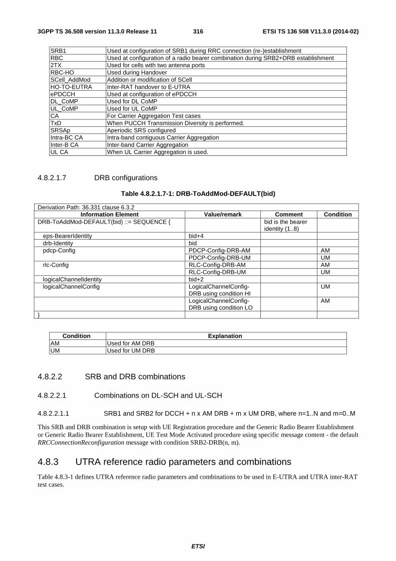
ETSI
ETSI TS 136 508 V11.3.0 (2014-02)3163GPP TS 36.508 version 11.3.0 Release 11
SRB1 Used at configuration of SRB1 during RRC connection (re-)establishment RBC Used at configuration of a radio bearer combination during SRB2+DRB establishment 2TX Used for cells with two antenna ports RBC-HO Used during Handover SCell_AddMod Addition or modification of SCell HO-TO-EUTRA Inter-RAT handover to E-UTRA ePDCCH Used at configuration of ePDCCH DL_CoMP Used for DL CoMP UL_CoMP Used for UL CoMP CA For Carrier Aggregation Test cases TxD When PUCCH Transmission Diversity is performed. SRSAp Aperiodic SRS configured Intra-BC CA Intra-band contiguous Carrier Aggregation Inter-B CA Inter-band Carrier Aggregation UL CA When UL Carrier Aggregation is used.
4.8.2.1.7 DRB configurations
Table 4.8.2.1.7-1: DRB-ToAddMod-DEFAULT(bid)
Derivation Path: 36.331 clause 6.3.2 Information Element Value/remark Comment Condition
DRB-ToAddMod-DEFAULT(bid) ::= SEQUENCE { bid is the bearer identity (1..8)
eps-BearerIdentity bid+4 drb-Identity bid pdcp-Config PDCP-Config-DRB-AM AM PDCP-Config-DRB-UM UM rlc-Config RLC-Config-DRB-AM AM RLC-Config-DRB-UM UM logicalChannelIdentity bid+2 logicalChannelConfig LogicalChannelConfig-
DRB using condition HI UM
LogicalChannelConfig-DRB using condition LO
AM
}
Condition Explanation AM Used for AM DRB UM Used for UM DRB
4.8.2.2 SRB and DRB combinations
4.8.2.2.1 Combinations on DL-SCH and UL-SCH
4.8.2.2.1.1 SRB1 and SRB2 for DCCH + n x AM DRB + m x UM DRB, where n=1..N and m=0..M
This SRB and DRB combination is setup with UE Registration procedure and the Generic Radio Bearer Establishment or Generic Radio Bearer Establishment, UE Test Mode Activated procedure using specific message content - the default RRCConnectionReconfiguration message with condition SRB2-DRB(n, m).
4.8.3 UTRA reference radio parameters and combinations
Table 4.8.3-1 defines UTRA reference radio parameters and combinations to be used in E-UTRA and UTRA inter-RAT test cases.

ETSI
ETSI TS 136 508 V11.3.0 (2014-02)3173GPP TS 36.508 version 11.3.0 Release 11
Table 4.8.3-1: UTRA reference radio parameters and combinations
Condition Reference configuration Comment UTRA Speech TS 34.108 subclause 6.10.2.4.1.4 Conversational / speech / UL:12.2 DL:12.2 kbps / CS RAB +
UL:3.4 DL:3.4 kbps SRBs for DCCH UTRA FDD PS RB
TS 34.108 subclause 6.10.2.4.1.26 Interactive or background / UL:64 DL: 64 kbps / PS RAB + UL:3.4 DL:3.4 kbps SRBs for DCCH
UTRA HSDPA RB
TS 34.108 subclause 6.10.2.4.5.1 Interactive or background / UL:64 DL: [max bit rate depending on UE category] / PS RAB + UL:3.4 DL:3.4 kbps SRBs for DCCH
UTRA HSUPA/HSDPA RB
TS 34.108 subclause 6.10.2.4.6.3 Streaming or interactive or background / UL: [max bit rate depending on UE category and TTI] DL: [max bit rate depending on UE category] / PS RAB + UL: [max bit rate depending on UE category and TTI] DL: [max bit rate depending on UE category] SRBs for DCCH on E-DCH and HS-DSCH
UTRA PS RB + Speech
TS 34.108 subclause 6.10.2.4.1.40 Conversational / speech / UL:12.2 DL:12.2 kbps / CS RAB + Interactive or background / UL:64 DL:64 kbps / PS RAB+ UL:3.4 DL: 3.4 kbps SRBs for DCCH
4.8.4 GERAN reference PDP context parameters
Table 4.8.4-1 defines GERAN reference PDP context parameters to be used in E-UTRA and GERAN inter-RAT test cases.
Table 4.8.4-1: GERAN reference PDP context parameters
Condition Reference configuration Comment GPRS TS 51.010-1 subclause 40.5, Test
PDP context3. Test PDP context3 is the default Test PDP context which is used in the GERAN Inter-RAT GPRS test cases where no particular Test PDP contexts are specified. Compression is always turned off if nothing else is stated explicitly in the test case.
4.9 Common test USIM, CSIM and ISIM parameters This clause defines default parameters for programming the elementary files of the test UICC when running conformance test cases defined in 3GPP TS 36.523-1[18].
4.9.1 General
See clause 8.1 in 3GPP TS 34.108 [5].
4.9.1.1 Definitions
See clause 8.1.1 in 3GPP TS 34.108 [5].
4.9.1.2 Definition of the test algorithm for authentication
Same as clause 8.1.2 in 3GPP TS 34.108[5].
4.9.1.2.1 Authentication and key derivation in the test USIM, CSIM and ISIM and SS
UE and SS calculate Ck, Ik, AUTN, RES[XRES] as in clause 8.1.2.1 in 3GPP TS 34.108 [5]. Derivation of KASME and other E-UTRA Keys shall be as defined in Annex A of 3GPP TS 33.401 [31], using Key derivation function HMAC-SHA-256 algorithm.

ETSI
ETSI TS 136 508 V11.3.0 (2014-02)3183GPP TS 36.508 version 11.3.0 Release 11
4.9.1.2.2 Generation of re-synchronization parameters in the USIM, CSIM and ISIM
Same as clause 8.1.2.1 in 3GPP TS 34.108[5].
4.9.1.2.3 Using the authentication test algorithm for UE conformance testing
See clause 8.1.2.3 in 3GPP TS 34.108 [5].
4.9.2 Default parameters for the test USIM, CSIM and ISIM
Same as clause 8.2 in 3GPP TS 34.108 [5].
4.9.3 Default settings for the Elementary Files (EFs)
The format and coding of elementary files of the USIM are defined in 3GPP TS 31.101 [32] and 3GPP TS 31.102 [33] . Those of the ISIM are defined in 3GPP TS 31.101 [32] and 3GPP TS 31.103 [45]. Those of the CSIM are defined in 3GPP2 C.S0065-B [48].
The settings of the elementary files at the MF and USIM ADF (Application DF) level resp. the ISIM ADF (Application DF) level are the same as section 8.3 in 3GPP TS 34.108 [5] resp. section 4.2 in 3GPP TS 34.229-1 Annex E [46] and 3GPP TS 34.229-3 Annex B.1 [47] with the exceptions listed below. The settings of the elementary files at the CSIM ADF (Application DF) level as specified below. Note that some files may be updated by the UE based on information received from the SS.
4.9.3.1 Modified contents of the USIM Elementary Files
EFEPSLOCI (EPS location information)
File size: 18 Bytes
Default values: Bytes 1 to 12 (HEX): FF FF FF FF FF FF FF FF FF FF FF FF(GUTI)
Bytes 13 to 17 (HEX): 42 F6 18 FF FE (Last visited registered TAI)
Byte 18 (BIN): 00000001 (EPS update status = "not updated")
Bytes 13 to 17: TAI-MCC = 246 (bytes 13 to 14) and TAI-MNC = 81 (byte 15) are frequently used. The TAC (bytes 16 to 17) is set to "FF FE" since this, in conjunction with byte 18 setting of "01", is used to ensure that the UE performs Attach at the beginning of a test.
Bytes in this file (e.g. GUTI in bytes 1 to 12) may be updated as a result of a tracking area update attempt by the UE.
EFEPSNSC (EPS NAS Security Context)
The programming of this EF follows default parameter written in 3GPP TS 31.102 [23], annex E.
EFNASCONFIG (Non Access Stratum Configuration)
File size: 28 Bytes
Default values: Bytes 1 to 28 (HEX): FF FF … FF
The programming of this EF follows the specific USIM requirements given in 3GPP TS 36.523-1 [18].
EFUST (USIM Service Table):
Services Activated Version Service n°15: Cell Broadcast Message Identifier Optional Service n°16: Cell Broadcast Message Identifier Ranges Optional Service n°85 EPS Mobility Management Information Yes Service n°87 Call control on EPS PDN connection by USIM No

ETSI
ETSI TS 136 508 V11.3.0 (2014-02)3193GPP TS 36.508 version 11.3.0 Release 11
Services Activated Version Service n°96 Non Access Stratum Configuration Optional
4.9.3.2 Modified contents of the CSIM Elementary Files
EFCOUNT (Call Count)
The programming of this EF follows default parameter written in 3GPP2 C.S0065-B [48], Annex E.
EFIMSI_M (IMSI_M)
The programming of this EF follows default parameter written in 3GPP2 C.S0065-B [48], Annex E.
EFIMSI_T (IMSI_T)
The programming of this EF follows default parameter written in 3GPP2 C.S0065-B [48], Annex E.
EFTMSI (TMSI)
The programming of this EF follows default parameter written in 3GPP2 C.S0065-B [48], Annex E.
EFAH (Analog Home SID)
The programming of this EF follows default parameter written in 3GPP2 C.S0065-B [48], Annex E.
EFAOP (Analog Operational Parameters)
The programming of this EF is a test house option.
EFALOC (Analog Location and Registration Indicators)
The programming of this EF is a test house option.
EFCDMAHOME (CDMA Home SID, NID)
Record size: 5 Bytes
Record count: 6
Record 1:
Default values: Bytes 1 to 2 (HEX): E8 03 (CDMA Home SID (SIDp): 1000)
Bytes 3 to 4 (HEX): AE 08 (CDMA Home NID (NIDp): 2222)
Bytes 5 (HEX): 00 (Band Class: 0 (800 MHz cellular band))
Record 2:
Default values: Bytes 1 to 2 (HEX): E8 03 (CDMA Home SID (SIDp): 1000)
Bytes 3 to 4 (HEX): AE 08 (CDMA Home NID (NIDp): 2222)
Bytes 5 (HEX): 01 (Band Class: 1 (1.8 to 2.0 GHz PCS band))
Record 3:
Default values: Bytes 1 to 2 (HEX): E8 03 (CDMA Home SID (SIDp): 1000)
Bytes 3 to 4 (HEX): AE 08 (CDMA Home NID (NIDp): 2222)
Bytes 5 (HEX): 03 (Band Class: 3 (832 to 925 MHz JTACS band))

ETSI
ETSI TS 136 508 V11.3.0 (2014-02)3203GPP TS 36.508 version 11.3.0 Release 11
Record 4:
Default values: Bytes 1 to 2 (HEX): E8 03 (CDMA Home SID (SIDp): 1000)
Bytes 3 to 4 (HEX): AE 08 (CDMA Home NID (NIDp): 2222)
Bytes 5 (HEX): 04 (Band Class: 4 (1.75 to 1.87 GHz Korean PCS band))
Record 5:
Default values: Bytes 1 to 2 (HEX): E8 03 (CDMA Home SID (SIDp): 1000)
Bytes 3 to 4 (HEX): AE 08 (CDMA Home NID (NIDp): 2222)
Bytes 5 (HEX): 05 (Band Class: 5 (450 MHz NMT band))
Record 6:
Default values: Bytes 1 to 2 (HEX): E8 03 (CDMA Home SID (SIDp): 1000)
Bytes 3 to 4 (HEX): AE 08 (CDMA Home NID (NIDp): 2222)
Bytes 5 (HEX): 06 (Band Class: 6 (2 GHz IMT-2000 band))
EFZNREGI (CDMA Zone-Based Registration Indicators)
The programming of this EF follows default parameter written in 3GPP2 C.S0065-B [48], Annex E.
EFSNREGI (CDMA System-Network Registration Indicators)
The programming of this EF is a test house option.
EFDISTREGI (CDMA Distance-Based Registration Indicators)
The programming of this EF follows default parameter written in 3GPP2 C.S0065-B [48], Annex E.
EFACCOLC (Access Overload Class ACCOLCp)
The 4 LSB of this 1 byte file are der-bit access overload class indicator is derived from the last digit of the associated decimal representation of the IMSI_M vis decimal to binary conversion.
File size: 1 byte
Default value: Bits 4 to 7 are reserved and set to ‘0000’. Bits 0 to 3 are derived from the last digit of the associated decimal representation of the IMSI_M via decimal to binary conversion.
EFTERM (Call Termination Mode Preferences)
The programming of this EF is a test house option.
EFSSCI (Suggested Slot Cycle Index)
The programming of this EF is a test house option.
EFACP (Analog Channel Preferences)
The programming of this EF is a test house option.
EFPRL (Preferred Roaming List)
File size: 18 Bytes
Default values: Bytes 1 to 18 (HEX): 00 12 00 00 00 00 40 01 21 00 02 80 00 50 00 00 6E DB

ETSI
ETSI TS 136 508 V11.3.0 (2014-02)3213GPP TS 36.508 version 11.3.0 Release 11
The interpretation of the default values read as follows:
PRL ID – 0
Preferred only – 0
Default roaming indication – 0
Number of Acquisition Records – 1
Number of system records – 1
EFRUIMID (Removable UIMID)
This EF stores a 32-bit electronic identification number (ID) unique to the CSIM or a 32-bit pseudo-UIMID of the CSIM. It is specified by the CSIM manufacturer.
EFCSIM_ST (CSIM Service Table)
Services will be allocated and activated as follows.
Services Activated Version Service n°1 : Local Phone Book Option Service n°2 : Fixed Dialling Numbers (FDN) Option Service n°3 : Extension 2 Option Service n°4 : Service Dialling Numbers (SDN) Option Service n°5 : Extension3 Option Service n°6: Short Message Storage Yes Service n°7: Short Message Parameters (SMP) Yes Service n°8: HRPD Yes Service n°9: Service Category Program for BC-SMS Option Service n°10: CDMA Home Service Provider Name Yes Service n°11: Data Download via SMS Broadcast (for CCAT) Option Service n°12: Data Download via SMS-PP (for CCAT) Option Service n°13: Call Control (for CCAT) Option Service n°14: 3GPD-SIP Option Service n°15: 3GPD-MIP Option Service n°16: AKA Yes Service n°17: IP-based Location Services (LCS) Option Service n°18: BCMCS Option Service n°19: Multimedia Messaging Service (MMS) Option Service n°20: Extension 8 Option Service n°21: MMS User Connectivity Parameters Option Service n°22: Application Authentication Option Service n°23: Group Identifier Level 1 Option Service n°24: Group Identifier Level 2 Option Service n°25: De-Personalization Control Keys Option Service n°26: Cooperative Network List Option Service n°27: Outgoing Call Information (OCI) Option Service n°28: Incoming Call Information (ICI) Option Service n°29: Extension 5 Option Service n°30: Multimedia Storage Option Service n°31: Image (EFIMG) Option Service n°32: Enabled Services Table Yes Service n°33: Capability Configuration Parameters (CCP) Option Service n°34: SF_EUIMID-based EUIMID Option Service n°35: Messaging and 3GPD Extensions Option Service n°36: Root Certificates Option Service n°37: WAP Browser Option Service n°38: Java Option Service n°39: Reserved for CDG No Service n°40: Reserved for CDG No Service n°41: IPv6 Option Service n°42: Proactive CSIM (for CCAT) Option

ETSI
ETSI TS 136 508 V11.3.0 (2014-02)3223GPP TS 36.508 version 11.3.0 Release 11
EFSPC (Service Programming Code)
The programming of this EF follows default parameter written in 3GPP2 C.S0065-B [48], Annex E.
EFOTAPASPC (OTAPA/SPC_Enabled)
The programming of this EF follows default parameter written in 3GPP2 C.S0065-B [48], Annex E.
EFNAMLOCK (NAM_LOCK)
The programming of this EF is a test house option.
EFOTA (OTASP/OTAPA Features)
The programming of this EF is a test house option.
EFSP (Service Preferences)
The programming of this EF is a test house option.
EFESN_MEID_ME (ESN_ME or MEID_ME)
The programming of this EF follows default parameter written in 3GPP2 C.S0065-B [48], Annex E.
EFLI (Language Indication)
The programming of this EF is a test house option.
EFFDN (Fixed Dialling Numbers)
The programming of this EF is a test house option.
EFSMS (Short Messages)
The programming of this EF follows default parameter written in 3GPP2 C.S0065-B [48], Annex E.
EFSMSP (Short Message Service Parameters)
Record size: 12 Bytes
Record count: 1
Record 1:
Default values: Bytes 1 to 23 (HEX): 00 02 10 02 5D FE FF FF 02 F5 FF FF FF FF FF FF FF FF
08 03 08 01 C0
The interpretation of the default values in this record read as follows:
Teleservice Identifier: CDMA Cellular Messaging Teleservice [CMT-95]
Parameter Indicators: MSG_ENCODING, Validity Period, Bearer Data
Message Encoding: 7-bit ASCII
Validity Period: Indefinite
Bearer Data:
Priority Indicator: Emergency
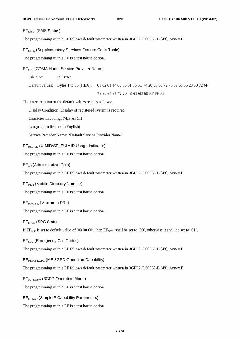
ETSI
ETSI TS 136 508 V11.3.0 (2014-02)3233GPP TS 36.508 version 11.3.0 Release 11
EFSMSS (SMS Status)
The programming of this EF follows default parameter written in 3GPP2 C.S0065-B [48], Annex E.
EFSSFC (Supplementary Services Feature Code Table)
The programming of this EF is a test house option.
EFSPN (CDMA Home Service Provider Name)
File size: 35 Bytes
Default values: Bytes 1 to 35 (HEX): 01 02 01 44 65 66 61 75 6C 74 20 53 65 72 76 69 63 65 20 50 72 6F
76 69 64 65 72 20 4E 61 6D 65 FF FF FF
The interpretation of the default values read as follows:
Display Condition: Display of registered system is required
Character Encoding: 7-bit ASCII
Language Indicator: 1 (English)
Service Provider Name: “Default Service Provider Name”
EFUSGIND (UIMID/SF_EUIMID Usage Indicator)
The programming of this EF is a test house option.
EFAD (Administrative Data)
The programming of this EF follows default parameter written in 3GPP2 C.S0065-B [48], Annex E.
EFMDN (Mobile Directory Number)
The programming of this EF is a test house option.
EFMAXPRL (Maximum PRL)
The programming of this EF is a test house option.
EFSPCS (SPC Status)
If EFSPC is set to default value of ’00 00 00’, then EFSPCS shall be set to ‘00’, otherwise it shall be set to ‘01’.
EFECC (Emergency Call Codes)
The programming of this EF follows default parameter written in 3GPP2 C.S0065-B [48], Annex E.
EFME3GPDOPC (ME 3GPD Operation Capability)
The programming of this EF follows default parameter written in 3GPP2 C.S0065-B [48], Annex E.
EF3GPDOPM (3GPD Operation Mode)
The programming of this EF is a test house option.
EFSIPCAP (SimpleIP Capability Parameters)
The programming of this EF is a test house option.

ETSI
ETSI TS 136 508 V11.3.0 (2014-02)3243GPP TS 36.508 version 11.3.0 Release 11
EFMIPCAP (MobileIP Capability Parameters)
The programming of this EF is a test house option.
EFSIPUPP (SimpleIP User Profile Parameters)
The programming of this EF is a test house option.
EFMIPUPP (MobileIP User Profile Parameters)
The programming of this EF is a test house option.
EFSIPSP (SimpleIP Status Parameters)
The programming of this EF is a test house option.
EFMIPSP (MobileIP Status Parameters)
The programming of this EF is a test house option.
EFSIPPAPSS (SimpleIP PAP SS Parameters)
The programming of this EF is a test house option.
EFPUZL (Preferred User Zone List)
The programming of this EF is a test house option.
EFMAXPUZL (Maximum PUZL)
The programming of this EF is a test house option.
EFMECRP (ME-specific Configuration Request Parameters)
The programming of this EF follows default parameter written in 3GPP2 C.S0065-B [48], Annex E.
EFHRPDCAP (HRPD Access Authentication Capability Parameters)
File size: 3 Bytes
Default values: Bytes 1 to 3 (HEX): 20 F8 80
The interpretation of the default values read as follows:
Maximum NAI Length: 32
Maximum Length of Shared Secret: 31
Authentication Algorithms: PPP CHAP
EFHRPDUPP (HRPD Access Authentication User Profile Parameters)
File size: 14 Bytes
Default values: Bytes 1 to 14 (HEX): 0D 0B 61 62 63 40 78 79 7A 2E 63 6F 6D 10
The interpretation of the default values read as follows:
HRPD Profile NAI: “[email protected]”
HRPD Profile Authentication Algorithm: CHAP

ETSI
ETSI TS 136 508 V11.3.0 (2014-02)3253GPP TS 36.508 version 11.3.0 Release 11
EFCSSPR (CUR_SSPR_P_REV)
The programming of this EF follows default parameter written in 3GPP2 C.S0065-B [48], Annex E.
EFATC (Access Terminal Class)
The programming of this EF is a test house option.
EFEPRL (Extended Preferred Roaming List)
File size: 129 Bytes
Default values: Bytes 1 to 16 (HEX): 00 81 00 00 03 80 01 80 00 04 00 0A 04 01 64 03
Bytes 17 to 32 (HEX): 0B 0B 04 01 64 03 F5 0A 04 0A 58 08 19 0B 04 0A
Bytes 33 to 48 (HEX): 58 0C 97 0A 02 31 13 0B 02 30 C8 71 C0 02 00 10
Bytes 49 to 64 (HEX): 1F 01 00 C8 FF FF 00 80 00 38 E0 08 00 00 80 00
Bytes 65 to 80 (HEX): 71 E0 12 00 10 1F 01 00 C8 FF FF 00 80 00 38 E0
Bytes 81 to 96 (HEX): 18 00 00 80 00 71 C0 22 00 10 1F 01 00 C8 FF FF
Bytes 97 to 112 (HEX): 00 80 80 38 E0 28 00 00 80 80 71 E0 02 00 10 1F
Bytes 113 to 128 (HEX):01 00 C8 FF FF 00 80 80 38 E0 08 00 00 80 80 B5
Byte 129 (HEX): A8
The interpretation of the default values read as follows:
PRL ID – 0
List Type: IS-683D
Preferred only – 1
Default roaming indication – 0
Number of acquisition records – 6
- Index: 0, Type: CDMA Generic, Band: 0, Channel: 356 and 779
- Index: 1, Type: HDR Generic Band: 0, Channel: 356 and 1013
- Index: 2, Type: CDMA Generic, Band: 1, Channel: 600 and 25
- Index: 3, Type: HDR Generic, Band: 1, Channel: 600 and 1175
- Index: 4, Type: CDMA Generic, Band: 6, Channel: 275
- Index: 5, Type: HDR Generic, Band: 6, Channel: 200
Number of records in the Common Subnet Table – 0
Number of system records – 8
- Acquisition Index: 1, Type: IS-856, Roam Indicator: 0, Subnet ID: /0, Association Tag: 0
- Acquisition Index: 3, Type: IS-856, Roam Indicator: 0, Subnet ID: /0, Association Tag: 0
- Acquisition Index: 5, Type: IS-856, Roam Indicator: 0, Subnet ID: /0, Association Tag: 1
- Acquisition Index: 1, Type: IS-856, Roam Indicator: 0, Subnet ID: /0, Association Tag: 1
- Acquisition Index: 0, Type: MCC-MNC-based, Roam Indicator: 0, Subnet ID: MCC-MNC SID/NID, MCC: 001, MNC: 01, SID: 200, NID: 65535100, Association Tag: 0

ETSI
ETSI TS 136 508 V11.3.0 (2014-02)3263GPP TS 36.508 version 11.3.0 Release 11
- Acquisition Index: 2, Type: MCC-MNC-based, Roam Indicator: 0, Subnet ID: MCC-MNC SID/NID, MCC: 001, MNC: 01, SID: 200, NID: 65535100, Association Tag: 0
- Acquisition Index: 4, Type: MCC-MNC-based, Roam Indicator: 0, Subnet ID: MCC-MNC SID/NID, MCC: 001, MNC: 01, SID: 200, NID: 65535100, Association Tag: 1
- Acquisition Index: 0, Type: MCC-MNC-based, Roam Indicator: 0, Subnet ID: MCC-MNC SID/NID, MCC: 001, MNC: 01, SID: 200, NID: 65535, Association Tag: 1
EFMSPL (Multimode system selection System Priority List)
File size: 18 Bytes
Default values: Bytes 1 to 18 (HEX): 00 0F 01 00 01 01 01 03 07 08 02 0C 00 3E 00 FF FF FF
The interpretation of the default values read as follows:
Current MMSS_P_REV – 1
MLPL Version ID – 1
MLPL Identification – 1
Number of MLPL Records – 1
- Index: 1, Location Parameter Type Value: default, MSPL Index: 1
EFMLPL (Multimode system selection Location associated Priority List)
File size: 18 Bytes
Default values: Bytes 1 to 18 (HEX): 00 09 01 00 01 01 01 00 01 FF FF FF FF FF FF FF FF FF
The interpretation of the default values read as follows:
Current MMSS_P_REV – 1
MSPL Version ID – 1
MSPL Block 1:
MSPL Identification – 1,
Number of MSPL ID1 records – 3
- Index 1: System Type: EUTRA, Priority Class: Home Only, System Priority: 1, Higher Priority Search Time: 64 minutes, Network Capability Indicator: no Network CAP used
- Index 2: System Type: cdma2000 HRPD, Priority Class: Home + Preferred, System Priority: 1, Higher Priority Search Time: 64 minutes, Network Capability Indicator: no Network CAP used
- Index 3: System Type: cdma2000 AI, Priority Class: Any, System Priority: 1, Higher Priority Search Time: 64 minutes, Network Capability Indicator: no Network CAP used
EFBCSMScfg (Broadcast Short Message Configuration)
The programming of this EF is a test house option.
EFBCSMSpref (Broadcast Short Message Preference)
The programming of this EF follows default parameter written in 3GPP2 C.S0065-B [48], Annex E.
EFBCSMStable (Broadcast Short Message Table)
The programming of this EF follows default parameter written in 3GPP2 C.S0065-B [48], Annex E.
ETSI
ETSI TS 136 508 V11.3.0 (2014-02)3273GPP TS 36.508 version 11.3.0 Release 11
EFBCSMSP (Broadcast Short Message Parameter)
The programming of this EF follows default parameter written in 3GPP2 C.S0065-B [48], Annex E.
EFBAKPARA (Currently used BAK Parameters)
The programming of this EF is a test house option.
EFUpBAKPARA (Updated BAK Parameters)
The programming of this EF is a test house option.
EFMMSN (MMS Notification)
The programming of this EF follows default parameter written in 3GPP2 C.S0065-B [48], Annex E.
EFEXT8 (Extension 8)
The programming of this EF follows default parameter written in 3GPP2 C.S0065-B [48], Annex E.
EFMMSICP (MMS Issuer Connectivity Parameters)
The programming of this EF follows default parameter written in 3GPP2 C.S0065-B [48], Annex E.
EFMMSUP (MMS User Preferences)
The programming of this EF follows default parameter written in 3GPP2 C.S0065-B [48], Annex E.
EFMMSUCP (MMS User Connectivity Parameters)
The programming of this EF follows default parameter written in 3GPP2 C.S0065-B [48], Annex E.
EFAuthCapability (Authentication Capability)
The programming of this EF follows default parameter written in 3GPP2 C.S0065-B [48], Annex E.
EF3GCIK (3G Cipher and Integrity Keys)
The programming of this EF is a test house option.
EFDCK (De-Personalization Control Keys)
The programming of this EF is a test house option.
EFGID1 (Group Identifier Level 1)
The programming of this EF is a test house option.
EFGID2 (Group Identifier Level 2)
The programming of this EF is a test house option.
EFCDMACNL (CDMA Co-operative Network List)
The programming of this EF is a test house option.
EFHOME_TAG (Home System Tag)
The programming of this EF is a test house option.

ETSI
ETSI TS 136 508 V11.3.0 (2014-02)3283GPP TS 36.508 version 11.3.0 Release 11
EFGROUP_TAG (Group Tag List)
The programming of this EF is a test house option.
EFSPECIFIC_TAG (Specific Tag List)
The programming of this EF is a test house option.
EFCALL_PROMPT (Call Prompt List)
The programming of this EF is a test house option.
EFSF_EUIMID (Short Form EUIMID)
Specified by CSIM Manufacturer.
EFEST (Enabled Service Table)
The programming of this EF is a test house option.
EFHiddenKey (Key for hidden phone book entries)
The programming of this EF is a test house option.
EFLCSVER (LCS Protocol Version)
The programming of this EF is a test house option.
EFLCSCP (LCS Connectivity Parameter)
The programming of this EF is a test house option.
EFSDN (Service Dialling Numbers)
The programming of this EF is a test house option.
EFEXT2(Extension2)
The programming of this EF is a test house option.
EFEXT3(Extension3)
The programming of this EF is a test house option.
EFICI (Incoming Call Information)
The programming of this EF is a test house option.
EFOCI (Outgoing Call Information)
The programming of this EF is a test house option.
EFEXT5 (Extension 5)
The programming of this EF is a test house option.
EFCCP2 (Capability Configuration Parameters 2)
The programming of this EF is a test house option.

ETSI
ETSI TS 136 508 V11.3.0 (2014-02)3293GPP TS 36.508 version 11.3.0 Release 11
EFAppLabels (Application Labels)
The programming of this EF is a test house option.
EFModel (Device Model Information)
The programming of this EF follows default parameter written in 3GPP2 C.S0065-B [48], Annex E.
EFRC (Root Certificates)
The programming of this EF is a test house option.
EFSMSCAP (SMS Capabilities)
File size: 4 Bytes
Default values: Bytes 1 to 4 (HEX): 3C 08 07 01
The interpretation of the default values read as follows:
SMS Retry Period: 60 seconds
SMS Retry Interval: 8 seconds
SMS Flags:
Send On Access: True
Send on Traffic: True
Send as Standard EMS: True
SMS Preferred Service Option: SO 6
EFMIPFlags (MobileIP Flags)
The programming of this EF is a test house option.
EF3GPDUPPExt (3GPD User Profile Parameters Extension)
The programming of this EF is a test house option.
EFIPV6CAP (IPv6 Capabilities)
The programming of this EF is a test house option.
EFTCPConfig (TCp Configurations)
The programming of this EF is a test house option.
EFDGC (Data Generic Configurations)
The programming of this EF is a test house option.
EFWAPBrowserCP (WAP Browser Connectivity Parameters)
The programming of this EF is a test house option.
EFWAPBrowserBM (WAP Browser Bookmarks)
The programming of this EF follows default parameter written in 3GPP2 C.S0065-B [48], Annex E.

ETSI
ETSI TS 136 508 V11.3.0 (2014-02)3303GPP TS 36.508 version 11.3.0 Release 11
EFMMSConfig (MMS Configuration)
The programming of this EF is a test house option.
EFJDL (Java Download URL)
The programming of this EF is a test house option.

3GPP TS 36.508 version 11.3.0 Release 11 ETSI TS 136 508 V11.3.0 (2014-02)
ETSI
331
5 Test environment for RF test This section contains all the exceptions of the common test parameters specified in clause 4 for specific needs of test cases defined in TS 36.521-1 [21]. Exceptions specified in clause 5 overwrite the parameter settings of clause 4; exceptions defined within the test cases overwrite parameter settings of clause 4 and 5.
5.1 Requirements of test equipment No common RF test environment requirements are specified in addition to the common requirements described in clause 4.2. Specific RF requirements are indicated within the test cases defined in TS 36.521-1 [21].
5.2 RF Reference system configurations
5.2.1 Common parameters for simulated E-UTRA cells
5.2.1.1 Combinations of system information blocks
The combination of system information blocks required by a test case depends on the test case scenario. In this clause, the following combinations of system information blocks are defined.
Combination 1 is the default combination which applies to the following test case scenarios:
- E-UTRA FDD single cell scenario
- E-UTRA TDD single cell scenario
- E-UTRA FDD intra-frequency multi cell scenario
- E-UTRA TDD intra-frequency multi cell scenario
Combination 2 applies to the following test case scenarios:
- E-UTRA FDD + MBMS
- E-UTRA TDD + MBMS
Combination 3 applies to the following test case scenarios:
- E-UTRA FDD intra-band carrier aggregation component carriers cell scenario
- E-UTRA FDD inter-band carrier aggregation component carriers cell scenario
- E-UTRA TDD intra-band carrier aggregation component carriers cell scenario
The combinations of system information blocks for test cases in TS 36.521-1 [21] is defined in table 5.2-1.1-1.
Table 5.2.1.1-1: Combinations of system information blocks
System information block type Combination
No. SIB2 SIB3 SIB4 SIB5 SIB6 SIB7 SIB8 SIB9 SIB10 SIB11 SIB12 SIB13
1 X X 2 X X X 3 X X X
5.2.1.2 Scheduling of system information blocks
The scheduling configurations for combinations of system information blocks are defined in the following tables. SIB1 will be transmitted during subframes#5 which SFN mod 2 = 0, and SIB2+SIB3 will be transmitted during

3GPP TS 36.508 version 11.3.0 Release 11 ETSI TS 136 508 V11.3.0 (2014-02)
ETSI
332
subframes#5 which SFN mod 2 = 1 with 8 radio frames periodicity. SIB5 will be transmitted during subframes#5 which SFN mod 2 = 1 with 64 radio frames periodicity
Table 5.2.1.2-1: Scheduling for combination 1
Scheduling Information No.
Periodicity [radio frames]
Mapping of system information blocks
1 8 SIB2, SIB3
Table 5.2.1.2-2: Scheduling for combination 2
Scheduling Information No.
Periodicity [radio frames]
Mapping of system information blocks
1 8 SIB2, SIB3 2 64 SIB13
Table 5.2.1.2-3: Scheduling for combination 3
Scheduling Information No.
Periodicity [radio frames]
Mapping of system information blocks
1 8 SIB2, SIB3 2 64 SIB5
- SystemInformationBlockType2
As defined in Table 4.4.3.3-1 with the following exceptions:
Table 5.2.1.2-2: SystemInformationBlockType2 exceptions
Derivation Path: 36.331 clause 6.3.1 Information Element Value/remark Comment Condition
SystemInformationBlockType2 ::= SEQUENCE {
timeAlignmentTimerCommon infinity }
5.2.1.3 Common contents of system information messages
- MasterInformationBlock
As defined in Table 4.4.3.2-1 without exceptions.
- SystemInformation
As defined in Table 5.2.1.3-1As defined in Table without exceptions.

3GPP TS 36.508 version 11.3.0 Release 11 ETSI TS 136 508 V11.3.0 (2014-02)
ETSI
333
Table 5.2.1.3-1: SystemInformation
Derivation Path: Clause 4.4.3.2 Table 4.4.3.2-2 Information Element Value/remark Comment Condition
SystemInformation ::= SEQUENCE { criticalExtensions CHOICE { systemInformation-r8 SEQUENCE { sib-TypeAndInfo SEQUENCE (SIZE (1..maxSIB)) OF CHOICE {}
See subclause 5.2.1.1 and 5.2.1.2
criticalExtensionsFuture SEQUENCE {} Not present } } }
- SystemInformationBlockType1
As defined in Table 4.4.3.2-3 with the following exceptions:
Table 5.2.1.3-2: SystemInformationBlockType1 exceptions
Derivation Path: Clause 4.4.3.2 Table 4.4.3.2-3 Information Element Value/remark Comment Condition
SystemInformationBlockType1 ::= SEQUENCE {
si-WindowLength ms40 }
5.2A Generic RF procedures Editor’s note: The UE test state used for testing is specified in the individual test cases in the corresponding test
specification TS 36.521-1 [21] or TS 36.521-3 [34].
This clause describes UE test states which can be used in the initial condition of many test cases defined in TS 36.521-1 [21] and TS 36.521-3 [34].
5.2A.1 UE RF test states
Table 5.2A.1-1: The E-UTRAN UE states
RRC ECM EMM ESM UE Test Mode
State 3A-RF
Generic Default RB Established, UE Test Mode Activated
RRC_CONNECTED 1 data radio bearer configured
ECM-CONNECTED EMM-REGISTERED 1 default EPS bearer context active
Active
5.2A.2 Generic Default Radio Bearer Establishment, UE Test Mode Activated (State 3A-RF)
Editor’s note: In tests refering to test mode State 3A-RF, in order to avoid any uncontrollable transmission of uplink U-plane data, test mode State 4A-RF (specified in 5.2A.3) may be used and configured instead.
5.2A.2.1 Initial conditions
System Simulator:
- 1 cell, default parameters.

3GPP TS 36.508 version 11.3.0 Release 11 ETSI TS 136 508 V11.3.0 (2014-02)
ETSI
334
- The procedure shall be performed under ideal radio conditions as defined in clause 5
User Equipment:
- The Test USIM shall be inserted.
5.2A.2.2 Definition of system information messages
The default system information messages are used.
5.2A.2.3 Procedure
Table 5.2A.2.3-1: UE registration with default EPS bearer establishment and test mode activation procedures
Step Procedure Message Sequence U - S Message
1 to 18
Same procedure for steps 1 to 18 as specified in the procedure in clause 4.5.2A.3
- -
5.2A.2.4 Specific message contents
All specific message contents shall be referred to clause 4.5.2A.4, with the exceptions below.
Table 5.2A.2.4-1: ACTIVATE DEFAULT EPS BEARER CONTEXT REQUEST (Step 16 in Table 4.5.2A.3-1)
Derivation Path: Table 4.7.3-6 Information Element Value/remark Comment Condition
PDN address Length of PDN address contents 5 octets PDN type value ‘001’B IPv4 PDN address information IPv4 address The SS provides a
valid IPv4 address
ESM cause IF "PDN type" IE in step 4 is 'IPv4v6' THEN '00110010'B ELSE Not present
"PDN type IPv4 only allowed"
5.2A.3 Loopback Activation without looped data (State 4A-RF)
Editor’s note: Test mode State 4A-RF is used and configured as an alternative to test mode State 3A-RF, to avoid any uncontrollable transmission of uplink U-plane data.
5.2A.3.1 Initial conditions
System Simulator:
- 1 cell, default parameters.
- The procedure shall be performed under ideal radio conditions as defined in clause 5
User Equipment:
- The UE shall be in Generic RB Establishment state, UE Test Mode Activated (State 3A-RF).
5.2A.3.2 Definition of system information messages
The default system information messages are used.
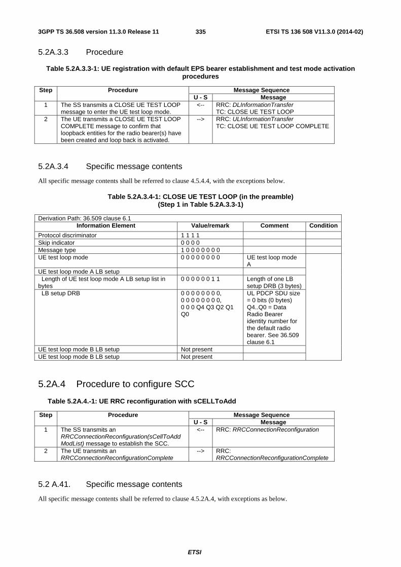
3GPP TS 36.508 version 11.3.0 Release 11 ETSI TS 136 508 V11.3.0 (2014-02)
ETSI
335
5.2A.3.3 Procedure
Table 5.2A.3.3-1: UE registration with default EPS bearer establishment and test mode activation procedures
Step Procedure Message Sequence U - S Message
1 The SS transmits a CLOSE UE TEST LOOP message to enter the UE test loop mode.
<-- RRC: DLInformationTransfer TC: CLOSE UE TEST LOOP
2 The UE transmits a CLOSE UE TEST LOOP COMPLETE message to confirm that loopback entities for the radio bearer(s) have been created and loop back is activated.
--> RRC: ULInformationTransfer TC: CLOSE UE TEST LOOP COMPLETE
5.2A.3.4 Specific message contents
All specific message contents shall be referred to clause 4.5.4.4, with the exceptions below.
Table 5.2A.3.4-1: CLOSE UE TEST LOOP (in the preamble) (Step 1 in Table 5.2A.3.3-1)
Derivation Path: 36.509 clause 6.1 Information Element Value/remark Comment Condition
Protocol discriminator 1 1 1 1 Skip indicator 0 0 0 0 Message type 1 0 0 0 0 0 0 0 UE test loop mode 0 0 0 0 0 0 0 0 UE test loop mode
A
UE test loop mode A LB setup Length of UE test loop mode A LB setup list in bytes
0 0 0 0 0 0 1 1 Length of one LB setup DRB (3 bytes)
LB setup DRB 0 0 0 0 0 0 0 0, 0 0 0 0 0 0 0 0, 0 0 0 Q4 Q3 Q2 Q1 Q0
UL PDCP SDU size = 0 bits (0 bytes) Q4..Q0 = Data Radio Bearer identity number for the default radio bearer. See 36.509 clause 6.1
UE test loop mode B LB setup Not present UE test loop mode B LB setup Not present
5.2A.4 Procedure to configure SCC
Table 5.2A.4.-1: UE RRC reconfiguration with sCELLToAdd
Step Procedure Message Sequence U - S Message
1 The SS transmits an RRCConnectionReconfiguration(sCellToAddModList) message to establish the SCC.
<-- RRC: RRCConnectionReconfiguration
2 The UE transmits an RRCConnectionReconfigurationComplete
--> RRC: RRCConnectionReconfigurationComplete
5.2 A.41. Specific message contents
All specific message contents shall be referred to clause 4.5.2A.4, with exceptions as below.
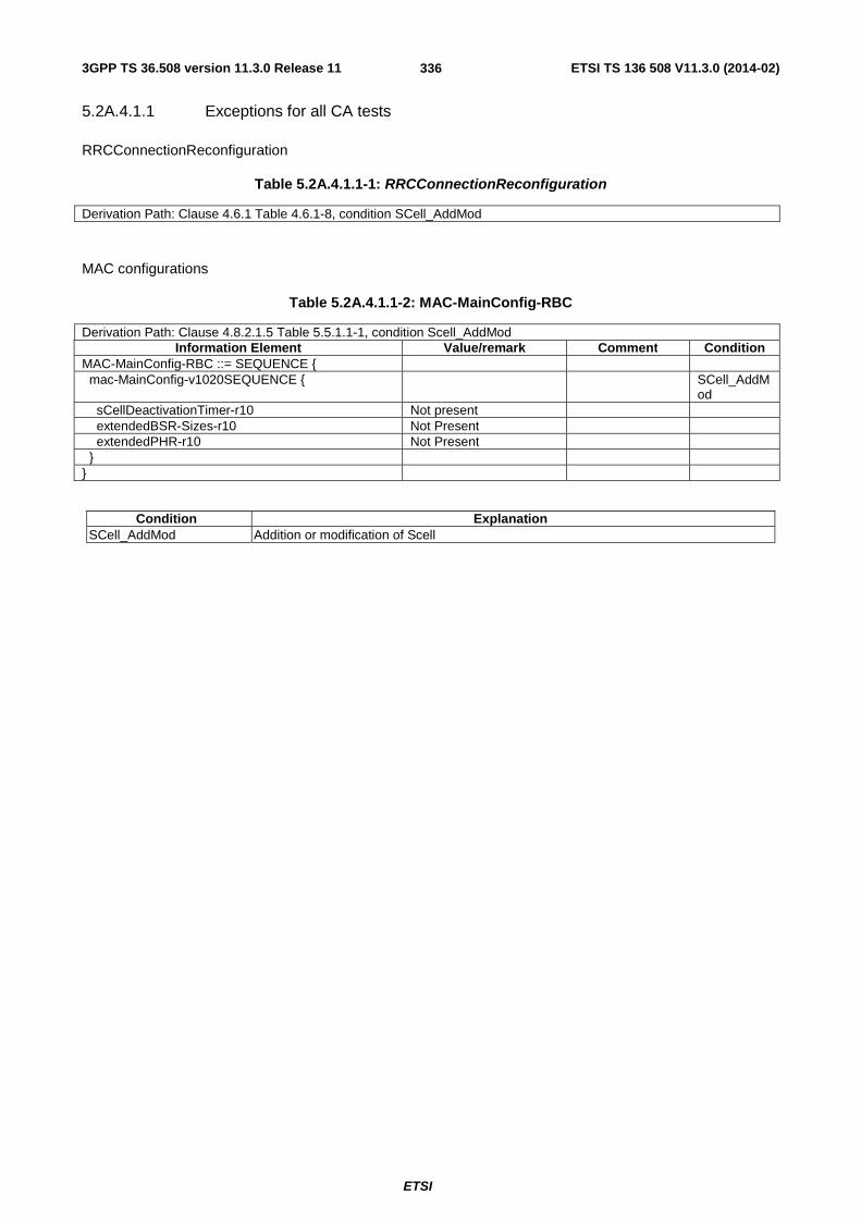
3GPP TS 36.508 version 11.3.0 Release 11 ETSI TS 136 508 V11.3.0 (2014-02)
ETSI
336
5.2A.4.1.1 Exceptions for all CA tests
RRCConnectionReconfiguration
Table 5.2A.4.1.1-1: RRCConnectionReconfiguration
Derivation Path: Clause 4.6.1 Table 4.6.1-8, condition SCell_AddMod
MAC configurations
Table 5.2A.4.1.1-2: MAC-MainConfig-RBC
Derivation Path: Clause 4.8.2.1.5 Table 5.5.1.1-1, condition Scell_AddMod Information Element Value/remark Comment Condition
MAC-MainConfig-RBC ::= SEQUENCE { mac-MainConfig-v1020SEQUENCE { SCell_AddM
od sCellDeactivationTimer-r10 Not present extendedBSR-Sizes-r10 Not Present extendedPHR-r10 Not Present } }
Condition Explanation SCell_AddMod Addition or modification of Scell

3GPP TS 36.508 version 11.3.0 Release 11 ETSI TS 136 508 V11.3.0 (2014-02)
ETSI
337
5.2A.4.1.2 Exceptions for UL CA tests
RadioResourceConfigCommonSCell-r10-DEFAULT
Table 5.2A.4.1.2-1: RadioResourceConfigCommonSCell-r10-DEFAULT
Derivation Path: Clause 4.6.3 Table 4.6.3-13A Information Element Value/remark Comment Condition
RadioResourceConfigCommonSCell-r10 ::= SEQUENCE {
ul-Configuration-r10 SEQUENCE { UL CA ul-FreqInfo-r10 SEQUENCE { ul-CarrierFreq-r10 Not Present For FDD: If
absent, the (default) value determined from the default TX-RX frequency separation defined in 3GPP TS 36.101 [27], table 5.7.3-1 applies.
For TDD: This parameter is absent and it is equal to the downlink frequency.
ul-Bandwidth-r10 Not Present Same downlink bandwidth as used for target SCell
additionalSpectrumEmissionSCell-r10 1 (CA_NS_01) } soundingRS-UL-ConfigCommon-r10 Not present } }
Condition Explanation UL CA When UL Carrier Aggregation is used.
PhysicalConfigDedicatedSCell-r10-DEFAULT
Table 5.2A.4.1.2-2: PhysicalConfigDedicatedSCell-r10-DEFAULT
Derivation Path: Clause 4.6.3 Table 4.6.3-6A Information Element Value/remark Comment Condition
PhysicalConfigDedicatedSCell-r10 ::= SEQUENCE { ul-Configuration-r10 Present ul-Configuration-r10 SEQUENCE { UL CA antennaInfoUL-r10 Not Present pusch-ConfigDedicatedSCell-r10 Not present uplinkPowerControlDedicatedSCell-r10 UplinkPowerControlDedic
atedSCell-r10-DEFAULT
cqi-ReportConfigSCell-r10 Not present soundingRS-UL-ConfigDedicated-r10 Not present soundingRS-UL-ConfigDedicated-v1020 Not present soundingRS-UL-ConfigDedicatedAperiodic-r10 Not present } }

3GPP TS 36.508 version 11.3.0 Release 11 ETSI TS 136 508 V11.3.0 (2014-02)
ETSI
338
Condition Explanation UL CA When UL Carrier Aggregation is used.
5.3 Default RRC message and information elements contents
5.3.1 Radio resource control information elements
As defined in clause 4.6.3 with the following exceptions:
Table 5.3.1-1: TDD-Config-DEFAULT
Derivation Path: Clause 4.6.3 Table 4.6.3-23 Information Element Value/remark Comment Condition
TDD-Config-DEFAULT ::= SEQUENCE { subframeAssignment sa1 specialSubframePatterns ssp4 RF }
Condition Explanation RF For all the RF tests specified in 36.521-1
Table 5.3.1-2: RadioResourceConfigCommonSIB-DEFAULT
Derivation Path: Clause 4.6.3 Table 4.6.3-14 Information Element Value/remark Comment Condition
RadioResourceConfigCommonSIB-DEFAULT ::= SEQUENCE {
rach-ConfigCommon RACH-ConfigCommon-DEFAULT
bcch-Config BCCH-Config-DEFAULT pcch-Config PCCH-Config-DEFAULT prach-Config PRACH-ConfigSIB-
DEFAULT
pdsch-ConfigCommon PDSCH-ConfigCommon-DEFAULT
pusch-ConfigCommon PUSCH-ConfigCommon-DEFAULT
pucch-ConfigCommon PUCCH-ConfigCommon-DEFAULT
soundingRS-UL-ConfigCommon CHOICE { release NULL } uplinkPowerControlCommon UplinkPowerControlCom
mon-DEFAULT
ul-CyclicPrefixLength len1 }
Table 5.3.1-3: PRACH-Config-DEFAULT
Derivation Path: Clause 4.6.3 Table 4.6.3-7 Information Element Value/remark Comment Condition
PRACH-Config-DEFAULT ::= SEQUENCE { prach-ConfigInfo SEQUENCE { prach-ConfigIndex 3 TDD } }
Condition Explanation

3GPP TS 36.508 version 11.3.0 Release 11 ETSI TS 136 508 V11.3.0 (2014-02)
ETSI
339
TDD TDD cell environment
Table 5.3.1-4: RadioResourceConfigCommonSCell-r10-DEFAULT
Derivation Path: Clause 4.6.3 Table 4.6.3-13A Information Element Value/remark Comment Condition
RadioResourceConfigCommonSCell-r10 ::= SEQUENCE {
ul-Configuration-r10 Not Present ul-Configuration-r10 SEQUENCE { Not Present }
Table 5.3.1-5: PhysicalConfigDedicatedSCell-r10-DEFAULT
Derivation Path: Clause 4.6.3 Table 4.6.3-6A Information Element Value/remark Comment Condition
PhysicalConfigDedicatedSCell-r10 ::= SEQUENCE { ul-Configuration-r10 Not Present ul-Configuration-r10 SEQUENCE { Not Present }
5.4 Default NAS message and information elements contents
5.5 Reference radio bearer configurations
5.5.1 SRB and DRB parameters
5.5.1.1 MAC configurations
As defined in clause 4.8.2.1.5 with the following exceptions:
Table 5.5.1.1-1: MAC-MainConfig-RBC
Derivation Path: Clause 4.8.2.1.5, Table 4.8.2.1.5-1 Information Element Value/remark Comment Condition
MAC-MainConfig-RBC ::= SEQUENCE { ul-SCH-Config Not present SCell_AddM
od ul-SCH-Config SEQUENCE { maxHARQ-Tx n1 Only one
transmission per UL HARQ
} drx-Config Not present SCell_AddM
od drx-Config CHOICE { release NULL } timeAlignmentTimerDedicated infinity }
Condition Explanation SCell_AddMod Addition or modification of Scell

3GPP TS 36.508 version 11.3.0 Release 11 ETSI TS 136 508 V11.3.0 (2014-02)
ETSI
340
5.5.1.2 Physical Layer configurations
Table 5.5.1.2-1: PhysicalConfigDedicated-DEFAULT
Derivation Path: Clause 4.8.2.1.6 Table 4.8.2.1.6-1 Information Element Value/remark Comment Condition
PhysicalConfigDedicated-DEFAULT ::= SEQUENCE { pdsch-ConfigDedicated PDSCH-
ConfigDedicated-DEFAULT
See subclause 4.6.3
SRB1
Not present RBC pucch-ConfigDedicated PUCCH-
ConfigDedicated-DEFAULT
See subclause 4.6.3
SRB1
Not present RBC pusch-ConfigDedicated PUSCH-
ConfigDedicated-DEFAULT
See subclause 4.6.3
SRB1
Not present RBC uplinkPowerControlDedicated UplinkPowerControlDedic
ated-DEFAULT See subclause 4.6.3
SRB1
Not present RBC tpc-PDCCH-ConfigPUCCH Not present SRB1 TPC-PDCCH-Config-
DEFAULT using condition PUCCH
See subclause 4.6.3
RBC
tpc-PDCCH-ConfigPUSCH Not present SRB1 TPC-PDCCH-Config-
DEFAULT using condition PUSCH
See subclause 4.6.3
RBC
cqi-ReportConfig Not present SRB1 Not present RBC soundingRS-UL-ConfigDedicated Not present SRB1 Not present RBC antennaInfo CHOICE { defaultValue NULL } schedulingRequestConfig Not present SRB1 Not present See subclause
4.6.3 RBC
} cqi-ReportConfig-r10 Not present SCell_AddM
od
Condition Explanation SRB1 Used at configuration of SRB1 during RRC connection (re-)establishment RBC Used at configuration of a radio bearer combination during SRB2+DRB establishment SCell_AddMod Addition or modification of SCell
5.5.1.3 SRB and DRB combinations
5.5.1.3.1 Combinations on DL-SCH and UL-SCH
5.5.1.3.1.1 SRB1 and SRB2 for DCCH + n x AM DRB + m x UM DRB, where n=1 and m=0
This SRB and DRB combination is setup in UE Registration procedure and the Generic Radio Bearer Establishment with UE Test Mode Activated using specific message content - the default RRCConnectionReconfiguration message with condition SRB2-DRB(n, m).

3GPP TS 36.508 version 11.3.0 Release 11 ETSI TS 136 508 V11.3.0 (2014-02)
ETSI
341
6 Test environment for Signalling test
6.1 Requirements of test equipment The requirements of test equipment specified in this subclause apply to Signalling test cases defined in TS 36.523-1 [18], in addition to the common requirements of test equipment specified in cause 4.2 of this specification.
Test equipment shall be able to simulate cells of Radio Access Technology (RAT) E-UTRA, UTRA, GSM or HRPD / 1xRTT. Regardless of respective RAT, the overall number and configuration of cells to be simulated simultaneously by test equipment shall not exceed the resources specified in the following Table 6.1-1:
Table 6.1-1: Maximum resources in terms of number / configuration of cells to be simulated simultaneously in a test setup
Simulation of Max. number / configuration of cells
(SISO / SIMO)
Max. number / configuration of cells
(MIMO) E-UTRA single-mode networks (FDD or TDD) 3x cells n/a E-UTRA dual-mode networks (FDD and TDD) 3x cells n/a E-UTRA networks involving Carrier Aggregation 4x cells n/a Mixed E-UTRA / UTRA networks 3x cells n/a Mixed E-UTRA / GSM networks 3x cells n/a Mixed E-UTRA / HRPD or 1xRTT networks 3x cells n/a Mixed E-UTRA / UTRA / GSM networks 3x cells n/a Note 1: No differentiation between cell configuration types (as defined in clause 6.3.3) here, because these
types are relevant to specific test cases and their TTCN-3 implementation only. Note 2: Only network scenarios specified in clause 4.4.1 and 6.3.2.1 have been covered. Note 4: In case of Carrier Aggregation, each cell can act as a PCell, an SCell, or a standalone cell (not
used as a CA component carrier). In Release 10 a maximum of 1 SCell can be aggregated with a PCell.
Note 5: Virtual Cells are not included in the maximum cell number as they do not require resources in the SS.
Exceptions to the requirements outlined above are possible but need special evidence to be provided explicitly in the test case prose and should be allowed only if the test case purpose cannot be met otherwise.
6.2 Reference test conditions The reference test conditions specified in this subclause apply to all Signalling test cases defined in TS 36.523-1 [18] unless otherwise specified, in addition to the common reference test conditions specified in subclause 4.3 of this specification.
6.2.1 Physical channel allocations
6.2.1.1 Antennas
If the UE has two Rx antennas, the same downlink signal is applied to each one, except if MIMO is tested. Both UE Rx antennas shall be connected.
If the UE has one Rx antenna, the downlink signal is applied to it.
6.2.1.2 Downlink physical channels and physical signals
Power allocation of downlink physical channels for Signalling test cases is specified in table 6.2.1.2-1.

3GPP TS 36.508 version 11.3.0 Release 11 ETSI TS 136 508 V11.3.0 (2014-02)
ETSI
342
Table 6.2.1.2-1: Power allocation for OFDM symbols and reference signals for Signalling test cases
Physical Channel EPRE Ratio Comment PBCH PBCH_RA = 0 dB
PBCH_RB = 0 dB PSS PSS_RA = 0 dB SSS SSS_RA = 0 dB PCFICH PCFICH_RB = 0 dB PDCCH PDCCH_RA = 0 dB
PDCCH_RB = 0 dB PDSCH (BCCH, CCCH, PCCH)
PDCCH_RA = 0 dB To be consistent with default physical channel configuration in 36.331 [17], 9.2.4
PDCCH_RB = 0 dB
PDSCH (DCCH, DTCH) PDSCH_RA = -3 dB To reduce interference from PDSCH of intra-frequency neighbour cells
PDSCH_RB = -3 dB To reduce interference from PDSCH of intra-frequency neighbour cells
PHICH PHICH_RB = 0 dB
6.2.1.3 Mapping of downlink physical channels and signals to physical resources
Same as clause 4.3.3.3
6.2.1.4 Uplink physical channels and physical signals
[FFS].
6.2.1.5 Mapping of uplink physical channels and signals to physical resources
[FFS].
6.2.2 Signal levels
6.2.2.1 Downlink signal levels
The default settings of suitable cells and non-suitable cells for E-UTRA are specified in table 6.2.2.1-1.
Cells which are expected to be undetectable for UE under test shall fulfil the condition of non-suitable “Off” cell in table 6.2.2.1-1.

3GPP TS 36.508 version 11.3.0 Release 11 ETSI TS 136 508 V11.3.0 (2014-02)
ETSI
343
Table 6.2.2.1-1: Default settings of suitable / non-suitable cells
Power level type E-UTRAN (Note 1-3)
UTRAN GERAN
Unit Power level Serving cell dBm/15kHz -85 Table 6.1.1 (FDD) /
6.1.6a (TDD) [5] Table 6.1.10 [5]
Suitable neighbour intra-frequency cell dBm/15kHz -91 Table 6.1.2 (FDD) / 6.1.7 (TDD) [5]
n/a
Suitable neighbour inter-frequency cell dBm/15kHz -97 Table 6.1.2 (FDD) / 6.1.7 (TDD) [5]
Table 6.1.10 [5]
Non-suitable cell dBm/15kHz -115 Table 6.1.3 (FDD) / 6.1.8 (TDD) [5]
Table 6.1.11 [5]
Non-suitable “Off” cell dBm/15kHz ≤ -145 Table 6.1.4 (FDD) / 6.1.9 (TDD) [5]
Cell is switched-off
Note 1: The power level is specified in terms of cell-specific RS EPRE instead of RSRP as RSRP is a measured value and cannot be directly controlled by the SS.
Note 2: Power levels are specified based on the precondition that q-Hyst, a3-Offset and hysteresis are 0 dB. Note 3: The power level is specified at each UE Rx antenna.
The default signal level uncertainty is specified in table 6.2.2.1-2 for any level specified, unless a tighter uncertainty is specified by a test case in TS 36.523-1 [18].
Table 6.2.2.1-2: SS signal level uncertainty
Absolute signal level uncertainty for each cell
Relative signal level uncertainty between
multiple cells Intra-frequency +/-3 dB at each test port +/-3 dB Inter-frequency +/-3 dB at each test port See Note 1 Note 1: For Inter-frequency cells the relative signal level uncertainty between
multiple cells is determined by the absolute uncertainty of each cell, and does not have any additional constraint.
Cell-specific RS EPRE setting should be equal to or higher than -115 dBm except for Non-suitable "Off" cell. The figure is chosen to ensure that for all bands the DL signal is within the RSRP measurement range specified in TS 36.133 [39] clauses 9.1.2 and 9.1.3, taking into account the SS default absolute signal level uncertainty.
NOTE: (The power spectral density of a white noise source; specified in TS 36.133 [39]) can be assumed to be -Infinity [dBm/15kHz] for all intra and inter frequency test cases. It is applicable to both idle mode and connected mode in TS 36.523-1 [18], unless otherwise specified in specific test cases.
For test cases requiring AWGN (Noc), the default level uncertainty is specified in table 6.2.2.1-3 for any level specified, unless a tighter uncertainty is specified by a test case in TS 36.523-1 [18].
Table 6.2.2.1-3: SS AWGN level uncertainty
Absolute AWGN level uncertainty for each
frequency Intra-frequency +/-3 dB at each test port Inter-frequency +/-3 dB at each test port
6.2.2.2 Measurement accuracy and side conditions
Measurement accuracy shall be considered in setting downlink power levels.
RSRP measurement accuracy in E-UTRA RRC_IDLE state is specified in table 6.2.2.2-1, derived from TS 36.133 [39] clauses 4.2.2.3 and 4.2.2.4. This measurement accuracy is applicable to idle mode test cases specified in TS 36.523-1 [18]. For the serving cell and suitable neighbour cells, the following side conditions shall be satisfied including the effect of signal level uncertainty.
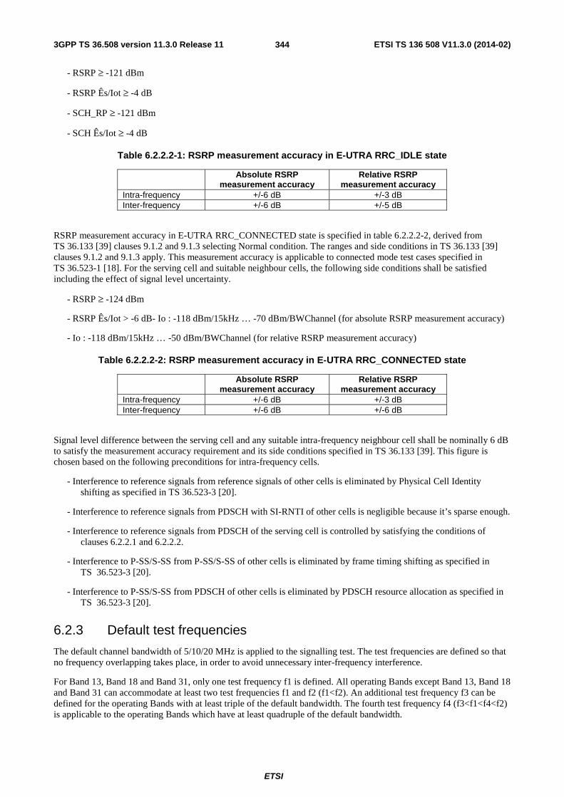
3GPP TS 36.508 version 11.3.0 Release 11 ETSI TS 136 508 V11.3.0 (2014-02)
ETSI
344
- RSRP ≥ -121 dBm
- RSRP Ês/Iot ≥ -4 dB
- SCH_RP ≥ -121 dBm
- SCH Ês/Iot ≥ -4 dB
Table 6.2.2.2-1: RSRP measurement accuracy in E-UTRA RRC_IDLE state
Absolute RSRP measurement accuracy
Relative RSRP measurement accuracy
Intra-frequency +/-6 dB +/-3 dB Inter-frequency +/-6 dB +/-5 dB
RSRP measurement accuracy in E-UTRA RRC_CONNECTED state is specified in table 6.2.2.2-2, derived from TS 36.133 [39] clauses 9.1.2 and 9.1.3 selecting Normal condition. The ranges and side conditions in TS 36.133 [39] clauses 9.1.2 and 9.1.3 apply. This measurement accuracy is applicable to connected mode test cases specified in TS 36.523-1 [18]. For the serving cell and suitable neighbour cells, the following side conditions shall be satisfied including the effect of signal level uncertainty.
- RSRP ≥ -124 dBm
- RSRP Ês/Iot > -6 dB- Io : -118 dBm/15kHz … -70 dBm/BWChannel (for absolute RSRP measurement accuracy)
- Io : -118 dBm/15kHz … -50 dBm/BWChannel (for relative RSRP measurement accuracy)
Table 6.2.2.2-2: RSRP measurement accuracy in E-UTRA RRC_CONNECTED state
Absolute RSRP measurement accuracy
Relative RSRP measurement accuracy
Intra-frequency +/-6 dB +/-3 dB Inter-frequency +/-6 dB +/-6 dB
Signal level difference between the serving cell and any suitable intra-frequency neighbour cell shall be nominally 6 dB to satisfy the measurement accuracy requirement and its side conditions specified in TS 36.133 [39]. This figure is chosen based on the following preconditions for intra-frequency cells.
- Interference to reference signals from reference signals of other cells is eliminated by Physical Cell Identity shifting as specified in TS 36.523-3 [20].
- Interference to reference signals from PDSCH with SI-RNTI of other cells is negligible because it’s sparse enough.
- Interference to reference signals from PDSCH of the serving cell is controlled by satisfying the conditions of clauses 6.2.2.1 and 6.2.2.2.
- Interference to P-SS/S-SS from P-SS/S-SS of other cells is eliminated by frame timing shifting as specified in TS 36.523-3 [20].
- Interference to P-SS/S-SS from PDSCH of other cells is eliminated by PDSCH resource allocation as specified in TS 36.523-3 [20].
6.2.3 Default test frequencies
The default channel bandwidth of 5/10/20 MHz is applied to the signalling test. The test frequencies are defined so that no frequency overlapping takes place, in order to avoid unnecessary inter-frequency interference.
For Band 13, Band 18 and Band 31, only one test frequency f1 is defined. All operating Bands except Band 13, Band 18 and Band 31 can accommodate at least two test frequencies f1 and f2 (f1<f2). An additional test frequency f3 can be defined for the operating Bands with at least triple of the default bandwidth. The fourth test frequency f4 (f3<f1<f4<f2) is applicable to the operating Bands which have at least quadruple of the default bandwidth.

3GPP TS 36.508 version 11.3.0 Release 11 ETSI TS 136 508 V11.3.0 (2014-02)
ETSI
345
To the single cell signalling test with channel bandwidth different from the default bandwidths of the operating bands, Mid Range defined in clause 4.3.1 is applied.
6.2.3.1 Test frequencies for signalling test
Test frequencies for signalling test are specified in table 6.2.3.1-1 and 6.2.3.1-1a for FDD and table 6.2.3.1-2 and 6.2.3.1-2a for TDD. Except f4 and a few f1, f5 which are specified according to EARFCN of the concerned operating Bands, the majority of the test frequencies in table 6.2.3.1-1, 6.2.3.1-1a, 6.2.3.1-2 and 6.2.3.1-2a are specified in terms of Low, Mid and High which are referred to the Low Range, Mid Range and High Range in clause 4.3.1.
Table 6.2.3.1-1: Test frequencies for E-UTRA FDD(5MHz)
E-UTRA Operating
Band
Bandwidth [MHz]
f1, f5 f2, f6 f3, f7 f4 NUL NDL NUL NDL NUL NDL NUL NDL
1 60 Mid Mid High High Low Low 18350 350 2 60 Mid Mid High High Low Low 18950 950 3 75 Mid Mid High High Low Low 19625 1625 4 45 Mid Mid High High Low Low 20225 2225 5 25 Mid Mid High High Low Low 20575 2575 6 10 Low Low High High N/A N/A N/A N/A 7 70 Mid Mid High High Low Low 21150 3150 8 35 Mid Mid High High Low Low 21675 3675 9 35 Mid Mid High High Low Low 22025 4025 10 60 Mid Mid High High Low Low 22500 4500 12 17 Mid Mid High High Low Low N/A N/A 14 10 Low Low High High N/A N/A N/A N/A … 17 12 Low Low High High N/A N/A N/A N/A 19 15 Mid Mid High High Low Low N/A N/A 21 15 Mid Mid High High Low Low N/A N/A 22 80 Mid Mid High High Low Low 24950 6950 ... 23 20 25575 7575 High High Low Low 25625 7625 24 34 Mid Mid High High Low Low 25920 7920 25 65 Mid Mid High High Low Low 26390 8390 26 35 Mid Mid High High Low Low 26865 8865 27 17 Mid Mid High High Low Low N/A N/A 281 45 Mid Mid High High Low Low 27560 9560 31 5 Mid Mid N/A N/A N/A N/A N/A N/A
Note 1: Band 28 is tested at the upper duplexer in Table 4.3.1.1.28-2
Table 6.2.3.1-1a: Test frequencies for E-UTRA FDD(10MHz)
E-UTRA Operating
Band
Bandwidth [MHz]
f1, f5 f2, f6 f3, f7 f4 NUL NDL NUL NDL NUL NDL NUL NDL
11 20 Low Low High High N/A N/A N/A N/A 13 10 Mid Mid N/A N/A N/A N/A N/A N/A 18 15 Low Low N/A N/A N/A N/A N/A N/A 20 30 Mid Mid High High Low Low N/A N/A 23 20 Low Low High High N/A N/A N/A N/A
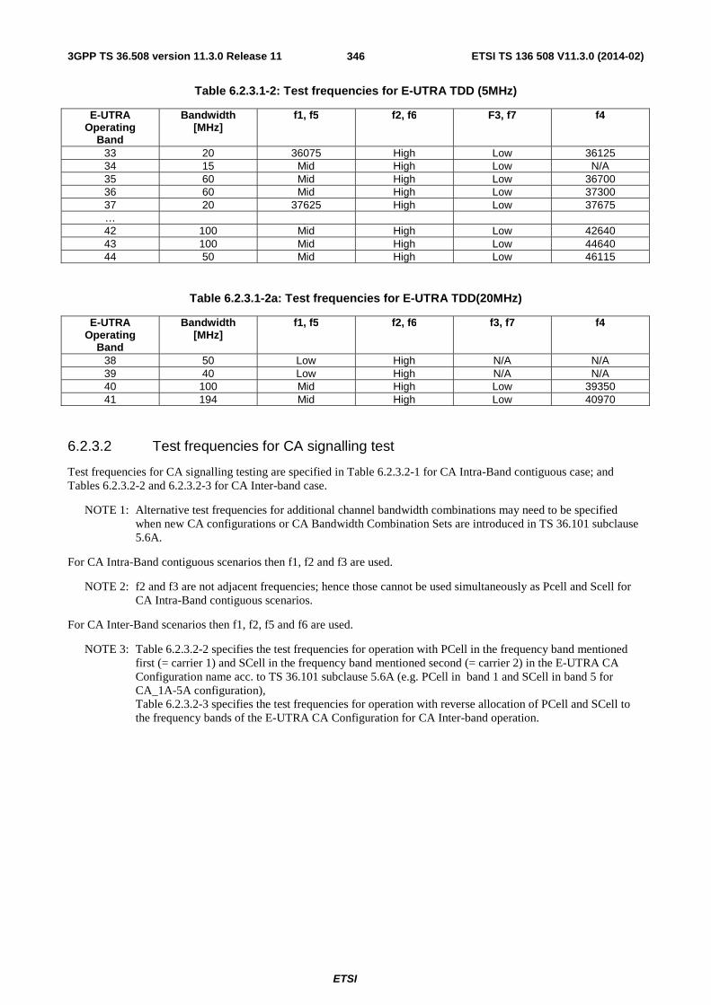
3GPP TS 36.508 version 11.3.0 Release 11 ETSI TS 136 508 V11.3.0 (2014-02)
ETSI
346
Table 6.2.3.1-2: Test frequencies for E-UTRA TDD (5MHz)
E-UTRA Operating
Band
Bandwidth [MHz]
f1, f5 f2, f6 F3, f7 f4
33 20 36075 High Low 36125 34 15 Mid High Low N/A 35 60 Mid High Low 36700 36 60 Mid High Low 37300 37 20 37625 High Low 37675 … 42 100 Mid High Low 42640 43 100 Mid High Low 44640 44 50 Mid High Low 46115
Table 6.2.3.1-2a: Test frequencies for E-UTRA TDD(20MHz)
E-UTRA Operating
Band
Bandwidth [MHz]
f1, f5 f2, f6 f3, f7 f4
38 50 Low High N/A N/A 39 40 Low High N/A N/A 40 100 Mid High Low 39350 41 194 Mid High Low 40970
6.2.3.2 Test frequencies for CA signalling test
Test frequencies for CA signalling testing are specified in Table 6.2.3.2-1 for CA Intra-Band contiguous case; and Tables 6.2.3.2-2 and 6.2.3.2-3 for CA Inter-band case.
NOTE 1: Alternative test frequencies for additional channel bandwidth combinations may need to be specified when new CA configurations or CA Bandwidth Combination Sets are introduced in TS 36.101 subclause 5.6A.
For CA Intra-Band contiguous scenarios then f1, f2 and f3 are used.
NOTE 2: f2 and f3 are not adjacent frequencies; hence those cannot be used simultaneously as Pcell and Scell for CA Intra-Band contiguous scenarios.
For CA Inter-Band scenarios then f1, f2, f5 and f6 are used.
NOTE 3: Table 6.2.3.2-2 specifies the test frequencies for operation with PCell in the frequency band mentioned first (= carrier 1) and SCell in the frequency band mentioned second (= carrier 2) in the E-UTRA CA Configuration name acc. to TS 36.101 subclause 5.6A (e.g. PCell in band 1 and SCell in band 5 for CA_1A-5A configuration), Table 6.2.3.2-3 specifies the test frequencies for operation with reverse allocation of PCell and SCell to the frequency bands of the E-UTRA CA Configuration for CA Inter-band operation.

3GPP TS 36.508 version 11.3.0 Release 11 ETSI TS 136 508 V11.3.0 (2014-02)
ETSI
347
Table 6.2.3.2-1: Test frequencies for E-UTRA PCell and SCell for CA contiguous Intra-band operation
E-UTRA CA Configuration
Width of Operating
band [MHz]
CC Combination
/ NRB_agg
Test Frequency
CC NRB NUL Frequency of Uplink [MHz]
NDL Frequency of Downlink [MHz
CA_1C 60 100 + 100 f1 CC 100 18300 1950 300 2140 f2 CC 100 18498 1969.8 498 2159.8 f3 CC 100 18102 1930.2 102 2120.2
CA_7C 70 100 + 100 f1 CC 100 21000 2525 3000 2645 f2 CC 100 21198 2544.8 3198 2664.8 f3 CC 100 20802 2505.2 2802 2625.2
CA_38C 50 100 + 100 f1 CC 100 37900 2585 37900 2585 f2 CC 100 38098 2604.8 38098 2604.8 f3 N/A N/A N/A N/A N/A
CA_40C 100 100 + 100 f1 CC 100 39050 2340 39050 2340 f2 CC 100 39248 2359.8 39248 2359.8 f3 CC 100 38852 2320,2 38852 2320,2
CA_41C 194 100 + 100 f1 CC 100 40520 2583 40520 2583 f2 CC 100 40718 2602.8 40718 2602.8 f3 CC 100 40322 2563.2 40322 2563.2
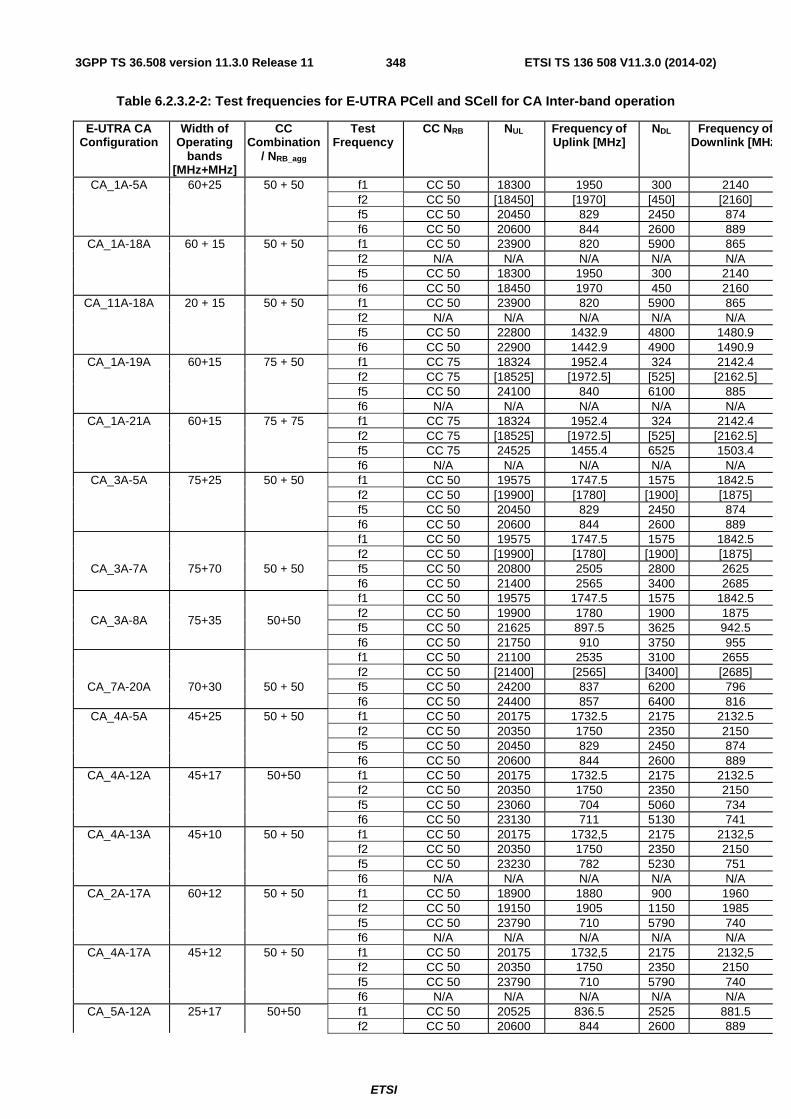
3GPP TS 36.508 version 11.3.0 Release 11 ETSI TS 136 508 V11.3.0 (2014-02)
ETSI
348
Table 6.2.3.2-2: Test frequencies for E-UTRA PCell and SCell for CA Inter-band operation
E-UTRA CA Configuration
Width of Operating
bands [MHz+MHz]
CC Combination
/ NRB_agg
Test Frequency
CC NRB NUL Frequency of Uplink [MHz]
NDL Frequency of Downlink [MHz
CA_1A-5A 60+25 50 + 50 f1 CC 50 18300 1950 300 2140 f2 CC 50 [18450] [1970] [450] [2160] f5 CC 50 20450 829 2450 874 f6 CC 50 20600 844 2600 889
CA_1A-18A 60 + 15 50 + 50 f1 CC 50 23900 820 5900 865 f2 N/A N/A N/A N/A N/A f5 CC 50 18300 1950 300 2140 f6 CC 50 18450 1970 450 2160
CA_11A-18A 20 + 15 50 + 50 f1 CC 50 23900 820 5900 865 f2 N/A N/A N/A N/A N/A f5 CC 50 22800 1432.9 4800 1480.9 f6 CC 50 22900 1442.9 4900 1490.9
CA_1A-19A 60+15 75 + 50 f1 CC 75 18324 1952.4 324 2142.4 f2 CC 75 [18525] [1972.5] [525] [2162.5] f5 CC 50 24100 840 6100 885 f6 N/A N/A N/A N/A N/A
CA_1A-21A 60+15 75 + 75 f1 CC 75 18324 1952.4 324 2142.4 f2 CC 75 [18525] [1972.5] [525] [2162.5] f5 CC 75 24525 1455.4 6525 1503.4 f6 N/A N/A N/A N/A N/A
CA_3A-5A 75+25 50 + 50 f1 CC 50 19575 1747.5 1575 1842.5 f2 CC 50 [19900] [1780] [1900] [1875] f5 CC 50 20450 829 2450 874 f6 CC 50 20600 844 2600 889 f1 CC 50 19575 1747.5 1575 1842.5 f2 CC 50 [19900] [1780] [1900] [1875]
CA_3A-7A 75+70 50 + 50 f5 CC 50 20800 2505 2800 2625 f6 CC 50 21400 2565 3400 2685
CA_3A-8A 75+35 50+50
f1 CC 50 19575 1747.5 1575 1842.5 f2 CC 50 19900 1780 1900 1875 f5 CC 50 21625 897.5 3625 942.5 f6 CC 50 21750 910 3750 955
f1 CC 50 21100 2535 3100 2655 f2 CC 50 [21400] [2565] [3400] [2685]
CA_7A-20A 70+30 50 + 50 f5 CC 50 24200 837 6200 796 f6 CC 50 24400 857 6400 816
CA_4A-5A 45+25 50 + 50 f1 CC 50 20175 1732.5 2175 2132.5 f2 CC 50 20350 1750 2350 2150 f5 CC 50 20450 829 2450 874 f6 CC 50 20600 844 2600 889
CA_4A-12A 45+17 50+50 f1 CC 50 20175 1732.5 2175 2132.5 f2 CC 50 20350 1750 2350 2150 f5 CC 50 23060 704 5060 734 f6 CC 50 23130 711 5130 741
CA_4A-13A 45+10 50 + 50 f1 CC 50 20175 1732,5 2175 2132,5 f2 CC 50 20350 1750 2350 2150 f5 CC 50 23230 782 5230 751 f6 N/A N/A N/A N/A N/A
CA_2A-17A 60+12 50 + 50 f1 CC 50 18900 1880 900 1960 f2 CC 50 19150 1905 1150 1985 f5 CC 50 23790 710 5790 740 f6 N/A N/A N/A N/A N/A
CA_4A-17A 45+12 50 + 50 f1 CC 50 20175 1732,5 2175 2132,5 f2 CC 50 20350 1750 2350 2150 f5 CC 50 23790 710 5790 740 f6 N/A N/A N/A N/A N/A
CA_5A-12A 25+17 50+50 f1 CC 50 20525 836.5 2525 881.5 f2 CC 50 20600 844 2600 889

3GPP TS 36.508 version 11.3.0 Release 11 ETSI TS 136 508 V11.3.0 (2014-02)
ETSI
349
f5 CC 50 23060 704 5060 734 f6 CC 50 23130 711 5130 741
CA_2A-29A 60+11 50 + 50 f1 CC 50 18900 1880 900 1960 f2 CC 50 19150 1905 1150 1985 f5 CC 50 N/A N/A 9720 723 f6 N/A N/A N/A N/A N/A
CA_4A-29A 45+11 50 + 50 f1 CC 50 20175 1732.5 2175 2132.5 f2 CC 50 20350 1750 2350 2150 f5 CC 50 N/A N/A 9720 723 f6 N/A N/A N/A N/A N/A
CA_5A-17A 25+12 50 + 50 f1 CC 50 20525 836.5 2525 881.5 f2 CC 50 20600 844 2600 889 f5 CC 50 23790 710 5790 740 f6 N/A N/A N/A N/A N/A
Table 6.2.3.2-3: Test frequencies for E-UTRA PCell and SCell for reverse CA Inter-band operation
E-UTRA CA Configuration
Width of Operating
bands [MHz+MHz]
CC Combination
/ NRB_agg
Test Frequency
CC NRB NUL Frequency of Uplink [MHz]
NDL Frequency of Downlink [MHz
CA_2A-17A (reverse)
60+12 50 + 50 f5 CC 50 18900 1880 900 1960 f6 CC 50 19150 1905 1150 1985 f1 CC 50 23790 710 5790 740 f2 N/A N/A N/A N/A N/A
CA_4A-17A (reverse)
45+12 50 + 50 f5 CC 50 20175 1732,5 2175 2132,5 f6 CC 50 20350 1750 2350 2150 f1 CC 50 23790 710 5790 740 f2 N/A N/A N/A N/A N/A
6.3 Reference system configurations The reference system configurations specified in this subclause apply to all Signalling test cases defined in TS 36.523-1 [18] unless otherwise specified, in addition to the common reference system configurations specified in subclause 4.4 of this specification.
For Signalling testing, MIMO (Multiple Input Multiple Output) is not applied for all cell configurations regardless of UE MIMO functionality. Only one SS Tx antenna is used.
One or two UE antennas are used for all signalling test cases. (*1)
(*1) Two UE antennas configuration is possible for UE diversity case.
6.3.1 Default parameter specific for simulated cells
Default parameters specific for simulated cells are specified in this subclause.
6.3.1.1 Intra-frequency neighbouring cell list in SIB4 for E-UTRA cells
Intra-frequency neighbouring cell list for signalling test cases is defined in table 6.3.1.1-1. This table is referred to in the default contents of IE intraFreqNeighbouringCellList in SystemInformationBlockType4 defined in table 4.4.3.3-3.

3GPP TS 36.508 version 11.3.0 Release 11 ETSI TS 136 508 V11.3.0 (2014-02)
ETSI
350
Table 6.3.1.1-1: Intra-frequency neighbouring cell lists for E-UTRA cells
cell ID Test Frequency
intra-frequency neighbouring cell list number of
entries physCellId[n] q-OffsetCell [n]
1 2 3 1 2 3 Cell 1 f1 3 Cell 2 Cell 4 Cell 11 dB0 dB0 dB0 Cell 2 f1 3 Cell 1 Cell 4 Cell 11 dB0 dB0 dB0 Cell 4 f1 3 Cell 1 Cell 2 Cell 11 dB0 dB0 dB0
Cell 11 f1 3 Cell 1 Cell 2 Cell 4 dB0 dB0 dB0 Cell 3 f2 1 Cell 23 - - dB0 - -
Cell 23 f2 1 Cell 3 - - dB0 - -
NOTE: The intra-frequency E-UTRA neighbouring cell list for signalling NAS test cases when cells are on same PLMN is defined in table 6.3.2.3.1-1.
6.3.1.2 Inter-frequency carrier frequency list in SIB5 for E-UTRA cells
Inter-frequency E-UTRA carrier frequency list for signalling test cases is defined in table 6.3.1.2-1. This table is referred to in the default contents of IE interFreqCarrierFreqList in SystemInformationBlockType5 defined in table 4.4.3.3-4.
Table 6.3.1.2-1: Inter-frequency carrier frequency lists for E-UTRA cells
cell ID Test Frequency
interFreqCarrierFreqList number of
entries dl-CarrierFreq[n]
1 2 3 Cell 1 Cell 2 Cell 4
Cell 11
f1 3 f2 f3 f5
Cell 3 Cell 23
f2 3 f1 f3 f5
Cell 6 f3 3 f1 f2 f5 Cell 10 f5 3 f1 f2 f3
Note 1: The inter-frequency E-UTRA carrier frequency list for signalling NAS test cases when cells are on same PLMN is defined in table 6.3.2.3.2-1.
Note 2: Depending on the Band under test, f3 may not be applicable. Note 3: In case of Test frequency f1, f2 and f3, dl-CarrierFreq f5 as part
of inter-frequency list is applicable only in case of multi-band scenarios.
Note 4: In case of Test frequency f5, dl-CarrierFreq f1 as part of inter-frequency list is applicable only in case of multi-band scenarios.
In the case of dual mode multi-cell network scenarios as defined in subclause 4.4.1.3, inter-frequency E-UTRA carrier frequency list for signalling test cases is defined in table 6.3.1.2-2.
Table 6.3.1.2-2: Inter-frequency carrier frequency lists for E-UTRA cells in dual mode scenario
cell ID Test Frequency
interFreqCarrierFreqList number of
entries dl-CarrierFreq[n]
1 2 3 Cell 1 Cell 2 Cell 4
f1 3 f2 f5 f6
Cell 3 f2 3 f1 f5 f6 Cell 10, Cell 30, Cell 31
f5 3 f1 f2 f6
Cell 28, Cell 29
f6 3 f1 f2 f5
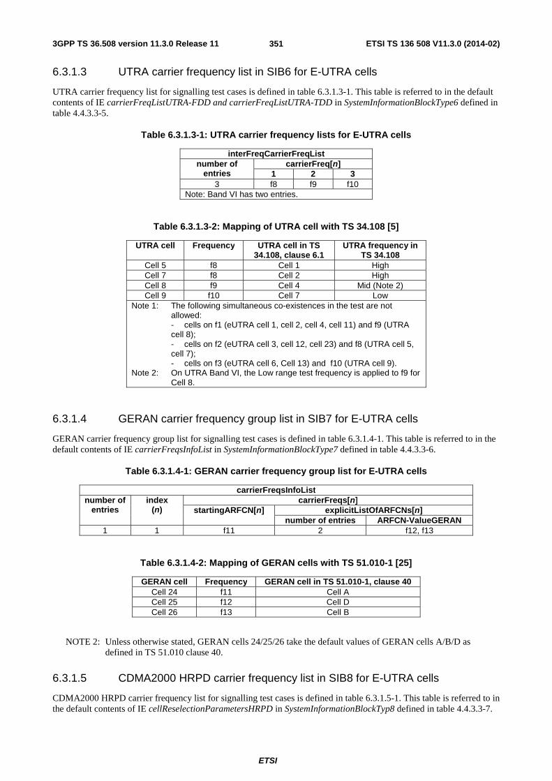
3GPP TS 36.508 version 11.3.0 Release 11 ETSI TS 136 508 V11.3.0 (2014-02)
ETSI
351
6.3.1.3 UTRA carrier frequency list in SIB6 for E-UTRA cells
UTRA carrier frequency list for signalling test cases is defined in table 6.3.1.3-1. This table is referred to in the default contents of IE carrierFreqListUTRA-FDD and carrierFreqListUTRA-TDD in SystemInformationBlockType6 defined in table 4.4.3.3-5.
Table 6.3.1.3-1: UTRA carrier frequency lists for E-UTRA cells
interFreqCarrierFreqList number of
entries carrierFreq[n]
1 2 3 3 f8 f9 f10
Note: Band VI has two entries.
Table 6.3.1.3-2: Mapping of UTRA cell with TS 34.108 [5]
UTRA cell Frequency UTRA cell in TS 34.108, clause 6.1
UTRA frequency in TS 34.108
Cell 5 f8 Cell 1 High Cell 7 f8 Cell 2 High Cell 8 f9 Cell 4 Mid (Note 2) Cell 9 f10 Cell 7 Low
Note 1: The following simultaneous co-existences in the test are not allowed: - cells on f1 (eUTRA cell 1, cell 2, cell 4, cell 11) and f9 (UTRA cell 8); - cells on f2 (eUTRA cell 3, cell 12, cell 23) and f8 (UTRA cell 5, cell 7); - cells on f3 (eUTRA cell 6, Cell 13) and f10 (UTRA cell 9).
Note 2: On UTRA Band VI, the Low range test frequency is applied to f9 for Cell 8.
6.3.1.4 GERAN carrier frequency group list in SIB7 for E-UTRA cells
GERAN carrier frequency group list for signalling test cases is defined in table 6.3.1.4-1. This table is referred to in the default contents of IE carrierFreqsInfoList in SystemInformationBlockType7 defined in table 4.4.3.3-6.
Table 6.3.1.4-1: GERAN carrier frequency group list for E-UTRA cells
carrierFreqsInfoList number of
entries index
(n) carrierFreqs[n]
startingARFCN[n] explicitListOfARFCNs[n] number of entries ARFCN-ValueGERAN
1 1 f11 2 f12, f13
Table 6.3.1.4-2: Mapping of GERAN cells with TS 51.010-1 [25]
GERAN cell Frequency GERAN cell in TS 51.010-1, clause 40 Cell 24 f11 Cell A Cell 25 f12 Cell D Cell 26 f13 Cell B
NOTE 2: Unless otherwise stated, GERAN cells 24/25/26 take the default values of GERAN cells A/B/D as defined in TS 51.010 clause 40.
6.3.1.5 CDMA2000 HRPD carrier frequency list in SIB8 for E-UTRA cells
CDMA2000 HRPD carrier frequency list for signalling test cases is defined in table 6.3.1.5-1. This table is referred to in the default contents of IE cellReselectionParametersHRPD in SystemInformationBlockTyp8 defined in table 4.4.3.3-7.

3GPP TS 36.508 version 11.3.0 Release 11 ETSI TS 136 508 V11.3.0 (2014-02)
ETSI
352
Table 6.3.1.5-1: CDMA2000 HRPD carrier frequency list for E-UTRA cells
neighCellsPerFreqList number of
entries index
(n) arfcn[n] physCellIdList[n]
number of entries
index PhysCellIdCDMA2000
3 1 f14 2 1 Cell 15 2 Cell 16
2 f15 1 1 Cell 17 3 f16 1 1 Cell 18
6.3.1.6 CDMA2000 1xRTT carrier frequency list in SIB8 for E-UTRA cells
CDMA2000 1xRTT carrier frequency list for signalling test cases is defined in table 6.3.1.6-1. This table is referred to in the default contents of IE cellReselectionParameters1XRTT in SystemInformationBlockTyp8 defined in table 4.4.3.3-7.
Table 6.3.1.6-1: CDMA2000 1xRTT carrier frequency list for E-UTRA cells
neighCellsPerFreqList number of
entries index
(n) arfcn[n] physCellIdList[n]
number of entries
index PhysCellIdCDMA2000
3 1 f17 2 1 Cell 19 2 Cell 20
2 f18 1 1 Cell 21 3 f19 1 1 Cell 22
6.3.1.7 E-UTRA carrier frequency list in SIB19 for UTRA cells
E-UTRA carrier frequency list for signalling test cases is defined in table 6.3.1.7-1. This table is referred to in the default contents of IE eutra-FrequencyAndPriorityInfoList in System Information Block type 19 defined in table 4.4.4.1-1.
Table 6.3.1.7-1: E-UTRA carrier frequency list for UTRA cells
eutra-FrequencyAndPriorityInfoList number of
entries earfcn[n]
1 2 3 4 - 4 f1 f2 f3 f4 -
Note: Depending on the Band under test, f2, f3 and f4 may not be applicable.
6.3.2 Default configurations for NAS test cases
The default configurations specified in this subclause apply only to NAS test cases. They apply to all NAS test cases unless otherwise specified.
6.3.2.1 Simulated network scenarios for NAS test cases
Simulated network scenarios for NAS test cases to be tested are specified in the pre-test conditions of each individual test case.
NOTE: The number of cells specified does not necessarily correspond to the maximum number of resources to be configured simultaneously in test equipment. Please refer to Table 6.1-1 for such information.
Any combination is allowed with the following restrictions:
- Cell E should not be used if Cell G or Cell H is used, otherwise two different PLMNs will be operated on the same frequency

3GPP TS 36.508 version 11.3.0 Release 11 ETSI TS 136 508 V11.3.0 (2014-02)
ETSI
353
- a maximum 3 cells on the same frequency can be used, i.e. only 3 cells out of cells A, B, C, D and M may be used simultaneously in each individual test case when cells in the test case are in different PLMNs (refer to Table 6.3.2.2-3).
6.3.2.2 Simulated NAS cells
Simulated NAS cells and default parameters are specified in table 6.3.2.2-1.
Unless otherwise specified, the default parameters specified in section 4 also apply to all NAS cells.
Table 6.3.2.2-1: Default parameters for simulated NAS cells
NAS cell ID
Tracking Area TA# list (Note 1)
GUTI (Note 2) TA# PLMN TAC MME Identifier M-TMSI
MCC MNC MME Group ID MME Code Cell A TAI-1 (Note 3) 1 TAI-1 32769 1 Arbitrarily
selected according to TS 23.003
subclause 2.8 [2].
Cell B TAI-2 (Note 3) 2 TAI-2 32770 1 Cell C TAI-3 (Note 3) 3 TAI-3 32771 1 Cell D TAI-4 (Note 3) 4 TAI-4 32772 1 Cell E TAI-12 002 101 3 TAI-12 32777 1 Cell F Cell G TAI-7 (Note 4) 02 1 TAI-7 32775 1 Cell H TAI-8 (Note 4) 02 2 TAI-8 32776 1 Cell I TAI-9 002 101 1 TAI-9 32777 1 Cell J TAI-10 003 101 1 TAI-10 32778 1 Cell K TAI-9 002 101 1 TAI-9 32777 1 Cell L TAI-11 002 101 2 TAI-11 32779 1 Cell M TAI-1 (Note 3) 1 TAI-1 32769 1
Note 1: The value(s) in the column TA# list indicates TAI(s) included in the response messages of the registration procedure (ATTACH ACCEPT or TRACKING AREA UPDATE ACCEPT) when the UE performs the registration procedure on a corresponding cell.
Note 2: The value in the column GUTI indicates GUTI included in the response messages of the registration procedure (ATTACH ACCEPT or TRACKING AREA UPDATE ACCEPT) when the UE performs the registration procedure on a corresponding cell.
Note 3: Set to the same Mobile Country Code and Mobile Network Code stored in EFIMSI on the test USIM card (subclause 4.9.3).
Note 4: Set to the same Mobile Country Code stored in EFIMSI on the test USIM card (subclause 4.9.3). Note 5: Cell A is a serving cell and the other cells are suitable neighbour cells. The definitions are specified in
subclause 6.2.2.1.
Table 6.3.2.2-2: Default cell identifiers for simulated NAS cells when cells are in same PLMN
NAS cell ID
Frequency E-UTRAN Cell Identifier Physical layer cell identity
rootSequenceIndex FDD
rootSequenceIndex TDD eNB Identifier Cell
Identity Cell A f1 ‘0000 0000 0000
0001 0001’B '0000
0001'B 1 22 0
Cell B f1 ‘0000 0000 0000 0001 0001’B
'0000 0010'B
2 86 8
Cell C f2 ‘0000 0000 0000 0001 0010’B
'0000 0011'B
3 22 0
Cell D f1 ‘0000 0000 0000 0001 0001’B
'0000 0100'B
4 150 16
Cell E NA NA NA NA NA NA Cell F NA NA NA NA NA NA Cell G NA NA NA NA NA NA Cell H NA NA NA NA NA NA Cell I NA NA NA NA NA NA Cell J NA NA NA NA NA NA Cell M f2 ‘0000 0000 0000
0010 0001’B '0001
0001'B 17 86 8

3GPP TS 36.508 version 11.3.0 Release 11 ETSI TS 136 508 V11.3.0 (2014-02)
ETSI
354
Table 6.3.2.2-3: Default cell identifiers for simulated NAS cells when cells are in different PLMNs
NAS cell ID PLMN Frequency
E-UTRAN Cell Identifier Physical layer cell identity
rootSequenceIndex
FDD
rootSequenceIndex
TDD eNB Identifier Cell
Identity Cell A MCC/MNC=
MCC/MNC in USIM f1 '0000 0000 0000
0010 0001'B '0000
0001'B 1 22 0
Cell B MCC/MNC= MCC/MNC in USIM
f1 '0000 0000 0000 0010 0001'B
'0000 0010'B
2 86 8
Cell C MCC/MNC= MCC/MNC in USIM
f1 '0000 0000 0000 0010 0001'B
'0000 0011'B
3 150 16
Cell D MCC/MNC= MCC/MNC in USIM
f1 '0000 0000 0000 0010 0001'B
'0000 0100'B
4 214 24
Cell E MCC=002 MNC=101
f2 ‘0000 0000 0000 0011 0101’B
'0001 0111'B
23 22 0
Cell F NA NA NA NA NA NA NA Cell G MCC = MCC in USIM
MNC=02 f2 '0000 0000 0000
0010 0010'B '0000
1011'B 11 86 8
Cell H MCC= MCC in USIM MNC=02
f2 '0000 0000 0000 0010 0010'B
'0000 1100'B
12 150 16
Cell I MCC=002 MNC=101
f3 (Note 1) '0000 0000 0000 0010 0011'B
'0000 1101'B
13 22 0
Cell J MCC=003 MNC=101
f4 (Note 1) '0000 0000 0000 0010 0100'B
'0000 1110'B
14 22 0
Cell K MCC=002 MNC=101
f3 (Note 1) '0000 0000 0000 0010 0011'B
'0000 1111'B
15 86 8
Cell L MCC=002 MNC=101
f3 (Note 1) '0000 0000 0000 0010 0011'B
'0001 0000'B
16 150 16
Cell M MCC/MNC= MCC/MNC in USIM
f1 '0000 0000 0000 0010 0001'B
'0001 0001'B
17 278 32
Note 1: The test frequency f3 or f4 is allocated to the cell if f1 and f2 are already allocated to the cells in the test. Otherwise, f1 or f2 is allocated, instead.
6.3.2.3 Broadcast system information
6.3.2.3.1 Intra-frequency neighbouring cell list in SIB4 for E-UTRA NAS cells
Intra-frequency neighbouring cell list of the same PLMN for the NAS signalling test is defined in table 6.3.2.3.1-1 when SIB4 to be broadcast.
Table 6.3.2.3.1-1: Intra-freq. lists in SIB4 for NAS test cases (same PLMN)
NAS cell ID Test Frequency
Intra-frequency neighbouring cell list number of
entries physCellId[n]
1 2 Cell A f1 2 Cell B Cell D Cell B f1 2 Cell A Cell D Cell D f1 2 Cell A Cell B Cell C f2 1 Cell M N/A Cell M f2 1 Cell C N/A
6.3.2.3.2 Inter-frequency carrier frequency list in SIB5 for E-UTRA NAS cells
Inter-frequency neighbouring carrier and cell lists for NAS signalling test cases are defined in table 6.3.2.3.2-1 for same PLMN and table 6.3.2.3.2-2 for different PLMN.

3GPP TS 36.508 version 11.3.0 Release 11 ETSI TS 136 508 V11.3.0 (2014-02)
ETSI
355
Table 6.3.2.3.2-1: Inter-freq. lists in SIB5 for NAS test cases (same PLMN)
NAS cell ID Test Frequency
interFreqCarrierFreqList number of
entries dl-CarrierFreq[n] 1 2
Cell A Cell B Cell D
f1 1 f2 NA
Cell C Cell M
f2 1 f1 NA
NOTE: Operating on Band 13, SIB5 is not broadcast.
Table 6.3.2.3.2-2: Inter-freq. lists in SIB5 for NAS test cases (different PLMN)
NAS cell ID Test Frequency interFreqCarrierFreqList Condition number of
entries dl-CarrierFreq[n] 1 2
Cell A Cell B Cell C Cell D Cell M
f1 0 NA NA
Cell G Cell H
f2 0 NA NA
Cell I Cell K Cell L
f3 0 NA NA E-NOT-CONF
1 f2 E-CONF
Cell J f4 0 NA NA Cell E f2 1 f3 NA
Condition Explanation E-NOT-CONF cell E is not configured in the test E-CONF cell E is configured in the test
6.3.3 Cell configurations
For the purpose of test not involving Carrier Aggregation, three types of SS cell configurations are defined, full (Active) cell configuration, broadcast only cell configuration and minimum uplink cell configuration.
The abovementioned configurations can also be used in Carrier Aggregation test cases, either for PCells or SCells. However another configuration, the virtual cell configuration, can additionally be used for an SCell that is not active.
6.3.3.1 Full cell configuration
Full cell configuration is also called active cell configuration. The cell configuration, in minimum, has all defined DL and UL physical channels configured, i.e.
in DL: PBCH, PCFICH, PDCCH, PDSCH, PHICH,
in UL: PRACH, PUCCH, PUSCH.
The DL and UL Reference and synchronization (both primary and secondary) signals are also configured.
6.3.3.2 Minimum uplink cell configuration
In this cell configuration,
in DL: physical channels capable of transmission, i.e. PBCH, PCFICH, PDCCH, PDSCH are configured;
DL physical reference and synchronization (both primary and secondary) signals are also configured.

3GPP TS 36.508 version 11.3.0 Release 11 ETSI TS 136 508 V11.3.0 (2014-02)
ETSI
356
In UL: PRACH is configured. SS shall report any detection of PRACH preambles, in order to assign test verdicts. Decoding the preambles is not required.
6.3.3.3 Broadcast only cell configuration
In this cell configuration,
in DL: physical channels capable of transmission, i.e. PBCH, PCFICH, PDCCH, PDSCH are configured;
DL physical reference and synchronization (both primary and secondary) signals are also configured.
in UL: no physical resources are configured, neither channels, nor signals.
6.3.3.3A Virtual cell configuration
In this cell configuration,
in DL: no physical resources are configured, neither channels, nor signals;
in UL: no physical resources are configured, neither channels, nor signals.
6.3.3.4 Application of different cell configurations
By default, the cells specified in 36.523-1 are defined with the full cell configuration, unless it is explicitly specified as either the broadcast only, minimum uplink, or virtual cell configuration. The full cell configuration is suitable for UE to start camping, establish RRC connection or hand over from another active cell.
The broadcast only cells identified as ‘DL only’ can be applied in some RRC measurement test cases to those neighbour cells which UE shall not camp on during the test case execution.
The capability of a minimum uplink cell is much weaker than a full cell, but stronger than a broadcast only cell in UL. This cell configuration identified as ‘min UL’ can be applied in the idle mode test cases to those neighbour cells which a conformant UE shall not camp on during the test case execution.
The virtual cell configuration can only be used in Carrier Aggregation test cases as an SCell which is not active, i.e. the UE has it configured via RRC signalling but does not need to send or receive anything in this SCell.
If a cell configuration is specified in a test case it shall remain unchanged throughout the test case specification. In addition, there shall not be any requirement in the test specification or test implementation for a cell reconfiguration from one of the above configurations to the other.
For the UE conformance test, the broadcast only cell configuration can be replaced and implemented with the minimum uplink or full cell configurations. The minimum uplink cell configuration can also be implemented with the full cell configuration. The replacements in the implementation have no impact on the test purposes and the test requirements. The implementation guidelines are referred to 36.523-3.
6.3.4 SCell configurations
For the purpose of System Simulator resource management for Carrier Aggregation testing the following types of SCell configurations are defined:
- Active SCell: A cell that becomes an SCell at any point of time during the test case and which, while being an SCell, is activated .
- Inactive SCell: A cell that becomes an SCell at any point of time during the test case, but is never activated while being an SCell.
SCell activation is defined as sending an Activation/Deactivation MAC Control Element (ref. 36.321 cl. 6.1.3.8) to the UE to activate the SCell.
The SCell type does not depend on what the cell is used for in the test case while not being an SCell, and does not directly relate to the cell type specified in section 6.3.3. In particular an Inactive SCell can still be used as full cell or
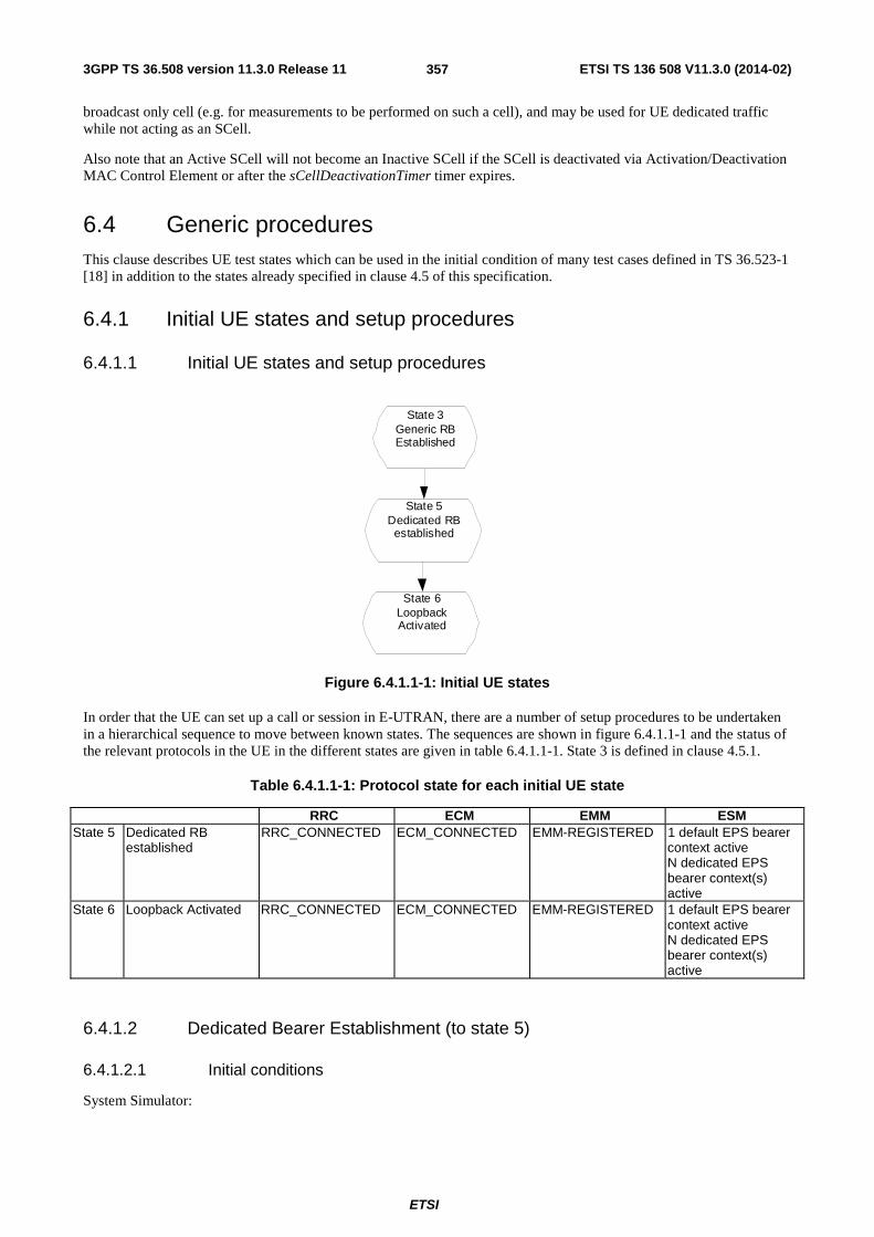
3GPP TS 36.508 version 11.3.0 Release 11 ETSI TS 136 508 V11.3.0 (2014-02)
ETSI
357
broadcast only cell (e.g. for measurements to be performed on such a cell), and may be used for UE dedicated traffic while not acting as an SCell.
Also note that an Active SCell will not become an Inactive SCell if the SCell is deactivated via Activation/Deactivation MAC Control Element or after the sCellDeactivationTimer timer expires.
6.4 Generic procedures This clause describes UE test states which can be used in the initial condition of many test cases defined in TS 36.523-1 [18] in addition to the states already specified in clause 4.5 of this specification.
6.4.1 Initial UE states and setup procedures
6.4.1.1 Initial UE states and setup procedures
State 3
Generic RB Established
State 5 Dedicated RB
established
State 6 Loopback Activated
Figure 6.4.1.1-1: Initial UE states
In order that the UE can set up a call or session in E-UTRAN, there are a number of setup procedures to be undertaken in a hierarchical sequence to move between known states. The sequences are shown in figure 6.4.1.1-1 and the status of the relevant protocols in the UE in the different states are given in table 6.4.1.1-1. State 3 is defined in clause 4.5.1.
Table 6.4.1.1-1: Protocol state for each initial UE state
RRC ECM EMM ESM State 5 Dedicated RB
established RRC_CONNECTED ECM_CONNECTED EMM-REGISTERED 1 default EPS bearer
context active N dedicated EPS bearer context(s) active
State 6 Loopback Activated RRC_CONNECTED ECM_CONNECTED EMM-REGISTERED 1 default EPS bearer context active N dedicated EPS bearer context(s) active
6.4.1.2 Dedicated Bearer Establishment (to state 5)
6.4.1.2.1 Initial conditions
System Simulator:

3GPP TS 36.508 version 11.3.0 Release 11 ETSI TS 136 508 V11.3.0 (2014-02)
ETSI
358
- Parameters are set to the default parameters for the basic single cell environment, as defined in subclause 4.4, unless otherwise specified in the test case.
User Equipment:
- The UE shall be in Generic RB established (State 3).
6.4.1.2.2 Definition of system information messages
The default system information messages are used.
6.4.1.2.3 Procedure
The establishment of dedicated radio bearer connection is assumed to always be mobile terminated.
Table 6.4.1.2.3-1: Procedure for dedicated bearer establishment
Step Procedure Message Sequence U - S Message
1 The SS configures new data radio bearer(s) and the associated dedicated EPS bearer context(s).
<-- RRC: RRCConnectionReconfiguration NAS: ACTIVATE DEDICATED EPS BEARER CONTEXT REQUEST
2 The UE transmits an RRCConnectionReconfigurationComplete message to confirm the establishment of the new data radio bearer(s), associated with the dedicated EPS bearer context(s) in the NAS message.
--> RRC: RRCConnectionReconfigurationComplete
3 The UE transmits an ACTIVATE DEDICATED EPS BEARER CONTEXT ACCEPT message.
--> NAS: ACTIVATE DEDICATED EPS BEARER CONTEXT ACCEPT
6.4.1.2.4 Specific message contents
All specific message contents shall be referred to clause 4.6 and 4.7.
6.4.1.3 Loopback Activation (to state 6)
Editor’s Note: This section will be completed when message for loopback activation is defined in TS 36.509. The table below is just an example and should be aligned with TS 36.509.
6.4.1.3.1 Initial conditions
System Simulator:
- Parameters are set to the default parameters for the basic single cell environment, as defined in subclause 4.4, unless otherwise specified in the test case.
User Equipment:
- The UE shall be in Dedicated Radio Bearer Established (State 5).
6.4.1.3.2 Definition of system information messages
The default system information messages are used.

3GPP TS 36.508 version 11.3.0 Release 11 ETSI TS 136 508 V11.3.0 (2014-02)
ETSI
359
6.4.1.3.3 Procedure
Table 6.4.1.3.3-1: Procedure for loopback activation
Step Procedure Message Sequence U - S Message
1 The SS transmits an ACTIVATE RB TEST MODE message to activate UE radio bearer test mode procedure.
<-- RRC: DLInformationTransfer TC: ACTIVATE RB TEST MODE
2 The UE transmits an ACTIVATE RB TEST MODE COMPLETE message.
--> RRC: ULInformationTransfer TC: ACTIVATE RB TEST MODE COMPLETE
3 The SS transmits a CLOSE UE TEST LOOP message to enter the UE test loop mode.
<-- RRC: DLInformationTransfer TC: CLOSE UE TEST LOOP
4 The UE transmits a CLOSE UE TEST LOOP COMPLETE message to confirm that loopback entities for the radio bearer(s) have been created and loop back is activated (State 6).
--> RRC: ULInformationTransfer TC: CLOSE UE TEST LOOP COMPLETE
6.4.1.3.4 Specific message contents
All specific message contents shall be referred to clause 4.6, 4.7 and 4.7A.
6.4.2 Test procedures
6.4.2.1 Introduction
This section defines test procedures which can be used within test procedure sequences for test steps where checking the UE state is needed.
For each test procedure,
- at the start of the test procedure,
- the System Simulator condition and the value of system information messages are the ones applicable in the test case referring to this test procedure, as they are after the execution of the test step immediately preceding the test step where the test procedure is used;
- the initial UE condition is one indicated in the test case referring to this procedure, as it is after the execution of the test step immediately preceding the test step where the test procedure is used.
- at the end of the test procedure,
- the System Simulator condition after the test procedure execution is complete is the same as before it is started (this should not be changed by the test procedure).
6.4.2.2 Test procedure to check RRC_IDLE state
This procedure aims at checking whether the UE is in RRC_IDLE on a certain cell of a test case or not.

3GPP TS 36.508 version 11.3.0 Release 11 ETSI TS 136 508 V11.3.0 (2014-02)
ETSI
360
Table 6.4.2.2-1: Test procedure sequence
St Procedure Message Sequence TP Verdict U - S Message/PDU/SDU
0 The SS waits 1 second. - - - - 1 The SS sends RRC Paging message with UE
S-TMSI on the cell(s) specified in the test case.
<-- RRC: Paging (PCCH) - -
2 Check: Does the UE send an RRCConnectionRequest message on the cell specified in the test case ?
--> RRC: RRCConnectionRequest P
3 The SS transmits a RRCConnectionSetup message
<-- RRC: RRCConnectionSetup - -
4 The UE transmits an RRCConnectionSetupComplete message to confirm the successful completion of the connection establishment and to initiate the session management procedure by including the SERVICE REQUEST message.
--> RRC: RRCConnectionSetup Complete NAS: SERVICE REQUEST
- -
5 - 6 Void - - - - 7 The SS transmits a SecurityModeCommand
message to activate AS security. <-- RRC: SecurityModeCommand - -
8 The UE transmits a SecurityModeComplete message.
--> RRC: SecurityModeComplete - -
9 The SS transmits a RRCConnectionReconfiguration message to establish the default bearer with condition SRB2-DRB(1, 0) according to 4.8.2.2.1.1,
<-- RRC: RRCConnectionReconfiguration
- -
10 The UE transmits an RRCConnectionReconfiguration complete message.
--> RRC: RRCConnectionReconfigurationComplete
- -
11 The SS release the RRC connection. <-- RRC: RRCConnectionRelease - -
6.4.2.3 Test procedure to check RRC_CONNECTED state
Table 6.4.2.3-1: Test procedure sequence
St Procedure Message Sequence TP Verdict U - S Message/PDU/SDU
1 The SS sends UECapabilityEnquiry message to the UE.
<-- UECapabilityEnquiry - -
2 Check: Does the UE send a UECapabilityInformation message?
--> UECapabilityInformation P
6.4.2.4 Test procedure Paging (for NAS testing)
This procedure aims at checking whether the UE is in registered with a certain S-TMSI.
For the PS domain this procedure is identical to the procedure in 6.4.2.2 except that the S-TMSI as indicated in step 1 is the one explicitly specified in the test step calling this procedure.
For the CS domain the test procedure is FFS (i.e. it shall be avoided to make use of CS paging in the test case design).
6.4.2.5 Test procedure for no response to paging (for NAS testing)
This procedure aims at checking that the UE ignores paging messages with a specified identity.
The procedure is defined in table 6.4.2.5-1.

3GPP TS 36.508 version 11.3.0 Release 11 ETSI TS 136 508 V11.3.0 (2014-02)
ETSI
361
Table 6.4.2.5-1: Test procedure sequence
St Procedure Message Sequence TP Verdict U - S Message
0 The SS waits 1 second. - - - - 1 The SS transmits a paging message using the
UE identity and the CN domain which are both specified in the referring test step, and on the cell which is specified in the referring test step.
<-- Paging - -
2 Check: Does the UE send an RRCConnectionRequest message on the cell where the paging was transmitted within the next 3s?
--> RRCConnectionRequest F
6.4.2.6 Test procedure to check that a dedicated EPS bearer context is active (for NAS testing)
This procedure aims at checking that a dedicated EPS bearer context is active.
The procedure is defined in table 6.4.2.6-1.
Table 6.4.2.6-1: Test procedure sequence
St Procedure Message Sequence TP Verdict U - S Message
1 The SS modifies existing data radio bearer(s) and the associated EPS bearer context(s) with Bearer QoS update.
<-- RRC: RRCConnectionReconfiguration NAS: MODIFY EPS BEARER CONTEXT REQUEST
- -
2 The UE transmits an RRCConnectionReconfigurationComplete message to confirm the modification of the existing data radio bearer(s), associated with the EPS bearer context(s) in the NAS message.
--> RRC: RRCConnectionReconfigurationComplete
- -
3 Check: Does the UE transmit a MODIFY EPS BEARER CONTEXT ACCEPT message?
--> RRC: ULInformationTransfer NAS: MODIFY EPS BEARER CONTEXT ACCEPT
P
6.4.2.7 Test procedure to check that UE is camped on a new E-UTRAN cell
This procedure aims at checking whether the UE is camping on a new E-UTRAN cell with different TAI of a test case or not.
The procedure is defined in table 6.4.2.7-1.

3GPP TS 36.508 version 11.3.0 Release 11 ETSI TS 136 508 V11.3.0 (2014-02)
ETSI
362
Table 6.4.2.7-1: Test procedure sequence
St Procedure Message Sequence TP Verdict U - S Message
1 The UE transmits an RRCConnectionRequest message on the cell specified in the test case.
--> RRC: RRCConnectionRequest - -
2 SS transmit an RRCConnectionSetup message. <--
RRC: RRCConnectionSetup - -
3 The UE transmits an RRCConnectionSetupComplete message to confirm the successful completion of the connection establishment and a TRACKING AREA UPDATE REQUEST message is sent to update the registration of the actual tracking area.
--> RRC: RRCConnectionSetupComplete NAS: TRACKING AREA UPDATE REQUEST
- -
4 SS responds with TRACKING AREA UPDATE ACCEPT message.
<-- RRC: DLInformationTransfer NAS: TRACKING AREA UPDATE ACCEPT
- -
5 Check: Does the UE send a TRACKING AREA UPDATE COMPLETE on the cell specified in the test case?
--> RRC: ULInformationTransfer NAS: TRACKING AREA UPDATE COMPLETE
- P
6 The SS transmits an RRCConnectionRelease message to release RRC connection and move to RRC_IDLE.
<-- RRC: RRCConnectionRelease - -
NOTE 1: The periodic tracking area updating timer T3412 is deactivated by default during the attach procedure (TS 36.508 clause 4.7.2).
NOTE 2: The SS does not initiate authentication and NAS SECURITY MODE COMMAND are not performed (reuse of keys allocated during the attach procedure).
6.4.2.7A Test procedure to check that UE is camped on E-UTRAN cell upon mobility from another RAT
This procedure aims at checking whether the UE is camping on a E-UTRAN cell upon mobility from another RAT after Inter RAT reselection.
The procedure if PDP context was established before inter RAT reselection, is defined in table 6.4.2.7A-1.

3GPP TS 36.508 version 11.3.0 Release 11 ETSI TS 136 508 V11.3.0 (2014-02)
ETSI
363
Table 6.4.2.7A-1: Test procedure sequence
St Procedure Message Sequence TP Verdict U - S Message
1 The UE transmits a RRCConnectionRequest message on the cell specified in the test case.
--> RRC: RRCConnectionRequest - -
2 SS transmit an RRCConnectionSetup message. <--
RRC: RRCConnectionSetup - -
3 The UE transmits a RRCConnectionSetupComplete message to confirm the successful completion of the connection establishment and a TRACKING AREA UPDATE REQUEST message is sent to update the registration of the actual tracking area.
--> RRC: RRCConnectionSetupComplete NAS: TRACKING AREA UPDATE REQUEST
- -
4 The SS transmits a NAS SECURITY MODE COMMAND message to activate NAS security (mapped security context) (Note 1).
<-- RRC: DLInformationTransfer NAS: SECURITY MODE COMMAND
- -
5 The UE transmits a NAS SECURITY MODE COMPLETE message and establishes the initial security configuration.
--> RRC: ULInformationTransfer NAS: SECURITY MODE COMPLETE
- -
6 SS responds with TRACKING AREA UPDATE ACCEPT message.
<-- RRC: DLInformationTransfer NAS: TRACKING AREA UPDATE ACCEPT
- -
7 Check: Does the UE send a TRACKING AREA UPDATE COMPLETE on the cell specified in the test case?
--> RRC: ULInformationTransfer NAS: TRACKING AREA UPDATE COMPLETE
- P
8 The SS transmits an RRCConnectionRelease message to release RRC connection and move to RRC_IDLE.
<-- RRC: RRCConnectionRelease - -
Note 1: Step 4 and 5 are executed only when UE and SS does not have a native security context.
The procedure if PDP context was not established before inter RAT reselection, is defined in table 6.4.2.7A-2.
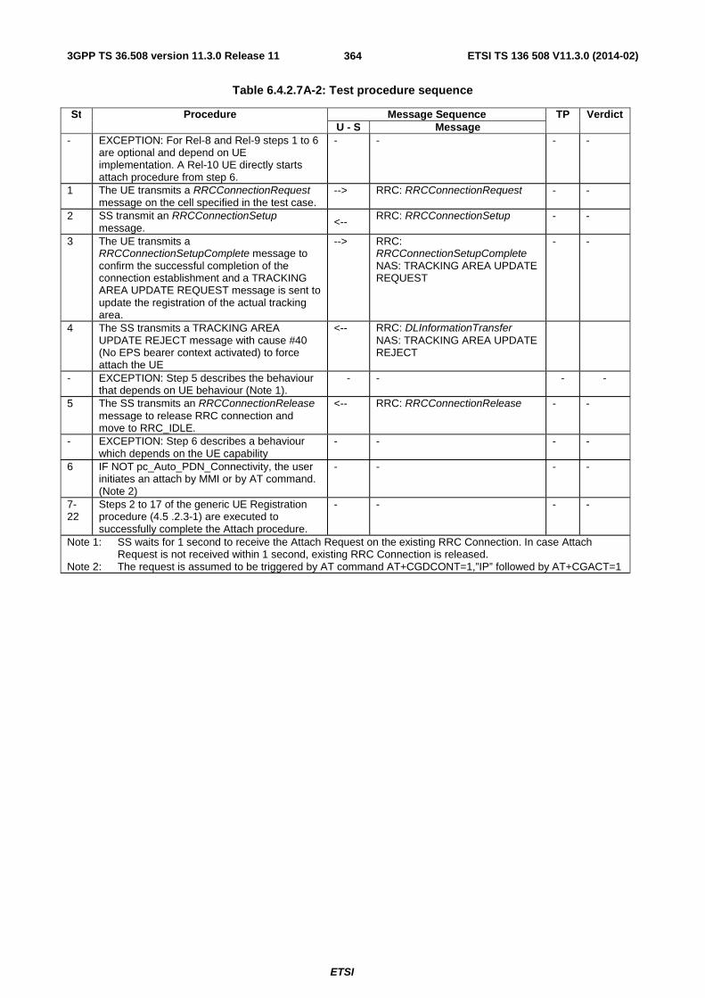
3GPP TS 36.508 version 11.3.0 Release 11 ETSI TS 136 508 V11.3.0 (2014-02)
ETSI
364
Table 6.4.2.7A-2: Test procedure sequence
St Procedure Message Sequence TP Verdict U - S Message
- EXCEPTION: For Rel-8 and Rel-9 steps 1 to 6 are optional and depend on UE implementation. A Rel-10 UE directly starts attach procedure from step 6.
- - - -
1 The UE transmits a RRCConnectionRequest message on the cell specified in the test case.
--> RRC: RRCConnectionRequest - -
2 SS transmit an RRCConnectionSetup message. <--
RRC: RRCConnectionSetup - -
3 The UE transmits a RRCConnectionSetupComplete message to confirm the successful completion of the connection establishment and a TRACKING AREA UPDATE REQUEST message is sent to update the registration of the actual tracking area.
--> RRC: RRCConnectionSetupComplete NAS: TRACKING AREA UPDATE REQUEST
- -
4 The SS transmits a TRACKING AREA UPDATE REJECT message with cause #40 (No EPS bearer context activated) to force attach the UE
<-- RRC: DLInformationTransfer NAS: TRACKING AREA UPDATE REJECT
- EXCEPTION: Step 5 describes the behaviour that depends on UE behaviour (Note 1).
- - - -
5 The SS transmits an RRCConnectionRelease message to release RRC connection and move to RRC_IDLE.
<-- RRC: RRCConnectionRelease - -
- EXCEPTION: Step 6 describes a behaviour which depends on the UE capability
- - - -
6 IF NOT pc_Auto_PDN_Connectivity, the user initiates an attach by MMI or by AT command. (Note 2)
- - - -
7-22
Steps 2 to 17 of the generic UE Registration procedure (4.5 .2.3-1) are executed to successfully complete the Attach procedure.
- - - -
Note 1: SS waits for 1 second to receive the Attach Request on the existing RRC Connection. In case Attach Request is not received within 1 second, existing RRC Connection is released.
Note 2: The request is assumed to be triggered by AT command AT+CGDCONT=1,”IP” followed by AT+CGACT=1
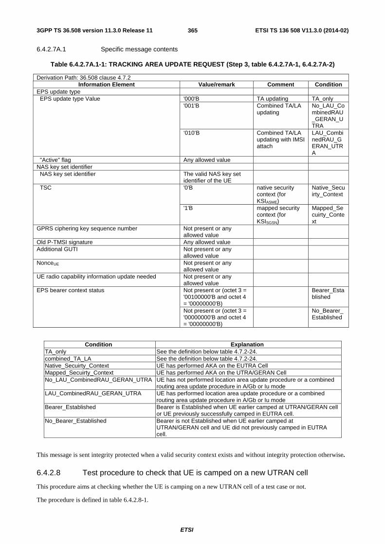
3GPP TS 36.508 version 11.3.0 Release 11 ETSI TS 136 508 V11.3.0 (2014-02)
ETSI
365
6.4.2.7A.1 Specific message contents
Table 6.4.2.7A.1-1: TRACKING AREA UPDATE REQUEST (Step 3, table 6.4.2.7A-1, 6.4.2.7A-2)
Derivation Path: 36.508 clause 4.7.2 Information Element Value/remark Comment Condition
EPS update type EPS update type Value '000'B TA updating TA_only '001'B Combined TA/LA
updating No_LAU_CombinedRAU_GERAN_UTRA
‘010’B Combined TA/LA updating with IMSI attach
LAU_CombinedRAU_GERAN_UTRA
"Active" flag Any allowed value NAS key set identifier NAS key set identifier The valid NAS key set
identifier of the UE
TSC '0'B native security context (for KSIASME)
Native_Secuirty_Context
'1'B mapped security context (for KSISGSN)
Mapped_Secuirty_Context
GPRS ciphering key sequence number Not present or any allowed value
Old P-TMSI signature Any allowed value Additional GUTI Not present or any
allowed value
NonceUE Not present or any allowed value
UE radio capability information update needed Not present or any allowed value
EPS bearer context status Not present or (octet 3 = '00100000'B and octet 4 = '00000000'B)
Bearer_Established
Not present or (octet 3 = '00000000'B and octet 4 = '00000000'B)
No_Bearer_Established
Condition Explanation TA_only See the definition below table 4.7.2-24. combined_TA_LA See the definition below table 4.7.2-24. Native_Secuirty_Context UE has performed AKA on the EUTRA Cell Mapped_Secuirty_Context UE has performed AKA on the UTRA/GERAN Cell No_LAU_CombinedRAU_GERAN_UTRA UE has not performed location area update procedure or a combined
routing area update procedure in A/Gb or Iu mode LAU_CombinedRAU_GERAN_UTRA UE has performed location area update procedure or a combined
routing area update procedure in A/Gb or Iu mode Bearer_Established Bearer is Established when UE earlier camped at UTRAN/GERAN cell
or UE previously successfully camped in EUTRA cell. No_Bearer_Established Bearer is not Established when UE earlier camped at
UTRAN/GERAN cell and UE did not previously camped in EUTRA cell.
This message is sent integrity protected when a valid security context exists and without integrity protection otherwise.
6.4.2.8 Test procedure to check that UE is camped on a new UTRAN cell
This procedure aims at checking whether the UE is camping on a new UTRAN cell of a test case or not.
The procedure is defined in table 6.4.2.8-1.

3GPP TS 36.508 version 11.3.0 Release 11 ETSI TS 136 508 V11.3.0 (2014-02)
ETSI
366
Table 6.4.2.8-1: Test procedure sequence
St Procedure Message Sequence TP Verdict U - S Message
1 The UE transmits a RRC CONNECTION REQUEST message on the cell specified in the test case.
--> RRC: RRC CONNECTION REQUEST
- -
2 The SS transmits an RRC CONNECTION SETUP message.
<-- RRC: RRC CONNECTION SETUP
- -
3 The UE transmits an RRC CONNECTION SETUP COMPLETE message.
--> RRC: RRC CONNECTION SETUP COMPLETE
- -
4 The UE transmits a ROUTING AREA UPDATE REQUEST message.
--> RRC: INITIAL DIRECT TRANSFER NAS: ROUTING AREA UPDATE REQUEST
- -
5 The SS transmits a SECURITY MODE COMMAND message.
<-- RRC: SECURITY MODE COMMAND
- -
6 The UE transmits a SECURITY MODE COMPLETE message.
--> RRC: SECURITY MODE COMPLETE
- -
7 The SS transmits a ROUTING AREA UPDATE ACCEPT message.
<-- RRC: DOWNLINK DIRECT TRANSFER NAS: ROUTING AREA UPDATE ACCEPT
- -
8 The UE transmits a ROUTING AREA UPDATE COMPLETE message.
--> RRC: UPLINK DIRECT TRANSFER NAS: ROUTING AREA UPDATE COMPLETE
- -
9 The SS transmits a RRC CONNECTION RELEASE message.
<-- RRC: RRC CONNECTION RELEASE
- -
10 Check: Does the UE transmit an RRC CONNECTION RELEASE COMPLETE message on the cell specified in the test?
--> RRC: RRC CONNECTION RELEASE COMPLETE
- P
NOTE: The TS 34.108 [5] and TS 34.123-1 [7] use Network Mode of Operation I as default, for this reason a combined MM/GMM procedure is performed.
6.4.2.9 Test procedure to check that UE is camped on a new GERAN cell
This procedure aims at checking whether the UE is camping on a new GERAN cell of a test case or not.
The procedure is defined in table 6.4.2.9-1.

3GPP TS 36.508 version 11.3.0 Release 11 ETSI TS 136 508 V11.3.0 (2014-02)
ETSI
367
Table 6.4.2.9-1: Test procedure sequence
St Procedure Message Sequence TP Verdict U - S Message
1 Check: Does the UE send a CHANNEL REQUEST message on the cell(s) specified in the test case?
--> CHANNEL REQUEST - -
2 An uplink TBF is established in order to allow the UE to transmit a ROUTING AREA UPDATE REQUEST message signalling.
- - - -
3 The UE transmits a ROUTING AREA UPDATE REQUEST message.
--> ROUTING AREA UPDATING REQUEST
- -
4 A downlink TBF is established by the SS in order to transmit the AUTHENTICATION AND CIPHERING REQUEST message
- - - -
5 The SS transmits an AUTHENTICATION AND CIPHERING REQUEST message.
<-- AUTHENTICATION AND CIPHERING REQUEST
- -
6 An uplink TBF is established in order to allow the UE to transmit an AUTHENTICATION AND CIPHERING RESPONSE message
- - - -
7 The UE transmits a AUTHENTICATION AND CIPHERING RESPONSE message.
--> AUTHENTICATION AND CIPHERING RESPONSE
- -
8 A downlink TBF is established by the SS in order to transmit the ROUTING AREA UPDATE ACCEPT message
- - - -
9 The SS transmits a ROUTING AREA UPDATE ACCEPT message.
<-- ROUTING AREA UPDATING ACCEPT
- -
10 An uplink TBF is established in order to allow the UE to transmit a ROUTING AREA UPDATE COMPLETE message
- -
11 The UE transmits a ROUTING AREA UPDATE COMPLETE message.
--> ROUTING AREA UPDATING COMPLETE
- P
NOTE: The TS 51.010-1 [25] uses Network Mode of Operation I as default, for this reason a combined MM/GMM procedure is performed.
6.4.2.10 Test procedure to check that UE performs tracking area updating procedure without ISR and security reconfiguration after successful completion of handover from UTRA
This procedure aims at checking whether the UE performs tracking area updating procedure where ISR is not activated and security reconfiguration after successful completion of handover from UTRA.
The procedure is defined in table 6.4.2.10-1.

3GPP TS 36.508 version 11.3.0 Release 11 ETSI TS 136 508 V11.3.0 (2014-02)
ETSI
368
Table 6.4.2.10-1: Test procedure sequence
St Procedure Message Sequence TP Verdict U - S Message
1 The UE transmits an ULInformationTransfer message on the cell specified in the test case. This message includes a TRACKING AREA UPDATE REQUEST message.
--> RRC: ULInformationTransfer NAS: TRACKING AREA UPDATE REQUEST
- -
2 The SS transmits a DLInformationTransfer message on the cell specified in the test case. This message includes a TRACKING AREA UPDATE ACCEPT message.
<-- RRC:DLInformationTransfer NAS: TRACKING AREA UPDATE ACCEPT
- -
3 The UE transmits an ULInformationTransfer message on the cell specified in the test case. This message includes a TRACKING AREA UPDATE COMPLETE message.
--> RRC:ULInformationTransfer NAS: TRACKING AREA UPDATE COMPLETE
- -
- EXCEPTION: Steps 4a1 to 4a2 describe behaviour that depends on the IE included in TRACKING AREA UPDATE REQUEST in step 1.
- - - -
4a1 IF TRACKING AREA UPDATE REQUEST transmitted in step 1 does not contain a valid KSIASME THEN the SS transmits a DLInformationTransfer message on the cell specified in the test case. This message includes an AUTHENTICATION REQUEST message.
<-- RRC:DLInformationTransfer NAS: AUTHENTICATION REQUEST
- -
4a2 The UE transmits an ULInformationTransfer message on the cell specified in the test case. This message includes an AUTHENTICATION RESPONSE message.
--> RRC:ULInformationTransfer NAS: AUTHENTICATION RESPONSE
- -
5 The SS transmits a DLInformationTransfer message on the cell specified in the test case. This message includes a SECURITY MODE COMMAND message to take the native EPS security context into use.
<-- RRC:DLInformationTransfer NAS: SECURITY MODE COMMAND
- -
6 The UE transmits an ULInformationTransfer message on the cell specified in the test case. This message includes a SECURITY MODE COMPLETE message.
--> RRC:ULInformationTransfer NAS: SECURITY MODE COMPLETE
- -
7 The SS transmits an RRCConnectionReconfiguration message to perform intra cell handover and security reconfiguration on the cell specified in the test case.
<-- RRC:RRCConnectionReconfiguration
- -
8 Check: Does the UE transmit an RRCConnectionReconfigurationComplete message on the cell specified in the test case?
--> RRC:RRCConnectionReconfigurationComplete
- P

3GPP TS 36.508 version 11.3.0 Release 11 ETSI TS 136 508 V11.3.0 (2014-02)
ETSI
369
Table 6.4.2.10-2: Message TRACKING AREA UPDATE REQUEST (step 1, Table 6.4.2.10-1)
Derivation Path: 36.508 clause 4.7.2-27 Information Element Value/remark Comment Condition
NAS key set identifier NAS key set identifier The valid NAS key
set identifier of the UE
mapped security context (for KSISGSN)
TSC 1 Non-current native NAS key set identifier
NAS key set identifier The valid NAS key set identifier of the
UE
native security context (for KSIASME)
TSC 0 Old P-TMSI signature any allowed value
Additional GUTI any allowed value
Table 6.4.2.10-3: RRCConnectionReconfiguration (step 7, Table 6.4.2.10-1)
Derivation Path: 36.508, Table 4.6.1-8
Table 6.4.2.10-4: SecurityConfigHO (IE in RRCConnectionReconfiguration, Table 6.4.2.10-3)
Derivation Path: 36.508, Table 4.6.4-1 Information Element Value/remark Comment Condition
SecurityConfigHO ::= SEQUENCE { handoverType CHOICE { intraLTE SEQUENCE { keyChangeIndicator TRUE nextHopChainingCount 0 } } }
6.4.3 Reference test procedures for TTCN development
This clause describes reference test procedures for the purpose of TTCN development.

3GPP TS 36.508 version 11.3.0 Release 11 ETSI TS 136 508 V11.3.0 (2014-02)
ETSI
370
6.4.3.1 UE triggered establishment of a dedicated EPS bearer context
Table 6.4.3.1-1: Test procedure sequence
St Procedure Message Sequence U - S Message
1 Cause the UE to request bearer resource allocation of dedicated EPS bearer associated with first PDN connectivity. (see Note 1)
- -
- EXCEPTION: Steps 2a1 to 2a7 describe behaviour that depends on RRC state; the "lower case letter" identifies a step sequence that takes place if the UE is in RRC_IDLE state.
- -
2a1 IF the UE is in RRC_IDLE state THEN the UE transmits an RRCConnectionRequest message.
--> RRC: RRCConnectionRequest
2a2 The SS transmits an RRCConnectionSetup message.
<-- RRC: RRCConnectionSetup
2a3 The UE transmits an RRCConnectionSetupComplete including the SERVICE REQUEST message.
--> RRC: RRCConnectionSetupComplete NAS: SERVICE REQUEST
2a4 The SS transmits a SecurityModeCommand message to activate AS security.
<-- RRC: SecurityModeCommand
2a5 The UE transmits a SecurityModeComplete message and establishes the initial security configuration.
--> RRC: SecurityModeComplete
2a6 The SS transmits an RRCConnectionReconfiguration message to configure data radio bearer(s) associated with the existing EPS bearer context. The RRCConnectionReconfiguration message is using condition SRB2-DRB(n, m) where n and m are the number of DRBs associated with existing EPS bearer contexts and configured respectively with RLC-AM and RLC-UM.
<-- RRC: RRCConnectionReconfiguration
2a7 The UE transmits an RRCConnectionReconfigurationComplete message.
--> RRC: RRCConnectionReconfigurationComplete
3 The UE transmits an ULInformationTransfer message including the BEARER RESOURCE ALLOCATION REQUEST message.
--> RRC: ULInformationTransfer NAS: BEARER RESOURCE ALLOCATION REQUEST
4 The SS transmits an RRCConnectionReconfiguration message including the ACTIVATE DEDICATED EPS BEARER CONTEXT REQUEST message to establish the dedicated EPS bearer context.
<-- RRC: RRCConnectionReconfiguration NAS: ACTIVATE DEDICATED EPS BEARER CONTEXT REQUEST
5 The UE transmits an RRCConnectionReconfigurationComplete message.
--> RRC: RRCConnectionReconfigurationComplete
6 The UE transmits an ULInformationTransfer message including the ACTIVATE DEDICATED EPS BEARER CONTEXT ACCEPT message.
--> RRC: ULInformationTransfer NAS: ACTIVATE DEDICATED EPS BEARER CONTEXT ACCEPT
Note 1: The request is assumed to be triggered by AT command +CGDSCONT, and +CGACT (activated). Note 2: If UE sends IP related data this shall be handled by the SS.
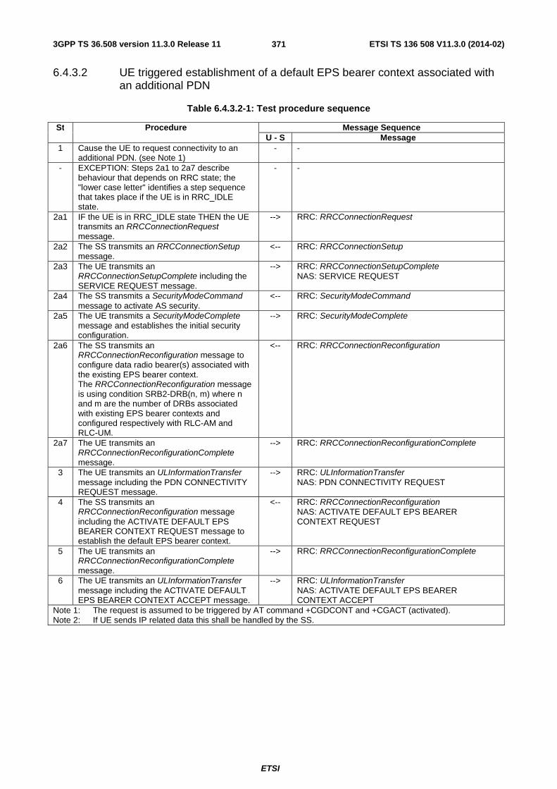
3GPP TS 36.508 version 11.3.0 Release 11 ETSI TS 136 508 V11.3.0 (2014-02)
ETSI
371
6.4.3.2 UE triggered establishment of a default EPS bearer context associated with an additional PDN
Table 6.4.3.2-1: Test procedure sequence
St Procedure Message Sequence U - S Message
1 Cause the UE to request connectivity to an additional PDN. (see Note 1)
- -
- EXCEPTION: Steps 2a1 to 2a7 describe behaviour that depends on RRC state; the "lower case letter" identifies a step sequence that takes place if the UE is in RRC_IDLE state.
- -
2a1 IF the UE is in RRC_IDLE state THEN the UE transmits an RRCConnectionRequest message.
--> RRC: RRCConnectionRequest
2a2 The SS transmits an RRCConnectionSetup message.
<-- RRC: RRCConnectionSetup
2a3 The UE transmits an RRCConnectionSetupComplete including the SERVICE REQUEST message.
--> RRC: RRCConnectionSetupComplete NAS: SERVICE REQUEST
2a4 The SS transmits a SecurityModeCommand message to activate AS security.
<-- RRC: SecurityModeCommand
2a5 The UE transmits a SecurityModeComplete message and establishes the initial security configuration.
--> RRC: SecurityModeComplete
2a6 The SS transmits an RRCConnectionReconfiguration message to configure data radio bearer(s) associated with the existing EPS bearer context. The RRCConnectionReconfiguration message is using condition SRB2-DRB(n, m) where n and m are the number of DRBs associated with existing EPS bearer contexts and configured respectively with RLC-AM and RLC-UM.
<-- RRC: RRCConnectionReconfiguration
2a7 The UE transmits an RRCConnectionReconfigurationComplete message.
--> RRC: RRCConnectionReconfigurationComplete
3 The UE transmits an ULInformationTransfer message including the PDN CONNECTIVITY REQUEST message.
--> RRC: ULInformationTransfer NAS: PDN CONNECTIVITY REQUEST
4 The SS transmits an RRCConnectionReconfiguration message including the ACTIVATE DEFAULT EPS BEARER CONTEXT REQUEST message to establish the default EPS bearer context.
<-- RRC: RRCConnectionReconfiguration NAS: ACTIVATE DEFAULT EPS BEARER CONTEXT REQUEST
5 The UE transmits an RRCConnectionReconfigurationComplete message.
--> RRC: RRCConnectionReconfigurationComplete
6 The UE transmits an ULInformationTransfer message including the ACTIVATE DEFAULT EPS BEARER CONTEXT ACCEPT message.
--> RRC: ULInformationTransfer NAS: ACTIVATE DEFAULT EPS BEARER CONTEXT ACCEPT
Note 1: The request is assumed to be triggered by AT command +CGDCONT and +CGACT (activated). Note 2: If UE sends IP related data this shall be handled by the SS.

3GPP TS 36.508 version 11.3.0 Release 11 ETSI TS 136 508 V11.3.0 (2014-02)
ETSI
372
Table 6.4.3.2-2: Message PDN CONNECTIVITY REQUEST (step 3, Table 6.4.3.2-1)
Derivation Path: TS 36.508 Table 4.7.3-20 Information Element Value/remark Comment Condition
EPS bearer identity 0000 No EPS bearer identity assigned
Procedure transaction identity PTI-1 UE assigns a particular PTI not yet used between 1 and 254
ESM information transfer flag Not present This IE is only used during an attach procedure.
Access point name APN-1(New PDN name) The requested PDN is different from default PDN
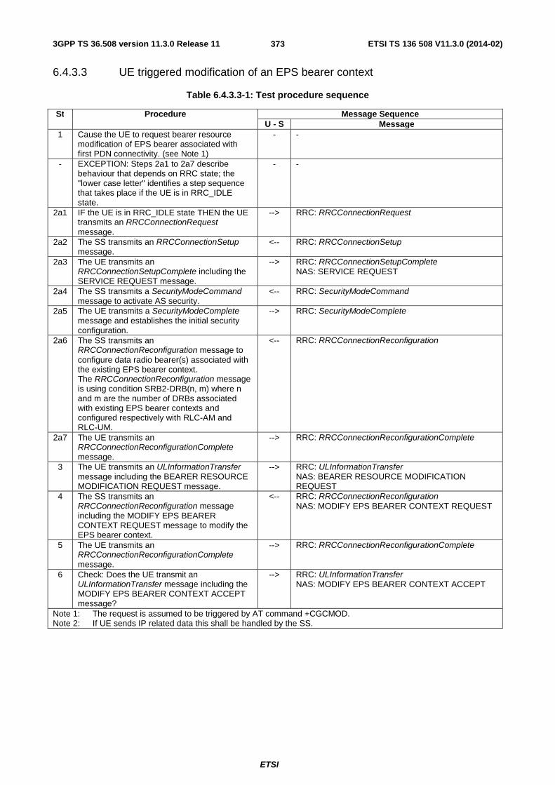
3GPP TS 36.508 version 11.3.0 Release 11 ETSI TS 136 508 V11.3.0 (2014-02)
ETSI
373
6.4.3.3 UE triggered modification of an EPS bearer context
Table 6.4.3.3-1: Test procedure sequence
St Procedure Message Sequence U - S Message
1 Cause the UE to request bearer resource modification of EPS bearer associated with first PDN connectivity. (see Note 1)
- -
- EXCEPTION: Steps 2a1 to 2a7 describe behaviour that depends on RRC state; the "lower case letter" identifies a step sequence that takes place if the UE is in RRC_IDLE state.
- -
2a1 IF the UE is in RRC_IDLE state THEN the UE transmits an RRCConnectionRequest message.
--> RRC: RRCConnectionRequest
2a2 The SS transmits an RRCConnectionSetup message.
<-- RRC: RRCConnectionSetup
2a3 The UE transmits an RRCConnectionSetupComplete including the SERVICE REQUEST message.
--> RRC: RRCConnectionSetupComplete NAS: SERVICE REQUEST
2a4 The SS transmits a SecurityModeCommand message to activate AS security.
<-- RRC: SecurityModeCommand
2a5 The UE transmits a SecurityModeComplete message and establishes the initial security configuration.
--> RRC: SecurityModeComplete
2a6 The SS transmits an RRCConnectionReconfiguration message to configure data radio bearer(s) associated with the existing EPS bearer context. The RRCConnectionReconfiguration message is using condition SRB2-DRB(n, m) where n and m are the number of DRBs associated with existing EPS bearer contexts and configured respectively with RLC-AM and RLC-UM.
<-- RRC: RRCConnectionReconfiguration
2a7 The UE transmits an RRCConnectionReconfigurationComplete message.
--> RRC: RRCConnectionReconfigurationComplete
3 The UE transmits an ULInformationTransfer message including the BEARER RESOURCE MODIFICATION REQUEST message.
--> RRC: ULInformationTransfer NAS: BEARER RESOURCE MODIFICATION REQUEST
4 The SS transmits an RRCConnectionReconfiguration message including the MODIFY EPS BEARER CONTEXT REQUEST message to modify the EPS bearer context.
<-- RRC: RRCConnectionReconfiguration NAS: MODIFY EPS BEARER CONTEXT REQUEST
5 The UE transmits an RRCConnectionReconfigurationComplete message.
--> RRC: RRCConnectionReconfigurationComplete
6 Check: Does the UE transmit an ULInformationTransfer message including the MODIFY EPS BEARER CONTEXT ACCEPT message?
--> RRC: ULInformationTransfer NAS: MODIFY EPS BEARER CONTEXT ACCEPT
Note 1: The request is assumed to be triggered by AT command +CGCMOD. Note 2: If UE sends IP related data this shall be handled by the SS.
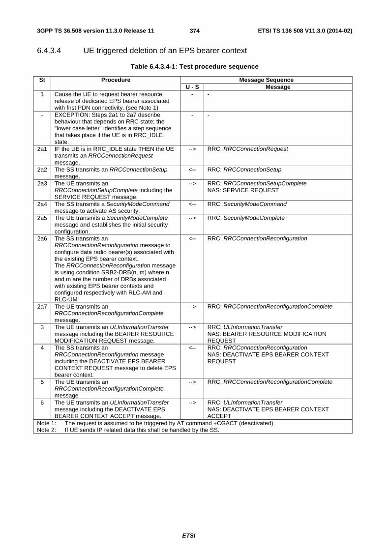
3GPP TS 36.508 version 11.3.0 Release 11 ETSI TS 136 508 V11.3.0 (2014-02)
ETSI
374
6.4.3.4 UE triggered deletion of an EPS bearer context
Table 6.4.3.4-1: Test procedure sequence
St Procedure Message Sequence U - S Message
1 Cause the UE to request bearer resource release of dedicated EPS bearer associated with first PDN connectivity. (see Note 1)
- -
- EXCEPTION: Steps 2a1 to 2a7 describe behaviour that depends on RRC state; the "lower case letter" identifies a step sequence that takes place if the UE is in RRC_IDLE state.
- -
2a1 IF the UE is in RRC_IDLE state THEN the UE transmits an RRCConnectionRequest message.
--> RRC: RRCConnectionRequest
2a2 The SS transmits an RRCConnectionSetup message.
<-- RRC: RRCConnectionSetup
2a3 The UE transmits an RRCConnectionSetupComplete including the SERVICE REQUEST message.
--> RRC: RRCConnectionSetupComplete NAS: SERVICE REQUEST
2a4 The SS transmits a SecurityModeCommand message to activate AS security.
<-- RRC: SecurityModeCommand
2a5 The UE transmits a SecurityModeComplete message and establishes the initial security configuration.
--> RRC: SecurityModeComplete
2a6 The SS transmits an RRCConnectionReconfiguration message to configure data radio bearer(s) associated with the existing EPS bearer context. The RRCConnectionReconfiguration message is using condition SRB2-DRB(n, m) where n and m are the number of DRBs associated with existing EPS bearer contexts and configured respectively with RLC-AM and RLC-UM.
<-- RRC: RRCConnectionReconfiguration
2a7 The UE transmits an RRCConnectionReconfigurationComplete message.
--> RRC: RRCConnectionReconfigurationComplete
3 The UE transmits an ULInformationTransfer message including the BEARER RESOURCE MODIFICATION REQUEST message.
--> RRC: ULInformationTransfer NAS: BEARER RESOURCE MODIFICATION REQUEST
4 The SS transmits an RRCConnectionReconfiguration message including the DEACTIVATE EPS BEARER CONTEXT REQUEST message to delete EPS bearer context.
<-- RRC: RRCConnectionReconfiguration NAS: DEACTIVATE EPS BEARER CONTEXT REQUEST
5 The UE transmits an RRCConnectionReconfigurationComplete message
--> RRC: RRCConnectionReconfigurationComplete
6 The UE transmits an ULInformationTransfer message including the DEACTIVATE EPS BEARER CONTEXT ACCEPT message.
--> RRC: ULInformationTransfer NAS: DEACTIVATE EPS BEARER CONTEXT ACCEPT
Note 1: The request is assumed to be triggered by AT command +CGACT (deactivated). Note 2: If UE sends IP related data this shall be handled by the SS.

3GPP TS 36.508 version 11.3.0 Release 11 ETSI TS 136 508 V11.3.0 (2014-02)
ETSI
375
6.4.3.5 UE triggered CS call
Table 6.4.3.5-1: Test procedure sequence
St Procedure Message Sequence U - S Message
1 Cause the UE to originate CS call. (see Note 1)
- -
- EXCEPTION: Steps 2a1 to 2b1 describe behaviour that depends on RRC state; the "lower case letter" identifies a step sequence that takes place depending on RRC state.
- -
2a1 IF the UE is in RRC_IDLE state THEN the UE transmits an RRCConnectionRequest message.
--> RRC: RRCConnectionRequest
2a2 The SS transmits an RRCConnectionSetup message.
<-- RRC: RRCConnectionSetup
2a3 The UE transmits an RRCConnectionSetupComplete including the EXTENDED SERVICE REQUEST message.
--> RRC: RRCConnectionSetupComplete NAS: EXTENDED SERVICE REQUEST
2b1 ELSE The UE transmits an ULInformationTransfer message including the EXTENDED SERVICE REQUEST message.
--> RRC: ULInformationTransfer NAS: EXTENDED SERVICE REQUEST
Note 1: The request is assumed to be triggered by AT command D.

3GPP TS 36.508 version 11.3.0 Release 11 ETSI TS 136 508 V11.3.0 (2014-02)
ETSI
376
6.4.3.6 UE triggered MO SMS over SGs
Table 6.4.3.6-1: Test procedure sequence
St Procedure Message Sequence U - S Message
1 Cause the UE to originate SMS message. (see Note 1)
- -
- EXCEPTION: Steps 2a1 to 2a7 describe behaviour that depends on RRC state; the "lower case letter" identifies a step sequence that takes place if the UE is in RRC_IDLE state.
- -
2a1 IF the UE is in RRC_IDLE state THEN the UE transmits an RRCConnectionRequest message.
--> RRC: RRCConnectionRequest
2a2 The SS transmits an RRCConnectionSetup message.
<-- RRC: RRCConnectionSetup
2a3 The UE transmits an RRCConnectionSetupComplete including the SERVICE REQUEST message.
--> RRC: RRCConnectionSetupComplete NAS: SERVICE REQUEST
2a4 The SS transmits a SecurityModeCommand message to activate AS security.
<-- RRC: SecurityModeCommand
2a5 The UE transmits a SecurityModeComplete message and establishes the initial security configuration.
--> RRC: SecurityModeComplete
2a6 The SS transmits an RRCConnectionReconfiguration message to configure data radio bearer(s) associated with the existing EPS bearer context. The RRCConnectionReconfiguration message is using condition SRB2-DRB(n, m) where n and m are the number of DRBs associated with existing EPS bearer contexts and configured respectively with RLC-AM and RLC-UM.
<-- RRC: RRCConnectionReconfiguration
2a7 The UE transmits an RRCConnectionReconfigurationComplete message.
--> RRC: RRCConnectionReconfigurationComplete
3 The UE transmits an ULInformationTransfer message including the UPLINK NAS TRANSPORT message to send the SMS message.
--> RRC: ULInformationTransfer NAS: UPLINK NAS TRANSPORT
4 The SS transmits a DLInformationTransfer message including the DOWNLINK NAS TRANSPORT message to acknowledge receipt of the SMS message.
<-- RRC: DLInformationTransfer NAS: DOWNLINK NAS TRANSPORT
5 The SS transmits a DLInformationTransfer message including the DOWNLINK NAS TRANSPORT message to send the delivery report.
<-- RRC: DLInformationTransfer NAS: DOWNLINK NAS TRANSPORT
6 The UE transmits an ULInformationTransfer message including the UPLINK NAS TRANSPORT message to acknowledge receipt of the delivery report.
--> RRC: ULInformationTransfer NAS: UPLINK NAS TRANSPORT
Note 1: The request is assumed to be triggered by AT command +CMGW and +CMSS.
6.4.3.7 CS fallback to UTRAN procedures (LAI of UTRAN cell same as the LAI received in combined Attach procedure in EUTRA cell)
All procedures specified in this clause are referred to the UTRA target cell where the UE has been redirected or handed over from the EUTRA cell after a CS call requested. The default message contents are found in TS 34.108 [5], clause 9.
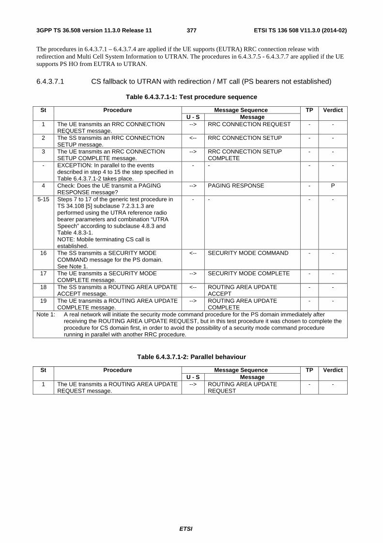
3GPP TS 36.508 version 11.3.0 Release 11 ETSI TS 136 508 V11.3.0 (2014-02)
ETSI
377
The procedures in 6.4.3.7.1 – 6.4.3.7.4 are applied if the UE supports (EUTRA) RRC connection release with redirection and Multi Cell System Information to UTRAN. The procedures in 6.4.3.7.5 - 6.4.3.7.7 are applied if the UE supports PS HO from EUTRA to UTRAN.
6.4.3.7.1 CS fallback to UTRAN with redirection / MT call (PS bearers not established)
Table 6.4.3.7.1-1: Test procedure sequence
St Procedure Message Sequence TP Verdict U - S Message
1 The UE transmits an RRC CONNECTION REQUEST message.
--> RRC CONNECTION REQUEST - -
2 The SS transmits an RRC CONNECTION SETUP message.
<-- RRC CONNECTION SETUP - -
3 The UE transmits an RRC CONNECTION SETUP COMPLETE message.
--> RRC CONNECTION SETUP COMPLETE
- -
- EXCEPTION: In parallel to the events described in step 4 to 15 the step specified in Table 6.4.3.7.1-2 takes place.
- - - -
4 Check: Does the UE transmit a PAGING RESPONSE message?
--> PAGING RESPONSE - P
5-15 Steps 7 to 17 of the generic test procedure in TS 34.108 [5] subclause 7.2.3.1.3 are performed using the UTRA reference radio bearer parameters and combination “UTRA Speech” according to subclause 4.8.3 and Table 4.8.3-1. NOTE: Mobile terminating CS call is established.
- - - -
16 The SS transmits a SECURITY MODE COMMAND message for the PS domain. See Note 1.
<-- SECURITY MODE COMMAND - -
17 The UE transmits a SECURITY MODE COMPLETE message.
--> SECURITY MODE COMPLETE - -
18 The SS transmits a ROUTING AREA UPDATE ACCEPT message.
<-- ROUTING AREA UPDATE ACCEPT
- -
19 The UE transmits a ROUTING AREA UPDATE COMPLETE message.
--> ROUTING AREA UPDATE COMPLETE
- -
Note 1: A real network will initiate the security mode command procedure for the PS domain immediately after receiving the ROUTING AREA UPDATE REQUEST, but in this test procedure it was chosen to complete the procedure for CS domain first, in order to avoid the possibility of a security mode command procedure running in parallel with another RRC procedure.
Table 6.4.3.7.1-2: Parallel behaviour
St Procedure Message Sequence TP Verdict U - S Message
1 The UE transmits a ROUTING AREA UPDATE REQUEST message.
--> ROUTING AREA UPDATE REQUEST
- -

3GPP TS 36.508 version 11.3.0 Release 11 ETSI TS 136 508 V11.3.0 (2014-02)
ETSI
378
6.4.3.7.2 CS fallback to UTRAN with redirection / MO call (PS bearers not established)
Table 6.4.3.7.2-1: Test procedure sequence
St Procedure Message Sequence TP Verdict U - S Message
1 The UE transmits an RRC CONNECTION REQUEST message.
--> RRC CONNECTION REQUEST - -
2 The SS transmits an RRC CONNECTION SETUP message.
<-- RRC CONNECTION SETUP - -
3 The UE transmits an RRC CONNECTION SETUP COMPLETE message.
--> RRC CONNECTION SETUP COMPLETE
- -
- EXCEPTION: In parallel to the events described in step 4 to 15 the step specified in Table 6.4.3.7.2-2 takes place.
- - - -
4 Check: Does the UE transmit a CM SERVICE REQUEST message?
--> CM SERVICE REQUEST - P
5-15 Steps 6 to 16 of the generic test procedure in TS 34.108 [5] subclause 7.2.3.2.3 are performed using the UTRA reference radio bearer parameters and combination “UTRA Speech” according to subclause 4.8.3 and Table 4.8.3-1. NOTE: Mobile originating CS call is established.
- - - -
16 The SS transmits a SECURITY MODE COMMAND message for the PS domain. See Note 1.
<-- SECURITY MODE COMMAND - -
17 The UE transmits a SECURITY MODE COMPLETE message.
--> SECURITY MODE COMPLETE - -
18 The SS transmits a ROUTING AREA UPDATE ACCEPT message.
<-- ROUTING AREA UPDATE ACCEPT
- -
19 The UE transmits a ROUTING AREA UPDATE COMPLETE message.
--> ROUTING AREA UPDATE COMPLETE
- -
Note 1: A real network will initiate the security mode command procedure for the PS domain immediately after receiving the ROUTING AREA UPDATE REQUEST, but in this test procedure it was chosen to complete the procedure for CS domain first, in order to avoid the possibility of a security mode command procedure running in parallel with another RRC procedure.
Table 6.4.3.7.2-2: Parallel behaviour
St Procedure Message Sequence TP Verdict U - S Message
1 The UE transmits a ROUTING AREA UPDATE REQUEST message.
--> ROUTING AREA UPDATE REQUEST
- -

3GPP TS 36.508 version 11.3.0 Release 11 ETSI TS 136 508 V11.3.0 (2014-02)
ETSI
379
6.4.3.7.3 CS fallback to UTRAN with redirection / MT call (PS bearer established)
Table 6.4.3.7.3-1: Test procedure sequence
St Procedure Message Sequence TP Verdict U - S Message
1-19 Steps 1-19 of table 6.4.3.7.1-1. NOTE: Mobile terminating CS call is established and Routing Area Update procedure is performed
- -
20 Check: Does the UE transmit a SERVICE REQUEST message?
--> SERVICE REQUEST - P
21 SS transmits a RADIO BEARER SETUP message, using the UTRA reference radio bearer parameters and combination “UTRA PS RB + Speech” according to subclause 4.8.3 and Table 4.8.3-1. NOTE: Mobile originating packet switched session is established.
<-- RADIO BEARER SETUP - -
22 The UE transmits a RADIO BEARER SETUP COMPLETE message
--> RADIO BEARER SETUP COMPLETE
- -
6.4.3.7.4 CS fallback to UTRAN with redirection / MO call (PS bearer established)
Table 6.4.3.7.4-1: Test procedure sequence
St Procedure Message Sequence TP Verdict U - S Message
1-19 Steps 1-19 of table 6.4.3.7.2-1. NOTE: Mobile originating CS call is set up and Routing Area Update procedure is performed
- - - -
20 Check: Does the UE transmit a SERVICE REQUEST message?
--> SERVICE REQUEST - P
21 SS transmits a RADIO BEARER SETUP message, using the UTRA reference radio bearer parameters and combination “UTRA PS RB + Speech” according to subclause 4.8.3 and Table 4.8.3-1. NOTE: Mobile originating packet switched session is established.
<-- RADIO BEARER SETUP - -
22 The UE transmits a RADIO BEARER SETUP COMPLETE message
--> RADIO BEARER SETUP COMPLETE
- -

3GPP TS 36.508 version 11.3.0 Release 11 ETSI TS 136 508 V11.3.0 (2014-02)
ETSI
380
6.4.3.7.5 CS fallback to UTRAN with Handover / MT call
Table 6.4.3.7.5-1: Test procedure sequence
St Procedure Message Sequence TP Verdict U - S Message
1 Check: Does the UE transmit a HANDOVER TO UTRAN COMPLETE message?
--> HANDOVER TO UTRAN COMPLETE
- P
- EXCEPTION: In parallel to the events described in step 2a1 to 9 the steps specified in table 6.4.3.7.5-2 takes place.
- - - -
- Exception: Steps 2a1 to 2a10 and 2b1 to 2b9 describe behaviour that depends on the UE capability; the "lower case letter" identifies a step sequence that takes place if a capability is supported. Note: One sequence of steps 2a1 to 2a10 or 2b1 to 2b9 are executed
- - - -
2a1 IF the UE does not determine the LAI of the new UTRAN cell, THEN Check: Does the UE transmit a LOCATION UPDATING REQUEST message?
--> LOCATION UPDATING REQUEST
- P
2a2 The SS transmits AUTHENTICATION REQUEST
<-- AUTHENTICATION REQUEST - -
2a3 The UE transmits AUTHENTICATION RESPONSE
--> AUTHENTICATION RESPONSE - -
2a4 The SS transmits a SECURITY MODE COMMAND message for the CS domain.
<-- SECURITY MODE COMMAND - -
2a5 The UE transmits a SECURITY MODE COMPLETE message.
--> SECURITY MODE COMPLETE - -
2a6 The SS transmits a LOCATION UPDATING ACCEPT message.
<-- LOCATION UPDATING ACCEPT - -
2a7 The SS transmits a SECURITY MODE COMMAND message for the PS domain.
<-- SECURITY MODE COMMAND - -
2a8 The UE transmits a SECURITY MODE COMPLETE message.
--> SECURITY MODE COMPLETE - -
2a9 The SS transmits an UTRAN MOBILITY INFORMATION message to notify CN information.
<-- UTRAN MOBILITY INFORMATION
- -
2a10 The UE transmits an UTRAN MOBILITY INFORMATION CONFIRM message.
--> UTRAN MOBILITY INFORMATION CONFIRM
- -
Exception: Steps 2b1 to 2b4 takes place if pc_UMI_ProcNeeded_DuringCSFB
2b1 The SS transmits a SECURITY MODE COMMAND message for the PS domain.
<-- SECURITY MODE COMMAND - -
2b2 The UE transmits a SECURITY MODE COMPLETE message.
--> SECURITY MODE COMPLETE - -
2b3 The SS transmits an UTRAN MOBILITY INFORMATION message to notify CN information.
<-- UTRAN MOBILITY INFORMATION
- -
2b4 The UE transmits an UTRAN MOBILITY INFORMATION CONFIRM message.
--> UTRAN MOBILITY INFORMATION CONFIRM
- -
2b5 Check: Does the UE transmit a PAGING RESPONSE?
--> PAGING RESPONSE - P
2b6 The SS transmits AUTHENTICATION REQUEST
<-- AUTHENTICATION REQUEST - -
2b7 The UE transmits AUTHENTICATION RESPONSE
--> AUTHENTICATION RESPONSE - -
2b8 The SS transmits a SECURITY MODE COMMAND message for the CS domain.
<-- SECURITY MODE COMMAND - -
2b9 The UE transmits a SECURITY MODE COMPLETE message.
--> SECURITY MODE COMPLETE - -
3-9 Steps 11 to 17 of the generic test procedure in TS 34.108 subclause 7.2.3.1.3 are performed using the UTRA reference radio bearer parameters and combination “UTRA PS RB + Speech” according to subclause 4.8.3 and
- - - -

3GPP TS 36.508 version 11.3.0 Release 11 ETSI TS 136 508 V11.3.0 (2014-02)
ETSI
381
Table 4.8.3-1. NOTE: Mobile terminating CS call is established.
10 The SS transmits a ROUTING AREA UPDATE ACCEPT.
<-- ROUTING AREA UPDATE ACCEPT
- -
11 The UE sends ROUTING AREA UPDATE COMPLETE.
--> ROUTING AREA UPDATE COMPLETE
- -
Table 6.4.3.7.5-2: Parallel behaviour
St Procedure Message Sequence TP Verdict U - S Message
1 The UE transmits a ROUTING AREA UPDATE REQUEST message.
--> ROUTING AREA UPDATE REQUEST
- -
6.4.3.7.5.1 Specific message contents
Table 6.4.3.7.5.1-1: Void
Table 6.4.3.7.5.1-2: LOCATION UPDATING ACCEPT (step 2a6 of table 6.4.3.7.5-1)
Derivation Path: TS 36.508 Table 4.7B.2-5 Information Element Value/remark Comment Condition
Mobile identity Not present

3GPP TS 36.508 version 11.3.0 Release 11 ETSI TS 136 508 V11.3.0 (2014-02)
ETSI
382
6.4.3.7.6 CS fallback to UTRAN with Handover / MO call
Table 6.4.3.7.6-1: Test procedure sequence
St Procedure Message Sequence TP Verdict U - S Message
1 Check: Does the UE transmit a HANDOVER TO UTRAN COMPLETE message?
--> HANDOVER TO UTRAN COMPLETE
- P
- EXCEPTION: In parallel to the events described in step 2a1 to 9 the steps specified in table 6.4.3.7.6-2 takes place.
- - - -
- Exception: Steps 2a1 to 2a12 and 2b1 to 2b9 describe behaviour that depends on the UE capability; the "lower case letter" identifies a step sequence that takes place if a capability is supported. Note: One sequence of steps 2a1 to 2a12 or 2b1 to 2b9 are executed
- - - -
2a1 IF the UE does not determine the LAI of the new UTRAN cell, THEN Check: Does the UE transmit a LOCATION UPDATING REQUEST message?
--> LOCATION UPDATING REQUEST
- P
2a2 The SS transmits AUTHENTICATION REQUEST
<-- AUTHENTICATION REQUEST - -
2a3 The UE transmits AUTHENTICATION RESPONSE
--> AUTHENTICATION RESPONSE - -
2a4 The SS transmits a SECURITY MODE COMMAND message for the CS domain.
<-- SECURITY MODE COMMAND - -
2a5 The UE transmits a SECURITY MODE COMPLETE message.
--> SECURITY MODE COMPLETE - -
2a6 The SS transmits a LOCATION UPDATING ACCEPT message.
<-- LOCATION UPDATING ACCEPT - -
2a7 Check: Does the UE transmit a CM SERVICE REQUEST?
--> CM SERVICE REQUEST - P
2a8 The SS transmits a SECURITY MODE COMMAND message for the PS domain.
<-- SECURITY MODE COMMAND - -
2a9 The UE transmits a SECURITY MODE COMPLETE message.
--> SECURITY MODE COMPLETE - -
2a10 The SS transmits an UTRAN MOBILITY INFORMATION message to notify CN information.
<-- UTRAN MOBILITY INFORMATION
- -
2a11 The UE transmits an UTRAN MOBILITY INFORMATION CONFIRM message.
--> UTRAN MOBILITY INFORMATION CONFIRM
- -
2a12 The SS transmits a CM SERVICE ACCEPT message.
<-- CM SERVICE ACCEPT - -
Exception: Steps 2b1 to 2b4 takes place if pc_UMI_ProcNeeded_DuringCSFB
2b1 The SS transmits a SECURITY MODE COMMAND message for the PS domain.
<-- SECURITY MODE COMMAND - -
2b2 The UE transmits a SECURITY MODE COMPLETE message.
--> SECURITY MODE COMPLETE - -
2b3 The SS transmits an UTRAN MOBILITY INFORMATION message to notify CN information.
<-- UTRAN MOBILITY INFORMATION
- -
2b4 The UE transmits an UTRAN MOBILITY INFORMATION CONFIRM message.
--> UTRAN MOBILITY INFORMATION CONFIRM
- -
2b5 Check: Does the UE transmit a CM SERVICE REQUEST?
--> CM SERVICE REQUEST - P
2b6 The SS transmits AUTHENTICATION REQUEST
<-- AUTHENTICATION REQUEST - -
2b7 The UE transmits AUTHENTICATION RESPONSE
--> AUTHENTICATION RESPONSE - -
2b8 The SS transmits a SECURITY MODE COMMAND message for the CS domain.
<-- SECURITY MODE COMMAND - -
2b9 The UE transmits a SECURITY MODE COMPLETE message.
--> SECURITY MODE COMPLETE - -
3 The UE transmits a SETUP message. --> SETUP - -

3GPP TS 36.508 version 11.3.0 Release 11 ETSI TS 136 508 V11.3.0 (2014-02)
ETSI
383
4-9 Steps 11 to 16 of the generic test procedure in TS 34.108 subclause 7.2.3.2.3 are performed using the UTRA reference radio bearer parameters and combination “UTRA PS RB + Speech” according to subclause 4.8.3 and Table 4.8.3-1. NOTE: Mobile originating CS call is established.
- - - -
10 The SS transmits a ROUTING AREA UPDATE ACCEPT.
<-- ROUTING AREA UPDATE ACCEPT
- -
11 The UE sends ROUTING AREA UPDATE COMPLETE.
--> ROUTING AREA UPDATE COMPLETE
- -
Table 6.4.3.7.6-2: Parallel behaviour
St Procedure Message Sequence TP Verdict U - S Message
1 The UE transmits a ROUTING AREA UPDATE REQUEST message.
--> ROUTING AREA UPDATE REQUEST
- -
6.4.3.7.6.1 Specific message contents
None.
Table 6.4.3.7.6.1-1: LOCATION UPDATING ACCEPT (step 2a6 of table 6.4.3.7.6-1)
Derivation Path: TS 36.508 Table 4.7B.2-5 Information Element Value/remark Comment Condition
Mobile identity Not present

3GPP TS 36.508 version 11.3.0 Release 11 ETSI TS 136 508 V11.3.0 (2014-02)
ETSI
384
6.4.3.7.7 CS fallback to UTRAN with Handover / emergency call
Table 6.4.3.7.7-1: Test procedure sequence
St Procedure Message Sequence TP Verdict U - S Message
1 Check: Does the UE transmit a HANDOVER TO UTRAN COMPLETE message?
--> HANDOVER TO UTRAN COMPLETE
- P
- EXCEPTION: In parallel to the events described in step 2a1 to 9 the steps specified in table 6.4.3.7.7-2 takes place.
- - - -
- Exception: Steps 2a1 to 2a12 and 2b1 to 2b9 describe behaviour that depends on the UE capability; the "lower case letter" identifies a step sequence that takes place if a capability is supported. Note: One sequence of steps 2a1 to 2a12 or 2b1 to 2b9 are executed
- - - -
2a1 IF the UE does not determine the LAI of the new UTRAN cell, THEN Check: Does the UE transmit a LOCATION UPDATING REQUEST message?
--> LOCATION UPDATING REQUEST
- P
2a2 The SS transmits AUTHENTICATION REQUEST
<-- AUTHENTICATION REQUEST - -
2a3 The UE transmits AUTHENTICATION RESPONSE
--> AUTHENTICATION RESPONSE - -
2a4 The SS transmits a SECURITY MODE COMMAND message for the CS domain.
<-- SECURITY MODE COMMAND - -
2a5 The UE transmits a SECURITY MODE COMPLETE message.
--> SECURITY MODE COMPLETE - -
2a6 The SS transmits a LOCATION UPDATING ACCEPT message.
<-- LOCATION UPDATING ACCEPT - -
2a7 Check: Does the UE transmit a CM SERVICE REQUEST?
--> CM SERVICE REQUEST - P
2a8 The SS transmits a SECURITY MODE COMMAND message for the PS domain.
<-- SECURITY MODE COMMAND - -
2a9 The UE transmits a SECURITY MODE COMPLETE message.
--> SECURITY MODE COMPLETE - -
2a10 The SS transmits an UTRAN MOBILITY INFORMATION message to notify CN information.
<-- UTRAN MOBILITY INFORMATION
- -
2a11 The UE transmits an UTRAN MOBILITY INFORMATION CONFIRM message.
--> UTRAN MOBILITY INFORMATION CONFIRM
- -
2a12 The SS transmits a CM SERVICE ACCEPT message.
<-- CM SERVICE ACCEPT - -
Exception: Steps 2b1 to 2b4 takes place if pc_UMI_ProcNeeded_DuringCSFB
2b1 The SS transmits a SECURITY MODE COMMAND message for the PS domain.
<-- SECURITY MODE COMMAND - -
2b2 The UE transmits a SECURITY MODE COMPLETE message.
--> SECURITY MODE COMPLETE - -
2b3 The SS transmits an UTRAN MOBILITY INFORMATION message to notify CN information.
<-- UTRAN MOBILITY INFORMATION
- -
2b4 The UE transmits an UTRAN MOBILITY INFORMATION CONFIRM message.
--> UTRAN MOBILITY INFORMATION CONFIRM
- -
2b5 Check: Does the UE transmit a CM SERVICE REQUEST?
--> CM SERVICE REQUEST - P
2b6 The SS transmits AUTHENTICATION REQUEST
<-- AUTHENTICATION REQUEST - -
2b7 The UE transmits AUTHENTICATION RESPONSE
--> AUTHENTICATION RESPONSE - -
2b8 The SS transmits a SECURITY MODE COMMAND message for the CS domain.
<-- SECURITY MODE COMMAND - -
2b9 The UE transmits a SECURITY MODE COMPLETE message.
--> SECURITY MODE COMPLETE - -
3 The UE transmits an EMERGENCY SETUP --> EMERGENCY SETUP - -
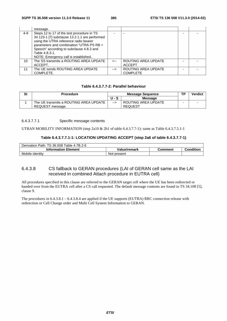
3GPP TS 36.508 version 11.3.0 Release 11 ETSI TS 136 508 V11.3.0 (2014-02)
ETSI
385
message. 4-9 Steps 12 to 17 of the test procedure in TS
34.123-1 [7] subclause 13.2.1.1 are performed using the UTRA reference radio bearer parameters and combination “UTRA PS RB + Speech” according to subclause 4.8.3 and Table 4.8.3-1. NOTE: Emergency call is established..
- - - -
10 The SS transmits a ROUTING AREA UPDATE ACCEPT.
<-- ROUTING AREA UPDATE ACCEPT
- -
11 The UE sends ROUTING AREA UPDATE COMPLETE.
--> ROUTING AREA UPDATE COMPLETE
- -
Table 6.4.3.7.7-2: Parallel behaviour
St Procedure Message Sequence TP Verdict U - S Message
1 The UE transmits a ROUTING AREA UPDATE REQUEST message.
--> ROUTING AREA UPDATE REQUEST
- -
6.4.3.7.7.1 Specific message contents
UTRAN MOBILITY INFORMATION (step 2a10 & 2b1 of table 6.4.3.7.7-1): same as Table 6.4.3.7.5.1-1
Table 6.4.3.7.7.1-1: LOCATION UPDATING ACCEPT (step 2a6 of table 6.4.3.7.7-1)
Derivation Path: TS 36.508 Table 4.7B.2-5 Information Element Value/remark Comment Condition
Mobile identity Not present
6.4.3.8 CS fallback to GERAN procedures (LAI of GERAN cell same as the LAI received in combined Attach procedure in EUTRA cell)
All procedures specified in this clause are referred to the GERAN target cell where the UE has been redirected or handed over from the EUTRA cell after a CS call requested. The default message contents are found in TS 34.108 [5], clause 9.
The procedures in 6.4.3.8.1 – 6.4.3.8.4 are applied if the UE supports (EUTRA) RRC connection release with redirection or Cell Change order and Multi Cell System Information to GERAN.

3GPP TS 36.508 version 11.3.0 Release 11 ETSI TS 136 508 V11.3.0 (2014-02)
ETSI
386
6.4.3.8.1 CS fallback to GERAN with redirection or CCO / MT call (DTM not supported)
Table 6.4.3.8.1-1: Test procedure sequence
St Procedure Message Sequence TP Verdict U - S Message
1 The UE transmits a CHANNEL REQUEST message.
--> CHANNEL REQUEST - -
2 The SS transmits an IMMEDIATE ASSIGNMENT message.
<-- IMMEDIATE ASSIGNMENT - -
3 Void - - - - - EXCEPTION: In parallel to the events
described in step 4 to 19 the steps specified in table 6.4.3.8.1-2 takes place
- - - -
4 Check: Does the UE transmit a PAGING RESPONSE message?
--> PAGING RESPONSE - P
4A The UE transmits a Classmark Change message
--> CLASSMARK CHANGE - -
- EXCEPTION: Step 4B describes behaviour that depends on the UE capability.
- - - -
4B IF pc_UTRA then the UE transmits a Utran Classmark message
--> UTRAN CLASSMARK CHANGE - -
5-19 Steps 5 to 19 of the generic test procedure in TS 51.010-1 sub clause 10.3.3 are performed NOTE: Mobile terminating CS call is established.
- - - -
20 The SS transmits DISCONNECT. <-- DISCONNECT - - 21 The UE transmits RELEASE.. --> RELEASE - - 22 The SS transmits RELEASE COMPLETE. <-- RELEASE COMPLETE - - 23 The SS transmits CHANNEL RELEASE, with
GPRS Resumption Field set to 1 <-- CHANNEL RELEASE - -
24-34
Steps 1 to 11 of the generic test procedure in sub clause 6.4.2.9 are performed.
- - - -
Table 6.4.3.8.1-2: Parallel behaviour
St Procedure Message Sequence TP Verdict U - S Message
1 The UE transmits a GPRS SUSPENSION REQUEST message.
--> GPRS SUSPENSION REQUEST - -

3GPP TS 36.508 version 11.3.0 Release 11 ETSI TS 136 508 V11.3.0 (2014-02)
ETSI
387
6.4.3.8.2 CS fallback to GERAN with redirection or CCO / MO call (DTM not supported)
Table 6.4.3.8.2-1: Test procedure sequence
St Procedure Message Sequence TP Verdict U - S Message
1 The UE transmits a CHANNEL REQUEST message.
--> CHANNEL REQUEST - -
2 The SS transmits an IMMEDIATE ASSIGNMENT message.
<-- IMMEDIATE ASSIGNMENT - -
3 Void - - - - - EXCEPTION: In parallel to the events
described in step 4 to 17 the steps specified in table 6.4.3.8.2-2 takes place
- - - -
4 Check: Does the UE transmit a CM SERVICE REQUEST message?
--> CM SERVICE REQUEST - P
4A The UE transmits a Classmark Change message
--> CLASSMARK CHANGE - -
- EXCEPTION: Step 4B describes behaviour that depends on the UE capability.
- - - -
4B IF pc_UTRA then the UE transmits a Utran Classmark message
--> UTRAN CLASSMARK CHANGE - -
5-17 Steps 5 to 17 of the generic test procedure in TS 51.010-1 sub clause 10.2.3 are performed NOTE: Mobile originating CS call is established.
- - - -
18 The SS transmits DISCONNECT. <-- DISCONNECT - - 19 The UE transmits RELEASE.. --> RELEASE - - 20 The SS transmits RELEASE COMPLETE. <-- RELEASE COMPLETE - - 21 The SS transmits CHANNEL RELEASE, with
GPRS Resumption Field set to 1 <-- CHANNEL RELEASE - -
22-32
Steps 1 to 11 of the generic test procedure in sub clause 6.4.2.9 are performed.
- - - -
Table 6.4.3.8.2-2: Parallel behaviour
St Procedure Message Sequence TP Verdict U - S Message
1 The UE transmits a GPRS SUSPENSION REQUEST message.
--> GPRS SUSPENSION REQUEST - -
6.4.3.8.3 CS fallback to GERAN with PS Handover / MT call (EDTM not supported)
Same as test procedure sequence in 36.523-1 [18] clause 13.1.11.3.2 from steps 11 to end.
6.4.3.8.4 CS fallback to GERAN with PS Handover / MO call (EDTM not supported)
Same as test procedure sequence in 36.523-1 [18] clause 13.1.12.3.2 from steps 4 to end.
6.4.3.8.5 CS fallback to GERAN with PS Handover / MT call (EDTM supported)
Same as test procedure sequence in 36.523-1 [18] clause 13.1.13.3.2 from steps 7 to end.
6.4.3.9 SRVCC Handover to UTRA
The procedure specified in this clause are referred to the UTRA target cell where the UE has been SRVCC handed over from the EUTRA cell. The default message contents are found in TS 34.108 [5], clause 9.

3GPP TS 36.508 version 11.3.0 Release 11 ETSI TS 136 508 V11.3.0 (2014-02)
ETSI
388
Table 6.4.3.9-1: Test procedure sequence
St Procedure Message Sequence TP Verdict U - S Message
1 Check: Does the UE transmit a HANDOVER TO UTRAN COMPLETE message?
--> HANDOVER TO UTRAN COMPLETE
- P
- EXCEPTION: In parallel to the events described in step 2 to 7 the steps specified in table 6.4.3.9-2 takes place.
- - - -
2 The SS transmits a SECURITY MODE COMMAND message for the CS domain.
<-- SECURITY MODE COMMAND - -
3 The UE transmits a SECURITY MODE COMPLETE message.
--> SECURITY MODE COMPLETE - -
4 The SS transmits an UTRAN MOBILITY INFORMATION message to notify CN information.
<-- UTRAN MOBILITY INFORMATION
- -
5 The UE transmits an UTRAN MOBILITY INFORMATION CONFIRM message.
--> UTRAN MOBILITY INFORMATION CONFIRM
- -
6 The SS transmits a TMSI REALLOCATION COMMAND message.
<-- TMSI REALLOCATION COMMAND
- -
7 The UE transmits a TMSI REALLOCATION COMPLETE message.
--> TMSI REALLOCATION COMPLETE
- -
8 The SS transmits a ROUTING AREA UPDATE ACCEPT.
<-- ROUTING AREA UPDATE ACCEPT
- -
9 The UE sends ROUTING AREA UPDATE COMPLETE.
--> ROUTING AREA UPDATE COMPLETE
- -
Table 6.4.3.9-2: Parallel behaviour
St Procedure Message Sequence TP Verdict U - S Message
1 The UE transmits a ROUTING AREA UPDATE REQUEST message.
--> ROUTING AREA UPDATE REQUEST
- -
6.4.3.9.1 Specific message contents
Table 6.4.3.9.1-1: SECURITY MODE COMMAND (step 2, Table 8.4.1.2.3.2-1)
Derivation Path: 34.108 clause 9.1.1 (SECURITY MODE COMMAND message) Information Element Condition Value/remark
Ciphering mode info Not Present
6.4.3A Test case postambles
6.4.3A.1 Introduction
In order to make test cases perfectly reproducible, the UE under test is switched off after the test procedure sequence of a test case is complete. In order to make it possible to run a number of test cases without any manual operation, it is important that the SS can properly handle any possible signalling from the UE between the end of the test procedure sequence and until the UE is off.
After the last verdict of a test procedure sequence is assigned, it is necessary to:
- terminate any ongoing signalling procedure,
- switch off the UE.
Usually, this can be performed by completing necessary TAU/LAU/RAU procedures, completing any ongoing voice call (CS or IMS), and switching off the UE with a detach procedure.
3GPP TS 36.508 version 11.3.0 Release 11 ETSI TS 136 508 V11.3.0 (2014-02)
ETSI
389
6.4.3A.2 Reference end states
Test procedures in TS 36.523-1 may only partially terminate ongoing signalling procedures, provided they indicate a reference end state at the end of the test procedure sequence, so that a matching procedure in TS 36.523-3 can be executed to switch off the UE.
Reference end states definitions include the necessary pieces of information to predict UE behaviour during the postambles.
If any extra information was stored in the UE or the USIM due to the test procedure sequence, it should be removed explicitly by the test procedure sequence, before the UE can be left in a reference end state.

3GPP TS 36.508 version 11.3.0 Release 11 ETSI TS 136 508 V11.3.0 (2014-02)
ETSI
390
Table 6.4.3A.2-1: Reference end states
Name Description Optional information E-UTRA idle (E1) The UE:
- is camped on an E-UTRA cell, and RRC idle and - registered for EPS services and EPS update status is "updated" and - is registered for non-EPS services and update status is updated (if CS fallback or SMS over SGs is supported) and - has one or more default EPS bearer context are active, zero or more dedicated EPS bearer contexts are active.
The test case may indicate that the UE is not registered for non-EPS services, though the UE supports CS fallback or SMS over SGs.
E-UTRA connected (E2)
Same as E-UTRA idle, except that: - the UE is RRC connected and - DRBs for all active EPS bearer contexts are established.
Same as for E-UTRA idle.
E-UTRA connected, T3440 started
(E2_T3440)
Same as E-UTRA idle, except that: - the UE is RRC connected and - Timer T3440 is started in UE.
Same as for E-UTRA idle.
E-UTRA test mode (E3)
Same as E-UTRA connected and - test mode is active and - test loop is closed.
Same as for E-UTRA idle.
E-UTRA deregistered (E4)
The UE is: - camped on an E-UTRA cell, and idle and - not registered of EPS services and - not registered for non-EPS services.
UTRA idle (U1) The UE is: - camped on a UTRA cell, RRC idle and - IMSI attached and update status is "updated" (if the UE supports CS domain) and - GPRS attached, GPRS update state is "updated", and zero or one or several PDP context(s) with interactive or background QoS are active.
The test case may indicate that the UE is not IMSI attached though the UE supports CS domain.
UTRA connected (U2) Same as UTRA idle, except that: - the UE is in CELL_DCH state and - a RAB associated with the active PDP context is established.
The test case may indicate that the UE is not IMSI attached though the UE supports CS domain.
UTRA handover (U3) The UE: - was E-UTRA connected and - has completed a handover to UMTS and - hasn't yet sent or received any NAS signalling on the target UTRAN cell.
Same as for UTRA connected.
UTRA CS fallback (U4) The UE: - was E-UTRA idle or E-UTRA connected and - has transmitted an EXTENDED SERVICE REQUEST message due to MO or MT CS fallback call and - either the UE has completed a handover to UMTS or the UE has been redirected to UMTS and has established the RRC connection to a UTRA cell, and the target UTRA cell has activated security and RABs for all previously active EPS bearer contexts were established and - the UE hasn't yet sent or received any NAS signalling on the target UTRAN cell
UTRA CS call (U5) The UE was in UTRAN CS fallback and the UE has completed LAU/RAU procedure if necessary and has established a CS call or the UE was in E-UTRAN connected and the UE has completed LAU/RAU procedure if necessary and has performed a handover to UTRAN with SRVCC.
UTRA deregistered (U6)
The UE is: - camped on a UTRA cell, and idle and - not registered GPRS/non-GPRS services
GERAN idle (G1) The UE: - is camped on an GERAN cell, in idle mode and GPRS idle state and - is registered for PS services and GPRS update status is "updated" and zero or one or several PDP context(s) with interactive or background QoS are active. - is IMSI attached (if CS domain is supported)
GERAN PS handover (G2)
The UE: - was E-UTRA connected and

3GPP TS 36.508 version 11.3.0 Release 11 ETSI TS 136 508 V11.3.0 (2014-02)
ETSI
391
- has performed a PS handover procedure to a GERAN cell and - hasn't yet sent or received any NAS signalling on the target GERAN cell.
GERAN CS fallback (G3)
The UE: - was E-UTRA idle or E-UTRA connected and - has transmitted an EXTENDED SERVICE REQUEST message due to MO or MT CS fallback call and - either the UE has completed a PS handover to GERAN or a CCO to GERAN or the UE has been redirected to GERAN and has entered dedicated mode, and if DTM is supported, - the UE hasn't yet sent or received any NAS signalling on the target GERAN cell
GERAN CS call (G4) The UE was in GERAN CS fallback and the UE has established a CS call or the UE was in E-UTRAN connected and has performed a handover to GERAN with SRVCC.
GERAN deregistered (G5)
The UE is: - camped on a GERAN cell, and idle and - not registered GPRS/non-GPRS services
1xRTT state 1 (1x1) FFS ... ...
HRPD state 1 (H1) FFS ... ...
6.5 Default RRC message and information element contents The default RRC message and information element contents specified in this subclause apply to all Signalling test cases defined in TS 36.523-1 [18] unless otherwise specified, in addition to the default RRC message and information element contents specified in subclause 4.6 of this specification.
6.5.1 Measurement information elements
- MeasConfig-DEFAULT
Table 6.5.1-1: MeasConfig-DEFAULT
Derivation Path: 36.331, clause 6.3.5 Information Element Value/remark Comment Condition
MeasConfig-DEFAULT ::= SEQUENCE { measObjectToRemoveList Not present measObjectToAddModList Not present reportConfigToRemoveList Not present reportConfigToAddModList Not present measIdToRemoveList Not present measIdToAddModList Not present quantityConfig Not present quantityConfig QuantityConfig-
DEFAULT UTRAN,
GERAN, CDMA2000
measGapConfig Not present MeasGapConfig-GP1 INTER-
FREQ, UTRAN
MeasGapConfig-GP2 GERAN, INTER-RAT
s-Measure Not present preRegistrationInfoHRPD Not present speedStatePars Not present }

3GPP TS 36.508 version 11.3.0 Release 11 ETSI TS 136 508 V11.3.0 (2014-02)
ETSI
392
Condition Explanation INTER-FREQ For E-UTRA inter-freq measurements UTRAN For inter-RAT measurements with UTRAN GERAN For inter-RAT measurements with GERAN CDMA2000 For inter-RAT measurements with CDMA2000 INTER-RAT For inter-RAT measurements with UTRAN and GERAN
- MeasGapConfig-GP1
Table 6.5.1-2: MeasGapConfig-GP1
Derivation Path: 36.331, clause 6.3.5 Information Element Value/remark Comment Condition
MeasGapConfig-GP1 ::= CHOICE { setup SEQUENCE { gapOffset CHOICE { gp0 30 TGRP = 40 ms } } }
- MeasGapConfig-GP2
Table 6.5.1-3: MeasGapConfig-GP2
Derivation Path: 36.331, clause 6.3.5 Information Element Value/remark Comment Condition
MeasGapConfig-GP2 ::= CHOICE { setup SEQUENCE { gapOffset CHOICE { gp1 30 TGRP = 80 ms } } }
6.6 Default NAS message and information element contents The default NAS message and information element contents specified in this subclause apply to all Signalling test cases defined in TS 36.523-1 [18] unless otherwise specified, in addition to the default NAS message and information element contents specified in subclause 4.7 of this specification.
6.6.1 Reference default EPS bearer contexts
The following table defines Reference default EPS bearer contexts. Default EPS bearer context1 is the default "default EPS bearer context" which is used in the common procedures and test cases where no particular default EPS bearer context is specified.
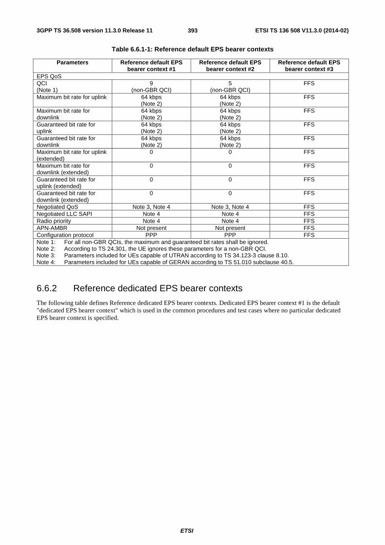
3GPP TS 36.508 version 11.3.0 Release 11 ETSI TS 136 508 V11.3.0 (2014-02)
ETSI
393
Table 6.6.1-1: Reference default EPS bearer contexts
Parameters Reference default EPS bearer context #1
Reference default EPS bearer context #2
Reference default EPS bearer context #3
EPS QoS QCI (Note 1)
9 (non-GBR QCI)
5 (non-GBR QCI)
FFS
Maximum bit rate for uplink 64 kbps (Note 2)
64 kbps (Note 2)
FFS
Maximum bit rate for downlink
64 kbps (Note 2)
64 kbps (Note 2)
FFS
Guaranteed bit rate for uplink
64 kbps (Note 2)
64 kbps (Note 2)
FFS
Guaranteed bit rate for downlink
64 kbps (Note 2)
64 kbps (Note 2)
FFS
Maximum bit rate for uplink (extended)
0 0 FFS
Maximum bit rate for downlink (extended)
0 0 FFS
Guaranteed bit rate for uplink (extended)
0 0 FFS
Guaranteed bit rate for downlink (extended)
0 0 FFS
Negotiated QoS Note 3, Note 4 Note 3, Note 4 FFS Negotiated LLC SAPI Note 4 Note 4 FFS Radio priority Note 4 Note 4 FFS APN-AMBR Not present Not present FFS Configuration protocol PPP PPP FFS Note 1: For all non-GBR QCIs, the maximum and guaranteed bit rates shall be ignored. Note 2: According to TS 24.301, the UE ignores these parameters for a non-GBR QCI. Note 3: Parameters included for UEs capable of UTRAN according to TS 34.123-3 clause 8.10. Note 4: Parameters included for UEs capable of GERAN according to TS 51.010 subclause 40.5.
6.6.2 Reference dedicated EPS bearer contexts
The following table defines Reference dedicated EPS bearer contexts. Dedicated EPS bearer context #1 is the default "dedicated EPS bearer context" which is used in the common procedures and test cases where no particular dedicated EPS bearer context is specified.

3GPP TS 36.508 version 11.3.0 Release 11 ETSI TS 136 508 V11.3.0 (2014-02)
ETSI
394
Table 6.6.2-1: Reference dedicated EPS bearer contexts
Parameters Reference dedicated EPS bearer context #1
Reference dedicated EPS bearer context #2
Reference dedicated EPS bearer context #3
Reference dedEPS bearer con
Linked EPS bearer identity Reference default EPS bearer #1
Reference default EPS bearer #1
Reference default EPS bearer #2
Reference defabearer #2
EPS QoS QCI (Note 1)
1 (GBR QCI)
5 (non-GBR QCI)
2 (GBR QCI)
1 (GBR QC
Maximum bit rate for uplink 384 kbps 384 kbps (Note 2)
432 kbps 384 kbps
Maximum bit rate for downlink
384 kbps 384 kbps (Note 2)
432 kbps 384 kbps
Guaranteed bit rate for uplink
128 kbps 128 kbps (Note 2)
432 kbps 128 kbps
Guaranteed bit rate for downlink
128 kbps 128 kbps (Note 2)
432 kbps 128 kbps
Maximum bit rate for uplink (extended)
0 0 0 0
Maximum bit rate for downlink (extended)
0 0 0 0
Guaranteed bit rate for uplink (extended)
0 0 0 0
Guaranteed bit rate for downlink (extended)
0 0 0 0
TFT TFT operation code "create new TFT" "create new TFT" "create new TFT" "create new TE bit 0 0 0 0 Packet filters (Note 5)
1, 2 3 5 4
Negotiated QoS Traffic Class conversational See "PDP
ContextDchForLTE" (Note 3);
See "PDP context3" (Note 6)
conversational conversatio
Delivery Order 'no' See "PDP ContextDchForLTE"
(Note 3); See "PDP context3"
(Note 6)
’no’ 'no'
Delivery of erroneous SDU 'no' See "PDP ContextDchForLTE"
(Note 3); See "PDP context3"
(Note 6)
’no’ 'no'
Maximum SDU size 150 See "PDP ContextDchForLTE"
(Note 3); See "PDP context3"
(Note 6)
1400 150
Maximum bit rate for uplink 384 kbps See "PDP ContextDchForLTE"
(Note 3); See "PDP context3"
(Note 6)
432 kbps 384 kbps
Maximum bit rate for downlink
384 kbps See "PDP ContextDchForLTE"
(Note 3); See "PDP context3"
(Note 6)
432 kbps 384 kbps
Residual BER 5*10-2 See "PDP ContextDchForLTE"
(Note 3); See "PDP context3"
(Note 6)
10-5 5*10-2
SDU error ratio 10-2 See "PDP 7*10-3 10-2

3GPP TS 36.508 version 11.3.0 Release 11 ETSI TS 136 508 V11.3.0 (2014-02)
ETSI
395
ContextDchForLTE" (Note 3);
See "PDP context3" (Note 6)
Transfer delay 80 ms See "PDP ContextDchForLTE"
(Note 3); See "PDP context3"
(Note 6)
130 ms 80 ms
Traffic Handling priority 0 See "PDP ContextDchForLTE"
(Note 3); See "PDP context3"
(Note 6)
0 0
Guaranteed bit rate for uplink
0 See "PDP ContextDchForLTE"
(Note 3); See "PDP context3"
(Note 6)
0 0
Guaranteed bit rate for downlink
0 See "PDP ContextDchForLTE"
(Note 3); See "PDP context3"
(Note 6)
0 0
Signalling Indication 0 See "PDP ContextDchForLTE"
(Note 3); See "PDP context3"
(Note 6)
0 0
Source Statistics Descriptor 0 See "PDP ContextDchForLTE"
(Note 3); See "PDP context3"
(Note 6)
0 1
Maximum bit rate for downlink (extended)
0 See "PDP ContextDchForLTE"
(Note 3); See "PDP context3"
(Note 6)
0 0
Guaranteed bit rate for downlink (extended)
0 See "PDP ContextDchForLTE"
(Note 3); See "PDP context3"
(Note 6)
0 0
Maximum bit rate for uplink (extended)
0 See "PDP ContextDchForLTE"
(Note 3); See "PDP context3"
(Note 6)
0 0
Guaranteed bit rate for uplink (extended)
0 See "PDP ContextDchForLTE"
(Note 3); See "PDP context3"
(Note 6)
0 0
Negotiated LLC SAPI 3 (Note 6) See "PDP context3" (Note 6)
- 3 (Note 6
Radio priority 1 (Note 6) See "PDP context3" (Note 6)
- 1 (Note 6
Protocol configuration options
- - - -
Note 1: For all non-GBR QCIs, the maximum and guaranteed bit rates shall be ignored. Note 2: According to TS 24.301, the UE ignores these parameters for a non-GBR QCI. Note 3: Parameters included for UEs capable of UTRAN according to TS 34.123-3 clause 8.10 (table 8.10.1 and 8.10.2). Note 5: This row refers to the reference packet filters defined in the tables below. For each reference dedicated EPS bearer conte
of reference packet filter numbers is provided. Note 6: Parameter included for UEs capable of GERAN; when value is not provided then value from TS 51.010 subclause 40.5 is

3GPP TS 36.508 version 11.3.0 Release 11 ETSI TS 136 508 V11.3.0 (2014-02)
ETSI
396
Table 6.6.2-2: Reference packet filter #1
Derivation path: 24.008 table 10.5.162 Information Element Value/Remark Comment Condition
Identifier 0 0 0 1 0 0 0 0 DL only filter,ID=0 Evaluation precedence (0 0 0 0 0 0 0 0) + EPS
Bearer ID - 6 0 to 7
Component type 1 ID 0 0 0 1 0 0 0 0 IPv4 remote address type
remoteIPv4
0 0 1 0 0 0 0 0 IPv6 remote address type
remoteIPv6
Component type 1 Value remoteAddress 255.255.255.255
See note 1 remoteIPv4
remoteAddress ff:ff:ff:ff:ff:ff:ff:ff: ff:ff:ff:ff:ff:ff:ff:ff
See note 1 remoteIPv6
Component type 2 ID 0 1 0 1 0 0 0 0 Single remote port type
Component type 2 Value 31 160 + EPS Bearer ID - 6
Component type 3 ID 0 0 1 1 0 0 0 0 Protocol identifier/Next header type
Component type 3 Value 17 UDP Note 1: remoteAddress should be set to the address of an IP server able to send a flow of downlink IP/UDP
packets to the UE. remoteIPv4 applies if the UE has acquired an IPv4 address only, remoteIPv6 applies if the UE has acquired an IPv6 address only, or both an IPv6 and an IPv4 address.
Table 6.6.2-3: Reference packet filter #2
Derivation path: 24.008 table 10.5.162 Information Element Value/Remark Comment Condition
Identifier 0 0 1 0 0 0 0 1 UL only filter, ID=1
Evaluation precedence (0 0 0 0 0 0 0 0) + EPS Bearer ID - 6 + 8
8 to 15
Component type 1 ID 0 0 0 1 0 0 0 0 IPv4 remote address type
remoteIPv4
0 0 1 0 0 0 0 0 IPv6 remote address type
remoteIPv6
Component type 1 Value remoteAddress 255.255.255.255
See note 1 remoteIPv4
remoteAddress ff:ff:ff:ff:ff:ff:ff:ff: ff:ff:ff:ff:ff:ff:ff:ff
See note 1 remoteIPv6
Component type 2 ID 0 1 0 1 0 0 0 0 Single remote port type
Component type 2 Value 61 000 + EPS Bearer ID - 6
Component type 3 ID 0 0 1 1 0 0 0 0 Protocol identifier/Next header type
Component type 3 Value 17 UDP Note 1: remoteAddress should be set to the address of an IP server able to process a flow of uplink IP/UDP
packets received from the UE. When configured together with packet filter #1, remoteAddress is the same as that for packet filter #1. remoteIPv4 applies if the UE has acquired an IPv4 address only, remoteIPv6 applies if the UE has acquired an IPv6 address only, or both an IPv6 and an IPv4 address.

3GPP TS 36.508 version 11.3.0 Release 11 ETSI TS 136 508 V11.3.0 (2014-02)
ETSI
397
Table 6.6.2-4: Reference packet filter #3
Derivation path: 24.008 table 10.5.162 Information Element Value/Remark Comment Condition
Identifier 0 0 1 1 0 0 1 0 Bidirectional filter, ID=2
Evaluation precedence 0 0 0 0 1 1 1 1 Lowest priority Component type 1 ID 0 0 0 1 0 0 0 0 IPv4 remote
address type remoteIPv4
0 0 1 0 0 0 0 0 IPv6 remote address type
remoteIPv6
Component type 1 Value remoteAddress 255.255.255.255
See note 1 remoteIPv4
remoteAddress ff:ff:ff:ff:ff:ff:ff:ff: ff:ff:ff:ff:ff:ff:ff:ff
See note 1 remoteIPv6
Note 1: remoteAddress should be set to the address of an IP server able to process a uplink IP packets from the UE and transmit downlink IP packets to the UE. remoteIPv4 applies if the UE has acquired an IPv4 address only, remoteIPv6 applies if the UE has acquired an IPv6 address only, or both an IPv6 and an IPv4 address.
Table 6.6.2-5: Reference packet filter #4
Derivation path: 24.008 table 10.5.162 Information Element Value/Remark Comment Condition
Identifier 0 0 1 1 0 0 1 1 Bidirectional,ID=3 Evaluation precedence (0 0 0 0 0 0 0 0) + EPS
Bearer ID – 6 0 to 7
Component type 1 ID 0 1 0 1 0 0 0 1 Remote port range type
Component type 1 Value media port SS speech media port as used in the SDP negotiation (RTP remote port); see Note 1
media port + 1 RTCP remote port; see Note 1
Component type 2 ID 0 0 1 1 0 0 0 0 Protocol identifier/Next header type
Component type 2 Value 17 UDP Note 1: Acc. to TS 26.114 and RFC 4566 a “media port” can be understood as the transport port to which a media
stream is sent.
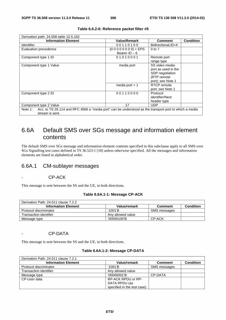
3GPP TS 36.508 version 11.3.0 Release 11 ETSI TS 136 508 V11.3.0 (2014-02)
ETSI
398
Table 6.6.2-6: Reference packet filter #5
Derivation path: 24.008 table 10.5.162 Information Element Value/Remark Comment Condition
Identifier 0 0 1 1 0 1 0 0 Bidirectional,ID=4 Evaluation precedence (0 0 0 0 0 0 0 0) + EPS
Bearer ID – 6 0 to 7
Component type 1 ID 0 1 0 1 0 0 0 1 Remote port range type
Component type 1 Value media port SS video media port as used in the SDP negotiation (RTP remote port); see Note 1
media port + 1 RTCP remote port; see Note 1
Component type 2 ID 0 0 1 1 0 0 0 0 Protocol identifier/Next header type
Component type 2 Value 17 UDP Note 1: Acc. to TS 26.114 and RFC 4566 a “media port” can be understood as the transport port to which a media
stream is sent.
6.6A Default SMS over SGs message and information element contents
The default SMS over SGs message and information element contents specified in this subclause apply to all SMS over SGs Signalling test cases defined in TS 36.523-1 [18] unless otherwise specified. All the messages and information elements are listed in alphabetical order.
6.6A.1 CM-sublayer messages
- CP-ACK
This message is sent between the SS and the UE, in both directions.
Table 6.6A.1-1: Message CP-ACK
Derivation Path: 24.011 clause 7.2.2 Information Element Value/remark Comment Condition
Protocol discriminator ‘1001’B SMS messages Transaction identifier Any allowed value Message type ‘00000100’B CP-ACK
- CP-DATA
This message is sent between the SS and the UE, in both directions.
Table 6.6A.1-2: Message CP-DATA
Derivation Path: 24.011 clause 7.2.1 Information Element Value/remark Comment Condition
Protocol discriminator ‘1001’B SMS messages Transaction identifier Any allowed value Message type ‘00000001’B CP-DATA CP-User data RP-ACK RPDU or RP-
DATA RPDU (as specified in the test case)
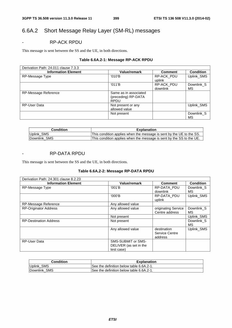
3GPP TS 36.508 version 11.3.0 Release 11 ETSI TS 136 508 V11.3.0 (2014-02)
ETSI
399
6.6A.2 Short Message Relay Layer (SM-RL) messages
- RP-ACK RPDU
This message is sent between the SS and the UE, in both directions.
Table 6.6A.2-1: Message RP-ACK RPDU
Derivation Path: 24.011 clause 7.3.3 Information Element Value/remark Comment Condition
RP-Message Type ‘010’B RP-ACK_PDU uplink
Uplink_SMS
‘011’B RP-ACK_PDU downlink
Downlink_SMS
RP-Message Reference Same as in associated (preceding) RP-DATA RPDU
RP-User Data Not present or any allowed value
Uplink_SMS
Not present Downlink_SMS
Condition Explanation Uplink_SMS This condition applies when the message is sent by the UE to the SS. Downlink_SMS This condition applies when the message is sent by the SS to the UE.
- RP-DATA RPDU
This message is sent between the SS and the UE, in both directions.
Table 6.6A.2-2: Message RP-DATA RPDU
Derivation Path: 24.301 clause 8.2.23 Information Element Value/remark Comment Condition
RP-Message Type ‘001’B RP-DATA_PDU downlink
Downlink_SMS
‘000’B RP-DATA_PDU uplink
Uplink_SMS
RP-Message Reference Any allowed value RP-Originator Address Any allowed value originating Service
Centre address Downlink_SMS
Not present Uplink_SMS RP-Destination Address Not present Downlink_S
MS Any allowed value destination
Service Centre address
Uplink_SMS
RP-User Data SMS-SUBMIT or SMS-DELIVER (as set in the test case)
Condition Explanation Uplink_SMS See the definition below table 6.6A.2-1. Downlink_SMS See the definition below table 6.6A.2-1.
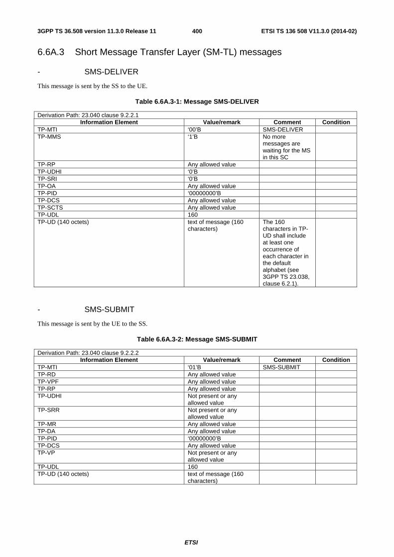
3GPP TS 36.508 version 11.3.0 Release 11 ETSI TS 136 508 V11.3.0 (2014-02)
ETSI
400
6.6A.3 Short Message Transfer Layer (SM-TL) messages
- SMS-DELIVER
This message is sent by the SS to the UE.
Table 6.6A.3-1: Message SMS-DELIVER
Derivation Path: 23.040 clause 9.2.2.1 Information Element Value/remark Comment Condition
TP-MTI ‘00’B SMS-DELIVER TP-MMS ‘1’B No more
messages are waiting for the MS in this SC
TP-RP Any allowed value TP-UDHI ‘0’B TP-SRI ‘0’B TP-OA Any allowed value TP-PID ‘00000000’B TP-DCS Any allowed value TP-SCTS Any allowed value TP-UDL 160 TP-UD (140 octets) text of message (160
characters) The 160 characters in TP-UD shall include at least one occurrence of each character in the default alphabet (see 3GPP TS 23.038, clause 6.2.1).
- SMS-SUBMIT
This message is sent by the UE to the SS.
Table 6.6A.3-2: Message SMS-SUBMIT
Derivation Path: 23.040 clause 9.2.2.2 Information Element Value/remark Comment Condition
TP-MTI ‘01’B SMS-SUBMIT TP-RD Any allowed value TP-VPF Any allowed value TP-RP Any allowed value TP-UDHI Not present or any
allowed value
TP-SRR Not present or any allowed value
TP-MR Any allowed value TP-DA Any allowed value TP-PID ‘00000000’B TP-DCS Any allowed value TP-VP Not present or any
allowed value
TP-UDL 160 TP-UD (140 octets) text of message (160
characters)

3GPP TS 36.508 version 11.3.0 Release 11 ETSI TS 136 508 V11.3.0 (2014-02)
ETSI
401
6.6B Reference radio bearer configurations
6.6B.1 SRB and DRB parameters and combinations
6.6B.1.1 SRB and DRB parameters
6.6B.1.1.1 Physical Layer configurations
Table 6.6B.1.1.1-1: PhysicalConfigDedicated-DEFAULT
Derivation Path: TS 36.508 clause 4.8.2.1.6, Table 4.8.2.1.6-1 Information Element Value/remark Comment Condition
PhysicalConfigDedicated-DEFAULT ::= SEQUENCE { cqi-ReportConfig CQI-ReportConfig-
DEFAULT using condition CQI_PERIODIC
See subclause 4.6.3
SRB1 or RBC or RBC-HO or HO-TO-EUTRA
soundingRS-UL-ConfigDedicated SoundingRS-UL-ConfigDedicated-DEFAULT
See subclause 4.6.3
SRB1 or RBC or RBC-HO or HO-TO-EUTRA
}
Condition Explanation SRB1 Used at configuration of SRB1 during RRC connection (re-)establishment RBC Used at configuration of a radio bearer combination during SRB2+DRB establishment 2TX Used for cells with two antenna ports RBC-HO Used during Handover HO-TO-EUTRA Inter-RAT handover to E-UTRA
6.7 Timer Tolerances The timer tolerances specified for the test environment in this subclause apply to all Signalling test cases defined in TS 36.523-1 [18] unless otherwise specified
All the timers used during testing are within a tolerance margin given by the equation below. If for a specific test a different tolerance value is required then this should be specified in the relevant test document (i.e. the document where the test is described).
Timer tolerance = 10%, or 5 × RTT , whichever value is the greater.
Where RTT = 8 TTIs for FDD, and RTT= Maximum RTT from Table 6.7-1 for TDD (see Note). NOTE: Since the exact RTT for TDD varies depending on the UL/DL configurations and subframe number [29],
the maximum RTT is defined in Table 6.7-1.

3GPP TS 36.508 version 11.3.0 Release 11 ETSI TS 136 508 V11.3.0 (2014-02)
ETSI
402
Table 6.7-1: Maximum RTT for TDD UL/DL configurations
UL/DL Configuration Maximum RTT (TTIs) 0 10 1* 11 2 12 3 15 4 16 5 TBD 6 11
*Note: Default UL/DL configuration defined in Table 4.6.3-23 of TS 36.508
7 Test environment for RRM tests This section contains all the exceptions of the common test parameters specified in clause 4 for specific needs of test cases defined in TS 36.521-3 [34], TS 34.121-1 [50] and TS 34.122[51]. Exceptions specified in clause 7 overwrite the parameter settings of clause 4; exceptions defined within the test cases overwrite parameter settings of clause 4 and 7.
This clause describes UE test states which can be used in the initial condition for TS 36.521-3 [34], TS 34.121-1 [50] and TS 34.122[51].
7.1 Requirements of test equipment <void>
7.2 RRM Reference system configurations
7.2.1 Common parameters for simulated E-UTRA cells
7.2.1.1 Combinations of system information blocks
<void>
7.2.1.2 Scheduling of system information blocks
<void>
7.2.1.3 Common contents of system information messages
- SystemInformationBlockType2
As defined in Table 4.4.3.3-1 with the following exceptions:

3GPP TS 36.508 version 11.3.0 Release 11 ETSI TS 136 508 V11.3.0 (2014-02)
ETSI
403
Table 7.2.1.3-1: SystemInformationBlockType2 exceptions
Derivation Path: Clause 4.4.3.3, Table 4.4.3.3-1 SystemInformationBlockType2 Information Element Value/remark Comment Condition
mbsfn-SubframeConfig ::= SEQUENCE { FDD radioframeAllocationPeriod n1 Every radio frame
is with MBSFN subframe
radioframeAllocationOffset 0 subframeAllocation CHOICE { oneFrame 111111 Subframe 1, 2, 3,
6, 7, 8 is used for MBSFN
- SystemInformationBlockType3
As defined in Table 4.4.3.3-2 with the following exceptions:
Table 7.2.1.3-2: SystemInformationBlockType3 exceptions
Derivation Path: Clause 4.4.3.3, Table 4.4.3.3-2 SystemInformationBlockType3 Information Element Value/remark Comment Condition
neighCellConfig ‘10’B (The MBSFN subframe allocations of all neighbour cells are identical to or subsets of that in the serving cell)
FDD with E-UTRA FDD neighbour cell
- SystemInformationBlockType5
As defined in Table 4.4.3.3-3 with the following exceptions:
Table 7.2.1.3-3: SystemInformationBlockType5 exceptions
Derivation Path: Clause 4.4.3.3, Table 4.4.3.3-4 SystemInformationBlockType5 Information Element Value/remark Comment Condition
neighCellConfig[n] ‘10’B (The MBSFN subframe allocations of all neighbour cells are identical to or subsets of that in the serving cell)
FDD with E-UTRA FDD neighbour cell
‘11’B (Different UL/DL allocation in neighbouring cells for TDD compared to the serving cell)
FDD with E-UTRA TDD neighbour cell, TDD with E-UTRA FDD neighbour cell
- SystemInformationBlockType7
As defined in Table 4.4.3.3-6 with the following exceptions:
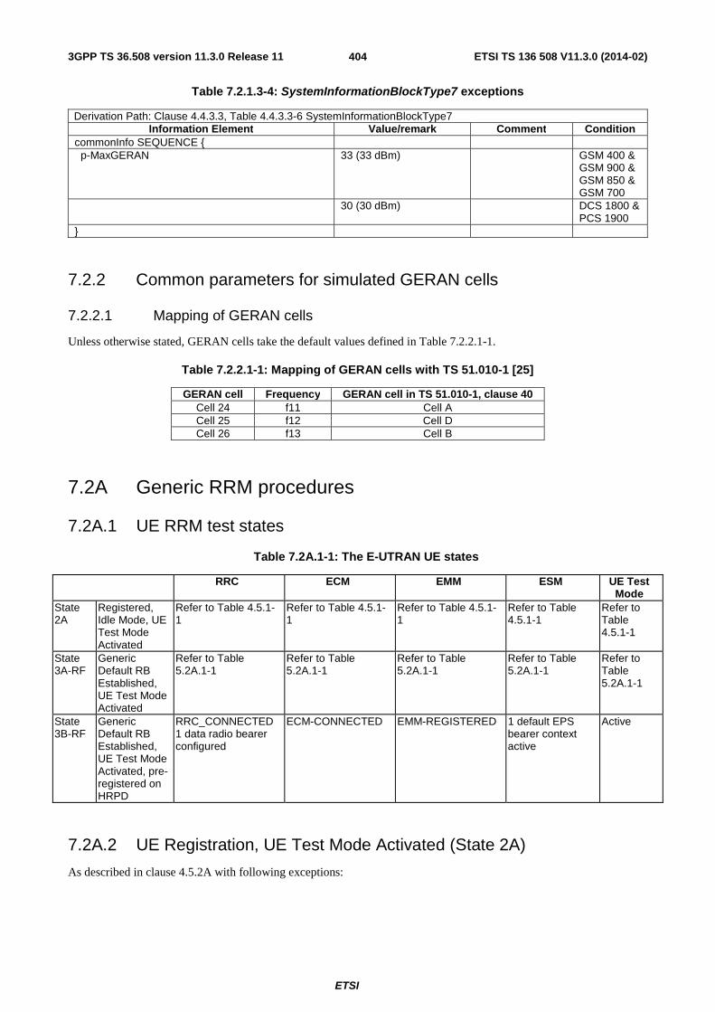
3GPP TS 36.508 version 11.3.0 Release 11 ETSI TS 136 508 V11.3.0 (2014-02)
ETSI
404
Table 7.2.1.3-4: SystemInformationBlockType7 exceptions
Derivation Path: Clause 4.4.3.3, Table 4.4.3.3-6 SystemInformationBlockType7 Information Element Value/remark Comment Condition
commonInfo SEQUENCE { p-MaxGERAN 33 (33 dBm) GSM 400 &
GSM 900 & GSM 850 & GSM 700
30 (30 dBm) DCS 1800 & PCS 1900
}
7.2.2 Common parameters for simulated GERAN cells
7.2.2.1 Mapping of GERAN cells
Unless otherwise stated, GERAN cells take the default values defined in Table 7.2.2.1-1.
Table 7.2.2.1-1: Mapping of GERAN cells with TS 51.010-1 [25]
GERAN cell Frequency GERAN cell in TS 51.010-1, clause 40 Cell 24 f11 Cell A Cell 25 f12 Cell D Cell 26 f13 Cell B
7.2A Generic RRM procedures
7.2A.1 UE RRM test states
Table 7.2A.1-1: The E-UTRAN UE states
RRC ECM EMM ESM UE Test Mode
State 2A
Registered, Idle Mode, UE Test Mode Activated
Refer to Table 4.5.1-1
Refer to Table 4.5.1-1
Refer to Table 4.5.1-1
Refer to Table 4.5.1-1
Refer to Table 4.5.1-1
State 3A-RF
Generic Default RB Established, UE Test Mode Activated
Refer to Table 5.2A.1-1
Refer to Table 5.2A.1-1
Refer to Table 5.2A.1-1
Refer to Table 5.2A.1-1
Refer to Table 5.2A.1-1
State 3B-RF
Generic Default RB Established, UE Test Mode Activated, pre-registered on HRPD
RRC_CONNECTED 1 data radio bearer configured
ECM-CONNECTED EMM-REGISTERED 1 default EPS bearer context active
Active
7.2A.2 UE Registration, UE Test Mode Activated (State 2A)
As described in clause 4.5.2A with following exceptions:

3GPP TS 36.508 version 11.3.0 Release 11 ETSI TS 136 508 V11.3.0 (2014-02)
ETSI
405
Table 7.2A.2-1: ACTIVATE DEFAULT EPS BEARER CONTEXT REQUEST (Step 16 in Table 4.5.2A.3-1)
Derivation Path: Table 4.7.3-6 Information Element Value/remark Comment Condition
PDN address Length of PDN address contents 5 octets PDN type value ‘001’B IPv4 PDN address information IPv4 address The SS provides a
valid IPv4 address
ESM cause IF "PDN type" IE in step 4 is 'IPv4v6' THEN '00110010'B ELSE Not present
"PDN type IPv4 only allowed"
7.2A.3 Generic Default Radio Bearer Establishment, UE Test Mode Activated (State 3A-RF)
As described in clause 5.2A.2.
7.2A.4 Generic Default Radio Bearer Establishment, UE Test Mode Activated, pre-registration on HRPD (State 3B-RF)
Editor’s note: This section is incomplete. The following aspects are either missing or not yet determined: Other than UATI Request message and UATI Assignment message are FFS
7.2A.4.1 Initial conditions
System Simulator:
- Cell 1
- Cell 1 is transmitting SystemInformationBlockType8
User Equipment:
- The Test USIM shall be inserted.
7.2A.4.2 Definition of system information messages
As described in clause 4.5.2B.2.
7.2A.4.3 Procedure
Table 7.2A.4.3-1: UE registration with default EPS bearer establishment, test mode activation and HRPD pre-registration procedures (state 1 to state 3B-RF)
Step Procedure Message Sequence U - S Message
1 to 18
Same procedure for steps 1 to 18 as specified in the procedure in clause 4.5.2A.3 and 7.2A.2
- -
19 to 36
Same procedure for steps 17 to 30D as specified in the procedure in clause 4.5.2B.3
7.2A.4.4 Specific message contents
As described in clauses 4.5.2B.4 and 7.2A.2.
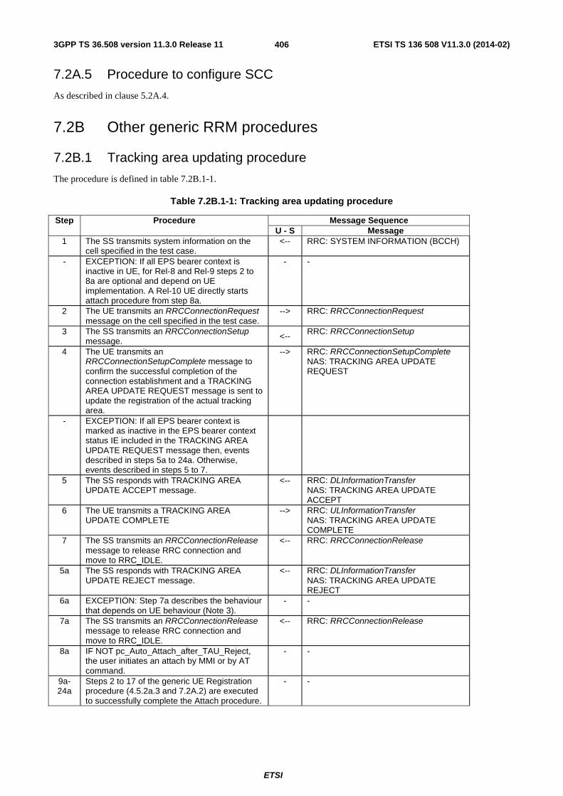
3GPP TS 36.508 version 11.3.0 Release 11 ETSI TS 136 508 V11.3.0 (2014-02)
ETSI
406
7.2A.5 Procedure to configure SCC
As described in clause 5.2A.4.
7.2B Other generic RRM procedures
7.2B.1 Tracking area updating procedure
The procedure is defined in table 7.2B.1-1.
Table 7.2B.1-1: Tracking area updating procedure
Step Procedure Message Sequence U - S Message
1 The SS transmits system information on the cell specified in the test case.
<-- RRC: SYSTEM INFORMATION (BCCH)
- EXCEPTION: If all EPS bearer context is inactive in UE, for Rel-8 and Rel-9 steps 2 to 8a are optional and depend on UE implementation. A Rel-10 UE directly starts attach procedure from step 8a.
- -
2 The UE transmits an RRCConnectionRequest message on the cell specified in the test case.
--> RRC: RRCConnectionRequest
3 The SS transmits an RRCConnectionSetup message. <--
RRC: RRCConnectionSetup
4 The UE transmits an RRCConnectionSetupComplete message to confirm the successful completion of the connection establishment and a TRACKING AREA UPDATE REQUEST message is sent to update the registration of the actual tracking area.
--> RRC: RRCConnectionSetupComplete NAS: TRACKING AREA UPDATE REQUEST
- EXCEPTION: If all EPS bearer context is marked as inactive in the EPS bearer context status IE included in the TRACKING AREA UPDATE REQUEST message then, events described in steps 5a to 24a. Otherwise, events described in steps 5 to 7.
5 The SS responds with TRACKING AREA UPDATE ACCEPT message.
<-- RRC: DLInformationTransfer NAS: TRACKING AREA UPDATE ACCEPT
6 The UE transmits a TRACKING AREA UPDATE COMPLETE
--> RRC: ULInformationTransfer NAS: TRACKING AREA UPDATE COMPLETE
7 The SS transmits an RRCConnectionRelease message to release RRC connection and move to RRC_IDLE.
<-- RRC: RRCConnectionRelease
5a The SS responds with TRACKING AREA UPDATE REJECT message.
<-- RRC: DLInformationTransfer NAS: TRACKING AREA UPDATE REJECT
6a EXCEPTION: Step 7a describes the behaviour that depends on UE behaviour (Note 3).
- -
7a The SS transmits an RRCConnectionRelease message to release RRC connection and move to RRC_IDLE.
<-- RRC: RRCConnectionRelease
8a IF NOT pc_Auto_Attach_after_TAU_Reject, the user initiates an attach by MMI or by AT command.
- -
9a-24a
Steps 2 to 17 of the generic UE Registration procedure (4.5.2a.3 and 7.2A.2) are executed to successfully complete the Attach procedure.
- -

3GPP TS 36.508 version 11.3.0 Release 11 ETSI TS 136 508 V11.3.0 (2014-02)
ETSI
407
NOTE 1: The periodic tracking area updating timer T3412 is deactivated by default during the attach procedure (TS 36.508 clause 4.7.2).
NOTE 2: The SS does not initiate authentication and NAS SECURITY MODE COMMAND are not performed (reuse of keys allocated during the attach procedure).
NOTE 3: The SS waits for 1 second to receive the Attach Request on the existing RRC Connection. In case Attach Request is not received within 1 second, existing RRC Connection is released.
7.3 Default RRC message and information elements contents
7.3.1 Contents of RRC messages
FFS.
7.3.2 Radio resource control information elements
Editor’s note: Unless otherwise stated in the test parameters or messages exceptions in the respective test cases in TS 36.521-3 [34], PRACH configuration index and exceptional message as specified in Table 7.3.2-1 is used.
As defined in clause 4.6.3 with the following exceptions:
Table 7.3.2-1: PRACH-Config-DEFAULT
Derivation Path: Clause 4.6.3 Table 4.6.3-7 Information Element Value/remark Comment Condition
PRACH-Config-DEFAULT ::= SEQUENCE { prach-ConfigIndex 3 TDD }
Condition Explanation TDD TDD cell environment
Table 7.3.2-2: RadioResourceConfigCommonSCell-r10-DEFAULT
Derivation Path: Clause 4.6.3 Table 4.6.3-13A Information Element Value/remark Comment Condition
RadioResourceConfigCommonSCell-r10 ::= SEQUENCE {
mbsfn-SubframeConfigList-r10 SEQUENCE { FDD radioframeAllocationPeriod n1 Every radio frame
is with MBSFN subframe
radioframeAllocationOffset 0 subframeAllocation CHOICE { oneFrame 111111 Subframe 1, 2, 3,
6, 7, 8 is used for MBSFN
} } ul-Configuration-r10 Not Present }
Condition Explanation FDD FDD cell environment

3GPP TS 36.508 version 11.3.0 Release 11 ETSI TS 136 508 V11.3.0 (2014-02)
ETSI
408
Table 7.3.2-3: PhysicalConfigDedicatedSCell-r10-DEFAULT
Derivation Path: Clause 4.6.3 Table 4.6.3-6A Information Element Value/remark Comment Condition
PhysicalConfigDedicatedSCell-r10 ::= SEQUENCE { ul-Configuration-r10 Not Present }
7.3.3 Measurement information elements
As defined in clause 4.6.6 with the following exceptions:
Table 7.3.4-1: MeasObjectEUTRA-GENERIC (Freq)
Derivation Path: Clause 4.6.6, Table 4.6.6-2 Information Element Value/remark Comment Condition
neighCellConfig 10'B (The MBSFN subframe allocations of all neighbour cells are identical to or subsets of that in the serving cell)
FDD with E-UTRA FDD neighbour cell
‘11’B (Different UL/DL allocation in neighbouring cells for TDD compared to the serving cell)
FDD with E-UTRA TDD neighbour cell, TDD with E-UTRA FDD neighbour cell
7.4 Default NAS message and information elements contents
7.5 Reference radio bearer configurations
7.5.1 SRB and DRB parameters
7.5.1.1 MAC configurations
As defined in clause 4.8.2.1.5 with the following exceptions:
Table 7.5.1.1-1: MAC-MainConfig-RBC
Derivation Path: Clause 4.8.2.1.5 Table 4.8.2.1.5-1 Information Element Value/remark Comment Condition
MAC-MainConfig-RBC ::= SEQUENCE { mac-MainConfig-v1020SEQUENCE { SCell_AddM
od sCellDeactivationTimer-r10 Not present extendedBSR-Sizes-r10 Not Present extendedPHR-r10 Not Present } }
Condition Explanation SCell_AddMod Addition or modification of Scell

3GPP TS 36.508 version 11.3.0 Release 11 ETSI TS 136 508 V11.3.0 (2014-02)
ETSI
409
Annex A (informative): Connection Diagrams
Definition of Terms
System Simulator or SS – A device or system, that is capable of generating simulated Node B signalling and analysing UE signalling responses on one or more RF channels, in order to create the required test environment for the UE under test. It will also include the following capabilities:
1. Measurement and control of the UE Tx output power through TPC commands
2. Measurement of Throughput
3. Measurement of signalling timing and delays
4. Ability to simulate UTRAN and/or E-UTRAN and/or GERAN signalling
Test System – A combination of devices brought together into a system for the purpose of making one or more measurements on a UE in accordance with the test case requirements. A test system may include one or more System Simulators if additional signalling is required for the test case. The following diagrams are all examples of Test Systems.
NOTE 1: The above terms are logical definitions to be used to describe the test methods used in the documents TS36.521-1, TS 36.523-1and TS36.521-3 in practice, real devices called 'System Simulators' may also include additional measurement capabilities or may only support those features required for the test cases they are designed to perform.
NOTE 2: Components in the connection diagrams: The components in the connection diagrams represent ideal components. They are intended to display the wanted signal flow. They don’t mandate real implementations. An alternative to Figure. A3 is shown below as an example: It is nearer to real implementations. The signal levels are the same as in Figure A3. The signal flow cannot be displayed as detailed as in Figure A.3.
SS
RX/TX
RX UE under Test
RX/TX
Ior
Îor Splitter/ combiner
Alternative to Figure A.3
Connection: Each connection is displayed as a one or two sided arrow, showing the intended signal flow.
Circulator: The signal, entering one port, is conducted to the adjacent port, indicated by the arrow. The attenuation among the above mentioned ports is ideally 0 and the isolation among the other ports is ideally ∞.
Splitter: a splitter has one input and 2 or more outputs. The signal at the input is equally divided to the outputs. The attenuation from input to the outputs is ideally 0 and the isolation between the outputs is ideally ∞.

3GPP TS 36.508 version 11.3.0 Release 11 ETSI TS 136 508 V11.3.0 (2014-02)
ETSI
410
Combiner: a combiner has one output and 2 or more inputs. The signals at the inputs are conducted to the output, all with the same, ideally 0 attenuation. The isolation between the inputs is ideally ∞.
Switch: contacts a sink (or source) alternatively to two or more sources (or sinks).
Fader: The fader has one input and one output. The MIMO fading channel is represented by several single faders (e.g. 8 in case of a MIMO antenna configuration 4x2) The correlation among the faders is described in TS 36.521-1 clause B.2.2
Attenuator: TBD
General considerations on connections for CA testing
Figures A.32<x> to A.37<x> and A.41<x> to A.44<x> contain connection diagrams for CA testing. Different options (<x> = a, b, c) have been defined for each connection, to consider different UE employments with respect to UE antenna connectors and signal mapping:
- a: Separate antenna connectors for each CC. An optional Combiner may be used in case the UE employs one common wide band antenna only for the receive diversity for both CC-s.
- b: Common antenna connectors for both CC-s with same UL transmit antenna connector.
- c: Common antenna connectors for both CC-s with different UL transmit antenna connectors.
The connections are referred in tests as Figure group which imply figures with the same arabic numeral in the number, but different latin letter extension (e.g. Figure A.32a, A.32b etc). The selection of the connection option for testing is done according to the UE employment as appropriate.
Following symbolic is used in the connection diagrams to distinguish CC-s and paths:
- p: primary CC
- s: secondary CC
- <j>: (integer) defines the receive antenna and the path to it <j> for a given CC
- <i><j>: (integer) defines the path between transmit antenna <i> and receive antenna <j> for a given CC
The connections are general and support CA both in DL and UL. According to the test conditions, if the UL CA is not used, the “secondary CC of UL” in the connections may be ignored.
For contiguous CA, AWGN_p and AWGN_s affecting the same UE antenna connector can be unified to a single AWGN_p/s with higher bandwidth.
Figure A.1: Void

3GPP TS 36.508 version 11.3.0 Release 11 ETSI TS 136 508 V11.3.0 (2014-02)
ETSI
411
SS
TX
RX
Îor
Spectrum Analyzer
RX
UE under Test
RX/TX
Splitter
CW Gen
Σ splitter
Figure A.2: Connection for Transmitter Intermodulation tests
SS
TX
RX
RX
UE under Test
RX/TX
Ior
Îor
Splitter
Figure A.3: Connection for basic single cell, RX and TX tests

3GPP TS 36.508 version 11.3.0 Release 11 ETSI TS 136 508 V11.3.0 (2014-02)
ETSI
412
RX
UE under Test
SS
TX
RX
RX/TX
Ior
Io
Σ
Interference Signal Generator
Ioc
Îor Splitter
Figure A.4: Connection for Receiver tests with E-UTRA-Interference
RX
UE under Test
SS
TX
RX
RX/TX
Ior
Io
Σ
CW Signal Generator
I blocking
Îor Splitter
Figure A.5: Connection for Receiver tests with CW interferer

3GPP TS 36.508 version 11.3.0 Release 11 ETSI TS 136 508 V11.3.0 (2014-02)
ETSI
413
RX
UE under Test
SS TX
RX
Ior
Io
Σ
Tone
Îor
CW Signal Generator
Ioc Interference Signal Generator
RX/TX
Splitter
Figure A.6: Connection for Receiver tests with both E-UTRA Interference and additional CW signal
Splitter
Spectrum
Analyzer
splitter
SS
TX
RX
Ior
Îor
RX
UE under Test
RX/TX
Figure A.7: Connection for TX-tests with additional Spectrum Analyzer

3GPP TS 36.508 version 11.3.0 Release 11 ETSI TS 136 508 V11.3.0 (2014-02)
ETSI
414
Figure A.8: Connection for RX-tests with additional Spectrum Analyzer
SS TX
RX
RX
UE
under
test
TX/RX
Fader 1
Fader 2
Σ
Σ
splitter
AWGN Gen 1
AWGN Gen 2
Figure A.9: Connection for RX performance tests with antenna configuration 1x2 (single antenna port)
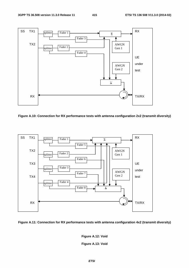
3GPP TS 36.508 version 11.3.0 Release 11 ETSI TS 136 508 V11.3.0 (2014-02)
ETSI
415
SS TX1
TX2
RX
RX
UE
under
test
TX/RX
Fader 1
Fader 3
Fader 4
Σ
Σ
splitter
splitter AWGN Gen 1
AWGN Gen 2
Fader 2
Figure A.10: Connection for RX performance tests with antenna configuration 2x2 (transmit diversity)
SS TX1
TX2
TX3
TX4
RX
RX
UE
under
test
TX/RX
Fader 1
Fader 3
Fader 4
Fader 5
Fader 8
Fader 7
Fader 6
Σ
Σ
splitter
splitter
splitter
splitter
AWGN Gen 1
AWGN Gen 2
Fader 2
Figure A.11: Connection for RX performance tests with antenna configuration 4x2 (transmit diversity)
Figure A.12: Void
Figure A.13: Void
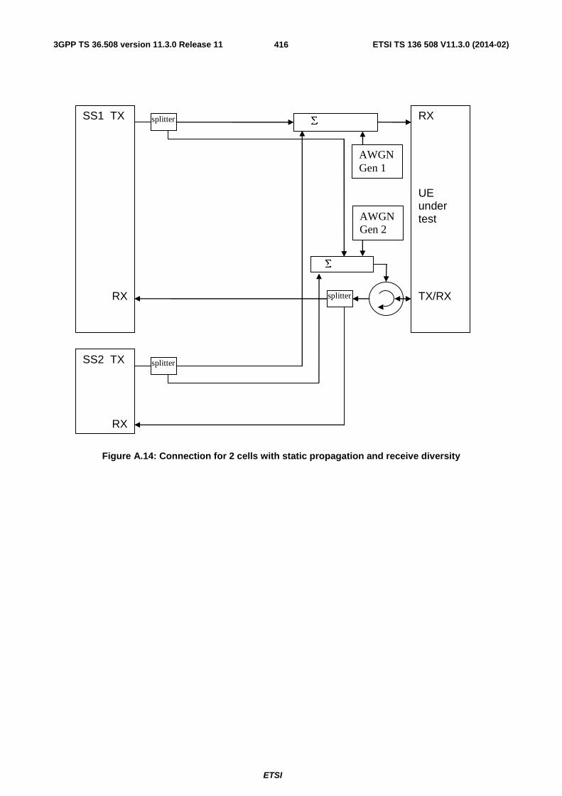
3GPP TS 36.508 version 11.3.0 Release 11 ETSI TS 136 508 V11.3.0 (2014-02)
ETSI
416
SS1 TX
RX
RX UE under test TX/RX
Σ
Σ
splitter
AWGN Gen 1
AWGN Gen 2
SS2 TX
RX
splitter
splitter
Figure A.14: Connection for 2 cells with static propagation and receive diversity

3GPP TS 36.508 version 11.3.0 Release 11 ETSI TS 136 508 V11.3.0 (2014-02)
ETSI
417
SS1 TX
RX
RX UE under test TX/RX
Fader 1
Fader 2
Σ
Σ
splitter
AWGN Gen 1
AWGN Gen 2
SS2 TX
RX
Fader 3
Fader 4
splitter
splitter
Figure A.15: Connection for 2 cells with multipath fading propagation and receive diversity

3GPP TS 36.508 version 11.3.0 Release 11 ETSI TS 136 508 V11.3.0 (2014-02)
ETSI
418
Figure A.16: Connection for single cell Signalling tests

3GPP TS 36.508 version 11.3.0 Release 11 ETSI TS 136 508 V11.3.0 (2014-02)
ETSI
419
UE under
Test
RX/TX
RXSplitter
SS2
RX
TX
Further cells
added in
similar way
RX
TX
Σ
Splitter
SS1
RX
TX
Figure A.17: Connection for multiple cells Signalling tests
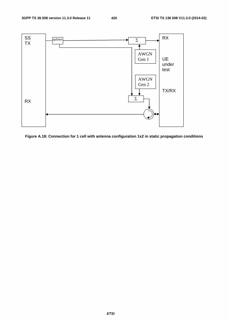
3GPP TS 36.508 version 11.3.0 Release 11 ETSI TS 136 508 V11.3.0 (2014-02)
ETSI
420
SS TX RX
RX UE under test TX/RX
Σ
Σ
splitter
AWGN Gen 1
AWGN Gen 2
Figure A.18: Connection for 1 cell with antenna configuration 1x2 in static propagation conditions

3GPP TS 36.508 version 11.3.0 Release 11 ETSI TS 136 508 V11.3.0 (2014-02)
ETSI
421
SS1 TX
RX
RX UE under test TX/RX
Σ
Σ
AWGN Gen 1
SS2 TX
RX
splitter
SS3 TX
RX
splitter
splitter Fader 1
Fader 2
Fader 3
Fader 4
AWGN Gen 2
splitter
Figure A.19: Connection for 3 cells with antenna configuration 1x2 in static (cell 1) and multipath fading (cell 2 and 3) propagation conditions and receive diversity
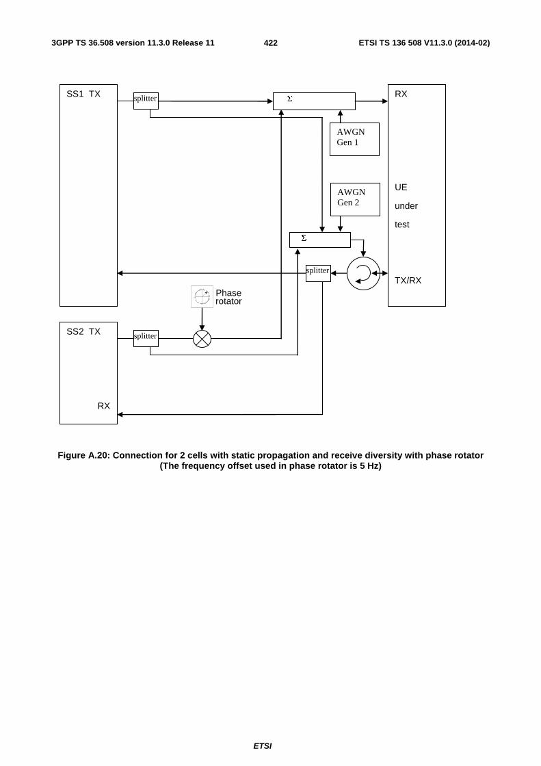
3GPP TS 36.508 version 11.3.0 Release 11 ETSI TS 136 508 V11.3.0 (2014-02)
ETSI
422
SS1 TX
RX
UE
under
test
TX/RX
Σ
Σ
splitter
AWGN Gen 1
AWGN Gen 2
SS2 TX
RX
splitter
splitter
Phase rotator
Figure A.20: Connection for 2 cells with static propagation and receive diversity with phase rotator (The frequency offset used in phase rotator is 5 Hz)

3GPP TS 36.508 version 11.3.0 Release 11 ETSI TS 136 508 V11.3.0 (2014-02)
ETSI
423
SS TX
RX
RX
UE
under
test
TX/RX
Fader 1
Fader 2
Σ
Σ
splitter
Iot Gen 1
Iot Gen 2
Figure A.21: Connection for frequency-selective interference with multipath fading propagation and receive diversity
SS Origin cell E-UTRA TX RX
RX diversty UE RX/TX
Σ
Σ
AWGN Origin
AWGN Origin
SS Target ≠ E-UTRA
AWGN Target
Splitter
Splitter
Splitter
AWGN Target
Figure A.22: Connection for 2 cells with static propagation condition. Origin (E-UTRAN) and target cell (≠ E-UTRAN) received with RX diversity

3GPP TS 36.508 version 11.3.0 Release 11 ETSI TS 136 508 V11.3.0 (2014-02)
ETSI
424
SS Origin cell E-UTRA TX RX
RX diversty UE RX/TX
Σ
Σ
AWGN Origin
AWGN Origin
SS Target ≠ E-UTRA
AWGN Target
Splitter
Splitter
Splitter
Fader
Fader
Fader
Fader
AWGN Target
Figure A.23: Connection for 2 cells with multipath fading propagation condition. Origin (E-UTRAN) and target cell (≠ E-UTRAN) received with RX diversity

3GPP TS 36.508 version 11.3.0 Release 11 ETSI TS 136 508 V11.3.0 (2014-02)
ETSI
425
SS1 TX Origin Cell E-UTRAN
RX
RX UE under test TX/RX
Σ
Σ
AWGN Origin
SS2 TX Target E-UTRAN
RX
splitter
SS3 TX Target ≠ E-UTRAN
RX
splitter
splitter Fader 1
Fader 2
AWGN Origin
splitter
AWGN Target
Fader 3
Fader 4
AWGN Target
Figure A.24: Connection for 3 cells with antenna configuration 1x2 in static (cell 1) and multipath fading conditions (cell 2 and 3) and multiple RAT and receive diversity

3GPP TS 36.508 version 11.3.0 Release 11 ETSI TS 136 508 V11.3.0 (2014-02)
ETSI
426
SS1 TX Origin Cell E-UTRAN
RX
RX UE under test TX/RX
Σ
Σ
AWGN
SS2 TX Target E-UTRAN
RX
splitter
SS3 TX Target ≠ E-UTRAN
RX
splitter
splitter Fader 3
Fader 4
AWGN
splitter
AWGN Target
Fader 1
Fader 2
AWGN Target
Figure A.25: Connection for 3 cells with antenna configuration 1x2 in multipath fading (cell 1and 2) and multiple RAT (cell 3 static) and receive diversity

3GPP TS 36.508 version 11.3.0 Release 11 ETSI TS 136 508 V11.3.0 (2014-02)
ETSI
427
SS Origin cell E-UTRA TX RX
RX diversty UE RX/TX
Σ
Σ
AWGN Origin
AWGN Origin
SS Target ≠ E-UTRA
AWGN Target
Splitter
Splitter
Splitter
Fader
Fader
AWGN Target
Figure A.26: Connection for 2 cells. Origin (E-UTRAN, multipath fading) and target cell (≠ E-UTRAN, static) received with RX diversity
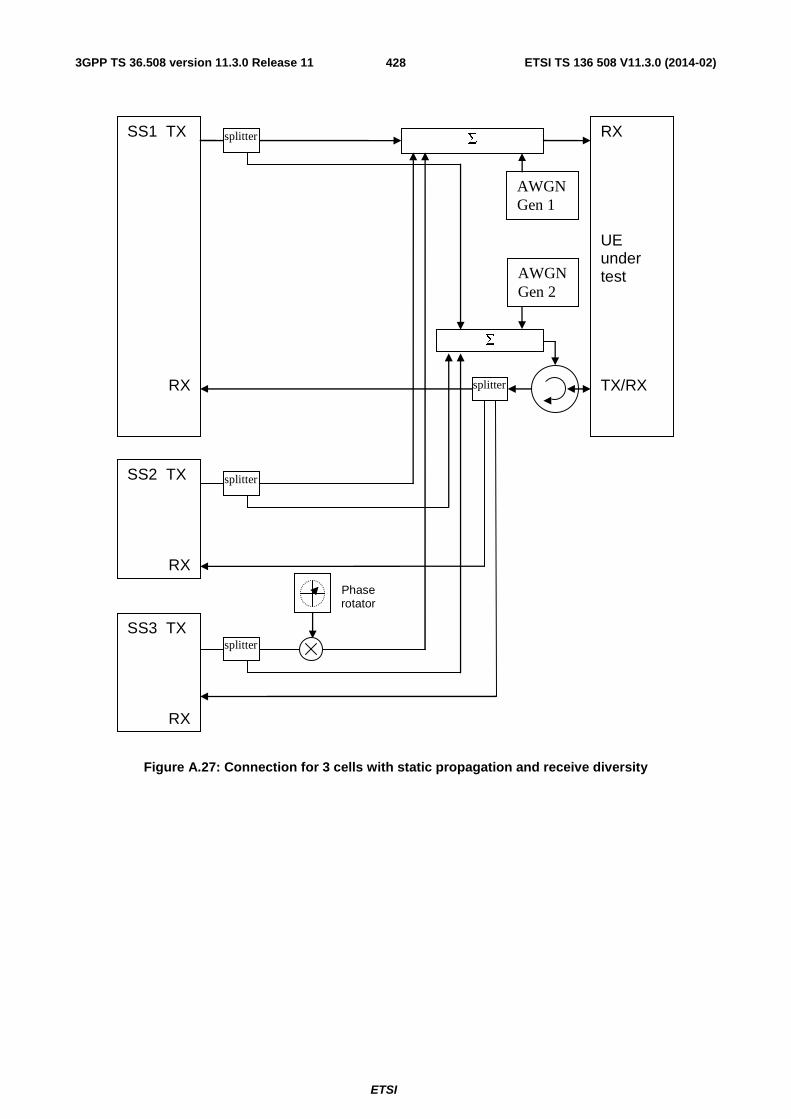
3GPP TS 36.508 version 11.3.0 Release 11 ETSI TS 136 508 V11.3.0 (2014-02)
ETSI
428
SS1 TX
RX
RX UE under test TX/RX
Σ
Σ
AWGN Gen 1
SS2 TX
RX
splitter
SS3 TX
RX
splitter
splitter
AWGN Gen 2
splitter
Phase rotator
Figure A.27: Connection for 3 cells with static propagation and receive diversity

3GPP TS 36.508 version 11.3.0 Release 11 ETSI TS 136 508 V11.3.0 (2014-02)
ETSI
429
SS TX
RX1
RX2
TX/RX
UE
under
test
TX/RX
splitter
Figure A.28: Connection for basic UL MIMO with receive diversity

3GPP TS 36.508 version 11.3.0 Release 11 ETSI TS 136 508 V11.3.0 (2014-02)
ETSI
430
SS TX
RX1
RX2
TX/RX
UE
under
test
TX/RX
splitter Σ
InterferenceSignal Generator
Figure A.29: Connection for UL MIMO Receiver tests with E-UTRA-Interference

3GPP TS 36.508 version 11.3.0 Release 11 ETSI TS 136 508 V11.3.0 (2014-02)
ETSI
431
SS TX
RX1
RX2
TX/RX
UE
under
test
TX/RX
splitter Σ
CW Signal Generator
Figure A.30: Connection for UL MIMO Receiver tests with CW Interference

3GPP TS 36.508 version 11.3.0 Release 11 ETSI TS 136 508 V11.3.0 (2014-02)
ETSI
432
SS TX
RX1
RX2
TX/RX
UE
under
test
TX/RX
splitter Σ
CW
Signal Generator
Interference
Signal Generator
Figure A.31: Connection for UL MIMO Receiver tests with both E-UTRA-Interference and additional CW signal
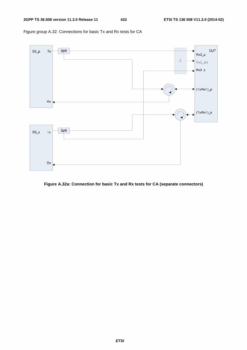
3GPP TS 36.508 version 11.3.0 Release 11 ETSI TS 136 508 V11.3.0 (2014-02)
ETSI
433
Figure group A.32: Connections for basic Tx and Rx tests for CA
Σ
DUT
Rx2_p
Rx2_p/s
Rx2_s
(Tx/Rx1)_p
(Tx/Rx1)_s
SS_p Tx
Rx
Split
Split
SS_s Tx
Rx
Figure A.32a: Connection for basic Tx and Rx tests for CA (separate connectors)
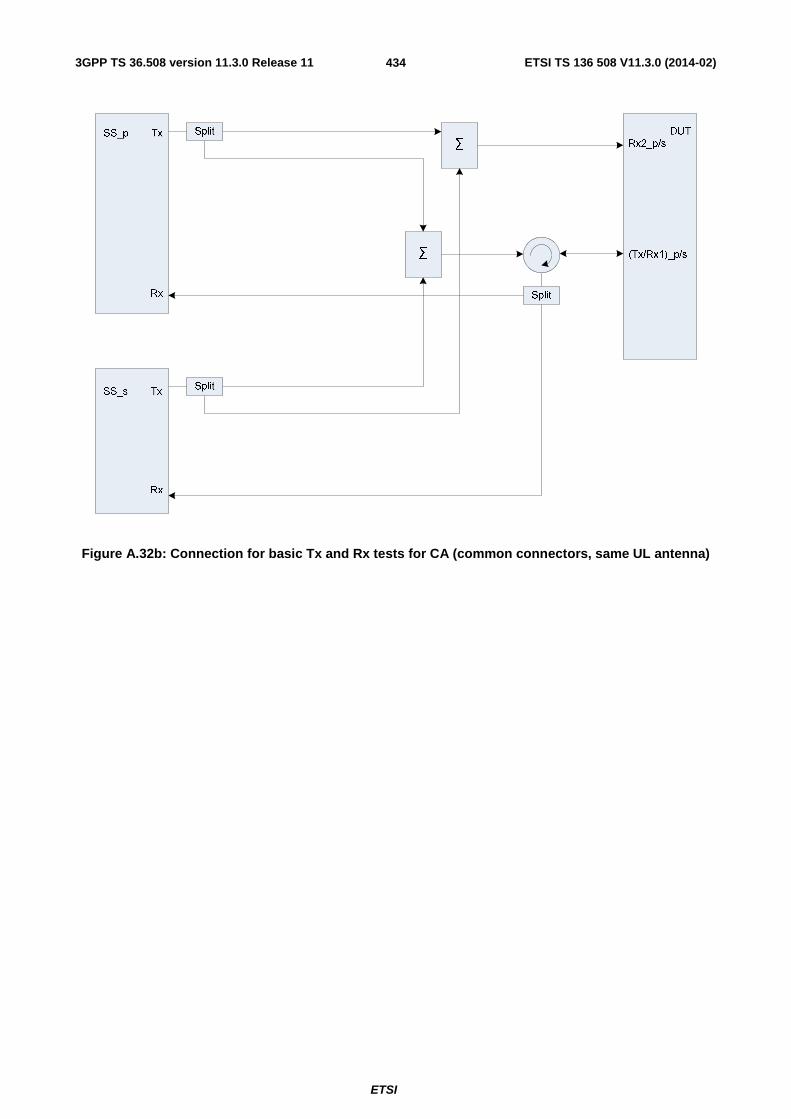
3GPP TS 36.508 version 11.3.0 Release 11 ETSI TS 136 508 V11.3.0 (2014-02)
ETSI
434
Figure A.32b: Connection for basic Tx and Rx tests for CA (common connectors, same UL antenna)

3GPP TS 36.508 version 11.3.0 Release 11 ETSI TS 136 508 V11.3.0 (2014-02)
ETSI
435
Figure A.32c: Connection for basic Tx and Rx tests for CA (common connectors, different UL antennas)

3GPP TS 36.508 version 11.3.0 Release 11 ETSI TS 136 508 V11.3.0 (2014-02)
ETSI
436
Figure group A.33: Connection for Tx tests for CA with additional Spectrum Analyzer
Σ
DUT
Rx2_p
Rx2_p/s
Rx2_s
(Tx/Rx1)_p
(Tx/Rx1)_s
SS_p Tx
Rx
Split
Split
SS_s Tx
Rx
Split
Split
Spectrum
analyzer
Figure A.33a: Connection for Tx tests for CA with additional Spectrum Analyzer (separate connectors)
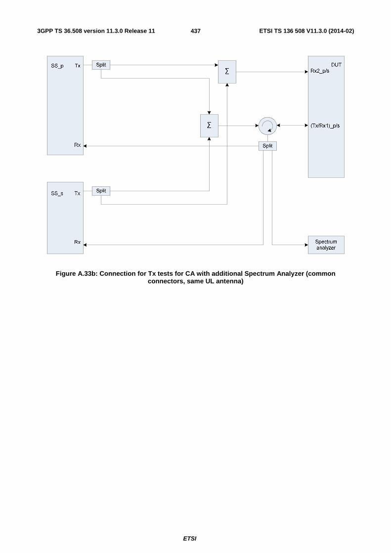
3GPP TS 36.508 version 11.3.0 Release 11 ETSI TS 136 508 V11.3.0 (2014-02)
ETSI
437
Figure A.33b: Connection for Tx tests for CA with additional Spectrum Analyzer (common connectors, same UL antenna)
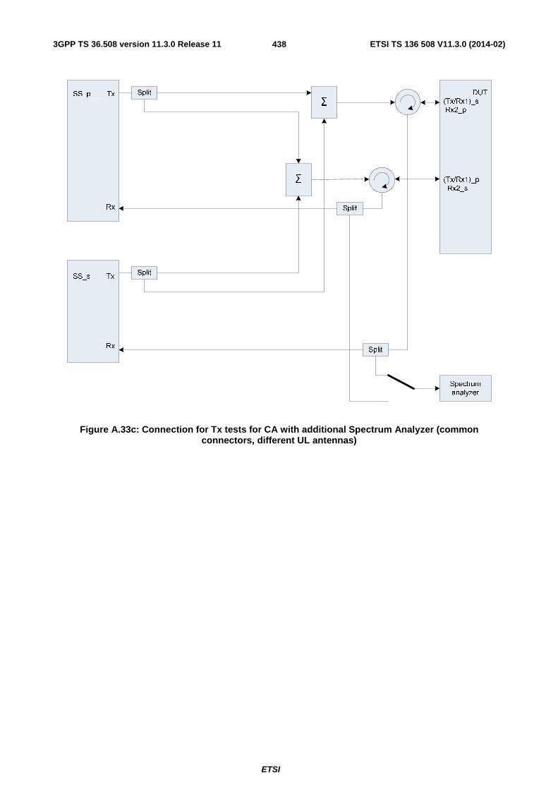
3GPP TS 36.508 version 11.3.0 Release 11 ETSI TS 136 508 V11.3.0 (2014-02)
ETSI
438
DUT
(Tx/Rx1)_s
Rx2_p
(Tx/Rx1)_p
Rx2_s
SS_p Tx
Rx
Σ
Σ
Split SS_s Tx
Rx
Split
Spectrum
analyzer
Split
Split
Figure A.33c: Connection for Tx tests for CA with additional Spectrum Analyzer (common connectors, different UL antennas)

3GPP TS 36.508 version 11.3.0 Release 11 ETSI TS 136 508 V11.3.0 (2014-02)
ETSI
439
Figure group A.34: Connection for Rx tests for CA with additional Interferer / CW
Σ
DUT
Rx2_p
Rx2_p/s
Rx2_s
(Tx/Rx1)_p
(Tx/Rx1)_s
SS_p Tx
Rx
Σ
Σ
Σ
Σ
Split
Split
SS_s Tx
Rx
Interferer /
CWSplit
Figure A.34a: Connection for Rx tests for CA with additional Interferer / CW (separate connectors)

3GPP TS 36.508 version 11.3.0 Release 11 ETSI TS 136 508 V11.3.0 (2014-02)
ETSI
440
DUT
Rx2_p/s
(Tx/Rx1)_p/s
SS_p Tx
Rx
Σ
Σ
Split
Split
SS_s Tx
Rx
Split
Interferer /
CWSplit
Figure A.34b: Connection for Rx tests for CA with additional Interferer / CW (common connectors, same UL antenna)

3GPP TS 36.508 version 11.3.0 Release 11 ETSI TS 136 508 V11.3.0 (2014-02)
ETSI
441
DUT
(Tx/Rx1)_s
Rx2_p
(Tx/Rx1)_p
Rx2_s
SS_p Tx
Rx
Σ
Σ
Split SS_s Tx
Rx
Split
Interferer /
CWSplit
Figure A.34c: Connection for Rx tests for CA with additional Interferer / CW (common connectors, different UL antennas)

3GPP TS 36.508 version 11.3.0 Release 11 ETSI TS 136 508 V11.3.0 (2014-02)
ETSI
442
Figure group A.35: Connection for Rx performance tests for CA with antenna configuration 1x2
Σ
DUT
Rx2_p
Rx2_p/s
Rx2_s
(Tx/Rx1)_p
(Tx/Rx1)_s
SS_p Tx
Rx
Σ
Σ
AWGN_s2
Σ
AWGN_p2
AWGN_p1
Σ
AWGN_s1
Split
Split
SS_s Tx
Rx
Fader_p2
Fader_p1
Fader_s1
Fader_s2
Figure A.35a: Connection for Rx performance tests for CA with antenna configuration 1x2 (separate connectors)

3GPP TS 36.508 version 11.3.0 Release 11 ETSI TS 136 508 V11.3.0 (2014-02)
ETSI
443
DUT
Rx2_p/s
(Tx/Rx1)_p/s
SS_p Tx
Rx
Σ
Σ
AWGN_p2
AWGN_p1
AWGN_s1
Split
Split
SS_s Tx
Rx
AWGN_s2
Split Fader_p2
Fader_p1
Fader_s1
Fader_s2
Figure A.35b: Connection for Rx performance tests for CA with antenna configuration 1x2 (common connectors, same UL antenna)

3GPP TS 36.508 version 11.3.0 Release 11 ETSI TS 136 508 V11.3.0 (2014-02)
ETSI
444
DUT
(Tx/Rx1)_s
Rx2_p
(Tx/Rx1)_p
Rx2_s
SS_p Tx
Rx
Σ
Σ
AWGN_p2
AWGN_s1
AWGN_p1
AWGN_s2
Split SS_s Tx
Rx
Split Fader_p2
Fader_p1
Fader_s1
Fader_s2
Figure A.35c: Connection for Rx performance tests for CA with antenna configuration 1x2 (common connectors, different UL antennas)

3GPP TS 36.508 version 11.3.0 Release 11 ETSI TS 136 508 V11.3.0 (2014-02)
ETSI
445
Figure group A.36: Connection for Rx performance tests for CA with antenna configuration 2x2
Σ
DUT
Rx2_p
Rx2_p/s
Rx2_s
(Tx/Rx1)_p
(Tx/Rx1)_s
SS_p Tx1
Tx2
Rx
Σ
Σ
AWGN_s2
Σ
AWGN_p2
AWGN_p1
Σ
AWGN_s1
Split
Split
SS_s Tx1
Tx2
Rx
Fader_p12
Fader_p11
Fader_s11
Fader_s22
Split Fader_p22
Fader_p21
Split Fader_s21
Fader_s22
Figure A.36a: Connection for Rx performance tests for CA with antenna configuration 2x2 (separate connectors)
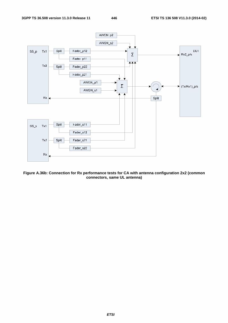
3GPP TS 36.508 version 11.3.0 Release 11 ETSI TS 136 508 V11.3.0 (2014-02)
ETSI
446
DUT
Rx2_p/s
(Tx/Rx1)_p/s
SS_p Tx1
Tx2
Rx
Σ
Σ
AWGN_p2
AWGN_p1
AWGN_s1
Split
Split
SS_s Tx1
Tx2
Rx
AWGN_s2
Split Fader_p12
Fader_p11
Fader_s11
Fader_s12
Split Fader_p22
Fader_p21
Split Fader_s21
Fader_s22
Figure A.36b: Connection for Rx performance tests for CA with antenna configuration 2x2 (common connectors, same UL antenna)

3GPP TS 36.508 version 11.3.0 Release 11 ETSI TS 136 508 V11.3.0 (2014-02)
ETSI
447
DUT
(Tx/Rx1)_s
Rx2_p
(Tx/Rx1)_p
Rx2_s
SS_p Tx1
Tx2
Rx
Σ
Σ
AWGN_p2
AWGN_s1
AWGN_p1
AWGN_s2
Split SS_s Tx1
Tx2
Rx
Split Fader_p12
Fader_p11
Fader_s12
Fader_s11
Split Fader_p22
Fader_p21
Split Fader_s22
Fader_s21
Figure A.36c: Connection for Rx performance tests for CA with antenna configuration 2x2 (common connectors, different UL antennas)

3GPP TS 36.508 version 11.3.0 Release 11 ETSI TS 136 508 V11.3.0 (2014-02)
ETSI
448
Figure group A.37: Connection for Tx tests for CA with additional CW and Spectrum Analyzer
Σ
DUT
Rx2_p
Rx2_p/s
Rx2_s
(Tx/Rx1)_p
(Tx/Rx1)_s
SS_p Tx
Rx
Σ
Σ
Split
Split
SS_s Tx
Rx
CW SplitSpectrum
analyzer
Split
Split
Figure A.37a: Connection for Tx tests for CA with additional CW and Spectrum Analyzer (separate connectors)
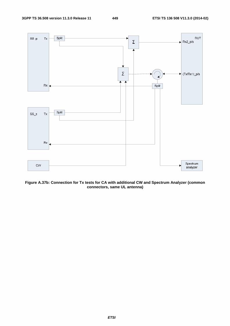
3GPP TS 36.508 version 11.3.0 Release 11 ETSI TS 136 508 V11.3.0 (2014-02)
ETSI
449
DUT
Rx2_p/s
(Tx/Rx1)_p/s
SS_p Tx
Rx
Σ
Σ
Split
Split
SS_s Tx
Rx
Split
CWSpectrum
analyzer
Figure A.37b: Connection for Tx tests for CA with additional CW and Spectrum Analyzer (common connectors, same UL antenna)

3GPP TS 36.508 version 11.3.0 Release 11 ETSI TS 136 508 V11.3.0 (2014-02)
ETSI
450
DUT
(Tx/Rx1)_s
Rx2_p
(Tx/Rx1)_p
Rx2_s
SS_p Tx
Rx
Σ
Σ
Split SS_s Tx
Rx
Split
CW SplitSpectrum
analyzer
Split
Split
Figure A.37c: Connection for Tx tests for CA with additional CW and Spectrum Analyzer (common connectors, different UL antennas)

3GPP TS 36.508 version 11.3.0 Release 11 ETSI TS 136 508 V11.3.0 (2014-02)
ETSI
451
Figure A.38: Connection for UL MIMO tests with additional Spectrum Analyzer
SS TX
RX1
RX2
TX/RX
UE
under
test
TX/RX
splitter Σ
CW Signal Generator
splitter
splitter
Spectrum Analyzer
Figure A.39: Connection for Transmitter Intermodulation tests for UL-MIMO

3GPP TS 36.508 version 11.3.0 Release 11 ETSI TS 136 508 V11.3.0 (2014-02)
ETSI
452
Figure A.40: Connection for 2 cells, antenna configuration 2x2, multipath fading and receive diversity
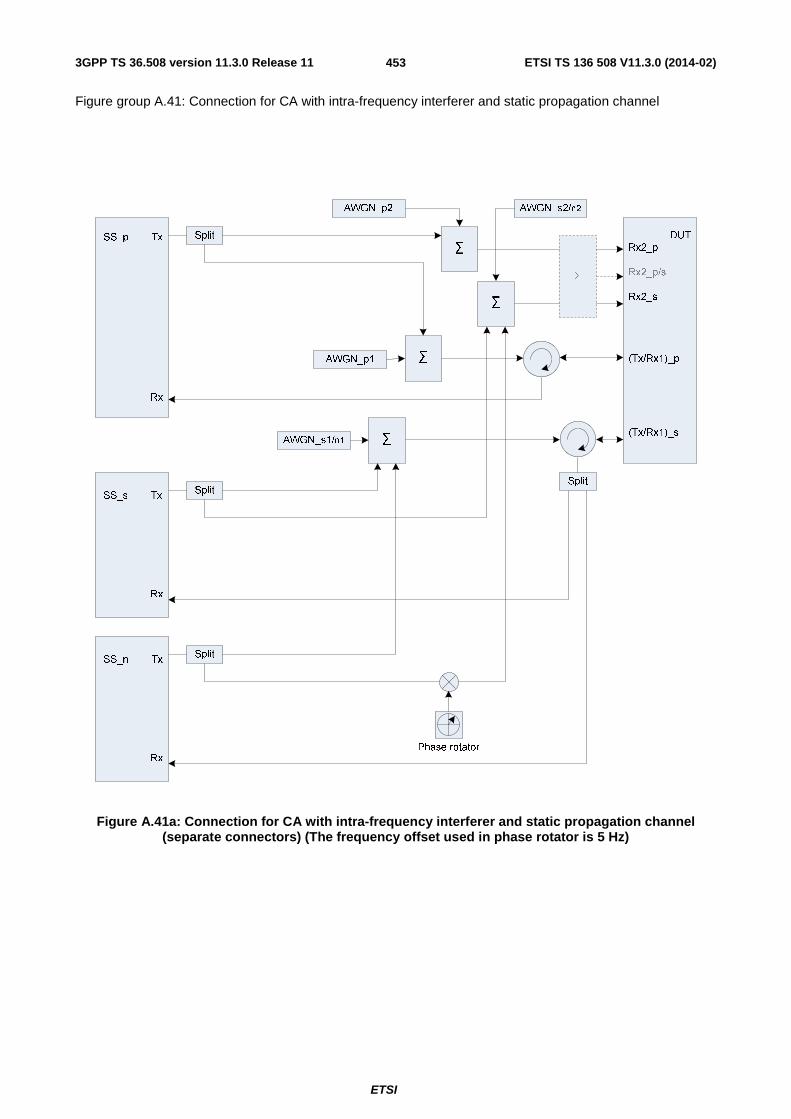
3GPP TS 36.508 version 11.3.0 Release 11 ETSI TS 136 508 V11.3.0 (2014-02)
ETSI
453
Figure group A.41: Connection for CA with intra-frequency interferer and static propagation channel
DUT
Rx2_p
Rx2_p/s
Rx2_s
(Tx/Rx1)_p
(Tx/Rx1)_s
SS_p Tx
Rx
Σ
Σ
AWGN_s2/n2
Σ
AWGN_p2
AWGN_p1
ΣAWGN_s1/n1
Split
Split
Split SS_n Tx
Rx
Split
SS_s Tx
Rx
Σ
Phase rotator
Figure A.41a: Connection for CA with intra-frequency interferer and static propagation channel (separate connectors) (The frequency offset used in phase rotator is 5 Hz)

3GPP TS 36.508 version 11.3.0 Release 11 ETSI TS 136 508 V11.3.0 (2014-02)
ETSI
454
DUT
Rx2_p/s
(Tx/Rx1)_p/s
SS_p Tx
Rx
Σ
Σ
AWGN_p2
AWGN_p1
AWGN_s1/n1
Split
Split SS_n Tx
Rx
Split
SS_s Tx
Rx
AWGN_s2/n2
Split
Phase rotator
Figure A.41b: Connection for CA with intra-frequency interferer and static propagation channel (common connectors, same UL antenna) (The frequency offset used in phase rotator is 5 Hz)
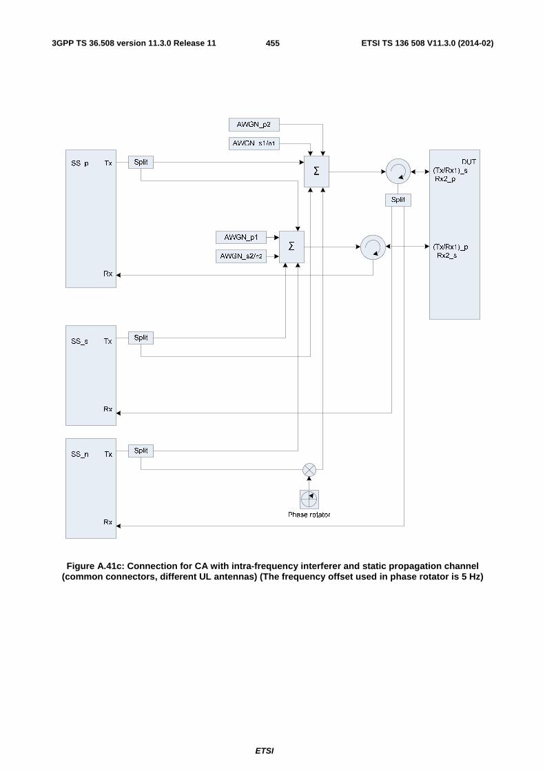
3GPP TS 36.508 version 11.3.0 Release 11 ETSI TS 136 508 V11.3.0 (2014-02)
ETSI
455
DUT
(Tx/Rx1)_s
Rx2_p
(Tx/Rx1)_p
Rx2_s
SS_p Tx
Rx
Σ
Σ
AWGN_p2
AWGN_s1/n1
AWGN_p1
AWGN_s2/n2
Split
Split SS_n Tx
Rx
SS_s Tx
Rx
Split
Split
Phase rotator
Figure A.41c: Connection for CA with intra-frequency interferer and static propagation channel (common connectors, different UL antennas) (The frequency offset used in phase rotator is 5 Hz)

3GPP TS 36.508 version 11.3.0 Release 11 ETSI TS 136 508 V11.3.0 (2014-02)
ETSI
456
Figure group A.42: Connection for CA with intra-frequency interferer and multipath fading propagation
DUT
Rx2_p
RX2_p/s
Rx2_s
(Tx/Rx1)_p
(Tx/Rx1)_s
SS_p Tx
Rx
Σ
Σ
AWGN_s2/n2
Σ
AWGN_p2
AWGN_p1
ΣAWGN_s1/n1
Split
Split
Split SS_n Tx
Rx
Split
SS_s Tx
Rx
Fader_p2
Fader_p1
Fader_s1
Fader_s2
Fader_n1
Fader_n2
Σ
Figure A.42a: Connection for CA with intra-frequency interferer and multipath fading propagation (separate connectors)

3GPP TS 36.508 version 11.3.0 Release 11 ETSI TS 136 508 V11.3.0 (2014-02)
ETSI
457
DUT
Rx2_p/s
(Tx/Rx1)_p/s
SS_p Tx
Rx
Σ
Σ
AWGN_p2
AWGN_p1
AWGN_s1/n1
Split
Split SS_n Tx
Rx
Split
SS_s Tx
Rx
AWGN_s2/n2
Split
Fader_s1
Fader_s2
Fader_n1
Fader_n2
Fader_p2
Fader_p1
Figure A.42b: Connection for CA with intra-frequency interferer and multipath fading propagation (common connectors, same UL antenna)

3GPP TS 36.508 version 11.3.0 Release 11 ETSI TS 136 508 V11.3.0 (2014-02)
ETSI
458
DUT
(Tx/Rx1)_s
Rx2_p
(Tx/Rx1)_p
Rx2_s
SS_p Tx
Rx
Σ
Σ
AWGN_p2
AWGN_s1/n1
AWGN_p1
AWGN_s2/n2
Split
Split SS_n Tx
Rx
SS_s Tx
Rx
Split
Split
Fader_s2
Fader_s1
Fader_n1
Fader_n2
Fader_p2
Fader_p1
Figure A.42c: Connection for CA with intra-frequency interferer and multipath fading propagation (common connectors, different UL antennas)

3GPP TS 36.508 version 11.3.0 Release 11 ETSI TS 136 508 V11.3.0 (2014-02)
ETSI
459
Figure group A.43: Connection for CA with inter-frequency interferer and multipath fading propagation
DUT
Rx2_p
RX2_p/s
Rx2_s
(Tx/Rx1)_p
(Tx/Rx1)_s
SS_p Tx
Rx
Σ
Fader_p2
Fader_p1
Σ
AWGN_s2
Σ
AWGN_p2
AWGN_p1
ΣAWGN_s1
Split Fader_s1
Fader_s2
Split
Split SS_n Tx
Rx
Split
Σ
Split
SS_s Tx
Rx
Σ
Σ
AWGN_n2
AWGN_n1
Fader_n1
Fader_n2
Split
Split
Σ
Figure A.43a: Connection for CA with inter-frequency interferer and multipath fading propagation (separate connectors)

3GPP TS 36.508 version 11.3.0 Release 11 ETSI TS 136 508 V11.3.0 (2014-02)
ETSI
460
DUT
Rx2_p/s
(Tx/Rx1)_p/s
SS_p Tx
Rx
Σ
Σ
AWGN_s2
AWGN_s1
AWGN_n1
Split Fader_s1
Fader_s2
Split SS_n Tx
Rx
Fader_n1
Fader_n2
Split
SS_s Tx
Rx
AWGN_p2
Fader_p2
Fader_p1
AWGN_n2
Split
AWGN_p1
Figure A.43b: Connection for CA with inter-frequency interferer and multipath fading propagation (common connectors, same UL antenna)

3GPP TS 36.508 version 11.3.0 Release 11 ETSI TS 136 508 V11.3.0 (2014-02)
ETSI
461
DUT
(Tx/Rx1)_s
Rx2_p
(Tx/Rx1)_p
Rx2_s
SS_p Tx
Rx
Σ
Σ
AWGN_s1
AWGN_n2
AWGN_s2
AWGN_n1
Split Fader_s2
Fader_s1
Split SS_n Tx
Rx
Fader_n1
Fader_n2
Split
SS_s Tx
Rx
AWGN_p2
Split
Σ
Fader_p2
Fader_p1
Split
AWGN_p1
Figure A.43c: Connection for CA with inter-frequency interferer and multipath fading propagation (common connectors, different UL antennas)

3GPP TS 36.508 version 11.3.0 Release 11 ETSI TS 136 508 V11.3.0 (2014-02)
ETSI
462
Figure group A.44: Connection for CA with inter-RAT interferer and multipath fading propagation
DUT
Rx2_p
RX2_p/s
Rx2_s
(Tx/Rx1)_p
(Tx/Rx1)_s
SS_p Tx
Rx
Σ
Fader_p2
Fader_p1
Σ
AWGN_s2
Σ
AWGN_p2
AWGN_p1
ΣAWGN_s1
Split Fader_s1
Fader_s2
Split
Split SS_n Tx
Rx
Split
Σ
Split
SS_s Tx
Rx
Split
SplitΣ
Σ
AWGN_n1
AWGN_n2
Σ
Figure A.44a: Connection for CA with inter-RAT interferer and multipath fading propagation (separate connectors)

3GPP TS 36.508 version 11.3.0 Release 11 ETSI TS 136 508 V11.3.0 (2014-02)
ETSI
463
DUT
Rx2_p/s
(Tx/Rx1)_p/s
SS_p Tx
Rx
Σ
Σ
AWGN_s2
AWGN_s1
AWGN_n1
Split Fader_s1
Fader_s2
Split SS_n Tx
Rx
Split
SS_s Tx
Rx
AWGN_p2
Fader_p2
Fader_p1
AWGN_n2
Split
AWGN_p1
Figure A.44b: Connection for CA with inter-RAT interferer and multipath fading propagation (common connectors, same UL antenna)

3GPP TS 36.508 version 11.3.0 Release 11 ETSI TS 136 508 V11.3.0 (2014-02)
ETSI
464
DUT
(Tx/Rx1)_s
Rx2_p
(Tx/Rx1)_p
Rx2_s
SS_p Tx
Rx
Σ
Σ
AWGN_s1
AWGN_n2
AWGN_s2
AWGN_n1
Split Fader_s2
Fader_s1
Split SS_n Tx
Rx
Split
SS_s Tx
Rx
AWGN_p2
Split
Σ
Fader_p2
Fader_p1
Split
AWGN_p1
Figure A.44c: Connection for CA with inter-RAT interferer and multipath fading propagation (common connectors, different UL antennas)
Figure group A.45: Connection for 2 cells with antenna configuration 1x2 and static propagation

3GPP TS 36.508 version 11.3.0 Release 11 ETSI TS 136 508 V11.3.0 (2014-02)
ETSI
465
Σ
DUTRx2_p
Rx2_p/s
Rx2_s
(Tx/Rx1)_p
(Tx/Rx1)_s
SS_p Tx
Rx
Σ
Σ
AWGN_s2
Σ
AWGN_p2
AWGN_p1
Σ
AWGN_s1
Split
Split
SS_s Tx
Rx
Figure A.45a: Connection for 2 cells with antenna configuration 1x2 and static propagation (separate connectors)

3GPP TS 36.508 version 11.3.0 Release 11 ETSI TS 136 508 V11.3.0 (2014-02)
ETSI
466
DUTRx2_p/s
(Tx/Rx1)_p/s
SS_p Tx
Rx
Σ
Σ
AWGN_p2
AWGN_p1
AWGN_s1
Split
Split
SS_s Tx
Rx
AWGN_s2
Split
Figure A.45b: Connection for 2 cells with antenna configuration 1x2 and static propagation (common connectors, same UL antenna)

3GPP TS 36.508 version 11.3.0 Release 11 ETSI TS 136 508 V11.3.0 (2014-02)
ETSI
467
DUT(Tx/Rx1)_s Rx2_p
(Tx/Rx1)_p Rx2_s
SS_p Tx
Rx
Σ
Σ
AWGN_p2
AWGN_s1
AWGN_p1
AWGN_s2
Split SS_s Tx
Rx
Split
Figure A.45c: Connection for 2 cells with antenna configuration 1x2 and static propagation (common connectors, different UL antennas)
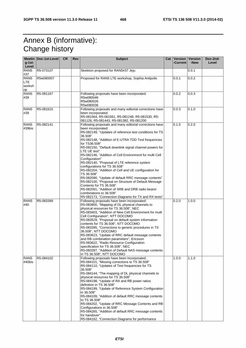
3GPP TS 36.508 version 11.3.0 Release 11 ETSI TS 136 508 V11.3.0 (2014-02)
ETSI
468
Annex B (informative): Change history Meeting-1st-Level
Doc-1st-Level CR Rev Subject Cat Version-Current
Version-New
Doc-2nd-Level
RAN5 #37
R5-073107 Skeleton proposed for RAN5#37 Jeju 0.0.1
RAN5 LTE workshop
R5w080007 Proposed for RAN5 LTE workshop, Sophia Antipolis 0.0.1 0.0.2
RAN5 #39
R5-081167 Following proposals have been incorporated: R5w080046 R5w080026 R5w080036
0.0.2 0.0.3
RAN5 #39
R5-081615 Following proposals and many editorial corrections have been incorporated: R5-081564, R5-081561, R5-081248, R5-081530, R5-081126, R5-081443, R5-081382, R5-081200
0.0.3 0.1.0
RAN5 #39bis
R5-082141 Following proposals and many editorial corrections have been incorporated: R5-082149, "Updates of reference test conditions for TS 36.508" R5-082148, "Addition of E-UTRA TDD Test frequencies for TS36.508" R5-082150, "Default downlink signal channel powers for LTE UE test" R5-082146, "Addition of Cell Environment for multi Cell Configuration" R5-082140, "Proposal of LTE reference system configurations for TS 36.508" R5-082204, "Addition of Cell and UE configuration for TS 36.508" R5-082090, "Update of default RRC message contents" R5-082100, "Proposal on Structure of Default Message Contents for TS 36.508" R5-082091, "Addition of SRB and DRB radio bearer combinations to 36.508" R5-082173, "Connection Diagrams for TX and RX tests"
0.1.0 0.2.0
RAN5 #40
R5-083399 Following proposals have been incorporated: R5-083800, "Mapping of DL physical channels to physical resources for TS 36.508", NEC R5-083403, "Addition of New Cell Environment for multi Cell Configuration", NTT DOCOMO R5-083529, "Proposal on default system information contents for TS 36.508", NTT DOCOMO R5-083395, "Corrections to generic procedures in TS 36.508", NTT DOCOMO R5-083623, "Update of RRC default message contents and RB combination parameters", Ericsson R5-083622, "Radio Resource Configuration specification for TS 36.508", NEC R5-083397, "Addition of Default NAS message contents in TS 36.508", NTT DOCOMO
0.2.0 1.0.0
RAN5 #40bis
R5-084102 Following proposals have been incorporated: R5-084101, “Missing corrections to TS 36.508” R5-084110, “Updates of Test frequencies for TS 36.508” R5-084144, “The mapping of DL physical channels to physical resources for TS 36.508” R5-084198, “Update of RA and RB power ratios definition in TS 36.508” R5-084199, “Update of Reference System Configuration in 36.508” R5-084109, “Addition of default RRC message contents to TS 36.508” R5-084202, “Update of RRC Message Contents and RB Configurations in 36.508” R5-084265, “Addition of default RRC message contents for handover” R5-084162, “Connection Diagrams for performance
1.0.0 1.1.0

3GPP TS 36.508 version 11.3.0 Release 11 ETSI TS 136 508 V11.3.0 (2014-02)
ETSI
469
Meeting-1st-Level
Doc-1st-Level CR Rev Subject Cat Version-Current
Version-New
Doc-2nd-Level
tests” RAN5 #41
R5-085145 Following proposals have been incorporated: R5-085087, "Updates of Test frequencies for TS 36.508" R5-085701, "Cleaning up section 5 in TS 36.508" R5-085252, "Correction to Section 4.3.3.2 of TS 36.508" R5-085315, "Connection Diagrams: delete the editorial note" R5-085454, "Addition of timer tolerances" R5-085566, "Addition of default settings of suitable / non-suitable cells in TS 36.508" R5-085541, "Update to default configurations of simulated cells in TS 36.508" R5-085514, "Update to default configurations of system information blocks in TS 36.508" R5-085472, "Addition of default settings of suitable / non-suitable cells in TS 36.508" R5-085394, "Update of Reference system configurations in 36.508" R5-085457, "Update to generic procedure in TS 36.508" R5-085458, "Addition of new generic procedure to check the UE does not answer to paging" R5-085523, "Update of default RRC message contents" R5-085381, "Addition to default RRC IE contents for measurement configuration" R5-085469, "Update to default NAS message contents in TS 36.508" R5-085451, "Parameter settings for reference RB configurations" R5-085556, "Common test USIM parameters for EPS testing"
1.1.0 2.0.0
RAN#42
RP-085145 Approval of version 2.0.0 at RAN#42, then updated to v 8.0.0.
2.0.0 8.0.0
Editorial corrections. 8.0.0 8.0.1 RAN5 #41bis
R5-086021 0001 - Introduction of half cell configurations in eUTRA SS 8.0.1 8.1.0
RAN5 #41bis
R5-086166 0002 - Removal of Redundant Environmental Conditions 8.0.1 8.1.0
RAN5 #41bis
R5-086221 0003 - CR to 36.508: correction of EARFCN 8.0.1 8.1.0
RAN5 #41bis
R5-086226 0004 - Correction to the default system informations in TS 36.508
8.0.1 8.1.0
RAN5 #41bis
R5-086236 0005 - Connection diagrams for RRM 8.0.1 8.1.0
RAN5 #41bis
R5-086346 0006 - Update of the default message AUTHENTICATION FAILURE
8.0.1 8.1.0
RAN5 #41bis
R5-086362 0007 - update of reference configuration systems for CDMA2000 in 36.508
8.0.1 8.1.0
RAN5 #41bis
R5-086363 0008 - Updated of common and default parameters for CDMA2000 cells
8.0.1 8.1.0
RAN5 #41bis
R5-086364 0009 - Update of SystemInformationBlockType8 in 36.508 8.0.1 8.1.0
RAN5 #41bis
R5-086369 0010 - Addition of reference EPS bearer contexts 8.0.1 8.1.0
RAN5 #41bis
R5-086370 0011 - Mapping of default DL Physical Channels for TDD in 36.508
8.0.1 8.1.0
RAN5 #41bis
R5-086400 0012 - Addition of RS_EPRE powers to default DL signal levels 8.0.1 8.1.0
RAN5 #42
R5-090084 0013 - Test procedure to verify that an EPS bearer context is active
8.0.1 8.1.0
RAN5 #42
R5-090362 0014 - Correction to the definition of simulated NAS cells in TS 36.508
8.0.1 8.1.0
RAN5 #42
R5-090464 0015 - Clean up the test algorithm for authentication 8.0.1 8.1.0
RAN5 #42
R5-090586 0016 - Add specific information elements for RRC reconfiguration
8.0.1 8.1.0
RAN5 #42
R5-090630 0017 - Introduction of alternative DRX configurations 8.0.1 8.1.0
RAN5 #42
R5-090681 0018 - Correction to the default NAS message contents in TS 36.508
8.0.1 8.1.0
RAN5 #42
R5-090682 0019 - Correction to the definition of simulated cells in TS 36.508
8.0.1 8.1.0

3GPP TS 36.508 version 11.3.0 Release 11 ETSI TS 136 508 V11.3.0 (2014-02)
ETSI
470
Meeting-1st-Level
Doc-1st-Level CR Rev Subject Cat Version-Current
Version-New
Doc-2nd-Level
RAN5 #42
R5-090698 0020 - Update of 4.5 generic procedures in 36.508 8.0.1 8.1.0
RAN5 #42
R5-090699 0021 - TDD RTT correction for timer tolerance 8.0.1 8.1.0
RAN5 #42
R5-090759 0022 - Correction to the default RRC message contents in TS 36.508
8.0.1 8.1.0
RAN5 #42
R5-091000 0023 - Correction to clause 4.3.3.3 8.0.1 8.1.0
RAN5 #42
R5-091001 0024 - LTE-RF: Clarification to 36.508 Simulated Cells for RF tests
8.0.1 8.1.0
RAN5 #43
RP-090447 0025 - Correction to Cell off power 8.1.0 8.2.0 R5-092086
RAN5 #43
RP-090447 0026 - LTE Signalling Tests: UE Rx antenna connection 8.1.0 8.2.0 R5-092087
RAN5 #43
RP-090448 0027 - CR to 36.508 for subclause 4.3.1 channel bandwidth clarification for RF tests (re-submit no changes)
8.1.0 8.2.0 R5-092124
RAN5 #43
RP-090448 0028 - Text for 4.2.2: Minimum functional requirements 8.1.0 8.2.0 R5-092128
RAN5 #43
RP-090448 0029 - Annex A: transition from 1 to 2 RX antenna 8.1.0 8.2.0 R5-092132
RAN5 #43
RP-090447 0030 - Update of SN length in UM RLC default configuration 8.1.0 8.2.0 R5-092202
RAN5 #43
RP-090448 0031 - TP for simulated UTRA TDD cell parameter 8.1.0 8.2.0 R5-092275
RAN5 #43
RP-090447 0032 - Correction to specific message contents in setup procedure in TS 36.508
8.1.0 8.2.0 R5-092349
RAN5 #43
RP-090447 0033 - Correction to the definition of simulated NAS cells in TS 36.508
8.1.0 8.2.0 R5-092352
RAN5 #43
RP-090447 0034 - CR on 6.7 TDD Timer Tolerance in 36.508 8.1.0 8.2.0 R5-092363
RAN5 #43
RP-090448 0044 - Update of 4.5.2A in 36.508 (Re-submit not change) 8.1.0 8.2.0 R5-092457
RAN5 #43
RP-090448 0035 - Default value of q-RxLevMin for RF TCs 8.1.0 8.2.0 R5-092458
RAN5 #43
RP-090598 0045 - CR to 36.508 Addition of test frequencies for band 18 and band 19
8.1.0 8.2.0 R5-092535
RAN5 #43
RP-090447 0036 - Update of the default NAS message contents in TS 36.508
8.1.0 8.2.0 R5-092708
RAN5 #43
RP-090447 0037 - Correction to reference radio bearer configurations 8.1.0 8.2.0 R5-092721
RAN5 #43
RP-090447 0038 - Definition of default Test Control (TC) messages 8.1.0 8.2.0 R5-092734
RAN5 #43
RP-090448 0039 - Modification of procedures in section 4.5.2.3 /4.5.2A 8.1.0 8.2.0 R5-092735
RAN5 #43
RP-090447 0040 - Addition of default physical layer parameters 8.1.0 8.2.0 R5-092736
RAN5 #43
RP-090447 0041 - Correction to default RRC message contents 8.1.0 8.2.0 R5-092738
RAN5 #43
RP-090447 0042 - Introduction in 36.508 of a common tracking/routing area update procedure for Idle mode and RRC connection release test cases
8.1.0 8.2.0 R5-092765
RAN5 #43
RP-090447 0043 - Corrections to default system configurations in TS 36.508
8.1.0 8.2.0 R5-092773
RAN5 #43
RP-090447 0046 - Max. resources for signalling test cases 8.1.0 8.2.0 R5-092723
- - - - Editorial corrections and merging of all sections together 8.2.0 8.2.1 - RAN5 #44
RP-090802 0047 - Correction to the default value of ul-Bandwidth in TS 36.508
F 8.2.1 8.3.0 R5-094059
RAN5 #44
RP-090802 0048 - UTRAN SIB scheduling for LTE interRAT test F 8.2.1 8.3.0 R5-094072
RAN5 #44
RP-090802 0049 - Correction to the default NAS message contents F 8.2.1 8.3.0 R5-094141
RAN5 #44
RP-090802 0050 - TDD fields in default physical layer parameters F 8.2.1 8.3.0 R5-094279
RAN5 #44
RP-090802 0051 - Addition of UTRA reference radio bearer parameters and GERAN reference PDP context parameters for E-UTRA Inter-RAT testing
F 8.2.1 8.3.0 R5-094304
RAN5 #44
RP-090801 0052 - System information scheduling for RF testing F 8.2.1 8.3.0 R5-094311
RAN5 #44
RP-090801 0053 - Connection for 1 cell with antenna configuration 1x2 in static propagation conditions
F 8.2.1 8.3.0 R5-094364
RAN5 RP-090801 0054 - Correction to 4.3.1.2.5 TDD reference test frequencies F 8.2.1 8.3.0 R5-094373

3GPP TS 36.508 version 11.3.0 Release 11 ETSI TS 136 508 V11.3.0 (2014-02)
ETSI
471
Meeting-1st-Level
Doc-1st-Level CR Rev Subject Cat Version-Current
Version-New
Doc-2nd-Level
#44 for Operating Band 37 RAN5 #44
RP-090801 0055 - LTE RF: Physical Layer configurations for RF/RRM testing
F 8.2.1 8.3.0 R5-094421
RAN5 #44
RP-090802 0056 - Update of SN length in PDCP default configuration F 8.2.1 8.3.0 R5-094533
RAN5 #44
RP-090802 0057 - Corrections to default RRC message and IE contents F 8.2.1 8.3.0 R5-094639
RAN5 #44
RP-090801 0058 - Update of TDD reference test frequencies for operating band 40
F 8.2.1 8.3.0 R5-094786
RAN5 #44
RP-090810 0059 - TDD special subframe pattern update F 8.2.1 8.3.0 R5-094901
RAN5 #44
RP-090802 0060 - corrections to reference RB configurations F 8.2.1 8.3.0 R5-095064
RAN5 #44
RP-090802 0061 - Correction of test procedure 6.4.2.7 in TS 36.508 F 8.2.1 8.3.0 R5-095093
RAN5 #44
RP-090802 0062 - Adding new elementary files to the default USIM settings
F 8.2.1 8.3.0 R5-095100
RAN5 #44
RP-090802 0063 - Correction to the Test procedure to check RRC_IDLE state
F 8.2.1 8.3.0 R5-095102
RAN5 #44
RP-090802 0064 - Introduction of UE mode of operation into NAS default message contents
F 8.2.1 8.3.0 R5-095138
RAN5 #44
RP-090802 0065 - TDD ACK/NACK feedback mode update F 8.2.1 8.3.0 R5-095152
RAN5 #44
RP-090802 0066 - Corrections to default signal levels F 8.2.1 8.3.0 R5-095206
RAN5 #44
RP-090802 0067 - Update to default messages in regard to IP address allocation
F 8.2.1 8.3.0 R5-095218
RAN5 #45
RP-091121 0068 - Correction to 4.3.1.2.6 TDD reference test frequencies for Operating Band 38
F 8.3.0 8.4.0 R5-095486
RAN5 #45
RP-091121 0069 - Correction CR to 36.508: Set the default parameter for offsetFreq in MeasObjectGERAN Information Element
F 8.3.0 8.4.0 R5-095514
RAN5 #45
RP-091470 0070 - Addition of HSPA UTRA reference radio bearer parameters for E-UTRA Inter-RAT testing
F 8.3.0 8.4.0 R5-095555
RAN5 #45
RP-091122 0071 - Introduction of RS power boosting to reduce interference
F 8.3.0 8.4.0 R5-095594
RAN5 #45
RP-091122 0072 - Corrections to default RRC message contents F 8.3.0 8.4.0 R5-095651
RAN5 #45
RP-091122 0073 - Clarification for Cell Configuration Identifiers in 36.508 F 8.3.0 8.4.0 R5-096005
RAN5 #45
RP-091122 0074 - Correction to the generic procedure for IP allocation and more
F 8.3.0 8.4.0 R5-096114
RAN5 #45
RP-091122 0075 - Addition of new generic procedure for TAU after inter-RAT HO from UTRA
F 8.3.0 8.4.0 R5-096115
RAN5 #45
RP-091122 0076 - Update of header chapter 5.2 in 36.508 F 8.3.0 8.4.0 R5-096202
RAN5 #45
RP-091122 0077 - Correction to the default NAS message contents F 8.3.0 8.4.0 R5-096403
RAN5 #45
RP-091122 0078 - cell frequency allocation F 8.3.0 8.4.0 R5-096440
RAN5 #45
RP-091122 0079 - Correction for IP address allocation F 8.3.0 8.4.0 R5-096447
RAN5 #45
RP-091122 0080 - LAI and TMSI in ATTACH ACCEPT and TAU ACCEPT messages
F 8.3.0 8.4.0 R5-096449
RAN5 #45
RP-091122 0081 - Addition of generic procedure for IP address allocation / configuration in U-plane
F 8.3.0 8.4.0 R5-096455
RAN5 #45
RP-091122 0082 - Correction of test procedures in TS 36.508 F 8.3.0 8.4.0 R5-096456
RAN5 #45
RP-091122 0083 - Update of MAC configuration for disabling PHR and BSR for L2 test cases
F 8.3.0 8.4.0 R5-096458
RAN5 #45
RP-091122 0084 - Addition of default UTRA message contents to TS 36.508
F 8.3.0 8.4.0 R5-096461
RAN5 #45
RP-091122 0085 - Clarification to the mapping of GERAN cells and the default parameter values
F 8.3.0 8.4.0 R5-096462
RAN5 #45
RP-091122 0086 - Correction of TFTs for reference dedicated EPS bearer contexts
F 8.3.0 8.4.0 R5-096464
RAN5 #45
RP-091122 0087 - Cleanup of default NAS message contents F 8.3.0 8.4.0 R5-096465
RAN5 #45
RP-091122 0088 - LTE-Sig: Assignment of different rootSequenceIndex for cells at the same frequency
F 8.3.0 8.4.0 R5-096641
RAN5 #46
RP-100143 0089 - Correction of SIB19 scheduling position in the neighbouring UTRA cell
F 8.4.0 8.5.0 R5-100086

3GPP TS 36.508 version 11.3.0 Release 11 ETSI TS 136 508 V11.3.0 (2014-02)
ETSI
472
Meeting-1st-Level
Doc-1st-Level CR Rev Subject Cat Version-Current
Version-New
Doc-2nd-Level
RAN5 #46
RP-100143 0091 - Correction of Quantity Configuration for EUTRA F 8.4.0 8.5.0 R5-100110
RAN5 #46
RP-100143 0092 - Correction for the offset value of RSRP in EUTRA F 8.4.0 8.5.0 R5-100111
RAN5 #46
RP-100143 0093 - SIB10 and SIB11 periodicity F 8.4.0 8.5.0 R5-100112
RAN5 #46
RP-100143 0094 - Assignment of rootSequenceIndex for simulated NAS cells in different PLMNs
F 8.4.0 8.5.0 R5-100260
RAN5 #46
RP-100143 0095 - Editorial correction to the default value of 'p-a' F 8.4.0 8.5.0 R5-100261
RAN5 #46
RP-100142 0096 - New chapter: Test environment for RRM tests F 8.4.0 8.5.0 R5-100396
RAN5 #46
RP-100143 0097 - Remove UM in DRB reconfiguration F 8.4.0 8.5.0 R5-100487
RAN5 #46
RP-100143 0098 - Addition of default power allocation for two TX antennas F 8.4.0 8.5.0 R5-100518
RAN5 #46
RP-100143 0099 - Correction to TFT parameters used in ACTIVATE DEDICATED EPS BEARER CONTEXT REQUEST message
F 8.4.0 8.5.0 R5-100771
RAN5 #46
RP-100143 0100 - Update to RRC common messages for support of test cases for MIMO
F 8.4.0 8.5.0 R5-100786
RAN5 #46
RP-100152 0101 - Adding band 20 in 36.508 F 8.4.0 8.5.0 R5-100846
RAN5 #46
RP-100154 0102 - CR to 36.508: Update test frequencies with extended LTE1500 operating bands
F 8.4.0 8.5.0 R5-100847
RAN5 #46
RP-100143 0103 - Defining default message contents for ATTACH/TAU REQUEST/ACCEPT messages according to UE capability
F 8.4.0 8.5.0 R5-101021
RAN5 #46
RP-100143 0104 - Limitation of simultaneous co-existence of intra-freq cells to reduce interference
F 8.4.0 8.5.0 R5-101029
RAN5 #46
RP-100143 0105 - An additional option for IP address allocation in test cases using UE test mode
F 8.4.0 8.5.0 R5-101045
RAN5 #46
RP-100143 0106 - Specify default UL NAS check F 8.4.0 8.5.0 R5-101051
RAN5 #46
RP-100143 0107 - Correct default requirement for some mandatory information elements
F 8.4.0 8.5.0 R5-101052
RAN5 #46
RP-100142 0108 - Addition of Tracking area updating procedure F 8.4.0 8.5.0 R5-101136
RAN5 #46
RP-100143 0109 - Clarification of Security Protection for NAS Messages F 8.4.0 8.5.0 R5-101147
RAN5 #46
RP-100143 0110 - Update to layer 2 UM test cases to increase the drx-Inactivity Timer to psf200
F 8.4.0 8.5.0 R5-101178
RAN5 #46
RP-100143 0111 - Addition of new generic procedure for bearer establishment for MO call.
F 8.4.0 8.5.0 R5-101187
RAN5 #46
RP-100143 0112 - update of default bandwidth configuration for signalling F 8.4.0 8.5.0 R5-101207
RP#47 - - - Moved to v9.0.0 with no change - 8.5.0 9.0.0 -
RP#48 RP-100510 0143 - Clarification of security protection when NAS security mode procedure has taken place outside of a TC sequence
F 9.0.0 9.1.0 R5-103085
RP#48 RP-100523 0113 - CR to 36.508: Update of EARFCN for band 21 F 9.0.0 9.1.0 R5-103101
RP#48 RP-100510 0114 - Correction to the default message contents of EXTENDED SERVICE REQUEST
F 9.0.0 9.1.0 R5-103128
RP#48 RP-100510 0115 - Removal of unrealistic network behaviour from generic procedures
F 9.0.0 9.1.0 R5-103223
RP#48 RP-100510 0116 - Correction of table numbers in clause 6.2.3.1 F 9.0.0 9.1.0 R5-103232
RP#48 RP-100510 0117 - Correction to default values for PhysicalConfigDedicated and MIMO
F 9.0.0 9.1.0 R5-103287
RP#48 RP-100510 0118 - Correction to SR-ConfigIndex for LTE TDD signalling test cases
F 9.0.0 9.1.0 R5-103290
RP#48 RP-100510 0119 - Correction to MME Group ID to set MSB to 1 F 9.0.0 9.1.0 R5-103298
RP#48 RP-100500 0144 - Connection diagram for test 8.11.2 (3 cells) F 9.0.0 9.1.0 R5-103311
RP#48 RP-100510 0120 - New combination of system information blocks for CSG Cell in TS 36.508
F 9.0.0 9.1.0 R5-103363
RP#48 RP-100510 0121 - Clarification of security protection for detach request message
F 9.0.0 9.1.0 R5-103368

3GPP TS 36.508 version 11.3.0 Release 11 ETSI TS 136 508 V11.3.0 (2014-02)
ETSI
473
Meeting-1st-Level
Doc-1st-Level CR Rev Subject Cat Version-Current
Version-New
Doc-2nd-Level
RP#48 RP-100510 0122 - Corrections to cell numbers for 3GPP2 Inter-RAT network scenarios
F 9.0.0 9.1.0 R5-103374
RP#48 RP-100510 0140 - Clarification to default message content for Modify EPS Bearer Context Request message
F 9.0.0 9.1.0 R5-103625
RP#48 RP-100510 0141 - Clarification to default message content for RRC Connection Reconfiguration message
F 9.0.0 9.1.0 R5-103626
RP#48 RP-100524 0123 - Addition of WLAN test cell F 9.0.0 9.1.0 R5-103647
RP#48 RP-100524 0124 - Addition of default message contents for mobility management based on DSMIPv6 testing
F 9.0.0 9.1.0 R5-103648
RP#48 RP-100510 0125 - Update default message contents for EPS attach conditions
F 9.0.0 9.1.0 R5-103673
RP#48 RP-100510 0126 - Update default message with network support for IMS voice
F 9.0.0 9.1.0 R5-103674
RP#48 RP-100510 0127 - Correction to Generic Test Procedure in TS 36.508 F 9.0.0 9.1.0 R5-103675
RP#48 RP-100510 0128 - Default settings of suitable - non-suitable cells for UTRAN/GERAN
F 9.0.0 9.1.0 R5-103677
RP#48 RP-100510 0129 - Correction to IE schedulingRequestConfig during Handover
F 9.0.0 9.1.0 R5-103678
RP#48 RP-100510 0130 - Update generic procedures for IMS F 9.0.0 9.1.0 R5-103679
RP#48 RP-100510 0131 - Aligning E-UTRAN USIM parameters for multi-RAT devices
F 9.0.0 9.1.0 R5-103680
RP#48 RP-100510 0132 - Adding Additional Update Result handling to the default messages
F 9.0.0 9.1.0 R5-103681
RP#48 RP-100509 0133 - Connection diagram update for intra-freq measurement with phase rotator
F 9.0.0 9.1.0 R5-103770
RP#48 RP-100509 0134 - Update of default bandwidth configuration for Signalling for Band 38
F 9.0.0 9.1.0 R5-103813
RP#48 RP-100524 0135 - Addition of generic procedures for mobility management based on DSMIPv6 testing
F 9.0.0 9.1.0 R5-103858
RP#48 RP-100510 0136 - Addition of new generic procedure for MO SMS over SGs and clarifications
F 9.0.0 9.1.0 R5-103869
RP#48 RP-100510 0137 - Addition of generic procedures for HRPD and 1xRTT pre-registration
F 9.0.0 9.1.0 R5-103870
RP#48 RP-100510 0138 - Introduction of reference information for test case postambles
F 9.0.0 9.1.0 R5-103875
RP#48 RP-100509 0139 - Physical layer parameter correction to DCI formats used in RF tests
F 9.0.0 9.1.0 R5-103885
RP#49 RP-100812 0145 - Update of tested channel bandwidths for Bands 13, 14 and 17
F 9.1.0 9.2.0 R5-104089
RP#49 RP-100816 0146 - Correction to remove special configurations for UM Bearer test cases
F 9.1.0 9.2.0 R5-104106
RP#49 RP-100816 0147 - Clarification to the procedure: UE triggered establishment of a default EPS bearer context associated with an additional PDN
F 9.1.0 9.2.0 R5-104128
RP#49 RP-100816 0148 - Correction to Inter-frequency carrier frequency list in SIB5 and E-UTRA carrier frequency list in SIB19
F 9.1.0 9.2.0 R5-104169
RP#49 RP-100816 0149 - Update of 6.2.3 of 36.508 - description of default frequency for the single cell signalling test
F 9.1.0 9.2.0 R5-104220
RP#49 RP-100831 0150 - Update of default message contents for DSMIPv6 testing
F 9.1.0 9.2.0 R5-104392
RP#49 RP-100837 0151 - Addition of UE test state model for HRPD F 9.1.0 9.2.0 R5-104454
RP#49 RP-100812 0152 - Correction to Qrxlevmin in SIB 1 for RF and RRM F 9.1.0 9.2.0 R5-104503
RP#49 RP-100816 0153 - Specification of HRPD specific values in SIB8 F 9.1.0 9.2.0 R5-104547
RP#49 RP-100816 0154 - Update of default bandwidth configuration for signalling F 9.1.0 9.2.0 R5-104685
RP#49 RP-100816 0155 - Clarification to packet filter identifier and precedence in TFT
F 9.1.0 9.2.0 R5-104702
RP#49 RP-100816 0156 - Add P-CSCF method II for IMS F 9.1.0 9.2.0 R5-104703
RP#49 RP-100816 0157 - Update generic procedures for IMS F 9.1.0 9.2.0 R5-104704
RP#49 RP-100816 0158 - Correction of clause 4.3.3.4 F 9.1.0 9.2.0 R5-104705
RP#49 RP-100816 0159 - Correction to Downlink Frequency for N_DL 4850 F 9.1.0 9.2.0 R5-104706
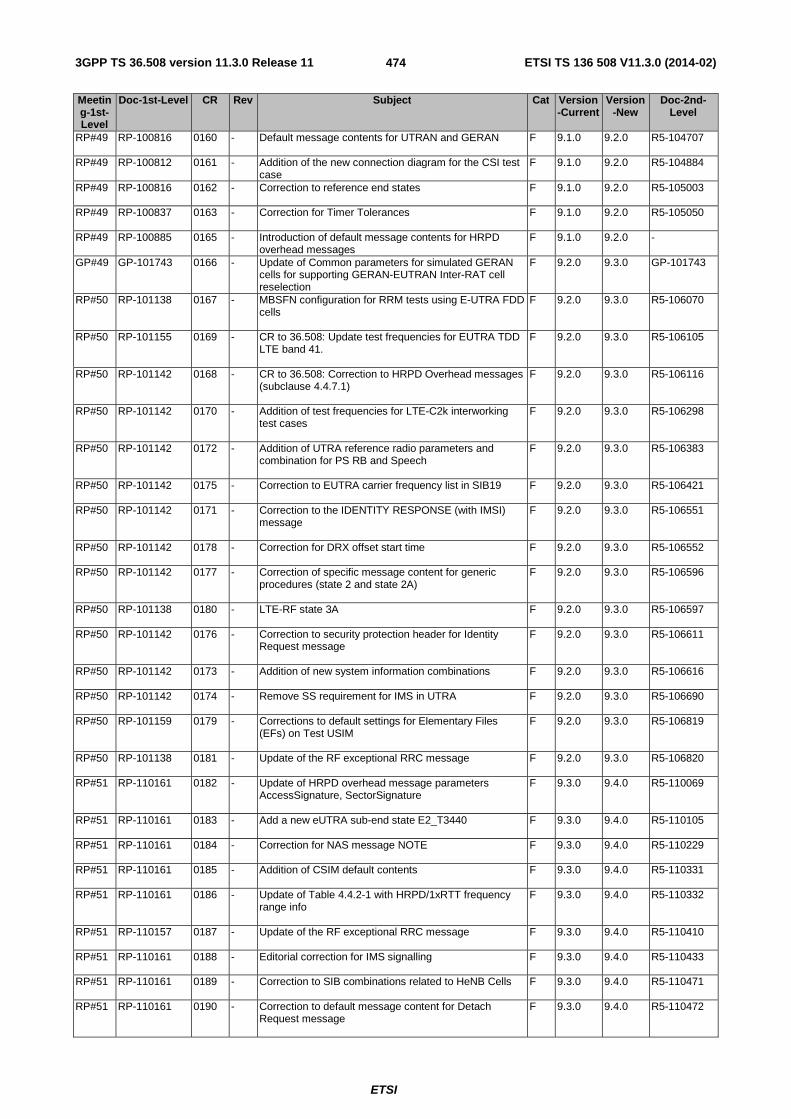
3GPP TS 36.508 version 11.3.0 Release 11 ETSI TS 136 508 V11.3.0 (2014-02)
ETSI
474
Meeting-1st-Level
Doc-1st-Level CR Rev Subject Cat Version-Current
Version-New
Doc-2nd-Level
RP#49 RP-100816 0160 - Default message contents for UTRAN and GERAN F 9.1.0 9.2.0 R5-104707
RP#49 RP-100812 0161 - Addition of the new connection diagram for the CSI test case
F 9.1.0 9.2.0 R5-104884
RP#49 RP-100816 0162 - Correction to reference end states F 9.1.0 9.2.0 R5-105003
RP#49 RP-100837 0163 - Correction for Timer Tolerances F 9.1.0 9.2.0 R5-105050
RP#49 RP-100885 0165 - Introduction of default message contents for HRPD overhead messages
F 9.1.0 9.2.0 -
GP#49 GP-101743 0166 - Update of Common parameters for simulated GERAN cells for supporting GERAN-EUTRAN Inter-RAT cell reselection
F 9.2.0 9.3.0 GP-101743
RP#50 RP-101138 0167 - MBSFN configuration for RRM tests using E-UTRA FDD cells
F 9.2.0 9.3.0 R5-106070
RP#50 RP-101155 0169 - CR to 36.508: Update test frequencies for EUTRA TDD LTE band 41.
F 9.2.0 9.3.0 R5-106105
RP#50 RP-101142 0168 - CR to 36.508: Correction to HRPD Overhead messages (subclause 4.4.7.1)
F 9.2.0 9.3.0 R5-106116
RP#50 RP-101142 0170 - Addition of test frequencies for LTE-C2k interworking test cases
F 9.2.0 9.3.0 R5-106298
RP#50 RP-101142 0172 - Addition of UTRA reference radio parameters and combination for PS RB and Speech
F 9.2.0 9.3.0 R5-106383
RP#50 RP-101142 0175 - Correction to EUTRA carrier frequency list in SIB19 F 9.2.0 9.3.0 R5-106421
RP#50 RP-101142 0171 - Correction to the IDENTITY RESPONSE (with IMSI) message
F 9.2.0 9.3.0 R5-106551
RP#50 RP-101142 0178 - Correction for DRX offset start time F 9.2.0 9.3.0 R5-106552
RP#50 RP-101142 0177 - Correction of specific message content for generic procedures (state 2 and state 2A)
F 9.2.0 9.3.0 R5-106596
RP#50 RP-101138 0180 - LTE-RF state 3A F 9.2.0 9.3.0 R5-106597
RP#50 RP-101142 0176 - Correction to security protection header for Identity Request message
F 9.2.0 9.3.0 R5-106611
RP#50 RP-101142 0173 - Addition of new system information combinations F 9.2.0 9.3.0 R5-106616
RP#50 RP-101142 0174 - Remove SS requirement for IMS in UTRA F 9.2.0 9.3.0 R5-106690
RP#50 RP-101159 0179 - Corrections to default settings for Elementary Files (EFs) on Test USIM
F 9.2.0 9.3.0 R5-106819
RP#50 RP-101138 0181 - Update of the RF exceptional RRC message F 9.2.0 9.3.0 R5-106820
RP#51 RP-110161 0182 - Update of HRPD overhead message parameters AccessSignature, SectorSignature
F 9.3.0 9.4.0 R5-110069
RP#51 RP-110161 0183 - Add a new eUTRA sub-end state E2_T3440 F 9.3.0 9.4.0 R5-110105
RP#51 RP-110161 0184 - Correction for NAS message NOTE F 9.3.0 9.4.0 R5-110229
RP#51 RP-110161 0185 - Addition of CSIM default contents F 9.3.0 9.4.0 R5-110331
RP#51 RP-110161 0186 - Update of Table 4.4.2-1 with HRPD/1xRTT frequency range info
F 9.3.0 9.4.0 R5-110332
RP#51 RP-110157 0187 - Update of the RF exceptional RRC message F 9.3.0 9.4.0 R5-110410
RP#51 RP-110161 0188 - Editorial correction for IMS signalling F 9.3.0 9.4.0 R5-110433
RP#51 RP-110161 0189 - Correction to SIB combinations related to HeNB Cells F 9.3.0 9.4.0 R5-110471
RP#51 RP-110161 0190 - Correction to default message content for Detach Request message
F 9.3.0 9.4.0 R5-110472

3GPP TS 36.508 version 11.3.0 Release 11 ETSI TS 136 508 V11.3.0 (2014-02)
ETSI
475
Meeting-1st-Level
Doc-1st-Level CR Rev Subject Cat Version-Current
Version-New
Doc-2nd-Level
RP#51 RP-110157 0191 - Removal of Lower Humidity Limit in Normal Conditions F 9.3.0 9.4.0 R5-110534
RP#51 RP-110157 0192 - Correction of EARFCN numbers for band 41 F 9.3.0 9.4.0 R5-110542
RP#51 RP-110161 0193 - Removal of "Modified contents of the EFs at the ISIM ADF (application DF) level"
F 9.3.0 9.4.0 R5-110593
RP#51 RP-110161 0194 - Correction of the IEs for compressed mode in table 4.7B.1-5
F 9.3.0 9.4.0 R5-110601
RP#51 RP-110161 0195 - Update to default message content for TRACKING AREA UPDATE REQUEST message
F 9.3.0 9.4.0 R5-110703
RP#51 RP-110161 0196 - Add default APN for IMS F 9.3.0 9.4.0 R5-110708
RP#51 RP-110161 0197 - Introduction of over head messages for CDMA2000 1XRTT
F 9.3.0 9.4.0 R5-110710
RP#51 RP-110161 0198 - Addition of default SMS over SGs message contents F 9.3.0 9.4.0 R5-110875
RP#51 RP-110161 0199 - Correction to 'Test procedure to check that UE is camped on E-UTRAN cell upon mobility from another RAT'
F 9.3.0 9.4.0 R5-110746
RP#51 RP-110161 0200 - Correction of frequency allocations F 9.3.0 9.4.0 R5-110788
RP#51 RP-110161 0201 - Update of Reference packet filters contents F 9.3.0 9.4.0 R5-110789
RP#51 RP-110157 0202 - Correction to FDD Reference Test Frequencies for Operating Band 12
F 9.3.0 9.4.0 R5-110846
RP#51 RP-110157 0203 - LTE RF: state 3A-RF update F 9.3.0 9.4.0 R5-110937
RP#51 RP-110172 0204 - Add test frequencies for bands 42, 43 (3500MHz) F 9.3.0 9.4.0 R5-110968
RP#52 RP-110647 0205 - Correction to default message content of LOCATION UPDATING REQUEST message
F 9.4.0 9.5.0 R5-112114
RP#52 RP-110647 0206 - Correction to default message content of TRACKING AREA UPDATE REQUEST message
F 9.4.0 9.5.0 R5-112120
RP#52 RP-110643 0207 - PRACH-Config-DEFAULT for RF-tests TDD: Correction to derivation path
F 9.4.0 9.5.0 R5-112146
RP#52 RP-110643 0208 - Correction to connection diagram for CQI with uneven interference test (A.21)
F 9.4.0 9.5.0 R5-112147
RP#52 RP-110647 0209 - Update to Common contents of system information blocks
F 9.4.0 9.5.0 R5-112161
RP#52 RP-110647 0210 - Addition of missing labels in Figure 4.5.1-1 F 9.4.0 9.5.0 R5-112278
RP#52 RP-110647 0211 - Corrections to Table 4.3.7-6 F 9.4.0 9.5.0 R5-112279
RP#52 RP-110647 0212 - Update of CSIM default contents F 9.4.0 9.5.0 R5-112285
RP#52 RP-110660 0213 - Add emergency bearer support F 9.4.0 9.5.0 R5-112289
RP#52 RP-110667 0214 - Band 24 Addition to TS 36.508 F 9.4.0 9.5.0 R5-112381
RP#52 RP-110643 0215 - New connection diagrams to Annex A F 9.4.0 9.5.0 R5-112458
RP#52 RP-110647 0216 - Correction to Derivation Path for RB Setup on UTRA side (condition UTRA PS RB)
F 9.4.0 9.5.0 R5-112571
RP#52 RP-110647 0217 - Update APN check at attach F 9.4.0 9.5.0 R5-112598
RP#52 RP-110647 0218 - Update of SIB7 default message contents F 9.4.0 9.5.0 R5-112599
RP#52 RP-110647 0219 - Clarification to conditions for IP address configuration over user plane
F 9.4.0 9.5.0 R5-112600

3GPP TS 36.508 version 11.3.0 Release 11 ETSI TS 136 508 V11.3.0 (2014-02)
ETSI
476
Meeting-1st-Level
Doc-1st-Level CR Rev Subject Cat Version-Current
Version-New
Doc-2nd-Level
RP#52 RP-110666 0220 - Introduction of UE Test Loop Mode C for LTE MBMS testing
F 9.4.0 9.5.0 R5-112675
RP#52 RP-110647 0222 - Update 36.508 QoS definition for InterRat test cases F 9.4.0 9.5.0 R5-112698
RP#52 RP-110666 0221 - Addition of some MBMS related message definitions in TS36.508
F 9.4.0 9.5.0 R5-112748
RP#52 RP-110647 0223 - Introduction of generic CS fall back procedures for UTRAN and GERAN
F 9.4.0 9.5.0 R5-112751
RP#52 RP-110643 0224 - Default Bandwidth Configuration for RF Testing F 9.4.0 9.5.0 R5-112760
RP#52 RP-110643 0225 - Update for PRACH-Config-DEFAULT for the default TDD RRM message
F 9.4.0 9.5.0 R5-112872
RP#52 RP-110647 0205 - Correction to default message content of LOCATION UPDATING REQUEST message
F 9.4.0 9.5.0 R5-112114
RP#52 RP-110647 0206 - Correction to default message content of TRACKING AREA UPDATE REQUEST message
F 9.4.0 9.5.0 R5-112120
RP#52 RP-110643 0207 - PRACH-Config-DEFAULT for RF-tests TDD: Correction to derivation path
F 9.4.0 9.5.0 R5-112146
RP#52 RP-110643 0208 - Correction to connection diagram for CQI with uneven interference test (A.21)
F 9.4.0 9.5.0 R5-112147
RP#52 RP-110647 0209 - Update to Common contents of system information blocks
F 9.4.0 9.5.0 R5-112161
RP#52 RP-110647 0210 - Addition of missing labels in Figure 4.5.1-1 F 9.4.0 9.5.0 R5-112278
RP#52 RP-110647 0211 - Corrections to Table 4.3.7-6 F 9.4.0 9.5.0 R5-112279
RP#52 RP-110647 0212 - Update of CSIM default contents F 9.4.0 9.5.0 R5-112285
RP#52 RP-110660 0213 - Add emergency bearer support F 9.4.0 9.5.0 R5-112289
RP#52 RP-110667 0214 - Band 24 Addition to TS 36.508 F 9.4.0 9.5.0 R5-112381
RP#52 RP-110643 0215 - New connection diagrams to Annex A F 9.4.0 9.5.0 R5-112458
RP#52 RP-110647 0216 - Correction to Derivation Path for RB Setup on UTRA side (condition UTRA PS RB)
F 9.4.0 9.5.0 R5-112571
RP#52 RP-110647 0217 - Update APN check at attach F 9.4.0 9.5.0 R5-112598
RP#52 RP-110647 0218 - Update of SIB7 default message contents F 9.4.0 9.5.0 R5-112599
RP#52 RP-110647 0219 - Clarification to conditions for IP address configuration over user plane
F 9.4.0 9.5.0 R5-112600
RP#52 RP-110647 0222 - Update 36.508 QoS definition for InterRat test cases F 9.4.0 9.5.0 R5-112698
RP#52 RP-110666 0221 - Addition of some MBMS related message definitions in TS36.508
F 9.4.0 9.5.0 R5-112748
RP#52 RP-110647 0223 - Introduction of generic CS fall back procedures for UTRAN and GERAN
F 9.4.0 9.5.0 R5-112751
RP#52 RP-110643 0224 - Default Bandwidth Configuration for RF Testing F 9.4.0 9.5.0 R5-112760
RP#52 RP-110643 0225 - Update for PRACH-Config-DEFAULT for the default TDD RRM message
F 9.4.0 9.5.0 R5-112872
RP#53 RP-111138 0226 - Correction for generic CS fallback procedures for UTRAN
F 9.5.0 9.6.0 R5-113033
RP#53 RP-111138 0227 - Correction to paging test procedure F 9.5.0 9.6.0 R5-113163
RP#53 RP-111138 0228 - Deletion of 'EPSOnlyAttachForced' in common part F 9.5.0 9.6.0 R5-113195

3GPP TS 36.508 version 11.3.0 Release 11 ETSI TS 136 508 V11.3.0 (2014-02)
ETSI
477
Meeting-1st-Level
Doc-1st-Level CR Rev Subject Cat Version-Current
Version-New
Doc-2nd-Level
RP#53 RP-111135 0229 - Deletion of 'EPSOnlyAttachForced' in RF part F 9.5.0 9.6.0 R5-113213
RP#53 RP-111135 0230 - Correction to PhysicalConfigDedicated-DEFAULT for HO case
F 9.5.0 9.6.0 R5-113450
RP#53 RP-111138 0231 - Addition of the 'Expanded 1900 MHz band' as operating band 25 to TS 36.508
F 9.5.0 9.6.0 R5-113500
RP#53 RP-111153 0232 - Band 24 Details for Signalling part of 36.508 F 9.5.0 9.6.0 R5-113521
RP#53 RP-111138 0233 - Add new SI combination F 9.5.0 9.6.0 R5-113658
RP#53 RP-111138 0234 - Update of HRPD/1xRTT test frequencies, pre-registration procedures and message contents
F 9.5.0 9.6.0 R5-113659
RP#53 RP-111138 0235 - Correction to test procedures specific message contents F 9.5.0 9.6.0 R5-113660
RP#53 RP-111138 0236 - Correction to 'Test procedure to check that UE is camped on E-UTRAN cell upon mobility from another RAT'
F 9.5.0 9.6.0 R5-113661
RP#53 RP-111138 0237 - Correction for the default NAS message contents F 9.5.0 9.6.0 R5-113662
RP#53 RP-111138 0238 - Update UTRA RRC messages F 9.5.0 9.6.0 R5-113663
RP#53 RP-111138 0239 - Update UTRA NAS messages F 9.5.0 9.6.0 R5-113664
RP#53 RP-111138 0240 - Addition of default GERAN message PS HANDOVER COMMAND
F 9.5.0 9.6.0 R5-113665
RP#53 RP-111138 0241 - Update test procedure 6.4.3.7.6 F 9.5.0 9.6.0 R5-113666
RP#53 RP-111138 0242 - Update test procedure 6.4.3.7.5 F 9.5.0 9.6.0 R5-113667
RP#53 RP-111155 0243 - Update test frequencies for FDD LTE Band 23 in 36.508 F 9.5.0 9.6.0 R5-113749
RP#53 RP-111138 0244 - Correction on the IE ReportConfigEUTRA-PERIODICAL definition
F 9.5.0 9.6.0 R5-113751
RP#53 RP-111148 0245 - Correction to TS36.508 subclause 4.6.1 F 9.5.0 9.6.0 R5-113761
RP#53 RP-111145 0246 - Combined parallel procedures between EUTRA/EPC and IMS emergency call
F 9.5.0 9.6.0 R5-113801
RP#53 RP-111135 0247 - RF/RRM State 3A-RF: Editors note F 9.5.0 9.6.0 R5-114037
RP#54 RP-111579 0248 - Correction of the default message contents of Transaction Identifiers in Activate Default EPS Bearer Context and Activate Dedicated EPS Bearer Context messages
F 9.6.0 9.7.0 R5-115091
RP#54 RP-111596 0250 - Adding band 22 (3500MHz FDD) to 36.508 F 9.6.0 9.7.0 R5-115185
RP#54 RP-111579 0251 - Update of UE Registration pre-registration on 1xRTT registrationPeriod
F 9.6.0 9.7.0 R5-115264
RP#54 RP-111579 0252 - Update UTRA RRC message for handover to UTRAN F 9.6.0 9.7.0 R5-115533
RP#54 RP-111579 0253 - Add reference default EPS bearer context for QCI 5 F 9.6.0 9.7.0 R5-115537
RP#54 RP-111579 0254 - Correction of EPS Bearer Contexts F 9.6.0 9.7.0 R5-115585
RP#54 RP-111579 0255 - Correction to ESM default messages F 9.6.0 9.7.0 R5-115618
RP#54 RP-111579 0256 - Introduction of Combined Generic test procedure for IMS Speech call
F 9.6.0 9.7.0 R5-115619
RP#54 RP-111576 0257 - default band configuration for RF testing in band 25 F 9.6.0 9.7.0 R5-115633
RP#54 RP-111579 0258 - Complete the system configuration for dual mode network scenario
F 9.6.0 9.7.0 R5-115694
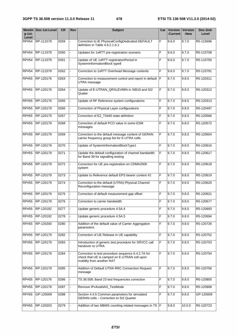
3GPP TS 36.508 version 11.3.0 Release 11 ETSI TS 136 508 V11.3.0 (2014-02)
ETSI
478
Meeting-1st-Level
Doc-1st-Level CR Rev Subject Cat Version-Current
Version-New
Doc-2nd-Level
RP#54 RP-111579 0259 - Correction to IE PhysicalConfigDedicated-DEFAULT definition in Table 4.8.2.1.6-1
F 9.6.0 9.7.0 R5-115696
RP#54 RP-111579 0260 - Updates for 1xRTT pre-registration scenario F 9.6.0 9.7.0 R5-115708
RP#54 RP-111579 0261 - Update of UE 1xRTT registrationPeriod in SystemInformationBlock type8
F 9.6.0 9.7.0 R5-115750
RP#54 RP-111579 0262 - Correction to 1xRTT Overhead Message contents F 9.6.0 9.7.0 R5-115791
RP#55 RP-120176 0263 - Correction to measurement control and report in default UTRA message
F 9.7.0 9.8.0 R5-120311
RP#55 RP-120176 0264 - Update of E-UTRAN_QRXLEVMIN in SIB19 and SI2 Quater
F 9.7.0 9.8.0 R5-120312
RP#55 RP-120176 0265 - Update of RF Reference system configurations F 9.7.0 9.8.0 R5-120313
RP#55 RP-120179 0266 - Correction of Physical Layer configurations F 9.7.0 9.8.0 R5-120497
RP#55 RP-120179 0267 - Correction of E2_T3440 state definition F 9.7.0 9.8.0 R5-120566
RP#55 RP-120179 0268 - Correction of default PCO value in some ESM messages
F 9.7.0 9.8.0 R5-120572
RP#55 RP-120179 0269 - Correction to the default message content of GERAN carrier frequency group list for E-UTRA cells
F 9.7.0 9.8.0 R5-120604
RP#55 RP-120179 0270 - Update of SystemInformationBlockType1 F 9.7.0 9.8.0 R5-120616
RP#55 RP-120179 0271 - Update the default configuration of channel bandwidth for Band 39 for signalling testing
F 9.7.0 9.8.0 R5-120617
RP#55 RP-120179 0272 - Correction for UE pre-registration on CDMA2000 system
F 9.7.0 9.8.0 R5-120618
RP#55 RP-120179 0273 - Update to Reference default EPS bearer context #2 F 9.7.0 9.8.0 R5-120619
RP#55 RP-120179 0274 - Correction to the default (UTRA) Physical Channel Reconfiguration message
F 9.7.0 9.8.0 R5-120620
RP#55 RP-120179 0275 - Correction of default measurement gap offset F 9.7.0 9.8.0 R5-120621
RP#55 RP-120179 0276 - Correction to carrier bandwidth F 9.7.0 9.8.0 R5-120677
RP#55 RP-120192 0277 - Update generic procedure 4.5A.4 F 9.7.0 9.8.0 R5-120693
RP#55 RP-120192 0278 - Update generic procedure 4.5A.5 F 9.7.0 9.8.0 R5-120694
RP#55 RP-120200 0280 - Addition of the default value of Carrier Aggregation parameters
F 9.7.0 9.8.0 R5-120726
RP#55 RP-120179 0282 - Correction of UE Release in UE capability F 9.7.0 9.8.0 R5-120752
RP#55 RP-120179 0283 - Introduction of generic test procedure for SRVCC call handover to UTRA
F 9.7.0 9.8.0 R5-120753
RP#55 RP-120179 0284 - Correction to test procedure sequence 6.4.2.7A for check that UE is camped on E-UTRAN cell upon mobility from another RAT
F 9.7.0 9.8.0 R5-120754
RP#55 RP-120179 0285 - Addition of Default UTRA RRC Connection Request message
F 9.7.0 9.8.0 R5-120756
RP#55 RP-120176 0286 - TS 36.508: Band 23 test frequencies correction F 9.7.0 9.8.0 R5-120800
RP#55 RP-120179 0287 - Remove IPv4viaNAS_TestMode F 9.7.0 9.8.0 R5-120908
RP#55 GP-120009 0288 - Section 4.4.5 Common parameters for simulated GERAN cells – Correction to SI2 Quarter
F 9.7.0 9.8.0 GP-120009
RP#55 RP-120203 0279 - Addition of two MBMS counting related messages in TS F 9.8.0 10.0.0 R5-120723

3GPP TS 36.508 version 11.3.0 Release 11 ETSI TS 136 508 V11.3.0 (2014-02)
ETSI
479
Meeting-1st-Level
Doc-1st-Level CR Rev Subject Cat Version-Current
Version-New
Doc-2nd-Level
36.508
RP#55 RP-120199 0281 - Introduction of new RRC default messages for Rel-10 and MDT
F 9.8.0 10.0.0 R5-120737
RP#56 RP-120644 0290 - Correction of power ratio allocation on PDSCH for common logical channels
F 10.0.0 10.1.0 R5-121089
RP#56 RP-120644 0291 - Correction to default mobilityParameters message contents
F 10.0.0 10.1.0 R5-121121
RP#56 RP-120644 0292 - Corrections to default overhead messages for HRPD F 10.0.0 10.1.0 R5-121122
RP#56 RP-120644 0293 - Corrections to default overhead messages for 1xRTT F 10.0.0 10.1.0 R5-121123
RP#56 RP-120644 0294 - Update of CSFBParametersRequest/ResponseCDMA2000 process in Registration
F 10.0.0 10.1.0 R5-121276
RP#56 RP-120641 0295 - RRM: Definition of parameters for simulated GSM cells F 10.0.0 10.1.0 R5-121357
RP#56 RP-120662 0296 - SIB Combination for CA test scenarios F 10.0.0 10.1.0 R5-121383
RP#56 RP-120644 0297 - Addition of default value of RSRQ Cell Reselection parameters
F 10.0.0 10.1.0 R5-121384
RP#56 RP-120641 0298 - Test frequencies for inter-band cells in RRM tests F 10.0.0 10.1.0 R5-121407
RP#56 RP-120644 0299 - Update generic procedure 4.5A.6 F 10.0.0 10.1.0 R5-121413
RP#56 RP-120644 0300 - Update generic procedure 4.5A.7 F 10.0.0 10.1.0 R5-121414
RP#56 RP-120644 0301 - Update generic procedure 4.5A.3 F 10.0.0 10.1.0 R5-121439
RP#56 RP-120644 0302 - Correction to RadioResourceConfigCommon-DEFAULT F 10.0.0 10.1.0 R5-121447
RP#56 RP-120641 0304 - Removing 5.2A.3 for State 2A F 10.0.0 10.1.0 R5-121521
RP#56 RP-120641 0305 - Addition of A-GNSS testing to Test frequencies clause 4.3.1
F 10.0.0 10.1.0 R5-121543
RP#56 RP-120641 0306 - Ensuring all SS TX antennas are in use for whole test sequence
F 10.0.0 10.1.0 R5-121544
RP#56 RP-120641 0307 - Connection diagram for RRM 3 cell TCs with static propagation
F 10.0.0 10.1.0 R5-121556
RP#56 RP-120644 0308 - Correction of Physical Layer configurations tables F 10.0.0 10.1.0 R5-121665
RP#56 RP-120644 0309 - Update of default bandwidth configuration for E-UTRA FDD band 11 and 18
F 10.0.0 10.1.0 R5-121712
RP#56 RP-120644 0310 - Correction to default SIB4 contents for CSG cells F 10.0.0 10.1.0 R5-121733
RP#56 RP-120644 0311 - Update of CDMA2000 Band Class data and addition of CDMA2000 Band Class 10
F 10.0.0 10.1.0 R5-121734
RP#56 RP-120644 0312 - Update to Reference dedicated EPS bearer context #3 F 10.0.0 10.1.0 R5-121735
RP#56 RP-120644 0313 - Add generic procedure MO video call F 10.0.0 10.1.0 R5-121736
RP#56 RP-120644 0314 - Add generic procedure MT video call F 10.0.0 10.1.0 R5-121737
RP#56 RP-120644 0315 - Clarifications to UICC requirements for LTE-C2K testing F 10.0.0 10.1.0 R5-121809
RP#56 RP-120644 0316 - Update UE capability information F 10.0.0 10.1.0 R5-121847
RP#56 RP-120658 0317 - Introduction of System information for PWS F 10.0.0 10.1.0 R5-121854
RP#56 RP-120662 0318 - Update of the default value of Carrier Aggregation parameters
F 10.0.0 10.1.0 R5-121856
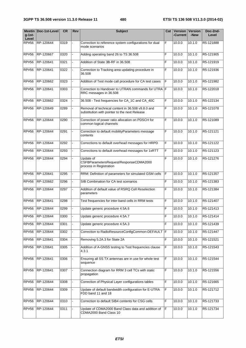
3GPP TS 36.508 version 11.3.0 Release 11 ETSI TS 136 508 V11.3.0 (2014-02)
ETSI
480
Meeting-1st-Level
Doc-1st-Level CR Rev Subject Cat Version-Current
Version-New
Doc-2nd-Level
RP#56 RP-120644 0319 - Correction to reference system configurations for dual mode scenarios
F 10.0.0 10.1.0 R5-121888
RP#56 RP-120667 0320 - Adding operating band 26 to TS 36.508 F 10.0.0 10.1.0 R5-121905
RP#56 RP-120641 0321 - Addition of State 3B-RF in 36.508 F 10.0.0 10.1.0 R5-121919
RP#56 RP-120641 0322 - Correction to Tracking area updating procedure in 36.508
F 10.0.0 10.1.0 R5-121936
RP#56 RP-120662 0323 - Addition of Test mode call procedure for CA test cases F 10.0.0 10.1.0 R5-121982
RP#56 RP-120641 0303 - Correction to Handover to UTRAN commands for UTRA RRC messages in 36.508
F 10.0.0 10.1.0 R5-122018
RP#56 RP-120662 0324 - 36.508 - Test frequencies for CA_1C and CA_40C F 10.0.0 10.1.0 R5-122134
RP#56 RP-120649 0289 - Removal of technical content in 36.508 v9.8.0 and substitution with pointer to the next Release
F 10.0.0 10.1.0 R5-121078
RP#56 RP-120644 0290 - Correction of power ratio allocation on PDSCH for common logical channels
F 10.0.0 10.1.0 R5-121089
RP#56 RP-120644 0291 - Correction to default mobilityParameters message contents
F 10.0.0 10.1.0 R5-121121
RP#56 RP-120644 0292 - Corrections to default overhead messages for HRPD F 10.0.0 10.1.0 R5-121122
RP#56 RP-120644 0293 - Corrections to default overhead messages for 1xRTT F 10.0.0 10.1.0 R5-121123
RP#56 RP-120644 0294 - Update of CSFBParametersRequest/ResponseCDMA2000 process in Registration
F 10.0.0 10.1.0 R5-121276
RP#56 RP-120641 0295 - RRM: Definition of parameters for simulated GSM cells F 10.0.0 10.1.0 R5-121357
RP#56 RP-120662 0296 - SIB Combination for CA test scenarios F 10.0.0 10.1.0 R5-121383
RP#56 RP-120644 0297 - Addition of default value of RSRQ Cell Reselection parameters
F 10.0.0 10.1.0 R5-121384
RP#56 RP-120641 0298 - Test frequencies for inter-band cells in RRM tests F 10.0.0 10.1.0 R5-121407
RP#56 RP-120644 0299 - Update generic procedure 4.5A.6 F 10.0.0 10.1.0 R5-121413
RP#56 RP-120644 0300 - Update generic procedure 4.5A.7 F 10.0.0 10.1.0 R5-121414
RP#56 RP-120644 0301 - Update generic procedure 4.5A.3 F 10.0.0 10.1.0 R5-121439
RP#56 RP-120644 0302 - Correction to RadioResourceConfigCommon-DEFAULT F 10.0.0 10.1.0 R5-121447
RP#56 RP-120641 0304 - Removing 5.2A.3 for State 2A F 10.0.0 10.1.0 R5-121521
RP#56 RP-120641 0305 - Addition of A-GNSS testing to Test frequencies clause 4.3.1
F 10.0.0 10.1.0 R5-121543
RP#56 RP-120641 0306 - Ensuring all SS TX antennas are in use for whole test sequence
F 10.0.0 10.1.0 R5-121544
RP#56 RP-120641 0307 - Connection diagram for RRM 3 cell TCs with static propagation
F 10.0.0 10.1.0 R5-121556
RP#56 RP-120644 0308 - Correction of Physical Layer configurations tables F 10.0.0 10.1.0 R5-121665
RP#56 RP-120644 0309 - Update of default bandwidth configuration for E-UTRA FDD band 11 and 18
F 10.0.0 10.1.0 R5-121712
RP#56 RP-120644 0310 - Correction to default SIB4 contents for CSG cells F 10.0.0 10.1.0 R5-121733
RP#56 RP-120644 0311 - Update of CDMA2000 Band Class data and addition of CDMA2000 Band Class 10
F 10.0.0 10.1.0 R5-121734

3GPP TS 36.508 version 11.3.0 Release 11 ETSI TS 136 508 V11.3.0 (2014-02)
ETSI
481
Meeting-1st-Level
Doc-1st-Level CR Rev Subject Cat Version-Current
Version-New
Doc-2nd-Level
RP#56 RP-120644 0312 - Update to Reference dedicated EPS bearer context #3 F 10.0.0 10.1.0 R5-121735
RP#56 RP-120644 0313 - Add generic procedure MO video call F 10.0.0 10.1.0 R5-121736
RP#56 RP-120644 0314 - Add generic procedure MT video call F 10.0.0 10.1.0 R5-121737
RP#56 RP-120644 0315 - Clarifications to UICC requirements for LTE-C2K testing F 10.0.0 10.1.0 R5-121809
RP#56 RP-120644 0316 - Update UE capability information F 10.0.0 10.1.0 R5-121847
RP#56 RP-120658 0317 - Introduction of System information for PWS F 10.0.0 10.1.0 R5-121854
RP#56 RP-120662 0318 - Update of the default value of Carrier Aggregation parameters
F 10.0.0 10.1.0 R5-121856
RP#56 RP-120644 0319 - Correction to reference system configurations for dual mode scenarios
F 10.0.0 10.1.0 R5-121888
RP#56 RP-120667 0320 - Adding operating band 26 to TS 36.508 F 10.0.0 10.1.0 R5-121905
RP#56 RP-120641 0321 - Addition of State 3B-RF in 36.508 F 10.0.0 10.1.0 R5-121919
RP#56 RP-120641 0322 - Correction to Tracking area updating procedure in 36.508
F 10.0.0 10.1.0 R5-121936
RP#56 RP-120662 0323 - Addition of Test mode call procedure for CA test cases F 10.0.0 10.1.0 R5-121982
RP#56 RP-120641 0303 - Correction to Handover to UTRAN commands for UTRA RRC messages in 36.508
F 10.0.0 10.1.0 R5-122018
RP#56 RP-120662 0324 - 36.508 - Test frequencies for CA_1C and CA_40C F 10.0.0 10.1.0 R5-122134
RP#57 RP-121098 0325 - Correction to default message content of UTRA NAS attach accept message
F 10.1.0 10.2.0 R5-123114
RP#57 RP-121098 0326 - Correction default message content for Tracking Area Update Request message
F 10.1.0 10.2.0 R5-123117
RP#57 RP-121095 0327 - RF: Addition of messages and SIB combination informations for RF MBMS tests
F 10.1.0 10.2.0 R5-123211
RP#57 RP-121098 0328 - Clarify requirements for ROHC F 10.1.0 10.2.0 R5-123259
RP#57 RP-121098 0329 - Updates to cl 6.x regarding use of MIMO F 10.1.0 10.2.0 R5-123304
RP#57 RP-121113 0330 - Update of default parameters for Carrier Aggregation F 10.1.0 10.2.0 R5-123305
RP#57 RP-121098 0331 - Addition of default value of Additional update parameters
F 10.1.0 10.2.0 R5-123306
RP#57 RP-121098 0332 - Addition of default value of Explicit Signalling Indication parameters
F 10.1.0 10.2.0 R5-123307
RP#57 RP-121095 0333 - Update of NeighCellConfig for RRM tests F 10.1.0 10.2.0 R5-123328
RP#57 RP-121095 0334 - Correction to HO commands for UTRAN TDD F 10.1.0 10.2.0 R5-123329
RP#57 RP-121116 0335 - Addition of new connection diagrams for UL-MIMO Testing
F 10.1.0 10.2.0 R5-123390
RP#57 RP-121098 0336 - Correction to generic test procedure CS fallback to GERAN with redirection or CCO / MT call(DTM not supported)
F 10.1.0 10.2.0 R5-123629
RP#57 RP-121098 0337 - Correction to RRC Connection Reconfiguration message during Handover from UTRA to EUTRA
F 10.1.0 10.2.0 R5-123630
RP#57 RP-121098 0338 - Update to Reference dedicated EPS bearer context #3 F 10.1.0 10.2.0 R5-123632
RP#57 RP-121098 0339 - Update generic procedure 4.5A.6 F 10.1.0 10.2.0 R5-123633
RP#57 RP-121098 0340 - Update generic procedure 4.5A.7 F 10.1.0 10.2.0 R5-123634

3GPP TS 36.508 version 11.3.0 Release 11 ETSI TS 136 508 V11.3.0 (2014-02)
ETSI
482
Meeting-1st-Level
Doc-1st-Level CR Rev Subject Cat Version-Current
Version-New
Doc-2nd-Level
RP#57 RP-121098 0341 - Update generic procedure 4.5A.8 F 10.1.0 10.2.0 R5-123635
RP#57 RP-121098 0342 - Update generic procedure 4.5A.9 F 10.1.0 10.2.0 R5-123636
RP#57 RP-121098 0343 - Update the default value of IE RadioResourceConfigCommon and IE additionalSpectrumEmission
F 10.1.0 10.2.0 R5-123712
RP#57 RP-121098 0344 - Correction to test procedure 6.4.2.10 F 10.1.0 10.2.0 R5-123720
RP#57 RP-121098 0345 - Corrections to CDMA2000 message sequences F 10.1.0 10.2.0 R5-123728
RP#57 RP-121098 0346 - Update of UE Capability Information F 10.1.0 10.2.0 R5-123729
RP#57 RP-121098 0347 - Update of Paging test procedure (for NAS test cases) F 10.1.0 10.2.0 R5-123730
RP#57 RP-121098 0348 - Addition of guard timer to the procedure for IMS signalling
F 10.1.0 10.2.0 R5-123731
RP#57 RP-121098 0349 - Update to cl. 6.4.2.7A and 7.2B.1 F 10.1.0 10.2.0 R5-123734
RP#57 RP-121113 0351 - Extension of cell configurations for Carrier Aggregation F 10.1.0 10.2.0 R5-123751
RP#57 RP-121113 0352 - Maximum number of cells simultaneously used in Carrier Aggregation test cases
F 10.1.0 10.2.0 R5-123752
RP#57 RP-121098 0353 - Update of default MSPL and MLPL contents in Test UICC
F 10.1.0 10.2.0 R5-123767
RP#57 RP-121113 0354 - Correction to the CA test state references F 10.1.0 10.2.0 R5-123949
RP#58 RP-121681 0356 - Addition of new connection diagram for UL-MIMO testing
F 10.2.0 10.3.0 R5-125107
RP#58 RP-121659 0357 - Update to test procedure sequence 6.4.2.7A for check that UE is camped on E-UTRAN cell upon mobility from another RAT
F 10.2.0 10.3.0 R5-125116
RP#58 RP-121677 0358 - Introduction of connection diagrams for CA tests F 10.2.0 10.3.0 R5-125187
RP#58 RP-121685 0359 - Addition of default message contents for ESM NOTIFICATION message
F 10.2.0 10.3.0 R5-125219
RP#58 RP-121659 0360 - Modification of measurement configuration for UTRAN FDD SIG
F 10.2.0 10.3.0 R5-125283
RP#58 RP-121659 0361 - Clarification of table 6.6.2-1 F 10.2.0 10.3.0 R5-125287
RP#58 RP-121656 0362 - Addition of channel bandwidth tested for E-UTRA FDD band 19
F 10.2.0 10.3.0 R5-125303
RP#58 RP-121656 0363 - Correction of circulator in connection diagrams F 10.2.0 10.3.0 R5-125370
RP#58 RP-121656 0364 - Correction to test channel numbers for Band 26 F 10.2.0 10.3.0 R5-125372
RP#58 RP-121656 0365 - Update of Chw Bw Parameters for 1.4MHz and 3MHz F 10.2.0 10.3.0 R5-125373
RP#58 RP-121659 0366 - Update generic procedure 4.5A.7 F 10.2.0 10.3.0 R5-125530
RP#58 RP-121659 0367 - Update of default ROUTING AREA UPDATE REQUEST message
F 10.2.0 10.3.0 R5-125545
RP#58 RP-121690 0368 - CA_38: Addition of new test frequency for CA band 38 F 10.2.0 10.3.0 R5-125573
RP#58 RP-121689 0369 - Addition of Band 28 definition F 10.2.0 10.3.0 R5-125778
RP#58 RP-121685 0370 - Add generic procedure for IMS MO speech and aSRVCC
F 10.2.0 10.3.0 R5-125792
RP#58 RP-121677 0371 - Modification to state 3A-RF-CA initial conditions of clause 5.2A.4
F 10.2.0 10.3.0 R5-125800
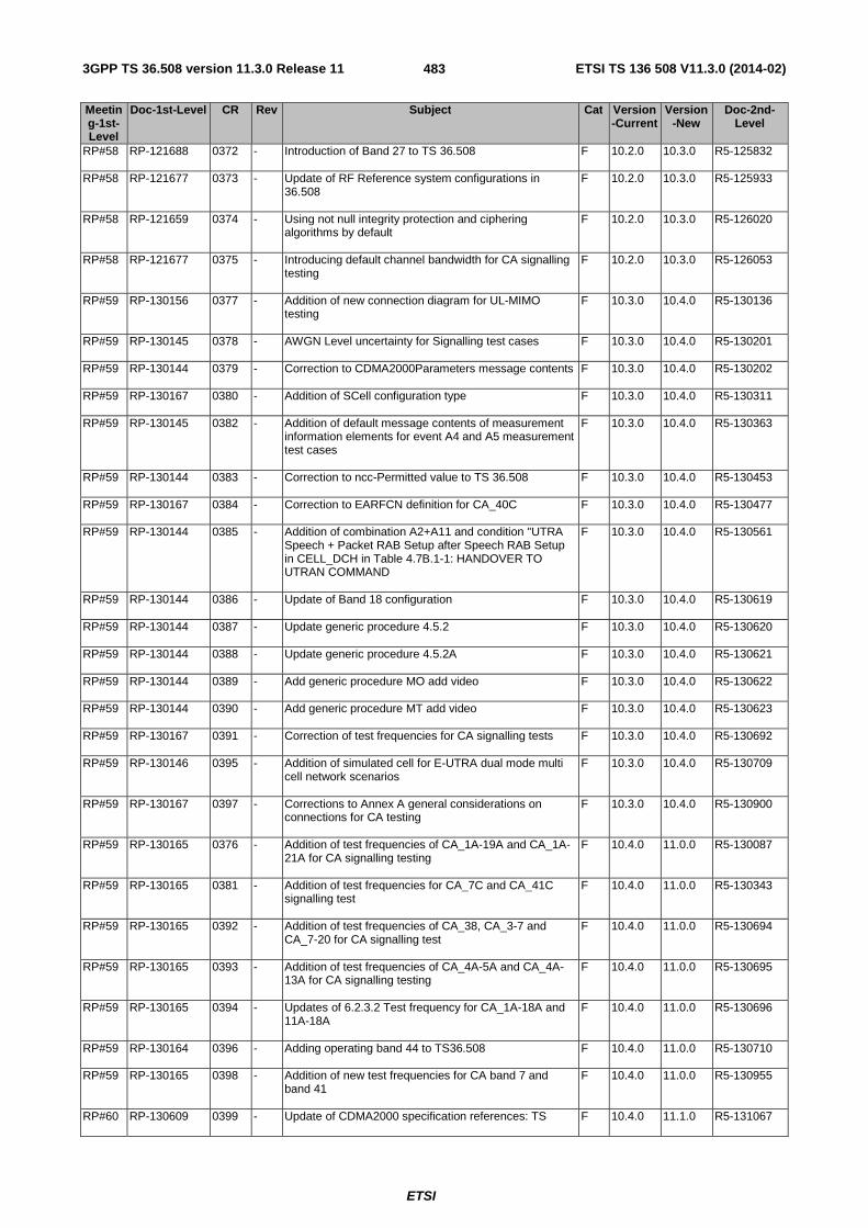
3GPP TS 36.508 version 11.3.0 Release 11 ETSI TS 136 508 V11.3.0 (2014-02)
ETSI
483
Meeting-1st-Level
Doc-1st-Level CR Rev Subject Cat Version-Current
Version-New
Doc-2nd-Level
RP#58 RP-121688 0372 - Introduction of Band 27 to TS 36.508 F 10.2.0 10.3.0 R5-125832
RP#58 RP-121677 0373 - Update of RF Reference system configurations in 36.508
F 10.2.0 10.3.0 R5-125933
RP#58 RP-121659 0374 - Using not null integrity protection and ciphering algorithms by default
F 10.2.0 10.3.0 R5-126020
RP#58 RP-121677 0375 - Introducing default channel bandwidth for CA signalling testing
F 10.2.0 10.3.0 R5-126053
RP#59 RP-130156 0377 - Addition of new connection diagram for UL-MIMO testing
F 10.3.0 10.4.0 R5-130136
RP#59 RP-130145 0378 - AWGN Level uncertainty for Signalling test cases F 10.3.0 10.4.0 R5-130201
RP#59 RP-130144 0379 - Correction to CDMA2000Parameters message contents F 10.3.0 10.4.0 R5-130202
RP#59 RP-130167 0380 - Addition of SCell configuration type F 10.3.0 10.4.0 R5-130311
RP#59 RP-130145 0382 - Addition of default message contents of measurement information elements for event A4 and A5 measurement test cases
F 10.3.0 10.4.0 R5-130363
RP#59 RP-130144 0383 - Correction to ncc-Permitted value to TS 36.508 F 10.3.0 10.4.0 R5-130453
RP#59 RP-130167 0384 - Correction to EARFCN definition for CA_40C F 10.3.0 10.4.0 R5-130477
RP#59 RP-130144 0385 - Addition of combination A2+A11 and condition "UTRA Speech + Packet RAB Setup after Speech RAB Setup in CELL_DCH in Table 4.7B.1-1: HANDOVER TO UTRAN COMMAND
F 10.3.0 10.4.0 R5-130561
RP#59 RP-130144 0386 - Update of Band 18 configuration F 10.3.0 10.4.0 R5-130619
RP#59 RP-130144 0387 - Update generic procedure 4.5.2 F 10.3.0 10.4.0 R5-130620
RP#59 RP-130144 0388 - Update generic procedure 4.5.2A F 10.3.0 10.4.0 R5-130621
RP#59 RP-130144 0389 - Add generic procedure MO add video F 10.3.0 10.4.0 R5-130622
RP#59 RP-130144 0390 - Add generic procedure MT add video F 10.3.0 10.4.0 R5-130623
RP#59 RP-130167 0391 - Correction of test frequencies for CA signalling tests F 10.3.0 10.4.0 R5-130692
RP#59 RP-130146 0395 - Addition of simulated cell for E-UTRA dual mode multi cell network scenarios
F 10.3.0 10.4.0 R5-130709
RP#59 RP-130167 0397 - Corrections to Annex A general considerations on connections for CA testing
F 10.3.0 10.4.0 R5-130900
RP#59 RP-130165 0376 - Addition of test frequencies of CA_1A-19A and CA_1A-21A for CA signalling testing
F 10.4.0 11.0.0 R5-130087
RP#59 RP-130165 0381 - Addition of test frequencies for CA_7C and CA_41C signalling test
F 10.4.0 11.0.0 R5-130343
RP#59 RP-130165 0392 - Addition of test frequencies of CA_38, CA_3-7 and CA_7-20 for CA signalling test
F 10.4.0 11.0.0 R5-130694
RP#59 RP-130165 0393 - Addition of test frequencies of CA_4A-5A and CA_4A-13A for CA signalling testing
F 10.4.0 11.0.0 R5-130695
RP#59 RP-130165 0394 - Updates of 6.2.3.2 Test frequency for CA_1A-18A and 11A-18A
F 10.4.0 11.0.0 R5-130696
RP#59 RP-130164 0396 - Adding operating band 44 to TS36.508 F 10.4.0 11.0.0 R5-130710
RP#59 RP-130165 0398 - Addition of new test frequencies for CA band 7 and band 41
F 10.4.0 11.0.0 R5-130955
RP#60 RP-130609 0399 - Update of CDMA2000 specification references: TS F 10.4.0 11.1.0 R5-131067

3GPP TS 36.508 version 11.3.0 Release 11 ETSI TS 136 508 V11.3.0 (2014-02)
ETSI
484
Meeting-1st-Level
Doc-1st-Level CR Rev Subject Cat Version-Current
Version-New
Doc-2nd-Level
36.508
RP#60 RP-130609 0401 - Editorial Fix Hysteris values for event B1&B2 ReportConfigInterRAT for GERAN
F 10.4.0 11.1.0 R5-131090
RP#60 RP-130622 0402 - eICIC: Connection diagram for 2x2 antenna configuration scenarios
F 10.4.0 11.1.0 R5-131116
RP#60 RP-130636 0403 - CA: Connection diagrams for RRM tests F 10.4.0 11.1.0 R5-131117
RP#60 RP-130609 0404 - Clarification to ncc-Permitted value interpretation in TS 36.508
F 10.4.0 11.1.0 R5-131322
RP#60 RP-130626 0405 - Maintenance of Band 23 Requirements in TS 36.508 F 10.4.0 11.1.0 R5-131462
RP#60 RP-130626 0406 - Adding IE T3412 extended value F 10.4.0 11.1.0 R5-131474
RP#60 RP-130611 0408 - Addition of exception for p-MaxGERAN of SIB7 F 10.4.0 11.1.0 R5-131583
RP#60 RP-130627 0409 - Correction of test bandwidth for band 44 F 10.4.0 11.1.0 R5-131611
RP#60 RP-130631 0410 - Addition of default parameters for ePDCCH F 10.4.0 11.1.0 R5-131638
RP#60 RP-130630 0411 - Addition of default parameters for CoMP F 10.4.0 11.1.0 R5-131667
RP#60 RP-130628 0412 - Addition of test frequencies for CA_2A-17A and CA_4A-17A for signalling testing
F 10.4.0 11.1.0 R5-131704
RP#60 RP-130611 0413 - Editorial update of generic procedure 4.5.2 F 10.4.0 11.1.0 R5-131804
RP#60 RP-130611 0414 - Editorial update of generic procedure 4.5.2A F 10.4.0 11.1.0 R5-131805
RP#60 RP-130609 0415 - Correction of DRB Logical Channel configuration F 10.4.0 11.1.0 R5-131806
RP#60 RP-130611 0416 - Add generic procedure for XCAP establishment F 10.4.0 11.1.0 R5-131807
RP#60 RP-130611 0417 - Corrections to default messages for eMBMS testing F 10.4.0 11.1.0 R5-131809
RP#60 RP-130611 0418 - Complete the default MEASUREMENT CONTROL MESSAGE for LCR_TDD_UTRAN
F 10.4.0 11.1.0 R5-131872
RP#60 RP-130636 0419 - Carrier Aggregation: PCC and SCC Configuration Update
F 10.4.0 11.1.0 R5-131885
RP#60 RP-130609 0420 - Update of UECapabilityInformation for Rel-11 UEs F 10.4.0 11.1.0 R5-131888
RP#60 RP-130636 0421 - Modifications to Common Section CA settings F 10.4.0 11.1.0 R5-132002
RP#60 RP-130636 0422 - Correction to test frequencies for CA signalling test F 10.4.0 11.1.0 R5-132027
RP#60 RP-130629 0423 - Modification of default contents for UEInformationRequest message
F 10.4.0 11.1.0 R5-132029
RP#60 RP-130628 0424 - Addition of test frequencies of CA_4-12, CA_5-12 for CA signalling test
F 10.4.0 11.1.0 R5-132041
RP#60 RP-130611 0426 - Addition of generic procedure for IMS call release F 10.4.0 11.1.0 R5-132066
RP#60 RP-130609 0425 - Update of CSIM and USIM EFs F 10.4.0 11.1.0 R5-132082
RP#60 RP-130609 0427 - Corrections to setup of dedicated EPS bearer contexts in IMS generic procedures
F 10.4.0 11.1.0 R5-132085
RP#60 RP-130636 0428 - Modifications to RF Section CA settings F 10.4.0 11.1.0 R5-132106
RP#60 RP-130610 0429 - Correction to generic MO CSFB procedures F 10.4.0 11.1.0 R5-131496
RP#60 - - - Correction in history table from v11.0.0 to v11.1.0 F 11.0.0 11.1.1
RP#61 RP-131115 0460 - Addition of frequency f2 to band combinations CA_2A-17A and CA_4A-17A
F 11.1.1 11.2.0 R5-133094

3GPP TS 36.508 version 11.3.0 Release 11 ETSI TS 136 508 V11.3.0 (2014-02)
ETSI
485
Meeting-1st-Level
Doc-1st-Level CR Rev Subject Cat Version-Current
Version-New
Doc-2nd-Level
RP#61 RP-131115 0430 - Addition of test frequencies of CA_3-8 for CA signaling test
F 11.1.1 11.2.0 R5-133113
RP#61 RP-131103 0431 - Addition of option to use IP addresses from PCO IE in ESM INFORMATION RESPONSE
F 11.1.1 11.2.0 R5-133116
RP#61 RP-131101 0432 - Update of CSIM Elementary File for EPRL F 11.1.1 11.2.0 R5-133118
RP#61 RP-131103 0433 - Correction to SystemInformationBlockType13 message (eMBMS testing)
F 11.1.1 11.2.0 R5-133159
RP#61 RP-131114 0434 - Correction to default MBMS Counting messages F 11.1.1 11.2.0 R5-133160
RP#61 RP-131111 0435 - CA RRM: Phase rotator for intra-frequency static scenarios
F 11.1.1 11.2.0 R5-133224
RP#61 RP-131125 0436 - Addition of Band 31 to 36.508 F 11.1.1 11.2.0 R5-133246
RP#61 RP-131111 0437 - Test frequencies for RF intra-band contiguous CA tests F 11.1.1 11.2.0 R5-133270
RP#61 RP-131115 0438 - Update of PUCCH-ConfigDedicated-v1020-DEFAULT for TDD
F 11.1.1 11.2.0 R5-133275
RP#61 RP-131101 0439 - Default Bandwidth Configuration for E-UTRA Band 2 RF Testing
F 11.1.1 11.2.0 R5-133306
RP#61 RP-131116 0440 - Modification of default contents for UEInformationRequest message
F 11.1.1 11.2.0 R5-133321
RP#61 RP-131115 0441 - Correction of reference to cell frequencies for CA signalling test cases
F 11.1.1 11.2.0 R5-133348
RP#61 RP-131101 0442 - Correction to SID value F 11.1.1 11.2.0 R5-133365
RP#61 RP-131101 0443 - Update of generic procedure 4.5A.7 F 11.1.1 11.2.0 R5-133366
RP#61 RP-131101 0444 - Update of generic procedure 4.5A.14 F 11.1.1 11.2.0 R5-133367
RP#61 RP-131111 0445 - Update of Generic RRM procedures for CA F 11.1.1 11.2.0 R5-133451
RP#61 RP-131113 0446 - Default Message Contents for eICIC PCell Pattern F 11.1.1 11.2.0 R5-133453
RP#61 RP-131103 0447 - Corrections to the reference dedicated EPS bearer contexts
F 11.1.1 11.2.0 R5-133509
RP#61 RP-131101 0448 - Extension of default contents of ACTIVATE DEFAULT EPS BEARER CONTEXT REQUESTS message
F 11.1.1 11.2.0 R5-133554
RP#61 RP-131101 0449 - Corrections to allow ISIM or USIM to be used in test cases using IMS
F 11.1.1 11.2.0 R5-133582
RP#61 RP-131101 0450 - Correction of Feature Group Indicators in Table 4.6.1-23 F 11.1.1 11.2.0 R5-133583
RP#61 RP-131101 0451 - Correction to ROUTING AREA UPDATE ACCEPT default message contents
F 11.1.1 11.2.0 R5-133584
RP#61 RP-131115 0452 - Addition of test frequencies of CA_3A-5A for CA signalling test
F 11.1.1 11.2.0 R5-133614
RP#61 RP-131115 0453 - Extension of EUTRA CA test frequency configurations F 11.1.1 11.2.0 R5-133615
RP#61 RP-131113 0454 - Update of Measurement information element F 11.1.1 11.2.0 R5-133645
RP#61 RP-131117 0455 - Introduction of new default messages for eMBMS service continuity testing
F 11.1.1 11.2.0 R5-133661
RP#61 RP-131117 0456 - Introduction of system information combinations for eMBMS service continuity testing
F 11.1.1 11.2.0 R5-133662
RP#61 RP-131118 0457 - Addition of specific message formats for eDDA test cases.
F 11.1.1 11.2.0 R5-133674

3GPP TS 36.508 version 11.3.0 Release 11 ETSI TS 136 508 V11.3.0 (2014-02)
ETSI
486
Meeting-1st-Level
Doc-1st-Level CR Rev Subject Cat Version-Current
Version-New
Doc-2nd-Level
RP#61 RP-131101 0458 - Missing agreed change in 36.508 F 11.1.1 11.2.0 R5-133704
RP#61 RP-131101 0459 - Clean up of 36.508 F 11.1.1 11.2.0 R5-133714
RP#62 RP-131864 0461 - Correction of MBSFNAreaConfiguration and SIB combination 15
F 11.2.0 11.3.0 R5-134152
RP#62 RP-131874 0465 - Correction to MeasConfig-DEFAULT F 11.2.0 11.3.0 R5-134459
RP#62 RP-131876 0466 - General clarification to CA test frequency tables for signalling
F 11.2.0 11.3.0 R5-134642
RP#62 RP-131861 0467 - Update to MeasConfig-DEFAULT F 11.2.0 11.3.0 R5-134645
RP#62 RP-131861 0469 - Editorial correction to generic MO CSFB procedures F 11.2.0 11.3.0 R5-134726
RP#62 RP-131864 0470 - Corrections to default message contents of MBMSCountingRequest
F 11.2.0 11.3.0 R5-134727
RP#62 RP-131876 0471 - Extension of default settings for the Elementary Files on Test UICC
F 11.2.0 11.3.0 R5-134730
RP#62 RP-131877 0472 - Addition of CA band combinations CA_2A_29A, CA_4A_29A and CA_5A_17A
F 11.2.0 11.3.0 R5-134786
RP#62 RP-131873 0475 - Addition of connection diagrams for CA CSI tests F 11.2.0 11.3.0 R5-134803
RP#62 RP-131873 0477 - Correction to PhysicalConfigDedicated-DEFAULT for SCell_AddMod
F 11.2.0 11.3.0 R5-134903
RP#62 RP-131873 0478 - Clarification of multi antenna ports for all neighboring cells
F 11.2.0 11.3.0 R5-134904
RP#62 RP-131877 0480 - Addition of B29 test frequencies to 36.508 F 11.2.0 11.3.0 R5-134986
RP#62 RP-131861 0481 - Corrections to procedures for State 3A-RF F 11.2.0 11.3.0 R5-135013
RP#62 RP-131864 0468 - Correction to Generic Test Procedure for IMS Emergency call establishment in EUTRA: Limited Service
F 11.2.0 11.3.0 R5-135069
RP#62 RP-131864 0479 - Correction of generic test procedure for IMS Emergency Call establishment in EUTRA limited service
F 11.2.0 11.3.0 R5-135070

3GPP TS 36.508 version 11.3.0 Release 11 ETSI TS 136 508 V11.3.0 (2014-02)
ETSI
487
History
Document history
V11.0.0 May 2013 Publication
V11.1.1 August 2013 Publication
V11.2.0 October 2013 Publication
V11.3.0 February 2014 Publication
Related Documents