ETSI TS 136 101 V10.3.0 (2011-06) Technical Specification LTE; Evolved Universal Terrestrial Radio Access (E-UTRA); User Equipment (UE) radio transmission and reception (3GPP TS 36.101 version 10.3.0 Release 10)

Welcome message from author
This document is posted to help you gain knowledge. Please leave a comment to let me know what you think about it! Share it to your friends and learn new things together.
Transcript
ETSI TS 136 101 V10.3.0 (2011-06)
Technical Specification
LTE;Evolved Universal Terrestrial Radio Access (E-UTRA);
User Equipment (UE) radio transmission and reception (3GPP TS 36.101 version 10.3.0 Release 10)
ETSI
ETSI TS 136 101 V10.3.0 (2011-06)13GPP TS 36.101 version 10.3.0 Release 10
Reference RTS/TSGR-0436101va30
Keywords LTE
ETSI
650 Route des Lucioles F-06921 Sophia Antipolis Cedex - FRANCE
Tel.: +33 4 92 94 42 00 Fax: +33 4 93 65 47 16
Siret N° 348 623 562 00017 - NAF 742 C
Association à but non lucratif enregistrée à la Sous-Préfecture de Grasse (06) N° 7803/88
Important notice
Individual copies of the present document can be downloaded from: http://www.etsi.org
The present document may be made available in more than one electronic version or in print. In any case of existing or perceived difference in contents between such versions, the reference version is the Portable Document Format (PDF).
In case of dispute, the reference shall be the printing on ETSI printers of the PDF version kept on a specific network drive within ETSI Secretariat.
Users of the present document should be aware that the document may be subject to revision or change of status. Information on the current status of this and other ETSI documents is available at
http://portal.etsi.org/tb/status/status.asp
If you find errors in the present document, please send your comment to one of the following services: http://portal.etsi.org/chaircor/ETSI_support.asp
Copyright Notification
No part may be reproduced except as authorized by written permission. The copyright and the foregoing restriction extend to reproduction in all media.
© European Telecommunications Standards Institute 2011.
All rights reserved.
DECTTM, PLUGTESTSTM, UMTSTM and the ETSI logo are Trade Marks of ETSI registered for the benefit of its Members. 3GPPTM and LTE™ are Trade Marks of ETSI registered for the benefit of its Members and
of the 3GPP Organizational Partners. GSM® and the GSM logo are Trade Marks registered and owned by the GSM Association.
ETSI
ETSI TS 136 101 V10.3.0 (2011-06)23GPP TS 36.101 version 10.3.0 Release 10
Intellectual Property Rights IPRs essential or potentially essential to the present document may have been declared to ETSI. The information pertaining to these essential IPRs, if any, is publicly available for ETSI members and non-members, and can be found in ETSI SR 000 314: "Intellectual Property Rights (IPRs); Essential, or potentially Essential, IPRs notified to ETSI in respect of ETSI standards", which is available from the ETSI Secretariat. Latest updates are available on the ETSI Web server (http://ipr.etsi.org).
Pursuant to the ETSI IPR Policy, no investigation, including IPR searches, has been carried out by ETSI. No guarantee can be given as to the existence of other IPRs not referenced in ETSI SR 000 314 (or the updates on the ETSI Web server) which are, or may be, or may become, essential to the present document.
Foreword This Technical Specification (TS) has been produced by ETSI 3rd Generation Partnership Project (3GPP).
The present document may refer to technical specifications or reports using their 3GPP identities, UMTS identities or GSM identities. These should be interpreted as being references to the corresponding ETSI deliverables.
The cross reference between GSM, UMTS, 3GPP and ETSI identities can be found under http://webapp.etsi.org/key/queryform.asp.
ETSI
ETSI TS 136 101 V10.3.0 (2011-06)33GPP TS 36.101 version 10.3.0 Release 10
Contents
Intellectual Property Rights ................................................................................................................................ 2
Foreword ............................................................................................................................................................. 2
Foreword ........................................................................................................................................................... 11
1 Scope ...................................................................................................................................................... 12
2 References .............................................................................................................................................. 12
3 Definitions, symbols and abbreviations ................................................................................................. 12
3.1 Definitions ........................................................................................................................................................ 12
3.2 Symbols ............................................................................................................................................................ 13
3.3 Abbreviations ................................................................................................................................................... 14
4 General ................................................................................................................................................... 15
4.1 Relationship between minimum requirements and test requirements .............................................................. 15
4.2 Applicability of minimum requirements ......................................................................................................... 15
4.3 Void .................................................................................................................................................................. 16
4.3A Applicability of minimum requirements (CA, UL-MIMO, eDL-MIMO, CPE)............................................... 16
4.4 RF requirements in later releases ..................................................................................................................... 16
5 Operating bands and channel arrangement ............................................................................................. 16
5.1 General ............................................................................................................................................................. 16
5.2 Void .................................................................................................................................................................. 17
5.3 Void .................................................................................................................................................................. 17
5.4 Void .................................................................................................................................................................. 17
5.5 Operating bands ................................................................................................................................................ 17
5.5A Operating bands for CA ................................................................................................................................... 18
5.5B Operating bands for UL-MIMO ....................................................................................................................... 18
5.6 Channel bandwidth ........................................................................................................................................... 18
5.6.1 Channel bandwidths per operating band ..................................................................................................... 19
5.6A Channel bandwidth for CA ............................................................................................................................... 20
5.6A.1 Channel bandwidths per operating band for CA ......................................................................................... 22
5.6B Channel bandwidth for UL-MIMO .................................................................................................................. 22
5.6B.1 Channel bandwidths per operating band for UL-MIMO ............................................................................ 22
5.7 Channel arrangement ........................................................................................................................................ 23
5.7.1 Channel spacing .......................................................................................................................................... 23
5.7.1A Channel spacing for intra-band contiguous CA .......................................................................................... 23
5.7.2 Channel raster ............................................................................................................................................. 23
5.7.2A Channel raster for CA ................................................................................................................................. 23
5.7.3 Carrier frequency and EARFCN ................................................................................................................. 23
5.7.4 TX–RX frequency separation ..................................................................................................................... 24
5.7.4A TX–RX frequency separation for CA ......................................................................................................... 25
6 Transmitter characteristics ..................................................................................................................... 25
6.1 General ............................................................................................................................................................. 25
6.2 Transmit power ................................................................................................................................................ 26
6.2.1 Void ............................................................................................................................................................ 26
6.2.2 UE Maximum Output Power ...................................................................................................................... 26
6.2.2A UE Maximum Output Power for intra-band contiguous CA ...................................................................... 27
6.2.2B UE Maximum Output Power for UL-MIMO .............................................................................................. 27
6.2.3 UE Maximum Output power for modulation / channel bandwidth............................................................. 28
6.2.3A UE Maximum Output power for modulation / channel bandwidth for CA ................................................ 28
6.2.3B UE Maximum Output power for modulation / channel bandwidth for UL-MIMO .................................... 28
6.2.4 UE Maximum Output Power with additional requirements ........................................................................ 29
6.2.4A UE Maximum Output Power with additional requirements for intra-band contiguous CA ........................ 31
6.2.4B UE Maximum Output Power with additional requirements for UL-MIMO ............................................... 31
6.2.5 Configured transmitted Power .................................................................................................................... 31
6.2.5A Configured transmitted Power for CA ........................................................................................................ 32
ETSI
ETSI TS 136 101 V10.3.0 (2011-06)43GPP TS 36.101 version 10.3.0 Release 10
6.2.5B Configured transmitted power for UL-MIMO ............................................................................................ 34
6.3 Output power dynamics .................................................................................................................................... 35
6.3.1 (Void) .......................................................................................................................................................... 35
6.3.2 Minimum output power .............................................................................................................................. 35
6.3.2.1 Minimum requirement .......................................................................................................................... 35
6.3.2A UE Minimum output power for CA ............................................................................................................ 35
6.3.2A.1 Minimum requirement for CA .............................................................................................................. 35
6.3.2B UE Minimum output power for UL-MIMO ............................................................................................... 36
6.3.2B.1 Minimum requirement .......................................................................................................................... 36
6.3.3 Transmit OFF power ................................................................................................................................... 36
6.3.3.1. Minimum requirement .......................................................................................................................... 36
6.3.3A UE Transmit OFF power for CA ................................................................................................................ 37
6.3.3A.1 Minimum requirement for CA .............................................................................................................. 37
6.3.3B UE Transmit OFF power for UL-MIMO .................................................................................................... 37
6.3.3B.1 Minimum requirement .......................................................................................................................... 37
6.3.4 ON/OFF time mask ..................................................................................................................................... 37
6.3.4.1 General ON/OFF time mask ................................................................................................................. 37
6.3.4.2 PRACH and SRS time mask ................................................................................................................. 38
6.3.4.2.1 PRACH time mask .......................................................................................................................... 38
6.3.4.2.2 SRS time mask ................................................................................................................................ 38
6.3.4.3 Slot / Sub frame boundary time mask ................................................................................................... 39
6.3.4.4 PUCCH / PUSCH / SRS time mask ...................................................................................................... 40
6.3.4A ON/OFF time mask for CA ........................................................................................................................ 41
6.3.4B ON/OFF time mask for UL-MIMO ............................................................................................................ 41
6.3.5 Power Control ............................................................................................................................................. 41
6.3.5.1 Absolute Power Tolerance .................................................................................................................... 41
6.3.5.1.1 Minimum requirements ................................................................................................................... 41
6.3.5.2 Relative Power tolerance ....................................................................................................................... 42
6.3.5.2.1 Minimum requirements ................................................................................................................... 42
6.3.5.3 Aggregate power control tolerance ....................................................................................................... 43
6.3.5.3.1 Minimum requirement ..................................................................................................................... 43
6.3.5A Void ............................................................................................................................................................ 43
6.3.5B Power Control for UL-MIMO .................................................................................................................... 43
6.4 Void .................................................................................................................................................................. 44
6.5 Transmit signal quality ..................................................................................................................................... 44
6.5.1 Frequency error ........................................................................................................................................... 44
6.5.1A Frequency error for Intraband CA .............................................................................................................. 44
6.5.1B Frequency error for UL-MIMO .................................................................................................................. 44
6.5.2 Transmit modulation quality ....................................................................................................................... 44
6.5.2.1 Error Vector Magnitude ........................................................................................................................ 44
6.5.2.1.1 Minimum requirement ..................................................................................................................... 45
6.5.2.2 Carrier leakage ...................................................................................................................................... 45
6.5.2.2.1 Minimum requirements ................................................................................................................... 45
6.5.2.3 In-band emissions ................................................................................................................................. 45
6.5.2.3.1 Minimum requirements ................................................................................................................... 45
6.5.2.4 EVM equalizer spectrum flatness ......................................................................................................... 46
6.5.2.4.1 Minimum requirements ................................................................................................................... 46
6.5.2A Void ............................................................................................................................................................ 47
6.5.2B Transmit modulation quality for UL-MIMO .............................................................................................. 47
6.5.2B.1 Error Vector Magnitude ........................................................................................................................ 48
6.5.2B.2 Carrier leakage ...................................................................................................................................... 48
6.5.2B.3 In-band emissions ................................................................................................................................. 48
6.5.2B.4 EVM equalizer spectrum flatness for UL-MIMO ................................................................................. 48
6.6 Output RF spectrum emissions ......................................................................................................................... 48
6.6.1 Occupied bandwidth ................................................................................................................................... 48
6.6.1A Occupied bandwidth for intra-band contiguous CA ................................................................................... 49
6.6.1B Occupied bandwidth for UL-MIMO ........................................................................................................... 49
6.6.2 Out of band emission .................................................................................................................................. 49
6.6.2.1 Spectrum emission mask ....................................................................................................................... 49
6.6.2.1.1 Minimum requirement ..................................................................................................................... 49
6.6.2.1A Spectrum emission mask for intra-band contiguous CA ....................................................................... 50
6.6.2.2 Additional Spectrum Emission Mask .................................................................................................... 50
ETSI
ETSI TS 136 101 V10.3.0 (2011-06)53GPP TS 36.101 version 10.3.0 Release 10
6.6.2.2.1 Minimum requirement (network signalled value "NS_03" and “NS_11”) ...................................... 50
6.6.2.2.2 Minimum requirement (network signalled value "NS_04") ............................................................ 51
6.6.2.2.3 Minimum requirement (network signalled value "NS_06" or “NS_07”) ........................................ 51
6.6.2.3 Adjacent Channel Leakage Ratio .......................................................................................................... 52
6.6.2.3.1 Minimum requirement E-UTRA ..................................................................................................... 52
6.6.2.3.1A Void ................................................................................................................................................. 53
6.6.2.3.2 Minimum requirements UTRA ....................................................................................................... 53
6.6.2.3.2A Minimum requirement UTRA for CA ............................................................................................. 54
6.6.2.3.3A Minimum requirement CA E-UTRA for CA ................................................................................... 54
6.6.2.4 Additional ACLR requirements ............................................................................................................ 54
6.6.2.4.1 Void ................................................................................................................................................. 55
6.6.2A Void ............................................................................................................................................................ 55
6.6.2B Out of band emission for UL-MIMO .......................................................................................................... 55
6.6.3 Spurious emissions ..................................................................................................................................... 55
6.6.3.1 Minimum requirements ......................................................................................................................... 55
6.6.3.1A Minimum requirements for CA ............................................................................................................. 56
6.6.3.2 Spurious emission band UE co-existence ............................................................................................. 56
6.6.3.3 Additional spurious emissions .............................................................................................................. 59
6.6.3.3.1 Minimum requirement (network signalled value "NS_05") ............................................................ 59
6.6.3.3.2 Minimum requirement (network signalled value “NS_07”) ............................................................ 60
6.6.3.3.3 Minimum requirement (network signalled value “NS_08”) ............................................................ 60
6.6.3.3.4 Minimum requirement (network signalled value “NS_09”) ............................................................ 60
6.6.3A Void ............................................................................................................................................................ 61
6.6.3B Spurious emission for UL-MIMO .............................................................................................................. 61
6.6A Void .................................................................................................................................................................. 61
6.6B Void .................................................................................................................................................................. 61
6.7 Transmit intermodulation ................................................................................................................................. 61
6.7.1 Minimum requirement ................................................................................................................................ 61
6.7.1A Minimum requirement for CA .................................................................................................................... 62
6.7.1B Minimum requirement for UL-MIMO ........................................................................................................ 62
6.8 Time alignment between transmitter branches for UL-MIMO......................................................................... 62
6.8.1 Minimum Requirements ............................................................................................................................. 62
7 Receiver characteristics .......................................................................................................................... 63
7.1 General ............................................................................................................................................................. 63
7.2 Diversity characteristics ................................................................................................................................... 63
7.3 Reference sensitivity power level ..................................................................................................................... 63
7.3.1 Minimum requirements (QPSK) ................................................................................................................. 63
7.3.1A Minimum requirements (QPSK) for CA ..................................................................................................... 67
7.3.1B Minimum requirements (QPSK) for UL-MIMO ........................................................................................ 68
7.3.2 Requirement for large transmission configurations .................................................................................... 68
7.4 Maximum input level ....................................................................................................................................... 68
7.4.1 Minimum requirements ............................................................................................................................... 68
7.4.1A Void ............................................................................................................................................................ 69
7.4.1B Minimum requirements for UL-MIMO ...................................................................................................... 69
7.4A UE maximum input level for CA ..................................................................................................................... 69
7.4A.1 Minimum requirements for CA .................................................................................................................. 69
7.5 Adjacent Channel Selectivity (ACS) ................................................................................................................ 69
7.5.1 Minimum requirements ............................................................................................................................... 69
7.5.1A Minimum requirements for CA .................................................................................................................. 71
7.5.1B Minimum requirements for UL-MIMO ...................................................................................................... 72
7.6 Blocking characteristics ................................................................................................................................... 72
7.6.1 In-band blocking ......................................................................................................................................... 72
7.6.1.1 Minimum requirements ......................................................................................................................... 72
7.6.1.1A Minimum requirements for CA ............................................................................................................. 73
7.6.2 Out-of-band blocking .................................................................................................................................. 74
7.6.2.1 Minimum requirements ......................................................................................................................... 74
7.6.2.1A Minimum requirements for CA ............................................................................................................. 75
7.6.3 Narrow band blocking ................................................................................................................................ 76
7.6.3.1 Minimum requirements ......................................................................................................................... 76
7.6.3.1A Minimum requirements for CA ............................................................................................................. 77
7.6A Void .................................................................................................................................................................. 77
ETSI
ETSI TS 136 101 V10.3.0 (2011-06)63GPP TS 36.101 version 10.3.0 Release 10
7.6B Blocking characteristics for UL-MIMO ........................................................................................................... 78
7.7 Spurious response ............................................................................................................................................. 78
7.7.1 Minimum requirements ............................................................................................................................... 78
7.7.1A Minimum requirements for CA .................................................................................................................. 78
7.7.1B Minimum requirements for UL-MIMO ...................................................................................................... 79
7.8 Intermodulation characteristics ........................................................................................................................ 79
7.8.1 Wide band intermodulation......................................................................................................................... 79
7.8.1.1 Minimum requirements ......................................................................................................................... 79
7.8.1A Minimum requirements for CA .................................................................................................................. 80
7.8.1B Minimum requirements for UL-MIMO ...................................................................................................... 81
7.8.2 Void ............................................................................................................................................................ 81
7.9 Spurious emissions ........................................................................................................................................... 81
7.9.1 Minimum requirements ............................................................................................................................... 81
7.10 Receiver image ................................................................................................................................................. 82
7.10.1 Void ............................................................................................................................................................ 82
7.10.1A Minimum requirements for CA .................................................................................................................. 82
8 Performance requirement ....................................................................................................................... 82
8.1 General ............................................................................................................................................................. 82
8.1.1 Dual-antenna receiver capability ................................................................................................................ 82
8.1.1.1 Simultaneous unicast and MBMS operations........................................................................................ 82
8.1.1.2 Dual-antenna receiver capability in idle mode ...................................................................................... 82
8.2 Demodulation of PDSCH (Cell-Specific Reference Symbols) ........................................................................ 82
8.2.1 FDD (Fixed Reference Channel) ................................................................................................................ 82
8.2.1.1 Single-antenna port performance .......................................................................................................... 83
8.2.1.1.1 Minimum Requirement ................................................................................................................... 83
8.2.1.1.2 Void ................................................................................................................................................. 84
8.2.1.1.3 Void ................................................................................................................................................. 84
8.2.1.1.4 Minimum Requirement 1 PRB allocation in presence of MBSFN .................................................. 84
8.2.1.2 Transmit diversity performance ............................................................................................................ 85
8.2.1.2.1 Minimum Requirement 2 Tx Antenna Port ..................................................................................... 85
8.2.1.2.2 Minimum Requirement 4 Tx Antenna Port ..................................................................................... 86
8.2.1.3 Open-loop spatial multiplexing performance ........................................................................................ 86
8.2.1.3.1 Minimum Requirement 2 Tx Antenna Port ..................................................................................... 86
8.2.1.3.2 Minimum Requirement 4 Tx Antenna Port ..................................................................................... 86
8.2.1.4 Closed-loop spatial multiplexing performance ..................................................................................... 87
8.2.1.4.1 Minimum Requirement Single-Layer Spatial Multiplexing 2 Tx Antenna Port .............................. 87
8.2.1.4.1A Minimum Requirement Single-Layer Spatial Multiplexing 4 Tx Antenna Port .............................. 88
8.2.1.4.2 Minimum Requirement Multi-Layer Spatial Multiplexing 2 Tx Antenna Port ............................... 88
8.2.1.4.3 Minimum Requirement Multi-Layer Spatial Multiplexing 4 Tx Antenna Port ............................... 89
8.2.1.5 MU-MIMO............................................................................................................................................ 89
8.2.1.6 [Control channel performance: D-BCH and PCH] ............................................................................... 89
8.2.2 TDD (Fixed Reference Channel) ................................................................................................................ 89
8.2.2.1 Single-antenna port performance .......................................................................................................... 90
8.2.2.1.1 Minimum Requirement ................................................................................................................... 90
8.2.2.1.2 Void ................................................................................................................................................. 92
8.2.2.1.3 Void ................................................................................................................................................. 92
8.2.2.1.4 Minimum Requirement 1 PRB allocation in presence of MBSFN .................................................. 92
8.2.2.2 Transmit diversity performance ............................................................................................................ 93
8.2.2.2.1 Minimum Requirement 2 Tx Antenna Port ..................................................................................... 93
8.2.2.2.2 Minimum Requirement 4 Tx Antenna Port ..................................................................................... 94
8.2.2.3 Open-loop spatial multiplexing performance ........................................................................................ 94
8.2.2.3.1 Minimum Requirement 2 Tx Antenna Port ..................................................................................... 94
8.2.2.3.2 Minimum Requirement 4 Tx Antenna Port ..................................................................................... 95
8.2.2.4 Closed-loop spatial multiplexing performance ..................................................................................... 95
8.2.2.4.1 Minimum Requirement Single-Layer Spatial Multiplexing 2 Tx Antenna Port .............................. 95
8.2.2.4.1A Minimum Requirement Single-Layer Spatial Multiplexing 4 Tx Antenna Port .............................. 96
8.2.2.4.2 Minimum Requirement Multi-Layer Spatial Multiplexing 2 Tx Antenna Port ............................... 97
8.2.2.4.3 Minimum Requirement Multi-Layer Spatial Multiplexing 4 Tx Antenna Port ............................... 98
8.2.2.5 MU-MIMO............................................................................................................................................ 99
8.2.2.6 [Control channel performance: D-BCH and PCH] ............................................................................... 99
8.3 Demodulation of PDSCH (User-Specific Reference Symbols)........................................................................ 99
ETSI
ETSI TS 136 101 V10.3.0 (2011-06)73GPP TS 36.101 version 10.3.0 Release 10
8.3.1 FDD ............................................................................................................................................................ 99
8.3.2 TDD ............................................................................................................................................................ 99
8.3.2.1 Single-layer Spatial Multiplexing ......................................................................................................... 99
8.3.2.2 Dual-Layer Spatial Multiplexing ........................................................................................................ 102
8.4 Demodulation of PDCCH/PCFICH ............................................................................................................... 102
8.4.1 FDD .......................................................................................................................................................... 103
8.4.1.1 Single-antenna port performance ........................................................................................................ 103
8.4.1.2 Transmit diversity performance .......................................................................................................... 103
8.4.1.2.1 Minimum Requirement 2 Tx Antenna Port ................................................................................... 103
8.4.1.2.2 Minimum Requirement 4 Tx Antenna Port ................................................................................... 103
8.4.2 TDD .......................................................................................................................................................... 104
8.4.2.1 Single-antenna port performance ........................................................................................................ 104
8.4.2.2 Transmit diversity performance .......................................................................................................... 104
8.4.2.2.1 Minimum Requirement 2 Tx Antenna Port ................................................................................... 104
8.4.2.2.2 Minimum Requirement 4 Tx Antenna Port ................................................................................... 105
8.5 Demodulation of PHICH ................................................................................................................................ 105
8.5.1 FDD .......................................................................................................................................................... 105
8.5.1.1 Single-antenna port performance ........................................................................................................ 105
8.5.1.2 Transmit diversity performance .......................................................................................................... 106
8.5.1.2.1 Minimum Requirement 2 Tx Antenna Port ................................................................................... 106
8.5.1.2.2 Minimum Requirement 4 Tx Antenna Port ................................................................................... 106
8.5.2 TDD .......................................................................................................................................................... 107
8.5.2.1 Single-antenna port performance ........................................................................................................ 107
8.5.2.2 Transmit diversity performance .......................................................................................................... 107
8.5.2.2.1 Minimum Requirement 2 Tx Antenna Port ................................................................................... 107
8.5.2.2.2 Minimum Requirement 4 Tx Antenna Port ................................................................................... 108
8.6 Demodulation of PBCH ................................................................................................................................. 108
8.6.1 FDD .......................................................................................................................................................... 108
8.6.1.1 Single-antenna port performance ........................................................................................................ 108
8.6.1.2 Transmit diversity performance .......................................................................................................... 109
8.6.1.2.1 Minimum Requirement 2 Tx Antenna Port ................................................................................... 109
8.6.1.2.2 Minimum Requirement 4 Tx Antenna Port ................................................................................... 109
8.6.2 TDD .......................................................................................................................................................... 109
8.6.2.1 Single-antenna port performance ........................................................................................................ 109
8.6.2.2 Transmit diversity performance .......................................................................................................... 110
8.6.2.2.1 Minimum Requirement 2 Tx Antenna Port ................................................................................... 110
8.6.2.2.2 Minimum Requirement 4 Tx Antenna Port ................................................................................... 110
8.7 Sustained downlink data rate provided by lower layers ................................................................................. 110
8.7.1 FDD .......................................................................................................................................................... 110
8.7.2 TDD .......................................................................................................................................................... 112
9 Reporting of Channel State Information .............................................................................................. 113
9.1 General ........................................................................................................................................................... 113
9.2 CQI reporting definition under AWGN conditions ........................................................................................ 113
9.2.1 Minimum requirement PUCCH 1-0 .......................................................................................................... 114
9.2.1.1 FDD..................................................................................................................................................... 114
9.2.1.2 TDD .................................................................................................................................................... 114
9.2.2 Minimum requirement PUCCH 1-1 .......................................................................................................... 115
9.2.2.1 FDD..................................................................................................................................................... 115
9.2.2.2 TDD .................................................................................................................................................... 116
9.3 CQI reporting under fading conditions ........................................................................................................... 117
9.3.1 Frequency-selective scheduling mode ...................................................................................................... 117
9.3.1.1 Minimum requirement PUSCH 3-0 .................................................................................................... 117
9.3.1.1.1 FDD ............................................................................................................................................... 117
9.3.1.1.2 TDD ............................................................................................................................................... 118
9.3.2 Frequency non-selective scheduling mode ............................................................................................... 119
9.3.2.1 Minimum requirement PUCCH 1-0 .................................................................................................... 120
9.3.2.1.1 FDD ............................................................................................................................................... 120
9.3.2.1.2 TDD ............................................................................................................................................... 121
9.3.3 Frequency-selective interference .............................................................................................................. 122
9.3.3.1 Minimum requirement PUSCH 3-0 .................................................................................................... 123
9.3.3.1.1 FDD ............................................................................................................................................... 123
ETSI
ETSI TS 136 101 V10.3.0 (2011-06)83GPP TS 36.101 version 10.3.0 Release 10
9.3.3.1.2 TDD ............................................................................................................................................... 123
9.3.4 UE-selected subband CQI ......................................................................................................................... 124
9.3.4.1 Minimum requirement PUSCH 2-0 .................................................................................................... 125
9.3.4.1.1 FDD ............................................................................................................................................... 125
9.3.4.1.2 TDD ............................................................................................................................................... 125
9.3.4.2 Minimum requirement PUCCH 2-0 .................................................................................................... 126
9.3.4.2.1 FDD ............................................................................................................................................... 126
9.3.4.2.2 TDD ............................................................................................................................................... 128
9.4 Reporting of Precoding Matrix Indicator (PMI) ............................................................................................. 130
9.4.1 Single PMI ................................................................................................................................................ 130
9.4.1.1 Minimum requirement PUSCH 3-1 .................................................................................................... 130
9.4.1.1.1 FDD ............................................................................................................................................... 130
9.4.1.1.2 TDD ............................................................................................................................................... 131
9.4.1.2 Minimum requirement PUCCH 2-1 .................................................................................................... 132
9.4.1.2.1 FDD ............................................................................................................................................... 132
9.4.1.2.2 TDD ............................................................................................................................................... 133
9.4.2 Multiple PMI ............................................................................................................................................ 135
9.4.2.1 Minimum requirement PUSCH 1-2 .................................................................................................... 135
9.4.2.1.1 FDD ............................................................................................................................................... 135
9.4.2.1.2 TDD ............................................................................................................................................... 135
9.4.2.2 Minimum requirement PUSCH 2-2 .................................................................................................... 136
9.4.2.2.1 FDD ............................................................................................................................................... 136
9.4.2.2.2 TDD ............................................................................................................................................... 137
9.5 Reporting of Rank Indicator (RI) ................................................................................................................... 138
9.5.1 Minimum requirement .............................................................................................................................. 138
9.5.1.1 FDD..................................................................................................................................................... 138
9.5.1.2 TDD .................................................................................................................................................... 139
10 Performance requirement (MBMS) ...................................................................................................... 140
10.1 FDD (Fixed Reference Channel) ............................................................................................................................. 140
10.1.1 Minimum requirement .......................................................................................................................................... 141
10.2 TDD (Fixed Reference Channel) ............................................................................................................................. 141
10.2.1 Minimum requirement .......................................................................................................................................... 142
Annex A (normative): Measurement channels ................................................................................ 143
A.1 General ................................................................................................................................................. 143
A.2 UL reference measurement channels ................................................................................................... 143
A.2.1 General ........................................................................................................................................................... 143
A.2.1.1 Applicability and common parameters ..................................................................................................... 143
A.2.1.2 Determination of payload size .................................................................................................................. 143
A.2.2 Reference measurement channels for FDD .................................................................................................... 144
A.2.2.1 Full RB allocation ..................................................................................................................................... 144
A.2.2.1.1 QPSK .................................................................................................................................................. 144
A.2.2.1.2 16-QAM .............................................................................................................................................. 144
A.2.2.1.3 64-QAM .............................................................................................................................................. 144
A.2.2.2 Partial RB allocation ................................................................................................................................. 145
A.2.2.2.1 QPSK .................................................................................................................................................. 145
A.2.2.2.2 16-QAM .............................................................................................................................................. 147
A.2.2.2.3 64-QAM .............................................................................................................................................. 149
A.2.3 Reference measurement channels for TDD .................................................................................................... 149
A.2.3.1 Full RB allocation ..................................................................................................................................... 149
A.2.3.1.1 QPSK .................................................................................................................................................. 149
A.2.3.1.2 16-QAM .............................................................................................................................................. 150
A.2.3.1.3 64-QAM .............................................................................................................................................. 150
A.2.3.2 Partial RB allocation ................................................................................................................................. 150
A.2.3.2.1 QPSK .................................................................................................................................................. 151
A.2.3.2.2 16-QAM .............................................................................................................................................. 154
A.2.3.2.3 64-QAM .............................................................................................................................................. 156
A.3 DL reference measurement channels ................................................................................................... 156
A.3.1 General ........................................................................................................................................................... 156
ETSI
ETSI TS 136 101 V10.3.0 (2011-06)93GPP TS 36.101 version 10.3.0 Release 10
A.3.2 Reference measurement channel for receiver characteristics ......................................................................... 157
A.3.3 Reference measurement channels for PDSCH performance requirements (FDD) ......................................... 165
A.3.3.1 Single-antenna transmission (Common Reference Symbols) ................................................................... 165
A.3.3.2 Multi-antenna transmission (Common Reference Symbols) .................................................................... 170
A.3.3.2.1 Two antenna ports ............................................................................................................................... 170
A.3.3.2.2 Four antenna ports ............................................................................................................................... 171
A.3.3.3 [RMC for UE-Specific Reference Symbols] ............................................................................................ 172
A.3.4 Reference measurement channels for PDSCH performance requirements (TDD) ......................................... 172
A.3.4.1 Single-antenna transmission (Common Reference Symbols) ................................................................... 172
A.3.4.2 Multi-antenna transmission (Common Reference Signals) ...................................................................... 179
A.3.4.2.1 Two antenna ports ............................................................................................................................... 179
A.3.4.2.2 Four antenna ports ............................................................................................................................... 180
A.3.4.3 Reference Measurement Channels for UE-Specific Reference Symbols ................................................. 180
A.3.4.3.1 Single antenna port (Cell Specific) ..................................................................................................... 180
A.3.4.3.2 Two antenna ports (Cell Specific) ....................................................................................................... 181
A.3.5 Reference measurement channels for PDCCH/PCFICH performance requirements ..................................... 183
A.3.5.1 FDD .......................................................................................................................................................... 183
A.3.5.2 TDD .......................................................................................................................................................... 183
A.3.6 Reference measurement channels for PHICH performance requirements ..................................................... 183
A.3.7 Reference measurement channels for PBCH performance requirements ....................................................... 184
A.3.8 Reference measurement channels for MBMS performance requirements ..................................................... 184
A.3.8.1 FDD 184
A.3.8.2 TDD 185
A.3.9 Reference measurement channels for sustained downlink data rate provided by lower layers ...................... 188
A.3.9.1 FDD .......................................................................................................................................................... 188
A.3.9.2 TDD .......................................................................................................................................................... 189
A.4 CSI reference measurement channels ................................................................................................... 189
A.5 OFDMA Channel Noise Generator (OCNG) ....................................................................................... 195
A.5.1 OCNG Patterns for FDD ................................................................................................................................ 195
A.5.1.1 OCNG FDD pattern 1: One sided dynamic OCNG FDD pattern ............................................................. 195
A.5.1.2 OCNG FDD pattern 2: Two sided dynamic OCNG FDD pattern ............................................................ 196
A.5.1.3 OCNG FDD pattern 3: 49 RB OCNG allocation with MBSFN in 10 MHz ............................................. 197
A.5.1.4 OCNG FDD pattern 4: One sided dynamic OCNG FDD pattern for MBMS transmission ..................... 197
A.5.2 OCNG Patterns for TDD ................................................................................................................................ 198
A.5.2.1 OCNG TDD pattern 1: One sided dynamic OCNG TDD pattern ............................................................. 198
A.5.2.2 OCNG TDD pattern 2: Two sided dynamic OCNG TDD pattern ............................................................ 199
A.5.2.3 OCNG TDD pattern 3: 49 RB OCNG allocation with MBSFN in 10 MHz ............................................. 200
A.5.2.4 OCNG TDD pattern 4: One sided dynamic OCNG TDD pattern for MBMS transmission ..................... 200
Annex B (normative): Propagation conditions ................................................................................ 202
B.1 Static propagation condition ................................................................................................................. 202
B.2 Multi-path fading propagation conditions ............................................................................................ 202
B.2.1 Delay profiles ................................................................................................................................................. 202
B.2.2 Combinations of channel model parameters .................................................................................................. 203
B.2.3 MIMO Channel Correlation Matrices ............................................................................................................ 204
B.2.3.1 Definition of MIMO Correlation Matrices ............................................................................................... 204
B.2.3.2 MIMO Correlation Matrices at High, Medium and Low Level ................................................................ 205
B.2.4 Propagation conditions for CQI tests.............................................................................................................. 207
B.2.5 Void ................................................................................................................................................................ 207
B.2.6 MBSFN Propagation Channel Profile ............................................................................................................ 207
B.3 High speed train scenario ..................................................................................................................... 208
B.4 Beamforming Model ............................................................................................................................ 209
B.4.1 Single-layer beamforming (Antenna port 5, 7, or 8) ...................................................................................... 209
B.4.2 Dual-layer beamforming (antenna ports 7 and 8) ........................................................................................... 210
Annex C (normative): Downlink Physical Channels ....................................................................... 211
C.1 General ................................................................................................................................................. 211
ETSI
ETSI TS 136 101 V10.3.0 (2011-06)103GPP TS 36.101 version 10.3.0 Release 10
C.2 Set-up ................................................................................................................................................... 211
C.3 Connection ........................................................................................................................................... 211
C.3.1 Measurement of Receiver Characteristics ...................................................................................................... 211
C.3.2 Measurement of Performance requirements ................................................................................................... 212
Annex D (normative): Characteristics of the interfering signal .................................................... 213
D.1 General ................................................................................................................................................. 213
D.2 Interference signals............................................................................................................................... 213
Annex E (normative): Environmental conditions ........................................................................... 214
E.1 General ................................................................................................................................................. 214
E.2 Environmental ...................................................................................................................................... 214
E.2.1 Temperature ................................................................................................................................................... 214
E.2.2 Voltage ........................................................................................................................................................... 214
E.2.3 Vibration......................................................................................................................................................... 215
Annex F (normative): Transmit modulation ................................................................................... 216
F.1 Measurement Point ............................................................................................................................... 216
F.2 Basic Error Vector Magnitude measurement ....................................................................................... 216
F.3 Basic in-band emissions measurement ................................................................................................. 217
F.4 Modified signal under test .................................................................................................................... 217
F.5 Window length ..................................................................................................................................... 219
F.5.1 Timing offset .................................................................................................................................................. 219
F.5.2 Window length ............................................................................................................................................... 219
F.5.3 Window length for normal CP ....................................................................................................................... 219
F.5.4 Window length for Extended CP .................................................................................................................... 220
F.5.5 Window length for PRACH ........................................................................................................................... 220
F.6 Averaged EVM .................................................................................................................................... 221
F.7 Spectrum Flatness ................................................................................................................................ 222
Annex X (informative): Reference sensitivity level in lower SNR .................................................... 223
X.1 General ................................................................................................................................................. 223
X.2 Typical receiver sensitivity performance (QPSK) ............................................................................... 223
X.3 Reference measurement channel for REFSENSE in lower SNR ......................................................... 226
Annex G (informative): Change history ............................................................................................ 228
History ............................................................................................................................................................ 235
ETSI
ETSI TS 136 101 V10.3.0 (2011-06)113GPP TS 36.101 version 10.3.0 Release 10
Foreword This Technical Specification (TS) has been produced by the 3rd Generation Partnership Project (3GPP).
The contents of the present document are subject to continuing work within the TSG and may change following formal TSG approval. Should the TSG modify the contents of the present document, it will be re-released by the TSG with an identifying change of release date and an increase in version number as follows:
Version x.y.z
Where:
x the first digit:
1 presented to TSG for information;
2 presented to TSG for approval;
3 or greater indicates TSG approved document under change control.
y the second digit is incremented for all changes of substance, i.e. technical enhancements, corrections, updates, etc.
z the third digit is incremented when editorial only changes have been incorporated in the document.
ETSI
ETSI TS 136 101 V10.3.0 (2011-06)123GPP TS 36.101 version 10.3.0 Release 10
1 Scope The present document establishes the minimum RF characteristics and minimum performance requirements for E-UTRA User Equipment (UE).
2 References The following documents contain provisions which, through reference in this text, constitute provisions of the present document.
- References are either specific (identified by date of publication, edition number, version number, etc.) or non-specific.
- For a specific reference, subsequent revisions do not apply.
- For a non-specific reference, the latest version applies. In the case of a reference to a 3GPP document (including a GSM document), a non-specific reference implicitly refers to the latest version of that document in the same Release as the present document.
[1] 3GPP TR 21.905: "Vocabulary for 3GPP Specifications".
[2] ITU-R Recommendation SM.329-10, "Unwanted emissions in the spurious domain"
[3] ITU-R Recommendation M.1545: "Measurement uncertainty as it applies to test limits for the terrestrial component of International Mobile Telecommunications-2000".
[4] 3GPP TS 36.211: "Physical Channels and Modulation".
[5] 3GPP TS 36.212: "Multiplexing and channel coding".
[6] 3GPP TS 36.213: "Physical layer procedures".
[7] 3GPP TS 36.331: " Requirements for support of radio resource management ".
[8] 3GPP TS 36.307: " Requirements on User Equipments (UEs) supporting a release-independent frequency band".
3 Definitions, symbols and abbreviations
3.1 Definitions For the purposes of the present document, the terms and definitions given in TR 21.905 [1] and the following apply in the case of a single component carrier. A term defined in the present document takes precedence over the definition of the same term, if any, in TR 21.905 [1].
Aggregated Channel Bandwidth: The RF bandwidth in which a UE transmits and receives multiple contiguously aggregated carriers.
Aggregated Transmission Bandwidth Configuration: The number of resource block allocated within the aggregated channel bandwidth.
Carrier aggregation: Aggregation of two or more component carriers in order to support wider transmission bandwidths.
ETSI
ETSI TS 136 101 V10.3.0 (2011-06)133GPP TS 36.101 version 10.3.0 Release 10
Carrier aggregation band: A set of one or more operating bands across which multiple carriers are aggregated with a specific set of technical requirements.
Carrier aggregation bandwidth class: A class defined by the aggregated transmission bandwidth configuration and maximum number of component carriers supported by a UE.
Carrier aggregation configuration: A combination of CA operating band(s) and CA bandwidth class(es) supported by a UE.
Channel edge: The lowest and highest frequency of the carrier, separated by the channel bandwidth.
Channel bandwidth: The RF bandwidth supporting a single E-UTRA RF carrier with the transmission bandwidth configured in the uplink or downlink of a cell. The channel bandwidth is measured in MHz and is used as a reference for transmitter and receiver RF requirements.
Contiguous carriers: A set of two or more carriers configured in a spectrum block where there are no RF requirements based on co-existence for un-coordinated operation within the spectrum block.
Inter-band carrier aggregation: Carrier aggregation of component carriers in different operating bands.
NOTE: Carriers aggregated in each band can be contiguous or non-contiguous.
Intra-band contiguous carrier aggregation: Contiguous carriers aggregated in the same operating band.
Intra-band non-contiguous carrier aggregation: Non-contiguous carriers aggregated in the same operating band.
3.2 Symbols For the purposes of the present document, the following symbols apply:
BWChannel Channel bandwidth BWChannel_CA Aggregated channel bandwidth, expressed in MHz. BWGB Virtual guard band to facilitate transmitter (receiver) filtering above / below edge CCs.
RSE Transmitted energy per RE for reference symbols during the useful part of the symbol, i.e.
excluding the cyclic prefix, (average power normalized to the subcarrier spacing) at the eNode B transmit antenna connector
sE The received energy per RE of the wanted signal during the useful part of the symbol, i.e.
excluding the cyclic prefix, averaged across the allocated RB(s) (average power within the allocated RB(s), divided by the number of RE within this allocation, and normalized to the subcarrier spacing) at the UE antenna connector
F Frequency FInterferer (offset) Frequency offset of the interferer FInterferer Frequency of the interferer FC Frequency of the carrier centre frequency FCA_low The centre frequency of the lowest carrier, expressed in MHz. FCA_high The centre frequency of the highest carrier, expressed in MHz. FDL_low The lowest frequency of the downlink operating band FDL_high The highest frequency of the downlink operating band FUL_low The lowest frequency of the uplink operating band FUL_high The highest frequency of the uplink operating band Fedge_low The lower edge of aggregated channel bandwidth, expressed in MHz. Fedge_high The higher edge of aggregated channel bandwidth, expressed in MHz. Foffset Frequency offset from FC_high to the higher edge or FC_low to the lower edge.
oI The power spectral density of the total input signal (power averaged over the useful part of the
symbols within the transmission bandwidth configuration, divided by the total number of RE for this configuration and normalised to the subcarrier spacing) at the UE antenna connector, including the own-cell downlink signal
orI The total transmitted power spectral density of the own-cell downlink signal (power averaged over
the useful part of the symbols within the transmission bandwidth configuration, divided by the total number of RE for this configuration and normalised to the subcarrier spacing) at the eNode B transmit antenna connector
ETSI
ETSI TS 136 101 V10.3.0 (2011-06)143GPP TS 36.101 version 10.3.0 Release 10
orI The total received power spectral density of the own-cell downlink signal (power averaged over
the useful part of the symbols within the transmission bandwidth configuration, divided by the total number of RE for this configuration and normalised to the subcarrier spacing) at the UE antenna connector
otI The received power spectral density of the total noise and interference for a certain RE (average
power obtained within the RE and normalized to the subcarrier spacing) as measured at the UE antenna connector
Ncp Cyclic prefix length NDL Downlink EARFCN
ocN The power spectral density of a white noise source (average power per RE normalised to the
subcarrier spacing), simulating interference from cells that are not defined in a test procedure, as measured at the UE antenna connector NOffs-DL Offset used for calculating downlink EARFCN
NOffs-UL Offset used for calculating uplink EARFCN
otxN The power spectral density of a white noise source (average power per RE normalised to the
subcarrier spacing) simulating eNode B transmitter impairments as measured at the eNode B transmit antenna connector
NRB Transmission bandwidth configuration, expressed in units of resource blocks NRB_agg Aggregated Transmission Bandwidth Configuration The number of the aggregated RBs within the
fully allocated Aggregated Channel bandwidth. NRB_alloc Total number of simultaneously transmitted resource blocks in Aggregated Channel Bandwidth
configuration. NUL Uplink EARFCN Rav Minimum average throughput per RB PCMAX The configured maximum UE output power. PCMAX,c The configured maximum UE output power for serving cell c. PEMAX Maximum allowed UE output power signalled by higher layers. Same as IE P-Max, defined in [7]. PEMAX,c Maximum allowed UE output power signalled by higher layers for serving cell c. Same as IE
P-Max, defined in [7]. PInterferer Modulated mean power of the interferer PPowerClass PPowerClass is the nominal UE power (i.e., no tolerance). PUMAX The measured configured maximum UE output power. ΔFOOB Δ Frequency of Out Of Band emission. ΔRIB,c Allowed reference sensitivity relaxation due to support for inter-band CA operation, for serving
cell c. ΔTIB,c Allowed maximum configured output power relaxation due to support for inter-band CA
operation, for serving cell c. ΔTC Allowed operating band edge transmission power relaxation. ΔTC,c Allowed operating band edge transmission power relaxation for serving cell c.
3.3 Abbreviations For the purposes of the present document, the abbreviations given in TR 21.905 [1] and the following apply. An abbreviation defined in the present document takes precedence over the definition of the same abbreviation, if any, in TR 21.905 [1].
ACLR Adjacent Channel Leakage Ratio ACS Adjacent Channel Selectivity A-MPR Additional Maximum Power Reduction AWGN Additive White Gaussian Noise BS Base Station CA Carrier Aggregation CA_X CA for band X where X is the applicable E-UTRA operating band CA_X-Y CA for band X and Band Y where X and Y are the applicable E-UTRA operating band CC Component Carriers CPE Customer Premise Equipment CPE_X Customer Premise Equipment for E-UTRA operating band X CW Continuous Wave DL Downlink eDL-MIMO Down Link Multiple Antenna transmission EARFCN E-UTRA Absolute Radio Frequency Channel Number
ETSI
ETSI TS 136 101 V10.3.0 (2011-06)153GPP TS 36.101 version 10.3.0 Release 10
EPRE Energy Per Resource Element E-UTRA Evolved UMTS Terrestrial Radio Access EUTRAN Evolved UMTS Terrestrial Radio Access Network EVM Error Vector Magnitude FDD Frequency Division Duplex FRC Fixed Reference Channel HD-FDD Half- Duplex FDD MCS Modulation and Coding Scheme MOP Maximum Output Power MPR Maximum Power Reduction MSD Maximum Sensitivity Degradation OCNG OFDMA Channel Noise Generator OFDMA Orthogonal Frequency Division Multiple Access OOB Out-of-band PA Power Amplifier P-MPR Power Management Maximum Power Reduction PSS Primary Synchronization Signal PSS_RA PSS-to-RS EPRE ratio for the channel PSS RE Resource Element REFSENS Reference Sensitivity power level r.m.s Root Mean Square SNR Signal-to-Noise Ratio SSS Secondary Synchronization Signal SSS_RA SSS-to-RS EPRE ratio for the channel SSS TDD Time Division Duplex UE User Equipment UL Uplink UL-MIMO Up Link Multiple Antenna transmission UMTS Universal Mobile Telecommunications System UTRA UMTS Terrestrial Radio Access UTRAN UMTS Terrestrial Radio Access Network xCH_RA xCH-to-RS EPRE ratio for the channel xCH in all transmitted OFDM symbols not containing RS xCH_RB xCH-to-RS EPRE ratio for the channel xCH in all transmitted OFDM symbols containing RS
4 General
4.1 Relationship between minimum requirements and test requirements
The Minimum Requirements given in this specification make no allowance for measurement uncertainty. The test specification TS 36.521-1 Annex F defines Test Tolerances. These Test Tolerances are individually calculated for each test. The Test Tolerances are used to relax the Minimum Requirements in this specification to create Test Requirements.
The measurement results returned by the Test System are compared - without any modification - against the Test Requirements as defined by the shared risk principle.
The Shared Risk principle is defined in ITU-R M.1545 [3].
4.2 Applicability of minimum requirements a) In this specification the Minimum Requirements are specified as general requirements and additional requirements.
Where the Requirement is specified as a general requirement, the requirement is mandated to be met in all scenarios
b) For specific scenarios for which an additional requirement is specified, in addition to meeting the general requirement, the UE is mandated to meet the additional requirements.
ETSI
ETSI TS 136 101 V10.3.0 (2011-06)163GPP TS 36.101 version 10.3.0 Release 10
c) The reference sensitivity power levels defined in subclause 7.3 are valid for the specified reference measurement channels.
d) Note: Receiver sensitivity degradation may occur when:
1) the UE simultaneously transmits and receives with bandwidth allocations less than the transmission bandwidth configuration (see Figure 5.6-1), and
2) any part of the downlink transmission bandwidth is within an uplink transmission bandwidth from the downlink center subcarrier.
e) The spurious emissions power requirements are for the long term average of the power. For the purpose of reducing measurement uncertainty it is acceptable to average the measured power over a period of time sufficient to reduce the uncertainty due to the statistical nature of the signal.
4.3 Void
4.3A Applicability of minimum requirements (CA, UL-MIMO, eDL-MIMO, CPE)
The requirements which are specific to CA, UL-MA, DL_MA and CPE are specified as suffix A, B, C, D where;
a) Suffix A additional requirements need to support CA
b) Suffix B additional requirements need to support UL-MIMO
c) Suffix C additional requirements need to support CPE
d) Suffix D additional requirements need to support eDL-MIMO
A terminal which supports the above features needs to meet both the general requirements and the additional requirement applicable to the additional sub-clause (suffix A, B, C and D). Where there is a difference in requirement between the general requirements and the additional sub-clause requirements (suffix A, B, C and D), the tighter requirements are applicable unless stated otherwise in the additional sub-clause.
A terminal which support more than one feature (CA, UL-MIMO, eDL-MIMO and CPE) shall meet all of the separate corresponding requirements.
4.4 RF requirements in later releases The standardisation of new frequency bands may be independent of a release. However, in order to implement a UE that conforms to a particular release but supports a band of operation that is specified in a later release, it is necessary to specify some extra requirements. TS 36.307 [8] specifies requirements on UEs supporting a frequency band that is independent of release.
NOTE: For terminals conforming to the 3GPP release of the present document, some RF requirements in later releases may be mandatory independent of whether the UE supports the bands specified in later releases or not. The set of requirements from later releases that is also mandatory for UEs conforming to the 3GPP release of the present document is determined by regional regulation.
5 Operating bands and channel arrangement
5.1 General The channel arrangements presented in this clause are based on the operating bands and channel bandwidths defined in the present release of specifications.
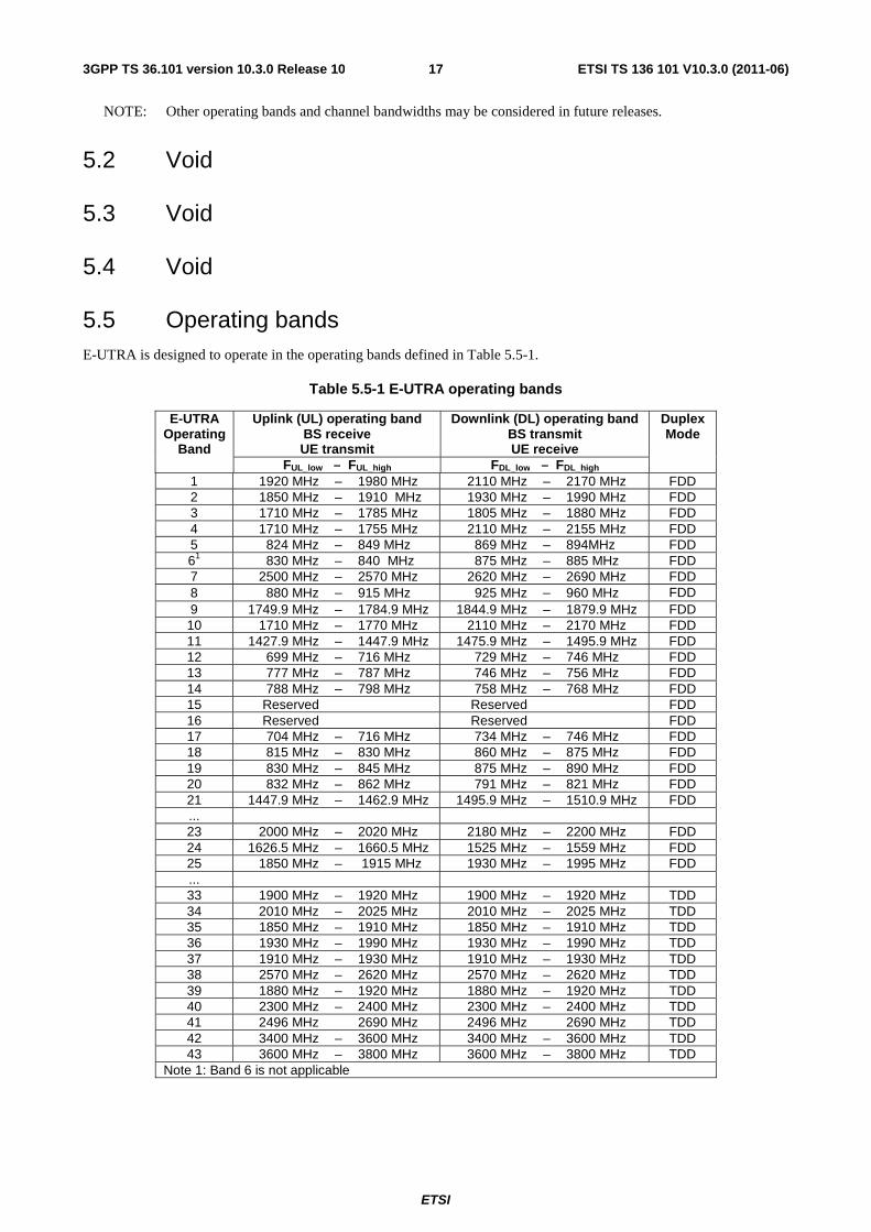
ETSI
ETSI TS 136 101 V10.3.0 (2011-06)173GPP TS 36.101 version 10.3.0 Release 10
NOTE: Other operating bands and channel bandwidths may be considered in future releases.
5.2 Void
5.3 Void
5.4 Void
5.5 Operating bands E-UTRA is designed to operate in the operating bands defined in Table 5.5-1.
Table 5.5-1 E-UTRA operating bands
E-UTRA Operating
Band
Uplink (UL) operating band BS receive UE transmit
Downlink (DL) operating band BS transmit UE receive
Duplex Mode
FUL_low – FUL_high FDL_low – FDL_high 1 1920 MHz – 1980 MHz 2110 MHz – 2170 MHz FDD 2 1850 MHz – 1910 MHz 1930 MHz – 1990 MHz FDD 3 1710 MHz – 1785 MHz 1805 MHz – 1880 MHz FDD 4 1710 MHz – 1755 MHz 2110 MHz – 2155 MHz FDD 5 824 MHz – 849 MHz 869 MHz – 894MHz FDD 61 830 MHz – 840 MHz 875 MHz – 885 MHz FDD 7 2500 MHz – 2570 MHz 2620 MHz – 2690 MHz FDD 8 880 MHz – 915 MHz 925 MHz – 960 MHz FDD 9 1749.9 MHz – 1784.9 MHz 1844.9 MHz – 1879.9 MHz FDD 10 1710 MHz – 1770 MHz 2110 MHz – 2170 MHz FDD 11 1427.9 MHz – 1447.9 MHz 1475.9 MHz – 1495.9 MHz FDD 12 699 MHz – 716 MHz 729 MHz – 746 MHz FDD 13 777 MHz – 787 MHz 746 MHz – 756 MHz FDD 14 788 MHz – 798 MHz 758 MHz – 768 MHz FDD 15 Reserved Reserved FDD 16 Reserved Reserved FDD 17 704 MHz – 716 MHz 734 MHz – 746 MHz FDD 18 815 MHz – 830 MHz 860 MHz – 875 MHz FDD 19 830 MHz – 845 MHz 875 MHz – 890 MHz FDD 20 832 MHz – 862 MHz 791 MHz – 821 MHz FDD 21 1447.9 MHz – 1462.9 MHz 1495.9 MHz – 1510.9 MHz FDD ... 23 2000 MHz – 2020 MHz 2180 MHz – 2200 MHz FDD 24 1626.5 MHz – 1660.5 MHz 1525 MHz – 1559 MHz FDD 25 1850 MHz – 1915 MHz 1930 MHz – 1995 MHz FDD ... 33 1900 MHz – 1920 MHz 1900 MHz – 1920 MHz TDD 34 2010 MHz – 2025 MHz 2010 MHz – 2025 MHz TDD 35 1850 MHz – 1910 MHz 1850 MHz – 1910 MHz TDD 36 1930 MHz – 1990 MHz 1930 MHz – 1990 MHz TDD 37 1910 MHz – 1930 MHz 1910 MHz – 1930 MHz TDD 38 2570 MHz – 2620 MHz 2570 MHz – 2620 MHz TDD 39 1880 MHz – 1920 MHz 1880 MHz – 1920 MHz TDD 40 2300 MHz – 2400 MHz 2300 MHz – 2400 MHz TDD 41 2496 MHz 2690 MHz 2496 MHz 2690 MHz TDD 42 3400 MHz – 3600 MHz 3400 MHz – 3600 MHz TDD 43 3600 MHz – 3800 MHz 3600 MHz – 3800 MHz TDD
Note 1: Band 6 is not applicable
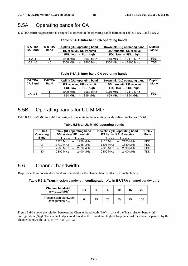
ETSI
ETSI TS 136 101 V10.3.0 (2011-06)183GPP TS 36.101 version 10.3.0 Release 10
5.5A Operating bands for CA E-UTRA carrier aggregation is designed to operate in the operating bands defined in Tables 5.5A-1 and 5.5A-2.
Table 5.5A-1: Intra band CA operating bands
E-UTRA CA Band
E-UTRA Band
Uplink (UL) operating band Downlink (DL) operating band Duplex Mode BS receive / UE transmit BS transmit / UE receive
FUL_low – FUL_high FDL_low – FDL_high
CA_1 1 1920 MHz – 1980 MHz 2110 MHz – 2170 MHz FDD CA_40 40 2300 MHz – 2400 MHz 2300 MHz – 2400 MHz TDD
Table 5.5A-2: Inter band CA operating bands
E-UTRA CA Band
E-UTRA Band
Uplink (UL) operating band Downlink (DL) operating band Duplex Mode BS receive / UE transmit BS transmit / UE receive
FUL_low – FUL_high FDL_low – FDL_high
CA_1-5 1 1920 MHz – 1980 MHz 2110 MHz – 2170 MHz
FDD 5 824 MHz – 849 MHz 869 MHz – 894 MHz
5.5B Operating bands for UL-MIMO E-UTRA UL-MIMO in Rel-10 is designed to operate in the operating bands defined in Tables 5.5B-1.
Table 5.5B-1: UL-MIMO operating bands
E-UTRA Operating
Band
Uplink (UL) operating band BS receive/ UE transmit
Downlink (DL) operating band BS transmit / UE receive
Duplex Mode
FUL_low – FUL_high FDL_low – FDL_high 1 1920 MHz – 1980 MHz 2110 MHz – 2170 MHz FDD 3 1710 MHz – 1785 MHz 1805 MHz – 1880 MHz FDD 7 2500 MHz – 2570 MHz 2620 MHz – 2690 MHz FDD 40 2300 MHz – 2400 MHz 2300 MHz – 2400 MHz TDD
5.6 Channel bandwidth Requirements in present document are specified for the channel bandwidths listed in Table 5.6-1.
Table 5.6-1: Transmission bandwidth configuration NRB in E-UTRA channel bandwidths
Channel bandwidth BWChannel [MHz] 1.4 3 5 10 15 20
Transmission bandwidth configuration NRB 6 15 25 50 75 100
Figure 5.6-1 shows the relation between the Channel bandwidth (BWChannel) and the Transmission bandwidth configuration (NRB). The channel edges are defined as the lowest and highest frequencies of the carrier separated by the channel bandwidth, i.e. at FC +/- BWChannel /2.
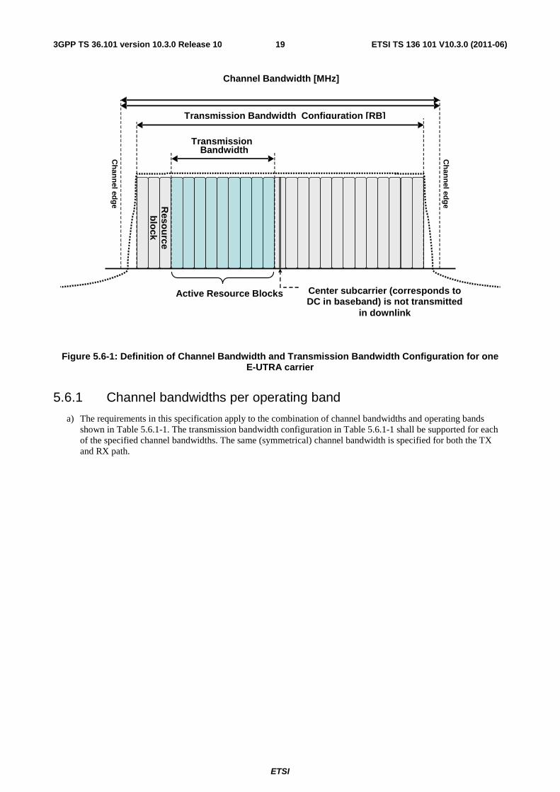
ETSI
ETSI TS 136 101 V10.3.0 (2011-06)193GPP TS 36.101 version 10.3.0 Release 10
Channel Bandwidth [MHz]
Figure 5.6-1: Definition of Channel Bandwidth and Transmission Bandwidth Configuration for one E-UTRA carrier
5.6.1 Channel bandwidths per operating band
a) The requirements in this specification apply to the combination of channel bandwidths and operating bands shown in Table 5.6.1-1. The transmission bandwidth configuration in Table 5.6.1-1 shall be supported for each of the specified channel bandwidths. The same (symmetrical) channel bandwidth is specified for both the TX and RX path.
Transmission
Center subcarrier (corresponds to DC in baseband) is not transmitted
in downlink
Active Resource Blocks
Ch
ann
el edg
e
Ch
ann
el edg
e Reso
urce
blo
ck
Transmission Bandwidth Configuration [RB]
Bandwidth
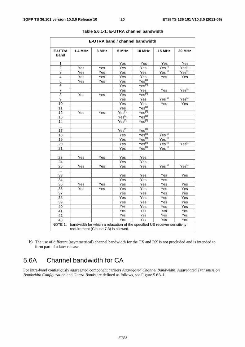
ETSI
ETSI TS 136 101 V10.3.0 (2011-06)203GPP TS 36.101 version 10.3.0 Release 10
Table 5.6.1-1: E-UTRA channel bandwidth
E-UTRA band / channel bandwidth
E-UTRA Band
1.4 MHz 3 MHz 5 MHz 10 MHz 15 MHz 20 MHz
1 Yes Yes Yes Yes 2 Yes Yes Yes Yes Yes[1] Yes[1] 3 Yes Yes Yes Yes Yes[1] Yes[1] 4 Yes Yes Yes Yes Yes Yes 5 Yes Yes Yes Yes[1] 6 Yes Yes[1] 7 Yes Yes Yes Yes[1] 8 Yes Yes Yes Yes[1] 9 Yes Yes Yes[1] Yes[1]
10 Yes Yes Yes Yes 11 Yes Yes[1] 12 Yes Yes Yes[1] Yes[1] 13 Yes[1] Yes[1] 14 Yes[1] Yes[1] ... 17 Yes[1] Yes[1] 18 Yes Yes[1] Yes[1] 19 Yes Yes[1] Yes[1] 20 Yes Yes[1] Yes[1] Yes[1] 21 Yes Yes[1] Yes[1] ... 23 Yes Yes Yes Yes 24 Yes Yes 25 Yes Yes Yes Yes Yes[1] Yes[1] ... 33 Yes Yes Yes Yes 34 Yes Yes Yes 35 Yes Yes Yes Yes Yes Yes 36 Yes Yes Yes Yes Yes Yes 37 Yes Yes Yes Yes 38 Yes Yes Yes Yes 39 Yes Yes Yes Yes 40 Yes Yes Yes Yes 41 Yes Yes Yes Yes 42 Yes Yes Yes Yes
43 Yes Yes Yes Yes
NOTE 1: bandwidth for which a relaxation of the specified UE receiver sensitivity requirement (Clause 7.3) is allowed.
b) The use of different (asymmetrical) channel bandwidth for the TX and RX is not precluded and is intended to form part of a later release.
5.6A Channel bandwidth for CA For intra-band contiguously aggregated component carriers Aggregated Channel Bandwidth, Aggregated Transmission Bandwidth Configuration and Guard Bands are defined as follows, see Figure 5.6A-1.
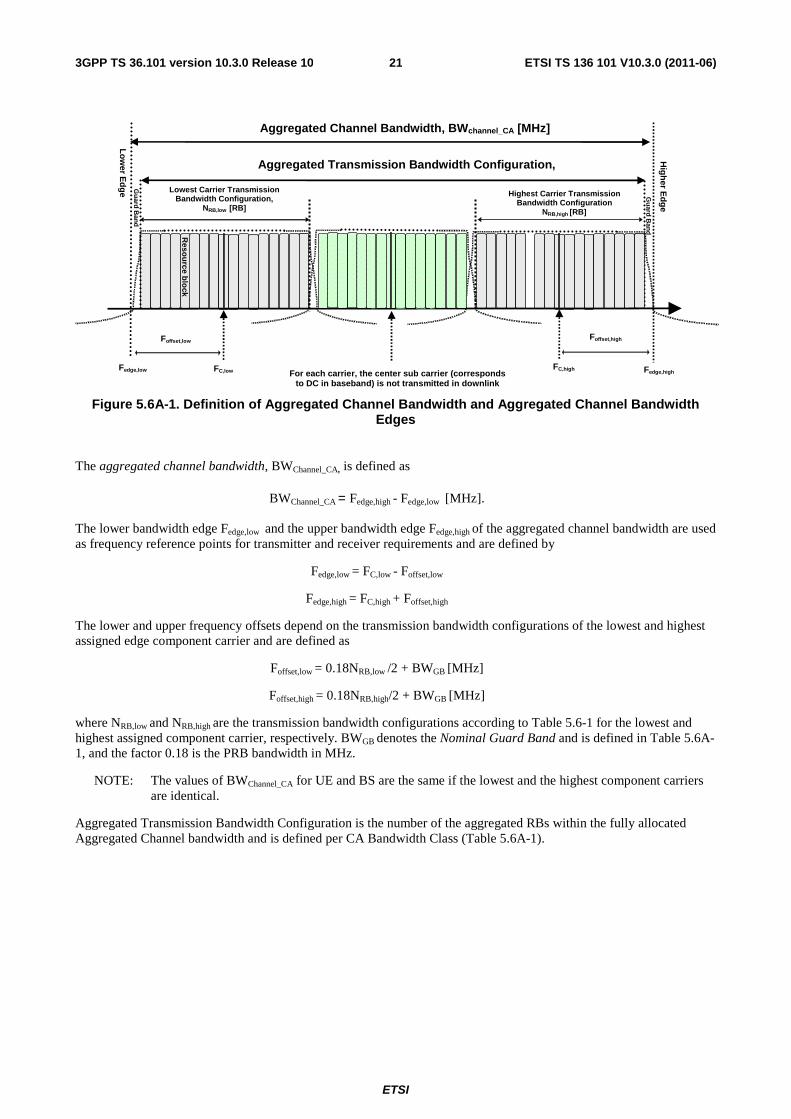
ETSI
ETSI TS 136 101 V10.3.0 (2011-06)213GPP TS 36.101 version 10.3.0 Release 10
Figure 5.6A-1. Definition of Aggregated Channel Bandwidth and Aggregated Channel Bandwidth Edges
The aggregated channel bandwidth, BWChannel_CA, is defined as
BWChannel_CA = Fedge,high - Fedge,low [MHz].
The lower bandwidth edge Fedge,low and the upper bandwidth edge Fedge,high of the aggregated channel bandwidth are used as frequency reference points for transmitter and receiver requirements and are defined by
Fedge,low = FC,low - Foffset,low
Fedge,high = FC,high + Foffset,high
The lower and upper frequency offsets depend on the transmission bandwidth configurations of the lowest and highest assigned edge component carrier and are defined as
Foffset,low = 0.18NRB,low /2 + BWGB [MHz]
Foffset,high = 0.18NRB,high/2 + BWGB [MHz]
where NRB,low and NRB,high are the transmission bandwidth configurations according to Table 5.6-1 for the lowest and highest assigned component carrier, respectively. BWGB denotes the Nominal Guard Band and is defined in Table 5.6A-1, and the factor 0.18 is the PRB bandwidth in MHz.
NOTE: The values of BWChannel_CA for UE and BS are the same if the lowest and the highest component carriers are identical.
Aggregated Transmission Bandwidth Configuration is the number of the aggregated RBs within the fully allocated Aggregated Channel bandwidth and is defined per CA Bandwidth Class (Table 5.6A-1).
FC,low
Lo
wer E
dg
e
Hig
her E
dg
e
Lowest Carrier Transmission Bandwidth Configuration,
NRB,low [RB]
FC,high
Foffset,low
Highest Carrier Transmission Bandwidth Configuration
NRB,high [RB]
Reso
urce b
lock
Aggregated Channel Bandwidth, BWchannel_CA [MHz]
Fedge,low Fedge,high For each carrier, the center sub carrier (corresponds to DC in baseband) is not transmitted in downlink
Foffset,high
Gu
ard B
and
Gu
ard B
and
Aggregated Transmission Bandwidth Configuration, N [RB]
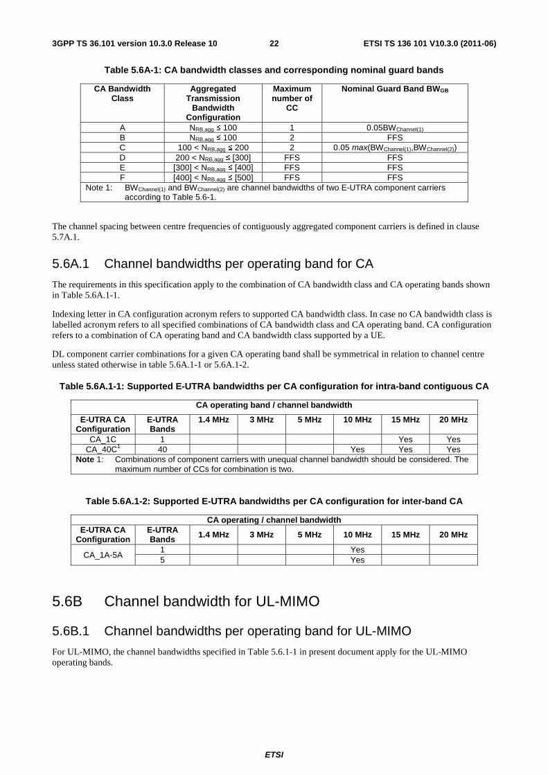
ETSI
ETSI TS 136 101 V10.3.0 (2011-06)223GPP TS 36.101 version 10.3.0 Release 10
Table 5.6A-1: CA bandwidth classes and corresponding nominal guard bands
CA Bandwidth Class
Aggregated Transmission
Bandwidth Configuration
Maximum number of
CC
Nominal Guard Band BWGB
A NRB,agg ≤ 100 1 0.05BWChannel(1) B NRB,agg ≤ 100 2 FFS C 100 < NRB,agg ≤ 200 2 0.05 max(BWChannel(1),BWChannel(2)) D 200 < NRB,agg ≤ [300] FFS FFS E [300] < NRB,agg ≤ [400] FFS FFS F [400] < NRB,agg ≤ [500] FFS FFS
Note 1: BWChannel(1) and BWChannel(2) are channel bandwidths of two E-UTRA component carriers according to Table 5.6-1.
The channel spacing between centre frequencies of contiguously aggregated component carriers is defined in clause 5.7A.1.
5.6A.1 Channel bandwidths per operating band for CA
The requirements in this specification apply to the combination of CA bandwidth class and CA operating bands shown in Table 5.6A.1-1.
Indexing letter in CA configuration acronym refers to supported CA bandwidth class. In case no CA bandwidth class is labelled acronym refers to all specified combinations of CA bandwidth class and CA operating band. CA configuration refers to a combination of CA operating band and CA bandwidth class supported by a UE.
DL component carrier combinations for a given CA operating band shall be symmetrical in relation to channel centre unless stated otherwise in table 5.6A.1-1 or 5.6A.1-2.
Table 5.6A.1-1: Supported E-UTRA bandwidths per CA configuration for intra-band contiguous CA
CA operating band / channel bandwidth
E-UTRA CA Configuration
E-UTRA Bands
1.4 MHz 3 MHz 5 MHz 10 MHz 15 MHz 20 MHz
CA_1C 1 Yes Yes CA_40C1 40 Yes Yes Yes
Note 1: Combinations of component carriers with unequal channel bandwidth should be considered. The maximum number of CCs for combination is two.
Table 5.6A.1-2: Supported E-UTRA bandwidths per CA configuration for inter-band CA
CA operating / channel bandwidth E-UTRA CA
Configuration E-UTRA Bands 1.4 MHz 3 MHz 5 MHz 10 MHz 15 MHz 20 MHz
CA_1A-5A 1 Yes 5 Yes
5.6B Channel bandwidth for UL-MIMO
5.6B.1 Channel bandwidths per operating band for UL-MIMO
For UL-MIMO, the channel bandwidths specified in Table 5.6.1-1 in present document apply for the UL-MIMO operating bands.
ETSI
ETSI TS 136 101 V10.3.0 (2011-06)233GPP TS 36.101 version 10.3.0 Release 10
5.7 Channel arrangement
5.7.1 Channel spacing
The spacing between carriers will depend on the deployment scenario, the size of the frequency block available and the channel bandwidths. The nominal channel spacing between two adjacent E-UTRA carriers is defined as following:
Nominal Channel spacing = (BWChannel(1) + BWChannel(2))/2
where BWChannel(1) and BWChannel(2) are the channel bandwidths of the two respective E-UTRA carriers. The channel spacing can be adjusted to optimize performance in a particular deployment scenario.
5.7.1A Channel spacing for intra-band contiguous CA
For CA Bandwidth Class C, the nominal channel spacing between two adjacent E-UTRA component carriers is defined as the following:
[ ]MHz3.06.0
1.0 spacingchannelNominal
)2()1()2()1(
⎥⎥
⎦
⎥
⎢⎢
⎣
⎢ −−+= ChannelChannelChannelChannel BWBWBWBW
where BWChannel(1) and BWChannel(2) are the channel bandwidths of the two respective E-UTRA component carriers according to Table 5.6-1 with values in MHz. The channel spacing for intra-band contiguous carrier aggregation can be adjusted to any multiple of 300 kHz less than the nominal channel spacing to optimize performance in a particular deployment scenario.
5.7.2 Channel raster
The channel raster is 100 kHz for all bands, which means that the carrier centre frequency must be an integer multiple of 100 kHz.
5.7.2A Channel raster for CA
For LTE-A same channel raster as in E-UTRA Rel-9 is applied. Hence the channel raster is 100 kHz for all bands, which means that the carrier centre frequency must be an integer multiple of 100 kHz.
5.7.3 Carrier frequency and EARFCN
The carrier frequency in the uplink and downlink is designated by the E-UTRA Absolute Radio Frequency Channel Number (EARFCN) in the range 0 - 65535. The relation between EARFCN and the carrier frequency in MHz for the downlink is given by the following equation, where FDL_low and NOffs-DL are given in table 5.7.3-1 and NDL is the downlink EARFCN.
FDL = FDL_low + 0.1(NDL – NOffs-DL)
The relation between EARFCN and the carrier frequency in MHz for the uplink is given by the following equation where FUL_low and NOffs-UL are given in table 5.7.3-1 and NUL is the uplink EARFCN.
FUL = FUL_low + 0.1(NUL – NOffs-UL)
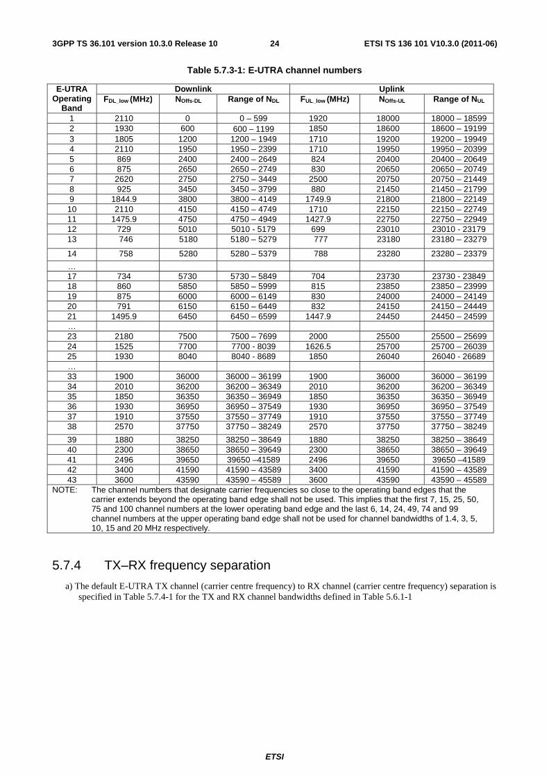
ETSI
ETSI TS 136 101 V10.3.0 (2011-06)243GPP TS 36.101 version 10.3.0 Release 10
Table 5.7.3-1: E-UTRA channel numbers
E-UTRA Operating
Band
Downlink Uplink FDL_low (MHz) NOffs-DL Range of NDL FUL_low (MHz) NOffs-UL Range of NUL
1 2110 0 0 – 599 1920 18000 18000 – 18599 2 1930 600 600 − 1199 1850 18600 18600 – 19199 3 1805 1200 1200 – 1949 1710 19200 19200 – 19949 4 2110 1950 1950 – 2399 1710 19950 19950 – 20399 5 869 2400 2400 – 2649 824 20400 20400 – 20649 6 875 2650 2650 – 2749 830 20650 20650 – 20749 7 2620 2750 2750 – 3449 2500 20750 20750 – 21449 8 925 3450 3450 – 3799 880 21450 21450 – 21799 9 1844.9 3800 3800 – 4149 1749.9 21800 21800 – 22149 10 2110 4150 4150 – 4749 1710 22150 22150 – 22749 11 1475.9 4750 4750 – 4949 1427.9 22750 22750 – 22949 12 729 5010 5010 - 5179 699 23010 23010 - 23179 13 746 5180 5180 – 5279 777 23180 23180 – 23279
14 758 5280 5280 – 5379 788 23280 23280 – 23379
… 17 734 5730 5730 – 5849 704 23730 23730 - 23849 18 860 5850 5850 – 5999 815 23850 23850 – 23999 19 875 6000 6000 – 6149 830 24000 24000 – 24149 20 791 6150 6150 – 6449 832 24150 24150 – 24449 21 1495.9 6450 6450 – 6599 1447.9 24450 24450 – 24599 … 23 2180 7500 7500 – 7699 2000 25500 25500 – 25699 24 1525 7700 7700 - 8039 1626.5 25700 25700 – 26039 25 1930 8040 8040 - 8689 1850 26040 26040 - 26689 … 33 1900 36000 36000 – 36199 1900 36000 36000 – 36199 34 2010 36200 36200 – 36349 2010 36200 36200 – 36349 35 1850 36350 36350 – 36949 1850 36350 36350 – 36949 36 1930 36950 36950 – 37549 1930 36950 36950 – 37549 37 1910 37550 37550 – 37749 1910 37550 37550 – 37749 38 2570 37750 37750 – 38249 2570 37750 37750 – 38249
39 1880 38250 38250 – 38649 1880 38250 38250 – 38649 40 2300 38650 38650 – 39649 2300 38650 38650 – 39649 41 2496 39650 39650 –41589 2496 39650 39650 –41589 42 3400 41590 41590 – 43589 3400 41590 41590 – 43589 43 3600 43590 43590 – 45589 3600 43590 43590 – 45589
NOTE: The channel numbers that designate carrier frequencies so close to the operating band edges that the carrier extends beyond the operating band edge shall not be used. This implies that the first 7, 15, 25, 50, 75 and 100 channel numbers at the lower operating band edge and the last 6, 14, 24, 49, 74 and 99 channel numbers at the upper operating band edge shall not be used for channel bandwidths of 1.4, 3, 5, 10, 15 and 20 MHz respectively.
5.7.4 TX–RX frequency separation
a) The default E-UTRA TX channel (carrier centre frequency) to RX channel (carrier centre frequency) separation is specified in Table 5.7.4-1 for the TX and RX channel bandwidths defined in Table 5.6.1-1
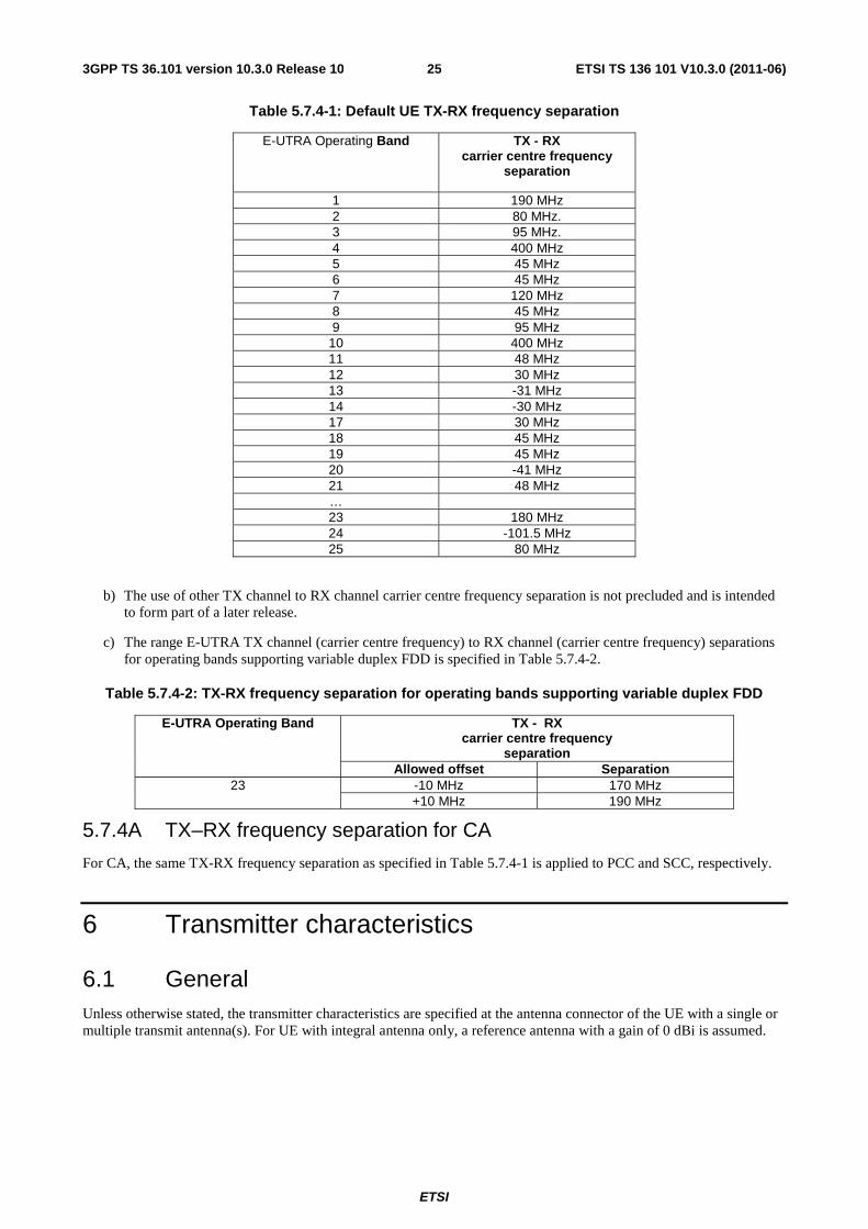
ETSI
ETSI TS 136 101 V10.3.0 (2011-06)253GPP TS 36.101 version 10.3.0 Release 10
Table 5.7.4-1: Default UE TX-RX frequency separation
E-UTRA Operating Band TX - RX carrier centre frequency
separation
1 190 MHz 2 80 MHz. 3 95 MHz. 4 400 MHz 5 45 MHz 6 45 MHz 7 120 MHz 8 45 MHz 9 95 MHz
10 400 MHz 11 48 MHz 12 30 MHz 13 -31 MHz 14 -30 MHz 17 30 MHz 18 45 MHz 19 45 MHz 20 -41 MHz 21 48 MHz … 23 180 MHz 24 -101.5 MHz 25 80 MHz
b) The use of other TX channel to RX channel carrier centre frequency separation is not precluded and is intended to form part of a later release.
c) The range E-UTRA TX channel (carrier centre frequency) to RX channel (carrier centre frequency) separations for operating bands supporting variable duplex FDD is specified in Table 5.7.4-2.
Table 5.7.4-2: TX-RX frequency separation for operating bands supporting variable duplex FDD
E-UTRA Operating Band TX - RX carrier centre frequency
separation Allowed offset Separation
23 -10 MHz 170 MHz +10 MHz 190 MHz
5.7.4A TX–RX frequency separation for CA
For CA, the same TX-RX frequency separation as specified in Table 5.7.4-1 is applied to PCC and SCC, respectively.
6 Transmitter characteristics
6.1 General Unless otherwise stated, the transmitter characteristics are specified at the antenna connector of the UE with a single or multiple transmit antenna(s). For UE with integral antenna only, a reference antenna with a gain of 0 dBi is assumed.
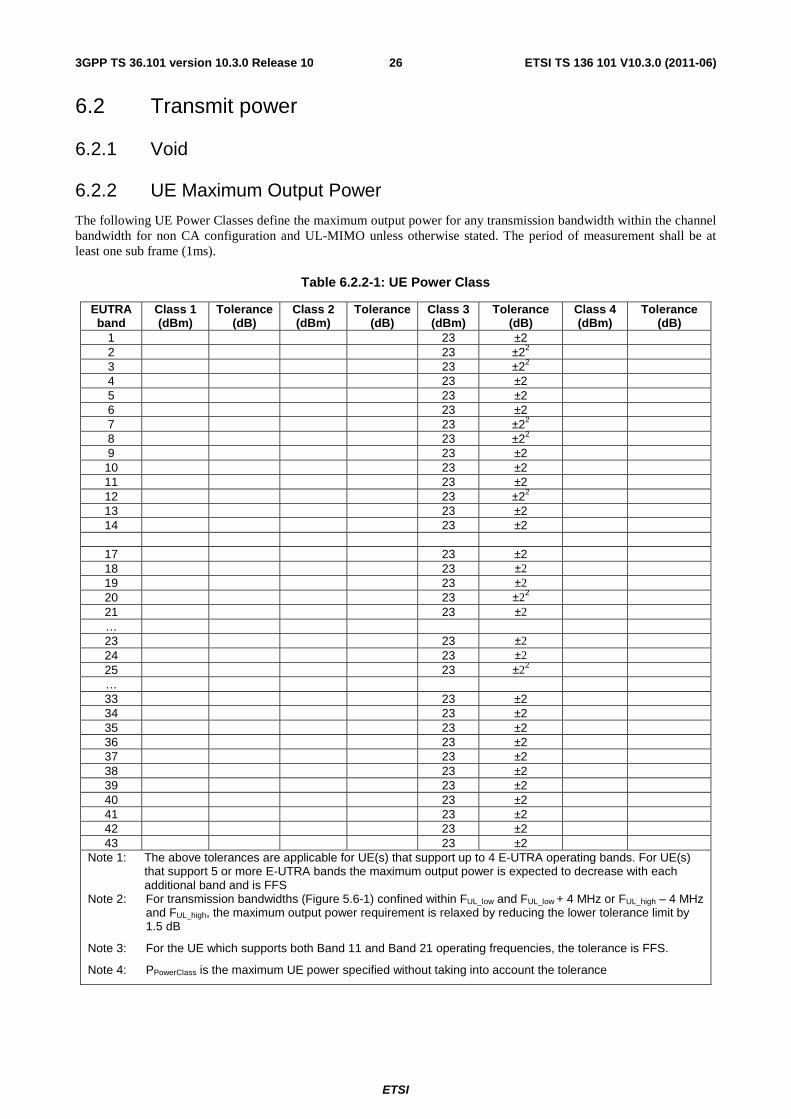
ETSI
ETSI TS 136 101 V10.3.0 (2011-06)263GPP TS 36.101 version 10.3.0 Release 10
6.2 Transmit power
6.2.1 Void
6.2.2 UE Maximum Output Power
The following UE Power Classes define the maximum output power for any transmission bandwidth within the channel bandwidth for non CA configuration and UL-MIMO unless otherwise stated. The period of measurement shall be at least one sub frame (1ms).
Table 6.2.2-1: UE Power Class
EUTRA band
Class 1 (dBm)
Tolerance (dB)
Class 2 (dBm)
Tolerance (dB)
Class 3 (dBm)
Tolerance (dB)
Class 4 (dBm)
Tolerance (dB)
1 23 ±2 2 23 ±22 3 23 ±22 4 23 ±2 5 23 ±2 6 23 ±2 7 23 ±22 8 23 ±22 9 23 ±2 10 23 ±2 11 23 ±2 12 23 ±22 13 23 ±2 14 23 ±2
17 23 ±2 18 23 ±2 19 23 ±2 20 23 ±22 21 23 ±2 … 23 23 ±2 24 23 ±2 25 23 ±22 … 33 23 ±2 34 23 ±2 35 23 ±2 36 23 ±2 37 23 ±2 38 23 ±2 39 23 ±2 40 23 ±2 41 23 ±2 42 23 ±2 43 23 ±2
Note 1: The above tolerances are applicable for UE(s) that support up to 4 E-UTRA operating bands. For UE(s) that support 5 or more E-UTRA bands the maximum output power is expected to decrease with each additional band and is FFS
Note 2: For transmission bandwidths (Figure 5.6-1) confined within FUL_low and FUL_low + 4 MHz or FUL_high – 4 MHz and FUL_high, the maximum output power requirement is relaxed by reducing the lower tolerance limit by 1.5 dB
Note 3: For the UE which supports both Band 11 and Band 21 operating frequencies, the tolerance is FFS.
Note 4: PPowerClass is the maximum UE power specified without taking into account the tolerance
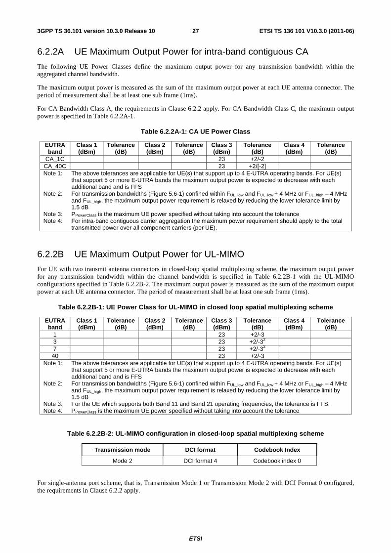
ETSI
ETSI TS 136 101 V10.3.0 (2011-06)273GPP TS 36.101 version 10.3.0 Release 10
6.2.2A UE Maximum Output Power for intra-band contiguous CA
The following UE Power Classes define the maximum output power for any transmission bandwidth within the aggregated channel bandwidth.
The maximum output power is measured as the sum of the maximum output power at each UE antenna connector. The period of measurement shall be at least one sub frame (1ms).
For CA Bandwidth Class A, the requirements in Clause 6.2.2 apply. For CA Bandwidth Class C, the maximum output power is specified in Table 6.2.2A-1.
Table 6.2.2A-1: CA UE Power Class
EUTRA band
Class 1 (dBm)
Tolerance (dB)
Class 2 (dBm)
Tolerance (dB)
Class 3 (dBm)
Tolerance (dB)
Class 4 (dBm)
Tolerance (dB)
CA_1C 23 +2/-2 CA_40C 23 +2/[-2] Note 1: The above tolerances are applicable for UE(s) that support up to 4 E-UTRA operating bands. For UE(s)
that support 5 or more E-UTRA bands the maximum output power is expected to decrease with each additional band and is FFS
Note 2: For transmission bandwidths (Figure 5.6-1) confined within FUL_low and FUL_low + 4 MHz or FUL_high – 4 MHz and FUL_high, the maximum output power requirement is relaxed by reducing the lower tolerance limit by 1.5 dB
Note 3: PPowerClass is the maximum UE power specified without taking into account the tolerance Note 4: For intra-band contiguous carrier aggregation the maximum power requirement should apply to the total
transmitted power over all component carriers (per UE).
6.2.2B UE Maximum Output Power for UL-MIMO
For UE with two transmit antenna connectors in closed-loop spatial multiplexing scheme, the maximum output power for any transmission bandwidth within the channel bandwidth is specified in Table 6.2.2B-1 with the UL-MIMO configurations specified in Table 6.2.2B-2. The maximum output power is measured as the sum of the maximum output power at each UE antenna connector. The period of measurement shall be at least one sub frame (1ms).
Table 6.2.2B-1: UE Power Class for UL-MIMO in closed loop spatial multiplexing scheme
EUTRA band
Class 1 (dBm)
Tolerance (dB)
Class 2 (dBm)
Tolerance (dB)
Class 3 (dBm)
Tolerance (dB)
Class 4 (dBm)
Tolerance (dB)
1 23 +2/-3 3 23 +2/-32 7 23 +2/-32 40 23 +2/-3
Note 1: The above tolerances are applicable for UE(s) that support up to 4 E-UTRA operating bands. For UE(s) that support 5 or more E-UTRA bands the maximum output power is expected to decrease with each additional band and is FFS
Note 2: For transmission bandwidths (Figure 5.6-1) confined within FUL_low and FUL_low + 4 MHz or FUL_high – 4 MHz and FUL_high, the maximum output power requirement is relaxed by reducing the lower tolerance limit by 1.5 dB
Note 3: For the UE which supports both Band 11 and Band 21 operating frequencies, the tolerance is FFS. Note 4: PPowerClass is the maximum UE power specified without taking into account the tolerance
Table 6.2.2B-2: UL-MIMO configuration in closed-loop spatial multiplexing scheme
Transmission mode DCI format Codebook Index
Mode 2 DCI format 4 Codebook index 0
For single-antenna port scheme, that is, Transmission Mode 1 or Transmission Mode 2 with DCI Format 0 configured, the requirements in Clause 6.2.2 apply.
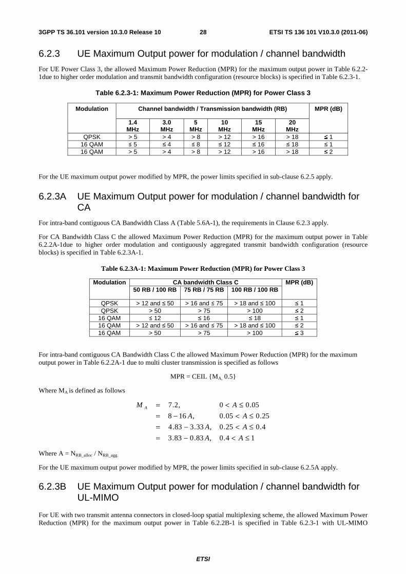
ETSI
ETSI TS 136 101 V10.3.0 (2011-06)283GPP TS 36.101 version 10.3.0 Release 10
6.2.3 UE Maximum Output power for modulation / channel bandwidth
For UE Power Class 3, the allowed Maximum Power Reduction (MPR) for the maximum output power in Table 6.2.2-1due to higher order modulation and transmit bandwidth configuration (resource blocks) is specified in Table 6.2.3-1.
Table 6.2.3-1: Maximum Power Reduction (MPR) for Power Class 3
Modulation Channel bandwidth / Transmission bandwidth (RB) MPR (dB)
1.4 MHz
3.0 MHz
5 MHz
10 MHz
15 MHz
20 MHz
QPSK > 5 > 4 > 8 > 12 > 16 > 18 ≤ 1 16 QAM ≤ 5 ≤ 4 ≤ 8 ≤ 12 ≤ 16 ≤ 18 ≤ 1 16 QAM > 5 > 4 > 8 > 12 > 16 > 18 ≤ 2
For the UE maximum output power modified by MPR, the power limits specified in sub-clause 6.2.5 apply.
6.2.3A UE Maximum Output power for modulation / channel bandwidth for CA
For intra-band contiguous CA Bandwidth Class A (Table 5.6A-1), the requirements in Clause 6.2.3 apply.
For CA Bandwidth Class C the allowed Maximum Power Reduction (MPR) for the maximum output power in Table 6.2.2A-1due to higher order modulation and contiguously aggregated transmit bandwidth configuration (resource blocks) is specified in Table 6.2.3A-1.
Table 6.2.3A-1: Maximum Power Reduction (MPR) for Power Class 3
Modulation CA bandwidth Class C MPR (dB) 50 RB / 100 RB 75 RB / 75 RB 100 RB / 100 RB
QPSK > 12 and ≤ 50 > 16 and ≤ 75 > 18 and ≤ 100 ≤ 1 QPSK > 50 > 75 > 100 ≤ 2
16 QAM ≤ 12 ≤ 16 ≤ 18 ≤ 1 16 QAM > 12 and ≤ 50 > 16 and ≤ 75 > 18 and ≤ 100 ≤ 2 16 QAM > 50 > 75 > 100 ≤ 3
For intra-band contiguous CA Bandwidth Class C the allowed Maximum Power Reduction (MPR) for the maximum output power in Table 6.2.2A-1 due to multi cluster transmission is specified as follows
MPR = CEIL {MA, 0.5}
Where MA is defined as follows
14.0,83.083.3
4.025.0,33.383.4
25.005.0,168
05.00,2.7
≤<−=≤<−=≤<−=
≤<=
AA
AA
AA
AM A
Where A = NRB_alloc / NRB_agg.
For the UE maximum output power modified by MPR, the power limits specified in sub-clause 6.2.5A apply.
6.2.3B UE Maximum Output power for modulation / channel bandwidth for UL-MIMO
For UE with two transmit antenna connectors in closed-loop spatial multiplexing scheme, the allowed Maximum Power Reduction (MPR) for the maximum output power in Table 6.2.2B-1 is specified in Table 6.2.3-1 with UL-MIMO
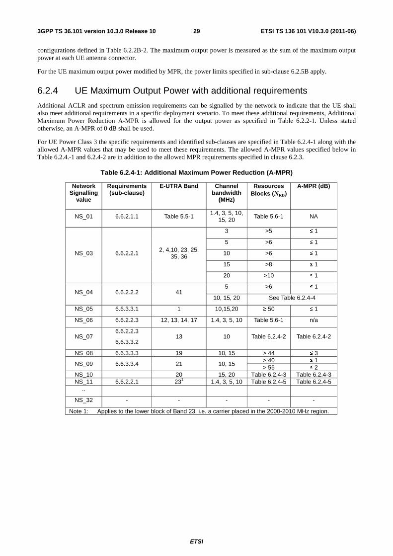
ETSI
ETSI TS 136 101 V10.3.0 (2011-06)293GPP TS 36.101 version 10.3.0 Release 10
configurations defined in Table 6.2.2B-2. The maximum output power is measured as the sum of the maximum output power at each UE antenna connector.
For the UE maximum output power modified by MPR, the power limits specified in sub-clause 6.2.5B apply.
6.2.4 UE Maximum Output Power with additional requirements
Additional ACLR and spectrum emission requirements can be signalled by the network to indicate that the UE shall also meet additional requirements in a specific deployment scenario. To meet these additional requirements, Additional Maximum Power Reduction A-MPR is allowed for the output power as specified in Table 6.2.2-1. Unless stated otherwise, an A-MPR of 0 dB shall be used.
For UE Power Class 3 the specific requirements and identified sub-clauses are specified in Table 6.2.4-1 along with the allowed A-MPR values that may be used to meet these requirements. The allowed A-MPR values specified below in Table 6.2.4.-1 and 6.2.4-2 are in addition to the allowed MPR requirements specified in clause 6.2.3.
Table 6.2.4-1: Additional Maximum Power Reduction (A-MPR)
Network Signalling
value
Requirements (sub-clause)
E-UTRA Band Channel bandwidth
(MHz)
Resources Blocks (NRB)
A-MPR (dB)
NS_01 6.6.2.1.1 Table 5.5-1 1.4, 3, 5, 10, 15, 20 Table 5.6-1 NA
NS_03 6.6.2.2.1 2, 4,10, 23, 25, 35, 36
3 >5 ≤ 1
5 >6 ≤ 1
10 >6 ≤ 1
15 >8 ≤ 1
20 >10 ≤ 1
NS_04 6.6.2.2.2 41 5 >6 ≤ 1
10, 15, 20 See Table 6.2.4-4
NS_05 6.6.3.3.1 1 10,15,20 ≥ 50 ≤ 1
NS_06 6.6.2.2.3 12, 13, 14, 17 1.4, 3, 5, 10 Table 5.6-1 n/a
NS_07 6.6.2.2.3
6.6.3.3.2 13 10 Table 6.2.4-2 Table 6.2.4-2
NS_08 6.6.3.3.3 19 10, 15 > 44 ≤ 3
NS_09 6.6.3.3.4 21 10, 15 > 40 ≤ 1 > 55 ≤ 2
NS_10 20 15, 20 Table 6.2.4-3 Table 6.2.4-3 NS_11 6.6.2.2.1 231 1.4, 3, 5, 10 Table 6.2.4-5 Table 6.2.4-5
..
NS_32 - - - - -
Note 1: Applies to the lower block of Band 23, i.e. a carrier placed in the 2000-2010 MHz region.
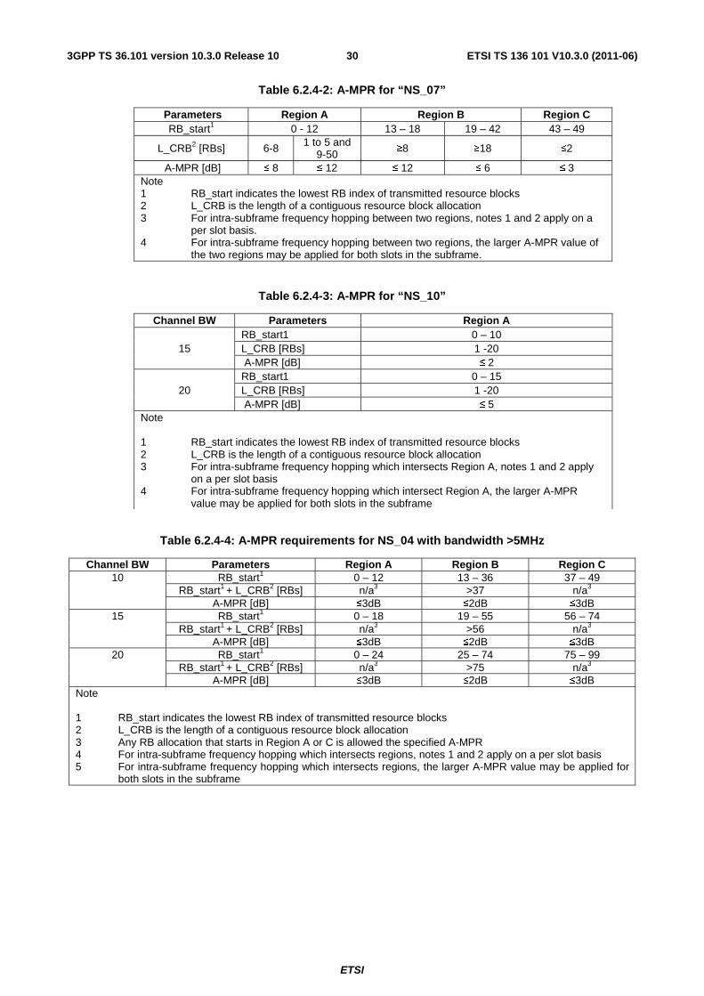
ETSI
ETSI TS 136 101 V10.3.0 (2011-06)303GPP TS 36.101 version 10.3.0 Release 10
Table 6.2.4-2: A-MPR for “NS_07”
Parameters Region A Region B Region C RB_start1 0 - 12 13 – 18 19 – 42 43 – 49
L_CRB2 [RBs] 6-8 1 to 5 and 9-50 ≥8 ≥18 ≤2
A-MPR [dB] ≤ 8 ≤ 12 ≤ 12 ≤ 6 ≤ 3 Note 1 RB_start indicates the lowest RB index of transmitted resource blocks 2 L_CRB is the length of a contiguous resource block allocation 3 For intra-subframe frequency hopping between two regions, notes 1 and 2 apply on a
per slot basis. 4 For intra-subframe frequency hopping between two regions, the larger A-MPR value of
the two regions may be applied for both slots in the subframe.
Table 6.2.4-3: A-MPR for “NS_10”
Channel BW Parameters Region A
15 RB_start1 0 – 10 L_CRB [RBs] 1 -20 A-MPR [dB] ≤ 2
20 RB_start1 0 – 15 L_CRB [RBs] 1 -20 A-MPR [dB] ≤ 5
Note 1 RB_start indicates the lowest RB index of transmitted resource blocks 2 L_CRB is the length of a contiguous resource block allocation 3 For intra-subframe frequency hopping which intersects Region A, notes 1 and 2 apply
on a per slot basis 4 For intra-subframe frequency hopping which intersect Region A, the larger A-MPR
value may be applied for both slots in the subframe
Table 6.2.4-4: A-MPR requirements for NS_04 with bandwidth >5MHz
Channel BW Parameters Region A Region B Region C 10 RB_start1 0 – 12 13 – 36 37 – 49
RB_start1 + L_CRB2 [RBs] n/a3 >37 n/a3 A-MPR [dB] ≤3dB ≤2dB ≤3dB
15 RB_start1 0 – 18 19 – 55 56 – 74 RB_start1 + L_CRB2 [RBs] n/a3 >56 n/a3
A-MPR [dB] ≤3dB ≤2dB ≤3dB 20 RB_start1 0 – 24 25 – 74 75 – 99
RB_start1 + L_CRB2 [RBs] n/a3 >75 n/a3 A-MPR [dB] ≤3dB ≤2dB ≤3dB
Note 1 RB_start indicates the lowest RB index of transmitted resource blocks 2 L_CRB is the length of a contiguous resource block allocation 3 Any RB allocation that starts in Region A or C is allowed the specified A-MPR 4 For intra-subframe frequency hopping which intersects regions, notes 1 and 2 apply on a per slot basis 5 For intra-subframe frequency hopping which intersects regions, the larger A-MPR value may be applied for
both slots in the subframe
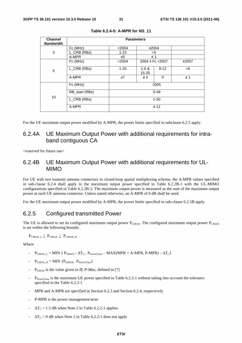
ETSI
ETSI TS 136 101 V10.3.0 (2011-06)313GPP TS 36.101 version 10.3.0 Release 10
Table 6.2.4-5: A-MPR for NS_11
Channel Bandwidth
Parameters
3 Fc (MHz) <2004 ≥2004 L_CRB (RBs) 1-15 >5 A-MPR ≤5 ≤ 1
5
Fc (MHz) <2004 2004 ≤ Fc <2007 ≥2007
L_CRB (RBs) 1-25 1-6 & 15-25
8-12 >6
A-MPR ≤7 ≤ 4 0 ≤ 1
10
Fc (MHz) 2005
RB_start (RBs) 0-49
L_CRB (RBs) 1-50
A-MPR ≤ 12
For the UE maximum output power modified by A-MPR, the power limits specified in subclause 6.2.5 apply.
6.2.4A UE Maximum Output Power with additional requirements for intra-band contiguous CA
<reserved for future use>
6.2.4B UE Maximum Output Power with additional requirements for UL-MIMO
For UE with two transmit antenna connectors in closed-loop spatial multiplexing scheme, the A-MPR values specified in sub-clause 6.2.4 shall apply to the maximum output power specified in Table 6.2.2B-1 with the UL-MIMO configurations specified in Table 6.2.2B-2. The maximum output power is measured as the sum of the maximum output power at each UE antenna connector. Unless stated otherwise, an A-MPR of 0 dB shall be used.
For the UE maximum output power modified by A-MPR, the power limits specified in sub-clause 6.2.5B apply.
6.2.5 Configured transmitted Power
The UE is allowed to set its configured maximum output power PCMAX. The configured maximum output power PCMAX is set within the following bounds:
PCMAX_L ≤ PCMAX ≤ PCMAX_H
Where
- PCMAX_L = MIN { PEMAX – ΔTC, PPowerClass – MAX(MPR + A-MPR, P-MPR) – ΔTC}
- PCMAX_H = MIN {PEMAX, PPowerClass}
- PEMAX is the value given to IE P-Max, defined in [7]
- PPowerClass is the maximum UE power specified in Table 6.2.2-1 without taking into account the tolerance specified in the Table 6.2.2-1
- MPR and A-MPR are specified in Section 6.2.3 and Section 6.2.4, respectively
- P-MPR is the power management term
- ΔTC = 1.5 dB when Note 2 in Table 6.2.2-1 applies
- ΔTC = 0 dB when Note 2 in Table 6.2.2-1 does not apply
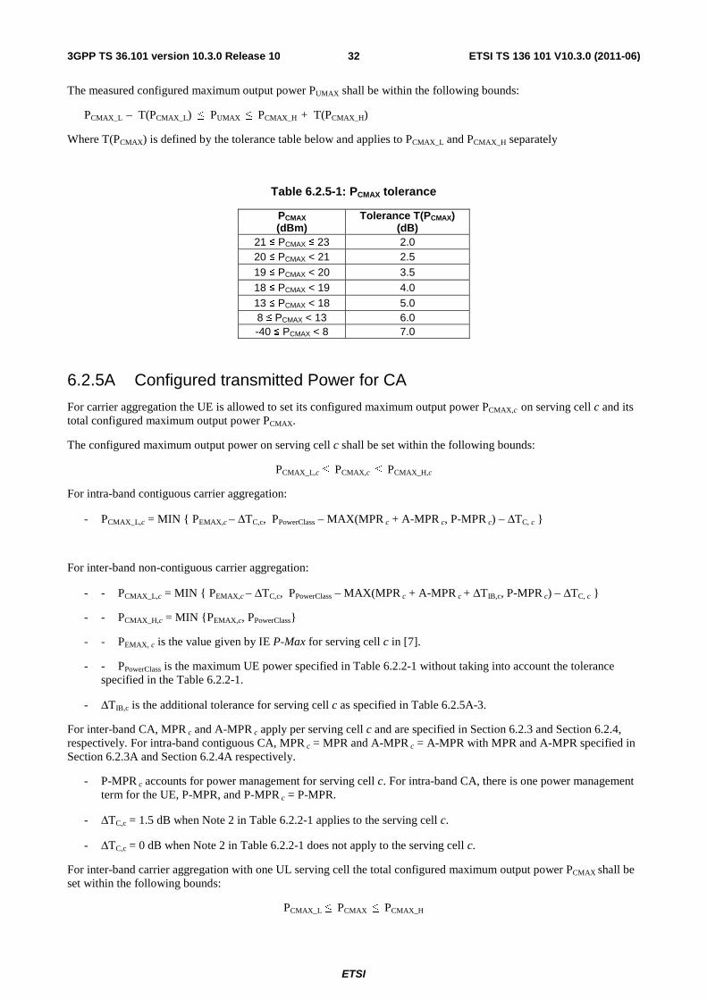
ETSI
ETSI TS 136 101 V10.3.0 (2011-06)323GPP TS 36.101 version 10.3.0 Release 10
The measured configured maximum output power PUMAX shall be within the following bounds:
PCMAX_L – T(PCMAX_L) ≤ PUMAX ≤ PCMAX_H + T(PCMAX_H)
Where T(PCMAX) is defined by the tolerance table below and applies to PCMAX_L and PCMAX_H separately
Table 6.2.5-1: PCMAX tolerance
PCMAX (dBm)
Tolerance T(PCMAX) (dB)
21 ≤ PCMAX ≤ 23 2.0 20 ≤ PCMAX < 21 2.5 19 ≤ PCMAX < 20 3.5 18 ≤ PCMAX < 19 4.0 13 ≤ PCMAX < 18 5.0 8 ≤ PCMAX < 13 6.0 -40 ≤ PCMAX < 8 7.0
6.2.5A Configured transmitted Power for CA
For carrier aggregation the UE is allowed to set its configured maximum output power PCMAX,c on serving cell c and its total configured maximum output power PCMAX.
The configured maximum output power on serving cell c shall be set within the following bounds:
PCMAX_L,c ≤ PCMAX,c ≤ PCMAX_H,c
For intra-band contiguous carrier aggregation:
- PCMAX_L,c = MIN { PEMAX,c – ΔTC,c, PPowerClass – MAX(MPR c + A-MPR c, P-MPR c) – ΔTC, c }
For inter-band non-contiguous carrier aggregation:
- - PCMAX_L,c = MIN { PEMAX,c – ΔTC,c, PPowerClass – MAX(MPR c + A-MPR c + ΔTIB,c, P-MPR c) – ΔTC, c }
- - PCMAX_H,c = MIN {PEMAX,c, PPowerClass}
- - PEMAX, c is the value given by IE P-Max for serving cell c in [7].
- - PPowerClass is the maximum UE power specified in Table 6.2.2-1 without taking into account the tolerance specified in the Table 6.2.2-1.
- ΔTIB,c is the additional tolerance for serving cell c as specified in Table 6.2.5A-3.
For inter-band CA, MPR c and A-MPR c apply per serving cell c and are specified in Section 6.2.3 and Section 6.2.4, respectively. For intra-band contiguous CA, MPR c = MPR and A-MPR c = A-MPR with MPR and A-MPR specified in Section 6.2.3A and Section 6.2.4A respectively.
- P-MPR c accounts for power management for serving cell c. For intra-band CA, there is one power management term for the UE, P-MPR, and P-MPR c = P-MPR.
- ΔTC,c = 1.5 dB when Note 2 in Table 6.2.2-1 applies to the serving cell c.
- ΔTC,c = 0 dB when Note 2 in Table 6.2.2-1 does not apply to the serving cell c.
For inter-band carrier aggregation with one UL serving cell the total configured maximum output power PCMAX shall be set within the following bounds:
PCMAX_L ≤ PCMAX ≤ PCMAX_H
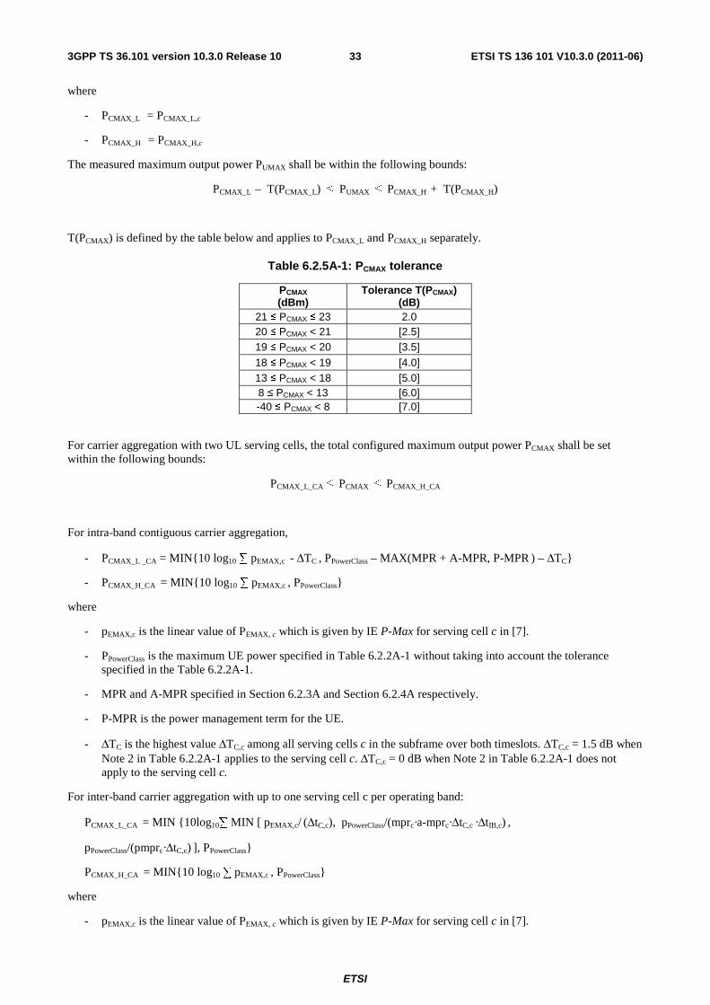
ETSI
ETSI TS 136 101 V10.3.0 (2011-06)333GPP TS 36.101 version 10.3.0 Release 10
where
- PCMAX_L = PCMAX_L,c
- PCMAX_H = PCMAX_H,c
The measured maximum output power PUMAX shall be within the following bounds:
PCMAX_L – T(PCMAX_L) ≤ PUMAX ≤ PCMAX_H + T(PCMAX_H)
T(PCMAX) is defined by the table below and applies to PCMAX_L and PCMAX_H separately.
Table 6.2.5A-1: PCMAX tolerance
PCMAX (dBm)
Tolerance T(PCMAX) (dB)
21 ≤ PCMAX ≤ 23 2.0 20 ≤ PCMAX < 21 [2.5] 19 ≤ PCMAX < 20 [3.5]
18 ≤ PCMAX < 19 [4.0] 13 ≤ PCMAX < 18 [5.0] 8 ≤ PCMAX < 13 [6.0] -40 ≤ PCMAX < 8 [7.0]
For carrier aggregation with two UL serving cells, the total configured maximum output power PCMAX shall be set within the following bounds:
PCMAX_L_CA ≤ PCMAX ≤ PCMAX_H_CA
For intra-band contiguous carrier aggregation,
- PCMAX_L _CA = MIN{10 log10 ∑ pEMAX,c - ΔTC , PPowerClass – MAX(MPR + A-MPR, P-MPR ) – ΔTC}
- PCMAX_H_CA = MIN{10 log10 ∑ pEMAX,c , PPowerClass}
where
- pEMAX,c is the linear value of PEMAX, c which is given by IE P-Max for serving cell c in [7].
- PPowerClass is the maximum UE power specified in Table 6.2.2A-1 without taking into account the tolerance specified in the Table 6.2.2A-1.
- MPR and A-MPR specified in Section 6.2.3A and Section 6.2.4A respectively.
- P-MPR is the power management term for the UE.
- ΔTC is the highest value ΔTC,c among all serving cells c in the subframe over both timeslots. ΔTC,c = 1.5 dB when Note 2 in Table 6.2.2A-1 applies to the serving cell c. ΔTC,c = 0 dB when Note 2 in Table 6.2.2A-1 does not apply to the serving cell c.
For inter-band carrier aggregation with up to one serving cell c per operating band:
PCMAX_L_CA = MIN {10log10∑ MIN [ pEMAX,c/ (ΔtC,c), pPowerClass/(mprc·a-mprc·ΔtC,c ·ΔtIB,c) ,
pPowerClass/(pmprc·ΔtC,c) ], PPowerClass}
PCMAX_H_CA = MIN{10 log10 ∑ pEMAX,c , PPowerClass}
where
- pEMAX,c is the linear value of PEMAX, c which is given by IE P-Max for serving cell c in [7].
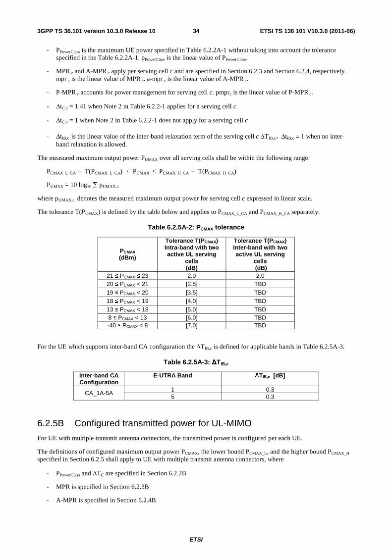
ETSI
ETSI TS 136 101 V10.3.0 (2011-06)343GPP TS 36.101 version 10.3.0 Release 10
- PPowerClass is the maximum UE power specified in Table 6.2.2A-1 without taking into account the tolerance specified in the Table 6.2.2A-1. pPowerClass is the linear value of PPowerClass.
- MPR c and A-MPR c apply per serving cell c and are specified in Section 6.2.3 and Section 6.2.4, respectively. mpr c is the linear value of MPR c. a-mpr c is the linear value of A-MPR c.
- P-MPR c accounts for power management for serving cell c. pmprc is the linear value of P-MPR c.
- ΔtC,c = 1.41 when Note 2 in Table 6.2.2-1 applies for a serving cell c
- ΔtC,c = 1 when Note 2 in Table 6.2.2-1 does not apply for a serving cell c
- ΔtIB,c is the linear value of the inter-band relaxation term of the serving cell c ΔTIB,c. ΔtIB,c = 1 when no inter-band relaxation is allowed.
The measured maximum output power PUMAX over all serving cells shall be within the following range:
PCMAX_L_CA – T(PCMAX_L_CA) ≤ PUMAX ≤ PCMAX_H_CA + T(PCMAX_H_CA)
PUMAX = 10 log10 ∑ pUMAX,c
where pUMAX,c denotes the measured maximum output power for serving cell c expressed in linear scale.
The tolerance T(PCMAX) is defined by the table below and applies to PCMAX_L_CA and PCMAX_H_CA separately.
Table 6.2.5A-2: PCMAX tolerance
PCMAX (dBm)
Tolerance T(PCMAX) Intra-band with two active UL serving
cells (dB)
Tolerance T(PCMAX) Inter-band with two active UL serving
cells (dB)
21 ≤ PCMAX ≤ 23 2.0 2.0 20 ≤ PCMAX < 21 [2.5] TBD 19 ≤ PCMAX < 20 [3.5] TBD 18 ≤ PCMAX < 19 [4.0] TBD 13 ≤ PCMAX < 18 [5.0] TBD 8 ≤ PCMAX < 13 [6.0] TBD -40 ≤ PCMAX < 8 [7.0] TBD
For the UE which supports inter-band CA configuration the ΔTIB,c is defined for applicable bands in Table 6.2.5A-3.
Table 6.2.5A-3: ΔTIB,c
Inter-band CA Configuration
E-UTRA Band ΔTIB,c [dB]
CA_1A-5A 1 0.3 5 0.3
6.2.5B Configured transmitted power for UL-MIMO
For UE with multiple transmit antenna connectors, the transmitted power is configured per each UE.
The definitions of configured maximum output power PCMAX, the lower bound PCMAX_L, and the higher bound PCMAX_H specified in Section 6.2.5 shall apply to UE with multiple transmit antenna connectors, where
- PPowerClass and ΔTC are specified in Section 6.2.2B
- MPR is specified in Section 6.2.3B
- A-MPR is specified in Section 6.2.4B

ETSI
ETSI TS 136 101 V10.3.0 (2011-06)353GPP TS 36.101 version 10.3.0 Release 10
The measured configured maximum output power PUMAX shall be within the following bounds:
PCMAX_L – T LOW(PCMAX_L) ≤ PUMAX ≤ PCMAX_H + T HIGH(PCMAX_H)
where TLOW(PCMAX_L) and THIGH(PCMAX_H) are defined as the tolerance and applies to PCMAX_L and PCMAX_H separately.
For UE with two transmit antenna connectors, the tolerance is specified in Table 6.2.5B-1 with UL-MIMO configurations specified in Table 6.2.2B-2.
Table 6.2.5B-1: PCMAX tolerance in closed-loop spatial multiplexing scheme
PCMAX (dBm)
Tolerance TLOW(PCMAX_L) (dB)
Tolerance THIGH(PCMAX_H) (dB)
PCMAX=23 3.0 2.0 [22] ≤ PCMAX < [23] [5.0] [2.0] [21] ≤ PCMAX < [22] [5.0] [3.0]
[20] ≤ PCMAX < [21] [6.0] [4.0]
[16] ≤ PCMAX < [20] [5.0] [11] ≤ PCMAX < [16] [6.0] [-40] ≤ PCMAX < [11] [7.0]
6.3 Output power dynamics
6.3.1 (Void)
6.3.2 Minimum output power
The minimum controlled output power of the UE is defined as the broadband transmit power of the UE, i.e. the power in the channel bandwidth for all transmit bandwidth configurations (resource blocks), when the power is set to a minimum value.
6.3.2.1 Minimum requirement
The minimum output power is defined as the mean power in one sub-frame (1ms). The minimum output power shall not exceed the values specified in Table 6.3.2.1-1.
Table 6.3.2.1-1: Minimum output power
Channel bandwidth / Minimum output power / measurement bandwidth
1.4 MHz
3.0 MHz
5 MHz
10 MHz
15 MHz
20 MHz
Minimum output power -40 dBm
Measurement bandwidth 1.08 MHz 2.7 MHz 4.5 MHz 9.0 MHz 13.5 MHz 18 MHz
6.3.2A UE Minimum output power for CA
For intra-band contiguous carrier aggregation, the minimum controlled output power of the UE is defined as the transmit power of the UE per component carrier, i.e., the power in the channel bandwidth of each component carrier for all transmit bandwidth configurations (resource blocks), when the power on both component carriers are set to a minimum value.
6.3.2A.1 Minimum requirement for CA
The minimum output power is defined as the mean power in one sub-frame (1ms). The minimum output power shall not exceed the values specified in Table 6.3.2A.1-1.
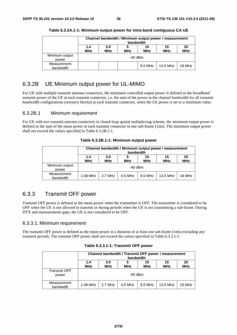
ETSI
ETSI TS 136 101 V10.3.0 (2011-06)363GPP TS 36.101 version 10.3.0 Release 10
Table 6.3.2A.1-1: Minimum output power for intra-band contiguous CA UE
Channel bandwidth / Minimum output power / measurement bandwidth
1.4 MHz
3.0 MHz
5 MHz
10 MHz
15 MHz
20 MHz
Minimum output power -40 dBm
Measurement bandwidth
9.0 MHz 13.5 MHz 18 MHz
6.3.2B UE Minimum output power for UL-MIMO
For UE with multiple transmit antenna connectors, the minimum controlled output power is defined as the broadband transmit power of the UE at each transmit connector, i.e. the sum of the power in the channel bandwidth for all transmit bandwidth configurations (resource blocks) at each transmit connector, when the UE power is set to a minimum value.
6.3.2B.1 Minimum requirement
For UE with two transmit antenna connectors in closed-loop spatial multiplexing scheme, the minimum output power is defined as the sum of the mean power at each transmit connector in one sub-frame (1ms). The minimum output power shall not exceed the values specified in Table 6.3.2B.1-1.
Table 6.3.2B.1-1: Minimum output power
Channel bandwidth / Minimum output power / measurement bandwidth
1.4 MHz
3.0 MHz
5 MHz
10 MHz
15 MHz
20 MHz
Minimum output power -40 dBm
Measurement bandwidth 1.08 MHz 2.7 MHz 4.5 MHz 9.0 MHz 13.5 MHz 18 MHz
6.3.3 Transmit OFF power
Transmit OFF power is defined as the mean power when the transmitter is OFF. The transmitter is considered to be OFF when the UE is not allowed to transmit or during periods when the UE is not transmitting a sub-frame. During DTX and measurements gaps, the UE is not considered to be OFF.
6.3.3.1. Minimum requirement
The transmit OFF power is defined as the mean power in a duration of at least one sub-frame (1ms) excluding any transient periods. The transmit OFF power shall not exceed the values specified in Table 6.3.3.1-1.
Table 6.3.3.1-1: Transmit OFF power
Channel bandwidth / Transmit OFF power / measurement bandwidth
1.4 MHz
3.0 MHz
5 MHz
10 MHz
15 MHz
20 MHz
Transmit OFF power -50 dBm
Measurement bandwidth 1.08 MHz 2.7 MHz 4.5 MHz 9.0 MHz 13.5 MHz 18 MHz
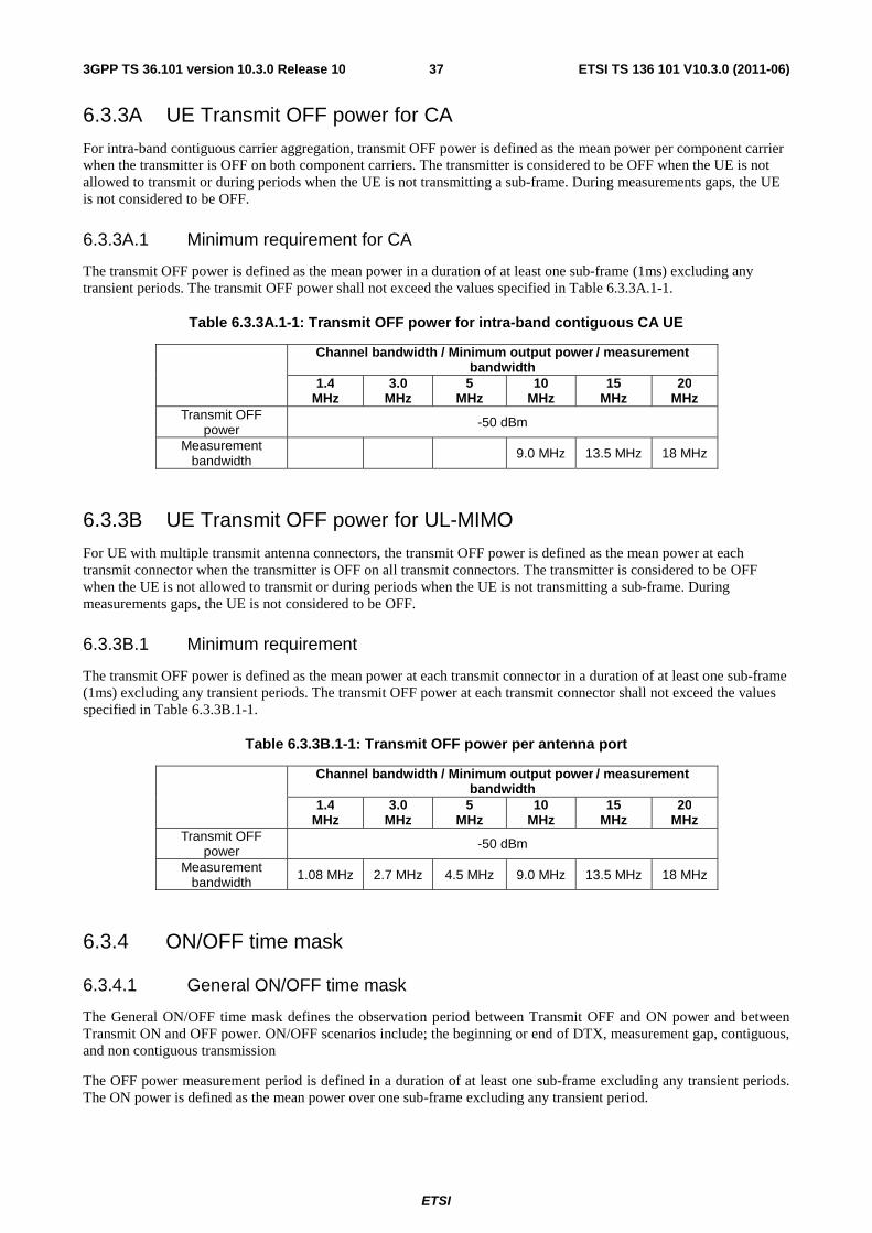
ETSI
ETSI TS 136 101 V10.3.0 (2011-06)373GPP TS 36.101 version 10.3.0 Release 10
6.3.3A UE Transmit OFF power for CA
For intra-band contiguous carrier aggregation, transmit OFF power is defined as the mean power per component carrier when the transmitter is OFF on both component carriers. The transmitter is considered to be OFF when the UE is not allowed to transmit or during periods when the UE is not transmitting a sub-frame. During measurements gaps, the UE is not considered to be OFF.
6.3.3A.1 Minimum requirement for CA
The transmit OFF power is defined as the mean power in a duration of at least one sub-frame (1ms) excluding any transient periods. The transmit OFF power shall not exceed the values specified in Table 6.3.3A.1-1.
Table 6.3.3A.1-1: Transmit OFF power for intra-band contiguous CA UE
Channel bandwidth / Minimum output power / measurement bandwidth
1.4 MHz
3.0 MHz
5 MHz
10 MHz
15 MHz
20 MHz
Transmit OFF power -50 dBm
Measurement bandwidth 9.0 MHz 13.5 MHz 18 MHz
6.3.3B UE Transmit OFF power for UL-MIMO
For UE with multiple transmit antenna connectors, the transmit OFF power is defined as the mean power at each transmit connector when the transmitter is OFF on all transmit connectors. The transmitter is considered to be OFF when the UE is not allowed to transmit or during periods when the UE is not transmitting a sub-frame. During measurements gaps, the UE is not considered to be OFF.
6.3.3B.1 Minimum requirement
The transmit OFF power is defined as the mean power at each transmit connector in a duration of at least one sub-frame (1ms) excluding any transient periods. The transmit OFF power at each transmit connector shall not exceed the values specified in Table 6.3.3B.1-1.
Table 6.3.3B.1-1: Transmit OFF power per antenna port
Channel bandwidth / Minimum output power / measurement bandwidth
1.4 MHz
3.0 MHz
5 MHz
10 MHz
15 MHz
20 MHz
Transmit OFF power -50 dBm
Measurement bandwidth 1.08 MHz 2.7 MHz 4.5 MHz 9.0 MHz 13.5 MHz 18 MHz
6.3.4 ON/OFF time mask
6.3.4.1 General ON/OFF time mask
The General ON/OFF time mask defines the observation period between Transmit OFF and ON power and between Transmit ON and OFF power. ON/OFF scenarios include; the beginning or end of DTX, measurement gap, contiguous, and non contiguous transmission
The OFF power measurement period is defined in a duration of at least one sub-frame excluding any transient periods. The ON power is defined as the mean power over one sub-frame excluding any transient period.
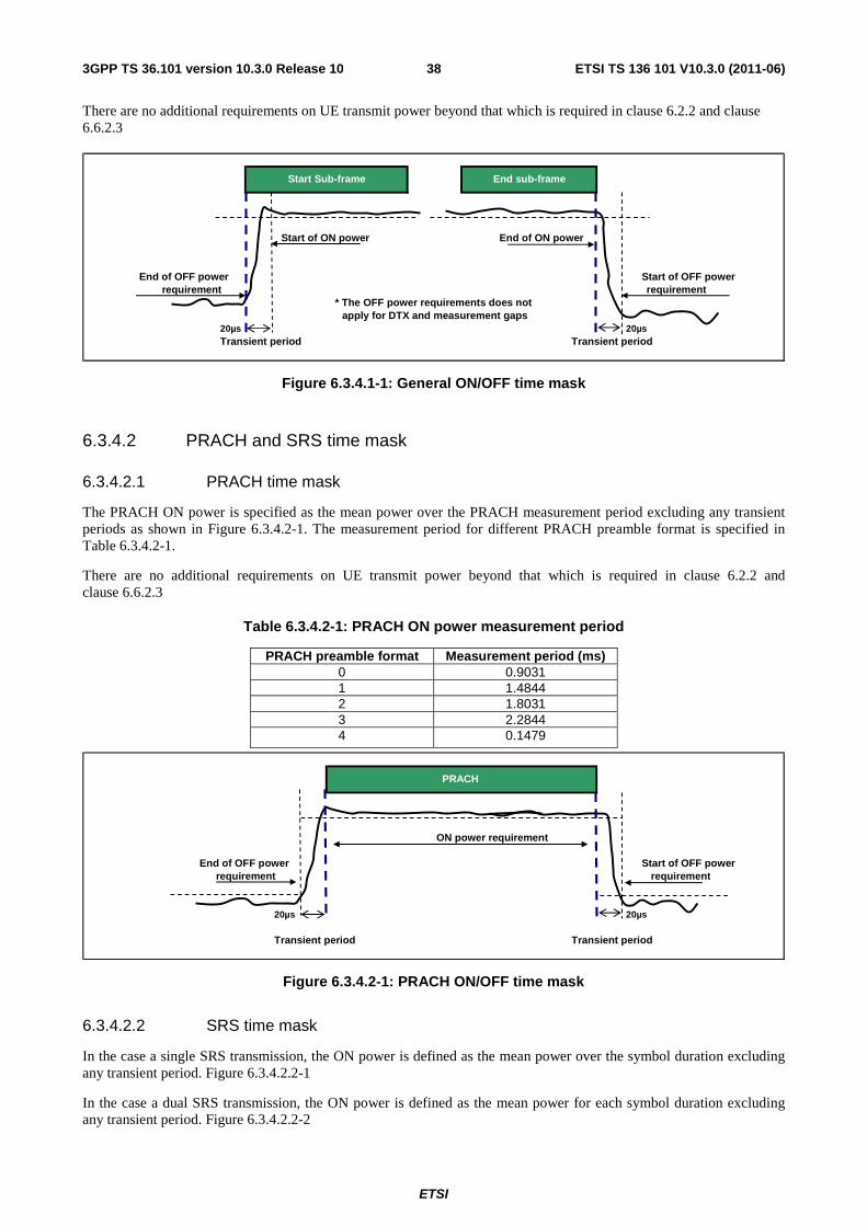
ETSI
ETSI TS 136 101 V10.3.0 (2011-06)383GPP TS 36.101 version 10.3.0 Release 10
There are no additional requirements on UE transmit power beyond that which is required in clause 6.2.2 and clause 6.6.2.3
End of OFF power
20µs 20µsTransient period Transient period
Start of OFF power
Start of ON power
requirement
Start Sub-frame End sub-frame
End of ON power
requirement* The OFF power requirements does not
apply for DTX and measurement gaps
Figure 6.3.4.1-1: General ON/OFF time mask
6.3.4.2 PRACH and SRS time mask
6.3.4.2.1 PRACH time mask
The PRACH ON power is specified as the mean power over the PRACH measurement period excluding any transient periods as shown in Figure 6.3.4.2-1. The measurement period for different PRACH preamble format is specified in Table 6.3.4.2-1.
There are no additional requirements on UE transmit power beyond that which is required in clause 6.2.2 and clause 6.6.2.3
Table 6.3.4.2-1: PRACH ON power measurement period
PRACH preamble format Measurement period (ms) 0 0.9031 1 1.4844 2 1.8031 3 2.2844 4 0.1479
ON power requirement
requirement
20µs 20µs
Transient period Transient period
PRACH
End of OFF power Start of OFF power requirement
Figure 6.3.4.2-1: PRACH ON/OFF time mask
6.3.4.2.2 SRS time mask
In the case a single SRS transmission, the ON power is defined as the mean power over the symbol duration excluding any transient period. Figure 6.3.4.2.2-1
In the case a dual SRS transmission, the ON power is defined as the mean power for each symbol duration excluding any transient period. Figure 6.3.4.2.2-2
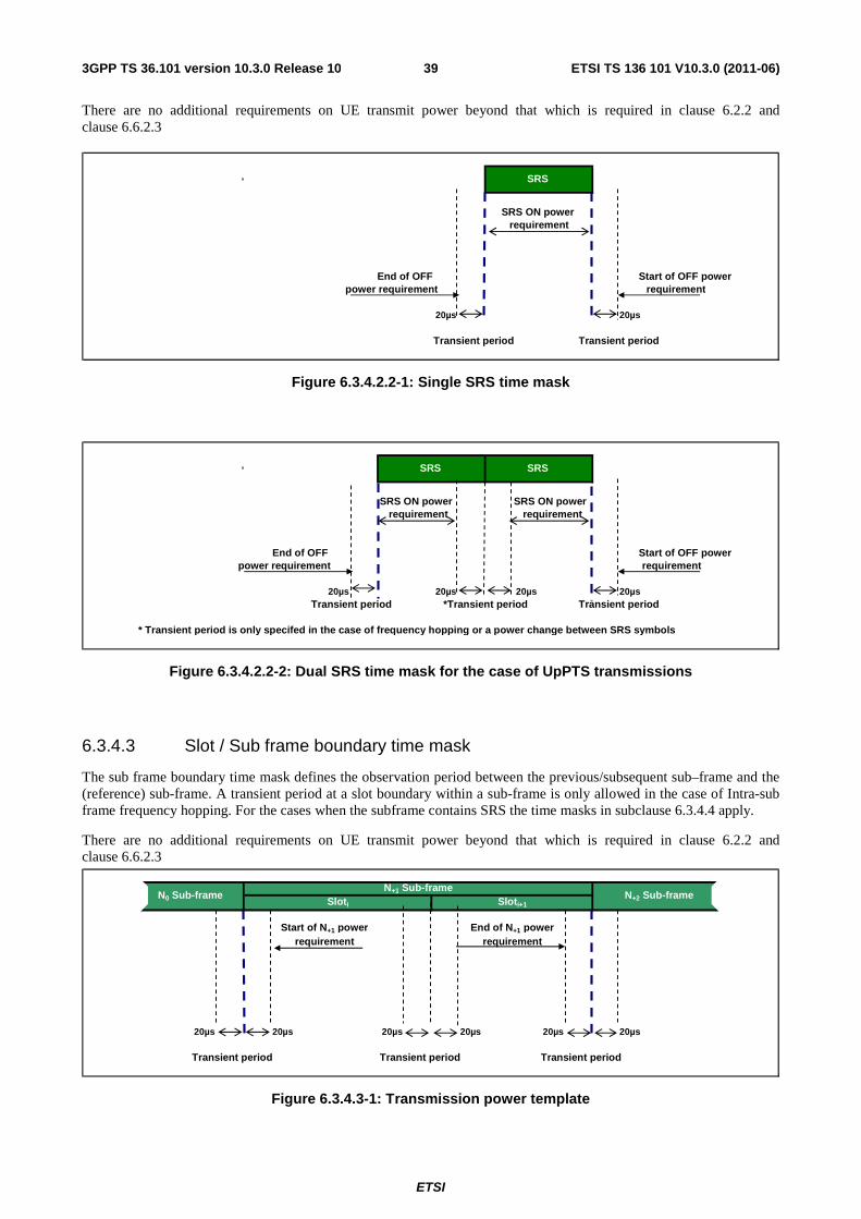
ETSI
ETSI TS 136 101 V10.3.0 (2011-06)393GPP TS 36.101 version 10.3.0 Release 10
There are no additional requirements on UE transmit power beyond that which is required in clause 6.2.2 and clause 6.6.2.3
requirement
20µs 20µs
Transient period Transient period
End of OFFpower requirement
SRS
SRS ON power requirement
Start of OFF power
Figure 6.3.4.2.2-1: Single SRS time mask
End of OFF
20µs 20µs 20µs 20µs
* Transient period is only specifed in the case of frequency hopping or a power change between SRS symbols
*Transient periodTransient period
SRS SRS
requirement
Transient period
Start of OFF power power requirement
SRS ON power requirement
SRS ON power requirement
Figure 6.3.4.2.2-2: Dual SRS time mask for the case of UpPTS transmissions
6.3.4.3 Slot / Sub frame boundary time mask
The sub frame boundary time mask defines the observation period between the previous/subsequent sub–frame and the (reference) sub-frame. A transient period at a slot boundary within a sub-frame is only allowed in the case of Intra-sub frame frequency hopping. For the cases when the subframe contains SRS the time masks in subclause 6.3.4.4 apply.
There are no additional requirements on UE transmit power beyond that which is required in clause 6.2.2 and clause 6.6.2.3
20µs 20µs 20µs 20µs 20µs 20µs
Transient period Transient period Transient period
Start of N+1 power requirement
End of N+1 power requirement
N+1 Sub-frame Sloti Sloti+1
N0 Sub-frame N+2 Sub-frame
Figure 6.3.4.3-1: Transmission power template
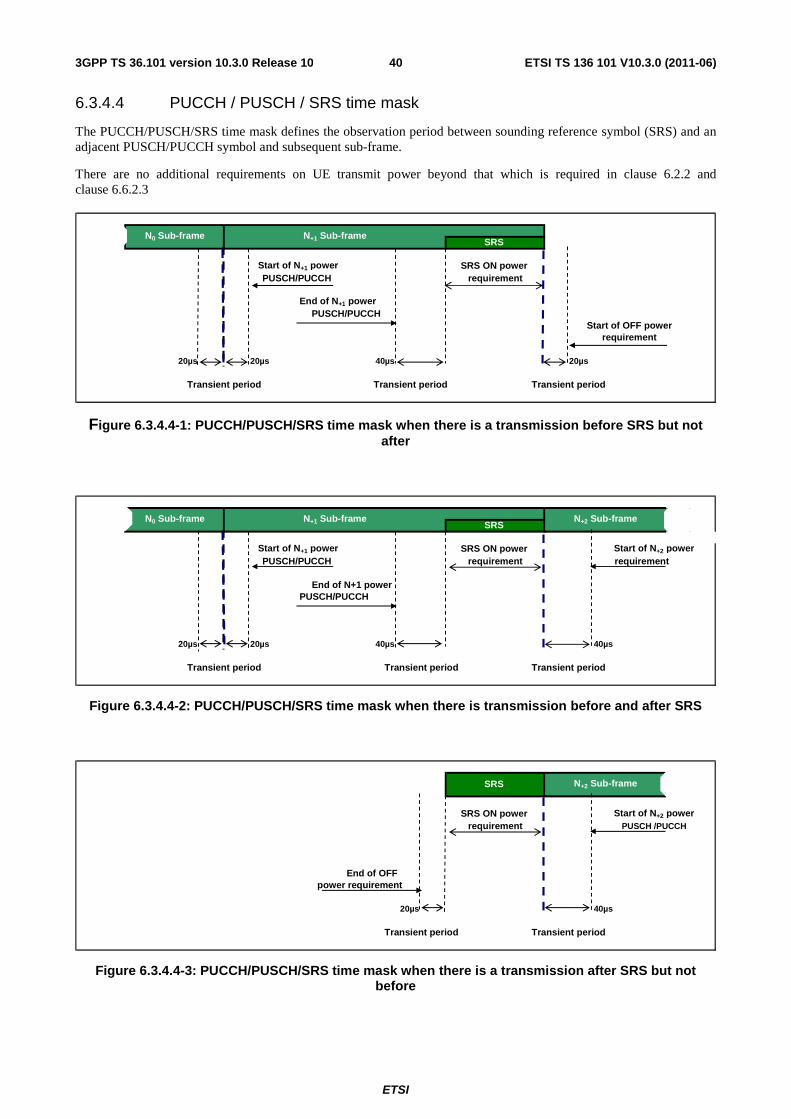
ETSI
ETSI TS 136 101 V10.3.0 (2011-06)403GPP TS 36.101 version 10.3.0 Release 10
6.3.4.4 PUCCH / PUSCH / SRS time mask
The PUCCH/PUSCH/SRS time mask defines the observation period between sounding reference symbol (SRS) and an adjacent PUSCH/PUCCH symbol and subsequent sub-frame.
There are no additional requirements on UE transmit power beyond that which is required in clause 6.2.2 and clause 6.6.2.3
End of N+1 power
20µs 20µs 40µs 20µs
Transient period
requirementStart of OFF power
Transient period
Start of N+1 power PUSCH/PUCCH
Transient period
N0 Sub-frame N+1 Sub-frame SRS
PUSCH/PUCCH
SRS ON power requirement
Figure 6.3.4.4-1: PUCCH/PUSCH/SRS time mask when there is a transmission before SRS but not after
PUSCH/PUCCH
20µs 20µs 40µs 40µs
SRS ON power
N0 Sub-frame N+1 Sub-frame N+2 Sub-frameSRS
PUSCH/PUCCH requirement
Transient period
End of N+1 power
Start of N+1 power Start of N+2 power
Transient period
requirement
Transient period
Figure 6.3.4.4-2: PUCCH/PUSCH/SRS time mask when there is transmission before and after SRS
20µs 40µs
Transient period
PUSCH /PUCCHStart of N+2 power
power requirement
Transient period
End of OFF
SRS N+2 Sub-frame
SRS ON power requirement
Figure 6.3.4.4-3: PUCCH/PUSCH/SRS time mask when there is a transmission after SRS but not before
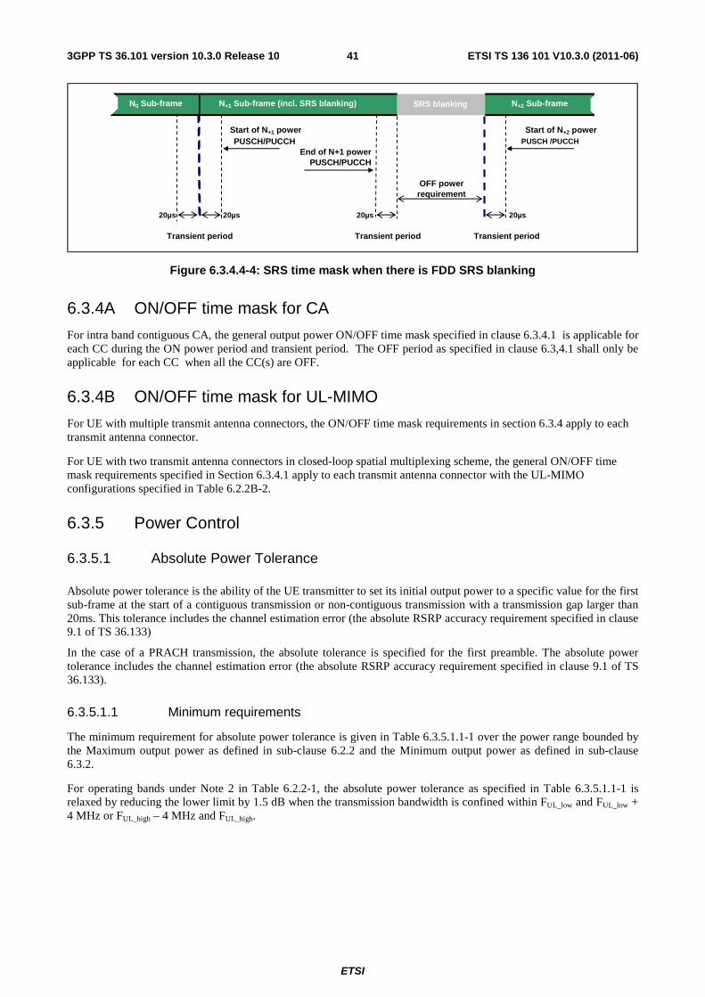
ETSI
ETSI TS 136 101 V10.3.0 (2011-06)413GPP TS 36.101 version 10.3.0 Release 10
20µs 20µs 20µs 20µs
Transient period
PUSCH /PUCCH
N+2 Sub-frame
End of N+1 power
SRS blanking
PUSCH/PUCCH Start of N+1 power
N0 Sub-frame
Transient period Transient period
PUSCH/PUCCH
OFF power
N+1 Sub-frame (incl. SRS blanking)
Start of N+2 power
requirement
Figure 6.3.4.4-4: SRS time mask when there is FDD SRS blanking
6.3.4A ON/OFF time mask for CA
For intra band contiguous CA, the general output power ON/OFF time mask specified in clause 6.3.4.1 is applicable for each CC during the ON power period and transient period. The OFF period as specified in clause 6.3,4.1 shall only be applicable for each CC when all the CC(s) are OFF.
6.3.4B ON/OFF time mask for UL-MIMO
For UE with multiple transmit antenna connectors, the ON/OFF time mask requirements in section 6.3.4 apply to each transmit antenna connector.
For UE with two transmit antenna connectors in closed-loop spatial multiplexing scheme, the general ON/OFF time mask requirements specified in Section 6.3.4.1 apply to each transmit antenna connector with the UL-MIMO configurations specified in Table 6.2.2B-2.
6.3.5 Power Control
6.3.5.1 Absolute Power Tolerance
Absolute power tolerance is the ability of the UE transmitter to set its initial output power to a specific value for the first sub-frame at the start of a contiguous transmission or non-contiguous transmission with a transmission gap larger than 20ms. This tolerance includes the channel estimation error (the absolute RSRP accuracy requirement specified in clause 9.1 of TS 36.133)
In the case of a PRACH transmission, the absolute tolerance is specified for the first preamble. The absolute power tolerance includes the channel estimation error (the absolute RSRP accuracy requirement specified in clause 9.1 of TS 36.133).
6.3.5.1.1 Minimum requirements
The minimum requirement for absolute power tolerance is given in Table 6.3.5.1.1-1 over the power range bounded by the Maximum output power as defined in sub-clause 6.2.2 and the Minimum output power as defined in sub-clause 6.3.2.
For operating bands under Note 2 in Table 6.2.2-1, the absolute power tolerance as specified in Table 6.3.5.1.1-1 is relaxed by reducing the lower limit by 1.5 dB when the transmission bandwidth is confined within FUL_low and FUL_low + 4 MHz or FUL_high – 4 MHz and FUL_high.
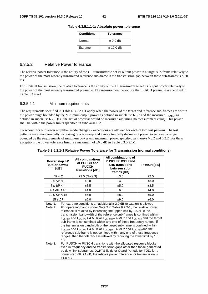
ETSI
ETSI TS 136 101 V10.3.0 (2011-06)423GPP TS 36.101 version 10.3.0 Release 10
Table 6.3.5.1.1-1: Absolute power tolerance
Conditions Tolerance
Normal ± 9.0 dB
Extreme ± 12.0 dB
6.3.5.2 Relative Power tolerance
The relative power tolerance is the ability of the UE transmitter to set its output power in a target sub-frame relatively to the power of the most recently transmitted reference sub-frame if the transmission gap between these sub-frames is ≤ 20 ms.
For PRACH transmission, the relative tolerance is the ability of the UE transmitter to set its output power relatively to the power of the most recently transmitted preamble. The measurement period for the PRACH preamble is specified in Table 6.3.4.2-1.
6.3.5.2.1 Minimum requirements
The requirements specified in Table 6.3.5.2.1-1 apply when the power of the target and reference sub-frames are within the power range bounded by the Minimum output power as defined in subclause 6.3.2 and the measured PUMAX as defined in subclause 6.2.5 (i.e, the actual power as would be measured assuming no measurement error). This power shall be within the power limits specified in subclause 6.2.5.
To account for RF Power amplifier mode changes 2 exceptions are allowed for each of two test patterns. The test patterns are a monotonically increasing power sweep and a monotonically decreasing power sweep over a range bounded by the requirements of minimum power and maximum power specified in clauses 6.3.2 and 6.2.2. For these exceptions the power tolerance limit is a maximum of ±6.0 dB in Table 6.3.5.2.1-1
Table 6.3.5.2.1-1 Relative Power Tolerance for Transmission (normal conditions)
Power step ΔP (Up or down)
[dB]
All combinations of PUSCH and
PUCCH transitions [dB]
All combinations of PUSCH/PUCCH and
SRS transitions between sub-frames [dB]
PRACH [dB]
ΔP < 2 ±2.5 (Note 3) ±3.0 ±2.5
2 ≤ ΔP < 3 ±3.0 ±4.0 ±3.0
3 ≤ ΔP < 4 ±3.5 ±5.0 ±3.5
4 ≤ ΔP ≤ 10 ±4.0 ±6.0 ±4.0
10 ≤ ΔP < 15 ±5.0 ±8.0 ±5.0
15 ≤ ΔP ±6.0 ±9.0 ±6.0 Note 1: For extreme conditions an additional ± 2.0 dB relaxation is allowed Note 2: For operating bands under Note 2 in Table 6.2.2-1, the relative power
tolerance is relaxed by increasing the upper limit by 1.5 dB if the transmission bandwidth of the reference sub-frames is confined within FUL_low and FUL_low + 4 MHz or FUL_high – 4 MHz and FUL_high and the target sub-frame is not confined within any one of these frequency ranges; if the transmission bandwidth of the target sub-frame is confined within FUL_low and FUL_low + 4 MHz or FUL_high – 4 MHz and FUL_high and the reference sub-frame is not confined within any one of these frequency ranges, then the tolerance is relaxed by reducing the lower limit by 1.5 dB.
Note 3: For PUSCH to PUSCH transitions with the allocated resource blocks fixed in frequency and no transmission gaps other than those generated by downlink subframes, DwPTS fields or Guard Periods for TDD: for a power step ΔP ≤ 1 dB, the relative power tolerance for transmission is ±1.0 dB.
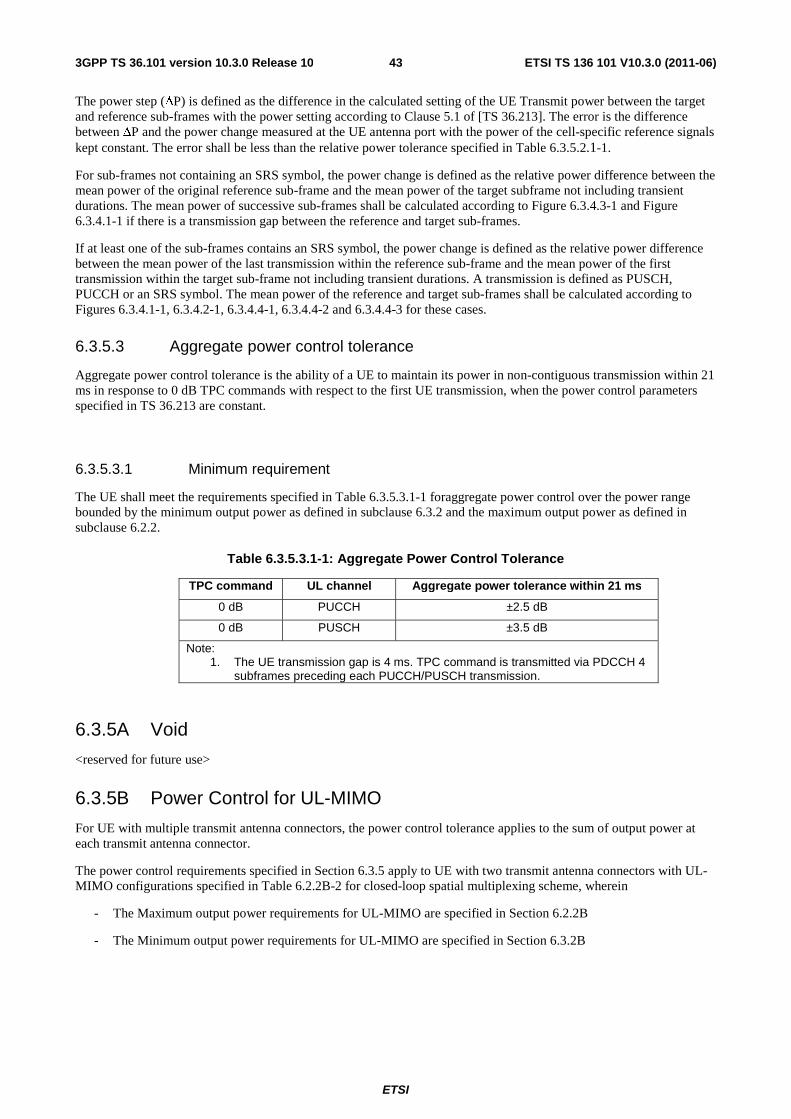
ETSI
ETSI TS 136 101 V10.3.0 (2011-06)433GPP TS 36.101 version 10.3.0 Release 10
The power step (ΔP) is defined as the difference in the calculated setting of the UE Transmit power between the target and reference sub-frames with the power setting according to Clause 5.1 of [TS 36.213]. The error is the difference between ΔP and the power change measured at the UE antenna port with the power of the cell-specific reference signals kept constant. The error shall be less than the relative power tolerance specified in Table 6.3.5.2.1-1.
For sub-frames not containing an SRS symbol, the power change is defined as the relative power difference between the mean power of the original reference sub-frame and the mean power of the target subframe not including transient durations. The mean power of successive sub-frames shall be calculated according to Figure 6.3.4.3-1 and Figure 6.3.4.1-1 if there is a transmission gap between the reference and target sub-frames.
If at least one of the sub-frames contains an SRS symbol, the power change is defined as the relative power difference between the mean power of the last transmission within the reference sub-frame and the mean power of the first transmission within the target sub-frame not including transient durations. A transmission is defined as PUSCH, PUCCH or an SRS symbol. The mean power of the reference and target sub-frames shall be calculated according to Figures 6.3.4.1-1, 6.3.4.2-1, 6.3.4.4-1, 6.3.4.4-2 and 6.3.4.4-3 for these cases.
6.3.5.3 Aggregate power control tolerance
Aggregate power control tolerance is the ability of a UE to maintain its power in non-contiguous transmission within 21 ms in response to 0 dB TPC commands with respect to the first UE transmission, when the power control parameters specified in TS 36.213 are constant.
6.3.5.3.1 Minimum requirement
The UE shall meet the requirements specified in Table 6.3.5.3.1-1 foraggregate power control over the power range bounded by the minimum output power as defined in subclause 6.3.2 and the maximum output power as defined in subclause 6.2.2.
Table 6.3.5.3.1-1: Aggregate Power Control Tolerance
TPC command UL channel Aggregate power tolerance within 21 ms
0 dB PUCCH ±2.5 dB
0 dB PUSCH ±3.5 dB
Note: 1. The UE transmission gap is 4 ms. TPC command is transmitted via PDCCH 4
subframes preceding each PUCCH/PUSCH transmission.
6.3.5A Void
<reserved for future use>
6.3.5B Power Control for UL-MIMO
For UE with multiple transmit antenna connectors, the power control tolerance applies to the sum of output power at each transmit antenna connector.
The power control requirements specified in Section 6.3.5 apply to UE with two transmit antenna connectors with UL-MIMO configurations specified in Table 6.2.2B-2 for closed-loop spatial multiplexing scheme, wherein
- The Maximum output power requirements for UL-MIMO are specified in Section 6.2.2B
- The Minimum output power requirements for UL-MIMO are specified in Section 6.3.2B
ETSI
ETSI TS 136 101 V10.3.0 (2011-06)443GPP TS 36.101 version 10.3.0 Release 10
6.4 Void
6.5 Transmit signal quality
6.5.1 Frequency error
The UE modulated carrier frequency shall be accurate to within ±0.1 PPM observed over a period of one time slot (0.5 ms) compared to the carrier frequency received from the E-UTRA Node B
6.5.1A Frequency error for Intraband CA
The UE modulated carrier frequencies per band shall be accurate to within ±0.1 PPM observed over a period of one timeslot compared to the carrier frequency of primary component carrier received from the E-UTRA in the corresponding band.
6.5.1B Frequency error for UL-MIMO
For UE(s) with multiple transmit antenna connectors, the UE modulated carrier frequency at each transmit antenna connector shall be accurate to within ±0.1 PPM observed over a period of one time slot (0.5 ms) compared to the carrier frequency received from the E-UTRA Node B.
6.5.2 Transmit modulation quality
Transmit modulation quality defines the modulation quality for expected in-channel RF transmissions from the UE. The transmit modulation quality is specified in terms of:
- Error Vector Magnitude (EVM) for the allocated resource blocks (RBs)
- EVM equalizer spectrum flatness derived from the equalizer coefficients generated by the EVM measurement process
- Carrier leakage (caused by IQ offset)
- In-band emissions for the non-allocated RB
All the parameters defined in clause 6.5.2 are defined using the measurement methodology specified in Annex F.
6.5.2.1 Error Vector Magnitude
The Error Vector Magnitude is a measure of the difference between the reference waveform and the measured waveform. This difference is called the error vector. Before calculating the EVM the measured waveform is corrected by the sample timing offset and RF frequency offset. Then the IQ origin offset shall be removed from the measured waveform before calculating the EVM.
The measured waveform is further modified by selecting the absolute phase and absolute amplitude of the Tx chain. The EVM result is defined after the front-end IDFT as the square root of the ratio of the mean error vector power to the mean reference power expressed as a %.
The basic EVM measurement interval in the time domain is one preamble sequence for the PRACH and is one slot for the PUCCH and PUSCH in the time domain.. When the PUSCH or PUCCH transmission slot is shortened due to multiplexing with SRS, the EVM measurement interval is reduced by one symbol, accordingly. The PUSCH or PUCCH EVM measurement interval is also reduced when the mean power, modulation or allocation between slots is expected to change. In the case of PUSCH transmission, the measurement interval is reduced by a time interval equal to the sum of 5 μs and the applicable exclusion period defined in subclause 6.3.4, adjacent to the boundary where the power change is expected to occur. The PUSCH exclusion period is applied to the signal obtained after the front-end IDFT. In the case of PUCCH transmission with power change, the PUCCH EVM measurement interval is reduced by one symbol adjacent to the boundary where the power change is expected to occur.
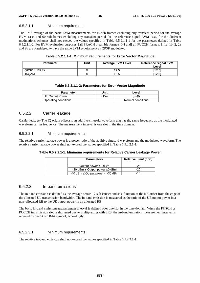
ETSI
ETSI TS 136 101 V10.3.0 (2011-06)453GPP TS 36.101 version 10.3.0 Release 10
6.5.2.1.1 Minimum requirement
The RMS average of the basic EVM measurements for 10 sub-frames excluding any transient period for the average EVM case, and 60 sub-frames excluding any transient period for the reference signal EVM case, for the different modulations schemes shall not exceed the values specified in Table 6.5.2.1.1-1 for the parameters defined in Table 6.5.2.1.1-2. For EVM evaluation purposes, [all PRACH preamble formats 0-4 and] all PUCCH formats 1, 1a, 1b, 2, 2a and 2b are considered to have the same EVM requirement as QPSK modulated.
Table 6.5.2.1.1-1: Minimum requirements for Error Vector Magnitude
Parameter Unit Average EVM Level Reference Signal EVM Level
QPSK or BPSK % 17.5 [17.5] 16QAM % 12.5 [12.5]
Table 6.5.2.1.1-2: Parameters for Error Vector Magnitude
Parameter Unit Level UE Output Power dBm ≥ -40 Operating conditions Normal conditions
6.5.2.2 Carrier leakage
Carrier leakage (The IQ origin offset) is an additive sinusoid waveform that has the same frequency as the modulated waveform carrier frequency. The measurement interval is one slot in the time domain.
6.5.2.2.1 Minimum requirements
The relative carrier leakage power is a power ratio of the additive sinusoid waveform and the modulated waveform. The relative carrier leakage power shall not exceed the values specified in Table 6.5.2.2.1-1.
Table 6.5.2.2.1-1: Minimum requirements for Relative Carrier Leakage Power
Parameters Relative Limit (dBc)
Output power >0 dBm -25 -30 dBm ≤ Output power ≤0 dBm -20
-40 dBm ≤ Output power < -30 dBm -10
6.5.2.3 In-band emissions
The in-band emission is defined as the average across 12 sub-carrier and as a function of the RB offset from the edge of the allocated UL transmission bandwidth. The in-band emission is measured as the ratio of the UE output power in a non–allocated RB to the UE output power in an allocated RB.
The basic in-band emissions measurement interval is defined over one slot in the time domain. When the PUSCH or PUCCH transmission slot is shortened due to multiplexing with SRS, the in-band emissions measurement interval is reduced by one SC-FDMA symbol, accordingly.
6.5.2.3.1 Minimum requirements
The relative in-band emission shall not exceed the values specified in Table 6.5.2.3.1-1.
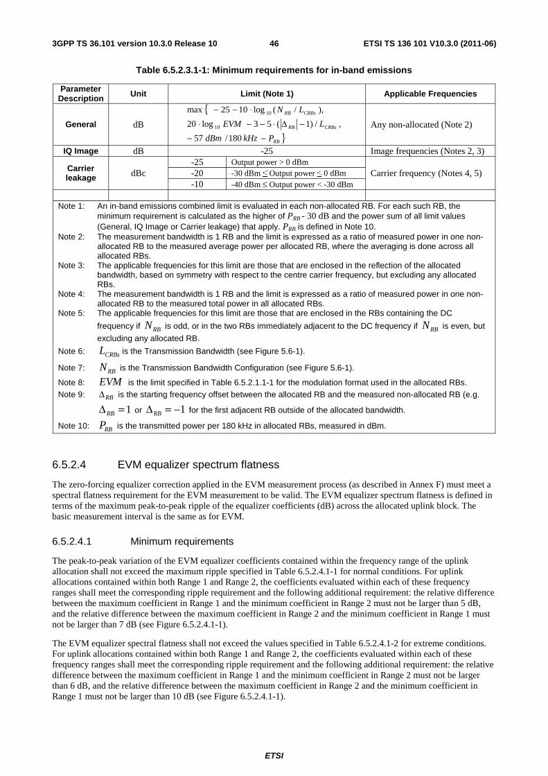
ETSI
ETSI TS 136 101 V10.3.0 (2011-06)463GPP TS 36.101 version 10.3.0 Release 10
Table 6.5.2.3.1-1: Minimum requirements for in-band emissions
Parameter Description Unit Limit (Note 1) Applicable Frequencies
General dB
{
}RB
CRBsRB
CRBsRB
PkHzdBm
LEVM
LN
−−−Δ⋅−−⋅
⋅−−
180/57
,/)1(53log20
),/(log1025max
10
10
Any non-allocated (Note 2)
IQ Image dB -25 Image frequencies (Notes 2, 3)
Carrier leakage dBc
-25 Output power > 0 dBm Carrier frequency (Notes 4, 5) -20 -30 dBm ≤ Output power ≤ 0 dBm
-10 -40 dBm ≤ Output power < -30 dBm Note 1: An in-band emissions combined limit is evaluated in each non-allocated RB. For each such RB, the
minimum requirement is calculated as the higher of PRB - 30 dB and the power sum of all limit values (General, IQ Image or Carrier leakage) that apply. PRB is defined in Note 10.
Note 2: The measurement bandwidth is 1 RB and the limit is expressed as a ratio of measured power in one non-allocated RB to the measured average power per allocated RB, where the averaging is done across all allocated RBs.
Note 3: The applicable frequencies for this limit are those that are enclosed in the reflection of the allocated bandwidth, based on symmetry with respect to the centre carrier frequency, but excluding any allocated RBs.
Note 4: The measurement bandwidth is 1 RB and the limit is expressed as a ratio of measured power in one non-allocated RB to the measured total power in all allocated RBs.
Note 5: The applicable frequencies for this limit are those that are enclosed in the RBs containing the DC
frequency if RBN is odd, or in the two RBs immediately adjacent to the DC frequency if RBN is even, but
excluding any allocated RB.
Note 6: CRBsL is the Transmission Bandwidth (see Figure 5.6-1).
Note 7: RBN is the Transmission Bandwidth Configuration (see Figure 5.6-1).
Note 8: EVM is the limit specified in Table 6.5.2.1.1-1 for the modulation format used in the allocated RBs. Note 9: RBΔ is the starting frequency offset between the allocated RB and the measured non-allocated RB (e.g.
1=ΔRB or 1−=ΔRB for the first adjacent RB outside of the allocated bandwidth.
Note 10: RBP is the transmitted power per 180 kHz in allocated RBs, measured in dBm.
6.5.2.4 EVM equalizer spectrum flatness
The zero-forcing equalizer correction applied in the EVM measurement process (as described in Annex F) must meet a spectral flatness requirement for the EVM measurement to be valid. The EVM equalizer spectrum flatness is defined in terms of the maximum peak-to-peak ripple of the equalizer coefficients (dB) across the allocated uplink block. The basic measurement interval is the same as for EVM.
6.5.2.4.1 Minimum requirements
The peak-to-peak variation of the EVM equalizer coefficients contained within the frequency range of the uplink allocation shall not exceed the maximum ripple specified in Table 6.5.2.4.1-1 for normal conditions. For uplink allocations contained within both Range 1 and Range 2, the coefficients evaluated within each of these frequency ranges shall meet the corresponding ripple requirement and the following additional requirement: the relative difference between the maximum coefficient in Range 1 and the minimum coefficient in Range 2 must not be larger than 5 dB, and the relative difference between the maximum coefficient in Range 2 and the minimum coefficient in Range 1 must not be larger than 7 dB (see Figure 6.5.2.4.1-1).
The EVM equalizer spectral flatness shall not exceed the values specified in Table 6.5.2.4.1-2 for extreme conditions. For uplink allocations contained within both Range 1 and Range 2, the coefficients evaluated within each of these frequency ranges shall meet the corresponding ripple requirement and the following additional requirement: the relative difference between the maximum coefficient in Range 1 and the minimum coefficient in Range 2 must not be larger than 6 dB, and the relative difference between the maximum coefficient in Range 2 and the minimum coefficient in Range 1 must not be larger than 10 dB (see Figure 6.5.2.4.1-1).

ETSI
ETSI TS 136 101 V10.3.0 (2011-06)473GPP TS 36.101 version 10.3.0 Release 10
Table 6.5.2.4.1-1: Minimum requirements for EVM equalizer spectrum flatness (normal conditions)
Frequency Range Maximum Ripple [dB] FUL_Meas – FUL_Low ≥ 3 MHz and FUL_High – FUL_Meas ≥ 3 MHz
(Range 1) 4 (p-p)
FUL_Meas – FUL_Low < 3 MHz or FUL_High – FUL_Meas < 3 MHz (Range 2)
8 (p-p)
Note 1: FUL_Meas refers to the sub-carrier frequency for which the equalizer coefficient is evaluated
Note 2: FUL_Low and FUL_High refer to each E-UTRA frequency band specified in Table 5.5-1
Table 6.5.2.4.1-2: Minimum requirements for EVM equalizer spectrum flatness (extreme conditions)
Frequency Range Maximum Ripple [dB] FUL_Meas – FUL_Low ≥ 5 MHz and FUL_High – FUL_Meas ≥ 5 MHz
(Range 1) 4 (p-p)
FUL_Meas – FUL_Low < 5 MHz or FUL_High – FUL_Meas < 5 MHz (Range 2)
12 (p-p)
Note 1: FUL_Meas refers to the sub-carrier frequency for which the equalizer coefficient is evaluated
Note 2: FUL_Low and FUL_High refer to each E-UTRA frequency band specified in Table 5.5-1
Figure 6.5.2.4.1-1: The limits for EVM equalizer spectral flatness with the maximum allowed variation of the coefficients indicated (the ETC minimum requirement within brackets).
6.5.2A Void
<reserved for future use>
6.5.2B Transmit modulation quality for UL-MIMO
For UE with multiple transmit antenna connectors, the transmit modulation quality requirements are specified at each transmit antenna connector.
The transmit modulation quality is specified in terms of:
- Error Vector Magnitude (EVM) for the allocated resource blocks (RBs)
- EVM equalizer spectrum flatness derived from the equalizer coefficients generated by the EVM measurement process
- Carrier leakage (caused by IQ offset)
- In-band emissions for the non-allocated RB
f FUL_High FUL_High – 3(5) MHz
< 4(4) dBp-p
Range 1 Range 2
max(Range 1)-min(Range 2) < 5(6) dB max(Range 2)-min(Range 1) < 7(10) dB < 8(12) dBp-p
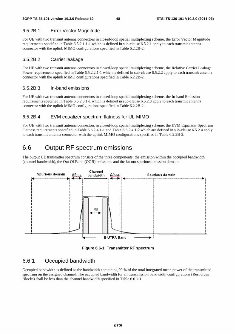
ETSI
ETSI TS 136 101 V10.3.0 (2011-06)483GPP TS 36.101 version 10.3.0 Release 10
6.5.2B.1 Error Vector Magnitude
For UE with two transmit antenna connectors in closed-loop spatial multiplexing scheme, the Error Vector Magnitude requirements specified in Table 6.5.2.1.1-1 which is defined in sub-clause 6.5.2.1 apply to each transmit antenna connector with the uplink MIMO configurations specified in Table 6.2.2B-2.
6.5.2B.2 Carrier leakage
For UE with two transmit antenna connectors in closed-loop spatial multiplexing scheme, the Relative Carrier Leakage Power requirements specified in Table 6.5.2.2.1-1 which is defined in sub-clause 6.5.2.2 apply to each transmit antenna connector with the uplink MIMO configurations specified in Table 6.2.2B-2.
6.5.2B.3 In-band emissions
For UE with two transmit antenna connectors in closed-loop spatial multiplexing scheme, the In-band Emission requirements specified in Table 6.5.2.3.1-1 which is defined in sub-clause 6.5.2.3 apply to each transmit antenna connector with the uplink MIMO configurations specified in Table 6.2.2B-2.
6.5.2B.4 EVM equalizer spectrum flatness for UL-MIMO
For UE with two transmit antenna connectors in closed-loop spatial multiplexing scheme, the EVM Equalizer Spectrum Flatness requirements specified in Table 6.5.2.4.1-1 and Table 6.5.2.4.1-2 which are defined in sub-clause 6.5.2.4 apply to each transmit antenna connector with the uplink MIMO configurations specified in Table 6.2.2B-2.
6.6 Output RF spectrum emissions The output UE transmitter spectrum consists of the three components; the emission within the occupied bandwidth (channel bandwidth), the Out Of Band (OOB) emissions and the far out spurious emission domain.
Figure 6.6-1: Transmitter RF spectrum
6.6.1 Occupied bandwidth
Occupied bandwidth is defined as the bandwidth containing 99 % of the total integrated mean power of the transmitted spectrum on the assigned channel. The occupied bandwidth for all transmission bandwidth configurations (Resources Blocks) shall be less than the channel bandwidth specified in Table 6.6.1-1
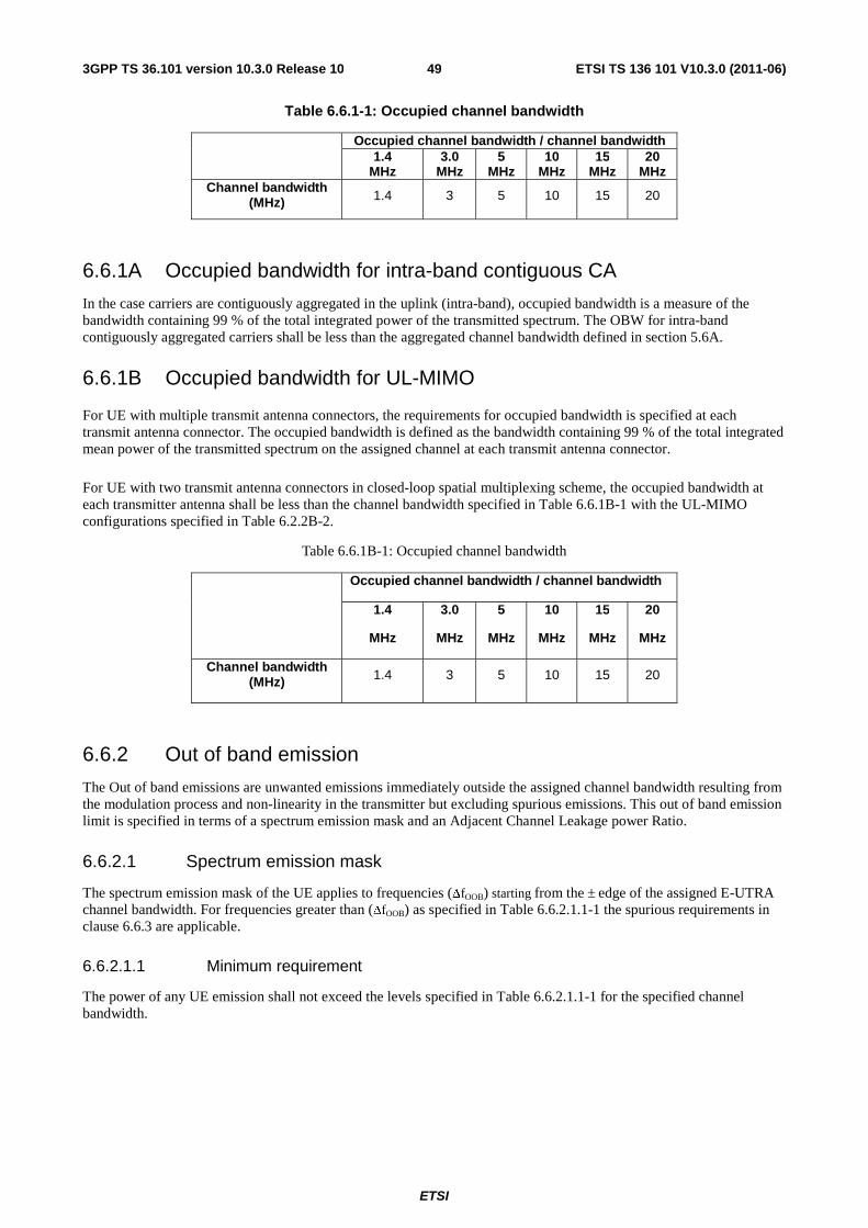
ETSI
ETSI TS 136 101 V10.3.0 (2011-06)493GPP TS 36.101 version 10.3.0 Release 10
Table 6.6.1-1: Occupied channel bandwidth
Occupied channel bandwidth / channel bandwidth
1.4 MHz
3.0 MHz
5 MHz
10 MHz
15 MHz
20 MHz
Channel bandwidth (MHz) 1.4 3 5 10 15 20
6.6.1A Occupied bandwidth for intra-band contiguous CA
In the case carriers are contiguously aggregated in the uplink (intra-band), occupied bandwidth is a measure of the bandwidth containing 99 % of the total integrated power of the transmitted spectrum. The OBW for intra-band contiguously aggregated carriers shall be less than the aggregated channel bandwidth defined in section 5.6A.
6.6.1B Occupied bandwidth for UL-MIMO
For UE with multiple transmit antenna connectors, the requirements for occupied bandwidth is specified at each transmit antenna connector. The occupied bandwidth is defined as the bandwidth containing 99 % of the total integrated mean power of the transmitted spectrum on the assigned channel at each transmit antenna connector.
For UE with two transmit antenna connectors in closed-loop spatial multiplexing scheme, the occupied bandwidth at each transmitter antenna shall be less than the channel bandwidth specified in Table 6.6.1B-1 with the UL-MIMO configurations specified in Table 6.2.2B-2.
Table 6.6.1B-1: Occupied channel bandwidth
Occupied channel bandwidth / channel bandwidth
1.4
MHz
3.0
MHz
5
MHz
10
MHz
15
MHz
20
MHz
Channel bandwidth (MHz) 1.4 3 5 10 15 20
6.6.2 Out of band emission
The Out of band emissions are unwanted emissions immediately outside the assigned channel bandwidth resulting from the modulation process and non-linearity in the transmitter but excluding spurious emissions. This out of band emission limit is specified in terms of a spectrum emission mask and an Adjacent Channel Leakage power Ratio.
6.6.2.1 Spectrum emission mask
The spectrum emission mask of the UE applies to frequencies (ΔfOOB) starting from the ± edge of the assigned E-UTRA channel bandwidth. For frequencies greater than (ΔfOOB) as specified in Table 6.6.2.1.1-1 the spurious requirements in clause 6.6.3 are applicable.
6.6.2.1.1 Minimum requirement
The power of any UE emission shall not exceed the levels specified in Table 6.6.2.1.1-1 for the specified channel bandwidth.
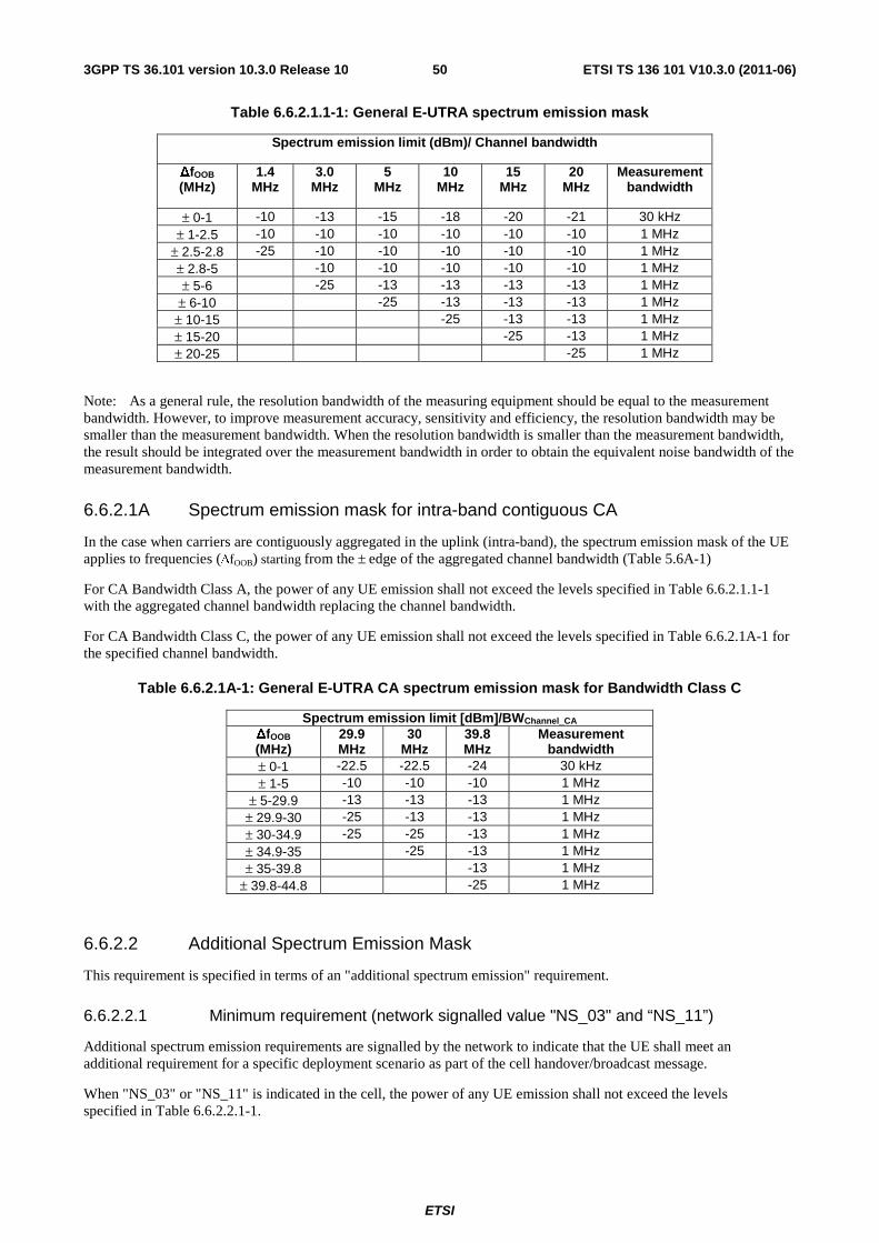
ETSI
ETSI TS 136 101 V10.3.0 (2011-06)503GPP TS 36.101 version 10.3.0 Release 10
Table 6.6.2.1.1-1: General E-UTRA spectrum emission mask
Spectrum emission limit (dBm)/ Channel bandwidth
ΔfOOB (MHz)
1.4 MHz
3.0 MHz
5 MHz
10 MHz
15 MHz
20 MHz
Measurement bandwidth
± 0-1 -10 -13 -15 -18 -20 -21 30 kHz ± 1-2.5 -10 -10 -10 -10 -10 -10 1 MHz
± 2.5-2.8 -25 -10 -10 -10 -10 -10 1 MHz ± 2.8-5 -10 -10 -10 -10 -10 1 MHz ± 5-6 -25 -13 -13 -13 -13 1 MHz
± 6-10 -25 -13 -13 -13 1 MHz ± 10-15 -25 -13 -13 1 MHz ± 15-20 -25 -13 1 MHz ± 20-25 -25 1 MHz
Note: As a general rule, the resolution bandwidth of the measuring equipment should be equal to the measurement bandwidth. However, to improve measurement accuracy, sensitivity and efficiency, the resolution bandwidth may be smaller than the measurement bandwidth. When the resolution bandwidth is smaller than the measurement bandwidth, the result should be integrated over the measurement bandwidth in order to obtain the equivalent noise bandwidth of the measurement bandwidth.
6.6.2.1A Spectrum emission mask for intra-band contiguous CA
In the case when carriers are contiguously aggregated in the uplink (intra-band), the spectrum emission mask of the UE applies to frequencies (ΔfOOB) starting from the ± edge of the aggregated channel bandwidth (Table 5.6A-1)
For CA Bandwidth Class A, the power of any UE emission shall not exceed the levels specified in Table 6.6.2.1.1-1 with the aggregated channel bandwidth replacing the channel bandwidth.
For CA Bandwidth Class C, the power of any UE emission shall not exceed the levels specified in Table 6.6.2.1A-1 for the specified channel bandwidth.
Table 6.6.2.1A-1: General E-UTRA CA spectrum emission mask for Bandwidth Class C
Spectrum emission limit [dBm]/BWChannel_CA ΔfOOB (MHz)
29.9 MHz
30 MHz
39.8 MHz
Measurement bandwidth
± 0-1 -22.5 -22.5 -24 30 kHz ± 1-5 -10 -10 -10 1 MHz
± 5-29.9 -13 -13 -13 1 MHz ± 29.9-30 -25 -13 -13 1 MHz ± 30-34.9 -25 -25 -13 1 MHz ± 34.9-35 -25 -13 1 MHz ± 35-39.8 -13 1 MHz
± 39.8-44.8 -25 1 MHz
6.6.2.2 Additional Spectrum Emission Mask
This requirement is specified in terms of an "additional spectrum emission" requirement.
6.6.2.2.1 Minimum requirement (network signalled value "NS_03" and “NS_11”)
Additional spectrum emission requirements are signalled by the network to indicate that the UE shall meet an additional requirement for a specific deployment scenario as part of the cell handover/broadcast message.
When "NS_03" or "NS_11" is indicated in the cell, the power of any UE emission shall not exceed the levels specified in Table 6.6.2.2.1-1.
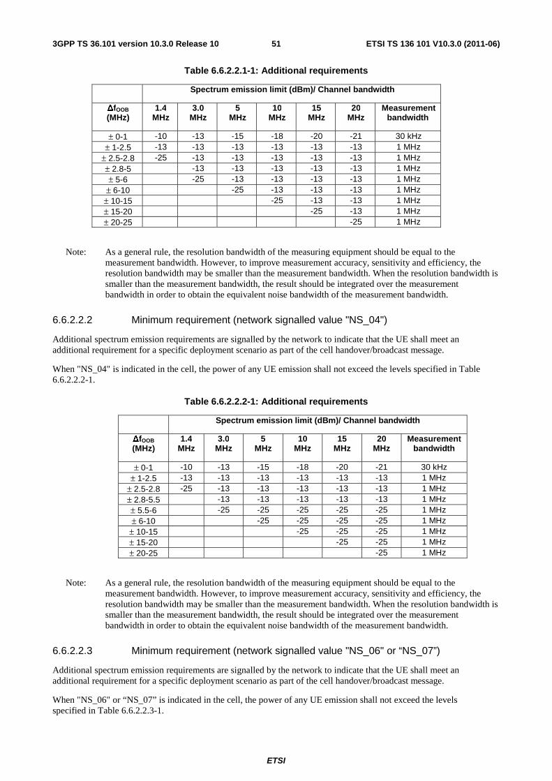
ETSI
ETSI TS 136 101 V10.3.0 (2011-06)513GPP TS 36.101 version 10.3.0 Release 10
Table 6.6.2.2.1-1: Additional requirements
Spectrum emission limit (dBm)/ Channel bandwidth
ΔfOOB (MHz)
1.4 MHz
3.0 MHz
5 MHz
10 MHz
15 MHz
20 MHz
Measurement bandwidth
± 0-1 -10 -13 -15 -18 -20 -21 30 kHz ± 1-2.5 -13 -13 -13 -13 -13 -13 1 MHz
± 2.5-2.8 -25 -13 -13 -13 -13 -13 1 MHz ± 2.8-5 -13 -13 -13 -13 -13 1 MHz ± 5-6 -25 -13 -13 -13 -13 1 MHz
± 6-10 -25 -13 -13 -13 1 MHz ± 10-15 -25 -13 -13 1 MHz ± 15-20 -25 -13 1 MHz ± 20-25 -25 1 MHz
Note: As a general rule, the resolution bandwidth of the measuring equipment should be equal to the measurement bandwidth. However, to improve measurement accuracy, sensitivity and efficiency, the resolution bandwidth may be smaller than the measurement bandwidth. When the resolution bandwidth is smaller than the measurement bandwidth, the result should be integrated over the measurement bandwidth in order to obtain the equivalent noise bandwidth of the measurement bandwidth.
6.6.2.2.2 Minimum requirement (network signalled value "NS_04")
Additional spectrum emission requirements are signalled by the network to indicate that the UE shall meet an additional requirement for a specific deployment scenario as part of the cell handover/broadcast message.
When "NS_04" is indicated in the cell, the power of any UE emission shall not exceed the levels specified in Table 6.6.2.2.2-1.
Table 6.6.2.2.2-1: Additional requirements
Spectrum emission limit (dBm)/ Channel bandwidth
ΔfOOB (MHz)
1.4 MHz
3.0 MHz
5 MHz
10 MHz
15 MHz
20 MHz
Measurement bandwidth
± 0-1 -10 -13 -15 -18 -20 -21 30 kHz ± 1-2.5 -13 -13 -13 -13 -13 -13 1 MHz
± 2.5-2.8 -25 -13 -13 -13 -13 -13 1 MHz ± 2.8-5.5 -13 -13 -13 -13 -13 1 MHz ± 5.5-6 -25 -25 -25 -25 -25 1 MHz ± 6-10 -25 -25 -25 -25 1 MHz
± 10-15 -25 -25 -25 1 MHz ± 15-20 -25 -25 1 MHz ± 20-25 -25 1 MHz
Note: As a general rule, the resolution bandwidth of the measuring equipment should be equal to the measurement bandwidth. However, to improve measurement accuracy, sensitivity and efficiency, the resolution bandwidth may be smaller than the measurement bandwidth. When the resolution bandwidth is smaller than the measurement bandwidth, the result should be integrated over the measurement bandwidth in order to obtain the equivalent noise bandwidth of the measurement bandwidth.
6.6.2.2.3 Minimum requirement (network signalled value "NS_06" or “NS_07”)
Additional spectrum emission requirements are signalled by the network to indicate that the UE shall meet an additional requirement for a specific deployment scenario as part of the cell handover/broadcast message.
When "NS_06" or “NS_07” is indicated in the cell, the power of any UE emission shall not exceed the levels specified in Table 6.6.2.2.3-1.
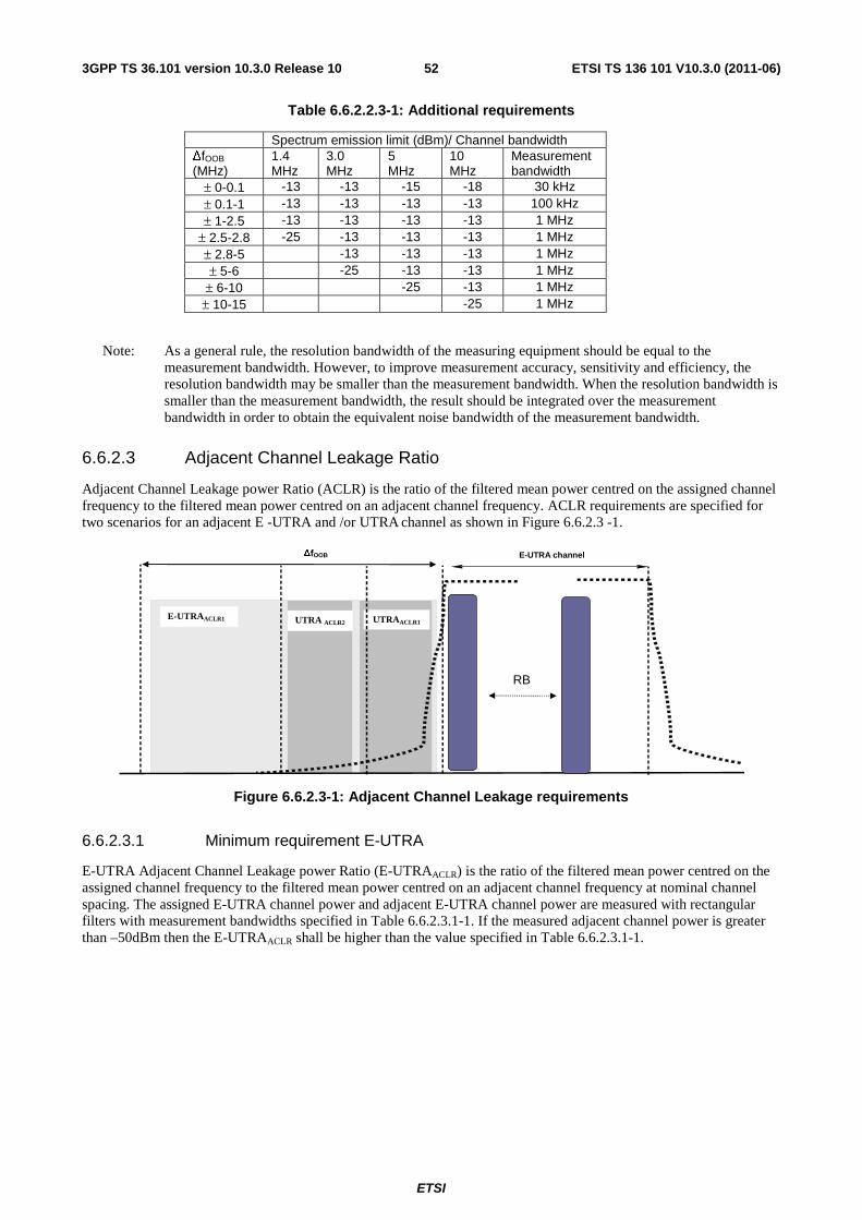
ETSI
ETSI TS 136 101 V10.3.0 (2011-06)523GPP TS 36.101 version 10.3.0 Release 10
Table 6.6.2.2.3-1: Additional requirements
Spectrum emission limit (dBm)/ Channel bandwidth ΔfOOB (MHz)
1.4 MHz
3.0 MHz
5 MHz
10 MHz
Measurement bandwidth
± 0-0.1 -13 -13 -15 -18 30 kHz ± 0.1-1 -13 -13 -13 -13 100 kHz ± 1-2.5 -13 -13 -13 -13 1 MHz
± 2.5-2.8 -25 -13 -13 -13 1 MHz ± 2.8-5 -13 -13 -13 1 MHz ± 5-6 -25 -13 -13 1 MHz
± 6-10 -25 -13 1 MHz ± 10-15 -25 1 MHz
Note: As a general rule, the resolution bandwidth of the measuring equipment should be equal to the measurement bandwidth. However, to improve measurement accuracy, sensitivity and efficiency, the resolution bandwidth may be smaller than the measurement bandwidth. When the resolution bandwidth is smaller than the measurement bandwidth, the result should be integrated over the measurement bandwidth in order to obtain the equivalent noise bandwidth of the measurement bandwidth.
6.6.2.3 Adjacent Channel Leakage Ratio
Adjacent Channel Leakage power Ratio (ACLR) is the ratio of the filtered mean power centred on the assigned channel frequency to the filtered mean power centred on an adjacent channel frequency. ACLR requirements are specified for two scenarios for an adjacent E -UTRA and /or UTRA channel as shown in Figure 6.6.2.3 -1.
E-UTRAACLR1 UTRA ACLR2 UTRAACLR1
RB
E-UTRA channel
ΔfOOB
Figure 6.6.2.3-1: Adjacent Channel Leakage requirements
6.6.2.3.1 Minimum requirement E-UTRA
E-UTRA Adjacent Channel Leakage power Ratio (E-UTRAACLR) is the ratio of the filtered mean power centred on the assigned channel frequency to the filtered mean power centred on an adjacent channel frequency at nominal channel spacing. The assigned E-UTRA channel power and adjacent E-UTRA channel power are measured with rectangular filters with measurement bandwidths specified in Table 6.6.2.3.1-1. If the measured adjacent channel power is greater than –50dBm then the E-UTRAACLR shall be higher than the value specified in Table 6.6.2.3.1-1.
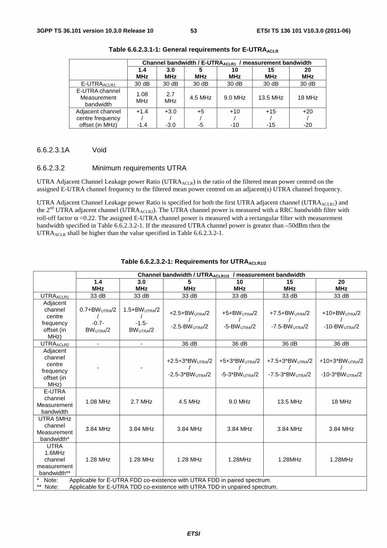
ETSI
ETSI TS 136 101 V10.3.0 (2011-06)533GPP TS 36.101 version 10.3.0 Release 10
Table 6.6.2.3.1-1: General requirements for E-UTRAACLR
Channel bandwidth / E-UTRAACLR1 / measurement bandwidth 1.4
MHz 3.0
MHz 5
MHz 10
MHz 15
MHz 20
MHz E-UTRAACLR1 30 dB 30 dB 30 dB 30 dB 30 dB 30 dB
E-UTRA channel Measurement
bandwidth
1.08 MHz
2.7 MHz 4.5 MHz 9.0 MHz 13.5 MHz 18 MHz
Adjacent channel centre frequency offset (in MHz)
+1.4 /
-1.4
+3.0 /
-3.0
+5 /
-5
+10 /
-10
+15 /
-15
+20 /
-20
6.6.2.3.1A Void
6.6.2.3.2 Minimum requirements UTRA
UTRA Adjacent Channel Leakage power Ratio (UTRAACLR) is the ratio of the filtered mean power centred on the assigned E-UTRA channel frequency to the filtered mean power centred on an adjacent(s) UTRA channel frequency.
UTRA Adjacent Channel Leakage power Ratio is specified for both the first UTRA adjacent channel (UTRAACLR1) and the 2nd UTRA adjacent channel (UTRAACLR2). The UTRA channel power is measured with a RRC bandwidth filter with roll-off factor α =0.22. The assigned E-UTRA channel power is measured with a rectangular filter with measurement bandwidth specified in Table 6.6.2.3.2-1. If the measured UTRA channel power is greater than –50dBm then the UTRAACLR shall be higher than the value specified in Table 6.6.2.3.2-1.
Table 6.6.2.3.2-1: Requirements for UTRAACLR1/2
Channel bandwidth / UTRAACLR1/2 / measurement bandwidth 1.4
MHz 3.0
MHz 5
MHz 10
MHz 15
MHz 20
MHz UTRAACLR1 33 dB 33 dB 33 dB 33 dB 33 dB 33 dB Adjacent channel centre
frequency offset (in
MHz)
0.7+BWUTRA/2 /
-0.7-BWUTRA/2
1.5+BWUTRA/2 /
-1.5-BWUTRA/2
+2.5+BWUTRA/2 /
-2.5-BWUTRA/2
+5+BWUTRA/2 /
-5-BWUTRA/2
+7.5+BWUTRA/2 /
-7.5-BWUTRA/2
+10+BWUTRA/2 /
-10-BWUTRA/2
UTRAACLR2 - - 36 dB 36 dB 36 dB 36 dB Adjacent channel centre
frequency offset (in
MHz)
- - +2.5+3*BWUTRA/2
/ -2.5-3*BWUTRA/2
+5+3*BWUTRA/2 /
-5-3*BWUTRA/2
+7.5+3*BWUTRA/2 /
-7.5-3*BWUTRA/2
+10+3*BWUTRA/2 /
-10-3*BWUTRA/2
E-UTRA
channel Measurement
bandwidth
1.08 MHz 2.7 MHz 4.5 MHz 9.0 MHz 13.5 MHz 18 MHz
UTRA 5MHz channel
Measurement bandwidth*
3.84 MHz 3.84 MHz 3.84 MHz 3.84 MHz 3.84 MHz 3.84 MHz
UTRA 1.6MHz channel
measurement bandwidth**
1.28 MHz 1.28 MHz 1.28 MHz 1.28MHz 1.28MHz 1.28MHz
* Note: Applicable for E-UTRA FDD co-existence with UTRA FDD in paired spectrum. ** Note: Applicable for E-UTRA TDD co-existence with UTRA TDD in unpaired spectrum.
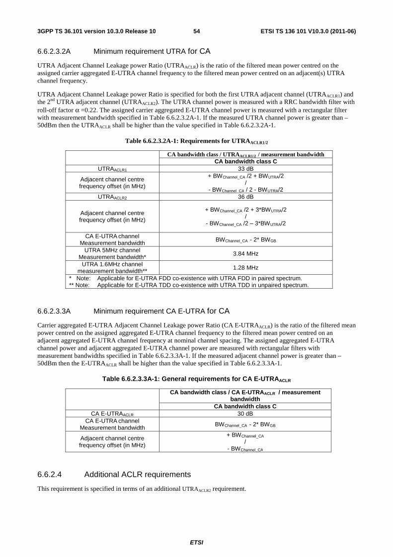
ETSI
ETSI TS 136 101 V10.3.0 (2011-06)543GPP TS 36.101 version 10.3.0 Release 10
6.6.2.3.2A Minimum requirement UTRA for CA
UTRA Adjacent Channel Leakage power Ratio (UTRAACLR) is the ratio of the filtered mean power centred on the assigned carrier aggregated E-UTRA channel frequency to the filtered mean power centred on an adjacent(s) UTRA channel frequency.
UTRA Adjacent Channel Leakage power Ratio is specified for both the first UTRA adjacent channel (UTRAACLR1) and the 2nd UTRA adjacent channel (UTRAACLR2). The UTRA channel power is measured with a RRC bandwidth filter with roll-off factor α =0.22. The assigned carrier aggregated E-UTRA channel power is measured with a rectangular filter with measurement bandwidth specified in Table 6.6.2.3.2A-1. If the measured UTRA channel power is greater than –50dBm then the UTRAACLR shall be higher than the value specified in Table 6.6.2.3.2A-1.
Table 6.6.2.3.2A-1: Requirements for UTRAACLR1/2
CA bandwidth class / UTRAACLR1/2 / measurement bandwidth CA bandwidth class C
UTRAACLR1 33 dB
Adjacent channel centre frequency offset (in MHz)
+ BWChannel_CA /2 + BWUTRA/2 /
- BWChannel_CA / 2 - BWUTRA/2 UTRAACLR2 36 dB
Adjacent channel centre frequency offset (in MHz)
+ BWChannel_CA /2 + 3*BWUTRA/2 /
- BWChannel_CA /2 – 3*BWUTRA/2
CA E-UTRA channel Measurement bandwidth BWChannel_CA - 2* BWGB
UTRA 5MHz channel Measurement bandwidth* 3.84 MHz
UTRA 1.6MHz channel measurement bandwidth** 1.28 MHz
* Note: Applicable for E-UTRA FDD co-existence with UTRA FDD in paired spectrum. ** Note: Applicable for E-UTRA TDD co-existence with UTRA TDD in unpaired spectrum.
6.6.2.3.3A Minimum requirement CA E-UTRA for CA
Carrier aggregated E-UTRA Adjacent Channel Leakage power Ratio (CA E-UTRAACLR) is the ratio of the filtered mean power centred on the assigned aggregated E-UTRA channel frequency to the filtered mean power centred on an adjacent aggregated E-UTRA channel frequency at nominal channel spacing. The assigned aggregated E-UTRA channel power and adjacent aggregated E-UTRA channel power are measured with rectangular filters with measurement bandwidths specified in Table 6.6.2.3.3A-1. If the measured adjacent channel power is greater than –50dBm then the E-UTRAACLR shall be higher than the value specified in Table 6.6.2.3.3A-1.
Table 6.6.2.3.3A-1: General requirements for CA E-UTRAACLR
CA bandwidth class / CA E-UTRAACLR / measurement bandwidth
CA bandwidth class C CA E-UTRAACLR 30 dB
CA E-UTRA channel Measurement bandwidth BWChannel_CA - 2* BWGB
Adjacent channel centre frequency offset (in MHz)
+ BWChannel_CA /
- BWChannel_CA
6.6.2.4 Additional ACLR requirements
This requirement is specified in terms of an additional UTRAACLR2 requirement.
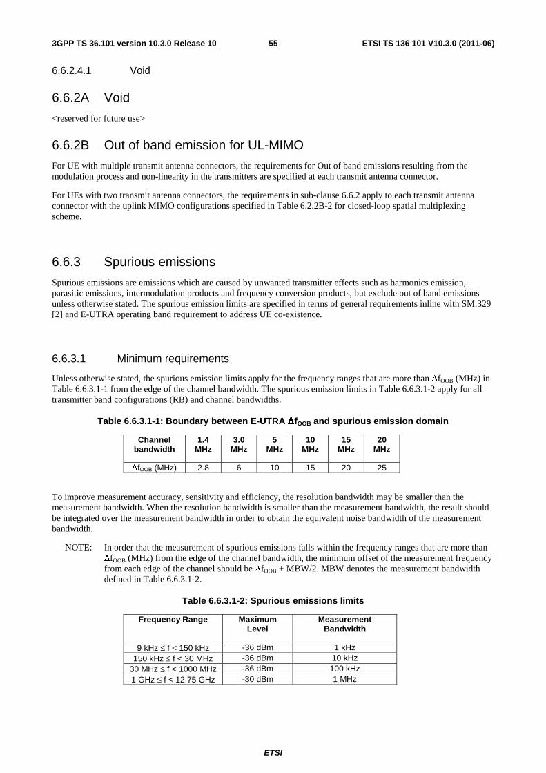
ETSI
ETSI TS 136 101 V10.3.0 (2011-06)553GPP TS 36.101 version 10.3.0 Release 10
6.6.2.4.1 Void
6.6.2A Void
<reserved for future use>
6.6.2B Out of band emission for UL-MIMO
For UE with multiple transmit antenna connectors, the requirements for Out of band emissions resulting from the modulation process and non-linearity in the transmitters are specified at each transmit antenna connector.
For UEs with two transmit antenna connectors, the requirements in sub-clause 6.6.2 apply to each transmit antenna connector with the uplink MIMO configurations specified in Table 6.2.2B-2 for closed-loop spatial multiplexing scheme.
6.6.3 Spurious emissions
Spurious emissions are emissions which are caused by unwanted transmitter effects such as harmonics emission, parasitic emissions, intermodulation products and frequency conversion products, but exclude out of band emissions unless otherwise stated. The spurious emission limits are specified in terms of general requirements inline with SM.329 [2] and E-UTRA operating band requirement to address UE co-existence.
6.6.3.1 Minimum requirements
Unless otherwise stated, the spurious emission limits apply for the frequency ranges that are more than ΔfOOB (MHz) in Table 6.6.3.1-1 from the edge of the channel bandwidth. The spurious emission limits in Table 6.6.3.1-2 apply for all transmitter band configurations (RB) and channel bandwidths.
Table 6.6.3.1-1: Boundary between E-UTRA ΔfOOB and spurious emission domain
Channel bandwidth
1.4 MHz
3.0 MHz
5 MHz
10 MHz
15 MHz
20 MHz
ΔfOOB (MHz) 2.8 6 10 15 20 25
To improve measurement accuracy, sensitivity and efficiency, the resolution bandwidth may be smaller than the measurement bandwidth. When the resolution bandwidth is smaller than the measurement bandwidth, the result should be integrated over the measurement bandwidth in order to obtain the equivalent noise bandwidth of the measurement bandwidth.
NOTE: In order that the measurement of spurious emissions falls within the frequency ranges that are more than ΔfOOB (MHz) from the edge of the channel bandwidth, the minimum offset of the measurement frequency from each edge of the channel should be ΔfOOB + MBW/2. MBW denotes the measurement bandwidth defined in Table 6.6.3.1-2.
Table 6.6.3.1-2: Spurious emissions limits
Frequency Range Maximum Level
Measurement Bandwidth
9 kHz ≤ f < 150 kHz -36 dBm 1 kHz 150 kHz ≤ f < 30 MHz -36 dBm 10 kHz
30 MHz ≤ f < 1000 MHz -36 dBm 100 kHz 1 GHz ≤ f < 12.75 GHz -30 dBm 1 MHz
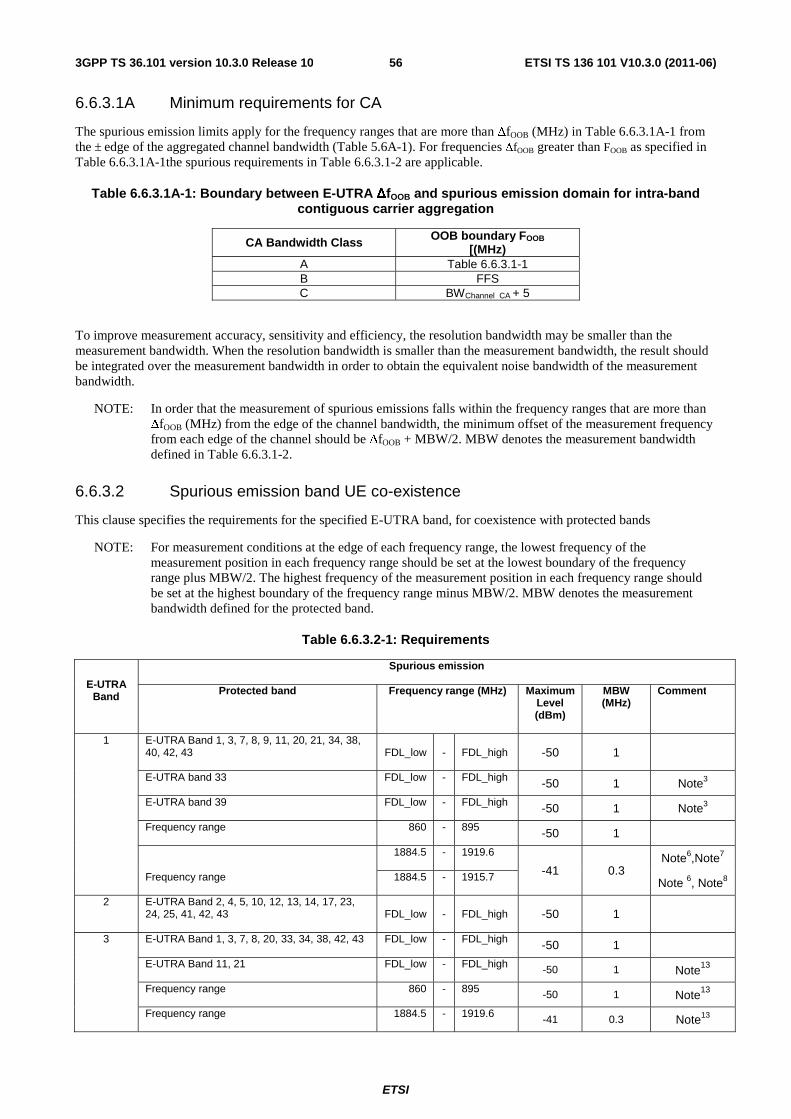
ETSI
ETSI TS 136 101 V10.3.0 (2011-06)563GPP TS 36.101 version 10.3.0 Release 10
6.6.3.1A Minimum requirements for CA
The spurious emission limits apply for the frequency ranges that are more than ΔfOOB (MHz) in Table 6.6.3.1A-1 from the ± edge of the aggregated channel bandwidth (Table 5.6A-1). For frequencies ΔfOOB greater than FOOB as specified in Table 6.6.3.1A-1the spurious requirements in Table 6.6.3.1-2 are applicable.
Table 6.6.3.1A-1: Boundary between E-UTRA ΔfOOB and spurious emission domain for intra-band contiguous carrier aggregation
CA Bandwidth Class OOB boundary FOOB
[(MHz) A Table 6.6.3.1-1 B FFS C BWChannel_CA + 5
To improve measurement accuracy, sensitivity and efficiency, the resolution bandwidth may be smaller than the measurement bandwidth. When the resolution bandwidth is smaller than the measurement bandwidth, the result should be integrated over the measurement bandwidth in order to obtain the equivalent noise bandwidth of the measurement bandwidth.
NOTE: In order that the measurement of spurious emissions falls within the frequency ranges that are more than ΔfOOB (MHz) from the edge of the channel bandwidth, the minimum offset of the measurement frequency from each edge of the channel should be ΔfOOB + MBW/2. MBW denotes the measurement bandwidth defined in Table 6.6.3.1-2.
6.6.3.2 Spurious emission band UE co-existence
This clause specifies the requirements for the specified E-UTRA band, for coexistence with protected bands
NOTE: For measurement conditions at the edge of each frequency range, the lowest frequency of the measurement position in each frequency range should be set at the lowest boundary of the frequency range plus MBW/2. The highest frequency of the measurement position in each frequency range should be set at the highest boundary of the frequency range minus MBW/2. MBW denotes the measurement bandwidth defined for the protected band.
Table 6.6.3.2-1: Requirements
E-UTRA Band
Spurious emission
Protected band Frequency range (MHz) Maximum Level (dBm)
MBW (MHz)
Comment
1 E-UTRA Band 1, 3, 7, 8, 9, 11, 20, 21, 34, 38, 40, 42, 43 FDL_low - FDL_high -50 1
E-UTRA band 33 FDL_low - FDL_high -50 1 Note3
E-UTRA band 39 FDL_low - FDL_high -50 1 Note3
Frequency range 860 - 895 -50 1
Frequency range
1884.5 - 1919.6
-41 0.3 Note6,Note7
1884.5 - 1915.7 Note 6, Note8
2 E-UTRA Band 2, 4, 5, 10, 12, 13, 14, 17, 23, 24, 25, 41, 42, 43 FDL_low - FDL_high -50 1
3 E-UTRA Band 1, 3, 7, 8, 20, 33, 34, 38, 42, 43 FDL_low - FDL_high -50 1
E-UTRA Band 11, 21 FDL_low - FDL_high -50 1 Note13
Frequency range 860 - 895 -50 1 Note13
Frequency range 1884.5 - 1919.6 -41 0.3 Note13
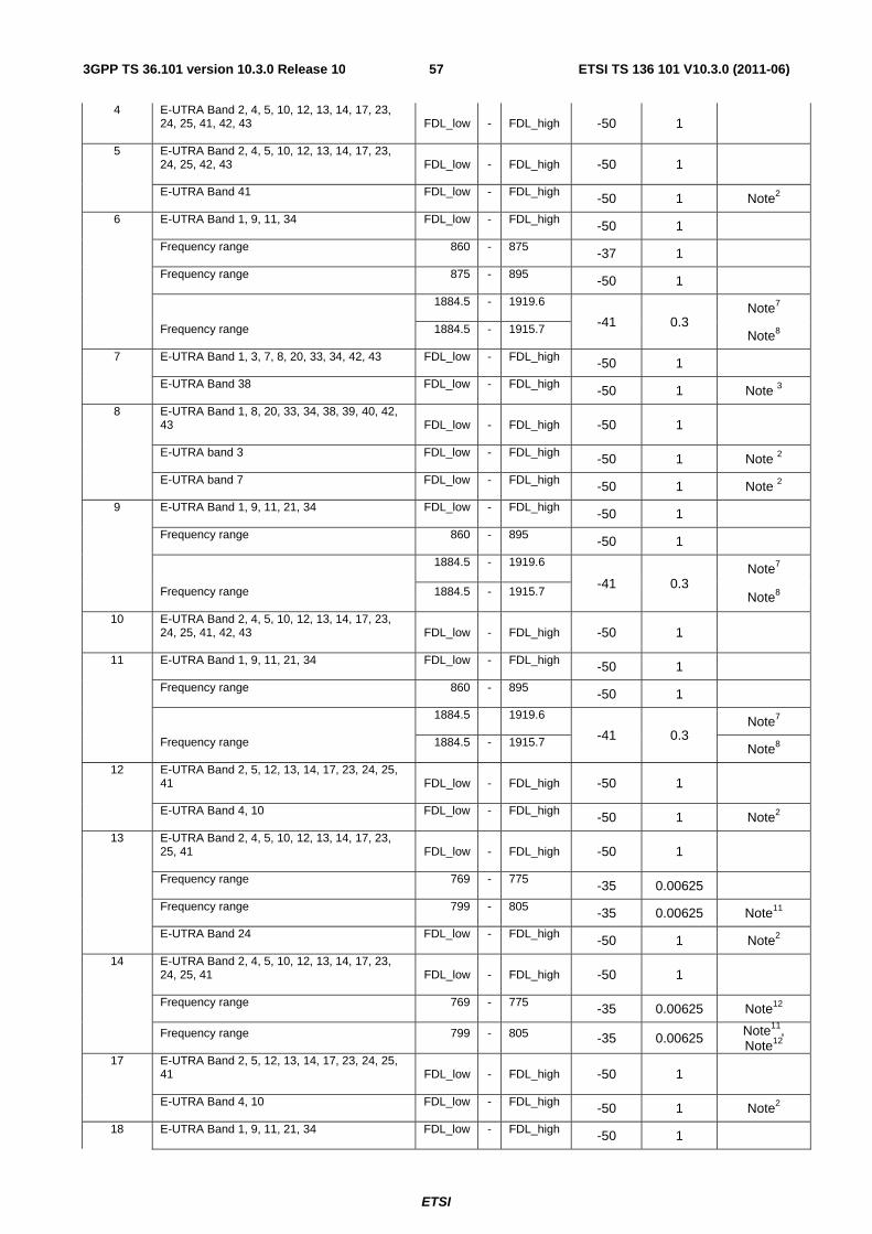
ETSI
ETSI TS 136 101 V10.3.0 (2011-06)573GPP TS 36.101 version 10.3.0 Release 10
4 E-UTRA Band 2, 4, 5, 10, 12, 13, 14, 17, 23, 24, 25, 41, 42, 43 FDL_low - FDL_high -50 1
5 E-UTRA Band 2, 4, 5, 10, 12, 13, 14, 17, 23, 24, 25, 42, 43 FDL_low - FDL_high -50 1
E-UTRA Band 41 FDL_low - FDL_high -50 1 Note2
6 E-UTRA Band 1, 9, 11, 34 FDL_low - FDL_high -50 1
Frequency range 860 - 875 -37 1
Frequency range 875 - 895 -50 1
Frequency range
1884.5 - 1919.6
-41 0.3 Note7
1884.5 - 1915.7 Note8
7 E-UTRA Band 1, 3, 7, 8, 20, 33, 34, 42, 43 FDL_low - FDL_high -50 1
E-UTRA Band 38 FDL_low - FDL_high -50 1 Note 3
8 E-UTRA Band 1, 8, 20, 33, 34, 38, 39, 40, 42, 43 FDL_low - FDL_high -50 1
E-UTRA band 3 FDL_low - FDL_high -50 1 Note 2
E-UTRA band 7 FDL_low - FDL_high -50 1 Note 2
9 E-UTRA Band 1, 9, 11, 21, 34 FDL_low - FDL_high -50 1
Frequency range 860 - 895 -50 1
Frequency range
1884.5 - 1919.6
-41 0.3 Note7
1884.5 - 1915.7 Note8
10 E-UTRA Band 2, 4, 5, 10, 12, 13, 14, 17, 23, 24, 25, 41, 42, 43 FDL_low - FDL_high -50 1
11 E-UTRA Band 1, 9, 11, 21, 34 FDL_low - FDL_high -50 1
Frequency range 860 - 895 -50 1
Frequency range
1884.5 1919.6
-41 0.3 Note7
1884.5 - 1915.7 Note8
12 E-UTRA Band 2, 5, 12, 13, 14, 17, 23, 24, 25, 41 FDL_low - FDL_high -50 1
E-UTRA Band 4, 10 FDL_low - FDL_high -50 1 Note2
13 E-UTRA Band 2, 4, 5, 10, 12, 13, 14, 17, 23, 25, 41 FDL_low - FDL_high -50 1
Frequency range 769 - 775 -35 0.00625
Frequency range 799 - 805 -35 0.00625 Note11
E-UTRA Band 24 FDL_low - FDL_high -50 1 Note2
14
E-UTRA Band 2, 4, 5, 10, 12, 13, 14, 17, 23, 24, 25, 41 FDL_low - FDL_high -50 1
Frequency range 769 - 775 -35 0.00625 Note12
Frequency range 799 - 805 -35 0.00625 Note11, Note12
17 E-UTRA Band 2, 5, 12, 13, 14, 17, 23, 24, 25, 41 FDL_low - FDL_high -50 1
E-UTRA Band 4, 10 FDL_low - FDL_high -50 1 Note2
18 E-UTRA Band 1, 9, 11, 21, 34 FDL_low - FDL_high -50 1
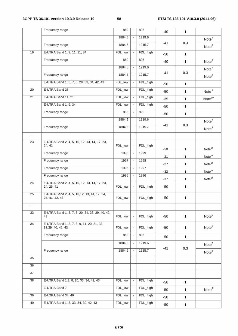
ETSI
ETSI TS 136 101 V10.3.0 (2011-06)583GPP TS 36.101 version 10.3.0 Release 10
Frequency range 860 - 895 -40 1
Frequency range
1884.5 - 1919.6
-41 0.3 Note7
1884.5 - 1915.7 Note8
19 E-UTRA Band 1, 9, 11, 21, 34 FDL_low - FDL_high -50 1
Frequency range 860 - 895 -40 1 Note9
Frequency range
1884.5 - 1919.6
-41 0.3 Note7
1884.5 - 1915.7 Note8
20
E-UTRA Band 1, 3, 7, 8, 20, 33, 34, 42, 43 FDL_low - FDL_high -50 1
E-UTRA Band 38 FDL_low - FDL_high -50 1 Note 2
21 E-UTRA Band 11, 21 FDL_low - FDL_high -35 1 Note10
E-UTRA Band 1, 9, 34 FDL_low - FDL_high -50 1
Frequency range 860 - 895 -50 1
Frequency range
1884.5 1919.6
-41 0.3 Note7
1884.5 - 1915.7 Note8
…
23 E-UTRA Band 2, 4, 5, 10, 12, 13, 14, 17, 23, 24, 41 FDL_low - FDL_high
-50 1 Note14 Frequency range 1998 - 1999
-21 1 Note14 Frequency range 1997 - 1998
-27 1 Note14 Frequency range 1996 - 1997
-32 1 Note14 Frequency range 1995 - 1996
-37 1 Note14 24 E-UTRA Band 2, 4, 5, 10, 12, 13, 14, 17, 23,
24, 25, 41 FDL_low - FDL_high -50 1
25 E-UTRA Band 2, 4, 5, 10,12, 13, 14, 17, 24, 25, 41, 42, 43 FDL_low - FDL_high -50 1
…
33 E-UTRA Band 1, 3, 7, 8, 20, 34, 38, 39, 40, 42, 43 FDL_low - FDL_high -50 1 Note5
34 E-UTRA Band 1, 3, 7, 8, 9, 11, 20, 21, 33, 38,39, 40, 42, 43 FDL_low - FDL_high -50 1 Note5
Frequency range 860 - 895 -50 1
Frequency range
1884.5 - 1919.6
-41 0.3 Note7
1884.5 - 1915.7 Note8
35
36
37 -
38 E-UTRA Band 1,3, 8, 20, 33, 34, 42, 43 FDL_low - FDL_high -50 1
E-UTRA Band 7 FDL_low - FDL_high -50 1 Note3
39 E-UTRA Band 34, 40 FDL_low - FDL_high -50 1
40 E-UTRA Band 1, 3, 33, 34, 39, 42, 43 FDL_low - FDL_high -50 1
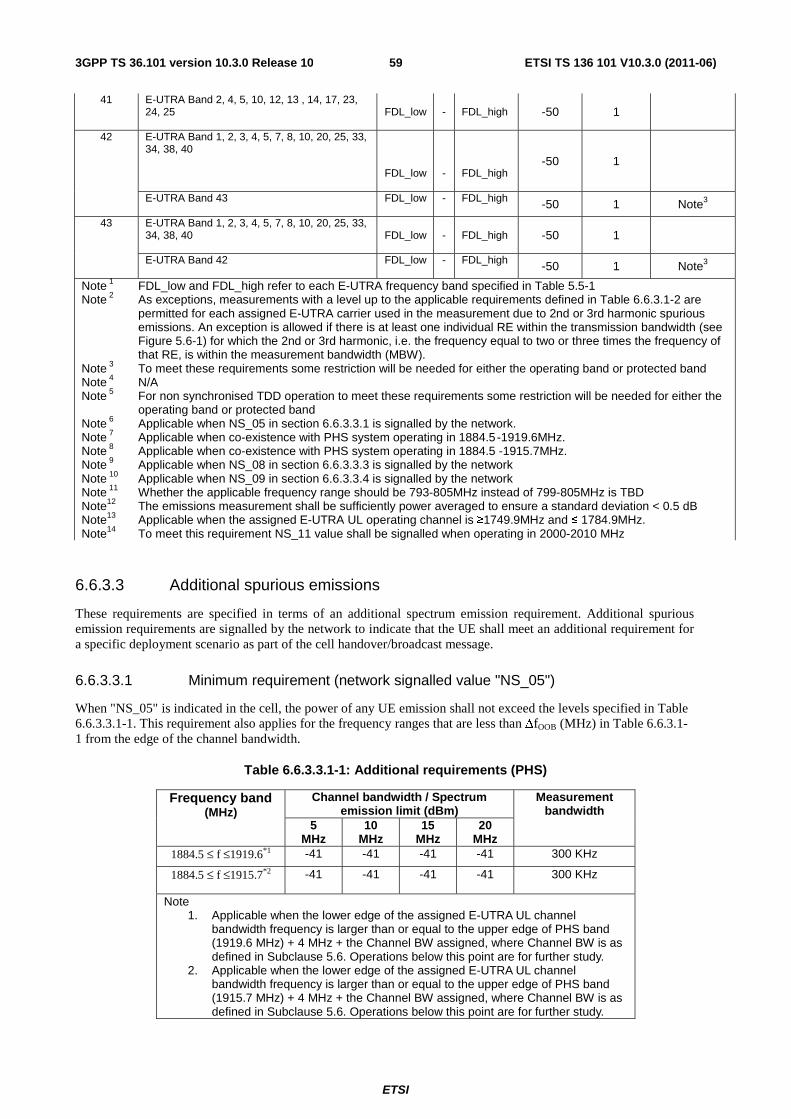
ETSI
ETSI TS 136 101 V10.3.0 (2011-06)593GPP TS 36.101 version 10.3.0 Release 10
41 E-UTRA Band 2, 4, 5, 10, 12, 13 , 14, 17, 23, 24, 25 FDL_low - FDL_high -50 1
42 E-UTRA Band 1, 2, 3, 4, 5, 7, 8, 10, 20, 25, 33, 34, 38, 40
FDL_low - FDL_high -50 1
E-UTRA Band 43 FDL_low - FDL_high -50 1 Note3
43 E-UTRA Band 1, 2, 3, 4, 5, 7, 8, 10, 20, 25, 33, 34, 38, 40 FDL_low - FDL_high -50 1
E-UTRA Band 42 FDL_low - FDL_high -50 1 Note3
Note 1 FDL_low and FDL_high refer to each E-UTRA frequency band specified in Table 5.5-1 Note 2 As exceptions, measurements with a level up to the applicable requirements defined in Table 6.6.3.1-2 are
permitted for each assigned E-UTRA carrier used in the measurement due to 2nd or 3rd harmonic spurious emissions. An exception is allowed if there is at least one individual RE within the transmission bandwidth (see Figure 5.6-1) for which the 2nd or 3rd harmonic, i.e. the frequency equal to two or three times the frequency of that RE, is within the measurement bandwidth (MBW).
Note 3 To meet these requirements some restriction will be needed for either the operating band or protected band Note 4 N/A Note 5 For non synchronised TDD operation to meet these requirements some restriction will be needed for either the
operating band or protected band Note 6 Applicable when NS_05 in section 6.6.3.3.1 is signalled by the network. Note 7 Applicable when co-existence with PHS system operating in 1884.5 -1919.6MHz. Note 8 Applicable when co-existence with PHS system operating in 1884.5 -1915.7MHz. Note 9 Applicable when NS_08 in section 6.6.3.3.3 is signalled by the network Note 10 Applicable when NS_09 in section 6.6.3.3.4 is signalled by the network Note 11 Whether the applicable frequency range should be 793-805MHz instead of 799-805MHz is TBD Note12 The emissions measurement shall be sufficiently power averaged to ensure a standard deviation < 0.5 dB Note13 Applicable when the assigned E-UTRA UL operating channel is ≥1749.9MHz and ≤ 1784.9MHz. Note14 To meet this requirement NS_11 value shall be signalled when operating in 2000-2010 MHz
6.6.3.3 Additional spurious emissions
These requirements are specified in terms of an additional spectrum emission requirement. Additional spurious emission requirements are signalled by the network to indicate that the UE shall meet an additional requirement for a specific deployment scenario as part of the cell handover/broadcast message.
6.6.3.3.1 Minimum requirement (network signalled value "NS_05")
When "NS_05" is indicated in the cell, the power of any UE emission shall not exceed the levels specified in Table 6.6.3.3.1-1. This requirement also applies for the frequency ranges that are less than ΔfOOB (MHz) in Table 6.6.3.1-1 from the edge of the channel bandwidth.
Table 6.6.3.3.1-1: Additional requirements (PHS)
Frequency band (MHz)
Channel bandwidth / Spectrum emission limit (dBm)
Measurement bandwidth
5 MHz
10 MHz
15 MHz
20 MHz
1884.5 ≤ f ≤1919.6*1 -41 -41 -41 -41 300 KHz
1884.5 ≤ f ≤1915.7*2 -41 -41 -41 -41 300 KHz
Note 1. Applicable when the lower edge of the assigned E-UTRA UL channel
bandwidth frequency is larger than or equal to the upper edge of PHS band (1919.6 MHz) + 4 MHz + the Channel BW assigned, where Channel BW is as defined in Subclause 5.6. Operations below this point are for further study.
2. Applicable when the lower edge of the assigned E-UTRA UL channel bandwidth frequency is larger than or equal to the upper edge of PHS band (1915.7 MHz) + 4 MHz + the Channel BW assigned, where Channel BW is as defined in Subclause 5.6. Operations below this point are for further study.
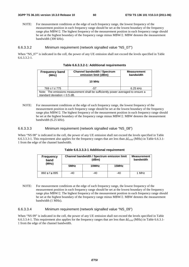
ETSI
ETSI TS 136 101 V10.3.0 (2011-06)603GPP TS 36.101 version 10.3.0 Release 10
NOTE: For measurement conditions at the edge of each frequency range, the lowest frequency of the measurement position in each frequency range should be set at the lowest boundary of the frequency range plus MBW/2. The highest frequency of the measurement position in each frequency range should be set at the highest boundary of the frequency range minus MBW/2. MBW denotes the measurement bandwidth (300 kHz).
6.6.3.3.2 Minimum requirement (network signalled value “NS_07”)
When “NS_07” is indicated in the cell, the power of any UE emission shall not exceed the levels specified in Table 6.6.3.3.2-1.
Table 6.6.3.3.2-1: Additional requirements
Frequency band (MHz)
Channel bandwidth / Spectrum emission limit (dBm)
Measurement bandwidth
10 MHz
769 ≤ f ≤ 775 -57 6.25 kHz
Note: The emissions measurement shall be sufficiently power averaged to ensure a standard deviation < 0.5 dB.
NOTE: For measurement conditions at the edge of each frequency range, the lowest frequency of the measurement position in each frequency range should be set at the lowest boundary of the frequency range plus MBW/2. The highest frequency of the measurement position in each frequency range should be set at the highest boundary of the frequency range minus MBW/2. MBW denotes the measurement bandwidth (6.25 kHz).
6.6.3.3.3 Minimum requirement (network signalled value “NS_08”)
When “NS 08” is indicated in the cell, the power of any UE emission shall not exceed the levels specified in Table 6.6.3.3.3-1. This requirement also applies for the frequency ranges that are less than ΔfOOB (MHz) in Table 6.6.3.1-1 from the edge of the channel bandwidth.
Table 6.6.3.3.3-1 Additional requirement
Frequency band (MHz)
Channel bandwidth / Spectrum emission limit (dBm)
Measurement bandwidth
5MHz 10MHz 15MHz
860 ≤ f ≤ 895 -40 -40 -40 1 MHz
NOTE: For measurement conditions at the edge of each frequency range, the lowest frequency of the measurement position in each frequency range should be set at the lowest boundary of the frequency range plus MBW/2. The highest frequency of the measurement position in each frequency range should be set at the highest boundary of the frequency range minus MBW/2. MBW denotes the measurement bandwidth (1 MHz).
6.6.3.3.4 Minimum requirement (network signalled value “NS_09”)
When “NS 09” is indicated in the cell, the power of any UE emission shall not exceed the levels specified in Table 6.6.3.3.4-1. This requirement also applies for the frequency ranges that are less than ΔfOOB (MHz) in Table 6.6.3.1-1 from the edge of the channel bandwidth.
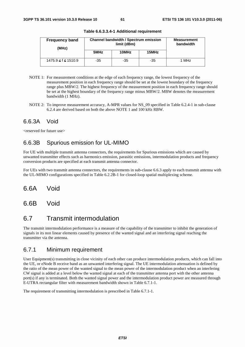
ETSI
ETSI TS 136 101 V10.3.0 (2011-06)613GPP TS 36.101 version 10.3.0 Release 10
Table 6.6.3.3.4-1 Additional requirement
Frequency band
(MHz)
Channel bandwidth / Spectrum emission limit (dBm)
Measurement bandwidth
5MHz 10MHz 15MHz
1475.9 ≤ f ≤ 1510.9 -35 -35 -35 1 MHz
NOTE 1: For measurement conditions at the edge of each frequency range, the lowest frequency of the measurement position in each frequency range should be set at the lowest boundary of the frequency range plus MBW/2. The highest frequency of the measurement position in each frequency range should be set at the highest boundary of the frequency range minus MBW/2. MBW denotes the measurement bandwidth (1 MHz).
NOTE 2: To improve measurement accuracy, A-MPR values for NS_09 specified in Table 6.2.4-1 in sub-clause 6.2.4 are derived based on both the above NOTE 1 and 100 kHz RBW.
6.6.3A Void
<reserved for future use>
6.6.3B Spurious emission for UL-MIMO
For UE with multiple transmit antenna connectors, the requirements for Spurious emissions which are caused by unwanted transmitter effects such as harmonics emission, parasitic emissions, intermodulation products and frequency conversion products are specified at each transmit antenna connector.
For UEs with two transmit antenna connectors, the requirements in sub-clause 6.6.3 apply to each transmit antenna with the UL-MIMO configurations specified in Table 6.2.2B-1 for closed-loop spatial multiplexing scheme.
6.6A Void
6.6B Void
6.7 Transmit intermodulation The transmit intermodulation performance is a measure of the capability of the transmitter to inhibit the generation of signals in its non linear elements caused by presence of the wanted signal and an interfering signal reaching the transmitter via the antenna.
6.7.1 Minimum requirement
User Equipment(s) transmitting in close vicinity of each other can produce intermodulation products, which can fall into the UE, or eNode B receive band as an unwanted interfering signal. The UE intermodulation attenuation is defined by the ratio of the mean power of the wanted signal to the mean power of the intermodulation product when an interfering CW signal is added at a level below the wanted signal at each of the transmitter antenna port with the other antenna port(s) if any is terminated. Both the wanted signal power and the intermodulation product power are measured through E-UTRA rectangular filter with measurement bandwidth shown in Table 6.7.1-1.
The requirement of transmitting intermodulation is prescribed in Table 6.7.1-1.
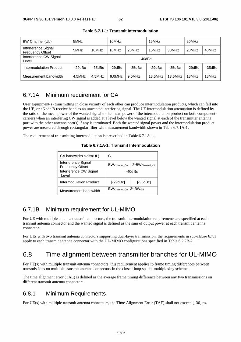
ETSI
ETSI TS 136 101 V10.3.0 (2011-06)623GPP TS 36.101 version 10.3.0 Release 10
Table 6.7.1-1: Transmit Intermodulation
BW Channel (UL) 5MHz 10MHz 15MHz 20MHz
Interference Signal Frequency Offset 5MHz 10MHz 10MHz 20MHz 15MHz 30MHz 20MHz 40MHz
Interference CW Signal Level -40dBc
Intermodulation Product -29dBc -35dBc -29dBc -35dBc -29dBc -35dBc -29dBc -35dBc
Measurement bandwidth 4.5MHz 4.5MHz 9.0MHz 9.0MHz 13.5MHz 13.5MHz 18MHz 18MHz
6.7.1A Minimum requirement for CA
User Equipment(s) transmitting in close vicinity of each other can produce intermodulation products, which can fall into the UE, or eNode B receive band as an unwanted interfering signal. The UE intermodulation attenuation is defined by the ratio of the mean power of the wanted signal to the mean power of the intermodulation product on both component carriers when an interfering CW signal is added at a level below the wanted signal at each of the transmitter antenna port with the other antenna port(s) if any is terminated. Both the wanted signal power and the intermodulation product power are measured through rectangular filter with measurement bandwidth shown in Table 6.7.1A-1.
The requirement of transmitting intermodulation is prescribed in Table 6.7.1A-1.
Table 6.7.1A-1: Transmit Intermodulation
CA bandwidth class(UL) C
Interference Signal Frequency Offset BWChannel_CA 2*BWChannel_CA
Interference CW Signal Level
-40dBc
Intermodulation Product [-29dBc] [-35dBc]
Measurement bandwidth BWChannel_CA- 2* BWGB
6.7.1B Minimum requirement for UL-MIMO
For UE with multiple antenna transmit connectors, the transmit intermodulation requirements are specified at each transmit antenna connector and the wanted signal is defined as the sum of output power at each transmit antenna connector.
For UEs with two transmit antenna connectors supporting dual-layer transmission, the requirements in sub-clause 6.7.1 apply to each transmit antenna connector with the UL-MIMO configurations specified in Table 6.2.2B-2.
6.8 Time alignment between transmitter branches for UL-MIMO For UE(s) with multiple transmit antenna connectors, this requirement applies to frame timing differences between transmissions on multiple transmit antenna connectors in the closed-loop spatial multiplexing scheme.
The time alignment error (TAE) is defined as the average frame timing difference between any two transmissions on different transmit antenna connectors.
6.8.1 Minimum Requirements
For UE(s) with multiple transmit antenna connectors, the Time Alignment Error (TAE) shall not exceed [130] ns.
ETSI
ETSI TS 136 101 V10.3.0 (2011-06)633GPP TS 36.101 version 10.3.0 Release 10
7 Receiver characteristics
7.1 General Unless otherwise stated the receiver characteristics are specified at the antenna connector(s) of the UE. For UE(s) with an integral antenna only, a reference antenna(s) with a gain of 0 dBi is assumed for each antenna port(s). UE with an integral antenna(s) may be taken into account by converting these power levels into field strength requirements, assuming a 0 dBi gain antenna. . For UEs with more than one receiver antenna connector, identical interfering signals shall be applied to each receiver antenna port if more than one of these is used (diversity).
The levels of the test signal applied to each of the antenna connectors shall be as defined in the respective sections below.
With the exception of Clause 7.3, the requirements shall be verified with the network signalling value NS_01 configured (Table 6.2.4-1).
All the parameters in clause 7 are defined using the UL reference measurement channels specified in Annexes A.2.2 and A.2.3, the DL reference measurement channels specified in Annex A.3.2 and using the set-up specified in Annex C.3.1
7.2 Diversity characteristics The requirements in Section 7 assume that the receiver is equipped with two Rx port as a baseline. These requirements apply to all UE categories unless stated otherwise. Requirements for 4 ports are FFS. With the exception of clause 7.9 all requirements shall be verified by using both (all) antenna ports simultaneously.
7.3 Reference sensitivity power level The reference sensitivity power level REFSENS is the minimum mean power applied to both the UE antenna ports at which the throughput shall meet or exceed the requirements for the specified reference measurement channel.
7.3.1 Minimum requirements (QPSK)
The throughput shall be ≥ 95% of the maximum throughput of the reference measurement channels as specified in Annexes A.2.2, A.2.3 and A.3.2 (with one sided dynamic OCNG Pattern OP.1 FDD/TDD for the DL-signal as described in Annex A.5.1.1/A.5.2.1) with parameters specified in Table 7.3.1-1 and table 7.3.1-2
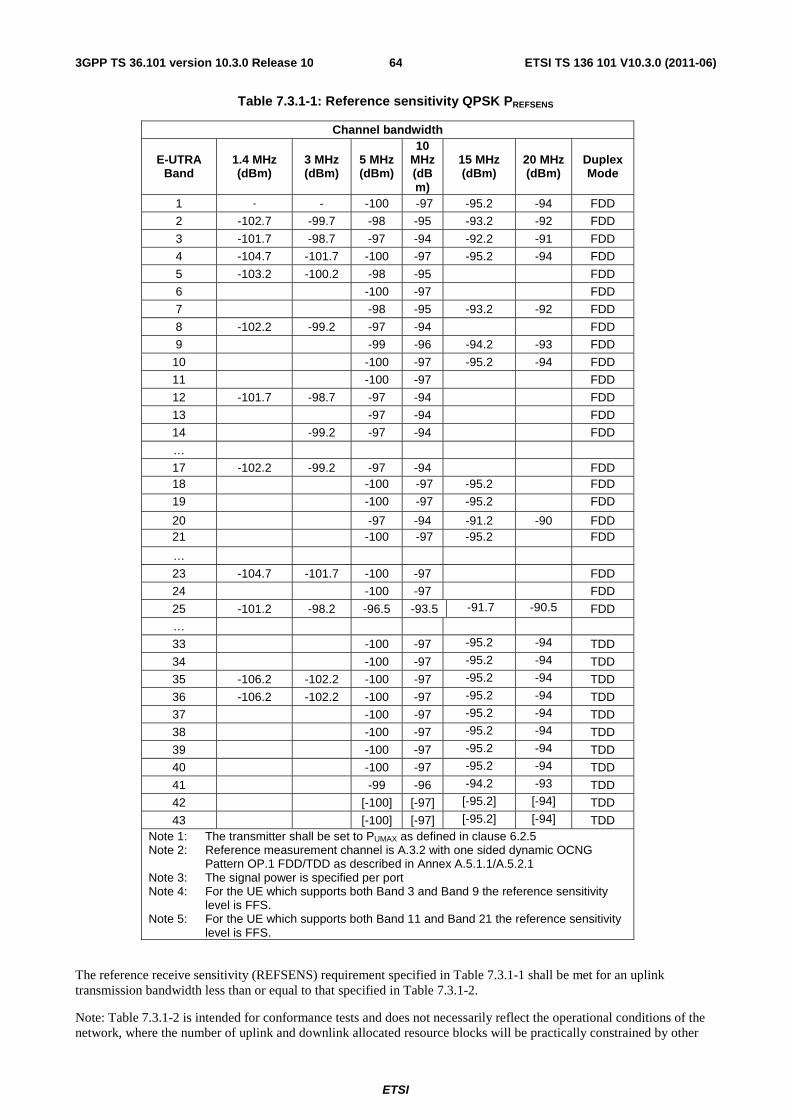
ETSI
ETSI TS 136 101 V10.3.0 (2011-06)643GPP TS 36.101 version 10.3.0 Release 10
Table 7.3.1-1: Reference sensitivity QPSK PREFSENS
Channel bandwidth
E-UTRA Band
1.4 MHz (dBm)
3 MHz (dBm)
5 MHz (dBm)
10 MHz (dBm)
15 MHz (dBm)
20 MHz (dBm)
Duplex Mode
1 - - -100 -97 -95.2 -94 FDD
2 -102.7 -99.7 -98 -95 -93.2 -92 FDD
3 -101.7 -98.7 -97 -94 -92.2 -91 FDD
4 -104.7 -101.7 -100 -97 -95.2 -94 FDD
5 -103.2 -100.2 -98 -95 FDD
6 -100 -97 FDD
7 -98 -95 -93.2 -92 FDD
8 -102.2 -99.2 -97 -94 FDD
9 -99 -96 -94.2 -93 FDD
10 -100 -97 -95.2 -94 FDD
11 -100 -97 FDD
12 -101.7 -98.7 -97 -94 FDD
13 -97 -94 FDD
14 -99.2 -97 -94 FDD
…
17 -102.2 -99.2 -97 -94 FDD 18 -100 -97 -95.2 FDD
19 -100 -97 -95.2 FDD
20 -97 -94 -91.2 -90 FDD 21 -100 -97 -95.2 FDD
…
23 -104.7 -101.7 -100 -97 FDD
24 -100 -97 FDD
25 -101.2 -98.2 -96.5 -93.5 -91.7 -90.5 FDD
…
33 -100 -97 -95.2 -94 TDD
34 -100 -97 -95.2 -94 TDD
35 -106.2 -102.2 -100 -97 -95.2 -94 TDD
36 -106.2 -102.2 -100 -97 -95.2 -94 TDD
37 -100 -97 -95.2 -94 TDD
38 -100 -97 -95.2 -94 TDD
39 -100 -97 -95.2 -94 TDD
40 -100 -97 -95.2 -94 TDD
41 -99 -96 -94.2 -93 TDD
42 [-100] [-97] [-95.2] [-94] TDD
43 [-100] [-97] [-95.2] [-94] TDD Note 1: The transmitter shall be set to PUMAX as defined in clause 6.2.5 Note 2: Reference measurement channel is A.3.2 with one sided dynamic OCNG
Pattern OP.1 FDD/TDD as described in Annex A.5.1.1/A.5.2.1 Note 3: The signal power is specified per port Note 4: For the UE which supports both Band 3 and Band 9 the reference sensitivity
level is FFS. Note 5: For the UE which supports both Band 11 and Band 21 the reference sensitivity
level is FFS.
The reference receive sensitivity (REFSENS) requirement specified in Table 7.3.1-1 shall be met for an uplink transmission bandwidth less than or equal to that specified in Table 7.3.1-2.
Note: Table 7.3.1-2 is intended for conformance tests and does not necessarily reflect the operational conditions of the network, where the number of uplink and downlink allocated resource blocks will be practically constrained by other
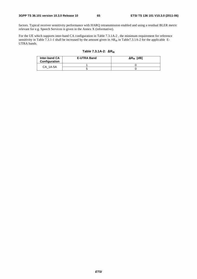
ETSI
ETSI TS 136 101 V10.3.0 (2011-06)653GPP TS 36.101 version 10.3.0 Release 10
factors. Typical receiver sensitivity performance with HARQ retransmission enabled and using a residual BLER metric relevant for e.g. Speech Services is given in the Annex X (informative).
For the UE which supports inter-band CA configuration in Table 7.3.1A-2 , the minimum requirement for reference sensitivity in Table 7.3.1-1 shall be increased by the amount given in ΔRIB in Table7.3.1A-2 for the applicable E-UTRA bands.
Table 7.3.1A-2: ΔRIB
Inter-band CA Configuration
E-UTRA Band ΔRIB [dB]
CA_1A-5A 1 0 5 0
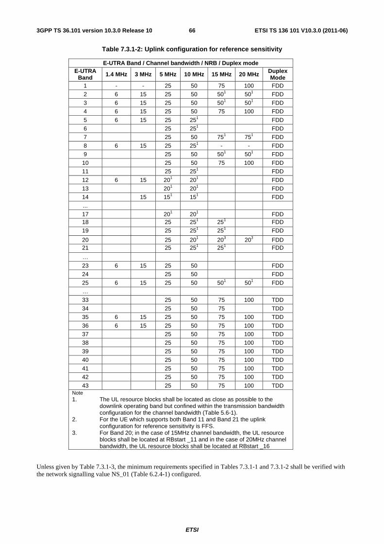
ETSI
ETSI TS 136 101 V10.3.0 (2011-06)663GPP TS 36.101 version 10.3.0 Release 10
Table 7.3.1-2: Uplink configuration for reference sensitivity
E-UTRA Band / Channel bandwidth / NRB / Duplex mode E-UTRA
Band 1.4 MHz 3 MHz 5 MHz 10 MHz 15 MHz 20 MHz Duplex Mode
1 - - 25 50 75 100 FDD
2 6 15 25 50 501 501 FDD
3 6 15 25 50 501 501 FDD
4 6 15 25 50 75 100 FDD
5 6 15 25 251 FDD
6 25 251 FDD
7 25 50 751 751 FDD
8 6 15 25 251 - - FDD
9 25 50 501 501 FDD
10 25 50 75 100 FDD
11 25 251 FDD
12 6 15 201 201 FDD
13 201 201 FDD
14 15 151 151 FDD
...
17 201 201 FDD 18 25 251 251 FDD
19 25 251 251 FDD
20 25 201 203 203 FDD 21 25 251 251 FDD
…
23 6 15 25 50 FDD
24 25 50 FDD
25 6 15 25 50 501 501 FDD
…
33 25 50 75 100 TDD
34 25 50 75 TDD
35 6 15 25 50 75 100 TDD
36 6 15 25 50 75 100 TDD
37 25 50 75 100 TDD
38 25 50 75 100 TDD
39 25 50 75 100 TDD
40 25 50 75 100 TDD
41 25 50 75 100 TDD
42 25 50 75 100 TDD
43 25 50 75 100 TDD Note 1. The UL resource blocks shall be located as close as possible to the
downlink operating band but confined within the transmission bandwidth configuration for the channel bandwidth (Table 5.6-1).
2. For the UE which supports both Band 11 and Band 21 the uplink configuration for reference sensitivity is FFS.
3. For Band 20; in the case of 15MHz channel bandwidth, the UL resource blocks shall be located at RBstart _11 and in the case of 20MHz channel bandwidth, the UL resource blocks shall be located at RBstart _16
Unless given by Table 7.3.1-3, the minimum requirements specified in Tables 7.3.1-1 and 7.3.1-2 shall be verified with the network signalling value NS_01 (Table 6.2.4-1) configured.
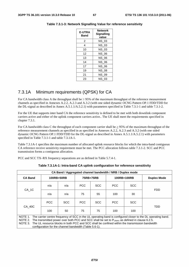
ETSI
ETSI TS 136 101 V10.3.0 (2011-06)673GPP TS 36.101 version 10.3.0 Release 10
Table 7.3.1-3: Network Signalling Value for reference sensitivity
E-UTRA Band
Network Signalling
value 2 NS_03
4 NS_03
10 NS_03
12 NS_06
13 NS_06
14 NS_06
17 NS_06
19 NS_08
21 NS_09
23 NS_03
7.3.1A Minimum requirements (QPSK) for CA
For CA bandwidth class A the throughput shall be ≥ 95% of the maximum throughput of the reference measurement channels as specified in Annexes A.2.2, A.2.3 and A.3.2 (with one sided dynamic OCNG Pattern OP.1 FDD/TDD for the DL-signal as described in Annex A.5.1.1/A.5.2.1) with parameters specified in Table 7.3.1-1 and table 7.3.1-2.
For the UE that supports inter band CA the reference sensitivity is defined to be met with both downlink component carriers active and either of the uplink component carriers active.. The UE shall meet the requirements specified in chapter 7.3.1.
For CA bandwidth class C the throughput of each component carrier shall be ≥ 95% of the maximum throughput of the reference measurement channels as specified in as specified in Annexes A.2.2, A.2.3 and A.3.2 (with one sided dynamic OCNG Pattern OP.1 FDD/TDD for the DL-signal as described in Annex A.5.1.1/A.5.2.1) with parameters specified in Table 7.3.1-1 and table 7.3.1A-1.
Table 7.3.1A-1 specifies the maximum number of allocated uplink resource blocks for which the intra-band contiguous CA reference receive sensitivity requirement must be met. The PCC allocation follows table 7.3.1-2. SCC and PCC transmission forms a contiguous allocation.
PCC and SCC TX–RX frequency separations are as defined in Table 5.7.4-1.
Table 7.3.1A-1: Intra-band CA uplink configuration for reference sensitivity
CA Band / Aggregated channel bandwidth / NRB / Duplex mode
CA Band 100RB+50RB 75RB+75RB 100RB+100RB Duplex Mode
CA_1C
n/a n/a PCC SCC PCC SCC
FDD
n/a n/a 75 55 100 30
CA_40C
PCC SCC PCC SCC PCC SCC
TDD
100 50 75 75 100 100
NOTE 1. The carrier centre frequency of SCC in the UL operating band is configured closer to the DL operating band. NOTE 2. The transmitted power over both PCC and SCC shall be set to PUMAX as defined in clause 6.2.5. NOTE 3. The UL resource blocks in both PCC and SCC shall be confined within the transmission bandwidth
configuration for the channel bandwidth (Table 5.6-1).
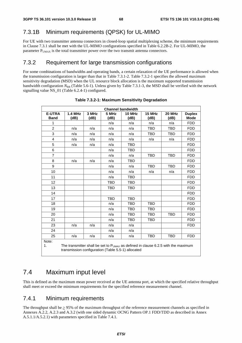
ETSI
ETSI TS 136 101 V10.3.0 (2011-06)683GPP TS 36.101 version 10.3.0 Release 10
7.3.1B Minimum requirements (QPSK) for UL-MIMO
For UE with two transmitter antenna connectors in closed-loop spatial multiplexing scheme, the minimum requirements in Clause 7.3.1 shall be met with the UL-MIMO configurations specified in Table 6.2.2B-2. For UL-MIMO, the parameter PUMAX is the total transmitter power over the two transmit antenna connectors.
7.3.2 Requirement for large transmission configurations
For some combinations of bandwidths and operating bands, a certain relaxation of the UE performance is allowed when the transmission configuration is larger than that in Table 7.3.1-2. Table 7.3.2-1 specifies the allowed maximum sensitivity degradation (MSD) when the UL resource block allocation is the maximum supported transmission bandwidth configuration NRB (Table 5.6-1). Unless given by Table 7.3.1-3, the MSD shall be verified with the network signalling value NS_01 (Table 6.2.4-1) configured.
Table 7.3.2-1: Maximum Sensitivity Degradation
Channel bandwidth E-UTRA
Band 1.4 MHz
(dB) 3 MHz (dB)
5 MHz (dB)
10 MHz (dB)
15 MHz (dB)
20 MHz (dB)
Duplex Mode
1 n/a n/a n/a n/a FDD
2 n/a n/a n/a n/a TBD TBD FDD
3 n/a n/a n/a n/a TBD TBD FDD
4 n/a n/a n/a n/a n/a n/a FDD
5 n/a n/a n/a TBD FDD
6 n/a TBD FDD
7 n/a n/a TBD TBD FDD
8 n/a n/a n/a TBD FDD
9 n/a n/a TBD TBD FDD
10 n/a n/a n/a n/a FDD
11 n/a TBD FDD
12 TBD TBD FDD
13 TBD TBD FDD
14 FDD
17 TBD TBD FDD 18 n/a TBD TBD FDD
19 n/a TBD TBD FDD
20 n/a TBD TBD TBD FDD
21 n/a TBD TBD FDD
23 n/a n/a n/a n/a FDD
24 n/a n/a
25 n/a n/a n/a n/a TBD TBD FDD
Note: 1. The transmitter shall be set to PUMAX as defined in clause 6.2.5 with the maximum
transmission configuration (Table 5.5-1) allocated
7.4 Maximum input level This is defined as the maximum mean power received at the UE antenna port, at which the specified relative throughput shall meet or exceed the minimum requirements for the specified reference measurement channel.
7.4.1 Minimum requirements
The throughput shall be ≥ 95% of the maximum throughput of the reference measurement channels as specified in Annexes A.2.2, A.2.3 and A.3.2 (with one sided dynamic OCNG Pattern OP.1 FDD/TDD as described in Annex A.5.1.1/A.5.2.1) with parameters specified in Table 7.4.1.
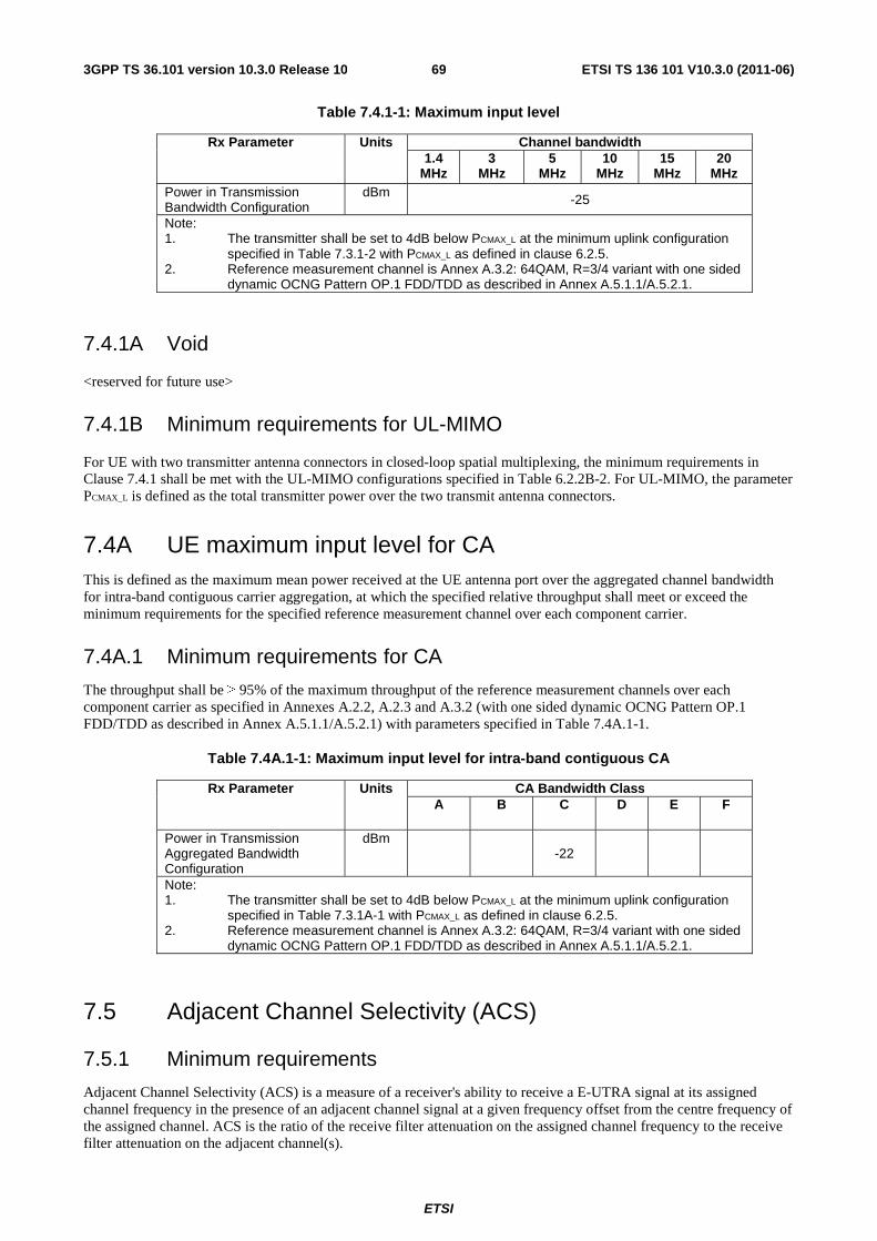
ETSI
ETSI TS 136 101 V10.3.0 (2011-06)693GPP TS 36.101 version 10.3.0 Release 10
Table 7.4.1-1: Maximum input level
Rx Parameter Units Channel bandwidth 1.4
MHz 3
MHz 5
MHz 10
MHz 15
MHz 20
MHz Power in Transmission Bandwidth Configuration
dBm -25
Note: 1. The transmitter shall be set to 4dB below PCMAX_L at the minimum uplink configuration
specified in Table 7.3.1-2 with PCMAX_L as defined in clause 6.2.5. 2. Reference measurement channel is Annex A.3.2: 64QAM, R=3/4 variant with one sided
dynamic OCNG Pattern OP.1 FDD/TDD as described in Annex A.5.1.1/A.5.2.1.
7.4.1A Void
<reserved for future use>
7.4.1B Minimum requirements for UL-MIMO
For UE with two transmitter antenna connectors in closed-loop spatial multiplexing, the minimum requirements in Clause 7.4.1 shall be met with the UL-MIMO configurations specified in Table 6.2.2B-2. For UL-MIMO, the parameter PCMAX_L is defined as the total transmitter power over the two transmit antenna connectors.
7.4A UE maximum input level for CA This is defined as the maximum mean power received at the UE antenna port over the aggregated channel bandwidth for intra-band contiguous carrier aggregation, at which the specified relative throughput shall meet or exceed the minimum requirements for the specified reference measurement channel over each component carrier.
7.4A.1 Minimum requirements for CA
The throughput shall be ≥ 95% of the maximum throughput of the reference measurement channels over each component carrier as specified in Annexes A.2.2, A.2.3 and A.3.2 (with one sided dynamic OCNG Pattern OP.1 FDD/TDD as described in Annex A.5.1.1/A.5.2.1) with parameters specified in Table 7.4A.1-1.
Table 7.4A.1-1: Maximum input level for intra-band contiguous CA
Rx Parameter Units CA Bandwidth Class A B C D E F
Power in Transmission Aggregated Bandwidth Configuration
dBm -22
Note: 1. The transmitter shall be set to 4dB below PCMAX_L at the minimum uplink configuration
specified in Table 7.3.1A-1 with PCMAX_L as defined in clause 6.2.5. 2. Reference measurement channel is Annex A.3.2: 64QAM, R=3/4 variant with one sided
dynamic OCNG Pattern OP.1 FDD/TDD as described in Annex A.5.1.1/A.5.2.1.
7.5 Adjacent Channel Selectivity (ACS)
7.5.1 Minimum requirements
Adjacent Channel Selectivity (ACS) is a measure of a receiver's ability to receive a E-UTRA signal at its assigned channel frequency in the presence of an adjacent channel signal at a given frequency offset from the centre frequency of the assigned channel. ACS is the ratio of the receive filter attenuation on the assigned channel frequency to the receive filter attenuation on the adjacent channel(s).
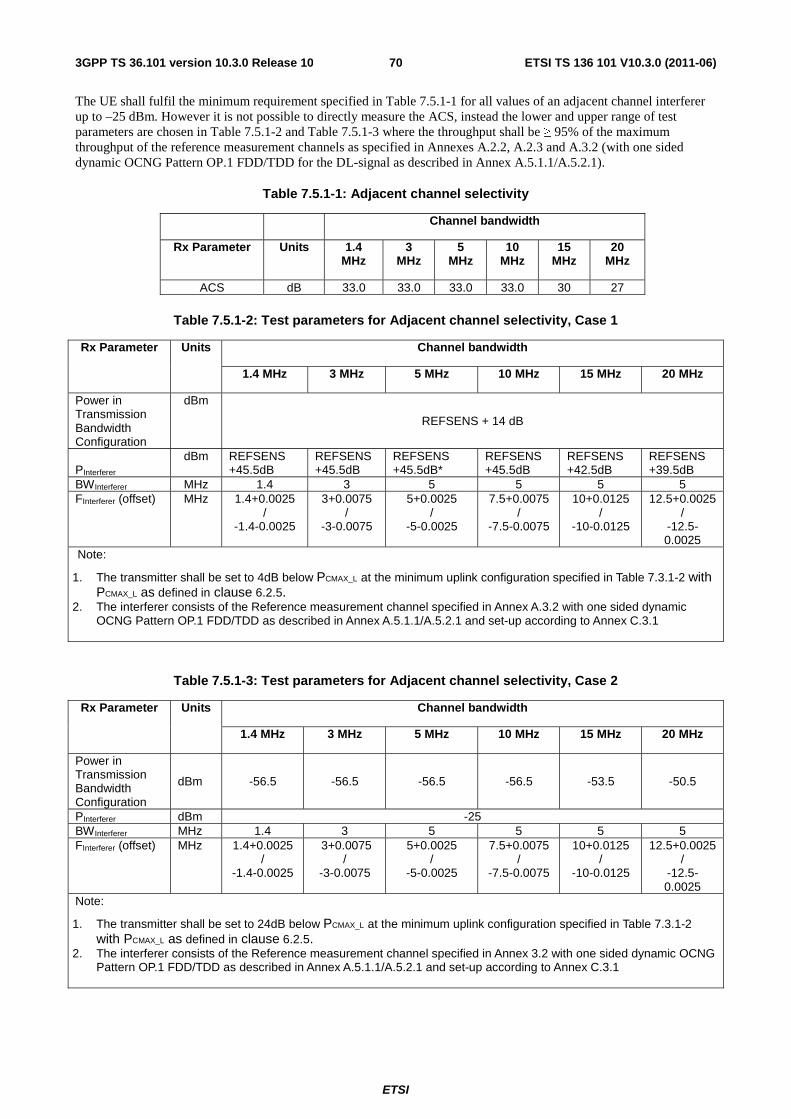
ETSI
ETSI TS 136 101 V10.3.0 (2011-06)703GPP TS 36.101 version 10.3.0 Release 10
The UE shall fulfil the minimum requirement specified in Table 7.5.1-1 for all values of an adjacent channel interferer up to –25 dBm. However it is not possible to directly measure the ACS, instead the lower and upper range of test parameters are chosen in Table 7.5.1-2 and Table 7.5.1-3 where the throughput shall be ≥ 95% of the maximum throughput of the reference measurement channels as specified in Annexes A.2.2, A.2.3 and A.3.2 (with one sided dynamic OCNG Pattern OP.1 FDD/TDD for the DL-signal as described in Annex A.5.1.1/A.5.2.1).
Table 7.5.1-1: Adjacent channel selectivity
Channel bandwidth
Rx Parameter Units 1.4 MHz
3 MHz
5 MHz
10 MHz
15 MHz
20 MHz
ACS dB 33.0 33.0 33.0 33.0 30 27
Table 7.5.1-2: Test parameters for Adjacent channel selectivity, Case 1
Rx Parameter Units Channel bandwidth
1.4 MHz 3 MHz 5 MHz 10 MHz 15 MHz 20 MHz
Power in Transmission Bandwidth Configuration
dBm
REFSENS + 14 dB
PInterferer dBm REFSENS
+45.5dB REFSENS +45.5dB
REFSENS +45.5dB*
REFSENS +45.5dB
REFSENS +42.5dB
REFSENS +39.5dB
BWInterferer MHz 1.4 3 5 5 5 5 FInterferer (offset) MHz 1.4+0.0025
/ -1.4-0.0025
3+0.0075 /
-3-0.0075
5+0.0025 /
-5-0.0025
7.5+0.0075 /
-7.5-0.0075
10+0.0125 /
-10-0.0125
12.5+0.0025 /
-12.5-0.0025
Note:
1. The transmitter shall be set to 4dB below PCMAX_L at the minimum uplink configuration specified in Table 7.3.1-2 with PCMAX_L as defined in clause 6.2.5.
2. The interferer consists of the Reference measurement channel specified in Annex A.3.2 with one sided dynamic OCNG Pattern OP.1 FDD/TDD as described in Annex A.5.1.1/A.5.2.1 and set-up according to Annex C.3.1
Table 7.5.1-3: Test parameters for Adjacent channel selectivity, Case 2
Rx Parameter Units Channel bandwidth
1.4 MHz 3 MHz 5 MHz 10 MHz 15 MHz 20 MHz
Power in Transmission Bandwidth Configuration
dBm -56.5 -56.5 -56.5 -56.5 -53.5 -50.5
PInterferer dBm -25 BWInterferer MHz 1.4 3 5 5 5 5 FInterferer (offset) MHz 1.4+0.0025
/ -1.4-0.0025
3+0.0075 /
-3-0.0075
5+0.0025 /
-5-0.0025
7.5+0.0075 /
-7.5-0.0075
10+0.0125 /
-10-0.0125
12.5+0.0025 /
-12.5-0.0025
Note:
1. The transmitter shall be set to 24dB below PCMAX_L at the minimum uplink configuration specified in Table 7.3.1-2 with PCMAX_L as defined in clause 6.2.5.
2. The interferer consists of the Reference measurement channel specified in Annex 3.2 with one sided dynamic OCNG Pattern OP.1 FDD/TDD as described in Annex A.5.1.1/A.5.2.1 and set-up according to Annex C.3.1
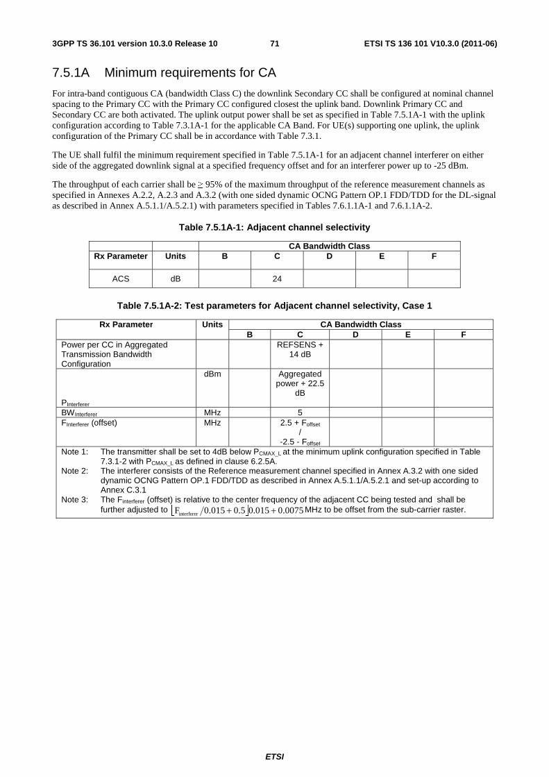
ETSI
ETSI TS 136 101 V10.3.0 (2011-06)713GPP TS 36.101 version 10.3.0 Release 10
7.5.1A Minimum requirements for CA
For intra-band contiguous CA (bandwidth Class C) the downlink Secondary CC shall be configured at nominal channel spacing to the Primary CC with the Primary CC configured closest the uplink band. Downlink Primary CC and Secondary CC are both activated. The uplink output power shall be set as specified in Table 7.5.1A-1 with the uplink configuration according to Table 7.3.1A-1 for the applicable CA Band. For UE(s) supporting one uplink, the uplink configuration of the Primary CC shall be in accordance with Table 7.3.1.
The UE shall fulfil the minimum requirement specified in Table 7.5.1A-1 for an adjacent channel interferer on either side of the aggregated downlink signal at a specified frequency offset and for an interferer power up to -25 dBm.
The throughput of each carrier shall be ≥ 95% of the maximum throughput of the reference measurement channels as specified in Annexes A.2.2, A.2.3 and A.3.2 (with one sided dynamic OCNG Pattern OP.1 FDD/TDD for the DL-signal as described in Annex A.5.1.1/A.5.2.1) with parameters specified in Tables 7.6.1.1A-1 and 7.6.1.1A-2.
Table 7.5.1A-1: Adjacent channel selectivity
CA Bandwidth Class Rx Parameter Units B C D E F
ACS dB 24
Table 7.5.1A-2: Test parameters for Adjacent channel selectivity, Case 1
Rx Parameter Units CA Bandwidth Class B C D E F
Power per CC in Aggregated Transmission Bandwidth Configuration
REFSENS + 14 dB
PInterferer
dBm Aggregated power + 22.5
dB
BWInterferer MHz 5 FInterferer (offset)
MHz 2.5 + Foffset /
-2.5 - Foffset
Note 1: The transmitter shall be set to 4dB below PCMAX_L at the minimum uplink configuration specified in Table 7.3.1-2 with PCMAX_L as defined in clause 6.2.5A.
Note 2: The interferer consists of the Reference measurement channel specified in Annex A.3.2 with one sided dynamic OCNG Pattern OP.1 FDD/TDD as described in Annex A.5.1.1/A.5.2.1 and set-up according to Annex C.3.1
Note 3: The Finterferer (offset) is relative to the center frequency of the adjacent CC being tested and shall be further adjusted to ⎣ ⎦ 0075.0015.00.50.015Finterferer ++ MHz to be offset from the sub-carrier raster.
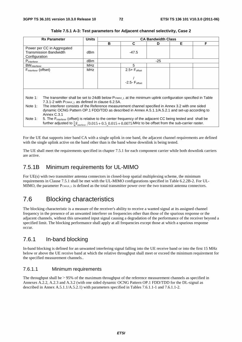
ETSI
ETSI TS 136 101 V10.3.0 (2011-06)723GPP TS 36.101 version 10.3.0 Release 10
Table 7.5.1 A-3: Test parameters for Adjacent channel selectivity, Case 2
Rx Parameter Units CA Bandwidth Class B C D E F
Power per CC in Aggregated Transmission Bandwidth Configuration
dBm -47.5
PInterferer dBm -25 BWInterferer MHz 5 FInterferer (offset)
MHz 2.5+ Foffset
/
-2.5- Foffset
Note 1: The transmitter shall be set to 24dB below PCMAX_L at the minimum uplink configuration specified in Table 7.3.1-2 with PCMAX_L as defined in clause 6.2.5A.
Note 1: The interferer consists of the Reference measurement channel specified in Annex 3.2 with one sided dynamic OCNG Pattern OP.1 FDD/TDD as described in Annex A.5.1.1/A.5.2.1 and set-up according to Annex C.3.1
Note 1: 5. The Finterferer (offset) is relative to the center frequency of the adjacent CC being tested and shall be further adjusted to ⎣ ⎦ 0075.0015.00.50.015Finterferer ++ MHz to be offset from the sub-carrier raster.
For the UE that supports inter band CA with a single uplink in one band, the adjacent channel requirements are defined with the single uplink active on the band other than is the band whose downlink is being tested.
The UE shall meet the requirements specified in chapter 7.5.1 for each component carrier while both downlink carriers are active.
7.5.1B Minimum requirements for UL-MIMO
For UE(s) with two transmitter antenna connectors in closed-loop spatial multiplexing scheme, the minimum requirements in Clause 7.5.1 shall be met with the UL-MIMO configurations specified in Table 6.2.2B-2. For UL-MIMO, the parameter PCMAX_L is defined as the total transmitter power over the two transmit antenna connectors.
7.6 Blocking characteristics The blocking characteristic is a measure of the receiver's ability to receive a wanted signal at its assigned channel frequency in the presence of an unwanted interferer on frequencies other than those of the spurious response or the adjacent channels, without this unwanted input signal causing a degradation of the performance of the receiver beyond a specified limit. The blocking performance shall apply at all frequencies except those at which a spurious response occur.
7.6.1 In-band blocking
In-band blocking is defined for an unwanted interfering signal falling into the UE receive band or into the first 15 MHz below or above the UE receive band at which the relative throughput shall meet or exceed the minimum requirement for the specified measurement channels..
7.6.1.1 Minimum requirements
The throughput shall be ≥ 95% of the maximum throughput of the reference measurement channels as specified in Annexes A.2.2, A.2.3 and A.3.2 (with one sided dynamic OCNG Pattern OP.1 FDD/TDD for the DL-signal as described in Annex A.5.1.1/A.5.2.1) with parameters specified in Tables 7.6.1.1-1 and 7.6.1.1-2.
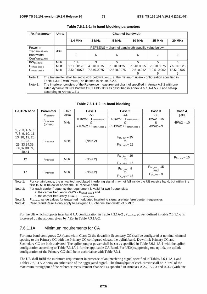
ETSI
ETSI TS 136 101 V10.3.0 (2011-06)733GPP TS 36.101 version 10.3.0 Release 10
Table 7.6.1.1-1: In band blocking parameters
Rx Parameter Units Channel bandwidth
1.4 MHz 3 MHz 5 MHz 10 MHz 15 MHz 20 MHz
Power in Transmission Bandwidth Configuration
dBm
REFSENS + channel bandwidth specific value below
6 6 6 6 7 9
BWInterferer MHz 1.4 3 5 5 5 5 FIoffset, case 1 MHz 2.1+0.0125 4.5+0.0075 7.5+0.0125 7.5+0.0025 7.5+0.0075 7.5+0.0125 FIoffset, case 2 MHz 3.5+0.0075 7.5+0.0075 12.5+0.0075 12.5+0.012
5 12.5+0.002
5 12.5+0.007
5 Note 1: The transmitter shall be set to 4dB below PCMAX_L at the minimum uplink configuration specified in
Table 7.3.1-2 with PCMAX_L as defined in clause 6.2.5. Note 2: The interferer consists of the Reference measurement channel specified in Annex A.3.2 with one
sided dynamic OCNG Pattern OP.1 FDD/TDD as described in Annex A.5.1.1/A.5.2.1 and set-up according to Annex C.3.1
Table 7.6.1.1-2: In-band blocking
E-UTRA band Parameter Unit Case 1 Case 2 Case 3 Case 4 PInterferer dBm -56 -44 -30 [-30]
FInterferer (offset) MHz
=-BW/2 – FIoffset,case 1 &
=+BW/2 + FIoffset,case 1
≤-BW/2 – FIoffset,case 2 &
≥+BW/2 + FIoffset,case 2
-BW/2 – 15 &
-BW/2 – 9 -BW/2 – 10
1, 2, 3, 4, 5, 6, 7, 8, 9, 10, 11, 13, 18, 19, 20,
21, 23, 25, 33,34,35, 36,37,38,39,
40,41
FInterferer MHz (Note 2) FDL_low – 15
to FDL_high + 15
12 FInterferer MHz (Note 2) FDL_low – 10
to FDL_high + 15
FDL_low – 10
17 FInterferer MHz (Note 2) FDL_low – 9
to FDL_high + 15
FDL_low – 15 and
FDL_low – 9
Note 1: For certain bands, the unwanted modulated interfering signal may not fall inside the UE receive band, but within the first 15 MHz below or above the UE receive band
Note 2: For each carrier frequency the requirement is valid for two frequencies: a. the carrier frequency -BW/2 - FIoffset, case 1 and b. the carrier frequency +BW/2 + FIoffset, case 1
Note 3: FInterferer range values for unwanted modulated interfering signal are interferer center frequencies Note 4: Case 3 and Case 4 only apply to assigned UE channel bandwidth of 5 MHz
For the UE which supports inter band CA configuration in Table 7.3.1A-2 , PInterferer power defined in table 7.6.1.1-2 is increased by the amount given by ΔRIB in Table 7.3.1A-2.
7.6.1.1A Minimum requirements for CA
For intra-band contiguous CA (bandwidth Class C) the downlink Secondary CC shall be configured at nominal channel spacing to the Primary CC with the Primary CC configured closest the uplink band. Downlink Primary CC and Secondary CC are both activated. The uplink output power shall be set as specified in Table 7.6.1.1A-1 with the uplink configuration according to Table 7.3.1A-1 for the applicable CA Band. For UE(s) supporting one uplink, the uplink configuration of the Primary CC shall be in accordance with Table 7.3.1.
The UE shall fulfil the minimum requirement in presence of an interfering signal specified in Tables 7.6.1.1A-1 and Tables 7.6.1.1A-2 being on either side of the aggregated signal. The throughput of each carrier shall be ≥ 95% of the maximum throughput of the reference measurement channels as specified in Annexes A.2.2, A.2.3 and A.3.2 (with one
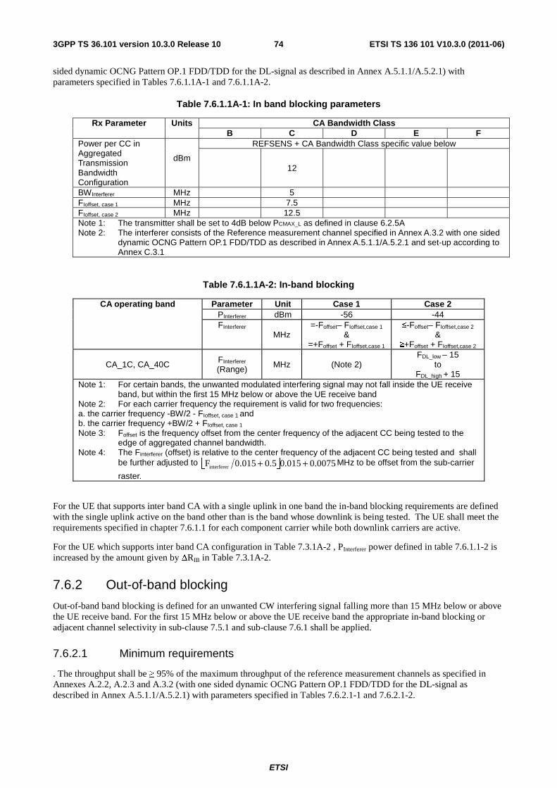
ETSI
ETSI TS 136 101 V10.3.0 (2011-06)743GPP TS 36.101 version 10.3.0 Release 10
sided dynamic OCNG Pattern OP.1 FDD/TDD for the DL-signal as described in Annex A.5.1.1/A.5.2.1) with parameters specified in Tables 7.6.1.1A-1 and 7.6.1.1A-2.
Table 7.6.1.1A-1: In band blocking parameters
Rx Parameter Units CA Bandwidth Class B C D E F
Power per CC in Aggregated Transmission Bandwidth Configuration
dBm
REFSENS + CA Bandwidth Class specific value below
12
BWInterferer MHz 5 FIoffset, case 1 MHz 7.5 FIoffset, case 2 MHz 12.5 Note 1: The transmitter shall be set to 4dB below PCMAX_L as defined in clause 6.2.5A Note 2: The interferer consists of the Reference measurement channel specified in Annex A.3.2 with one sided
dynamic OCNG Pattern OP.1 FDD/TDD as described in Annex A.5.1.1/A.5.2.1 and set-up according to Annex C.3.1
Table 7.6.1.1A-2: In-band blocking
CA operating band Parameter Unit Case 1 Case 2 PInterferer dBm -56 -44 FInterferer
MHz =-Foffset– FIoffset,case 1
& =+Foffset + FIoffset,case 1
≤-Foffset– FIoffset,case 2 &
≥+Foffset + FIoffset,case 2
CA_1C, CA_40C FInterferer (Range) MHz (Note 2)
FDL_low – 15 to
FDL_high + 15 Note 1: For certain bands, the unwanted modulated interfering signal may not fall inside the UE receive
band, but within the first 15 MHz below or above the UE receive band Note 2: For each carrier frequency the requirement is valid for two frequencies: a. the carrier frequency -BW/2 - FIoffset, case 1 and b. the carrier frequency +BW/2 + FIoffset, case 1 Note 3: Foffset is the frequency offset from the center frequency of the adjacent CC being tested to the
edge of aggregated channel bandwidth. Note 4: The Finterferer (offset) is relative to the center frequency of the adjacent CC being tested and shall
be further adjusted to ⎣ ⎦ 0075.0015.05.00.015Finterferer ++ MHz to be offset from the sub-carrier
raster.
For the UE that supports inter band CA with a single uplink in one band the in-band blocking requirements are defined with the single uplink active on the band other than is the band whose downlink is being tested. The UE shall meet the requirements specified in chapter 7.6.1.1 for each component carrier while both downlink carriers are active.
For the UE which supports inter band CA configuration in Table 7.3.1A-2 , PInterferer power defined in table 7.6.1.1-2 is increased by the amount given by ΔRIB in Table 7.3.1A-2.
7.6.2 Out-of-band blocking
Out-of-band band blocking is defined for an unwanted CW interfering signal falling more than 15 MHz below or above the UE receive band. For the first 15 MHz below or above the UE receive band the appropriate in-band blocking or adjacent channel selectivity in sub-clause 7.5.1 and sub-clause 7.6.1 shall be applied.
7.6.2.1 Minimum requirements
. The throughput shall be ≥ 95% of the maximum throughput of the reference measurement channels as specified in Annexes A.2.2, A.2.3 and A.3.2 (with one sided dynamic OCNG Pattern OP.1 FDD/TDD for the DL-signal as described in Annex A.5.1.1/A.5.2.1) with parameters specified in Tables 7.6.2.1-1 and 7.6.2.1-2.
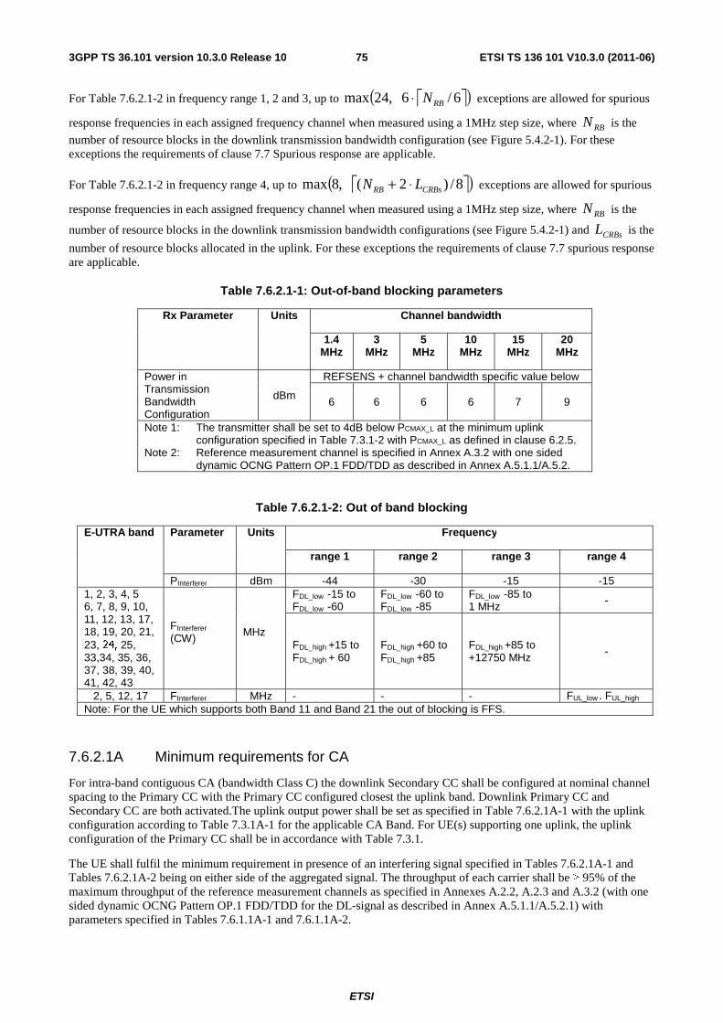
ETSI
ETSI TS 136 101 V10.3.0 (2011-06)753GPP TS 36.101 version 10.3.0 Release 10
For Table 7.6.2.1-2 in frequency range 1, 2 and 3, up to ⎡ ⎤( )6/6,24max RBN⋅ exceptions are allowed for spurious
response frequencies in each assigned frequency channel when measured using a 1MHz step size, where RBN is the
number of resource blocks in the downlink transmission bandwidth configuration (see Figure 5.4.2-1). For these exceptions the requirements of clause 7.7 Spurious response are applicable.
For Table 7.6.2.1-2 in frequency range 4, up to ⎡ ⎤( )8/)2(,8max CRBsRB LN ⋅+ exceptions are allowed for spurious
response frequencies in each assigned frequency channel when measured using a 1MHz step size, where RBN is the
number of resource blocks in the downlink transmission bandwidth configurations (see Figure 5.4.2-1) and CRBsL is the
number of resource blocks allocated in the uplink. For these exceptions the requirements of clause 7.7 spurious response are applicable.
Table 7.6.2.1-1: Out-of-band blocking parameters
Rx Parameter Units Channel bandwidth
1.4 MHz
3 MHz
5 MHz
10 MHz
15 MHz
20 MHz
Power in Transmission Bandwidth Configuration
dBm
REFSENS + channel bandwidth specific value below
6 6 6 6 7 9
Note 1: The transmitter shall be set to 4dB below PCMAX_L at the minimum uplink configuration specified in Table 7.3.1-2 with PCMAX_L as defined in clause 6.2.5.
Note 2: Reference measurement channel is specified in Annex A.3.2 with one sided dynamic OCNG Pattern OP.1 FDD/TDD as described in Annex A.5.1.1/A.5.2.
Table 7.6.2.1-2: Out of band blocking
E-UTRA band Parameter Units Frequency
range 1 range 2 range 3 range 4
PInterferer dBm -44 -30 -15 -15 1, 2, 3, 4, 5 6, 7, 8, 9, 10, 11, 12, 13, 17, 18, 19, 20, 21, 23, 24, 25, 33,34, 35, 36, 37, 38, 39, 40, 41, 42, 43
FInterferer
(CW)
MHz
FDL_low -15 to FDL_low -60
FDL_low -60 to FDL_low -85
FDL_low -85 to 1 MHz -
FDL_high +15 to FDL_high + 60
FDL_high +60 to FDL_high +85
FDL_high +85 to +12750 MHz -
2, 5, 12, 17 FInterferer MHz - - - FUL_low - FUL_high Note: For the UE which supports both Band 11 and Band 21 the out of blocking is FFS.
7.6.2.1A Minimum requirements for CA
For intra-band contiguous CA (bandwidth Class C) the downlink Secondary CC shall be configured at nominal channel spacing to the Primary CC with the Primary CC configured closest the uplink band. Downlink Primary CC and Secondary CC are both activated.The uplink output power shall be set as specified in Table 7.6.2.1A-1 with the uplink configuration according to Table 7.3.1A-1 for the applicable CA Band. For UE(s) supporting one uplink, the uplink configuration of the Primary CC shall be in accordance with Table 7.3.1.
The UE shall fulfil the minimum requirement in presence of an interfering signal specified in Tables 7.6.2.1A-1 and Tables 7.6.2.1A-2 being on either side of the aggregated signal. The throughput of each carrier shall be ≥ 95% of the maximum throughput of the reference measurement channels as specified in Annexes A.2.2, A.2.3 and A.3.2 (with one sided dynamic OCNG Pattern OP.1 FDD/TDD for the DL-signal as described in Annex A.5.1.1/A.5.2.1) with parameters specified in Tables 7.6.1.1A-1 and 7.6.1.1A-2.
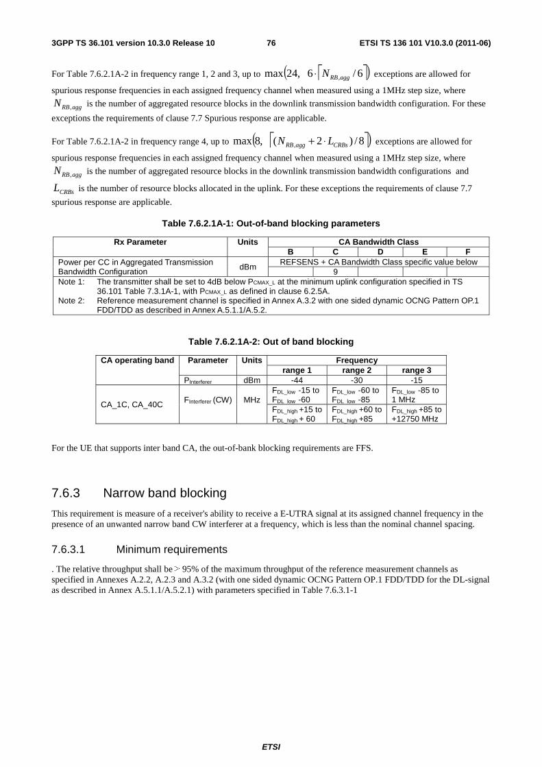
ETSI
ETSI TS 136 101 V10.3.0 (2011-06)763GPP TS 36.101 version 10.3.0 Release 10
For Table 7.6.2.1A-2 in frequency range 1, 2 and 3, up to ⎡ ⎤( )6/6,24max ,aggRBN⋅ exceptions are allowed for
spurious response frequencies in each assigned frequency channel when measured using a 1MHz step size, where
aggRBN , is the number of aggregated resource blocks in the downlink transmission bandwidth configuration. For these
exceptions the requirements of clause 7.7 Spurious response are applicable.
For Table 7.6.2.1A-2 in frequency range 4, up to ⎡ ⎤( )8/)2(,8max , CRBsaggRB LN ⋅+ exceptions are allowed for
spurious response frequencies in each assigned frequency channel when measured using a 1MHz step size, where
aggRBN , is the number of aggregated resource blocks in the downlink transmission bandwidth configurations and
CRBsL is the number of resource blocks allocated in the uplink. For these exceptions the requirements of clause 7.7
spurious response are applicable.
Table 7.6.2.1A-1: Out-of-band blocking parameters
Rx Parameter Units CA Bandwidth Class B C D E F
Power per CC in Aggregated Transmission Bandwidth Configuration dBm
REFSENS + CA Bandwidth Class specific value below 9
Note 1: The transmitter shall be set to 4dB below PCMAX_L at the minimum uplink configuration specified in TS 36.101 Table 7.3.1A-1, with PCMAX_L as defined in clause 6.2.5A.
Note 2: Reference measurement channel is specified in Annex A.3.2 with one sided dynamic OCNG Pattern OP.1 FDD/TDD as described in Annex A.5.1.1/A.5.2.
Table 7.6.2.1A-2: Out of band blocking
CA operating band Parameter Units Frequency range 1 range 2 range 3
PInterferer dBm -44 -30 -15
CA_1C, CA_40C FInterferer (CW)
MHz
FDL_low -15 to FDL_low -60
FDL_low -60 to FDL_low -85
FDL_low -85 to 1 MHz
FDL_high +15 to FDL_high + 60
FDL_high +60 to FDL_high +85
FDL_high +85 to +12750 MHz
For the UE that supports inter band CA, the out-of-bank blocking requirements are FFS.
7.6.3 Narrow band blocking
This requirement is measure of a receiver's ability to receive a E-UTRA signal at its assigned channel frequency in the presence of an unwanted narrow band CW interferer at a frequency, which is less than the nominal channel spacing.
7.6.3.1 Minimum requirements
. The relative throughput shall be ≥ 95% of the maximum throughput of the reference measurement channels as specified in Annexes A.2.2, A.2.3 and A.3.2 (with one sided dynamic OCNG Pattern OP.1 FDD/TDD for the DL-signal as described in Annex A.5.1.1/A.5.2.1) with parameters specified in Table 7.6.3.1-1
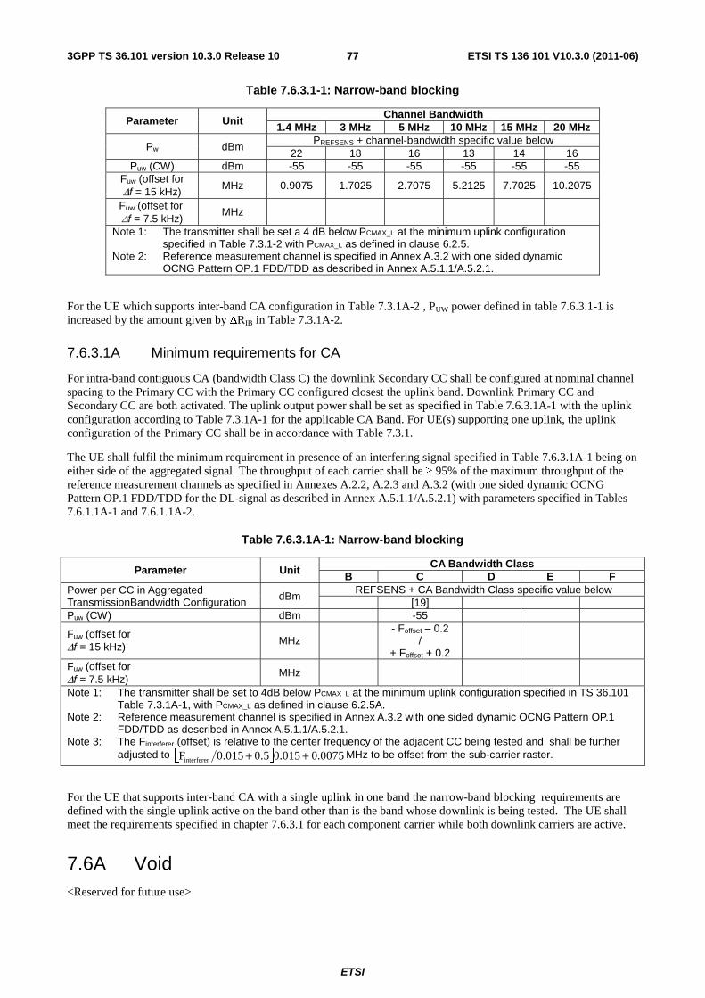
ETSI
ETSI TS 136 101 V10.3.0 (2011-06)773GPP TS 36.101 version 10.3.0 Release 10
Table 7.6.3.1-1: Narrow-band blocking
Parameter Unit Channel Bandwidth
1.4 MHz 3 MHz 5 MHz 10 MHz 15 MHz 20 MHz
Pw dBm PREFSENS + channel-bandwidth specific value below
22 18 16 13 14 16 Puw (CW) dBm -55 -55 -55 -55 -55 -55
Fuw (offset for Δf = 15 kHz)
MHz 0.9075 1.7025 2.7075 5.2125 7.7025 10.2075
Fuw (offset for Δf = 7.5 kHz) MHz
Note 1: The transmitter shall be set a 4 dB below PCMAX_L at the minimum uplink configuration specified in Table 7.3.1-2 with PCMAX_L as defined in clause 6.2.5.
Note 2: Reference measurement channel is specified in Annex A.3.2 with one sided dynamic OCNG Pattern OP.1 FDD/TDD as described in Annex A.5.1.1/A.5.2.1.
For the UE which supports inter-band CA configuration in Table 7.3.1A-2 , PUW power defined in table 7.6.3.1-1 is increased by the amount given by ΔRIB in Table 7.3.1A-2.
7.6.3.1A Minimum requirements for CA
For intra-band contiguous CA (bandwidth Class C) the downlink Secondary CC shall be configured at nominal channel spacing to the Primary CC with the Primary CC configured closest the uplink band. Downlink Primary CC and Secondary CC are both activated. The uplink output power shall be set as specified in Table 7.6.3.1A-1 with the uplink configuration according to Table 7.3.1A-1 for the applicable CA Band. For UE(s) supporting one uplink, the uplink configuration of the Primary CC shall be in accordance with Table 7.3.1.
The UE shall fulfil the minimum requirement in presence of an interfering signal specified in Table 7.6.3.1A-1 being on either side of the aggregated signal. The throughput of each carrier shall be ≥ 95% of the maximum throughput of the reference measurement channels as specified in Annexes A.2.2, A.2.3 and A.3.2 (with one sided dynamic OCNG Pattern OP.1 FDD/TDD for the DL-signal as described in Annex A.5.1.1/A.5.2.1) with parameters specified in Tables 7.6.1.1A-1 and 7.6.1.1A-2.
Table 7.6.3.1A-1: Narrow-band blocking
Parameter Unit CA Bandwidth Class
B C D E F Power per CC in Aggregated TransmissionBandwidth Configuration dBm
REFSENS + CA Bandwidth Class specific value below [19]
Puw (CW) dBm -55
Fuw (offset for Δf = 15 kHz)
MHz - Foffset – 0.2
/ + Foffset + 0.2
Fuw (offset for Δf = 7.5 kHz) MHz
Note 1: The transmitter shall be set to 4dB below PCMAX_L at the minimum uplink configuration specified in TS 36.101 Table 7.3.1A-1, with PCMAX_L as defined in clause 6.2.5A.
Note 2: Reference measurement channel is specified in Annex A.3.2 with one sided dynamic OCNG Pattern OP.1 FDD/TDD as described in Annex A.5.1.1/A.5.2.1.
Note 3: The Finterferer (offset) is relative to the center frequency of the adjacent CC being tested and shall be further adjusted to ⎣ ⎦ 0075.0015.00.5 0.015Finterferer ++ MHz to be offset from the sub-carrier raster.
For the UE that supports inter-band CA with a single uplink in one band the narrow-band blocking requirements are defined with the single uplink active on the band other than is the band whose downlink is being tested. The UE shall meet the requirements specified in chapter 7.6.3.1 for each component carrier while both downlink carriers are active.
7.6A Void <Reserved for future use>
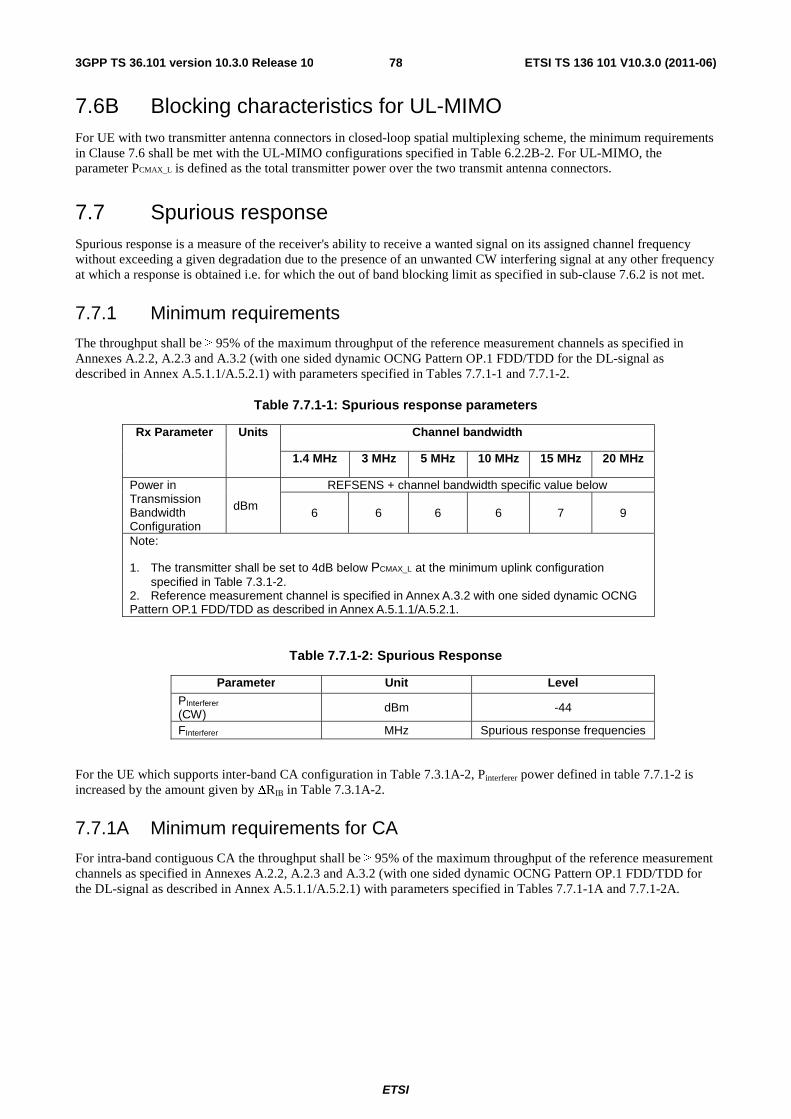
ETSI
ETSI TS 136 101 V10.3.0 (2011-06)783GPP TS 36.101 version 10.3.0 Release 10
7.6B Blocking characteristics for UL-MIMO For UE with two transmitter antenna connectors in closed-loop spatial multiplexing scheme, the minimum requirements in Clause 7.6 shall be met with the UL-MIMO configurations specified in Table 6.2.2B-2. For UL-MIMO, the parameter PCMAX_L is defined as the total transmitter power over the two transmit antenna connectors.
7.7 Spurious response Spurious response is a measure of the receiver's ability to receive a wanted signal on its assigned channel frequency without exceeding a given degradation due to the presence of an unwanted CW interfering signal at any other frequency at which a response is obtained i.e. for which the out of band blocking limit as specified in sub-clause 7.6.2 is not met.
7.7.1 Minimum requirements
The throughput shall be ≥ 95% of the maximum throughput of the reference measurement channels as specified in Annexes A.2.2, A.2.3 and A.3.2 (with one sided dynamic OCNG Pattern OP.1 FDD/TDD for the DL-signal as described in Annex A.5.1.1/A.5.2.1) with parameters specified in Tables 7.7.1-1 and 7.7.1-2.
Table 7.7.1-1: Spurious response parameters
Rx Parameter Units Channel bandwidth
1.4 MHz 3 MHz 5 MHz 10 MHz 15 MHz 20 MHz
Power in Transmission Bandwidth Configuration
dBm
REFSENS + channel bandwidth specific value below
6 6 6 6 7 9
Note:
1. The transmitter shall be set to 4dB below PCMAX_L at the minimum uplink configuration specified in Table 7.3.1-2. 2. Reference measurement channel is specified in Annex A.3.2 with one sided dynamic OCNG Pattern OP.1 FDD/TDD as described in Annex A.5.1.1/A.5.2.1.
Table 7.7.1-2: Spurious Response
Parameter Unit Level
PInterferer
(CW) dBm -44
FInterferer MHz Spurious response frequencies
For the UE which supports inter-band CA configuration in Table 7.3.1A-2, Pinterferer power defined in table 7.7.1-2 is increased by the amount given by ΔRIB in Table 7.3.1A-2.
7.7.1A Minimum requirements for CA
For intra-band contiguous CA the throughput shall be ≥ 95% of the maximum throughput of the reference measurement channels as specified in Annexes A.2.2, A.2.3 and A.3.2 (with one sided dynamic OCNG Pattern OP.1 FDD/TDD for the DL-signal as described in Annex A.5.1.1/A.5.2.1) with parameters specified in Tables 7.7.1-1A and 7.7.1-2A.
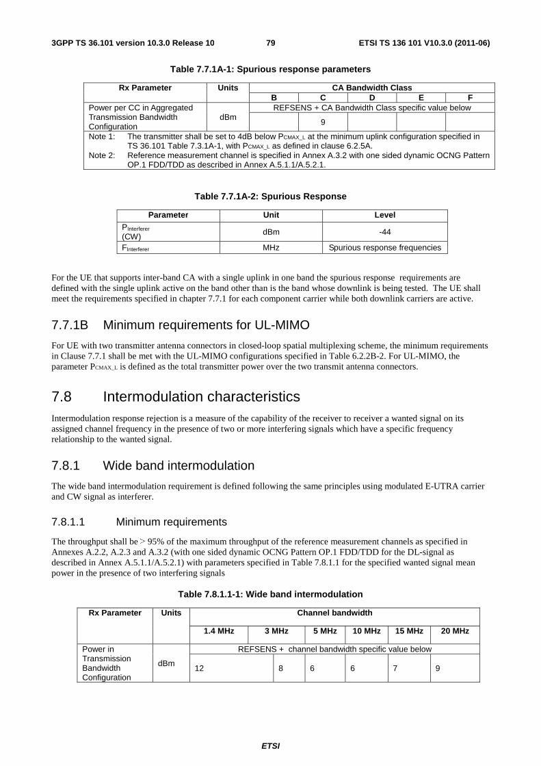
ETSI
ETSI TS 136 101 V10.3.0 (2011-06)793GPP TS 36.101 version 10.3.0 Release 10
Table 7.7.1A-1: Spurious response parameters
Rx Parameter Units CA Bandwidth Class B C D E F
Power per CC in Aggregated Transmission Bandwidth Configuration
dBm REFSENS + CA Bandwidth Class specific value below
9
Note 1: The transmitter shall be set to 4dB below PCMAX_L at the minimum uplink configuration specified in TS 36.101 Table 7.3.1A-1, with PCMAX_L as defined in clause 6.2.5A.
Note 2: Reference measurement channel is specified in Annex A.3.2 with one sided dynamic OCNG Pattern OP.1 FDD/TDD as described in Annex A.5.1.1/A.5.2.1.
Table 7.7.1A-2: Spurious Response
Parameter Unit Level
PInterferer
(CW) dBm -44
FInterferer MHz Spurious response frequencies
For the UE that supports inter-band CA with a single uplink in one band the spurious response requirements are defined with the single uplink active on the band other than is the band whose downlink is being tested. The UE shall meet the requirements specified in chapter 7.7.1 for each component carrier while both downlink carriers are active.
7.7.1B Minimum requirements for UL-MIMO
For UE with two transmitter antenna connectors in closed-loop spatial multiplexing scheme, the minimum requirements in Clause 7.7.1 shall be met with the UL-MIMO configurations specified in Table 6.2.2B-2. For UL-MIMO, the parameter PCMAX_L is defined as the total transmitter power over the two transmit antenna connectors.
7.8 Intermodulation characteristics Intermodulation response rejection is a measure of the capability of the receiver to receiver a wanted signal on its assigned channel frequency in the presence of two or more interfering signals which have a specific frequency relationship to the wanted signal.
7.8.1 Wide band intermodulation
The wide band intermodulation requirement is defined following the same principles using modulated E-UTRA carrier and CW signal as interferer.
7.8.1.1 Minimum requirements
The throughput shall be ≥ 95% of the maximum throughput of the reference measurement channels as specified in Annexes A.2.2, A.2.3 and A.3.2 (with one sided dynamic OCNG Pattern OP.1 FDD/TDD for the DL-signal as described in Annex A.5.1.1/A.5.2.1) with parameters specified in Table 7.8.1.1 for the specified wanted signal mean power in the presence of two interfering signals
Table 7.8.1.1-1: Wide band intermodulation
Rx Parameter Units Channel bandwidth
1.4 MHz 3 MHz 5 MHz 10 MHz 15 MHz 20 MHz
Power in Transmission Bandwidth Configuration
dBm
REFSENS + channel bandwidth specific value below
12 8 6 6 7 9
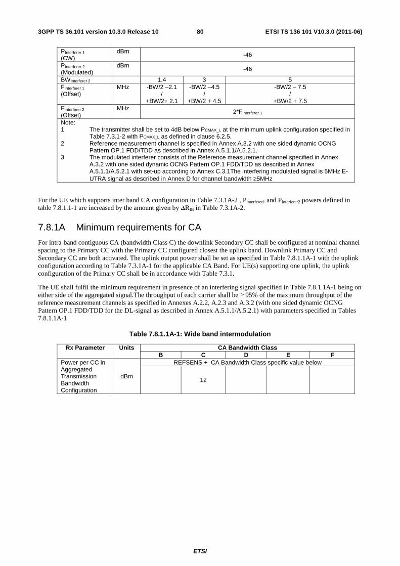
ETSI
ETSI TS 136 101 V10.3.0 (2011-06)803GPP TS 36.101 version 10.3.0 Release 10
PInterferer 1 (CW)
dBm -46
PInterferer 2 (Modulated)
dBm -46
BWInterferer 2 1.4 3 5 FInterferer 1 (Offset)
MHz -BW/2 –2.1 /
+BW/2+ 2.1
-BW/2 –4.5 /
+BW/2 + 4.5
-BW/2 – 7.5 /
+BW/2 + 7.5 FInterferer 2 (Offset)
MHz 2*FInterferer 1
Note: 1 The transmitter shall be set to 4dB below PCMAX_L at the minimum uplink configuration specified in
Table 7.3.1-2 with PCMAX_L as defined in clause 6.2.5. 2 Reference measurement channel is specified in Annex A.3.2 with one sided dynamic OCNG
Pattern OP.1 FDD/TDD as described in Annex A.5.1.1/A.5.2.1. 3 The modulated interferer consists of the Reference measurement channel specified in Annex
A.3.2 with one sided dynamic OCNG Pattern OP.1 FDD/TDD as described in Annex A.5.1.1/A.5.2.1 with set-up according to Annex C.3.1The interfering modulated signal is 5MHz E-UTRA signal as described in Annex D for channel bandwidth ≥5MHz
For the UE which supports inter band CA configuration in Table 7.3.1A-2 , Pinterferer1 and Pinterferer2 powers defined in table 7.8.1.1-1 are increased by the amount given by ΔRIB in Table 7.3.1A-2.
7.8.1A Minimum requirements for CA
For intra-band contiguous CA (bandwidth Class C) the downlink Secondary CC shall be configured at nominal channel spacing to the Primary CC with the Primary CC configured closest the uplink band. Downlink Primary CC and Secondary CC are both activated. The uplink output power shall be set as specified in Table 7.8.1.1A-1 with the uplink configuration according to Table 7.3.1A-1 for the applicable CA Band. For UE(s) supporting one uplink, the uplink configuration of the Primary CC shall be in accordance with Table 7.3.1.
The UE shall fulfil the minimum requirement in presence of an interfering signal specified in Table 7.8.1.1A-1 being on either side of the aggregated signal.The throughput of each carrier shall be ≥ 95% of the maximum throughput of the reference measurement channels as specified in Annexes A.2.2, A.2.3 and A.3.2 (with one sided dynamic OCNG Pattern OP.1 FDD/TDD for the DL-signal as described in Annex A.5.1.1/A.5.2.1) with parameters specified in Tables 7.8.1.1A-1
Table 7.8.1.1A-1: Wide band intermodulation
Rx Parameter Units CA Bandwidth Class B C D E F
Power per CC in Aggregated Transmission Bandwidth Configuration
dBm
REFSENS + CA Bandwidth Class specific value below
12
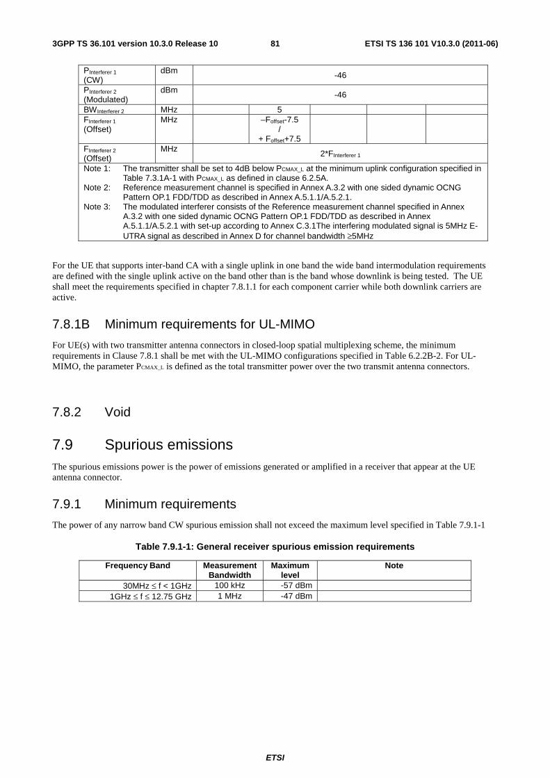
ETSI
ETSI TS 136 101 V10.3.0 (2011-06)813GPP TS 36.101 version 10.3.0 Release 10
PInterferer 1 (CW)
dBm -46
PInterferer 2 (Modulated)
dBm -46
BWInterferer 2 MHz 5 FInterferer 1 (Offset)
MHz
–Foffset-7.5 /
+ Foffset+7.5 FInterferer 2 (Offset)
MHz 2*FInterferer 1
Note 1: The transmitter shall be set to 4dB below PCMAX_L at the minimum uplink configuration specified in Table 7.3.1A-1 with PCMAX_L as defined in clause 6.2.5A.
Note 2: Reference measurement channel is specified in Annex A.3.2 with one sided dynamic OCNG Pattern OP.1 FDD/TDD as described in Annex A.5.1.1/A.5.2.1.
Note 3: The modulated interferer consists of the Reference measurement channel specified in Annex A.3.2 with one sided dynamic OCNG Pattern OP.1 FDD/TDD as described in Annex A.5.1.1/A.5.2.1 with set-up according to Annex C.3.1The interfering modulated signal is 5MHz E-UTRA signal as described in Annex D for channel bandwidth ≥5MHz
For the UE that supports inter-band CA with a single uplink in one band the wide band intermodulation requirements are defined with the single uplink active on the band other than is the band whose downlink is being tested. The UE shall meet the requirements specified in chapter 7.8.1.1 for each component carrier while both downlink carriers are active.
7.8.1B Minimum requirements for UL-MIMO
For UE(s) with two transmitter antenna connectors in closed-loop spatial multiplexing scheme, the minimum requirements in Clause 7.8.1 shall be met with the UL-MIMO configurations specified in Table 6.2.2B-2. For UL-MIMO, the parameter PCMAX_L is defined as the total transmitter power over the two transmit antenna connectors.
7.8.2 Void
7.9 Spurious emissions The spurious emissions power is the power of emissions generated or amplified in a receiver that appear at the UE antenna connector.
7.9.1 Minimum requirements
The power of any narrow band CW spurious emission shall not exceed the maximum level specified in Table 7.9.1-1
Table 7.9.1-1: General receiver spurious emission requirements
Frequency Band Measurement Bandwidth
Maximum level
Note
30MHz ≤ f < 1GHz 100 kHz -57 dBm 1GHz ≤ f ≤ 12.75 GHz 1 MHz -47 dBm
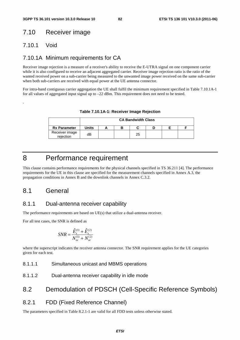
ETSI
ETSI TS 136 101 V10.3.0 (2011-06)823GPP TS 36.101 version 10.3.0 Release 10
7.10 Receiver image
7.10.1 Void
7.10.1A Minimum requirements for CA
Receiver image rejection is a measure of a receiver's ability to receive the E-UTRA signal on one component carrier while it is also configured to receive an adjacent aggregated carrier. Receiver image rejection ratio is the ratio of the wanted received power on a sub-carrier being measured to the unwanted image power received on the same sub-carrier when both sub-carriers are received with equal power at the UE antenna connector.
For intra-band contiguous carrier aggregation the UE shall fulfil the minimum requirement specified in Table 7.10.1A-1 for all values of aggregated input signal up to –22 dBm. This requirement does not need to be tested.
.
Table 7.10.1A-1: Receiver Image Rejection
CA Bandwidth Class
Rx Parameter Units A B C D E F Receiver image
rejection dB 25
8 Performance requirement This clause contains performance requirements for the physical channels specified in TS 36.211 [4]. The performance requirements for the UE in this clause are specified for the measurement channels specified in Annex A.3, the propagation conditions in Annex B and the downlink channels in Annex C.3.2.
8.1 General
8.1.1 Dual-antenna receiver capability
The performance requirements are based on UE(s) that utilize a dual-antenna receiver.
For all test cases, the SNR is defined as
)2()1(
)2()1( ˆˆ
ococ
ss
NN
EESNR
++=
where the superscript indicates the receiver antenna connector. The SNR requirement applies for the UE categories given for each test.
8.1.1.1 Simultaneous unicast and MBMS operations
8.1.1.2 Dual-antenna receiver capability in idle mode
8.2 Demodulation of PDSCH (Cell-Specific Reference Symbols)
8.2.1 FDD (Fixed Reference Channel)
The parameters specified in Table 8.2.1-1 are valid for all FDD tests unless otherwise stated.
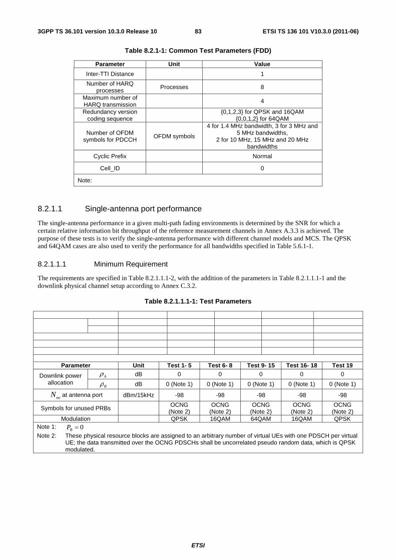
ETSI
ETSI TS 136 101 V10.3.0 (2011-06)833GPP TS 36.101 version 10.3.0 Release 10
Table 8.2.1-1: Common Test Parameters (FDD)
Parameter Unit Value
Inter-TTI Distance 1
Number of HARQ processes Processes 8
Maximum number of HARQ transmission
4
Redundancy version coding sequence {0,1,2,3} for QPSK and 16QAM
{0,0,1,2} for 64QAM
Number of OFDM symbols for PDCCH OFDM symbols
4 for 1.4 MHz bandwidth, 3 for 3 MHz and 5 MHz bandwidths,
2 for 10 MHz, 15 MHz and 20 MHz bandwidths
Cyclic Prefix Normal
Cell_ID 0
Note:
8.2.1.1 Single-antenna port performance
The single-antenna performance in a given multi-path fading environments is determined by the SNR for which a certain relative information bit throughput of the reference measurement channels in Annex A.3.3 is achieved. The purpose of these tests is to verify the single-antenna performance with different channel models and MCS. The QPSK and 64QAM cases are also used to verify the performance for all bandwidths specified in Table 5.6.1-1.
8.2.1.1.1 Minimum Requirement
The requirements are specified in Table 8.2.1.1.1-2, with the addition of the parameters in Table 8.2.1.1.1-1 and the downlink physical channel setup according to Annex C.3.2.
Table 8.2.1.1.1-1: Test Parameters
Parameter Unit Test 1- 5 Test 6- 8 Test 9- 15 Test 16- 18 Test 19
Downlink power allocation
Aρ dB 0 0 0 0 0
Bρ dB 0 (Note 1) 0 (Note 1) 0 (Note 1) 0 (Note 1) 0 (Note 1)
ocN at antenna port dBm/15kHz -98 -98 -98 -98 -98
Symbols for unused PRBs OCNG (Note 2)
OCNG (Note 2)
OCNG (Note 2)
OCNG (Note 2)
OCNG (Note 2)
Modulation QPSK 16QAM 64QAM 16QAM QPSK Note 1: 0=BP
Note 2: These physical resource blocks are assigned to an arbitrary number of virtual UEs with one PDSCH per virtual UE; the data transmitted over the OCNG PDSCHs shall be uncorrelated pseudo random data, which is QPSK modulated.
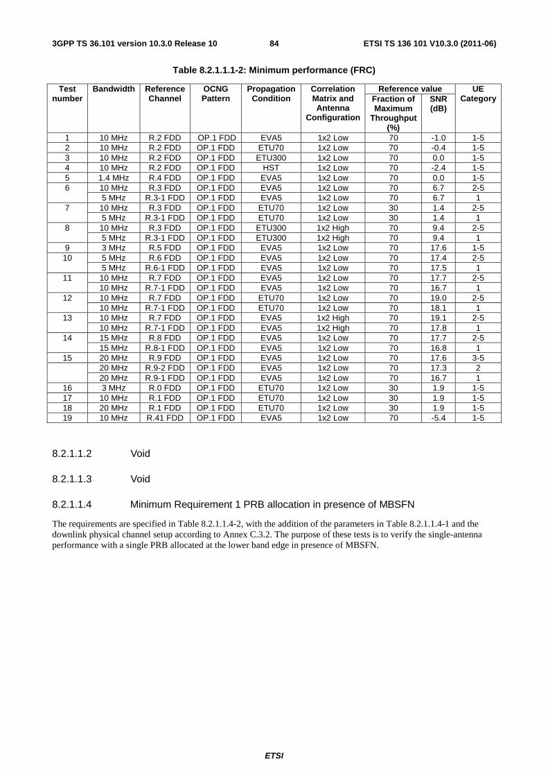
ETSI
ETSI TS 136 101 V10.3.0 (2011-06)843GPP TS 36.101 version 10.3.0 Release 10
Table 8.2.1.1.1-2: Minimum performance (FRC)
Test number
Bandwidth Reference Channel
OCNG Pattern
Propagation Condition
Correlation Matrix and Antenna
Configuration
Reference value UE Category Fraction of
Maximum Throughput
(%)
SNR (dB)
1 10 MHz R.2 FDD OP.1 FDD EVA5 1x2 Low 70 -1.0 1-5 2 10 MHz R.2 FDD OP.1 FDD ETU70 1x2 Low 70 -0.4 1-5 3 10 MHz R.2 FDD OP.1 FDD ETU300 1x2 Low 70 0.0 1-5 4 10 MHz R.2 FDD OP.1 FDD HST 1x2 Low 70 -2.4 1-5 5 1.4 MHz R.4 FDD OP.1 FDD EVA5 1x2 Low 70 0.0 1-5 6 10 MHz R.3 FDD OP.1 FDD EVA5 1x2 Low 70 6.7 2-5
5 MHz R.3-1 FDD OP.1 FDD EVA5 1x2 Low 70 6.7 1 7 10 MHz R.3 FDD OP.1 FDD ETU70 1x2 Low 30 1.4 2-5
5 MHz R.3-1 FDD OP.1 FDD ETU70 1x2 Low 30 1.4 1 8 10 MHz R.3 FDD OP.1 FDD ETU300 1x2 High 70 9.4 2-5
5 MHz R.3-1 FDD OP.1 FDD ETU300 1x2 High 70 9.4 1 9 3 MHz R.5 FDD OP.1 FDD EVA5 1x2 Low 70 17.6 1-5 10 5 MHz R.6 FDD OP.1 FDD EVA5 1x2 Low 70 17.4 2-5
5 MHz R.6-1 FDD OP.1 FDD EVA5 1x2 Low 70 17.5 1 11 10 MHz R.7 FDD OP.1 FDD EVA5 1x2 Low 70 17.7 2-5
10 MHz R.7-1 FDD OP.1 FDD EVA5 1x2 Low 70 16.7 1 12 10 MHz R.7 FDD OP.1 FDD ETU70 1x2 Low 70 19.0 2-5
10 MHz R.7-1 FDD OP.1 FDD ETU70 1x2 Low 70 18.1 1 13 10 MHz R.7 FDD OP.1 FDD EVA5 1x2 High 70 19.1 2-5
10 MHz R.7-1 FDD OP.1 FDD EVA5 1x2 High 70 17.8 1 14 15 MHz R.8 FDD OP.1 FDD EVA5 1x2 Low 70 17.7 2-5
15 MHz R.8-1 FDD OP.1 FDD EVA5 1x2 Low 70 16.8 1 15 20 MHz R.9 FDD OP.1 FDD EVA5 1x2 Low 70 17.6 3-5 20 MHz R.9-2 FDD OP.1 FDD EVA5 1x2 Low 70 17.3 2
20 MHz R.9-1 FDD OP.1 FDD EVA5 1x2 Low 70 16.7 1 16 3 MHz R.0 FDD OP.1 FDD ETU70 1x2 Low 30 1.9 1-5 17 10 MHz R.1 FDD OP.1 FDD ETU70 1x2 Low 30 1.9 1-5 18 20 MHz R.1 FDD OP.1 FDD ETU70 1x2 Low 30 1.9 1-5 19 10 MHz R.41 FDD OP.1 FDD EVA5 1x2 Low 70 -5.4 1-5
8.2.1.1.2 Void
8.2.1.1.3 Void
8.2.1.1.4 Minimum Requirement 1 PRB allocation in presence of MBSFN
The requirements are specified in Table 8.2.1.1.4-2, with the addition of the parameters in Table 8.2.1.1.4-1 and the downlink physical channel setup according to Annex C.3.2. The purpose of these tests is to verify the single-antenna performance with a single PRB allocated at the lower band edge in presence of MBSFN.
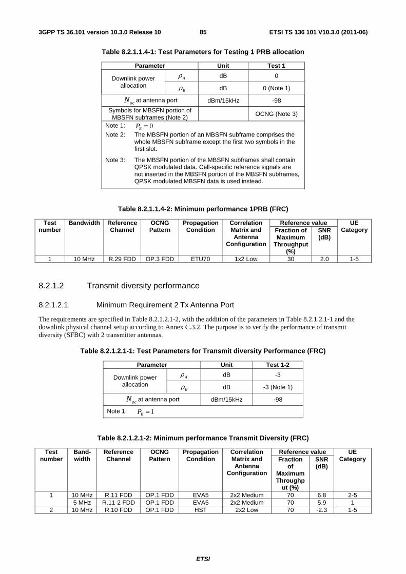
ETSI
ETSI TS 136 101 V10.3.0 (2011-06)853GPP TS 36.101 version 10.3.0 Release 10
Table 8.2.1.1.4-1: Test Parameters for Testing 1 PRB allocation
Parameter Unit Test 1
Downlink power allocation
Aρ dB 0
Bρ dB 0 (Note 1)
ocN at antenna port dBm/15kHz -98
Symbols for MBSFN portion of MBSFN subframes (Note 2)
OCNG (Note 3)
Note 1: 0=BP
Note 2: The MBSFN portion of an MBSFN subframe comprises the whole MBSFN subframe except the first two symbols in the first slot.
Note 3: The MBSFN portion of the MBSFN subframes shall contain QPSK modulated data. Cell-specific reference signals are not inserted in the MBSFN portion of the MBSFN subframes, QPSK modulated MBSFN data is used instead.
Table 8.2.1.1.4-2: Minimum performance 1PRB (FRC)
Test number
Bandwidth Reference Channel
OCNG Pattern
Propagation Condition
Correlation Matrix and Antenna
Configuration
Reference value UE Category Fraction of
Maximum Throughput
(%)
SNR (dB)
1 10 MHz R.29 FDD OP.3 FDD ETU70 1x2 Low 30 2.0 1-5
8.2.1.2 Transmit diversity performance
8.2.1.2.1 Minimum Requirement 2 Tx Antenna Port
The requirements are specified in Table 8.2.1.2.1-2, with the addition of the parameters in Table 8.2.1.2.1-1 and the downlink physical channel setup according to Annex C.3.2. The purpose is to verify the performance of transmit diversity (SFBC) with 2 transmitter antennas.
Table 8.2.1.2.1-1: Test Parameters for Transmit diversity Performance (FRC)
Parameter Unit Test 1-2
Downlink power allocation
Aρ dB -3
Bρ dB -3 (Note 1)
ocN at antenna port dBm/15kHz -98
Note 1: 1=BP
Table 8.2.1.2.1-2: Minimum performance Transmit Diversity (FRC)
Test number
Band-width
Reference Channel
OCNG Pattern
Propagation Condition
Correlation Matrix and Antenna
Configuration
Reference value UE Category Fraction
of Maximum Throughp
ut (%)
SNR (dB)
1 10 MHz R.11 FDD OP.1 FDD EVA5 2x2 Medium 70 6.8 2-5 5 MHz R.11-2 FDD OP.1 FDD EVA5 2x2 Medium 70 5.9 1
2 10 MHz R.10 FDD OP.1 FDD HST 2x2 Low 70 -2.3 1-5
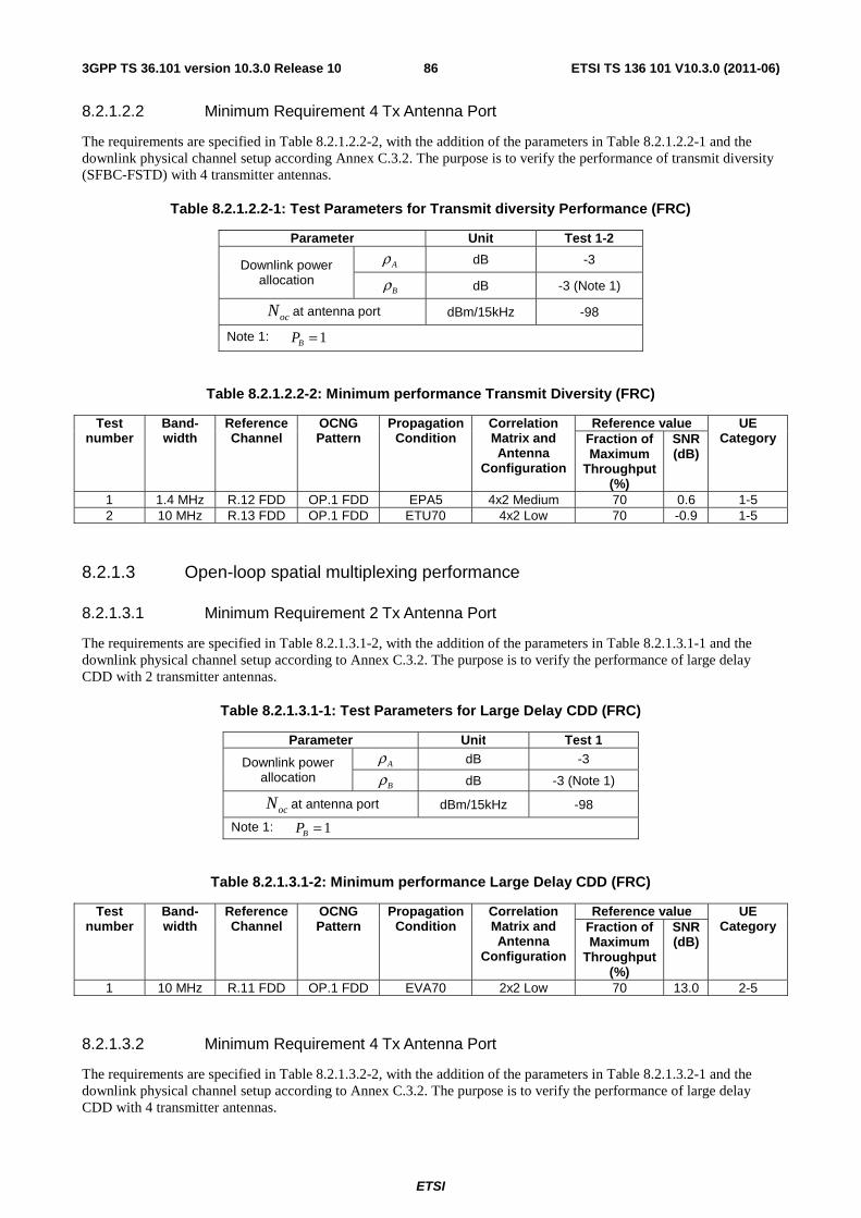
ETSI
ETSI TS 136 101 V10.3.0 (2011-06)863GPP TS 36.101 version 10.3.0 Release 10
8.2.1.2.2 Minimum Requirement 4 Tx Antenna Port
The requirements are specified in Table 8.2.1.2.2-2, with the addition of the parameters in Table 8.2.1.2.2-1 and the downlink physical channel setup according Annex C.3.2. The purpose is to verify the performance of transmit diversity (SFBC-FSTD) with 4 transmitter antennas.
Table 8.2.1.2.2-1: Test Parameters for Transmit diversity Performance (FRC)
Parameter Unit Test 1-2
Downlink power allocation
Aρ dB -3
Bρ dB -3 (Note 1)
ocN at antenna port dBm/15kHz -98
Note 1: 1=BP
Table 8.2.1.2.2-2: Minimum performance Transmit Diversity (FRC)
Test number
Band-width
Reference Channel
OCNG Pattern
Propagation Condition
Correlation Matrix and Antenna
Configuration
Reference value UE Category Fraction of
Maximum Throughput
(%)
SNR (dB)
1 1.4 MHz R.12 FDD OP.1 FDD EPA5 4x2 Medium 70 0.6 1-5 2 10 MHz R.13 FDD OP.1 FDD ETU70 4x2 Low 70 -0.9 1-5
8.2.1.3 Open-loop spatial multiplexing performance
8.2.1.3.1 Minimum Requirement 2 Tx Antenna Port
The requirements are specified in Table 8.2.1.3.1-2, with the addition of the parameters in Table 8.2.1.3.1-1 and the downlink physical channel setup according to Annex C.3.2. The purpose is to verify the performance of large delay CDD with 2 transmitter antennas.
Table 8.2.1.3.1-1: Test Parameters for Large Delay CDD (FRC)
Parameter Unit Test 1
Downlink power allocation
Aρ dB -3
Bρ dB -3 (Note 1)
ocN at antenna port dBm/15kHz -98
Note 1: 1=BP
Table 8.2.1.3.1-2: Minimum performance Large Delay CDD (FRC)
Test number
Band-width
Reference Channel
OCNG Pattern
Propagation Condition
Correlation Matrix and Antenna
Configuration
Reference value UE Category Fraction of
Maximum Throughput
(%)
SNR (dB)
1 10 MHz R.11 FDD OP.1 FDD EVA70 2x2 Low 70 13.0 2-5
8.2.1.3.2 Minimum Requirement 4 Tx Antenna Port
The requirements are specified in Table 8.2.1.3.2-2, with the addition of the parameters in Table 8.2.1.3.2-1 and the downlink physical channel setup according to Annex C.3.2. The purpose is to verify the performance of large delay CDD with 4 transmitter antennas.
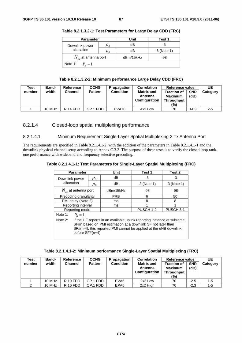
ETSI
ETSI TS 136 101 V10.3.0 (2011-06)873GPP TS 36.101 version 10.3.0 Release 10
Table 8.2.1.3.2-1: Test Parameters for Large Delay CDD (FRC)
Parameter Unit Test 1
Downlink power allocation
Aρ dB -6
Bρ dB -6 (Note 1)
ocN at antenna port dBm/15kHz -98
Note 1: 1=BP
Table 8.2.1.3.2-2: Minimum performance Large Delay CDD (FRC)
Test number
Band-width
Reference Channel
OCNG Pattern
Propagation Condition
Correlation Matrix and Antenna
Configuration
Reference value UE Category Fraction of
Maximum Throughput
(%)
SNR (dB)
1 10 MHz R.14 FDD OP.1 FDD EVA70 4x2 Low 70 14.3 2-5
8.2.1.4 Closed-loop spatial multiplexing performance
8.2.1.4.1 Minimum Requirement Single-Layer Spatial Multiplexing 2 Tx Antenna Port
The requirements are specified in Table 8.2.1.4.1-2, with the addition of the parameters in Table 8.2.1.4.1-1 and the downlink physical channel setup according to Annex C.3.2. The purpose of these tests is to verify the closed loop rank-one performance with wideband and frequency selective precoding.
Table 8.2.1.4.1-1: Test Parameters for Single-Layer Spatial Multiplexing (FRC)
Parameter Unit Test 1 Test 2
Downlink power allocation
Aρ dB -3 -3
Bρ dB -3 (Note 1) -3 (Note 1)
ocN at antenna port dBm/15kHz -98 -98
Precoding granularity PRB 6 50 PMI delay (Note 2) ms 8 8 Reporting interval ms 1 1 Reporting mode PUSCH 1-2 PUSCH 3-1
Note 1: 1=BP
Note 2: If the UE reports in an available uplink reporting instance at subrame SF#n based on PMI estimation at a downlink SF not later than SF#(n-4), this reported PMI cannot be applied at the eNB downlink before SF#(n+4)
Table 8.2.1.4.1-2: Minimum performance Single-Layer Spatial Multiplexing (FRC)
Test number
Band-width
Reference Channel
OCNG Pattern
Propagation Condition
Correlation Matrix and Antenna
Configuration
Reference value UE Category Fraction of
Maximum Throughput
(%)
SNR (dB)
1 10 MHz R.10 FDD OP.1 FDD EVA5 2x2 Low 70 -2.5 1-5 2 10 MHz R.10 FDD OP.1 FDD EPA5 2x2 High 70 -2.3 1-5
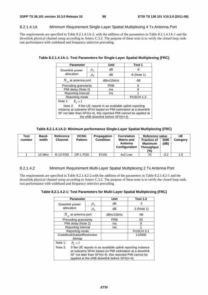
ETSI
ETSI TS 136 101 V10.3.0 (2011-06)883GPP TS 36.101 version 10.3.0 Release 10
8.2.1.4.1A Minimum Requirement Single-Layer Spatial Multiplexing 4 Tx Antenna Port
The requirements are specified in Table 8.2.1.4.1A-2, with the addition of the parameters in Table 8.2.1.4.1A-1 and the downlink physical channel setup according to Annex C.3.2. The purpose of these tests is to verify the closed loop rank-one performance with wideband and frequency selective precoding.
Table 8.2.1.4.1A-1: Test Parameters for Single-Layer Spatial Multiplexing (FRC)
Parameter Unit Test 1
Downlink power allocation
Aρ dB -6
Bρ dB -6 (Note 1)
ocN at antenna port dBm/15kHz -98
Precoding granularity PRB 6 PMI delay (Note 2) ms 8 Reporting interval ms 1 Reporting mode PUSCH 1-2
Note 1: 1=BP
Note 2: If the UE reports in an available uplink reporting instance at subrame SF#n based on PMI estimation at a downlink SF not later than SF#(n-4), this reported PMI cannot be applied at
the eNB downlink before SF#(n+4)
Table 8.2.1.4.1A-2: Minimum performance Single-Layer Spatial Multiplexing (FRC)
Test number
Band-width
Reference Channel
OCNG Pattern
Propagation Condition
Correlation Matrix and Antenna
Configuration
Reference value UE Category Fraction of
Maximum Throughput
(%)
SNR (dB)
1 10 MHz R.13 FDD OP.1 FDD EVA5 4x2 Low 70 -3.2 1-5
8.2.1.4.2 Minimum Requirement Multi-Layer Spatial Multiplexing 2 Tx Antenna Port
The requirements are specified in Table 8.2.1.4.2-2,with the addition of the parameters in Table 8.2.1.4.2-1 and the downlink physical channel setup according to Annex C.3.2. The purpose of these tests is to verify the closed loop rank-two performance with wideband and frequency selective precoding.
Table 8.2.1.4.2-1: Test Parameters for Multi-Layer Spatial Multiplexing (FRC)
Parameter Unit Test 1-2
Downlink power allocation
Aρ dB -3
Bρ dB -3 (Note 1)
ocN at antenna port dBm/15kHz -98
Precoding granularity PRB 50 PMI delay (Note 2) ms 8 Reporting interval ms 1 Reporting mode PUSCH 3-1
CodeBookSubsetRestriction bitmap
110000
Note 1: 1=BP
Note 2: If the UE reports in an available uplink reporting instance at subrame SF#n based on PMI estimation at a downlink SF not later than SF#(n-4), this reported PMI cannot be applied at the eNB downlink before SF#(n+4)
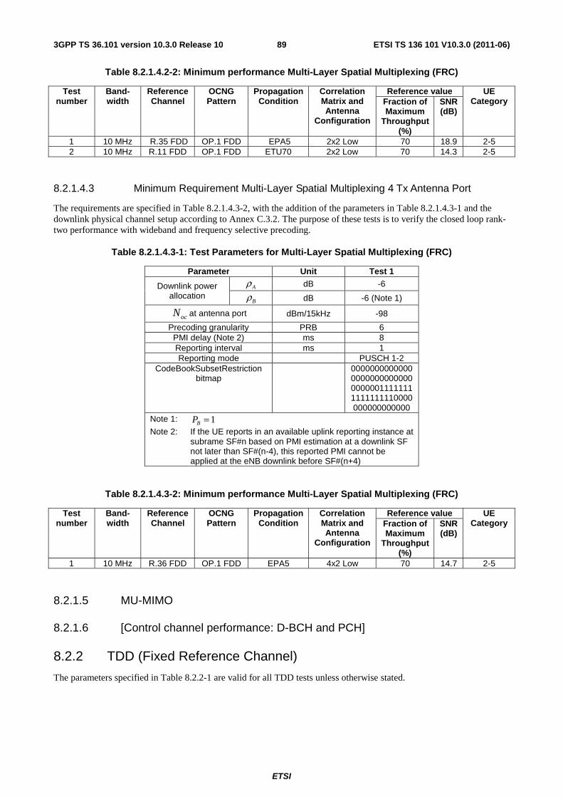
ETSI
ETSI TS 136 101 V10.3.0 (2011-06)893GPP TS 36.101 version 10.3.0 Release 10
Table 8.2.1.4.2-2: Minimum performance Multi-Layer Spatial Multiplexing (FRC)
Test number
Band-width
Reference Channel
OCNG Pattern
Propagation Condition
Correlation Matrix and Antenna
Configuration
Reference value UE Category Fraction of
Maximum Throughput
(%)
SNR (dB)
1 10 MHz R.35 FDD OP.1 FDD EPA5 2x2 Low 70 18.9 2-5 2 10 MHz R.11 FDD OP.1 FDD ETU70 2x2 Low 70 14.3 2-5
8.2.1.4.3 Minimum Requirement Multi-Layer Spatial Multiplexing 4 Tx Antenna Port
The requirements are specified in Table 8.2.1.4.3-2, with the addition of the parameters in Table 8.2.1.4.3-1 and the downlink physical channel setup according to Annex C.3.2. The purpose of these tests is to verify the closed loop rank-two performance with wideband and frequency selective precoding.
Table 8.2.1.4.3-1: Test Parameters for Multi-Layer Spatial Multiplexing (FRC)
Parameter Unit Test 1
Downlink power allocation
Aρ dB -6
Bρ dB -6 (Note 1)
ocN at antenna port dBm/15kHz -98
Precoding granularity PRB 6 PMI delay (Note 2) ms 8 Reporting interval ms 1 Reporting mode PUSCH 1-2
CodeBookSubsetRestriction bitmap
0000000000000000000000000000000011111111111111110000000000000000
Note 1: 1=BP
Note 2: If the UE reports in an available uplink reporting instance at subrame SF#n based on PMI estimation at a downlink SF not later than SF#(n-4), this reported PMI cannot be applied at the eNB downlink before SF#(n+4)
Table 8.2.1.4.3-2: Minimum performance Multi-Layer Spatial Multiplexing (FRC)
Test number
Band-width
Reference Channel
OCNG Pattern
Propagation Condition
Correlation Matrix and Antenna
Configuration
Reference value UE Category Fraction of
Maximum Throughput
(%)
SNR (dB)
1 10 MHz R.36 FDD OP.1 FDD EPA5 4x2 Low 70 14.7 2-5
8.2.1.5 MU-MIMO
8.2.1.6 [Control channel performance: D-BCH and PCH]
8.2.2 TDD (Fixed Reference Channel)
The parameters specified in Table 8.2.2-1 are valid for all TDD tests unless otherwise stated.
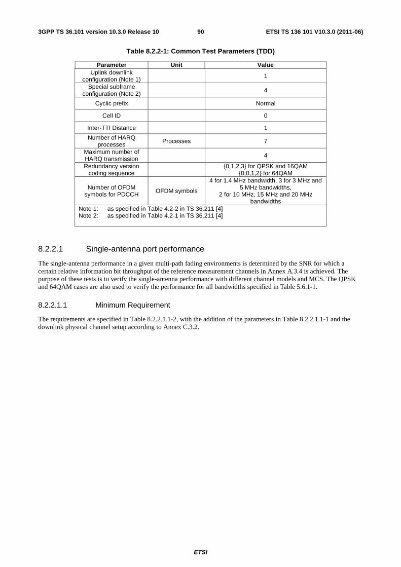
ETSI
ETSI TS 136 101 V10.3.0 (2011-06)903GPP TS 36.101 version 10.3.0 Release 10
Table 8.2.2-1: Common Test Parameters (TDD)
Parameter Unit Value Uplink downlink
configuration (Note 1) 1
Special subframe configuration (Note 2) 4
Cyclic prefix Normal
Cell ID 0
Inter-TTI Distance 1
Number of HARQ processes Processes 7
Maximum number of HARQ transmission
4
Redundancy version coding sequence {0,1,2,3} for QPSK and 16QAM
{0,0,1,2} for 64QAM
Number of OFDM symbols for PDCCH OFDM symbols
4 for 1.4 MHz bandwidth, 3 for 3 MHz and 5 MHz bandwidths,
2 for 10 MHz, 15 MHz and 20 MHz bandwidths
Note 1: as specified in Table 4.2-2 in TS 36.211 [4] Note 2: as specified in Table 4.2-1 in TS 36.211 [4]
8.2.2.1 Single-antenna port performance
The single-antenna performance in a given multi-path fading environments is determined by the SNR for which a certain relative information bit throughput of the reference measurement channels in Annex A.3.4 is achieved. The purpose of these tests is to verify the single-antenna performance with different channel models and MCS. The QPSK and 64QAM cases are also used to verify the performance for all bandwidths specified in Table 5.6.1-1.
8.2.2.1.1 Minimum Requirement
The requirements are specified in Table 8.2.2.1.1-2, with the addition of the parameters in Table 8.2.2.1.1-1 and the downlink physical channel setup according to Annex C.3.2.
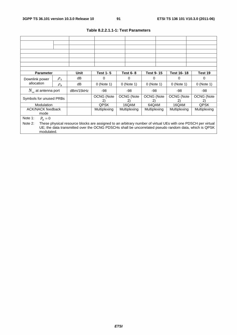
ETSI
ETSI TS 136 101 V10.3.0 (2011-06)913GPP TS 36.101 version 10.3.0 Release 10
Table 8.2.2.1.1-1: Test Parameters
Parameter Unit Test 1- 5 Test 6- 8 Test 9- 15 Test 16- 18 Test 19
Downlink power allocation
Aρ dB 0 0 0 0 0
Bρ dB 0 (Note 1) 0 (Note 1) 0 (Note 1) 0 (Note 1) 0 (Note 1)
ocN at antenna port dBm/15kHz -98 -98 -98 -98 -98
Symbols for unused PRBs OCNG (Note 2)
OCNG (Note 2)
OCNG (Note 2)
OCNG (Note 2)
OCNG (Note 2)
Modulation QPSK 16QAM 64QAM 16QAM QPSK ACK/NACK feedback
mode Multiplexing Multiplexing Multiplexing Multiplexing Multiplexing
Note 1: 0=BP
Note 2: These physical resource blocks are assigned to an arbitrary number of virtual UEs with one PDSCH per virtual UE; the data transmitted over the OCNG PDSCHs shall be uncorrelated pseudo random data, which is QPSK modulated.
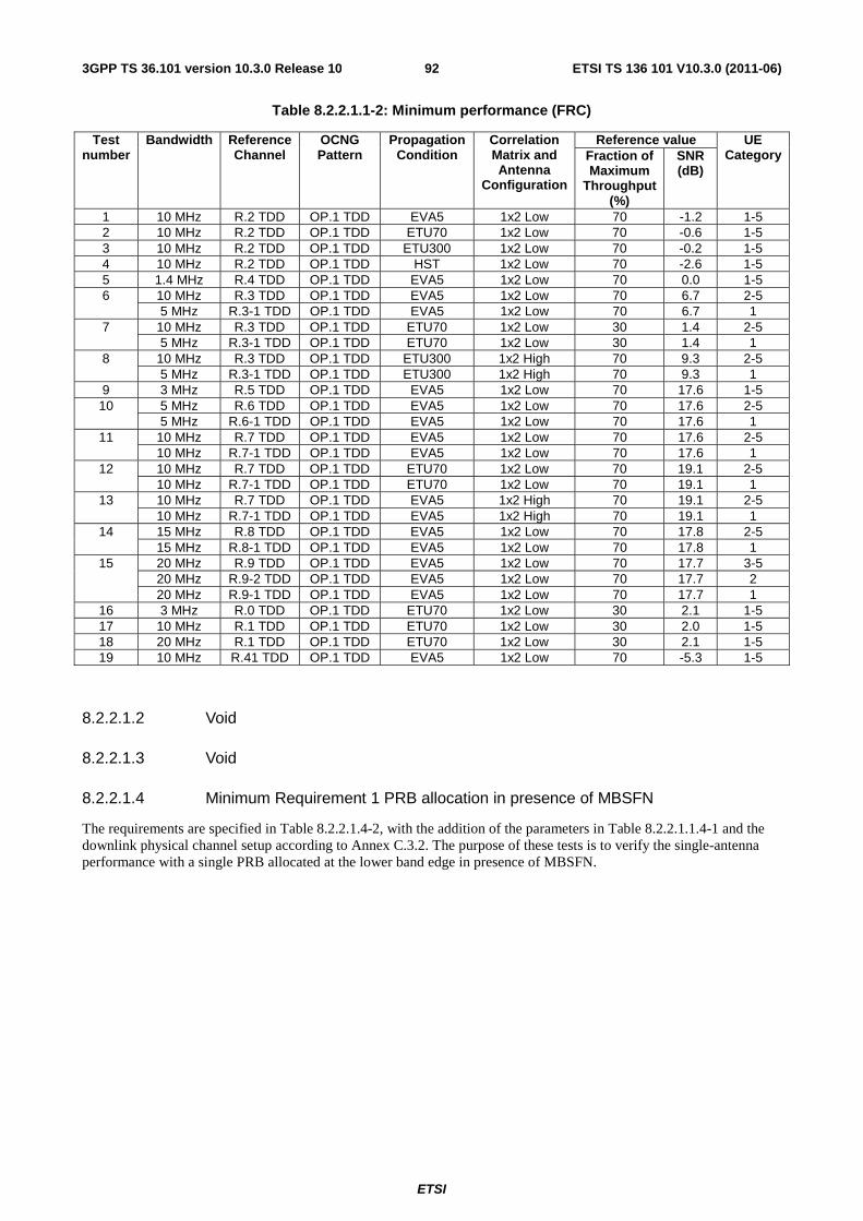
ETSI
ETSI TS 136 101 V10.3.0 (2011-06)923GPP TS 36.101 version 10.3.0 Release 10
Table 8.2.2.1.1-2: Minimum performance (FRC)
Test number
Bandwidth Reference Channel
OCNG Pattern
Propagation Condition
Correlation Matrix and Antenna
Configuration
Reference value UE Category Fraction of
Maximum Throughput
(%)
SNR (dB)
1 10 MHz R.2 TDD OP.1 TDD EVA5 1x2 Low 70 -1.2 1-5 2 10 MHz R.2 TDD OP.1 TDD ETU70 1x2 Low 70 -0.6 1-5 3 10 MHz R.2 TDD OP.1 TDD ETU300 1x2 Low 70 -0.2 1-5 4 10 MHz R.2 TDD OP.1 TDD HST 1x2 Low 70 -2.6 1-5 5 1.4 MHz R.4 TDD OP.1 TDD EVA5 1x2 Low 70 0.0 1-5 6 10 MHz R.3 TDD OP.1 TDD EVA5 1x2 Low 70 6.7 2-5
5 MHz R.3-1 TDD OP.1 TDD EVA5 1x2 Low 70 6.7 1 7 10 MHz R.3 TDD OP.1 TDD ETU70 1x2 Low 30 1.4 2-5
5 MHz R.3-1 TDD OP.1 TDD ETU70 1x2 Low 30 1.4 1 8 10 MHz R.3 TDD OP.1 TDD ETU300 1x2 High 70 9.3 2-5
5 MHz R.3-1 TDD OP.1 TDD ETU300 1x2 High 70 9.3 1 9 3 MHz R.5 TDD OP.1 TDD EVA5 1x2 Low 70 17.6 1-5 10 5 MHz R.6 TDD OP.1 TDD EVA5 1x2 Low 70 17.6 2-5
5 MHz R.6-1 TDD OP.1 TDD EVA5 1x2 Low 70 17.6 1 11 10 MHz R.7 TDD OP.1 TDD EVA5 1x2 Low 70 17.6 2-5
10 MHz R.7-1 TDD OP.1 TDD EVA5 1x2 Low 70 17.6 1 12 10 MHz R.7 TDD OP.1 TDD ETU70 1x2 Low 70 19.1 2-5
10 MHz R.7-1 TDD OP.1 TDD ETU70 1x2 Low 70 19.1 1 13 10 MHz R.7 TDD OP.1 TDD EVA5 1x2 High 70 19.1 2-5
10 MHz R.7-1 TDD OP.1 TDD EVA5 1x2 High 70 19.1 1 14 15 MHz R.8 TDD OP.1 TDD EVA5 1x2 Low 70 17.8 2-5
15 MHz R.8-1 TDD OP.1 TDD EVA5 1x2 Low 70 17.8 1 15 20 MHz R.9 TDD OP.1 TDD EVA5 1x2 Low 70 17.7 3-5
20 MHz R.9-2 TDD OP.1 TDD EVA5 1x2 Low 70 17.7 2 20 MHz R.9-1 TDD OP.1 TDD EVA5 1x2 Low 70 17.7 1
16 3 MHz R.0 TDD OP.1 TDD ETU70 1x2 Low 30 2.1 1-5 17 10 MHz R.1 TDD OP.1 TDD ETU70 1x2 Low 30 2.0 1-5 18 20 MHz R.1 TDD OP.1 TDD ETU70 1x2 Low 30 2.1 1-5 19 10 MHz R.41 TDD OP.1 TDD EVA5 1x2 Low 70 -5.3 1-5
8.2.2.1.2 Void
8.2.2.1.3 Void
8.2.2.1.4 Minimum Requirement 1 PRB allocation in presence of MBSFN
The requirements are specified in Table 8.2.2.1.4-2, with the addition of the parameters in Table 8.2.2.1.1.4-1 and the downlink physical channel setup according to Annex C.3.2. The purpose of these tests is to verify the single-antenna performance with a single PRB allocated at the lower band edge in presence of MBSFN.
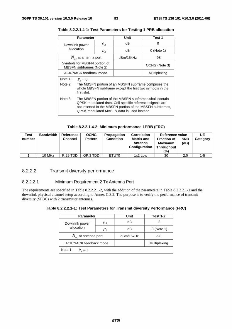
ETSI
ETSI TS 136 101 V10.3.0 (2011-06)933GPP TS 36.101 version 10.3.0 Release 10
Table 8.2.2.1.4-1: Test Parameters for Testing 1 PRB allocation
Parameter Unit Test 1
Downlink power allocation
Aρ dB 0
Bρ dB 0 (Note 1)
ocN at antenna port dBm/15kHz -98
Symbols for MBSFN portion of MBSFN subframes (Note 2)
OCNG (Note 3)
ACK/NACK feedback mode Multiplexing
Note 1: 0=BP
Note 2: The MBSFN portion of an MBSFN subframe comprises the whole MBSFN subframe except the first two symbols in the first slot.
Note 3: The MBSFN portion of the MBSFN subframes shall contain QPSK modulated data. Cell-specific reference signals are not inserted in the MBSFN portion of the MBSFN subframes, QPSK modulated MBSFN data is used instead.
Table 8.2.2.1.4-2: Minimum performance 1PRB (FRC)
Test number
Bandwidth Reference Channel
OCNG Pattern
Propagation Condition
Correlation Matrix and Antenna
Configuration
Reference value UE Category Fraction of
Maximum Throughput
(%)
SNR (dB)
1 10 MHz R.29 TDD OP.3 TDD ETU70 1x2 Low 30 2.0 1-5
8.2.2.2 Transmit diversity performance
8.2.2.2.1 Minimum Requirement 2 Tx Antenna Port
The requirements are specified in Table 8.2.2.2.1-2, with the addition of the parameters in Table 8.2.2.2.1-1 and the downlink physical channel setup according to Annex C.3.2. The purpose is to verify the performance of transmit diversity (SFBC) with 2 transmitter antennas.
Table 8.2.2.2.1-1: Test Parameters for Transmit diversity Performance (FRC)
Parameter Unit Test 1-2
Downlink power allocation
Aρ dB -3
Bρ dB -3 (Note 1)
ocN at antenna port dBm/15kHz -98
ACK/NACK feedback mode Multiplexing
Note 1: 1=BP
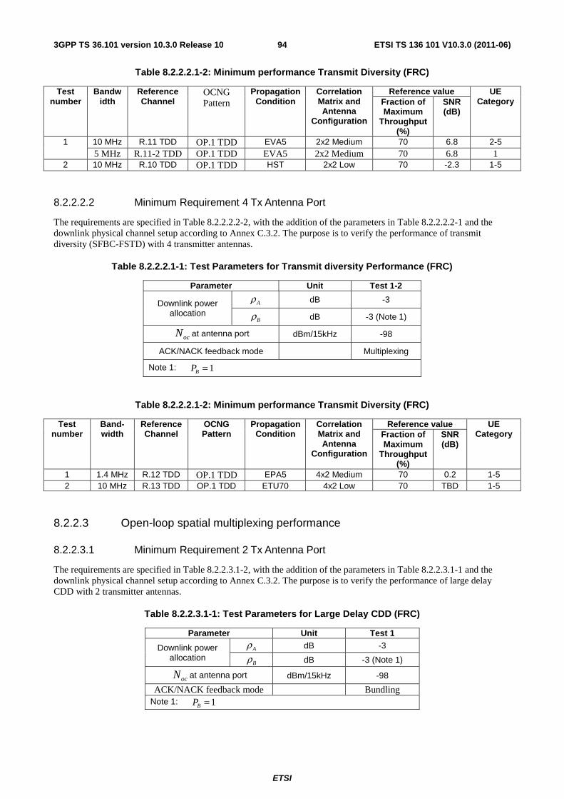
ETSI
ETSI TS 136 101 V10.3.0 (2011-06)943GPP TS 36.101 version 10.3.0 Release 10
Table 8.2.2.2.1-2: Minimum performance Transmit Diversity (FRC)
Test number
Bandwidth
Reference Channel
OCNG Pattern
Propagation Condition
Correlation Matrix and Antenna
Configuration
Reference value UE Category Fraction of
Maximum Throughput
(%)
SNR (dB)
1 10 MHz R.11 TDD OP.1 TDD EVA5 2x2 Medium 70 6.8 2-5 5 MHz R.11-2 TDD OP.1 TDD EVA5 2x2 Medium 70 6.8 1
2 10 MHz R.10 TDD OP.1 TDD HST 2x2 Low 70 -2.3 1-5
8.2.2.2.2 Minimum Requirement 4 Tx Antenna Port
The requirements are specified in Table 8.2.2.2.2-2, with the addition of the parameters in Table 8.2.2.2.2-1 and the downlink physical channel setup according to Annex C.3.2. The purpose is to verify the performance of transmit diversity (SFBC-FSTD) with 4 transmitter antennas.
Table 8.2.2.2.1-1: Test Parameters for Transmit diversity Performance (FRC)
Parameter Unit Test 1-2
Downlink power allocation
Aρ dB -3
Bρ dB -3 (Note 1)
ocN at antenna port dBm/15kHz -98
ACK/NACK feedback mode Multiplexing
Note 1: 1=BP
Table 8.2.2.2.1-2: Minimum performance Transmit Diversity (FRC)
Test number
Band-width
Reference Channel
OCNG Pattern
Propagation Condition
Correlation Matrix and Antenna
Configuration
Reference value UE Category Fraction of
Maximum Throughput
(%)
SNR (dB)
1 1.4 MHz R.12 TDD OP.1 TDD EPA5 4x2 Medium 70 0.2 1-5 2 10 MHz R.13 TDD OP.1 TDD ETU70 4x2 Low 70 TBD 1-5
8.2.2.3 Open-loop spatial multiplexing performance
8.2.2.3.1 Minimum Requirement 2 Tx Antenna Port
The requirements are specified in Table 8.2.2.3.1-2, with the addition of the parameters in Table 8.2.2.3.1-1 and the downlink physical channel setup according to Annex C.3.2. The purpose is to verify the performance of large delay CDD with 2 transmitter antennas.
Table 8.2.2.3.1-1: Test Parameters for Large Delay CDD (FRC)
Parameter Unit Test 1
Downlink power allocation
Aρ dB -3
Bρ dB -3 (Note 1)
ocN at antenna port dBm/15kHz -98
ACK/NACK feedback mode Bundling Note 1: 1=BP
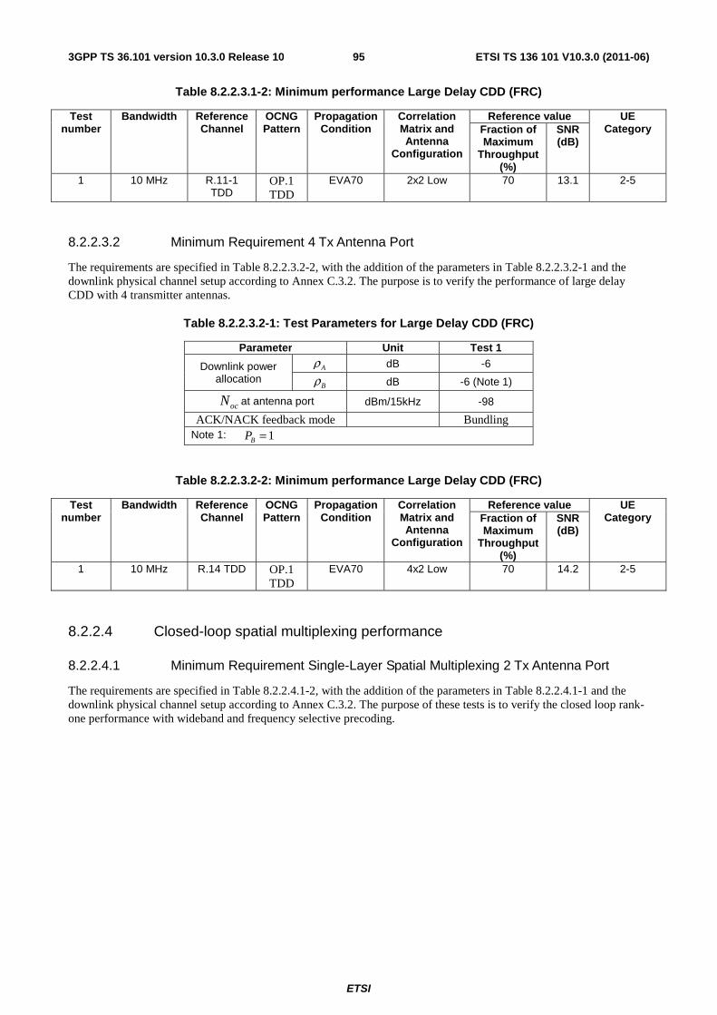
ETSI
ETSI TS 136 101 V10.3.0 (2011-06)953GPP TS 36.101 version 10.3.0 Release 10
Table 8.2.2.3.1-2: Minimum performance Large Delay CDD (FRC)
Test number
Bandwidth Reference Channel
OCNG Pattern
Propagation Condition
Correlation Matrix and Antenna
Configuration
Reference value UE Category Fraction of
Maximum Throughput
(%)
SNR (dB)
1 10 MHz R.11-1 TDD
OP.1 TDD
EVA70 2x2 Low 70 13.1 2-5
8.2.2.3.2 Minimum Requirement 4 Tx Antenna Port
The requirements are specified in Table 8.2.2.3.2-2, with the addition of the parameters in Table 8.2.2.3.2-1 and the downlink physical channel setup according to Annex C.3.2. The purpose is to verify the performance of large delay CDD with 4 transmitter antennas.
Table 8.2.2.3.2-1: Test Parameters for Large Delay CDD (FRC)
Parameter Unit Test 1
Downlink power allocation
Aρ dB -6
Bρ dB -6 (Note 1)
ocN at antenna port dBm/15kHz -98
ACK/NACK feedback mode Bundling Note 1: 1=BP
Table 8.2.2.3.2-2: Minimum performance Large Delay CDD (FRC)
Test number
Bandwidth Reference Channel
OCNG Pattern
Propagation Condition
Correlation Matrix and Antenna
Configuration
Reference value UE Category Fraction of
Maximum Throughput
(%)
SNR (dB)
1 10 MHz R.14 TDD OP.1 TDD
EVA70 4x2 Low 70 14.2 2-5
8.2.2.4 Closed-loop spatial multiplexing performance
8.2.2.4.1 Minimum Requirement Single-Layer Spatial Multiplexing 2 Tx Antenna Port
The requirements are specified in Table 8.2.2.4.1-2, with the addition of the parameters in Table 8.2.2.4.1-1 and the downlink physical channel setup according to Annex C.3.2. The purpose of these tests is to verify the closed loop rank-one performance with wideband and frequency selective precoding.
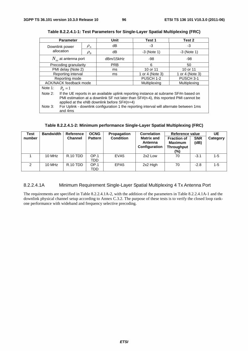
ETSI
ETSI TS 136 101 V10.3.0 (2011-06)963GPP TS 36.101 version 10.3.0 Release 10
Table 8.2.2.4.1-1: Test Parameters for Single-Layer Spatial Multiplexing (FRC)
Parameter Unit Test 1 Test 2
Downlink power allocation
Aρ dB -3 -3
Bρ dB -3 (Note 1) -3 (Note 1)
ocN at antenna port dBm/15kHz -98 -98
Precoding granularity PRB 6 50 PMI delay (Note 2) ms 10 or 11 10 or 11 Reporting interval ms 1 or 4 (Note 3) 1 or 4 (Note 3) Reporting mode PUSCH 1-2 PUSCH 3-1
ACK/NACK feedback mode Multiplexing Multiplexing Note 1: 1=BP
Note 2: If the UE reports in an available uplink reporting instance at subrame SF#n based on PMI estimation at a downlink SF not later than SF#(n-4), this reported PMI cannot be applied at the eNB downlink before SF#(n+4)
Note 3: For Uplink - downlink configuration 1 the reporting interval will alternate between 1ms and 4ms
Table 8.2.2.4.1-2: Minimum performance Single-Layer Spatial Multiplexing (FRC)
Test number
Bandwidth Reference Channel
OCNG Pattern
Propagation Condition
Correlation Matrix and Antenna
Configuration
Reference value UE Category Fraction of
Maximum Throughput
(%)
SNR (dB)
1 10 MHz R.10 TDD OP.1 TDD
EVA5 2x2 Low 70 -3.1 1-5
2 10 MHz R.10 TDD OP.1 TDD
EPA5 2x2 High 70 -2.8 1-5
8.2.2.4.1A Minimum Requirement Single-Layer Spatial Multiplexing 4 Tx Antenna Port
The requirements are specified in Table 8.2.2.4.1A-2, with the addition of the parameters in Table 8.2.2.4.1A-1 and the downlink physical channel setup according to Annex C.3.2. The purpose of these tests is to verify the closed loop rank-one performance with wideband and frequency selective precoding.
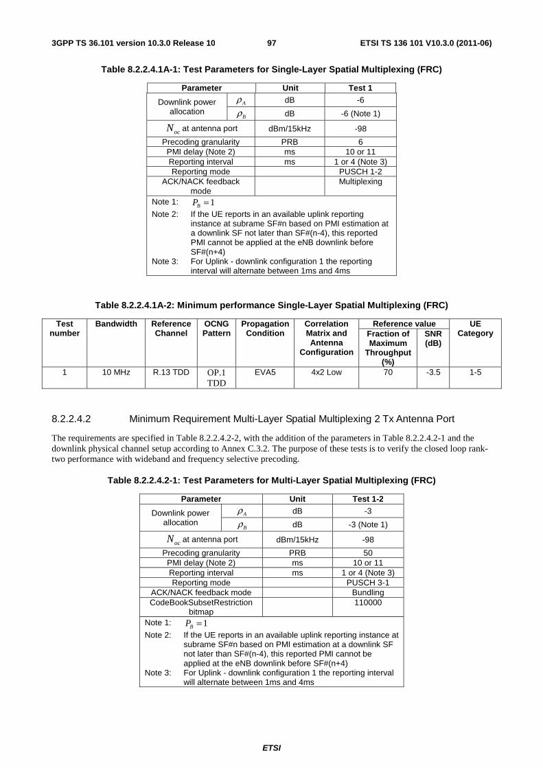
ETSI
ETSI TS 136 101 V10.3.0 (2011-06)973GPP TS 36.101 version 10.3.0 Release 10
Table 8.2.2.4.1A-1: Test Parameters for Single-Layer Spatial Multiplexing (FRC)
Parameter Unit Test 1
Downlink power allocation
Aρ dB -6
Bρ dB -6 (Note 1)
ocN at antenna port dBm/15kHz -98
Precoding granularity PRB 6 PMI delay (Note 2) ms 10 or 11 Reporting interval ms 1 or 4 (Note 3) Reporting mode PUSCH 1-2
ACK/NACK feedback mode
Multiplexing
Note 1: 1=BP
Note 2: If the UE reports in an available uplink reporting instance at subrame SF#n based on PMI estimation at a downlink SF not later than SF#(n-4), this reported PMI cannot be applied at the eNB downlink before SF#(n+4)
Note 3: For Uplink - downlink configuration 1 the reporting interval will alternate between 1ms and 4ms
Table 8.2.2.4.1A-2: Minimum performance Single-Layer Spatial Multiplexing (FRC)
Test number
Bandwidth Reference Channel
OCNG Pattern
Propagation Condition
Correlation Matrix and Antenna
Configuration
Reference value UE Category Fraction of
Maximum Throughput
(%)
SNR (dB)
1 10 MHz R.13 TDD OP.1 TDD
EVA5 4x2 Low 70 -3.5 1-5
8.2.2.4.2 Minimum Requirement Multi-Layer Spatial Multiplexing 2 Tx Antenna Port
The requirements are specified in Table 8.2.2.4.2-2, with the addition of the parameters in Table 8.2.2.4.2-1 and the downlink physical channel setup according to Annex C.3.2. The purpose of these tests is to verify the closed loop rank-two performance with wideband and frequency selective precoding.
Table 8.2.2.4.2-1: Test Parameters for Multi-Layer Spatial Multiplexing (FRC)
Parameter Unit Test 1-2
Downlink power allocation
Aρ dB -3
Bρ dB -3 (Note 1)
ocN at antenna port dBm/15kHz -98
Precoding granularity PRB 50 PMI delay (Note 2) ms 10 or 11 Reporting interval ms 1 or 4 (Note 3) Reporting mode PUSCH 3-1
ACK/NACK feedback mode Bundling CodeBookSubsetRestriction
bitmap 110000
Note 1: 1=BP
Note 2: If the UE reports in an available uplink reporting instance at subrame SF#n based on PMI estimation at a downlink SF not later than SF#(n-4), this reported PMI cannot be applied at the eNB downlink before SF#(n+4)
Note 3: For Uplink - downlink configuration 1 the reporting interval will alternate between 1ms and 4ms
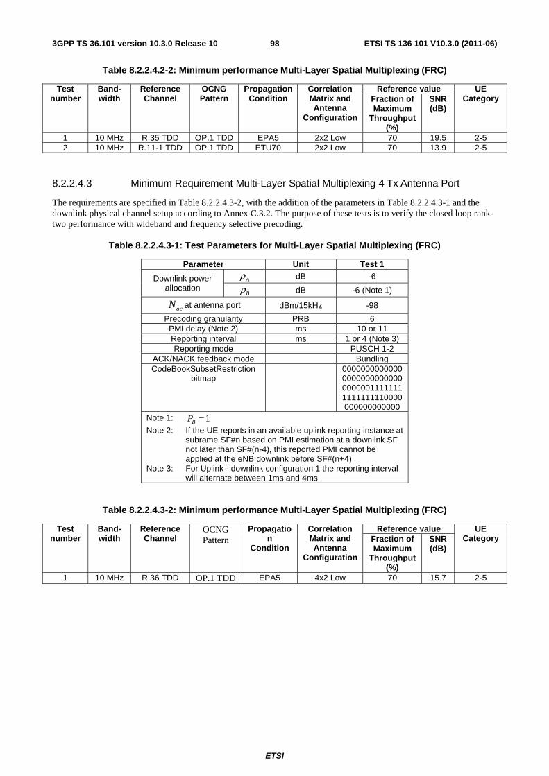
ETSI
ETSI TS 136 101 V10.3.0 (2011-06)983GPP TS 36.101 version 10.3.0 Release 10
Table 8.2.2.4.2-2: Minimum performance Multi-Layer Spatial Multiplexing (FRC)
Test number
Band-width
Reference Channel
OCNG Pattern
Propagation Condition
Correlation Matrix and Antenna
Configuration
Reference value UE Category Fraction of
Maximum Throughput
(%)
SNR (dB)
1 10 MHz R.35 TDD OP.1 TDD EPA5 2x2 Low 70 19.5 2-5 2 10 MHz R.11-1 TDD OP.1 TDD ETU70 2x2 Low 70 13.9 2-5
8.2.2.4.3 Minimum Requirement Multi-Layer Spatial Multiplexing 4 Tx Antenna Port
The requirements are specified in Table 8.2.2.4.3-2, with the addition of the parameters in Table 8.2.2.4.3-1 and the downlink physical channel setup according to Annex C.3.2. The purpose of these tests is to verify the closed loop rank-two performance with wideband and frequency selective precoding.
Table 8.2.2.4.3-1: Test Parameters for Multi-Layer Spatial Multiplexing (FRC)
Parameter Unit Test 1
Downlink power allocation
Aρ dB -6
Bρ dB -6 (Note 1)
ocN at antenna port dBm/15kHz -98
Precoding granularity PRB 6 PMI delay (Note 2) ms 10 or 11 Reporting interval ms 1 or 4 (Note 3) Reporting mode PUSCH 1-2
ACK/NACK feedback mode Bundling CodeBookSubsetRestriction
bitmap 0000000000000
000000000000000000011111111111111110000000000000000
Note 1: 1=BP
Note 2: If the UE reports in an available uplink reporting instance at subrame SF#n based on PMI estimation at a downlink SF not later than SF#(n-4), this reported PMI cannot be applied at the eNB downlink before SF#(n+4)
Note 3: For Uplink - downlink configuration 1 the reporting interval will alternate between 1ms and 4ms
Table 8.2.2.4.3-2: Minimum performance Multi-Layer Spatial Multiplexing (FRC)
Test number
Band-width
Reference Channel
OCNG Pattern
Propagation
Condition
Correlation Matrix and Antenna
Configuration
Reference value UE Category Fraction of
Maximum Throughput
(%)
SNR (dB)
1 10 MHz R.36 TDD OP.1 TDD EPA5 4x2 Low 70 15.7 2-5
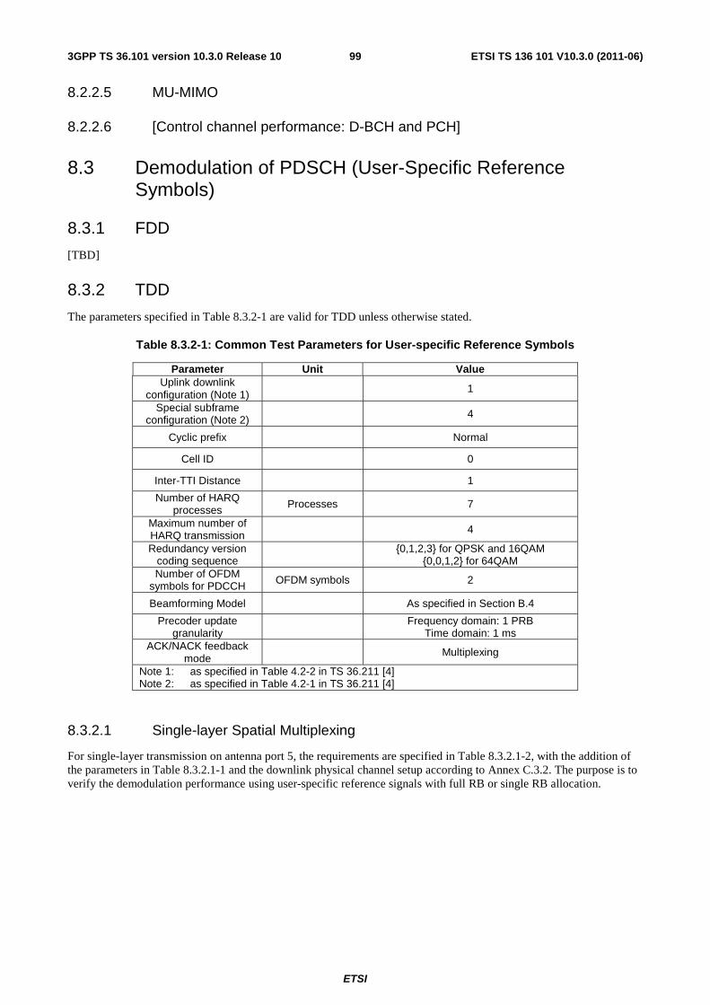
ETSI
ETSI TS 136 101 V10.3.0 (2011-06)993GPP TS 36.101 version 10.3.0 Release 10
8.2.2.5 MU-MIMO
8.2.2.6 [Control channel performance: D-BCH and PCH]
8.3 Demodulation of PDSCH (User-Specific Reference Symbols)
8.3.1 FDD
[TBD]
8.3.2 TDD
The parameters specified in Table 8.3.2-1 are valid for TDD unless otherwise stated.
Table 8.3.2-1: Common Test Parameters for User-specific Reference Symbols
Parameter Unit Value Uplink downlink
configuration (Note 1) 1
Special subframe configuration (Note 2) 4
Cyclic prefix Normal
Cell ID 0
Inter-TTI Distance 1
Number of HARQ processes Processes 7
Maximum number of HARQ transmission
4
Redundancy version coding sequence {0,1,2,3} for QPSK and 16QAM
{0,0,1,2} for 64QAM Number of OFDM
symbols for PDCCH OFDM symbols 2
Beamforming Model As specified in Section B.4
Precoder update granularity Frequency domain: 1 PRB
Time domain: 1 ms ACK/NACK feedback
mode Multiplexing
Note 1: as specified in Table 4.2-2 in TS 36.211 [4] Note 2: as specified in Table 4.2-1 in TS 36.211 [4]
8.3.2.1 Single-layer Spatial Multiplexing
For single-layer transmission on antenna port 5, the requirements are specified in Table 8.3.2.1-2, with the addition of the parameters in Table 8.3.2.1-1 and the downlink physical channel setup according to Annex C.3.2. The purpose is to verify the demodulation performance using user-specific reference signals with full RB or single RB allocation.
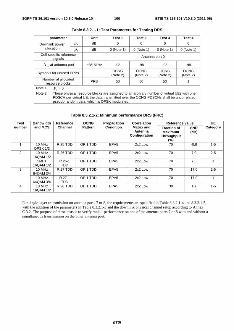
ETSI
ETSI TS 136 101 V10.3.0 (2011-06)1003GPP TS 36.101 version 10.3.0 Release 10
Table 8.3.2.1-1: Test Parameters for Testing DRS
parameter Unit Test 1 Test 2 Test 3 Test 4
Downlink power allocation
Aρ dB 0 0 0 0
Bρ dB 0 (Note 1) 0 (Note 1) 0 (Note 1) 0 (Note 1) Cell-specific reference
signals Antenna port 0
ocN at antenna port dB/15kHz -98 -98 -98 -98
Symbols for unused PRBs OCNG (Note 2)
OCNG (Note 2)
OCNG (Note 2)
OCNG (Note 2)
Number of allocated resource blocks PRB 50 50 50 1
Note 1: 0=BP
Note 2: These physical resource blocks are assigned to an arbitrary number of virtual UEs with one PDSCH per virtual UE; the data transmitted over the OCNG PDSCHs shall be uncorrelated pseudo random data, which is QPSK modulated.
Table 8.3.2.1-2: Minimum performance DRS (FRC)
Test number
Bandwidth and MCS
Reference Channel
OCNG Pattern
Propagation Condition
Correlation Matrix and Antenna
Configuration
Reference value UE Category Fraction of
Maximum Throughput
(%)
SNR (dB)
1 10 MHz QPSK 1/3
R.25 TDD OP.1 TDD EPA5 2x2 Low 70 -0.8 1-5
2 10 MHz 16QAM 1/2
R.26 TDD OP.1 TDD EPA5 2x2 Low 70 7.0 2-5
5MHz 16QAM 1/2
R.26-1 TDD
OP.1 TDD EPA5 2x2 Low 70 7.0 1
3 10 MHz 64QAM 3/4
R.27 TDD OP.1 TDD EPA5 2x2 Low 70 17.0 2-5
10 MHz 64QAM 3/4
R.27-1 TDD
OP.1 TDD EPA5 2x2 Low 70 17.0 1
4 10 MHz 16QAM 1/2
R.28 TDD OP.1 TDD EPA5 2x2 Low 30 1.7 1-5
For single-layer transmission on antenna ports 7 or 8, the requirements are specified in Table 8.3.2.1-4 and 8.3.2.1-5, with the addition of the parameters in Table 8.3.2.1-3 and the downlink physical channel setup according to Annex C.3.2. The purpose of these tests is to verify rank-1 performance on one of the antenna ports 7 or 8 with and without a simultaneous transmission on the other antenna port.
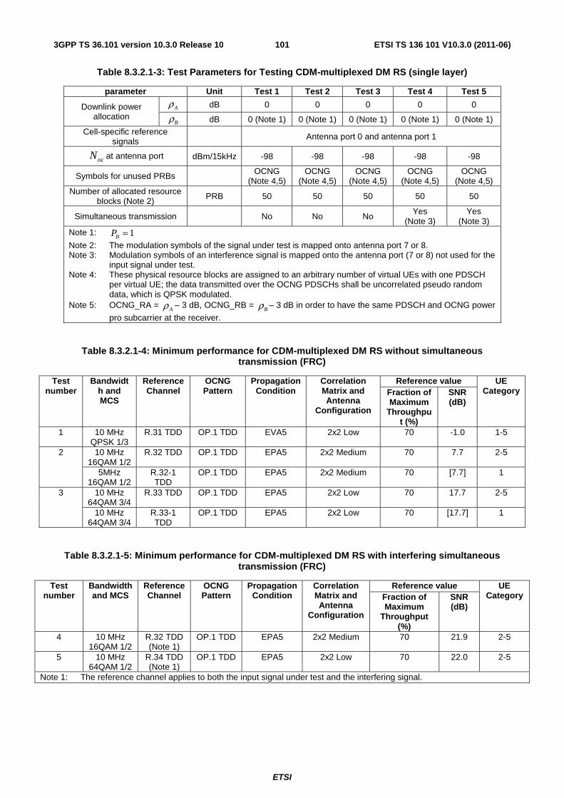
ETSI
ETSI TS 136 101 V10.3.0 (2011-06)1013GPP TS 36.101 version 10.3.0 Release 10
Table 8.3.2.1-3: Test Parameters for Testing CDM-multiplexed DM RS (single layer)
parameter Unit Test 1 Test 2 Test 3 Test 4 Test 5
Downlink power allocation
Aρ dB 0 0 0 0 0
Bρ dB 0 (Note 1) 0 (Note 1) 0 (Note 1) 0 (Note 1) 0 (Note 1) Cell-specific reference
signals Antenna port 0 and antenna port 1
ocN at antenna port dBm/15kHz -98 -98 -98 -98 -98
Symbols for unused PRBs OCNG (Note 4,5)
OCNG (Note 4,5)
OCNG (Note 4,5)
OCNG (Note 4,5)
OCNG (Note 4,5)
Number of allocated resource blocks (Note 2) PRB 50 50 50 50 50
Simultaneous transmission No No No Yes
(Note 3) Yes
(Note 3) Note 1: 1=BP
Note 2: The modulation symbols of the signal under test is mapped onto antenna port 7 or 8. Note 3: Modulation symbols of an interference signal is mapped onto the antenna port (7 or 8) not used for the
input signal under test. Note 4: These physical resource blocks are assigned to an arbitrary number of virtual UEs with one PDSCH
per virtual UE; the data transmitted over the OCNG PDSCHs shall be uncorrelated pseudo random data, which is QPSK modulated.
Note 5: OCNG_RA = Aρ – 3 dB, OCNG_RB =
Bρ – 3 dB in order to have the same PDSCH and OCNG power
pro subcarrier at the receiver.
Table 8.3.2.1-4: Minimum performance for CDM-multiplexed DM RS without simultaneous transmission (FRC)
Test number
Bandwidth and MCS
Reference Channel
OCNG Pattern
Propagation Condition
Correlation Matrix and Antenna
Configuration
Reference value UE Category Fraction of
Maximum Throughpu
t (%)
SNR (dB)
1 10 MHz QPSK 1/3
R.31 TDD OP.1 TDD EVA5 2x2 Low 70 -1.0 1-5
2 10 MHz 16QAM 1/2
R.32 TDD OP.1 TDD EPA5 2x2 Medium 70 7.7 2-5
5MHz 16QAM 1/2
R.32-1 TDD
OP.1 TDD EPA5 2x2 Medium 70 [7.7] 1
3 10 MHz 64QAM 3/4
R.33 TDD OP.1 TDD EPA5 2x2 Low 70 17.7 2-5
10 MHz 64QAM 3/4
R.33-1 TDD
OP.1 TDD EPA5 2x2 Low 70 [17.7] 1
Table 8.3.2.1-5: Minimum performance for CDM-multiplexed DM RS with interfering simultaneous transmission (FRC)
Test number
Bandwidth and MCS
Reference Channel
OCNG Pattern
Propagation Condition
Correlation Matrix and Antenna
Configuration
Reference value UE Category Fraction of
Maximum Throughput
(%)
SNR (dB)
4 10 MHz 16QAM 1/2
R.32 TDD (Note 1)
OP.1 TDD EPA5 2x2 Medium 70 21.9 2-5
5 10 MHz 64QAM 1/2
R.34 TDD (Note 1)
OP.1 TDD EPA5 2x2 Low 70 22.0 2-5
Note 1: The reference channel applies to both the input signal under test and the interfering signal.
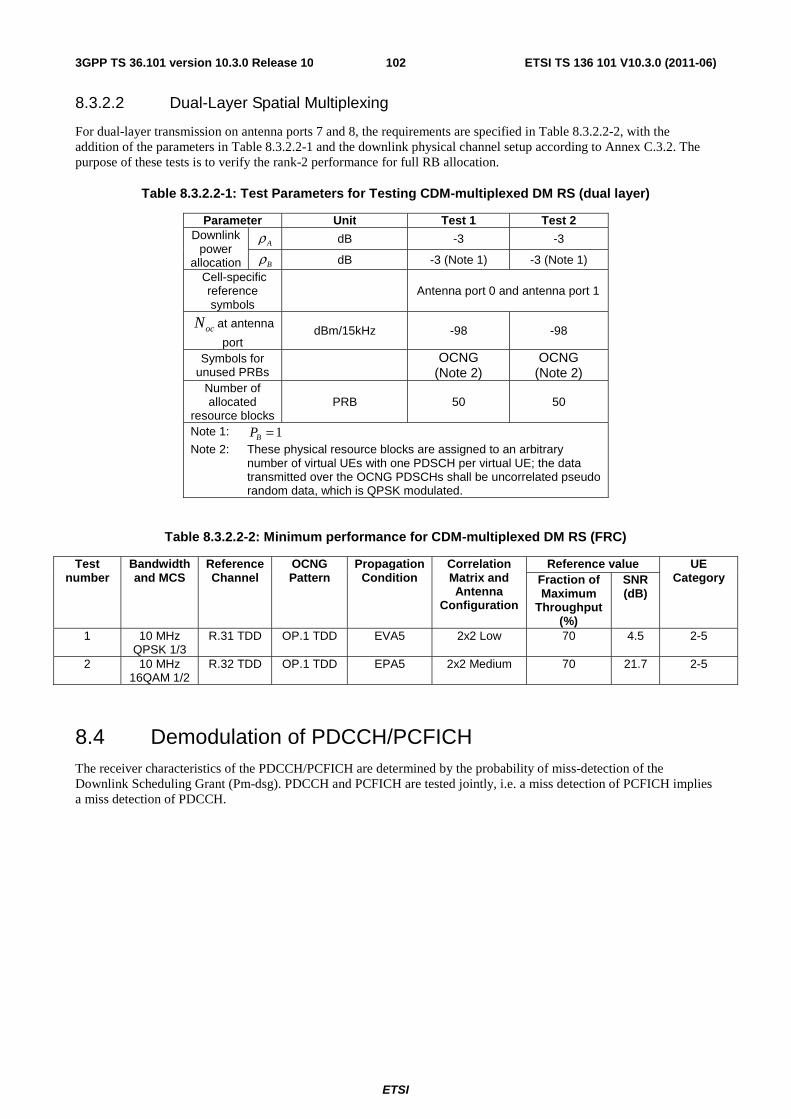
ETSI
ETSI TS 136 101 V10.3.0 (2011-06)1023GPP TS 36.101 version 10.3.0 Release 10
8.3.2.2 Dual-Layer Spatial Multiplexing
For dual-layer transmission on antenna ports 7 and 8, the requirements are specified in Table 8.3.2.2-2, with the addition of the parameters in Table 8.3.2.2-1 and the downlink physical channel setup according to Annex C.3.2. The purpose of these tests is to verify the rank-2 performance for full RB allocation.
Table 8.3.2.2-1: Test Parameters for Testing CDM-multiplexed DM RS (dual layer)
Parameter Unit Test 1 Test 2 Downlink
power allocation
Aρ dB -3 -3
Bρ dB -3 (Note 1) -3 (Note 1) Cell-specific
reference symbols
Antenna port 0 and antenna port 1
ocN at antenna
port dBm/15kHz -98 -98
Symbols for unused PRBs
OCNG (Note 2)
OCNG (Note 2)
Number of allocated
resource blocks PRB 50 50
Note 1: 1=BP
Note 2: These physical resource blocks are assigned to an arbitrary number of virtual UEs with one PDSCH per virtual UE; the data transmitted over the OCNG PDSCHs shall be uncorrelated pseudo random data, which is QPSK modulated.
Table 8.3.2.2-2: Minimum performance for CDM-multiplexed DM RS (FRC)
Test number
Bandwidth and MCS
Reference Channel
OCNG Pattern
Propagation Condition
Correlation Matrix and Antenna
Configuration
Reference value UE Category Fraction of
Maximum Throughput
(%)
SNR (dB)
1 10 MHz QPSK 1/3
R.31 TDD OP.1 TDD EVA5 2x2 Low 70 4.5 2-5
2 10 MHz 16QAM 1/2
R.32 TDD OP.1 TDD EPA5 2x2 Medium 70 21.7 2-5
8.4 Demodulation of PDCCH/PCFICH The receiver characteristics of the PDCCH/PCFICH are determined by the probability of miss-detection of the Downlink Scheduling Grant (Pm-dsg). PDCCH and PCFICH are tested jointly, i.e. a miss detection of PCFICH implies a miss detection of PDCCH.
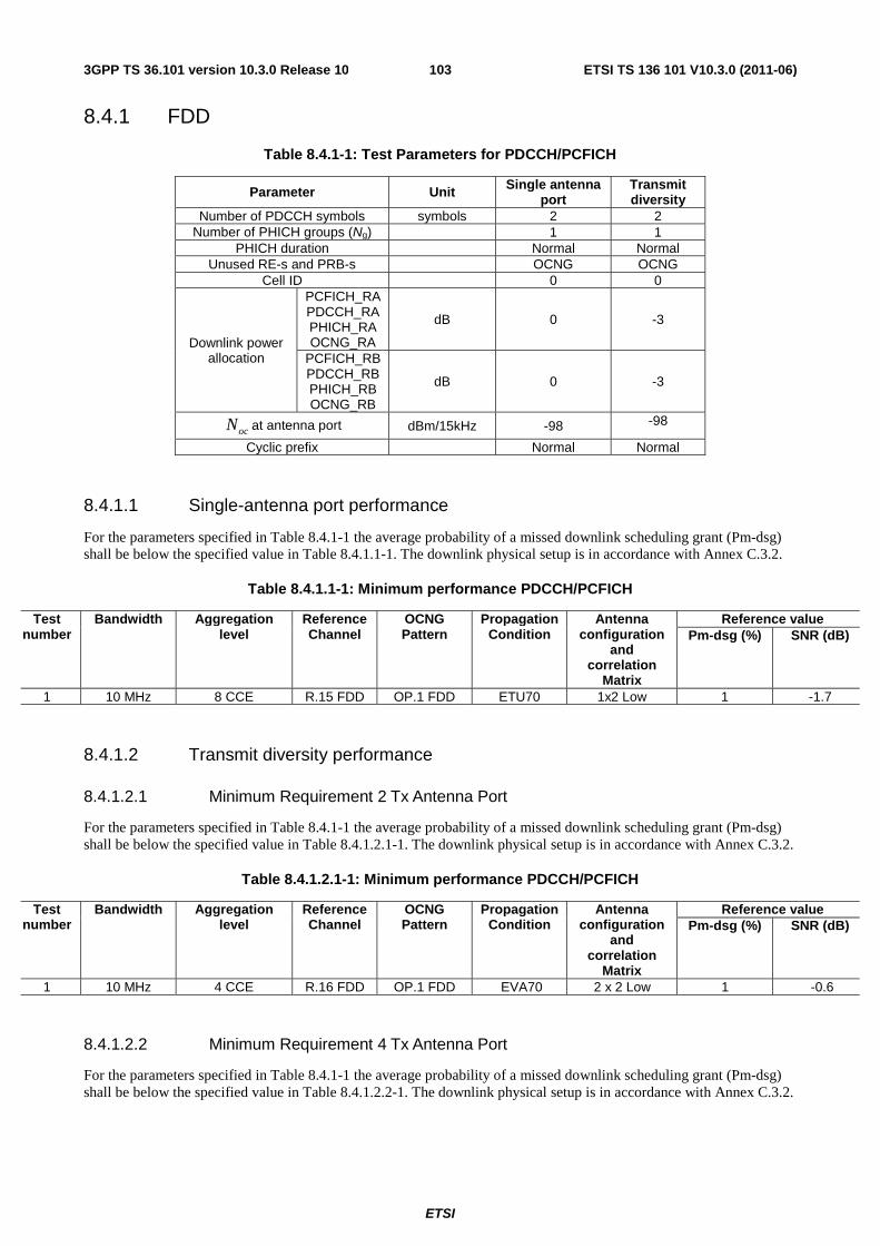
ETSI
ETSI TS 136 101 V10.3.0 (2011-06)1033GPP TS 36.101 version 10.3.0 Release 10
8.4.1 FDD
Table 8.4.1-1: Test Parameters for PDCCH/PCFICH
Parameter Unit Single antenna port
Transmit diversity
Number of PDCCH symbols symbols 2 2 Number of PHICH groups (Ng) 1 1
PHICH duration Normal Normal Unused RE-s and PRB-s OCNG OCNG
Cell ID 0 0
Downlink power allocation
PCFICH_RA PDCCH_RA PHICH_RA OCNG_RA
dB 0 -3
PCFICH_RB PDCCH_RB PHICH_RB OCNG_RB
dB 0 -3
ocN at antenna port dBm/15kHz -98 -98
Cyclic prefix Normal Normal
8.4.1.1 Single-antenna port performance
For the parameters specified in Table 8.4.1-1 the average probability of a missed downlink scheduling grant (Pm-dsg) shall be below the specified value in Table 8.4.1.1-1. The downlink physical setup is in accordance with Annex C.3.2.
Table 8.4.1.1-1: Minimum performance PDCCH/PCFICH
Test number
Bandwidth Aggregation level
Reference Channel
OCNG Pattern
Propagation Condition
Antenna configuration
and correlation
Matrix
Reference value Pm-dsg (%) SNR (dB)
1 10 MHz 8 CCE R.15 FDD OP.1 FDD ETU70 1x2 Low 1 -1.7
8.4.1.2 Transmit diversity performance
8.4.1.2.1 Minimum Requirement 2 Tx Antenna Port
For the parameters specified in Table 8.4.1-1 the average probability of a missed downlink scheduling grant (Pm-dsg) shall be below the specified value in Table 8.4.1.2.1-1. The downlink physical setup is in accordance with Annex C.3.2.
Table 8.4.1.2.1-1: Minimum performance PDCCH/PCFICH
Test number
Bandwidth Aggregation level
Reference Channel
OCNG Pattern
Propagation Condition
Antenna configuration
and correlation
Matrix
Reference value Pm-dsg (%) SNR (dB)
1 10 MHz 4 CCE R.16 FDD OP.1 FDD EVA70 2 x 2 Low 1 -0.6
8.4.1.2.2 Minimum Requirement 4 Tx Antenna Port
For the parameters specified in Table 8.4.1-1 the average probability of a missed downlink scheduling grant (Pm-dsg) shall be below the specified value in Table 8.4.1.2.2-1. The downlink physical setup is in accordance with Annex C.3.2.
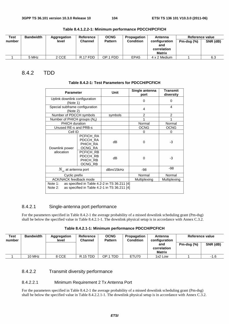
ETSI
ETSI TS 136 101 V10.3.0 (2011-06)1043GPP TS 36.101 version 10.3.0 Release 10
Table 8.4.1.2.2-1: Minimum performance PDCCH/PCFICH
Test number
Bandwidth Aggregation level
Reference Channel
OCNG Pattern
Propagation Condition
Antenna configuration
and correlation
Matrix
Reference value Pm-dsg (%) SNR (dB)
1 5 MHz 2 CCE R.17 FDD OP.1 FDD EPA5 4 x 2 Medium 1 6.3
8.4.2 TDD
Table 8.4.2-1: Test Parameters for PDCCH/PCFICH
Parameter Unit Single antenna port
Transmit diversity
Uplink downlink configuration (Note 1) 0 0
Special subframe configuration (Note 2) 4
4
Number of PDCCH symbols symbols 2 2 Number of PHICH groups (Ng) 1 1
PHICH duration Normal Normal Unused RE-s and PRB-s OCNG OCNG
Cell ID 0 0
Downlink power allocation
PCFICH_RA PDCCH_RA PHICH_RA OCNG_RA
dB 0 -3
PCFICH_RB PDCCH_RB PHICH_RB OCNG_RB
dB 0 -3
ocN at antenna port dBm/15kHz -98 -98
Cyclic prefix Normal Normal ACK/NACK feedback mode Multiplexing Multiplexing
Note 1: as specified in Table 4.2-2 in TS 36.211 [4] Note 2: as specified in Table 4.2-1 in TS 36.211 [4]
8.4.2.1 Single-antenna port performance
For the parameters specified in Table 8.4.2-1 the average probability of a missed downlink scheduling grant (Pm-dsg) shall be below the specified value in Table 8.4.2.1-1. The downlink physical setup is in accordance with Annex C.3.2.
Table 8.4.2.1-1: Minimum performance PDCCH/PCFICH
Test number
Bandwidth Aggregation level
Reference Channel
OCNG Pattern
Propagation Condition
Antenna configuration
and correlation
Matrix
Reference value
Pm-dsg (%) SNR (dB)
1 10 MHz 8 CCE R.15 TDD OP.1 TDD ETU70 1x2 Low 1 -1.6
8.4.2.2 Transmit diversity performance
8.4.2.2.1 Minimum Requirement 2 Tx Antenna Port
For the parameters specified in Table 8.4.2-1 the average probability of a missed downlink scheduling grant (Pm-dsg) shall be below the specified value in Table 8.4.2.2.1-1. The downlink physical setup is in accordance with Annex C.3.2.
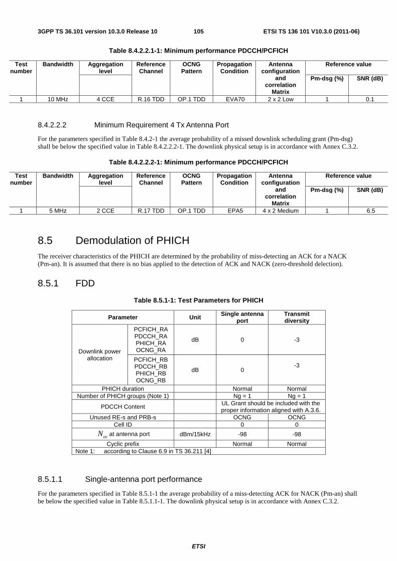
ETSI
ETSI TS 136 101 V10.3.0 (2011-06)1053GPP TS 36.101 version 10.3.0 Release 10
Table 8.4.2.2.1-1: Minimum performance PDCCH/PCFICH
Test number
Bandwidth Aggregation level
Reference Channel
OCNG Pattern
Propagation Condition
Antenna configuration
and correlation
Matrix
Reference value
Pm-dsg (%) SNR (dB)
1 10 MHz 4 CCE R.16 TDD OP.1 TDD EVA70 2 x 2 Low 1 0.1
8.4.2.2.2 Minimum Requirement 4 Tx Antenna Port
For the parameters specified in Table 8.4.2-1 the average probability of a missed downlink scheduling grant (Pm-dsg) shall be below the specified value in Table 8.4.2.2.2-1. The downlink physical setup is in accordance with Annex C.3.2.
Table 8.4.2.2.2-1: Minimum performance PDCCH/PCFICH
Test number
Bandwidth Aggregation level
Reference Channel
OCNG Pattern
Propagation Condition
Antenna configuration
and correlation
Matrix
Reference value
Pm-dsg (%) SNR (dB)
1 5 MHz 2 CCE R.17 TDD OP.1 TDD EPA5 4 x 2 Medium 1 6.5
8.5 Demodulation of PHICH The receiver characteristics of the PHICH are determined by the probability of miss-detecting an ACK for a NACK (Pm-an). It is assumed that there is no bias applied to the detection of ACK and NACK (zero-threshold delection).
8.5.1 FDD
Table 8.5.1-1: Test Parameters for PHICH
Parameter Unit Single antenna port
Transmit diversity
Downlink power allocation
PCFICH_RA PDCCH_RA PHICH_RA OCNG_RA
dB
0
-3
PCFICH_RB PDCCH_RB PHICH_RB OCNG_RB
dB
0
-3
PHICH duration Normal Normal Number of PHICH groups (Note 1) Ng = 1 Ng = 1
PDCCH Content UL Grant should be included with the proper information aligned with A.3.6.
Unused RE-s and PRB-s OCNG OCNG Cell ID 0 0
ocN at antenna port dBm/15kHz -98 -98
Cyclic prefix Normal Normal Note 1: according to Clause 6.9 in TS 36.211 [4]
8.5.1.1 Single-antenna port performance
For the parameters specified in Table 8.5.1-1 the average probability of a miss-detecting ACK for NACK (Pm-an) shall be below the specified value in Table 8.5.1.1-1. The downlink physical setup is in accordance with Annex C.3.2.
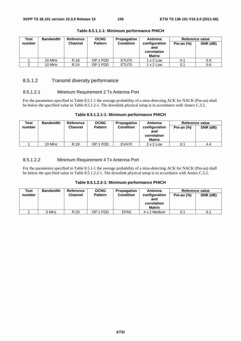
ETSI
ETSI TS 136 101 V10.3.0 (2011-06)1063GPP TS 36.101 version 10.3.0 Release 10
Table 8.5.1.1-1: Minimum performance PHICH
Test number
Bandwidth Reference Channel
OCNG Pattern
Propagation Condition
Antenna configuration
and correlation
Matrix
Reference value Pm-an (%) SNR (dB)
1 10 MHz R.18 OP.1 FDD ETU70 1 x 2 Low 0.1 5.5 2 10 MHz R.24 OP.1 FDD ETU70 1 x 2 Low 0.1 0.6
8.5.1.2 Transmit diversity performance
8.5.1.2.1 Minimum Requirement 2 Tx Antenna Port
For the parameters specified in Table 8.5.1-1 the average probability of a miss-detecting ACK for NACK (Pm-an) shall be below the specified value in Table 8.5.1.2-1. The downlink physical setup is in accordance with Annex C.3.2.
Table 8.5.1.2.1-1: Minimum performance PHICH
Test number
Bandwidth Reference Channel
OCNG Pattern
Propagation Condition
Antenna configuration
and correlation
Matrix
Reference value Pm-an (%) SNR (dB)
1 10 MHz R.19 OP.1 FDD EVA70 2 x 2 Low 0.1 4.4
8.5.1.2.2 Minimum Requirement 4 Tx Antenna Port
For the parameters specified in Table 8.5.1-1 the average probability of a miss-detecting ACK for NACK (Pm-an) shall be below the specified value in Table 8.5.1.2.2-1. The downlink physical setup is in accordance with Annex C.3.2.
Table 8.5.1.2.2-1: Minimum performance PHICH
Test number
Bandwidth Reference Channel
OCNG Pattern
Propagation Condition
Antenna configuration
and correlation
Matrix
Reference value Pm-an (%) SNR (dB)
1 5 MHz R.20 OP.1 FDD EPA5 4 x 2 Medium 0.1 6.1
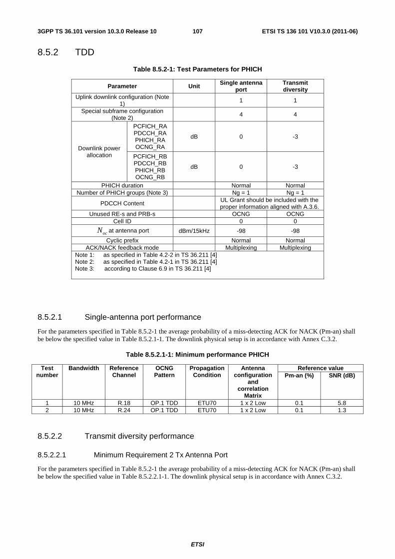
ETSI
ETSI TS 136 101 V10.3.0 (2011-06)1073GPP TS 36.101 version 10.3.0 Release 10
8.5.2 TDD
Table 8.5.2-1: Test Parameters for PHICH
Parameter Unit Single antenna port
Transmit diversity
Uplink downlink configuration (Note 1) 1 1
Special subframe configuration (Note 2) 4 4
Downlink power allocation
PCFICH_RA PDCCH_RA PHICH_RA OCNG_RA
dB
0
-3
PCFICH_RB PDCCH_RB PHICH_RB OCNG_RB
dB
0
-3
PHICH duration Normal Normal Number of PHICH groups (Note 3) Ng = 1 Ng = 1
PDCCH Content UL Grant should be included with the proper information aligned with A.3.6.
Unused RE-s and PRB-s OCNG OCNG Cell ID 0 0
ocN at antenna port dBm/15kHz -98 -98
Cyclic prefix Normal Normal ACK/NACK feedback mode Multiplexing Multiplexing
Note 1: as specified in Table 4.2-2 in TS 36.211 [4] Note 2: as specified in Table 4.2-1 in TS 36.211 [4] Note 3: according to Clause 6.9 in TS 36.211 [4]
8.5.2.1 Single-antenna port performance
For the parameters specified in Table 8.5.2-1 the average probability of a miss-detecting ACK for NACK (Pm-an) shall be below the specified value in Table 8.5.2.1-1. The downlink physical setup is in accordance with Annex C.3.2.
Table 8.5.2.1-1: Minimum performance PHICH
Test number
Bandwidth Reference Channel
OCNG Pattern
Propagation Condition
Antenna configuration
and correlation
Matrix
Reference value Pm-an (%) SNR (dB)
1 10 MHz R.18 OP.1 TDD ETU70 1 x 2 Low 0.1 5.8 2 10 MHz R.24 OP.1 TDD ETU70 1 x 2 Low 0.1 1.3
8.5.2.2 Transmit diversity performance
8.5.2.2.1 Minimum Requirement 2 Tx Antenna Port
For the parameters specified in Table 8.5.2-1 the average probability of a miss-detecting ACK for NACK (Pm-an) shall be below the specified value in Table 8.5.2.2.1-1. The downlink physical setup is in accordance with Annex C.3.2.
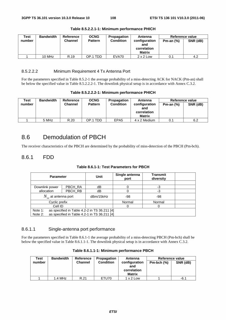
ETSI
ETSI TS 136 101 V10.3.0 (2011-06)1083GPP TS 36.101 version 10.3.0 Release 10
Table 8.5.2.2.1-1: Minimum performance PHICH
Test number
Bandwidth Reference Channel
OCNG Pattern
Propagation Condition
Antenna configuration
and correlation
Matrix
Reference value Pm-an (%) SNR (dB)
1 10 MHz R.19 OP.1 TDD EVA70 2 x 2 Low 0.1 4.2
8.5.2.2.2 Minimum Requirement 4 Tx Antenna Port
For the parameters specified in Table 8.5.2-1 the average probability of a miss-detecting ACK for NACK (Pm-an) shall be below the specified value in Table 8.5.2.2.2-1. The downlink physical setup is in accordance with Annex C.3.2.
Table 8.5.2.2.2-1: Minimum performance PHICH
Test number
Bandwidth Reference Channel
OCNG Pattern
Propagation Condition
Antenna configuration
and correlation
Matrix
Reference value Pm-an (%) SNR (dB)
1 5 MHz R.20 OP.1 TDD EPA5 4 x 2 Medium 0.1 6.2
8.6 Demodulation of PBCH The receiver characteristics of the PBCH are determined by the probability of miss-detection of the PBCH (Pm-bch).
8.6.1 FDD
Table 8.6.1-1: Test Parameters for PBCH
Parameter Unit Single antenna port
Transmit diversity
Downlink power
allocation PBCH_RA dB 0 -3 PBCH_RB dB 0 -3
ocN at antenna port dBm/15kHz -98 -98
Cyclic prefix Normal Normal Cell ID 0 0
Note 1: as specified in Table 4.2-2 in TS 36.211 [4] Note 2: as specified in Table 4.2-1 in TS 36.211 [4]
8.6.1.1 Single-antenna port performance
For the parameters specified in Table 8.6.1-1 the average probability of a miss-detecting PBCH (Pm-bch) shall be below the specified value in Table 8.6.1.1-1. The downlink physical setup is in accordance with Annex C.3.2.
Table 8.6.1.1-1: Minimum performance PBCH
Test number
Bandwidth Reference Channel
Propagation Condition
Antenna configuration
and correlation
Matrix
Reference value Pm-bch (%) SNR (dB)
1 1.4 MHz R.21 ETU70 1 x 2 Low 1 -6.1
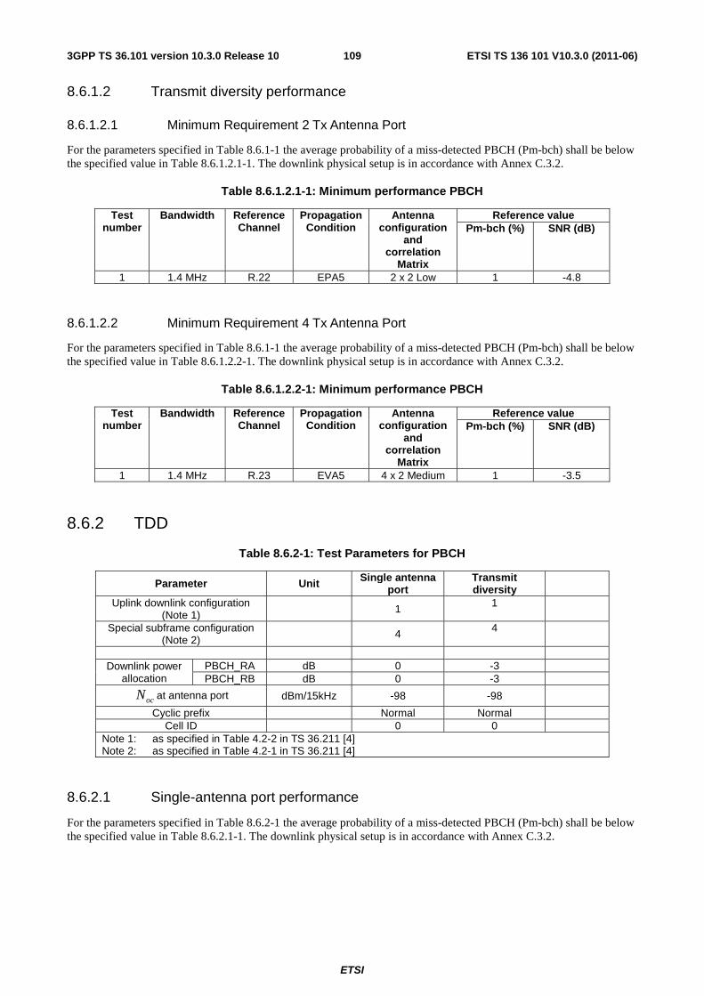
ETSI
ETSI TS 136 101 V10.3.0 (2011-06)1093GPP TS 36.101 version 10.3.0 Release 10
8.6.1.2 Transmit diversity performance
8.6.1.2.1 Minimum Requirement 2 Tx Antenna Port
For the parameters specified in Table 8.6.1-1 the average probability of a miss-detected PBCH (Pm-bch) shall be below the specified value in Table 8.6.1.2.1-1. The downlink physical setup is in accordance with Annex C.3.2.
Table 8.6.1.2.1-1: Minimum performance PBCH
Test number
Bandwidth Reference Channel
Propagation Condition
Antenna configuration
and correlation
Matrix
Reference value Pm-bch (%) SNR (dB)
1 1.4 MHz R.22 EPA5 2 x 2 Low 1 -4.8
8.6.1.2.2 Minimum Requirement 4 Tx Antenna Port
For the parameters specified in Table 8.6.1-1 the average probability of a miss-detected PBCH (Pm-bch) shall be below the specified value in Table 8.6.1.2.2-1. The downlink physical setup is in accordance with Annex C.3.2.
Table 8.6.1.2.2-1: Minimum performance PBCH
Test number
Bandwidth Reference Channel
Propagation Condition
Antenna configuration
and correlation
Matrix
Reference value Pm-bch (%) SNR (dB)
1 1.4 MHz R.23 EVA5 4 x 2 Medium 1 -3.5
8.6.2 TDD
Table 8.6.2-1: Test Parameters for PBCH
Parameter Unit Single antenna port
Transmit diversity
Uplink downlink configuration (Note 1) 1 1
Special subframe configuration (Note 2) 4 4
Downlink power
allocation PBCH_RA dB 0 -3 PBCH_RB dB 0 -3
ocN at antenna port dBm/15kHz -98 -98
Cyclic prefix Normal Normal Cell ID 0 0
Note 1: as specified in Table 4.2-2 in TS 36.211 [4] Note 2: as specified in Table 4.2-1 in TS 36.211 [4]
8.6.2.1 Single-antenna port performance
For the parameters specified in Table 8.6.2-1 the average probability of a miss-detected PBCH (Pm-bch) shall be below the specified value in Table 8.6.2.1-1. The downlink physical setup is in accordance with Annex C.3.2.
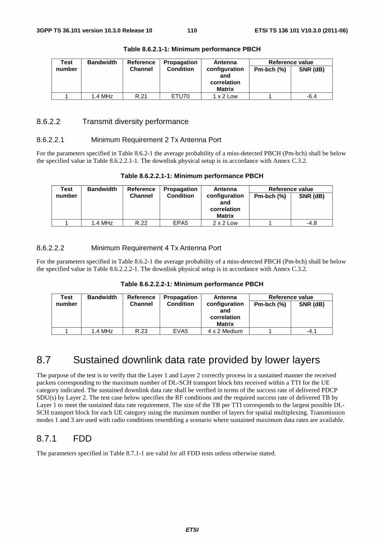
ETSI
ETSI TS 136 101 V10.3.0 (2011-06)1103GPP TS 36.101 version 10.3.0 Release 10
Table 8.6.2.1-1: Minimum performance PBCH
Test number
Bandwidth Reference Channel
Propagation Condition
Antenna configuration
and correlation
Matrix
Reference value Pm-bch (%) SNR (dB)
1 1.4 MHz R.21 ETU70 1 x 2 Low 1 -6.4
8.6.2.2 Transmit diversity performance
8.6.2.2.1 Minimum Requirement 2 Tx Antenna Port
For the parameters specified in Table 8.6.2-1 the average probability of a miss-detected PBCH (Pm-bch) shall be below the specified value in Table 8.6.2.2.1-1. The downlink physical setup is in accordance with Annex C.3.2.
Table 8.6.2.2.1-1: Minimum performance PBCH
Test number
Bandwidth Reference Channel
Propagation Condition
Antenna configuration
and correlation
Matrix
Reference value Pm-bch (%) SNR (dB)
1 1.4 MHz R.22 EPA5 2 x 2 Low 1 -4.8
8.6.2.2.2 Minimum Requirement 4 Tx Antenna Port
For the parameters specified in Table 8.6.2-1 the average probability of a miss-detected PBCH (Pm-bch) shall be below the specified value in Table 8.6.2.2.2-1. The downlink physical setup is in accordance with Annex C.3.2.
Table 8.6.2.2.2-1: Minimum performance PBCH
Test number
Bandwidth Reference Channel
Propagation Condition
Antenna configuration
and correlation
Matrix
Reference value Pm-bch (%) SNR (dB)
1 1.4 MHz R.23 EVA5 4 x 2 Medium 1 -4.1
8.7 Sustained downlink data rate provided by lower layers The purpose of the test is to verify that the Layer 1 and Layer 2 correctly process in a sustained manner the received packets corresponding to the maximum number of DL-SCH transport block bits received within a TTI for the UE category indicated. The sustained downlink data rate shall be verified in terms of the success rate of delivered PDCP SDU(s) by Layer 2. The test case below specifies the RF conditions and the required success rate of delivered TB by Layer 1 to meet the sustained data rate requirement. The size of the TB per TTI corresponds to the largest possible DL-SCH transport block for each UE category using the maximum number of layers for spatial multiplexing. Transmission modes 1 and 3 are used with radio conditions resembling a scenario where sustained maximum data rates are available.
8.7.1 FDD
The parameters specified in Table 8.7.1-1 are valid for all FDD tests unless otherwise stated.
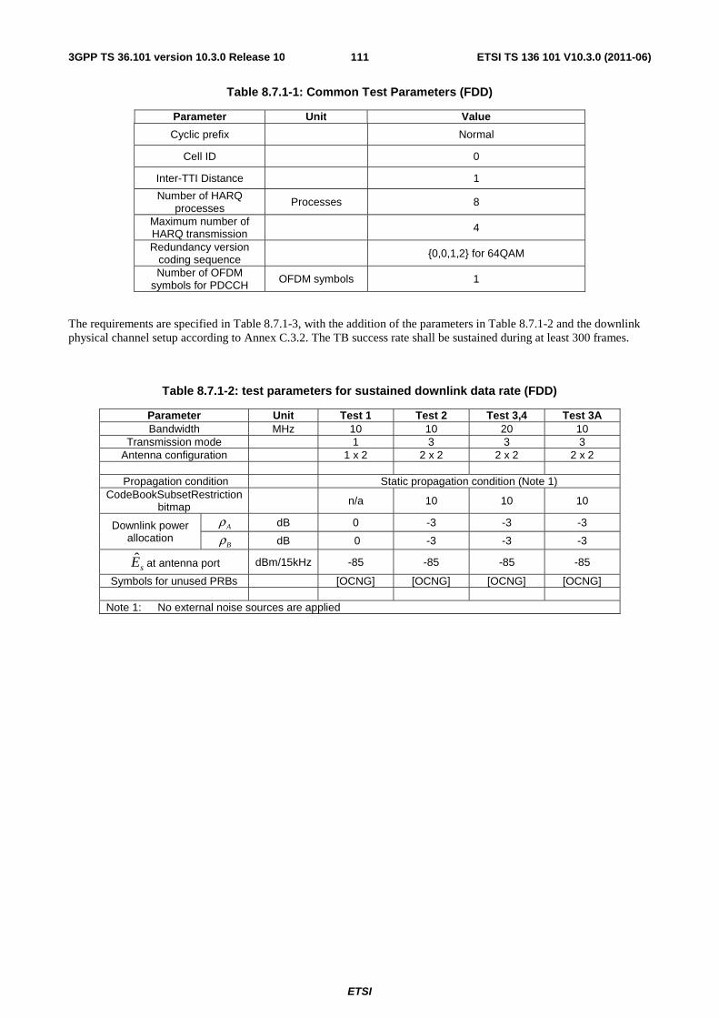
ETSI
ETSI TS 136 101 V10.3.0 (2011-06)1113GPP TS 36.101 version 10.3.0 Release 10
Table 8.7.1-1: Common Test Parameters (FDD)
Parameter Unit Value
Cyclic prefix Normal
Cell ID 0
Inter-TTI Distance 1
Number of HARQ processes
Processes 8
Maximum number of HARQ transmission
4
Redundancy version coding sequence {0,0,1,2} for 64QAM
Number of OFDM symbols for PDCCH
OFDM symbols 1
The requirements are specified in Table 8.7.1-3, with the addition of the parameters in Table 8.7.1-2 and the downlink physical channel setup according to Annex C.3.2. The TB success rate shall be sustained during at least 300 frames.
Table 8.7.1-2: test parameters for sustained downlink data rate (FDD)
Parameter Unit Test 1 Test 2 Test 3,4 Test 3A Bandwidth MHz 10 10 20 10
Transmission mode 1 3 3 3 Antenna configuration 1 x 2 2 x 2 2 x 2 2 x 2
Propagation condition Static propagation condition (Note 1)
CodeBookSubsetRestriction bitmap n/a 10 10 10
Downlink power allocation
Aρ dB 0 -3 -3 -3
Bρ dB 0 -3 -3 -3
sE at antenna port dBm/15kHz -85 -85 -85 -85
Symbols for unused PRBs [OCNG] [OCNG] [OCNG] [OCNG]
Note 1: No external noise sources are applied
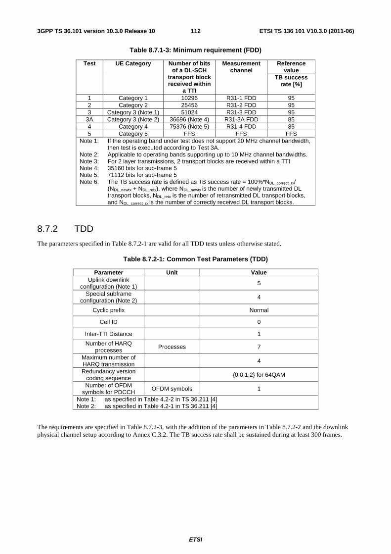
ETSI
ETSI TS 136 101 V10.3.0 (2011-06)1123GPP TS 36.101 version 10.3.0 Release 10
Table 8.7.1-3: Minimum requirement (FDD)
Test UE Category Number of bits of a DL-SCH
transport block received within
a TTI
Measurement channel
Reference value
TB success rate [%]
1 Category 1 10296 R31-1 FDD 95 2 Category 2 25456 R31-2 FDD 95 3 Category 3 (Note 1) 51024 R31-3 FDD 95
3A Category 3 (Note 2) 36696 (Note 4) R31-3A FDD 85 4 Category 4 75376 (Note 5) R31-4 FDD 85 5 Category 5 FFS FFS FFS
Note 1: If the operating band under test does not support 20 MHz channel bandwidth, then test is executed according to Test 3A.
Note 2: Applicable to operating bands supporting up to 10 MHz channel bandwidths. Note 3: For 2 layer transmissions, 2 transport blocks are received within a TTI Note 4: 35160 bits for sub-frame 5 Note 5: 71112 bits for sub-frame 5 Note 6: The TB success rate is defined as TB success rate = 100%*NDL_correct_rx/
(NDL_newtx + NDL_retx), where NDL_newtx is the number of newly transmitted DL transport blocks, NDL_retx is the number of retransmitted DL transport blocks, and NDL_correct_rx is the number of correctly received DL transport blocks.
8.7.2 TDD
The parameters specified in Table 8.7.2-1 are valid for all TDD tests unless otherwise stated.
Table 8.7.2-1: Common Test Parameters (TDD)
Parameter Unit Value Uplink downlink
configuration (Note 1) 5
Special subframe configuration (Note 2) 4
Cyclic prefix Normal
Cell ID 0
Inter-TTI Distance 1
Number of HARQ processes Processes 7
Maximum number of HARQ transmission
4
Redundancy version coding sequence {0,0,1,2} for 64QAM
Number of OFDM symbols for PDCCH OFDM symbols 1
Note 1: as specified in Table 4.2-2 in TS 36.211 [4] Note 2: as specified in Table 4.2-1 in TS 36.211 [4]
The requirements are specified in Table 8.7.2-3, with the addition of the parameters in Table 8.7.2-2 and the downlink physical channel setup according to Annex C.3.2. The TB success rate shall be sustained during at least 300 frames.
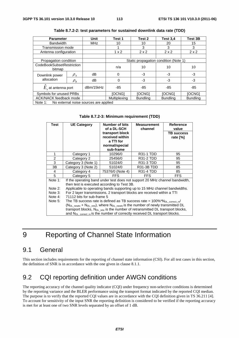
ETSI
ETSI TS 136 101 V10.3.0 (2011-06)1133GPP TS 36.101 version 10.3.0 Release 10
Table 8.7.2-2: test parameters for sustained downlink data rate (TDD)
Parameter Unit Test 1 Test 2 Test 3,4 Test 3B Bandwidth MHz 10 10 20 15
Transmission mode 1 3 3 3 Antenna configuration 1 x 2 2 x 2 2 x 2 2 x 2
Propagation condition Static propagation condition (Note 1)
CodeBookSubsetRestriction bitmap n/a 10 10 10
Downlink power allocation
Aρ dB 0 -3 -3 -3
Bρ dB 0 -3 -3 -3
sE at antenna port dBm/15kHz -85 -85 -85 -85
Symbols for unused PRBs [OCNG] [OCNG] [OCNG] [OCNG] ACK/NACK feedback mode Multiplexing Bundling Bundling Bundling Note 1: No external noise sources are applied
Table 8.7.2-3: Minimum requirement (TDD)
Test UE Category Number of bits of a DL-SCH
transport block received within
a TTI for normal/special
sub-frame
Measurement channel
Reference value
TB success rate [%]
1 Category 1 10296/0 R31-1 TDD 95 2 Category 2 25456/0 R31-2 TDD 95 3 Category 3 (Note 1) 51024/0 R31-3 TDD 95
3B Category 3 (Note 2) 51024/0 R31-3B TDD 85 4 Category 4 75376/0 (Note 4) R31-4 TDD 85 5 Category 5 FFS FFS FFS
Note 1: If the operating band under test does not support 20 MHz channel bandwidth, then test is executed according to Test 3B.
Note 2: Applicable to operating bands supporting up to 15 MHz channel bandwidths. Note 3: For 2 layer transmissions, 2 transport blocks are received within a TTI Note 4: 71112 bits for sub-frame 5 Note 5: The TB success rate is defined as TB success rate = 100%*NDL_correct_rx/
(NDL_newtx + NDL_retx), where NDL_newtx is the number of newly transmitted DL transport blocks, NDL_retx is the number of retransmitted DL transport blocks, and NDL_correct_rx is the number of correctly received DL transport blocks.
9 Reporting of Channel State Information
9.1 General This section includes requirements for the reporting of channel state information (CSI). For all test cases in this section, the definition of SNR is in accordance with the one given in clause 8.1.1.
9.2 CQI reporting definition under AWGN conditions The reporting accuracy of the channel quality indicator (CQI) under frequency non-selective conditions is determined by the reporting variance and the BLER performance using the transport format indicated by the reported CQI median. The purpose is to verify that the reported CQI values are in accordance with the CQI definition given in TS 36.211 [4]. To account for sensitivity of the input SNR the reporting definition is considered to be verified if the reporting accuracy is met for at least one of two SNR levels separated by an offset of 1 dB.
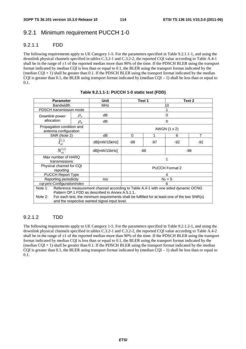
ETSI
ETSI TS 136 101 V10.3.0 (2011-06)1143GPP TS 36.101 version 10.3.0 Release 10
9.2.1 Minimum requirement PUCCH 1-0
9.2.1.1 FDD
The following requirements apply to UE Category 1-5. For the parameters specified in Table 9.2.1.1-1, and using the downlink physical channels specified in tables C.3.2-1 and C.3.2-2, the reported CQI value according to Table A.4-1 shall be in the range of ±1 of the reported median more than 90% of the time. If the PDSCH BLER using the transport format indicated by median CQI is less than or equal to 0.1, the BLER using the transport format indicated by the (median CQI + 1) shall be greater than 0.1. If the PDSCH BLER using the transport format indicated by the median CQI is greater than 0.1, the BLER using transport format indicated by (median CQI – 1) shall be less than or equal to 0.1.
Table 9.2.1.1-1: PUCCH 1-0 static test (FDD)
Parameter Unit Test 1 Test 2 Bandwidth MHz 10
PDSCH transmission mode 1
Downlink power allocation
Aρ dB 0
Bρ dB 0 Propagation condition and
antenna configuration AWGN (1 x 2)
SNR (Note 2) dB 0 1 6 7 )(ˆ j
orI dB[mW/15kHz] -98 -97 -92 -91
)( jocN dB[mW/15kHz] -98 -98
Max number of HARQ transmissions 1
Physical channel for CQI reporting
PUCCH Format 2
PUCCH Report Type 4 Reporting periodicity ms NP = 5
cqi-pmi-ConfigurationIndex 6 Note 1: Reference measurement channel according to Table A.4-1 with one sided dynamic OCNG
Pattern OP.1 FDD as described in Annex A.5.1.1. Note 2: For each test, the minimum requirements shall be fulfilled for at least one of the two SNR(s)
and the respective wanted signal input level.
9.2.1.2 TDD
The following requirements apply to UE Category 1-5. For the parameters specified in Table 9.2.1.2-1, and using the downlink physical channels specified in tables C.3.2-1 and C.3.2-2, the reported CQI value according to Table A.4-2 shall be in the range of ±1 of the reported median more than 90% of the time. If the PDSCH BLER using the transport format indicated by median CQI is less than or equal to 0.1, the BLER using the transport format indicated by the (median CQI + 1) shall be greater than 0.1. If the PDSCH BLER using the transport format indicated by the median CQI is greater than 0.1, the BLER using transport format indicated by (median CQI – 1) shall be less than or equal to 0.1.
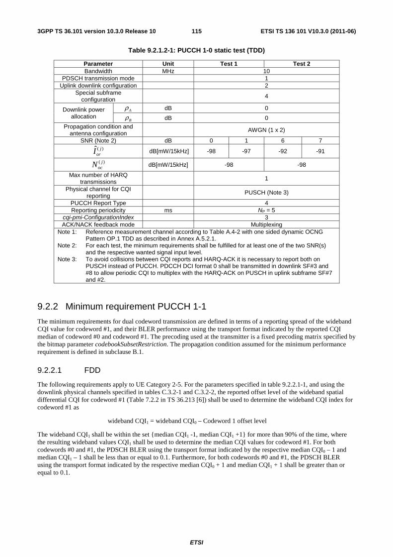
ETSI
ETSI TS 136 101 V10.3.0 (2011-06)1153GPP TS 36.101 version 10.3.0 Release 10
Table 9.2.1.2-1: PUCCH 1-0 static test (TDD)
Parameter Unit Test 1 Test 2 Bandwidth MHz 10
PDSCH transmission mode 1 Uplink downlink configuration 2
Special subframe configuration 4
Downlink power allocation
Aρ dB 0
Bρ dB 0 Propagation condition and
antenna configuration AWGN (1 x 2)
SNR (Note 2) dB 0 1 6 7 )(ˆ j
orI dB[mW/15kHz] -98 -97 -92 -91
)( jocN dB[mW/15kHz] -98 -98
Max number of HARQ transmissions 1
Physical channel for CQI reporting PUSCH (Note 3)
PUCCH Report Type 4 Reporting periodicity ms NP = 5
cqi-pmi-ConfigurationIndex 3 ACK/NACK feedback mode Multiplexing
Note 1: Reference measurement channel according to Table A.4-2 with one sided dynamic OCNG Pattern OP.1 TDD as described in Annex A.5.2.1.
Note 2: For each test, the minimum requirements shall be fulfilled for at least one of the two SNR(s) and the respective wanted signal input level.
Note 3: To avoid collisions between CQI reports and HARQ-ACK it is necessary to report both on PUSCH instead of PUCCH. PDCCH DCI format 0 shall be transmitted in downlink SF#3 and #8 to allow periodic CQI to multiplex with the HARQ-ACK on PUSCH in uplink subframe SF#7 and #2.
9.2.2 Minimum requirement PUCCH 1-1
The minimum requirements for dual codeword transmission are defined in terms of a reporting spread of the wideband CQI value for codeword #1, and their BLER performance using the transport format indicated by the reported CQI median of codeword #0 and codeword #1. The precoding used at the transmitter is a fixed precoding matrix specified by the bitmap parameter codebookSubsetRestriction. The propagation condition assumed for the minimum performance requirement is defined in subclause B.1.
9.2.2.1 FDD
The following requirements apply to UE Category 2-5. For the parameters specified in table 9.2.2.1-1, and using the downlink physical channels specified in tables C.3.2-1 and C.3.2-2, the reported offset level of the wideband spatial differential CQI for codeword #1 (Table 7.2.2 in TS 36.213 [6]) shall be used to determine the wideband CQI index for codeword #1 as
wideband CQI1 = wideband CQI0 – Codeword 1 offset level
The wideband CQI1 shall be within the set {median CQI1 -1, median CQI1 +1} for more than 90% of the time, where the resulting wideband values CQI1 shall be used to determine the median CQI values for codeword #1. For both codewords #0 and #1, the PDSCH BLER using the transport format indicated by the respective median CQI0 – 1 and median CQI1 – 1 shall be less than or equal to 0.1. Furthermore, for both codewords #0 and #1, the PDSCH BLER using the transport format indicated by the respective median CQI0 + 1 and median CQI1 + 1 shall be greater than or equal to 0.1.
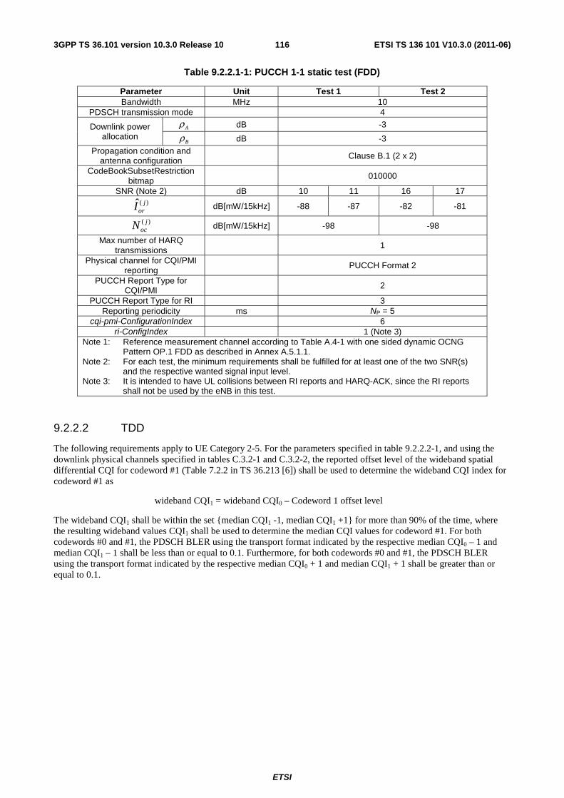
ETSI
ETSI TS 136 101 V10.3.0 (2011-06)1163GPP TS 36.101 version 10.3.0 Release 10
Table 9.2.2.1-1: PUCCH 1-1 static test (FDD)
Parameter Unit Test 1 Test 2 Bandwidth MHz 10
PDSCH transmission mode 4
Downlink power allocation
Aρ dB -3
Bρ dB -3 Propagation condition and
antenna configuration Clause B.1 (2 x 2)
CodeBookSubsetRestriction bitmap 010000
SNR (Note 2) dB 10 11 16 17 )(ˆ j
orI dB[mW/15kHz] -88 -87 -82 -81
)( jocN dB[mW/15kHz] -98 -98
Max number of HARQ transmissions 1
Physical channel for CQI/PMI reporting PUCCH Format 2
PUCCH Report Type for CQI/PMI 2
PUCCH Report Type for RI 3 Reporting periodicity ms NP = 5
cqi-pmi-ConfigurationIndex 6 ri-ConfigIndex 1 (Note 3)
Note 1: Reference measurement channel according to Table A.4-1 with one sided dynamic OCNG Pattern OP.1 FDD as described in Annex A.5.1.1.
Note 2: For each test, the minimum requirements shall be fulfilled for at least one of the two SNR(s) and the respective wanted signal input level.
Note 3: It is intended to have UL collisions between RI reports and HARQ-ACK, since the RI reports shall not be used by the eNB in this test.
9.2.2.2 TDD
The following requirements apply to UE Category 2-5. For the parameters specified in table 9.2.2.2-1, and using the downlink physical channels specified in tables C.3.2-1 and C.3.2-2, the reported offset level of the wideband spatial differential CQI for codeword #1 (Table 7.2.2 in TS 36.213 [6]) shall be used to determine the wideband CQI index for codeword #1 as
wideband CQI1 = wideband CQI0 – Codeword 1 offset level
The wideband CQI1 shall be within the set {median CQI1 -1, median CQI1 +1} for more than 90% of the time, where the resulting wideband values CQI1 shall be used to determine the median CQI values for codeword #1. For both codewords #0 and #1, the PDSCH BLER using the transport format indicated by the respective median CQI0 – 1 and median CQI1 – 1 shall be less than or equal to 0.1. Furthermore, for both codewords #0 and #1, the PDSCH BLER using the transport format indicated by the respective median CQI0 + 1 and median CQI1 + 1 shall be greater than or equal to 0.1.
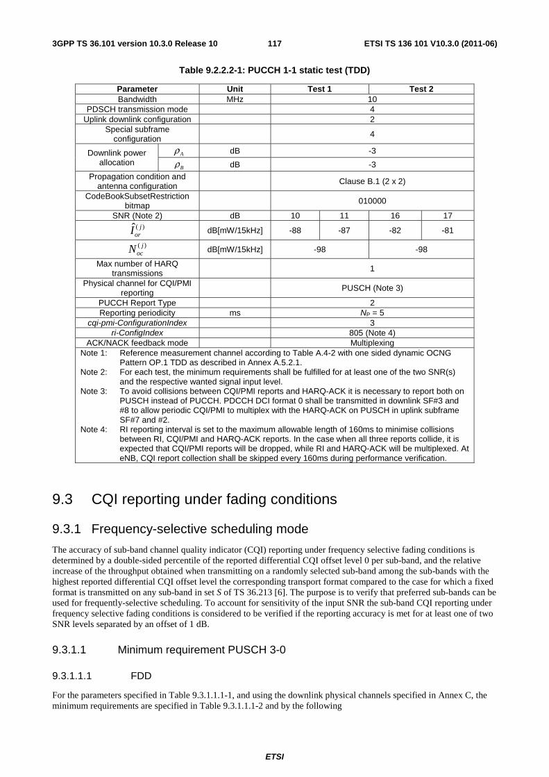
ETSI
ETSI TS 136 101 V10.3.0 (2011-06)1173GPP TS 36.101 version 10.3.0 Release 10
Table 9.2.2.2-1: PUCCH 1-1 static test (TDD)
Parameter Unit Test 1 Test 2 Bandwidth MHz 10
PDSCH transmission mode 4 Uplink downlink configuration 2
Special subframe configuration 4
Downlink power allocation
Aρ dB -3
Bρ dB -3 Propagation condition and
antenna configuration Clause B.1 (2 x 2)
CodeBookSubsetRestriction bitmap 010000
SNR (Note 2) dB 10 11 16 17 )(ˆ j
orI dB[mW/15kHz] -88 -87 -82 -81
)( jocN dB[mW/15kHz] -98 -98
Max number of HARQ transmissions 1
Physical channel for CQI/PMI reporting PUSCH (Note 3)
PUCCH Report Type 2 Reporting periodicity ms NP = 5
cqi-pmi-ConfigurationIndex 3 ri-ConfigIndex 805 (Note 4)
ACK/NACK feedback mode Multiplexing Note 1: Reference measurement channel according to Table A.4-2 with one sided dynamic OCNG
Pattern OP.1 TDD as described in Annex A.5.2.1. Note 2: For each test, the minimum requirements shall be fulfilled for at least one of the two SNR(s)
and the respective wanted signal input level. Note 3: To avoid collisions between CQI/PMI reports and HARQ-ACK it is necessary to report both on
PUSCH instead of PUCCH. PDCCH DCI format 0 shall be transmitted in downlink SF#3 and #8 to allow periodic CQI/PMI to multiplex with the HARQ-ACK on PUSCH in uplink subframe SF#7 and #2.
Note 4: RI reporting interval is set to the maximum allowable length of 160ms to minimise collisions between RI, CQI/PMI and HARQ-ACK reports. In the case when all three reports collide, it is expected that CQI/PMI reports will be dropped, while RI and HARQ-ACK will be multiplexed. At eNB, CQI report collection shall be skipped every 160ms during performance verification.
9.3 CQI reporting under fading conditions
9.3.1 Frequency-selective scheduling mode
The accuracy of sub-band channel quality indicator (CQI) reporting under frequency selective fading conditions is determined by a double-sided percentile of the reported differential CQI offset level 0 per sub-band, and the relative increase of the throughput obtained when transmitting on a randomly selected sub-band among the sub-bands with the highest reported differential CQI offset level the corresponding transport format compared to the case for which a fixed format is transmitted on any sub-band in set S of TS 36.213 [6]. The purpose is to verify that preferred sub-bands can be used for frequently-selective scheduling. To account for sensitivity of the input SNR the sub-band CQI reporting under frequency selective fading conditions is considered to be verified if the reporting accuracy is met for at least one of two SNR levels separated by an offset of 1 dB.
9.3.1.1 Minimum requirement PUSCH 3-0
9.3.1.1.1 FDD
For the parameters specified in Table 9.3.1.1.1-1, and using the downlink physical channels specified in Annex C, the minimum requirements are specified in Table 9.3.1.1.1-2 and by the following
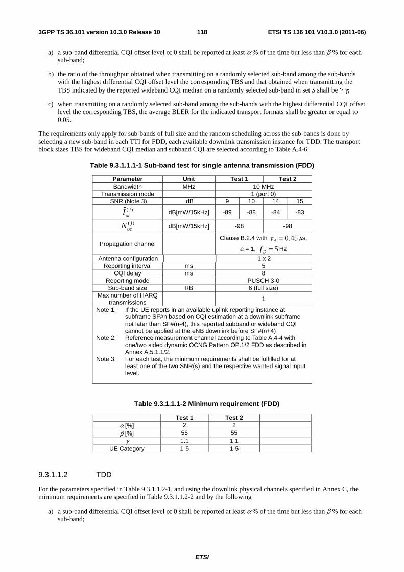
ETSI
ETSI TS 136 101 V10.3.0 (2011-06)1183GPP TS 36.101 version 10.3.0 Release 10
a) a sub-band differential CQI offset level of 0 shall be reported at least α % of the time but less than β % for each sub-band;
b) the ratio of the throughput obtained when transmitting on a randomly selected sub-band among the sub-bands with the highest differential CQI offset level the corresponding TBS and that obtained when transmitting the TBS indicated by the reported wideband CQI median on a randomly selected sub-band in set S shall be ≥ γ;
c) when transmitting on a randomly selected sub-band among the sub-bands with the highest differential CQI offset level the corresponding TBS, the average BLER for the indicated transport formats shall be greater or equal to 0.05.
The requirements only apply for sub-bands of full size and the random scheduling across the sub-bands is done by selecting a new sub-band in each TTI for FDD, each available downlink transmission instance for TDD. The transport block sizes TBS for wideband CQI median and subband CQI are selected according to Table A.4-6.
Table 9.3.1.1.1-1 Sub-band test for single antenna transmission (FDD)
Parameter Unit Test 1 Test 2 Bandwidth MHz 10 MHz
Transmission mode 1 (port 0) SNR (Note 3) dB 9 10 14 15
)(ˆ jorI dB[mW/15kHz] -89 -88 -84 -83
)( jocN dB[mW/15kHz] -98 -98
Propagation channel Clause B.2.4 with 45.0=dτ μs,
a = 1, 5=Df Hz
Antenna configuration 1 x 2 Reporting interval ms 5
CQI delay ms 8 Reporting mode PUSCH 3-0 Sub-band size RB 6 (full size)
Max number of HARQ transmissions
1
Note 1: If the UE reports in an available uplink reporting instance at subframe SF#n based on CQI estimation at a downlink subframe not later than SF#(n-4), this reported subband or wideband CQI cannot be applied at the eNB downlink before SF#(n+4)
Note 2: Reference measurement channel according to Table A.4-4 with one/two sided dynamic OCNG Pattern OP.1/2 FDD as described in Annex A.5.1.1/2.
Note 3: For each test, the minimum requirements shall be fulfilled for at least one of the two SNR(s) and the respective wanted signal input level.
Table 9.3.1.1.1-2 Minimum requirement (FDD)
Test 1 Test 2 α [%] 2 2 β [%] 55 55
γ 1.1 1.1 UE Category 1-5 1-5
9.3.1.1.2 TDD
For the parameters specified in Table 9.3.1.1.2-1, and using the downlink physical channels specified in Annex C, the minimum requirements are specified in Table 9.3.1.1.2-2 and by the following
a) a sub-band differential CQI offset level of 0 shall be reported at least α % of the time but less than β % for each sub-band;
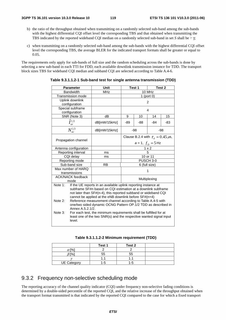
ETSI
ETSI TS 136 101 V10.3.0 (2011-06)1193GPP TS 36.101 version 10.3.0 Release 10
b) the ratio of the throughput obtained when transmitting on a randomly selected sub-band among the sub-bands with the highest differential CQI offset level the corresponding TBS and that obtained when transmitting the TBS indicated by the reported wideband CQI median on a randomly selected sub-band in set S shall be ≥ γ;
c) when transmitting on a randomly selected sub-band among the sub-bands with the highest differential CQI offset level the corresponding TBS, the average BLER for the indicated transport formats shall be greater or equal to 0.05.
The requirements only apply for sub-bands of full size and the random scheduling across the sub-bands is done by selecting a new sub-band in each TTI for FDD, each available downlink transmission instance for TDD. The transport block sizes TBS for wideband CQI median and subband CQI are selected according to Table A.4-6.
Table 9.3.1.1.2-1 Sub-band test for single antenna transmission (TDD)
Parameter Unit Test 1 Test 2 Bandwidth MHz 10 MHz
Transmission mode 1 (port 0) Uplink downlink
configuration 2
Special subframe configuration 4
SNR (Note 3) dB 9 10 14 15 )(ˆ j
orI dB[mW/15kHz] -89 -88 -84 -83
)( jocN dB[mW/15kHz] -98 -98
Propagation channel Clause B.2.4 with 45.0=dτ μs,
a = 1, 5=Df Hz
Antenna configuration 1 x 2 Reporting interval ms 5
CQI delay ms 10 or 11 Reporting mode PUSCH 3-0 Sub-band size RB 6 (full size)
Max number of HARQ transmissions 1
ACK/NACK feedback mode
Multiplexing
Note 1: If the UE reports in an available uplink reporting instance at subframe SF#n based on CQI estimation at a downlink subframe not later than SF#(n-4), this reported subband or wideband CQI cannot be applied at the eNB downlink before SF#(n+4)
Note 2: Reference measurement channel according to Table A.4-5 with one/two sided dynamic OCNG Pattern OP.1/2 TDD as described in Annex A.5.2.1/2.
Note 3: For each test, the minimum requirements shall be fulfilled for at least one of the two SNR(s) and the respective wanted signal input level.
Table 9.3.1.1.2-2 Minimum requirement (TDD)
Test 1 Test 2 α [%] 2 2 β [%] 55 55
γ 1.1 1.1 UE Category 1-5 1-5
9.3.2 Frequency non-selective scheduling mode
The reporting accuracy of the channel quality indicator (CQI) under frequency non-selective fading conditions is determined by a double-sided percentile of the reported CQI, and the relative increase of the throughput obtained when the transport format transmitted is that indicated by the reported CQI compared to the case for which a fixed transport
ETSI
ETSI TS 136 101 V10.3.0 (2011-06)1203GPP TS 36.101 version 10.3.0 Release 10
format configured according to the reported median CQI is transmitted. In addition, the reporting accuracy is determined by a minimum BLER using the transport formats indicated by the reported CQI. The purpose is to verify that the UE is tracking the channel variations and selecting the largest transport format possible according to the prevailing channel state for frequently non-selective scheduling. To account for sensitivity of the input SNR the CQI reporting under frequency non-selective fading conditions is considered to be verified if the reporting accuracy is met for at least one of two SNR levels separated by an offset of 1 dB.
9.3.2.1 Minimum requirement PUCCH 1-0
9.3.2.1.1 FDD
For the parameters specified in Table 9.3.2.1.1-1, and using the downlink physical channels specified in Annex C, the minimum requirements are specified in Table 9.3.2.1.1-2 and by the following
a) a CQI index not in the set {median CQI -1, median CQI +1} shall be reported at least α % of the time;
b) the ratio of the throughput obtained when transmitting the transport format indicated by each reported wideband CQI index and that obtained when transmitting a fixed transport format configured according to the wideband CQI median shall be ≥ γ ;
c) when transmitting the transport format indicated by each reported wideband CQI index, the average BLER for the indicated transport formats shall be greater or equal to 0.02
The transport block sizes TBS for wideband CQI median and reported wideband CQI are selected according to Table A.4-3 (for Category 2-5) or Table A.4-9 (for Category 1).
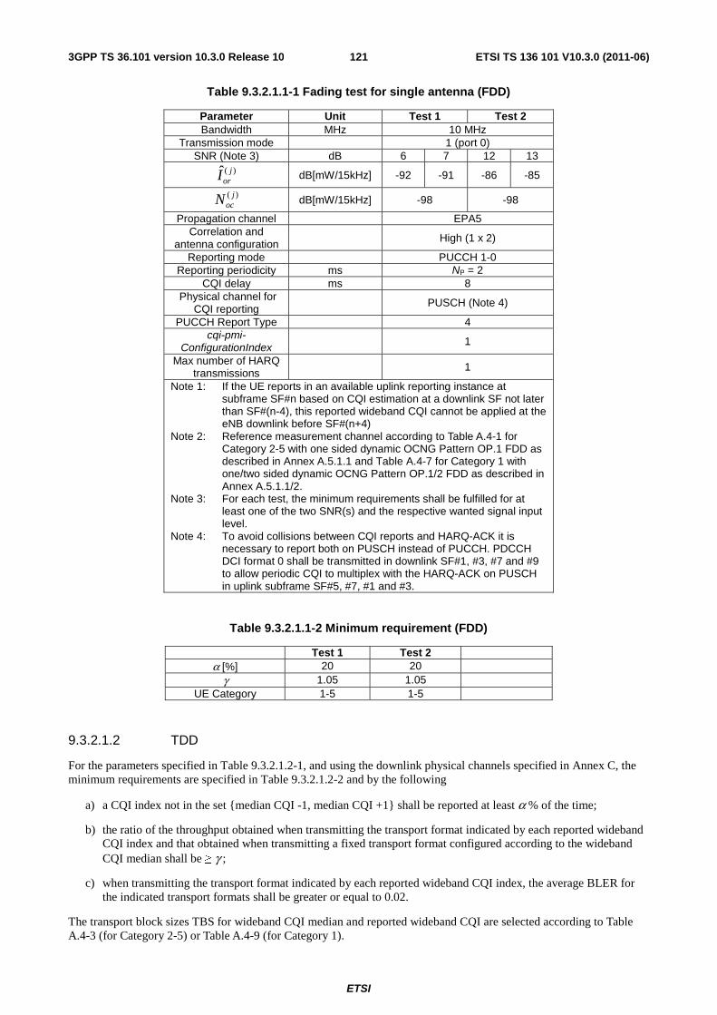
ETSI
ETSI TS 136 101 V10.3.0 (2011-06)1213GPP TS 36.101 version 10.3.0 Release 10
Table 9.3.2.1.1-1 Fading test for single antenna (FDD)
Parameter Unit Test 1 Test 2 Bandwidth MHz 10 MHz
Transmission mode 1 (port 0) SNR (Note 3) dB 6 7 12 13
)(ˆ jorI dB[mW/15kHz] -92 -91 -86 -85
)( jocN dB[mW/15kHz] -98 -98
Propagation channel EPA5 Correlation and
antenna configuration High (1 x 2)
Reporting mode PUCCH 1-0 Reporting periodicity ms NP = 2
CQI delay ms 8 Physical channel for
CQI reporting PUSCH (Note 4)
PUCCH Report Type 4 cqi-pmi-
ConfigurationIndex 1
Max number of HARQ transmissions 1
Note 1: If the UE reports in an available uplink reporting instance at subframe SF#n based on CQI estimation at a downlink SF not later than SF#(n-4), this reported wideband CQI cannot be applied at the eNB downlink before SF#(n+4)
Note 2: Reference measurement channel according to Table A.4-1 for Category 2-5 with one sided dynamic OCNG Pattern OP.1 FDD as described in Annex A.5.1.1 and Table A.4-7 for Category 1 with one/two sided dynamic OCNG Pattern OP.1/2 FDD as described in Annex A.5.1.1/2.
Note 3: For each test, the minimum requirements shall be fulfilled for at least one of the two SNR(s) and the respective wanted signal input level.
Note 4: To avoid collisions between CQI reports and HARQ-ACK it is necessary to report both on PUSCH instead of PUCCH. PDCCH DCI format 0 shall be transmitted in downlink SF#1, #3, #7 and #9 to allow periodic CQI to multiplex with the HARQ-ACK on PUSCH in uplink subframe SF#5, #7, #1 and #3.
Table 9.3.2.1.1-2 Minimum requirement (FDD)
Test 1 Test 2 α [%] 20 20
γ 1.05 1.05 UE Category 1-5 1-5
9.3.2.1.2 TDD
For the parameters specified in Table 9.3.2.1.2-1, and using the downlink physical channels specified in Annex C, the minimum requirements are specified in Table 9.3.2.1.2-2 and by the following
a) a CQI index not in the set {median CQI -1, median CQI +1} shall be reported at least α % of the time;
b) the ratio of the throughput obtained when transmitting the transport format indicated by each reported wideband CQI index and that obtained when transmitting a fixed transport format configured according to the wideband CQI median shall be ≥ γ ;
c) when transmitting the transport format indicated by each reported wideband CQI index, the average BLER for the indicated transport formats shall be greater or equal to 0.02.
The transport block sizes TBS for wideband CQI median and reported wideband CQI are selected according to Table A.4-3 (for Category 2-5) or Table A.4-9 (for Category 1).
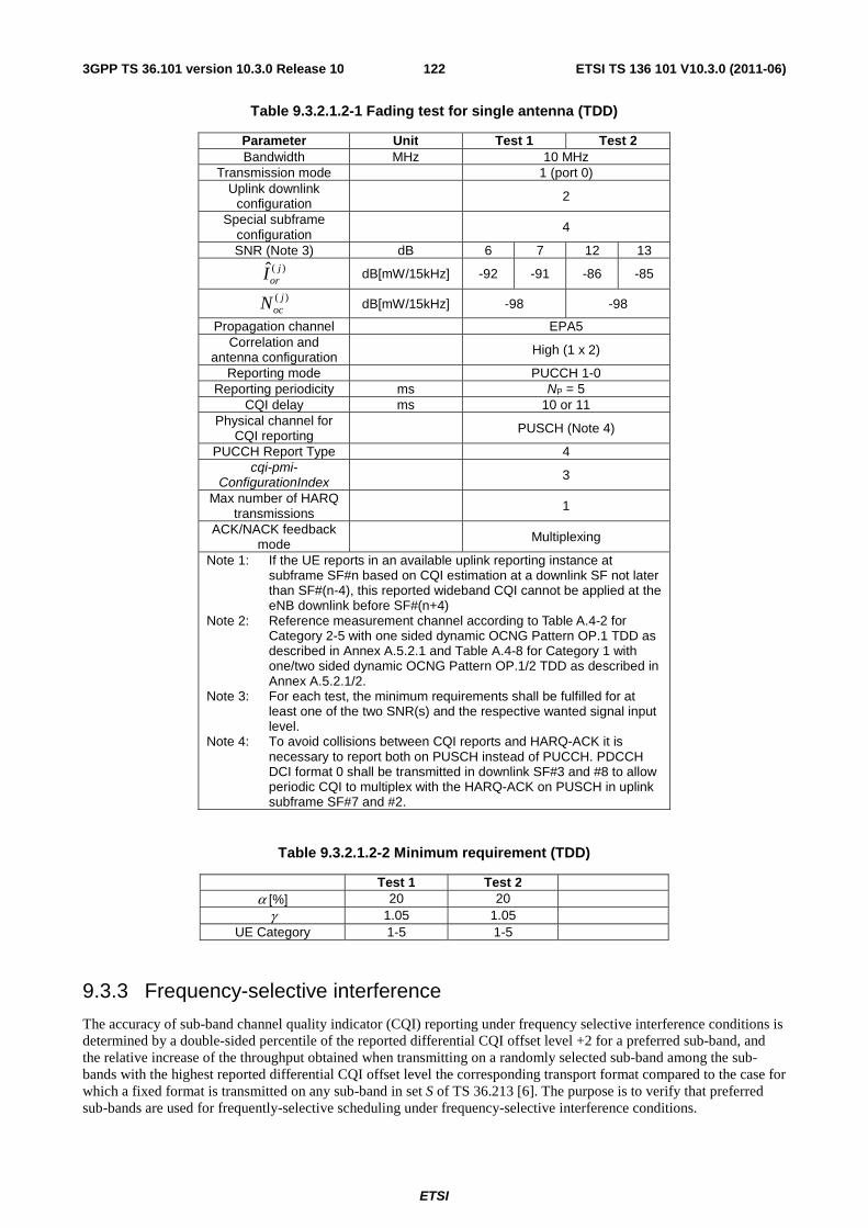
ETSI
ETSI TS 136 101 V10.3.0 (2011-06)1223GPP TS 36.101 version 10.3.0 Release 10
Table 9.3.2.1.2-1 Fading test for single antenna (TDD)
Parameter Unit Test 1 Test 2 Bandwidth MHz 10 MHz
Transmission mode 1 (port 0) Uplink downlink
configuration 2
Special subframe configuration
4
SNR (Note 3) dB 6 7 12 13 )(ˆ j
orI dB[mW/15kHz] -92 -91 -86 -85
)( jocN dB[mW/15kHz] -98 -98
Propagation channel EPA5 Correlation and
antenna configuration High (1 x 2)
Reporting mode PUCCH 1-0 Reporting periodicity ms NP = 5
CQI delay ms 10 or 11 Physical channel for
CQI reporting PUSCH (Note 4)
PUCCH Report Type 4 cqi-pmi-
ConfigurationIndex 3
Max number of HARQ transmissions
1
ACK/NACK feedback mode Multiplexing
Note 1: If the UE reports in an available uplink reporting instance at subframe SF#n based on CQI estimation at a downlink SF not later than SF#(n-4), this reported wideband CQI cannot be applied at the eNB downlink before SF#(n+4)
Note 2: Reference measurement channel according to Table A.4-2 for Category 2-5 with one sided dynamic OCNG Pattern OP.1 TDD as described in Annex A.5.2.1 and Table A.4-8 for Category 1 with one/two sided dynamic OCNG Pattern OP.1/2 TDD as described in Annex A.5.2.1/2.
Note 3: For each test, the minimum requirements shall be fulfilled for at least one of the two SNR(s) and the respective wanted signal input level.
Note 4: To avoid collisions between CQI reports and HARQ-ACK it is necessary to report both on PUSCH instead of PUCCH. PDCCH DCI format 0 shall be transmitted in downlink SF#3 and #8 to allow periodic CQI to multiplex with the HARQ-ACK on PUSCH in uplink subframe SF#7 and #2.
Table 9.3.2.1.2-2 Minimum requirement (TDD)
Test 1 Test 2 α [%] 20 20
γ 1.05 1.05 UE Category 1-5 1-5
9.3.3 Frequency-selective interference
The accuracy of sub-band channel quality indicator (CQI) reporting under frequency selective interference conditions is determined by a double-sided percentile of the reported differential CQI offset level +2 for a preferred sub-band, and the relative increase of the throughput obtained when transmitting on a randomly selected sub-band among the sub-bands with the highest reported differential CQI offset level the corresponding transport format compared to the case for which a fixed format is transmitted on any sub-band in set S of TS 36.213 [6]. The purpose is to verify that preferred sub-bands are used for frequently-selective scheduling under frequency-selective interference conditions.
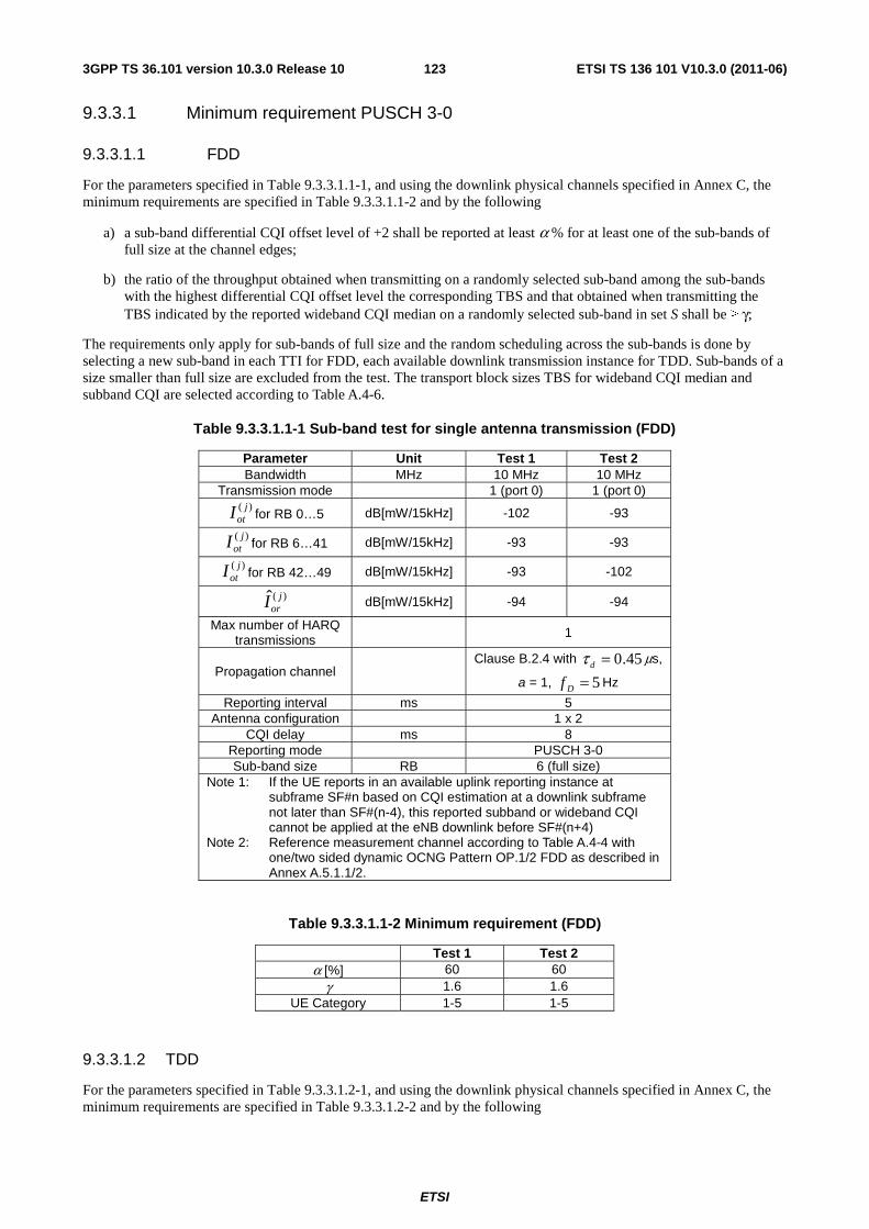
ETSI
ETSI TS 136 101 V10.3.0 (2011-06)1233GPP TS 36.101 version 10.3.0 Release 10
9.3.3.1 Minimum requirement PUSCH 3-0
9.3.3.1.1 FDD
For the parameters specified in Table 9.3.3.1.1-1, and using the downlink physical channels specified in Annex C, the minimum requirements are specified in Table 9.3.3.1.1-2 and by the following
a) a sub-band differential CQI offset level of +2 shall be reported at least α % for at least one of the sub-bands of full size at the channel edges;
b) the ratio of the throughput obtained when transmitting on a randomly selected sub-band among the sub-bands with the highest differential CQI offset level the corresponding TBS and that obtained when transmitting the TBS indicated by the reported wideband CQI median on a randomly selected sub-band in set S shall be ≥ γ;
The requirements only apply for sub-bands of full size and the random scheduling across the sub-bands is done by selecting a new sub-band in each TTI for FDD, each available downlink transmission instance for TDD. Sub-bands of a size smaller than full size are excluded from the test. The transport block sizes TBS for wideband CQI median and subband CQI are selected according to Table A.4-6.
Table 9.3.3.1.1-1 Sub-band test for single antenna transmission (FDD)
Parameter Unit Test 1 Test 2 Bandwidth MHz 10 MHz 10 MHz
Transmission mode 1 (port 0) 1 (port 0) )( j
otI for RB 0…5 dB[mW/15kHz] -102 -93
)( jotI for RB 6…41 dB[mW/15kHz] -93 -93
)( jotI for RB 42…49 dB[mW/15kHz] -93 -102
)(ˆ jorI dB[mW/15kHz] -94 -94
Max number of HARQ transmissions 1
Propagation channel Clause B.2.4 with 45.0=dτ μs,
a = 1, 5=Df Hz
Reporting interval ms 5 Antenna configuration 1 x 2
CQI delay ms 8 Reporting mode PUSCH 3-0 Sub-band size RB 6 (full size)
Note 1: If the UE reports in an available uplink reporting instance at subframe SF#n based on CQI estimation at a downlink subframe not later than SF#(n-4), this reported subband or wideband CQI cannot be applied at the eNB downlink before SF#(n+4)
Note 2: Reference measurement channel according to Table A.4-4 with one/two sided dynamic OCNG Pattern OP.1/2 FDD as described in Annex A.5.1.1/2.
Table 9.3.3.1.1-2 Minimum requirement (FDD)
Test 1 Test 2 α [%] 60 60
γ 1.6 1.6 UE Category 1-5 1-5
9.3.3.1.2 TDD
For the parameters specified in Table 9.3.3.1.2-1, and using the downlink physical channels specified in Annex C, the minimum requirements are specified in Table 9.3.3.1.2-2 and by the following
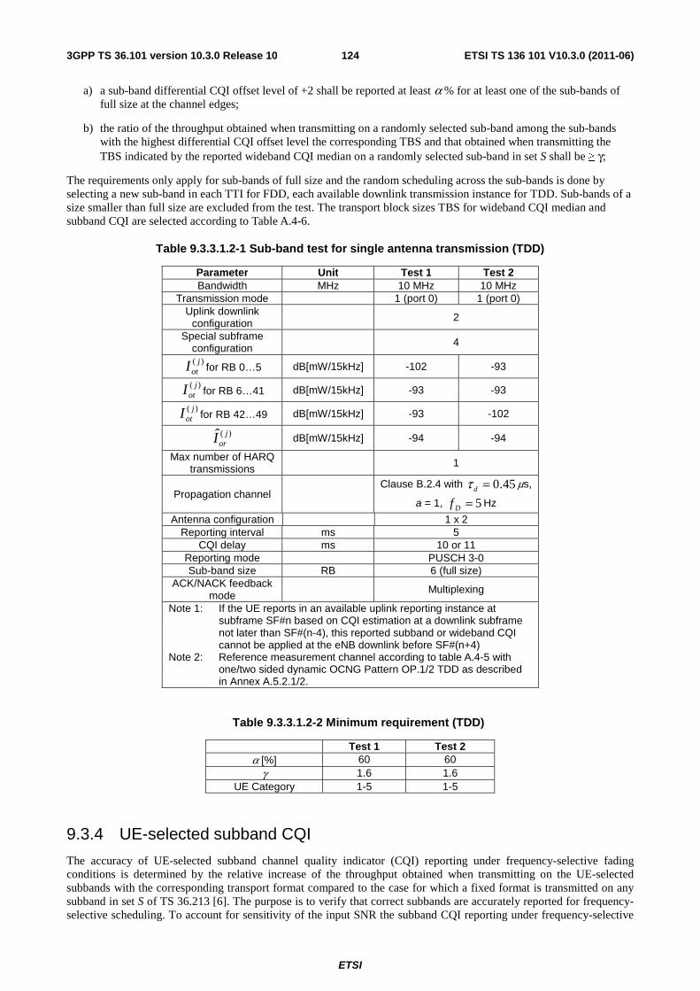
ETSI
ETSI TS 136 101 V10.3.0 (2011-06)1243GPP TS 36.101 version 10.3.0 Release 10
a) a sub-band differential CQI offset level of +2 shall be reported at least α % for at least one of the sub-bands of full size at the channel edges;
b) the ratio of the throughput obtained when transmitting on a randomly selected sub-band among the sub-bands with the highest differential CQI offset level the corresponding TBS and that obtained when transmitting the TBS indicated by the reported wideband CQI median on a randomly selected sub-band in set S shall be ≥ γ;
The requirements only apply for sub-bands of full size and the random scheduling across the sub-bands is done by selecting a new sub-band in each TTI for FDD, each available downlink transmission instance for TDD. Sub-bands of a size smaller than full size are excluded from the test. The transport block sizes TBS for wideband CQI median and subband CQI are selected according to Table A.4-6.
Table 9.3.3.1.2-1 Sub-band test for single antenna transmission (TDD)
Parameter Unit Test 1 Test 2 Bandwidth MHz 10 MHz 10 MHz
Transmission mode 1 (port 0) 1 (port 0) Uplink downlink
configuration 2
Special subframe configuration 4
)( jotI for RB 0…5 dB[mW/15kHz] -102 -93
)( jotI for RB 6…41 dB[mW/15kHz] -93 -93
)( jotI for RB 42…49 dB[mW/15kHz] -93 -102
)(ˆ jorI dB[mW/15kHz] -94 -94
Max number of HARQ transmissions 1
Propagation channel Clause B.2.4 with 45.0=dτ μs,
a = 1, 5=Df Hz
Antenna configuration 1 x 2 Reporting interval ms 5
CQI delay ms 10 or 11 Reporting mode PUSCH 3-0 Sub-band size RB 6 (full size)
ACK/NACK feedback mode
Multiplexing
Note 1: If the UE reports in an available uplink reporting instance at subframe SF#n based on CQI estimation at a downlink subframe not later than SF#(n-4), this reported subband or wideband CQI cannot be applied at the eNB downlink before SF#(n+4)
Note 2: Reference measurement channel according to table A.4-5 with one/two sided dynamic OCNG Pattern OP.1/2 TDD as described in Annex A.5.2.1/2.
Table 9.3.3.1.2-2 Minimum requirement (TDD)
Test 1 Test 2 α [%] 60 60
γ 1.6 1.6 UE Category 1-5 1-5
9.3.4 UE-selected subband CQI
The accuracy of UE-selected subband channel quality indicator (CQI) reporting under frequency-selective fading conditions is determined by the relative increase of the throughput obtained when transmitting on the UE-selected subbands with the corresponding transport format compared to the case for which a fixed format is transmitted on any subband in set S of TS 36.213 [6]. The purpose is to verify that correct subbands are accurately reported for frequency-selective scheduling. To account for sensitivity of the input SNR the subband CQI reporting under frequency-selective
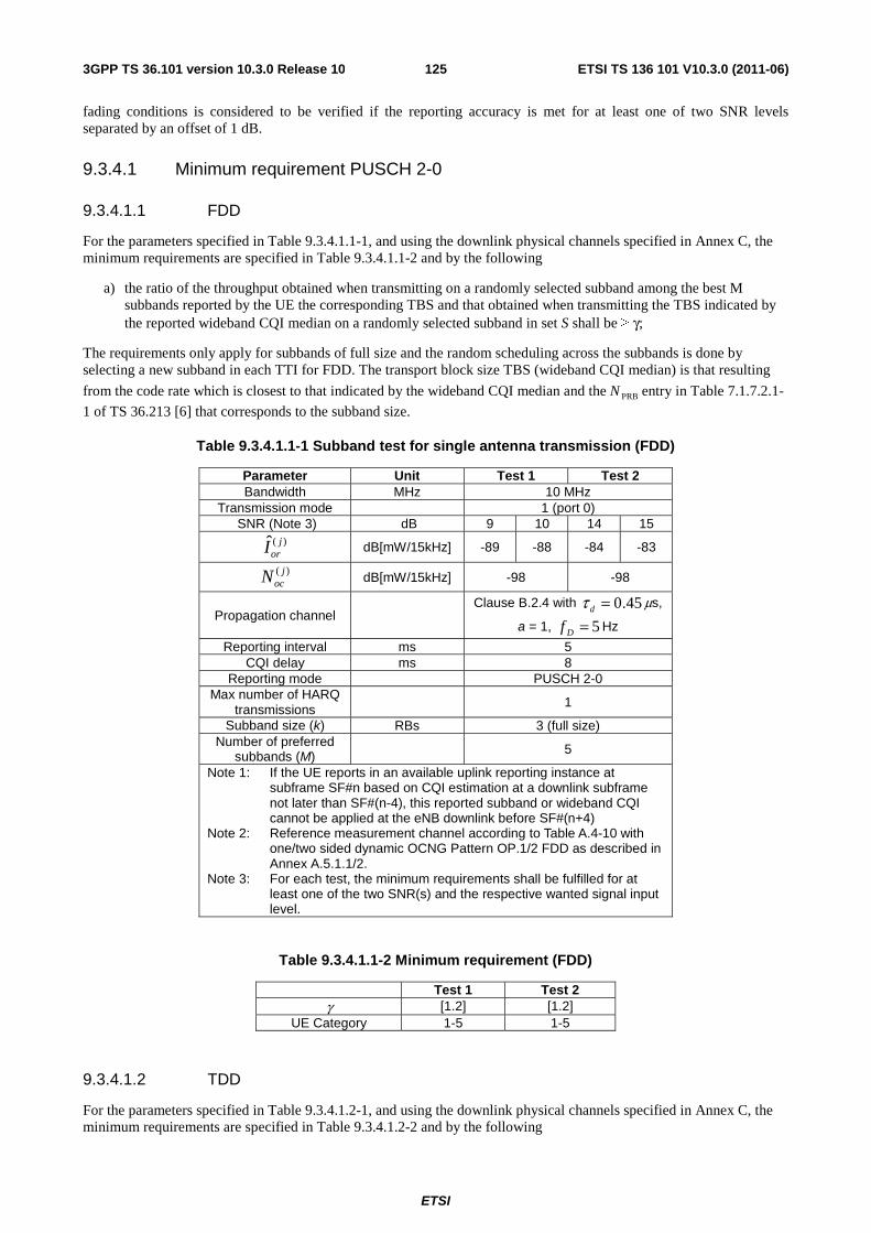
ETSI
ETSI TS 136 101 V10.3.0 (2011-06)1253GPP TS 36.101 version 10.3.0 Release 10
fading conditions is considered to be verified if the reporting accuracy is met for at least one of two SNR levels separated by an offset of 1 dB.
9.3.4.1 Minimum requirement PUSCH 2-0
9.3.4.1.1 FDD
For the parameters specified in Table 9.3.4.1.1-1, and using the downlink physical channels specified in Annex C, the minimum requirements are specified in Table 9.3.4.1.1-2 and by the following
a) the ratio of the throughput obtained when transmitting on a randomly selected subband among the best M subbands reported by the UE the corresponding TBS and that obtained when transmitting the TBS indicated by the reported wideband CQI median on a randomly selected subband in set S shall be ≥ γ;
The requirements only apply for subbands of full size and the random scheduling across the subbands is done by selecting a new subband in each TTI for FDD. The transport block size TBS (wideband CQI median) is that resulting
from the code rate which is closest to that indicated by the wideband CQI median and the PRBN entry in Table 7.1.7.2.1-
1 of TS 36.213 [6] that corresponds to the subband size.
Table 9.3.4.1.1-1 Subband test for single antenna transmission (FDD)
Parameter Unit Test 1 Test 2 Bandwidth MHz 10 MHz
Transmission mode 1 (port 0) SNR (Note 3) dB 9 10 14 15
)(ˆ jorI dB[mW/15kHz] -89 -88 -84 -83
)( jocN dB[mW/15kHz] -98 -98
Propagation channel Clause B.2.4 with 45.0=dτ μs,
a = 1, 5=Df Hz
Reporting interval ms 5 CQI delay ms 8
Reporting mode PUSCH 2-0 Max number of HARQ
transmissions 1
Subband size (k) RBs 3 (full size) Number of preferred
subbands (M) 5
Note 1: If the UE reports in an available uplink reporting instance at subframe SF#n based on CQI estimation at a downlink subframe not later than SF#(n-4), this reported subband or wideband CQI cannot be applied at the eNB downlink before SF#(n+4)
Note 2: Reference measurement channel according to Table A.4-10 with one/two sided dynamic OCNG Pattern OP.1/2 FDD as described in Annex A.5.1.1/2.
Note 3: For each test, the minimum requirements shall be fulfilled for at least one of the two SNR(s) and the respective wanted signal input level.
Table 9.3.4.1.1-2 Minimum requirement (FDD)
Test 1 Test 2 γ [1.2] [1.2]
UE Category 1-5 1-5
9.3.4.1.2 TDD
For the parameters specified in Table 9.3.4.1.2-1, and using the downlink physical channels specified in Annex C, the minimum requirements are specified in Table 9.3.4.1.2-2 and by the following
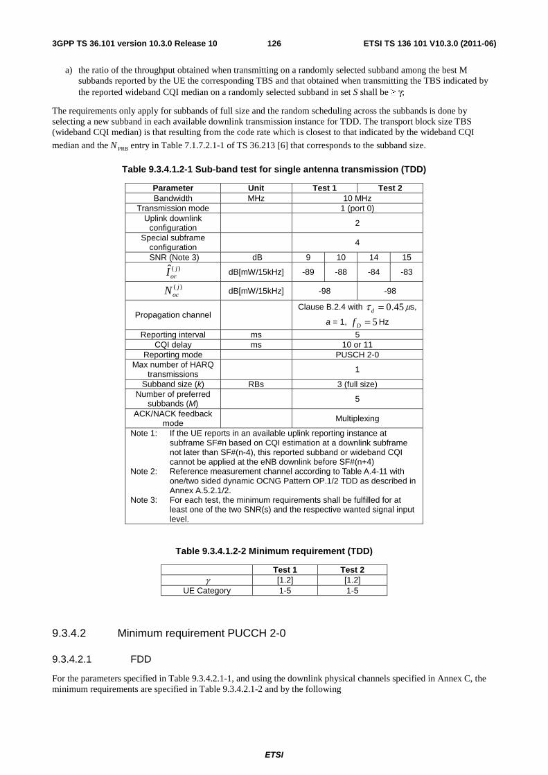
ETSI
ETSI TS 136 101 V10.3.0 (2011-06)1263GPP TS 36.101 version 10.3.0 Release 10
a) the ratio of the throughput obtained when transmitting on a randomly selected subband among the best M subbands reported by the UE the corresponding TBS and that obtained when transmitting the TBS indicated by the reported wideband CQI median on a randomly selected subband in set S shall be ≥ γ;
The requirements only apply for subbands of full size and the random scheduling across the subbands is done by selecting a new subband in each available downlink transmission instance for TDD. The transport block size TBS (wideband CQI median) is that resulting from the code rate which is closest to that indicated by the wideband CQI
median and the PRBN entry in Table 7.1.7.2.1-1 of TS 36.213 [6] that corresponds to the subband size.
Table 9.3.4.1.2-1 Sub-band test for single antenna transmission (TDD)
Parameter Unit Test 1 Test 2 Bandwidth MHz 10 MHz
Transmission mode 1 (port 0) Uplink downlink
configuration 2
Special subframe configuration 4
SNR (Note 3) dB 9 10 14 15 )(ˆ j
orI dB[mW/15kHz] -89 -88 -84 -83
)( jocN dB[mW/15kHz] -98 -98
Propagation channel Clause B.2.4 with 45.0=dτ μs,
a = 1, 5=Df Hz
Reporting interval ms 5 CQI delay ms 10 or 11
Reporting mode PUSCH 2-0 Max number of HARQ
transmissions 1
Subband size (k) RBs 3 (full size) Number of preferred
subbands (M) 5
ACK/NACK feedback mode Multiplexing
Note 1: If the UE reports in an available uplink reporting instance at subframe SF#n based on CQI estimation at a downlink subframe not later than SF#(n-4), this reported subband or wideband CQI cannot be applied at the eNB downlink before SF#(n+4)
Note 2: Reference measurement channel according to Table A.4-11 with one/two sided dynamic OCNG Pattern OP.1/2 TDD as described in Annex A.5.2.1/2.
Note 3: For each test, the minimum requirements shall be fulfilled for at least one of the two SNR(s) and the respective wanted signal input level.
Table 9.3.4.1.2-2 Minimum requirement (TDD)
Test 1 Test 2 γ [1.2] [1.2]
UE Category 1-5 1-5
9.3.4.2 Minimum requirement PUCCH 2-0
9.3.4.2.1 FDD
For the parameters specified in Table 9.3.4.2.1-1, and using the downlink physical channels specified in Annex C, the minimum requirements are specified in Table 9.3.4.2.1-2 and by the following
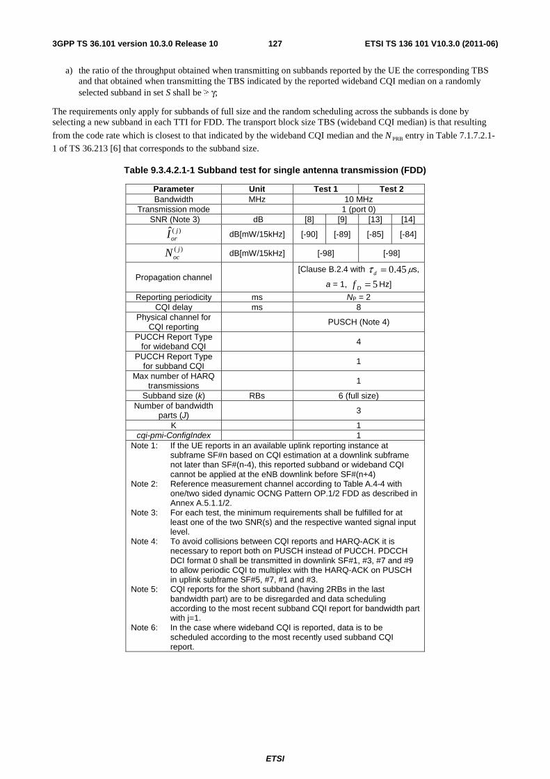
ETSI
ETSI TS 136 101 V10.3.0 (2011-06)1273GPP TS 36.101 version 10.3.0 Release 10
a) the ratio of the throughput obtained when transmitting on subbands reported by the UE the corresponding TBS and that obtained when transmitting the TBS indicated by the reported wideband CQI median on a randomly selected subband in set S shall be ≥ γ;
The requirements only apply for subbands of full size and the random scheduling across the subbands is done by selecting a new subband in each TTI for FDD. The transport block size TBS (wideband CQI median) is that resulting
from the code rate which is closest to that indicated by the wideband CQI median and the PRBN entry in Table 7.1.7.2.1-
1 of TS 36.213 [6] that corresponds to the subband size.
Table 9.3.4.2.1-1 Subband test for single antenna transmission (FDD)
Parameter Unit Test 1 Test 2 Bandwidth MHz 10 MHz
Transmission mode 1 (port 0) SNR (Note 3) dB [8] [9] [13] [14]
)(ˆ jorI dB[mW/15kHz] [-90] [-89] [-85] [-84]
)( jocN dB[mW/15kHz] [-98] [-98]
Propagation channel [Clause B.2.4 with 45.0=dτ μs,
a = 1, 5=Df Hz]
Reporting periodicity ms NP = 2 CQI delay ms 8
Physical channel for CQI reporting
PUSCH (Note 4)
PUCCH Report Type for wideband CQI 4
PUCCH Report Type for subband CQI 1
Max number of HARQ transmissions
1
Subband size (k) RBs 6 (full size) Number of bandwidth
parts (J) 3
K 1 cqi-pmi-ConfigIndex 1
Note 1: If the UE reports in an available uplink reporting instance at subframe SF#n based on CQI estimation at a downlink subframe not later than SF#(n-4), this reported subband or wideband CQI cannot be applied at the eNB downlink before SF#(n+4)
Note 2: Reference measurement channel according to Table A.4-4 with one/two sided dynamic OCNG Pattern OP.1/2 FDD as described in Annex A.5.1.1/2.
Note 3: For each test, the minimum requirements shall be fulfilled for at least one of the two SNR(s) and the respective wanted signal input level.
Note 4: To avoid collisions between CQI reports and HARQ-ACK it is necessary to report both on PUSCH instead of PUCCH. PDCCH DCI format 0 shall be transmitted in downlink SF#1, #3, #7 and #9 to allow periodic CQI to multiplex with the HARQ-ACK on PUSCH in uplink subframe SF#5, #7, #1 and #3.
Note 5: CQI reports for the short subband (having 2RBs in the last bandwidth part) are to be disregarded and data scheduling according to the most recent subband CQI report for bandwidth part with j=1.
Note 6: In the case where wideband CQI is reported, data is to be scheduled according to the most recently used subband CQI report.
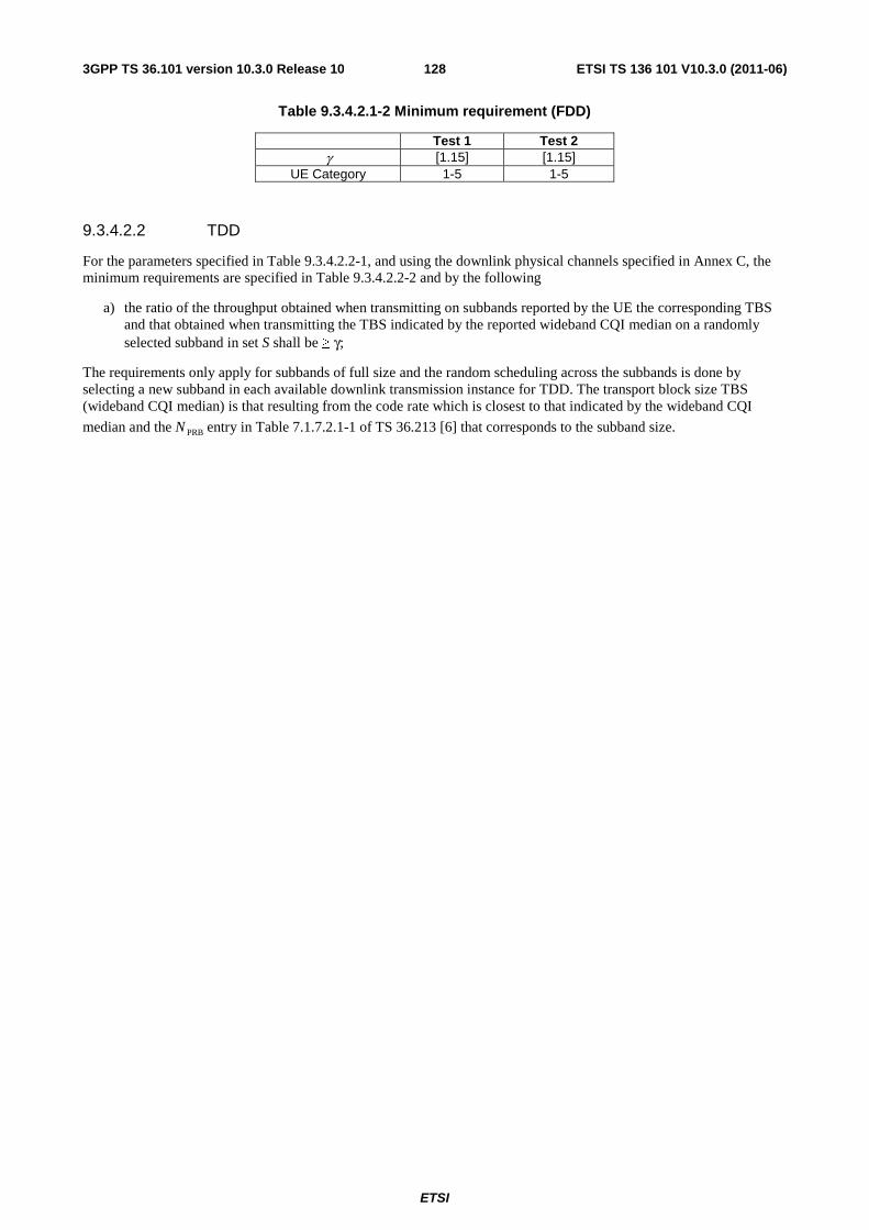
ETSI
ETSI TS 136 101 V10.3.0 (2011-06)1283GPP TS 36.101 version 10.3.0 Release 10
Table 9.3.4.2.1-2 Minimum requirement (FDD)
Test 1 Test 2 γ [1.15] [1.15]
UE Category 1-5 1-5
9.3.4.2.2 TDD
For the parameters specified in Table 9.3.4.2.2-1, and using the downlink physical channels specified in Annex C, the minimum requirements are specified in Table 9.3.4.2.2-2 and by the following
a) the ratio of the throughput obtained when transmitting on subbands reported by the UE the corresponding TBS and that obtained when transmitting the TBS indicated by the reported wideband CQI median on a randomly selected subband in set S shall be ≥ γ;
The requirements only apply for subbands of full size and the random scheduling across the subbands is done by selecting a new subband in each available downlink transmission instance for TDD. The transport block size TBS (wideband CQI median) is that resulting from the code rate which is closest to that indicated by the wideband CQI
median and the PRBN entry in Table 7.1.7.2.1-1 of TS 36.213 [6] that corresponds to the subband size.
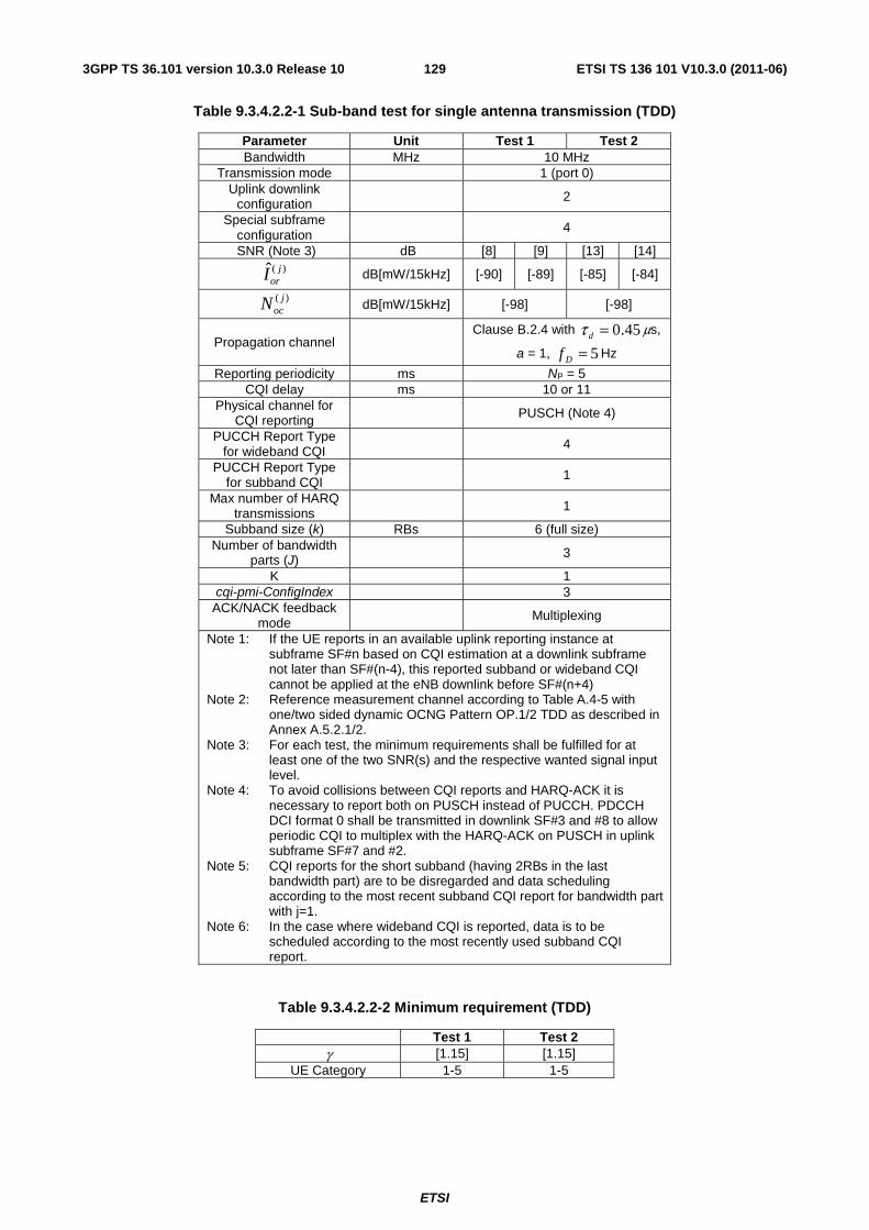
ETSI
ETSI TS 136 101 V10.3.0 (2011-06)1293GPP TS 36.101 version 10.3.0 Release 10
Table 9.3.4.2.2-1 Sub-band test for single antenna transmission (TDD)
Parameter Unit Test 1 Test 2 Bandwidth MHz 10 MHz
Transmission mode 1 (port 0) Uplink downlink
configuration 2
Special subframe configuration
4
SNR (Note 3) dB [8] [9] [13] [14] )(ˆ j
orI dB[mW/15kHz] [-90] [-89] [-85] [-84]
)( jocN dB[mW/15kHz] [-98] [-98]
Propagation channel Clause B.2.4 with 45.0=dτ μs,
a = 1, 5=Df Hz
Reporting periodicity ms NP = 5 CQI delay ms 10 or 11
Physical channel for CQI reporting PUSCH (Note 4)
PUCCH Report Type for wideband CQI 4
PUCCH Report Type for subband CQI 1
Max number of HARQ transmissions 1
Subband size (k) RBs 6 (full size) Number of bandwidth
parts (J) 3
K 1 cqi-pmi-ConfigIndex 3
ACK/NACK feedback mode Multiplexing
Note 1: If the UE reports in an available uplink reporting instance at subframe SF#n based on CQI estimation at a downlink subframe not later than SF#(n-4), this reported subband or wideband CQI cannot be applied at the eNB downlink before SF#(n+4)
Note 2: Reference measurement channel according to Table A.4-5 with one/two sided dynamic OCNG Pattern OP.1/2 TDD as described in Annex A.5.2.1/2.
Note 3: For each test, the minimum requirements shall be fulfilled for at least one of the two SNR(s) and the respective wanted signal input level.
Note 4: To avoid collisions between CQI reports and HARQ-ACK it is necessary to report both on PUSCH instead of PUCCH. PDCCH DCI format 0 shall be transmitted in downlink SF#3 and #8 to allow periodic CQI to multiplex with the HARQ-ACK on PUSCH in uplink subframe SF#7 and #2.
Note 5: CQI reports for the short subband (having 2RBs in the last bandwidth part) are to be disregarded and data scheduling according to the most recent subband CQI report for bandwidth part with j=1.
Note 6: In the case where wideband CQI is reported, data is to be scheduled according to the most recently used subband CQI report.
Table 9.3.4.2.2-2 Minimum requirement (TDD)
Test 1 Test 2 γ [1.15] [1.15]
UE Category 1-5 1-5
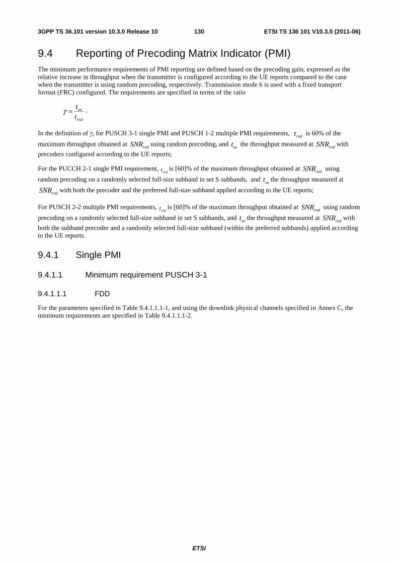
ETSI
ETSI TS 136 101 V10.3.0 (2011-06)1303GPP TS 36.101 version 10.3.0 Release 10
9.4 Reporting of Precoding Matrix Indicator (PMI) The minimum performance requirements of PMI reporting are defined based on the precoding gain, expressed as the relative increase in throughput when the transmitter is configured according to the UE reports compared to the case when the transmitter is using random precoding, respectively. Transmission mode 6 is used with a fixed transport format (FRC) configured. The requirements are specified in terms of the ratio
rnd
ue
t
t=γ .
In the definition of γ, for PUSCH 3-1 single PMI and PUSCH 1-2 multiple PMI requirements, rndt is 60% of the
maximum throughput obtained at rndSNR using random precoding, and uet the throughput measured at rndSNR with
precoders configured according to the UE reports;
For the PUCCH 2-1 single PMI requirement, rndt is [60]% of the maximum throughput obtained at rndSNR using
random precoding on a randomly selected full-size subband in set S subbands, and uet the throughput measured at
rndSNR with both the precoder and the preferred full-size subband applied according to the UE reports;
For PUSCH 2-2 multiple PMI requirements, rndt is [60]% of the maximum throughput obtained at rndSNR using random
precoding on a randomly selected full-size subband in set S subbands, and uet the throughput measured at rndSNR with
both the subband precoder and a randomly selected full-size subband (within the preferred subbands) applied according to the UE reports.
9.4.1 Single PMI
9.4.1.1 Minimum requirement PUSCH 3-1
9.4.1.1.1 FDD
For the parameters specified in Table 9.4.1.1.1-1, and using the downlink physical channels specified in Annex C, the minimum requirements are specified in Table 9.4.1.1.1-2.
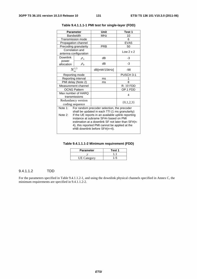
ETSI
ETSI TS 136 101 V10.3.0 (2011-06)1313GPP TS 36.101 version 10.3.0 Release 10
Table 9.4.1.1.1-1 PMI test for single-layer (FDD)
Parameter Unit Test 1 Bandwidth MHz 10
Transmission mode 6 Propagation channel EVA5 Precoding granularity PRB 50
Correlation and antenna configuration Low 2 x 2
Downlink power
allocation
Aρ dB -3
Bρ dB -3
)( jocN dB[mW/15kHz] -98
Reporting mode PUSCH 3-1 Reporting interval ms 1
PMI delay (Note 2) ms 8 Measurement channel R. 10 FDD
OCNG Pattern OP.1 FDD Max number of HARQ
transmissions 4
Redundancy version coding sequence
{0,1,2,3}
Note 1: For random precoder selection, the precoder shall be updated in each TTI (1 ms granularity)
Note 2: If the UE reports in an available uplink reporting instance at subrame SF#n based on PMI estimation at a downlink SF not later than SF#(n-4), this reported PMI cannot be applied at the eNB downlink before SF#(n+4).
Table 9.4.1.1.1-2 Minimum requirement (FDD)
Parameter Test 1 γ 1.1
UE Category 1-5
9.4.1.1.2 TDD
For the parameters specified in Table 9.4.1.1.2-1, and using the downlink physical channels specified in Annex C, the minimum requirements are specified in 9.4.1.1.2-2.
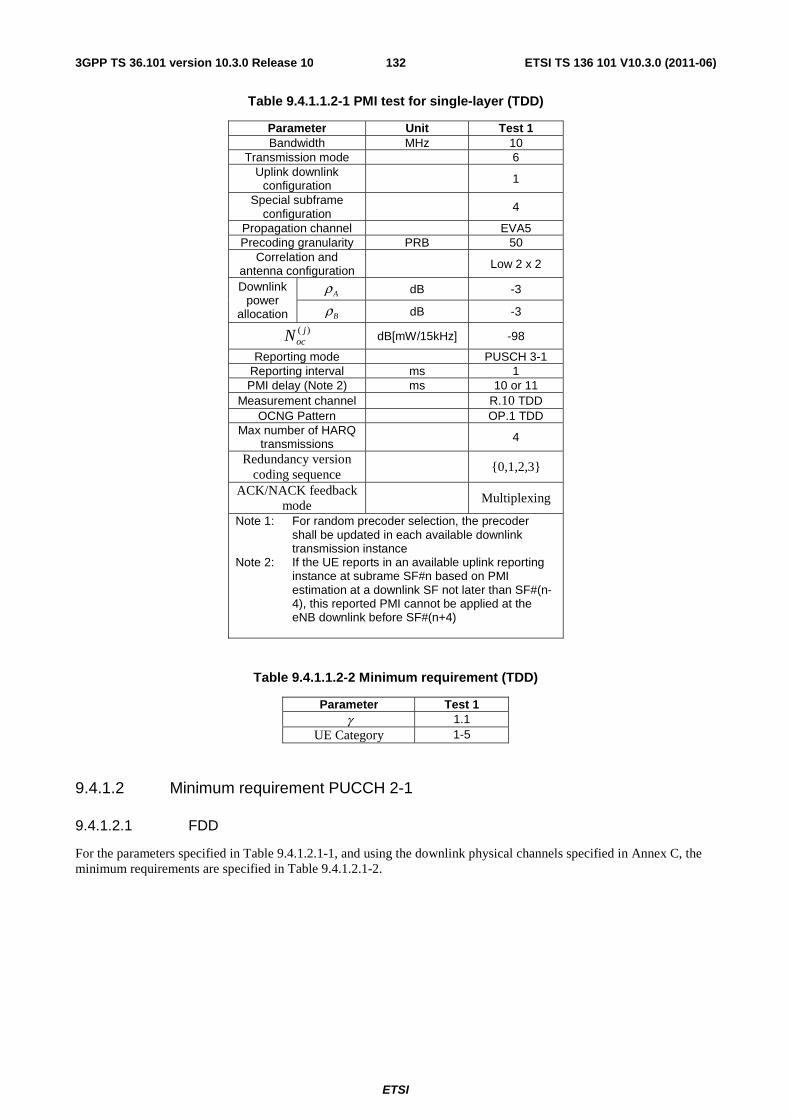
ETSI
ETSI TS 136 101 V10.3.0 (2011-06)1323GPP TS 36.101 version 10.3.0 Release 10
Table 9.4.1.1.2-1 PMI test for single-layer (TDD)
Parameter Unit Test 1 Bandwidth MHz 10
Transmission mode 6 Uplink downlink
configuration 1
Special subframe configuration
4
Propagation channel EVA5 Precoding granularity PRB 50
Correlation and antenna configuration Low 2 x 2
Downlink power
allocation
Aρ dB -3
Bρ dB -3
)( jocN dB[mW/15kHz] -98
Reporting mode PUSCH 3-1 Reporting interval ms 1 PMI delay (Note 2) ms 10 or 11
Measurement channel R.10 TDD OCNG Pattern OP.1 TDD
Max number of HARQ transmissions 4
Redundancy version coding sequence
{0,1,2,3}
ACK/NACK feedback mode
Multiplexing
Note 1: For random precoder selection, the precoder shall be updated in each available downlink transmission instance
Note 2: If the UE reports in an available uplink reporting instance at subrame SF#n based on PMI estimation at a downlink SF not later than SF#(n-4), this reported PMI cannot be applied at the eNB downlink before SF#(n+4)
Table 9.4.1.1.2-2 Minimum requirement (TDD)
Parameter Test 1 γ 1.1
UE Category 1-5
9.4.1.2 Minimum requirement PUCCH 2-1
9.4.1.2.1 FDD
For the parameters specified in Table 9.4.1.2.1-1, and using the downlink physical channels specified in Annex C, the minimum requirements are specified in Table 9.4.1.2.1-2.
ETSI
ETSI TS 136 101 V10.3.0 (2011-06)1333GPP TS 36.101 version 10.3.0 Release 10
Table 9.4.1.2.1-1 PMI test for single-layer (FDD)
Parameter Unit Test 1 Bandwidth MHz 10
Transmission mode 6 Propagation channel [EVA5]
Correlation and antenna configuration Low 4 x 2
Downlink power
allocation
Aρ dB -6
Bρ dB -6
)( jocN dB[mW/15kHz] -98
PMI delay ms [8 or 9] Reporting mode PUCCH 2-1
Reporting periodicity ms NP = 2 Physical channel for
CQI reporting PUSCH (Note 3)
PUCCH Report Type for wideband CQI/PMI 2
PUCCH Report Type for subband CQI 1
Measurement channel [R.14-1 FDD] OCNG Pattern [OP.1/2 FDD]
Precoding granularity PRB 6 (full size) Number of bandwidth
parts (J) 3
K 1 cqi-pmi-ConfigIndex 1
Max number of HARQ transmissions 4
Redundancy version coding sequence {0,1,2,3}
Note 1: For random precoder selection, the precoder shall be updated every two TTI (2 ms granularity)
Note 2: If the UE reports in an available uplink reporting instance at subrame SF#n based on PMI estimation at a downlink SF not later than SF#(n-4), this reported PMI cannot be applied at the eNB downlink before SF#(n+4).
Note 3: To avoid collisions between HARQ-ACK and wideband CQI/PMI or subband CQI, it is necessary to report both on PUSCH instead of PUCCH. PDCCH DCI format 0 shall be transmitted in downlink SF#1, #3, #7 and #9 to allow periodic CQI to multiplex with the HARQ-ACK on PUSCH in uplink subframe SF#5, #7, #1 and #3.
Note 4: Reports for the short subband (having 2RBs in the last bandwidth part) are to be disregarded and instead data is to be transmitted on the most recently used subband for bandwidth part with j=1.
Note 5: In the case where wideband PMI is reported, data is to be transmitted on the most recently used subband.
Table 9.4.1.2.1-2 Minimum requirement (FDD)
Test 1 γ [1.2]
UE Category 1-5
9.4.1.2.2 TDD
For the parameters specified in Table 9.4.1.2.2-1, and using the downlink physical channels specified in Annex C, the minimum requirements are specified in Table 9.4.1.2.2-2.
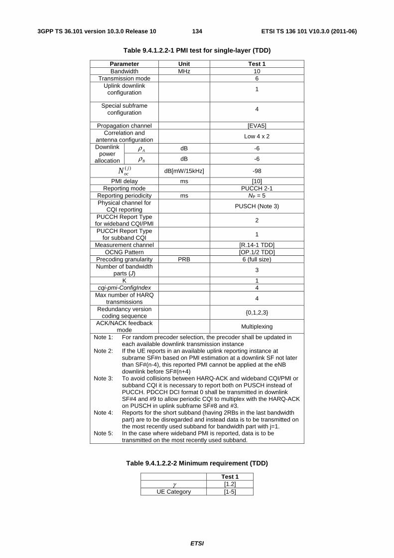
ETSI
ETSI TS 136 101 V10.3.0 (2011-06)1343GPP TS 36.101 version 10.3.0 Release 10
Table 9.4.1.2.2-1 PMI test for single-layer (TDD)
Parameter Unit Test 1 Bandwidth MHz 10
Transmission mode 6 Uplink downlink
configuration 1
Special subframe configuration 4
Propagation channel [EVA5] Correlation and
antenna configuration Low 4 x 2
Downlink power
allocation
Aρ dB -6
Bρ dB -6
)( jocN dB[mW/15kHz] -98
PMI delay ms [10] Reporting mode PUCCH 2-1
Reporting periodicity ms NP = 5 Physical channel for
CQI reporting PUSCH (Note 3)
PUCCH Report Type for wideband CQI/PMI 2
PUCCH Report Type for subband CQI 1
Measurement channel [R.14-1 TDD] OCNG Pattern [OP.1/2 TDD]
Precoding granularity PRB 6 (full size) Number of bandwidth
parts (J) 3
K 1 cqi-pmi-ConfigIndex 4
Max number of HARQ transmissions 4
Redundancy version coding sequence {0,1,2,3}
ACK/NACK feedback mode Multiplexing
Note 1: For random precoder selection, the precoder shall be updated in each available downlink transmission instance
Note 2: If the UE reports in an available uplink reporting instance at subrame SF#n based on PMI estimation at a downlink SF not later than SF#(n-4), this reported PMI cannot be applied at the eNB downlink before SF#(n+4)
Note 3: To avoid collisions between HARQ-ACK and wideband CQI/PMI or subband CQI it is necessary to report both on PUSCH instead of PUCCH. PDCCH DCI format 0 shall be transmitted in downlink SF#4 and #9 to allow periodic CQI to multiplex with the HARQ-ACK on PUSCH in uplink subframe SF#8 and #3.
Note 4: Reports for the short subband (having 2RBs in the last bandwidth part) are to be disregarded and instead data is to be transmitted on the most recently used subband for bandwidth part with j=1.
Note 5: In the case where wideband PMI is reported, data is to be transmitted on the most recently used subband.
Table 9.4.1.2.2-2 Minimum requirement (TDD)
Test 1 γ [1.2]
UE Category [1-5]
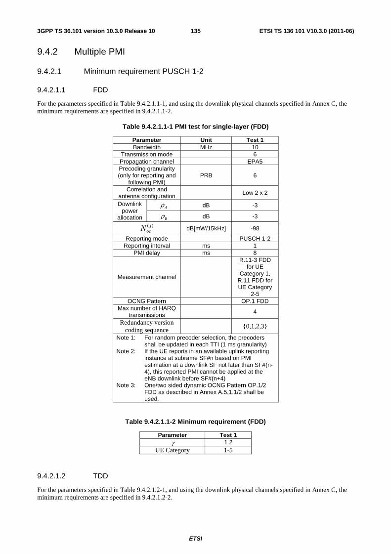
ETSI
ETSI TS 136 101 V10.3.0 (2011-06)1353GPP TS 36.101 version 10.3.0 Release 10
9.4.2 Multiple PMI
9.4.2.1 Minimum requirement PUSCH 1-2
9.4.2.1.1 FDD
For the parameters specified in Table 9.4.2.1.1-1, and using the downlink physical channels specified in Annex C, the minimum requirements are specified in 9.4.2.1.1-2.
Table 9.4.2.1.1-1 PMI test for single-layer (FDD)
Parameter Unit Test 1 Bandwidth MHz 10
Transmission mode 6 Propagation channel EPA5 Precoding granularity (only for reporting and
following PMI) PRB 6
Correlation and antenna configuration Low 2 x 2
Downlink power
allocation
Aρ dB -3
Bρ dB -3
)( jocN dB[mW/15kHz] -98
Reporting mode PUSCH 1-2 Reporting interval ms 1
PMI delay ms 8
Measurement channel
R.11-3 FDD for UE
Category 1, R.11 FDD for UE Category
2-5 OCNG Pattern OP.1 FDD
Max number of HARQ transmissions 4
Redundancy version coding sequence
{0,1,2,3}
Note 1: For random precoder selection, the precoders shall be updated in each TTI (1 ms granularity)
Note 2: If the UE reports in an available uplink reporting instance at subrame SF#n based on PMI estimation at a downlink SF not later than SF#(n-4), this reported PMI cannot be applied at the eNB downlink before SF#(n+4)
Note 3: One/two sided dynamic OCNG Pattern OP.1/2 FDD as described in Annex A.5.1.1/2 shall be used.
Table 9.4.2.1.1-2 Minimum requirement (FDD)
Parameter Test 1 γ 1.2
UE Category 1-5
9.4.2.1.2 TDD
For the parameters specified in Table 9.4.2.1.2-1, and using the downlink physical channels specified in Annex C, the minimum requirements are specified in 9.4.2.1.2-2.
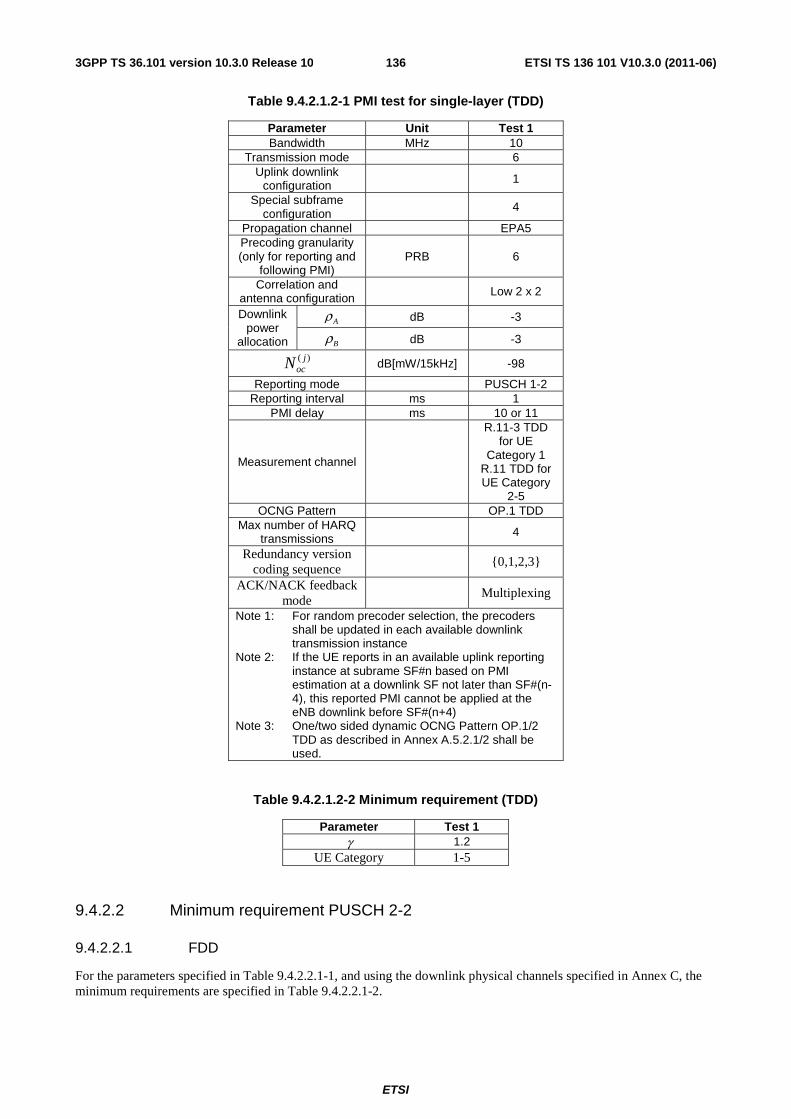
ETSI
ETSI TS 136 101 V10.3.0 (2011-06)1363GPP TS 36.101 version 10.3.0 Release 10
Table 9.4.2.1.2-1 PMI test for single-layer (TDD)
Parameter Unit Test 1 Bandwidth MHz 10
Transmission mode 6 Uplink downlink
configuration 1
Special subframe configuration
4
Propagation channel EPA5 Precoding granularity (only for reporting and
following PMI) PRB 6
Correlation and antenna configuration Low 2 x 2
Downlink power
allocation
Aρ dB -3
Bρ dB -3
)( jocN dB[mW/15kHz] -98
Reporting mode PUSCH 1-2 Reporting interval ms 1
PMI delay ms 10 or 11
Measurement channel
R.11-3 TDD for UE
Category 1 R.11 TDD for UE Category
2-5 OCNG Pattern OP.1 TDD
Max number of HARQ transmissions 4
Redundancy version coding sequence
{0,1,2,3}
ACK/NACK feedback mode
Multiplexing
Note 1: For random precoder selection, the precoders shall be updated in each available downlink transmission instance
Note 2: If the UE reports in an available uplink reporting instance at subrame SF#n based on PMI estimation at a downlink SF not later than SF#(n-4), this reported PMI cannot be applied at the eNB downlink before SF#(n+4)
Note 3: One/two sided dynamic OCNG Pattern OP.1/2 TDD as described in Annex A.5.2.1/2 shall be used.
Table 9.4.2.1.2-2 Minimum requirement (TDD)
Parameter Test 1 γ 1.2
UE Category 1-5
9.4.2.2 Minimum requirement PUSCH 2-2
9.4.2.2.1 FDD
For the parameters specified in Table 9.4.2.2.1-1, and using the downlink physical channels specified in Annex C, the minimum requirements are specified in Table 9.4.2.2.1-2.
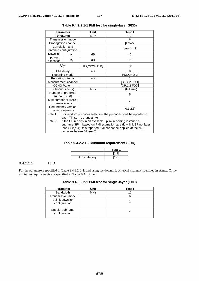
ETSI
ETSI TS 136 101 V10.3.0 (2011-06)1373GPP TS 36.101 version 10.3.0 Release 10
Table 9.4.2.2.1-1 PMI test for single-layer (FDD)
Parameter Unit Test 1 Bandwidth MHz 10
Transmission mode 6 Propagation channel [EVA5]
Correlation and antenna configuration Low 4 x 2
Downlink power
allocation
Aρ dB -6
Bρ dB -6
)( jocN dB[mW/15kHz] -98
PMI delay ms 8 Reporting mode PUSCH 2-2
Reporting interval ms 1 Measurement channel [R.14-2 FDD]
OCNG Pattern [OP.1/2 FDD] Subband size (k) RBs 3 (full size)
Number of preferred subbands (M) 5
Max number of HARQ transmissions 4
Redundancy version coding sequence {0,1,2,3}
Note 1: For random precoder selection, the precoder shall be updated in each TTI (1 ms granularity)
Note 2: If the UE reports in an available uplink reporting instance at subrame SF#n based on PMI estimation at a downlink SF not later than SF#(n-4), this reported PMI cannot be applied at the eNB downlink before SF#(n+4)
Table 9.4.2.2.1-2 Minimum requirement (FDD)
Test 1 γ [1.2]
UE Category [1-5]
9.4.2.2.2 TDD
For the parameters specified in Table 9.4.2.2.2-1, and using the downlink physical channels specified in Annex C, the minimum requirements are specified in Table 9.4.2.2.2-2.
Table 9.4.2.2.2-1 PMI test for single-layer (TDD)
Parameter Unit Test 1 Bandwidth MHz 10
Transmission mode 6 Uplink downlink
configuration 1
Special subframe configuration 4
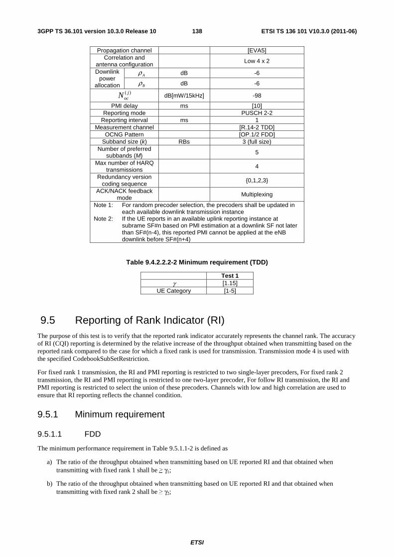
ETSI
ETSI TS 136 101 V10.3.0 (2011-06)1383GPP TS 36.101 version 10.3.0 Release 10
Propagation channel [EVA5] Correlation and
antenna configuration Low 4 x 2
Downlink power
allocation
Aρ dB -6
Bρ dB -6
)( jocN dB[mW/15kHz] -98
PMI delay ms [10] Reporting mode PUSCH 2-2
Reporting interval ms 1 Measurement channel [R.14-2 TDD]
OCNG Pattern [OP.1/2 FDD] Subband size (k) RBs 3 (full size)
Number of preferred subbands (M) 5
Max number of HARQ transmissions 4
Redundancy version coding sequence {0,1,2,3}
ACK/NACK feedback mode Multiplexing
Note 1: For random precoder selection, the precoders shall be updated in each available downlink transmission instance
Note 2: If the UE reports in an available uplink reporting instance at subrame SF#n based on PMI estimation at a downlink SF not later than SF#(n-4), this reported PMI cannot be applied at the eNB downlink before SF#(n+4)
Table 9.4.2.2.2-2 Minimum requirement (TDD)
Test 1 γ [1.15]
UE Category [1-5]
9.5 Reporting of Rank Indicator (RI) The purpose of this test is to verify that the reported rank indicator accurately represents the channel rank. The accuracy of RI (CQI) reporting is determined by the relative increase of the throughput obtained when transmitting based on the reported rank compared to the case for which a fixed rank is used for transmission. Transmission mode 4 is used with the specified CodebookSubSetRestriction.
For fixed rank 1 transmission, the RI and PMI reporting is restricted to two single-layer precoders, For fixed rank 2 transmission, the RI and PMI reporting is restricted to one two-layer precoder, For follow RI transmission, the RI and PMI reporting is restricted to select the union of these precoders. Channels with low and high correlation are used to ensure that RI reporting reflects the channel condition.
9.5.1 Minimum requirement
9.5.1.1 FDD
The minimum performance requirement in Table 9.5.1.1-2 is defined as
a) The ratio of the throughput obtained when transmitting based on UE reported RI and that obtained when transmitting with fixed rank 1 shall be ≥ γ1;
b) The ratio of the throughput obtained when transmitting based on UE reported RI and that obtained when transmitting with fixed rank 2 shall be ≥ γ2;
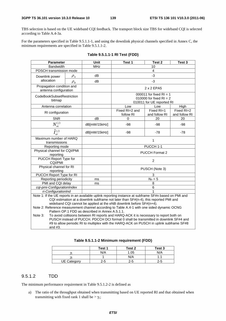
ETSI
ETSI TS 136 101 V10.3.0 (2011-06)1393GPP TS 36.101 version 10.3.0 Release 10
TBS selection is based on the UE wideband CQI feedback. The transport block size TBS for wideband CQI is selected according to Table A.4-3a.
For the parameters specified in Table 9.5.1.1-1, and using the downlink physical channels specified in Annex C, the minimum requirements are specified in Table 9.5.1.1-2.
Table 9.5.1.1-1 RI Test (FDD)
Parameter Unit Test 1 Test 2 Test 3 Bandwidth MHz 10
PDSCH transmission mode 4
Downlink power allocation
Aρ dB -3
Bρ dB -3 Propagation condition and
antenna configuration 2 x 2 EPA5
CodeBookSubsetRestriction bitmap
000011 for fixed RI = 1 010000 for fixed RI = 2
010011 for UE reported RI Antenna correlation Low Low High
RI configuration Fixed RI=2 and follow RI
Fixed RI=1 and follow RI
Fixed RI=2 and follow RI
SNR dB 0 20 20 )( j
ocN dB[mW/15kHz] -98 -98 -98
)(ˆ jorI dB[mW/15kHz] -98 -78 -78
Maximum number of HARQ transmissions 1
Reporting mode PUCCH 1-1 Physical channel for CQI/PMI
reporting PUCCH Format 2
PUCCH Report Type for CQI/PMI 2
Physical channel for RI reporting PUSCH (Note 3)
PUCCH Report Type for RI 3 Reporting periodicity ms NP = 5 PMI and CQI delay ms 8
cqi-pmi-ConfigurationIndex 6 ri-ConfigurationInd 1
Note 1: If the UE reports in an available uplink reporting instance at subframe SF#n based on PMI and CQI estimation at a downlink subframe not later than SF#(n-4), this reported PMI and wideband CQI cannot be applied at the eNB downlink before SF#(n+4).
Note 2: Reference measurement channel according to Table A.4-1 with one sided dynamic OCNG Pattern OP.1 FDD as described in Annex A.5.1.1.
Note 3: To avoid collisions between RI reports and HARQ-ACK it is necessary to report both on PUSCH instead of PUCCH. PDCCH DCI format 0 shall be transmitted in downlink SF#4 and #9 to allow periodic RI to multiplex with the HARQ-ACK on PUSCH in uplink subframe SF#8 and #3.
Table 9.5.1.1-2 Minimum requirement (FDD)
Test 1 Test 2 Test 3 γ1 N/A 1.05 N/A γ2 1 N/A 1.1
UE Category 2-5 2-5 2-5
9.5.1.2 TDD
The minimum performance requirement in Table 9.5.1.2-2 is defined as
a) The ratio of the throughput obtained when transmitting based on UE reported RI and that obtained when transmitting with fixed rank 1 shall be ≥ γ1;

ETSI
ETSI TS 136 101 V10.3.0 (2011-06)1403GPP TS 36.101 version 10.3.0 Release 10
b) The ratio of the throughput obtained when transmitting based on UE reported RI and that obtained when transmitting with fixed rank 2 shall be ≥ γ2;
TBS selection is based on the UE wideband CQI feedback. The transport block size TBS for wideband CQI is selected according to Table A.4-3 (for rank 1) and Table A.4-3a (for rank 2).
For the parameters specified in Table 9.5.1.2-1, and using the downlink physical channels specified in Annex C, the minimum requirements are specified in Table 9.5.1.2-2.
Table 9.5.1.2-1 RI Test (TDD)
Parameter Unit Test 1 Test 2 Test 3 Bandwidth MHz 10
PDSCH transmission mode 4
Downlink power allocation
Aρ dB -3
Bρ dB -3 Uplink downlink configuration 2
Special subframe configuration 4
Propagation condition and antenna configuration 2 x 2 EPA5
CodeBookSubsetRestriction bitmap
000011 for fixed RI = 1 010000 for fixed RI = 2
010011 for UE reported RI Antenna correlation Low Low High
RI configuration Fixed RI=2 and follow RI
Fixed RI=1 and follow RI
Fixed RI=2 and follow RI
SNR dB 0 20 20 )( j
ocN dB[mW/15kHz] -98 -98 -98
)(ˆ jorI dB[mW/15kHz] -98 -78 -78
Maximum number of HARQ transmissions 1
Reporting mode PUSCH 3-1 (Note 3) Reporting interval ms 5
PMI and CQI delay ms 10 or 11 ACK/NACK feedback mode Bundling
Note 1: If the UE reports in an available uplink reporting instance at subframe SF#n based on PMI and CQI estimation at a downlink subframe not later than SF#(n-4), this reported PMI and wideband CQI cannot be applied at the eNB downlink before SF#(n+4).
Note 2: Reference measurement channel according to Table A.4-2 with one sided dynamic OCNG Pattern OP.1 TDD as described in Annex A.5.2.1. Note 3: Reported wideband CQI and PMI are used and sub-band CQI is discarded.
Table 9.5.1.2-2 Minimum requirement (TDD)
Test 1 Test 2 Test 3 γ1 N/A 1.05 N/A γ2 1 N/A 1.1
UE Category 2-5 2-5 2-5
10 Performance requirement (MBMS)
10.1 FDD (Fixed Reference Channel) The parameters specified in Table 10.1-1 are valid for all FDD tests unless otherwise stated. For the requirements defined in this section, the difference between CRS EPRE and the MBSFN RS EPRE should be set to 0 dB as the UE
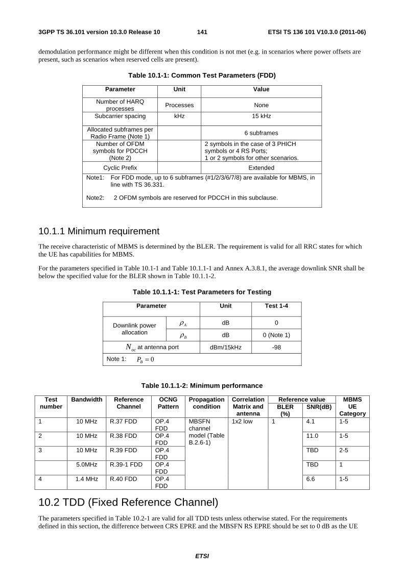
ETSI
ETSI TS 136 101 V10.3.0 (2011-06)1413GPP TS 36.101 version 10.3.0 Release 10
demodulation performance might be different when this condition is not met (e.g. in scenarios where power offsets are present, such as scenarios when reserved cells are present).
Table 10.1-1: Common Test Parameters (FDD)
Parameter Unit Value
Number of HARQ processes Processes None
Subcarrier spacing kHz 15 kHz
Allocated subframes per Radio Frame (Note 1) 6 subframes
Number of OFDM symbols for PDCCH
(Note 2)
2 symbols in the case of 3 PHICH symbols or 4 RS Ports; 1 or 2 symbols for other scenarios.
Cyclic Prefix Extended
Note1: For FDD mode, up to 6 subframes (#1/2/3/6/7/8) are available for MBMS, in line with TS 36.331.
Note2: 2 OFDM symbols are reserved for PDCCH in this subclause.
10.1.1 Minimum requirement
The receive characteristic of MBMS is determined by the BLER. The requirement is valid for all RRC states for which the UE has capabilities for MBMS.
For the parameters specified in Table 10.1-1 and Table 10.1.1-1 and Annex A.3.8.1, the average downlink SNR shall be below the specified value for the BLER shown in Table 10.1.1-2.
Table 10.1.1-1: Test Parameters for Testing
Parameter
Unit Test 1-4
Downlink power allocation
Aρ dB 0
Bρ dB 0 (Note 1)
ocN at antenna port dBm/15kHz -98
Note 1: 0=BP
Table 10.1.1-2: Minimum performance
Test number
Bandwidth Reference Channel
OCNG Pattern
Propagation condition
Correlation Matrix and
antenna
Reference value MBMS UE
Category BLER
(%) SNR(dB)
1 10 MHz R.37 FDD OP.4 FDD
MBSFN channel model (Table B.2.6-1)
1x2 low 1 4.1 1-5
2 10 MHz R.38 FDD OP.4 FDD
11.0 1-5
3 10 MHz R.39 FDD OP.4 FDD
TBD 2-5
5.0MHz R.39-1 FDD OP.4 FDD
TBD 1
4 1.4 MHz R.40 FDD OP.4 FDD
6.6 1-5
10.2 TDD (Fixed Reference Channel) The parameters specified in Table 10.2-1 are valid for all TDD tests unless otherwise stated. For the requirements defined in this section, the difference between CRS EPRE and the MBSFN RS EPRE should be set to 0 dB as the UE
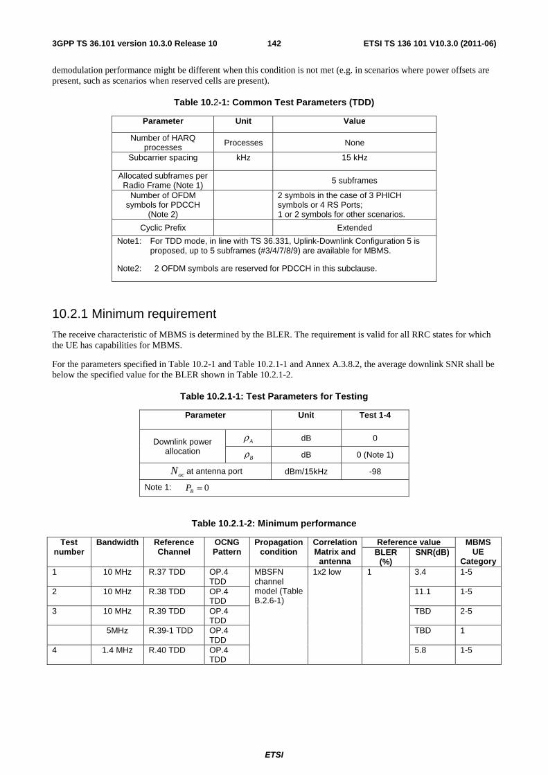
ETSI
ETSI TS 136 101 V10.3.0 (2011-06)1423GPP TS 36.101 version 10.3.0 Release 10
demodulation performance might be different when this condition is not met (e.g. in scenarios where power offsets are present, such as scenarios when reserved cells are present).
Table 10.2-1: Common Test Parameters (TDD)
Parameter Unit Value
Number of HARQ processes Processes None
Subcarrier spacing kHz 15 kHz
Allocated subframes per Radio Frame (Note 1) 5 subframes
Number of OFDM symbols for PDCCH
(Note 2)
2 symbols in the case of 3 PHICH symbols or 4 RS Ports; 1 or 2 symbols for other scenarios.
Cyclic Prefix Extended
Note1: For TDD mode, in line with TS 36.331, Uplink-Downlink Configuration 5 is proposed, up to 5 subframes (#3/4/7/8/9) are available for MBMS.
Note2: 2 OFDM symbols are reserved for PDCCH in this subclause.
10.2.1 Minimum requirement
The receive characteristic of MBMS is determined by the BLER. The requirement is valid for all RRC states for which the UE has capabilities for MBMS.
For the parameters specified in Table 10.2-1 and Table 10.2.1-1 and Annex A.3.8.2, the average downlink SNR shall be below the specified value for the BLER shown in Table 10.2.1-2.
Table 10.2.1-1: Test Parameters for Testing
Parameter
Unit Test 1-4
Downlink power allocation
Aρ dB 0
Bρ dB 0 (Note 1)
ocN at antenna port dBm/15kHz -98
Note 1: 0=BP
Table 10.2.1-2: Minimum performance
Test number
Bandwidth Reference Channel
OCNG Pattern
Propagation condition
Correlation Matrix and
antenna
Reference value MBMS UE
Category BLER
(%) SNR(dB)
1 10 MHz R.37 TDD OP.4 TDD
MBSFN channel model (Table B.2.6-1)
1x2 low 1 3.4 1-5
2 10 MHz R.38 TDD OP.4 TDD
11.1 1-5
3 10 MHz R.39 TDD OP.4 TDD
TBD 2-5
5MHz R.39-1 TDD OP.4 TDD
TBD 1
4 1.4 MHz R.40 TDD OP.4 TDD
5.8 1-5
ETSI
ETSI TS 136 101 V10.3.0 (2011-06)1433GPP TS 36.101 version 10.3.0 Release 10
Annex A (normative): Measurement channels
A.1 General The throughput values defined in the measurement channels specified in Annex A, are calculated and are valid per datastream (codeword). For multi-stream (more than one codeword) transmissions, the throughput referenced in the minimum requirements is the sum of throughputs of all datastreams (codewords).
A.2 UL reference measurement channels
A.2.1 General
A.2.1.1 Applicability and common parameters
The following sections define the UL signal applicable to the Transmitter Characteristics (clause 6) and for the Receiver Characteristics (clause 7) where the UL signal is relevant.
The Reference channels in this section assume transmission of PUSCH and Demodulation Reference signal only. The following conditions apply:
- 1 HARQ transmission
- Cyclic Prefix normal
- PUSCH hopping off
- Link adaptation off
- Demodulation Reference signal as per TS 36.211 [4] subclause 5.5.2.1.2.
Where ACK/NACK is transmitted, it is assumed to be multiplexed on PUSCH as per TS 36.212 [5] subclause 5.2.2.6.
- ACK/NACK 1 bit
- ACK/NACK mapping adjacent to Demodulation Reference symbol
- ACK/NACK resources punctured into data
- Max number of resources for ACK/NACK: 4 SC-FDMA symbols per subframe
- No CQI transmitted, no RI transmitted
A.2.1.2 Determination of payload size
The algorithm for determining the payload size A is as follows; given a desired coding rate R and radio block allocation NRB
1. Calculate the number of channel bits Nch that can be transmitted during the first transmission of a given sub-frame.
2. Find A such that the resulting coding rate is as close to R as possible, that is,
chNAR /)24(min +− ,
subject to

ETSI
ETSI TS 136 101 V10.3.0 (2011-06)1443GPP TS 36.101 version 10.3.0 Release 10
a) A is a valid TB size according to section 7.1.7 of TS 36.213 [6] assuming an allocation of NRB resource blocks.
b) Segmentation is not included in this formula, but should be considered in the TBS calculation.
c) For RMC-s, which at the nominal target coding rate do not cover all the possible UE categories for the given modulation, reduce the target coding rate gradually (within the same modulation), until the maximal possible number of UE categories is covered.
3. If there is more than one A that minimises the equation above, then the larger value is chosen per default.
A.2.2 Reference measurement channels for FDD
A.2.2.1 Full RB allocation
A.2.2.1.1 QPSK
Table A.2.2.1.1-1 Reference Channels for QPSK with full RB allocation
Parameter Unit Value Channel bandwidth MHz 1.4 3 5 10 15 20 Allocated resource blocks 6 15 25 50 75 100 DFT-OFDM Symbols per Sub-Frame 12 12 12 12 12 12 Modulation QPSK QPSK QPSK QPSK QPSK QPSK Target Coding rate 1/3 1/3 1/3 1/3 1/5 1/6 Payload size Bits 600 1544 2216 5160 4392 4584 Transport block CRC Bits 24 24 24 24 24 24 Number of code blocks per Sub-Frame (Note 1)
1 1 1 1 1 1
Total number of bits per Sub-Frame Bits 1728 4320 7200 14400 21600 28800 Total symbols per Sub-Frame 864 2160 3600 7200 10800 14400 UE Category 1-5 1-5 1-5 1-5 1-5 1-5 Note 1: If more than one Code Block is present, an additional CRC sequence of L = 24 Bits is attached
to each Code Block (otherwise L = 0 Bit)
A.2.2.1.2 16-QAM
Table A.2.2.1.2-1 Reference Channels for 16-QAM with full RB allocation
Parameter Unit Value Channel bandwidth MHz 1.4 3 5 10 15 20 Allocated resource blocks 6 15 25 50 75 100 DFT-OFDM Symbols per Sub-Frame 12 12 12 12 12 12 Modulation 16QAM 16QAM 16QAM 16QAM 16QAM 16QAM Target Coding rate 3/4 1/2 1/3 3/4 1/2 1/3 Payload size Bits 2600 4264 4968 21384 21384 19848 Transport block CRC Bits 24 24 24 24 24 24 Number of code blocks per Sub-Frame (Note 1)
1 1 1 4 4 4
Total number of bits per Sub-Frame Bits 3456 8640 14400 28800 43200 57600 Total symbols per Sub-Frame 864 2160 3600 7200 10800 14400 UE Category 1-5 1-5 1-5 2-5 2-5 2-5 Note 1: If more than one Code Block is present, an additional CRC sequence of L = 24 Bits is attached to each
Code Block (otherwise L = 0 Bit)
A.2.2.1.3 64-QAM
[FFS]
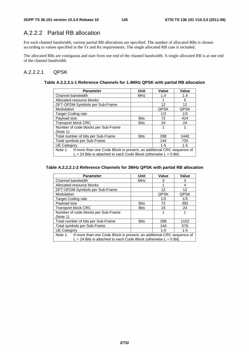
ETSI
ETSI TS 136 101 V10.3.0 (2011-06)1453GPP TS 36.101 version 10.3.0 Release 10
A.2.2.2 Partial RB allocation
For each channel bandwidth, various partial RB allocations are specified. The number of allocated RBs is chosen according to values specified in the Tx and Rx requirements. The single allocated RB case is included.
The allocated RBs are contiguous and start from one end of the channel bandwidth. A single allocated RB is at one end of the channel bandwidth.
A.2.2.2.1 QPSK
Table A.2.2.2.1-1 Reference Channels for 1.4MHz QPSK with partial RB allocation
Parameter Unit Value Value Channel bandwidth MHz 1.4 1.4 Allocated resource blocks 1 5 DFT-OFDM Symbols per Sub-Frame 12 12 Modulation QPSK QPSK Target Coding rate 1/3 1/3 Payload size Bits 72 424 Transport block CRC Bits 24 24 Number of code blocks per Sub-Frame (Note 1)
1 1
Total number of bits per Sub-Frame Bits 288 1440 Total symbols per Sub-Frame 144 720 UE Category 1-5 1-5 Note 1: If more than one Code Block is present, an additional CRC sequence of
L = 24 Bits is attached to each Code Block (otherwise L = 0 Bit)
Table A.2.2.2.1-2 Reference Channels for 3MHz QPSK with partial RB allocation
Parameter Unit Value Value Channel bandwidth MHz 3 3 Allocated resource blocks 1 4 DFT-OFDM Symbols per Sub-Frame 12 12 Modulation QPSK QPSK Target Coding rate 1/3 1/3 Payload size Bits 72 392 Transport block CRC Bits 24 24 Number of code blocks per Sub-Frame (Note 1)
1 1
Total number of bits per Sub-Frame Bits 288 1152 Total symbols per Sub-Frame 144 576 UE Category 1-5 1-5 Note 1: If more than one Code Block is present, an additional CRC sequence of
L = 24 Bits is attached to each Code Block (otherwise L = 0 Bit)
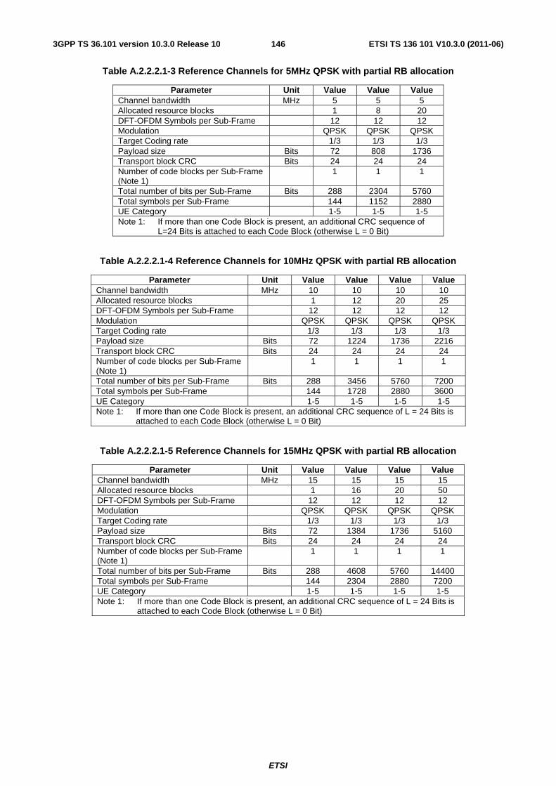
ETSI
ETSI TS 136 101 V10.3.0 (2011-06)1463GPP TS 36.101 version 10.3.0 Release 10
Table A.2.2.2.1-3 Reference Channels for 5MHz QPSK with partial RB allocation
Parameter Unit Value Value Value Channel bandwidth MHz 5 5 5 Allocated resource blocks 1 8 20 DFT-OFDM Symbols per Sub-Frame 12 12 12 Modulation QPSK QPSK QPSK Target Coding rate 1/3 1/3 1/3 Payload size Bits 72 808 1736 Transport block CRC Bits 24 24 24 Number of code blocks per Sub-Frame (Note 1)
1 1 1
Total number of bits per Sub-Frame Bits 288 2304 5760 Total symbols per Sub-Frame 144 1152 2880 UE Category 1-5 1-5 1-5 Note 1: If more than one Code Block is present, an additional CRC sequence of
L=24 Bits is attached to each Code Block (otherwise L = 0 Bit)
Table A.2.2.2.1-4 Reference Channels for 10MHz QPSK with partial RB allocation
Parameter Unit Value Value Value Value Channel bandwidth MHz 10 10 10 10 Allocated resource blocks 1 12 20 25 DFT-OFDM Symbols per Sub-Frame 12 12 12 12 Modulation QPSK QPSK QPSK QPSK Target Coding rate 1/3 1/3 1/3 1/3 Payload size Bits 72 1224 1736 2216 Transport block CRC Bits 24 24 24 24 Number of code blocks per Sub-Frame (Note 1)
1 1 1 1
Total number of bits per Sub-Frame Bits 288 3456 5760 7200 Total symbols per Sub-Frame 144 1728 2880 3600 UE Category 1-5 1-5 1-5 1-5 Note 1: If more than one Code Block is present, an additional CRC sequence of L = 24 Bits is
attached to each Code Block (otherwise L = 0 Bit)
Table A.2.2.2.1-5 Reference Channels for 15MHz QPSK with partial RB allocation
Parameter Unit Value Value Value Value Channel bandwidth MHz 15 15 15 15 Allocated resource blocks 1 16 20 50 DFT-OFDM Symbols per Sub-Frame 12 12 12 12 Modulation QPSK QPSK QPSK QPSK Target Coding rate 1/3 1/3 1/3 1/3 Payload size Bits 72 1384 1736 5160 Transport block CRC Bits 24 24 24 24 Number of code blocks per Sub-Frame (Note 1)
1 1 1 1
Total number of bits per Sub-Frame Bits 288 4608 5760 14400 Total symbols per Sub-Frame 144 2304 2880 7200 UE Category 1-5 1-5 1-5 1-5 Note 1: If more than one Code Block is present, an additional CRC sequence of L = 24 Bits is
attached to each Code Block (otherwise L = 0 Bit)
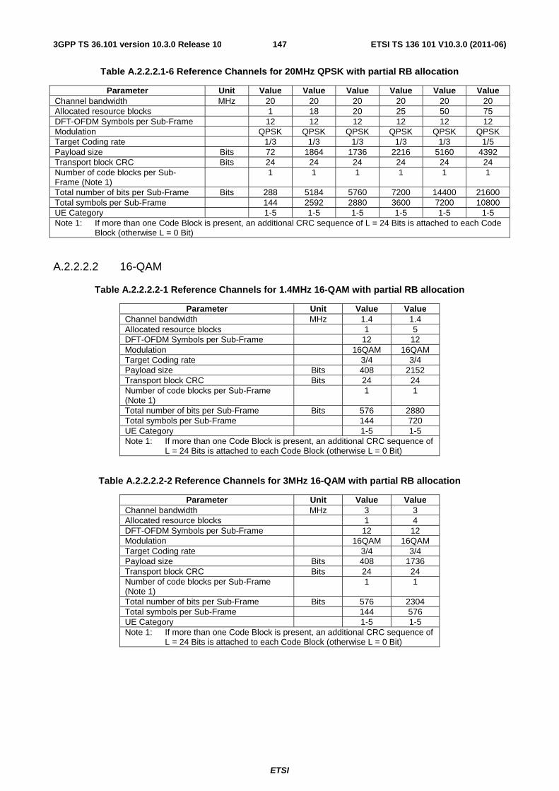
ETSI
ETSI TS 136 101 V10.3.0 (2011-06)1473GPP TS 36.101 version 10.3.0 Release 10
Table A.2.2.2.1-6 Reference Channels for 20MHz QPSK with partial RB allocation
Parameter Unit Value Value Value Value Value Value Channel bandwidth MHz 20 20 20 20 20 20 Allocated resource blocks 1 18 20 25 50 75 DFT-OFDM Symbols per Sub-Frame 12 12 12 12 12 12 Modulation QPSK QPSK QPSK QPSK QPSK QPSK Target Coding rate 1/3 1/3 1/3 1/3 1/3 1/5 Payload size Bits 72 1864 1736 2216 5160 4392 Transport block CRC Bits 24 24 24 24 24 24 Number of code blocks per Sub-Frame (Note 1)
1 1 1 1 1 1
Total number of bits per Sub-Frame Bits 288 5184 5760 7200 14400 21600 Total symbols per Sub-Frame 144 2592 2880 3600 7200 10800 UE Category 1-5 1-5 1-5 1-5 1-5 1-5 Note 1: If more than one Code Block is present, an additional CRC sequence of L = 24 Bits is attached to each Code
Block (otherwise L = 0 Bit)
A.2.2.2.2 16-QAM
Table A.2.2.2.2-1 Reference Channels for 1.4MHz 16-QAM with partial RB allocation
Parameter Unit Value Value Channel bandwidth MHz 1.4 1.4 Allocated resource blocks 1 5 DFT-OFDM Symbols per Sub-Frame 12 12 Modulation 16QAM 16QAM Target Coding rate 3/4 3/4 Payload size Bits 408 2152 Transport block CRC Bits 24 24 Number of code blocks per Sub-Frame (Note 1)
1 1
Total number of bits per Sub-Frame Bits 576 2880 Total symbols per Sub-Frame 144 720 UE Category 1-5 1-5 Note 1: If more than one Code Block is present, an additional CRC sequence of
L = 24 Bits is attached to each Code Block (otherwise L = 0 Bit)
Table A.2.2.2.2-2 Reference Channels for 3MHz 16-QAM with partial RB allocation
Parameter Unit Value Value Channel bandwidth MHz 3 3 Allocated resource blocks 1 4 DFT-OFDM Symbols per Sub-Frame 12 12 Modulation 16QAM 16QAM Target Coding rate 3/4 3/4 Payload size Bits 408 1736 Transport block CRC Bits 24 24 Number of code blocks per Sub-Frame (Note 1)
1 1
Total number of bits per Sub-Frame Bits 576 2304 Total symbols per Sub-Frame 144 576 UE Category 1-5 1-5 Note 1: If more than one Code Block is present, an additional CRC sequence of
L = 24 Bits is attached to each Code Block (otherwise L = 0 Bit)
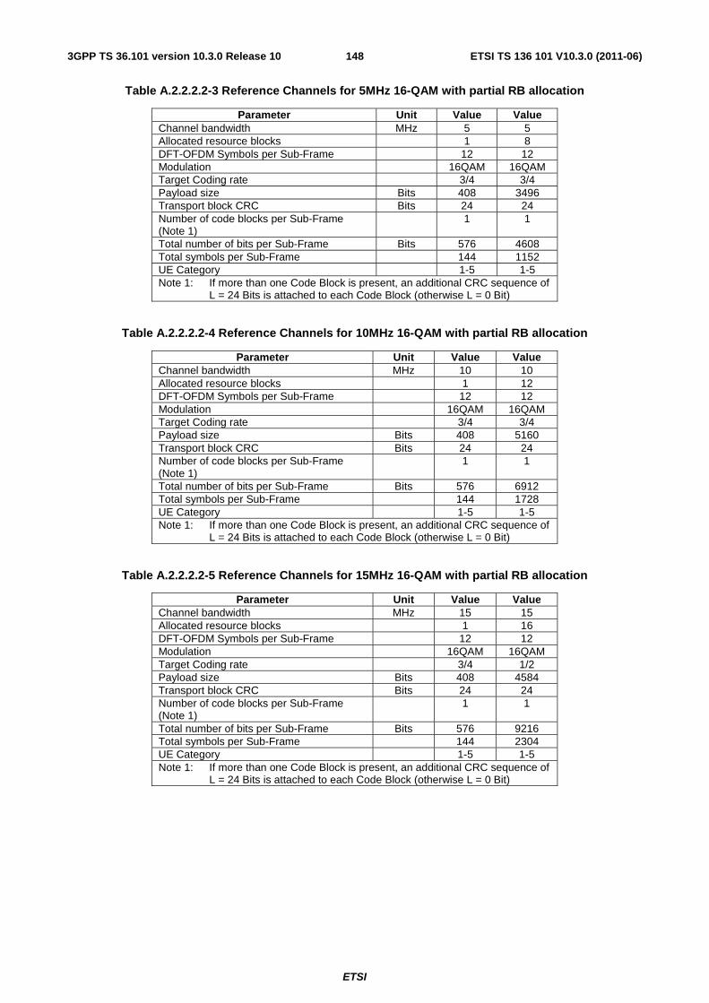
ETSI
ETSI TS 136 101 V10.3.0 (2011-06)1483GPP TS 36.101 version 10.3.0 Release 10
Table A.2.2.2.2-3 Reference Channels for 5MHz 16-QAM with partial RB allocation
Parameter Unit Value Value Channel bandwidth MHz 5 5 Allocated resource blocks 1 8 DFT-OFDM Symbols per Sub-Frame 12 12 Modulation 16QAM 16QAM Target Coding rate 3/4 3/4 Payload size Bits 408 3496 Transport block CRC Bits 24 24 Number of code blocks per Sub-Frame (Note 1)
1 1
Total number of bits per Sub-Frame Bits 576 4608 Total symbols per Sub-Frame 144 1152 UE Category 1-5 1-5 Note 1: If more than one Code Block is present, an additional CRC sequence of
L = 24 Bits is attached to each Code Block (otherwise L = 0 Bit)
Table A.2.2.2.2-4 Reference Channels for 10MHz 16-QAM with partial RB allocation
Parameter Unit Value Value Channel bandwidth MHz 10 10 Allocated resource blocks 1 12 DFT-OFDM Symbols per Sub-Frame 12 12 Modulation 16QAM 16QAM Target Coding rate 3/4 3/4 Payload size Bits 408 5160 Transport block CRC Bits 24 24 Number of code blocks per Sub-Frame (Note 1)
1 1
Total number of bits per Sub-Frame Bits 576 6912 Total symbols per Sub-Frame 144 1728 UE Category 1-5 1-5 Note 1: If more than one Code Block is present, an additional CRC sequence of
L = 24 Bits is attached to each Code Block (otherwise L = 0 Bit)
Table A.2.2.2.2-5 Reference Channels for 15MHz 16-QAM with partial RB allocation
Parameter Unit Value Value Channel bandwidth MHz 15 15 Allocated resource blocks 1 16 DFT-OFDM Symbols per Sub-Frame 12 12 Modulation 16QAM 16QAM Target Coding rate 3/4 1/2 Payload size Bits 408 4584 Transport block CRC Bits 24 24 Number of code blocks per Sub-Frame (Note 1)
1 1
Total number of bits per Sub-Frame Bits 576 9216 Total symbols per Sub-Frame 144 2304 UE Category 1-5 1-5 Note 1: If more than one Code Block is present, an additional CRC sequence of
L = 24 Bits is attached to each Code Block (otherwise L = 0 Bit)
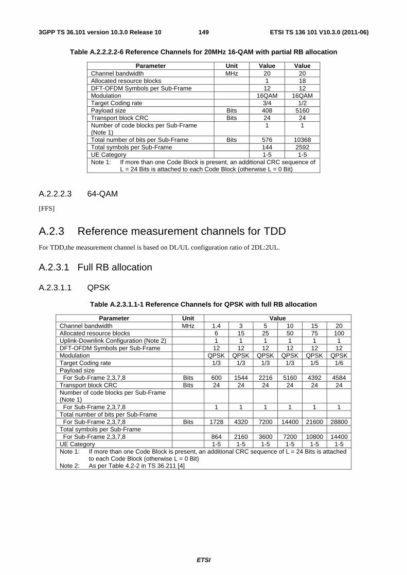
ETSI
ETSI TS 136 101 V10.3.0 (2011-06)1493GPP TS 36.101 version 10.3.0 Release 10
Table A.2.2.2.2-6 Reference Channels for 20MHz 16-QAM with partial RB allocation
Parameter Unit Value Value Channel bandwidth MHz 20 20 Allocated resource blocks 1 18 DFT-OFDM Symbols per Sub-Frame 12 12 Modulation 16QAM 16QAM Target Coding rate 3/4 1/2 Payload size Bits 408 5160 Transport block CRC Bits 24 24 Number of code blocks per Sub-Frame (Note 1)
1 1
Total number of bits per Sub-Frame Bits 576 10368 Total symbols per Sub-Frame 144 2592 UE Category 1-5 1-5 Note 1: If more than one Code Block is present, an additional CRC sequence of
L = 24 Bits is attached to each Code Block (otherwise L = 0 Bit)
A.2.2.2.3 64-QAM
[FFS]
A.2.3 Reference measurement channels for TDD For TDD,the measurement channel is based on DL/UL configuration ratio of 2DL:2UL.
A.2.3.1 Full RB allocation
A.2.3.1.1 QPSK
Table A.2.3.1.1-1 Reference Channels for QPSK with full RB allocation
Parameter Unit Value Channel bandwidth MHz 1.4 3 5 10 15 20 Allocated resource blocks 6 15 25 50 75 100 Uplink-Downlink Configuration (Note 2) 1 1 1 1 1 1 DFT-OFDM Symbols per Sub-Frame 12 12 12 12 12 12 Modulation QPSK QPSK QPSK QPSK QPSK QPSK Target Coding rate 1/3 1/3 1/3 1/3 1/5 1/6 Payload size For Sub-Frame 2,3,7,8 Bits 600 1544 2216 5160 4392 4584 Transport block CRC Bits 24 24 24 24 24 24 Number of code blocks per Sub-Frame (Note 1)
For Sub-Frame 2,3,7,8 1 1 1 1 1 1 Total number of bits per Sub-Frame For Sub-Frame 2,3,7,8 Bits 1728 4320 7200 14400 21600 28800 Total symbols per Sub-Frame For Sub-Frame 2,3,7,8 864 2160 3600 7200 10800 14400 UE Category 1-5 1-5 1-5 1-5 1-5 1-5 Note 1: If more than one Code Block is present, an additional CRC sequence of L = 24 Bits is attached
to each Code Block (otherwise L = 0 Bit) Note 2: As per Table 4.2-2 in TS 36.211 [4]
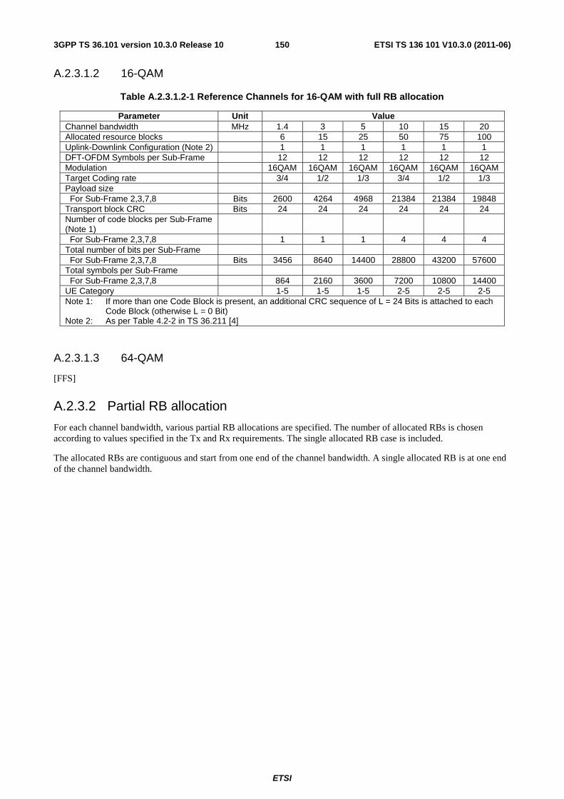
ETSI
ETSI TS 136 101 V10.3.0 (2011-06)1503GPP TS 36.101 version 10.3.0 Release 10
A.2.3.1.2 16-QAM
Table A.2.3.1.2-1 Reference Channels for 16-QAM with full RB allocation
Parameter Unit Value Channel bandwidth MHz 1.4 3 5 10 15 20 Allocated resource blocks 6 15 25 50 75 100 Uplink-Downlink Configuration (Note 2) 1 1 1 1 1 1 DFT-OFDM Symbols per Sub-Frame 12 12 12 12 12 12 Modulation 16QAM 16QAM 16QAM 16QAM 16QAM 16QAM Target Coding rate 3/4 1/2 1/3 3/4 1/2 1/3 Payload size For Sub-Frame 2,3,7,8 Bits 2600 4264 4968 21384 21384 19848 Transport block CRC Bits 24 24 24 24 24 24 Number of code blocks per Sub-Frame (Note 1)
For Sub-Frame 2,3,7,8 1 1 1 4 4 4 Total number of bits per Sub-Frame For Sub-Frame 2,3,7,8 Bits 3456 8640 14400 28800 43200 57600 Total symbols per Sub-Frame For Sub-Frame 2,3,7,8 864 2160 3600 7200 10800 14400 UE Category 1-5 1-5 1-5 2-5 2-5 2-5 Note 1: If more than one Code Block is present, an additional CRC sequence of L = 24 Bits is attached to each
Code Block (otherwise L = 0 Bit) Note 2: As per Table 4.2-2 in TS 36.211 [4]
A.2.3.1.3 64-QAM
[FFS]
A.2.3.2 Partial RB allocation
For each channel bandwidth, various partial RB allocations are specified. The number of allocated RBs is chosen according to values specified in the Tx and Rx requirements. The single allocated RB case is included.
The allocated RBs are contiguous and start from one end of the channel bandwidth. A single allocated RB is at one end of the channel bandwidth.
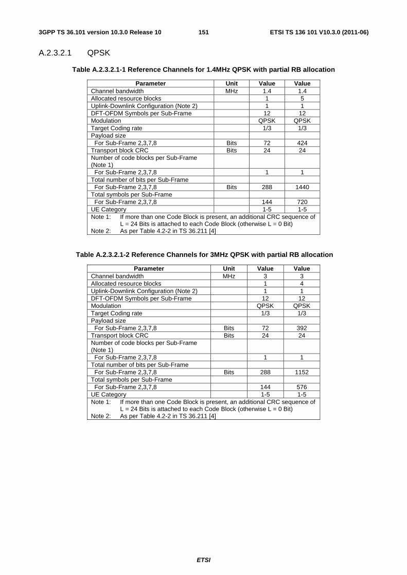
ETSI
ETSI TS 136 101 V10.3.0 (2011-06)1513GPP TS 36.101 version 10.3.0 Release 10
A.2.3.2.1 QPSK
Table A.2.3.2.1-1 Reference Channels for 1.4MHz QPSK with partial RB allocation
Parameter Unit Value Value Channel bandwidth MHz 1.4 1.4 Allocated resource blocks 1 5 Uplink-Downlink Configuration (Note 2) 1 1 DFT-OFDM Symbols per Sub-Frame 12 12 Modulation QPSK QPSK Target Coding rate 1/3 1/3 Payload size For Sub-Frame 2,3,7,8 Bits 72 424 Transport block CRC Bits 24 24 Number of code blocks per Sub-Frame (Note 1)
For Sub-Frame 2,3,7,8 1 1 Total number of bits per Sub-Frame For Sub-Frame 2,3,7,8 Bits 288 1440 Total symbols per Sub-Frame For Sub-Frame 2,3,7,8 144 720 UE Category 1-5 1-5 Note 1: If more than one Code Block is present, an additional CRC sequence of
L = 24 Bits is attached to each Code Block (otherwise L = 0 Bit) Note 2: As per Table 4.2-2 in TS 36.211 [4]
Table A.2.3.2.1-2 Reference Channels for 3MHz QPSK with partial RB allocation
Parameter Unit Value Value Channel bandwidth MHz 3 3 Allocated resource blocks 1 4 Uplink-Downlink Configuration (Note 2) 1 1 DFT-OFDM Symbols per Sub-Frame 12 12 Modulation QPSK QPSK Target Coding rate 1/3 1/3 Payload size For Sub-Frame 2,3,7,8 Bits 72 392 Transport block CRC Bits 24 24 Number of code blocks per Sub-Frame (Note 1)
For Sub-Frame 2,3,7,8 1 1 Total number of bits per Sub-Frame For Sub-Frame 2,3,7,8 Bits 288 1152 Total symbols per Sub-Frame For Sub-Frame 2,3,7,8 144 576 UE Category 1-5 1-5 Note 1: If more than one Code Block is present, an additional CRC sequence of
L = 24 Bits is attached to each Code Block (otherwise L = 0 Bit) Note 2: As per Table 4.2-2 in TS 36.211 [4]
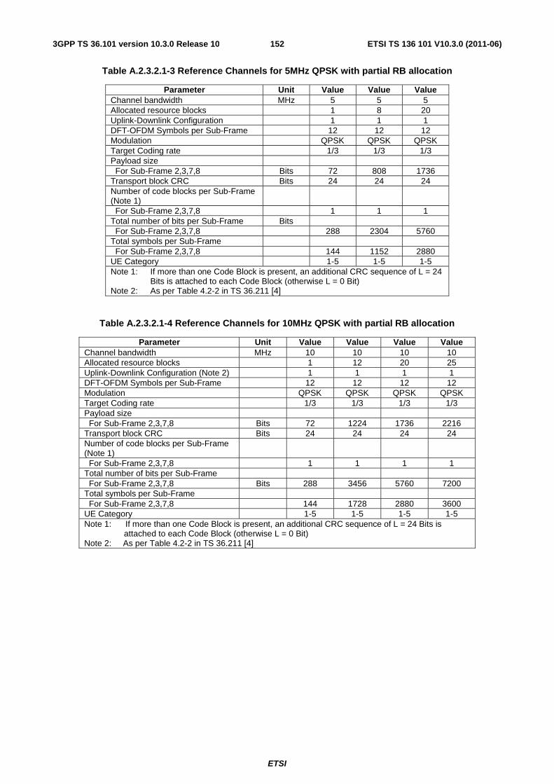
ETSI
ETSI TS 136 101 V10.3.0 (2011-06)1523GPP TS 36.101 version 10.3.0 Release 10
Table A.2.3.2.1-3 Reference Channels for 5MHz QPSK with partial RB allocation
Parameter Unit Value Value Value Channel bandwidth MHz 5 5 5 Allocated resource blocks 1 8 20 Uplink-Downlink Configuration 1 1 1 DFT-OFDM Symbols per Sub-Frame 12 12 12 Modulation QPSK QPSK QPSK Target Coding rate 1/3 1/3 1/3 Payload size For Sub-Frame 2,3,7,8 Bits 72 808 1736 Transport block CRC Bits 24 24 24 Number of code blocks per Sub-Frame (Note 1)
For Sub-Frame 2,3,7,8 1 1 1 Total number of bits per Sub-Frame Bits For Sub-Frame 2,3,7,8 288 2304 5760 Total symbols per Sub-Frame For Sub-Frame 2,3,7,8 144 1152 2880 UE Category 1-5 1-5 1-5 Note 1: If more than one Code Block is present, an additional CRC sequence of L = 24
Bits is attached to each Code Block (otherwise L = 0 Bit) Note 2: As per Table 4.2-2 in TS 36.211 [4]
Table A.2.3.2.1-4 Reference Channels for 10MHz QPSK with partial RB allocation
Parameter Unit Value Value Value Value Channel bandwidth MHz 10 10 10 10 Allocated resource blocks 1 12 20 25 Uplink-Downlink Configuration (Note 2) 1 1 1 1 DFT-OFDM Symbols per Sub-Frame 12 12 12 12 Modulation QPSK QPSK QPSK QPSK Target Coding rate 1/3 1/3 1/3 1/3 Payload size For Sub-Frame 2,3,7,8 Bits 72 1224 1736 2216 Transport block CRC Bits 24 24 24 24 Number of code blocks per Sub-Frame (Note 1)
For Sub-Frame 2,3,7,8 1 1 1 1 Total number of bits per Sub-Frame For Sub-Frame 2,3,7,8 Bits 288 3456 5760 7200 Total symbols per Sub-Frame For Sub-Frame 2,3,7,8 144 1728 2880 3600 UE Category 1-5 1-5 1-5 1-5 Note 1: If more than one Code Block is present, an additional CRC sequence of L = 24 Bits is
attached to each Code Block (otherwise L = 0 Bit) Note 2: As per Table 4.2-2 in TS 36.211 [4]

ETSI
ETSI TS 136 101 V10.3.0 (2011-06)1533GPP TS 36.101 version 10.3.0 Release 10
Table A.2.3.2.1-5 Reference Channels for 15MHz QPSK with partial RB allocation
Parameter Unit Value Value Value Channel bandwidth MHz 15 15 15 Allocated resource blocks 1 16 50 Uplink-Downlink Configuration (Note 2) 1 1 1 DFT-OFDM Symbols per Sub-Frame 12 12 12 Modulation QPSK QPSK QPSK Target Coding rate 1/3 1/3 1/3 Payload size For Sub-Frame 2,3,7,8 Bits 72 1384 5160 Transport block CRC Bits 24 24 24 Number of code blocks per Sub-Frame (Note 1)
For Sub-Frame 2,3,7,8 1 1 1 Total number of bits per Sub-Frame For Sub-Frame 2,3,7,8 Bits 288 4608 14400 Total symbols per Sub-Frame For Sub-Frame 2,3,7,8 144 2304 7200 UE Category 1-5 1-5 1-5 Note 1: If more than one Code Block is present, an additional CRC sequence of L = 24
Bits is attached to each Code Block (otherwise L = 0 Bit) Note 2: As per Table 4.2-2 in TS 36.211 [4]
Table A.2.3.2.1-6 Reference Channels for 20MHz QPSK with partial RB allocation
Parameter Unit Value Value Value Value Value Channel bandwidth MHz 20 20 20 20 20 Allocated resource blocks 1 18 25 50 75 Uplink-Downlink Configuration (Note 2) 1 1 1 1 1 DFT-OFDM Symbols per Sub-Frame 12 12 12 12 12 Modulation QPSK QPSK QPSK QPSK QPSK Target Coding rate 1/3 1/3 1/3 1/3 1/5 Payload size For Sub-Frame 2,3,7,8 Bits 72 1864 2216 5160 4392 Transport block CRC Bits 24 24 24 24 24 Number of code blocks per Sub-Frame (Note 1)
For Sub-Frame 2,3,7,8 1 1 1 1 1 Total number of bits per Sub-Frame For Sub-Frame 2,3,7,8 Bits 288 5184 7200 14400 21600 Total symbols per Sub-Frame For Sub-Frame 2,3,7,8 144 2592 3600 7200 10800 UE Category 1-5 1-5 1-5 1-5 1-5 Note 1: If more than one Code Block is present, an additional CRC sequence of L = 24 Bits is attached to each
Code Block (otherwise L = 0 Bit) Note 2: As per Table 4.2-2 in TS 36.211 [4]
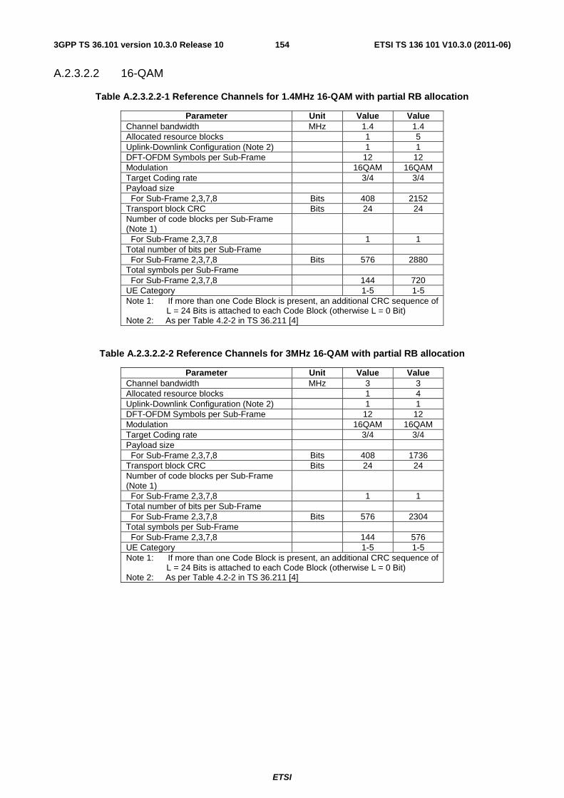
ETSI
ETSI TS 136 101 V10.3.0 (2011-06)1543GPP TS 36.101 version 10.3.0 Release 10
A.2.3.2.2 16-QAM
Table A.2.3.2.2-1 Reference Channels for 1.4MHz 16-QAM with partial RB allocation
Parameter Unit Value Value Channel bandwidth MHz 1.4 1.4 Allocated resource blocks 1 5 Uplink-Downlink Configuration (Note 2) 1 1 DFT-OFDM Symbols per Sub-Frame 12 12 Modulation 16QAM 16QAM Target Coding rate 3/4 3/4 Payload size For Sub-Frame 2,3,7,8 Bits 408 2152 Transport block CRC Bits 24 24 Number of code blocks per Sub-Frame (Note 1)
For Sub-Frame 2,3,7,8 1 1 Total number of bits per Sub-Frame For Sub-Frame 2,3,7,8 Bits 576 2880 Total symbols per Sub-Frame For Sub-Frame 2,3,7,8 144 720 UE Category 1-5 1-5 Note 1: If more than one Code Block is present, an additional CRC sequence of
L = 24 Bits is attached to each Code Block (otherwise L = 0 Bit) Note 2: As per Table 4.2-2 in TS 36.211 [4]
Table A.2.3.2.2-2 Reference Channels for 3MHz 16-QAM with partial RB allocation
Parameter Unit Value Value Channel bandwidth MHz 3 3 Allocated resource blocks 1 4 Uplink-Downlink Configuration (Note 2) 1 1 DFT-OFDM Symbols per Sub-Frame 12 12 Modulation 16QAM 16QAM Target Coding rate 3/4 3/4 Payload size For Sub-Frame 2,3,7,8 Bits 408 1736 Transport block CRC Bits 24 24 Number of code blocks per Sub-Frame (Note 1)
For Sub-Frame 2,3,7,8 1 1 Total number of bits per Sub-Frame For Sub-Frame 2,3,7,8 Bits 576 2304 Total symbols per Sub-Frame For Sub-Frame 2,3,7,8 144 576 UE Category 1-5 1-5 Note 1: If more than one Code Block is present, an additional CRC sequence of
L = 24 Bits is attached to each Code Block (otherwise L = 0 Bit) Note 2: As per Table 4.2-2 in TS 36.211 [4]
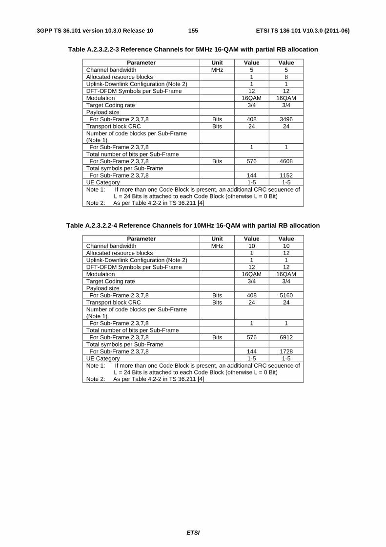
ETSI
ETSI TS 136 101 V10.3.0 (2011-06)1553GPP TS 36.101 version 10.3.0 Release 10
Table A.2.3.2.2-3 Reference Channels for 5MHz 16-QAM with partial RB allocation
Parameter Unit Value Value Channel bandwidth MHz 5 5 Allocated resource blocks 1 8 Uplink-Downlink Configuration (Note 2) 1 1 DFT-OFDM Symbols per Sub-Frame 12 12 Modulation 16QAM 16QAM Target Coding rate 3/4 3/4 Payload size For Sub-Frame 2,3,7,8 Bits 408 3496 Transport block CRC Bits 24 24 Number of code blocks per Sub-Frame (Note 1)
For Sub-Frame 2,3,7,8 1 1 Total number of bits per Sub-Frame For Sub-Frame 2,3,7,8 Bits 576 4608 Total symbols per Sub-Frame For Sub-Frame 2,3,7,8 144 1152 UE Category 1-5 1-5 Note 1: If more than one Code Block is present, an additional CRC sequence of
L = 24 Bits is attached to each Code Block (otherwise L = 0 Bit) Note 2: As per Table 4.2-2 in TS 36.211 [4]
Table A.2.3.2.2-4 Reference Channels for 10MHz 16-QAM with partial RB allocation
Parameter Unit Value Value Channel bandwidth MHz 10 10 Allocated resource blocks 1 12 Uplink-Downlink Configuration (Note 2) 1 1 DFT-OFDM Symbols per Sub-Frame 12 12 Modulation 16QAM 16QAM Target Coding rate 3/4 3/4 Payload size For Sub-Frame 2,3,7,8 Bits 408 5160 Transport block CRC Bits 24 24 Number of code blocks per Sub-Frame (Note 1)
For Sub-Frame 2,3,7,8 1 1 Total number of bits per Sub-Frame For Sub-Frame 2,3,7,8 Bits 576 6912 Total symbols per Sub-Frame For Sub-Frame 2,3,7,8 144 1728 UE Category 1-5 1-5 Note 1: If more than one Code Block is present, an additional CRC sequence of
L = 24 Bits is attached to each Code Block (otherwise L = 0 Bit) Note 2: As per Table 4.2-2 in TS 36.211 [4]
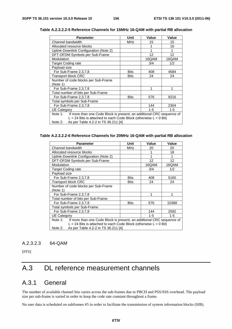
ETSI
ETSI TS 136 101 V10.3.0 (2011-06)1563GPP TS 36.101 version 10.3.0 Release 10
Table A.2.3.2.2-5 Reference Channels for 15MHz 16-QAM with partial RB allocation
Parameter Unit Value Value Channel bandwidth MHz 15 15 Allocated resource blocks 1 16 Uplink-Downlink Configuration (Note 2) 1 1 DFT-OFDM Symbols per Sub-Frame 12 12 Modulation 16QAM 16QAM Target Coding rate 3/4 1/2 Payload size For Sub-Frame 2,3,7,8 Bits 408 4584 Transport block CRC Bits 24 24 Number of code blocks per Sub-Frame (Note 1)
For Sub-Frame 2,3,7,8 1 1 Total number of bits per Sub-Frame For Sub-Frame 2,3,7,8 Bits 576 9216 Total symbols per Sub-Frame For Sub-Frame 2,3,7,8 144 2304 UE Category 1-5 1-5 Note 1: If more than one Code Block is present, an additional CRC sequence of
L = 24 Bits is attached to each Code Block (otherwise L = 0 Bit) Note 2: As per Table 4.2-2 in TS 36.211 [4]
Table A.2.3.2.2-6 Reference Channels for 20MHz 16-QAM with partial RB allocation
Parameter Unit Value Value Channel bandwidth MHz 20 20 Allocated resource blocks 1 18 Uplink-Downlink Configuration (Note 2) 1 1 DFT-OFDM Symbols per Sub-Frame 12 12 Modulation 16QAM 16QAM Target Coding rate 3/4 1/2 Payload size For Sub-Frame 2,3,7,8 Bits 408 5160 Transport block CRC Bits 24 24 Number of code blocks per Sub-Frame (Note 1)
For Sub-Frame 2,3,7,8 1 1 Total number of bits per Sub-Frame For Sub-Frame 2,3,7,8 Bits 576 10368 Total symbols per Sub-Frame For Sub-Frame 2,3,7,8 144 2592 UE Category 1-5 1-5 Note 1: If more than one Code Block is present, an additional CRC sequence of
L = 24 Bits is attached to each Code Block (otherwise L = 0 Bit) Note 2: As per Table 4.2-2 in TS 36.211 [4]
A.2.3.2.3 64-QAM
[FFS]
A.3 DL reference measurement channels
A.3.1 General The number of available channel bits varies across the sub-frames due to PBCH and PSS/SSS overhead. The payload size per sub-frame is varied in order to keep the code rate constant throughout a frame.
No user data is scheduled on subframes #5 in order to facilitate the transmission of system information blocks (SIB).
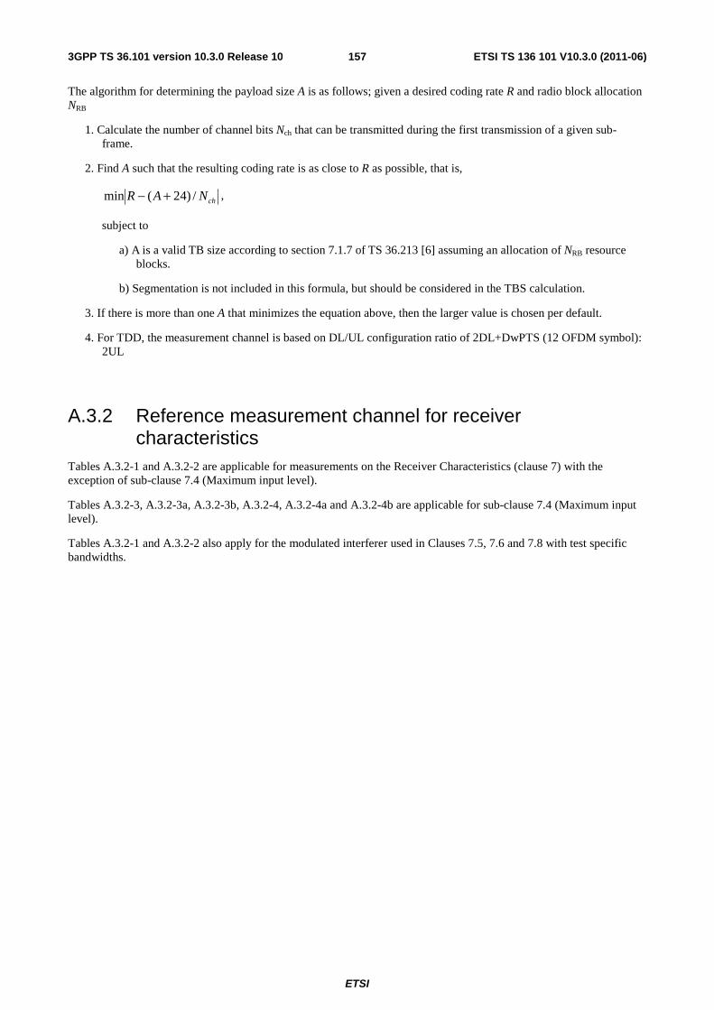
ETSI
ETSI TS 136 101 V10.3.0 (2011-06)1573GPP TS 36.101 version 10.3.0 Release 10
The algorithm for determining the payload size A is as follows; given a desired coding rate R and radio block allocation NRB
1. Calculate the number of channel bits Nch that can be transmitted during the first transmission of a given sub-frame.
2. Find A such that the resulting coding rate is as close to R as possible, that is,
chNAR /)24(min +− ,
subject to
a) A is a valid TB size according to section 7.1.7 of TS 36.213 [6] assuming an allocation of NRB resource blocks.
b) Segmentation is not included in this formula, but should be considered in the TBS calculation.
3. If there is more than one A that minimizes the equation above, then the larger value is chosen per default.
4. For TDD, the measurement channel is based on DL/UL configuration ratio of 2DL+DwPTS (12 OFDM symbol): 2UL
A.3.2 Reference measurement channel for receiver characteristics
Tables A.3.2-1 and A.3.2-2 are applicable for measurements on the Receiver Characteristics (clause 7) with the exception of sub-clause 7.4 (Maximum input level).
Tables A.3.2-3, A.3.2-3a, A.3.2-3b, A.3.2-4, A.3.2-4a and A.3.2-4b are applicable for sub-clause 7.4 (Maximum input level).
Tables A.3.2-1 and A.3.2-2 also apply for the modulated interferer used in Clauses 7.5, 7.6 and 7.8 with test specific bandwidths.
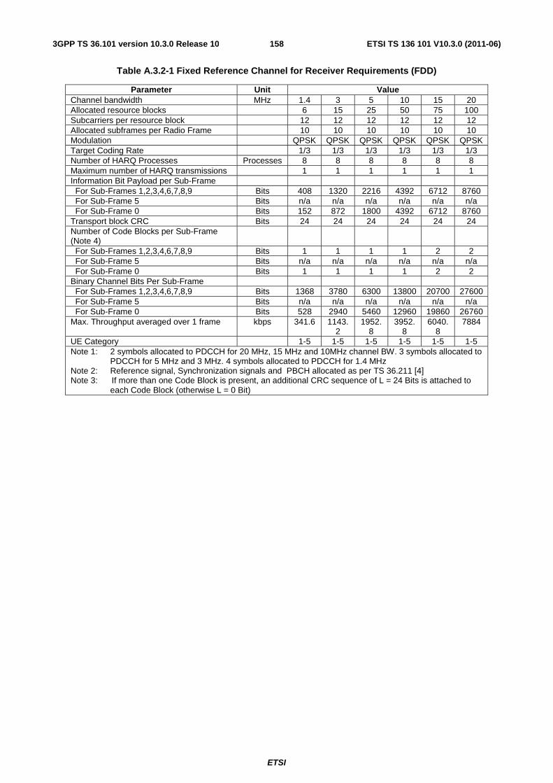
ETSI
ETSI TS 136 101 V10.3.0 (2011-06)1583GPP TS 36.101 version 10.3.0 Release 10
Table A.3.2-1 Fixed Reference Channel for Receiver Requirements (FDD)
Parameter Unit Value Channel bandwidth MHz 1.4 3 5 10 15 20 Allocated resource blocks 6 15 25 50 75 100 Subcarriers per resource block 12 12 12 12 12 12 Allocated subframes per Radio Frame 10 10 10 10 10 10 Modulation QPSK QPSK QPSK QPSK QPSK QPSK Target Coding Rate 1/3 1/3 1/3 1/3 1/3 1/3 Number of HARQ Processes Processes 8 8 8 8 8 8 Maximum number of HARQ transmissions 1 1 1 1 1 1 Information Bit Payload per Sub-Frame For Sub-Frames 1,2,3,4,6,7,8,9 Bits 408 1320 2216 4392 6712 8760 For Sub-Frame 5 Bits n/a n/a n/a n/a n/a n/a For Sub-Frame 0 Bits 152 872 1800 4392 6712 8760 Transport block CRC Bits 24 24 24 24 24 24 Number of Code Blocks per Sub-Frame (Note 4)
For Sub-Frames 1,2,3,4,6,7,8,9 Bits 1 1 1 1 2 2 For Sub-Frame 5 Bits n/a n/a n/a n/a n/a n/a For Sub-Frame 0 Bits 1 1 1 1 2 2 Binary Channel Bits Per Sub-Frame For Sub-Frames 1,2,3,4,6,7,8,9 Bits 1368 3780 6300 13800 20700 27600 For Sub-Frame 5 Bits n/a n/a n/a n/a n/a n/a For Sub-Frame 0 Bits 528 2940 5460 12960 19860 26760 Max. Throughput averaged over 1 frame kbps 341.6 1143.
2 1952.
8 3952.
8 6040.
8 7884
UE Category 1-5 1-5 1-5 1-5 1-5 1-5 Note 1: 2 symbols allocated to PDCCH for 20 MHz, 15 MHz and 10MHz channel BW. 3 symbols allocated to
PDCCH for 5 MHz and 3 MHz. 4 symbols allocated to PDCCH for 1.4 MHz Note 2: Reference signal, Synchronization signals and PBCH allocated as per TS 36.211 [4] Note 3: If more than one Code Block is present, an additional CRC sequence of L = 24 Bits is attached to
each Code Block (otherwise L = 0 Bit)
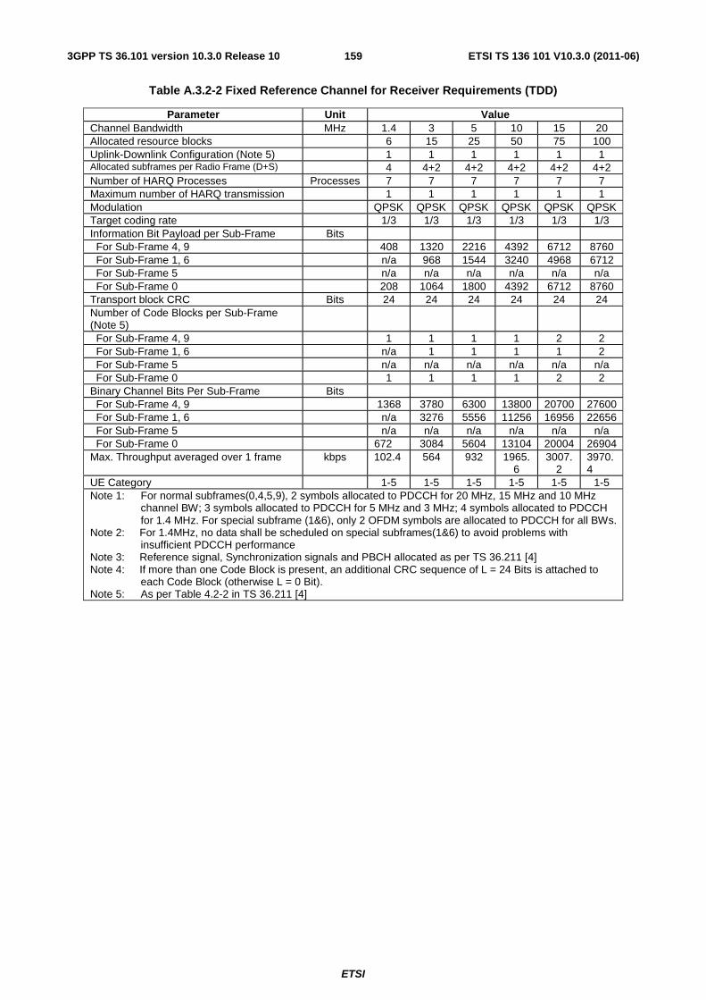
ETSI
ETSI TS 136 101 V10.3.0 (2011-06)1593GPP TS 36.101 version 10.3.0 Release 10
Table A.3.2-2 Fixed Reference Channel for Receiver Requirements (TDD)
Parameter Unit Value Channel Bandwidth MHz 1.4 3 5 10 15 20 Allocated resource blocks 6 15 25 50 75 100 Uplink-Downlink Configuration (Note 5) 1 1 1 1 1 1 Allocated subframes per Radio Frame (D+S) 4 4+2 4+2 4+2 4+2 4+2 Number of HARQ Processes Processes 7 7 7 7 7 7 Maximum number of HARQ transmission 1 1 1 1 1 1 Modulation QPSK QPSK QPSK QPSK QPSK QPSK Target coding rate 1/3 1/3 1/3 1/3 1/3 1/3 Information Bit Payload per Sub-Frame Bits For Sub-Frame 4, 9 408 1320 2216 4392 6712 8760 For Sub-Frame 1, 6 n/a 968 1544 3240 4968 6712 For Sub-Frame 5 n/a n/a n/a n/a n/a n/a For Sub-Frame 0 208 1064 1800 4392 6712 8760 Transport block CRC Bits 24 24 24 24 24 24 Number of Code Blocks per Sub-Frame (Note 5)
For Sub-Frame 4, 9 1 1 1 1 2 2 For Sub-Frame 1, 6 n/a 1 1 1 1 2 For Sub-Frame 5 n/a n/a n/a n/a n/a n/a For Sub-Frame 0 1 1 1 1 2 2 Binary Channel Bits Per Sub-Frame Bits For Sub-Frame 4, 9 1368 3780 6300 13800 20700 27600 For Sub-Frame 1, 6 n/a 3276 5556 11256 16956 22656 For Sub-Frame 5 n/a n/a n/a n/a n/a n/a For Sub-Frame 0 672 3084 5604 13104 20004 26904 Max. Throughput averaged over 1 frame kbps 102.4 564 932 1965.
6 3007.
2 3970.4
UE Category 1-5 1-5 1-5 1-5 1-5 1-5 Note 1: For normal subframes(0,4,5,9), 2 symbols allocated to PDCCH for 20 MHz, 15 MHz and 10 MHz
channel BW; 3 symbols allocated to PDCCH for 5 MHz and 3 MHz; 4 symbols allocated to PDCCH for 1.4 MHz. For special subframe (1&6), only 2 OFDM symbols are allocated to PDCCH for all BWs.
Note 2: For 1.4MHz, no data shall be scheduled on special subframes(1&6) to avoid problems with insufficient PDCCH performance
Note 3: Reference signal, Synchronization signals and PBCH allocated as per TS 36.211 [4] Note 4: If more than one Code Block is present, an additional CRC sequence of L = 24 Bits is attached to
each Code Block (otherwise L = 0 Bit). Note 5: As per Table 4.2-2 in TS 36.211 [4]
ETSI
ETSI TS 136 101 V10.3.0 (2011-06)1603GPP TS 36.101 version 10.3.0 Release 10
Table A.3.2-3 Fixed Reference Channel for Maximum input level for UE Categories 3-5 (FDD)
Parameter Unit Value Channel bandwidth MHz 1.4 3 5 10 15 20 Allocated resource blocks 6 15 25 50 75 100 Subcarriers per resource block 12 12 12 12 12 12 Allocated subframes per Radio Frame 10 10 10 10 10 10 Modulation 64QAM 64QAM 64QAM 64QAM 64QAM 64QAM Target Coding Rate 3/4 3/4 3/4 3/4 3/4 3/4 Number of HARQ Processes Processes 8 8 8 8 8 8 Maximum number of HARQ transmissions 1 1 1 1 1 1 Information Bit Payload per Sub-Frame For Sub-Frames 1,2,3,4,6,7,8,9 Bits 2984 8504 14112 30576 46888 61664 For Sub-Frame 5 Bits n/a n/a n/a n/a n/a n/a For Sub-Frame 0 Bits n/a 6456 12576 28336 45352 61664 Transport block CRC Bits 24 24 24 24 24 24 Number of Code Blocks per Sub-Frame (Note 4)
For Sub-Frames 1,2,3,4,6,7,8,9 1 2 3 5 8 11 For Sub-Frame 5 n/a n/a n/a n/a n/a n/a For Sub-Frame 0 n/a 2 3 5 8 11 Binary Channel Bits Per Sub-Frame For Sub-Frames 1,2,3,4,6,7,8,9 Bits 4104 11340 18900 41400 62100 82800 For Sub-Frame 5 Bits n/a n/a n/a n/a n/a n/a For Sub-Frame 0 Bits n/a 8820 16380 38880 59580 80280 Max. Throughput averaged over 1 frame kbps 2387.2 7448.8 12547 27294 42046 55498 Note 1: 2 symbols allocated to PDCCH for 20 MHz, 15 MHz and 10 MHz channel BW. 3 symbols allocated to PDCCH
for 5 MHz and 3 MHz. 4 symbols allocated to PDCCH for 1.4 MHz Note 2: Reference signal, Synchronization signals and PBCH allocated as per TS 36.211 [4] Note 3: If more than one Code Block is present, an additional CRC sequence of L = 24 Bits is attached to each Code
Block (otherwise L = 0 Bit)
Table A.3.2-3a Fixed Reference Channel for Maximum input level for UE Category 1 (FDD)
Parameter Unit Value Channel bandwidth MHz 1.4 3 5 10 15 20 Allocated resource blocks 6 15 18 17 17 17 Subcarriers per resource block 12 12 12 12 12 12 Allocated subframes per Radio Frame 10 10 10 10 10 10 Modulation 64QAM 64QAM 64QAM 64QAM 64QAM 64QAM Target Coding Rate 3/4 3/4 3/4 3/4 3/4 3/4 Number of HARQ Processes Processes 8 8 8 8 8 8 Maximum number of HARQ transmissions 1 1 1 1 1 1 Information Bit Payload For Sub-Frames 1,2,3,4,6,7,8,9 Bits 2984 8504 10296 10296 10296 10296 For Sub-Frame 5 Bits n/a n/a n/a n/a n/a n/a For Sub-Frame 0 Bits n/a 6456 8248 10296 10296 10296 Transport block CRC Bits 24 24 24 24 24 24 Number of Code Blocks per Sub-Frame (Note 4)
For Sub-Frames 1,2,3,4,6,7,8,9 1 2 2 2 2 2 For Sub-Frame 5 n/a n/a n/a n/a n/a n/a For Sub-Frame 0 n/a 2 2 2 2 2 Binary Channel Bits Per Sub-Frame For Sub-Frames 1,2,3,4,6,7,8,9 Bits 4104 11340 13608 14076 14076 14076 For Sub-Frame 5 Bits n/a n/a n/a n/a n/a n/a For Sub-Frame 0 Bits n/a 8820 11088 14076 14076 14076 Max. Throughput averaged over 1 frame kbps 2387.2 7448.8 9079.6 9266.4 9266.4 9266.4 Note 1: 2 symbols allocated to PDCCH for 20 MHz, 15 MHz and 10 MHz channel BW. 3 symbols allocated to PDCCH
for 5 MHz and 3 MHz. 4 symbols allocated to PDCCH for 1.4 MHz Note 2: Reference signal, Synchronization signals and PBCH allocated as per TS 36.211 [4] Note 3: If more than one Code Block is present, an additional CRC sequence of L = 24 Bits is attached to each Code
Block (otherwise L = 0 Bit)
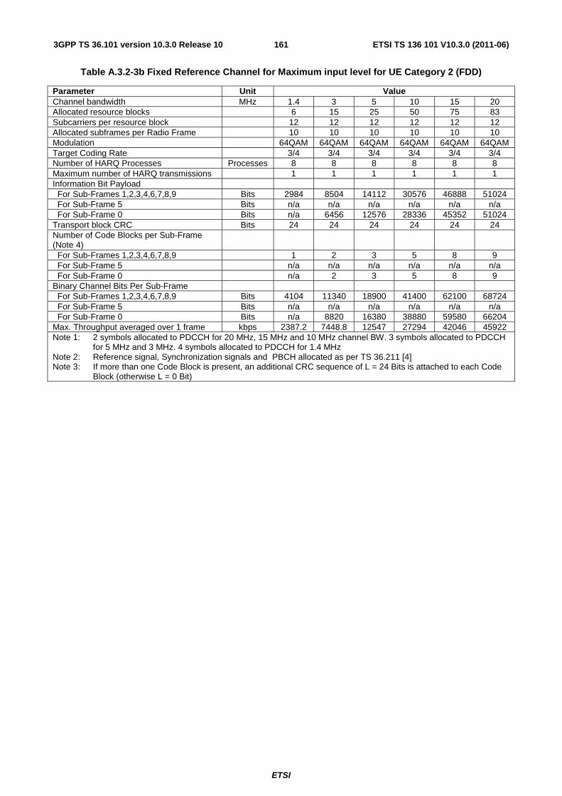
ETSI
ETSI TS 136 101 V10.3.0 (2011-06)1613GPP TS 36.101 version 10.3.0 Release 10
Table A.3.2-3b Fixed Reference Channel for Maximum input level for UE Category 2 (FDD)
Parameter Unit Value Channel bandwidth MHz 1.4 3 5 10 15 20 Allocated resource blocks 6 15 25 50 75 83 Subcarriers per resource block 12 12 12 12 12 12 Allocated subframes per Radio Frame 10 10 10 10 10 10 Modulation 64QAM 64QAM 64QAM 64QAM 64QAM 64QAM Target Coding Rate 3/4 3/4 3/4 3/4 3/4 3/4 Number of HARQ Processes Processes 8 8 8 8 8 8 Maximum number of HARQ transmissions 1 1 1 1 1 1 Information Bit Payload For Sub-Frames 1,2,3,4,6,7,8,9 Bits 2984 8504 14112 30576 46888 51024 For Sub-Frame 5 Bits n/a n/a n/a n/a n/a n/a For Sub-Frame 0 Bits n/a 6456 12576 28336 45352 51024 Transport block CRC Bits 24 24 24 24 24 24 Number of Code Blocks per Sub-Frame (Note 4)
For Sub-Frames 1,2,3,4,6,7,8,9 1 2 3 5 8 9 For Sub-Frame 5 n/a n/a n/a n/a n/a n/a For Sub-Frame 0 n/a 2 3 5 8 9 Binary Channel Bits Per Sub-Frame For Sub-Frames 1,2,3,4,6,7,8,9 Bits 4104 11340 18900 41400 62100 68724 For Sub-Frame 5 Bits n/a n/a n/a n/a n/a n/a For Sub-Frame 0 Bits n/a 8820 16380 38880 59580 66204 Max. Throughput averaged over 1 frame kbps 2387.2 7448.8 12547 27294 42046 45922 Note 1: 2 symbols allocated to PDCCH for 20 MHz, 15 MHz and 10 MHz channel BW. 3 symbols allocated to PDCCH
for 5 MHz and 3 MHz. 4 symbols allocated to PDCCH for 1.4 MHz Note 2: Reference signal, Synchronization signals and PBCH allocated as per TS 36.211 [4] Note 3: If more than one Code Block is present, an additional CRC sequence of L = 24 Bits is attached to each Code
Block (otherwise L = 0 Bit)
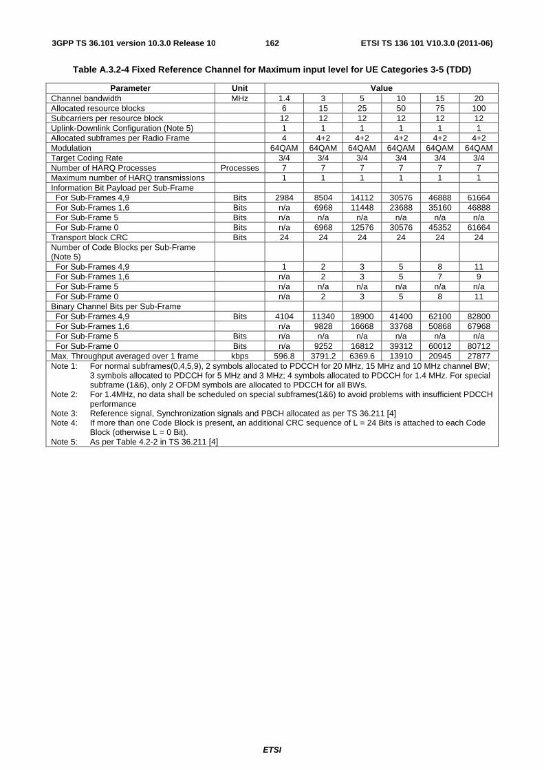
ETSI
ETSI TS 136 101 V10.3.0 (2011-06)1623GPP TS 36.101 version 10.3.0 Release 10
Table A.3.2-4 Fixed Reference Channel for Maximum input level for UE Categories 3-5 (TDD)
Parameter Unit Value Channel bandwidth MHz 1.4 3 5 10 15 20 Allocated resource blocks 6 15 25 50 75 100 Subcarriers per resource block 12 12 12 12 12 12 Uplink-Downlink Configuration (Note 5) 1 1 1 1 1 1 Allocated subframes per Radio Frame 4 4+2 4+2 4+2 4+2 4+2 Modulation 64QAM 64QAM 64QAM 64QAM 64QAM 64QAM Target Coding Rate 3/4 3/4 3/4 3/4 3/4 3/4 Number of HARQ Processes Processes 7 7 7 7 7 7 Maximum number of HARQ transmissions 1 1 1 1 1 1 Information Bit Payload per Sub-Frame For Sub-Frames 4,9 Bits 2984 8504 14112 30576 46888 61664 For Sub-Frames 1,6 Bits n/a 6968 11448 23688 35160 46888 For Sub-Frame 5 Bits n/a n/a n/a n/a n/a n/a For Sub-Frame 0 Bits n/a 6968 12576 30576 45352 61664 Transport block CRC Bits 24 24 24 24 24 24 Number of Code Blocks per Sub-Frame (Note 5)
For Sub-Frames 4,9 1 2 3 5 8 11 For Sub-Frames 1,6 n/a 2 3 5 7 9 For Sub-Frame 5 n/a n/a n/a n/a n/a n/a For Sub-Frame 0 n/a 2 3 5 8 11 Binary Channel Bits per Sub-Frame For Sub-Frames 4,9 Bits 4104 11340 18900 41400 62100 82800 For Sub-Frames 1,6 n/a 9828 16668 33768 50868 67968 For Sub-Frame 5 Bits n/a n/a n/a n/a n/a n/a For Sub-Frame 0 Bits n/a 9252 16812 39312 60012 80712 Max. Throughput averaged over 1 frame kbps 596.8 3791.2 6369.6 13910 20945 27877 Note 1: For normal subframes(0,4,5,9), 2 symbols allocated to PDCCH for 20 MHz, 15 MHz and 10 MHz channel BW;
3 symbols allocated to PDCCH for 5 MHz and 3 MHz; 4 symbols allocated to PDCCH for 1.4 MHz. For special subframe (1&6), only 2 OFDM symbols are allocated to PDCCH for all BWs.
Note 2: For 1.4MHz, no data shall be scheduled on special subframes(1&6) to avoid problems with insufficient PDCCH performance
Note 3: Reference signal, Synchronization signals and PBCH allocated as per TS 36.211 [4] Note 4: If more than one Code Block is present, an additional CRC sequence of L = 24 Bits is attached to each Code
Block (otherwise L = 0 Bit). Note 5: As per Table 4.2-2 in TS 36.211 [4]
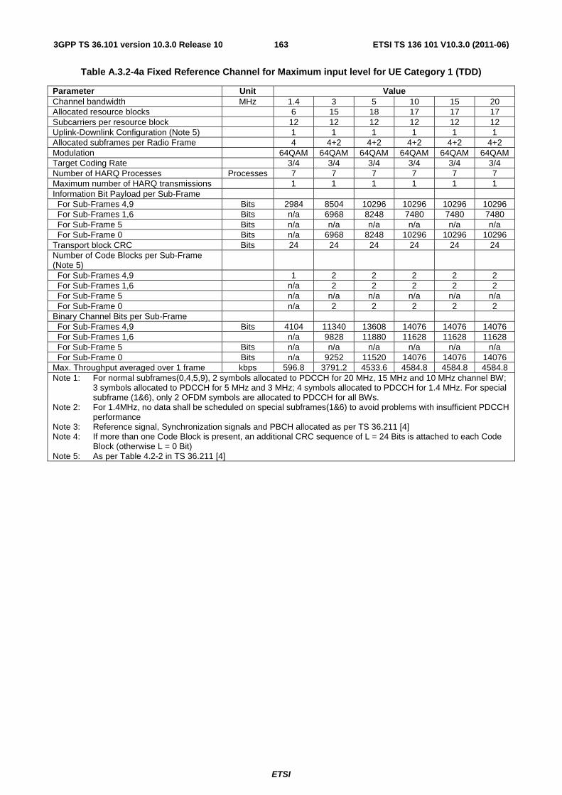
ETSI
ETSI TS 136 101 V10.3.0 (2011-06)1633GPP TS 36.101 version 10.3.0 Release 10
Table A.3.2-4a Fixed Reference Channel for Maximum input level for UE Category 1 (TDD)
Parameter Unit Value Channel bandwidth MHz 1.4 3 5 10 15 20 Allocated resource blocks 6 15 18 17 17 17 Subcarriers per resource block 12 12 12 12 12 12 Uplink-Downlink Configuration (Note 5) 1 1 1 1 1 1 Allocated subframes per Radio Frame 4 4+2 4+2 4+2 4+2 4+2 Modulation 64QAM 64QAM 64QAM 64QAM 64QAM 64QAM Target Coding Rate 3/4 3/4 3/4 3/4 3/4 3/4 Number of HARQ Processes Processes 7 7 7 7 7 7 Maximum number of HARQ transmissions 1 1 1 1 1 1 Information Bit Payload per Sub-Frame For Sub-Frames 4,9 Bits 2984 8504 10296 10296 10296 10296 For Sub-Frames 1,6 Bits n/a 6968 8248 7480 7480 7480 For Sub-Frame 5 Bits n/a n/a n/a n/a n/a n/a For Sub-Frame 0 Bits n/a 6968 8248 10296 10296 10296 Transport block CRC Bits 24 24 24 24 24 24 Number of Code Blocks per Sub-Frame (Note 5)
For Sub-Frames 4,9 1 2 2 2 2 2 For Sub-Frames 1,6 n/a 2 2 2 2 2 For Sub-Frame 5 n/a n/a n/a n/a n/a n/a For Sub-Frame 0 n/a 2 2 2 2 2 Binary Channel Bits per Sub-Frame For Sub-Frames 4,9 Bits 4104 11340 13608 14076 14076 14076 For Sub-Frames 1,6 n/a 9828 11880 11628 11628 11628 For Sub-Frame 5 Bits n/a n/a n/a n/a n/a n/a For Sub-Frame 0 Bits n/a 9252 11520 14076 14076 14076 Max. Throughput averaged over 1 frame kbps 596.8 3791.2 4533.6 4584.8 4584.8 4584.8 Note 1: For normal subframes(0,4,5,9), 2 symbols allocated to PDCCH for 20 MHz, 15 MHz and 10 MHz channel BW;
3 symbols allocated to PDCCH for 5 MHz and 3 MHz; 4 symbols allocated to PDCCH for 1.4 MHz. For special subframe (1&6), only 2 OFDM symbols are allocated to PDCCH for all BWs.
Note 2: For 1.4MHz, no data shall be scheduled on special subframes(1&6) to avoid problems with insufficient PDCCH performance
Note 3: Reference signal, Synchronization signals and PBCH allocated as per TS 36.211 [4] Note 4: If more than one Code Block is present, an additional CRC sequence of L = 24 Bits is attached to each Code
Block (otherwise L = 0 Bit) Note 5: As per Table 4.2-2 in TS 36.211 [4]

ETSI
ETSI TS 136 101 V10.3.0 (2011-06)1643GPP TS 36.101 version 10.3.0 Release 10
Table A.3.2-4b Fixed Reference Channel for Maximum input level for UE Category 2 (TDD)
Parameter Unit Value Channel bandwidth MHz 1.4 3 5 10 15 20 Allocated resource blocks 6 15 25 50 75 83 Subcarriers per resource block 12 12 12 12 12 12 Uplink-Downlink Configuration (Note 5) 1 1 1 1 1 1 Allocated subframes per Radio Frame 4 4+2 4+2 4+2 4+2 4+2 Modulation 64QAM 64QAM 64QAM 64QAM 64QAM 64QAM Target Coding Rate 3/4 3/4 3/4 3/4 3/4 3/4 Number of HARQ Processes Processes 7 7 7 7 7 7 Maximum number of HARQ transmissions 1 1 1 1 1 1 Information Bit Payload per Sub-Frame For Sub-Frames 4,9 Bits 2984 8504 14112 30576 46888 51024 For Sub-Frames 1,6 Bits n/a 6968 11448 23688 35160 39232 For Sub-Frame 5 Bits n/a n/a n/a n/a n/a n/a For Sub-Frame 0 Bits n/a 6968 12576 30576 45352 51024 Transport block CRC Bits 24 24 24 24 24 24 Number of Code Blocks per Sub-Frame (Note 5)
For Sub-Frames 4,9 1 2 3 5 8 9 For Sub-Frames 1,6 n/a 2 3 5 7 7 For Sub-Frame 5 n/a n/a n/a n/a n/a n/a For Sub-Frame 0 n/a 2 3 5 8 9 Binary Channel Bits per Sub-Frame For Sub-Frames 4,9 Bits 4104 11340 18900 41400 62100 68724 For Sub-Frames 1,6 n/a 9828 16668 33768 50868 56340 For Sub-Frame 5 Bits n/a n/a n/a n/a n/a n/a For Sub-Frame 0 Bits n/a 9252 16380 39312 60012 66636 Max. Throughput averaged over 1 frame kbps 596.8 3791.2 6369.6 13910 20945 23154 Note 1: For normal subframes(0,4,5,9), 2 symbols allocated to PDCCH for 20 MHz, 15 MHz and 10 MHz channel BW;
3 symbols allocated to PDCCH for 5 MHz and 3 MHz; 4 symbols allocated to PDCCH for 1.4 MHz. For special subframe (1&6), only 2 OFDM symbols are allocated to PDCCH for all BWs.
Note 2: For 1.4MHz, no data shall be scheduled on special subframes(1&6) to avoid problems with insufficient PDCCH performance
Note 3: Reference signal, Synchronization signals and PBCH allocated as per TS 36.211 [4] Note 4: If more than one Code Block is present, an additional CRC sequence of L = 24 Bits is attached to each Code
Block (otherwise L = 0 Bit) Note 5: As per Table 4.2-2 in TS 36.211 [4]
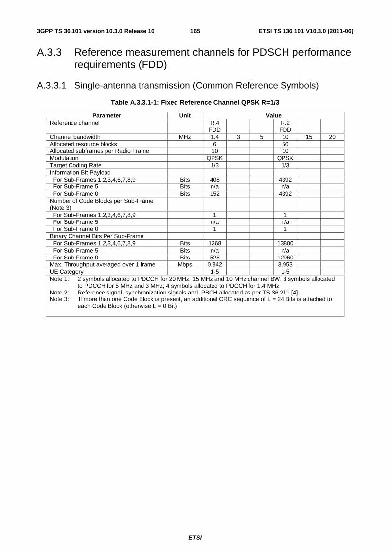
ETSI
ETSI TS 136 101 V10.3.0 (2011-06)1653GPP TS 36.101 version 10.3.0 Release 10
A.3.3 Reference measurement channels for PDSCH performance requirements (FDD)
A.3.3.1 Single-antenna transmission (Common Reference Symbols)
Table A.3.3.1-1: Fixed Reference Channel QPSK R=1/3
Parameter Unit Value Reference channel R.4
FDD R.2
FDD
Channel bandwidth MHz 1.4 3 5 10 15 20 Allocated resource blocks 6 50 Allocated subframes per Radio Frame 10 10 Modulation QPSK QPSK Target Coding Rate 1/3 1/3 Information Bit Payload For Sub-Frames 1,2,3,4,6,7,8,9 Bits 408 4392 For Sub-Frame 5 Bits n/a n/a For Sub-Frame 0 Bits 152 4392 Number of Code Blocks per Sub-Frame (Note 3)
For Sub-Frames 1,2,3,4,6,7,8,9 1 1 For Sub-Frame 5 n/a n/a For Sub-Frame 0 1 1 Binary Channel Bits Per Sub-Frame For Sub-Frames 1,2,3,4,6,7,8,9 Bits 1368 13800 For Sub-Frame 5 Bits n/a n/a For Sub-Frame 0 Bits 528 12960 Max. Throughput averaged over 1 frame Mbps 0.342 3.953 UE Category 1-5 1-5 Note 1: 2 symbols allocated to PDCCH for 20 MHz, 15 MHz and 10 MHz channel BW; 3 symbols allocated
to PDCCH for 5 MHz and 3 MHz; 4 symbols allocated to PDCCH for 1.4 MHz Note 2: Reference signal, synchronization signals and PBCH allocated as per TS 36.211 [4] Note 3: If more than one Code Block is present, an additional CRC sequence of L = 24 Bits is attached to
each Code Block (otherwise L = 0 Bit)
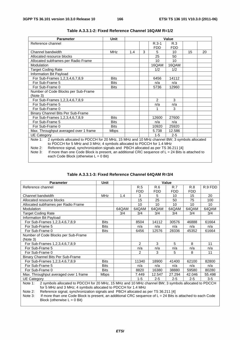
ETSI
ETSI TS 136 101 V10.3.0 (2011-06)1663GPP TS 36.101 version 10.3.0 Release 10
Table A.3.3.1-2: Fixed Reference Channel 16QAM R=1/2
Parameter Unit Value Reference channel R.3-1
FDD R.3 FDD
Channel bandwidth MHz 1.4 3 5 10 15 20 Allocated resource blocks 25 50 Allocated subframes per Radio Frame 10 10 Modulation 16QAM 16QAM Target Coding Rate 1/2 1/2 Information Bit Payload For Sub-Frames 1,2,3,4,6,7,8,9 Bits 6456 14112 For Sub-Frame 5 Bits n/a n/a For Sub-Frame 0 Bits 5736 12960 Number of Code Blocks per Sub-Frame (Note 3)
For Sub-Frames 1,2,3,4,6,7,8,9 2 3 For Sub-Frame 5 n/a n/a For Sub-Frame 0 1 3 Binary Channel Bits Per Sub-Frame For Sub-Frames 1,2,3,4,6,7,8,9 Bits 12600 27600 For Sub-Frame 5 Bits n/a n/a For Sub-Frame 0 Bits 10920 25920 Max. Throughput averaged over 1 frame Mbps 5.738 12.586 UE Category 1-5 2-5 Note 1: 2 symbols allocated to PDCCH for 20 MHz, 15 MHz and 10 MHz channel BW; 3 symbols allocated
to PDCCH for 5 MHz and 3 MHz; 4 symbols allocated to PDCCH for 1.4 MHz Note 2: Reference signal, synchronization signals and PBCH allocated as per TS 36.211 [4] Note 3: If more than one Code Block is present, an additional CRC sequence of L = 24 Bits is attached to
each Code Block (otherwise L = 0 Bit)
Table A.3.3.1-3: Fixed Reference Channel 64QAM R=3/4
Parameter Unit Value Reference channel R.5
FDD R.6 FDD
R.7 FDD
R.8 FDD
R.9 FDD
Channel bandwidth MHz 1.4 3 5 10 15 20 Allocated resource blocks 15 25 50 75 100 Allocated subframes per Radio Frame 10 10 10 10 10 Modulation 64QAM 64QAM 64QAM 64QAM 64QAM 64QAM Target Coding Rate 3/4 3/4 3/4 3/4 3/4 3/4 Information Bit Payload For Sub-Frames 1,2,3,4,6,7,8,9 Bits 8504 14112 30576 46888 61664 For Sub-Frame 5 Bits n/a n/a n/a n/a n/a For Sub-Frame 0 Bits 6456 12576 28336 45352 61664 Number of Code Blocks per Sub-Frame (Note 3)
For Sub-Frames 1,2,3,4,6,7,8,9 2 3 5 8 11 For Sub-Frame 5 n/a n/a n/a n/a n/a For Sub-Frame 0 2 3 5 8 11 Binary Channel Bits Per Sub-Frame For Sub-Frames 1,2,3,4,6,7,8,9 Bits 11340 18900 41400 62100 82800 For Sub-Frame 5 Bits n/a n/a n/a n/a n/a For Sub-Frame 0 Bits 8820 16380 38880 59580 80280 Max. Throughput averaged over 1 frame Mbps 7.449 12.547 27.294 42.046 55.498 UE Category 1-5 2-5 2-5 2-5 3-5 Note 1: 2 symbols allocated to PDCCH for 20 MHz, 15 MHz and 10 MHz channel BW; 3 symbols allocated to PDCCH
for 5 MHz and 3 MHz; 4 symbols allocated to PDCCH for 1.4 MHz Note 2: Reference signal, synchronization signals and PBCH allocated as per TS 36.211 [4] Note 3: If more than one Code Block is present, an additional CRC sequence of L = 24 Bits is attached to each Code
Block (otherwise L = 0 Bit)
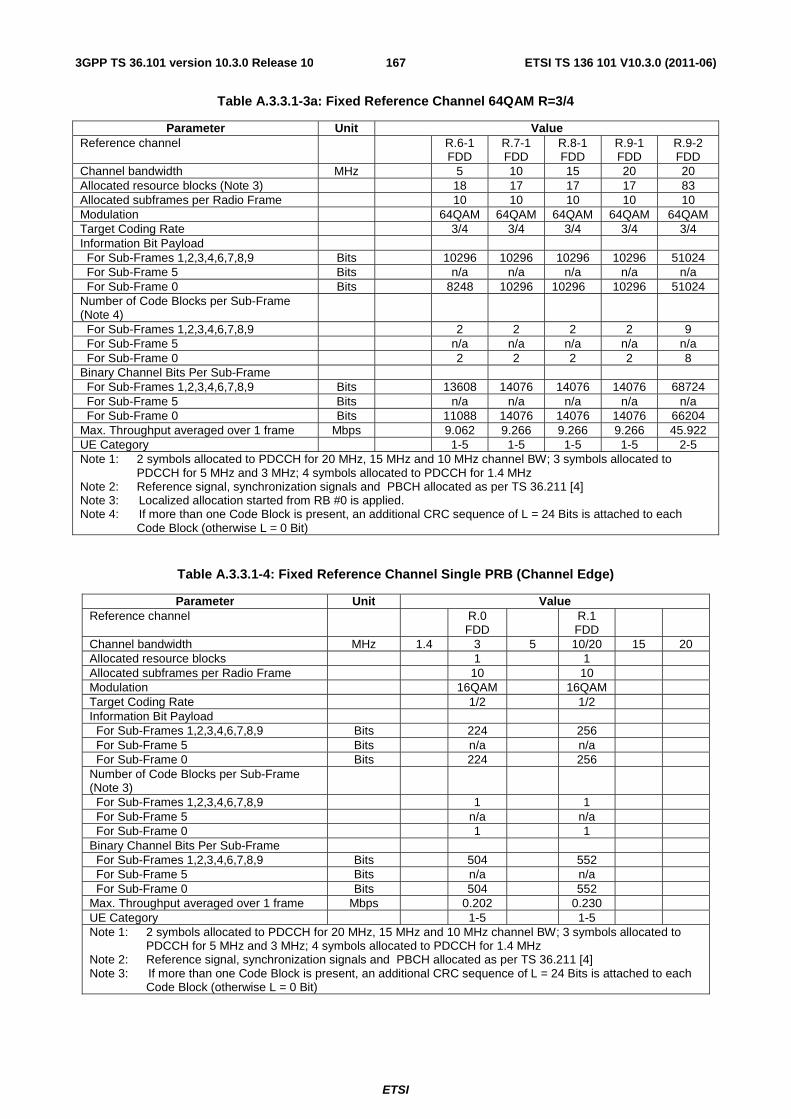
ETSI
ETSI TS 136 101 V10.3.0 (2011-06)1673GPP TS 36.101 version 10.3.0 Release 10
Table A.3.3.1-3a: Fixed Reference Channel 64QAM R=3/4
Parameter Unit Value Reference channel R.6-1
FDD R.7-1 FDD
R.8-1 FDD
R.9-1 FDD
R.9-2 FDD
Channel bandwidth MHz 5 10 15 20 20 Allocated resource blocks (Note 3) 18 17 17 17 83 Allocated subframes per Radio Frame 10 10 10 10 10 Modulation 64QAM 64QAM 64QAM 64QAM 64QAM Target Coding Rate 3/4 3/4 3/4 3/4 3/4 Information Bit Payload For Sub-Frames 1,2,3,4,6,7,8,9 Bits 10296 10296 10296 10296 51024 For Sub-Frame 5 Bits n/a n/a n/a n/a n/a For Sub-Frame 0 Bits 8248 10296 10296 10296 51024 Number of Code Blocks per Sub-Frame (Note 4)
For Sub-Frames 1,2,3,4,6,7,8,9 2 2 2 2 9 For Sub-Frame 5 n/a n/a n/a n/a n/a For Sub-Frame 0 2 2 2 2 8 Binary Channel Bits Per Sub-Frame For Sub-Frames 1,2,3,4,6,7,8,9 Bits 13608 14076 14076 14076 68724 For Sub-Frame 5 Bits n/a n/a n/a n/a n/a For Sub-Frame 0 Bits 11088 14076 14076 14076 66204 Max. Throughput averaged over 1 frame Mbps 9.062 9.266 9.266 9.266 45.922 UE Category 1-5 1-5 1-5 1-5 2-5 Note 1: 2 symbols allocated to PDCCH for 20 MHz, 15 MHz and 10 MHz channel BW; 3 symbols allocated to
PDCCH for 5 MHz and 3 MHz; 4 symbols allocated to PDCCH for 1.4 MHz Note 2: Reference signal, synchronization signals and PBCH allocated as per TS 36.211 [4] Note 3: Localized allocation started from RB #0 is applied. Note 4: If more than one Code Block is present, an additional CRC sequence of L = 24 Bits is attached to each
Code Block (otherwise L = 0 Bit)
Table A.3.3.1-4: Fixed Reference Channel Single PRB (Channel Edge)
Parameter Unit Value Reference channel R.0
FDD R.1
FDD
Channel bandwidth MHz 1.4 3 5 10/20 15 20 Allocated resource blocks 1 1 Allocated subframes per Radio Frame 10 10 Modulation 16QAM 16QAM Target Coding Rate 1/2 1/2 Information Bit Payload For Sub-Frames 1,2,3,4,6,7,8,9 Bits 224 256 For Sub-Frame 5 Bits n/a n/a For Sub-Frame 0 Bits 224 256 Number of Code Blocks per Sub-Frame (Note 3)
For Sub-Frames 1,2,3,4,6,7,8,9 1 1 For Sub-Frame 5 n/a n/a For Sub-Frame 0 1 1 Binary Channel Bits Per Sub-Frame For Sub-Frames 1,2,3,4,6,7,8,9 Bits 504 552 For Sub-Frame 5 Bits n/a n/a For Sub-Frame 0 Bits 504 552 Max. Throughput averaged over 1 frame Mbps 0.202 0.230 UE Category 1-5 1-5 Note 1: 2 symbols allocated to PDCCH for 20 MHz, 15 MHz and 10 MHz channel BW; 3 symbols allocated to
PDCCH for 5 MHz and 3 MHz; 4 symbols allocated to PDCCH for 1.4 MHz Note 2: Reference signal, synchronization signals and PBCH allocated as per TS 36.211 [4] Note 3: If more than one Code Block is present, an additional CRC sequence of L = 24 Bits is attached to each
Code Block (otherwise L = 0 Bit)
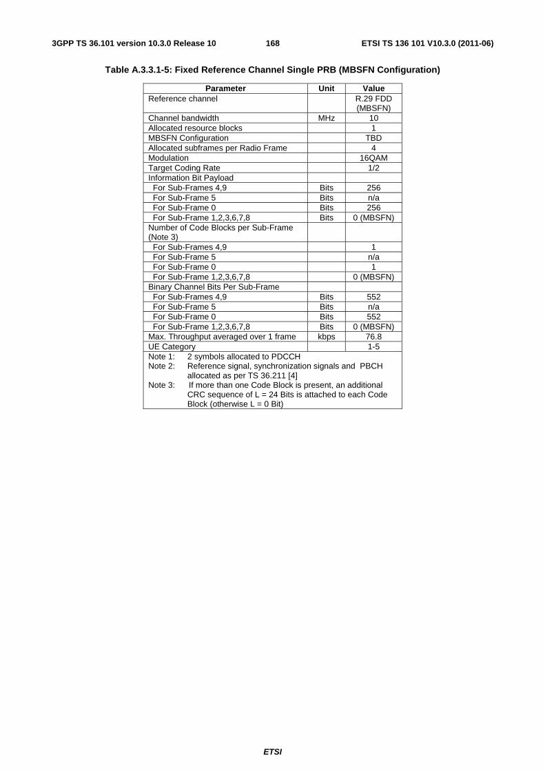
ETSI
ETSI TS 136 101 V10.3.0 (2011-06)1683GPP TS 36.101 version 10.3.0 Release 10
Table A.3.3.1-5: Fixed Reference Channel Single PRB (MBSFN Configuration)
Parameter Unit Value Reference channel R.29 FDD
(MBSFN) Channel bandwidth MHz 10 Allocated resource blocks 1 MBSFN Configuration TBD Allocated subframes per Radio Frame 4 Modulation 16QAM Target Coding Rate 1/2 Information Bit Payload For Sub-Frames 4,9 Bits 256 For Sub-Frame 5 Bits n/a For Sub-Frame 0 Bits 256 For Sub-Frame 1,2,3,6,7,8 Bits 0 (MBSFN) Number of Code Blocks per Sub-Frame (Note 3)
For Sub-Frames 4,9 1 For Sub-Frame 5 n/a For Sub-Frame 0 1 For Sub-Frame 1,2,3,6,7,8 0 (MBSFN) Binary Channel Bits Per Sub-Frame For Sub-Frames 4,9 Bits 552 For Sub-Frame 5 Bits n/a For Sub-Frame 0 Bits 552 For Sub-Frame 1,2,3,6,7,8 Bits 0 (MBSFN) Max. Throughput averaged over 1 frame kbps 76.8 UE Category 1-5 Note 1: 2 symbols allocated to PDCCH Note 2: Reference signal, synchronization signals and PBCH
allocated as per TS 36.211 [4] Note 3: If more than one Code Block is present, an additional
CRC sequence of L = 24 Bits is attached to each Code Block (otherwise L = 0 Bit)
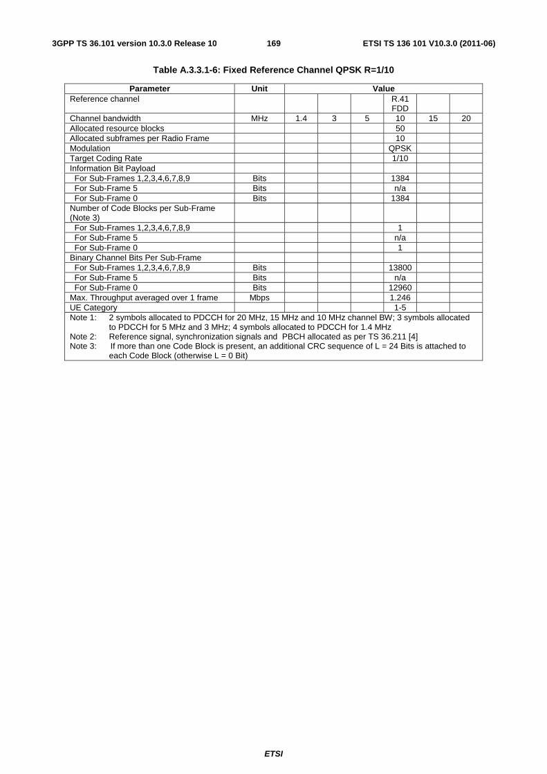
ETSI
ETSI TS 136 101 V10.3.0 (2011-06)1693GPP TS 36.101 version 10.3.0 Release 10
Table A.3.3.1-6: Fixed Reference Channel QPSK R=1/10
Parameter Unit Value Reference channel R.41
FDD
Channel bandwidth MHz 1.4 3 5 10 15 20 Allocated resource blocks 50 Allocated subframes per Radio Frame 10 Modulation QPSK Target Coding Rate 1/10 Information Bit Payload For Sub-Frames 1,2,3,4,6,7,8,9 Bits 1384 For Sub-Frame 5 Bits n/a For Sub-Frame 0 Bits 1384 Number of Code Blocks per Sub-Frame (Note 3)
For Sub-Frames 1,2,3,4,6,7,8,9 1 For Sub-Frame 5 n/a For Sub-Frame 0 1 Binary Channel Bits Per Sub-Frame For Sub-Frames 1,2,3,4,6,7,8,9 Bits 13800 For Sub-Frame 5 Bits n/a For Sub-Frame 0 Bits 12960 Max. Throughput averaged over 1 frame Mbps 1.246 UE Category 1-5 Note 1: 2 symbols allocated to PDCCH for 20 MHz, 15 MHz and 10 MHz channel BW; 3 symbols allocated
to PDCCH for 5 MHz and 3 MHz; 4 symbols allocated to PDCCH for 1.4 MHz Note 2: Reference signal, synchronization signals and PBCH allocated as per TS 36.211 [4] Note 3: If more than one Code Block is present, an additional CRC sequence of L = 24 Bits is attached to
each Code Block (otherwise L = 0 Bit)
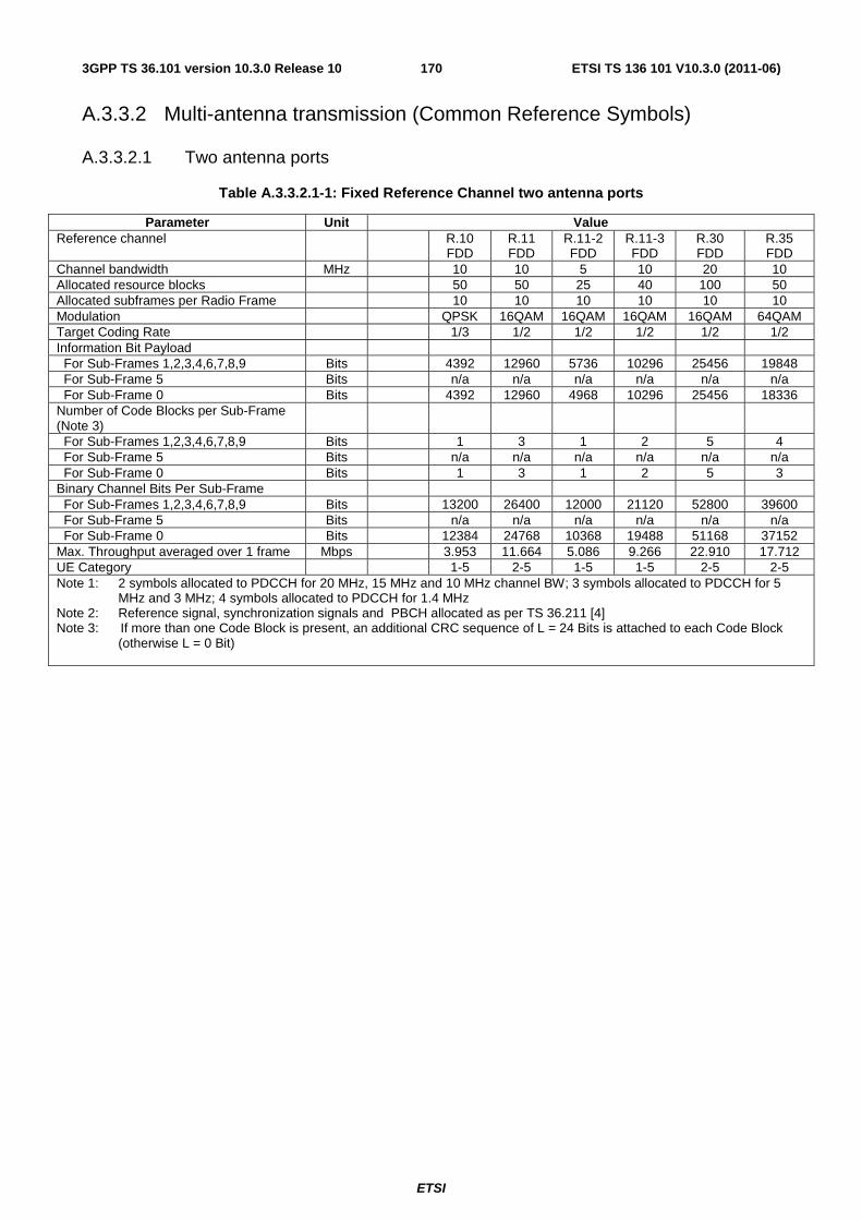
ETSI
ETSI TS 136 101 V10.3.0 (2011-06)1703GPP TS 36.101 version 10.3.0 Release 10
A.3.3.2 Multi-antenna transmission (Common Reference Symbols)
A.3.3.2.1 Two antenna ports
Table A.3.3.2.1-1: Fixed Reference Channel two antenna ports
Parameter Unit Value Reference channel R.10
FDD R.11 FDD
R.11-2 FDD
R.11-3 FDD
R.30 FDD
R.35 FDD
Channel bandwidth MHz 10 10 5 10 20 10 Allocated resource blocks 50 50 25 40 100 50 Allocated subframes per Radio Frame 10 10 10 10 10 10 Modulation QPSK 16QAM 16QAM 16QAM 16QAM 64QAM Target Coding Rate 1/3 1/2 1/2 1/2 1/2 1/2 Information Bit Payload For Sub-Frames 1,2,3,4,6,7,8,9 Bits 4392 12960 5736 10296 25456 19848 For Sub-Frame 5 Bits n/a n/a n/a n/a n/a n/a For Sub-Frame 0 Bits 4392 12960 4968 10296 25456 18336 Number of Code Blocks per Sub-Frame (Note 3)
For Sub-Frames 1,2,3,4,6,7,8,9 Bits 1 3 1 2 5 4 For Sub-Frame 5 Bits n/a n/a n/a n/a n/a n/a For Sub-Frame 0 Bits 1 3 1 2 5 3 Binary Channel Bits Per Sub-Frame For Sub-Frames 1,2,3,4,6,7,8,9 Bits 13200 26400 12000 21120 52800 39600 For Sub-Frame 5 Bits n/a n/a n/a n/a n/a n/a For Sub-Frame 0 Bits 12384 24768 10368 19488 51168 37152 Max. Throughput averaged over 1 frame Mbps 3.953 11.664 5.086 9.266 22.910 17.712 UE Category 1-5 2-5 1-5 1-5 2-5 2-5 Note 1: 2 symbols allocated to PDCCH for 20 MHz, 15 MHz and 10 MHz channel BW; 3 symbols allocated to PDCCH for 5
MHz and 3 MHz; 4 symbols allocated to PDCCH for 1.4 MHz Note 2: Reference signal, synchronization signals and PBCH allocated as per TS 36.211 [4] Note 3: If more than one Code Block is present, an additional CRC sequence of L = 24 Bits is attached to each Code Block
(otherwise L = 0 Bit)
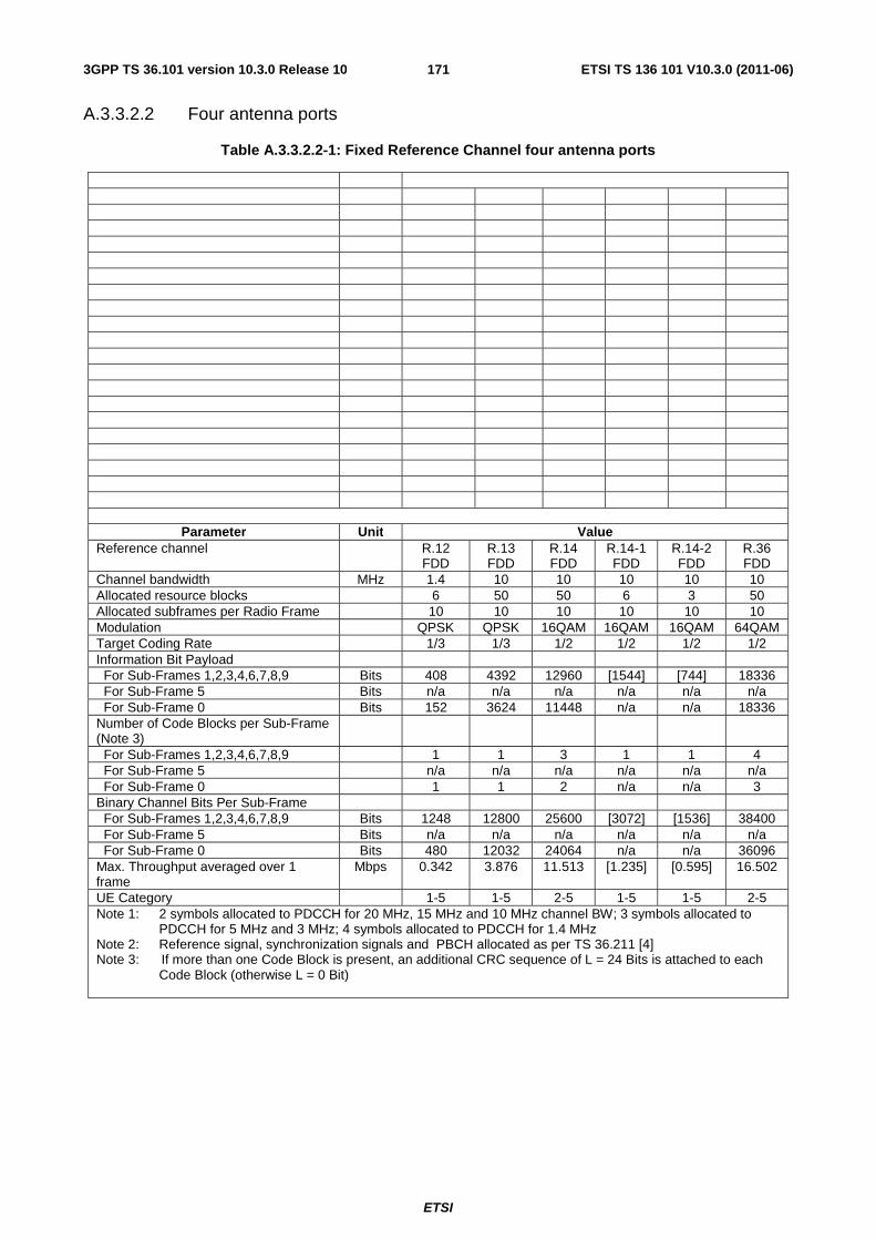
ETSI
ETSI TS 136 101 V10.3.0 (2011-06)1713GPP TS 36.101 version 10.3.0 Release 10
A.3.3.2.2 Four antenna ports
Table A.3.3.2.2-1: Fixed Reference Channel four antenna ports
Parameter Unit Value Reference channel R.12
FDD R.13 FDD
R.14 FDD
R.14-1 FDD
R.14-2 FDD
R.36 FDD
Channel bandwidth MHz 1.4 10 10 10 10 10 Allocated resource blocks 6 50 50 6 3 50 Allocated subframes per Radio Frame 10 10 10 10 10 10 Modulation QPSK QPSK 16QAM 16QAM 16QAM 64QAM Target Coding Rate 1/3 1/3 1/2 1/2 1/2 1/2 Information Bit Payload For Sub-Frames 1,2,3,4,6,7,8,9 Bits 408 4392 12960 [1544] [744] 18336 For Sub-Frame 5 Bits n/a n/a n/a n/a n/a n/a For Sub-Frame 0 Bits 152 3624 11448 n/a n/a 18336 Number of Code Blocks per Sub-Frame (Note 3)
For Sub-Frames 1,2,3,4,6,7,8,9 1 1 3 1 1 4 For Sub-Frame 5 n/a n/a n/a n/a n/a n/a For Sub-Frame 0 1 1 2 n/a n/a 3 Binary Channel Bits Per Sub-Frame For Sub-Frames 1,2,3,4,6,7,8,9 Bits 1248 12800 25600 [3072] [1536] 38400 For Sub-Frame 5 Bits n/a n/a n/a n/a n/a n/a For Sub-Frame 0 Bits 480 12032 24064 n/a n/a 36096 Max. Throughput averaged over 1 frame
Mbps 0.342 3.876 11.513 [1.235] [0.595] 16.502
UE Category 1-5 1-5 2-5 1-5 1-5 2-5 Note 1: 2 symbols allocated to PDCCH for 20 MHz, 15 MHz and 10 MHz channel BW; 3 symbols allocated to
PDCCH for 5 MHz and 3 MHz; 4 symbols allocated to PDCCH for 1.4 MHz Note 2: Reference signal, synchronization signals and PBCH allocated as per TS 36.211 [4] Note 3: If more than one Code Block is present, an additional CRC sequence of L = 24 Bits is attached to each
Code Block (otherwise L = 0 Bit)
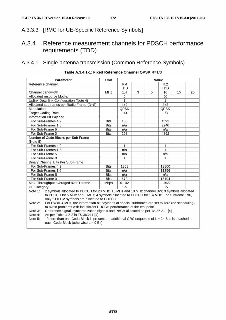
ETSI
ETSI TS 136 101 V10.3.0 (2011-06)1723GPP TS 36.101 version 10.3.0 Release 10
A.3.3.3 [RMC for UE-Specific Reference Symbols]
A.3.4 Reference measurement channels for PDSCH performance requirements (TDD)
A.3.4.1 Single-antenna transmission (Common Reference Symbols)
Table A.3.4.1-1: Fixed Reference Channel QPSK R=1/3
Parameter Unit Value Reference channel R.4
TDD R.2
TDD
Channel bandwidth MHz 1.4 3 5 10 15 20 Allocated resource blocks 6 50 Uplink-Downlink Configuration (Note 4) 1 1 Allocated subframes per Radio Frame (D+S) 4+2 4+2 Modulation QPSK QPSK Target Coding Rate 1/3 1/3 Information Bit Payload For Sub-Frames 4,9 Bits 408 4392 For Sub-Frames 1,6 Bits n/a 3240 For Sub-Frame 5 Bits n/a n/a For Sub-Frame 0 Bits 208 4392 Number of Code Blocks per Sub-Frame (Note 5)
For Sub-Frames 4,9 1 1 For Sub-Frames 1,6 n/a 1 For Sub-Frame 5 n/a n/a For Sub-Frame 0 1 1 Binary Channel Bits Per Sub-Frame For Sub-Frames 4,9 Bits 1368 13800 For Sub-Frames 1,6 Bits n/a 11256 For Sub-Frame 5 Bits n/a n/a For Sub-Frame 0 Bits 672 13104 Max. Throughput averaged over 1 frame Mbps 0.102 1.966 UE Category 1-5 1-5 Note 1: 2 symbols allocated to PDCCH for 20 MHz, 15 MHz and 10 MHz channel BW; 3 symbols allocated
to PDCCH for 5 MHz and 3 MHz; 4 symbols allocated to PDCCH for 1.4 MHz. For subframe 1&6, only 2 OFDM symbols are allocated to PDCCH.
Note 2: For BW=1.4 MHz, the information bit payloads of special subframes are set to zero (no scheduling) to avoid problems with insufficient PDCCH performance at the test point.
Note 3: Reference signal, synchronization signals and PBCH allocated as per TS 36.211 [4] Note 4: As per Table 4.2-2 in TS 36.211 [4] Note 5: If more than one Code Block is present, an additional CRC sequence of L = 24 Bits is attached to
each Code Block (otherwise L = 0 Bit)

ETSI
ETSI TS 136 101 V10.3.0 (2011-06)1733GPP TS 36.101 version 10.3.0 Release 10
Table A.3.4.1-2: Fixed Reference Channel 16QAM R=1/2
Parameter Unit Value Reference channel R.3-1
TDD R.3 TDD
Channel bandwidth MHz 1.4 3 5 10 15 20 Allocated resource blocks 25 50 Uplink-Downlink Configuration (Note 3) 1 1 Allocated subframes per Radio Frame (D+S) 4+2 4+2 Modulation 16QAM 16QAM Target Coding Rate 1/2 1/2 Information Bit Payload For Sub-Frames 4,9 Bits 6456 14112 For Sub-Frames 1,6 Bits 5160 11448 For Sub-Frame 5 Bits n/a n/a For Sub-Frame 0 Bits 5736 12960 Number of Code Blocks per Sub-Frame (Note 4)
For Sub-Frames 4,9 2 3 For Sub-Frames 1,6 1 2 For Sub-Frame 5 n/a n/a For Sub-Frame 0 1 3 Binary Channel Bits Per Sub-Frame For Sub-Frames 4,9 Bits 12600 27600 For Sub-Frames 1,6 Bits 11112 22512 For Sub-Frame 5 Bits n/a n/a For Sub-Frame 0 Bits 11208 26208 Max. Throughput averaged over 1 frame Mbps 2.897 6.408 UE Category 1-5 2-5 Note 1: 2 symbols allocated to PDCCH for 20 MHz, 15 MHz and 10 MHz channel BW; 3 symbols allocated to
PDCCH for 5 MHz and 3 MHz; 4 symbols allocated to PDCCH for 1.4 MHz. For subframe 1&6, only 2 OFDM symbols are allocated to PDCCH.
Note 2: Reference signal, synchronization signals and PBCH allocated as per TS 36.211 [4] Note 3: As per Table 4.2-2 in TS 36.211 [4] Note 4: If more than one Code Block is present, an additional CRC sequence of L = 24 Bits is attached to each
Code Block (otherwise L = 0 Bit)
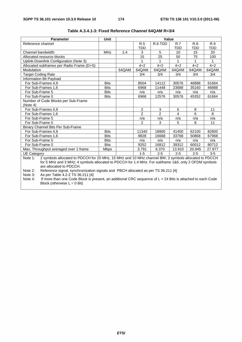
ETSI
ETSI TS 136 101 V10.3.0 (2011-06)1743GPP TS 36.101 version 10.3.0 Release 10
Table A.3.4.1-3: Fixed Reference Channel 64QAM R=3/4
Parameter Unit Value Reference channel R.5
TDD R.6 TDD R.7
TDD R.8 TDD
R.9 TDD
Channel bandwidth MHz 1.4 3 5 10 15 20 Allocated resource blocks 15 25 50 75 100 Uplink-Downlink Configuration (Note 3) 1 1 1 1 1 Allocated subframes per Radio Frame (D+S) 4+2 4+2 4+2 4+2 4+2 Modulation 64QAM 64QAM 64QAM 64QAM 64QAM 64QAM Target Coding Rate 3/4 3/4 3/4 3/4 3/4 Information Bit Payload For Sub-Frames 4,9 Bits 8504 14112 30576 46888 61664 For Sub-Frames 1,6 Bits 6968 11448 23688 35160 46888 For Sub-Frame 5 Bits n/a n/a n/a n/a n/a For Sub-Frame 0 Bits 6968 12576 30576 45352 61664 Number of Code Blocks per Sub-Frame (Note 4)
For Sub-Frames 4,9 2 3 5 8 11 For Sub-Frames 1,6 2 2 4 6 8 For Sub-Frame 5 n/a n/a n/a n/a n/a For Sub-Frame 0 2 3 5 8 11 Binary Channel Bits Per Sub-Frame For Sub-Frames 4,9 Bits 11340 18900 41400 62100 82800 For Sub-Frames 1,6 Bits 9828 16668 33768 50868 67968 For Sub-Frame 5 Bits n/a n/a n/a n/a n/a For Sub-Frame 0 Bits 9252 16812 39312 60012 80712 Max. Throughput averaged over 1 frame Mbps 3.791 6.370 13.910 20.945 27.877 UE Category 1-5 2-5 2-5 2-5 3-5 Note 1: 2 symbols allocated to PDCCH for 20 MHz, 15 MHz and 10 MHz channel BW; 3 symbols allocated to PDCCH
for 5 MHz and 3 MHz; 4 symbols allocated to PDCCH for 1.4 MHz. For subframe 1&6, only 2 OFDM symbols are allocated to PDCCH.
Note 2: Reference signal, synchronization signals and PBCH allocated as per TS 36.211 [4] Note 3: As per Table 4.2-2 TS 36.211 [4] Note 4: If more than one Code Block is present, an additional CRC sequence of L = 24 Bits is attached to each Code
Block (otherwise L = 0 Bit)
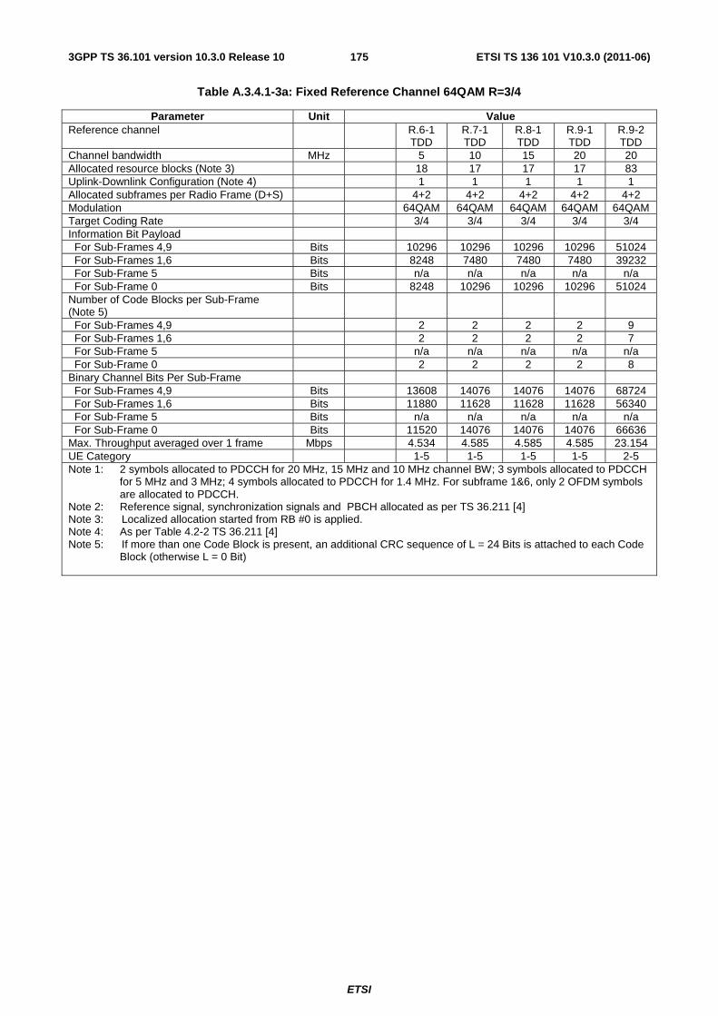
ETSI
ETSI TS 136 101 V10.3.0 (2011-06)1753GPP TS 36.101 version 10.3.0 Release 10
Table A.3.4.1-3a: Fixed Reference Channel 64QAM R=3/4
Parameter Unit Value Reference channel R.6-1
TDD R.7-1 TDD
R.8-1 TDD
R.9-1 TDD
R.9-2 TDD
Channel bandwidth MHz 5 10 15 20 20 Allocated resource blocks (Note 3) 18 17 17 17 83 Uplink-Downlink Configuration (Note 4) 1 1 1 1 1 Allocated subframes per Radio Frame (D+S) 4+2 4+2 4+2 4+2 4+2 Modulation 64QAM 64QAM 64QAM 64QAM 64QAM Target Coding Rate 3/4 3/4 3/4 3/4 3/4 Information Bit Payload For Sub-Frames 4,9 Bits 10296 10296 10296 10296 51024 For Sub-Frames 1,6 Bits 8248 7480 7480 7480 39232 For Sub-Frame 5 Bits n/a n/a n/a n/a n/a For Sub-Frame 0 Bits 8248 10296 10296 10296 51024 Number of Code Blocks per Sub-Frame (Note 5)
For Sub-Frames 4,9 2 2 2 2 9 For Sub-Frames 1,6 2 2 2 2 7 For Sub-Frame 5 n/a n/a n/a n/a n/a For Sub-Frame 0 2 2 2 2 8 Binary Channel Bits Per Sub-Frame For Sub-Frames 4,9 Bits 13608 14076 14076 14076 68724 For Sub-Frames 1,6 Bits 11880 11628 11628 11628 56340 For Sub-Frame 5 Bits n/a n/a n/a n/a n/a For Sub-Frame 0 Bits 11520 14076 14076 14076 66636 Max. Throughput averaged over 1 frame Mbps 4.534 4.585 4.585 4.585 23.154 UE Category 1-5 1-5 1-5 1-5 2-5 Note 1: 2 symbols allocated to PDCCH for 20 MHz, 15 MHz and 10 MHz channel BW; 3 symbols allocated to PDCCH
for 5 MHz and 3 MHz; 4 symbols allocated to PDCCH for 1.4 MHz. For subframe 1&6, only 2 OFDM symbols are allocated to PDCCH.
Note 2: Reference signal, synchronization signals and PBCH allocated as per TS 36.211 [4] Note 3: Localized allocation started from RB #0 is applied. Note 4: As per Table 4.2-2 TS 36.211 [4] Note 5: If more than one Code Block is present, an additional CRC sequence of L = 24 Bits is attached to each Code
Block (otherwise L = 0 Bit)
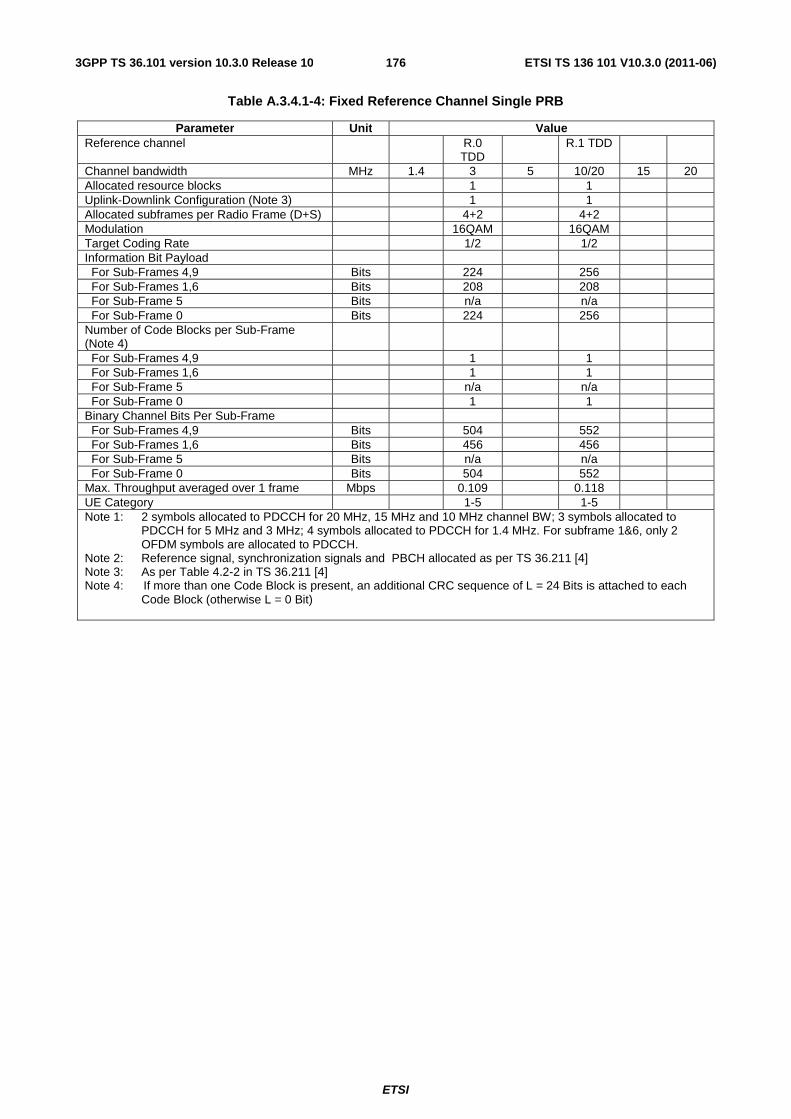
ETSI
ETSI TS 136 101 V10.3.0 (2011-06)1763GPP TS 36.101 version 10.3.0 Release 10
Table A.3.4.1-4: Fixed Reference Channel Single PRB
Parameter Unit Value Reference channel R.0
TDD R.1 TDD
Channel bandwidth MHz 1.4 3 5 10/20 15 20 Allocated resource blocks 1 1 Uplink-Downlink Configuration (Note 3) 1 1 Allocated subframes per Radio Frame (D+S) 4+2 4+2 Modulation 16QAM 16QAM Target Coding Rate 1/2 1/2 Information Bit Payload For Sub-Frames 4,9 Bits 224 256 For Sub-Frames 1,6 Bits 208 208 For Sub-Frame 5 Bits n/a n/a For Sub-Frame 0 Bits 224 256 Number of Code Blocks per Sub-Frame (Note 4)
For Sub-Frames 4,9 1 1 For Sub-Frames 1,6 1 1 For Sub-Frame 5 n/a n/a For Sub-Frame 0 1 1 Binary Channel Bits Per Sub-Frame For Sub-Frames 4,9 Bits 504 552 For Sub-Frames 1,6 Bits 456 456 For Sub-Frame 5 Bits n/a n/a For Sub-Frame 0 Bits 504 552 Max. Throughput averaged over 1 frame Mbps 0.109 0.118 UE Category 1-5 1-5 Note 1: 2 symbols allocated to PDCCH for 20 MHz, 15 MHz and 10 MHz channel BW; 3 symbols allocated to
PDCCH for 5 MHz and 3 MHz; 4 symbols allocated to PDCCH for 1.4 MHz. For subframe 1&6, only 2 OFDM symbols are allocated to PDCCH.
Note 2: Reference signal, synchronization signals and PBCH allocated as per TS 36.211 [4] Note 3: As per Table 4.2-2 in TS 36.211 [4] Note 4: If more than one Code Block is present, an additional CRC sequence of L = 24 Bits is attached to each
Code Block (otherwise L = 0 Bit)
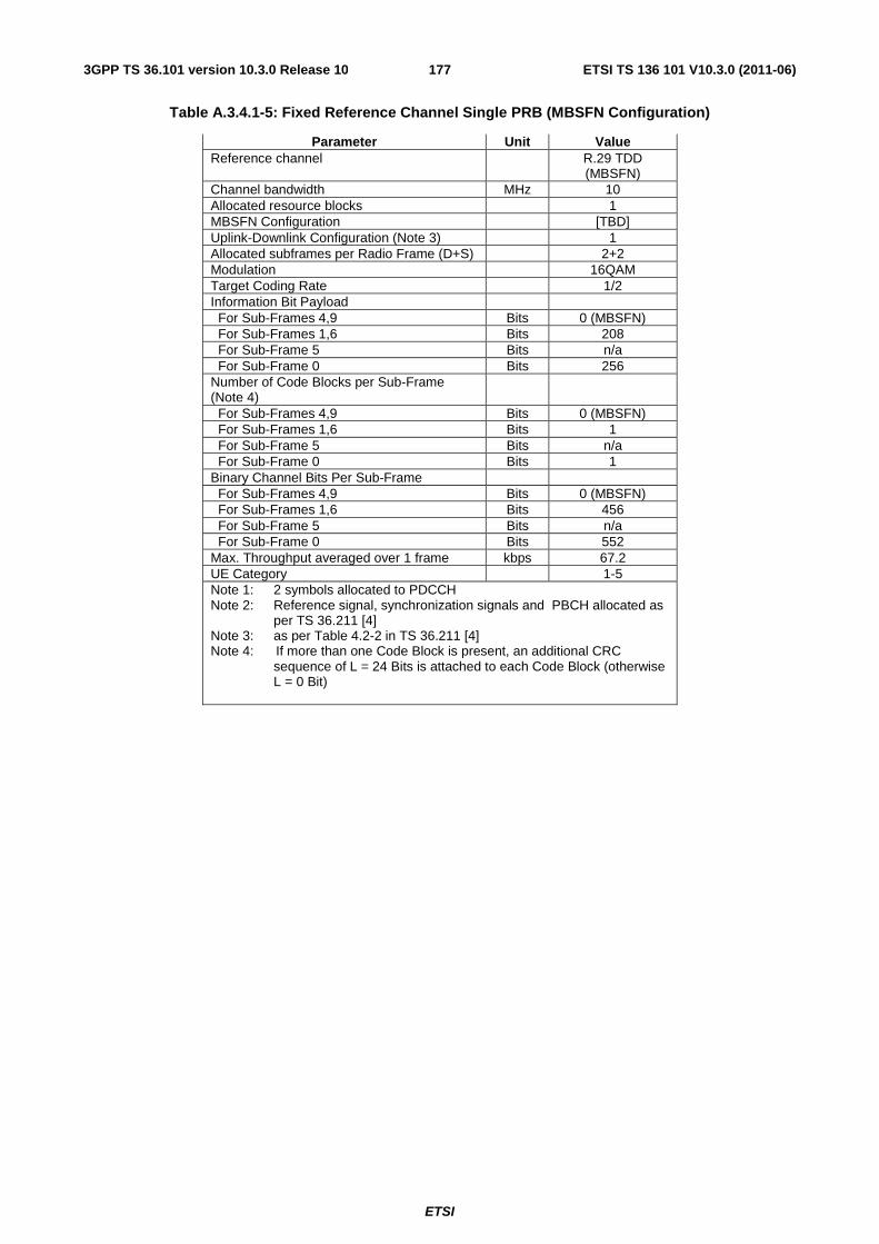
ETSI
ETSI TS 136 101 V10.3.0 (2011-06)1773GPP TS 36.101 version 10.3.0 Release 10
Table A.3.4.1-5: Fixed Reference Channel Single PRB (MBSFN Configuration)
Parameter Unit Value Reference channel R.29 TDD
(MBSFN) Channel bandwidth MHz 10 Allocated resource blocks 1 MBSFN Configuration [TBD] Uplink-Downlink Configuration (Note 3) 1 Allocated subframes per Radio Frame (D+S) 2+2 Modulation 16QAM Target Coding Rate 1/2 Information Bit Payload For Sub-Frames 4,9 Bits 0 (MBSFN) For Sub-Frames 1,6 Bits 208 For Sub-Frame 5 Bits n/a For Sub-Frame 0 Bits 256 Number of Code Blocks per Sub-Frame (Note 4)
For Sub-Frames 4,9 Bits 0 (MBSFN) For Sub-Frames 1,6 Bits 1 For Sub-Frame 5 Bits n/a For Sub-Frame 0 Bits 1 Binary Channel Bits Per Sub-Frame For Sub-Frames 4,9 Bits 0 (MBSFN) For Sub-Frames 1,6 Bits 456 For Sub-Frame 5 Bits n/a For Sub-Frame 0 Bits 552 Max. Throughput averaged over 1 frame kbps 67.2
UE Category 1-5 Note 1: 2 symbols allocated to PDCCH Note 2: Reference signal, synchronization signals and PBCH allocated as
per TS 36.211 [4] Note 3: as per Table 4.2-2 in TS 36.211 [4] Note 4: If more than one Code Block is present, an additional CRC
sequence of L = 24 Bits is attached to each Code Block (otherwise L = 0 Bit)
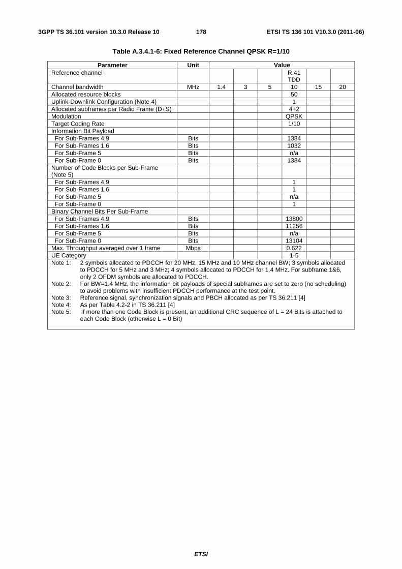
ETSI
ETSI TS 136 101 V10.3.0 (2011-06)1783GPP TS 36.101 version 10.3.0 Release 10
Table A.3.4.1-6: Fixed Reference Channel QPSK R=1/10
Parameter Unit Value Reference channel R.41
TDD
Channel bandwidth MHz 1.4 3 5 10 15 20 Allocated resource blocks 50 Uplink-Downlink Configuration (Note 4) 1 Allocated subframes per Radio Frame (D+S) 4+2 Modulation QPSK Target Coding Rate 1/10 Information Bit Payload For Sub-Frames 4,9 Bits 1384 For Sub-Frames 1,6 Bits 1032 For Sub-Frame 5 Bits n/a For Sub-Frame 0 Bits 1384 Number of Code Blocks per Sub-Frame (Note 5)
For Sub-Frames 4,9 1 For Sub-Frames 1,6 1 For Sub-Frame 5 n/a For Sub-Frame 0 1 Binary Channel Bits Per Sub-Frame For Sub-Frames 4,9 Bits 13800 For Sub-Frames 1,6 Bits 11256 For Sub-Frame 5 Bits n/a For Sub-Frame 0 Bits 13104 Max. Throughput averaged over 1 frame Mbps 0.622 UE Category 1-5 Note 1: 2 symbols allocated to PDCCH for 20 MHz, 15 MHz and 10 MHz channel BW; 3 symbols allocated
to PDCCH for 5 MHz and 3 MHz; 4 symbols allocated to PDCCH for 1.4 MHz. For subframe 1&6, only 2 OFDM symbols are allocated to PDCCH.
Note 2: For BW=1.4 MHz, the information bit payloads of special subframes are set to zero (no scheduling) to avoid problems with insufficient PDCCH performance at the test point.
Note 3: Reference signal, synchronization signals and PBCH allocated as per TS 36.211 [4] Note 4: As per Table 4.2-2 in TS 36.211 [4] Note 5: If more than one Code Block is present, an additional CRC sequence of L = 24 Bits is attached to
each Code Block (otherwise L = 0 Bit)
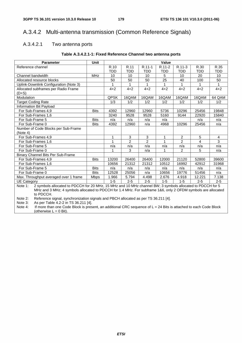
ETSI
ETSI TS 136 101 V10.3.0 (2011-06)1793GPP TS 36.101 version 10.3.0 Release 10
A.3.4.2 Multi-antenna transmission (Common Reference Signals)
A.3.4.2.1 Two antenna ports
Table A.3.4.2.1-1: Fixed Reference Channel two antenna ports
Parameter Unit Value Reference channel R.10
TDD R.11 TDD
R.11-1 TDD
R.11-2 TDD
R.11-3 TDD
R.30 TDD
R.35 TDD
Channel bandwidth MHz 10 10 10 5 10 20 10 Allocated resource blocks 50 50 50 25 40 100 50 Uplink-Downlink Configuration (Note 3) 1 1 1 1 1 1 1 Allocated subframes per Radio Frame (D+S)
4+2 4+2 4+2 4+2 4+2 4+2 4+2
Modulation QPSK 16QAM 16QAM 16QAM 16QAM 16QAM 64 QAM Target Coding Rate 1/3 1/2 1/2 1/2 1/2 1/2 1/2 Information Bit Payload For Sub-Frames 4,9 Bits 4392 12960 12960 5736 10296 25456 19848 For Sub-Frames 1,6 3240 9528 9528 5160 9144 22920 15840 For Sub-Frame 5 Bits n/a n/a n/a n/a n/a n/a For Sub-Frame 0 Bits 4392 12960 n/a 4968 10296 25456 n/a Number of Code Blocks per Sub-Frame (Note 4)
For Sub-Frames 4,9 1 3 3 1 2 5 4 For Sub-Frames 1,6 1 2 2 1 2 4 3 For Sub-Frame 5 n/a n/a n/a n/a n/a n/a n/a For Sub-Frame 0 1 3 n/a 1 2 5 n/a Binary Channel Bits Per Sub-Frame For Sub-Frames 4,9 Bits 13200 26400 26400 12000 21120 52800 39600 For Sub-Frames 1,6 10656 21312 21312 10512 16992 42912 31968 For Sub-Frame 5 Bits n/a n/a n/a n/a n/a n/a n/a For Sub-Frame 0 Bits 12528 25056 n/a 10656 19776 51456 n/a Max. Throughput averaged over 1 frame Mbps 1.966 5.794 4.498 2.676 4.918 12.221 7.138 UE Category 1-5 2-5 2-5 1-5 1-5 2-5 2-5 Note 1: 2 symbols allocated to PDCCH for 20 MHz, 15 MHz and 10 MHz channel BW; 3 symbols allocated to PDCCH for 5
MHz and 3 MHz; 4 symbols allocated to PDCCH for 1.4 MHz. For subframe 1&6, only 2 OFDM symbols are allocated to PDCCH.
Note 2: Reference signal, synchronization signals and PBCH allocated as per TS 36.211 [4]. Note 3: As per Table 4.2-2 in TS 36.211 [4]. Note 4: If more than one Code Block is present, an additional CRC sequence of L = 24 Bits is attached to each Code Block
(otherwise L = 0 Bit).
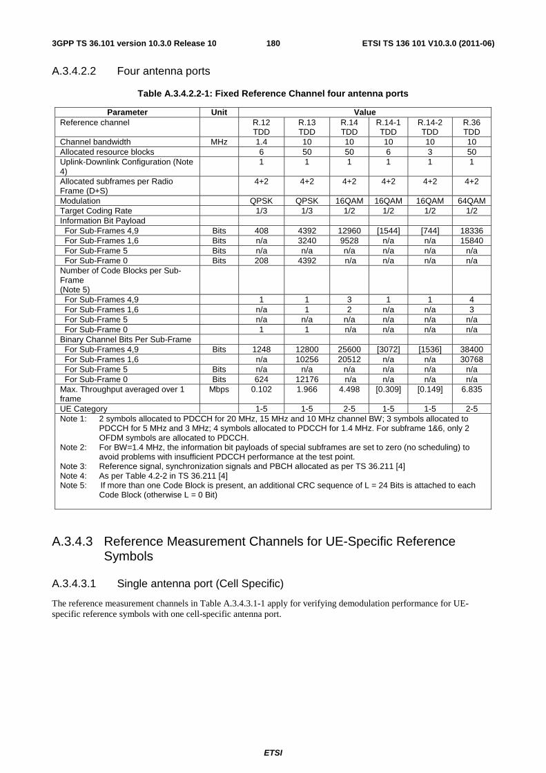
ETSI
ETSI TS 136 101 V10.3.0 (2011-06)1803GPP TS 36.101 version 10.3.0 Release 10
A.3.4.2.2 Four antenna ports
Table A.3.4.2.2-1: Fixed Reference Channel four antenna ports
Parameter Unit Value Reference channel R.12
TDD R.13 TDD
R.14 TDD
R.14-1 TDD
R.14-2 TDD
R.36 TDD
Channel bandwidth MHz 1.4 10 10 10 10 10 Allocated resource blocks 6 50 50 6 3 50 Uplink-Downlink Configuration (Note 4)
1 1 1 1 1 1
Allocated subframes per Radio Frame (D+S)
4+2 4+2 4+2 4+2 4+2 4+2
Modulation QPSK QPSK 16QAM 16QAM 16QAM 64QAM Target Coding Rate 1/3 1/3 1/2 1/2 1/2 1/2 Information Bit Payload For Sub-Frames 4,9 Bits 408 4392 12960 [1544] [744] 18336 For Sub-Frames 1,6 Bits n/a 3240 9528 n/a n/a 15840 For Sub-Frame 5 Bits n/a n/a n/a n/a n/a n/a For Sub-Frame 0 Bits 208 4392 n/a n/a n/a n/a Number of Code Blocks per Sub-Frame (Note 5)
For Sub-Frames 4,9 1 1 3 1 1 4 For Sub-Frames 1,6 n/a 1 2 n/a n/a 3 For Sub-Frame 5 n/a n/a n/a n/a n/a n/a For Sub-Frame 0 1 1 n/a n/a n/a n/a Binary Channel Bits Per Sub-Frame For Sub-Frames 4,9 Bits 1248 12800 25600 [3072] [1536] 38400 For Sub-Frames 1,6 n/a 10256 20512 n/a n/a 30768 For Sub-Frame 5 Bits n/a n/a n/a n/a n/a n/a For Sub-Frame 0 Bits 624 12176 n/a n/a n/a n/a Max. Throughput averaged over 1 frame
Mbps 0.102 1.966 4.498 [0.309] [0.149] 6.835
UE Category 1-5 1-5 2-5 1-5 1-5 2-5 Note 1: 2 symbols allocated to PDCCH for 20 MHz, 15 MHz and 10 MHz channel BW; 3 symbols allocated to
PDCCH for 5 MHz and 3 MHz; 4 symbols allocated to PDCCH for 1.4 MHz. For subframe 1&6, only 2 OFDM symbols are allocated to PDCCH.
Note 2: For BW=1.4 MHz, the information bit payloads of special subframes are set to zero (no scheduling) to avoid problems with insufficient PDCCH performance at the test point.
Note 3: Reference signal, synchronization signals and PBCH allocated as per TS 36.211 [4] Note 4: As per Table 4.2-2 in TS 36.211 [4] Note 5: If more than one Code Block is present, an additional CRC sequence of L = 24 Bits is attached to each
Code Block (otherwise L = 0 Bit)
A.3.4.3 Reference Measurement Channels for UE-Specific Reference Symbols
A.3.4.3.1 Single antenna port (Cell Specific)
The reference measurement channels in Table A.3.4.3.1-1 apply for verifying demodulation performance for UE-specific reference symbols with one cell-specific antenna port.
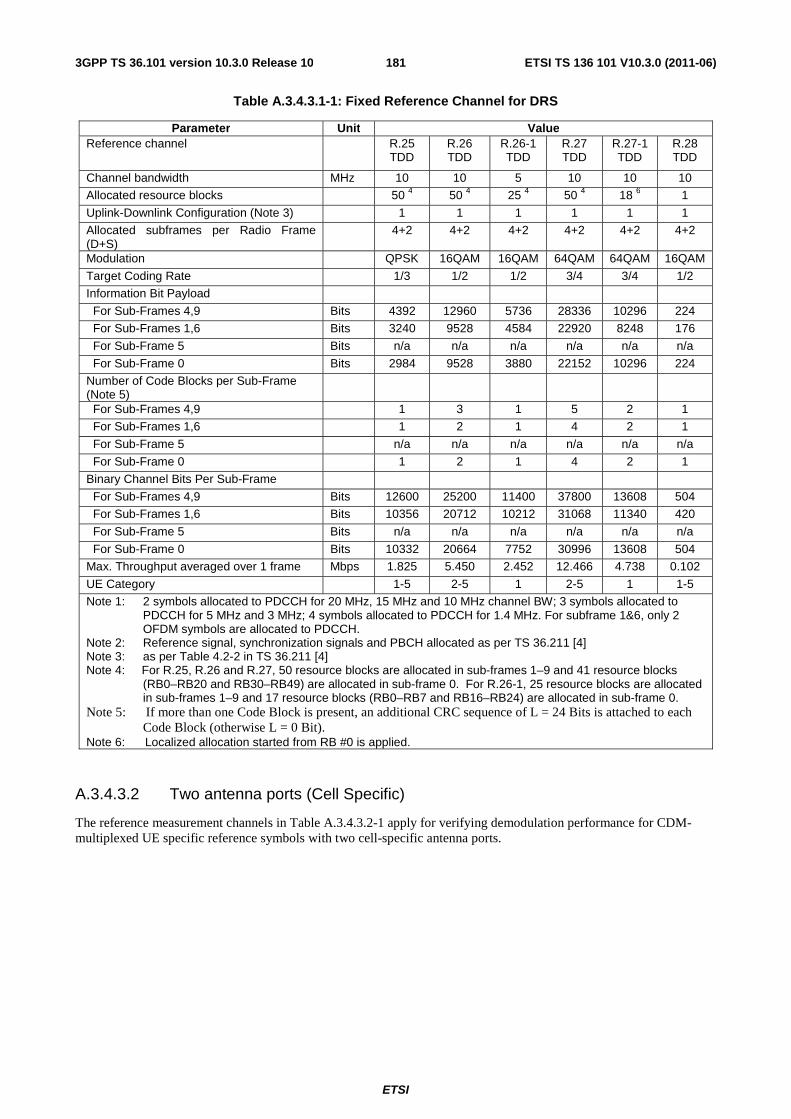
ETSI
ETSI TS 136 101 V10.3.0 (2011-06)1813GPP TS 36.101 version 10.3.0 Release 10
Table A.3.4.3.1-1: Fixed Reference Channel for DRS
Parameter Unit Value Reference channel R.25
TDD R.26 TDD
R.26-1 TDD
R.27 TDD
R.27-1 TDD
R.28 TDD
Channel bandwidth MHz 10 10 5 10 10 10
Allocated resource blocks 50 4 50 4 25 4 50 4 18 6 1
Uplink-Downlink Configuration (Note 3) 1 1 1 1 1 1
Allocated subframes per Radio Frame (D+S)
4+2 4+2 4+2 4+2 4+2 4+2
Modulation QPSK 16QAM 16QAM 64QAM 64QAM 16QAM
Target Coding Rate 1/3 1/2 1/2 3/4 3/4 1/2
Information Bit Payload
For Sub-Frames 4,9 Bits 4392 12960 5736 28336 10296 224
For Sub-Frames 1,6 Bits 3240 9528 4584 22920 8248 176
For Sub-Frame 5 Bits n/a n/a n/a n/a n/a n/a
For Sub-Frame 0 Bits 2984 9528 3880 22152 10296 224
Number of Code Blocks per Sub-Frame (Note 5)
For Sub-Frames 4,9 1 3 1 5 2 1
For Sub-Frames 1,6 1 2 1 4 2 1
For Sub-Frame 5 n/a n/a n/a n/a n/a n/a
For Sub-Frame 0 1 2 1 4 2 1
Binary Channel Bits Per Sub-Frame
For Sub-Frames 4,9 Bits 12600 25200 11400 37800 13608 504
For Sub-Frames 1,6 Bits 10356 20712 10212 31068 11340 420
For Sub-Frame 5 Bits n/a n/a n/a n/a n/a n/a
For Sub-Frame 0 Bits 10332 20664 7752 30996 13608 504
Max. Throughput averaged over 1 frame Mbps 1.825 5.450 2.452 12.466 4.738 0.102
UE Category 1-5 2-5 1 2-5 1 1-5
Note 1: 2 symbols allocated to PDCCH for 20 MHz, 15 MHz and 10 MHz channel BW; 3 symbols allocated to PDCCH for 5 MHz and 3 MHz; 4 symbols allocated to PDCCH for 1.4 MHz. For subframe 1&6, only 2 OFDM symbols are allocated to PDCCH.
Note 2: Reference signal, synchronization signals and PBCH allocated as per TS 36.211 [4] Note 3: as per Table 4.2-2 in TS 36.211 [4] Note 4: For R.25, R.26 and R.27, 50 resource blocks are allocated in sub-frames 1–9 and 41 resource blocks
(RB0–RB20 and RB30–RB49) are allocated in sub-frame 0. For R.26-1, 25 resource blocks are allocated in sub-frames 1–9 and 17 resource blocks (RB0–RB7 and RB16–RB24) are allocated in sub-frame 0.
Note 5: If more than one Code Block is present, an additional CRC sequence of L = 24 Bits is attached to each Code Block (otherwise L = 0 Bit).
Note 6: Localized allocation started from RB #0 is applied.
A.3.4.3.2 Two antenna ports (Cell Specific)
The reference measurement channels in Table A.3.4.3.2-1 apply for verifying demodulation performance for CDM-multiplexed UE specific reference symbols with two cell-specific antenna ports.
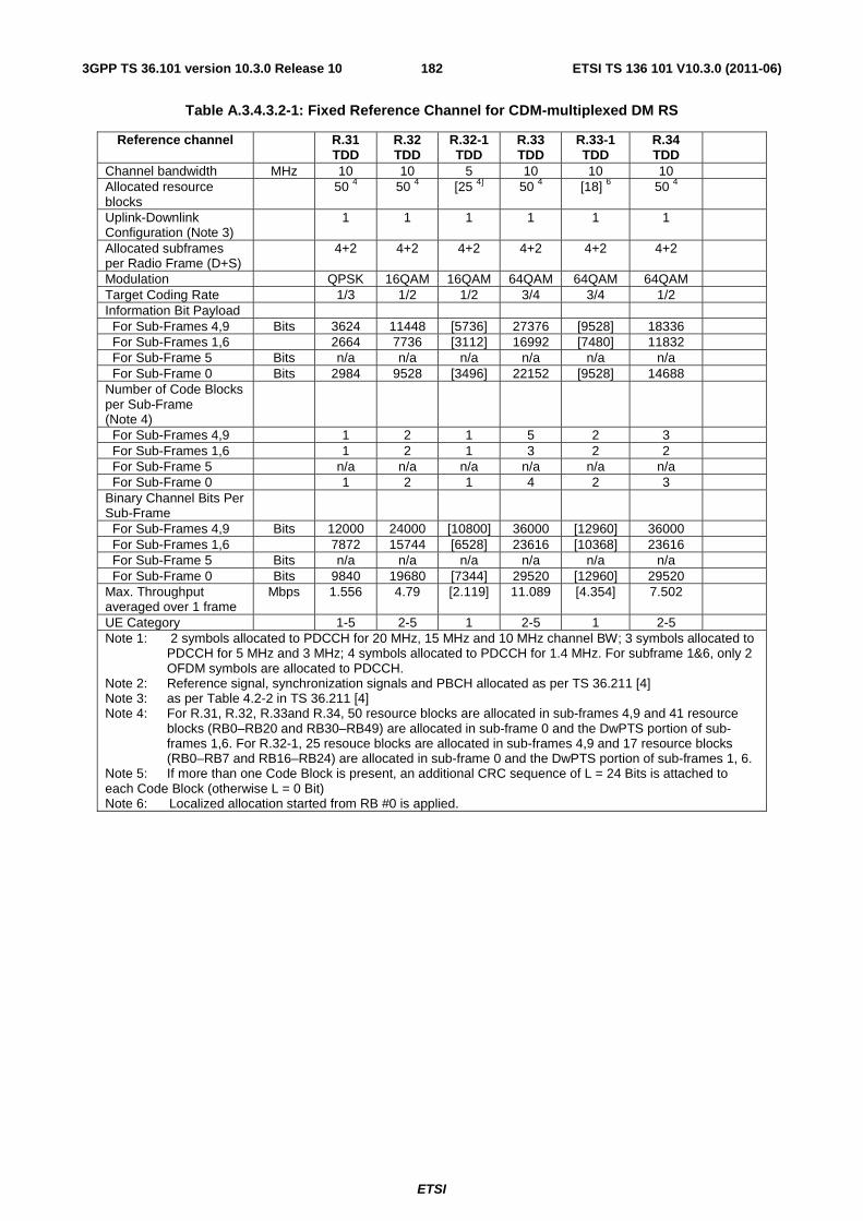
ETSI
ETSI TS 136 101 V10.3.0 (2011-06)1823GPP TS 36.101 version 10.3.0 Release 10
Table A.3.4.3.2-1: Fixed Reference Channel for CDM-multiplexed DM RS
Reference channel R.31 TDD
R.32 TDD
R.32-1 TDD
R.33 TDD
R.33-1 TDD
R.34 TDD
Channel bandwidth MHz 10 10 5 10 10 10 Allocated resource blocks
50 4 50 4 [25 4] 50 4 [18] 6 50 4
Uplink-Downlink Configuration (Note 3)
1 1 1 1 1 1
Allocated subframes per Radio Frame (D+S)
4+2 4+2 4+2 4+2 4+2 4+2
Modulation QPSK 16QAM 16QAM 64QAM 64QAM 64QAM Target Coding Rate 1/3 1/2 1/2 3/4 3/4 1/2 Information Bit Payload For Sub-Frames 4,9 Bits 3624 11448 [5736] 27376 [9528] 18336 For Sub-Frames 1,6 2664 7736 [3112] 16992 [7480] 11832 For Sub-Frame 5 Bits n/a n/a n/a n/a n/a n/a For Sub-Frame 0 Bits 2984 9528 [3496] 22152 [9528] 14688 Number of Code Blocks per Sub-Frame (Note 4)
For Sub-Frames 4,9 1 2 1 5 2 3 For Sub-Frames 1,6 1 2 1 3 2 2 For Sub-Frame 5 n/a n/a n/a n/a n/a n/a For Sub-Frame 0 1 2 1 4 2 3 Binary Channel Bits Per Sub-Frame
For Sub-Frames 4,9 Bits 12000 24000 [10800] 36000 [12960] 36000 For Sub-Frames 1,6 7872 15744 [6528] 23616 [10368] 23616 For Sub-Frame 5 Bits n/a n/a n/a n/a n/a n/a For Sub-Frame 0 Bits 9840 19680 [7344] 29520 [12960] 29520 Max. Throughput averaged over 1 frame
Mbps 1.556 4.79 [2.119] 11.089 [4.354] 7.502
UE Category 1-5 2-5 1 2-5 1 2-5 Note 1: 2 symbols allocated to PDCCH for 20 MHz, 15 MHz and 10 MHz channel BW; 3 symbols allocated to
PDCCH for 5 MHz and 3 MHz; 4 symbols allocated to PDCCH for 1.4 MHz. For subframe 1&6, only 2 OFDM symbols are allocated to PDCCH.
Note 2: Reference signal, synchronization signals and PBCH allocated as per TS 36.211 [4] Note 3: as per Table 4.2-2 in TS 36.211 [4] Note 4: For R.31, R.32, R.33and R.34, 50 resource blocks are allocated in sub-frames 4,9 and 41 resource
blocks (RB0–RB20 and RB30–RB49) are allocated in sub-frame 0 and the DwPTS portion of sub-frames 1,6. For R.32-1, 25 resouce blocks are allocated in sub-frames 4,9 and 17 resource blocks (RB0–RB7 and RB16–RB24) are allocated in sub-frame 0 and the DwPTS portion of sub-frames 1, 6.
Note 5: If more than one Code Block is present, an additional CRC sequence of L = 24 Bits is attached to each Code Block (otherwise L = 0 Bit) Note 6: Localized allocation started from RB #0 is applied.
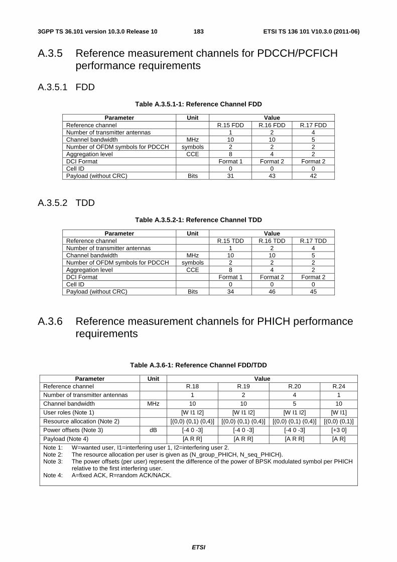
ETSI
ETSI TS 136 101 V10.3.0 (2011-06)1833GPP TS 36.101 version 10.3.0 Release 10
A.3.5 Reference measurement channels for PDCCH/PCFICH performance requirements
A.3.5.1 FDD
Table A.3.5.1-1: Reference Channel FDD
Parameter Unit Value Reference channel R.15 FDD R.16 FDD R.17 FDD Number of transmitter antennas 1 2 4 Channel bandwidth MHz 10 10 5 Number of OFDM symbols for PDCCH symbols 2 2 2 Aggregation level CCE 8 4 2 DCI Format Format 1 Format 2 Format 2 Cell ID 0 0 0 Payload (without CRC) Bits 31 43 42
A.3.5.2 TDD
Table A.3.5.2-1: Reference Channel TDD
Parameter Unit Value Reference channel R.15 TDD R.16 TDD R.17 TDD Number of transmitter antennas 1 2 4 Channel bandwidth MHz 10 10 5 Number of OFDM symbols for PDCCH symbols 2 2 2 Aggregation level CCE 8 4 2 DCI Format Format 1 Format 2 Format 2 Cell ID 0 0 0 Payload (without CRC) Bits 34 46 45
A.3.6 Reference measurement channels for PHICH performance requirements
Table A.3.6-1: Reference Channel FDD/TDD
Parameter Unit Value Reference channel R.18 R.19 R.20 R.24 Number of transmitter antennas 1 2 4 1
Channel bandwidth MHz 10 10 5 10
User roles (Note 1) [W I1 I2] [W I1 I2] [W I1 I2] [W I1]
Resource allocation (Note 2) [(0,0) (0,1) (0,4)] [(0,0) (0,1) (0,4)] [(0,0) (0,1) (0,4)] [(0,0) (0,1)]
Power offsets (Note 3) dB [-4 0 -3] [-4 0 -3] [-4 0 -3] [+3 0]
Payload (Note 4) [A R R] [A R R] [A R R] [A R]
Note 1: W=wanted user, I1=interfering user 1, I2=interfering user 2. Note 2: The resource allocation per user is given as (N_group_PHICH, N_seq_PHICH). Note 3: The power offsets (per user) represent the difference of the power of BPSK modulated symbol per PHICH
relative to the first interfering user. Note 4: A=fixed ACK, R=random ACK/NACK.
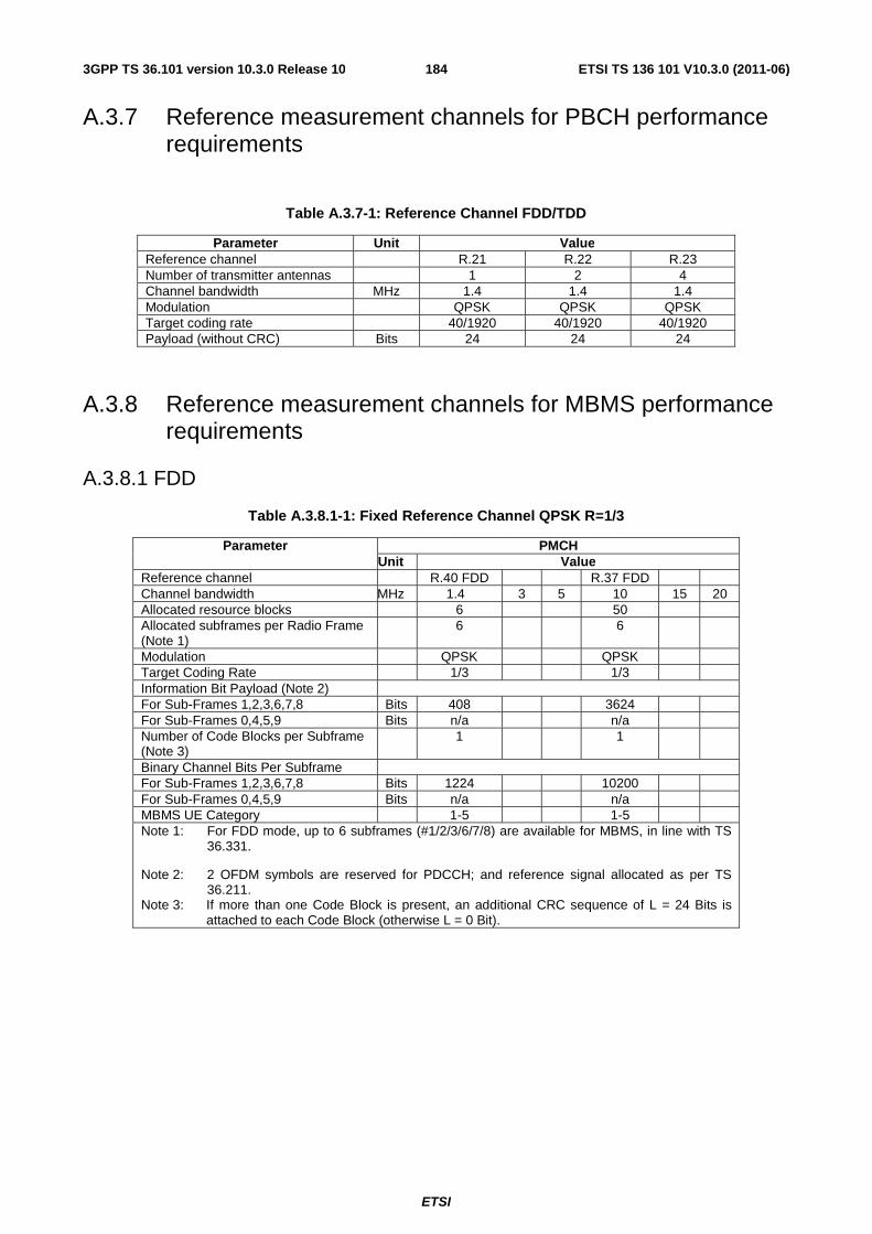
ETSI
ETSI TS 136 101 V10.3.0 (2011-06)1843GPP TS 36.101 version 10.3.0 Release 10
A.3.7 Reference measurement channels for PBCH performance requirements
Table A.3.7-1: Reference Channel FDD/TDD
Parameter Unit Value Reference channel R.21 R.22 R.23 Number of transmitter antennas 1 2 4 Channel bandwidth MHz 1.4 1.4 1.4 Modulation QPSK QPSK QPSK Target coding rate 40/1920 40/1920 40/1920 Payload (without CRC) Bits 24 24 24
A.3.8 Reference measurement channels for MBMS performance requirements
A.3.8.1 FDD
Table A.3.8.1-1: Fixed Reference Channel QPSK R=1/3
Parameter PMCH Unit Value
Reference channel R.40 FDD R.37 FDD Channel bandwidth MHz 1.4 3 5 10 15 20 Allocated resource blocks 6 50 Allocated subframes per Radio Frame (Note 1)
6 6
Modulation QPSK QPSK Target Coding Rate 1/3 1/3 Information Bit Payload (Note 2) For Sub-Frames 1,2,3,6,7,8 Bits 408 3624 For Sub-Frames 0,4,5,9 Bits n/a n/a Number of Code Blocks per Subframe (Note 3)
1 1
Binary Channel Bits Per Subframe For Sub-Frames 1,2,3,6,7,8 Bits 1224 10200 For Sub-Frames 0,4,5,9 Bits n/a n/a MBMS UE Category 1-5 1-5 Note 1: For FDD mode, up to 6 subframes (#1/2/3/6/7/8) are available for MBMS, in line with TS
36.331.
Note 2: 2 OFDM symbols are reserved for PDCCH; and reference signal allocated as per TS 36.211.
Note 3: If more than one Code Block is present, an additional CRC sequence of L = 24 Bits is attached to each Code Block (otherwise L = 0 Bit).
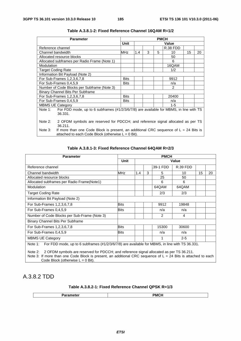
ETSI
ETSI TS 136 101 V10.3.0 (2011-06)1853GPP TS 36.101 version 10.3.0 Release 10
Table A.3.8.1-2: Fixed Reference Channel 16QAM R=1/2
Parameter PMCH Unit Value
Reference channel R.38 FDD Channel bandwidth MHz 1.4 3 5 10 15 20 Allocated resource blocks 50 Allocated subframes per Radio Frame (Note 1) 6 Modulation 16QAM Target Coding Rate 1/2 Information Bit Payload (Note 2) For Sub-Frames 1,2,3,6,7,8 Bits 9912 For Sub-Frames 0,4,5,9 Bits n/a Number of Code Blocks per Subframe (Note 3) 2 Binary Channel Bits Per Subframe For Sub-Frames 1,2,3,6,7,8 Bits 20400 For Sub-Frames 0,4,5,9 Bits n/a MBMS UE Category 1-5 Note 1: For FDD mode, up to 6 subframes (#1/2/3/6/7/8) are available for MBMS, in line with TS
36.331.
Note 2: 2 OFDM symbols are reserved for PDCCH; and reference signal allocated as per TS 36.211.
Note 3: If more than one Code Block is present, an additional CRC sequence of L = 24 Bits is attached to each Code Block (otherwise L = 0 Bit).
Table A.3.8.1-3: Fixed Reference Channel 64QAM R=2/3
Parameter PMCH Unit Value
Reference channel R.39-1 FDD R.39 FDD
Channel bandwidth MHz 1.4 3 5 10 15 20 Allocated resource blocks 25 50 Allocated subframes per Radio Frame(Note1) 6 6 Modulation 64QAM 64QAM
Target Coding Rate 2/3 2/3
Information Bit Payload (Note 2)
For Sub-Frames 1,2,3,6,7,8 Bits 9912 19848
For Sub-Frames 0,4,5,9 Bits n/a n/a
Number of Code Blocks per Sub-Frame (Note 3) 2 4
Binary Channel Bits Per Subframe
For Sub-Frames 1,2,3,6,7,8 Bits 15300 30600
For Sub-Frames 0,4,5,9 Bits n/a n/a
MBMS UE Category 1 2-5
Note 1: For FDD mode, up to 6 subframes (#1/2/3/6/7/8) are available for MBMS, in line with TS 36.331.
Note 2: 2 OFDM symbols are reserved for PDCCH; and reference signal allocated as per TS 36.211. Note 3: If more than one Code Block is present, an additional CRC sequence of L = 24 Bits is attached to each
Code Block (otherwise L = 0 Bit).
A.3.8.2 TDD
Table A.3.8.2-1: Fixed Reference Channel QPSK R=1/3
Parameter PMCH
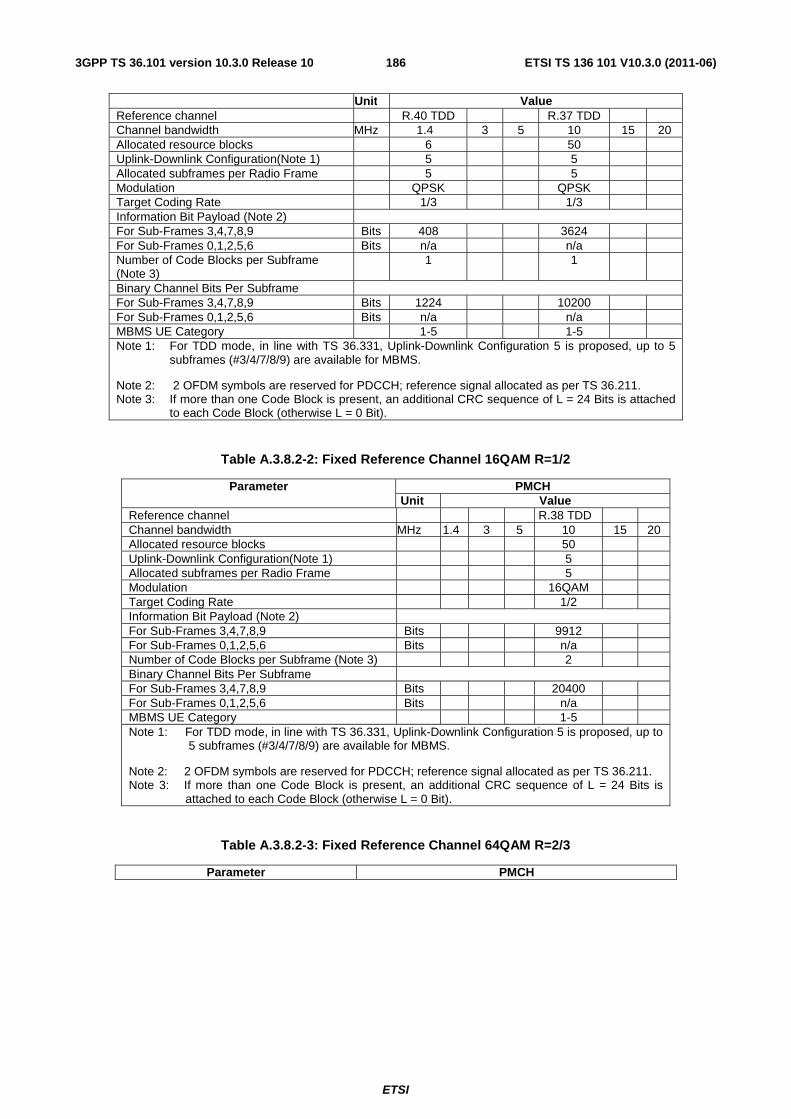
ETSI
ETSI TS 136 101 V10.3.0 (2011-06)1863GPP TS 36.101 version 10.3.0 Release 10
Unit Value Reference channel R.40 TDD R.37 TDD Channel bandwidth MHz 1.4 3 5 10 15 20 Allocated resource blocks 6 50 Uplink-Downlink Configuration(Note 1) 5 5 Allocated subframes per Radio Frame 5 5 Modulation QPSK QPSK Target Coding Rate 1/3 1/3 Information Bit Payload (Note 2) For Sub-Frames 3,4,7,8,9 Bits 408 3624 For Sub-Frames 0,1,2,5,6 Bits n/a n/a Number of Code Blocks per Subframe (Note 3)
1 1
Binary Channel Bits Per Subframe For Sub-Frames 3,4,7,8,9 Bits 1224 10200 For Sub-Frames 0,1,2,5,6 Bits n/a n/a MBMS UE Category 1-5 1-5 Note 1: For TDD mode, in line with TS 36.331, Uplink-Downlink Configuration 5 is proposed, up to 5
subframes (#3/4/7/8/9) are available for MBMS.
Note 2: 2 OFDM symbols are reserved for PDCCH; reference signal allocated as per TS 36.211. Note 3: If more than one Code Block is present, an additional CRC sequence of L = 24 Bits is attached
to each Code Block (otherwise L = 0 Bit).
Table A.3.8.2-2: Fixed Reference Channel 16QAM R=1/2
Parameter PMCH Unit Value
Reference channel R.38 TDD Channel bandwidth MHz 1.4 3 5 10 15 20 Allocated resource blocks 50 Uplink-Downlink Configuration(Note 1) 5 Allocated subframes per Radio Frame 5 Modulation 16QAM Target Coding Rate 1/2 Information Bit Payload (Note 2) For Sub-Frames 3,4,7,8,9 Bits 9912 For Sub-Frames 0,1,2,5,6 Bits n/a Number of Code Blocks per Subframe (Note 3) 2 Binary Channel Bits Per Subframe For Sub-Frames 3,4,7,8,9 Bits 20400 For Sub-Frames 0,1,2,5,6 Bits n/a MBMS UE Category 1-5 Note 1: For TDD mode, in line with TS 36.331, Uplink-Downlink Configuration 5 is proposed, up to
5 subframes (#3/4/7/8/9) are available for MBMS.
Note 2: 2 OFDM symbols are reserved for PDCCH; reference signal allocated as per TS 36.211. Note 3: If more than one Code Block is present, an additional CRC sequence of L = 24 Bits is
attached to each Code Block (otherwise L = 0 Bit).
Table A.3.8.2-3: Fixed Reference Channel 64QAM R=2/3
Parameter PMCH
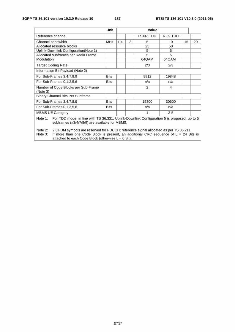
ETSI
ETSI TS 136 101 V10.3.0 (2011-06)1873GPP TS 36.101 version 10.3.0 Release 10
Unit Value
Reference channel R.39-1TDD R.39 TDD
Channel bandwidth MHz 1.4 3 5 10 15 20 Allocated resource blocks 25 50 Uplink-Downlink Configuration(Note 1) 5 5 Allocated subframes per Radio Frame 5 5 Modulation 64QAM 64QAM
Target Coding Rate 2/3 2/3
Information Bit Payload (Note 2)
For Sub-Frames 3,4,7,8,9 Bits 9912 19848
For Sub-Frames 0,1,2,5,6 Bits n/a n/a
Number of Code Blocks per Sub-Frame (Note 3)
2 4
Binary Channel Bits Per Subframe
For Sub-Frames 3,4,7,8,9 Bits 15300 30600
For Sub-Frames 0,1,2,5,6 Bits n/a n/a
MBMS UE Category 1 2-5
Note 1: For TDD mode, in line with TS 36.331, Uplink-Downlink Configuration 5 is proposed, up to 5 subframes (#3/4/7/8/9) are available for MBMS.
Note 2: 2 OFDM symbols are reserved for PDCCH; reference signal allocated as per TS 36.211. Note 3: If more than one Code Block is present, an additional CRC sequence of L = 24 Bits is
attached to each Code Block (otherwise L = 0 Bit).
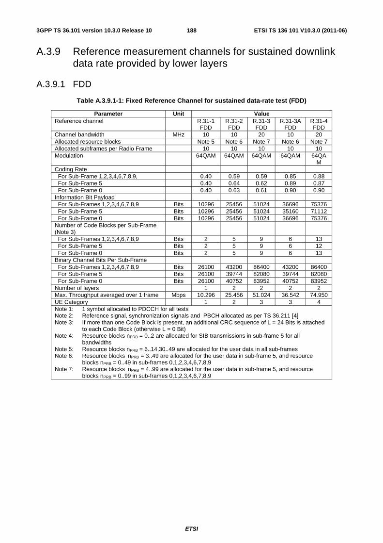
ETSI
ETSI TS 136 101 V10.3.0 (2011-06)1883GPP TS 36.101 version 10.3.0 Release 10
A.3.9 Reference measurement channels for sustained downlink data rate provided by lower layers
A.3.9.1 FDD
Table A.3.9.1-1: Fixed Reference Channel for sustained data-rate test (FDD)
Parameter Unit Value Reference channel R.31-1
FDD R.31-2 FDD
R.31-3 FDD
R.31-3A FDD
R.31-4 FDD
Channel bandwidth MHz 10 10 20 10 20 Allocated resource blocks Note 5 Note 6 Note 7 Note 6 Note 7 Allocated subframes per Radio Frame 10 10 10 10 10 Modulation 64QAM 64QAM 64QAM 64QAM 64QA
M Coding Rate For Sub-Frame 1,2,3,4,6,7,8,9, 0.40 0.59 0.59 0.85 0.88 For Sub-Frame 5 0.40 0.64 0.62 0.89 0.87 For Sub-Frame 0 0.40 0.63 0.61 0.90 0.90 Information Bit Payload For Sub-Frames 1,2,3,4,6,7,8,9 Bits 10296 25456 51024 36696 75376 For Sub-Frame 5 Bits 10296 25456 51024 35160 71112 For Sub-Frame 0 Bits 10296 25456 51024 36696 75376 Number of Code Blocks per Sub-Frame (Note 3)
For Sub-Frames 1,2,3,4,6,7,8,9 Bits 2 5 9 6 13 For Sub-Frame 5 Bits 2 5 9 6 12 For Sub-Frame 0 Bits 2 5 9 6 13 Binary Channel Bits Per Sub-Frame For Sub-Frames 1,2,3,4,6,7,8,9 Bits 26100 43200 86400 43200 86400 For Sub-Frame 5 Bits 26100 39744 82080 39744 82080 For Sub-Frame 0 Bits 26100 40752 83952 40752 83952 Number of layers 1 2 2 2 2 Max. Throughput averaged over 1 frame Mbps 10.296 25.456 51.024 36.542 74.950 UE Category 1 2 3 3 4 Note 1: 1 symbol allocated to PDCCH for all tests Note 2: Reference signal, synchronization signals and PBCH allocated as per TS 36.211 [4] Note 3: If more than one Code Block is present, an additional CRC sequence of L = 24 Bits is attached
to each Code Block (otherwise L = 0 Bit) Note 4: Resource blocks nPRB = 0..2 are allocated for SIB transmissions in sub-frame 5 for all
bandwidths Note 5: Resource blocks nPRB = 6..14,30..49 are allocated for the user data in all sub-frames Note 6: Resource blocks nPRB = 3..49 are allocated for the user data in sub-frame 5, and resource
blocks nPRB = 0..49 in sub-frames 0,1,2,3,4,6,7,8,9 Note 7: Resource blocks nPRB = 4..99 are allocated for the user data in sub-frame 5, and resource
blocks nPRB = 0..99 in sub-frames 0,1,2,3,4,6,7,8,9
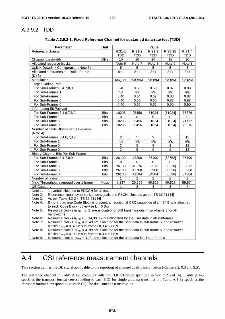
ETSI
ETSI TS 136 101 V10.3.0 (2011-06)1893GPP TS 36.101 version 10.3.0 Release 10
A.3.9.2 TDD
Table A.3.9.2-1: Fixed Reference Channel for sustained data-rate test (TDD)
Parameter Unit Value Reference channel R.31-1
TDD R.31-2 TDD
R.31-3 TDD
R.31-3B TDD
R.31-4 TDD
Channel bandwidth MHz 10 10 20 15 20 Allocated resource blocks Note 6 Note 7 Note 8 Note 9 Note 8 Uplink-Downlink Configuration (Note 3) 5 5 5 5 5 Allocated subframes per Radio Frame (D+S)
8+1 8+1 8+1 8+1 8+1
Modulation 64QAM 64QAM 64QAM 64QAM 64QAM Target Coding Rate For Sub-Frames 3,4,7,8,9 0.40 0.59 0.59 0.87 0.88 For Sub-Frames 1 n/a n/a n/a n/a n/a For Sub-Frames 5 0.40 0.64 0.62 0.88 0.87 For Sub-Frames 6 0.40 0.60 0.60 0.88 0.88 For Sub-Frames 0 0.40 0.62 0.61 0.90 0.90 Information Bit Payload For Sub-Frames 3,4,6,7,8,9 Bits 10296 25456 51024 [51024] 75376 For Sub-Frame 1 Bits 0 0 0 0 0 For Sub-Frame 5 Bits 10296 25456 51024 [51024] 71112 For Sub-Frame 0 Bits 10296 25456 51024 [51024] 75376 Number of Code Blocks per Sub-Frame (Note 4)
For Sub-Frames 3,4,6,7,8,9 2 5 9 9 13 For Sub-Frame 1 n/a n/a n/a n/a n/a For Sub-Frame 5 2 5 9 9 12 For Sub-Frame 0 2 5 9 9 13 Binary Channel Bits Per Sub-Frame For Sub-Frames 3,4,7,8,9 Bits 26100 43200 86400 [58752] 86400 For Sub-Frame 1 Bits 0 0 0 0 0 For Sub-Frame 5 Bits 26100 40176 82512 [58320] 82512 For Sub-Frame 6 Bits 26100 42768 85968 [58320] 85968 For Sub-Frame 0 Bits 26100 41184 84384 [56736] 84384 Number of layers 1 2 2 2 2 Max. Throughput averaged over 1 frame Mbps 8.237 20.365 40.819 40.819 59.874 UE Category 1 2 3 3 4 Note 1: 1 symbol allocated to PDCCH for all tests Note 2: Reference signal, synchronization signals and PBCH allocated as per TS 36.211 [4] Note 3: As per Table 4.2-2 in TS 36.211 [4] Note 4: If more than one Code Block is present, an additional CRC sequence of L = 24 Bits is attached
to each Code Block (otherwise L = 0 Bit) Note 5: Resource blocks nPRB = 0..2 are allocated for SIB transmissions in sub-frame 5 for all
bandwidths Note 6: Resource blocks nPRB = 6..14,30..49 are allocated for the user data in all subframes Note 7: Resource blocks nPRB = 3..49 are allocated for the user data in sub-frame 5, and resource
blocks nPRB = 0..49 in sub-frames 0,3,4,6,7,8,9 Note 8: Resource blocks nPRB = 4..99 are allocated for the user data in sub-frame 5, and resource
blocks nPRB = 0..99 in sub-frames 0,3,4,6,7,8,9 Note 9: Resource blocks nPRB = 4..71 are allocated for the user data in all sub-frames
A.4 CSI reference measurement channels This section defines the DL signal applicable to the reporting of channel quality information (Clause 9.2, 9.3 and 9.5).
The reference channel in Table A.4-1 complies with the CQI definition specified in Sec. 7.2.3 of [6]. Table A.4-3 specifies the transport format corresponding to each CQI for single antenna transmission. Table A.4-3a specifies the transport format corresponding to each CQI for dual antenna transmission.
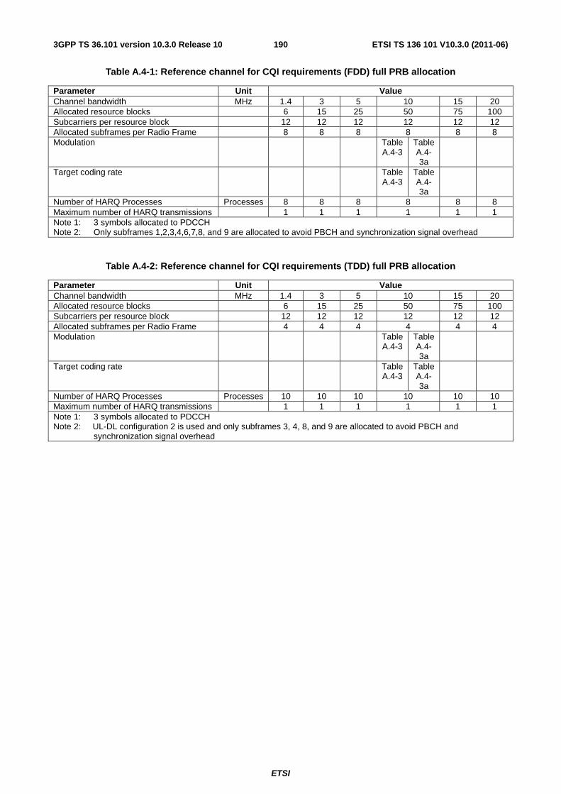
ETSI
ETSI TS 136 101 V10.3.0 (2011-06)1903GPP TS 36.101 version 10.3.0 Release 10
Table A.4-1: Reference channel for CQI requirements (FDD) full PRB allocation
Parameter Unit Value Channel bandwidth MHz 1.4 3 5 10 15 20 Allocated resource blocks 6 15 25 50 75 100 Subcarriers per resource block 12 12 12 12 12 12 Allocated subframes per Radio Frame 8 8 8 8 8 8 Modulation Table
A.4-3 Table A.4-3a
Target coding rate Table A.4-3
Table A.4-3a
Number of HARQ Processes Processes 8 8 8 8 8 8 Maximum number of HARQ transmissions 1 1 1 1 1 1 Note 1: 3 symbols allocated to PDCCH Note 2: Only subframes 1,2,3,4,6,7,8, and 9 are allocated to avoid PBCH and synchronization signal overhead
Table A.4-2: Reference channel for CQI requirements (TDD) full PRB allocation
Parameter Unit Value Channel bandwidth MHz 1.4 3 5 10 15 20 Allocated resource blocks 6 15 25 50 75 100 Subcarriers per resource block 12 12 12 12 12 12 Allocated subframes per Radio Frame 4 4 4 4 4 4 Modulation Table
A.4-3 Table A.4-3a
Target coding rate Table A.4-3
Table A.4-3a
Number of HARQ Processes Processes 10 10 10 10 10 10 Maximum number of HARQ transmissions 1 1 1 1 1 1 Note 1: 3 symbols allocated to PDCCH Note 2: UL-DL configuration 2 is used and only subframes 3, 4, 8, and 9 are allocated to avoid PBCH and
synchronization signal overhead
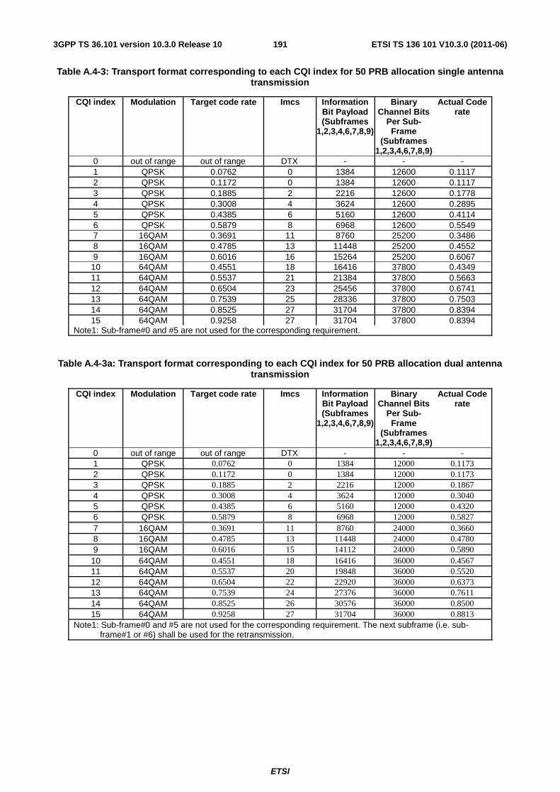
ETSI
ETSI TS 136 101 V10.3.0 (2011-06)1913GPP TS 36.101 version 10.3.0 Release 10
Table A.4-3: Transport format corresponding to each CQI index for 50 PRB allocation single antenna transmission
CQI index Modulation Target code rate Imcs Information Bit Payload (Subframes
1,2,3,4,6,7,8,9)
Binary Channel Bits
Per Sub-Frame
(Subframes 1,2,3,4,6,7,8,9)
Actual Code rate
0 out of range out of range DTX - - - 1 QPSK 0.0762 0 1384 12600 0.1117 2 QPSK 0.1172 0 1384 12600 0.1117 3 QPSK 0.1885 2 2216 12600 0.1778 4 QPSK 0.3008 4 3624 12600 0.2895 5 QPSK 0.4385 6 5160 12600 0.4114 6 QPSK 0.5879 8 6968 12600 0.5549 7 16QAM 0.3691 11 8760 25200 0.3486 8 16QAM 0.4785 13 11448 25200 0.4552 9 16QAM 0.6016 16 15264 25200 0.6067 10 64QAM 0.4551 18 16416 37800 0.4349 11 64QAM 0.5537 21 21384 37800 0.5663 12 64QAM 0.6504 23 25456 37800 0.6741 13 64QAM 0.7539 25 28336 37800 0.7503 14 64QAM 0.8525 27 31704 37800 0.8394 15 64QAM 0.9258 27 31704 37800 0.8394
Note1: Sub-frame#0 and #5 are not used for the corresponding requirement.
Table A.4-3a: Transport format corresponding to each CQI index for 50 PRB allocation dual antenna transmission
CQI index Modulation Target code rate Imcs Information Bit Payload (Subframes
1,2,3,4,6,7,8,9)
Binary Channel Bits
Per Sub-Frame
(Subframes 1,2,3,4,6,7,8,9)
Actual Code rate
0 out of range out of range DTX - - - 1 QPSK 0.0762 0 1384 12000 0.1173 2 QPSK 0.1172 0 1384 12000 0.1173 3 QPSK 0.1885 2 2216 12000 0.1867 4 QPSK 0.3008 4 3624 12000 0.3040 5 QPSK 0.4385 6 5160 12000 0.4320 6 QPSK 0.5879 8 6968 12000 0.5827 7 16QAM 0.3691 11 8760 24000 0.3660 8 16QAM 0.4785 13 11448 24000 0.4780 9 16QAM 0.6016 15 14112 24000 0.5890 10 64QAM 0.4551 18 16416 36000 0.4567 11 64QAM 0.5537 20 19848 36000 0.5520 12 64QAM 0.6504 22 22920 36000 0.6373 13 64QAM 0.7539 24 27376 36000 0.7611 14 64QAM 0.8525 26 30576 36000 0.8500 15 64QAM 0.9258 27 31704 36000 0.8813
Note1: Sub-frame#0 and #5 are not used for the corresponding requirement. The next subframe (i.e. sub-frame#1 or #6) shall be used for the retransmission.
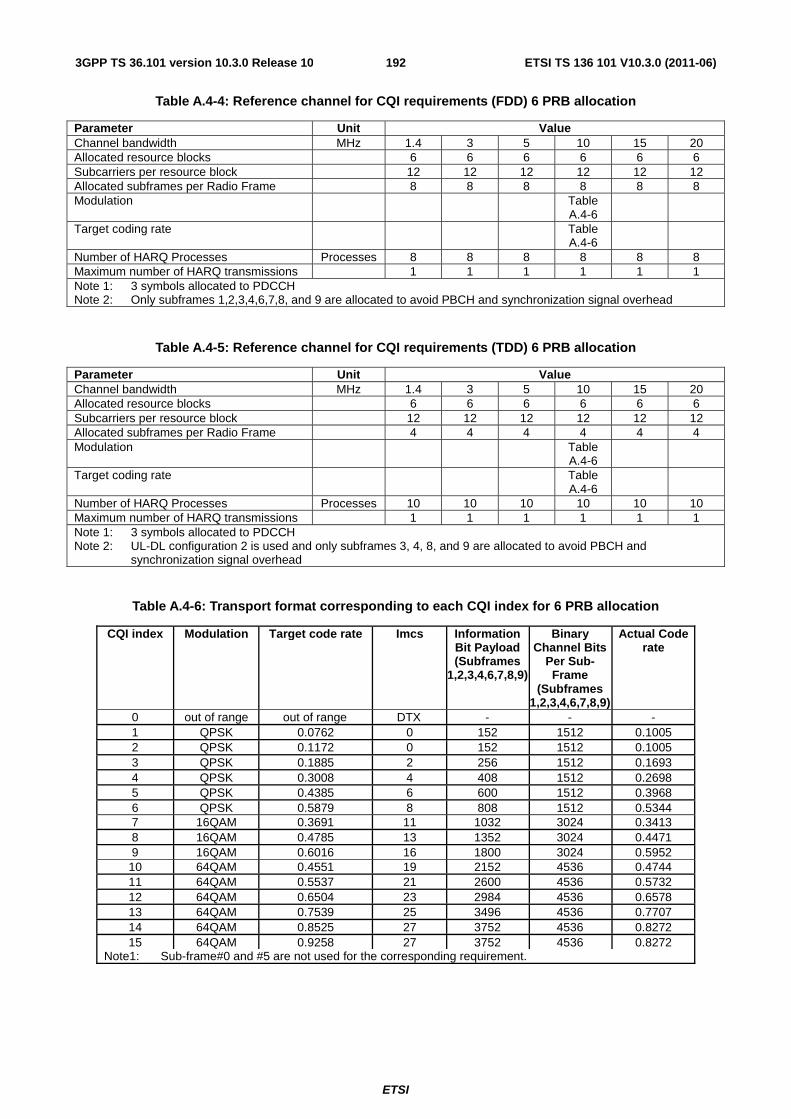
ETSI
ETSI TS 136 101 V10.3.0 (2011-06)1923GPP TS 36.101 version 10.3.0 Release 10
Table A.4-4: Reference channel for CQI requirements (FDD) 6 PRB allocation
Parameter Unit Value Channel bandwidth MHz 1.4 3 5 10 15 20 Allocated resource blocks 6 6 6 6 6 6 Subcarriers per resource block 12 12 12 12 12 12 Allocated subframes per Radio Frame 8 8 8 8 8 8 Modulation Table
A.4-6
Target coding rate Table A.4-6
Number of HARQ Processes Processes 8 8 8 8 8 8 Maximum number of HARQ transmissions 1 1 1 1 1 1 Note 1: 3 symbols allocated to PDCCH Note 2: Only subframes 1,2,3,4,6,7,8, and 9 are allocated to avoid PBCH and synchronization signal overhead
Table A.4-5: Reference channel for CQI requirements (TDD) 6 PRB allocation
Parameter Unit Value Channel bandwidth MHz 1.4 3 5 10 15 20 Allocated resource blocks 6 6 6 6 6 6 Subcarriers per resource block 12 12 12 12 12 12 Allocated subframes per Radio Frame 4 4 4 4 4 4 Modulation Table
A.4-6
Target coding rate Table A.4-6
Number of HARQ Processes Processes 10 10 10 10 10 10 Maximum number of HARQ transmissions 1 1 1 1 1 1 Note 1: 3 symbols allocated to PDCCH Note 2: UL-DL configuration 2 is used and only subframes 3, 4, 8, and 9 are allocated to avoid PBCH and
synchronization signal overhead
Table A.4-6: Transport format corresponding to each CQI index for 6 PRB allocation
CQI index Modulation Target code rate Imcs Information Bit Payload (Subframes
1,2,3,4,6,7,8,9)
Binary Channel Bits
Per Sub-Frame
(Subframes 1,2,3,4,6,7,8,9)
Actual Code rate
0 out of range out of range DTX - - - 1 QPSK 0.0762 0 152 1512 0.1005 2 QPSK 0.1172 0 152 1512 0.1005 3 QPSK 0.1885 2 256 1512 0.1693 4 QPSK 0.3008 4 408 1512 0.2698 5 QPSK 0.4385 6 600 1512 0.3968 6 QPSK 0.5879 8 808 1512 0.5344 7 16QAM 0.3691 11 1032 3024 0.3413 8 16QAM 0.4785 13 1352 3024 0.4471 9 16QAM 0.6016 16 1800 3024 0.5952 10 64QAM 0.4551 19 2152 4536 0.4744 11 64QAM 0.5537 21 2600 4536 0.5732 12 64QAM 0.6504 23 2984 4536 0.6578 13 64QAM 0.7539 25 3496 4536 0.7707 14 64QAM 0.8525 27 3752 4536 0.8272 15 64QAM 0.9258 27 3752 4536 0.8272
Note1: Sub-frame#0 and #5 are not used for the corresponding requirement.
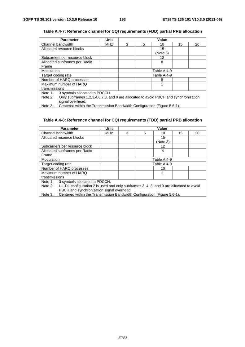
ETSI
ETSI TS 136 101 V10.3.0 (2011-06)1933GPP TS 36.101 version 10.3.0 Release 10
Table A.4-7: Reference channel for CQI requirements (FDD) partial PRB allocation
Parameter Unit Value Channel bandwidth MHz 3 5 10 15 20 Allocated resource blocks 15
(Note 3)
Subcarriers per resource block 12 Allocated subframes per Radio Frame
8
Modulation Table A.4-9 Target coding rate Table A.4-9 Number of HARQ processes 8 Maximum number of HARQ transmissions
1
Note 1: 3 symbols allocated to PDCCH. Note 2: Only subframes 1,2,3,4,6,7,8, and 9 are allocated to avoid PBCH and synchronization
signal overhead. Note 3: Centered within the Transmission Bandwidth Configuration (Figure 5.6-1).
Table A.4-8: Reference channel for CQI requirements (TDD) partial PRB allocation
Parameter Unit Value Channel bandwidth MHz 3 5 10 15 20 Allocated resource blocks 15
(Note 3)
Subcarriers per resource block 12 Allocated subframes per Radio Frame
4
Modulation Table A.4-9 Target coding rate Table A.4-9 Number of HARQ processes 10 Maximum number of HARQ transmissions
1
Note 1: 3 symbols allocated to PDCCH. Note 2: UL-DL configuration 2 is used and only subframes 3, 4, 8, and 9 are allocated to avoid
PBCH and synchronization signal overhead. Note 3: Centered within the Transmission Bandwidth Configuration (Figure 5.6-1).
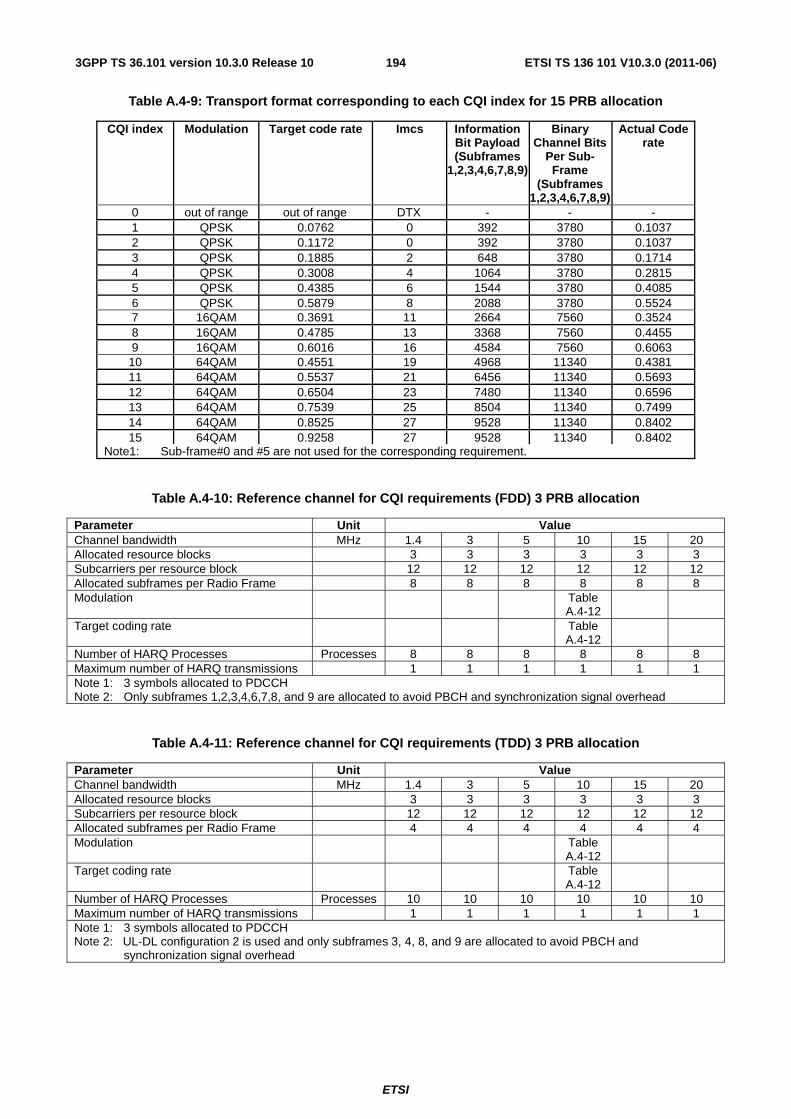
ETSI
ETSI TS 136 101 V10.3.0 (2011-06)1943GPP TS 36.101 version 10.3.0 Release 10
Table A.4-9: Transport format corresponding to each CQI index for 15 PRB allocation
CQI index Modulation Target code rate Imcs Information Bit Payload (Subframes
1,2,3,4,6,7,8,9)
Binary Channel Bits
Per Sub-Frame
(Subframes 1,2,3,4,6,7,8,9)
Actual Code rate
0 out of range out of range DTX - - - 1 QPSK 0.0762 0 392 3780 0.1037 2 QPSK 0.1172 0 392 3780 0.1037 3 QPSK 0.1885 2 648 3780 0.1714 4 QPSK 0.3008 4 1064 3780 0.2815 5 QPSK 0.4385 6 1544 3780 0.4085 6 QPSK 0.5879 8 2088 3780 0.5524 7 16QAM 0.3691 11 2664 7560 0.3524 8 16QAM 0.4785 13 3368 7560 0.4455 9 16QAM 0.6016 16 4584 7560 0.6063 10 64QAM 0.4551 19 4968 11340 0.4381 11 64QAM 0.5537 21 6456 11340 0.5693 12 64QAM 0.6504 23 7480 11340 0.6596 13 64QAM 0.7539 25 8504 11340 0.7499 14 64QAM 0.8525 27 9528 11340 0.8402 15 64QAM 0.9258 27 9528 11340 0.8402
Note1: Sub-frame#0 and #5 are not used for the corresponding requirement.
Table A.4-10: Reference channel for CQI requirements (FDD) 3 PRB allocation
Parameter Unit Value Channel bandwidth MHz 1.4 3 5 10 15 20 Allocated resource blocks 3 3 3 3 3 3 Subcarriers per resource block 12 12 12 12 12 12 Allocated subframes per Radio Frame 8 8 8 8 8 8 Modulation Table
A.4-12
Target coding rate Table A.4-12
Number of HARQ Processes Processes 8 8 8 8 8 8 Maximum number of HARQ transmissions 1 1 1 1 1 1 Note 1: 3 symbols allocated to PDCCH Note 2: Only subframes 1,2,3,4,6,7,8, and 9 are allocated to avoid PBCH and synchronization signal overhead
Table A.4-11: Reference channel for CQI requirements (TDD) 3 PRB allocation
Parameter Unit Value Channel bandwidth MHz 1.4 3 5 10 15 20 Allocated resource blocks 3 3 3 3 3 3 Subcarriers per resource block 12 12 12 12 12 12 Allocated subframes per Radio Frame 4 4 4 4 4 4 Modulation Table
A.4-12
Target coding rate Table A.4-12
Number of HARQ Processes Processes 10 10 10 10 10 10 Maximum number of HARQ transmissions 1 1 1 1 1 1 Note 1: 3 symbols allocated to PDCCH Note 2: UL-DL configuration 2 is used and only subframes 3, 4, 8, and 9 are allocated to avoid PBCH and
synchronization signal overhead
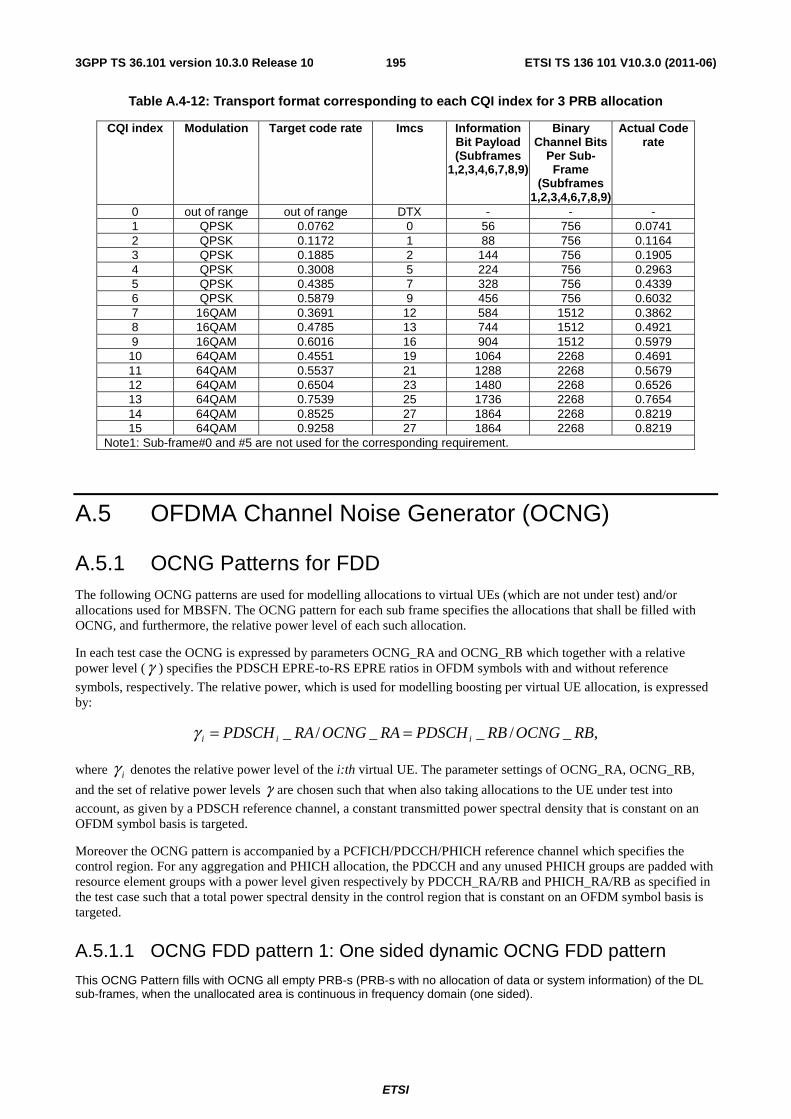
ETSI
ETSI TS 136 101 V10.3.0 (2011-06)1953GPP TS 36.101 version 10.3.0 Release 10
Table A.4-12: Transport format corresponding to each CQI index for 3 PRB allocation
CQI index Modulation Target code rate Imcs Information Bit Payload (Subframes
1,2,3,4,6,7,8,9)
Binary Channel Bits
Per Sub-Frame
(Subframes 1,2,3,4,6,7,8,9)
Actual Code rate
0 out of range out of range DTX - - - 1 QPSK 0.0762 0 56 756 0.0741 2 QPSK 0.1172 1 88 756 0.1164 3 QPSK 0.1885 2 144 756 0.1905 4 QPSK 0.3008 5 224 756 0.2963 5 QPSK 0.4385 7 328 756 0.4339 6 QPSK 0.5879 9 456 756 0.6032 7 16QAM 0.3691 12 584 1512 0.3862 8 16QAM 0.4785 13 744 1512 0.4921 9 16QAM 0.6016 16 904 1512 0.5979 10 64QAM 0.4551 19 1064 2268 0.4691 11 64QAM 0.5537 21 1288 2268 0.5679 12 64QAM 0.6504 23 1480 2268 0.6526 13 64QAM 0.7539 25 1736 2268 0.7654 14 64QAM 0.8525 27 1864 2268 0.8219 15 64QAM 0.9258 27 1864 2268 0.8219
Note1: Sub-frame#0 and #5 are not used for the corresponding requirement.
A.5 OFDMA Channel Noise Generator (OCNG)
A.5.1 OCNG Patterns for FDD The following OCNG patterns are used for modelling allocations to virtual UEs (which are not under test) and/or allocations used for MBSFN. The OCNG pattern for each sub frame specifies the allocations that shall be filled with OCNG, and furthermore, the relative power level of each such allocation.
In each test case the OCNG is expressed by parameters OCNG_RA and OCNG_RB which together with a relative power level (γ ) specifies the PDSCH EPRE-to-RS EPRE ratios in OFDM symbols with and without reference
symbols, respectively. The relative power, which is used for modelling boosting per virtual UE allocation, is expressed by:
,_/__/_ RBOCNGRBPDSCHRAOCNGRAPDSCH iii ==γ
where iγ denotes the relative power level of the i:th virtual UE. The parameter settings of OCNG_RA, OCNG_RB,
and the set of relative power levels γ are chosen such that when also taking allocations to the UE under test into
account, as given by a PDSCH reference channel, a constant transmitted power spectral density that is constant on an OFDM symbol basis is targeted.
Moreover the OCNG pattern is accompanied by a PCFICH/PDCCH/PHICH reference channel which specifies the control region. For any aggregation and PHICH allocation, the PDCCH and any unused PHICH groups are padded with resource element groups with a power level given respectively by PDCCH_RA/RB and PHICH_RA/RB as specified in the test case such that a total power spectral density in the control region that is constant on an OFDM symbol basis is targeted.
A.5.1.1 OCNG FDD pattern 1: One sided dynamic OCNG FDD pattern
This OCNG Pattern fills with OCNG all empty PRB-s (PRB-s with no allocation of data or system information) of the DL sub-frames, when the unallocated area is continuous in frequency domain (one sided).
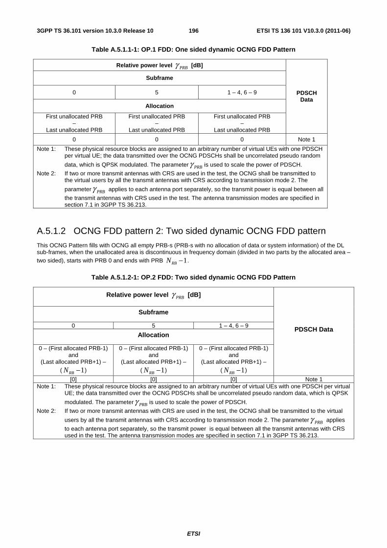
ETSI
ETSI TS 136 101 V10.3.0 (2011-06)1963GPP TS 36.101 version 10.3.0 Release 10
Table A.5.1.1-1: OP.1 FDD: One sided dynamic OCNG FDD Pattern
Relative power level PRBγ [dB]
PDSCH Data
Subframe
0 5 1 – 4, 6 – 9
Allocation
First unallocated PRB –
Last unallocated PRB
First unallocated PRB –
Last unallocated PRB
First unallocated PRB –
Last unallocated PRB
0 0 0 Note 1
Note 1: These physical resource blocks are assigned to an arbitrary number of virtual UEs with one PDSCH per virtual UE; the data transmitted over the OCNG PDSCHs shall be uncorrelated pseudo random
data, which is QPSK modulated. The parameter PRBγ is used to scale the power of PDSCH.
Note 2: If two or more transmit antennas with CRS are used in the test, the OCNG shall be transmitted to the virtual users by all the transmit antennas with CRS according to transmission mode 2. The
parameter PRBγ applies to each antenna port separately, so the transmit power is equal between all
the transmit antennas with CRS used in the test. The antenna transmission modes are specified in section 7.1 in 3GPP TS 36.213.
A.5.1.2 OCNG FDD pattern 2: Two sided dynamic OCNG FDD pattern
This OCNG Pattern fills with OCNG all empty PRB-s (PRB-s with no allocation of data or system information) of the DL sub-frames, when the unallocated area is discontinuous in frequency domain (divided in two parts by the allocated area – two sided), starts with PRB 0 and ends with PRB 1RBN − .
Table A.5.1.2-1: OP.2 FDD: Two sided dynamic OCNG FDD Pattern
Relative power level PRBγ [dB]
PDSCH Data
Subframe
0 5 1 – 4, 6 – 9
Allocation
0 – (First allocated PRB-1) and
(Last allocated PRB+1) – ( 1RBN − )
0 – (First allocated PRB-1) and
(Last allocated PRB+1) – ( 1RBN − )
0 – (First allocated PRB-1) and
(Last allocated PRB+1) – ( 1RBN − )
[0] [0] [0] Note 1 Note 1: These physical resource blocks are assigned to an arbitrary number of virtual UEs with one PDSCH per virtual
UE; the data transmitted over the OCNG PDSCHs shall be uncorrelated pseudo random data, which is QPSK
modulated. The parameter PRBγ is used to scale the power of PDSCH.
Note 2: If two or more transmit antennas with CRS are used in the test, the OCNG shall be transmitted to the virtual
users by all the transmit antennas with CRS according to transmission mode 2. The parameter PRBγ applies
to each antenna port separately, so the transmit power is equal between all the transmit antennas with CRS used in the test. The antenna transmission modes are specified in section 7.1 in 3GPP TS 36.213.
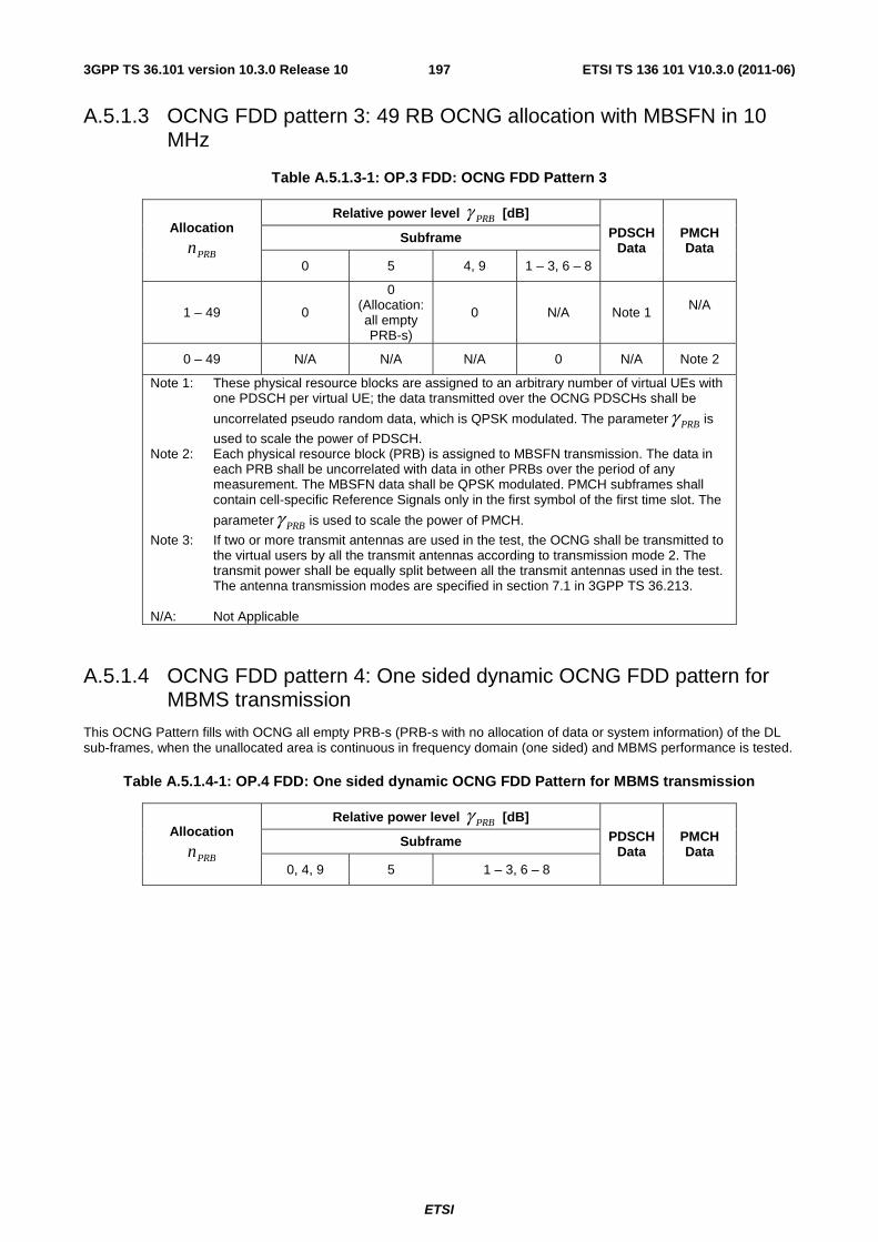
ETSI
ETSI TS 136 101 V10.3.0 (2011-06)1973GPP TS 36.101 version 10.3.0 Release 10
A.5.1.3 OCNG FDD pattern 3: 49 RB OCNG allocation with MBSFN in 10 MHz
Table A.5.1.3-1: OP.3 FDD: OCNG FDD Pattern 3
Allocation
PRBn
Relative power level PRBγ [dB] PDSCH
Data PMCH Data
Subframe
0 5 4, 9 1 – 3, 6 – 8
1 – 49 0
0 (Allocation: all empty PRB-s)
0 N/A Note 1 N/A
0 – 49 N/A N/A N/A 0 N/A Note 2
Note 1: These physical resource blocks are assigned to an arbitrary number of virtual UEs with one PDSCH per virtual UE; the data transmitted over the OCNG PDSCHs shall be
uncorrelated pseudo random data, which is QPSK modulated. The parameter PRBγ is
used to scale the power of PDSCH. Note 2: Each physical resource block (PRB) is assigned to MBSFN transmission. The data in
each PRB shall be uncorrelated with data in other PRBs over the period of any measurement. The MBSFN data shall be QPSK modulated. PMCH subframes shall contain cell-specific Reference Signals only in the first symbol of the first time slot. The
parameter PRBγ is used to scale the power of PMCH.
Note 3: If two or more transmit antennas are used in the test, the OCNG shall be transmitted to the virtual users by all the transmit antennas according to transmission mode 2. The transmit power shall be equally split between all the transmit antennas used in the test. The antenna transmission modes are specified in section 7.1 in 3GPP TS 36.213.
N/A: Not Applicable
A.5.1.4 OCNG FDD pattern 4: One sided dynamic OCNG FDD pattern for MBMS transmission
This OCNG Pattern fills with OCNG all empty PRB-s (PRB-s with no allocation of data or system information) of the DL sub-frames, when the unallocated area is continuous in frequency domain (one sided) and MBMS performance is tested.
Table A.5.1.4-1: OP.4 FDD: One sided dynamic OCNG FDD Pattern for MBMS transmission
Allocation
PRBn
Relative power level PRBγ [dB] PDSCH
Data PMCH Data
Subframe
0, 4, 9 5 1 – 3, 6 – 8
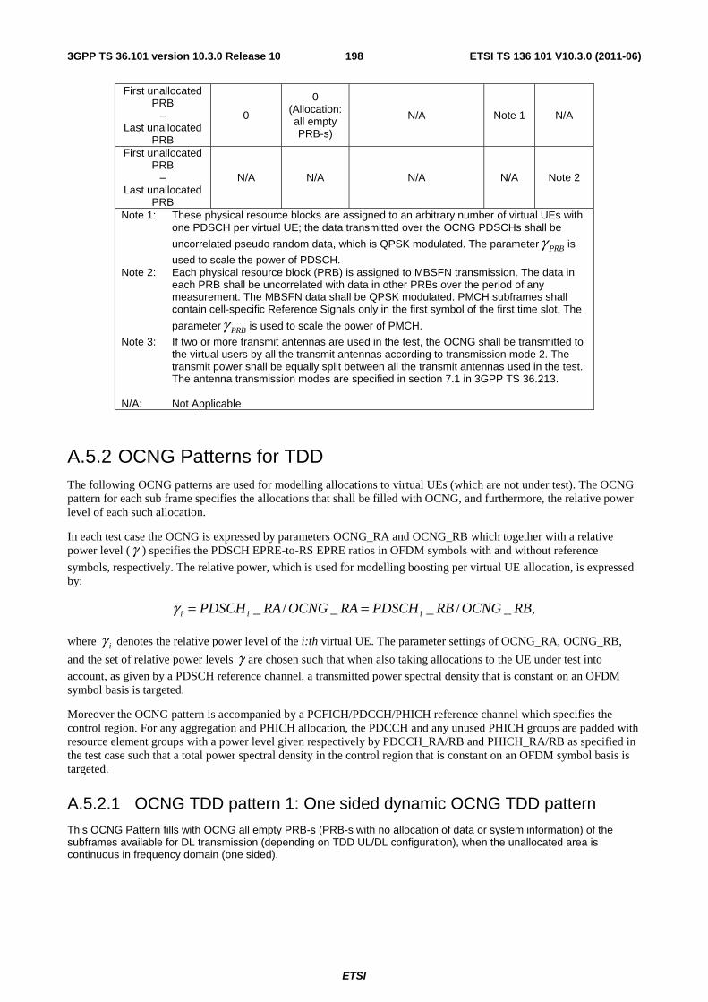
ETSI
ETSI TS 136 101 V10.3.0 (2011-06)1983GPP TS 36.101 version 10.3.0 Release 10
First unallocated PRB
– Last unallocated
PRB
0
0 (Allocation: all empty PRB-s)
N/A Note 1 N/A
First unallocated PRB
– Last unallocated
PRB
N/A N/A N/A N/A Note 2
Note 1: These physical resource blocks are assigned to an arbitrary number of virtual UEs with one PDSCH per virtual UE; the data transmitted over the OCNG PDSCHs shall be
uncorrelated pseudo random data, which is QPSK modulated. The parameter PRBγ is
used to scale the power of PDSCH. Note 2: Each physical resource block (PRB) is assigned to MBSFN transmission. The data in
each PRB shall be uncorrelated with data in other PRBs over the period of any measurement. The MBSFN data shall be QPSK modulated. PMCH subframes shall contain cell-specific Reference Signals only in the first symbol of the first time slot. The
parameter PRBγ is used to scale the power of PMCH.
Note 3: If two or more transmit antennas are used in the test, the OCNG shall be transmitted to the virtual users by all the transmit antennas according to transmission mode 2. The transmit power shall be equally split between all the transmit antennas used in the test. The antenna transmission modes are specified in section 7.1 in 3GPP TS 36.213.
N/A: Not Applicable
A.5.2 OCNG Patterns for TDD The following OCNG patterns are used for modelling allocations to virtual UEs (which are not under test). The OCNG pattern for each sub frame specifies the allocations that shall be filled with OCNG, and furthermore, the relative power level of each such allocation.
In each test case the OCNG is expressed by parameters OCNG_RA and OCNG_RB which together with a relative power level (γ ) specifies the PDSCH EPRE-to-RS EPRE ratios in OFDM symbols with and without reference
symbols, respectively. The relative power, which is used for modelling boosting per virtual UE allocation, is expressed by:
,_/__/_ RBOCNGRBPDSCHRAOCNGRAPDSCH iii ==γ
where iγ denotes the relative power level of the i:th virtual UE. The parameter settings of OCNG_RA, OCNG_RB,
and the set of relative power levels γ are chosen such that when also taking allocations to the UE under test into
account, as given by a PDSCH reference channel, a transmitted power spectral density that is constant on an OFDM symbol basis is targeted.
Moreover the OCNG pattern is accompanied by a PCFICH/PDCCH/PHICH reference channel which specifies the control region. For any aggregation and PHICH allocation, the PDCCH and any unused PHICH groups are padded with resource element groups with a power level given respectively by PDCCH_RA/RB and PHICH_RA/RB as specified in the test case such that a total power spectral density in the control region that is constant on an OFDM symbol basis is targeted.
A.5.2.1 OCNG TDD pattern 1: One sided dynamic OCNG TDD pattern
This OCNG Pattern fills with OCNG all empty PRB-s (PRB-s with no allocation of data or system information) of the subframes available for DL transmission (depending on TDD UL/DL configuration), when the unallocated area is continuous in frequency domain (one sided).
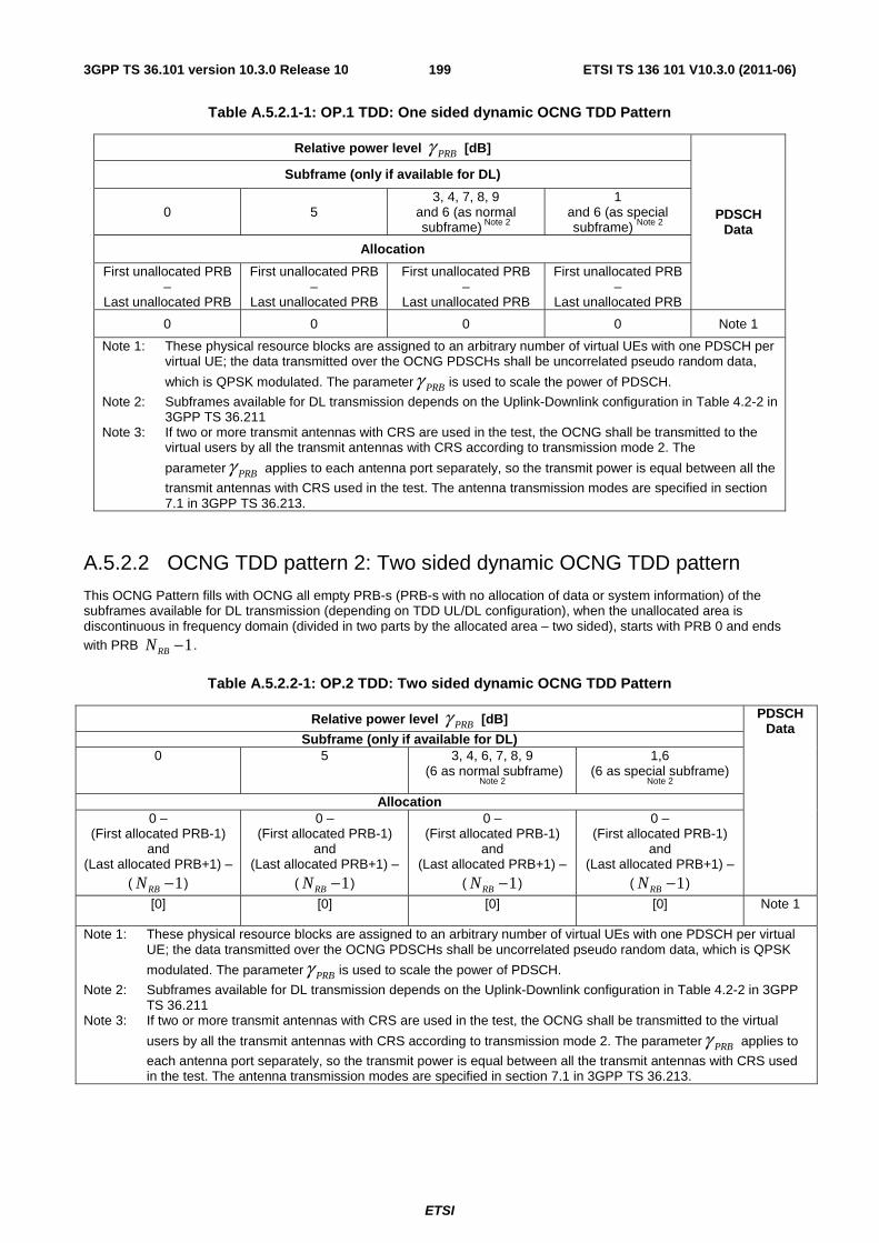
ETSI
ETSI TS 136 101 V10.3.0 (2011-06)1993GPP TS 36.101 version 10.3.0 Release 10
Table A.5.2.1-1: OP.1 TDD: One sided dynamic OCNG TDD Pattern
Relative power level PRBγ [dB]
PDSCH Data
Subframe (only if available for DL)
0 5 3, 4, 7, 8, 9
and 6 (as normal subframe) Note 2
1 and 6 (as special subframe) Note 2
Allocation
First unallocated PRB –
Last unallocated PRB
First unallocated PRB –
Last unallocated PRB
First unallocated PRB –
Last unallocated PRB
First unallocated PRB –
Last unallocated PRB
0 0 0 0 Note 1
Note 1: These physical resource blocks are assigned to an arbitrary number of virtual UEs with one PDSCH per virtual UE; the data transmitted over the OCNG PDSCHs shall be uncorrelated pseudo random data,
which is QPSK modulated. The parameter PRBγ is used to scale the power of PDSCH.
Note 2: Subframes available for DL transmission depends on the Uplink-Downlink configuration in Table 4.2-2 in 3GPP TS 36.211
Note 3: If two or more transmit antennas with CRS are used in the test, the OCNG shall be transmitted to the virtual users by all the transmit antennas with CRS according to transmission mode 2. The
parameter PRBγ applies to each antenna port separately, so the transmit power is equal between all the
transmit antennas with CRS used in the test. The antenna transmission modes are specified in section 7.1 in 3GPP TS 36.213.
A.5.2.2 OCNG TDD pattern 2: Two sided dynamic OCNG TDD pattern
This OCNG Pattern fills with OCNG all empty PRB-s (PRB-s with no allocation of data or system information) of the subframes available for DL transmission (depending on TDD UL/DL configuration), when the unallocated area is discontinuous in frequency domain (divided in two parts by the allocated area – two sided), starts with PRB 0 and ends with PRB 1RBN − .
Table A.5.2.2-1: OP.2 TDD: Two sided dynamic OCNG TDD Pattern
Relative power level PRBγ [dB] PDSCH Data
Subframe (only if available for DL) 0 5 3, 4, 6, 7, 8, 9
(6 as normal subframe)
Note 2
1,6 (6 as special subframe)
Note 2 Allocation
0 – (First allocated PRB-1)
and (Last allocated PRB+1) –
( 1RBN − )
0 – (First allocated PRB-1)
and (Last allocated PRB+1) –
( 1RBN − )
0 – (First allocated PRB-1)
and (Last allocated PRB+1) –
( 1RBN − )
0 – (First allocated PRB-1)
and (Last allocated PRB+1) –
( 1RBN − )
[0] [0] [0] [0] Note 1
Note 1: These physical resource blocks are assigned to an arbitrary number of virtual UEs with one PDSCH per virtual UE; the data transmitted over the OCNG PDSCHs shall be uncorrelated pseudo random data, which is QPSK
modulated. The parameter PRBγ is used to scale the power of PDSCH.
Note 2: Subframes available for DL transmission depends on the Uplink-Downlink configuration in Table 4.2-2 in 3GPP TS 36.211
Note 3: If two or more transmit antennas with CRS are used in the test, the OCNG shall be transmitted to the virtual
users by all the transmit antennas with CRS according to transmission mode 2. The parameter PRBγ applies to
each antenna port separately, so the transmit power is equal between all the transmit antennas with CRS used in the test. The antenna transmission modes are specified in section 7.1 in 3GPP TS 36.213.
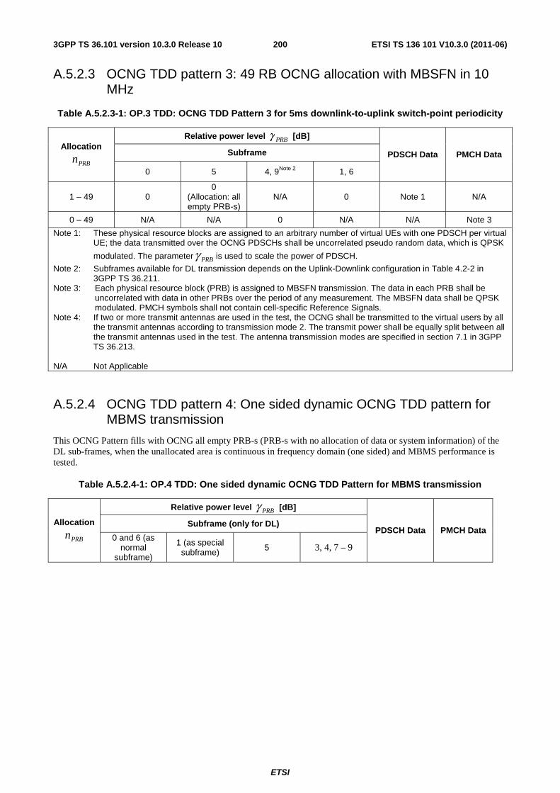
ETSI
ETSI TS 136 101 V10.3.0 (2011-06)2003GPP TS 36.101 version 10.3.0 Release 10
A.5.2.3 OCNG TDD pattern 3: 49 RB OCNG allocation with MBSFN in 10 MHz
Table A.5.2.3-1: OP.3 TDD: OCNG TDD Pattern 3 for 5ms downlink-to-uplink switch-point periodicity
Allocation
PRBn
Relative power level PRBγ [dB]
PDSCH Data PMCH Data Subframe
0 5 4, 9Note 2 1, 6
1 – 49 0 0
(Allocation: all empty PRB-s)
N/A 0 Note 1 N/A
0 – 49 N/A N/A 0 N/A N/A Note 3
Note 1: These physical resource blocks are assigned to an arbitrary number of virtual UEs with one PDSCH per virtual UE; the data transmitted over the OCNG PDSCHs shall be uncorrelated pseudo random data, which is QPSK
modulated. The parameter PRBγ is used to scale the power of PDSCH.
Note 2: Subframes available for DL transmission depends on the Uplink-Downlink configuration in Table 4.2-2 in 3GPP TS 36.211.
Note 3: Each physical resource block (PRB) is assigned to MBSFN transmission. The data in each PRB shall be uncorrelated with data in other PRBs over the period of any measurement. The MBSFN data shall be QPSK modulated. PMCH symbols shall not contain cell-specific Reference Signals.
Note 4: If two or more transmit antennas are used in the test, the OCNG shall be transmitted to the virtual users by all the transmit antennas according to transmission mode 2. The transmit power shall be equally split between all the transmit antennas used in the test. The antenna transmission modes are specified in section 7.1 in 3GPP TS 36.213.
N/A Not Applicable
A.5.2.4 OCNG TDD pattern 4: One sided dynamic OCNG TDD pattern for MBMS transmission
This OCNG Pattern fills with OCNG all empty PRB-s (PRB-s with no allocation of data or system information) of the DL sub-frames, when the unallocated area is continuous in frequency domain (one sided) and MBMS performance is tested.
Table A.5.2.4-1: OP.4 TDD: One sided dynamic OCNG TDD Pattern for MBMS transmission
Allocation
PRBn
Relative power level PRBγ [dB]
PDSCH Data PMCH Data Subframe (only for DL)
0 and 6 (as normal
subframe)
1 (as special subframe) 5 3, 4, 7 – 9
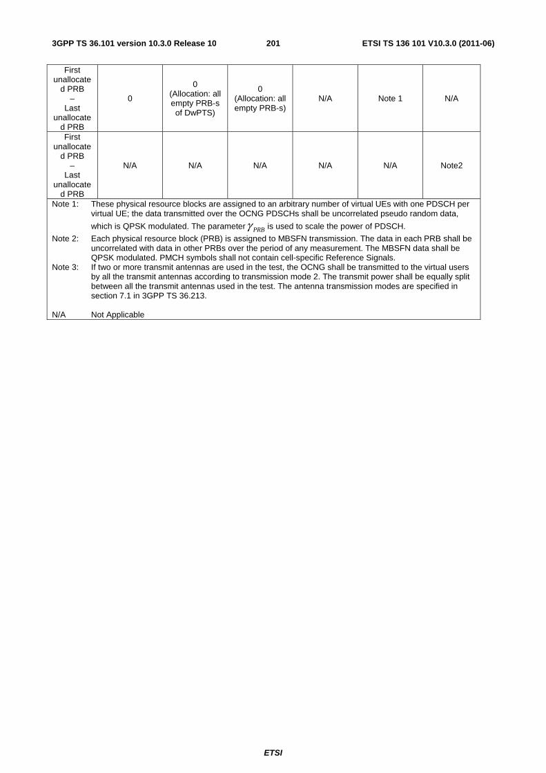
ETSI
ETSI TS 136 101 V10.3.0 (2011-06)2013GPP TS 36.101 version 10.3.0 Release 10
First unallocate
d PRB –
Last unallocate
d PRB
0
0 (Allocation: all empty PRB-s of DwPTS)
0 (Allocation: all empty PRB-s)
N/A Note 1 N/A
First unallocate
d PRB –
Last unallocate
d PRB
N/A N/A N/A N/A N/A Note2
Note 1: These physical resource blocks are assigned to an arbitrary number of virtual UEs with one PDSCH per virtual UE; the data transmitted over the OCNG PDSCHs shall be uncorrelated pseudo random data,
which is QPSK modulated. The parameter PRBγ is used to scale the power of PDSCH.
Note 2: Each physical resource block (PRB) is assigned to MBSFN transmission. The data in each PRB shall be uncorrelated with data in other PRBs over the period of any measurement. The MBSFN data shall be QPSK modulated. PMCH symbols shall not contain cell-specific Reference Signals.
Note 3: If two or more transmit antennas are used in the test, the OCNG shall be transmitted to the virtual users by all the transmit antennas according to transmission mode 2. The transmit power shall be equally split between all the transmit antennas used in the test. The antenna transmission modes are specified in section 7.1 in 3GPP TS 36.213.
N/A Not Applicable
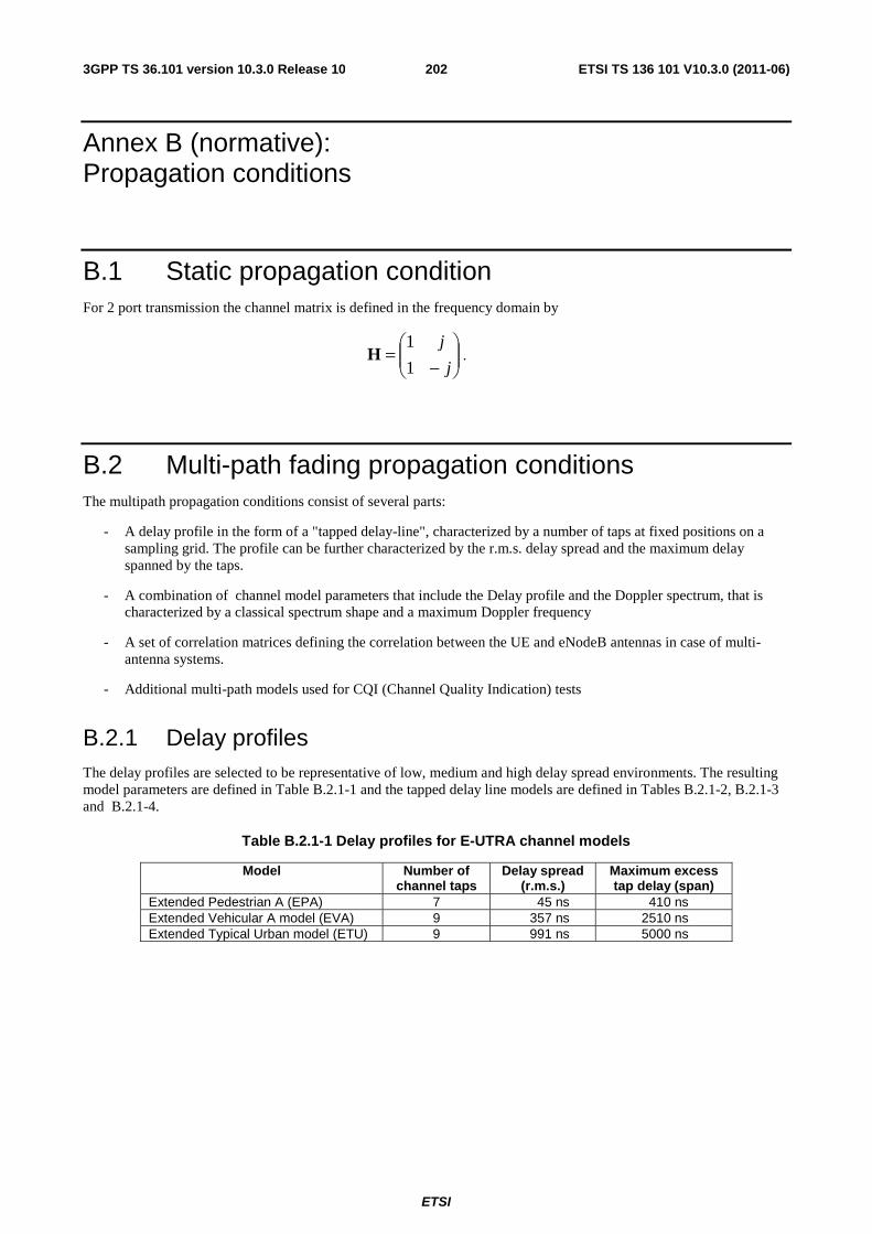
ETSI
ETSI TS 136 101 V10.3.0 (2011-06)2023GPP TS 36.101 version 10.3.0 Release 10
Annex B (normative): Propagation conditions
B.1 Static propagation condition For 2 port transmission the channel matrix is defined in the frequency domain by
⎟⎟⎠
⎞⎜⎜⎝
⎛
−=
j
j
1
1H .
B.2 Multi-path fading propagation conditions The multipath propagation conditions consist of several parts:
- A delay profile in the form of a "tapped delay-line", characterized by a number of taps at fixed positions on a sampling grid. The profile can be further characterized by the r.m.s. delay spread and the maximum delay spanned by the taps.
- A combination of channel model parameters that include the Delay profile and the Doppler spectrum, that is characterized by a classical spectrum shape and a maximum Doppler frequency
- A set of correlation matrices defining the correlation between the UE and eNodeB antennas in case of multi-antenna systems.
- Additional multi-path models used for CQI (Channel Quality Indication) tests
B.2.1 Delay profiles The delay profiles are selected to be representative of low, medium and high delay spread environments. The resulting model parameters are defined in Table B.2.1-1 and the tapped delay line models are defined in Tables B.2.1-2, B.2.1-3 and B.2.1-4.
Table B.2.1-1 Delay profiles for E-UTRA channel models
Model Number of channel taps
Delay spread (r.m.s.)
Maximum excess tap delay (span)
Extended Pedestrian A (EPA) 7 45 ns 410 ns Extended Vehicular A model (EVA) 9 357 ns 2510 ns Extended Typical Urban model (ETU) 9 991 ns 5000 ns
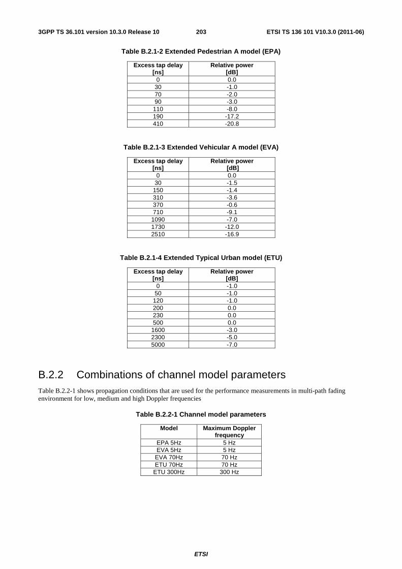
ETSI
ETSI TS 136 101 V10.3.0 (2011-06)2033GPP TS 36.101 version 10.3.0 Release 10
Table B.2.1-2 Extended Pedestrian A model (EPA)
Excess tap delay [ns]
Relative power [dB]
0 0.0 30 -1.0 70 -2.0 90 -3.0
110 -8.0 190 -17.2 410 -20.8
Table B.2.1-3 Extended Vehicular A model (EVA)
Excess tap delay [ns]
Relative power [dB]
0 0.0 30 -1.5
150 -1.4 310 -3.6 370 -0.6 710 -9.1
1090 -7.0 1730 -12.0 2510 -16.9
Table B.2.1-4 Extended Typical Urban model (ETU)
Excess tap delay [ns]
Relative power [dB]
0 -1.0 50 -1.0
120 -1.0 200 0.0 230 0.0 500 0.0
1600 -3.0 2300 -5.0 5000 -7.0
B.2.2 Combinations of channel model parameters Table B.2.2-1 shows propagation conditions that are used for the performance measurements in multi-path fading environment for low, medium and high Doppler frequencies
Table B.2.2-1 Channel model parameters
Model Maximum Doppler frequency
EPA 5Hz 5 Hz EVA 5Hz 5 Hz
EVA 70Hz 70 Hz ETU 70Hz 70 Hz
ETU 300Hz 300 Hz
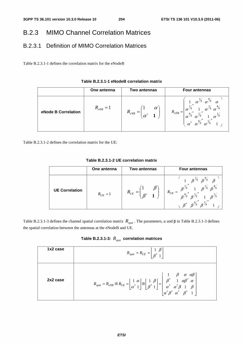
ETSI
ETSI TS 136 101 V10.3.0 (2011-06)2043GPP TS 36.101 version 10.3.0 Release 10
B.2.3 MIMO Channel Correlation Matrices
B.2.3.1 Definition of MIMO Correlation Matrices
Table B.2.3.1-1 defines the correlation matrix for the eNodeB
Table B.2.3.1-1 eNodeB correlation matrix
One antenna Two antennas Four antennas
eNode B Correlation 1=eNBR
⎟⎟⎠
⎞⎜⎜⎝
⎛= ∗ 1
αα1
eNBR
⎟⎟⎟⎟⎟⎟
⎠
⎞
⎜⎜⎜⎜⎜⎜
⎝
⎛
=
1
1
1
1
*9
1*9
4*
91*
91*
94
94
91*
91
94
91
ααα
ααα
ααα
ααα
eNBR
Table B.2.3.1-2 defines the correlation matrix for the UE:
Table B.2.3.1-2 UE correlation matrix
One antenna Two antennas Four antennas
UE Correlation 1=UER ⎟
⎟⎠
⎞⎜⎜⎝
⎛= ∗ 1
ββ1
UER
⎟⎟⎟⎟⎟⎟⎟
⎠
⎞
⎜⎜⎜⎜⎜⎜⎜
⎝
⎛
=
1
1
1
1
*9
1*9
4*
91*
91*
94
94
91*
91
94
91
βββ
βββ
βββ
βββ
UER
Table B.2.3.1-3 defines the channel spatial correlation matrix spatR . The parameters, α and β in Table B.2.3.1-3 defines
the spatial correlation between the antennas at the eNodeB and UE.
Table B.2.3.1-3: spatR correlation matrices
1x2 case ⎥⎦
⎤⎢⎣
⎡==
1
1*β
βUEspat RR
2x2 case
⎥⎥⎥⎥
⎦
⎤
⎢⎢⎢⎢
⎣
⎡
=⎥⎦
⎤⎢⎣
⎡⊗⎥
⎦
⎤⎢⎣
⎡=⊗=
1
1
1
1
1
1
1
1
****
**
**
**
βαβαββααααββ
αβαβ
ββ
αα
UEeNBspat RRR
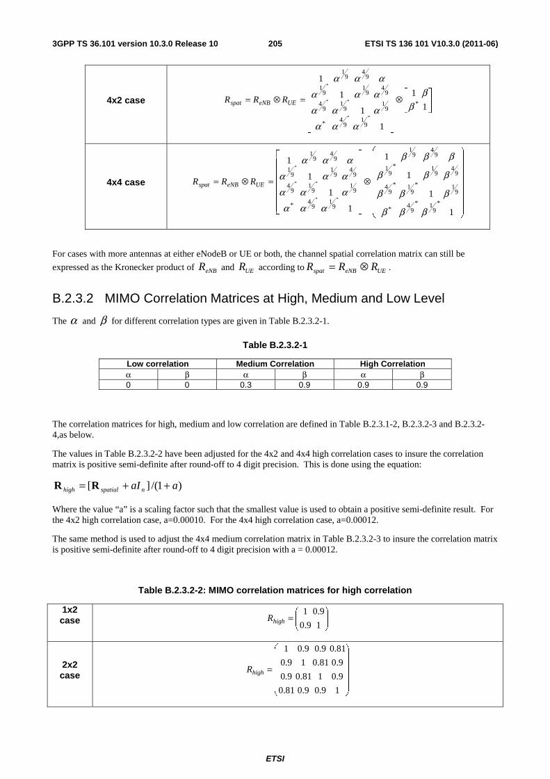
ETSI
ETSI TS 136 101 V10.3.0 (2011-06)2053GPP TS 36.101 version 10.3.0 Release 10
4x2 case ⎥⎦
⎤⎢⎣
⎡⊗
⎥⎥⎥⎥⎥⎥
⎦
⎤
⎢⎢⎢⎢⎢⎢
⎣
⎡
=⊗=1
1
1
1
1
1
*
91
94*
91
91
94
94
91
91
94
91
**
**
*
ββ
αααααα
ααα
ααα
UEeNBspat RRR
4x4 case
⎟⎟⎟⎟⎟⎟⎟
⎠
⎞
⎜⎜⎜⎜⎜⎜⎜
⎝
⎛
⊗
⎥⎥⎥⎥⎥⎥
⎦
⎤
⎢⎢⎢⎢⎢⎢
⎣
⎡
=⊗=
1
1
1
1
1
1
1
1
*9
1*9
4*
91*
91*
94
94
91*
91
94
91
91
94*
91
91
94
94
91
91
94
91
**
**
*
βββ
βββ
βββ
βββ
ααα
ααα
ααα
ααα
UEeNBspat RRR
For cases with more antennas at either eNodeB or UE or both, the channel spatial correlation matrix can still be
expressed as the Kronecker product of eNBR and UER according to UEeNBspat RRR ⊗= .
B.2.3.2 MIMO Correlation Matrices at High, Medium and Low Level
The α and β for different correlation types are given in Table B.2.3.2-1.
Table B.2.3.2-1
Low correlation Medium Correlation High Correlation α β α β α β 0 0 0.3 0.9 0.9 0.9
The correlation matrices for high, medium and low correlation are defined in Table B.2.3.1-2, B.2.3.2-3 and B.2.3.2-4,as below.
The values in Table B.2.3.2-2 have been adjusted for the 4x2 and 4x4 high correlation cases to insure the correlation matrix is positive semi-definite after round-off to 4 digit precision. This is done using the equation:
)1/(][ aaI nspatialhigh ++= RR
Where the value “a” is a scaling factor such that the smallest value is used to obtain a positive semi-definite result. For the 4x2 high correlation case, a=0.00010. For the 4x4 high correlation case, a=0.00012.
The same method is used to adjust the 4x4 medium correlation matrix in Table B.2.3.2-3 to insure the correlation matrix is positive semi-definite after round-off to 4 digit precision with a = 0.00012.
Table B.2.3.2-2: MIMO correlation matrices for high correlation
1x2 case ⎟⎟
⎠
⎞⎜⎜⎝
⎛=
19.0
9.01highR
2x2 case
⎟⎟⎟⎟⎟
⎠
⎞
⎜⎜⎜⎜⎜
⎝
⎛
=
19.09.081.0
9.0181.09.0
9.081.019.0
81.09.09.01
highR
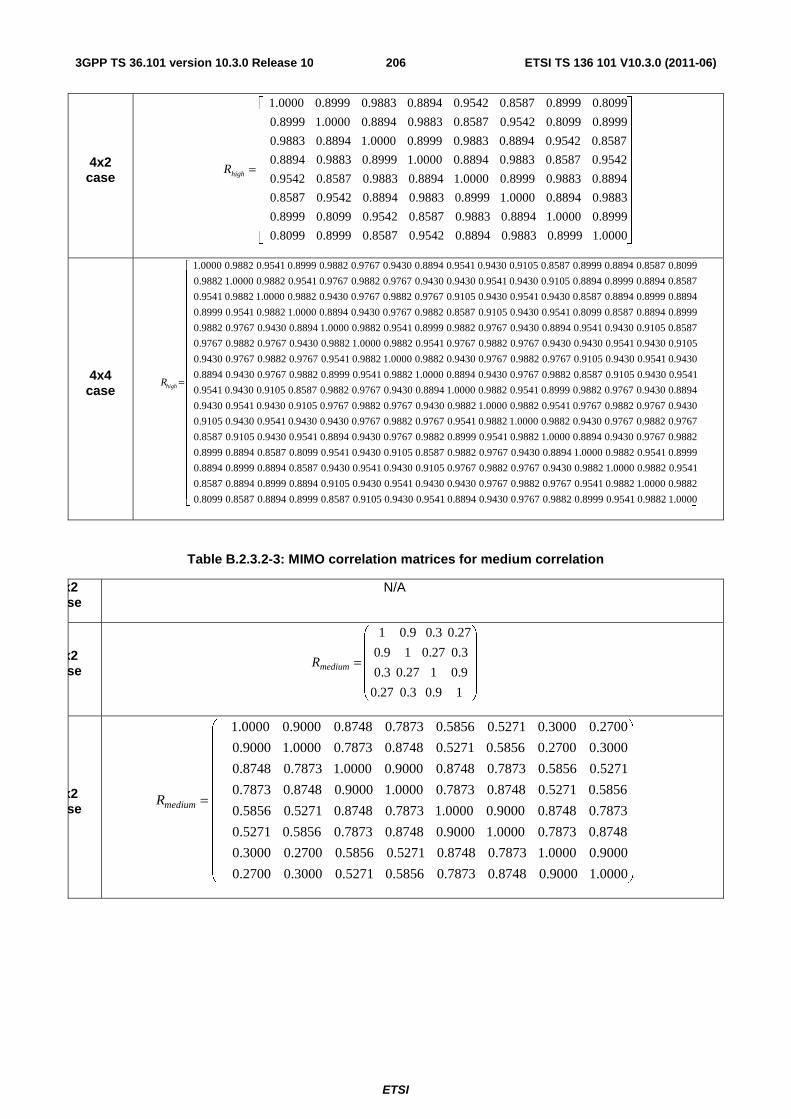
ETSI
ETSI TS 136 101 V10.3.0 (2011-06)2063GPP TS 36.101 version 10.3.0 Release 10
4x2 case
⎥⎥⎥⎥⎥⎥⎥⎥⎥⎥⎥
⎦
⎤
⎢⎢⎢⎢⎢⎢⎢⎢⎢⎢⎢
⎣
⎡
=
1.0000 0.8999 0.9883 0.8894 0.9542 0.8587 0.8999 0.8099
0.8999 1.0000 0.8894 0.9883 0.8587 0.9542 0.8099 0.8999
0.9883 0.8894 1.0000 0.8999 0.9883 0.8894 0.9542 0.8587
0.8894 0.9883 0.8999 1.0000 0.8894 0.9883 0.8587 0.9542
0.9542 0.8587 0.9883 0.8894 1.0000 0.8999 0.9883 0.8894
0.8587 0.9542 0.8894 0.9883 0.8999 1.0000 0.8894 0.9883
0.8999 0.8099 0.9542 0.8587 0.9883 0.8894 1.0000 0.8999
0.8099 0.8999 0.8587 0.9542 0.8894 0.9883 0.8999 1.0000
highR
4x4 case
⎥⎥⎥⎥⎥⎥⎥⎥⎥⎥⎥⎥⎥⎥⎥⎥⎥⎥⎥⎥⎥⎥⎥
⎦
⎤
⎢⎢⎢⎢⎢⎢⎢⎢⎢⎢⎢⎢⎢⎢⎢⎢⎢⎢⎢⎢⎢⎢⎢
⎣
⎡
=
1.0000 0.9882 0.9541 0.8999 0.9882 0.9767 0.9430 0.8894 0.9541 0.9430 0.9105 0.8587 0.8999 0.8894 0.8587 0.8099
0.9882 1.0000 0.9882 0.9541 0.9767 0.9882 0.9767 0.9430 0.9430 0.9541 0.9430 0.9105 0.8894 0.8999 0.8894 0.8587
0.9541 0.9882 1.0000 0.9882 0.9430 0.9767 0.9882 0.9767 0.9105 0.9430 0.9541 0.9430 0.8587 0.8894 0.8999 0.8894
0.8999 0.9541 0.9882 1.0000 0.8894 0.9430 0.9767 0.9882 0.8587 0.9105 0.9430 0.9541 0.8099 0.8587 0.8894 0.8999
0.9882 0.9767 0.9430 0.8894 1.0000 0.9882 0.9541 0.8999 0.9882 0.9767 0.9430 0.8894 0.9541 0.9430 0.9105 0.8587
0.9767 0.9882 0.9767 0.9430 0.9882 1.0000 0.9882 0.9541 0.9767 0.9882 0.9767 0.9430 0.9430 0.9541 0.9430 0.9105
0.9430 0.9767 0.9882 0.9767 0.9541 0.9882 1.0000 0.9882 0.9430 0.9767 0.9882 0.9767 0.9105 0.9430 0.9541 0.9430
0.8894 0.9430 0.9767 0.9882 0.8999 0.9541 0.9882 1.0000 0.8894 0.9430 0.9767 0.9882 0.8587 0.9105 0.9430 0.9541
0.9541 0.9430 0.9105 0.8587 0.9882 0.9767 0.9430 0.8894 1.0000 0.9882 0.9541 0.8999 0.9882 0.9767 0.9430 0.8894
0.9430 0.9541 0.9430 0.9105 0.9767 0.9882 0.9767 0.9430 0.9882 1.0000 0.9882 0.9541 0.9767 0.9882 0.9767 0.9430
0.9105 0.9430 0.9541 0.9430 0.9430 0.9767 0.9882 0.9767 0.9541 0.9882 1.0000 0.9882 0.9430 0.9767 0.9882 0.9767
0.8587 0.9105 0.9430 0.9541 0.8894 0.9430 0.9767 0.9882 0.8999 0.9541 0.9882 1.0000 0.8894 0.9430 0.9767 0.9882
0.8999 0.8894 0.8587 0.8099 0.9541 0.9430 0.9105 0.8587 0.9882 0.9767 0.9430 0.8894 1.0000 0.9882 0.9541 0.8999
0.8894 0.8999 0.8894 0.8587 0.9430 0.9541 0.9430 0.9105 0.9767 0.9882 0.9767 0.9430 0.9882 1.0000 0.9882 0.9541
0.8587 0.8894 0.8999 0.8894 0.9105 0.9430 0.9541 0.9430 0.9430 0.9767 0.9882 0.9767 0.9541 0.9882 1.0000 0.9882
0.8099 0.8587 0.8894 0.8999 0.8587 0.9105 0.9430 0.9541 0.8894 0.9430 0.9767 0.9882 0.8999 0.9541 0.9882 1.0000
highR
Table B.2.3.2-3: MIMO correlation matrices for medium correlation
1x2 ase
N/A
2x2 ase
⎟⎟⎟⎟⎟
⎠
⎞
⎜⎜⎜⎜⎜
⎝
⎛
=
19.03.027.0
9.0127.03.0
3.027.019.0
27.03.09.01
mediumR
4x2 ase
⎟⎟⎟⎟⎟⎟⎟⎟⎟⎟⎟
⎠
⎞
⎜⎜⎜⎜⎜⎜⎜⎜⎜⎜⎜
⎝
⎛
=
1.0000 0.9000 0.8748 0.7873 0.5856 0.5271 0.3000 0.2700
0.9000 1.0000 0.7873 0.8748 0.5271 0.5856 0.2700 0.3000
0.8748 0.7873 1.0000 0.9000 0.8748 0.7873 0.5856 0.5271
0.7873 0.8748 0.9000 1.0000 0.7873 0.8748 0.5271 0.5856
0.5856 0.5271 0.8748 0.7873 1.0000 0.9000 0.8748 0.7873
0.5271 0.5856 0.7873 0.8748 0.9000 1.0000 0.7873 0.8748
0.3000 0.2700 0.5856 0.5271 0.8748 0.7873 1.0000 0.9000
0.2700 0.3000 0.5271 0.5856 0.7873 0.8748 0.9000 1.0000
mediumR
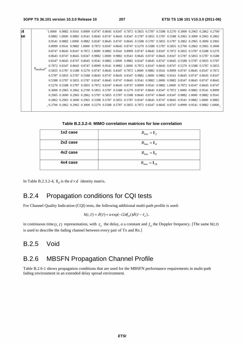
ETSI
ETSI TS 136 101 V10.3.0 (2011-06)2073GPP TS 36.101 version 10.3.0 Release 10
4x4 ase
⎟⎟⎟⎟⎟⎟⎟⎟⎟⎟⎟⎟⎟⎟⎟⎟⎟⎟⎟⎟⎟⎟⎟⎟
⎠
⎞
⎜⎜⎜⎜⎜⎜⎜⎜⎜⎜⎜⎜⎜⎜⎜⎜⎜⎜⎜⎜⎜⎜⎜⎜
⎝
⎛
=
1.0000
0.9882
0.9541
0.8999
0.8747
0.8645
0.8347
0.7872
0.5855
0.5787
0.5588
0.5270
0.3000
0.2965
0.2862
0.2700
0.9882
1.0000
0.9882
0.9541
0.8645
0.8747
0.8645
0.8347
0.5787
0.5855
0.5787
0.5588
0.2965
0.3000
0.2965
0.2862
0.9541
0.9882
1.0000
0.9882
0.8347
0.8645
0.8747
0.8645
0.5588
0.5787
0.5855
0.5787
0.2862
0.2965
0.3000
0.2965
0.8999
0.9541
0.9882
1.0000
0.7872
0.8347
0.8645
0.8747
0.5270
0.5588
0.5787
0.5855
0.2700
0.2862
0.2965
0.3000
0.8747
0.8645
0.8347
0.7872
1.0000
0.9882
0.9541
0.8999
0.8747
0.8645
0.8347
0.7872
0.5855
0.5787
0.5588
0.5270
0.8645
0.8747
0.8645
0.8347
0.9882
1.0000
0.9882
0.9541
0.8645
0.8747
0.8645
0.8347
0.5787
0.5855
0.5787
0.5588
0.8347
0.8645
0.8747
0.8645
0.9541
0.9882
1.0000
0.9882
0.8347
0.8645
0.8747
0.8645
0.5588
0.5787
0.5855
0.5787
0.7872
0.8347
0.8645
0.8747
0.8999
0.9541
0.9882
1.0000
0.7872
0.8347
0.8645
0.8747
0.5270
0.5588
0.5787
0.5855
0.5855
0.5787
0.5588
0.5270
0.8747
0.8645
0.8347
0.7872
1.0000
0.9882
0.9541
0.8999
0.8747
0.8645
0.8347
0.7872
0.5787
0.5855
0.5787
0.5588
0.8645
0.8747
0.8645
0.8347
0.9882
1.0000
0.9882
0.9541
0.8645
0.8747
0.8645
0.8347
0.5588
0.5787
0.5855
0.5787
0.8347
0.8645
0.8747
0.8645
0.9541
0.9882
1.0000
0.9882
0.8347
0.8645
0.8747
0.8645
0.5270
0.5588
0.5787
0.5855
0.7872
0.8347
0.8645
0.8747
0.8999
0.9541
0.9882
1.0000
0.7872
0.8347
0.8645
0.8747
0.3000
0.2965
0.2862
0.2700
0.5855
0.5787
0.5588
0.5270
0.8747
0.8645
0.8347
0.7872
1.0000
0.9882
0.9541
0.8999
0.2965
0.3000
0.2965
0.2862
0.5787
0.5855
0.5787
0.5588
0.8645
0.8747
0.8645
0.8347
0.9882
1.0000
0.9882
0.9541
0.2862
0.2965
0.3000
0.2965
0.5588
0.5787
0.5855
0.5787
0.8347
0.8645
0.8747
0.8645
0.9541
0.9882
1.0000
0.9882
0.2700
0.2862
0.2965
0.3000
0.5270
0.5588
0.5787
0.5855
0.7872
0.8347
0.8645
0.8747
0.8999
0.9541
0.9882
1.0000
mediumR
Table B.2.3.2-4: MIMO correlation matrices for low correlation
1x2 case 2I=lowR
2x2 case 4I=lowR
4x2 case 8I=lowR
4x4 case 16I=lowR
In Table B.2.3.2-4, dI is the dd × identity matrix.
B.2.4 Propagation conditions for CQI tests For Channel Quality Indication (CQI) tests, the following additional multi-path profile is used:
)()2exp()(),( dDtfiath ττδπτδτ −−+= ,
in continuous time ),( τt representation, with dτ the delay, a a constant and
Df the Doppler frequency. [The same h(t,τ)
is used to describe the fading channel between every pair of Tx and Rx.]
B.2.5 Void
B.2.6 MBSFN Propagation Channel Profile Table B.2.6-1 shows propagation conditions that are used for the MBSFN performance requirements in multi-path fading environment in an extended delay spread environment.
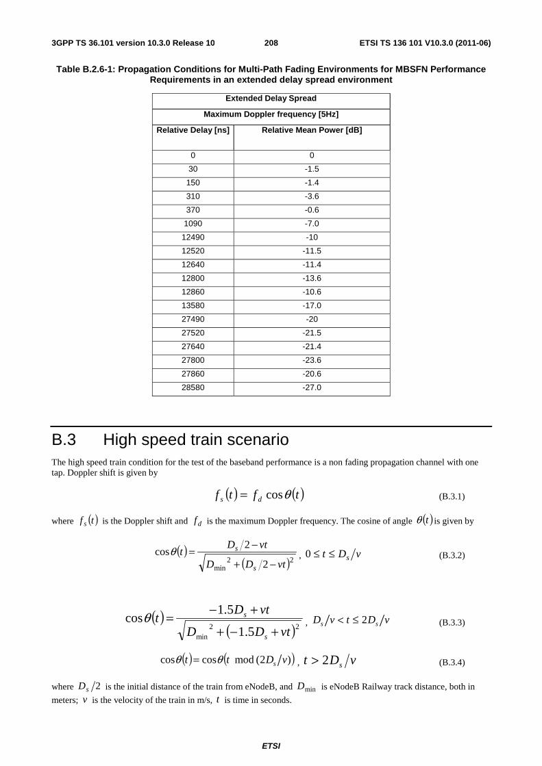
ETSI
ETSI TS 136 101 V10.3.0 (2011-06)2083GPP TS 36.101 version 10.3.0 Release 10
Table B.2.6-1: Propagation Conditions for Multi-Path Fading Environments for MBSFN Performance Requirements in an extended delay spread environment
Extended Delay Spread
Maximum Doppler frequency [5Hz]
Relative Delay [ns] Relative Mean Power [dB]
0 0
30 -1.5
150 -1.4
310 -3.6
370 -0.6
1090 -7.0
12490 -10
12520 -11.5
12640 -11.4
12800 -13.6
12860 -10.6
13580 -17.0
27490 -20
27520 -21.5
27640 -21.4
27800 -23.6
27860 -20.6
28580 -27.0
B.3 High speed train scenario The high speed train condition for the test of the baseband performance is a non fading propagation channel with one tap. Doppler shift is given by
( ) ( )tftf ds θcos= (B.3.1)
where ( )tf s is the Doppler shift and df is the maximum Doppler frequency. The cosine of angle ( )tθ is given by
( )( )22
min 2
2cos
vtDD
vtDt
s
s
−+
−=θ , vDt s≤≤0 (B.3.2)
( )( )22
min 5.1
5.1cos
vtDD
vtDt
s
s
+−+
+−=θ , vDtvD ss 2≤< (B.3.3)
( ) ( ))2( mod coscos vDtt sθθ = , vDt s2> (B.3.4)
where 2sD is the initial distance of the train from eNodeB, and minD is eNodeB Railway track distance, both in
meters; v is the velocity of the train in m/s, t is time in seconds.
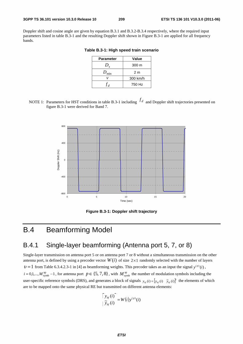
ETSI
ETSI TS 136 101 V10.3.0 (2011-06)2093GPP TS 36.101 version 10.3.0 Release 10
Doppler shift and cosine angle are given by equation B.3.1 and B.3.2-B.3.4 respectively, where the required input parameters listed in table B.3-1 and the resulting Doppler shift shown in Figure B.3-1 are applied for all frequency bands.
Table B.3-1: High speed train scenario
Parameter Value
sD 300 m
minD 2 m
v 300 km/h
df 750 Hz
NOTE 1: Parameters for HST conditions in table B.3-1 including df and Doppler shift trajectories presented on
figure B.3-1 were derived for Band 7.
-800
-400
0
400
800
0 5 10 15 20
Time (sec)
Dop
pler
Shi
ft (H
z)
Figure B.3-1: Doppler shift trajectory
B.4 Beamforming Model
B.4.1 Single-layer beamforming (Antenna port 5, 7, or 8) Single-layer transmission on antenna port 5 or on antenna port 7 or 8 without a simultaneous transmission on the other antenna port, is defined by using a precoder vector )(iW of size 12× randomly selected with the number of layers
1=υ from Table 6.3.4.2.3-1 in [4] as beamforming weights. This precoder takes as an input the signal )()( iy p ,
1,...,1,0 apsymb −= Mi , for antenna port }8 ,7 ,5{∈p , with ap
symbM the number of modulation symbols including the
user-specific reference symbols (DRS), and generates a block of signals [ ]Tbfbfbf iyiyiy )(~)()( = the elements of which
are to be mapped onto the same physical RE but transmitted on different antenna elements:
( ) )()(~)(
)( iyiWiy
iyp
bf
bf =⎥⎦
⎤⎢⎣
⎡
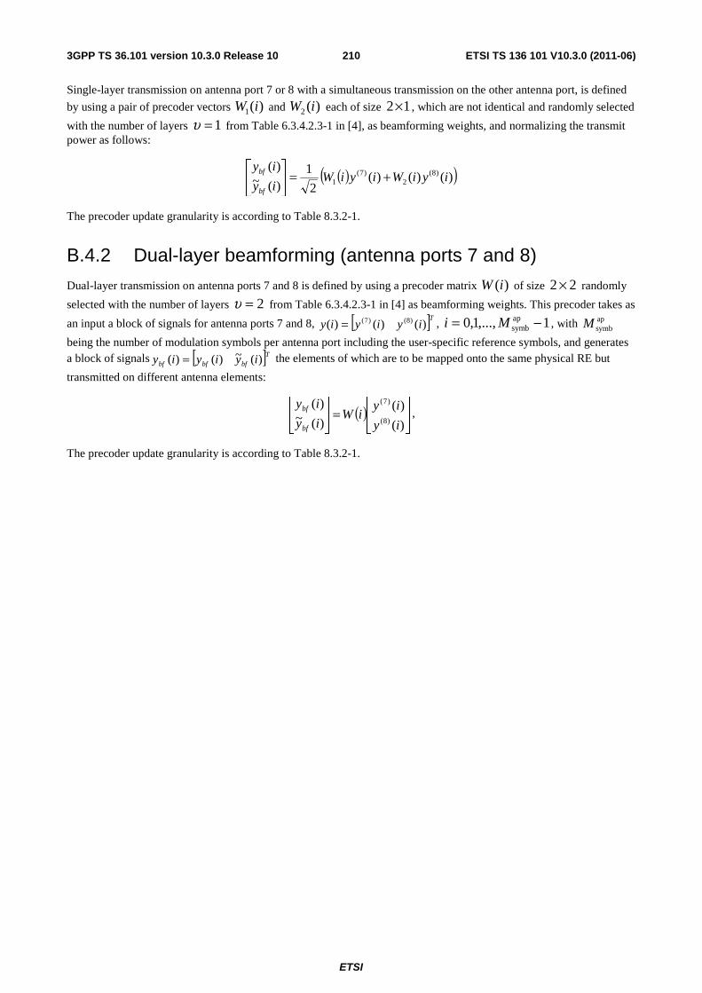
ETSI
ETSI TS 136 101 V10.3.0 (2011-06)2103GPP TS 36.101 version 10.3.0 Release 10
Single-layer transmission on antenna port 7 or 8 with a simultaneous transmission on the other antenna port, is defined
by using a pair of precoder vectors )(1 iW and )(2 iW each of size 12× , which are not identical and randomly selected
with the number of layers 1=υ from Table 6.3.4.2.3-1 in [4], as beamforming weights, and normalizing the transmit power as follows:
( )( ))()()(2
1)(~)(
)8(2
)7(1 iyiWiyiW
iy
iy
bf
bf +=⎥⎦
⎤⎢⎣
⎡
The precoder update granularity is according to Table 8.3.2-1.
B.4.2 Dual-layer beamforming (antenna ports 7 and 8)
Dual-layer transmission on antenna ports 7 and 8 is defined by using a precoder matrix )(iW of size 22 × randomly
selected with the number of layers 2=υ from Table 6.3.4.2.3-1 in [4] as beamforming weights. This precoder takes as
an input a block of signals for antenna ports 7 and 8, [ ]Tiyiyiy )()()( )8()7(= , 1,...,1,0 apsymb −= Mi , with ap
symbM
being the number of modulation symbols per antenna port including the user-specific reference symbols, and generates a block of signals [ ]Tbfbfbf iyiyiy )(~)()( = the elements of which are to be mapped onto the same physical RE but
transmitted on different antenna elements:
( ) ⎥⎦
⎤⎢⎣
⎡=⎥
⎦
⎤⎢⎣
⎡
)(
)()(~)(
)8(
)7(
iy
iyiW
iy
iy
bf
bf ,
The precoder update granularity is according to Table 8.3.2-1.
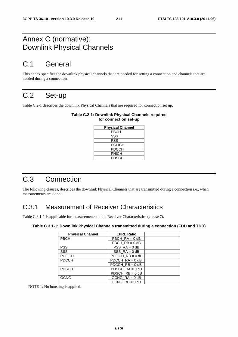
ETSI
ETSI TS 136 101 V10.3.0 (2011-06)2113GPP TS 36.101 version 10.3.0 Release 10
Annex C (normative): Downlink Physical Channels
C.1 General This annex specifies the downlink physical channels that are needed for setting a connection and channels that are needed during a connection.
C.2 Set-up Table C.2-1 describes the downlink Physical Channels that are required for connection set up.
Table C.2-1: Downlink Physical Channels required for connection set-up
Physical Channel PBCH SSS PSS PCFICH PDCCH PHICH PDSCH
C.3 Connection The following clauses, describes the downlink Physical Channels that are transmitted during a connection i.e., when measurements are done.
C.3.1 Measurement of Receiver Characteristics Table C.3.1-1 is applicable for measurements on the Receiver Characteristics (clause 7).
Table C.3.1-1: Downlink Physical Channels transmitted during a connection (FDD and TDD)
Physical Channel EPRE Ratio PBCH PBCH_RA = 0 dB
PBCH_RB = 0 dB PSS PSS_RA = 0 dB SSS SSS_RA = 0 dB PCFICH PCFICH_RB = 0 dB PDCCH PDCCH_RA = 0 dB
PDCCH_RB = 0 dB PDSCH PDSCH_RA = 0 dB
PDSCH_RB = 0 dB OCNG OCNG_RA = 0 dB
OCNG_RB = 0 dB NOTE 1: No boosting is applied.
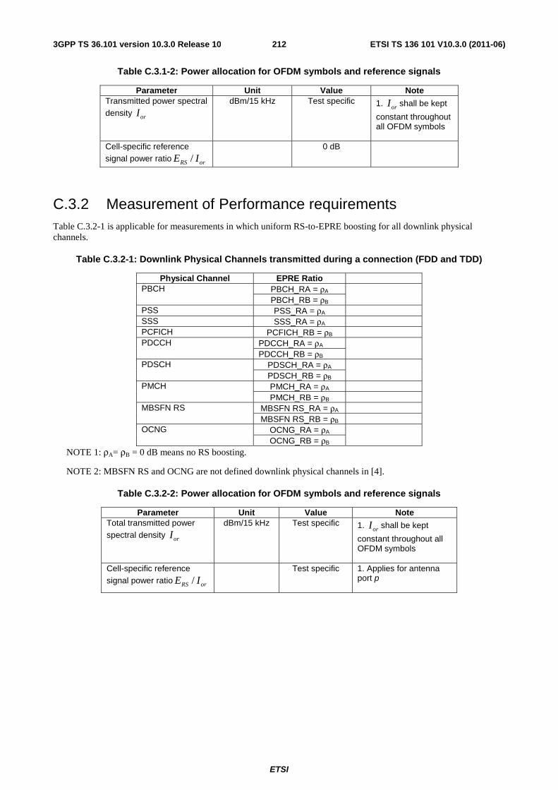
ETSI
ETSI TS 136 101 V10.3.0 (2011-06)2123GPP TS 36.101 version 10.3.0 Release 10
Table C.3.1-2: Power allocation for OFDM symbols and reference signals
Parameter Unit Value Note Transmitted power spectral density orI
dBm/15 kHz Test specific 1. orI shall be kept
constant throughout all OFDM symbols
Cell-specific reference signal power ratio orRS IE /
0 dB
C.3.2 Measurement of Performance requirements Table C.3.2-1 is applicable for measurements in which uniform RS-to-EPRE boosting for all downlink physical channels.
Table C.3.2-1: Downlink Physical Channels transmitted during a connection (FDD and TDD)
Physical Channel EPRE Ratio PBCH PBCH_RA = ρA
PBCH_RB = ρB PSS PSS_RA = ρA SSS SSS_RA = ρA PCFICH PCFICH_RB = ρB PDCCH PDCCH_RA = ρA
PDCCH_RB = ρB PDSCH PDSCH_RA = ρA
PDSCH_RB = ρB PMCH PMCH_RA = ρA
PMCH_RB = ρB MBSFN RS MBSFN RS_RA = ρA
MBSFN RS_RB = ρB OCNG OCNG_RA = ρA
OCNG_RB = ρB NOTE 1: ρA= ρB = 0 dB means no RS boosting.
NOTE 2: MBSFN RS and OCNG are not defined downlink physical channels in [4].
Table C.3.2-2: Power allocation for OFDM symbols and reference signals
Parameter Unit Value Note Total transmitted power spectral density orI
dBm/15 kHz Test specific 1. orI shall be kept
constant throughout all OFDM symbols
Cell-specific reference signal power ratio orRS IE /
Test specific 1. Applies for antenna port p
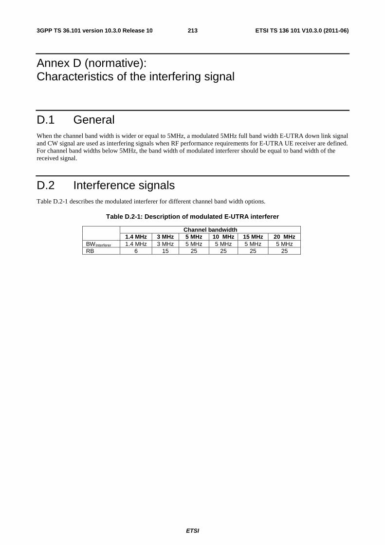
ETSI
ETSI TS 136 101 V10.3.0 (2011-06)2133GPP TS 36.101 version 10.3.0 Release 10
Annex D (normative): Characteristics of the interfering signal
D.1 General When the channel band width is wider or equal to 5MHz, a modulated 5MHz full band width E-UTRA down link signal and CW signal are used as interfering signals when RF performance requirements for E-UTRA UE receiver are defined. For channel band widths below 5MHz, the band width of modulated interferer should be equal to band width of the received signal.
D.2 Interference signals Table D.2-1 describes the modulated interferer for different channel band width options.
Table D.2-1: Description of modulated E-UTRA interferer
Channel bandwidth 1.4 MHz 3 MHz 5 MHz 10 MHz 15 MHz 20 MHz
BWInterferer 1.4 MHz 3 MHz 5 MHz 5 MHz 5 MHz 5 MHz RB 6 15 25 25 25 25
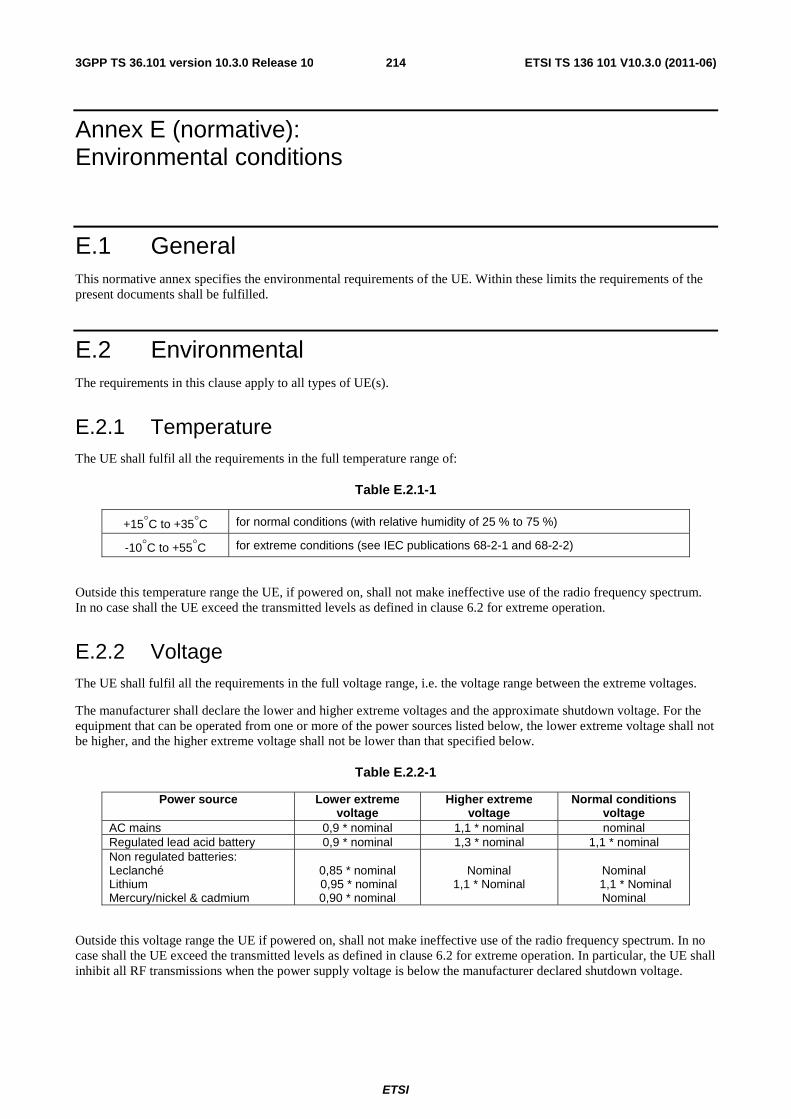
ETSI
ETSI TS 136 101 V10.3.0 (2011-06)2143GPP TS 36.101 version 10.3.0 Release 10
Annex E (normative): Environmental conditions
E.1 General This normative annex specifies the environmental requirements of the UE. Within these limits the requirements of the present documents shall be fulfilled.
E.2 Environmental The requirements in this clause apply to all types of UE(s).
E.2.1 Temperature The UE shall fulfil all the requirements in the full temperature range of:
Table E.2.1-1
+15°C to +35°C for normal conditions (with relative humidity of 25 % to 75 %)
-10°C to +55°C for extreme conditions (see IEC publications 68-2-1 and 68-2-2)
Outside this temperature range the UE, if powered on, shall not make ineffective use of the radio frequency spectrum. In no case shall the UE exceed the transmitted levels as defined in clause 6.2 for extreme operation.
E.2.2 Voltage The UE shall fulfil all the requirements in the full voltage range, i.e. the voltage range between the extreme voltages.
The manufacturer shall declare the lower and higher extreme voltages and the approximate shutdown voltage. For the equipment that can be operated from one or more of the power sources listed below, the lower extreme voltage shall not be higher, and the higher extreme voltage shall not be lower than that specified below.
Table E.2.2-1
Power source Lower extreme voltage
Higher extreme voltage
Normal conditions voltage
AC mains 0,9 * nominal 1,1 * nominal nominal Regulated lead acid battery 0,9 * nominal 1,3 * nominal 1,1 * nominal Non regulated batteries: Leclanché Lithium Mercury/nickel & cadmium
0,85 * nominal 0,95 * nominal 0,90 * nominal
Nominal
1,1 * Nominal
Nominal 1,1 * Nominal Nominal
Outside this voltage range the UE if powered on, shall not make ineffective use of the radio frequency spectrum. In no case shall the UE exceed the transmitted levels as defined in clause 6.2 for extreme operation. In particular, the UE shall inhibit all RF transmissions when the power supply voltage is below the manufacturer declared shutdown voltage.
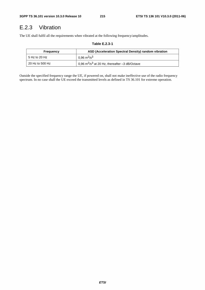
ETSI
ETSI TS 136 101 V10.3.0 (2011-06)2153GPP TS 36.101 version 10.3.0 Release 10
E.2.3 Vibration The UE shall fulfil all the requirements when vibrated at the following frequency/amplitudes.
Table E.2.3-1
Frequency ASD (Acceleration Spectral Density) random vibration
5 Hz to 20 Hz 0,96 m2/s3
20 Hz to 500 Hz 0,96 m2/s3 at 20 Hz, thereafter –3 dB/Octave
Outside the specified frequency range the UE, if powered on, shall not make ineffective use of the radio frequency spectrum. In no case shall the UE exceed the transmitted levels as defined in TS 36.101 for extreme operation.
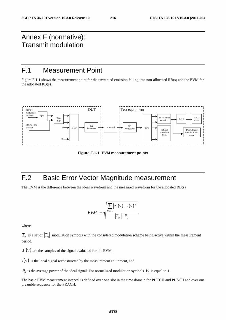
ETSI
ETSI TS 136 101 V10.3.0 (2011-06)2163GPP TS 36.101 version 10.3.0 Release 10
Annex F (normative): Transmit modulation
F.1 Measurement Point Figure F.1-1 shows the measurement point for the unwanted emission falling into non-allocated RB(s) and the EVM for the allocated RB(s).
Figure F.1-1: EVM measurement points
F.2 Basic Error Vector Magnitude measurement The EVM is the difference between the ideal waveform and the measured waveform for the allocated RB(s)
( ) ( )
0
2'
PT
vivz
EVMm
Tv m
⋅
−=
∑∈
,
where
mT is a set of mT modulation symbols with the considered modulation scheme being active within the measurement
period,
( )vz' are the samples of the signal evaluated for the EVM,
( )vi is the ideal signal reconstructed by the measurement equipment, and
0P is the average power of the ideal signal. For normalized modulation symbols 0P is equal to 1.
The basic EVM measurement interval is defined over one slot in the time domain for PUCCH and PUSCH and over one preamble sequence for the PRACH.
DFT
IFFT
TX Front --end
Channel
RF
correction
FFT
Tx-Rx chain equalizer
In-band emissions
meas.
EVM meas.
0
0
IDFT
DUT
Test equipment
PUCCH and DM-RS EVM
meas.
PUCCH and DM-RS
Tone map
PUSCH modulated symbols
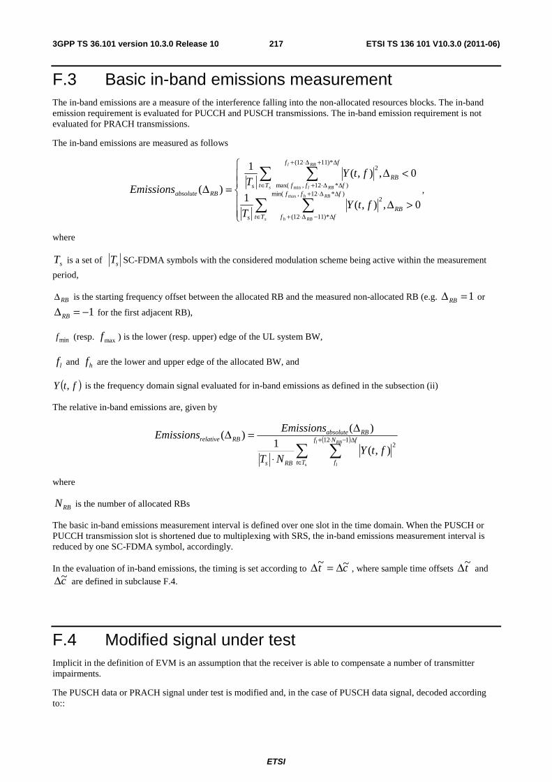
ETSI
ETSI TS 136 101 V10.3.0 (2011-06)2173GPP TS 36.101 version 10.3.0 Release 10
F.3 Basic in-band emissions measurement The in-band emissions are a measure of the interference falling into the non-allocated resources blocks. The in-band emission requirement is evaluated for PUCCH and PUSCH transmissions. The in-band emission requirement is not evaluated for PRACH transmissions.
The in-band emissions are measured as follows
⎪⎪
⎩
⎪⎪
⎨
⎧
>Δ
<Δ=Δ
∑ ∑
∑ ∑
∈
ΔΔ⋅+
Δ−Δ⋅+
∈
Δ+Δ⋅+
ΔΔ⋅+
0,),(1
0,),(1
)( )*12,min(
*)1112(
2
*)1112(
)*12,max(
2
max
min
RBTt
fff
ffs
RBTt
ff
fffsRBabsolute
s
RBh
RBh
s
RBl
RBl
ftYT
ftYT
Emissions ,
where
sT is a set of sT SC-FDMA symbols with the considered modulation scheme being active within the measurement
period,
RBΔ is the starting frequency offset between the allocated RB and the measured non-allocated RB (e.g. 1=ΔRB or
1−=ΔRB for the first adjacent RB),
minf (resp. maxf ) is the lower (resp. upper) edge of the UL system BW,
lf and hf are the lower and upper edge of the allocated BW, and
( )ftY , is the frequency domain signal evaluated for in-band emissions as defined in the subsection (ii)
The relative in-band emissions are, given by
( )
∑ ∑∈
Δ−⋅+
⋅
Δ=Δ
s
RBl
lTt
fNf
fRBs
RBabsoluteRBrelative
ftYNT
EmissionsEmissions 112
2),(
1)(
)(
where
RBN is the number of allocated RBs
The basic in-band emissions measurement interval is defined over one slot in the time domain. When the PUSCH or PUCCH transmission slot is shortened due to multiplexing with SRS, the in-band emissions measurement interval is reduced by one SC-FDMA symbol, accordingly.
In the evaluation of in-band emissions, the timing is set according to ct ~~ Δ=Δ , where sample time offsets t~Δ and
c~Δ are defined in subclause F.4.
F.4 Modified signal under test Implicit in the definition of EVM is an assumption that the receiver is able to compensate a number of transmitter impairments.
The PUSCH data or PRACH signal under test is modified and, in the case of PUSCH data signal, decoded according to::
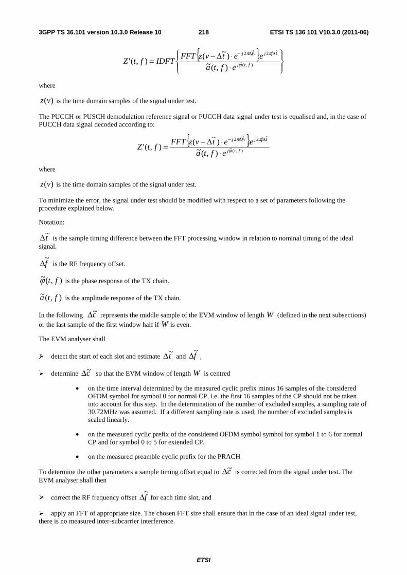
ETSI
ETSI TS 136 101 V10.3.0 (2011-06)2183GPP TS 36.101 version 10.3.0 Release 10
{ }⎪⎭
⎪⎬⎫
⎪⎩
⎪⎨⎧
⋅⋅Δ−=
ΔΔ−
),(~
~2~
2
),(~.)~(
),(' ftj
tfjvfj
efta
eetvzFFTIDFTftZ ϕ
ππ
where
)(vz is the time domain samples of the signal under test.
The PUCCH or PUSCH demodulation reference signal or PUCCH data signal under test is equalised and, in the case of PUCCH data signal decoded according to:
{ }),(~
~2~
2
),(~.)~(
),('ftj
tfjvfj
efta
eetvzFFTftZ ϕ
ππ
⋅⋅Δ−=
ΔΔ−
where
)(vz is the time domain samples of the signal under test.
To minimize the error, the signal under test should be modified with respect to a set of parameters following the procedure explained below.
Notation:
t~Δ is the sample timing difference between the FFT processing window in relation to nominal timing of the ideal signal.
f~Δ is the RF frequency offset.
),(~ ftϕ is the phase response of the TX chain.
),(~ fta is the amplitude response of the TX chain.
In the following c~Δ represents the middle sample of the EVM window of length W (defined in the next subsections)
or the last sample of the first window half if W is even.
The EVM analyser shall
� detect the start of each slot and estimate t~Δ and f~Δ ,
� determine c~Δ so that the EVM window of length W is centred
• on the time interval determined by the measured cyclic prefix minus 16 samples of the considered OFDM symbol for symbol 0 for normal CP, i.e. the first 16 samples of the CP should not be taken into account for this step. In the determination of the number of excluded samples, a sampling rate of 30.72MHz was assumed. If a different sampling rate is used, the number of excluded samples is scaled linearly.
• on the measured cyclic prefix of the considered OFDM symbol symbol for symbol 1 to 6 for normal CP and for symbol 0 to 5 for extended CP.
• on the measured preamble cyclic prefix for the PRACH
To determine the other parameters a sample timing offset equal to c~Δ is corrected from the signal under test. The EVM analyser shall then
� correct the RF frequency offset f~Δ for each time slot, and
� apply an FFT of appropriate size. The chosen FFT size shall ensure that in the case of an ideal signal under test, there is no measured inter-subcarrier interference.
ETSI
ETSI TS 136 101 V10.3.0 (2011-06)2193GPP TS 36.101 version 10.3.0 Release 10
The IQ origin offset shall be removed from the evaluated signal before calculating the EVM and the in-band emissions; however, the removed relative IQ origin offset power (relative carrier leakage power) also has to satisfy the applicable requirement.
At this stage the allocated RBs shall be separated from the non-allocated RBs. In the case of PUCCH and PUSCH EVM, the signal on the non-allocated RB(s), ( )ftY , , is used to evaluate the in-band emissions.
Moreover, the following procedure applies only to the signal on the allocated RB(s).
- In the case of PUCCH and PUSCH, the UL EVM analyzer shall estimate the TX chain equalizer coefficients ),(~ fta and ),(~ ftϕ used by the ZF equalizer for all subcarriers by time averaging at each
signal subcarrier of the amplitude and phase of the reference and data symbols. The time-averaging length is 1 slot. This process creates an average amplitude and phase for each signal subcarrier used by the ZF equalizer. The knowledge of data modulation symbols may be required in this step because the determination of symbols by demodulation is not reliable before signal equalization.
- In the case of PRACH, the UL EVM analyzer shall estimate the TX chain coefficients )(~ ta and )(~ tϕ
used for phase and amplitude correction and are seleted so as to minimize the resulting EVM. The TX chain coefficients are not dependent on frequency, i.e. )(~),(~ tafta = and )(~),(~ tft ϕϕ = . The TX
chain coefficient are chosen independently for each preamble transmission and for each t~Δ .
At this stage estimates of f~Δ , ),(~ fta , ),(~ ftϕ and c~Δ are available. t~Δ is one of the extremities of the window
W , i.e. t~Δ can be ⎥⎦
⎥⎢⎣
⎢−+Δ2
~ Wc α or ⎥⎦
⎥⎢⎣
⎢+Δ2
~ Wc , where 0=α if W is odd and 1=α if W is even. The EVM
analyser shall then
� calculate EVMl with t~Δ set to ⎥⎦
⎥⎢⎣
⎢−+Δ2
~ Wc α ,
� calculate EVMh with t~Δ set to ⎥⎦
⎥⎢⎣
⎢+Δ2
~ Wc .
F.5 Window length
F.5.1 Timing offset As a result of using a cyclic prefix, there is a range of t~Δ , which, at least in the case of perfect Tx signal quality, would give close to minimum error vector magnitude. As a first order approximation, that range should be equal to the length of the cyclic prefix. Any time domain windowing or FIR pulse shaping applied by the transmitter reduces the t~Δ range within which the error vector is close to its minimum.
F.5.2 Window length
The window length W affects the measured EVM, and is expressed as a function of the configured cyclic prefix length. In the case where equalization is present, as with frequency domain EVM computation, the effect of FIR is reduced. This is because the equalization can correct most of the linear distortion introduced by the FIR. However, the time domain windowing effect can’t be removed.
F.5.3 Window length for normal CP
The table below specifies the EVM window length at channel bandwidths 1.4, 3, 5, 10, 15, 20 MHz, for normal CP. The nominal window length for 3 MHz is rounded down one sample to allow the window to be centered on the symbol.
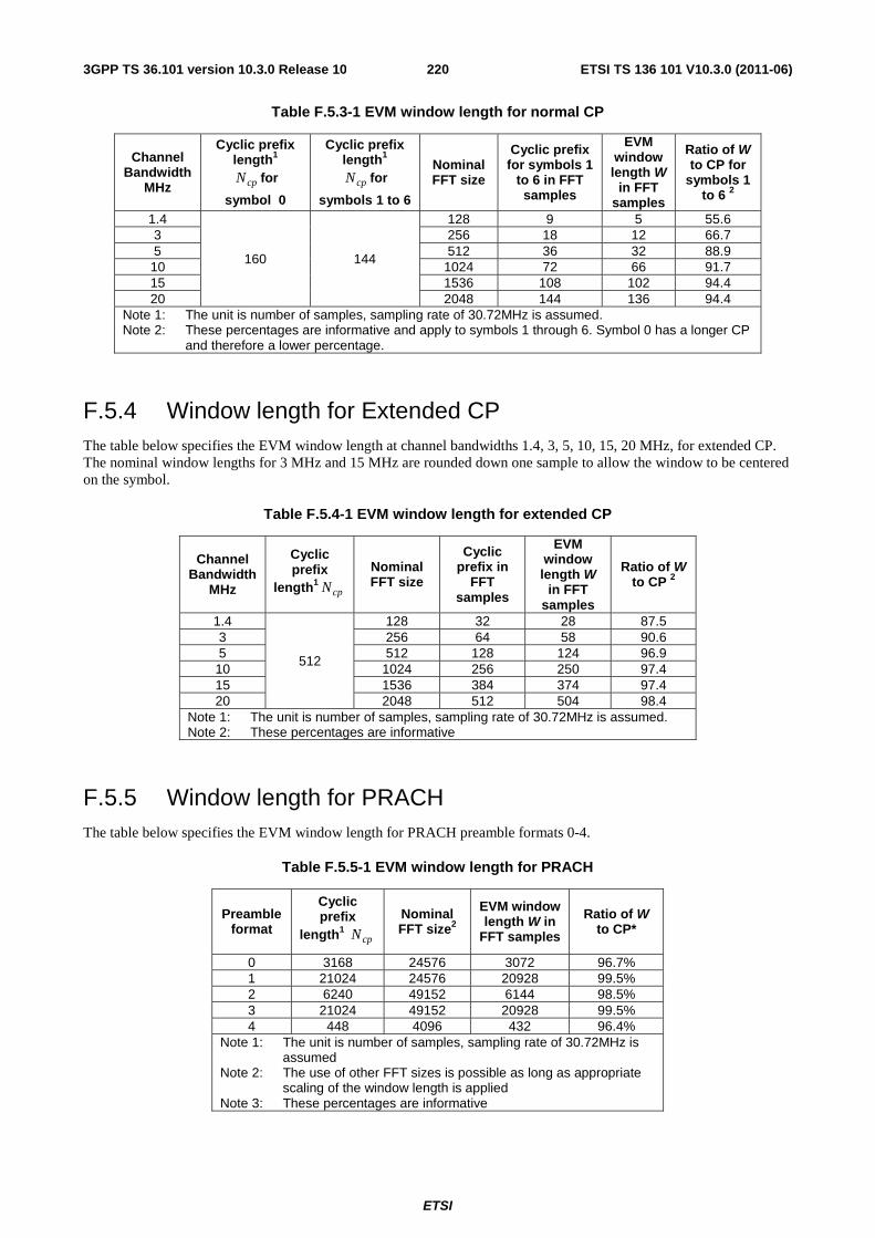
ETSI
ETSI TS 136 101 V10.3.0 (2011-06)2203GPP TS 36.101 version 10.3.0 Release 10
Table F.5.3-1 EVM window length for normal CP
Channel Bandwidth
MHz
Cyclic prefix length1
cpN for
symbol 0
Cyclic prefix length1
cpN for
symbols 1 to 6
Nominal FFT size
Cyclic prefix for symbols 1
to 6 in FFT samples
EVM window length W
in FFT samples
Ratio of W to CP for
symbols 1 to 6 2
1.4
160 144
128 9 5 55.6 3 256 18 12 66.7 5 512 36 32 88.9 10 1024 72 66 91.7 15 1536 108 102 94.4 20 2048 144 136 94.4
Note 1: The unit is number of samples, sampling rate of 30.72MHz is assumed. Note 2: These percentages are informative and apply to symbols 1 through 6. Symbol 0 has a longer CP
and therefore a lower percentage.
F.5.4 Window length for Extended CP The table below specifies the EVM window length at channel bandwidths 1.4, 3, 5, 10, 15, 20 MHz, for extended CP. The nominal window lengths for 3 MHz and 15 MHz are rounded down one sample to allow the window to be centered on the symbol.
Table F.5.4-1 EVM window length for extended CP
Channel Bandwidth
MHz
Cyclic prefix
length1cpN
Nominal FFT size
Cyclic prefix in
FFT samples
EVM window length W
in FFT samples
Ratio of W to CP 2
1.4
512
128 32 28 87.5 3 256 64 58 90.6 5 512 128 124 96.9 10 1024 256 250 97.4 15 1536 384 374 97.4 20 2048 512 504 98.4
Note 1: The unit is number of samples, sampling rate of 30.72MHz is assumed. Note 2: These percentages are informative
F.5.5 Window length for PRACH The table below specifies the EVM window length for PRACH preamble formats 0-4.
Table F.5.5-1 EVM window length for PRACH
Preamble format
Cyclic prefix
length1 cpN
Nominal FFT size2
EVM window length W in
FFT samples
Ratio of W to CP*
0 3168 24576 3072 96.7% 1 21024 24576 20928 99.5% 2 6240 49152 6144 98.5% 3 21024 49152 20928 99.5% 4 448 4096 432 96.4%
Note 1: The unit is number of samples, sampling rate of 30.72MHz is assumed
Note 2: The use of other FFT sizes is possible as long as appropriate scaling of the window length is applied
Note 3: These percentages are informative
ETSI
ETSI TS 136 101 V10.3.0 (2011-06)2213GPP TS 36.101 version 10.3.0 Release 10
F.6 Averaged EVM The general EVM is averaged over basic EVM measurements for 20 slots in the time domain.
∑=
=20
1
2
20
1
iiEVMEVM
The EVM requirements shall be tested against the maximum of the RMS average at the window W extremities of the EVM measurements:
Thus lEVM is calculated using ltt ~~ Δ=Δ in the expressions above and hEVM is calculated using htt ~~ Δ=Δ .
Thus we get:
)EVM ,EVMmax( l hEVM =
The calculation of the EVM for the demodulation reference signal, DMRSEVM , follows the same procedure as
calculating the general EVM, with the exception that the modulation symbol set mT defined in clause F.2 is restricted
to symbols containing uplink demodulation reference signals.
The basic DMRSEVM measurements are first averaged over 20 slots in the time domain to obtain an intermediate
average DMRSEVM .
∑=
=20
1
2,20
1
iiDMRSDMRS EVMEVM
In the determination of each iDMRSEVM , , the timing is set to ltt ~~ Δ=Δ if hl EVMEVM > , and it is set to
htt ~~ Δ=Δ otherwise, where lEVM and hEVM are the general average EVM values calculated in the same 20 slots
over which the intermediate average DMRSEVM is calculated. Note that in some cases, the general average EVM may be calculated only for the purpose of timing selection for the demodulation reference signal EVM.
Then the results are further averaged to get the EVM for the demodulation reference signal, DMRSEVM ,
∑=
=6
1
2,
61
j
jDMRSDMRS EVMEVM
The PRACH EVM, PRACHEVM , is averaged over two preamble sequence measurements for preamble formats 0, 1, 2,
3, and it is averaged over 10 preamble sequence measurements for preamble format 4.
The EVM requirements shall be tested against the maximum of the RMS average at the window W extremities of the EVM measurements:
Thus lPRACH,EVM is calculated using ltt ~~ Δ=Δ and hPRACH,EVM is calculated using htt ~~ Δ=Δ .
Thus we get:
)EVM ,EVMmax( hPRACH,lPRACH,=PRACHEVM
ETSI
ETSI TS 136 101 V10.3.0 (2011-06)2223GPP TS 36.101 version 10.3.0 Release 10
F.7 Spectrum Flatness The data shall be taken from FFT coded data symbols and the demodulation reference symbols of the allocated resource block.
ETSI
ETSI TS 136 101 V10.3.0 (2011-06)2233GPP TS 36.101 version 10.3.0 Release 10
Annex X (informative): Reference sensitivity level in lower SNR This annex contains information on typical receiver sensitivity when HARQ transmission is enabled allowing operation in lower SNR regions (HARQ is disabled in conformance testing), thus representing the configuration normally used in live network operation under noise-limited conditions.
X.1 General The reference sensitivity power level PSENS with HARQ retransmission enabled (operation in lower SNR) is the minimum mean power applied to both the UE antenna ports at which the residual BLER after HARQ shall meet or exceed the requirements for the specified reference measurement channel. The residual BLER after HARQ transmission is defined as follows:
B
ABLERresidual −=1
A : Number of correctly decoded MAC PDUs
B : Number of transmitted MAC PDUs (Retransmitted MAC PDUs are not counted)
X.2 Typical receiver sensitivity performance (QPSK) The residual BLER after HARQ shall be lower than 1% for the reference measurement channels as specified in Annexes X.3 (with one sided dynamic OCNG Pattern OP.1 FDD/TDD for the DL-signal as described in Annex A.5.1.1/A.5.2.1) with parameters specified in Table X.2-1 and Table X.2-2
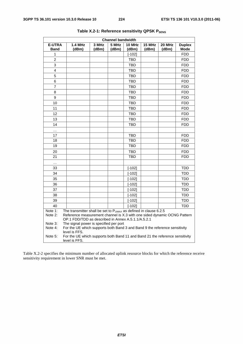
ETSI
ETSI TS 136 101 V10.3.0 (2011-06)2243GPP TS 36.101 version 10.3.0 Release 10
Table X.2-1: Reference sensitivity QPSK PSENS
Channel bandwidth E-UTRA
Band 1.4 MHz (dBm)
3 MHz (dBm)
5 MHz (dBm)
10 MHz (dBm)
15 MHz (dBm)
20 MHz (dBm)
Duplex Mode
1 [-102] FDD
2 TBD FDD
3 TBD FDD
4 TBD FDD
5 TBD FDD
6 TBD FDD
7 TBD FDD
8 TBD FDD
9 TBD FDD
10 TBD FDD
11 TBD FDD
12 TBD FDD
13 TBD FDD
14 TBD FDD
…
17 TBD FDD 18 TBD FDD
19 TBD FDD
20 TBD FDD 21 TBD FDD
…
33 [-102] TDD
34 [-102] TDD
35 [-102] TDD
36 [-102] TDD
37 [-102] TDD
38 [-102] TDD
39 [-102] TDD
40 [-102] TDD Note 1: The transmitter shall be set to PUMAX as defined in clause 6.2.5 Note 2: Reference measurement channel is X.3 with one sided dynamic OCNG Pattern
OP.1 FDD/TDD as described in Annex A.5.1.1/A.5.2.1 Note 3: The signal power is specified per port Note 4: For the UE which supports both Band 3 and Band 9 the reference sensitivity
level is FFS. Note 5: For the UE which supports both Band 11 and Band 21 the reference sensitivity
level is FFS.
Table X.2-2 specifies the minimum number of allocated uplink resource blocks for which the reference receive sensitivity requirement in lower SNR must be met.
ETSI
ETSI TS 136 101 V10.3.0 (2011-06)2253GPP TS 36.101 version 10.3.0 Release 10
Table X.2-2: Minimum uplink configuration for reference sensitivity
E-UTRA Band / Channel bandwidth / NRB / Duplex mode E-UTRA
Band 1.4 MHz 3 MHz 5 MHz 10 MHz 15 MHz 20 MHz Duplex Mode
1 [6]1 FDD
2 [6]1 FDD
3 [6]1 FDD
4 [6]1 FDD
5 [6]1 FDD
6 [6]1 FDD
7 [6]1 FDD
8 [6]1 FDD
9 [6]1 FDD
10 [6]1 FDD
11 [6]1 FDD
12 [6]1 FDD
13 [6]1 FDD
14 [6]1 FDD
...
17 [6]1 FDD 18 [6]1 FDD
19 [6]1 FDD
20 [6]1 FDD 21 [6]1 FDD
…
33 50 TDD
34 50 TDD
35 50 TDD
36 50 TDD
37 50 TDD
38 50 TDD
39 50 TDD
40 50 TDD Note 1. The UL resource blocks shall be located as close as possible to the
downlink operating band but confined within the transmission bandwidth configuration for the channel bandwidth (Table 5.6-1).
2. For the UE which supports both Band 11 and Band 21 the minimum uplink configuration for reference sensitivity is FFS.
4. For Band 20; in the case of 15MHz channel bandwidth, the UL resource blocks shall be located at RBstart _11 and in the case of 20MHz channel bandwidth, the UL resource blocks shall be located at RBstart _16
Unless given by Table X.2-3, the minimum requirements specified in Tables X.2-1 and X.2-2 shall be verified with the network signalling value NS_01 (Table 6.2.4-1) configured.
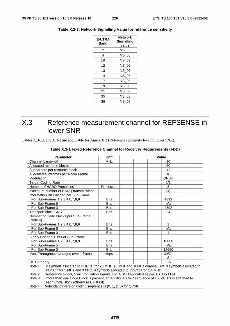
ETSI
ETSI TS 136 101 V10.3.0 (2011-06)2263GPP TS 36.101 version 10.3.0 Release 10
Table X.2-3: Network Signalling Value for reference sensitivity
E-UTRA Band
Network Signalling
value 2 NS_03
4 NS_03
10 NS_03
12 NS_06
13 NS_06
14 NS_06
17 NS_06
19 NS_08
21 NS_09
35 NS_03
36 NS_03
X.3 Reference measurement channel for REFSENSE in lower SNR
Tables X.3-1A and X.3-2 are applicable for Annex X.2 (Reference sensitivity level in lower SNR).
Table X.3-1 Fixed Reference Channel for Receiver Requirements (FDD)
Parameter Unit Value Channel bandwidth MHz 10 Allocated resource blocks 50 Subcarriers per resource block 12 Allocated subframes per Radio Frame 10 Modulation QPSK Target Coding Rate 1/3 Number of HARQ Processes Processes 8 Maximum number of HARQ transmissions [4] Information Bit Payload per Sub-Frame For Sub-Frames 1,2,3,4,6,7,8,9 Bits 4392 For Sub-Frame 5 Bits n/a For Sub-Frame 0 Bits 4392 Transport block CRC Bits 24 Number of Code Blocks per Sub-Frame (Note 4)
For Sub-Frames 1,2,3,4,6,7,8,9 Bits 1 For Sub-Frame 5 Bits n/a For Sub-Frame 0 Bits 1 Binary Channel Bits Per Sub-Frame For Sub-Frames 1,2,3,4,6,7,8,9 Bits 13800 For Sub-Frame 5 Bits n/a For Sub-Frame 0 Bits 12960 Max. Throughput averaged over 1 frame kbps 3952.
8
UE Category 1-5 Note 1: 2 symbols allocated to PDCCH for 20 MHz, 15 MHz and 10MHz channel BW. 3 symbols allocated to
PDCCH for 5 MHz and 3 MHz. 4 symbols allocated to PDCCH for 1.4 MHz Note 2: Reference signal, Synchronization signals and PBCH allocated as per TS 36.211 [4] Note 3: If more than one Code Block is present, an additional CRC sequence of L = 24 Bits is attached to
each Code Block (otherwise L = 0 Bit) Note 4: Redundancy version coding sequence is {0, 1, 2, 3} for QPSK.
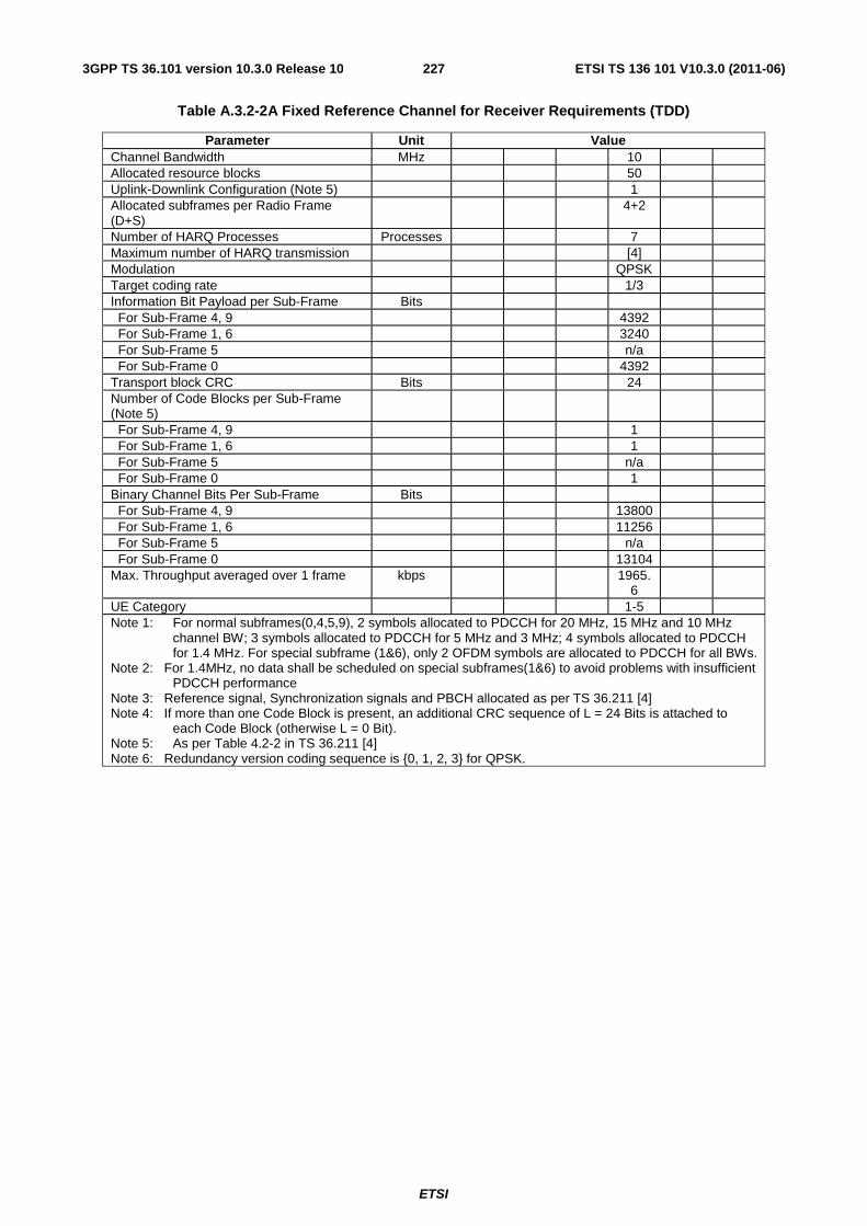
ETSI
ETSI TS 136 101 V10.3.0 (2011-06)2273GPP TS 36.101 version 10.3.0 Release 10
Table A.3.2-2A Fixed Reference Channel for Receiver Requirements (TDD)
Parameter Unit Value Channel Bandwidth MHz 10 Allocated resource blocks 50 Uplink-Downlink Configuration (Note 5) 1 Allocated subframes per Radio Frame (D+S)
4+2
Number of HARQ Processes Processes 7 Maximum number of HARQ transmission [4] Modulation QPSK Target coding rate 1/3 Information Bit Payload per Sub-Frame Bits For Sub-Frame 4, 9 4392 For Sub-Frame 1, 6 3240 For Sub-Frame 5 n/a For Sub-Frame 0 4392 Transport block CRC Bits 24 Number of Code Blocks per Sub-Frame (Note 5)
For Sub-Frame 4, 9 1 For Sub-Frame 1, 6 1 For Sub-Frame 5 n/a For Sub-Frame 0 1 Binary Channel Bits Per Sub-Frame Bits For Sub-Frame 4, 9 13800 For Sub-Frame 1, 6 11256 For Sub-Frame 5 n/a For Sub-Frame 0 13104 Max. Throughput averaged over 1 frame kbps 1965.
6
UE Category 1-5 Note 1: For normal subframes(0,4,5,9), 2 symbols allocated to PDCCH for 20 MHz, 15 MHz and 10 MHz
channel BW; 3 symbols allocated to PDCCH for 5 MHz and 3 MHz; 4 symbols allocated to PDCCH for 1.4 MHz. For special subframe (1&6), only 2 OFDM symbols are allocated to PDCCH for all BWs.
Note 2: For 1.4MHz, no data shall be scheduled on special subframes(1&6) to avoid problems with insufficient PDCCH performance
Note 3: Reference signal, Synchronization signals and PBCH allocated as per TS 36.211 [4] Note 4: If more than one Code Block is present, an additional CRC sequence of L = 24 Bits is attached to
each Code Block (otherwise L = 0 Bit). Note 5: As per Table 4.2-2 in TS 36.211 [4] Note 6: Redundancy version coding sequence is {0, 1, 2, 3} for QPSK.
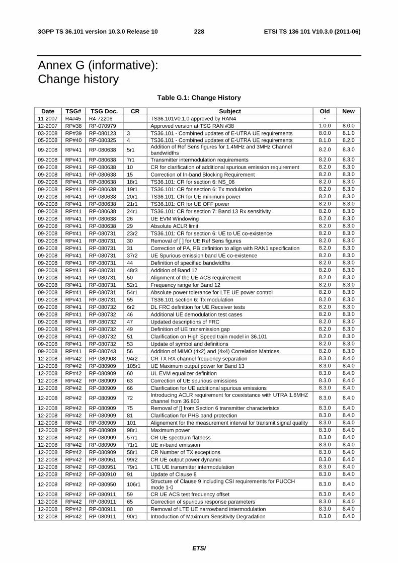
ETSI
ETSI TS 136 101 V10.3.0 (2011-06)2283GPP TS 36.101 version 10.3.0 Release 10
Annex G (informative): Change history
Table G.1: Change History
Date TSG# TSG Doc. CR Subject Old New 11-2007 R4#45 R4-72206 TS36.101V0.1.0 approved by RAN4 - 12-2007 RP#38 RP-070979 Approved version at TSG RAN #38 1.0.0 8.0.0 03-2008 RP#39 RP-080123 3 TS36.101 - Combined updates of E-UTRA UE requirements 8.0.0 8.1.0 05-2008 RP#40 RP-080325 4 TS36.101 - Combined updates of E-UTRA UE requirements 8.1.0 8.2.0
09-2008 RP#41 RP-080638 5r1 Addition of Ref Sens figures for 1.4MHz and 3MHz Channel bandwiidths
8.2.0 8.3.0
09-2008 RP#41 RP-080638 7r1 Transmitter intermodulation requirements 8.2.0 8.3.0 09-2008 RP#41 RP-080638 10 CR for clarification of additional spurious emission requirement 8.2.0 8.3.0
09-2008 RP#41 RP-080638 15 Correction of In-band Blocking Requirement 8.2.0 8.3.0 09-2008 RP#41 RP-080638 18r1 TS36.101: CR for section 6: NS_06 8.2.0 8.3.0 09-2008 RP#41 RP-080638 19r1 TS36.101: CR for section 6: Tx modulation 8.2.0 8.3.0
09-2008 RP#41 RP-080638 20r1 TS36.101: CR for UE minimum power 8.2.0 8.3.0 09-2008 RP#41 RP-080638 21r1 TS36.101: CR for UE OFF power 8.2.0 8.3.0 09-2008 RP#41 RP-080638 24r1 TS36.101: CR for section 7: Band 13 Rx sensitivity 8.2.0 8.3.0 09-2008 RP#41 RP-080638 26 UE EVM Windowing 8.2.0 8.3.0 09-2008 RP#41 RP-080638 29 Absolute ACLR limit 8.2.0 8.3.0 09-2008 RP#41 RP-080731 23r2 TS36.101: CR for section 6: UE to UE co-existence 8.2.0 8.3.0 09-2008 RP#41 RP-080731 30 Removal of [ ] for UE Ref Sens figures 8.2.0 8.3.0
09-2008 RP#41 RP-080731 31 Correction of PA, PB definition to align with RAN1 specification 8.2.0 8.3.0 09-2008 RP#41 RP-080731 37r2 UE Spurious emission band UE co-existence 8.2.0 8.3.0 09-2008 RP#41 RP-080731 44 Definition of specified bandwidths 8.2.0 8.3.0
09-2008 RP#41 RP-080731 48r3 Addition of Band 17 8.2.0 8.3.0 09-2008 RP#41 RP-080731 50 Alignment of the UE ACS requirement 8.2.0 8.3.0 09-2008 RP#41 RP-080731 52r1 Frequency range for Band 12 8.2.0 8.3.0 09-2008 RP#41 RP-080731 54r1 Absolute power tolerance for LTE UE power control 8.2.0 8.3.0 09-2008 RP#41 RP-080731 55 TS36.101 section 6: Tx modulation 8.2.0 8.3.0 09-2008 RP#41 RP-080732 6r2 DL FRC definition for UE Receiver tests 8.2.0 8.3.0 09-2008 RP#41 RP-080732 46 Additional UE demodulation test cases 8.2.0 8.3.0
09-2008 RP#41 RP-080732 47 Updated descriptions of FRC 8.2.0 8.3.0 09-2008 RP#41 RP-080732 49 Definition of UE transmission gap 8.2.0 8.3.0 09-2008 RP#41 RP-080732 51 Clarification on High Speed train model in 36.101 8.2.0 8.3.0
09-2008 RP#41 RP-080732 53 Update of symbol and definitions 8.2.0 8.3.0 09-2008 RP#41 RP-080743 56 Addition of MIMO (4x2) and (4x4) Correlation Matrices 8.2.0 8.3.0 12-2008 RP#42 RP-080908 94r2 CR TX RX channel frequency separation 8.3.0 8.4.0 12-2008 RP#42 RP-080909 105r1 UE Maximum output power for Band 13 8.3.0 8.4.0 12-2008 RP#42 RP-080909 60 UL EVM equalizer definition 8.3.0 8.4.0 12-2008 RP#42 RP-080909 63 Correction of UE spurious emissions 8.3.0 8.4.0 12-2008 RP#42 RP-080909 66 Clarification for UE additional spurious emissions 8.3.0 8.4.0
12-2008 RP#42 RP-080909 72 Introducing ACLR requirement for coexistance with UTRA 1.6MHZ channel from 36.803
8.3.0 8.4.0
12-2008 RP#42 RP-080909 75 Removal of [] from Section 6 transmitter characteristcs 8.3.0 8.4.0 12-2008 RP#42 RP-080909 81 Clarification for PHS band protection 8.3.0 8.4.0 12-2008 RP#42 RP-080909 101 Alignement for the measurement interval for transmit signal quality 8.3.0 8.4.0 12-2008 RP#42 RP-080909 98r1 Maximum power 8.3.0 8.4.0 12-2008 RP#42 RP-080909 57r1 CR UE spectrum flatness 8.3.0 8.4.0 12-2008 RP#42 RP-080909 71r1 UE in-band emission 8.3.0 8.4.0 12-2008 RP#42 RP-080909 58r1 CR Number of TX exceptions 8.3.0 8.4.0 12-2008 RP#42 RP-080951 99r2 CR UE output power dynamic 8.3.0 8.4.0
12-2008 RP#42 RP-080951 79r1 LTE UE transmitter intermodulation 8.3.0 8.4.0 12-2008 RP#42 RP-080910 91 Update of Clause 8 8.3.0 8.4.0
12-2008 RP#42 RP-080950 106r1 Structure of Clause 9 including CSI requirements for PUCCH mode 1-0
8.3.0 8.4.0
12-2008 RP#42 RP-080911 59 CR UE ACS test frequency offset 8.3.0 8.4.0 12-2008 RP#42 RP-080911 65 Correction of spurious response parameters 8.3.0 8.4.0 12-2008 RP#42 RP-080911 80 Removal of LTE UE narrowband intermodulation 8.3.0 8.4.0
12-2008 RP#42 RP-080911 90r1 Introduction of Maximum Sensitivity Degradation 8.3.0 8.4.0
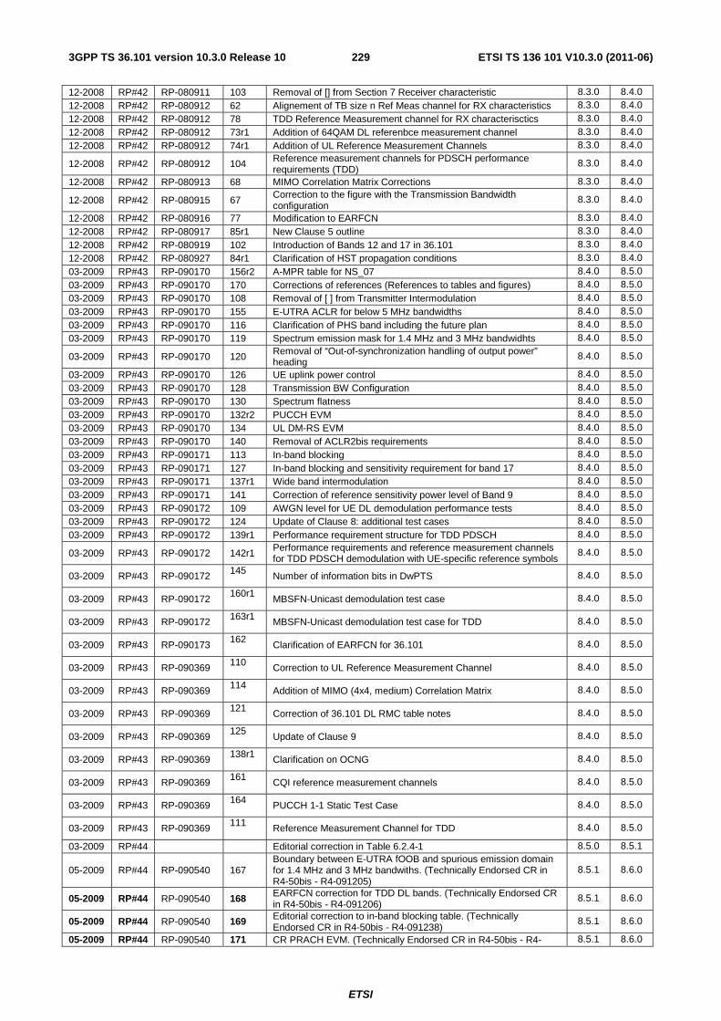
ETSI
ETSI TS 136 101 V10.3.0 (2011-06)2293GPP TS 36.101 version 10.3.0 Release 10
12-2008 RP#42 RP-080911 103 Removal of [] from Section 7 Receiver characteristic 8.3.0 8.4.0 12-2008 RP#42 RP-080912 62 Alignement of TB size n Ref Meas channel for RX characteristics 8.3.0 8.4.0 12-2008 RP#42 RP-080912 78 TDD Reference Measurement channel for RX characterisctics 8.3.0 8.4.0 12-2008 RP#42 RP-080912 73r1 Addition of 64QAM DL referenbce measurement channel 8.3.0 8.4.0 12-2008 RP#42 RP-080912 74r1 Addition of UL Reference Measurement Channels 8.3.0 8.4.0
12-2008 RP#42 RP-080912 104 Reference measurement channels for PDSCH performance requirements (TDD)
8.3.0 8.4.0
12-2008 RP#42 RP-080913 68 MIMO Correlation Matrix Corrections 8.3.0 8.4.0
12-2008 RP#42 RP-080915 67 Correction to the figure with the Transmission Bandwidth configuration
8.3.0 8.4.0
12-2008 RP#42 RP-080916 77 Modification to EARFCN 8.3.0 8.4.0 12-2008 RP#42 RP-080917 85r1 New Clause 5 outline 8.3.0 8.4.0
12-2008 RP#42 RP-080919 102 Introduction of Bands 12 and 17 in 36.101 8.3.0 8.4.0 12-2008 RP#42 RP-080927 84r1 Clarification of HST propagation conditions 8.3.0 8.4.0 03-2009 RP#43 RP-090170 156r2 A-MPR table for NS_07 8.4.0 8.5.0 03-2009 RP#43 RP-090170 170 Corrections of references (References to tables and figures) 8.4.0 8.5.0 03-2009 RP#43 RP-090170 108 Removal of [ ] from Transmitter Intermodulation 8.4.0 8.5.0 03-2009 RP#43 RP-090170 155 E-UTRA ACLR for below 5 MHz bandwidths 8.4.0 8.5.0 03-2009 RP#43 RP-090170 116 Clarification of PHS band including the future plan 8.4.0 8.5.0 03-2009 RP#43 RP-090170 119 Spectrum emission mask for 1.4 MHz and 3 MHz bandwidhts 8.4.0 8.5.0
03-2009 RP#43 RP-090170 120 Removal of “Out-of-synchronization handling of output power” heading
8.4.0 8.5.0
03-2009 RP#43 RP-090170 126 UE uplink power control 8.4.0 8.5.0 03-2009 RP#43 RP-090170 128 Transmission BW Configuration 8.4.0 8.5.0 03-2009 RP#43 RP-090170 130 Spectrum flatness 8.4.0 8.5.0 03-2009 RP#43 RP-090170 132r2 PUCCH EVM 8.4.0 8.5.0 03-2009 RP#43 RP-090170 134 UL DM-RS EVM 8.4.0 8.5.0 03-2009 RP#43 RP-090170 140 Removal of ACLR2bis requirements 8.4.0 8.5.0 03-2009 RP#43 RP-090171 113 In-band blocking 8.4.0 8.5.0
03-2009 RP#43 RP-090171 127 In-band blocking and sensitivity requirement for band 17 8.4.0 8.5.0 03-2009 RP#43 RP-090171 137r1 Wide band intermodulation 8.4.0 8.5.0 03-2009 RP#43 RP-090171 141 Correction of reference sensitivity power level of Band 9 8.4.0 8.5.0 03-2009 RP#43 RP-090172 109 AWGN level for UE DL demodulation performance tests 8.4.0 8.5.0 03-2009 RP#43 RP-090172 124 Update of Clause 8: additional test cases 8.4.0 8.5.0 03-2009 RP#43 RP-090172 139r1 Performance requirement structure for TDD PDSCH 8.4.0 8.5.0
03-2009 RP#43 RP-090172 142r1 Performance requirements and reference measurement channels for TDD PDSCH demodulation with UE-specific reference symbols
8.4.0 8.5.0
03-2009 RP#43 RP-090172 145 Number of information bits in DwPTS 8.4.0 8.5.0
03-2009 RP#43 RP-090172 160r1 MBSFN-Unicast demodulation test case 8.4.0 8.5.0
03-2009 RP#43 RP-090172 163r1 MBSFN-Unicast demodulation test case for TDD 8.4.0 8.5.0
03-2009 RP#43 RP-090173 162 Clarification of EARFCN for 36.101 8.4.0 8.5.0
03-2009 RP#43 RP-090369 110 Correction to UL Reference Measurement Channel 8.4.0 8.5.0
03-2009 RP#43 RP-090369 114 Addition of MIMO (4x4, medium) Correlation Matrix 8.4.0 8.5.0
03-2009 RP#43 RP-090369 121 Correction of 36.101 DL RMC table notes 8.4.0 8.5.0
03-2009 RP#43 RP-090369 125 Update of Clause 9 8.4.0 8.5.0
03-2009 RP#43 RP-090369 138r1 Clarification on OCNG 8.4.0 8.5.0
03-2009 RP#43 RP-090369 161 CQI reference measurement channels 8.4.0 8.5.0
03-2009 RP#43 RP-090369 164 PUCCH 1-1 Static Test Case 8.4.0 8.5.0
03-2009 RP#43 RP-090369 111
Reference Measurement Channel for TDD 8.4.0 8.5.0
03-2009 RP#44 Editorial correction in Table 6.2.4-1 8.5.0 8.5.1
05-2009 RP#44 RP-090540 167 Boundary between E-UTRA fOOB and spurious emission domain for 1.4 MHz and 3 MHz bandwiths. (Technically Endorsed CR in R4-50bis - R4-091205)
8.5.1 8.6.0
05-2009 RP#44 RP-090540 168 EARFCN correction for TDD DL bands. (Technically Endorsed CR in R4-50bis - R4-091206)
8.5.1 8.6.0
05-2009 RP#44 RP-090540 169 Editorial correction to in-band blocking table. (Technically Endorsed CR in R4-50bis - R4-091238)
8.5.1 8.6.0
05-2009 RP#44 RP-090540 171 CR PRACH EVM. (Technically Endorsed CR in R4-50bis - R4- 8.5.1 8.6.0
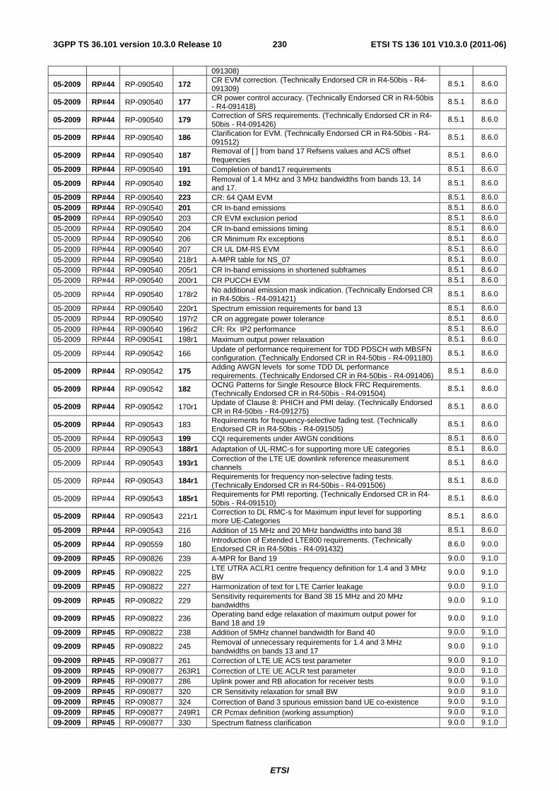
ETSI
ETSI TS 136 101 V10.3.0 (2011-06)2303GPP TS 36.101 version 10.3.0 Release 10
091308)
05-2009 RP#44 RP-090540 172 CR EVM correction. (Technically Endorsed CR in R4-50bis - R4-091309)
8.5.1 8.6.0
05-2009 RP#44 RP-090540 177 CR power control accuracy. (Technically Endorsed CR in R4-50bis - R4-091418)
8.5.1 8.6.0
05-2009 RP#44 RP-090540 179 Correction of SRS requirements. (Technically Endorsed CR in R4-50bis - R4-091426)
8.5.1 8.6.0
05-2009 RP#44 RP-090540 186 Clarification for EVM. (Technically Endorsed CR in R4-50bis - R4-091512)
8.5.1 8.6.0
05-2009 RP#44 RP-090540 187 Removal of [ ] from band 17 Refsens values and ACS offset frequencies
8.5.1 8.6.0
05-2009 RP#44 RP-090540 191 Completion of band17 requirements 8.5.1 8.6.0
05-2009 RP#44 RP-090540 192 Removal of 1.4 MHz and 3 MHz bandwidths from bands 13, 14 and 17.
8.5.1 8.6.0
05-2009 RP#44 RP-090540 223 CR: 64 QAM EVM 8.5.1 8.6.0 05-2009 RP#44 RP-090540 201 CR In-band emissions 8.5.1 8.6.0 05-2009 RP#44 RP-090540 203 CR EVM exclusion period 8.5.1 8.6.0
05-2009 RP#44 RP-090540 204 CR In-band emissions timing 8.5.1 8.6.0 05-2009 RP#44 RP-090540 206 CR Minimum Rx exceptions 8.5.1 8.6.0 05-2009 RP#44 RP-090540 207 CR UL DM-RS EVM 8.5.1 8.6.0 05-2009 RP#44 RP-090540 218r1 A-MPR table for NS_07 8.5.1 8.6.0 05-2009 RP#44 RP-090540 205r1 CR In-band emissions in shortened subframes 8.5.1 8.6.0 05-2009 RP#44 RP-090540 200r1 CR PUCCH EVM 8.5.1 8.6.0
05-2009 RP#44 RP-090540 178r2 No additional emission mask indication. (Technically Endorsed CR in R4-50bis - R4-091421)
8.5.1 8.6.0
05-2009 RP#44 RP-090540 220r1 Spectrum emission requirements for band 13 8.5.1 8.6.0 05-2009 RP#44 RP-090540 197r2 CR on aggregate power tolerance 8.5.1 8.6.0 05-2009 RP#44 RP-090540 196r2 CR: Rx IP2 performance 8.5.1 8.6.0 05-2009 RP#44 RP-090541 198r1 Maximum output power relaxation 8.5.1 8.6.0
05-2009 RP#44 RP-090542 166 Update of performance requirement for TDD PDSCH with MBSFN configuration. (Technically Endorsed CR in R4-50bis - R4-091180)
8.5.1 8.6.0
05-2009 RP#44 RP-090542 175 Adding AWGN levels for some TDD DL performance requirements. (Technically Endorsed CR in R4-50bis - R4-091406)
8.5.1 8.6.0
05-2009 RP#44 RP-090542 182 OCNG Patterns for Single Resource Block FRC Requirements. (Technically Endorsed CR in R4-50bis - R4-091504)
8.5.1 8.6.0
05-2009 RP#44 RP-090542 170r1 Update of Clause 8: PHICH and PMI delay. (Technically Endorsed CR in R4-50bis - R4-091275)
8.5.1 8.6.0
05-2009 RP#44 RP-090543 183 Requirements for frequency-selective fading test. (Technically Endorsed CR in R4-50bis - R4-091505)
8.5.1 8.6.0
05-2009 RP#44 RP-090543 199 CQI requirements under AWGN conditions 8.5.1 8.6.0 05-2009 RP#44 RP-090543 188r1 Adaptation of UL-RMC-s for supporting more UE categories 8.5.1 8.6.0
05-2009 RP#44 RP-090543 193r1 Correction of the LTE UE downlink reference measurement channels
8.5.1 8.6.0
05-2009 RP#44 RP-090543 184r1 Requirements for frequency non-selective fading tests. (Technically Endorsed CR in R4-50bis - R4-091506)
8.5.1 8.6.0
05-2009 RP#44 RP-090543 185r1 Requirements for PMI reporting. (Technically Endorsed CR in R4-50bis - R4-091510)
8.5.1 8.6.0
05-2009 RP#44 RP-090543 221r1 Correction to DL RMC-s for Maximum input level for supporting more UE-Categories
8.5.1 8.6.0
05-2009 RP#44 RP-090543 216 Addition of 15 MHz and 20 MHz bandwidths into band 38 8.5.1 8.6.0
05-2009 RP#44 RP-090559 180 Introduction of Extended LTE800 requirements. (Technically Endorsed CR in R4-50bis - R4-091432)
8.6.0 9.0.0
09-2009 RP#45 RP-090826 239 A-MPR for Band 19 9.0.0 9.1.0
09-2009 RP#45 RP-090822 225 LTE UTRA ACLR1 centre frequency definition for 1.4 and 3 MHz BW
9.0.0 9.1.0
09-2009 RP#45 RP-090822 227 Harmonization of text for LTE Carrier leakage 9.0.0 9.1.0
09-2009 RP#45 RP-090822 229 Sensitivity requirements for Band 38 15 MHz and 20 MHz bandwidths
9.0.0 9.1.0
09-2009 RP#45 RP-090822 236 Operating band edge relaxation of maximum output power for Band 18 and 19
9.0.0 9.1.0
09-2009 RP#45 RP-090822 238 Addition of 5MHz channel bandwidth for Band 40 9.0.0 9.1.0
09-2009 RP#45 RP-090822 245 Removal of unnecessary requirements for 1.4 and 3 MHz bandwidths on bands 13 and 17
9.0.0 9.1.0
09-2009 RP#45 RP-090877 261 Correction of LTE UE ACS test parameter 9.0.0 9.1.0 09-2009 RP#45 RP-090877 263R1 Correction of LTE UE ACLR test parameter 9.0.0 9.1.0 09-2009 RP#45 RP-090877 286 Uplink power and RB allocation for receiver tests 9.0.0 9.1.0 09-2009 RP#45 RP-090877 320 CR Sensitivity relaxation for small BW 9.0.0 9.1.0 09-2009 RP#45 RP-090877 324 Correction of Band 3 spurious emission band UE co-existence 9.0.0 9.1.0 09-2009 RP#45 RP-090877 249R1 CR Pcmax definition (working assumption) 9.0.0 9.1.0 09-2009 RP#45 RP-090877 330 Spectrum flatness clarification 9.0.0 9.1.0
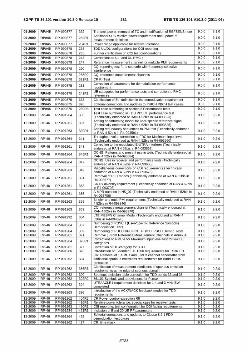
ETSI
ETSI TS 136 101 V10.3.0 (2011-06)2313GPP TS 36.101 version 10.3.0 Release 10
09-2009 RP#45 RP-090877 332 Transmit power: removal of TC and modification of REFSENS note 9.0.0 9.1.0
09-2009 RP#45 RP-090877 282R1 Additional SRS relative power requirement and update of measurement definition
9.0.0 9.1.0
09-2009 RP#45 RP-090877 284R1 Power range applicable for relative tolerance 9.0.0 9.1.0 09-2009 RP#45 RP-090878 233 TDD UL/DL configurations for CQI reporting 9.0.0 9.1.0 09-2009 RP#45 RP-090878 235 Further clarification on CQI test configurations 9.0.0 9.1.0 09-2009 RP#45 RP-090878 243 Corrections to UL- and DL-RMC-s 9.0.0 9.1.0 09-2009 RP#45 RP-090878 247 Reference measurement channel for multiple PMI requirements 9.0.0 9.1.0
09-2009 RP#45 RP-090878 290 CQI reporting test for a scenario with frequency-selective interference
9.0.0 9.1.0
09-2009 RP#45 RP-090878 265R2 CQI reference measurement channels 9.0.0 9.1.0 09-2009 RP#45 RP-090878 321R1 CR RI Test 9.0.0 9.1.0
09-2009 RP#45 RP-090875 231 Correction of parameters for demodulation performance requirement
9.0.0 9.1.0
09-2009 RP#45 RP-090875 241R1 UE categories for performance tests and correction to RMC references
9.0.0 9.1.0
09-2009 RP#45 RP-090875 333 Clarification of Ês definition in the demodulation requirement 9.0.0 9.1.0 09-2009 RP#45 RP-090875 326 Editorial corrections and updates to PHICH PBCH test cases. 9.0.0 9.1.0 09-2009 RP#45 RP-090875 259R3 Test case numbering in section 8 Performance tests 9.0.0 9.1.0
12-2009 RP-46 RP-091264 335 Test case numbering in TDD PDSCH performance test (Technically endorsed at RAN 4 52bis in R4-093523) 9.1.0 9.2.0
12-2009 RP-46 RP-091261 337 Adding beamforming model for user-specfic reference signal (Technically endorsed at RAN 4 52bis in R4-093525) 9.1.0 9.2.0
12-2009 RP-46 RP-091263 339R1 Adding redundancy sequences to PMI test (Technically endorsed at RAN 4 52bis in R4-093581) 9.1.0 9.2.0
12-2009 RP-46 RP-091264 341 Throughput value correction at FRC for Maximum input level (Technically endorsed at RAN 4 52bis in R4-093660) 9.1.0 9.2.0
12-2009 RP-46 RP-091261 343 Correction to the modulated E-UTRA interferer (Technically endorsed at RAN 4 52bis in R4-093662) 9.1.0 9.2.0
12-2009 RP-46 RP-091264 345R1 OCNG: Patterns and present use in tests (Technically endorsed at RAN 4 52bis in R4-093664) 9.1.0 9.2.0
12-2009 RP-46 RP-091264 347 OCNG: Use in receiver and performance tests (Technically endorsed at RAN 4 52bis in R4-093666)
9.1.0 9.2.0
12-2009 RP-46 RP-091263 349 Miscellaneous corrections on CSI requirements (Technically endorsed at RAN 4 52bis in R4-093676) 9.1.0 9.2.0
12-2009 RP-46 RP-091261 351 Removal of RLC modes (Technically endorsed at RAN 4 52bis in R4-093677)
9.1.0 9.2.0
12-2009 RP-46 RP-091261 353 CR Rx diversity requirement (Technically endorsed at RAN 4 52bis in R4-093703) 9.1.0 9.2.0
12-2009 RP-46 RP-091261 355 A-MPR notation in NS_07 (Technically endorsed at RAN 4 52bis in R4-093706)
9.1.0 9.2.0
12-2009 RP-46 RP-091263 359 Single- and multi-PMI requirements (Technically endorsed at RAN 4 52bis in R4-093846) 9.1.0 9.2.0
12-2009 RP-46 RP-091263 363 CQI reference measurement channel (Technically endorsed at RAN 4 52bis in R4-093970)
9.1.0 9.2.0
12-2009 RP-46 RP-091292 364 LTE MBSFN Channel Model (Technically endorsed at RAN 4 52bis in R4-094020) 9.1.0 9.2.0
12-2009 RP-46 RP-091264 367 Numbering of PDSCH (User-Specific Reference Symbols) Demodulation Tests
9.1.0 9.2.0
12-2009 RP-46 RP-091264 369 Numbering of PDCCH/PCFICH, PHICH, PBCH Demod Tests 9.1.0 9.2.0 12-2009 RP-46 RP-091261 371 Remove [ ] from Reference Measurement Channels in Annex A 9.1.0 9.2.0
12-2009 RP-46 RP-091264 373R1 Corrections to RMC-s for Maximum input level test for low UE categories 9.1.0 9.2.0
12-2009 RP-46 RP-091261 377 Correction of UE-category for R.30 9.1.0 9.2.0 12-2009 RP-46 RP-091286 378 Introduction of Extended LTE1500 requirements for TS36.101 9.1.0 9.2.0
12-2009 RP-46 RP-091262 384 CR: Removal of 1.4 MHz and 3 MHz channel bandwidths from additional spurious emissions requirements for Band 1 PHS protection
9.1.0 9.2.0
12-2009 RP-46 RP-091262 386R3 Clarification of measurement conditions of spurious emission requirements at the edge of spurious domain 9.1.0 9.2.0
12-2009 RP-46 RP-091262 390 Spurious emission table correction for TDD bands 33 and 38. 9.1.0 9.2.0 12-2009 RP-46 RP-091262 392R2 36.101 Symbols and abreviations for Pcmax 9.1.0 9.2.0
12-2009 RP-46 RP-091262 394 UTRAACLR1 requirement definition for 1.4 and 3 MHz BW completed 9.1.0 9.2.0
12-2009 RP-46 RP-091263 396 Introduction of the ACK/NACK feedback modes for TDD requirements
9.1.0 9.2.0
12-2009 RP-46 RP-091262 404R3 CR Power control exception R8 9.1.0 9.2.0 12-2009 RP-46 RP-091262 416R1 Relative power tolerance: special case for receiver tests 9.1.0 9.2.0 12-2009 RP-46 RP-091263 420R1 CSI reporting: test configuration for CQI fading requirements 9.1.0 9.2.0 12-2009 RP-46 RP-091284 421R1 Inclusion of Band 20 UE RF parameters 9.1.0 9.2.0
12-2009 RP-46 RP-091264 425 Editorial corrections and updates to Clause 8.2.1 FDD demodulation test cases
9.1.0 9.2.0
12-2009 RP-46 RP-091262 427 CR: time mask 9.1.0 9.2.0
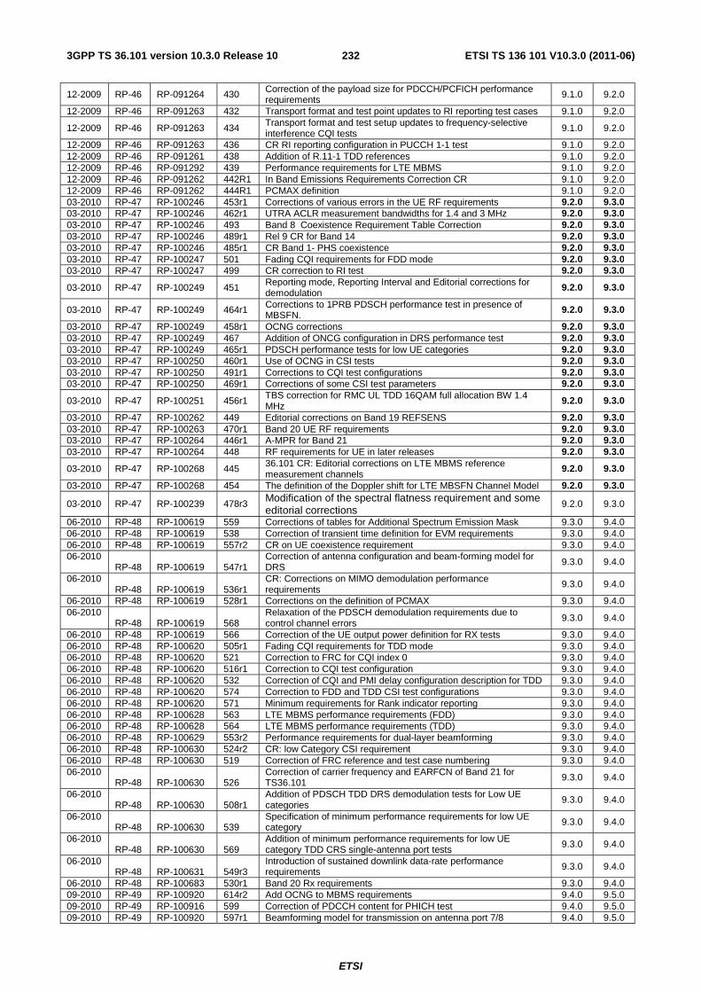
ETSI
ETSI TS 136 101 V10.3.0 (2011-06)2323GPP TS 36.101 version 10.3.0 Release 10
12-2009 RP-46 RP-091264 430 Correction of the payload size for PDCCH/PCFICH performance requirements 9.1.0 9.2.0
12-2009 RP-46 RP-091263 432 Transport format and test point updates to RI reporting test cases 9.1.0 9.2.0
12-2009 RP-46 RP-091263 434 Transport format and test setup updates to frequency-selective interference CQI tests
9.1.0 9.2.0
12-2009 RP-46 RP-091263 436 CR RI reporting configuration in PUCCH 1-1 test 9.1.0 9.2.0 12-2009 RP-46 RP-091261 438 Addition of R.11-1 TDD references 9.1.0 9.2.0 12-2009 RP-46 RP-091292 439 Performance requirements for LTE MBMS 9.1.0 9.2.0 12-2009 RP-46 RP-091262 442R1 In Band Emissions Requirements Correction CR 9.1.0 9.2.0 12-2009 RP-46 RP-091262 444R1 PCMAX definition 9.1.0 9.2.0 03-2010 RP-47 RP-100246 453r1 Corrections of various errors in the UE RF requirements 9.2.0 9.3.0 03-2010 RP-47 RP-100246 462r1 UTRA ACLR measurement bandwidths for 1.4 and 3 MHz 9.2.0 9.3.0 03-2010 RP-47 RP-100246 493 Band 8 Coexistence Requirement Table Correction 9.2.0 9.3.0 03-2010 RP-47 RP-100246 489r1 Rel 9 CR for Band 14 9.2.0 9.3.0 03-2010 RP-47 RP-100246 485r1 CR Band 1- PHS coexistence 9.2.0 9.3.0 03-2010 RP-47 RP-100247 501 Fading CQI requirements for FDD mode 9.2.0 9.3.0 03-2010 RP-47 RP-100247 499 CR correction to RI test 9.2.0 9.3.0
03-2010 RP-47 RP-100249 451 Reporting mode, Reporting Interval and Editorial corrections for demodulation
9.2.0 9.3.0
03-2010 RP-47 RP-100249 464r1 Corrections to 1PRB PDSCH performance test in presence of MBSFN.
9.2.0 9.3.0
03-2010 RP-47 RP-100249 458r1 OCNG corrections 9.2.0 9.3.0 03-2010 RP-47 RP-100249 467 Addition of ONCG configuration in DRS performance test 9.2.0 9.3.0 03-2010 RP-47 RP-100249 465r1 PDSCH performance tests for low UE categories 9.2.0 9.3.0 03-2010 RP-47 RP-100250 460r1 Use of OCNG in CSI tests 9.2.0 9.3.0 03-2010 RP-47 RP-100250 491r1 Corrections to CQI test configurations 9.2.0 9.3.0 03-2010 RP-47 RP-100250 469r1 Corrections of some CSI test parameters 9.2.0 9.3.0
03-2010 RP-47 RP-100251 456r1 TBS correction for RMC UL TDD 16QAM full allocation BW 1.4 MHz
9.2.0 9.3.0
03-2010 RP-47 RP-100262 449 Editorial corrections on Band 19 REFSENS 9.2.0 9.3.0 03-2010 RP-47 RP-100263 470r1 Band 20 UE RF requirements 9.2.0 9.3.0 03-2010 RP-47 RP-100264 446r1 A-MPR for Band 21 9.2.0 9.3.0 03-2010 RP-47 RP-100264 448 RF requirements for UE in later releases 9.2.0 9.3.0
03-2010 RP-47 RP-100268 445 36.101 CR: Editorial corrections on LTE MBMS reference measurement channels
9.2.0 9.3.0
03-2010 RP-47 RP-100268 454 The definition of the Doppler shift for LTE MBSFN Channel Model 9.2.0 9.3.0
03-2010 RP-47 RP-100239 478r3 Modification of the spectral flatness requirement and some editorial corrections
9.2.0 9.3.0
06-2010 RP-48 RP-100619 559 Corrections of tables for Additional Spectrum Emission Mask 9.3.0 9.4.0 06-2010 RP-48 RP-100619 538 Correction of transient time definition for EVM requirements 9.3.0 9.4.0 06-2010 RP-48 RP-100619 557r2 CR on UE coexistence requirement 9.3.0 9.4.0 06-2010
RP-48 RP-100619 547r1 Correction of antenna configuration and beam-forming model for DRS 9.3.0 9.4.0
06-2010 RP-48 RP-100619 536r1
CR: Corrections on MIMO demodulation performance requirements
9.3.0 9.4.0
06-2010 RP-48 RP-100619 528r1 Corrections on the definition of PCMAX 9.3.0 9.4.0 06-2010
RP-48 RP-100619 568 Relaxation of the PDSCH demodulation requirements due to control channel errors 9.3.0 9.4.0
06-2010 RP-48 RP-100619 566 Correction of the UE output power definition for RX tests 9.3.0 9.4.0 06-2010 RP-48 RP-100620 505r1 Fading CQI requirements for TDD mode 9.3.0 9.4.0 06-2010 RP-48 RP-100620 521 Correction to FRC for CQI index 0 9.3.0 9.4.0 06-2010 RP-48 RP-100620 516r1 Correction to CQI test configuration 9.3.0 9.4.0 06-2010 RP-48 RP-100620 532 Correction of CQI and PMI delay configuration description for TDD 9.3.0 9.4.0 06-2010 RP-48 RP-100620 574 Correction to FDD and TDD CSI test configurations 9.3.0 9.4.0 06-2010 RP-48 RP-100620 571 Minimum requirements for Rank indicator reporting 9.3.0 9.4.0 06-2010 RP-48 RP-100628 563 LTE MBMS performance requirements (FDD) 9.3.0 9.4.0 06-2010 RP-48 RP-100628 564 LTE MBMS performance requirements (TDD) 9.3.0 9.4.0 06-2010 RP-48 RP-100629 553r2 Performance requirements for dual-layer beamforming 9.3.0 9.4.0 06-2010 RP-48 RP-100630 524r2 CR: low Category CSI requirement 9.3.0 9.4.0 06-2010 RP-48 RP-100630 519 Correction of FRC reference and test case numbering 9.3.0 9.4.0 06-2010
RP-48 RP-100630 526 Correction of carrier frequency and EARFCN of Band 21 for TS36.101 9.3.0 9.4.0
06-2010 RP-48 RP-100630 508r1
Addition of PDSCH TDD DRS demodulation tests for Low UE categories 9.3.0 9.4.0
06-2010 RP-48 RP-100630 539
Specification of minimum performance requirements for low UE category 9.3.0 9.4.0
06-2010 RP-48 RP-100630 569
Addition of minimum performance requirements for low UE category TDD CRS single-antenna port tests
9.3.0 9.4.0
06-2010 RP-48 RP-100631 549r3
Introduction of sustained downlink data-rate performance requirements 9.3.0 9.4.0
06-2010 RP-48 RP-100683 530r1 Band 20 Rx requirements 9.3.0 9.4.0 09-2010 RP-49 RP-100920 614r2 Add OCNG to MBMS requirements 9.4.0 9.5.0 09-2010 RP-49 RP-100916 599 Correction of PDCCH content for PHICH test 9.4.0 9.5.0 09-2010 RP-49 RP-100920 597r1 Beamforming model for transmission on antenna port 7/8 9.4.0 9.5.0
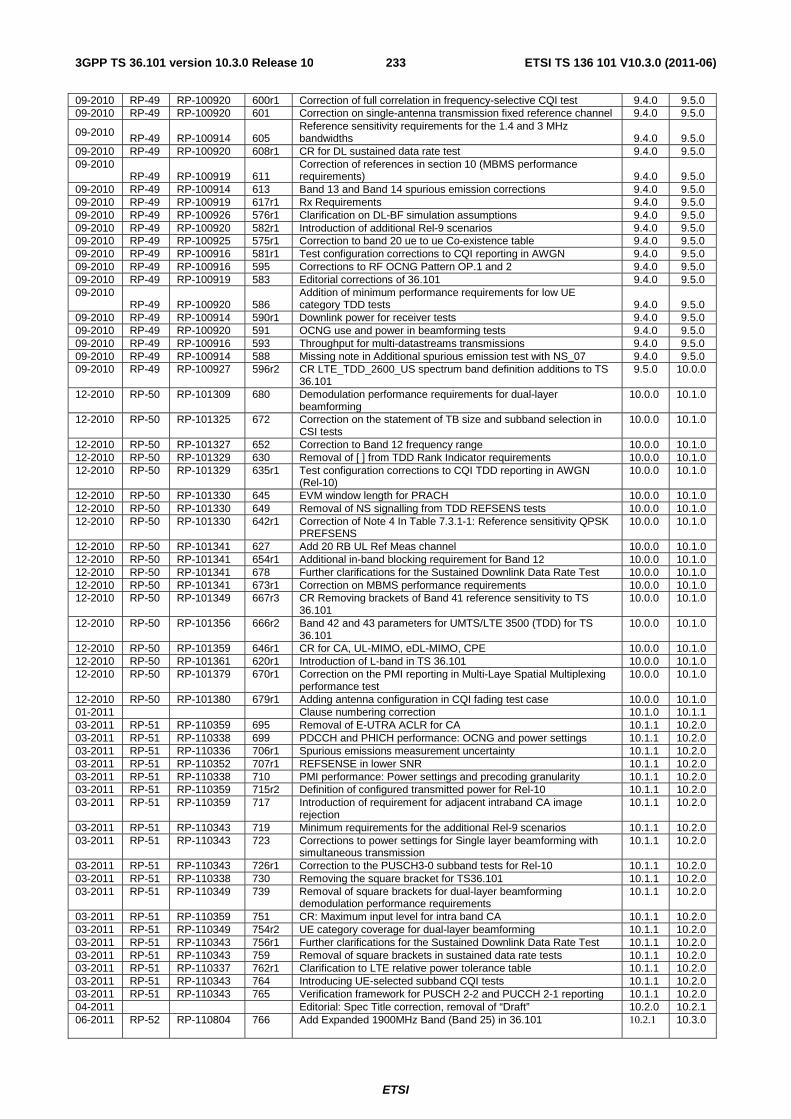
ETSI
ETSI TS 136 101 V10.3.0 (2011-06)2333GPP TS 36.101 version 10.3.0 Release 10
09-2010 RP-49 RP-100920 600r1 Correction of full correlation in frequency-selective CQI test 9.4.0 9.5.0 09-2010 RP-49 RP-100920 601 Correction on single-antenna transmission fixed reference channel 9.4.0 9.5.0
09-2010 RP-49 RP-100914 605 Reference sensitivity requirements for the 1.4 and 3 MHz bandwidths 9.4.0 9.5.0
09-2010 RP-49 RP-100920 608r1 CR for DL sustained data rate test 9.4.0 9.5.0 09-2010
RP-49 RP-100919 611 Correction of references in section 10 (MBMS performance requirements) 9.4.0 9.5.0
09-2010 RP-49 RP-100914 613 Band 13 and Band 14 spurious emission corrections 9.4.0 9.5.0 09-2010 RP-49 RP-100919 617r1 Rx Requirements 9.4.0 9.5.0 09-2010 RP-49 RP-100926 576r1 Clarification on DL-BF simulation assumptions 9.4.0 9.5.0 09-2010 RP-49 RP-100920 582r1 Introduction of additional Rel-9 scenarios 9.4.0 9.5.0 09-2010 RP-49 RP-100925 575r1 Correction to band 20 ue to ue Co-existence table 9.4.0 9.5.0 09-2010 RP-49 RP-100916 581r1 Test configuration corrections to CQI reporting in AWGN 9.4.0 9.5.0 09-2010 RP-49 RP-100916 595 Corrections to RF OCNG Pattern OP.1 and 2 9.4.0 9.5.0 09-2010 RP-49 RP-100919 583 Editorial corrections of 36.101 9.4.0 9.5.0 09-2010
RP-49 RP-100920 586 Addition of minimum performance requirements for low UE category TDD tests 9.4.0 9.5.0
09-2010 RP-49 RP-100914 590r1 Downlink power for receiver tests 9.4.0 9.5.0 09-2010 RP-49 RP-100920 591 OCNG use and power in beamforming tests 9.4.0 9.5.0 09-2010 RP-49 RP-100916 593 Throughput for multi-datastreams transmissions 9.4.0 9.5.0 09-2010 RP-49 RP-100914 588 Missing note in Additional spurious emission test with NS_07 9.4.0 9.5.0 09-2010 RP-49 RP-100927 596r2 CR LTE_TDD_2600_US spectrum band definition additions to TS
36.101 9.5.0 10.0.0
12-2010 RP-50 RP-101309 680 Demodulation performance requirements for dual-layer beamforming
10.0.0 10.1.0
12-2010 RP-50 RP-101325 672 Correction on the statement of TB size and subband selection in CSI tests
10.0.0 10.1.0
12-2010 RP-50 RP-101327 652 Correction to Band 12 frequency range 10.0.0 10.1.0 12-2010 RP-50 RP-101329 630 Removal of [ ] from TDD Rank Indicator requirements 10.0.0 10.1.0 12-2010 RP-50 RP-101329 635r1 Test configuration corrections to CQI TDD reporting in AWGN
(Rel-10) 10.0.0 10.1.0
12-2010 RP-50 RP-101330 645 EVM window length for PRACH 10.0.0 10.1.0 12-2010 RP-50 RP-101330 649 Removal of NS signalling from TDD REFSENS tests 10.0.0 10.1.0 12-2010 RP-50 RP-101330 642r1 Correction of Note 4 In Table 7.3.1-1: Reference sensitivity QPSK
PREFSENS 10.0.0 10.1.0
12-2010 RP-50 RP-101341 627 Add 20 RB UL Ref Meas channel 10.0.0 10.1.0 12-2010 RP-50 RP-101341 654r1 Additional in-band blocking requirement for Band 12 10.0.0 10.1.0 12-2010 RP-50 RP-101341 678 Further clarifications for the Sustained Downlink Data Rate Test 10.0.0 10.1.0 12-2010 RP-50 RP-101341 673r1 Correction on MBMS performance requirements 10.0.0 10.1.0 12-2010 RP-50 RP-101349 667r3 CR Removing brackets of Band 41 reference sensitivity to TS
36.101 10.0.0 10.1.0
12-2010 RP-50 RP-101356 666r2 Band 42 and 43 parameters for UMTS/LTE 3500 (TDD) for TS 36.101
10.0.0 10.1.0
12-2010 RP-50 RP-101359 646r1 CR for CA, UL-MIMO, eDL-MIMO, CPE 10.0.0 10.1.0 12-2010 RP-50 RP-101361 620r1 Introduction of L-band in TS 36.101 10.0.0 10.1.0 12-2010 RP-50 RP-101379 670r1 Correction on the PMI reporting in Multi-Laye Spatial Multiplexing
performance test 10.0.0 10.1.0
12-2010 RP-50 RP-101380 679r1 Adding antenna configuration in CQI fading test case 10.0.0 10.1.0 01-2011 Clause numbering correction 10.1.0 10.1.1 03-2011 RP-51 RP-110359 695 Removal of E-UTRA ACLR for CA 10.1.1 10.2.0 03-2011 RP-51 RP-110338 699 PDCCH and PHICH performance: OCNG and power settings 10.1.1 10.2.0 03-2011 RP-51 RP-110336 706r1 Spurious emissions measurement uncertainty 10.1.1 10.2.0 03-2011 RP-51 RP-110352 707r1 REFSENSE in lower SNR 10.1.1 10.2.0 03-2011 RP-51 RP-110338 710 PMI performance: Power settings and precoding granularity 10.1.1 10.2.0 03-2011 RP-51 RP-110359 715r2 Definition of configured transmitted power for Rel-10 10.1.1 10.2.0 03-2011 RP-51 RP-110359 717 Introduction of requirement for adjacent intraband CA image
rejection 10.1.1 10.2.0
03-2011 RP-51 RP-110343 719 Minimum requirements for the additional Rel-9 scenarios 10.1.1 10.2.0 03-2011 RP-51 RP-110343 723 Corrections to power settings for Single layer beamforming with
simultaneous transmission 10.1.1 10.2.0
03-2011 RP-51 RP-110343 726r1 Correction to the PUSCH3-0 subband tests for Rel-10 10.1.1 10.2.0 03-2011 RP-51 RP-110338 730 Removing the square bracket for TS36.101 10.1.1 10.2.0 03-2011 RP-51 RP-110349 739 Removal of square brackets for dual-layer beamforming
demodulation performance requirements 10.1.1 10.2.0
03-2011 RP-51 RP-110359 751 CR: Maximum input level for intra band CA 10.1.1 10.2.0 03-2011 RP-51 RP-110349 754r2 UE category coverage for dual-layer beamforming 10.1.1 10.2.0 03-2011 RP-51 RP-110343 756r1 Further clarifications for the Sustained Downlink Data Rate Test 10.1.1 10.2.0 03-2011 RP-51 RP-110343 759 Removal of square brackets in sustained data rate tests 10.1.1 10.2.0 03-2011 RP-51 RP-110337 762r1 Clarification to LTE relative power tolerance table 10.1.1 10.2.0 03-2011 RP-51 RP-110343 764 Introducing UE-selected subband CQI tests 10.1.1 10.2.0 03-2011 RP-51 RP-110343 765 Verification framework for PUSCH 2-2 and PUCCH 2-1 reporting 10.1.1 10.2.0 04-2011 Editorial: Spec Title correction, removal of “Draft” 10.2.0 10.2.1 06-2011 RP-52 RP-110804 766 Add Expanded 1900MHz Band (Band 25) in 36.101 10.2.1 10.3.0
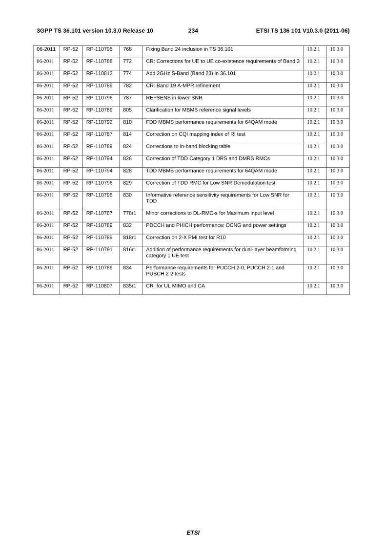
ETSI
ETSI TS 136 101 V10.3.0 (2011-06)2343GPP TS 36.101 version 10.3.0 Release 10
06-2011 RP-52 RP-110795 768 Fixing Band 24 inclusion in TS 36.101 10.2.1 10.3.0
06-2011 RP-52 RP-110788 772 CR: Corrections for UE to UE co-existence requirements of Band 3 10.2.1 10.3.0
06-2011 RP-52 RP-110812 774 Add 2GHz S-Band (Band 23) in 36.101 10.2.1 10.3.0
06-2011 RP-52 RP-110789 782 CR: Band 19 A-MPR refinement 10.2.1 10.3.0
06-2011 RP-52 RP-110796 787 REFSENS in lower SNR 10.2.1 10.3.0
06-2011 RP-52 RP-110789 805 Clarification for MBMS reference signal levels 10.2.1 10.3.0
06-2011 RP-52 RP-110792 810 FDD MBMS performance requirements for 64QAM mode 10.2.1 10.3.0
06-2011 RP-52 RP-110787 814 Correction on CQI mapping index of RI test 10.2.1 10.3.0
06-2011 RP-52 RP-110789 824 Corrections to in-band blocking table 10.2.1 10.3.0
06-2011 RP-52 RP-110794 826 Correction of TDD Category 1 DRS and DMRS RMCs 10.2.1 10.3.0
06-2011 RP-52 RP-110794 828 TDD MBMS performance requirements for 64QAM mode 10.2.1 10.3.0
06-2011 RP-52 RP-110796 829 Correction of TDD RMC for Low SNR Demodulation test 10.2.1 10.3.0
06-2011 RP-52 RP-110796 830 Informative reference sensitivity requirements for Low SNR for TDD
10.2.1 10.3.0
06-2011 RP-52 RP-110787 778r1 Minor corrections to DL-RMC-s for Maximum input level 10.2.1 10.3.0
06-2011 RP-52 RP-110789 832 PDCCH and PHICH performance: OCNG and power settings 10.2.1 10.3.0
06-2011 RP-52 RP-110789 818r1 Correction on 2-X PMI test for R10 10.2.1 10.3.0
06-2011 RP-52 RP-110791 816r1 Addition of performance requirements for dual-layer beamforming category 1 UE test
10.2.1 10.3.0
06-2011 RP-52 RP-110789 834 Performance requirements for PUCCH 2-0, PUCCH 2-1 and PUSCH 2-2 tests
10.2.1 10.3.0
06-2011 RP-52 RP-110807 835r1 CR for UL MIMO and CA 10.2.1 10.3.0

ETSI
ETSI TS 136 101 V10.3.0 (2011-06)2353GPP TS 36.101 version 10.3.0 Release 10
History
Document history
V10.1.1 January 2011 Publication
V10.2.1 May 2011 Publication
V10.3.0 June 2011 Publication
Related Documents