ETSI TS 123 121 V3.5.1 (2000-12) Technical Specification Digital cellular telecommunications system (Phase 2+) (GSM); Universal Mobile Telecommunications System (UMTS); Architectural Requirements for Release 1999 (3GPP TS 23.121 version 3.5.1 Release 1999) GLOBAL SYSTEM FOR MOBILE COMMUNICATIONS R

Welcome message from author
This document is posted to help you gain knowledge. Please leave a comment to let me know what you think about it! Share it to your friends and learn new things together.
Transcript
ETSI TS 123 121 V3.5.1 (2000-12)Technical Specification
Digital cellular telecommunications system (Phase 2+) (GSM);Universal Mobile Telecommunications System (UMTS);
Architectural Requirements for Release 1999(3GPP TS 23.121 version 3.5.1 Release 1999)
GLOBAL SYSTEM FORMOBILE COMMUNICATIONS
R
1
ETSI
ETSI TS 123 121 V3.5.1 (2000-12)3GPP TS 23.121 version 3.5.1 Release 1999
ReferenceRTS/TSGS-0223121UR3
KeywordsGSM, UMTS
ETSI
650 Route des LuciolesF-06921 Sophia Antipolis Cedex - FRANCE
Tel.: +33 4 92 94 42 00 Fax: +33 4 93 65 47 16
Siret N° 348 623 562 00017 - NAF 742 CAssociation à but non lucratif enregistrée à laSous-Préfecture de Grasse (06) N° 7803/88
Important notice
Individual copies of the present document can be downloaded from:http://www.etsi.org
The present document may be made available in more than one electronic version or in print. In any case of existing orperceived difference in contents between such versions, the reference version is the Portable Document Format (PDF).
In case of dispute, the reference shall be the printing on ETSI printers of the PDF version kept on a specific network drivewithin ETSI Secretariat.
Users of the present document should be aware that the document may be subject to revision or change of status.Information on the current status of this and other ETSI documents is available at http://www.etsi.org/tb/status/
If you find errors in the present document, send your comment to:[email protected]
Copyright Notification
No part may be reproduced except as authorized by written permission.The copyright and the foregoing restriction extend to reproduction in all media.
© European Telecommunications Standards Institute 2000.
All rights reserved.
2
ETSI
ETSI TS 123 121 V3.5.1 (2000-12)3GPP TS 23.121 version 3.5.1 Release 1999
Intellectual Property RightsIPRs essential or potentially essential to the present document may have been declared to ETSI. The informationpertaining to these essential IPRs, if any, is publicly available for ETSI members and non-members, and can be foundin ETSI SR 000 314: "Intellectual Property Rights (IPRs); Essential, or potentially Essential, IPRs notified to ETSI inrespect of ETSI standards", which is available from the ETSI Secretariat. Latest updates are available on the ETSI Webserver (http://www.etsi.org/ipr).
Pursuant to the ETSI IPR Policy, no investigation, including IPR searches, has been carried out by ETSI. No guaranteecan be given as to the existence of other IPRs not referenced in ETSI SR 000 314 (or the updates on the ETSI Webserver) which are, or may be, or may become, essential to the present document.
ForewordThis Technical Specification (TS) has been produced by the ETSI 3rd Generation Partnership Project (3GPP).
The present document may refer to technical specifications or reports using their 3GPP identities, UMTS identities orGSM identities. These should be interpreted as being references to the corresponding ETSI deliverables.
The cross reference between GSM, UMTS, 3GPP and ETSI identities can be found under www.etsi.org/key .
ETSI
ETSI TS 123 121 V3.5.1 (2000-12)33GPP TS 23.121 version 3.5.1 Release 1999
Contents
Foreword ............................................................................................................................................................5
1 Scope ........................................................................................................................................................6
2 References ................................................................................................................................................6
3 Definitions................................................................................................................................................6
4 Working assumptions...............................................................................................................................74.1 General ...............................................................................................................................................................74.2 Iu Interface .........................................................................................................................................................74.2.1 Iu Control Plane............................................................................................................................................84.2.2 Iu User plane.................................................................................................................................................94.2.2.1 Principles of User Data Retrieve in UMTS and at GSM-UMTS Hand-Over for PS Domain...............104.2.2.1.1 Requirements for Data retrieve at GPRS/UMTS handover.............................................................104.2.2.1.2 Adopted solution for data retrieve at GPRS-UMTS handover ........................................................104.2.2.1.3 Requirements for data retrieve in UMTS ........................................................................................114.2.2.1.4 Adopted solution for data retrieve in UMTS...................................................................................124.2.2.1.5 User plane protocol stacks for UMTS data retrieve ........................................................................124.2.2.1.6 User plane protocol stacks for data retrieve between UTRAN and 2G-SGSN................................134.2.2.2 Packet buffering in SRNC and transmission of not yet acknowledged downstream packets at
SRNC relocation ...................................................................................................................................134.2.2.3 Load sharing..........................................................................................................................................144.3 UMTS Mobility Management (UMM) ............................................................................................................144.3.1 Location Management and Mobility Management concept overview........................................................144.3.1.1 Use of combined procedures for UMTS ...............................................................................................174.3.2 Description of the Location Management and Mobility Management Concept .........................................174.3.2.1 Area concepts........................................................................................................................................174.3.2.1.1 Location areas..................................................................................................................................184.3.2.1.2 Routing areas...................................................................................................................................184.3.2.1.3 UTRAN internal areas.....................................................................................................................184.3.2.1.4 Relationship between the different areas.........................................................................................184.3.2.1.5 Hierarchical tracking concept..........................................................................................................194.3.3 Relationship between MM and SM states for an UE..................................................................................194.3.4 Requirement in case of temporarily loss of coverage of packet UE ...........................................................204.3.5 MM functionality in different UE service states.........................................................................................204.3.6 The RRC state machine ..............................................................................................................................214.3.7 Relationship between CS and PS service states and RRC state for an UE .................................................224.3.8 Service registration and location update .....................................................................................................234.3.8.1 Location area update .............................................................................................................................234.3.8.2 Routing area update ..............................................................................................................................234.3.8.3 Combined updates.................................................................................................................................234.3.9 Paging initiated by CN................................................................................................................................234.3.10 Signalling connection establishment...........................................................................................................244.3.11 Relations between SRNS relocation and Location registration ..................................................................244.3.12 Requirements on Identifiers for UMTS and GSM......................................................................................254.3.13 Use of TMSI signature................................................................................................................................264.3.13.1 IMSI attach............................................................................................................................................264.3.13.2 Location Area update ............................................................................................................................264.3.13.3 MM System Information.......................................................................................................................264.3.13.4 IMSI detach procedure..........................................................................................................................274.3.14 Signalling procedures .................................................................................................................................274.3.14.1 Idle mode procedures ............................................................................................................................274.3.14.1.1 Location Area update ......................................................................................................................274.3.14.1.2 Routing Area update........................................................................................................................294.3.14.1.3 Periodic Registration towards both CN nodes without use of Gs....................................................304.3.14.1.4 Periodic Registration with use of Gs/UMSC...................................................................................31
ETSI
ETSI TS 123 121 V3.5.1 (2000-12)43GPP TS 23.121 version 3.5.1 Release 1999
4.3.14.1.5 UE initiated Combined Detach Procedure when using Gs/UMSC..................................................324.3.14.2 SRNS Relocation ..................................................................................................................................324.3.14.2.1 SRNS relocation principles .............................................................................................................324.3.14.2.2 SRNS relocation (UE connected to a single CN node, 3G_MSC/VLR) followed by Location
Registration in new Routing Area ...................................................................................................334.3.14.2.3 SRNS relocation (UE connected to a single CN node, 3G_SGSN) followed by Location
Registration in new Location Area..................................................................................................354.3.14.3 Comparison between UMTS and GSM ................................................................................................354.3.14.3.1 PS –idle state ...................................................................................................................................364.3.14.3.2 PS –connected state .........................................................................................................................364.3.14.4 Issues for further study..........................................................................................................................364.3.15 (void) ..........................................................................................................................................................364.3.16 UTRAN coordination .................................................................................................................................364.4 UMTS call control............................................................................................................................................374.4.1 Technical Requirements .............................................................................................................................374.4.2 Architecture for Multimedia .......................................................................................................................374.4.2.1 Packet Switched Domain ......................................................................................................................384.4.2.2 Circuit Switched Domain......................................................................................................................404.4.3 Typical Scenarios for Multimedia Control and User Plane ........................................................................414.4.3.1 H.324M to H.324M Call .......................................................................................................................414.4.3.2 IMT-2000 H.323 to H.323 call .............................................................................................................424.5 Core network layer 3 ........................................................................................................................................434.6 Structure of radio interface layer 3...................................................................................................................444.7 Alternate Access technologies to UTRAN.......................................................................................................444.7.1 Advantages of attaching HIPERLAN 2 to UMTS......................................................................................454.7.2 HIPERLAN 2 UMTS Interworking............................................................................................................454.7.3 Related Actions...........................................................................................................................................454.8 Location of the IP compression function in UMTS..........................................................................................454.8.1 Functional role of SNDCP / PDCP.............................................................................................................454.8.2 Position for header compression.................................................................................................................464.8.3 Implied protocol stack ................................................................................................................................464.9 Short Message Service for UMTS....................................................................................................................464.9.1 Protocols and architecture...........................................................................................................................464.10a Cell Broadcast Service in UMTS .....................................................................................................................474.10a.1 Network Architecture .................................................................................................................................474.10 Mobile IP for UMTS/GPRS End Users............................................................................................................494.10.1 Mobile IP for UMTS/GPRS End Users ......................................................................................................494.10.1.1 Alterations of and Additions to Current GPRS Standards ....................................................................514.11 Allowed network and terminal configurations .................................................................................................51
5 UMTS to UMTS handover for circuit switched services.......................................................................52
6 Interoperability between GSM and UMTS ............................................................................................526.1 Circuit Switched Handover and Roaming Principles .......................................................................................526.1.1 UMTS to GSM handover for circuit switched services ..............................................................................546.1.2 GSM to UMTS handover for circuit switched services ..............................................................................546.2 Packet Switched Handover and Roaming Principles........................................................................................546.2.1 Implications ................................................................................................................................................556.2.2 Signalling procedures .................................................................................................................................556.2.2.1 Handover from UMTS to GSM GPRS .................................................................................................556.2.2.2 Handover from GSM GPRS to UMTS .................................................................................................55
Annex A (informative): Reduction of UMTS signalling .....................................................................56
A.1 GLR Concept .........................................................................................................................................56A.1.1 Overview of the GLR Concept.........................................................................................................................56
Annex B (informative): Change History ..............................................................................................57
ETSI
ETSI TS 123 121 V3.5.1 (2000-12)53GPP TS 23.121 version 3.5.1 Release 1999
ForewordThis Technical Specification (TS) has been produced by the 3rd Generation Partnership Project (3GPP).
The contents of the present document are subject to continuing work within the TSG and may change following formalTSG approval. Should the TSG modify the contents of the present document, it will be re-released by the TSG with anidentifying change of release date and an increase in version number as follows:
Version x.y.z
where:
x the first digit:
3. presented to TSG for information;
3. presented to TSG for approval;
3. or greater indicates TSG approved document under change control.
Y the second digit is incremented for all changes of substance, i.e. technical enhancements, corrections,updates, etc.
z the third digit is incremented when editorial only changes have been incorporated in the document.
ETSI
ETSI TS 123 121 V3.5.1 (2000-12)63GPP TS 23.121 version 3.5.1 Release 1999
1 ScopeThe present document covers issues related to the evolution of the GSM platform towards UMTS with the overall goalof fulfilling the UMTS service requirements, the support of the UMTS role model, support of roaming and support ofnew functionality, signalling systems and interfaces.
2 ReferencesThe following documents contain provisions which, through reference in this text, constitute provisions of the presentdocument.
• References are either specific (identified by date of publication, edition number, version number, etc.) ornon-specific.
• For a specific reference, subsequent revisions do not apply.
• For a non-specific reference, the latest version applies.
[1] 3GPP TS 22.001 : « Services Principles ».
[2] 3GPP TS 23.002: "Network Architecture".
[3] 3GPP TS 23.060: "General Packet Radio Service (GPRS) Service description; Stage 2".
[4] ETSI TC-SMG GSM 11.14: "Specification of Subscriber Identity Module – Mobile Equipment(SIM – ME) Interface for SIM Application Toolkit".
[5] (void)
[6] 3GPP TS 23.101: "3rd Generation mobile system Release 1999 Specifications"
[7] (void)
[8] UMTSYY.01, UE-UTRAN Radio Interface Protocol Architecture – Stage 2.
[9] UMTSYY.03, Description of UE states and Procedures in Connected Mode.
[10] C. Perkins, Editor, RFC 2002, "IP Mobility Support", October 1996.
[11] B. Aboba and M. Beadles, RFC 2486, "The Network Access Identifier", January 1999.
[12] Pat R. Calhoun and Charles E. Perkins, "Mobile IP Network Address Identifier Extension",February 1999. Work in progress (http://www.ietf.org/internet-drafts/draft-ietf-mobileip-mn-nai-00.txt).
[13] http://www.ietf.org/html.charters/mobileip-charter.html
[14] 3GPP TR 21.905: "3G Vocabulary".
3 DefinitionsFor the purposes of the present document, the terms defined in 3GPP TR 21.905 apply:
ETSI
ETSI TS 123 121 V3.5.1 (2000-12)73GPP TS 23.121 version 3.5.1 Release 1999
4 Working assumptionsInformation flows provided in the present document are for information only. They do not constrain implementation.
4.1 GeneralThe phase 1 UMTS/Release '99 GSM standards should provide the capability to support:
- a core network based on an evolved 2G MSC and an evolved SGSN;
- an optionally evolved Gs interface;
- mobile Ipv4 with Foreign Agent care-of addresses to end users over the UMTS/GPRS network, where the FA islocated in the GGSN;
- class A GSM' mobiles;
- transcoder location shall be according to 23.930;
- UMTS/IMT2000 Phase1 (Release 99) network architecture and standards shall allow the operator to choosebetween Integrated and Separated core networks for transmission (including L2);
- the UMTS standard shall allow for both separated and combined MSC/VLR and SGSN configurations;
- the UE shall be able to handle separated or combined MSCs and SGSNs;
- there can be several user planes to these CN nodes.
The following general concepts should be followed:
- separate the layer 3 control signalling from the layer 2 transport discussion (do not optimise layer 3 for onelayer 2 technology);
- MSC-MSC layer 3 call control is out of scope of standardisation in SMG;
- as future evolution may lead to the migration of some services from the CS-domain to the PS-domain withoutchanges to the associated higher-layer protocols or functions. UMTS release 99 shall provide the flexibility to dothis in a way that is backwards compatible with release 99 Ues provided this does not introduce significant newcomplexity or requirements in the system.
4.2 Iu Interface- Transport protocol across the Iu interface for UTRAN shall be according to 23.930.
- The UTRAN shall support two logically separate signalling flows via Iu to combined or separate network nodesof different types (MSC and SGSN).
- The UTRAN shall contain a "domain distribution function" to route transparent application-level controlsignalling from the UE to the correct core network domain. The UE shall indicate the type of application beingaddressed (e.g. via a protocol discriminator). The UTRAN shall map this on to the correct Iu instance to forwardthe signalling.
- UTRAN-services (including radio access bearers) shall be independent from the core network domain used toaccess them. Either core network domain can access any appropriate UTRAN-service (e.g. it should be possibleto access a "speech" radio access bearer from the PS-domain).
- The protocol architecture for the User Plane of the Iu interface towards the IP domain shall be based on the sameprinciples as for the (evolved) Gn interface, i.e. the user plane part of GTP over UDP/IP shall be used for` ignalling of end user data packets over the Iu interface. If the Iu data transport bases on ATM PVCs then the IuIP layer provides the Iu network layer services, e.g. routing, addressing, load sharing and redundancy. In thiscase an IP network may be configured to transfer Iu data units between RNSs and 3G-SGSNs.

ETSI
ETSI TS 123 121 V3.5.1 (2000-12)83GPP TS 23.121 version 3.5.1 Release 1999
- One or several AAL5/ATM Permanent VCs may be used as the common layer 2 resources between the UTRANand the 'IP domain' of the CN. The reason for usage of several permanent AAL5/ATM VCs may e.g. be for loadsharing and redundancy. It is also possible to use one switched VC per user flow (PDP context or radio accessbearer). Switched VCs may be used, however the standardization of the procedures and protocols for use ofSwitched VCs is outside the scope of the 3GPP. If operators use switched VC, the specification of proceduresand protocol for switched VCs are up to operators and out of scope of the UMTS/IMT-2000 specification.
Iu-PS
AAL5
ATM
UDP/IP
GTPUser plane
AAL5
ATM
UDP/IP
GTPUser plane
Figure 4.1: Protocol Architecture for the Iu user plane towards the IP domain
- Charging functionality is located at the 3G-SGSN. On the other hand, only RNC can identify the actual packetvolume successfully transferred to a UE. In order for 3G-SGSN to provide the volume based charging for IPdomain, the standard shall support the following procedures over Iu interface.
- The RNC indicates the volume of all not transferred downlink data (discarded or forwarded to 2G-SGSN) to the3G-SGSN so that the 3G-SGSN can correct its counter. Partially transferred packets are handled as nottransferred.
- The RNC delivers to the 3G-SGSN the discarded or forwarded volume accumulated over an implementationdependent time and not per discarded or forwarded packet.
- The 3G-SGSN can ask the RNC to provide the volume of buffered downlink data to correct its counter at anytime the 3G-SGSN wants.
4.2.1 Iu Control Plane
For transport of RANAP messages over Iu an SCCP protocol shall be used for both packet and circuit switcheddomains. The SCCP protocol shall fully comply with ITU-T white book. RANAP protocol shall be designed to use thisservice according to the ITU-T standard. Iu shall be designed so that RANAP is not impacted by alternatives for SCCPmessage transport on layers below SCCP.
In the circuit switched domain SCCP messages shall be transported on a broadband SS7 stack comprising MTP3b ontop of SAAL-NNI. In this domain no other alternatives are standardised in release 99.
In the packet switched domain the UMTS standard shall allow operators to chose one out of two standardised protocolsuites for transport of SCCP messages.
1) Broadband SS7 stack comprising MTP3b on top of SAAL-NNI.
2) IETF/Sigtran CTP protocol suite for MTP3 users with adaptation to SCCP. The protocol suite shall fully complywith the IETF standards developed by the Sigtran working group. No UMTS specific adaptations shall bestandardised below the SCCP protocol.
The grey colour denotes protocols being developed by the IETF sigtran group.

ETSI
ETSI TS 123 121 V3.5.1 (2000-12)93GPP TS 23.121 version 3.5.1 Release 1999
RANAP
MTP-3bCTP
(module SCCP/MTP3 users)
SAAL-NNI IP
SCCP
Figure 4.2: RANAP protocol stack options
4.2.2 Iu User plane
- The standard shall support that the user data flows transported over the Iu reference point to/from the 'IP domain'shall be multiplexed on top of common layer 2 resources.
- If the Iu data transport bases on ATM PVCs then the Iu IP layer provides the Iu network layer services,e.g. routing, addressing, load sharing and redundancy. In this case an IP network may be configured to transferIu data units between RNSs and 3G-SGSNs.
- One or several AAL5/ATM Permanent VCs may be used as the common layer 2 resources between the UTRANand the 'IP domain' of the CN. The reason for usage of several permanent AAL5/ATM VCs may e.g. be for loadsharing and redundancy. It is also possible to use one switched VC per user flow (PDP context or radio accessbearer).
- A tunnelling protocol is used on top of this common layer 2. This tunnelling protocol corresponds to anevolution of the user plane part of the GTP protocol used in GPRS put on top of UDP/IP.
- The user data plane in the UMTS network is made up of two tunnels:
- a first IP/UDP/GTP tunnel between RNC and 3G SGSN on Iu;
- a second IP/UDP/GTP tunnel between GGSN and 3G SGSN on Gn.
This architecture:
- provides hierarchical mobility;
- allows having the RNC directly connected on the IP domain backbone;
- ensures that all traffic is routed through 3G-SGSN that may perform functions such as charging and LawfulInterception;
- would allow to have different protocols (or protocol version) on Gn and Iu if needed in the future.
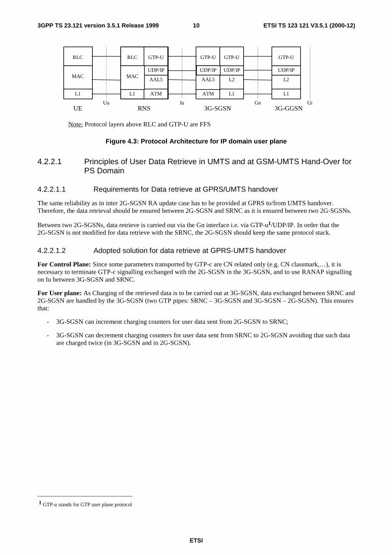
The protocol stack is shown in figure 4.3.
ETSI
ETSI TS 123 121 V3.5.1 (2000-12)103GPP TS 23.121 version 3.5.1 Release 1999
RLC
MAC
L1
GTP-U
BSSGP
ATM
L2
L1
UDP/IP
L2
L1
UDP/IP
Uu Iu Gn GiUE RNS 3G-SGSN 3G-GGSN
GTP-UGTP-U
UDP/IP
RLC
L1
AAL5
ATM
UDP/IP
GTP-U
MAC
Note: Protocol layers above RLC and GTP-U are FFS
AAL5
Figure 4.3: Protocol Architecture for IP domain user plane
4.2.2.1 Principles of User Data Retrieve in UMTS and at GSM-UMTS Hand-Over forPS Domain
4.2.2.1.1 Requirements for Data retrieve at GPRS/UMTS handover
The same reliability as in inter 2G-SGSN RA update case has to be provided at GPRS to/from UMTS handover.Therefore, the data retrieval should be ensured between 2G-SGSN and SRNC as it is ensured between two 2G-SGSNs.
Between two 2G-SGSNs, data retrieve is carried out via the Gn interface i.e. via GTP-u1/UDP/IP. In order that the2G-SGSN is not modified for data retrieve with the SRNC, the 2G-SGSN should keep the same protocol stack.
4.2.2.1.2 Adopted solution for data retrieve at GPRS-UMTS handover
For Control Plane: Since some parameters transported by GTP-c are CN related only (e.g. CN classmark,…), it isnecessary to terminate GTP-c signalling exchanged with the 2G-SGSN in the 3G-SGSN, and to use RANAP signallingon Iu between 3G-SGSN and SRNC.
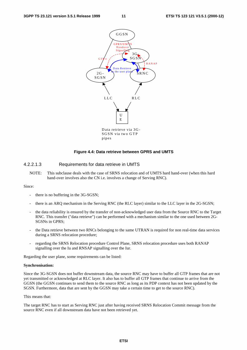
For User plane: As Charging of the retrieved data is to be carried out at 3G-SGSN, data exchanged between SRNC and2G-SGSN are handled by the 3G-SGSN (two GTP pipes: SRNC – 3G-SGSN and 3G-SGSN – 2G-SGSN). This ensuresthat:
- 3G-SGSN can increment charging counters for user data sent from 2G-SGSN to SRNC;
- 3G-SGSN can decrement charging counters for user data sent from SRNC to 2G-SGSN avoiding that such dataare charged twice (in 3G-SGSN and in 2G-SGSN).
1 GTP-u stands for GTP user plane protocol
ETSI
ETSI TS 123 121 V3.5.1 (2000-12)113GPP TS 23.121 version 3.5.1 Release 1999
G G S N
2G -S G S N
S R N C
UE
R L CL L C
3G -S G S N
D ata re trieve v ia 3G -S G S N via tw o G T Ppipes
D ata R etrieveIn th e u ser p lan e
G P R S /U M T SH and overS ign a llin g
R A N A P
G T P -c
Figure 4.4: Data retrieve between GPRS and UMTS
4.2.2.1.3 Requirements for data retrieve in UMTS
NOTE: This subclause deals with the case of SRNS relocation and of UMTS hard hand-over (when this hardhand-over involves also the CN i.e. involves a change of Serving RNC).
Since:
- there is no buffering in the 3G-SGSN;
- there is an ARQ mechanism in the Serving RNC (the RLC layer) similar to the LLC layer in the 2G-SGSN;
- the data reliability is ensured by the transfer of non-acknowledged user data from the Source RNC to the TargetRNC. This transfer ("data retrieve") can be performed with a mechanism similar to the one used between 2G-SGSNs in GPRS;
- the Data retrieve between two RNCs belonging to the same UTRAN is required for non real-time data servicesduring a SRNS relocation procedure;
- regarding the SRNS Relocation procedure Control Plane, SRNS relocation procedure uses both RANAPsignalling over the Iu and RNSAP signalling over the Iur.
Regarding the user plane, some requirements can be listed:
Synchronisation:
Since the 3G-SGSN does not buffer downstream data, the source RNC may have to buffer all GTP frames that are notyet transmitted or acknowledged at RLC layer. It also has to buffer all GTP frames that continue to arrive from theGGSN (the GGSN continues to send them to the source RNC as long as its PDP context has not been updated by theSGSN. Furthermore, data that are sent by the GGSN may take a certain time to get to the source RNC).
This means that:
The target RNC has to start as Serving RNC just after having received SRNS Relocation Commit message from thesource RNC even if all downstream data have not been retrieved yet.

ETSI
ETSI TS 123 121 V3.5.1 (2000-12)123GPP TS 23.121 version 3.5.1 Release 1999
The user data retrieve may last a relatively long time. A timer is armed in the Source SRNC at the beginning of the datatransfer phase. The contexts related to the UE in the Source SNRC will be released when the timer expires, i.e. whendownstream data from GGSN is considered as finished.
Data reliability:
Depending upon the required reliability, there could be a need for a layer 2 protocol or not. In the GPRS, the user data istransfer via GTP/UPD/IP if the user-to-user data is IP-based, and via GTP/TCP/IP if the user-to-user data is X25-based.Here, only GTP/UDP/IP is considered.
Multiplexing of PDP contexts during data retrieve:
Several SRNS Relocation procedures for different users and/or different bearers may be carried out simultaneously andindependently. GTP is used to differentiate the data retrieve contexts.
Associated signalling:
Considering signalling, there are two kinds of signalling:
Signalling linked with transmission of CN parameters. This corresponds to signalling exchanged on Gn between 3G-SGSNs during the (first) phase of resources for the SRNS relocation.
Signalling linked with the transmission of the sequence numbers of the acknowledged protocol (RLC) between SRNCand UE. This can be done over Iur when the source SRNC actually hands-over the role of SRNC (when sending theRNSAP "Relocation commit" to the target SRNS).
4.2.2.1.4 Adopted solution for data retrieve in UMTS
Data Retrieve procedure at SRNS relocation shall be carried out through the Iu interface: data exchanged betweensource and target SRNC are carried over Iu at ATM layer. They are routed at IP layer towards the target SRNC andthere is one single GTP tunnel between the source SRNC and the target SRNC.
SRNC
GGSN
SRNC
UE
RLCRLC
3G-SGSN 3G-SGSN
data retrieve via 3G-SGSN
User data stream
RNSAPSignalling
SRNSRelocationSignalling
GTP-c
RANAPRANAP
Figure 4.5: User data Retrieve in UMTS
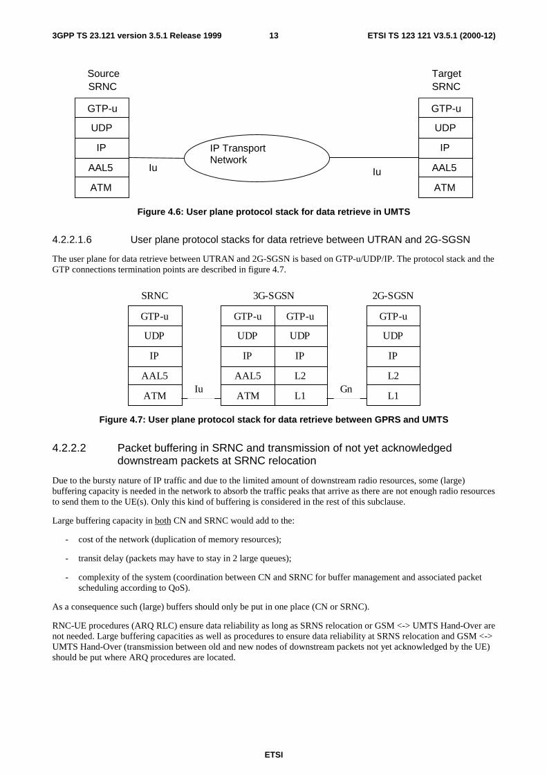
4.2.2.1.5 User plane protocol stacks for UMTS data retrieve
The user plane for data retrieve between two RNCs is based on GTP-u/UDP/IP. The GTP connections are terminated inthe source SNRC and the target SRNC as described in figure 4.6.
ETSI
ETSI TS 123 121 V3.5.1 (2000-12)133GPP TS 23.121 version 3.5.1 Release 1999
Iu Iu
GTP-u
AAL5
IP
UDP
ATM
GTP-u
AAL5
IP
UDP
ATM
SourceSRNC
TargetSRNC
IP TransportNetwork
Figure 4.6: User plane protocol stack for data retrieve in UMTS
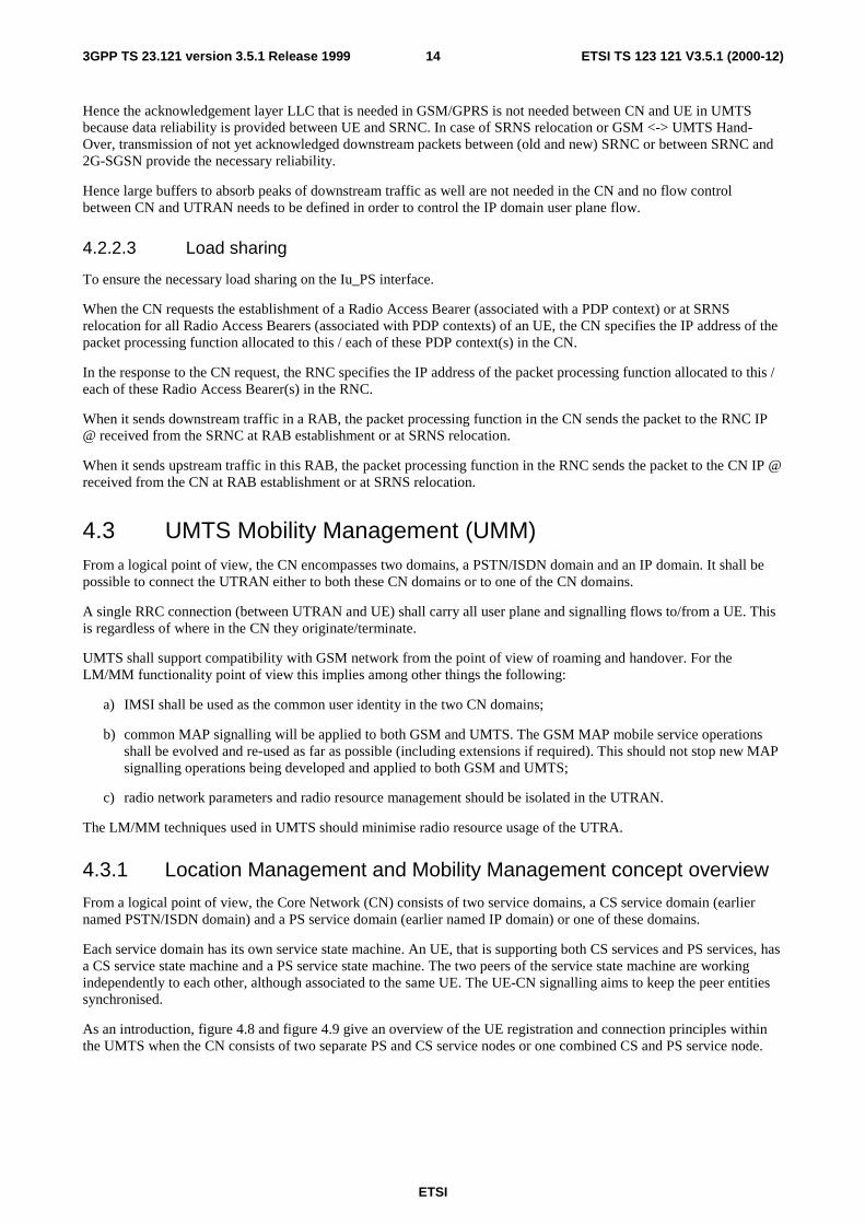
4.2.2.1.6 User plane protocol stacks for data retrieve between UTRAN and 2G-SGSN
The user plane for data retrieve between UTRAN and 2G-SGSN is based on GTP-u/UDP/IP. The protocol stack and theGTP connections termination points are described in figure 4.7.
GTP-u
AAL5
IP
UDP
ATM
GTP-u
L2
IP
UDP
L1
SRNC 3G-SGSN 2G-SGSN
GTP-u
L2
IP
UDP
L1
GTP-u
AAL5
IP
UDP
ATMIu Gn
Figure 4.7: User plane protocol stack for data retrieve between GPRS and UMTS
4.2.2.2 Packet buffering in SRNC and transmission of not yet acknowledgeddownstream packets at SRNC relocation
Due to the bursty nature of IP traffic and due to the limited amount of downstream radio resources, some (large)buffering capacity is needed in the network to absorb the traffic peaks that arrive as there are not enough radio resourcesto send them to the UE(s). Only this kind of buffering is considered in the rest of this subclause.
Large buffering capacity in both CN and SRNC would add to the:
- cost of the network (duplication of memory resources);
- transit delay (packets may have to stay in 2 large queues);
- complexity of the system (coordination between CN and SRNC for buffer management and associated packetscheduling according to QoS).
As a consequence such (large) buffers should only be put in one place (CN or SRNC).
RNC-UE procedures (ARQ RLC) ensure data reliability as long as SRNS relocation or GSM <-> UMTS Hand-Over arenot needed. Large buffering capacities as well as procedures to ensure data reliability at SRNS relocation and GSM <->UMTS Hand-Over (transmission between old and new nodes of downstream packets not yet acknowledged by the UE)should be put where ARQ procedures are located.
ETSI
ETSI TS 123 121 V3.5.1 (2000-12)143GPP TS 23.121 version 3.5.1 Release 1999
Hence the acknowledgement layer LLC that is needed in GSM/GPRS is not needed between CN and UE in UMTSbecause data reliability is provided between UE and SRNC. In case of SRNS relocation or GSM <-> UMTS Hand-Over, transmission of not yet acknowledged downstream packets between (old and new) SRNC or between SRNC and2G-SGSN provide the necessary reliability.
Hence large buffers to absorb peaks of downstream traffic as well are not needed in the CN and no flow controlbetween CN and UTRAN needs to be defined in order to control the IP domain user plane flow.
4.2.2.3 Load sharing
To ensure the necessary load sharing on the Iu_PS interface.
When the CN requests the establishment of a Radio Access Bearer (associated with a PDP context) or at SRNSrelocation for all Radio Access Bearers (associated with PDP contexts) of an UE, the CN specifies the IP address of thepacket processing function allocated to this / each of these PDP context(s) in the CN.
In the response to the CN request, the RNC specifies the IP address of the packet processing function allocated to this /each of these Radio Access Bearer(s) in the RNC.
When it sends downstream traffic in a RAB, the packet processing function in the CN sends the packet to the RNC IP@ received from the SRNC at RAB establishment or at SRNS relocation.
When it sends upstream traffic in this RAB, the packet processing function in the RNC sends the packet to the CN IP @received from the CN at RAB establishment or at SRNS relocation.
4.3 UMTS Mobility Management (UMM)From a logical point of view, the CN encompasses two domains, a PSTN/ISDN domain and an IP domain. It shall bepossible to connect the UTRAN either to both these CN domains or to one of the CN domains.
A single RRC connection (between UTRAN and UE) shall carry all user plane and signalling flows to/from a UE. Thisis regardless of where in the CN they originate/terminate.
UMTS shall support compatibility with GSM network from the point of view of roaming and handover. For theLM/MM functionality point of view this implies among other things the following:
a) IMSI shall be used as the common user identity in the two CN domains;
b) common MAP signalling will be applied to both GSM and UMTS. The GSM MAP mobile service operationsshall be evolved and re-used as far as possible (including extensions if required). This should not stop new MAPsignalling operations being developed and applied to both GSM and UMTS;
c) radio network parameters and radio resource management should be isolated in the UTRAN.
The LM/MM techniques used in UMTS should minimise radio resource usage of the UTRA.
4.3.1 Location Management and Mobility Management concept overview
From a logical point of view, the Core Network (CN) consists of two service domains, a CS service domain (earliernamed PSTN/ISDN domain) and a PS service domain (earlier named IP domain) or one of these domains.
Each service domain has its own service state machine. An UE, that is supporting both CS services and PS services, hasa CS service state machine and a PS service state machine. The two peers of the service state machine are workingindependently to each other, although associated to the same UE. The UE-CN signalling aims to keep the peer entitiessynchronised.
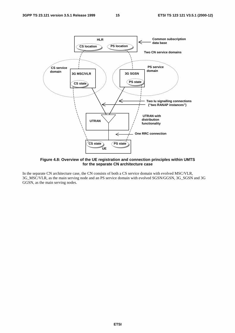
As an introduction, figure 4.8 and figure 4.9 give an overview of the UE registration and connection principles withinthe UMTS when the CN consists of two separate PS and CS service nodes or one combined CS and PS service node.
ETSI
ETSI TS 123 121 V3.5.1 (2000-12)153GPP TS 23.121 version 3.5.1 Release 1999
Two Iu signalling connections (“two RANAP instances”)
UTRAN
3G SGSN
HLR
3G MSC/VLR
UE
CS servicedomain
Two CN service domains
One RRC connection
UTRAN withdistributionfunctionality
PS servicedomain
Common subscription data base
CS state PS state
PS state CS state
CS location PS location
Figure 4.8: Overview of the UE registration and connection principles within UMTSfor the separate CN architecture case
In the separate CN architecture case, the CN consists of both a CS service domain with evolved MSC/VLR,3G_MSC/VLR, as the main serving node and an PS service domain with evolved SGSN/GGSN, 3G_SGSN and 3GGGSN, as the main serving nodes.
ETSI
ETSI TS 123 121 V3.5.1 (2000-12)163GPP TS 23.121 version 3.5.1 Release 1999
Two Iu signalling connections “two RANAP instances”
UTRAN
HLR
UMSC
UE
CS servicedomain
Two CN service domains
One RRC connection
UTRAN withdistributionfunctionality
PS servicedomain
Common subscription data base
CS state PS state
PS state CS state
CS location PS location
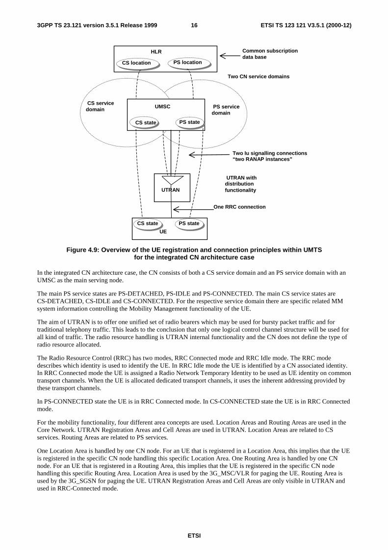
Figure 4.9: Overview of the UE registration and connection principles within UMTSfor the integrated CN architecture case
In the integrated CN architecture case, the CN consists of both a CS service domain and an PS service domain with anUMSC as the main serving node.
The main PS service states are PS-DETACHED, PS-IDLE and PS-CONNECTED. The main CS service states areCS-DETACHED, CS-IDLE and CS-CONNECTED. For the respective service domain there are specific related MMsystem information controlling the Mobility Management functionality of the UE.
The aim of UTRAN is to offer one unified set of radio bearers which may be used for bursty packet traffic and fortraditional telephony traffic. This leads to the conclusion that only one logical control channel structure will be used forall kind of traffic. The radio resource handling is UTRAN internal functionality and the CN does not define the type ofradio resource allocated.
The Radio Resource Control (RRC) has two modes, RRC Connected mode and RRC Idle mode. The RRC modedescribes which identity is used to identify the UE. In RRC Idle mode the UE is identified by a CN associated identity.In RRC Connected mode the UE is assigned a Radio Network Temporary Identity to be used as UE identity on commontransport channels. When the UE is allocated dedicated transport channels, it uses the inherent addressing provided bythese transport channels.
In PS-CONNECTED state the UE is in RRC Connected mode. In CS-CONNECTED state the UE is in RRC Connectedmode.
For the mobility functionality, four different area concepts are used. Location Areas and Routing Areas are used in theCore Network. UTRAN Registration Areas and Cell Areas are used in UTRAN. Location Areas are related to CSservices. Routing Areas are related to PS services.
One Location Area is handled by one CN node. For an UE that is registered in a Location Area, this implies that the UEis registered in the specific CN node handling this specific Location Area. One Routing Area is handled by one CNnode. For an UE that is registered in a Routing Area, this implies that the UE is registered in the specific CN nodehandling this specific Routing Area. Location Area is used by the 3G_MSC/VLR for paging the UE. Routing Area isused by the 3G_SGSN for paging the UE. UTRAN Registration Areas and Cell Areas are only visible in UTRAN andused in RRC-Connected mode.
ETSI
ETSI TS 123 121 V3.5.1 (2000-12)173GPP TS 23.121 version 3.5.1 Release 1999
For the relations between Location Area (LA) and Routing Area (RA) is described in subclause 4.3.2.
In RRC Idle mode it is the broadcasted MM system information (e.g. information about the present Location Area andpresent Routing Area) that determines when the UE initiates a location registration procedure towards the CN. An UEin state CS-IDLE will in RRC Idle mode, initiate Location Area update towards the CN when crossing LA border. AnUE in state PS-IDLE will in RRC Idle mode initiate Routing Area update towards the CN when crossing RA border.
In RRC Connected mode, the UE receives the MM system information on the established RRC connection. (I.e. thebroadcasted MM system information is not used by the UE in the RRC connected mode.) An UE in state CS-IDLE will,in RRC Connected mode, initiate Location Area update towards the CN when receiving information indicating a newLocation Area. An UE in state PS-IDLE will, in RRC Connected mode, initiate Routing Area update towards the CNwhen receiving information indicating a new Routing Area. An UE in state CS-CONNECTED will, in RRC Connectedmode, not initiate Location Area update towards the CN. An UE in state PS- CONNECTED will, in RRC Connectedmode, not initiate Routing Area update towards the CN.
In CS-DETACHED mode the UE will not initiate any Location Area update and this independent of the RRC mode. InPS-DETACHED mode the UE will not initiate any Routing Area update and this independent of the RRC mode.
In additional to normal location registration when changing registration area, the UE may (network options) perform CSperiodic registration when in CS-IDLE state and PS periodic registration when in PS-IDLE state. The respectiveperiodic registration may be on/off on Location Area respective Routing Area level.
On the Mobility Management level, IMSI and CS related TMSI are used as UE identities in the CS service domain, andIMSI and PS related TMSI are used as UE identities in the PS service domain. The IMSI is the common UE identity forthe two CN service domains.
A signalling connection between the UE and the CN refers to a logical connection consisting of an RRC connectionbetween UE and UTRAN and an Iu signalling connection ("one RANAP instance") between the UTRAN and the CNnode. The CS service domain related signalling and PS service domain related signalling uses one common RRCconnection and two Iu signalling connections ("two RANAP instances"), i.e. one Iu signalling connection for the CSservice domain and one Iu signalling connection for the PS service domain.
4.3.1.1 Use of combined procedures for UMTS
The use of separated PS and CS mobility mechanisms within the UE and within the CN may lead to non-optimal usageof the radio resource (for example a UE in PS idle and CS idle state would perform both location updates (for the CSmechanism) and Routing area updates (for PS mechanisms)).
UMTS should optimise the use of radio resources., The use of combined updates (similar to the current GSM/GPRS Gscombined update mechanism) may enable this. To offer flexibility in the provision of mobility management for UMTS,it should be possible to use combined mechanisms for location management purposes as well as for attach/detach statuspurposes.
From the UE perspective it should be possible for the UE to perform combined update mechanisms (operator option).UMTS Phase 1 R99 terminals should support the use of both combined and separate mechanisms. The support of thisfeature by all UMTS mobiles will also ease evolution of UMTS MM in the future.
In the UMTS specifications the RAN will not co-ordinate mobility management procedures that are logically betweenthe core network and the MS. This includes: location management, authentication, temporary identity management andequipment identity check.
4.3.2 Description of the Location Management and Mobility ManagementConcept
4.3.2.1 Area concepts
For the mobility functionality four different area concepts are used. Location Area and Routing Area in the CN as wellas UTRAN Registration Area and Cell areas in the UTRAN.
ETSI
ETSI TS 123 121 V3.5.1 (2000-12)183GPP TS 23.121 version 3.5.1 Release 1999
4.3.2.1.1 Location areas
For CS services, the CN uses Location Areas (LA). Location Area is used e.g. at CN initiated paging related to CSservices. A CS service related temporary identity, CS –TMSI, may be allocated to the UE. This temporary identity isthen unique within a LA.
4.3.2.1.2 Routing areas
For PS services, the CN uses Routing Areas (RA). Routing Area is used e.g. at CN initiated paging related to PSservices. A PS service related temporary identity, PS-TMSI, may be allocated to the UE. This temporary identity is thenunique within a RA.
4.3.2.1.3 UTRAN internal areas
UTRAN internal areas are used when the terminal is in RRC-Connected mode (see chapter 3.3). The areas are used ate.g. UTRAN initiated paging. UTRAN internal area updating is a radio network procedure and the UTRAN internalarea structure should not be visible outside UTRAN. In RRC connected mode, the UE position is known on cell level oron UTRAN Registration Area (URA) level. RNTI is used as a temporary UE identifier used within UTRAN andallocated at RRC connection establishment.
4.3.2.1.4 Relationship between the different areas
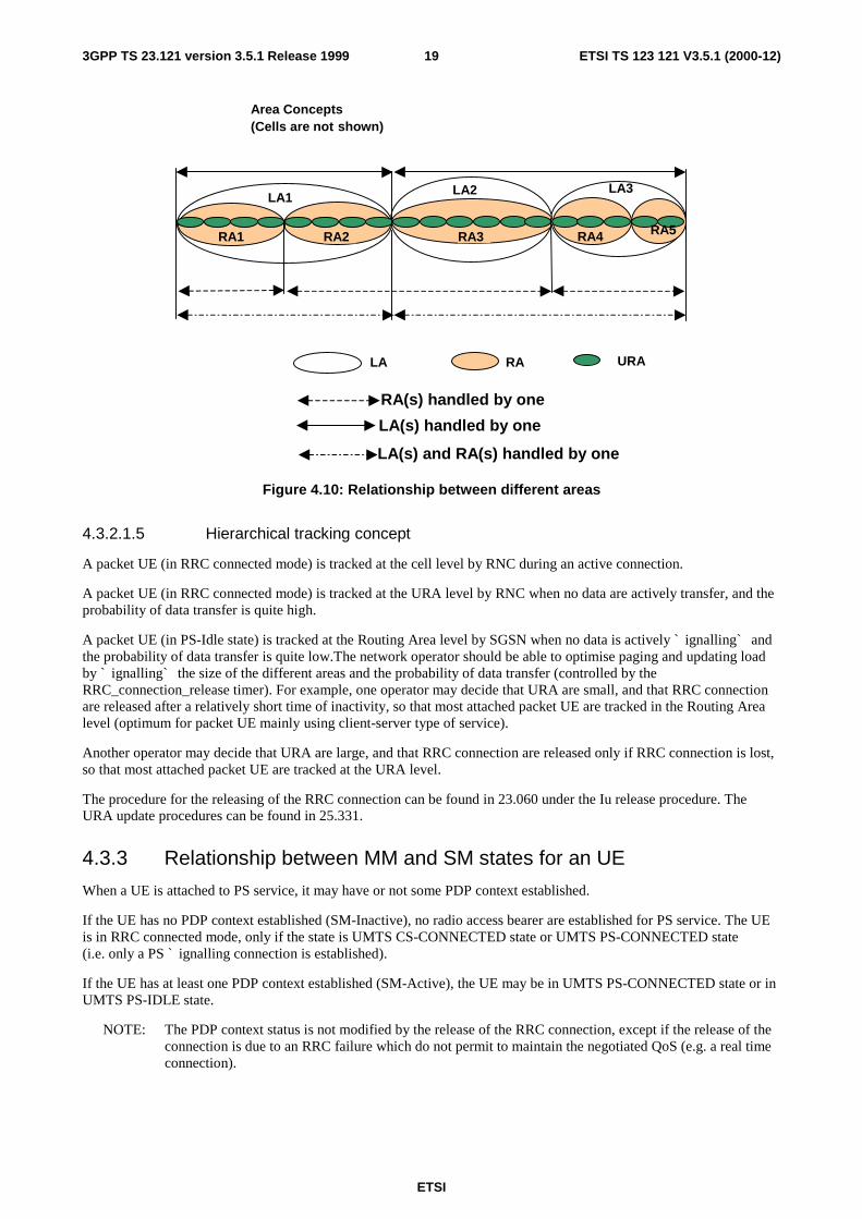
The following area relations exist:
- there may not be any relation between URA and LA respectively between URA and RA. The URA concept isdefined in TS 25.331;
- one RA consists of a number of cells belonging to RNCs that are connected to the same CN node;
- one LA consists of a number of cells belonging to RNCs that are connected to the same CN node;
- one RA is handled by only one CN serving node, i.e. one UMSC or one 3G_SGSN;
- one LA is handled by only one CN serving node, i.e. one UMSC or one 3G_MSC/VLR.
The GSM defined relations between LA and RA applies i.e. the following relations between LA and RA are possible:
- RA and LA is equal;
- one RA is a subset of one, and only one, LA, meaning that a RA do not span more than one LA.
The mapping between one LA and RNCs is handled within the MSC/VLR owning this LA. The mapping between oneRA and RNCs is handled within the SGSN owning this RA. The mapping between LA and cells respective between RAand cells is handled within RNC.
ETSI
ETSI TS 123 121 V3.5.1 (2000-12)193GPP TS 23.121 version 3.5.1 Release 1999
Area Concepts(Cells are not shown)
RA(s) handled by one
LA(s) handled by one
RA1 RA2 RA3
LA1 LA2
RA4
LA3
RA5
URALA RA
LA(s) and RA(s) handled by one
Figure 4.10: Relationship between different areas
4.3.2.1.5 Hierarchical tracking concept
A packet UE (in RRC connected mode) is tracked at the cell level by RNC during an active connection.
A packet UE (in RRC connected mode) is tracked at the URA level by RNC when no data are actively transfer, and theprobability of data transfer is quite high.
A packet UE (in PS-Idle state) is tracked at the Routing Area level by SGSN when no data is actively ` ignalling` andthe probability of data transfer is quite low.The network operator should be able to optimise paging and updating loadby ` ignalling` the size of the different areas and the probability of data transfer (controlled by theRRC_connection_release timer). For example, one operator may decide that URA are small, and that RRC connectionare released after a relatively short time of inactivity, so that most attached packet UE are tracked in the Routing Arealevel (optimum for packet UE mainly using client-server type of service).
Another operator may decide that URA are large, and that RRC connection are released only if RRC connection is lost,so that most attached packet UE are tracked at the URA level.
The procedure for the releasing of the RRC connection can be found in 23.060 under the Iu release procedure. TheURA update procedures can be found in 25.331.
4.3.3 Relationship between MM and SM states for an UE
When a UE is attached to PS service, it may have or not some PDP context established.
If the UE has no PDP context established (SM-Inactive), no radio access bearer are established for PS service. The UEis in RRC connected mode, only if the state is UMTS CS-CONNECTED state or UMTS PS-CONNECTED state(i.e. only a PS ` ignalling connection is established).
If the UE has at least one PDP context established (SM-Active), the UE may be in UMTS PS-CONNECTED state or inUMTS PS-IDLE state.
NOTE: The PDP context status is not modified by the release of the RRC connection, except if the release of theconnection is due to an RRC failure which do not permit to maintain the negotiated QoS (e.g. a real timeconnection).
ETSI
ETSI TS 123 121 V3.5.1 (2000-12)203GPP TS 23.121 version 3.5.1 Release 1999
4.3.4 Requirement in case of temporarily loss of coverage of packet UE
A packet attached UE using non-real time bearer shall not lose its PDP context in case of temporarily loss of coverage.AUE specific Mobile Reachable Timer should monitor how long PDP context(s) are kept after a UE has lost coverage.
4.3.5 MM functionality in different UE service states
Below are the main UE service states and related MM functionality described. For the determination on when LA orRA is changed, see chapter on "Handling of MM system information".
CS service states and related MM functionality:
- CS-DETACHED: The UE is not reachable by the network for CS services. The UE does not initiate LA updatesat LA changes and no periodic CS service updates;
- CS-IDLE: The UE is reachable by paging for CS services. The UE initiates LA updates at LA changes. The UEmay initiate periodic CS service updates and this depending on the CS periodic update state of the present LA;
- CS-CONNECTED: The UE has a signalling connection for CS services established between the UE and the CN.The UE does not initiate LA update (even not when the present LA changes) and no periodic CS service updates.
PS service states and related MM functionality:
- PS-DETACHED: The UE is not reachable by the network for PS services. The UE does not initiate RA updatesat RA changes and no periodic PS service updates;
- PS-IDLE: The UE is reachable by paging for PS services. The UE initiates RA updates at RA changes. The UEmay initiate periodic PS service updates and this depending on the PS periodic update state of the present RA;
- PS-CONNECTED: The UE has a signalling connection for PS services established between the UE and the CN.The UE initiates RA update when RAI in MM system information changes. No periodic PS service updates.
There may also be a NULL state. In the UE, this state corresponds to power off or maybe a "no SIM" condition. In theCN, the NULL state correspond to CS-DETACHED and PS-DETACHED.
For each state transition there can be several events that triggers the transition. Some of them are described below.
NOTE: Some of these may coincide, e.g. moving from CS-IDLE to CS-DETACHED and moving from PS-IDLEto PS-DETACHED.
Moving from CS-IDLE to CS-CONNECTED:
The state transition from CS-IDLE to CS-CONNECTED is performed when a signalling connection is establishedbetween UE and CN for CS services. In GSM this state transition is triggered by the messageCM_SERVICE_REQUEST or PAGE_RESPONSE.
Moving from CS-CONNECTED to CS-IDLE:
The state transition from CS-CONNECTED to CS-IDLE is performed when the signalling connection for CS services isreleased, e.g. at call release and no other CS service is ongoing. A radio link failure may also trigger this state transition.
Moving from CS-IDLE to CS-DETACHED:
The transition from CS-IDLE to CS-DETACHED may be triggered by some action from the user of the UE but anexpiring timer in the network could also trigger it. The UE is marked as CS_DETACHED in the CN and then as aconsequence no CS service establishment is possible.
Moving from PS-IDLE to PS-CONNECTED:
The state transition from PS-IDLE to PS-CONNECTED is performed when a signalling connection is establishedbetween UE and CN for PS services.

ETSI
ETSI TS 123 121 V3.5.1 (2000-12)213GPP TS 23.121 version 3.5.1 Release 1999
Moving from PS-CONNECTED to PS-IDLE:
The state transition from PS-CONNECTED to PS-IDLE is performed when the signalling connection for PS services isreleased, e.g. at release of a PS service, no other PS service is ongoing and at release of the RRC connection in case ofvery low level of activity. A radio link failure may also trigger this state transition.
Moving from PS-IDLE to PS-DETACHED:
The transition from PS-IDLE to PS-DETACHED may be triggered by some action from the user of the UE but anexpiring timer in the network could also trigger it. The UE is marked as PS_DETACHED in the CN and then as aconsequence no PS service establishment is possible.
4.3.6 The RRC state machine
The RRC state machine is a description model of how the UE and the UTRAN co-operate regarding RRC functionality.The RRC state describes the state of the UE in the UTRAN. Here follows a brief description of the RRC state machine,for more information see [UMTS YY.01] and [UMTS YY.03].
NOTE: RRC idle mode and RRC connected mode refer to the UE idle mode and UE connected mode respectivelyin [UMTS YY.01] and [UMTS YY.03].
The RRC state machine exists as peer entities, one in the UE and one in UTRAN. Apart from transient situations anderror cases they are synchronised. The figure below illustrates the main modes/states of the RRC state machine.
Idle mode
CellConnected
RRCconnectionestablishment
URAConnected
RRCconnectionrelease
Enter URAconnected state
Enter cellconnected state
Connected mode
Figure 4.11: RRC modes, main RRC states and main mode/state transitions
RRC-Idle_mode:
In the Idle mode there is no connection established between UE and UTRAN. There is no signalling between UTRANand the UE except for system information that is sent from UTRAN down link on a Broadcast channel to the UE. TheUE can also receive paging messages with a CN identity on the PCH. There is no information on the UE stored inUTRAN in this state.
RRC-Connected_mode:
In the Connected mode the main states are Cell Connected state and URA connected state. In this mode there is oneRNC that is acting as Serving RNC (SRNC), and an RRC connection is established between the UE and this SRNC.
- When the UE position is known on cell level, the UE is in the cell connected state. When in cell connected state,the RRC connection mobility is handled by handover procedures.
- When the UE position is known on URA level, the UE is in the URA connected state. The URA contains a set ofcells. URA updating procedures provides the mobility functionality in this state. In URA connected state nodedicated radio resources are used.

ETSI
ETSI TS 123 121 V3.5.1 (2000-12)223GPP TS 23.121 version 3.5.1 Release 1999
4.3.7 Relationship between CS and PS service states and RRC state foran UE
During non-transient conditions the following relations are valid between service states and RRC modes for an UE:
- when in either CS-CONNECTED state or PS-CONNECTED state, or in both CS-CONNECTED state and PS-CONNECTED state, then the UE is in RRC connected mode;
- when in neither CS-CONNECTED state nor PS-CONNECTED state, then the UE is in RRC idle mode.
Figure 4.12 and figure 4.13 illustrate two examples on the relations between the RRC states and CS/PS service states.These figures illustrate the separated CN case.
SRNC RNC
3G_MSC/VLR 3G_SGSN
RRC state
CS state
UE
RRC CELL-CONNECTED
CS-CONNECTED
RRC CELL-CONNECTED
PS-IDLE
PS-IDLE
PS state
CS-CONNECTED
Or UMSC
Figure 4.12: UE in CS-CONNECTED state and PS-IDLE state
RNC RNC
3G_MSC/VLR 3G_SGSN
UE
RRC IDLE MODE
CSIDLE
RRC IDLEMODE
CS-IDLE
PSDETACHED
PS-DETACHED
RRC state
CS state
PS state
Or UMSC
Figure 4.13

ETSI
ETSI TS 123 121 V3.5.1 (2000-12)233GPP TS 23.121 version 3.5.1 Release 1999
4.3.8 Service registration and location update
Service registration (attach) in the respective CN service domain is done initially (after UE being detached due toe.g. power off). When a registration area is changed a location update is performed. In addition, periodic registrationcan be performed. Here follows descriptions of when the respective CN registration area is changed.
NOTE: It is not here defined which different registration procedures that are needed.
4.3.8.1 Location area update
Location area update is initiated by the UE to inform the CS service domain of the core network that the UE has entereda new location area. In case the new location area is in an area served by another CN node, the location area update alsotriggers the registration of the subscriber in the new CN node and a location update for CS services towards the HLR.
Location area update is only initiated by the UE when the UE is in state CS-IDLE, and this independently of the PSstate. If the UE is CS-IDLE but RRC connected, which means that the UE is in PS-CONNECTED state, location areaupdate is initiated by the UE when it receives information indicating a new location area (see also the chapter "Handlingof MM system information").
4.3.8.2 Routing area update
Routing area update is initiated by the UE to inform the PS service domain of the core network that the UE has entereda new routing area. In case the new routing area is in an area served by another CN node, the routing area update alsotriggers the registration of the subscriber in the new CN node and a location update for PS services towards the HLR.
Routing area update is initiated by the UE when the UE is in state PS-IDLE, and this independently of the CS state. Ifthe UE is PS-IDLE but RRC connected, which means that the UE is in CS-CONNECTED state, routing area update isinitiated by the UE when it receives information indicating a new routing area (see also the chapter "Handling of MMsystem information").
When the UE is in PS-CONNECTED state the UE initiates RA update when RAI in MM system information changes.
4.3.8.3 Combined updates
The GSM radio interface combined procedures and their support via the Gs interface is the starting point for the supportof combined updates.
4.3.9 Paging initiated by CN
Here follows a possible solution with a page co-ordination within the UTRAN. Other alternatives are possible.
- A CN node requests paging only for UE in CS-IDLE state or PS IDLE state. In the separate CN architecture,paging from a CN node is done independent of the service state of the UE in the other CN service domain.
- In this alternative with page co-ordination in UTRAN, the UE does not need to listen to the PCH (Page Channel)in RRC connected mode (at least not when UE is allocated a dedicated channel).
- At each page request received from a CN node, the RNC controls whether the UE has an established RRCconnection or not. For this, the context that is build up in the SRNC for UE in RRC connected mode mustcontain the IMSI, i.e. the UE identity common for the two CN domains.
- If no context is found for the UE, "normal PCH paging" is performed. This implies transfer on the Pagingchannel of a page message indicating the UE paging identity received from the CN and a CN service domaintype indication.
- If a context is found, a "CN paging message" is transferred using the existing RRC connection. This messageindicates then the UE paging identity received from the CN and a CN service domain type indication.
- In case of a single CN element, paging may be (but not mandatory) co-ordinated at the CN.
ETSI
ETSI TS 123 121 V3.5.1 (2000-12)243GPP TS 23.121 version 3.5.1 Release 1999
NOTE: The RNC might use another identity e.g. TMSI, P-TMSI, or other radio related identity, to page themobile.
4.3.10 Signalling connection establishment
A signalling connection between the UE and a CN node refers here to a logical connection consisting of an RRCconnection between UE and UTRAN and an Iu signalling connection between UTRAN and the CN node. Thesignalling connection is used for transfer of higher layer (MM, CM) information between the UE and the CN node.
At a CM service request to one of the CN service domains, UE will only request establishment of a new signallingconnection when no such connection exists towards the applicable CN service domain.
If no RRC connection exists, this is established in conjugation with (before) the transfer of the signalling establishmentrequest. At the RRC connection establishment, an UE context is built up in the SRNC.
If an RRC connection is already established, the UE will send the signalling establishment request using that RRCconnection.
At reception of the signalling establishment request, the SRNC will establish an Iu connection towards the CN nodeindicated by the CN service domain type received from UE.
4.3.11 Relations between SRNS relocation and Location registration
This chapter is included in order to clarify the need for separate handling of MM registration area (LA and RA)information in RRC idle mode respective in RRC connected mode. The following example illustrates relations betweenSRNC relocation, registration area (LA/RA) change and location/routing area updates. As shown in the example, this isequally applicable for a UMSC as well as the 3G-MSC/VLR and 3G-SGSN.
NOTE 1: The example is based on the assumptions that one RNC can set up Iu connections to only one3G_MSC/VLR (or UMSC) and only one 3G_SGSN (or UMSC), and that the CN node is configured toonly send page to the RNC(s) that is controlling cells within the relevant LA/RA.
Preconditions:
- LA1 (Location Area 1) is handled by 3G_MSC/VLR1 (or UMSC1) and LA2 is handled by 3G_MSC/VLR2 (orUMSC2);
- RA1 (Routing Area 1) is handled by 3G_SGSN1 (or UMSC1) and RA2 is handled by 3G_SGSN2 (or UMSC2);
- UE is registered in LA1 in 3G_MSC/VLR1 and in RA1 in 3G_SGSN1;
- the UE is in PS-CONNECTED state and a signalling connection exists between UE and 3G_SGSN1;
- the UE is in CS-IDLE state and no signalling connection exists between UE and 3G_MSC/VLR1;
- RNC1 is acting as SRNC and RNC2 is acting as DRNC;
- UE is in RRC cell connected state and with dedicated channels established to cells within both RNC1 and RNC2.UE does not listening to the PCH;
- the registration area information sent to the UE indicates LA1 and RA1.
The UE can always (at least in normal working states) identify the present available registration area (LA respectiveRA) associated with the respective CN service domain. The determination of the present area differs depending on thestate of the UE. For UE in RRC idle mode (UE with no ongoing communication with the network) it is the cell selectionmechanism in the UE that is used. For UE in RRC connected mode it is the UTRAN that determines the area (althougha change can implicit be initiated by the UE).
It is the network that supplies the MM system information to the UE. For UE in RRC idle mode the MM systeminformation is provided by the system information broadcasting function. For UE in RRC connected mode, the MMsystem information is supplied by the SRNC to the UE at each change of this information. This leads to that in RRCconnected mode, the MM registration area (e.g. LA and RA) information sent on broadcast channel is not used.

ETSI
ETSI TS 123 121 V3.5.1 (2000-12)253GPP TS 23.121 version 3.5.1 Release 1999
Or UMSC2 Or UMSC1
LA1, RA1
SGSN1 SGSN2MSC1 MSC2
RNC1 RNC2
UE
LA2, RA2
Figure 4.14: Illustration of the preconditions in the described example
In figure 4.14 MSC stands for 3G_MSC/VLR and SGSN for 3G_SGSN.
The UE moves now further towards right, leaving the coverage area of cells controlled by RNC1, and resulting in thatthe UE has dedicated channel(s) established to cell(s) within only RNC2. This may result in the following sequence ofevents:
- the SRNC (RNC1) may decide to perform an SRNC relocation resulting in that the RNC2 becomes SRNC. Thechange of SRNC will in this example also imply a change of SGSN (or UMSC) with an update of the UElocation registration for the PS service domain;
- after this SRNC relocation or combined with this procedure, the MM registration area information sent to the UEis changed and indicates now LA2 and RA2;
NOTE 2: The MM registration area information need not be sent for every SRNS relocation, nor does it precludeMM registration area information being sent in other occasions.
- the changed MM registration area information will result in that the UE initiates a location update, which resultsin a registration change from LA1 in 3G_MSC/VLR1 to LA2 in 3G_MSC/VLR2.
The area information can not be changed to indicate LA2 unless SRNC relocation has been performed. This since thelocation update signalling will be sent from the UE, by using the established RRC connection to SRNC, and then to the3G_MSC/VLR to which the SRNC belongs.
4.3.12 Requirements on Identifiers for UMTS and GSM
1a) The format of the UMTS Location Area Identifier and UMTS TMSI shall not prevent a dual mode GSM-UMTSmobile which was last location updated over the GSM radio interface (i.e. has a GSM LAI and GSM TMSI),from performing a location update (or other signalling) over the UMTS radio interface to a UMTS MSC.
1b)The format of the UMTS Location Area Identifier and UMTS TMSI shall not prevent a dual mode GSM-UMTSmobile which was last location updated over the UMTS radio interface (i.e. has a UMTS LAI and UMTS TMSI),from performing a location update (or other signalling) over the GSM radio interface to a GSM MSC.
1c) The format of the UMTS Routing Area Identifier and UMTS P-TMSI shall not prevent a dual modeGSM-UMTS mobile which was last routing area updated over the GSM radio interface (i.e. has a GSM RAI andGSM P-TMSI), from performing a routing area update (or other signalling) over the UMTS radio interface to aUMTS SGSN.
1d)The format of the UMTS Routing Area Identifier and UMTS P-TMSI shall not prevent a dual modeGSM-UMTS mobile which was last routing area updated over the UMTS radio interface (i.e. has a UMTS RAIand UMTS P-TMSI), from performing a routing area update (or other signalling) over the GSM radio interfaceto a GSM SGSN.
2) The standard shall support means by which an operator can configure GSM and UMTS cells to be members ofthe same registration area (i.e. the mobile can receive paging from whichever cell it is camped on and does notneed to location update (or routing update) just because the mobile has changed from a UMTS to a GSM cell).
ETSI
ETSI TS 123 121 V3.5.1 (2000-12)263GPP TS 23.121 version 3.5.1 Release 1999
3a) The standard shall support means by which an operator can allocate GSM and UMTS LAIs which enable GSMMSCs to be able to contact UMTS MSCs and vice versa.
3b)The standard shall support means by which an operator can allocate GSM and UMTS RAIs which enable GSMSGSNs to be able to contact UMTS SGSNs and vice versa.
4) The standard shall support means by which an operator can ensure that the IMSI does not need to be sent overthe radio interface when the mobile station moves from a GSM cell to a UMTS cell (and vice-versa).
5) The standard shall support means by which an operator can ensure that the IMSI does not need to be sent overthe radio interface when a USIM is moved from a UMTS mobile station to a GSM mobile station (andvice-versa).
6) The standard need not support means by which an operator can ensure that the IMSI is not sent over the radiointerface when a GSM SIM is moved from a GSM mobile station to a UMTS mobile station (and vice-versa).
4.3.13 Use of TMSI signature
Void.
Figures 4.15 and 4.16: (void).
4.3.13.1 IMSI attach
Void.
4.3.13.2 Location Area update
Void.
4.3.13.3 MM System Information
The system information that is needed for the Mobility Management functionality contains parameters such as:
- MCC, MNC, LAC, RAC, Periodic Location Area Update timer, and Periodic Routing Area Update timer;
- in each UMTS cell (UTRAN cell) the network broadcasts MM system information on the broadcast channel. InRRC idle mode, when the UE camps on one cell, it receives all MM system information valid for this cell on thebroadcast channel of the cell. The received MM system information is then the "current MM systeminformation";
- in RRC connected mode, it is the responsibility of the SRNS to control the current MM system information validfor the UE. At any changes, the established RRC connection is used for transferring the new MM systeminformation to the UE. E.g. at SRNS relocation, the new SRNS shall have logic for sending applicable MMsystem information to the UE. This information is determined by e.g. the Location Areas and the Routing Areashandled by the respective CN node to which the SRNS can set up Iu signalling connections. At reception of newMM system information from the SRNC on the established RRC connection, the UE uses this new informationas the "current MM system information";
NOTE: The MM system information need not necessarily be sent for every SRNSs relocation, nor does it preludeMM system information being sent on other occasions.
- at the RRC connection establishment, the UE uses the broadcasted MM system information of the cell where theestablishment is made as the "current MM system information";
- when the UE leaves the RRC connected mode and enters RRC idle mode, the UE uses the broadcasted MMsystem information of the chosen cell, which is determined by the UE idle mode cell selection/re-selectionprocess that is then performed, as the "current MM system information";
- the "current MM system information" is used by the MM functionality in the UE respecting the rules for the UEservice state of the respective MM state machine, see subclause 7.3.3;
ETSI
ETSI TS 123 121 V3.5.1 (2000-12)273GPP TS 23.121 version 3.5.1 Release 1999
- MM functionality in different UE service states and subclause 7.3.6 Service registration and location update.
4.3.13.4 IMSI detach procedure
Void.
4.3.14 Signalling procedures
4.3.14.1 Idle mode procedures
The signalling procedures shown in the following subclauses do not represent the complete set of possibilities, nor dothey mandate this kind of operation. The standard will specify a set of elementary procedures for each interface, whichmay be combined in different ways in an implementation. Therefore these sequences are merely examples of a typicalimplementation. By default the combined procedures as defined in GSM 03.60 are also applicable when using Gs.
Furthermore the list of parameters may not be complete, but should only be seen as examples of possible informationcarried by the messages.
4.3.14.1.1 Location Area update
This example shows location registration when changing Location Area including change of 3G-MSC/VLR and whenthe UE is in MM idle state towards the 3G_MSC/VLR.
The illustrated transfer of MM signalling to/from the UE uses an established RRC connection. This RRC connectioncan have been established beforehand due to ongoing interwork between UE and 3G-SGSN or be established only forthis location registration procedure towards the 3G_MSC/VLR.
For each indicated MM message sent in this case to/from UE, the CN discriminator indicates 3G_MSC/VLR.
ETSI
ETSI TS 123 121 V3.5.1 (2000-12)283GPP TS 23.121 version 3.5.1 Release 1999
UE New 3G_MSC/VLR
SRNS
5. Cancel Location
Old 3G-MSC/VLR
HLR
3. Security Functions
2. Send Identification Req.(TMSI)
5. Cancel Location Ack
7. Upd. Location Ack
9. TMSI reallocationcomplete (new TMSI)
6. Insert SubscriberDataAck
10. Release
8. Location Update Accept(new LAI, new TMSI)
1. LA Update Req.(oldLAI, old TMSI)
4. Update Location
2. Send Identification Ack.(IMSI, triplets)
6. Insert Subscriber Data
1. RRC connectionestablishment
10. RRCconnectionrelease
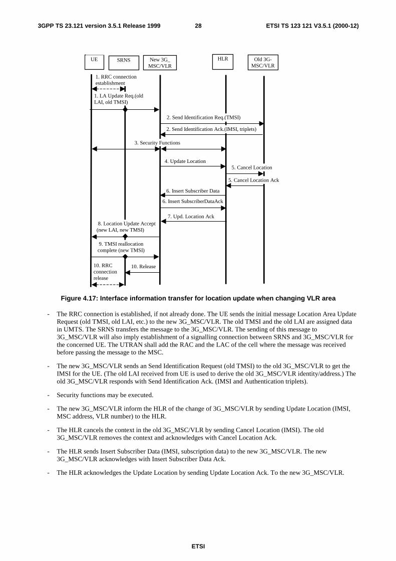
Figure 4.17: Interface information transfer for location update when changing VLR area
- The RRC connection is established, if not already done. The UE sends the initial message Location Area UpdateRequest (old TMSI, old LAI, etc.) to the new 3G_MSC/VLR. The old TMSI and the old LAI are assigned datain UMTS. The SRNS transfers the message to the 3G_MSC/VLR. The sending of this message to3G_MSC/VLR will also imply establishment of a signalling connection between SRNS and 3G_MSC/VLR forthe concerned UE. The UTRAN shall add the RAC and the LAC of the cell where the message was receivedbefore passing the message to the MSC.
- The new 3G_MSC/VLR sends an Send Identification Request (old TMSI) to the old 3G_MSC/VLR to get theIMSI for the UE. (The old LAI received from UE is used to derive the old 3G_MSC/VLR identity/address.) Theold 3G_MSC/VLR responds with Send Identification Ack. (IMSI and Authentication triplets).
- Security functions may be executed.
- The new 3G_MSC/VLR inform the HLR of the change of 3G_MSC/VLR by sending Update Location (IMSI,MSC address, VLR number) to the HLR.
- The HLR cancels the context in the old 3G_MSC/VLR by sending Cancel Location (IMSI). The old3G_MSC/VLR removes the context and acknowledges with Cancel Location Ack.
- The HLR sends Insert Subscriber Data (IMSI, subscription data) to the new 3G_MSC/VLR. The new3G_MSC/VLR acknowledges with Insert Subscriber Data Ack.
- The HLR acknowledges the Update Location by sending Update Location Ack. To the new 3G_MSC/VLR.
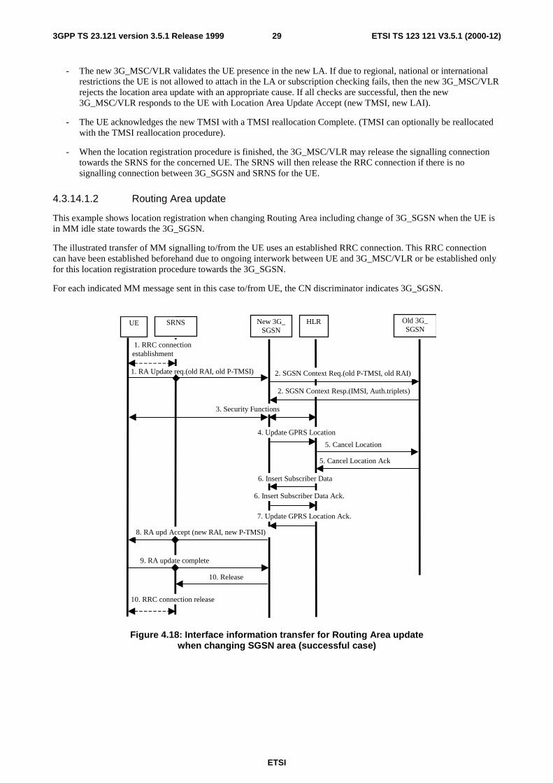
ETSI
ETSI TS 123 121 V3.5.1 (2000-12)293GPP TS 23.121 version 3.5.1 Release 1999
- The new 3G_MSC/VLR validates the UE presence in the new LA. If due to regional, national or internationalrestrictions the UE is not allowed to attach in the LA or subscription checking fails, then the new 3G_MSC/VLRrejects the location area update with an appropriate cause. If all checks are successful, then the new3G_MSC/VLR responds to the UE with Location Area Update Accept (new TMSI, new LAI).
- The UE acknowledges the new TMSI with a TMSI reallocation Complete. (TMSI can optionally be reallocatedwith the TMSI reallocation procedure).
- When the location registration procedure is finished, the 3G_MSC/VLR may release the signalling connectiontowards the SRNS for the concerned UE. The SRNS will then release the RRC connection if there is nosignalling connection between 3G_SGSN and SRNS for the UE.
4.3.14.1.2 Routing Area update
This example shows location registration when changing Routing Area including change of 3G_SGSN when the UE isin MM idle state towards the 3G_SGSN.
The illustrated transfer of MM signalling to/from the UE uses an established RRC connection. This RRC connectioncan have been established beforehand due to ongoing interwork between UE and 3G_MSC/VLR or be established onlyfor this location registration procedure towards the 3G_SGSN.
For each indicated MM message sent in this case to/from UE, the CN discriminator indicates 3G_SGSN.
UE SRNS Old 3G_SGSN
5. Cancel Location
New 3G_SGSN
HLR
3. Security Functions
2. SGSN Context Req.(old P-TMSI, old RAI)
5. Cancel Location Ack
7. Update GPRS Location Ack.
9. RA update complete
6. Insert Subscriber Data Ack.
10. Release
8. RA upd Accept (new RAI, new P-TMSI)
1. RA Update req.(old RAI, old P-TMSI)
4. Update GPRS Location
2. SGSN Context Resp.(IMSI, Auth.triplets)
6. Insert Subscriber Data
1. RRC connectionestablishment
10. RRC connection release
Figure 4.18: Interface information transfer for Routing Area updatewhen changing SGSN area (successful case)
ETSI
ETSI TS 123 121 V3.5.1 (2000-12)303GPP TS 23.121 version 3.5.1 Release 1999
- The RRC connection is established, if not already done. The UE sends the initial message Routing Area UpdateRequest (old P-TMSI, old RAI, etc.) to the new 3G_SGSN. The old P-TMSI and the old RAI are assigned datain UMTS. The SRNS transfers the message to the 3G_SGSN. The sending of this message to 3G_SGSN willalso imply establishment of a signalling connection between SRNS and 3G_SGSN for the concerned UE. TheUTRAN shall add the RAC and the LAC of the cell where the message was received before passing the messageto the SGSN.
- The new 3G_SGSN send an SGSN Context Request (old P-TMSI, old RAI) to the old 3G_SGSN to get the IMSIfor the UE. (The old RAI received from UE is used to derive the old 3G_SGSN identity/address.) The old3G_SGSN responds with SGSN Context Response (e.g. IMSI, PDP context information and Authenticationtriplets).
- Security functions may be executed.
- The new 3G_SGSN informs the HLR of the change of 3G_SGSN by sending Update GPRS Location (IMSI,SGSN number, SGSN address) to the HLR.
- The HLR cancels the context in the old 3G_SGSN by sending Cancel Location (IMSI). The old 3G_SGSNremoves the context and acknowledges with Cancel Location Ack.
- The HLR sends Insert Subscriber Data (IMSI, subscription data) to the new 3G_SGSN. The new 3G_SGSNacknowledges with Insert Subscriber Data Ack.
- The HLR acknowledges the Update GPRS Location by sending Update GPRS Location Ack. To the new3G_SGSN.
- The new 3G_SGSN validate the Ues presence in the new RA. If due to regional, national or internationalrestrictions the UE is not allowed to attach in the RA or subscription checking fails, then the new 3G_SGSNrejects the Routing Area Update Request with an appropriate cause. If all checks are successful, then the new3G_SGSN responds to the UE with Routing Area Update Accept (new P-TMSI, new RAI, etc.).
- The UE acknowledges the new P-TMSI with Routing Area Update Complete.
- When the location registration procedure is finished, the 3G_SGSN may release the signalling connectiontowards the SRNS for the concerned UE. The SRNS will then release the RRC connection if there is nosignalling connection between 3G_MSC/VLR and SRNS for the UE.
4.3.14.1.3 Periodic Registration towards both CN nodes without use of Gs
This example shows Periodic Registration to both the 3G_MSC/VLR and the 3G-SGSN (i.e. no change of registrationareas) when the UE is in MM idle state and registered in both the 3G_SGSN and the 3G_MSC/VLR.
The illustrated transfer of MM signalling to/from the UE uses an established RRC connection. This RRC connectionwill be established, is in this case, only for the two registration procedures towards the 3G_SGSN and 3G_MSC/VLR.
For each indicated MM message sent to/from UE, the CN discriminator indicates either 3G_ SGSN or 3G_MSC/VLR.

ETSI
ETSI TS 123 121 V3.5.1 (2000-12)313GPP TS 23.121 version 3.5.1 Release 1999
UE SRNS HLR3G_SGSN
3G_MSC/VLR
2. Security Functions
1. LA Update Req.(old TMSI, old LAI)
4. Release
4. Release
3. RA upd Accept
1. RA Update req.(old P-TMSI, old RAI)
3. LA upd Accept
1. RRC connectionestablishment
5. RRC connection release
Figure 4.19: Interface information transfer for periodic registration to 3G_SGSNand 3G_MSC/VLR (successful case)
- The RRC connection is established. The UE sends the initial messages Routing Area Update Request (oldP-TMSI, old RAI, etc.) to the 3G_SGSN and Location Area Update Request (old TMSI, old LAI, etc.) to the3G_MSC/VLR. In both cases, the UE will indicate the cause periodic registration. The sending of the respectivemessage to SGSN respective to MSC/VLR will also imply establishment of a signalling connection betweenSRNS and SGSN and a signalling connection between SRNS and MSC/VLR for the concerned UE.
- Security functions may be executed.
- The 3G_SGSN respective the 3G_MSC/VLR validates the Ues presence. If all checks are successful, then the3G_SGSN responds to the UE with Routing Area Update Accept and 3G_MSC/VLR responds to the UE withLocation Area Update Accept.
- When the periodic registration procedure is finished, the 3G_SGSN respective the 3G_MSC/VLR may releasethe signalling connection towards the SRNS for the concerned UE. If both CN nodes release the signallingconnection towards the SRNS for the concerned UE, then the SRNS will release the RRC connection towardsthe UE.
4.3.14.1.4 Periodic Registration with use of Gs/UMSC
RRC connection establishment
UE RNS UMSC/3G-SGSN
Routing Area Update (old RAI, P-TMSI, P-TMSIS)
Routing Area Accept (RAI, P-TMSI, P-TMSIS)
Release
RRC connection release
Figure 4.20: Periodic update procedure when the MS is attached for both CS and PS services
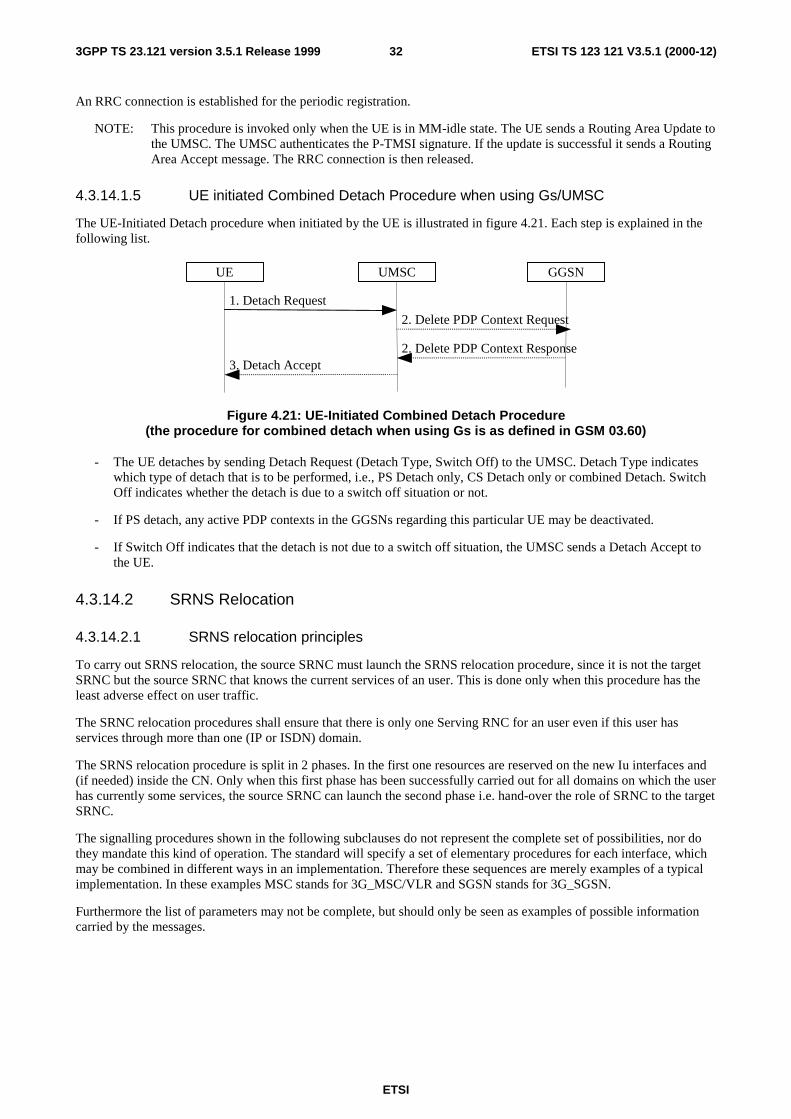
ETSI
ETSI TS 123 121 V3.5.1 (2000-12)323GPP TS 23.121 version 3.5.1 Release 1999
An RRC connection is established for the periodic registration.
NOTE: This procedure is invoked only when the UE is in MM-idle state. The UE sends a Routing Area Update tothe UMSC. The UMSC authenticates the P-TMSI signature. If the update is successful it sends a RoutingArea Accept message. The RRC connection is then released.
4.3.14.1.5 UE initiated Combined Detach Procedure when using Gs/UMSC
The UE-Initiated Detach procedure when initiated by the UE is illustrated in figure 4.21. Each step is explained in thefollowing list.
2. Delete PDP Context Response
1. Detach Request
2. Delete PDP Context Request
3. Detach Accept
UE GGSNUMSC
Figure 4.21: UE-Initiated Combined Detach Procedure(the procedure for combined detach when using Gs is as defined in GSM 03.60)
- The UE detaches by sending Detach Request (Detach Type, Switch Off) to the UMSC. Detach Type indicateswhich type of detach that is to be performed, i.e., PS Detach only, CS Detach only or combined Detach. SwitchOff indicates whether the detach is due to a switch off situation or not.
- If PS detach, any active PDP contexts in the GGSNs regarding this particular UE may be deactivated.
- If Switch Off indicates that the detach is not due to a switch off situation, the UMSC sends a Detach Accept tothe UE.
4.3.14.2 SRNS Relocation
4.3.14.2.1 SRNS relocation principles
To carry out SRNS relocation, the source SRNC must launch the SRNS relocation procedure, since it is not the targetSRNC but the source SRNC that knows the current services of an user. This is done only when this procedure has theleast adverse effect on user traffic.
The SRNC relocation procedures shall ensure that there is only one Serving RNC for an user even if this user hasservices through more than one (IP or ISDN) domain.
The SRNS relocation procedure is split in 2 phases. In the first one resources are reserved on the new Iu interfaces and(if needed) inside the CN. Only when this first phase has been successfully carried out for all domains on which the userhas currently some services, the source SRNC can launch the second phase i.e. hand-over the role of SRNC to the targetSRNC.
The signalling procedures shown in the following subclauses do not represent the complete set of possibilities, nor dothey mandate this kind of operation. The standard will specify a set of elementary procedures for each interface, whichmay be combined in different ways in an implementation. Therefore these sequences are merely examples of a typicalimplementation. In these examples MSC stands for 3G_MSC/VLR and SGSN stands for 3G_SGSN.
Furthermore the list of parameters may not be complete, but should only be seen as examples of possible informationcarried by the messages.
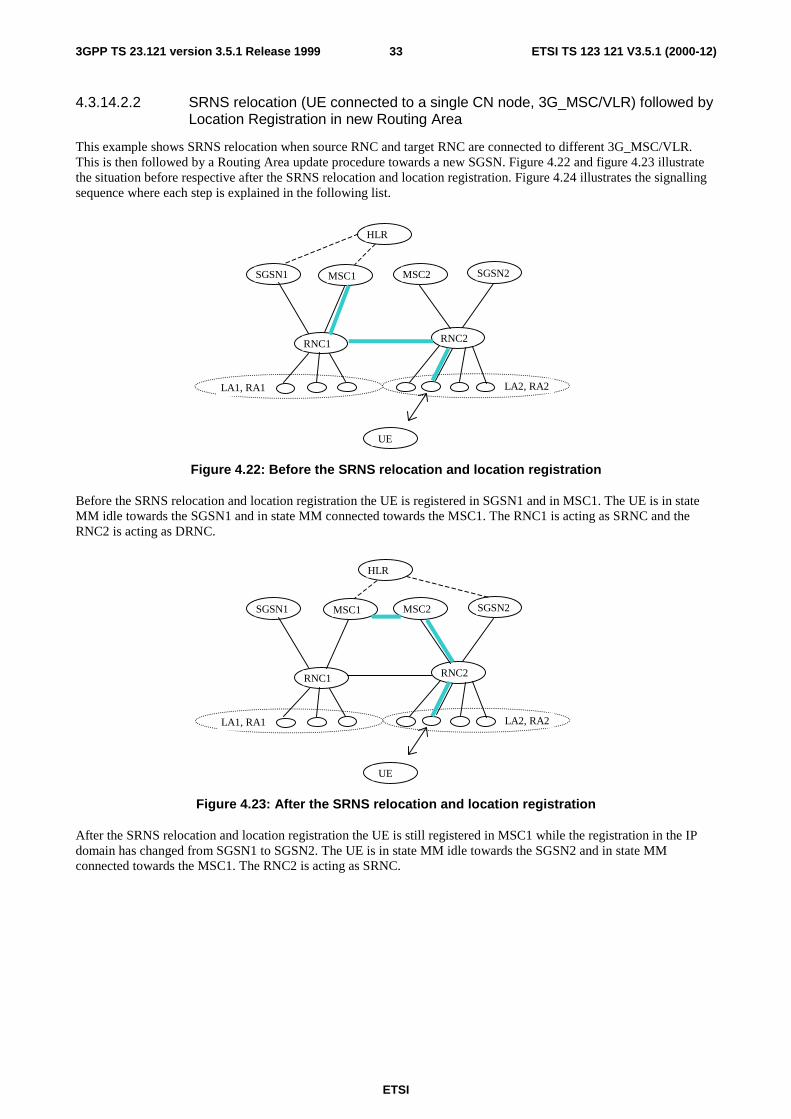
ETSI
ETSI TS 123 121 V3.5.1 (2000-12)333GPP TS 23.121 version 3.5.1 Release 1999
4.3.14.2.2 SRNS relocation (UE connected to a single CN node, 3G_MSC/VLR) followed byLocation Registration in new Routing Area
This example shows SRNS relocation when source RNC and target RNC are connected to different 3G_MSC/VLR.This is then followed by a Routing Area update procedure towards a new SGSN. Figure 4.22 and figure 4.23 illustratethe situation before respective after the SRNS relocation and location registration. Figure 4.24 illustrates the signallingsequence where each step is explained in the following list.
LA1, RA1
MSC1 SGSN2SGSN1 MSC2
RNC1 RNC2
UE
LA2, RA2
HLR
Figure 4.22: Before the SRNS relocation and location registration
Before the SRNS relocation and location registration the UE is registered in SGSN1 and in MSC1. The UE is in stateMM idle towards the SGSN1 and in state MM connected towards the MSC1. The RNC1 is acting as SRNC and theRNC2 is acting as DRNC.
LA1, RA1
MSC1 SGSN2SGSN1 MSC2
RNC1 RNC2
UE
LA2, RA2
HLR
Figure 4.23: After the SRNS relocation and location registration
After the SRNS relocation and location registration the UE is still registered in MSC1 while the registration in the IPdomain has changed from SGSN1 to SGSN2. The UE is in state MM idle towards the SGSN2 and in state MMconnected towards the MSC1. The RNC2 is acting as SRNC.

ETSI
ETSI TS 123 121 V3.5.1 (2000-12)343GPP TS 23.121 version 3.5.1 Release 1999
UE TargetRNC
SourceRNC
4. Prepare SRNC Reloc response
6. SRNC Reloc Commit
AnchorMSC
Non-anchorMSC
HLR
5. SRNC Reloc Proceed 2
2.Prepare SRNC Relocation
7. SRNC Reloc Complete
3. SRNC Relocation Proceeding 1
(a)
8.Release
9. New MM System Info
1. SRNC Relocation Required
3. SRNC Relocation Request
7. Complete SRNC Reloc
SGSN2 SGSN1
10. Routing Area Update
(b)
Figure 4.24: Interface information transfer for SRNS relocation when UE connectedto 3G_MSC/VLR followed by location registration in new Routing Area.
- UTRAN makes the decision to perform the Serving RNC relocation procedure. This includes decision on intowhich RNC (Target RNC) the Serving RNC functionality is to be relocated. The source SRNC sends SRNCRelocation required messages to the MSC. This message includes parameters such as target RNC identifier andan information field that shall be passed transparently to the target RNC.
- Upon reception of SRNC Relocation required message the Anchor MSC (MSC1) prepares itself for the switchand determines from the received information that the SRNC relocation will (in this case) involve another MSC.The Anchor MSC will then send a Prepare SRNC Relocation Request to the applicable non-anchor MSC(MSC2) including the information received from the Source RNC.
- The non-anchor MSC will send a SRNC Relocation Request message to the target RNC. This message includesinformation for building up the SRNC context, transparently sent from Source RNC (UE id., no of connected CNnodes, UE capability information), and directives for setting up Iu user plane transport bearers. When Iu userplane transport bearers have been established, and target RNC has completed its preparation phase, SRNCRelocation Proceeding 1 message is sent to the non-anchor MSC.
- The Prepare SRNC Relocation Response that is sent from non-anchor MSC to Anchor MSC will contain theSRNC Relocation Proceeding 1 received from target RNC.
- When the SRNC Relocation Proceeding 1 has been received in the Anchor MSC, the user plane transport bearershas been allocated the whole path between target RNC and Anchor MSC and the Anchor MSC is ready for theSRNC move, then the Anchor MSC indicates the completion of preparation phase at the CN side for the SRNCrelocation by sending the SRNC relocation proceeding 2 message to the Source RNC.
- When the source RNC has received the SRNC Relocation Proceeding 2 message, the source RNC sends a SRNCRelocation Commit message to the target RNC. The target RNC executes switch for all bearers at the earliestsuitable time instance.
- Immediately after a successful switch at RNC, target RNC (=SRNC) sends SRNC Relocation Complete messageto the non-anchor MSC. This message is included by the non-anchor MSC in the Complete SRNC relocationmessage that is sent to the anchor MSC. Upon reception of this message, the Anchor-MSC switches from the oldIu transport bearers to the new ones.
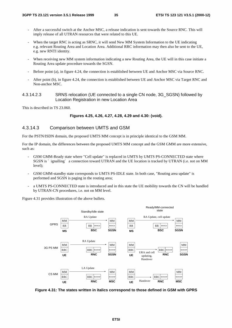
ETSI
ETSI TS 123 121 V3.5.1 (2000-12)353GPP TS 23.121 version 3.5.1 Release 1999
- After a successful switch at the Anchor MSC, a release indication is sent towards the Source RNC. This willimply release of all UTRAN resources that were related to this UE.
- When the target RNC is acting as SRNC, it will send New MM System Information to the UE indicatinge.g. relevant Routing Area and Location Area. Additional RRC information may then also be sent to the UE,e.g. new RNTI identity.
- When receiving new MM system information indicating a new Routing Area, the UE will in this case initiate aRouting Area update procedure towards the SGSN.
- Before point (a), in figure 4.24, the connection is established between UE and Anchor MSC via Source RNC.
- After point (b), in figure 4.24, the connection is established between UE and Anchor MSC via Target RNC andNon-anchor MSC.
4.3.14.2.3 SRNS relocation (UE connected to a single CN node, 3G_SGSN) followed byLocation Registration in new Location Area
This is described in TS 23.060.
Figures 4.25, 4.26, 4.27, 4.28, 4.29 and 4.30: (void).
4.3.14.3 Comparison between UMTS and GSM
For the PSTN/ISDN domain, the proposed UMTS MM concept is in principle identical to the GSM MM.
For the IP domain, the differences between the proposed UMTS MM concept and the GSM GMM are more extensive,such as:
- GSM GMM-Ready state where "Cell update" is replaced in UMTS by UMTS PS-CONNECTED state whereSGSN is ` ignalling` a connection toward UTRAN and the UE location is tracked by UTRAN (i.e. not on MMlevel);
- GSM GMM-standby state corresponds to UMTS PS-IDLE state. In both case, "Routing area update" isperformed and SGSN is paging in the routing area;
- a UMTS PS-CONNECTED state is introduced and in this state the UE mobility towards the CN will be handledby UTRAN-CN procedures, i.e. not on MM level.
Figure 4.31 provides illustration of the above bullets.
MM
RR RR BSSGb BSSGb
MMRA Update
MS BSC SGSN
MM
RRC RRC RANAP RANAP
MMLA Update
UE RNC MSC
MM
RR RR BSSGb BSSGb
MMRA Update, cell update
MS BSC SGSN
MM
RRC RRC RANAP RANAP
MM
URA and cellupdating,Handover
UE RNC SGSN
MM
RRC RRC RANAP RANAP
MM
UE RNC MSC
MM
RRC RRC RANAP RANAP
MMRA Update
UE RNC SGSN
GPRS
3G PS MM
CS MM
Standby/Idle state
Ready/MM-connectedstate
Handover
Figure 4.31: The states written in italics correspond to those defined in GSM with GPRS
ETSI
ETSI TS 123 121 V3.5.1 (2000-12)363GPP TS 23.121 version 3.5.1 Release 1999
4.3.14.3.1 PS –idle state
The RA update procedure is utilised to update the whereabouts of the UE into SGSN. The updating into SGSN takesplace irrespectively of the CS MM state in MSC.
4.3.14.3.2 PS –connected state
The URA and cell updating and handover procedures presented in figure 4.31 are based on UMTS YY.03 [2]. In brief,the aim in [2] is to introduce functionality that caters for the same functionality as standby/ready in GPRS. The RRCshall be designed in such a fashion, which allows the state of the RRC connection to define the level of activityassociated to a packet data connection. The key parameters of each state are the required activity and resources withinthe state and the required signalling prior to the packet transmission. The operator configurableRRC_connection_release timer can be used to release RRC connections in case of very low level of activity and in casethe QoS requirements e.g. delay requirement allow the release of the RRC connection.
The cell update and URA update between UE and RNC are used when the UE is in RRC common channel state,i.e. when the above mentioned parameters allow to scale down the resources reserved for the UE (for a more detaileddescription on this, see [2]). For example, the purpose of the cell update procedure is to allow the UE to inform itscurrent location in the corresponding RRC state. According to [2] the cell update procedure replaces handover in thecorresponding RRC substate.
A significant deviation from GPRS is the introduction of the handover procedures for connections supporting trafficinto IP domain (in RRC cell connected state, see [2]).
The UE moves to PS-IDLE state in case of expiry of RRC_connection_release timer or an RRC connection failure.
4.3.14.4 Issues for further study
List of issues that are for further study related to this chapter and is the following:
- more details are required with regards to the differences with regards to the "IP-domain" MM compared toGPRS MM, especially considering roaming and handover to/from UMTS to GSM/GPRS;
- more details should be provided with regards to the logical relations between UE-CN and UTRAN-CN, and howthese relate to the physical interconnection between UTRAN and the CN nodes(s), namely whether onelogical/physical Iu can be used to interconnect the UTRAN with the CN.
4.3.15 (void)
4.3.16 UTRAN coordination
The UTRAN coordinates the resource allocation of an UE attached to both PS and CS services. The UTRAN shallreject or downgrade a connection which cannot be granted [3]. The cause might be congestion on the radio interface, orthe existence of other connections between this UE and the other CN.
The UTRAN use the IMSI to identify a UE. The IMSI is transferred from the Core Network to the UTRAN with thecommon ID procedure. When an Iu connection is established, the Core Network shall perform the RANAP common IDprocedure toward UTRAN as soon as the UE is identified (IMSI). The IMSI is only stored in the UTRAN for theduration of the RRC Connection.

ETSI
ETSI TS 123 121 V3.5.1 (2000-12)373GPP TS 23.121 version 3.5.1 Release 1999
4.4 UMTS call control
4.4.1 Technical Requirements
The following technical requirements are applied to support multimedia in GSM/UMTS.
P1) GSM/UMTS shall enable the provisioning of multimedia services and multivendor interworking between UEand network.
P2) Basic voice and PDP-context establishment shall be based on GSM CC/SM respectively.
P3) Handover and roaming to and from GSM shall be supported provided GSM is capable of supporting theongoing media service.
P4) Ideas, concepts and procedures developed by other fora e.g. other standards bodies such as ITU, IETF etc. shallbe included or referenced in GSM/UMTS when found suitable.
P5) To ensure multi-vendor inter-working and UE roaming, a single standardised multimedia protocol for CSdomain and a single standardised multimedia protocol for PS domain shall be selected for GSM / UMTS R99.This does not preclude the selection of other protocols by UMTS in the future.
H.323 shall be the multimedia call control model for the PS domain in UMTS R99.
P6) For multimedia services the standardized multimedia protocol shall be run transparently via a PDP-context or acircuit-switched connection established using GSM SM/CC . This allows transparent hand-over and roamingbetween GSM and UMTS provided that GSM supports the QoS requirements.
Figure 4.36 illustrates the realisation of the multimedia service based on P6). 'Multimedia Protocol' indicates thefunctionality either inside the communicating user's terminal or a gateway (e.g. H.323 Gateway)/GK. It is essentially acontrol function both for user plane and control plane for the multimedia communication.
UE MSC GSN
GSM CC GSM SM GSM CC GSM SM
MultimediaProtocol
GK/Gateway
MultimediaProtocol
MultimediaProtocol
MultimediaProtocol
Figure 4.36: Support of multimedia making use of GSM SM/CC
Based on the requirements listed above, GSM CC/SM represented by GSM 04.08 forms a solid foundation for UMTSCC/SM for Release 99. UMTS CC/SM for Release 99 is to be developed from GSM CC/SM by introducing some welldefined enhancements.
Existing (and future) multimedia protocols can be supported by the UMTS CC/SM as application layer protocols, withno (or in some instances only minor) impact to UMTS CC/SM.
4.4.2 Architecture for Multimedia
In order to include multimedia in release 99 an architecture for multimedia is required. Subclauses 4.4.2.1 and 4.4.2.2detail the architecture for UMTS multimedia. It is recognised that it may not be possible to include all the functionalityincluded in this architecture in release 99.
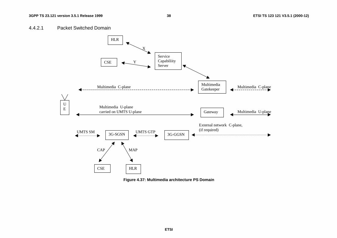
ETSI
ETSI TS 123 121 V3.5.1 (2000-12)383GPP TS 23.121 version 3.5.1 Release 1999
4.4.2.1 Packet Switched Domain
Multimedia C-plane
UE Multimedia U-plane
carried on UMTS U-plane
External network C-plane,(if required)UMTS SM
Multimedia C-plane
3G-SGSN 3G-GGSN
Gateway
MultimediaGatekeeper
ServiceCapabiliityServer
CSE
HLR
Multimedia U-plane
UMTS GTP
X
Y
CSE HLR
MAPCAP
Figure 4.37: Multimedia architecture PS Domain

ETSI
ETSI TS 123 121 V3.5.1 (2000-12)393GPP TS 23.121 version 3.5.1 Release 1999
The multimedia C-plane and U-plane are run transparently over a PDP-context between the UE and multimediagatekeeper and gateway.
The multimedia U-plane runs between the UE and the multimedia gateway. The multimedia gateway maps themultimedia U-plane on to the U plane in the external network eg. Internet, PSTN. In some cases, such as a UMTS toUMTS call this may unnecessary.
The multimedia control protocol is run between the UE and multimedia gatekeeper. The multimedia gatekeeper isresponsible for establishing a multimedia C plane connection on the terminating network.
The service capability server is functionally distinct from the multimedia gatekeeper. It is responsible for creatingmultimedia services. The standardisation of the interface between the service capability server and the multimediagatekeeper is for further study. The service capability server may require interfaces to the HLR and CSE (CamelService Environment) in order to enable interactions between multimedia services and the services provided by theseplatforms. In this case the interfaces X and Y in figure 4.37 will require standardisation, (It is not proposed that this beincluded in release 99). The handling of MT communications is for further study.
Services can be delivered at two levels:
- bearer level services are those which correspond to the UMTS bearer service and are delivered via the SGSN,HLR and CSE. Examples of bearer level services are pre-paid or barring of PDP context establishment (for theUMTS bearer service);
- multimedia level services are delivered via the multimedia gatekeeper and service capability server possibly incombination with the HLR and CSE. Examples of multimedia services are video conferencing, call forwardingand pre-paid (of the multimedia component).
The multimedia gatekeeper and service capability server may be located within or external to the UMTS PLMN. Theimplications of the location of the multimedia gatekeeper and service capability server are for further study.
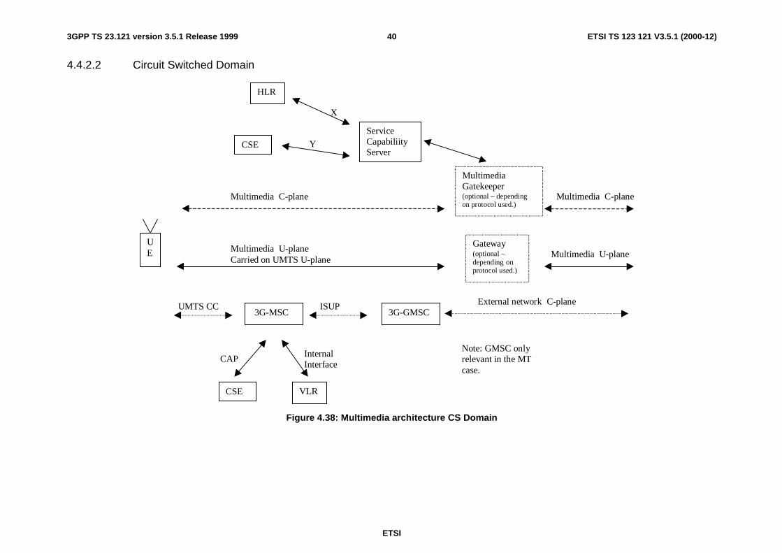
ETSI
ETSI TS 123 121 V3.5.1 (2000-12)403GPP TS 23.121 version 3.5.1 Release 1999
4.4.2.2 Circuit Switched Domain
Multimedia C-plane
UE Multimedia U-plane
Carried on UMTS U-plane
External network C-planeUMTS CC
Multimedia C-plane
3G-MSC 3G-GMSC
Gateway(optional –depending onprotocol used.)
MultimediaGatekeeper(optional – dependingon protocol used.)
ServiceCapabiliityServer
CSE
HLR
Multimedia U-plane
ISUP
X
Y
CSE VLR
Note: GMSC onlyrelevant in the MTcase.
CAP InternalInterface
Figure 4.38: Multimedia architecture CS Domain

ETSI
ETSI TS 123 121 V3.5.1 (2000-12)413GPP TS 23.121 version 3.5.1 Release 1999
The multimedia C-plane and U-plane are run transparently over a bearer between the UE and destination or ` ignallingthe multimedia gatekeeper and/or gateway if present.
The multimedia U-plane runs between the UE and destination. Optionaly the multimedia U-plane is terminated at thethe multimedia gateway, which interworks with the external network.
The multimedia control protocol is run between the UE and the destination. Optionally the multimedia gatekeeper isresponsible for establishing a multimedia C plane connection on the fixed network.
The service capability server is functionally distinct from the multimedia gatekeeper. It is responsible for creatingmultimedia services. The standardisation of the interface between the service capability server and the multimediagatekeeper is for further study. The service capability server may require interfaces to the HLR and CSE (CamelService Environment) in order to enable interactions between multimedia services and the services provided by theseplatforms. In this case the interfaces X and Y in figure 4.38 will require standardisation, (It is not proposed that this beincluded in release 99). The handling of MT communications is for further study.
Services can be delivered at two levels:
- bearer level services are those which correspond to the UMTS bearer service and are delivered via the MSC,HLR and CSE. Examples of bearer level services are pre-paid or call barring (for the UMTS bearer service);
- multimedia level services are delivered via the multimedia gatekeeper (if present) and service capability serverpossibly in combination with the HLR and CSE. Examples of multimedia services are video conferencing, callforwarding and pre-paid (of the multimedia component). If there is no multimedia gatekeeper network levelmultimedia services can not be provided.
The multimedia gatekeeper and service capability server may be located within or external to the UMTS PLMN. Theimplications of the location of the multimedia gatekeeper and service capability server are for further study.
4.4.3 Typical Scenarios for Multimedia Control and User Plane
Two typical call scenarios to support multimedia services, H.324 and H.323, respectively, are presented as examples.As an assumption, the calls are between the peer multimedia terminals over an IMT-2000 network. As shown in thefollowing subclauses, the multimedia signalling protocol and data transmission for both call scenarios can be performedend-to-end on the IMT-2000 user plane and is thereby transparent to the IMT-2000 Core Network. The IMT-2000operators still control the multimedia service towards the end-user by providing the service via a service node (gateway,gatekeeper or application server) inside its own domain. Some other call scenarios e.g. IMT-2000 to ISDN/PSTN and/orIMT-2000 to the IP network can also be illustrated in a similar fashion.
4.4.3.1 H.324M to H.324M Call
In figure 4.39, the H.324M IMT-2000 terminal initiates the call set-up procedure by sending a 04.08 SET-UP messageto the originating MSC/VLR.
After the received 04.08 SETUP message, the originating MSC/VLR sends an ISUP Initial Address Message (IAM) tothe terminating MSC/VLR. The terminating MSC/VLR performs a 04.08 SETUP procedure towards the H.324MUMTS terminal. The communication link is now established between the two H.324M endpoints.
The logical channels can now be established using the H.245 open logical channel procedure.
No gateway is needed in this case. This case is simple to support and requires little standardization.
The 04.08 Bearer Capability is used to indicate 64 kbits/s bit transparent case described in GSM 07.01 can be used, aswell as H.223/H.245.
The 04.08 LLC is used to indicate H.223/H.245. This makes the called IMT-2000 mobile terminal activate its H.324Mapplication when receiving the SETUP (LLC:H.223/H.245).
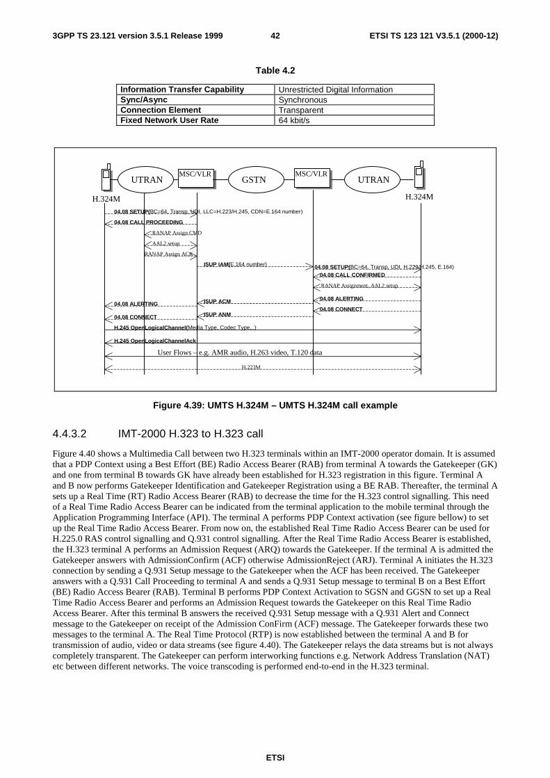
ETSI
ETSI TS 123 121 V3.5.1 (2000-12)423GPP TS 23.121 version 3.5.1 Release 1999
Table 4.2
Information Transfer Capability Unrestricted Digital InformationSync/Async SynchronousConnection Element TransparentFixed Network User Rate 64 kbit/s
H.324M
MSC/VLR MSC/VLR
H.324M
GSTN
04.08 SETUP(BC=64, Transp, UDI, LLC=H.223/H.245, CDN=E.164 number)
04.08 CALL PROCEEDING
UTRAN UTRAN
AAL2 setup
RANAP Assign CMD
RANAP Assign ACK
ISUP IAM(E.164 number)
ISUP ACM
ISUP ANM
04.08 ALERTING
04.08 CONNECT
04.08 SETUP(BC=64, Transp, UDI, H.223/H.245, E.164) 04.08 CALL CONFIRMED
RANAP Assignment, AAL2 setup
04.08 ALERTING
04.08 CONNECT
H.245 OpenLogicalChannel(Media Type, Codec Type,..)
H.245 OpenLogicalChannelAck
User Flows – e.g. AMR audio, H.263 video, T.120 data
H.223M
Figure 4.39: UMTS H.324M – UMTS H.324M call example
4.4.3.2 IMT-2000 H.323 to H.323 call
Figure 4.40 shows a Multimedia Call between two H.323 terminals within an IMT-2000 operator domain. It is assumedthat a PDP Context using a Best Effort (BE) Radio Access Bearer (RAB) from terminal A towards the Gatekeeper (GK)and one from terminal B towards GK have already been established for H.323 registration in this figure. Terminal Aand B now performs Gatekeeper Identification and Gatekeeper Registration using a BE RAB. Thereafter, the terminal Asets up a Real Time (RT) Radio Access Bearer (RAB) to decrease the time for the H.323 control signalling. This needof a Real Time Radio Access Bearer can be indicated from the terminal application to the mobile terminal through theApplication Programming Interface (API). The terminal A performs PDP Context activation (see figure bellow) to setup the Real Time Radio Access Bearer. From now on, the established Real Time Radio Access Bearer can be used forH.225.0 RAS control signalling and Q.931 control signalling. After the Real Time Radio Access Bearer is established,the H.323 terminal A performs an Admission Request (ARQ) towards the Gatekeeper. If the terminal A is admitted theGatekeeper answers with AdmissionConfirm (ACF) otherwise AdmissionReject (ARJ). Terminal A initiates the H.323connection by sending a Q.931 Setup message to the Gatekeeper when the ACF has been received. The Gatekeeperanswers with a Q.931 Call Proceeding to terminal A and sends a Q.931 Setup message to terminal B on a Best Effort(BE) Radio Access Bearer (RAB). Terminal B performs PDP Context Activation to SGSN and GGSN to set up a RealTime Radio Access Bearer and performs an Admission Request towards the Gatekeeper on this Real Time RadioAccess Bearer. After this terminal B answers the received Q.931 Setup message with a Q.931 Alert and Connectmessage to the Gatekeeper on receipt of the Admission ConFirm (ACF) message. The Gatekeeper forwards these twomessages to the terminal A. The Real Time Protocol (RTP) is now established between the terminal A and B fortransmission of audio, video or data streams (see figure 4.40). The Gatekeeper relays the data streams but is not alwayscompletely transparent. The Gatekeeper can perform interworking functions e.g. Network Address Translation (NAT)etc between different networks. The voice transcoding is performed end-to-end in the H.323 terminal.
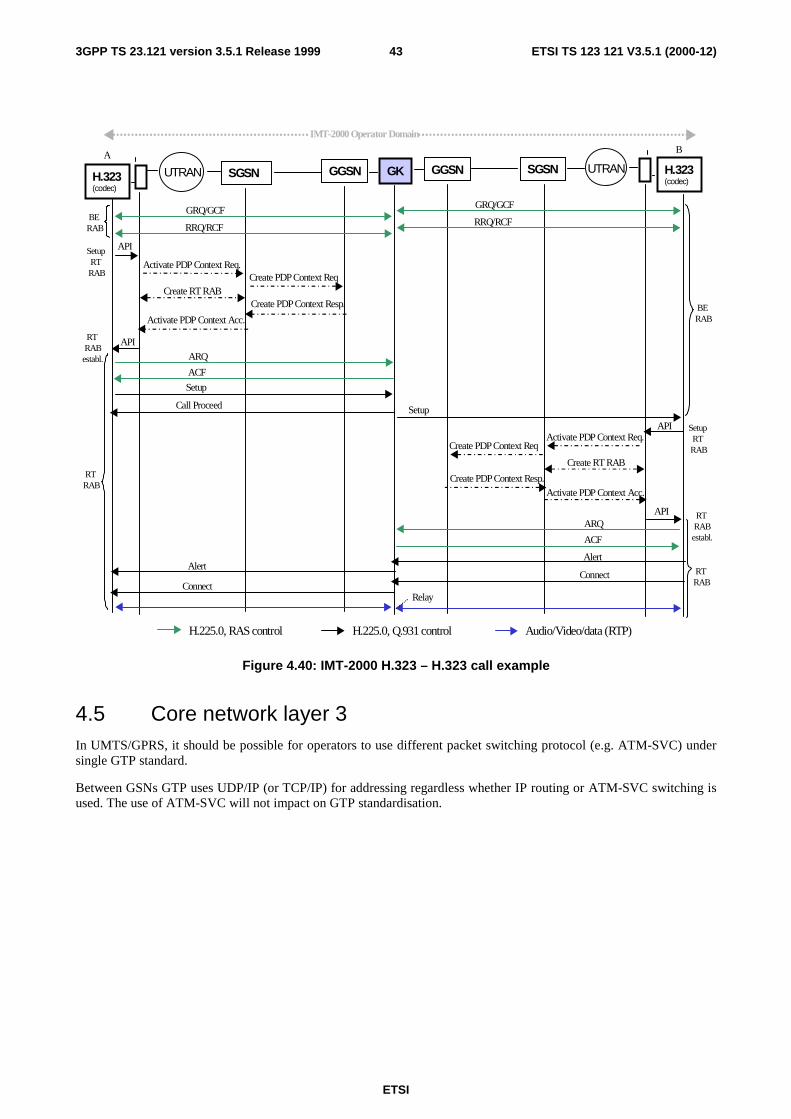
ETSI
ETSI TS 123 121 V3.5.1 (2000-12)433GPP TS 23.121 version 3.5.1 Release 1999
UTRAN GGSNSGSN
H.225.0, Q.931 controlH.225.0, RAS control
ARQ
ACF
Setup
Call Proceed
GK GGSN SGSN UTRAN H.323(codec)
GRQ/GCF
RRQ/RCF
Activate PDP Context Req.Create PDP Context Req
Create PDP Context Resp.
Activate PDP Context Acc.
IMT-2000 Operator Domain
RT RABestabl.
BE RAB
A B
GRQ/GCF
RRQ/RCF
Setup
BE RAB
Activate PDP Context Req.Create PDP Context Req
Create PDP Context Resp.Activate PDP Context Acc.
API
API
AlertAlert
ConnectConnect
Audio/Video/data (RTP)
API
API
Setup RT RAB
Setup RT RAB
RT RAB
RT RAB
Relay
H.323(codec)
ARQ
ACF
RT RABestabl.
Create RT RAB
Create RT RAB
Figure 4.40: IMT-2000 H.323 – H.323 call example
4.5 Core network layer 3In UMTS/GPRS, it should be possible for operators to use different packet switching protocol (e.g. ATM-SVC) undersingle GTP standard.
Between GSNs GTP uses UDP/IP (or TCP/IP) for addressing regardless whether IP routing or ATM-SVC switching isused. The use of ATM-SVC will not impact on GTP standardisation.
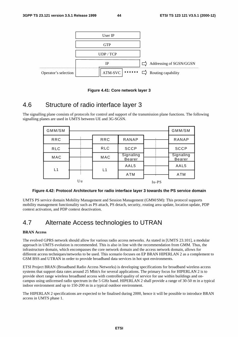
ETSI
ETSI TS 123 121 V3.5.1 (2000-12)443GPP TS 23.121 version 3.5.1 Release 1999
User IP
GTP
UDP / TCP
IP Addressing of SGSN/GGSN
Operator’s selection ATM-SVC Routing capability
Figure 4.41: Core network layer 3
4.6 Structure of radio interface layer 3The signalling plane consists of protocols for control and support of the transmission plane functions. The followingsignalling planes are used in UMTS between UE and 3G-SGSN.
Iu-PS
GMM/SM
RANAP
SignalingBearer
AAL5
ATM
RANAP
SignalingBearer
AAL5
ATM
GMM/SM
RRC
RLC
MAC
L1
Uu
RRC
L1
RLC
MAC
SCCP SCCP
Figure 4.42: Protocol Architecture for radio interface layer 3 towards the PS service domain
UMTS PS service domain Mobility Management and Session Management (GMM/SM): This protocol supportsmobility management functionality such as PS attach, PS detach, security, routing area update, location update, PDPcontext activation, and PDP context deactivation.
4.7 Alternate Access technologies to UTRANBRAN Access
The evolved GPRS network should allow for various radio access networks. As stated in [UMTS 23.101], a modularapproach in UMTS evolution is recommended. This is also in line with the recommendation from GMM. Thus, theinfrastructure domain, which encompasses the core network domain and the access network domain, allows fordifferent access techniques/networks to be used. This scenario focuses on EP BRAN HIPERLAN 2 as a complement toGSM BSS and UTRAN in order to provide broadband data services in hot spot environments.
ETSI Project BRAN (Broadband Radio Access Networks) is developing specifications for broadband wireless accesssystems that support data rates around 25 Mbit/s for several applications. The primary focus for HIPERLAN 2 is toprovide short range wireless broadband access with controlled quality of service for use within buildings and on-campus using unlicensed radio spectrum in the 5 GHz band. HIPERLAN 2 shall provide a range of 30-50 m in a typicalindoor environment and up to 150-200 m in a typical outdoor environment.
The HIPERLAN 2 specifications are expected to be finalised during 2000, hence it will be possible to introduce BRANaccess in UMTS phase 1.
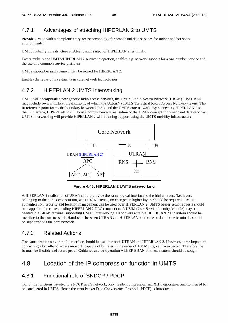
ETSI
ETSI TS 123 121 V3.5.1 (2000-12)453GPP TS 23.121 version 3.5.1 Release 1999
4.7.1 Advantages of attaching HIPERLAN 2 to UMTS
Provide UMTS with a complementary access technology for broadband data services for indoor and hot spotsenvironments.
UMTS mobility infrastructure enables roaming also for HIPERLAN 2 terminals.
Easier multi-mode UMTS/HIPERLAN 2 service integration, enables e.g. network support for a one number service andthe use of a common service platform.
UMTS subscriber management may be reused for HIPERLAN 2.
Enables the reuse of investments in core network technologies.
4.7.2 HIPERLAN 2 UMTS Interworking
UMTS will incorporate a new generic radio access network, the UMTS Radio Access Network (URAN). The URANmay include several different realisations, of which the UTRAN (UMTS Terrestrial Radio Access Network) is one. TheIu reference point forms the boundary between URAN and the UMTS core network. By connecting HIPERLAN 2 tothe Iu interface, HIPERLAN 2 will form a complimentary realisation of the URAN concept for broadband data services.UMTS interworking will provide HIPERLAN 2 with roaming support using the UMTS mobility infrastructure.
UTRAN
RNSRNS
IuIu
IurAPT APT
BRAN (HIPERLAN 2)
APT
Iu
APC
Core Network
Figure 4.43: HIPERLAN 2 UMTS interworking
A HIPERLAN 2 realisation of URAN should provide the same logical interface to the higher layers (i.e. layersbelonging to the non-access stratum) as UTRAN. Hence, no changes in higher layers should be required. UMTSauthentication, security and location management can be used over HIPERLAN 2. UMTS bearer setup requests shouldbe mapped to the corresponding HIPERLAN 2 DLC connection. A USIM (User Service Identity Module) may beneeded in a BRAN terminal supporting UMTS interworking. Handovers within a HIPERLAN 2 subsystem should beinvisible to the core network. Handovers between UTRAN and HIPERLAN 2, in case of dual mode terminals, shouldbe supported via the core network.
4.7.3 Related Actions
The same protocols over the Iu interface should be used for both UTRAN and HIPERLAN 2. However, some impact ofconnecting a broadband access network, capable of bit rates in the order of 100 Mbit/s, can be expected. Therefore theIu must be flexible and future proof. Guidance and co-operation with EP BRAN on these matters should be sought.
4.8 Location of the IP compression function in UMTS
4.8.1 Functional role of SNDCP / PDCP
Out of the functions devoted to SNDCP in 2G network, only header compression and XID negotiation functions need tobe considered in UMTS. Hence the term Packet Data Convergence Protocol (PDCP) is introduced.
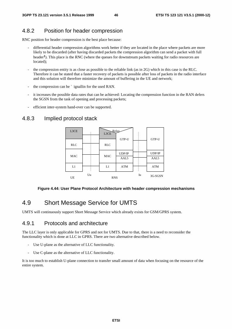
ETSI
ETSI TS 123 121 V3.5.1 (2000-12)463GPP TS 23.121 version 3.5.1 Release 1999
4.8.2 Position for header compression
RNC position for header compression is the best place because:
- differential header compression algorithms work better if they are located in the place where packets are morelikely to be discarded (after having discarded packets the compression algorithm can send a packet with fullheader1). This place is the RNC (where the queues for downstream packets waiting for radio resources arelocated);
- the compression entity is as close as possible to the reliable link (as in 2G) which in this case is the RLC.Therefore it can be stated that a faster recovery of packets is possible after loss of packets in the radio interfaceand this solution will therefore minimize the amount of buffering in the UE and network;
- the compression can be ` ignallin for the used RAN.
- it increases the possible data rates that can be achieved: Locating the compression function in the RAN defersthe SGSN from the task of opening and processing packets;
- efficient inter-system hand-over can be supported.
4.8.3 Implied protocol stack
IuUu
L1
MAC
L3CE
ATM
AAL5
UE RNS
L1 ATM
MACAAL5
UDP/IP
L3CE
RLC
GTP-U GTP-U
RLC
UDP/IP
Relay
3G-SGSN
Figure 4.44: User Plane Protocol Architecture with header compression mechanisms
4.9 Short Message Service for UMTSUMTS will continuously support Short Message Service which already exists for GSM/GPRS system.
4.9.1 Protocols and architecture
The LLC layer is only applicable for GPRS and not for UMTS. Due to that, there is a need to reconsider thefunctionality which is done at LLC in GPRS. There are two alternative described below.
- Use U-plane as the alternative of LLC functionality.
- Use C-plane as the alternative of LLC functionality.
It is too much to establish U-plane connection to transfer small amount of data when focusing on the resource of theentire system.

ETSI
ETSI TS 123 121 V3.5.1 (2000-12)473GPP TS 23.121 version 3.5.1 Release 1999
If C-plane was used for data transfer, it can save resource compared with establishing U-plane connection(by usingcommon channel, efficient use of radio resource is possible). It also possess the advantage of making it possible to usesame SMS transfer procedure for CS domain and PS domain. Therefore, it comes to a conclusion that the C-plane shallbe used for SMS transfer in UMTS system.
The C-plane is a signalling connection between UE and MSC or SGSN, respectively. Establishment of a securesignalling connection is offered by the GMM in the PS domain and by the MM in the CS domain. SMS is a user of thatsecure signalling connection.
AAL5
RANAPSCCP
Relay
RRCRLC
MAC
L1
RANAPSCCP
AAL5
Uu IuUE RNS MSC/
SGSN
SignallingBearer
RRCRLC
MACSignalling
Bearer
ATM
L1
ATM
SMS /GMM / MM
SMS /GMM / MM
Figure 4.45: Protocol architecture for 3G SMS for both a CS service domain and a PS service domain
4.10a Cell Broadcast Service in UMTSThe Cell Broadcast Service (CBS) is defined as a UMTS R99 requirement to guarantee the continuity of thecorresponding GSM services. It shall be provided seamlessly (as far as the user or the users terminal equipment isconcerned) across the UMTS and GSM network.
4.10a.1 Network Architecture
Figure 4.45a proposes a straight forward adoption of the GSM cell broadcast architecture in UMTS.
The basic network structure replaces the GSM BSS with the UTRAN containing the RNC and the Node B. The cellbroadcast center (CBC) is part of the core network and connected via the IuBC reference point to the RNC. On thelogical interface between the CBC and the RNC a mandatory protocol shall be defined to meet the requirements definedin 3GPP TS 23.041. Based on this architecture and the current requirements for cell broadcast the core networkelements like MSC, VLR, HLR etc are not involved for the service delivery.
Uu
CellBroadcast
Center
(CBC)
UTRAN
RNCNode B
Node BUE
UE
1
Iub
IuBC
Figure 4.45a: Architecture for the Cell Broadcast Service in UMTS
IuBC is the reference point between the CBC and the RNC. The protocol stack between the CBC and the RNC is givenin figure 4.45b.
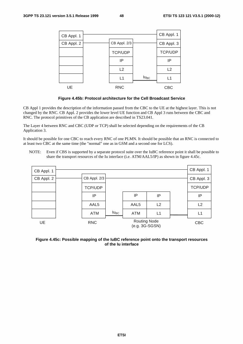
ETSI
ETSI TS 123 121 V3.5.1 (2000-12)483GPP TS 23.121 version 3.5.1 Release 1999
L2
IP
L1
L2
IP
TCP/UDP
L1
RNC CBC
IuBC
CB Appl. 2/3 CB Appl. 3
TCP/UDP
UE
CB Appl. 2
CB Appl. 1CB Appl. 1
Figure 4.45b: Protocol architecture for the Cell Broadcast Service
CB Appl 1 provides the description of the information passed from the CBC to the UE at the highest layer. This is notchanged by the RNC. CB Appl. 2 provides the lower level UE function and CB Appl 3 runs between the CBC andRNC. The protocol primitives of the CB application are described in TS23.041.
The Layer 4 between RNC and CBC (UDP or TCP) shall be selected depending on the requirements of the CBApplication 3.
It should be possible for one CBC to reach every RNC of one PLMN. It should be possible that an RNC is connected toat least two CBC at the same time (the "normal" one as in GSM and a second one for LCS).
NOTE: Even if CBS is supported by a separate protocol suite over the IuBC reference point it shall be possible toshare the transport resources of the Iu interface (i.e. ATM/AAL5/IP) as shown in figure 4.45c.
L2
IP
L1
AAL5
IP
TCP/UDP
ATM
RNC Routing Node(e.g. 3G-SGSN)
CBC
L2
IP
L1
AAL5
IP
ATMIuBC
CB Appl. 2/3 CB Appl. 3
TCP/UDP
UE
CB Appl. 2
CB Appl. 1CB Appl. 1
Figure 4.45c: Possible mapping of the IuBC reference point onto the transport resourcesof the Iu interface
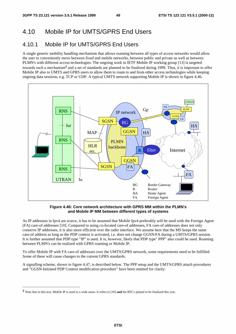
ETSI
ETSI TS 123 121 V3.5.1 (2000-12)493GPP TS 23.121 version 3.5.1 Release 1999
4.10 Mobile IP for UMTS/GPRS End Users
4.10.1 Mobile IP for UMTS/GPRS End Users
A single generic mobility handling mechanism that allows roaming between all types of access networks would allowthe user to conveniently move between fixed and mobile networks, between public and private as well as betweenPLMN's with different access technologies. The ongoing work in IETF Mobile IP working group [13] is targetedtowards such a mechanism2 and a set of standards are planned to be finalized during 1999. Thus, it is important to offerMobile IP also to UMTS and GPRS users to allow them to roam to and from other access technologies while keepingongoing data sessions, e.g. TCP or UDP. A typical UMTS network supporting Mobile IP is shown in figure 4.46.
Iu
CN
UTRAN
HA
UTRAN
RNS
RNS
RNS
IP network
HLRetc.
Iur
filter Internet
MAP
HA
HA
R
Gp
SGSN
GGSN
GGSNFASGSN
PLMNbackbone
GGSN
SGSN
BG
BG Border GatewayR RouterHA Home AgentFA Foreign Agent
FA
FA
Figure 4.46: Core network architecture with GPRS MM within the PLMN'sand Mobile IP MM between different types of systems
As IP addresses in Ipv4 are scarce, it has to be assumed that Mobile Ipv4 preferably will be used with the Foreign Agent(FA) care-of addresses [10]. Compared to using co-located care-of addresses, FA care-of addresses does not onlyconserve IP addresses, it is also more efficient over the radio interface. We assume here that the MS keeps the samecare-of address as long as the PDP context is activated, i.e. does not change GGSN/FA during a UMTS/GPRS session.It is further assumed that PDP type "IP" is used. It is, however, likely that PDP type" PPP" also could be used. Roamingbetween PLMN's can be realized with GPRS roaming or Mobile IP.
To offer Mobile IP with FA care-of addresses over the UMTS/GPRS network, some requirements need to be fulfilled.Some of these will cause changes to the current GPRS standards.
A signalling scheme, shown in figure 4.47, is described below. The PPP setup and the UMTS/GPRS attach proceduresand "GGSN-Initiated PDP Context modification procedure" have been omitted for clarity.
2 Note that in this text, Mobile IP is used in a wide sense. It refers to [10] and the RFC's planed to be finalized this year.

ETSI
ETSI TS 123 121 V3.5.1 (2000-12)503GPP TS 23.121 version 3.5.1 Release 1999
5. Activate PDPContext Accept
(no PDP address)
4. Create PDPContext Response(no PDP address)
2. Activate PDP Context Request
( APN=MIPv4FA )
IPv4 - Registration UMTS/GPRS + MIP , FA care-of address
TE MT HomeNetwork
SGSN GGSN/FA
3. Create PDPContext Request
( APN=MIPv4FA )
6. Agent Advertisement
7. MIP Registration Request
9. MIP Registration Reply10. MIP Registration Reply
1. AT Command (APN)
8. MIP Registration Request
A. Select suitable GGSN
Figure 4.47: PDP Context activation with Mobile IP registration(the PPP setup and UMTS/GPRS attach procedures not included)
1. The AT command carries parameters that the MT needs to request the PDP Context Activation. The importantparameter here, is the APN (Access Point Name), see clause A below. The AT command is followed by a setupof the PPP connection between the MT and the TE, which are not included in the figure.
2. The MT sends the "Activate PDP Context Request" to the SGSN. The message includes various parameters ofwhich the "APN" (Access Point Name) and the "Requested PDP Address" are of interest here. The MS may useAPN to select a reference point to a certain external network and/or to select a service. APN is a logical namereferring to the external packet data network and/or to a service that the subscriber wishes to connect to. The"Requested PDP Address" should be omitted for all MS's using Mobile IP. This is done irrespective of if the MThas a permanently assigned Mobile IP address from its Mobile IP home network, a previously assigned dynamichome address from its Mobile IP home network or if it wishes the Mobile IP home network to allocate a "new"dynamic home address.
A. The SGSN will base the choice of GGSN on the APN that is given by the MS.
The APN consists of two parts: the Network ID and the Operator ID. If no APN is given and PDP type is "IP", theSGSN chooses a suitable GGSN according to operator's configuration of the SGSN. Similarly, a Network ID of theformat vvv (one label, no dots) can be used to specify any GGSN with a specific service (vvv), e.g. Internet access,gateway for voice over IP, Mobile IP FA. If the SGSN is not configured to identify the requested service it may try witha DNS interrogation for vvv.current-operator.current-country.gprs or, if that is not successful, with vvv.home-operator.home-country.gprs, where the home parameters are taken from the subscription data.
3. The SGSN requests the selected GGSN to set up a PDP Context for the MS. The PDP address and APN fieldsare the same as in the "Activate PDP Context Request" message.
4. A Create PDP Context Response is sent from the GGSN/FA to the SGSN. If the creation of PDP Context wassuccessful, some parameters will be returned to the SGSN, if not, error code will be returned. If the GGSN hasbeen configured by the operator to use a Foreign Agent for the requested APN, the PDP address returned by the
ETSI
ETSI TS 123 121 V3.5.1 (2000-12)513GPP TS 23.121 version 3.5.1 Release 1999
GGSN shall be set to 0.0.0.0. indicating that the PDP address shall be negotiated by the MS with a Home Agentafter the PDP context activation procedure.
5. The Activate PDP Context Accept message is sent by the SGSN to the MS and contains similar information asthe Create PDP Context Response message.
6. The Agent Advertisement [10] is an ICMP (Internet Control Message Protocol) Router Advertisement messagewith a mobility agent advertisement extension. The latter part contains parameters of the FA that the mobilenode needs, among those are one or more care-of addresses that the FA offers. This message should be sent, inthe UMTS/GPRS user plane, as an IP limited broadcast message, i.e. destination address 255.255.255.255,however only on the TEID for the newly arrived MS to avoid broadcast over the radio interface.
7. The Mobile IP Registration Request is sent from the mobile node to the GGSN/FA across the GPRS/UMTSbackbone as user traffic. The mobile node includes its (permanent) home address as a parameter [10].Alternatively, it can request a temporary address assigned by the home network by including the NetworkAccess Identifier (NAI) in a Mobile-Node-NAI Extension [12], [11].
8. The FA forwards the Mobile IP Registration Request to the home network of the mobile node, where it getprocessed by a Home Agent (HA). Meanwhile, the GGSN/FA needs to store the home address of the mobilenode or the NAI and the local link address of the MS, i.e. the TEID.
9. The Registration Reply is sent from the home network to the FA, which extracts the information it needs (e.g.the home address of the mobile node if allocated by the home network).
10. The FA forwards the message to the mobile node in the UMTS/GPRS user plane. As the FA/GGSN knows theTEID and the NAI or home address, it can pass it on to the correct MS. A home address of the MS allocated bythe home network is sent to the SGSN by means of the "GGSN-Initiated PDP Context modification procedure"described in [23.060].
4.10.1.1 Alterations of and Additions to Current GPRS Standards
To support Mobile IP as described above, the following alterations and additions to the GPRS specifications arenecessary:
1) the functionality of the GGSN needs to be enhanced with FA functionality, according to IETF specifications. Forinteroperability, a set of RFC's should be recommended. There is no need to standardize an interface between theGGSN and the FA, as it is considered being one integrated node;
2) the GGSN/FA node should send a FA Advertisement message after sending the Create PDP Context Response;
3) the GGSN should not give the MS a temporary UMTS/GPRS IP (PDP) address if the Mobile IP FA service hasbeen requested;
4) the GGSN/FA and the MS shall exchange Mobile IP ` ignalling messages in the UMTS/GPRS user plane;
5) allow the APN to mean a GGSN with a specific service, not only a physical node. To support this, the operatormust have the possibility to configure the SGSN or DNS with the choice of GGSN depending on service. Adefault mechanism is also needed to use a GGSN in the MS's home network if the visited SGSN does notsupport the requested service. Finally, an agreement between operators is needed on the possible APN's.
4.11 Allowed network and terminal configurationsA UMTS network is divided into a radio access network and a core network, which are connected via an open interfaceover the Iu reference point. Furthermore, the core network is from a functional point of view divided into a PacketSwitched Service Domain and a Circuit Switched Service Domain.
The following network configurations shall be allowed:
a) networks which provide the functionality of CS Service Domain and PS Service Domain;
b) networks which only provide the functionality of the CS Service Domain;
ETSI
ETSI TS 123 121 V3.5.1 (2000-12)523GPP TS 23.121 version 3.5.1 Release 1999
c) networks which only provide the functionality of the PS Service Domain.
The following terminal configurations shall be allowed:
a) terminals which are able to access both to the CS Domain and PS Domain;
b) terminals which are only able to access to the PS Domain;
c) terminals which are only able to access to the CS Domain.
It shall be noted that e.g. terminal which is only able to access to the PS Domain supports only mobility management,protocols etc. of that particular domain. The different configurations given above shall not prevent CS-type servicesfrom being delivered over the PS domain.
5 UMTS to UMTS handover for circuit switchedservices
For UMTS to UMTS Inter-MSC Hand-Over / SRNS relocation the MAP E interface transporting RANAP messagesshall be used.
[Ed note: signalling flows are to be provided and be in line with "GSM to UMTS handover for circuit switchedservices"]
6 Interoperability between GSM and UMTSThe requirements for GSM – UMTS interoperability is defined in 22.129.
UMTS is a system supporting handovers between GSM and UMTS in both directions. To support these handoverseffectively, the following is required from a dual mode MS/UE supporting simultaneous ISDN/PSTN and packetservice in GSM/UMTS.
Depending upon the solution adopted for GSM-UMTS handover, the MS/UE supporting simultaneous ISDN/PSTN andpacket service may be required to perform appropriate update into CN depending on the activity of the UE once thehandover between GSM and UMTS is completed. This update is needed to avoid any severe interruptions on theaccessibility of packet services after the handover.
The nature of the update to be made after the handover in both direction, i.e., from GSM to UMTS and from UMTS toGSM, from MS/UE depends on the activity of the UE in the following way:
- ISDN/PSTN connection: RA update only (if RA is changed);
- Packet connection: LA and RA update (if RA and LA are changed).
Both ISDN/PSTN and packet connection: RA update only (if RA is changed).
6.1 Circuit Switched Handover and Roaming PrinciplesIntroduction of a UMTS Core Network necessitates the inter-connection with legacy systems to allow inter-PLMNroaming and handover.
For ease of convergence with the existing networks and the introduction of dual mode handsets, roaming and handoverto/from UMTS should be performed in the simplest manner that requires as little change as possible to the legacynetworks and standards, i.e. inter-MSC handover functionality.
These principles provide – from a user perspective – transparency of handover and roaming. In addition, operatorsproviding UMTS services should also allow access to legacy networks using existing subscriber profiles and networkinterfaces.
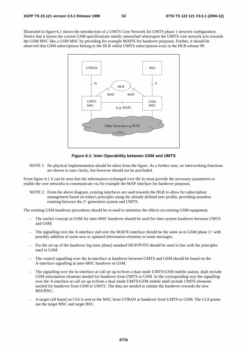
ETSI
ETSI TS 123 121 V3.5.1 (2000-12)533GPP TS 23.121 version 3.5.1 Release 1999
Illustrated in figure 6.1 shows the introduction of a UMTS Core Network for UMTS phase 1 network configuration.Notice that it leaves the current GSM specifications mainly untouched whereupon the UMTS core network acts towardsthe GSM MSC like a GSM MSC by providing for example MAP/E for handover purposes. Further, it should beobserved that GSM subscriptions belong to the HLR whilst UMTS subscriptions exist in the HLR release 99.
UTRAN
GSMMSC
UMTSMSC
BSS
Iu A
(e.g. MAP)
HLR
MAP
Other Networks e.g PSTN
MAP
Figure 6.1: Inter-Operability between GSM and UMTS
NOTE 1: No physical implementation should be taken from the figure. As a further note, no interworking functionsare shown to ease clarity, but however should not be precluded.
From figure 6.1 it can be seen that the information exchanged over the Iu must provide the necessary parameters toenable the core networks to communicate via for example the MAP interface for handover purposes.
NOTE 2: From the above diagram, existing interfaces are used towards the HLR to allow for subscriptionmanagement based on today's principles using the already defined user profile, providing seamlessroaming between the 2nd generation system and UMTS.
The existing GSM handover procedures should be re-used to minimise the effects on existing GSM equipment.
- The anchor concept in GSM for inter-MSC handover should be used for inter-system handover between UMTSand GSM.
- The signalling over the A-interface and over the MAP/E-interface should be the same as in GSM phase 2+ withpossibly addition of some new or updated information elements in some messages.
- For the set up of the handover leg (user plane) standard ISUP/POTS should be used in line with the principlesused in GSM.
- The control signalling over the Iu-interface at handover between UMTS and GSM should be based on theA-interface signalling at inter-MSC handover in GSM.
- The signalling over the Iu-interface at call set up to/from a dual mode UMTS/GSM mobile station, shall includeGSM information elements needed for handover from UMTS to GSM. In the corresponding way the signallingover the A-interface at call set up to/from a dual mode UMTS/GSM mobile shall include UMTS elementsneeded for handover from GSM to UMTS. The data are needed to initiate the handover towards the newBSS/RNC.
- A target cell based on CGI is sent to the MSC from UTRAN at handover from UMTS to GSM. The CGI pointsout the target MSC and target BSC.

ETSI
ETSI TS 123 121 V3.5.1 (2000-12)543GPP TS 23.121 version 3.5.1 Release 1999
- A target cell based on CGI is sent to the MSC from the BSS at handover from GSM to UMTS. The CGI pointsout the target UMTS MSC and target RNC (UMTS MSC does the translation from CGI to RNC identity).
6.1.1 UMTS to GSM handover for circuit switched services
UMTS to GSM handover for circuit switched services is detailed in 23.009.
6.1.2 GSM to UMTS handover for circuit switched services
UMTS to GSM handover for circuit switched services is detailed in 23.009.
6.2 Packet Switched Handover and Roaming PrinciplesThe introduction of a UMTS core Network illustrates the requirement for inter-connection with the legacy GSM systemto allow inter-PLMN roaming and handover.
Even though there is no current GPRS deployment, the operator may decide to deploy a GPRS network prior to thedeployment of a UMTS network. Therefore, the introduction of a UMTS Core Network may require to be inter-connected to the legacy packet network.
As in the circuit switched case, roaming and handover to/from UMTS should be performed in the simplest manner thatrequires as little change as possible to the GPRS network and standards, i.e. inter-GSN handover functionality. Inaddition, access is provided to the GPRS network using the existing subscriber profiles and current network interfaces.
A similar figure to figure 6.1 is illustrated in figure 6.2. Notice that it also leaves the current GPRS specificationsmainly untouched whereupon the UMTS core network acts towards the GSN like a GSN by providing for example Gn.Further, it should be observed that GPRS subscriptions belong to the HLR whilst UMTS subscriptions exist in the HLRrelease 99.
MAP
UTRAN BSS
Iu Gb
Gn
HLRMAP
Other Networks e.g PDN
3G-GGSN
3G_SGSN
Gn
2G-GGSN
2G-GGSN
Figure 6.2: Inter-Operability between GSNs and UMTS
NOTE 1: No physical implementation should be taken from figure 6.2. As a further note, no interworking functionsare shown to ease clarity, but however should not be precluded.
From figure 6.2 it can be seen that to provide inter-working between legacy packet switched and UMTS packetswitched services, the information exchanged over the Iu must provide the necessary parameters to enable the corenetworks to communicate via for example the Gn interface for handover purposes.
ETSI
ETSI TS 123 121 V3.5.1 (2000-12)553GPP TS 23.121 version 3.5.1 Release 1999
NOTE 2: From the above diagram, the same principles are used as in the circuit switched services to provideseamless roaming.
6.2.1 Implications
- The active PDP context resides in the same GGSN even after a handover between GSM and UMTS (bothdirections). This corresponds in principle to the anchor concept on the circuit switched side, but note thatwhereas packet sessions are long lived, the anchor MSC remains only for the duration of a CS call (typicallymuch shorter than a packet session).
- Assuming an internal structure in UMTS CN that contains logical GGSN and SGSN nodes, the signalling overthe inter-system GGSN-SGSN interface should be a joint evolution of Gn for the GSM system and UMTS.I.e. when Gn evolves in the sequence of GSM releases, Gn should include any new or updated informationnecessary for interoperation.
- The corresponding SGSN-SGSN inter-system interface (also Gn) should also be evolved together. However, inthis case the changes relative to the current GPRS release may possibly be more profound.
6.2.2 Signalling procedures
The signalling procedures shows how handover UMTS <-> GSM GPRS can be done. The parameters carried by eachmessage is not complete and shall be seen as examples of important information carried be the messages.
The signalling sequences shows the case when the UMTS 3G_SGSN and the GPRS 2G_SGSN are located in separate"physical" nodes.
If the 3G_SGSN and 2G_SGSN are located within the same "physical" node, no signalling are needed between3G_SGSN and 2G_SGSN.
For handover in the UMTS to GSM GPRS direction the intention is to re-use the handover principles of GSM GPRStoday in order to limit the changes in GSM GPRS and to take the changes if any on the UMTS side. The belowspecified messages is standard GSM 2+ messages (when applicable).
6.2.2.1 Handover from UMTS to GSM GPRS
Handover from UMTS to GSM GPRS is detailed in 23.060.
6.2.2.2 Handover from GSM GPRS to UMTS
Handover from GSM GPRS to UMTS is detailed in 23.060.
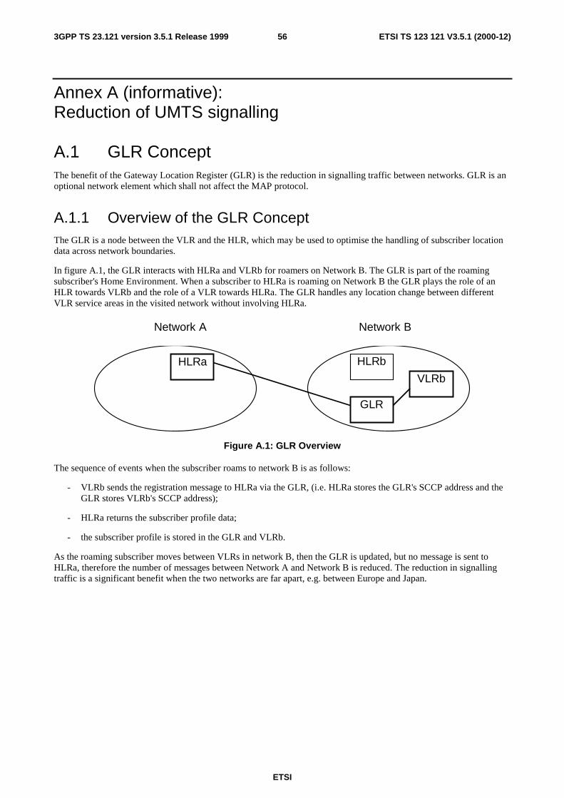
ETSI
ETSI TS 123 121 V3.5.1 (2000-12)563GPP TS 23.121 version 3.5.1 Release 1999
Annex A (informative):Reduction of UMTS signalling
A.1 GLR ConceptThe benefit of the Gateway Location Register (GLR) is the reduction in signalling traffic between networks. GLR is anoptional network element which shall not affect the MAP protocol.
A.1.1 Overview of the GLR ConceptThe GLR is a node between the VLR and the HLR, which may be used to optimise the handling of subscriber locationdata across network boundaries.
In figure A.1, the GLR interacts with HLRa and VLRb for roamers on Network B. The GLR is part of the roamingsubscriber's Home Environment. When a subscriber to HLRa is roaming on Network B the GLR plays the role of anHLR towards VLRb and the role of a VLR towards HLRa. The GLR handles any location change between differentVLR service areas in the visited network without involving HLRa.
Network A Network B
HLRa HLRb
GLR
VLRb
Figure A.1: GLR Overview
The sequence of events when the subscriber roams to network B is as follows:
- VLRb sends the registration message to HLRa via the GLR, (i.e. HLRa stores the GLR's SCCP address and theGLR stores VLRb's SCCP address);
- HLRa returns the subscriber profile data;
- the subscriber profile is stored in the GLR and VLRb.
As the roaming subscriber moves between VLRs in network B, then the GLR is updated, but no message is sent toHLRa, therefore the number of messages between Network A and Network B is reduced. The reduction in signallingtraffic is a significant benefit when the two networks are far apart, e.g. between Europe and Japan.
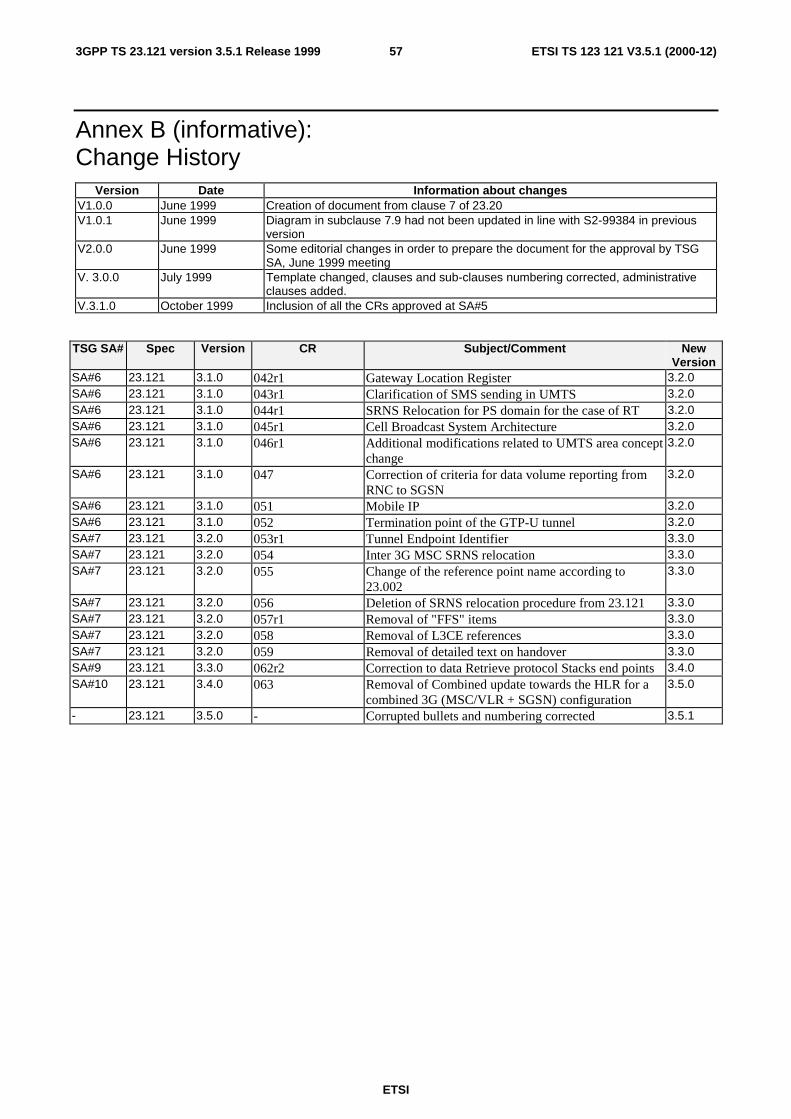
ETSI
ETSI TS 123 121 V3.5.1 (2000-12)573GPP TS 23.121 version 3.5.1 Release 1999
Annex B (informative):Change History
Version Date Information about changesV1.0.0 June 1999 Creation of document from clause 7 of 23.20V1.0.1 June 1999 Diagram in subclause 7.9 had not been updated in line with S2-99384 in previous
versionV2.0.0 June 1999 Some editorial changes in order to prepare the document for the approval by TSG
SA, June 1999 meetingV. 3.0.0 July 1999 Template changed, clauses and sub-clauses numbering corrected, administrative
clauses added.V.3.1.0 October 1999 Inclusion of all the CRs approved at SA#5
TSG SA# Spec Version CR Subject/Comment NewVersion
SA#6 23.121 3.1.0 042r1 Gateway Location Register 3.2.0SA#6 23.121 3.1.0 043r1 Clarification of SMS sending in UMTS 3.2.0SA#6 23.121 3.1.0 044r1 SRNS Relocation for PS domain for the case of RT 3.2.0SA#6 23.121 3.1.0 045r1 Cell Broadcast System Architecture 3.2.0SA#6 23.121 3.1.0 046r1 Additional modifications related to UMTS area concept
change3.2.0
SA#6 23.121 3.1.0 047 Correction of criteria for data volume reporting fromRNC to SGSN
3.2.0
SA#6 23.121 3.1.0 051 Mobile IP 3.2.0SA#6 23.121 3.1.0 052 Termination point of the GTP-U tunnel 3.2.0SA#7 23.121 3.2.0 053r1 Tunnel Endpoint Identifier 3.3.0SA#7 23.121 3.2.0 054 Inter 3G MSC SRNS relocation 3.3.0SA#7 23.121 3.2.0 055 Change of the reference point name according to
23.0023.3.0
SA#7 23.121 3.2.0 056 Deletion of SRNS relocation procedure from 23.121 3.3.0SA#7 23.121 3.2.0 057r1 Removal of "FFS" items 3.3.0SA#7 23.121 3.2.0 058 Removal of L3CE references 3.3.0SA#7 23.121 3.2.0 059 Removal of detailed text on handover 3.3.0SA#9 23.121 3.3.0 062r2 Correction to data Retrieve protocol Stacks end points 3.4.0SA#10 23.121 3.4.0 063 Removal of Combined update towards the HLR for a
combined 3G (MSC/VLR + SGSN) configuration3.5.0
- 23.121 3.5.0 - Corrupted bullets and numbering corrected 3.5.1

58
ETSI
ETSI TS 123 121 V3.5.1 (2000-12)3GPP TS 23.121 version 3.5.1 Release 1999
History
Document history
V3.2.0 January 2000 Publication
V3.3.0 March 2000 Publication
V3.4.0 October 2000 Publication
V3.5.1 December 2000 Publication
Related Documents