ETSI TS 102 361-3 V1.2.1 (2013-07) Electromagnetic compatibility and Radio spectrum Matters (ERM); Digital Mobile Radio (DMR) Systems; Part 3: DMR data protocol Technical Specification

Welcome message from author
This document is posted to help you gain knowledge. Please leave a comment to let me know what you think about it! Share it to your friends and learn new things together.
Transcript

ETSI TS 102 361-3 V1.2.1 (2013-07)
Electromagnetic compatibility and Radio spectrum Matters (ERM);
Digital Mobile Radio (DMR) Systems; Part 3: DMR data protocol
Technical Specification

ETSI
ETSI TS 102 361-3 V1.2.1 (2013-07)2
Reference RTS/ERM-TGDMR-312-3
Keywords air interface, data, digital, PMR, protocol, radio
ETSI
650 Route des Lucioles F-06921 Sophia Antipolis Cedex - FRANCE
Tel.: +33 4 92 94 42 00 Fax: +33 4 93 65 47 16
Siret N° 348 623 562 00017 - NAF 742 C
Association à but non lucratif enregistrée à la Sous-Préfecture de Grasse (06) N° 7803/88
Important notice
Individual copies of the present document can be downloaded from: http://www.etsi.org
The present document may be made available in more than one electronic version or in print. In any case of existing or perceived difference in contents between such versions, the reference version is the Portable Document Format (PDF).
In case of dispute, the reference shall be the printing on ETSI printers of the PDF version kept on a specific network drive within ETSI Secretariat.
Users of the present document should be aware that the document may be subject to revision or change of status. Information on the current status of this and other ETSI documents is available at
http://portal.etsi.org/tb/status/status.asp
If you find errors in the present document, please send your comment to one of the following services: http://portal.etsi.org/chaircor/ETSI_support.asp
Copyright Notification
No part may be reproduced except as authorized by written permission. The copyright and the foregoing restriction extend to reproduction in all media.
© European Telecommunications Standards Institute 2013.
All rights reserved.
DECTTM, PLUGTESTSTM, UMTSTM and the ETSI logo are Trade Marks of ETSI registered for the benefit of its Members. 3GPPTM and LTE™ are Trade Marks of ETSI registered for the benefit of its Members and
of the 3GPP Organizational Partners. GSM® and the GSM logo are Trade Marks registered and owned by the GSM Association.
ETSI
ETSI TS 102 361-3 V1.2.1 (2013-07)3
Contents Intellectual Property Rights ................................................................................................................................ 6
Foreword ............................................................................................................................................................. 6
1 Scope ........................................................................................................................................................ 7
2 References ................................................................................................................................................ 7
2.1 Normative references ......................................................................................................................................... 7
2.2 Informative references ........................................................................................................................................ 8
3 Definitions and abbreviations ................................................................................................................... 8
3.1 Definitions .......................................................................................................................................................... 8
3.2 Abbreviations ................................................................................................................................................... 10
4 Overview ................................................................................................................................................ 11
4.1 Protocol architecture......................................................................................................................................... 11
4.1.1 Air Interface Physical Layer (layer 1)......................................................................................................... 12
4.1.2 Air Interface Data Link Layer (layer 2) ...................................................................................................... 13
4.1.3 Air Interface Call Control Layer (layer 3) .................................................................................................. 13
4.2 Overview of the DMR Packet Data Protocol (PDP) ........................................................................................ 13
4.3 Feature interoperability .................................................................................................................................... 14
5 Internet Protocol (IP) bearer service....................................................................................................... 14
5.1 IP addressing .................................................................................................................................................... 15
5.1.1 DLL derived IP addressing ......................................................................................................................... 15
5.1.2 DLL neutral IP addressing .......................................................................................................................... 16
5.2 IP error messages.............................................................................................................................................. 16
5.3 Unconfirmed data DLL bearer service ............................................................................................................. 17
5.3.1 Unconfirmed IP Data Types/PDUs ............................................................................................................. 18
5.3.1.1 Rate ½ coded unconfirmed IP Data Types/PDUs ................................................................................. 18
5.3.1.2 Rate ¾ coded unconfirmed IP Data Types/PDUs ................................................................................. 18
5.3.1.3 Rate 1 coded unconfirmed IP Data Types/PDUs .................................................................................. 18
5.3.2 Unconfirmed IP data SDL .......................................................................................................................... 18
5.3.3 Unconfirmed IP Data MSCs ....................................................................................................................... 20
5.3.3.1 TX unconfirmed IP data MSC .............................................................................................................. 20
5.3.3.2 Form and send DLL data message MSC ............................................................................................... 21
5.3.3.3 Unconfirmed Data Repeat ..................................................................................................................... 22
5.4 Confirmed data DLL bearer service ................................................................................................................. 23
5.4.1 Confirmed IP Data Types/PDUs ................................................................................................................. 24
5.4.1.1 Rate ½ coded confirmed IP Data Types/PDUs ..................................................................................... 24
5.4.1.2 Rate ¾ coded confirmed IP Data Types/PDUs ..................................................................................... 24
5.4.1.2A Rate 1 coded confirmed IP Data Types/PDUs ...................................................................................... 24
5.4.1.3 Confirmed response Data Types/PDUs ................................................................................................. 24
5.4.2 Confirmed IP Data SDL ............................................................................................................................. 25
5.4.2.1 Confirmed data source SDL .................................................................................................................. 25
5.4.2.2 Confirmed data target SDL ................................................................................................................... 27
5.4.3 Confirmed data MSCs ................................................................................................................................ 28
5.4.3.1 Confirmed data source MSCs ............................................................................................................... 28
5.4.3.1.1 TX confirmed IP data MSC ............................................................................................................. 28
5.4.3.1.2 Form and send DLL data message MSC ......................................................................................... 28
5.4.3.1.3 Process DLL confirmed response MSC .......................................................................................... 29
5.4.3.2 Confirmed data target MSCs ................................................................................................................. 30
5.4.3.2.1 RX confirmed data MSC ................................................................................................................. 30
5.4.3.3 Confirmed data BS MSCs ..................................................................................................................... 30
5.4.3.3.1 Confirmed data repeat MSC ............................................................................................................ 30
5.4.3.3.2 Confirmed data hangtime MSC ....................................................................................................... 31
5.4.4 Sliding window confirmed data .................................................................................................................. 32
5.5 UDP/IPv4 data .................................................................................................................................................. 32
5.6 UDP/IPv4 header compression......................................................................................................................... 33
ETSI
ETSI TS 102 361-3 V1.2.1 (2013-07)4
5.7 Application Data over IP Bearer Service ......................................................................................................... 34
5.7.1 Text Messaging ........................................................................................................................................... 35
5.7.2 Location ...................................................................................................................................................... 35
6 Short data bearer service ........................................................................................................................ 35
6.1 Defined Data .................................................................................................................................................... 35
6.1.1 Defined Data Types/PDUs .......................................................................................................................... 35
6.1.2 Defined data information element values ................................................................................................... 36
6.2 Raw data ........................................................................................................................................................... 36
6.2.1 Raw data types/PDUs ................................................................................................................................. 36
6.2.2 Raw data information element values ......................................................................................................... 36
6.3 Status/precoded data ......................................................................................................................................... 36
6.3.1 Status/precoded data types/PDUs ............................................................................................................... 37
6.3.2 Status/precoded data information element values ....................................................................................... 37
6.4 Short data confirmed response ......................................................................................................................... 37
7 PDU description ..................................................................................................................................... 38
7.1 Layer 3 and 4 PDP PDUs ................................................................................................................................. 38
7.1.1 Full Link Control (FULL LC) PDUs .......................................................................................................... 38
7.1.1.1 Terminator Data Link Control PDU ...................................................................................................... 38
7.2 UDP/IPv4 Compressed Header ........................................................................................................................ 39
7.2.1 UDP Header Information Elements ............................................................................................................ 39
7.2.1.1 UDP Source Port Number ..................................................................................................................... 39
7.2.1.2 UDP Destination Port Number .............................................................................................................. 39
7.2.1.3 UDP Length .......................................................................................................................................... 40
7.2.1.4 UDP Checksum ..................................................................................................................................... 40
7.2.2 IPv4 Header Information Elements ............................................................................................................ 40
7.2.2.1 IPv4 Version ......................................................................................................................................... 40
7.2.2.2 IPv4 Internet Header Length (IHL) ....................................................................................................... 40
7.2.2.3 IPv4 Type Of Service (TOS) ................................................................................................................. 41
7.2.2.4 IPv4 Total Length ................................................................................................................................. 41
7.2.2.5 IPv4 Identification ................................................................................................................................. 41
7.2.2.6 IPv4 Flags ............................................................................................................................................. 41
7.2.2.7 IPv4 Fragment Offset ............................................................................................................................ 41
7.2.2.8 IPv4 Time to Live ................................................................................................................................. 42
7.2.2.9 IPv4 Protocol......................................................................................................................................... 42
7.2.2.10 IPv4 Header Checksum ......................................................................................................................... 42
7.2.2.11 IPv4 Source Address ............................................................................................................................. 42
7.2.2.12 IPv4 Destination Address ...................................................................................................................... 42
7.2.3 UDP/IPv4 Compressed Header................................................................................................................... 43
7.2.4 UDP/IPv4 Compressed Header Information Elements ............................................................................... 43
7.2.4.1 Source IP Address IDentifier (SAID) ................................................................................................... 43
7.2.4.2 Destination IP Address IDentifier (DAID) ........................................................................................... 43
7.2.4.3 UDP Source Port IDentifier (SPID) ...................................................................................................... 44
7.2.4.4 UDP Destination Port IDentifier (DPID) .............................................................................................. 44
7.2.4.5 Header Compression Opcode ................................................................................................................ 44
7.2.4.6 Extended Header 1 ................................................................................................................................ 45
7.2.4.7 Extended Header 2 ................................................................................................................................ 45
Annex A (normative): PDP timers and constants in DMR............................................................... 46
A.1 Layer 2 timers ......................................................................................................................................... 46
A.2 Layer 2 constants .................................................................................................................................... 46
Annex B (normative): Opcode reference lists .................................................................................... 47
B.1 PDP Full Link Control Opcode list ........................................................................................................ 47
Annex C (informative): IPv6 transport over PDP ............................................................................... 48
C.1 IPv6 addressing ...................................................................................................................................... 48
C.2 Address mapping over PDP ................................................................................................................... 49
ETSI
ETSI TS 102 361-3 V1.2.1 (2013-07)5
C.3 IPv6 tunnelling techniques ..................................................................................................................... 49
Annex D (informative): Change requests ............................................................................................. 51
Annex E (informative): Bibliography ................................................................................................... 52
History .............................................................................................................................................................. 53
ETSI
ETSI TS 102 361-3 V1.2.1 (2013-07)6
Intellectual Property Rights IPRs essential or potentially essential to the present document may have been declared to ETSI. The information pertaining to these essential IPRs, if any, is publicly available for ETSI members and non-members, and can be found in ETSI SR 000 314: "Intellectual Property Rights (IPRs); Essential, or potentially Essential, IPRs notified to ETSI in respect of ETSI standards", which is available from the ETSI Secretariat. Latest updates are available on the ETSI Web server (http://ipr.etsi.org).
Pursuant to the ETSI IPR Policy, no investigation, including IPR searches, has been carried out by ETSI. No guarantee can be given as to the existence of other IPRs not referenced in ETSI SR 000 314 (or the updates on the ETSI Web server) which are, or may be, or may become, essential to the present document.
Foreword This Technical Specification (TS) has been produced by ETSI Technical Committee Electromagnetic compatibility and Radio spectrum Matters (ERM).
The present document is part 3 of a multi-part deliverable covering the Technical Requirements for Digital Mobile Radio (DMR), as identified below:
Part 1: "DMR Air Interface (AI) protocol";
Part 2: "DMR voice and generic services and facilities";
Part 3: "DMR data protocol";
Part 4: "DMR trunking protocol".
ETSI
ETSI TS 102 361-3 V1.2.1 (2013-07)7
1 Scope The present document contains technical requirements for Digital Mobile Radio (DMR) operating in the existing licensed land mobile service frequency bands, as identified in CEPT/ERC T/R 25-08 [3].
The present document describes the packet data protocol (PDP) of a scalable Digital Mobile Radio system which covers three tiers of possible products:
Tier I: DMR equipment having an integral antenna and working in direct mode (communication without infrastructure) under a general authorization with no individual rights operation.
Tier II: DMR systems operating under individual licences working in direct mode or using a Base Station (BS) for repeating.
Tier III: DMR trunking systems under individual licences operating with a controller function that automatically regulates the communications.
NOTE 1: Tier II and Tier III products encompass both simulcast and non-simulcast systems.
NOTE 2: The three tiers of possible products will work only independently and not interoperable.
The present document specifies the Packet Data Protocol (PDP) of DMR that has been specifically developed with the intention of being suitable for all identified product tiers. The DMR protocol is intended to be applicable to the land mobile frequency bands, physical channel offset, duplex spacing, range assumptions and all other spectrum parameters without need for any change.
2 References References are either specific (identified by date of publication and/or edition number or version number) or non-specific. For specific references, only the cited version applies. For non-specific references, the latest version of the reference document (including any amendments) applies.
Referenced documents which are not found to be publicly available in the expected location might be found at http://docbox.etsi.org/Reference.
NOTE: While any hyperlinks included in this clause were valid at the time of publication, ETSI cannot guarantee their long term validity.
2.1 Normative references The following referenced documents are necessary for the application of the present document.
[1] ETSI TS 102 361-1: "Electromagnetic compatibility and Radio spectrum Matters (ERM); Digital Mobile Radio (DMR) Systems; Part 1: DMR Air Interface (AI) protocol".
[2] ETSI TS 102 361-2: "Electromagnetic compatibility and Radio spectrum Matters (ERM); Digital Mobile Radio (DMR) Systems; Part 2: DMR voice and generic services and facilities".
[3] CEPT/ERC T/R 25-08: "Planning criteria and coordination of frequencies in the land mobile service in the range 29,7 - 921 MHz".
[4] IETF RFC 791: "Internet Protocol; DARPA Internet Program; Protocol Specification".
[5] IETF RFC 792: "Internet Control Message Protocol; DARPA Internet Program; Protocol Specification".
[6] IETF RFC 1918: "Address Allocation for Private Internets".
[7] IETF RFC 826: "Ethernet Address Resolution Protocol: Or converting network protocol addresses to 48.bit Ethernet address for transmission on Ethernet hardware".

ETSI
ETSI TS 102 361-3 V1.2.1 (2013-07)8
[8] IETF RFC 2460: "Internet Protocol, Version 6 (IPv6) Specification ".
[9] IETF RFC 2529: "Transmission of IPv6 over IPv4 Domains without Explicit Tunnels".
[10] IETF RFC 3056: "Connection of IPv6 Domains via IPv4 Clouds".
[11] IETF RFC 3142: "An IPv6-to-IPv4 Transport Relay Translator".
[12] IETF RFC 4213: "Basic Transition Mechanisms for IPv6 Hosts and Routers".
[13] ETSI TS 100 392-18-1: "Terrestrial Trunked Radio (TETRA); Voice plus Data (V+D) and Direct Mode Operation (DMO); Part 18: Air Interface optimized applications; Sub-part 1: Location Information Protocol (LIP)".
[14] IETF RFC 768: "User Datagram Protocol".
[15] IETF RFC 2781: "UTF-16, an encoding of ISO 10646".
2.2 Informative references The following referenced documents are not necessary for the application of the present document but they assist the user with regard to a particular subject area.
Not applicable.
3 Definitions and abbreviations
3.1 Definitions For the purposes of the present document, the following terms and definitions apply:
Base Station (BS): fixed end equipment that is used to obtain DMR services
bearer service: telecommunication service providing the capability for information transfer between access point
burst: elementary amount of bits within the physical channel
NOTE: For detailed burst definition see clause 4.2.1 in TS 102 361-1 [1].
call: complete sequence of related transactions between MSs
NOTE: Transactions may be one or more bursts containing specific call related information.
Control plane (C-plane): part of the DMR protocol stack dedicated to control and data services
conventional: non-trunked communication
NOTE: This is a communication technique where any radio unit (MS) may communicate with one or more other radio units (MSs) without using a trunking protocol, and may be either in direct mode or using any additional equipment (e.g. BS).
Digital Mobile Radio (DMR): physical grouping that contains all of the mobile and/or fixed end equipment that is used to obtain DMR services
direct mode: mode of operation where MSs may communicate outside the control of a network
NOTE: This is communication technique where any radio unit (MS) may communicate with one or more other radio units (MSs) without the need for any additional equipment (e.g. BS).

ETSI
ETSI TS 102 361-3 V1.2.1 (2013-07)9
duplex: mode of operation by which information can be transferred in both directions and where the two directions are independent
NOTE: Duplex is also known as full duplex.
frame: two contiguous time slots labelled 1 and 2
NOTE: A frame has a length of 60 ms.
logical channel: distinct data path between logical endpoints
NOTE: The logical channels are labelled 1 and 2. The logical channel may consist of sub-channels, e.g. SYNC, embedded signalling, etc.
Mobile Station (MS): physical grouping that contains all of the mobile equipment that is used to obtain DMR mobile services
payload: bits in the information field
physical channel: RF carrier that is modulated with information bits of the bursts
NOTE: The RF carrier may be a single frequency or a duplex pair of frequencies. The physical channel of a DMR subsystem is required to support the logical channels.
Protocol Data Unit (PDU): unit of information consisting of protocol control information (signalling) and possibly user data exchanged between peer protocol layer entities
Radio Frequency channel: radio frequency carrier (RF carrier)
NOTE: This is a specified portion of the RF spectrum. In DMR, the RF carrier separation is 12,5 kHz. The physical channel may be a single frequency or a duplex spaced pair of frequencies.
repeater mode: mode of operation where MSs may communicate through a BS
NOTE: This is a communication technique where any radio unit (MS) may communicate with one or more other radio units (MSs) with the need for an intermediate BS.
sliding window: DLL confirmed data transmission flow control procedure that requires the target to store multiple data packets and provide a confirmed response on all the stored data upon request from the source
stop and wait: DLL confirmed data transmission flow control procedure that requires the target to send a confirmation response after receiving each data packet
superframe: 6 continuous traffic bursts on a logical channel labelled "A" to "F"
NOTE: A superframe has a length of 360 ms and is used for voice traffic only.
time slot (or slot): elementary timing of the physical channel
NOTE: A timeslot has a length of 30 ms and will be numbered "1" or "2".
transmission: transfer period of bursts containing information or signalling
NOTE: The transmission may be continuous, i.e. multiple bursts transmission without ramp-up, ramp-down, or discontinuous, i.e. single burst transmission with ramp-up and ramp-down period.
trunking: network controlled communication
NOTE: This is a communication technique where any radio unit (MS) may communicate with one or more other radio units (MSs) using a trunking protocol and all MSs will be under control of a network.
User plane (U-plane): part of the DMR protocol stack dedicated to user voice services
ETSI
ETSI TS 102 361-3 V1.2.1 (2013-07)10
3.2 Abbreviations For the purposes of the present document, the following abbreviations apply:
AB Appended Block ACK (positive) ACKnowledgement AI Air Interface ARP Address Resolution Protocol AT Access Type BMP Basic Multilingual Plane BS Base Station
NOTE: A reference designating a fixed end device.
CACH Common Announcement CHannel CCL Call Control Layer CRC Cyclic Redundancy Checksum for data error detection C-plane Control plane DAID Destination (IP) Address IDentifier DD Defined Data DLL Data Link Layer DMR Digital Mobile Radio DNF Do Not Fragment DPF Data Packet Format DPID (UDP) Destination Port IDentifier ERC European Radiocommunication Committee FEC Forward Error Correction FID Feature set ID FLCO Full Link Control Opcode FMF Full Message Flag FULL LC Full Link Control HMSC High level Message Sequence Chart ICMP Internet Control Message Protocol ID Identifier IHL Internet Header Length IP Internet Protocol IPv4 Internet Protocol version 4 IPv6 Internet Protocol version 6 IT Impolite Type LAN Local Area Network LC Link Control LLC Link Layer Control LLID Logical Link ID LSB Least Significant Bit MAC Medium Access Control MFID Manufacturer's FID MS Mobile Station
NOTE: A reference designating a mobile or portable radio.
MSB Most Significant Bit MSC Message Sequence Chart MTU Maximum Transfer Unit NA Not Applicable NACK Negative ACKnowledgement NAT Network Address Translator PDP Packet Data Protocol PDU Protocol Data Unit PF Protect Flag PL Physical Layer RAN Radio Area Network RF Radio Frequency
ETSI
ETSI TS 102 361-3 V1.2.1 (2013-07)11
RFC Request For Comments RX Receive RX_LB Receive Last Block SACK Selective ACKnowledgement SAID Source (IP) Address IDentifier SAP Service Access Point
NOTE: Where a network provides a service.
SARQ Selective Automatic Repeat reQuest SDL Specification and Description Language SPID (UDP) Source Port IDentifier TCP Transmission Control Protocol TD Terminator Data TDMA Time Division Multiple Access TOS Type Of Service TX Transmit UDP User Datagram Protocol USB Universal Serial Bus UTF-16BE Unicode Transformation Format 16 bit Big-Endian U-plane User plane
4 Overview The present document describes a Digital Mobile Radio (DMR) system for Tier I, Tier II and Tier III products which employ a Time Division Multiple Access (TDMA) technology using a 2-slot TDMA solution and RF carrier bandwidth of 12,5 kHz (see note 1).
NOTE 1: DMR system for Tier I products employs a continuous transmission variation of the previously mentioned technology.
The present document describes the Call Control Layer (CCL) of the DMR Air Interface (AI) for packet data call control. Radio equipment (fixed, mobile or portable) which conform to the present document shall be interoperable at the Air Interface with equipment from other manufacturers. Radio equipment of the present document shall also comply with TS 102 361-1 [1].
The present document will not provide the specification or operational detail for system implementations which include but are not limited to trunking, roaming, network management, vocoder, security, voice and generic services and facilities, subsystems interfaces and data between private and public switched telephone networks. It describes only the appropriate access requirements compatible with the Air Interface.
NOTE 2: The DMR standard consists of a multi-part deliverable, which will be referred to in the present document if needed.
4.1 Protocol architecture The purpose of this clause is to provide a model where the different functions and processes are identified and allocated to different layers in the DMR protocol stack.
The protocol stack in this clause and all other related clauses describe and specify the interfaces, but these stacks do not imply or restrict any implementation.
The DMR protocol architecture which is defined herein follows the generic layered structure, which is accepted for reference description and specification of layered communication architectures.
The DMR standard defines the protocols for the following 3 layered model as shown in figure 4.1.
The base of the protocol stack is the Physical Layer (PL) which is the layer 1.

ETSI
ETSI TS 102 361-3 V1.2.1 (2013-07)12
The Data Link Layer (DLL), which is the layer 2, shall handle sharing of the medium by a number of users. At the DLL, the protocol stack shall be divided vertically into two parts, the User plane (U-plane), for transporting information without addressing capability (e.g. voice), and the Control plane (C-plane) for signalling information, both control and data, with addressing capability, as illustrated by figure 4.1.
NOTE 1: It is appropriate to bear in mind the different requirements of C-plane and U-plane information. C-plane information needs only a discrete (or non-continuous) physical link to pass information although it needs a continuous virtual link to support the service. This may also be called signalling or packet mode service. Acknowledgements may or may not be requested. U-plane information, on the other hand, requires a regular physical link to be available so that a constant delay service can be supported. This may also be called circuit mode service.
NOTE 2: The DLL identified in figure 4.1 may be further sub-divided in the air interface protocol to separate the functionality of Medium Access Control (MAC) and Logical Link Control (LLC), which is often performed in radio air interface protocols due to the specialized nature of these two tasks. Such separation is not presented in the present document and is implementation specific. It is further implementation specific if layer 2 at U-plane offers only MAC for the service.
The Call Control Layer (CCL), which is layer 3, lies in the C-plane and is responsible for control of the call (addressing, features, etc.), provides the services supported by DMR, and supports Short Data and Packet Data service. U-plane access at layer 2 (DLL) supports voice service which is available in DMR. The Control Layer for data call control offered by DMR is described in the present document. The voice and generic services and facilities offered by DMR are described in TS 102 361-2 [2].
AI Layer 2
AI Layer 1
Call Control Layer
Data Link Layer
Physical Layer
Voice payload
AI Layer 3
Control plane User plane
Call Control information
Short Data service
Packet Data service
Figure 4.1: DMR protocol stack
4.1.1 Air Interface Physical Layer (layer 1) The Air Interface layer 1 shall be the physical interface. It shall deal with the physical burst, composed of bits, which is to be sent and/or received. The Physical Layer is described in TS 102 361-1 [1].
The Air Interface layer 1 contains the following functions:
• modulation and demodulation;
• transmitter and receiver switching;
• RF characteristics;
• bits and symbol definition;
• frequency and symbol synchronization;
• burst building.
ETSI
ETSI TS 102 361-3 V1.2.1 (2013-07)13
4.1.2 Air Interface Data Link Layer (layer 2) The Air Interface layer 2 shall handle logical connections and shall hide the physical medium from the upper layers. The Data Link Layer is described in TS 102 361-1 [1].
The main functions are as follows:
• channel coding (FEC, CRC);
• interleaving, de-interleaving and bit ordering;
• acknowledgement and retry mechanism;
• media access control and channel management;
• framing, superframe building and synchronization;
• burst and parameter definition;
• link addressing (source and/or destination);
• interfacing of voice applications (vocoder data) with the PL;
• data bearer services;
• exchanging signalling and/or user data with the CCL.
Packet Data Protocol specific DLL features are described in the present document.
4.1.3 Air Interface Call Control Layer (layer 3) Air Interface layer 3 (CCL) is applicable only to the C-plane, and shall be an entity for the services and features supported by DMR on top of the layer 2 functionality. The Call Control Layer functionality for voice and generic services and facilities is described in clause 5 of TS 102 361-2 [2].
The CCL provides the following functions:
• BS activation;
• establishing, maintaining and terminating of calls;
• individual or group call transmission and reception;
• destination addressing (DMR IDs or gateway as appropriate);
• support of intrinsic services (emergency signalling, pre-emption, late entry, etc.);
• announcement signalling.
Packet Data Protocol specific CCL features that are described in the Internet Protocol bearer service clause of the present document refer to the IP layer.
4.2 Overview of the DMR Packet Data Protocol (PDP) The Packet Data Protocol described for DMR is related to packet data transmission procedures, e.g. unconfirmed data, confirmed data, confirmed data response etc. The Packet Data Protocol defined for DMR contains intrinsic (embedded) signalling or procedures which may relate to one or more packet data transmission procedures.
All users related signalling or presentation above layer 3 are not part of the present document and are implementation specific.
ETSI
ETSI TS 102 361-3 V1.2.1 (2013-07)14
The Packet Data Protocol defined in the present document may be used for DMR products and is called the "default Packet Data Protocol". There is a possibility in the DMR standard which allows manufacturers to define and implement "private" feature sets which contains additional "private" signalling, which may not be understood by products not supporting this "private" feature set.
The Packet Data Protocol contains the following types of DLL bearer service data transmissions:
• unconfirmed data transmission;
• confirmed data:
- data transmission;
- response transmission.
The Packet Data Protocol contains the following types of layer 3 bearer service data transmissions:
• Internet Protocol;
• Short Data:
- raw data;
- status/precoded data;
- defined data.
These layer 3 bearer services are built on top of the DLL bearer services.
The present document defines the DMR Packet Data Protocol (PDP) for packet data operation. Data messages of arbitrary length are transferred over the DMR Air Interface using a packet technique. The layer 2 DMR PDP PDUs are defined in clause 8 of TS 102 361-1 [1].
The description of the Packet Data Protocol uses SDL diagrams where necessary to illustrate and highlight specific points in both direct mode and Base Station (BS) mode. Other aspects of the DMR radio system required are the High Level MS SDL, the High Level BS SDL, HMSC and MSC diagrams. For the High Level SDL diagrams and state description refer to TS 102 361-1 [1], annex G.
4.3 Feature interoperability The Feature set ID (FID) identifies one of several different feature sets and is only carried in the second data header.
To ensure interoperability at the Air Interface, packet data transmissions that are standardized in the present document and available in the equipment shall be accessible only via a single data header.
Packet data transmissions that are not standardized in the present document are only available via an alternative Manufacturer's FID (MFID) in the second data header.
5 Internet Protocol (IP) bearer service The present document supports the following network layer protocol:
• Internet Protocol version 4 (IPv4).
NOTE: For detailed description refer to RFC 791 [4].
IPv4 provides a connectionless, best-effort datagram delivery between two service access points. IPv4 protocol is called on by host-to-host protocols (e.g. TCP, UDP) in an internet environment. IPv4 calls on Air Interface protocol to carry the IP datagram over the air.
The DMR IP bearer service is built on top of the DLL bearer services (unconfirmed data and confirmed data) that are defined in clauses 5.3 and 5.4 of the present document.
ETSI
ETSI TS 102 361-3 V1.2.1 (2013-07)15
DMR PDP extends DMR to act as an IP subnet. This enables application programmers to build their applications in a well standardized environment.
The implementation of BS IP routing and relaying as well as the connection to external networks is outside the scope of the present document.
5.1 IP addressing
5.1.1 DLL derived IP addressing This clause deals with the value of the IP addresses of a MS, an IP capable peripheral device connected to the MS, and a group when the IP address is derived from the DLL address. All the IPv4 addresses (of MSs, of IP capable peripherals, and of groups of MSs) should be unique. The unique IPv4 address is derived from the DLL address of the MS, which is defined in annex A of TS 102 361-1 [1]. The derivation of IP addresses simplifies the configuration of a MS. It also eliminates the need for implementation of the Address Resolution Protocol (ARP). If any of the subnets are connected to the public internet, a Network Address Translator (NAT) should be present in the DMR entity where this connection occurs.
NOTE 1: ARP is a protocol used by the IPv4, to learn of the mapping between the IP addresses to the addresses used by a data link protocol. The term "address resolution" refers to the process of finding an address.
The radio network may be capable of supporting multiple subnets. Some examples are listed below.
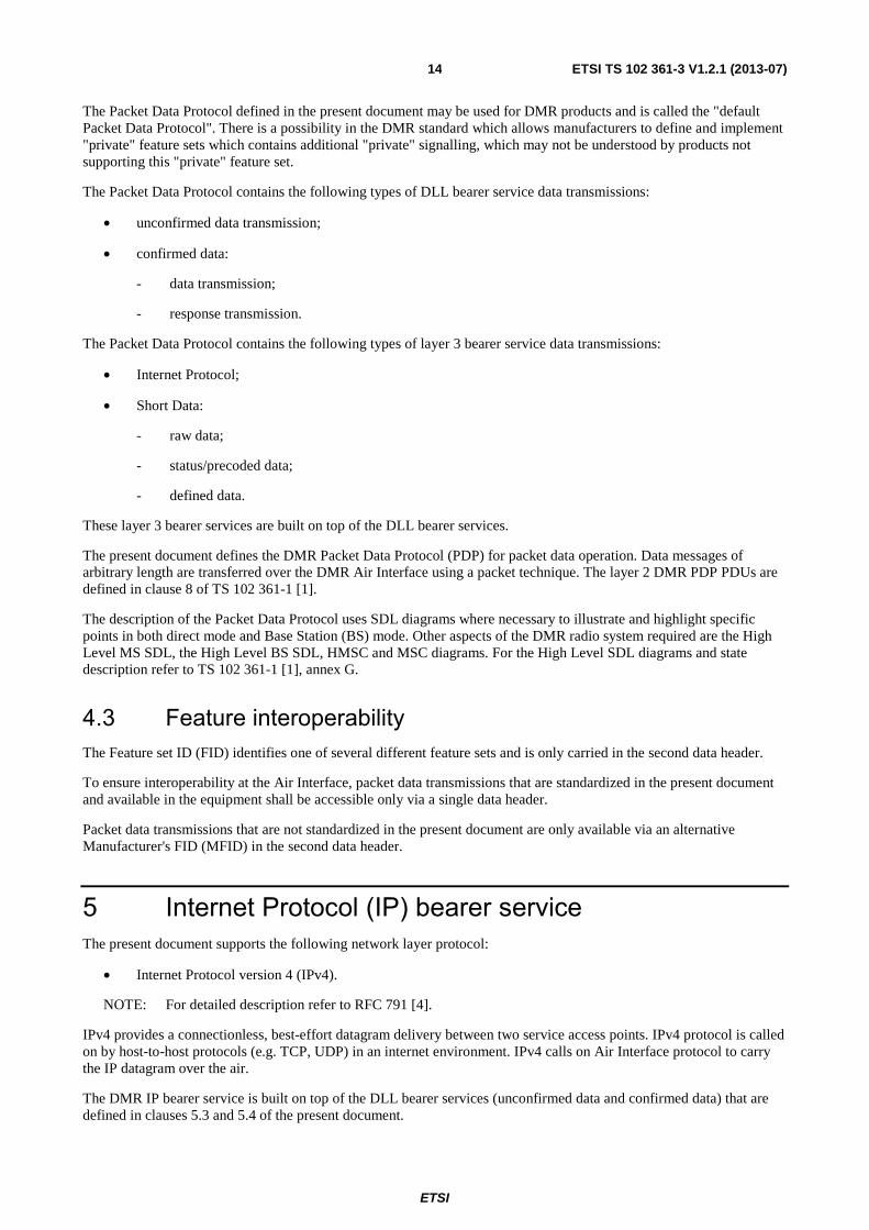
When mapping between the DLL individual address of a MS and the IP addresses of the MS (including its IP capable peripheral) the following rules shall apply:
a) the IP address of a MS and its IP capable peripheral is a "class A" address, see figure 5.1;
b) the host number field of the IP address of a MS or its peripheral is the 24 bit DLL address of the MS;
c) the "Network ID" field of the IP address of an MS is either a configured value or a default value;
d) the "Network ID" field of the IP address of the IP capable peripheral is the "Network ID" field of the MS + 1.
02 XXXXXXX2 24 bits layer 2 address of a MS
24 bits host numberNetwork ID
02 XXXXXXX2 24 bits layer 2 address of a MS02 XXXXXXX2 24 bits layer 2 address of a MS
24 bits host numberNetwork ID
Figure 5.1: Class A address format
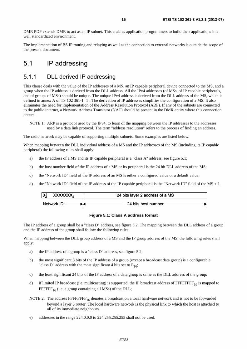
The IP address of a group shall be a "class D" address, see figure 5.2. The mapping between the DLL address of a group and the IP address of the group shall follow the following rules:
When mapping between the DLL group address of a MS and the IP group address of the MS, the following rules shall apply:
a) the IP address of a group is a "class D" address, see figure 5.2;
b) the most significant 8 bits of the IP address of a group (except a broadcast data group) is a configurable "class D" address with the most significant 4 bits set to E16;
c) the least significant 24 bits of the IP address of a data group is same as the DLL address of the group;
d) if limited IP broadcast (i.e. multicasting) is supported, the IP broadcast address of FFFFFFFF16 is mapped to
FFFFFF16 (i.e. a group containing all MSs) of the DLL;
NOTE 2: The address FFFFFFFF16 denotes a broadcast on a local hardware network and is not to be forwarded
beyond a layer 3 router. The local hardware network is the physical link to which the host is attached to all of its immediate neighbours.
e) addresses in the range 224.0.0.0 to 224.255.255.255 shall not be used.
ETSI
ETSI TS 102 361-3 V1.2.1 (2013-07)16
24 bits layer 2 address of a talkgroup11102 XXXX2
24 bits host numberNetwork ID
24 bits layer 2 address of a talkgroup11102 XXXX2 24 bits layer 2 address of a talkgroup11102 XXXX2
24 bits host numberNetwork ID
Figure 5.2: Class D address format
5.1.2 DLL neutral IP addressing This clause deals primarily with the value of the IP addresses of MSs and IP capable peripheral devices when the DLL address is not linked to the IP address. However, ARP tables with a fixed relationship between IP and DMR addresses are possible and left to the manufacturer's implementation. All the IPv4 addresses (of MSs and IP capable devices) should be unique. If any MS or IP capable device is connected to the public internet the unique IP addresses should follow the addressing recommendations as defined in RFC 1918 [6]. These are listed below for reference.
10.0.0.0 - 10.255.255.255 (10/8 prefix).
172.16.0.0 - 172.31.255.255 (172.16/12 prefix).
192.168.0.0 - 192.168.255.255 (192.168/16 prefix).
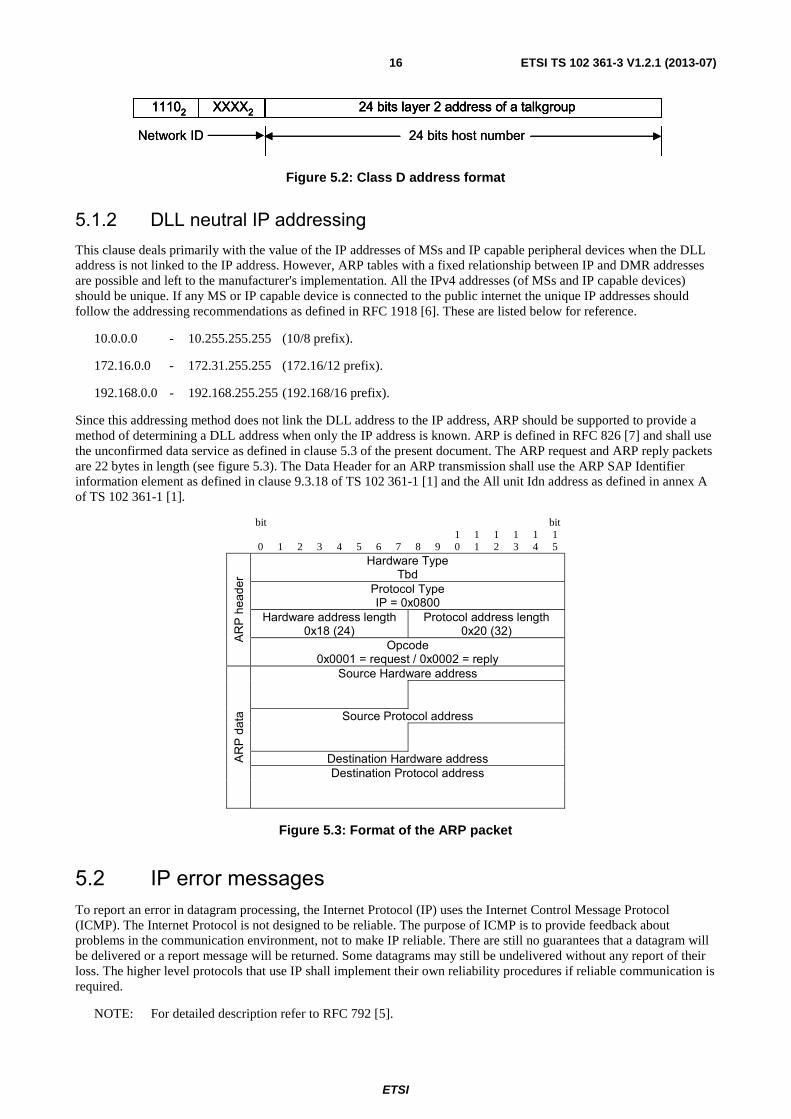
Since this addressing method does not link the DLL address to the IP address, ARP should be supported to provide a method of determining a DLL address when only the IP address is known. ARP is defined in RFC 826 [7] and shall use the unconfirmed data service as defined in clause 5.3 of the present document. The ARP request and ARP reply packets are 22 bytes in length (see figure 5.3). The Data Header for an ARP transmission shall use the ARP SAP Identifier information element as defined in clause 9.3.18 of TS 102 361-1 [1] and the All unit Idn address as defined in annex A of TS 102 361-1 [1].
bit bit
0 1 2 3 4 5 6 7 8 9 1 0
1 1
1 2
1 3
1 4
1 5
AR
P h
eade
r
Hardware Type Tbd
Protocol Type IP = 0x0800
Hardware address length 0x18 (24)
Protocol address length 0x20 (32)
Opcode 0x0001 = request / 0x0002 = reply
AR
P d
ata
Source Hardware address
Source Protocol address Destination Hardware address Destination Protocol address
Figure 5.3: Format of the ARP packet
5.2 IP error messages To report an error in datagram processing, the Internet Protocol (IP) uses the Internet Control Message Protocol (ICMP). The Internet Protocol is not designed to be reliable. The purpose of ICMP is to provide feedback about problems in the communication environment, not to make IP reliable. There are still no guarantees that a datagram will be delivered or a report message will be returned. Some datagrams may still be undelivered without any report of their loss. The higher level protocols that use IP shall implement their own reliability procedures if reliable communication is required.
NOTE: For detailed description refer to RFC 792 [5].
ETSI
ETSI TS 102 361-3 V1.2.1 (2013-07)17
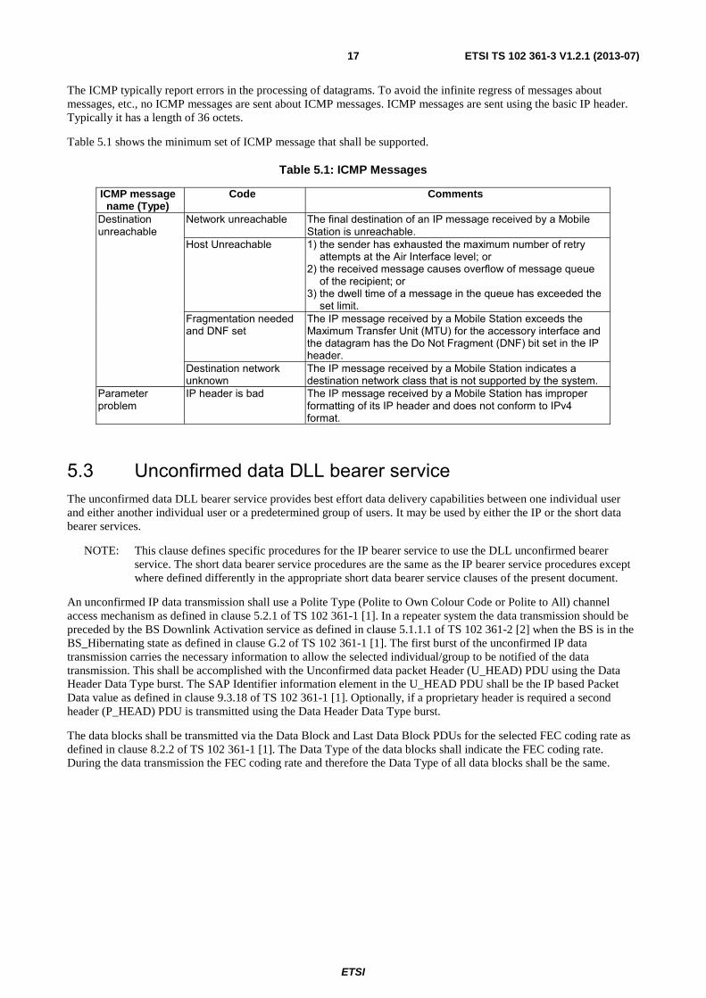
The ICMP typically report errors in the processing of datagrams. To avoid the infinite regress of messages about messages, etc., no ICMP messages are sent about ICMP messages. ICMP messages are sent using the basic IP header. Typically it has a length of 36 octets.
Table 5.1 shows the minimum set of ICMP message that shall be supported.
Table 5.1: ICMP Messages
ICMP message name (Type)
Code Comments
Destination unreachable
Network unreachable The final destination of an IP message received by a Mobile Station is unreachable.
Host Unreachable 1) the sender has exhausted the maximum number of retry attempts at the Air Interface level; or
2) the received message causes overflow of message queue of the recipient; or
3) the dwell time of a message in the queue has exceeded the set limit.
Fragmentation needed and DNF set
The IP message received by a Mobile Station exceeds the Maximum Transfer Unit (MTU) for the accessory interface and the datagram has the Do Not Fragment (DNF) bit set in the IP header.
Destination network unknown
The IP message received by a Mobile Station indicates a destination network class that is not supported by the system.
Parameter problem
IP header is bad The IP message received by a Mobile Station has improper formatting of its IP header and does not conform to IPv4 format.
5.3 Unconfirmed data DLL bearer service The unconfirmed data DLL bearer service provides best effort data delivery capabilities between one individual user and either another individual user or a predetermined group of users. It may be used by either the IP or the short data bearer services.
NOTE: This clause defines specific procedures for the IP bearer service to use the DLL unconfirmed bearer service. The short data bearer service procedures are the same as the IP bearer service procedures except where defined differently in the appropriate short data bearer service clauses of the present document.
An unconfirmed IP data transmission shall use a Polite Type (Polite to Own Colour Code or Polite to All) channel access mechanism as defined in clause 5.2.1 of TS 102 361-1 [1]. In a repeater system the data transmission should be preceded by the BS Downlink Activation service as defined in clause 5.1.1.1 of TS 102 361-2 [2] when the BS is in the BS_Hibernating state as defined in clause G.2 of TS 102 361-1 [1]. The first burst of the unconfirmed IP data transmission carries the necessary information to allow the selected individual/group to be notified of the data transmission. This shall be accomplished with the Unconfirmed data packet Header (U_HEAD) PDU using the Data Header Data Type burst. The SAP Identifier information element in the U_HEAD PDU shall be the IP based Packet Data value as defined in clause 9.3.18 of TS 102 361-1 [1]. Optionally, if a proprietary header is required a second header (P_HEAD) PDU is transmitted using the Data Header Data Type burst.
The data blocks shall be transmitted via the Data Block and Last Data Block PDUs for the selected FEC coding rate as defined in clause 8.2.2 of TS 102 361-1 [1]. The Data Type of the data blocks shall indicate the FEC coding rate. During the data transmission the FEC coding rate and therefore the Data Type of all data blocks shall be the same.

ETSI
ETSI TS 102 361-3 V1.2.1 (2013-07)18
5.3.1 Unconfirmed IP Data Types/PDUs
5.3.1.1 Rate ½ coded unconfirmed IP Data Types/PDUs
Rate ½ coded IP unconfirmed Data for both direct mode and repeater mode requires two Data Types and three PDUs. These are listed in table 5.2. If a proprietary header is supported, a fourth PDU is required.
Table 5.2: Rate ½ Coded Unconfirmed IP Data Types/PDUs
Data Type Value Function PDU DPF
Data Header 01102 Addressing U_HEAD 00102 Proprietary Header P_HEAD 11112
Rate ½ Coded Data 01112 Data Block R_1_2_DATA NA Last Data Block R_1_2_LDATA NA
5.3.1.2 Rate ¾ coded unconfirmed IP Data Types/PDUs
Rate ¾ coded unconfirmed IP Data for both direct mode and repeater mode requires two Data Types and three PDUs. These are listed in table 5.3. If a proprietary header is supported, a fourth PDU is required.
NOTE: The headers for rate ¾ unconfirmed IP data are rate ½ coded.
Table 5.3: Rate ¾ Coded Unconfirmed IP Data Types/PDUs
Data Type Value Function PDU DPF
Data Header 01102 Addressing U_HEAD 00102 Proprietary Header P_HEAD 11112
Rate ¾ Coded Data 10002 Data Block R_3_4_DATA NA Last Data Block R_3_4_LDATA NA
5.3.1.3 Rate 1 coded unconfirmed IP Data Types/PDUs
Rate 1 coded unconfirmed IP Data for both direct mode and repeater mode requires two Data Types and three PDUs. These are listed in table 5.3A. If a proprietary header is supported, a fourth PDU is required.
NOTE: The headers for rate 1 unconfirmed IP data are rate ½ coded.
Table 5.3A: Rate 1 coded Unconfirmed IP Data Types/PDUs
Data Type Value Function PDU DPF
Data Header 01102 Addressing U_HEAD 00102 Proprietary Header P_HEAD 11112
Rate 1 Coded Data 10102 Data Block R_1_DATA NA Last Data Block R_1_LDATA NA
5.3.2 Unconfirmed IP data SDL Channel access procedures are built upon the procedures defined in clause 5 of TS 102 361-1 [1].The specific channel access rules for Unconfirmed Data are illustrated via SDL in figure 5.4. This includes the addition of T_DataTxLmt and the DLL retry process when the channel is busy.
Figure 5.4 illustrates the DLL layer when it receives an IP_Data primitive from the CCL (IP Layer). The DLL starts both T_DataTxLmt and T_IdleSrch timers and transitions to the Qualify_Idle state. T_DataTxLmt is a timer that limits the amount of time the DLL will attempt to transmit the data.
In the Qualify_Idle state the DLL attempts to determine the channel status. If the channel is idle the DLL will transmit the data. If T_IdleSrch expires the channel is busy and the DLL starts T_Holdoff and transitions to the Holdoff state.

ETSI
ETSI TS 102 361-3 V1.2.1 (2013-07)19
T_Holdoff is a random timer used to minimize collisions when the channel becomes idle. When T_Holdoff expires the DLL starts T_IdleSrch and repeats the process to qualify the channel status.
While the DLL is in either the Qualify_Idle or Holdoff states and T_DataTxLmt expires, it shall abort the data transmission. As shown in figure 5.4, the DLL sends a ICMP primitive to the CCL indicating that the dwell time of the message was exceeded and the host was unreachable.
process Unconfirmed_Data_DLL 1(1)
TX_Idle Qualify_Idle
IP_Data T_IdleSrch Idle T_DataTXLmt
Set (T_DataTxLmt)
Set (T_Holdoff)
Reset (T_DataTXLmt)
Reset (T_IdleSrch)
Set (T_IdleSrch) Holdoff Reset (T_
IdleSrch) ICMP
Qualify_Idle T_DataTXLmt T_Holdoff Transmit TX_Idle
Reset (T_Holdoff)
Set (T_IdleSrch)
ICMP Qualify_Idle
TX_Idle
Figure 5.4: Unconfirmed IP Data Channel Access SDL

ETSI
ETSI TS 102 361-3 V1.2.1 (2013-07)20
5.3.3 Unconfirmed IP Data MSCs The following MSCs are used to provide additional clarity to the Unconfirmed IP Data SDL defined in clause 5.3.2.
5.3.3.1 TX unconfirmed IP data MSC
Figure 5.5 illustrates when the DLL receives an IP_Data primitive indicating unconfirmed DLL delivery from the CCL. The DLL starts the T_DataTxLmt timer and then forms and attempts to send the data message, which is illustrated in clause 5.3.3.2. If T_DataTxLmt timer expires, the DLL sends a ICMP primitive to the CCL indicating the destination was unreachable and transitions to PS_TX_Idle state. The timers are defined in clause 5.3.2.
DLL PLCCL
version: 0.1last updated: 5/11/2005by: TB
TX_Idle
1
1alt
Data Not Transmitted
1
Data Transmitted
Form_and_Send_a_DLL_Data_Message
TX_Idle
MSC TX_Unconfirmed_IP_Data
ICMP
(Destination Unreachable)
T_DataTxLmt
IP_Data
(Unconfirmed)T_DataTxLmt
Figure 5.5: TX Unconfirmed IP Data MSC
ETSI
ETSI TS 102 361-3 V1.2.1 (2013-07)21
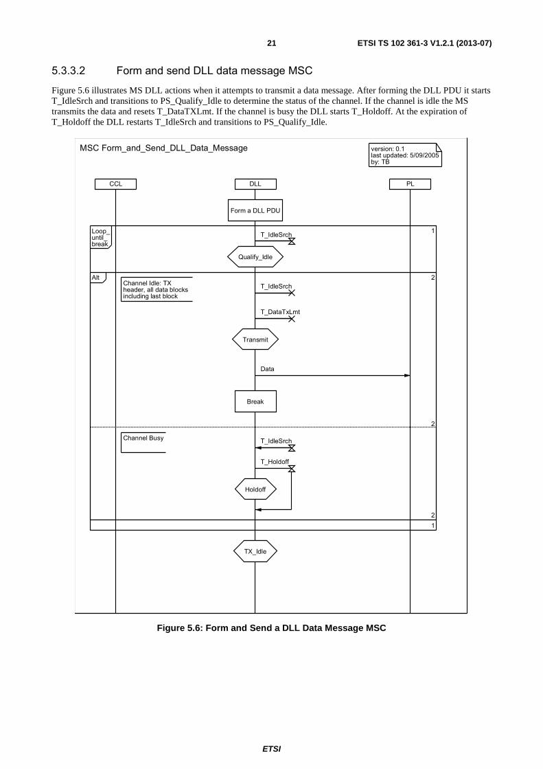
5.3.3.2 Form and send DLL data message MSC
Figure 5.6 illustrates MS DLL actions when it attempts to transmit a data message. After forming the DLL PDU it starts T_IdleSrch and transitions to PS_Qualify_Idle to determine the status of the channel. If the channel is idle the MS transmits the data and resets T_DataTXLmt. If the channel is busy the DLL starts T_Holdoff. At the expiration of T_Holdoff the DLL restarts T_IdleSrch and transitions to PS_Qualify_Idle.
DLL PLCCL
version: 0.1last updated: 5/09/2005by: TB
TX_Idle
1
1Loop_until_break
2
2Alt
Channel Busy
Transmit
Holdoff
2
Break
Channel Idle: TX header, all data blocks including last block
Form a DLL PDU
Qualify_Idle
MSC Form_and_Send_DLL_Data_Message
T_IdleSrch
T_DataTxLmt
T_Holdoff
T_IdleSrch
Data
T_IdleSrch
Figure 5.6: Form and Send a DLL Data Message MSC
ETSI
ETSI TS 102 361-3 V1.2.1 (2013-07)22
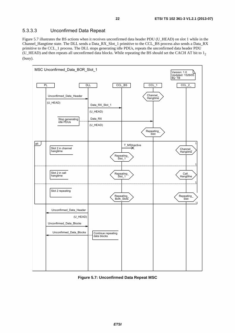
5.3.3.3 Unconfirmed Data Repeat
Figure 5.7 illustrates the BS actions when it receives unconfirmed data header PDU (U_HEAD) on slot 1 while in the Channel_Hangtime state. The DLL sends a Data_RX_Slot_1 primitive to the CCL_BS process also sends a Data_RX primitive to the CCL_1 process. The DLL stops generating idle PDUs, repeats the unconfirmed data header PDU (U_HEAD) and then repeats all unconfirmed data blocks. While repeating the BS should set the CACH AT bit to 12
(busy).
CCL_1CCL_BSDLL CCL_2_PL
Version: 1.0Updated: 1526/05By: TB
1
1
1
1alt
Repeating_Slot
Channel_Hangtime
Repeating_Slot_1
Repeating_Slot_1
Repeating_Both_Slots
MSC Unconfirmed_Data_BOR_Slot_1
Continue repeatingdata blocks
Stop generatingidle PDUs
Slot 2 in callhangtime
Repeating_Slot
Call_Hangtime
Channel_Hangtime
Slot 2 repeating
Slot 2 in channelhangtime
Data_RX
(U_HEAD)
Data_RX_Slot_1
(U_HEAD)
T_MSInactive
Unconfirmed_Data_Blocks
Unconfirmed_Data_Header
(U_HEAD)
Unconfirmed_Data_Header
(U_HEAD)
Unconfirmed_Data_Blocks
Figure 5.7: Unconfirmed Data Repeat MSC

ETSI
ETSI TS 102 361-3 V1.2.1 (2013-07)23
5.4 Confirmed data DLL bearer service The Confirmed Data Service provides acknowledged data delivery capabilities between one individual user and either another individual user or possibly a small predetermined group of users. It may be used by either the IP or the short data bearer services.
NOTE: This clause defines specific procedures for the IP bearer service to use the DLL confirmed bearer service. The short data bearer service procedures are the same as the IP bearer service procedures except where defined differently in the appropriate short data bearer service clauses of the present document.
The Selective Automatic Repeat reQuest (SARQ) error control process is used to provide confirmation. The IP confirmed data bearer service shall support a stop and wait flow control procedure and may support a sliding window flow control procedure. The optional sliding window procedure is defined in clause 5.4.4.
A confirmed IP data transmission shall use a Polite Type (Polite to Own Colour Code or Polite to All) channel access mechanism as defined in clause 5.2.1 of TS 102 361-1 [1]. In a repeater system the data transmission should be preceded by the BS Downlink Activation service as defined in clause 5.1.1.1 of TS 102 361-2 [2] when the BS is in the BS_Hibernating state as defined in clause G.2 of TS 102 361-1 [1]. The DMR confirmed data service uses a Selective Automatic Response reQuest (SARQ) error control process to confirm the data delivery.
The first burst of the confirmed IP data transmission carries the necessary information to allow the selected target to be notified of the data transmission. This shall be accomplished with the confirmed data packet Header (C_HEAD) PDU using the Data Header Data Type burst. The SAP Identifier information element in the U_HEAD PDU shall be the IP based Packet Data value as defined in clause 9.3.18 of TS 102 361-1 [1].The Full Message Flag (F) information element in the C_HEAD PDU shall be set to 12 to indicate it is transmitting a complete message with regards to the DLL. When
operating with a stop and wait flow control procedure, the Acknowledge (A) information element in the C_HEAD PDU shall be set to 12 to indicate to the target that a confirmation response is required. Optionally, if a proprietary header is
required a second header (P_HEAD) PDU is transmitted using the Data Header Data Type burst.
A confirmed data message is made of multiple blocks where each block has a 7-bit serial number and a 9-bit CRC. On the first transmission, all of the blocks are sent. The last block also contains a message CRC for the entire message. The data blocks shall be transmitted via the Data Block and Last Data Block PDUs for the selected FEC coding rate as defined in clause 8.2.2 of TS 102 361-1 [1]. The Data Type of the data blocks shall indicate the FEC coding rate. During the data transmission the FEC coding rate and therefore the Data Type of all data blocks shall be the same.
In direct mode after the Last Data Block PDU is transmitted, the source shall complete the confirmed data transmission by transmitting the Terminator Data Link Control (TD_LC) PDU using a Terminator with LC Data Type burst. In repeater mode the source shall not transmit anything after the Last Data Block PDU. However, the BS may transmit the TD_LC PDU to establish a reserved response time for the destination to transmit a response.
Upon receiving a stop and wait data transmission, the target shall respond with a response that is unconfirmed. In repeater mode the MS shall send the response with an impolite channel access mechanism as defined in clause 5.2.1 of TS 102 361-1 [1]. In direct mode the MS shall send the response with an impolite or polite channel access mechanism as defined in clause 5.2.1 of TS 102 361-1 [1].
The MS shall send a confirmed response with a Confirmed Response packet Header (C_RHEAD) using the Data Header Data Type burst. The SAP Identifier information element in the C_RHEAD PDU shall be the same value as contained in the C_HEAD PDU when no proprietary header is used. Optionally, if a proprietary header is required a second header (P_HEAD) PDU is transmitted using the Data Header Data Type burst. If all messages received from the source passed the CRC checks, then the target has completed its response after transmitting the header(s). However, if there is a CRC mismatch for some of the blocks then the target shall also send a response message containing the list of blocks whose CRC is not matching. The response message uses a Confirmed Response packet Data block (C_RDATA) PDU with a Data Type of Rate ½ Coded Data.
In the case when a selective retry is attempted, the sender retransmits the listed block(s), which are preceded by the Confirmed data packet header (C_HEAD) PDU. The Full Message Flag (F) information element in the C_HEAD PDU shall be set to 02 to indicate it is transmitting a partial message with regards to the DLL. This process repeats until all
the blocks are received successfully up to a maximum number of times.
ETSI
ETSI TS 102 361-3 V1.2.1 (2013-07)24
5.4.1 Confirmed IP Data Types/PDUs
5.4.1.1 Rate ½ coded confirmed IP Data Types/PDUs
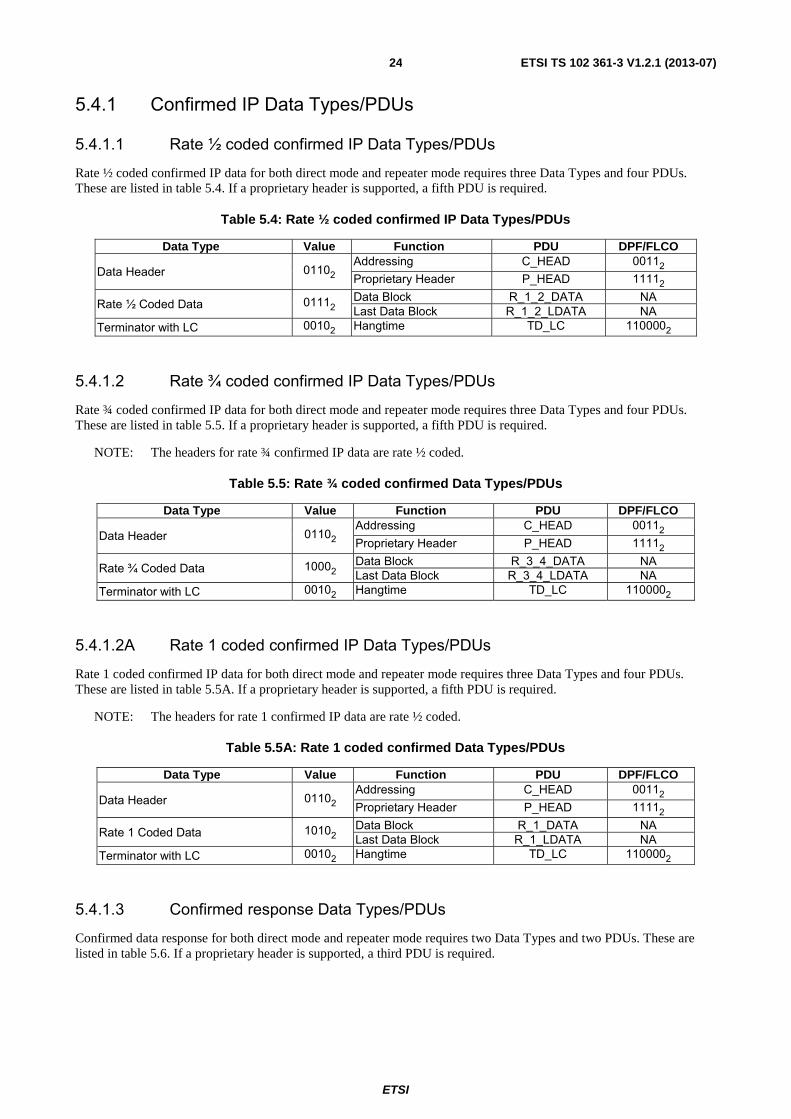
Rate ½ coded confirmed IP data for both direct mode and repeater mode requires three Data Types and four PDUs. These are listed in table 5.4. If a proprietary header is supported, a fifth PDU is required.
Table 5.4: Rate ½ coded confirmed IP Data Types/PDUs
Data Type Value Function PDU DPF/FLCO
Data Header 01102 Addressing C_HEAD 00112 Proprietary Header P_HEAD 11112
Rate ½ Coded Data 01112 Data Block R_1_2_DATA NA Last Data Block R_1_2_LDATA NA
Terminator with LC 00102 Hangtime TD_LC 1100002
5.4.1.2 Rate ¾ coded confirmed IP Data Types/PDUs
Rate ¾ coded confirmed IP data for both direct mode and repeater mode requires three Data Types and four PDUs. These are listed in table 5.5. If a proprietary header is supported, a fifth PDU is required.
NOTE: The headers for rate ¾ confirmed IP data are rate ½ coded.
Table 5.5: Rate ¾ coded confirmed Data Types/PDUs
Data Type Value Function PDU DPF/FLCO
Data Header 01102 Addressing C_HEAD 00112 Proprietary Header P_HEAD 11112
Rate ¾ Coded Data 10002 Data Block R_3_4_DATA NA Last Data Block R_3_4_LDATA NA
Terminator with LC 00102 Hangtime TD_LC 1100002
5.4.1.2A Rate 1 coded confirmed IP Data Types/PDUs
Rate 1 coded confirmed IP data for both direct mode and repeater mode requires three Data Types and four PDUs. These are listed in table 5.5A. If a proprietary header is supported, a fifth PDU is required.
NOTE: The headers for rate 1 confirmed IP data are rate ½ coded.
Table 5.5A: Rate 1 coded confirmed Data Types/PDUs
Data Type Value Function PDU DPF/FLCO
Data Header 01102 Addressing C_HEAD 00112 Proprietary Header P_HEAD 11112
Rate 1 Coded Data 10102 Data Block R_1_DATA NA Last Data Block R_1_LDATA NA
Terminator with LC 00102 Hangtime TD_LC 1100002
5.4.1.3 Confirmed response Data Types/PDUs
Confirmed data response for both direct mode and repeater mode requires two Data Types and two PDUs. These are listed in table 5.6. If a proprietary header is supported, a third PDU is required.

ETSI
ETSI TS 102 361-3 V1.2.1 (2013-07)25
Table 5.6: Confirmed response data types/PDUs
Data Type Value Function PDU DPF
Data Header 01102 Addressing C_RHEAD 00012 Proprietary Header P_HEAD 11112
Rate ½ Coded Data 01112 Response Packet Data Block C_RDATA NA
The response message defined by the Class, Type and Status information elements of the C_RHEAD for stop and wait flow control is listed in table 5.7. Information element N(S) is the Send Sequence Number contained in C_HEAD.
NOTE: Table 5.7 is a subset of the Response Packet definitions table found in clause 8.2.2.3 of TS 102 361-1 [1].
Table 5.7: IP data response packet class, type, and status definitions with stop and wait flow control
Class Type Status Message Comment 002 0012 N(S) ACK All blocks of all packets of N(S) are successfully received. 012 0002 N(S) NACK Illegal format. 012 0012 N(S) NACK Packet N(S) CRC failed. 012 0102 N(S) NACK Memory of the recipient is full. 012 1002 N(S) NACK Undeliverable. 102 0002 N(S) SACK The recipient requests the selective retry of the blocks indicated in the
data block of the response packet for N(S).
5.4.2 Confirmed IP Data SDL This clause uses SDL to illustrate the IP data bearer service using stop and wait flow control with the DLL confirmed data bearer service.
5.4.2.1 Confirmed data source SDL
Channel access procedures are built upon the procedures defined in clause 5 of TS 102 361-1 [1]. The specific channel access rules for Confirmed Data are illustrated via SDL in figure 5.8.This includes the addition of T_DataTxLmt and the DLL retry process when the channel is busy as well as the T_RspnsWait and the reception of the confirmation response.
Figure 5.8 illustrates the DLL layer when it receives an IP_Data primitive from the CCL (IP Layer). The DLL starts both T_DataTxLmt and T_IdleSrch timers and transitions to the Qualify_Idle state. T_DataTxLmt is a timer that limits the amount of time the DLL will attempt to transmit the data. It also initializes the air interface retry counter to 0.
In the Qualify_Idle state the DLL attempts to determine the channel status. If T_IdleSrch expires, the channel is busy and the DLL starts T_Holdoff and transitions to the Holdoff state. T_Holdoff is a random timer used to minimize collisions when the channel becomes idle. When T_Holdoff expires the DLL starts T_IdleSrch and repeats the process to qualify the channel status.
If the channel is idle the DLL will transmit the data, increment the air interface retry counter by 1 and start T_RspnsWait as it waits for the confirmation response from the target. If T_RspnsWait expires and the air interface retry counter is < N_RtryLmt then the DLL starts both T_DataTxLmt and T_IdleSrch and attempts to retransmit the data. If T_RspnsWait expires and air interface retry counter is = N_RtryLmt then the transmission is denied and the DLL sends an ICMP primitive to the CCL indicating the maximum number of retry attempts at the air interface was exhausted.
While the DLL is in either the Qualify_Idle or Holdoff states and T_DataTxLmt expires, it shall deny the data transmission. In the illustration the DLL sends a ICMP primitive to the CCL indicating that the dwell time of the message was exceeded and the host was unreachable.
If a Confirmed Data Response is received the DLL determines which blocks need to be resent. If no blocks need to be resent the transmission was successful. If some or all blocks need to be resent and the air interface retry counter is < N_RtryLmt then the DLL starts both T_DataTxLmt and T_IdleSrch and transitions to the Qualify_Idle state. From here, the process repeats as defined above. If the air interface counter is = N_RtryLmt then the transmission is stopped and the DLL sends an ICMP primitive to the CCL.

ETSI
ETSI TS 102 361-3 V1.2.1 (2013-07)26
process Confirmed_Data_DLL_Source 1(1)Qualify_Idle
TX_Idle
T_IdleSrch Idle T_DataTXLmt
IP_Data
Set (T_Holdoff)
Reset (T_DataTXLmt)
Reset (T_IdleSrch)
N:=0 Air InterfaceRetry Counter
Holdoff Reset (T_IdleSrch) ICMP
Set (T_DataTxLmt)
T_DataTXLmt T_Holdoff N:=N+1 TX_Idle
Set (T_IdleSrch)
Reset (T_Holdoff)
Set (T_IdleSrch) Transmit
Qualify_Idle
ICMP Qualify_Idle TX_Complete
TX_Idle Set (T_RspnsWait)
Wait_for_Response
RX_Response
T_RspnsWait
Successful_Blocks
TX_Idle N<RtryLmt
Set (T_DataTxLmt) ICMP
Set (T_IdleSrch) TX_Idle
Qualify_Idle
=_All
<_All
yes no
Figure 5.8: Source confirmed data transmission SDL

ETSI
ETSI TS 102 361-3 V1.2.1 (2013-07)27
5.4.2.2 Confirmed data target SDL
Figure 5.9 illustrates the target actions when confirmed data is received. Each block is CRC checked as well as the entire fragment. If some blocks fail block CRC check, the target attempts to send a SACK response. If all blocks pass the CRC check but fail the fragment CRC check the target attempts to send a NACK response. If all blocks pass the CRC check and the target attempts to send an ACK response. In direct mode the response is sent either impolitely or politely while in repeater mode the response is sent impolitely.
process Confirmed_Data_DLL_Target 1(1)
TX_Idle
RX_Confirmed_Data
ID in headermatches
Block_CRC_Check
Successful_Blocks
Assemble_Response
Class = 10 (SACK) in C_RHEAD
Message_CRC_Check
Successful_Fragment_CRC
Assemble_Response
Class = 00 (ACK)in C_RHEAD
Assemble_Response
Class = 01 (NACK)in C_RHEAD
RX_Data
Mode
Set (T_IdleSrch)
Qualify_Idle
T_IdleSrch Idle Transmit
TX_Denied TX_Complete
TX_Idle
<_All=_All
yes
no
Peer_to_Peer Repeater
Figure 5.9: Target confirmed data transmission SDL

ETSI
ETSI TS 102 361-3 V1.2.1 (2013-07)28
5.4.3 Confirmed data MSCs The following MSCs are used to provide additional clarity to the confirmed IP data SDL defined in clauses 5.4.2.1 and 5.4.2.2. Here the IP data bearer service uses stop and wait flow control with the DLL confirmed data bearer service.
5.4.3.1 Confirmed data source MSCs
5.4.3.1.1 TX confirmed IP data MSC
Figure 5.10 illustrates when the DLL receives an IP_Data primitive indicating confirmed DLL delivery from the CCL. The DLL starts the T_DataTxLmt timer and then forms and attempts to send the data message, which is illustrated in clause 5.4.3.1.2. When the data is transmitted, the DLL starts T_RspnsWait and waits for the response as described in clause 5.4.3.1.3. If T_DataTxLmt timer expires, the DLL sends a ICMP primitive to the CCL indicating the destination was unreachable and transitions to PS_TX_Idle state. The timers are defined in clause 5.4.2.
DLL PLCCL
version: 0.1last updated: 5/11/2005by: TB
Form_and_Send_a_DLL_Data_Message
Data Transmitted
1
1alt
Process_the_DLL_Confirmed_Response
1
Data Not Transmitted
TX_Idle
TX_Idle
MSC TX_a_Confirmed_IP_Datagram
IP_Data
(Confirmed)T_DataTxLmt
T_RspnsWait
T_DataTxLmt
ICMP
(Destination Unreachable)
Figure 5.10: TX Confirmed IP Data MSC
5.4.3.1.2 Form and send DLL data message MSC
The MSC for forming and sending the DLL confirmed data message is the same as the MSC defined in clause 5.3.3.2 for unconfirmed data.

ETSI
ETSI TS 102 361-3 V1.2.1 (2013-07)29
5.4.3.1.3 Process DLL confirmed response MSC
Figure 5.11 illustrates the SDL in clause 5.4.2.1 with an MSC when the source waits to receive the confirmed response header. If Class = 002 (ACK) all data blocks were successfully received. However, if Class = 102 (SACK) the target is
indicating in the Confirmed Response Data which blocks need to be resent. If the Confirmed Response Header is not received the DLL behaves the same as if it received a response with Class = 012 (NACK). If the target requests a
retransmittal but the air interface retry counter is = N_RtryLmt then the DLL sends an ICMP primitive to the CCL indicating that the host was unreachable and the number of air interface retries was exhausted. If the target requests a retransmittal and the air interface retry counter is < N_RtryLmt then the DLL forms and sends the appropriate DLL data message. After retransmission T_RspnsWait is started and the DLL again waits for the confirmed response header.
DLL PLCCL
version: 0.1last updated: 5/11/2005by: TB
1
1alt
2
2alt
Process_the_DLL_Confirmed_Response
Form_and_Send_a_DLL_Data_Message
Retries < N_RetryLmt
2
2
2
2alt
1
Retries = N_RetryLmt
No responsereceived
Process_the_DLL_Confirmed_Response
Form_and_Send_a_DLL_Data_Message
Retries < N_RetryLmt
Retries = N_RetryLmt
NACK or SACK received
ACK received
MSC Process_DLL_Confirmed_Response
Response_PDU
(class=01 or 10)
T_RspnsWait
ICMP
(Destination Unreachable)
T_RspnsWait
T_RspnsWait
ICMP
(Destination Unreachable)
T_RspnsWait
T_RspnsWait
Response_PDU
(class=00)
Figure 5.11: Process the DLL confirmed response MSC

ETSI
ETSI TS 102 361-3 V1.2.1 (2013-07)30
5.4.3.2 Confirmed data target MSCs
5.4.3.2.1 RX confirmed data MSC
Figure 5.12 illustrates the confirmed data target actions when the source uses stop and wait flow control instead of sliding window flow control and the MS is designed to transmit polite data responses. After the appropriate response is determined it starts T_IdleSrch. If the channel is idle the response is transmitted. For confirmed data, idle also applies to data hangtime. In the rare occurrence that the channel is busy, the message is not transmitted. The source data transmission mechanism will transmit the data again.
DLL PLCCL
version: 0.1last updated: 5/11/2005by: TB
1
1
1alt
1
1alt
2
2alt
2
1
Channel Busy
TX_Idle
Channel Idle
Class = 00in C_RHEAD
Fragment CRCPassed (ACK)
AssembleResponse
Fragment CRCFailed (NACK)
Class = 01in C_RHEAD
AssembleResponse
Fragment CheckCRC
No Block CRC Failures
Class = 10in C_RHEAD
AssembleResponse
Block CRCFailures (SACK)
Block CheckCRC
MSC RX_Confirmed_Data
T_IdleSrch
T_IdleSrch
Confirmed_Data_Response
T_IdleSrch
Confirmed_Data
Figure 5.12: RX confirmed data MSC
5.4.3.3 Confirmed data BS MSCs
5.4.3.3.1 Confirmed data repeat MSC
The confirmed data repeat MSC is the same as the unconfirmed data repeat MSC in clause 5.3.3.3 with the exception that the U_HEAD PDU is replaced by the confirmed data header PDU (C_HEAD).
ETSI
ETSI TS 102 361-3 V1.2.1 (2013-07)31
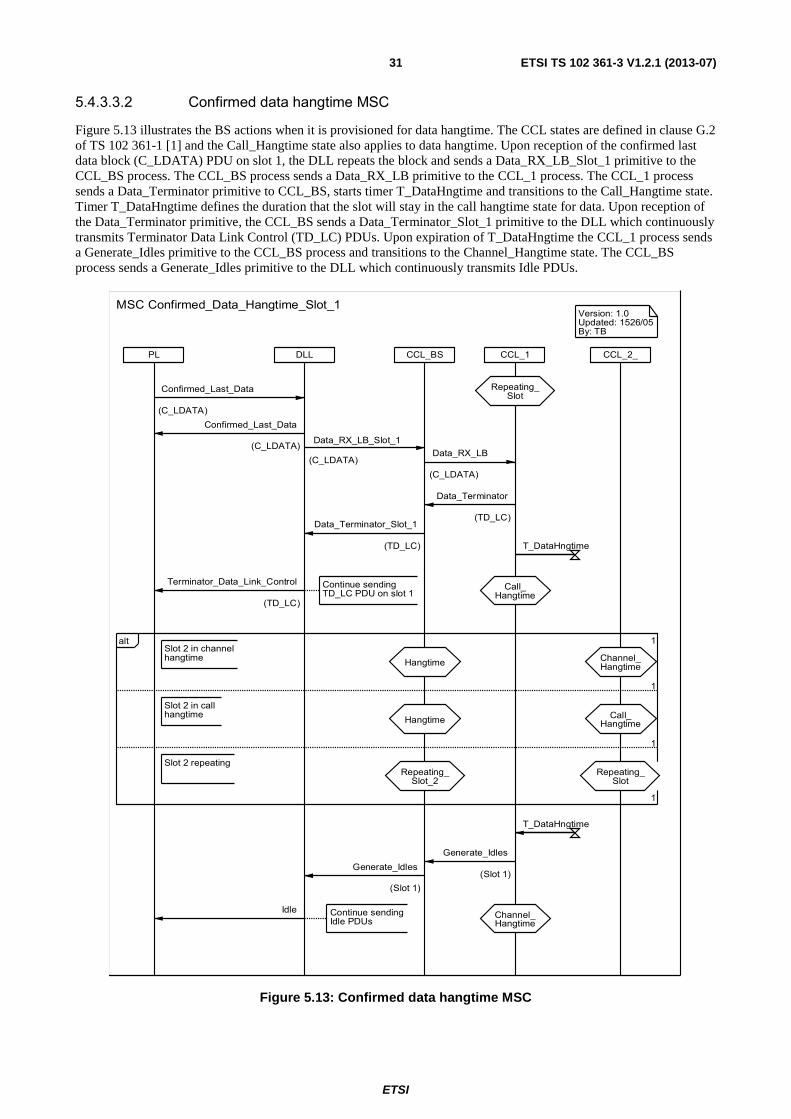
5.4.3.3.2 Confirmed data hangtime MSC
Figure 5.13 illustrates the BS actions when it is provisioned for data hangtime. The CCL states are defined in clause G.2 of TS 102 361-1 [1] and the Call_Hangtime state also applies to data hangtime. Upon reception of the confirmed last data block (C_LDATA) PDU on slot 1, the DLL repeats the block and sends a Data_RX_LB_Slot_1 primitive to the CCL_BS process. The CCL_BS process sends a Data_RX_LB primitive to the CCL_1 process. The CCL_1 process sends a Data_Terminator primitive to CCL_BS, starts timer T_DataHngtime and transitions to the Call_Hangtime state. Timer T_DataHngtime defines the duration that the slot will stay in the call hangtime state for data. Upon reception of the Data_Terminator primitive, the CCL_BS sends a Data_Terminator_Slot_1 primitive to the DLL which continuously transmits Terminator Data Link Control (TD_LC) PDUs. Upon expiration of T_DataHngtime the CCL_1 process sends a Generate_Idles primitive to the CCL_BS process and transitions to the Channel_Hangtime state. The CCL_BS process sends a Generate_Idles primitive to the DLL which continuously transmits Idle PDUs.
CCL_BSDLL CCL_1 CCL_2_PL
Version: 1.0Updated: 1526/05By: TB
Channel_Hangtime
Continue sendingIdle PDUs
Call_Hangtime
Continue sendingTD_LC PDU on slot 1
Slot 2 in channelhangtime Channel_
HangtimeHangtime
1
1alt
Slot 2 in callhangtime
1
1
Call_HangtimeHangtime
Slot 2 repeatingRepeating_
SlotRepeating_
Slot_2
MSC Confirmed_Data_Hangtime_Slot_1
Repeating_Slot
T_DataHngtime
Data_Terminator_Slot_1
(TD_LC)
Data_Terminator
(TD_LC)
Confirmed_Last_Data
(C_LDATA)
Confirmed_Last_Data
(C_LDATA)
Data_RX_LB
(C_LDATA)
Data_RX_LB_Slot_1
(C_LDATA)
T_DataHngtime
Idle
Generate_Idles
(Slot 1)
Generate_Idles
(Slot 1)
Terminator_Data_Link_Control
(TD_LC)
Figure 5.13: Confirmed data hangtime MSC
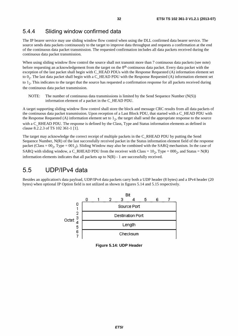
ETSI
ETSI TS 102 361-3 V1.2.1 (2013-07)32
5.4.4 Sliding window confirmed data The IP bearer service may use sliding window flow control when using the DLL confirmed data bearer service. The source sends data packets continuously to the target to improve data throughput and requests a confirmation at the end of the continuous data packet transmission. The requested confirmation includes all data packets received during the continuous data packet transmission.
When using sliding window flow control the source shall not transmit more than 7 continuous data packets (see note) before requesting an acknowledgement from the target on the 8th continuous data packet. Every data packet with the exception of the last packet shall begin with C_HEAD PDUs with the Response Requested (A) information element set to 02. The last data packet shall begin with a C_HEAD PDU with the Response Requested (A) information element set
to 12. This indicates to the target that the source has requested a confirmation response for all packets received during
the continuous data packet transmission.
NOTE: The number of continuous data transmissions is limited by the Send Sequence Number (N(S)) information element of a packet in the C_HEAD PDU.
A target supporting sliding window flow control shall store the block and message CRC results from all data packets of the continuous data packet transmission. Upon reception of a Last Block PDU, that started with a C_HEAD PDU with the Response Requested (A) information element set to 12, the target shall send the appropriate response to the source
with a C_RHEAD PDU. The response is defined by the Class, Type and Status information elements as defined in clause 8.2.2.3 of TS 102 361-1 [1].
The target may acknowledge the correct receipt of multiple packets in the C_RHEAD PDU by putting the Send Sequence Number, N(R) of the last successfully received packet in the Status information element field of the response packet (Class = 002, Type = 0012). Sliding Window may also be combined with the SARQ mechanism. In the case of
SARQ with sliding window, a C_RHEAD PDU from the receiver with Class = 102, Type = 0002, and Status = N(R)
information elements indicates that all packets up to N(R) - 1 are successfully received.
5.5 UDP/IPv4 data Besides an application's data payload, UDP/IPv4 data packets carry both a UDP header (8 bytes) and a IPv4 header (20 bytes) when optional IP Option field is not utilized as shown in figures 5.14 and 5.15 respectively.
Figure 5.14: UDP Header
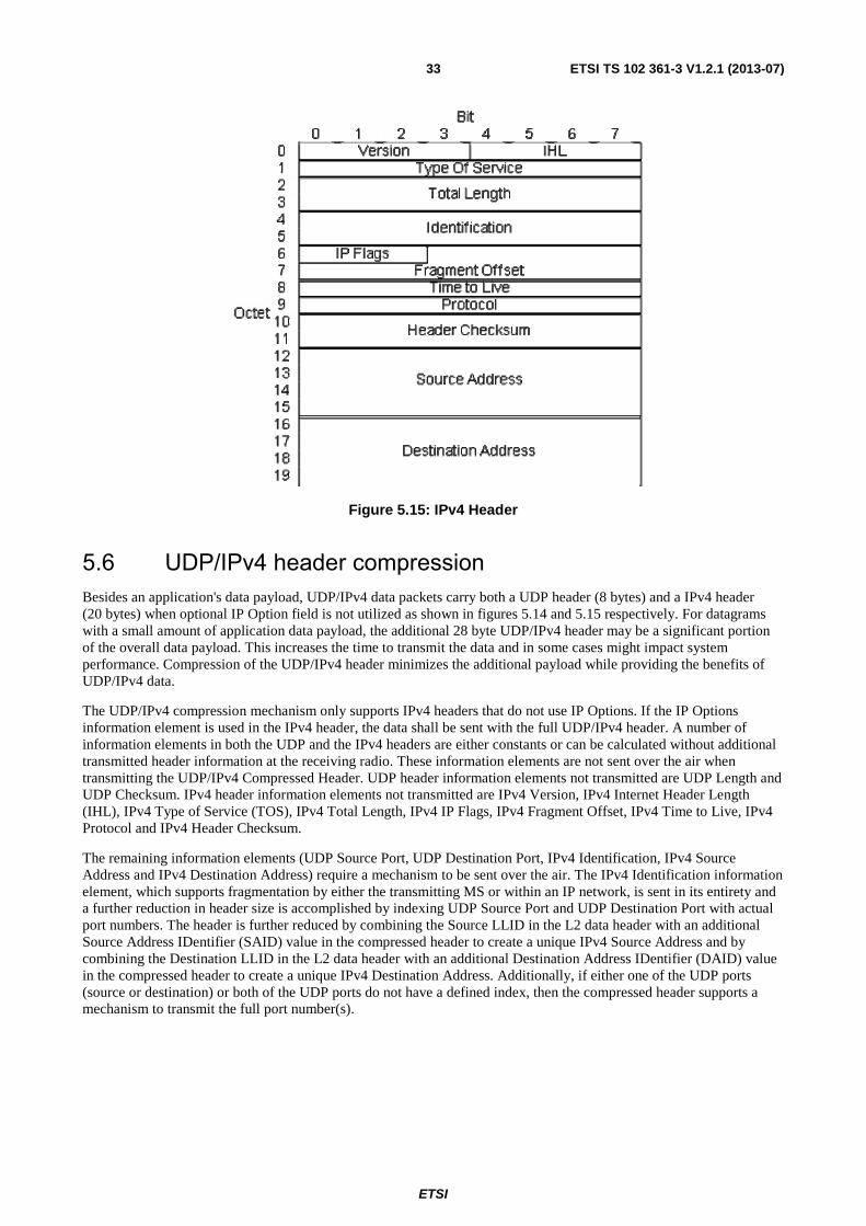
ETSI
ETSI TS 102 361-3 V1.2.1 (2013-07)33
Figure 5.15: IPv4 Header
5.6 UDP/IPv4 header compression Besides an application's data payload, UDP/IPv4 data packets carry both a UDP header (8 bytes) and a IPv4 header (20 bytes) when optional IP Option field is not utilized as shown in figures 5.14 and 5.15 respectively. For datagrams with a small amount of application data payload, the additional 28 byte UDP/IPv4 header may be a significant portion of the overall data payload. This increases the time to transmit the data and in some cases might impact system performance. Compression of the UDP/IPv4 header minimizes the additional payload while providing the benefits of UDP/IPv4 data.
The UDP/IPv4 compression mechanism only supports IPv4 headers that do not use IP Options. If the IP Options information element is used in the IPv4 header, the data shall be sent with the full UDP/IPv4 header. A number of information elements in both the UDP and the IPv4 headers are either constants or can be calculated without additional transmitted header information at the receiving radio. These information elements are not sent over the air when transmitting the UDP/IPv4 Compressed Header. UDP header information elements not transmitted are UDP Length and UDP Checksum. IPv4 header information elements not transmitted are IPv4 Version, IPv4 Internet Header Length (IHL), IPv4 Type of Service (TOS), IPv4 Total Length, IPv4 IP Flags, IPv4 Fragment Offset, IPv4 Time to Live, IPv4 Protocol and IPv4 Header Checksum.
The remaining information elements (UDP Source Port, UDP Destination Port, IPv4 Identification, IPv4 Source Address and IPv4 Destination Address) require a mechanism to be sent over the air. The IPv4 Identification information element, which supports fragmentation by either the transmitting MS or within an IP network, is sent in its entirety and a further reduction in header size is accomplished by indexing UDP Source Port and UDP Destination Port with actual port numbers. The header is further reduced by combining the Source LLID in the L2 data header with an additional Source Address IDentifier (SAID) value in the compressed header to create a unique IPv4 Source Address and by combining the Destination LLID in the L2 data header with an additional Destination Address IDentifier (DAID) value in the compressed header to create a unique IPv4 Destination Address. Additionally, if either one of the UDP ports (source or destination) or both of the UDP ports do not have a defined index, then the compressed header supports a mechanism to transmit the full port number(s).
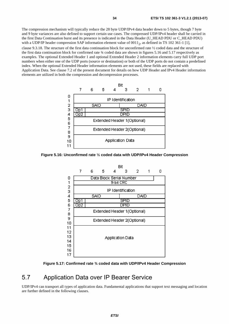
ETSI
ETSI TS 102 361-3 V1.2.1 (2013-07)34
The compression mechanism will typically reduce the 28 byte UDP/IPv4 data header down to 5 bytes, though 7 byte and 9 byte variances are also defined to support certain use cases. The compressed UDP/IPv4 header shall be carried in the first Data Continuation burst and its presence is indicated in the Data Header (U_HEAD PDU or C_HEAD PDU) with a UDP/IP header compression SAP information element value of 00112, as defined in TS 102 361-1 [1],
clause 9.3.18. The structure of the first data continuation block for unconfirmed rate ½ coded data and the structure of the first data continuation block for confirmed rate ¾ coded data are shown in figures 5.16 and 5.17 respectively as examples. The optional Extended Header 1 and optional Extended Header 2 information elements carry full UDP port numbers when either one of the UDP ports (source or destination) or both of the UDP ports do not contain a predefined index. When the optional Extended Header information elements are not used, these fields are replaced with Application Data. See clause 7.2 of the present document for details on how UDP Header and IPv4 Header information elements are utilized in both the compression and decompression processes.
Figure 5.16: Unconfirmed rate ½ coded data with UDP/IPv4 Header Compression
Figure 5.17: Confirmed rate ¾ coded data with UDP/IPv4 Header Compression
5.7 Application Data over IP Bearer Service UDP/IPv4 can transport all types of application data. Fundamental applications that support text messaging and location are further defined in the following clauses.
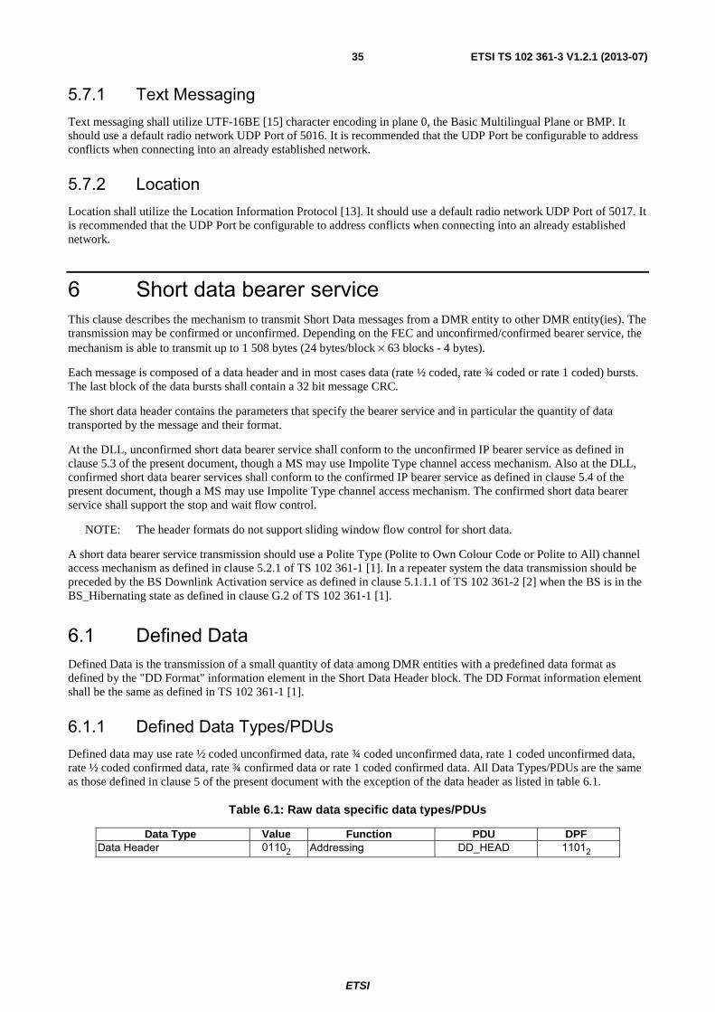
ETSI
ETSI TS 102 361-3 V1.2.1 (2013-07)35
5.7.1 Text Messaging Text messaging shall utilize UTF-16BE [15] character encoding in plane 0, the Basic Multilingual Plane or BMP. It should use a default radio network UDP Port of 5016. It is recommended that the UDP Port be configurable to address conflicts when connecting into an already established network.
5.7.2 Location Location shall utilize the Location Information Protocol [13]. It should use a default radio network UDP Port of 5017. It is recommended that the UDP Port be configurable to address conflicts when connecting into an already established network.
6 Short data bearer service This clause describes the mechanism to transmit Short Data messages from a DMR entity to other DMR entity(ies). The transmission may be confirmed or unconfirmed. Depending on the FEC and unconfirmed/confirmed bearer service, the mechanism is able to transmit up to 1 508 bytes (24 bytes/block × 63 blocks - 4 bytes).
Each message is composed of a data header and in most cases data (rate ½ coded, rate ¾ coded or rate 1 coded) bursts. The last block of the data bursts shall contain a 32 bit message CRC.
The short data header contains the parameters that specify the bearer service and in particular the quantity of data transported by the message and their format.
At the DLL, unconfirmed short data bearer service shall conform to the unconfirmed IP bearer service as defined in clause 5.3 of the present document, though a MS may use Impolite Type channel access mechanism. Also at the DLL, confirmed short data bearer services shall conform to the confirmed IP bearer service as defined in clause 5.4 of the present document, though a MS may use Impolite Type channel access mechanism. The confirmed short data bearer service shall support the stop and wait flow control.
NOTE: The header formats do not support sliding window flow control for short data.
A short data bearer service transmission should use a Polite Type (Polite to Own Colour Code or Polite to All) channel access mechanism as defined in clause 5.2.1 of TS 102 361-1 [1]. In a repeater system the data transmission should be preceded by the BS Downlink Activation service as defined in clause 5.1.1.1 of TS 102 361-2 [2] when the BS is in the BS_Hibernating state as defined in clause G.2 of TS 102 361-1 [1].
6.1 Defined Data Defined Data is the transmission of a small quantity of data among DMR entities with a predefined data format as defined by the "DD Format" information element in the Short Data Header block. The DD Format information element shall be the same as defined in TS 102 361-1 [1].
6.1.1 Defined Data Types/PDUs Defined data may use rate ½ coded unconfirmed data, rate ¾ coded unconfirmed data, rate 1 coded unconfirmed data, rate ½ coded confirmed data, rate ¾ confirmed data or rate 1 coded confirmed data. All Data Types/PDUs are the same as those defined in clause 5 of the present document with the exception of the data header as listed in table 6.1.
Table 6.1: Raw data specific data types/PDUs
Data Type Value Function PDU DPF Data Header 01102 Addressing DD_HEAD 11012

ETSI
ETSI TS 102 361-3 V1.2.1 (2013-07)36
6.1.2 Defined data information element values Defined data shall use the Short Data SAP Identifier information element value as defined in clause 9.3.18 of TS 102 361-1 [1].
The Appended Blocks information element of the header shall not be set to 0000002 since all data is carried in the data
blocks.
The Response Requested (A) information element of the header shall be set to 02 for unconfirmed data and shall be set
to 12 for confirmed data.
6.2 Raw data Raw data is the transmission of a small quantity of data among applications running on DMR entities that leaves the management of the format of the transmitted data to the applications themselves. The DMR DLL provides the transmission of data between a source port and a destination port of the DMR entities as specified in the source and destination port fields respectively.
6.2.1 Raw data types/PDUs Raw data may use rate ½ coded unconfirmed data, rate ¾ coded unconfirmed data, rate 1 coded unconfirmed data, rate ½ coded confirmed data, rate ¾ coded confirmed data or rate 1 coded confirmed data. All Data Types/PDUs are the same as those defined in clause 5 of the present document with the exception of the data header as listed in table 6.2.
Table 6.2: Raw data specific data types/PDUs
Data Type Value Function PDU DPF Data Header 01102 Addressing R_HEAD 11102
6.2.2 Raw data information element values Raw data shall use the Short Data SAP Identifier information element value as defined in clause 9.3.18 of TS 102 361-1 [1].
The Appended Blocks information element of the header shall not be set to 0000002 since all data is carried in the data
blocks.
The Response Requested (A) information element of the header shall be set to 02 for unconfirmed data and shall be set
to 12 for confirmed data.
6.3 Status/precoded data Status/precoded is the transmission of precoded and status messages from a DMR entity to other DMR entity(ies). A precoded/status message is a service that permits a code to be sent over the air whose meaning is known by all the other parties. Usually there is a lookup table stored in each DMR entity that contains the mapping between code and meaning (e.g. code = 00000000012 meaning = "Arrived"). The precoded and status messages contain all information within the
data header. Therefore the AB (appended blocks) information element of the data header shall be set to 0000002.
NOTE: Status/precoded data does not support DLL SARQ.
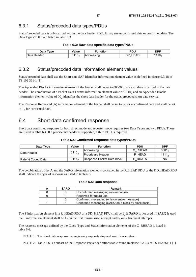
ETSI
ETSI TS 102 361-3 V1.2.1 (2013-07)37
6.3.1 Status/precoded data types/PDUs Status/precoded data is only carried within the data header PDU. It may use unconfirmed data or confirmed data. The Data Types/PDUs are listed in table 6.3.
Table 6.3: Raw data specific data types/PDUs
Data Type Value Function PDU DPF Data Header 01102 Addressing SP_HEAD 11102
6.3.2 Status/precoded data information element values Status/precoded data shall use the Short data SAP Identifier information element value as defined in clause 9.3.18 of TS 102 361-1 [1].
The Appended Blocks information element of the header shall be set to 0000002 since all data is carried in the data
header. The combination of a Packet Data Format information element value of 11102 and an Appended Blocks
information element value of 002 identifies the short data header for the status/precoded short data service.
The Response Requested (A) information element of the header shall be set to 02 for unconfirmed data and shall be set
to 12 for confirmed data.
6.4 Short data confirmed response Short data confirmed response for both direct mode and repeater mode requires two Data Types and two PDUs. These are listed in table 6.4. If a proprietary header is supported, a third PDU is required.
Table 6.4: Confirmed response data types/PDUs
Data Type Value Function PDU DPF
Data Header 01102 Addressing C_RHEAD 00012 Proprietary Header P_HEAD 11112
Rate ½ Coded Data 01112 Response Packet Data Block C_RDATA NA
The combination of the A and the SARQ information elements contained in the R_HEAD PDU or the DD_HEAD PDU shall indicate the type of response as listed in table 6.5.
Table 6.5: Data response
A SARQ Remark 0 0 Unconfirmed messaging (no response) 0 1 Reserved for future use 1 0 Confirmed messaging (only on entire message) 1 1 Confirmed messaging (SARQ on a block by block basis)
The F information element in a R_HEAD PDU or a DD_HEAD PDU shall be 12 if SARQ is not used. If SARQ is used
the F information element shall be 12 on the first transmission attempt and 02 on subsequent attempts.
The response message defined by the Class, Type and Status information elements of the C_RHEAD is listed in table 6.6.
NOTE 1: The short data response message only supports stop and wait flow control.
NOTE 2: Table 6.6 is a subset of the Response Packet definitions table found in clause 8.2.2.3 of TS 102 361-1 [1].

ETSI
ETSI TS 102 361-3 V1.2.1 (2013-07)38
Table 6.6: Short data response packet class, type, and Status definitions
Class Type Status Message Comment 002 0012 0002 ACK All blocks of all packets are successfully received. 012 0002 0002 NACK Illegal format. 012 0012 0002 NACK Packet CRC failed. 012 0102 0002 NACK Memory of the recipient is full. 012 1002 0002 NACK Undeliverable. 102 0002 0002 SACK The recipient requests the selective retry of the blocks indicated in the
data block of the response packet.
7 PDU description This clause describes the PDUs which apply to the DMR layer 3 Packet Data Protocol as described in the present document.
The following clauses contain descriptions of the PDUs and the information elements contained within them. The structure of the PDU definition represented by the tables is as follows:
• the information element column gives the name of the contained element(s);
• the element length column defines the length of the element in bits;
• the remarks column contains other information on the information element.
The elements shall be transmitted in the order specified by TS 102 361-1 [1].
7.1 Layer 3 and 4 PDP PDUs Due to the nature of DMR, with close interaction between layers 2 and 3, and with a high degree of information about the state of the channel being needed, the layer 3 PDUs detailed in the following clauses may include two element types:
• Message dependent elements:
- These elements are visible to layer 2 and may be used by any MS (that is able to decode them), irrespective of addressing. These elements depend on the message type element. Some are generated by layer 2 when it constructs the complete message whereas others are generated by layer 3.
• Feature elements:
- These are "true" layer 3 elements. They are only processed by the MSs to which they are addressed.
Where both types exist in the PDU they are shown separately.
7.1.1 Full Link Control (FULL LC) PDUs This clause describes the FULL LC PDUs for PDP. For a detailed definition of LC messages see clause 7 of TS 102 361-1 [1].
7.1.1.1 Terminator Data Link Control PDU
Octet 0 and 1 of the Terminator Data Link Control (TD_LC) PDU conform to the LC format structure as defined in figure 7.1 of clause 7.1 in TS 102 361-1 [1]. Octets 2 - 8 contain the Terminator Data Link Control specific information. The TD_LC PDU is shown in table 7.1.

ETSI
ETSI TS 102 361-3 V1.2.1 (2013-07)39
Table 7.1: TD_LC PDU content
Information element Length Remark Message dependent elements
Protect Flag (PF) 1 See clause 9.3.10 of TS 102 361-1 [1]. Reserved 1 This bit shall be set to 02.
Feature elements Full Link Control Opcode (FLCO) 6 Shall be set to 1100002. Feature set ID (FID) 8 Shall be set to 000000002. Logical Link ID (LLID) 24 Destination, see clause 9.3.19 of TS 102 361-1 [1]. Logical Link ID (LLID) 24 Source, see clause 9.3.19 of TS 102 361-1 [1]. Group or Individual (G/I) 1 This bit shall be set for a group to 12, see clause 9.3.15 of TS 102 361-1 [1]. Response Requested (A) 1 See clause 9.3.16 of TS 102 361-1 [1]. Full Message Flag (FMF) 1 See clause 9.3.20 of TS 102 361-1 [1]. Reserved 1 This bit shall be set to 02. Re-Synchronization flag (S) 1 See clause 9.3.23 of TS 102 361-1 [1]. Send sequence Number (N(S)) 3 See clause 9.3.24 of TS 102 361-1 [1].
7.2 UDP/IPv4 Compressed Header
7.2.1 UDP Header Information Elements The UDP header is defined in RFC 768 [14]. When a MS receives a compressed UDP/IPv4 header it shall decompress the UDP header before sending to the IP layer. This clause describes how UDP header information elements are utilized in the UDP header compression and decompression processes.
7.2.1.1 UDP Source Port Number
The actions of an MS when forming the UDP/IPv4 compressed header are dependant upon whether or not the MS contains a predefined Source Port IDentifier (SPID) linked to the UDP Source Port Number in the UDP header. If a predefined linkage exists in the MS, the corresponding SPID information element shall be transmitted in the compressed header. If a predefined link does not exist, the SPID information element shall be transmitted as 00000002
and the complete UDP Source Port Number shall be transmitted in an optional Extended Header information element in the compressed header. When a Source Port Number is sent in an optional Extended Header, it is always sent in Extended Header 1.
The actions of an MS when decompressing a received UDP/IPv4 compressed header are dependant upon the received SPID information element. If the received SPID value is not 00000002 then the UDP Source Port Number in the UDP
Header is the Source Port Number linked to the SPID value in the receiving MS. If the received SPID value is 00000002
then the UDP Source Port Number in the UDP header is in an optional Extended Header information element. When a Source Port Number is sent in an optional Extended Header, it is always sent in Extended Header 1.
7.2.1.2 UDP Destination Port Number
The actions of an MS when forming the UDP/IPv4 compressed header are dependant upon whether or not the MS contains a predefined Destination Port IDentifier (DPID) linked to the UDP Destination Port Number in the UDP header. If a predefined linkage exists in the MS, the corresponding DPID information element shall be transmitted in the compressed header. If a predefined link does not exist, the DPID information element shall be transmitted as 00000002 and the complete UDP Destination Port Number shall be transmitted in an optional Extended Header
information element in the compressed header. When a Destination Port Number is sent in an optional Extended Header, it may be sent in either Extended Header 1 or Extended Header 2. If the UDP Source Port Number in the compressed header is not 00000002 then the UDP Destination Port Number is sent in Extended Header 1. If the UDP
Source Port Number in the compressed header is 00000002 then the UDP Destination Port Number is sent in Extended
Header 2.
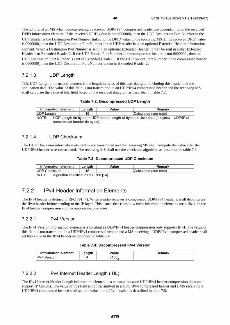
ETSI
ETSI TS 102 361-3 V1.2.1 (2013-07)40
The actions of an MS when decompressing a received UDP/IPv4 compressed header are dependant upon the received DPID information element. If the received DPID value is not 00000002 then the UDP Destination Port Number in the
UDP Header is the Destination Port Number linked to the DPID value in the receiving MS. If the received DPID value is 00000002 then the UDP Destination Port Number in the UDP header is in an optional Extended Header information
element. When a Destination Port Number is sent in an optional Extended Header, it may be sent in either Extended Header 1 or Extended Header 2. If the UDP Source Port Number in the compressed header is not 00000002 then the
UDP Destination Port Number is sent in Extended Header 1. If the UDP Source Port Number in the compressed header is 00000002 then the UDP Destination Port Number is sent in Extended Header 2.
7.2.1.3 UDP Length
This UDP Length information element is the length in bytes of this user datagram including this header and the application data. The value of this field is not transmitted in an UDP/IPv4 compressed header and the receiving MS shall calculate the value of this field based on the received datagram as described in table 7.2.
Table 7.2: Decompressed UDP Length
Information element Length Value Remark UDP Length 16 Calculated (see note) NOTE: UDP Length (in bytes) = UDP header length (8 bytes) + User data (in bytes) – UDP/IPv4
compressed header (in bytes).
7.2.1.4 UDP Checksum
The UDP Checksum information element is not transmitted and the receiving MS shall compute the value after the UDP/IPv4 header is re-constructed. The receiving MS shall use the checksum algorithm as described in table 7.3.
Table 7.3: Decompressed UDP Checksum
Information element Length Value Remark UDP Checksum 16 Calculated (see note) NOTE: Algorithm specified in RFC 768 [14].
7.2.2 IPv4 Header Information Elements The IPv4 header is defined in RFC 791 [4]. When a radio receives a compressed UDP/IPv4 header it shall decompress the IPv4 header before sending to the IP layer. This clause describes how these information elements are utilized in the IPv4 header compression and decompression processes.
7.2.2.1 IPv4 Version
The IPv4 Version information element is a constant as UDP/IPv4 header compression only supports IPv4. The value of this field is not transmitted in a UDP/IPv4 compressed header and a MS receiving a UDP/IPv4 compressed header shall set this value in the IPv4 header as described in table 7.4.
Table 7.4: Decompressed IPv4 Version
Information element Length Value Remark IPv4 Version 4 01002
7.2.2.2 IPv4 Internet Header Length (IHL)
The IPv4 Internet Header Length information element is a constant because UDP/IPv4 header compression does not support IP Options. The value of this field is not transmitted in a UDP/IPv4 compressed header and a MS receiving a UDP/IPv4 compressed headed shall set this value in the IPv4 header as described in table 7.5.
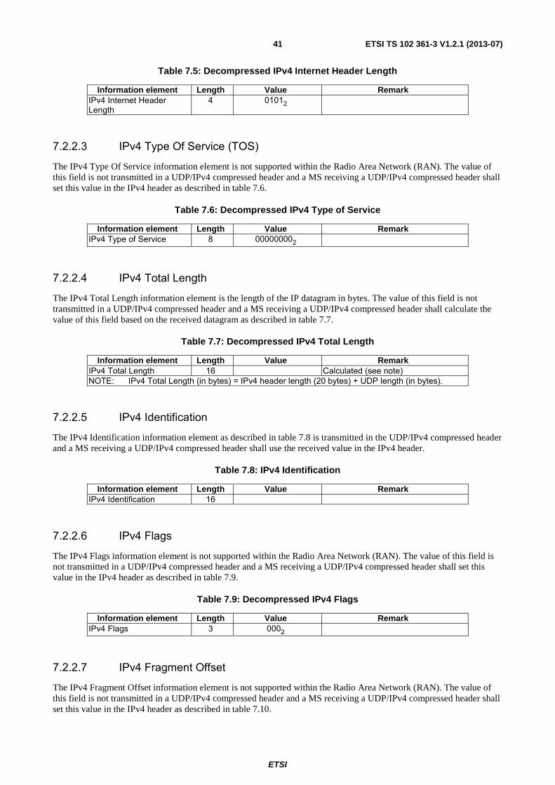
ETSI
ETSI TS 102 361-3 V1.2.1 (2013-07)41
Table 7.5: Decompressed IPv4 Internet Header Length
Information element Length Value Remark IPv4 Internet Header Length
4 01012
7.2.2.3 IPv4 Type Of Service (TOS)
The IPv4 Type Of Service information element is not supported within the Radio Area Network (RAN). The value of this field is not transmitted in a UDP/IPv4 compressed header and a MS receiving a UDP/IPv4 compressed header shall set this value in the IPv4 header as described in table 7.6.
Table 7.6: Decompressed IPv4 Type of Service
Information element Length Value Remark IPv4 Type of Service 8 000000002
7.2.2.4 IPv4 Total Length
The IPv4 Total Length information element is the length of the IP datagram in bytes. The value of this field is not transmitted in a UDP/IPv4 compressed header and a MS receiving a UDP/IPv4 compressed header shall calculate the value of this field based on the received datagram as described in table 7.7.
Table 7.7: Decompressed IPv4 Total Length
Information element Length Value Remark IPv4 Total Length 16 Calculated (see note) NOTE: IPv4 Total Length (in bytes) = IPv4 header length (20 bytes) + UDP length (in bytes).
7.2.2.5 IPv4 Identification
The IPv4 Identification information element as described in table 7.8 is transmitted in the UDP/IPv4 compressed header and a MS receiving a UDP/IPv4 compressed header shall use the received value in the IPv4 header.
Table 7.8: IPv4 Identification
Information element Length Value Remark IPv4 Identification 16
7.2.2.6 IPv4 Flags
The IPv4 Flags information element is not supported within the Radio Area Network (RAN). The value of this field is not transmitted in a UDP/IPv4 compressed header and a MS receiving a UDP/IPv4 compressed header shall set this value in the IPv4 header as described in table 7.9.
Table 7.9: Decompressed IPv4 Flags
Information element Length Value Remark IPv4 Flags 3 0002
7.2.2.7 IPv4 Fragment Offset
The IPv4 Fragment Offset information element is not supported within the Radio Area Network (RAN). The value of this field is not transmitted in a UDP/IPv4 compressed header and a MS receiving a UDP/IPv4 compressed header shall set this value in the IPv4 header as described in table 7.10.

ETSI
ETSI TS 102 361-3 V1.2.1 (2013-07)42
Table 7.10: Decompressed IPv4 Fragment Offset
Information element Length Value Remark IPv4 Fragment Offset 13 00000000000002
7.2.2.8 IPv4 Time to Live
The IPv4 Time to Live information element is not supported within the Radio Area Network (RAN). The value of this field is not transmitted in a UDP/IPv4 compressed header and a MS receiving a UDP/IPv4 compressed header shall set this value in the IPv4 header as described in table 7.11.
Table 7.11: Decompressed IPv4 Time To Live
Information element Length Value Remark IPv4 Time To Live 8 010000002
7.2.2.9 IPv4 Protocol
The IPv4 Protocol information element indicates the next layer protocol used in the data portion of the internet datagram. This will be a constant as UDP/IPv4 Header Compression only supports a next layer protocol of UDP. The value of this field is not transmitted in a UDP/IPv4 compressed header and a MS receiving a UDP/IPv4 compressed header shall set this value in the IPv4 header as described in table 7.12.
Table 7.12: Decompressed IPv4 Protocol
Information element Length Value Remark IPv4 Protocol 8 000100012
7.2.2.10 IPv4 Header Checksum
The IPv4 Header Checksum information element is not transmitted and the receiving MS shall compute the value after the UDP/IPv4 header is re-constructed. The receiving MS shall use the checksum algorithm specified in RFC 791 [4].
Table 7.13: Decompressed IPv4 Header Checksum
Information element Length Value Remark UDP Checksum 16 Calculated (see note) NOTE: Algorithm specified in RFC 791 [4].
7.2.2.11 IPv4 Source Address
The IPv4 Source Address information element is the source of the IP datagram and it is not transmitted in a UDP/IPv4 compressed header. The receiving MS shall derive the value from the SAID information element in the UDP/IPv4 compressed header and the source LLID in either the U_HEAD (unconfirmed) or C_HEAD (confirmed) Data Header.
For example if the system is using a Class A Radio Network value of 12, the received SAID information element value is 00002 (Radio Network) and the received source LLID is 5, then the derived IPv4 Source Address is 12.0.0.5. This
follows clause 5.1.1, DLL derived IP addressing, in the present document.
7.2.2.12 IPv4 Destination Address
The IPv4 Destination Address information element is the destination of the IP datagram and it is not transmitted in a UDP/IPv4 compressed header. The receiving MS shall derive the value from the DAID information element in the UDP/IPv4 compressed header and the destination LLID in either the U_HEAD (unconfirmed) or C_HEAD (confirmed) Data Header.
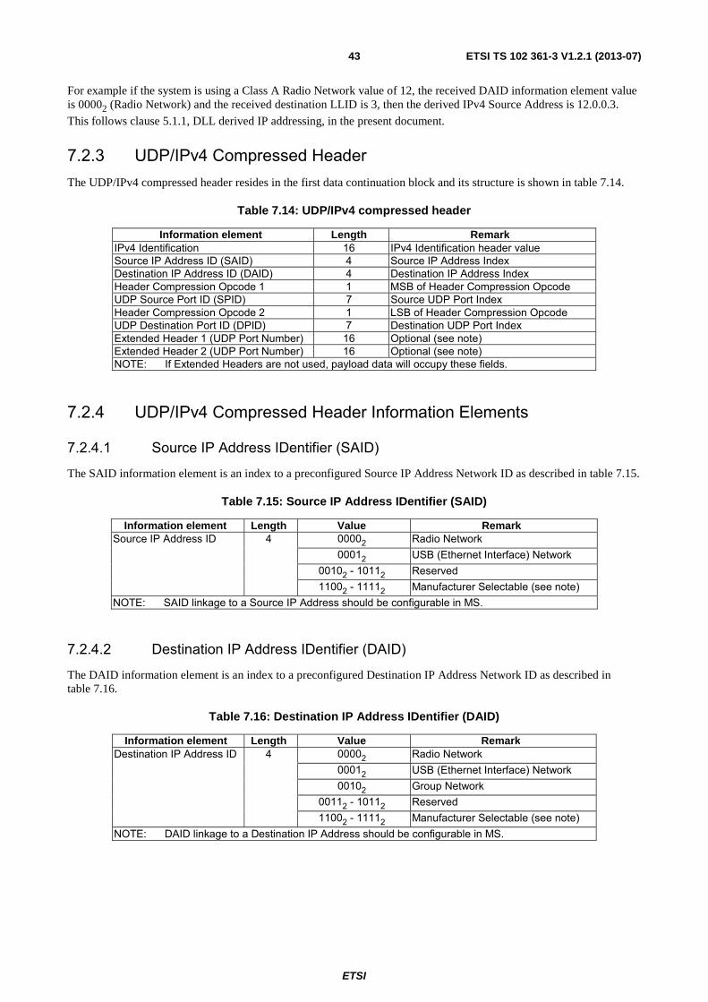
ETSI
ETSI TS 102 361-3 V1.2.1 (2013-07)43
For example if the system is using a Class A Radio Network value of 12, the received DAID information element value is 00002 (Radio Network) and the received destination LLID is 3, then the derived IPv4 Source Address is 12.0.0.3.
This follows clause 5.1.1, DLL derived IP addressing, in the present document.
7.2.3 UDP/IPv4 Compressed Header The UDP/IPv4 compressed header resides in the first data continuation block and its structure is shown in table 7.14.
Table 7.14: UDP/IPv4 compressed header
Information element Length Remark IPv4 Identification 16 IPv4 Identification header value Source IP Address ID (SAID) 4 Source IP Address Index Destination IP Address ID (DAID) 4 Destination IP Address Index Header Compression Opcode 1 1 MSB of Header Compression Opcode UDP Source Port ID (SPID) 7 Source UDP Port Index Header Compression Opcode 2 1 LSB of Header Compression Opcode UDP Destination Port ID (DPID) 7 Destination UDP Port Index Extended Header 1 (UDP Port Number) 16 Optional (see note) Extended Header 2 (UDP Port Number) 16 Optional (see note) NOTE: If Extended Headers are not used, payload data will occupy these fields.
7.2.4 UDP/IPv4 Compressed Header Information Elements
7.2.4.1 Source IP Address IDentifier (SAID)
The SAID information element is an index to a preconfigured Source IP Address Network ID as described in table 7.15.
Table 7.15: Source IP Address IDentifier (SAID)
Information element Length Value Remark Source IP Address ID 4 00002 Radio Network
00012 USB (Ethernet Interface) Network 00102 - 10112 Reserved 11002 - 11112 Manufacturer Selectable (see note)
NOTE: SAID linkage to a Source IP Address should be configurable in MS.
7.2.4.2 Destination IP Address IDentifier (DAID)
The DAID information element is an index to a preconfigured Destination IP Address Network ID as described in table 7.16.
Table 7.16: Destination IP Address IDentifier (DAID)
Information element Length Value Remark Destination IP Address ID 4 00002 Radio Network
00012 USB (Ethernet Interface) Network 00102 Group Network
00112 - 10112 Reserved 11002 - 11112 Manufacturer Selectable (see note)
NOTE: DAID linkage to a Destination IP Address should be configurable in MS.

ETSI
ETSI TS 102 361-3 V1.2.1 (2013-07)44
7.2.4.3 UDP Source Port IDentifier (SPID)
The SPID information element is an index to a preconfigured Source UDP port number as described in table 7.17.
Table 7.17: UDP Source Port IDentifier (SPID)
Information element
Length Value UDP Port Number
Remark
UDP Source Port ID 7 00000002 NA In Extended Header 00000012 5016 UTF-16BE Text
Message (see note 1) 00000102 5017 Location Interface
Protocol (see note 1) 00000112 - 10111102 NA Reserved 10111112 - 11111112 configurable Manufacturer Selectable
(see note 2) NOTE 1: The UDP port number is a default value to be used within the radio network. NOTE 2: SPID linkage to a UDP Source Port should be configurable in MS.
7.2.4.4 UDP Destination Port IDentifier (DPID)
The DPID information element is an index to a predetermined Destination IP Address as described in table 7.18.
Table 7.18: UDP Destination Port IDentifier (DPID)
Information element
Length Value UDP Port Number
Remark
Destination Port ID 7 00000002 NA In Extended Header 00000012 5016 UTF-16BE Text
Message (see note 1) 00000102 5017 Location Interface
Protocol (see note 1) 00000112 - 10111102 NA Reserved 10111112 - 11111112 configurable Manufacturer Selectable
(see note 2) NOTE 1: The UDP port number is a default value to be used within the radio network. NOTE 2: DPID linkage to a UDP Destination Port should be configurable in MS.
7.2.4.5 Header Compression Opcode
The Header Compression Opcode information element indentifies the format of the compressed header as described in table 7.19.
Table 7.19: Header Compression Opcode
Information element Length Value Remark Header Compression Opcode
2 002 UDP/IPv4 Header Compression All others Reserved
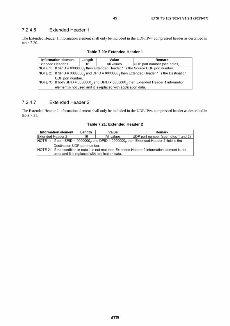
ETSI
ETSI TS 102 361-3 V1.2.1 (2013-07)45
7.2.4.6 Extended Header 1
The Extended Header 1 information element shall only be included in the UDP/IPv4 compressed header as described in table 7.20.
Table 7.20: Extended Header 1
Information element Length Value Remark Extended Header 1 16 All values UDP port number (see notes) NOTE 1: If SPID = 00000002 then Extended Header 1 is the Source UDP port number. NOTE 2: If SPID ≠ 00000002 and DPID = 00000002 then Extended Header 1 is the Destination
UDP port number. NOTE 3: If both SPID ≠ 00000002 and DPID ≠ 00000002 then Extended Header 1 information
element is not used and it is replaced with application data.
7.2.4.7 Extended Header 2
The Extended Header 2 information element shall only be included in the UDP/IPv4 compressed header as described in table 7.21.
Table 7.21: Extended Header 2
Information element Length Value Remark Extended Header 2 16 All values UDP port number (see notes 1 and 2) NOTE 1: If both SPID = 00000002 and DPID = 00000002 then Extended Header 2 field is the
Destination UDP port number. NOTE 2: If the condition in note 1 is not met then Extended Header 2 information element is not
used and it is replaced with application data.

ETSI
ETSI TS 102 361-3 V1.2.1 (2013-07)46
Annex A (normative): PDP timers and constants in DMR This annex lists the timers in a DMR PDP MS.
Where indicated, a value should be chosen by the MS/BS designer from within the specified range. For other timers and constants, a default value may be specified and the value of these timers and constants shall be configurable within the DMR entity (MS or BS).
A.1 Layer 2 timers T_DataTxLmt Data Transmission Limit
Value chosen by MS designer. Recommended maximum value = 60 seconds
NOTE 1: T_DataTxLmt is the time duration that an MS will attempt to transmit an unconfirmed data message or attempt to transmit a confirmed data message and receive a reply.
T_RspnsWait Confirmed Data Response Wait Limit Value chosen by MS designer. Recommended value = 180 ms
Recommended minimum value (simulcast systems) = 2,0 seconds
NOTE 2: T_RspnsWait is the time duration that an MS will wait to receive the confirmed header packet data response.
T_Holdoff Random Holdoff Time Range chosen by MS designer. MS randomly generates timer duration over the range. Range chosen by MS designer. Minimum value = TBD. Recommended maximum value = 2 seconds (Unconfirmed Data). Recommended maximum value = 2 seconds (Confirmed Data).
NOTE 3: T_Holdoff is utilized to minimize collisions when data messages are queued and the channel becomes idle.
T_DataHngtime Data Hangtime Value chosen by BS designer. Recommended value = 180 ms (3 traffic bursts).
NOTE 4: T_DataHngtime is the time that the BS will transmit Terminator Data Link Control (TD_LC) PDUs to reserve the channel for a confirmed data response.
A.2 Layer 2 constants N_RtryLmt Data Air Interface Retry Limit
Value chosen by MS designer. Recommended maximum value = 8.
NOTE: N_RtryLmt is the number of times the DLL will transmit and attempt to receive the confirmed data response from the target MS.
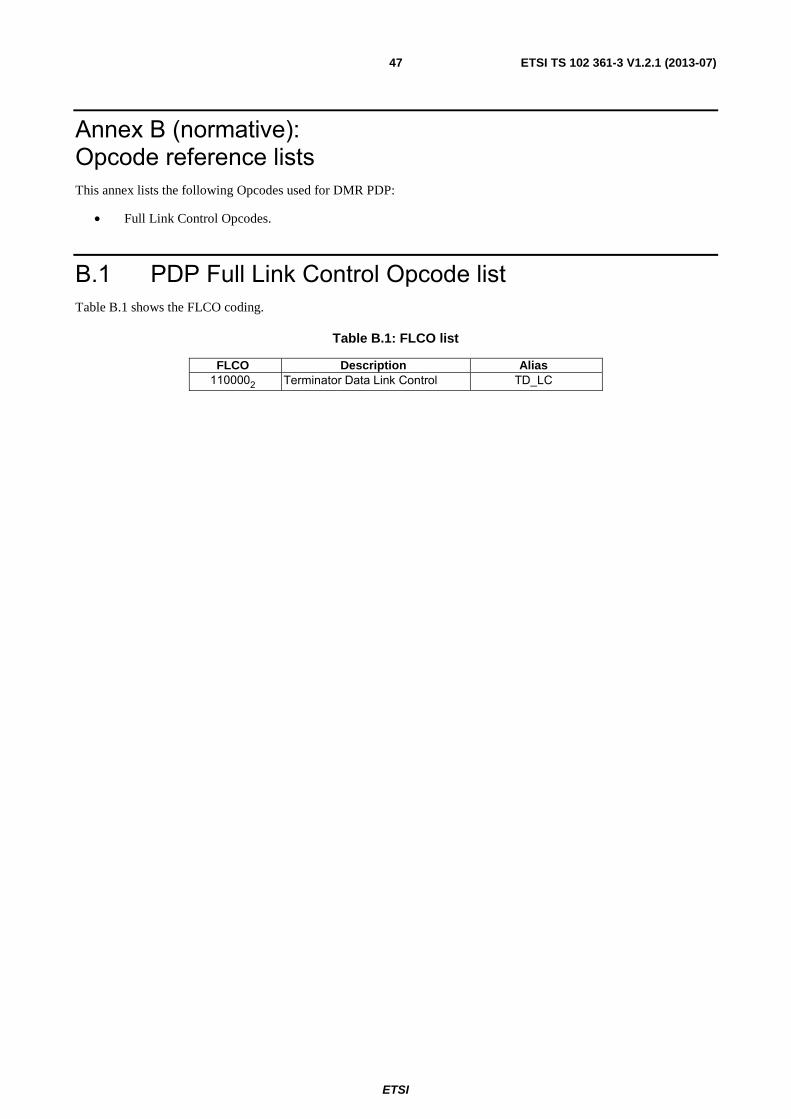
ETSI
ETSI TS 102 361-3 V1.2.1 (2013-07)47
Annex B (normative): Opcode reference lists This annex lists the following Opcodes used for DMR PDP:
• Full Link Control Opcodes.
B.1 PDP Full Link Control Opcode list Table B.1 shows the FLCO coding.
Table B.1: FLCO list
FLCO Description Alias 1100002 Terminator Data Link Control TD_LC

ETSI
ETSI TS 102 361-3 V1.2.1 (2013-07)48
Annex C (informative): IPv6 transport over PDP This annex shows some strategies and gives some references on how IPv6 packets can be transported on the DMR Packet Data Protocol that is tailored to transport IPv4 packets.
C.1 IPv6 addressing The new generation of the Internet Protocol is IPv6. A detailed description of IPv6 protocol is present in RFC 2460 [8], "Internet Protocol, Version 6 (IPv6) Specification".
In IPv6 the IP address has a length of 128 bits. There are three types of addresses:
Unicast: An identifier for a single interface. A packet sent to a Unicast address is delivered to the interface identified by that address.
Anycast: An identifier for a set of interfaces (typically belonging to different nodes). A packet sent to an anycast address is delivered to one of the interfaces identified by that address (the "nearest" one, according to the routing protocols' measure of distance).
Multicast: An identifier for a set of interfaces (typically belonging to different nodes). A packet sent to a multicast address is delivered to all interfaces identified by that address.
For the scope of this annex only Unicast addresses are taken into account. The Unicast address has a length of 128 bits and can be divided into several fields. The IPv6 addresses are written in hexadecimal format as shown below.
Unspecified address: 0000000016
NOTE 1: The unspecified address indicates the absence of an address.
Loopback address: 0000000116
NOTE 2: The loopback address may be used by a node to send an IPv6 packet to itself.
The general Global Unicast addressing scheme is described in table C.1.
Table C.1: Global Unicast addressing scheme
n bits m bits 128-n-m bits global routing prefix subnet ID interface ID
The IPv6 transition mechanisms include a technique for nodes and routers to dynamically tunnel IPv6 packets over IPv4 routing infrastructure. IPv6 nodes that use this technique are assigned special IPv6 Unicast addresses that carry a global IPv4 address in the low-order 32 bits. This type of address is termed an "IPv4-compatible IPv6 address" and is shown in table C.2.
Table C.2: IPv4-compatible IPv6 address
80 bits (10 bytes) 16 bits 32 bits 00 00 00 00 00 00 00 00 00 00 00 00 IPv4 address
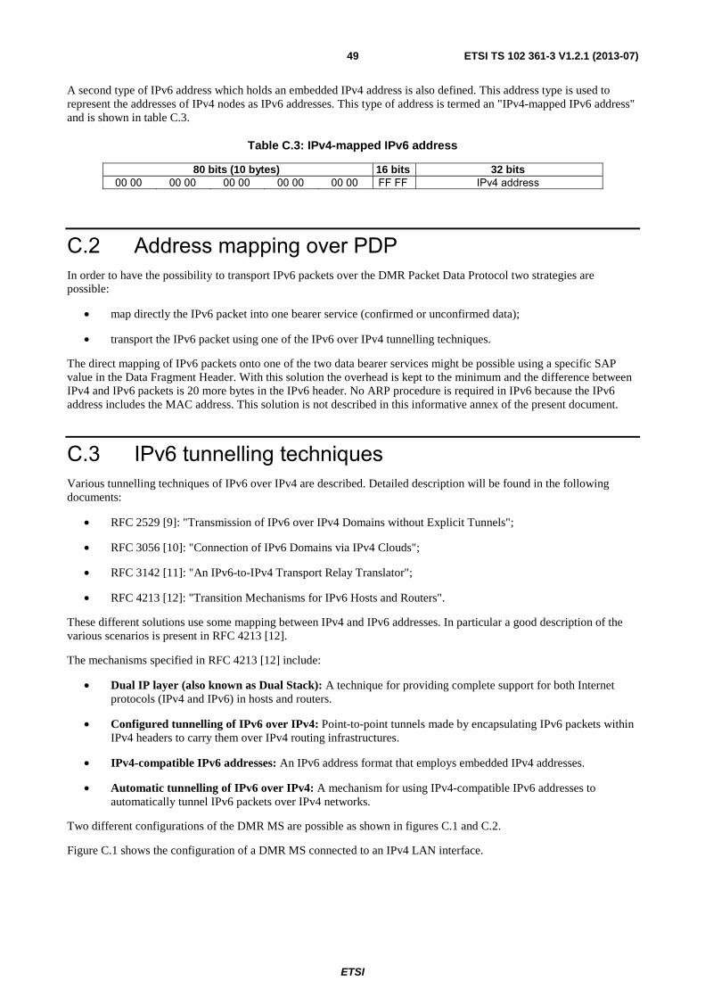
ETSI
ETSI TS 102 361-3 V1.2.1 (2013-07)49
A second type of IPv6 address which holds an embedded IPv4 address is also defined. This address type is used to represent the addresses of IPv4 nodes as IPv6 addresses. This type of address is termed an "IPv4-mapped IPv6 address" and is shown in table C.3.
Table C.3: IPv4-mapped IPv6 address
80 bits (10 bytes) 16 bits 32 bits 00 00 00 00 00 00 00 00 00 00 FF FF IPv4 address
C.2 Address mapping over PDP In order to have the possibility to transport IPv6 packets over the DMR Packet Data Protocol two strategies are possible:
• map directly the IPv6 packet into one bearer service (confirmed or unconfirmed data);
• transport the IPv6 packet using one of the IPv6 over IPv4 tunnelling techniques.
The direct mapping of IPv6 packets onto one of the two data bearer services might be possible using a specific SAP value in the Data Fragment Header. With this solution the overhead is kept to the minimum and the difference between IPv4 and IPv6 packets is 20 more bytes in the IPv6 header. No ARP procedure is required in IPv6 because the IPv6 address includes the MAC address. This solution is not described in this informative annex of the present document.
C.3 IPv6 tunnelling techniques Various tunnelling techniques of IPv6 over IPv4 are described. Detailed description will be found in the following documents:
• RFC 2529 [9]: "Transmission of IPv6 over IPv4 Domains without Explicit Tunnels";
• RFC 3056 [10]: "Connection of IPv6 Domains via IPv4 Clouds";
• RFC 3142 [11]: "An IPv6-to-IPv4 Transport Relay Translator";
• RFC 4213 [12]: "Transition Mechanisms for IPv6 Hosts and Routers".
These different solutions use some mapping between IPv4 and IPv6 addresses. In particular a good description of the various scenarios is present in RFC 4213 [12].
The mechanisms specified in RFC 4213 [12] include:
• Dual IP layer (also known as Dual Stack): A technique for providing complete support for both Internet protocols (IPv4 and IPv6) in hosts and routers.
• Configured tunnelling of IPv6 over IPv4: Point-to-point tunnels made by encapsulating IPv6 packets within IPv4 headers to carry them over IPv4 routing infrastructures.
• IPv4-compatible IPv6 addresses: An IPv6 address format that employs embedded IPv4 addresses.
• Automatic tunnelling of IPv6 over IPv4: A mechanism for using IPv4-compatible IPv6 addresses to automatically tunnel IPv6 packets over IPv4 networks.
Two different configurations of the DMR MS are possible as shown in figures C.1 and C.2.
Figure C.1 shows the configuration of a DMR MS connected to an IPv4 LAN interface.

ETSI
ETSI TS 102 361-3 V1.2.1 (2013-07)50
DMR AILAN
IPv4 IPv4
IPv6 - IPv4(dual stack)
DMR MS
Figure C.1: DMR connected to IPv4
With this configuration the tunnelling is to be managed directly by the host connected to the DMR MS. This host can use either the automatic tunnelling or the configured tunnelling as described below:
Case 1a: If both the source and the destination hosts have IPv4-compatible IPv6 addresses, the automatic tunnelling is natively transported on the IPv4 DMR interface and the routing of the packet is done by the ARP over DMR procedure. In practice the automatic tunnelling permits the mobile host to mobile host direct communication among IPv6 host over an IPv4 routing infrastructure.
Case 1b: If either the source or the destination hosts have no IPv4-compatible IPv6 addresses then the only possibility is to use configured tunnelling. In this case the source host knows that there is an IPv4 tunnel between its interface and another interface of another device that is able to route the IPv6 packet to the target host. In practice this configured tunnel is from each mobile host to a switching centre where an IPv6 router is present. In this case there is not the possibility to have mobile host to mobile host direct communication among IPv6 host.
Figure C.2 shows a configuration of a DMR MS connected to an IPv6 LAN interface.
DMR AILAN
IPv6 IPv4
IPv6 DMR MS
Figure C.2: DMR connected to IPv6
With this configuration the tunnelling is to be managed from each DMR MS that has an IPv6 capable device connected. The DMR MS can use either the automatic tunnelling or the configured tunnelling depending on the type of IPv6 addresses used by source and destination hosts.
Case 2a: If both the source and the destination hosts own IPv4-compatible IPv6 addresses, the automatic tunnelling is natively transported on the IPv4 DMR interface and the routing of the packet is done by the ARP over DMR procedure. In practice the automatic tunnelling permits the mobile host to mobile host direct communication among IPv6 host over an IPv4 routing infrastructure.
Case 2b: If either the source or the destination hosts have no IPv4-compatible IPv6 addresses then the only possibility is to use configured tunnelling. In this case the DMR MS knows that there is an IPv4 tunnel between its IPv4 interface and another interface of another device that is able to route the IPv6 packet to the target host. In practice this configured tunnel is from each DMR MS to a switching centre where an IPv6 router is present. In this case there is not the possibility to have mobile host to mobile host direct communication among IPv6 host.
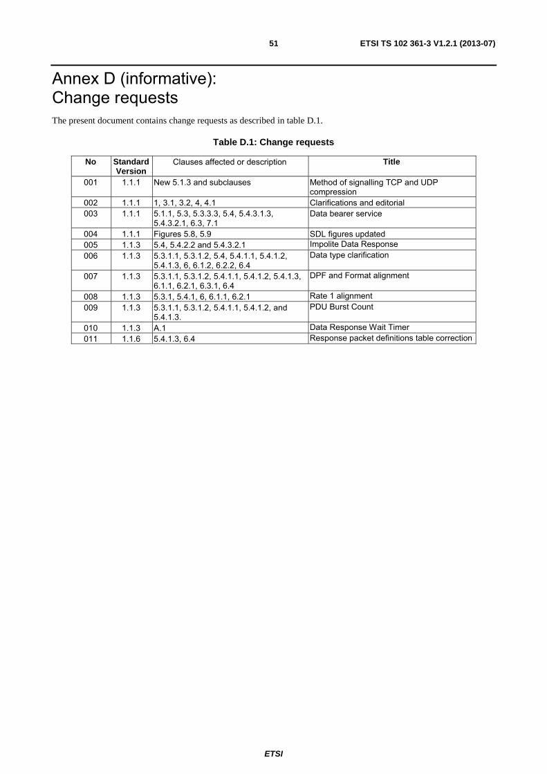
ETSI
ETSI TS 102 361-3 V1.2.1 (2013-07)51
Annex D (informative): Change requests The present document contains change requests as described in table D.1.
Table D.1: Change requests
No Standard Version
Clauses affected or description Title
001 1.1.1 New 5.1.3 and subclauses Method of signalling TCP and UDP compression
002 1.1.1 1, 3.1, 3.2, 4, 4.1 Clarifications and editorial 003 1.1.1 5.1.1, 5.3, 5.3.3.3, 5.4, 5.4.3.1.3,
5.4.3.2.1, 6.3, 7.1 Data bearer service
004 1.1.1 Figures 5.8, 5.9 SDL figures updated 005 1.1.3 5.4, 5.4.2.2 and 5.4.3.2.1 Impolite Data Response 006 1.1.3 5.3.1.1, 5.3.1.2, 5.4, 5.4.1.1, 5.4.1.2,
5.4.1.3, 6, 6.1.2, 6.2.2, 6.4 Data type clarification
007 1.1.3 5.3.1.1, 5.3.1.2, 5.4.1.1, 5.4.1.2, 5.4.1.3, 6.1.1, 6.2.1, 6.3.1, 6.4
DPF and Format alignment
008 1.1.3 5.3.1, 5.4.1, 6, 6.1.1, 6.2.1 Rate 1 alignment 009 1.1.3 5.3.1.1, 5.3.1.2, 5.4.1.1, 5.4.1.2, and
5.4.1.3. PDU Burst Count
010 1.1.3 A.1 Data Response Wait Timer 011 1.1.6 5.4.1.3, 6.4 Response packet definitions table correction

ETSI
ETSI TS 102 361-3 V1.2.1 (2013-07)52
Annex E (informative): Bibliography
• ETSI TR 102 335-1: "Electromagnetic compatibility and Radio spectrum Matters (ERM); System reference document for harmonized use of Digital Mobile Radio (DMR); Part 1: Tier 1 DMR#, expected to be for general authorization with no individual rights operation".
• ETSI TR 102 335-2: "Electromagnetic compatibility and Radio spectrum Matters (ERM); System reference document for harmonized use of Digital Mobile Radio (DMR); Part 2: Systems operating under individual licences in the existing land mobile service spectrum bands".

ETSI
ETSI TS 102 361-3 V1.2.1 (2013-07)53
History Document history
V1.1.1 January 2006 Publication
V1.1.3 September 2006 Publication
V1.1.7 December 2007 Publication
V1.2.1 July 2013 Publication
Related Documents