The World Leader in Cold-Formed Steel Trusses Truss Design Manual a division of ITW Building Components Group @Seismicisolation @Seismicisolation

Welcome message from author
This document is posted to help you gain knowledge. Please leave a comment to let me know what you think about it! Share it to your friends and learn new things together.
Transcript

The World Leader in Cold-Formed Steel Trusses
Truss Design ManualV2
a division of ITW Building Components Group
888.565.9181 • www.TrusSteel.com
a division of ITW Building Components Group
Truss Design Manual
@Seismicisolation@Seismicisolation

TRUSS DESIGN MANUAL
1 OVERVIEW
1.01 Introduction
1.02 Specifiers & Designers
1.03 Contractor & Installer
1.04 Truss Components & Code Recognition
1.05 Framing & Connections
1.06 Authorized TrusSteel Fabricators
1.07 Education & CES
1.08 Notes Page
2 APPLICATIONS
2.01 Applications
2.02 Projects
3 SPECIFYING / DESIGNING
3.01 Overview
3.02 Building Codes & Design Standards
3.03 Information Required for Truss Design
3.05 TrusSteel System
3.07 Wind Loading
3.10 Snow Loading
3.11 Seismic Loading
3.13 Sound Control
3.14 Sustainability & LEED
3.15 Fire Resistance & UL
3.16 Trusses as Building Components
3.17 Roof Truss Systems - Framing
3.22 Roof Truss Systems - Sample Spans
3.23 Floor Truss Systems
3.26 Guide Specifications
© Copyright 2012 ITW Building Components Group, Inc.
This Design Manual is intended as a guide to building professionals for suggested uses of TrusSteel trusses. The building code of jurisdiction and a truss designprofessional should be consulted before incorporating information from this publication into any plan or structure.
ITW Building Components Group, Inc., nor any of its divisions or companies, does not warrant the recommendations and information contained herein as properunder all conditions and expressly disclaims any responsibility for damages arising from the use, application or reliance on the recommendations contained herein.
4 ENGINEERING / SHOP DRAWINGS
4.01 Engineering
4.03 Shop Drawings
4.04 Notes Page
5 DETAILS / CONNECTIONS
5.01 Overview
5.03 Standard Details
5.04 Truss-to-Truss Connections
5.06 Gable Outlooker Connections
5.07 Truss-to-Bearing Connections
5.13 Piggyback and Valley Truss Connections
6 TRUSS FABRICATION / QUALITY
6.01 Overview
7 INSTALLATION / BRACING
7.01 Site Conditions & Safety
7.02 Handling & Storage
7.03 Lifting & Staging
7.04 Bracing
7.05 Rafting
8 REFERENCES / RESOURCES
8.01 Industry Resources
8.02 Glossary
8.07 Weights of Materials
TABLE OF CONTENTS
1206
@Seismicisolation@Seismicisolation


OVERVIEW
This Manual is intended for quick reference only. Drawings and illustrations shown are samples only and are not intended for detailingor construction. Please refer to the TrusSteel Standard Details for technical information on connection design, product use and safety.
1 2 3 4 5 6 7 81.01
Unmatched strength and stiffness in acold-formed steel truss.
TrusSteel is the most accepted, most specified cold-formed steel (CFS) truss system on the market today. Noother building component combines strength, stiffness, fireresistance, insect resistance and design flexibility so well.
The unique, patented truss chord shape and Double-ShearTM fasteners, combined with multiple types of webshapes, make TrusSteel CFS trusses, pound-for-pound, thestrongest and stiffest cold-formed steel trusses on themarket. Not surprisingly, these same characteristicscombine to create a light, economical steel buildingcomponent having exceptional load-span capabilities, withclear spans in excess of 80 ft.
Supported by powerful Alpine steelVIEWTM design andanalysis software, TrusSteel CFS trusses provide reliable,economical structural solutions for almost every roof or floorapplication.
The Most Trusted Name in CFS Trusses
Alpine Engineered Products, Inc. was a drivingforce in the creation of the wood truss industryover forty years ago. Since that beginning, theindustry has consistently recognized Alpine asengineering and innovation leaders. Now, as apart of the ITW Building Components Group, Inc.Alpine provides the same leadership in thefounding and development of the pre-engineeredCFS truss industry.
The TrusSteel Division has decades of combinedexpertise in the truss and CFS building productsindustry. The TrusSteel product line combinesover forty years of truss engineering andsoftware knowledge with cutting-edgerollforming technology and the proven quality ofin-house truss fabrication. As a result, moreTrusSteel trusses are installed each year thanany other proprietary CFS truss system.
TrusSteel provides ongoing leadership to thetruss industry through hands-on participation inkey organizations such as the Cold-Formed SteelEngineers Institute (formerly LGSEA), theAmerican Iron and Steel Institute, the CFSCouncil of the SBCA, the AISI Committee onFraming Standards (COFS), and the Center forCold-Formed Steel Structures.
TrusSteel is actively involved in programs withthe International Code Council and UnderwritersLaboratories.
Every TrusSteel truss is designed using theindustry-leading Alpine steelVIEW software.steelVIEW is the most accurate truss designsoftware in the industry for a number of reasons,including:
• True multi-node modeling, not the estimatednode modeling used by other CFS truss designsoftware packages.
• Multiple load case analysis applied to eachtruss, including gravity, wind, seismic andunbalanced conditions.
• Analysis methodologies derived from the mostextensive full-scale testing program in theindustry, utilizing the AISI Specification for theDesign of Cold-Formed Steel StructuralMembers.
Authorized TrusSteel Fabricators, operatingthe steelVIEW software in-house andsupported by TrusSteel engineeringresources, provide solutions for the mostcomplex truss systems.
AmericanIron and Steel
Institute
@Seismicisolation@Seismicisolation
1 2 3 4 5 6 7 81.02
OVERVIEW
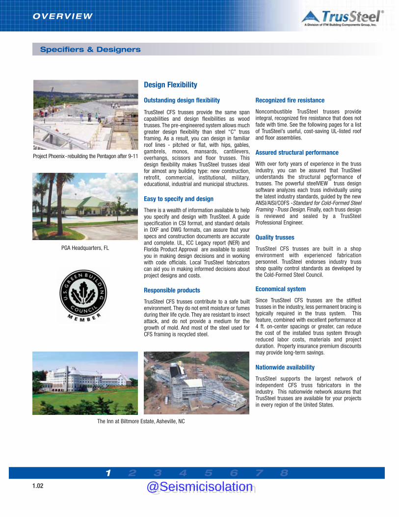
Outstanding design flexibility
TrusSteel CFS trusses provide the same spancapabilities and design flexibilities as woodtrusses. The pre-engineered system allows muchgreater design flexibility than steel “C” trussframing. As a result, you can design in familiarroof lines - pitched or flat, with hips, gables,gambrels, monos, mansards, cantilevers,overhangs, scissors and floor trusses. Thisdesign flexibility makes TrusSteel trusses idealfor almost any building type: new construction,retrofit, commercial, institutional, military,educational, industrial and municipal structures.
Easy to specify and design
There is a wealth of information available to helpyou specify and design with TrusSteel. A guidespecification in CSI format, and standard detailsin DXF and DWG formats, can assure that yourspecs and construction documents are accurateand complete. UL, ICC Legacy report (NER) andFlorida Product Approval are available to assistyou in making design decisions and in workingwith code officials. Local TrusSteel fabricatorscan aid you in making informed decisions aboutproject designs and costs.
Responsible products
TrusSteel CFS trusses contribute to a safe builtenvironment. They do not emit moisture or fumesduring their life cycle. They are resistant to insectattack, and do not provide a medium for thegrowth of mold. And most of the steel used forCFS framing is recycled steel.
Recognized fire resistance
Noncombustible TrusSteel trusses provideintegral, recognized fire resistance that does notfade with time. See the following pages for a listof TrusSteel’s useful, cost-saving UL-listed roofand floor assemblies.
Assured structural performance
With over forty years of experience in the trussindustry, you can be assured that TrusSteelunderstands the structural performance oftrusses. The powerful steelVIEW
TM
truss designsoftware analyzes each truss individually usingthe latest industry standards, guided by the newANSI/AISI/COFS -Standard for Cold-Formed SteelFraming -Truss Design. Finally, each truss designis reviewed and sealed by a TrusSteelProfessional Engineer.
Quality trusses
TrusSteel CFS trusses are built in a shopenvironment with experienced fabricationpersonnel. TrusSteel endorses industry trussshop quality control standards as developed bythe Cold-Formed Steel Council.
Economical system
Since TrusSteel CFS trusses are the stiffesttrusses in the industry, less permanent bracing istypically required in the truss system. Thisfeature, combined with excellent performance at4 ft. on-center spacings or greater, can reducethe cost of the installed truss system throughreduced labor costs, materials and projectduration. Property insurance premium discountsmay provide long-term savings.
Nationwide availability
TrusSteel supports the largest network ofindependent CFS truss fabricators in theindustry. This nationwide network assures thatTrusSteel trusses are available for your projectsin every region of the United States.
Design Flexibility
Specifiers & Designers
The Inn at Biltmore Estate, Asheville, NC
Project Phoenix-rebuilding the Pentagon after 9-11
PGA Headquarters, FL
@Seismicisolation@Seismicisolation

1 2 3 4 5 6 7 81.03
Safer to Handle
Unique features of TrusSteel trusses make themsafe to handle and install. Stiffer trusses addhandling control and reduce the danger ofbuckling during lifting and placement. The rollededges of the chords and webs help protectworkers from cuts.
Easier to Install
TrusSteel trusses can be as light as one-half theweight of similar wood or “C” stud steel trusses.Unlike some other CFS trusses, laterally stiffTrusSteel trusses resist folding or “butterflying”.And TrusSteel trusses work exceptionally well inrafted installations.
No Special Tools Required
The tools you are now using to install CFSframing are all you need to install TrusSteeltrusses. A full line of TrusSteel constructionhardware allows you to make connections withstandard screws. Installation details andconstruction hardware are available from yourAuthorized TrusSteel Fabricator.
Reduced Callbacks
TrusSteel trusses reduce callbacks because theystart straighter and remain straighter than manyother types of trusses. And the dimensionalstability of steel reduces drywall fastener pops.
Save Time, Effort and Money
TrusSteel trusses streamline the building cycleand save money.
• Timely quotations from local TrusSteelAuthorized Fabricators providecompetitive prices and define projectcosts up front.
• Sealed engineering drawings and code-compliant components expeditesubmittals.
• Quicker turn-arounds for revisions.• Delivered to the site ready to install, shop-
built trusses save days of labor.• Faster truss installation with accurate
layouts, extensive details, and a full line ofinstallation hardware.
• Easier site inspections withcomprehensive shop drawings andclearly identified components.
Delivered Quality
Roof lines plane accurately, eaves and soffitsalign properly, and interior ceiling lines are flatand true. High-quality TrusSteel trusses help youachieve your quality goals.
Delivered Value
From bidding to punch list, TrusSteel deliversvalue to your project through increased safety,quality, efficiency and cost-effectiveness.
Contractor-Friendly Installation
Truss Rafting
What is Rafting?
Truss rafting is a framing technique wherecompleted trusses, designed to be rafted, areassembled into an entire roof section on theground and then lifted as an assembly onto thebuilding structure. The assembly can consist ofjust the trusses, or the trusses plus purlins, roofdeck and final roofing which is all installed on theground before the assembly is lifted into place.Employing a rafting technique can save time,increase safety and reduce insurance costs onmany projects.
Why Raft With TrusSteel?
The exceptional strength-to-weight characteristicsand lateral stability of the TrusSteel trusses makethem the ideal truss for use in a rafting process.These characteristics allow an average-sizedcrane to lift the completed truss assembly intoposition. The stiffness and stability of theTrusSteel trusses create an assembly that willsurvive a lift without introducing significantadditional bracing.
Contractor & Installer
OVERVIEW
@Seismicisolation@Seismicisolation

OVERVIEW
1 2 3 4 5 6 7 81.04
Unique Chord Sections
The symmetrical shape of TrusSteel’s patentedU-shaped chord sections provides nearly equalchord member moment capacity in both in-planedirections. The TrusSteel chord members havesuperior bending strength in out-of-planedirections. These characteristics combine tocreate an efficient truss that is exceptionallystrong and stiff. The recent addition of specialchord sections for short span / low loadconditions and for long span / high lowconditions improves the value engineering of theentire system.
Webs
TrusSteel utilizes both commercial grade closed-tube webs and proprietary roll-formed z-webs todeliver the most cost effective roof system. Bothproducts have unique “double symmetric”properties which contributes to the strength,stiffness and stability of the truss as well asreducing lateral bracing.
TrusSteel members are designed and built in compliance with ASTM A370, ASTM A653, ASTM A500,ANSI Standards, and voluntary standards as described in our own reports from UnderwritersLaboratories (UL) and ICC Legacy reports (NER and Florida Product Approval). Visit our web site todownload the complete reports.
Patented Fasteners
TrusSteel is the only CFS truss system in theindustry using Double-ShearTM fastenertechnology. This patented technology provides arigid, bolt-like connection at all chord/webintersections and is specially designed to resistmovement and back-out. Color-coded, markedfasteners create the most dependable, easilyinspected connection available for CFSmaterials.
Structural Connections
TrusSteel delivers a full line of truss-to-truss andtruss-to-bearing connectors that provideconsistent quality and structural values.
The industry’s most extensive library of StandardDetails describing our connections, connectors andsection properties is available in various CAD formatson CD or from www.TrusSteel.com.
UL Listings TrusSteel products qualify for hourly ratings as shown below.Assemblies
Truss Components
Code Recognition
Truss Components & Code Recognition
@Seismicisolation@Seismicisolation

1 2 3 4 5 6 7 81.05
Framing & Connections
TrusSteel Connectors
An extensive set of TrusSteel connectors andapplication details allows a designer to create acomplete truss framing system, whatever theroof type, supporting conditions or other framingmaterials. All TrusSteel connectors are load-rated connectors.
Refer to Section 5 of this manual for theengineering values of our full line of connectors(simplified examples are shown here). TrusSteelStandard Details are available for eachconnection application. These Details includeload data as well as installation requirements.Standard Details are available in CAD formatsfrom www.TrusSteel.com and are also containedon the electronic version of this manual.
SteelDraw Truss Shop Drawings with:• All trusses marked and coordinated to layout• All truss members clearly identified• Complete general notes• Fully dimensioned truss profile with bearing elevations,
fastener quantities, pitch marks, web bracing locations and more• Truss reactions and bearing widths• Job-specific loads
Layout Drawings with:• Truss marks• Key bearing and framing dimensions• Truss spacings• Connection and bracing details
Standard Details
Truss ShopDraw TM and Layout TM Information
OVERVIEW
HANGER DETAILS UPLIFT ATTACHMENT TO STEEL UPLIFT ATTACHMENT TO STEEL
UPLIFT ATTACHMENTTO CONCRETE SPRINKLER PIPE HANGER SPRINKLER PIPE HANGER
Bottom chord bearing trussto girder truss
Bottom chord bearing trussto steel beam connection
Bottom chord bearing truss toCFS track connection
Bottom chord bearing truss toconcrete bearing
Bottom chord sprinkler pipe hangerusing Sammys x-Press 35 (XP 35)
Truss top chord hangerdetail
@Seismicisolation@Seismicisolation

1 2 3 4 5 6 7 81.06
OVERVIEW
What services can an AuthorizedFabricator provide?
Knowledge. TrusSteel Authorized Fabricators aretruss experts. They can answer questions abouttruss applications and installations as well asquestions about pricing and delivery. Do youhave questions about truss layouts, spans,spacings, profiles, systems, connections,bracing, overhangs, mechanical chases...andmore? Call your local Authorized Fabricator. Theycan save you money up front in your designdevelopment or structural design process.
Engineering. All TrusSteel trusses areengineered trusses. An Authorized Fabricator canprovide not just building components, but canalso provide individually-engineered and sealedtrusses. A staff of over fifty engineers, coveringevery state in the USA, reviews and seals over4,500,000 truss designs each year.
TrusSteel provides steelVIEWTM software to allAuthorized Fabricators. This powerful proprietarysoftware package includes 3-D modeling andtruss layout, truss engineering and biddingmodules. By-products of these key elements areindustry-best truss layouts, shop drawings andcutting sheets.
Quality trusses. Each Authorized Fabricatorbuilds TrusSteel trusses in a plant environment toensure the highest quality components. Trussesare built according to engineered shop drawings
and highly accurate cutting/assemblingdrawings created by the steelVIEW software.TrusSteel trusses are built with patented Double-ShearTM fasteners and internal connectors toassure consistently accurate trusses.
How can I find local AuthorizedFabricators?
You can find a list of Authorized Fabricators onthe TrusSteel Web site at www.TrusSteel.com. Or,you can call the TrusSteel information line at888-565-9181. Wherever your project is located,you can probably find at least two AuthorizedFabricators to provide competitive quotes onyour project.
Additional Services
Structural Services. Through their affiliationwith strategic partner BBD Engineering & DesignFirm, LLC (www.bbdengineering.com), a fee-based, full-service consulting engineering firm,TrusSteel Authorized Fabricators can provide fullframing system design services (including thedesign of special connections, bracing, purlins,decks - even entire building framing systems).
Authorized TrusSteel Fabricators
Who is a TrusSteel AuthorizedFabricator?
A TrusSteel Authorized Fabricator is anindependently-owned and operated local
truss fabrication shop. Each Fabricatormarkets and services truss projects in their own
region, backed by over 40 continuous years ofAlpine truss experience. Taken together, the nationwide
network of TrusSteel Authorized Fabricators forms a vast repository of truss and framingknowledge at your disposal.
@Seismicisolation@Seismicisolation

1 2 3 4 5 6 7 81.07
Attention:Project Architects
and Engineers
The TrusSteel Division has severaleducational presentations that we canmake in your office or at the localchapter of your professionalorganization.
The “Cold-Formed Steel Trusses 101”and “Bracing for Steel Trusses”presentations are accredited by theAmerican Institute of Architects undertheir Continuing Education System. AIAmembers who participate will receiveone LU Hour of credit, and TrusSteel willfile Form B with the AIA. All otherparticipants will receive a Certificate ofCompletion.
Target AudiencesArchitects, engineers, specifiers andother design professionals in thebuilding market; can be presented toany size audience.
AV NeededElectrical power and a screen forPowerPoint (CES facilitator will providethe laptop computer, video projector andsamples).
Other PresentationsOther non-accredited presentations areavailable, suitable for various venues.Contact your TrusSteel RegionalManager for details.
Facilitator QualificationsTrusSteel facilitators have extensiveexperience in the truss and buildingindustries and are well versed in trussdesign and installation.
Length: One HourCredits: One LU HourHSW: YesCost: None
DescriptionThis presentation includes a brief history andoverview of the various types of cold-formedsteel (CFS) truss systems on the market, theirphysical and structural characteristics andperformance, common system applications andlimitations, and how to specify these systems.
Length: One HourCredits: One LU HourHSW: YesCost: None
DescriptionThis presentation includes an overview of thevarious types of cold-formed steel (CFS) trusssystems on the market, common loadingsituations, structural construction bracing needsand how to specify the bracing for thesesystems.
Educational & CES
Learning ObjectivesAt the end of this program, participants will beable to:
• Identify the different types of CFS trusssystems,
• Understand the product capabilities andlimitations of various CFS truss systems,
• Specify a CFS truss system.
How TaughtUsing a PowerPoint presentation and physicalsamples, the CES facilitator presents informationon the nature and types of CFS truss systems,including basic terminology and applications.Physical samples are used to demonstrate trussterminology.
Cold-Formed Steel Trusses 101
Bracing for Steel Trusses
Learning ObjectivesAt the end of this program, participants will beable to:
• Identify the different types of CFS trusssystems,
• Understand common load conditions,• Specify the bracing for a CFS truss
system.
How TaughtUsing PowerPoint and physical samples, the CESfacilitator presents information on the nature andtypes of CFS truss systems, including basicterminology and applications. Physical samplesare used to demonstrate truss terminology.
OVERVIEW
@Seismicisolation@Seismicisolation

1 2 3 4 5 6 7 81.08
OVERVIEW
Notes
@Seismicisolation@Seismicisolation

1 2 3 4 5 6 7 82.01
Institutional – Schools – Universities – Churches – Museums – Healthcare – Clinics – Hospitals – Assisted Living Centers – RetirementCenters – Municipal – Community Centers – Town Halls – Hospitality – Hotels – Motels – Commercial – Malls – Banks – Truck StopsTelecommunications – Shopping Centers – Restaurants – Historical Renovation – Industrial – Storage – Roof Refit - Condominiums
Multi-Family – Single-Family – Recreation – Ball Parks – Gaming – Government/Military – Barracks – Depots – Offices
TrusSteel Cold-Formed Steel (CFS) trussesare now in service within literally thousandsof buildings, in dozens of buildingapplications.This guide shares only a smallfraction of the total uses of TrusSteel. Youcan view additional information on thesecase studies and other studies on theTrusSteel web site: www.TrusSteel.com.
TrusSteel trusses can be used to create
roofs and floors of all types (gables, hips,
monos, gambrels, etc.). They can be used in
many special applications, including:
• Re-roofs (over existing structures)
• Equipment screens
• Porte cocheres
• Ag structures
• Flat roofs
• Canopies
• Mansards
• Shelters
• Frames
Your imagination is the only limit
APPLICAT IONS
@Seismicisolation@Seismicisolation
1 2 3 4 5 6 7 82.02
APPLICAT IONS
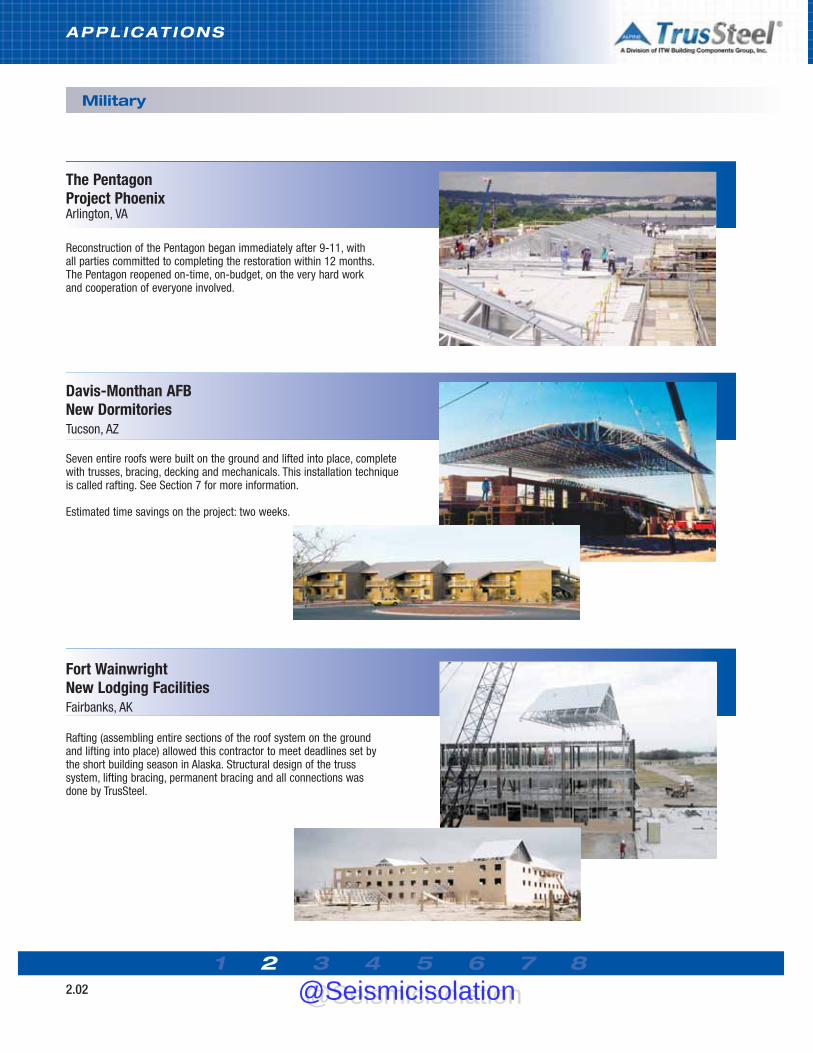
Military
Reconstruction of the Pentagon began immediately after 9-11, withall parties committed to completing the restoration within 12 months.The Pentagon reopened on-time, on-budget, on the very hard workand cooperation of everyone involved.
The PentagonProject PhoenixArlington, VA
Davis-Monthan AFBNew DormitoriesTucson, AZ
Seven entire roofs were built on the ground and lifted into place, completewith trusses, bracing, decking and mechanicals. This installation techniqueis called rafting. See Section 7 for more information.
Estimated time savings on the project: two weeks.
Fort WainwrightNew Lodging FacilitiesFairbanks, AK
Rafting (assembling entire sections of the roof system on the groundand lifting into place) allowed this contractor to meet deadlines set bythe short building season in Alaska. Structural design of the trusssystem, lifting bracing, permanent bracing and all connections wasdone by TrusSteel.
@Seismicisolation@Seismicisolation

APPLICAT IONS
1 2 3 4 5 6 7 82.03
Hospitality / Eldercare
Over 35,000 SF of TrusSteel trusses top the new Inn on BiltmoreEstate. Located on a national historic site, quality and ease ofinstallation were of paramount importance to the owner.
Unusual framing situations, including radial and conical roof areas,provided challenges met by the truss fabricator and TrusSteelengineering team.
The Inn on Biltmore EstateLuxury HotelAsheville,NC
Design Flexibility
The pre-engineered TrusSteel system allows much greater designflexibility than steel “C” truss framing. As a result, you can design infamiliar roof lines - pitched or flat, with hips, gables, gambrels,monos, mansards, cantilevers, overhangs, scissors - as well as floortrusses. This design flexibility makes TrusSteel ideal for almost anybuilding type.
The GarlandsAssisted-Living CommunityBarrington, IL
Over 150,000 SF of TrusSteel trusses helped to create the “FrenchCountry” style of this campus. One of the many TrusSteel UL Listedassemblies met the architect’s and owner’s requirements for fireprotection.
Noncombustible TrusSteel trusses provide integral, recognized fireresistance that does not fade with time. Useful, cost-saving ULListed roof and floor assemblies can help you meet the needs ofdemanding building types, owners and codes. For more informationon UL Listed assemblies, see Section 3 of this Manual.
@Seismicisolation@Seismicisolation

1 2 3 4 5 6 7 82.04
APPLICAT IONS
Municipal / Institutional
The design of this fire station required long, clear spans andnoncombustible framing. The truck bay areas were covered with 85-footclear span TrusSteel trusses. For ease of shipment,these trusses were shop fabricated in two halves thatwere then connected together in the field by theinstaller.
Golden City StationFire StationLouisville, KY
PGA HeadquartersHistorical CenterPort St. Lucie, FL
The new showpiece of the Professional GolfersAssociation headquarters campus is the PGA HistoricalCenter. TrusSteel trusses were selected for their highquality and overall economy of installation.
Coral Baptist ChurchNew Church ComplexCoral Springs, FL
The truss systems for the many roofs over this new worship,education and fellowship complex contained just about every typeof truss under the sun. There were piggybacked trusses, flats,drags, hips, commons, monos and radials - with about everybearing condition imaginable, including heavy steel, CFS steel, barjoists and masonry. Because of the design flexibility of TrusSteelCFS trusses, they interfaced well with all these types of framingsystems.
@Seismicisolation@Seismicisolation

APPLICAT IONS
1 2 3 4 5 6 7 82.05
Industrial / Educational / Residential
Collaboration between engineers at Freightliner, TrusSteel and the localtruss fabricator resulted in a state-of-the-art design framed completelyfrom TrusSteel products.
Freightliner Research FacilityWind TunnelSwan Island, OR
Alleghany Highlands SchoolsElementary and Middle SchoolsLowmoor, VA
This campus of new elementary and middle schools includedover 112,000 SF of TrusSteel trusses. TrusSteel cold-formedsteel (CFS) trusses offer the features of non-combustibility,UL-Listed assemblies and recycled content demanded on manyschool projects.
Schnee ResidenceScottsdale, AZ
Over 12,000 SF of TrusSteel trusses shelter this new home in thedesert. Fifty-foot trusses framed in a radial pattern created large,open living areas.
TrusSteel CFS trusses are among the lightest and strongest steelframing made. They are an excellent alternative to heavier steelframing and trusses, such as “C” stud trusses or stick framing.Because of their superior lateral stiffness and high strength-to-weight ratio, TrusSteel common trusses, in short spans, may belifted and installed without the use of a crane. This can provide asignificant benefit on small projects or structures built in areaswith limited access.
@Seismicisolation@Seismicisolation

1 2 3 4 5 6 7 83.01
SPECIFY ING / DESIGNING
Specifications & Design Overview
Pre-Engineered TrussesCold-Formed Steel (CFS) trusses should bespecified as “pre-engineered” trusses. The term"pre-engineered" reflects the concept of adesired outcome, where the individual trusseshave been fully analyzed and engineered to meetall specified load conditions. Individual trussdesigns should be sealed by a ProfessionalEngineer who is registered in the state where theproject is located.
Pre-Fabricated TrussesCFS trusses should also be specified as “pre-fabricated cold-formed steel (CFS) trusses”.Trusses should be fabricated in a shopenvironment with experienced fabricationpersonnel. Trusses that are fabricated at the jobsite should not be allowed. TrusSteel endorsesindustry truss shop quality control standards asdeveloped by the SBCA’s Cold-Formed SteelCouncil.
The terminology “cold-formed steel” is replacingthe old terminology of “light gauge steel” for
several reasons. In the code standards for theseproducts (AISI, COFS, ICC, etc.), these productsare now referred to as cold-formed steel. Inaddition, the gauge system of referencingmaterial thicknesses is becoming obsolete andhas been replaced with mil thicknessdesignations.
Industry StandardsThe specifier should assure that all applicableindustry standards are referenced within theproject specification. All applicable loads andload conditions, as well as all other performancecriteria, applicable codes, building use andgeometry, etc. should be clearly defined withinthe specifications and project design drawings.For a further discussion on required information,please see “Information Required for TrussDesign”.
Specifying CFS Trusses
Design and Review Process
RequirementsDue to its importance in the overall success of aproject, it is worth repeating that the BuildingDesigner must clearly state, in the plans andspecifications, all specific requirements for thetrusses. This clear and thorough communicationof performance criteria will help truss suppliers,general contractors and truss installers providemore accurate pricing, preliminary designs, andultimately a better product on the project.
Truss DesignProject plans and specifications will eventuallybe sent for pricing to companies involved in themanufacture of CFS trusses. After a trussmanufacturer is awarded the project, the actualdesign of the truss system will begin. The trussmanufacturer will use the plans andspecifications to create an economical trussframing package.
Truss Package SubmittalOnce the truss designs have been completed andsealed by a professional engineer, the designswill be submitted to the Building Designer forreview and approval. If the Building Designer issatisfied with the truss submittal, then the trussmanufacturer will begin fabricating the trusses. Ifthe Building Designer is not satisfied, the trusssubmittal will be rejected and returned to thetruss manufacturer along with preciseinstructions on corrective action. The trussmanufacturer will make the necessarycorrections and then resubmit the trusses to theBuilding Designer. This process will continueuntil the Building Designer approves the trusssubmittal package.
Approval, Fabrication and DeliveryOnce the Building Designer approves the trusssubmittal package, the truss manufacturer willbegin the fabrication of the trusses. Afterfabrication, the trusses will be delivered to thejobsite, ready to be installed on the building.
As a tool for the specifier, a complete GuideSpecification for TrusSteel, written in
standard three-part format, is available onthe CD version of this manual.
@Seismicisolation@Seismicisolation

1 2 3 4 5 6 7 83.02
SPECIFY ING / DESIGNING
Applicable Building Code
For many years, the vast majority of buildingconstruction within the USA was governed byone of three model building codes: UBC, SBC orBOCA. In recent years, these three codes havemerged and been reborn as the InternationalBuilding Code (IBC). The IBC, as developed by theInternational Code Council (ICC), has beenadopted by municipalities and will be theapplicable model code for the vast majority ofconstruction within the USA.
The provisions of the applicable building codewill provide important factors in the design of anygiven project. For this reason, one of the firststeps a Building Designer should undertake inthe design of any building is the preciseidentification of the applicable code. Thisconcept may seem too obvious, but there can bedifferent versions of the same building code (e.g.different publication dates) in use. There are alsoinstances when a city or an entire state maydecide to publish its own building code.
Requirements for Design Completion
Once the Building Designer has ascertained theapplicable code, they can discover the minimumrequirements for design completion that themunicipality has set forth for its jurisdiction. Mostmunicipalities state that they require a 100%complete design at the time of permitting.
Selecting the Structural System
One of the most important decisions madeduring building design will be the selection of thestructural system. Once a system is selected, theBuilding Designer will go to the applicable codeand find the provisions that will control thedesign of the structural elements. For CFSsystems, the “Steel” chapter of the code willpresent these provisions.
The applicable building code will eithercompletely outline the design procedures for aparticular material or it will reference therequired design standard. If a design standard isreferenced, this will be clearly stated in thebuilding code and the Building Designer canproceed to the “Referenced Standards” chapterto locate the proper design standard.
Design Standards
Model building codes contain provisions for thedesign of almost any type of building using manytypes of materials, including CFS. TheInternational Building Code (IBC) will determinethe design provisions for construction with CFSin two different ways. The first way is to provideexplicit provisions that are published within theCode. The second way is to adopt existingstandards by reference.
For the IBC to adopt a standard by reference, thatstandard must be developed according toguidelines created by the American NationalStandards Institute (ANSI). As with any buildingmaterial, CFS members are designed accordingto standards developed by industry organizationsthat are intimately familiar with the design of CFSmembers. In the CFS truss industry, theAmerican Iron and Steel Institute (AISI) is theorganization that is ANSI-approved to developstandards. Within the AISI, there are two ANSIstandards writing committees: the Committee onSpecifications (AISI/COS) and the Committee onFraming Standards (AISI/COFS).
The AISI/COS has developed the primarystandard for CFS design that is in use today: theNorth American Specification for the Design ofCold-Formed Steel Structural Members (AISI-S100). This standard outlines what types of steelshall be considered as CFS and how CFSmembers shall be designed when subjected tomoment, shear and axial forces. The standardsdeveloped by the AISI/COFS use this documentas their baseline for design procedures andexpand upon specific issues of the given framingtype.
Building Codes & Design Standards
AISI / COFS Standards
The AISI/COFS has developed eightstandards that are in use today:
• General Provisions(AISI-S200)
• Code of Standard Practice(AISI-S202)
• Wall Stud Design(AISI-S211)
• Header Design(AISI-S212)
• Lateral Design(AISI-S213)
• Truss Design(AISI-S214)
• Prescriptive Method for One andTwo-Family Dwelling(AISI-S230)
Of the eight AISI standards listedabove, General Provisions, TrussDesign and the Code of StandardPriactice documents affect the designand fabrication of CFS trusses. Thesestandards are subject to periodicrevision. Please check the AISI Website for the most current revisions.
@Seismicisolation@Seismicisolation

1 2 3 4 5 6 7 83.03
SPECIFY ING / DESIGNING
Information Required for Truss Design
Building Use
Building regulations differ for various types ofuse and occupancy. Specific classifications ofuse are: single family residential, multi-familyresidential, offices, retail, manufacturing,churches, institutions (long-term care, nursinghomes, schools, hospitals, jails, etc.) oragricultural (non-human occupancy). There arealso fire protection requirements for buildingsthat may require the CFS members andassemblies to perform in specific manners.
At times, the CFS truss system may be requiredto perform in an atmosphere that may becorrosive to CFS members. It is important toproperly specify the level of protection that willbe required to keep the underlying steel safefrom damage by this atmosphere.
Applicable Building Code
Clearly identify the Applicable Building Code forthe specific site location (also called the BuildingCode of Jurisdiction).
Geometry of the Structure
Furnish span (out-to-out of bearings, pluscantilevers, if any), slope, overhang conditions,etc. that form the profiles or external geometry ofthe trusses. Truss web configurations need notbe furnished, as they are determined by theoverall truss design.
Truss Bearings
Specify all exterior and interior points of bearing,showing location by dimensions, size, andelevation above ground or benchmarks. It isimportant to specify the type of bearing materialto be used to properly design connections to thebearing. Required information could includegrade of steel, grade of wood, strength ofconcrete, etc.
Truss Spacings
Give desired center-to-center spacings oftrusses.
Truss Restraint
When designing trusses, it is important that thetruss designer know how the truss chords will berestrained. The two most common methods ofrestraint are structural sheathing and purlins.
In the structural sheathing method, sheathing -most commonly plywood, oriented strand board(OSB), and metal deck (such as B-deck) - isapplied directly to the truss chords. The designand connection of these decks to the trusses isthe responsibility of the building designer.
In the purlin method, CFS members used aspurlins are attached directly to the truss chord toproperly support the truss chord laterally. CFShat channels or Z shaped members arecommonly used as purlins. This method istypically used when the sheathing material is notcapable of spanning the distance betweentrusses. The design and connection of the purlinmembers is the responsibility of the buildingdesigner.
Truss manufacturers need certain specific information on every projectin order to design and fabricate trusses. As a building designer, specifieror installer, you can help expedite your order and assure proper fit byproviding the following information to the truss manufacturer.
Support of Mechanical EquipmentTrusses under mechanical units must bespecifically designed. If the buildingdesigner is relying on the sheathing tosupport the mechanical load or other heavyload, it is important that the buildingdesigner verify the sheathing thickness andcapability. Mechanical loads may producesufficient vibration to be considered in thetruss design. Such loads may requireadditional trusses or custom design.
@Seismicisolation@Seismicisolation

1 2 3 4 5 6 7 83.04
SPECIFY ING / DESIGNING
Information Required for Truss Design
Specified Design Loads
Trusses are required to transfer various types ofloads down to the support structure. Ultimatelyall loads must be carried down to the foundationof the structure. Truss design (specified) loadsinclude both live and dead loads which may beuniformly distributed or concentrated at variouslocations. These loads consist of gravity loads,wind loads, earthquake loads, snow loads, rainloads, etc.
Referenced within the IBC, the standard thatdeals with loads is the American Society of CivilEngineers (ASCE) standard, Minimum DesignLoads for Buildings and Other Structures. Thelatest version of this standard is published incooperation with the Structural EngineeringInstitute (SEI) and is referenced as SEI/ASCE7, orcommonly as “ASCE7” where the last two digitsreference the year the standard was published.ASCE7 is the reference standard that a BuildingDesigner will use when determining what loads abuilding element must resist.
It is the responsibility of the Building Designer tospecify all the loads that the framing memberswill encounter and communicate them to thetruss designer. The truss designer will use those
Special Conditions
• Jobsite conditions that may cause rough handling of the trusses.• High moisture or temperature conditions.• Extreme environmental exposures that may cause corrosion to CFS members.• Use of trusses to transfer wind or seismic loads to the supporting structure.• In-plane and out-of-plane loads, such as lateral loads, are examples of loads that are
required to be transferred to the supporting structure.• Fire resistance requirements.• Higher adjacent roofs that may discharge snow onto lower roofs.• Location from coastline, building exposure, building category and height
above ground for wind.• Parapets, signage or other obstructions that may cause snow drifting or prevent the free
run-off of water from the roof. These types of building elements may also induce additionaldead loads that must be applied to the trusses.
• Any other condition that affects the load carrying ability of the roof or floor framing.• Floor trusses, office loads or ceramic tiles require special considerations during the
building and truss design process.
loads when designing the truss system, so it isvery important that the specification of theseloads be both thorough and clear.
Live/Environmental Loads: These loads arenon-permanent loads. Examples include theweight of temporary construction loads andoccupant floor loads. Environmental loads areproduced by snow, wind, rain or seismic events,are usually uniform in their application, and areset by the building codes or the buildingdesigner. They will vary by location and use, andshould be furnished in pounds-per-square-footor other clearly defined units.
Dead Loads: Dead loads include the weight ofthe materials in the structure and any itemspermanently placed on the structure.
Special Loads: Special loads can be live ordead. Examples of special loads might includemechanical units, poultry cages, cranes,sprinkler systems, moveable partition walls, atticstorage, etc. The weight, location and method ofattachment must be provided to the trussdesigner. Multiple load cases may be required intruss design.
Rebuilding the Pentagon
@Seismicisolation@Seismicisolation

Allowable Shear Loads per Double-Shear FastenerLBS (kN)
Tube Web Thickness Chord Thickness in Mils (GA)
Mils (GA) 28 (22) 33 (20) 43 (18) 54 (16) 68 (14) 97 (12)33 (20) 700 (3.11) 772 (3.43) 878 (3.91) 995 (4.43) 995 (4.43) 995 (4.43)47 (18) 779 (3.47) 977 (4.35) 1263 (5.62) 1348 (5.60) 1348 (5.60) 1348 (5.60)63 (16) 779 (3.47) 977 (4.35) 1263 (5.62) 1348 (5.60) 1348 (5.60) 1348 (5.60)
1 2 3 4 5 6 7 83.05
SPECIFY ING / DESIGNING
TrusSteel System
Chord members
Chord members are available in three series:TSC2.75, TSC3.00 and TSC4.00. Available in avariety of material thicknesses, chords may beintermixed within a truss to achieve the mostefficient truss designs. All steel conforms toASTM A653 and A500 standards. See the tablein this Section, and the TrusSteel StandardDetails, for member properties.
Web Members
Web members are either closed weldedrectangular steel tubes or patented, proprietaryroll-formed z-webs. Members are available inmany dimensions and thicknesses, and are usedin trusses as needed for their individual strengthand stiffness.
Pitch Break Connectors
Internal connections between truss chords aremade using patented pitch break connectors.These internal connectors allow for the assemblyof very consistent joints at critical points such asat the truss peak.
Installation Hardware
A full line of installation hardware is available forattaching TrusSteel trusses to steel, CFS,concrete and wood supports as well as to othertrusses. All hardware components are load rated- see Section 5 for details.
Double-ShearTM Fasteners
TrusSteel trusses are assembled using thepatented #14 Double-Shear self-drilling tappingfasteners. This technology provides a rigid, bolt-like connection at all chord-to-web intersections.Each fastener employs an integral washer andAnti-BackoutTM technology to resist movementand back-out. Color-coded, marked fastenerscreate the most dependable, easily inspectedconnection available for CFS materials. Thesefasteners also allow the single-sided fabricationof trusses (truss assembly without “flipping”trusses). Refer to Standard Detail TS011 forallowable shear loads per fastener into variousthicknesses of steel.
Galvanization
TrusSteel chords, webs and hardwarecomponents are galvanized for protectionagainst corrosion during fabrication andinstallation. Most TrusSteel components have G-90 galvanized coating. TrusSteel’s galvanizationprotection far exceeds the industry standard G-60 coating.
The unique, patented shape of TrusSteel chord members gives themexceptional strength and stiffness. Combined with the TrusSteel webs,connectors and the patented Double-ShearTM fasteners, these elements cancreate CFS trusses that have the highest strength-to-weight ratio in theindustry.
Notes1. Based upon the material thicknesses of TrusSteel members.2. Double-Shear fasteners include 14AMDB1.25, 14AMDR1.5, 14AMDB2.125, 14AMDR2.375.3. Fastener values were determined by tests following guidelines set forth in Chapter F of the 2007
edition of the North American Specification for the Design of Cold-Formed Steel Structural Members
Typical pitch break connection
@Seismicisolation@Seismicisolation

1 2 3 4 5 6 7 83.06
SPECIFY ING / DESIGNING
TrusSteel System
Product Identification
For easy identification, each chord is stenciledwith the following chord information (exampleshown in parenthesis - see photo):
• Designation (43TSC4.00)• ICC-ES Legacy Report (NER 529)• Size (2.5 x 4.00)• Mil thickness (43)• Yield strength of steel (55 KSI)• Chord galvanization (G-60)• UL Recognized Component Mark• TrusSteel name• Patent number
Double-ShearTM fasteners have head markingsthat show the Alpine delta logo (see photo).Heads are color-coded according to size and usein the truss.
Additional InfoRefer to the TrusSteel Standard Details for additionalinformation regarding the physical and structuralproperties of TrusSteel components. These Details areconsidered an adjunct to this manual and they areavailable in CAD formats from www.TrusSteel.com and arealso on the electronic version of this manual.
Cross-SectionTaken through TrusSteel chord and web,
showing the Double-Shear fasteners. TrusSteel chord markingsAs shown in a typical bundle of TSC4.00 chord material.
TrusSteel Member PropertiesIn inches, unless noted otherwise
Member Width Height Throat Fy KSI (MPa) Available Mils (GA) Galvanization
TSC2.75 1-1/2 2-3/4 3/4 55 (379) 28 (22), 33 (20), 43 (18) Min. G-60 or equivalent
TSC3.00 2-1/2 3 1-1/2 55 (379) 28 (22), 33 (20) 43 (18), 54 (16) Min. G-60 or equivalent
TSC4.00 2-1/2 4 1-1/2 55 (379) 28 (22), 33 (20), 43 (18), 54 (16) Min. G-60 or equivalent
50 (350) 68 (14), 97 (12)
Tube Webs various 45 (310) 33 (20), 47 (18), 63 (16) Min. G-60 or equivalent
Z-Webs various 40 (275) 33 (20), 43 (18) Min. G-60 or equivalent
Width
Throat
Dept
h
@Seismicisolation@Seismicisolation

1 2 3 4 5 6 7 83.07
SPECIFY ING / DESIGNING
Wind Loading
Design Responsibility
It is the responsibility of the building designer tocommunicate the wind loading requirements tothe truss designer. This includes (but may not belimited to) all of the factors described in the WindLoad Factors list shown in this section. Thebuilding code utilized by the local jurisdiction willoutline the wind loading requirements for astructure either explicitly or by reference. Forinstance, the International Building Code (IBC),2009 edition, references that the AmericanSociety of Civil Engineers (ASCE) standardASCE7-05 be used to determine the wind loadapplied to a structure.
Vertical Loads and Uplift Loads
Trusses resist wind loads, which include anyloads applied to trusses by the wind when itencounters a structure. When wind encounters asurface of a structure, it creates a load on thatsurface which must be resisted and transferred.As wind encounters the roof surface of abuilding, it creates loads on those surfaces thatact perpendicular to the surface and can be ineither an inward direction or an outwarddirection.
Engineers typically call a load acting inward tothe roof surface a downward load from wind. Aload acting outward to the roof surface is calledan uplift load. The directions of these loads aredependent on geometric factors associated withthe building. The magnitudes of these loads aredependent on many factors, including windspeed, wind direction, site geometry, sitelocation, building geometry and building type.
Since wind loads act in a direction that isperpendicular to the roof surfaces, a sloped roofsurface will have a component of this load thatacts in a vertical direction and a component ofthis load that acts in a horizontal direction.Supporting trusses resist vertical loads, whichthey eventually transmit down to the buildingcomponents that support the trusses (walls,girders, etc.). Supporting trusses must also resistuplift loads transmitted from the roof surface.These uplift loads produce uplift reactions at thetruss supports that must be resisted.
Lateral Loads
Since roof structures are typically framed entirelywith trusses, it is necessary for trusses to resistthe horizontal component of a wind load, oftencalled a lateral load.
A truss can resist a lateral load if the truss isattached directly to its supports in a manner thatis adequate to transfer this load into the trusssupport. To do this, the truss support itself mustbe designed to receive and resist this load andultimately transfer it down to the buildingfoundation. If the truss-to-support connectiondoes not resist this load adequately, a truss canslide off its supports when a horizontal load isapplied.
Another way to resist a horizontal load, which ismore common in modern building design, is totransmit the load through a diaphragm.Diaphragms are built of structural sheathing thatis directly applied to the truss top and/or bottomchords. Common types of structural sheathingare corrugated metal deck (e.g. B-deck) or woodstructural panels (e.g. plywood). A diaphragmacts like a beam in that it takes the horizontalload component applied to many trusses andtransfers it out to building elements that are ableto resist this accumulated horizontal load.
A truss that is used to transfer a diaphragm loaddown to a resisting shear wall is commonlyreferred to as a “drag truss” as it “drags” thelateral load from the diaphragm to the shearwall. If the building designer intends a truss to beused as a drag truss to transfer lateral loads, it isimportant that the loads be determined by thebuilding designer and transmitted to the trussdesigner.
Stress Reversal
It is important to design a structure and itselements to resist loads for winds coming fromall directions. When subjected to wind loads, theinternal members of a truss can experience astress reversal. A stress reversal occurs when amember is subjected to a force that is in theopposite direction as another stress from adifferent type of load.
Cold-Formed Steel (CFS) trusses have performedwell when subjected to high wind situations suchas hurricanes, down bursts and tornados. Recenthurricane activity in the United Statesunderscores the strong performance of CFStrusses.
@Seismicisolation@Seismicisolation

1 2 3 4 5 6 7 83.08
SPECIFY ING / DESIGNING
Wind Loading
For example, when designing a single truss, agravity load is a downward-acting load while awind load is typically an uplift or upward-actingload. It is extremely important that each truss beanalyzed for a stress reversal situation, so thateach truss is designed to support every kind ofload that it may encounter.
Attachment to Supports
A wide variety of TrusSteel connection hardware,with associated application details, is availablefor anchoring trusses to the supporting structure.These rated hardware connectors can beinstalled to resist wind (uplift) loads, in-planelateral loads and out-of-plane lateral loads - inany combination of these loads. It is imperativethat the building designer clearly define the loadsthat a truss, and the truss connections, mustresist.
Demise of the Allowable Stress Increase
As a result of recent developments in thestandards associated with the design of CFSmembers, designers are no longer able toincrease allowable stresses by 1/3 when theloads are from wind or seismic events. In thepast, it was common practice to allow suchincreases. This practice was supported by designprofessionals, design specifications, loadingstandards, and building codes for a century andhad deep roots in the design community. Thisincrease was allowed for seismic loads becausethese loads were not considered until recently.The rationale for the increase was that seismicloads were intermittent and of short duration.
Research since that time has shown that steelstrength does not increase with load durations
typical of wind and seismic events, has improvedour accuracy in determining wind and seismicdesign loads, and has resulted in changes indesign loads to account for the intermittentnature and variability of such loads. One suchchange permits a 25% reduction in live loadwhen two or more types of live load exist,provided the 1/3 stress increase is not alsotaken. This 25% reduction in load is identical toa 1/3 increase in allowable stress, insofar as 3/4is the inverse of 4/3, and has been confused asbeing equal to the existing 1.33 increase factor.However, this 25% reduction cannot be appliedto a load case consisting solely of dead plus windloads, which may govern the design of rooftrusses in high wind regions. For this reason, theloss of the 1/3 stress increase factor mayincrease the amount of steel in a member by asmuch as 1/3. While such an increase is extremeand not typical, it is likely that trusses in highwind regions will show some greater materialthicknesses (gauges) of component sections onoccasion due to the removal of this factor.
The above change was first published in the1970s and used by some designers instead ofthe old 1/3 stress increase factor, but the oldfactor remained available (and in use) untilrecently. The IBC no longer permits the increasefactor for a load case of solely dead plus wind (orseismic) load.
While it can be difficult to accept building codechanges that may cause increases in materialcosts, this change is needed to assure that CFScontinues to show safe and consistentengineering performance under severe loadingslike hurricanes and earthquakes.
The IBC no longer permits the increase factorfor a load case of solely dead plus wind (orseismic) load.
@Seismicisolation@Seismicisolation

1 2 3 4 5 6 7 83.09
SPECIFY ING / DESIGNING
Wind Loading
Notes
1. Values are nominal design 3-second gust wind speeds in miles per hour (m/s) at 33 ft. (10m) above ground for Exposure C category.2. Linear interpolation between wind contours is permitted.3. Islands and coastal areas outside the last contour shall use the last wind speed contour of the coastal area.4. Mountainous terrain, gorges, ocean promontories, and special wind regions shall be examined for unusual wind conditions.5. Regions outside the contiguous 48 states - refer to ASCE 7 or your local building official.
Determining the correct wind loads on individual structures can be very complicated, and it is importantto have a firm understanding of the way that a structure resists the wind. The following is a partial listingof the factors that may have an influence on the wind loads used for the design of a truss:• Geographic location of the building (to determine the basic wind speed, see “Basic Wind
Speed Map”)• Height above ground• Exposure category of terrain around the building being designed• Building use• Location of truss in building• Location of building in relation to hills and escarpments• Building dimensions• Area of load carried by the truss• Building porosity (open, closed or partially open)• Dead load on the trusses to be considered for wind analysis (usually
less than the gravity design dead load).
Wind Load Factors
@Seismicisolation@Seismicisolation
1 2 3 4 5 6 7 83.10
SPECIFY ING / DESIGNING
Snow Loading
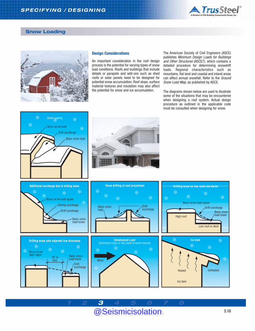
Design Considerations
An important consideration in the roof designprocess is the potential for varying types of snowload conditions. Roofs and buildings that includedetails or parapets and add-ons such as shedroofs or solar panels need to be designed forpotential snow accumulation. Roof slope, surfacematerial textures and insulation may also affectthe potential for snow and ice accumulation.
The American Society of Civil Engineers (ASCE)publishes Minimum Design Loads for Buildingsand Other Structures (ASCE7), which contains adetailed procedure for determining snowdriftloads. Regional characteristics such asmountains, flat land and coastal and inland areascan affect annual snowfall. Refer to the GroundSnow Load Map, as published by ASCE.
The diagrams shown below are used to illustratesome of the situations that may be encounteredwhen designing a roof system. Actual designprocedure as outlined in the applicable codemust be consulted when designing for snow.
Snow Loading
@Seismicisolation@Seismicisolation

1 2 3 4 5 6 7 83.11
SPECIFY ING / DESIGNING
Seismic Loading
Seismic Events
Over sixty percent of the land area of the USA isconsidered seismically active. Certain regions ofthe country are more prone to heavy seismicactivity than other areas, examples beingCalifornia, Alaska and Hawaii. Structures in theseregions are required to be designed for specificlateral loads imposed through seismic activity.
In a seismic event, slippage in the earth's crustreleases energy that is transmitted along thesurface of the earth as a series of waves, similarto the way that waves travel across water whenthe surface is disturbed. These waves canproduce an up-and-down motion, a sidewaysmotion, or both.
The type and severity of the motion depends onthe amount of initial energy released, thedistance from the epicenter, type of ground faultand soil characteristics. The back-and-forthmovement can cause brief accelerations of 1g orhigher in strong earthquakes. This ground
vibration changes its magnitude throughout theduration of a seismic event. The vibrationsusually taper off, or dampen, in a few seconds,although the waves can continue for severalminutes. Aftershocks are earthquakes of lessermagnitude than the main earthquake. They mayoccur for hours or days after the mainearthquake and originate near the initialepicenter.
Seismic Design Categories
The International Building Code assigns aSeismic Design Category to each location in theUSA based on earthquake probability, occupancy,and soil characteristics. Categories A and B areassigned to locations that do not require anyseismic design. Structures built in Category Clocations require some special detailing, but oneand two family dwellings are exempt from theseismic provisions. Categories D1, D2, and Erequire successively more load resistance andattention to prescriptive details.
Map shown for illustration purposes only. See the IBC or ASCE7 for actual seismic loading maps and data.
@Seismicisolation@Seismicisolation
1 2 3 4 5 6 7 83.12
SPECIFY ING / DESIGNING
Seismic Loading
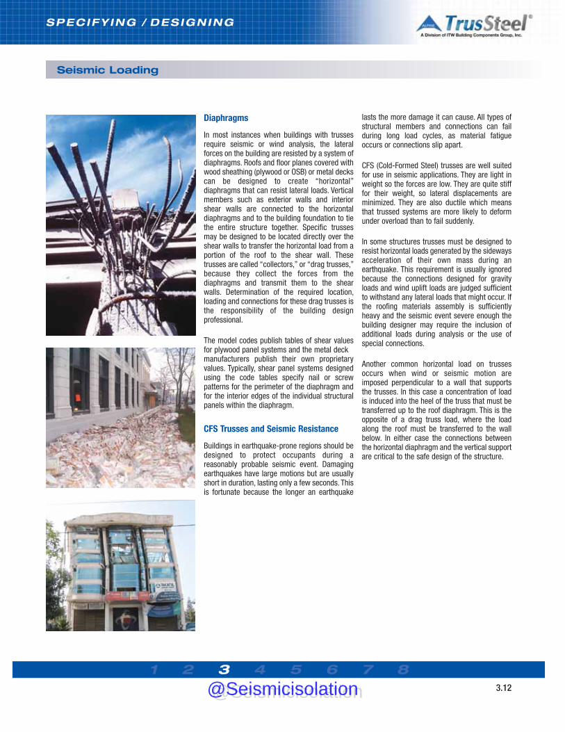
Diaphragms
In most instances when buildings with trussesrequire seismic or wind analysis, the lateralforces on the building are resisted by a system ofdiaphragms. Roofs and floor planes covered withwood sheathing (plywood or OSB) or metal deckscan be designed to create “horizontal”diaphragms that can resist lateral loads. Verticalmembers such as exterior walls and interiorshear walls are connected to the horizontaldiaphragms and to the building foundation to tiethe entire structure together. Specific trussesmay be designed to be located directly over theshear walls to transfer the horizontal load from aportion of the roof to the shear wall. Thesetrusses are called “collectors,” or “drag trusses,”because they collect the forces from thediaphragms and transmit them to the shearwalls. Determination of the required location,loading and connections for these drag trusses isthe responsibility of the building designprofessional.
The model codes publish tables of shear valuesfor plywood panel systems and the metal deckmanufacturers publish their own proprietaryvalues. Typically, shear panel systems designedusing the code tables specify nail or screwpatterns for the perimeter of the diaphragm andfor the interior edges of the individual structuralpanels within the diaphragm.
CFS Trusses and Seismic Resistance
Buildings in earthquake-prone regions should bedesigned to protect occupants during areasonably probable seismic event. Damagingearthquakes have large motions but are usuallyshort in duration, lasting only a few seconds. Thisis fortunate because the longer an earthquake
lasts the more damage it can cause. All types ofstructural members and connections can failduring long load cycles, as material fatigueoccurs or connections slip apart.
CFS (Cold-Formed Steel) trusses are well suitedfor use in seismic applications. They are light inweight so the forces are low. They are quite stifffor their weight, so lateral displacements areminimized. They are also ductile which meansthat trussed systems are more likely to deformunder overload than to fail suddenly.
In some structures trusses must be designed toresist horizontal loads generated by the sidewaysacceleration of their own mass during anearthquake. This requirement is usually ignoredbecause the connections designed for gravityloads and wind uplift loads are judged sufficientto withstand any lateral loads that might occur. Ifthe roofing materials assembly is sufficientlyheavy and the seismic event severe enough thebuilding designer may require the inclusion ofadditional loads during analysis or the use ofspecial connections.
Another common horizontal load on trussesoccurs when wind or seismic motion areimposed perpendicular to a wall that supportsthe trusses. In this case a concentration of loadis induced into the heel of the truss that must betransferred up to the roof diaphragm. This is theopposite of a drag truss load, where the loadalong the roof must be transferred to the wallbelow. In either case the connections betweenthe horizontal diaphragm and the vertical supportare critical to the safe design of the structure.
@Seismicisolation@Seismicisolation

1 2 3 4 5 6 7 83.13
SPECIFY ING / DESIGNING
Sound Control
The Mass Law
The amount of sound, or vibration, which istransmitted through floors, walls and ceilings isgoverned by the Mass Law, a theoretical rule thatrelates the mass per unit area to the control ofairborne sound. The Mass Law equationestimates that each time the frequency ofmeasurement or the mass per unit area of asingle layer is doubled, the sound transmissionloss (STL) is increased by about 6 decibels (dB).A 6 dB reduction in sound provides roughly a25% reduction of the original sound level,contingent upon other factors such astemperature and the frequency (Hz) of the sound.In construction terms, a 4 inch thick concretefloor has a sound transmission loss (STL) of 42dB at 250 Hz. Doubling the floor thickness to 8inches only increases the STL to 48 dB. Thisdoubling in thickness (and mass) provides onlythe 25% reduction in transmission lossdescribed above. This is not an acceptablesolution in today’s construction market.
Sound Control
The subject of sound transmission is situation, orconstruction project, specific. The source of thesound or noise may be airborne, or structure-borne, or a combination of both. Typically theelimination of airborne noise requires a reductionin the energy level of the sound waves, which arecreated by fluctuations in atmospheric pressurereaching the eardrum. Structure-borne noise iscreated by unwanted vibrations. The designershould select, from the outset, the system andproducts that will deliver the appropriate results.It is normally far more economical to integratethe solution into the initial design than to attemptto create an “add-on” solution during theconstruction phase.
There are a number of companies specializing inthe engineering of noise control systems.Because increasing mass is no longer thesolution of choice, these companies designsystems and products that create an interruptionin the noise path or create a containment barrier(at the source) to prevent the noise from reachingthe receiver. These companies use four basictools to combat noise transmission: absorption,barriers, damping and vibration isolation. Anumber of products, from decking and fabricbarriers to mechanical devices, are used toaddress specific transmission loss needs.
Resources
In general, many sound control design methods,products and applications that work with otherframing systems can work with CFS framing.Some of these products have been tested in CFSapplications and the product manufacturers havepublished data on these applications. Thebuilding designer who is striving for a particularsound control solution should carefully examinethe manufacturer’s published data as well asdata published by independent researchers.
Here is a small sampling from the wide range ofvaluable informational sources on sound control:
SSteel FFraming AAlliance (SFA)www.steelframingalliance.comResidential Steel Framing – Builder’s Guideto Fire and Acoustical Details, prepared forThe U.S. Department of Housing and UrbanDevelopment (HUD) and the Steel FramingAlliance by the National Association ofHome Builders (NAHB) Research Center,Inc (2004).
North AAmerican IInsulation MManufacturersAssociation (NAIMA)www.naima.org
Unwanted Sound
The transmission of unwanted sound,classified as noise, is one of the mostcommon complaints made by theoccupants of modern buildings. Thisproblem has grown in recent years asmaterial suppliers have developedproducts and construction methods toreduce the weight of building components.The goal has been to conserve materialand reduce both component cost andconstruction time. Unfortunately, the goalsof lighter weight building materials and thecontainment of noise often come into directconflict.
Noise Is Measured in Decibels (dB)
Whispers: about 20 dB Normal conversations: about 60 dB City traffic: about 80 dB Lawn mower/leaf blower: about 103 dB
Repeated exposure to sounds over 85 decibels is considered dangerous to hearing, and thelouder the noise, the less time it takes to damage hearing.
Methods of Sound Propagation
reflection absorption transmission
@Seismicisolation@Seismicisolation

1 2 3 4 5 6 7 83.14
SPECIFY ING / DESIGNING
Sustainability & LEED
Checklist (Materials and Resources section)allow the award of one point each for overallbuilding materials totals which exceed 5% (onepoint) and 10% (one point) recycled content(based on post-consumer + 1/2 post-industrialcontent). Since local TrusSteel AuthorizedFabricators build TrusSteel trusses, attributiontoward further LEED points may be obtainedwhen TrusSteel trusses are obtained from anAuthorized Fabricator that is considered local tothe project. Project checklists of the availableLEED points are available from the USGBC.
Recycled Content
TrusSteel trusses are made with 100% U.S.Prime steel. This steel is not only 100%recyclable, it is composed of steel that is nearlyall recycled. According to the Steel RecyclingInstitute, “steel used in structural steel buildingproducts, whether produced via the EAF (electricarc furnace) method or the BOF (blast oxygenfurnace) method can be used in the LEEDcalculations to exceed both 5% and 10% goals.”Further information on the LEED calculation maybe obtained from the USGBC and from the SteelRecycling Institute publication, Steel Takes LEEDwith Recycled Content.
The U. S. Green Building Council
The U. S. Green Building Council (USGBC) definesitself as “the nation’s foremost coalition ofleaders from across the building industryworking to promote buildings that areenvironmentally responsible, profitable andhealthy places to live and work.” Council-sponsored consensus committees havedeveloped the Leadership in Energy andEnvironmental Design (LEED) Green BuildingRating System in order to accelerate thedevelopment and implementation of greenbuilding practices. TrusSteel is proud to be amember and supporter of the U.S. Green BuildingCouncil.
LEED Standards
Currently, LEED-NC (New Construction) is a goal-oriented standard whereby point-based goals areset for specific areas of building design, withpoint awards based upon green-oriented criteriasuch as reduced site disturbance, increasedenergy performance, resource reuse, use ofmaterials local to the site and the specificrecycled content of building materials. Sections4.1 and 4.2 (Recycled Content) of the LEED-NC
Information Resources
Here are Web sites where you can learn more about the USGBC,calculating LEED percentages and steel recycling:
U.S. Green Building Council (creators of the LEED standards)www.usgbc.org
Steel Recycling Institutewww.recycle-steel.org
American Institute of Steel Construction (AISC) www.aisc.org
@Seismicisolation@Seismicisolation

1 2 3 4 5 6 7 83.15
SPECIFY ING / DESIGNING
Fire Resistance & UL
TrusSteel and UL
Building codes often have requirements thatbuilding elements perform for a specific period oftime when subjected to the elevatedtemperatures associated with a fire event, basedupon the defined type of building/occupancy. Oneof these requirements is that the buildingelement must withstand a fire event whilesupporting a specific load. One method ofdocumenting this performance is by testing atUnderwriters Laboratories, Inc. (UL). UL has theability to perform fire tests on building elementsand assemblies according to standardspublished by the American Society of Testing andMaterials (ASTM). Building elements andassemblies that pass this testing qualify asListed UL assemblies.
Building assemblies containing TrusSteel trusseshave been tested at UL, and these assemblieshave been Listed as having 1 hour, 1-1/2 hourand 2 hour fire resistive properties as describedand when utilized as described in the UL reportslisted in this Guide. TrusSteel has earned the ULClassification Mark as to its fire-resistiveproperties. This mark appears on TrusSteelmembers for easy identification.
Insurance rating bureaus and many Federal,
state, county and municipal authorities andinspectors recognize UL listings. The buildingdesigner is responsible for determining thesuitability of use for UL Listed assemblies inspecific building designs.
Online Updates
Underwriters Laboratories (UL) Listed FireResistive Designs with TrusSteel trusses haveproven to be key documents in gaining theconfidence and specifications of architects,engineers and end users. TrusSteel Listed FireRated Assemblies have also proven to be livingdocuments, undergoing frequent updates asTrusSteel, along with our partner companies inthese listings, continues to expand the Listings toinclude different materials and materialconfigurations. For this reason, we do not providea printed copy of these Listings but ratherencourage designers to visit the UL Web site andview or download the most current Listings. Tofind these Listings, point your browser tohttp://www.ul.com and search on the DesignNumbers listed in this Guide, or perform akeyword search for “TrusSteel” under theCertifications section of the website.
UL Listings TrusSteel products qualify for hourly ratings as shown below.Assemblies
TrusSteel components bear the UL RecognizedComponent mark.
@Seismicisolation@Seismicisolation

1 2 3 4 5 6 7 83.16
SPECIFY ING / DESIGNING
Trusses as Building Components
Efficient Components
Trusses are versatile and efficient framingcomponents. They are available in an almostinfinite combination of profiles, depths, andinternal web patterns, depending upon therequired building geometry and loads. The greatefficiency of trusses comes as the result of thecustom-design of almost every truss for itsparticular location and application.
Truss Profiles
Truss profiles are usually the result of the need tocreate specific roof planes and perimeterconditions. Truss depths are usually driven byroof planes and heel heights, but are also drivenby the need to create strength.
Truss Web Patterns
Truss web patterns are generated by the trussdesigner to create the most efficient truss. Webpatterns are often tailored to allow more efficienttruss bracing. Patterns can also be tailored tocreate clear paths (runs or chases) through theweb pattern to allow the passage of ductwork.The creation of these runs can speed theinstallation of mechanical systems.
Available Combinations
The trusses in these charts represent a fractionof the possible combinations of truss span, load,profile and depth. If you have a specific trussconfiguration and you need load/spaninformation, please contact your local AuthorizedTrusSteel Fabricator. You can find a list of theseFabricators on www.TrusSteel.com.
Fink
Howe
Double Fink
Double Howe
Double Fink Scissor
Howe Scissor
Room-in-Attic
Hip Girder
Flat Truss (Warren pattern)
Sloping Top Chord (Howe pattern)
Scissor mono
Mono
@Seismicisolation@Seismicisolation

Note: Truss bracing not shown for clarity.
1 2 3 4 5 6 7 83.17
SPECIFY ING / DESIGNING
Roof Truss Systems - Framing Styles
Introduction
Framing with trusses gives the building designer the versatility to accomplish a multitude ofinterior and exterior building geometries while allowing the inside of the building to be free ofany supports. Within any roof style there are many truss framing methods or systems. Thesesystems can vary based on framing material (steel or wood), the experience of the designer, andeven vary from region to region. However trusses are designed and regardless of the roof style,the challenge is to create a truss system that is efficient both to fabricate and to install. A few ofthe more common framing systems for steel trusses are described below. Please note that thenames given to specific trusses, truss conditions and framing systems can vary from region toregion. Ceiling lines may be flat or sloped. Sloped ceilings have some limitations, so pleaseconsult the truss designer.
Hip Systems
A hip roof framing system allows a roof area tohave a sloping roof plane rising from every wallsegment. This system uses smaller trusses (jacktrusses) that are placed at 90 degrees to thefront wall (see illustration). A truss (hip jack) runsdirectly underneath the hip ridge line and spansat an angle different from the other trusses. Hipjack trusses are supported by a larger truss(sometimes called the #1 hip truss) that spans
the width of the building and is located a shortdistance (setback distance) from the front wall.For best efficiency of the stepdown hip system, agood rule of thumb is to keep the setbackdistance to less than 10 feet. A hip system offersthe benefits of clear span with an eave or fascialine maintained at the same elevation around thebuilding. The end slope may be equal to ordifferent from the side slope.
Typical Stepdown Hip System
@Seismicisolation@Seismicisolation

1 2 3 4 5 6 7 83.18
SPECIFY ING / DESIGNING
Roof Truss Systems - Framing Styles
Gable and Valley Systems
Gable System
A gabled roof system allows a framed area tohave a vertical plane coming off an end wall.This framing system gives the appearance thatthe vertical plane of the end wall extends up tothe roof plane. The trusses in this system spanthe width of the roof area and can be of the sameprofile throughout the length of the buildingprovided other interior or exterior geometrychanges do not occur. The first truss is locatedon the end wall and is called the gable end truss.The gable end truss, unlike the other trusses in
this system, is typically supported continuouslyby the end wall for vertical loads, and resists thehorizontal wind load and transfers that load tothe building diaphragm. Because of its uniquerole, the gable end truss may have a differentweb pattern and may require different types of
bracing than the common trusses. A gable endtruss will typically have vertical webs spaced at16” or (no more than) 24” on center, to resistlateral wind loads and to accommodate theattachment of sheathing. Gable end trussvertical webs, when sheathed, will act like wallstuds.
Valley System
Valley trusses are generally supported by theclear-span trusses below to form new,intersecting ridge lines. Valley trusses can beattached directly to the top chord of thesupporting trusses below or directly to the roofdecking (see photo).
Note: Truss bracing not shown for clarity.
Typical Gable & Valley System
@Seismicisolation@Seismicisolation

1 2 3 4 5 6 7 83.19
SPECIFY ING / DESIGNING
Roof Truss Systems -Piggybacks
Cap truss installed on top of base truss. Notecontinuous bracing on top chord of base trussand connection clip.
Applications
There are instances when a roof trussapplication, due to a combination of roof pitchand truss span, will require trusses that wouldbe too tall to build, deliver or handleeconomically. In such instances, two or moretrusses can be built and delivered which will,when installed together, do the work of eachsingle, oversized truss. Of these two trusses,the bottom component is called the base trussand the truss that rides on top is called thepiggyback or cap truss (see illustration). As arule of thumb, individual trusses that would beover ten to twelve feet tall would probably becandidates for a piggyback system.
Installation Sequence
During installation, piggyback system basetrusses are installed first and proper bracing isinstalled for the base truss set. Base trussesmust be installed to resist the uplift forces of theentire piggyback system. Bracing of the topchords of the base trusses is essential and isoften accomplished using roof decking/sheathing or continuous purlins. This bracingmust be completed prior to the installation of thecap trusses.
Cap trusses are then attached to the basetrusses in a proper manner to resist lateral anduplift forces. Connections of the cap trusses tothe base truss set are sometimes made usingproprietary connectors (see Section 5). Decks orpurlins for the roof membrane system may thenbe applied to the cap trusses.
During design and estimation, designers andcontractors will want to account for theseadditional materials as well as for the fastenersrequired to install decking, purlins, clips, etc.Additional labor may be required to install thesematerials and the piggyback trusses.
Piggyback System
@Seismicisolation@Seismicisolation

1 2 3 4 5 6 7 83.20
SPECIFY ING / DESIGNING
Roof Truss Systems -Piggybacks
Standard Details
Several TrusSteel Standard Details are availableto assist the designer in understanding anddetailing piggyback systems. These Details maybe downloaded from www.TrusSteel.com or fromthe electronic version of this manual. DetailTS003A is shown below as an example.
Rafting
Piggyback truss systems, when properlydesigned and braced, can be candidates for theinstallation technique known as rafting. SeeSection 7 of this manual for more information onrafting.
Required Information
The Truss Designer will need the followinginformation about the roof system beforedesigning the piggyback system: • all roof conditions that could require trusses
whose height will exceed the maximum allowable truss height (candidates for piggybacking)
• type of continuous framing / support to be used on top of the base trusses (roof decking/sheathing or continuous purlins)
• type of clip to be used to attach the piggybacktrusses to the base trusses or to the roof decking/sheathing.
@Seismicisolation@Seismicisolation

1 2 3 4 5 6 7 83.21
SPECIFY ING / DESIGNING
Roof Truss Systems - Overhangs & Cantilevers
Truss Heels
The end of a truss is also known as the heel of atruss. All trusses have two heels, one at eachend. The heel height of a truss is the distancefrom the top edge of the top chord to the bottomedge of the bottom chord at the heel (seeillustration).
Minimum Heel Heights for TrusSteel Trusses
Due to the internal configuration of heels for non-parallel chord trusses, these trusses have aminimum heel height (see table below). TrusSteeltrusses can be fabricated with lower-than-minimum heel heights. Using greater thanminimum heel heights can help create moreefficient trusses.
Minimum Heel Height Table
Heel height in inches Roof Chord Size Slope TSC2.75 TSC4.00________________________
2 5-9/16 8-1/16 3 5-5/8 8-1/8 4 5-11/16 8-1/45 5-3/4 8-3/86 5-7/8 8-1/27 5-15/16 8-11/168 6-1/16 8-13/169 6-3/16 9
10 6-3/8 9-1/411 6-1/2 9-7/1612 6-11/16 9-11/16
Overhangs and Cantilevers
Most designers who place pitched roofs onbuildings design those roofs with perimeteroverhangs. Overhangs can be accomplished withtrusses by extending the top chords of trusses(overhangs), or by cantilevering the ends of thetrusses out past the perimeter bearing support(see illustration). Cantilevered trusses aregenerally more efficient trusses than those withoverhangs, and can simplify the installation offascia and soffit materials. A cantilevered trusscan also have a top chord overhang.
Standard Heel
Standard Heel with Overhang
Standard Heel with Boxed Return
Cantilevered Heel
Heel
hei
ght
Heel
hei
ght
Cantilever distance
Common Heel Conditions
@Seismicisolation@Seismicisolation

1 2 3 4 5 6 7 83.22
SPECIFY ING / DESIGNING
Sample Tables
Each TrusSteel truss is engineeredindividually to meet the load, span, spacingand geometry requirements of a specificproject. There are literally millions of possiblecombinations. These tables show a smallsample of those combinations, based on themost common design criteria and simplecommon trusses.
Contact your local TrusSteel AuthorizedFabricator to obtain truss designs for yourspecific project needs.
General Notes:1) Spans shown in charts are in feet.2) Loads shown above are outlined as Top Chord Live Load (TCLL), Top Chord Dead Load (TCDL) and
Bottom Chord Dead Load (BCDL).3) Top chords are assumed to be restrained laterally by structural sheathing.4) Bottom chords are assumed to be restrained laterally at intervals not to exceed 24 inches.5) Deflection limits: Live Load - L/360, Total Load - L/2406) Trusses designed in accordance with ASCE7-02 wind and these considerations:
• Wind speed shown in charts• Exposure C• Building category II• Truss bearing elevation is 8’0”• No topographic effect from escarpment or hill taken into consideration.• Enclosed building
7) Certain truss span and pitch combinations may require a truss to be “piggybacked” due to shipping restrictions.
8) Trusses in excess of 80’-0” are possible - refer to TrusSteel Technical Bulletin TB991102.For additional information regarding large span trusses, contact a TrusSteel Authorized Fabricator.
9) Scissor trusses described in this table are designed with a bottom chord pitch equal to half of the top chord pitch (i.e. a 6/12 top chord pitch scissor truss will have a 3/12 bottom chord pitch). Many other top/bottom chord pitch variations are possible.
10) Designs may include multiple material thicknesses (mils or gauges) for top and bottom chords as determined by the designer using steelVIEW engineering software. Maximum steel thicknesses are43 mils (18 GA) for the TSC2.75 chord and 54 mils (16 GA) for the TSC4.00 chord in table above.
11) Truss web patterns will be determined by the designer using steelVIEW engineering software.
Roof Truss Systems - Sample Spans
@Seismicisolation@Seismicisolation

1 2 3 4 5 6 7 83.23
SPECIFY ING / DESIGNING
Floor Truss Systems
Configurations
TrusSteel open web floor trusses are fabricatedwith the same materials used in TrusSteel rooftrusses. The obvious advantage of an open webfloor truss over conventional joist framing is theease of equipment installation for themechanical, electrical and plumbing trades.TrusSteel open web floor trusses may allowgreater clear-span capabilities and facilitate avariety of bearing options. Truss depth and on-center spacing will be determined by specificloading and span requirements.
Serviceability
Serviceability parameters are specified by thebuilding designer and then trusses are designedaccordingly. In order to ensure a rigid floor
system, TrusSteel recommends a minimum liveload deflection criteria of L/360; more rigidrequirements may be specified. All TrusSteelfloor trusses are recommended to be fabricatedwith a minimum of two patented Double-Shearfasteners at all web-to-chord connections toensure rotational stability of the web andincrease product stiffness.
Girders
Multiple ply girders at stairwells and otheropenings allow TrusSteel to provide the entirefloor framing package. These girders aredesigned to carry concentrated loads at specificlocations and must be installed according toapproved shop drawings. Standard connectiondetails are provided with the truss package toensure proper installation and load transfer.
Truss bears on support member at thetruss heel.
Continuous strongback bracing providesstability and reduces dynamic response oftruss system.
Duct work runs through optional integralchase opening created in truss webs.
Truss girder (two-ply girder shown)supports other CFS trusses.
Typical Floor Truss System
TrusSteel floor trusses provide the convenienceof open web members.
Note: Truss bracing not shown for clarity.
@Seismicisolation@Seismicisolation

1 2 3 4 5 6 7 83.24
SPECIFY ING / DESIGNING
Floor Truss Systems
Bearing Options
Multiple bearing options offer the buildingdesigner flexibility in assigning bearingelevations and coordinating with other structuralsystems. While the majority of floor trusses beardirectly on the truss bottom chord, top chordbearing can be an option to reduce the overallbuilding height. Mid-height bearing at bothexterior and interior beams can eliminate theneed for boxed framing and deliver a flat ceilingthroughout.
Dynamic Response
The dynamic response of a TrusSteel open webtruss floor system is greatly reduced by requiringthe installation of strongback bridging (generallya 5-1/2” cee stud attached to vertical webs) at amaximum of 10’-0” on-center. This loaddistribution mechanism converts individual trusscomponents into a rigid floor system. Strongbackbridging may be attached to the truss webmembers with standard single shear screws.
Deck Connections
Whether using a plywood sub-floor in residentialframing or metal deck with concrete incommercial construction, deck attachment canbe achieved with screws or proprietary ringshank pneumatically installed nails. TrusSteelrecommends a minimum steel thickness of 33mils (20 GA) for the truss top chord in all floortruss applications. The application of acousticaland thermal gasket materials to the top chordcan reduce sound and thermal transmission.
Strongback splice - overlap one truss as shown.
Standard strongback installed on vertical webs.
@Seismicisolation@Seismicisolation

1 2 3 4 5 6 7 83.25
SPECIFY ING / DESIGNING
Floor Truss Systems - Sample Span Tables
Floor Truss Span Tables
The abbreviated span tables shown representonly a small sample of the possible floor trussload/span/depth combinations. Contact yourlocal TrusSteel Authorized Fabricator to discussyour specific truss needs.
Allowable Duct Size Table
This chart shows a sampling of available ductopenings in web patterns that are available insome of the most common floor trussconfigurations. Sizes of allowable openings maybe affected by specific floor loading conditions.Contact your TrusSteel Authorized Fabricator todiscuss your specific truss needs.
Allowable Duct Sizes
@Seismicisolation@Seismicisolation

1 2 3 4 5 6 7 83.26
SPECIFY ING / DESIGNING
Guide Specification - Section 05 44 00
Notes to Specifier This section is based on products engineeredby ITW Building Components Group, Inc.,which is located at:
1950 Marley Drive Haines City, FL 33844 Tel: (888) 565-9181 www.TrusSteel.com
Truss Fabricators A nationwide network of TrusSteel
Authorized Fabricators quote, build anddeliver the trusses (in the same businessmodel as wood trusses). For a list of TrusSteel Authorized Fabricators, visitwww.TrusSteel.com.
ProductThe TrusSteel Division of ITW Builing
Components Group, the Truss ComponentManufacturer, has a unique, proprietary Cold-Formed Steel (CFS) chord section that, whencombined with a dedicated truss design andengineering software package, allows localfabricators to supply high quality, reliabledesigns with great speed and flexibility.
The CFS trusses are light in weight andeasy to deliver, handle, and install, whileproviding resistance to insect damage,deterioration, shrinkage, fire damage, and nailpopping that can affect wood trussassemblies.
The TrusSteel chord shape is a symmetrical"U" shape that avoids the eccentric loadingconditions that often occur with non-symmetrical chord shapes like common steel"C" shapes, sometimes referred to as "back-to-back" shapes.
Electronic SpecificationsAn electronic, text-only version of this
specification is available on the CD version ofthe manual or from www.TrusSteel.com. Thisspecification is provided in text-only formatwith a minimum of formatting for use in allword processors.
Additional Notes in Specifications This specification contains additional
explanatory notes and instructions. These areindicated with a ## symbol and are printed ingray text within the body of the specification.
SECTION 05 44 00 (Section 05425 in MasterFormat 1995)
PRE-ENGINEERED PRE-FABRICATEDCOLD-FORMED STEEL TRUSSES
PART 1 - GENERAL
1.1 - SECTION INCLUDES
A. Pre-engineered cold-formed steel trusses.
B . Cold-formed steel framing accessories.
1.2 - RELATED SECTIONS ## Delete any sections below not relevant to thisproject; add others as required. A. Section 05 30 00 -Metal Decking (Section05300 in MasterFormat 1995).
B. Section 05 40 00 - Cold-Formed MetalFraming (Section 05400 in MasterFormat 1995).
1.3 - DEFINITIONS A. Truss Component Manufacturer: Themanufacturer of the components that will beassembled into trusses by the Truss Fabricator.See MANUFACTURERS for acceptable TrussComponent Manufacturer. ## Delete the last sentence in the followingparagraph if acceptable Truss Fabricators are notlisted in PART 2.
B. Truss Manufacturer: The individual ororganization that assembles the TrussComponent Manufacturer’s components intocompleted trusses. See MANUFACTURERS foracceptable Truss Fabricators.
C. Truss Design Drawing: Written, graphic andpictorial depiction of an individual truss.
D. Truss Design Engineer: Person who islicensed to practice engineering as defined bythe legal requirements of the jurisdiction inwhich the building is to be constructed and whosupervises the preparation of the truss designdrawings. In this case, the Truss DesignEngineer is the Truss Component Manufacturer.
E. Truss Placement Diagram: Illustrationidentifying the assumed location of each truss.
1.4 - REFERENCES ## Delete references from the list below that arenot actually required by the text of the edited
section.
A. ANSI/AISI/COS/S100-07/S2-10: NorthAmerican Specification for the Design of Cold-Formed Steel Structural Members; American Ironand Steel Institute; 2007 edition including the2010 Supplement.
B. ANSI/AISI/COFS/S200-07: North AmericanStandard for Cold-Formed Steel Framing -General Provisions; 2007.
C. ANSI/AISI/COFS/S214-07/S2-08: NorthAmerican Standard for Cold-Formed SteelFraming - Truss Design; 2007 edition includingthe 2008 Supplement.
D. AISI/COFS - Practice Guide - CF06-1: Code ofStandard Practice for Cold-Formed SteelStructural Framing; 2006.
E. ASTM A 370-09 - Standard Test Methods andDefinitions for Mechanical Testing of SteelProducts; 2009.
F. ASTM A 500-03a - Standard Specification forCold-Formed Welded and Seamless Carbon SteelStructural Tubing in Rounds and Shapes; 2003.
G. ASTM A 653-09 - Standard Specification forSteel Sheet, Zinc-Coated (Galvanized) or Zinc-Iron Alloy-Coated (Galvannealed) by the Hot-DipProcess; 2009.
H. CFSBCSI - Cold-Formed Steel BuildingComponents Safety Information; Cold-FormedSteel Council (CFSC); 2008 edition with CFSB3summary sheet insert.
I. CFSEI Technical Note 551d - Design Guide forConstruction Bracing of Cold-Formed SteelTrusses; Cold-Formed Steel Engineers Institute;February 1997.
J. CFSEI Technical Note 551e - Design Guide forPermanent Bracing of Cold-Formed SteelTrusses; Cold-Formed Steel Engineers Institute;February 1998.
1.5 - SUBMITTALS A. Submit under provisions of Section 01 30 00(Section 01300 IN MF95).
B. Product Data: Truss ComponentManufacturer's descriptive literature for eachitem of cold-formed metal framing and eachaccessory specified in this section.
@Seismicisolation@Seismicisolation
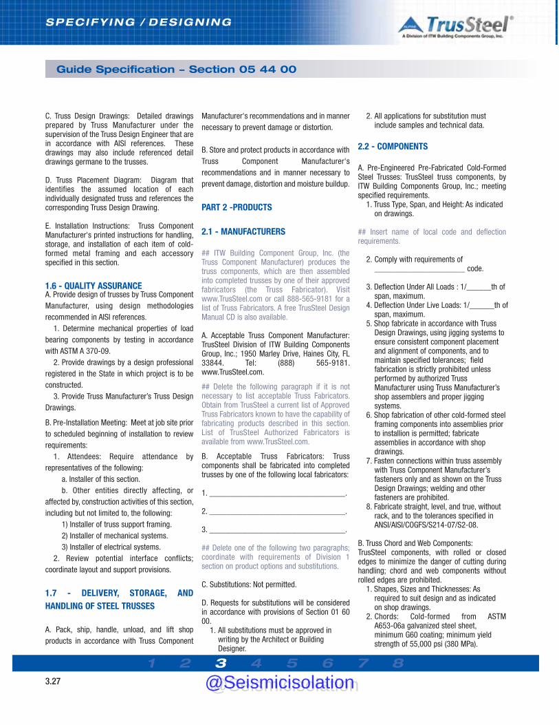
1 2 3 4 5 6 7 83.27
SPECIFY ING / DESIGNING
Guide Specification - Section 05 44 00
C. Truss Design Drawings: Detailed drawingsprepared by Truss Manufacturer under thesupervision of the Truss Design Engineer that arein accordance with AISI references. Thesedrawings may also include referenced detaildrawings germane to the trusses.
D. Truss Placement Diagram: Diagram thatidentifies the assumed location of eachindividually designated truss and references thecorresponding Truss Design Drawing.
E. Installation Instructions: Truss ComponentManufacturer's printed instructions for handling,storage, and installation of each item of cold-formed metal framing and each accessoryspecified in this section.
1.6 - QUALITY ASSURANCE A. Provide design of trusses by Truss ComponentManufacturer, using design methodologiesrecommended in AISI references.
1. Determine mechanical properties of loadbearing components by testing in accordancewith ASTM A 370-09.
2. Provide drawings by a design professionalregistered in the State in which project is to beconstructed.
3. Provide Truss Manufacturer’s Truss DesignDrawings.
B. Pre-Installation Meeting: Meet at job site priorto scheduled beginning of installation to reviewrequirements:
1. Attendees: Require attendance byrepresentatives of the following:
a. Installer of this section.b. Other entities directly affecting, or
affected by, construction activities of this section,including but not limited to, the following:
1) Installer of truss support framing.2) Installer of mechanical systems.3) Installer of electrical systems.
2. Review potential interface conflicts;coordinate layout and support provisions.
1.7 - DELIVERY, STORAGE, ANDHANDLING OF STEEL TRUSSES
A. Pack, ship, handle, unload, and lift shopproducts in accordance with Truss Component
Manufacturer's recommendations and in mannernecessary to prevent damage or distortion.
B. Store and protect products in accordance withTruss Component Manufacturer'srecommendations and in manner necessary toprevent damage, distortion and moisture buildup.
PART 2 -PRODUCTS
2.1 - MANUFACTURERS
## ITW Building Component Group, Inc. (theTruss Component Manufacturer) produces thetruss components, which are then assembledinto completed trusses by one of their approvedfabricators (the Truss Fabricator). Visitwww.TrusSteel.com or call 888-565-9181 for alist of Truss Fabricators. A free TrusSteel DesignManual CD is also available.
A. Acceptable Truss Component Manufacturer:TrusSteel Division of ITW Building ComponentsGroup, Inc.; 1950 Marley Drive, Haines City, FL33844. Tel: (888) 565-9181.www.TrusSteel.com.
## Delete the following paragraph if it is notnecessary to list acceptable Truss Fabricators.Obtain from TrusSteel a current list of ApprovedTruss Fabricators known to have the capability offabricating products described in this section.List of TrusSteel Authorized Fabricators isavailable from www.TrusSteel.com.
B. Acceptable Truss Fabricators: Trusscomponents shall be fabricated into completedtrusses by one of the following local fabricators:
1. _________________________________.
2. _________________________________.
3. _________________________________.
## Delete one of the following two paragraphs;coordinate with requirements of Division 1section on product options and substitutions.
C. Substitutions: Not permitted.
D. Requests for substitutions will be consideredin accordance with provisions of Section 01 6000.
1. All substitutions must be approved in writing by the Architect or Building Designer.
2. All applications for substitution must include samples and technical data.
2.2 - COMPONENTS
A. Pre-Engineered Pre-Fabricated Cold-FormedSteel Trusses: TrusSteel truss components, byITW Building Components Group, Inc.; meetingspecified requirements.
1. Truss Type, Span, and Height: As indicated on drawings.
## Insert name of local code and deflectionrequirements.
2. Comply with requirements of ______________________ code.
3. Deflection Under All Loads : 1/______th ofspan, maximum.
4. Deflection Under Live Loads: 1/______th ofspan, maximum.
5. Shop fabricate in accordance with Truss Design Drawings, using jigging systems toensure consistent component placement and alignment of components, and to maintain specified tolerances; field fabrication is strictly prohibited unless performed by authorized Truss Manufacturer using Truss Manufacturer’s shop assemblers and proper jigging systems.
6. Shop fabrication of other cold-formed steelframing components into assemblies prior to installion is permitted; fabricate assemblies in accordance with shop drawings.
7. Fasten connections within truss assembly with Truss Component Manufacturer’s fasteners only and as shown on the Truss Design Drawings; welding and other fasteners are prohibited.
8. Fabricate straight, level, and true, without rack, and to the tolerances specified in ANSI/AISI/COGFS/S214-07/S2-08.
B. Truss Chord and Web Components: TrusSteel components, with rolled or closededges to minimize the danger of cutting duringhandling; chord and web components withoutrolled edges are prohibited.
1. Shapes, Sizes and Thicknesses: As required to suit design and as indicated on shop drawings.
2. Chords: Cold-formed from ASTM A653-06a galvanized steel sheet, minimum G60 coating; minimum yield strength of 55,000 psi (380 MPa).
@Seismicisolation@Seismicisolation

1 2 3 4 5 6 7 83.28
SPECIFY ING / DESIGNING
Guide Specification - Section 05 44 00
## Some TrusSteel chord members aremanufactured from ASTM A653 steel of a highergrade with minimum yield strength of 55 ksi (380MPa) and minimum tensile strength of 65 ksi (448MPa)
a. Nominal 28 mil (22 GA) members:1) Minimum bare metal thickness:
0.0284 inch (0.72 mm).2) Maximum design thickness:
0.0299 inch (0.76 mm).b. Nominal 33 mil (20 GA) members:
1) Minimum bare metal thickness: 0.0329 inch (0.84 mm).
2) Maximum design thickness: 0.0346 inch (0.88 mm).
c. Nominal 43 mil (18 GA) members:1) Minimum bare metal thickness:
0.0428 inch (1.09 mm).2) Maximum design thickness:
0.0451 inch (1.15 mm).d. Nominal 54 mil (16 GA) members:
1) Minimum bare metal thickness: 0.0538 inch (1.37 mm).
2) Maximum design thickness: 0.0566 inch (1.44 mm).
e. Nominal 68 mil (14 GA) members:1) Minimum bare metal thickness:
0.0677 inch (1.72 mm).2) Maximum design thickness:
0.0713 inch (1.31 mm).f. Nominal 97 mil (12 GA) members:
1) Minimum bare metal thickness: 0.0966 inch (2.46 mm).
2) Maximum design thickness: 0.1017 inch (2.58 mm).
3. Tube Webs: Cold-formed ASTM A500steel structural tubing; minimum yieldstrength of 45 ksi (310 MPa); minimum tensilestrength of 55 ksi (380 MPa).
a. Nominal 33 mil (20 GA) members:1) Minimum bare metal thickness:
0.033 inch (0.84 mm).2) Maximum design thickness:
0.035 inch (0.89 mm).b. Nominal 47 mil (18 GA) members:
1) Minimum bare metal thickness:0.047 inch (1.19 mm).
2)Maximum design thickness: 0.049 inch (1.24 mm).
c. Nominal 63 mil (16 GA) members:1) Minimum bare metal thickness:
0.063 inch (1.6 mm).2) Maximum design thickness:
0.065 inch (1.65 mm).
4. Rolled formed Webs: Cold-formed fromASTM A 653/A 653M galvanized steel sheet,
minimum G90 coating; minimum yield strengthof 40 ksi (276 MPa) for 20 and 18 GAcomponents or 50 ksi (345 MPa) for 16 GAcomponents; minimum tensile strength of 55 ksi(379 MPa) for 20 and 18 GA components or 65ksi (448 MPa) for 16 GA components.
a. Nominal 33 mil (20 GA) members:1) Minimum bare metal thickness:
0.0329 inch (0.84 mm).2) Maximum design thickness:
0.0346 inch (0.88 mm).b. Nominal 43 mil (18 GA) members:
1) Minimum bare metal thickness: 0.0428 inch (1.09 mm).
2) Maximum design thickness: 0.0451 inch (1.15 mm).
c. Nominal 54 mil (16 GA) members:1) Minimum bare metal thickness:
0.0538 inch (1.37 mm).2) Maximum design thickness:
0.0566 inch (1.44 mm).C. Fasteners Used in Fabricating Trusses:Fasteners as recommended by Truss ComponentManufacturer, bearing stamp of TrussComponent Manufacturer for readyidentification.
PART 3 EXECUTION
3.1 EXAMINATION
A. Verify that bearing surfaces and substrates areready to receive steel trusses.
## The tolerances appropriate for truss bearingssurfaces are dependent on required tolerances ofsubsequent construction; coordinate with othersections and modify as required.
B. Verify that truss bearing surfaces are withinthe following tolerances:
1. Variation from Level or Specified Plane: Maximum 1/8 inch in 10 feet (6 mm in 3 m).
2. Variation from Specified Position: Maximum1/4 inch (6 mm).
C. Verify that rough-in utilities and chases thatwill penetrate plane of trusses are in correctlocations and do not interfere with truss, bracingor bridging placement.
D. Inspect conditions under which installation isto be performed and submit written notification ifsuch conditions are unacceptable to installer.
1. Notify Architect/Engineer-of-Record within 24 hours of inspection.
2. Beginning construction activities of this
section before unacceptable conditions have been corrected is prohibited.
3. Beginning construction activities of this section indicates installer’s acceptance of conditions.
3.2 - INSTALLATION
A. Install trusses in accordance with TrussComponent Manufacturer’s instructions andTruss Manufacturer’s Truss Design Drawings.Use correct fasteners as previously described.
B. Place components at spacings indicated onthe Truss Design Drawings.
C. Install all erection (temporary installation)bracing and permanent bracing and bridgingbefore application of any loads; followrecommendations of the CFSBCSI - Cold-FormedSteel Building Components Safety Information.
D. Install erection bracing -followrecommendations of CFSBCSI Cold-Formed SteelBuilding Components Safety Information.
1. Provide bracing that holds trusses straight and plumb and in safe condition until decking and permanent truss bracing has been fastened to form a structurally soundframing system.
2. All sub-contractors shall employ proper construction procedures to insure adequatedistribution of temporary construction loadsso that the carrying capacity of any single truss or group of trusses is not exceeded.
E. Install permanent bracing and bridging asshown in the Architect/Engineer-of-Record’sdrawings and notes and as shown in the TrussFabricator’s shop drawings.
F. Removal, cutting or alteration of any trusschord, web or bracing member in the field isprohibited unless approved in advance in writingby the Architect/Engineer-of-Record and theTruss Designer.
G. Repair or replace damaged chords, webs, andcompleted trusses as previously directed andapproved in writing by the Architect/BuildingDesigner and the Truss ComponentManufacturer.
3.3 FIELD QUALITY CONTROL ## This article is optional.
A. Owner will provide inspection service toinspect field connections; see Section 01 40 00.
@Seismicisolation@Seismicisolation

1 2 3 4 5 6 7 8
ENGINEERING / SHOP DRAWINGS
Engineering
4.01
Design Responsibilities
The Committee on Framing Standards (COFS) ofthe American Iron and Steel Institute has createdthe Standard for Cold-Formed Steel Framing -Truss Design (latest revision is AISI S214-07/S2-08) to provide technical information andspecifications on CFS truss construction. Specificdesign responsibilities are defined within theStandard in Section B. While these definitions arenot intended to replace any other allotments ofresponsibilities that may be agreed upon byinvolved parties, they do provide a provenframework for most projects. Theresponsibilities, as defined in the Standard, aregiven below:
The Building Designer
The Building Designer shall specify the followinginformation:
(a) design loads in accordance with Section Cof the Standard
(b) roof profile and geometry(c) bearing conditions(d) temperature and moisture environment for
the intended end use (e) any special requirements or considerations
to be taken into the truss design.
The Building Designer shall provide for thefollowing in the design and detailing of thebuilding:
(a) horizontal, vertical, or other truss deflectiondue to design loads
(b) truss movement due to temperature changes
(c) truss supports and anchorage accommodating horizontal, vertical or otherreactions or displacements
(d) permanent truss bracing to resist wind, seismic, and any other lateral forces actingperpendicular to the plane of the truss
(e) permanent lateral bracing as specified by the truss designer.
Truss Designer
The Truss Designer shall make available, uponrequest, comprehensive design calculationsincluding the following information:
(a) loads and load combinations considered(b) axial forces, moments, and shears
resulting from the applied loads and load combinations
(c) design assumptions.
Truss Design Drawings
The truss design drawings shall include, as aminimum, the following information:
(a) slope, depth, span, and spacing of the truss(b) bearing locations and minimum bearing
lengths(c) design loading(s)(d) nominal reaction forces and direction(e) location of all truss connections(f) gusset plate locations, sizes and material
specification (g) fastener type, size, quantities and
locations(h) shape and material specification for each
component (i) maximum nominal compressive force in all
truss members(j) locations of required permanent truss
member bracing(k) connection requirements for:
(1) truss-to-truss girder(2) truss ply-to-ply(3) field assembly of trusses
(l) calculated deflection ratio and/ or maximum deflection for live and total load.
Loading
The loads and load combinations to be used inthe design of cold-formed steel trusses shall bedetermined by the building designer asestablished by the local building code. In theabsence of such a code, the loads, andcombinations of loads shall be in accordancewith accepted engineering practice for thegeographical area under consideration asspecified by the appropriate sections of ASCE 7.
These and other reference materials areavailable from the American Iron and SteelInstitute. See Section 8 of this Manual for contactinformation.
@Seismicisolation@Seismicisolation
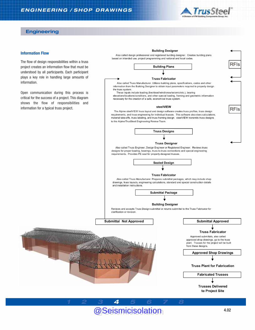
1 2 3 4 5 6 7 8
ENGINEERING / SHOP DRAWINGS
Engineering
4.02
Information Flow
The flow of design responsibilities within a trussproject creates an information flow that must beunderstood by all participants. Each participantplays a key role in handling large amounts ofinformation.
Open communication during this process iscritical for the success of a project. This diagramshows the flow of responsibilities andinformation for a typical truss project.
@Seismicisolation@Seismicisolation
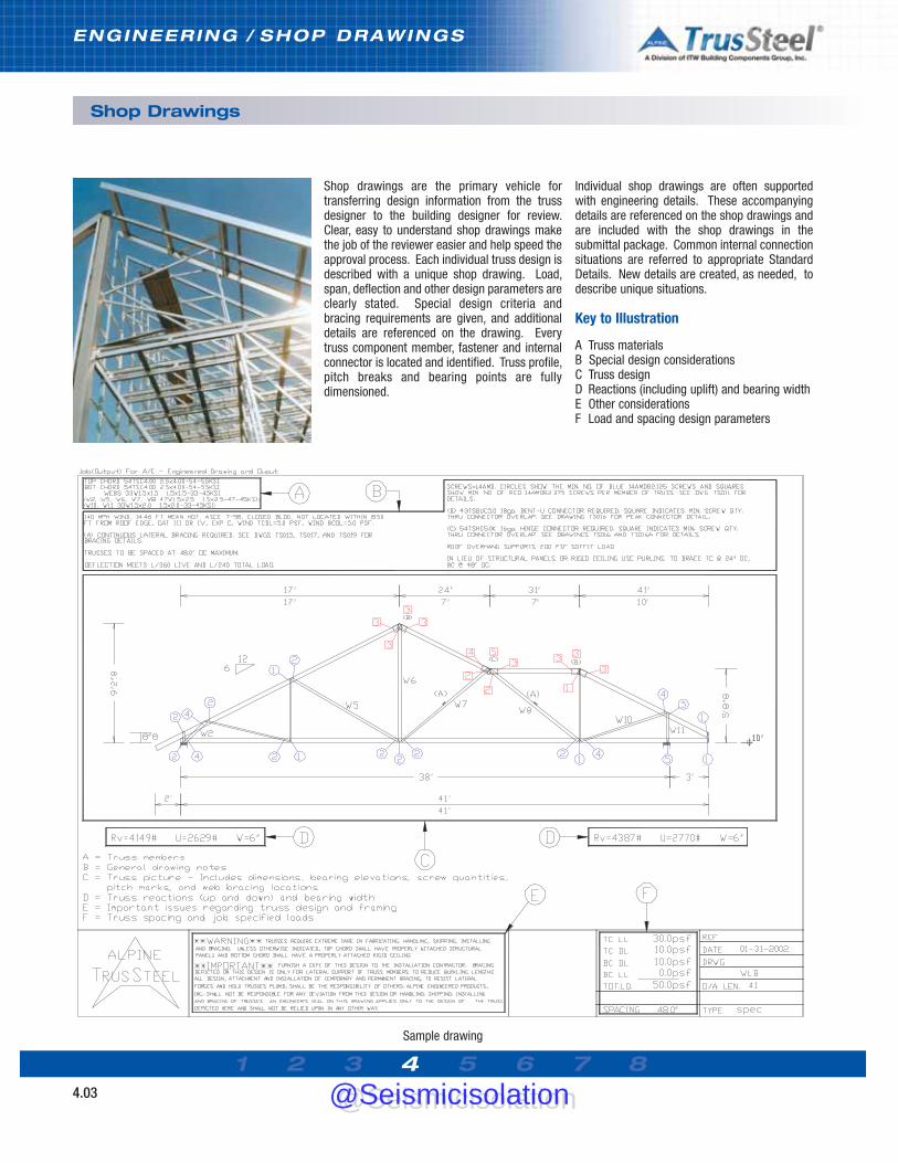
Sample drawing
1 2 3 4 5 6 7 8
ENGINEERING / SHOP DRAWINGS
Shop Drawings
4.03
Shop drawings are the primary vehicle fortransferring design information from the trussdesigner to the building designer for review.Clear, easy to understand shop drawings makethe job of the reviewer easier and help speed theapproval process. Each individual truss design isdescribed with a unique shop drawing. Load,span, deflection and other design parameters areclearly stated. Special design criteria andbracing requirements are given, and additionaldetails are referenced on the drawing. Everytruss component member, fastener and internalconnector is located and identified. Truss profile,pitch breaks and bearing points are fullydimensioned.
Individual shop drawings are often supportedwith engineering details. These accompanyingdetails are referenced on the shop drawings andare included with the shop drawings in thesubmittal package. Common internal connectionsituations are referred to appropriate StandardDetails. New details are created, as needed, todescribe unique situations.
Key to Illustration
A Truss materialsB Special design considerationsC Truss designD Reactions (including uplift) and bearing widthE Other considerationsF Load and spacing design parameters
@Seismicisolation@Seismicisolation


1 2 3 4 5 6 7 85.01
CONNECTIONS / DETAILS
Overview & Applications
Trusses are connected to each other, as well asto other building systems and bearings, throughthe use of proprietary connectors (sometimescalled “connectors”). These proprietaryconnectors, sold by Alpine, are manufactured toAlpine specifications and form an integral part ofthe complete TrusSteel system.
The following pages of this manual are anintroduction to these connectors and their use.This introduction is not intended to be acomprehensive technical guide for eachconnection type. For complete technical data oneach connection, please refer to the TrusSteelStandard Details.
All connectors attach to TrusSteel trusses withstandard self-drilling tapping screws.Connectors attach to different bearing materialsthrough the use of a variety of screws, pins,welds and embedded anchors.
Other ConnectionsThe following connections are not shown in thismanual - please refer to the Standard Details:• truss fabrication connections (chord to web,
chord to chord, etc.)• assembly of multi-ply trusses (whereby
several trusses are connected side-by-side tocreate one multi-ply truss)
• connection or suspension of mechanical loadsfrom trusses.
General Notes for All Connections• Connectors and fasteners specified are
designed to support the loads listed in the allowable tables on the TrusSteel Standard Details and in this manual.
• Install connectors and fasteners as specified on the TrusSteel Standard Details. Refer to theStandard Details for important information notshown in this manual.
• Allowable loads have not been increased for wind, seismic or other factors.
• Install all fasteners and connectors prior to loading the connection.
• Allowable loads are listed in imperial (LBS) and metric (kN) units.
• All steel thicknesses given are actual base metal thicknesses.
• Connectors are fabricated from G-90 or equal galvanized steel.
Notes for Truss-to-Truss Connections• Connections are designed to support vertical
loads only in an upward or downward direction.
Notes on Truss-to-Bearing Connections • Upward loads listed are MAXIMUM allowable
loads.• For lateral load capacities, see the Standard
Details.• If upward loads will be acting in combination
with lateral loads, please contact a TrusSteel engineer to determine the adequacy of the connection.
General Notes for FastenersThe fasteners specified in this publication, and onthe Standard Details, shall be used in strictaccordance with the Details. If an “or equal”statement appears within a Detail, the substitutedfastener shall be qualified by a professionalengineer prior to the installation of the substitute.The allowable load capacity of the substitutedfastener shall be confirmed through reliablepublished test data or calculations.
Notes on Self-Drilling Tapping Screws (SDS)• Allowable loads are determined per the AISI
North American Specification for the Design of Cold-Formed Steel Structural Members
• SDS shall comply with ASTM C1513 or an approved design or recognized design Standard
• #10 tapping screw is 0.19” (nom. dia.)• #12 tapping screw is 0.216” (nom. dia.)• #14 tapping screw is 0.25” (nom. dia.)• Screw spacing, end and edge distance shall
be 3 times the nominal diameter.• Screw point style to be determined, based
upon the recommended steel thickness for the given style.
• Screw length to be determined, so that when installed the screw shows three exposed threads (out the back of the connected parts) or as otherwise determined by a professional engineer.
• References- AISI/COFS/S200 North American Standard for
Cold-Formed Steel Framing - General Provisions
- Technical Note F102-11, Screw Fastener Selection for Cold-Formed Steel Frame Construction, CFSEI, November 2011
@Seismicisolation@Seismicisolation

CONNECTIONS / DETAILS
Overview & Application
1 2 3 4 5 6 7 85.02
Notes on Wood Screws• Allowable loads shall be determined by
ANSI/AF&PA NDS• All wood screws shall comply with ASME
Standard B18.6.1 or an approved design or recognized design standard.
Notes on Hilti® Powder-Actuated Fasteners• Shall comply with ICBO Evaluation Report
ER-2388.• Allowable loads shall be determined by ICBO
Evaluation Report ER-2388.• Shall comply with Hilti North American
Product Technical Guide, 2005.
Notes on ITW Buildex® TAPCON® Fasteners• Shall comply with ICC-ES Legacy Report
ER-3370.• Allowable loads shall be determined by
ICC-ES Legacy Report ER-3370.• Shall comply with ITW Buildex Product
Catalog
ITW Building Components Group, Inc. shall not be responsible for any performance failure in aconnection due to a deviation from the Standard Details. Any variation from these Details shallbe approved in advance by Alpine Engineers.
Notes on Welds• Electrode strength, weld size, length and
spacing shall comply with specifications as shown on applicable TrusSteel Standard Details
• Welds shall be designed in accordance with the AISI North American Specification for the Design of Cold-Formed Steel Structural Members
• Welds and welding shall comply with requirements of American Welding Society (AWS) D1.3, Structural Welding Code - Sheet Steel.
This Manual is intended for quick reference only. Drawings and illustrations shown are samples only and are not intended for detailingor construction. Please refer to the TrusSteel Standard Details for technical information on connection design, product use and safety.@Seismicisolation@Seismicisolation

1 2 3 4 5 6 7 85.03
CONNECTIONS / DETAILS
Standard Details
Obtaining the DetailsThese Details are made available to the design community, free of charge, in DWG and DXF CAD
formats as well as in the printer-friendly PDF format. TrusSteel encourages designers to
incorporate these details directly into their construction documents.
Designers can obtain these Details via download at www.TrusSteel.com, or via the interactive
CD version of this manual. To request the CD, please send an e-mail to [email protected],
and include your name, your company name and your mailing address.
ITWBCG Hardware\
k.nnnn
Standard DetailsTrusSteel has developed a library of StandardDetails to assist designers in their understandingand use of these products. The library is dividedinto sets of details, grouped by application. Setnames include:• Bracing• Connections: Mechanical/ Hanging• Connections: Truss-to-Bearing• Connections: Truss-to-Truss• Product Properties• Truss Framing Conditions• Truss Internal Connections.
Details within these sets cover these applicationsand more:• truss to bearing connections (CFS steel, red
iron, wood and concrete bearings)• truss bearing types (scissor, top and bottom
chord bearings)• truss internal connections, including
- multi-ply trusses,- splices- pitch breaks
• truss bracing• gable ends• piggyback framing• valley framing• overhangs• outlookers• duct penetrations• sprinkler and other hanging loads• member section properties.
Sample Detail
@Seismicisolation@Seismicisolation

1 2 3 4 5 6 7 85.04
CONNECTIONS / DETAILS
Right Angle (90º) Truss Web-to-Web Connections
DescriptionRight angle truss-to-truss connections may bemade at the truss vertical webs by using TTCclips. TTC clips may be used to fasten supportedtrusses to single, double and triple-ply girdertrusses. TSC2.75 chord trusses require TTC3and TTC5 clips. TSC4.00 chord trusses requireTTC4 and TTC7 clips.
FastenersTTC clips are installed using industry-standard#10 self-drilling tapping screws. See StandardDetails for fastener quantities and placement toreach Maximum Reactions.
Reference Standard DetailsPlease refer to these Standard Details forinformation regarding the selection of TTC clipsizes and installation requirements:
TS001TS001ATS001BTS001CTS001DTS001ETS001F
Connections using TTC Clips
Connections using TSHDC Clips
Girder truss
TTC clip
Supported truss
Connections with TTC clips may be made at eitherheel or end web of supported truss.
Girder truss
TSHDC clip
Supported truss
DescriptionTSHDC clips may be used to fasten supportedtrusses to single, double and triple-ply girdertrusses with differing web dimensions. Pleaserefer to the appropriate Standard Details forinformation regarding the selection of TSHDC clipsizes and installation requirements (see tablebelow).
FastenersTSHDC clips are installed using industry-standard #10 self-drilling tapping screws. SeeStandard Details for fastener quantities andplacement to reach Maximum Reactions.
Connections with TSHDC clips may be made at eitherheel (not shown) or at the end web of supported truss.
TrusSteel Chord SizeTSC2.75TSC2.75TSC4.00TSC4.00TSC4.00TSC4.00
Girder Vertical Size
3/4” x 1-1/2”3/4” x 2-1/4”
1-1/2” x 1-1/2”1-1/2” x 2”
1-1/2” x 2-1/2”1-1/2” x 3-1/2”
Type of Clip
TSHDC1.52TSHDC2.252
TSCC664TSHDC2.04TSHDC2.54TSHDC3.54
StandardDetail
TS059, TS059A, TS059BTS059, TS059A, TS059BTS060, TS060A, TS060BTS060, TS060A, TS060BTS060, TS060A, TS060BTS060, TS060A, TS060B
Reference Standard Details and Clip Selection
Valid for one, two and three ply girders.
Maximum Reaction (R)LBS (kN)
1976 (8.79)2470 (10.99)
No. of Clips 12
Maximum Connection ReactionsDownward and Uplift
Valid for one, two and three ply girders.
Maximum Reaction (R) LBS (kN)
3500 (15.57)4700 (20.91)
ChordSize
TSC2.75TSC4.00
Maximum Connection ReactionsDownward and Uplift
@Seismicisolation@Seismicisolation

1 2 3 4 5 6 7 85.05
CONNECTIONS / DETAILS
Right Angle (90º) Truss Chord-to-Chord Connections
DescriptionRight angle truss-to-truss connections may bemade at the truss chords by using TSJH-serieshangers. TSJH-series hangers may be used tofasten supported trusses to single, double andtriple-ply girder trusses.
FastenersHanger connections are made using industry-standard #10 self-drilling tapping screws.Allowable loads shown are for full fastenerpatterns. There are also allowable load valuesavailable based upon partial fastener patterns.See the referenced Standard Details for moreinformation.
Reference Standard DetailsPlease refer to these Standard Details forinformation regarding the selection of TSJH-series hanger sizes and installationrequirements:
TS022 connecting to single ply girder trussesTS022A connecting to single ply girder trussesTS023 connecting to multi-ply girder trussesTS024 connecting to multi-ply girder trussesTS024A connecting to multi-ply girder trusses
TSC2.75 supported truss connection to TSC2.75girder truss with TSJH22 Hanger.
Connections using TSJH Hangers
TSC2.75 supported truss connection to TSC4.00girder truss with TSJH24 Hanger.
TSC4.00 supported truss connection to TSC4.00girder truss with TSJH44 Hanger.
Allowable Load LBS (kN)
DownUp
28TSC 22 GA
740 (3.29)
680 (3.02)
Maximum Connection ReactionsDownward and Uplift
TSC2.75 Girder with TSC2.75 Supported TrussUsing TSJH22 Hangers
Girder Chord Gauge33TSC 20 GA
920 (4.09)
770 (3.43)
43TSC18 GA
1380 (6.14)
1010 (4.49)
Allowable Load LBS (kN)
Down
Up
28TSC 22 GA
920 (4.09)
610 (2.71)
TSC4.00 Girder with TSC2.75 or TSC4.00Supported Truss
Using TSJH24 and TSJH44 Hangers
Girder Chord Gauge54TSC16 GA
1360 (6.05)
1130 (5.03)
33TSC 20 GA
1140 (5.07)
780 (3.47)
43TSC18 GA
1350 (6.01)
1010 (4.49)
@Seismicisolation@Seismicisolation

1 2 3 4 5 6 7 85.06
CONNECTIONS / DETAILS
Variable Angle Truss Web-to-Web Connections
Reference Standard DetailsPlease refer to these Standard Details forinformation regarding the selection of TTC clipsizes, and the required quantities and placementlocations of fasteners:
TS025 45° corner setTS025A non-45° corner setTS056 raftersTS056A rafters
Maximum Connection ReactionsRefer to the referenced Standard Details forallowable loads.
Connections using TTC Clips
Supported truss
TTC clip
Girder truss
DescriptionTruss-to-truss connections of variable anglesmay be made at the truss vertical webs by usingTTC clips. TTC clips may be used to fastensupported trusses to single-ply girder trusses.They are especially useful for makingconnections for hip jacks and corner jacks in hipsets.
FastenersThese connections are made with #10 self-drilling tapping screws.
TTC clips may also be used for rafterto truss connections.
Connections at Gable Outlookers Using ITWBCG Hardware Connectors
Outlooker “C” member
TSJH Connector
Fascia memberEnd gable truss (dropped-top gable)
HT2.5A
DescriptionIn gable outlooker situations, CFS “C” framingmay be attached to TrusSteel trusses usingTrusSteel TSJH connectors and ITWBCGHardware HT2.5A connectors.
FastenersThese connectors are attached to the trussesand the “C” framing with #10 self-drillingtapping screws.
Reference Standard DetailsPlease refer to the Standard Detail below forinformation regarding the selection of HT2.5Aconnectors and installation requirements:
TS041
Connections at Gable Outlookers
@Seismicisolation@Seismicisolation

1 2 3 4 5 6 7 85.07
CONNECTIONS / DETAILS
Welded Connections to CFS Steel and Heavy Steel Bearings
Connections using WTC Clips
DescriptionCFS trusses may be anchored to both CFS steeland heavy steel bearings using TrusSteel WTCclips. Several sizes of WTC clips are available,depending upon the required load transfercapability.
FastenersThese clips are attached to the truss with #10self-drilling tapping screws and are attached tothe supporting members by welding. SeeStandard Details for welding specifications.
Reference Standard DetailsPlease refer to these Standard Details forinformation regarding the selection of WTC clips,clip sizes, top plate minimums, installationrequirements and lateral load capacities:
TS027TS027ATS027BTS027C
Welded connection to heavy steel using WTC Clip
Welded connection to CFS using WTC Clip
Chord Mil (GA)28TSC (22)33TSC (20)43TSC (18)54TSC (16)
TS6WTC3Clip on One Face
550 (2.45)550 (2.45)550 (2.45)550 (2.45)
Clip on Each Face1640 (7.30)2040 (9.07)
3040 (13.52)3260 (14.50)
Refer to Standard Detail TS027
Chord Mil (GA)28TSC (22)33TSC (20)43TSC (18)54TSC (16)
TS1WTC3Clip on One Face
550 (2.45)550 (2.45)550 (2.45)550 (2.45)
Clip on Each Face1640 (7.30)2040 (9.07)
3040 (13.52)4180 (18.60)
Refer to Standard Detail TS027
Chord Mil (GA)28TSC (22)33TSC (20)43TSC (18)54TSC (16)
TS6WTC5Clip on One Face
550 (2.45)550 (2.45)550 (2.45)550 (2.45)
Clip on Each Face2460 (10.94)3060 (13.61)4560 (20.28)5050 (22.46)
Refer to Standard Detail TS027A
Maximum Connection Reactions - UpliftLBS (kN)
Chord Mil (GA)28TSC (22)33TSC (20)43TSC (18)54TSC (16)
TS1WTC5Clip on One Face
550 (2.45)550 (2.45)550 (2.45)550 (2.45)
Clip on Each Face2460 (10.94)3060 (13.61)4560 (20.28)6280 (27.93)
Refer to Standard Detail TS027A
Connections to Heavy Steel
Connections to CFS
Chord Mil (GA)28TSC (22)33TSC (20)43TSC (18)54TSC (16)
TS6WTC3Clip on One Face
550 (2.45)550 (2.45)550 (2.45)550 (2.45)
Clip on Each Face1640 (7.30)2040 (9.07)
3040 (13.52)3260 (14.50)
Refer to Standard Detail TS027B
Chord Mil (GA)28TSC (22)33TSC (20)43TSC (18)54TSC (16)
TS1WTC3Clip on One Face
550 (2.45)550 (2.45)550 (2.45)550 (2.45)
Clip on Each Face1640 (7.30)2040 (9.07)
3040 (13.52)4180 (18.60)
Refer to Standard Detail TS027B
Chord Mil (GA)28TSC (22)33TSC (20)43TSC (18)54TSC (16)
TS6WTC5Clip on One Face
550 (2.45)550 (2.45)550 (2.45)550 (2.45)
Clip on Each Face2460 (10.94)3060 (13.61)4560 (20.28)5050 (22.46)
Refer to Standard Detail TS027C
Chord Mil (GA)28TSC (22)33TSC (20)43TSC (18)54TSC (16)
TS1WTC5Clip on One Face
550 (2.45)550 (2.45)550 (2.45)550 (2.45)
Clip on Each Face2460 (10.94)3060 (13.61)4560 (20.28)6280 (27.93)
Refer to Standard Detail TS027C
@Seismicisolation@Seismicisolation

1 2 3 4 5 6 7 85.08
CONNECTIONS / DETAILS
Fastened Connections to CFS Steel Bearings
Connections using TSUC Clips
DescriptionCFS trusses may be anchored to cold-formedsteel bearings using TrusSteel TSUC clips.Several sizes of TSUC clips are available,depending upon the required load transfercapability.
FastenersThese clips are attached to the truss and bearingwith #10 self-drilling tapping screws. Note thatthe name for these screws is sometimesabbreviated as SDS.
Reference Standard DetailsPlease refer to these Standard Details forinformation regarding the selection of TSUCclips, clip sizes, installation requirements andlateral load capacities:
TS028TS029
TSUC Clip attached to CFS bearing using #10 self-drilling tapping screws
Mil - Grade28 Mil - Grade 3328 Mil - Grade 5033 Mil - Grade 3333 Mil - Grade 5043 Mil - Grade 3343 Mil - Grade 5054 Mil - Grade 3354 Mil - Grade 5068 Mil - Grade 3368 Mil - Grade 5097 Mil - Grade 3397 Mil - Grade 50
Wall Top PlateMinimum Thickness
Refer to Standard Detail TS028
Maximum Connection Reactions - Uplift
TSUC3 Clips to CFS Bearing
IN (mm)0.0269 (0.68)0.0269 (0.68)0.0328 (0.83)0.0328 (0.83)0.0428 (1.09)0.0428 (1.09)0.0538 (1.37)0.0538 (1.37)0.0677 (1.72)0.0677 (1.72)0.0966 (2.45)0.0966 (2.45)
Clip OnOne FaceLBS (kN)
170 (0.76)250 (1.11)210 (0.93)310 (1.38)280 (1.25)400 (1.78)350 (1.56)400 (1.78)400 (1.78)400 (1.78)400 (1.78)400 (1.78)
Clip OnEach FaceLBS (kN)
410 (1.82)590 (2.62)500 (2.22)730 (3.25)650 (2.89)950 (4.23)830 (3.69)
1190 (5.29)1040 (4.63)1230 (5.47)1230 (5.47)1230 (5.47)
Mil - Grade28 Mil - Grade 3328 Mil - Grade 5033 Mil - Grade 3333 Mil - Grade 5043 Mil - Grade 3343 Mil - Grade 5054 Mil - Grade 3354 Mil - Grade 5068 Mil - Grade 3368 Mil - Grade 5097 Mil - Grade 3397 Mil - Grade 50
Wall Top PlateMinimum Thickness
Refer to Standard Detail TS029
TSUC5 Clips to CFS Bearing
IN (mm)0.0269 (0.68)0.0269 (0.68)0.0328 (0.83)0.0328 (0.83)0.0428 (1.09)0.0428 (1.09)0.0538 (1.37)0.0538 (1.37)0.0677 (1.72)0.0677 (1.72)0.0966 (2.45)0.0966 (2.45)
Clip OnOne FaceLBS (kN)
290 (1.29)400 (1.78)350 (1.56)400 (1.78)400 (1.78)400 (1.78)400 (1.78)400 (1.78)400 (1.78)400 (1.78)400 (1.78)400 (1.78)
Clip OnEach FaceLBS (kN)
680 (3.02)990 (4.40)840 (3.74)
1210 (5.38)1090 (4.85)1580 (7.03)1370 (6.09)1980 (8.81)1730 (7.70)2050 (9.12)2050 (9.12)2050 (9.12)
@Seismicisolation@Seismicisolation

1 2 3 4 5 6 7 85.09
CONNECTIONS / DETAILS
Connections using TSUC Clips DescriptionCFS trusses may be anchored to heavy steelbearings by using TrusSteel TSUC clips. Severalsizes of TSUC clips are available, depending uponthe required load transfer capability.
FastenersThese clips are attached to the truss with #10self-drilling tapping screws. Clips are attached tobearing with #12 or #14 screws, or pins.
TSUC5 Clip attached to red iron bearing. See StandardDetails for fastener placement.
Fastened Connections to Heavy Steel Bearings
Reference Standard DetailsPlease refer to these Standard Details forinformation regarding the selection of TSUCclips, clip sizes, installation requirements andlateral load capacities:
TS039 pins into 3/16” to 1/2” steel TS040 pins into 3/16”to 1/2” steel TS047 screws into 1/8” to 1/2” steelTS048 screws into 1/8” to 1/2” steel
TSUC5 Clip attached to concrete bearing withTapcon® fasteners.
DescriptionCFS trusses may be anchored to concretebearings by using TrusSteel TSUC clips. Severalsizes of TSUC clips are available, depending uponthe required load transfer capability.
FastenersThese clips are attached to the truss with #10self-drilling tapping screws, and can be attachedto the bearing with Tapcon® fasteners.
Reference Standard DetailsPlease refer to these Standard Details forinformation regarding the selection of TSUCclips, clip sizes, installation requirements andlateral load capacities:
TS030TS031
Fastened Connections to Concrete Bearings
Connections using TSUC Clips
Maximum Connection Reactions - Uplift
ClipTSUC3
TSUC3
TSUC5
TSUC5
TSUC3
TSUC5
Steel ThicknessIN (mm)
3/16 (4.76)
1/4 (6.35) to 1/2 (12.70)
3/16 (4.76)
1/4 (6.35) to 1/2 (12.70)
1/8 (3.18) to 1/2 (12.70)
1/8 (3.18) to 1/2 (12.70)
Clip on One FaceLBS (kN)
400 (1.78)
400 (1.78)
400 (1.78)
400 (1.78)
400 (1.78)
400 (1.78)
Clip on Each FaceLBS (kN)
1230 (5.47)
1230 (5.47)
2050 (9.12)
2050 (9.12)
1230 (5.47)
2050 (9.12)
StandardDetailTS039
TS039
TS040
TS040
TS047
TS048
Maximum Connection Reactions - Uplift
ClipTSUC3TSUC3TSUC3TSUC3
Concrete StrengthPSI (MPa)
2000 (13.79)3000 (20.68)4000 (27.58)5000 (34.47)
Clip on One FaceLBS (kN)
n/an/an/an/a
Clip on Each FaceLBS (kN)
520 (2.31)570 (2.54)660 (2.94)740 (3.29)
StandardDetailTS030TS030TS030TS030
TSUC5TSUC5TSUC5TSUC5
2000 (13.79)3000 (20.68)4000 (27.58)5000 (34.47)
400 (1.78)400 (1.78)400 (1.78)400 (1.78)
520 (2.31)570 (2.54)660 (2.94)740 (3.29)
TS031TS031TS031TS031
@Seismicisolation@Seismicisolation
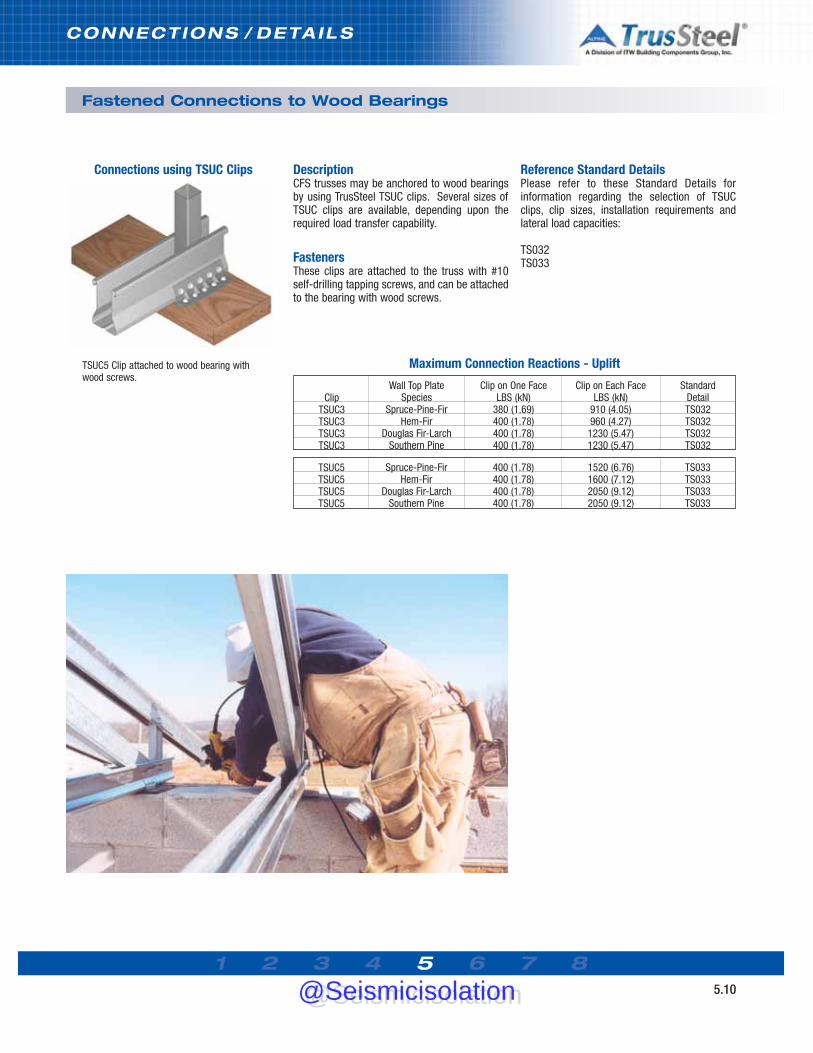
1 2 3 4 5 6 7 85.10
CONNECTIONS / DETAILS
TSUC5 Clip attached to wood bearing withwood screws.
DescriptionCFS trusses may be anchored to wood bearingsby using TrusSteel TSUC clips. Several sizes ofTSUC clips are available, depending upon therequired load transfer capability.
FastenersThese clips are attached to the truss with #10self-drilling tapping screws, and can be attachedto the bearing with wood screws.
Reference Standard DetailsPlease refer to these Standard Details forinformation regarding the selection of TSUCclips, clip sizes, installation requirements andlateral load capacities:
TS032TS033
Fastened Connections to Wood Bearings
Connections using TSUC Clips
Maximum Connection Reactions - Uplift
ClipTSUC3TSUC3TSUC3TSUC3
Wall Top PlateSpecies
Spruce-Pine-FirHem-Fir
Douglas Fir-LarchSouthern Pine
Clip on One FaceLBS (kN)
380 (1.69)400 (1.78)400 (1.78)400 (1.78)
Clip on Each FaceLBS (kN)
910 (4.05)960 (4.27)
1230 (5.47)1230 (5.47)
StandardDetailTS032TS032TS032TS032
TSUC5TSUC5TSUC5TSUC5
Spruce-Pine-FirHem-Fir
Douglas Fir-LarchSouthern Pine
400 (1.78)400 (1.78)400 (1.78)400 (1.78)
1520 (6.76)1600 (7.12)2050 (9.12)2050 (9.12)
TS033TS033TS033TS033
@Seismicisolation@Seismicisolation

1 2 3 4 5 6 7 85.11
CONNECTIONS / DETAILS
Connections using ITWBCG HardwareETAM Straps
DescriptionCFS trusses may be attached by ETAM strapsembedded into concrete beams. These straps areattached to the truss with #10 self-drillingtapping screws. Several sizes of ETAM straps areavailable, depending upon the required loadtransfer capability. See referred Standard Detailsfor lateral load capacities.
FastenersThese straps are attached to the truss with #10self-drilling tapping screws.
ETAM strap at truss heel or internal bearing
Embedded Connections to Concrete
Reference Standard DetailsPlease refer to these Standard Details forinformation regarding the selection of ETAMStraps and installation requirements:
TS034TS035
No. of Screwsper ETAM
3456
TSC2.75LBS (kN)
550 (2.45)550 (2.45)550 (2.45)550 (2.45)
ETAM on One FaceTSC4.00LBS (kN)
660 (2.94)880 (3.91)880 (3.91)880 (3.91)
ETAM on Each FaceTSC2.75 & TSC4.00
LBS (kN)1320 (5.87)1760 (7.83)1760 (7.83)1760 (7.83)
ETAM Straps into Concrete Bearing (Internal)
Refer to Standard Detail TS034
ETAMstrap at truss heel
Maximum Connection Reactions - Uplift
Top Chord28TSC2.7533TSC2.7543TSC2.7528TSC4.0033TSC4.0043TSC4.0054TSC4.00
Mil (GA)28 (22)33 (20)43 (18)28 (22)33 (20)43 (18)54 (16)
ETAM on One FaceLBS (kN)
530 (2.36)550 (2.45)550 (2.45)510 (2.27)660 (2.94)900 (4.00)900 (4.00)
ETAM on Each FaceLBS (kN)
1230 (5.47)1530 (6.81)1760 (7.83)1760 (7.83)1760 (7.83)1760 (7.83)1760 (7.83)
ETAM Straps into Concrete Bearing (Heel)
Refer to Standard Detail TS035
Maximum Connection Reactions - Uplift
@Seismicisolation@Seismicisolation

1 2 3 4 5 6 7 85.12
CONNECTIONS / DETAILS
ITWBCGPart
GTH2GTH2
Single-Ply TrusSteelTop Chord
TSC2.75 w/ Seat PlateTSC4.00 w/ Seat Plate
Mil (GA)Range
28-43 (22-18)28-54 (22-16)
CapacityLBS (kN)
4110 (18.28)4110 (18.28)
Standard DetailTS050TS050
GTH2GTH2GTH2GTH2GTH2GTH2GTH2
28TSC2.75 w/o Seat Plate33TSC2.75 w/o Seat Plate43TSC2.75 w/o Seat Plate28TSC4.00 w/o Seat Plate33TSC4.00 w/o Seat Plate43TSC4.00 w/o Seat Plate54TSC4.00 w/o Seat Plate
28 (22)33 (20)43 (18)28 (22)33 (20)43 (18)54 (16)
870 (3.87)1220 (5.43)1270 (5.65)810 (3.60)
1140 (5.07)2100 (9.34)
2530 (11.25)
TS051TS051TS051TS051TS051TS051TS051
ITWBCGPart
GTH2GTH4GTH2
Two-Ply TrusSteelTop Chord
TSC2.75 w/ Seat PlateTSC4.00 w/ Seat PlateTSC2.75 w/o Seat Plate
Mil (GA)Range
28-43 (22-18)28-54 (22-16)28-43 (22-18)
CapacityLBS (kN)
5050 (22.46)5290 (23.53)1270 (5.65)
Standard DetailTS052TS054TS053
ITWBCGPart
GTH3
Three-Ply TrusSteelTop Chord
TSC2.75 w/ Seat Plate
Mil (GA)Range
28-43 (22-18)
CapacityLBS (kN)
6580 (29.27)
Standard DetailTS055
Connections using ITWBCG HardwareGTH Connectors
DescriptionCFS trusses may be attached to concretebearings using GTH connectors. Several sizes ofGTH connectors are available, depending uponthe required load transfer capability.
FastenersThese connectors are attached to the truss with#10 self-drilling tapping screws and theconnectors are fastened to the concrete bearingusing threaded rods which are installed into theconcrete using an epoxy adhesive.
TrusSteel truss anchored to concrete bearing usingITWBCG Hardware GTH-series connector and epoxy-installed threaded rod.
Embedded Connections to Concrete
Reference Standard DetailsPlease refer to the Standard Details shown in thechart below for information regarding theselection of GTH connectors, sizes andinstallation requirements:
TS050TS051TS052TS053TS054TS055
Maximum Connection Reactions - Uplift
@Seismicisolation@Seismicisolation

1 2 3 4 5 6 7 85.13
CONNECTIONS / DETAILS
Connections using ITWCBCG HardwareHT2.5A Connectors
DescriptionCFS trusses in a piggyback configuration may beanchored to the top chords of base trusses usingTrusSteel TTC7 clips or ITWBCG Hardware FALFraming Anchors.
FastenersThese connections are made with #10 self-drilling tapping screws.
Fastened Connections for Piggybacks
Reference Standard DetailsPlease refer to these Standard Details forinformation regarding the selection andinstallation requirements:
TS003TS003ATS003B
Connections using ITWBCG HardwareHT2.5A Connectors
DescriptionCFS trusses in a valley configuration may beattached to the top chords of TrusSteel trussesusing ITWBCG Hardware HT2.5A connectors.
FastenersThese connections are made with #10 self-drilling tapping screws.
Reference Standard DetailsPlease refer to these Standard Details forinformation regarding the selection andinstallation requirements:
TS026 as shown at leftTS026A to metal deckTS026B to wood structural panels
Fastened Connections for Valley Trusses
Truss to truss - refer to TS026
Truss to wood structural panels. - refer to TS026B
@Seismicisolation@Seismicisolation

1 2 3 4 5 6 7 86.01
TRUSS FABRICAT ION / QUALITY
Overview
Site-Fabricated vs Shop-Fabricated CFS Trusses
Prior to the emergence of pre-fabricated CFStruss systems, contractors built most CFStrusses on the jobsite using c-stud material.While many contractors were more than capableof building a CFS truss, jobsite issues such as theavailability of flat terrain for truss fabrication,exposure to the elements, handling issues andthe availability of experienced fabricationpersonnel often challenged the completion ofquality trusses in a timely manner. Any one ofthese issues could lead to delays in trussfabrication and so to delays in one of the mostcritical phases of construction: the drying-in ofthe building.
Overall, the construction industry welcomed theadvent of pre-engineered, pre-fabricated CFStrusses in the same way as they welcomed theadvent of wood trusses and bar joists. Thesebuilding components, assembled in a shop inadvance of need and properly stored until readyfor delivery, removed a burdensome jobsite taskfrom the contractors’ busy schedule anddelivered a product that was generally high inquality.
The Advantages of Quality Control
TrusSteel Authorized Fabricators assembleTrusSteel CFS trusses in a truss shopenvironment. The reason is quality control. In-shop quality control assures that each truss is: • assembled to dimensional tolerances (to
assure a good fit at the jobsite), • assembled in strict accordance with the
materials and fastening methods described onthe shop drawings (to assure specified structural performance),
• handled, stored and eventually shipped in a manner to eliminate damage.
TrusSteel supports the efforts of industryorganizations, such as SBC Colf_formed SteelCouncil in the implementation of qualityassurance standards.
The Advantages of Trained Assemblers
For a truss package to fit and perform accordingto dimensional and structural specifications, thetruss fabricator must assemble each individualtruss to exacting standards. The fabricator mustuse trained sawyers and proper cutting andjigging equipment to ensure the trusses will havestraight chords, tight joints and to maintainconsistency of pattern from one truss to the next.Trained assemblers should install fasteners toensure the accuracy of each internal connectionand to avoid commonplace problems such as theover-torquing of fasteners.
The Advantages of Proper Equipment
TrusSteel is the only proprietary CFS trusstechnology supplier that offers a complete line oftruss fabrication equipment. Drawing uponAlpine’s more than forty years of experience inwood truss fabrication equipment, TrusSteeloffers a complete line of cutting, measuring,jigging and handling systems.
TrusSteel provides a line of band saws formaterials cutting that are safe, quiet andaccurate. By teaming these saws with anautomatic or manual measuring system, asawyer can greatly improve his output whilemaintaining strict dimensional standards.
Sophisticated full-automatic jigging systems,such as the AutoSet C, allow the electronictransfer of truss profile data directly to the jigtable. Semi-automatic jigging systems, such asthe AutoSet, and manual jigging tables can allowany truss shop to make quick and accuratesetups.
Truss ejector systems, roller beds and stackingsystems can make truss handling quick, simpleand safe. Specialty presses, metalworkers andswagers expedite the assembling of the mostcomplicated trusses and complete thiscomprehensive product line.
@Seismicisolation@Seismicisolation

TRUSS FABRICAT ION / QUALITY
Overview
1 2 3 4 5 6 7 86.02
Truss Size Limitations
Handling and shipping issues limit the size ofindividual CFS trusses. Smaller trusses can bejoined in the field (field splicing) to create largertrusses. Practical limits for handling and shippingwill vary depending upon the capabilities of theindividual truss shop and the distance to thejobsite. Contact your local TrusSteel AuthorizedFabricator for specific information.
The Advantages of TrusSteel
The advantages of TrusSteel in the fabricationprocess translate into advantages to thedesigner, contractor and owner. The fact that theproprietary shape is easy and stable to handlemakes for faster assembly just as it makes forstronger, lighter, stiffer trusses in the field. Rolledchord edges and closed tube webs make forsafer handling in both shop and field. Proprietary,color-coded fasteners make for quick, accurateassembly just as they make it easier for fieldinspection. The in-plane assemblies ofcomponents in the trusses allow the creation oftight bundles that stack and unstack efficiently atthe shop and jobsite and are more resistant tohandling damage.
The Authorized Fabricator Advantage
Each TrusSteel Authorized Fabricator is anindependently owned and operatedlocal/regional truss fabrication shop. AuthorizedFabricators market and service truss projects intheir own region, backed by the forty continuousyears of truss experience. Taken together, thenationwide network of TrusSteel AuthorizedFabricators forms a vast array of truss andframing knowledge at the disposal of thedesigner and installer.
Truss Jigging Systems
Alpine Equipment’s Steel AutoSet CTM and SteelAutoSetTM Jigging Systems brings accuracy andautomation to the steel truss fabrication shop.
When the Steel AutoSet C is used with the AlpinesteelVIEW software, truss jig setups are createdautomatically as the truss is designed. Setupsare then transferred to the shop floor, where asingle shop worker can adjust the jig rail stopswithin seconds (using the AutoSet C touch-screen input computer terminal).
Truss fabrication setups on the AutoSet andAutoSet C are fast, accurate, and repeatable. Nospecial tools are required to operate the jiggingsystems. Setups on the AutoSet System aremade in minutes by a single worker using adriver gun and a digital counter.
Both the Steel AutoSet C and the Steel AutoSetJigging Systems can be used for the fabricationof all types of cold-formed components.
Truss Handling Systems
An integral truss ejector system speeds theremoval of completed trusses from the jig. And,because the ejectors do the lifting, shop workersare subject to less strain and fatigue. Lessfatigue means workers remain more productive.Conveyor runs, truss stackers and other handlingequipment are also available from TrusSteel.
@Seismicisolation@Seismicisolation

1 2 3 4 5 6 7 87.01
INSTALLAT ION / BRACING
Site Conditions & Safety
Safety is no accident. Safe work habits and asafe work environment are the responsibility ofeveryone on the job site. All injuries can beprevented through appropriate training,awareness and actions. Proper safetyequipment, such as glasses, hard hats, shoesand harnesses, must be used consistently andcorrectly.
Site conditions
Proper site conditions for the installation oftrusses are primarily the responsibility of theowner’s representative for construction. Unlessotherwise designated, that representative isusually the general contractor or the constructionmanager.
The American Iron and Steel Institute haspublished guidelines for establishing good sitepractices. The following list of responsibilities istaken from the AISI/S202. Designations shown inparentheses refer to the corresponding sectionsof that publication.
(F2.1) The installer of CFS trusses shall bepermitted to use the most efficient andeconomical method and sequence of installationor assembly available consistent with thecontract documents. When the owner contractsseparately with a component manufacturer andinstaller, the owner is responsible forcoordinating work between contractors.
(F2.2) The installer shall examine areas andconditions under which framing materials are tobe installed. Work shall not proceed untilunsatisfactory conditions have been corrected bythose responsible.
(F2.3) The owner’s representative forconstruction shall provide and maintainadequate access necessary for equipment andframing materials to be installed. The owner’srepresentative for construction shall provide theinstaller with level, convenient, and adequatespace to safely use the necessary equipmentand install the framing materials.
(F2.4) The contractor shall coordinate settingdrawings, dimensional problems, compatibility ofvarious trades and / or installation.
Bracing
All temporary installation bracing, permanentbracing and bridging must be fully and correctlyinstalled prior to the application of any loads,including any temporary loads resulting fromconstruction procedures. Refer to Section 7 inthis Manual for more information.
Installation Tolerances
Structural members and component assembliesshall be installed in accordance with thetolerances prescribed in the AISI/S200: NorthAmerican Standard for Cold-Formed SteelFraming - General Provisions. Trusses shall beinstalled in accordance with the additionalrequirements of the AISI /S214: North AmericanStandard for Cold-Formed Steel Framing - TrussDesign.
Field Modifications and Repairs
Removal, cutting or alteration of any truss chord,web or bracing member in the field is prohibited,unless approved in advance, in writing, by thetruss designer (Truss Component Manufacturer).
Field Quality Control
Trusses shall be installed in accordance with therequirements of the AISI/S214: North AmericanStandard for Cold-Formed Steel Framing - TrussDesign. and with any standards andrequirements set forth in the constructiondocuments. The owner's representative forconstruction will provide inspection service toinspect field connections.
@Seismicisolation@Seismicisolation

INSTALLAT ION / BRACING
Handling & Storage
1 2 3 4 5 6 7 87.02
Material Receiving
Inspect all CFS materials immediately uponarrival. Report all damaged or missing materialimmediately to vendor and note all damage oncarrier's shipping documents.
Material Handling
Finished CFS trusses are usually banded withsteel strapping in conveniently sized bundles.The strapping helps maintain truss alignmentand the bundle strength minimizes damageduring delivery and storage. WARNING: Exercisecare when removing strapping to prevent injury. Throughout all phases of construction, care mustbe taken to avoid excessive lateral bending of thetrusses which can cause joint and memberdamage.
If possible, CFS trusses should be unloaded onrelatively smooth ground. They should not beunloaded on rough terrain that would causeundue lateral strain resulting in distortion of thetruss joints. Rough terrain can also causedamage to overhangs, soffit returns and otherparts of the truss.
Always lift long pieces of material from morethan one lift point to avoid crimping. Take carewhen banding; do not crimp or bend material. Donot store other materials on top of CFS materials.
Material Storage
Formed CFS components made of galvanizedsteel material shall be stored in a low moistureenvironment. Under no circumstances shouldstored material be allowed to become wet. Whenstored in bundles, materials shall be stored at anincline to promote the drainage of any moistureand to avoid moisture build-up in and on theparts.
Storage area shall have good ventilation. Areasthat have poor ventilation, and that have thepotential for trapping moist air in risingtemperatures, can create a ‘hot house’ effectthat may cause condensation between the layersof rolled or bundled material. This trappedcondensation can have the same effect on storedmaterial as exposing it to direct moisture. Forlong-term storage, inspect bundled materialsregularly to assure that moisture has notpenetrated the bundle.
Storage environments shall be ventilated to avoidtemperature differentials in excess of 20ºFbetween the stored material and the ambienttemperature of the storage. Environments thatallow temperature differentials in excess of 20ºFcan promote moisture condensation onmaterials.
Cold steel materials shall be allowed to warmproperly before storage. The rapid warming ofincoming materials (when moved from a coolenvironment to a warm environment) can createcondensation. If incoming galvanized steel feelscold to the touch, allow it to warm slowly in acool indoor area away from drafts. When thesteel has warmed it may be transferred to aproper storage area.
If trusses are stored in the vertical position, theyshould be staked on both sides of the bundle toprevent toppling and personal injury.
These storage instructions must be followed toavoid chalking on any galvanized materials(truss, stud, track, etc.). Chalking is created bythe invasion of moisture between two zinccoated surfaces that are not allowed to dry in anenvironment having adequate air flow. Thechalking is created through a chemical reactionbetween the two surfaces when they are storedin an oxygen deprived atmosphere.
TrusSteel trusses are often light enough for twomen to unstack and stage.
Horizontal storage of trusses.
Vertical storage using a rack or stand. Alwaysstake trusses to prevent toppling.
@Seismicisolation@Seismicisolation

1 2 3 4 5 6 7 87.03
INSTALLAT ION / BRACING
Lifting & Staging
Proper Lifting of CFS Trusses
Trusses may be installed manually, by crane, orby forklift, depending on truss size, wall heightand job conditions. Individual trusses shouldalways be carried vertically to avoid lateral strainand damage to joints and members.
Trusses installed manually are slid into positionover the sidewall and rotated into position usingpoles. The longer the span, the more workersneeded to avoid excessive lateral strain on thetrusses. Trusses should be supported at jointsand the peak while being raised.
Large trusses should be installed by a crane orforklift employing chokers, slings, spreader barsand strong-backs to prevent lateral bending.Trusses may be lifted singly, in banded groups, orin pre-assembled groups or rafts.
Tag lines should always be used to controlmovement of trusses during lifting andplacement. Workers should always use allappropriate safety equipment.
Storage of Materials During Installation
Care must be taken, after truss installation, not tooverload trusses with the storage of otherbuilding materials. Under no circumstancesshould any materials be stored on top ofunbraced trusses!
Reference Document
Refer to the CFSC Cold-Formed Steel BuildingComponent Safety Information documentCFSBCSI before handling or installing trusses.This document is available from the CFSC atwww.cfsc.sbcindustry.com/cfsbsci.php.
Lift shown using a spreader bar to distribute theload. Tag lines must be used during lifting.
Lift shown using a spreader bar to distribute theload. Tag lines must be used during lifting.
Lift shown using a strongback to distribute theload. Tag lines must be used during lifting.
WARNING: Exercise care when removingstrapping to prevent injury.
This installer is using a heavy steel truss as astrongback.
@Seismicisolation@Seismicisolation

1 2 3 4 5 6 7 87.04
INSTALLAT ION / BRACING
Bracing
Permanent Bracing
Permanent bracing typically includes continuouslateral bracing (CLB), diagonal bracing, bridgingand blocking at the heels and ends of thetrusses. This bracing functions to strengthen andstabilize the truss chords and webs which maybe particularly long or highly stressed. Therequired locations of the continuous lateralbracing are typically called out on the shopdrawings supplied by the truss engineeringcompany. These lateral braces must be stabilizedat regular intervals with diagonal bracing. Thisextremely important bracing system creates thecontinuous path through which all loads appliedto the roof are transferred from the truss systeminto the walls and eventually to the ground.
Due to the component-centered nature of ourfast track building process, permanent bracingdesign is not supplied by the wall panelizer ordesigner, or by the truss fabricator, becauseneither party controls the design process of theother component. To bridge this gap in theinformation process, a number of engineeringfirms are beginning to provide permanentbracing design based on their review of the walland truss layouts supplied by separate parties.
Bracing and Structural Performance
The structural performance of a frame buildingdepends on continuous paths for all loads to betransferred to the ground. In the specific instanceof pre-engineered trusses, there are two types ofnecessary bracing which are sometimesconfused: construction (temporary) andpermanent bracing. Each is important to theconstruction process and to the structuralintegrity of the building.
Construction (Temporary) Bracing
This is the proper bracing of the trusses duringthe installation phase of the structure. Much likewalls are braced until the completion of theframing process, when trusses are placed on theplate line, they must be braced to hold themsafely and securely in place, and to resistenvironmental influences such as wind gustsduring the framing process. Construction bracingguidelines are available through truss industrydocuments for truss spans up to 60 ft. For spansover 60 ft. a professional engineer should beconsulted for the construction bracing plan.
Top chord diagonal bracing
Top chord lateral bracing
Ground bracing for first truss
Temporary Bracing for Installation
Examples of permanent bracing at truss heels,using cross-bracing (top) and trusses asblocking (bottom)
@Seismicisolation@Seismicisolation
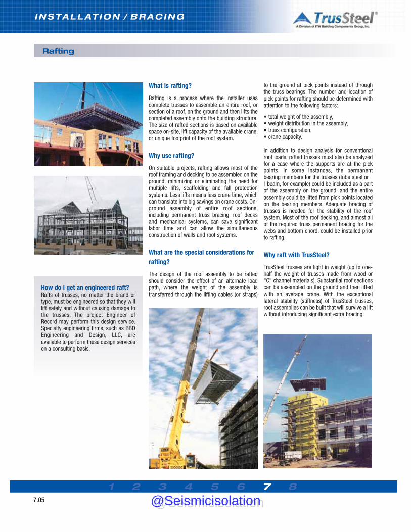
1 2 3 4 5 6 7 87.05
INSTALLAT ION / BRACING
Rafting
What is rafting?
Rafting is a process where the installer usescomplete trusses to assemble an entire roof, orsection of a roof, on the ground and then lifts thecompleted assembly onto the building structure.The size of rafted sections is based on availablespace on-site, lift capacity of the available crane,or unique footprint of the roof system.
Why use rafting?
On suitable projects, rafting allows most of theroof framing and decking to be assembled on theground, minimizing or eliminating the need formultiple lifts, scaffolding and fall protectionsystems. Less lifts means less crane time, whichcan translate into big savings on crane costs. On-ground assembly of entire roof sections,including permanent truss bracing, roof decksand mechanical systems, can save significantlabor time and can allow the simultaneousconstruction of walls and roof systems.
What are the special considerations forrafting?
The design of the roof assembly to be raftedshould consider the effect of an alternate loadpath, where the weight of the assembly istransferred through the lifting cables (or straps)
to the ground at pick points instead of throughthe truss bearings. The number and location ofpick points for rafting should be determined withattention to the following factors:
• total weight of the assembly, • weight distribution in the assembly, • truss configuration, • crane capacity.
In addition to design analysis for conventionalroof loads, rafted trusses must also be analyzedfor a case where the supports are at the pickpoints. In some instances, the permanentbearing members for the trusses (tube steel or I-beam, for example) could be included as a partof the assembly on the ground, and the entireassembly could be lifted from pick points locatedon the bearing members. Adequate bracing oftrusses is needed for the stability of the roofsystem. Most of the roof decking, and almost allof the required truss permanent bracing for thewebs and bottom chord, could be installed priorto rafting.
Why raft with TrusSteel?
TrusSteel trusses are light in weight (up to one-half the weight of trusses made from wood or"C" channel materials). Substantial roof sectionscan be assembled on the ground and then liftedwith an average crane. With the exceptionallateral stability (stiffness) of TrusSteel trusses,roof assemblies can be built that will survive a liftwithout introducing significant extra bracing.
How do I get an engineered raft?Rafts of trusses, no matter the brand ortype, must be engineered so that they willlift safely and without causing damage tothe trusses. The project Engineer ofRecord may perform this design service.Specialty engineering firms, such as BBDEngineering and Design, LLC, areavailable to perform these design serviceson a consulting basis.
@Seismicisolation@Seismicisolation
1 2 3 4 5 6 7 88.01
REFERENCES/RESOURCES
These organizations and materials canprovide resources for the design, use andinstallation of CFS framing as well as anoverview of good construction practices.Please contact the publisher or groupdirectly for further information.
Industry Resources
American Institute of Architects (AIA)202-626-7300 www.aia.orgLocate architects and find information on theprofession, contract documents and more.
American Institute of Steel Construction(AISC)312-670-2400 www.aisc.org
American Iron and Steel Institute (AISI)202-452-7100 www.steel.orgAIS S100-07: North American Specification forthe Design of Cold-Formed Steel StructuralMembers; American Iron and Steel Institute;2007 Edition with Supplement 2AISI-S200-07: AISI North American Standard forCold-Formed Steel Framing - General Provisions;2007 Edition.AISI-S202-11: AISI Code of Standard Practice forCold-Formed Steel Structural Framing; 2011Edition.AISI-S214-07: AISI Norh American Standard forCold-Formed Steel Framing - Truss Design, 2007Edition.
American National Standards Institute (ANSI)212-642-4900 www.ansi.orgAdministers and coordinates U.S. voluntarystandards.
American Society of Civil Engineers (ASCE)800-548-2723 www.asce.orgMinimum Design Loads for Buildings And OtherStructures, ASCE 7-10Structural Engineering InstituteSTRUCTURE magazine
American Society for Testing and Materials(ASTM)610-832-9585 www.astm.org
ASTM E-119 - Test Methods for Fire Tests for
Building Construction and MaterialsASTM A 370-06 - Standard Test Methods andDefinitions for Mechanical Testing of SteelProducts.ASTM A 500-03a - Standard Specification forCold-Formed Welded and Seamless Carbon SteelStructural Tubing in Rounds and Shapes.ASTM A 653-06a - Standard Specification forSteel Sheet, Zinc-Coated (Galvanized) or Zinc-Iron Alloy-Coated (Galvannealed) by the Hot-DipProcess.
Association of Crane & Rigging Professionals800-690-3921 www.acrp.netGain expertise in lifting and handling buildingmaterials.
Association of the Wall and Ceiling Industry703-534-8300 www.awci.orgAWCI-SFA Steel Framing Education ProgramAWCI Construction Dimension magazineAWCI bookstore
Center for Cold-Formed Steel Structures(CCFSS)573-341-4471 http://campus.umr.edu/ccfss/CCFSS Technical BulletinsCCFSS NewsletterEducational seminars
Construction Specifications Institute (CSI)800-689-2900 www.csinet.orgMasterFormat 2004 Construction Specifier magazineNational CAD Standard
Design-Build Institute of America (DBIA)202-682-0110 www.dbia.orgDBIA bookstoreNumerous educational resources
Gypsum Association202-289-5440 www.gypsum.orgFire Resistance Design Manual, GA-600
International Code Council (ICC)888-422-7233 www.iccsafe.orgThe International Building CodeICC-ES Evaluation Service www.icc-es.org
Cold-Formed Steel Engineers Institute (CFSEI) 202-263-4488 www.cfsei.org
CFSEI 551d - Design Guide: Construction Bracingof Cold-Formed Steel Trusses; September 2002.CFSEI 551e - Design Guide: Permanent Bracingof Cold-Formed Steel Trusses; February 1998.CFSEI 551f - Specifying Pre-Engineered Cold-Formed Steel Floor and Roof Trusses; October1998.NewslettersResearch Notes
Occupational Safety and HealthAdministration (OSHA)Directorate of Construction202-693-2020 www.osha.govSafety regulations and procedures
The Steel Framing Alliance202-785-2022www.steelframingalliance.comVarious technical and marketing documentsTraining for steel framers
Metal Construction Association847-375-4718 www.metalconstruction.orgMetalcon Show
SBCA Cold-formed Steel Truss Council(CFSC)608-274-4849 www.cfsc.scbindustry.comTruss labelsTruss educational programsQuality programCFSBCSI document
Steel Deck Institute (SDI)847-458-4647 www.sdi.orgDiaphragm Design Manual
Steel Recycling Institute (SRI)800-937-1226 www.recycle-steel.orgSteel Takes LEED with Recycled Content°®
Underwriters Laboratories (UL)877-854-3577 www.ul.comUL Fire Resistance Directory
U.S. Green Building Council (USGBC)202-828-7422 www.usgbc.orgInformation on the LEED program
@Seismicisolation@Seismicisolation

REFERENCES/RESOURCES
Glossary
1 2 3 4 5 6 7 88.02
Accepted Engineering Practice An engineeringapproach that conforms to accepted principles,tests, technical standards, and sound judgment.
ASD (Allowable Strength Design) Method ofproportioning structural components such thatthe allowable strength equals or exceeds therequired strength of the component under theaction of the ASD load combinations.
ASD Load Combination Load combination in theapplicable building code intended for allowablestrength design (allowable stress design).
Allowable Strength* Nominal strength dividedby the safety factor, Rn/Ω.
Applicable Building Code Building code underwhich the structure is designed.
Available Strength* Design strength orallowable strength as appropriate.
Approved Approval by a building official, codeofficial, design professional, or authority withjurisdiction.
Axial Force The number of pounds of tension orcompression in a truss member acting parallel tothe length of the member resulting from a loadapplied to the truss.
Base Metal Thickness The thickness of baresteel exclusive of all coatings.
Bearing Structural support of a truss, usuallywalls, beams, concrete slabs and hangers.
Bending Moment A measure of the amount ofbending in a member due to forces actingperpendicular to the member.
Blocking C-shaped, track, brake shape, or flatstrap material attached to structural members,flat strap, or sheathing panels to transfer shearforces.
Bottom Chord A horizontal (or inclined in ascissor truss) member that establishes the loweredge of the truss, usually carrying combinedtension and bending stresses.
Braced Frame An essentially vertical trusssystem that provides resistance to lateral loadsand provides stability for the structural system.
Bracing Structural elements that are installed toprovide restraint or support (or both) to otherframing members so that the complete assemblyforms a stable structure.
Bridging Cross-bracing or blocking placedbetween joists to provide lateral support.
Buckling A kink, wrinkle, bulge, or other loss inthe original shape of a member due tocompression, bending, bearing, or shear loads.
Building Designer Also referred to as designprofessional and registered building designer isan individual or organization responsible for theoverall building design in accordance with thestatutes and regulations governing theprofessional registration and certification ofarchitects or engineers of the jurisdiction wherethe building will be located.
Camber An upward vertical displacement builtinto a truss, usually to offset deflection due todead load.
Cantilever The part of a structural member thatextends beyond its support.
Chord Member A structural member that formsthe top or bottom component of a truss.
Clear Span Horizontal distance between interioredges of supports.
Cold-Formed Sheet Steel Sheet steel or stripthat is formed by (1) press-braking blankssheared from sheets or cut length of coils orplates, or by (2) continuous roll forming of cold-or hot-rolled coils of sheet steel; both formingoperations are performed at ambient roomtemperature, that is, without the addition of heatsuch as would be required for hot forming.
Cold-Formed Steel Structural Member Shapemanufactured by press-braking blanks shearedfrom sheets, cut lengths of coils or plates, or byroll forming cold- or hot-rolled coils or sheets;both forming operations being performed atambient room temperature, that is, withoutmanifest addition of heat such as would berequired for hot forming.
Collateral Load The weight of any non-movingequipment or material, such as ceilings,electrical or mechanical equipment, sprinklersystems, plumbing, or ceilings.
Combined Stress The combination of axial andbending stresses or shear and bending stressesacting on a member simultaneously. Thesestresses typically occur in both top and bottomchords.
Concentrated Load A load, in addition touniform design loads, applied at a specific point.Examples include cranes, hoists, HVACequipment and sprinkler pipes.
Compression A force caused by loads beingplaced on a member that causes a squeezing orshortening effect of the member as in the topchord of a truss when load is applied.
Component Assembly A fabricatedassemblage of cold-formed steel structuralmembers that is manufactured by thecomponent manufacturer, which may alsoinclude structural steel framing, sheathing,insulation or other products.
Component Design Drawings The written,graphic and pictorial definition of an individualcomponent assembly, which includesengineering design data.
Component Designer The individual ororganization responsible for the engineeringdesign of component assemblies. See TrussDesigner.
Component Manufacturer The individual ororganization responsible for the manufacturingof component assemblies for the project. SeeTruss Manufacturer.
Component Placement Diagram Theillustration supplied by the componentmanufacturer identifying the location assumedfor each of the component assemblies whichreferences each individually designatedcomponent design drawing.
@Seismicisolation@Seismicisolation
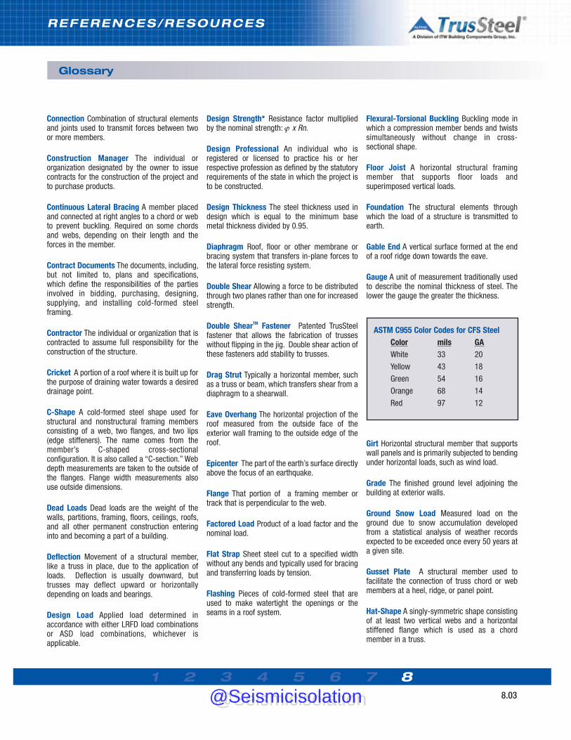
1 2 3 4 5 6 7 88.03
Glossary
Connection Combination of structural elementsand joints used to transmit forces between twoor more members.
Construction Manager The individual ororganization designated by the owner to issuecontracts for the construction of the project andto purchase products.
Continuous Lateral Bracing A member placedand connected at right angles to a chord or webto prevent buckling. Required on some chordsand webs, depending on their length and theforces in the member.
Contract Documents The documents, including,but not limited to, plans and specifications,which define the responsibilities of the partiesinvolved in bidding, purchasing, designing,supplying, and installing cold-formed steelframing.
Contractor The individual or organization that iscontracted to assume full responsibility for theconstruction of the structure.
Cricket A portion of a roof where it is built up forthe purpose of draining water towards a desireddrainage point.
C-Shape A cold-formed steel shape used forstructural and nonstructural framing membersconsisting of a web, two flanges, and two lips(edge stiffeners). The name comes from themember’s C-shaped cross-sectionalconfiguration. It is also called a “C-section.” Webdepth measurements are taken to the outside ofthe flanges. Flange width measurements alsouse outside dimensions.
Dead Loads Dead loads are the weight of thewalls, partitions, framing, floors, ceilings, roofs,and all other permanent construction enteringinto and becoming a part of a building.
Deflection Movement of a structural member,like a truss in place, due to the application ofloads. Deflection is usually downward, buttrusses may deflect upward or horizontallydepending on loads and bearings.
Design Load Applied load determined inaccordance with either LRFD load combinationsor ASD load combinations, whichever isapplicable.
Design Strength* Resistance factor multipliedby the nominal strength: ϕ x Rn.
Design Professional An individual who isregistered or licensed to practice his or herrespective profession as defined by the statutoryrequirements of the state in which the project isto be constructed.
Design Thickness The steel thickness used indesign which is equal to the minimum basemetal thickness divided by 0.95.
Diaphragm Roof, floor or other membrane orbracing system that transfers in-plane forces tothe lateral force resisting system.
Double Shear Allowing a force to be distributedthrough two planes rather than one for increasedstrength.
Double ShearTM Fastener Patented TrusSteelfastener that allows the fabrication of trusseswithout flipping in the jig. Double shear action ofthese fasteners add stability to trusses.
Drag Strut Typically a horizontal member, suchas a truss or beam, which transfers shear from adiaphragm to a shearwall.
Eave Overhang The horizontal projection of theroof measured from the outside face of theexterior wall framing to the outside edge of theroof.
Epicenter The part of the earth’s surface directlyabove the focus of an earthquake.
Flange That portion of a framing member ortrack that is perpendicular to the web.
Factored Load Product of a load factor and thenominal load.
Flat Strap Sheet steel cut to a specified widthwithout any bends and typically used for bracingand transferring loads by tension.
Flashing Pieces of cold-formed steel that areused to make watertight the openings or theseams in a roof system.
Flexural-Torsional Buckling Buckling mode inwhich a compression member bends and twistssimultaneously without change in cross-sectional shape.
Floor Joist A horizontal structural framingmember that supports floor loads andsuperimposed vertical loads.
Foundation The structural elements throughwhich the load of a structure is transmitted toearth.
Gable End A vertical surface formed at the endof a roof ridge down towards the eave.
Gauge A unit of measurement traditionally usedto describe the nominal thickness of steel. Thelower the gauge the greater the thickness.
Girt Horizontal structural member that supportswall panels and is primarily subjected to bendingunder horizontal loads, such as wind load.
Grade The finished ground level adjoining thebuilding at exterior walls.
Ground Snow Load Measured load on theground due to snow accumulation developedfrom a statistical analysis of weather recordsexpected to be exceeded once every 50 years ata given site.
Gusset Plate A structural member used tofacilitate the connection of truss chord or webmembers at a heel, ridge, or panel point.
Hat-Shape A singly-symmetric shape consistingof at least two vertical webs and a horizontalstiffened flange which is used as a chordmember in a truss.
ASTM C955 Color Codes for CFS SteelColor mils GAWhite 33 20
Yellow 43 18
Green 54 16
Orange 68 14
Red 97 12
REFERENCES/RESOURCES
@Seismicisolation@Seismicisolation
1 2 3 4 5 6 7 88.04
REFERENCES/RESOURCES
Glossary
Heel Point on a truss at which the top chord andbottom chord intersect at the end of a truss witha sloping top chord.
Hip-Set A sloped roof surface that extends froma roof ridge towards the eave.
Installation Drawings Drawings that show thelocation and installation of the cold-formed steelstructural framing.
Installer Party responsible for the installation ofcold-formed steel products.
Joint Area where two or more ends, surfaces, oredges are attached. Categorized by type offastener or weld used and the method of forcetransfer.
Lateral Forces Non-gravity forces acting on abuilding such as wind and seismic.
Lateral Force Resisting System The structuralelements and connections required to resistracking and overturning due to wind and/orseismic forces imposed upon the structure inaccordance with the applicable building code.
Lateral Load A horizontal force created by windor earthquake that acts on a structure or itscomponents.
Level Return Filler placed horizontally from theend of an overhang back to the bearing supportto form soffit framing.
Live Loads Live loads are transient andsustained loads usually created by people andfurnishing, respectively.
Load Force or other action that results from theweight of building materials, occupants and theirpossessions, environmental effects, differentialmovement, or restrained dimensional changes.
Load Effect Forces, stresses, and deformationsproduced in a structural component by theapplied loads.
Load Factor Factor that accounts for deviationsof the nominal load from the actual load, foruncertainties in the analysis that transforms theload into a load effect, and for the probability that
more than one extreme load will occursimultaneously.
LRFD (Load and Resistance Factor Design)Method of proportioning structural componentssuch that the design strength equals or exceedsthe required strength of the component underthe action of the LRFD load combinations.
LRFD Load Combination Load combination inthe applicable building code intended forstrength design (Load and Resistance FactorDesign).
Material Supplier An individual or entityresponsible for furnishing framing materials forthe project.
Mil A unit of measurement used in measuringthe thickness of thin steel elements. One milequals 1/1000 of an inch (e.g., 33 mil = 0.033inch).
Moment Frame Framing system that providesresistance to lateral loads and provides stabilityto the structural system primarily by shear andflexure of the framing members and theirconnections.
Multi-Node Analysis A truss analysismethodology when each individual web memberat a joint is modeled with its own node.
Multiple Span The span made by a continuousmember with intermediate supports.
Nominal Load Magnitude of the load specifiedby the applicable building code.
Nominal Strength* Strength of a structure orcomponent (without the resistance factor orsafety factor applied) to resist the load effects, asdetermined in accordance with a Specification orStandard.
Overhang The extension of the top or bottomchord of a truss beyond the bearing support.
Panel In a truss, the chord segment defined bytwo successive joints.
Panel Length The centerline distance betweenjoints measured horizontally.
Panel Point The connection region between aweb and chord member.
Peak Point on a truss where two sloped chordsmeet.
PPermanent LLoad Load in which variations overtime are rare or of small magnitude. All otherloads are variable loads.
Piggyback Truss. A truss supported directly ontop of another truss. Trusses are piggybackeddue to height restrictions in fabrication anddelivery.
Pitch See Slope.
Pitch Break A location around the perimeter ofa truss where the chord changes pitch.
Plans Drawings prepared by the designprofessional for the owner of the project. Thesedrawings include but are not limited to floorplans, framing plans, elevations, sections, detailsand schedules as necessary to define the desiredconstruction.
Purlin Horizontal structural member thatsupports roof deck and is primarily subjected tobending under vertical loads such as snow, windor dead loads. (May also brace the top chord oftrusses in certain applications, resulting in anapplied axial force).
Rake The inclined edge of a roof.
Rake Overhang The horizontal projection of theroof measured from the outside face of a gableendwall to the outside edge of the roof.
Rational Engineering Analysis Analysis basedon theory that is appropriate for the situation,relevant test data if available, and soundengineering judgment.
Reaction Forces acting on a truss through itssupports which are equal (but opposite) to thesum of the dead and live loads.
Release for Construction The release by theowner’s representative, permitting thecomponent manufacturer and/or installer tocommence work under the contract, including
@Seismicisolation@Seismicisolation
1 2 3 4 5 6 7 88.05
Glossary
ordering framing material and preparinginstallation drawings.
Required Strength* Forces, stresses, anddeformations produced in a structuralcomponent, determined by either structuralanalysis, for the LRFD or ASD load combinations,as appropriate, or as specified by Specification orStandard.
Resistance Factor, Ψ Factor that accounts forunavoidable deviations of the nominal strengthfrom the actual strength and for the manner andconsequences of failure.
Ridge The line formed by the joining of the topedges of two sloping roof surfaces.
Safety Factor, Ω Factor that accounts fordeviations of the actual strength from thenominal strength, deviations of the actual loadfrom the nominal load, uncertainties in theanalysis that transforms the load into a loadeffect and for the manner and consequences offailure.
Secondary Bending The bending stress in amember caused by the deflection of the wholetruss.
Service Load Load under which serviceabilitylimit states are evaluated.
Shear Wall Wall that provides resistance tolateral loads in the plane of the wall and providesstability for the structural system.
Shop Drawings Drawings for the production ofindividual component assemblies for the project.
Slope (Pitch) The inches in vertical rise in 12inches of horizontal run for inclined members,generally expressed as 3/12, 4/12, etc.
Specialty Designer The individual ororganization having responsibility for the designof the specialty items. This responsibility shall bein accordance with the state’s statues andregulations governing the professionalregistration and certification of architects orengineers. Also referred to as componentdesigner, specialty engineer, design engineer,registered engineer, and engineer, but hereinafterwill be referred to as Specialty Designer. The
requirement for a Specialty Designer is typicallycalled out on architectural specifications orstructural general notes. The Specialty Designeris typically not the Structural Engineer-of-Record.
Specifications Written instructions, which, withthe plans, define the materials, standards, designof the products, and workmanship expected on aconstruction project.
Specified Minimum Yield Stress Lower limit ofyield stress specified for a material as defined byASTM
Splice The point at which two chord members ofthe same slope are joined together to form asingle member.
Static Load A load or series of loads that aresupported by, or are applied to, a structure sogradually that forces caused by change inmomentum of the load and structural elementscan be neglected and all parts of the system atany instant are essentially in equilibrium.
Strain The geometrical expression ofdeformation caused by the action of stress on aphysical body.
Stress A unit force working within a member,usually expressed in pounds per square inch(psi).
Strongback A load distribution member typicallyused in a floor truss system and installedperpendicular through the trusses.
Structural Analysis Determination of loadeffects on members and connections based onprinciples of structural mechanics.
Structural Component Member, connector,connecting element or assemblage.
Structural Engineer-of-Record The designprofessional who is responsible for sealing thecontract documents, which indicates that he orshe has performed or supervised the analysis,design and document preparation for thestructure and has knowledge of therequirements for the load carrying structuralsystem.
Structural Sheathing The covering (e.g.,plywood, oriented strand board or steel deck)used directly over structural members (e.g.,joists) to distribute loads, brace walls, andgenerally strengthen the assembly.
Sub-Contractor The individual or organizationwith whom a contractor has contracted tofurnishl and/or install a portion of the project.
Tensile Strength (of material) See UltimateStrength.
Top Chord An inclined or horizontal memberthat establishes the upper edge of a truss.
Truss A coplanar system of structural membersjoined together at their ends usually to constructa series of triangles that form a stable beam-likeframework.
Truss Designer Also referred to as trussengineer, design engineer and registeredengineer, is an individual or organizationresponsible for the design of cold-formed steeltrusses.
Truss Manufacturer An individual ororganization engaged in the manufacturing ofsite-built or in-plant trusses. Also called theTruss Fabricator.
Unbalanced Load Live loads that are appliednon-uniformly across the span of the truss. Thistype of loading is required by most buildingcodes.
Ultimate Strength (Fu) The property of steelassociated with the maximum stress that can bedeveloped prior to rupture. Also known as tensilestrength.
Uniform Load A total load that is equallydistributed over a given length, usuallyexpressed in pounds per square foot (psf).
Valley A depression in a roof where two roofslopes meet.
Valley Set A group of trusses required to fill in asection of a roof. Valley trusses generally haveonly vertical webs and are supported on top ofother trusses.
REFERENCES/RESOURCES
@Seismicisolation@Seismicisolation

1 2 3 4 5 6 7 88.06
REFERENCES/RESOURCES
Variable Load. Load not classified as permanentload.
Web Crippling. The localized permanent(inelastic) deformation of the web membersubjected to concentrated load or reaction atbearing supports.
Webs. Members that join the top and bottomchords to form the triangular patterns that givetruss action, usually carrying tension orcompression stresses (no bending).
Web Stiffener. Additional material that isattached to the web to strengthen the memberagainst web crippling. Also called bearing ortransverse stiffener.
Yield Strength (Fy). Stress at which a materialexhibits a specified limiting deviation from theproportionality of stress to strain as defined byASTM.
Z-Shape. A point-symmetric or non-symmetricsection which is used as a chord member in atruss.
* Terms shown with an asterisk are usuallyqualified by the type of load effect, for example,nominal tensile strength, available compressivestrength, or design flexural strength.
Glossary
Sources
• AISC and AISI Standard Definitions for Usein the Design of Steel Structures, 2007Edition • AIS S100-07: North AmericanSpecification for the Design of Cold-FormedSteel Structural Members; American Iron andSteel Institute; 2007 Edition withSupplement 2• AISI-S200-07: AISI North AmericanStandard for Cold-Formed Steel Framing -General Provisions; 2007 Edition.• AISI-S214-07: AISI Norh AmericanStandard for Cold-Formed Steel Framing -Truss Design, 2007 Edition.• The Encyclopedia of Trusses, AlpineEngineered Products, Inc.
Definitions presented in this Glossary werecompiled and provided solely for theeducation of the reader. While every efforthas been made to keep these definitionsaccurate, helpful and up-to-date, it is not theintent of this compilation to supplant existingor future regulatory or statutory definitions.
@Seismicisolation@Seismicisolation

1 2 3 4 5 6 7 88.07
Weights of Materials
Composition Roofing2-15 lb. and 1-90 lb. 1.753-15 lb. and 1-90 lb. 2.2 Felt, 3 ply 1.5 Felt, 3 ply and gravel 5.6 Felt, 4 ply and gravel 6.0 Felt, 5 ply and gravel 6.5 3/4” ceramic or quality tile 10.0 Single-ply (mod. bitumen) 1.0
Misc. Roofing MaterialsRoll roofing 1.0 Asphalt shinges 2.0 Book tile (2”) 12.0 Cement tile 16.0 Clay tile (w/ mortar) 10.0
Spanish 19.0 Roman 12.0
Misc. Decking MaterialsTectum (1”) 2.0 Vermiculite concrete 2.6 Insulrock (1”) 2.7
Wood Decking3/8" plywood 1.1 1/2” plywood 1.5 5/8” plywood 1.8 3/4” plywood 2.31-1/8” plywood 3.4 1” sheathing 2.3 2” decking 4.3 3” decking 7.0 4” decking 9.3
Roof Sheathing3/8” plywood 1.1 1/2” plywood 1.5 5/8” plywood 1.8 3/4” plywood 2.2 1-1/8” plywood 3.3 1” (sheathing) nominal 2.1
FloorHardwood (nominal 1”) 3.8 Concrete (per 1” of thickness)
Insulating lightweight 2.5 Lightweight 6.0-10.0 Reinforced 12.5
Linoleum or soft tile 1.5 3/4” ceramic or quality tile 10.0 Terrazo (1.5”) 19.0 Cement finish (per 1” thick) 12.0
Corrugated Galvanized Steel Deck (2)57 mil (16 GA) 3.5 45 mil (18 GA) 2.8 34 mil (20 GA) 2.1 28 mil (22 GA) 1.7 24 mil (24 GA) 1.1 18 mil (26 GA) 1.0
Roll or Batt InsulationRock wool (1”) 0.2 Glass wool (1”) 0.1
Rigid InsulationTemlock (1”) 1.2 Cork 0.7 Gold bond (1”) 1.5 Styrofoam (1”) 0.2 Foamglass (1”) 0.8 Rigid fiber glass (1”) 1.5
CeilingsAcoustical fiber tile 1.0 1/2” gypsum board 2.0 5/8” gypsum board 2.5 Plaster (1” thick) 8.0 Metal suspension system 0.5 Metal suspension with tile 1.8 Wood suspension system 2.0 Wood suspension with tile 2.5
All weights shown in PSF unless noted otherwise.Weights and dimensions shown are generic - physical properties of actual materials may vary from product to product.
REFERENCES/RESOURCES
@Seismicisolation@Seismicisolation

1 2 3 4 5 6 7 88.08
REFERENCES/RESOURCES
Industry-Best Resources
TrusSteel has created the industry’s mostcomplete set of technical resources for thedesign and application of pre-engineered Cold-Formed Steel trusses. This information ispublished in several formats that are available toprofessionals who specify and design with CFStrusses.
www.TrusSteel.com
The TrusSteel Web site is the industry’s mostcomprehensive resource on CFS trusses. Learnthe history of Alpine and TrusSteel, find a localAuthorized Fabricator, download StandardDetails, research UL and code issues, request anAIA/CES seminar and much more. Get TrusSteelinformation when you need it - 24 / 7 / 365.
Truss Manual CD
TrusSteel also publishes the Manual you arereading as an interactive CD that is available toarchitects and engineers who specify and designwith CFS trusses. The CD contains not only thismanual but also the complete library of TruSteelStandard Details in DXF and DWG CAD fileformats. To request a copy of the Design ManualCD, just visit www.TrusSteel.com.
TrusSteel Standard Details
TrusSteel maintains this growing library of over100 details and makes it available, free ofcharge, to industry professionals. Use thesedetails for reference during design, then cut-and-paste them right into your constructiondocuments.
Guide Specification
The TrusSteel Guide Spec is written in thestandard three-part CSI format. This spec isavailable from our Web site, and from the DesignManual CD, in pure text format that you can cut-and-paste without fear of reformatting yourcurrent specs or importing contaminated files.
TrusSteel Authorized Fabricators
Your local Authorized Fabricators can be one ofyour most valuable resources when you areplanning and designing your building. These roofframing specialists can help you realize yourdesign vision in the most economical, easily-builtand safe manner. Need information on trussdesigns, prices and delivery? Need help inworking out a difficult roof plan? Your localAuthorized Fabricator can help. Go towww.TrusSteel.com to find a Fabricator nearyou.
For more information, contact: [email protected] or go to: www.TrusSteel.comor call 888-565-9181.
@Seismicisolation@Seismicisolation

The World Leader in Cold-Formed Steel Trusses
Truss Design Manual
V2
a division of ITW Building Components Group
888.565.9181 • www.TrusSteel.com
a division of ITW Building Components Group
Truss Design Manual
@Seismicisolation@Seismicisolation
Related Documents