IEEE TRANSACTIONS ON PATTERN ANALYSIS AND MACHINE INTELLIGENCE, VOL. 21, NO. 3, MARCH 1999 235 Short Papers_________________________________________________________________ True Multi-Image Alignment and Its Application to Mosaicing and Lens Distortion Correction Harpreet S. Sawhney, Member, IEEE, and Rakesh Kumar, Member, IEEE Abstract—Multiple images of a scene are related through 2D/3D view transformations and linear and non-linear camera transformations. In the traditional techniques to compute these transformations, especially the ones relying on direct intensity gradients, one image and its coordinate system have been assumed to be ideal and distortion free. In this paper, we present an algorithm for true multi-image alignment that does not rely on the measurements of a reference image being distortion free. The algorithm is developed to specifically align and mosaic images using parametric transformations in the presence of lens distortion. When lens distortion is present, none of the images can be assumed to be ideal. In our formulation, all the images are modeled as intensity measurements represented in their respective coordinate systems, each of which is related to an ideal coordinate system through an interior camera transformation and an exterior view transformation. The goal of the accompanying algorithm is to compute an image in the ideal coordinate system while solving for the transformations that relate the ideal system with each of the data images. Key advantages of the technique presented in this paper are: (i) no reliance on one distortion free image, (ii) ability to register images and compute coordinate transformations even when the multiple images are of an extended scene with no overlap between the first and last frame of the sequence, and (iii) ability to handle linear and non- linear transformations within the same framework. Results of applying the algorithm are presented for the correction of lens distortion, and creation of video mosaics. Index Terms—Image sequence analysis, video mosaics, lens distortion correction. ———————— F ———————— 1 INTRODUCTION MULTIPLE images of a scene are related through 2D/3D view transformations and linear and non-linear camera transforma- tions. Automatic computation of these transformations is im- portant for applications like image/video mosaicing, structure from motion, and recovery of camera and object motions. Direct methods for simultaneously computing the correspondences between frames and the unknown transformations through alignment have been actively explored in the past few years. Direct methods have been fruitfully employed in a hierarchical coarse-to-fine optimization framework to estimate 2D parametric transformations [2], [3], 3D view and parallax estimates [11], [15] both over two and multiple frames [5], 2D layered and moving object representations [1], [8], [10], and to create 2D and 3D aligned video mosaics, [12], [13], [16], [22]. In all the direct techniques, one image and its coordinate sys- tem have been assumed to be ideal and distortion free. In this pa- per, we present an algorithm for true multi-image alignment that does not rely on the measurements of a reference image being distortion free. For instance, in the presence of lens distortion, none of the images can be assumed to be ideal. In our formulation, all the images are modeled as intensity measurements represented in their respective coordinate systems, each of which is related to an ideal coordinate system through an interior camera transfor- mation and an exterior view transformation. The goal of the ac- companying algorithm is to compute an image in the ideal coordi- nate system while solving for the transformations that relate the ideal system with each of the data images. The algorithm is based on a minimum variance estimate of the ideal image that is com- puted using direct multiresolution methods. The algorithm is presented specifically for the problem of aligning multiple images using parametric transformations when lens distortion is present. Most traditional methods for lens distor- tion correction have relied either on external calibrated objects [23] or use discrete feature correspondences [24], [21]. Our image alignment method extends the lens distortion estimation to direct methods. In addition, we apply the multi-image alignment tech- nique to image mosaicing and show that lens distortion correction is necessary for geometrically correct mosaics. For mosaics using single 1D scans of a scene in which only each frame’s spatial neighbors are temporal neighbors too, it may be possible to gener- ate “well-aligned” mosaics by appropriate cut lines that minimize the effect of lens distortion [14]. However, for general mosaics with 2D scans (in which spatial neighbors may not be temporal neigh- bors) it is necessary to align multiple images within 2D neighbor- hoods while correcting for lens distortion. This work demonstrates the effect of lens distortion correction and multi-image alignment for video mosaics. For details of 1D versus 2D mosaicing with globally consistent alignment, see [20] and [17]. Key advantages of our technique are: 1) no reliance on one ideal and distortion free image, 2) ability to register images and compute coordinate transfor- mations even when the multiple images are of an extended scene with no overlap between the first and last frame of the sequence, and 3) ability to handle linear and nonlinear transformations within the same framework. In Section 2, the formulations of the multiview variance error function and an iterative solution are presented. Section 3 presents the optimization strategy. Subsequently, we present experimental results for the new algorithm for two applications: correction of lens distortion and creation of video mosaics. Finally, in Section 6, some experiments on the validation of our lens distortion model are presented. 2 FORMULATION Given images I 1 / I N , the coordinate system of each I i is repre- sented as a transformed version of an ideal reference coordinate system typically not belonging to any particular image. Therefore, a point p = (x, y) in the ideal system is related to an observed point p i = (x i , y i ) in the ith image through a two-step transformation. In the first step, p is transformed through a transformation, A i , which typically is a 3D-to-2D or 2D-to-2D projection transformation, to an undistorted coordinate p I i = x y I i I i , 4 9 . In the second step, p I i is further transformed, typically through a nonlinear camera trans- formation, g, to obtain the observed video coordinate p i = (x i , y i ). For the purposes of the formulation here to avoid notational com- plexity, g is assumed to be the same for each image. Conceptually it is easy to extend the formulation to handle more nonlinear dis- tortion parameters. The functional relationship between a refer- 0162-8828/99/$10.00 © 1999 IEEE ²²²²²²²²²²²²²²²² • The authors are with Sarnoff Corporation, CN5300, Princeton, NJ 08530. E-mail: {hsawhney,rkumar}@sarnoff.com. Manuscript received 1 Aug. 1997; revised 5 Jan. 1999. Recommended for accep- tance by R. Szeliski. For information on obtaining reprints of this article, please send e-mail to: [email protected], and reference IEEECS Log Number 107732.

Welcome message from author
This document is posted to help you gain knowledge. Please leave a comment to let me know what you think about it! Share it to your friends and learn new things together.
Transcript
IEEE TRANSACTIONS ON PATTERN ANALYSIS AND MACHINE INTELLIGENCE, VOL. 21, NO. 3, MARCH 1999 235
Short Papers_________________________________________________________________
True Multi-Image Alignment and ItsApplication to Mosaicing and Lens
Distortion Correction
Harpreet S. Sawhney, Member, IEEE, and
Rakesh Kumar, Member, IEEE
Abstract—Multiple images of a scene are related through 2D/3D viewtransformations and linear and non-linear camera transformations. Inthe traditional techniques to compute these transformations, especiallythe ones relying on direct intensity gradients, one image and itscoordinate system have been assumed to be ideal and distortion free.In this paper, we present an algorithm for true multi-image alignmentthat does not rely on the measurements of a reference image beingdistortion free. The algorithm is developed to specifically align andmosaic images using parametric transformations in the presence oflens distortion. When lens distortion is present, none of the images canbe assumed to be ideal. In our formulation, all the images are modeledas intensity measurements represented in their respective coordinatesystems, each of which is related to an ideal coordinate systemthrough an interior camera transformation and an exterior viewtransformation. The goal of the accompanying algorithm is to computean image in the ideal coordinate system while solving for thetransformations that relate the ideal system with each of the dataimages. Key advantages of the technique presented in this paper are:(i) no reliance on one distortion free image, (ii) ability to register imagesand compute coordinate transformations even when the multipleimages are of an extended scene with no overlap between the first andlast frame of the sequence, and (iii) ability to handle linear and non-linear transformations within the same framework. Results of applyingthe algorithm are presented for the correction of lens distortion, andcreation of video mosaics.
Index Terms—Image sequence analysis, video mosaics, lensdistortion correction.
———————— F ————————
1 INTRODUCTION
MULTIPLE images of a scene are related through 2D/3D viewtransformations and linear and non-linear camera transforma-tions. Automatic computation of these transformations is im-portant for applications like image/video mosaicing, structurefrom motion, and recovery of camera and object motions. Directmethods for simultaneously computing the correspondencesbetween frames and the unknown transformations throughalignment have been actively explored in the past few years.Direct methods have been fruitfully employed in a hierarchicalcoarse-to-fine optimization framework to estimate 2D parametrictransformations [2], [3], 3D view and parallax estimates [11], [15]both over two and multiple frames [5], 2D layered and movingobject representations [1], [8], [10], and to create 2D and 3Daligned video mosaics, [12], [13], [16], [22].
In all the direct techniques, one image and its coordinate sys-tem have been assumed to be ideal and distortion free. In this pa-per, we present an algorithm for true multi-image alignment thatdoes not rely on the measurements of a reference image being
distortion free. For instance, in the presence of lens distortion,none of the images can be assumed to be ideal. In our formulation,all the images are modeled as intensity measurements representedin their respective coordinate systems, each of which is related toan ideal coordinate system through an interior camera transfor-mation and an exterior view transformation. The goal of the ac-companying algorithm is to compute an image in the ideal coordi-nate system while solving for the transformations that relate theideal system with each of the data images. The algorithm is basedon a minimum variance estimate of the ideal image that is com-puted using direct multiresolution methods.
The algorithm is presented specifically for the problem ofaligning multiple images using parametric transformations whenlens distortion is present. Most traditional methods for lens distor-tion correction have relied either on external calibrated objects [23]or use discrete feature correspondences [24], [21]. Our imagealignment method extends the lens distortion estimation to directmethods. In addition, we apply the multi-image alignment tech-nique to image mosaicing and show that lens distortion correctionis necessary for geometrically correct mosaics. For mosaics usingsingle 1D scans of a scene in which only each frame’s spatialneighbors are temporal neighbors too, it may be possible to gener-ate “well-aligned” mosaics by appropriate cut lines that minimizethe effect of lens distortion [14]. However, for general mosaics with2D scans (in which spatial neighbors may not be temporal neigh-bors) it is necessary to align multiple images within 2D neighbor-hoods while correcting for lens distortion. This work demonstratesthe effect of lens distortion correction and multi-image alignmentfor video mosaics. For details of 1D versus 2D mosaicing withglobally consistent alignment, see [20] and [17].
Key advantages of our technique are:
1)� no reliance on one ideal and distortion free image,2)� ability to register images and compute coordinate transfor-
mations even when the multiple images are of an extendedscene with no overlap between the first and last frame of thesequence, and
3)� ability to handle linear and nonlinear transformationswithin the same framework.
In Section 2, the formulations of the multiview variance errorfunction and an iterative solution are presented. Section 3 presentsthe optimization strategy. Subsequently, we present experimentalresults for the new algorithm for two applications: correction oflens distortion and creation of video mosaics. Finally, in Section 6,some experiments on the validation of our lens distortion modelare presented.
2 FORMULATION
Given images I1 ¤ IN, the coordinate system of each Ii is repre-sented as a transformed version of an ideal reference coordinatesystem typically not belonging to any particular image. Therefore,a point p = (x, y) in the ideal system is related to an observed pointpi = (xi, yi) in the ith image through a two-step transformation. Inthe first step, p is transformed through a transformation, Ai, whichtypically is a 3D-to-2D or 2D-to-2D projection transformation, to
an undistorted coordinate pIi = x yI
iIi,4 9 . In the second step, pI
i is
further transformed, typically through a nonlinear camera trans-formation, g, to obtain the observed video coordinate pi = (xi, yi).For the purposes of the formulation here to avoid notational com-plexity, g is assumed to be the same for each image. Conceptuallyit is easy to extend the formulation to handle more nonlinear dis-tortion parameters. The functional relationship between a refer-
0162-8828/99/$10.00 © 1999 IEEE
²²²²²²²²²²²²²²²²
•� The authors are with Sarnoff Corporation, CN5300, Princeton, NJ 08530.�E-mail: {hsawhney,rkumar}@sarnoff.com.
Manuscript received 1 Aug. 1997; revised 5 Jan. 1999. Recommended for accep-tance by R. Szeliski.For information on obtaining reprints of this article, please send e-mail to:[email protected], and reference IEEECS Log Number 107732.
236 IEEE TRANSACTIONS ON PATTERN ANALYSIS AND MACHINE INTELLIGENCE, VOL. 21, NO. 3, MARCH 1999
-�?352'8&7,21?73$0,?��,1352'?0$5��?������?����'2& FRUUHVSRQGHQFH���GRW $* ��������� ��������������30 �������
ence coordinate p and the corresponding video coordinate can besuccinctly expressed as:
p p p p P p AiIi
Ii
Ii= + =Γ ; ;γ4 9 4 9i (1)
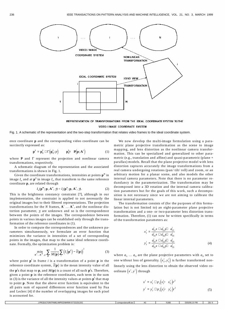
where P and G represent the projection and nonlinear cameratransformations, respectively.
A schematic diagram of the representation and the associatedtransformations is shown in Fig. 1.
Given the coordinate transformations, intensities at points pm inimage Im and at pn in image In, that transform to the same referencecoordinate p, are related through
Im(pm; p, Am, g) = In(pn; p, An, g). (2)
This is the brightness constancy constraint [7], although in ourimplementation, the constraint is applied to not necessarily theoriginal images but to their filtered representations. The projectiontransformations for the N frames, A1 ¤ AN, and the nonlinear dis-tortion parameter, g, are unknown and so is the correspondencebetween the points of the images. The correspondence betweenpoints in various images can be established only through the trans-formation of the reference coordinates in (1).
In order to compute the correspondences and the unknown pa-rameters simultaneously, we formulate an error function thatminimizes the variance in intensities of a set of correspondingpoints in the images, that map to the same ideal reference coordi-nate. Formally, the optimization problem is:
min,A A p
i
pp p
1
1 2
K N MI Ii
iγ 1 6 4 9 1 64 9∑ ∑ − (3)
where point pi in frame i is a transformation of a point p in thereference coordinate system, I p1 6 is the mean intensity value of all
the pis that map to p, and M(p) is a count of all such pis. Therefore,given a point p in the reference coordinates, each term in the sumin (3) is the variance of all the intensity values at points pi that mapto point p. Note that the above error function is equivalent to theall pairs sum of squared differences error function used by Fuaand Leclerc [4] if the number of overlapping images for each pixelis accounted for.
We now develop the multi-image formulation using a para-metric plane projective transformation as the scene to imagemapping, and lens distortion as the nonlinear camera transfor-mation. This can be specialized and generalized to other para-metric (e.g., translation and affine) and quasi-parametric (plane +parallax) models. Recall that the plane projective model with lensdistortion captures accurately the image transformations from areal camera undergoing rotations (pan/tilt/roll) and zoom, or anarbitrary motion for a planar scene, and also models the otherinternal camera parameters. Note that there is no parameter re-dundancy in the parameterization. The transformation may bedecomposed into a 3D rotation and the internal camera calibra-tion parameters but for the goals of this work, such a decompo-sition is not necessary since we are not aiming to calibrate thelinear internal parameters.
The transformation consists of (for the purposes of this formu-lation but is not limited to) an eight-parameter plane projectivetransformation and a one- or two-parameter lens distortion trans-formation. Therefore, (1) can now be written specifically in termsof the transformation parameters as:
xa x a y a
a x a y a
ya x a y a
a x a y a
Ii
i i i
i i i
Ii
i i i
i i i
=+ +
+ +
=+ +
+ +
11 12 13
31 32 33
21 22 23
31 32 33
(4)
where a11 ¤ a33 are the plane projective parameters with a33 set to
one without loss of generality. x yIi
Ii,4 9 is further transformed non-
linearly using the lens distortion to obtain the observed video co-
ordinate x yi i,4 9 through
x x x x r
y y y y r
iIi
Ii
Ci
iIi
Ii
Ci
= + −
= + −
γ
γ
12
12
4 94 9 (5)
Fig. 1. A schematic of the representation and the two-step transformation that relates video frames to the ideal coordinate system.
IEEE TRANSACTIONS ON PATTERN ANALYSIS AND MACHINE INTELLIGENCE, VOL. 21, NO. 3, MARCH 1999 237
-�?352'8&7,21?73$0,?��,1352'?0$5��?������?����'2& FRUUHVSRQGHQFH���GRW $* ��������� ��������������30 �������
where piC C
iCix y= ,4 9 is the image center for the ith frame, and
r x x y yIi
Ci
Ii
Ci2 2 2
= − + −4 9 4 9 is the squared distance of x yIi
Ii,4 9 from
the center.The above equation models only the cubic term of radial lens
distortion. This simplification is for both illustrative purposes aswell as serves as a reasonable model for the cameras used in ourexperimentation. However, the alignment technique presented inthis paper can easily be applied to other more general models oflens distortion. For simplicity, it is assumed that each video frameis distorted with the same lens distortion parameter g1, not an un-reasonable assumption for many real scenarios. This implies thatimaging under varying zoom factors is not handled since the zoomcan change the lens distortion and other parameters too. It is alsoassumed that the x and y scale factors for the frame coordinates arethe same. It is to be noted that if there is no nonlinear distortion (asin (1)), then the observed coordinates of one image can be chosenas the reference coordinates. This is a special case of the aboveformulation.
2.1 Iterative SolutionIt is evident from the optimization function in (3) and the trans-formations in (4) and (5) that the unknown parameters cannot beobtained in closed form. We employ the Levenberg-Marquardttechnique for minimizing sum of squares error functions.
In order to apply the LM technique, each term in (3) is line-arized. Each term is of the form:
EM
I Iip pp
p pi i; ; ,4 94 9 1 6 4 9 1 64 9$ γ 1
1= − , (6)
where $ represents the set of all the N unknown Ais. Given a so-lution of the unknown parameters $k, γ 1k
at the kth step in the
optimization process, each E((pi; p); $, g1) is linearized around thissolution as:
E
E E
E E
kN
T
kT T
k k k
T T
k k k
p p
p p A A
p p
i
i
i
; ; ,
; ; ,
; ; ,
,
,
4 94 9
4 94 9
4 94 9
$
$
$ $
$
$
γ
γ δ δ δγ
γ δ δγ
γ
γ
1
11
1
1 1
1
1
≈ + ∇ �!
"$#
= + ∇
K
(7)
E
MI I
k
i ki
ki
k
k k
p p
pp p A p p A
i
i i
; ; ,
; , ; ,
4 94 9
1 6 4 94 9 4 94 9
$ γ
γ γ
1
1 1
1
=
−�� �� (8)
The first term on the right-hand side in (8) is the intensity valuefor image i sampled at location pi which is a forward mapping ofthe corresponding point p in the reference image with mappingparameters Ak
i
k,γ 1 . Recall that we do not a priori know the corre-
spondences (pi, p); these are known only through the mappingparameters. Given that typically only the forward mapping from p
to pi is known, Ii ki
kp p Ai ; ,γ 14 94 9 can be written in terms of a
warped image represented in the reference p coordinates, that is,
I Ii ki
iw
kp p A pi ; ,γ 14 94 9 1 6= . The warped image is created by com-
puting pi for image i using p and the parameters Aki
k,γ 1 , and in-
terpolating the known values of the image Ii at integer pixel loca-tions. Therefore, Ii
w p1 6 represents the current estimate of image i
represented in the reference coordinates. Also,
IM
Iki
iw
ik
p p Ap
pi ; ,γ 1
14 94 9 1 6 1 6= ∑ .
Therefore, at the kth parameter values,
EM
I Ik iw w
kp p
pp pi ; ; ,4 94 9 1 6 1 6 1 64 9$ γ 1
1= − .
The gradient term in the first-order approximation of (7) can bewritten as:
∇ = ∇ ∇���
−
∇ ∇���
�� ��
�� ��∑
EM
I
MI
k k ki
k
ki
k
i
ii
$ , ; ,
; ,
γ γ
γ
11
1
1
1
pp p
pp p
i i
p p A
i i
p p A
i
i
1 6 4 94 9
1 6 4 94 9 (9)
The gradients of images are in their respective coordinate sys-tems and are 1 �2 matrices. Again, the gradient images are repre-sented in the reference coordinate system for particular values ofthe unknown parameters, $k, γ 1k
, through interpolation and
warping. The gradients of the ith image’s (Ii) coordinate system,pi, are with respect to the unknown parameters, Ai,g1, evaluatedat the current values Ak
i
k,γ 1 . Each of these is a 2 �(N � M + 1)
matrix where M is the dimension of each unknown parametervector Ai, N is the number of images, and 1 accounts for the un-known scalar g1.
The gradients of the image coordinates can be expressed as:
∇ = ∇ + ∇�� �� �� ��A
i
A Ii
A Iip p pi i i, ,;
γ γγ
1 11Γ4 9 .
The gradients are separated into the ones with respect to Ai and g1.From (1) and (5),
∇ = + + − −��
��∇
A
i2 I
i iIi i
A pp I p p p p
Iii ir C C
T1 21
21γ γ4 9 ,
where I2 is the 2 � 2 identity matrix.
Using the augmented vector p pa = 1T
,
∇ = �!
"$#A I
i 1 3 2
3 1 3p
h 0 h0 h hi
where
0
hA p A p A p
hA p A p
hA p A p
A A A A
3
1
3i
a 3i
a 3i
a
2
3i
a 3i
a
3
3i
a 3i
a
1i
2i
3i
=
=�!
"$##
= − −�!
"$##
= − −�!
"$##
= �!
"$#
0 0 0
1 1 11
1 1
1 1
T T T
T Ii
T Ii
T Ii
T Ii
i T T T T
x y
x x x y
y x y y
Furthermore, ∇ = −γ 1
2p p piIi i
C r .
Let g p pi
A
iiiI i= ∇ ∇4 9 be a 1 � M matrix, and g Ii
i= ∇ ∇p pi i4 9 γ 1
be a scalar. Also let G(p) = [g1 ¤ gi ¤ gN] be the 1 � M * N matrix ofall the gis, and g = Íig
i. Then ¹E of (9) can be written as:
∇ = −EM
gM
gi i10 0 0 0
1
pg
pG p1 6 1 6 1 6K K .
238 IEEE TRANSACTIONS ON PATTERN ANALYSIS AND MACHINE INTELLIGENCE, VOL. 21, NO. 3, MARCH 1999
-�?352'8&7,21?73$0,?��,1352'?0$5��?������?����'2& FRUUHVSRQGHQFH���GRW $* ��������� ��������������30 �������
Each iteration solves the following linear sum of squares prob-lem using LM:
min ; ;δ δγ
δδγ$�
$1 1
2
E Ei
p p p pi i
p4 9 4 9+ ∇ �
! "$#
���
���∑∑ .
For each point p in the reference coordinates, all the imagesthat contain a point that maps to p contribute an equation tothe system of equations corresponding to the above problem.LM iterations look for a solution that results in a reduction ofthe error function by making the Hessian diagonally dominantprogressively, if the original system leads to an increase in theerror value. In order to obtain a well-conditioned system ofequations, the unknown parameters are scaled appropriately sothat the Hessian remains well conditioned. The 3 � 3 projectivematrix is normalized to express its parameters with respect to acoordinate system with its origin in the image as the nominalimage center, and is scaled by a scale factor that is half thelarger of the image dimensions. This normalization is similar tothe one proposed by Hartley [6] for fundamental matrix com-putation. In addition, we further scale the a31 and a32 parametersto make their magnitude’s roughly of the order of the otherlinear parameters. Also, the lens distortion is scaled by thecube of the scale factor to make its magnitude also comparableto the other parameters.
3 MINIMIZATION STRATEGY
In order to handle a wide range of motion between frames, and toefficiently compute large number of parameters through framealignment, we adopt an optimization strategy that uses:
1)� progressively complex models of motion and2)� coarse-to-fine tracking of the model parameters.
3.1 Progressive ComplexityIn order to efficiently solve for a large number of parameters (typi-cally, 8N + 1 for N + 1 frames with their respective plane projectivetransformations and a common lens distortion parameter), wehave empirically found that the use of models with a progressiveincrease in complexity helps tremendously. Spurious local minimaare avoided, and the number of iterations required is considerablyreduced.
The progressive complexity strategy is to divide the optimiza-tion process into a sequence of steps. At each step, an increasinglyhigher parametric order motion model is inserted in (3) and thesubsequent error function is minimized. The results from the pre-vious step are used as an initial estimate for the next step. Theunknown projective parameters can be decomposed into the fol-lowing hierarchy for estimation:
1)� 2D Translation, two unknown parameters, a ai i13 23, , for each
frame (4).We first solve for only the translation parameters within aregion of interest which is limited to an inner central square,typically 1
3 of the input images along each dimension. Pixelsat the inner central square suffer from little lens distortion ascompared to pixels in the outer boundaries.
2)�Affine, six unknown parameters a a a a a ai i i i i i11 12 13 21 22 23, , , , , .
The initial translation is used to solve for affine parameters.The region of interest is expanded a little (to a dimension of23 of the image), but still does not cover the whole image.
3)�Projective, eight1 parameters plus the global lens distortionparameters as in (4) and (5).
1. Note, the projective transformation can also be modeled by nine pa-rameters, with the constraint that the sum of squares of the nine parametersis equal to one.
Finally, the affine parameters are used as an initial estimatefor computing the projective and the lens distortion pa-rameters simultaneously. In this step, the error function isoptimized over the entire image.
In some situations, step 2 may be skipped.
3.2 Coarse-to-Fine MinimizationIn addition to the progressive complexity strategy, in order to alignframes with displacements in tens of pixels, optimization overcoarse-to-fine levels of a Gaussian/Laplacian pyramid is neces-sary. The parameters are first estimated at the coarse level of thepyramid, and the results from this level are used as an initial esti-mate for the next finer level of the pyramid.
Typically the two strategies are combined. At the coarser levelsof the pyramid, only the low-order models are computed. Theresults from these are used as an initial estimate for solving thehigher-order models at the finer levels of the pyramid.
4 EXPERIMENTS WITH LENS DISTORTION CORRECTION
One of the applications for multi-image registration is video mo-saics using off-the-shelf inexpensive PC cameras. Severe lensdistortion is a common occurrence in most of these cameras. Inorder to create high quality mosaics using these cameras, it isnecessary to correct for the distortion. Our algorithm may beused for this purpose either to compute the lens distortion pa-rameter in an initializing phase in which only a few frames areused or along with the computation of the alignment parametersfor each frame. We have chosen two representative scenes andscanning modes:
1)� a 3D scene that is scanned by approximately rotating ahand-held camera from a fixed location and
2)� a planar document scene that is scanned using an arbitrarymotion of the camera.
Note that since our goal is not full camera calibration but imagealignment with lens distortion correction, we do not attempt todecompose the projective transformations into the linear cameracalibration parameters and the corresponding rotations and trans-lations. Influence of lens distortion parameters on linear calibra-tion using pure rotations is studied in [9].
We first show the results of computing the lens distortion pa-rameters from a few frames. In principle, two frames should besufficient to solve for the view transformation and lens distortion.However, we have observed that often two frames lead to localminimum solutions that can be avoided by using three frames.
We emphasize that for all the results reported next, the lensdistortion and projective parameters were found automaticallyusing the progressive complexity strategy. In other words, the ini-tial parameters were identity for the projective transformation andzero for the lens distortion parameter. The center of distortion waskept fixed at the nominal image center. Tests with varying the im-age center are reported in Section 6. The experiments were run ona Pentium 200 MHz machine, and the time taken ranged from 30 sto 2 min for a triple of frames each of size 320 � 240. The variationin execution times is due to the iterative nature of the nonlinearminimization process. Varying number of iterations were executedfor the different data sets.
4.1 Room SequenceThe first experiment is on a room sequence. The sequence was ac-quired through a hand held inexpensive Toshiba desktop CCD cam-era. A sequence of the room covering about 120 degrees was cap-tured through two roughly panning swipes of a hand-held camera.
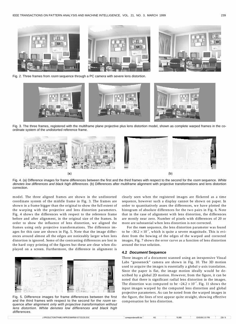
The multiframe registration algorithm was applied on threeframes, shown in Fig. 2, with a plane projective and lens distortion
IEEE TRANSACTIONS ON PATTERN ANALYSIS AND MACHINE INTELLIGENCE, VOL. 21, NO. 3, MARCH 1999 239
-�?352'8&7,21?73$0,?��,1352'?0$5��?������?����'2& FRUUHVSRQGHQFH���GRW $* ��������� ��������������30 �������
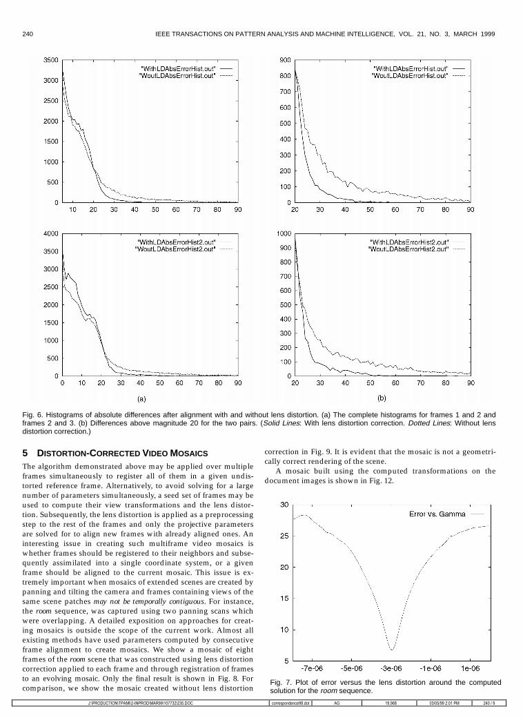
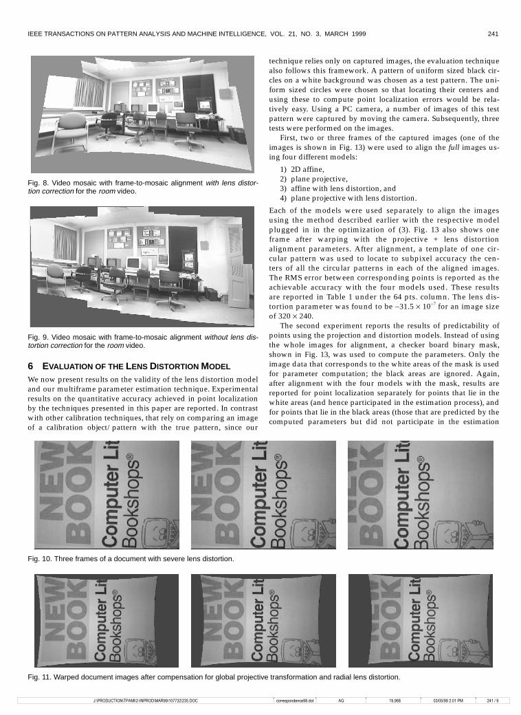
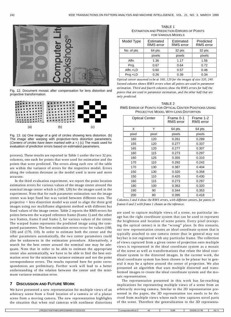
model. The three aligned frames are shown in the undistortedcoordinate system of the middle frame in Fig. 3. The frames areshown in a frame bigger than the original to show the full extent ofthe warping with the projective and lens distortion parameters.Fig. 4 shows the differences with respect to the reference framebefore and after alignment, in the original size of the frames. Inorder to show the influence of lens distortion, we aligned theframes using only projective transformations. The difference im-ages for this case are shown in Fig. 5. Note that the image differ-ences around almost all the edges are noticeably larger when lensdistortion is ignored. Some of the contrasting differences are lost inthe hard copy printing of the figures but these are clear when dis-played on a screen. Furthermore, the difference in alignment is
clearly seen when the registered images are flickered as a timesequence, however such a display cannot be shown on paper. Inorder to quantitatively asses the differences, we have plotted thehistogram of absolute differences for the two pairs in Fig. 6. Notethat in the case of alignment with lens distortion, the differencesare mostly near zero. Number of pixels with differences of 20 ormore are substantial when lens distortion is not corrected.
For the room sequence, the lens distortion parameter was foundto be -30.2 � 10-7, which is quite a severe magnitude. This is evi-dent from the bowing of the edges of the warped and correctedimages. Fig. 7 shows the error curve as a function of lens distortionaround the true solution.
4.2 Document SequenceThree images of a document scanned using an inexpensive VisualLabs “gooseneck” camera are shown in Fig. 10. The 3D motionused to acquire the images is essentially a global y-axis translation.Since the paper is flat, the image motion ideally would be de-scribed by a global 2D motion. However, from the figure, it can benoted that there is significant radial lens distortion in the images.The distortion was computed to be -24.2 � 10-7. Fig. 11 shows theinput images warped by the computed lens distortion and globalprojective parameters. As can be noted from the warped images inthe figure, the lines of text appear quite straight, showing effectivecompensation for lens distortion.
Fig. 2. Three frames from room sequence through a PC camera with severe lens distortion.
Fig. 3. The three frames, registered with the multiframe plane projective plus lens distortion model, shown as complete warped frames in the co-ordinate system of the undistorted reference frame.
Fig. 4. (a) Difference images for frame differences between the first and the third frames with respect to the second for the room sequence. Whitedenotes low differences and black high differences. (b) Differences after multiframe alignment with projective transformations and lens distortioncorrection.
Fig. 5. Difference images for frame differences between the firstand the third frames with respect to the second for the room se-quence after alignment only with projective transformation withoutlens distortion. White denotes low differences and black highdifferences.
240 IEEE TRANSACTIONS ON PATTERN ANALYSIS AND MACHINE INTELLIGENCE, VOL. 21, NO. 3, MARCH 1999
-�?352'8&7,21?73$0,?��,1352'?0$5��?������?����'2& FRUUHVSRQGHQFH���GRW $* ��������� ��������������30 �������
5 DISTORTION-CORRECTED VIDEO MOSAICS
The algorithm demonstrated above may be applied over multipleframes simultaneously to register all of them in a given undis-torted reference frame. Alternatively, to avoid solving for a largenumber of parameters simultaneously, a seed set of frames may beused to compute their view transformations and the lens distor-tion. Subsequently, the lens distortion is applied as a preprocessingstep to the rest of the frames and only the projective parametersare solved for to align new frames with already aligned ones. Aninteresting issue in creating such multiframe video mosaics iswhether frames should be registered to their neighbors and subse-quently assimilated into a single coordinate system, or a givenframe should be aligned to the current mosaic. This issue is ex-tremely important when mosaics of extended scenes are created bypanning and tilting the camera and frames containing views of thesame scene patches may not be temporally contiguous. For instance,the room sequence, was captured using two panning scans whichwere overlapping. A detailed exposition on approaches for creat-ing mosaics is outside the scope of the current work. Almost allexisting methods have used parameters computed by consecutiveframe alignment to create mosaics. We show a mosaic of eightframes of the room scene that was constructed using lens distortioncorrection applied to each frame and through registration of framesto an evolving mosaic. Only the final result is shown in Fig. 8. Forcomparison, we show the mosaic created without lens distortion
correction in Fig. 9. It is evident that the mosaic is not a geometri-cally correct rendering of the scene.
A mosaic built using the computed transformations on thedocument images is shown in Fig. 12.
Fig. 6. Histograms of absolute differences after alignment with and without lens distortion. (a) The complete histograms for frames 1 and 2 andframes 2 and 3. (b) Differences above magnitude 20 for the two pairs. (Solid Lines: With lens distortion correction. Dotted Lines: Without lensdistortion correction.)
Fig. 7. Plot of error versus the lens distortion around the computedsolution for the room sequence.
IEEE TRANSACTIONS ON PATTERN ANALYSIS AND MACHINE INTELLIGENCE, VOL. 21, NO. 3, MARCH 1999 241
-�?352'8&7,21?73$0,?��,1352'?0$5��?������?����'2& FRUUHVSRQGHQFH���GRW $* ��������� ��������������30 �������
6 EVALUATION OF THE LENS DISTORTION MODEL
We now present results on the validity of the lens distortion modeland our multiframe parameter estimation technique. Experimentalresults on the quantitative accuracy achieved in point localizationby the techniques presented in this paper are reported. In contrastwith other calibration techniques, that rely on comparing an imageof a calibration object/pattern with the true pattern, since our
technique relies only on captured images, the evaluation techniquealso follows this framework. A pattern of uniform sized black cir-cles on a white background was chosen as a test pattern. The uni-form sized circles were chosen so that locating their centers andusing these to compute point localization errors would be rela-tively easy. Using a PC camera, a number of images of this testpattern were captured by moving the camera. Subsequently, threetests were performed on the images.
First, two or three frames of the captured images (one of theimages is shown in Fig. 13) were used to align the full images us-ing four different models:
1)� 2D affine,2)� plane projective,3)� affine with lens distortion, and4)� plane projective with lens distortion.
Each of the models were used separately to align the imagesusing the method described earlier with the respective modelplugged in in the optimization of (3). Fig. 13 also shows oneframe after warping with the projective + lens distortionalignment parameters. After alignment, a template of one cir-cular pattern was used to locate to subpixel accuracy the cen-ters of all the circular patterns in each of the aligned images.The RMS error between corresponding points is reported as theachievable accuracy with the four models used. These resultsare reported in Table 1 under the 64 pts. column. The lens dis-tortion parameter was found to be -31.5 � 10-7 for an image sizeof 320 � 240.
The second experiment reports the results of predictability ofpoints using the projection and distortion models. Instead of usingthe whole images for alignment, a checker board binary mask,shown in Fig. 13, was used to compute the parameters. Only theimage data that corresponds to the white areas of the mask is usedfor parameter computation; the black areas are ignored. Again,after alignment with the four models with the mask, results arereported for point localization separately for points that lie in thewhite areas (and hence participated in the estimation process), andfor points that lie in the black areas (those that are predicted by thecomputed parameters but did not participate in the estimation
Fig. 8. Video mosaic with frame-to-mosaic alignment with lens distor-tion correction for the room video.
Fig. 9. Video mosaic with frame-to-mosaic alignment without lens dis-tortion correction for the room video.
Fig. 10. Three frames of a document with severe lens distortion.
Fig. 11. Warped document images after compensation for global projective transformation and radial lens distortion.
242 IEEE TRANSACTIONS ON PATTERN ANALYSIS AND MACHINE INTELLIGENCE, VOL. 21, NO. 3, MARCH 1999
-�?352'8&7,21?73$0,?��,1352'?0$5��?������?����'2& FRUUHVSRQGHQFH���GRW $* ��������� ��������������30 �������
process). These results are reported in Table 1 under the two 32 pts.columns, one each for points that were used for estimation and thepoints that were predicted. The errors along each row of the tableare within the variance of errors for the respective model. Errorsalong the columns decrease as the model used is more and moreaccurate.
In the third evaluation experiment, we report the point locationestimation errors for various values of the image center around thenominal image center which is (160, 120) for the images used in theexperiment. Note that for each parameter estimation run the imagecenter was kept fixed but was varied between different runs. Theprojective + lens distortion model was used to align the three gridimages using our multiframe alignment method with different butfixed values of the image center. Table 2 reports the RMS errors forpoints between the warped reference frame (frame 1) and the othertwo frames, frame 0 and frame 2, for various values of the center.The warped frame represents the predicted image using the com-puted parameters. The best estimation errors occur for values (160,120) and (170, 110). In order to estimate both the center and theother parameters automatically, the two center parameters couldalso be unknowns in the estimation procedure. Alternatively, asearch for the best center around the nominal one may be ade-quate. Note that in order to be able to estimate the appropriatecenter also automatically, we have to be able to find the best esti-mation error for the minimum variance estimate and not the pointcorrespondence errors. The results reported here for point corre-spondences are preliminary. Further work will lead to a betterunderstanding of the relation between the center and the mini-mum variance estimation error.
7 DISCUSSION AND FUTURE WORK
We have presented a new representation for multiple views of anarbitrary scene from a fixed location of a camera or of a planarscene from a moving camera. The new representation highlightsthe situation that when real cameras with nonlinear distortions
are used to capture multiple views of a scene, no particular im-age has the right coordinate system that can be used to representthe brightness and location of scene points. Every pixel (except-ing the optical center) is in the “wrong” place. In this scenario,our new representation creates an ideal coordinate system that istypically attached to one camera center (but in general may notbe) but is not registered with any particular frame. The collectionof views captured from a given center of projection onto multipleviews is represented in the ideal coordinate system as a mosaicof the scene as well as transformations that relate the ideal coor-dinate system to the distorted images. In the current work, theideal coordinate system has been chosen to be planar but in gen-eral it may be a sphere around the center of projection. We alsopresented an algorithm that uses multiple distorted and trans-formed images to create the ideal coordinate system and the mo-saic representation.
The representation presented in this work has far-reachingimplications for representing multiple views of a scene from anarbitrarily moving camera. Similar to the 2D representation pre-sented in the paper, the 3D representation too needs to be de-rived from multiple views where each view captures novel partsof the scene. Therefore the generalization to the 3D representa-
Fig. 12. Document mosaic after compensation for lens distortion andprojective transformation.
(a) (b) (c)
Fig. 13. (a) One image of a grid of circles showing lens distortion. (b)The image after warping with projective+lens distortion parameters.(Centers of circles have been marked with a +.) (c) The mask used forevaluation of prediction errors based on estimated parameters.
TABLE 1ESTIMATION AND PREDICTION ERRORS OF POINTS
FOR VARIOUS MODELS
Model Type EstimatedRMS error
EstimatedRMS error
PredictedRMS error
No. of pts. 64 pts. 32 pts. 32 pts.
pixels pixels pixels
Affn. 1.36 1.17 1.56Proj. 0.67 0.64 0.72
Affn.+LD 0.60 0.57 0.46Proj.+LD 0.26 0.39 0.34
Optical center assumed to be at 160, 120 for the images of size 320, 240.Second column shows RMS errors when all points are used in parameterestimation. Third and fourth columns show the RMS errors for half thepoints that are used in parameter estimation, and the other half that areonly predicted.
TABLE 2RMS ERROR OF POINTS FOR OPTICAL CENTER POSITIONS USING
PROJECTIVE MODEL WITH LENS DISTORTION
Optical Center Frame 0-1RMS error
Frame 1-2RMS error
X Y 64 pts. 64 pts.
pixel pixel pixels pixels
160 120 0.261 0.289155 120 0.277 0.337165 120 0.277 0.307160 115 0.273 0.297160 125 0.355 0.310170 110 0.292 0.242170 130 0.387 0.404150 130 0.320 0.358150 110 0.420 0.430160 115 0.273 0.297180 100 0.363 0.320190 90 0.344 0.353200 80 0.395 0.418
Columns 3 and 4 show the RMS errors, with different centers, for points inframes 0 and 2 with frame 1 chosen as the reference.
IEEE TRANSACTIONS ON PATTERN ANALYSIS AND MACHINE INTELLIGENCE, VOL. 21, NO. 3, MARCH 1999 243
-�?352'8&7,21?73$0,?��,1352'?0$5��?������?����'2& FRUUHVSRQGHQFH���GRW $* ��������� ��������������30 �������
tion involves choosing an ideal coordinate system (again thatmay or may not be attached to a given camera), and then creat-ing a 3D “mosaic” representation that integrates informationfrom multiple views while accounting for view transformationsand occlusion/visibility constraints [12], [18]. We are activelyfollowing this line of research.
ACKNOWLEDGMENTS
Our sincere thanks to the anonymous reviewers and the area edi-tor whose detailed comments have helped us sharpen the contentand presentation in this paper.
REFERENCES[1]� S. Ayer and H.S. Sawhney, “Layered Representation of Motion Video
Using Robust Maximum-Likelihood Estimation of Mixture Modelsand MDL Encoding,” Proc. Int’l Conf. Computer Vision, pp. 777–784,1995. ftp://eagle.almaden.ibm.com/pub/cs/reports/vision/layered_motion.ps.Z.
[2]� J.R. Bergen et al., “Hierarchical Model-Based Motion Estima-tion,” Proc. Second European Conf. Computer Vision, pp. 237–252,1992.
[3]� M.J. Black and P. Anandan, “The Robust Estimation of Multi-ple Motions: Affine and Piecewise-Smooth Flow Fields,” Com-puter Vision and Image Understanding, vol. 63, no. 1, pp. 75–104,1996.
[4]� P. Fua and Y.G. Leclerc, “Object-Centered Surface Reconstruction:Combining Multi-Image Stereo and Shading,” Int’l J. Computer Vi-sion, vol. 16, pp. 35–56, 1995.
[5]� K.J. Hanna and N.E. Okamoto, “Combining Stereo and MotionAnalysis for Direct Estimation of Scene Structure,” Proc. Int’l Conf.Computer Vision, pp. 357–365, 1993.
[6]� R. Hartley, “In Defense of the Eight Point Algorithm,” Proc. Int’lConf. Computer Vision, pp. 1,064–1,070, 1995.
[7]� B.K.P. Horn and B.G. Schunck, “Determining Optical Flow,” Arti-ficial Intelligence, vol. 17, no. 1–3, pp. 185–203, 1981.
[8]� S. Hsu, P. Anandan, and S. Peleg, “Accurate Computation of Op-tical Flow by Using Layered Motion Representation,” ICPR, pp.743–746, Jerusalem, Israel, Oct. 1994.
[9]� S. Hsu and H.S. Sawhney, “Influence of Global Constraints andLens Distortion on Pose and Appearance Recovery From a PurelyRotating Camera,” WACV’98, pp. 154-159, Princeton, N.J., Oct.1998.
[10]� M. Irani, P. Anandan, and S. Hsu, “Mosaic Based Representationsof Video Sequences and Their Applications,” Proc. Int’l Conf. Com-puter Vision, pp. 605–611, 1995.
[11]� M. Irani, B. Rousso, and S. Peleg, “Detecting and Tracking Multi-ple Moving Objects Using Temporal Integration,” ECCV, pp. 282–287, Santa Margherita, Italy, May 1992.
[12]� R. Kumar, P. Anandan, and K. Hanna, “Direct Recovery of ShapeFrom Multiple Views: A Parallax Based Approach,” ICPR, pp.685–688, 1994.
[13]� R. Kumar, P. Anandan, M. Irani, et al., “Representation of ScenesFrom Collection of Images,” Proc. IEEE Workshop Representation ofVisual Scenes, 1995.
[14]� S. Mann and R.W. Picard, “Virtual Bellows: Constructing HighQuality Stills From Video,” ICIP, 1994.
[15]� S. Peleg and J. Herman, “Panoramic Mosaics by Manifold Projec-tion,” CVPR, pp. 338–343, 1997.
[16]� H.S. Sawhney, “Simplifying Motion and Structure Analysis UsingPlanar Parallax and Image Warping,” Proc. Int’l Conf. Pattern Rec-ognition, pp. A403–A408, 1994.
[17]� H.S. Sawhney, S. Ayer, and M. Gorkani, “Model-Based 2D & 3DDominant Motion Estimation for Mosaicing and Video Repre-sentation,” Proc. Int’l Conf. Computer Vision, pp. 583–590, 1995.ftp://eagle.almaden.ibm.com/pub/cs/reports/vision/dominant_motion.ps.Z.
[18]� H.S. Sawhney, S. Hsu, and R. Kumar, “Robust Video MosaicingThrough Topology Inference and Local to Global Alignment,”ECCV, pp. 103–119, 1998.
[19]� S.M. Seitz and C.R. Dyer, “Photo-Realistic Scene Reconstructionby Voxel Coloring,” Proc. Computer Vision and Pattern RecognitionConf., pp. 1,067-1,073, 1997.
[20]� H. Shum and R. Szeliski, “Construction and Refinement of Pano-ramic Mosaics With Global and Local Alignment,” Proc. Int’l Conf.Computer Vision, 1998.
[21]� G. Stein, “Lens Distortion Calibration Using Point Correspon-dences,” Proc. Computer Vision and Pattern Recognition Conf., pp.602–608, 1997.
[22]� R. Szeliski, “Image Mosaicing for Tele-Reality Applications,” IEEEWorkshop Applications of Computer Vision, pp. 44–53, 1994.
[23]� R.Y. Tsai, “An Efficient and Accurate Camera Calibration Tech-nique for 3D Machine Vision,” Proc. Computer Vision and PatternRecognition Conf., pp. 364–374, 1986.
[24]� Z. Zhang, “On the Epipolar Geometry Between Two Images WithLens Distortion,” Proc. Int’l Conf. Pattern Recognition, vol. 1, pp.407–411, 1996.
Related Documents


![WCE 2014, July 2 - 4, 2014, London, U.K. A Study on the Distortion … · 2014-05-01 · lens distortion. One is a pincushion distortion and the other is a barrel distortion [1-3].](https://static.cupdf.com/doc/110x72/5e834c02c6ae4f1b297c8804/wce-2014-july-2-4-2014-london-uk-a-study-on-the-distortion-2014-05-01.jpg)


