Nov 8 2012 Troubleshooting Guide imagePRESS 1135/1125/1110 Series

Welcome message from author
This document is posted to help you gain knowledge. Please leave a comment to let me know what you think about it! Share it to your friends and learn new things together.
Transcript

Nov 8 2012
Troubleshooting Guide imagePRESS 1135/1125/1110 Series
M03455
Typewritten Text
Version 3.0


ApplicationThis manual has been issued by Canon Inc. for qualified persons to learn technical theory, installation, maintenance, and repair
of products. This manual covers all localities where the products are sold. For this reason, there may be information in this
manual that does not apply to your locality.
CorrectionsThis manual may contain technical inaccuracies or typographical errors due to improvements or changes in products. When
changes occur in applicable products or in the contents of this manual, Canon will release technical information as the need
arises. In the event of major changes in the contents of this manual over a long or short period, Canon will issue a new edition
of this manual.
The following paragraph does not apply to any countries where such provisions are inconsistent with local law.
TrademarksThe product names and company names used in this manual are the registered trademarks of the individual companies.
CopyrightThis manual is copyrighted with all rights reserved. Under the copyright laws, this manual may not be copied, reproduced or
translated into another language, in whole or in part, without the written consent of Canon Inc.
CautionUse of this manual should be strictly supervised to avoid disclosure of confidential information.
COPYRIGHT © 2001 CANON INC.Printed in Japan
Introduction
i
Symbols UsedThis documentation uses the following symbols to indicate special information:
Symbol Description
Indicates an item of a non-specific nature, possibly classified as Note, Caution, or Warning.
Indicates an item requiring care to avoid electric shocks.
Indicates an item requiring care to avoid combustion (fire).
Indicates an item prohibiting disassembly to avoid electric shocks or problems.
Indicates an item requiring disconnection of the power plug from the electric outlet.
Indicates an item intended to provide notes assisting the understanding of the topic in question.
Indicates an item of reference assisting the understanding of the topic in question.
Provides a description of a service mode.
Provides a description of the nature of an error indication.
Memo
REF.

Introduction
ii
The following rules apply throughout this Service Manual:1. Each chapter contains sections explaining the purpose of specific functions and the relationship between electrical and mechanical systems with refer-
ence to the timing of operation.In the diagrams, represents the path of mechanical drive; where a signal name accompanies the symbol , the arrow indicates thedirection of the electric signal.The expression "turn on the power" means flipping on the power switch, closing the front door, and closing the delivery unit door, which results insupplying the machine with power.
2. In the digital circuits, '1'is used to indicate that the voltage level of a given signal is "High", while '0' is used to indicate "Low".(The voltage value,however, differs from circuit to circuit.) In addition, the asterisk (*) as in "DRMD*" indicates that the DRMD signal goes on when '0'.In practically all cases, the internal mechanisms of a microprocessor cannot be checked in the field. Therefore, the operations of the microprocessorsused in the machines are not discussed: they are explained in terms of from sensors to the input of the DC controller PCB and from the output of theDC controller PCB to the loads.
The descriptions in this Service Manual are subject to change without notice for product improvement or other purposes, and major changes will be com-municated in the form of Service Information bulletins.All service persons are expected to have a good understanding of the contents of this Service Manual and all relevant Service Information bulletins and beable to identify and isolate faults in the machine."

Contents
Contents
Chapter 1 Correcting Faulty Images
1.1 Troubleshooting .............................................................................................................................................. 1- 11.1.1 Image Faults ............................................................................................................................................. 1- 1
1.1.1.1 Light Image/Weak Density .............................................................................................................. 1- 11.1.1.2 Foggy Image...................................................................................................................................... 1- 21.1.1.3 Uneven Density ................................................................................................................................. 1- 61.1.1.4 Image Displacement/Out of Focus............................................................................................... 1- 271.1.1.5 Partially Blank/Streaked................................................................................................................. 1- 361.1.1.6 Smudged/Streaked ......................................................................................................................... 1- 451.1.1.7 Poor Finxing..................................................................................................................................... 1- 72
1.1.2 Faulty Feeding ........................................................................................................................................ 1- 721.1.2.1 Double-Feed/ Multiple Feed.......................................................................................................... 1- 721.1.2.2 Fold/Rip ............................................................................................................................................ 1- 811.1.2.3 Wrinkle.............................................................................................................................................. 1- 881.1.2.4 Ripple/Curl ....................................................................................................................................... 1- 891.1.2.5 Poor Paper Pick-up ........................................................................................................................ 1- 90
1.1.3 Malfunction .............................................................................................................................................. 1- 911.1.3.1 No Power.......................................................................................................................................... 1- 911.1.3.2 Malfunction/Faulty Detection....................................................................................................... 1- 1001.1.3.3 Other Defect .................................................................................................................................. 1- 1261.1.3.4 Part Breakage/Detachment ......................................................................................................... 1- 138
1.1.4 Printing/scanning .................................................................................................................................. 1- 1521.1.4.1 Faulty Printing/Scanning Result ................................................................................................. 1- 152
1.1.5 Network .................................................................................................................................................. 1- 1541.1.5.1 Start-up Failure ............................................................................................................................. 1- 1541.1.5.2 Connection Problem ..................................................................................................................... 1- 154
1.1.6 Jam (Main Unit) .................................................................................................................................... 1- 1571.1.6.1 012A Jam code : Occurred using LTR : Solved by replacing delivery ribs [G] ................... 1- 1571.1.6.2 010F/020E/0401 Jam Code due to breakage of the entrance upper holder (front) ........... 1- 1571.1.6.3 0113 jam code: due to broken wire of Inner Paper Delivery Assembly [G] ......................... 1- 1591.1.6.4 012A Jam Code on face down: Due to connector connection failure of Delivery Switch Motor
[G]............................................................................................................................................................ 1- 1601.1.6.5 0206 Jam Code: Due to bent Cam Plate located on the rear frame of the pre registration feed
assembly [G].......................................................................................................................................... 1- 1601.1.6.6 0214 Jam is Occurring, When Running Double Sided Copy, With Five Copies Left In The Run
[G]............................................................................................................................................................ 1- 1611.1.6.7 0216 Jam code [G] ....................................................................................................................... 1- 1611.1.6.8 022A Jam Code on longer media: Solved by cleaning Tension rollers and Bushings located in
Front Delivery Buffer Unit [G].............................................................................................................. 1- 1611.1.6.9 0401/010D/010E Jam Code: C.I.S. glass of pre-registration guide assembly comes off . 1- 1621.1.6.10 0A10 jam code appears after the completion of a jam due to the pre-fixing paper feed belt
displacement. ........................................................................................................................................ 1- 1631.1.6.11 0A11 Jam code due to the fixing inlet sensor spring failure ................................................ 1- 164
1.1.7 Jam (Document Feeder) ..................................................................................................................... 1- 171
Contents
1.1.7.1 0045/0047/0049 Jam codes due to the turned up sheet of the registration guide ............. 1- 1711.1.7.2 0094 Jam Code remains to be displayed due to the peeling double-stick tape on the
Registration Sensor reflector (Color Image Reader-L1) ................................................................. 1- 1761.1.8 Jam (FIN)............................................................................................................................................... 1- 177
1.1.8.1 1001/1002 Jam Code: Due to paper lint entering Shaft Support of Feed Roller (Finisher-AG1/Saddle Finisher-AG2) [G] .................................................................................................................... 1- 177
1.1.8.2 1002/1101 Jam Code due to wrong assembly of entrance jam dial (Finisher-AG1/Saddle Finisher-AG2) ........................................................................................................................................ 1- 178
1.1.8.3 11B3/11B5/11B7/1F07/1FC2/1103/1764/1765/1766/175E/1777/1752 Jam Code due to detachment of spring (Professional Puncher-B1/Professional Puncher Integration Unit-A1) .. 1- 179
1.1.8.4 11B3/11A7 Jam Code on single sided job: Solved by replacing Entrance Motor and Exit Motor (Professional Puncher-B1) [G]............................................................................................................ 1- 184
1.1.8.5 11B3/11B5/11B7/1F07/1FC2/1103/1764/1765/1766/175E/1777/1752 Jam Code due to detachment of spring (Professional Puncher-B1/Professional Puncher Integration Unit-A1) .. 1- 184
1.1.8.6 1796 Jam Code (Finisher-AG1/Saddle Finisher-AG2) ........................................................... 1- 1891.1.8.7 1FC2 Jam Code occurs due to the bend of the aligner drive flexible shaft (Professional
Puncher-B1)........................................................................................................................................... 1- 1901.1.9 Error Code ............................................................................................................................................. 1- 191
1.1.9.1 E000-0206/E004-0013 occurs due to disconnection of the heater of the pressure roller . 1- 1911.1.9.2 E004-0012 : Occurred during warming up : Solved by replacing Heater lamp [G] ............ 1- 1911.1.9.3 E009-0009 : Occurred during start up : Solved by replacing 24v power PCB 1 [G] .......... 1- 1921.1.9.4 E009-0020 At "heavy 4 or higher": Solved by replacing Fixing Sub Driver PCB 1 [G]...... 1- 1921.1.9.5 E009-0009 occurs due to breakage of 20T/42T gear in the fixing drive assembly ............ 1- 1931.1.9.6 E5A2 due to falling out of Bushing in Waste Paper Case Assembly (Perfect Binder-C1) 1- 1941.1.9.7 E013-0003 : Solved by removing toner from waste toner feed screw [G] ........................... 1- 1941.1.9.8 E015/E260/E998 Added Error Codes ....................................................................................... 1- 1951.1.9.9 E023-0020 / White streaks on image due to oversupply of toner ......................................... 1- 1961.1.9.10 E028-0001 Due to Toner Bottle is not slid back and forth [G] ............................................. 1- 2021.1.9.11 E060-010x due to malfunction in wire cleaning pad of primary charging wire.................. 1- 2061.1.9.12 E060-0001 : Motor (M4) does not rotate due to bad connection of connecter of primary
charging wire cleaning motor .............................................................................................................. 1- 2061.1.9.13 E061 displayed at blank prints [G] ........................................................................................... 1- 2071.1.9.14 E070-0001 Error in drum home position detection [G] ......................................................... 1- 2081.1.9.15 E075-0001 due to the shaved ITB-related rollers.................................................................. 1- 2081.1.9.16 E261-0001 Error Code [G] ........................................................................................................ 1- 2121.1.9.17 E261 [G] ....................................................................................................................................... 1- 2131.1.9.18 E355-0004 : occurs after replacing main controller PCB 1 .................................................. 1- 2131.1.9.19 E500 intermittent Occurrence [G]............................................................................................. 1- 2131.1.9.20 E500-0001 : Due to blown fuse on DC Power Supply PCB (Professional Puncher Integration
Unit-A1) [G] ............................................................................................................................................ 1- 2141.1.9.21 E503-0082 due to fuse blowout in finisher controller PCB assembly (Trimmer-D1) ....... 1- 2141.1.9.22 E531-8001 : Due to Swing Guide solenoid failure (Finisher-AG1/Saddle Finisher-AG2) [G] 1-
2151.1.9.23 E542-8003/E540-8001 at power-on [G] ................................................................................. 1- 2161.1.9.24 E567 Error Code (High Capacity Stacker-E1) [G] ................................................................. 1- 2161.1.9.25 E57A-8001 Erratic Double Stapling (Finisher/Saddle Finisher) [G].................................... 1- 2161.1.9.26 E580 displayed [G] ..................................................................................................................... 1- 2171.1.9.27 E5A2 due to falling out of Bushing in Waste Paper Case Assembly (Perfect Binder-C1) ..... 1-
2171.1.9.28 E5A2-8083 (Perfect Binder-C1) [G] ......................................................................................... 1- 218
Contents
1.1.9.29 E5A7-11C7 : Drive belt tension is decreased, the belt slipped on the pulley (Trimmer-D1) ..1- 218
1.1.9.30 E5A7 due to incomplete trim section insert (Trimmer-D1)....................................................1- 2201.1.9.31 E5AF-8071 (Two-Knife Booklet Trimmer-A1) [G]...................................................................1- 2211.1.9.32 E5B5-8016 : Due to short circuit of waste paper case Assembly harness (Perfect Binder-C1)
[G] ............................................................................................................................................................1- 2211.1.9.33 E5BA-0003/E5BA-0004/E5BA-0005 due to open circuit of spine bending closed sensor
harness (Perfect Binder-C1) ................................................................................................................1- 2211.1.9.34 E5BB-0005 occurs due to the broken spine plate pressure sensor harness (Perfect Binder-
C1) ...........................................................................................................................................................1- 2261.1.9.35 E5BD-8001 Error Code (Perfect Binder-C1) [G] ....................................................................1- 2341.1.9.36 E5C5-0003 when using the Perfect Binder [G].......................................................................1- 2341.1.9.37 E711-0001 : at power ON after upgrading software for options with SST .........................1- 2341.1.9.38 E719-0022 [G]..............................................................................................................................1- 2351.1.9.39 E732-0001/E733-0001 occurs when optional expansion RAM is expanded.....................1- 2351.1.9.40 E750 Error Code [G] ...................................................................................................................1- 2351.1.9.41 E842-0012 occurs due to lack of advancement amount of sensor flag against external heat
engage/disengage sensor (PS16) ......................................................................................................1- 2351.1.9.42 E842-0011 [G]..............................................................................................................................1- 2361.1.9.43 E862-0125 (POD Deck-C1) [G].................................................................................................1- 2371.1.9.44 E862-0205 Code (POD Deck-C1) [G] ......................................................................................1- 2381.1.9.45 E863-0201 Solved by replacing DC power supply assembly 2 (POD Deck-C1/Secondary
POD Deck-C1) [G].................................................................................................................................1- 2381.1.9.46 E907-0001 Due to installation error of Deck Left Front Cover Safety Switch (Paper Deck-AF1)
[G] ............................................................................................................................................................1- 2381.1.10 Specifications-related FAQ................................................................................................................1- 239
1.1.10.1 FAQ on Main Unit Specifications ..............................................................................................1- 2391.1.10.2 FAQ on Send Specifications......................................................................................................1- 2561.1.10.3 FAQ on PS/PCL Specifications.................................................................................................1- 261


Chapter 1 Correcting Faulty Images

Contents
Contents
1.1 Troubleshooting............................................................................................................................................................. 1-11.1.1 Image Faults ................................................................................................................................................................................. 1-1
1.1.1.1 Light Image/Weak Density .............................................................................................................................................................................1-11.1.1.1.1 Changing image density affects only the first sheet in continuous print run and this occurs with the firm wear ver. earlier than 23.04 of
DC controller board ..........................................................................................................................................................................................1-11.1.1.1.2 After Replacing the Primary Corona Assembly the Copies Look Gray [G] ..........................................................................................1-11.1.1.1.3 Low density images occur when outputting continuously in machines prior to DC Controller Software Ver.30.06 ............................1-11.1.1.1.4 Poor copy quality on rear side of print : Due to bushings loose from secondary transfer inner roller unit [G] .....................................1-1
1.1.1.2 Foggy Image ...................................................................................................................................................................................................1-21.1.1.2.1 Dark image appears in edge of image when using 13x19 paper size copy paper...................................................................................1-21.1.1.2.2 Reduction of time for adjusting solid and halftone density ....................................................................................................................1-31.1.1.2.3 Stabilization of image density with the aim of reducing (D-max control and PASCAL adjustment method).......................................1-5
1.1.1.3 Uneven Density...............................................................................................................................................................................................1-61.1.1.3.1 Unevenness image appears on 2 places where driven rollers rotate (with the distance approx. 160 mm), in the sub scanning direction of
half tone image on transparency paper because paper-dust sticks in driven roller. ..........................................................................................1-61.1.1.3.2 Unevenness image appears in sub scanning direction on half tone image, due to primary corona wire deterioration ..........................1-81.1.1.3.3 Uneven density image (front and rear) : Height adjustment for primary charging wire ........................................................................1-81.1.1.3.4 Uneven Density [G] ................................................................................................................................................................................1-91.1.1.3.5 Toner-spatter ...........................................................................................................................................................................................1-91.1.1.3.6 Uneven density of images at 340 mm intervals due to poor accuracy of the rear drum flange............................................................1-131.1.1.3.7 Uneven image at the leading edge of a halftone image due to the thickness of the toner on the developing sleeve............................1-26
1.1.1.4 Image Displacement/Out of Focus................................................................................................................................................................1-271.1.1.4.1 Unfocused image appears in edge of margin of image with high toner deposit amount (in low humidity environment) ...................1-271.1.1.4.2 Blurred image appears approx. 300mm from leading edge, on large size, heavy paper ......................................................................1-281.1.1.4.3 Blurred image / wavy image [G]...........................................................................................................................................................1-291.1.1.4.4 Paper displacement in the main scanning direction upon feeding preprinted media............................................................................1-291.1.1.4.5 Prevention of side registration displacement on pre-printed paper by executing CIS adjustment .......................................................1-291.1.1.4.6 Upon duplexing, image displacement dependent on the trimming state of paper ................................................................................1-311.1.1.4.7 Image shifting 3 to 6mm (1/8 to a 1/4 of an inch) in the crossfeed direction towards the operator: Resolved by replacing the Pre-
Registration Guide Assembly [G]...................................................................................................................................................................1-351.1.1.5 Partially Blank/Streaked ...............................................................................................................................................................................1-36
1.1.1.5.1 Random black band and horizontal lines appear in the main scanning direction in half tone image ...................................................1-361.1.1.5.2 Image density loss due to excessive transfer in second page of duplex printing on solid black and half tone image area in low humidity
environment ....................................................................................................................................................................................................1-371.1.1.5.3 Mottled image appears in second page of duplex printing on solid black and half tone image area in low humidity environment....1-371.1.1.5.4 Separation claw trace occurs in sub scanning direction of image in first page of duplex printing on heavy paper after continuance feeding
of plain papers .................................................................................................................................................................................................1-381.1.1.5.5 Vertical and horizontal lines appears on image of first page of duplex printing on heavy paper due to insufficient refresh of pressure
roller (uneven in wiping).................................................................................................................................................................................1-381.1.1.5.6 White dots in solid black part of image, because paper dust of paper sticks in guide plate and wheel of fixing feed unit..................1-391.1.1.5.7 The image shifts to a corner and cuts parts of the image when making copies. [G] ............................................................................1-391.1.1.5.8 Streaks image in sub scanning direction due to wrongly faced Drum cleaning blade..........................................................................1-391.1.1.5.9 White line in image due to oversupply of toner....................................................................................................................................1-44
1.1.1.6 Smudged/Streaked ........................................................................................................................................................................................1-451.1.1.6.1 Toner splash occurs in trail edge of half tone image due to low humidity environment......................................................................1-451.1.1.6.2 White line or black line appears on the edge at reading with copyboard glass (Color Image Reader-L1) ..........................................1-461.1.1.6.3 Line on image due to damaged tension spring in fixing cleaner assembly...........................................................................................1-461.1.1.6.4 Stained image of 125mm pitch due to faulty installation of I.T.B. cleaner assembly ..........................................................................1-471.1.1.6.5 Two lines of soil at the center of paper edge of trailing edge of paper because coating of ribs of back end limit assembly adheres to the
paper................................................................................................................................................................................................................1-481.1.1.6.6 Random Black Dots on Operator Side [G] ...........................................................................................................................................1-481.1.1.6.7 Toner dropping [G] ...............................................................................................................................................................................1-49
Contents
1.1.1.6.8 Intermittently, On the Back Side of a Single Sided Copy, A 50mm (Two Inch) Wide Light Gray Band Occurs Near the Trail Edge of the Copy, in the Cross-Feed Direction [G] ..................................................................................................................................................... 1-49
1.1.1.6.9 Stained image due to faulty ITB cleaning ............................................................................................................................................ 1-491.1.1.6.10 Soiled image in the sub scanning direction due to dirty driven rollers in the paper feeding area. ..................................................... 1-501.1.1.6.11 Criterion for judging the necessity of cleaning on the basis of the soiling level of the Feed Roller with the aim of reducing the cleaning
time ................................................................................................................................................................................................................. 1-511.1.1.6.12 Black band appears in sub scanning direction when scanning both sides simultaneously at DADF (Color Image Reader-L1) ....... 1-511.1.1.6.13 Stained image due to toner dropping from the drum cleaning unit .................................................................................................... 1-581.1.1.6.14 Stained image due to toner dropping from ITB Cleaning unit ........................................................................................................... 1-631.1.1.6.15 Stained image/streaks due to faulty ITB cleaning in the sub scanning direction ............................................................................... 1-671.1.1.6.16 When using the puncher, roller marks appears on the image due to the friction of drive roller. (Professional Puncher-B1)............ 1-69
1.1.1.7 Poor Finxing ................................................................................................................................................................................................. 1-721.1.1.7.1 Poor fixing: when using cold papers or inferior papers........................................................................................................................ 1-72
1.1.2 Faulty Feeding............................................................................................................................................................................ 1-721.1.2.1 Double-Feed/ Multiple Feed......................................................................................................................................................................... 1-72
1.1.2.1.1 Pick-up failure, multi feed (how to adjust the pick-up air flow) .......................................................................................................... 1-721.1.2.1.2 Multiple feeding; difference of the symptom depending upon DC-CON version ............................................................................... 1-791.1.2.1.3 Double feeding occurs frequently with pre-printed paper .................................................................................................................... 1-81
1.1.2.2 Fold/Rip ........................................................................................................................................................................................................ 1-811.1.2.2.1 Paper edge flips (Finisher AF1 / Saddle Finisher AF2) ....................................................................................................................... 1-811.1.2.2.2 Dog eared corner lead edge non-operator side. [G].............................................................................................................................. 1-841.1.2.2.3 Punch hole ripping (Finisher-AF1/Saddle Finisher-AF2 + Professional Puncher-B1) ........................................................................ 1-84
1.1.2.3 Wrinkle ......................................................................................................................................................................................................... 1-881.1.2.3.1 Paper wrinkle occurred on the too light paper (approx.52gsm) or coated paper (approx.100gsm) of A3 size or 13x19 inch paper due to
uneven surface temperature of pressure roller................................................................................................................................................ 1-881.1.2.3.2 Intermittent wrinkles: Rotational failure of Pre-fixing feed exhaust fan (FM13) [G].......................................................................... 1-89
1.1.2.4 Ripple/Curl ................................................................................................................................................................................................... 1-891.1.2.4.1 Stack failure due to upper curl of delivered papers (Stacker-E1)......................................................................................................... 1-891.1.2.4.2 Paper Curling [G] ................................................................................................................................................................................. 1-90
1.1.2.5 Poor Paper Pick-up ....................................................................................................................................................................................... 1-901.1.2.5.1 At the time of printing using pre-printed papers, pickup failure/double-feed occurs .......................................................................... 1-90
1.1.3 Malfunction ................................................................................................................................................................................ 1-911.1.3.1 No Power ...................................................................................................................................................................................................... 1-91
1.1.3.1.1 "The Default Key is corrupted or invalid" is displayed, after HDD replacement or formatting, after main controller PCB replacement or RAM clear ...................................................................................................................................................................................................... 1-91
1.1.3.1.2 Machine fails to be turned ON after adding the System Upgrade RAM-B1 upon installation ............................................................ 1-911.1.3.1.3 No Progress bar display/No Main Power Lamp lighting after turning the main power SW on........................................................... 1-921.1.3.1.4 Remedy depending on the situation when "host machine not starting up" occurred ........................................................................... 1-921.1.3.1.5 Main power switch gets turned off shortly after turning on the switch due to failure of the main power switch................................ 1-961.1.3.1.6 Machine Shuts Off when the progress bar reaches 1/2 during startup: Solved by replacing Main Switch [G] ................................... 1-99
1.1.3.2 Malfunction/Faulty Detection..................................................................................................................................................................... 1-1001.1.3.2.1 Front cover/waste toner cover can't be opened because adjuster does not contact with floor............................................................ 1-1001.1.3.2.2 Staple failure due to paper misalignment (Finisher-AF1/Saddle Finisher-AF2)................................................................................ 1-1001.1.3.2.3 Wrinkle in saddle stitch folding area occurs on strong friction resistance paper when saddle stitching with small number of paper (Saddle
Finisher-AG2)............................................................................................................................................................................................... 1-1011.1.3.2.4 Blank Display with Green Power Light On [G] ................................................................................................................................. 1-1011.1.3.2.5 Progress Bar Locked [G] .................................................................................................................................................................... 1-1021.1.3.2.6 Saddle Finisher-AG2 Not Folding or Saddle Stitching Booklet [G].................................................................................................. 1-1021.1.3.2.7 The Two knife Booklet Trimmer-A1 is not recognized by the imagePRESS Marking Engine [G] .................................................. 1-1021.1.3.2.8 imagePRESS not seeing accessories during installation [G].............................................................................................................. 1-1031.1.3.2.9 Green LED on Control Panel Only [G] .............................................................................................................................................. 1-1031.1.3.2.10 All jobs are delivered to Tray B(lower tray) (Finisher-AF1/AG1/AF2/AG2) [G]........................................................................... 1-1031.1.3.2.11 No Power due to Missing Remote at J681 [G] ................................................................................................................................. 1-1031.1.3.2.12 There is an "Add Paper" Message, Even Though the Drawer Has Paper In It [G] .......................................................................... 1-1031.1.3.2.13 Progress Bar Stops at One Inch [G].................................................................................................................................................. 1-1041.1.3.2.14 Progress bar stops halfway and machine locks up/shuts down upon startup ................................................................................... 1-1041.1.3.2.15 "Paper Type" is grayed out in saddle-stitching with imageWARE Prepress Manager Select V1.0.0 and PS printer driver versions earlier
than Ver. 20.55 ............................................................................................................................................................................................. 1-1041.1.3.2.16 Can not print landscape from Adobe CS5 application from Mac OS 10.6.5 [G]............................................................................. 1-1051.1.3.2.17 When printing from Microsoft Word2003/2007/2010, paper is fed from incorrect paper source ................................................... 1-1051.1.3.2.18 Poor Stacking at the Finisher (Finisher-AG1/Saddle Finisher-AG2) [G] ........................................................................................ 1-1061.1.3.2.19 Deck open switch will not light green, deck drawer will not open and no lifter operation (Side Paper Deck-AF1(Multi Drawer)) [G]..
Contents
1-1061.1.3.2.20 The Copier Will Not Deliver Copies or Prints to Tray A: Solved by Common Settings was initialized (Finisher-AF1/Saddle Finisher-
AF2) [G]........................................................................................................................................................................................................1-1071.1.3.2.21 Unable to stop the initial rotation with DC-CON Ver.45.03 after performing TONER-S ...............................................................1-1081.1.3.2.22 The POD Deck-C1/Secondary POD Deck-C1 Not Recognized: Solved by upgrading system software to latest version [G] .......1-1081.1.3.2.23 Poor paper alignment while printing booklet in saddle stitch due to the broken tension spring (Saddle Finisher-AF2/Saddle Finisher-
AG2)..............................................................................................................................................................................................................1-1081.1.3.2.24 Exceptional Settings disappear after storing to the Mail Box and the Change Print Settings button was pressed down with PS3 printer
driver .............................................................................................................................................................................................................1-1201.1.3.2.25 Wrong LED indication occurs in the system software STACK Ver.15.01 or later for the high capacity stacker-E1......................1-1221.1.3.2.26 Wrong LED indication occurs in the system software BND-TRIM Ver.2.01 or later for the Perfect Binder-C1 (Perfect Binder-C1).1-
1231.1.3.2.27 New Toner Bottle never rotated: Solved by replacing Hopper Driver PCB and Hopper Motor [G] ...............................................1-125
1.1.3.3 Other Defect................................................................................................................................................................................................1-1261.1.3.3.1 Lower part of front cover can't close properly due to front cover distortion ......................................................................................1-1261.1.3.3.2 Machine doesn't start because the main power switch is turned OFF when the system software is being downloaded in SST........1-1271.1.3.3.3 Deck does not open even though deck open/close button is pressed after position adjustment of latch claw or replacement of deck
solenoid .........................................................................................................................................................................................................1-1271.1.3.3.4 Toner scattering inside machine due to improper installation of Developing Sleeve Unit ................................................................1-1301.1.3.3.5 Service Support Tool Crashes - Getting Run Time Error [G] ............................................................................................................1-1301.1.3.3.6 Booklet Printing With imagePRESS PS Driver Not Stapling Or Folding [G] ...................................................................................1-1301.1.3.3.7 Incorrect Finisher Number is Displayed on the Error Message [G] ...................................................................................................1-1341.1.3.3.8 The Copier Does Not Post A Load Toner Message: Occured on machines with system software Ver.45.02 or later [G] ................1-1341.1.3.3.9 Faulty stacking (Finisher-AF1/Saddle Finisher-AF2) ........................................................................................................................1-1351.1.3.3.10 Uneven Glue Application: Due to improper alignment of main gripper assembly (Perfect Binder-C1) [G]...................................1-1361.1.3.3.11 "Send via Server" is Greyed Out when Performing Scan to I-Fax [G].............................................................................................1-137
1.1.3.4 Part Breakage/Detachment..........................................................................................................................................................................1-1381.1.3.4.1 Saddle Unit can't be set to original position, after Inner Booklet Trimmer-A1 is installed (imagePRESS 1110 + Saddle Finisher-AG2)
1-1381.1.3.4.2 Breakage of the 51T gear which drives the pressure roller due to inappropriate installation of the insulating bush .........................1-1391.1.3.4.3 Abrasion on lateral side of paper feed belt in pre-fixing paper feed assembly due to touching Loop Sensor Flag after displacement of
paper feed belt ...............................................................................................................................................................................................1-1401.1.3.4.4 Drum Shaft shaving attributed to wrong installation of Drum Shaft ..................................................................................................1-141
1.1.4 Printing/scanning...................................................................................................................................................................... 1-1521.1.4.1 Faulty Printing/Scanning Result .................................................................................................................................................................1-152
1.1.4.1.1 At the time of printing using pre-printed papers, ink on the pre-printed papers is fused ...................................................................1-1521.1.4.1.2 At the time of printing using pre-printed papers, toner printed on the ink area on the paper comes off ............................................1-1531.1.4.1.3 At the time of printing using pre-printed papers, moire occurs ..........................................................................................................1-1531.1.4.1.4 Rod-shaped text/Text error on a certain Pages/Word/PDF data when printing by using MacPS printer driver from MacOS X 10.6.7 .1-
1531.1.4.1.5 Multiple sets are not output when printing from Windows7/Illustrator10. ........................................................................................1-1531.1.4.1.6 When printing with PS3 printer driver, there is no difference in output image quality between 600dpi and 1200dpi ......................1-153
1.1.5 Network.................................................................................................................................................................................... 1-1541.1.5.1 Start-up Failure ...........................................................................................................................................................................................1-154
1.1.5.1.1 Restores from the Sleep mode, machine can't print or it takes time, in the machine connected with Spanning Tree-supported Hub.....1-154
1.1.5.2 Connection Problem....................................................................................................................................................................................1-1541.1.5.2.1 Cannot connect to network (TCP/IP), ping does not get through at installation ................................................................................1-1541.1.5.2.2 Network Troubleshooting TCP/IP Checklist [G]................................................................................................................................1-155
1.1.6 Jam (Main Unit) ....................................................................................................................................................................... 1-1571.1.6.1 012A Jam code : Occurred using LTR : Solved by replacing delivery ribs [G].........................................................................................1-1571.1.6.2 010F/020E/0401 Jam Code due to breakage of the entrance upper holder (front) .....................................................................................1-1571.1.6.3 0113 jam code: due to broken wire of Inner Paper Delivery Assembly [G] ..............................................................................................1-1591.1.6.4 012A Jam Code on face down: Due to connector connection failure of Delivery Switch Motor [G]........................................................1-1601.1.6.5 0206 Jam Code: Due to bent Cam Plate located on the rear frame of the pre registration feed assembly [G]...........................................1-1601.1.6.6 0214 Jam is Occurring, When Running Double Sided Copy, With Five Copies Left In The Run [G]......................................................1-1611.1.6.7 0216 Jam code [G] ......................................................................................................................................................................................1-1611.1.6.8 022A Jam Code on longer media: Solved by cleaning Tension rollers and Bushings located in Front Delivery Buffer Unit [G]............1-1611.1.6.9 0401/010D/010E Jam Code: C.I.S. glass of pre-registration guide assembly comes off ...........................................................................1-1621.1.6.10 0A10 jam code appears after the completion of a jam due to the pre-fixing paper feed belt displacement. ............................................1-1631.1.6.11 0A11 Jam code due to the fixing inlet sensor spring failure.....................................................................................................................1-164
1.1.7 Jam (Document Feeder) ........................................................................................................................................................... 1-171
Contents
1.1.7.1 0045/0047/0049 Jam codes due to the turned up sheet of the registration guide ....................................................................................... 1-1711.1.7.2 0094 Jam Code remains to be displayed due to the peeling double-stick tape on the Registration Sensor reflector (Color Image Reader-L1).
1-1761.1.8 Jam (FIN) ................................................................................................................................................................................. 1-177
1.1.8.1 1001/1002 Jam Code: Due to paper lint entering Shaft Support of Feed Roller (Finisher-AG1/Saddle Finisher-AG2) [G] .................... 1-1771.1.8.2 1002/1101 Jam Code due to wrong assembly of entrance jam dial (Finisher-AG1/Saddle Finisher-AG2) .............................................. 1-1781.1.8.3 11B3/11B5/11B7/1F07/1FC2/1103/1764/1765/1766/175E/1777/1752 Jam Code due to detachment of spring (Professional Puncher-B1/
Professional Puncher Integration Unit-A1) ....................................................................................................................................................... 1-1791.1.8.4 11B3/11A7 Jam Code on single sided job: Solved by replacing Entrance Motor and Exit Motor (Professional Puncher-B1) [G].......... 1-1841.1.8.5 11B3/11B5/11B7/1F07/1FC2/1103/1764/1765/1766/175E/1777/1752 Jam Code due to detachment of spring (Professional Puncher-B1/
Professional Puncher Integration Unit-A1) ....................................................................................................................................................... 1-1841.1.8.6 1796 Jam Code (Finisher-AG1/Saddle Finisher-AG2) .............................................................................................................................. 1-1891.1.8.7 1FC2 Jam Code occurs due to the bend of the aligner drive flexible shaft (Professional Puncher-B1) .................................................... 1-190
1.1.9 Error Code................................................................................................................................................................................ 1-1911.1.9.1 E000-0206/E004-0013 occurs due to disconnection of the heater of the pressure roller........................................................................... 1-1911.1.9.2 E004-0012 : Occurred during warming up : Solved by replacing Heater lamp [G]................................................................................... 1-1911.1.9.3 E009-0009 : Occurred during start up : Solved by replacing 24v power PCB 1 [G] ................................................................................. 1-1921.1.9.4 E009-0020 At "heavy 4 or higher": Solved by replacing Fixing Sub Driver PCB 1 [G]........................................................................... 1-1921.1.9.5 E009-0009 occurs due to breakage of 20T/42T gear in the fixing drive assembly.................................................................................... 1-1931.1.9.6 E5A2 due to falling out of Bushing in Waste Paper Case Assembly (Perfect Binder-C1) ........................................................................ 1-1941.1.9.7 E013-0003 : Solved by removing toner from waste toner feed screw [G]................................................................................................. 1-1941.1.9.8 E015/E260/E998 Added Error Codes......................................................................................................................................................... 1-1951.1.9.9 E023-0020 / White streaks on image due to oversupply of toner............................................................................................................... 1-1961.1.9.10 E028-0001 Due to Toner Bottle is not slid back and forth [G] ................................................................................................................ 1-2021.1.9.11 E060-010x due to malfunction in wire cleaning pad of primary charging wire....................................................................................... 1-2061.1.9.12 E060-0001 : Motor (M4) does not rotate due to bad connection of connecter of primary charging wire cleaning motor ...................... 1-2061.1.9.13 E061 displayed at blank prints [G] ........................................................................................................................................................... 1-2071.1.9.14 E070-0001 Error in drum home position detection [G]............................................................................................................................ 1-2081.1.9.15 E075-0001 due to the shaved ITB-related rollers..................................................................................................................................... 1-2081.1.9.16 E261-0001 Error Code [G] ....................................................................................................................................................................... 1-2121.1.9.17 E261 [G] ................................................................................................................................................................................................... 1-2131.1.9.18 E355-0004 : occurs after replacing main controller PCB 1...................................................................................................................... 1-2131.1.9.19 E500 intermittent Occurrence [G] ............................................................................................................................................................ 1-2131.1.9.20 E500-0001 : Due to blown fuse on DC Power Supply PCB (Professional Puncher Integration Unit-A1) [G] ....................................... 1-2141.1.9.21 E503-0082 due to fuse blowout in finisher controller PCB assembly (Trimmer-D1) ............................................................................. 1-2141.1.9.22 E531-8001 : Due to Swing Guide solenoid failure (Finisher-AG1/Saddle Finisher-AG2) [G] ............................................................... 1-2151.1.9.23 E542-8003/E540-8001 at power-on [G].................................................................................................................................................. 1-2161.1.9.24 E567 Error Code (High Capacity Stacker-E1) [G]................................................................................................................................... 1-2161.1.9.25 E57A-8001 Erratic Double Stapling (Finisher/Saddle Finisher) [G] ....................................................................................................... 1-2161.1.9.26 E580 displayed [G] ................................................................................................................................................................................... 1-2171.1.9.27 E5A2 due to falling out of Bushing in Waste Paper Case Assembly (Perfect Binder-C1) ...................................................................... 1-2171.1.9.28 E5A2-8083 (Perfect Binder-C1) [G] ........................................................................................................................................................ 1-2181.1.9.29 E5A7-11C7 : Drive belt tension is decreased, the belt slipped on the pulley (Trimmer-D1) .................................................................. 1-2181.1.9.30 E5A7 due to incomplete trim section insert (Trimmer-D1) ..................................................................................................................... 1-2201.1.9.31 E5AF-8071 (Two-Knife Booklet Trimmer-A1) [G] ................................................................................................................................ 1-2211.1.9.32 E5B5-8016 : Due to short circuit of waste paper case Assembly harness (Perfect Binder-C1) [G] ........................................................ 1-2211.1.9.33 E5BA-0003/E5BA-0004/E5BA-0005 due to open circuit of spine bending closed sensor harness (Perfect Binder-C1) ....................... 1-2211.1.9.34 E5BB-0005 occurs due to the broken spine plate pressure sensor harness (Perfect Binder-C1) ............................................................. 1-2261.1.9.35 E5BD-8001 Error Code (Perfect Binder-C1) [G]..................................................................................................................................... 1-2341.1.9.36 E5C5-0003 when using the Perfect Binder [G]........................................................................................................................................ 1-2341.1.9.37 E711-0001 : at power ON after upgrading software for options with SST.............................................................................................. 1-2341.1.9.38 E719-0022 [G] .......................................................................................................................................................................................... 1-2351.1.9.39 E732-0001/E733-0001 occurs when optional expansion RAM is expanded ........................................................................................... 1-2351.1.9.40 E750 Error Code [G] ................................................................................................................................................................................ 1-2351.1.9.41 E842-0012 occurs due to lack of advancement amount of sensor flag against external heat engage/disengage sensor (PS16).............. 1-2351.1.9.42 E842-0011 [G] .......................................................................................................................................................................................... 1-2361.1.9.43 E862-0125 (POD Deck-C1) [G]............................................................................................................................................................... 1-2371.1.9.44 E862-0205 Code (POD Deck-C1) [G] ..................................................................................................................................................... 1-2381.1.9.45 E863-0201 Solved by replacing DC power supply assembly 2 (POD Deck-C1/Secondary POD Deck-C1) [G] ................................... 1-2381.1.9.46 E907-0001 Due to installation error of Deck Left Front Cover Safety Switch (Paper Deck-AF1) [G]................................................... 1-238
1.1.10 Specifications-related FAQ.................................................................................................................................................... 1-2391.1.10.1 FAQ on Main Unit Specifications ............................................................................................................................................................ 1-239
Contents
1.1.10.1.1 Control card is not recognized (Card Reader-C1) ............................................................................................................................1-2391.1.10.1.2 How to check RAM capacity mounted on host machine..................................................................................................................1-2391.1.10.1.3 Version downgrade after downloading DCON/RCON software used in SST .................................................................................1-2391.1.10.1.4 How to clear system administrator’s password registered in Additional Functions.........................................................................1-2391.1.10.1.5 [READY] is not displayed on status line of service mode screen and cannot judge whether host machine is [READY] or not. Because
paper is not loaded on paper pickup deck at installation ..............................................................................................................................1-2401.1.10.1.6 How to check capacity of expanded memory (IA-RAM) equipped in host machine.......................................................................1-2401.1.10.1.7 Cassette switch before all the paper in the cassette is fed out during continuous copy, Cassette Auto Selection ON.....................1-2401.1.10.1.8 Setting of the Dip switches on the punch controller PCB assembly according to the destination (Finisher-AG2+Punch Unit-BF1/BG1/
BH1)..............................................................................................................................................................................................................1-2401.1.10.1.9 Regarding pre-printed paper that can not be used with this product ................................................................................................1-2401.1.10.1.10 Unable to print page numbering on inserted sheets ........................................................................................................................1-2411.1.10.1.11 Paper Separation Fan Level [G]......................................................................................................................................................1-2411.1.10.1.12 How do you trace the Remote power on sequence for the High Capacity stacker-E1 [G].............................................................1-2411.1.10.1.13 How do you trace the REMOTE power On sequence for the Saddle Finisher-AF2 / Finisher-AF1 [G] .......................................1-2411.1.10.1.14 Can the Paper Folding Unit-F1 Adjustments be Performed using the Main Engine Service Mode? [G] ......................................1-2421.1.10.1.15 The Paper Catalog Option is Grayed Out, Within the Print Driver [G]..........................................................................................1-2421.1.10.1.16 After Replacing The Insertion Unit in the Stacker, Do Any Adjustments Need to be Made? [G].................................................1-2421.1.10.1.17 Jam in Finisher/Trimmer on power up [G] .....................................................................................................................................1-2431.1.10.1.18 Changing the combining order of documents within Canon PageComposer [G]...........................................................................1-2431.1.10.1.19 Department ID totals missing field [G]...........................................................................................................................................1-2431.1.10.1.20 Dividing data into chunks when sending with WebDAV [G] ........................................................................................................1-2441.1.10.1.21 When Setting Up Mailboxes, The Erase Time Is Grayed Out And Cannot Be Changed [G] ........................................................1-2441.1.10.1.22 How to Change the imageRUNNER IMG-CONT Service Mode Setting to Attach a PS controller [G].......................................1-2441.1.10.1.23 How do you trace the REMOTE power on sequence for the Perfect Binder-C1 [G].....................................................................1-2451.1.10.1.24 How do you trace the REMOTE power On sequence for the Saddle Finisher-AF2/Finisher-AF1 and Saddle Finisher-AG2/Finisher-
AG1 [G] ........................................................................................................................................................................................................1-2451.1.10.1.25 Canon Mac OS X Driver DMG Files do not Run Properly (Disk Copy does not Launch) [G] .....................................................1-2451.1.10.1.26 Is There a Way to Add a Pause Printing Button Within the System Monitor? [G] ........................................................................1-2451.1.10.1.27 "Zoom Fine Adjustment" Option on the Copier [G].......................................................................................................................1-2461.1.10.1.28 User Authentication Feature on the Fiery Print Server [G] ............................................................................................................1-2461.1.10.1.29 Specifying the document name while sending to the User Inbox [G] ............................................................................................1-2481.1.10.1.30 Push Scanning to File with Universal Send Using TCP/IP to a Novell NetWare Server [G] ........................................................1-2481.1.10.1.31 PC Requirements for the Service Support Tool [G] .......................................................................................................................1-2481.1.10.1.32 Print Profiles are not Displayed When Printing Through a Network Printer [G]...........................................................................1-2491.1.10.1.33 Printing Jobs through the FTP Command [G] ................................................................................................................................1-2501.1.10.1.34 Removing the "Print Job" Tab from the Copier's Display [G] .......................................................................................................1-2501.1.10.1.35 Encrypted Secured Print Feature [G] ..............................................................................................................................................1-2511.1.10.1.36 Adding Canon Printer drivers to the broker for Use in Novell iPrint and Novell NDPS printing [G]...........................................1-2511.1.10.1.37 Data Compression Ratio for Remote Scans [G] .............................................................................................................................1-2531.1.10.1.38 Problems Printing with Finishing Options from a Multiple Worksheet Microsoft Excel Job [G] .................................................1-2541.1.10.1.39 Turn Windows Firewall on or off on windows 7 [G] .....................................................................................................................1-2541.1.10.1.40 User Authentication Systems with the Access Management System [G] ......................................................................................1-2541.1.10.1.41 Password setting to access the service mode, for security measure [G] .........................................................................................1-2551.1.10.1.42 Is The imagePRESS An S or P Model? [G]....................................................................................................................................1-2551.1.10.1.43 Firebird Database User Account [G] ..............................................................................................................................................1-2551.1.10.1.44 Canon LMS Content Delivery System [G] .....................................................................................................................................1-2561.1.10.1.45 Assigning an IPv4 and IPv6 IP address to an imagePRESS Series [G] .........................................................................................1-2561.1.10.1.46 Number of Copies/Job Duration Status Display [G] ......................................................................................................................1-256
1.1.10.2 FAQ on Send Specifications .....................................................................................................................................................................1-2561.1.10.2.1 Types of SEND Expansion Option and their function......................................................................................................................1-2561.1.10.2.2 Function and Installation of SEND Expansion Options ...................................................................................................................1-2571.1.10.2.3 What file types can be printed with FTP? [G] ..................................................................................................................................1-2571.1.10.2.4 What is FTP PASV Mode in the Devices Used For? [G].................................................................................................................1-2591.1.10.2.5 Can the Copier Perform Universal Send to a Secure FTP Server [G] ..............................................................................................1-2611.1.10.2.6 Sending to a hidden share [G]...........................................................................................................................................................1-261
1.1.10.3 FAQ on PS/PCL Specifications ................................................................................................................................................................1-2611.1.10.3.1 Function and Condition of Print Function Expansion Option ..........................................................................................................1-261

Chapter 1
1-1
1.1 Troubleshooting
1.1.1 Image Faults
1.1.1.1 Light Image/Weak Density
1.1.1.1.1 Changing image density affects only the first sheet in continuous print run and this occurs with the firm wear ver. earlier than 23.04 of DC controller board
0024-4389
imagePRESS 1110 / imagePRESS 1125 / imagePRESS 1135
[ Inspected by Canon Inc. ]DescriptionIn the field, changing image density with exposure adjustment scale [A] affected only the first sheet and from the second sheet, the density returned to the default.When the same symptom occurs, perform the following field remedy.
Field RemedyPress Service Mode > COPIER > Display > VERSION and check the version;if it is earlier than Ver. 23.04, upgrade the software to Ver.23.04 or later.
When upgrading to DCON Ver.23.04, the following version combination is required.System(32.03)/Language(32.03)/Boot(2.24)/RUI(30.24)/MEAP(32.01)/DCON(23.04)/SDICT(20.02)/TSTMP(1.01)/HELP(10.01)/MEDIA(1.30)/ViceDict(1.10)/HD Format(2.09)/WEBDAV(1.01)/Smcont(2.01)/RCON(3.01)/KEY(2.02)/Flash(1.55)
1.1.1.1.2 After Replacing the Primary Corona Assembly the Copies Look Gray [G]0025-3951
imagePRESS 1110 / imagePRESS 1125 / imagePRESS 1135
[ Case in the field ]DescriptionAfter replacing the Primary Corona Assembly the copies look gray. Field RemedyIf the copies look gray, after replacing the primary corona assembly, perform the following in service mode:Copier > Function > Misc-P > INTER-EX Select the item and press the OK key. The machine will perform the adjustment automatically. [Note]- INTER-EX is defined as the following:Use to execute the regular multipal initial rotations performed the first time for the day excluding idling of the Photosensitive Drum and cleaning of the Chargingwire. - If the copies still do not look dark enough, perform an Auto Gradation Adjustment.
1.1.1.1.3 Low density images occur when outputting continuously in machines prior to DC Controller Software Ver.30.060025-4270
imagePRESS 1110 / imagePRESS 1125 / imagePRESS 1135
[ Inspected by Canon Inc. ]DescriptionAs a result of inspection, the following was found: low density images occurred in some of the pages when outputting continuously. Field RemedySelect Service Mode > COPIER > Display > VERSION > DC-CON, and check the version. If the version is prior to Ver.30.06, upgrade it to Ver.30.06 or later.
When upgrading the version to Ver.30.06, use the follwing combination of versions.System(44.05)/Language(44.05)/Boot(3.25)/RUI(40.01)/MEAP(43.01)/DCON(30.06)/SDICT(20.02)/TSTMP(1.01)/HELP(10.01)/MEDIA(2.03)/ViceDict(1.10)/HD Format(0210)/WEBDAV(1.01)/Smcont(3.05)/RCON(5.02)/KEY(2.02)/Flash(1.55)/Flash20(1.59)
1.1.1.1.4 Poor copy quality on rear side of print : Due to bushings loose from secondary transfer inner roller unit [G]0028-3053
imagePRESS 1110 / imagePRESS 1125 / imagePRESS 1135
[ Case in the field ] DescriptionUsing test prints PG 6 and PG 7 it is noted that the copy quality along the rear side is poor. Solids are weak and 1/2 tones look washed out. Text appears to be OKwhen in fact it also is weak. Field Remedy
Chapter 1
1-2
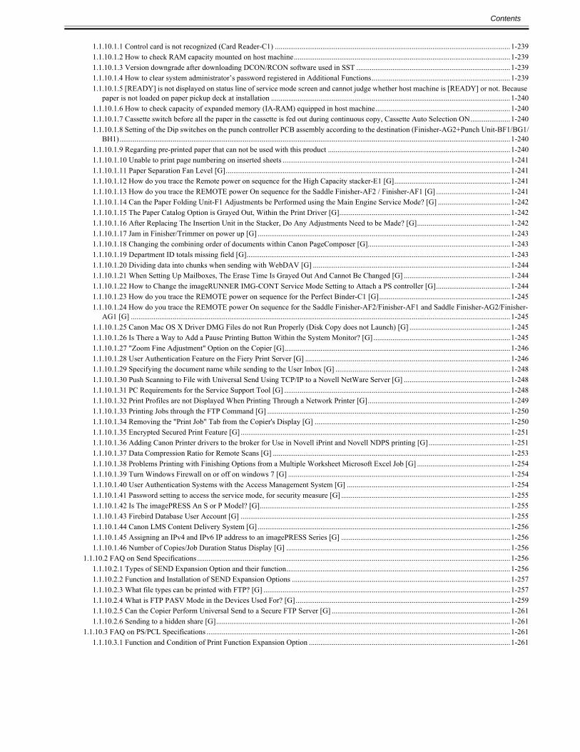
Check and see if the bushings that lock in the transfer roller (underside of the ITB Assembly) are in place. The P/N for the bushings are :FC7-9299 for the rightand FC7-9298 for the left. These will hold the transfer roller to the proper height.
FC7-9298 BUSHING (left)FC7-9299 BUSHING (right)
1.1.1.2 Foggy Image
1.1.1.2.1 Dark image appears in edge of image when using 13x19 paper size copy paper0022-9623
imagePRESS 1110 / imagePRESS 1125 / imagePRESS 1135
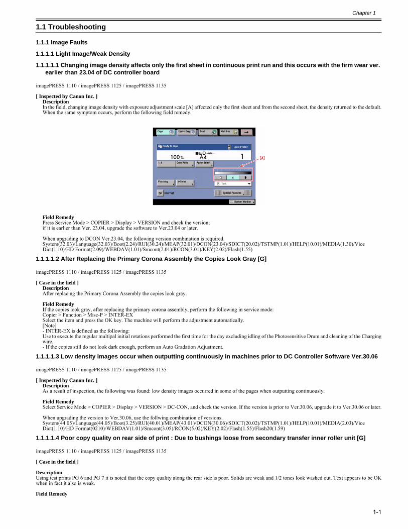
[ Verified by Canon Inc. ]DescriptionThere is symptom which dark image appears in the edge of image when using 13x19 paper size copy paper. When the similar symptom occurs, follow the stepsbelow.
CauseBecause toner layer in the edge of the developing sleeve clutter.
Chapter 1
1-3
Field RemedyExecute the below service mode, and adjust the right edge registration position.Service Mode > COPIER > Adjust > FEED-ADJ > REG-R, input the value number of the front side in the first row, and the value number of the back side inthe second row.[Reference] As the value is changed by 1, the image is shifted by 0.1 mm toward the horizontal scanning direction.+ : toward rear (right edge margin is decreased)- : toward front (right edge margin is increased)
1.1.1.2.2 Reduction of time for adjusting solid and halftone density0028-1412
imagePRESS 1110 / imagePRESS 1125 / imagePRESS 1135
[ Verified by Canon Inc. ]Step1
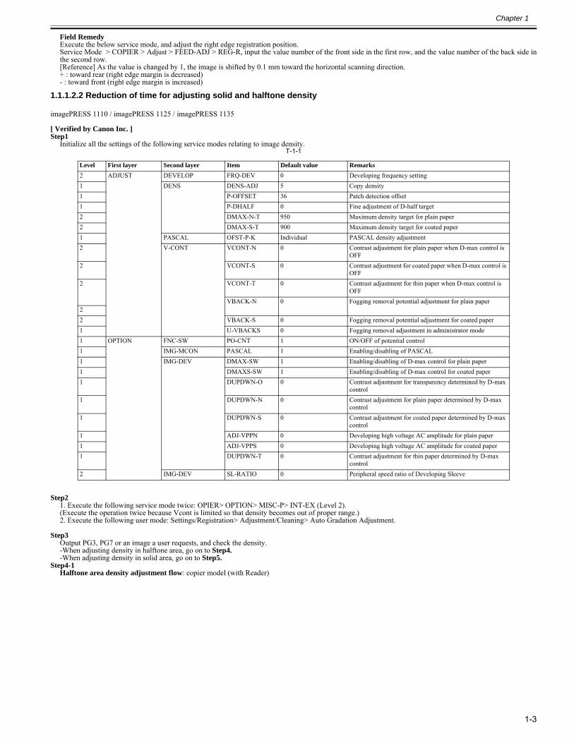
Initialize all the settings of the following service modes relating to image density.T-1-1
Step21. Execute the following service mode twice: OPIER> OPTION> MISC-P> INT-EX (Level 2). (Execute the operation twice because Vcont is limited so that density becomes out of proper range.)2. Execute the following user mode: Settings/Registration> Adjustment/Cleaning> Auto Gradation Adjustment.
Step3Output PG3, PG7 or an image a user requests, and check the density.-When adjusting density in halftone area, go on to Step4.-When adjusting density in solid area, go on to Step5.
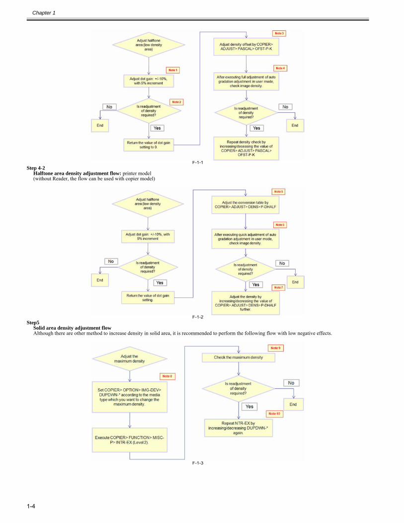
Step4-1Halftone area density adjustment flow: copier model (with Reader)
Level First layer Second layer Item Default value Remarks2 ADJUST DEVELOP FRQ-DEV 0 Developing frequency setting1 DENS DENS-ADJ 5 Copy density1 P-OFFSET 36 Patch detection offset1 P-DHALF 0 Fine adjustment of D-half target2 DMAX-N-T 950 Maximum density target for plain paper2 DMAX-S-T 900 Maximum density target for coated paper1 PASCAL OFST-P-K Individual PASCAL density adjustment2 V-CONT VCONT-N 0 Contrast adjustment for plain paper when D-max control is
OFF2 VCONT-S 0 Contrast adjustment for coated paper when D-max control is
OFF2 VCONT-T 0 Contrast adjustment for thin paper when D-max control is
OFFVBACK-N 0 Fogging removal potential adjustment for plain paper
22 VBACK-S 0 Fogging removal potential adjustment for coated paper1 U-VBACKS 0 Fogging removal adjustment in administrator mode1 OPTION FNC-SW PO-CNT 1 ON/OFF of potential control1 IMG-MCON PASCAL 1 Enabling/disabling of PASCAL1 IMG-DEV DMAX-SW 1 Enabling/disabling of D-max control for plain paper1 DMAXS-SW 1 Enabling/disabling of D-max control for coated paper1 DUPDWN-O 0 Contrast adjustment for transparency determined by D-max
control1 DUPDWN-N 0 Contrast adjustment for plain paper determined by D-max
control1 DUPDWN-S 0 Contrast adjustment for coated paper determined by D-max
control1 ADJ-VPPN 0 Developing high voltage AC amplitude for plain paper1 ADJ-VPPS 0 Developing high voltage AC amplitude for coated paper1 DUPDWN-T 0 Contrast adjustment for thin paper determined by D-max
control2 IMG-DEV SL-RATIO 0 Peripheral speed ratio of Developing Sleeve
Chapter 1
1-4
F-1-1Step 4-2
Halftone area density adjustment flow: printer model (without Reader, the flow can be used with copier model)
F-1-2Step5
Solid area density adjustment flow Although there are other method to increase density in solid area, it is recommended to perform the following flow with low negative effects.
F-1-3
Chapter 1
1-5
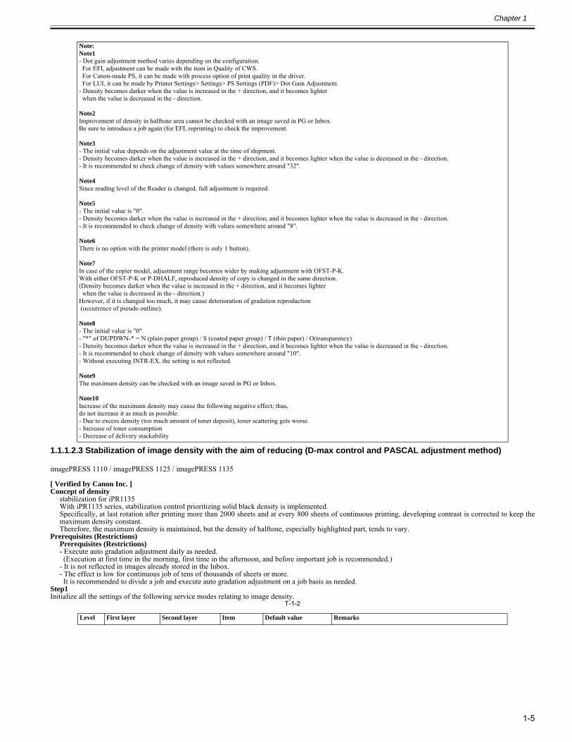
1.1.1.2.3 Stabilization of image density with the aim of reducing (D-max control and PASCAL adjustment method)0028-1426
imagePRESS 1110 / imagePRESS 1125 / imagePRESS 1135
[ Verified by Canon Inc. ]Concept of density
stabilization for iPR1135With iPR1135 series, stabilization control prioritizing solid black density is implemented.Specifically, at last rotation after printing more than 2000 sheets and at every 800 sheets of continuous printing, developing contrast is corrected to keep themaximum density constant.Therefore, the maximum density is maintained, but the density of halftone, especially highlighted part, tends to vary.
Prerequisites (Restrictions)Prerequisites (Restrictions)- Execute auto gradation adjustment daily as needed. (Execution at first time in the morning, first time in the afternoon, and before important job is recommended.)- It is not reflected in images already stored in the Inbox.- The effect is low for continuous job of tens of thousands of sheets or more. It is recommended to divide a job and execute auto gradation adjustment on a job basis as needed.
Step1Initialize all the settings of the following service modes relating to image density.
T-1-2
Note:Note1- Dot gain adjustment method varies depending on the configuration. For EFI, adjustment can be made with the item in Quality of CWS. For Canon-made PS, it can be made with process option of print quality in the driver. For LUI, it can be made by Printer Settings> Settings> PS Settings (PDF)> Dot Gain Adjustment.- Density becomes darker when the value is increased in the + direction, and it becomes lighter when the value is decreased in the - direction.
Note2Improvement of density in halftone area cannot be checked with an image saved in PG or Inbox.Be sure to introduce a job again (for EFI, reprinting) to check the improvement.
Note3- The initial value depends on the adjustment value at the time of shipment.- Density becomes darker when the value is increased in the + direction, and it becomes lighter when the value is decreased in the - direction.- It is recommended to check change of density with values somewhere around "32".
Note4Since reading level of the Reader is changed, full adjustment is required.
Note5- The initial value is "0".- Density becomes darker when the value is increased in the + direction, and it becomes lighter when the value is decreased in the - direction.- It is recommended to check change of density with values somewhere around "8".
Note6There is no option with the printer model (there is only 1 button).
Note7In case of the copier model, adjustment range becomes wider by making adjustment with OFST-P-K.With either OFST-P-K or P-DHALF, reproduced density of copy is changed in the same direction. (Density becomes darker when the value is increased in the + direction, and it becomes lighter when the value is decreased in the - direction.)However, if it is changed too much, it may cause deterioration of gradation reproduction (occurrence of pseudo outline).
Note8- The initial value is "0".- "*" of DUPDWN-* = N (plain paper group) / S (coated paper group) / T (thin paper) / O(transparency)- Density becomes darker when the value is increased in the + direction, and it becomes lighter when the value is decreased in the - direction.- It is recommended to check change of density with values somewhere around "10".- Without executing INTR-EX, the setting is not reflected.
Note9The maximum density can be checked with an image saved in PG or Inbox.
Note10Increase of the maximum density may cause the following negative effect; thus, do not increase it as much as possible.- Due to excess density (too much amount of toner deposit), toner scattering gets worse.- Increase of toner consumption- Decrease of delivery stackability
Level First layer Second layer Item Default value Remarks
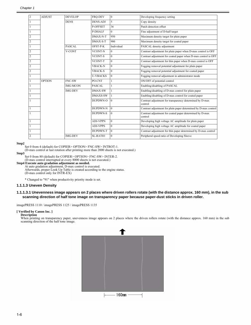
Chapter 1
1-6
Step2Set 0 from 4 (default) for COPIER> OPTION> FNC-SW> INTROT-1. (D-max control at last rotation after printing more than 2000 sheets is not executed.)
Step3Set 0 from 80 (default) for COPIER> OPTION> FNC-SW> INTER-2. (D-max control interrupted at every 8000 sheets is not executed.)
Step4 Execute auto gradation adjustment as needed. At auto gradation adjustment, D-max control is executed. Afterwards, proper Look Up Table is created according to the engine status.(D-max control only for INTR-EX)
* Changed to "91" when productivity priority mode is set.
1.1.1.3 Uneven Density
1.1.1.3.1 Unevenness image appears on 2 places where driven rollers rotate (with the distance approx. 160 mm), in the sub scanning direction of half tone image on transparency paper because paper-dust sticks in driven roller.
0022-9655
imagePRESS 1110 / imagePRESS 1125 / imagePRESS 1135
[ Verified by Canon Inc. ]DescriptionWhen printing on transparency paper, unevenness image appears on 2 places where the driven rollers rotate (with the distance approx. 160 mm) in the subscanning direction of the half tone image.
2 ADJUST DEVELOP FRQ-DEV 0 Developing frequency setting
1 DENS DENS-ADJ 5 Copy density
1 P-OFFSET 36 Patch detection offset
1 P-DHALF 0 Fine adjustment of D-half target
2 DMAX-N-T 950 Maximum density target for plain paper
2 DMAX-S-T 900 Maximum density target for coated paper
1 PASCAL OFST-P-K Individual PASCAL density adjustment
2 V-CONT VCONT-N 0 Contrast adjustment for plain paper when D-max control is OFF
2 VCONT-S 0 Contrast adjustment for coated paper when D-max control is OFF
2 VCONT-T 0 Contrast adjustment for thin paper when D-max control is OFF
2 VBACK-N 0 Fogging removal potential adjustment for plain paper
2 VBACK-S 0 Fogging removal potential adjustment for coated paper
1 U-VBACKS 0 Fogging removal adjustment in administrator mode
1 OPTION FNC-SW PO-CNT 1 ON/OFF of potential control
1 IMG-MCON PASCAL 1 Enabling/disabling of PASCAL
1 IMG-DEV DMAX-SW 1 Enabling/disabling of D-max control for plain paper
1 DMAXS-SW 1 Enabling/disabling of D-max control for coated paper
1 DUPDWN-O 0 Contrast adjustment for transparency determined by D-max control
1 DUPDWN-N 0 Contrast adjustment for plain paper determined by D-max control
1 DUPDWN-S 0 Contrast adjustment for coated paper determined by D-max control
1 ADJ-VPPN 0 Developing high voltage AC amplitude for plain paper
1 ADJ-VPPS 0 Developing high voltage AC amplitude for coated paper
1 DUPDWN-T 0 Contrast adjustment for thin paper determined by D-max control
2 IMG-DEV SL-RATIO 0 Peripheral speed ratio of Developing Sleeve
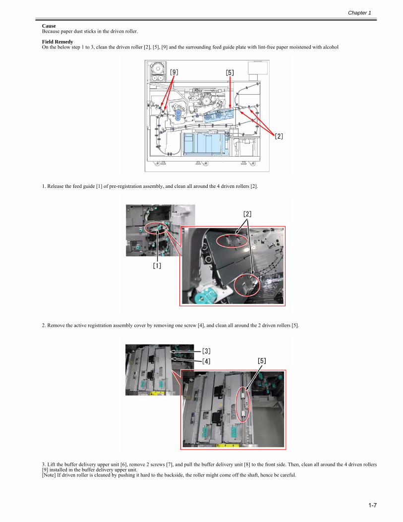
Chapter 1
1-7
CauseBecause paper dust sticks in the driven roller.
Field RemedyOn the below step 1 to 3, clean the driven roller [2], [5], [9] and the surrounding feed guide plate with lint-free paper moistened with alcohol
1. Release the feed guide [1] of pre-registration assembly, and clean all around the 4 driven rollers [2].
2. Remove the active registration assembly cover by removing one screw [4], and clean all around the 2 driven rollers [5].
3. Lift the buffer delivery upper unit [6], remove 2 screws [7], and pull the buffer delivery unit [8] to the front side. Then, clean all around the 4 driven rollers[9] installed in the buffer delivery upper unit.[Note] If driven roller is cleaned by pushing it hard to the backside, the roller might come off the shaft, hence be careful.
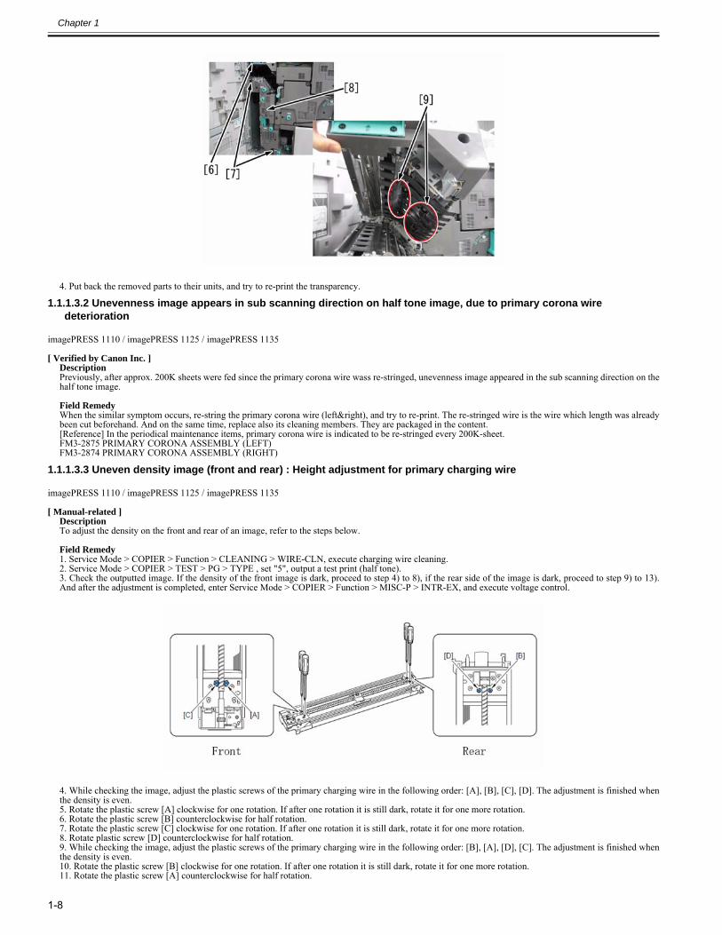
Chapter 1
1-8
4. Put back the removed parts to their units, and try to re-print the transparency.
1.1.1.3.2 Unevenness image appears in sub scanning direction on half tone image, due to primary corona wire deterioration
0022-9667
imagePRESS 1110 / imagePRESS 1125 / imagePRESS 1135
[ Verified by Canon Inc. ]DescriptionPreviously, after approx. 200K sheets were fed since the primary corona wire wass re-stringed, unevenness image appeared in the sub scanning direction on thehalf tone image.
Field RemedyWhen the similar symptom occurs, re-string the primary corona wire (left&right), and try to re-print. The re-stringed wire is the wire which length was alreadybeen cut beforehand. And on the same time, replace also its cleaning members. They are packaged in the content.[Reference] In the periodical maintenance items, primary corona wire is indicated to be re-stringed every 200K-sheet.FM3-2875 PRIMARY CORONA ASSEMBLY (LEFT)FM3-2874 PRIMARY CORONA ASSEMBLY (RIGHT)
1.1.1.3.3 Uneven density image (front and rear) : Height adjustment for primary charging wire0023-2471
imagePRESS 1110 / imagePRESS 1125 / imagePRESS 1135
[ Manual-related ]DescriptionTo adjust the density on the front and rear of an image, refer to the steps below.
Field Remedy1. Service Mode > COPIER > Function > CLEANING > WIRE-CLN, execute charging wire cleaning.2. Service Mode > COPIER > TEST > PG > TYPE , set "5", output a test print (half tone).3. Check the outputted image. If the density of the front image is dark, proceed to step 4) to 8), if the rear side of the image is dark, proceed to step 9) to 13).And after the adjustment is completed, enter Service Mode > COPIER > Function > MISC-P > INTR-EX, and execute voltage control.
4. While checking the image, adjust the plastic screws of the primary charging wire in the following order: [A], [B], [C], [D]. The adjustment is finished whenthe density is even.5. Rotate the plastic screw [A] clockwise for one rotation. If after one rotation it is still dark, rotate it for one more rotation.6. Rotate the plastic screw [B] counterclockwise for half rotation.7. Rotate the plastic screw [C] clockwise for one rotation. If after one rotation it is still dark, rotate it for one more rotation.8. Rotate plastic screw [D] counterclockwise for half rotation.9. While checking the image, adjust the plastic screws of the primary charging wire in the following order: [B], [A], [D], [C]. The adjustment is finished whenthe density is even.10. Rotate the plastic screw [B] clockwise for one rotation. If after one rotation it is still dark, rotate it for one more rotation.11. Rotate the plastic screw [A] counterclockwise for half rotation.
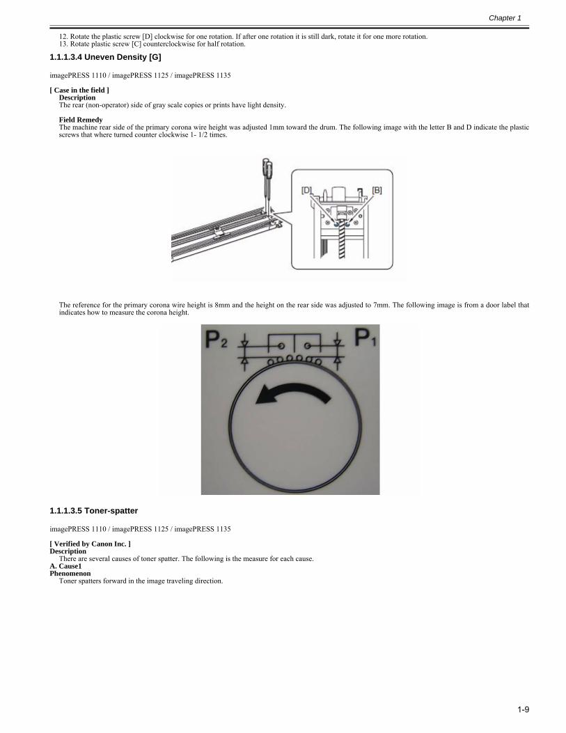
Chapter 1
1-9
12. Rotate the plastic screw [D] clockwise for one rotation. If after one rotation it is still dark, rotate it for one more rotation.13. Rotate plastic screw [C] counterclockwise for half rotation.
1.1.1.3.4 Uneven Density [G]0025-3953
imagePRESS 1110 / imagePRESS 1125 / imagePRESS 1135
[ Case in the field ]DescriptionThe rear (non-operator) side of gray scale copies or prints have light density. Field RemedyThe machine rear side of the primary corona wire height was adjusted 1mm toward the drum. The following image with the letter B and D indicate the plasticscrews that where turned counter clockwise 1- 1/2 times.
The reference for the primary corona wire height is 8mm and the height on the rear side was adjusted to 7mm. The following image is from a door label thatindicates how to measure the corona height.
1.1.1.3.5 Toner-spatter0028-1373
imagePRESS 1110 / imagePRESS 1125 / imagePRESS 1135
[ Verified by Canon Inc. ]Description
There are several causes of toner spatter. The following is the measure for each cause.A. Cause1Phenomenon
Toner spatters forward in the image traveling direction.
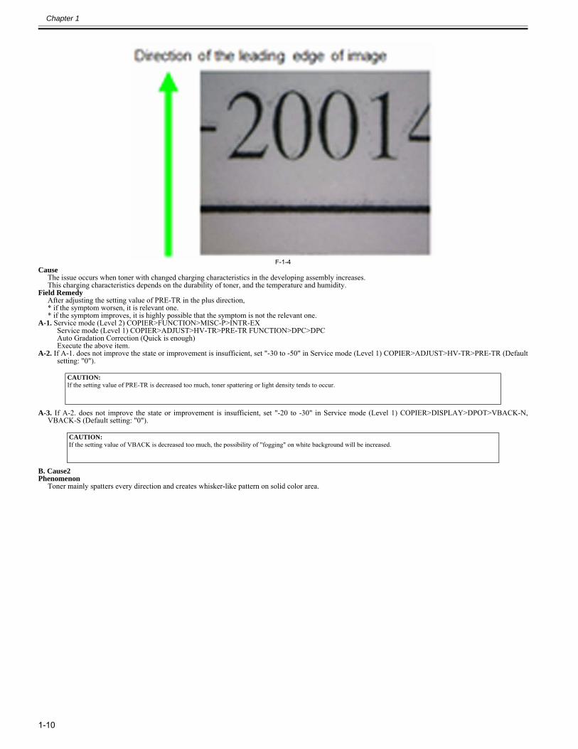
Chapter 1
1-10
F-1-4Cause
The issue occurs when toner with changed charging characteristics in the developing assembly increases.This charging characteristics depends on the durability of toner, and the temperature and humidity.
Field RemedyAfter adjusting the setting value of PRE-TR in the plus direction,* if the symptom worsen, it is relevant one.* if the symptom improves, it is highly possible that the symptom is not the relevant one.
A-1. Service mode (Level 2) COPIER>FUNCTION>MISC-P>INTR-EXService mode (Level 1) COPIER>ADJUST>HV-TR>PRE-TR FUNCTION>DPC>DPCAuto Gradation Correction (Quick is enough)Execute the above item.
A-2. If A-1. does not improve the state or improvement is insufficient, set "-30 to -50" in Service mode (Level 1) COPIER>ADJUST>HV-TR>PRE-TR (Defaultsetting: "0").
A-3. If A-2. does not improve the state or improvement is insufficient, set "-20 to -30" in Service mode (Level 1) COPIER>DISPLAY>DPOT>VBACK-N,VBACK-S (Default setting: "0").
B. Cause2Phenomenon
Toner mainly spatters every direction and creates whisker-like pattern on solid color area.
CAUTION:If the setting value of PRE-TR is decreased too much, toner spattering or light density tends to occur.
CAUTION:If the setting value of VBACK is decreased too much, the possibility of "fogging" on white background will be increased.
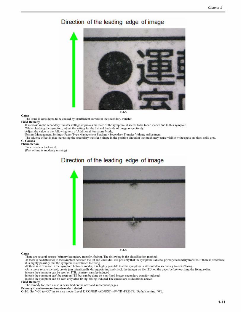
Chapter 1
1-11
F-1-5Cause
The issue is considered to be caused by insufficient current in the secondary transfer.Field Remedy
If increase in the secondary transfer voltage improves the state of the symptom, it seems to be toner spatter due to this symptom.While checking the symptom, adjust the setting for the 1st and 2nd side of image respectively.Adjust the value in the following item of Additional Functions Mode;System Management Settings>Paper Type Management Settings> Secondary Transfer Voltage Adjustment.The adverse effect is that increasing the secondary transfer voltage in the positive direction too much may cause visible white spots on black solid area.
C. Cause3Phenomenon
Toner spatters backward.(Part of line is suddenly missing)
F-1-6Cause
There are several causes (primary/secondary transfer, fixing). The following is the classification method;-If there is no difference in the symptom between the 1st and 2nd sides, it is possibly that the symptom is due to primary/secondary transfer. If there is difference,it is highly possibly that the symptom is attributed to fixing. -If there is difference in the symptom between media, it is highly possible that the symptom is attributed to secondary transfer/fixing.-As a more secure method, create jam intentionally during printing and check the images on the ITB, on the paper before touching the fixing roller.in case the symptom can be seen on ITB: primary transfer-inducedin case the symptom can't be seen on ITB but can be done on non-fixed image: secondary transfer-inducedin case the symptom can be seen only after fixing: fixing-induced The causes are as described above.
Field RemedyThe remedy for each cause is described on the next and subsequent pages.
Primary transfer-/secondary-transfer relatedC-1-1. Set "+30 to +50" in Service mode (Level 1) COPIER>ADJUST>HV-TR>PRE-TR (Default setting: "0").
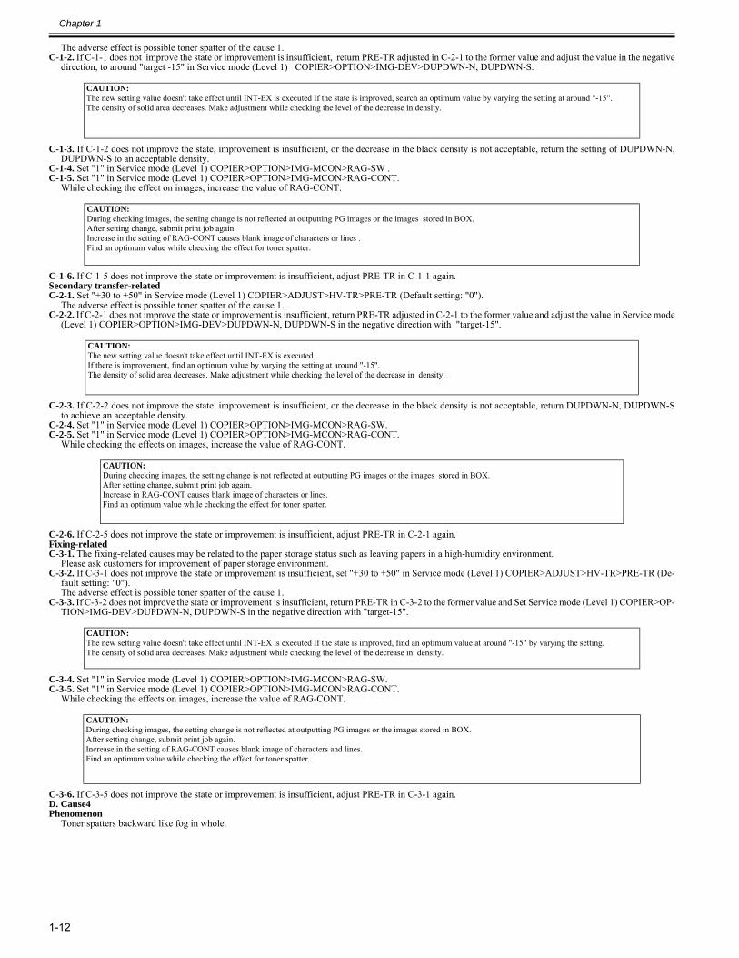
Chapter 1
1-12
The adverse effect is possible toner spatter of the cause 1.C-1-2. If C-1-1 does not improve the state or improvement is insufficient, return PRE-TR adjusted in C-2-1 to the former value and adjust the value in the negative
direction, to around "target -15" in Service mode (Level 1) COPIER>OPTION>IMG-DEV>DUPDWN-N, DUPDWN-S.
C-1-3. If C-1-2 does not improve the state, improvement is insufficient, or the decrease in the black density is not acceptable, return the setting of DUPDWN-N,DUPDWN-S to an acceptable density.
C-1-4. Set "1" in Service mode (Level 1) COPIER>OPTION>IMG-MCON>RAG-SW .C-1-5. Set "1" in Service mode (Level 1) COPIER>OPTION>IMG-MCON>RAG-CONT.
While checking the effect on images, increase the value of RAG-CONT.
C-1-6. If C-1-5 does not improve the state or improvement is insufficient, adjust PRE-TR in C-1-1 again.Secondary transfer-relatedC-2-1. Set "+30 to +50" in Service mode (Level 1) COPIER>ADJUST>HV-TR>PRE-TR (Default setting: "0").
The adverse effect is possible toner spatter of the cause 1.C-2-2. If C-2-1 does not improve the state or improvement is insufficient, return PRE-TR adjusted in C-2-1 to the former value and adjust the value in Service mode
(Level 1) COPIER>OPTION>IMG-DEV>DUPDWN-N, DUPDWN-S in the negative direction with "target-15".
C-2-3. If C-2-2 does not improve the state, improvement is insufficient, or the decrease in the black density is not acceptable, return DUPDWN-N, DUPDWN-Sto achieve an acceptable density.
C-2-4. Set "1" in Service mode (Level 1) COPIER>OPTION>IMG-MCON>RAG-SW.C-2-5. Set "1" in Service mode (Level 1) COPIER>OPTION>IMG-MCON>RAG-CONT.
While checking the effects on images, increase the value of RAG-CONT.
C-2-6. If C-2-5 does not improve the state or improvement is insufficient, adjust PRE-TR in C-2-1 again.Fixing-relatedC-3-1. The fixing-related causes may be related to the paper storage status such as leaving papers in a high-humidity environment.
Please ask customers for improvement of paper storage environment.C-3-2. If C-3-1 does not improve the state or improvement is insufficient, set "+30 to +50" in Service mode (Level 1) COPIER>ADJUST>HV-TR>PRE-TR (De-
fault setting: "0"). The adverse effect is possible toner spatter of the cause 1.
C-3-3. If C-3-2 does not improve the state or improvement is insufficient, return PRE-TR in C-3-2 to the former value and Set Service mode (Level 1) COPIER>OP-TION>IMG-DEV>DUPDWN-N, DUPDWN-S in the negative direction with "target-15".
C-3-4. Set "1" in Service mode (Level 1) COPIER>OPTION>IMG-MCON>RAG-SW.C-3-5. Set "1" in Service mode (Level 1) COPIER>OPTION>IMG-MCON>RAG-CONT.
While checking the effects on images, increase the value of RAG-CONT.
C-3-6. If C-3-5 does not improve the state or improvement is insufficient, adjust PRE-TR in C-3-1 again.D. Cause4Phenomenon
Toner spatters backward like fog in whole.
CAUTION:The new setting value doesn't take effect until INT-EX is executed If the state is improved, search an optimum value by varying the setting at around "-15".The density of solid area decreases. Make adjustment while checking the level of the decrease in density.
CAUTION:During checking images, the setting change is not reflected at outputting PG images or the images stored in BOX.After setting change, submit print job again.Increase in the setting of RAG-CONT causes blank image of characters or lines .Find an optimum value while checking the effect for toner spatter.
CAUTION:The new setting value doesn't take effect until INT-EX is executedIf there is improvement, find an optimum value by varying the setting at around "-15".The density of solid area decreases. Make adjustment while checking the level of the decrease in density.
CAUTION:During checking images, the setting change is not reflected at outputting PG images or the images stored in BOX. After setting change, submit print job again.Increase in RAG-CONT causes blank image of characters or lines.Find an optimum value while checking the effect for toner spatter.
CAUTION:The new setting value doesn't take effect until INT-EX is executed If the state is improved, find an optimum value at around "-15" by varying the setting.The density of solid area decreases. Make adjustment while checking the level of the decrease in density.
CAUTION:During checking images, the setting change is not reflected at outputting PG images or the images stored in BOX. After setting change, submit print job again.Increase in the setting of RAG-CONT causes blank image of characters and lines.Find an optimum value while checking the effect for toner spatter.
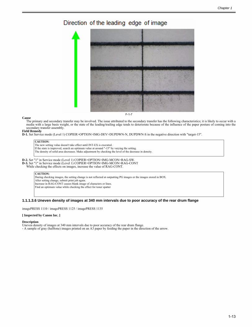
Chapter 1
1-13
F-1-7Cause
The primary and secondary transfer may be involved. The issue attributed to the secondary transfer has the following characteristics; it is likely to occur with amedia with a large basis weight, or the state of the leading/trailing edge tends to deteriorate because of the influence of the paper posture of coming into thesecondary transfer assembly.
Field RemedyD-1. Set Service mode (Level 1) COPIER>OPTION>IMG-DEV>DUPDWN-N, DUPDWN-S in the negative direction with "target-15".
D-2. Set "1" in Service mode (Level 1) COPIER>OPTION>IMG-MCON>RAG-SW.D-3. Set "1" in Service mode (Level 1) COPIER>OPTION>IMG-MCON>RAG-CONT
While checking the effects on images, increase the value of RAG-CONT.
1.1.1.3.6 Uneven density of images at 340 mm intervals due to poor accuracy of the rear drum flange0028-3809
imagePRESS 1110 / imagePRESS 1125 / imagePRESS 1135
[ Inspected by Canon Inc. ]
DescriptionUneven density of images at 340 mm intervals due to poor accuracy of the rear drum flange.- A sample of gray (halftone) images printed on an A3 paper by feeding the paper in the direction of the arrow.
CAUTION:The new setting value doesn't take effect until INT-EX is executed.If the state is improved, search an optimum value at around "-15" by varying the setting.The density of solid area decreases. Make adjustment by checking the level of the decrease in density.
CAUTION:During checking images, the setting change is not reflected at outputting PG images or the images stored in BOX. After setting change, submit print job again.Increase in RAG-CONT causes blank image of characters or lines.Find an optimum value while checking the effect for toner spatter
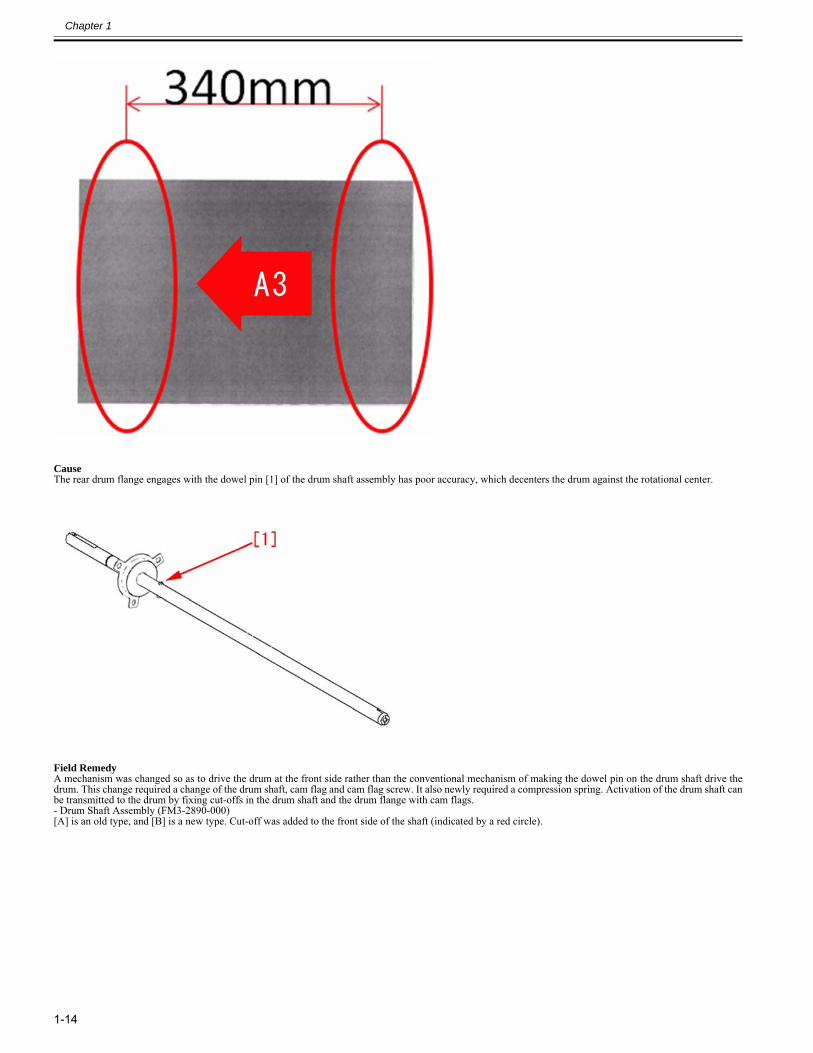
Chapter 1
1-14
CauseThe rear drum flange engages with the dowel pin [1] of the drum shaft assembly has poor accuracy, which decenters the drum against the rotational center.
Field RemedyA mechanism was changed so as to drive the drum at the front side rather than the conventional mechanism of making the dowel pin on the drum shaft drive thedrum. This change required a change of the drum shaft, cam flag and cam flag screw. It also newly required a compression spring. Activation of the drum shaft canbe transmitted to the drum by fixing cut-offs in the drum shaft and the drum flange with cam flags.- Drum Shaft Assembly (FM3-2890-000)[A] is an old type, and [B] is a new type. Cut-off was added to the front side of the shaft (indicated by a red circle).
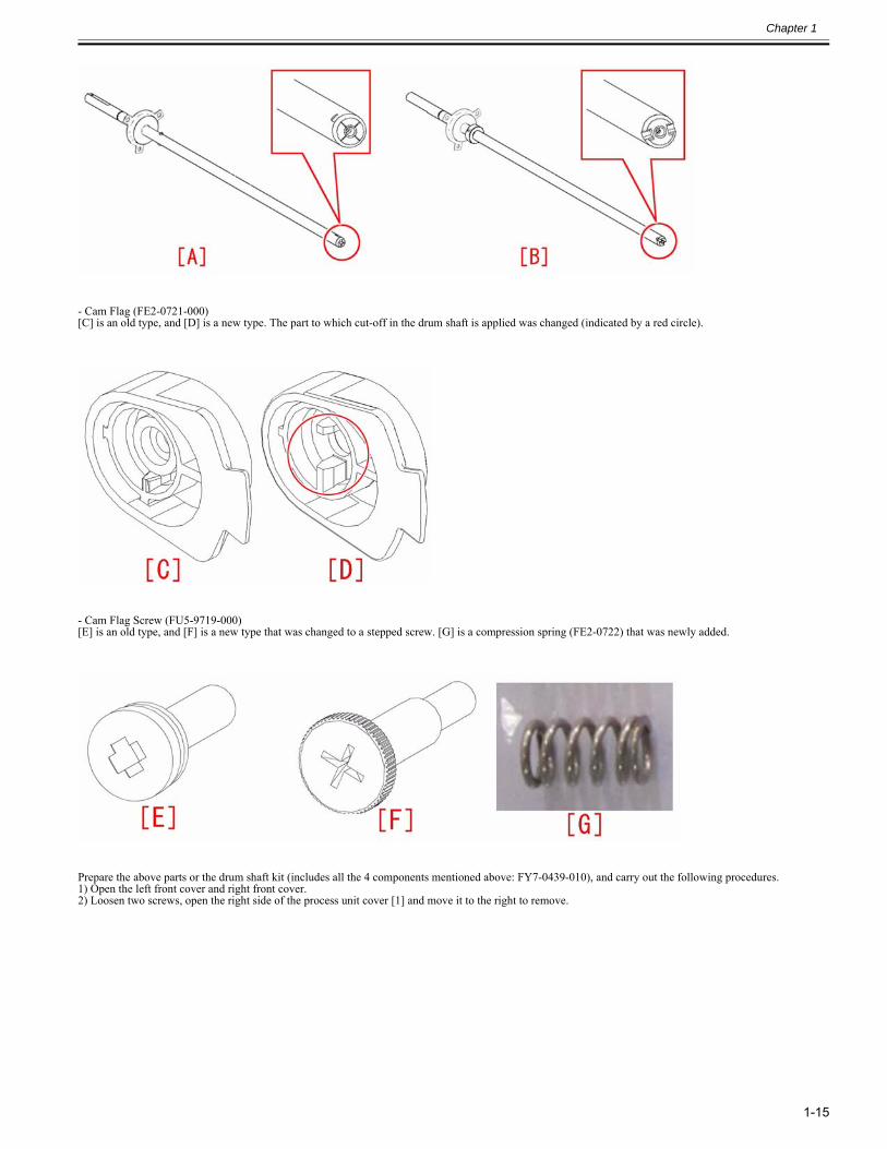
Chapter 1
1-15
- Cam Flag (FE2-0721-000)[C] is an old type, and [D] is a new type. The part to which cut-off in the drum shaft is applied was changed (indicated by a red circle).
- Cam Flag Screw (FU5-9719-000)[E] is an old type, and [F] is a new type that was changed to a stepped screw. [G] is a compression spring (FE2-0722) that was newly added.
Prepare the above parts or the drum shaft kit (includes all the 4 components mentioned above: FY7-0439-010), and carry out the following procedures.1) Open the left front cover and right front cover.2) Loosen two screws, open the right side of the process unit cover [1] and move it to the right to remove.
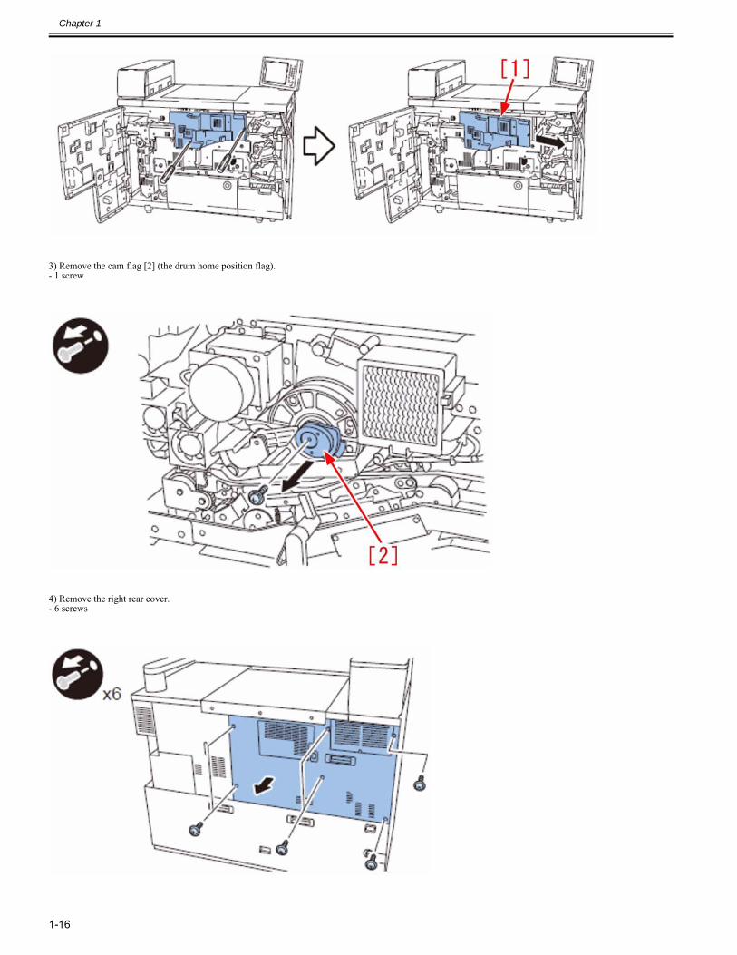
Chapter 1
1-16
3) Remove the cam flag [2] (the drum home position flag).- 1 screw
4) Remove the right rear cover.- 6 screws
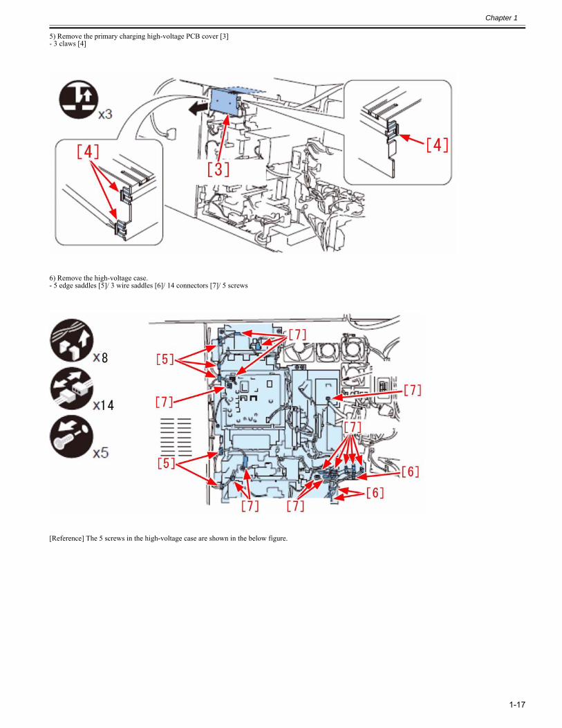
Chapter 1
1-17
5) Remove the primary charging high-voltage PCB cover [3]- 3 claws [4]
6) Remove the high-voltage case.- 5 edge saddles [5]/ 3 wire saddles [6]/ 14 connectors [7]/ 5 screws
[Reference] The 5 screws in the high-voltage case are shown in the below figure.
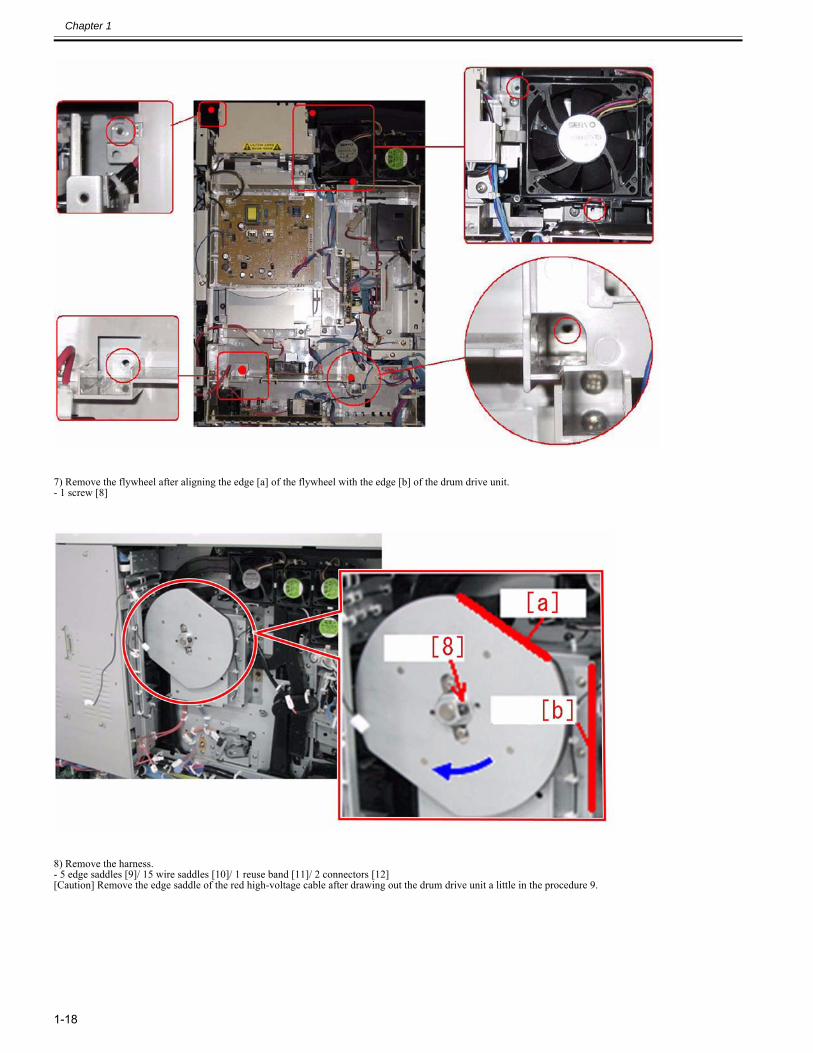
Chapter 1
1-18
7) Remove the flywheel after aligning the edge [a] of the flywheel with the edge [b] of the drum drive unit.- 1 screw [8]
8) Remove the harness.- 5 edge saddles [9]/ 15 wire saddles [10]/ 1 reuse band [11]/ 2 connectors [12][Caution] Remove the edge saddle of the red high-voltage cable after drawing out the drum drive unit a little in the procedure 9.
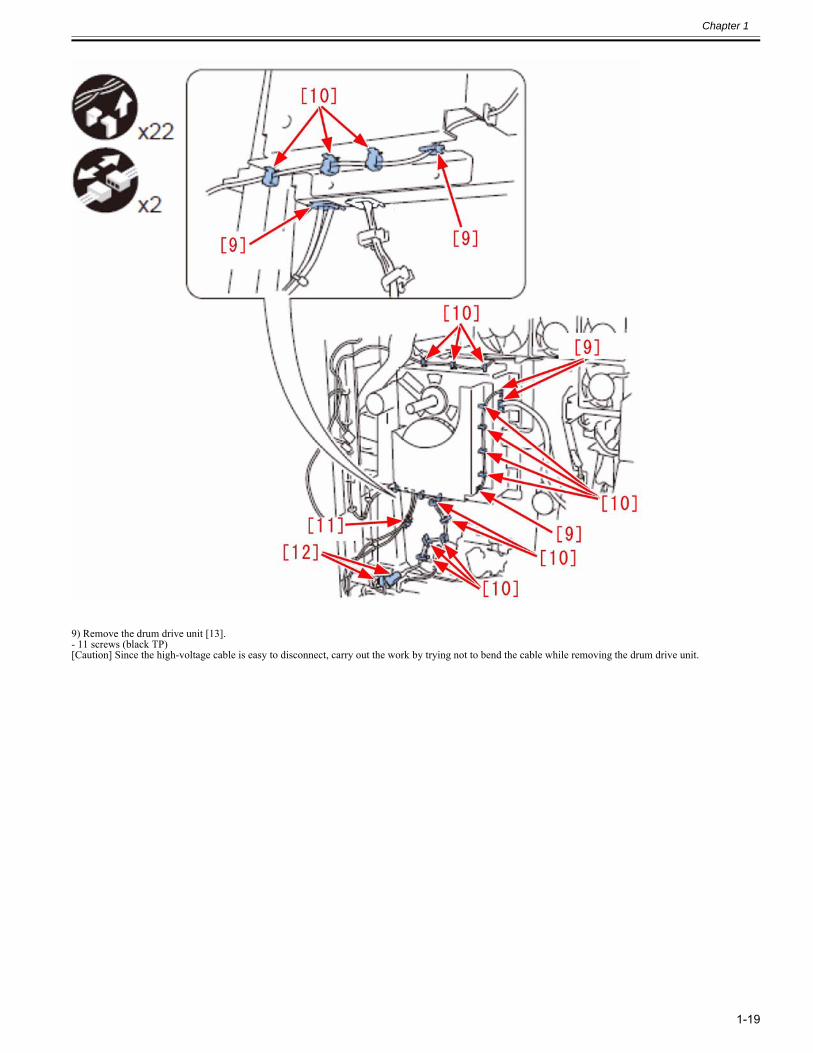
Chapter 1
1-19
9) Remove the drum drive unit [13].- 11 screws (black TP)[Caution] Since the high-voltage cable is easy to disconnect, carry out the work by trying not to bend the cable while removing the drum drive unit.
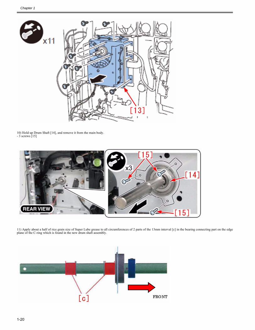
Chapter 1
1-20
10) Hold up Drum Shaft [14], and remove it from the main body.- 3 screws [15]
11) Apply about a half of rice grain size of Super Lube grease to all circumferences of 2 parts of the 13mm interval [c] in the bearing connecting part on the edgeplane of the C-ring which is found in the new drum shaft assembly.
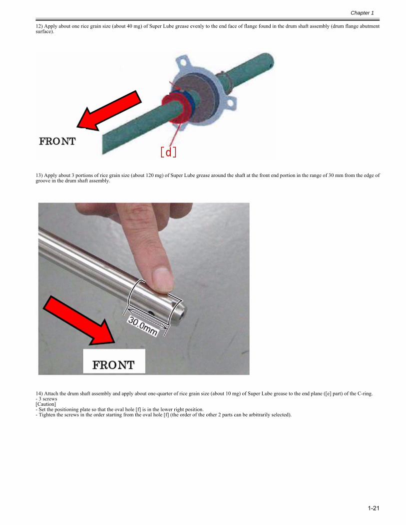
Chapter 1
1-21
12) Apply about one rice grain size (about 40 mg) of Super Lube grease evenly to the end face of flange found in the drum shaft assembly (drum flange abutmentsurface).
13) Apply about 3 portions of rice grain size (about 120 mg) of Super Lube grease around the shaft at the front end portion in the range of 30 mm from the edge ofgroove in the drum shaft assembly.
14) Attach the drum shaft assembly and apply about one-quarter of rice grain size (about 10 mg) of Super Lube grease to the end plane ([e] part) of the C-ring.- 3 screws[Caution]- Set the positioning plate so that the oval hole [f] is in the lower right position.- Tighten the screws in the order starting from the oval hole [f] (the order of the other 2 parts can be arbitrarily selected).
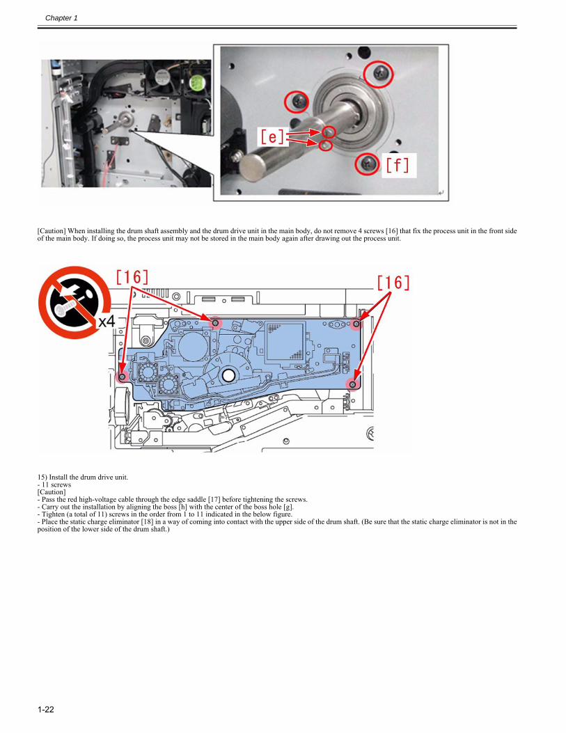
Chapter 1
1-22
[Caution] When installing the drum shaft assembly and the drum drive unit in the main body, do not remove 4 screws [16] that fix the process unit in the front sideof the main body. If doing so, the process unit may not be stored in the main body again after drawing out the process unit.
15) Install the drum drive unit.- 11 screws[Caution]- Pass the red high-voltage cable through the edge saddle [17] before tightening the screws.- Carry out the installation by aligning the boss [h] with the center of the boss hole [g].- Tighten (a total of 11) screws in the order from 1 to 11 indicated in the below figure.- Place the static charge eliminator [18] in a way of coming into contact with the upper side of the drum shaft. (Be sure that the static charge eliminator is not in theposition of the lower side of the drum shaft.)
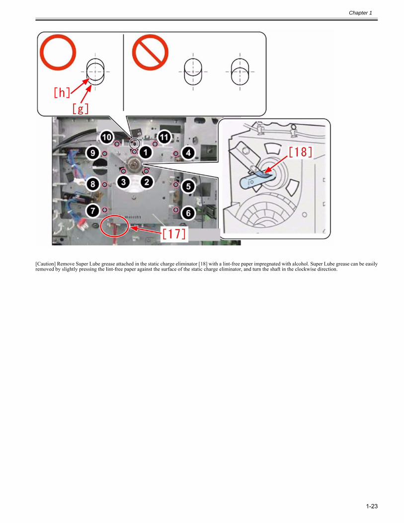
Chapter 1
1-23
[Caution] Remove Super Lube grease attached in the static charge eliminator [18] with a lint-free paper impregnated with alcohol. Super Lube grease can be easilyremoved by slightly pressing the lint-free paper against the surface of the static charge eliminator, and turn the shaft in the clockwise direction.
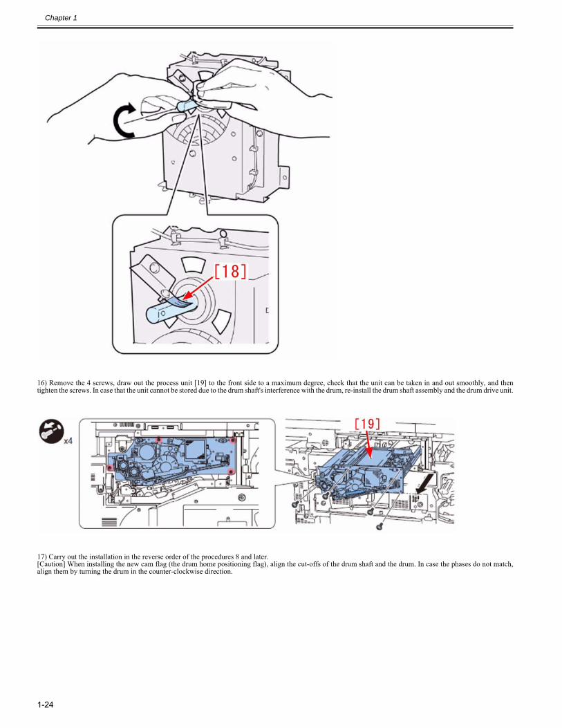
Chapter 1
1-24
16) Remove the 4 screws, draw out the process unit [19] to the front side to a maximum degree, check that the unit can be taken in and out smoothly, and thentighten the screws. In case that the unit cannot be stored due to the drum shaft's interference with the drum, re-install the drum shaft assembly and the drum drive unit.
17) Carry out the installation in the reverse order of the procedures 8 and later.[Caution] When installing the new cam flag (the drum home positioning flag), align the cut-offs of the drum shaft and the drum. In case the phases do not match,align them by turning the drum in the counter-clockwise direction.
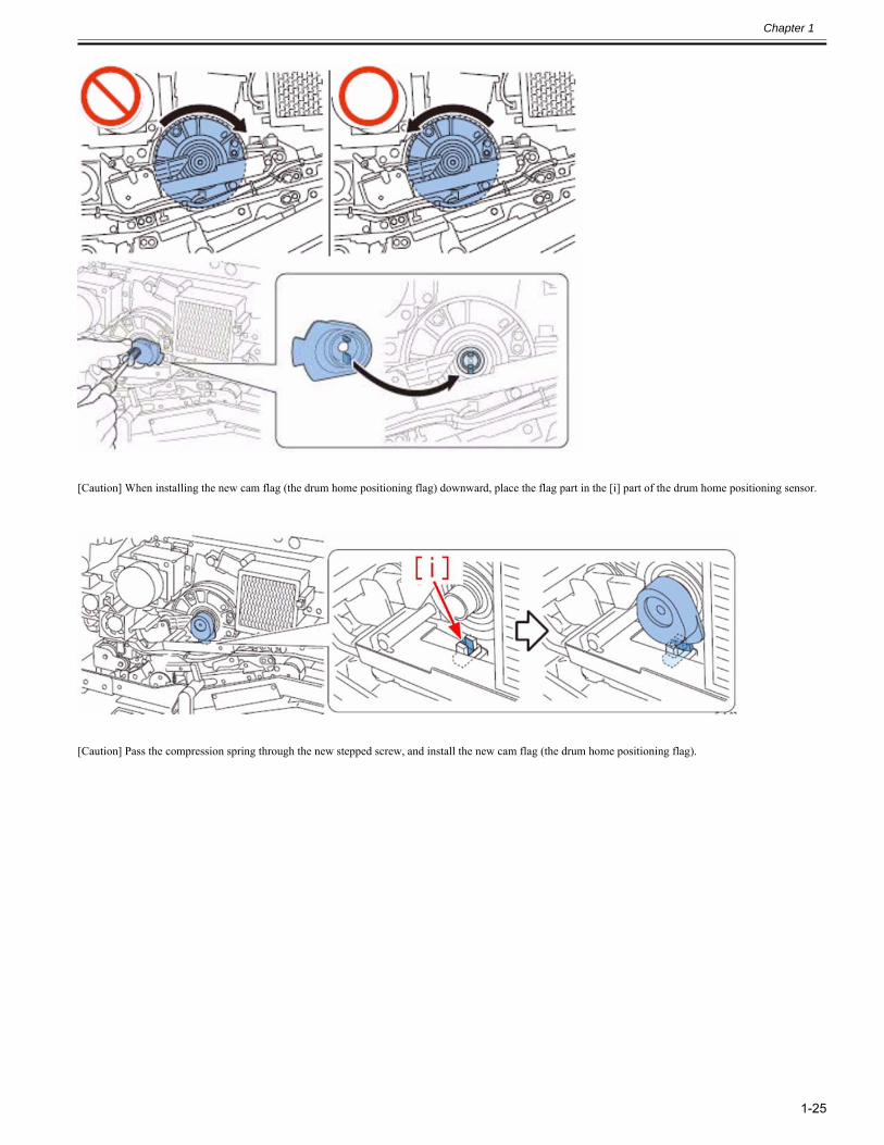
Chapter 1
1-25
[Caution] When installing the new cam flag (the drum home positioning flag) downward, place the flag part in the [i] part of the drum home positioning sensor.
[Caution] Pass the compression spring through the new stepped screw, and install the new cam flag (the drum home positioning flag).
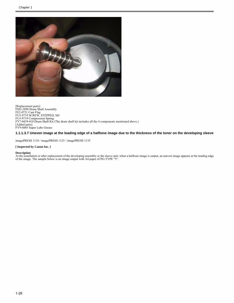
Chapter 1
1-26
[Replacement parts]FM3-2890 Drum Shaft AssemblyFE2-0721 Cam FlagFU5-9719 SCREW, STEPPED, M5FU5-9719 Compression SpringFY7-0439-010 Drum Shaft Kit (The drum shaft kit includes all the 4 components mentioned above.)[Added parts]FY9-6005 Super Lube Grease
1.1.1.3.7 Uneven image at the leading edge of a halftone image due to the thickness of the toner on the developing sleeve0028-4056
imagePRESS 1110 / imagePRESS 1125 / imagePRESS 1135
[ Inspected by Canon Inc. ]
DescriptionAt the installation or after replacement of the developing assembly or the sleeve unit, when a halftone image is output, an uneven image appears at the leading edgeof the image. The sample below is an image output with A4 paper of PG-TYPE "5".
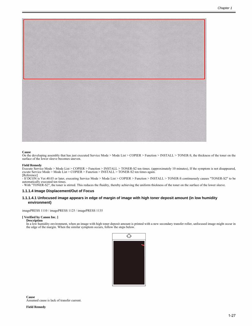
Chapter 1
1-27
CauseOn the developing assembly that has just executed Service Mode > Mode List > COPIER > Function > INSTALL > TONER-S, the thickness of the toner on thesurface of the lower sleeve becomes uneven.
Field RemedyExecute Service Mode > Mode List > COPIER > Function > INSTALL > TONER-S2 ten times. (approximately 10 minutes), If the symptom is not disappeared,excute Service Mode > Mode List > COPIER > Function > INSTALL > TONER-S2 ten times again.[Reference]- If DCON is Ver.40.03 or later, executing Service Mode > Mode List > COPIER > Function > INSTALL > TONER-S continuously causes "TONER-S2" to beautomatically executed ten times.- With "TONER-S2", the toner is stirred. This reduces the fluidity, thereby achieving the uniform thickness of the toner on the surface of the lower sleeve.
1.1.1.4 Image Displacement/Out of Focus
1.1.1.4.1 Unfocused image appears in edge of margin of image with high toner deposit amount (in low humidity environment)
0022-9637
imagePRESS 1110 / imagePRESS 1125 / imagePRESS 1135
[ Verified by Canon Inc. ]DescriptionIn a low humidity environment, when an image with high toner deposit amount is printed with a new secondary transfer roller, unfocused image might occur inthe edge of the margin. When the similar symptom occurs, follow the steps below.
CauseAssumed cause is lack of transfer current.
Field Remedy
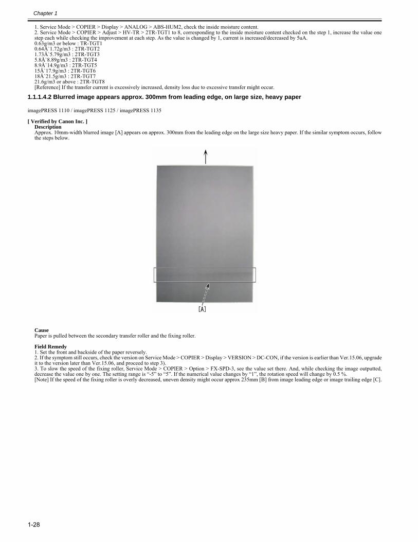
Chapter 1
1-28
1. Service Mode > COPIER > Display > ANALOG > ABS-HUM2, check the inside moisture content.2. Service Mode > COPIER > Adjust > HV-TR > 2TR-TGT1 to 8, corresponding to the inside moisture content checked on the step 1, increase the value onestep each while checking the improvement at each step. As the value is changed by 1, current is increased/decreased by 5uA.0.63g/m3 or below : TR-TGT10.64Å`1.72g/m3 : 2TR-TGT21.73Å`5.79g/m3 : 2TR-TGT35.8Å`8.89g/m3 : 2TR-TGT48.9Å`14.9g/m3 : 2TR-TGT515Å`17.9g/m3 : 2TR-TGT618Å`21.5g/m3 : 2TR-TGT721.6g/m3 or above : 2TR-TGT8[Reference] If the transfer current is excessively increased, density loss due to excessive transfer might occur.
1.1.1.4.2 Blurred image appears approx. 300mm from leading edge, on large size, heavy paper0023-1932
imagePRESS 1110 / imagePRESS 1125 / imagePRESS 1135
[ Verified by Canon Inc. ]DescriptionApprox. 10mm-width blurred image [A] appears on approx. 300mm from the leading edge on the large size heavy paper. If the similar symptom occurs, followthe steps below.
Cause Paper is pulled between the secondary transfer roller and the fixing roller.
Field Remedy1. Set the front and backside of the paper reversely.2. If the symptom still occurs, check the version on Service Mode > COPIER > Display > VERSION > DC-CON, if the version is earlier than Ver.15.06, upgradeit to the version later than Ver.15.06, and proceed to step 3).3. To slow the speed of the fixing roller, Service Mode > COPIER > Option > FX-SPD-3, see the value set there. And, while checking the image outputted,decrease the value one by one. The setting range is “-5” to “5”. If the numerical value changes by “1”, the rotation speed will change by 0.5 %. [Note] If the speed of the fixing roller is overly decreased, uneven density might occur approx 235mm [B] from image leading edge or image trailing edge [C].
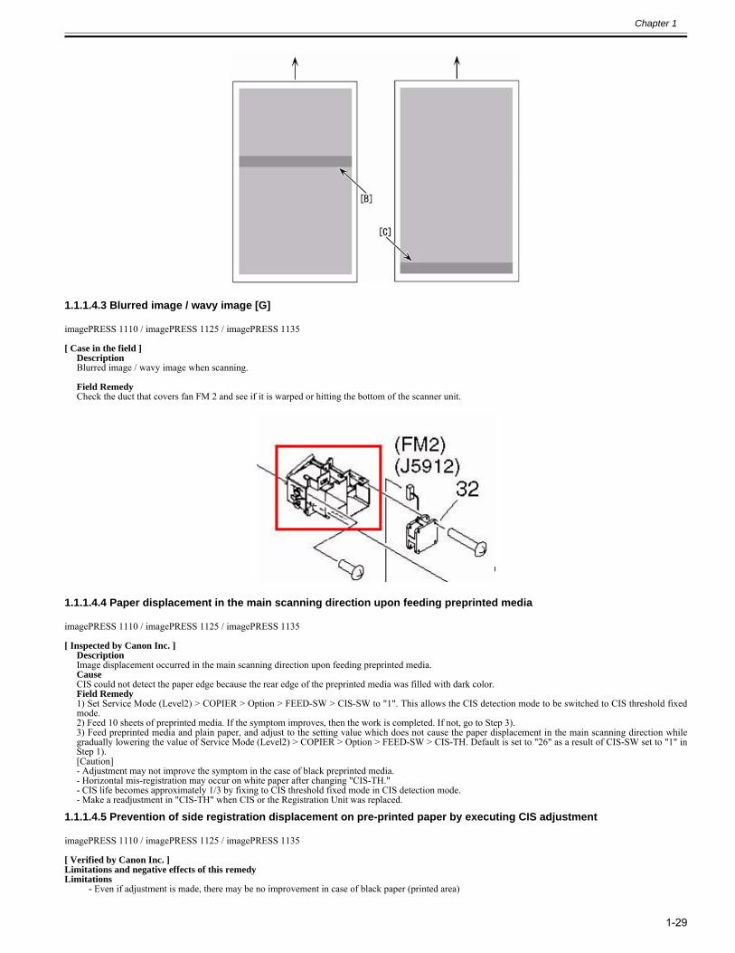
Chapter 1
1-29
1.1.1.4.3 Blurred image / wavy image [G]0025-5240
imagePRESS 1110 / imagePRESS 1125 / imagePRESS 1135
[ Case in the field ]DescriptionBlurred image / wavy image when scanning. Field RemedyCheck the duct that covers fan FM 2 and see if it is warped or hitting the bottom of the scanner unit.
1.1.1.4.4 Paper displacement in the main scanning direction upon feeding preprinted media0027-3502
imagePRESS 1110 / imagePRESS 1125 / imagePRESS 1135
[ Inspected by Canon Inc. ]DescriptionImage displacement occurred in the main scanning direction upon feeding preprinted media.CauseCIS could not detect the paper edge because the rear edge of the preprinted media was filled with dark color.Field Remedy1) Set Service Mode (Level2) > COPIER > Option > FEED-SW > CIS-SW to "1". This allows the CIS detection mode to be switched to CIS threshold fixedmode.2) Feed 10 sheets of preprinted media. If the symptom improves, then the work is completed. If not, go to Step 3).3) Feed preprinted media and plain paper, and adjust to the setting value which does not cause the paper displacement in the main scanning direction whilegradually lowering the value of Service Mode (Level2) > COPIER > Option > FEED-SW > CIS-TH. Default is set to "26" as a result of CIS-SW set to "1" inStep 1). [Caution] - Adjustment may not improve the symptom in the case of black preprinted media.- Horizontal mis-registration may occur on white paper after changing "CIS-TH."- CIS life becomes approximately 1/3 by fixing to CIS threshold fixed mode in CIS detection mode.- Make a readjustment in "CIS-TH" when CIS or the Registration Unit was replaced.
1.1.1.4.5 Prevention of side registration displacement on pre-printed paper by executing CIS adjustment0028-1424
imagePRESS 1110 / imagePRESS 1125 / imagePRESS 1135
[ Verified by Canon Inc. ]Limitations and negative effects of this remedyLimitations
- Even if adjustment is made, there may be no improvement in case of black paper (printed area)
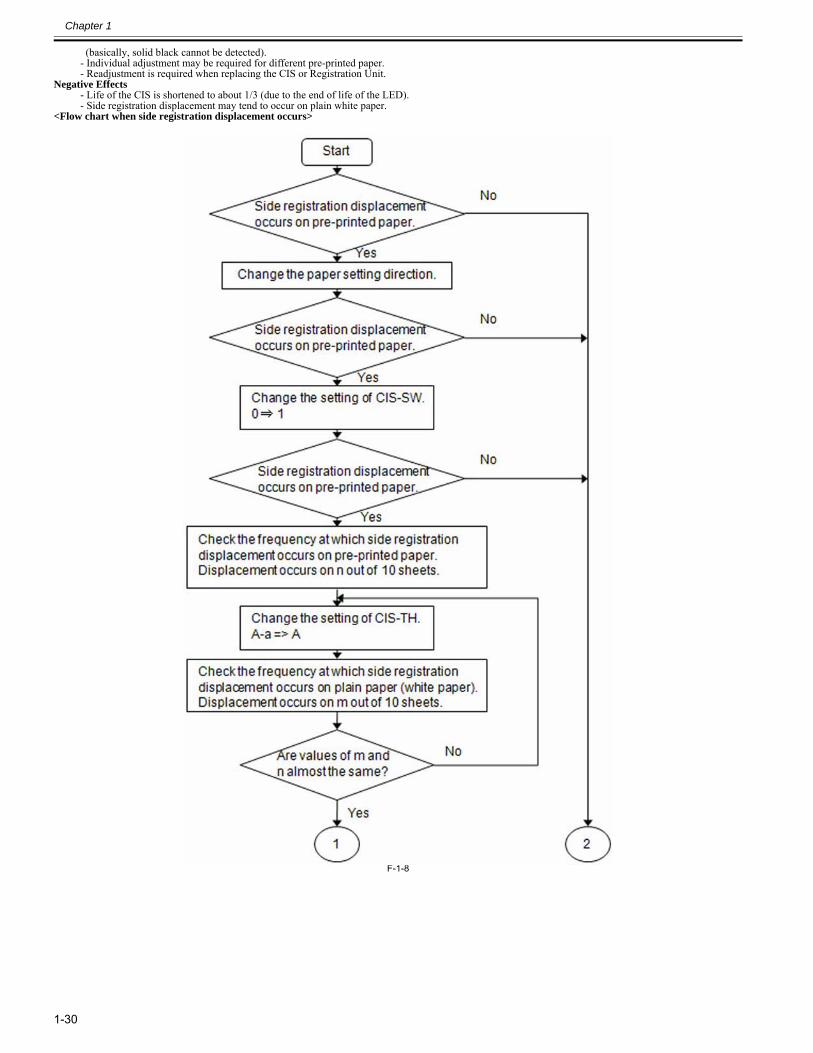
Chapter 1
1-30
(basically, solid black cannot be detected). - Individual adjustment may be required for different pre-printed paper.- Readjustment is required when replacing the CIS or Registration Unit.
Negative Effects- Life of the CIS is shortened to about 1/3 (due to the end of life of the LED).- Side registration displacement may tend to occur on plain white paper.
<Flow chart when side registration displacement occurs>
F-1-8
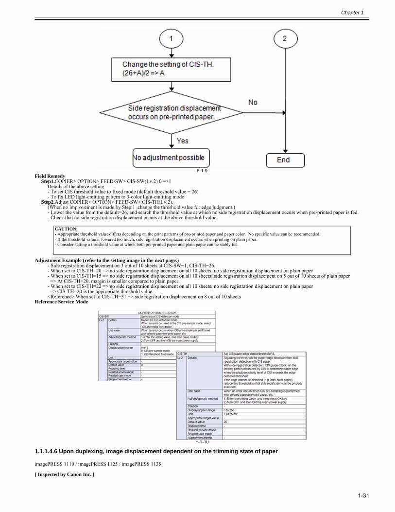
Chapter 1
1-31
F-1-9Field Remedy
Step1.COPIER> OPTION> FEED-SW> CIS-SW(Lv.2) 0 =>1Details of the above setting- To set CIS threshold value to fixed mode (default threshold value = 26)- To fix LED light-emitting pattern to 3-color light-emitting mode
Step2.Adjust COPIER> OPTION> FEED-SW> CIS-TH(Lv.2).(When no improvement is made by Step 1 ,change the threshold value for edge judgment.)- Lower the value from the default=26, and search the threshold value at which no side registration displacement occurs when pre-printed paper is fed.- Check that no side registration displacement occurs at the above threshold value.
Adjustment Example (refer to the setting image in the next page.)- Side registration displacement on 3 out of 10 sheets at CIS-SW=1, CIS-TH=26.- When set to CIS-TH=20 => no side registration displacement on all 10 sheets; no side registration displacement on plain paper- When set to CIS-TH=15 => no side registration displacement on all 10 sheets; side registration displacement on 5 out of 10 sheets of plain paper => At CIS-TH=20, margin is smaller compared to plain paper.- When set to CIS-TH=22 => no side registration displacement on all 10 sheets; no side registration displacement on plain paper => CIS-TH=20 is the appropriate threshold value.<Reference> When set to CIS-TH=31 => side registration displacement on 8 out of 10 sheets
Reference Service Mode
F-1-10
1.1.1.4.6 Upon duplexing, image displacement dependent on the trimming state of paper0028-5185
imagePRESS 1110 / imagePRESS 1125 / imagePRESS 1135
[ Inspected by Canon Inc. ]
CAUTION:- Appropriate threshold value differs depending on the print patterns of pre-printed paper and paper color. No specific value can be recommended.- If the threshold value is lowered too much, side registration displacement occurs when printing on plain paper.- Consider setting a threshold value at which both pre-printed paper and plain paper can be stably fed.
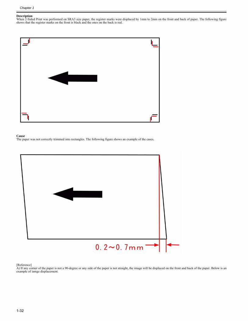
Chapter 1
1-32
DescriptionWhen 2-Sided Print was performed on SRA3 size paper, the register marks were displaced by 1mm to 2mm on the front and back of paper. The following figureshows that the register marks on the front is black and the ones on the back is red.
CauseThe paper was not correctly trimmed into rectangles. The following figure shows an example of the cases.
[Reference]A) If any corner of the paper is not a 90-degree or any side of the paper is not straight, the image will be displaced on the front and back of the paper. Below is anexample of iamge displacement.
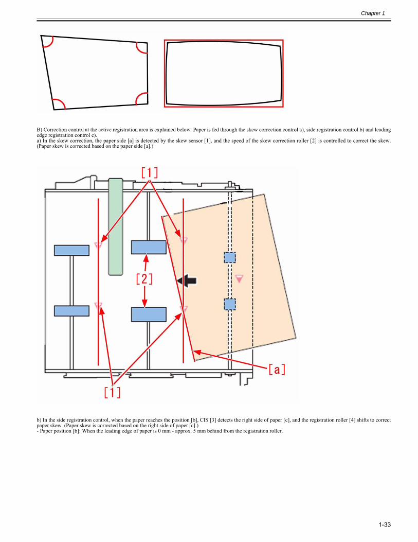
Chapter 1
1-33
B) Correction control at the active registration area is explained below. Paper is fed through the skew correction control a), side registration control b) and leadingedge registration control c).a) In the skew correction, the paper side [a] is detected by the skew sensor [1], and the speed of the skew correction roller [2] is controlled to correct the skew.(Paper skew is corrected based on the paper side [a].)
b) In the side registration control, when the paper reaches the position [b], CIS [3] detects the right side of paper [c], and the registration roller [4] shifts to correctpaper skew. (Paper skew is corrected based on the right side of paper [c].)- Paper position [b]: When the leading edge of paper is 0 mm - approx. 5 mm behind from the registration roller.
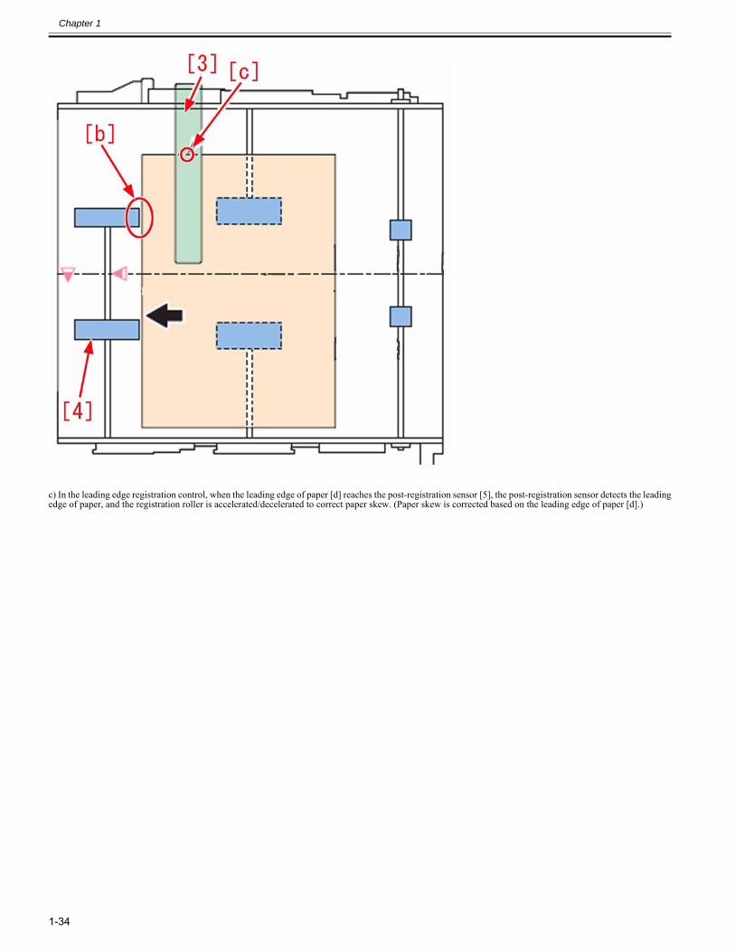
Chapter 1
1-34
c) In the leading edge registration control, when the leading edge of paper [d] reaches the post-registration sensor [5], the post-registration sensor detects the leadingedge of paper, and the registration roller is accelerated/decelerated to correct paper skew. (Paper skew is corrected based on the leading edge of paper [d].)
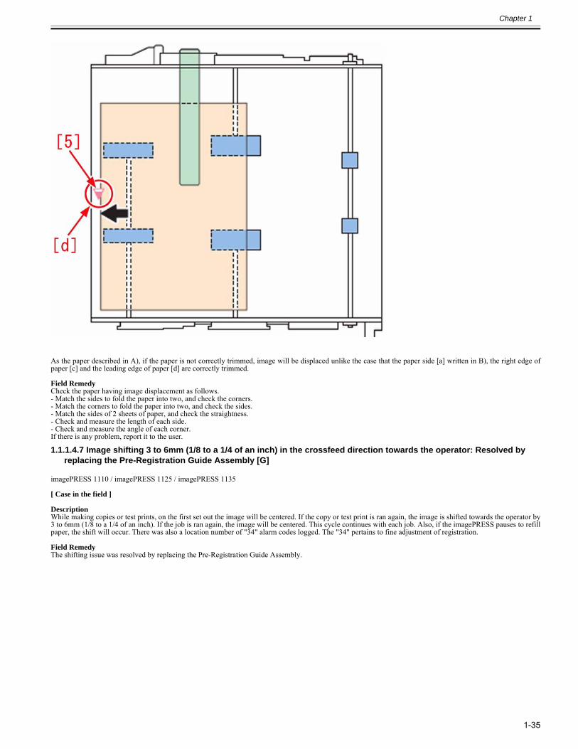
Chapter 1
1-35
As the paper described in A), if the paper is not correctly trimmed, image will be displaced unlike the case that the paper side [a] written in B), the right edge ofpaper [c] and the leading edge of paper [d] are correctly trimmed.
Field RemedyCheck the paper having image displacement as follows.- Match the sides to fold the paper into two, and check the corners.- Match the corners to fold the paper into two, and check the sides.- Match the sides of 2 sheets of paper, and check the straightness.- Check and measure the length of each side.- Check and measure the angle of each corner.If there is any problem, report it to the user.
1.1.1.4.7 Image shifting 3 to 6mm (1/8 to a 1/4 of an inch) in the crossfeed direction towards the operator: Resolved by replacing the Pre-Registration Guide Assembly [G]
0028-6725
imagePRESS 1110 / imagePRESS 1125 / imagePRESS 1135
[ Case in the field ] DescriptionWhile making copies or test prints, on the first set out the image will be centered. If the copy or test print is ran again, the image is shifted towards the operator by3 to 6mm (1/8 to a 1/4 of an inch). If the job is ran again, the image will be centered. This cycle continues with each job. Also, if the imagePRESS pauses to refillpaper, the shift will occur. There was also a location number of "34" alarm codes logged. The "34" pertains to fine adjustment of registration. Field RemedyThe shifting issue was resolved by replacing the Pre-Registration Guide Assembly.
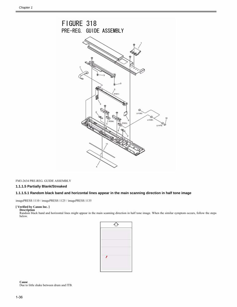
Chapter 1
1-36
FM3-2634 PRE-REG. GUIDE ASSEMBLY
1.1.1.5 Partially Blank/Streaked
1.1.1.5.1 Random black band and horizontal lines appear in the main scanning direction in half tone image0022-9617
imagePRESS 1110 / imagePRESS 1125 / imagePRESS 1135
[ Verified by Canon Inc. ]Description Random black band and horizontal lines might appear in the main scanning direction in half tone image. When the similar symptom occurs, follow the stepsbelow.
CauseDue to little shake between drum and ITB.
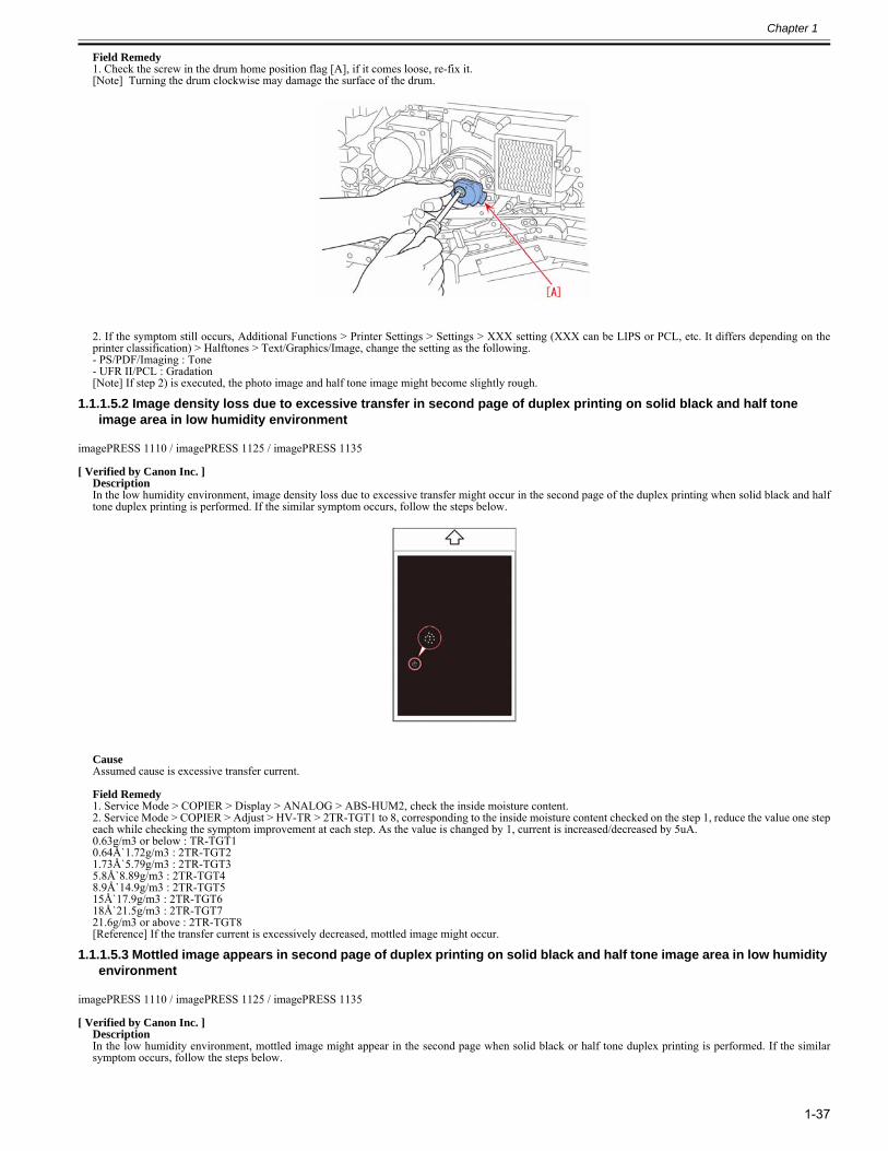
Chapter 1
1-37
Field Remedy1. Check the screw in the drum home position flag [A], if it comes loose, re-fix it.[Note] Turning the drum clockwise may damage the surface of the drum.
2. If the symptom still occurs, Additional Functions > Printer Settings > Settings > XXX setting (XXX can be LIPS or PCL, etc. It differs depending on theprinter classification) > Halftones > Text/Graphics/Image, change the setting as the following.- PS/PDF/Imaging : Tone - UFR II/PCL : Gradation[Note] If step 2) is executed, the photo image and half tone image might become slightly rough.
1.1.1.5.2 Image density loss due to excessive transfer in second page of duplex printing on solid black and half tone image area in low humidity environment
0022-9629
imagePRESS 1110 / imagePRESS 1125 / imagePRESS 1135
[ Verified by Canon Inc. ]DescriptionIn the low humidity environment, image density loss due to excessive transfer might occur in the second page of the duplex printing when solid black and halftone duplex printing is performed. If the similar symptom occurs, follow the steps below.
CauseAssumed cause is excessive transfer current.
Field Remedy1. Service Mode > COPIER > Display > ANALOG > ABS-HUM2, check the inside moisture content.2. Service Mode > COPIER > Adjust > HV-TR > 2TR-TGT1 to 8, corresponding to the inside moisture content checked on the step 1, reduce the value one stepeach while checking the symptom improvement at each step. As the value is changed by 1, current is increased/decreased by 5uA.0.63g/m3 or below : TR-TGT10.64Å`1.72g/m3 : 2TR-TGT21.73Å`5.79g/m3 : 2TR-TGT35.8Å`8.89g/m3 : 2TR-TGT48.9Å`14.9g/m3 : 2TR-TGT515Å`17.9g/m3 : 2TR-TGT618Å`21.5g/m3 : 2TR-TGT721.6g/m3 or above : 2TR-TGT8[Reference] If the transfer current is excessively decreased, mottled image might occur.
1.1.1.5.3 Mottled image appears in second page of duplex printing on solid black and half tone image area in low humidity environment
0022-9632
imagePRESS 1110 / imagePRESS 1125 / imagePRESS 1135
[ Verified by Canon Inc. ]DescriptionIn the low humidity environment, mottled image might appear in the second page when solid black or half tone duplex printing is performed. If the similarsymptom occurs, follow the steps below.
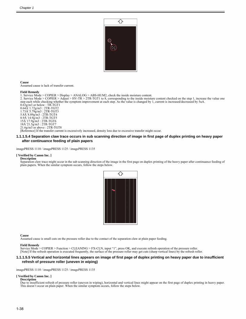
Chapter 1
1-38
CauseAssumed cause is lack of transfer current.
Field Remedy1. Service Mode > COPIER > Display > ANALOG > ABS-HUM2, check the inside moisture content.2. Service Mode > COPIER > Adjust > HV-TR > 2TR-TGT1 to 8, corresponding to the inside moisture content checked on the step 1, increase the value onestep each while checking whether the symptom improvement at each step. As the value is changed by 1, current is increased/decreased by 5uA.0.63g/m3 or below : TR-TGT10.64Å`1.72g/m3 : 2TR-TGT21.73Å`5.79g/m3 : 2TR-TGT35.8Å`8.89g/m3 : 2TR-TGT48.9Å`14.9g/m3 : 2TR-TGT515Å`17.9g/m3 : 2TR-TGT618Å`21.5g/m3 : 2TR-TGT721.6g/m3 or above : 2TR-TGT8[Reference] If the transfer current is excessively increased, density loss due to excessive transfer might occur.
1.1.1.5.4 Separation claw trace occurs in sub scanning direction of image in first page of duplex printing on heavy paper after continuance feeding of plain papers
0022-9639
imagePRESS 1110 / imagePRESS 1125 / imagePRESS 1135
[ Verified by Canon Inc. ]DescriptionSeparation claw trace might occur in the sub scanning direction of the image in the first page on duplex printing of the heavy paper after continuance feeding ofplain papers. When the similar symptom occurs, follow the steps below.
CauseAssumed cause is small cuts on the pressure roller due to the contact of the separation claw at plain paper feeding.
Field RemedyService Mode > COPIER > Function > CLEANING > FX-CLN, input “1”, press OK, and execute refresh operation of the pressure roller.[Note] If the refresh operation is executed frequently, the surface of the pressure roller may get cuts (sharp vertical lines) by the refresh roller.
1.1.1.5.5 Vertical and horizontal lines appears on image of first page of duplex printing on heavy paper due to insufficient refresh of pressure roller (uneven in wiping)
0022-9643
imagePRESS 1110 / imagePRESS 1125 / imagePRESS 1135
[ Verified by Canon Inc. ]DescriptionDue to insufficient refresh of pressure roller (uneven in wiping), horizontal and vertical lines might appear on the first page of duplex printing in heavy paper.This doesn’t occur on plain paper. When the similar symptom occurs, follow the steps below.
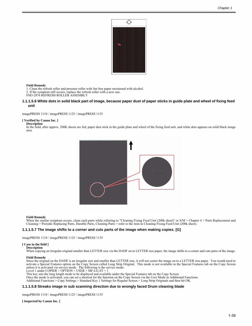
Chapter 1
1-39
Field Remedy1. Clean the refresh roller and pressure roller with lint free paper moistened with alcohol.2. If the symptom still occurs, replace the refresh roller with a new one.FM3-2876 REFRESH ROLLER ASSEMBLY
1.1.1.5.6 White dots in solid black part of image, because paper dust of paper sticks in guide plate and wheel of fixing feed unit
0023-3346
imagePRESS 1110 / imagePRESS 1125 / imagePRESS 1135
[ Verified by Canon Inc. ]DescriptionIn the field, after approx. 200K sheets are fed, paper dust stick in the guide plate and wheel of the fixing feed unit, and white dots appears on solid black imagearea.
Field RemedyWhen the similar symptom occurs, clean each parts while referring to "Cleaning Fixing Feed Unit (200k sheet)" or S/M > Chapter 4 > Parts Replacement andCleaning > Periodic Replacing Parts, Durable Parts, Cleaning Parts > refer to the item in Cleaning Fixing Feed Unit (200k sheet).
1.1.1.5.7 The image shifts to a corner and cuts parts of the image when making copies. [G]0025-5238
imagePRESS 1110 / imagePRESS 1125 / imagePRESS 1135
[ Case in the field ]DescriptionWhen copying an irregular original smaller than LETTER size via the DADF on to LETTER size paper, the image shifts to a corner and cuts parts of the image. Field RemedySince the original on the DADF is an irregular size and smaller than LETTER size, it will not center the image on to a LETTER size paper. You would need toactivate a Special Features option on the Copy Screen called Long Strip Original. This mode is not available in the Special Features tab on the Copy Screenunless it is activated via service mode. The following is the service mode:Level 1 under COPIER > OPTION > USER > MF-LG-ST = 1This key sets the long length mode to be displayed and available under the Special Features tab on the Copy Screen. Once the mode is activated, you can set a shortcut for the function on the Copy Screen via the User Mode in Additional Functions.Additional Functions > Copy Settings > Standard Key 1 Settings for Regular Screen > Long Strip Originals and then hit OK.
1.1.1.5.8 Streaks image in sub scanning direction due to wrongly faced Drum cleaning blade0028-4340
imagePRESS 1110 / imagePRESS 1125 / imagePRESS 1135
[ Inspected by Canon Inc. ]
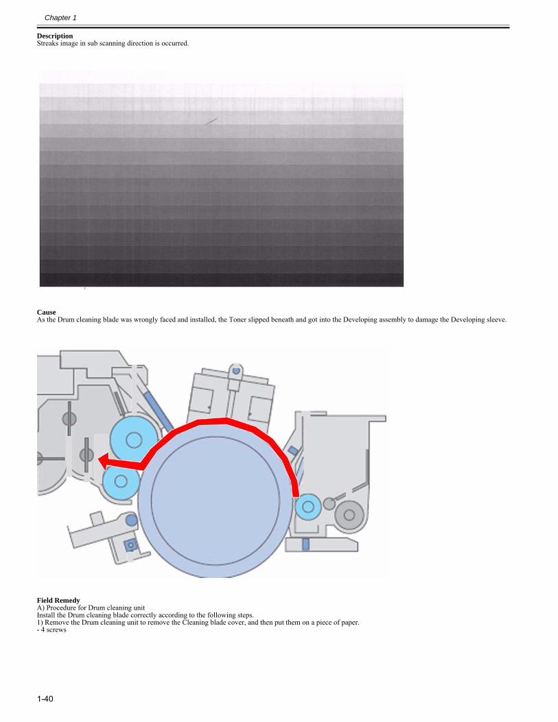
Chapter 1
1-40
DescriptionStreaks image in sub scanning direction is occurred.
CauseAs the Drum cleaning blade was wrongly faced and installed, the Toner slipped beneath and got into the Developing assembly to damage the Developing sleeve.
Field RemedyA) Procedure for Drum cleaning unitInstall the Drum cleaning blade correctly according to the following steps.1) Remove the Drum cleaning unit to remove the Cleaning blade cover, and then put them on a piece of paper.- 4 screws
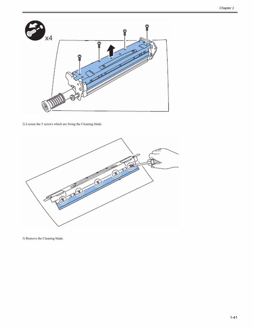
Chapter 1
1-41
2) Loosen the 5 screws which are fixing the Cleaning blade.
3) Remove the Cleaning blade.
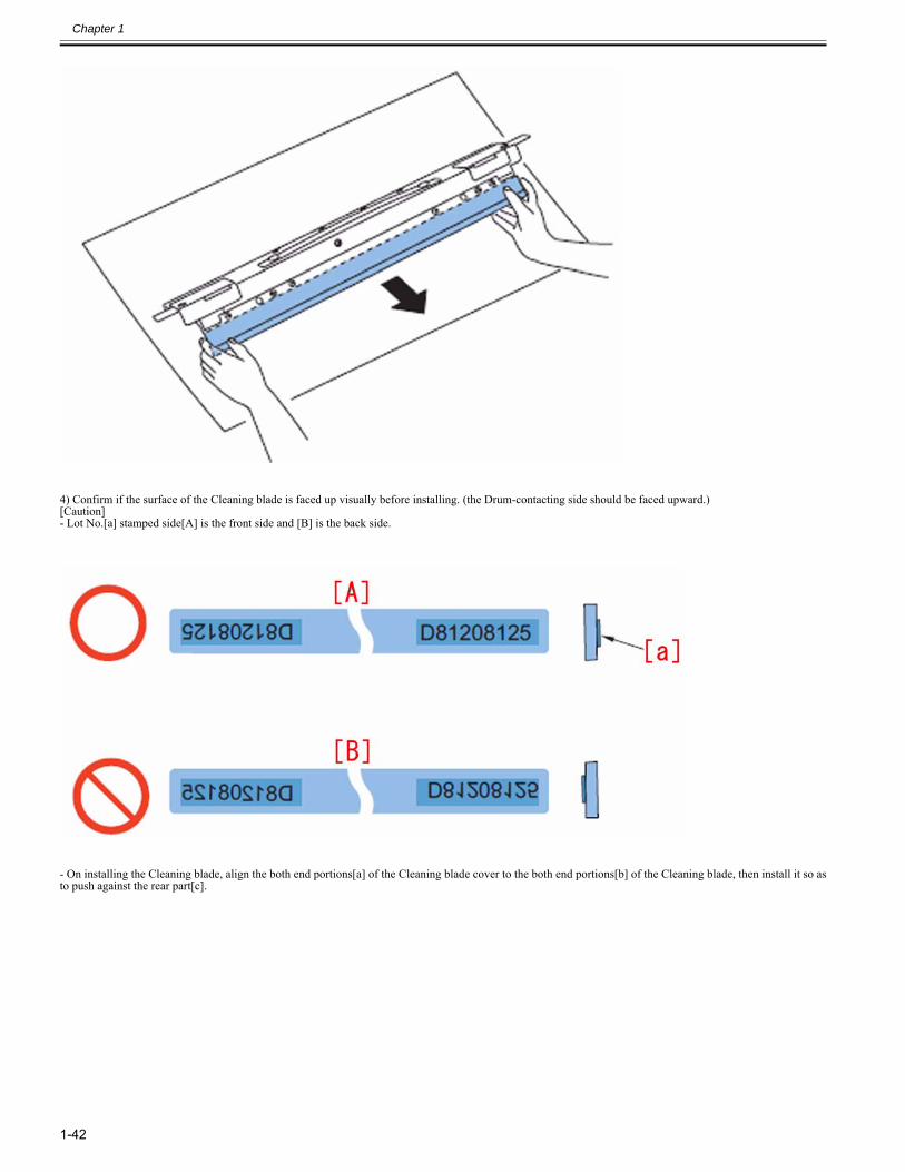
Chapter 1
1-42
4) Confirm if the surface of the Cleaning blade is faced up visually before installing. (the Drum-contacting side should be faced upward.)[Caution]- Lot No.[a] stamped side[A] is the front side and [B] is the back side.
- On installing the Cleaning blade, align the both end portions[a] of the Cleaning blade cover to the both end portions[b] of the Cleaning blade, then install it so asto push against the rear part[c].
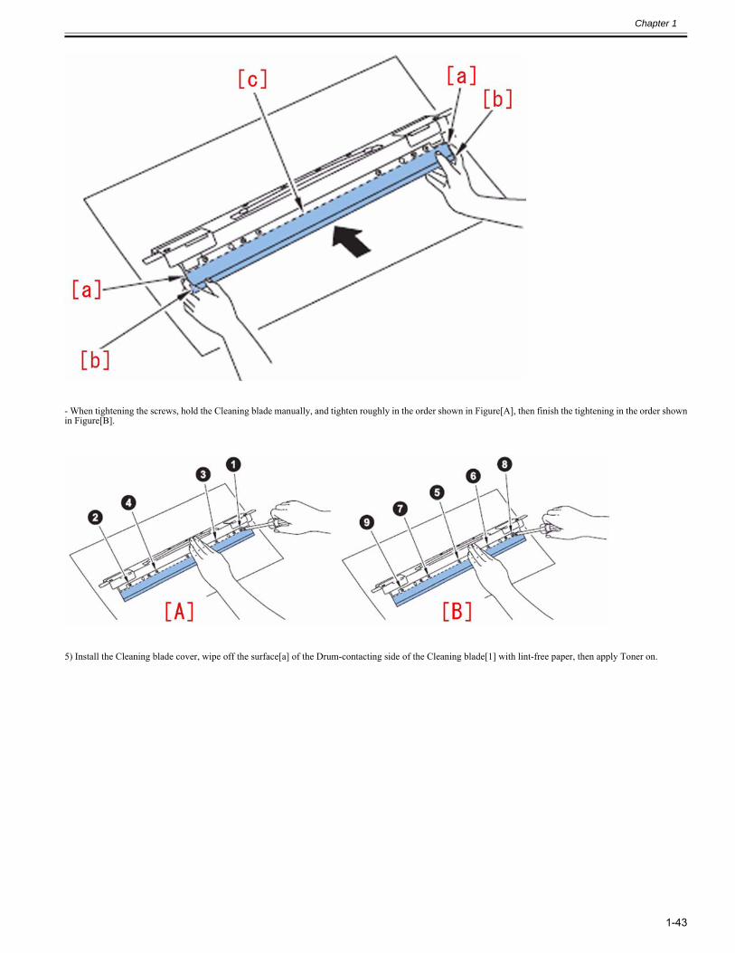
Chapter 1
1-43
- When tightening the screws, hold the Cleaning blade manually, and tighten roughly in the order shown in Figure[A], then finish the tightening in the order shownin Figure[B].
5) Install the Cleaning blade cover, wipe off the surface[a] of the Drum-contacting side of the Cleaning blade[1] with lint-free paper, then apply Toner on.
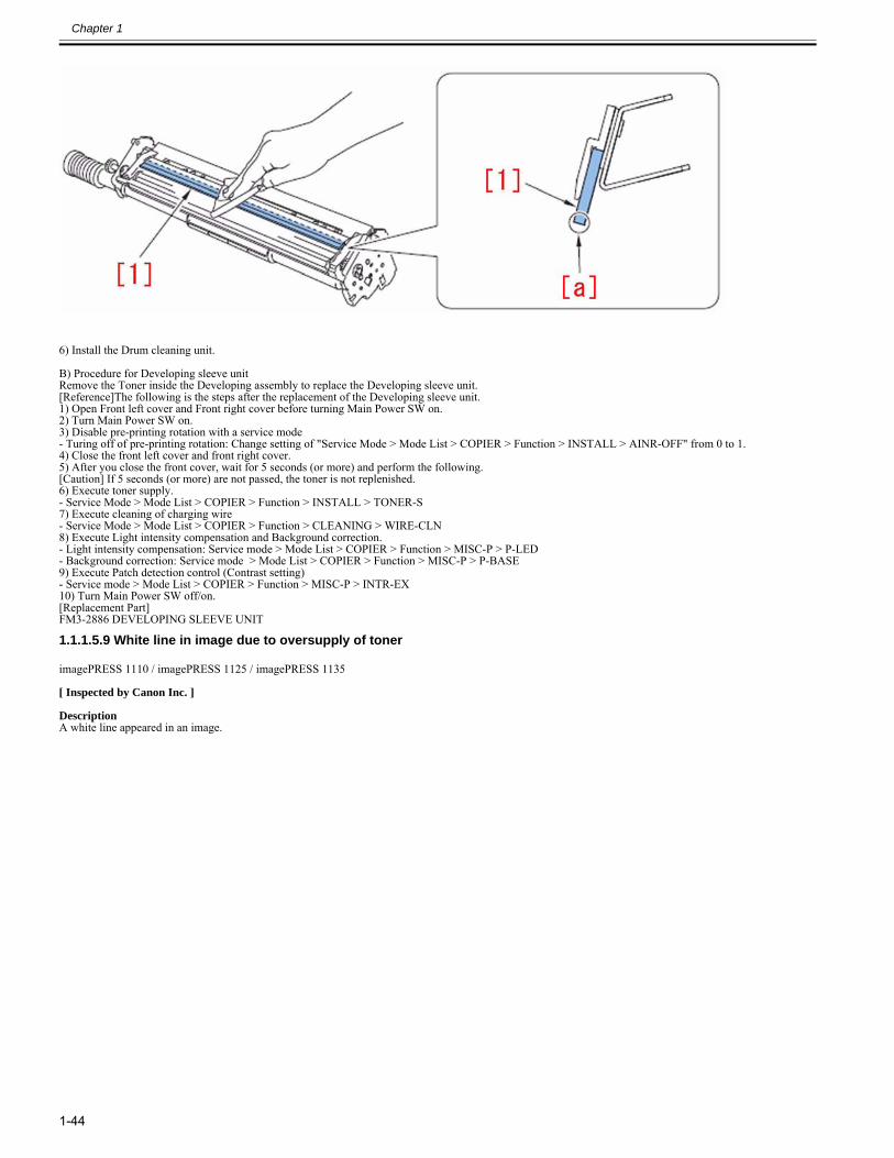
Chapter 1
1-44
6) Install the Drum cleaning unit.
B) Procedure for Developing sleeve unitRemove the Toner inside the Developing assembly to replace the Developing sleeve unit.[Reference]The following is the steps after the replacement of the Developing sleeve unit.1) Open Front left cover and Front right cover before turning Main Power SW on.2) Turn Main Power SW on.3) Disable pre-printing rotation with a service mode- Turing off of pre-printing rotation: Change setting of "Service Mode > Mode List > COPIER > Function > INSTALL > AINR-OFF" from 0 to 1.4) Close the front left cover and front right cover.5) After you close the front cover, wait for 5 seconds (or more) and perform the following.[Caution] If 5 seconds (or more) are not passed, the toner is not replenished.6) Execute toner supply.- Service Mode > Mode List > COPIER > Function > INSTALL > TONER-S7) Execute cleaning of charging wire- Service Mode > Mode List > COPIER > Function > CLEANING > WIRE-CLN8) Execute Light intensity compensation and Background correction.- Light intensity compensation: Service mode > Mode List > COPIER > Function > MISC-P > P-LED- Background correction: Service mode > Mode List > COPIER > Function > MISC-P > P-BASE9) Execute Patch detection control (Contrast setting)- Service mode > Mode List > COPIER > Function > MISC-P > INTR-EX10) Turn Main Power SW off/on.[Replacement Part]FM3-2886 DEVELOPING SLEEVE UNIT
1.1.1.5.9 White line in image due to oversupply of toner0028-7098
imagePRESS 1110 / imagePRESS 1125 / imagePRESS 1135
[ Inspected by Canon Inc. ]
DescriptionA white line appeared in an image.
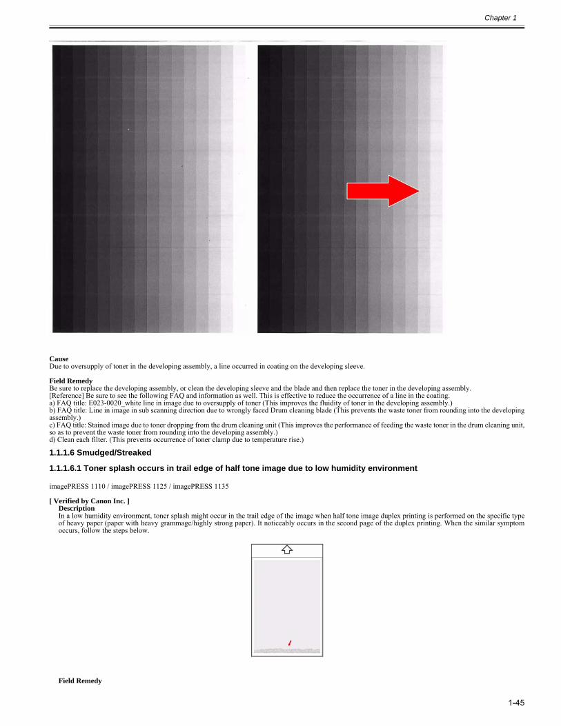
Chapter 1
1-45
CauseDue to oversupply of toner in the developing assembly, a line occurred in coating on the developing sleeve.
Field RemedyBe sure to replace the developing assembly, or clean the developing sleeve and the blade and then replace the toner in the developing assembly.[Reference] Be sure to see the following FAQ and information as well. This is effective to reduce the occurrence of a line in the coating.a) FAQ title: E023-0020_white line in image due to oversupply of toner (This improves the fluidity of toner in the developing assembly.)b) FAQ title: Line in image in sub scanning direction due to wrongly faced Drum cleaning blade (This prevents the waste toner from rounding into the developingassembly.)c) FAQ title: Stained image due to toner dropping from the drum cleaning unit (This improves the performance of feeding the waste toner in the drum cleaning unit,so as to prevent the waste toner from rounding into the developing assembly.)d) Clean each filter. (This prevents occurrence of toner clamp due to temperature rise.)
1.1.1.6 Smudged/Streaked
1.1.1.6.1 Toner splash occurs in trail edge of half tone image due to low humidity environment0022-9626
imagePRESS 1110 / imagePRESS 1125 / imagePRESS 1135
[ Verified by Canon Inc. ]DescriptionIn a low humidity environment, toner splash might occur in the trail edge of the image when half tone image duplex printing is performed on the specific typeof heavy paper (paper with heavy grammage/highly strong paper). It noticeably occurs in the second page of the duplex printing. When the similar symptomoccurs, follow the steps below.
Field Remedy
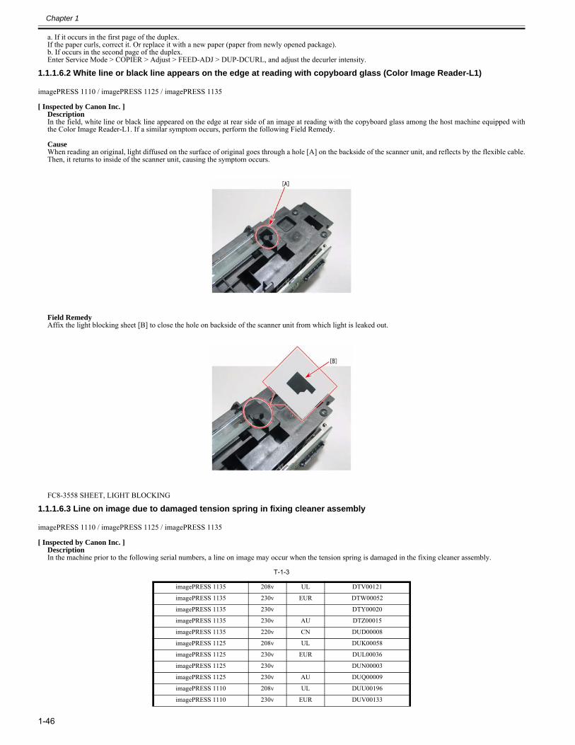
Chapter 1
1-46
a. If it occurs in the first page of the duplex.If the paper curls, correct it. Or replace it with a new paper (paper from newly opened package). b. If occurs in the second page of the duplex.Enter Service Mode > COPIER > Adjust > FEED-ADJ > DUP-DCURL, and adjust the decurler intensity.
1.1.1.6.2 White line or black line appears on the edge at reading with copyboard glass (Color Image Reader-L1)0024-7086
imagePRESS 1110 / imagePRESS 1125 / imagePRESS 1135
[ Inspected by Canon Inc. ]DescriptionIn the field, white line or black line appeared on the edge at rear side of an image at reading with the copyboard glass among the host machine equipped withthe Color Image Reader-L1. If a similar symptom occurs, perform the following Field Remedy. CauseWhen reading an original, light diffused on the surface of original goes through a hole [A] on the backside of the scanner unit, and reflects by the flexible cable.Then, it returns to inside of the scanner unit, causing the symptom occurs.
Field RemedyAffix the light blocking sheet [B] to close the hole on backside of the scanner unit from which light is leaked out.
FC8-3558 SHEET, LIGHT BLOCKING
1.1.1.6.3 Line on image due to damaged tension spring in fixing cleaner assembly0024-7263
imagePRESS 1110 / imagePRESS 1125 / imagePRESS 1135
[ Inspected by Canon Inc. ]DescriptionIn the machine prior to the following serial numbers, a line on image may occur when the tension spring is damaged in the fixing cleaner assembly.
T-1-3
imagePRESS 1135 208v UL DTV00121
imagePRESS 1135 230v EUR DTW00052
imagePRESS 1135 230v DTY00020
imagePRESS 1135 230v AU DTZ00015
imagePRESS 1135 220v CN DUD00008
imagePRESS 1125 208v UL DUK00058
imagePRESS 1125 230v EUR DUL00036
imagePRESS 1125 230v DUN00003
imagePRESS 1125 230v AU DUQ00009
imagePRESS 1110 208v UL DUU00196
imagePRESS 1110 230v EUR DUV00133
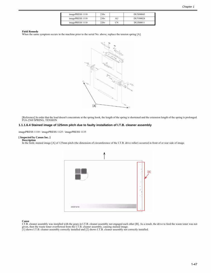
Chapter 1
1-47
Field RemedyWhen the same symptom occurs in the machine prior to the serial No. above, replace the tension spring [A].
[Reference] In order that the load doesn't concentrate at the spring hook, the length of the spring is shortened and the extension length of the spring is prolonged.FU6-2569 SPRING, TENSION
1.1.1.6.4 Stained image of 125mm pitch due to faulty installation of I.T.B. cleaner assembly0024-9236
imagePRESS 1110 / imagePRESS 1125 / imagePRESS 1135
[ Inspected by Canon Inc. ]DescriptionIn the field, stained image [A] of 125mm pitch (the dimension of circumference of the I.T.B. drive roller) occurred in front of or rear side of image.
CauseI.T.B. cleaner assembly was installed with the gears in I.T.B. cleaner assembly not engaged each other [B]. As a result, the drive to feed the waste toner was notgiven, then the waste toner overflowed from the I.T.B. cleaner assembly, causing stained image.[1] shows I.T.B. cleaner assembly correctly installed and [2] shows I.T.B. cleaner assembly not correctly installed.
imagePRESS 1110 230v DUX00045
imagePRESS 1110 230v AU DUY00024
imagePRESS 1110 220v CN DUZ00011
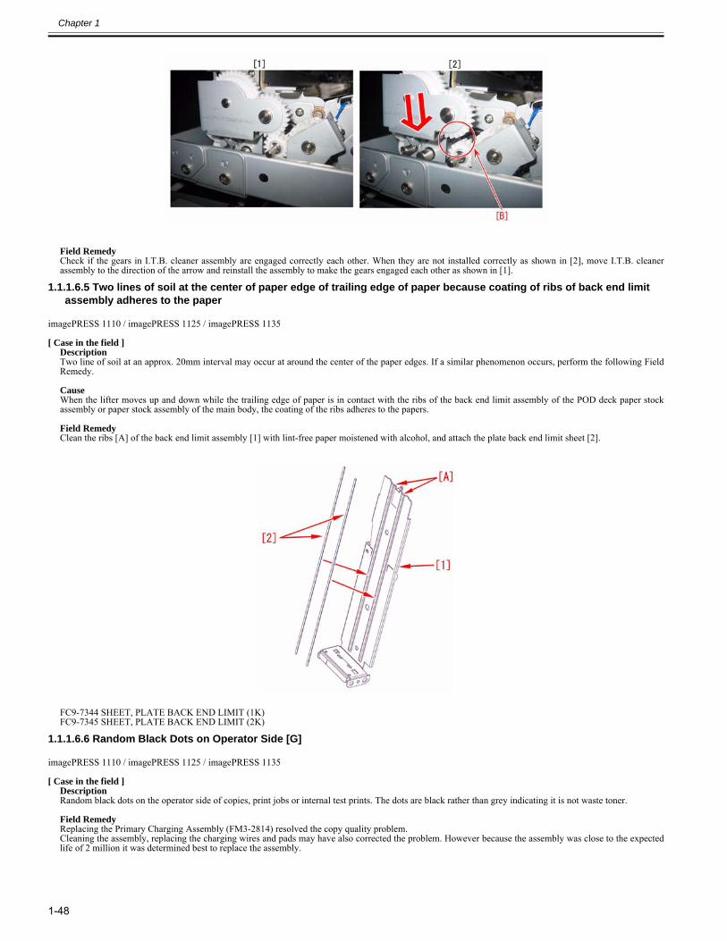
Chapter 1
1-48
Field RemedyCheck if the gears in I.T.B. cleaner assembly are engaged correctly each other. When they are not installed correctly as shown in [2], move I.T.B. cleanerassembly to the direction of the arrow and reinstall the assembly to make the gears engaged each other as shown in [1].
1.1.1.6.5 Two lines of soil at the center of paper edge of trailing edge of paper because coating of ribs of back end limit assembly adheres to the paper
0025-2167
imagePRESS 1110 / imagePRESS 1125 / imagePRESS 1135
[ Case in the field ]DescriptionTwo line of soil at an approx. 20mm interval may occur at around the center of the paper edges. If a similar phenomenon occurs, perform the following FieldRemedy. CauseWhen the lifter moves up and down while the trailing edge of paper is in contact with the ribs of the back end limit assembly of the POD deck paper stockassembly or paper stock assembly of the main body, the coating of the ribs adheres to the papers. Field RemedyClean the ribs [A] of the back end limit assembly [1] with lint-free paper moistened with alcohol, and attach the plate back end limit sheet [2].
FC9-7344 SHEET, PLATE BACK END LIMIT (1K)FC9-7345 SHEET, PLATE BACK END LIMIT (2K)
1.1.1.6.6 Random Black Dots on Operator Side [G]0025-3959
imagePRESS 1110 / imagePRESS 1125 / imagePRESS 1135
[ Case in the field ]DescriptionRandom black dots on the operator side of copies, print jobs or internal test prints. The dots are black rather than grey indicating it is not waste toner. Field RemedyReplacing the Primary Charging Assembly (FM3-2814) resolved the copy quality problem. Cleaning the assembly, replacing the charging wires and pads may have also corrected the problem. However because the assembly was close to the expectedlife of 2 million it was determined best to replace the assembly.
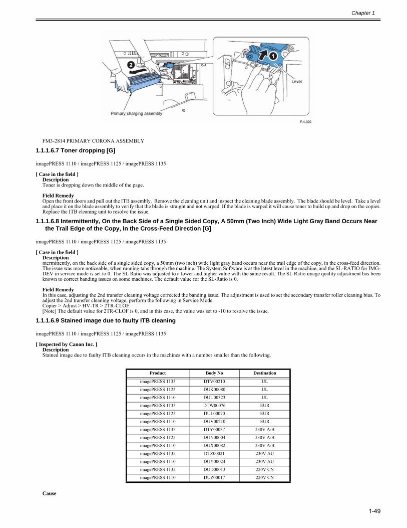
Chapter 1
1-49
FM3-2814 PRIMARY CORONA ASSEMBLY
1.1.1.6.7 Toner dropping [G]0025-3973
imagePRESS 1110 / imagePRESS 1125 / imagePRESS 1135
[ Case in the field ]DescriptionToner is dropping down the middle of the page. Field RemedyOpen the front doors and pull out the ITB assembly. Remove the cleaning unit and inspect the cleaning blade assembly. The blade should be level. Take a leveland place it on the blade assembly to verify that the blade is straight and not warped. If the blade is warped it will cause toner to build up and drop on the copies.Replace the ITB cleaning unit to resolve the issue.
1.1.1.6.8 Intermittently, On the Back Side of a Single Sided Copy, A 50mm (Two Inch) Wide Light Gray Band Occurs Near the Trail Edge of the Copy, in the Cross-Feed Direction [G]
0025-3976
imagePRESS 1110 / imagePRESS 1125 / imagePRESS 1135
[ Case in the field ]Descriptionntermittently, on the back side of a single sided copy, a 50mm (two inch) wide light gray band occurs near the trail edge of the copy, in the cross-feed direction.The issue was more noticeable, when running tabs through the machine. The System Software is at the latest level in the machine, and the SL-RATIO for IMG-DEV in service mode is set to 0. The SL Ratio was adjusted to a lower and higher value with the same result. The SL Ratio image quality adjustment has beenknown to correct banding issues on some machines. The default value for the SL-Ratio is 0. Field RemedyIn this case, adjusting the 2nd transfer cleaning voltage corrected the banding issue. The adjustment is used to set the secondary transfer roller cleaning bias. Toadjust the 2nd transfer cleaning voltage, perform the following in Service Mode.Copier > Adjust > HV-TR > 2TR-CLOF[Note] The default value for 2TR-CLOF is 0, and in this case, the value was set to -10 to resolve the issue.
1.1.1.6.9 Stained image due to faulty ITB cleaning0026-2932
imagePRESS 1110 / imagePRESS 1125 / imagePRESS 1135
[ Inspected by Canon Inc. ]DescriptionStained image due to faulty ITB cleaning occurs in the machines with a number smaller than the following.
Cause
Product Body No Destination
imagePRESS 1135 DTV00210 UL
imagePRESS 1125 DUK00080 UL
imagePRESS 1110 DUU00323 UL
imagePRESS 1135 DTW00076 EUR
imagePRESS 1125 DUL00070 EUR
imagePRESS 1110 DUV00210 EUR
imagePRESS 1135 DTY00037 230V A/B
imagePRESS 1125 DUN00004 230V A/B
imagePRESS 1110 DUX00082 230V A/B
imagePRESS 1135 DTZ00021 230V AU
imagePRESS 1110 DUY00024 230V AU
imagePRESS 1135 DUD00013 220V CN
imagePRESS 1110 DUZ00017 220V CN
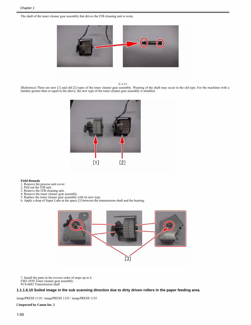
Chapter 1
1-50
The shaft of the toner cleaner gear assembly that drives the ITB cleaning unit is worn.
F-1-11[Reference] There are new [1] and old [2] types of the toner cleaner gear assembly. Wearing of the shaft may occur in the old type. For the machines with anumber greater than or equal to the above, the new type of the toner cleaner gear assembly is installed.
Field Remedy1. Remove the process unit cover.2. Pull out the ITB unit.3. Remove the ITB cleaning unit.4. Remove the toner cleaner gear assembly5. Replace the toner cleaner gear assembly with its new type.6. Apply a drop of Super Lube at the space [3] between the transmission shaft and the bearing.
7. Install the parts in the reverse order of steps up to 4.FM3-2856 Toner cleaner gear assemblyFC8-6682 Transmission shaft
1.1.1.6.10 Soiled image in the sub scanning direction due to dirty driven rollers in the paper feeding area.0027-3501
imagePRESS 1110 / imagePRESS 1125 / imagePRESS 1135
[ Inspected by Canon Inc. ]
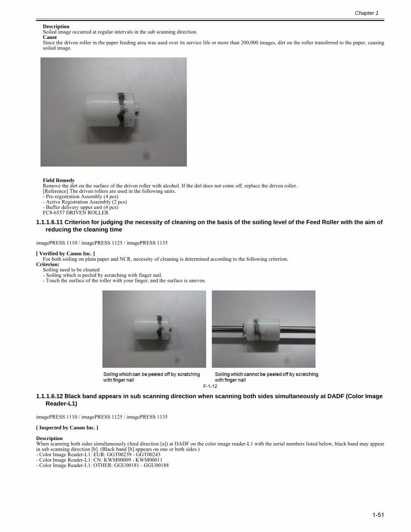
Chapter 1
1-51
DescriptionSoiled image occurred at regular intervals in the sub scanning direction.CauseSince the driven roller in the paper feeding area was used over its service life or more than 200,000 images, dirt on the roller transferred to the paper, causingsoiled image.
Field RemedyRemove the dirt on the surface of the driven roller with alcohol. If the dirt does not come off, replace the driven roller.[Reference] The driven rollers are used in the following units.- Pre-registration Assembly (4 pcs)- Active Registration Assembly (2 pcs)- Buffer delivery upper unit (4 pcs)FC8-6557 DRIVEN ROLLER
1.1.1.6.11 Criterion for judging the necessity of cleaning on the basis of the soiling level of the Feed Roller with the aim of reducing the cleaning time
0028-1423
imagePRESS 1110 / imagePRESS 1125 / imagePRESS 1135
[ Verified by Canon Inc. ]For both soiling on plain paper and NCR, necessity of cleaning is determined according to the following criterion.
Criterion:Soiling need to be cleaned- Soiling which is peeled by scratching with finger nail.- Touch the surface of the roller with your finger, and the surface is uneven.
F-1-12
1.1.1.6.12 Black band appears in sub scanning direction when scanning both sides simultaneously at DADF (Color Image Reader-L1)
0028-3284
imagePRESS 1110 / imagePRESS 1125 / imagePRESS 1135
[ Inspected by Canon Inc. ]
DescriptionWhen scanning both sides simultaneously (feed direction [a]) at DADF on the color image reader-L1 with the serial numbers listed below, black band may appearin sub scanning direction [b]. (Black band [b] appears on one or both sides.)- Color Image Reader-L1: EUR: GGT00239 - GGT00243- Color Image Reader-L1: CN: KWM00009 - KWM00011- Color Image Reader-L1: OTHER: GGU00181 - GGU00188
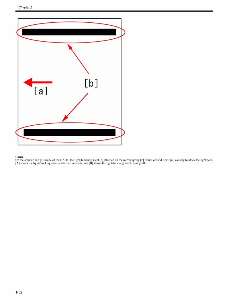
Chapter 1
1-52
CauseOn the scanner unit [1] inside of the DADF, the light-blocking sheet [3] attached on the mirror spring [2] comes off and floats [a], causing to block the light path.[A] shows the light-blocking sheet is attached securely, and [B] shows the light-blocking sheet coming off.
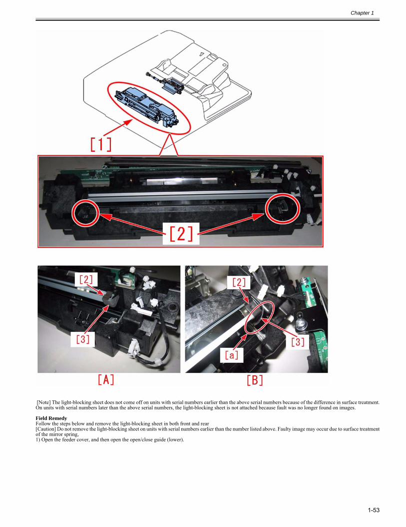
Chapter 1
1-53
[Note] The light-blocking sheet does not come off on units with serial numbers earlier than the above serial numbers because of the difference in surface treatment.On units with serial numbers later than the above serial numbers, the light-blocking sheet is not attached because fault was no longer found on images.
Field RemedyFollow the steps below and remove the light-blocking sheet in both front and rear[Caution] Do not remove the light-blocking sheet on units with serial numbers earlier than the number listed above. Faulty image may occur due to surface treatmentof the mirror spring, 1) Open the feeder cover, and then open the open/close guide (lower).
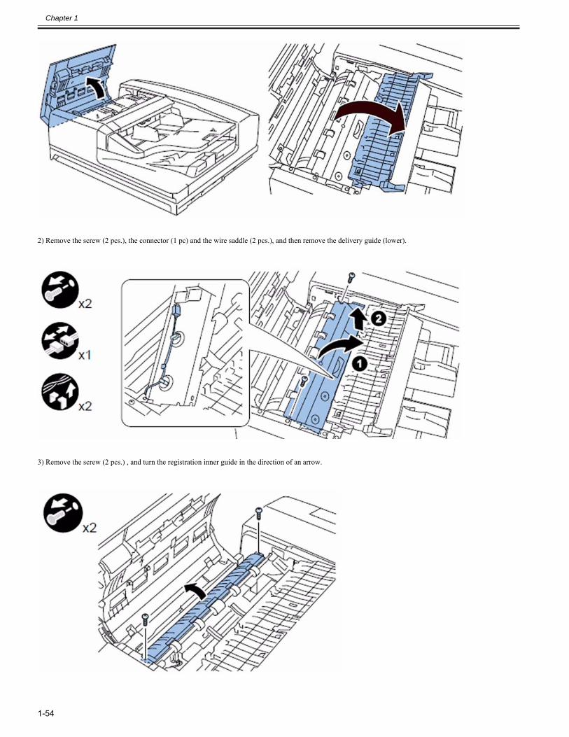
Chapter 1
1-54
2) Remove the screw (2 pcs.), the connector (1 pc) and the wire saddle (2 pcs.), and then remove the delivery guide (lower).
3) Remove the screw (2 pcs.) , and turn the registration inner guide in the direction of an arrow.
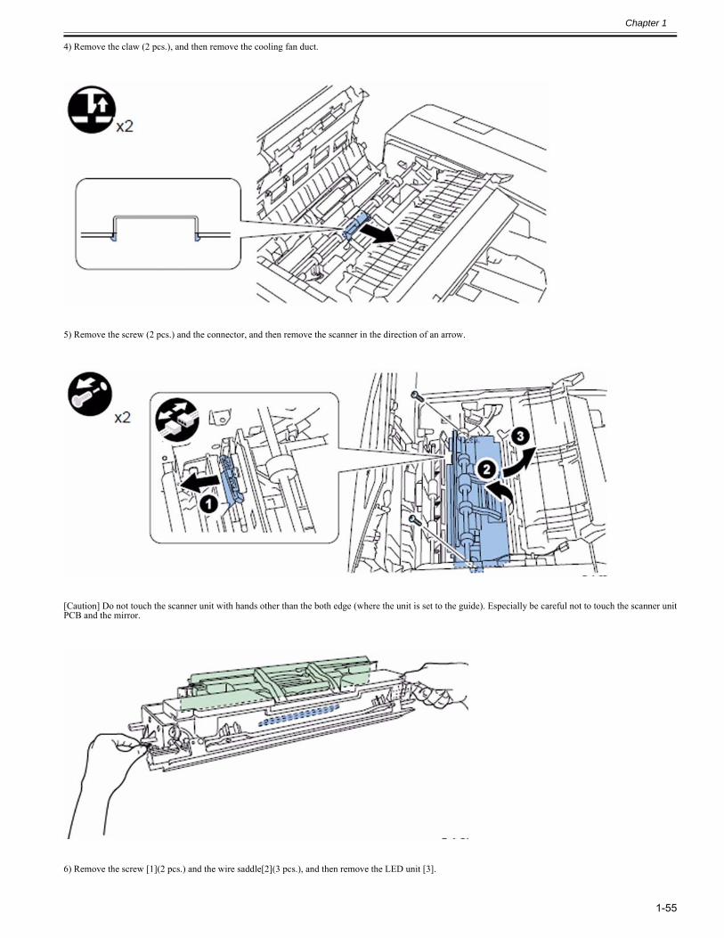
Chapter 1
1-55
4) Remove the claw (2 pcs.), and then remove the cooling fan duct.
5) Remove the screw (2 pcs.) and the connector, and then remove the scanner in the direction of an arrow.
[Caution] Do not touch the scanner unit with hands other than the both edge (where the unit is set to the guide). Especially be careful not to touch the scanner unitPCB and the mirror.
6) Remove the screw [1](2 pcs.) and the wire saddle[2](3 pcs.), and then remove the LED unit [3].
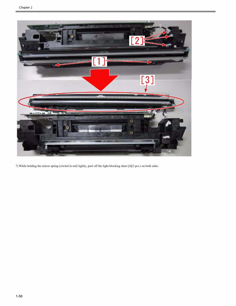
Chapter 1
1-56
7) While holding the mirror spring (circled in red) lightly, peel off the light-blocking sheet [4](2 pcs.) on both sides.
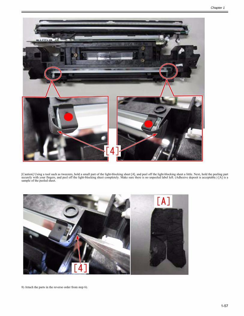
Chapter 1
1-57
[Caution] Using a tool such as tweezers, hold a small part of the light-blocking sheet [4], and peel off the light-blocking sheet a little. Next, hold the peeling partsecurely with your fingers, and peel off the light-blocking sheet completely. Make sure there is no unpeeled label left. (Adhesive deposit is acceptable.) [A] is asample of the peeled sheet.
8) Attach the parts in the reverse order from step 6).
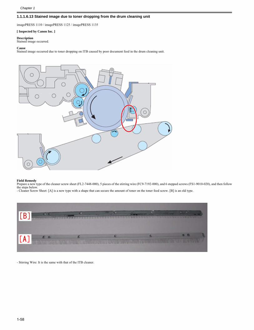
Chapter 1
1-58
1.1.1.6.13 Stained image due to toner dropping from the drum cleaning unit0028-4473
imagePRESS 1110 / imagePRESS 1125 / imagePRESS 1135
[ Inspected by Canon Inc. ]
DescriptionStained image occurred.
CauseStained image occurred due to toner dropping on ITB caused by poor document feed in the drum cleaning unit.
Field RemedyPrepare a new type of the cleaner screw sheet (FL2-7448-000), 5 pieces of the stirring wire (FC9-7192-000), and 6 stepped screws (FS1-9010-020), and then followthe steps below.- Cleaner Screw Sheet: [A] is a new type with a shape that can secure the amount of toner on the toner feed screw. [B] is an old type.
- Stirring Wire: It is the same with that of the ITB cleaner.
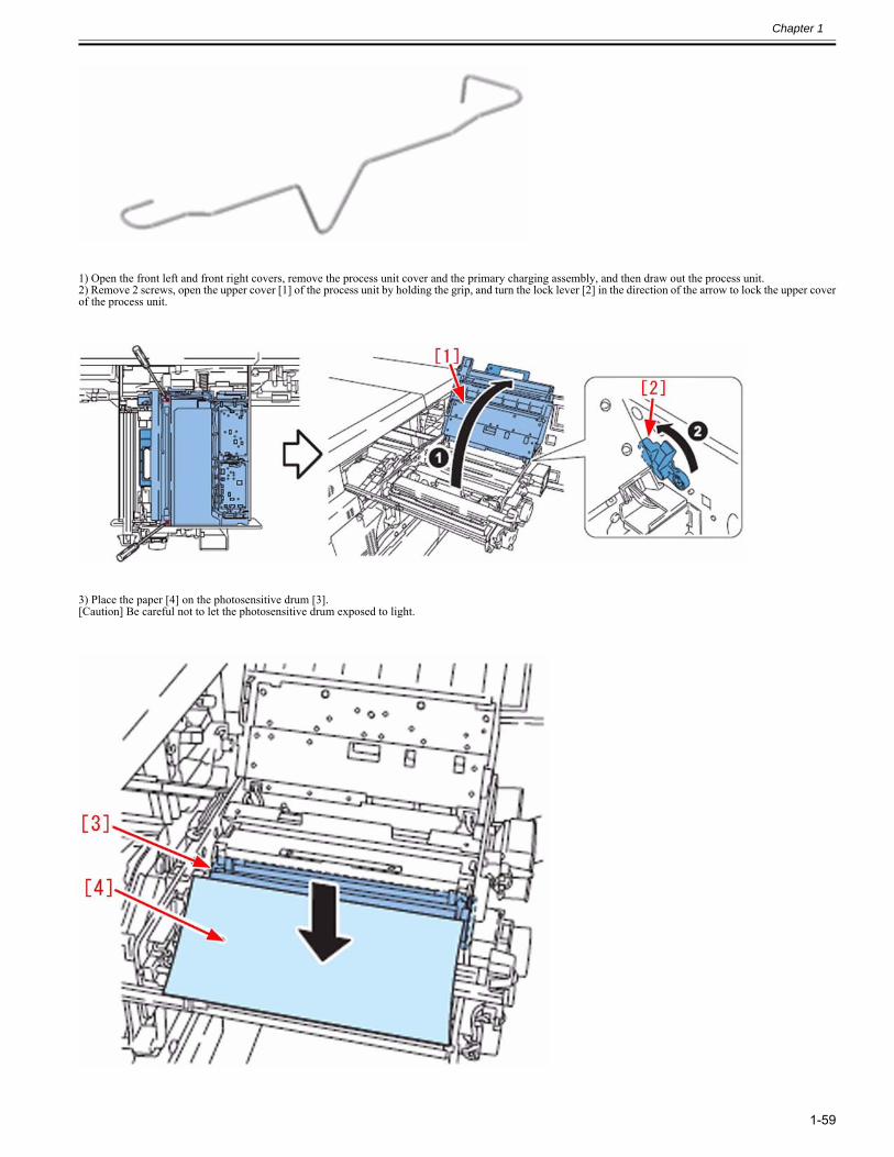
Chapter 1
1-59
1) Open the front left and front right covers, remove the process unit cover and the primary charging assembly, and then draw out the process unit.2) Remove 2 screws, open the upper cover [1] of the process unit by holding the grip, and turn the lock lever [2] in the direction of the arrow to lock the upper coverof the process unit.
3) Place the paper [4] on the photosensitive drum [3].[Caution] Be careful not to let the photosensitive drum exposed to light.
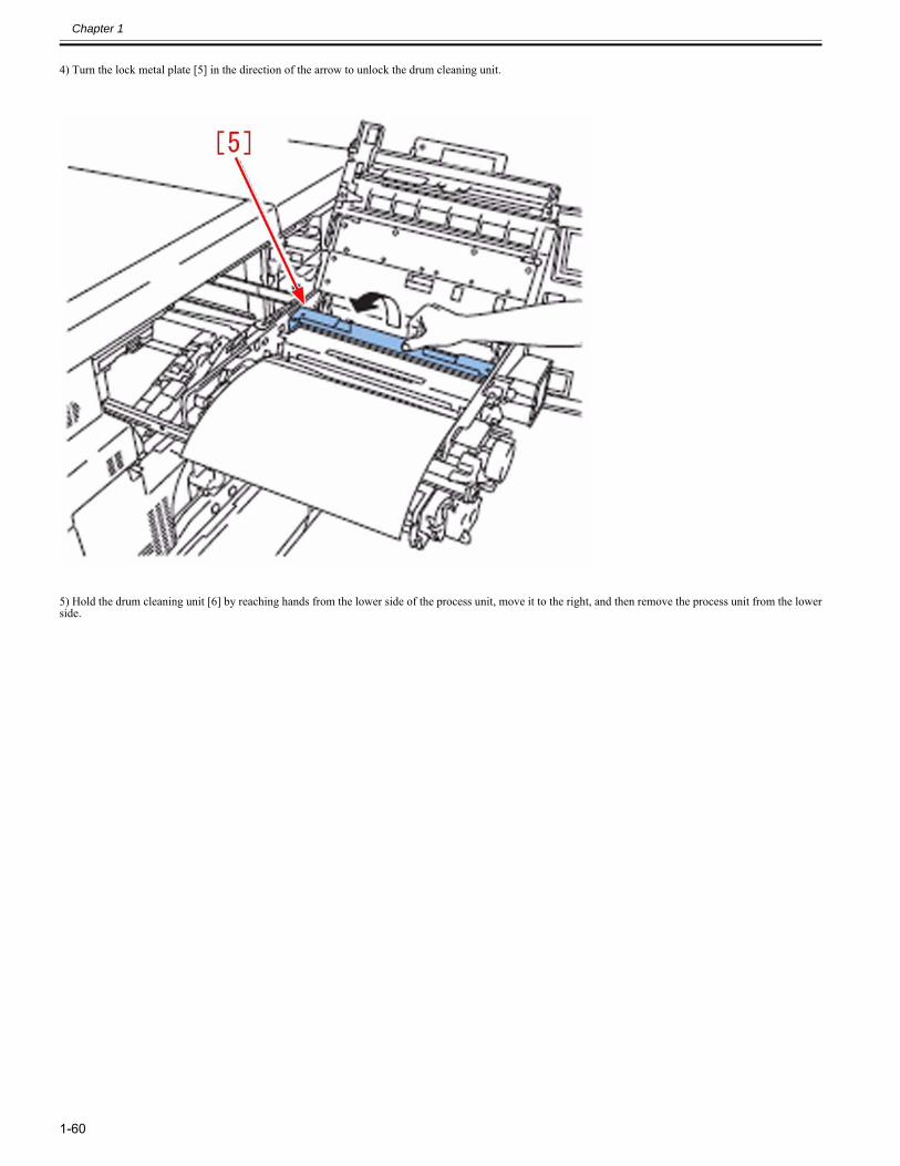
Chapter 1
1-60
4) Turn the lock metal plate [5] in the direction of the arrow to unlock the drum cleaning unit.
5) Hold the drum cleaning unit [6] by reaching hands from the lower side of the process unit, move it to the right, and then remove the process unit from the lowerside.
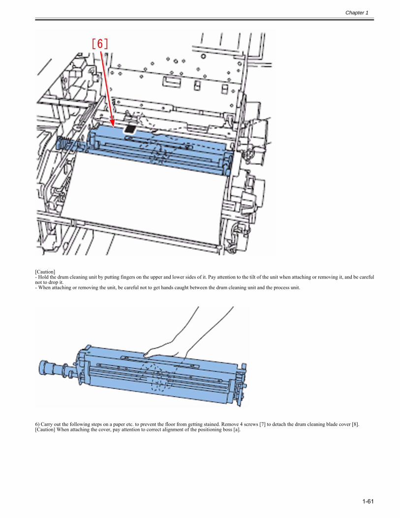
Chapter 1
1-61
[Caution]- Hold the drum cleaning unit by putting fingers on the upper and lower sides of it. Pay attention to the tilt of the unit when attaching or removing it, and be carefulnot to drop it.- When attaching or removing the unit, be careful not to get hands caught between the drum cleaning unit and the process unit.
6) Carry out the following steps on a paper etc. to prevent the floor from getting stained. Remove 4 screws [7] to detach the drum cleaning blade cover [8].[Caution] When attaching the cover, pay attention to correct alignment of the positioning boss [a].
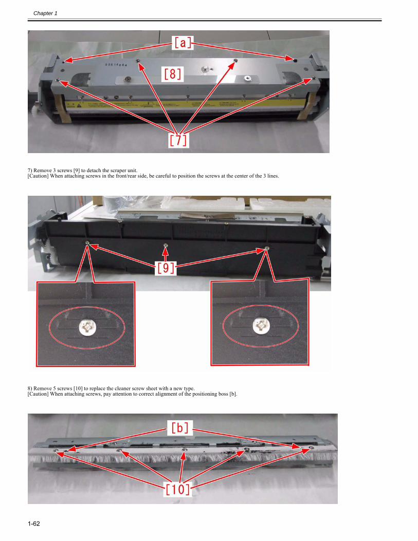
Chapter 1
1-62
7) Remove 3 screws [9] to detach the scraper unit.[Caution] When attaching screws in the front/rear side, be careful to position the screws at the center of the 3 lines.
8) Remove 5 screws [10] to replace the cleaner screw sheet with a new type.[Caution] When attaching screws, pay attention to correct alignment of the positioning boss [b].
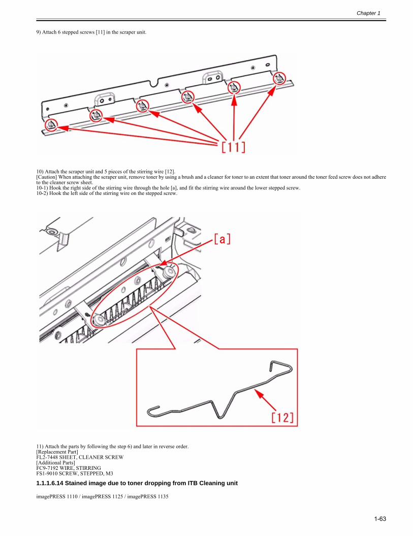
Chapter 1
1-63
9) Attach 6 stepped screws [11] in the scraper unit.
10) Attach the scraper unit and 5 pieces of the stirring wire [12].[Caution] When attaching the scraper unit, remove toner by using a brush and a cleaner for toner to an extent that toner around the toner feed screw does not adhereto the cleaner screw sheet.10-1) Hook the right side of the stirring wire through the hole [a], and fit the stirring wire around the lower stepped screw.10-2) Hook the left side of the stirring wire on the stepped screw.
11) Attach the parts by following the step 6) and later in reverse order.[Replacement Part]FL2-7448 SHEET, CLEANER SCREW[Additional Parts]FC9-7192 WIRE, STIRRINGFS1-9010 SCREW, STEPPED, M3
1.1.1.6.14 Stained image due to toner dropping from ITB Cleaning unit0028-4555
imagePRESS 1110 / imagePRESS 1125 / imagePRESS 1135
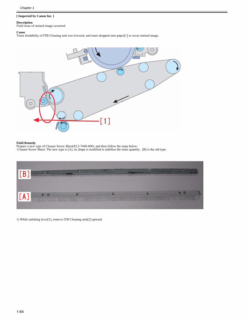
Chapter 1
1-64
[ Inspected by Canon Inc. ]
DescriptionField issue of stained image occurred.
CauseToner feedability of ITB Cleaning unit was lowered, and toner dropped onto paper[1] to occur stained image.
Field RemedyPrepare a new type of Cleaner Screw Sheet(FL2-7448-000), and then follow the steps below:-Cleaner Screw Sheet: The new type is [A], its shape is modified to stabilize the toner quantity. [B] is the old type.
1) While unloking lever[1], remove ITB Cleaning unit[2] upward.
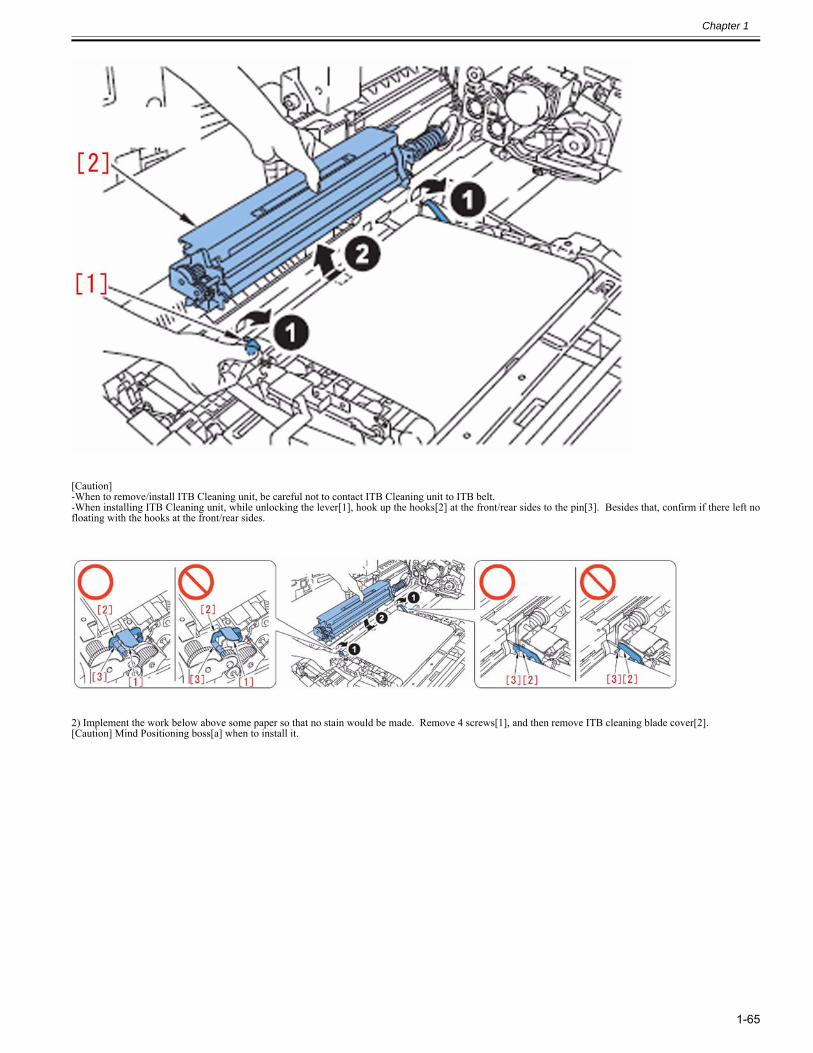
Chapter 1
1-65
[Caution]-When to remove/install ITB Cleaning unit, be careful not to contact ITB Cleaning unit to ITB belt.-When installing ITB Cleaning unit, while unlocking the lever[1], hook up the hooks[2] at the front/rear sides to the pin[3]. Besides that, confirm if there left nofloating with the hooks at the front/rear sides.
2) Implement the work below above some paper so that no stain would be made. Remove 4 screws[1], and then remove ITB cleaning blade cover[2].[Caution] Mind Positioning boss[a] when to install it.
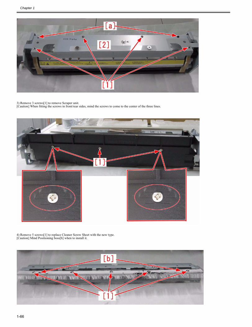
Chapter 1
1-66
3) Remove 3 screws[1] to remove Scraper unit.[Caution] When fitting the screws in front/rear sides, mind the screws to come to the center of the three lines.
4) Remove 5 screws[1] to replace Cleaner Screw Sheet with the new type.[Caution] Mind Positioning boss[b] when to install it.
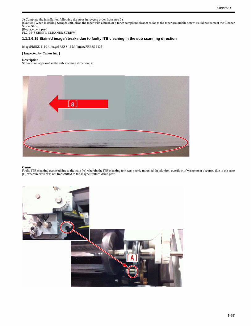
Chapter 1
1-67
5) Complete the installation following the steps in reverse order from step 3).[Caution] When installing Scraper unit, clean the toner with a brush or a toner compliant cleaner as far as the toner around the screw would not contact the CleanerScrew Sheet.[Replacement part]FL2-7448 SHEET, CLEANER SCREW
1.1.1.6.15 Stained image/streaks due to faulty ITB cleaning in the sub scanning direction0028-4574
imagePRESS 1110 / imagePRESS 1125 / imagePRESS 1135
[ Inspected by Canon Inc. ]
DescriptionStreak stain appeared in the sub scanning direction [a].
CauseFaulty ITB cleaning occurred due to the state [A] wherein the ITB cleaning unit was poorly mounted. In addition, overflow of waste toner occurred due to the state[B] wherein drive was not transmitted to the magnet roller's drive gear.
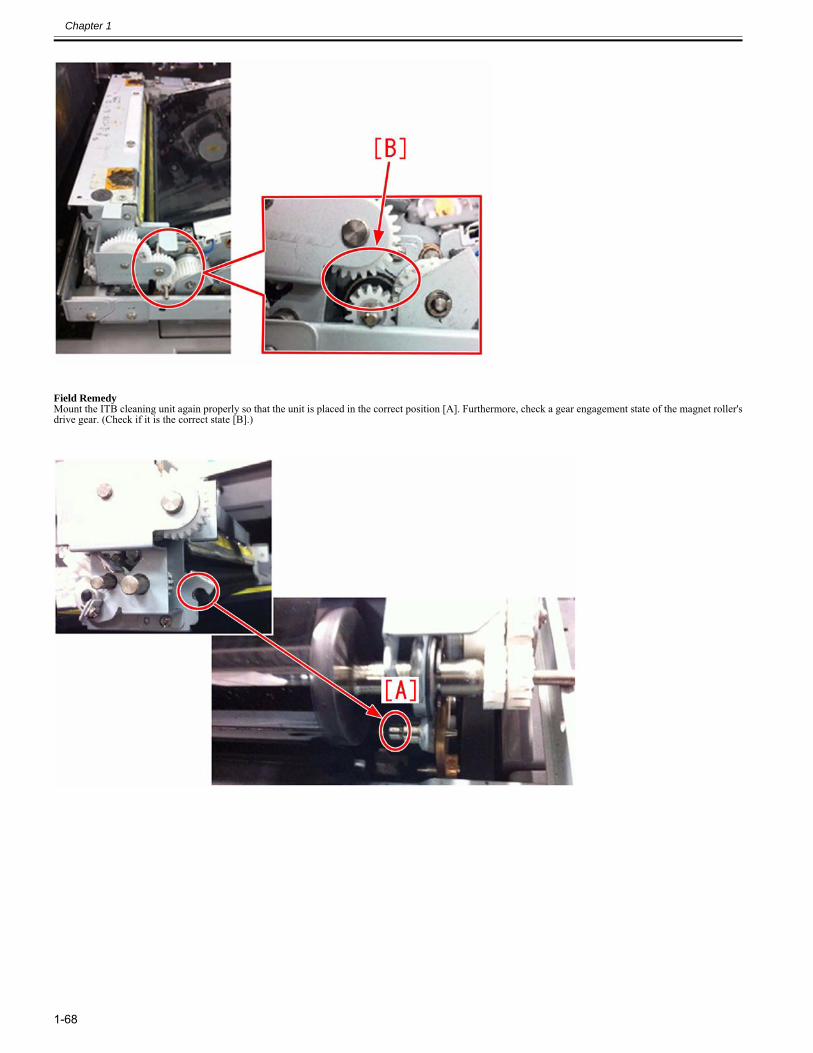
Chapter 1
1-68
Field RemedyMount the ITB cleaning unit again properly so that the unit is placed in the correct position [A]. Furthermore, check a gear engagement state of the magnet roller'sdrive gear. (Check if it is the correct state [B].)
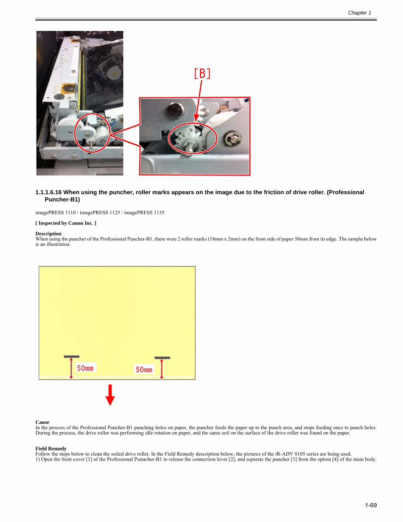
Chapter 1
1-69
1.1.1.6.16 When using the puncher, roller marks appears on the image due to the friction of drive roller. (Professional Puncher-B1)
0029-0348
imagePRESS 1110 / imagePRESS 1125 / imagePRESS 1135
[ Inspected by Canon Inc. ]
DescriptionWhen using the puncher of the Professional Puncher-B1, there were 2 roller marks (18mm x 2mm) on the front side of paper 50mm from its edge. The sample belowis an illustration.
CauseIn the process of the Professional Puncher-B1 punching holes on paper, the puncher feeds the paper up to the punch area, and stops feeding once to punch holes.During the process, the drive roller was performing idle rotation on paper, and the same soil on the surface of the drive roller was found on the paper.
Field RemedyFollow the steps below to clean the soiled drive roller. In the Field Remedy description below, the pictures of the iR-ADV 8105 series are being used.1) Open the front cover [1] of the Professional Punncher-B1 to release the connection lever [2], and separate the puncher [3] from the option [4] of the main body.
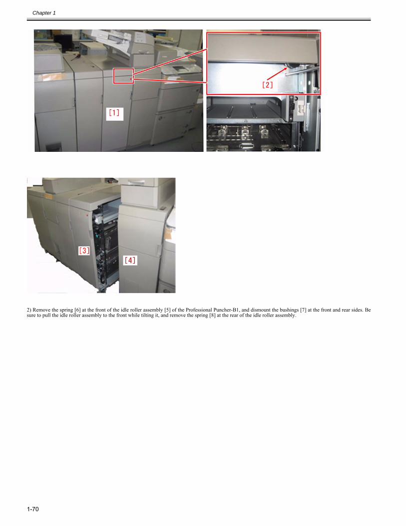
Chapter 1
1-70
2) Remove the spring [6] at the front of the idle roller assembly [5] of the Professional Puncher-B1, and dismount the bushings [7] at the front and rear sides. Besure to pull the idle roller assembly to the front while tilting it, and remove the spring [8] at the rear of the idle roller assembly.
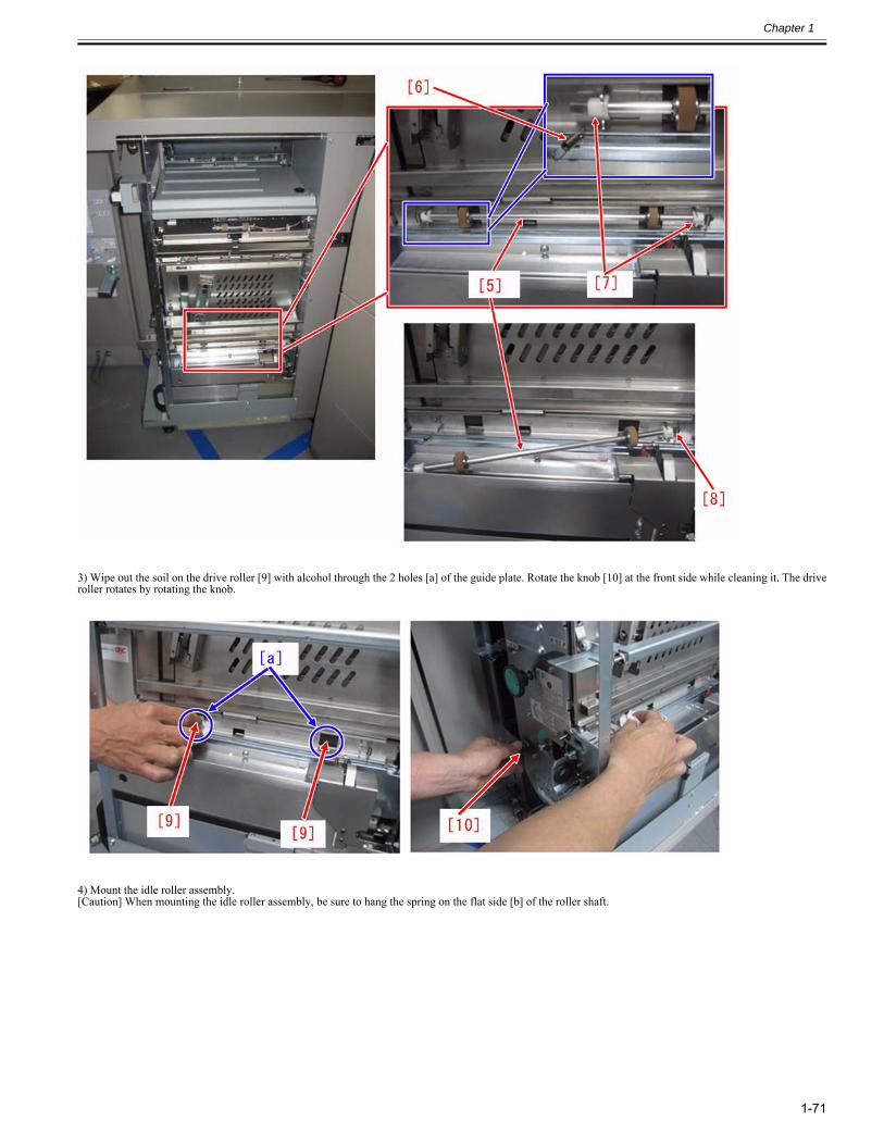
Chapter 1
1-71
3) Wipe out the soil on the drive roller [9] with alcohol through the 2 holes [a] of the guide plate. Rotate the knob [10] at the front side while cleaning it. The driveroller rotates by rotating the knob.
4) Mount the idle roller assembly.[Caution] When mounting the idle roller assembly, be sure to hang the spring on the flat side [b] of the roller shaft.
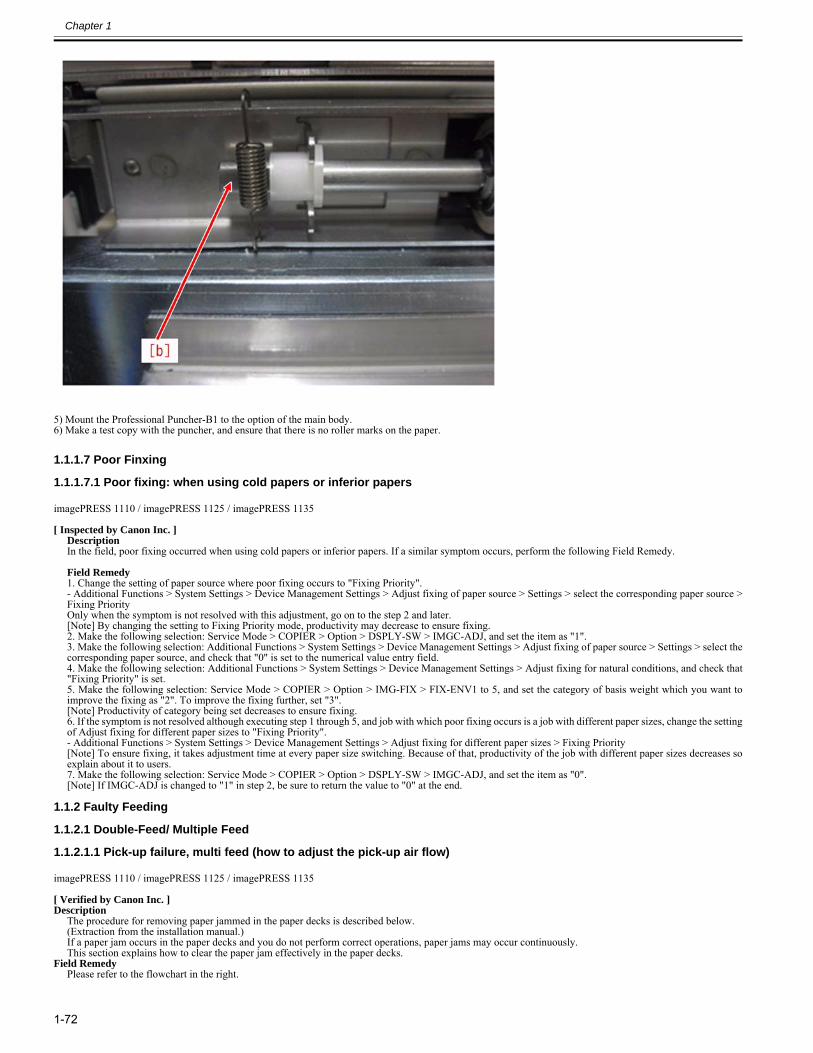
Chapter 1
1-72
5) Mount the Professional Puncher-B1 to the option of the main body.6) Make a test copy with the puncher, and ensure that there is no roller marks on the paper.
1.1.1.7 Poor Finxing
1.1.1.7.1 Poor fixing: when using cold papers or inferior papers0025-0677
imagePRESS 1110 / imagePRESS 1125 / imagePRESS 1135
[ Inspected by Canon Inc. ]Description In the field, poor fixing occurred when using cold papers or inferior papers. If a similar symptom occurs, perform the following Field Remedy. Field Remedy 1. Change the setting of paper source where poor fixing occurs to "Fixing Priority".- Additional Functions > System Settings > Device Management Settings > Adjust fixing of paper source > Settings > select the corresponding paper source >Fixing PriorityOnly when the symptom is not resolved with this adjustment, go on to the step 2 and later.[Note] By changing the setting to Fixing Priority mode, productivity may decrease to ensure fixing.2. Make the following selection: Service Mode > COPIER > Option > DSPLY-SW > IMGC-ADJ, and set the item as "1".3. Make the following selection: Additional Functions > System Settings > Device Management Settings > Adjust fixing of paper source > Settings > select thecorresponding paper source, and check that "0" is set to the numerical value entry field.4. Make the following selection: Additional Functions > System Settings > Device Management Settings > Adjust fixing for natural conditions, and check that"Fixing Priority" is set.5. Make the following selection: Service Mode > COPIER > Option > IMG-FIX > FIX-ENV1 to 5, and set the category of basis weight which you want toimprove the fixing as "2". To improve the fixing further, set "3".[Note] Productivity of category being set decreases to ensure fixing.6. If the symptom is not resolved although executing step 1 through 5, and job with which poor fixing occurs is a job with different paper sizes, change the settingof Adjust fixing for different paper sizes to "Fixing Priority".- Additional Functions > System Settings > Device Management Settings > Adjust fixing for different paper sizes > Fixing Priority[Note] To ensure fixing, it takes adjustment time at every paper size switching. Because of that, productivity of the job with different paper sizes decreases soexplain about it to users.7. Make the following selection: Service Mode > COPIER > Option > DSPLY-SW > IMGC-ADJ, and set the item as "0".[Note] If IMGC-ADJ is changed to "1" in step 2, be sure to return the value to "0" at the end.
1.1.2 Faulty Feeding
1.1.2.1 Double-Feed/ Multiple Feed
1.1.2.1.1 Pick-up failure, multi feed (how to adjust the pick-up air flow)0028-1422
imagePRESS 1110 / imagePRESS 1125 / imagePRESS 1135
[ Verified by Canon Inc. ]Description
The procedure for removing paper jammed in the paper decks is described below.(Extraction from the installation manual.)If a paper jam occurs in the paper decks and you do not perform correct operations, paper jams may occur continuously. This section explains how to clear the paper jam effectively in the paper decks.
Field RemedyPlease refer to the flowchart in the right.
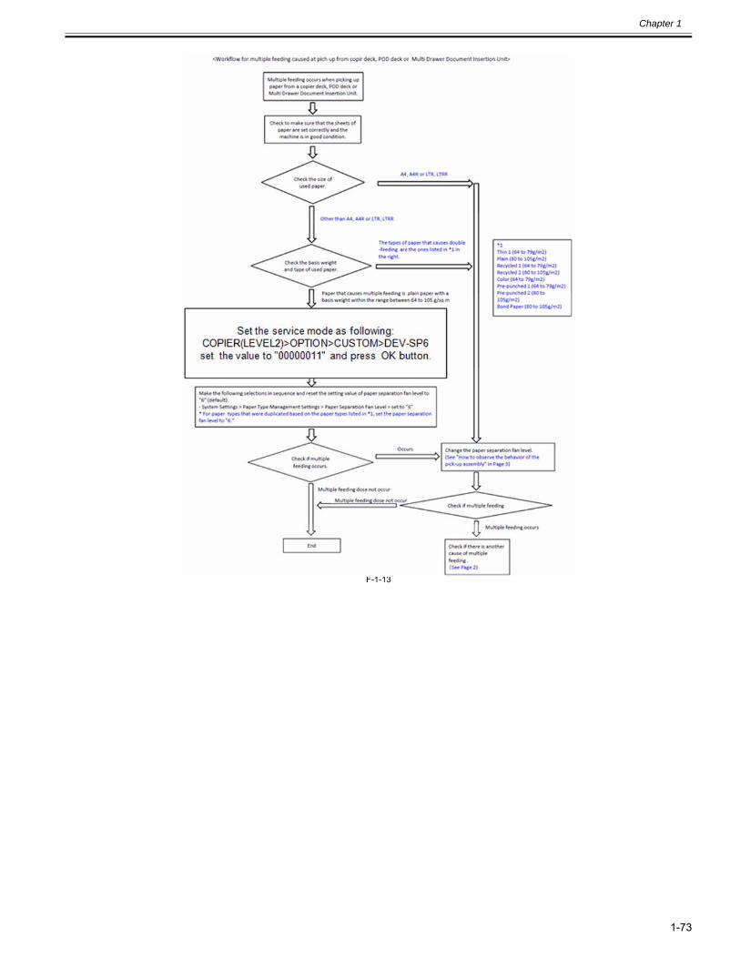
Chapter 1
1-73
F-1-13
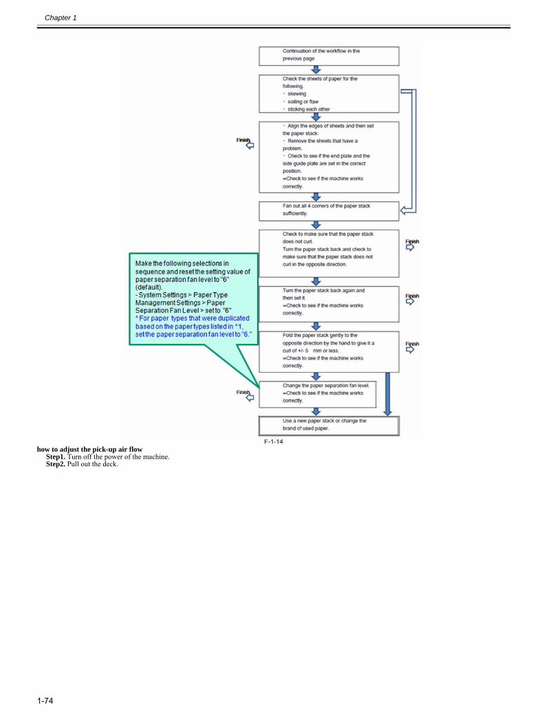
Chapter 1
1-74
F-1-14how to adjust the pick-up air flow
Step1. Turn off the power of the machine. Step2. Pull out the deck.
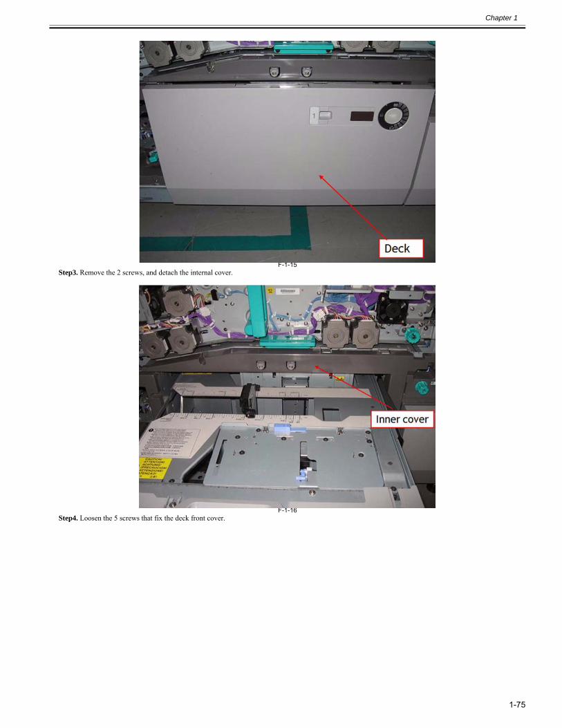
Chapter 1
1-75
F-1-15Step3. Remove the 2 screws, and detach the internal cover.
F-1-16Step4. Loosen the 5 screws that fix the deck front cover.
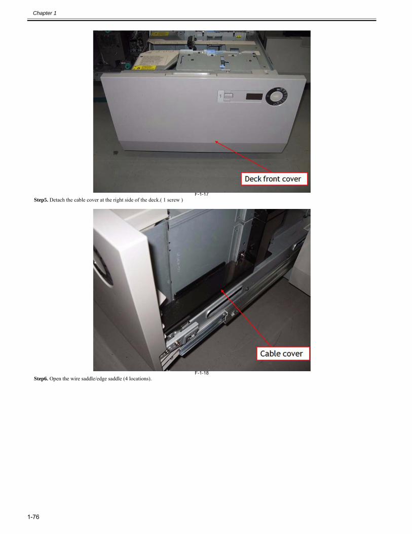
Chapter 1
1-76
F-1-17Step5. Detach the cable cover at the right side of the deck.( 1 screw )
F-1-18Step6. Open the wire saddle/edge saddle (4 locations).
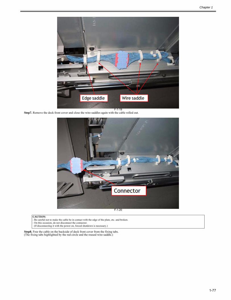
Chapter 1
1-77
F-1-19Step7. Remove the deck front cover and close the wire-saddles again with the cable rolled out.
F-1-20
Step8. Free the cable on the backside of deck front cover from the fixing tabs.(The fixing tabs highlighted by the red circle and the reused wire-saddle.)
CAUTION:- Be careful not to make the cable be in contact with the edge of the plate, etc. and broken. - On this occasion, do not disconnect the connector. (If disconnecting it with the power on, forced shutdown is necessary.)
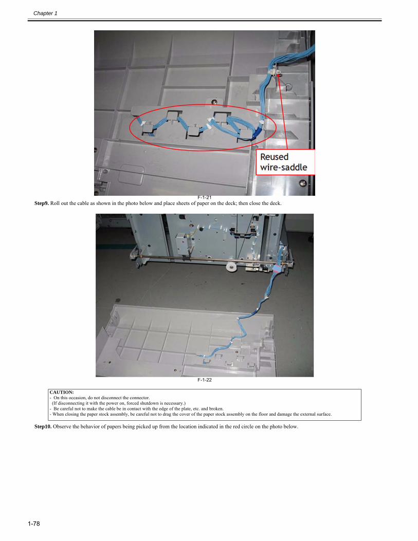
Chapter 1
1-78
F-1-21Step9. Roll out the cable as shown in the photo below and place sheets of paper on the deck; then close the deck.
F-1-22
Step10. Observe the behavior of papers being picked up from the location indicated in the red circle on the photo below.
CAUTION:- On this occasion, do not disconnect the connector. (If disconnecting it with the power on, forced shutdown is necessary.) - Be careful not to make the cable be in contact with the edge of the plate, etc. and broken. - When closing the paper stock assembly, be careful not to drag the cover of the paper stock assembly on the floor and damage the external surface.
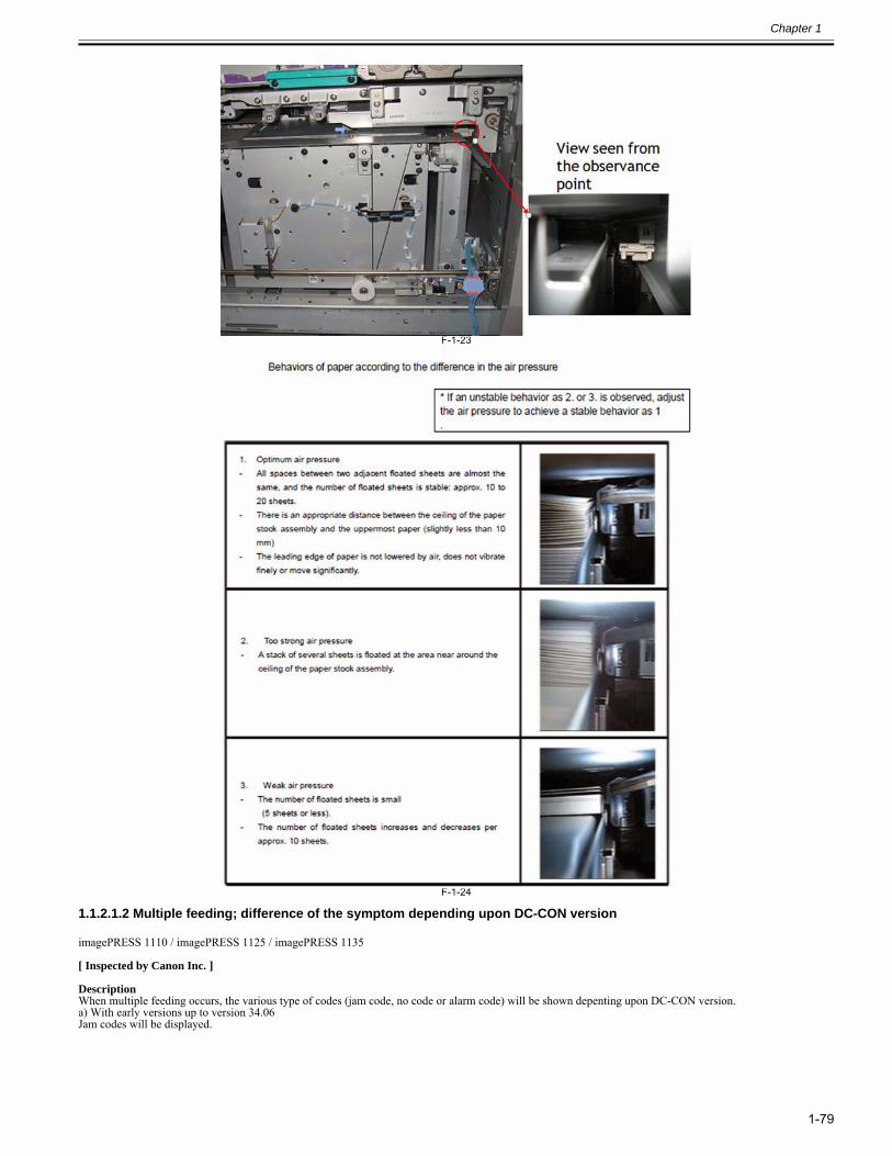
Chapter 1
1-79
F-1-23
F-1-24
1.1.2.1.2 Multiple feeding; difference of the symptom depending upon DC-CON version0028-5291
imagePRESS 1110 / imagePRESS 1125 / imagePRESS 1135
[ Inspected by Canon Inc. ]
DescriptionWhen multiple feeding occurs, the various type of codes (jam code, no code or alarm code) will be shown depenting upon DC-CON version.a) With early versions up to version 34.06Jam codes will be displayed.
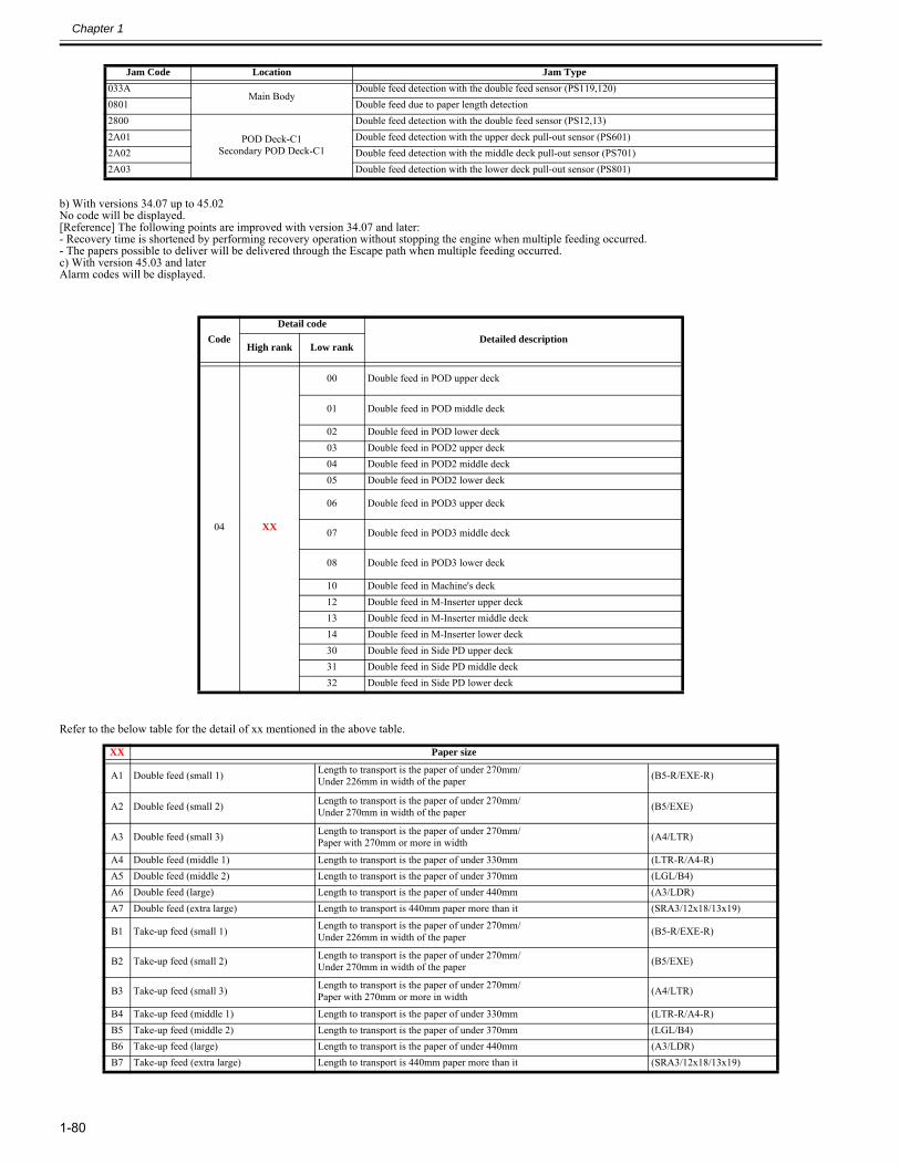
Chapter 1
1-80
b) With versions 34.07 up to 45.02No code will be displayed.[Reference] The following points are improved with version 34.07 and later:- Recovery time is shortened by performing recovery operation without stopping the engine when multiple feeding occurred.- The papers possible to deliver will be delivered through the Escape path when multiple feeding occurred.c) With version 45.03 and laterAlarm codes will be displayed.
Refer to the below table for the detail of xx mentioned in the above table.
Jam Code Location Jam Type033A
Main BodyDouble feed detection with the double feed sensor (PS119,120)
0801 Double feed due to paper length detection2800
POD Deck-C1Secondary POD Deck-C1
Double feed detection with the double feed sensor (PS12,13)2A01 Double feed detection with the upper deck pull-out sensor (PS601)2A02 Double feed detection with the middle deck pull-out sensor (PS701)2A03 Double feed detection with the lower deck pull-out sensor (PS801)
CodeDetail code
Detailed descriptionHigh rank Low rank
04 XX
00 Double feed in POD upper deck
01 Double feed in POD middle deck
02 Double feed in POD lower deck03 Double feed in POD2 upper deck04 Double feed in POD2 middle deck05 Double feed in POD2 lower deck
06 Double feed in POD3 upper deck
07 Double feed in POD3 middle deck
08 Double feed in POD3 lower deck
10 Double feed in Machine's deck12 Double feed in M-Inserter upper deck13 Double feed in M-Inserter middle deck14 Double feed in M-Inserter lower deck30 Double feed in Side PD upper deck31 Double feed in Side PD middle deck32 Double feed in Side PD lower deck
XX Paper size
A1 Double feed (small 1) Length to transport is the paper of under 270mm/Under 226mm in width of the paper (B5-R/EXE-R)
A2 Double feed (small 2) Length to transport is the paper of under 270mm/Under 270mm in width of the paper (B5/EXE)
A3 Double feed (small 3) Length to transport is the paper of under 270mm/Paper with 270mm or more in width (A4/LTR)
A4 Double feed (middle 1) Length to transport is the paper of under 330mm (LTR-R/A4-R)A5 Double feed (middle 2) Length to transport is the paper of under 370mm (LGL/B4)A6 Double feed (large) Length to transport is the paper of under 440mm (A3/LDR)A7 Double feed (extra large) Length to transport is 440mm paper more than it (SRA3/12x18/13x19)
B1 Take-up feed (small 1) Length to transport is the paper of under 270mm/Under 226mm in width of the paper (B5-R/EXE-R)
B2 Take-up feed (small 2) Length to transport is the paper of under 270mm/Under 270mm in width of the paper (B5/EXE)
B3 Take-up feed (small 3) Length to transport is the paper of under 270mm/Paper with 270mm or more in width (A4/LTR)
B4 Take-up feed (middle 1) Length to transport is the paper of under 330mm (LTR-R/A4-R)B5 Take-up feed (middle 2) Length to transport is the paper of under 370mm (LGL/B4)B6 Take-up feed (large) Length to transport is the paper of under 440mm (A3/LDR)B7 Take-up feed (extra large) Length to transport is 440mm paper more than it (SRA3/12x18/13x19)
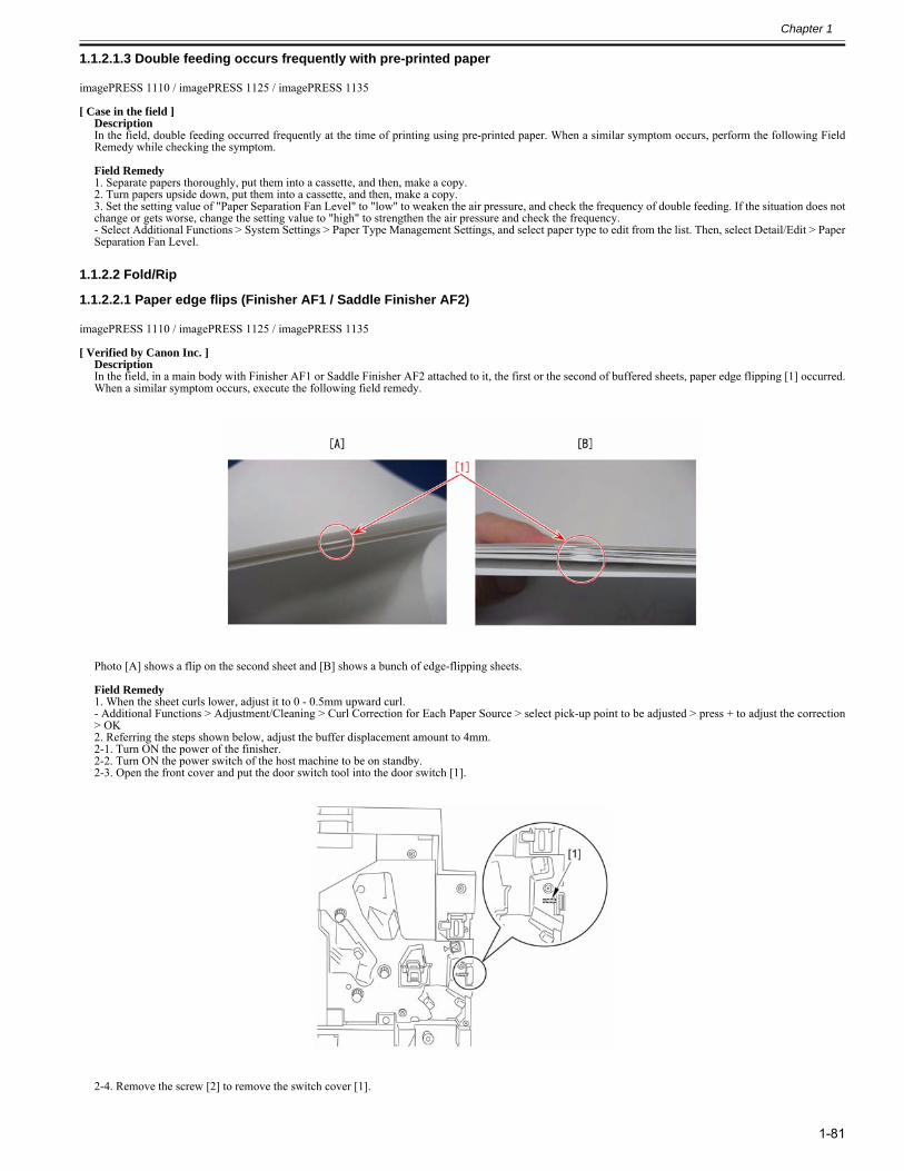
Chapter 1
1-81
1.1.2.1.3 Double feeding occurs frequently with pre-printed paper0024-7080
imagePRESS 1110 / imagePRESS 1125 / imagePRESS 1135
[ Case in the field ]DescriptionIn the field, double feeding occurred frequently at the time of printing using pre-printed paper. When a similar symptom occurs, perform the following FieldRemedy while checking the symptom. Field Remedy1. Separate papers thoroughly, put them into a cassette, and then, make a copy. 2. Turn papers upside down, put them into a cassette, and then, make a copy. 3. Set the setting value of "Paper Separation Fan Level" to "low" to weaken the air pressure, and check the frequency of double feeding. If the situation does notchange or gets worse, change the setting value to "high" to strengthen the air pressure and check the frequency. - Select Additional Functions > System Settings > Paper Type Management Settings, and select paper type to edit from the list. Then, select Detail/Edit > PaperSeparation Fan Level.
1.1.2.2 Fold/Rip
1.1.2.2.1 Paper edge flips (Finisher AF1 / Saddle Finisher AF2)0024-4390
imagePRESS 1110 / imagePRESS 1125 / imagePRESS 1135
[ Verified by Canon Inc. ]DescriptionIn the field, in a main body with Finisher AF1 or Saddle Finisher AF2 attached to it, the first or the second of buffered sheets, paper edge flipping [1] occurred.When a similar symptom occurs, execute the following field remedy.
Photo [A] shows a flip on the second sheet and [B] shows a bunch of edge-flipping sheets. Field Remedy 1. When the sheet curls lower, adjust it to 0 - 0.5mm upward curl.- Additional Functions > Adjustment/Cleaning > Curl Correction for Each Paper Source > select pick-up point to be adjusted > press + to adjust the correction> OK2. Referring the steps shown below, adjust the buffer displacement amount to 4mm.2-1. Turn ON the power of the finisher.2-2. Turn ON the power switch of the host machine to be on standby.2-3. Open the front cover and put the door switch tool into the door switch [1].
2-4. Remove the screw [2] to remove the switch cover [1].
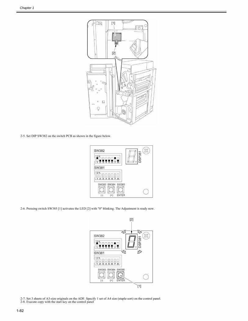
Chapter 1
1-82
2-5. Set DIP SW382 on the switch PCB as shown in the figure below.
2-6. Pressing switch SW385 [1] activates the LED [2] with "0" blinking. The Adjustment is ready now.
2-7. Set 3 sheets of A3-size originals on the ADF. Specify 1 set of A4 size (staple-sort) on the control panel.2-8. Execute copy with the start key on the control panel
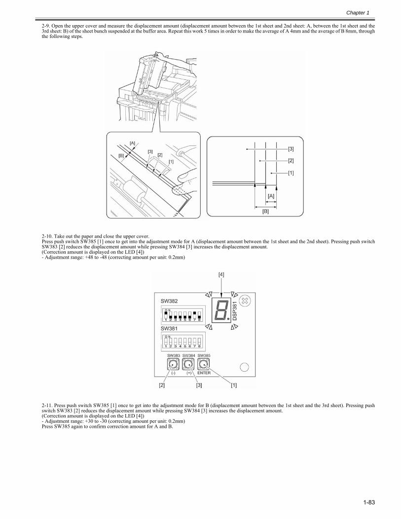
Chapter 1
1-83
2-9. Open the upper cover and measure the displacement amount (displacement amount between the 1st sheet and 2nd sheet: A, between the 1st sheet and the3rd sheet: B) of the sheet bunch suspended at the buffer area. Repeat this work 5 times in order to make the average of A 4mm and the average of B 8mm, throughthe following steps.
2-10. Take out the paper and close the upper cover.Press push switch SW385 [1] once to get into the adjustment mode for A (displacement amount between the 1st sheet and the 2nd sheet). Pressing push switchSW383 [2] reduces the displacement amount while pressing SW384 [3] increases the displacement amount.(Correction amount is displayed on the LED [4])- Adjustment range: +48 to -48 (correcting amount per unit: 0.2mm)
2-11. Press push switch SW385 [1] once to get into the adjustment mode for B (displacement amount between the 1st sheet and the 3rd sheet). Pressing pushswitch SW383 [2] reduces the displacement amount while pressing SW384 [3] increases the displacement amount.(Correction amount is displayed on the LED [4])- Adjustment range: +30 to -30 (correcting amount per unit: 0.2mm)Press SW385 again to confirm correction amount for A and B.
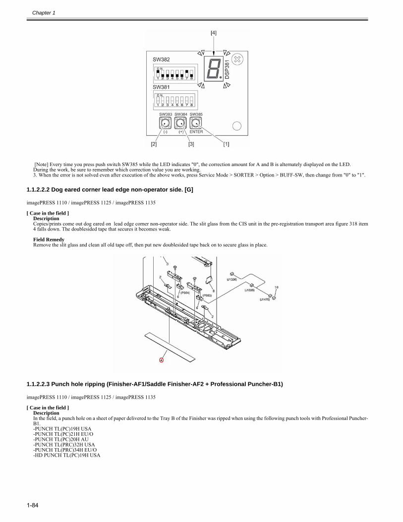
Chapter 1
1-84
[Note] Every time you press push switch SW385 while the LED indicates "0", the correction amount for A and B is alternately displayed on the LED.During the work, be sure to remember which correction value you are working.3. When the error is not solved even after execution of the above works, press Service Mode > SORTER > Option > BUFF-SW, then change from "0" to "1".
1.1.2.2.2 Dog eared corner lead edge non-operator side. [G]0025-4000
imagePRESS 1110 / imagePRESS 1125 / imagePRESS 1135
[ Case in the field ]DescriptionCopies/prints come out dog eared on lead edge corner non-operator side. The slit glass from the CIS unit in the pre-registration transport area figure 318 item4 falls down. The doublesided tape that secures it becomes weak. Field RemedyRemove the slit glass and clean all old tape off, then put new doublesided tape back on to secure glass in place.
1.1.2.2.3 Punch hole ripping (Finisher-AF1/Saddle Finisher-AF2 + Professional Puncher-B1)0025-8620
imagePRESS 1110 / imagePRESS 1125 / imagePRESS 1135
[ Case in the field ]DescriptionIn the field, a punch hole on a sheet of paper delivered to the Tray B of the Finisher was ripped when using the following punch tools with Professional Puncher-B1.-PUNCH TL(PC)19H USA-PUNCH TL(PC)21H EU/O-PUNCH TL(PC)20H AU-PUNCH TL(PRC)32H USA-PUNCH TL(PRC)34H EU/O-HD PUNCH TL(PC)19H USA
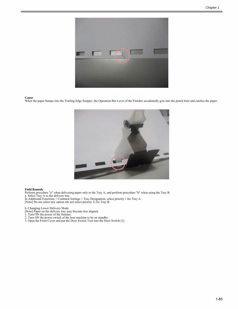
Chapter 1
1-85
CauseWhen the paper bumps into the Trailing Edge Stopper, the Operation Bin Lever of the Finisher accidentally gets into the punch hole and catches the paper.
Field RemedyPerform procedure "a" when delivering paper only to the Tray A, and perform procedure "b" when using the Tray B.a. Select Tray A as the delivery tray.In Additional Functions > Common Settings > Tray Designation, select priority 1 for Tray A.[Note] Do not select any option (do not select priority 2) for Tray B.
b. Changing Lower Delivery Mode[Note] Paper on the delivery tray may become less aligned.1. Turn ON the power of the finisher.2. Turn ON the power switch of the host machine to be on standby.3. Open the Front Cover and put the Door Switch Tool into the Door Switch [1].
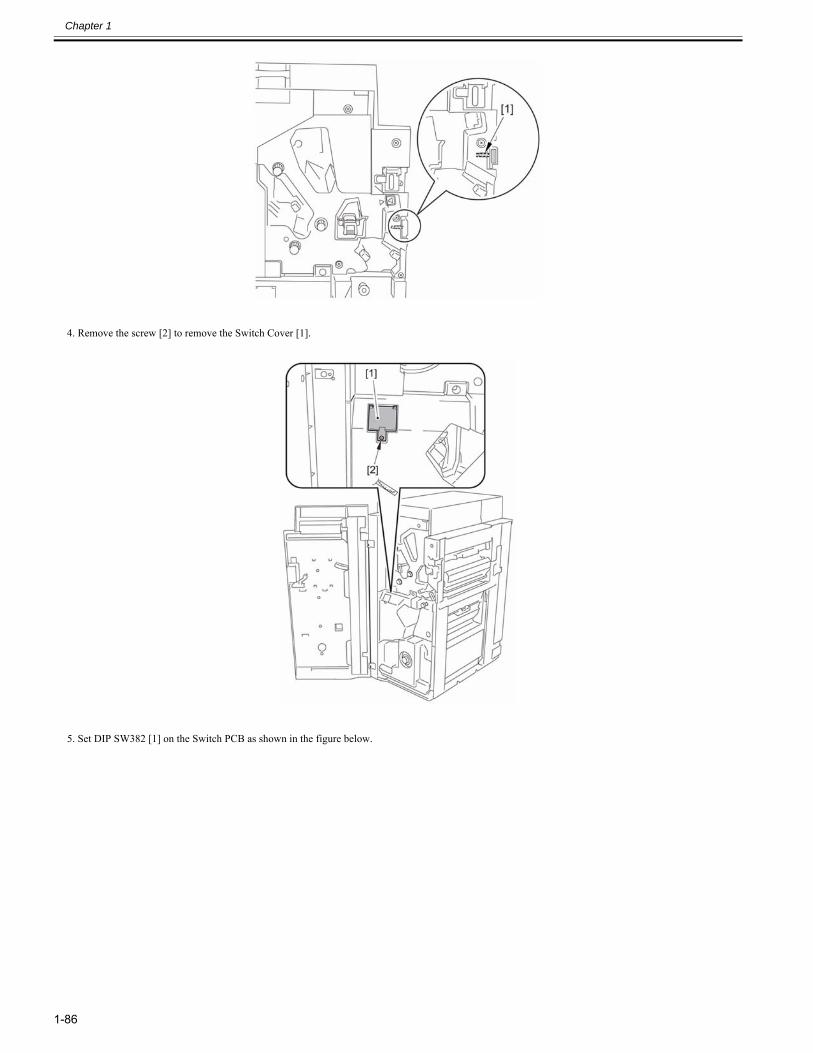
Chapter 1
1-86
4. Remove the screw [2] to remove the Switch Cover [1].
5. Set DIP SW382 [1] on the Switch PCB as shown in the figure below.
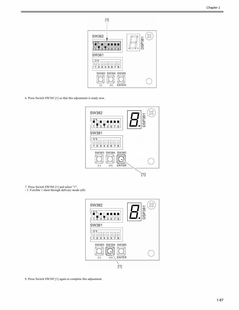
Chapter 1
1-87
6. Press Switch SW385 [1] so that this adjustment is ready now.
7. Press Switch SW384 [1] and select "1".- 1: Forcible 1 sheet through delivery mode (all)
8. Press Switch SW385 [1] again to complete this adjustment.
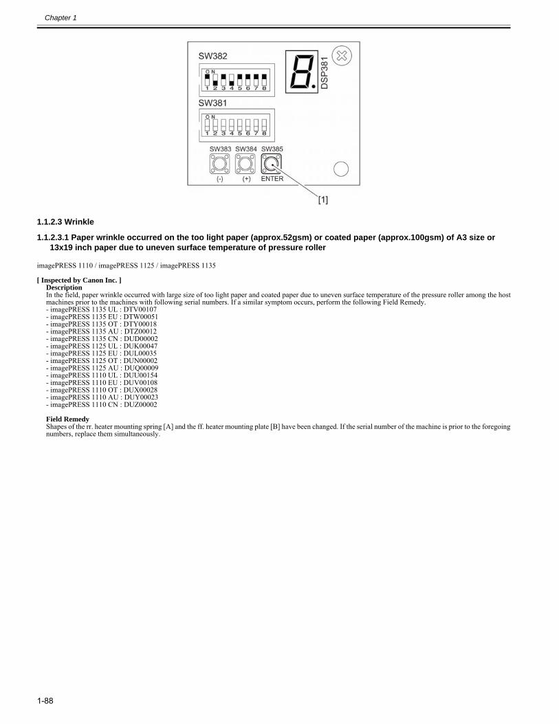
Chapter 1
1-88
1.1.2.3 Wrinkle
1.1.2.3.1 Paper wrinkle occurred on the too light paper (approx.52gsm) or coated paper (approx.100gsm) of A3 size or 13x19 inch paper due to uneven surface temperature of pressure roller
0024-2442
imagePRESS 1110 / imagePRESS 1125 / imagePRESS 1135
[ Inspected by Canon Inc. ]Description In the field, paper wrinkle occurred with large size of too light paper and coated paper due to uneven surface temperature of the pressure roller among the hostmachines prior to the machines with following serial numbers. If a similar symptom occurs, perform the following Field Remedy. - imagePRESS 1135 UL : DTV00107- imagePRESS 1135 EU : DTW00051- imagePRESS 1135 OT : DTY00018- imagePRESS 1135 AU : DTZ00012- imagePRESS 1135 CN : DUD00002- imagePRESS 1125 UL : DUK00047- imagePRESS 1125 EU : DUL00035- imagePRESS 1125 OT : DUN00002- imagePRESS 1125 AU : DUQ00009- imagePRESS 1110 UL : DUU00154- imagePRESS 1110 EU : DUV00108- imagePRESS 1110 OT : DUX00028- imagePRESS 1110 AU : DUY00023- imagePRESS 1110 CN : DUZ00002 Field RemedyShapes of the rr. heater mounting spring [A] and the ff. heater mounting plate [B] have been changed. If the serial number of the machine is prior to the foregoingnumbers, replace them simultaneously.
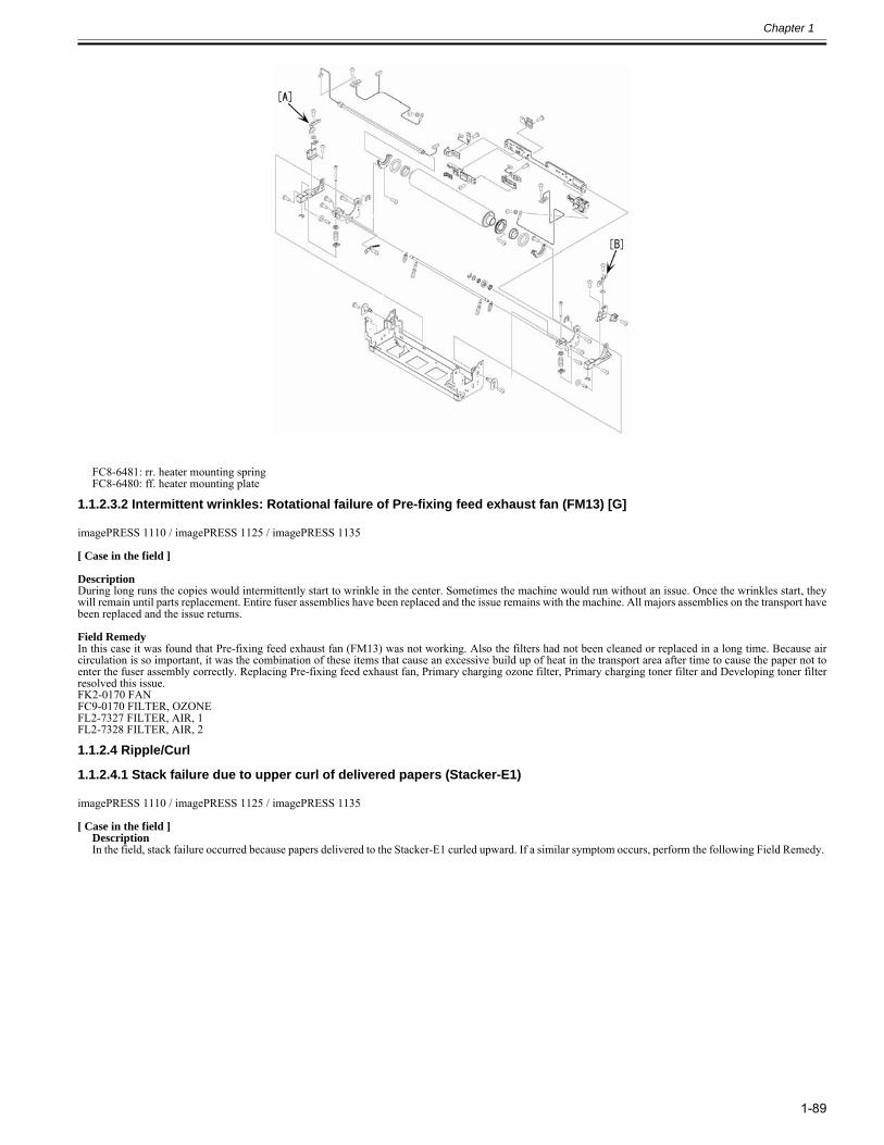
Chapter 1
1-89
FC8-6481: rr. heater mounting springFC8-6480: ff. heater mounting plate
1.1.2.3.2 Intermittent wrinkles: Rotational failure of Pre-fixing feed exhaust fan (FM13) [G]0028-6727
imagePRESS 1110 / imagePRESS 1125 / imagePRESS 1135
[ Case in the field ] DescriptionDuring long runs the copies would intermittently start to wrinkle in the center. Sometimes the machine would run without an issue. Once the wrinkles start, theywill remain until parts replacement. Entire fuser assemblies have been replaced and the issue remains with the machine. All majors assemblies on the transport havebeen replaced and the issue returns. Field RemedyIn this case it was found that Pre-fixing feed exhaust fan (FM13) was not working. Also the filters had not been cleaned or replaced in a long time. Because aircirculation is so important, it was the combination of these items that cause an excessive build up of heat in the transport area after time to cause the paper not toenter the fuser assembly correctly. Replacing Pre-fixing feed exhaust fan, Primary charging ozone filter, Primary charging toner filter and Developing toner filterresolved this issue.FK2-0170 FANFC9-0170 FILTER, OZONEFL2-7327 FILTER, AIR, 1FL2-7328 FILTER, AIR, 2
1.1.2.4 Ripple/Curl
1.1.2.4.1 Stack failure due to upper curl of delivered papers (Stacker-E1)0024-7089
imagePRESS 1110 / imagePRESS 1125 / imagePRESS 1135
[ Case in the field ]Description In the field, stack failure occurred because papers delivered to the Stacker-E1 curled upward. If a similar symptom occurs, perform the following Field Remedy.
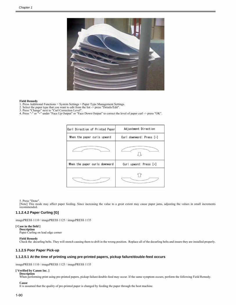
Chapter 1
1-90
Field Remedy1. Press Additional Functions > System Settings > Paper Type Management Settings.2. Select the paper type that you want to edit from the list -> press "Details/Edit".3. Press "Change" next to "Curl Correction Level".4. Press "-" or "+" under "Face Up Output" or "Face Down Output" to correct the level of paper curl -> press "OK".
5. Press "Done".[Note] This mode may affect paper feeding. Since increasing the value to a great extent may cause paper jams, adjusting the values in small incrementsrecommended.
1.1.2.4.2 Paper Curling [G]0025-3999
imagePRESS 1110 / imagePRESS 1125 / imagePRESS 1135
[ Case in the field ]DescriptionPaper Curling on lead edge corner Field RemedyCheck the decurling belts. They will stretch causing them to drift in the wrong position. Replace all of the decurling belts and insure they are installed properly.
1.1.2.5 Poor Paper Pick-up
1.1.2.5.1 At the time of printing using pre-printed papers, pickup failure/double-feed occurs0024-1676
imagePRESS 1110 / imagePRESS 1125 / imagePRESS 1135
[ Verified by Canon Inc. ]Description When performing print using pre-printed papers, pickup failure/double-feed may occur. If the same symptom occurs, perform the following Field Remedy. CauseIt is assumed that the quality of pre-printed paper is changed by feeding the paper through the host machine.
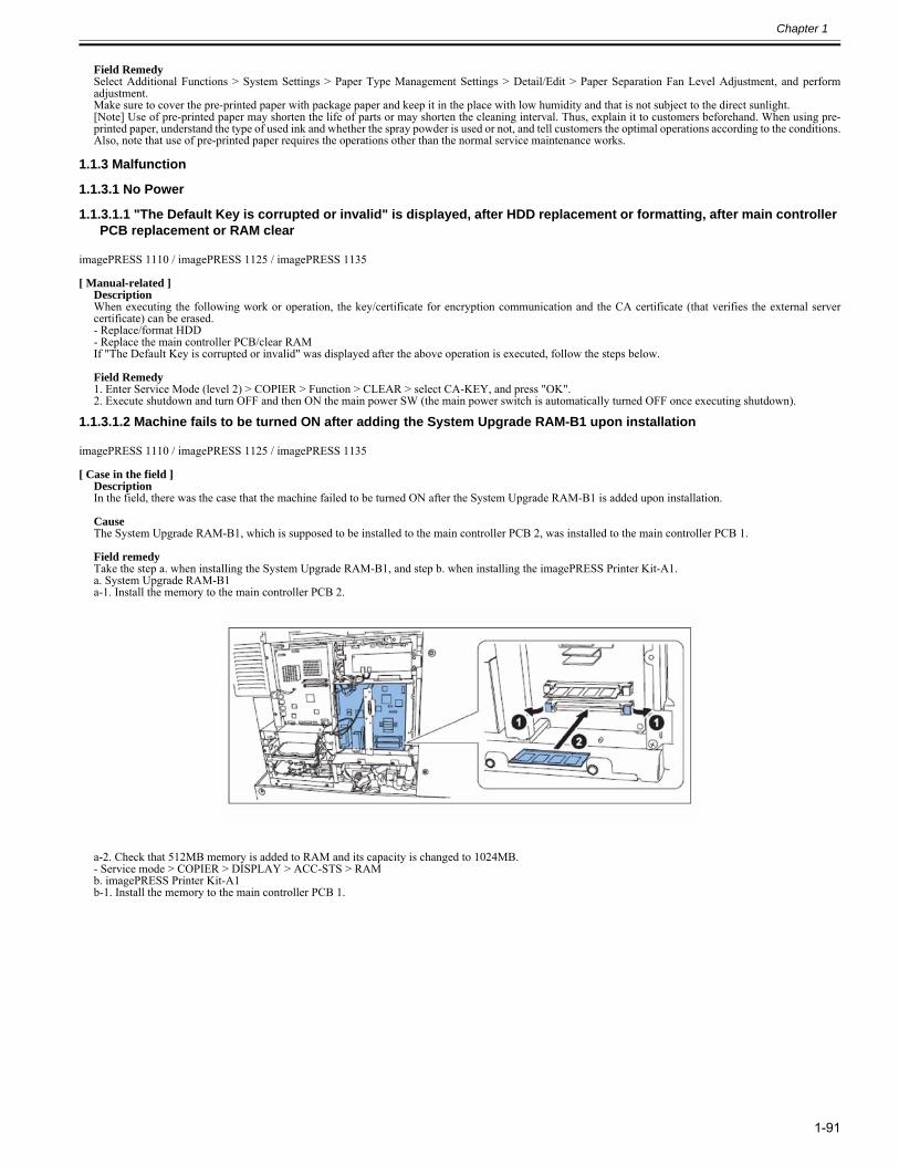
Chapter 1
1-91
Field RemedySelect Additional Functions > System Settings > Paper Type Management Settings > Detail/Edit > Paper Separation Fan Level Adjustment, and performadjustment. Make sure to cover the pre-printed paper with package paper and keep it in the place with low humidity and that is not subject to the direct sunlight.[Note] Use of pre-printed paper may shorten the life of parts or may shorten the cleaning interval. Thus, explain it to customers beforehand. When using pre-printed paper, understand the type of used ink and whether the spray powder is used or not, and tell customers the optimal operations according to the conditions.Also, note that use of pre-printed paper requires the operations other than the normal service maintenance works.
1.1.3 Malfunction
1.1.3.1 No Power
1.1.3.1.1 "The Default Key is corrupted or invalid" is displayed, after HDD replacement or formatting, after main controller PCB replacement or RAM clear
0023-2488
imagePRESS 1110 / imagePRESS 1125 / imagePRESS 1135
[ Manual-related ]DescriptionWhen executing the following work or operation, the key/certificate for encryption communication and the CA certificate (that verifies the external servercertificate) can be erased.- Replace/format HDD- Replace the main controller PCB/clear RAMIf "The Default Key is corrupted or invalid" was displayed after the above operation is executed, follow the steps below.
Field Remedy1. Enter Service Mode (level 2) > COPIER > Function > CLEAR > select CA-KEY, and press "OK".2. Execute shutdown and turn OFF and then ON the main power SW (the main power switch is automatically turned OFF once executing shutdown).
1.1.3.1.2 Machine fails to be turned ON after adding the System Upgrade RAM-B1 upon installation0023-8548
imagePRESS 1110 / imagePRESS 1125 / imagePRESS 1135
[ Case in the field ]DescriptionIn the field, there was the case that the machine failed to be turned ON after the System Upgrade RAM-B1 is added upon installation.
CauseThe System Upgrade RAM-B1, which is supposed to be installed to the main controller PCB 2, was installed to the main controller PCB 1.
Field remedyTake the step a. when installing the System Upgrade RAM-B1, and step b. when installing the imagePRESS Printer Kit-A1.a. System Upgrade RAM-B1a-1. Install the memory to the main controller PCB 2.
a-2. Check that 512MB memory is added to RAM and its capacity is changed to 1024MB.- Service mode > COPIER > DISPLAY > ACC-STS > RAMb. imagePRESS Printer Kit-A1b-1. Install the memory to the main controller PCB 1.
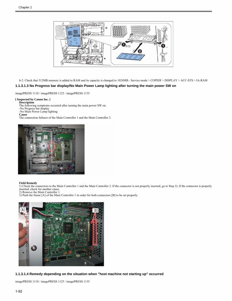
Chapter 1
1-92
b-2. Check that 512MB memory is added to RAM and its capacity is changed to 1024MB.- Service mode > COPIER > DISPLAY > ACC-STS > IA-RAM
1.1.3.1.3 No Progress bar display/No Main Power Lamp lighting after turning the main power SW on0027-3503
imagePRESS 1110 / imagePRESS 1125 / imagePRESS 1135
[ Inspected by Canon Inc. ]DescriptionThe following symptoms occurred after turning the main power SW on.-No Progress bar display-No Main Power Lamp lightingCauseThe connection failures of the Main Controller 1 and the Main Controller 2.
Field Remedy1) Check the connectors to the Main Controller 1 and the Main Controller 2. If the connector is not properly inserted, go to Step 2). If the connector is properlyinserted, check for another cause.2) Remove the Main Controller 1.3) Push the frame [A] of the Main Controller 1 in order for both connectors [B] to be set properly.
1.1.3.1.4 Remedy depending on the situation when "host machine not starting up" occurred0028-1425
imagePRESS 1110 / imagePRESS 1125 / imagePRESS 1135
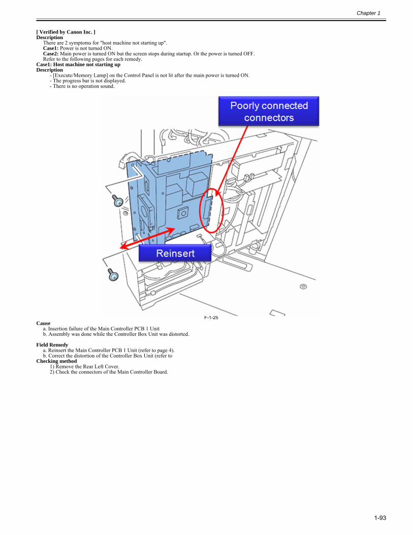
Chapter 1
1-93
[ Verified by Canon Inc. ]Description
There are 2 symptoms for "host machine not starting up".Case1: Power is not turned ON.Case2: Main power is turned ON but the screen stops during startup. Or the power is turned OFF.Refer to the following pages for each remedy.
Case1: Host machine not starting up Description
- [Execute/Memory Lamp] on the Control Panel is not lit after the main power is turned ON. - The progress bar is not displayed.- There is no operation sound.
F-1-25Cause
a. Insertion failure of the Main Controller PCB 1 Unitb. Assembly was done while the Controller Box Unit was distorted.
Field Remedy a. Reinsert the Main Controller PCB 1 Unit (refer to page 4).b. Correct the distortion of the Controller Box Unit (refer to
Checking method1) Remove the Rear Left Cover.2) Check the connectors of the Main Controller Board.
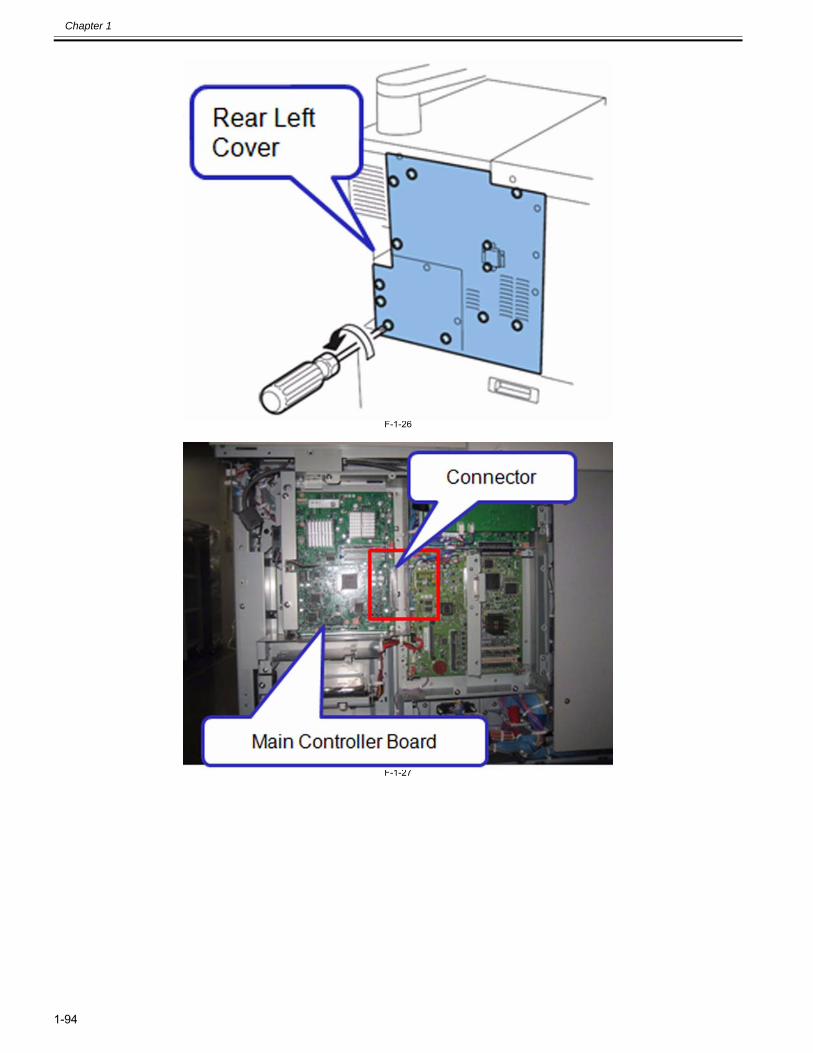
Chapter 1
1-94
F-1-26
F-1-27
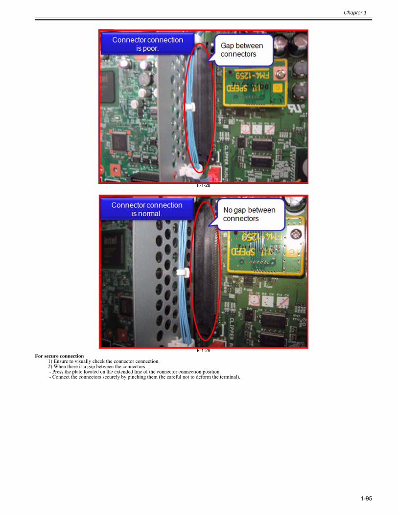
Chapter 1
1-95
F-1-28
F-1-29For secure connection
1) Ensure to visually check the connector connection. 2) When there is a gap between the connectors - Press the plate located on the extended line of the connector connection position. - Connect the connectors securely by pinching them (be careful not to deform the terminal).
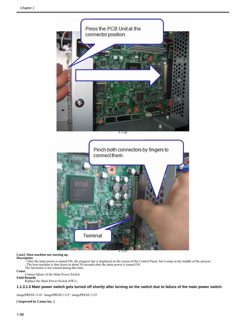
Chapter 1
1-96
F-1-30
F-1-31Case2: Host machine not starting upDescription
- After the main power is turned ON, the progress bar is displayed on the screen of the Control Panel, but it stops in the middle of the process.- The host machine is shut down in about 30 seconds after the main power is turned ON.The fan/motor is not rotated during this time.
CauseContact failure of the Main Power Switch
Field RemedyReplace the Main Power Switch (SW1).
1.1.3.1.5 Main power switch gets turned off shortly after turning on the switch due to failure of the main power switch0028-3871
imagePRESS 1110 / imagePRESS 1125 / imagePRESS 1135
[ Inspected by Canon Inc. ]
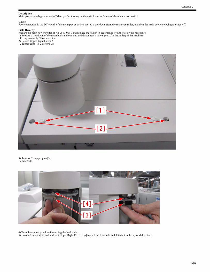
Chapter 1
1-97
DescriptionMain power switch gets turned off shortly after turning on the switch due to failure of the main power switch
CausePoor connection in the DC circuit of the main power switch caused a shutdown from the main controller, and then the main power switch got turned off.
Field RemedyPrepare the main power switch (FK2-2509-000), and replace the switch in accordance with the following procedure.1) Execute a shutdown of the main body and options, and disconnect a power plug (for the outlet) of the machine.- Fixing assembly / Host machine2) Detach Upper Right Cover 2- 2 rubber caps [1]/ 2 screws [2]
3) Remove 2 stopper pins [3]- 2 screws [4]
4) Turn the control panel until reaching the back side.5) Loosen 2 screws [5], and slide out Upper Right Cover 1 [6] toward the front side and detach it in the upward direction.
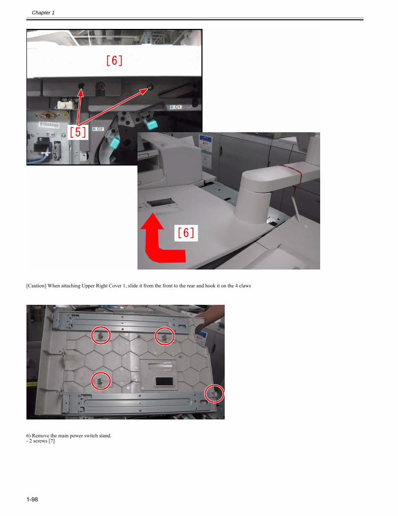
Chapter 1
1-98
[Caution] When attaching Upper Right Cover 1, slide it from the front to the rear and hook it on the 4 claws
6) Remove the main power switch stand.- 2 screws [7]
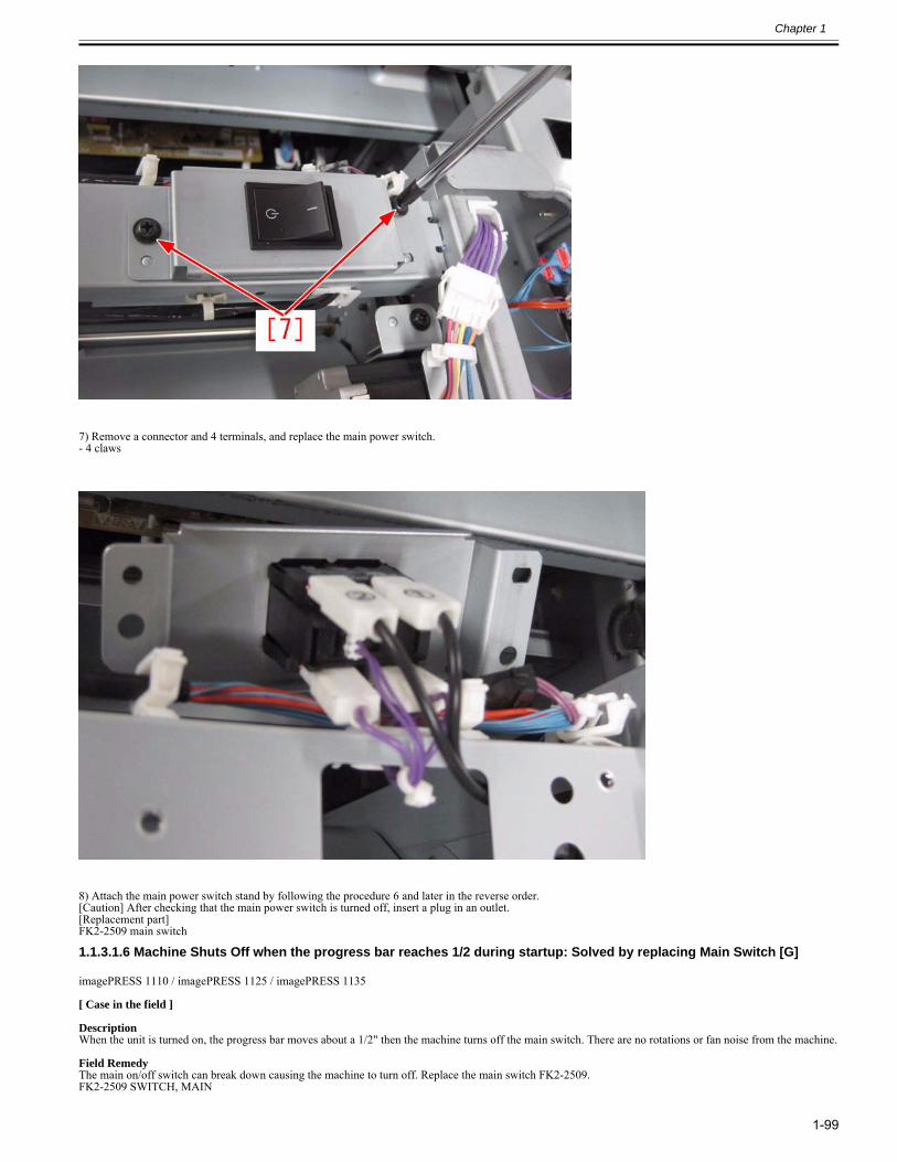
Chapter 1
1-99
7) Remove a connector and 4 terminals, and replace the main power switch.- 4 claws
8) Attach the main power switch stand by following the procedure 6 and later in the reverse order.[Caution] After checking that the main power switch is turned off, insert a plug in an outlet.[Replacement part]FK2-2509 main switch
1.1.3.1.6 Machine Shuts Off when the progress bar reaches 1/2 during startup: Solved by replacing Main Switch [G]0028-9837
imagePRESS 1110 / imagePRESS 1125 / imagePRESS 1135
[ Case in the field ] DescriptionWhen the unit is turned on, the progress bar moves about a 1/2" then the machine turns off the main switch. There are no rotations or fan noise from the machine. Field RemedyThe main on/off switch can break down causing the machine to turn off. Replace the main switch FK2-2509.FK2-2509 SWITCH, MAIN
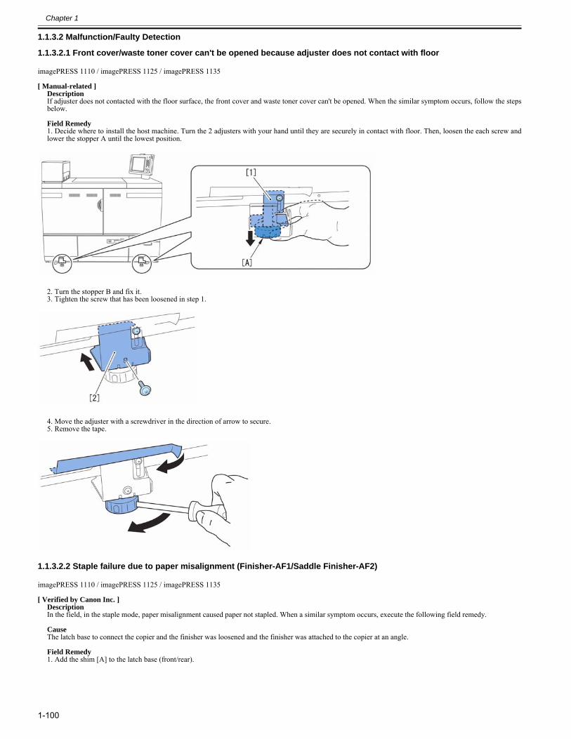
Chapter 1
1-100
1.1.3.2 Malfunction/Faulty Detection
1.1.3.2.1 Front cover/waste toner cover can't be opened because adjuster does not contact with floor0023-1922
imagePRESS 1110 / imagePRESS 1125 / imagePRESS 1135
[ Manual-related ]DescriptionIf adjuster does not contacted with the floor surface, the front cover and waste toner cover can't be opened. When the similar symptom occurs, follow the stepsbelow.
Field Remedy1. Decide where to install the host machine. Turn the 2 adjusters with your hand until they are securely in contact with floor. Then, loosen the each screw andlower the stopper A until the lowest position.
2. Turn the stopper B and fix it.3. Tighten the screw that has been loosened in step 1.
4. Move the adjuster with a screwdriver in the direction of arrow to secure.5. Remove the tape.
1.1.3.2.2 Staple failure due to paper misalignment (Finisher-AF1/Saddle Finisher-AF2)0024-6568
imagePRESS 1110 / imagePRESS 1125 / imagePRESS 1135
[ Verified by Canon Inc. ]DescriptionIn the field, in the staple mode, paper misalignment caused paper not stapled. When a similar symptom occurs, execute the following field remedy. CauseThe latch base to connect the copier and the finisher was loosened and the finisher was attached to the copier at an angle. Field Remedy1. Add the shim [A] to the latch base (front/rear).
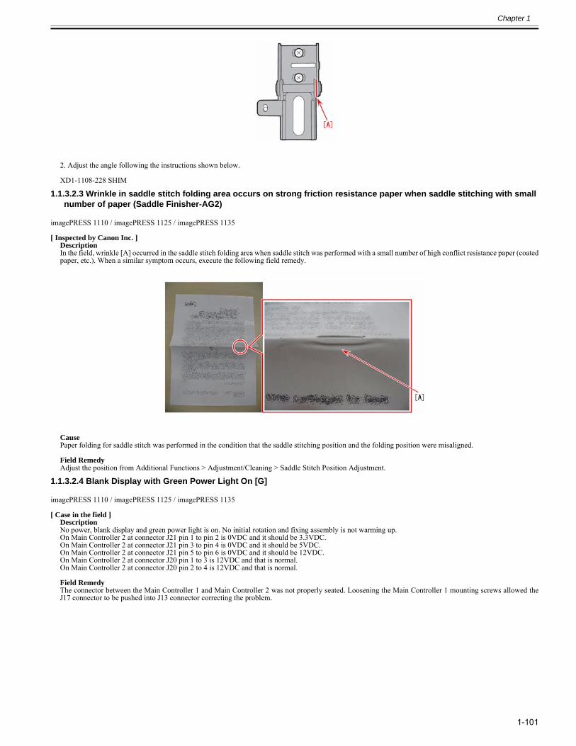
Chapter 1
1-101
2. Adjust the angle following the instructions shown below. XD1-1108-228 SHIM
1.1.3.2.3 Wrinkle in saddle stitch folding area occurs on strong friction resistance paper when saddle stitching with small number of paper (Saddle Finisher-AG2)
0024-8231
imagePRESS 1110 / imagePRESS 1125 / imagePRESS 1135
[ Inspected by Canon Inc. ]DescriptionIn the field, wrinkle [A] occurred in the saddle stitch folding area when saddle stitch was performed with a small number of high conflict resistance paper (coatedpaper, etc.). When a similar symptom occurs, execute the following field remedy.
CausePaper folding for saddle stitch was performed in the condition that the saddle stitching position and the folding position were misaligned. Field RemedyAdjust the position from Additional Functions > Adjustment/Cleaning > Saddle Stitch Position Adjustment.
1.1.3.2.4 Blank Display with Green Power Light On [G]0025-3713
imagePRESS 1110 / imagePRESS 1125 / imagePRESS 1135
[ Case in the field ]DescriptionNo power, blank display and green power light is on. No initial rotation and fixing assembly is not warming up. On Main Controller 2 at connector J21 pin 1 to pin 2 is 0VDC and it should be 3.3VDC.On Main Controller 2 at connector J21 pin 3 to pin 4 is 0VDC and it should be 5VDC.On Main Controller 2 at connector J21 pin 5 to pin 6 is 0VDC and it should be 12VDC.On Main Controller 2 at connector J20 pin 1 to 3 is 12VDC and that is normal.On Main Controller 2 at connector J20 pin 2 to 4 is 12VDC and that is normal. Field RemedyThe connector between the Main Controller 1 and Main Controller 2 was not properly seated. Loosening the Main Controller 1 mounting screws allowed theJ17 connector to be pushed into J13 connector correcting the problem.
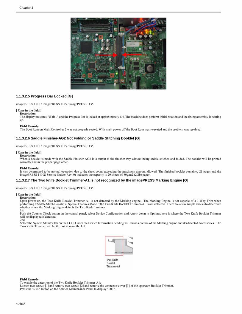
Chapter 1
1-102
1.1.3.2.5 Progress Bar Locked [G]0025-3717
imagePRESS 1110 / imagePRESS 1125 / imagePRESS 1135
[ Case in the field ]DescriptionThe display indicates "Wait..." and the Progress Bar is locked at approximately 1/4. The machine does perform initial rotation and the fixing assembly is heatingup. Field RemedyThe Boot Rom on Main Controller 2 was not properly seated. With main power off the Boot Rom was re-seated and the problem was resolved.
1.1.3.2.6 Saddle Finisher-AG2 Not Folding or Saddle Stitching Booklet [G]0025-3930
imagePRESS 1110 / imagePRESS 1125 / imagePRESS 1135
[ Case in the field ]DescriptionWhen a booklet is made with the Saddle Finisher-AG2 it is output to the finisher tray without being saddle stitched and folded. The booklet will be printedcorrectly and in the proper page order. Field RemedyIt was determined to be normal operation due to the sheet count exceeding the maximum amount allowed. The finished booklet contained 21 pages and theimagePRESS 1110S Service Guide (Rev. 0) indicates the capacity is 20 sheets of 80g/m2 (20lb) paper.
1.1.3.2.7 The Two knife Booklet Trimmer-A1 is not recognized by the imagePRESS Marking Engine [G]0025-3933
imagePRESS 1110 / imagePRESS 1125 / imagePRESS 1135
[ Case in the field ]DescriptionUpon power up, the Two Knife Booklet Trimmer-A1 is not detected by the Marking engine. The Marking Engine is not capable of a 3-Way Trim whenperforming a Saddle Stitch Booklet in Special Features Mode if the Two Knife Booklet Trimmer-A1 is not detected. There are a few simple checks to determinewhether or not the Marking Engine detects the Two Knife Trimmer.1stPush the Counter Check button on the control panel, select Device Configuration and Arrow down to Options, here is where the Two Knife Booklet Trimmerwill be displayed if detected.2ndSelect the System Monitor tab on the LCD, Under the Device Information heading will show a picture of the Marking engine and it's detected Accessories. TheTwo Knife Trimmer will be the last item on the left.
Field RemedyTo enable the detection of the Two Knife Booklet Trimmer-A1:Loosen two screws [1] and remove two screws [2] and remove the connector cover [3] of the upstream Booklet Trimmer.Press the "SYS" button on the Service Maintenance Panel to display "S03".
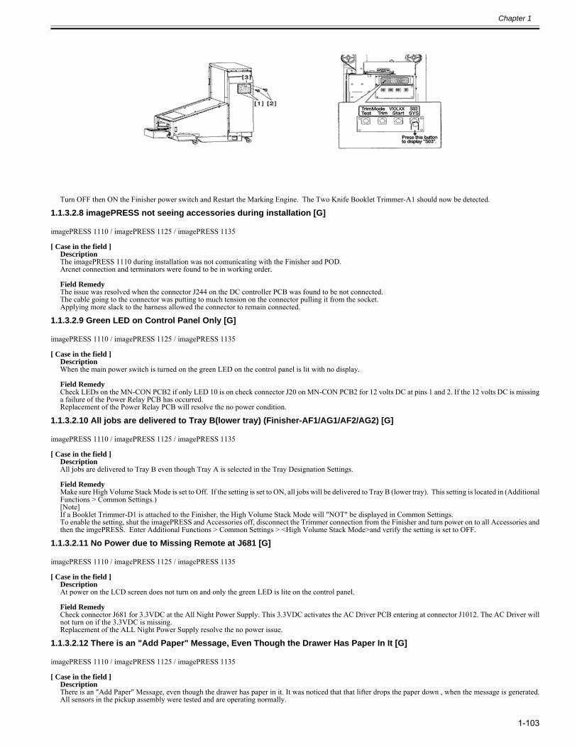
Chapter 1
1-103
Turn OFF then ON the Finisher power switch and Restart the Marking Engine. The Two Knife Booklet Trimmer-A1 should now be detected.
1.1.3.2.8 imagePRESS not seeing accessories during installation [G]0025-3944
imagePRESS 1110 / imagePRESS 1125 / imagePRESS 1135
[ Case in the field ]DescriptionThe imagePRESS 1110 during installation was not comunicating with the Finisher and POD.Arcnet connection and terminators were found to be in working order. Field RemedyThe issue was resolved when the connector J244 on the DC controller PCB was found to be not connected.The cable going to the connector was putting to much tension on the connector pulling it from the socket.Applying more slack to the harness allowed the connector to remain connected.
1.1.3.2.9 Green LED on Control Panel Only [G]0025-5166
imagePRESS 1110 / imagePRESS 1125 / imagePRESS 1135
[ Case in the field ]DescriptionWhen the main power switch is turned on the green LED on the control panel is lit with no display. Field RemedyCheck LEDs on the MN-CON PCB2 if only LED 10 is on check connector J20 on MN-CON PCB2 for 12 volts DC at pins 1 and 2. If the 12 volts DC is missinga failure of the Power Relay PCB has occurred.Replacement of the Power Relay PCB will resolve the no power condition.
1.1.3.2.10 All jobs are delivered to Tray B(lower tray) (Finisher-AF1/AG1/AF2/AG2) [G]0025-5169
imagePRESS 1110 / imagePRESS 1125 / imagePRESS 1135
[ Case in the field ]DescriptionAll jobs are delivered to Tray B even though Tray A is selected in the Tray Designation Settings. Field RemedyMake sure High Volume Stack Mode is set to Off. If the setting is set to ON, all jobs will be delivered to Tray B (lower tray). This setting is located in (AdditionalFunctions > Common Settings.)[Note]If a Booklet Trimmer-D1 is attached to the Finisher, the High Volume Stack Mode will "NOT" be displayed in Common Settings. To enable the setting, shut the imagePRESS and Accessories off, disconnect the Trimmer connection from the Finisher and turn power on to all Accessories andthen the imgePRESS. Enter Additional Functions > Common Settings > <High Volume Stack Mode>and verify the setting is set to OFF.
1.1.3.2.11 No Power due to Missing Remote at J681 [G]0025-5170
imagePRESS 1110 / imagePRESS 1125 / imagePRESS 1135
[ Case in the field ]DescriptionAt power on the LCD screen does not turn on and only the green LED is lite on the control panel. Field RemedyCheck connector J681 for 3.3VDC at the All Night Power Supply. This 3.3VDC activates the AC Driver PCB entering at connector J1012. The AC Driver willnot turn on if the 3.3VDC is missing. Replacement of the ALL Night Power Supply resolve the no power issue.
1.1.3.2.12 There is an "Add Paper" Message, Even Though the Drawer Has Paper In It [G]0025-5173
imagePRESS 1110 / imagePRESS 1125 / imagePRESS 1135
[ Case in the field ]DescriptionThere is an "Add Paper" Message, even though the drawer has paper in it. It was noticed that that lifter drops the paper down , when the message is generated.All sensors in the pickup assembly were tested and are operating normally.
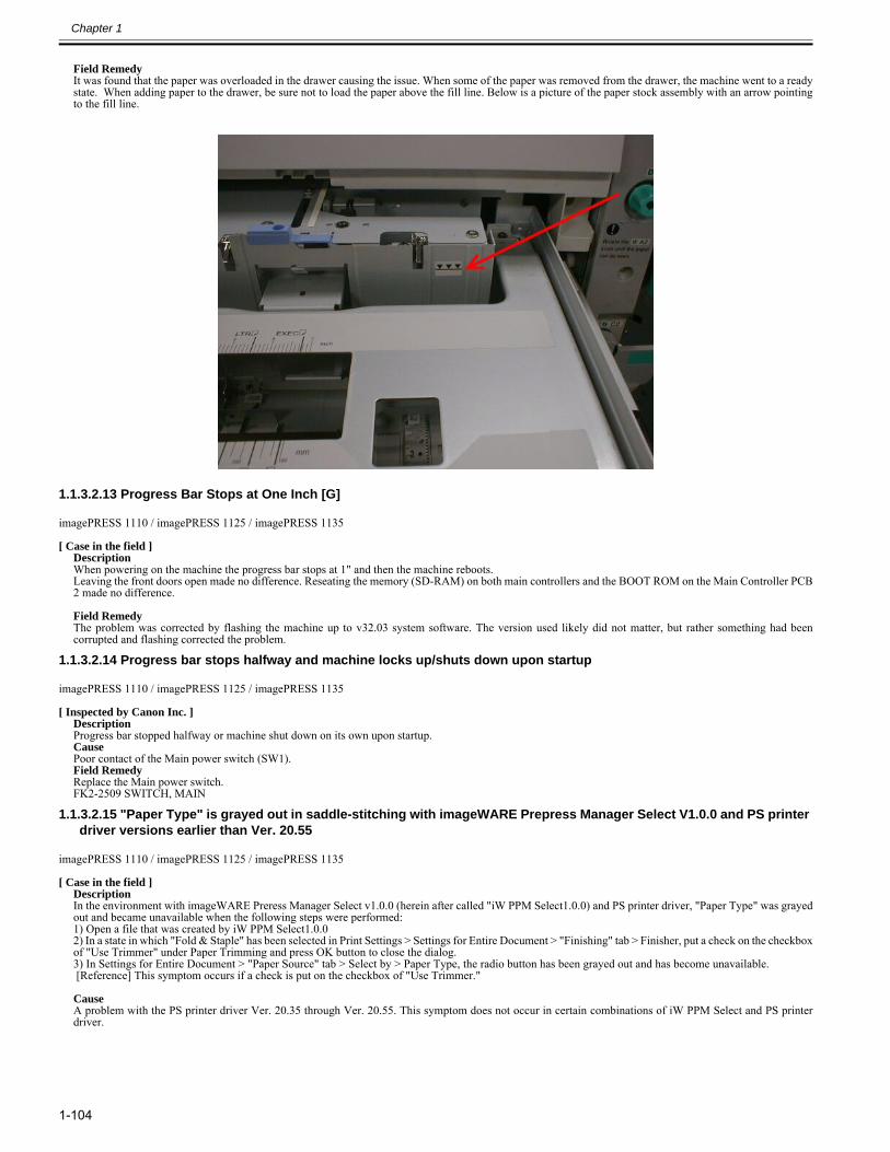
Chapter 1
1-104
Field RemedyIt was found that the paper was overloaded in the drawer causing the issue. When some of the paper was removed from the drawer, the machine went to a readystate. When adding paper to the drawer, be sure not to load the paper above the fill line. Below is a picture of the paper stock assembly with an arrow pointingto the fill line.
1.1.3.2.13 Progress Bar Stops at One Inch [G]0025-5294
imagePRESS 1110 / imagePRESS 1125 / imagePRESS 1135
[ Case in the field ]DescriptionWhen powering on the machine the progress bar stops at 1" and then the machine reboots.Leaving the front doors open made no difference. Reseating the memory (SD-RAM) on both main controllers and the BOOT ROM on the Main Controller PCB2 made no difference. Field RemedyThe problem was corrected by flashing the machine up to v32.03 system software. The version used likely did not matter, but rather something had beencorrupted and flashing corrected the problem.
1.1.3.2.14 Progress bar stops halfway and machine locks up/shuts down upon startup0027-3504
imagePRESS 1110 / imagePRESS 1125 / imagePRESS 1135
[ Inspected by Canon Inc. ]DescriptionProgress bar stopped halfway or machine shut down on its own upon startup.CausePoor contact of the Main power switch (SW1).Field RemedyReplace the Main power switch.FK2-2509 SWITCH, MAIN
1.1.3.2.15 "Paper Type" is grayed out in saddle-stitching with imageWARE Prepress Manager Select V1.0.0 and PS printer driver versions earlier than Ver. 20.55
0027-5020
imagePRESS 1110 / imagePRESS 1125 / imagePRESS 1135
[ Case in the field ]DescriptionIn the environment with imageWARE Preress Manager Select v1.0.0 (herein after called "iW PPM Select1.0.0) and PS printer driver, "Paper Type" was grayedout and became unavailable when the following steps were performed:1) Open a file that was created by iW PPM Select1.0.02) In a state in which "Fold & Staple" has been selected in Print Settings > Settings for Entire Document > "Finishing" tab > Finisher, put a check on the checkboxof "Use Trimmer" under Paper Trimming and press OK button to close the dialog.3) In Settings for Entire Document > "Paper Source" tab > Select by > Paper Type, the radio button has been grayed out and has become unavailable. [Reference] This symptom occurs if a check is put on the checkbox of "Use Trimmer."
CauseA problem with the PS printer driver Ver. 20.35 through Ver. 20.55. This symptom does not occur in certain combinations of iW PPM Select and PS printerdriver.
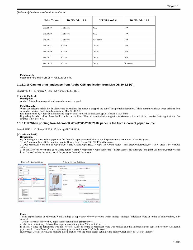
Chapter 1
1-105
[Reference] Combination of versions confirmed
Field remedyUpgrade the PS printer driver to Ver.20.60 or later.
1.1.3.2.16 Can not print landscape from Adobe CS5 application from Mac OS 10.6.5 [G]0027-5979
imagePRESS 1110 / imagePRESS 1125 / imagePRESS 1135
[ Case in the field ]DescriptionAdobe CS5 applications print landscape documents cropped. Field RemedyWhen you select to print a file in a landscape orientation, the output is cropped and cut off in a portrait orientation. This is currently an issue when printing froman Adobe Creative Suite 5 application from Mac OS 10.6.5.It is documented by Adobe at the following support link: http://kb2.adobe.com/cps/881/cpsid_88128.htmlUpgrading the Mac OS to 10.6.6 should resolve the problem. This link also includes suggested workarounds for each of the Creative Suite applications if anupgrade is not possible.
1.1.3.2.17 When printing from Microsoft Word2003/2007/2010, paper is fed from incorrect paper source0027-7465
imagePRESS 1110 / imagePRESS 1125 / imagePRESS 1135
[ Case in the field ]DescriptionBy following the steps below, paper was fed from the paper source which was not the paper source the printer driver designated.1) Set Automatic Paper Selection function for Drawer1 and Drawer2 to "OFF" on the copier. 2) Open Microsoft Word data. In Page Layout > Size > More Paper Size... > Paper tab > Paper source > First page:/Other pages, set "Auto." (This is not a defaultsetting.)3) In the Microsoft Word data, click Office button > Print > Properties > Paper source tab > Paper Source, set "Drawer2" and print. As a result, paper was fedfrom Drawer3 where the same size of the paper as Drawer2 has was set.
CauseThis is a specification of Microsoft Word. Settings of paper source below decide to which settings, setting of Microsoft Word or setting of printer driver, to beenabled. - Default tray (xx): followed by paper source setting from printer driver.- Other than default tray: followed by paper source setting from Microsoft Word.In this case, since the default tray was not selected, "Auto" as setting of Microsoft Word was enabled and this information was sent to the copier. As a result,paper was fed from Drawer3 where automatic paper selection was "ON" in the copier.[Reference] Default tray (xx) is changed in conjunction with the paper source setting of the printer which is set as "Default Printer".
Driver Version iW PPM Select1.0.0 iW PPM Select2.0.1 iW PPM Select2.1.0
Ver.20.10 Not occur N/A N/A
Ver.20.20 Not occur N/A N/A
Ver.20.27 Not occur Not occur N/A
Ver.20.35 Occur Occur N/A
Ver.20.50 Occur Occur N/A
Ver.20.52 Occur Occur N/A
Ver.20.55 Occur Occur Not occur
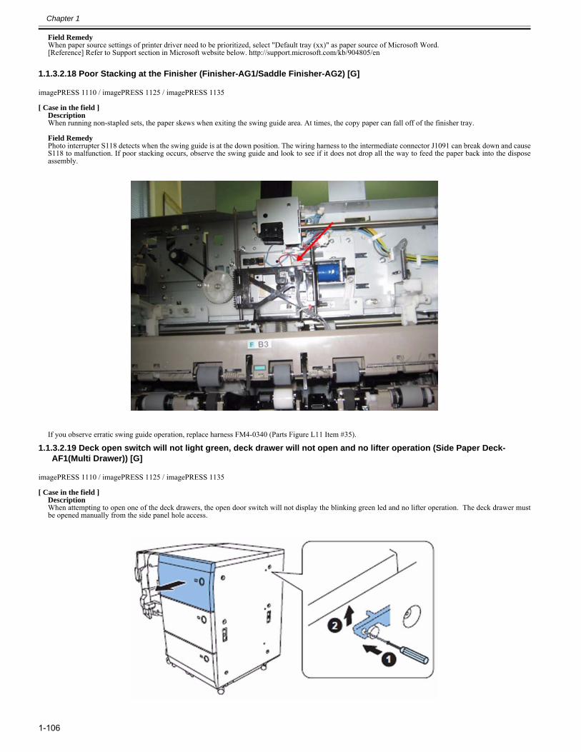
Chapter 1
1-106
Field Remedy When paper source settings of printer driver need to be prioritized, select "Default tray (xx)" as paper source of Microsoft Word. [Reference] Refer to Support section in Microsoft website below. http://support.microsoft.com/kb/904805/en
1.1.3.2.18 Poor Stacking at the Finisher (Finisher-AG1/Saddle Finisher-AG2) [G]0028-0796
imagePRESS 1110 / imagePRESS 1125 / imagePRESS 1135
[ Case in the field ]DescriptionWhen running non-stapled sets, the paper skews when exiting the swing guide area. At times, the copy paper can fall off of the finisher tray. Field RemedyPhoto interrupter S118 detects when the swing guide is at the down position. The wiring harness to the intermediate connector J1091 can break down and causeS118 to malfunction. If poor stacking occurs, observe the swing guide and look to see if it does not drop all the way to feed the paper back into the disposeassembly.
If you observe erratic swing guide operation, replace harness FM4-0340 (Parts Figure L11 Item #35).
1.1.3.2.19 Deck open switch will not light green, deck drawer will not open and no lifter operation (Side Paper Deck-AF1(Multi Drawer)) [G]
0028-1803
imagePRESS 1110 / imagePRESS 1125 / imagePRESS 1135
[ Case in the field ]DescriptionWhen attempting to open one of the deck drawers, the open door switch will not display the blinking green led and no lifter operation. The deck drawer mustbe opened manually from the side panel hole access.
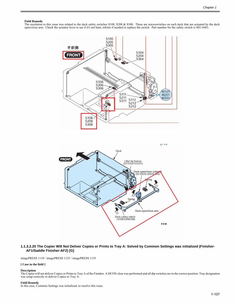
Chapter 1
1-107
Field RemedyThe resolution to this issue was related to the deck safety switches S108, S208 & S308. These are microswitches on each deck that are actuated by the deckopen/close arm. Check the actuator lever to see if it's not bent, reform if needed or replace the switch. Part number for the safety switch is 4H1-6481.
1.1.3.2.20 The Copier Will Not Deliver Copies or Prints to Tray A: Solved by Common Settings was initialized (Finisher-AF1/Saddle Finisher-AF2) [G]
0028-3030
imagePRESS 1110 / imagePRESS 1125 / imagePRESS 1135
[ Case in the field ] DescriptionThe Copier will not deliver Copies or Prints to Tray A of the Finisher. A DCON clear was performed and all dip switches are in the correct position. Tray designationwas setup correctly to deliver Copies to Tray A. Field RemedyIn this case, Common Settings was initialized, to resolve this issue.

Chapter 1
1-108
[Caution] Data such as the Address Book and Additional Functions settings are stored on the internal hard disk of the machine. The data that can be backed up isindicated below.- Address Book, Additional Functions settings, forwarding settings, Mail Box function data (User Inbox data, forms for the Form Composition mode)- Data that can be backed up using the Device Information Delivery Settings mode- License files for MEAP applications- User authentication information registered for the Local Device Authentication system of SSO-H (Single Sign-On H)- Data stored by MEAP applications
1.1.3.2.21 Unable to stop the initial rotation with DC-CON Ver.45.03 after performing TONER-S0028-4190
imagePRESS 1110 / imagePRESS 1125 / imagePRESS 1135
[ Inspected by Canon Inc. ]
DescriptionWhen printing, the initial rotation could not be stopped, thereby resulting in a failure in printing.
CauseWhen there is a problem with DC-CON Ver.45.03 and the developing cylinder is kept operating for many hours such as in case of TONER-S, the image stabilizationcontrol does not work correctly during the initial rotation for the next printing job, which results in the engine of the copier left running.
Field RemedyWhen the version of DC-CON is Ver.45.03, after either service mode below is performed, turn OFF/ON the main switch, and then run print jobs.a) Service Mode > Mode List > COPIER > Function > INSTALL > TONER-Sb) In case of performing the Service Mode > Mode List > COPIER > Function > INSTALL > TONER-S2 twice or more. (No problem if it is conducted once.)
1.1.3.2.22 The POD Deck-C1/Secondary POD Deck-C1 Not Recognized: Solved by upgrading system software to latest version [G]
0028-4616
imagePRESS 1110 / imagePRESS 1125 / imagePRESS 1135
[ Case in the field ] DescriptionWhen starting up the imagePRESS, both of the POD decks, are not recognized by the main unit. This is happening during a new install. If one POD is disconnected,and the remaining POD is terminated, one POD will be recognized. The assignment for the POD Deck-C1, does show in Service Mode, Level 1 COPIER > OPTION> ACCPST-P. The Dip switch settings are correct for each POD. All other accessories, Finisher, Puncher, etc, are all recognized at start up. Field RemedyIn this instance, it was decided to try to flash the copier, and all accessories with the latest SSW. After the flash, all accessories including the POD Decks, wererecognized at startup.
1.1.3.2.23 Poor paper alignment while printing booklet in saddle stitch due to the broken tension spring (Saddle Finisher-AF2/Saddle Finisher-AG2)
0028-5677
imagePRESS 1110 / imagePRESS 1125 / imagePRESS 1135
[ Inspected by Canon Inc. ]
DescriptionPoor paper alignment while printing booklet in saddle stitch occurred.
CauseAs the tension spring[2] of the edge stopper unit[1] is broken, the balance between upper/lower stopper is lost, and then paper does not stop at the proper position.The photo shown below is the broken tension spring[2].
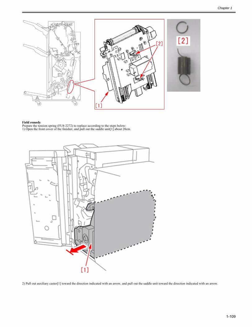
Chapter 1
1-109
Field remedyPrepare the tension spring (FU8-2272) to replace according to the steps below:1) Open the front cover of the finisher, and pull out the saddle unit[1] about 20cm.
2) Pull out auxiliary caster[1] toward the direction indicated with an arrow, and pull out the saddle unit toward the direction indicated with an arrow.
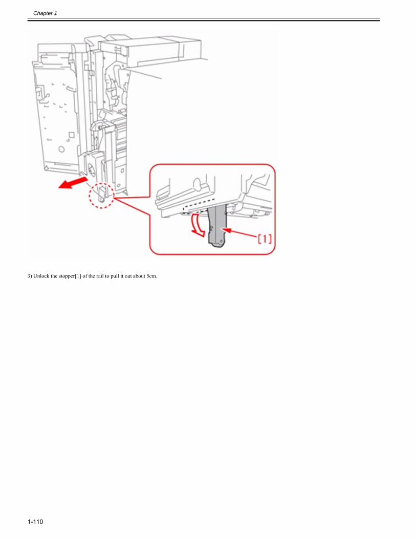
Chapter 1
1-110
3) Unlock the stopper[1] of the rail to pull it out about 5cm.
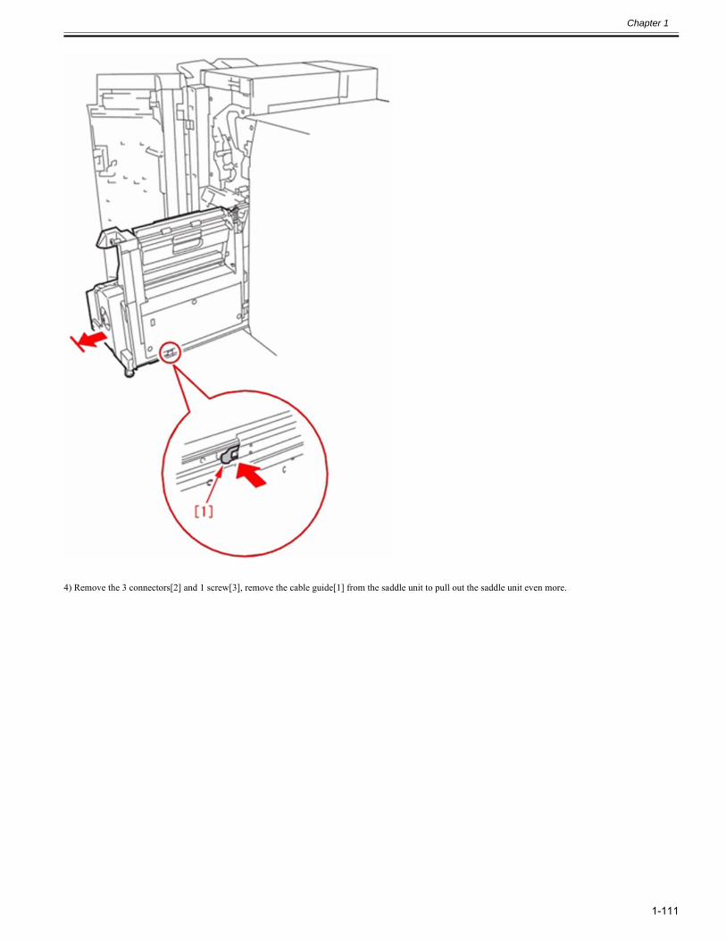
Chapter 1
1-111
4) Remove the 3 connectors[2] and 1 screw[3], remove the cable guide[1] from the saddle unit to pull out the saddle unit even more.
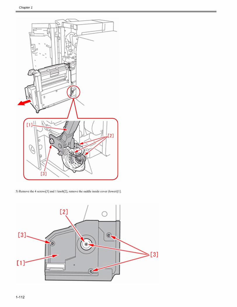
Chapter 1
1-112
5) Remove the 4 screws[3] and 1 knob[2], remove the saddle inside cover (lower)[1].
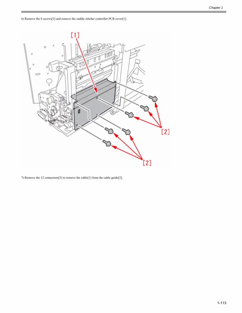
Chapter 1
1-113
6) Remove the 6 screws[2] and remove the saddle stitcher controller PCB cover[1].
7) Remove the 12 connectors[3] to remove the cable[1] form the cable guide[2].
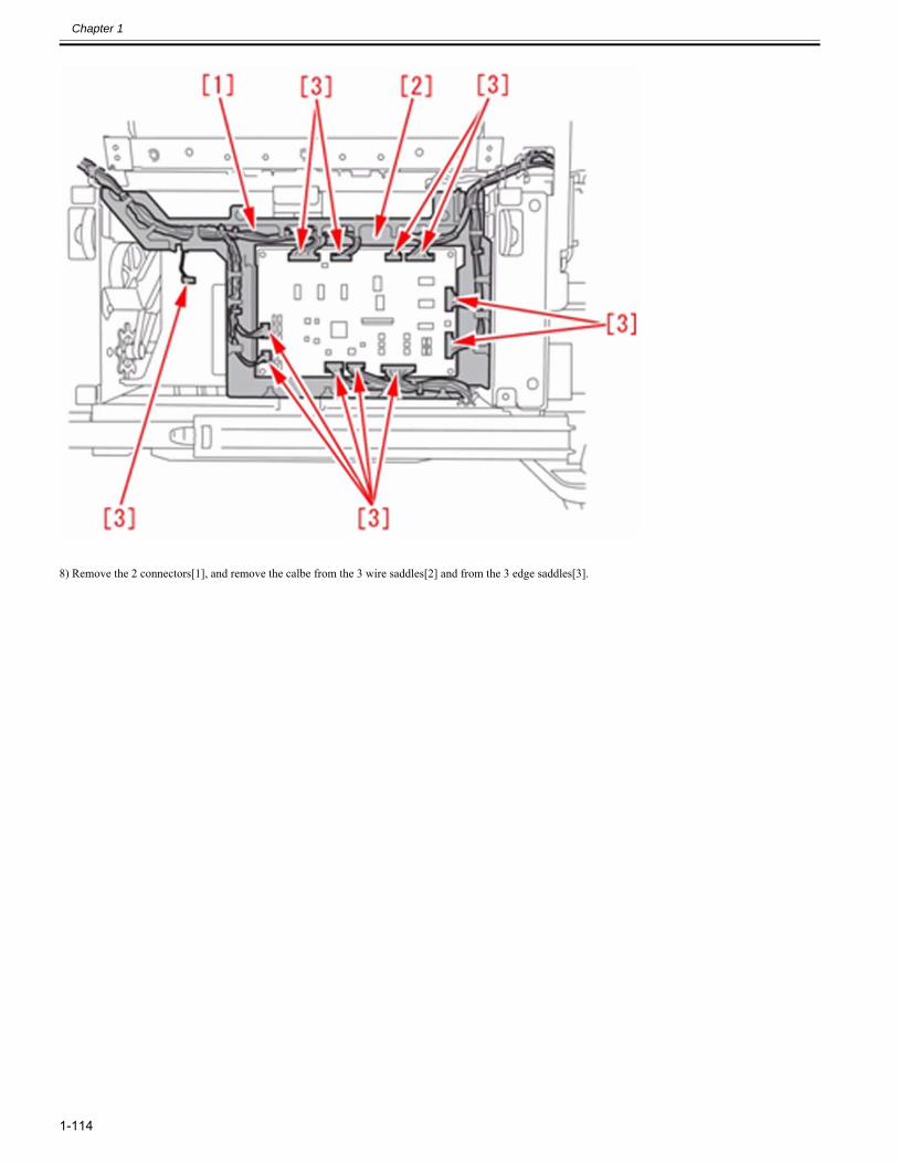
Chapter 1
1-114
8) Remove the 2 connectors[1], and remove the calbe from the 3 wire saddles[2] and from the 3 edge saddles[3].
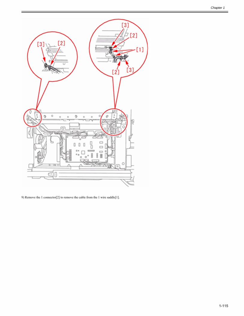
Chapter 1
1-115
9) Remove the 1 connector[2] to remove the cable from the 1 wire saddle[1].
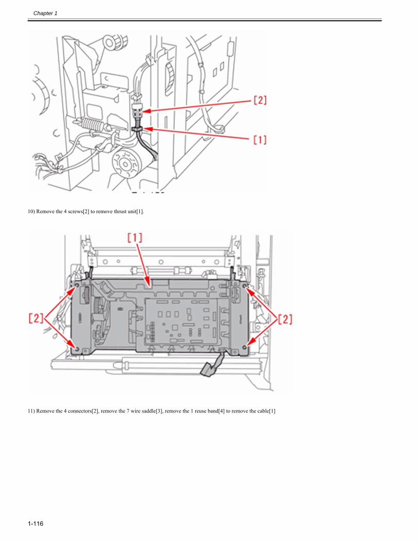
Chapter 1
1-116
10) Remove the 4 screws[2] to remove thrust unit[1].
11) Remove the 4 connectors[2], remove the 7 wire saddle[3], remove the 1 reuse band[4] to remove the cable[1]
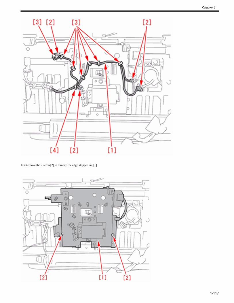
Chapter 1
1-117
12) Remove the 2 screw[2] to remove the edge stopper unit[1].
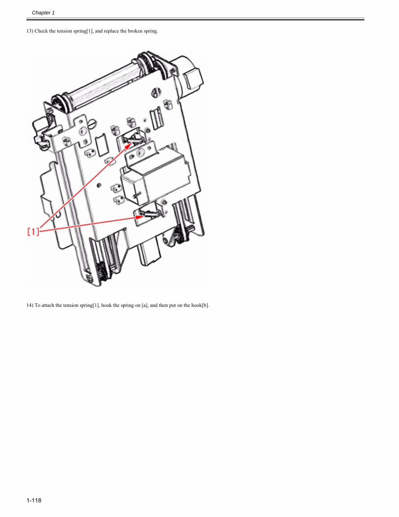
Chapter 1
1-118
13) Check the tension spring[1], and replace the broken spring.
14) To attach the tension spring[1], hook the spring on [a], and then put on the hook[b].
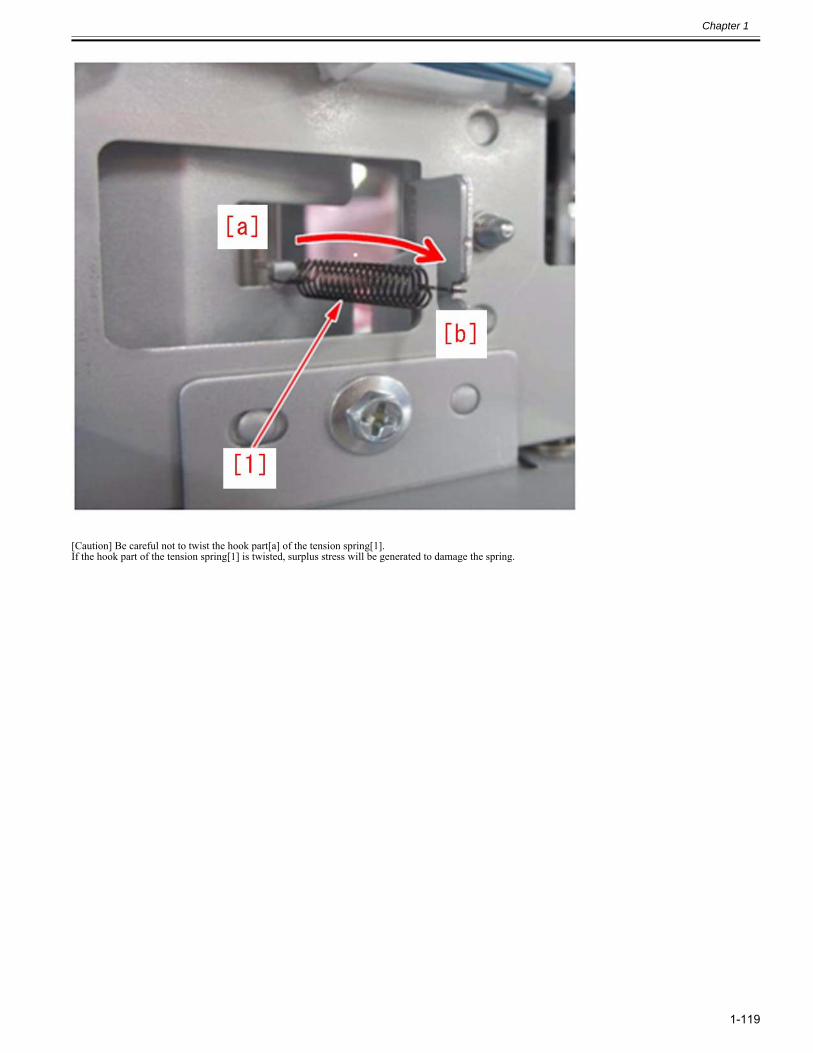
Chapter 1
1-119
[Caution] Be careful not to twist the hook part[a] of the tension spring[1].If the hook part of the tension spring[1] is twisted, surplus stress will be generated to damage the spring.
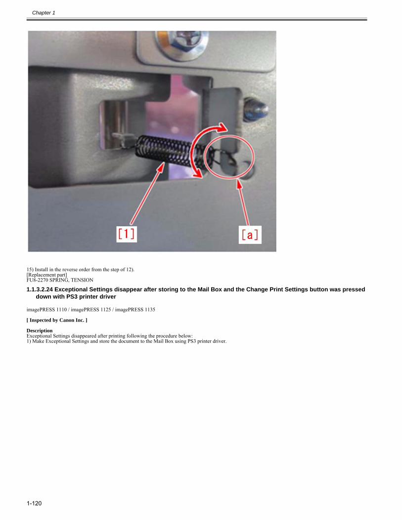
Chapter 1
1-120
15) Install in the reverse order from the step of 12).[Replacement part]FU8-2270 SPRING, TENSION
1.1.3.2.24 Exceptional Settings disappear after storing to the Mail Box and the Change Print Settings button was pressed down with PS3 printer driver
0028-6856
imagePRESS 1110 / imagePRESS 1125 / imagePRESS 1135
[ Inspected by Canon Inc. ]
DescriptionExceptional Settings disappeared after printing following the procedure below:1) Make Exceptional Settings and store the document to the Mail Box using PS3 printer driver.
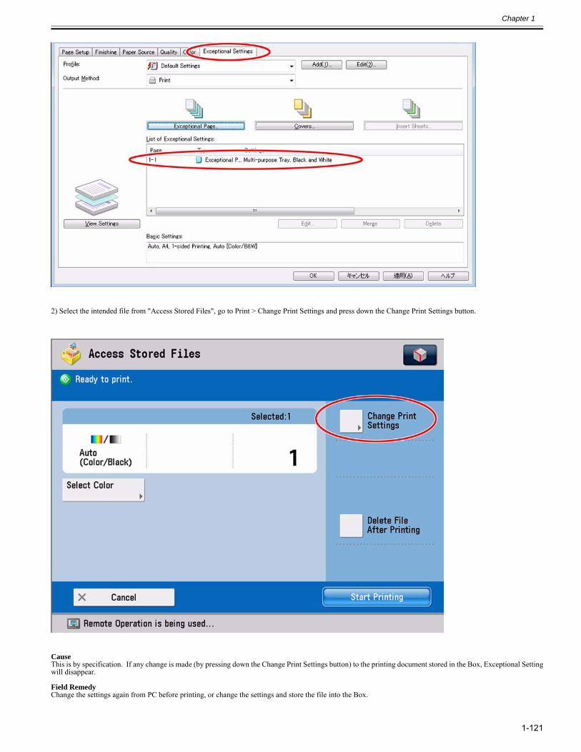
Chapter 1
1-121
2) Select the intended file from "Access Stored Files", go to Print > Change Print Settings and press down the Change Print Settings button.
CauseThis is by specification. If any change is made (by pressing down the Change Print Settings button) to the printing document stored in the Box, Exceptional Settingwill disappear.
Field RemedyChange the settings again from PC before printing, or change the settings and store the file into the Box.
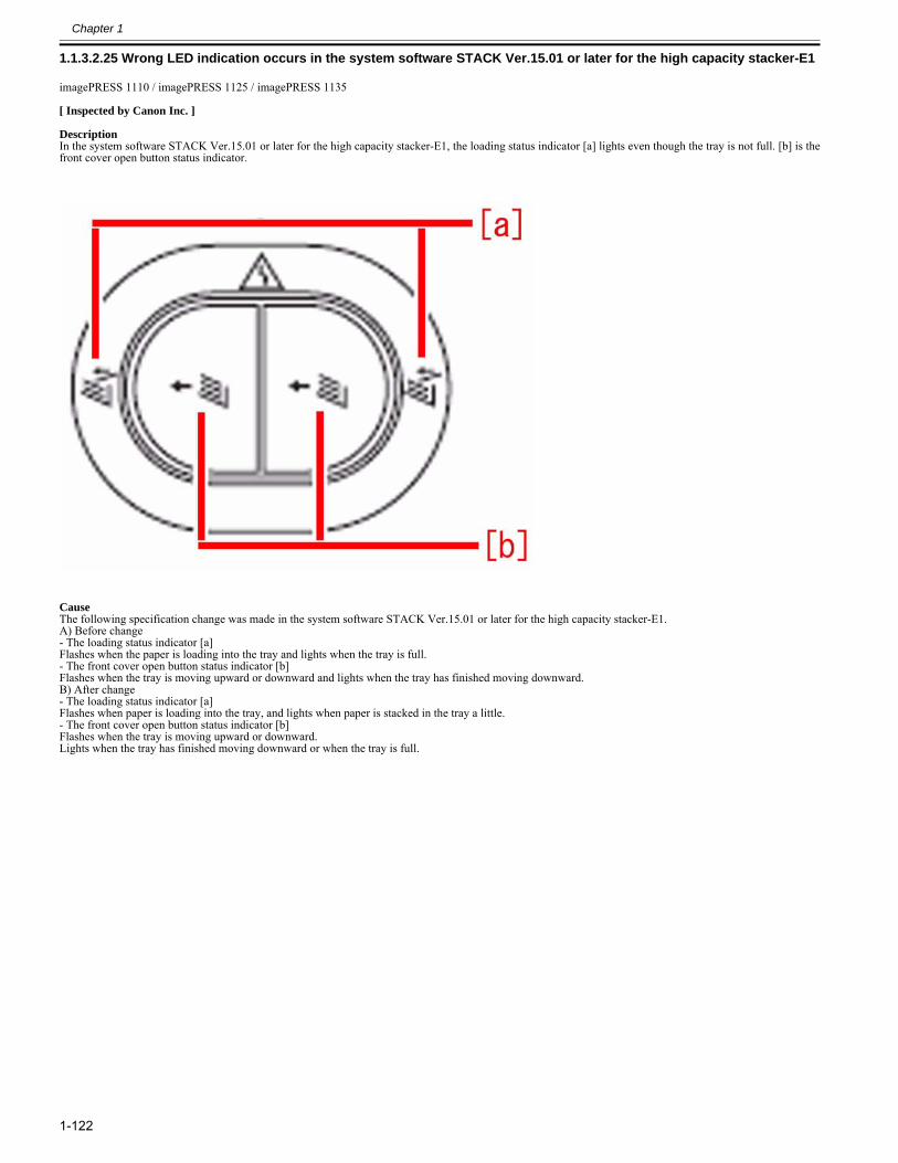
Chapter 1
1-122
1.1.3.2.25 Wrong LED indication occurs in the system software STACK Ver.15.01 or later for the high capacity stacker-E10028-8248
imagePRESS 1110 / imagePRESS 1125 / imagePRESS 1135
[ Inspected by Canon Inc. ]
DescriptionIn the system software STACK Ver.15.01 or later for the high capacity stacker-E1, the loading status indicator [a] lights even though the tray is not full. [b] is thefront cover open button status indicator.
CauseThe following specification change was made in the system software STACK Ver.15.01 or later for the high capacity stacker-E1.A) Before change- The loading status indicator [a]Flashes when the paper is loading into the tray and lights when the tray is full.- The front cover open button status indicator [b]Flashes when the tray is moving upward or downward and lights when the tray has finished moving downward.B) After change- The loading status indicator [a]Flashes when paper is loading into the tray, and lights when paper is stacked in the tray a little.- The front cover open button status indicator [b]Flashes when the tray is moving upward or downward.Lights when the tray has finished moving downward or when the tray is full.
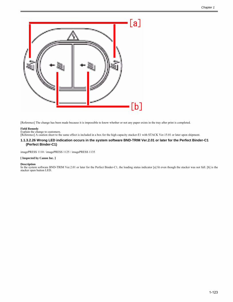
Chapter 1
1-123
[Reference] The change has been made because it is impossible to know whether or not any paper exists in the tray after print is completed.
Field RemedyExplain the change to customers.[Reference] A caution sheet to the same effect is included in a box for the high capacity stacker-E1 with STACK Ver.15.01 or later upon shipment.
1.1.3.2.26 Wrong LED indication occurs in the system software BND-TRIM Ver.2.01 or later for the Perfect Binder-C1 (Perfect Binder-C1)
0028-9542
imagePRESS 1110 / imagePRESS 1125 / imagePRESS 1135
[ Inspected by Canon Inc. ]
DescriptionIn the system software BND-TRIM Ver.2.01 or later for the Perfect Binder-C1, the loading status indicator [a] lit even though the stacker was not full. [b] is thestacker open button LED.
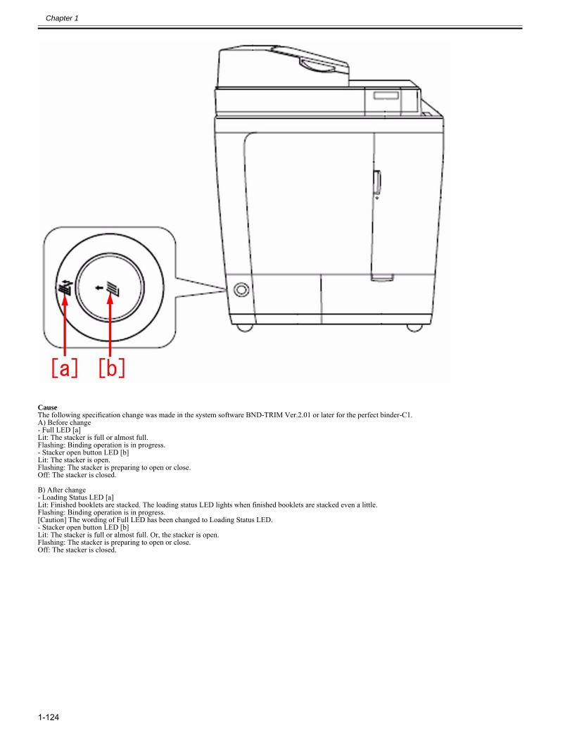
Chapter 1
1-124
CauseThe following specification change was made in the system software BND-TRIM Ver.2.01 or later for the perfect binder-C1.A) Before change- Full LED [a]Lit: The stacker is full or almost full.Flashing: Binding operation is in progress.- Stacker open button LED [b]Lit: The stacker is open.Flashing: The stacker is preparing to open or close.Off: The stacker is closed.
B) After change- Loading Status LED [a]Lit: Finished booklets are stacked. The loading status LED lights when finished booklets are stacked even a little.Flashing: Binding operation is in progress.[Caution] The wording of Full LED has been changed to Loading Status LED.- Stacker open button LED [b]Lit: The stacker is full or almost full. Or, the stacker is open.Flashing: The stacker is preparing to open or close.Off: The stacker is closed.
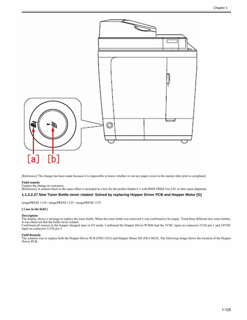
Chapter 1
1-125
[Reference] The change has been made because it is impossible to know whether or not any paper exists in the stacker after print is completed.
Field remedyExplain the change to customers.[Reference] A caution sheet to the same effect is included in a box for the perfect binder-C1 with BND-TRIM Ver.2.01 or later upon shipment.
1.1.3.2.27 New Toner Bottle never rotated: Solved by replacing Hopper Driver PCB and Hopper Motor [G]0028-9826
imagePRESS 1110 / imagePRESS 1125 / imagePRESS 1135
[ Case in the field ] DescriptionThe display shows a message to replace the toner bottle. When the toner bottle was removed it was confirmed to be empty. Tried three different new toner bottles.It was observed that the bottle never rotated.Confirmed all sensors in the hopper changed state in I/O mode. Confirmed the Hopper Driver PCB46 had the 5VDC input on connector J1326 pin 1 and 24VDCinput on connector J1326 pin 3. Field RemedyThe solution was to replace both the Hopper Driver PCB (FM3-5243) and Hopper Motor M3 (FK3-0824). The following image shows the location of the HopperDriver PCB.
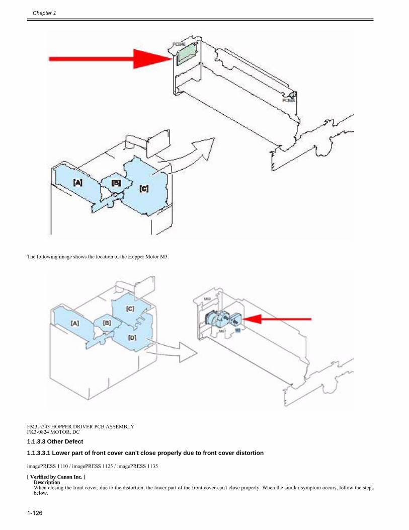
Chapter 1
1-126
The following image shows the location of the Hopper Motor M3.
FM3-5243 HOPPER DRIVER PCB ASSEMBLYFK3-0824 MOTOR, DC
1.1.3.3 Other Defect
1.1.3.3.1 Lower part of front cover can't close properly due to front cover distortion0022-9648
imagePRESS 1110 / imagePRESS 1125 / imagePRESS 1135
[ Verified by Canon Inc. ]DescriptionWhen closing the front cover, due to the distortion, the lower part of the front cover can't close properly. When the similar symptom occurs, follow the stepsbelow.
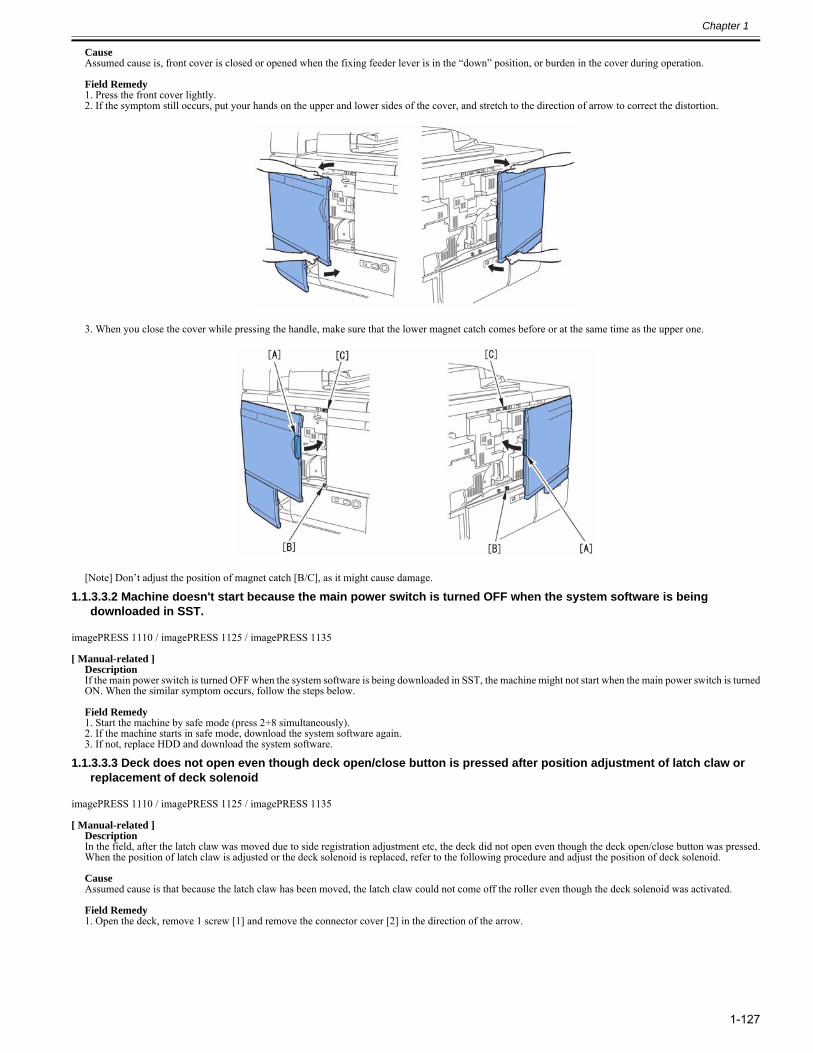
Chapter 1
1-127
CauseAssumed cause is, front cover is closed or opened when the fixing feeder lever is in the “down” position, or burden in the cover during operation.
Field Remedy1. Press the front cover lightly.2. If the symptom still occurs, put your hands on the upper and lower sides of the cover, and stretch to the direction of arrow to correct the distortion.
3. When you close the cover while pressing the handle, make sure that the lower magnet catch comes before or at the same time as the upper one.
[Note] Don’t adjust the position of magnet catch [B/C], as it might cause damage.
1.1.3.3.2 Machine doesn't start because the main power switch is turned OFF when the system software is being downloaded in SST.
0023-0745
imagePRESS 1110 / imagePRESS 1125 / imagePRESS 1135
[ Manual-related ]DescriptionIf the main power switch is turned OFF when the system software is being downloaded in SST, the machine might not start when the main power switch is turnedON. When the similar symptom occurs, follow the steps below.
Field Remedy1. Start the machine by safe mode (press 2+8 simultaneously).2. If the machine starts in safe mode, download the system software again.3. If not, replace HDD and download the system software.
1.1.3.3.3 Deck does not open even though deck open/close button is pressed after position adjustment of latch claw or replacement of deck solenoid
0023-0879
imagePRESS 1110 / imagePRESS 1125 / imagePRESS 1135
[ Manual-related ]DescriptionIn the field, after the latch claw was moved due to side registration adjustment etc, the deck did not open even though the deck open/close button was pressed.When the position of latch claw is adjusted or the deck solenoid is replaced, refer to the following procedure and adjust the position of deck solenoid.
CauseAssumed cause is that because the latch claw has been moved, the latch claw could not come off the roller even though the deck solenoid was activated.
Field Remedy1. Open the deck, remove 1 screw [1] and remove the connector cover [2] in the direction of the arrow.
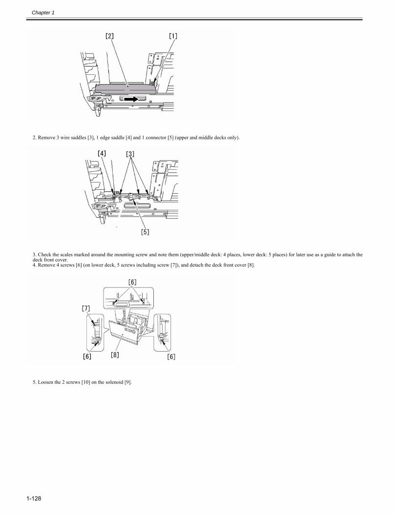
Chapter 1
1-128
2. Remove 3 wire saddles [3], 1 edge saddle [4] and 1 connector [5] (upper and middle decks only).
3. Check the scales marked around the mounting screw and note them (upper/middle deck: 4 places, lower deck: 5 places) for later use as a guide to attach thedeck front cover.4. Remove 4 screws [6] (on lower deck, 5 screws including screw [7]), and detach the deck front cover [8].
5. Loosen the 2 screws [10] on the solenoid [9].
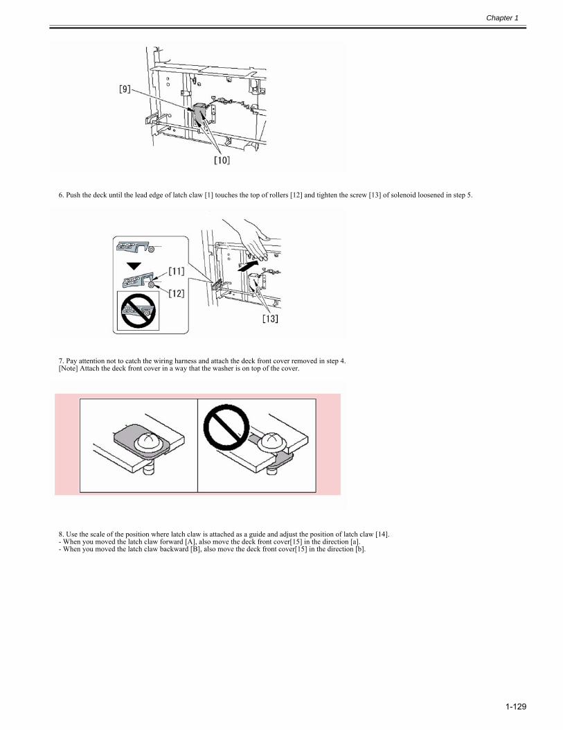
Chapter 1
1-129
6. Push the deck until the lead edge of latch claw [1] touches the top of rollers [12] and tighten the screw [13] of solenoid loosened in step 5.
7. Pay attention not to catch the wiring harness and attach the deck front cover removed in step 4.[Note] Attach the deck front cover in a way that the washer is on top of the cover.
8. Use the scale of the position where latch claw is attached as a guide and adjust the position of latch claw [14].- When you moved the latch claw forward [A], also move the deck front cover[15] in the direction [a].- When you moved the latch claw backward [B], also move the deck front cover[15] in the direction [b].
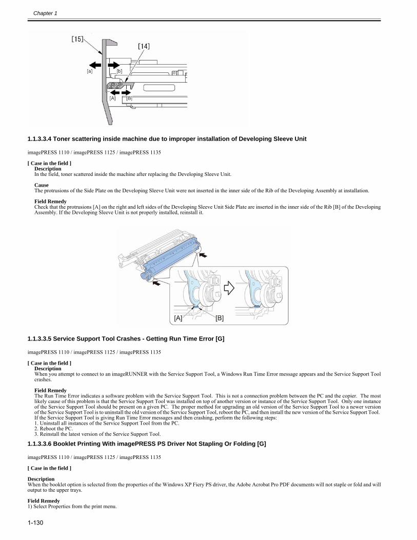
Chapter 1
1-130
1.1.3.3.4 Toner scattering inside machine due to improper installation of Developing Sleeve Unit0025-3265
imagePRESS 1110 / imagePRESS 1125 / imagePRESS 1135
[ Case in the field ]DescriptionIn the field, toner scattered inside the machine after replacing the Developing Sleeve Unit. CauseThe protrusions of the Side Plate on the Developing Sleeve Unit were not inserted in the inner side of the Rib of the Developing Assembly at installation. Field RemedyCheck that the protrusions [A] on the right and left sides of the Developing Sleeve Unit Side Plate are inserted in the inner side of the Rib [B] of the DevelopingAssembly. If the Developing Sleeve Unit is not properly installed, reinstall it.
1.1.3.3.5 Service Support Tool Crashes - Getting Run Time Error [G]0025-5172
imagePRESS 1110 / imagePRESS 1125 / imagePRESS 1135
[ Case in the field ]DescriptionWhen you attempt to connect to an imageRUNNER with the Service Support Tool, a Windows Run Time Error message appears and the Service Support Toolcrashes. Field RemedyThe Run Time Error indicates a software problem with the Service Support Tool. This is not a connection problem between the PC and the copier. The mostlikely cause of this problem is that the Service Support Tool was installed on top of another version or instance of the Service Support Tool. Only one instanceof the Service Support Tool should be present on a given PC. The proper method for upgrading an old version of the Service Support Tool to a newer versionof the Service Support Tool is to uninstall the old version of the Service Support Tool, reboot the PC, and then install the new version of the Service Support Tool. If the Service Support Tool is giving Run Time Error messages and then crashing, perform the following steps:1. Uninstall all instances of the Service Support Tool from the PC.2. Reboot the PC.3. Reinstall the latest version of the Service Support Tool.
1.1.3.3.6 Booklet Printing With imagePRESS PS Driver Not Stapling Or Folding [G]0028-2814
imagePRESS 1110 / imagePRESS 1125 / imagePRESS 1135
[ Case in the field ] DescriptionWhen the booklet option is selected from the properties of the Windows XP Fiery PS driver, the Adobe Acrobat Pro PDF documents will not staple or fold and willoutput to the upper trays. Field Remedy1) Select Properties from the print menu.
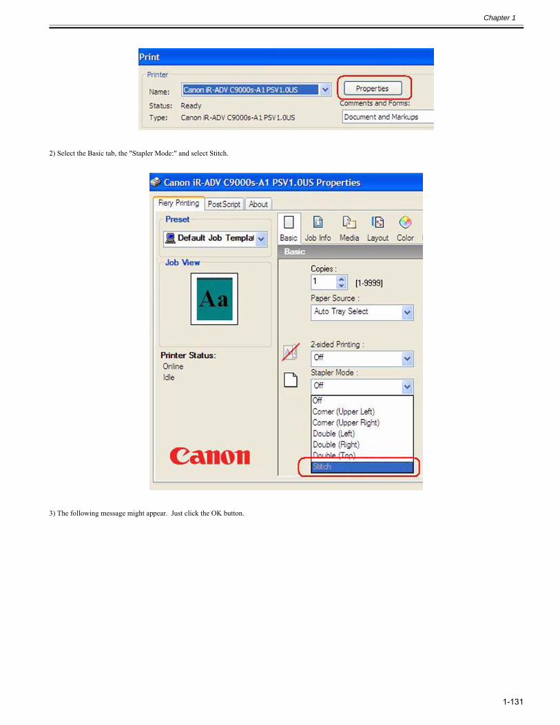
Chapter 1
1-131
2) Select the Basic tab, the "Stapler Mode:" and select Stitch.
3) The following message might appear. Just click the OK button.
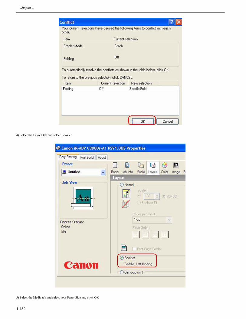
Chapter 1
1-132
4) Select the Layout tab and select Booklet.
5) Select the Media tab and select your Paper Size and click OK
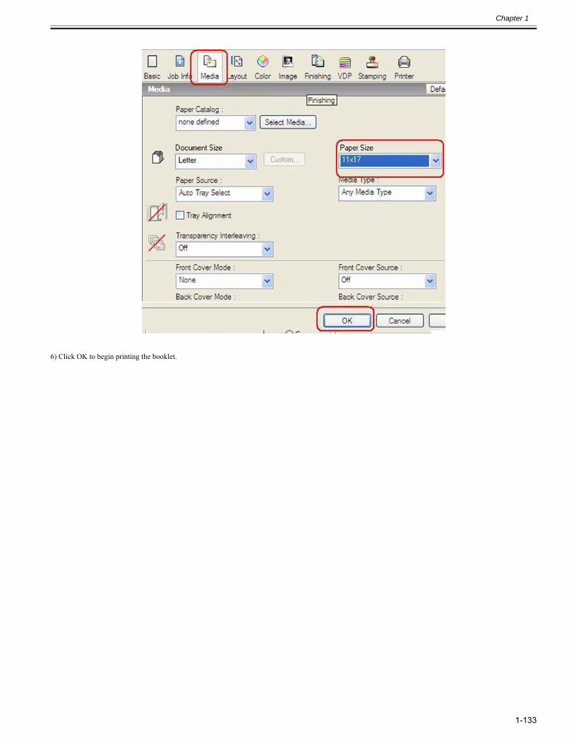
Chapter 1
1-133
6) Click OK to begin printing the booklet.
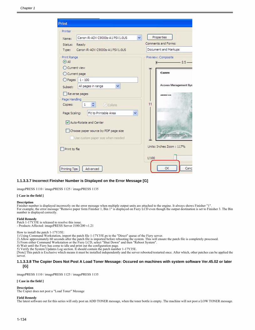
Chapter 1
1-134
1.1.3.3.7 Incorrect Finisher Number is Displayed on the Error Message [G]0028-2821
imagePRESS 1110 / imagePRESS 1125 / imagePRESS 1135
[ Case in the field ] DescriptionFinisher number is displayed incorrectly on the error message when multiple output units are attached to the engine. It always shows Finisher "1".For example, the error message "Remove paper form Finisher 1, Bin 1" is displayed on Fiery LCD even though the output destination is set to Finisher 3. The Binnumber is displayed correctly. Field RemedyPatch 1-17Y35E is released to resolve this issue.- Products Affected: imagePRESS Server J100/200 v1.21
How to install the patch 1-17Y35E:1) Using Command Workstation, import the patch file 1-17Y35E.ps to the "Direct" queue of the Fiery server.2) Allow approximately 60 seconds after the patch file is imported before rebooting the system. This will ensure the patch file is completely processed.3) From either Command Workstation or the Fiery LCD, select "Shut Down" and then "Reboot System".4) Wait until the Fiery has come to idle and print out the configuration page.5) Verify the System Updates Log section. It should contain the patch number 1-17Y35E.[Note] This patch is Exclusive which means it must be installed independently and the server rebooted/restarted once. After which, other patches can be applied theserver.
1.1.3.3.8 The Copier Does Not Post A Load Toner Message: Occured on machines with system software Ver.45.02 or later [G]
0028-3642
imagePRESS 1110 / imagePRESS 1125 / imagePRESS 1135
[ Case in the field ] DescriptionThe Copier does not post a "Load Toner" Message Field RemedyThe latest software out for this series will only post an ADD TONER message, when the toner bottle is empty. The machine will not post a LOW TONER message.
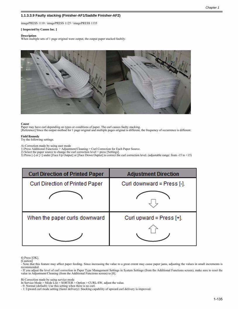
Chapter 1
1-135
1.1.3.3.9 Faulty stacking (Finisher-AF1/Saddle Finisher-AF2)0028-7189
imagePRESS 1110 / imagePRESS 1125 / imagePRESS 1135
[ Inspected by Canon Inc. ]
DescriptionWhen multiple sets of 1 page original were output, the output paper stacked faultily.
CausePaper may have curl depending on types or conditions of paper. The curl causes faulty stacking.[Reference] Since the output method for 1 page original and multiple pages original is different, the frequency of occurrence is different.
Field RemedyTry the following settings.
A) Correction made by using user mode1) Press Additional Functions > Adjustment/Cleaning > Curl Correction for Each Paper Source.2) Select the paper source to change the curl correction level > press [Settings].3) Press [-] or [+] under [Face Up Output] or [Face Down Ouptut] to correct the curl correction level. (adjustable range: from -15 to +15)
4) Press [OK].[Caution]- Note that this feature may affect paper feeding. Since increasing the value to a great extent may cause paper jams, adjusting the values in small increments isrecommended.- If you adjust the level of curl correction in Paper Type Management Settings in System Settings (from the Additional Functions screen), make sure to reset thevalue in Adjustment/Cleaning (from the Additional Functions screen) to [0].
B) Correction made by using service modeIn Service Mode > Mode List > SORTER > Option > CURL-SW, adjust the value.- 0: Normal (default): Use this setting when there is no curl.- 1: Upward curl mode setting (faster delivery): Stacking capability of upward curl delivery is improved.
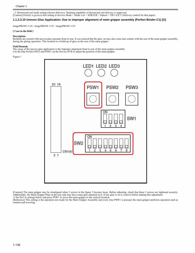
Chapter 1
1-136
- 2: Downward curl mode setting (slower delivery): Stacking capability of downward curl delivery is improved.[Caution] Priority is given to this setting in Service Mode > Mode List > SORTER > Option > TRY-EJCT (Delivery control for thin paper)
1.1.3.3.10 Uneven Glue Application: Due to improper alignment of main gripper assembly (Perfect Binder-C1) [G]0028-8502
imagePRESS 1110 / imagePRESS 1125 / imagePRESS 1135
[ Case in the field ] DescriptionBooklets are created with uneven glue amounts front to rear. It was noticed that the glue vat may also come into contact with the rear of the main gripper assembly,during the gluing operation. This resulted in a build up of glue on the rear of the main gripper. Field RemedyThe cause of the uneven glue application is the improper alignment front to rear of the main gripper assembly.Use the Dip Switch (SW2) and PSW1 on the Service PCB to adjust the position of the main gripper. Figure 1
[Caution] The main gripper may be misaligned when 2 screws in the figure 3 become loose. Before adjusting, check that these 2 screws are tightened securely.Additionally, the Main Gripper Plate in the rear side may have some glue attached on it. If any glue is on it, remove before making this adjustment.1) Set Sw2 to settings below and press PSW1 to move the main gripper to the vertical location.[Reference] This setting is the operation test mode for the Main Gripper Assembly and every time PSW1 is pressed, the main gripper performs operation such asrotation and lowering.
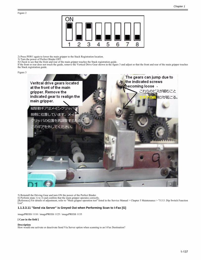
Chapter 1
1-137
Figure 2
2) Press PSW1 again to lower the main gripper to the Stack Registration location.3) Turn the power of Perfect Binder OFF.4) Check to see that the front and rear of the main gripper touches the Stack registration guide.If the front or rear does not touch the guide, remove the Vertical Drive Gear shown in the figure 3 and adjust so that the front and rear of the main gripper touchesthe Stack registration guide. Figure 3
5) Reinstall the Driving Gear and turn ON the power of the Perfect Binder.6) Perform steps 1) to 3) and confirm that the main gripper operates correctly.[Reference] For details of adjustment, refer to "Main gripper operation test" listed in the Service Manual > Chapter 5 Maintenance > "5.5.5. Dip Switch FunctionList".
1.1.3.3.11 "Send via Server" is Greyed Out when Performing Scan to I-Fax [G]0029-1293
imagePRESS 1110 / imagePRESS 1125 / imagePRESS 1135
[ Case in the field ] DescriptionHow would one activate or deactivate Send Via Server option when scanning to an I-Fax Destination?
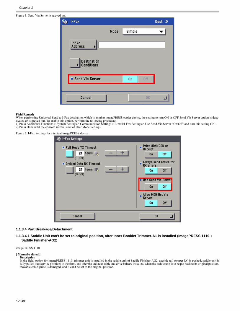
Chapter 1
1-138
Figure 1. Send Via Server is greyed out.
Field RemedyWhen performing Universal Send to I-Fax destination which is another imagePRESS copier device, the setting to turn ON or OFF Send Via Server option is deac-tivated or is greyed out. To enable this option, perform the following procedure:1) Press Additional Functions > System Settings > Communication Settings > E-mail/I-Fax Settings > Use Send Via Server "On/Off" and turn this setting ON.2) Press Done until the console screen is out of User Mode Settings. Figure 2. I-Fax Settings for a typical imagePRESS device
1.1.3.4 Part Breakage/Detachment
1.1.3.4.1 Saddle Unit can't be set to original position, after Inner Booklet Trimmer-A1 is installed (imagePRESS 1110 + Saddle Finisher-AG2)
0023-5485
imagePRESS 1110
[ Manual-related ]DescriptionIn the field, option for imagePRESS 1110, trimmer unit is installed in the saddle unit of Saddle Finisher-AG2, accride rail stopper [A] is pushed, saddle unit isfully pulled out (service position) to the front, and after the unit rear cable and drive belt are installed, when the saddle unit is to be put back to its original position,movable cable guide is damaged, and it can't be set to the original position.
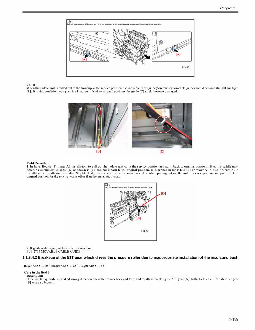
Chapter 1
1-139
CauseWhen the saddle unit is pulled out to the front up to the service position, the movable cable guide(communication cable guide) would become straight and tight[B]. If in this condition, you push hard and put it back to original position, the guide [C] might become damaged.
Field Remedy1. In Inner Booklet Trimmer-A1 installation, to pull out the saddle unit up to the service position and put it back to original position, lift up the saddle unit-finisher communication cable [D] as shown in [E], and put it back to the original position, as described in Inner Booklet Trimmer-A1 > S/M > Chapter 3 >Installation > Installation Procedure Step14. And, please also execute the same procedure when pulling out saddle unit to service position and put it back tooriginal position for the service works other than the installation work.
2. If guide is damaged, replace it with a new one.FC9-2765 MOVABLE CABLE GUIDE
1.1.3.4.2 Breakage of the 51T gear which drives the pressure roller due to inappropriate installation of the insulating bush0023-8549
imagePRESS 1110 / imagePRESS 1125 / imagePRESS 1135
[ Case in the field ]DescriptionIf the insulating bush is installed wrong direction, the roller moves back and forth and results in breaking the 51T gear [A]. In the field case, Refresh roller gear[B] was also broken.
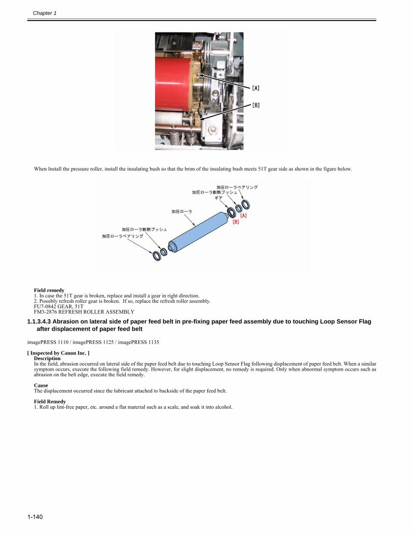
Chapter 1
1-140
When Install the pressure roller, install the insulating bush so that the brim of the insulating bush meets 51T gear side as shown in the figure below.
Field remedy1. In case the 51T gear is broken, replace and install a gear in right direction.2. Possibly refresh roller gear is broken. If so, replace the refresh roller assembly. FU7-0842 GEAR, 51TFM3-2876 REFRESH ROLLER ASSEMBLY
1.1.3.4.3 Abrasion on lateral side of paper feed belt in pre-fixing paper feed assembly due to touching Loop Sensor Flag after displacement of paper feed belt
0024-8233
imagePRESS 1110 / imagePRESS 1125 / imagePRESS 1135
[ Inspected by Canon Inc. ]DescriptionIn the field, abrasion occurred on lateral side of the paper feed belt due to touching Loop Sensor Flag following displacement of paper feed belt. When a similarsymptom occurs, execute the following field remedy. However, for slight displacement, no remedy is required. Only when abnormal symptom occurs such asabrasion on the belt edge, execute the field remedy. CauseThe displacement occurred since the lubricant attached to backside of the paper feed belt. Field Remedy1. Roll up lint-free paper, etc. around a flat material such as a scale, and soak it into alcohol.
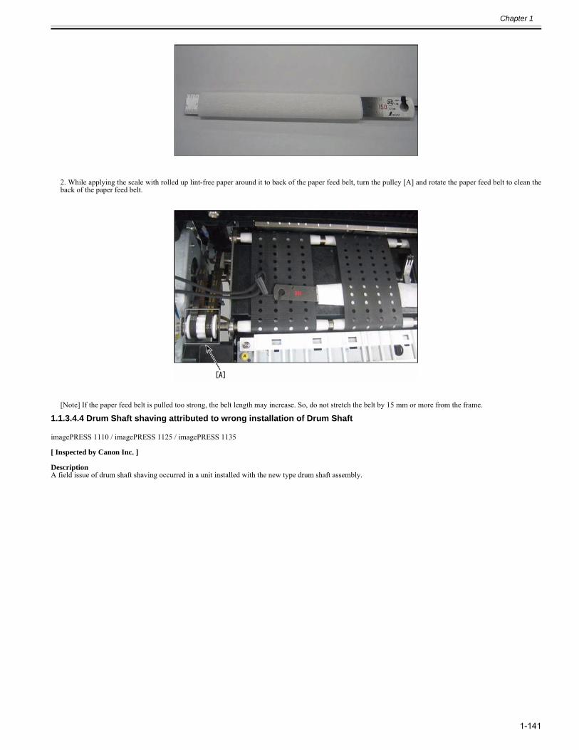
Chapter 1
1-141
2. While applying the scale with rolled up lint-free paper around it to back of the paper feed belt, turn the pulley [A] and rotate the paper feed belt to clean theback of the paper feed belt.
[Note] If the paper feed belt is pulled too strong, the belt length may increase. So, do not stretch the belt by 15 mm or more from the frame.
1.1.3.4.4 Drum Shaft shaving attributed to wrong installation of Drum Shaft0028-3586
imagePRESS 1110 / imagePRESS 1125 / imagePRESS 1135
[ Inspected by Canon Inc. ]
DescriptionA field issue of drum shaft shaving occurred in a unit installed with the new type drum shaft assembly.
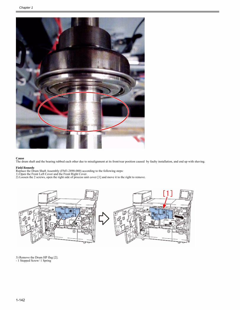
Chapter 1
1-142
CauseThe drum shaft and the bearing rubbed each other due to misalignment at its front/rear position caused by faulty installation, and end up with shaving.
Field RemedyReplace the Drum Shaft Assembly (FM3-2890-000) according to the following steps:1) Open the Front Left Cover and the Front Right Cover.2) Loosen the 2 screws, open the right side of process unit cover [1] and move it to the right to remove.
3) Remove the Drum HP flag [2].- 1 Stepped Screw/ 1 Spring
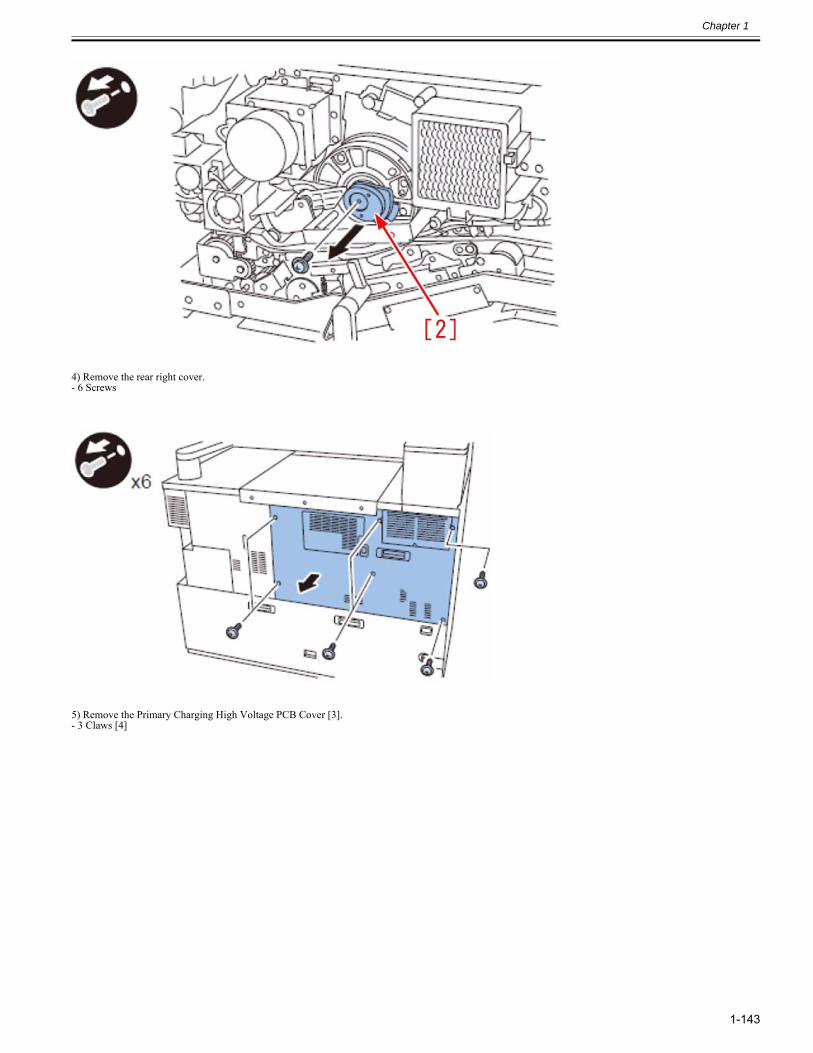
Chapter 1
1-143
4) Remove the rear right cover.- 6 Screws
5) Remove the Primary Charging High Voltage PCB Cover [3].- 3 Claws [4]
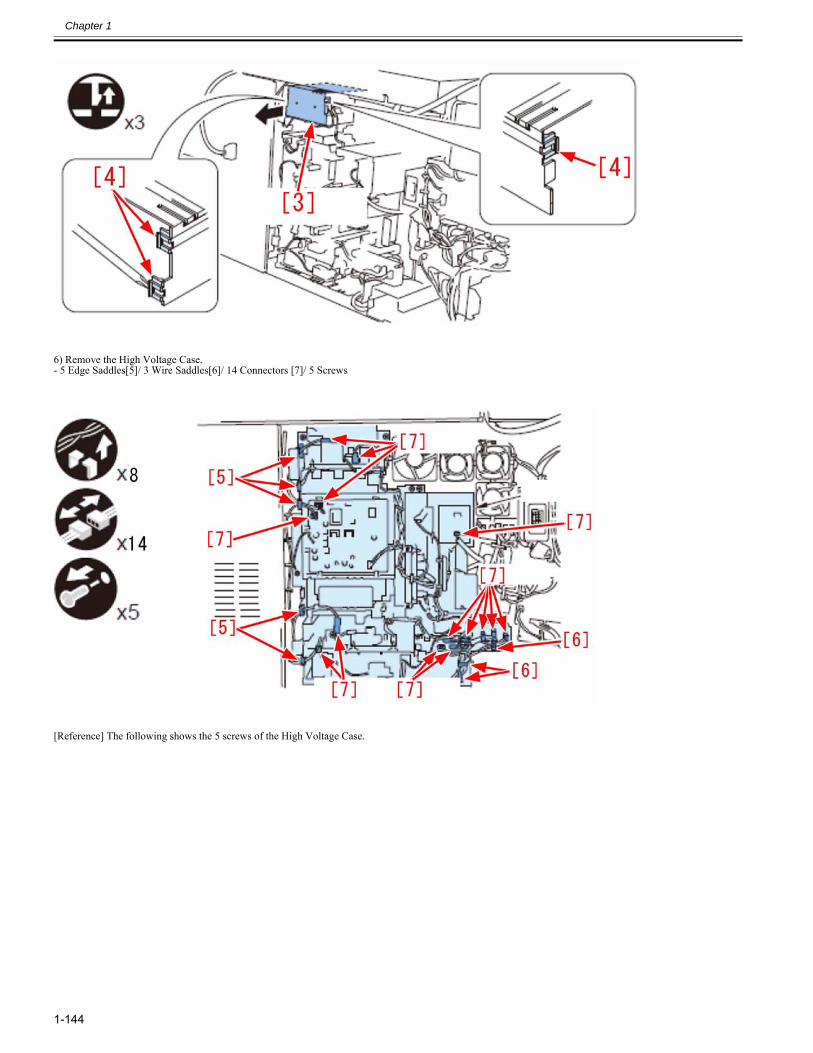
Chapter 1
1-144
6) Remove the High Voltage Case.- 5 Edge Saddles[5]/ 3 Wire Saddles[6]/ 14 Connectors [7]/ 5 Screws
[Reference] The following shows the 5 screws of the High Voltage Case.
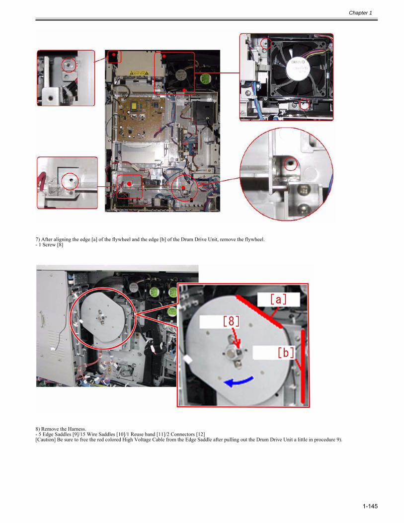
Chapter 1
1-145
7) After aligning the edge [a] of the flywheel and the edge [b] of the Drum Drive Unit, remove the flywheel.- 1 Screw [8]
8) Remove the Harness.- 5 Edge Saddles [9]/15 Wire Saddles [10]/1 Reuse band [11]/2 Connectors [12][Caution] Be sure to free the red colored High Voltage Cable from the Edge Saddle after pulling out the Drum Drive Unit a little in procedure 9).
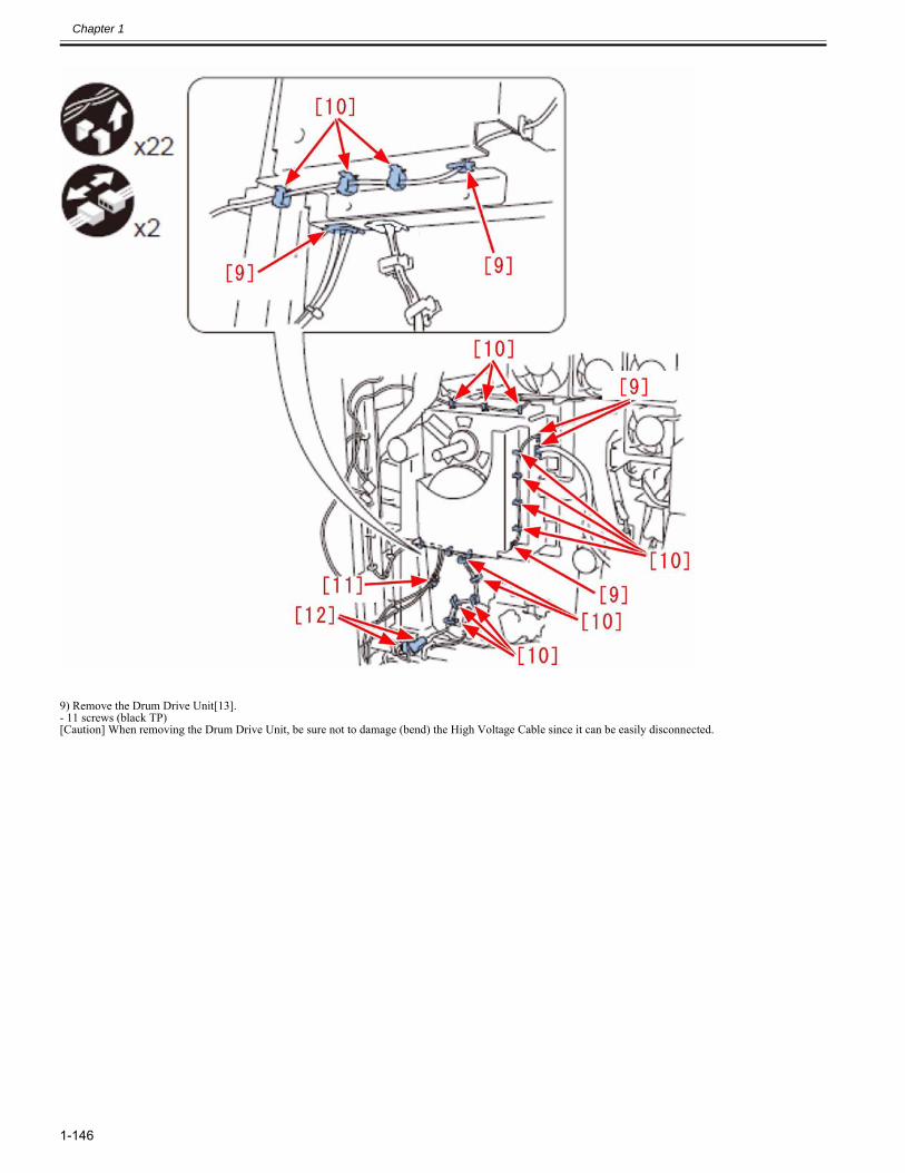
Chapter 1
1-146
9) Remove the Drum Drive Unit[13].- 11 screws (black TP)[Caution] When removing the Drum Drive Unit, be sure not to damage (bend) the High Voltage Cable since it can be easily disconnected.
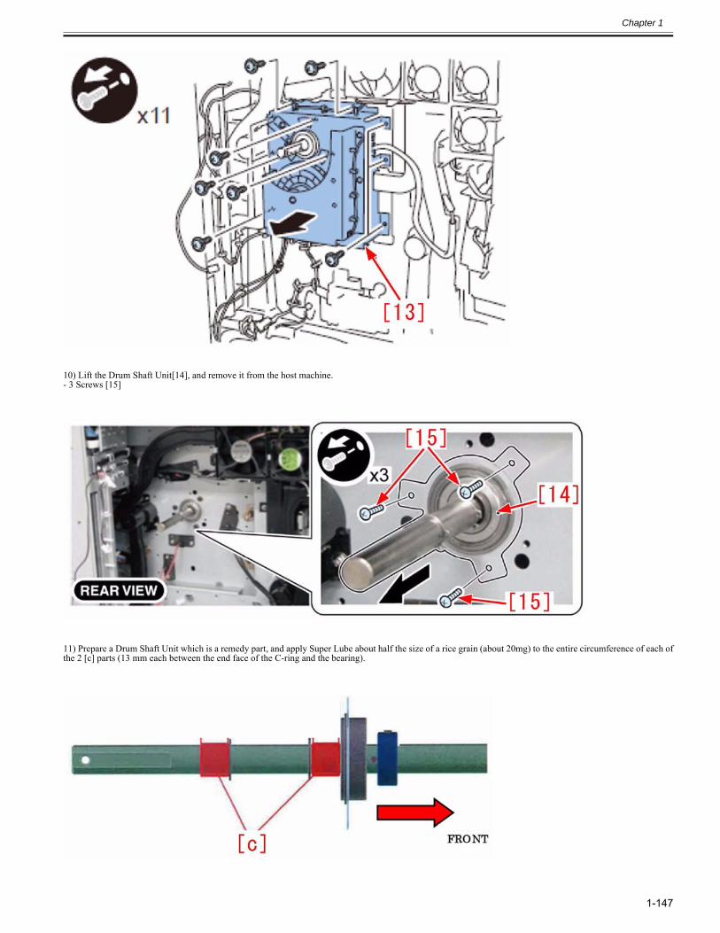
Chapter 1
1-147
10) Lift the Drum Shaft Unit[14], and remove it from the host machine.- 3 Screws [15]
11) Prepare a Drum Shaft Unit which is a remedy part, and apply Super Lube about half the size of a rice grain (about 20mg) to the entire circumference of each ofthe 2 [c] parts (13 mm each between the end face of the C-ring and the bearing).
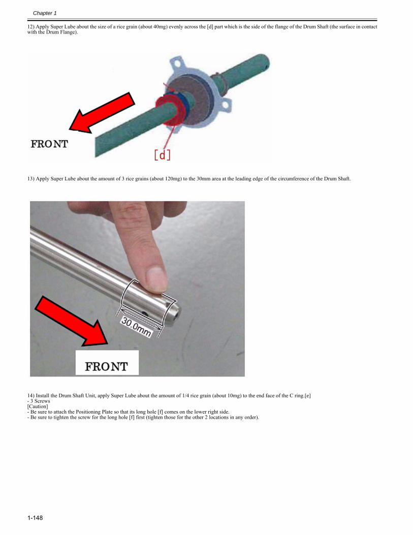
Chapter 1
1-148
12) Apply Super Lube about the size of a rice grain (about 40mg) evenly across the [d] part which is the side of the flange of the Drum Shaft (the surface in contactwith the Drum Flange).
13) Apply Super Lube about the amount of 3 rice grains (about 120mg) to the 30mm area at the leading edge of the circumference of the Drum Shaft.
14) Install the Drum Shaft Unit, apply Super Lube about the amount of 1/4 rice grain (about 10mg) to the end face of the C ring.[e]- 3 Screws[Caution]- Be sure to attach the Positioning Plate so that its long hole [f] comes on the lower right side.- Be sure to tighten the screw for the long hole [f] first (tighten those for the other 2 locations in any order).
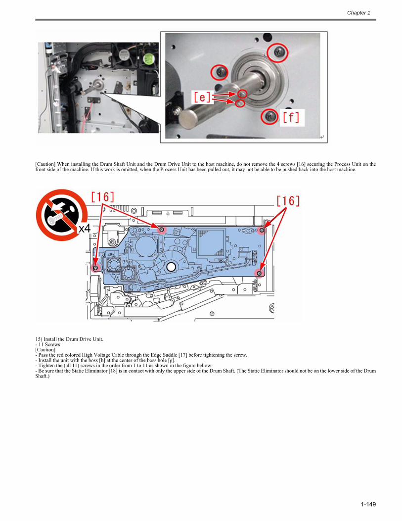
Chapter 1
1-149
[Caution] When installing the Drum Shaft Unit and the Drum Drive Unit to the host machine, do not remove the 4 screws [16] securing the Process Unit on thefront side of the machine. If this work is omitted, when the Process Unit has been pulled out, it may not be able to be pushed back into the host machine.
15) Install the Drum Drive Unit.- 11 Screws[Caution]- Pass the red colored High Voltage Cable through the Edge Saddle [17] before tightening the screw.- Install the unit with the boss [h] at the center of the boss hole [g].- Tighten the (all 11) screws in the order from 1 to 11 as shown in the figure bellow.- Be sure that the Static Eliminator [18] is in contact with only the upper side of the Drum Shaft. (The Static Eliminator should not be on the lower side of the DrumShaft.)
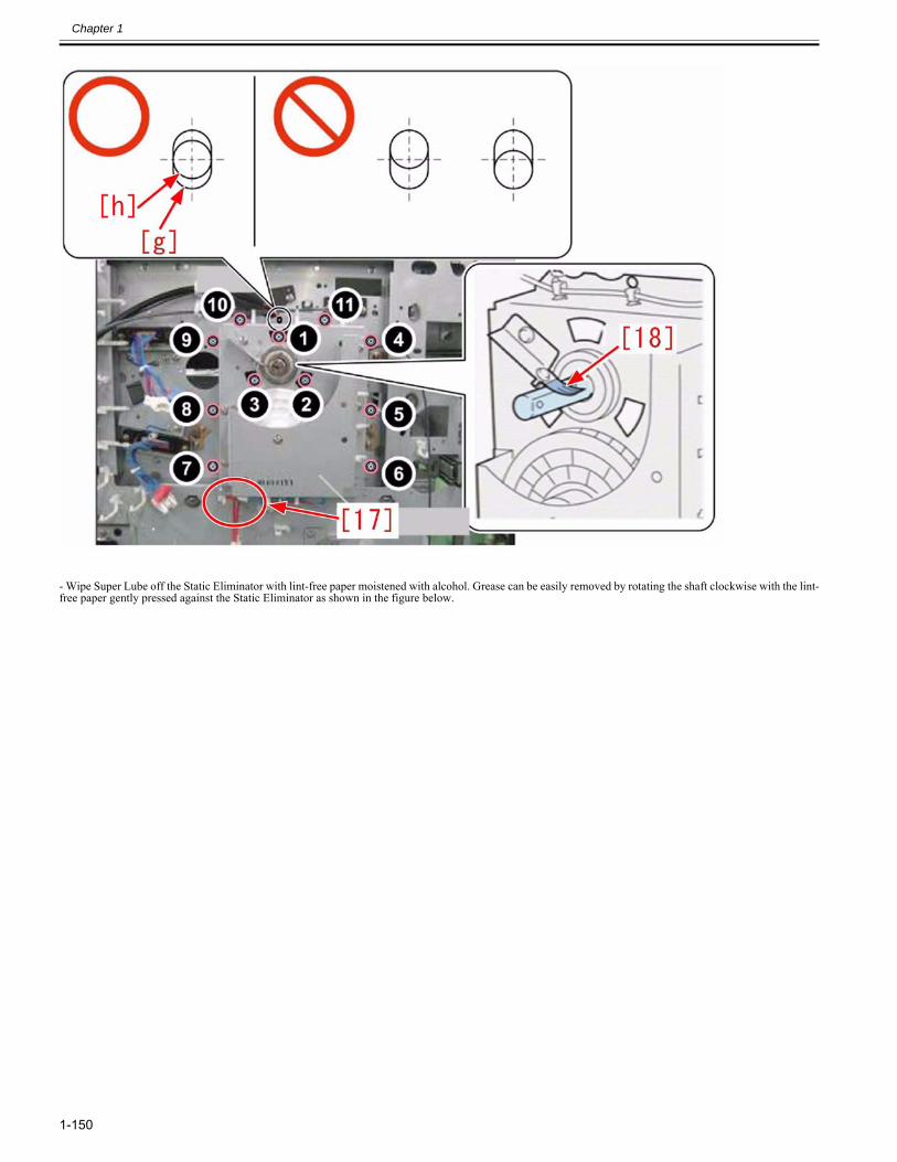
Chapter 1
1-150
- Wipe Super Lube off the Static Eliminator with lint-free paper moistened with alcohol. Grease can be easily removed by rotating the shaft clockwise with the lint-free paper gently pressed against the Static Eliminator as shown in the figure below.
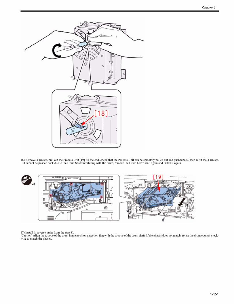
Chapter 1
1-151
16) Remove 4 screws, pull out the Process Unit [19] till the end, check that the Process Unit can be smoothly pulled out and pushedback, then re-fit the 4 screws.If it cannot be pushed back due to the Drum Shaft interfering with the drum, remove the Drum Drive Unit again and install it again.
17) Install in reverse order from the step 8).[Caution] Align the groove of the drum home position detection flag with the groove of the drum shaft. If the phases does not match, rotate the drum counter clock-wise to match the phases.
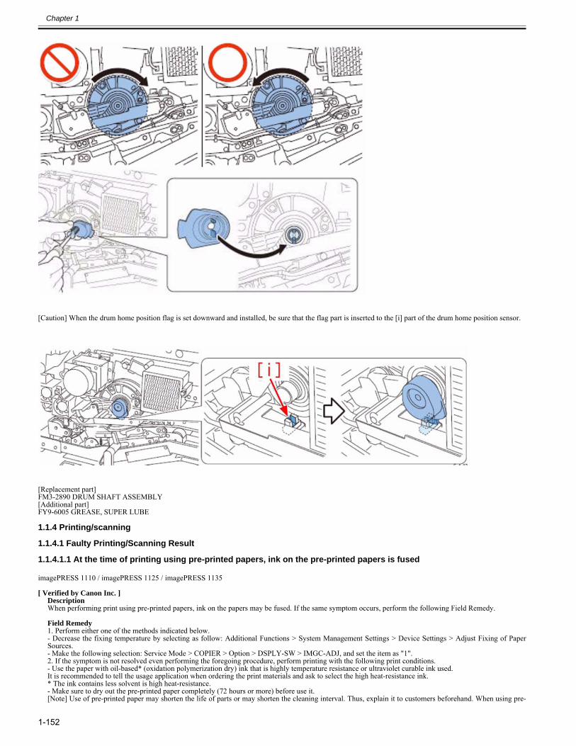
Chapter 1
1-152
[Caution] When the drum home position flag is set downward and installed, be sure that the flag part is inserted to the [i] part of the drum home position sensor.
[Replacement part]FM3-2890 DRUM SHAFT ASSEMBLY[Additional part]FY9-6005 GREASE, SUPER LUBE
1.1.4 Printing/scanning
1.1.4.1 Faulty Printing/Scanning Result
1.1.4.1.1 At the time of printing using pre-printed papers, ink on the pre-printed papers is fused0024-1662
imagePRESS 1110 / imagePRESS 1125 / imagePRESS 1135
[ Verified by Canon Inc. ]DescriptionWhen performing print using pre-printed papers, ink on the papers may be fused. If the same symptom occurs, perform the following Field Remedy. Field Remedy1. Perform either one of the methods indicated below. - Decrease the fixing temperature by selecting as follow: Additional Functions > System Management Settings > Device Settings > Adjust Fixing of PaperSources. - Make the following selection: Service Mode > COPIER > Option > DSPLY-SW > IMGC-ADJ, and set the item as "1". 2. If the symptom is not resolved even performing the foregoing procedure, perform printing with the following print conditions. - Use the paper with oil-based* (oxidation polymerization dry) ink that is highly temperature resistance or ultraviolet curable ink used.It is recommended to tell the usage application when ordering the print materials and ask to select the high heat-resistance ink.* The ink contains less solvent is high heat-resistance.- Make sure to dry out the pre-printed paper completely (72 hours or more) before use it.[Note] Use of pre-printed paper may shorten the life of parts or may shorten the cleaning interval. Thus, explain it to customers beforehand. When using pre-
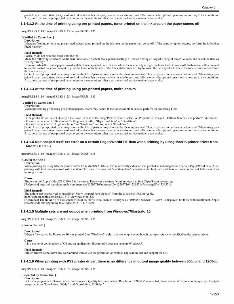
Chapter 1
1-153
printed paper, understand the type of used ink and whether the spray powder is used or not, and tell customers the optimal operations according to the conditions.Also, note that use of pre-printed paper requires the operations other than the normal service maintenance works.
1.1.4.1.2 At the time of printing using pre-printed papers, toner printed on the ink area on the paper comes off0024-1665
imagePRESS 1110 / imagePRESS 1125 / imagePRESS 1135
[ Verified by Canon Inc. ]DescriptionWhen performing print using pre-printed papers, toner printed on the ink area on the paper may come off. If the same symptom occurs, perform the followingField Remedy. Field RemedyBasically, do not print the toner onto the ink. Make the following selection: Additional Functions > System Management Settings > Device Settings > Adjust Fixing of Paper Sources, and select the item as"Fixing Priority". However, when the coated paper is used and the toner is printed onto the area where the ink density is high, the toner tends to come off. In this case, either preventto use the coated paper or prevent to print the toner onto the ink. If the toner still comes off, try to lower the density of ink where the toner comes off or lowerthe toner density.[Note] Use of pre-printed paper may shorten the life of parts or may shorten the cleaning interval. Thus, explain it to customers beforehand. When using pre-printed paper, understand the type of used ink and whether the spray powder is used or not, and tell customers the optimal operations according to the conditions.Also, note that use of pre-printed paper requires the operations other than the normal service maintenance works.
1.1.4.1.3 At the time of printing using pre-printed papers, moire occurs0024-1668
imagePRESS 1110 / imagePRESS 1125 / imagePRESS 1135
[ Verified by Canon Inc. ]DescriptionWhen performing print using pre-printed papers, moire may occur. If the same symptom occurs, perform the following Field Field RemedyIn the printer driver, select Quality > Halftone (in case of the imagePRESS Server, select Job Properties > Image > Halftone Screen), and perform adjustment. - If moire occurs due to "Resolution" setting, select either "High resolution" or "Gradation". - If moire occurs due to "High resolution" or "Gradation" setting, select "Resolution". [Note] Use of pre-printed paper may shorten the life of parts or may shorten the cleaning interval. Thus, explain it to customers beforehand. When using pre-printed paper, understand the type of used ink and whether the spray powder is used or not, and tell customers the optimal operations according to the conditions.Also, note that use of pre-printed paper requires the operations other than the normal service maintenance works.
1.1.4.1.4 Rod-shaped text/Text error on a certain Pages/Word/PDF data when printing by using MacPS printer driver from MacOS X 10.6.7
0027-4450
imagePRESS 1110 / imagePRESS 1125 / imagePRESS 1135
[ Case in the field ]DescriptionWhen printing by using MacPS printer driver from MacOS X 10.6.7, text is vertically extended and printed as rod-shaped for a certain Pages/Word data. Also,printing with text error occurred with a certain PDF data. It seems that "a certain data" depends on the font used and there are some reports of failures such asmissing letters.
CauseThe system of Apple's MacOS X 10.6.7 is the cause. There was a system failure in regard to font (OpenType) processing.[Reference] https://discussions.apple.com/message/13295716?messageID=13295716#13295716?messageID=13295716
Field RemedyThe failure can be resolved by installing "Snow Leopard Font Update" from the following URL of Apple. http://support.apple.com/kb/DL1377?viewlocale=en_US[Reference] The Build No of the system without the above installment is displayed as "10J868", whereas "10J869" is displayed for those with installment. Applerecommends this upgrading to all MacOS X 10.6.7 users.
1.1.4.1.5 Multiple sets are not output when printing from Windows7/Illustrator10.0027-5731
imagePRESS 1110 / imagePRESS 1125 / imagePRESS 1135
[ Case in the field ]
DescriptionWhen a file created by Illustrator 10 was printed from Windows7, only 1 set was output even though multiple sets were specified on the printer driver.
CauseIt is a matter of combination of OS and an application. Illustrator10 does not support Windows7.
Field RemedyPrinter drivers do not have any workaround. Please use the printer driver with an application that can support the OS.
1.1.4.1.6 When printing with PS3 printer driver, there is no difference in output image quality between 600dpi and 1200dpi0027-6186
imagePRESS 1110 / imagePRESS 1125 / imagePRESS 1135
[ Inspected by Canon Inc. ]DescriptionIn Printer properties > General tab > Preferences > Quality tab, even when "Resolution: 1200dpi" is selected, there was no difference in the quality of outputimage between "Resolution: 600dpi" and "Resolution: 1200 dpi."
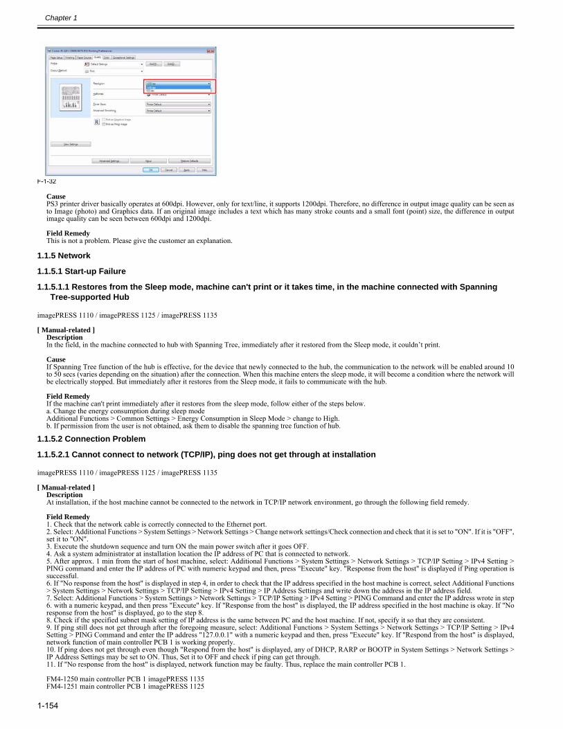
Chapter 1
1-154
F-1-32
CausePS3 printer driver basically operates at 600dpi. However, only for text/line, it supports 1200dpi. Therefore, no difference in output image quality can be seen asto Image (photo) and Graphics data. If an original image includes a text which has many stroke counts and a small font (point) size, the difference in outputimage quality can be seen between 600dpi and 1200dpi.
Field RemedyThis is not a problem. Please give the customer an explanation.
1.1.5 Network
1.1.5.1 Start-up Failure
1.1.5.1.1 Restores from the Sleep mode, machine can't print or it takes time, in the machine connected with Spanning Tree-supported Hub
0023-1919
imagePRESS 1110 / imagePRESS 1125 / imagePRESS 1135
[ Manual-related ]DescriptionIn the field, in the machine connected to hub with Spanning Tree, immediately after it restored from the Sleep mode, it couldn’t print.
CauseIf Spanning Tree function of the hub is effective, for the device that newly connected to the hub, the communication to the network will be enabled around 10to 50 secs (varies depending on the situation) after the connection. When this machine enters the sleep mode, it will become a condition where the network willbe electrically stopped. But immediately after it restores from the Sleep mode, it fails to communicate with the hub.
Field RemedyIf the machine can't print immediately after it restores from the sleep mode, follow either of the steps below. a. Change the energy consumption during sleep modeAdditional Functions > Common Settings > Energy Consumption in Sleep Mode > change to High.b. If permission from the user is not obtained, ask them to disable the spanning tree function of hub.
1.1.5.2 Connection Problem
1.1.5.2.1 Cannot connect to network (TCP/IP), ping does not get through at installation0023-7061
imagePRESS 1110 / imagePRESS 1125 / imagePRESS 1135
[ Manual-related ]DescriptionAt installation, if the host machine cannot be connected to the network in TCP/IP network environment, go through the following field remedy. Field Remedy1. Check that the network cable is correctly connected to the Ethernet port.2. Select: Additional Functions > System Settings > Network Settings > Change network settings/Check connection and check that it is set to "ON". If it is "OFF",set it to "ON".3. Execute the shutdown sequence and turn ON the main power switch after it goes OFF.4. Ask a system administrator at installation location the IP address of PC that is connected to network.5. After approx. 1 min from the start of host machine, select: Additional Functions > System Settings > Network Settings > TCP/IP Setting > IPv4 Setting >PING command and enter the IP address of PC with numeric keypad and then, press "Execute" key. "Response from the host" is displayed if Ping operation issuccessful.6. If "No response from the host" is displayed in step 4, in order to check that the IP address specified in the host machine is correct, select Additional Functions> System Settings > Network Settings > TCP/IP Setting > IPv4 Setting > IP Address Settings and write down the address in the IP address field.7. Select: Additional Functions > System Settings > Network Settings > TCP/IP Setting > IPv4 Setting > PING Command and enter the IP address wrote in step6. with a numeric keypad, and then press "Execute" key. If "Response from the host" is displayed, the IP address specified in the host machine is okay. If "Noresponse from the host" is displayed, go to the step 8.8. Check if the specified subnet mask setting of IP address is the same between PC and the host machine. If not, specify it so that they are consistent.9. If ping still does not get through after the foregoing measure, select: Additional Functions > System Settings > Network Settings > TCP/IP Setting > IPv4Setting > PING Command and enter the IP address "127.0.0.1" with a numeric keypad and then, press "Execute" key. If "Respond from the host" is displayed,network function of main controller PCB 1 is working properly.10. If ping does not get through even though "Respond from the host" is displayed, any of DHCP, RARP or BOOTP in System Settings > Network Settings >IP Address Settings may be set to ON. Thus, Set it to OFF and check if ping can get through.11. If "No response from the host" is displayed, network function may be faulty. Thus, replace the main controller PCB 1.
FM4-1250 main controller PCB 1 imagePRESS 1135FM4-1251 main controller PCB 1 imagePRESS 1125

Chapter 1
1-155
FM4-1252 main controller PCB 1 imagePRESS 1110
1.1.5.2.2 Network Troubleshooting TCP/IP Checklist [G]0025-5232
imagePRESS 1110 / imagePRESS 1125 / imagePRESS 1135
[ Case in the field ]DescriptionWhat are the best steps to take in troubleshooting TCP/IP connectivity on a Windows network? Field RemedyIn a Windows TCP/IP environment, network configuration problems inevitably arise. Often the problem can be traced to an improperly configured TCP/IPsetting, but finding the culprit can be difficult. Below are some steps to help determine where the problem exists:1. What stopped working? The client, server, or the printer? Ask around to learn if the outage is affecting others or just a single desktop.2. If the server stopped working, you should notice other co-workers with similar problems. If this is the case, focus on fixing the server.3. If a single client PC has stopped responding to the network, ask the user whether new software was just loaded or any recent changes have been made to thesystem, including the installation of service packs, new Internet software, video games, and so on.4. Check the physical network. The physical topology of your network is most prone to failure. In fact, most network problems are often due to Physical Layerfailures (cabling, etc).5. Is it plugged in? Check all network cable connections. Start at the NIC. Is there a green link light? Check the wiring closet to see if someone "borrowed" thepatch cable. Check the hub to see if the system is getting a link across the cable.6. If you don't have a cable tester, get one. Cabling is very susceptible to electricians, cleaning people and so on.7. Start PINGing. Windows TCP/IP has the PING command built in. In a typical network you have this order (client->gateway->server) or (client->gateway->internet). First, attempt to PING yourself from the Windows command prompt. Your local "loopback" address for such testing is 127.0.0.1. Example:C:\WINDOWS>PING 127.0.0.1PINGing 127.0.0.1 with 32 bytes of data:Reply from 127.0.0.1: bytes=32 time<10ms TTL=32Reply from 127.0.0.1: bytes=32 time<10ms TTL=32Reply from 127.0.0.1: bytes=32 time<10ms TTL=32Reply from 127.0.0.1: bytes=32 time=1ms TTL=32PING statistics for 127.0.0.1:Packets: Sent = 4, Received = 4, Lost = 0 (0% loss),Approximate round trip times in milliseconds:Minimum = 0ms, Maximum = 1ms, Average = 0msIf you do not receive a successful PING from yourself, in Windows, try re-installing the TCP/IP protocol from the Network Control Panel or the NetworkInterface card drivers. 8. If PINGing your loopback worked fine, then try PINGing someone who is on the same subnet as your PC. Be sure the target IP address being PINGed is avalid IP address assigned to a system; otherwise, you'll receive errors. Use the Start | Run | IPCONFIG command to learn your NT/2000 machine's IPconfiguration (use WINIPCFG with Windows 9x).WINDOWS SYSTEMS* IP Config provides valuable information about what network you are on, as well as your gateway address.
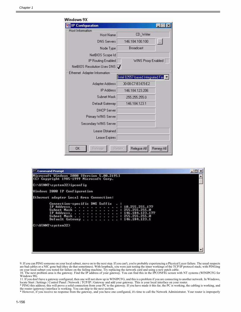
Chapter 1
1-156
9. If you can PING someone on your local subnet, move on to the next step. If you can't, you're probably experiencing a Physical Layer failure. The usual suspectsare bad cables or a NIC gone bad (they do that sometimes). With loopback, you were just testing the inner workings of the TCP/IP protocol stack; with PINGingon your local subnet you tested for failure on the failing machine. Try replacing the network card and using a new patch cable.10. The next problem area is the gateway. Find the IP address of your gateway. You can find this in the IPCONFIG screen with NT systems (WINIPCFG forWindows 98). 11. If you don't have a gateway configured, then one will not show up in WINIPCFG, and this is a problem if you are connecting to another network. In Windows,locate Start | Settings | Control Panel | Network | TCP/IP | Gateway and add your gateway. This is your local interface on your router. * PING this address; this will prove a solid connection from your PC to the gateway. If you have made it this far, the PC is working, the cabling is working, andthe router (gateway) interface is working. You can skip to the next section.* However, if you receive no response from the gateway, and you have one configured, it's time to call the Network Administrator. Your router is improperly
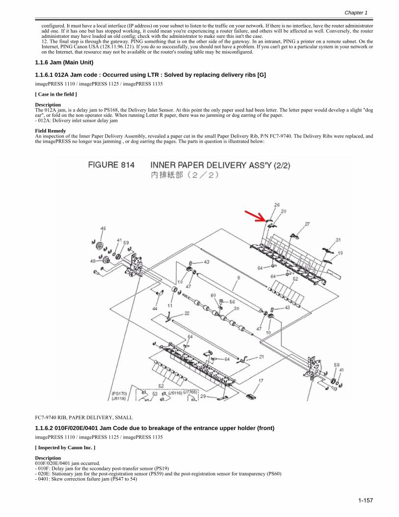
Chapter 1
1-157
configured. It must have a local interface (IP address) on your subnet to listen to the traffic on your network. If there is no interface, have the router administratoradd one. If it has one but has stopped working, it could mean you're experiencing a router failure, and others will be affected as well. Conversely, the routeradministrator may have loaded an old config; check with the administrator to make sure this isn't the case.12. The final step is through the gateway. PING something that is on the other side of the gateway. In an intranet, PING a printer on a remote subnet. On theInternet, PING Canon USA (128.11.96.121). If you do so successfully, you should not have a problem. If you can't get to a particular system in your network oron the Internet, that resource may not be available or the router's routing table may be misconfigured.
1.1.6 Jam (Main Unit)
1.1.6.1 012A Jam code : Occurred using LTR : Solved by replacing delivery ribs [G]0028-3045
imagePRESS 1110 / imagePRESS 1125 / imagePRESS 1135
[ Case in the field ] DescriptionThe 012A jam, is a delay jam to PS168, the Delivery Inlet Sensor. At this point the only paper used had been letter. The letter paper would develop a slight "dogear", or fold on the non operator side. When running Letter R paper, there was no jamming or dog earring of the paper.- 012A: Delivery inlet sensor delay jam Field RemedyAn inspection of the Inner Paper Delivery Assembly, revealed a paper cut in the small Paper Delivery Rib, P/N FC7-9740. The Delivery Ribs were replaced, andthe imagePRESS no longer was jamming , or dog earring the pages. The parts in question is illustrated below:
FC7-9740 RIB, PAPER DELIVERY, SMALL
1.1.6.2 010F/020E/0401 Jam Code due to breakage of the entrance upper holder (front)0028-6084
imagePRESS 1110 / imagePRESS 1125 / imagePRESS 1135
[ Inspected by Canon Inc. ]
Description010F/020E/0401 jam occurred.- 010F: Delay jam for the secondary post-transfer sensor (PS19)- 020E: Stationary jam for the post-registration sensor (PS59) and the post-registration sensor for transparency (PS60)- 0401: Skew correction failure jam (PS47 to 54)
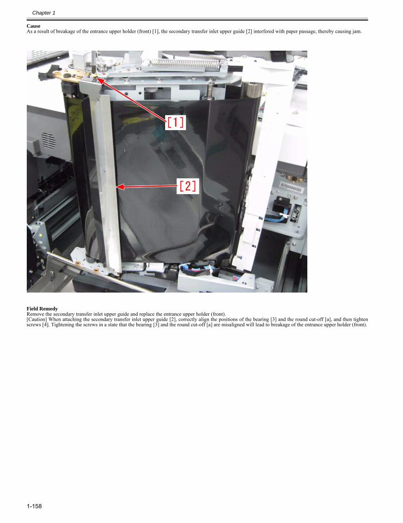
Chapter 1
1-158
CauseAs a result of breakage of the entrance upper holder (front) [1], the secondary transfer inlet upper guide [2] interfered with paper passage, thereby causing jam.
Field RemedyRemove the secondary transfer inlet upper guide and replace the entrance upper holder (front).[Caution] When attaching the secondary transfer inlet upper guide [2], correctly align the positions of the bearing [3] and the round cut-off [a], and then tightenscrews [4]. Tightening the screws in a state that the bearing [3] and the round cut-off [a] are misaligned will lead to breakage of the entrance upper holder (front).
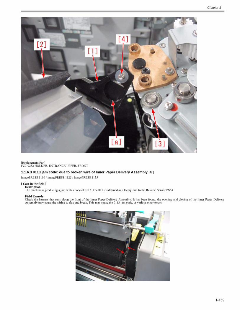
Chapter 1
1-159
[Replacement Part]FC7-9252 HOLDER, ENTRANCE UPPER, FRONT
1.1.6.3 0113 jam code: due to broken wire of Inner Paper Delivery Assembly [G]0028-0801
imagePRESS 1110 / imagePRESS 1125 / imagePRESS 1135
[ Case in the field ]DescriptionThe machine is producing a jam with a code of 0113. The 0113 is defined as a Delay Jam to the Reverse Sensor PS64. Field RemedyCheck the harness that runs along the front of the Inner Paper Delivery Assembly. It has been found, the opening and closing of the Inner Paper DeliveryAssembly may cause the wiring to flex and break. This may cause the 0113 jam code, or various other errors.
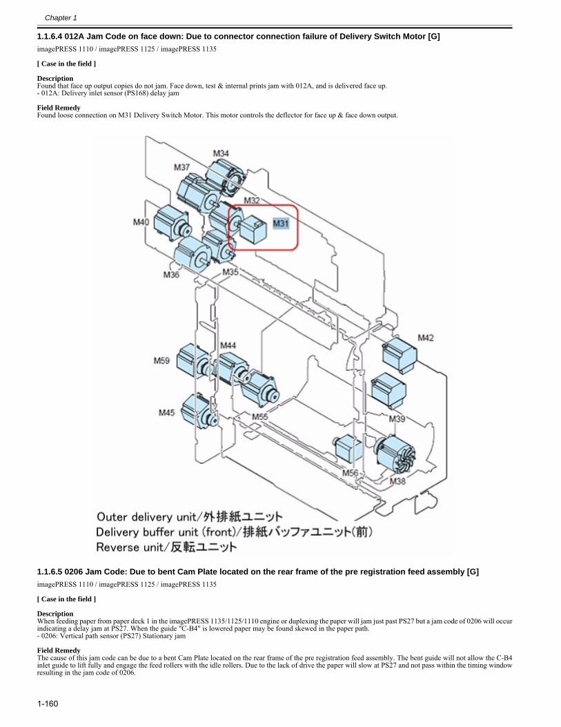
Chapter 1
1-160
1.1.6.4 012A Jam Code on face down: Due to connector connection failure of Delivery Switch Motor [G]0028-9825
imagePRESS 1110 / imagePRESS 1125 / imagePRESS 1135
[ Case in the field ] DescriptionFound that face up output copies do not jam. Face down, test & internal prints jam with 012A, and is delivered face up.- 012A: Delivery inlet sensor (PS168) delay jam Field RemedyFound loose connection on M31 Delivery Switch Motor. This motor controls the deflector for face up & face down output.
1.1.6.5 0206 Jam Code: Due to bent Cam Plate located on the rear frame of the pre registration feed assembly [G]0028-4621
imagePRESS 1110 / imagePRESS 1125 / imagePRESS 1135
[ Case in the field ] DescriptionWhen feeding paper from paper deck 1 in the imagePRESS 1135/1125/1110 engine or duplexing the paper will jam just past PS27 but a jam code of 0206 will occurindicating a delay jam at PS27. When the guide "C-B4" is lowered paper may be found skewed in the paper path.- 0206: Vertical path sensor (PS27) Stationary jam Field RemedyThe cause of this jam code can be due to a bent Cam Plate located on the rear frame of the pre registration feed assembly. The bent guide will not allow the C-B4inlet guide to lift fully and engage the feed rollers with the idle rollers. Due to the lack of drive the paper will slow at PS27 and not pass within the timing windowresulting in the jam code of 0206.
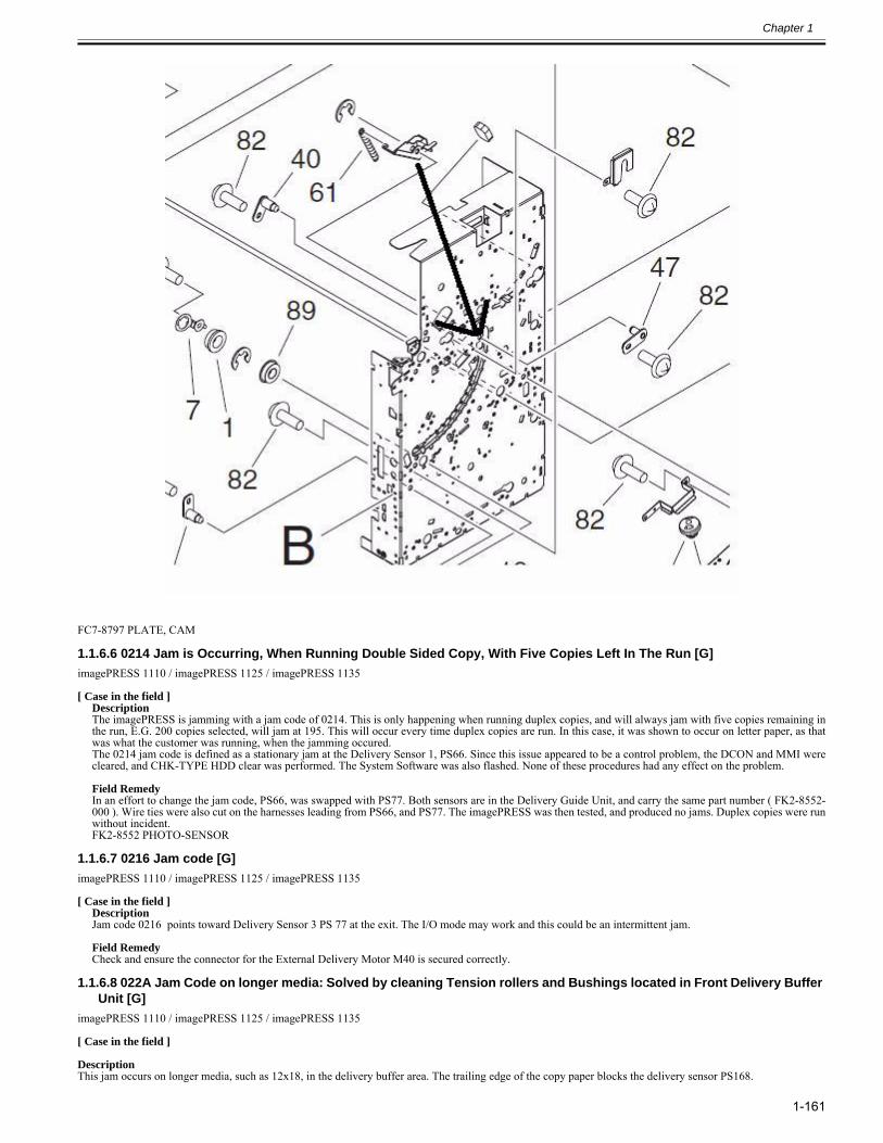
Chapter 1
1-161
FC7-8797 PLATE, CAM
1.1.6.6 0214 Jam is Occurring, When Running Double Sided Copy, With Five Copies Left In The Run [G]0025-5219
imagePRESS 1110 / imagePRESS 1125 / imagePRESS 1135
[ Case in the field ]DescriptionThe imagePRESS is jamming with a jam code of 0214. This is only happening when running duplex copies, and will always jam with five copies remaining inthe run, E.G. 200 copies selected, will jam at 195. This will occur every time duplex copies are run. In this case, it was shown to occur on letter paper, as thatwas what the customer was running, when the jamming occured.The 0214 jam code is defined as a stationary jam at the Delivery Sensor 1, PS66. Since this issue appeared to be a control problem, the DCON and MMI werecleared, and CHK-TYPE HDD clear was performed. The System Software was also flashed. None of these procedures had any effect on the problem. Field RemedyIn an effort to change the jam code, PS66, was swapped with PS77. Both sensors are in the Delivery Guide Unit, and carry the same part number ( FK2-8552-000 ). Wire ties were also cut on the harnesses leading from PS66, and PS77. The imagePRESS was then tested, and produced no jams. Duplex copies were runwithout incident.FK2-8552 PHOTO-SENSOR
1.1.6.7 0216 Jam code [G]0025-3978
imagePRESS 1110 / imagePRESS 1125 / imagePRESS 1135
[ Case in the field ]DescriptionJam code 0216 points toward Delivery Sensor 3 PS 77 at the exit. The I/O mode may work and this could be an intermittent jam. Field RemedyCheck and ensure the connector for the External Delivery Motor M40 is secured correctly.
1.1.6.8 022A Jam Code on longer media: Solved by cleaning Tension rollers and Bushings located in Front Delivery Buffer Unit [G]
0028-9827
imagePRESS 1110 / imagePRESS 1125 / imagePRESS 1135
[ Case in the field ] DescriptionThis jam occurs on longer media, such as 12x18, in the delivery buffer area. The trailing edge of the copy paper blocks the delivery sensor PS168.
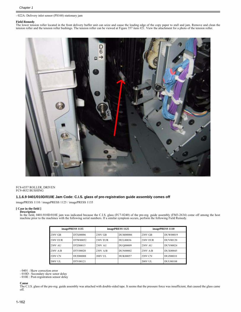
Chapter 1
1-162
- 022A: Delivery inlet sensor (PS168) stationary jam Field RemedyThe lower tension roller located in the front delivery buffer unit can seize and cause the leading edge of the copy paper to stall and jam. Remove and clean thetension roller and the tension roller bushings. The tension roller can be viewed at Figure 357 item #21. View the attachment for a photo of the tension roller.
FC8-6557 ROLLER, DRIVENFC9-4832 BUSHING
1.1.6.9 0401/010D/010E Jam Code: C.I.S. glass of pre-registration guide assembly comes off0024-7083
imagePRESS 1110 / imagePRESS 1125 / imagePRESS 1135
[ Case in the field ]DescriptionIn the field, 0401/010D/010E jam was indicated because the C.I.S. glass (FC7-8240) of the pre-reg. guide assembly (FM3-2634) come off among the hostmachine prior to the machines with the following serial numbers. If a similar symptom occurs, perform the following Field Remedy.
- 0401 : Skew correction error- 010D : Secondary skew senor delay- 010E : Post-registration sensor delay CauseThe C.I.S. glass of the pre-reg. guide assembly was attached with double-sided tape. It seems that the pressure force was insufficient, that caused the glass cameoff.
imagePRESS 1135 imagePRESS 1125 imagePRESS 1110
230V GB DTX00006 230V GB DUM00006 230V GB DUW00019
230V EUR DTW00052 230V EUR DUL00036 230V EUR DUV00120
230V AU DTZ00015 230V AU DUQ00009 230V AU DUY00024
230V A/B DTY00020 230V A/B DUN00002 230V A/B DUX00045
220V CN DUD00008 208V UL DUK00057 220V CN DUZ00010
208V UL DTV00121 208V UL DUU00188
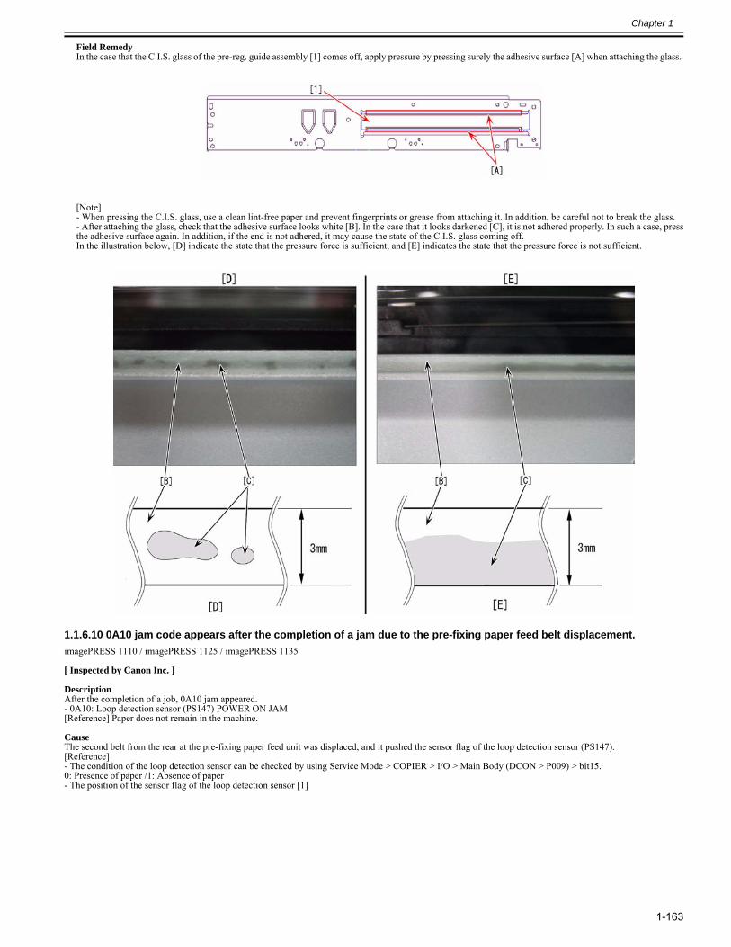
Chapter 1
1-163
Field Remedy In the case that the C.I.S. glass of the pre-reg. guide assembly [1] comes off, apply pressure by pressing surely the adhesive surface [A] when attaching the glass.
[Note] - When pressing the C.I.S. glass, use a clean lint-free paper and prevent fingerprints or grease from attaching it. In addition, be careful not to break the glass. - After attaching the glass, check that the adhesive surface looks white [B]. In the case that it looks darkened [C], it is not adhered properly. In such a case, pressthe adhesive surface again. In addition, if the end is not adhered, it may cause the state of the C.I.S. glass coming off. In the illustration below, [D] indicate the state that the pressure force is sufficient, and [E] indicates the state that the pressure force is not sufficient.
1.1.6.10 0A10 jam code appears after the completion of a jam due to the pre-fixing paper feed belt displacement.0028-6732
imagePRESS 1110 / imagePRESS 1125 / imagePRESS 1135
[ Inspected by Canon Inc. ]
DescriptionAfter the completion of a job, 0A10 jam appeared.- 0A10: Loop detection sensor (PS147) POWER ON JAM[Reference] Paper does not remain in the machine.
CauseThe second belt from the rear at the pre-fixing paper feed unit was displaced, and it pushed the sensor flag of the loop detection sensor (PS147).[Reference]- The condition of the loop detection sensor can be checked by using Service Mode > COPIER > I/O > Main Body (DCON > P009) > bit15.0: Presence of paper /1: Absence of paper- The position of the sensor flag of the loop detection sensor [1]
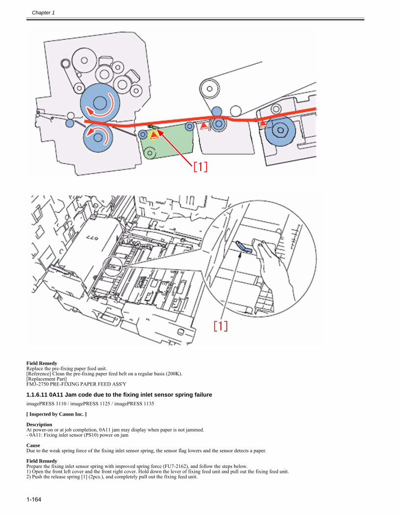
Chapter 1
1-164
Field RemedyReplace the pre-fixing paper feed unit.[Reference] Clean the pre-fixing paper feed belt on a regular basis (200K).[Replacement Part] FM3-2750 PRE-FIXING PAPER FEED ASS'Y
1.1.6.11 0A11 Jam code due to the fixing inlet sensor spring failure0028-1862
imagePRESS 1110 / imagePRESS 1125 / imagePRESS 1135
[ Inspected by Canon Inc. ]
DescriptionAt power-on or at job completion, 0A11 jam may display when paper is not jammed. - 0A11: Fixing inlet sensor (PS10) power on jam
CauseDue to the weak spring force of the fixing inlet sensor spring, the sensor flag lowers and the sensor detects a paper.
Field RemedyPrepare the fixing inlet sensor spring with improved spring force (FU7-2162), and follow the steps below.1) Open the front left cover and the front right cover. Hold down the lever of fixing feed unit and pull out the fixing feed unit.2) Push the release spring [1] (2pcs.), and completely pull out the fixing feed unit.
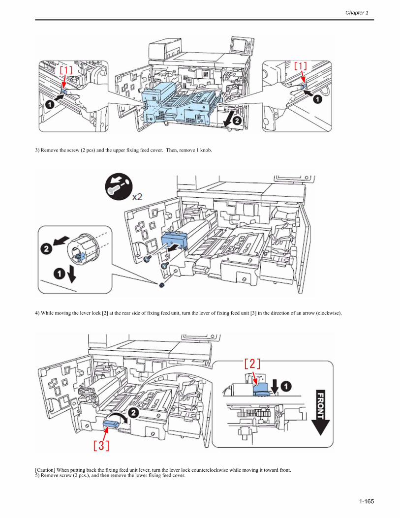
Chapter 1
1-165
3) Remove the screw (2 pcs) and the upper fixing feed cover. Then, remove 1 knob.
4) While moving the lever lock [2] at the rear side of fixing feed unit, turn the lever of fixing feed unit [3] in the direction of an arrow (clockwise).
[Caution] When putting back the fixing feed unit lever, turn the lever lock counterclockwise while moving it toward front. 5) Remove screw (2 pcs.), and then remove the lower fixing feed cover.
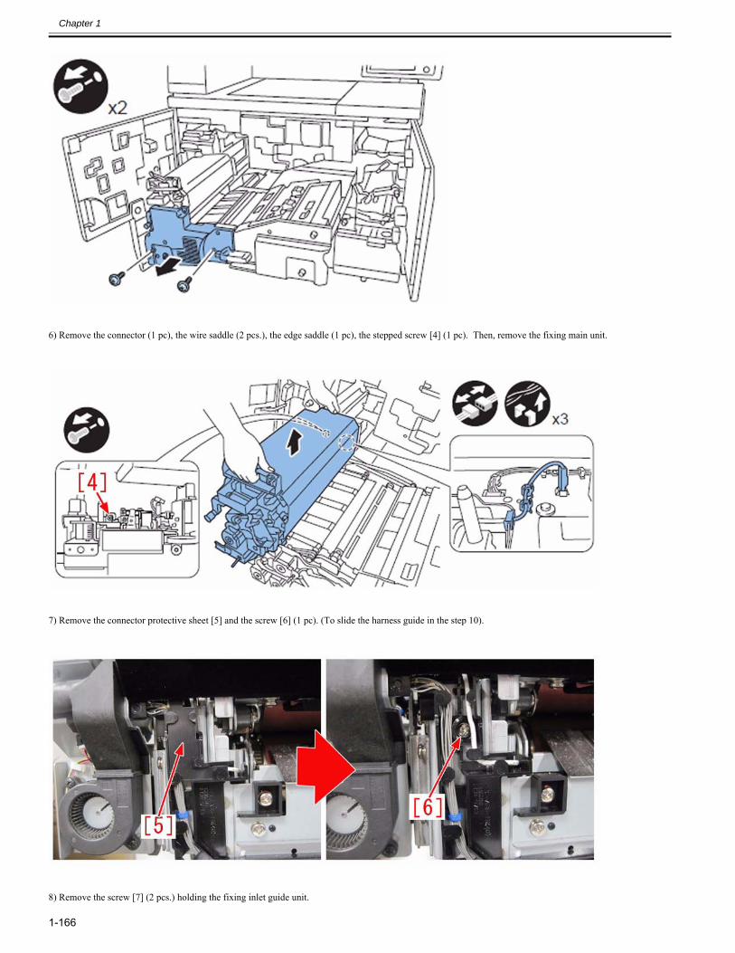
Chapter 1
1-166
6) Remove the connector (1 pc), the wire saddle (2 pcs.), the edge saddle (1 pc), the stepped screw [4] (1 pc). Then, remove the fixing main unit.
7) Remove the connector protective sheet [5] and the screw [6] (1 pc). (To slide the harness guide in the step 10).
8) Remove the screw [7] (2 pcs.) holding the fixing inlet guide unit.
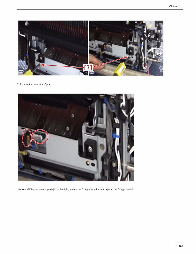
Chapter 1
1-167
9) Remove the connector (2 pcs.)
10) After sliding the harness guide [8] to the right, remove the fixing inlet guide unit [9] from the fixing assembly.
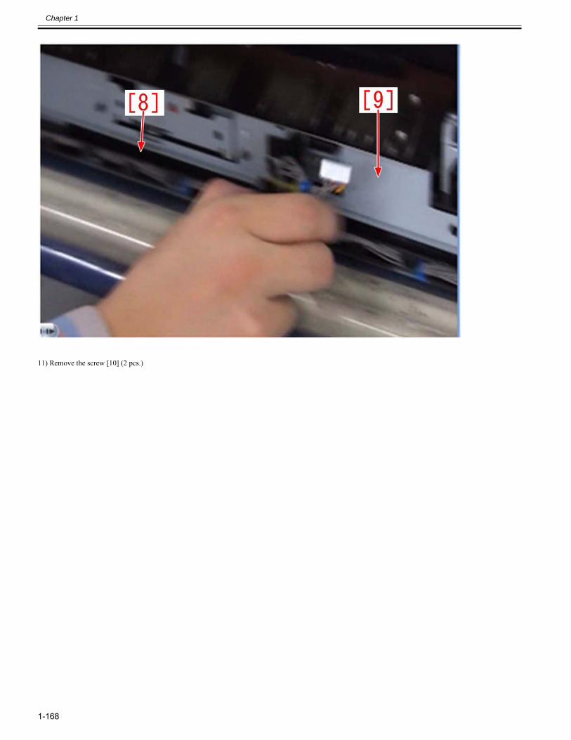
Chapter 1
1-168
11) Remove the screw [10] (2 pcs.)
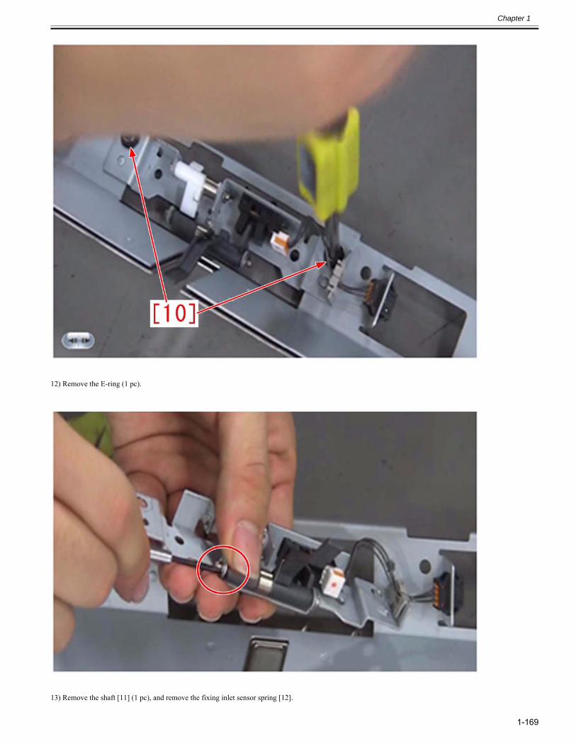
Chapter 1
1-169
12) Remove the E-ring (1 pc).
13) Remove the shaft [11] (1 pc), and remove the fixing inlet sensor spring [12].
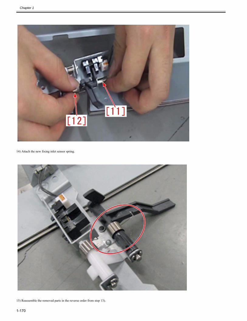
Chapter 1
1-170
14) Attach the new fixing inlet sensor spring.
15) Reassemble the removed parts in the reverse order from step 13).
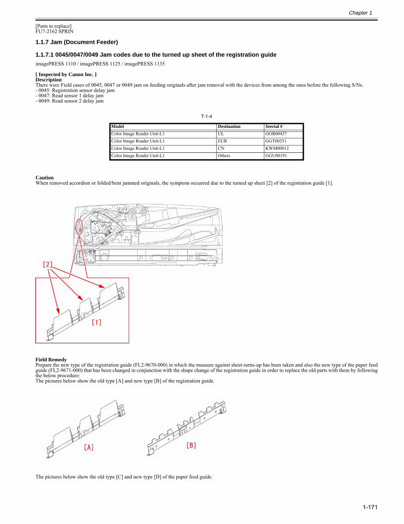
Chapter 1
1-171
[Parts to replace]FU7-2162 SPRIN
1.1.7 Jam (Document Feeder)
1.1.7.1 0045/0047/0049 Jam codes due to the turned up sheet of the registration guide0029-2851
imagePRESS 1110 / imagePRESS 1125 / imagePRESS 1135
[ Inspected by Canon Inc. ]DescriptionThere were Field cases of 0045, 0047 or 0049 jam on feeding originals after jam removal with the devices from among the ones before the following S/Ns.- 0045: Registration sensor delay jam- 0047: Read sensor 1 delay jam- 0049: Read sensor 2 delay jam
T-1-4
CautionWhen removed accordion or folded/bent jammed originals, the symptom occurred due to the turned up sheet [2] of the registration guide [1].
Field RemedyPrepare the new type of the registration guide (FL2-9670-000) in which the measure against sheet-turns-up has been taken and also the new type of the paper feedguide (FL2-9671-000) that has been changed in conjunction with the shape change of the registration guide in order to replace the old parts with them by followingthe below procedure:The pictures below show the old type [A] and new type [B] of the registration guide.
The pictures below show the old type [C] and new type [D] of the paper feed guide.
Model Destination Seerial #Color Image Reader Unit-L1 UL GGR00437Color Image Reader Unit-L1 EUR GGT00251Color Image Reader Unit-L1 CN KWM00012Color Image Reader Unit-L1 Others GGU00191
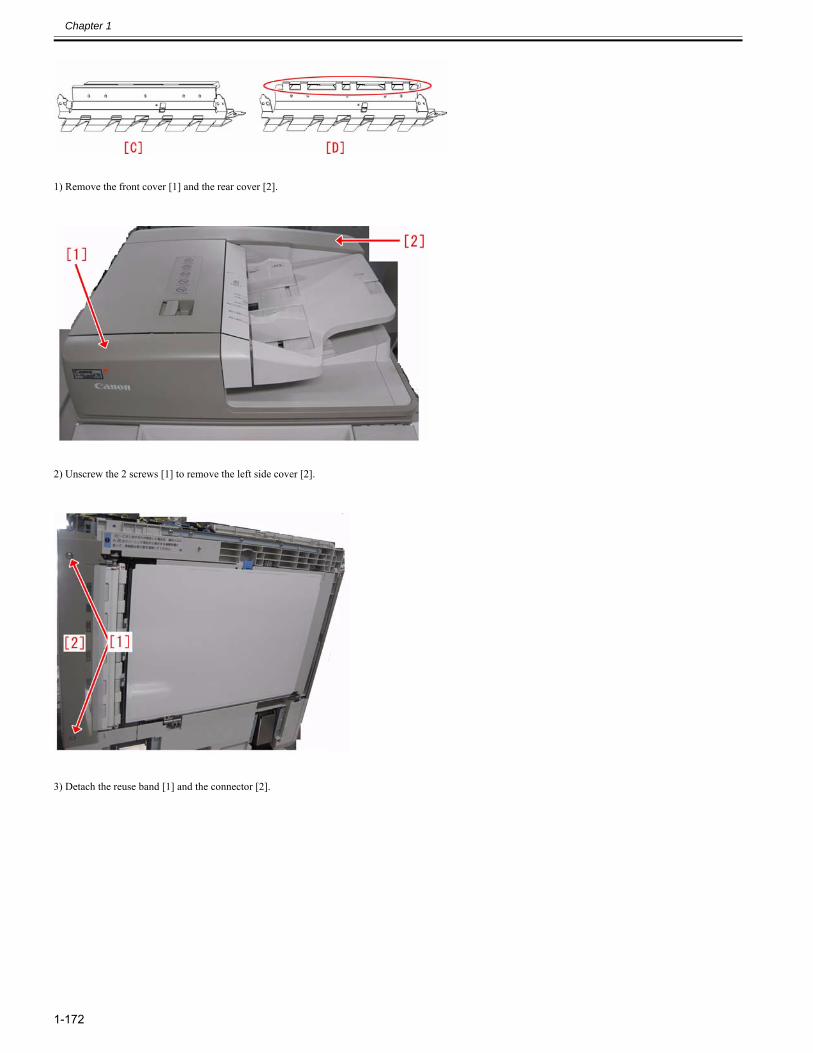
Chapter 1
1-172
1) Remove the front cover [1] and the rear cover [2].
2) Unscrew the 2 screws [1] to remove the left side cover [2].
3) Detach the reuse band [1] and the connector [2].
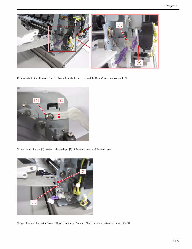
Chapter 1
1-173
4) Detach the E-ring [1] attached on the front side of the feeder cover and the Open/Close cover stopper 1 [2].
5) Unscrew the 1 screw [1] to remove the guide pin [2] of the feeder cover and the feeder cover.
6) Open the open/close guide (lower) [1] and unscrew the 2 screws [2] to remove the registration inner guide [3].
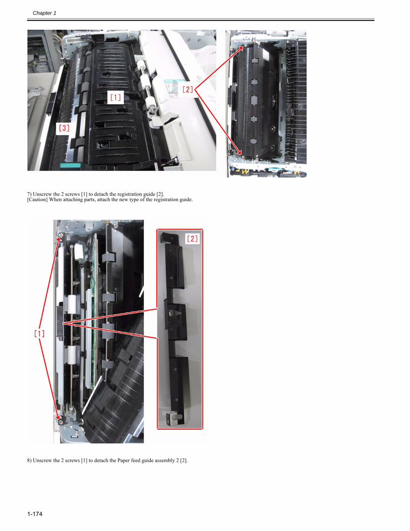
Chapter 1
1-174
7) Unscrew the 2 screws [1] to detach the registration guide [2].[Caution] When attaching parts, attach the new type of the registration guide.
8) Unscrew the 2 screws [1] to detach the Paper feed guide assembly 2 [2].
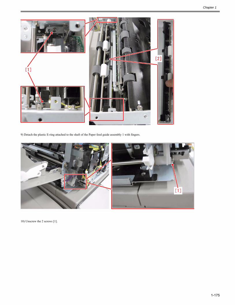
Chapter 1
1-175
9) Detach the plastic E-ring attached to the shaft of the Paper feed guide assembly 1 with fingers.
10) Unscrew the 2 screws [1].
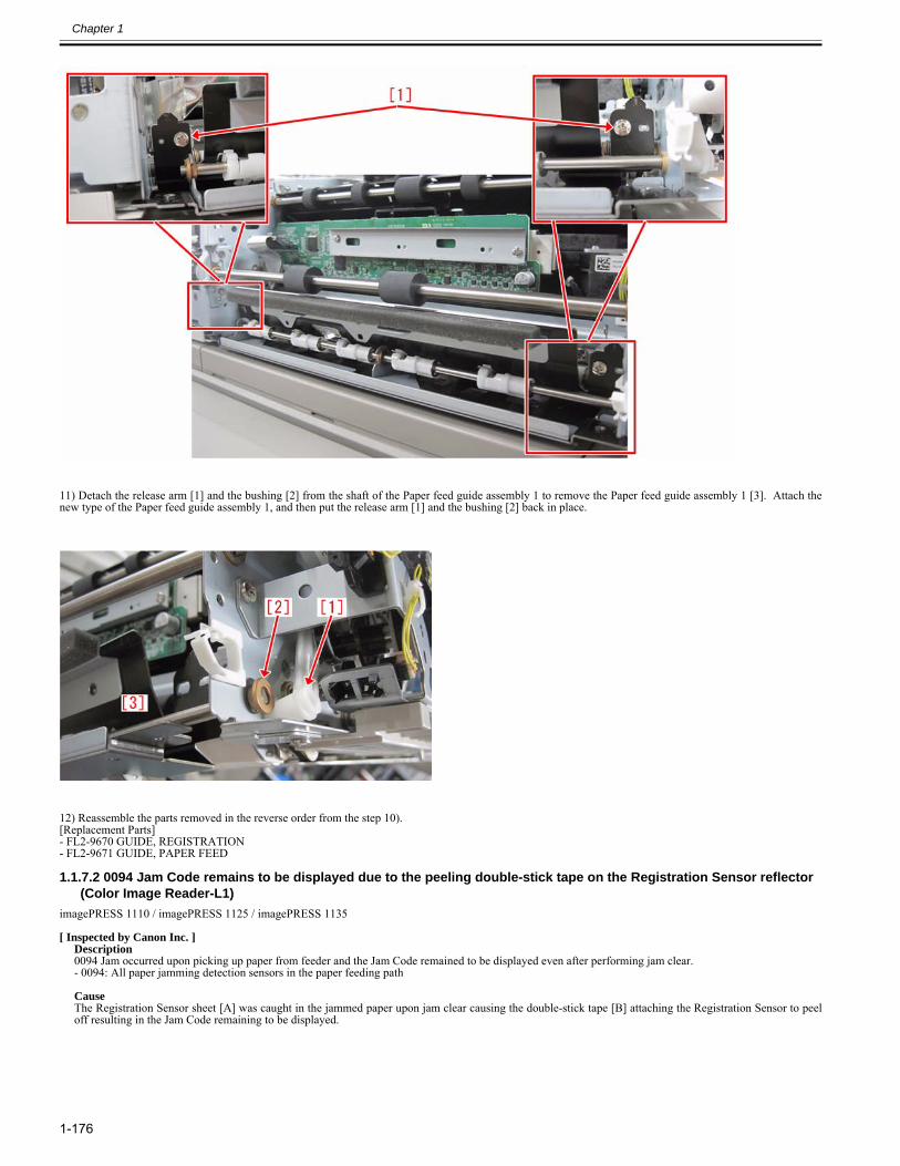
Chapter 1
1-176
11) Detach the release arm [1] and the bushing [2] from the shaft of the Paper feed guide assembly 1 to remove the Paper feed guide assembly 1 [3]. Attach thenew type of the Paper feed guide assembly 1, and then put the release arm [1] and the bushing [2] back in place.
12) Reassemble the parts removed in the reverse order from the step 10).[Replacement Parts]- FL2-9670 GUIDE, REGISTRATION- FL2-9671 GUIDE, PAPER FEED
1.1.7.2 0094 Jam Code remains to be displayed due to the peeling double-stick tape on the Registration Sensor reflector (Color Image Reader-L1)
0027-0814
imagePRESS 1110 / imagePRESS 1125 / imagePRESS 1135
[ Inspected by Canon Inc. ]Description0094 Jam occurred upon picking up paper from feeder and the Jam Code remained to be displayed even after performing jam clear.- 0094: All paper jamming detection sensors in the paper feeding path CauseThe Registration Sensor sheet [A] was caught in the jammed paper upon jam clear causing the double-stick tape [B] attaching the Registration Sensor to peeloff resulting in the Jam Code remaining to be displayed.
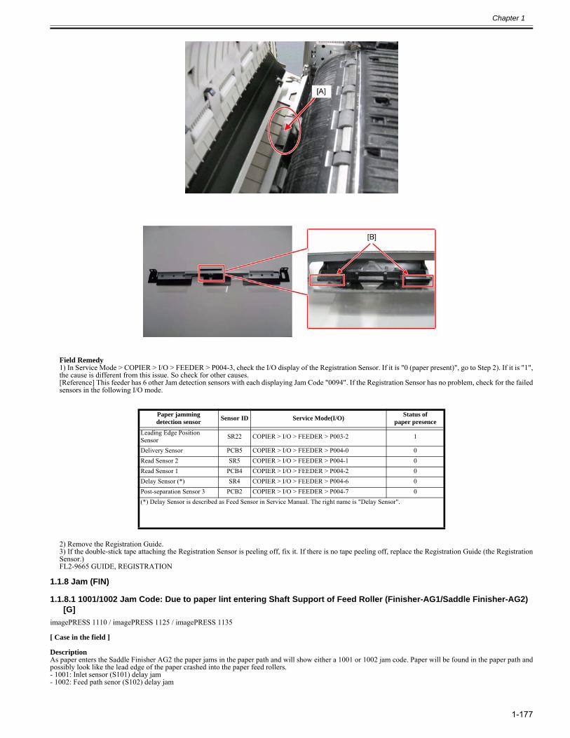
Chapter 1
1-177
Field Remedy1) In Service Mode > COPIER > I/O > FEEDER > P004-3, check the I/O display of the Registration Sensor. If it is "0 (paper present)", go to Step 2). If it is "1",the cause is different from this issue. So check for other causes.[Reference] This feeder has 6 other Jam detection sensors with each displaying Jam Code "0094". If the Registration Sensor has no problem, check for the failedsensors in the following I/O mode.
2) Remove the Registration Guide.3) If the double-stick tape attaching the Registration Sensor is peeling off, fix it. If there is no tape peeling off, replace the Registration Guide (the RegistrationSensor.) FL2-9665 GUIDE, REGISTRATION
1.1.8 Jam (FIN)
1.1.8.1 1001/1002 Jam Code: Due to paper lint entering Shaft Support of Feed Roller (Finisher-AG1/Saddle Finisher-AG2) [G]
0028-5394
imagePRESS 1110 / imagePRESS 1125 / imagePRESS 1135
[ Case in the field ] DescriptionAs paper enters the Saddle Finisher AG2 the paper jams in the paper path and will show either a 1001 or 1002 jam code. Paper will be found in the paper path andpossibly look like the lead edge of the paper crashed into the paper feed rollers.- 1001: Inlet sensor (S101) delay jam- 1002: Feed path senor (S102) delay jam
Paper jamming detection sensor Sensor ID Service Mode(I/O) Status of
paper presence
Leading Edge Position Sensor SR22 COPIER > I/O > FEEDER > P003-2 1
Delivery Sensor PCB5 COPIER > I/O > FEEDER > P004-0 0Read Sensor 2 SR5 COPIER > I/O > FEEDER > P004-1 0Read Sensor 1 PCB4 COPIER > I/O > FEEDER > P004-2 0Delay Sensor (*) SR4 COPIER > I/O > FEEDER > P004-6 0Post-separation Sensor 3 PCB2 COPIER > I/O > FEEDER > P004-7 0(*) Delay Sensor is described as Feed Sensor in Service Manual. The right name is "Delay Sensor".
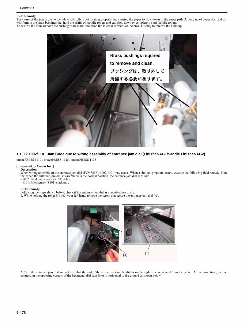
Chapter 1
1-178
Field RemedyThe cause of the jam is due to the white idle rollers not rotating properly and causing the paper to slow down in the paper path. A build up of paper dust and dirtwill form in the brass bushings that hold the shafts of the idle rollers and can slow down or completely bind the idle rollers.To resolve the issue remove the bushings and shafts and clean the internal surfaces of the brass bushing to remove the build up.
1.1.8.2 1002/1101 Jam Code due to wrong assembly of entrance jam dial (Finisher-AG1/Saddle Finisher-AG2)0024-8232
imagePRESS 1110 / imagePRESS 1125 / imagePRESS 1135
[ Inspected by Canon Inc. ]DescriptionWhen wrong assembly of the entrance jam dial (FC9-3256), 1002/1101 may occur. When a similar symptom occurs, execute the following field remedy. Notethat when the entrance jam dial is assembled in the normal position, the entrance jam dial runs idle.- 1002: Feed path sensor (S102) delay- 1101: Inlet sensor (S101) stationary Field RemedyFollowing the steps shown below, check if the entrance jam dial is assembled normally.1. While holding the roller [1] with your left hand, remove the screw that secure the entrance jam dial [A].
2. Turn the entrance jam dial and set it so that the end of the arrow mark on the dial is on the right side as viewed from the center. At the same time, the lineconnecting the opposing corners of the hexagonal dial (dot line) is horizontal to the ground as shown below.
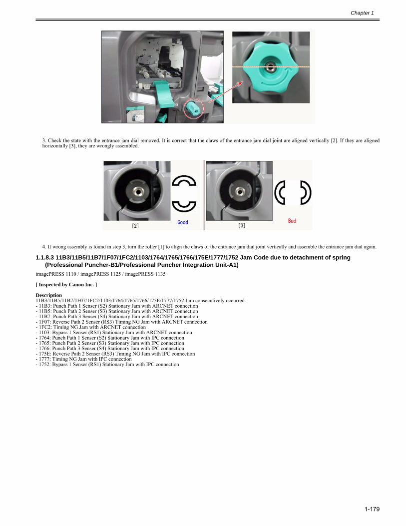
Chapter 1
1-179
3. Check the state with the entrance jam dial removed. It is correct that the claws of the entrance jam dial joint are aligned vertically [2]. If they are alignedhorizontally [3], they are wrongly assembled.
4. If wrong assembly is found in step 3, turn the roller [1] to align the claws of the entrance jam dial joint vertically and assemble the entrance jam dial again.
1.1.8.3 11B3/11B5/11B7/1F07/1FC2/1103/1764/1765/1766/175E/1777/1752 Jam Code due to detachment of spring (Professional Puncher-B1/Professional Puncher Integration Unit-A1)
0028-4799
imagePRESS 1110 / imagePRESS 1125 / imagePRESS 1135
[ Inspected by Canon Inc. ]
Description11B3/11B5/11B7/1F07/1FC2/1103/1764/1765/1766/175E/1777/1752 Jam consecutively occurred.- 11B3: Punch Path 1 Senser (S2) Stationary Jam with ARCNET connection- 11B5: Punch Path 2 Senser (S3) Stationary Jam with ARCNET connection- 11B7: Punch Path 3 Senser (S4) Stationary Jam with ARCNET connection- 1F07: Reverse Path 2 Senser (RS3) Timing NG Jam with ARCNET connection- 1FC2: Timing NG Jam with ARCNET connection- 1103: Bypass 1 Senser (RS1) Stationary Jam with ARCNET connection- 1764: Punch Path 1 Senser (S2) Stationary Jam with IPC connection- 1765: Punch Path 2 Senser (S3) Stationary Jam with IPC connection- 1766: Punch Path 3 Senser (S4) Stationary Jam with IPC connection- 175E: Reverse Path 2 Senser (RS3) Timing NG Jam with IPC connection- 1777: Timing NG Jam with IPC connection- 1752: Bypass 1 Senser (RS1) Stationary Jam with IPC connection
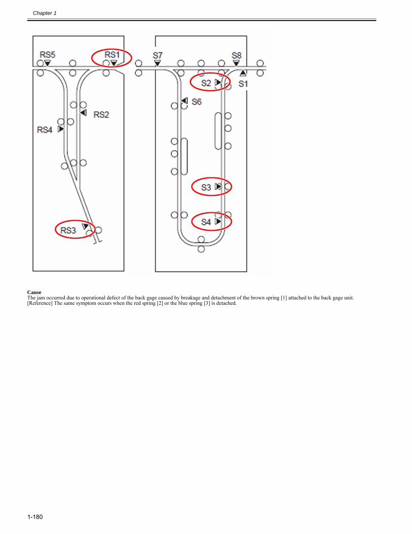
Chapter 1
1-180
CauseThe jam occurred due to operational defect of the back gage caused by breakage and detachment of the brown spring [1] attached to the back gage unit.[Reference] The same symptom occurs when the red spring [2] or the blue spring [3] is detached.
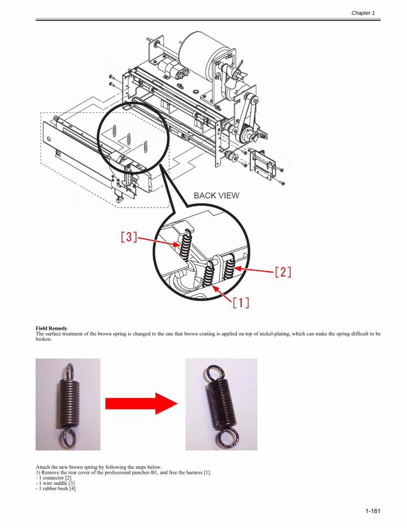
Chapter 1
1-181
Field RemedyThe surface treatment of the brown spring is changed to the one that brown coating is applied on top of nickel-plating, which can make the spring difficult to bebroken.
Attach the new brown spring by following the steps below.1) Remove the rear cover of the professional puncher-B1, and free the harness [1].- 1 connector [2]- 1 wire saddle [3]- 1 rubber bush [4]
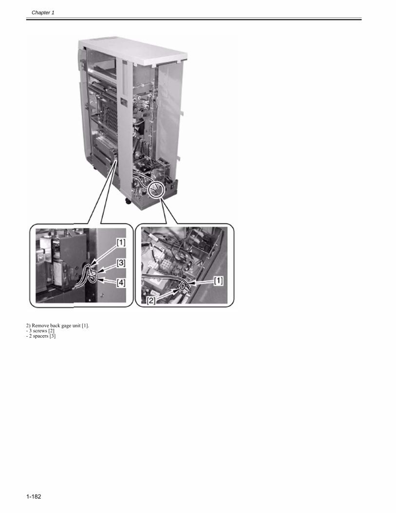
Chapter 1
1-182
2) Remove back gage unit [1].- 3 screws [2]- 2 spacers [3]
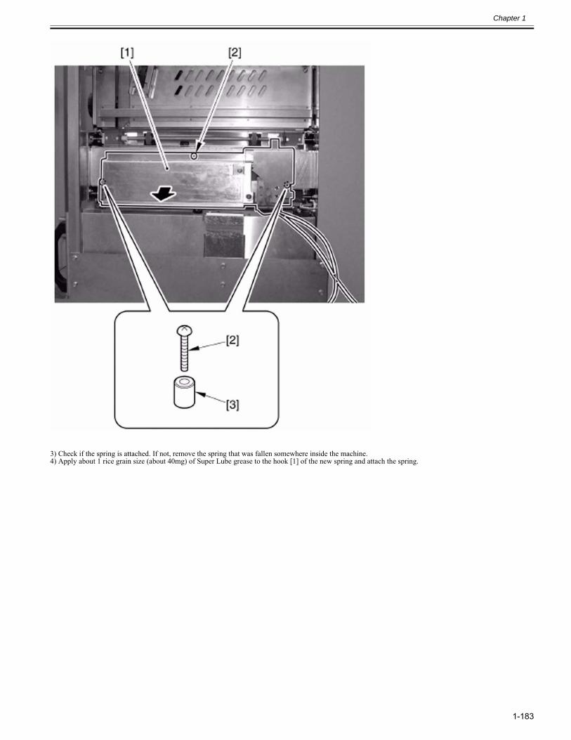
Chapter 1
1-183
3) Check if the spring is attached. If not, remove the spring that was fallen somewhere inside the machine.4) Apply about 1 rice grain size (about 40mg) of Super Lube grease to the hook [1] of the new spring and attach the spring.
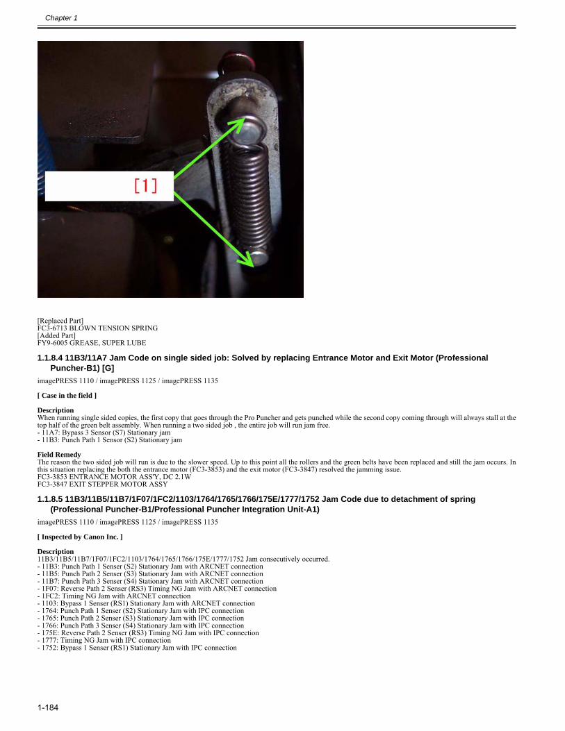
Chapter 1
1-184
[Replaced Part]FC3-6713 BLOWN TENSION SPRING[Added Part]FY9-6005 GREASE, SUPER LUBE
1.1.8.4 11B3/11A7 Jam Code on single sided job: Solved by replacing Entrance Motor and Exit Motor (Professional Puncher-B1) [G]
0028-9839
imagePRESS 1110 / imagePRESS 1125 / imagePRESS 1135
[ Case in the field ] DescriptionWhen running single sided copies, the first copy that goes through the Pro Puncher and gets punched while the second copy coming through will always stall at thetop half of the green belt assembly. When running a two sided job , the entire job will run jam free.- 11A7: Bypass 3 Sensor (S7) Stationary jam- 11B3: Punch Path 1 Sensor (S2) Stationary jam Field RemedyThe reason the two sided job will run is due to the slower speed. Up to this point all the rollers and the green belts have been replaced and still the jam occurs. Inthis situation replacing the both the entrance motor (FC3-3853) and the exit motor (FC3-3847) resolved the jamming issue.FC3-3853 ENTRANCE MOTOR ASS'Y, DC 2.1WFC3-3847 EXIT STEPPER MOTOR ASSY
1.1.8.5 11B3/11B5/11B7/1F07/1FC2/1103/1764/1765/1766/175E/1777/1752 Jam Code due to detachment of spring (Professional Puncher-B1/Professional Puncher Integration Unit-A1)
0029-1091
imagePRESS 1110 / imagePRESS 1125 / imagePRESS 1135
[ Inspected by Canon Inc. ]
Description11B3/11B5/11B7/1F07/1FC2/1103/1764/1765/1766/175E/1777/1752 Jam consecutively occurred.- 11B3: Punch Path 1 Senser (S2) Stationary Jam with ARCNET connection- 11B5: Punch Path 2 Senser (S3) Stationary Jam with ARCNET connection- 11B7: Punch Path 3 Senser (S4) Stationary Jam with ARCNET connection- 1F07: Reverse Path 2 Senser (RS3) Timing NG Jam with ARCNET connection- 1FC2: Timing NG Jam with ARCNET connection- 1103: Bypass 1 Senser (RS1) Stationary Jam with ARCNET connection- 1764: Punch Path 1 Senser (S2) Stationary Jam with IPC connection- 1765: Punch Path 2 Senser (S3) Stationary Jam with IPC connection- 1766: Punch Path 3 Senser (S4) Stationary Jam with IPC connection- 175E: Reverse Path 2 Senser (RS3) Timing NG Jam with IPC connection- 1777: Timing NG Jam with IPC connection- 1752: Bypass 1 Senser (RS1) Stationary Jam with IPC connection
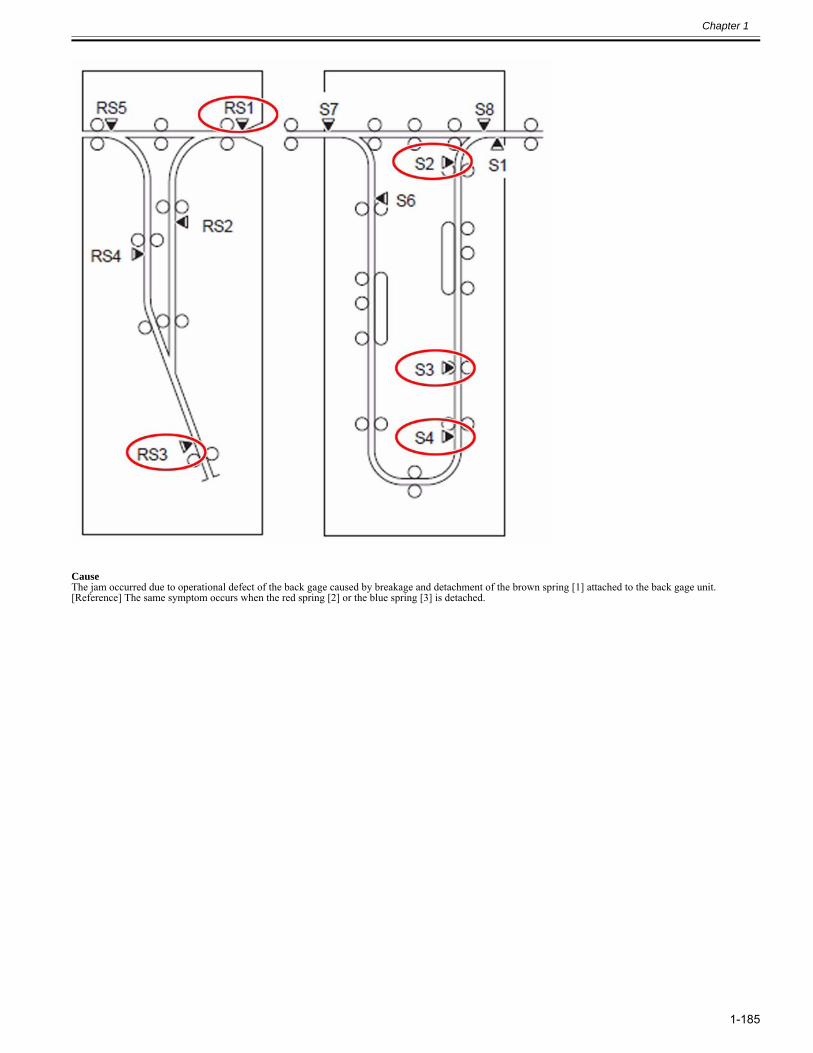
Chapter 1
1-185
CauseThe jam occurred due to operational defect of the back gage caused by breakage and detachment of the brown spring [1] attached to the back gage unit.[Reference] The same symptom occurs when the red spring [2] or the blue spring [3] is detached.
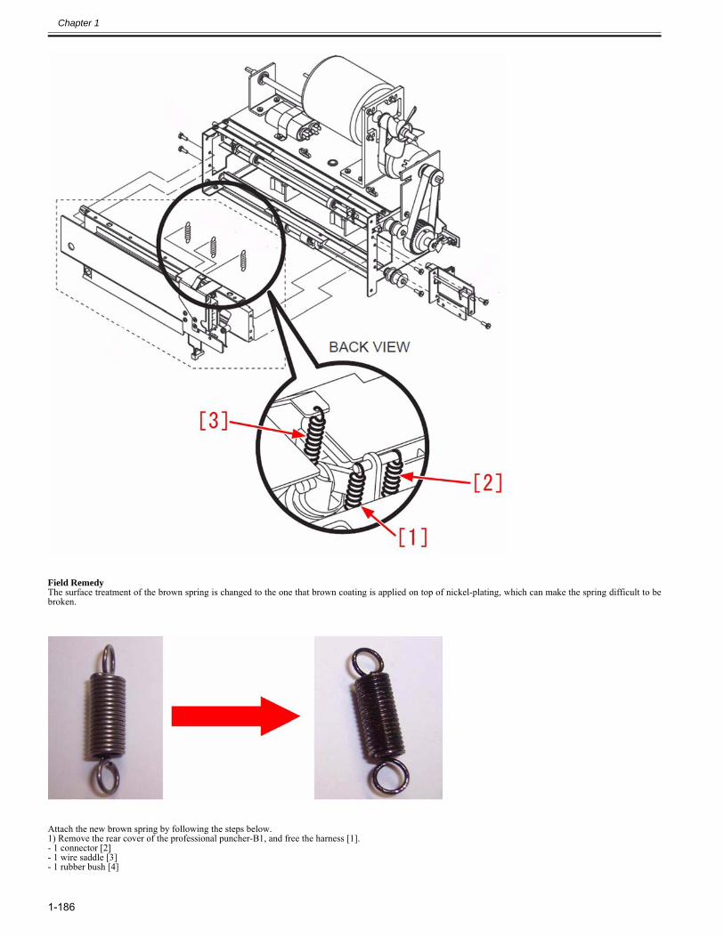
Chapter 1
1-186
Field RemedyThe surface treatment of the brown spring is changed to the one that brown coating is applied on top of nickel-plating, which can make the spring difficult to bebroken.
Attach the new brown spring by following the steps below.1) Remove the rear cover of the professional puncher-B1, and free the harness [1].- 1 connector [2]- 1 wire saddle [3]- 1 rubber bush [4]
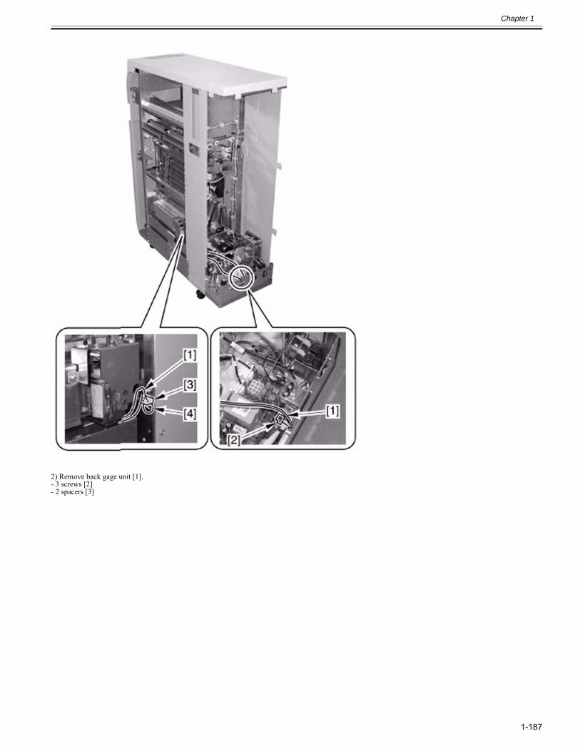
Chapter 1
1-187
2) Remove back gage unit [1].- 3 screws [2]- 2 spacers [3]
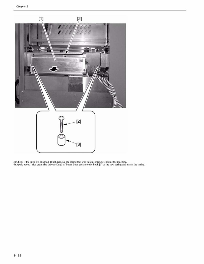
Chapter 1
1-188
3) Check if the spring is attached. If not, remove the spring that was fallen somewhere inside the machine.4) Apply about 1 rice grain size (about 40mg) of Super Lube grease to the hook [1] of the new spring and attach the spring.
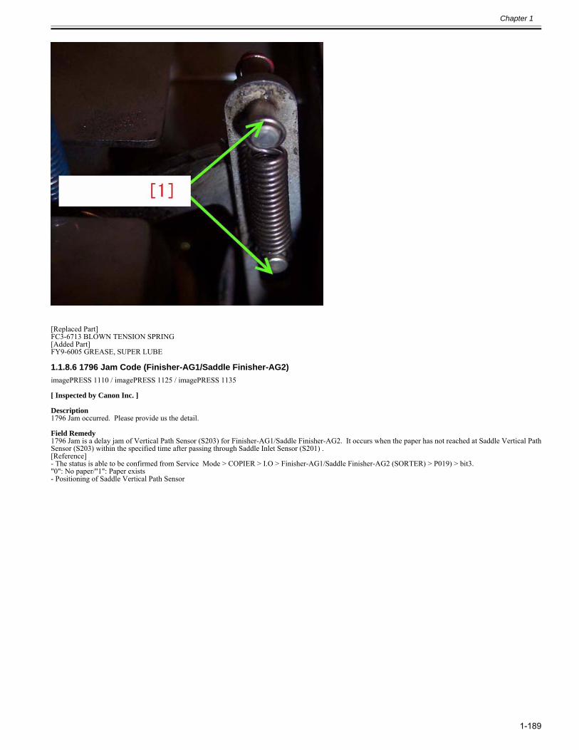
Chapter 1
1-189
[Replaced Part]FC3-6713 BLOWN TENSION SPRING[Added Part]FY9-6005 GREASE, SUPER LUBE
1.1.8.6 1796 Jam Code (Finisher-AG1/Saddle Finisher-AG2)0028-4136
imagePRESS 1110 / imagePRESS 1125 / imagePRESS 1135
[ Inspected by Canon Inc. ]
Description1796 Jam occurred. Please provide us the detail.
Field Remedy1796 Jam is a delay jam of Vertical Path Sensor (S203) for Finisher-AG1/Saddle Finisher-AG2. It occurs when the paper has not reached at Saddle Vertical PathSensor (S203) within the specified time after passing through Saddle Inlet Sensor (S201) .[Reference]- The status is able to be confirmed from Service Mode > COPIER > I.O > Finisher-AG1/Saddle Finisher-AG2 (SORTER) > P019) > bit3."0": No paper/"1": Paper exists- Positioning of Saddle Vertical Path Sensor
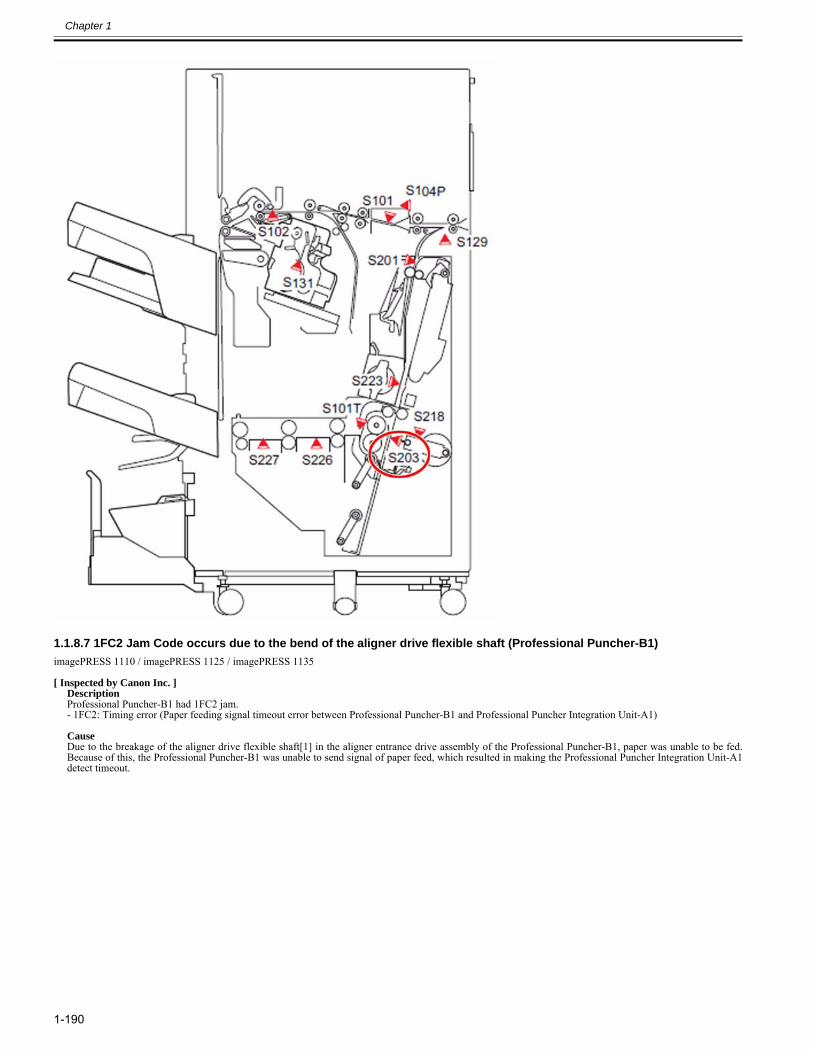
Chapter 1
1-190
1.1.8.7 1FC2 Jam Code occurs due to the bend of the aligner drive flexible shaft (Professional Puncher-B1)0027-5218
imagePRESS 1110 / imagePRESS 1125 / imagePRESS 1135
[ Inspected by Canon Inc. ]DescriptionProfessional Puncher-B1 had 1FC2 jam.- 1FC2: Timing error (Paper feeding signal timeout error between Professional Puncher-B1 and Professional Puncher Integration Unit-A1)
CauseDue to the breakage of the aligner drive flexible shaft[1] in the aligner entrance drive assembly of the Professional Puncher-B1, paper was unable to be fed.Because of this, the Professional Puncher-B1 was unable to send signal of paper feed, which resulted in making the Professional Puncher Integration Unit-A1detect timeout.
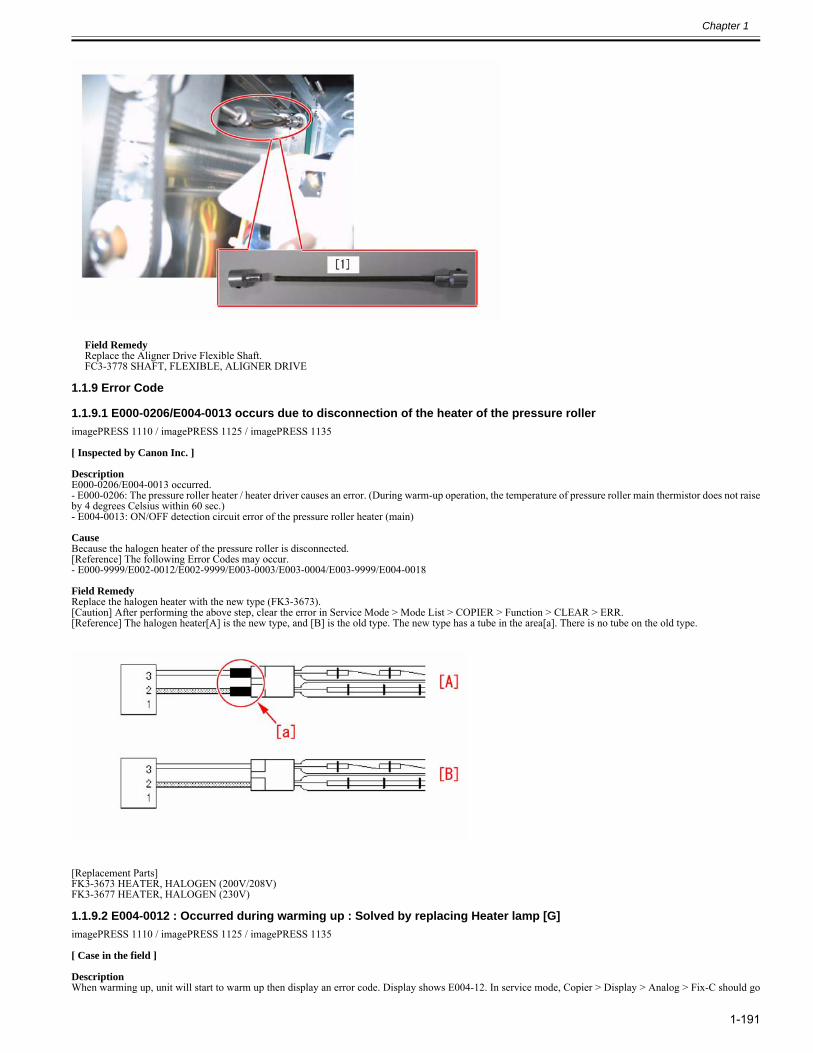
Chapter 1
1-191
Field RemedyReplace the Aligner Drive Flexible Shaft.FC3-3778 SHAFT, FLEXIBLE, ALIGNER DRIVE
1.1.9 Error Code
1.1.9.1 E000-0206/E004-0013 occurs due to disconnection of the heater of the pressure roller0028-6797
imagePRESS 1110 / imagePRESS 1125 / imagePRESS 1135
[ Inspected by Canon Inc. ]
DescriptionE000-0206/E004-0013 occurred.- E000-0206: The pressure roller heater / heater driver causes an error. (During warm-up operation, the temperature of pressure roller main thermistor does not raiseby 4 degrees Celsius within 60 sec.)- E004-0013: ON/OFF detection circuit error of the pressure roller heater (main)
CauseBecause the halogen heater of the pressure roller is disconnected.[Reference] The following Error Codes may occur.- E000-9999/E002-0012/E002-9999/E003-0003/E003-0004/E003-9999/E004-0018
Field RemedyReplace the halogen heater with the new type (FK3-3673).[Caution] After performing the above step, clear the error in Service Mode > Mode List > COPIER > Function > CLEAR > ERR.[Reference] The halogen heater[A] is the new type, and [B] is the old type. The new type has a tube in the area[a]. There is no tube on the old type.
[Replacement Parts]FK3-3673 HEATER, HALOGEN (200V/208V)FK3-3677 HEATER, HALOGEN (230V)
1.1.9.2 E004-0012 : Occurred during warming up : Solved by replacing Heater lamp [G]0028-3051
imagePRESS 1110 / imagePRESS 1125 / imagePRESS 1135
[ Case in the field ] DescriptionWhen warming up, unit will start to warm up then display an error code. Display shows E004-12. In service mode, Copier > Display > Analog > Fix-C should go
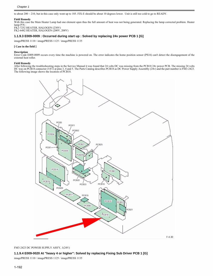
Chapter 1
1-192
to about 200 ~ 210, but in this case only went up to 185. FIX-E should be about 10 degrees lower. Unit is still too cold to go to READY. Field RemedyWith this case the Main Heater Lamp had one element open thus the full amount of heat was not being generated. Replacing the lamp corrected problem. Heaterlamp P/N :FK2-7252 HEATER, HALOGEN (230V)FK2-6482 HEATER, HALOGEN (200V, 208V)
1.1.9.3 E009-0009 : Occurred during start up : Solved by replacing 24v power PCB 1 [G]0028-3037
imagePRESS 1110 / imagePRESS 1125 / imagePRESS 1135
[ Case in the field ] DescriptionError Code E009-0009 occurs every time the machine is powered on. The error indicates the home position sensor (PS16) can't detect the disengagement of theexternal heat roller. Field RemedyAfter following the troubleshooting steps in the Service Manual it was found that 24 volts DC was missing from the PCB18 24v power PCB. The missing 24 voltsDC was on PCB18 connector J1472 at pins 3, 4 and 5. The Parts Catalog describes PCB18 as DC Power Supply Assembly (24v) and the part number is FM3-2423.The following image shows the location of PCB18.
FM3-2423 DC POWER SUPPLY ASS'Y, 1(24V)
1.1.9.4 E009-0020 At "heavy 4 or higher": Solved by replacing Fixing Sub Driver PCB 1 [G]0028-4618
imagePRESS 1110 / imagePRESS 1125 / imagePRESS 1135
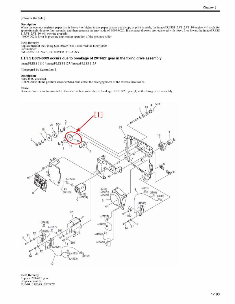
Chapter 1
1-193
[ Case in the field ] DescriptionWhen the operator registers paper that is heavy 4 or higher to any paper drawer and a copy or print is made, the imagePRESS1135/1125/1110 engine will cycle forapproximately three to four seconds; and then generate an error code of E009-0020. If the paper drawers are registered with heavy 3 or lower, the imagePRESS1135/1125/1110 will operate properly.- E009-0020: Error in pressure application operation of the pressure roller Field RemedyReplacement of the Fixing Sub Driver PCB 1 resolved the E009-0020.Part number:FM3-5235 FIXING SUB DRIVER PCB ASS'Y, 1
1.1.9.5 E009-0009 occurs due to breakage of 20T/42T gear in the fixing drive assembly0028-6671
imagePRESS 1110 / imagePRESS 1125 / imagePRESS 1135
[ Inspected by Canon Inc. ]
DescriptionE009-0009 occurred.- E009-0009: Home position sensor (PS16) can't detect the disengagement of the external heat roller.
CauseBecause drive is not transmitted to the external heat roller due to breakage of 20T/42T gear [1] in the fixing drive assembly.
Field RemedyReplace 20T/42T gear.[Replacement Part]FU6-0410 GEAR, 20T/42T
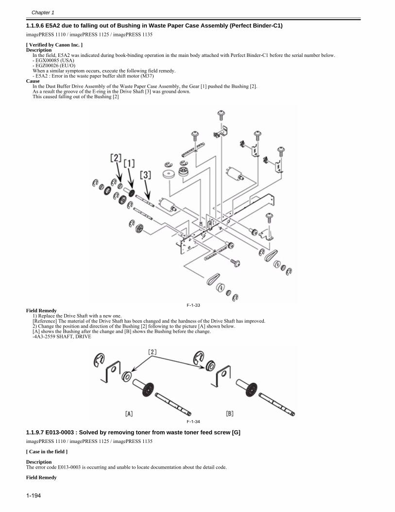
Chapter 1
1-194
1.1.9.6 E5A2 due to falling out of Bushing in Waste Paper Case Assembly (Perfect Binder-C1)0028-1420
imagePRESS 1110 / imagePRESS 1125 / imagePRESS 1135
[ Verified by Canon Inc. ]Description
In the field, E5A2 was indicated during book-binding operation in the main body attached with Perfect Binder-C1 before the serial number below.- EGX00085 (USA)- EGZ00026 (EU/O)When a similar symptom occurs, execute the following field remedy. - E5A2 : Error in the waste paper buffer shift motor (M37)
CauseIn the Dust Buffer Drive Assembly of the Waste Paper Case Assembly, the Gear [1] pushed the Bushing [2]. As a result the groove of the E-ring in the Drive Shaft [3] was ground down. This caused falling out of the Bushing [2]
F-1-33Field Remedy
1) Replace the Drive Shaft with a new one.[Reference] The material of the Drive Shaft has been changed and the hardness of the Drive Shaft has improved. 2) Change the position and direction of the Bushing [2] following to the picture [A] shown below. [A] shows the Bushing after the change and [B] shows the Bushing before the change. -4A3-2559 SHAFT, DRIVE
F-1-34
1.1.9.7 E013-0003 : Solved by removing toner from waste toner feed screw [G]0028-3035
imagePRESS 1110 / imagePRESS 1125 / imagePRESS 1135
[ Case in the field ] DescriptionThe error code E013-0003 is occurring and unable to locate documentation about the detail code. Field Remedy
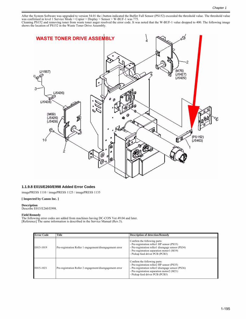
Chapter 1
1-195
After the System Software was upgraded to version 54.01 the i button indicated the Buffer Full Sensor (PS152) exceeded the threshold value. The threshold valuewas confirmed in level 1 Service Mode > Copier > Display > Sensor > W-BUF-1 was 775.Cleaning PS152 and removing toner from waste toner auger resolved the error code. It was noted that the W-BUF-1 value dropped to 400. The following imageshows the location of PS152 in the Waste Toner Drive Assembly.
1.1.9.8 E015/E260/E998 Added Error Codes0028-7019
imagePRESS 1110 / imagePRESS 1125 / imagePRESS 1135
[ Inspected by Canon Inc. ]
DescriptionDescribe E015/E260/E998.
Field RemedyThe following error codes are added from machines having DC-CON Ver.49.04 and later.[Reference] The same information is described in the Service Manual (Rev.5).
Error Code Title Description of detection/Remedy
E015-1019 Pre-registration Roller 1 engagement/disengagement error
Confirm the following parts:- Pre-registration roller1 HP sensor (PS33)- Pre-registration roller1 disengage sensor (PS34)- Pre-registration separation motor1 (M19)- Pickup feed driver PCB (PCB3)
E015-1021 Pre-registration Roller 2 engagement/disengagement error
Confirm the following parts:- Pre-registration roller2 HP sensor (PS35)- Pre-registration roller2 disengage sensor (PS36)- Pre-registration separation motor2 (M21)- Pickup feed driver PCB (PCB3)
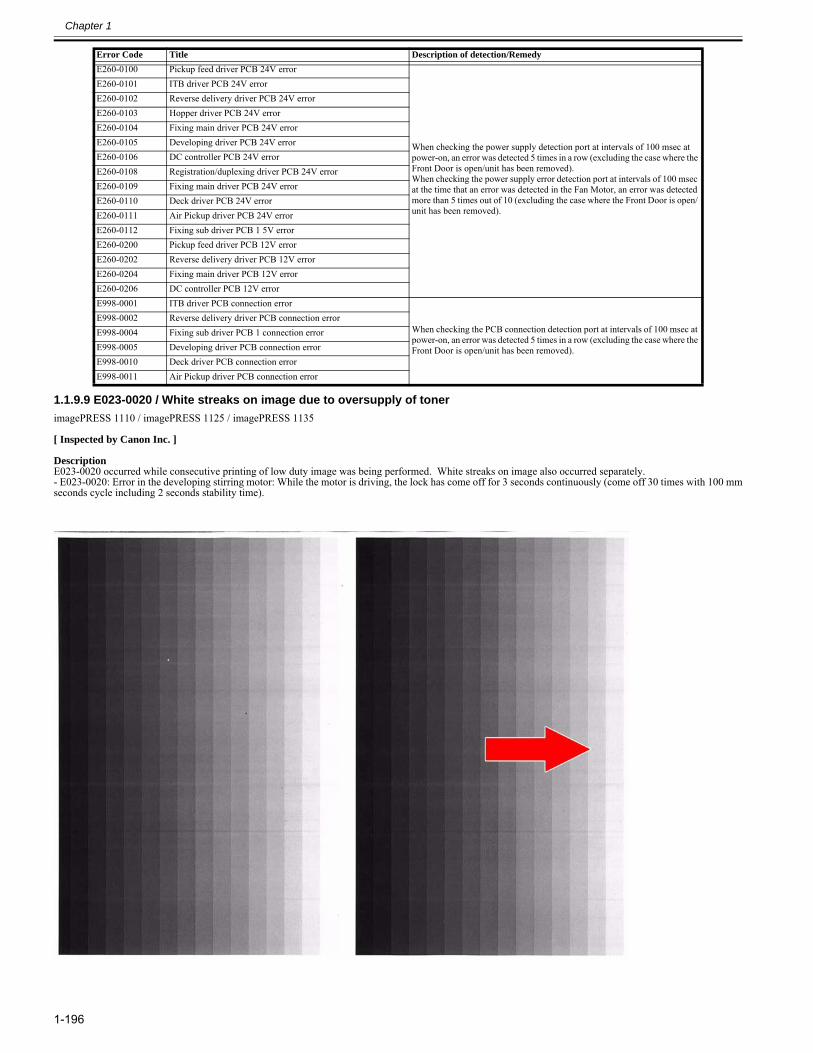
Chapter 1
1-196
1.1.9.9 E023-0020 / White streaks on image due to oversupply of toner0028-1015
imagePRESS 1110 / imagePRESS 1125 / imagePRESS 1135
[ Inspected by Canon Inc. ]
DescriptionE023-0020 occurred while consecutive printing of low duty image was being performed. White streaks on image also occurred separately.- E023-0020: Error in the developing stirring motor: While the motor is driving, the lock has come off for 3 seconds continuously (come off 30 times with 100 mmseconds cycle including 2 seconds stability time).
E260-0100 Pickup feed driver PCB 24V error
When checking the power supply detection port at intervals of 100 msec at power-on, an error was detected 5 times in a row (excluding the case where the Front Door is open/unit has been removed).When checking the power supply error detection port at intervals of 100 msec at the time that an error was detected in the Fan Motor, an error was detected more than 5 times out of 10 (excluding the case where the Front Door is open/ unit has been removed).
E260-0101 ITB driver PCB 24V errorE260-0102 Reverse delivery driver PCB 24V errorE260-0103 Hopper driver PCB 24V errorE260-0104 Fixing main driver PCB 24V errorE260-0105 Developing driver PCB 24V errorE260-0106 DC controller PCB 24V errorE260-0108 Registration/duplexing driver PCB 24V errorE260-0109 Fixing main driver PCB 24V errorE260-0110 Deck driver PCB 24V errorE260-0111 Air Pickup driver PCB 24V errorE260-0112 Fixing sub driver PCB 1 5V errorE260-0200 Pickup feed driver PCB 12V errorE260-0202 Reverse delivery driver PCB 12V errorE260-0204 Fixing main driver PCB 12V errorE260-0206 DC controller PCB 12V errorE998-0001 ITB driver PCB connection error
When checking the PCB connection detection port at intervals of 100 msec at power-on, an error was detected 5 times in a row (excluding the case where the Front Door is open/unit has been removed).
E998-0002 Reverse delivery driver PCB connection errorE998-0004 Fixing sub driver PCB 1 connection errorE998-0005 Developing driver PCB connection errorE998-0010 Deck driver PCB connection errorE998-0011 Air Pickup driver PCB connection error
Error Code Title Description of detection/Remedy
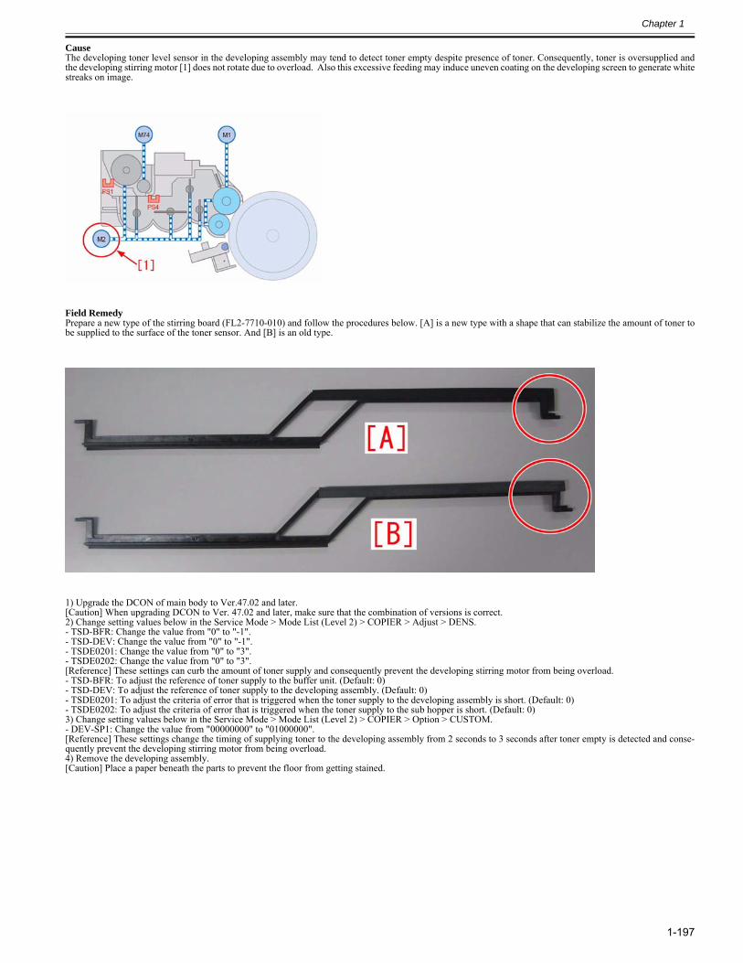
Chapter 1
1-197
Cause The developing toner level sensor in the developing assembly may tend to detect toner empty despite presence of toner. Consequently, toner is oversupplied andthe developing stirring motor [1] does not rotate due to overload. Also this excessive feeding may induce uneven coating on the developing screen to generate whitestreaks on image.
Field RemedyPrepare a new type of the stirring board (FL2-7710-010) and follow the procedures below. [A] is a new type with a shape that can stabilize the amount of toner tobe supplied to the surface of the toner sensor. And [B] is an old type.
1) Upgrade the DCON of main body to Ver.47.02 and later.[Caution] When upgrading DCON to Ver. 47.02 and later, make sure that the combination of versions is correct.2) Change setting values below in the Service Mode > Mode List (Level 2) > COPIER > Adjust > DENS.- TSD-BFR: Change the value from "0" to "-1".- TSD-DEV: Change the value from "0" to "-1".- TSDE0201: Change the value from "0" to "3".- TSDE0202: Change the value from "0" to "3".[Reference] These settings can curb the amount of toner supply and consequently prevent the developing stirring motor from being overload.- TSD-BFR: To adjust the reference of toner supply to the buffer unit. (Default: 0)- TSD-DEV: To adjust the reference of toner supply to the developing assembly. (Default: 0)- TSDE0201: To adjust the criteria of error that is triggered when the toner supply to the developing assembly is short. (Default: 0)- TSDE0202: To adjust the criteria of error that is triggered when the toner supply to the sub hopper is short. (Default: 0)3) Change setting values below in the Service Mode > Mode List (Level 2) > COPIER > Option > CUSTOM.- DEV-SP1: Change the value from "00000000" to "01000000".[Reference] These settings change the timing of supplying toner to the developing assembly from 2 seconds to 3 seconds after toner empty is detected and conse-quently prevent the developing stirring motor from being overload.4) Remove the developing assembly.[Caution] Place a paper beneath the parts to prevent the floor from getting stained.
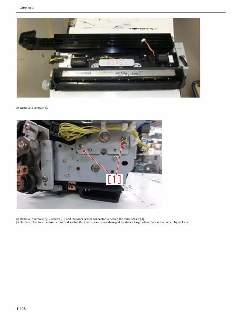
Chapter 1
1-198
5) Remove 2 screws [1].
6) Remove 2 screws [2], 2 screws [3], and the toner sensor connector to detach the toner sensor [4].[Reference] The toner sensor is removed so that the toner sensor is not damaged by static charge when toner is vacuumed by a cleaner.
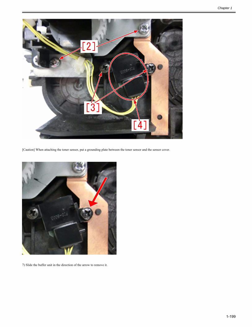
Chapter 1
1-199
[Caution] When attaching the toner sensor, put a grounding plate between the toner sensor and the sensor cover.
7) Slide the buffer unit in the direction of the arrow to remove it.
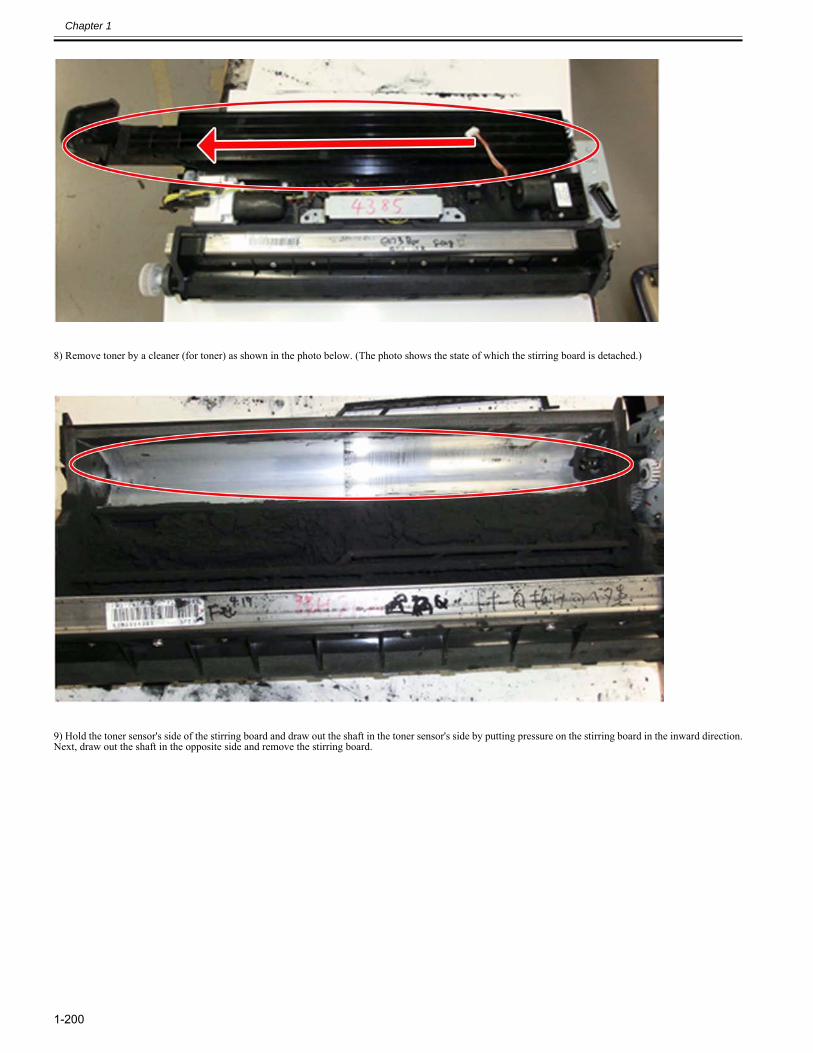
Chapter 1
1-200
8) Remove toner by a cleaner (for toner) as shown in the photo below. (The photo shows the state of which the stirring board is detached.)
9) Hold the toner sensor's side of the stirring board and draw out the shaft in the toner sensor's side by putting pressure on the stirring board in the inward direction.Next, draw out the shaft in the opposite side and remove the stirring board.
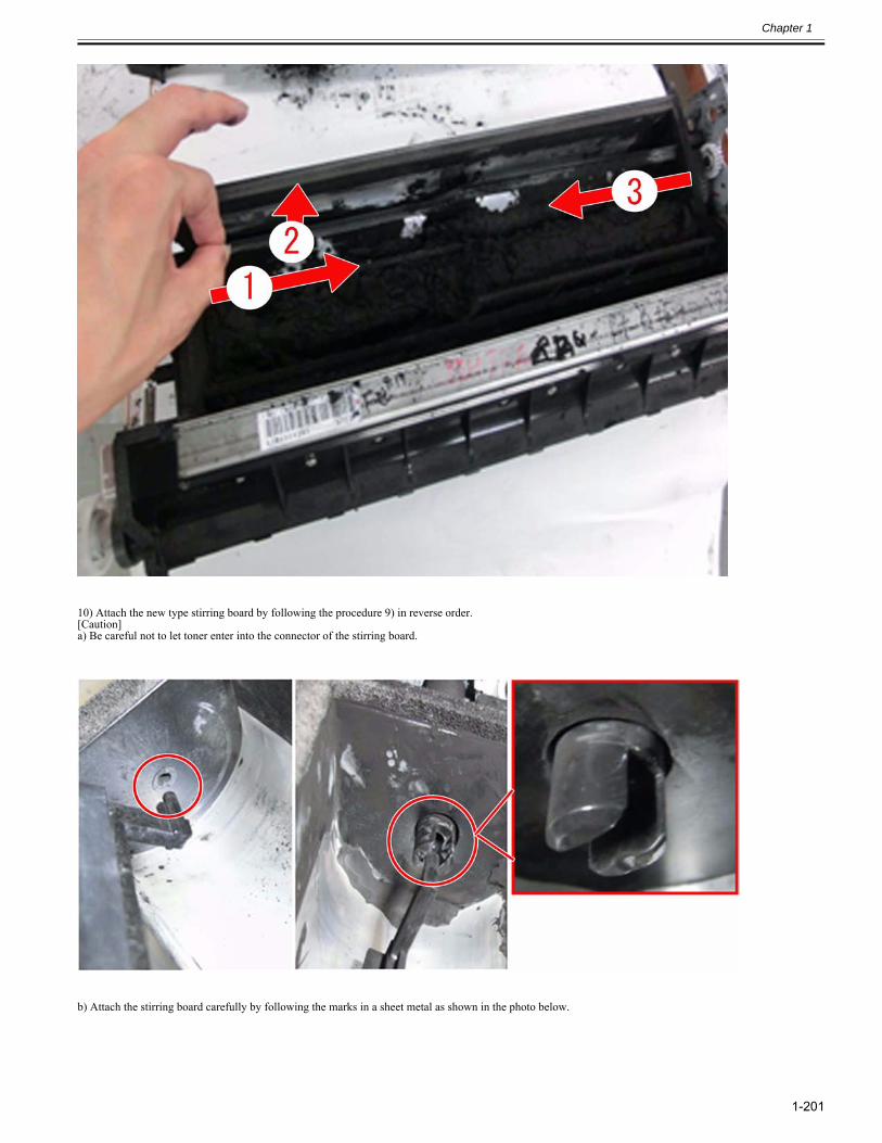
Chapter 1
1-201
10) Attach the new type stirring board by following the procedure 9) in reverse order.[Caution]a) Be careful not to let toner enter into the connector of the stirring board.
b) Attach the stirring board carefully by following the marks in a sheet metal as shown in the photo below.
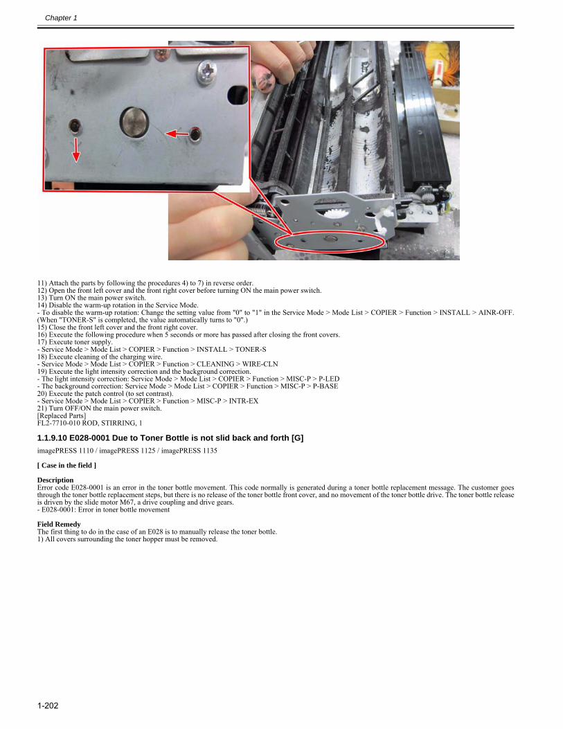
Chapter 1
1-202
11) Attach the parts by following the procedures 4) to 7) in reverse order.12) Open the front left cover and the front right cover before turning ON the main power switch.13) Turn ON the main power switch.14) Disable the warm-up rotation in the Service Mode.- To disable the warm-up rotation: Change the setting value from "0" to "1" in the Service Mode > Mode List > COPIER > Function > INSTALL > AINR-OFF.(When "TONER-S" is completed, the value automatically turns to "0".)15) Close the front left cover and the front right cover.16) Execute the following procedure when 5 seconds or more has passed after closing the front covers.17) Execute toner supply.- Service Mode > Mode List > COPIER > Function > INSTALL > TONER-S18) Execute cleaning of the charging wire.- Service Mode > Mode List > COPIER > Function > CLEANING > WIRE-CLN19) Execute the light intensity correction and the background correction.- The light intensity correction: Service Mode > Mode List > COPIER > Function > MISC-P > P-LED- The background correction: Service Mode > Mode List > COPIER > Function > MISC-P > P-BASE20) Execute the patch control (to set contrast).- Service Mode > Mode List > COPIER > Function > MISC-P > INTR-EX21) Turn OFF/ON the main power switch.[Replaced Parts]FL2-7710-010 ROD, STIRRING, 1
1.1.9.10 E028-0001 Due to Toner Bottle is not slid back and forth [G]0028-6716
imagePRESS 1110 / imagePRESS 1125 / imagePRESS 1135
[ Case in the field ] DescriptionError code E028-0001 is an error in the toner bottle movement. This code normally is generated during a toner bottle replacement message. The customer goesthrough the toner bottle replacement steps, but there is no release of the toner bottle front cover, and no movement of the toner bottle drive. The toner bottle releaseis driven by the slide motor M67, a drive coupling and drive gears.- E028-0001: Error in toner bottle movement Field RemedyThe first thing to do in the case of an E028 is to manually release the toner bottle. 1) All covers surrounding the toner hopper must be removed.
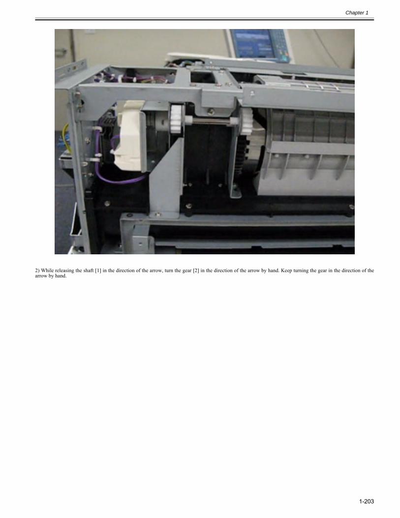
Chapter 1
1-203
2) While releasing the shaft [1] in the direction of the arrow, turn the gear [2] in the direction of the arrow by hand. Keep turning the gear in the direction of thearrow by hand.
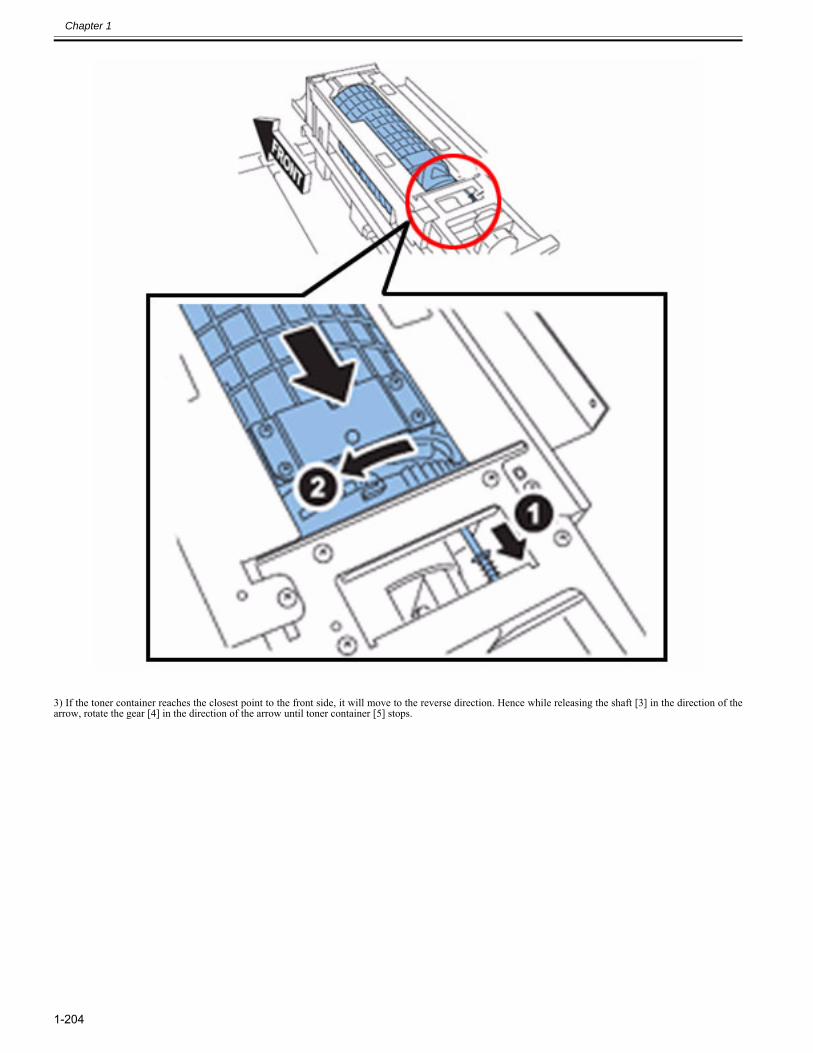
Chapter 1
1-204
3) If the toner container reaches the closest point to the front side, it will move to the reverse direction. Hence while releasing the shaft [3] in the direction of thearrow, rotate the gear [4] in the direction of the arrow until toner container [5] stops.
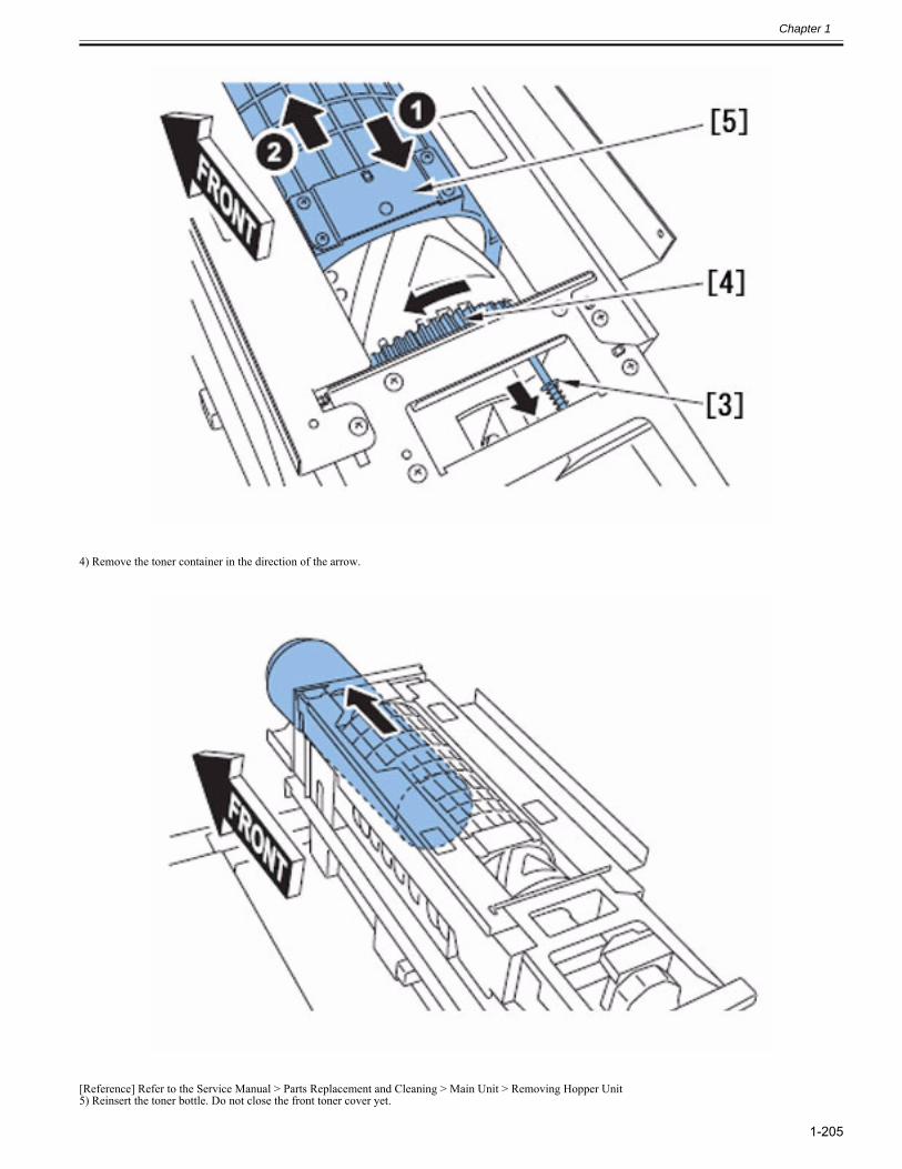
Chapter 1
1-205
4) Remove the toner container in the direction of the arrow.
[Reference] Refer to the Service Manual > Parts Replacement and Cleaning > Main Unit > Removing Hopper Unit5) Reinsert the toner bottle. Do not close the front toner cover yet.
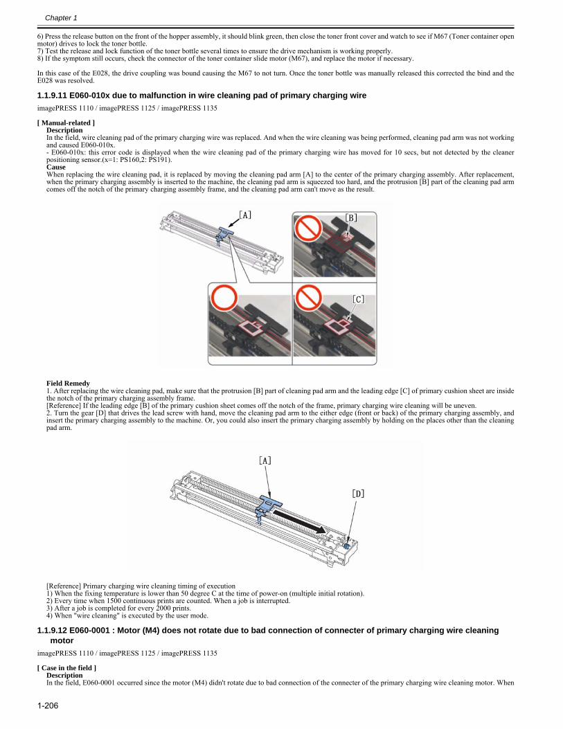
Chapter 1
1-206
6) Press the release button on the front of the hopper assembly, it should blink green, then close the toner front cover and watch to see if M67 (Toner container openmotor) drives to lock the toner bottle.7) Test the release and lock function of the toner bottle several times to ensure the drive mechanism is working properly.8) If the symptom still occurs, check the connector of the toner container slide motor (M67), and replace the motor if necessary.
In this case of the E028, the drive coupling was bound causing the M67 to not turn. Once the toner bottle was manually released this corrected the bind and theE028 was resolved.
1.1.9.11 E060-010x due to malfunction in wire cleaning pad of primary charging wire0023-2477
imagePRESS 1110 / imagePRESS 1125 / imagePRESS 1135
[ Manual-related ]DescriptionIn the field, wire cleaning pad of the primary charging wire was replaced. And when the wire cleaning was being performed, cleaning pad arm was not workingand caused E060-010x. - E060-010x: this error code is displayed when the wire cleaning pad of the primary charging wire has moved for 10 secs, but not detected by the cleanerpositioning sensor.(x=1: PS160,2: PS191).CauseWhen replacing the wire cleaning pad, it is replaced by moving the cleaning pad arm [A] to the center of the primary charging assembly. After replacement,when the primary charging assembly is inserted to the machine, the cleaning pad arm is squeezed too hard, and the protrusion [B] part of the cleaning pad armcomes off the notch of the primary charging assembly frame, and the cleaning pad arm can't move as the result.
Field Remedy1. After replacing the wire cleaning pad, make sure that the protrusion [B] part of cleaning pad arm and the leading edge [C] of primary cushion sheet are insidethe notch of the primary charging assembly frame.[Reference] If the leading edge [B] of the primary cushion sheet comes off the notch of the frame, primary charging wire cleaning will be uneven.2. Turn the gear [D] that drives the lead screw with hand, move the cleaning pad arm to the either edge (front or back) of the primary charging assembly, andinsert the primary charging assembly to the machine. Or, you could also insert the primary charging assembly by holding on the places other than the cleaningpad arm.
[Reference] Primary charging wire cleaning timing of execution1) When the fixing temperature is lower than 50 degree C at the time of power-on (multiple initial rotation).2) Every time when 1500 continuous prints are counted. When a job is interrupted.3) After a job is completed for every 2000 prints.4) When "wire cleaning" is executed by the user mode.
1.1.9.12 E060-0001 : Motor (M4) does not rotate due to bad connection of connecter of primary charging wire cleaning motor
0024-7082
imagePRESS 1110 / imagePRESS 1125 / imagePRESS 1135
[ Case in the field ]DescriptionIn the field, E060-0001 occurred since the motor (M4) didn't rotate due to bad connection of the connecter of the primary charging wire cleaning motor. When
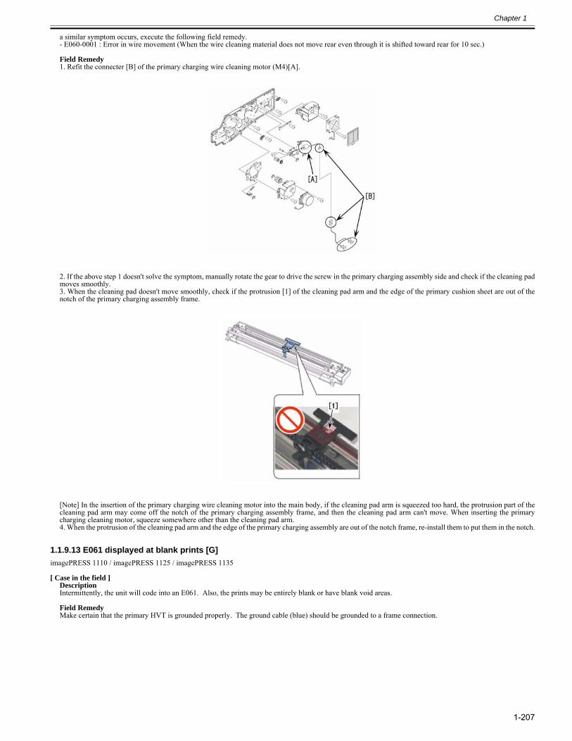
Chapter 1
1-207
a similar symptom occurs, execute the following field remedy.- E060-0001 : Error in wire movement (When the wire cleaning material does not move rear even through it is shifted toward rear for 10 sec.) Field Remedy1. Refit the connecter [B] of the primary charging wire cleaning motor (M4)[A].
2. If the above step 1 doesn't solve the symptom, manually rotate the gear to drive the screw in the primary charging assembly side and check if the cleaning padmoves smoothly.3. When the cleaning pad doesn't move smoothly, check if the protrusion [1] of the cleaning pad arm and the edge of the primary cushion sheet are out of thenotch of the primary charging assembly frame.
[Note] In the insertion of the primary charging wire cleaning motor into the main body, if the cleaning pad arm is squeezed too hard, the protrusion part of thecleaning pad arm may come off the notch of the primary charging assembly frame, and then the cleaning pad arm can't move. When inserting the primarycharging cleaning motor, squeeze somewhere other than the cleaning pad arm.4. When the protrusion of the cleaning pad arm and the edge of the primary charging assembly are out of the notch frame, re-install them to put them in the notch.
1.1.9.13 E061 displayed at blank prints [G]0025-3952
imagePRESS 1110 / imagePRESS 1125 / imagePRESS 1135
[ Case in the field ]DescriptionIntermittently, the unit will code into an E061. Also, the prints may be entirely blank or have blank void areas. Field RemedyMake certain that the primary HVT is grounded properly. The ground cable (blue) should be grounded to a frame connection.
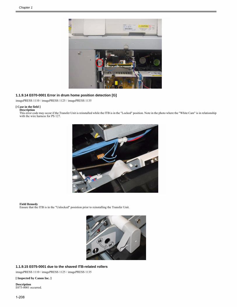
Chapter 1
1-208
1.1.9.14 E070-0001 Error in drum home position detection [G]0025-5176
imagePRESS 1110 / imagePRESS 1125 / imagePRESS 1135
[ Case in the field ]DescriptionThis error code may occur if the Transfer Unit is reinstalled while the ITB is in the "Locked" position. Note in the photo where the "White Cam" is in relationshipwith the wire harness for PS 127.
Field RemedyEnsure that the ITB is in the "Unlocked" posistion prior to reinstalling the Transfer Unit.
1.1.9.15 E075-0001 due to the shaved ITB-related rollers0028-4786
imagePRESS 1110 / imagePRESS 1125 / imagePRESS 1135
[ Inspected by Canon Inc. ]
DescriptionE075-0001 occurred.
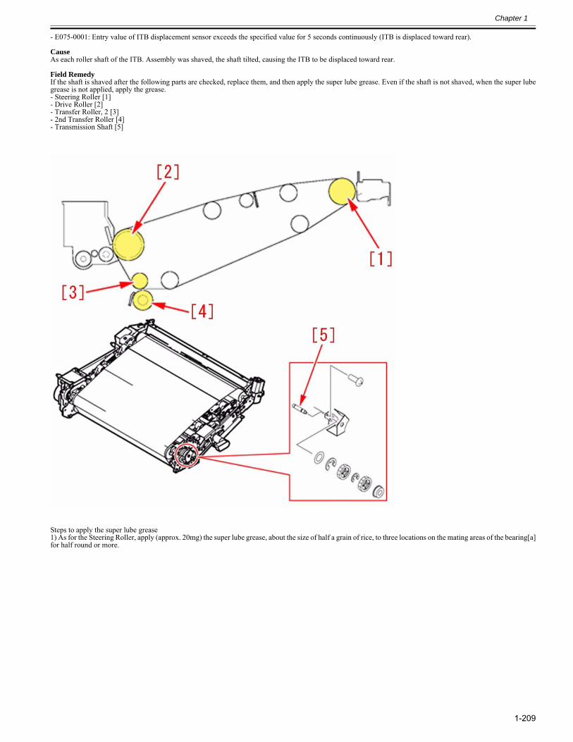
Chapter 1
1-209
- E075-0001: Entry value of ITB displacement sensor exceeds the specified value for 5 seconds continuously (ITB is displaced toward rear).
CauseAs each roller shaft of the ITB. Assembly was shaved, the shaft tilted, causing the ITB to be displaced toward rear.
Field RemedyIf the shaft is shaved after the following parts are checked, replace them, and then apply the super lube grease. Even if the shaft is not shaved, when the super lubegrease is not applied, apply the grease.- Steering Roller [1]- Drive Roller [2]- Transfer Roller, 2 [3]- 2nd Transfer Roller [4]- Transmission Shaft [5]
Steps to apply the super lube grease1) As for the Steering Roller, apply (approx. 20mg) the super lube grease, about the size of half a grain of rice, to three locations on the mating areas of the bearing[a]for half round or more.
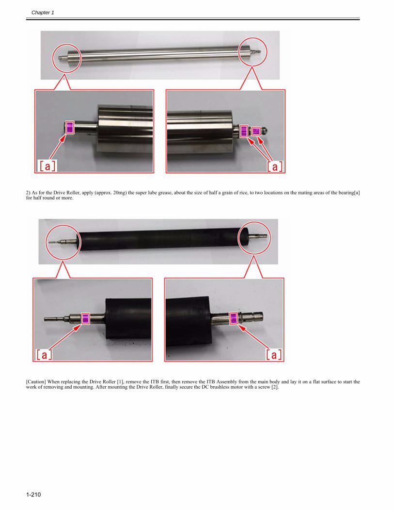
Chapter 1
1-210
2) As for the Drive Roller, apply (approx. 20mg) the super lube grease, about the size of half a grain of rice, to two locations on the mating areas of the bearing[a]for half round or more.
[Caution] When replacing the Drive Roller [1], remove the ITB first, then remove the ITB Assembly from the main body and lay it on a flat surface to start thework of removing and mounting. After mounting the Drive Roller, finally secure the DC brushless motor with a screw [2].
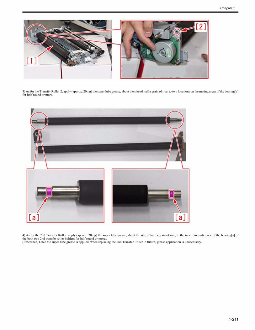
Chapter 1
1-211
3) As for the Transfer Roller 2, apply (approx. 20mg) the super lube grease, about the size of half a grain of rice, to two locations on the mating areas of the bearing[a]for half round or more.
4) As for the 2nd Transfer Roller, apply (approx. 20mg) the super lube grease, about the size of half a grain of rice, to the inner circumference of the bearing[a] ofthe both two 2nd transfer roller holders for half round or more..[Reference] Once the super lube grease is applied, when replacing the 2nd Transfer Roller in future, grease application is unnecessary.
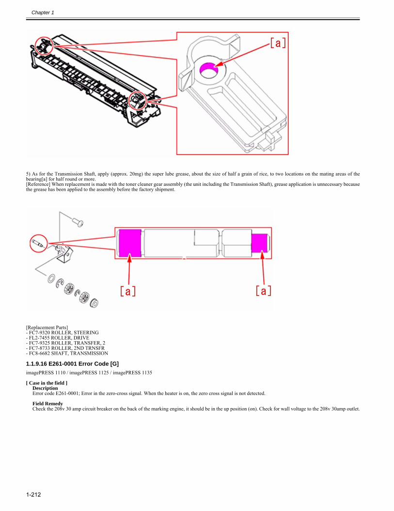
Chapter 1
1-212
5) As for the Transmission Shaft, apply (approx. 20mg) the super lube grease, about the size of half a grain of rice, to two locations on the mating areas of thebearing[a] for half round or more.[Reference] When replacement is made with the toner cleaner gear assembly (the unit including the Transmission Shaft), grease application is unnecessary becausethe grease has been applied to the assembly before the factory shipment.
[Replacement Parts]- FC7-9320 ROLLER, STEERING - FL2-7455 ROLLER, DRIVE- FC7-9325 ROLLER, TRANSFER, 2- FC7-8733 ROLLER, 2ND TRNSFR- FC8-6682 SHAFT, TRANSMISSION
1.1.9.16 E261-0001 Error Code [G]0025-5196
imagePRESS 1110 / imagePRESS 1125 / imagePRESS 1135
[ Case in the field ]DescriptionError code E261-0001; Error in the zero-cross signal. When the heater is on, the zero cross signal is not detected. Field RemedyCheck the 208v 30 amp circuit breaker on the back of the marking engine, it should be in the up position (on). Check for wall voltage to the 208v 30amp outlet.
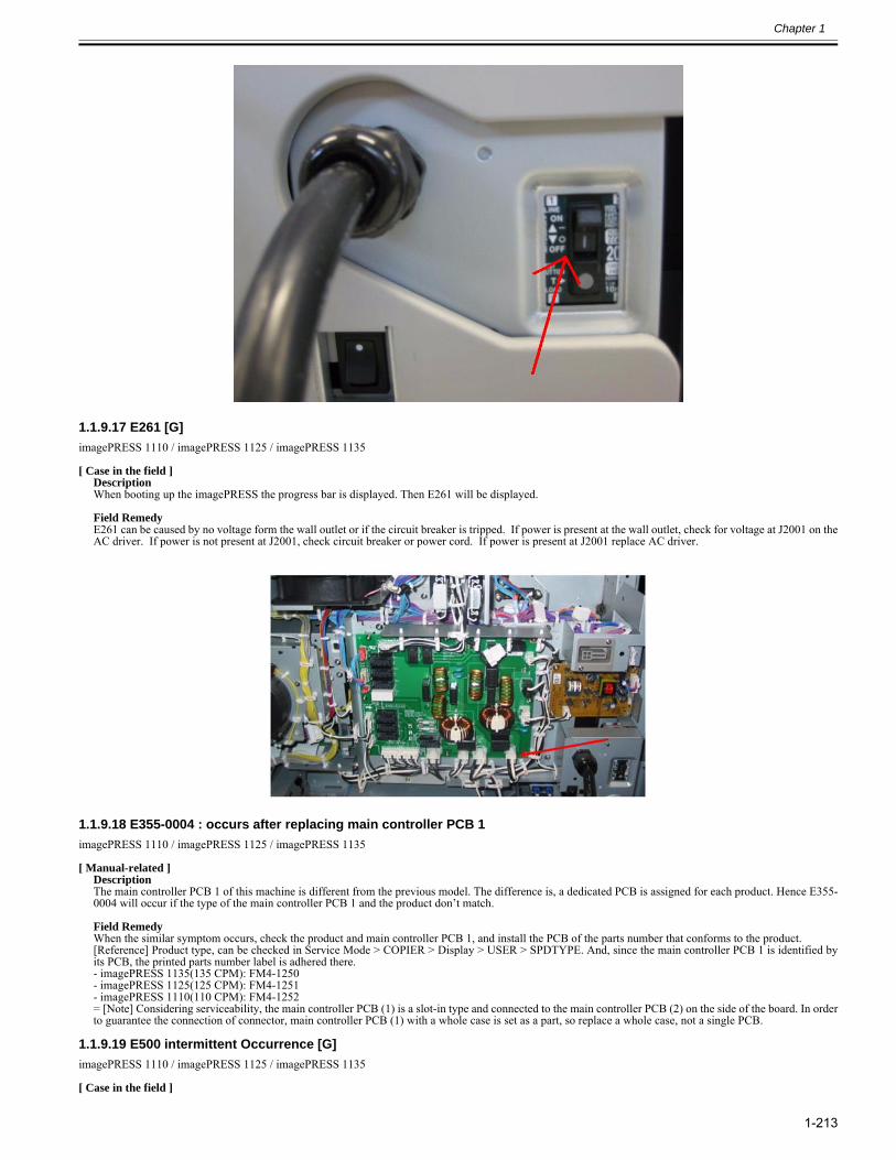
Chapter 1
1-213
1.1.9.17 E261 [G]0025-5201
imagePRESS 1110 / imagePRESS 1125 / imagePRESS 1135
[ Case in the field ]DescriptionWhen booting up the imagePRESS the progress bar is displayed. Then E261 will be displayed. Field RemedyE261 can be caused by no voltage form the wall outlet or if the circuit breaker is tripped. If power is present at the wall outlet, check for voltage at J2001 on theAC driver. If power is not present at J2001, check circuit breaker or power cord. If power is present at J2001 replace AC driver.
1.1.9.18 E355-0004 : occurs after replacing main controller PCB 10023-1920
imagePRESS 1110 / imagePRESS 1125 / imagePRESS 1135
[ Manual-related ]DescriptionThe main controller PCB 1 of this machine is different from the previous model. The difference is, a dedicated PCB is assigned for each product. Hence E355-0004 will occur if the type of the main controller PCB 1 and the product don’t match.
Field RemedyWhen the similar symptom occurs, check the product and main controller PCB 1, and install the PCB of the parts number that conforms to the product.[Reference] Product type, can be checked in Service Mode > COPIER > Display > USER > SPDTYPE. And, since the main controller PCB 1 is identified byits PCB, the printed parts number label is adhered there.- imagePRESS 1135(135 CPM): FM4-1250- imagePRESS 1125(125 CPM): FM4-1251- imagePRESS 1110(110 CPM): FM4-1252= [Note] Considering serviceability, the main controller PCB (1) is a slot-in type and connected to the main controller PCB (2) on the side of the board. In orderto guarantee the connection of connector, main controller PCB (1) with a whole case is set as a part, so replace a whole case, not a single PCB.
1.1.9.19 E500 intermittent Occurrence [G]0025-3947
imagePRESS 1110 / imagePRESS 1125 / imagePRESS 1135
[ Case in the field ]
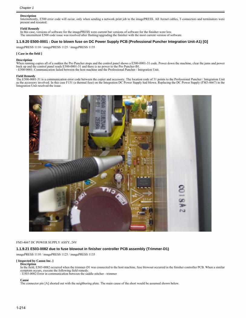
Chapter 1
1-214
DescriptionIntermittently, E500 error code will occur, only when sending a network print job to the imagePRESS. All Arcnet cables, T-connectors and terminators werepresent and reseated. Field RemedyIn this case, versions of software for the imagePRESS were current but versions of software for the finisher were low.The intermittent E500 code issue was resolved after flashing/upgrading the finisher with the most current version of software.
1.1.9.20 E500-0001 : Due to blown fuse on DC Power Supply PCB (Professional Puncher Integration Unit-A1) [G]0028-9847
imagePRESS 1110 / imagePRESS 1125 / imagePRESS 1135
[ Case in the field ] DescriptionWhen running copies all of a sudden the Pro Puncher stops and the control panel shows a E500-0001-31 code. Power down the machine, clear the jams and powerback up and the control panel reads E500-0001-31 and there is no power to the Pro Puncher-B1.- E500-0001: Communication failed between the host machine and the Professional Puncher / Integration Unit. Field RemedyThe E500-0001-31 is a communication error code between the copier and accessory. The location code of 31 points to the Professional Puncher / Integration Unitas the accessory involved. In this case F151 (a thermal fuse) on the Integration DC Power Supply had blown. Replacing the DC Power Supply (FM3-4667) in theIntegration Unit resolved the issue.
FM3-4667 DC POWER SUPPLY ASS'Y, 24V
1.1.9.21 E503-0082 due to fuse blowout in finisher controller PCB assembly (Trimmer-D1)0024-8234
imagePRESS 1110 / imagePRESS 1125 / imagePRESS 1135
[ Inspected by Canon Inc. ]DescriptionIn the field, E503-0082 occurred when the trimmer-D1 was connected to the host machine, fuse blowout occurred in the finisher controller PCB. When a similarsymptom occurs, execute the following field remedy.- E503-0082:Error in communication between the saddle stitcher - trimmer CauseThe connector pin [A] shorted out with the neighboring plate. The main cause of the short would be assumed shown below.
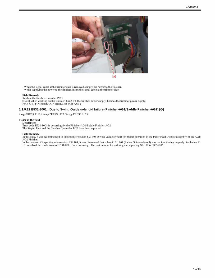
Chapter 1
1-215
- When the signal cable at the trimmer side is removed, supply the power to the finisher.- While supplying the power to the finisher, insert the signal cable at the trimmer side. Field RemedyReplace the finisher controller PCB.[Note] When working on the trimmer, turn OFF the finisher power supply, besides the trimmer power supply.FM3-8397 FINISHER CONTROLLER PCB ASS'Y
1.1.9.22 E531-8001 : Due to Swing Guide solenoid failure (Finisher-AG1/Saddle Finisher-AG2) [G]0028-0799
imagePRESS 1110 / imagePRESS 1125 / imagePRESS 1135
[ Case in the field ]DescriptionError code E531-8001 is occurring for the Finisher-AG1/Saddle Finisher-AG2.The Stapler Unit and the Finisher Controller PCB have been replaced. Field RemedyIn this case, it was recommended to inspect microswitch SW 103 (Swing Guide switch) for proper operation in the Paper Feed Dispose assembly of the AG1/AG2 Finisher.In the process of inspecting microswitch SW 103, it was discovered that solenoid SL 101 (Swing Guide solenoid) was not functioning properly. Replacing SL101 resolved the ecode issue of E531-8001 from occurring. The part number for ordering and replacing SL 101 is FK2-8206.
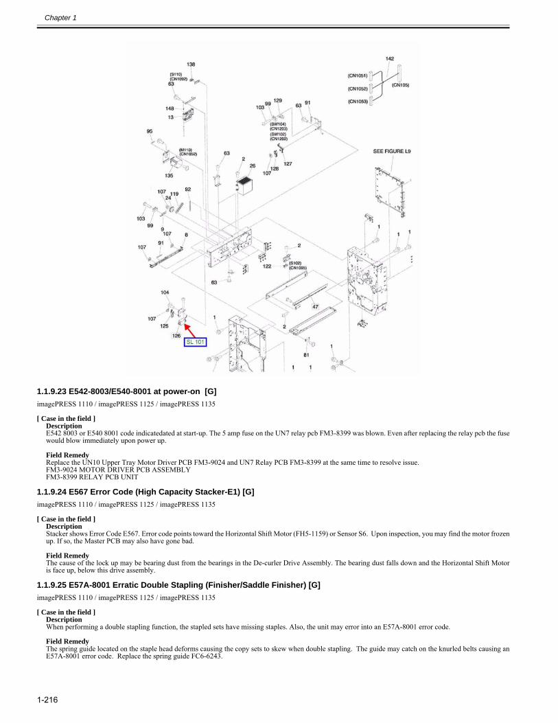
Chapter 1
1-216
1.1.9.23 E542-8003/E540-8001 at power-on [G]0025-3938
imagePRESS 1110 / imagePRESS 1125 / imagePRESS 1135
[ Case in the field ]DescriptionE542 8003 or E540 8001 code indicatedated at start-up. The 5 amp fuse on the UN7 relay pcb FM3-8399 was blown. Even after replacing the relay pcb the fusewould blow immediately upon power up. Field RemedyReplace the UN10 Upper Tray Motor Driver PCB FM3-9024 and UN7 Relay PCB FM3-8399 at the same time to resolve issue.FM3-9024 MOTOR DRIVER PCB ASSEMBLYFM3-8399 RELAY PCB UNIT
1.1.9.24 E567 Error Code (High Capacity Stacker-E1) [G]0025-5204
imagePRESS 1110 / imagePRESS 1125 / imagePRESS 1135
[ Case in the field ]DescriptionStacker shows Error Code E567. Error code points toward the Horizontal Shift Motor (FH5-1159) or Sensor S6. Upon inspection, you may find the motor frozenup. If so, the Master PCB may also have gone bad. Field RemedyThe cause of the lock up may be bearing dust from the bearings in the De-curler Drive Assembly. The bearing dust falls down and the Horizontal Shift Motoris face up, below this drive assembly.
1.1.9.25 E57A-8001 Erratic Double Stapling (Finisher/Saddle Finisher) [G]0025-5183
imagePRESS 1110 / imagePRESS 1125 / imagePRESS 1135
[ Case in the field ]DescriptionWhen performing a double stapling function, the stapled sets have missing staples. Also, the unit may error into an E57A-8001 error code. Field RemedyThe spring guide located on the staple head deforms causing the copy sets to skew when double stapling. The guide may catch on the knurled belts causing anE57A-8001 error code. Replace the spring guide FC6-6243.
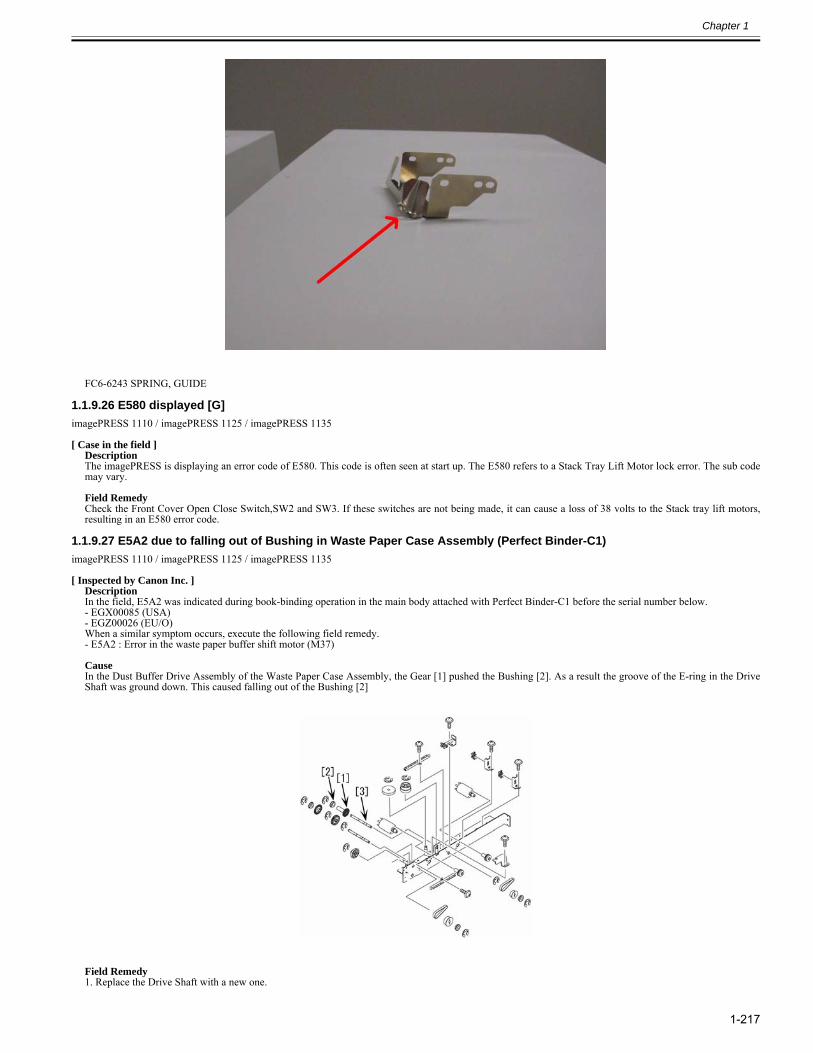
Chapter 1
1-217
FC6-6243 SPRING, GUIDE
1.1.9.26 E580 displayed [G]0025-3950
imagePRESS 1110 / imagePRESS 1125 / imagePRESS 1135
[ Case in the field ]DescriptionThe imagePRESS is displaying an error code of E580. This code is often seen at start up. The E580 refers to a Stack Tray Lift Motor lock error. The sub codemay vary. Field RemedyCheck the Front Cover Open Close Switch,SW2 and SW3. If these switches are not being made, it can cause a loss of 38 volts to the Stack tray lift motors,resulting in an E580 error code.
1.1.9.27 E5A2 due to falling out of Bushing in Waste Paper Case Assembly (Perfect Binder-C1)0024-6357
imagePRESS 1110 / imagePRESS 1125 / imagePRESS 1135
[ Inspected by Canon Inc. ]Description In the field, E5A2 was indicated during book-binding operation in the main body attached with Perfect Binder-C1 before the serial number below.- EGX00085 (USA)- EGZ00026 (EU/O)When a similar symptom occurs, execute the following field remedy.- E5A2 : Error in the waste paper buffer shift motor (M37) CauseIn the Dust Buffer Drive Assembly of the Waste Paper Case Assembly, the Gear [1] pushed the Bushing [2]. As a result the groove of the E-ring in the DriveShaft was ground down. This caused falling out of the Bushing [2]
Field Remedy1. Replace the Drive Shaft with a new one.
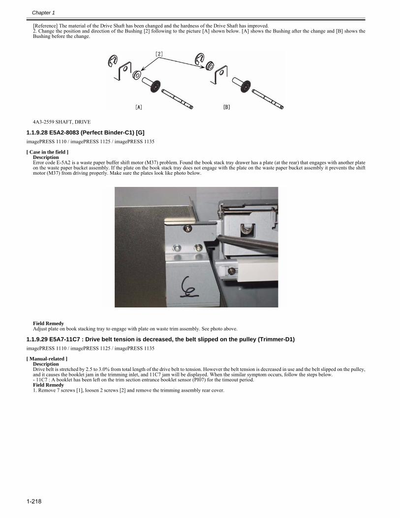
Chapter 1
1-218
[Reference] The material of the Drive Shaft has been changed and the hardness of the Drive Shaft has improved.2. Change the position and direction of the Bushing [2] following to the picture [A] shown below. [A] shows the Bushing after the change and [B] shows theBushing before the change.
4A3-2559 SHAFT, DRIVE
1.1.9.28 E5A2-8083 (Perfect Binder-C1) [G]0025-3942
imagePRESS 1110 / imagePRESS 1125 / imagePRESS 1135
[ Case in the field ]DescriptionError code E-5A2 is a waste paper buffer shift motor (M37) problem. Found the book stack tray drawer has a plate (at the rear) that engages with another plateon the waste paper bucket assembly. If the plate on the book stack tray does not engage with the plate on the waste paper bucket assembly it prevents the shiftmotor (M37) from driving properly. Make sure the plates look like photo below.
Field RemedyAdjust plate on book stacking tray to engage with plate on waste trim assembly. See photo above.
1.1.9.29 E5A7-11C7 : Drive belt tension is decreased, the belt slipped on the pulley (Trimmer-D1)0023-3344
imagePRESS 1110 / imagePRESS 1125 / imagePRESS 1135
[ Manual-related ]DescriptionDrive belt is stretched by 2.5 to 3.0% from total length of the drive belt to tension. However the belt tension is decreased in use and the belt slipped on the pulley,and it causes the booklet jam in the trimming inlet, and 11C7 jam will be displayed. When the similar symptom occurs, follow the steps below.- 11C7 : A booklet has been left on the trim section entrance booklet sensor (PI07) for the timeout period.Field Remedy1. Remove 7 screws [1], loosen 2 screws [2] and remove the trimming assembly rear cover.
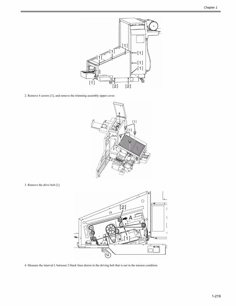
Chapter 1
1-219
2. Remove 4 screws [1], and remove the trimming assembly upper cover.
3. Remove the drive belt [1].
4. Measure the interval L between 2 black lines drawn in the driving belt that is not in the tension condition.
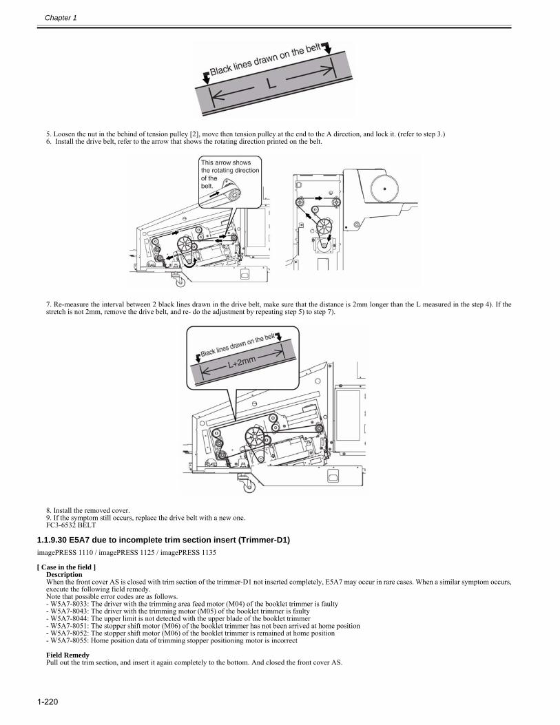
Chapter 1
1-220
5. Loosen the nut in the behind of tension pulley [2], move then tension pulley at the end to the A direction, and lock it. (refer to step 3.)6. Install the drive belt, refer to the arrow that shows the rotating direction printed on the belt.
7. Re-measure the interval between 2 black lines drawn in the drive belt, make sure that the distance is 2mm longer than the L measured in the step 4). If thestretch is not 2mm, remove the drive belt, and re- do the adjustment by repeating step 5) to step 7).
8. Install the removed cover.9. If the symptom still occurs, replace the drive belt with a new one.FC3-6532 BELT
1.1.9.30 E5A7 due to incomplete trim section insert (Trimmer-D1)0024-8235
imagePRESS 1110 / imagePRESS 1125 / imagePRESS 1135
[ Case in the field ]DescriptionWhen the front cover AS is closed with trim section of the trimmer-D1 not inserted completely, E5A7 may occur in rare cases. When a similar symptom occurs,execute the following field remedy.Note that possible error codes are as follows.- W5A7-8033: The driver with the trimming area feed motor (M04) of the booklet trimmer is faulty- W5A7-8043: The driver with the trimming motor (M05) of the booklet trimmer is faulty- W5A7-8044: The upper limit is not detected with the upper blade of the booklet trimmer- W5A7-8051: The stopper shift motor (M06) of the booklet trimmer has not been arrived at home position- W5A7-8052: The stopper shift motor (M06) of the booklet trimmer is remained at home position- W5A7-8055: Home position data of trimming stopper positioning motor is incorrect Field RemedyPull out the trim section, and insert it again completely to the bottom. And closed the front cover AS.
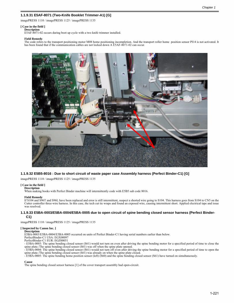
Chapter 1
1-221
1.1.9.31 E5AF-8071 (Two-Knife Booklet Trimmer-A1) [G]0025-5182
imagePRESS 1110 / imagePRESS 1125 / imagePRESS 1135
[ Case in the field ]DescriptionE5AF-8071-02 occurs during boot up cycle with a two knife trimmer installed. Field RemedyThe code refers to the transport positioning motor M08 home positioning incompletion. And the transport roller home position sensor PI14 is not activated. Ithas been found that if the communication cables are not locked down A E5AF-8071-02 can occur.
1.1.9.32 E5B5-8016 : Due to short circuit of waste paper case Assembly harness (Perfect Binder-C1) [G]0028-1801
imagePRESS 1110 / imagePRESS 1125 / imagePRESS 1135
[ Case in the field ]DescriptionWhen making books with Perfect Binder machine will intermittently code with E5B5 sub code 8016. Field RemedyIf S104 and S96T and S96L have been replaced and error is still intermittent, suspect a shorted wire going to S104. This harness goes from S104 to CN5 on theCutter controller three-wire harness. In this case, the tech cut tie wraps and found an exposed wire, causing intermittent short. Applied electrical tape and issuewas resolved.
1.1.9.33 E5BA-0003/E5BA-0004/E5BA-0005 due to open circuit of spine bending closed sensor harness (Perfect Binder-C1)
0028-1374
imagePRESS 1110 / imagePRESS 1125 / imagePRESS 1135
[ Inspected by Canon Inc. ]DescriptionE5BA-0003/E5BA-0004/E5BA-0005 occurred on units of Perfect Binder-C1 having serial numbers earlier than below. PerfectBinder-C1 USA: EGX00097PerfectBinder-C1 EUR: EGZ00051- E5BA-0003: The spine bending closed sensor (S61) would not turn on even after driving the spine bending motor for a specified period of time to close thespine plate./The spine bending closed sensor (S61) was off when the spine plate opened.- E5BA-0004: The spine bending closed sensor (S61) would not turn off even after driving the spine bending motor for a specified period of time to open thespine plate./The spine bending closed sensor (S61) was already on when the spine plate closed.- E5BA-0005: The spine bending home position sensor (left) (S60) and the spine bending closed sensor (S61) have turned on simultaneously.
CauseThe spine bending closed sensor harness [1] of the cover transport assembly had open-circuit.
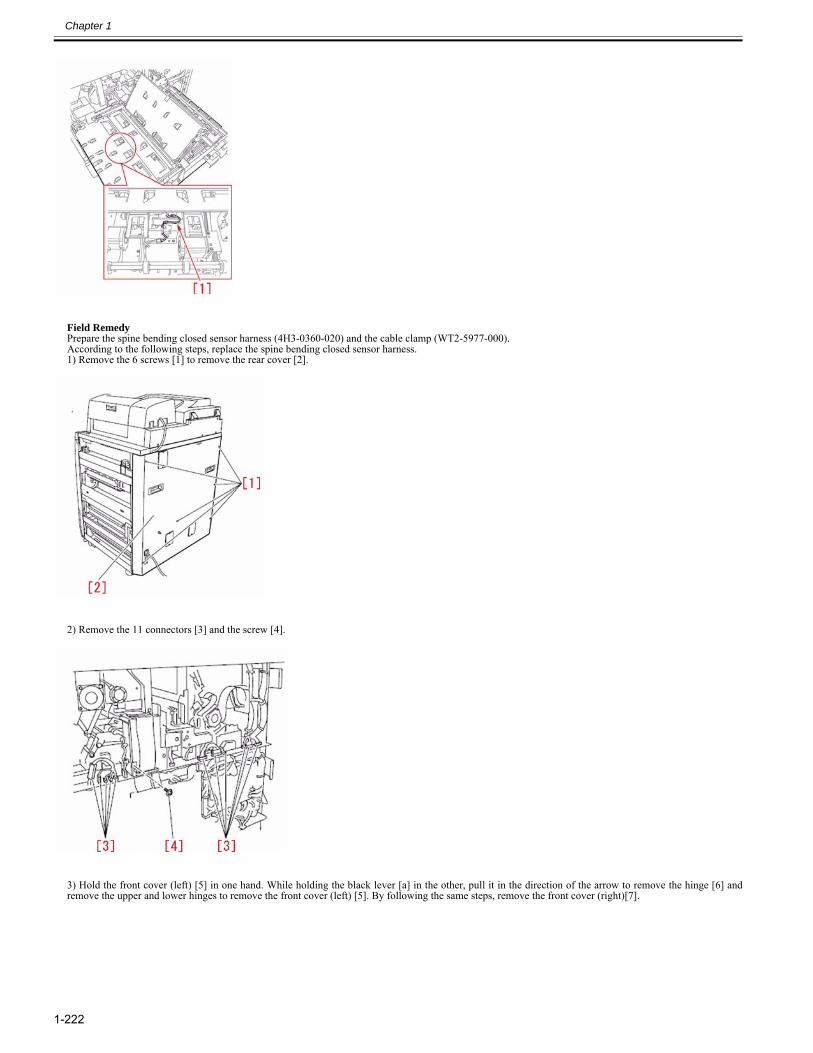
Chapter 1
1-222
Field RemedyPrepare the spine bending closed sensor harness (4H3-0360-020) and the cable clamp (WT2-5977-000).According to the following steps, replace the spine bending closed sensor harness.1) Remove the 6 screws [1] to remove the rear cover [2].
2) Remove the 11 connectors [3] and the screw [4].
3) Hold the front cover (left) [5] in one hand. While holding the black lever [a] in the other, pull it in the direction of the arrow to remove the hinge [6] andremove the upper and lower hinges to remove the front cover (left) [5]. By following the same steps, remove the front cover (right)[7].
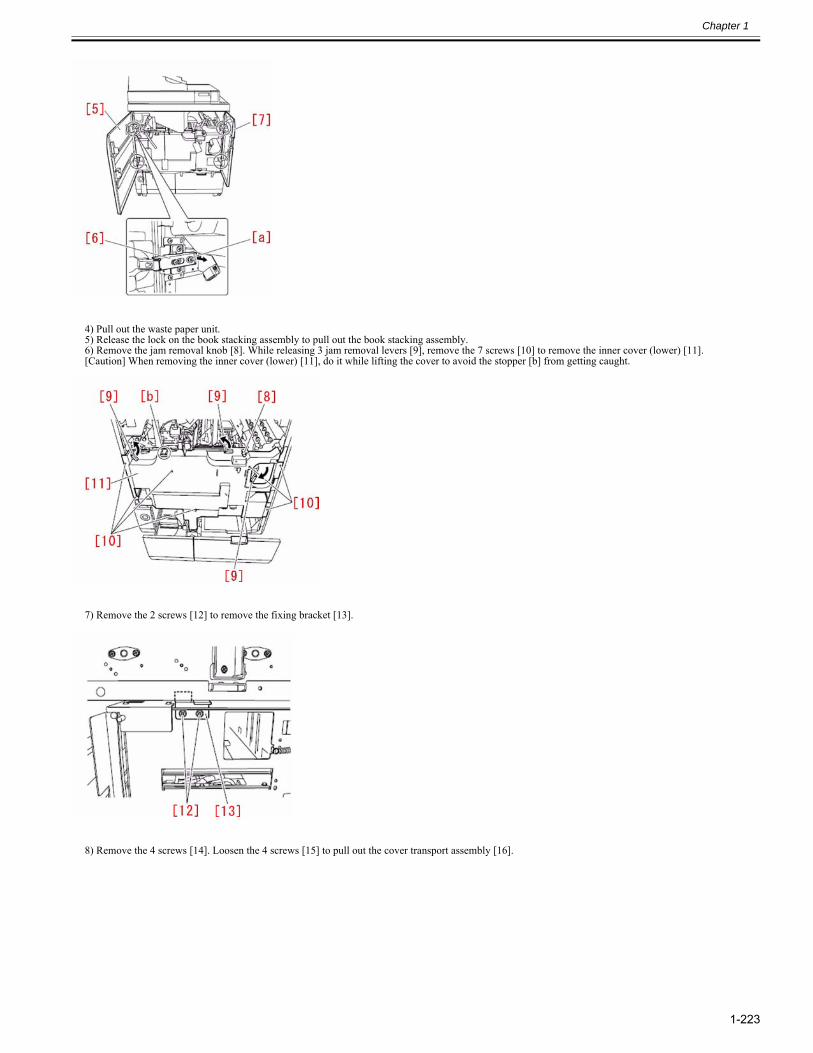
Chapter 1
1-223
4) Pull out the waste paper unit.5) Release the lock on the book stacking assembly to pull out the book stacking assembly.6) Remove the jam removal knob [8]. While releasing 3 jam removal levers [9], remove the 7 screws [10] to remove the inner cover (lower) [11].[Caution] When removing the inner cover (lower) [11], do it while lifting the cover to avoid the stopper [b] from getting caught.
7) Remove the 2 screws [12] to remove the fixing bracket [13].
8) Remove the 4 screws [14]. Loosen the 4 screws [15] to pull out the cover transport assembly [16].
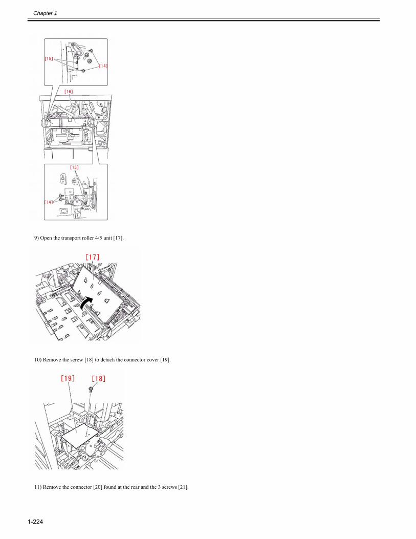
Chapter 1
1-224
9) Open the transport roller 4/5 unit [17].
10) Remove the screw [18] to detach the connector cover [19].
11) Remove the connector [20] found at the rear and the 3 screws [21].
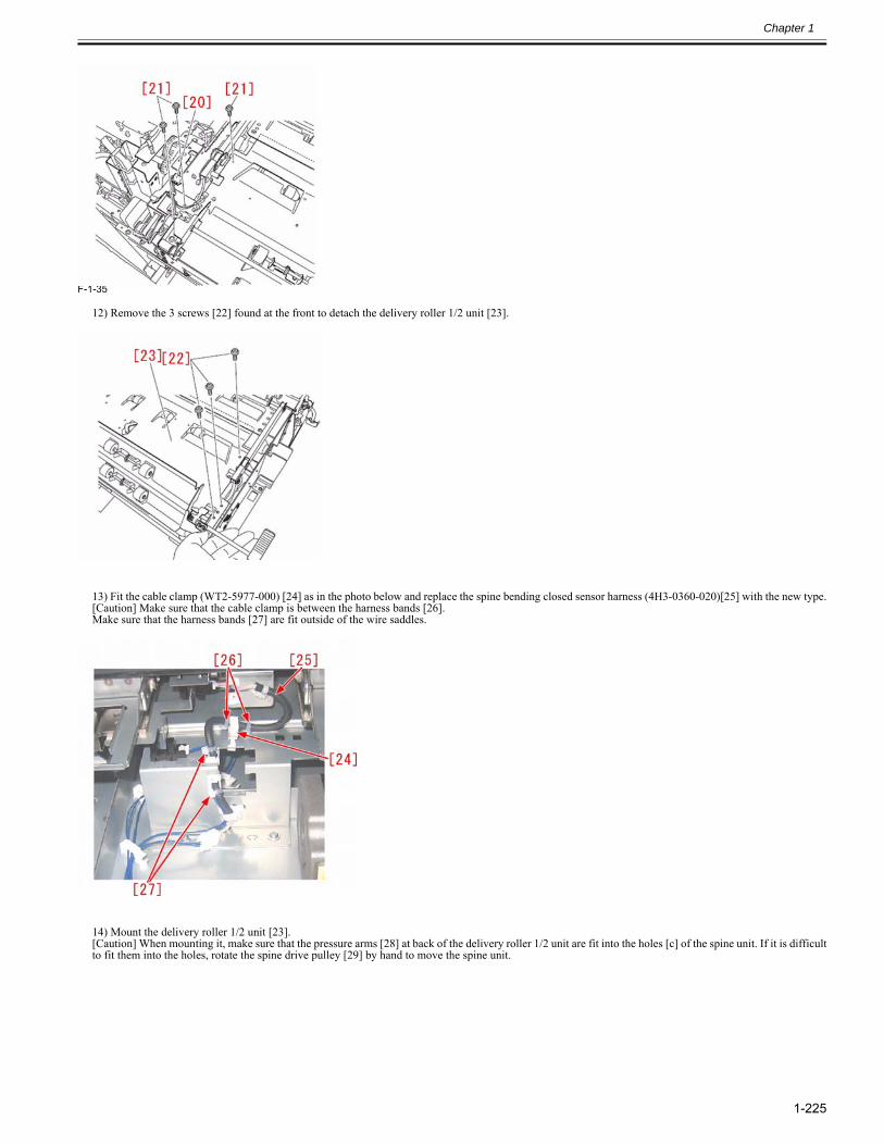
Chapter 1
1-225
F-1-35
12) Remove the 3 screws [22] found at the front to detach the delivery roller 1/2 unit [23].
13) Fit the cable clamp (WT2-5977-000) [24] as in the photo below and replace the spine bending closed sensor harness (4H3-0360-020)[25] with the new type.[Caution] Make sure that the cable clamp is between the harness bands [26].Make sure that the harness bands [27] are fit outside of the wire saddles.
14) Mount the delivery roller 1/2 unit [23].[Caution] When mounting it, make sure that the pressure arms [28] at back of the delivery roller 1/2 unit are fit into the holes [c] of the spine unit. If it is difficultto fit them into the holes, rotate the spine drive pulley [29] by hand to move the spine unit.
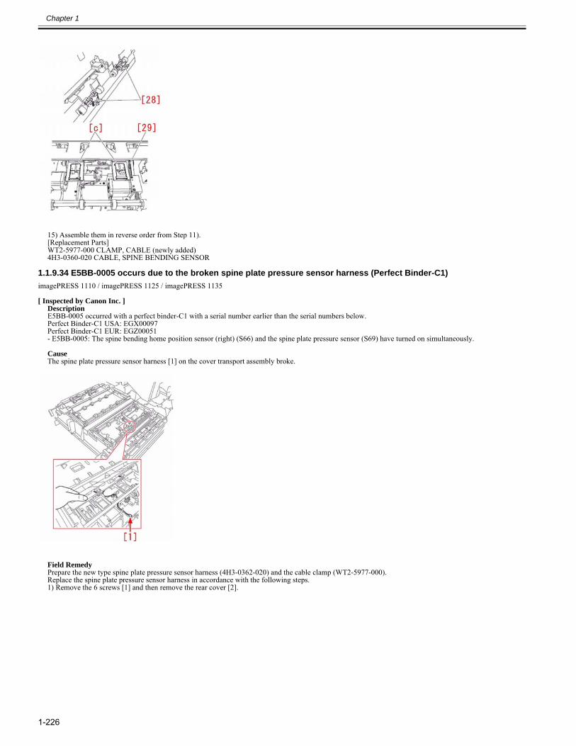
Chapter 1
1-226
15) Assemble them in reverse order from Step 11).[Replacement Parts]WT2-5977-000 CLAMP, CABLE (newly added)4H3-0360-020 CABLE, SPINE BENDING SENSOR
1.1.9.34 E5BB-0005 occurs due to the broken spine plate pressure sensor harness (Perfect Binder-C1)0028-1363
imagePRESS 1110 / imagePRESS 1125 / imagePRESS 1135
[ Inspected by Canon Inc. ]DescriptionE5BB-0005 occurred with a perfect binder-C1 with a serial number earlier than the serial numbers below.Perfect Binder-C1 USA: EGX00097Perfect Binder-C1 EUR: EGZ00051- E5BB-0005: The spine bending home position sensor (right) (S66) and the spine plate pressure sensor (S69) have turned on simultaneously.
CauseThe spine plate pressure sensor harness [1] on the cover transport assembly broke.
Field RemedyPrepare the new type spine plate pressure sensor harness (4H3-0362-020) and the cable clamp (WT2-5977-000).Replace the spine plate pressure sensor harness in accordance with the following steps.1) Remove the 6 screws [1] and then remove the rear cover [2].
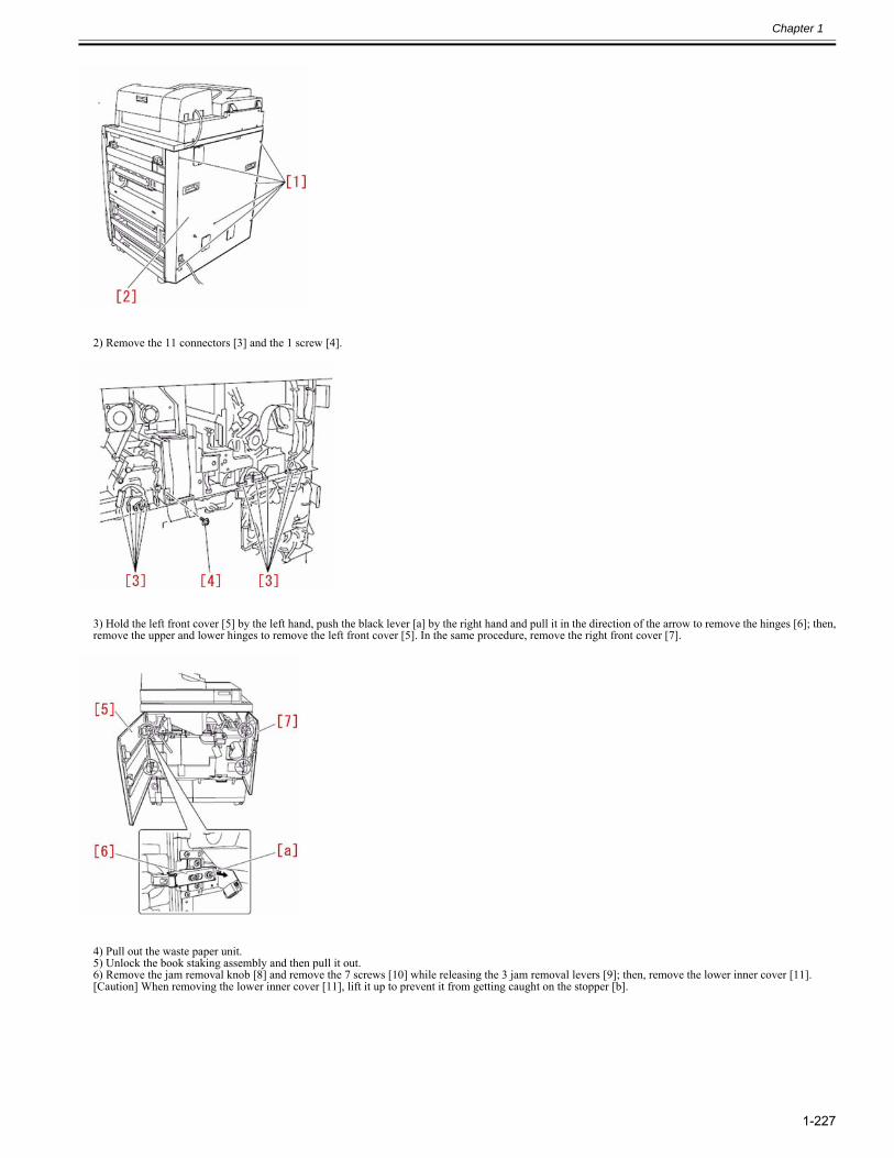
Chapter 1
1-227
2) Remove the 11 connectors [3] and the 1 screw [4].
3) Hold the left front cover [5] by the left hand, push the black lever [a] by the right hand and pull it in the direction of the arrow to remove the hinges [6]; then,remove the upper and lower hinges to remove the left front cover [5]. In the same procedure, remove the right front cover [7].
4) Pull out the waste paper unit.5) Unlock the book staking assembly and then pull it out.6) Remove the jam removal knob [8] and remove the 7 screws [10] while releasing the 3 jam removal levers [9]; then, remove the lower inner cover [11].[Caution] When removing the lower inner cover [11], lift it up to prevent it from getting caught on the stopper [b].
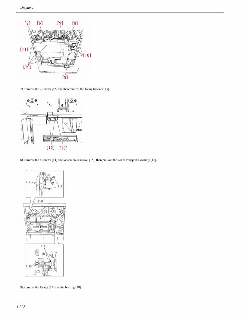
Chapter 1
1-228
7) Remove the 2 screws [12] and then remove the fixing bracket [13].
8) Remove the 4 screws [14] and loosen the 4 screws [15]; then pull out the cover transport assembly [16].
9) Remove the E-ring [17] and the bearing [18].
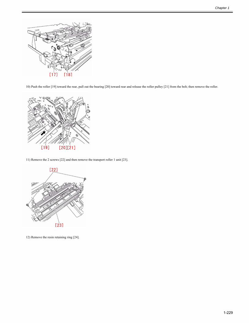
Chapter 1
1-229
10) Push the roller [19] toward the rear, pull out the bearing [20] toward rear and release the roller pulley [21] from the belt; then remove the roller.
11) Remove the 2 screws [22] and then remove the transport roller 1 unit [23].
12) Remove the resin retaining ring [24].
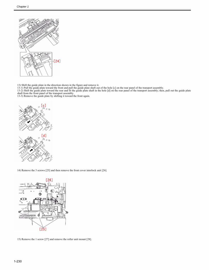
Chapter 1
1-230
13) Shift the guide plate in the direction shown in the figure and remove it.13-1) Pull the guide plate toward the front and pull the guide plate shaft out of the hole [c] on the rear panel of the transport assembly.13-2) Shift the guide plate toward the rear and fit the guide plate shaft in the hole [d] on the rear panel of the transport assembly; then, pull out the guide plateshaft from the front panel of the transport assembly.13-3) Remove the guide plate by shifting it toward the front again.
14) Remove the 3 screws [25] and then remove the front cover interlock unit [26].
15) Remove the 1 screw [27] and remove the roller unit mount [28].
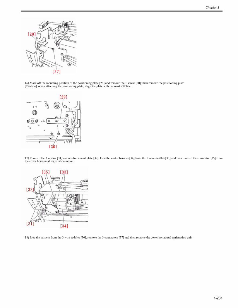
Chapter 1
1-231
16) Mark off the mounting position of the positioning plate [29] and remove the 1 screw [30]; then remove the positioning plate.[Caution] When attaching the positioning plate, align the plate with the mark-off line.
17) Remove the 3 screws [31] and reinforcement plate [32]. Free the motor harness [34] from the 2 wire saddles [33] and then remove the connector [35] fromthe cover horizontal registration motor.
18) Free the harness from the 3 wire saddles [36], remove the 3 connectors [37] and then remove the cover horizontal registration unit.
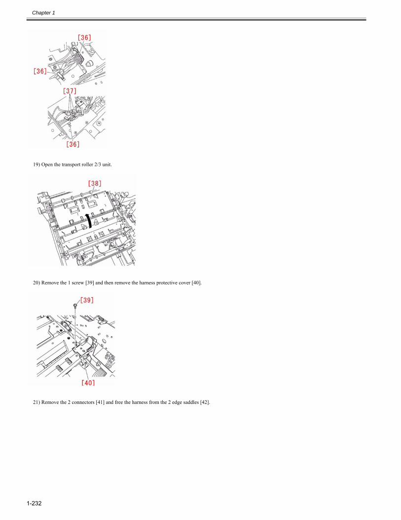
Chapter 1
1-232
19) Open the transport roller 2/3 unit.
20) Remove the 1 screw [39] and then remove the harness protective cover [40].
21) Remove the 2 connectors [41] and free the harness from the 2 edge saddles [42].
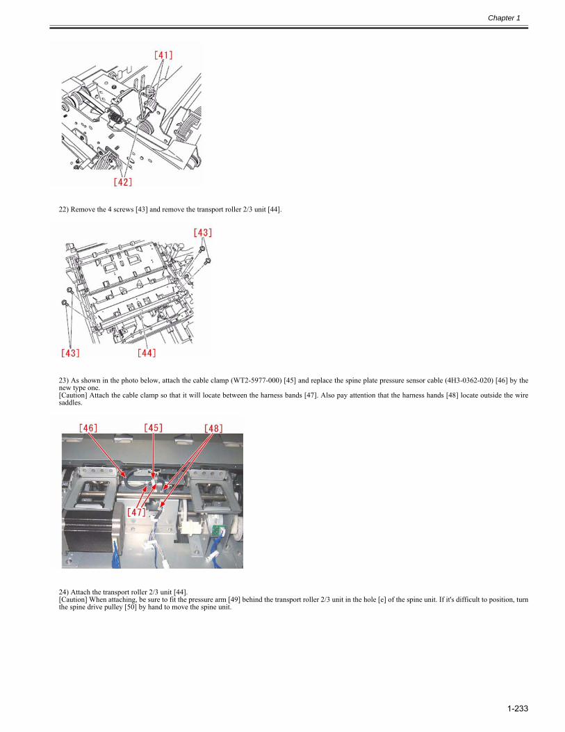
Chapter 1
1-233
22) Remove the 4 screws [43] and remove the transport roller 2/3 unit [44].
23) As shown in the photo below, attach the cable clamp (WT2-5977-000) [45] and replace the spine plate pressure sensor cable (4H3-0362-020) [46] by thenew type one.[Caution] Attach the cable clamp so that it will locate between the harness bands [47]. Also pay attention that the harness hands [48] locate outside the wiresaddles.
24) Attach the transport roller 2/3 unit [44].[Caution] When attaching, be sure to fit the pressure arm [49] behind the transport roller 2/3 unit in the hole [e] of the spine unit. If it's difficult to position, turnthe spine drive pulley [50] by hand to move the spine unit.
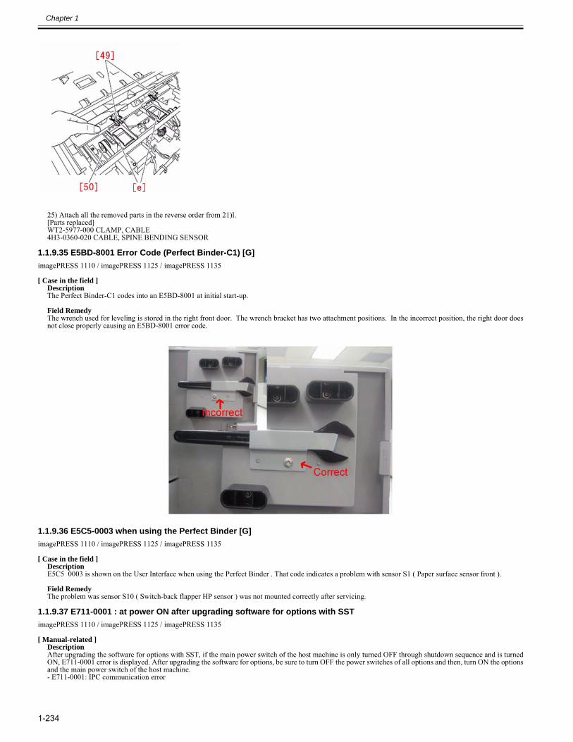
Chapter 1
1-234
25) Attach all the removed parts in the reverse order from 21)l.[Parts replaced] WT2-5977-000 CLAMP, CABLE4H3-0360-020 CABLE, SPINE BENDING SENSOR
1.1.9.35 E5BD-8001 Error Code (Perfect Binder-C1) [G]0025-5208
imagePRESS 1110 / imagePRESS 1125 / imagePRESS 1135
[ Case in the field ]DescriptionThe Perfect Binder-C1 codes into an E5BD-8001 at initial start-up. Field RemedyThe wrench used for leveling is stored in the right front door. The wrench bracket has two attachment positions. In the incorrect position, the right door doesnot close properly causing an E5BD-8001 error code.
1.1.9.36 E5C5-0003 when using the Perfect Binder [G]0025-3939
imagePRESS 1110 / imagePRESS 1125 / imagePRESS 1135
[ Case in the field ]DescriptionE5C5 0003 is shown on the User Interface when using the Perfect Binder . That code indicates a problem with sensor S1 ( Paper surface sensor front ). Field RemedyThe problem was sensor S10 ( Switch-back flapper HP sensor ) was not mounted correctly after servicing.
1.1.9.37 E711-0001 : at power ON after upgrading software for options with SST0023-0551
imagePRESS 1110 / imagePRESS 1125 / imagePRESS 1135
[ Manual-related ]DescriptionAfter upgrading the software for options with SST, if the main power switch of the host machine is only turned OFF through shutdown sequence and is turnedON, E711-0001 error is displayed. After upgrading the software for options, be sure to turn OFF the power switches of all options and then, turn ON the optionsand the main power switch of the host machine.- E711-0001: IPC communication error
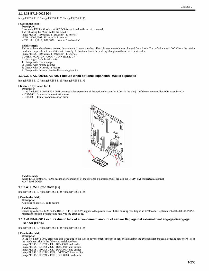
Chapter 1
1-235
1.1.9.38 E719-0022 [G]0025-5186
imagePRESS 1110 / imagePRESS 1125 / imagePRESS 1135
[ Case in the field ]DescriptionError code E719 with sub code 0022-00 is not listed in the service manual. The following E719 sub codes are listed: imagePRESS 1110Series/ 1125Series/ 1135Series-E719 0002,0003 Error in "coin vender"-E719 0011,0012,0031,0032 Error in "card reader" Field RemedyThis machine did not have a coin op device or card reader attached. The coin service mode was changed from 0 to 3. The default value is "0". Check the servicemodes settings below to see if it is set correctly. Reboot machine after making changes to the service mode value.imagePRESS 1110Series/ 1125Series/ 1135SeriesCOPIER > OPTION > ACC > COIN (Range 0-4)0: No charge (Default value = 0)1: Charge with coin manager2: Charge with remote counter3: Charge with DA (only in Japan)4: Charge with this machine itself (as a single unit)
1.1.9.39 E732-0001/E733-0001 occurs when optional expansion RAM is expanded0024-7945
imagePRESS 1110 / imagePRESS 1125 / imagePRESS 1135
[ Inspected by Canon Inc. ]DescriptionIn the field, E732-0001/E733-0001 occurred after expansion of the optional expansion ROM in the slot [1] of the main controller PCB assembly (2).- E732-0001: Scanner communication error- E733-0001: Printer communication error
Field RemedyWhen E732-0001/E733-0001 occurs after expansion of the optional expansion ROM, replace the DIMM [A] connected as default. WA7-5193 DIMM
1.1.9.40 E750 Error Code [G]0025-5191
imagePRESS 1110 / imagePRESS 1125 / imagePRESS 1135
[ Case in the field ]DescriptionAt power on an E750 code occurs. Field RemedyChecking voltage at J225 on the DC-CON PCB the 3.3V supply to the power relay PCB is missing resulting in an E750 code. Replacement of the DC-CON PCBrestored the missing voltage and resolved the error code.
1.1.9.41 E842-0012 occurs due to lack of advancement amount of sensor flag against external heat engage/disengage sensor (PS16)
0023-8003
imagePRESS 1110 / imagePRESS 1125 / imagePRESS 1135
[ Case in the field ]DescriptionIn the field, E842-0012 error was displayed due to the lack of advancement amount of sensor flag against the external heat engage/disengage sensor (PS16) onthe machines prior to the following serial numbersimagePRESS 1135 208V UL : DTV00051 and earlier imagePRESS 1125 208V UL : DUK00017 and earlier imagePRESS 1110 208V UL : DUU00094 and earlier imagePRESS 1135 230V EUR : DTW00025 and earlier imagePRESS 1125 230V EUR : DUL00008 and earlier
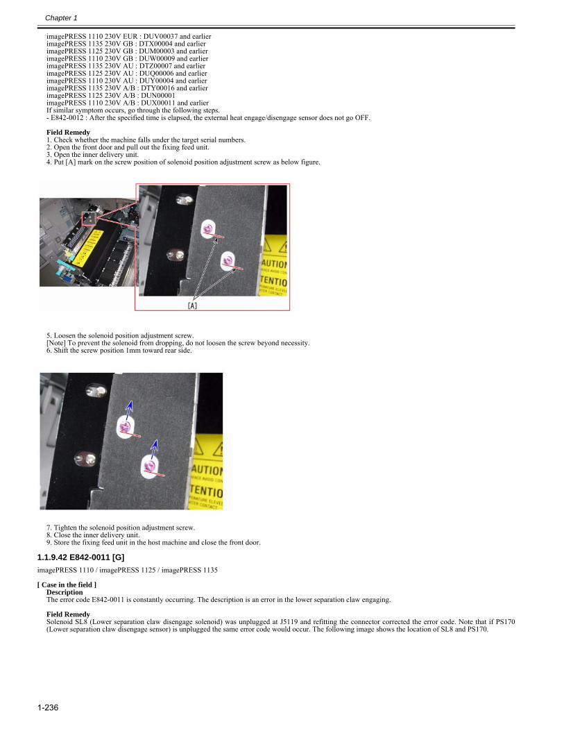
Chapter 1
1-236
imagePRESS 1110 230V EUR : DUV00037 and earlier imagePRESS 1135 230V GB : DTX00004 and earlier imagePRESS 1125 230V GB : DUM00003 and earlier imagePRESS 1110 230V GB : DUW00009 and earlier imagePRESS 1135 230V AU : DTZ00007 and earlier imagePRESS 1125 230V AU : DUQ00006 and earlier imagePRESS 1110 230V AU : DUY00004 and earlier imagePRESS 1135 230V A/B : DTY00016 and earlier imagePRESS 1125 230V A/B : DUN00001imagePRESS 1110 230V A/B : DUX00011 and earlierIf similar symptom occurs, go through the following steps.- E842-0012 : After the specified time is elapsed, the external heat engage/disengage sensor does not go OFF. Field Remedy1. Check whether the machine falls under the target serial numbers.2. Open the front door and pull out the fixing feed unit.3. Open the inner delivery unit.4. Put [A] mark on the screw position of solenoid position adjustment screw as below figure.
5. Loosen the solenoid position adjustment screw.[Note] To prevent the solenoid from dropping, do not loosen the screw beyond necessity.6. Shift the screw position 1mm toward rear side.
7. Tighten the solenoid position adjustment screw.8. Close the inner delivery unit.9. Store the fixing feed unit in the host machine and close the front door.
1.1.9.42 E842-0011 [G]0025-5181
imagePRESS 1110 / imagePRESS 1125 / imagePRESS 1135
[ Case in the field ]DescriptionThe error code E842-0011 is constantly occurring. The description is an error in the lower separation claw engaging. Field RemedySolenoid SL8 (Lower separation claw disengage solenoid) was unplugged at J5119 and refitting the connector corrected the error code. Note that if PS170(Lower separation claw disengage sensor) is unplugged the same error code would occur. The following image shows the location of SL8 and PS170.
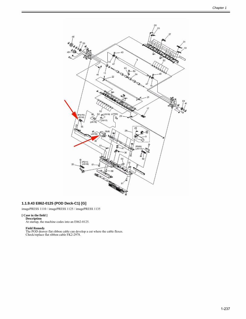
Chapter 1
1-237
1.1.9.43 E862-0125 (POD Deck-C1) [G]0025-5178
imagePRESS 1110 / imagePRESS 1125 / imagePRESS 1135
[ Case in the field ]DescriptionAt startup, the machine codes into an E862-0125. Field RemedyThe POD drawer flat ribbon cable can develop a cut where the cable flexes. Check/replace flat ribbon cable FK2-2978.
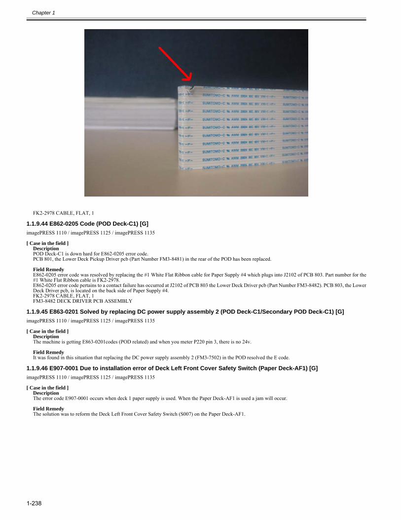
Chapter 1
1-238
FK2-2978 CABLE, FLAT, 1
1.1.9.44 E862-0205 Code (POD Deck-C1) [G]0025-5199
imagePRESS 1110 / imagePRESS 1125 / imagePRESS 1135
[ Case in the field ]DescriptionPOD Deck-C1 is down hard for E862-0205 error code. PCB 801, the Lower Deck Pickup Driver pcb (Part Number FM3-8481) in the rear of the POD has been replaced. Field RemedyE862-0205 error code was resolved by replacing the #1 White Flat Ribbon cable for Paper Supply #4 which plugs into J2102 of PCB 803. Part number for the#1 White Flat Ribbon cable is FK2-2978.E862-0205 error code pertains to a contact failure has occurred at J2102 of PCB 803 the Lower Deck Driver pcb (Part Number FM3-8482). PCB 803, the LowerDeck Driver pcb, is located on the back side of Paper Supply #4.FK2-2978 CABLE, FLAT, 1FM3-8482 DECK DRIVER PCB ASSEMBLY
1.1.9.45 E863-0201 Solved by replacing DC power supply assembly 2 (POD Deck-C1/Secondary POD Deck-C1) [G]0028-0802
imagePRESS 1110 / imagePRESS 1125 / imagePRESS 1135
[ Case in the field ]DescriptionThe machine is getting E863-0201codes (POD related) and when you meter P220 pin 3, there is no 24v. Field RemedyIt was found in this situation that replacing the DC power supply assembly 2 (FM3-7502) in the POD resolved the E code.
1.1.9.46 E907-0001 Due to installation error of Deck Left Front Cover Safety Switch (Paper Deck-AF1) [G]0028-0797
imagePRESS 1110 / imagePRESS 1125 / imagePRESS 1135
[ Case in the field ]DescriptionThe error code E907-0001 occurs when deck 1 paper supply is used. When the Paper Deck-AF1 is used a jam will occur. Field RemedyThe solution was to reform the Deck Left Front Cover Safety Switch (S007) on the Paper Deck-AF1.
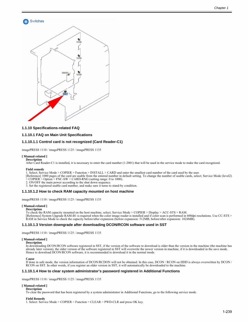
Chapter 1
1-239
1.1.10 Specifications-related FAQ
1.1.10.1 FAQ on Main Unit Specifications
1.1.10.1.1 Control card is not recognized (Card Reader-C1)0023-0555
imagePRESS 1110 / imagePRESS 1125 / imagePRESS 1135
[ Manual-related ]DescriptionAfter Card Reader-C1 is installed, it is necessary to enter the card number (1-2001) that will be used in the service mode to make the card recognized.
Field remedy1. Select; Service Mode > COPIER > Function > INSTALL > CARD and enter the smallest card number of the card used by the user.[Reference] 1000 pages of the card are usable from the entered number in default setting. To change the number of usable cards, select; Service Mode (level2)> COPIER > Option > FNC-SW > CARD-RNG (setting range: 0 to 1000).2. ON/OFF the main power according to the shut down sequence.3. Set the registered usable card number, and make sure it turns to stand-by condition.
1.1.10.1.2 How to check RAM capacity mounted on host machine0023-0556
imagePRESS 1110 / imagePRESS 1125 / imagePRESS 1135
[ Manual-related ]DescriptionTo check the RAM capacity mounted on the host machine, select; Service Mode > COPIER > Display > ACC-STS > RAM.[Reference] System Upgrade RAM-B1 is required when the color image reader is installed and if color scan is performed in 600dpi resolutions. Use CC-STS >RAM in Service Mode to check the capacity before/after expansion (before expansion: 512MB, before/after expansion: 1024MB).
1.1.10.1.3 Version downgrade after downloading DCON/RCON software used in SST0023-0747
imagePRESS 1110 / imagePRESS 1125 / imagePRESS 1135
[ Manual-related ]DescriptionIn downloading DCON/RCON software registered in SST, if the version of the software to download is older than the version in the machine (the machine hasalready later version), the older version of the software registered in SST will overwrite the newer version in machine, if it is downloaded in the save mode.Hence to download DCON/RCON software, it is recommended to download it in the normal mode.
CauseIf done in safe mode, the version information of DCON/RCDON will not be obtained. In this case, DCON / RCON on HDD is always overwritten by DCON /RCON on SST. In other words, if you register an older version in SST, it will automatically be downloaded to the machine.
1.1.10.1.4 How to clear system administrator’s password registered in Additional Functions0023-0874
imagePRESS 1110 / imagePRESS 1125 / imagePRESS 1135
[ Manual-related ]DescriptionTo clear the password that has been registered by a system administrator in Additional Functions, go to the following service mode.
Field Remedy1. Select: Service Mode > COPIER > Function > CLEAR > PWD-CLR and press OK key.
Chapter 1
1-240
2. Register the system administrator’s password again.[Note] Note that if the MMI is selected in Service Mode and clear is executed, the following setting values registered in Additional Functions will be also cleared(excluding values for copier control panel, common setting, and FAX).-Common Settings-Timer Settings-Adjustment/Cleaning-Report Settings-System Settings-Copy Settings-Communications Settings-Printer Settings
1.1.10.1.5 [READY] is not displayed on status line of service mode screen and cannot judge whether host machine is [READY] or not. Because paper is not loaded on paper pickup deck at installation
0023-0876
imagePRESS 1110 / imagePRESS 1125 / imagePRESS 1135
[ Manual-related ]DescriptionWhen you enter the service mode, if the paper is not loaded on the paper pickup deck, [NO-PAPER] is displayed primarily on the status line of service modescreen and you cannot check whether the host machine is [READY] or not. To check [READY] status of host machine, load the paper on the pickup deck. Makesure to load the paper by 10mm or more.
1.1.10.1.6 How to check capacity of expanded memory (IA-RAM) equipped in host machine0023-0926
imagePRESS 1110 / imagePRESS 1125 / imagePRESS 1135
[ Manual-related ]DescriptionTo check the capacity of expanded memory equipped in the main controller PCB assembly 1 of the machine, enter Service Mode > COPIER > Display > ACC-STS > IA-RAM.The standard is 512MB, and if the 512 MB-expanded-memory is added, it will become 1024MB. And to check whether it is properly installed or not, enterCounter Key “123” > Device Configuration, and it can be checked on the screen. Memory B is IA RAM.[Reference]- Expanded memory and Scan Memory is not compatible.
1.1.10.1.7 Cassette switch before all the paper in the cassette is fed out during continuous copy, Cassette Auto Selection ON
0023-3332
imagePRESS 1110 / imagePRESS 1125 / imagePRESS 1135
[ Manual-related ]DescriptionIf Additional function > Common setting > Cassette auto selection is ON, and "Productivity Priority" is selected, it is a control so that the cassette will be switchedbefore the paper in the first cassette is completely fed out (remains approx. 100 sheets : 80g/m2). Hence during continuous copy, the pickup will not be stoppeddue to the cassette switching. If "Productivity Priority" is not selected, the cassette is switched only when the paper is completely fed out, and the printing willstop due to paper-out, and down time will occur as the result.[Reference] For automatic cassette change selection, target pickup inlet can be selected from all pickup inlets, including pick up option (host machine deck, PODdeck, secondary POD deck).
1.1.10.1.8 Setting of the Dip switches on the punch controller PCB assembly according to the destination (Finisher-AG2+Punch Unit-BF1/BG1/BH1)
0023-8551
imagePRESS 1110 / imagePRESS 1125 / imagePRESS 1135
[ Manual-related ]DescriptionThe Dip switches on the punch controller PCB assembly are set according to the destination as shown below.
When you replace the punch controller PCB assembly (FM4-0310), make sure to check the settings of the Dip switches before installing a new one.
1.1.10.1.9 Regarding pre-printed paper that can not be used with this product0024-1681
imagePRESS 1110 / imagePRESS 1125 / imagePRESS 1135
[ Verified by Canon Inc. ]DescriptionDo not use the paper printed in a full-color laser printer using the toner which requires applying oil at fixing. Since the toner fixing temperature of this productis higher than the general color laser printer, the toner on the pre-printed paper fuses and at the same time, the paper wraps over the fixing assembly and possiblycausing the breakdown of this product. Even under the usable condition, quality of output result may deteriorated due to the gloss change. Only if the paper is picked up from the multi-inserter-A1 or inserter-F1 and also is used as a cover sheet or insertion sheet, the paper printed in a full-color laserprinter can be used. In that case, be careful of the paper curl or sticking.Following measure helps use the paper printed in the full-color laser printer.- Reduce the image density of pre-printed paper.
Name: Destination No. of Holes SW1 SW2
BF1: For USA 2/3 holes ON OFF
BG1: For France 2/4 holes OFF ON
BH1: For Sweden 4 holes ON ON
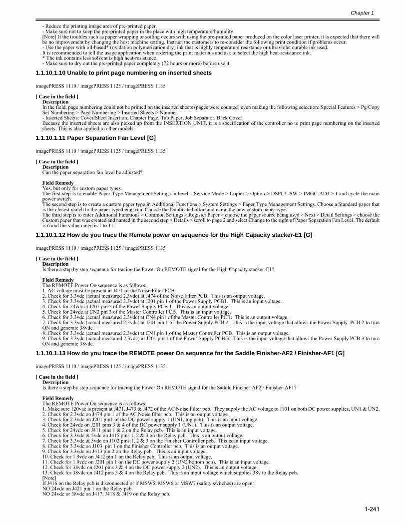
Chapter 1
1-241
- Reduce the printing image area of pre-printed paper.- Make sure not to keep the pre-printed paper in the place with high temperature/humidity.[Note] If the troubles such as paper wrapping or soiling occurs with using the pre-printed paper produced on the color laser printer, it is expected that there willbe no improvement by changing the host machine setting. Instruct the customers to re-consider the following print condition if problems occur.- Use the paper with oil-based* (oxidation polymerization dry) ink that is highly temperature resistance or ultraviolet curable ink used.It is recommended to tell the usage application when ordering the print materials and ask to select the high heat-resistance ink.* The ink contains less solvent is high heat-resistance.- Make sure to dry out the pre-printed paper completely (72 hours or more) before use it.
1.1.10.1.10 Unable to print page numbering on inserted sheets0024-7079
imagePRESS 1110 / imagePRESS 1125 / imagePRESS 1135
[ Case in the field ]DescriptionIn the field, page numbering could not be printed on the inserted sheets (pages were counted) even making the following selection: Special Features > Pg/CopySet Numbering > Page Numbering > Inserted Sheets > Number. - Inserted Sheets: Cover/Sheet Insertion, Chapter Page, Tab Paper, Job Separator, Back CoverBecause the inserted sheets are also picked up from the INSERTION UNIT, it is a specification of the controller no to print page numbering on the insertedsheets. This is also applied to other models.
1.1.10.1.11 Paper Separation Fan Level [G]0025-3932
imagePRESS 1110 / imagePRESS 1125 / imagePRESS 1135
[ Case in the field ]DescriptionCan the paper separation fan level be adjusted? Field RemedyYes, but only for custom paper types.The first step is to enable Paper Type Management Settings in level 1 Service Mode > Copier > Option > DSPLY-SW > IMGC-ADJ > 1 and cycle the mainpower switch.The second step is to create a custom paper type in Additional Functions > System Settings > Paper Type Management Settings. Choose a Standard paper thatis the closest match to the paper type being run. Choose the Duplicate button and name the new custom paper type.The third step is to enter Additional Functions > Common Settings > Register Paper > choose the paper source being used > Next > Detail Settings > choose theCustom paper that was created and named in the second step > Details > scroll to page 2 and select Change to the right of Paper Separation Fan Level. The defaultis 6 and the value range is 1 to 11.
1.1.10.1.12 How do you trace the Remote power on sequence for the High Capacity stacker-E1 [G]0025-3935
imagePRESS 1110 / imagePRESS 1125 / imagePRESS 1135
[ Case in the field ]DescriptionIs there a step by step sequence for tracing the Power On REMOTE signal for the High Capacity stacker-E1? Field RemedyThe REMOTE Power On sequence is as follows:1. AC voltage must be present at J471 of the Noise Filter PCB.2. Check for 3.3vdc (actual measured 2.3vdc) at J474 of the Noise Filter PCB. This is an output voltage.3. Check for 3.3vdc (actual measured 2.3vdc) at J201 pin 1 of the Power Supply PCB1. This is an input voltage.4. Check for 24vdc at J201 pin 5 of the Power Supply PCB 1. This is an output voltage.5. Check for 24vdc at CN2 pin 3 of the Master Controller PCB. This is an input voltage.6. Check for 3.3vdc (actual measured 2.3vdc) at CN4 pin1 of the Master Controller PCB. This is an output voltage.7. Check for 3.3vdc (actual measured 2.3vdc) at J201 pin 1 of the Power Supply PCB 2. This is the input voltage that allows the Power Supply PCB 2 to trunON and generate 38vdc.8. Check for 3.3vdc (actual measured 2.3vdc) at CN1 pin 1 of the Master Controller PCB. This is an output voltage.9. Check for 3.3vdc (actual measured 2.3vdc) at J201 pin 1 of the Power Supply PCB 3. This is the input voltage that allows the Power Supply PCB 3 to turnON and generate 38vdc.
1.1.10.1.13 How do you trace the REMOTE power On sequence for the Saddle Finisher-AF2 / Finisher-AF1 [G]0025-3937
imagePRESS 1110 / imagePRESS 1125 / imagePRESS 1135
[ Case in the field ]DescriptionIs there a step by step sequence for tracing the Power On REMOTE signal for the Saddle Finisher-AF2 / Finisher-AF1? Field RemedyThe REMOTE Power On sequence is as follows:1. Make sure 120vac is present at J471, J473 & J472 of the AC Noise Filter pcb. They supply the AC voltage to J101 on both DC power supplies, UN1 & UN2.2. Check for 2.3vdc on J474 pin 1 of the AC Noise filter pcb. This is an output voltage.3. Check for 2.3vdc on J201 pin1 of the DC power supply 1 (UN1, top pcb). This is an input voltage.4. Check for 24vdc on J201 pins 3 & 4 of the DC power supply 1 (UN1). This is an output voltage.5. Check for 24vdc on J411 pins 1 & 2 on the Relay pcb. This is an input voltage.6. Check for 3.3vdc & 5vdc on J415 pins 1, 2 & 3 on the Relay pcb. This is an output voltage.7. Check for 3.3vdc & 5vdc on J102 pins 1, 2 & 3 on the Finisher Controller pcb. This is an input voltage.8. Check for 3.3vdc on J103 pin 1 on the Finisher Controller pcb. This is an output voltage.9. Check for 3.3vdc on J413 pin 2 on the Relay pcb. This is an input voltage.10. Check for 1.9vdc on J412 pin 1 on the Relay pcb. This is an output voltage.11. Check for 1.9vdc on J201 pin 1 on the DC power supply 2 (UN2 bottom pcb). This is an input voltage.12. Check for 38vdc on J201 pins 3 & 4 on the DC power supply 2 (UN2). This is an output voltage.13. Check for 38vdc on J412 pins 3 & 4 on the Relay pcb. This is an input voltage which supplies 38v to the Relay pcb.[Note]If J416 on the Relay pcb is disconnected or if MSW5, MSW6 or MSW7 (safety switches) are open:NO 24vdc on J421 pin 1 on the Relay pcb.NO 24vdc or 38vdc on J417, J418 & J419 on the Relay pcb.
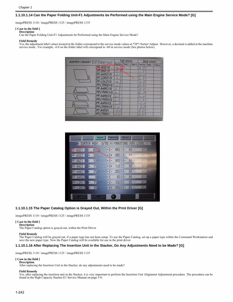
Chapter 1
1-242
1.1.10.1.14 Can the Paper Folding Unit-F1 Adjustments be Performed using the Main Engine Service Mode? [G]0025-3941
imagePRESS 1110 / imagePRESS 1125 / imagePRESS 1135
[ Case in the field ]DescriptionCan the Paper Folding Unit-F1 Adjustments be Performed using the Main Engine Service Mode? Field RemedyYes, the adjustment label values located at the folder correspond to the service mode values at *28*>Sorter>Adjust. However, a decimal is added at the machineservice mode. For example, -6.0 on the folder label will correspond to -60 in service mode (See photos below).
1.1.10.1.15 The Paper Catalog Option is Grayed Out, Within the Print Driver [G]0025-3946
imagePRESS 1110 / imagePRESS 1125 / imagePRESS 1135
[ Case in the field ]DescriptionThe Paper Catalog option is grayed out, within the Print Driver Field RemedyThe Paper Catalog will be grayed out, if a paper type has not been setup. To use the Paper Catalog, set up a paper type within the Command Workstation andsave the new paper type. Now the Paper Catalog will be available for use in the print driver.
1.1.10.1.16 After Replacing The Insertion Unit in the Stacker, Do Any Adjustments Need to be Made? [G]0025-3948
imagePRESS 1110 / imagePRESS 1125 / imagePRESS 1135
[ Case in the field ]DescriptionAfter replacing the Insertion Unit in the Stacker, do any adjustments need to be made? Field RemedyYes, after replacing the insertion unit in the Stacker, it is very important to perform the Insertion Unit Alignment Adjustment procedure. The procedure can befound in the High Capacity Stacker-E1 Service Manual on page 5-8.
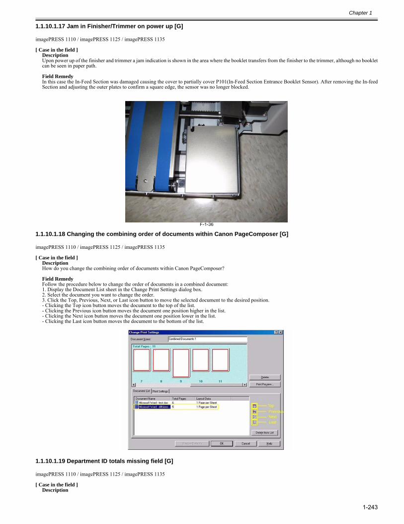
Chapter 1
1-243
1.1.10.1.17 Jam in Finisher/Trimmer on power up [G]0025-3977
imagePRESS 1110 / imagePRESS 1125 / imagePRESS 1135
[ Case in the field ]DescriptionUpon power up of the finisher and trimmer a jam indication is shown in the area where the booklet transfers from the finisher to the trimmer, although no bookletcan be seen in paper path. Field RemedyIn this case the In-Feed Section was damaged causing the cover to partially cover P101(In-Feed Section Entrance Booklet Sensor). After removing the In-feedSection and adjusting the outer plates to confirm a square edge, the sensor was no longer blocked.
F-1-36
1.1.10.1.18 Changing the combining order of documents within Canon PageComposer [G]0025-4045
imagePRESS 1110 / imagePRESS 1125 / imagePRESS 1135
[ Case in the field ]DescriptionHow do you change the combining order of documents within Canon PageComposer? Field RemedyFollow the procedure below to change the order of documents in a combined document: 1. Display the Document List sheet in the Change Print Settings dialog box.2. Select the document you want to change the order.3. Click the Top, Previous, Next, or Last icon button to move the selected document to the desired position.- Clicking the Top icon button moves the document to the top of the list.- Clicking the Previous icon button moves the document one position higher in the list.- Clicking the Next icon button moves the document one position lower in the list.- Clicking the Last icon button moves the document to the bottom of the list.
1.1.10.1.19 Department ID totals missing field [G]0025-4048
imagePRESS 1110 / imagePRESS 1125 / imagePRESS 1135
[ Case in the field ]Description
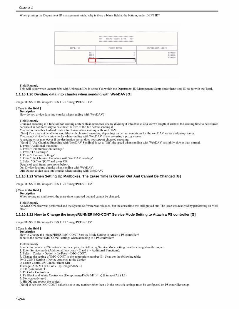
Chapter 1
1-244
When printing the Department ID management totals, why is there a blank field at the bottom, under DEPT ID?
Field RemedyThis will occur when Accept Jobs with Unknown ID's is set to Yes within the Department ID Management Setup since there is no ID to go with the Total.
1.1.10.1.20 Dividing data into chunks when sending with WebDAV [G]0025-4049
imagePRESS 1110 / imagePRESS 1125 / imagePRESS 1135
[ Case in the field ]DescriptionHow do you divide data into chunks when sending with WebDAV? Field RemedyChunked encoding is a function for sending a file with an unknown size by dividing it into chunks of a known length. It enables the sending time to be reducedbecause it is not necessary to calculate the size of the file before sending it. You can set whether to divide data into chunks when sending with WebDAV.[Note] You may not be able to send files with chunked encoding, depending on certain conditions for the webDAV server and proxy server.You cannot divide data into chunks when sending with WebDAV if you are using a proxy server.A sending error may occur if the destination server does not support chunked encoding.[Note] If [Use Chunked Encoding with WebDAV Sending] is set to 'Off', the speed when sending with WebDAV is slightly slower than normal.1. Press "Additional Function"2. Press "Communication Settings"3. Press "TX Settings"4. Press "Common Settings"5. Press "Use Chunked Encoding with WebDAV Sending"6. Select "On" or "[Off" and press OK.Details of each items are shown below.On: Divide data into chunks when sending with WebDAV.Off: Do not divide data into chunks when sending with WebDAV.
1.1.10.1.21 When Setting Up Mailboxes, The Erase Time Is Grayed Out And Cannot Be Changed [G]0025-4052
imagePRESS 1110 / imagePRESS 1125 / imagePRESS 1135
[ Case in the field ]DescriptionWhen setting up mailboxes, the erase time is grayed out and cannot be changed. Field RemedyAn MNCON clear was performed and the System Software was reloaded, but the erase time was still grayed out. The issue was resolved by performing an MMIclear.
1.1.10.1.22 How to Change the imageRUNNER IMG-CONT Service Mode Setting to Attach a PS controller [G]0025-4055
imagePRESS 1110 / imagePRESS 1125 / imagePRESS 1135
[ Case in the field ]DescriptionHow to Change the imagePRESS IMG-CONT Service Mode Setting to Attach a PS controller?What is the correct IMG-CONT settings when attaching to a PS controller? Field RemedyIn order to connect a PS controller to the copier, the following Service Mode setting must be changed on the copier: 1. Enter Service mode (Additional Functions > 2 and 8 > Additional Functions).2. Select Copier > Option > Int-Face > IMG-CONT.3. Change the setting of IMG-CONT to the appropriate number (0 - 5) as per the following table:IMG-CONT Setting : Device Attached to the Copier: 0: Canon Controller (Canon Printer Kit) 1: imagePASS M1 (v1.0 or v1.1), imagePASS L1 2: TR Systems/AHT 3: PS Color Controllers 4: PS Black and White Controllers (Except imagePASS M1(v1.x) & imagePASS L1) 5: Not currently used 4. Hit OK and reboot the copier.[Note] When the IMG-CONT value is set to any number other then a 0; the network settings must be configured on PS controller setup.
Chapter 1
1-245
1.1.10.1.23 How do you trace the REMOTE power on sequence for the Perfect Binder-C1 [G]0025-4056
imagePRESS 1110 / imagePRESS 1125 / imagePRESS 1135
[ Case in the field ]DescriptionIs there a step by step sequence for tracing the Power On REMOTE signal for the Perfect Binder-C1? Field RemedyThe REMOTE Power On sequence is as follows:1. Check that 208VAC is present at J84 on both Power Supply Units 1 & 2.2. Check for 5VDC (actual measured 5.27VDC) on J85, pin 1, on Power Supply Unit 1. This is an output voltage.3. Check for 5VDC (actual measured 5.27VDC) at CN10, pin 1, on the Master Controller PCB. This in an input voltage.4. Check for 24VDC at CN5, pin 5, on the Master Controller PCB. This is an output voltage.5. Check for 24VDC at CN60, pin5, on the Slave Controller PCB. This is an input voltage.6. Check for 24VDC at CN58, pin2, on the Slave Controller PCB. This is an output voltage.7. Check for 24VDC at J88, pin2, on Power Supply Unit 2. This is an input voltage that allows the Power Supply Unit 2 to turn on and generate 5VDC, 24VDC& 38VDC.
1.1.10.1.24 How do you trace the REMOTE power On sequence for the Saddle Finisher-AF2/Finisher-AF1 and Saddle Finisher-AG2/Finisher-AG1 [G]
0025-4068
imagePRESS 1110 / imagePRESS 1125 / imagePRESS 1135
[ Case in the field ]
DescriptionIs there a step by step sequence for tracing the Power On REMOTE signal for the Saddle Finisher-AF2/Finisher-AF1 and Saddle Finisher-AG2/Finisher-AG1? Field RemedyThe REMOTE Power On sequence is as follows:1) Make sure 120vac is present at J471, J473 & J472 of the AC Noise Filter pcb. They supply the AC voltage to J101 on both DC power supplies, UN1 & UN2.2) Check for 2.3vdc on J474 pin 1 of the AC Noise filter pcb. This is an output voltage.3) Check for 2.3vdc on J201 pin1 of the DC power supply 1 (UN1, top pcb). This is an input voltage.4) Check for 24vdc on J201 pins 3 & 4 of the DC power supply 1 (UN1). This is an output voltage.5) Check for 24vdc on J411 pins 1 & 2 on the Relay pcb. This is an input voltage.6) Check for 3.3vdc & 5vdc on J415 pins 1, 2 & 3 on the Relay pcb. This is an output voltage.7) Check for 3.3vdc & 5vdc on J102 pins 1, 2 & 3 on the Finisher Controller pcb. This is an input voltage.8) Check for 3.3vdc on J103 pin 1 on the Finisher Controller pcb. This is an output voltage.9) Check for 3.3vdc on J413 pin 2 on the Relay pcb. This is an input voltage.10) Check for 1.9vdc on J412 pin 1 on the Relay pcb. This is an output voltage.11) Check for 1.9vdc on J201 pin 1 on the DC power supply 2 (UN2 bottom pcb). This is an input voltage.12) Check for 38vdc on J201 pins 3 & 4 on the DC power supply 2 (UN2). This is an output voltage.13) Check for 38vdc on J412 pins 3 & 4 on the Relay pcb. This is an input voltage which supplies 38v to the Relay pcb.[Note]If J416 on the Relay pcb is disconnected or if MSW5, MSW6 or MSW7 (safety switches) are open:- NO 24vdc on J421 pin 1 on the Relay pcb.- NO 24vdc or 38vdc on J417, J418 & J419 on the Relay pcb.
1.1.10.1.25 Canon Mac OS X Driver DMG Files do not Run Properly (Disk Copy does not Launch) [G]0025-4072
imagePRESS 1110 / imagePRESS 1125 / imagePRESS 1135
[ Case in the field ]DescriptionWhen I click on the Canon Mac OS X driver disk image (*.dmg) file on a Mac OS X computer, the file opens in TextEdit displaying the file's code. Clicking adisk image (*.dmg) file should launch the Disk Copy utility which should mount a Volume icon on the desktop. Other disk image (*.dmg) files (ex. updates from Apple's website) function properly (Disk Copy launches) when they are clicked. The problem only seems tohappen with the Canon Mac OS X driver disk image files. Field RemedyThis seems to be a minor issue with some of the Canon disk image files. The Canon disk image files will open, but you must manually drag them into the DiskCopy utility. Simply clicking the Canon disk image file will launch TextEdit instead of Disk Copy. To mount the Canon disk image (*.dmg) files with Disk Copy on a Mac OS X computer:1. Switch to (launch) the Finder utility.2. Click the File menu and select New Finder Window. A Finder window will open.3. Click the View menu and select Show Tool Bar. A toolbar will be displayed in the Finder window.4. Click the Application icon in the toolbar.5. Scroll down and open the Utilities folder.6. Click the Disk Copy icon. The Disk Copy utility will launch.7. Drag the Canon disk image (*.dmg) file into the Disk Copy window.8. A Volume icon with the same name as the disk image file will be mounted on the desktop.
1.1.10.1.26 Is There a Way to Add a Pause Printing Button Within the System Monitor? [G]0025-4077
imagePRESS 1110 / imagePRESS 1125 / imagePRESS 1135
[ Case in the field ]DescriptionIs there a way to add a Pause Printing button within the System Monitor? I have seen the button on some of the machines, but not all. Field RemedyYes. The Pause Printing button can be added within the System Monitor. Perform the following in Service Mode to add the Pause button. Copier > Option > User > PR-PSESW. Set PR-PSESW to a 1 to display a Pause button within the Systems Monitor.
Chapter 1
1-246
1.1.10.1.27 "Zoom Fine Adjustment" Option on the Copier [G]0025-4078
imagePRESS 1110 / imagePRESS 1125 / imagePRESS 1135
[ Case in the field ]DescriptionHow do you adjust the inbox size of a print or copy job with the original? Field RemedyWhen you print a copy or a document from an inbox, a slight difference in size may occur between the size of the original image, and the size of the copied/printed image. In this case, you can perform a fine adjustment to compensate for this difference.1. Press [Additional Function].2. Press [Adjustment/Cleaning].3. Press [Zoom Fine Adjustment].4. Press [-] or [+] to adjust the percentage (%).5. Press [OK].If you are making an adjustment to either the X (Horizontal) or Y (vertical) direction, press [-] or [+] to enter a value for that direction only.
1.1.10.1.28 User Authentication Feature on the Fiery Print Server [G]0025-4083
imagePRESS 1110 / imagePRESS 1125 / imagePRESS 1135
[ Case in the field ] DescriptionWhat is the User Authentication option for? How can it be configured? Field RemedyKey Features of the User Authentication Option:The user authentication feature allows the rip to:- Authenticate user names.- Authorize actions based on the user's privileges.The rip can authenticate users who are:- Domain-based: users defined on a corporate server and accessed via LDAP.- imagePASS/ColorPASS/imagePRESS-based: users defined on the Controller.Fiery Features that Utilize the User Authentication Option:User Authentication is featured wherever a user may gain access to the Controller. The imagePASS / ColorPASS / imagePRESS authenticates user names in thefollowing manner:
1. WebTools\Docs: The user can login to the Docs functionality in WebTools as long as their user name/password meets one of the following conditions:- A local imagePASS/ColorPASS/imagePRESS user part of the imagePASS/ColorPASS/imagePRESS's contact list(whether or not it is currently part of a imagePASS/ColorPASS/imagePRESS group).- A domain user name is included in a current imagePASS/ColorPASS/imagePRESS group.- Domain user is part of an LDAP group included in a current imagePASS/ColorPASS/imagePRESS group.Once the user name/password is authenticated, the rip allows the user access to functionality corresponding with the user's privileges, as defined in the imagePASS/ColorPASS/imagePRESS groups. 2. Print Driver: The Print Driver for Windows (both PS and PCL versions) includes user name information with the print job. The Print Driver (Windows) supportsthe concept of both domain/LDAP user and the local user, even if the "Use Network Login" is not selected. This is through the following methods:- If the user name string entered is 'ArthurM', the imagePASS/ColorPASS/imagePRESS will assume this is a local user. The rip will by default, check the localcontacts.- If the user name string is "domain\username" such as "canon\arthurm", the imagePASS / ColorPASS / imagePRESS will assume this is a domain or LDAP user.The rip will by default, validate the user against the LDAP server.
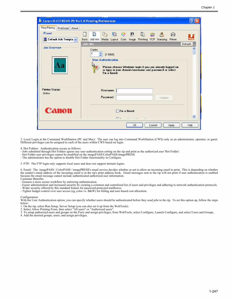
Chapter 1
1-247
3. Local Login at the Command WorkStation (PC and Mac): The user can log into Command WorkStation (CWS) only as an administrator, operator, or guest.Different privileges can be assigned to each of the users within CWS based on login.
4. Hot Folders: Authentication occurs as follows:- Jobs submitted through Hot Folders ignore any user authentication setting on the rip and print as the authorized user 'Hot Folder'.- Hot Folder user privileges cannot be modified on the imagePASS/ColorPASS/imagePRESS.- The administrator has the option to disable Hot Folder functionality in Configure.
5. FTP: The FTP login only supports local users and does not support domain logins.
6. Email: The imagePASS / ColorPASS / imagePRESS's email service decides whether or not to allow an incoming email to print. This is depending on whetherthe sender's email address of the incoming email is in the rip's print address book. Email messages sent to the rip will not print if user authentication is enabledbecause the email message cannot include authenticated authorized user information.Customer Benefits:- Ensures a more secure workflow by enforcing authentication.- Easier administration and increased security by creating a common and centralized list of users and privileges and adhering to network authentication protocols.- Wider security offered by this standard feature for password protected mailboxes.- Tighter budget control over user access (eg.,color vs. B&W) for billing and user-based cost allocation.
Configuration:With the User Authentication option, you can specify whether users should be authenticated before they send jobs to the rip. To set this option up, follow the stepsbelow:1. On the rip, select Run Setup, Server Setup (you can also set it up from the WebTools).2. Select Allow Printing From, then select "All users" or "Authorized users".3. To setup authorized users and groups on the Fiery and assign privileges, from WebTools, select Configure, Launch Configure, and select Users and Groups.4. Add the desired groups, users, and assign privileges.
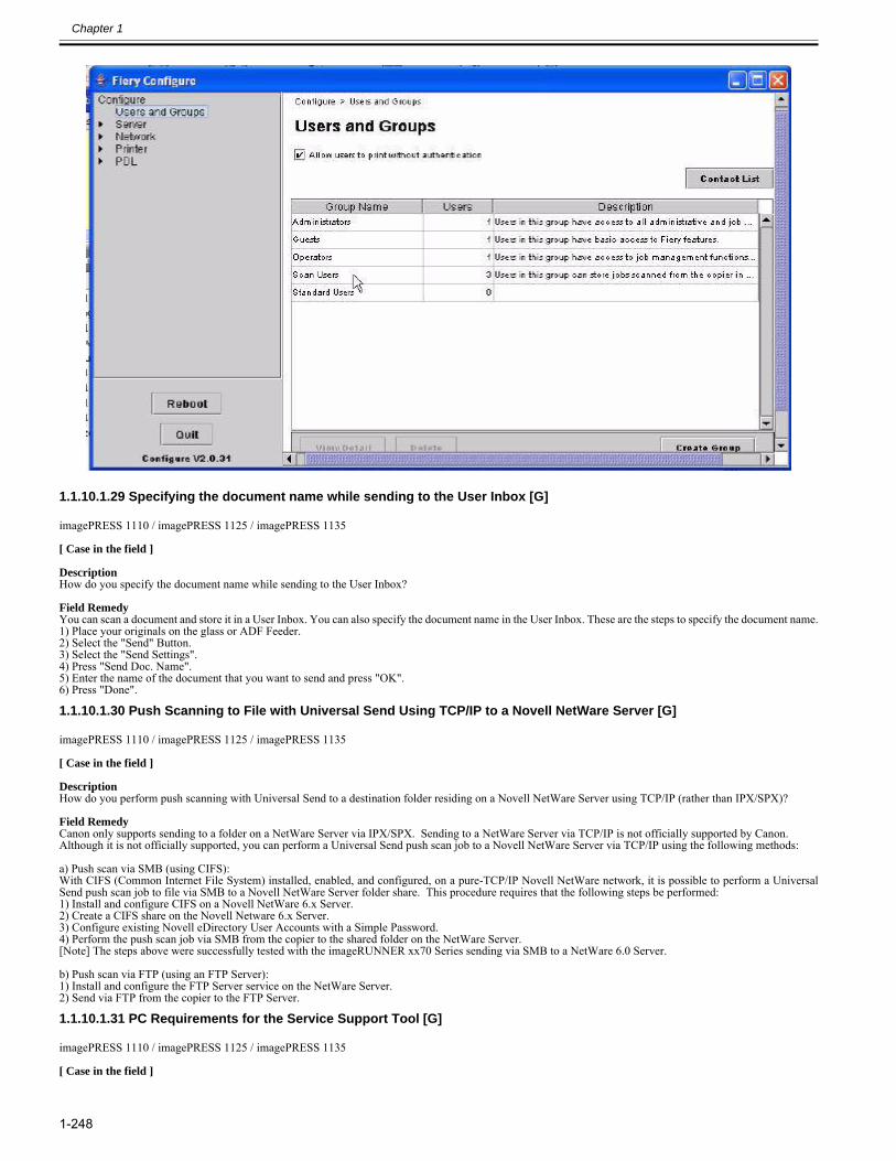
Chapter 1
1-248
1.1.10.1.29 Specifying the document name while sending to the User Inbox [G]0026-6189
imagePRESS 1110 / imagePRESS 1125 / imagePRESS 1135
[ Case in the field ] DescriptionHow do you specify the document name while sending to the User Inbox? Field RemedyYou can scan a document and store it in a User Inbox. You can also specify the document name in the User Inbox. These are the steps to specify the document name.1) Place your originals on the glass or ADF Feeder.2) Select the "Send" Button.3) Select the "Send Settings".4) Press "Send Doc. Name".5) Enter the name of the document that you want to send and press "OK".6) Press "Done".
1.1.10.1.30 Push Scanning to File with Universal Send Using TCP/IP to a Novell NetWare Server [G]0027-2936
imagePRESS 1110 / imagePRESS 1125 / imagePRESS 1135
[ Case in the field ] DescriptionHow do you perform push scanning with Universal Send to a destination folder residing on a Novell NetWare Server using TCP/IP (rather than IPX/SPX)? Field RemedyCanon only supports sending to a folder on a NetWare Server via IPX/SPX. Sending to a NetWare Server via TCP/IP is not officially supported by Canon. Although it is not officially supported, you can perform a Universal Send push scan job to a Novell NetWare Server via TCP/IP using the following methods:
a) Push scan via SMB (using CIFS):With CIFS (Common Internet File System) installed, enabled, and configured, on a pure-TCP/IP Novell NetWare network, it is possible to perform a UniversalSend push scan job to file via SMB to a Novell NetWare Server folder share. This procedure requires that the following steps be performed:1) Install and configure CIFS on a Novell NetWare 6.x Server. 2) Create a CIFS share on the Novell Netware 6.x Server. 3) Configure existing Novell eDirectory User Accounts with a Simple Password. 4) Perform the push scan job via SMB from the copier to the shared folder on the NetWare Server. [Note] The steps above were successfully tested with the imageRUNNER xx70 Series sending via SMB to a NetWare 6.0 Server.
b) Push scan via FTP (using an FTP Server):1) Install and configure the FTP Server service on the NetWare Server.2) Send via FTP from the copier to the FTP Server.
1.1.10.1.31 PC Requirements for the Service Support Tool [G]0027-4557
imagePRESS 1110 / imagePRESS 1125 / imagePRESS 1135
[ Case in the field ]
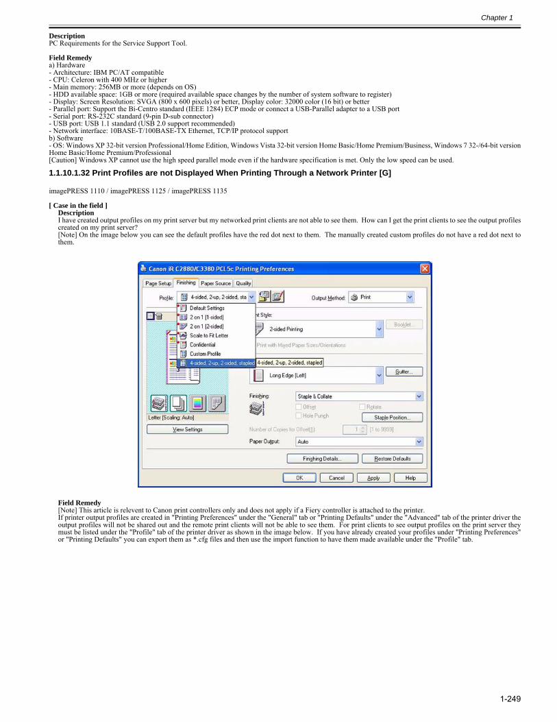
Chapter 1
1-249
DescriptionPC Requirements for the Service Support Tool. Field Remedya) Hardware- Architecture: IBM PC/AT compatible- CPU: Celeron with 400 MHz or higher- Main memory: 256MB or more (depends on OS)- HDD available space: 1GB or more (required available space changes by the number of system software to register)- Display: Screen Resolution: SVGA (800 x 600 pixels) or better, Display color: 32000 color (16 bit) or better- Parallel port: Support the Bi-Centro standard (IEEE 1284) ECP mode or connect a USB-Parallel adapter to a USB port- Serial port: RS-232C standard (9-pin D-sub connector)- USB port: USB 1.1 standard (USB 2.0 support recommended)- Network interface: 10BASE-T/100BASE-TX Ethernet, TCP/IP protocol supportb) Software- OS: Windows XP 32-bit version Professional/Home Edition, Windows Vista 32-bit version Home Basic/Home Premium/Business, Windows 7 32-/64-bit versionHome Basic/Home Premium/Professional[Caution] Windows XP cannot use the high speed parallel mode even if the hardware specification is met. Only the low speed can be used.
1.1.10.1.32 Print Profiles are not Displayed When Printing Through a Network Printer [G]0028-1096
imagePRESS 1110 / imagePRESS 1125 / imagePRESS 1135
[ Case in the field ]DescriptionI have created output profiles on my print server but my networked print clients are not able to see them. How can I get the print clients to see the output profilescreated on my print server?[Note] On the image below you can see the default profiles have the red dot next to them. The manually created custom profiles do not have a red dot next tothem.
Field Remedy[Note] This article is relevent to Canon print controllers only and does not apply if a Fiery controller is attached to the printer.If printer output profiles are created in "Printing Preferences" under the "General" tab or "Printing Defaults" under the "Advanced" tab of the printer driver theoutput profiles will not be shared out and the remote print clients will not be able to see them. For print clients to see output profiles on the print server theymust be listed under the "Profile" tab of the printer driver as shown in the image below. If you have already created your profiles under "Printing Preferences"or "Printing Defaults" you can export them as *.cfg files and then use the import function to have them made available under the "Profile" tab.
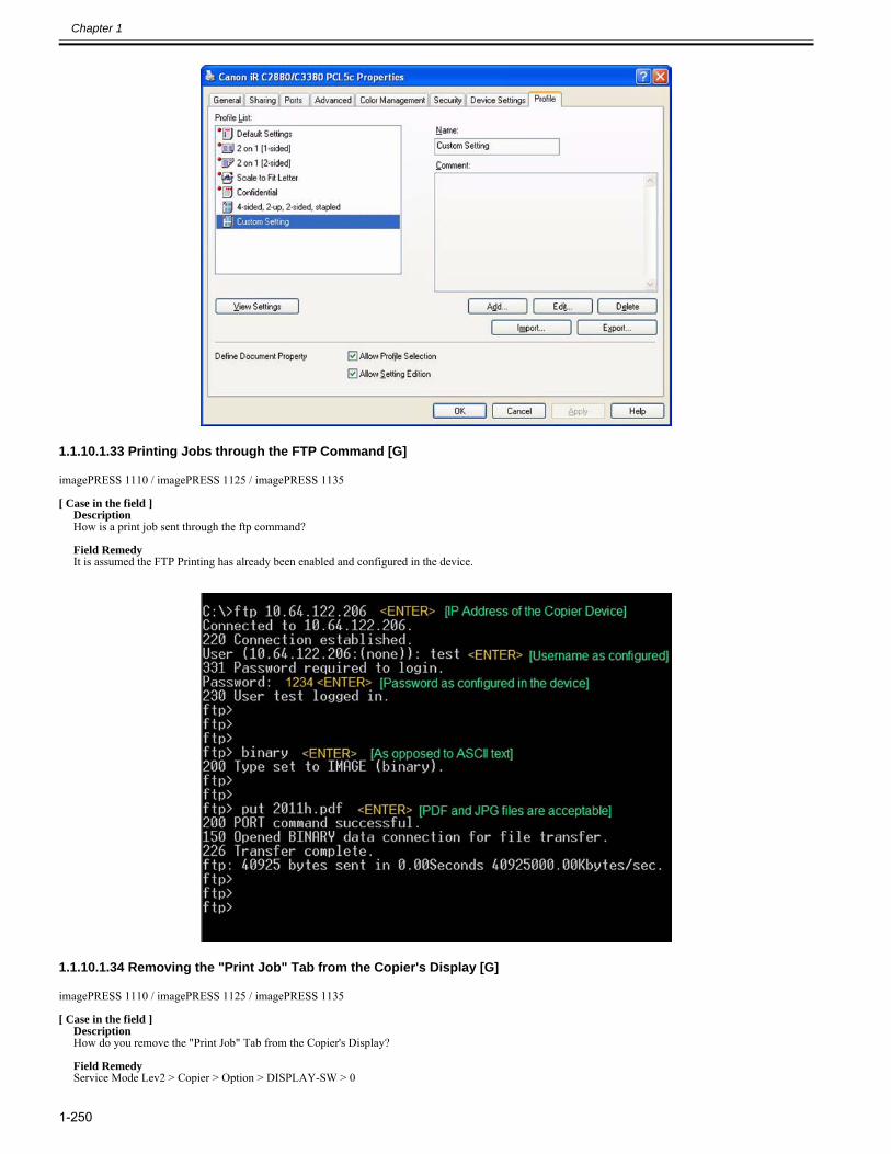
Chapter 1
1-250
1.1.10.1.33 Printing Jobs through the FTP Command [G]0028-1098
imagePRESS 1110 / imagePRESS 1125 / imagePRESS 1135
[ Case in the field ]DescriptionHow is a print job sent through the ftp command? Field RemedyIt is assumed the FTP Printing has already been enabled and configured in the device.
1.1.10.1.34 Removing the "Print Job" Tab from the Copier's Display [G]0028-1099
imagePRESS 1110 / imagePRESS 1125 / imagePRESS 1135
[ Case in the field ]DescriptionHow do you remove the "Print Job" Tab from the Copier's Display? Field RemedyService Mode Lev2 > Copier > Option > DISPLAY-SW > 0
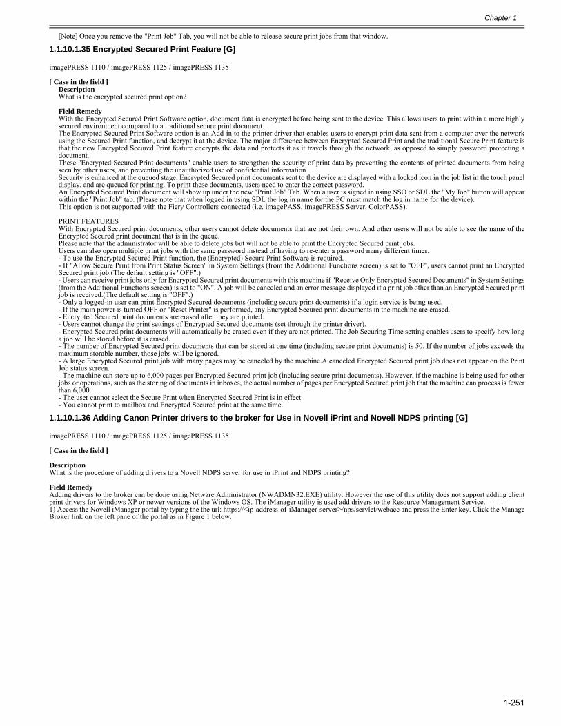
Chapter 1
1-251
[Note] Once you remove the "Print Job" Tab, you will not be able to release secure print jobs from that window.
1.1.10.1.35 Encrypted Secured Print Feature [G]0028-1100
imagePRESS 1110 / imagePRESS 1125 / imagePRESS 1135
[ Case in the field ]DescriptionWhat is the encrypted secured print option? Field RemedyWith the Encrypted Secured Print Software option, document data is encrypted before being sent to the device. This allows users to print within a more highlysecured environment compared to a traditional secure print document.The Encrypted Secured Print Software option is an Add-in to the printer driver that enables users to encrypt print data sent from a computer over the networkusing the Secured Print function, and decrypt it at the device. The major difference between Encrypted Secured Print and the traditional Secure Print feature isthat the new Encrypted Secured Print feature encrypts the data and protects it as it travels through the network, as opposed to simply password protecting adocument.These "Encrypted Secured Print documents" enable users to strengthen the security of print data by preventing the contents of printed documents from beingseen by other users, and preventing the unauthorized use of confidential information.Security is enhanced at the queued stage. Encrypted Secured print documents sent to the device are displayed with a locked icon in the job list in the touch paneldisplay, and are queued for printing. To print these documents, users need to enter the correct password.An Encrypted Secured Print document will show up under the new "Print Job" Tab. When a user is signed in using SSO or SDL the "My Job" button will appearwithin the "Print Job" tab. (Please note that when logged in using SDL the log in name for the PC must match the log in name for the device).This option is not supported with the Fiery Controllers connected (i.e. imagePASS, imagePRESS Server, ColorPASS).
PRINT FEATURESWith Encrypted Secured print documents, other users cannot delete documents that are not their own. And other users will not be able to see the name of theEncrypted Secured print document that is in the queue.Please note that the administrator will be able to delete jobs but will not be able to print the Encrypted Secured print jobs.Users can also open multiple print jobs with the same password instead of having to re-enter a password many different times.- To use the Encrypted Secured Print function, the (Encrypted) Secure Print Software is required.- If "Allow Secure Print from Print Status Screen" in System Settings (from the Additional Functions screen) is set to "OFF", users cannot print an EncryptedSecured print job.(The default setting is "OFF".)- Users can receive print jobs only for Encrypted Secured print documents with this machine if "Receive Only Encrypted Secured Documents" in System Settings(from the Additional Functions screen) is set to "ON". A job will be canceled and an error message displayed if a print job other than an Encrypted Secured printjob is received.(The default setting is "OFF".)- Only a logged-in user can print Encrypted Secured documents (including secure print documents) if a login service is being used.- If the main power is turned OFF or "Reset Printer" is performed, any Encrypted Secured print documents in the machine are erased.- Encrypted Secured print documents are erased after they are printed.- Users cannot change the print settings of Encrypted Secured documents (set through the printer driver).- Encrypted Secured print documents will automatically be erased even if they are not printed. The Job Securing Time setting enables users to specify how longa job will be stored before it is erased.- The number of Encrypted Secured print documents that can be stored at one time (including secure print documents) is 50. If the number of jobs exceeds themaximum storable number, those jobs will be ignored.- A large Encrypted Secured print job with many pages may be canceled by the machine.A canceled Encrypted Secured print job does not appear on the PrintJob status screen.- The machine can store up to 6,000 pages per Encrypted Secured print job (including secure print documents). However, if the machine is being used for otherjobs or operations, such as the storing of documents in inboxes, the actual number of pages per Encrypted Secured print job that the machine can process is fewerthan 6,000.- The user cannot select the Secure Print when Encrypted Secured Print is in effect.- You cannot print to mailbox and Encrypted Secured print at the same time.
1.1.10.1.36 Adding Canon Printer drivers to the broker for Use in Novell iPrint and Novell NDPS printing [G]0028-2817
imagePRESS 1110 / imagePRESS 1125 / imagePRESS 1135
[ Case in the field ] DescriptionWhat is the procedure of adding drivers to a Novell NDPS server for use in iPrint and NDPS printing? Field RemedyAdding drivers to the broker can be done using Netware Administrator (NWADMN32.EXE) utility. However the use of this utility does not support adding clientprint drivers for Windows XP or newer versions of the Windows OS. The iManager utility is used add drivers to the Resource Management Service. 1) Access the Novell iManager portal by typing the the url: https://<ip-address-of-iManager-server>/nps/servlet/webacc and press the Enter key. Click the ManageBroker link on the left pane of the portal as in Figure 1 below.
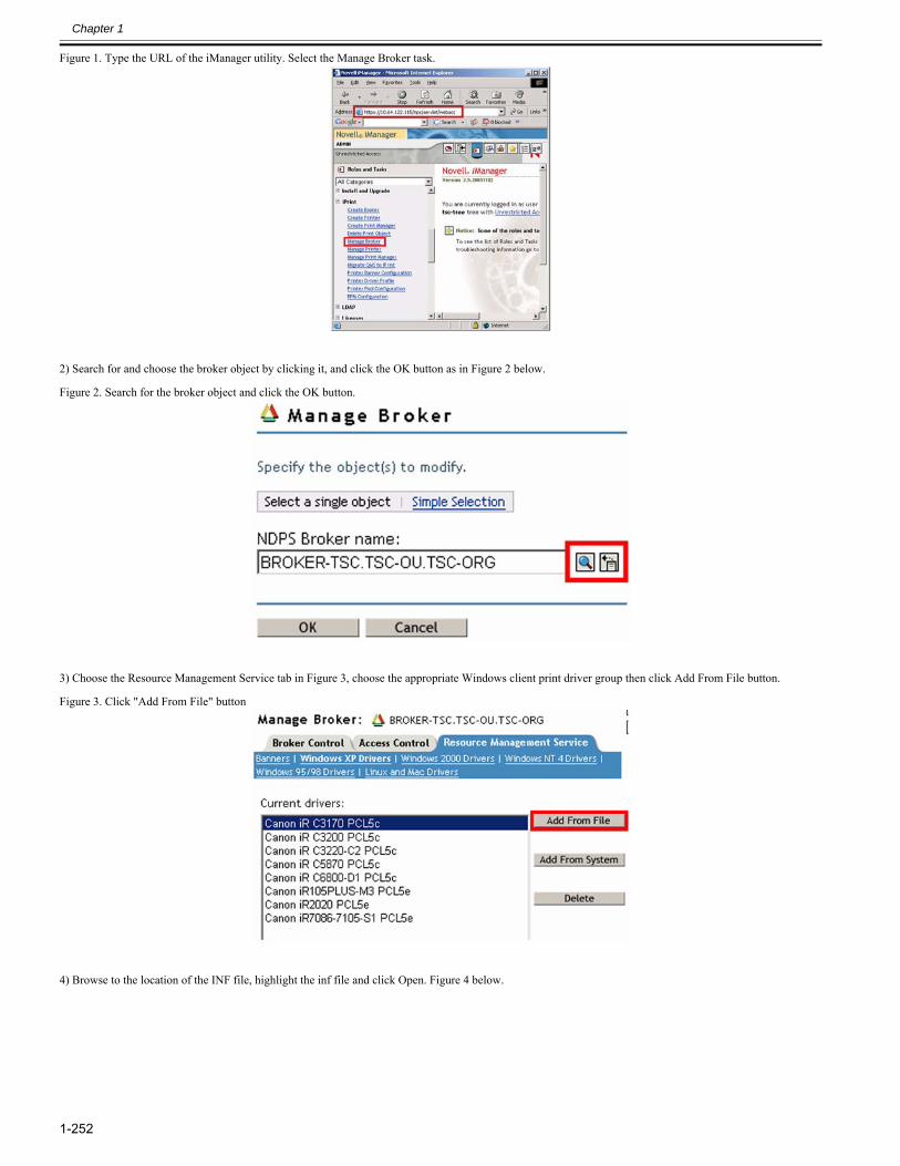
Chapter 1
1-252
Figure 1. Type the URL of the iManager utility. Select the Manage Broker task.
2) Search for and choose the broker object by clicking it, and click the OK button as in Figure 2 below. Figure 2. Search for the broker object and click the OK button.
3) Choose the Resource Management Service tab in Figure 3, choose the appropriate Windows client print driver group then click Add From File button. Figure 3. Click "Add From File" button
4) Browse to the location of the INF file, highlight the inf file and click Open. Figure 4 below.
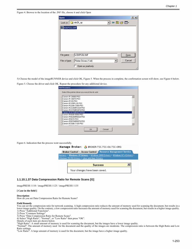
Chapter 1
1-253
Figure 4. Browse to the location of the .INF file, choose it and click Open
5) Choose the model of the imageRUNNER device and click OK, Figure 5. When the process in complete, the confirmation screen will show, see Figure 6 below. Figure 5. Choose the driver and click OK. Repeat the procedure for any additional device.
Figure 6. Indication that the process went successfully.
1.1.10.1.37 Data Compression Ratio for Remote Scans [G]0028-2822
imagePRESS 1110 / imagePRESS 1125 / imagePRESS 1135
[ Case in the field ] DescriptionHow do you set Data Compression Ratio for Remote Scans? Field RemedyYou can set the compression ratio for network scanning. A high compression ratio reduces the amount of memory used for scanning the document, but results in alower image quality. On the contrary, a low compression ratio increases the amount of memory used for scanning the document, but results in a higher image quality.1) Press "Additional Functions".2) Press "Common Settings"3) Press "Data Compression Ratio for Remote Scans".4) Select "High Ratio", "Normal", or "Low Ratio" then press "OK".Details of each item are shown below."High Ratio": A small amount of memory is used for scanning the document, but the images have a lower image quality."Normal": The amount of memory used for the document and the quality of the images are moderate. The compression ratio is between the High Ratio and LowRatio settings."Low Ratio": A large amount of memory is used for the document, but the image have a higher image quality.
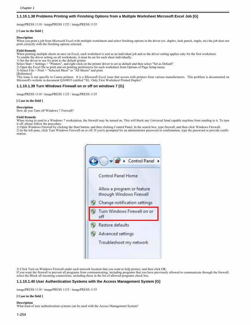
Chapter 1
1-254
1.1.10.1.38 Problems Printing with Finishing Options from a Multiple Worksheet Microsoft Excel Job [G]0028-4333
imagePRESS 1110 / imagePRESS 1125 / imagePRESS 1135
[ Case in the field ] DescriptionWhen you print a job from Microsoft Excel with multiple worksheets and select finishing options in the driver (ex. duplex, hole punch, staple, etc) the job does notprint correctly with the finishing options selected. Field RemedyWhen printing multiple sheets at once on Excel, each worksheet is sent as an individual job and so the driver setting applies only for the first worksheet.To enable the driver setting on all worksheets, it must be set for each sheet individually.1) Set the driver to use for print to the default printer.Select Start > Settings > "Printers", and right click on the printer driver to set as default and then select "Set as Default".2) Open the Excel file to print and set printing preferences for each worksheet from Options of Page Setup menu.3) Select File > Print > "Selected Sheet" or "All Sheets" and print.[Reference]This issue is not specific to Canon printers. It is a Microsoft Excel issue that occurs with printers from various manufacturers. This problem is documented onMicrosoft's website in document Q169033 entitled "XL: Only First Worksheet Printed Duplex".
1.1.10.1.39 Turn Windows Firewall on or off on windows 7 [G]0028-4334
imagePRESS 1110 / imagePRESS 1125 / imagePRESS 1135
[ Case in the field ] DescriptionHow do you Turn off Windows 7 Firewall? Field RemedyWhen trying to send to a Windows 7 workstation, the firewall may be turned on. This will block any Universal Send capable machine from sending to it. To turnit off, please follow the procedure.1) Open Windows Firewall by clicking the Start button, and then clicking Control Panel. In the search box, type firewall, and then click Windows Firewall.2) In the left pane, click Turn Windows Firewall on or off. If you're prompted for an administrator password or confirmation, type the password or provide confir-mation.
3) Click Turn on Windows Firewall under each network location that you want to help protect, and then click OK.If you want the firewall to prevent all programs from communicating, including programs that you have previously allowed to communicate through the firewall,select the Block all incoming connections, including those in the list of allowed programs check box.
1.1.10.1.40 User Authentication Systems with the Access Management System [G]0028-4335
imagePRESS 1110 / imagePRESS 1125 / imagePRESS 1135
[ Case in the field ] DescriptionWhat kind of user authentication systems can be used with the Access Management System?
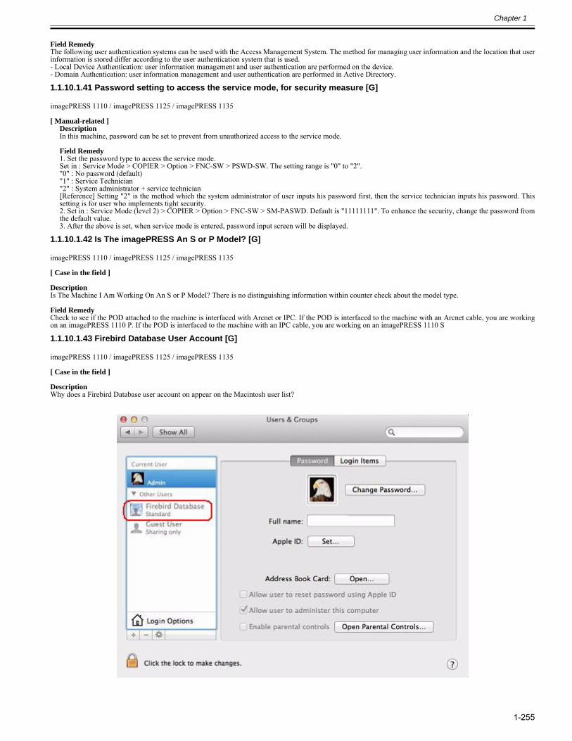
Chapter 1
1-255
Field RemedyThe following user authentication systems can be used with the Access Management System. The method for managing user information and the location that userinformation is stored differ according to the user authentication system that is used. - Local Device Authentication: user information management and user authentication are performed on the device. - Domain Authentication: user information management and user authentication are performed in Active Directory.
1.1.10.1.41 Password setting to access the service mode, for security measure [G]0028-4495
imagePRESS 1110 / imagePRESS 1125 / imagePRESS 1135
[ Manual-related ]DescriptionIn this machine, password can be set to prevent from unauthorized access to the service mode. Field Remedy1. Set the password type to access the service mode.Set in : Service Mode > COPIER > Option > FNC-SW > PSWD-SW. The setting range is "0" to "2"."0" : No password (default)"1" : Service Technician"2" : System administrator + service technician[Reference] Setting "2" is the method which the system administrator of user inputs his password first, then the service technician inputs his password. Thissetting is for user who implements tight security. 2. Set in : Service Mode (level 2) > COPIER > Option > FNC-SW > SM-PASWD. Default is "11111111". To enhance the security, change the password fromthe default value.3. After the above is set, when service mode is entered, password input screen will be displayed.
1.1.10.1.42 Is The imagePRESS An S or P Model? [G]0028-4522
imagePRESS 1110 / imagePRESS 1125 / imagePRESS 1135
[ Case in the field ] DescriptionIs The Machine I Am Working On An S or P Model? There is no distinguishing information within counter check about the model type. Field RemedyCheck to see if the POD attached to the machine is interfaced with Arcnet or IPC. If the POD is interfaced to the machine with an Arcnet cable, you are workingon an imagePRESS 1110 P. If the POD is interfaced to the machine with an IPC cable, you are working on an imagePRESS 1110 S
1.1.10.1.43 Firebird Database User Account [G]0028-5154
imagePRESS 1110 / imagePRESS 1125 / imagePRESS 1135
[ Case in the field ] DescriptionWhy does a Firebird Database user account on appear on the Macintosh user list?
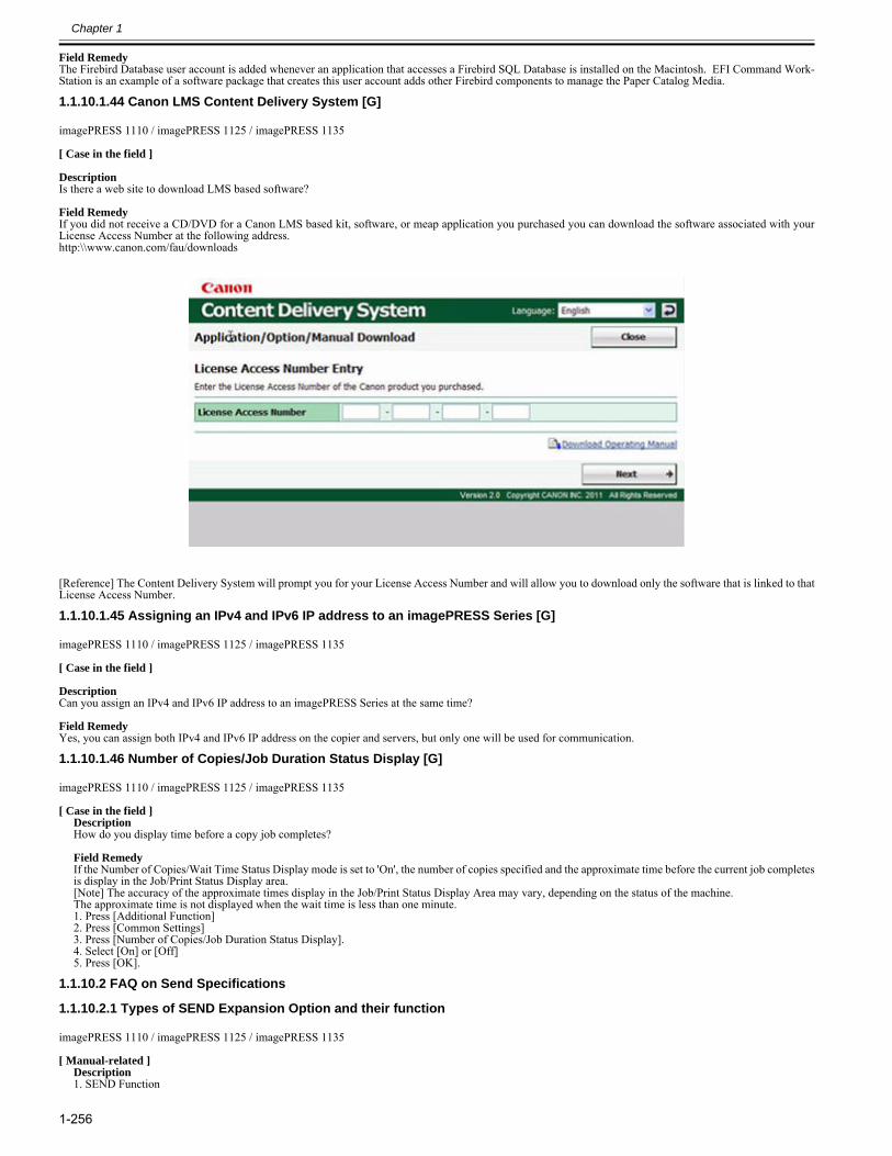
Chapter 1
1-256
Field RemedyThe Firebird Database user account is added whenever an application that accesses a Firebird SQL Database is installed on the Macintosh. EFI Command Work-Station is an example of a software package that creates this user account adds other Firebird components to manage the Paper Catalog Media.
1.1.10.1.44 Canon LMS Content Delivery System [G]0028-5156
imagePRESS 1110 / imagePRESS 1125 / imagePRESS 1135
[ Case in the field ] DescriptionIs there a web site to download LMS based software? Field RemedyIf you did not receive a CD/DVD for a Canon LMS based kit, software, or meap application you purchased you can download the software associated with yourLicense Access Number at the following address.http:\\www.canon.com/fau/downloads
[Reference] The Content Delivery System will prompt you for your License Access Number and will allow you to download only the software that is linked to thatLicense Access Number.
1.1.10.1.45 Assigning an IPv4 and IPv6 IP address to an imagePRESS Series [G]0029-1294
imagePRESS 1110 / imagePRESS 1125 / imagePRESS 1135
[ Case in the field ] DescriptionCan you assign an IPv4 and IPv6 IP address to an imagePRESS Series at the same time? Field RemedyYes, you can assign both IPv4 and IPv6 IP address on the copier and servers, but only one will be used for communication.
1.1.10.1.46 Number of Copies/Job Duration Status Display [G]0025-4073
imagePRESS 1110 / imagePRESS 1125 / imagePRESS 1135
[ Case in the field ]DescriptionHow do you display time before a copy job completes? Field RemedyIf the Number of Copies/Wait Time Status Display mode is set to 'On', the number of copies specified and the approximate time before the current job completesis display in the Job/Print Status Display area.[Note] The accuracy of the approximate times display in the Job/Print Status Display Area may vary, depending on the status of the machine.The approximate time is not displayed when the wait time is less than one minute.1. Press [Additional Function]2. Press [Common Settings]3. Press [Number of Copies/Job Duration Status Display]. 4. Select [On] or [Off]5. Press [OK].
1.1.10.2 FAQ on Send Specifications
1.1.10.2.1 Types of SEND Expansion Option and their function0023-0953
imagePRESS 1110 / imagePRESS 1125 / imagePRESS 1135
[ Manual-related ]Description1. SEND Function
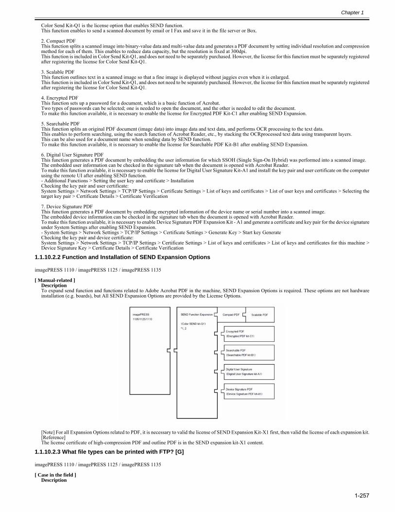
Chapter 1
1-257
Color Send Kit-Q1 is the license option that enables SEND function.This function enables to send a scanned document by email or I Fax and save it in the file server or Box.
2. Compact PDFThis function splits a scanned image into binary-value data and multi-value data and generates a PDF document by setting individual resolution and compressionmethod for each of them. This enables to reduce data capacity, but the resolution is fixed at 300dpi.This function is included in Color Send Kit-Q1, and does not need to be separately purchased. However, the license for this function must be separately registeredafter registering the license for Color Send Kit-Q1.
3. Scalable PDFThis function outlines text in a scanned image so that a fine image is displayed without jaggies even when it is enlarged.This function is included in Color Send Kit-Q1, and does not need to be separately purchased. However, the license for this function must be separately registeredafter registering the license for Color Send Kit-Q1.
4. Encrypted PDFThis function sets up a password for a document, which is a basic function of Acrobat.Two types of passwords can be selected; one is needed to open the document, and the other is needed to edit the document.To make this function available, it is necessary to enable the license for Encrypted PDF Kit-C1 after enabling SEND Expansion.
5. Searchable PDFThis function splits an original PDF document (image data) into image data and text data, and performs OCR processing to the text data.This enables to perform searching, using the search function of Acrobat Reader, etc., by stacking the OCRprocessed text data using transparent layers.This can be also used for a document name when sending data by SEND function.To make this function available, it is necessary to enable the license for Searchable PDF Kit-B1 after enabling SEND Expansion.
6. Digital User Signature PDFThis function generates a PDF document by embedding the user information for which SSOH (Single Sign-On Hybrid) was performed into a scanned image.The embedded user information can be checked in the signature tab when the document is opened with Acrobat Reader.To make this function available, it is necessary to enable the license for Digital User Signature Kit-A1 and install the key pair and user certificate on the computerusing the remote UI after enabling SEND function.- Additional Functions > Setting the user key and certificate > InstallationChecking the key pair and user certificate: System Settings > Network Settings > TCP/IP Settings > Certificate Settings > List of keys and certificates > List of user keys and certificates > Selecting thetarget key pair > Certificate Details > Certificate Verification
7. Device Signature PDFThis function generates a PDF document by embedding encrypted information of the device name or serial number into a scanned image.The embedded device information can be checked in the signature tab when the document is opened with Acrobat Reader.To make this function available, it is necessary to enable Device Signature PDF Expansion Kit - A1 and generate a certificate and key pair for the device signatureunder System Settings after enabling SEND Expansion.- System Settings > Network Settings > TCP/IP Settings > Certificate Settings > Generate Key > Start key GenerateChecking the key pair and device certificate: System Settings > Network Settings > TCP/IP Settings > Certificate Settings > List of keys and certificates > List of keys and certificates for this machine >Device Signature Key > Certificate Details > Certificate Verification
1.1.10.2.2 Function and Installation of SEND Expansion Options0023-1921
imagePRESS 1110 / imagePRESS 1125 / imagePRESS 1135
[ Manual-related ]DescriptionTo expand send function and functions related to Adobe Acrobat PDF in the machine, SEND Expansion Options is required. These options are not hardwareinstallation (e.g. boards), but All SEND Expansion Options are provided by the License Options.
[Note] For all Expansion Options related to PDF, it is necessary to valid the license of SEND Expansion Kit-X1 first, then valid the license of each expansion kit.[Reference] The license certificate of high-compression PDF and outline PDF is in the SEND expansion kit-X1 content.
1.1.10.2.3 What file types can be printed with FTP? [G]0028-1101
imagePRESS 1110 / imagePRESS 1125 / imagePRESS 1135
[ Case in the field ]Description
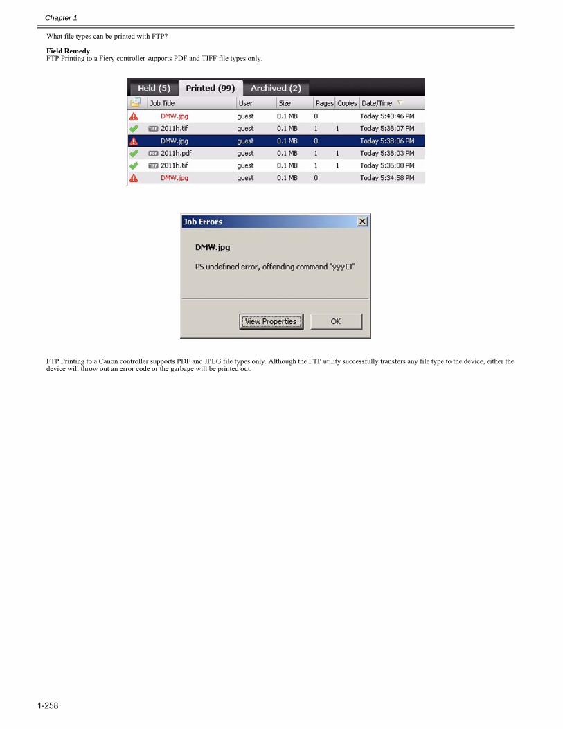
Chapter 1
1-258
What file types can be printed with FTP? Field RemedyFTP Printing to a Fiery controller supports PDF and TIFF file types only.
FTP Printing to a Canon controller supports PDF and JPEG file types only. Although the FTP utility successfully transfers any file type to the device, either thedevice will throw out an error code or the garbage will be printed out.
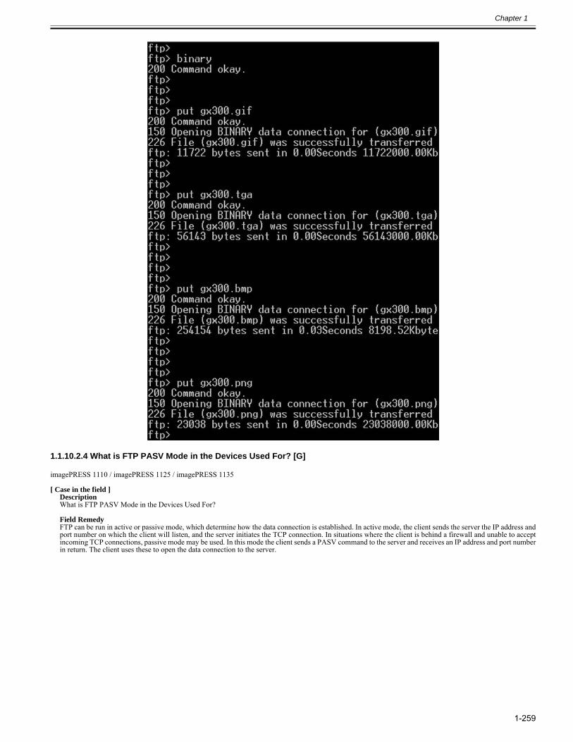
Chapter 1
1-259
1.1.10.2.4 What is FTP PASV Mode in the Devices Used For? [G]0028-1102
imagePRESS 1110 / imagePRESS 1125 / imagePRESS 1135
[ Case in the field ]DescriptionWhat is FTP PASV Mode in the Devices Used For? Field RemedyFTP can be run in active or passive mode, which determine how the data connection is established. In active mode, the client sends the server the IP address andport number on which the client will listen, and the server initiates the TCP connection. In situations where the client is behind a firewall and unable to acceptincoming TCP connections, passive mode may be used. In this mode the client sends a PASV command to the server and receives an IP address and port numberin return. The client uses these to open the data connection to the server.
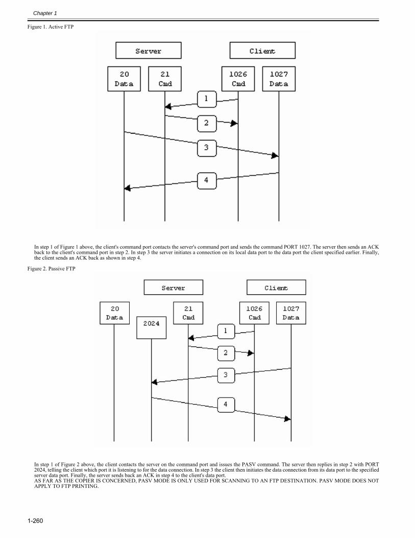
Chapter 1
1-260
Figure 1. Active FTP
In step 1 of Figure 1 above, the client's command port contacts the server's command port and sends the command PORT 1027. The server then sends an ACKback to the client's command port in step 2. In step 3 the server initiates a connection on its local data port to the data port the client specified earlier. Finally,the client sends an ACK back as shown in step 4.
Figure 2. Passive FTP
In step 1 of Figure 2 above, the client contacts the server on the command port and issues the PASV command. The server then replies in step 2 with PORT2024, telling the client which port it is listening to for the data connection. In step 3 the client then initiates the data connection from its data port to the specifiedserver data port. Finally, the server sends back an ACK in step 4 to the client's data port.AS FAR AS THE COPIER IS CONCERNED, PASV MODE IS ONLY USED FOR SCANNING TO AN FTP DESTINATION. PASV MODE DOES NOTAPPLY TO FTP PRINTING.
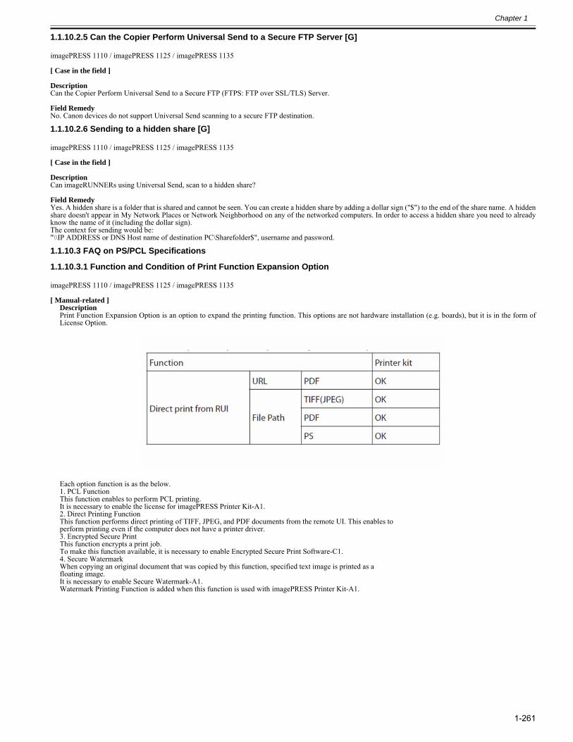
Chapter 1
1-261
1.1.10.2.5 Can the Copier Perform Universal Send to a Secure FTP Server [G]0028-2816
imagePRESS 1110 / imagePRESS 1125 / imagePRESS 1135
[ Case in the field ] DescriptionCan the Copier Perform Universal Send to a Secure FTP (FTPS: FTP over SSL/TLS) Server. Field RemedyNo. Canon devices do not support Universal Send scanning to a secure FTP destination.
1.1.10.2.6 Sending to a hidden share [G]0028-4331
imagePRESS 1110 / imagePRESS 1125 / imagePRESS 1135
[ Case in the field ] DescriptionCan imageRUNNERs using Universal Send, scan to a hidden share? Field RemedyYes. A hidden share is a folder that is shared and cannot be seen. You can create a hidden share by adding a dollar sign ("$") to the end of the share name. A hiddenshare doesn't appear in My Network Places or Network Neighborhood on any of the networked computers. In order to access a hidden share you need to alreadyknow the name of it (including the dollar sign).The context for sending would be:"\\IP ADDRESS or DNS Host name of destination PC\Sharefolder$", username and password.
1.1.10.3 FAQ on PS/PCL Specifications
1.1.10.3.1 Function and Condition of Print Function Expansion Option0023-1961
imagePRESS 1110 / imagePRESS 1125 / imagePRESS 1135
[ Manual-related ]DescriptionPrint Function Expansion Option is an option to expand the printing function. This options are not hardware installation (e.g. boards), but it is in the form ofLicense Option.
Each option function is as the below.1. PCL FunctionThis function enables to perform PCL printing.It is necessary to enable the license for imagePRESS Printer Kit-A1.2. Direct Printing FunctionThis function performs direct printing of TIFF, JPEG, and PDF documents from the remote UI. This enables toperform printing even if the computer does not have a printer driver.3. Encrypted Secure PrintThis function encrypts a print job.To make this function available, it is necessary to enable Encrypted Secure Print Software-C1.4. Secure WatermarkWhen copying an original document that was copied by this function, specified text image is printed as afloating image.It is necessary to enable Secure Watermark-A1.Watermark Printing Function is added when this function is used with imagePRESS Printer Kit-A1.


Nov 8 2012

Related Documents