Send documentation comments to [email protected]. B-1 Cisco MDS 9020 Fabric Switch Hardware Installation Guide OL-6987-01 APPENDIX B Troubleshooting This appendix describes how to troubleshoot the Cisco MDS 9020 Fabric hardware installation, and it includes the following information: • General System Checks, page B-1 • Troubleshooting Components, page B-1 • Identifying Startup Problems, page B-9 • Contacting Customer Service, page B-10 General System Checks Problems with the initial power up are often caused by a switch that has been disconnected from the power cord connector. When the initial system boot is complete, verify that: • The switch is installed correctly and it initializes without problems. Refer to Chapter 2, “Installing the Cisco MDS 9020 Fabric Switch.” • The power supply is supplying power to the system and the fans are operating. Troubleshooting Components Diagnostic information about the switch is available through the chassis LEDs and the port LEDs. This section describes the following types of diagnostics: • Switch Diagnostics, page B-2 • Power-On Self Test Diagnostics, page B-3 This section also describes how to use maintenance mode to recover a disabled switch.

Welcome message from author
This document is posted to help you gain knowledge. Please leave a comment to let me know what you think about it! Share it to your friends and learn new things together.
Transcript
Send documenta t ion comments to mdsfeedback -doc@c i sco .com.
Cisco MDS 9020 FabOL-6987-01
A P P E N D I X B
TroubleshootingThis appendix describes how to troubleshoot the Cisco MDS 9020 Fabric hardware installation, and it includes the following information:
• General System Checks, page B-1
• Troubleshooting Components, page B-1
• Identifying Startup Problems, page B-9
• Contacting Customer Service, page B-10
General System ChecksProblems with the initial power up are often caused by a switch that has been disconnected from the power cord connector. When the initial system boot is complete, verify that:
• The switch is installed correctly and it initializes without problems. Refer to Chapter 2, “Installing the Cisco MDS 9020 Fabric Switch.”
• The power supply is supplying power to the system and the fans are operating.
Troubleshooting ComponentsDiagnostic information about the switch is available through the chassis LEDs and the port LEDs. This section describes the following types of diagnostics:
• Switch Diagnostics, page B-2
• Power-On Self Test Diagnostics, page B-3
This section also describes how to use maintenance mode to recover a disabled switch.
B-1ric Switch Hardware Installation Guide
Send documenta t ion comments to mdsfeedback -doc@c i sco .com.
Appendix B TroubleshootingTroubleshooting Components
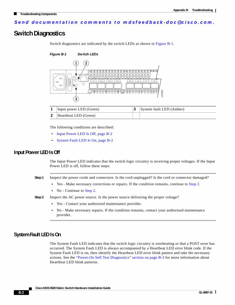
Switch DiagnosticsSwitch diagnostics are indicated by the switch LEDs as shown in Figure B-1.
Figure B-1 Switch LEDs
The following conditions are described:
• Input Power LED Is Off, page B-2
• System Fault LED Is On, page B-2
Input Power LED Is Off
The Input Power LED indicates that the switch logic circuitry is receiving proper voltages. If the Input Power LED is off, follow these steps:
Step 1 Inspect the power cords and connectors. Is the cord unplugged? Is the cord or connector damaged?
• Yes - Make necessary corrections or repairs. If the condition remains, continue to Step 2.
• No - Continue to Step 2.
Step 2 Inspect the AC power source. Is the power source delivering the proper voltage?
• Yes - Contact your authorized maintenance provider.
• No - Make necessary repairs. If the condition remains, contact your authorized maintenance provider.
System Fault LED Is On
The System Fault LED indicates that the switch logic circuitry is overheating or that a POST error has occurred. The System Fault LED is always accompanied by a Heartbeat LED error blink code. If the System Fault LED is on, then identify the Heartbeat LED error blink pattern and take the necessary actions. See the “Power-On Self Test Diagnostics” section on page B-3 for more information about Heartbeat LED blink patterns.
1 Input power LED (Green) 3 System fault LED (Amber)
2 Heartbeat LED (Green)
1376
50
1
3
2
B-2Cisco MDS 9020 Fabric Switch Hardware Installation Guide
OL-6987-01
Send documenta t ion comments to mdsfeedback -doc@c i sco .com.
Appendix B TroubleshootingTroubleshooting Components
Power-On Self Test DiagnosticsThe switch performs a series of tests as part of its power-up procedure. The POST diagnostic program performs the following tests:
• Checksum tests on the boot firmware in PROM and the switch firmware in Flash memory
• Internal data loopback test on all ports
• Access and integrity tests on the ASIC
During the POST, the switch logs any errors encountered. Some POST errors are critical, others are not. The switch uses the Heartbeat LED and the Logged-In LED to indicate switch and port status. A critical error disables the switch so that it will not operate. A non-critical error allows the switch to operate, but disables the ports that have errors. Whether the problem is critical or not, contact your authorized maintenance provider.
If there are no errors, the Heartbeat LED blinks at a steady rate of once per second. If a critical error occurs, the Heartbeat LED will show an error blink pattern and the System Fault LED will be on. If there are non-critical errors, the switch disables the failed ports and flashes the associated Logged-In LEDs.
The Heartbeat LED indicates the operational status of the switch. When the POST completes with no errors, the Heartbeat LED blinks at a steady rate of once per second. When the switch is in maintenance mode, the Heartbeat LED is on continuously. See the “Recovering a Switch Using Maintenance Mode” section on page B-6 for more information about maintenance mode. All other blink patterns indicate critical errors. In addition to producing Heartbeat error blink patterns, a critical error also turns on the System Fault LED.
The Heartbeat LED shows an error blink pattern for the following conditions:
• 2 blinks – Internal Firmware Failure Blink Pattern, page B-3
• 3 blinks – System Error Blink Pattern, page B-3
• 4 blinks – Configuration File System Error Blink Pattern, page B-3
• 5 blinks – Over Temperature Blink Pattern, page B-4
Internal Firmware Failure Blink Pattern
An internal firmware failure blink pattern is two blinks followed by a two-second pause. The two-blink error pattern indicates that the firmware has failed, and that the switch must be reset. Momentarily press and release the Maintenance button to reset the switch.
System Error Blink Pattern
A system error blink pattern is three blinks followed by a two-second pause. The three-blink error pattern indicates that a POST failure or a system error has left the switch inoperable. If a system error occurs, contact your authorized maintenance provider. Momentarily press and release the Maintenance button to reset the switch.
Configuration File System Error Blink Pattern
A configuration file system error blink pattern is four blinks followed by a two-second pause. The four-blink error pattern indicates that a file system error has occurred, and that the file system must be recreated. To recreate the file system, see “Remaking the Filesystem” section on page B-8.
B-3Cisco MDS 9020 Fabric Switch Hardware Installation Guide
OL-6987-01
Send documenta t ion comments to mdsfeedback -doc@c i sco .com.
Appendix B TroubleshootingTroubleshooting Components
Over Temperature Blink Pattern
An over temperature blink pattern is five blinks followed by a two-second pause. The five-blink error pattern indicates that the air temperature inside the switch has exceeded the failure temperature threshold. The failure temperature threshold is 70° C (158 ° F).
If the Heartbeat LED shows the over temperature blink pattern, follow these steps:
Step 1 Inspect the chassis vents. Are the intake and exhaust vents clear?
• Yes - Continue to Step 2.
• No - Remove any debris from fan intake and exhaust if necessary. If the condition remains, continue to Step 2.
Step 2 Consider the ambient air temperature near the switch and clearance around the switch. Make necessary corrections. If the condition remains, power down the switch and contact your authorized maintenance provider.
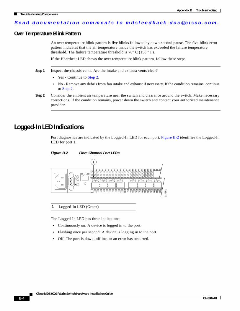
Logged-In LED IndicationsPort diagnostics are indicated by the Logged-In LED for each port. Figure B-2 identifies the Logged-In LED for port 1.
Figure B-2 Fibre Channel Port LEDs
The Logged-In LED has three indications:
• Continuously on: A device is logged in to the port.
• Flashing once per second: A device is logging in to the port.
• Off: The port is down, offline, or an error has occurred.
1 Logged-In LED (Green)
1376
511
B-4Cisco MDS 9020 Fabric Switch Hardware Installation Guide
OL-6987-01
Send documenta t ion comments to mdsfeedback -doc@c i sco .com.
Appendix B TroubleshootingTroubleshooting Components
If a Logged-In LED is off, review the logfile for messages regarding the affected port. A Logged-In LED error indication is often the result of E Port isolation. E Port isolation can be caused by the following:
• FL Port is connected to another switch
• Conflicting domain IDs
• Conflicting timeout values
• Conflicting zone membership between active zone sets
Refer to the Cisco MDS 9020 Fabric Switch Configuration Guide and Command Reference for information about how to change domain IDs, timeout values, and zoning.
To diagnose an isolated E Port, follow these steps:
Step 1 Display the logfile using the show logging logfile command. Does the logfile show a repeating message about an unsupported E Port command on the affected port?
• Yes - The port is configured as an FL Port and connected to another switch. Correct the port connection or the port type.
• No - Continue to Step 2.
Step 2 Display the fabric domain IDs using the show fcdomain domain-list command. Are all domain IDs in the fabric unique?
• Yes - Continue to Step 3.
• No - Correct the domain IDs on the offending switches. Reset the port. If the condition remains, continue to Step 3.
Step 3 Display timeout values using the show fctimer command on each switch. Compare the r_a_tov and e_d_tov timeout values for all switches in the fabric. Are the timeout values the same on every switch?
• Yes - Continue Step 4.
• No - Correct the timeout values on the offending switches. If the condition remains, continue to Step 4.
Step 4 Display the active zone set using the show zoneset active command on each switch. Compare the zone membership among the active zone sets. Are they the same?
• Yes - Contact your authorized maintenance provider.
• No - Deactivate one of the active zone sets or edit the conflicting zones so that their membership is the same. If the condition remains, contact your authorized maintenance provider.
B-5Cisco MDS 9020 Fabric Switch Hardware Installation Guide
OL-6987-01
Send documenta t ion comments to mdsfeedback -doc@c i sco .com.
Appendix B TroubleshootingTroubleshooting Components
Recovering a Switch Using Maintenance ModeA switch can become inoperable or unmanageable for the following reasons:
• Firmware becomes corrupt
• IP address is lost
• Switch configuration becomes corrupt
• Forgotten password
In these specific cases, you can recover the switch using maintenance mode. Maintenance mode temporarily returns the switch IP address to 10.0.0.1 and provides opportunities to do the following:
• Restore the default password for the admin account
• Restore the network configuration parameters to the default values
• Restore all switch configuration parameters to the factory default values
• Recreate the switch file system.
• Reset the switch
• Update the system boot loader
To recover a switch, follow these steps:
Step 1 Isolate the switch from the fabric.
Step 2 Establish a serial connection from the PC console to the switch console port.
Step 3 Place the switch in maintenance mode. Press and hold the Maintenance button with a pointed tool. When the Heartbeat LED turns on continuously, release the button.
Step 4 Enter the maintenance mode account name and password (prom, prom), and press the Enter key.
Switch login: promPassword:xxxx
Step 5 The Maintenance menu presents several recovery options. Select a switch recovery option by pressing the corresponding number (displayed in option: field) on the keyboard and press the Enter key.
0) Exit1) Image Unpack2) Reset Network Config3) Reset User Accounts to Default4) Copy Log Files5) Remove Switch Config6) Remake Filesystem7) Reset Switch8) Update Boot LoaderOption:
Step 6 To return to normal operation, select option 7, Reset Switch.
B-6Cisco MDS 9020 Fabric Switch Hardware Installation Guide
OL-6987-01
Send documenta t ion comments to mdsfeedback -doc@c i sco .com.
Appendix B TroubleshootingTroubleshooting Components
The maintenance menu options are described in the following sections:
• Exiting Maintenance Mode, page B-7
• Unpacking Firmware Image Files, page B-7
• Resetting the Network Configuration, page B-7
• Restoring the Default User Accounts, page B-7
• Copying Log Files, page B-7
• Removing the Switch Configuration, page B-8
• Remaking the Filesystem, page B-8
• Resetting the Switch, page B-8
• Updating the Boot Loader, page B-9
Exiting Maintenance Mode
This option closes the current login session. To log in again, enter the maintenance mode account name and password (prom, prom). To return to normal operation, select option 7 for Reset Switch from the Maintenance menu.
Unpacking Firmware Image Files
This option is not applicable to the Cisco MDS 9020 Fabric Switch.
Resetting the Network Configuration
The Reset Network Config option resets the network properties to the factory default values and disables the mgmt0 interface. The network default values are as follows:
• IP address: 10.0.0.1
• Subnet mask: 255.0.0.0
• Gateway: 10.0.0.254
Restoring the Default User Accounts
The Reset User Accounts to Default option restores the password for the Admin account name to the default (admin123) and removes all other user accounts from the switch.
Copying Log Files
This option is not applicable to the Cisco MDS 9020 Fabric Switch.
B-7Cisco MDS 9020 Fabric Switch Hardware Installation Guide
OL-6987-01
Send documenta t ion comments to mdsfeedback -doc@c i sco .com.
Appendix B TroubleshootingTroubleshooting Components
Removing the Switch Configuration
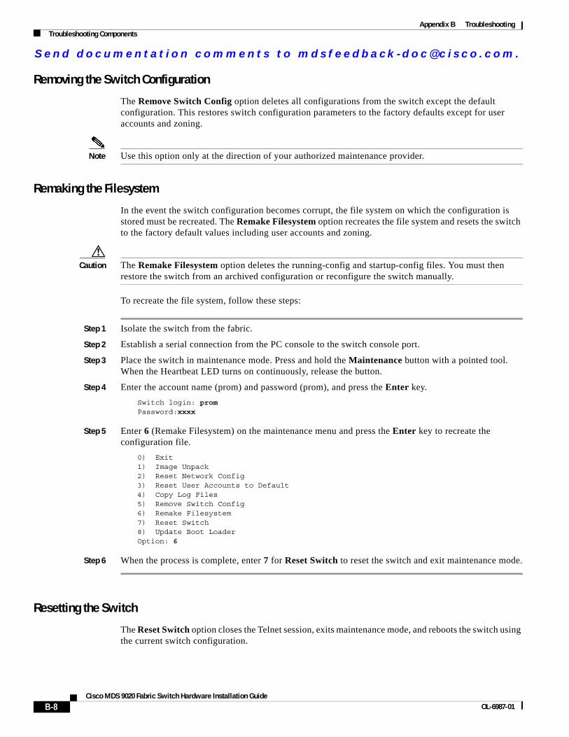
The Remove Switch Config option deletes all configurations from the switch except the default configuration. This restores switch configuration parameters to the factory defaults except for user accounts and zoning.
Note Use this option only at the direction of your authorized maintenance provider.
Remaking the Filesystem
In the event the switch configuration becomes corrupt, the file system on which the configuration is stored must be recreated. The Remake Filesystem option recreates the file system and resets the switch to the factory default values including user accounts and zoning.
Caution The Remake Filesystem option deletes the running-config and startup-config files. You must then restore the switch from an archived configuration or reconfigure the switch manually.
To recreate the file system, follow these steps:
Step 1 Isolate the switch from the fabric.
Step 2 Establish a serial connection from the PC console to the switch console port.
Step 3 Place the switch in maintenance mode. Press and hold the Maintenance button with a pointed tool. When the Heartbeat LED turns on continuously, release the button.
Step 4 Enter the account name (prom) and password (prom), and press the Enter key.
Switch login: promPassword:xxxx
Step 5 Enter 6 (Remake Filesystem) on the maintenance menu and press the Enter key to recreate the configuration file.
0) Exit1) Image Unpack2) Reset Network Config3) Reset User Accounts to Default4) Copy Log Files5) Remove Switch Config6) Remake Filesystem7) Reset Switch8) Update Boot LoaderOption: 6
Step 6 When the process is complete, enter 7 for Reset Switch to reset the switch and exit maintenance mode.
Resetting the Switch
The Reset Switch option closes the Telnet session, exits maintenance mode, and reboots the switch using the current switch configuration.
B-8Cisco MDS 9020 Fabric Switch Hardware Installation Guide
OL-6987-01
Send documenta t ion comments to mdsfeedback -doc@c i sco .com.
Appendix B TroubleshootingIdentifying Startup Problems
Updating the Boot Loader
The Update Boot Loader option updates the system boot loader, which loads the Linux kernel into memory.
Note Use this option only at the direction of your authorized maintenance provider.
Identifying Startup ProblemsLEDs indicate all system states in the startup sequence. By checking the LEDs, you can determine when and where the system failed in the startup sequence.
To identify startup problems, follow these steps:
Step 1 Turn on the power. You should immediately hear the fans begin to operate. If you determine that the power supply is functioning normally and that the fans are faulty, contact a customer service representative.
Step 2 Verify that the LEDs are on as follows:
• The Input Power LED is on.
• The Heartbeat LED is blinking once per second.
• The System Fault LED is off.
If the Input Power LED is off, see the “Input Power LED Is Off” section on page B-2 for troubleshooting procedures.
If the System Fault LED is on, the Heartbeat LED will show an error blink pattern. See the “Power-On Self Test Diagnostics” section on page B-3 for blink pattern descriptions and remedies.
Step 3 Verify that the terminal is set correctly and that it is connected properly to the console port if the boot information and system banner are not displayed.
B-9Cisco MDS 9020 Fabric Switch Hardware Installation Guide
OL-6987-01
Send documenta t ion comments to mdsfeedback -doc@c i sco .com.
Appendix B TroubleshootingContacting Customer Service
Contacting Customer ServiceIf you are unable to solve a startup problem after using the troubleshooting suggestions in this appendix, contact a customer service representative for assistance and further instructions. Before you call, have the following information ready to help your service provider assist you as quickly as possible:
• Date you received the switch
• Switch serial number (located on a label, beginning with SN:, on the upper right of the front bezel.)
Note If you have CLI access, execute the show module command to display the switch serial number.
• Type of software and release number
• Maintenance agreement or warranty information
• Brief description of the problem
• Brief explanation of the steps you have already taken to isolate and resolve the problem
After you have collected this information, see the “Obtaining Technical Assistance” section on page xii.
B-10Cisco MDS 9020 Fabric Switch Hardware Installation Guide
OL-6987-01
Related Documents