A WORLD OF COMFORT EN TROUBLESHOOTING AND REPAIR INSTRUCTIONS AIR HEATER 8 L VEHICLE HEATERS | TECHNICAL DOCUMENTATION Heaters for diesel Heater version D8LC – 12 V 25 1890 05 00 00 D8LC – 24 V 25 1891 05 00 00 THE TROUBLESHOOTING AND REPAIR INSTRUCTIONS ARE ONLY VALID FOR THE FOLLOWING ENGINE-INDEPENDENT AIR HEATERS

Welcome message from author
This document is posted to help you gain knowledge. Please leave a comment to let me know what you think about it! Share it to your friends and learn new things together.
Transcript

A W O R L D O F C O M F O R T
EN
TROubLeshOOTing AnD RepAiR insTRuCTiOns
AiR heATeR 8 L
V E h i c l E h E at E r s | T e C h n i C A L D O C u M e n TAT i O n
heaters for diesel
heater version
D8LC – 12 V 25 1890 05 00 00
D8LC – 24 V 25 1891 05 00 00
thE troublEshootiNg aNd rEpair iNstructioNs arE oNly Valid
for thE followiNg ENgiNE-iNdEpENdENt air hEatErs

2
COnTenTs
coNtENts
This list of contents gives you precise information about the contents of
the Troubleshooting and Repair instructions.
if you are looking for a term, technical term or you would like an ab-
breviation explained, please use the relevant index at the end of the
instructions.
ChApTeR TiTLe COnTenT pAge
1 introduction Foreword 4
special text structure, presentation and picture symbols 4
heater documentation 4
Further documentation 4
safety instructions for installation and repair 5
Liability claim / Warranty 5
Accident prevention 5
initial start-up of the heater or functional test after a repair 5
emergency shutdown – eMeRgenCY OFF 5
2 Function and operation Cutaway view 6
Functional description 7
Control and safety devices 7
3 Technical data Air heater 8 L 9
Control values 10
Temperature sensor diagram 10
Flame sensor diagram 10
4 Troubleshooting What to check first in case of faults 11
use the control unit to call the diagnostic signals 11
Overview of the test equipment and control units 12
Fault diagnosis using the diagnostic unit 13
Fault diagnosis with the eDiTh basic diagnostic tool 15
Fault diagnosis using the module timer 16
Fault diagnosis using the radio remote control Tp5 17
Fault diagnosis with easystart R+ and easystart T 18
5 Repair instructions Repair work 21
safety instructions to be noted and followed before working on the heater 21
parts list for assembly drawing 21
Assembly drawing 22
Contents and page references for repair steps 1-15 23
View of complete unit 23
Repair steps 1 – 15 24
Measuring the fuel quantity 34

3
COnTenTs
6 electrics page references for the circuit diagrams 35
parts list, heater 8 L circuit diagram 35
heater 8 L circuit diagram 36
parts list, circuit diagrams, control units 37
Circuit diagram for control units 38
parts list for circuit diagram of easystart R+ / R / T control units 43
Circuit diagram for easystart R+ control unit 44
Circuit diagram for easystart R+ control unit 45
Circuit diagram for easystart R control unit 46
Circuit diagram for easystart R control unit 47
Circuit diagram for easystart T control unit 48
Circuit diagram for easystart T control unit 49
Circuit diagram for Calltronic (Version ii from 2010) 50
7 service Certifications 51
Disposal 51
eC Declaration of Conformity 51
List of abbreviations 52

4
1 inTRODuCTiOn
forEword
These Troubleshooting and Repair instructions are applicable to the
heaters listed on the title page, to the exclusion of all liability claims.
Depending on the version or revised status of the heater, there may be
differences between it and these troubleshooting and repair instruc-
tions.
The user must check this before carrying out the repair work and, if
necessary, take the differences into account.
spEcial tExt structurE, prEsENtatioN aNd picturE symbols
special text formats and picture symbols are used in these instructions
to emphasise different situations and subjects. please refer to the fol-
lowing examples for their meanings and appropriate action.
speCiAL TexT FORMATs AnD pResenTATiOns
This dot () indicates a list, which is introduced by a heading.
– if an indented dash (–) follows a “dot”, this list is a sub-section of
the black dot.
underlined blue text denotes a cross-reference, which can be clicked
in the pDF format. The part of the document named in the text is then
displayed.
piCTuRe sYMbOLs
daNgEr!This information points out a potential serious or fatal danger. ignoring
this information can result in severe injuries.
Î This arrow indicates the appropriate precaution to take to avert the
danger.
attENtioN!This information points out a dangerous situation for a person and / or
the product. ignoring this information can result in personal injuries and
/ or damage to the unit.
Î This arrow indicates the appropriate precaution to take to avert the
danger.
plEasE NotE!These remarks contain recommendations for use and useful tips for the
operation, installation and repair of the heater.
hEatEr documENtatioN
COnTenT AnD puRpOse OF These TROubLeshOOTing AnD RepAiR
insTRuCTiOns
These instructions are to be used to correct faults and to perform
repairs on the heater. The work required for this may only be done by
personnel appropriately trained by a Je service partner.
furthEr documENtatioN
TeChniCAL DesCRipTiOn, insTALLATiOn, OpeRATing AnD
MAinTenAnCe insTRuCTiOns
This documentation provides the Je service partner with all the neces-
sary technical information, describes the correct installation in accord-
ance with the regulations and provides the customer with the necessary
information for safe operation of the heater.
spARe pARTs LisT
The spare parts list provides the Je service partner with the necessary
information for ordering spare parts in case of repairs.

5
iNitial start-up of thE hEatEr or fuNctioNal tEst aftEr
a rEpair
After installing or carrying out a repair on the heater, the whole fuel
supply system must be carefully vented.
Comply with the instructions issued by the vehicle manufacturer.
During the heater trial run, all fuel connections must be checked for
leaks and secure, tight fit.
if faults occur while the heater is running, use a diagnostic unit to
correct the cause of the fault.
EmErgENcy shutdowN – EmErgENcy off
if an emergency shutdown – eMeRgenCY OFF – is necessary during
operation, proceed as follows:
switch the heater off at the control unit or
remove the fuse or
disconnect the heater from the battery.
safEty iNstructioNs for iNstallatioN aNd rEpair
daNgEr!improper installation or repair of eberspächer heaters can cause a fire
or result toxic exhaust entering the inside of the vehicle.
This can cause serious and even fatal risks.
Î The heater may only be installed according to the specifications in
the technical documents or repaired using original spare parts by
authorised and trained persons.
Î installation and repairs by unauthorised and untrained persons,
repairs using non-original spare parts and without the technical
documents required for installation and repair are dangerous and
therefore are not permitted.
Î A repair may only be carried out in connection with the respective
unit-related technical description, installation instructions, operat-
ing instructions and maintenance instructions.
This document must be carefully read through before / during in-
stallation and repair and followed throughout. particular attention is
to be paid to the official regulations, the safety instructions and the
general information.
plEasE NotE! The relevant rules of sound engineering practice and any information
provided by the vehicle manufacturer are to be observed during the
installation and repair.
When carrying out electric welding on the vehicle, the positive cable
at the battery should be disconnected and placed at ground to pro-
tect the control box.
liability claim / warraNty
eberspächer does not accept any liability for defects and damage,
which are due to installation or repair by unauthorised and untrained
persons.
Compliance with the official regulations and the safety instructions is
prerequisite for liability claims.
Failure to comply with the official regulations and safety instructions
leads to exclusion of any liability of the heater manufacturer.
accidENt prEVENtioN
general accident prevention regulations and the corresponding work-
shop and operating safety instructions are to be observed.
1 inTRODuCTiOn

6
cutaway ViEw
1 heater impeller
2 Combustion air solenoid valve
3 glow plug
4 Relay, control
5 glow plug relay
6 Control box
7 heat exchanger
8 Overheating switch
9 Temperature limiter
10 Module timer
11 Room temperature sensor, external
12 Fan motor
13 Combustion air impeller
14 Fuel connection
15 Flame sensor
16 exhaust pipe seal
17 Outer jacket
18 Outflow
19 pot-type strainer, installed in the metering pump
20 Metering pump
21 exhaust pipe
A = exhaust
b = Fuel
F = Fresh air
V = Combustion air
W = hot air
2 FunCTiOn AnD OpeRATiOn

7
coNtrol aNd safEty dEVicEs
The flame is monitored by the flame sensor, the maximum allowable
temperature is monitored by the overheating switch. both affect the
control box, which switches off the heater in the event of faults.
if the heater does not ignite within 90 seconds after the fuel starts to
pump, the start is repeated.
if the heater still does not ignite after another 90 seconds of pumping
fuel, a safety lock-out occurs, i.e. the fuel supply is off and the fan
continues to run for approx. 3 minutes. After an impermissible num-
ber of failed start attempts, the control box is locked.*
if the flame goes off by itself during operation, the heater is restarted
first.
if the heater does not ignite within 90 seconds after the fuel delivery
has restarted, or ignites and goes out again within 10 minutes, a
safety lock-out occurs, i.e. the fuel delivery is switched off and the
fan carries on running for approx. 3 minutes.
The shutdown on faults can be cancelled by briefly switching off and
on again.
in the case of overheating, the overheating sensor triggers, the fuel
feed is interrupted and a shutdown on faults occurs.
if overheating is the cause of a shutdown on faults, the green operat-
ing display in the control unit flashes uniformly or the fault code is
displayed in the control unit.
After the cause of the overheating has been eliminated, the heater
can be restarted by switching it off and on again. After an impermis-
sible number of failed start attempts, the control box is locked.*
if the lower or upper voltage limit is reached, the heater is automati-
cally shut down.
The heater does not start up if the glow plug is defective or if the
electric lead to the metering pump is interrupted.
On starting, the function of the blower motor is tested. if the blower
motor does not start up, the heater switches to fault.
During operation, the blower motor is cyclically (4 min.) monitored.
if the motor speed is below the allowable limit a shutdown on faults
occurs.
plEasE NotE! Do not repeat the switching off / on routine more than twice.
fuNctioNal dEscriptioN
sWiTChing On
When the heater is switched on the operating display in the control unit
lights up.
The glow plug is switched on and the fan starts at maximum speed.
A clock relay ensures that the voltage at the glow plug does not exceed
the allowable range.
sTARTing The heATeR
After approx. 25 sec. the metering pump starts pumping the fuel for the
“high” control stage.
After a stable flame has formed and the flame sensor has detected the
flame, the glow plug is switched off after approx. 10 sec.
The heater continues running, positively controlled, for at least 30 sec.
in “high” control stage. Only then can the heat flow be controlled.
COnTROL in heATing MODe
During heating mode the interior temperature is measured constantly.
if the heated air outlet temperature is higher than the temperature set
at the control unit, the control starts.
Control stages “high” and “LOW” are provided, so that it is possible to
adjust the heat flow supplied by the heater to the heat requirement.
if the set temperature is still exceeded in “LOW” control stage, the
heater switches to the “OFF” control stage.
The fan runs on for approx. 3 minutes to cool down.
if the room temperature falls below the set value at the control unit, the
heater restarts in the “high” control stage
TeMpeRATuRe seLeCTiOn WiTh The COnTROL uniT
use the rotary control knob to select the required interior temperature.
The temperature setting can be between +10 °C and +30 °C, depend-
ing on the size of the space being heated and the prevailing outside
temperature.
The required setting of the control knob is an empirical value.
VenTiLATOR MODe
in ventilator mode the heater's fan runs in the “high” setting.
sWiTChing OFF
When the heater is switched off the operating display in the control unit
goes out.
The fuel pumping is switched off.
The fan runs on for approx. 3 minutes to cool down.
2 FunCTiOn AnD OpeRATiOn

8
* The lock can be cancelled and faults read out using the:
Module timer
easystart T timer
Tp5 radio remote control
easystart R+ radio remote control
With other control units by connecting the:
Diagnostic unit
eDiTh basic diagnostic tool
For details of connection and use see from page 13, for fault descrip-
tion and correction information see from page 19 in these Trouble-
shooting and Repair instructions.
2 FunCTiOn AnD OpeRATiOn

9
air hEatEr 8 l
heater type 8 l
heater version D 8 L C
heating medium Air
Control of the heat flow high Low
heat flow (W) 8000 3500
heater air flow rate without counterpressure (kg/h) 310
heater code 8
Fuel Diesel – standard commercially available (en 590)
Fuel consumption (l/h) 1.05 0.4
Rated voltage (V) 12 24
electrical power consumption (W) during operation high
115
Low
115
high
115
Low
115
while starting 330 380
Operating range
Lower voltage limit:
An undervoltage protection installed in the control box switches off the
heater if the lower voltage limit is reached.
approx. 10 volt approx. 20 volt
upper voltage limit:
An overvoltage protection installed in the control box switches off the
heater if the upper voltage limit is reached.
approx. 14 volt approx. 28 volt
hot air intake temperature max. +60 °C
Allowable ambient temperature during operation without operation
heater –40 °C to +60 °C –40 °C to +70 °C
Control box –40 °C to +60 °C –40 °C to +70 °C
Metering pump –40 °C to +60 °C –40 °C to +60 °C
interference suppression class Far (further measures possible)
Weight approx. 14 kg
Ventilation mode possible with corresponding circuit
noise emission – passenger compartment The maximum noise pressure level is <60 db (A), measured in the oper-
ating mode power stage “high”, as per 3. gsgV and Din 45 635 – part 1
respectively.
attENtioN!Operating the heater outside the specified technical data can cause
malfunctions.
Î The technical data must be complied with at all times.
plEasE NotE!if no limit values are given, the technical data listed is with the usual
heater tolerances of ± 10 % at nominal voltage and esslingen reference
altitude.
3 TeChniCAL DATA

10
coNtrol ValuEs
speed of the blower motor (at rated voltage)
– high
– Low
– After-run
3400 1/min. +300 1/min.
3200 1/min. +300 1/min.
3400 1/min. +300 1/min.
solenoid valve approx. 100 Ω at approx. 25 °C
Metering pump 12 V = 6 Ω / 24 V = 20 Ωglow plug approx. 1 ΩControl unit 12 V / 24 V 1740 Ω ±20 Ω to 2156 Ω ±60 ΩOverheating switch switching values 70 °C and 90 °C
external room temperature sensor 1895 Ω to 1950 Ω at 20 °C
tEmpEraturE sENsor diagram
Resi
stan
ce (Ω
)
Temperature (°C)
flamE sENsor diagram
Resi
stan
ce (Ω
)
Temperature (°C)
3 TeChniCAL DATA
11
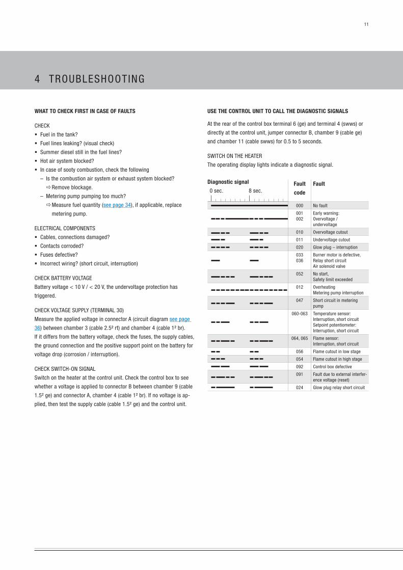
usE thE coNtrol uNit to call thE diagNostic sigNals
At the rear of the control box terminal 6 (ge) and terminal 4 (swws) or
directly at the control unit, jumper connector b, chamber 9 (cable ge)
and chamber 11 (cable swws) for 0.5 to 5 seconds.
sWiTCh On The heATeR
The operating display lights indicate a diagnostic signal.
diagnostic signal
0 sec. 8 sec.fault
code
fault
000 no fault
001002
early warning:Overvoltage / undervoltage
010 Overvoltage cutout
011 undervoltage cutout
020 glow plug – interruption
033036
burner motor is defective, Relay short circuit Air solenoid valve
052 no start, safety limit exceeded
012 OverheatingMetering pump interruption
047 short circuit in metering pump
060-063 Temperature sensor:interruption, short circuitsetpoint potentiometer:interruption, short circuit
064, 065 Flame sensor:interruption, short circuit
056 Flame cutout in low stage
054 Flame cutout in high stage
092 Control box defective
091 Fault due to external interfer-ence voltage (reset)
024 glow plug relay short circuit
what to chEck first iN casE of faults
CheCk
Fuel in the tank?
Fuel lines leaking? (visual check)
summer diesel still in the fuel lines?
hot air system blocked?
in case of sooty combustion, check the following
– is the combustion air system or exhaust system blocked?
ÖRemove blockage.
– Metering pump pumping too much?
ÖMeasure fuel quantity (see page 34), if applicable, replace
metering pump.
eLeCTRiCAL COMpOnenTs
Cables, connections damaged?
Contacts corroded?
Fuses defective?
incorrect wiring? (short circuit, interruption)
CheCk bATTeRY VOLTAge
battery voltage < 10 V / < 20 V, the undervoltage protection has
triggered.
CheCk VOLTAge suppLY (TeRMinAL 30)
Measure the applied voltage in connector A (circuit diagram see page
36) between chamber 3 (cable 2.5² rt) and chamber 4 (cable 1² br).
if it differs from the battery voltage, check the fuses, the supply cables,
the ground connection and the positive support point on the battery for
voltage drop (corrosion / interruption).
CheCk sWiTCh-On signAL
switch on the heater at the control unit. Check the control box to see
whether a voltage is applied to connector b between chamber 9 (cable
1.5² ge) and connector A, chamber 4 (cable 1² br). if no voltage is ap-
plied, then test the supply cable (cable 1.5² ge) and the control unit.
4 TROubLeshOOTing

12
oVErViEw of thE tEst EquipmENt aNd coNtrol uNits
The electronic control box can store up to 5 faults, which can be read
out and displayed.
The following test equipment / control units can be used to query the
fault memory in the control box and if necessary to delete the locking of
the control box:
test equipment order No. Diagnostic unit
eDiTh basic diagnostic tool
The current software can be
downloaded from the service
portal.
22 1529 89 00 00
22 1524 89 00 00
control unit order No. Module timer
Tp5 radio remote control
easystart T
easystart R+
22 1000 30 38 00
22 1000 32 01 00
22 1000 32 88 00
22 1000 32 80 00
plEasE NotE! The diagnostics cable (cable 0.5² bl/ws) must also be connected if
using control units.
if the fault memory cannot be read out, check the diagnostics cable
is properly laid and is not damaged.
ExtErNal diagNostics systEm
if an external, vehicle-specific diagnostics system is used Ö please
consult the vehicle manufacturer.
4 TROubLeshOOTing
13
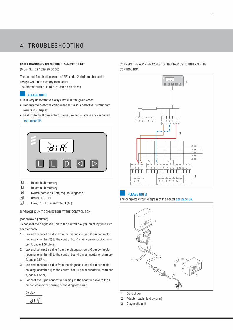
COnneCT The ADApTeR CAbLe TO The DiAgnOsTiC uniT AnD The
COnTROL bOx
1
2
3
plEasE NotE!The complete circuit diagram of the heater see page 36.
2
1
3
1 Control box
2 Adapter cable (laid by user)
3 Diagnostic unit
fault diagNosis usiNg thE diagNostic uNit
(Order no.: 22 1529 89 00 00)
The current fault is displayed as “AF” and a 2-digit number and is
always written in memory location F1.
The stored faults “F1” to “F5” can be displayed.
plEasE NotE! it is very important to always install in the given order.
not only the defective component, but also a defective current path
results in a display.
Fault code, fault description, cause / remedial action are described
from page 19.
l – Delete fault memory
l – Delete fault memory
d – switch heater on / off, request diagnosis
e – Return, F5 – F1
f – Flow, F1 – F5, current fault (AF)
DiAgnOsTiC uniT COnneCTiOn AT The COnTROL bOx
(see following sketch)
To connect the diagnostic unit to the control box you must lay your own
adapter cable.
1. Lay and connect a cable from the diagnostic unit (6 pin connector
housing, chamber 3) to the control box (14 pin connector b, cham-
ber 4, cable 1.5² blws).
2. Lay and connect a cable from the diagnostic unit (6 pin connector
housing, chamber 5) to the control box (4 pin connector A, chamber
3, cable 2.5² rt).
3. Lay and connect a cable from the diagnostic unit (6 pin connector
housing, chamber 1) to the control box (4 pin connector A, chamber
4, cable 1.5² br).
4. Connect the 6 pin connector housing of the adapter cable to the 6
pin tab connector housing of the diagnostic unit.
Display
4 TROubLeshOOTing
14
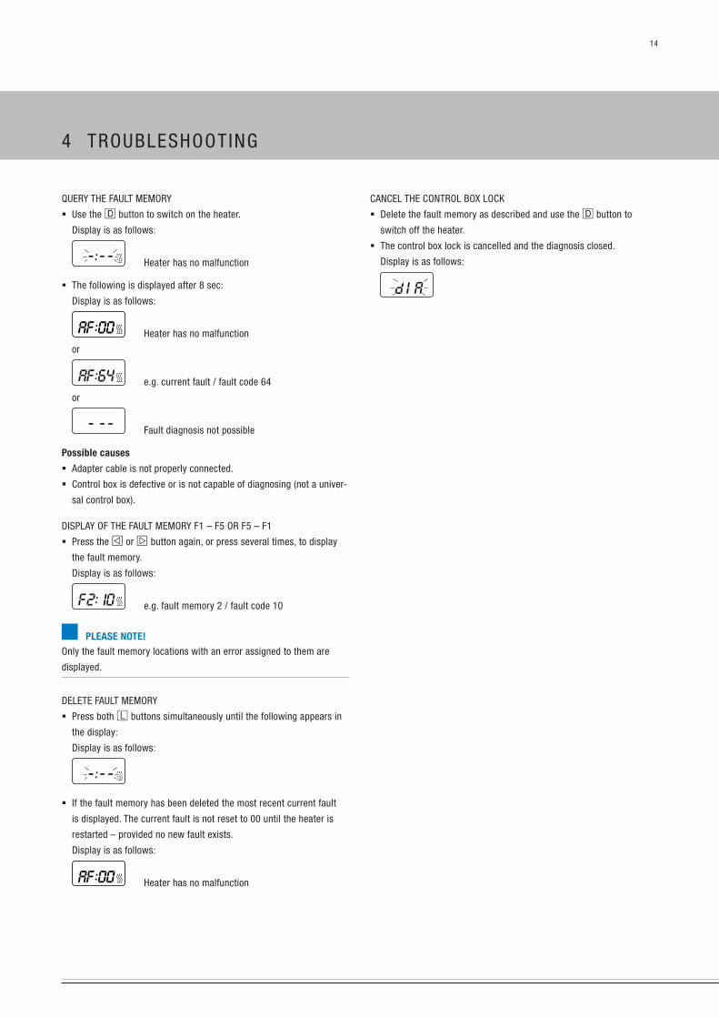
CAnCeL The COnTROL bOx LOCk
Delete the fault memory as described and use the d button to
switch off the heater.
The control box lock is cancelled and the diagnosis closed.
Display is as follows:
QueRY The FAuLT MeMORY
use the D button to switch on the heater.
Display is as follows:
heater has no malfunction
The following is displayed after 8 sec:
Display is as follows:
heater has no malfunction
or
e.g. current fault / fault code 64
or
Fault diagnosis not possible
possible causes
Adapter cable is not properly connected.
Control box is defective or is not capable of diagnosing (not a univer-
sal control box).
DispLAY OF The FAuLT MeMORY F1 – F5 OR F5 – F1
press the e or f button again, or press several times, to display
the fault memory.
Display is as follows:
e.g. fault memory 2 / fault code 10
plEasE NotE!Only the fault memory locations with an error assigned to them are
displayed.
DeLeTe FAuLT MeMORY
press both l buttons simultaneously until the following appears in
the display:
Display is as follows:
if the fault memory has been deleted the most recent current fault
is displayed. The current fault is not reset to 00 until the heater is
restarted – provided no new fault exists.
Display is as follows:
heater has no malfunction
4 TROubLeshOOTing

15
COnneCT The ADApTeR CAbLe TO The eDiTh bAsiC DiAgnOsTiC TOOL
AnD TO The COnTROL bOx
eDiTh basic diagnostic tool
1
3
2
plEasE NotE!The complete circuit diagram of the heater see page 36
2
1
3
5
4
1 Control box
2 Adapter cable (laid by user)
3 Connection to the eDiTh basic diagnostic tool
4 pC
5 sub-D connection cable
fault diagNosis with thE Edith basic diagNostic tool
Order no. 22 1541 89 00 00
plEasE NotE! Always connect in the given order!
To read out the faults and to connect the eDiTh basic to the control
box you must lay your own adapter cable.
The 14 pin plug-in connection may not be disconnected until the
heater has been switched off and the after-running has finished.
The eDiTh basic can only be used to read out the faults stored in the
control box and the current faults.
note and follow the eDiTh basic operating instructions.
Fault code, fault description, cause / remedial action are described
from page 19.
eDiTh bAsiC COnneCTiOn AT The COnTROL bOx
To connect the eDiTh basic to the control box you must lay your own
adapter cable.
1. Lay and connect a cable from the eDiTh basic (6 pin connector
housing, chamber 3) to the control box (14 pin connector b, cham-
ber 4, cable 1.5² blws).
2. Lay and connect a cable from the eDiTh basic (6 pin connector
housing, chamber 5) to the control box (4 pin connector A, chamber
3, cable 2.5² rt).
3. Lay and connect a cable from the eDiTh basic (6 pin connector
housing, chamber 1) to the control box (4 pin connector A, chamber
4, cable 1.5² br).
4. Connect the 6 pin connector housing of the adapter cable to the 6
pin tab connector housing of the eDiTh basic.
5. Connect the sub-D connection cable to the eDiTh basic and to the
pC.
4 TROubLeshOOTing

16
DispLAY FAuLT MeMORY F1 – F5
The individual fault memory locations are displayed in ascending order
by pressing or repeatedly pressing button f.
Display is as follows:
e.g. fault memory 2 / fault code 10
CAnCeL The COnTROL bOx LOCk AnD siMuLTAneOusLY DeLeTe The
FAuLT MeMORY
Condition:
An electrical connection exists from terminal 15 (ignition) to the module
timer, 12-pin connector, chamber 10.
press c button
Display is as follows:
the current fault F15 or F50.
press button a, keep it pressed and press button p within 2 sec-
onds.
The module timer is now in the “enquire fault memory” program.
switch off ignition (terminal 15).
press button a and button p at the same time, in addition, switch
on the ignition (terminal 15) and wait until the following appears in
the display.
After ignition “On” the following appears in the display:
Display flashes
heater symbol does not flash
switch the heater off and on Ö, the control box is unlocked and the
heater restarts.
After switching the heater off and on and re-enquiring the fault
memory the following appears in the display:
Display flashes,
heater symbol does not flash
fault diagNosis usiNg thE modulE timEr
Order no. 22 1000 30 38 00
The current fault is displayed as “AF” and a 2-digit number and is
always written in memory location F1. previous faults are transferred
into memory location F2 to F5. The stored faults “F1” to “F5” can be
displayed.
plEasE NotE! Only the fault memory locations with an error assigned to them are
displayed.
The bl/ws diagnostic cable must be connected in order to perform
the diagnosis. note and follow the heater's circuit diagram.
ensure adequate battery voltage (min. 10.5 V).
not only the defective component, but also a defective current path
results in a display.
Fault code, fault description, cause / remedial action are described
from page 19.
1 a button – time
2 p button – preselection
3 c button – heat
4 e button – return
5 f button – flow
6 Temperature controller
7 Display with “Current fault”
DispLAY CuRRenT FAuLT
Condition: The heater is switched off.
press c button Ö heater is switched on.
press a button and keep it pressed, then press p button within
2 seconds.
Display is as follows:
Current fault (e.g. fault code 64)
4 TROubLeshOOTing

17
example:
“F0 --” = undisturbed operation
“F064” = current fault 64
“F210” = Fault 10 stored in fault memory position 2 (“F2”).
DispLAY CuRRenT FAuLT OR DispLAY / DeLeTe FAuLT MeMORY
use the button to activate the mobile unit.
switch on the heater with the button.
press the button twice to open the Time setting menu – the time
flashes in the display.
press the button for approx. 2 sec – until the following appears
in the display:
press the button.
press the button.
press the button twice.
press the button.
Display
Current fault
Display
no errors/faults exist
use the and buttons to display the fault memory locations
1 to 5.
DeLeTe FAuLT MeMORY AnD CAnCeL The COnTROL bOx LOCk
use the button to delete the fault memory.
To confirm, press the button for approx. 2 sec until lights up
in the display – fault memory is deleted.
plEasE NotE!if the fault memory is to be deleted later, the whole procedure must be
repeated.
fault diagNosis usiNg thE radio rEmotE coNtrol tp5
Order no. 22 1000 32 01 00
if faults occur while the heater is running, they are displayed with “err”
after the mobile unit is activated.
plEasE NotE! before the diagnosis can be performed the diagnostic cable (blue /
white) must be connected. To this end, please refer to and follow the
circuit diagram for the radio remote control or the timer and for the
heater.
if the diagnostic cable (blue / white) is not connected, the “Diagno-
sis” menu is blocked.
ensure adequate battery voltage (min. 10.5 V / min. 21 V).
not only the defective component, but also a defective current path
results in a display.
Fault code, fault description, cause / remedial action are described
from page 19.
button for activating / deactivating the mobile unit
button for forward time setting
button for backward time setting
button for activating the setting options
button for switching heat / ventilate On / OF;
activate / deactivate preselection time
After the diagnostic cable (blue / white) has been connected and the
first logs have arrived at the stationary unit, the diagnose can be car-
ried out using the mobile unit of the Tp5 radio remote control. The cur-
rent fault is displayed, e.g. “F064”. The stored faults “F1” to “F5” can
be displayed.
4 TROubLeshOOTing

18
QueRY / DeLeTe FAuLT MeMORY AnD CAnCeL The heATeR LOCk
Activate mobile unit / timer
(see easystart R+ / easystart T operating instructions)
Confirm symbol with .
the heater is switched on.
Confirm operating time with .
Following activation, the following can be shown in the display (display
appears after approx. 20 sec.):
Display if errors/faults exist Display if no errors/faults exist
The following actions are possible with both displays:
Display current fault in fault memory.
briefly press and at the same time.
Display fault memory F1 – F5.
press or .
The current fault is always written in fault memory
F1.
Display fault memory again.
briefly press and at the same time.
Delete the fault memory and as a result, at the same
time cancel the control box lock.
Confirm current fault or one of the faults F1 – F5
with .
Confirm display deL again with .
The fault memory is deleted and the control box is
unlocked.
switch off the heater.
press .
fault diagNosis with Easystart r+ aNd Easystart t
easystart R+ radio remote control (Order no.: 22 1000 32 80 00)
easystart T timer (Order no.: 22 1000 32 88 00)
if faults occur in the heater while it is running, they are displayed with
“err” after the mobile unit or timer has been activated.
The current fault and the stored faults “F1” to “F5” can be displayed.
plEasE NotE! The bl/ws diagnostic cable must be connected in order to perform
the diagnosis. To this end, please refer to and follow the circuit dia-
gram for the radio remote control or the timer and for the heater.
if the diagnostics cable is not connected, the “Diagnosis” menu is
blocked.
not only the defective component, but also a defective current path
results in a display.
Fault code, fault description, cause / remedial action are described
from page 19.
ensure adequate battery voltage (min. 10.5 V / min. 21 V).
backwards control button
forwards control button
On / OFF activation button
Ok button (symbol selection / input confirmation)
4 TROubLeshOOTing

19
fault code fault description comments
remedial action
000 no fault — —
001 early warning, overvoltage Voltage at the control box, connector housing A between pin 3 and pin 4 is >14 V / >28 V.
002 early warning, undervoltage Voltage at the control box, connector housing A between pin 3 and pin 4 is <10 V / <20 V.
010 Overvoltage shutdown heater not functioning.
Overvoltage applied to control box for at least 20 seconds without interruption.
start the vehicle engine, measure the voltage at the control box, connector housing A
between pin 3 and pin 4.
if the voltage is >14 volt / >28 volt, then check the battery, the alternator controller and
the electric cables.
011 shutdown due to undervoltage
(heater not functioning)
heater not functioning.
undervoltage applied to control box for at least 20 seconds without interruption.
With the vehicle engine switched off, measure the voltage at the control box, connector
housing A between pin 3 and pin 4.
if the voltage is <10 volt / <20 volt, then check the fuses, the electric cables, the earth
connections and the positive support point at the battery for voltage drop (corrosion).
012 Overheating or metering pump
interruption
Metering pump is not functioning or temperature at the overheating sensor is >90 °C.
Check hot air system for blockage, if necessary remove blockage.
Check electric cables from control box, connector housing A, pin 2 and connector housing
b, pin12 for continuity, correct laying and damage.
Check the metering pump, renew if necessary – control values see page 34.
Check the overheating sensor, renew if necessary – control values see page 10.
020 glow plug interruption Check the glow plug, renew if necessary – control values from page 10.
023
024glow plug relay,
Coil – interruption
glow plug relay,
Coil – short circuit
Check electric cable from control box, connector housing b, pin 5 to the glow plug relay,
pin 85 for continuity, correct laying and damage.
– if ok, renew glow plug relay.
025 Diagnosis output short circuit A plus signal is applied at the control box, connector housing b, pin 4 (connection must be
potential-free).
Check the cable from the control box, connector housing b, pin 4 to the control unit (diag-
nostic display), if necessary correct fault .
033 burner motor does not rotate
(Control) relay is defective
impeller or combustion air fan motor is blocked (frozen, dirty, sluggish).
Remove blockage.
Check the cable from the relay (2.5.5, control), pin 87 for continuity, correct laying and
damage.
Check the (control) relay, renew if necessary.
036 (Control) relay – short circuit Check electric cable from the control box, connector housing b, pin 6 to the relay (2.5.5,
control), pin 85 for continuity, correct laying and damage.
Check the (control) relay, renew if necessary.
047 short circuit in metering pump Check connection of control box b12 up to the metering pump for short circuit.
Check metering pump, replace if necessary.
4 TROubLeshOOTing

20
fault code fault description comments
remedial action052 no start – safety time limit exceeded no flame detected within the start phase.
Check exhaust and combustion air system.
Check the fuel quantity and fuel supply, see page 34.
strainer inserted in the connection socket of the metering pump is dirty, --> renew
strainer.
Check the glow plug, renew if necessary – control values see page 10.
Check the flame sensor, renew if necessary – control values see page 10.
054
056Flame cutout in “high” control stage
Flame cutout in “Low” control stage
The heater has ignited and detected the flame, a flame cutout then occurs.
Check exhaust and combustion air system.
Check the fuel quantity and fuel supply, see page 34.
strainer inserted in the connection socket of the metering pump is dirty, Ö renew
strainer.
Check the flame sensor, renew if necessary – control values see page 10.
Check the fan speed, renew fan if necessary – control values see page 10.
Check the function of the solenoid valve, renew if necessary.
060
061
Temperature sensor – interruption
Temperature sensor – short circuit
Temperature sensor signals temperature value outside the measuring range.
Check the cables from the temperature sensor to the printed circuit board for continu-
ity, correct laying and damage.
Check the temperature sensor, renew if necessary – control values see page 10.
062
063
setpoint potentiometer – interruption
setpoint potentiometer – short circuit
potentiometer of the control unit signals setpoint outside of the control range.
Check the cables from the control box, connector housing A and b and from the control
unit up to the 14 pin connector for continuity, correct laying and damage.
Check the control unit, renew if necessary – control values see page 10.
064
065
Flame sensor interruption
Flame sensor – short circuit
Flame sensor signals temperature value outside the measurement range.
Check the electric cables from the control box, connector housing b, pin 2 and pin 10
up to the flame sensor for continuity, correct laying and damage
Check the flame sensor, renew if necessary – control values see page 10.
091 Fault due to external interference volt-
age (reset)
Control box fault due to interference voltages from the vehicle's electrical system.
possible causes: battery defect, charger defect, other fault sources.
Remove interference voltages.
092 Control box defective Replace control box.
4 TROubLeshOOTing

21
parts list for assEmbly drawiNg
1 Cover
2 glow plug
3 solenoid valve
4 printed circuit board
5 Control box
6 Overheating switch
7 Temperature sensor
8 Flame sensor
9 intake hood
10 Outlet hood
11 Jacket
12 heat exchanger
13 Fan
14 impeller
15 Lining and insulation
16 Relay, control
17 Relay, glow plug
18 Cable loom
19 seal, fan / heat exchanger
20 grommet, exhaust pipe
21 grommet, fuel pipe
22 grommet, flame sensor / overheating sensor cable loom
23 Fuse for impeller
24 Washer, A 4.3
25 bolt, b 4.2x19
26 spring lock washer, b 5
27 hexagon nut, M 5
rEpair work
The permitted repair work to the heater is described in the “Repair
instructions” chapter. The heater must be removed from the vehicle for
the repair work to be carried out.
The heater is assembled in the reverse order, note and follow any ad-
ditional instructions.
plEasE NotE!After completing all the work and installing the heater in the vehicle,
perform a functional check on the heater.
safEty iNstructioNs to bE NotEd aNd followEd bEforE
workiNg oN thE hEatEr
daNgEr!Risk OF inJuRY, buRns AnD pOisOning!
Î Always switch off the heater beforehand and leave it to cool.
Î Disconnect the battery.
Î The heater must not be operated in closed rooms such as garages
or workshops.
exception:
exhaust suction available directly at the entry to the exhaust pipe.
attENtioN! Î The seals of dismantled components must be renewed.
Î During repair work, check all components for damage and if neces-
sary replace.
Î Check connector contacts, plug-in connections and cables for cor-
rosion and damage and if necessary repair.
Î Only ever use eberspächer spare parts if replacements are neces-
sary.
Î Operation or the after-running of the heater may only be stopped in
an emergency (“eMeRgenCY OFF” see page 5) by interrupting
the battery current (risk of heater overheating).
5 RepAiR insTRuCTiOns

22
assEmbly drawiNg
9
6 7
1716
15
14
19
21
22
23
24 25
26 27
20
5
4
3
2
1
1011
12
13
8
18
5 RepAiR insTRuCTiOns
23
repair step 7 page 28
Dismantle temperature sensor
Check temperature sensor
repair step 8 page 29
Dismantle glow plug relay and control relay
repair step 9 page 29
Dismantle safety housing with cable loom
repair step 10 page 30
Dismantle outer jacket, hood and brackets
repair step 11 page 31
Dismantle flame sensor
Check flame sensor
repair step 12 page 31
Dismantle inlet hood
repair step 13 page 32
Dismantle blower from heat exchanger
repair step 14 page 32
Dismantle impeller
repair step 15 page 33
Dismantle combustion chamber lining
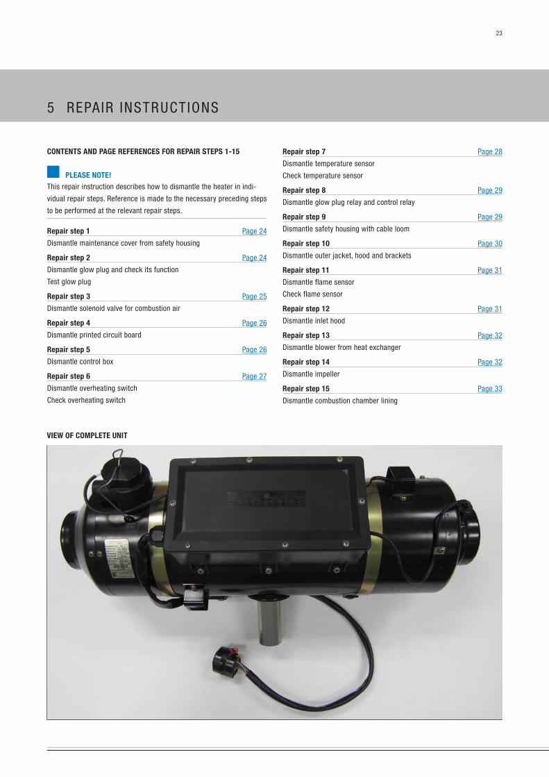
ViEw of complEtE uNit
coNtENts aNd pagE rEfErENcEs for rEpair stEps 1-15
plEasE NotE!This repair instruction describes how to dismantle the heater in indi-
vidual repair steps. Reference is made to the necessary preceding steps
to be performed at the relevant repair steps.
repair step 1 page 24
Dismantle maintenance cover from safety housing
repair step 2 page 24
Dismantle glow plug and check its function
Test glow plug
repair step 3 page 25
Dismantle solenoid valve for combustion air
repair step 4 page 26
Dismantle printed circuit board
repair step 5 page 26
Dismantle control box
repair step 6 page 27
Dismantle overheating switch
Check overheating switch
5 RepAiR insTRuCTiOns

24
1
1
1
2
1 spark plug connection with cable
2 glow plug
TesT The gLOW pLug
use a digital multimeter to test the glow plug.
Control values see page 10.
plEasE NotE!nOTes FOR The AsseMbLY:
glow plug tightening torque: 17+2 nm
rEpair stEps 1 – 15
rEpair stEp 1
DisMAnTLe MAinTenAnCe COVeR FROM The sAFeTY hOusing
unscrew the 8 fixing screws of the maintenance cover.
Remove the maintenance cover.
2
1
3
1 safety housing
2 Fixing screws
3 Maintenance cover
plEasE NotE!nOTes FOR The AsseMbLY:
Fixing screws tightening torque: 1.5+1 nm
rEpair stEp 2
DisMAnTLe gLOW pLug AnD CheCk iTs FunCTiOn
To dismantle the glow plug, complete Repair step 1 first.
Dismantle the spark plug connection from the glow plug.
use a ring spanner or another suitable tool to unscrew the glow plug.
1
1 spark plug connection with cable
5 RepAiR insTRuCTiOns

25
1
2
1 solenoid valve
2 2 pin connector housing
rEpair stEp 3
DisMAnTLe sOLenOiD VALVe FOR COMbusTiOn AiR
To dismantle the solenoid valve for combustion air, complete Repair
step 1 first.
Dismantle the combustion air hose from the solenoid valve.
Disconnect the plug-in connection of the solenoid valve in the safety
housing.
unpin both cables of the solenoid valve cable loom from the 2-pin
connector housing.
unlock the solenoid valve with the clip.
pull the solenoid valve off the heater.
pull the lead harness through the grommet and out of the safety
housing.
21
1 Clip
2 solenoid valve
1 2 3
1 solenoid valve, unlocked
2 Clip
3 solenoid valve plug-in connection (disconnected)
5 RepAiR insTRuCTiOns

26
rEpair stEp 5
DisMAnTLe COnTROL bOx
To dismantle the control box, complete Repair step 1 first.
unlock the control box and remove it from the bracket.
pull the 14 pin connector housing and 4 pin connector housing off
the control box.
1
3
12
1 Control box
2 14 pin connector housing
3 4 pin connector housing
rEpair stEp 4
DisMAnTLe pRinTeD CiRCuiT bOARD
To dismantle the printed circuit board, complete Repair step 1 first.
pull the 2 pin and 4 pin connector housing off the printed circuit
board.
unlock the printed circuit board and pull it out of the guide.
321
1
32
1 4 pin connector housing
2 2 pin connector housing
3 printed circuit board
5 RepAiR insTRuCTiOns

27
1
3
2
4
1
3
2
4
1 Overheating switch
2 Fixing screws (crosshead), overheating switch
3 protective bracket, overheating switch
4 Fixing screws (crosshead), protective bracket
CheCk OVeRheATing sWiTCh
Check the switching values of the overheating switch.
Control values see page 10.
if the measured value differs, replace the overheating switch.
plEasE NotE!nOTes FOR The AsseMbLY:
Tightening torque for fixing screws of the protective bracket and over-
heating switch: 1.4+0.5 nm
rEpair stEp 6
DisMAnTLe OVeRheATing sWiTCh
To dismantle the overheating switch, complete Repair step 1 first.
Disconnect the 2 pin plug-in connection from the overheating switch
in the safety housing.
undo two crosshead screws from the protective bracket of the over-
heating switch and remove the protective bracket.
undo two crosshead screws from the overheating switch and remove
the overheating switch.
1
1 2
1 plug-in connection of the overheating switch
2 protective bracket, overheating switch
5 RepAiR insTRuCTiOns
28
1
4
23
5
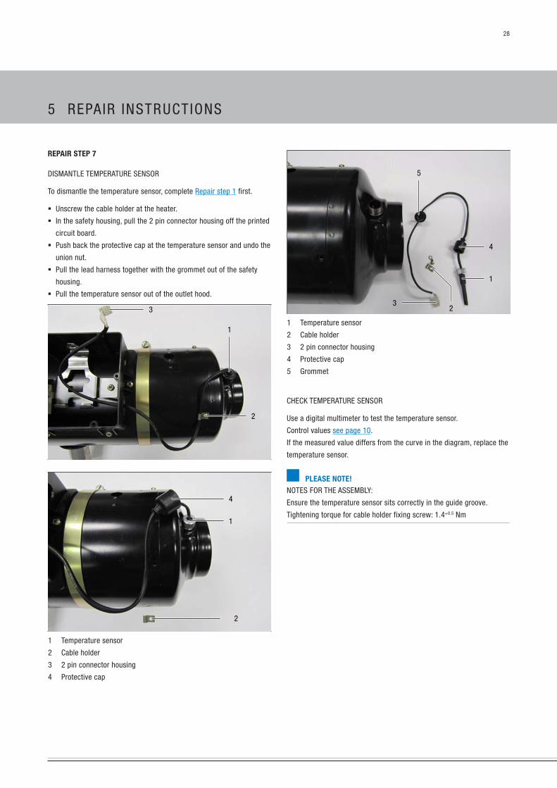
1 Temperature sensor
2 Cable holder
3 2 pin connector housing
4 protective cap
5 grommet
CheCk TeMpeRATuRe sensOR
use a digital multimeter to test the temperature sensor.
Control values see page 10.
if the measured value differs from the curve in the diagram, replace the
temperature sensor.
plEasE NotE!nOTes FOR The AsseMbLY:
ensure the temperature sensor sits correctly in the guide groove.
Tightening torque for cable holder fixing screw: 1.4+0.5 nm
rEpair stEp 7
DisMAnTLe TeMpeRATuRe sensOR
To dismantle the temperature sensor, complete Repair step 1 first.
unscrew the cable holder at the heater.
in the safety housing, pull the 2 pin connector housing off the printed
circuit board.
push back the protective cap at the temperature sensor and undo the
union nut.
pull the lead harness together with the grommet out of the safety
housing.
pull the temperature sensor out of the outlet hood.
2
3
1
2
1
4
1 Temperature sensor
2 Cable holder
3 2 pin connector housing
4 protective cap
5 RepAiR insTRuCTiOns

29
1
1 unscrew the fixing screw of the control relay pin base
1
2
1 3 pin plug-in connection from the flame sensor cable loom
2 3 pin plug-in connection from the electric motor cable loom
1
1 safety housing with cable loom
plEasE NotE!nOTes FOR The AsseMbLY:
Tightening torque for safety housing fixing screw: 1.4+0.5 nm
rEpair stEp 8
DisMAnTLe The gLOW pLug ReLAY AnD COnTROL ReLAY
To dismantle both relays, complete Repair step 1 first.
pull the glow plug relay and the control relay off the pin base.
1 2
1 Control relay
2 glow plug relay
rEpair stEp 9
DisMAnTLe sAFeTY hOusing WiTh CAbLe LOOM
To dismantle the safety housing with cable loom, complete Repair step
1 – 8 first (pull cable looms off the components).
unscrew the fixing screw of the glow plug relay pin base and the
control relay pin base.
Disconnect the 3 pin plug-in connection from the flame sensor cable
loom.
Disconnect the 3 pin plug-in connection from the electric motor cable
loom.
unscrew the 8 fixing screws of the safety housing.
Remove the safety housing with the cable loom.
1
1 unscrew the fixing screw of the glow plug relay pin base
5 RepAiR insTRuCTiOns

30
1 2
4564
3
1 Outer jacket
2 Outlet hood
3 brackets
4 Clips
5 protective bracket, fuel connection
6 Fuel connection grommet
plEasE NotE!The outer jacket is subject to mechanical stress.
nOTes FOR The AsseMbLY:
Tightening torque for outer jacket fixing screw: 1.4+0.5 nm
23
1
1 Outer jacket
2 Fan with inlet hood
3 heat exchanger
rEpair stEp 10
DisMAnTLe OuTeR JACkeT, hOOD AnD bRACkeTs
To dismantle the outer jacket, complete Repair step 1 – 9 first.
Dismantle the holder from the control box.
Dismantle the rubber grommet for the flame sensor cable loom and
the electric motor cable loom.
push the flame sensor cable loom and the electric motor cable loom
back through the openings in the outer jacket and into the inner area
of the heater.
Dismantle the protective bracket from the fuel connection.
Remove the fuel connection grommet.
unscrew the fixing screws of the outlet hood and remove the outlet
hood.
undo both clips and remove both brackets.
unscrew the fixing screws of the outer jacket at the carrier and at
the jacket overlap.
undo both clips completely and remove from the heater.
place the heater carefully on the inlet hood, bend open the outer
jacket by approx. 70 mm and remove from the heater.
1 2 3
1 3 pin connector housing, flame sensor cable loom
2 3 pin connector housing, electric motor cable loom
3 Control box holder
2
1
1 Fuel connection grommet
2 protective bracket of the fuel connection
5 RepAiR insTRuCTiOns

31
rEpair stEp 12
DisMAnTLe inLeT hOOD
To dismantle the inlet hood, complete Repair step 1 – 11 first.
unscrew the fixing screws of the inlet hood and remove inlet hood.
2
1 2
2
1
1 inlet hood
2 Retaining screw
rEpair stEp 11
DisMAnTLe FLAMe sensOR
To dismantle the flame sensor, complete Repair step 1 – 10 first.
Remove fixing clip and remove flame sensor.
21
1 Fixing clip
2 Flame sensor
CheCk FLAMe sensOR
use a digital multimeter to test the flame sensor.
Control values see page 10.
if the measured value differs from the curve in the diagram, replace the
flame sensor.
5 RepAiR insTRuCTiOns
32
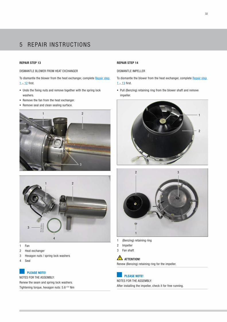
rEpair stEp 14
DisMAnTLe iMpeLLeR
To dismantle the blower from the heat exchanger, complete Repair step
1 – 13 first.
pull (benzing) retaining ring from the blower shaft and remove
impeller.
1
2
2 3
1
1 (benzing) retaining ring
2 impeller
3 Fan shaft
attENtioN!Renew (benzing) retaining ring for the impeller.
plEasE NotE!nOTes FOR The AsseMbLY:
After installing the impeller, check it for free running.
rEpair stEp 13
DisMAnTLe bLOWeR FROM heAT exChAngeR
To dismantle the blower from the heat exchanger, complete Repair step
1 – 12 first.
undo the fixing nuts and remove together with the spring lock
washers.
Remove the fan from the heat exchanger.
Remove seal and clean sealing surface.
1 2
3
3
1 2
4
1 Fan
2 heat exchanger
3 hexagon nuts / spring lock washers
4 seal
plEasE NotE!nOTes FOR The AsseMbLY:
Renew the seam and spring lock washers.
Tightening torque, hexagon nuts: 5.6+0.6 nm
5 RepAiR insTRuCTiOns

33
rEpair stEp 15
DisMAnTLe COMbusTiOn ChAMbeR Lining
To dismantle the combustion chamber lining, complete Repair step 1 –
13 first.
use a screw driver to pull the combustion chamber lining out of the
heat exchanger.
2
1
1
2
1 heat exchanger
2 Combustion chamber lining
5 RepAiR insTRuCTiOns

34
eVALuATiOn
Transfer the measured fuel quantity into the diagram.
The fuel consumption is ok, if the intersection of both values lies
within the boundary curves.
if the intersecting point is located outside, the metering pump must
be replaced.
Operating voltage (V)
Fuel
qua
ntity
(ml /
90
sec.
)
mEasuriNg thE fuEl quaNtity
before measuring the fuel quantity, check the following points in the
fuel supply.
Check the strainer in the metering pump.
Check the laying of the fuel lines.
Check fuel lines for leaks.
Check and tighten the hose connections.
is the fuel removal installed according to the details in the technical
description?
For precise fuel measurement at least 11 volt / 22 volt, maximum
13 volt / 26 volt should be applied to the control box.
pRepARing FOR The MeAsuReMenT
Disconnect fuel line from the heater and discharge into a measuring
cylinder.
Connect the voltmeter to the control box, connector A, terminal 3 (+)
and terminal 4 (–).
switch on heater. if the fuel is uniformly pumped (begins approx.
25 – 55 sec after being switched on), the fuel line is full and vented.
switch off heater and empty measuring cylinder.
MeAsuReMenT
switch on heater.
The fuel begins to be pumped approx. 25 – 55 sec after switching on
the heater.
During the measurement, hold the measuring cylinder at the level of
the glow plug.
Read off electrical voltage at the voltmeter.
After 90 sec. the pumping of the fuel is automatically switched off.
switch off the heater.
Read off the quantity of fuel in the measuring cylinder.
1 heater
2 Metering pump
3 Measuring cylinder (50 ml)
4 Fuel line
5 Voltmeter
6 Connection at the control box
5 RepAiR insTRuCTiOns

35
parts list, hEatEr 8 l circuit diagram
1.1 burner motor
1.1.1 Resistor for burner motor (partial load)
1.2 glow plug
1.5 Overheating switch
1.7 printed circuit board
1.8.5 Varistor
1.12 Flame sensor
1.13 Temperature sensor
2.1 Control box
2.2 Metering pump
2.3 Air solenoid valve (for combustion air)
2.5.1 glow plug relay
2.5.5 Control relay
2.7 Main fuse
12 volt = 30 A
24 volt = 25 A
2.15.1 Room temperature sensor (control)
5.1 battery
plEasE NotE!Circuit diagram see page 36.
CAbLe COLOuRs
rt red gn greenbl blue ge yellowws white vi violetsw black br brown
Connectors and bush housings are shown from the cable inlet side.
pagE rEfErENcEs for thE circuit diagrams
heater 8 L circuit diagram page 36
COnTROL uniTs
Module timer with potentiometer page 38
Module timer with control unit page 38
Control unit with radio remote control Tp5 page 39
Diagnostic unit page 39
Control unit with Calltronic and mini timer page 40
Control unit with Calltronic page 41
Control unit with mini timer and radio remote control Tp41i page 42
Control unit page 42
easystart R+ with control unit and easystart T page 44
easystart R+ with control unit page 45
easystart R with control unit and easystart T page 46
easystart R with control unit page 47
easystart T (2 times) with control unit page 48
easystart T with control unit page 49
Control unit with Calltronic 2010 page 50
6 eLeCTRiCs

36
hEatEr 8 l circuit diagram
25 1728 00 96 02 B
parts list see page 35
6 eLeCTRiCs
37
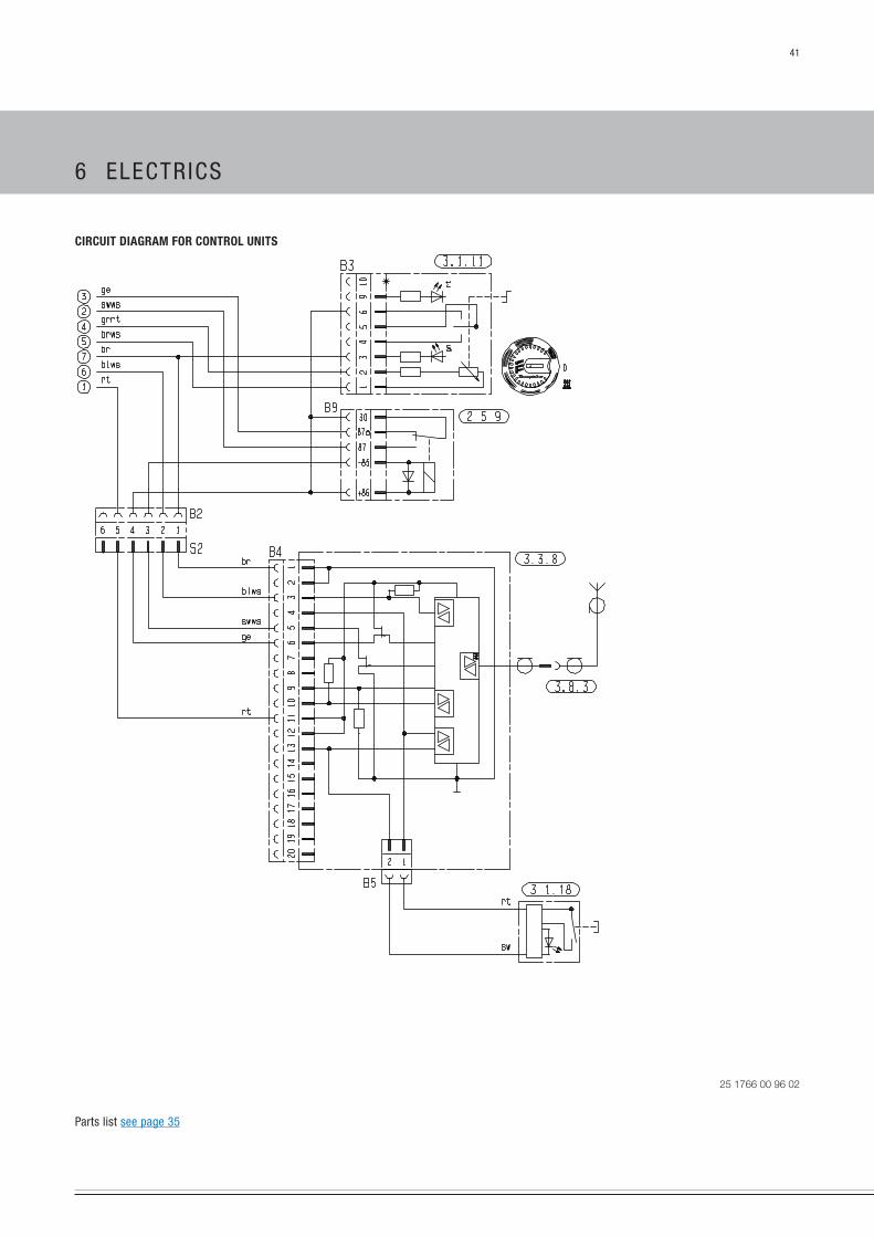
parts list, circuit diagrams, coNtrol uNits
2.5.9 Ventilate relay
2.15.1 Room temperature sensor*
2.15.9 Outside temperature sensor*
3.1.11 Control unit, round
3.1.12 Fault code query, optional
3.1.16 Radio remote control button
3.1.18 CALLTROniC button
3.2.8 Timer (ADR – potentiometer)
3.2.9 Timer, ADR
3.2.12 Timer, mini – 12 / 24 volt
3.2.14 Lighting, mini timer – 12 volt only
3.3.6 Radio remote control stationary part Tp41i
3.3.7 Radio remote control stationary part Tp5
3.3.8 CALLTROniC remote control
3.6.1 Cable harness for 3.1.11
3.8.3 Antenna
3.9.1 Diagnosis, Je diagnosis
a) Terminal “58” (lighting)
b) Terminal “15” (ignition)
c) Cable jumper required for normal operation (not ADR)
d) external On / OFF button
e) For timer connection: Cut cable here x
f) Connection, radio module
z) Lighting, terminal 58
insulate unused cable ends.
Connectors and bush housings are shown from the cable inlet side.
* for the temperature display of the control unit.
plEasE NotE!Circuit diagrams see page 38 – 42.
6 eLeCTRiCs

38
circuit diagram for coNtrol uNits
25 1766 00 96 01 F
parts list see page 35
6 eLeCTRiCs
39
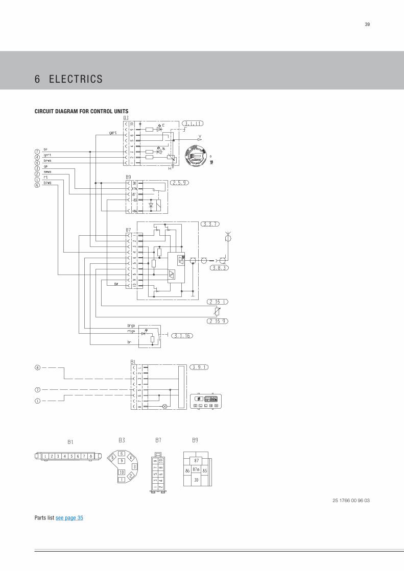
circuit diagram for coNtrol uNits
25 1766 00 96 03
parts list see page 35
6 eLeCTRiCs

40
circuit diagram for coNtrol uNits
25 1766 00 96 02
parts list see page 35
6 eLeCTRiCs
41
circuit diagram for coNtrol uNits
25 1766 00 96 02
parts list see page 35
6 eLeCTRiCs

42
circuit diagram for coNtrol uNits
25 1728 00 96 04
parts list see page 35
6 eLeCTRiCs
43
parts list for circuit diagram of Easystart r+ / r / t
coNtrol uNits
2.5.9 “Ventilate” relay
2.15.1 Room temperature sensor*
(included in easystart R+ scope of supply,
optional for easystart R / T)
2.15.9 Outside temperature sensor (optional)*
3.1.7 “On / OFF” button
3.1.11 Control unit, “round”
3.1.16 Radio remote control button
3.2.15 easystart T timer
3.3.9 Radio remote control, easystart R (stationary unit)
3.3.10 easystart R+ radio remote control (stationary unit)
3.6.1 Adapter cable
3.8.3 Antenna
c) Terminal 58 (lighting)
e) Connection, easystart T timer
g) external “On / OFF” button (optional)
insulate unused cable ends.
Connectors and bush housings are shown from the cable inlet side.
* for the temperature display of the control unit.
plEasE NotE!Circuit diagrams see page 44 – 49.
6 eLeCTRiCs
44
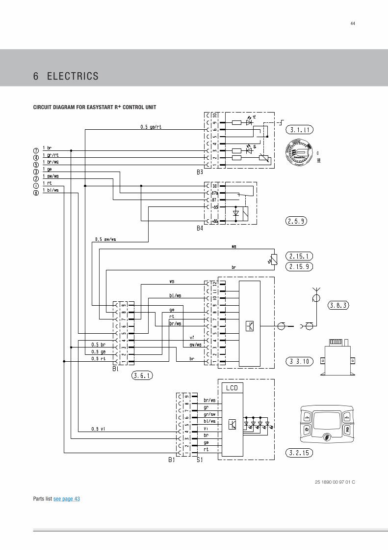
circuit diagram for Easystart r+ coNtrol uNit
25 1890 00 97 01 C
parts list see page 43
6 eLeCTRiCs

45
circuit diagram for Easystart r+ coNtrol uNit
25 1890 00 97 01 C
parts list see page 43
6 eLeCTRiCs

46
circuit diagram for Easystart r coNtrol uNit
25 1890 00 97 02 B
parts list see page 43
6 eLeCTRiCs

47
circuit diagram for Easystart r coNtrol uNit
25 1890 00 97 02 B
parts list see page 43
6 eLeCTRiCs
48
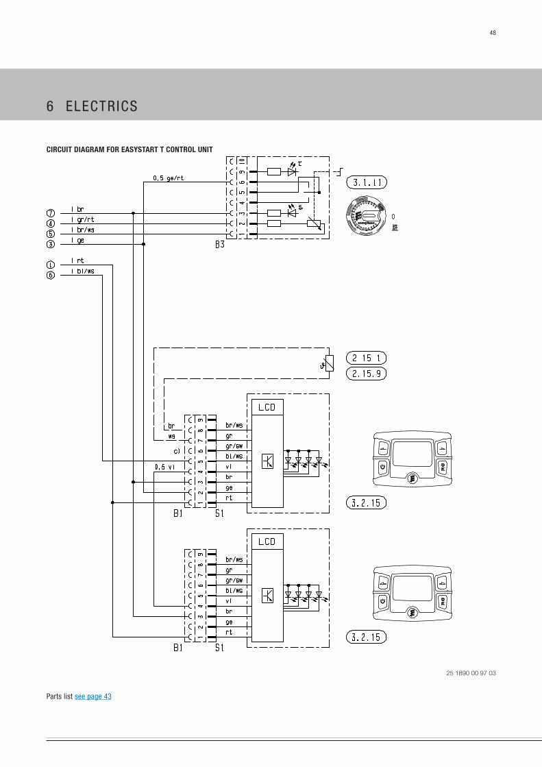
circuit diagram for Easystart t coNtrol uNit
25 1890 00 97 03
parts list see page 43
6 eLeCTRiCs

49
circuit diagram for Easystart t coNtrol uNit
25 1890 00 97 03 A
parts list see page 43
6 eLeCTRiCs

50
circuit diagram for calltroNic (VErsioN ii from 2010)
25 1890 00 97 05 A
parts list
2.5.9 “Ventilate” relay
3.1.11 Control unit, “round”
3.1.20 button, CALLTROniC
3.3.12 Calltronic (gsM module)
3.8.3 Antenna
6 eLeCTRiCs
51
Ec dEclaratioN of coNformity
With regard to the product named in the following
hEatEr typE 8 l
we herewith confirm that it conforms with the essential safety require-
ments stipulated in the directive of the eu Council on the approxima-
tion of the laws of the Member states relating to electromagnetic
Compati bility (89 / 336 / eeC).
This declaration applies to all heaters produced according to the D 8 LC
production drawings – which are part of this declaration.
The following standards / directives have been used to assess the prod-
uct with regard to electromagnetic compatibility:
en 50081 – 1 electromagnetic compatibility. generic emission stand-
ard. Residential, commercial and light industry
en 50082 – 1 electromagnetic compatibility. generic immunity
standard. Residential, commercial and light industry
72 / 245 / eeC – amendment status 95 / 54 / eC
interference suppression in motor vehicles.
cErtificatioNs
The high quality of eberspächer's products is the key to our success.
To guarantee this quality, we have organised all work processes in the
company along the lines of quality management (QM). even so, we
still carry out a large number of activities for continual improvement
of product quality in order to keep pace with the constantly growing
requirements of our customers.
All the steps necessary for quality assurance are stipulated in inter-
national standards.
This quality is to be considered in a comprehensive sense. it affects
products, procedures and customer / supplier relationships.
Officially approved public experts assess the system and the corre-
sponding certification company awards a certificate.
eberspächer has already qualified for the following standards:
quality maNagEmENt iN accordaNcE with
EN iso 9001:2000 aNd iso/ts 16949:1999
ENViroNmENtal maNagEmENt systEm iN accordaNcE with
EN iso 14001:1996
disposal
DispOsAL OF MATeRiALs
Old devices, defective components and packaging material can all be
separated and sorted into pure-grade fractions so that all parts can be
disposed of in an environmentally friendly way or their materials can be
recycled.
electric motors, control boxes and sensors (e.g. temperature sensors)
are deemed to be “electronic scrap”.
DisMAnTLing The heATeR
The heater is dismantled according to the repair stages in the current
troubleshooting / repair instructions.
pACkAging
The packaging of the heater can be kept in case it has to be sent back.
7 seRViCe

52
list of abbrEViatioNs
adr
european agreement about the international transport of dangerous
goods on the road (ADR).
a
Current intensity in ampere
V
Voltage in volt
w
power in watt
7 seRViCe

headquarters:
eberspächer Climate Control systems
gmbh & Co. kg
eberspächerstraße 24
73730 esslingen
hotline: 0800 1234300
Fax hotline: 01805 262624
www.eberspaecher.com 25 1
891
95 2
4 06
en
04.
2013
sub
ject
to c
hang
e w
ithou
t not
ice.
© e
bers
päch
er C
limat
e Co
ntro
l sys
tem
s g
mbh
& C
o. k
g
Related Documents