..- - _- ` -J, - _2^` /d' - ^- .¡y' "el.-,- J u:^S4c ^., d . .L aí". i-,3'-`, ... d -_' ;: ca' - ' ..- .s2- a_-. w <_r www.americanradiohistory.com

Welcome message from author
This document is posted to help you gain knowledge. Please leave a comment to let me know what you think about it! Share it to your friends and learn new things together.
Transcript
..- -
_- ` -J, - _2^` /d' -
^- .¡y'
"el.-,-
J u:^S4c ̂ ., d . .L
aí". i-,3'-`, ... d -_' ;: ca' - ' ..- .s2- a_-. w <_r
www.americanradiohistory.com
PERPETUAL
TROUBLE SHOOTER'S MANUAL . :.
by
JOHN F. RIDER
Published by
JOHN F. RIDER 1440 Broadway New York City
www.americanradiohistory.com
Other manuals by John F. Rider
Perpetual Trouble Shooter's Manual Volume I
About 1000 pages. Price $7.50
Perpetual Trouble Shooter's Manual Volume II
About 780 pages. Price $6.50
Perpetual Trouble Shooter's Manual Volume III
About 1185 pages. Price $7.50
Specialized Auto Radio Manual Volume I
About 350 pages. Price $3.50
The Perpetual Trouble Shooter's Manuals listed above are the "standard" of
the radio service industry.
Their absolute supremacy as sources of accurate-complete and detailed radio
service data is established by their use by the world-famous tube manufacturing
organizations, such as E. T. Cunningham, Inc., National Union Radio Corp.,
RCA Radiotron, Inc.-the most famous service instrument manufacturers, like
Weston, Hickok, Readrite and Supreme and their use and recommendation by
the world's leading radio receiver manufacturers.
Entire contents copyright 1933 by John F. Rider
Printed in U. S. A.
www.americanradiohistory.com
AUTHOR'S FOREWORD
This issue of Volume I is slightly different than earlier printings. One of the changes
is to be found in the method of indexing. You will note that it is the same as used in Volumes
II and III as recently issued.
The reason for this change is that the method of indexing as originally introduced in Vol-
ume III proved so much more popular than that previously employed in Volumes I and II, that
it was deemed most advantageous to establish a uniform index which would serve best over the
years to come.
Present owners of Volumes II and III, that is, owners of these manuals purchased prior to
November 15, may find that index which accompanies Volume III and the index in Volume II does
not conform with the pages in Volume I. We regret the slight inconvenience caused, but feel
that it is all for the better.
The complete index mentioned above and the Volume II index mentioned above can be used
to determine if the service information desired is to be found in Volume I. Reference to the in-
dividual index in Volume I will then indicate the correct page.
Another change in this revised issue is that the text matter contained in the front of the
earlier printings has been removed. This is the result of requests from service men who found
very little occasion at this date to refer to text originally prepared years ago.
In every other respect this Volume I is fully the equal of the earlier issues and in very many
cases, has additional information not contained in earlier issues.
The pages in this revised issue have been printed from engravings and we trust that the in-
creased legibility of type, the increased number of cases where electrical values are included, the
increased number of socket layouts-in general more data-will be received with favor and will
perhaps offset the slight inconvenience with respect to the indexing.
JOHN F. RIDER.
www.americanradiohistory.com

www.americanradiohistory.com
Il
0
2 J lL
www.americanradiohistory.com
PIEDMONT AMATEUR RADIO ASSOCATION OF
PORTLAND, OREGON
5017 N Interstate Ave. Phone WAlnut 3393
4
www.americanradiohistory.com
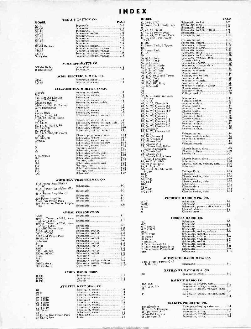
INDEX THE A -C DAYTON CO.
MODEL PAGE XL -5 XL -20 XL -25 XL -50 XL -60 XL -10 XL -70 XL -30 XL -61 Battery AC -63 AC -65 AC -66 Navigator
5 -Tube Reflex B Eliminator
Schematic 1-1 Schematic 1-1 Schematic 1-1 Schematic, socket 1-2 Schematic 1-2 Schematic 1-3 Schematic 1-3 Schematic 1-4 Schematic, socket 1-4 Schematic, socket, voltage 1-5 Schematic, socket, voltage 1-6 Schematic, socket, voltage 1-7 Schematic, socket, voltage 1-8
ACME APPARATUS CO. Schematic 1-1 Schematic 1-1
ACME ELECTRIC & MFG. CO. AC -7 Schematic, socket 1-1 SG -88 Schematic, socket 1-1
ALL-AMERICAN MOHAWK CORP. Navajo VA 115-1926 All -Electric 115r1926 Battery Mohawk 226 Mohawk 226, 12 Contact A-10 Eliminator 44 Forte, 1926 60, 61, 62, 85, 66
,6, 61, 62, 65, 66 Power Pack
70, 73, 75 80, 83, 84, 85, 86, 88 90, 25 -cycle 90, 60 -cycle 90, 25- & 60 -cycle Power
Pack 96, 60 -cycle Lyric D H J J K P C-6, Studio S-6 S-6 S-7 S-7 S-8 S-8 DC
Schematic, chassis 1-1 Schematic, socket 1-1 Schematic 1-2 Schematic, socket 1-2 Schematic, socket, cable 1-3 Schematic 1-4 Schematic 1-4 Schematic, socket 1-5 Schematic, socket 1-5 Schematic, socket, voltage 1-6
Schematic, wiring, plug 1-7 Schematic, socket, voltage, data i-8 Schematic, socket, voltage 1-9 Schematic, voltage 1-10 Schematic, voltage, socket 1-11
Chassis, plug connections 1-13 Schematic, socket 1-12 Schematic, socket, voltage 1-14 Schematic, socket, voltage 1-15 Schematic, socket, data 1-16 Voltage, values 1-17 Schematic, socket 1-18 Schematic, socket, data 1-19 Schematic, socket, data 1-20 Schematic, socket, data 1-21 Voltage, data 1-22 Schematic, socket, data 1-23 Voltage, data 1-24 Schematic, socket, data 1-25 Voltage, data 1-26 Schematic 1-27
AMERICAN TRANSFORMER CO. 25-A Power Amplifier (A
Unit) 25-A Power Amplifier (PA
Unit) 25-A Power Amplifier (P
Unit) 210 Power Amplifier Amertran Power Pack 250 Amertran Power Ampli-
fier
AMRAD S-522 3500-1 Tuner *3475, Am-
plifier *2634 3500-2 Tuner * 3730, Am-
plifier *2634 171 ABC Power Pack AC -7, AC -7C DC -7, DC -7C AC -5 and Power Pack 80, 82, 83 Inductrol 84 S-733 3590 AC -6, AC -6C DC -6, DC -6C 7100 7191 70 Bel -Canto 81 Bel -Canto 81
ARGUS
Schematic 1-1
Schematic 1-1
Schematic 1-1 Schematic 1-1 Schematic 1-1
Schematic 1-2
CORPORATION Schematic 1-1
Schematic 1-1
Schematic 1-1 Schematic 1-2 Schematic, socket 1-3 Schematic, socket 1-3 Schematic 1-4 Schematic, socket 1-4 Schematic 1-4 Schematic, socket 1-5 Schematic, socket 1-5 Schematic 1-5 Schematic, socket 1-6 Schematic, socket 1-6 Schematic 1-7 Schematic 1-7 Schematic, socket, voltage 1-8 Schematic, socket, voltage 1-9 Condenser data 1-10
RADIO CORP. B-125 Schematic B -I95 Schematic B-195 Chassis
ATWATER 10 10-B 12 19 *4880 20 *4640 20 *7570 20 *7960 21 *7780 30, 35, 48 32 36 Early, late Power Pack 37 Early, late
1-1 1-1 1-2
KENT MFG. CO. Schematic, socket 1-1 Schematic, socket 1-1 Schematic, socket 1-1 Schematic, socket 1-2 Schematic 1-2 Schematic, socket 1-2 Schematic, socket 1-3 Schematic, socket 1-3 Schematic, socket 1-4 Schematic, socket 1-4 Schematic 1-6 Data 1-5
MODEL 37, 37-F, 37-C 37 Power Pack, Early, late 38 40, 42, 52, 56, 57 40, 42, 52 Power Pack 40, 42, 44, 52 Power Pack 40, 45, 2nd Type Power
Pack 41 DC 41 Power Pack, 3 Types 43 43 Power Pack 44, 45 50 55, 55-C Early 55, 55-C Early 55, 55-C Late 55-F, 55 -FC Early 55-F, 55 -FC Early 55-F, 55 -FC Late 55-F, 55 -FC Late 60, 60-C 1st & 2nd Types 60, 60-C Early 60, 60-C Late 60, 61-C DC, Early 61, 61-C Late 68 66 66 67, 67-C, Early and late,
Battery 67, 67-C 70, 74, 76, Chassis D 70, 74, 76, Chassis D-1 70, 74, 76, Chassis D-2 70, 74, 76, Chassis D-2 70, 74, 76, Chassis F 70, 74, 76, Chassis F 70, 74, 76, Chassis L-1 70, 74, 76, Chassis L-1 70, 74, 76, Chassis L-2 70, 74, 76, Chassis L-2 76, Chassis P 70, 74, 76, Chassis L-2
and P 70, 76, Chassis Q 70, 76, Chassis Q 72, Chassis H-1 72, Chassis H-1 72, Chassis H-1, Below
serial *5,855,201 72, Chassis H-2 72, Chassis H-2 72, Chassis H-2, Above
serial *5,855,201 80, 80-F, 83, 83-F 80, 80-F, 83, 83-F 81, 81-B, 81-C 80, 81, 82, 83, 84, 85, 86,
87, 89 82-D 82-D 82, 82-F 82, 82-F 84-D 84-D 85, 85-F 85, 85-F
5 -AC 5 -DC 6 -AC 5 6
ATCHISON
PAGE Schematic, socket 1-7 Schematic, data 1-8 Schematic, socket 1-7 Schematic, socket, voltage 1-9 Schematic 1-9 Chassis layout 1-10
Chassis layout 1-10 Schematic, socket 1-11 Schematic, voltage 1-12 Schematic, chassis 1-13 Schematic, wiring 1-14 Schematic, data 1-15 Schematic, socket, data 1-16 Schematic, voltage, data 1-17 Chassis wiring 1-18 Schematic, chassis 1-19 Schematic, voltage, data 1-20 Chassis wiring 1-21 Schematic, chassis 1-22 Chassis wiring 1-23 Voltage, service data 1-24 Schematic, data 1-25 Schematic, chassis 1-27 Schematic, data 1-26 Schematic, socket, voltage 1-28 Chassis wiring 1-29 Schematic, data 1-30 Voltage, socket 1-32
Schematics 1-31 Voltage, socket 1-32 Schematic, data 1-33 Chassis wiring 1-34 Schematic, voltage 1-35 Chassis wiring 1-36 Chassis wiring 1-37 Schematic, data 1-38 Chassis wiring 1-39 Schematic, data 1-40 Schematic, data 1-41 Chassis wiring 1-42 Schematic, data 1-43
Voltage, notes 1-44 Voltage, socket, notes 1-45 Schematic, chassis 1-46 Schematic 1-47 Voltage, chassis 1-48
Chassis layout, data 1-49 Chassis, voltage 1-50 Schematic 1-51
Chassis layout, data 1-52 Schematic 1-53 Chassis, socket, voltage, data 1-54 Schematic 1-55
Voltage Data 1-56 Schematic 1-57 Chassis, socket, data 1-58 Schematic 1-59 Chassis, socket, data 1-60 Schematic 1-61 Chassis, data 1-62 Schematic 1-63 Chassis, socket, data 1-64
RADIO MFG. CO. Schematic 1-1 Schematic 1-1 Schematic, power unit chassis 1-2 Chassis layout 1-3 Chassis layout 1-3
AUDIOLA RADIO CO. 527 627 6-T (1927) 8-T (1927) 8430 30-B, 7330 31 Series 31 Super Audiola, Jr. 6 Tube Pentode 31 8 Tube Super Pentode 31 9 Tube Super Pentode 31 889
Schematic 1-1 Schematic 1-1 Schematic 1-2 Schematic 1-2 Schematic, socket, voltage 1-3 Schematic, socket 1-4
' Schematic, voltage 1-5 Schematic, voltage 1-6 Schematic, socket 1-7 Schematic, socket 1-7 Schematic, socket 1-8 Schematic 1-9 Schematic 1-10
AUTOMATIC RADIO MFG: CO. Tom Thumb Screen -Grid
4, Battery Schematic 1-1
NATHANIEL BALD/VIN & CO. 80 Schematic, Misc 1-1
B-7, B-9 A-3, A-5, A-7 C
F
BALKEIT RADIO Schematic, Schematic, Schematic,
list
BALKITE Specifications H, J, K, N Chargers B-180, Form A AB -6-180 Form A B-180 Form B
Schematic, list
CO. chassis, data 1-1 voltage, chassis 1-2 socket, voltage, parte
1-3 socket, voltage, parta
1-4
PRODUCTS CO. Voltages, charging rates, etc 1-1 Schematic 1-2 Schematic, wiring 1-3 Schematic, wiring 1-4 Schematic, wiring 1-4
www.americanradiohistory.com
MODEL PAGE
Trirdyn 51 5-38
10 Schematic 1-1 Buddy, Chum 12 Schematic, socket, voltage 1-2 AC -7, AC -7C
20, 21, 22 30S, 31S, 33S, 34S 40S, 41S, 42S, 828 41, 41A, 42 48 53, 54, 57 55 56 55, 56 58
60 Goldcrest Schematic 1-1 60S, 61S, 62S, 63S 70 Clearodyne Schematic 1-1 78 80 (Improved) Schematic 1-2 100 Series Schematic 1-2 110 Schematic 1-3 112 Schematic 1-3
CAPEHART CORPORATION 400, 401, 402 400 Series, PZ Amplifier 400 Series, RF 400, 401, 402
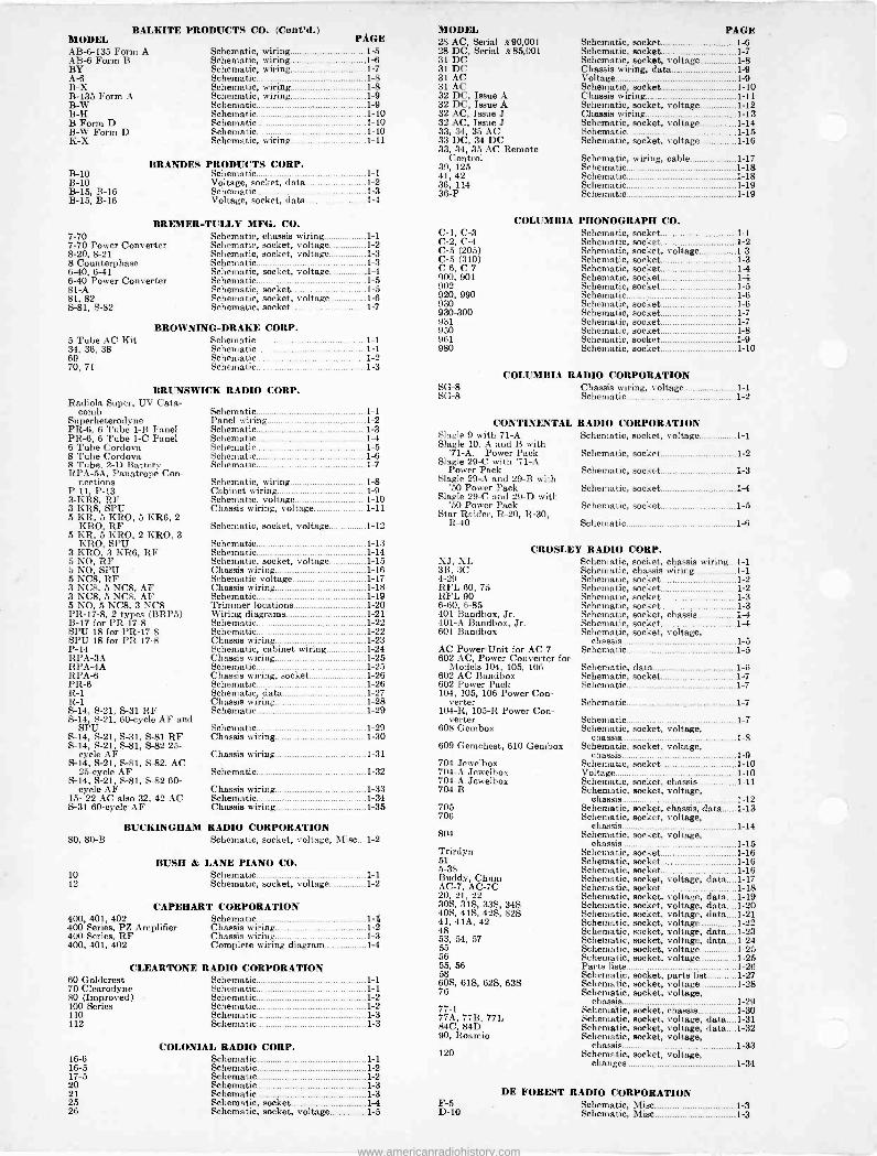
BALKITE PRODUCTS CO. (Cont'd.) MODEL PAGE AB -6-135 Form A AB -6 Form B BY A-6 B -X B-135 Form A B -W B -H B Form D B -W Form D K -X
Schematic, wiring 1-5 Schematic, wiring 1-6 Schematic, wiring 1-7 Schematic 1-8 Schematic, wiring 1-8 Schematic, wiring 1-9 Schematic 1-9 Schematic 1-10 Schematic 1-10 Schematic 1-10 Schematic, wiring 1-11
BRANDES PRODUCTS CORP. B-10 Schematic 1-1 B-10 Voltage, socket, data 1-2 B-15, B-16 Schematic 1-3 B-15, B-16 Voltage, socket, data 1-4
BREMER-TULLY MFG. CO. 7-70 Schematic, chassis wiring 1-1 7-70 Power Converter Schematic, socket, voltage 1-2 8-20, 8-21 Schematic, socket, voltage 1-3 8 Counterphase Schematic 1-3 6-40, 6-41 Schematic, socket, voltage 1-4 6-40 Power Converter Schematic 1-5 81-A Schematic, socket 1-5 81, 82 Schematic, socket, voltage 1-6 S-81, S-82 Schematic, socket 1-7
BROWNING -DRAKE CORP. 5 Tube AC Kit Schematic 1-1 34, 36, 38 Schematic 1-1 69 Schematic 1-2 70, 71 Schematic 1-3
BRUNSWICK RADIO CORP. Radiola Super, UV Cata-
comb Schematic 1-1 Superheterodyne Panel wiring 1-2 PR -6, 6 Tube 1-B Panel Schematic 1-3 PR -6, 6 Tube 1-C Panel Schematic 1-4 6 Tube Cordova Schematic 1-5 8 Tube Cordova Schematic 1-6 8 Tube, 2-D Battery Schematic 1-7 RPA-5A, Panatrope Con-
nections Schematic, wiring 1-8 P-11, P-13 Cabinet wiring 1-9 3-KR8, RF Schematic, voltage 1-10 3-KR8, SPU Chassis wiring, voltage 1-11 5 KR, 5 KRO, 5 KR6, 2
KRO, RF Schematic, socket, voltage 1-12 5 KR, 5 KRO, 2 KRO, 3
KRO, SPU Schematic 1-13 3 KRO, 3 KR6, RF Schematic 1-14 5 NO, RF Schematic, socket, voltage 1-15 5 NO, SPU Chassis wiring 1-16 5 NC8, RF Schematic voltage 1-17 3 NC8, 5 NC8, AF Chassis wiring 1-18 3 NC8, 5 NC8, AF Schematic 1-19 5 NO, 5 NC8, 3 NC8 Trimmer locations 1-20 PR -17-8, 2 types (BRP5) Wiring diagrams 1-21 B-17 for PR -17-8 Schematic 1-22 SPU 18 for PR -17-8 Schematic 1-22 SPU 18 for PR -17-8 Chassis wiring 1-23 P-14 Schematic, cabinet wiring 1-24 RPA-3A Chassis wiring 1-25 RPA-4A Schematic 1-25 RPA-6 Chassis wiring, socket 1-26 PR -6 Schematic 1-26 R-1 Schematic, data 1-27 R-1 Chassis wiring 1-28 S-14, S-21, S-31 RF Schematic 1-29 S-14, S-21, 60 -cycle AF and
SPU Schematic 1-29 S-14, S-21, S-31, S-81 RF Chassis wiring 1-30 S-14, S-21, S-81, S-82 25 -
cycle AF Chassis wiring 1-31 S-14, S-21, S-81, S-82, AC
25 -cycle AF Schematic 1-32 S-14, S-21, S-81, S-82 60 -
cycle AF Chassis wiring 1-33 15- 22 AC also 32, 42 AC Schematic 1-34 S-31 80 -cycle AF Chassis wiring 1-35
BUCKINGHAM RADIO CORPORATION 80, 80-B Schematic, socket, voltage, Misc....1-2
BUSH & LANE PIANO CO.
Schematic Chassis wiring Chassie wiring Complete wiring diagram
1-I 1-2 1-3 1-4
CLEARTONE RADIO CORPORATION
COLONIAL RADIO CORP. 16-6 Schematic 1-1 16-5 Schematic 1-2 17-5 Schematic 1-2 20 Schematic 1-3 21 Schematic 1-3 25 Schematic, socket 1-4 26 Schematic, socket, voltage 1-5
28 AC, Serial $ 90,001 Schematic, socket 1-6 28 DC, Serial *85,001 Schematic, socket 1-7 31 DC Schematic, socket, voltage 1-8 31 DC Chassis wiring, data 1-9 31 AC Voltage 1-9 31 AC Schematic, socket 1-10 32 DC, Issue A Chassis wiring 1-11 32 DC, Issue A Schematic, socket, voltage 1-12 32 AC, Issue J Chassis wiring 1-13 32 AC, Issue J Schematic, socket, voltage 1-14 33, 34, 35 AC Schematic 1-15 33 DC, 34 DC Schematic, socket, voltage 1-16 33, 34, 35 AC Remote
Control Schematic, wiring, cable 1-17 39, 125 Schematic 1-18 41, 42 Schematic 1-18 36, 114 Schematic 1-19 36-P Schematic 1-19
COLUMBIA PHONOGRAPH CO. C-1, C-3 Schematic, socket 1-1 C-2, C-4 Schematic, socket 1-2 C-5 (205) Schematic, socket, voltage 1-3 C-5 (310) Schematic, socket 1-3 C-6, C-7 Schematic, socket 1-4 900, 901 Schematic, socket 1-4 902 Schematic, socket 1-5 920, 990 Schematic 1-6 930 Schematic, socket 1-6 930-300 Schematic, socket 1-7 931 Schematic, socket 1-7 950 Schematic, socket 1-8 961 Schematic, socket 1-9 980 Schematic, socket 1-10
COLUMBIA RADIO CORPORATION SG -8 Chassis wiring, voltage 1-1 SG -8 Schematic 1-2
CONTINENTAL RADIO CORPORATION Slagle 9 with 71-A Schematic, socket, voltage 1-1 Slagle 10. A and B with
'71-A. Power Pack Schematic, socket 1-2 Slagle 29-C with '71-A
Power Pack Schematic, socket 1-3 Slagle 29-A and 29-B with
'50 Power Pack Schematic, socket 1-4 Slagle 29-C and 29-D with
'50 Power Pack Schematic, socket 1-5 Star Raider, R-20, R-30,
R-40 Schematic 1-6
CROSLEY RADIO CORP. XJ, XL Schematic, socket, chassis wiring...1-1 3B, 3C Schematic, chassis wiring 1-1 4-29 Schematic, socket 1-2 RFL 60, 75 Schematic, socket 1-2 RFL 90 Schematic, socket 1-3 6-60, 6-85 Schematic, socket 1-3 401 Bandbox, Jr. Schematic, socket, chassis 1-4 401-A Bandbox, Jr. Schematic, socket 1-4 601 Bandbox Schematic, socket, voltage,
chassis 1-5 AC Power Unit for AC -7 Schematic 1-5 602 AC, Power Converter for
Models 104, 105, 106 Schematic, data 1-6 602 AC Bandbox Schematic, socket 1-7 602 Power Pack Schematic 1-7 104, 105, 106 Power Con-
verter Schematic 1-7 104-R, 105-R Power Con-
verter Schematic 1-7 608 Gembox Schematic, socket, voltage,
chassis 1-8 609 Gemcheat, 610 Gembox Schematic, socket, voltage,
chassis 1-9 704 Jewelbox Schematic, socket 1-10 704-A Jewelbox Voltage 1-10 704-A Jewelbox Schematic, socket, chassis 1-11 704-B Schematic, socket, voltage,
chassis 1-12 705 Schematic, socket, chassis, data 1-13 708 Schematic, socket, voltage,
chassis 1-14 804 Schematic, socket, voltage,
chassis 1-15 Schematic, socket 1-16 Schematic, socket 1-16 Schematic, socket 1-16 Schematic, socket, voltage, data 1-17 Schematic, socket 1-18 Schematic, socket, voltage, data 1-19 Schematic, socket, voltage, data 1-20 Schematic, socket, voltage, data 1-21 Schematic, socket, voltage 1-22 Schematic, socket, voltage, data 1-23 Schematic, socket, voltage, data 1-24 Schematic, socket, voltage 1-25 Schematic, socket, voltage 1-25 Parte lists 1-26 Schematic, socket, parts list 1-27 Schematic, socket, voltage 1-28 Schematic, socket, voltage,
chassis 1-29 77-1 Schematic, socket, chassis 1-30 77A, 77B, 77L Schematic, socket, voltage, data 1-31 84C, 84D Schematic, socket, voltage, data. 1-32 90, Roamio Schematic, socket, voltage,
chassis 1-33 120 Schematic, socket, voltage,
changes 1-34
DE FOREST RADIO CORPORATION F-5 Schematic, Misc D-10 Schematic, Misc
1-3 1-3
www.americanradiohistory.com
MODEL CS -5 D-17
DE FOREST (Cont'd.) PAGE
Schematic, Misc 1-3 Schematic, Misc 1-3
DELCO RADIO CORP. 3002 Schematic, socket, chassis wiring,
voltage 1-1 3002 Chassis layout, control wiring,
data 1-2
EARL RADIO CORP. 21 -DC, 22 -DC Schematic, socket 1-1 121 Schematic 1-1 21, 22 AC Schematic, socket, voltage 1-2 24 -DC, 31 -DC, 32 -DC Schematic, socket 1-3 33-S AC Schematic 1-3 31, 32 AC Schematic, socket, voltage 1-4 41, 42 AC Schematic, socket, voltage 1-5
ECHOPHONE RADIO MFG. CO. S-3 Schematic 1-1 S-3 Revised Schematic 1-1 S-3 Voltage, data 1-2 S-3 Chassis views 1-3 S-4 Schematic 1-4 S-4 Voltage, data 1-5 S-4 Chassis views 1-6 S-5, Dynatron Schematic, socket, data 1-7 S-5 Revised Schematic, socket, data 1-8 S-5 Voltage, chassis layout 1-9
THOMAS C-1, Chassis.SC C-1, Chassis SC, Power Unit Rl, R2, C2, Chassis, Jr. and
Je. R1; 112, C2, Chassis, Jr. and
Je. Rl, R2, C2 60 cycles R4, R5, C4 (Umt Type 71I) R4, R5, C4 R4, 115, C4 R4, R5, C4 (Power Unit
Type 8P) R6, R7 Splitdorf Abbey, Jr. Splitdorf Abbey Battery Splitdorf R-100 Splitdorf E-175 Splitdorf R-200 Splitdorf RV -695
Loftin -White '45
ELECTRICAL S-61 R-1 R-2, RF Unit A-2, AF Unit 224 AC 224 AC 81, 82 (245) 335
F
65
A. EDISON, INC. Schematic, socket, voltage 1-1 Chassis wiring 1-2
Chassis wiring 1-3
Schematic, socket, voltage 1-4 Schematic, chassis wiring 1-5 Chassis wiring 1-6 Schematic, socket, voltage 1-7 Parts list 1-8
Chassis wiring 1-9 Schematic, socket, voltage 1-10 Schematic, socket 1-11 Schematic, socket 1-11 Schematic, socket 1-12 Schematic 1-13 Schematic, socket 1-12 Schematic, socket 1-12
ELECTRAD, INC. Schematic 1-1
RESEARCH LABORATORIES, INC. Schematic, socket 1-1 Schematic, socket 1-1 Schematic, socket 1-2 Schematic, socket 1-2 Schematic, socket 1-3 Chassis, voltage 1-4 Schematic, socket 1-5 Schematic, socket 1-6
EMERSON RADIO AND
EXPERIMENTERS' Navy C-10
FADA RADIO 460-A, R-60 Unit 475-A, SF 45-75 R -80-A Unit, 480-A, SF
50-80A 480-B, SF 50-80B 472UA, 475UA, 472CA,
475CA 262UA, 265UA, 262CA,
265CA C Electric Unit ABC SPU, Types 66-Q and
62-R ABC SPU, 86-V, 82-W 10, 11, 30, 31, 10Z, 11Z, 30Z,
31Z 16, 17, 32, 16Z, 32Z 18 DC 20, 20Z 22 Battery 25, 25Z 25, 25Z (M-250 and M -250Z
units) 35-B 35, 35Z 40 42, 44, 46, 41, 47 KF (43), KG (761, 762, 764,
766) 45, 45Z (KU) 48, 49 (KW) 45, 48, 49 50, 70, 71, 72, 50Z, 70Z E-180, E -180Z E-420, E -420Z 192-A (192S, 192BS units) 160 Neutrodyne Reflex 75, 77
B Eliminator
PHONOGRAPH CORPORATION Schematic, socket, voltage, parts
list 1-1 Schematic, condenser data 1-2
INFORMATION SERVICE Schematic, Misc 1-4
& ELECTRIC CORP. Schematic, socket 1-1 Schematic, socket, data 1-2
Schematic, socket 1-3 Schematic, socket 1-4
Schematic, socket, parts list 1-5
Schematic, socket, data 1-6 Schematic, chassis wiring 1-7
Schematic 1-8 Schematic 1-9
Schematic, socket, parts list 1-10 Schematic, socket, voltage 1-11 Schematic, socket 1-12 Schematic, socket, voltage 1-13 Schematic, socket 1-14 Schematic, socket, voltage, data 1-15
Schematic, socket, voltage 1-16 Schematic, voltage, data 1-17 Schematic, socket, voltage, data 1-18 Schematic, socket, voltage, data 1-19 Schematic, socket. 1-20
Schematic, data 1-21 Schematic, socket, data 1-22 Schematic, socket, data 1-23 Service notes 1-24 Schematic, socket, voltage 1-25 Schematic, chassis wiring, data 1-28 Schematic, chassis wiring, data 1-27 Schematic, socket 1-28 Schematic 1-28 Schematic, socket, voltage, data 1-29
FARRAND MFG. CO. Schematic, Misc 1-5
MODEL A-10, 59, 102 A-10 B B C C D, Code 68-070 D, Battery D, Code 79-070 D (60 cycles) E, Code 68-060 E DC F, Code 79-080 F, Code 79-080 F-10, DC, F-11 DC F, (25 cycles) G, (25 cycles) H, Code 71-030 H Receiver H, Power Unit K M
FEDERAL RADIO CORP. PAGE
Schematic, socket 1-1 Chassis wiring 1-2 Schematic 1-3 Chassis wiring 1-4 Schematic, socket 1-5 Chassis wiring 1-6 Schematic, socket 1-7 Chassis wiring 1-8 Schematic, socket, data 1-9 Chassis wiring 1-10 Schematic, socket 1-11 Schematic, socket 1-12 Chassis wiring 1-13 Schematic, socket 1-14 Schematic, socket, data 1-15 Schematic, socket 1-16 Schematic, socket, data 1-17 Schematic, socket, voltage 1-18 Chassis wiring 1-19 Chassis wiring 1-20 Schematic, socket 1-21 Schematic, socket, voltage 1-22
FEDERATED PURCHASER Cathedral Tone Schematic 1-1
FENWAY Superheterodyne, early and
late Schematic, Misc 1-5
FERRANTI, INC. 250-B-3 Schematic, Misc 1-6 250-C Schematic, Misc 1-6
FREED TELEVISION & RADIO CORP. NR -5 NR -6 NR -7 NR -8, NR -8A NR -9, NR -9A NR -10 NR -11 NR -11 Power Pack NR -12 ABC Power Pack FE -15 FE -18 NR -20 FE -30, 30N 40N, 48N 50 NR -53 NR -55 DC NR -55, NR -56 AC NR -57 NR -457 Power Unit NR -60 DC NR -60 AC NR -460 AC Power Unit NR -66, 66-A NR -70 AC NR -470 AC NR -77 800 NR -78 DC, NR -79 DC NR -78 AC, NR -79 AC NR -80 DC NR -80 AC NR -85 AC NR -90-S NR -95 AC
Schematic Schematic Schematic, socket Schematic, socket Schematic, socket Schematic, socket Schematic Schematic Schematic Schematic Schematic Schematic Schematic Schematic Schematic Schematic Schematic Schematic, socket Schematic, socket, voltage Schematic, socket Schematic Schematic Schematic, socket Schematic Schematic, socket Schematic, socket Schematic Schematic, socket Schematic Schematic, socket, voltage Schematic, socket, voltage Schematic, socket, voltage Schematic, socket, voltage Schematic, socket, voltage Schematic Schematic, socket, voltage
1-1 1-1 1-2 1-2 1-3 1-3 1-4 1-5 1-4 1-5 1-6 1-6 1-6 1-7 1-7 1-8 1-22 1-9 1-10 1-11 1-11 1-12 1-13 1-13 1-14 1-15 1-15 1-16 1-16 1-17 1-18 1-19 1-20 1-21 1-22 1-23
JESSE FRENCH & SONS PIANO CO. 8 Tube AC Schematic, socket, voltage, data 1-1 5-093 Schematic, socket, voltage 1-2
CHARLES FRESHMAN CO., INC. Masterpiece Equaphase G G with G -60-S Power Unit.
2 types H ABC Power Unit K L M N 2N with 2N -60-S Power Unit Q-15, Q-16 3-Q-15, 3-Q-16 QD-16-S
Motorola Auto Set Motorola Auto Set
Schematic 1-1 Schematic 1-1 Schematic, socket, voltage 1-2
Schematic, socket, voltage 1-3 Schematic, socket, voltage 1-4 Schematic 1-4 Schematic, socket, voltage 1-5 Schematic, socket 1-7 Schematic, socket, voltage 1-6 Schematic, socket, voltagd 1-7 Schematic 1-8 Schematic, socket 1-9 Schematic, socket, voltage 1-10 Schematic, socket, voltage 1-11
GALVIN MFG. CO. Schematic, Misc 1-7 Special notes for Buick and
Ford "A," Misc 1-8
DAVID GRIMES, INC. New Yorker, 110 -volt DC Schematic, Misc 1-9 Inverse Duplex, type 4 -DL Schematic, Misc 1-9 Inverse Duplex, 1927 Schematic, Misc 1-9
T-12 S-22 S-42 K-50, K-51 S -42-B T-41 H-31 H-51 H-71
GENERAL ELECTRIC CO. See RCA Victor R-5 See RCA Victor R-7 See RCA Victor R-9 See RCA Victor R-28 See RCA Victor R-43 See RCA Victor 48 See RCA Victor R-80 See RCA Victor R-82 See RCA Victor R-86
www.americanradiohistory.com
GENERAL M OTORS RADIO CORP. MODEL OEM -7 (4 tube) OEM -7 Super -Sel. OEM -11 (3 tube) 5044 (5 tube) 527 (5 tube) Day -Fan 5 -AC Day -Fan 5 -AC SPU Day -Fan 6 Day -Fan 6 Jr. Day -Fan 6-61 (5050) Day -Fan 5050, Battery Day -Fan 5050-7 Day -Fan 5051 (MG Set) Day -Fan 5052 (110 -volt DC) Day -Fan 5053 Day -Fan 5057 Day -Fan 5057 SPU Day -Fan 5065 AC Day -Fan 5524, 5525 SPU Day -Fan 5066 Day -Fan 5060 (32 -volt DC) B and C SPU Day -Fan 25, 26, 27, 28, 43,
48 Day -Fan 35 Day -Fan 5077 Day -Fan 5080 Day -Fan A-5003, A-5010 Day -Fan 5091 120, 130, 140. Below serial
í129100A -.1700B 120, 130, 140. Between
serial *29100A -62100A, 1700B -1964B
120, 130, 140. Above serial í162100A -1964B
170-E 170-E 110, 180, 190 Little General
210 Amplifier 250 Amplifier 390 Eliminator 361-B 360 Oscillator 360-A Oscillator 320 Oscillator 403-C
PAGE Schematic, socket 1-1 Schematic, socket 1-1 Schematic, socket 1-1 Schematic, socket 1-2 Schematic, socket 1-2 Schematic 1-3 Schematic, data 1-3 Schematic, socket 1-3 Schematic, socket 1-4 Schematic, socket, data 1-4 Schematic 1-9 Schematic, socket 1-9 Schematic, data, socket 1-5 Schematic, socket 1-8 Schematic, socket 1-6 Schematic, data 1-6 Schematic 1-6 Schematic, socket, data 1-7 Schematic 1-7 Schematic, data 1-7 Schematic, socket 1-8 Schematic 1-9
Schematic, socket, voltage Schematic, socket Schematic Schematic, socket, voltage Schematic, socket Schematic, socket, voltage
Schematic, socket, voltage
Schematic, socket, voltage 1-15
Schematic, socket, voltage 1-16 Schematic, socket, voltage 1-17 Chassis wiring, data 1-18 Schematic, socket, data 1-19
GENERAL RADIO CO. Schematic 1-1 Schematic 1-1 Schematic 1-1 Schematic diagrams 1-2 Schematic 1-3 Schematic 1-3 Schematic 1-3 Schematic 1-2
GILFILLAN BROS. 33 Schematic, socket 1-1 60 Schematic, socket 1-2 66 Schematic, socket 1-2 100 Schematic, socket 1-1
GB -4 GB -8 311 500 550 GB -678 340 600 GB -700 GB -770 GB -900
GRAYBAR ELECTRIC CO. See RCA Victor R-5 See RCA Victor R-7 See RCA Victor 33 See RCA Victor 44 See RCA Victor 46 See RCA Victor 48 See RCA Victor 62 See RCA Victor 66 See RCA Victor R-80 See RCA Victor R-82 See RCA Victor R-86
A. H. RORB BORD BORE RORF BORG RORH RORJ RORK RORL BORN BORO RORQ CR -1 CR -2 CR -3 CR -4 CR -5 CR -6 CR -7 CR -8 Broadcast Receiver CR -9 CR -12 CR -18 (Special) CR -13 CR -14 CR -18 (1 AF. Stage) Synchrophase 5, 671 Power
Unit Synchrophase 1925 Synchrophase MU -1 Synchrophase MU -1 Synchrophase MU -2 412 Pushpull Amplifier 428 DeLuxe Console Synchrophase AC -6 Synchrophase AC -6 Power
Unit Synchrophase 7 Battery 671-B Power Unit Synchrophase 7 AC Synchrophase S1C-4, Early
GREBE & CO. Schematic 1-1 Schematic 1-1 Schematic 1-1 Schematic 1-1 Schematic 1-2 Schematic 1-2 Schematic 1-2 Schematic 1-2 Schematic 1-2 Schematic 1-3 Schematic 1-3 Schematic 1-3 Schematic 1-4 Schematic 1-4 Schematic 1-4 Schematic 1-4 Schematic 1-5 Schematic 1-5 Schematic 1-5 Schematic 1-5 Schematic 1-6 Schematic, socket 1-7 Schematic, socket 1-6 Schematic, socket 1-7 Schematic 1-8 Schematic, socket 1-8 Schematic 1-9
Schematic, socket, voltage 1-10 Schematic 1-11 Schematic 1-11 Socket layout 1-12 Schematic, socket, voltage 1-12 Schematic, chassis wiring 1-13 Schematic 1-14 Schematic, socket, voltage 1-15
Chassis wiring (2 types) Schematic, socket Schematic, socket Schematic, socket, voltage Schematic, socket, voltage
MODEL AH -1 Schematic, socket, voltage HS -4, 1 Pentode Schematic, socket, voltage HS -4 with '45 Pushpull Schematic, socket, voltage HS -5 Schematic, socket, voltage
GRIGSBY-GRUNOW CO. 70 7-P-6, 7-P-3 (Two types) 7-P-6, 7-P-3 (Old wiring) 7-P-6, 7-P-3 70-B 7 -BP -6, 7 -BP -3 7 -BP -6, 7 -BP -3 180 8-P-6, 8-P-3 70-B, 180 90 100 90-B 100-B 130-A 230-A 20, 21,
1-10 20 1-10 30, 31 1-11 30 1-11 50, 52 1-12 50 1-13 60, 61, 62
60, 61, 62 (160, 163) 1-14 60, 61
160, 163 9-P-3, 9-P-6
22, 23
60, 63 60, 63 160, 161 (60 cycles) 160, 161 (25 cycles) 200, 291, 292, 295, 9950 200, 291, 292, 295, 9950
(2 types)
PAGE 1-20 1-21 1-22 1-23
Schematic, socket, voltage 1-1 Schematic 1-2 Chassis wiring 1-3 Chassis wiring 1-4 Schematic, socket, voltage 1-5 Schematic 1-6 Chassis wiring 1-7 Schematic, socket, voltage 1-8 Schematic, chassis wiring 1-9 Data 1-10 Schematic 1-11 Schematic 1-11 Schematic, socket, voltage 1-12 Schematic 1-12 Schematic, socket, voltage 1-13 Schematic, socket 1-13 Schematic, socket, voltage, data 1-14 Chassis views 1-15 Schematic, socket 1-16 Voltage, data 1-17 Schematic, socket, voltage 1-18 Chassis views 1-19 Schematic, socket 1-20 Voltage, data 1-21 Chassis views 1-22 Schematic, socket 1-23 Schematic, socket, voltage, data 1-24
GULBRANSEN CO. Schematic, socket, voltage 1-1 Chassis wiring, data 1-2 Schematic, data 1-3 Schematic, voltage 1-4 Voltage, socket, data 1-5
Schematic, socket 1-6
HAMMARLUND-ROBERTS, INC. H -R 5 Tube Schematic 1-1 H -R "Hi -Q" Schematic 1-1 H -R "Hi -Q" 6 Schematic, chassis wiring, data 1-2 H -R "Hi -Q" 29 Jr. (3 types) Schematic, socket, data 1-3 H -R "Hi -Q" 29 Master
H R (3 ty Q" 30 (30-R, Schematic, socket, data 1-4
Battery) Schematic 1-5 H -R "Hi -Q" 30 AC Schematic 1-5 H -R "Hi -Q" 30 DC Schematic, socket, voltage 1-6 H -R "Hi -Q" 31 Schematic 1-6
HAMMARLUND MFG. CO. Hawk Schematic 1-1 DeLuxe Schematic 1-1 Z4 Commander Schematic 1-1 Trans -Oceanic Two Schematic 1-1 AC & DC Converters Schematic 1-1
H -Y 7 H -Y 7 Battery H -Y 7-B
HATRY & YOUNG ' Schematic, parts list Misc. Page 1-10
Schematic Misc. Page 1-10 Schematic Misc. Page 1-10
HIGH FREQUENCY LABORATORIES A -C Special 9-in-Lme Mastertone 1929 Isotone 10
Schematic 1-1 Schematic 1-1 Schematic - 1-2 Schematic 1-2
HOWARD RADIO CO. A-5 A-6 SN -7 K Green Diamond 8
(Magnetic Spkr.) Green Diamond 8
(Dyn. Spkr. '71) Green Diamond 8
(Dyn. Spkr. '45) SG "A" RF Chassis SG "A" AF Chassis SG "C" RF Chassis SG "C" AF Chassis 395, 445, 470, 495 (135 AC
Chassis)
J. 3B Mixing Panel 3C Mixing Panel A (2 types) Pushpull Amplifier Monitor Amplifier Monitor Amplifier
Schematic, socket 1-1 Schematic, socket 1-1 Schematic, socket 1-2 Schematic 1-2
Schematic, socket, voltage, data 1-3
Schematic, socket, voltage, data 1-4
Schematic, socket, voltage, data 1-5 Schematic 1-6 Schematic, voltage, socket 1-7 Schematic 1-6 Schematic 1-7
Schematic, socket 1-8
E. JENKINS & S. E. ADAIR Schematic 1-1 Schematic 1-1 Schematic 1-2 Schematic 1-2 Schematic 1-2 Schematic 1-2
KELLOGG SWITCHBOARD & SUPPLY CO. 6 Tube Battery 7 Tube Cascade Wave Master RFL 701 AC -7 Tube Chassis B 523, 524, 525, 526, 527,
528 RF 1-16 523, 526 Power Unit 1-17 524, 525,. 527, 528 Power 1-17 Unit 1-18 533, 534, 535, 536 RF 1-19 Chassis
Schematic 1-1 Schematic 1-1 Schematic 1-1 Schematic....., 1-2 Schematic, voltage 1-2 Schematic, voltage 1-2
Schematic 1-3 Schematic; socket, voltage 1-4
Schematic, voltage, socket 1-5
Schematic, socket 1-6
www.americanradiohistory.com
COLIN B. KENNEDY CORP. MODEL PAGE
WILLIAM J. MURDOCK CO. MODEL PAGE
15, 16 (Type 430-43) Schematic 1-1 Neutrodyne, 3 Control Schematic, Misc 1-15 220 Schematic 1-1 7 -Tube, Single Control Schematic, socket, Misc 1-15 281 Schematic 1-1 175 to 25,000 Meters Schematic 1-1 5 Schematic 6 Type 421 Schematic
1-2 1-2 NATIONAL CARBON CO.
6 Type 420 Schematic 1-2 1, 2, 3 Schematic, socket 1-1 7 -Cornet DC Schematic, socket 1-3 20, 21 Schematic, socket 1-1 20, Type 440 Schematic 1-3 31, 32, 33, 34 Schematic, socket, voltage, parts 30, Type 435 Schematic, voltage 1-3 list 1-2 10 Schematic, socket, voltage 1-4 42, 43, 44 Schematic, socket, voltage, parts 20 Schematic, socket, voltage 1-4 list 1-3 Royal Schematic 1-5 52, 53, 54 Schematic, socket, voltage, parts Royal 60 Schematic, socket 1-5 list 1-4 26 Schematic, chassis, notes 1-6 30, 32 Schematic, chassis 1-7 34 Schematic, voltage 34 Chassis wiring
1-8 1-9 THE NATIONAL COMPANY
34 Changes, data 1-10 S -G 5 Schematic 1-1 Coronet 42 Schematic, chassis, voltage 1-11 S -G SW Tuner Schematic 1-1 Royal 80 Schematic 1-12 S -G SW Tuner with '71 Schematic 1-1 826-B Schematic 1-12 Auto Box Connections Wiring diagram 1-1
MB -29 Schematic 1-2 MB -30 Schematic, chassis 1-2
KING MFG. CO. Thrill Box AC, SW Schematic 1-2 10 -KI Schematic, socket 1-1 Auto Box Schematic 1-2 25 Schematic, socket 1-1 30 Schematic, socket 1-1 E Schematic, socket 1-2 F Schematic, socket 1-2 NORDEN-HAUCK, INC. G Schematic, socket H Schematic, socket J Schematic, socket 80 Schematic, socket 81 Schematic, socket 82 Schematic, socket
1-3 1-3 1-4 1-4 1-5 1-5
Super DX -5 Schematic Super DX -5A Schematic Admiralty Super 12 Schematic C-7 Schematic Super 10 Schematic
1-1 1-1 1-2 1-3 1-3
Royal (97) Schematic, socket 1-6 Imperial (98) Schematic, socket 1-6 Monarch (101) Schematic, socket, voltage 1-7 OPERADIO CORP. Royal (97) Voltage 61 Schematic, socket 62, 63 Schematic, socket 71 Schematic, socket
1-7 1-8 1-8 1-8
1925 Schematic, Misc 1926 Schematic, Misc 7 Schematic, Misc
1-16 1-16 1-16
KOLSTEB RADIO, INC. 6D, 6E, 6G, 6H (1927) Schematic, socket 1-1 OZARKA, INC. 7-A, 7-B (1926) Schematic, socket l-1 91 Battery Schematic, chassis 1-1 8A, SB, 8C (1926) Schematic, socket 1-1 Viking 90 AC Schematic, chassis, socket, 6-F, 6-J, 6-K, 6-L, 6-M, 6-R Schematic, socket, voltage 1-2 voltage 1-2 K-20, K-22, K-27 Schematic, socket, voltage 1-3 K-21, K-23, K-28 Schematic, socket, voltage 1-4 K-23 Reproducer Schematic 1-2 K-24 (250) Schematic 1-5 PHILCO RADIO & TELEVISION CORP. K-24 (210) Schematic, socket, voltage K-30, K-32 Schematic, socket K-42 Schematic, socket, voltage
1-5 1-6 1-7
B-253 Power Unit Schematic, data B-603 Power Unit Schematic, data 180-B Power Unit Schematic
1-1 1-1 1-2 K-43, K -43A (1929) Schematic, socket, voltage 1-8 B Part of AB Unit Chassis layout 1-2 K-44 (1929) Schematic, socket, voltage 1-9 AB -423, AB -463, AB -623, Schematics and layouts of
K-45 Schematic, socket 1-10 AB -663 power units 1-3 K-60, K-62 Schematic 1-11 DB, AB -463, AB -623, K-70, K-72 Schematic 1-12 AB -663 Specifications 1-4 K-80, K-82 Schematic 1-13 3 Transitone Schematic, compensating data, K-90, K-92 Schematic 1-14 parts list 1-5
20, 20-A Schematic, chassis view 1-6 R. E. LACAULT 30 Schematic, socket, chassis view
35 Schematic, voltage, data 1-7 1-8
All Wave Electric 9 Schematic, parts list, Misc 1-11 35 Chassis, data . 1-9 LR -4 Schematic, Misc 1-11 40 DC Schematic, voltage, data 1-10 L-2 Ultradyne Schematic, Misc 1-11 41 DC, 42 DC Schematic, socket, voltage, data....1-11
46, 46-E DC Chassis, voltage, parts list 1-12 LANG RADIO CO. 46, 46-E DC Schematic, voltage, data
50, 50-A Schematic, chassis, data 1-13 1-14
BA -5 Schematic, socket 1-1 50, 50A Voltage, parts values 1-15 BD -5-P Schematic, socket 1-1 65 Schematic, socket, voltage 1-16 BD -6 Schematic, socket 1-1 70, 70-A (Below No. BD -6-P Schematic, socket 1-2 B-22,000) Schematic, socket, voltage, data....1-17 F-9 Schematic, socket 1-2 70, 70-A Chassis, parts values 1-18 J-7 Schematic, socket 1-2 76 Schematic, socket, voltage - 1-19 M-7 Schematic, socket 1-3 77, 77-A Schematic, socket, data 1-20 R-8 Schematic, socket 1-3 82, 86 Schematic, socket, voltage 1-21
87 Schematic, socket 1-22 C. R. LEUTZ, INC.
C-10, Navy Model Schematic 1-1
95 Schematic, socket, voltage, data....1-23 96, 96-A Schematic, socket 1-24 112, 112-A (Below No.
Silver Ghost Schematic 1-1 174,001) Voltage, parts, values 1-25 C Schematic 1-1 112, 112-A Schematic, socket 1-26 Trans -Oceanic Schematic 1-2 211, 211-A Schematic, socket, data 1-27 Seven Seas Schematic, socket 1-2 212, 212-A Radio-
Phonograph Schematic 1-26 LINCOLN RADIO CORP. 270, 270-A Schematic, data
296, 296-A Schematic, socket, data 1-28 1-30
8-80 Schematic 1-1 500 Series Schematic, chassis wiring 1-29 31 Schematic 1-1
MADISON -MOORE PILOT RADIO & TUBE CORP. Superheterodyne Schematic, Misc One -Spot Super Schematic, Mise
1-12 1-12
171 Power Amplifier Schematic Public -Address System Schematic
1-1 1-1
K-111 ABC Pack Schematic 1-2 THE MAGNAVOX CO. Pilotone B Pack Schematic 1-2
One Dial Schematic, Misc A Schematic, Misc D Schematic, Misc
1-13 1-13 1-13
ABC Pack for SP5 Schematic Jumbo Power Pack Schematic Jumbo ABC Schematic Air -Hound (All Electric) Schematic
1-2 1-2 1-2 1-3
Air Scout (All Electric) Schematic 1-3 MAJOR LABORATORIES Pilotone (Electric) Schematic, socket 1-3
250 Amplifier Schematic, Misc 250 Amplifier Power Unit Schematic, Misc 12 Schematic, Misc ML -210 Amplifier Schematic, Misc
1-14 1-14 1-14 1-14
K-110, Super -Wasp, Battery Schematic, socket K-115, AC Super -Wasp Schematic, socket K-117, Twin Screen -Grid 8 Schematic K-121, K -121X, Country
Special Schematic, socket
1-4 1-4 1-4
1-5
McMILLAN RADIO CO. PE -6, SG, K-122, K-123,
K-124 Schematic, socket 1-5 8 (2 types) AC Schematic, socket, voltage Series 900 Schematic, socket, voltage
1-1 1-2
K-126, K-128 Schematic, socket 140 Auto Set Schematic, socket, wiring data S -W Converter Schematic
1-5 1-6 1-6
MONTGOMERY -WARD & CO. AC Midget, S-155, S -155-A,
S -155-B, S -155-F, C -157 C -157-A, C -157-B, C-157-1
62-055, 49, 1522, 1922, 1562 Schematic, socket, chassis, data 1-1 (2 Types) Schematic, socket 1-7
www.americanradiohistory.com
RCA -VICTOR CO., INC. MODEL AP -736 AP -736-B AP -777-C AP -947 AP -951 AP -951-A, 974-A,
AP -997-A AP -935 AP -937 AP -995 AP -997, AP -952 AP -997-C AP -1080 12-25 Tuscany 8-60 Radiola Grand Radiola Senior Radiola AR Radiola RS Radiola II Radiola III Radiola Balanced Amplifier Radiola Senior Amplifier Radiola III -A Radiola IV Radiola V Radiola VI Radiola VII Radiola VII -B Radiola Super VIII Radiola IX R-5 AC R-5 AC
R-7, R-9 AC Superette R-7, R-9 AC Superette R-15 Radiola 16 Radiola 17 Radiola 18 DC Radiola 18 AC Radiola 20 Radiola 21, 22 Radiola 24 Radiola 26 Radiola 25 Radiola 25 (104 Power Pack) Radiola 28, Battery Radiola 28 AC (104 Power
Supply) Radiola 30 AC (104 Power
Pack) Radiola 30-A Radiola 30-A Power Pack Victor R-32, RE -45, R-52 Radiola 32 AC Radiola 33 AC Radiola 33 DC Victor R-35, R-39, RE -57
Victor R-35, R-39, RE -57 Radiola 41 DC AF and
Power Unit Radiola 41 AC RF Sterling SPU Receptor SPU Radiola 42 R-43
R-43 Radiola 44 AC Radiola 46 DC Radiola 46 AC 44, 46 RF Chassis 44 Early SPU 44 Late SPU 46 SPU Radiola 47 Radiola 48 Radiola 60 Radiola 62 Radiola 64 Radiola 66 Radiola 67 Radiola 80 Radiola 82 Radiola 82 and 86 (Remote
Control) Radiola 82 (Remote Control) Radiola 82 and 86 (Remote
Control) Radiola 82 and 86 (Remote
Control) Radiola 82 and 86 (Remote
Control) Radiola 86 AC Circuits Radiola 86 SW Adaptor, SW -10 SW -10 100-A, 100-B, 103, 104 -AC 105, 106 Victor Alhambra I (7-1) Victor Alhambra II,
Florenza Victor Borgia I Victor Electrola Hyperion Victor 7-10, Radiola 16 Victor 7-11, Radiola 18 Victor 7-25, Radiola 17 Victor Borgia II Victor Tuscany Victor Cromwell, 12-1 Victor 12-15 Victor 12-15-C Victor E-35 Victor 7-3, 7-30, R-20 Victor 7-26 Victor 8-60 Victor 9-15 Victor 9-18
PAGE Schematic 1-1 Schematic, chassis wiring 1-1 Schematic 1-2 Schematic 1-2 Schematic 1-2
Schematic Schematic Schematic Schematic Schematic Schematic Schematic Socket layout Socket layout Schematic, socket Schematic, socket Schematic, socket Schematic, socket Schematic, socket Schematic, socket Schematic, socket Schematic, socket Schematic, socket Schematic, socket Schematic, socket Schematic, socket Schematic, socket Schematic, socket Schematic, socket, data Schematic, socket Parts list, notes Schematic, chassis wiring,
voltage 1-11 Chassis wiring 1-12 Schematic, voltage, service notes 1-13 Schematic, socket, voltage, data 1-14 Schematic, data, socket 1-15 Schematic, socket, voltage, data 1-15 Schematic, socket, voltage 1-16 Schematic, socket 1-16 Schematic, socket, data 1-17 Schematic, socket, voltage 1-18 Schematic, socket 1-19 Schematic, socket 1-19 Schematic, socket, wiring 1-20 Schematic, voltage 1-21 Schematic, wiring 1-22
Schematic, socket 1-23
Schematic, wiring, data 1-24 Schematic, socket, voltage 1-25 Schematic 1-25 Schematic, socket, voltage, data 1-26 Schematic, socket, data 1-27 Schematic, socket, voltage 1-28 Schematic, socket 1-28 AF Chassis wiring, socket,
voltage, data 1-29 Schematic, data 1-30
Chassis wiring, voltage 1-31 Schematic, socket, data 1-32 Schematic, voltage 1-32 Schematic, voltage 1-32 Schematic, notes 1-34 Schematic, socket, voltage,
chassis wiring 1-33 Service notes 1-34 Terminal voltage 1-35 Schematic 1-35 Terminal voltage 1-35 Schematic, socket, voltage 1-36 Schematic 1-36 Schematic 1-36 Schematic 1-36 Schematic, voltage, socket 1-37 Schematic, socket, voltage, data 1-38 Schematic, socket, voltage, data 1-39 Schematic, socket, voltage, data 1-40 Schematic, socket, voltage, data 1-41 Schematic, socket, voltage, data 1-42 Schematic, data 1-43 Schematic, socket, voltage 1-44 Schematic, socket 1-45
Assembly wiring 1-46 Schematic, notes 1-47
Receiver chassis wiring 1-48
Power unit chassis wiring 1-49
Remote control units, data 1-50 Schematics 1-51 Schematic, data 1-52 Schematic, chassis wiring 1-53 Voltage, chassis views, data 1-54 Schematic, socket, data 1-55 Schematic, socket, wiring 1-56 Schematic, socket 1-57
Schematic, socket 1-57 Schematic, socket 1-58 Schematic, socket 1-58 Schematic, socket 1-59 Schematic, socket, voltage 1-59 Schematic, socket 1-59 Schematic, socket 1-60 Schematic, socket 1-60 Schematic, socket 1-60 Schematic, socket 1-61 Schematic, socket 1-61 Cable wiring 1-61 Schematic, socket 1-62 Schematic, socket 1-62 Schematic, socket 1-63 Schematic, socket 1-63 Schematic, socket, voltage 1-64
1-2 1-3 1-3 1-4 1-4 1-4 1-3 1-4 1-4 1-5 1-5 1-5 1-5 1-6 1-6 1-6 1-6 1-7 1-7 1-7 1-7 1-8 1-8 1-9 1-8 1-10
MODEL Victor 9-25 Victor 9-40 Victor 9-54 Victor 9-55 Victor 10-51-A Victor 10-69 Victor 10-70 Victor 10-70-A Victor 12-25 Theremin Photophone SPU 62 Photophone SPU 63 Photophone SPU 206
PAGE Schematic, socket 1-65 Schematic 1-65 Schematic, socket, voltage 1-66 Schematic, socket 1-67 Schematic, socket 1-67 Schematic, socket, chassis wiring 1-68 Schematic, socket 1-69 Schematic, socket 1-69 Schematic, socket 1-69 Schematic, data 1-70 Schematic, chassis 1-71 Schematic 1-71 Schematic 1-71
RADIART LABORATORIES Magnaformer 9-8 Schematic, Misc 1-4
RADIO PRODUCTS CO. Dayrad 8-80 Dayrad 21 Output Meter 330 Mmf. Oscillator Dayrad 180 Dayrad HR Dayrad 870 Test Meter Dayrad 875
74-R 27-R Early and Late
Schematic 1-1 Schematic 1-2 Schematic 1-2 Schematic 1-3 Schematic 1-3 Schematic 1-3 Schematic 1-3
RADIOTROPE Schematic, socket, voltage 1-1 Schematic, socket, voltage 1-2
REES-MACE 5 -Tube Schematic, Misc 1-17 5 -Tube Screen Grid Schematic, Misc 1-17
REMLER COMPANY, LTD. 14 Schematic, socket, chassis,
voltage, data 1-1 Best 115 KC Schematic 1-2 Remler 29 Schematic 1-2
SAMSON ELECTRIC CO. S-100 Schematic 1-1 PAM -19 Schematic 1-1 Amplifier Schematic 1-1 PABC-2 Schematic 1-2 PABC-3 Schematic 1-2 PAM -3 Schematic 1-2 PABC-4 Schematic 1-3 PABC-5 Schematic 1-3
SCOTT TRANSFORMER CO. World Record 10 Shield Grid 9 All -Wave Super All -Wave Super All -Wave Super,
Pack All -Wave Super, 150 Power
Pack
11,12,15,16
106-B 108 108-A, 110 440 444 660 666-C 1020, 1030
145 Power
Schematic 1-1 Schematic 1-1 Receiver, chassis wiring, data 1-2 Schematic 1-3
Schematic, chassis wiring 1-4 Chassis views, schematic, control
box 1-5
SENTINEL RADIO CORP. (104) Schematic, socket, voltage, parts
values 1-1 Schematic 1-2 Schematic, socket 1-3 Schematic, socket 1-4 Schematic 1-5 Schematic, socket, voltage 1-5 Schematic 1-6 Schematic, socket 1-6 Schematic 1-7
SILVER -MARSHALL, INC. 30 Schematic, socket, voltage 1-1 440, Time Signal Amplifier Schematic 1-1 30-B, 60-B, 75-B, 90-B Schematic, socket, voltage 1-2 30 Circuit B Schematic, data 1-3 30 Circuit C Schematic, data 1-3 30 Circuit D Schematic, data 1-4 30 Circuit E Schematic, data 1-4 33-A Power Supply, 25 and
60 Cycles Schematic, socket voltage 1-5 34-A Schematic, socket 1-6
35-
5 A' Schematic, socket 1-6 36-A Schematic, socket, voltage 1-7 Bearcat, 37, 38, 39, 782
Midget Schematic, voltage 1-8 SM -651 Power Pack Schematic 1-9 SM 650-B Schematic 1-10 SM -652 Schematic 1-10 SM -660 Unipack Schematic 1-9 SM -660-B (Without pushpull
amplif.) Schematic 1-9 SM-669 Schematic, chassis wiring 1-10 670 -ABC ' Schematic, chassis wiring 1-11 670-B Schematic, chassis wiring 1-11 675 Schematic, chassis wiring, parts
list 1-12 677, 25 and 60 cycles Schematics, chassis wiring 1-13 678 -PD Schematic, chassis wiring 1-14 679 Schematic 1-14
www.americanradiohistory.com
SILVER -MARSHALL (Cont'd.) MODEL PAGE
STEWART-WARNER CORP. MODEL PAGE
685 Schematic 1-15 300, 305 Schematic, socket 1-1 690 Schematic 1-15 305, 315, 320 Schematic, socket 1-1 692 Schematic 1-15 310, 325 Schematic, socket 1-1 710, Sargent -Raymond 7 Schematic, chassis view, data 1-16 330 Schematic, socket 1-1 712 Schematic, socket, chassis view 1-17 335, 340 Schematic, socket 1-1 677-B Schematic, voltage 1-17 345, 350, 355, 360 Schematic, socket 1-1 714 Schematic, socket, voltage,
chassis views 1-18 385, 390 Schematic, socket 500, 520, 525 Schematic, socket
1-2 1-2
720 AC Schematic 1-19 530, 535 Schematic, socket 1-2 720 Battery Schematic, chassis view 1-19 530, 535, 715, 720 SPU Schematic 1-2 722 AC Schematic, socket, voltage, data....1-20 700, 705, 710 Schematic, socket 1-3 722 DC Schematic, chassis wiring 1-21 715, 720 Schematic, socket 1-3 724 AC Schematic, socket, voltage,
chassis view 1-22 750 Schematic, socket 801, 802 Schematic, socket
1-3 1-4
724 DC Schematic, socket 1-23 801, 801-A, 811, 811-A Long -Wave Receiver Schematic 1-23 (Series B) Schematic, socket, voltage 1-4 726 Schematic, socket, voltage, parts PU 801, 801-A, 811, 811-A Schematic 1-4
list 1-24 806 (Series A) Schematic, socket 1-5 730, 731 Schematic 1-25 806 (Series B) Schematic 1-5 735 AC Schematic 1-25 950 Series (Battery) Schematic, socket, voltage 1-5 735 DC Schematic 1-25 950 Series AC Schematic, socket, chassis 1-6 737 AC Bearcat Schematic, socket 1-26 901, 902, 903, 911, 912, 913 Schematic, socket, voltage, 738 AC SW Converter Schematic, socket 1-26 chassis 1-7 739 SW Superhet 950 Series DC Schematic, socket 1-8
Converter Schematic, data 1-27 971, 972, 973 DC Schematic 1-9 740 DC Schematic, chassis 1-28 980 Battery Schematic 1-9 740 AC Schematic 1-28 R -100-A, B, E AC Schematic 1-10 770 Auto Schematic, socket, chassis view 1-29 R-100 Series Chassis wiring, voltage 1-10 A Schematic, socket 1-30 R -100-A Continuity tests 1-11 F Schematic, socket 1-30 R -100-C DC Schematic, socket, voltage 1-12 D, E Schematic, socket, voltage 1-31 Resistors Variable and fixed, Part 1 1-13 S -C II Schematic 1-32 Resistors Fixed, Part 2 1-14 620 S -C Schematic 1-32 A -F. Transformers Data 1-15 635 Kit Schematic 1-32 642 AC Tuner Schematic 1-32
STORY & CLARK RADIO CORP. M. B. SLEEPER 36 Schematic, socket, chassis 1-1
RX-1 Schematic, Misc 1-18 43, 51 Schematic, socket 1-2
SIMPLEX RADIO CO. STROMBERG-CARLSON TEL. MFG. CO. D Schematic, socket G Schematic 6-A Schematic, socket F Schematic
1-1 1-1 1-2 1-2
1-A Schematic, socket 1-B Schematic, socket 501, 501-A, 501-B, 502,
502-A, 502-B Schematic, socket
1-1 1-1
1-1 403 -AA Schematic, socket 1-2
SONORA PHONOGRAPH CO. 523, 524 AC Schematic, socket 1-2
3R, 4R Schematic 5R Schematic 7P Schematic A30, A32 Schematic A30, A32 Socket, voltage, chassis wiring B31, 25 cycles Schematic, socket A36, A46 Schematic, socket, voltage A40 Schematic A40 Chassis wiring, voltage, socket DeLuxe 44 Schematic, voltage 2M Automatic Stop Schematic, parts details 2 RP, 25 cycles Schematic
1-1 1-2 1-3 1-4 1-5 1-6 1-7 1-8 1-9 1-10 1-11 1-12
403, 403-A Schematic 403-B Schematic 301-A Schematic 601, 602 Schematic, socket 633, 634 Schematic, socket 635, 636 (2 types) Schematic, socket, voltage 638 AC Chassis wiring 638 AC Schematic, socket, voltage 638 DC Schematic, socket 641, 642, 652, 654 Schematic, socket, voltage 642 Chassis wiring 652, 654 Chassis wiring 734 Schematic, socket
1-3 1-3 1-3 1-4 1-4 1-5 1-6 1-7 1-7 1-8 1-9 1-10 1-11
744 Schematic, socket 1-11 404 -RA Schematic, socket 846 AC Schematic, socket, voltage
1-11 1-12 SPARKS WITHINGTON CO.
AR -19 Schematic 1-1 846 Internal wiring 1-13 AR -50 Schematic 1-1 10, 11 Schematic, socket, voltage 1-14 AR -19, AR -50 Chassis views 1-2 10, 11 Chassis wiring 1-15 5-15, 5-26 Schematic 1-3 12, 14 Schematic, socket, voltage 1-18 6-15, 6-26 Schematic 1-3 Phonograph Pickup Schematic 1-16 31, 32 Schematic 1-4 Multiple Record Phonograph Chassis wiring 1-16 39 Schematic 1-4 12, 14 Chassis wiring 1-17 49 Schematic 1-5 19, 20 AC Schematic 1-18 AC -7, 62, 63 Schematic, socket, voltage 1-5 19, 20 AC Chassis wiring 1-19 55 AC, Police Desk Schematic 1-6 19, 20 AC Voltage, parts values 1-20 69, 79-A, 89 Schematic, voltage 1-7 19, 20 AC Chassis views data 1-21 89-A Schematic, voltage 1-7 Resistors, Carbon Color code, values 1-8 Resistors, Carbon and Wire - SUPREME INSTRUMENTS CORP.
wound Color code, values 99 Ensemble wiring 99 Schematic 109 DeLuxe Schematic 110, 111 AC, (2 types) Schematic 301 AC Schematic, voltage 420 AC Schematic 420 AC Chassis layout 420 DC Schematic
1-9 1-10 1-11 1-12 1-13 1-14 1-15 1-16 1-17
19 Revised Tube Checker Schematic 90 Analyzer Schematic Output Meter Schematic 99-A Analyzer Schematic 400-A Diagnometer Schematic 400-B, 84 Series
Diagnometer Schematic 70 Oscillator Schematic
1-1 1-2 1-2 1-3 1-4
1-5 1-6
420 DC Chassis layout 1-18 589 AC Schematic, voltage 600, 610, 620, 737 AC Schematic, voltage
1-19 1-20 TEMPLE CORPORATION
930 AC Schematic, voltage 1-21 8-60, 8-80, 8-90 Schematic, socket, voltage 1-1 931 AC Schematic, voltage 1-22 8-61, 8-81, 8-91 Schematic, socket, voltage 1-2 931 DC Schematic 1-22
THORDARSON ELECTRIC MFG. CO. STANDARD RADIO CORP.
Standardyne 29 AC Schematic, socket, Misc 1-19 R-171 Schematic, chassis wiring PP -171 Schematic, chassis wiring
1-1 1-1
210 Power Amplifier Schematic, chassis wiring 1-2 STEINITE RADIO CO. R-210 Schematic, chassis wiring 1-3
40, 40-A, 50, 50-A, 1 02, 102-A Schematic 1-1 213 Schematic Eliminator Schematic
1-3 1-3
40-C, 60-C, 102-C Schematic, voltage, socket .40, 45, 40-A, 45-A, 50-A
1-2 250 Power Amplifier Schematic, chassis wiring 14 102 SPU Schematic, voltage, socket 1-2
70, 80, 95 (Chassis #10) Schematic, socket, chassis wiring 1-3 TODD ELECTRIC COMPANY 261, 262, 263, 264, 2 65 Schematic, socket, voltage 990, 991, 992, 993 Schematic, socket, voltage
1-4 1-5 "A" Unit Schematic, Misc 1-18
STENODE RADIOSTAT TRANSFORMER CORP. OF AMERICA Stenode Radiostat Schematic, Misc 1-18 40 Schematic, socket, voltage,
chassis 1-1 40 Chassis data 1-2
STERLING MFG. CO. 51, 53, 55 AC Chassis, socket, voltage 1-3 3-A Schematic 1-1 51, 53, 55 AC Power pack chassis, receiver 4 Schematic 1-2 breakdown 1-4 Miniature Schematic, voltage 1-3 AC -60, 25-60 Schematic, socket, voltage, data....1-5 Miniature Chassis views, data 1-4 AC -60, 25-60 Chassis, test data 1-6 F Schematic 1-5 AC -61, 25-61 Schematic, socket, data 1-7 8 -Tube Receiver Schematic 1-5 AC -61 Chassis layout 1-8 R-511 Schematic 1-8 AC -61 Voltage, data 1-9 R-522 Schematic 1-6 AC -70 Schematic, socket, data 1-7
www.americanradiohistory.com
TRANSFORMER MODEL AC -70 AC -70 AC -80, 81 AC -80, 81 AC -80, 81 AC -84, 85 AC -90, 90-A, 91 AC -90, 90-A, 91 AC -90, 90-A, 91
CORP. OF AMERICA (Cont'd.) PAGE
Chassis layout 1-8 Voltage, data 1-9 Schematic, socket 1-10 Chassis layouts 1-11 Voltage breakdown analysis 1-12 Schematic, socket, voltage, data..: 1-13 Schematic, socket 1-10 Chassis layouts 1-11 Voltage, breakdown analysis 1-12
TRAV-LER RADIO & TELEVISION CORP. 6, 7 Schematic, socket 1-1 6, 7 AC and DC Power
Packs Schematic, data 1-1 SG -DX, C Schematic 1-2 K Schematic 1-2 Trav-Lette Schematic 1-2
TYRMAN ELECTRIC CORP. Tyrman 10 Schematic, Misc 1-20 Shielded Grid 7 Schematic, Misc 1-20 Imperial 80 Schematic, Misc 1-20
UNITED AMERICAN BOSCH CORP. BAN "B" Power Units Schematics 1-1 5 AC 5 AC 16 27 28 AC (2 types) 29 AC 28 AC Power Pack 29 AC, 825 Power Pack 35 46 AC 46, 126, 146, 166, 176 48, 49 AC 48, 49 AC 54 DC 54 DC 56 Battery 56 Battery 57, 58 58 AC
66, 76, 76-L 66AC, 96, 116, 136 AC 60, 60-D, 60-E, 61 62 DC 62 DC 63 DC 63 DC 73, 74 73, 74
80
DC 96, 156 107 AC
Schematic, socket, voltage 1-2 Parts values 1-3 Schematic, socket, voltage 1-4 Schematic, socket, voltage 1-4 Schematic, socket, voltage 1-5 Schematic, voltage 1-5 Chassis, parts values 1-6 Schematic, chassis, voltage 1-7 Schematic, socket, voltage 1-4 Schematic, socket, voltage 1-4 Schematic, socket, voltage 1-8 Schematic, socket, voltage, data 1-9 Chassis, wiring views 1-10 Schematic, socket, voltage, data 1-11 Chassis wiring views 1-12 Schematic, socket, parts list 1-13 Chassis wiring views 1-14 Schematic, socket, voltage 1-15 Schematic, socket, voltage,
parts list 1-17 Schematic, socket, voltage 1-15 Schematic, socket, voltage 1-15 Schematic, socket, parts list 1-16 Voltage, parts list 1-18 Schematic, socket 1-19 Voltage, parts list 1-20 Schematic 1-21 Parts list, voltage, data 1-22 Schematic, socket, chassis
wiring 1-23 Schematic, voltage, socket,
parts list 1-24 Schematic, socket, voltage 1-8 Schematic, socket, voltage 1-15
UNITED REPRODUCERS CORP. 20 Series Schematic 1-1 65 Schematic, socket, data 1-2 70 Series (71, 72) Schematic, socket 1-3
17 37
U. S. ELECTRIC CORP. Schematic, socket, data, Misc 1-21 Schematic, socket, data, Misc 1-21
U. S. RADIO & TELEVISION CORP. 20 Schematic, socket 1-1 20 Voltage, data 1-2 26 Schematic, socket, voltage 1-3 26-P Schematic, socket, voltage 1-3 26 Chassis wiring 1-4 26-P Parts list, voltage, data 1-4 27 Early Schematic, socket, voltage 1-5 27 Late Schematic, socket, voltage 1-5 27-P Schematic, chassis wiring of
motor board 1-6 28 Early Below *373,601 Schematic, socket, voltage 1-7 28 Late Above *373,601 Schematic, socket, voltage 1-7 28 Chassis wiring 1-8 29 Schematic, voltage 1-9 Apex 31 Schematic, socket, voltage 1-10 31-R (Remote Control) Schematic 1-10 32 Series Schematic, socket, voltage 1-11 Apex 36 Schematic, socket, voltage 1-12 Apex 37 Schematic, voltage 1-12 41-60, 43-25 Schematic, socket, voltage 1-13 42-60, 44-25 Schematic, socket 1-13 46, 47 Apex, 46-A, 47-A Schematic, socket, voltage, data 1-14 48, 48-A, 48-W, 482 Schematic, socket, voltage 1-15 49 Schematic 1-15 80 Schematic, socket, voltage 1-16
VALLEY ELECTRIC CO. MB "A" Power Unit Schematic, Misc 1-22
GEORGE W. WALKER CO. Victorian Standard Chassis wiring, Misc 1-23 Victorian Universal Chassis wiring, Misc 1-23
WELLS-GARDNER & CO. C, CG 1st and 2nd types Schematic, socket 1-1 C, CG Voltage, data, socket 1-2 72 Schematic, socket 1-3 80, 82-A Schematic, socket, data 1-4
WESTERN ELECTRIC CO. D-95508 Schematic 1-1 8-B Schematic 1-1 8-C Schematic 1-1
MODEL 9-A 10-A 17-B 25-B 32-A 41-A 42-A 43-A 45-A 46-A
WR -4 WR -5 WR -6 WR -7 WR -10 WR -12 WR -14
PAGE Schematic 1-2 Schematic 1-2 Schematic 1-2 Schematic 1-3 Schematic 1-4 Schematic 1-3 Schematic 1-4 Schematic 1-4 Schematic 1-3 Schematic 1-4
WESTINGHOUSE ELECTRIC & MFG. CO. See RCA Victor 48 See RCA Victor R-80 See RCA Victor R-82 See RCA Victor R-86 See RCA Victor R-7 See RCA Victor R-9 See RCA Victor R-5
WESTON ELECTRICAL INSTRUMENT CORP. Jewell Test Panel Schematic 1-1 Jewell 133 Schematic 1-2 Jewell 133-A Schematic - 1-2 Jewell 137 Schematic 1-3 Jewell 198, 199 (2nd type) Schematic 1-4 Jewell 209 Schematic 1-4 Jewell 408, 409 (1st type) Schematic 1-5 Jewell 408, 409 (2nd type) Schematic 1-6 Weston 526, Type 7 Schematic 1-7 Weston 537 Schematic 1-8 Jewell 540 Schematic 1-9 Jewell 560 Schematic 1-9 Weston 547 Schematic 1-10 Weston 555 Schematic 1-11 Weston 584 Schematic 1-11 Weston 565 Schematic 1-12 Jewell WD 566 Schematic 1-13 Weston 566 Schematic 1-14
WHOLESALE RADIO SERVICE CO., INC. Duo -Symphonic Junior 1931 Schematic, socket, voltage 1-1 Great Duo -Symphonic Schematic, socket, voltage 1-1 Duo -Symphonic 1930 Schematic, socket, voltage, data 1-2
Vitaphone 54
ZE-3 ZE-4 8E-6 11, 12, 14 (1st type) 12 (2nd type) 11-E, 14-E 17 ZE-5 Power Unit 33-X, 362-X ZE-10 ZE-13 Super -Zenith 27 31, 32 Battery 34-P, 342-P ZE-11 ZE-14
ZANEY-GILL CORP. Schematic, notes, Mise 1-24
ZENITH RADIO CORP. Schematic 1-1 Schematic 1-1 Schematic 1-1 Schematic, socket 1-2 Schematic, socket 1-2 Schematic, socket 1-3 Schematic, socket 1-4 Schematic 1-4 Schematic, socket, voltage 1-5 Schematic 1-5 Schematic 1-5 Schematic, socket 1-6 Schematic, socket 1-6 Schematic, socket, voltage 1-7 Schematic 1-7 Schematic 1-7
33, 34, 35, 35-A, 342, 352, 352-A, 362
ZE-10 ZE-13 37-A 35-PX, 35-APX, 352-PX,
352-APX ZE-18 35-P, 35 -AP, 352-P,
352 -AP ZE-11 for 35-P, 35 -AP,
37-A ZE-14 for 352-P, 352 -AP 39, 39-A, 392, 392-A 40-A ZE-12 for 39, 39-A, 40-A ZE-15 for 392, 392-A ZE-16 Filter 41, 42 422 52, 53 54 52, 53, 54, 55 ZE-50 60, 61, 62, 64, 67, 602, 613,
622, 642, 672 8E-60 ZE-70 71, 72, 73, 77, 712, 722,
732, 777 70 80 Hypermetron 8E-80 80 Hypermetron AH, CH, RH
AH, CH, RH LP 8 Tube Zenette, Chassis
A, B, C, D (2004) 5 Tube Zenette, Type
2009-C 563 DC 333, 353-A DC ZE-17 27 Super Zenith
Schematic, socket, voltage 1-8 Schematic 1-8 Schematic 1-8 Schematic 1-9
Schematic, socket, voltage 1-9 Schematic 1-9
Schematic, socket, voltage 1-10
Schematic 1-10 Schematic 1-10 Schematic, voltage 1-11 Schematic, socket 1-11 Schematic 1-12 Schematic 1-12 Schematic 1-12 Schematic, socket, voltage 1-13 Schematic, socket, voltage 1-13 Schematic, socket 1-14 Schematic, socket 1-14 Voltage, data 1-15 Schematic 1-15
Schematic, socket, voltage 1-16 Schematic 1-17 Schematic 1-17
Schematic, socket, voltage 1-18 Tone control, installation 1-19 Schematic, socket 1-20 Schematic, parts list 1-21 Parts list 1-22 Schematic, socket, chassis,
voltage 1-23 Service data, parts list 1-24 Schematic, socket, parts list 1-25
Schematic, socket, parts list - 1-26
Schematic, parts list 1-27 Schematic, socket 1-28 Schematic, socket 1-29 Schematic 1-29 Schematic 1-30
www.americanradiohistory.com
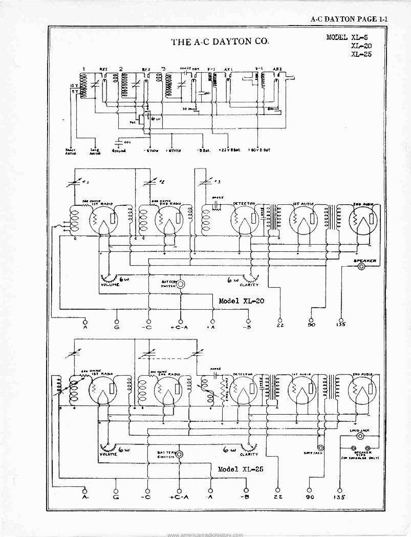
A -C DAYTON PAGE 1-1
21 ST P
RF.2
THE A -C DAYTON CO.
00025" i Y
E -I AF.1 2-1 A1.2
T J
-I- cot T sue Mngil OrouRd - GV.lte GVelts
DN OMMI IST RADIO
hC>
C C
It
{IO O H 2H0 R
N. ADIO
-DOM. + 22Y e eat. I 90 V B. Bdt.
DETECTOR
2
IST AUDIO
MODEL XL -5 XL -20 XL -25
ER, AtA
bw VOLUME
BATTER SWITCH
ó A
6W CLARITY
Model XL -20
o -C +-C-A +n -B
I. ORA ISTK RADIO SM .M IS RADIO
1
«.I
L
DETECT..
° sOo 13s
'.T AVe
VOLUME. SAT TER SWITCH
w L CLARITY
ó A.
Model XL -25
b -c +C -A A -e z 2
SAT Jot R
d
irEAKER O
ERO AUDIO
LOUD IACJI
o -t/ 0-
YEAKE TIPS (0 CM..ISJ INKY
o 90 135
www.americanradiohistory.com
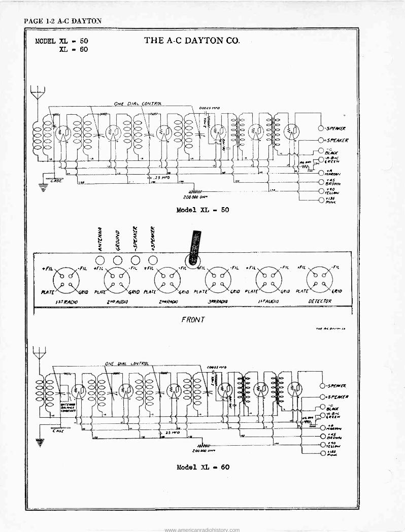
PAGE 1-2 A -C DAYTON
MODEL XL - 50 XL - 60
r
L A3£.
THE A -C DAYTON CO.
ON( D/AL CONTROL
Q W W
W 2 o b
OOOIS r1P0
200000 0Hr
Model XL - 50
p-SAfArEA:
SPEAKER
(-0 eiAcr -A-ec 4R£[N
M MAROON
*AS EIROWN
*AO r£LL My Ot/ PI33 NK
+O O fO tf1LL -FIL IL -FIL +fIL -FK +fll fIL
PIA GRID PLATE ER/D PLAT`RIO PLATE ÇRIP PC ATE BRIO
13TRADA9 z^pAbDIO 2/wRAO10 ,3RPRAOVO 13r AUDIO DETECTOR
ONE VIAL (-ON 7R04
O K
w
K>
FRON T
CD4
33 rND
:00 Poo o.r+
Model XL - 60
not 44 aA.ti+[
www.americanradiohistory.com
A -C DAYTON PAGE 1-3
THE A -C DAYTON CO.
'4d-.11 213)+v3d5
S3NoHd
I1 ti
a tr) +
N +
-O I
p 0+
oQ
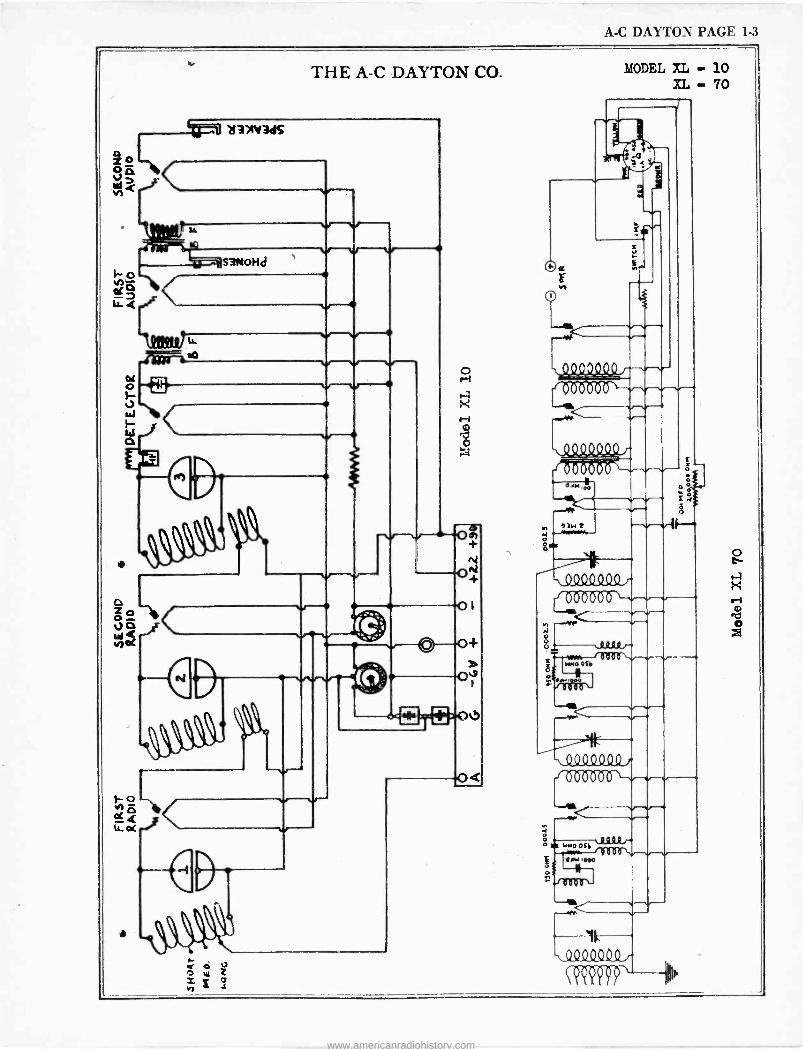
MODEL XL - 10 XL - 70
kQ.0 2200Ön- __,,4111111111ZMI
-si9 Q .ß449 r fó0000ó{
9lN T .1 f .........
z ^ 904SZß9 r
((MHO
0
= MMg oS o o
en
O
N
04aMGG OQ V¡ V V b
'd.M I 00 O
Qò QD - - -wC---.--- ---k -.404Q400
CRiP, ip
www.americanradiohistory.com
PAGE 1-4 A -C DAYTON
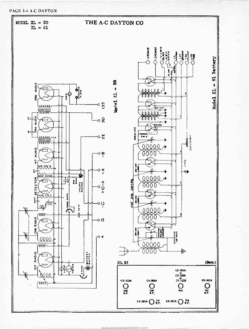
MODEL XL - 30 XL - El
º9Ga.
0 t
o'
GuoºJ--.
rYM ...M1
THE A -C DAYTON CO
ww. 7u 7 - vV -- .
I
r a z N
< tr
I
r
L
o N
e
XL 61
4 k :: t OV
3
,yy V t w -i `4 h V
C\J
. ' t. O O Q07 0000
W /i
LQQQQQf+ f ÓÓb
ti
(Batt.)
CX-112A CX-301A
0 0 2ni A.F. R.F.
CX301A st Rl.F.
CX-301A or
C x -300A
Cx or
CX-301A
o o Dot lot
A. F.
CX-301A O bd.
www.americanradiohistory.com
A -C DAYTON PAGE 1-5
N
QC
a
THE A -C DAYTON CO
tLQ_2-{Ir oa si
Odor' /00 i F---IIh
Q.11111)--0'. NX
I I I 1 1
/17p 00C,;erF
ti
lb-iX OA.' /00
A Sl/ MON
ASLw077JA1
O,.Ja --411
pX 41rtz
o we,/
S/ wesJY! 6
If / / I
` MNO 00000/ _II
e V c
ú
Tube Socket
1St R. F. 2nd R. F. 3rd R. F. Detector Ist A. F. 2nd A. F.
.rNl/
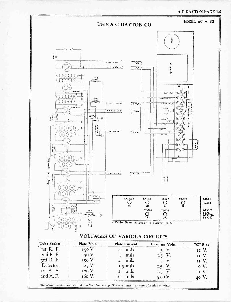
MODEL AC 63
OJY ACV/
Atri.
AM1 11.11
N /I s
N
N//y7 Al/ 4'77117
MO 7771 A r:
w0 nt,
MID
CX-380
CX.371A CX-326 C-327
o o o 2A. 2R. D.
CX-326 CX-326
o o FRONT
Used In Separate Power Unit.
VOLTAGES OF VARIOUS CIRCUITS Plate Volts
r5o V. 15o V. 150 V. 25 V.
I20 V. 16o V.
CX-326
o 14.
AC -63 (A.C.)
4-CX326 1-C327 1.CX3.1A 1-CX380
Plate Current Filament Volts "IC" Bias
4 mils 1.5 V. II V. 4 mils 1.5 V. II V. 4 mils I.5 V. II V. 1.5 mils 2.5 V. o V. 2 mails 1.5 V. II V.
16 mils 5.00 V. 4o V.
The above readings are taken at tao Volt line voltage. These readings may vary 5¶4 plus or minus.
www.americanradiohistory.com
PAGE 1-6 A -C DAYTON
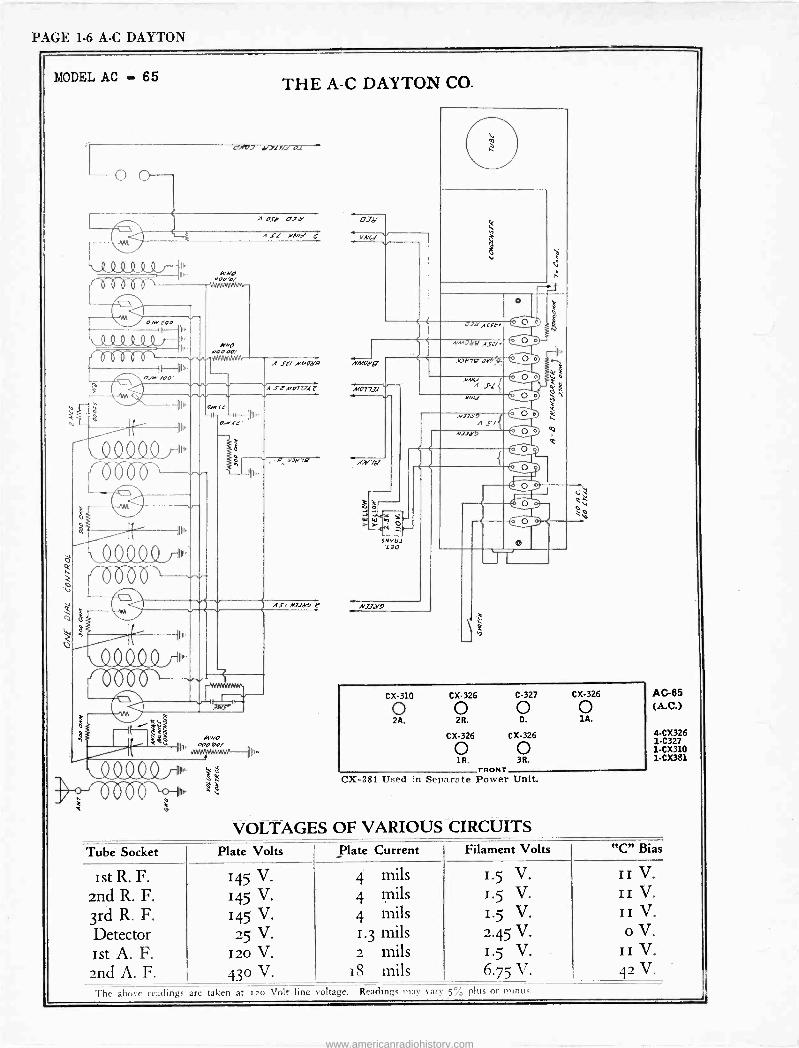
MODEL AC - 65
V
- p" )I V p I. 3 ,. v
THE A -C DAYTON CO.
O O
y..al7/.1 AZ
Ili
' V V V
NN
OJa tO0 oft . ̂ u
' VVVV V "
IIN
v v.+
WNO aO°
''V JVWJVM
Os*' ZOO'
A'NO °°° 00/ ~MN
A Oli O7 '
A St/ »emotes, »MOd'Q
SZ»07u4 t M07734
IuI,.
`Q Q Q Q ,-,.,-. ó Ób
°.wsr' -Ih --I1II1.-
0I.'SG'
- {pM
49 flI>'.
RSZYUP
II I
q-',-6'
XeNO
11111
l
ó W ti
Y Y S'130 130
AS/ N1Jd'J e N339
ED
¿
1: - : A0.161 0 O
;2/
*ODk
h'
I ti .
NM' - -' AS
.vi1e717 oJ) - ....
../NN A 1'( {
MM*! 0 O
-{ O s
ÿ
ti %
A/ AY A 9/{
NJ1y9 U 0 O
e
{-.«-
0
e0 -.1_ 0
J
CX-310 CX-326 C-327 CX-326
o o o o 2A. 2R. D. lA.
CX-326 CX-326
o o , FRONT r
CX-381 Used in Separate Power Unit.
VOLTAGES OF VARIOUS CIRCUITS
AC -65 (A.C.)
4-CX326 1-C327 1.CX310 1-CX381
Tube Socket Plate Volts Plate Current Filament Volts "C" Bias
Ist R. F. 145 V. 4 mils 1.5 V. II V.
znd R. F. 145 V. 4 mils 1.5 V. II V.
3rd R. F. 145 V. 4 mils 1.5 V. II V.
Detector 25 V. 1.3 mils 2.45 V. o V.
ist A. F. 120 V. 2 mils 1.5 V. II V.
2nd A. F. 430 V. 18 mils 6.75 V. 42 V.
The above readings are taken at 120 Volt line 'oltage. Readings may vary .5% plus or minus.
www.americanradiohistory.com
A -C DAYTON PAGE 1-7
THE A -C DAYTON CO.
oNnv 1.>7.i -od - 3019 r
v
xo - U
Ip
-! Q Q
Q
0 o wr °j
-t a3t+5'
Ó
1111,
u"
TWZYTh
;l
N33w9
II
s'r . narr
Levo
IIo' °°o'°o, . N,,w- ilu,.
II
IIII''
i <
1v
A i
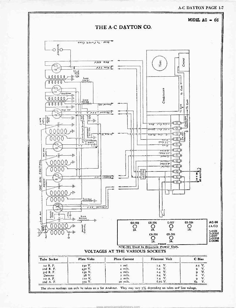
MODEL AC - 66
W
z
W
W O o2
C.>
1
1
o
V` °
C
V
f` 4
° ° O °
M O
H o7r/ tron S(
o .8 r Nn 0- S.'ia o. J
o o o O O
N° v r a. oN n. p-.
INld M
lro^ S( !o
OM Q O o
LN,Ó
N,3d J lroIl Sr f43.121 -D
° O o or ,.t
'`'oit s r O ° 7-.or 13/
CO e --J
° o
O O .
o
CX-350
2A.
CX-326 C-327 CX-326
o O o 2R. D. lA.
CX-324 CX-326
o o 1R. 3R.
FRONT CX-381 Used In Separate Power Unit.
VOLTAGES AT THE VARIOUS SOCKETS
Tube Socket Plate Volts Plate Current Filament Volt C Bias
ist R. F. 130 V. i mil. 2.4 V. r.5 V. 2nd R. F. Z30 V. 4 mils. 1.4 V. 9 V. 3rd R. F. 130 V. 4 mils. 1.4 V. 9 V. Detector 38 V. 2 mils. 2.4 V. o V. ist A. F. zio V. 2 mils. 1.4 V. 9 V.
2nd A. F. 35o V. 40 mils. 6.75 V. 63 V.
AC -88 (A.C.)
1-C324 3-CX326 1-C327 1CX350 1-CX3a1
The above readings can only he taken on a Set Analyzer. They may vary 5% depending on tubes and line voltage.
www.americanradiohistory.com
PAGE 1-8 A -C DAYTON
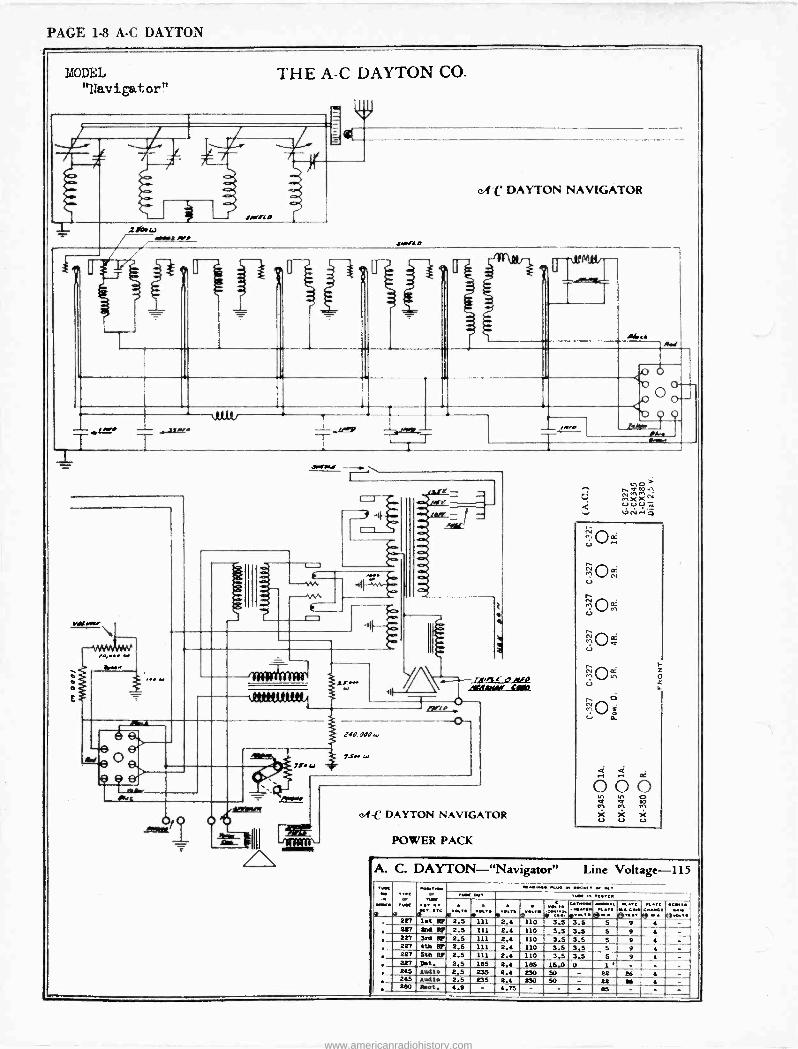
MODEL THE A -C DAYTON CO. "Navigator"
c.tC DAYTON NAVIGATOR
2i6.a/ MON rep
U *
mii,
.r.<A t Aw
. _
a
/me*h`M.+ _ jq.. -.-i fM --- T
_ T T T~ w
000
y \\r--- Arms,' o At,* I_L16 % -r---/o
Q
240. 900
7.fwr
0-
0.6 - I^ / \
e4 -C DAYTON NAVIGATOR
POWER PACK
U
4/
N M K
z o
lit A. C. DAYTON -"Navigator" Line Voltage -115
TIABC or 6 vy. ó6. ..` .4".''' 4r.,. o"."` m
«,6:` : ,;....g-.` ©., .'. ' sae ©...,. 257 16t P! 2.5 111 2.4 110 3.5 3.5 5 9 4 - 227 264 PT 2.5 111 2.4 110 3.5 3.5 5 9 4 - 227 3rd FP 2.5 111 2.4 110 3.5 3,5 5 9 4 - 227 6th PT 2.5 111 2.4 110 3.5 3.5 5 9 6 - 227 5th Pl 2.5 111 2.4 110 3.5 3.5 5 9 6 - 227 D6t. 2.5 185 2,6 185 15.0 0 1 ' - - - 245 Audio 2.5 235 2.4 230 50 - 22 86 4 - 245 Audio 2.5 235 2.4 230 50 - 22 216 4 - 280 Rect. 4.9 - 4.75 - - - 85 - - -
www.americanradiohistory.com
ACME APPARATUS PAGE 1-1
..ut.. (IM 7r.
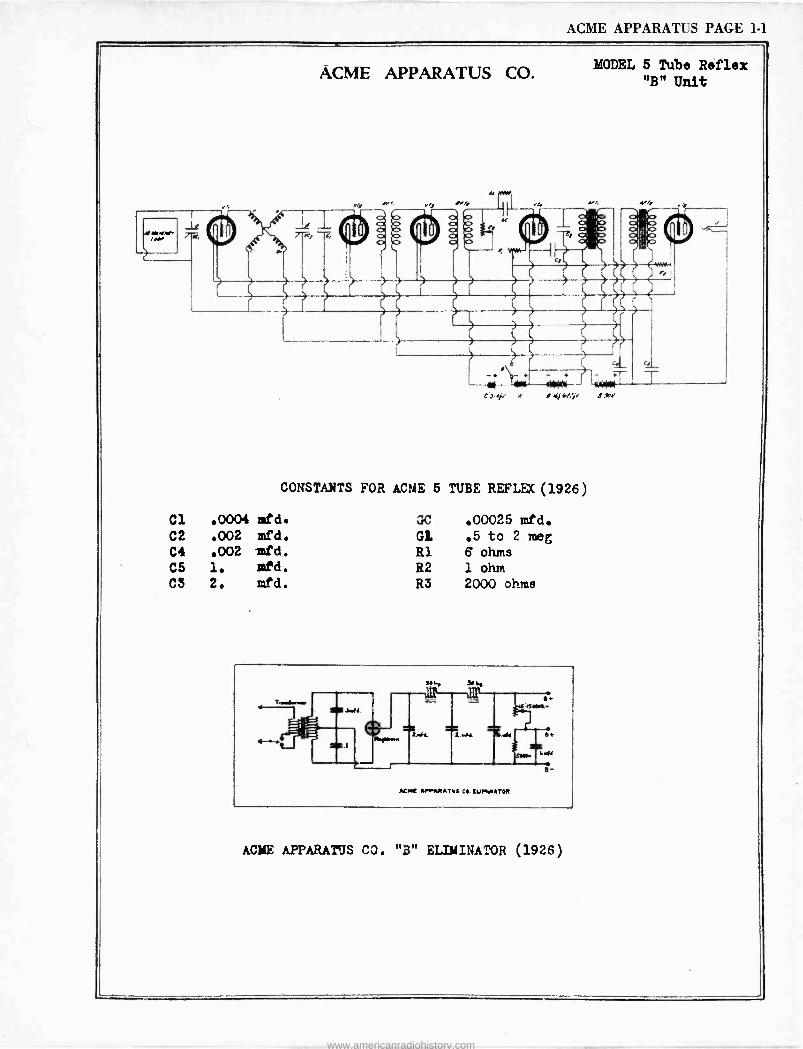
ACME APPARATUS CO.
4
s KJ.l.r
MODEL 5 Tube Reflex "B" Unit
T
Cl
CONSTANTS FOR ACME 6 TUBE REFLEK(1926)
.0004 mfd. .,C .00025 mfd.
C2 .002 mfd. GL .5 to 2 meg C4 .002 -mfd. R1 6 ohms C5 1. ed. R2 1 ohm C3 2. mfd. R3 2000 ohms
4
ACME RrqRATVE CO. CUMWATOR
ACME APPARATUS CO. "B" ELIMINATOR (1926)
www.americanradiohistory.com

www.americanradiohistory.com
ACME ELEC. PAGE 1-1
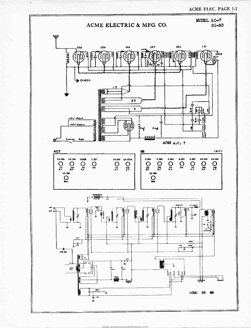
ACME ELECTRIC & MFG. CO.
CHASSIS
Black
AC7
MODEL AC..? SG -83
216 117 116 /7/
2.5
i
...-
00,
CX-326 Cx326 CX326 C-727 Cx-326 CX-373A
0 0 0 0 O O lst 2M 3rd D.t. lst isd R. F, lF- R. F. A.F. A.F.
cx-MO
O
as
ACME A.C. 7
(A.C.)
43241
0 C 324
0 C 324
0 C-327
0 C-327
0 CX-3A3
0 CX-3A3
0 ]st 2N 3rd D.t let 2M iM
R.F. R.I. R.F. A.F. A.F. A.F.
Cx3I10
ACME SG 88
www.americanradiohistory.com

www.americanradiohistory.com
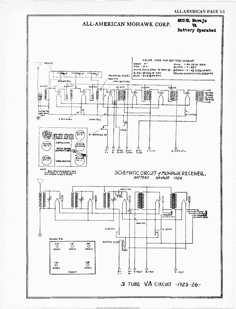
ALL-AMERICAN PAGE 1-1
MODE.. Navajo ALL-AMERICAN MOHAWK CORP. y
Battery Operated
7 FRAME
L - ---- ---J 6SACWA RE3
RFT
A
ib ONA AMA..
.n. L' V ,
hwA 1:.1e1ú1
Jt9.9 2.0.A
tN Au tel -A
Ir R 2.1 -A
94Ar14 Cons,.
SUVA LOfJPAwoFiVlt3
3ME4.4uF ltAk
NOTE: 7A.A4yaL/1IR$ A91
!499.599 le A 9.Ne 4 891919 AMO SN'tVZD 71 EA99 0244 I
n0
39 RFT.
ARLANCI9 PLAIES 00024 nf9.
Jnt4 Quo LEAK
FT AFr,
COLOR CODE AND BATTE/jy HOOKUP. 6ReEN - A- PiNK -9O,/dSOA. /QOE. Kisco - A + BLACK - C'- 42V wNITECOnncc7eD Rep 43- BROwN-C-4t,9,2EjoR(ffv. SLATE-B+22j eR 93v, yELLow [oynccrEDTO QREEMCt BLuE -B t67t oR SO v.
SAA Ff.
E A .%
d C9
2e O.1401j
b 0 0 O O o A. A beet a47 e 9. C r.Jo C- e- L.Jv. 7.9.4. T.ie. O
C-*J.YdY,
OUTPUT TRAKS-
T. Ley/ 3PPAXERI
SCHEMATIC CIRCUIT efM0l-4/ LJK R.ECEIVER.. BATTERY NAVAJO /926
O
11009.5 n.0,
J ní91
o e S a ó
Model VA
2 AF 1 AF DOT
0 o o UX201A UX201A UX201A
1RF 2 F
o o UX2DIA UX20IA
rRONT
6 ohms
Ai
isr AUO,O JACK
.0026 l'IE9.
!10 Ohms
6ATTERY 3Mt
O O 0 O A a/22/v. 6t 90 C- e -
Z../Wine ALA,
5 TUBE VA CIRCUIT -1925-26.-
www.americanradiohistory.com
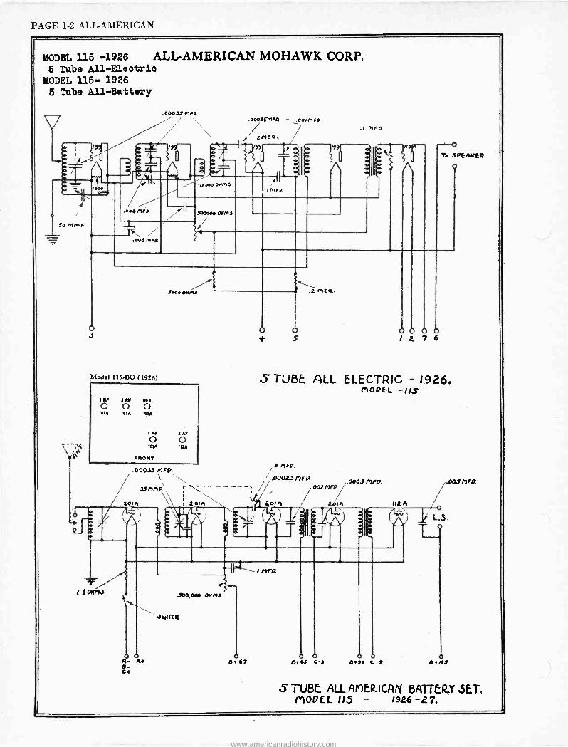
PAGE 1-2 ALL-AMERICAN
MODEL 115 -1926 ALL-AMERICAN MOHAWK CORP. 5 Tube A11-Eleotrio
MODEL 115- 1926
5 Tube All -Battery
,000 0004
SO MMF.
T-- .( v P
.00035 MAX \ \
-- -r- /'/^\\
/.Y1i.
.SDO000 ONMS /
T, / 4
.0002SmFR - .00IPtFOI
2ME4.
- 3 /99
.1 MEQ.
A O a
.006 melt
T. SPEAKER
o
Swo ON ma
Model 115.50 ( 1926)
iRP Z11F DET
O O O '01A '01A 'CIA
IAF ZAF
0 o '01A 'IZA
FRONT
.00033 MFG*.
201F1
1-í OIfM3.
º OfA 201n
2mE02.
O O 0 0 1 2 7 6
5 TUBE ALL ELECTRIC - 1926. MODEL -113
3MF0.
.00023 /7FG*.
002 MFG?
t,61 q
a 101
.0003 ly)Fp.
're If/ A 1\
.700,000 OHM3.
31YITiCM
O 0 0 0+67 be 9.5 c -.t
O O 0+f0 c-7
.003nFG*.
O 13S
S TUBE ALL APER-ICAN BATTERY SET. MODEL 115 - 1926-27.
www.americanradiohistory.com
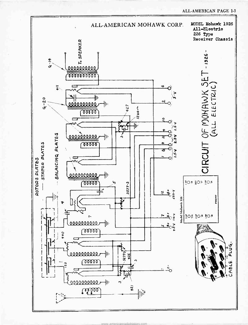
ALL-AMERICAN PAGE 1-3
ALL-AMERICAN MOHAWK CORP.
u
N
e a
I ffóO O
I
< -1 I
h
r
QQQSL4Q9044 )--ih.
(294.049(19 7-111.
flisn]
moti
_o
MODEL Mohawk 1926 All -Electric 226 Type Receiver Chassis
.o N o
.40:z.40:z o _ 0 á
www.americanradiohistory.com
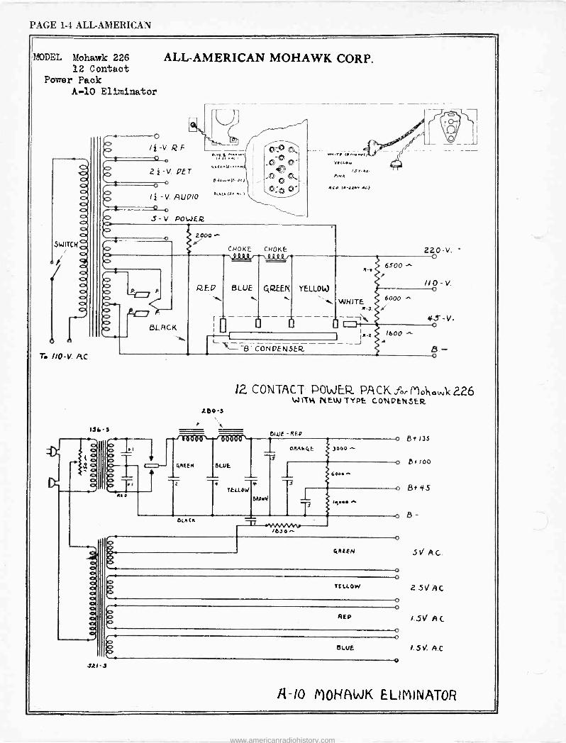
PAGE 1-4 ALL-AMERICAN
MODEL Mohawk 226 12 Contact
Power Pack A-10 Eliminator
SWITCH
411,
T. //0-V. fìC.
ALL-AMERICAN MOHAWK CORP.
, O KD i4-V.RF
º 22-V. PET
e O O
I } -V. AUPIO º o J- V. POWER
'i: ..
p,+ow.,(ecl
euu (r..
(..,,.wf, VI LL.w
IS V-44 Ionh
Ru u.ixw.u!
2000^
131. 3
BLACK
CHOKE CHOKE \JI -Lk -4.7
RED BLUE
UAW 6500
Y
220-V. O
YELLOW //o V.
6000
"8" CONDENSER_
WHITE R-3 4. ---ì 4S -V dI o
I
I 'Z -J
1600
1 i Z00-3
GREEN
T OLA CL
12 CONTACT POWER PA CK 226 W ITN NEW TYPE CONDtNSER
OWE
1
ELLE -REP
YELLOW
ORANCcE 3000
6..0
(y000
111-J
81-135
Bo /00
8+ 45
B -
OREEN .5 A.G.
YELLOW
REP
awe
o o
o o
o o
o
2.5,/ AC
/.S A.0
1.5. A.0
R-10 MOHAWK ELIMINATOR
www.americanradiohistory.com
ALL-AMERICAN PAGE 1-5
VA- 20 A
00016
ALL-AMERICAN MOHAWK CORP.
ux-101
.80045 w
M
,ivlYlRt/ 44, 55 (1926)
iv 2V IAF DEE o o O o 'ElA 'olA '01A 'DIA
IAI o o 'tIA
OR -71A
FRONT
I AF
'01A
r
O D _
)A .44016., ux-to(A
E
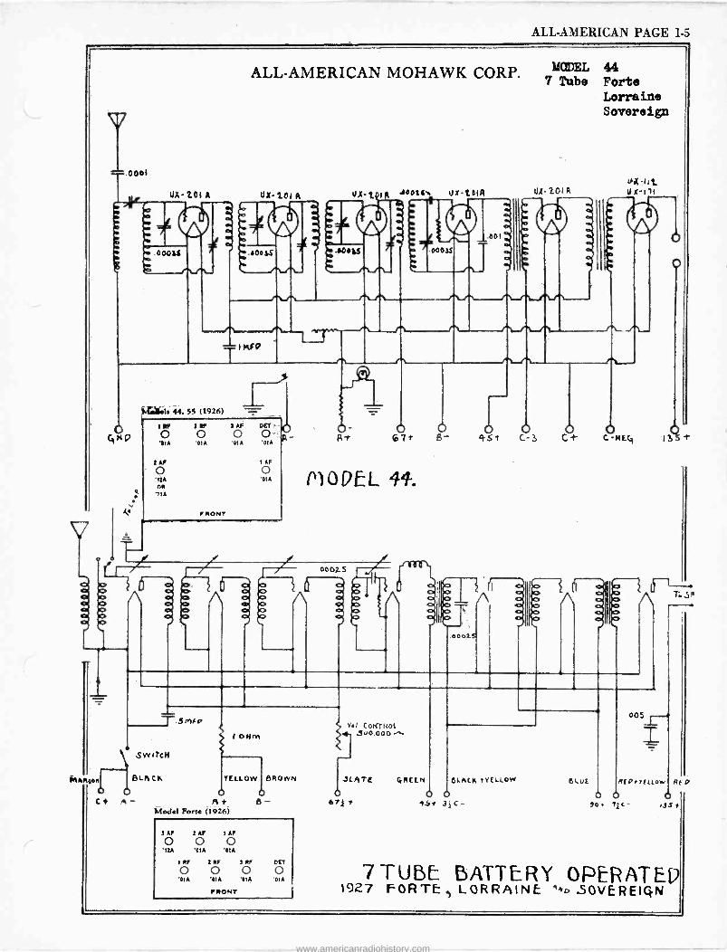
MODEL 44 7 Tube Forte
Lorraine Sovereign
U,(201Á 114 -hi_ ox-I(
o
ot o 405* 03 O CO-MECj IJ
MODEL 44.
OOOi.S
f¡ 00b
O'1 Ipo '/ oÌ b / \ P /O
}bO ol
00025
GIN
sé.
^R 10 r-
i:RR40R
T.S Mf v
SwitcH
8(-I1CK
C i A - Af alod«I Forte (1926)
YELLOW 9R own
B-
2AF 1AF 1AF
o o o 'IIA 'CIA '01A
11F 2 IF S RF DET
0 o o o '01A '01A '01A '01A
IRONT
VeI COY(?NOl 300,000 -,-
JLATE
67£ .2
005
z ORCEN dLA1CN 1vELLOW EluE A(OroFLlowl A( p
0 0 15A 34C-
6 o !0 Tic- .35
7TUBL BATTERY OPERATEP 1927 FORTE.) LORRAINE ""o SOV[REIQN
www.americanradiohistory.com
PAGE 1.6 ALL-AMERICAN
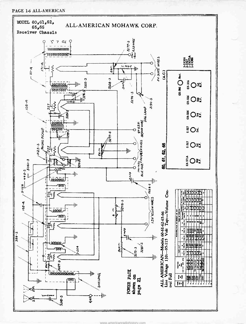
MODEL 60,61,62, 65,66
Receiver Chassis
`o N
$
7
ALL-AMERICAN MOHAWK CORP.
01
es N
!.I. 1.I 1.1.1
'ósoonee
n..
..1.1.1./.1
'1
e
I.
On006` --J
.4
Qº40044J
o'sa
-J
I -.MOW r I
' 1 'OW I
1--
<
II
ÿ
II
- - -
.. 'Sew f...r
w O
h1
o
b ñ ()II` >'t 'mad u
U0ó
1'
(r,
+.not7ó roviva.l
"
i?: ro.ó ro.ípÑ
1
!L'i f(M11917NMlMfP i iaOprL
° â 1 1 1ow 1 1 ' oÿ
)
C002030103
i Nr:lb ..C.p 1
i i 'a.::1:1
g..
p1MN $ -. t
=
# et0 1 Ii
M..r1l.Ip .i .+.i w%v:i 1
G
g7y-4ú4 44,..:N:4:
náia:
is! Beg 1131 f
www.americanradiohistory.com
ALL-AMERICAN PAGE 1-7
CNOKES
O o
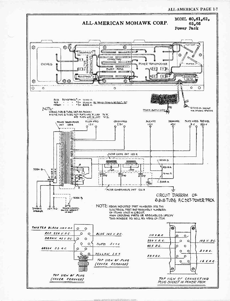
MODEL 60,61,62, ALL-AMERICAN MOHAWK CORP. 65,66
Power Pack
,y12E519TRNCEs7
O Ñ Z
_Jppu
0 4U
o o ..-, -, s u. } cad)
c4rs CCMNELTNG- av
I
PObvER TQR!JSFíCMER
.LOCK - 9i7sE: q,f n rp, , : --,t,.:1_._a:ae.., +
:nc_- --um- ' U ,,.....,.,..-. '
p ...................... nr o -..
o
BLUE R:SiSTANCE s I - to.000 A REV - 2- 2SooO+L 0R ORiLNClE-700oO1L ;IMRES' I OUT
PARRDON j- 4500
OT E.+ WIRING !-OR 6 TUBE SET -RS SMOWN- WIRING FOR 6 rt.) 5E. SET -PLATE WIRE R LER17 TO A;
asp 9L ATE Witt t.EAII 'o,
5286,
\1/4
rnqMlc enMER
POWER TRRN5FORMER UNIT 125q
110.v. A C. R CONTq01 LWILCM INNLONT
ye .66T
revis TL 0 QL AC.r //o v. g c
£ED 220 D.0
3,C06/A/ 45 V D.0
OI[EE.M Z.S q.c
TOP VICE Oi ?cc/4 (cove,[ .eenovep)
YEUOw nets I.Sv
CjREEN WIFES
54.
FILTER CHOKE UNIT 125-A
1- - - _Ante_ F'D
MF37
Nit MIRE
IIOv
Tw
J] r
HUER CONDENSER UNIT 1Z4 q
BStDwNWI¢E
ASV.
5256 S
4520 a
70 000 A.
L 5295 e
EMTENSiON SOCKtT 0R TXNRMC 99ERKER
54.RTE'N12ES et, we, 5 V. 220v
O O O
CIRCUIT- TIAGRRM Or - 6& -N8 TUBE R C SET POWER PRCK
NOTE. gBOVE INDICATED PART NUMBERS ARE THE
ELECTRICAL PART AND ASSEMBLY NUMBERS of- ITEMS USED IN CIRCUIT. WHEN ORDERiNg PARTS OR A'SEMBLIES SeCIMY TN1S NUMBER RS WELL RS NAME OT- ITEM
QCUE /05 Y. DC
SLgTE 5 V 9 C
yELLOW V
TOP y/EW OF .PLUG (CO H5,2 eE/`(OYCp)
YA.e
220 v c.
45 Y. D.C.
8.5 4.c.
o o p o
O O
e
/04 V. Oc.
4y4 C.
P P /6 Y. /9.c
TOP new OF CONNECt/A/G f'LUq SGY1(ET /N R7tte2 P4'CX
www.americanradiohistory.com
PAGE 1-8 ALL-AMERICAN
_
á
9
e N
tY
e
n
o NE
g nnnll
s2 N d
M
o N
d á 4 d á
e
ö F
ñ
IxMUa QIbJI 0 0 ? _ ,
Q
o o - u V u U
N
n
O
n
r
9
u
ö r &
e
n o A 0
J ó
o
u
á N 8 o
O -o u v
g 5u
I I
_
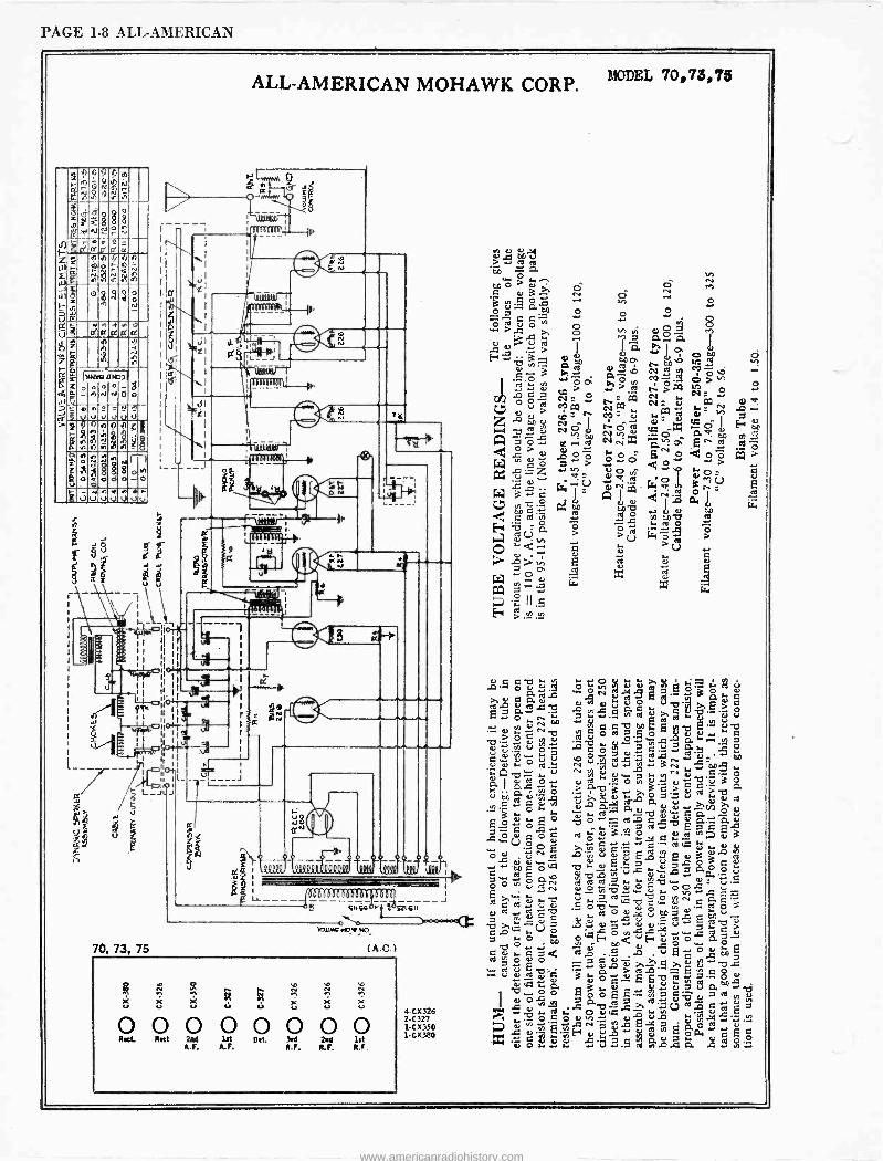
ALL-AMERICAN MOHAWK CORP. MODEL 70,73,78
Ii
`.""... I
oleb1116\;r0.
J
L
e N
t
11b1(ì1)11: 1
'MYIDe. J gg
l\- _ _ _tt
PN
2 a
II 1 1i II
4 Ìi IÌ
II
I i¡ II
11
u I
d/ L_J h>
e
70, 73, 75
-n»-10
IL l
h
iI
ä£
de I Iy i
. I
a
___2o_ QQQy( QºQQy l,
ttlii
is at I
- J SnSG á L21S11
xxou.ci+o
(A.C.)
o N N
sa,
)«st x x x x x u u
0 0 0 0 0 0 0 0 Mtt. Rett 2nd lit CI et. 3rd 2nd 1st
A.F. A.F. R.F. R.F. R.F.
4-CX326 2C327 1-Cx3S0 1CX380
PO Le Le ^ á '0). h o
to o v.-, ô o ie e 03 re cì .-ry. N e O --. O o 0:.a
-O p. ..O-.
td v O ... 8 pe vi co pj
rJ >'.O O- 7 Gry (1. I
-CI CJ > i ele C'. w/a Oso E-.ti'3 p mo r, to M-º O N yy .p -'3 wÓP pa,O.n CO 7; O>M a, > ..> ti ,CC N . A e_7 N
..o. N
to
4 r I O v<d 0? W Ñ N a,
m ry
rv. 0 > fr M- ÿ 4!n ç0 0 yI H,.j td ÿ Ñ 0 Ñ Ó Mú t 7 x .-- p N
...+ a.r C4 r4W Gä ..^:: A.eoc' .g° ó 6tVo doô W o q 0 > > O p 4 O 4 " > ,V ,e zo+ +n V p v p v ,_ 0) nt ,d :ed , V , . y %o °&7nU w ÿó =A1pQry1 LC .,v. 0.' oo
-tft
-°o' .n m0 al ...,1 e0eó d .1 .2
é'i a O >r. ó e -
C
; > Lró >
>)o ¢ e le r 0 C.>
u t V, n > £ d
°a
.A x AWo zz P.:1 ÿ. W
1..;7V°1I.S N
C -L ` > ...N. ..:
e 5 O
1.Q
..+ `3 6 O h
31 d
e 77 uOt
O @ d e0 10 u.y b V V u O 4 u ¿a > 8> e £.7..p-,C 7,.-21::.QatedOÁG.fd''á'V pp ,>. y V « ry Y c -o e0 £Y1y,ti £... `- v
0 Z 0 Y >óeb `eoó.$,oA a.-.
7...--
' ÿ ó.0,,úÓ70. .G ^ 'd - ÿ 0y00
0 . ,d. ry N/V,'y
V Ñ -+3N O1.. A b. 4 V ry N ;; 0 ... .. ^
.40..
.-. e _ O a ó.r °r u .n o.,OJueb., 3c . o °'ä 3'e> > C.' e0 á'v, . v>. G u ß 6 7 ¡ u v v e!
.N. ' 4 o s. L. Ñ a 0 T) ÿ C á G.0..
£oÿó7o ..00 OrdeL.tyv0.`_'0.0 O= e 1] ++ .. _ y 7 A -. £ O eEC s op O e , o; 3... 0 e ° A e, 3
v eft ,,
i Ó 0U'óó.£a 'iyi,Úvy L.eGid3L eJ ÿócó.cl fl=a£ e W eoóe
o °v''-oa ,,..."- uA3 aa ° V
O O Ou N ry ` O cft
N -- ,V V
/O./,,
p ..^. : .S
,y A Ñ.L.ui ú V.2 ld ,p -D ...0. 0 ry e a e ì O w d in N. O i
7 m y d C 6, L.'4 0 ä ó ^ t=C v
- C -O T e V 7 .0......),--.....1.--, V ÿ > á óU OoÉ. o o,sF c ó a ó ª:
O CO¢ u O O
.d o ú 0 -O á,_ fa A u e OA 7 a £ -3d0>.Tg>,'v-'s .: v db'C ä .. a ú ea+' £ 7.S o e,
6) .ii 4 Q. 0 0 '' £ G
t~,, 7 V a0 ÿ ...á o & ó ó 6£M olI.e:ñ_ ia v ÿ 4 ,cl 4 0 OteL-3 4 Nv .. QJ L.c
t4 ^
O e O el) 01 d ud úr u, .ary 7 úá e -Y O 0.0... xe ._ F a, .0 Il £ oG, á £ e dóg:±.6/. 'ú.S .a,á.áá ág'
www.americanradiohistory.com
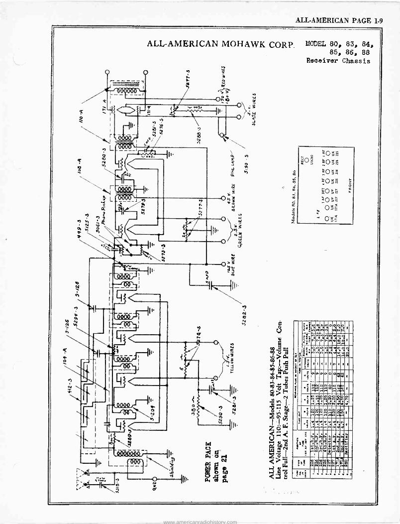
ALL-AMERICAN PAGE 1-9
10
Q
ó
N
\
ALL-AMERICAN MOHAWK CORP. MODEL 80, 83, 84, 85, 86, 88
Receiver Chassis
I Kw eip.
I I --¡tRi PÍ1
_
__-) h Abei',..-III. (li L_ _ _
O n Cr
h W h y
r: 3 V.o er i;e'
;«
1: 4 s
é
-.1m0w:c0000 ;* MVl17h NNN 1
..1,!-'1"-P7.1`11.9,0 4e"..........2.1.2,1,
rirl
, 1 1tM117NM1N.1Y1.Oo ii0iN..00d 0-1,1 CO
j 1 1 1 1 1 b1 1 1
; CO 0 P 0. 0 O N r.y N 1
:r~1Ñ...~14Ñ NNNNONNN h 1
le, OW) CO NO) r1 rtri
10OOppOO :NN10 0-1 CO N 444
: h
S
: á >
Op0000.. NNNNrN ri .-1.A r1 .`fr1 .1r5 . a
: : vacaear .-I r1. -1.I N N V
:1 e
. i'' =
L4 ON
áa 017 r1Nt7iI0.yNN
PN A má 4iiiOT.M
1+ Yr M1eM
éélN, 0ypV0
I. u,
I'll I.
Ñ2ÑÑg8 NN OWN
-.lg.
N...1N
Pi - . ._e
www.americanradiohistory.com
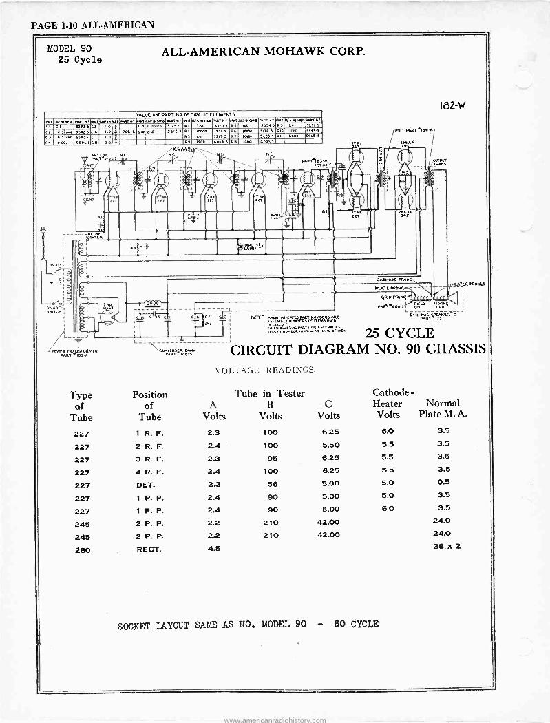
PAGE 1-10 ALL-AMERICAN
MODEL 90 25 Cycle
ALL-AMERICAN MOHAWK CORP.
VALUE AND PART N º OF CIRCUIT ELEMENT 5
UNIT CAPINIfO DARI N. MT COD IN MF I) PART N. UNIT CAD IN MED PAT NT UMI RCS MOMS RAT of Ú1Ú10051X0005 PART N. JNIT 0131010t600001N CI 01 555)5 CS 10 11 Ci 000025 51155 RI 300 552E 5 RS 100 5554 S 05 ZO 52711
CZ D S`ON« 3552.5(6 I.0 ( j 708-5 CIO 0S 5612.5 lit 10000 1515 R4 10000 51105 RIO 1000 550]5
C 3 0 551001 55525 C 7 I 0 o 05 20 5277-5 1.1 70000 5255 5 RII 0000 554E-5
C1 0002 55503 CO 20 0 R1 1500 4004-5 RE I000 40055
L
210
O 1
o LT
J
DOWER TRANSFORM(R PART -105-A
Type of
Tube
227
227
227 227
227
227 227
245
245 280
T31 L _
-X\COnANSí0CRH.5 BARK
PflR0
CAT1100C PRON4
pYI
PLATE PRO%
(SRID PROMS
PARM400-
I82-W
FIELD MOVINCI COIL COIL
1ER P0.ON45
- LL NOTE ABOVE INDICATED Nun NUMECRSAR! DYNPMIC;PCAKER 1
ASSEMBLY NVMBCRS OF ITEMSVXD PART 173
iH CIRCUIT MOANORDE411.5PA M. PARTS MC
25 CYCLE SPCCII"1 0.21415c0NNluwSIW.0 0 ITCM
CIRCUIT DIAGRAM NO. 90 CHASSIS VOLTAGE READINGS.
Position of
Tube A
Volts
Tube in Tester B
Volts C
Volts
1 R. F. 2.3 100 6.25
2 R. F. 2.4 100 5.50
3 R. F. 2.3 95 6.25
4 R. F. 2.4 100 6.25
DET. 2.3 56 5.00
1 P. P. 2.4 90 5.00
1 P. P. 2.4 90 5.00
2 P. P. 2.2 210 42.00
2 P. P. 2.2 210 42.00
RECT. 4.5
Cathode - Heater Normal Volts Plate M. A.
6.0 3.5
5.5 3.5
5.5 3.5
5.5 3.5
5.0 0.5
5.0 3.5
6.0 3.5
24.0
24.0
38 x 2
SOCKET LAYOUT SAME AS NO. MODEL 90 - 60 CYCLE
www.americanradiohistory.com
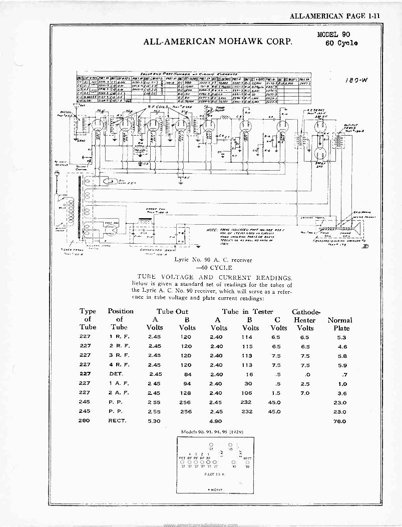
ALL-AMERICAN PAGE 1-11
ALL-AMERICAN MOHAWK CORP.
YRCURONO PRRTNue.erw e. Ces e.. r EarrtRRrs UINTCaPI7IV0Pw7Mqlt COP MRIO PIN17ae Pig CR°RFß PAR7N. Per RCSltO1M3PVT N.IM7rRpMldtü PAU N UINi(dS.IMtlIMJPg17Ne Ip1IT7ßNIpYMJ PART O C-/ p¡ o.e Jrf! -S C-7 oat 0.Oo/ .1 or /9e -R R-1 3E0 6(20-5 ,,e7 7,7000 5191-3 R -/J 24000 S/7L-3.(-pe(a00 JI07-3 C-2 0/ ..w-'1115-3 Cd 0e/ seal -11(4410 R-2 rqu0a 75/-s Rd SNKHr106/-s 01a..1,1,4. eta/ -S C-3 1 0. -"e JJ<t-3 C9 O.GI J -3N 2e0R- C111 I ß-3 SeOe dsot-3 R-9 0J JSº/ -3 ÆLf 71,4m J174-3 C-4 Q1 ""'' J372-3 cep e1 Cí670 0 7Q.4 /eo J53I-3 /P-/0OJ - S211-3 R-ld 10 2,177.3 C -S 0.00025 5/11.5 C-// as R.f 20 2117-S R-// epos 1774-3 R/7 tese .reses ,C-6 goal Se-5 ea /.O ie R6 751006 1295-3 /7l1 70,.00 ,n91 -SR -/a 0.000 rí67-5
RRrCOII n,..r1.
ROO
4 -/,e ,-
6s ere.e
R
Rl
RRT
e ere r'CerR -~
R
M
V
rC
L -L
*c.
Creaser Cots.
MIN s2i7KM Or' et
Op Æ
R7
l'.
MODEL 90 60 Cycle
71d 7tRN3 pr.,. u1 -n J.t
e
R
..4f- 242 -
l89 -W
o.er-PUT TRRNJ
r t n..re/!ht
nue
e w
a C.
w.11
CONOrnSrR .ewNK1 -J
/VOW, 00001 /NO/CRTE0 vwnT /RlI.RRE 1135r N51 OF cremi uJCO /N C/RCu/7 HNCN OROCRINC PORTS OR 1.7.5'01 .7rCC/fl" NO R1 n'era MS NwNr ee /rept
aw,o Aet"p
n.. tee -.I Feran "mopes/ Co,
2G-OrMweteC STwrrR 9 r+..r /19
Lyric No. 90 A. C. receiver -60 CYCLE
TUBE VOLTAGE AND CURRENT READINGS. Below is given a standard set of readings for the tubes of the Lyric A. C. No. 90 receiver, which will serve as a refer- ence in tube voltage and plate current readings:
Type Position Tube Out Tube in Tester Cathode - of of A B A B C Heater Normal
Tube Tube Volts Volts Volts Volts Volts Volts Plate 227 1 R. F. 2.45
227 2 R. F. 2.45 227 3 R. F. 2.45
227 4 R. F. 2.45
227 DET. 2.45
227 1 A. F. 2 45
227 2 A. F. 2, 45
245 P. P. 2 55 245 P. P. 2.55 280 RECT. 5.30
120 2.40 114
120 2.40 115
120 2.40 113
120 2.40 113
84 2.40 16
94 2.40 30
128 2.40 106
256 2.45 232
256 2.45 232
4.90
Models 90, 93, 94, 95 (1929)
O ; O '27 'a5 4
4 3 2 1 á
DET RF RF RF RF ' RECT O 00000; 0: O '27 '27 '27 '27 '27 '27 '45 '80
PILOT 2.5 V.
FRONT
6.5 6.5 5.3
6.5 6.5 4.6
7.5 7.5 5.8
7.5 7.5 5.9
.5 .0 .7
.5 2.5 1.0
1.5 7.0 3.6 45.0 23.0 45.0 23.0
78.0
www.americanradiohistory.com
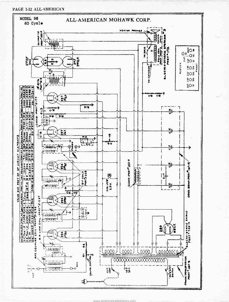
PAGE 1-12 ALL-AMERICAN
MODEL 96 60 Cycle
4M)
ON r t41,
18 o
w0 t1t
b L
'd
ò o
-re «u
pJuJ
c R
1 - - , 8 wwwww.I
`N.
3 o V
1
L- 6
ALL-AMERICAN MOHAWK CORP.
r
o
O III.
OC
i
weeraR rre.wesa
o u r
0 0o 0 0 00 o r---- - - ----- kQ Q_ Q0 1111/1ç I
-- c% ic oa-- --- - ------ -- ) . . -- ii o r i
www.americanradiohistory.com
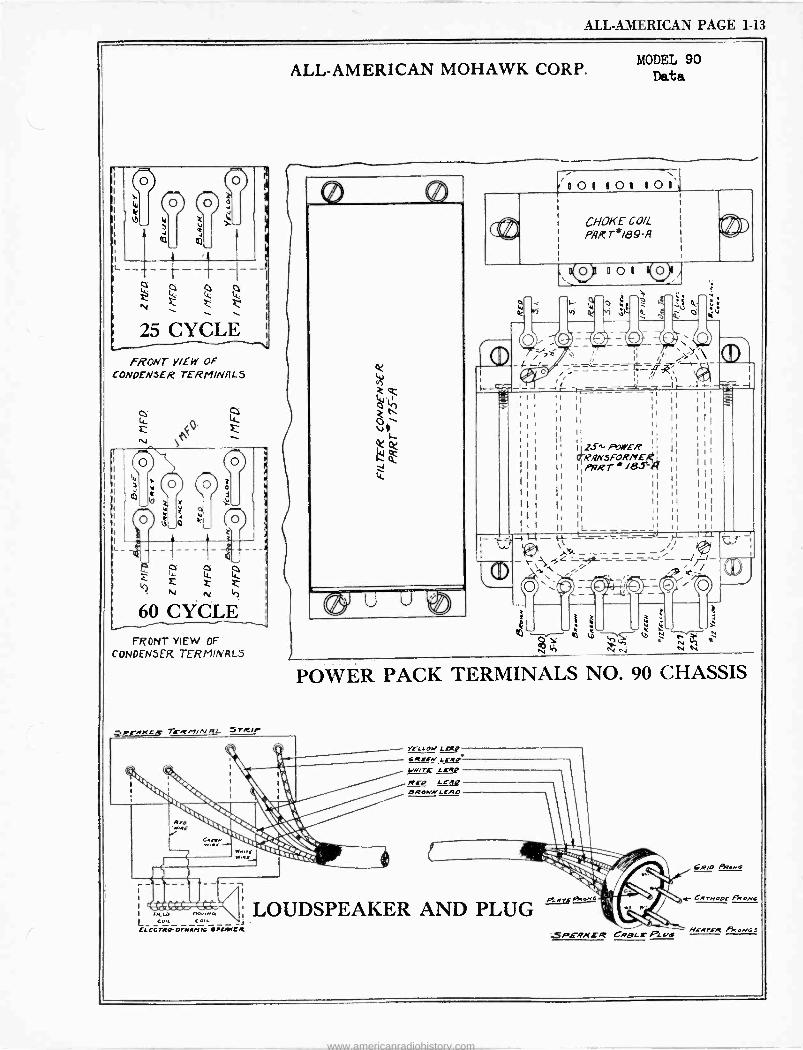
ALL-AMERICAN PAGE 1-13
FRcwr VIEW OF CONDENSER T£RMINHL5
14-
<O' NJ e
FRONT YIEW OF
CONDENSER TERMINALS
3ri'RKLR 71-Rninirf4 SrRir
ALL-AMERICAN MOHAWK CORP.
L_
I NLLC ,v e,. - _e,1,44
FLLGTRPor_MM1G IlAMLR
MODEL 90 Data
/101 101 101',
CHOKE COI( p,R r`I89-A
u 0 1 V_
, i1 1 1Y\ - _- -_ _ a, =- í----- i, , '_ ___;'_Ir-.J.- H
1 '1 11 1, I
' ;I II II I
11 11 1 II 11 i 11 I, 1 ; !
1 l' I 1Sti PqWER 1
11 I RRNSFR/YE,I
1
I
I 11 I i1vRT /8S-iQ I
I I II 1j I
1
i l I1 II I I 1 I
I ¡ 1
11 I
I I
I l'1 I
1 11 I
; 1
I II L -_ ' ' 11 z_.L-41 _--,_--- -__ r- -Iu
POWER PACK TERMINALS NO. 90 CHASSIS
LOUDSPEAKER AND PLUG SPEAKER CRBLrOLI/6
6R,o Rrewc
r CwrNoor PRona
mi -Arra -re PRlNGS
www.americanradiohistory.com
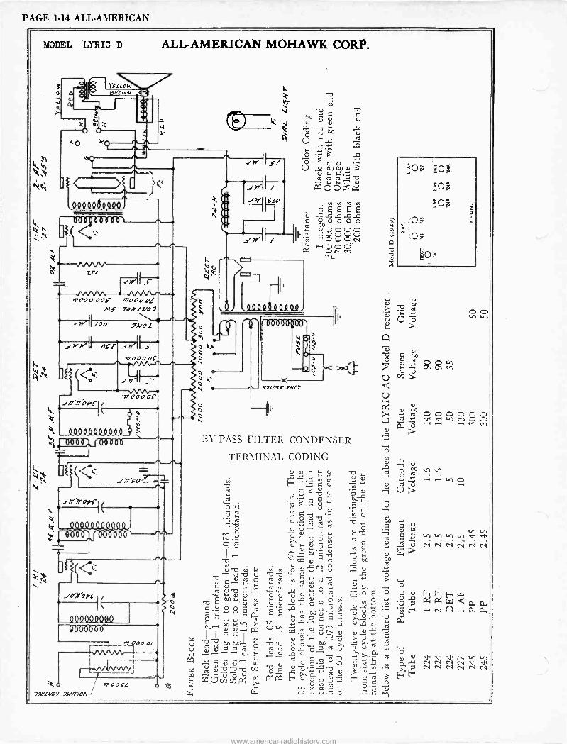
PAGE 1-14 ALL-AMERICAN
MODEL LYRIC D ALL-AMERICAN MOHAWK CORP.
W
Z77
0 D
000 opF e0,9,90L MS 702'11V07
7I /Op
ril000b£ _/e-e-pxse-i (
040000Q1040
177-7fOftl
1110(1.9 yt t111 .1
_sI//YOy4-
C
r -
0000.010.0 0óü600Ó
l
Ro 74,1,4107 .71.7//70/1
.
t7 oos[
o
t1
,,Ils/
e
!7!" ELO'
s 2 i'.. g R u q O p 0 0 0
II, it §gSs Ur,
P4 8 ert.
,tI 4 QQ0e944Q0,
e- o ir o o
0 o
o o 0
N')L)Mr 3N/ 7
BY-PASS FILTER CONDENSER
TERMINAL CODING G) U ..Z 1-. U
vi E-4 : G ú 7.3
nt ..c 3 U
3 .5,, ó O "cfh U ú w b Ç
U O
Ñ e) (...,--
>, h . O
vUi O Ou . I VD c.-.' U
ó ab v pC N v, OeN u Te
U TSb'^ 't. Oa t- w . 4-' b c U ^p w P w w ..x F. O
`+ t.- U O 0 0 u U 3óoo., úú °áº c .OO coi O ä 4.1 t.- ir r- .,, i I ^ FA `F'+.`, Oun U N m
cn y, p .--.
COD p nt 0... Ó p ú v Ú,^ u
``Co xaÿva w UO.OO ÿ b b't Cl) U .f : U a-' U
Pa _C7 cñ cñ á ÿ P4 Pa E úº' Ñ
c . s C('-'1
- LT N U Uc ..- O
x
o
c.) ó U ceó
r-; 1.-1 ó In U>
w Óq +-,
00 tr "cf cC } un in unan 'd 'd, U., , Ó lN N N Ñ x N c V
W c6 a Ó
0 O q u ray (s, (..i F=+ ó.n P4 P4 W Q
óE -t áá a
b w Ó c U U Ndc lto . á p Ñ N Ñ Ñ Ñ
Ó E4 Ey
7.2 Pa
www.americanradiohistory.com
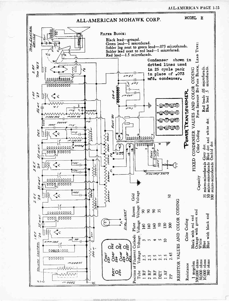
ALL-AMERICAN PAGE 1-15
l y N i
O10
ALL-AMERICAN MOHAWK CORP.
\ I/
h \\. Condenser shown in
1 dotted lines used
@'a 1 I in 25 cycle pack C7 ó N es ., in place of .073 z w w
,ºQQoQgº4Q9º mfd. condenser. A ó ó
: z sl / OU á .. t rs. ; e
., ._ .__-.. O Ki F { ̀̀ ._ N
(S:3)U
Q tit,
1 1 oc A I` ' I Ip,, p. ppp o z ú .
Ó ""s' h .0000c ' L- d W a4 0a AIpÓ N v>> .n000 ooF 000 or NL ^^
Z s.t p U < a.+
SOOOO" ^S V O O 4 .b /OO Ì I" yi.s-
I F-- Q 7
' 1'J OQ
ó_ ( { .......5- i I-- W .e á
O 0 1#,1## 111111 O T7 I( .,,o000F Ml 01 Q z U c 1 1 II' W ,, ` ó
444444444Q4'No/sd é 1 H z ó bo b
- e 1 1 1 1 1 IIE -_ _ W h 0 U >. y -C
é``. 1.1 Á C7a a
e `'
w -c -v ^ó Q N
' ì I I--+ o - - -' C a
`' 'II-. ' w 4121 ¡ O `, HJl /MS` 3N/7 l Ó + , u
11111 4
p, é é b ,--...1 Ú fo. 3 f~á Ñ i( <ti II-
M ;º O O8 t 0 `i C7
o z . ( o te. [ o
g g M o ió : III
ÿ? n>a). °á
úo ú -c,
ósóóö
« 8 ,-. °°
- p á 4. { 11 1.1
~' a
Q N à O ä
.. .,., -O
M M d ` 00rQ it v ä !/e/s-pF *4\ ..=
k t cop swC u 3
%
- OÑ O O U> cO3aaaa Z /,., y
Há 4 : v
wV
m bb6ab q ÑÑíg v,.n.n.nv,
OÑOÑOOÑ O N N N N CCyCmCmCC
wC 0000/ (,, r 44, R p I~ F R
v. U . .= G - - O 00000 O Ó .á Gt. Lja k, E.r ., , u O
v\Ì//v`' x a4 x w Q a. 25 25 25 M - , -.60'6 á
E ., cv M A , ß: a M ,-.e 1/4.11
M
MODEL H
OOSL
FILTER BLOCK:
Black lead-ground. Green lead -1 microfarad. Solder lug next to green lead-.073 microfarads. Solder lead next to red lead -1 microfarad. Red lead -1.5 microfarads.
www.americanradiohistory.com
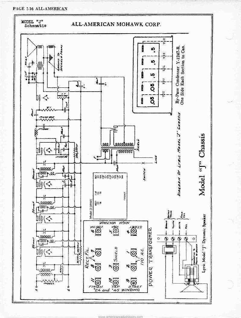
PAGE 1-16 ALL-AMERICAN
MODEL "J" Schematic
O
1-`1)°076'
*N.
-oaa oar
ALL-AMERICAN MOHAWK CORP.
11 e
-
11 i- --- ---- 1
40008440Q..
áo:^oo:&os
á
Wog
hH170/ HJ/N
41g9. d -L
o
-\Q9ººor-
-+aast o O
e a
O
Q -.IA,....,:=3. V Np é 0
Ili O O \ O2 °0 M N'
F/N/S N T4 P S Al2 T '24 and '45 WIND/NC
w
o .
ti
www.americanradiohistory.com
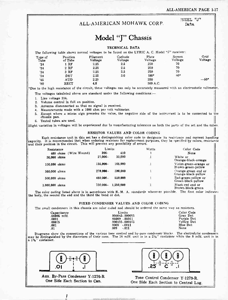
ALL-AMERICAN PAGE 1-17
The following table shows
Type of Tube '24 '24 '24 '24 '45 '80
*Due to the high
Position of Tube
1 RF 2 RF 3 RF DET AUD
RECT resistance of
ALL-AMERICAN MOHAWK CORP.
Model "J" Chassis
MODEL "J" Data
TECHNICAL DATA normal voltages to be found on the LYRIC A. C. Model "J" receiver:
Filament Voltage
2.25 2.25 2.25 2.25 2.25 4.8
the circuit, these voltages
Cathode Plate Voltage Voltage
2.5 250 2.5 250 2.5 250 3.0 180'
250 360 A.C.
can only be accurately measured
The voltages tabulated above are standard under the following conditions: - 1. Line voltage 114. 2. Volume control in full on position. 3. Antenna disconnected so that no signal is received. 4. Measurements made with a 1000 ohm per volt voltmeter. 5. Except where a minus sign precedes the value, the negative
chassis pan. 6. Tested tubes are used.
Slight variation in voltages will be experienced due
Screen Voltage
70 70 70 60*
Grid Voltage
-50 with an electrostatic voltmeter.
side of the instrument is to be connected to the
to manufacturing tolerance on both the parts of the set and the tubes.
RESISTOR VALUES AND COLOR CODING
Each resistance unit in this set has a distinguishing color code to designate its resistance and capacity. It is recommended that when ordering resistors for replacement purposes, they be specified by and their position in the circuit. This will prevent any possibility of errors.
current handling colors, resistance
Resistance Limits Watts Color Code 400 ohms (Wire Wound) 390- 410 1 None
30,000 ohms 27,000- 33,000 1 White or Orange -black -orange
150,000 ohms 135,000- 165,000 1 Violet -green -orange or Brown -green -yellow
300,000 ohms 270,000- 330,000 1 Orange -green end or Orange -black -yellow
500,000 ohms 450,000- 550,000 1 Red -green -yellow or Green -black -yellow
1,000,000 ohms 750,000- 1,250,000 1 Black -red end or Brown -black -green
The color coding listed above is in accordance with R.. M. A. standards wherever possible. The first color indicates the body, the second the end and the third the band or dot.
FIXED CONDENSER VALUES AND COLOR CODING
The small condensers in this chassis are color coded and should be ordered the same
Capacitance .00005 mfd. .0001 .00015 .001 .01
Limits 000045-.000055 00009 -.00011 000135-.000165
.0009 -.0011
.009 -.011
way as resistors. Color Code Grey Dot Purple Dot Yellow Dot Blue Dot None
Diagrams show the connections of the various tone control and by-pass condenser blocks. The electrolytic condensers may be distinguished by the diameters of their cans. The 16 mfd. unit is in a 21" container while the 8 mfd. unit is in a 1%" container.
Aux. By -Pass Condenser Y -1276-R. One Side Each Section to Can.
Tone Control Condenser Y -1279-R. One Side Each Section to Central Lug.
www.americanradiohistory.com
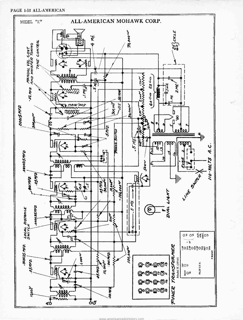
PAGE 1-18 ALL-AMERICAN
MODEL "K" ALL-AMERICAN MOHAWK CORP.
0
o
. . ,, :
É v-
-11193.131)
Ó-ÖZföÓO
sE h <Ä1-000 LL-
0
mow fops
<L -- DQ49,ººQ
o
Le
Qsl9r
i e'
O MO
<4"
ce;
O 0 O e
o
Ó
ot?
J
L
h Z
'12)
w
J
www.americanradiohistory.com
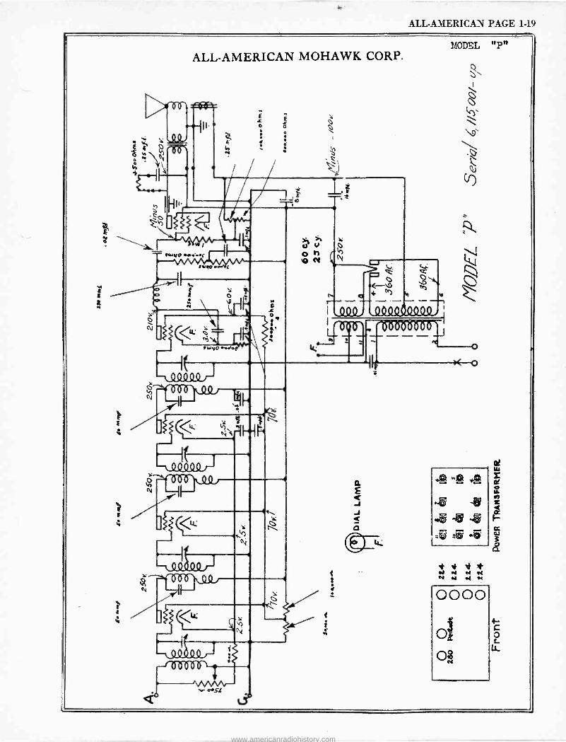
ALL-AMERICAN PAGE 1-19
MODEL "P" ALL-AMERICAN MOHAWK CORP.
ººSIS1º
E
ti
É E
> Q é = O O z e3ti
a h v r---- -- ----- - -- - ----
,4o4,.QQQQß4449,{
24IPI
000' /1111111 ,e.
---
:
f
i Y \ K et et N N .( et
0000
o o$
4- C o L
www.americanradiohistory.com
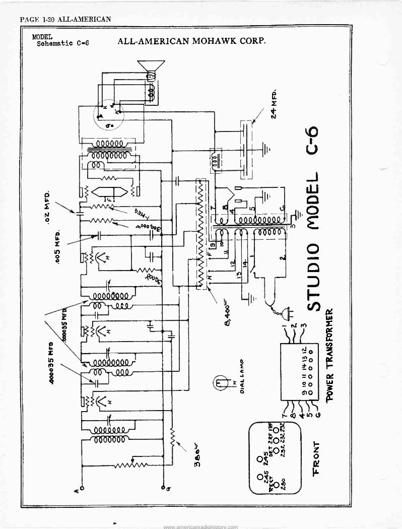
PAGE 1-20 ALL-AMERICAN
MODEL Schematic C-6 ALL-AMERICAN MOHAWK CORP.
_
00000 - 00090000 -' -1 - 6 <z_r>c
o
O LL
N 0 e
- --- incoo bee
`-/V/`- 4bo¿t,
Q_Q9OeOO
fo T
/111/111 -f QSZQ 1
_L
-LOºK944 r-1
--f ÓMOO \
vvnñw
L>
4
Onep$ a t'2 2
=1 O
º0 GI
Z o
1.4
www.americanradiohistory.com
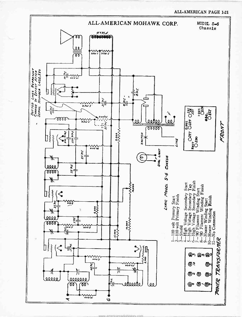
ALL-AMERICAN PAGE 1-21
>NI
'O06Ò
.0440, üó0
ALL-AMERICAN MOHAWK CORP.
O 73/_1
7341Y 9ib Z.
ti ^
3WS
000bc
3WG i \ i -+-g - t
I
000 'OC
M N
o 0 o
7i
o
`e 8 6b ` 000 1 00o f
)!. IF--
k +a
ti
>
MODEL S-6 Chassis
. h L N o ó
. cd ß. G s v)
CA.'. E-+ t7. 1-2 G
--b-C C i.. ó ó ózc , aoi v v Ç ÇN 3 LW
.o ÿvv-=-.
o ôôô3 -tg. »>=_...a >>T va
c C Cb,0b,0 4 Í o F2)xxxxz i% i-1.
ui> t !d % - e
,44Q40,
> o- ° ó- --- T -------..
LÖóQºQ.4 "-up
000 ̀ OJ
ilfy (1.ot` , 0 0 ,
www.americanradiohistory.com
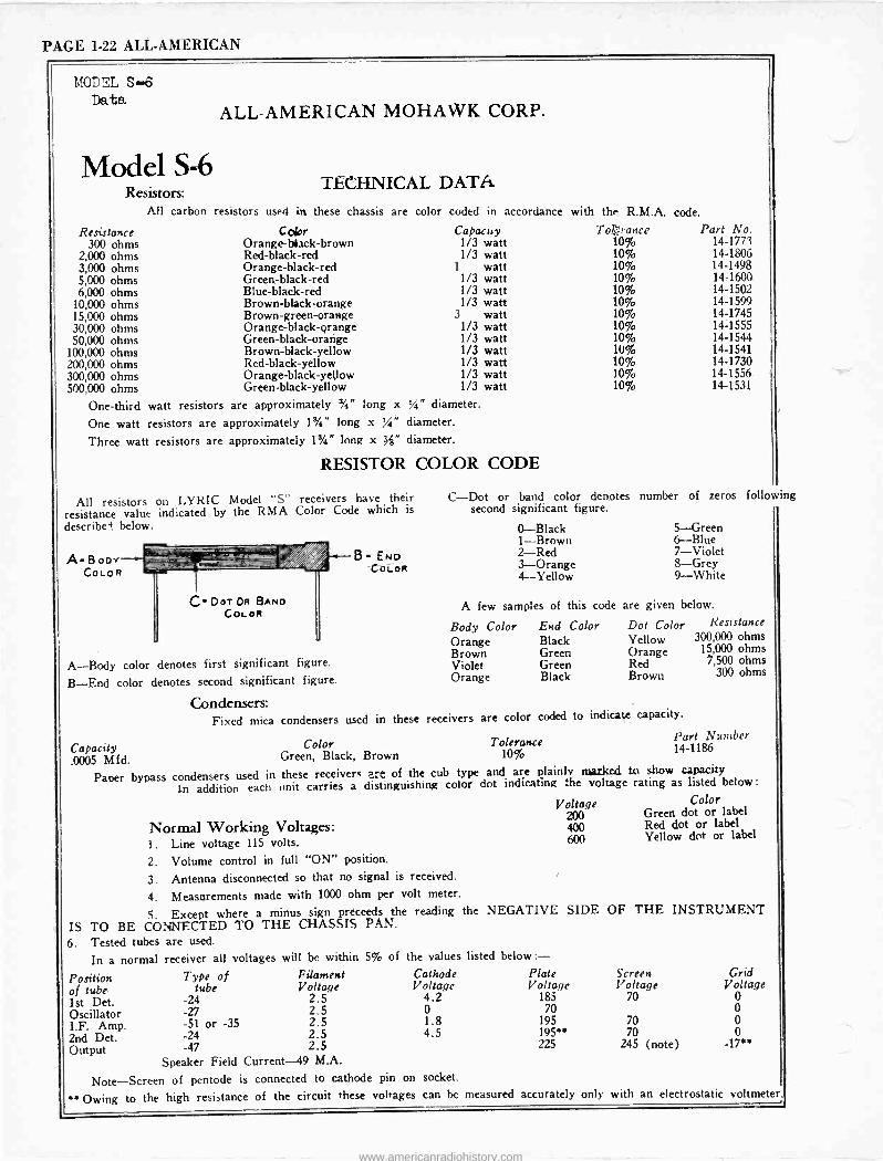
PAGE 1-22 ALL-AMERICAN
MODEL S...6 Data.
Model S-6 Resistors:
All carbon
ALL-AMERICAN MOHAWK CORP.
TECHNICAL DATA.
resistors used in these chassis are color coded in accordance with the R.M.A. code.
Resistance Color Capacity Tonrance Part No. 300 ohms Orange -black -brown 1/3 watt 10% 14-1773
2,000 ohms Red -black -red 1/3 watt 10% 14-1806 3,000 ohms Orange -black -red 1 watt 10% 14-1498 5,000 ohms Green -black -red 1/3 watt 10% 14-1600 6,000 ohms Blue -black -red 1/3 watt 10% 14-1502
10,000 ohms Brown -black -orange 1/3 watt 10% 14-1599 15,000 ohms Brown -green -orange 3 watt 10% 14-1745 30,000 ohms Orange -black -grange 1/3 watt 10% 14-1555 50,000 ohms Green -black -orange 1/3 watt 10% 14-1544
100,000 ohms Brown -black -yellow 1/3 watt 10% 14-1541 200,000 ohms Red -black -yellow 1/3 watt 10% 14-1730 300,000 ohms Orange -black -yellow 1/3 watt 10% 14-1556 500,000 ohms Green -black -yellow 1/3 watt 10% 14-1531
One-third watt resistors are approximately 3/4" long x /4" diameter.
One watt resistors are approximately 1%" long x %" diameter.
Three watt resistors are approximately 1$/4" long x diameter.
RESISTOR COLOR CODE
All resistors on LYRIC Model "S" receivers have their resistance value indicated by the RMA Color Code which is
describe] below.
A- Boor COLOR
A-Body color denotes first significant figure.
B-End color denotes second significant figure.
Condensers: Fixed mica condensers used in these receivers are color coded to indicate capacity.
Part Number 14-1186 Capacity
.0005 Mfd.
B END COLOR
C-Dot or band color denotes second significant figure.
0-Black 1-Brown 2-Red 3-Orange 4-Yellow
number of zeros following
5-Green 6-Blue 7-Violet 8-Grey 9-White
A few samples of this code are given below.
Body Color End Color Dot Color Resistance
Orange Black Yellow 300,000 ohms
Brown Green Orange 15,000 ohms Violet Green Red 9,500 ohms
Orange Black Brown 300 ohms
Color Tolerance Green, Black, Brown 10%
Paper bypass condensers used in these receivers are of the cub type and are plainly marked to show capacity
In addition each unit carries a distinguishing color dot indicating the voltage rating as listed below :
Color
Normal Working Voltages: 1. Line voltage 115 volts.
2. Volume control in full "ON" position.
3. Antenna disconnected so that no signal is received.
4. Measurements made with 1000 ohm per volt meter.
5. Except where a minus sign preceeds the reading the NEGATIVE SIDE OF THE INSTRUMENT IS TO BE CONNECTED TO THE CHASSIS PAN.
6. Tested tubes are used.
In a normal receiver all voltages will be within 5% of the values listed
Position of tube 1st Det. Oscillator 1.F. Amp. 2nd Det. Output
Type of tube
-24 -27 -51 or -35 -24 -47
Filament Voltage
2.5 2.5 2.5 2.5 2.5
Speaker Field Current -49 M.A.
Note-Screen of pentode is connected to cathode pin on socket.
* Owing to the high resistance of the circuit these voltages
Cathode Voltage
4.2 0 1.8 4.5
Voltage 200 400 600
below :- Plate Voltage
Green dot or label Red dot or label Yellow dot or label
Screen Voltage
Grid Voltage
185 70 0 70 0
195 70 0 195** 70 0 225 245 (note) =17**
can be measured accurately only with an electrostatic voltmeter
www.americanradiohistory.com
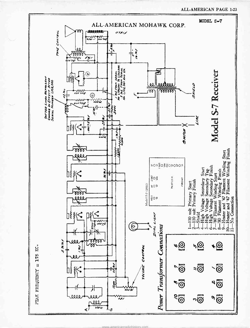
ALL-AMERICAN PAGE 1-23
ALL-AMERICAN MOHAWK CORP. ,ar.., o71í _ Y`.7óqu,a¡r_
{öooo I =lee'
#
.V^N O00 '00g
O
1
iJs<
vVVv-- n
oro ÌY
LLo ooooo%o
z o rc
MODEL S-7
..= be á. p .= ç c
ciiE-4g., ,55:ü:33 ,r .c t' t%CQinw [ 'i, 3..
L' T7b L W Íi, O O O -:
8 á3 +pww cncnv, ~ 3 o aav ,o aa HIiiuj> óó.áoaatuo 8 8 o
xxxxxz
--4 i .! 1, .
....1 .....I
www.americanradiohistory.com
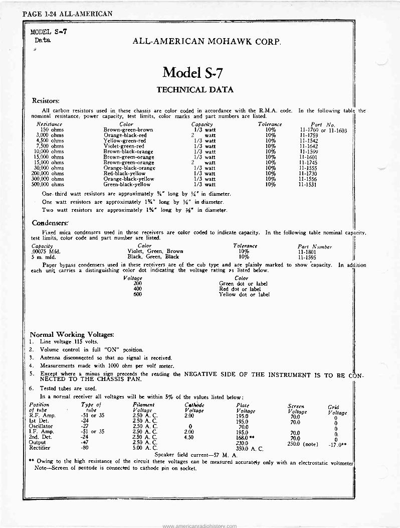
PAGE 1-24 ALL-AMERICAN
MODEL S-7 Data ALL-AMERICAN MOHAWK CORP.
Model S-7 TECHNICAL DATA
Resistors: All carbon resistors used in these chassis are color coded in accordance with the R.M.A. code.
nominal resistance, power capacity, test limits, color marks and part numbers are listed. In the following table the
Resistance Color Capacity Tolerance Part No. 150 ohms Brown -green -brown 1/3 watt 10% 11-1760 or 11-1603
3,000 ohms Orange -black -red 2 watt 10% 11-1759 4,500 ohms Yellow -green -red 1/3 watt 10% 11-1542 7,500 ohms Violet -green -red 1/3 watt 10% 11-1642
10,000 ohms Brown -black -orange 1/3 watt 10% 11-1599 15,000 ohms Brown -green -orange 1/3 watt 10% 11-1601 15,000 ohms Brown -green -orange 2 watt 10%- 11-1745 30,000 ohms Orange -black -orange 1/3 watt 10% 11-1555
200,000 ohms Red -black -yellow 1/3 watt 10% 11-1730 300,000 ohms Orange-black-yel low 1/3 watt 10% 11-1556 500,000 ohms Green -black -yellow 1/3 watt 10% 11-1531
One- third watt resistors are approximately %" long by '4" in diameter. One watt resistors are approximately 1%" long by %" in diameter.
by 4" in diameter. Two watt resistors are approximately 1%" long
Condensers:' Fixed mica condensers used in these receivers are color coded
test limits, color code and part number are listed.
Capacity Color .00075 Mfd. Violet, Green, Brown 5 m. mfd. Black, Green, Black
Paper bypass condensers used in these receivers are of the cub each unit carries a distinguishing color dot indicating the voltage
Voltage 200 400 600
to indicate capacity. In the following table nominal capacity.
Tolerance 10% 10%
Part Number 11-1801 11-1595
type and are plainly marked to show capacity. In addition rating as listed below.
Color Green dot or label Red dot or label Yellow dot or label
Normal Working Voltages: 1. Line voltage .115 volts. 2. Volume control in full "ON" position.
3. Antenna disconnected so that no signal is received. 4. Measurements made with 1000 ohm per volt meter. 5. Except where a minus sign preceeds the reading the NEGATIVE SIDE OF THE
NECTED TO THE CHASSIS PAN.
6 Tested tubes are used.
In a normal receiver all voltages will be within 5% of the values listed below :
Position Type of Filament Cathède Plate of tube tube Voltage Voltage Voltage R.F. Amp. -51 or 35 2.50 A. C. 2.00 195.0 Lst Det. -24 2.50 A. C. 195.0 Oscillator -27 2.50 A. C. 0 70.0 I.F. Amp. -51 or 35 2.50 A. C. 2.00 195.0 2nd. Det. -24 2.50 A. C. 4.50 168,0'* Output -47 2.50 A. C. 230.0 Rectifier -80 5.00 A. C. 350.0 A. C.
Speaker field current -57 M. A. * Owing to the high resistance of the circuit these voltages can be measured accurately only
Note-Screen of pentode is connected to cathode pin on socket.
INSTRUMENT IS TO BE CON -
Screen Grid Voltage Voltage
70.0 0 70.0 0
0 70.0 0. 70.0 0
250.0 (note) -17.0"
with an electrostatic voltmeter
www.americanradiohistory.com
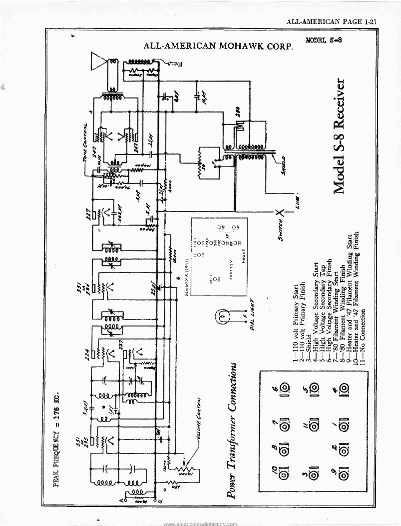
ALL-AMERICAN PAGE 1-25
h
ALL-AMERICAN MOHAWK CORP.
1
y ti
-----(
T ..s«/
-ººº 1/4)
.
eebz
S
do1aWà
ºQ9 -shelf
4404400/
0? 0=
o0a0 LL0 ó
><- k
MODEL S-8
www.americanradiohistory.com
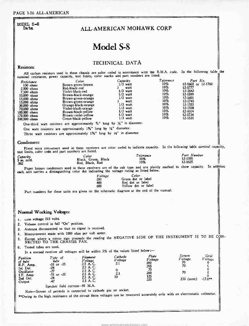
PAGE 1-26 ALL-AMERICAN
MODEL S-8 ALL-AMERICAN MOHAWK CORP
Model S-8
TECHNICAL DATA Resistors:
All carbon resistors used in these chassis are color coded in accordance warn the R.M.A. code. In the following table the
nominal resistance, power capacity, test limits, color marks and part numbers are listed.
Resistance Color Capacity Tolerance
150 ohms Brown -green -brown 1/3 watt 10% 2,000 ohms Red -black -red 3 watt 10%
7,500 ohms Violet -black -red 1/3 watt 10%
10,000 ohms Brown -black -orange 1/3 watt 10%
15,000 ohms Brown -green -orange 1/3 watt 10%
15,000 ohms Brown -green -orange 3 watt 10%
30,000 ohms Orange -black -orange 1/3 watt 10%
70,000 ohms Violet -black -orange 1/3 watt 10%
100,000 ohms Brown -black -yellow 1/3 watt 10%
170,000 ohms Brown -violet -yellow 1/3 watt 10%
500,000 ohms Green -black -yellow 1/3 watt 10%
One-third watt resistors are approximately %" long by 1/4" in diameter.
One watt resistors are approximately 1%" long by /" diameter.
Three watt resistors are approximately 1%" long by 4" in diameter.
Condensers: Fixed mica conuensers used in these receivers are color
test limits, color code and part numbers are listed.
Part No. 12-1603 or 12-1760 12-1777 12-1642 12-1599 12-1601 12-1745 12-1555 12-1558 12-1614 12-1734 12-1531
coded to indicate capacity. In the following table nominal capacity,
Capacity Color Tolerance Part Number 5 m. mfd. Black, Green, Black 10% 12-1595 .002 Red, Black, Red 10% 12-1625
Paper bypass condensers used in these receivers are of the cub type and are plainly marked to show capacity.
each unit carries a distinguishing color dot indicating the voltage rating as listed below.
Voltage Color 200 Greed dot or label 400 Red dot or label 600 Yellow dot or label
Part numbers for these units are given on the schematic diagram at the end of the manual.
Normal Working Voltages:'
t . Lane voltage 115 volts.
2. Volume control in full "On" position.
3. Antenna disconnected so that no signal is received.
4. Measurements made with 1000 ohm per volt meter.
5. Except where a minus sign preceeds the reading the NEGATIVE SIDE OF THE INSTRUMENT NECTED TO THE CHASSIS PAN.
In addition
IS TO BE CON -
6 Tested tubes are used.
In a normal receiver all voltages will be within 5% of the values listed below:-
Position Type of Filament Cathode Plate Screen Grid
of tube tube Voltage Voltage Voltage Voltage Voltage
R.F. Amp., -51 or -35 2.5 A. C. 2.1 200 70 0
1st Det. -24 2.5 A. C. 205 70 c
Oscillator -27 2.5 A. C. 0 70 70 0
I.F. Amp. -51 or -35 2.5 A. C. 2.1 200
2nd Det. -24 2.5 A. C. 10 125 250 (note) -17.0'
Output -47 2.5 A. C.
Speaker field current -91 M.A.
Note-Screen of pentode is connected to cathode pin on socket.
**Owing to the high resistance of the circuit these voltages can be measured accurately only with an electrostatic voltmeter.
www.americanradiohistory.com
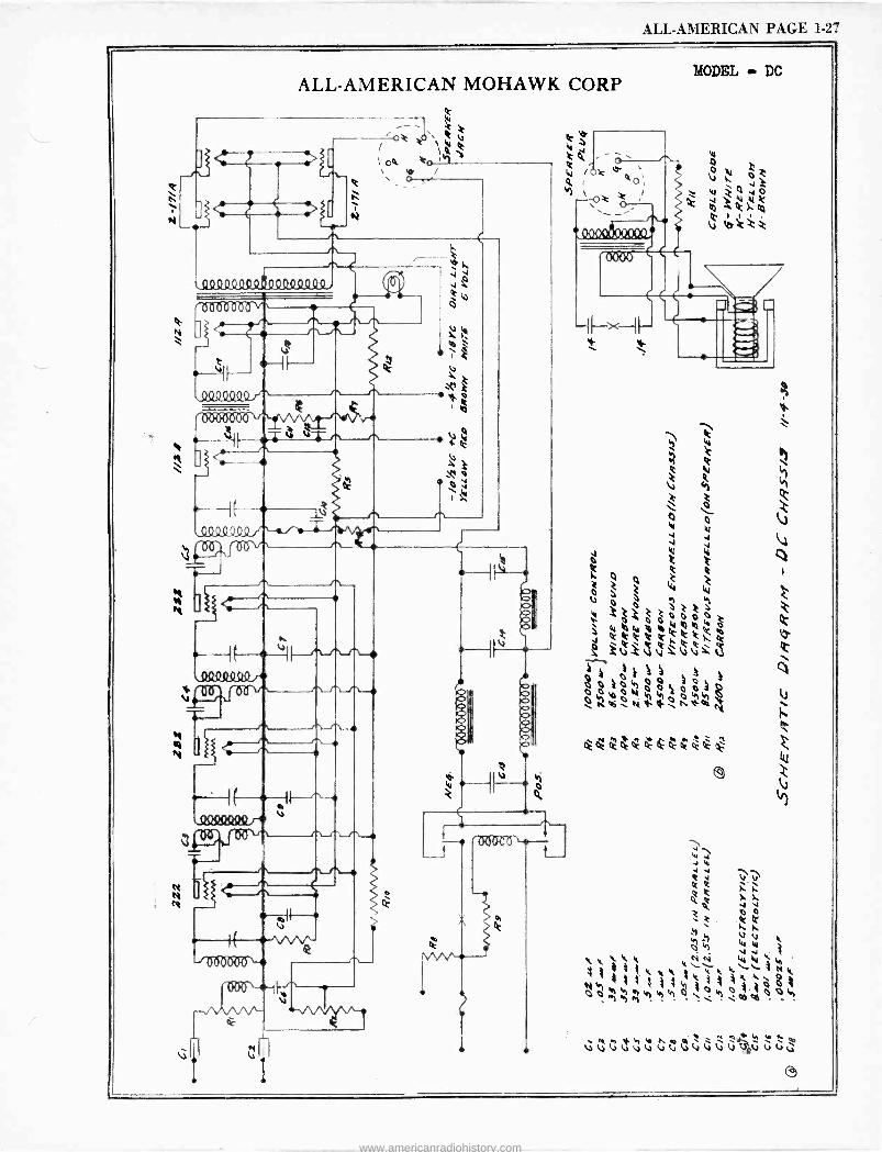
ALL-AMERICAN PAGE 1-27
ALL-AMERICAN MOHAWK CORP
C
et
W o- ,` o4 to. i
O. se
a / \ o .
Q9900QO0.QQºQ0000
1515195M2f \A" r
I I
00O(KM A'
_____AF__.IiV r e,
\ .----
6-----IE _il
0944000
" ^
T
4DQ449Qr+
N tN
n
=-1( ,- ,0094400 r+ v
I
J O
J oACen-
v ri e
- ñ f
n n n
0.1 (.1.
er ó
e'e e'e e
MODEL - DC
1 - 2: eew;
...;
r NI
J
k e: 4
> i
uV
"pz
\ 1/4 4 W
g ó2 Ñtti'tjo;
hWhÓ
14W
. .M vvG e evv www.americanradiohistory.com

www.americanradiohistory.com
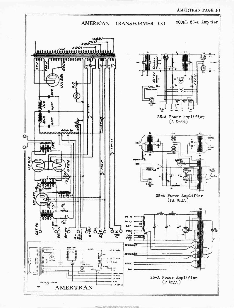
AMERTRAN PAGE 1-1
AMERICAN TRANSFORMER CO.
wori ASU
if 00/
r NN
YM/R I
CLU
es:t 1. V
c0 á0 W
Q
.lu u
r,
z ti
b"" c .a71
.. :,.., .....
AMERTRAN
11,4 AI
wi AI
RAY
tiKAC2kP.
R4
if
MODEL 25-A Amp ' ier
25-A Power Amplifier (A Unit)
-SO 1s
25-A Power Amplifier (PA Unit)
Lt
Ct
0G
25-A Power Amplifier (P Unit)
--J
www.americanradiohistory.com
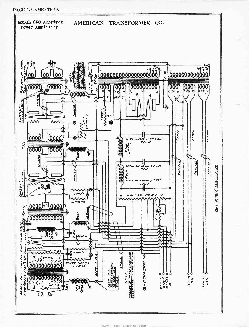
PAGE 1-2 AMERTRAN
MODEL 250 Amertran Power Amplifier
AMERICAN TRANSFORMER CO.
ti
3
T?K T y,
'0000 000ô V
C
i 0 cti r.
.-evaAA
v
3
e.a000r
o é Ir..w.r
: M
W
000ÓIGI
N
SW/!YJ' fit vAf (., o0o bs
o
Je ttir ºim,r IIM iv, 000i
Cr,h Nib
bide r
II 171 704 /.ryOM 2 PO 5.
O1/ b h ge
f170A .9N'4'iOM 2 O 009 o2,4'10 -
II
.Y 04 S/ S. gee' 0190, -i' Jd.CI
o o
a
www.americanradiohistory.com
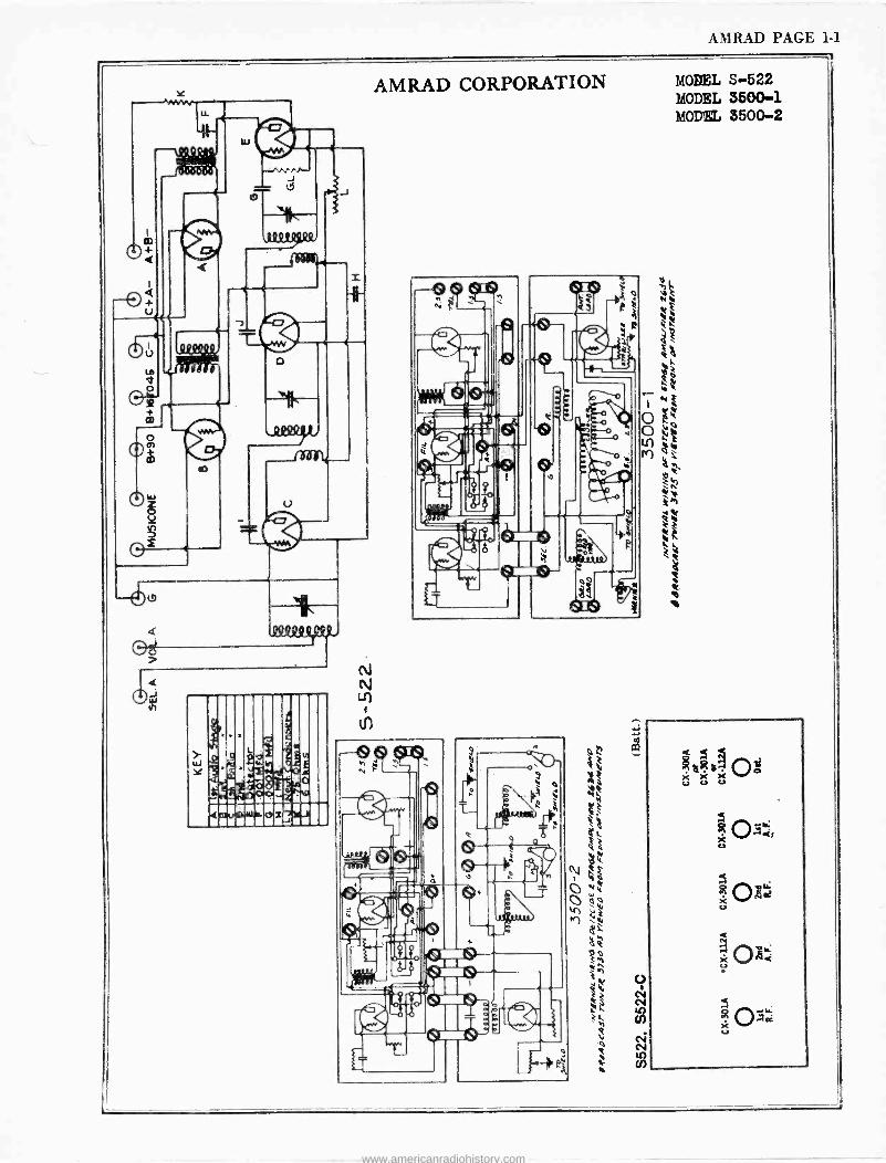
AMRAD PAGE 1-1
www.americanradiohistory.com
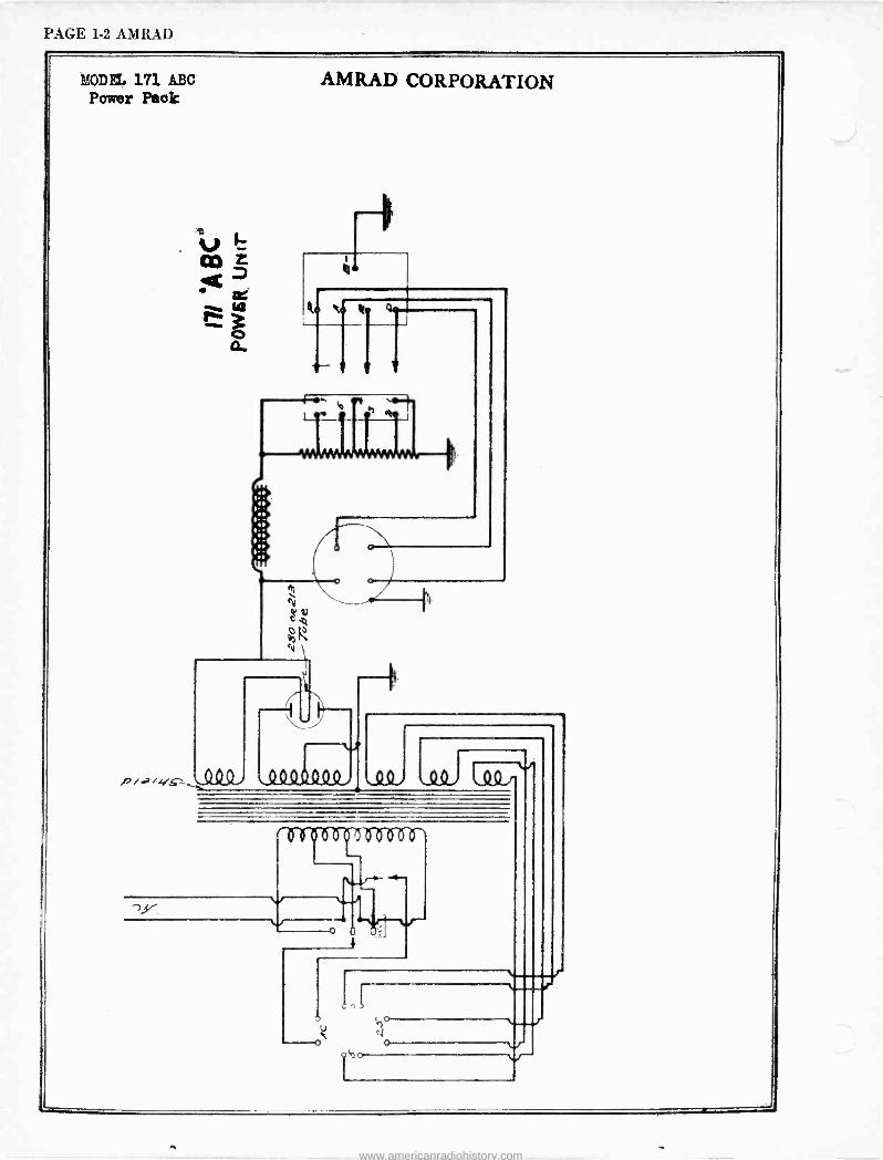
PAGE 1-2 AMRAD
MODEL 171 ABC AMRAD CORPORATION Power Peak
p -
<o Ih
o
o
www.americanradiohistory.com
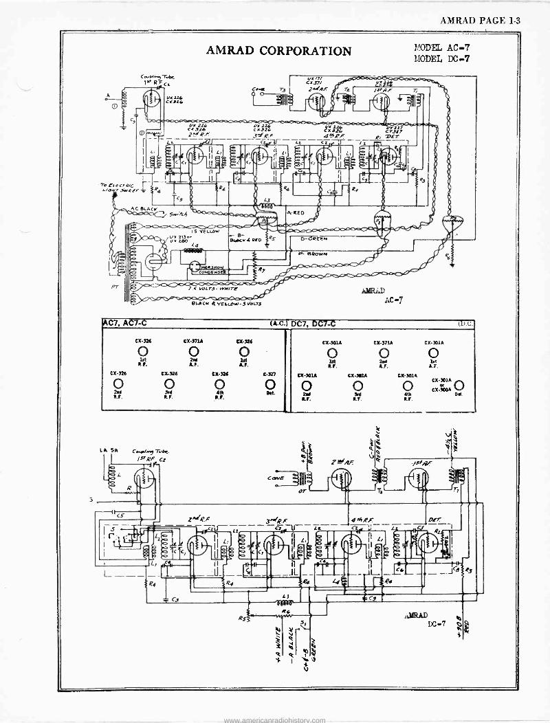
AMRAD PAGE 1-3
uX 226 CXlL6
AMRAD CORPORATION
s VOL7J- WN/fE
eX /7/ Cr<37/ j./RF
CX d26 N'Z26
4 ̂_t .P.F
OYS27 CY3t7
R, Ter 1
fYY[V W AC -7
MODEL AC -7 MODEL DC -7
AC7, AC7-C (s -C.1 DC7, DC7-C (D.C.
CX-326
0 2M R.F.
CX-326
lit R.F.
CX-326
0 3eA R.F.
CX371A
2M A.F.
CX-326
0 AtR
R.F.
CX-326
A.F.
C-327
O Od.
CX-301A
O 2d R.F.
CX-301A
O lit R.F.
CX-301A
0 led
R.F.
CX-371A
O 2aA A.F.
CX301A
0 MY R.F.
CX-301A
O lit
A.F.
O Od.
C.f.i.., Tyke,
/srRF CS
3^R.F cr11-11-
www.americanradiohistory.com
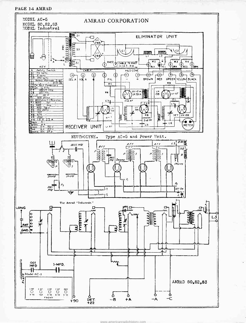
PAGE 1-4 AMRAD
MODEL AC. -5 MODEL 80, 82 83 ?.ZODEL Inducrol
LONG
AMIRAD CORPORATION
, r 51
.
--fl ELIMINATOR UNIT s illi
a - 33 1._ 4 ,,,,,c,_____22
rí./3i iii fó LI L2 o - ----as Sz
A - - R 2 $ R 3 32 RHEO.,¡CASLE TD RHEIT
KEY - V IN SET RIO k YE GIN RED DRN
A Safety 5w.lch MUS ICONE CABLE
$1 75 ve"' 32 S VeI/ s O- 5EL A VOL
O A
o 0 FIL.
0 0 0- - + BROWN
o RED GREEN YELLOW BLACK
J 350 volh ^, I ANFlAQ MERNpl1 ( ()D
C D-1 3Q Ñe(yvf
RS R9 C .C4 Condensers
R6 uX 112 or _
UX201A..- US
19! 1st AF -.
5'ce Og025f Mid
ÿÇ$g .00002 Mid rL2 30 K
RRR I 1QQ00 olim3 C3 2nd AF L R2 aj000ohm F. Remator
R3 8000 Del C7 R4 3000 Amp
' ux
199
/
Ux
$/ 199
R6
ó DCT UX 199
RggS 400o1 Tmiohms
R7 30á R8 475 R9 IOQO
-2 ó R7 swV/.- RIO n 2.5A
` 2ndRF
`C5 ` C6
kI.
A+ UN T RF METER flí'.w en D+ 50 V RECEIVER lat
.d B t 100 V itrown B+ 135 V
9 ooi MFO
. - `4 Model AC 5
4 O.
The
NEUTRODYNE. Type AC -5 and Power Unit.
Amred " Tnductrole."
z
1 RF 2 AF 2 RF 1 AF DET 0 0 0 0 0 X'99 112A X'99 X'99 X'99
FRONT D }9O DET.
+22 +A
A
A/iRP_D 80,82,83
-C
www.americanradiohistory.com
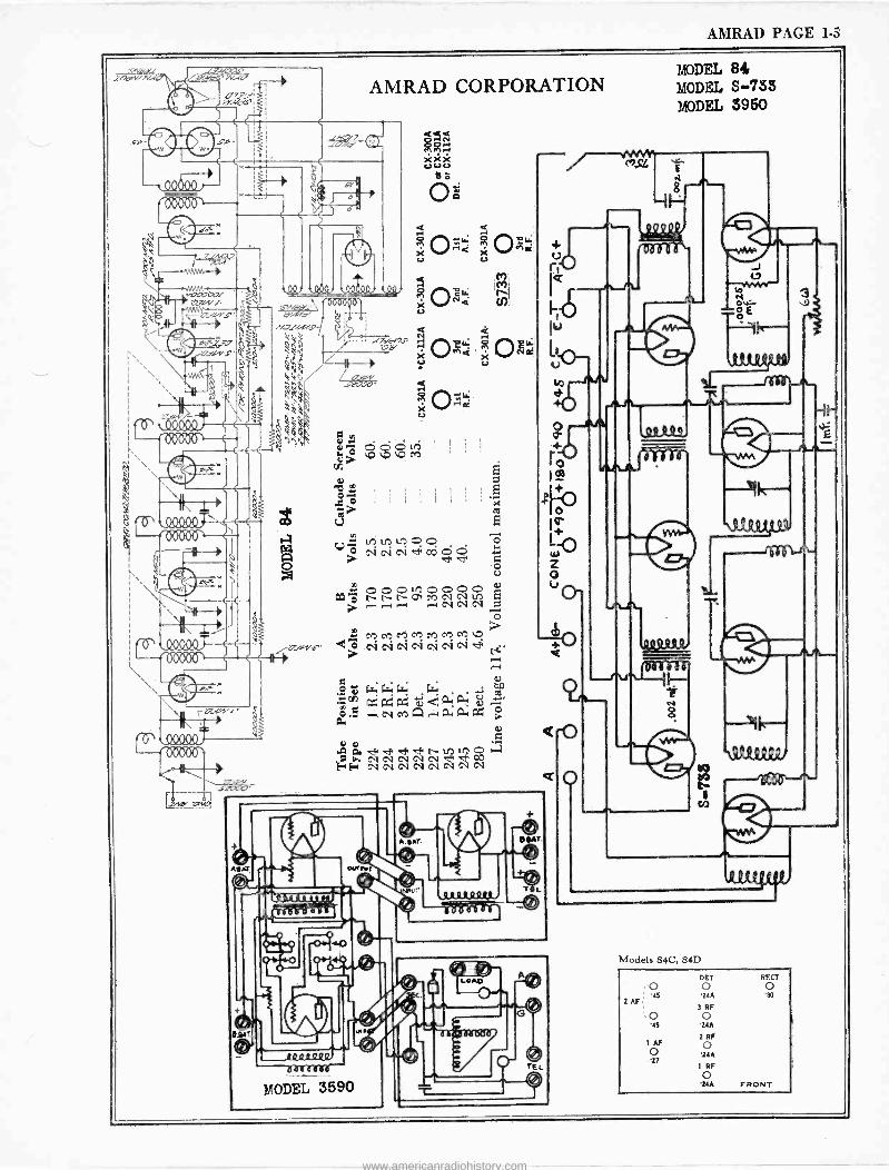
AMRAD PAGE 1-5
7nv. eA
AMRAD CORPORATION
.IíTvN/1S' t7d
o C,` QQ "itil ÿ ^ D G M ' ,
C Y ' Fi
47
.; , { i 1 gv E
4a °° ; tri w
Ó ; CV CV CV W, á Ó
V
tl ô ÓÓóMcoicoiíoi 9 -1,---1 1-4 1'-1 Cl Cl ,CV D
ó :: MMMMMMMVD*? C; .CV CV CV CV CV CV CV .4 ti
r-1 r-1
ú 4.1.;w ;L; LT; .s gn) ra;.áa; g 2-1 G.5 ,-4 CA CZ A,10; 1:1-; AC á
a ó X U
Q Q r
XOMa O= U U
Q -O 1 i+ áee aa l`- 2r lf o
0 h CV CV CV CV CV FE ei et
rag dÓ MODEL 3590
A. sAT.
MODEL 84 MODEL 5...733 MODEL 3950
a 8
'Models 84C, 84D
DET RF.CT
0 o o '24A '80
3 RE
'24A
2 RF
o 2U
1 RF
o 24A FRONT
www.americanradiohistory.com
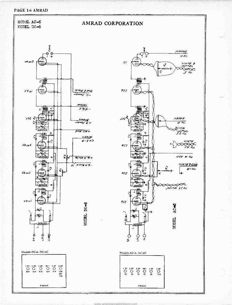
PAGE 1-6 AMRAD
MODEL AC -6 MODEL DC -6
3d ON
A21oa£
db oNZ
AMRAD CORPORATION
'O/8 iyet
--1ººlºr- L- . sFo/D, 1` wie4<'n.9 d - lh -
tiaPpiNp
V 2
V
o h
l/ML1iQ -Jsv'I41 g
4.4.0.111-1e1
9-9 t7
0.2:+ti^+xflcv
PD11
J
-k"-
Modele DC -6, DC -6C
1 RF 2 RF 3 RF OFT 1 AF 2 Al'
0 0 0 0 0 0 PIA 'CIA 111A '01A 'efA '12A
OR
'71A
'e'en, a 9* yl x>0747 b' 9 -
/L/
./V/NOdg
9ZZ
9ZZ
9ZZ
91Z
19 JP, ce
a-2d7a p nrO77,
-\-- eT1 //i,N
.SZ01
>247'78h
'a' O1
age' b' 01
a,e'7e p oa Or 8-'Ol
t. ..' - 11> .111F
.t
o go
Models AC -6, AC -6C
1 RF 2 RF 3 RF OCT 1 AF 2 AF 0 0 0 0 0 O 26 26 26 27 '26 71A
Ala 77.7X 5Y c1
FRONT FRONT
www.americanradiohistory.com
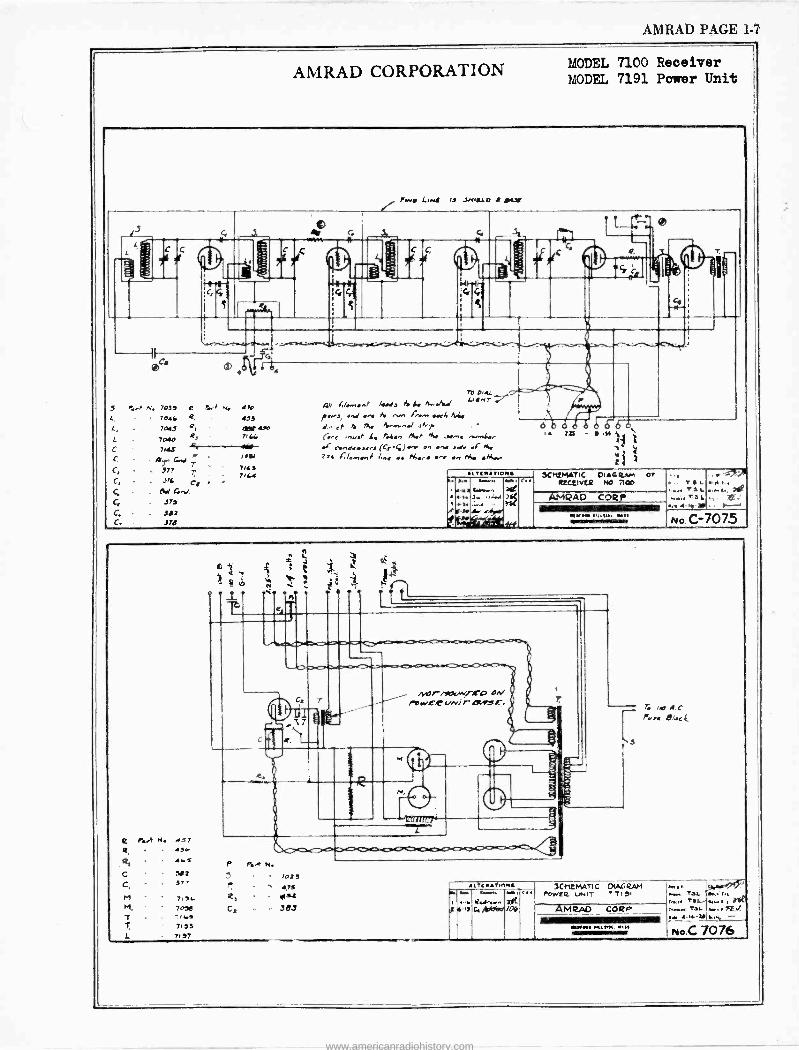
AMRAD PAGE 1-7
AMRAD CORPORATION MODEL 7100 Receiver MODEL 7191 Power Unit
l.3 .SMIaLD R K7e
3 e
i -i 1
Co m A G4
S ../ N. 7033 e 1..1 N. 47e
L, - 704k a. 413 L, 7045 Q. elf 49. L 7040 R,
' 7, 34,
C 7NS .41. ----MF C - pJ G.d T 7.a7
C, !77 7 774.3
C, .l76 C 4 . 74.4
C. A.' 4.,7. C. 373
C. 302 C. 370
7H 0.4L
Ali!/ .nf /.4/a ti i. M.Jt/ L/4M7
it.vs, an./ ... /0 n.., f:..,. .e/. M(. >x. a.,,.,.-/ ./.r .
C -.e. ..,...r 4. t.t.., ne., M, .,...,. .r .+..,e..s.r, (C,.4),.. e., ... s.l. .F *4 zaL len,.,f l.,. .. Me.. -. .., M. M..-
6 .. Vro - . ,>s
é7 2
IONS SC MEMO) OIAf.RAM or 1.. ... ........ ..., r.. actlV[p N0 71013
. . ' 141. are
, .,. ñ
3....o...4..1)f[ AMRAO CORP .
MIIMMIIIIIIIIMIIIIIMIEB .O (41 i/ !.y.d U111, MO ,ll,l.. Y., IIIMINZIMav +l4
. , T a L 4 1,
TS.L ,.,.. 241 ..-T3L:, 7-
No. C-7075
r.Y N. 457 434.
C 302 . 37 7
M 7. M, 7030
1i..a T A 33 L 737
4 o . L
# i N
,G
C. MlriM1/4.4v,.-dr0 o.V
rb wEt uivi 7' QI'dC.
P ß4H. 3 /0S3 P 473 R, - st C. . ,. 383
C
T qe A
P2
AL..,7,M[ 114.
-IS ,Zc/..-n 70e. C. /bided /OB
5C+1tMATIC DIA,C.RAM P0W[R UNIT 71 91
AMRAD CORP
nw.. IwI,. ,..,
._'yÇ ..... TL ..., r . TiL 44-, , 414 (+... TS/. .... FE..J, .W 411-31 - No.0 7076
www.americanradiohistory.com
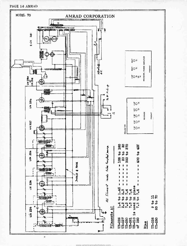
PAGE 1-8 AMRAD
MODEL 70
N
z N
AMRAD CORPORATION
WON
N N
e
x z
t
- 1:- ~I I _
Ablate
.x z
1 - 1c _ O
tDts 0r+0Q NCV IA 02r4w Ì Ì Ì Ì Ó N `M`.-MJÿÿ o
www.americanradiohistory.com
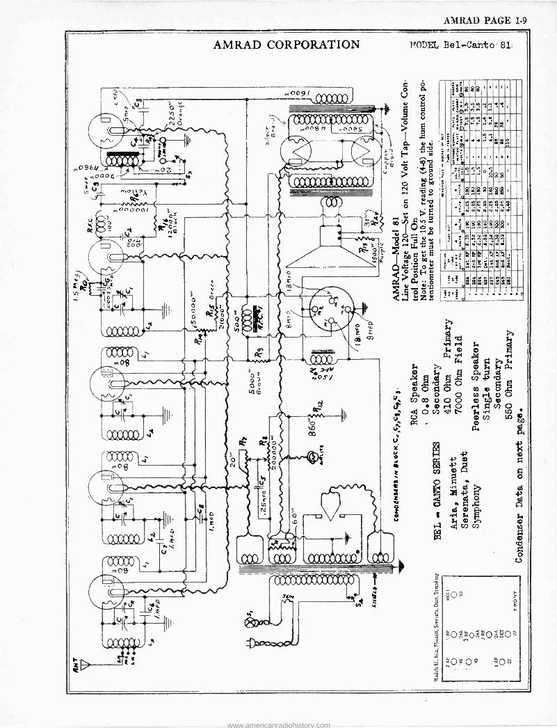
AMRAD PAGE 1-9
AMRAD CORPORATION MODEL Bel-Canto.81:
M
///./--- ,oßbb
{ ¡
v, e
molea
mOA 3
edá K e NM
J 001
zoo -
,n09
\
ep . .
/1./O1./
rOCCODÌ., o$ e. =1_7
e e ' I V V
10.01.
o
---` i ///11/t1////// i º mnnß f7 ,.,0005 > E
I
A
12 ñ_ ` U@ . y
r IIItIt1.1.1.1.i1 /Ñ o .,
m y O
.b --/y-, .
r i73
a0 ~ O ÿob. ÿ u
MI 3 d rr ;'ÿ 3 ' °' n E
o o 7 o o
uy
r
.°°9'000000)
.omt. + +'tiaV. >p,Fo E u ;;ó
z
2 ,Hv tios/
a
0 L z
vee1 (b)32006N0
,11111,'111111.1 SA.
ÿ " C=evvv.. W éë888"'''
-1
[ Óa Ib a
ri
a .i ri
.i
..
r
i¡9......e.: :;° - r .viññ ,
" r:
q°i ' .o.
! ,!
1 1 1 1 1 1
«
a 9'!"102 ..... a O OO
.oi a 2'1
t
;SSBR$e.
° 2222222:2 4j4 e4444.;
R8$8 '0 i ñ a
w N
ttyy N Vf q w r
N II r N N
II w
ª ,: , ::ári'dK zlrt
b3eeeááZa$ 3[E
9 -
Z o 4
O wo O 00
www.americanradiohistory.com
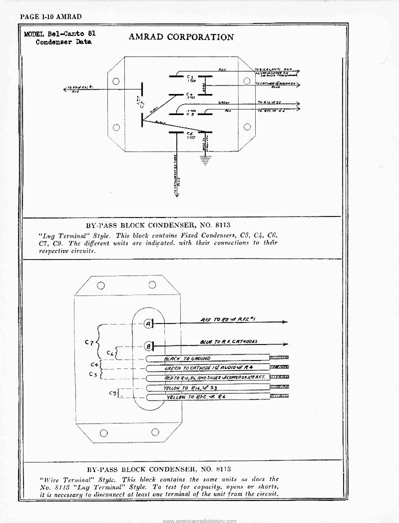
PAGE 1-10 AMRAD
MODEL Bel -Canto 81 Condenser Data
T043.íRRCJ/ pro
AMRAD CORPORATION
C+ .51
Roo
Gers..
NTO4N,R4f/C.i RN KN 2 MVO..wWAN4.
OTorwr knot /irm.wwt4+> e.ur
T. or$3
.rau i / c y
Oro r0. diC.ur. 44C
BY-PASS BLOCK CONDENSER, NO. 8113
"Lug Terminal" Style. This block contains Fixed Condensers, C3, C.4., CB,
C7, C9. The different units are indicated, with their connections to their respective circuits.
4 C3
O \ -a
Tb ,P9 tar ARC °/
áLl/E TO R. f. CRTNODES
13LRCIf TO GROUND
GRFEN TO CfITN00E /erÌi(/D/0 b/ R 4 blIZZOM
- ljhTOJQlS,yc,gNOStVER CoppERON.2wRFT F+r,c+++
- - YELLOW TO lPid, (f 53 :2211=3
YELLOW To IPkC. roc If
BY-PASS BLOCK CONDENSER, NO. 8113
"Wire Terminal" Style. This block contains the same, units as does the No. 8113 "Lug Terminal" Style. To test for capacity, opens or shorts, it is necessary to _disconnect at least one terminal of the unit from the circuit.
www.americanradiohistory.com
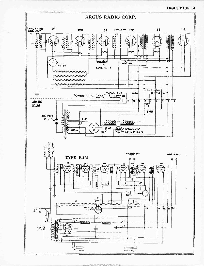
ARGUS PAGE 1-1
LON` SNORT ANT. ANT,
UÌ e
AR GUS
8125
199
ARGUS RADIO CORP.
199
POWER-RHEO
199
SENS ITI V ITY
ooO25 MF 199
2MF
199 112
A
w n
100 ÑP FUSE OHMj e
110-VoLT A.C.e
011á4e
1 LOUD S kR -
12 11 t0 a -
./1 MF
b A,¡
-.-1;71-
.1A
L
588-_ßBPS 5. MF d
T
www.americanradiohistory.com
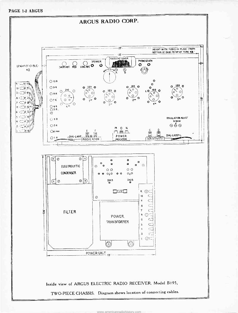
PAGE 1-2 ARGUS
LENGHT-CF-CABLE
42
.T
ARGUS RADIO CORP.
. 19
HEIGNT-WITHTUBES-iN -PLACEfROM- BOTTOM-OF-6ASE-T0-10P-OF-TUBE 6j('
f8 / RHEOSTAT COVER t . `
.
.
Q ¡ SPEAKER
IgRfANT REp LOÑG./!WT ® OO
010-R
Q 9-R 0 199 0
OBR 210 0 0`00
O o O 01R \O o O O
O6R O 6- O
O5R. O
0 4-R
O3R
O6LANN
r1`
,_ O
o O 2
I ¡, I!IIII
I i 1tliU
`O A
9 0
O
O O
O
M 0 r-, .
Vh4.
O B
O
O
N rI
9
°O O 3o
PHONOGRAPH
0 0
O O
99 o O O O
G 0 109 O OoO o 0
O O CTM
O
O 4M
OSCILLATION -ADJUST
DCREW
G 4 e or
3!1
-LAMP o
=- POWER 2
DIALLAH_ 01-R `AL
5 SiTIV11Y¡ MODULATION ,NDicATOR -(-- .
1
1
O 0
ELECTROLYTIC
CONDENSER
o o o o
O 0 0 0 O
O O O o O 0 0}0 0 0 010
216-B 216.5 o o
POWER
TRANSFORMER
R
t0
9
8
7 L R Cr.- G C" 5 r1
OQ ...:
POWER -UNIT 13'
Inside view of ARGUS ELECTRIC RADIO RECEIVER, Model B195,
TWO-PIECE CHASSIS. Diagram shows location of connecting cables.
www.americanradiohistory.com
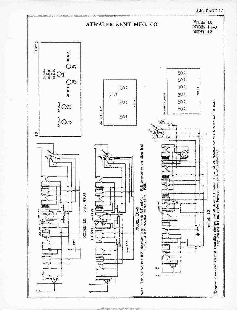
A.K. PAGE 1-1
o
ó X u
Y o
ATWATER KENT MFG. CO.
M
ó
I
MODEL 10 MODEL 10-B MODEL 12
10---:--y
c0
fut,
v
r V
cO
www.americanradiohistory.com
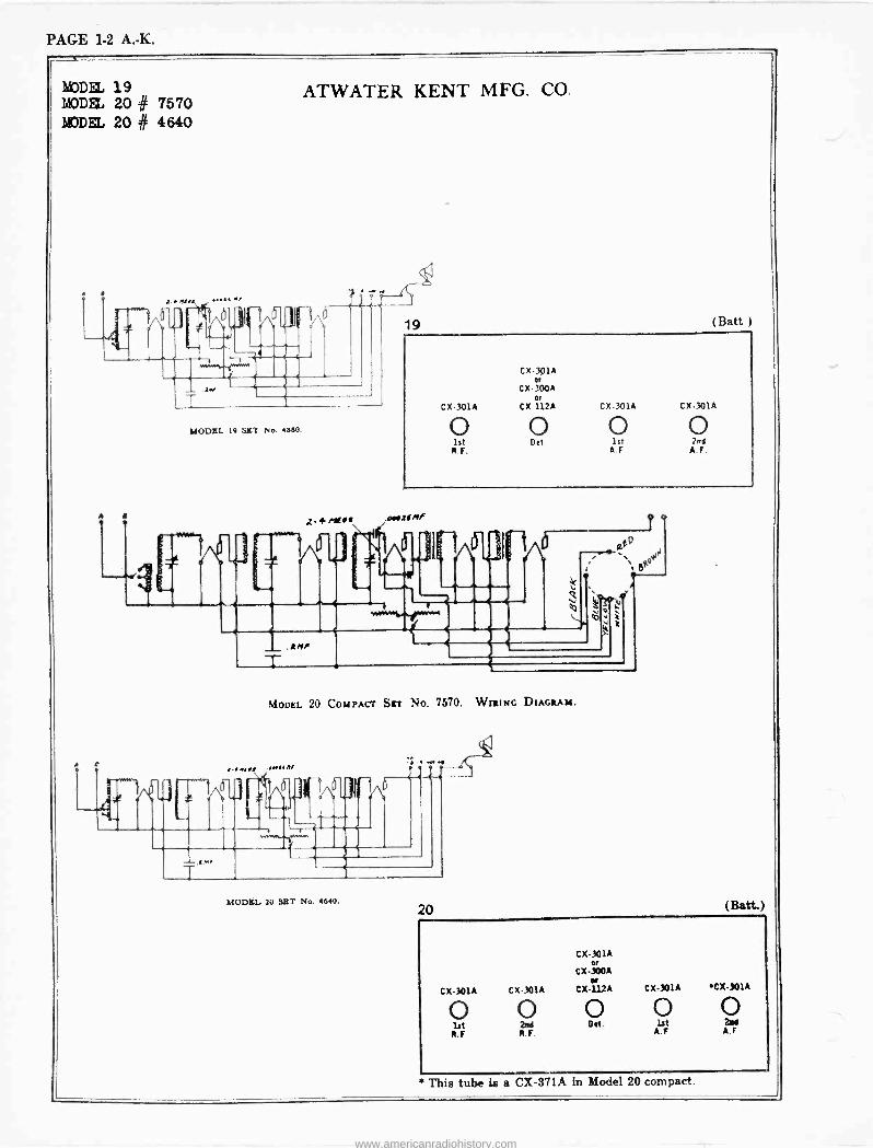
PAGE 1-2 A. -K.
MODEL 19 MODEL 20 # 7570 MODEL 20 # 4640
,.. ... ...
L _
A I .
ATWATER KENT MFG. CO.
6
J
_ .av
MODEL 10 SET No. 4660.
.A.I ww
.RMf
T
19 (Batt.)
CX301A a
CX.?00A os
CX-301A CX112A CX-301A CX301A
o o o o ht Det. 1st 2n5 B.F. A F A.F.
.0002f /If
rf ö
T D
aE .00`.-
DAo
MODEL 20 COMPACT SET No. 7570. WRING DIAGRAM.
(.mall 0116 A/
0 (5-j 1
.an, T
;_ N6H i(i q O s 7
e .
-4
MODEL. 20 SET No. 4640. 20 (Batt.)
CX-301A w
CX-300A or
CX-301A CX301A CX-112A CX-301A CX3O1A
o O O o O 1st 2ad Dd. 1st 2n1
B.F B.F. A.F A.F
This tube is a CR -371A in Model 20 compact.
www.americanradiohistory.com
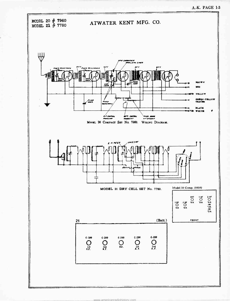
A. -K. PAGE 1-3
MODEL 20 # 7960 MODEL 21 # 7760 ATWATER KENT MFG. CO.
MIu /4f.K2R MIMI( L.IM 7/ILI
FF f / R1Ji1FIMC/ f/ R/ I> f
RR
1,712/ }ylwP!
M
1,/
BROW
M BBD
21
es- ~feu Art CIAVL AIM /M11a.27fR RMI7Rf .-H1RRe/
MODKL 90 COMPACT SET No. 7900. WIRING DIAGRAM.
IBRtM TBLLOw
-c 6RBEN-TBLLO w TRACER
.4 BL1CB -7jk warp' I
1
MODEL 21 DRY CELL SET No. 7780.
(Batt.)
C-299 C-299 C-299 C-299 C.299
1st 2nd Pet. 1st 2nd R.F. R F. A. F. A.F -
Model 20 Comp. (1925)
DET 1 AP j AF
0 0 0 1 RF 2 RF '01A '01A '01A 0 0 OR
'01A '01A '12A OR
'7I A
FRONT
www.americanradiohistory.com
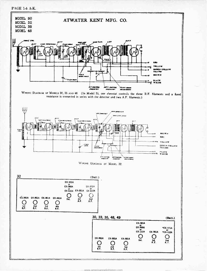
PAGE 1-4 A -K.
MODEL 30 MODEL 32 MODEL 35 MODEL 48
32
'map AAYAHtt
w
ATWATER KENT MFG. CO.
rfr traMf aaaIAN ,iMr
r-//!/ MOO
Md. WeirMMft
sie Core. 0.147
rI BID
Oraaf YELLOW
e ORION -YELLOW
rI
tirlAML AVTt ~TM 'AP JAW I11r/tiMT .r!fYIMT .K/R711Nnr
TRACIB
BROWN / BLACK !WHTTf
WIRING DIAGRAM or MODELS 30, 35 AND 48. (In Model 35, one rheostat controls the three R.F. filaments and a fixed resistance is connected in series with the detector and two A.F. filaments.)
ore n ! rar..aa !
rI !r I r.warl.v,pW r.aa.I.TMelt!
r.a' Ca+wrirar! «.. AArr!!+
An, row -.r i
irlas lwaawrA
.i BROWN
RED
ry YELLOW
ORE%Y -TEL LOW TRACER
a, rv..rAVA !Wlir Nlr.yrraf MAI AVOW, aUNr NI/I k WIRING DIAGRAM OF MODEL 32.
(Batt.)
Ci.' -301A CX-301A CX-301A CX-301A
O O Ca O lit 2nd 3rd 4th R.F. R.F. R.F. R.F.
CX-301A or
CX-300A or
CX-112A
O Dot.
CX 371A or
CX-301A CX-112A
O 1st 2nd A.F. A.F.
30, 33, 35, 48, 49
PI.ACK '4 WHITE
(Batt.)
CX-301A CX-301A CX301A
O ® O 1st 2nd 3rd
R.F. R.F. R.F.
CX-301A Or
CX-300A CX-371A N Or
CX-112A CX-301A CX-112A
O O O Dot. lft 2id
A. F. A. F.
www.americanradiohistory.com
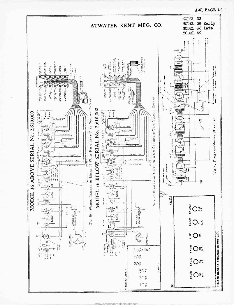
A -K. PAGE 1-5
MODEL 33 MODEL 36 Early MODEL 36 Late MODEL 49
www.americanradiohistory.com
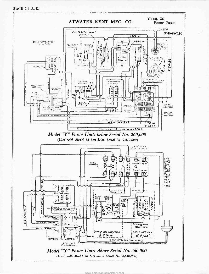
PAGE 1-6 A. -K.
ATWATER KENT MFG. CO. MODEL 36
Power Pack
NOIE DISREGARD MARKINGS MOULDED ON raoNT OF
IER.aAAL PANEL.
TrIE [ 1LIDE 5oC T.
T
ARNRM EMB SFO
LY.ER
DING.
E .
awR.CDING
E -r^ Q 0; 1
. rEj 9 ®.
J
Yr
m HIGH VOLTAGE NDING.
C
m
n
o K
COPPLE.TE UNII gstt
ISr A.F PLAIE RES BYPASS CONDENSER.
rr T
SPEAKER (YOKE.
1 3
Fl -GREEN TR ECA
CINfSf NSF R
055E MRLY. 2,0 MI
'IIZ fill_ T? 11 Lei
4.omf d J5 -OS
1700
FILTER -COOKE ASSEMBLY.
3 3 tl t
o nt -
o o
B AG
TELO
w
1100 w
3
o 1
ó
v CABLE
Schematic
aE.rarAC,F FON P UG
NNLICif Cr
IG TOGGLE S,riCN.
E-151 A F rILwMENT SHUNt MIENTIO-
MfTER
o
o R - l51 c,L
uPPLY
/ 3
e-, o
O e e w-eg
.8 DE T. GROUND
IST AF `NO
UPP A F'
LV. S
TE RrvI INAL RnNEL /
BN:K10. on ORE vEL.TR
,Jl"ÍÑV K,
Lli,q, ser IIE }vvLv
DET. FIL. SERIES r ,rD RCS -i 0.3 w 4-/3313
Y
J WIRE-_ .05 w t/3l2e ' RE SIST ANC
ZO w 4Q939
Model "Y" Power Units below Serial No. 260,000 (Used -with Model 36 Sets below Serial No. 2,610,000)
ti
S 3
IR1
O
CO
o
O I :Di ) éí í P?!
RECT. TUBE SOCKET
I re '9'1L
O 1,:0j 3i0}/
BIACR M16M VOLTAGE G.
1
PANEL ASSEMBLY
Ir DET.L.Mn11DING.....
BIACFI
co, PRIMARY 1
IO RED
4- -- - TRANSFORMER ASSEMBLY
2.. A.F. FIL:. hINOING I \
REE T. FIL. WINO,
2.F -1ST A. F FIL. WINDING.
t Y Y t
O, A
R.F.-!sr A.F FIL. SUPPLY
4P W
J, +B2N.4.Fi{1ᐠBND J LL1
® .4E ¡ e
/ ñ +81_AF +B OtTo aia a'44:0' O a 5 E A A 1 ti A
-t J
C YELLOW
r i ¡
FILTER I CONO.,
RED
4.0
-+- GREEN-YEL:)
i I
YELLOM-r GREEN
YELLOW
i
r
W S
e
.44
Ñ
YEL?R WHITE
fe, WY J o
_
Betrr
-1
o
LYE LLOEv-6REEN
I YïLLO1E-BWCR
CONDENSER ASSEMBLY ¡ CHOKE ASSEMBLY
r...r t..-1 9704 - ---- -- 110(JOLT SUPPLY CAREE AND PLUG-,
Model "Y" Power Units Above Serial No. 260,000 (Used -with Model 36 Sets above Serial No. 2,610,000)
ON A F FIL SNUNT RE iSrANCE.
DE ECTO0 FIL SHONE RESKS TANG E.
8A
AD:C.}: JOCiR.L
www.americanradiohistory.com
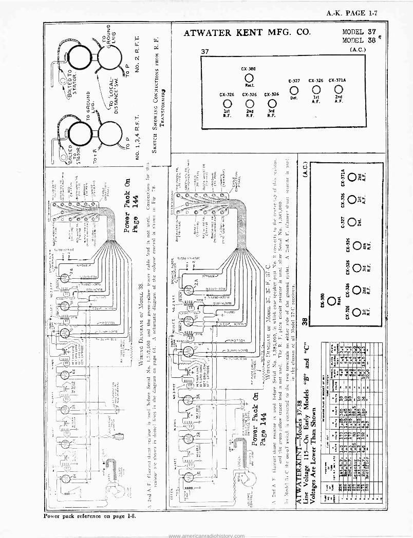
A. -K. PAGE 1-7
z
co M
a ñ
Ñ 0 < X r.
Oö Ñ P1 t 1 X VCe u
^` Ory c x = 0z 0=
-
ó:
[ nnrl:no i 4
[ . o MÌM173Mp1
n ove
ej.:11'.1'.. ijC mmsócmal .
'
' t:44.4,;.;JI:mmVmoo Ñc4i
fd 1 1 1 . 1 1 1
°d roi.oi.oi I.oiñl . E >
ao o ral el
Io N Io ral ral
1p 1
r-1' 1
N Ñ ' r rlriNriVe ON+9 e)
.
ta, er) rt`t- N riri
M.)N It-rn rl 1 rl
.d '
nM) rl el
:N 10101 MN rl p
O
a9ç I
1L GI
1>:1>:1,y
ó q IA á
po- :.4 V.mIÑ,,t
w Pv d
:Ed ObnoP"GNO NNNN[fo NNNNr1N
Y -i -
Power pack reference on page 1-8.
www.americanradiohistory.com
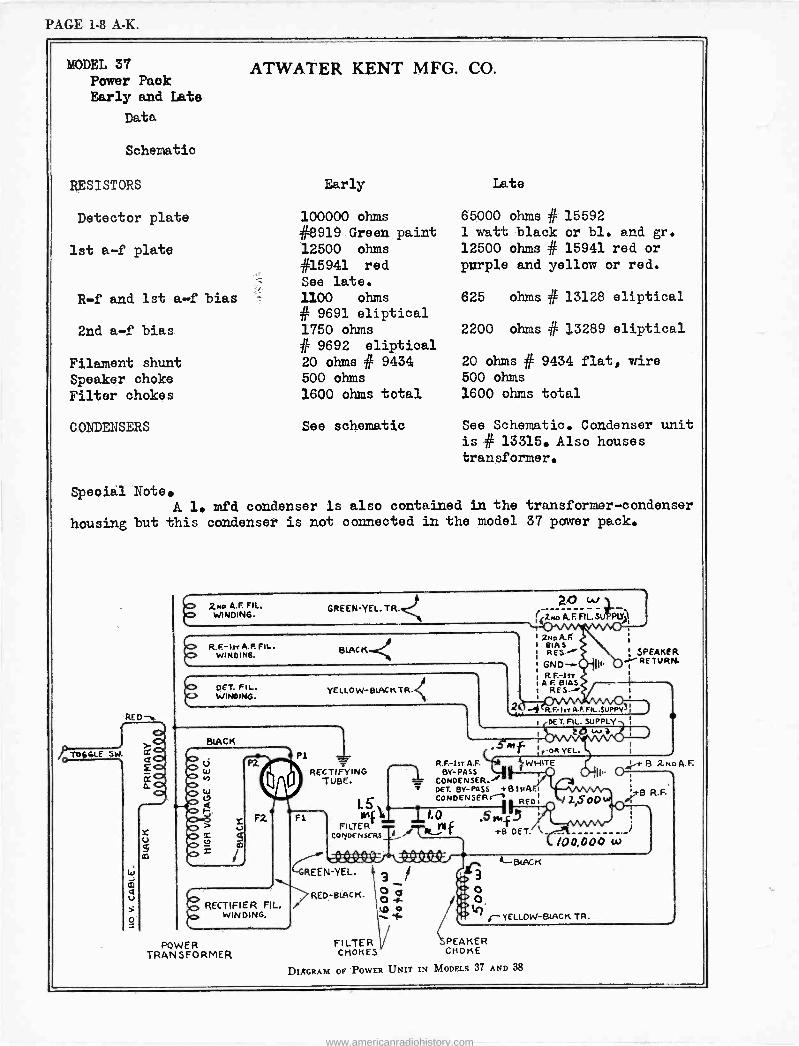
PAGE 1-8 A.K.
MODEL 37 Power Pack Early and Late
Data
Schematic
RESISTORS
Detector plate
1st a -f plate
R -f and 1st a -f bias
2nd a -f bias
Filament shunt
Speaker choke
Filter chokes
CONDENSERS
ATWATER KENT MFG. CO.
Early
100000 ohms #8919 Green paint 12500 ohms #15941 red See late.
1100 ohms # 9691 eliptical 1750 ohms
# 9692 eliptical 20 ohms # 9434 500 ohms
1600 ohms total
See schematic
Late
65000 ohms # 15592 1 watt black or bl. and gr. 12500 ohms # 15941 red or purple and yellow or red.
625 ohms # 13128 eliptical
2200 ohms if 13289 eliptical
20 ohms # 9434 flat, wire 500 ohms
1600 ohms total
See Schematic. Condenser unit
is # 13315. Also houses transformer.
Special Note. A 1. mfd condenser is also contained in the transformer -condenser
housing but this condenser is not connected in the model 37 power pack.
RED-
TOGGLE SW
W J Q Sl
v
O
cr
£
U J
-
C, 2MO A.F. FIL. WINDING.
GREEN-YEL. TR.
R.F.-Irr Fit-. WINOIN6. BLACK.<
CO DET. FIL. CU WINDING.
YELLOW-BIACKTR
BLACK / p Ú
p
I F2
RECTIFIER FIL. WINDING.
11
za w ( 4-zno A.F. Ft.SufiPuf11 ,
2NoA.l' I BIAS
RES.r
RF. -In I A.F. BIAS t
SPEAKER RETURN.
I --# R.F.-IrrA.FFIL.SIIPPY?
I DET. FIL. SUPPLY 0 Lv i
P1 _ ',art VEL.
R.F.-IsT A.F. W HITE RECTIFYING BY-PASS
tB1SrA.l TUBE.
T CONDENSER."' DET. BY-PASS
lS CONDENSER i REDi /20.00
POWER TRANSFORMER
FS in{1_ II.O .S«_FS FILTER +B DET. N CODENSERSf
+B 2noA.F.
TB R.F.
iOO,DOO w
-GREEN-YEL. , o 4-
0 RED -BOCK.
FILTER CHOKES
DIRGRAM OF POWER
1:
3
o o tr)
BLAG K
ç-YELLOW-BIAGK TR.
PEA K E R CrIOKE
UNIT IN MODELS 37 AND 38
www.americanradiohistory.com
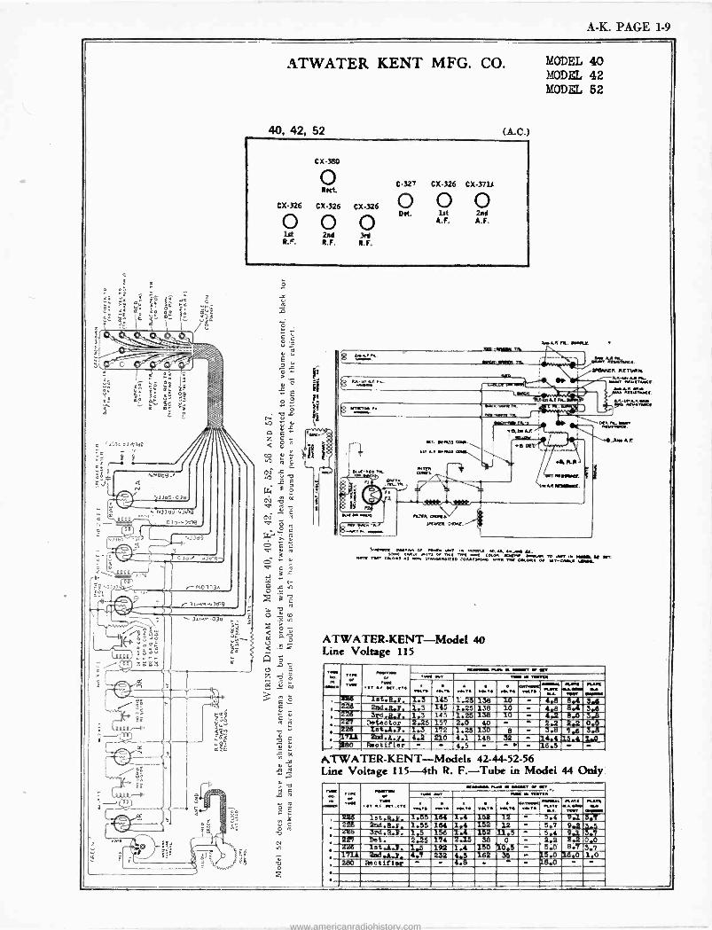
A -K. PAGE 1-9
ATWATER KENT MFG. CO.
40, 42, 52 (A.C.)
Cx380
C-327 CX326 CX371R
CX-326 CX326 CX-326 O O O INK lit 2nd O O o A.F. A.F.
1st 2nd 3rd R.". R. F. R. F.
ÿ MKnTJ w..-.
R.TER nof.s SKV.ER O -RE.
I» -NMI. 41.
MODEL 40 MODEL 42 MODEL 62
111, AA /....p.f.
i..R`fir.e. YeV.ER RETURN.
tTwtf. U Rl..tiltf.
41114t=1.2.
P%1- wwn.n.
.2. A.
k+.w..c >NM.,. o ...aw ..r, . w.r -S. ., N,-. .t. SOnf Y To. TTK COCYI. il.M IS *D urger - -R Y arr. w.Tf TwT COLO.S AS wOM ST.r1MR.IZEO COM[S.efO ..w.. T. CO.OwS or -T-CwOLr ADM.
AT W ATER-KENT-Model 40 Line Voltage 115
T... ,«T- 0,T... ..T te K..rTO...n
...... Ia.. .rsT Or fn T PIMA In T.Ta
rwn .w VOLT.CMNCT. O mom. nm Yf» Pun Y r.r....
LT.Y f ,Xgg iet.R.p. 1.3 345 1.1T1.38 TO - 4.8 8.4 33 r 226 2nd.8..2. 1.3 "1-4-5- 1.25 138 10 - 4.8 8.4 3..¢¢
226 3e.8.7. 1.3 145 1.25 138 10 - 4.2 8.0 5.8 227 Detector 2.25 157 2.0 el - - 2.2 2.2 0..0p
226 1et.1.3. 1.3 172 1.26 130 8 - 3.5 7.6 3.8 , T7i1 213d.A- 7. 4.2 210 4.1 148 32 14.4 13.4 Z,.O , 280 Reotif;er - - 4.5 - - - 18.5 - -
ATWATER-KENT--Models 42-44-52-56 Line Voltage 115 -4th R. F. -Tube in Model 44 Only
Twee .. Tema
r. -T -w op T.r
root ..T .-A raM - OOYT Or ftV
MOO - V 60,11.711 TqT
226 226 zre 227
lat.R.p. 2nd.R.z 3rd.R.i: pet.
1.55 1.55 1..5 2.25
164 164 156 174
1.4 1.4 1.4 2.1.5
152 152 152
38 226 1731
let.A.2. 1.5 192 4 '132
280 Rectifier
1.4
4:8
150 162
KH.Ar PLATS
.T ...wee
TIM?
ram* Y -.M 3.T 12 5.4 9.1
12 5.7 9.2 3.5 11.5 9 5.7
0 2.3 3 0.0 1.05 5.0 8.7 3.7
15.0 16.0 1.0 18.0
www.americanradiohistory.com
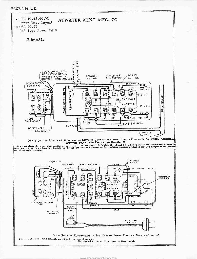
PAGE 1-10 A. -K.
r MODEL 40,42,44,52
Power Unit Layout
MODEL 40,45 2nd Type Power Unit
Schematio
ATWATER KENT MFG. CO.
w
BLACK. CONNECT TO REGULATING RES. IN MODELS 42,4-4-, 52.
(BROUGHT THRU ANGLE) W CC
fìiUE-RE D TR, (OR BIACK)
s
s
BLUE (OR BIACK)
GREEN -YE L. RED-RIACK
Ir F-
z W
A w d
BLACK
SPEAKER RETURN
R.F.-IST A.F. FIL. SUPPLY.
DET. FIL. SUPPLY.
BFtOWN-)e AA
LL- WHITEJ yy
44- +g R. F.
+B 2.ND A.
+g! 1ST A. DET
YEL.-)
BLACK -RED TR/
BLUE (OR RED)
e
TO TOGGLE SWITCH POWER UNIT IN MODELS 40, 42, 44 AND 52, SHOWING CONNECTIONS FROM SEALED- CONTAINER TO PANEL ASSEMBLY,
RECTIFIER SOCKET AND REGULATING RESISTANCE
This view shows the approximate posifion of leads from sealed container. In Models 42 44 and 52, a hole is cut in the rectiller-socket motmting
angle and the two black leads are brought up through the hole and connect to the regulating resistance, which is mounted upright at the felt- hatul
cad of the sealed container.
täI
m
GREEN-l'EL
N Wp
m
RED --GREEN
:-+ J
SOCKET FOR RECTIFIEF TUBE
REGULATING RESISTOR
BLACK-WHITE TR
Y 1 OW Y
O, 29 1~ 10, 1< > I re -Ri- +B R.F
i-..;á I Ó9.-sÿ11 +B, tNDAF 1=49.- IdÑ`: 1 L. in II.. !___4,4+B. IST AF
F +p. D T
''rQ, ;4i
BROWN OR-+
BLACK
BROWN
WHITE
BLACK T)
et u
YE
TO SPEAKER CHOKE
GREEN
)
LACK-RED
BLUE
110 -VOLT CABLE AND PLUG
'{Pi.i:: .:d::'. Y{:ti ::i,S;s! ,ï.::::: %s::'Y;; Y'; ,Y,Yi i Q¡tii,1,
CONDENSER ASSEMBLY
VIEW SHOWING CONNECTIONS IN 2ND TYPE OF POWER UNIT FOR MODELS 40 AND 45.
This view shows the panel assembly moved to left of normal position. The regulating resistor is not used in these models.
www.americanradiohistory.com
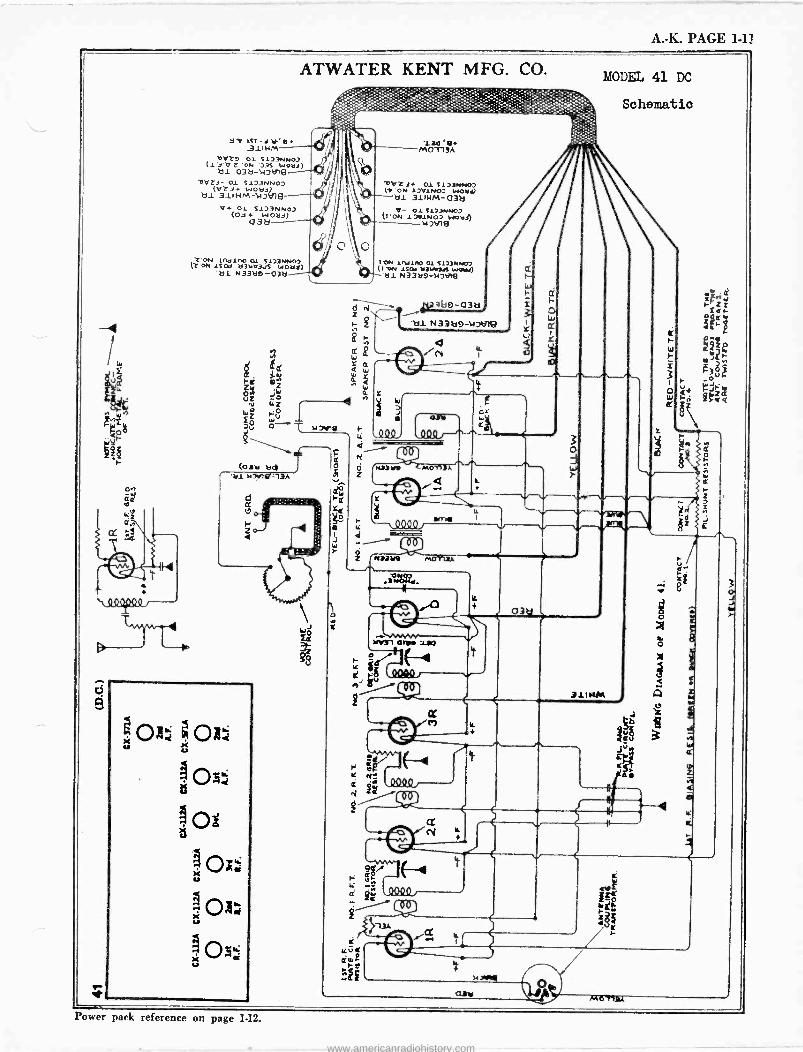
A. -K. PAGE 1-11
ATWATER KENT MFG. CO.
Hro ltt_1'y'e .311 H M-
bVT9 Ol S1]3NNO) (1 j'V T 'ON ')3S woad) i]1 031J -11)t119-
bVZd- 01 5173NNOD (VTd+ woad)
á11 31I H M -)+)li19 V+ 01 S123NNO2
(03 á3ä bd) -
7:'ON Indino 01 51i3NN02 U0 ON 1S Od 031.03dS WOa!)
'bl N33be-03b-
d
z <
3
le
0 O
R
13óa MOTTA
-011Z 3. 01 S10]NNO) (1, ON 1JV1NO_ INO0+0 bl 311HM-038
V- 01 T123NNO, (1 'ON 1701NO2 wotd!)
1C11 lhl111O 01 S113MNO2 (1 'ON 1TO11 11311II3A weed nl N33129 -14W19
d'
'4
sta3k10-038 Z p i r- Z 1
Y
N33119
n
'b1 N331í9-11 JFile
Zñ
H a W
MODEL 41 DC
31111M
Schematic
3 O j
Power pack reference on page 1-12.
www.americanradiohistory.com
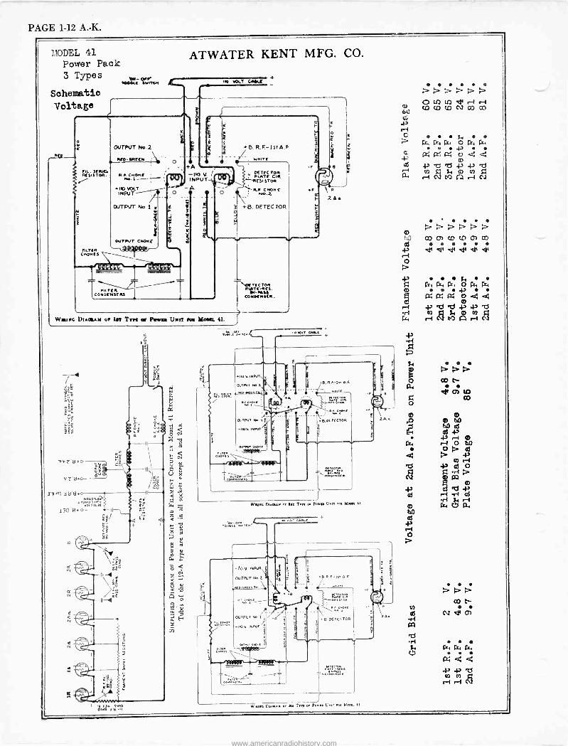
PAGE 1-12 A. -K.
MODEL 41 Power Pack 3 Types
Schematic
Voltage
FIL. OER/61 M SISTOR.
Puy (N CnOna1
ere- Pere »K( (worrier
OUTPUT P1. z
NM- KR((M : O
+IC MD T INPUT
+8, R.F.-IsTA.F
+8, DETECTOR
.------------21.-- /KT(-_ O(TFC70R R sr ei-
COrDENSERS M ` COMM' N(ER.
W Ill Rc DIAatAY or LIT Tm a PoWaa Uwlr roa Mom. 41.
4112"1,,c,./
3'V Izi-313'6 + IF bo+L(3u
gq 1MÖJ]IVW 1 31M
230 E. 4) ci Q
áa a xi
dea
OUTPUT N..I (
-10V. IMIVIr
.R.F-I.+A F
S. DETECTOR
Mono DNaou ir in Tr or Porno Urn roo Noon 11
oln e r-+.- CD CD CO cN2 co m
www.americanradiohistory.com
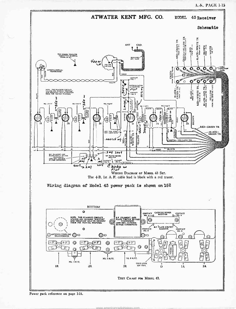
A. -K. PAGE 1 -Th
ATWATER KENT MFG. CO. MODEL 43 Receiver
IR
-l.
THIS SYMBOL INDICATES CONNECTION TO METAL
FRAME OF SET
ANTENNA ODUPLINC TRANSFORFIEN
NOTE THE FILAMENT CONTACT SPRINGS ARE MARKED -POSITIVE' AND "NEGATIVE" ONLY TO IDENTIFY THEM FOR TESTING PURPOSES
RFT
Zfi
2R
ILF. FILAMENT AND PLATE CIRCUIT BV.PAO
CONDENSERS (AND DET CATHODE - RY-PANS CONDENSER)
3R
-- T
T f f F
T.OY /ioo y Zw
NO.» 1151.
ANT
BEEN
GRD.
SHIELDED ANT LEAD
CONTACT NO
CATHODE SERIES RESISTOR ..,-
c4-47' i roFPJNTAtTl
SoDorNO 1 AFT
Ñ j 1`V I rBL
1I
NOTAST
L 1
MACK
3
o M
00
Y2 D
Id I-
cd Us
ág lY.
2A
SET V R CONDw-1
ET G ID ODN
/ .000iS pl.
.3R.4 2001 RA MATE CIRCUII
RESISTOR
CONTACT 1 CONTACT . NO iii NO. I w
RED
r 30 tiu.r WIRING DIAGRAM Or MODEL 43 SET.
The +B, 1st A. F. cable lead is black with a red tracer.
LACK
Wiring diagram of Model 43 power pack is shown on 152
BOTTOM
o NOTE: THE FILAMENT CONTACT SPRINGS ARE MARKED «POSITIVE" AND "NEGATIVE-' ONLY TO DENTIFY THEM FOR TESTING PURPOSES.
J /\ °ANTENNA COUPLING RnT
TRANSFORMER 4:/ o
4.1*
9
o
Schematic
IY
ò Y ó
< m
o, mLL
CARiI
TAPIR
RED-GREEN TR
BLACK- GREEN TR
R.F FILAMENT AND PLATE CIRCUIT BY-PASS
CONDENSERS (AND DET. CATHODE BY-PASS CONDENSER)
CONTACT CATHODE SERIES CONTACTNO.
I I RESISTOR I NO. E
0 CONTACT
NO. 3
O
1R
0
N0. I R.F.T.
.2R
O
NO. I R.P.T.
U
NO. 3 RFT.
3R GRID LEAK
(ON TOP)
H.P. PLATE CIRCUIT RESISTOR CONTACT
NO. 4
TEST CHART VOR MODEL 43.
}
IA }
2A
Power pack reference on page 1.14.
www.americanradiohistory.com
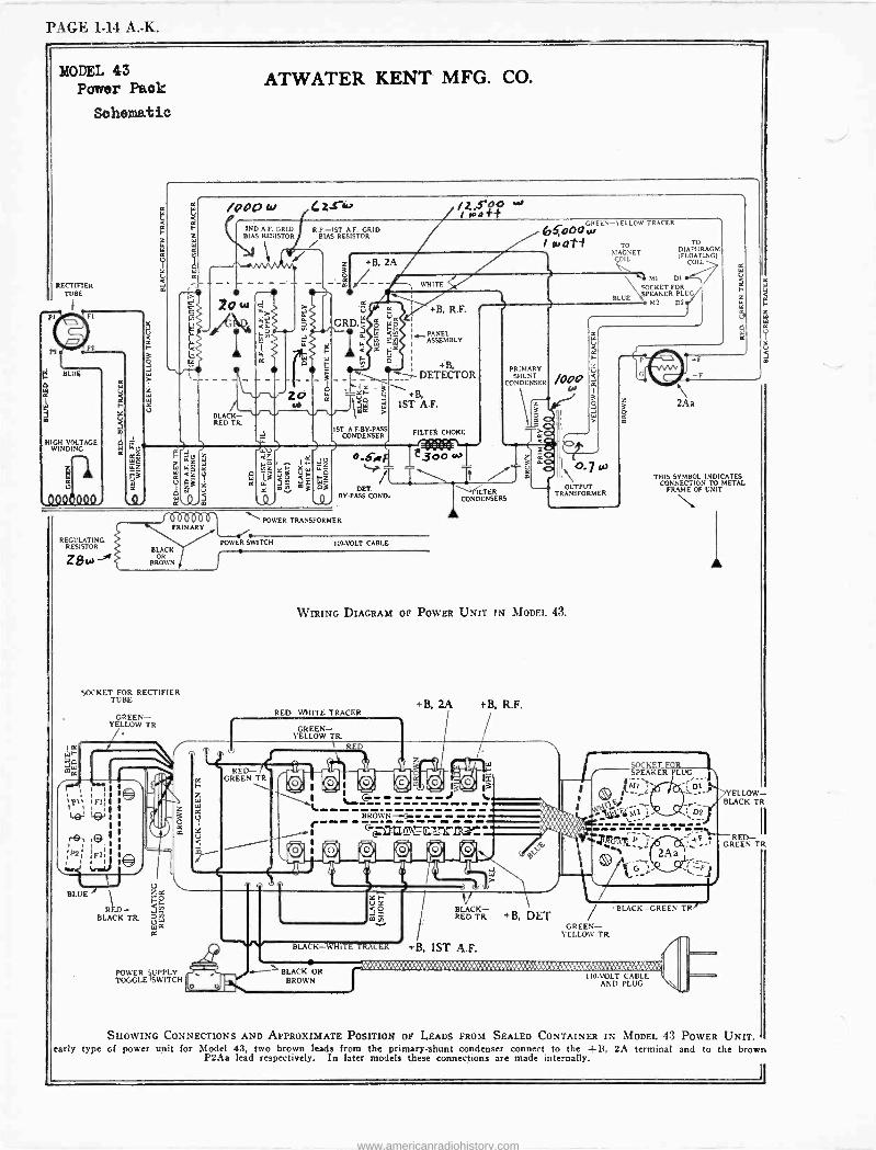
PAGE 1-14 A. -K.
MODEL 43 Paarer Pack
Schematic
RECTIFIER TUBE
BLUR
HIGH VOLTAGE WINDING
.QQOQ000
REGULATING RESISTOR
e
3
SL/
ATWATER KENT MFG. CO.
/000 4 4 2s -k,
2o
BLACK - RED TR.
2ND A.F. GRID R.F.-I5T A.F. GRID BIAS RESISTOR BIAS RESISTOR
16b000Ó1l PRIMARY
BLACK OR
BROWN
SOCKET FOR RECTIFIER TUBE
BLUE
GREEN- YELLOW TR
BLACK TR.
POWER 'SWITCH TOGGLE SWITCH
K
53
IJ +B, 2A
Ú
GRD. a
GREEN -YELLOW TRACER 667000 w I Wafi1 TO
SIAGN'ET COIL
WHITE
Cm
+B, R.F.
PANEL ASSEMBLY
+B, r DETECTOR I e
g \+B. tm IST A.F.
IST A.F.BY.PASS CONDENSER FILTER CHOKE
O.S,r e3,0 `>/T
." - . DET.
BY-PASS CORD. ILTER
CONDENSERS
TO DIAPHRAGM (FLOATING)
COIL
V MI DI
SOCKET FOR
BLUE SPEAKER PLUG
PRIMARY SHUNT
CONDENSER
POWER TRANSFORMER
POWER SWITCH IIO-VOLT CABLE
1
O O
z 3 ó0 ?á
M D2
/000
6Q
\o.7w OUTPUT
TRANSFORMER
WIRING DIAGRAM OF POWER UNIT IN MODF.I. 43.
RED WHITE TRACER
i RED- X
GREEN TR
GREEN- YELLOW TR.
r RED
+B, M tB. R.F.
13
_-i --- - -criIImG01YZIRsY- - s-. 1
BLACK-WHITE TRACER
J BLACK- RED TR.
+B, 1ST A.F.
+B, DET
2Aa
THIS SYMBOL INDICATES CONNECTION TO METAL
FRAME OF UNIT
SOCKET FOR SPEAKER PLUG
/ BLACK-GREEN TR,
GREEN- YELLOW TR
BLACK OR BROWN
::d:1: ::::::Ii :::4:: :::::.::::: ::::.'b'.CWMKe.y'.:!i.'tWii'./VMfiti. I IO.VOLT CABLE
AND PLUG
YELLOW- BLACK TR
RED- II GREEN TR
SHOWING CONNECTIONS AND APPROXIMATE POSITION OF LEADS FROM SEALED CONTAINER IN MODEL 43 POWER UNIT. early type of power unit for Model 43, two brown leads from the primary -shunt condenser connect to the +B, 2A terminal and to the brown
P2 Aa lead respectively. In later models these connections are made internally.
www.americanradiohistory.com
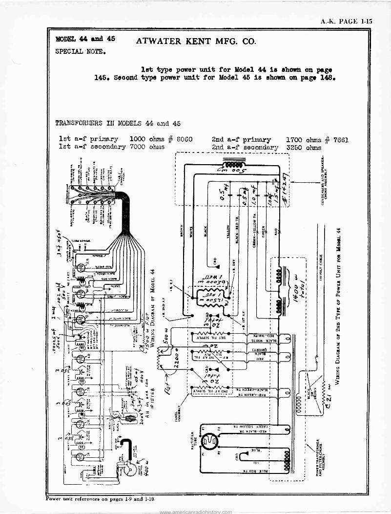
A. -K. PAGE 1-15
MODEL 44 and 45
SPECIAL NOTE.
ATWATER KENT MFG. CO.
lst type power unit for Model 44 is shown on page 145. Seoond type power unit for Model 45 is shown on page 148.
TRANSFORMERS IN MODELS 44 and 45
1st a -f primary 1000 ohms # 8060 2nd a -f primary 1700 ohms fir' 7661 1st a -f secondary 7000 ohms 2nd a -f secondary 3250 ohms
41 [lW 3r41 - N
that );r,.
^ SE
,----- -.....
z s
' `1110
o r
..//-PM M OOOS9
O
11DM / 1.+ eostl
b . -- \--- \ a
Y
a
Alaans ile 134
3
?t úT
W
u
311HM3a 311HM-MJV11
.,n 07,
Ald en '114 e V 151 -3 tl
4 4.!
Alea:l5 li S.J. N33tl9-435
Y
51 M0113A-53359 S.J. 535111--435 ,--9
3í11a.
l3A
Si a35-3n1e
1-
% 0l
Power unit references on pages 1-9 and 1.10.
www.americanradiohistory.com
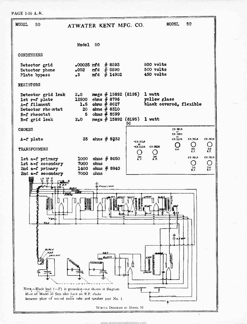
PAGE 1-16 A. -K.
MODEL 50 ATWATER KENT MFG. CO.
Model 50
CONDENSERS
Detector grid .00025 mfd # Detector phone .002 lafd # Plate bypass .3 mfd #
RESISTORS
Detector grid leak 2.0
1st r -f plate 12500
A -f filament 1.5 Detector rheostat 20
R -f rheostat 5
R -f grid leak 2.0
CHOKES
A -f plate 35
TRANSFORMERS
1st a -f primary 1000 let a -f secondary 7000 2nd a -f primary 1400 2nd a -f secondary 7000
8593 8590 14902
500 volts 500 volts 450 volts
MODEL 50
megs # 15892 (8195) 1 watt ohms # 8796 yellow glass ohms # 8627 black covered, flexible ohms # 8310 ohms # 8599 megs # 15892 (8195) 1 watt
50
ohms # 8;32
ohms # 8650 ohms ohms # 8940 ohms
PNOMF COMO
.c.
Rf
w
LACK
CX-371A or
CX-112A CX-301A
0 0 2rw ]st A. F. A. F.
CX-301A or
CX-300A or
CX-112A CX-301A CX-301A
O 0 0 Det. 4th 3rd
WW R. F.
CX-301A CX-3014
0 0 let 2nd R.F. R. F.
Bgld tosi
- N(,TE.-$'._ack lead (-F) is grounded-not shown in diagram
Most of Model 50 Sets also hase an R.F. choke
between plate OC second audio tube and speaker past No. I.
WIRING DIAGRAM OF MODEL 50.
www.americanradiohistory.com
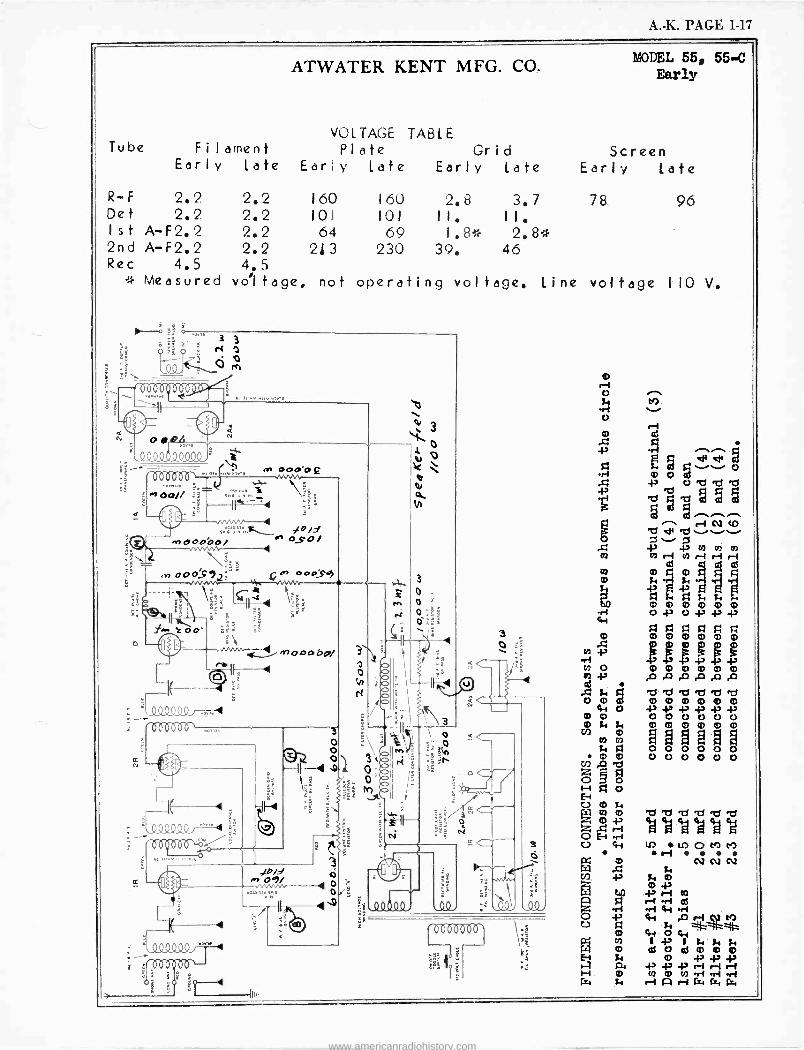
A. -K. PAGE 1-17
Tube
ATWATER KENT MFG. CO.
VOLTAGE TABLE Filament Plate Grid
Early Late Early Late Early late
MODEL 55, 55-C Early
Screen Early late
R -F 2.2 2.2 160 160 2.8 3.7 78 96 Det 2.2 2.2 101 LOI II. II. 1st A- F 2. 2 2.2 64 69 1.8* 2.8* 2nd A -F2.2 2.2 213 230 39. 46 Rec 4.5 4.5
* Measured voltage, not operating voltage. Line voltage IIO V.
I>
'.900000, "'"1 '00900of º
., ,.... .. a,. o
Lig
OR
.n. fa
- 0000
3
f<1
Q Q
a- N -
//0// //n/n/n -.01(ky0C1C1: 711 ;1
°;! . .,.
-e 1 i
< ` f17 'á - -
N
..,...<.f. -.)4P/J ..+eooóo/ in oSo/
\º » o00.S71' i`R
=l 0_0 (2.9 . '000000`
N
á
4
; °.000000 i"
00000
13 00¢ 1? -4 I
sn 000.99
000beg/
ll---
,/b/d re 09/
3
ó
0
£ f+1
0
3
ei cd
-P 43 ci Si
umi O0 M0 q0 00 q0 2 0 m m 0 0 0 0 0 0
oAo 1-4 a o
o
U 4l U) 1AOMM ,-i W f
NNN N is m
40 i Ñ DO
l r1 .ri41
á a
W Cg m
43° el m m ó
.Ha L.4,o
.-i I -i m m m CO ri eri :r 1
r=4 i. r-1AriW f=, Gy
www.americanradiohistory.com
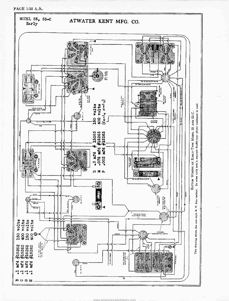
PAGE 1-18 A. -K.
MODEL 55, 55-C Earl, ATWATER KENT MFG. CO.
o.. '
.1
OP
O1Y3.00 «IS unlM 14m, .01141
M0r7o¡M11M,
.L.2131
eAr
ie
1NI
à
.I
CO CO t9 cOcOcO
1A11)In
t7 M,
nl.
0111
6.o1
,,C^M^ COcv^^
cv sEr
/W W W . N1CuCVN ti tn LA U) U)ri
ri r4 `3 * ̀ b á°°
r-1 r-1 ri r4 ..
anl
4 I 1' d7. e
n,
.MOM.
vllY
11111M$11/1. WW1!
111'0111'N11M'M2Y1.11
off
.! WIN
the
110.33 3110331e
i
t
e '1pYa :,.
AT k
M0131.Itl . ' Y
111-111316'M11M-MIYI.
.'O
ON 41.3113 WWIIM M 30'11 Ma141
111
01.02*' MIMYO..MYM1 MIMOS
A
U
i1
www.americanradiohistory.com
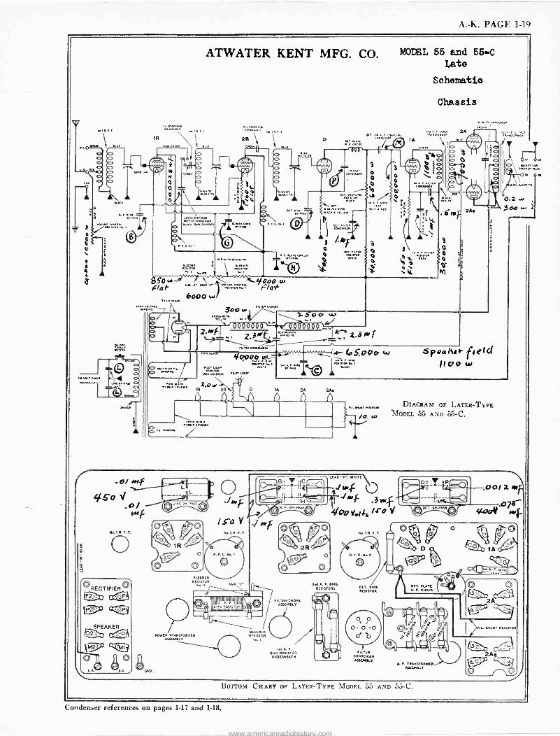
A. -Ih. PAGE 1-19
MODEL 55 and 56-C Late
Schematic)
Chassis
F...,.. 1R
,.,"c,Ec. M.:i ....
ZcR°:ó:;:i:° I..
r;:;,,,1°- .: c ó:
° 1A
c...,,...,:o..[: ..2A
I ¡o "\I1f- ' `000---
(rv/Q \\
C>
¡- `L b ¡- " %yá - O `1 ÑM fe, `1 IT b 9 à Ó o I. Q^f
,, o .I..., O z.:, K o 0 \ 0
0a. 0 p \A ó 1,.."2,,, , U ..K. r o iH\., úti
K..aLPN -' LCE...° = B. sn, / 2A.
= , 2n.I.,.,' : I^I A let..., R°. ...° rI :..y ... ö ref .°R°L,s st ó= j A 1 3
a = 1, ., v o ; 3 3\ o
1.. F. N.n c YI. 0 Del
«MU Q' 0 ." °... ¡ t. 0 e
E.NM K.,. O 0 4% w
.O + ` N. I : M 4 A NNIn ' 3 SS M,.. F., ,1`tou,
6000 uA ..e..° N
SPEAKER
mairroie RoLOT .met meet
ReetTOR
BLEEDER RESISTOR
No 2
POWER TRANSFORMER ASSEMBLY
N.. 2 R. F. T.
R. F.
SpvaKcs- f,e(cl 1 v o w
DIAGRAM OP LATER -TYPE MODEL 55 AND 55-C.
./44 /mi .3 YMf
400 Vo¡is /4.° V
2,00E A. F. BIAS N J__ RESISTORS
BLEEDER RESISTOR
FI LTER_C NO CE ASSEMBLY
, A F.
BIAS RESISTOR UNDERNEATH
o R.F.C. Ne. 2
DEf_ BIAS RESISTOR
T FILTER
CONDENSER ASSEMBLY
BET, PLATE R. F. CHOKE
A. F. TRANSFORMER ASSEMBLY
L SHUNT RESISTOR
Condenser references on pages 1-17 and 1-18.
www.americanradiohistory.com
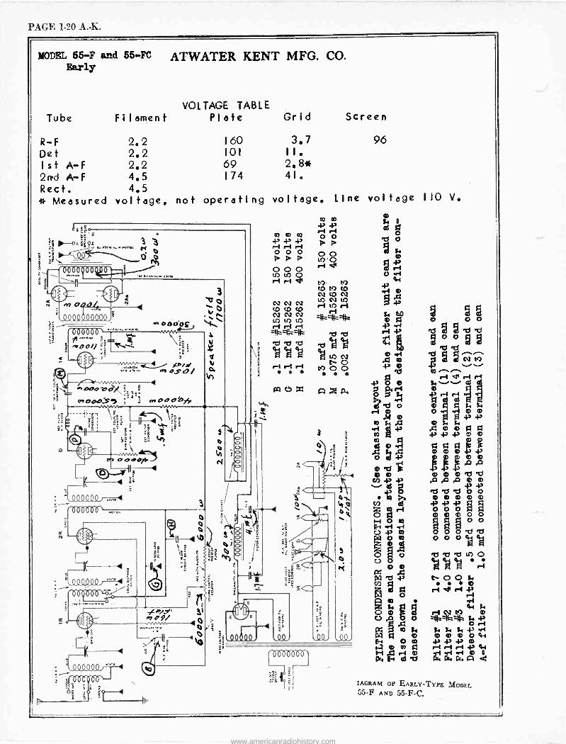
PAGE 1-20 A. -K.
MODEL 55-F and 55 -FC ATWATER KENT MFG. CO. Early
VOLTAGE TABLE Tube Filament Plate Grid
R-F 2.2 160 3.7
Det 2.2 101 II.
1st A-F 2.2 69 2.8* 2rrd A-F 4.5 174 41.
Rect. 4.5 * Measured voltage, not operating voltage.
000000`
Mooi/ :iTR
erne
3 O V
p O o
000113
R 4
.º9949º/
s
4
..o_.
º0000º/"i°
00
4
Iu
3
a
Ci
V Ci
E
0,09/ 3t
0 >
It' 0
Screen
96
Line voltage 110 V.
02 a 4> 43
CO CO 00 P P
0 0 0 0 0 P P P MO
0 0Q0
r-1
ri H d1 CMOMCO NCON M N U]
CN2 N N rl in ri C2 C2
CO
izt LO
e b 4aea tió
r -f M O O
0 f, 1
d g
ilI I %
43 ó g g
m .d.-...
0 N M v v d so ,-. -.
-i Ó 0 L. ..ei rl r-1
`o s e 43 .-1
sd
rl 0 O Ó Ó m c.d ® +>
.2 .-Ñ m m 0d ó mmó mb«g le i p.o
-P .0 A 0 00
.tg 00000 óó2 mmó
Rq Ú1 óm G O b 000agaj1 O d o
0 e d e M O
U O O `a q p e-1
po - f p L-00 $4
W5 g ri r Ì .-1
14 I I 44z o wq`00 0000w
is -IO dci g --11
i-1 í-1 + W
>I El GaC.WÁ
IAGRAM OP EARLY -TYPE MODEL 55-F AND 55 -F -C.
www.americanradiohistory.com
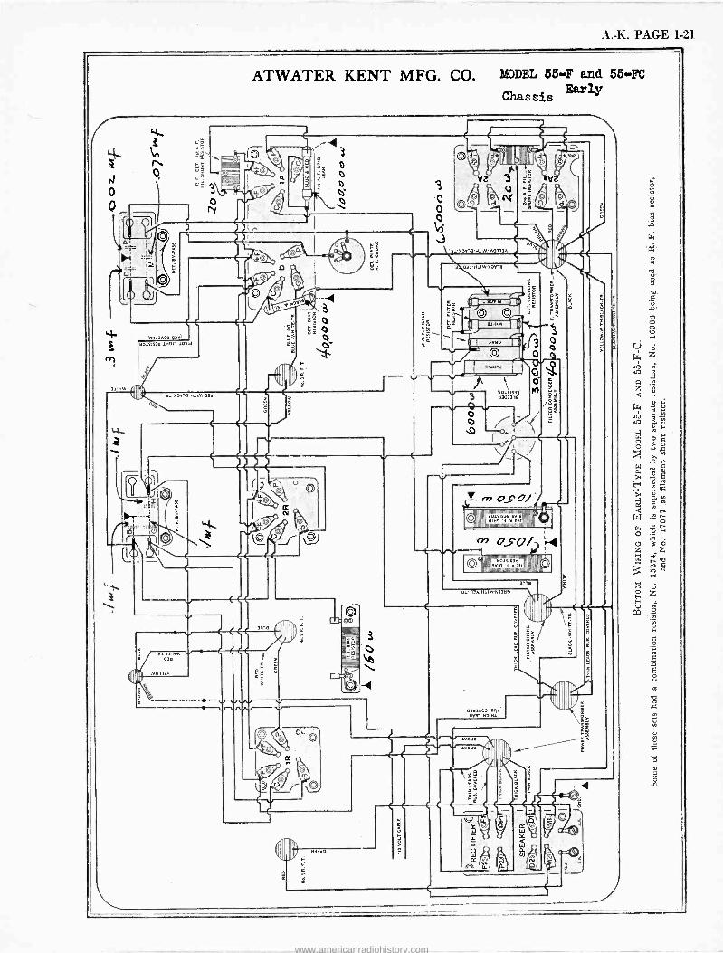
A. -K. PAGE 1-21
ATWATER KENT MFG. CO. MODEL 55-F and 55(4C
Chassis Early
r4 i<
bd- 10303A03 03tl)
30101030 10011 10114
111'MOV10-H11M'03tl
n
3
o o
1:1l'M2V10 0113A
'03Il'H11M'M0010
3
o
010
e
e 5
5
00101034 tl303319
II IIIAIIIIfi 101111111111 n lll ll' O1CIS3Il SVi0I/I
01130 b 'V Vu! pItl110111111111YW11110,N I I
3
r» 050/2 2-4
11 33 1111odi s1111s, 31,111101 I
IIItlÌIIW1117Ì11111WWIGIIilIIII
I
Ill' "13A-H11M'N33tl0
03tl3A00'611tl 0031 N11H1
nA
o
I
www.americanradiohistory.com
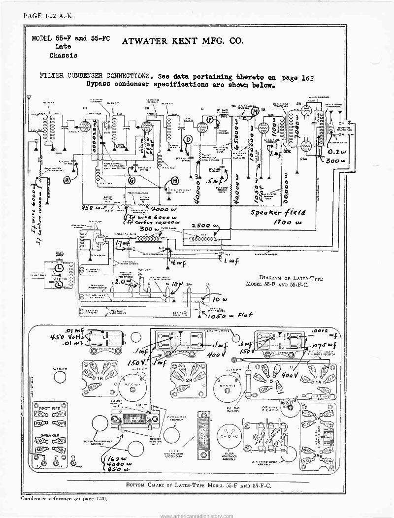
PAGE 1-22 A. -h.
FILTER CONDENSER CONNECTIONS. See data pertaining thereto on page 162 Bypass oondenser specifications are shown below.
CODDIfflele
3 o o
.9f -....
DUD INC441.0.11
DC/ ILITA 11131111/0111
Men
850 w a. . 5<00o w
Ty<<.LPe 6000w THICK CLACK SI Corion eo,000Lr 1500 w o
no I \ ..w
300 ER
6a bb 6ò o M [-Jo GiÒ óö0 o:N.,L- -i.. - T' + .. - . .R...M..
Qó >......, f 1.10117 C1MOT LIPPIT
l.I IC>
3 1R 4-O 42'...t.,-zI: oR
.. B..M. « \
° 2/A\
g^NL"I°'\ 1 Ów
RECTIFIER eta
OLINE BH-PASS
NozR FT
R. F. C. No,
BLEEDER RESISTOR
No,z
POWER TRANSFORMER ASSEMBLY
/4 0 w 4000 w 850 w
Luc >E.. \
BLEEDER RESISTOR
No. 1
R. DET I
FIL. SHUNT RESISTOR F. BY
LTER.CHORL ASSEMBLY
o A F. BIAS RESISTOR
UNDERNEATH
LEAD v", WHITE
No. SR.F.T
R. F. C. Noi
DET. BIAS RESISTOR
FILTER CONDENSER ASSEMBLY
DIAGRAM OP LATER -TYPE MODEL 55-F AND 55 -F -C.
DET. PLATE R. F. CHORE
A. P. TRANSFORMER ASSEEISLY
Condenser reference on page 1-20.
www.americanradiohistory.com
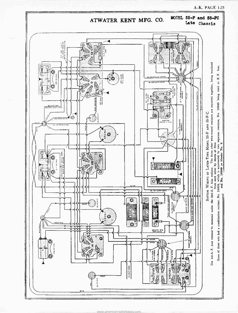
A. -K. PAGE 1-23
ATWATER KENT MFG. CO.MODEL 55.4 and 55 -FC Late Chassis
ra- o
1..H3 Q¡ I
(C 03v3,03 038'
A0 38 1H9,1 103iA
038 H1IM-H3.1
;le
30j 21' ) 001-H 0113A
U1'03tl-H11M'M00i
11)
p
D
e 3019-H1IM 03tl
tlO1S1S3tl b3111í -a y .I
o
ro _<#z5
N33tl0 iHl
8
01m®1mmim111nA1, 09931:I901III ell, '3 'V 0!! e
r-
tl019183tl ' II,I
lìl"l)A-H11M-N33tl0
]3A00 Y0 CAI OIHL
tl
lb
%10 _
www.americanradiohistory.com
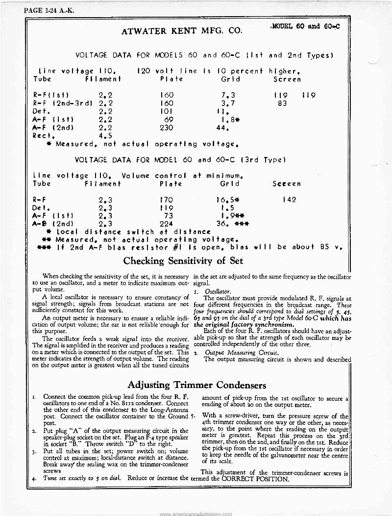
PAGE 1-24 A. -K.
ATWATER KENT MFG. CO. MODEL 60 and 60..0
VOLTAGE DATA FOR MODELS 60 and 60-C (1st and 2nd Types)
Line vol tage 110. 120 volt line is 10 percent higher. Tube Filament Plate Grid Screen
R-F(Ist) 2.2 160 7.3 119 119 R-F (2nd -3rd) 2.2 160 3.7 83 De t. 2.2 101 II.
A-F (Ist) 2.2 69 1.8* A-F (2nd) 2.2 230 44. Rect. 4.5
* Measured, not actual operating voltage.
Line Tube
VOLTAGE DATA FOR MODEL 60 and 60-C (3rd Type)
voltage 110. Volume control at minimum. Filament
R-F 2.3 Def. 2.3 A-F ( I st) 2.3 A-6 ( 2nd) 2.3
Plate Grid
170 119 73
224
Screen
I 42
* Local distance switch at distance ** Measured. not actual operating voltage. *** If 2nd A-F bias resistor #1 Is open, bias will be about 85 v.
Checking Sensitivity of Set
When checking the sensitivity of the set, it is necessary to use an oscillator, and a meter to indicate maximum out- put volume.
A local oscillator is necessary to ensure constancy of signal strength; signals from broadcast stations are not sufficiently constant for this work.
An output meter is necessary to ensure a reliable indi- cation of output volume; the ear is not reliable 'enough for this purpose.
The oscillator feeds a weak signal into the receiver. The signal is amplified in the receiver and produces a reading on a meter which is connected to the output of the set. This meter indicates the strength of output volume. The reading on the output meter is greatest when all the tuned circuits
in the set are adjusted to the same frequency as the oscillator signal. r. Oscillator.
The oscillator must provide modulated R. F. signals at four different frequencies in the broadcast range. These four frequencies should correspond to dial settings of 5, 45, 65 and 95 on the dial of a 3rd type Model 6o -C which has the original factory synchronism.
Each of the four R. F. oscillators should have an adjust- able pick-up so that the strength of each oscillator may be controlled independently of the other three. 2. Output Measuring Circuit.
The output measuring circuit is shown and described
Adjusting Trimmer Condensers Connect the common pick-up lead from the four R. F. oscillators to one end of a No. 8112 condenser. Connect the other end of this condenser to the Long -Antenna post. Connect the oscillator container to the Ground 5. post.
. Put plug "A" of the output measuring circuit in the speaker -plug socket on the set. Plug an F-4 type speaker in socket "B." Throw switch "D ' to the right. Put all tubes in the set; power switch on; volume control at maximum; local -distance switch at distance. Break away' the sealing wax on the trimmer -condenser screws
amount of pick-up from the ist oscillator to secure a reading of about 20 on the output meter.
With a screw -driver, turn the pressure screw of the 4th trimmer condenser one way or the other, as neces- sary, to the point where the reading on the output meter is greatest. Repeat this process on the 3rd trimmer, then on the 2nd, and finally on the ist. Reduce the pick-up from the 1st oscillator if necessary in order to keep the needle of the galvanometer near the centre of its scale.
This adjustment of the trimmer -condenser screws is Tune set exactly to 5 on dial. Reduce or increase the termed the CORRECT POSITION.
www.americanradiohistory.com
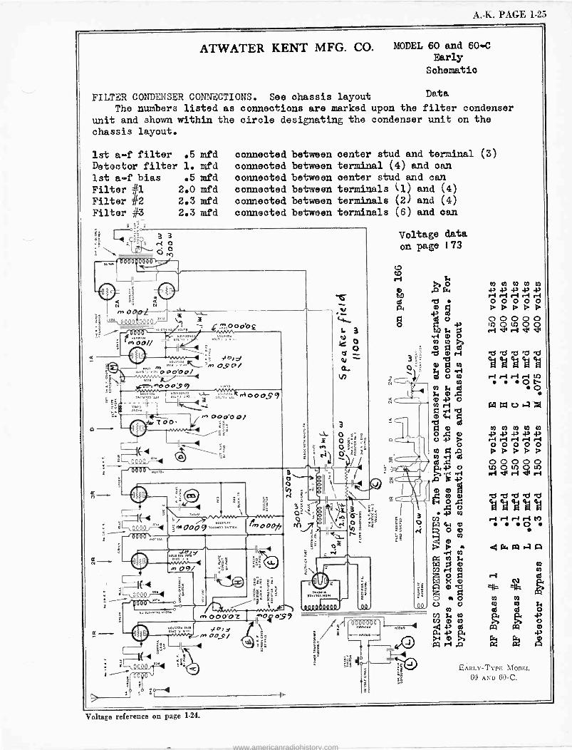
A. -K. PAGE 1-25
ATWATER KENT MFG. CO. MODEL so and so -c Early
Schematic
FILTER CONDENSER CONNECTIONS. See chassis layout Data
The numbers listed as connections are marked upon the filter condenser
unit and shown within the circle designating the condenser unit on the chassis layout.
1st a -f filter .5 mfd Detector filter 1. mfd 1st a -f bias
Filter 41 Filter #2 Filter 03
Q
6bó000b lF
3
©
3 o o ro
,,.o ººº 0000,,,,a
I
0+tlööl/
o --
ID
.5 mfd 2.0 mfd 2.3 mfd 2.3 mfd
a
4Z,47U° 0'0 £
33 0,0
connected connected connected connected connected connected
m ,.â :':°. _-m O.Ç o / m 0 00001
^000;$f 110.5
ekodnoz 13.2
°,°, IF ,
1111
roe-
; 6b 6b ` °
e knoOo$9
+ 00ó00/
ö=
41,
`-Q""L '
lit °. érwOOo9,°e.°> w 4,000,7
e) o9i
óºQ 55
000 ̀ n °
31
3015133111,, 0.0 1111
I(-10
,1 m 00.9/
p4.
between between between between between between
center stud and terminal terminal (4) and can center stud and can terminals (l and (4) terminals (2 and (4)
terminals (6) and can
3
O 7:
Ó áNp
nºº.oboa,oò
Voltage data
on page 173
(3)
NI b O C) .0 G4 +3 ri T! o m A -P di
e co H rl 0 O
mr 11
Tlb a: i lQ F7 \ b O
co O t`- VI Ni 121
in
O
A 0 O {' v tA
A.: or, «4
A c ,c:$ eTsee 'A ea ea ea ea
tl) r-1 r-1 rl 8-1M N, 00
0 O
w wavaA
Wz) r-01 00 v 0
C X m
7+ 0
aO w O U o O
1010113
1133112 / -4 43 QS
m / PU c -c
C)
o
o
o O 00
Ó Ó Ó A A A
1107 p0
rÌ dlri
EARLY -TYPE MODEL
60 AND 60-C.
Voltage reference on page 1-24.
www.americanradiohistory.com
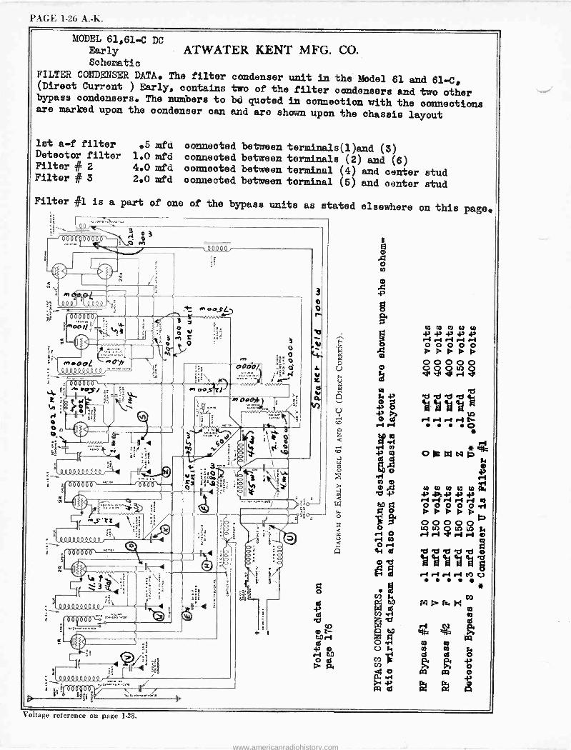
PAGE 1-26 A. -K.
MODEL 61,61-C DC Early Schematic
FILTER CONDENSER DATA. The filter (Direct Current ) Early, contains bypass condensers. The numbers to aro marked upon the condenser can
let a -f filter 05 mfa Detector filter 1.0 mfd Filter # 2 4.0 mfd Filter # 3 2.0 mfd
Filter e1 is a part of ono
ATWATER KENT MFG. CO.
condenser unit in the Model 61 and 61-C, two of the filter condensers and two other bd quoted in connection with the connections and aro shown upon the chassis layout
connected between terminals(1)and (3) connected between terminals (2) and (6) connected between terminal (4) and center stud connected between terminal (5) and center stud
of the bypass units as stated elsewhere on this page.
--Joao6ò6ò Ii
;x.909.
S)
Lp0000.
. MIR aZi I.1
min 1
A
rococo, A.
sOs' +
_l_E y. .+ O
``.ì \ ág t
ei
,0000000QQqjF
, 000000`
a2 i ia 1"
Q
O
T OOf 3 y o o n z
o
- IvK AS pps
Immaggimm
.1,03111.019.11.2
009 one: "'
: 3 a ( , z4-
ú, 5 35.
4119 0.9 QQQ9 f -,....n+.. g5;(000p6Ö
e4á;
at 00
i 5'
ïá 6 6 y
0
3
o
-F>
co 'ty
ri -1-7
tu9 0 cd d
r-1 aWNp
r-1 r -t r-1 r-1 CO . F
Voltage reference on page 1-28.
www.americanradiohistory.com
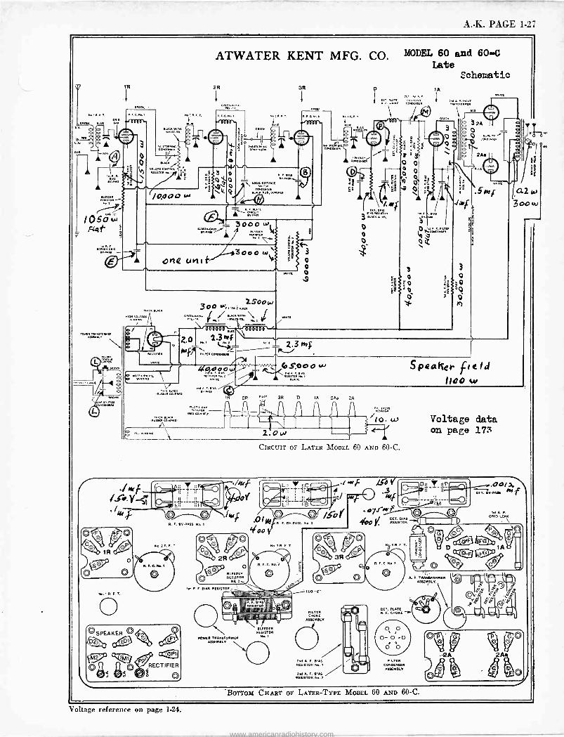
A. -K. PAGE 1-27
ATWATER KENT MFG. CO. MODEL 60 and 60-4 Late
Schematic
GIB GPM Is. GP
10,000 w
one unif
2.3N f
CONOGICG
0000 WsGPS
eno
Ro.xB.E.T
C BLEEDER RENSTOR
d.z,1f le R. F. BIAS RESISTOR._
CesetweeP
6S,000MACS
w
OPF[v 1
Alo
Peañer field 1100 w
IEow Voltage data on page 173
CIRCUIT or LATER MODEL 60 AND 60-C.
R. F. Bv.PASS Xe. x
RR, IÁÉXIIIIIINNNIy>
'IIPNI IIIIiA1IIIIINNH,-
BLEEDER RESISTOR
POWER TRANSFORMER RESEMBLE
FILTER CRONE
ASSEMBLY
xIM A. F. BIAS RESIBTOR Xo.l
xoF A. F. BIAS RESISTOR No. x
R.F.C. No. E
A. F. TRANVORMER ASSEMBLY.,
VET. PLATE F. CHOSE
-y
BOTTOM CHART Or LATER -TYPE MODEL 60 AND 60-C.
K A P.
ORZO LEAN
Voltage reference on page 1-24.
www.americanradiohistory.com
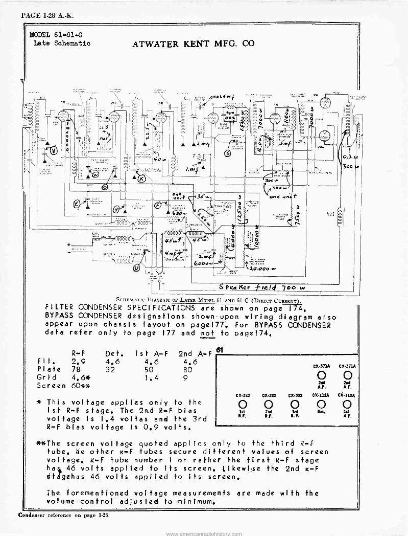
PAGE 1-28 A. -K.
<MO
MODEL 61-61-C Late Schematic ATWATER KENT MFG. CO
feel/41,1
99000
1. Arm> 3- III \
Pea Ker eeld 700 w
SCHEMATIC DIAGRAM OP LATER MODEL 61 AND 61-C (DIRECT CURRENT). FILTER CONDENSER SPECIFICATIONS are shown on page 174. BYPASS CONDENSER designations shown.upon wiring diagram also appear upon chassis layout on pagel77, For BYPASS CONDENSER data refer only to page 177 and not to page174.
R-F Fil, 2.9 Plate 78 Grid 4.6* Screen 60**
Def. Ist A-F 2nd A-F 61
4.6 4.6 4,6 32 50 80
1.4 9
* This voltage applies only to the Ist R-F stage. The 2n.d R -F bias voltage is 1.4 voltas and the 3rd R-F bias voltage is 0.9 volts.
CX.371A CX-371A
0 0 21,1 2nd A.F. A.F.
CX-322 CX-322 CX-322 CX-112A CX -112A
0 0 0 00 1st 2nd 3rd
R.F. R.F. NF. A.F.
**The screen voltage quoted applies only to the third R-F tube. We other K-F tubes secure different values of screen voltage. K-F tube number I or rather the first K-F stage hal. 46 volts applied to its screen. Likewifse the 2nd K-F dtégehas 46 volts applied to its screen.
The foremenfioned voltage measurements are made with the volume control adjusted to minimum.
Condenser reference on page 1-26.
www.americanradiohistory.com
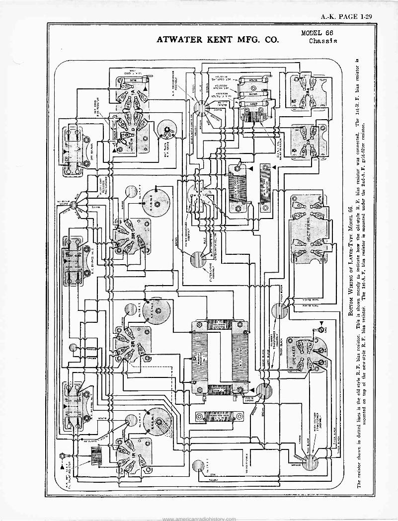
A. -K. PAGE 1-29
ATWATER KENT MFG. CO. MODEL 66
Chassis
0,19 a
-A
II'
tQ,
7=11
)
OO
3 do'.3a U01515313
n3 ua NOi 5i53tl
u3il 1 ' 1,1
;á ,d
8 111
il
o
Ó m
N
el d+
44 ey* 1
LL(
1117 '4111
iu.,'3o33,a
i
ÀJ
i
vae
=01
l n
D____7Z
6 ¡®
K Lai
/L¡
Cl.
C)
hsale dtlúue"rtar
v v
Iu
o
www.americanradiohistory.com
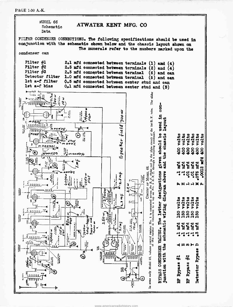
PAGE 1-30 A. -K.
MODEL 66 Schematic Data
ATWATER KENT MFG. CO
FILTER CONDENSER CONNECTIONS. The following specifications should be used in conjunction with the schematic shown below and the chassis layout shown on
The numerals refer to the numbers marked upon the condenser can
Filter #1 Filter #2 Filter #3 Detector filter 1st a -f filter 1st a -f bias
co
2.1 mfd 2.3 mfd 2.3 mfd 1.0 mfd 0.5 mfd 0.1 mfd
connoted between connected between connected between connected between connected between connected between
terminals (1) and (4) terminals (2) and (4) terminal (6) and can terminal (5) and can center stud and can center stud and (3)
1
:. ,'
dt.
G
i H
N y 10 10 00 10
r11 4,434)1
r -1 r -e1
O 0 0 0 0 0 AAAAAA 000000 ? ? ? ? ? ?
.`"dR7 M M 4a ek
ri rl rl e-1 U 0 o00 ag4w a
101010100 431 e-1
re -1 re -1 r -ei 0 0 0 0 0 A A A A
0 0 0 0 0 W LO 1n 10 lA ri ri r-1 ri r-1
-d 'd 2s 'd R3
a id '0 ri r4 ri NJ .....
IAtxld+A OD
www.americanradiohistory.com
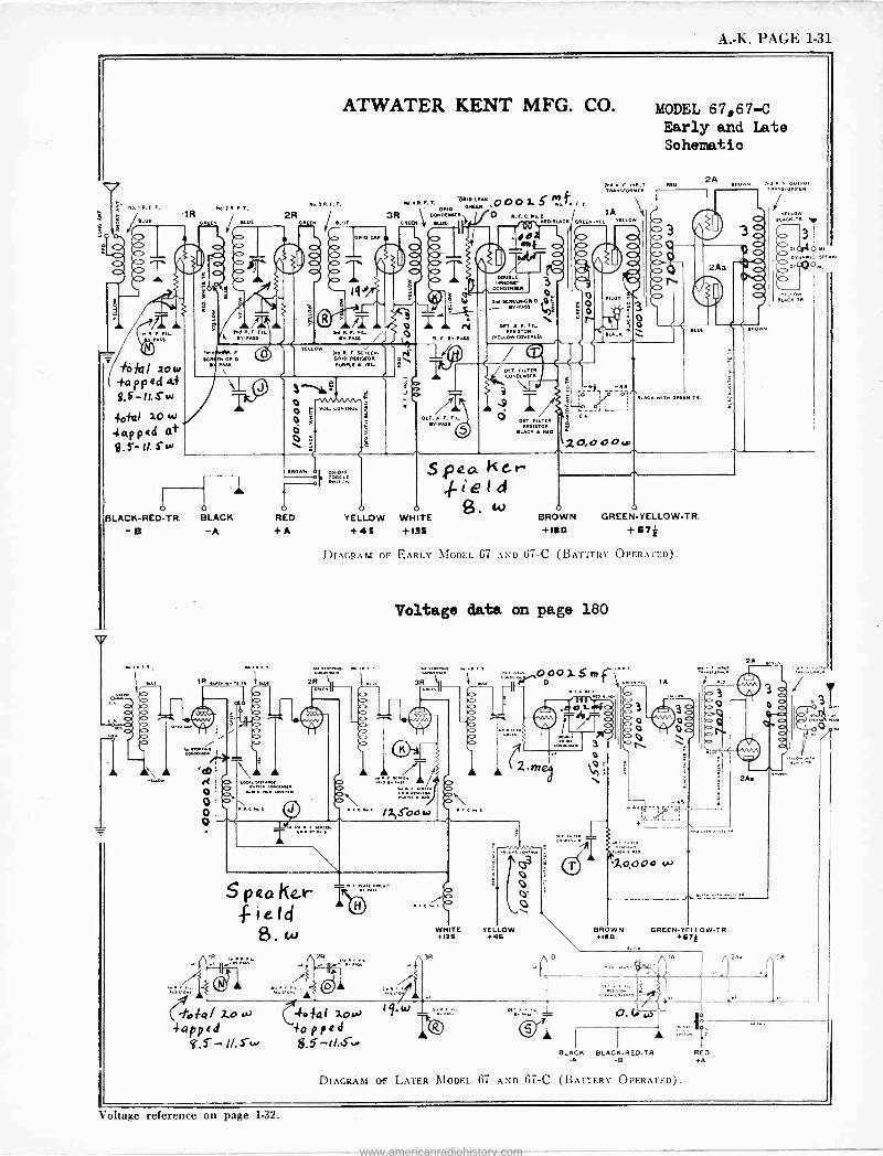
A. -K. PAGE 1-31
KRF N ORID RY FACf
ATWATER KENT MFG. CO.
RAU
Lu R. F. SCAM.. RUMOR
FORME A IEL
3MO oF VOL CONTROL
BLACK -RED -TR. BLACK RED
-B -A +A
v.
dI.)
o o o 0
S p ea Ke.r -Field
B. Lb
i - a ( fia><a/ 2.o E/C%
4appid
ON OFF
NF..R.F.T. aOXEMR.00G a. S INA 1.F.T. DRID 3R E\ coNDFnEER}-D R. F. N.p I
R p il WE. FD-0UCKjGREER.
C> O O
ó 1 1 ¡ R. F. 9YDASE
OCT. A.F. .v FAss .
DDDELa -RNDne
wNDFnstR
D[MEfIETORIL
VELLOW COVEREDr
DCT. FILTER
DR. FILTER RESiSTOR
RLACI RED
Spa KGr ,. e 1 d
0 0 $, w o YELLOW WHITE BROWN GREEN -YELLOW -TR.
+45 +135 +180 +87*
MODEL 67,67-C Early and Late Sohematio
m. A. E RED 2A ERO.. \z^R
sroñLF;A1
YELLOW RLA«TR.
a OI C> C>
TRANSFORMER
lA u. YELLOW
PILOT
3
m BLACK. s
p -.R
FLACRWIT.. GREEN TR.
ZO,OOO.0
DIAGRAM OF EARLY MODEL 67 AND 67-C (BATTERY OPERATED).
Voltage data on page 180
R
WHITE YELLOW +13S +4S
000x.Sm.f`" . ... IA
. c
9).3
1,0,00o
BROWN GREEN -YELLOW -TR. flea +G7k
T BLACK BLACK -RED -TR RED
-A -B .A
l
DIAGRAM 01' LATER MODEL 67 AND 67-C (BAT -I -REV OPERATED.
Voltage reference on page 1-32.
www.americanradiohistory.com
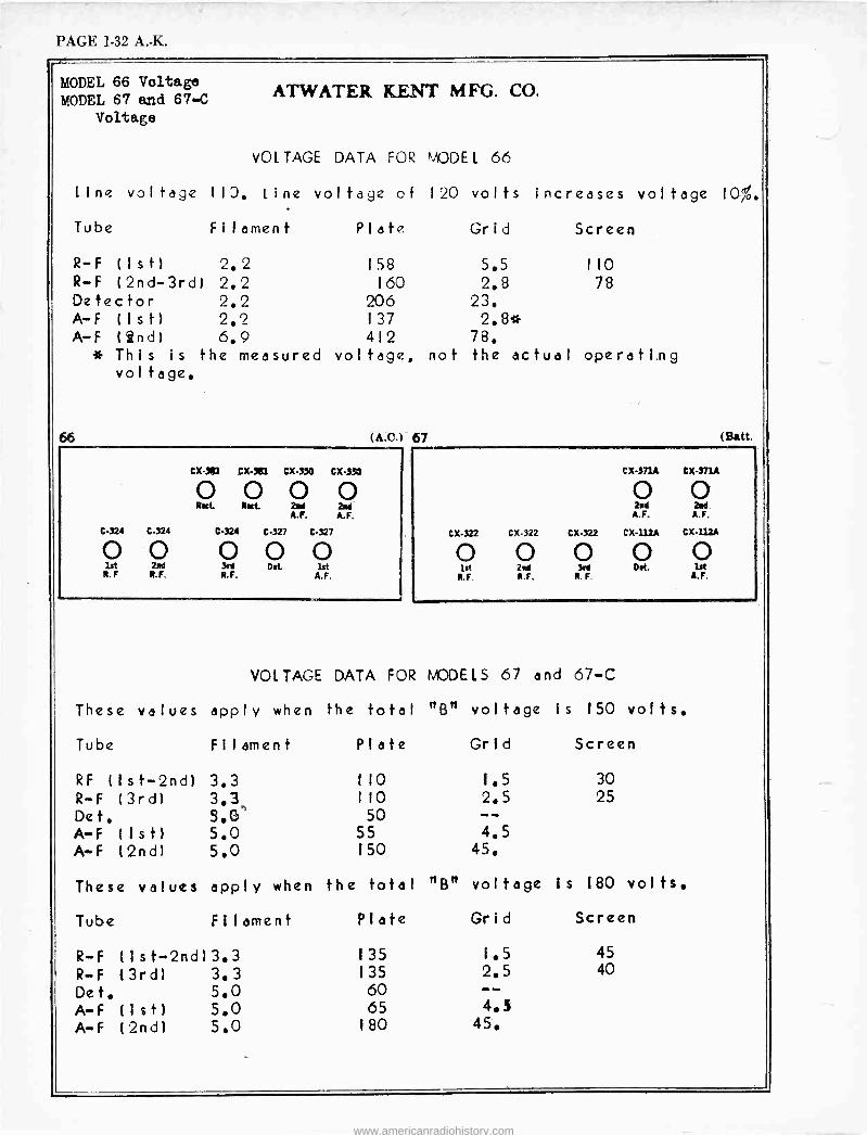
PAGE 1-32 A. -K.
MODEL 66 Voltage MODEL 67 and 67-C
Voltage AT -WATER KENT MFG. CO.
vOLTAGE DATA FOR MODEL 66
line voltage 110. line voltage of 120 volts increases voltage 10%.
Tube Filament Plate Grid Screen
R-F (Ist) 2.2 158 5.5 110 R-F (2nd -3rd) 2.2 160 2.8 78 Detector 2.2 206 23. A-F (Ist) 2.2 137 2.8* A-F ( 2nd) 6.9 412 78.
* This is the measured voltage, not the actual operating voltage.
(A.c. 67
Cx-381 CX-381 CX350 CX.330
0 0 0 0 Ract Net. 2nd 2nd
A.F. A.F.
C-324 C-324 C-324 C-327 C-327
0 0 0 0 0 lit 2nd 3ed Det 1st R.F R.F. R.F. A.F.
(satt.
cX-371A Cx-371A
0 0 2nd 2.d
A.F. A.F.
CX-322 CX-322 CX.322 CX112A CX111A
O O 0 0 O lit 2nd 3ed Det. lst
R.F. R.F. R. F. A.F.
VOLTAGE DATA FOR MODELS 67 and 67-C
These values apply when the total
Tube
RF ( I s t -2nd) R-F (3rd) Det. AwF (1st) A-F (2nd)
Filament Plate
trBtt voltage is ISO volts.
Grid Screen
3.3 110 1.5
3.3c 110 2.5 5.G'' 50 -- 5.0 55 4.5
5.0 150 45.
These values apply when the total
Tube
R-F R-F Det. A-F A-F
Filament Plate
Flan
30 25
voltage is 180 volts.
Grid Screen
(Ist-2nd)3.3 135 1.5
(3rd) 3.3 135 2.5
5.0 60 --
(Ist) 5.0 65 4.5
(2nd) 5.0 180 45.
45 40
www.americanradiohistory.com
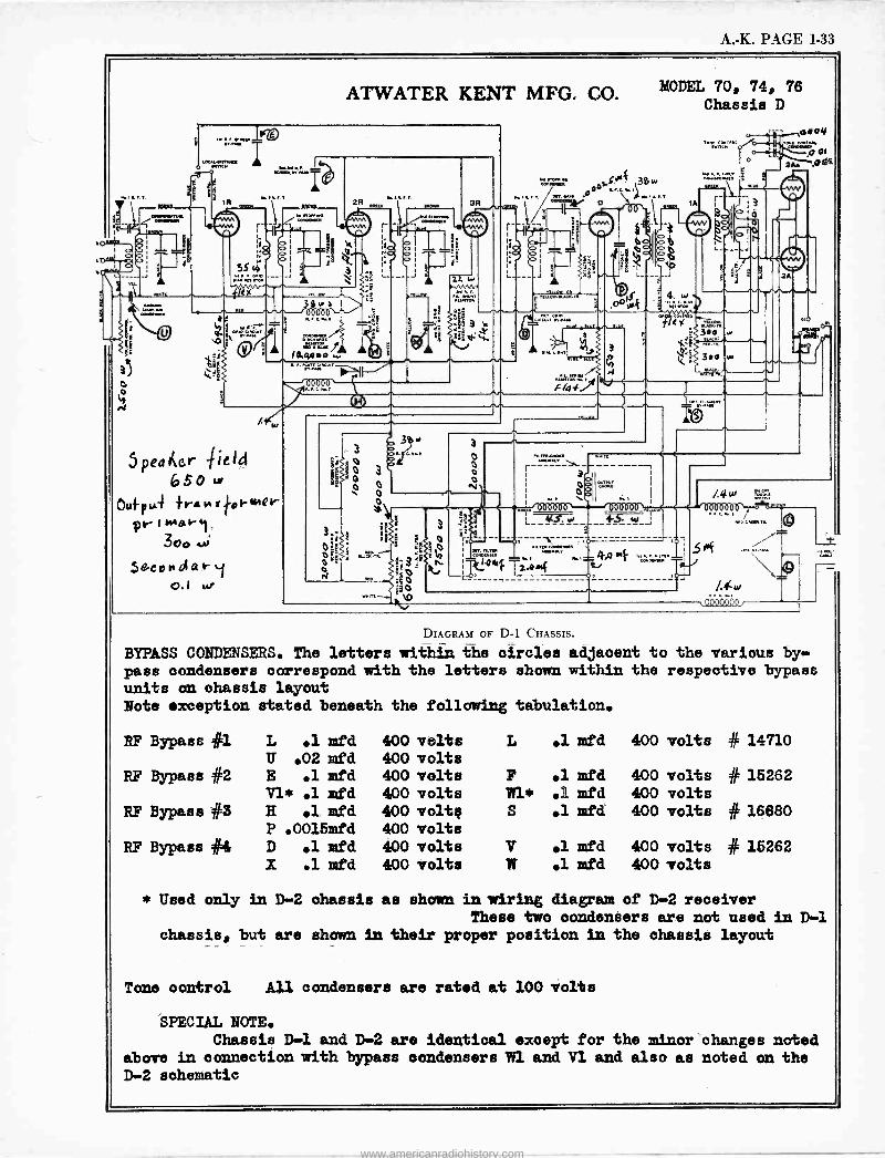
A. -K. PAGE 1-33
4.1010.
3
0
ATWATER KENT MFG. CO.
...... uÌ
5 pea 4er -1ield 65o to
2101. I
Oufpui +rRNrto1-w?r pr' 444°6-1
300 ,A;
Sgcondari o.l w
1,01,1113 2R
r-
O 0 0
3
A
3
0 0 0 O
N
-0w4 Tz.o«f
s.s.+
M D
r
45. so
-°r ...... '
3
0
w
3
4-S w
MODEL 70, 74, 76 Chassis D
,o0oy ......ó oI
° 2A. .00=
L. 1
3.0 w
/.4
fult
0
2
RID cetvt.t,
/.4=
, 06ó4ºb
DIAGRAM OF D-1 CHASSIS.
BYPASS CONDENSERS. The letters within the circles adjacent to the various by- pass condensers correspond with the letters shown within the respeotive bypass units on chassis layout Note exception stated beneath the following tabulation.
RF Bypass #1 L .1 mfd 400 volts L el mfd 400 volts U .02 mfd 400 volts
RF Bypass #2 E .1 mfd 400 volts F .1 mfd 400 volts Vi* .1 mfd 400 volts Wi* .1 mfd 400 volts
RF Bypass #5 H el mfd 400 volt¢ S .l mfd 400 volts P .0015mfd 400 volts
RF Bypass #4 D el mfd 400 volts V .1 mfd 400 volts X .1 mfd 400 volts W el mfd 400 volts
# 14710
# 15262
# 16880
# 15262
* Used only in D-2 chassis as shown in wiring diagram of D-2 receiver These two condensers are not used in D-1
chassis, but are shown in their proper position in the chassis layout
Tone control All condensers are rated at 100 volts
SPECIAL NOTE. Chassis D-1 and D-2 are identical except for the minor changes noted
above in connection with bypass condensers 11 and V1 and also as noted on the D-2 schematic
www.americanradiohistory.com
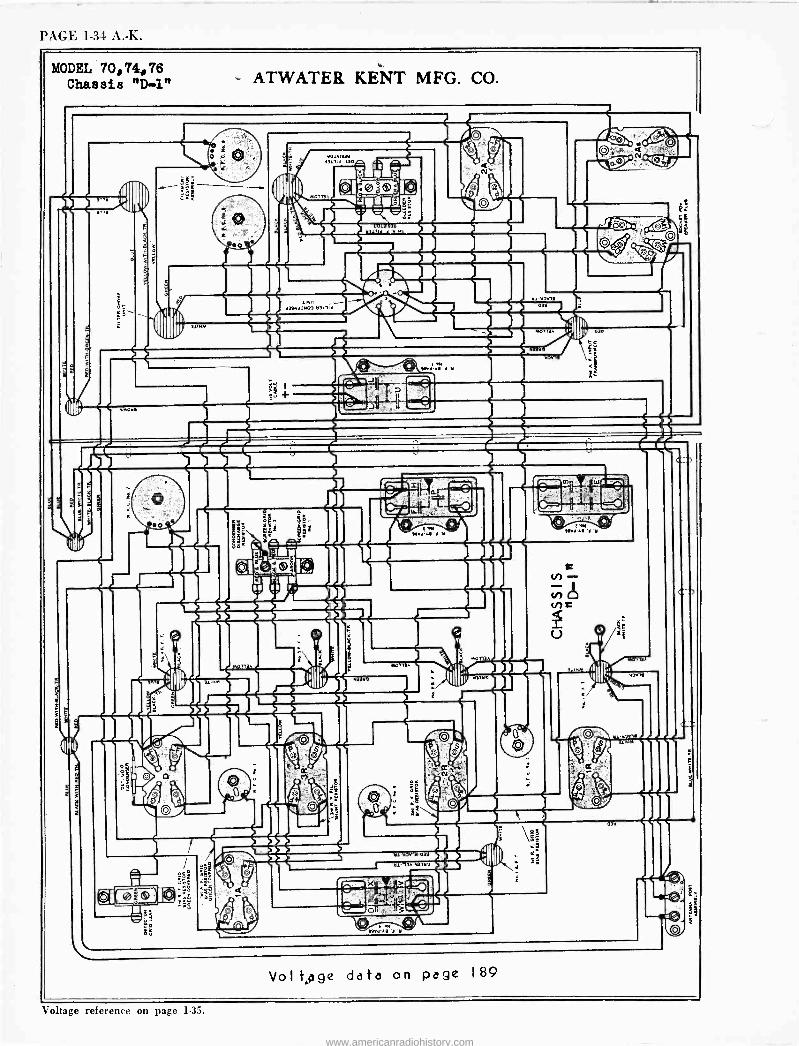
PAGE 1-34 A. -K.
MODEL, 70,74,76 Chassis "D-1"
yLLLIA
Voltage data on page 189
Voltage reference on page 1-35.
www.americanradiohistory.com
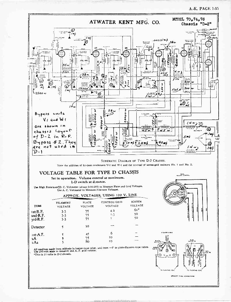
A. -K. PAGE 1-35
ATWATER KENT MFG. CO.
-.,<. . j~f.[,... wf-
/. lu
B1pas5 uhtts V, 4µA W I
pre. show" I H
chasSts (Qyoufi
o f D - z 11V,- F.
ßpass -rz. They qre nol used ìn ^
al
2 F.9,,
o [ O %to,I. ój .5
.1.
3
:Ó
'0 0.1
"e$to
f
o
ºt 3
pF,....F
t
ó o 0
32 w
.4
3 o o o 0 N+
les
MODEL 70,74,76 Chassie "D-2"
0001SM Orr
..13/3"'
r
,-----,
GOO
9 gAz_.r 4.°
/.Owf?TL.O iss
/. 4 tvJ M`5
s9Q4Q404. f
SCHEMATIC DIAGRAM OF TYPE D-2 CHASSIS.
Note the addition of by-pass condensers V-1 and W-1 and the reversal of screen -grid resistors No. I and No. 2.
VOLTAGE TABLE FOR TYPE D CHASSIS Set in operation. Volume control at maximum.
LAD switch at distance.
Use High ResistancefD. C. Voltmeter (about 0-50-250) to Measure Plate and Grid Voltages.
Use A. C. Voltmeter to Measure Filament Voltages.
APPROX. VOLTAGES, USING 120 V. LINE
FILAMENT PLATE CONTROL -GRID SCREEN
TUBE VOLTAGE VOLTAGE VOLTAGE VOLTAGE
Ist-R.F. 3.3 75 4.2 6o*
2nd-R.F. 3.3 75 1.3 50
3rd-R.F. 3.3 75 1 50
Detector 5 20 - ist -A.F. 5 45 6
2A 5 75 10
2Aa 5 8o lo
All readings made from cathode in heater -type tubes, and from -F in plain -filament -type tubes.
Use 250 -volt scale to measure and A. F. grid voltage.
'This is 50 volts in D-2 chassis.
- AFUNU CALA
13 EUCN.
W14 MAIN.
Tn rt.o.nnc col,
GE. WmITUTO
o
TO FLOATING COIL
LILAO[N FAN[, CONNECTION,
OLP UCN.A
www.americanradiohistory.com
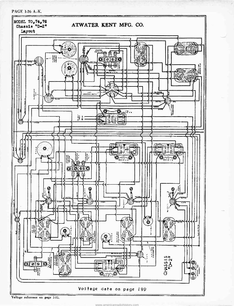
PAGE 1-36 A. -K.
MODEL 70,74,76 Chassis "D-2"
Layout
ó
OIL Frit-11
0,100 tl
011n 1 11 03tl
>4 J
Voltage reference on page 1.35.
www.americanradiohistory.com
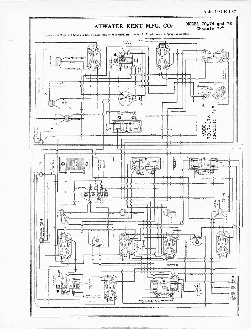
A. -K. PAGE 1-37
ATWATER KENT MFG. CO: MODEL 70,74 and 76 Chassis "F"
In some early Type F Chassis. a line by-pass condenser is used. and the 1st -A. F. grid resistor (gray) is omitted.
pIPuo
U w
SS All w3áÑ°o23úi
CO
@
s 53
>.e
et
www.americanradiohistory.com
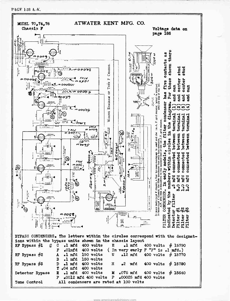
PAGE 1-38 A. -K.
MODEL 70,74,76 Chassis F
>71A,
ATWATER KENT MFG. CO.
0.1,X11.
o a'o2
r
000bai
oo at, -A
/d e/w
000Q, f
d
VD000
T
01.
cri 00r/
3 0 41;
0-4 Q
<Y)
iLl
,r) oast
o o
z
BYPASS CONDENSERS. The letters within ions within the bypass units shown in RF Bypass #1 g C .1 mfd 400 volts
F .0Imfd 400 volts RF Bypass #2 A .1 mfd 150 volts
B .1 mfd 150 'volts
RF Bypass #3 D .1 mfd 400 volts T .04 mfd 400 volts
Detector Bypass R 1 mfd 400 volts P 0012 mfd 400 vol
Tone Control All condensers are
o o
2g
Zi
o 9
00 0
6.1
Voltage data on page 186
1.4.
tlo
t5 0 ' 0 0-1.' 0 0 0 0 e e 43 e
eJ to ri 11 fz eri $3 gt
4-§ 0000 Mei :Diet! irk -; Goo oto
9-I
lei0000 eLlei2 f)ttli 8& 0000
gm -d4) Eddä h.p.0000 0000 o
me, ol
'2,
.1e- " .,2 . N
fri
o
0 0 Ng
0 0 .0 04)
43 0 a
LU g ge o
0 N N 00 00 11. 0 43-p Oie 5 2 2 irf
0000 0 14
A° Is 3
co id Ce a 0 tkl) e e -I e -i ri
V t'a ea va
1:, . . ri O
4.>
ei e 0 NI 4, 0 43NMN 0 0 0 0 0
Ei rf 0 43 e e e-1 Cf e -I gQ erl irf ir4rz4rz4rx.
the circles correspond with the designat- the chassis layout
E .1 mfd 400 volts # 15790 ( In very early F "F" is .1 mfd.)
ts rated at 100 volts
U .12 mfd 400 volts # 15770
H .2 mfd 400 volts # 15780
M .075 mfd 400 volts # 15640 P .00025 mfd 400 volts
www.americanradiohistory.com
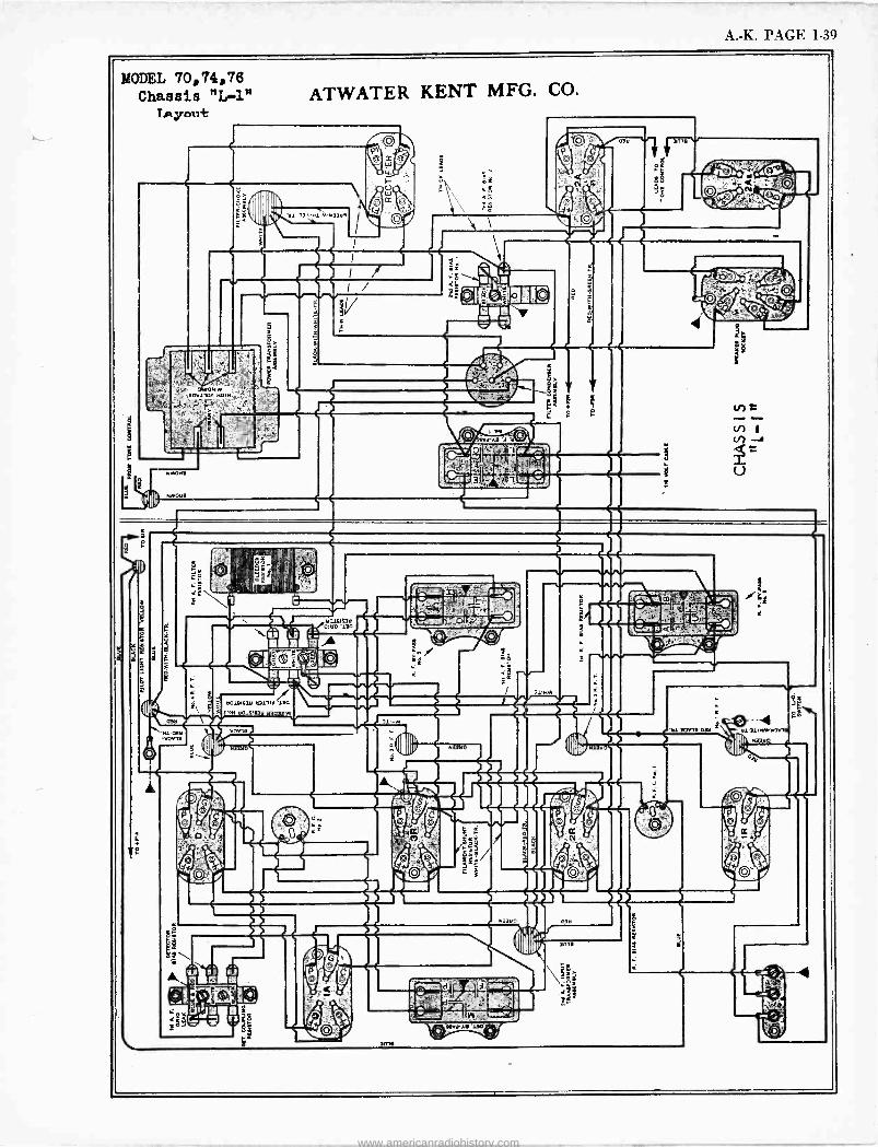
A. -K. PAGE 1-39
MODEL 70,74,76 Chassis "L-1"
LA joist
o»la»Ir 0r1w »0111
b0181i3b blalld '110
80iº'eie H3Q3319
ATWATER KENT MFG. CO.
áéóIsºb
9¡,.. =1J,..
-- " O , ,
81'111».»TV19
www.americanradiohistory.com
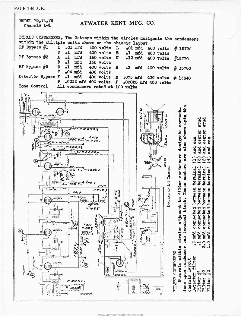
PAGE 1-40 A. -K.
MODEL 70,74,76 Chassis L-1 ATWATER KENT MFG. CO.
BYPASS CONDENSERS. The letters within the circles designate the within the multiple units shown on the chassis layout RF Bypass el L .01 mfd 400 volts L 01 mfd 400 volts
.1 mfd 400 volts E .1 mfd 400 volts RF Bypass #2 150 volts II .12' red 400 volts
150 volts 400 volts 400 volts 400 volts
RF Bypass #3
Detector Bypass
E 2 mfd 400 volts
M .075 mfd 400 volts 0012 mfd 400 volts P .00025 mfd 400 volts
Tone Control All oondonaors rated at 100 volts
P-2
C
A B
D T F P
.1 mfd
.1 mfd
.1 mfd 04 mfd .1 mfd
p
e
JIM
se
2
4L11W WIiNV1,
__ 00 0000_/' 0011
n000-ooi A - oSo /
4
4
r o o os9 d H-
oOO
;_/g'
~ o oóO ysj
a000 ale
bizrlz f o/Y
000º,
XJP/y .0009
istOO L/ ;VW .
^+oo9,s
3ti
Ox v Ót
. YV . ....... `
_---- ; i éá'
InOOSZ O ;
O .4 0
2
JO -
t 3 o o
e
(I
º o
-4010091
itNete
3
o o
3 0 o
condensers
# 15790
#15770
# 15780
15640
CO m .., m 07 N d+ O .........../..../......
U ©
ri
11 Si 0000
m 4,43434>
mm mmm ó tiii 4-
l+l
.Q m m . 03
.m 0 o
mX) m m m m 0 ri ó ó ó ó b n
il
o m
ii O o o
11 v
ri ni tio
ela Ad 4a gd
ai as 0 o co .-i 00
t, Ct ri m
cn to
rol 5ni 0 z +> W O O '?.z: 2 rcl°aaw
O i4 í"iri ri NM C) O ta
W ., 00000 H Ó 41
cd e r4 r -t r rl -r1ritf.
-rl o [. f
www.americanradiohistory.com

A. -K. I'AGL 1-11
MODEL 70, 74, 76 ATWATER KENT MFG. CO. Chassis L-2
BYPASS CONDENSERS. The letters within circles designate the condensers within the mi..ltiple units shown on the chassis layout
L RF Bypass #1 .01 mfd 400 volts L .01 mfd 400 volts C .1 mfd 400 volts E .1 mfd 400 volts
# 15790
RF Bypass #2 A .1 mfd 150 volts II .12 mfd 400 volts B .1 mfd 150 volts
# 15770
RF Bypass #3 D .1 mfd 400 volts H .2 mfd 400 volts T .04 mfd 400 volts
# 15780
Detector Bypass F .1 mfd 400 volts M .075 mfd 400 volts P .0012 mfd 400 volts P .00025 mfd 400 volts
Tone Control All condensers are rated at 100 volts
# 15640
ó10o--0;gam--- e .t:i T-
z
i t It
oop9 .. , -1.90004ó000,
+öö ó AVVO
.,,.:':~^'' OaOÓ£
-lierd00000', x.no..
1Ë !mop P.,s
.,: . ̀°«
.'. fe-OoOei
xaiy OSO 1
., oodo71,
Doc) aboor/
NVV T.S.^ xa/ dr 0 O
AhVV-44
m DOSt
.,,,
..a and
w 4
£ --1;';'/ í'Ii.^. 3x -. .g.i. . 3' óo
-' É o
0 .
z1
oi. ^ 000d0Q9
P4 T12S'cS'CS
. 1 52 2
_ et riNt9d.. .i
me.
72)::,
11111 óó O m m m m 4-1 re.,:e6, 4a e 4, e -P ó mmmS V9 07 eiJi m o. b e m O m.0 ov
0º p.a.Q¢t M C
Ó e R7 R3 Cl 2i e `m Ó O .}0 } v ; i O Ù U 1D 1 vn iiiAl mri óñ óñ°
eY
rigTJpT,altiiR7 i 4A 4A 4A
%
¢
e-t000N 22 Al
` o' CM ri r1
b r-1 Si ó 1 e
Qi m
r 43 it L
Q W 0 a T
rri ó e T r -I 'M 10 C., e
C 434h414:
4 s2t,s,s. m++Fó m .a î'. 42 r1 ri ri 0 wáA K ill wá
www.americanradiohistory.com
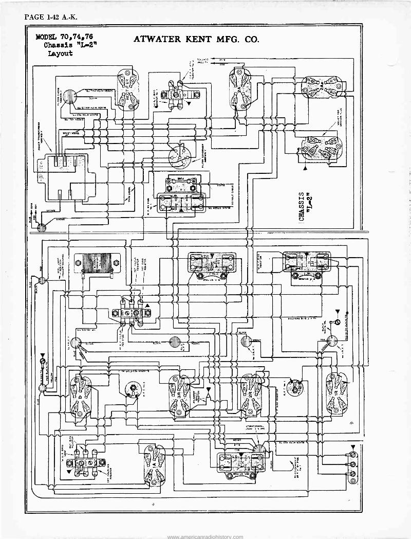
PAGE 1-42 A. -K.
MODEL 70,74,76 Chassis "Ir2" Layout
111
SOVel 1,31,
ATWATER KENT MFG. CO.
Mo,e
roe
0 e ----Tr-i!J"o
,,.
.m.
MOUll
f
z
emeo 142v10
-Qii .
a1" - tt..,..
e0iSi53e Sr 1 01
i ii
www.americanradiohistory.com
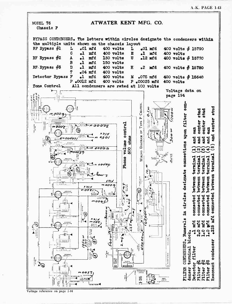
A. -K. PAGE 1-43
MODEL 76
Chassis P ATWATER KENT MFG. CO.
BYPASS CONDENSERS. The letters within circles designato the multiple units shown on the chassis layout RF Bypass #1 L .01 mfd 400 volts L O1 mfd
C .1 mid 400 volts E .1 mfd A .1 mfd 150 volts IT .12 mfd B .1 mfd 150 volts D .1 mfd 400 volts T .04 mfd 400 volts
Detector Bypass F 1 mfd 400 volts P .0012 mfd 400 volts
Tone Control A11 condensers are rated
RF Bypass #2
RF- Bypass #3
LÌTTI
i
é
-g iIL/ Qncri 7 44Q9 o i fö/
n0009
.,.,^7G
c., 00992
3 o o
the condensers within
400 volts # 15790 .400 volts 400 volts # 15770
H .2 mfd 400 volts # 15780
M .075 mfd P 00025 mfd at 100 volts
000,000
fl
o
400 volts # 15640 400 volts
Voltage data on page 194
3 o
$
o
o el r-1 ' M d" . `........
hifi r-i
r-1
Voltage reference on page 144
www.americanradiohistory.com
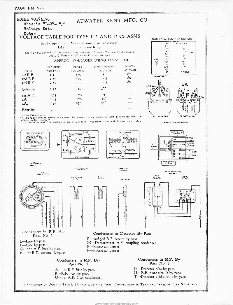
PAGE 1-44 A. -K.
MODEL 70,74,76 Chassis "L-2"- Voltage Voltage Data Notes
VOLTAGE TABLE FOR TYPE L-2 AND P CHASSIS Set in operation. Volume control at maximum.
L -D (or 'phono) switch up.
Use High Resistance D. C. Voltmeter (about 0-7,n,2 511) to Measure Plate and Grid Voltages.
Use A. C. Voltmeter to Measure Filament Voltages.
APPROX. VOLTAGES, USING 120 V. LINE
nPn ATWATER KENT MFG. CO.
TUBE
FILAMENT
VOLTAGE
PLATE
VOLTAGE
CONTROL -GRID
VOLTAGE
SCREEN
VOLTAGE
Ist-R.F. 2.4 ISO 5 85
2nd-R.F. 2.35 1óO 4.5 86
3rd-R.F. 2.35 Ió0 4.5 Rai
Detector 2..35 IIO 14**
Ist A.F. 2.35 70 2
2A 2.45 250 55* 2Aa 2.45 250 55*
Rectifier 5.
Use 250 -volt scale. B This Is the voltage across the detector bias resistor; when measuring from grid to cathode, the voltage reading is only 2.
All readings made from cathode in heater -type tubes, and from -F in plain -filament -type tubes.
INPUT A. F. TRAMFORMER
ASSEMBLY
s
IMF
T q
FILTED CONDENSEEM
FILTER CONDENSER ASSEMBLY
DUAL VOLUME CONTROL
LOCAL.DISTANCE SwiTCH
Condensers in R.F. By- Pass No. 1
L-Line by-pass. L-Line by-pass. C -2nd -A.F. bias by-pass. E-ist-R.F. screen by-pass.
ON.oFF SwiTC-
FILTER CHOKES
ED TK Ne , R. Me. 2
FILTER.CNOKE ASSESS SLY
DIAL LIGHT
Models 75P, 70, 74, 76, 60 (3rd type) (1930.
1 RF PILOT 3.2 V. o 24A
2 RF
O '24A
I AF 3RF
o O 21 '24A
DET
o '27
0- .45 2AF
0-- '45
RECT
o 'so
FRONT
To FLOATING COIL
COTNTTROL CONDENSER
Condensers in Detector By -Pass F -2nd -3rd R.F. screen by-pass. M-Detector-ist A.F. coupling condenser. P-Phone condenser. P-Phone condenser.
Condensers in R.F. By - Pass No. 2
A-ist-R.F. bias by-pass. B-R.F. bias by-pass. 'U-Ist-A.F. filter condenser..
OECD.
TO "LOOTING COIL
...ma r.Nu CONNSCTIGw
"CATER TRANSFORMER AUEMEIY
TONE CONTROL
SWITCH
Condensers in R.F. By - Pass No. 3
D-Detector bias by-pass. H-R.F. plate -circuit by-pass. T-Detector grid -circuit by-pass.
CONNECTION OF UNITS IN TYPE L-2 CHASSIS, AND, AT RIGHT. CONNECTIONS TO TERMINAL PANEL OF TYPE N SPEAKER.
www.americanradiohistory.com
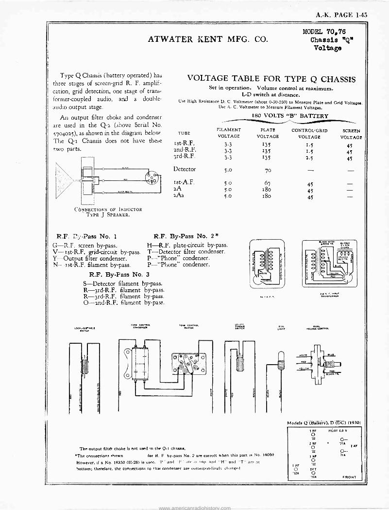
A. -K. PAGE 1-45
ATWATER KENT MFG. CO.
Type Q Chassis (battery operated) has three stages of screen -grid R. F. amplifi-
cation, grid detection, one stage of trans- former -coupled audio, and a double' audio output stage.
An output filter choke and condenser are used in the Q-2 (above Serial No. 5704025), as shown in the diagram below The Q I Chassis does not have these two parts.
CONNECTIONS OF INDUCTOR TYPE J SPEAKER.
R.F. íúy -Pass No. 1
G-R.F. screen by-pass. V-ist-R.F. grid -circuit by-pass. Y-Output filter condenser. N- ist-R.F. filament by-pass.
MODEL 70,76 Chassis "Q" Voltage
VOLTAGE TABLE FOR TYPE Q CHASSIS Set in operation. Volume control at maximum.
L -D switch at distance. Use High Resistance D. C. Voltmeter (about 0-50-250) to Measure Plate and Grid Voltages.
Use A. C. Voltmeter to Measure Filament Voltages.
180 VOLTS "B" BATTERY
TUBE
st-R.F. and-R.F. 3rd-R.F.
Detector
Ist -A.F. 2A 2Aa
FILAMENT
VOLTAGE
3.3 3.3 3.3
5.0
5.0 5.0 5.0
R.F. By -Pass No. 2 *
H-R.F. plate -circuit by-pass. T-Detector filter condenser. P-"Phone" condenser. P-"Phone" condenser.
R.F. By -Pass No. 3
S-Detector filament by-pass. R-3rd-R.F. filament by-pass. R-3rd-R.F. filament by-pass. O-and-R.F. filament by-pass.
LOCAL-0I1TAMC[ ewITCM
MOL COND[Mt[M
TOW CONTROL N/ITC11
PLATE VOLTAGE
135 135 135
CONTROL -GRID VOLTAGE
I.5 I.5 2.5
70
67 45 18o 45 18o 45
No T
The output filter choke is not used in the Q-1 chassis.
*The conne«ions shown for R F by-pass No. 2 are correct when this part is No. 16060
However. if a No. 18350 (H-281 is used. 'P" awl 'l'' :Ir. el top and "H" and "T" are al
bottom; therefore, the connections to chi, condenser are c Ineapon Iinulr :hanged
, ..,..rD ,I.
-OLV.íW! fAMTIIOI
SCREEN
VOLTAGE
45 45 45
Models Q (Battery), D'(13C) (1930)
1 AF
1 RF PILOT 6.0 V
O 'u
2 RF
O
3 RF
O '22
G DET '12A O
'12A FRONT
G- . '71A i AF
0- 716
www.americanradiohistory.com
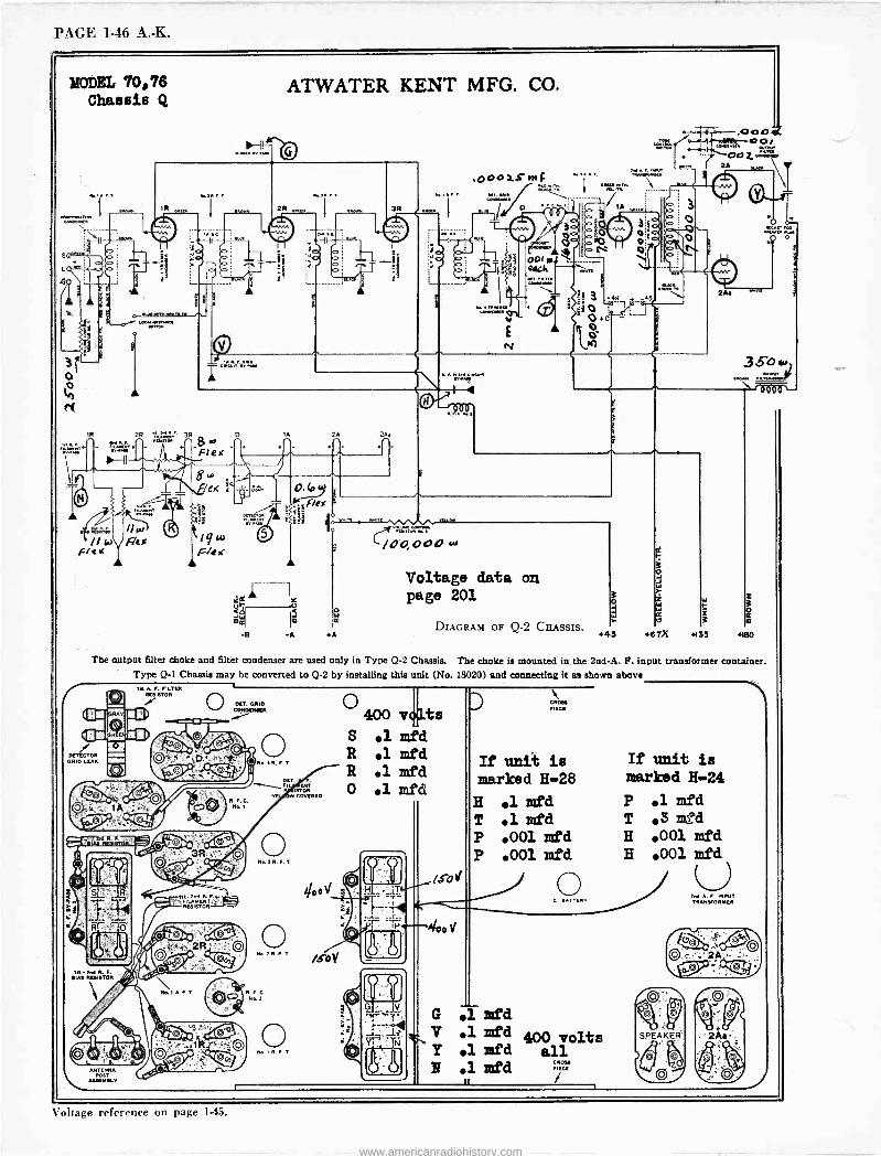
PAGE 1-46 A. -K.
MODEL 70,76 Chassis Q
aów\ o c
ATWATER KENT MFG. CO.
,000:.c.n. PT. RAM
`/d24 000 W
...,.V. ,._..,... 2211Z ... ..-----
IA
DIAGRAM OF Q-2 CIiASSIS.
000.K %-+-ir --oo,
The output filter choke and filter condenser are used only in Type Q-2 Chassis. The choke is mounted in the 2nd -A. F. input transformer container. Type Q-1 Chassis may be converted to Q-2 by installing this unit (No. 18020) and connecting it as shown above
DrTECTOR GRID EUR
N. R. P T
/SOY
ANTENNA
A.MEMBEV
400 41ts S .1mfd R .1mfd R .1mfd 0 lmfd
If unit is marked H-28
H 1 mfd T .1mfd P .001 mfd P .001 mfd
It unit is marked H-24
P .1mfd T .Smfd H .001 mfd H .001 mfd
SPEAKER
AM A. F. INPUT TRANVONMER
Iletlerf PO.
Voltage reference on page 1.45.
www.americanradiohistory.com
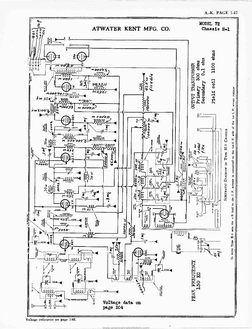
A. -K. PAGE 1-47
I4
fi.
?st
M 000'00) mY4 v v m
o
ATWATER KENT MFG. CO.
S t(.. YO1.,.lY 0.Y
v, T °Y'w' Yo,,..,- Wi .
q":27,: ¡o »,:90oS9
" N
a/tez/i rr, O.SO/-
i
.» OOO'O yy
/b OpÓO* .eel:::.l.
t dr
. tl4s.N.tl Y Y OUl1l0 O,YO
a Ï -Q Nd - 412]1)0Wd _
M1 ób
""r, I
YOOdYMI
IP `
M 0000/
.>., c., T t4
dfg ..".YOi'N,
n o 6 119e c+' aSE =e --t
m4- É I~
Q
e -4 s d3
_1`
r -I(
s3
Y2Y1. 4
H) J
O
ea
,ir
.000, M 9*
é
Yl'Y4Y,eNIIM-M019A
.
f= ' m OL\
3 O O
mY
e
Voltage data on page 204
3
0
o 0 o
3
:g
141.00
4,
2
ON,O IM 10.1.10., NOIN
ä;
MODEL 72 Chassis H-1
(,(
>né
/
Voltage reference on page 1-48.
www.americanradiohistory.com
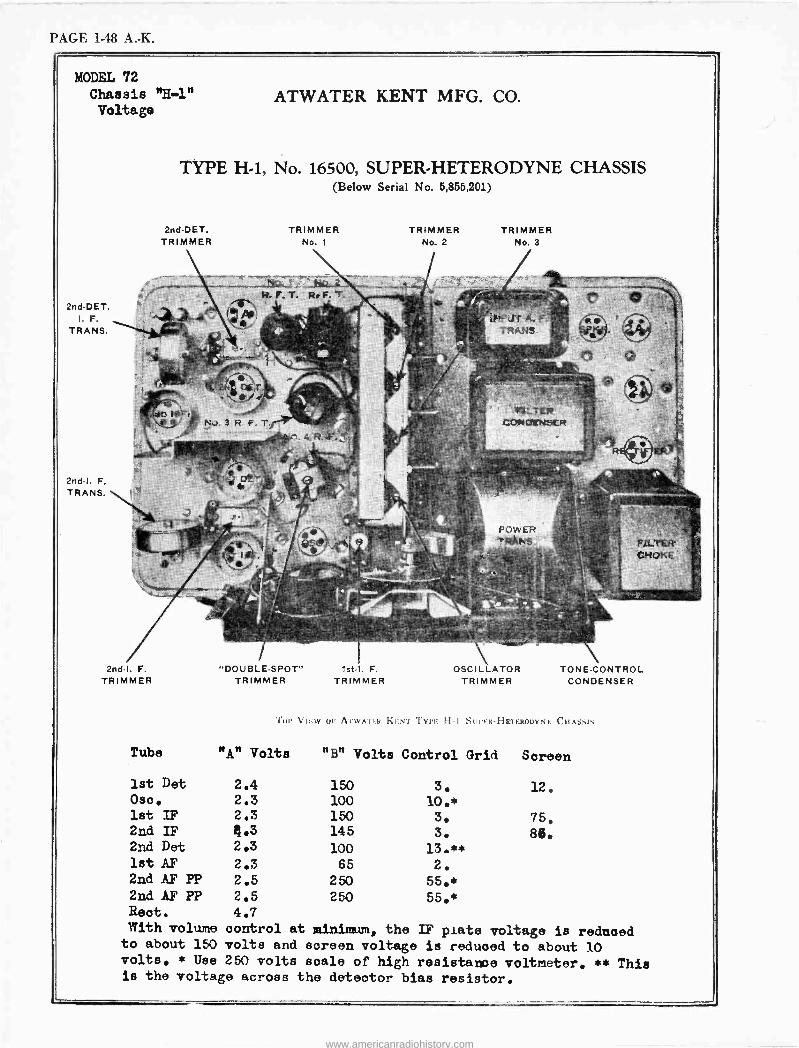
PAGE 1-48 A. -K.
MODEL 72 Chassis "H-1" Voltage
TYPE H-1, No. 16500, SUPER -HETERODYNE CHASSIS (Below Serial No. 5,855,201)
2nd-DET. TRIMMER
2nd-DET. I. F.
TRANS.
3G- 3 R. F.
2nd -I. F. TRIMMER
1st Det
Oso. 1st IF 2nd IF 2nd Det 1st AF 2nd AF PP 2nd AF PP Reot. With volume to about 150 volts. * Use
TRIMMER No. 1
"DOUBLE -SPOT" TRIMMER
1st -I. F.
TRrMMER
TRIMMER No. 2
TRIMMER No. 3
:. O.N lrSEFt
nOS'r'LFP
TRi1NS
OSCILLATOR TRIMMER
F`; LTEi f; "i,l}: .
TONE -CONTROL CONDENSER
Tlll' VIEW Or A'l'WA'l'F.k KF:NT TYPE H -I SIII'E.K-HETERUUYNF. CIIAstil1
"A" Volts "B" Volts Control Grid Screen
2.4 150 2.3 100 2.3 150 4.3 145 2.3 100 2.3 65 2.5 250 2.5 250 4.7
3. 12. 10.* 3. 75. 3. 86.
13.** 2.
55.*
55.*
control at minimum, the IF plate voltage is reduced volts and screen voltage is reduoed to about 10 250 volts Saale of high resistance voltmeter. ** This
is the voltage across the detector bias resistor.
www.americanradiohistory.com
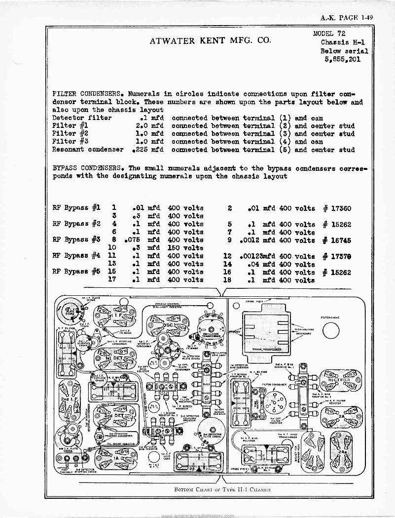
A. -K. PAGE 1-49
ATWATER KENT MFG. CO.
FILTER CONDENSERS. Numerals in circles indicate connections u denser terminal block. These numbers are shown upon the parts also upon the chassis layout Detector filter el mfd connected between terminal Filter #1 2.0 mfd connected between terminal Filter #2 1.0 mfd connected between terminal Filter #3 1.0 mfd connected between terminal Resonant condenser .225 mfd connected between terminal
MODEL 72
Chassis H-1
Below serial 5,855;201
pon filter con - layout below and
(1) and can (2) and center stud (3) and center stud (4) and can (5) and center stud
BYPASS CONDENSERS. The small numerals adjacent to the bypass ponds with the designating numerals upon the chassis layout
condensers corres -
RF Bypass #1 1 .01 mfd 400 volts 2 .01 mfd 400 volts # 17360 3 ®3 mfd 400 volts
RF Bypass #2 4 .1 mfd 400 volts 5 .1 mfd 400 volts # 15262 6 .1 mfd 400 volts 7 .1 mfd 400 volts
RF Bypass #3 8 .075 mfd 400 volta 9 .0012 mfd 400 volts # 16745 10 .3 mfd 150 volts
RF Bypass #4 11 .1 mfd 400 volts 12 .00123mfd 400 volts # 17370 13 .1 mfd 400 volts 14 .04 mfd 400 volts
RF Bypass #6 15 .1 mfd 400 volts 16 .1 mfd 400 volts # 15262 17 .1 mfd 400 volts 18 .1 mfd 400 volts
. PLATE n inoKE
A. © © 1st I. F ,E7'-, \ß
n TH. F.
çHOKÉ
TPIMMEP
2nd I. F. STOPPINO CONDENSER STOPPING
CONDENSER
2nd DE
PEeIBTOR
R. M7,45
NPEYPASS . 1
2nd DETECTOR TRIMMER CONDENSER
NELLOW COVERED, -IJGHT RESISTOR
IA8 na ETECTOR
PESISTOR
DE ECTOR PUTE CHOKE
In DET. PLATE
CONDENSER
a OdG
REBISTOR ER
in I.F.
STORBCREEN REBI
REN PEb18TOR N . 2nd DETECTOR
REBISTOR
UCX
AP00
0`PGÿ
tROFT
RESISTOR
CROSS PIECE
SIAB RES.GTOR
I CROSS PIECE C
A F. SIAS RESISTOR Na. 2 In RF815i0RR
HIGH -VOLTAGE
SECONDARY
INPUT TRANSFORMER
Borroí CHART or TYPE H-1 CH:,ssrs
www.americanradiohistory.com
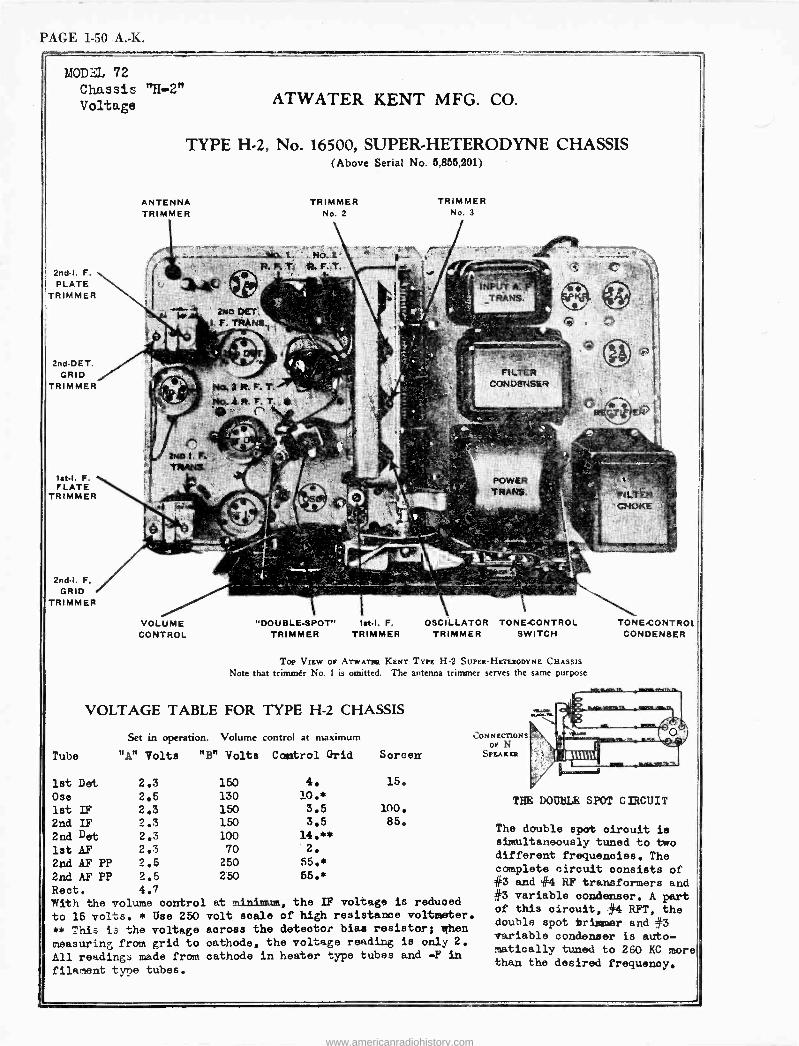
PAGE 1-50 A. -K.
MOD:M 72 Chassis "H-2" Voltage
2ndI. F.
PLATE TRIMMER
2nd-DET. GRID
TRIMMER
lit -I. F. LATE
TRIMMER
2ndI. F. GRID
TRIMMER
ATWATER KENT MFG. CO.
TYPE H-2, No. 16500, SUPER -HETERODYNE CHASSIS (Above Serial No. 5,855,201)
ANTENNA TRIMMER
VOLUME CONTROL
TRIMMER No. 2
"DOUBLE -SPOT" let -I. F. TRIMMER TRIMMER
TRIMMER No. 3
OSCILLATOR TONECONTROL TRIMMER SWITCH
To,. VIEW OP ATWATER KENT TYPE H-2 SUPER -HETERODYNE CHASSIS
Note that trimmer No. 1 is omitted. The antenna trimmer serves the same purpose
VOLTAGE TABLE FOR TYPE H-2 CHASSIS
Set in operation. Volume control at maximum
Tube "A" Volts "B" Volts Control Grid Screen
1st Dot 2.3 150 4. 15.
Ose 2.5 130 10.*
1st IF 2.3 150 3.5 100.
2nd IF 2.3 150 3.5 85.
2nd Det 2.3 100 14.**
1st AF 2.3 70 2.
2nd AF PP 2.5 250 55.*
2nd AF PP 2.5 250 55.*
Rect. 4.7
CONNECTIONS oP N
SPEAKER
With the volume control at minimum, the IF voltage is reduced
to 15 volts. * Use 250 volt scale of high resistance voltmeter.
** This is the voltage across the detector bias resistor; when
measuring from grid to oathode, the voltage reading is only 2.
All readings made from cathode in heater type tubes and -F in
filament type tubes.
TONE -CONTROL CONDENSER
THE DOUBLE SPOT CIRCUIT
The double spot oirouit is simultaneously tuned to two different frequencies. The complete circuit consists of #3 and #4 RF transformers and #3 variable condenser. A part of this circuit, #4 RFT, the double spot trimmer and #3 variable condenser is auto- matically tuned to 260 KC more than the desired frequency.
www.americanradiohistory.com
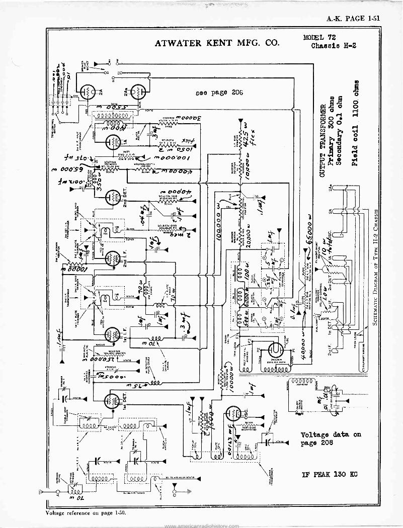
A. -K. PAGE 1-51
,_r_
b$
g« sl0 .+ 00059
fm trooi,
ATWATER KENT MFG. CO. MODEL 72
Chassis H-2
o- so
o
o a
Al3 s \.(2Q44 OQ40);
1111 ` ---»-lOr---
M
see page 206
tl3
Si
2N,!no00bg
Y3isis3tl )(b/ srn' I
E. , 0S o/ 03tl13013 n+000300/
tl0131t3tl DYIL1100 Y01S183tl tl31113
Y0103130 VuS 't30 W2
d
s
30
n
o o o Ò O
tld
r
ï
x
ó\ Iºwñ lUA
000D4Z3 ºwwY.
}Y ;
3º YJns
e Lº O\
4
WMotle
je-n_
e3 re) S L XYVi
tl MJV>9M ` V V V
( )12,09 / ><. -2Q94 4
in OL
ár
I(
VTh J
`.0QQ0)
33tl0
S
o
Q
e
o
t.P
f)
N o
N
oYiOYIM 30r110A tl01M
,444Ó400v
Igge
7
000019 óc
6. F- Lei ó(
nn3
N
0 T
Voltage data on --1(- ,Jn' 1 page 208
¡-O, ; Y. 3. tlM -t M Jn] 4 IP PEAK 130 KC
Voltage reference on page 1-50.
www.americanradiohistory.com
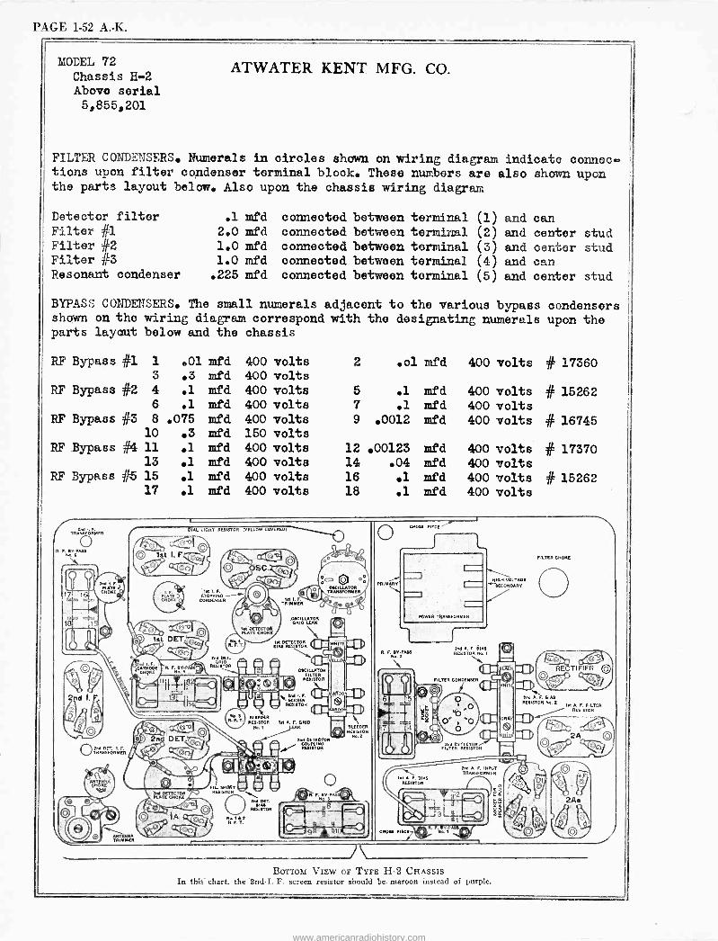
PAGE 1-52 A. -K.
MODEL 72 Chassis H-2 Above serial 5,855,201
ATWATER KENT MFG. CO.
FILTER CONDENSERS. Numerals in circles shown on wiring diagram indicate connec- tions upon filter condenser terminal block. These numbers are also shown upon the parts layout below. Also upon the chassis wiring diagram
Detector filter Filter #1 Filter #2 Filter #3 Resonant condenser
.1 mfd connected between terminal (1) and can 2.0 mfd connected between terminal (2) and center 1.0 mfd connected between terminal (3) and center 1.0 mfd connected between terminal (4) and can .225 mfd connected between terminal (5) and center
BYPASS CONDENSERS. The small numerals adjacent to the various bypass shown on the wiring diagram correspond with the designating numerals parts layout below and the chassis
stud stud
stud
condensers upon the
RF Bypass #1 1 .01 mfd 400 volts 2 .ol mfd 400 volts # 17360 3 .3 mfd 400 volts
RF Bypass #2 4 .1 mfd 400 volts 5 .1 mfd 400 volts # 15262 6 .1 mfd 400 volts 7 .1 mfd 400 volts
RF Bypass #3 8 .075 mfd 400 volts 9 .0012 mfd 400 volts # 16745 10 .3 mfd 150 volts
RF. Bypass #4 11 .1 mfd 400 volts 12 00123 mfd 400 volts # 17370 13 .1 mfd 400 volts 14 .04 mfd 400 volts
RF Bypass e 15 .1 mfd 400 volts 16 .1 mfd 400 volts # 15262 17 .1 mfd 400 volts 18 .1 mfd 400 volts
Rnd .F. TRANSFOPMER
2nd I. F.
ene RET. I.F. TRAISFORMER
DIAL LIGHT RESISTOR (YELLOW COVERED.
lot f. STOPPING
CONDENSER
l.t DETECTOR PLATE CNOKE
OSCILLATOR GRID LEAN
M DETECTOR DIN RESISTOR
BLEEDER RESISTOR IM A. F. GRID
No. t yFAK
2nd DET.
RESISTOR
OSCILLATOR TRANSFORMER
Ind DETECTOR COUPLING RpISTOR
BLEEDER RESISTOR
No.2
OCROSS PIECE
PRIMARY
POWER TI
R. F. BT -PASS No. 2
lit A. F. BIAS
2M A. F. BIN RF919TO R\Ho. 1
FILTER CONDENSER
W. -VOLTAGE TIECON DART
FILTER CRONE
I RESISTOR Rat lit A F. FILTER
2nd CETECTOR FILTER RESISTOR
2nd A. F. ININ)T TRANSFORM=R
r
A BOTTOM VIEW OF TYPE H-2 CHASSIS
In this chart. the 2nd -I. F. screen resistor should be maroon instead of purple.
www.americanradiohistory.com
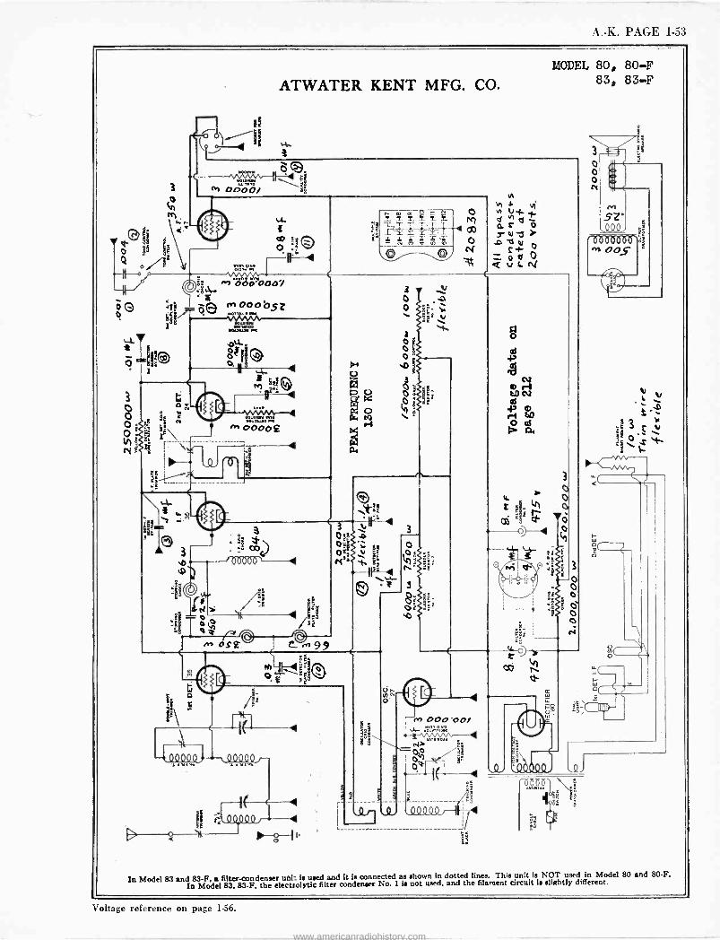
A. -K. PAGE 1-53
ATWATER KENT MFG. CO.
MODEL 80, 80-F 83, 83-F
In Model 83 and 83-F, n
efi83.8 F. the el ctttolytic use d
roondenser No l is not used, a it is connected as shown in
nd thted e filament circuit Is snee.
This unit is lightly different.T
used in Model 80 and 80-F.
Voltage reference on page 1.56.
www.americanradiohistory.com
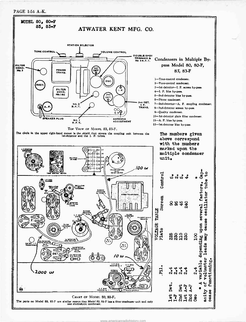
PAGE 1-54 A. -K.
MODEL 80, 80F 83, 83F
FILTER CON D. No. 3
ATWATER KENT MFG. CO.
STATION SELECTOR
TONE CONTROL VOLUME CONTROL DOUBLE -SPOT TRIMMER & No. 3 R.F.T.
SPEAKER PLUG No. 1
R.F.T. ANTENNA ADJUSTMENT
2ND DET. 1. F.
TRANS.
Top VIEW OF MODEL 83, 83-F. The circle in the upper right-hand corner is the shield that covers the coupling unit between the
let -detector and the I. F. tubes.
EM DETECTOR IRATE RESISTOR
YELLOW
IM CI pTq, cONOENWI
FR D(TVCTOR PLATO FILM
CHOKE
IILTER co44oEN.ER
M..!
KM. NE.,.TO.J
A. P. ORID. N.. E
kREEN EEsiiioR
DETECT. .,ss RESISTOR
VOLUME CONTROL
ON-OPI .24,1044
POWER TRANSEORMER
FILM MOMS. . 1 IIUMENT-6HUHT uIETOR
RESISTOR Ib. E LEAR
AHTEÿN TRIO
CHART OF MODEL 80, 80-F. The parta on Model 83, 83.l are similar except that Model 83. 83-F has a filter condenser unit and only
one electrolytic condenser.
Condensers in Multiple By- pass Model 80, 80-F,
83, 83F
1-Tone-control condenser. 2-Tone-control condenser. 3-1st-detector-I. F. ,creen by-pass. 4-I. F. bias by -pase.
5 -2nd -detector bias by-pass. 8-Phone condenser.
7-2nd-detector-A. F. coupling condenser. 8 -2nd -detector screen by-pass. 9-Quality condenser.
10-lst-detector plate filter condenser. 11-A. F. bias by-pass. 12 -1st -detector bias by -pass -
The numbers given above correspond with the numbers marked upon the multiple condenser unit
www.americanradiohistory.com
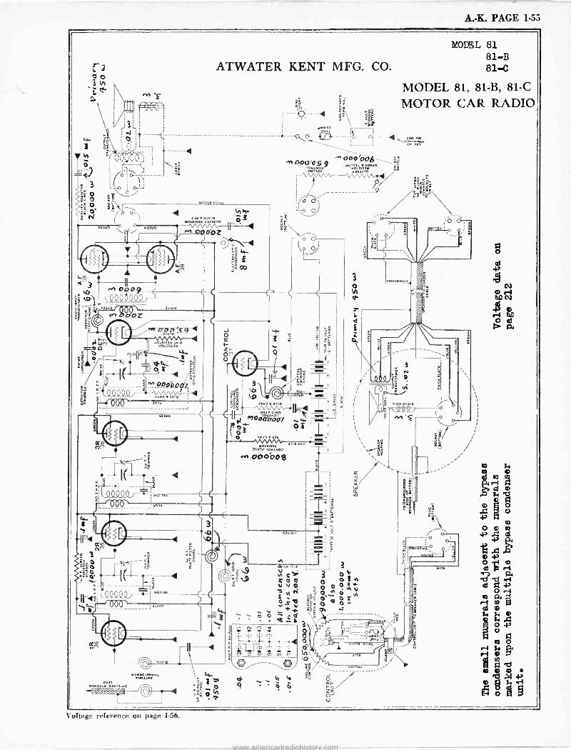
A. -K. PAGE 1-55
1i". 7 äe
Q-
MODEL 81 81-B
ATWATER KENT MFG. CO. 81-C
MODEL 81, 81-B, 81-C
MOTOR CAR RADIO
NMOtla MO1N1
4 OItl )IOY,9
te 3 M)IY0
OO Z
, Y3 MM)iM tll \ 4r
lllllllllllllll ó aú: o
4
- `\ .IYIiI ))na ----d --
.rf ODU'O$ 9 loM1YG0 IwnlOn
gr 44 : OM.
o. In
OOO ÓÉ. .MOIIIA Na3Y0
IÓI)lY ÇÑ
9/ L c
1:101I1S1Y iOla
31Y1.1 10tl1Y02
e.9 OOOÓO e
ó ó
3
-T' 1
3
3 ° 0 ° o!h s o O °tl°,v ºo r,c
o o r *v t W Oh
Qr i á ..- -------------
a 4 ò
O113w-----
a
oltage reference on page 1.56.
www.americanradiohistory.com
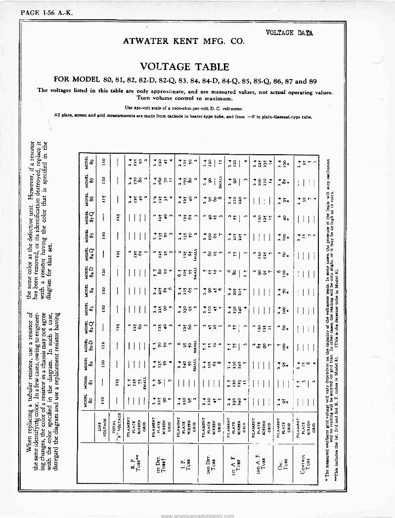
PAGE 1-56 A. -K.
VOLTAGE DATA
ATWATER KENT MFG. CO.
VOLTAGE TABLE FOR MODEL 80, 81, 82, 82-D, 82-Q, 83, 84, 84-D, 84-Q, 85, 85-Q, 86, 87 and 89
The voltages listed in this table are only approximate, and are measured values, not actual operating values. Turn volume control to maximum.
Use aso -volt scale of a i000 -ohm -per -volt D. C. voltmeter. All plate. screen and grid measurements are made from cathode in heater -type tube, and from -F in plaln-filament-type tube.
J 0 Q X
..1
Or
I H ., in H w~ ~ .rH H
~H H
I
J
O I f V H
1n.r- ÿ .
rile-
H H H O H
* r. ri ~
ó X
I
Ñ O H 00
Og O
Y O H 00
.F O 1 HU Y O en
HGI .f O a fi
~ v H. I I I I
J o $ I"ZH r Y
r r 02 H H H I I I I
.. H
P{ o< N
w 'y x ce-c'.I
I I I
H N O M H N N rn H O N rn H H N I ,-i N1 H O N N lr H O { IIII
12 I I I I I
N n O H gM
s V e.- r- M 00wMO - Hr H: rN : Hf HN HN
I I I I
H 8 rf
J N J I "H
r H"HIH"° r r "$H" HNI " H2"" .. ,- H$ I I I I
JA J
le
J ra
s I I I r " "0N "º r'091: H aa" O{ 1 1 1 I
° 2 .. I IIII f N MO H f M M,.1 HH r'& M N u- HH 1111 H{ I111
J M °° O
.. I II I I
h v. r& a0 H P -r0 M M ri..:*r -ar0 0 w I I I I
f Hg{ III I
Jcy O ö oo I
H$M HM$. H. , ",g{ I I I I
J
°z J
.. I I I I I
MOO tN M O`N <
a
aOH M r y
Ñ1 ri In hs. I I I I
° Ow" 2 .
I 1111 H.."~ I I I I
P{ ñ°°' X
H< X Ho°° 1-1 HHH" H"
J J
O 00 X
I ..r. r..H.n NPI `' 1111 I I I I rrr
I I I I I I I N1 H
óO 0 N 1n *O vH O NN f O O f 1 o--
X I 1111 H& ri 2' ir.' m7 -'47t III' HP{ IIII
w 0 F-
w Z
,-
w
F- F-
w-
1- F- X
F I- <<rt r J
1O Ó 243.
< ,< cC aG<a<yx O
i je O
,er -'je Le <rigg
w ,w, a <2s F< w G
<
w <
O < 0
o f- m
J0. 5 i
J C k á.
gig J J u i
J . 5 d
o. p O Z.
. O J áW O 4
{ "' o4
Am U.; 'A Á 2 F F
I
e2 zH
eel
2;Q OH
áJ
H;w óHf2
H H U
www.americanradiohistory.com
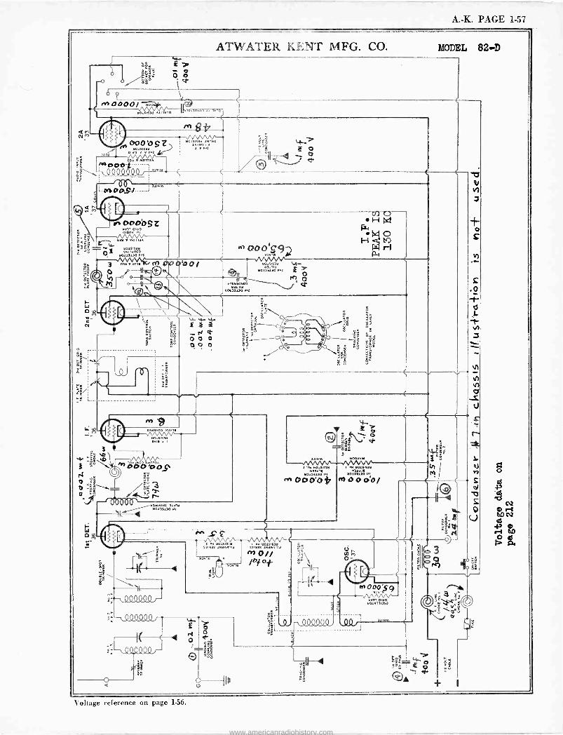
A. -K. PAGE 1-57
ATWATER KENT MFG. CO. MODEL 82-D
Q M N
ö;tl er,. ós w
Y ' ,e 0000/ 901914311. Ali 1.00
u3C130u00 A111v00
000'O S Z 0
015143tl 01 0 f't1
M0113A _\ PIN oOfl ci QO , 11rls
V 53 ì1111M .MD4.S/..._
I
1n
8fir 30111433 190114
3wYl1f
o
in OODoSZ o1n
? ó'á9 Oltl.M0113A
tl014143tl ò z 0911.003 110103110 wi
3 0 Xtl 3014 4 ^ 00 o S9
H 4 H
trJ O
1
e2 M
a Ñ
\ \
t.. oa/
Oó
0=\ ót Z
ryM ^ iy1
W
N t O 0 0
. C C
tld#áM;tl \rra -
031 tl0130 F.<s 11O7
re) c4-
tl31t1f tlOL03130 wz
o
3
ä
ág cEa
m tl3tl3A02 ,3.1.
110.1.119311 MI '1 l
,^) Wdijop
;=3 3 Q
000 \ 1tl131.,.
"7,
O hs`.' nct>
nÿ:
11111M 900tl.01
w..0141n11 1 w tlolnntl 110123130 Pl
3.1 tl013130 P1 3.2000'0* M1000Ó/
\ 1
\ Q900Q9 /-
;:-1/4.00000(17
-,00,0 000
#e_ e:
M M/\/'` ..11 tl01414'tl 1'01.1
tl0 14C3,
$31u 93wV1 34113 531u34 13
1001
3
M A
O
É \
--I(i¡
- ,
Q9000, .QQJ;
V oltage reference on page 1.56.
www.americanradiohistory.com
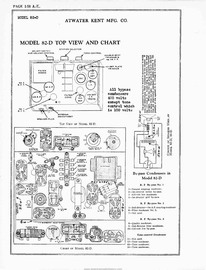
PAGE 1-58 A. -K.
MODEL 82-D ATWATER KENT MFG. CO.
MODEL 82-D TOP VIEW AND CHART
NO. 2 R. F. T.
NO. I R. F. T.
STATION SELECTOR ON-OFF SWITCH
AND VOLUME CONTROL TONE CONTROL
ANTENNA ADJUSTMENT
SPEAKER PLUG
TOP VIEW OF MODEL 82-D.
DOUBLE -SPOT TRIMMER & No. 3 R. F. T.
IST DET. PLATE TRIMMER
C
'4.101 Ç 38
h o,dutl o C I. m
n 7 o
ÑGaca > "°FVv
All bypass äno $$ Hm" condensers 411 g
ao-o 400 volts zQ"°
aw except tone óaö,ß
control which 2e20Mee is 100 volts wee a
TONE-cONTNOL {nIN LONO TOO[NKR 6WITCN
In DETECTOR KATE
TRIMMER
e°g is DET.
O
ÏIAñ CNÖK!
OSCILLATOR TRANSFORMER
C
WAS.,
TOR OHIO
UI{
R. F. {,RAISE Plc E
R O. EV-NAM N..e
. I. EV.IAu
lut OETECTOR {CREEN
ROI{TOR N. I
//lot DETECTOR
//Rfl 6T0R I{CRaN M. E
OSCILLATOR ARID LEAR I "C DEEECTOR /RESIETNO RE{I{TOR
Eno DETECTOR IILTIR RKIROR
IpCNR
V>",-0,4
N..
-J
.
N..I
FORE CONROL
coNoTeN{ER
Yee
OO OO SPEAKER
CHART OF MODEL 82-D.
h $ó
By-pass Condensers in Model 82-D
R. F. By-pass No. 1
1-Ground coupling condenser. 2 -1st -detector screen by-pass. 3 -110 -volt line condenser. 4 -1st -detector grid by-pass.
R. F. By-pass No. 2
5-2nd-detector-lst-A.F.coupling condenser 6-Filter condenser No. 2. 7-Not used.
R. F. By-pass No. 3
8-Quality condenser. 9 -2nd -detector filter .condenser.
10 -110 -volt line by-pass.
Tone -control Condenser
11-Not used. 12-Tone condenser. 13-Tone condenser. 14-Tone condenser.
www.americanradiohistory.com
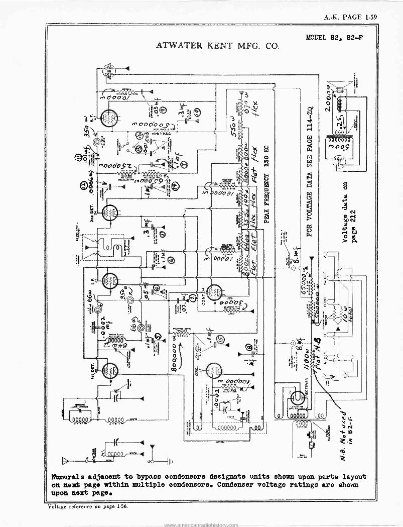
A. -K. PAGE 1-59
a II
D Ó sit$
ATWATER KENT MFG. CO.
T 000°o pfMT
n+-n+- e ....
' QoTOQº 4
w0.1.111/11w 111
ce
3 m00Ó00/
ooi i
t
110.11
MODEL 82, 82-F
LL
Numerals adjacent to bypass condensers designate units shown upon parts layout on next page within multiple condensers. Condenser voltage ratings are shown upon next page.
Voltage reference on page 156.
www.americanradiohistory.com
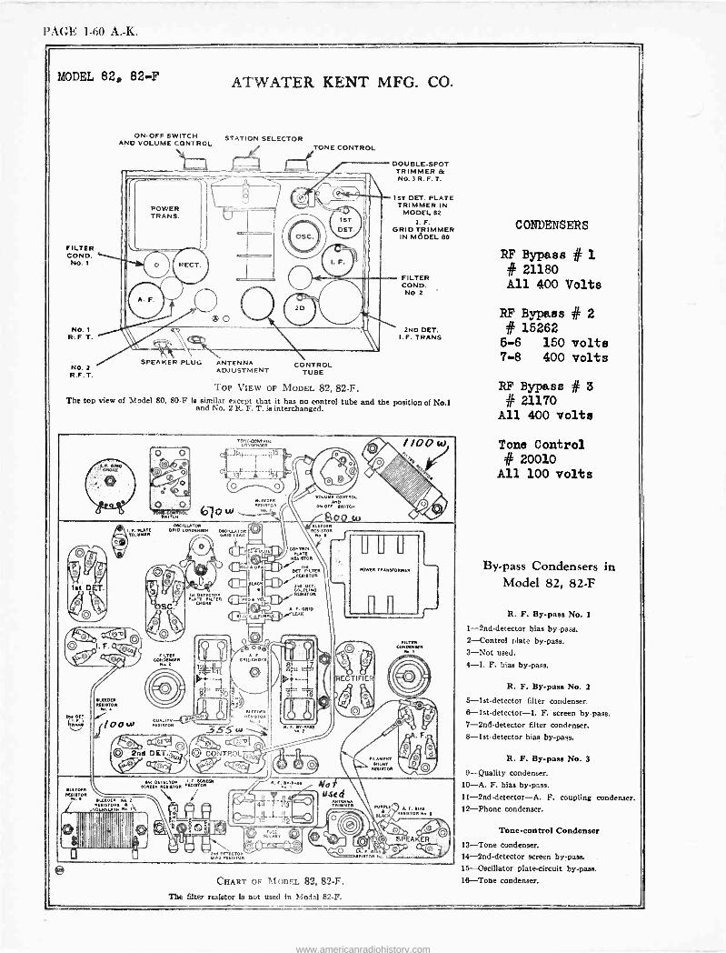
PAGE 1-60 A. -K.
MODEL 82, 82-F
FILTER COND. No. I
NO. I R. F T.
No. t R.F. T.
ON-OFF SWITCH AND VOLUME CONTROL
ATWATER KENT MFG. CO.
STATION SELECTOR
SPEAKER PLUG ANTENNA ADJUSTMENT
rn TONE CONTROL
CONTROL TUBE
DOUBLE -SPOT TRIMMER & NO. 3 R. F. T.
1ST DET. PLATE TRIMMER IN
MODEL 82
I. F. GRID TRIMMER
IN MÖDEL 80
FILTER COND.
NO 2
2ND DET. I. F. TRANS.
TOP VIEW OF MODEL 82, 82-F. The top view of Model 80, 80F is similar except that it has no control tube and the position of No.1 and No. 2 R. F. T. is interchanged.
REEDER ILLEIETON NF S
FILTTIN CONDENEER
M..T
QUALITY ADIETOR
REEDER NLSISTON
(37ow` N..,
PLAIT FIL LT P CHORS
00 . a ORIDCMONL
REEDER RESISTON
CONTROL
O
:naw..i
VOLUME CONTROL AND
owe,. SWITCH
CONTROL Run RONEY«
DET.. FILTRO NUISTON
//00 w . P
UUU POWER TRANSFORMER
ECTIFIE
FILAMENT SNUNT
NESISTOR
FILTER CONDIINSLN
N..
RES AISFT.
OR Na EIAE
E
® ' ` ' 'O O Q(Q S' A ER ,.). PE sI0 o a f -S
MON N..
CHART OF MODEL 82, 82-F. The filter resistor Is not used In Model 82-F.
CONDENSERS
RF Bypass # 1 # 21180 All 400 Volts
RF Bypass # 2 # 15262
5-6 150 volts 7-8 400 volts
RF Bypass # 3 # 21170
All 400 volts
Tone Control # 20010
All 100 volts
By-pass Condensers in Model 82, 82-F
R. F. By-pass No. 1
1 -2nd -detector bias bypass. 2-Control plate by-pass. 3-Not used. 4-I. F. bias by-pass.
R. F. By-pass No. 2
5-let-detector filter condenser. 6-1st-detectot-I. F. screen by-pass.. 7 -2nd -detector filter condenser. 8-let-detector bias by-pass.
R. F. By-pass No. 3
9-Quality condenser. 10-A. F. bias by-pass. 11-2nd-detector-A. F. coupling condenser. 12-Phone condenser.
Tone -control Condenser 13-Tone condenser. 14 -2nd -detector screen by-pass. 15-Oscillator plate -circuit by-pass. 16-Tone condenser.
www.americanradiohistory.com
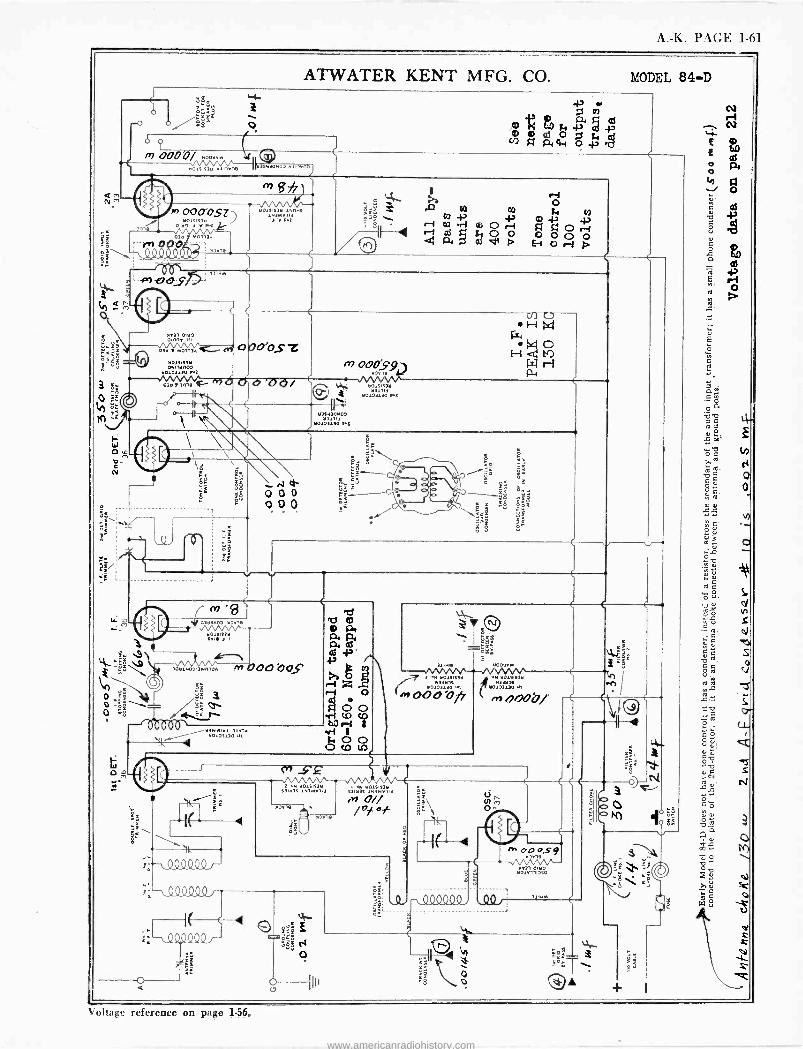
A. -K. PAGE 1-61
I aa t /$0 re woe/ Yoo
ATWATER KENT MFG. CO. MODEL 84-D
ò
o.
á ó o ó ó
co
>~ cot:t w a-, o -4-47
Yo.. :: ;:re
lh 000"0.97 le1 r i o z
Ò6 -en pO;j
i \ 3i 3
o
9 41n`<_ I Yoi1
31r,. Jl137 r,
10Y1701.311010
Zg
110171117 rvuvl f1 M COO YJOS
3070 Ali Y
rnYh r-4 o Ti V!
A r o ri Ei o r-I
O A
m oodS9 B
3 1. 7o3iié11 vI 13-
Yoi03130w:
113933Y700 Y111f
YO1N13o 31
rJ d` Q 0 0
o0
77 701711111 9311139 1113117114
7,11
11Ow311`Y 9311139 11f
S
3 'Nl .1.11.14.MIIYM
70101110 Yl
MOOOOf/
007737
e11 1101711111 331.19
11010313o m
+ OQOp/'
371000-5'9 313,7
09.00.0.
7m m7o 11o1m1xo
11N
r4
Q o
a
\ oltage reference on page 1.56.
www.americanradiohistory.com
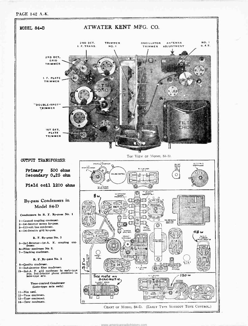
PAGE 1-62 A. -K.
MODEL 84-D ATWATER KENT MFG. CO.
2ND DET. GRID
TRIMMER
I. F. PLATE TRIMMER Er
"DOUBLE -SPOT" TRIMMER
1ST DET, PLATE
TRIMMER
OUTPUT TRANSFORffER
Primary 600 ohms Secondary 0.25 ohm
Field coil 1200 ohms
By-pass Condensers in Model 84-D
Condensers In R. F. By-pass No. 1
1-Ground coupling cOndenser. 2-lst-detector screen by-pass. 3 -110 -volt line condenser. 4-let-detector grid by-pass.
R. F. By-pass No. 2
5-2nddetector-let-A. F. coupling con- denser.
6-Filter condenser No. 2.
7-Tracking condenser.
R. F. By-pass No. 3
8-Quality condenser. 9 -2nd -detector filter condenser.
10 -2nd -A. F. grid condenser in early -type seta. 2nd -detector phone condenser in later -type sets.
Tone -control Condenser (Late -type sete only)
11-Not used. 12-Tone condenser. 13-Tone condenser. 14-Tone condenser.
2ND DET. I. F. TRANS.
TRIMMER NO. 1
OSCILLATOR ANTENNA TRIMMER ADJUSTMENT
TOP VIEW OF MODEL 84-D.
NO. 1
R. F.T.
See note on .5cherlatle,
FILAMENT EER ES RESISTOR No. 1
c,
Ad DETECTOR COUPLING RESISTOR
DIO INPUT TRANSFORM
e. F. EYRAEE No.
130 w TÁTENNA
ER
R.F.ON..i UNDERNEATH
.. aff FEARER `S '
CHART OF MODEL 84-D. (EARLY TYPE WITHOUT TONE CONTROL.)
www.americanradiohistory.com
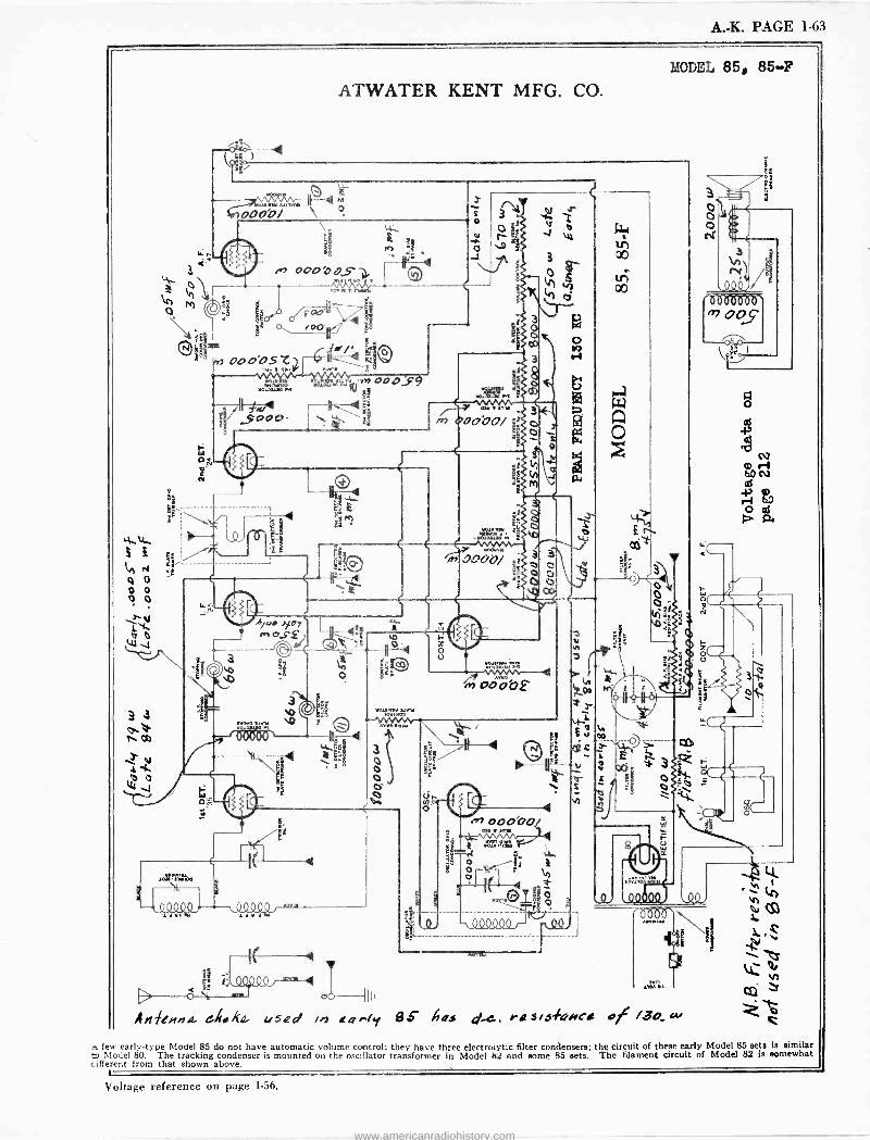
A. -K. PAGE 1-63
MODEL 85, 85-F
ATWATER KENT MFG. CO.
V
`1., o 4.1
QM
©§- /' ¢Fe
' ,AOOÓOSZJ,- M111/102 ..,, m ooO,s9 r F.K1
é ag .
v L. m...,. , 3 /-,ÇG09 I \ g m x0000/
1
0000/
b/.. .fny n, oS.F
If Y,,,. 4
D mn
AM en.l'a- used ii dao-fy 8.6- ties d-'-. ray/ 146vcs of /3o ex,
few early -type Model 85 do not have automatic volume control; they have three electrolytic filter condensers; the circuit of these early Model 85 sets is similar to Model 80. The tracking condenser is mounted on the oscillator transformer in Model 82 and some 85 sets. The filament circuit of Model 82 is somewhat c ifferent from that shown above.
Voltage reference on page 1-56.
www.americanradiohistory.com
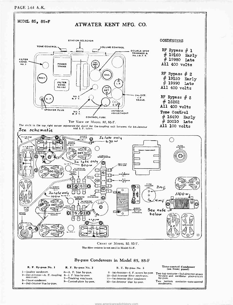
PAGE 1-64 A. -K.
MODEL 85, 85-F
FILTER COND.
NO..3
TONE CONTROL
SPEAKER PLUG
ATWATER KENT MFG. CO.
STATION SELECTOR
No. 1
R.F T.
VOLUME CONTROL
ANTENNA ADJUSTMENT
DOUBLE -SPOT TRIMMER & No. 3 R. F. T.
2NL OFT. I. F.
TRANS.
CONTROL TUBE,
TOP VIEW OF MODEL 85, 85-I.. The circle in the top right corner represents the shield for the coupling unit between the 1st -detector and I. F. tubes. See. schematic
lEt DEYECTOR ILTER-CHOK
TRNE
NTMRNENA TRI FR
-. FNAMENT.EHUNT ESISEOR
NTROL
R. F. By-pass No. I
I-Quality condenser. 2-2nd-detector-A. F. coupling
condenser.
3-Phone condenser. 4 -2nd -detector bias by-pass.
UR RESNITOR
I 02:3 ) 1st DET.7
e
ih I af42 only 10 'JO
o KRFENRVEMTOR
In la -Fe oaly 8oOw
End DETECTOR SCREEN RESISTOR
CONTROL
EHETOR
AUDIO 01110 LEAN
End DETECTOR COUtiro
oR
End DETECTOR i ER RESISTOR
DUALITY REUETOR
OSCILLIATEAKOR ORZO
'ROWU TRANSFORMER.
f-
A.CC, I uNRqlmoR l
A F. 4-SIN REfIET011 wE
o
ELEDER= - DRE «aE
'Iv SLEEOFR f -RESSTORE
S2 UNDERNEATH
CHART OF MODEL 85, 85-F. The filter resistor is not used in Model 85-F.
CONDENSERS
RF Bypass # 1 # 19160 Early # 19980 Late
All 400 volts
RF Bypass # 2 # 19150 Early # 19990 Late
All 400 volts
RF Bypass
# 15262 All 400 volts
Tone Control # 16490 Early # 20010 Late
All 100 volts
FILTER CONDENSER
UNIT
o
#3
TER ONENS[R
( OO OD
TIFIER OO
0,00) o a
nohliddi ° below
By-pass Condensers in Model 85, 85-F
R. F. By-pass No. 2
&-A. F. bias by-pass. 6-I. F. bias by-pass. 7-Tracking condenser. 8-Control-plate by-pass.
R. F. By-pass No. 3
9-1st-detector-I. F. screen by-pass. 10 -2nd -detector filter condenser. 11 -1st -detector filter condenser 12 -1st -detector bias by-pass.
4. f
Tone -control Condenser (on front panel)
Two top contacts -2nd -detector screen by-pass and oscillator plate -circuit by-pass.
Two bottom contacts-tone-control condensers.
www.americanradiohistory.com
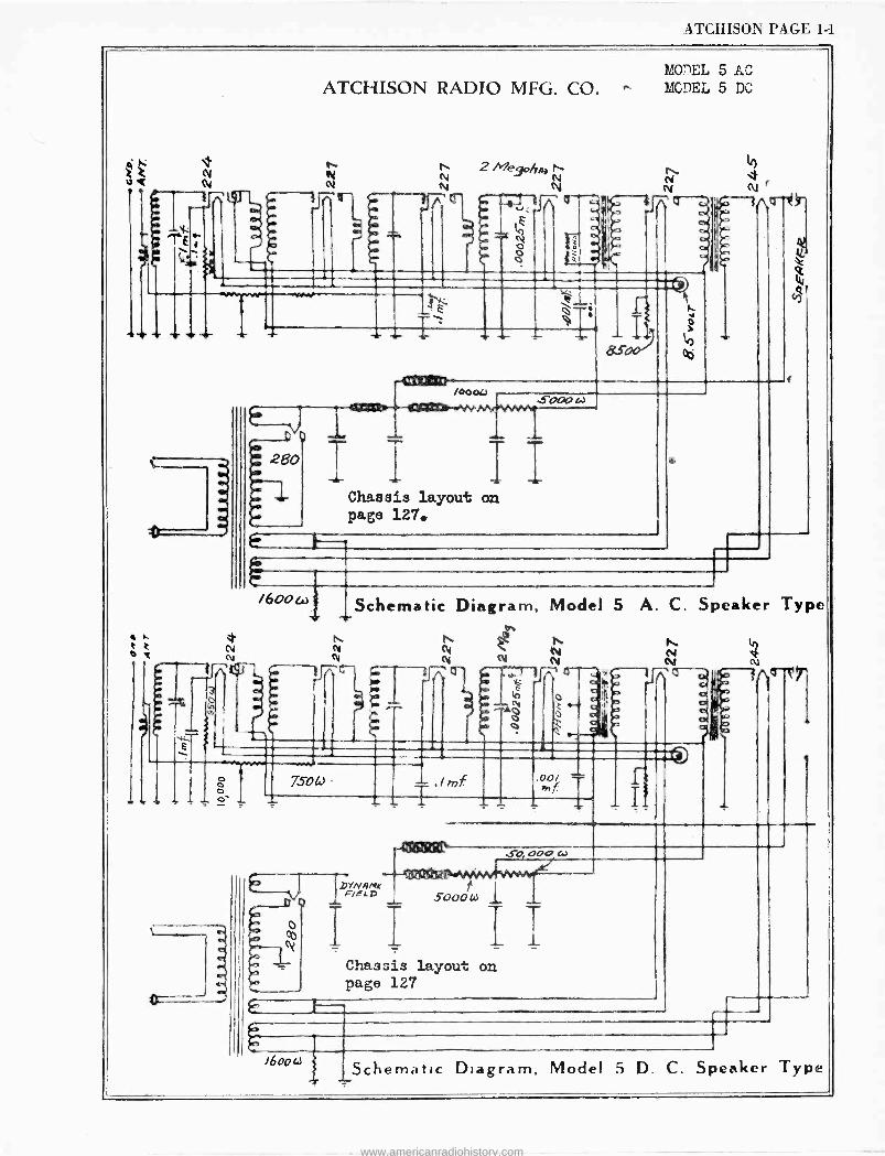
ATCHISON PAGE 1-1
Ñ
t
MODEL 5 AC
ATCHISON RADIO MFG. CO. w. MCDEL 5 DC
n N N
2 Meyoljm ti Ñ
Flj_ .,7\
N. N
r A 0-7.; J\cr-e-
3
280
,000iJ sooc,
1
i I I Chassis layout on page 127.
i600c., Schematic Diagram, Model 5 A. C. Speaker Type d,
* N t e t. eÑ N ei tV n N
- - -- Z r r
Hr ti N
.00/ f
So, 000
V il!nc ,SoO W 1
I II Chassis layout on page 127
e, 6
i600w 1Schematic Diagram, Model 5 D. C. Speaker Type
www.americanradiohistory.com
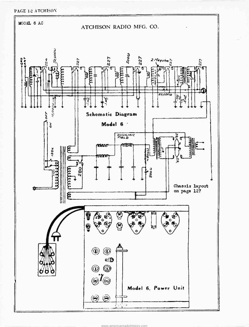
PAGE 1-2 ATCHISON
MODEL 6 AC ATCHISON RADIO MFG. CO.
Z V[ N 1 N
n
N N
2 Me9olioj Ñ
C e
N
t
e-
s o
T 1 If
Schematic Diagram
Model 6 '
so,000w
i .
`K;
fr
DANA M/C F/EL D
Mane-- ireath
o
N
elm 3 g 03
i Chassis layout on page 127
(ic-ü) e [A'
Model 6, Power Unit
1_ I
www.americanradiohistory.com
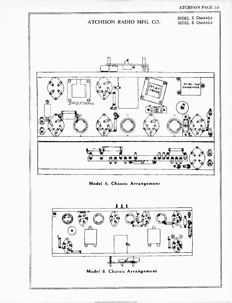
ATCHISON PAGE 1-3
MODEL 5 Chassis ATCHISON RADIO MFG. CO. MODEL 6 Chassis
ñ n
.. ' o -. 1 o
\J .c
=I h ,
Í /sri4C elk
DciAL .,m f COMywllt
._ , O O .
2-0 4-7,' re' /aNS,
J lie G
(:t ' S A T
a
%A E
W ..e 0...b --.... ---_. d q
el) 3)
Model 5, Chassis Arrangement
Model 6. Chassis Arrangement
www.americanradiohistory.com

,.,. .,.: www.americanradiohistory.com
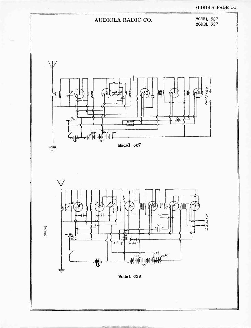
AUDIOLA PAGE 1-1
f
,M,.- .low
AUDIOLA RADIO CO.
C
II111I1
MODEL 527 MODEL 627
Model 527
pl
344 Any.
67z v/O5 22 i
_ {I1I 1 I1I1I'l I!I1IfI1II1I1
Model 627
www.americanradiohistory.com
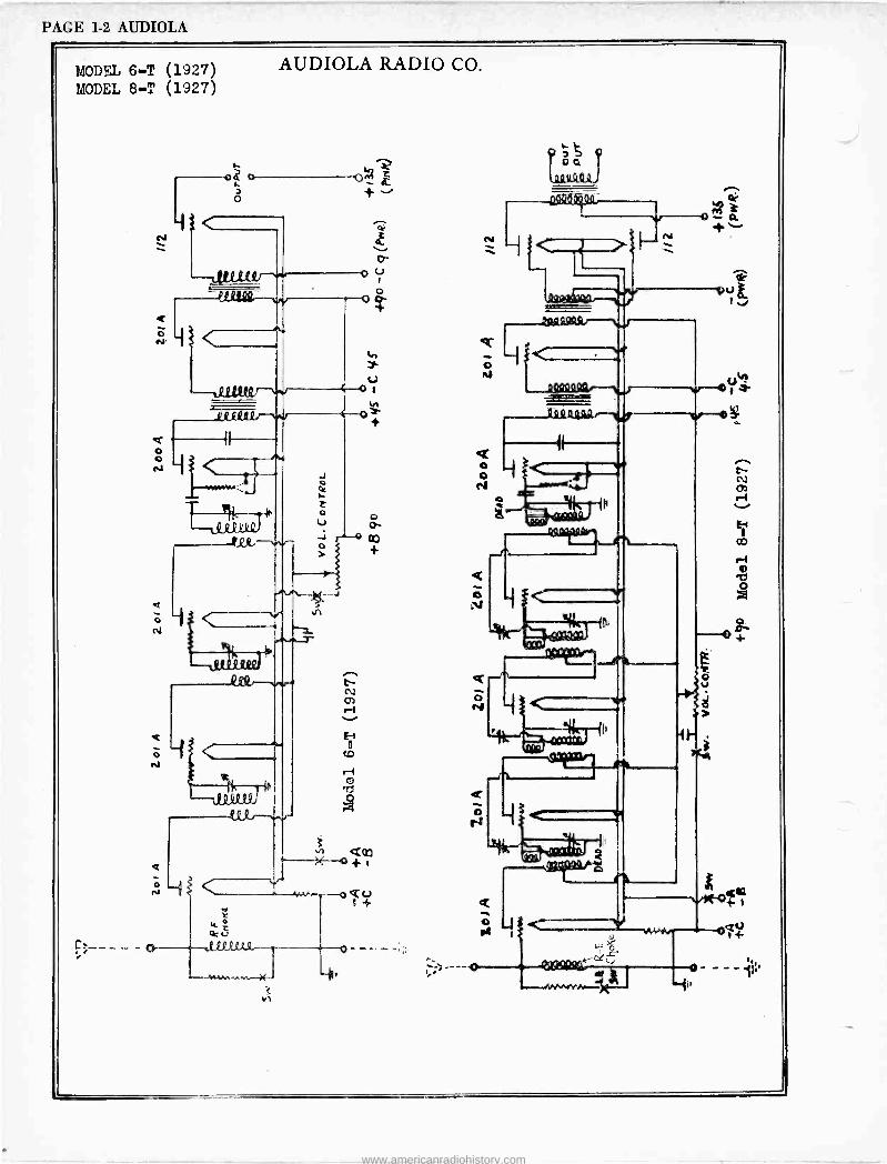
PAGE 1-2 AUDIOLA
MODEL 6-T (1927) MODEL 8-T (1927)
o
o o e4
o
o
'----
Z o
I
AUDIOLA RADIO CO.
f---® +Q2
o
< }
e
o . 1-+
O eV
o
N - 0. ..
us e
Q o
o- ---'' "{'
www.americanradiohistory.com
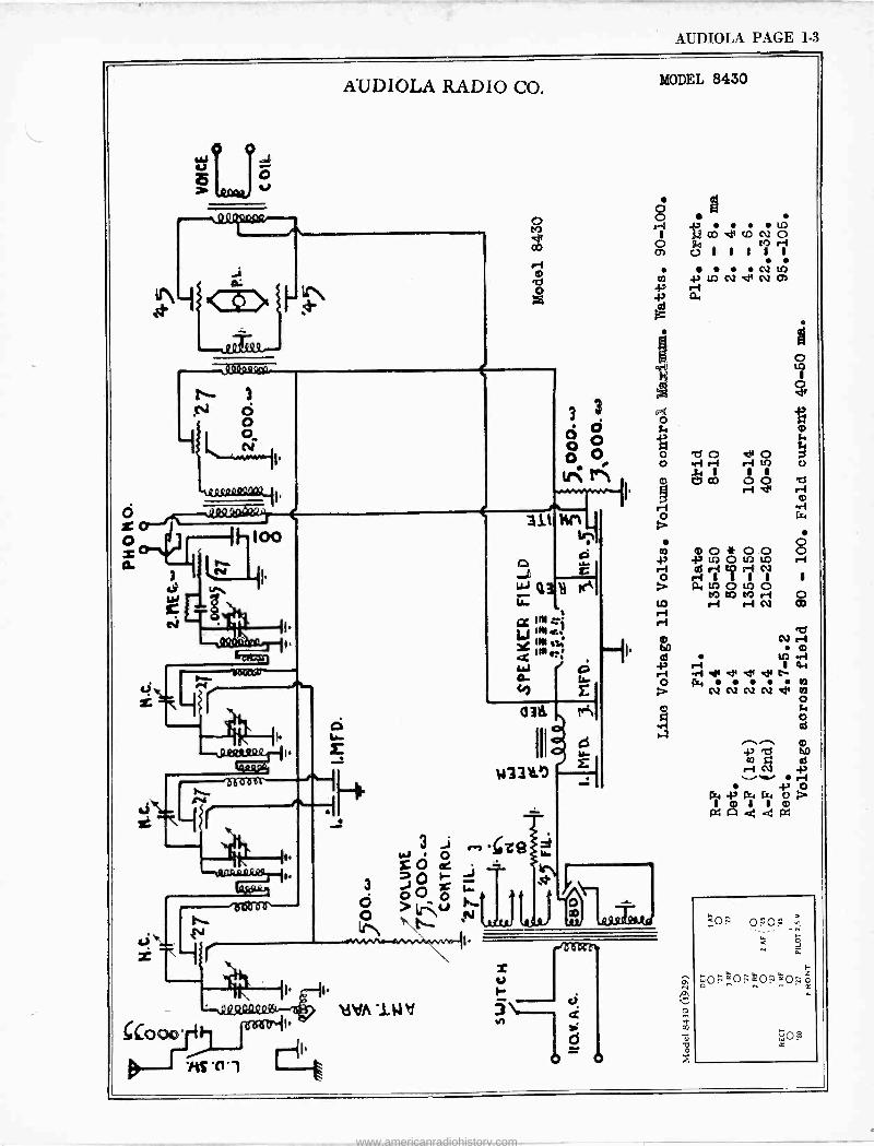
AUDIOLA PAGE 1-3
A UDIOLA RADIO CO.
d -J u G 8
>
COoo
AS -0 1
u 1..
Vitf iNd 3
e
IM
MODEL 8430
o } 1 f7 CO e ca N O o
U 1 1 1 1 1
N tf) m IAN NO) 43á Lit
i i i P. m láa
wooaooa
www.americanradiohistory.com
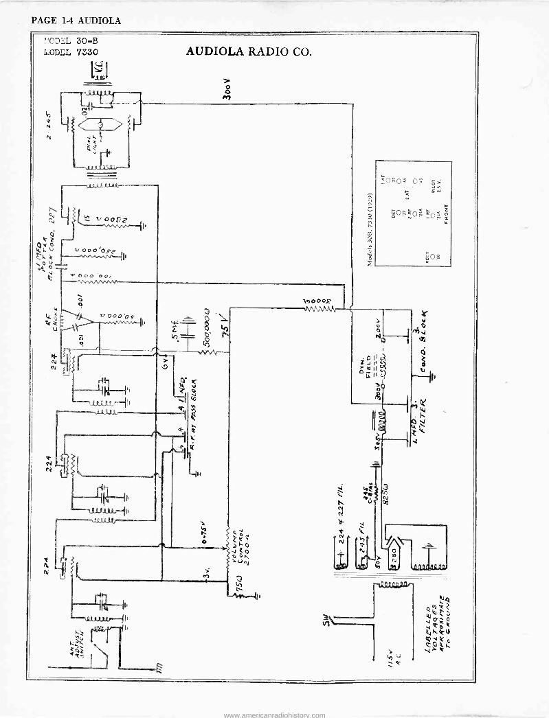
PAGE 1-4 AUDIOLA
AUDIOLA RADIO CO.
o o M
(-:':1)EL 30-B MODEL 7330
V 0o v---1`
vO[,O o0i NesAlnMM
ti
ú
QOQá Qo ;
0e0" =0
3
l J
e
www.americanradiohistory.com
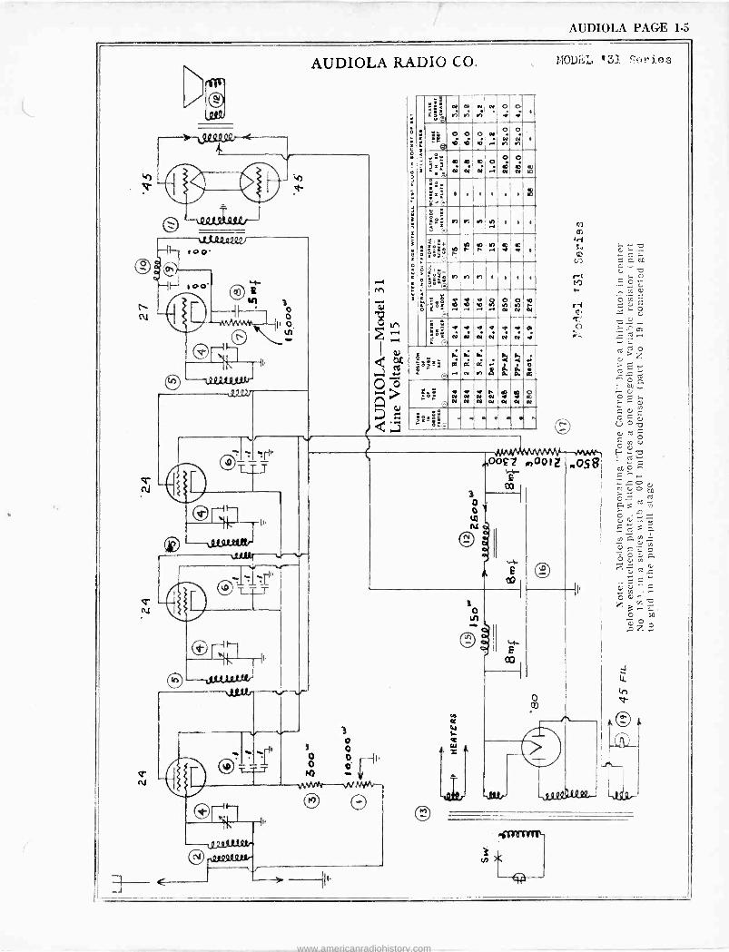
AUDIOLA PAGE 1-5
ort 112.2uáxur
.Q22'I
O
0
or -1.12.210121,.
-tti2212211'
AUDIOLA RADIO CO.
w ''+ ¡ú
O N
NI N Mi
6 y
O N O
.: ñ
O O N
O /ó N
O N
O
Ñ
1
IA
ñ
r r W 1 1 1 -r
b r a n h .1 e d 1
Ir+ ºio r 1 1 1
o y 'ói O G a ñ ÑN 1O/1 YO/
N N r N
iós)N '- (
'.°'. á Q N
N
/.. d co
á
al
r
Ñ
V á
ß
CV
N
s N
N
<
á.`
s a
3 o o
P i
Y o
o w
MOvLL '31 SAr i,es
m00£7 moot I.O58 F
o co
www.americanradiohistory.com
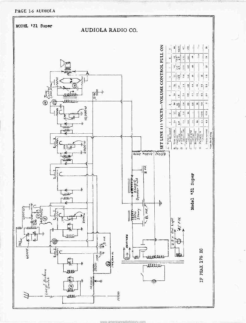
PAGE 1-6 AUDIOLA
MODEL '31 Super AUDIOLA RADIO CO.
a 8 c C °c o 0o È
O 3 o o E
E o
o o -- -- -
ru0
a
o
o
z o a a 7 a o C:i
H
o U
o
o
r
z á 1-4
cn
osez "oS18 c"oÇ8
E 0o
s
.Ia: 4è
ó4 «
« T w 0
I m
g .'; o
á
0
p
É
1 J -0223U.22 Qr---
ó
G
f ó°
`°ó
_ e, a., EL
GT.
d
.yi
11%,
Ú'
V K C..
wó
Ñ'
U
3 9 ,
ta mt U
J
www.americanradiohistory.com
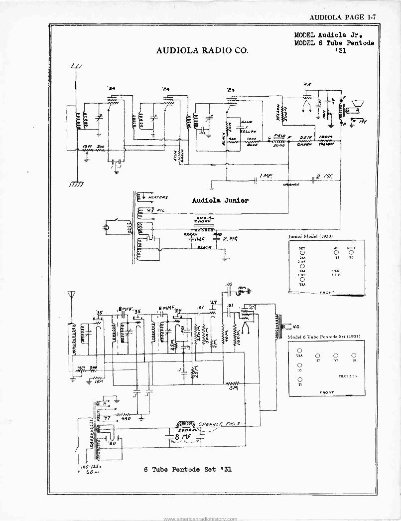
AUDIOLA PAGE 1.7
l
AUDIOLA RADIO CO.
'24 'P4
4 NerzvrcRS
.0:
. if Iaur
r / >21 -LOW
e e0 /000
MODEL Audio's. Jr. MODEL 6 Tube Pentode
'31
ts
/4o Site 5000
F
7s/1 GRm»,
/**er rraLeo,
Audiole Junior
6o0 J11.- CNOKE
RO cg1M
2. M F,
_BLfCK
$r1r1F.. 8 P1MF=
II- rï4 IH .*
4Y
E
O
'27
h
r
.0/ ,_1_41
'é
105-/Z.sr G0N
5M
raá SPERK.ER FIELD 2000.e..1 /
T8 iv:T
6 Tube Pentode Set '31
o
r
unior Model (1930)
DET AF RECT
0 0 0 '24A '45 'Aº
2 RF
o '24A
1 RF
o '24A
V.C.
PILOT 2.5 V.
FRONT
Model 6 Tube Pentode Set (1931)
20
o '35
o '35
O O O '27 '47 '89
PILOT 2.5 V.
FRONT
www.americanradiohistory.com
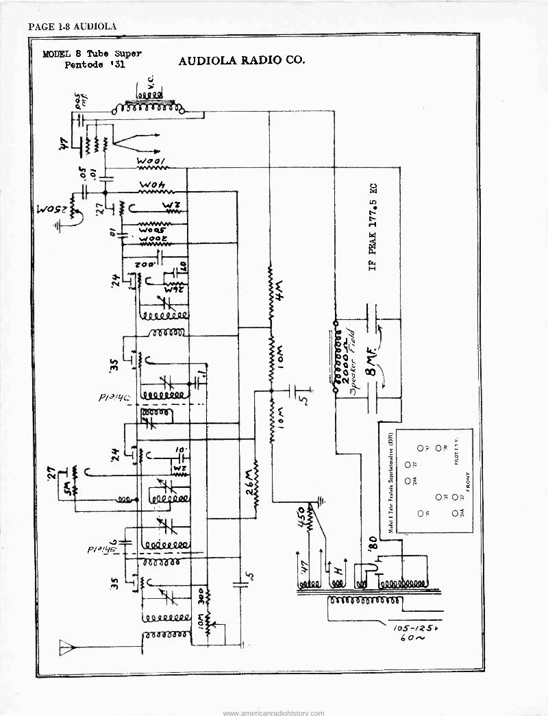
PAGE 1-8 AUDIOLA
MODEL 8 Tube Super Pentode '31 AUDIOLA RADIO CO.
c; >
414: tel 9jºº
Woo/ %0,_ 0 C
Woh
-r- WO QS' WOOL -I0A1MeN
Zoo'
in no L
P/.3'1/. 43Q44RSUt.
P
.29SüLtzeiv
d dáá'
ti ;C
M
o
e
w H
0= O$
OE;
a19
/o5-izS> 60
www.americanradiohistory.com
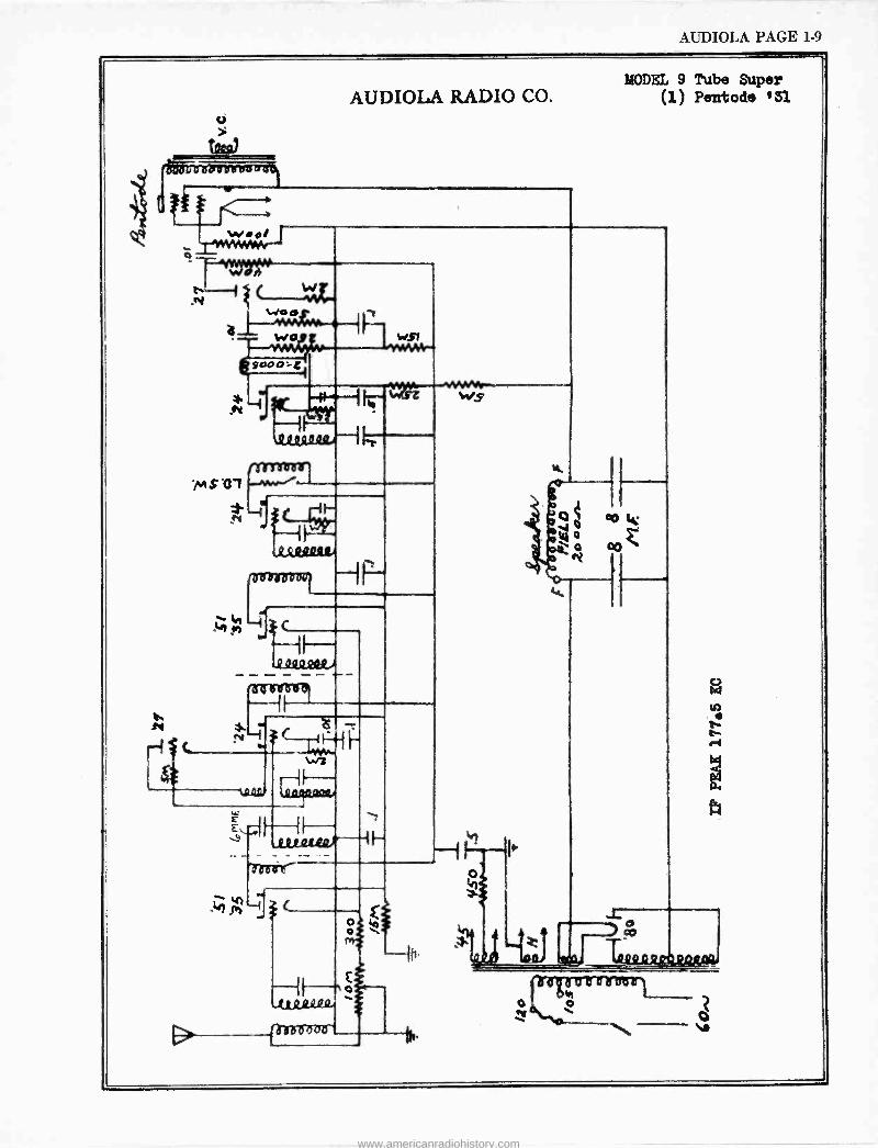
AUDIOLA PAGE 1-9
óDDD II sao v. t, w.ol
Y
MODEL 9 Tube Super AUDIOLA RADIO CO. (1) Pentode +31
Odo
wo
000
0öòa0g0Q1
C- elo)
a 43 ÌÌ . et et -4 ;
,u21 I04.4
Rii 0 or
WS(
0 o
M
o le)
T t09 o Qy .QQFaßr
0 K
www.americanradiohistory.com
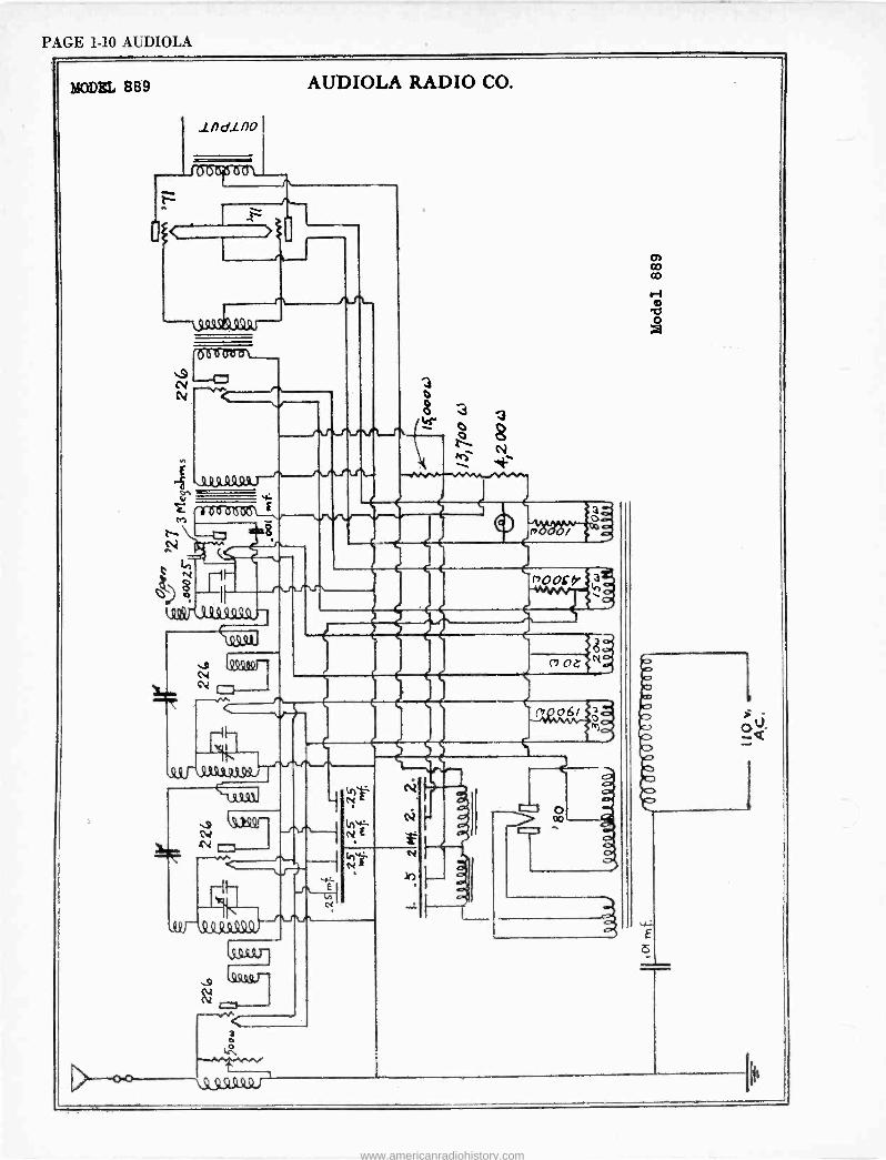
PAGE 1-10 AUDIOLA
MODEL 889 AUDIOLA RADIO CO.
lndlno
_1t3125f510 o \
49fl9,32.931.99.1
3 o
Lr° `N
óQ
www.americanradiohistory.com
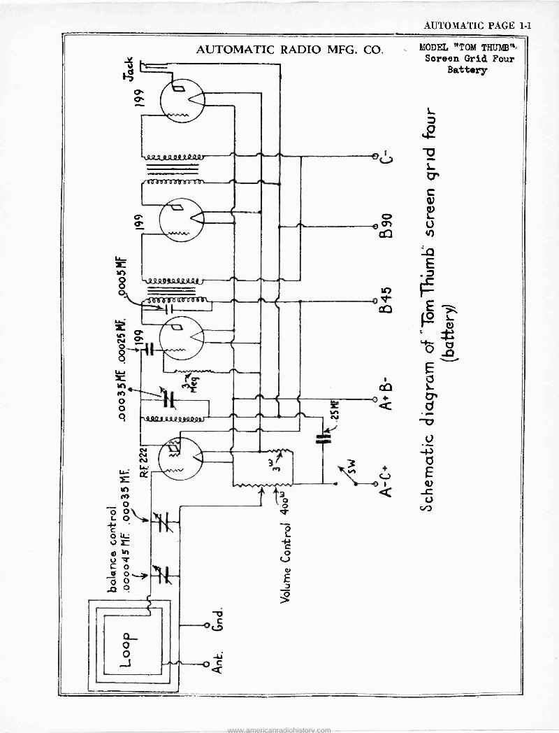
AL TOMATIC PAGE 1-1
AUTOMATIC RADIO MFG. CO.
+...
8 -,Qeaº,.cw
N o
o
O' o
1r) a(la o e
1:3
4 Aºs c a 9.31,R9¢4/
o O .J
MODEL "TOM THUMB", Screen Grid Four
Battery
www.americanradiohistory.com

e -.. r.:-.. r. T75.,,¡i. -w#a.:,r, ',
www.americanradiohistory.com
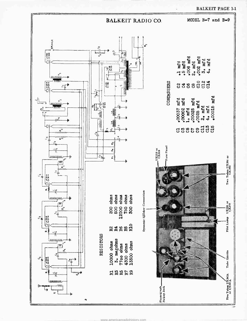
BALKEIT PAGE 1-1
-L
l1IR vvi,n)u
3
<
-o d
N^
- - -
e
n 0*
0000o900Qf
11241
--
l
0º00000..0-4
000
J
d
0
u
BALKEIT RADI O .CO.
r
J
Vf
ri
C4
ri t9 lO t 01 c4aaaa
0 4, O M
kJ
ay a "2. ao
s aa
MODEL B-7 and B-9
qY TST1 Eä +
A H °a Ó Ó
ri in O O M dr
f1
N CU er
Fÿ NetD OOrir-1rß WW U U U U U U U co
ó T1 Ry T! F(.1
U cN2 e Lo
da O N Q
O O O OOcVe ..d
ri VD OD ri !Q LO N CO ri ri r -I U U U U U 0 U U
ó
F
www.americanradiohistory.com
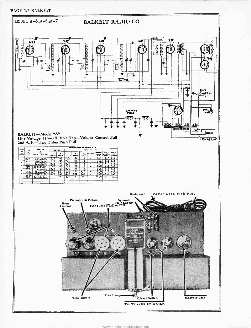
PAGE 1-2 BALKEIT
MODEL A -3,A. -5,A-7
r 121
1 T
BALKEIT RADIO CO.
127
: a
V.... $ t.H7ffi r
ó
zr b n
11
BALKEIT-Model "A" Line Voltage 115-1- H Volt Tap -Volume Control Full 2nd A. F. -Two Tubes Push Pull
aia. TV«i ;,- VON , a M..aK.
.SY Iwo. t or MT ...PUPS. ... . ... ,.. . MI.
.M,1 . ,. 00.V ,. '...a.i.. . de ST«l ... . ...,. W .... .aa
227 let.a.Y. 2.3 98 2.1 84 3 - 3.1 4,5 1.4
227 2nd.R,7. 2.3 98 2.1 84 5 - 3.1 4.5 1.4 .
227 3rd.R.1. 2 3 95 2.1 84 5 - 3.1 4.5 2.Í
1.4 0.2 1.4
,
227 Detectpr 2.3 46 2.I 30 0 - 2.2
. 227 1et.A.Y. -2.3 98 2.Y 84 6 - 3.1 4.5
; Z12A 2n4.A.Y. 4.7 142 4.5 132 9.5 - 9.0 13.8 4.8
11 2nd.A.Y. 4.7 142 4.5132 9.5 - '013. 4.8 ,
250 Heotífies - 4.5 - 12
Nun Ceri Rey
SPtwK[R FIELD
Resistance
Phonograph Pickup Dynamic Hum Field Supply
Control Five Tubes UY227 or C327
Tube Shied .
Power Cord with Plug
Voltage Switch
Two Tubes UX112A or C112A
0184 -
HIGH
1 ISV.ACUNE
www.americanradiohistory.com
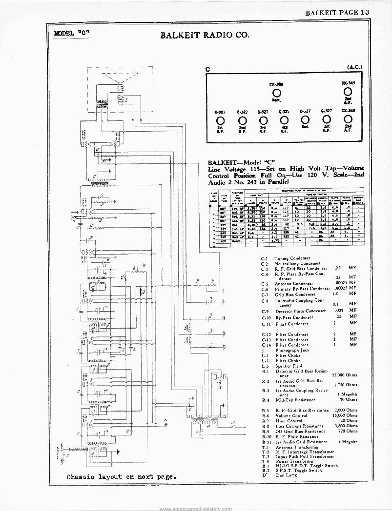
BALKEIT PAGE 1-3
MODEL "C"
Ei
Fee- ;'4rN.Nr
BALKEIT RADIO CO.
M
11.0-^-.
1(. 4.111. v P's.r
-
t£1 <
14,. T T' V93usss
_.¡Tli ¡I1I61r
äz
-i(
a9ssgp
.p
u
C (A.C.)
cx-3e0 CX-343
RO 4 A.F.
6-327 C-327 C-327 6-3ir c-)27 C-327 Cl( -345
p p p 0 0 0 0 R. F. R.F. R.F. R. F. A.F. A.F.
BALKEIT-Model "C" Line Voltage 115 -Set on High Volt Tap -Volume Control Position Full On Use 120 V. Scale -2nd Audio 2 No. 245 in Parallel
.,1. . TINT.. ere
° ®it7
r ,- n.. eve . ..
_ .K.. '136
.w.. ,.6
,
117'°10
..:.. ...._...._. S ¡Ru
10 3.8
..... 0... ..a
.,..t ....H .a
... .r - .t 11.36
' 117 ad p 6.36 U.S 5.4 117 10 10 3.6 4.6 .e - tare sel ir 1.34 116 5.4 117 10 10 3.8 4.6 .1 -
' ta7 4th If 5.36 156 4.4 117 10 10 3.8 4,A .8 - ' 127 Dat. 1.36 61 5.4 65 8.5 8.5 0.3 0.4 .1 - .
657 1.5 V /.76 118 2.4 117 5 7.6 46 6.1 1.6 - , 546 le 6 n 9.4 - 5.3 216 41 - /5 16 4. - ' au aä ar 2.4 - 2.2 153 41 - _54 se 4. , 8e0 Mot. - - 4.75 - - e4 - -
9009Q911i.
srt óñJzs;..rs h`.
1
0.
Chassis layout on next page.
4h
C-1 Tuning Condenser
C-2 Neutralizing Condenser
C-3 R. F. Grid Bias Condenser .25 MF
C-4 R. F. Plate By -Pass Con- denser.25 C-5 Antenna Condenser .00025 MF
C-6 Primary By -Pass Condenser .00025 MF
C-7 Grid Bias Condenser 1.0 MF
C-8 1st Audio Coupling Con- denser 0.1 MF
C-9 Detector Plate Condenser .002 MF
C -I0 By -Pass Condenser .25 MF
C-ll Filter Condenser 2 MF
C-12 Filter Condenser 2 MF C-13 Filter Condenser 2 MF C-14 Filter Condenser 1 MF J Phonograph Jack L-1 Filter Choke L-2 Filter Choke L-3 Speaker Field R-1 Detector Grid Bias Resist-
ance 25,000 Ohms
R-2 1st Audio Grid Bias Re sistance 1,750 Ohms
R-3 1st Audio Coupling Resist- ance .1 Megohn
R-4 Mid -Tap Resistance 20 Ohms
R-5 R. F. Grid Bias Resistance 2,000 Ohms
R-6 Volume Control 15,000 Ohms R-7 Hum Control 20 Ohms R-8 Loss Current Resistance 3,600 Ohms
R-9 245 Grid Bias Resistance 770 Ohms
R-10 R. F. Plate Rsistance R -I1 1st Audio Grid Resistance .5 Megohn
T-1 Antenna Transformer T-2 R. F. Interstage Transformer T-3 Input Push -Pull Transformer T-4 Power Transformer B -I HI -LO S.P.D.T. Toggle Switch B-2 S.P.S.T. Toggle Switch D' Dial Lamp
www.americanradiohistory.com
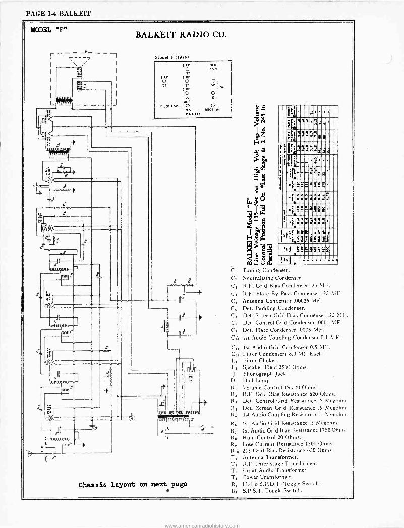
PAGE 1-4 BALKEIT
MODEL "F"
---_ ----, - -
L
3 {1
(
{
J
BALKEIT RADIO CO.
Model F (1929)
I RF
o '27
fAF 2RF o o o '27 '27 '15
3 RF
PILOT 2.5 V.
o o '27 '45
D ET
PILOT 2.5V. 0 0 '246 RECT'$0 FRONT
IAF
4 .-.vNMv7vr--R
Tu uNN.w,_
r
{rs
17
dour,, FY
to
-0
It uv 31A3{7
T7Te
-J Tu*
d +vnNr+-
4."41-----1'
Chassis layout on next page
8*
-w tea~ O
$ é . ~e
oo. ua C2 Tuning Condenser. Cº Neutralizing Condenser. C3 R.F. Grid Bias Condenser .25 MF. C4 R.F. Plate By -Pass Condenser .25 IF.
C0 Antenna Condenser .00025 MF. C6 Det. Padding Condenser. C7 Det. Screen Grid Bias Condenser .23 M F.
Ca Det. Control Grid Condenser .0001 MF. C6 Det. Plate Condenser .0005 MF.
C2ó 1st Audio Coupling Condenser 0.1 MF.
C1, 1st Audio Grid Condenser 0.5 MF. C12 Filter Condensers 8.0 MF Each. 1.1 Filter Choke. Lº Speaker Field 2500 Ohms. J Phonograph Jack.
D Dial Lamp. R2 Volume Control 15,000 Ohms. R2 R.F. Grid Bias Resistance 620 Ohms. R3 Det. Control Grid Resistance .5 Megohm R4 Det. Screen Grid Resistance .5 Megohm R6 1st Audio Coupling Resistance .1 Megohm.
R6 1st Audio Grid Resistance .5 Megohm.
R 7 1st Audio Grid Bias Resistance 1750 Ohms. R6 Hum Control 20 Ohms. R6 Loss Current Resistance 4500 Ohms RID 245 Grid Bias Resistance 650 Ohms Ti Antenna Transformer. T2 R.F. Inter stage Transformer. T3 Input Audio Transformer T4 Power Transformer. B2 Hi -Lo S.P.D.T. Toggle Switch. By S.P.S.T. Toggle Switch.
1
MÌ
E ig
a 4 e i 1 . ó 4 s
1;
11;
. f
R 4 n
e-
h
r
ó
Z 0
1 a
a
é
i i
n
ti s
a a a a a
a i
f!
w a
2 m
w 1 e e ,
! IhI
! a
E
b 5
I D
á
www.americanradiohistory.com
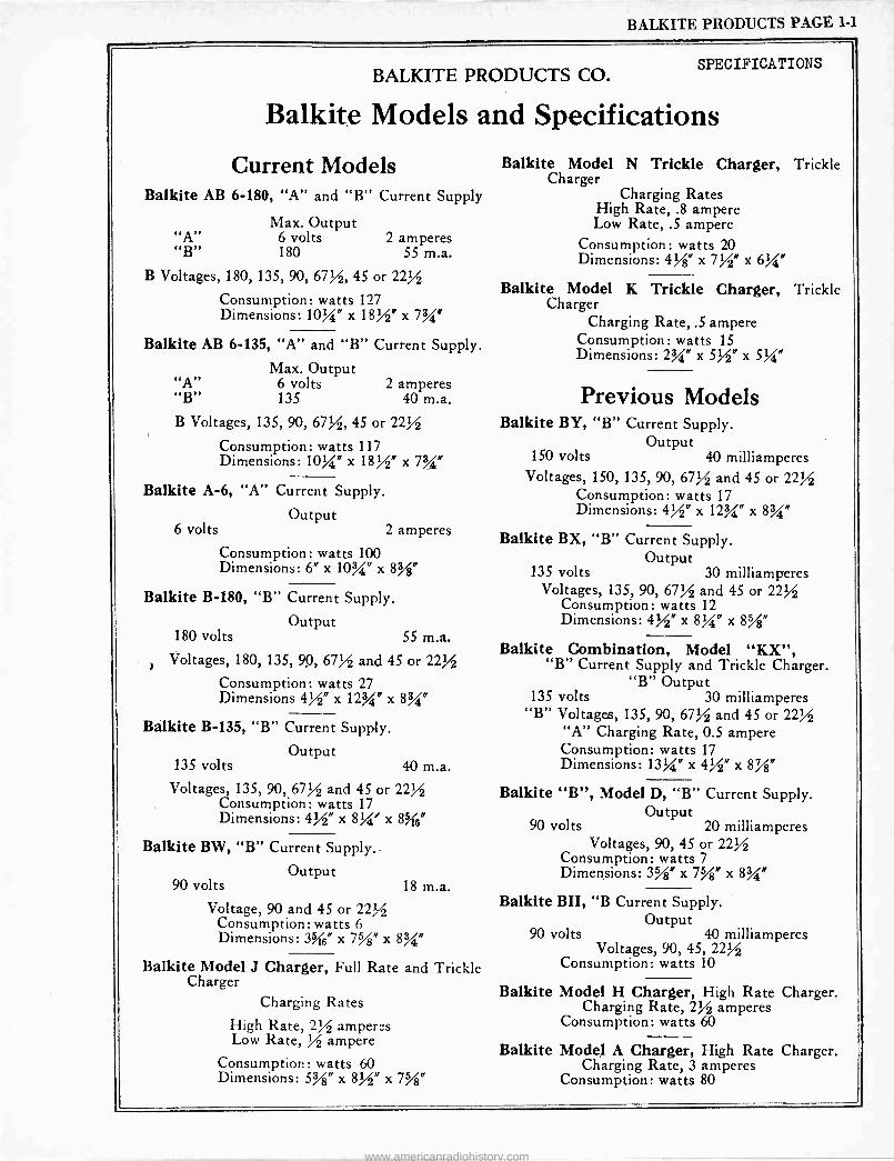
BALKITE PRODUCTS PAGE 1-1
BALKITE PRODUCTS CO. SPECIFICATIONS
Balkite Models and Specifications
Current Models Balkite AB 6-180, "A" and "B" Current Supply
Max. Output "A" 6 volts 2 amperes "B" 180 55 m.a.
B Voltages, 180, 135, 90, 67%, 45 or 22%
Consumption: watts 127 Dimensions: 10%" x 18%" x 7%"
Balkite AB 6-135, "A" and "B" Current Supply.
Max. Output 6 volts 2 amperes 135 40 m.a.
B Voltages, 135, 90, 67%, 45 or 22%
Consumption: watts 117 Dimensions: 10%" x 18%" x 7%"
Balkite A-6, "A" Current Supply.
Output 6 volts 2 amperes
Consumption: watts 100 Dimensions: 6" x 10%" x 8%"
Balkite B-180, "B" Current Supply.
Output 180 volts 55 m.a.
Voltages, 180, 135, 90, 67% and 45 or 22%
Consumption: watts 27 Dimensions 4%" x 12%" x 8%"
Balkite B-135, "B" Current Supply.
Output 135 volts 40 m.a.
Voltages, 135, 90, 67% and 45 or 22% Consumption: watts 17 Dimensions: 4%" x 8%' x 8 6"
Balkite BW, "B" Current Supply..
Output 90 volts 18 m.a.
Voltage, 90 and 45 or 22? s Consumption: watts 6 Dimensions: 3%s" x 7%" x 8%"
Balkite Model J Charger, Full Rate and Trickle Charger
Charging Rates
High Rate, 2% amperes Low Rate, % ampere
Consumption: watts 60 Dimensions: 5%" x 8%" x 7%"
Balkite Model N Trickle Charger, Trickle Charger
Charging Rates High Rate, .8 ampere Low Rate, .5 ampere
Consumption: watts 20 Dimensions: 4%" x 7%" x 6%"
Balkite Model K Trickle Charger, Trickle Charger
Charging Rate, .5 ampere Consumption: watts 15 Dimensions: 234" x 5%" x 5%"
Previous Models Balkite BY, "B" Current Supply.
Output 150 volts 40 milliamperes
Voltages, 150, 135, 90, 67% and 45 or 22% Consumption: watts 17 Dimensions: 4%" x 12%" x 83/"
Balkite BX, "B" Current Supply. Output
135 volts 30 milliamperes Voltages, 135, 90, 67% and 45 or 22%
Consumption: watts 12 Dimensions: 4%" x 8U" x
Balkite Combination, Model "KX", "B" Current Supply and Trickle Charger.
"B" Output 135 volts 30 milliamperes
"B" Voltages, 135, 90, 67% and 45 or 22% "A" Charging Rate, 0.5 ampere Consumption: watts 17 Dimensions: 13%" x 4%" x 8%"
Balkite "B", Model D, "B" Current Supply. Output
90 volts 20 milliamperes Voltages, 90, 45 or 22%
Consumption: watts 7 Dimensions: 3%" x 7%" x 8%"
Balkite BII, "B Current Supply. Output
90 volts 40 milliamperes Voltages, 90, 45, 22%
Consumption: watts 10
Balkite
Balkite
Model H Charger, High Rate Charger. Charging Rate, 2% amperes
Consumption: watts 60
Model A Charger, High Rate Charger. Charging Rate, 3 amperes
Consumption: watts 80
www.americanradiohistory.com
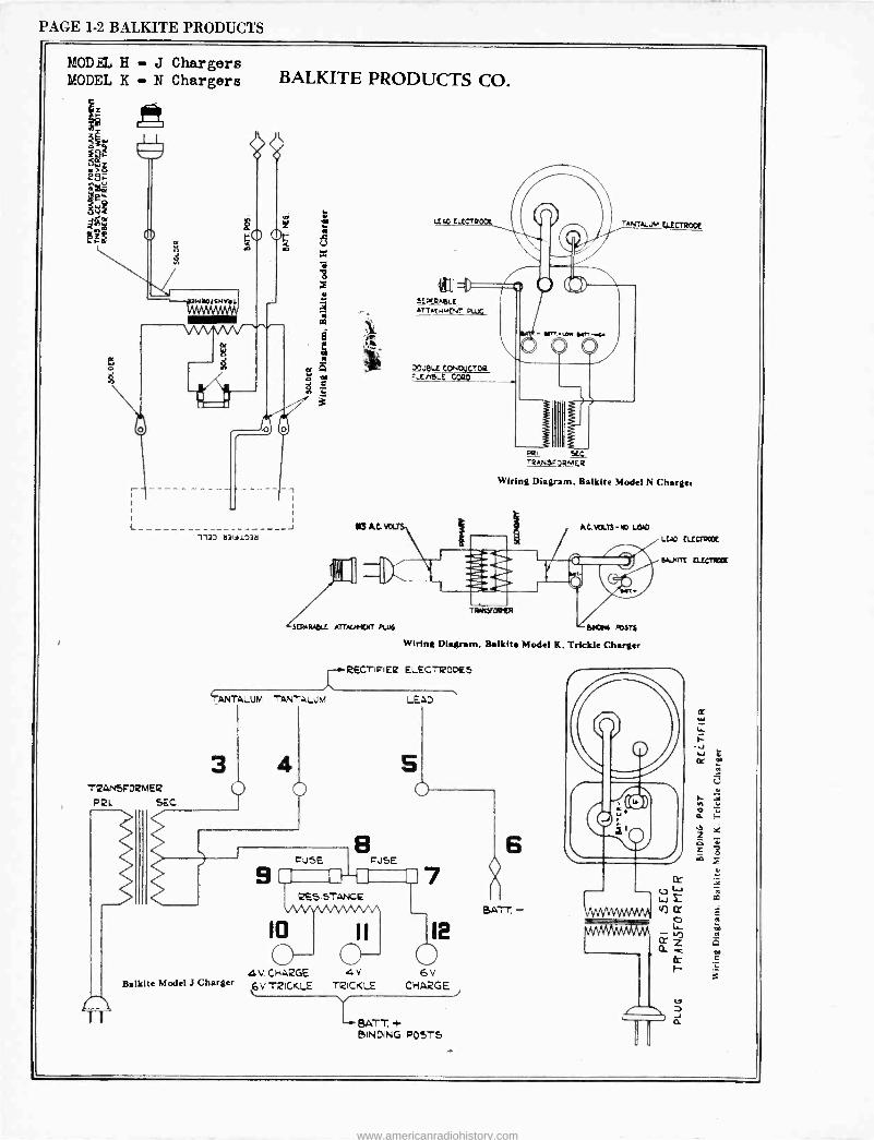
PAGE 1-2 BALKITE PRODUCTS
MODEL H - J Chargers MODEL K - N Chargers
L 117D b3ililp7b
SCAWIDLE ATTAGKM PU16
TANTALUM TANTALUM
3 TRANSFORMER
PRL SEC
Balkite Model J Charger
IC)
o 4V. CHARGE
6V TRICKLE
BALKITE PRODUCTS CO.
El Kt VOLTS
LCAO CLECTa TANTALUM CLECTRODE
l'lui . II -, ()
etegeeLt ATTxtri,[NT PLUG
JOUQLC CONIN TOR -[na_t CORO
Pº, xG TRANarORMER
Wiring Diagram, Balkite Model N Charger
wC.VOLTS-nD LOD
e il brie`d TFNMyPd ita
Baas POSTS
Wiring Diagram, Balkite Model K, Trickle Charger
RECTiiIE¢ ELECTRODES
LEAD
cuSE
RESISTANCE
7
11 12
o - 4V \'
TRICKLE CHARGE
LBATT..+ BINDING POSTS
ßGLTT, -
LEAD GUM=
e...uan curlew
www.americanradiohistory.com
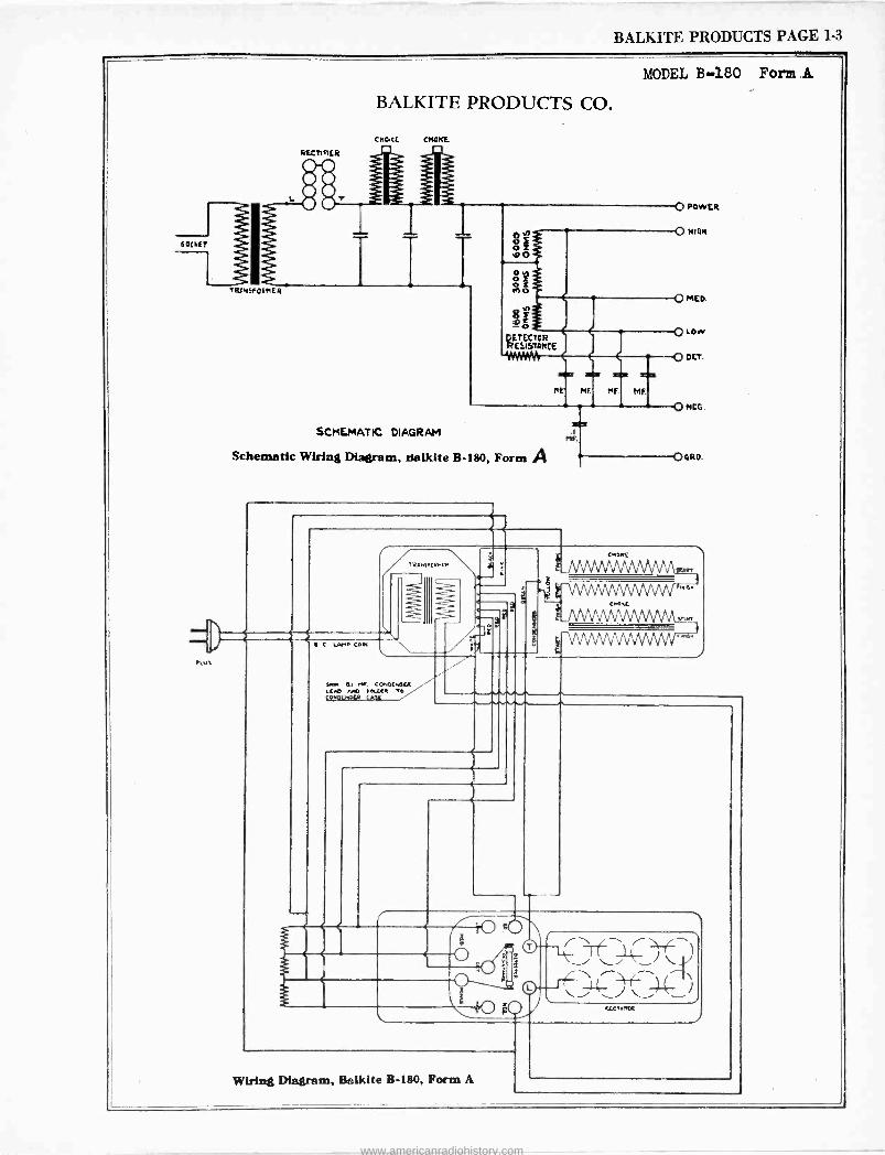
BALKITE PRODUCTS PAGE 1-3
MODEL B180 Form
60CMEf
PLU
TRiN5F0ihER
BALKITE PRODUCTS CO.
cKaEE
RECTIFIER
SCMEMATIC DIAGRAM 1
MF.
Schematic Wiring Diagram, tsalkite B-180, Form A
IVeNC 04rIP
ºw a .... cO.oIwu (C/D /AO 1>L TO Cl QMoLMNF CAPE
r
O PowcR
O man
O MEO.
O LOW
OCET.
Q MCG.
06RO.
$ g0
\ -..- . 1
PEC,IMPR
Wiring Diagram, Balkite B-180, Form A
www.americanradiohistory.com
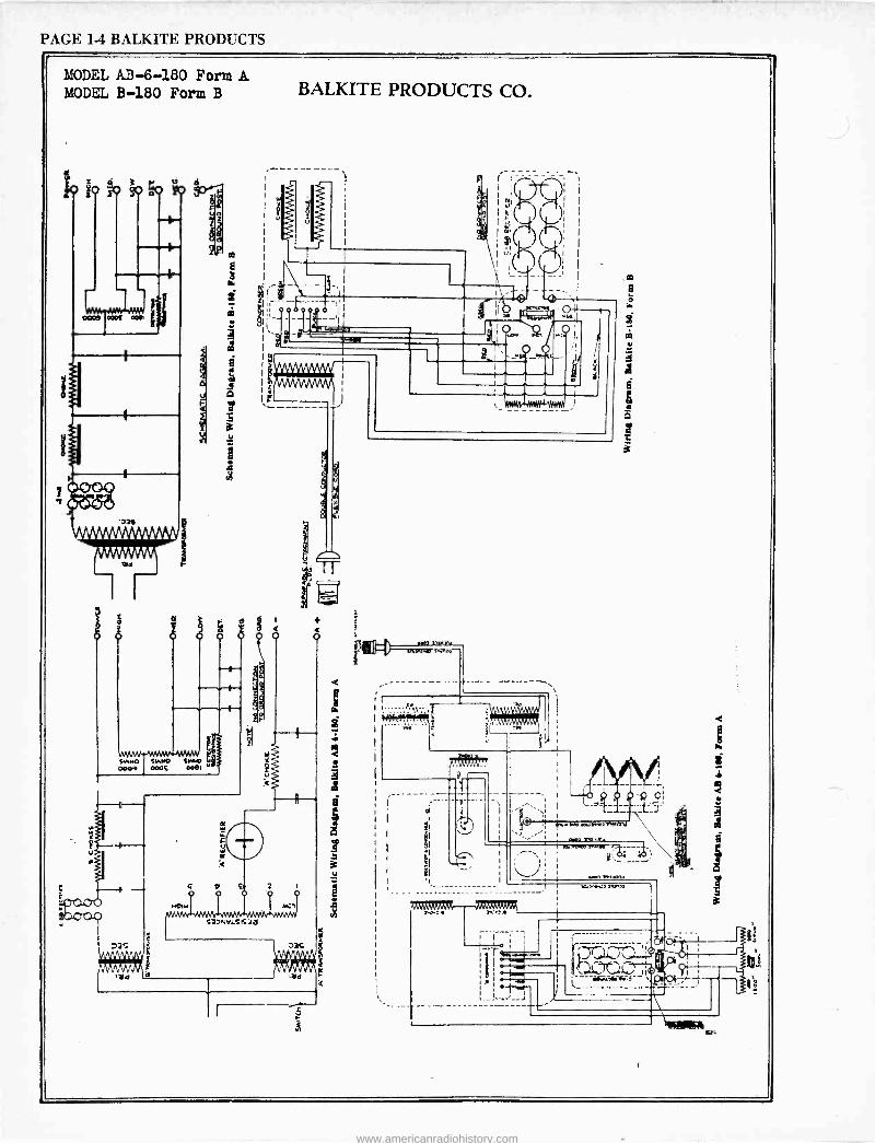
PAGE 1-4 BALKITE PRODUCTS
MODEL AB -6-180 Form A MODEL B-180 Form B
I!
a . : o u
i
we
BALKITE PRODUCTS CO.
.sea .... n.
l":
=man
_
. i I
,
T
,(I77 Tre
1
3
á
f
www.americanradiohistory.com
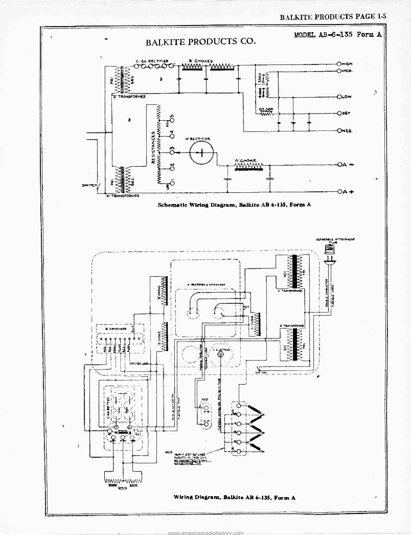
BALKITE PRODUCTS PAGE 1-5
BALKITE PRODUCTS CO.
C-66 RECTIFIER B CMOKES
u
TRANSFORMER
)
A' RECTIFIER
MODEL AB -6-135 Form A
OMIGM
ON.Eo.
O . ()Low
OBEY
O«EG.
OA -
OA t
A' CHOKE
T TRANSFORMER
Schematic Wiring Diagram, Balklte AB 6-135, Form A
. :
- --I YQOVCMal1
O L
o , .,
s f
_
, I [G°"5O -av
T
A' 91[CM1{4 E CNOama6a
- 1
; ` J j i
' 1
; i l _ --- }
ñ
E.EC-,att',
O I
1 I
1
I
I ro I,
IwO I
y I
5e.A72'241-^S1)Iela -LJ rg.r.fr.U4-3-
TgpM.OaMR
Wiring Diagram, Balkite AB 6-135, Form A
www.americanradiohistory.com
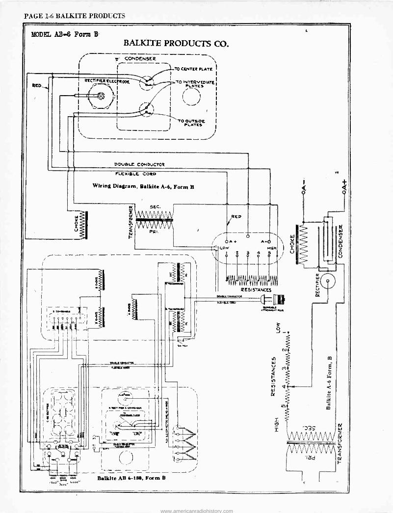
PAGE 1-6 BALKITE PRODUCTS
MODEL AB -6 Form B.
REA
BALKITE PRODUCTS CO.
i 1:' CONDENSER - ____ -___ %
TO CENTER PLATE i
RECTIFIER ELEC ODE TO INTER V EDIATE 1
+ PLATES
ú 1 i I \ ;
I I \ j
I I f. I I
I 1.-'' T P
O OUTSIDE (
( ------ -L.TE! I
\ ..-------------- -- : DOUBLE CONDUCTOR
FLEXIBLE, CORD
Wiring Diagram, Balkite A-6. Form B
5EC.
iUl VVYMI
GIRL
- m..,_ _ 1
0 ;I l i
,.o.& cravat
\ t ° ;
I
IBC, . I COMMA« ------,1 .trägi: I 1,
1 11 . -- - --%, I S'..á.° 7
14.,..C441
+ I I iI S: I
) 1l` - '+ I _-, I
,....1. ' I } f , - - - - - _ _ _ -- - ....-.
Balkite AB 6-181, Form B oesow I,noc'
www.americanradiohistory.com
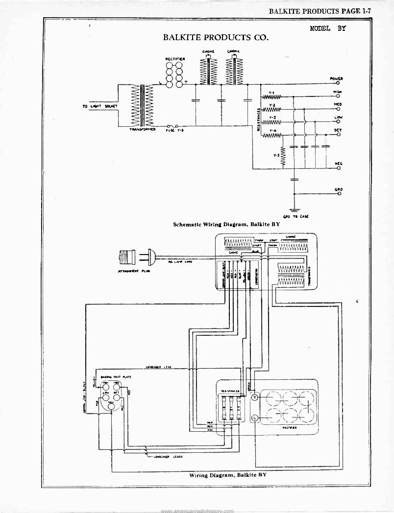
BALKITE PRODUCTS PAGE 1-7
MODEL BY
TO LNMT fOUItT
BALKITE PRODUCTS CO.
TIMMY -MAUI
A77ApKw7 KU
Busc 7s
vI NIt/l WIYMAN-. O
T -Z MCD
g o i v -J LOW
OCT
GRO TO GAY
Schematic Wiring Diagram, Balkite BY
AMMAN
4MM[
FOAM )7Aß1
1TYT 1101101 MUM L LAMP 60111:1
r
%íD
KlIATAK[A
IKC
1
1
11[474411
cOOCwAM UADJ
Wiring Diagram, Balkite BY
www.americanradiohistory.com
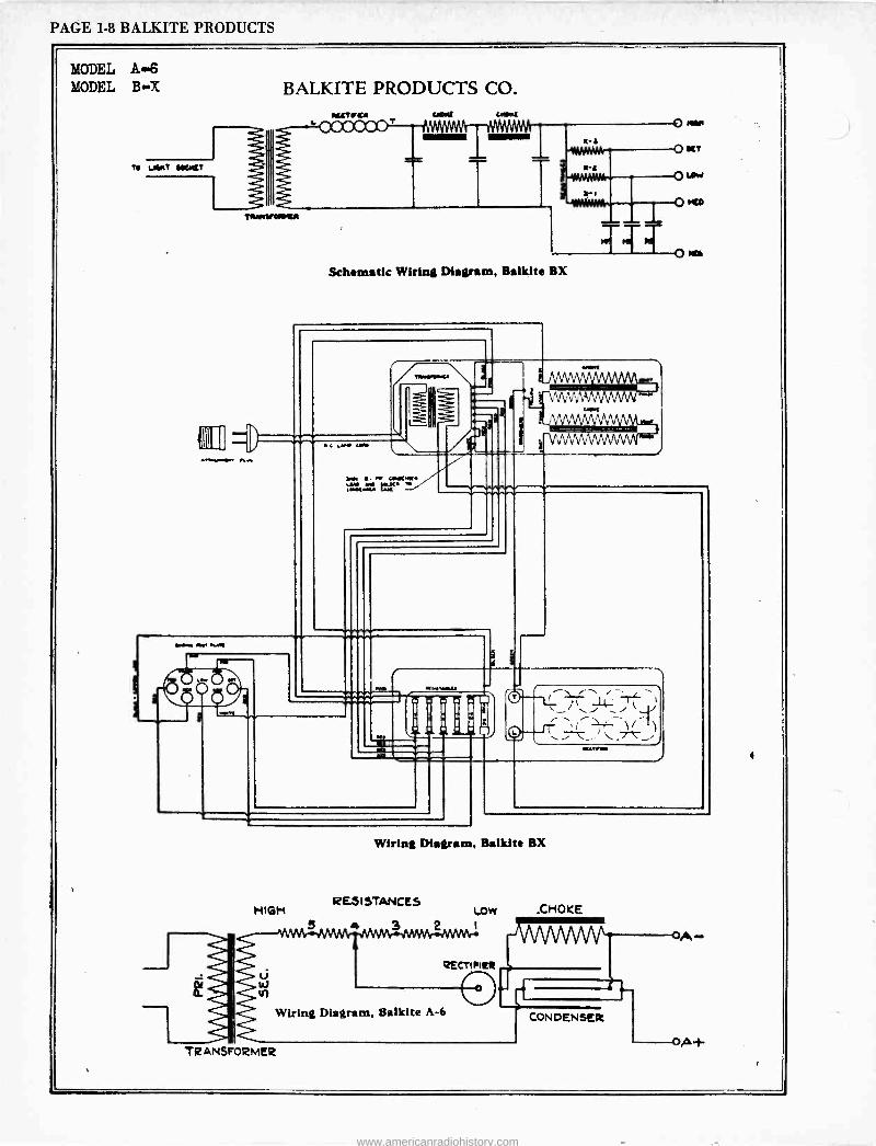
PAGE I-8 BALKITE PRODUCTS
MODEL A.6 MODEL BX
TO UWT tOfiQT
BALKITE PRODUCTS CO.
TTYwt/OAKA
TI' Schematic Wiring Diagram, Balkite BX
e a.w 0., w cNt+l[. ,ar r ix 11 wtru
o
MIMI. wr wwa
.....au -r- _
1) O -__ _
MGM
Wiring Diagram, Balkite BX
RESISTANCES LOW .CHOKE
3 2 i
QECri RltR
Wiring Diagram, Balkite A-6
TRANSFORMER
CONDENSER
O,
OA+
www.americanradiohistory.com
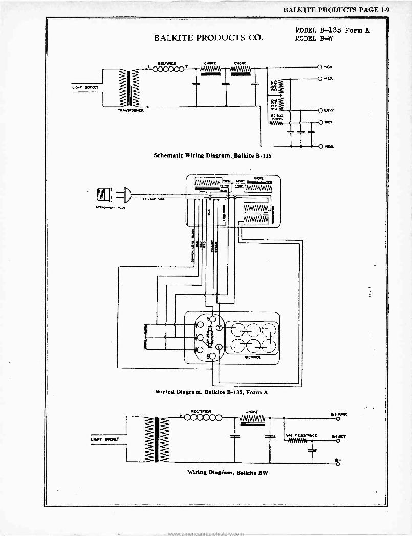
BALKITE PRODUCTS PAGE 1-9
BALKITE PRODUCTS CO.
lSTICt Mkt
Schematic Wiring Diagram, Balkite B-135
P02
lC ,... Cll 41T1014.4n e.t.a
ÿ
kAAAAmhti
JWJrWNNI
MODEL B-135 Form A MODEL B -W
0
--4-Th i \
Racnn1;
Wiring Diagram, Balkite B-135, Form A
atcrrICA .nervt
-000000 NÄMM
T Wiring Diagram, Balkite BW
Rciliuut
s- o
www.americanradiohistory.com
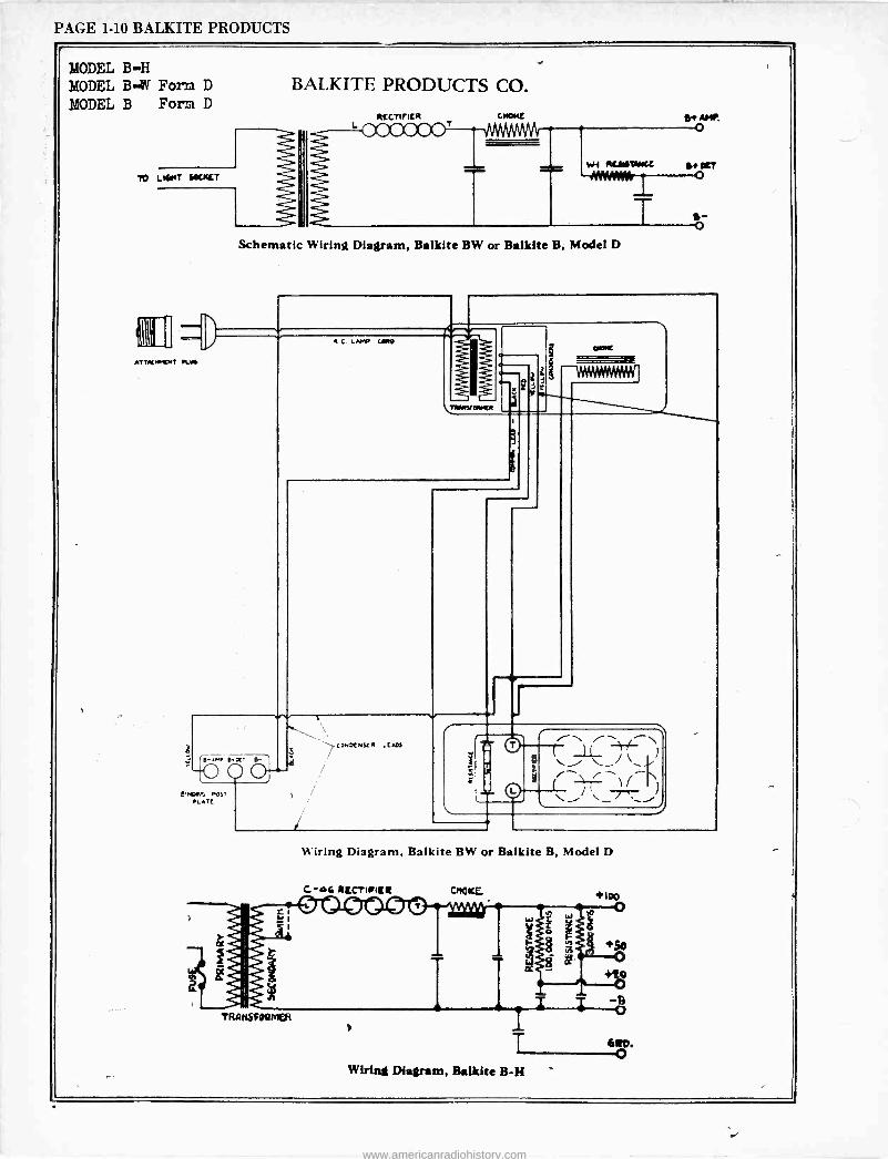
PAGE 1-10 BALKITE PRODUCTS
MODEL B -H MODEL B -W Form D
MODEL B Form D
BALKITE PRODUCTS CO.
TO L141147 lOCKET
ATTKM'OA P1.14
q[CTIfICR
7OC,JOOT 6$ AMI,
O
wi Aua9wCc a aR
Schematic Wiring Diagram, Balkite BW or Balkite B, Model D
T b_
e: x, e-
-;O a MD4A-. PC,-
Pi. ATE
AC LAMP COA9
TMIACOMMCA
ar 3
} CMOR
-VerWesWligi
)
i
COMOCMSCN ;CAD!
11
_-/". r , 7'7
J
Hiring Diagram, Balkite BW or Balkite B, Model D
Wiring Diagram, Balkite B -H
ál0. o
www.americanradiohistory.com
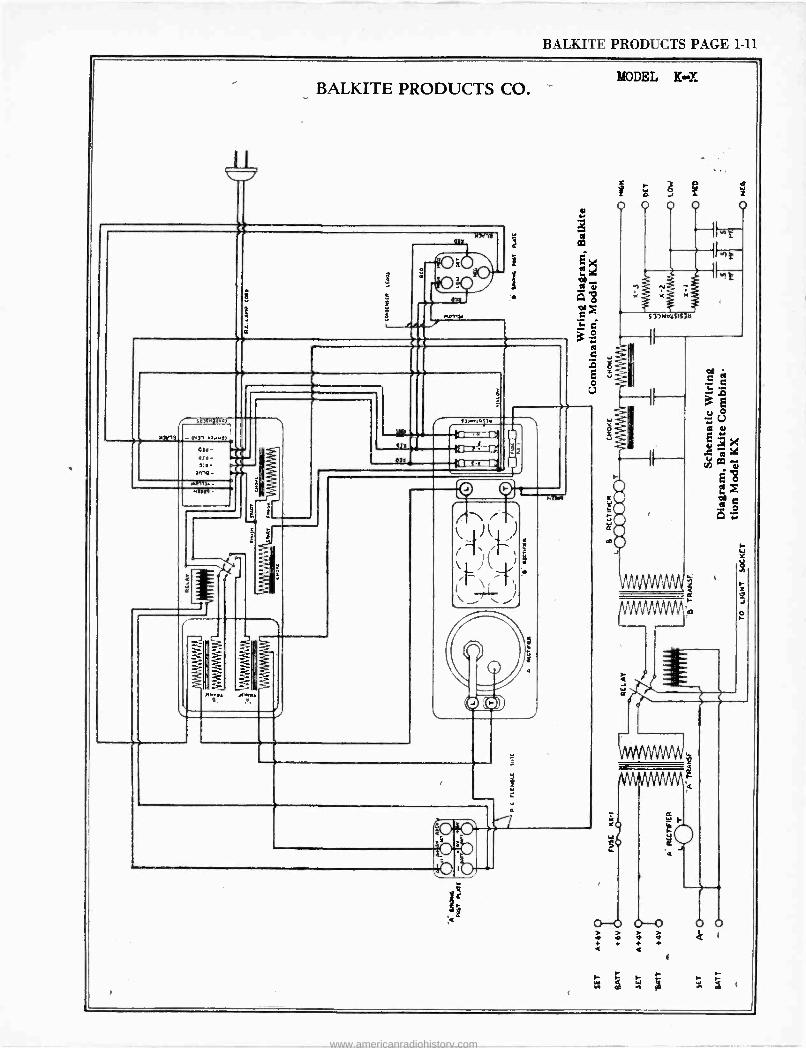
BALKITE PRODUCTS PAGE 1-11
BALKITE PRODUCTS CO.
low 13 all
0431 .eur07
0311- 31. Ol0-
M1O -
93
1
.331A
- Z 6
n..na 0u. v
r O
O
i
MODEL K -X
V
u r
o --o o--0 + 4 é á 1- + +
f
W z
(
www.americanradiohistory.com

r
www.americanradiohistory.com
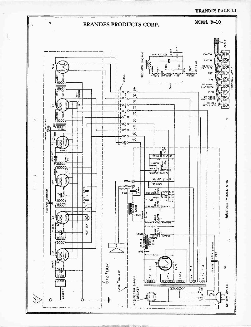
BRANDES PAGE 1-1
v BRANDES PRODUCTS CORP.
w + K
r
r6060 o K
re Ó E
'73u Z
F
(04Q9.
0000
I £
e 9009.
4 O
J
0'
> F o W F
.0n009 i+
> H LL Ñ
r= OC ^- + +
-,009g
MODEL B -IO
Q
> e Ç V
V0001 '1,041 1/008I
Ñ
o+o
0.90
O+O
j 0.2! c) .
M0113h
03d r -
- -->- Ñ
NV1Q r
NMOlig
V 000.05.> LL
JvW N- s E
vu z. NM01ig V000'O9'31INM
vw oz --n ..v+l.wor v0081
> _ NB9tl7`9
ÀrL
O
>
tQ4QQ90000Q90Q1 . efo
0321
)1V11]
211 143341'7 H1 M XJYIe
Yl O3Y 4111M )f]Vlg
nnNnn `(Y
z O
> o
z
11
t
i
www.americanradiohistory.com
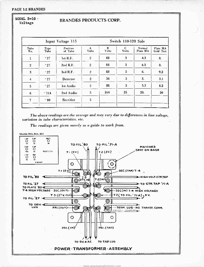
PAGE 1-2 BRANDES
MODEL B-10 Voltage BRANDES PRODUCTS CORP.
Input Voltage 115 Switch 110-120 Side
Tube No.
T}pe 1
Tube Position of Tube
A Volts
B Volts
C Volts
Normal Plate MA
Plate MA Grid Test
1 ' 27 1st R.F. 2 88 3 4.3 8.
2 ' 27 2nd R.F. 2 88 3 4.3 8.
3 ` 27 3rd R.F. 2 88 3 6. 9.2
4 ' 27 Detector 2 36 3 3. 3.1
5 ' 27 1st Audio 2 88 3 5.3 8.2
6 71A 2nd Audio 5 164 35 20. 30
7 ' 80 Rectifier 5
The above readings are the average and may vary due to differences in line voltage, variation in tube characteristics, etc.
The readings are given merely as a guide to work from.
Models B10, Bl 1, B12
1 ROFO O
2 RF SECT
'27 77 '60 TOFIL.80 TOFIL.`71-A 2AF 1R yO
PILOT 2 5 V
\ Tt (5v.)
l MATCHES 11 SPOT ON BASE T2 (5V.) 1 AF DET
O O '27 27
FRONT o TI (5V.)
1
TOFIL..80 -, ̀ T.3 ©(2?,I
TOFIL..27 -4 TO PLATE '80^4 T4 HIGHVOLTAGE SEC.(ouT)
T3 (2 v our) TO FIL.127 -f r
TO 120V. -4 LUG PRI.(oUT
O le, !JO 0 1 O T2 (TAP)O
1 O
SEC.(TAP) T-4
1rHIGHVOLT.CTR.TAP
TOCTR.TAP'7I-A e-
SEC(IN) T4 HIGH VOLTAGE T2(TOFIL.' 71Á))5V.
----TERM. LUG NO TRANSF. CONN.
o
PRI.( IN PRI. (TAP)
/?zT t TO SW.&A.C. TO TAPLUG
POWER TRANSFORMER ASSEMBLY
www.americanradiohistory.com
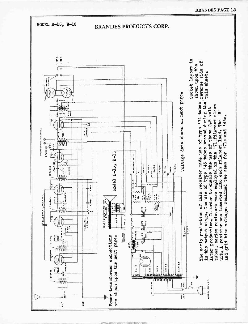
BRANDES PAGE 1-3
MODEL B-16, B-16 BRANDES PRODUCTS CORP.
8
111. vooºI :q
111. 111
s00q.
Z 9
19 12 60-1.
;
8
a
ö
V
r
ñ __
z 4 V
i; f á
o-
a
o o
Y
? o
o
. r-+ < o m
- e.0e -- s= ,,, o. .Jv--vv--vn
2..º o
O'
ó
r_, { 0
J dl' h É i1061-+
C
N
0000.
o O
000 0.00009 00 e009
eu
4.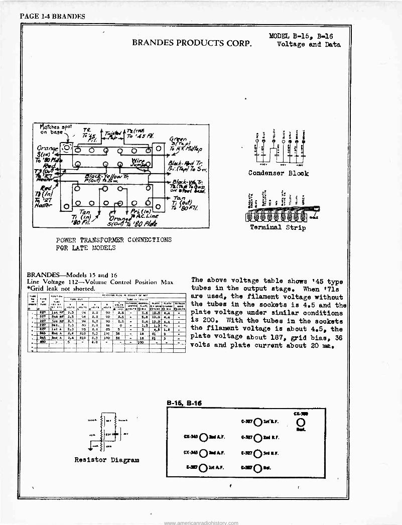
PAGE 14 BRANDES
MODEL B-15, B-16 BRANDES PRODUCTS CORP. Voltage and Data
Mlvtchea spoT on ba5Q 7rc (nr)
/Y, e4,,,,,
;O i o e O p Y, M,dfasP
,
To 80r/. A n n B/ad-ikd Tr;
T lowl Pri'. (Tay./ To 5 w,
72 27 a
TR. :
Ti (an '80 Fil
Prh' (M) i C, L1ne s(ro..%;80 P/de
POWER TRANSFOR.NEER CONNECTIONS FOR LATE MODELS
BRANDES Models 15 and 16 Line Voltage 112 -Volume Control Position Max *Grid leak not shorted.
O,... .u.. : .... .,.., o:.. ..,.. m ,., vet ó 0.. 0.11C..041
®:e.., 227 1.t RP 2.3 94 2.2 90 2.5 - 5.6 10.0 4.4 -
' 227 2nd PF 2.3 94 2.2 90 2.5 - 9.6 10.0 a.a - 0
227 3rd NF 2.3 94 80
2.2 90 2.5 - 5.6 10s0 y{ 227 tat. 2.3 2.2 24 0 - 1.3 1.3 - 227 1.t A 2.3 95 2.2 65 3 - 3 4.6 1.2 -
245 2nd A 2.4 210 2.3 190 36 - 16 21 3 -
, 2A5 2nd A 2.4 210 2.3 190 36 - 16 21 3 -
, 260 - 5 - 4.8 - - - 100 - - -
Resistor Diagram
Condenser Block
The above voltage table shows '45 type tubes in the output stage. When '71s are used, the filament voltage without the tubes in the sockets is 4.5 and the plate voltage under similar conditions is 200. With the tubes in the sockets the filament voltage is about 4.5, the plate voltage about 187, grid bias, 36 volts and plate current about 20 me.
B-15. B-16
C-227 O Lett. F.
Cx-!ti O2ad A.F. C-xt.'7 O tM &F.
Cx-346 O SN A.F. C-327 O 7r+ ti.r.
C.I/V O Lt A.F. trav 0 Ai.
cxr310
o
www.americanradiohistory.com
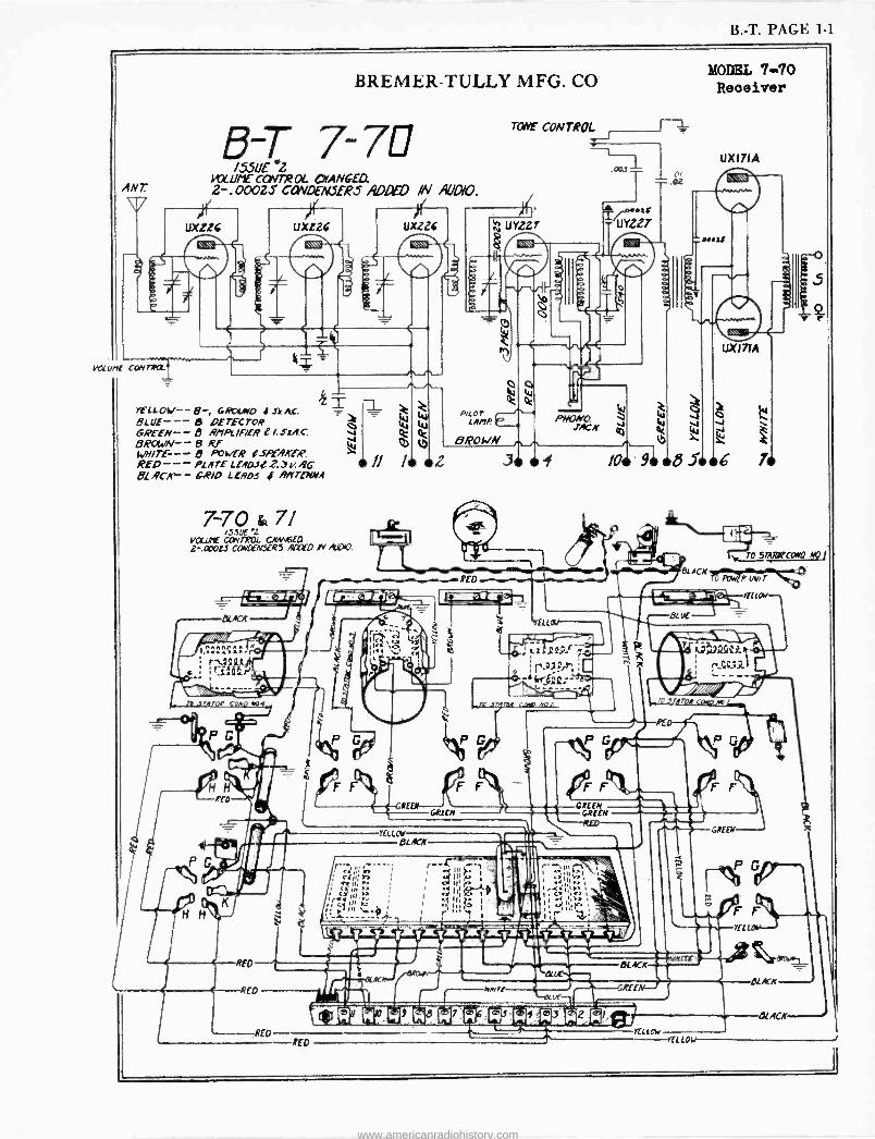
B. -T. PAGE 1-1
VOLUME' CONTAYl1
BREMER-TULLY MFG. CO
B -T 7-7E! i5.5UE L3
LqC U/'I E CdVTR AL CHANGED 2-.000ZS CüWDENSER3 ADDED IN AUDIO.
uxd2c Uxzzc
YELLOw-- B-, GRULwO I ..1"k leg. __ _ é BLUE--- 6 DETECTOR GREEN- -8 /9P/PY/F/ERe/StA.c: v BROWN- -e Rf 5 0 wore--- 5 POWER OSPEAA'EA'. REO--- PLATELEAOJ6.Z.JL<RG II 91 ACK-- - 6.P/0 LEADS I ANTENNA
7-70 &71 iJ3lK'Z mint GLivTROL cAf.wólD
2-.000Z5 IXa17AEAC5ERS /WM / .400.
//////i///,'- :::: ail:::."
%.22 21
... . ----- lb irAr K GOND 4U4
RED
I i
TGWE CONTROL
11' UYz2 f
P/LOT LAMP.
BROWN
ear uYzz7
2 3 ' 10 9i8S
ELLOV
GREEN GREEN
MODEL 7-70 Receiver
UX171A
BUCK FL1V UNIT
BLUE
ll-
YELLOW
www.americanradiohistory.com
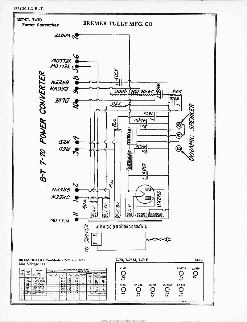
PAGE 1-2 B. -T.
MODEL 7-70 Power Converter
31/HM
BREMER-TULLY MFG. CO
%;:;;# 034 vC v
CC)
N332/9 N.73J
/`f077-7,(
tr)
BREMER-TULLY--Models 7-70 and 7-71 Line Voltage 115
--
oaok oarr
011
00,14-
"0.9/ )100i
A
N
Itlttlillllltt
'e" ....
Z2 1et.9.F. 1.4 150 b 12 171A Fuah-Pull 4.9 130 30 -- 18 31 13
226 2nG.R.F. 1 4 150 9 - 5 12 7 226 Srd.R.P. 1. 150 9 - 5 12 7
227 Detector 2.1 60 0 - 2 - -
227 let.A.F. 2.1 150 8 - 5 8 3 171A Fush-Pu11 4.9 150 18 - 18 E1 13
7-70, 7-74 M, 7-71P (A.C.)
C-327 CX-371A CX-380
0 O O lrt 2na Rut.
A.F. A.F
C-327 CX-326 CX-326 CX-371A CX-326
O O O O O o.t. 3a 2na 2na 1st
R.F. R.P A.F R.F
www.americanradiohistory.com
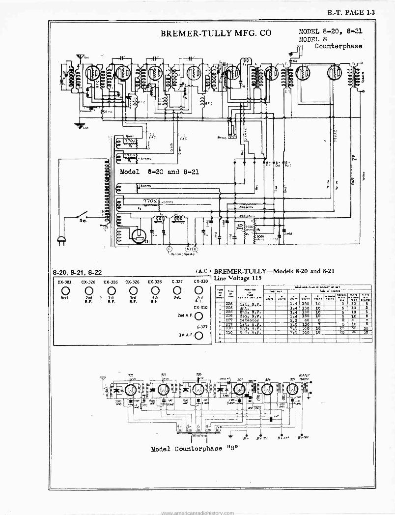
B. -T. PAGE 1-3
t. Ant
BREMER-TULLY MFG. CO
R
G QD
r, 9 r
I
r,
2t
MODEL 8-20, 8-21 MODEL 8
Counterphase
II á
-s. Green
í0 770..
l5 VAC
170u 8 ohms
15 VAC
t tJ
Model 8-20 and 8-21
Phoro M
115ohmz z
e8 8 R F Det
S. No I
Y Ú
170 c.) .40 orn
n, 3Me,.nn.
V
Sw.
O 81
Cl.
49000hnn
E` 11251 55004 ohms
a j R. É T
ti 3000 ohms C
1 fite
Pen
8-20, 8-21, 8-22
Dyn_mnic Speaker
(A.C.) BREMER-TULLY--Models 8-20 and 8-21 Line Voltage 115
CX-381 CX-326 CX-326 CX-326 CX-326 C-327 CX-310
0 0 0 0 0 0 0 Rect. 2nd ) 1st 3rd 4th Det 3rd
R.F. R.F. R.F. R.F. A.F.
C X-310
2nd A.F. O C-327
1st A.F.O
126 220 426
OW Or Ty« iint 1,04I in
.K.. «*' 5 6,
. 226 lnt. R.F. 1.4 150 10 10' 226 Ant,1.4 150 10 5 10 5 226 End. R.B. 1.4 150 10 5 10 5
, 't26 3rd. R.P. 1.4 150 10 6 10 6
227 Detector 2.2 60 0 2 - or
, 227 let. A.B. 2.2 130 7 6 10 5 310 2nd. A.P. 7.5 350 18 20 50 30
, 310 2nd. A.S. 7.5 350 18 20 OU 30
111 nI r.
Model Counterphase "8"
IXAh'I
47 7RA,yrf
www.americanradiohistory.com
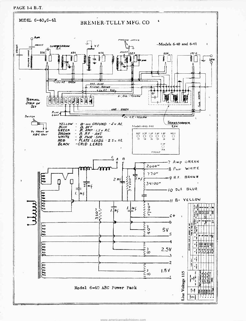
PAGE 14 B. -T.
o o O
MODEL 6-40,6-41
226
CO YSATtON n.
BREMER-TULLY MFG. CO
VC
226 I 226
TEgntmu. STRIP OM
JET
SwsrcN
/ S r Al GREEN OCr. - 6 UF eNNF! BROW..
2.fv, A,C. - RED
PNONo ..CA'S
227
rimsArM
-Models 6-40 and 6-41
226
L
à ea w ti
To FRONT er A -D -C (heir
Paora Lain L 1
,(:vo. - YéLLOw
AMP - GREEN
o SPK
s..
YELLOW - B- AND GRO(/ND S v. A,C, BLUE . ß DET GREEN - B, AMP - /. s v. A.C. BROWN RP - ANT WHITE - B, PWR - SPK. RED - PLATE LEADS 2. S v. A C.
BLACK -GRID LEADS
m
? m
1
A,C. YELLOW
TRANSFORMER J(o.lels 640, 641
DET 3 RF 1 AF 2 RF I RF RECT
0 0 0 0 0 0 '27 '26 '26 '26 '26 '80
2 AF
o '71A
FRONT
z000w 7 A wAp GREEN
9 Kut- WRITE 770w
9 R.F. ßRowN
314103'
IO De+ BLUE
3
0 In
M
Alf
3
o ~ C 3 o SV
s
o
3
Model 6-40 ABC Power Pack
2.51/ 3
2
oo 1.5 V
? 1
YELLOW
.ro
.1 ':
a a Im NGi r/ Ñ
1ii
a :r 3i
"f P OWI
.i
._
.ñ
.+.y
aa r1 .i i. .i
/4
-iii 4 Ao
tz
tai
iº1 ie Ñ N N eel
www.americanradiohistory.com
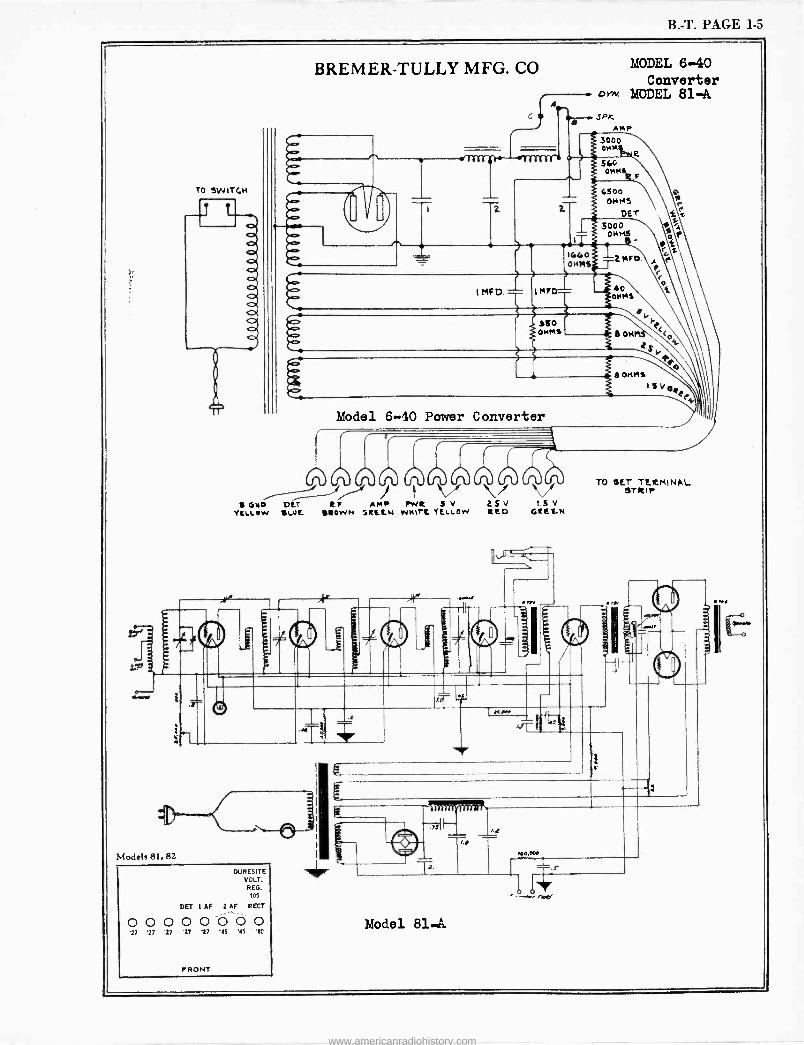
B. -T. PAGE 1-5
TO SWITCH
BREMER-TULLY MFG. CO OYN.
MODEL 6-40 Converter
MODEL 81-A SPX,
AMp 3000 OMM
I R
560 OAKSR
4500 \ OHMS e
DE
5000 014145
1640 OHMS
; MFD
I MFD. IMF
óe
t r 1.
40 OMM5
aso OHMS 6 ON
e
e<
18014445 I
Model 6-40 Power Converter
0.
, GND DLT R.F AMp FhVR S V
YLllow 1WL BROWN :RLLN WH17L TELLOW
Models 81, 82
DURESITE VOLT. REG. 105
DEI 1 AF 2 AF RECT
0 0 0 0 0 0 0 0 27 17 '27 17 17 '45 15 10
FRONT
Model 81.A.
Q5V t V RED GREEN
TO Ur TERMINAL STRIP
www.americanradiohistory.com
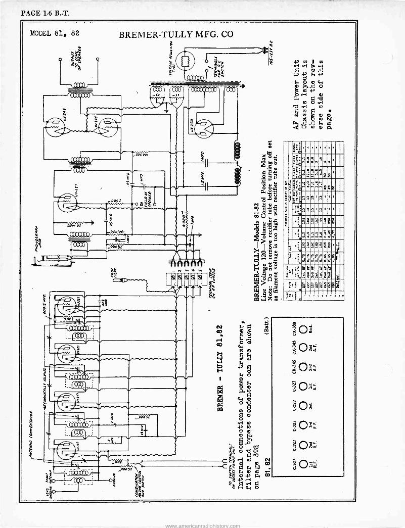
PAGE 1-6 B. -T.
MODEL 81, 82 BREMER-TULLY MFG. CO
óóW A VÑ OW
o
1
áA
h h
IMP
M
a
"was
ccriceot` er i 4Y1 tt s:
ey
ti
000 00i
0"memlat
JM'Ot
SI2U21J
.003'1
ti 00404
ózt C w4ti0
o N
s
V
IAAAAAAlI' .__024j
s s s
es
Y
; Ó $. er= O4 o me
-z
s
41
tO . O
v N`{
co
bD O
s:
W"
'
Ó :c':,
1 1 1 1 1 1 1 1
1;19 n oó0
o n +e ,
@.yooNi `. óm....M..ñR .,.. .
,
.®n q o n
o w n n
: n á á á
°.n.2.N,. I M I 1
'
:emr:m ' .. . .
immui'mee
.@.,....,12p '4,J,..4: Yl h N N
N h.g r V NN:
r
i
.1N
D bp p WWNNON
m Ó N
1 U :
+pN ; N
rY1 .-r N NN
N y NINN tl
N N
3 0h f r
;s a:o"vE . s1Nß,1a4
é «dd
:
E' `ú e¡í'3ñrná
ó_º
.?On¢ Le
a":
6f ND:
www.americanradiohistory.com
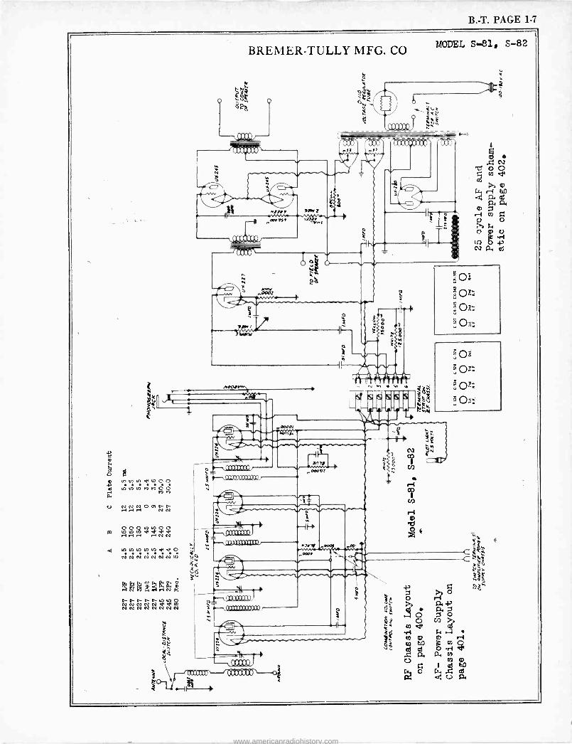
B. -T. PAGE 1-7
C CD
U p into u,.rtO 00 e Iñ ui eó ñ ó ó .N M M a C.) ce CV CV .yr-1.-i NN OOOOOO rO-1r1.-1 .-IÑ Ñ
u) In h -M O N N N N N N N v)
Mno`1N 1`tire-e-u)v)o N N N N M W CO
03 030303 N N N N
BREMER-TULLY MFG. CO
0
óó ºó o
ei ;2%
e M p
H»rs
,W 4 .p'
ti
rawvfr
MODEL S-81, S-82
s «n..e"
; , »~:
ow /fs fi fi
ivr
V 0
V~ N
AN NNW
Icocero
e I ó
7_ir N
PRO» aoocl `i
M MINIMUM .
Mae
, 4 ooar.z
MZ Q ..
) Ó i
//y/yyyy SAAM!
1
4
6
r
Ati
N e
www.americanradiohistory.com

:=--. ;..
www.americanradiohistory.com
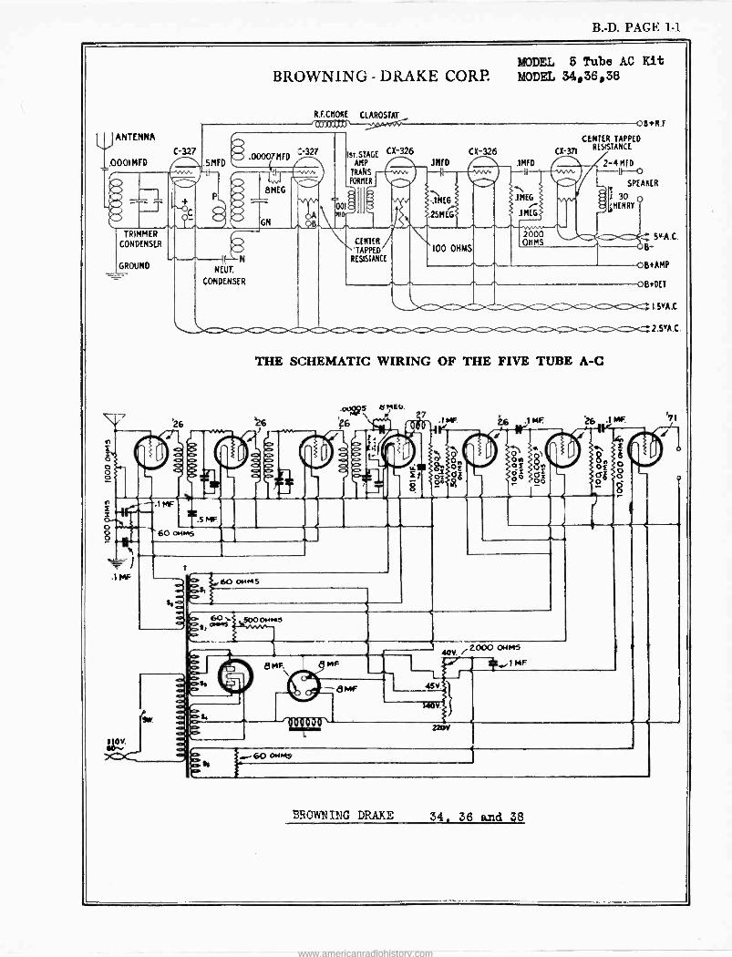
B. -D. PAGE 1-1
ANTENNA
_.0001 MFD
MODEL 5 Tube AC Kit BROWNING- DRAKE CORP. MODEL 34,36,38
C-327
TRIMMER CONDENSER
GROUND
in
O o,
Mk
V.
e
R.F.CHOKE CLAROSTAT
'ip')pC(pO s r OB*R.F
SMfD .000 MFD
1-;
8MEG
GM
:.-327
NEUT.
CONDENSER
ST. STAGE CE -326 AMP
TRANS FORMER
00 2 ierD
CENTER
TAPPED
RESISTANCE
]MfD
1ME6
.15MEG
CE -326
100 OHMS
INFO ---1
CENTER TAPPED
C1( 371 RESISTANCE
r1 .1MEG
1MEG$
2000 OHMS
.01111.
THE SCHEMATIC WIRING OF THE FIVE TUBE A -C
26 '26
.1MF
.5F
005 \ '?6
e
) t.
f.3
KEG. fi 27
0E0
60 aims
io o 0
60 044M
.IMF. ) MF.
2-I MID IF --O
SPEAKER
I 30 'HENRY
5yA.C. B
OB*AMP
0B*DET
I.VA.0
2.5'A C.
26 .1 MF '71
On 8^ oi VÉ -E O
óo oo=
Ç" O ò
o
60.. 5000HM3
8 14F.
d
e MF
no
_8MF V.
rrOVf. / 2000 OHMS
4C,,4C,,1 MF
14014.
a - 60 OWNS
BE OWNING DRAKE 34, 36 and 38
www.americanradiohistory.com
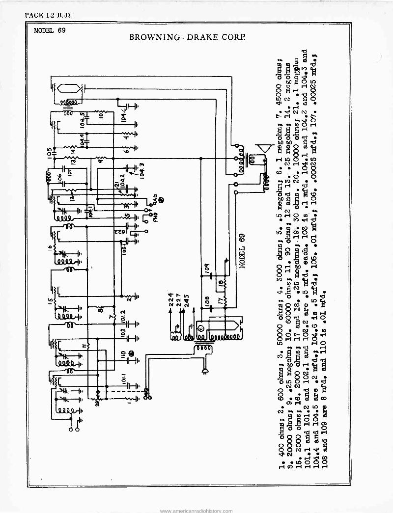
PAGE 1-2 B. -D.
MODEL 69 BROWNING - DRAKE CORP.
`G2
--11-+r ó Ne.0 -h- Ñ0
O - GIs f;O 1
Z7Ó 11
.JH1,
. ..
e -1H1'
le, N N T N N N
Ç e vl VD ó CM h
to .-1 o m to rl e
M ÿ te) cl O óÓ
m M
..§°:. ó 8 ri ri o .b ., v) M
mu) g. go
e .ä U') 4a ..,° . O
5' c0 ri
O O erl O OcD ct O.
. tD
ó ó ó ¿t .
O rar-Ir O M M b ri
M ,H m
g rl
. tel -1
cm R
g8OC2 Ó: d
C12.;
g CO
C7) ri CV up
CQ M M mri 8 r-1 cn
! O Ti b f-1 OQ§.y2
dfN` . tO OgO r CO ri ri r rI
www.americanradiohistory.com
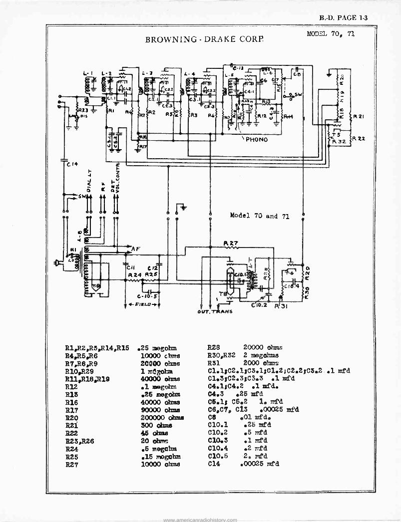
B. -D. PAGE 1-3
L- 1 L-2
DiS
C14
AF
BROWNING - DRAKE CORP.
G-10 S 4- PIELO -se
R1,R 2,R 3,R 14,R 15 R4,R5,R6 R7,R8pR9 R104R.29 R11,R18,`R19 R12 R13 R16 R17 R20 R21 322 R23,R26 R24 R25 R27
.25 megohm 10000 c trms 20000 ohms 1 rrt3otaa 40000 ohms .1 megahm .25 megohm 40000 Ohm 90000 ohms 200000 Ohms 300 Ohms 45 Ohms 20 oha,m .5 mogul= .15 mogul= 10000 ohms
Model 70 and 71
Fl 27
--
OUT. TRANS C10.2 R 3(
hSODEL 70, 71
cr
o
R28 20000 ohms R30,R32 2 megohm.s
R31 2000 ohms C1.1;C2.1;03.1;C1.2sC2.2;C3.2 .1 med C1.3;C2.3;C3.3 .1 mfd C4.1;C4.2 .1 add. C4.3 .25 zed 05.1; C5.2 1. mfd C69C7, C13 .00025 mfd C8 .01 mfd. C10.1 .25 med C10.2 .5 red C10.3 .1 mßd C10.4 .2 rdd C10.5 2. red C14 .00025 mfd
R21
R ZZ
www.americanradiohistory.com

www.americanradiohistory.com
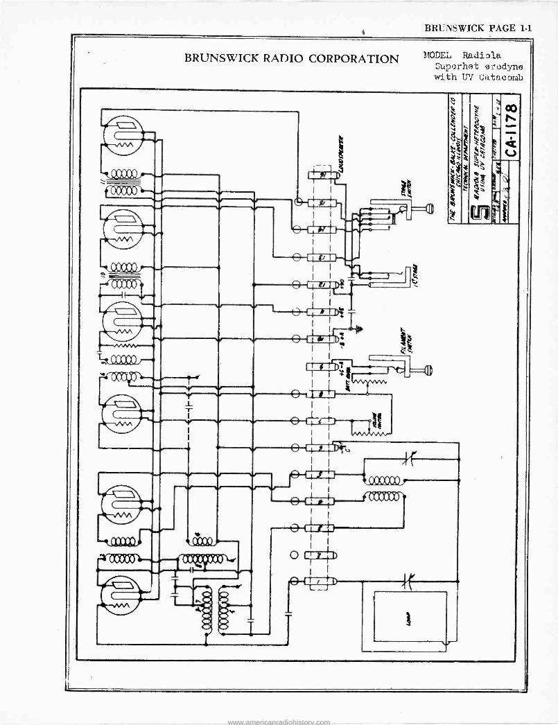
BRUNSWICK PAGE 1-1
BRUNSWICK RADIO CORPORATION P.4ODE;_, Radiola SUpeoY'}ì(j t t7 'UCiy71A
with UV Catacomb
v
fOOZXX» . .
244 .-- ^-CMDpi
s W '
AdO
Ralil .1.
o
L T
V Y a I
I 1 94 1
I
I
_- p ---r _r`L2D7tv
1,r
v
I
Ofi r.1
o
r
V\AJ1M! ,
www.americanradiohistory.com
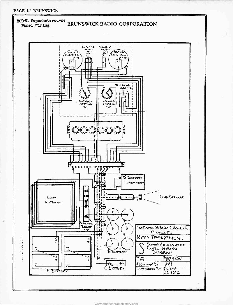
PAGE 1-2 BRUNSWICK
MODS, Superheterodyne Panel Wiring BRUNSWICK RADIO CORPORATION
r A)APt-i.iE2 FILAMENT
wi*cw SWITCN STAT
StLKTOR
DA" T ERY SETZ %SO
-IC-
00
VOLUME CONTROL
-u-
ELE %WME JA4C `,..1(1
u ; I
n nrt nn
LI LI uuu
`OOP
AMTENNA
ifi
3
eRMMAL ßOARD
-S-
L- t
o
1!). pATTERY
t r III (! _,'I r1i
I I t
tAT'rtrRY CONDLN SCR
p. AZTERY
-t
'boitsrr
LOUD S1"1-e,IcEsE
The brt»uw;ck óa.keCollendcrCo.
RAD10 DtPARïMENT Su PER -1-1 ET E tZoD`( Nt S PANEL W tRtts1G
D 1A6FZAM
7roced G, y 1i
Approved uPrR CEDED %`r Dw6.ty4
CA 11312
brawn Ft,y
www.americanradiohistory.com
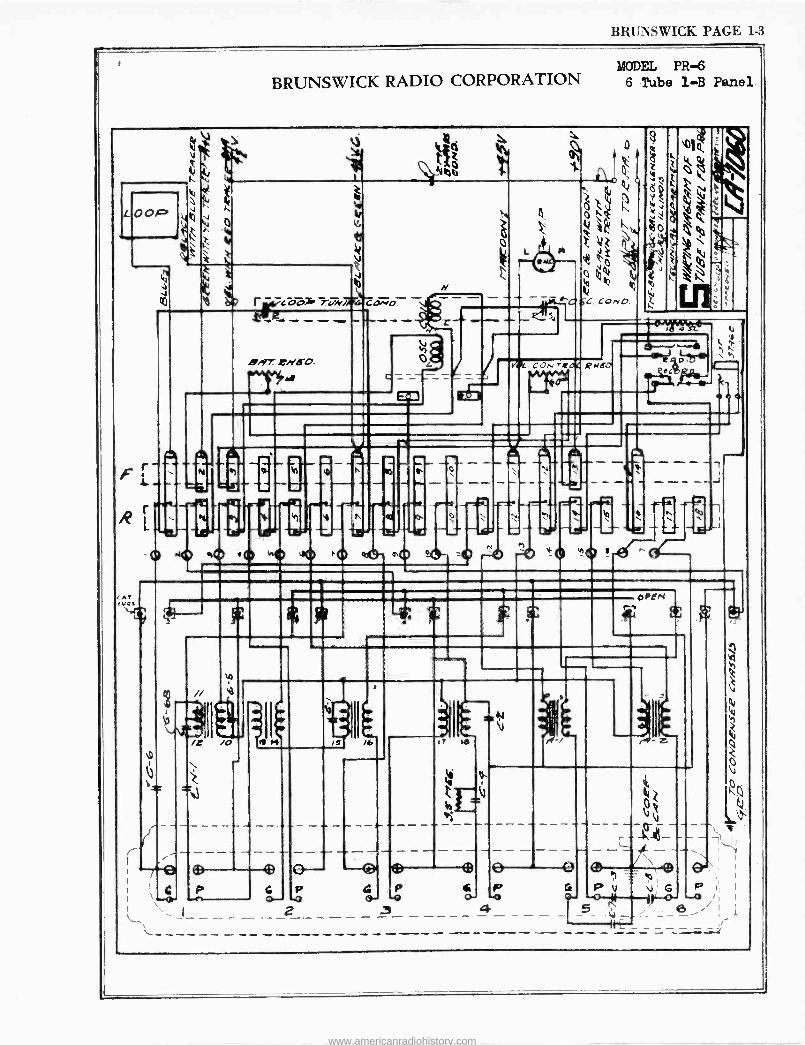
BRUNSWICK PAGE 1-3
BRUNSWICK RADIO CORPORATION MODEL PR -6
6 Tube l -B Panel
L OOP
8g1
V
4
Q
ó
1ÿLÖ0 T!!N/TI4 ccd'D
F 1-
R
LA VOS
- i SAT ,ci'go.
ó
N
i: =
AMA
%m
N e e
4 , - - -- co -+ l '411,1A
CON tear/ e er era
.1110.
a ó
Nl n
ib4Yt`
s--
a H OPEN
lTJ
(- - - --r-e ®--L e--- ---®
I ' C I \ 7-4)+ 4.' -0 O- -0 O- -O
L. 'J- --- - - 2 ----- ..3- ---- 4 - \ -
17
CM
3
G P v G P o- .o ,
-5 -- --- --- ----11 E_= _ __=.r
www.americanradiohistory.com
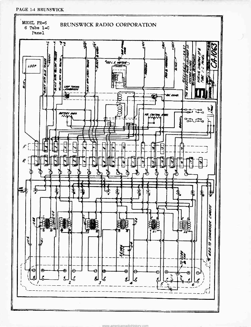
PAGE 1-4 BRUNSWICK
MODEL PR -6 6 Tube 1-C
Panel
OOP
o
c
o
BRUNSWICK RADIO CORPORATION
P O
o -- P -o
ed --6-$ ó-
O
A-/
O
0
'44
Co- roci /-0-12
Ttie
J
I
O-\ I
I 6/' -- - - - ---------'J
www.americanradiohistory.com
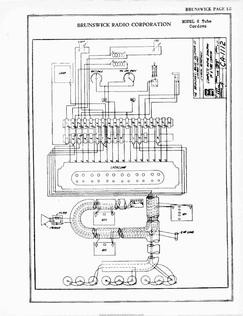
BRUNSWICK PAGE 1-5
BRUNSWICK RADIO CORPORATION MODEL 6 Tube
Cordova
[OOP . JJC
[ar.taVAra a
M M
n M
r
(I r1
; e CAlACafe
C0 O O 0 0 0 0 O O O O O O
0 0 0 0 0 0 0 0 0 0 0
1(p[/15f
JYr.drLP
'hit' 4j111 `i
li
11i111' _ ===J/ II/%/ ie
_ = - _ _
j
o 4« o
111r43412
www.americanradiohistory.com
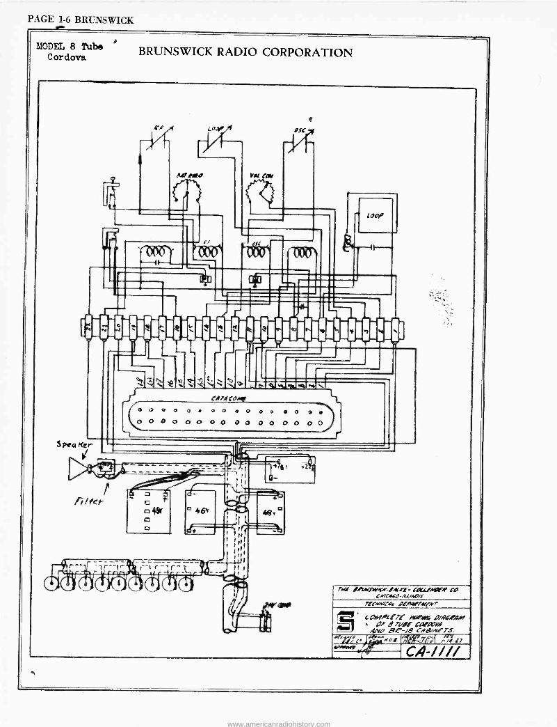
PAGE 1-6 BRUNSWICK
e
1
ce3 r
y N -44
MODEL 8 Tube Cordova BRUNSWICK RADIO CORPORATION
c/F f r/ -.
3 Pea rte r
`+t
J o
O 0
P v
1 Y I
Q K \ cif T,/comer
po Go 0. Go O o 000 0 0 0 0 OOQO r
rig dPrfreVK.e.BACYf- tA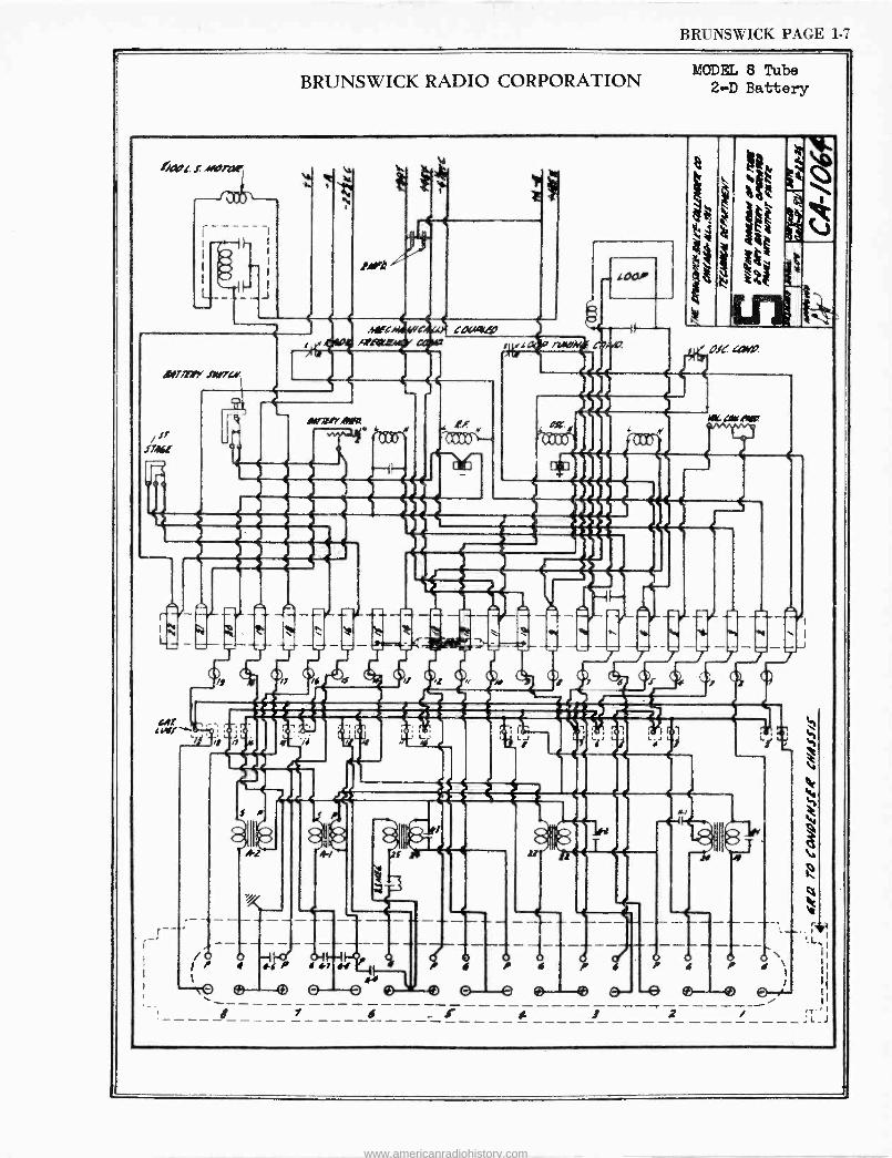
BRUNSWICK PAGE 1
BRUNSWICK RADIO CORPORATION MODEL 8 Tube
2-D Battery
»WI. ! alvlYx,
AO,lfir .0111744'
ve/
,-- - wM1 P s P s N
O o 0 ® O e ® ®(a-- _. r e s
P
-e A 1 2
o!«
H
r b - O ,
s / . \ ¡ 1
I
1 ®-e E? +`- ¿ I
/ .T -' { ------;i_1
www.americanradiohistory.com
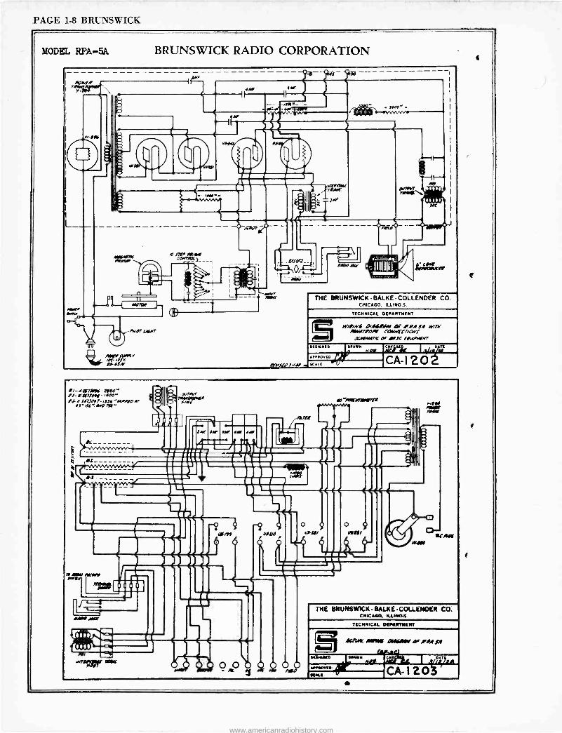
PAGE 1-8 BRUNSWICK
MODEI, RPA-5A BRUNSWICK RADIO CORPORATION
, WE4 I
7
___e_I
c
M
1111[1flK A ITV IIf41A7 CM7R]C_
n
/NOT LAfA'T
f1sRX 4,110_ !IF OW
[A[[
nw'
r T-
044 14 lCit /!
THE BRUNSWICK - BALKE -COLLENDER CO. CHICAGO. ILLINOIS
TECHNICAL DEPARTMENT
Iy/!/Nf D/,If.IAM Qr ¡pA S.I l4/7N Amed7lD/1 CQNtC7/ONl
JrN,WT/C c Mlc llwiAfNT
.fl271j0f,ffs .g
OISKNEO
IPAOVEO
sct[
.tOY c [ ufl 11/42 CA -I 20
//-l-Of7JP116 Z/00' !7-Kll7JD// ,400- Rl /'767J017 iJf4'Mi/[D47
47-44`:M'D7li'
l:T
,Y Mate IOl9NfM
7/lsGYt
*MO Ow
M( wit
.1V7fitv7 11JH4[IRII P/Nf
A0/n
4,
r
-"wormed
CC
THE BRUNSWICK BALKECOLLENOER CO. CHICAGO. ILLINOIS.
TECHNICAL DEPG T'«NT
«MIL ANfRIi AMiAGV Or.I 'A SI
KALE
N AWy
CNE I %illA
CA -I20
www.americanradiohistory.com
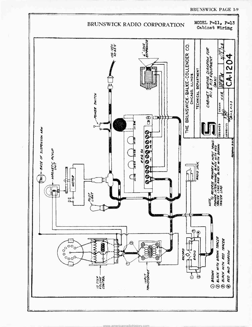
BRUNSWICK PAGE 1-9
BRUNSWICK RADIO CORPORATION
Ñr Ó U cr W o z W -J J Oa U
o z ra
J Q Ó cog
u U= u
2
m W r
MODEL P-11, P13 Cabinet Wiring
www.americanradiohistory.com
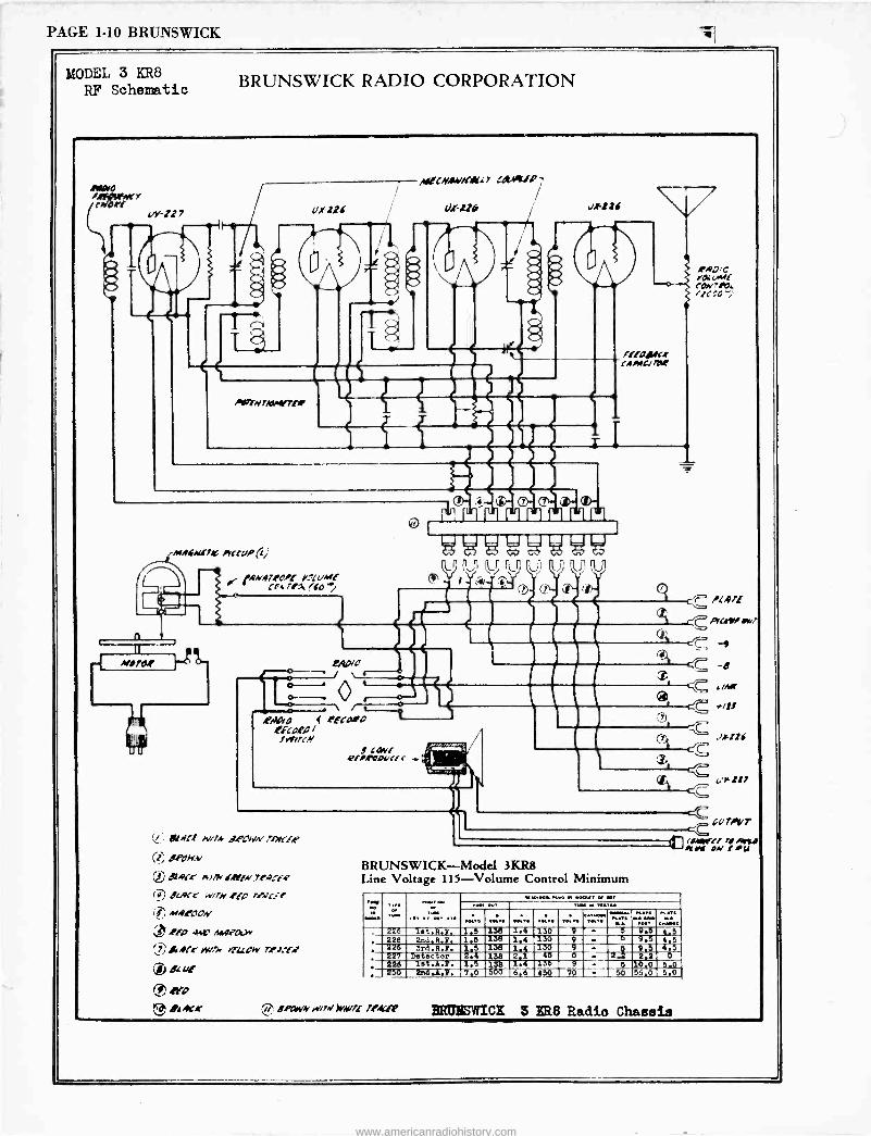
PAGE 1-10 BRUNSWICK
4
MODEL 3 KR8
RF Schematic BRUNSWICK RADIO CORPORATION
r+drl ur-127
_ » -
TI
,w(ICmAVKIK[ s atMtl %
o,rus , ALM
MtN7kW?!7r z
i
iMAfNl7,C IrltvP(;
60A4,47IO/f !.°LUmf -]I ' cr4 r/a (do'')
W,
n t
147 0 0
VWWWWWW L.ÿ (lP
r
Prgp/O /
, .\ .
,eaaro 4 eEtaoo
frtrirlN
(b ? 4
Fllihietr I.IMCJ7tle
t c PL/771"
t ----/C A'Crri Mr/ 021
I
! caw BlIRbOvcic
ri:
C7ri crCv
BRUNSWICK-Model 3KR8 Line Voltage 115-Volume Control Minimum
-'1
*41
J44ll6
Gc/TOeT
`N (04Alrrr 7/ /Oye/ /trli ON 1 G
; MM.....
ar
,...,. .. ...
...,... ».. . 40 . .., ... .. /44411
..... .. .«,. ...,. ,. . 5 .,.::..
, 226 let.R,Y. 1.5 138 1.4 130 9 ' - 9.5 4.5 , 226 2ndf R., 1.6 136 1.4 130 9 - 9 9.5 4.5
226 3r6,R.1e. 1.5 138 1.4 130 9 - p 9.5 4,5 , 227 .Detector 2 138 2i1 45 0 2.2 2.2 0 . 226 let.l.. 1.5 138 1.4 135 -9---- 5 i0.0 5.0 . 250 2nd.4.2. 7.0 500 6,6 450 70 - 50 55.0 5.0
ertLYM ./7N 1YAVrf rIACfP HRM SYPICK 3 ffit8 Radio Chassis
www.americanradiohistory.com
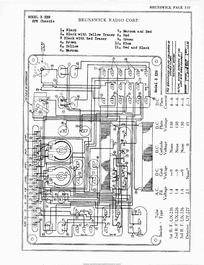
BRUNSWICK PAGE 1-11
MODEL 3 KR8 SPU Chassis BRUNSWICK RADIO CORP.
1. Black 7. Maroon and Red 2. Black with Yellow Tracer 8. Red 3 Black with Red Tracer 9. Green 4. Brown 10. Blue 6. Yellow 11. Red and Black 6. Maroon
A
a
(j°ó z >
000ir) M M M t
U
0 A 9
A C
Ú _z
a Ú ° o rn rn á>
> z - p` v N N N N
¢, N N N N.
E -+E- : >:< >1' D D a a
, Lt. Lr. Lc. ó a I .-bd
Sw44 r1CC 7 b -N M Ll
www.americanradiohistory.com
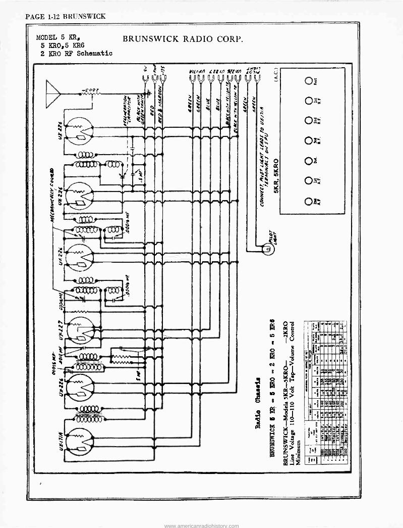
PAGE 1-12 BRUNSWICK
MODEL 5 KR, BRUNSWICK RADIO CORP. 5 KR0,5 KR6
2 KRO RF Schematic
ro
3 ??
o 6k t` r W j i
g á ö ë
et e tf
e. iefiet
/ M
di
a c : V V V V.
+..^^'1 "" "
tv h
i
v
Yr[i+n Zi Ln Xzxrl N,
4C 7h1
t
U3=, co --
v
v eoe idoe
k
`
o'`
o
www.americanradiohistory.com
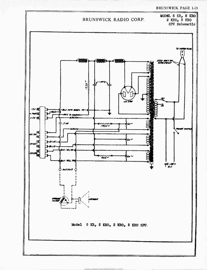
BRUNSWICK PAGE 1-13
BRUNSWICK RADIO CORP, MODEL 5 KR, 5 KRO
2 KRO, 3 KRO SPU Schematic
î `I M/O. h un
3 L! MYIM
, aro 1/M/ipp t4!!K
3---- 3 3-eir 3eic tit - r -,/Glie
422 w4c
i1r K i1.0
OUT/IT
1
1 1
1 1
1 1
i ,, J, I ¿
Zrege*` -- " wrw r ,'
Model 5 KR, 5 KRO, 2 KRO, 3 KRO SPU.
TO NOW I404
www.americanradiohistory.com
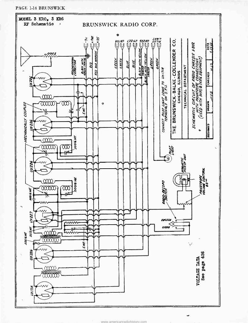
PAGE 1-14 BRUNSWICK
MODEL 3 KRO, 3 KR6
RF Schematic
;4
,0001
V+MJ )- ò 0 q
ti
BRUNSWICK RADIO CORP.
e
y V
HiciXn 9zz;m
V %.+ V V V V
" V V W t., v v
1,422 / 7 107/S WW o
V vv va 49er-
V V V
1 J1JZJ V V
v
m0», ---0---- 0/ON * ,.
www.americanradiohistory.com
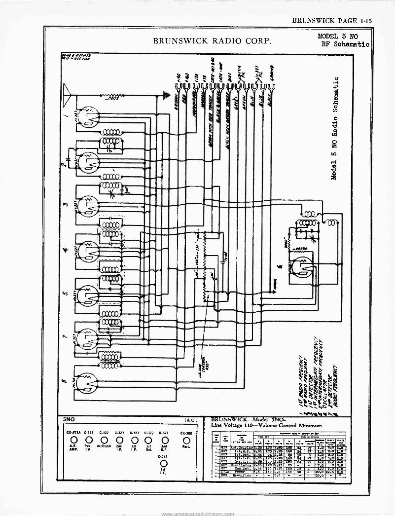
BRUNSWICK PAGE 1-15
umrs e»an -1.0# olfasJW
BRUNSWICK RADIO CORP. MODEL 5 NO RF Schematic
h
r
4 ! w
et es e e a z.~ vy --
e e ed-- .
=CO t t
CCooO .....-> . .
-_._.._..-
e
W
5NO (A.C.)
CX471A C-327 C-327 C-327 C-327 C-327
0 0 0 0 0 0 A.F. Pov. Occlllalos 264 1st 1st ANP. Ott. I.F. I. F. Ott.
C-327
O 2n6 R.F.
C327
o 1st
R. F.
C X-380
RO
..1169001.
BRUL'i SW ICK-Model 5N0 - Line Voltage 110 -Volume Control Minimum
227 A6t.Coi.4,r 2.55 170 2.25 160 24 1.0 4.0 1.0 227 1e6.2.7. 2.35 170 2.25 160 24 27 1.0 2.0 1.0 Z27 1et.Det. 2.35 94 2.25 80 10 u 1.0 2.0 1.0 227 1at.I.2. 2.35 170 2.25 160 24 27 1.0 3.0 2,0 227 2ndt.F. 2.3J 170 2.25 150 24 27 I.0 5.0 2..0 227 Oscillator 2.33 120 2.25 75 - - 7,0 0 0.0 227 223.Det. 2.35 570 2.25 160 15 -
- 1..0
i0.0 2.0
22.0 1,0
171A Power X5.5 160 3.0 153 30 . 2B0 Reetitier - - 5.0 - - - - 20.0
www.americanradiohistory.com
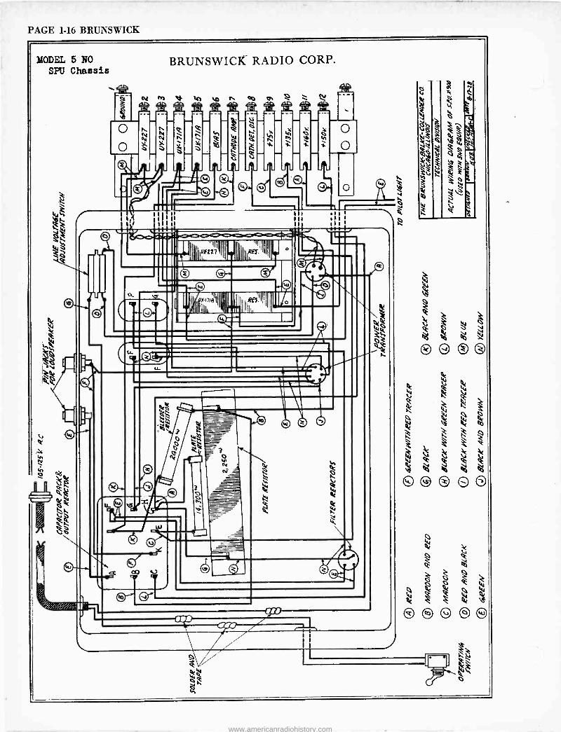
PAGE 1-16 BRUNSWICK
MODEL 5 NO SPU Chassis
-O
o-
BRUNSWICK RADIO CORP.
u1,YZ7 IIh..
J
Q t1/4 \ ~ ó
www.americanradiohistory.com
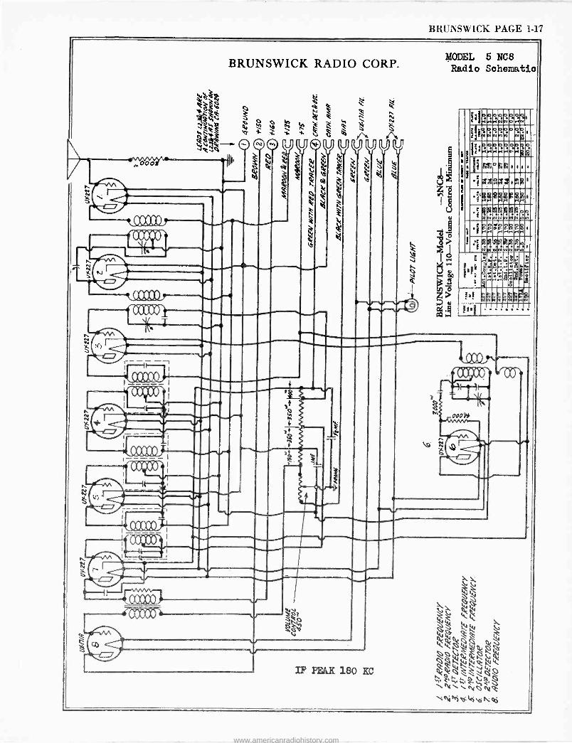
BRUNSWICK PAGE 1-17
BRUNSWICK RADIO CORP. MODEL 5 NC8 Radio Schematic
§
a n ..,.-ä 13
I
1
h 1111.1 1-1; rl ip'
_____ Iï11 ; , -- ri
+ i +
1.1.1.1.1_ llgi N. -1
1..1 IrA Nall IÏi11 1p ' r
,000
Q e n Ñ
` b ñ C
H
sa -I- -4. -I. i m iN A O©©
yyyoiyyvyy o d V Q! `t Vl V V !!1 G Or tt0! t `Z b S
r-
e144'Ij 1
^
IF PEAK 180 KC
1
M o r1 rl
o N N
0 O .+
gJ N
V N N M D o
N 4' 113 r+
o rl H
0 rl rl
p N r N
# t
2 ti á 1
it e e
5 N N
á
N N Ì M
ro.
N
e e
00 n
g
fal
!ei1
5 F O . IR+
V
N
ti
p
A
á li
N
M
d
a NVÓ
E
Ó
ymg r M
h rIN
zgoo-\ d(1 l v .
OODOy
1/4Y Ñ x
www.americanradiohistory.com
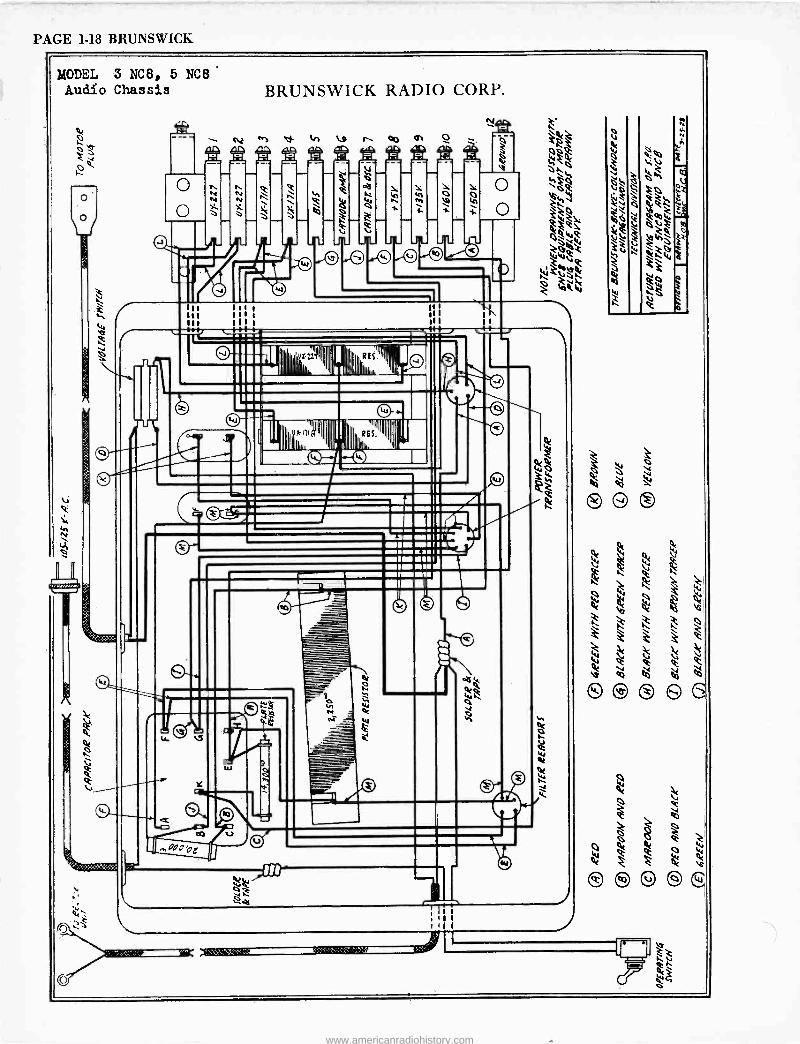
PAGE 1-18 BRUNSWICK
MODEL 3 NC8, 5 NCB
Audio Chassis BRUNSWICK RADIO CORP.
o
% i
o JL -
LJ
= 1 xllJ,' 2 ins.' = 0
.1=111 L %4ll 1II1,
I
RES. a oioamo
en
ó J
Of
Q .
© ©8 S C
1/41
Qt 0
www.americanradiohistory.com
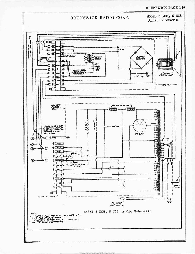
BRUNSWICK PAGE 1-19
BRUNSWICK RADIO CORP. MODEL 3 NCB, 5 NC8
Audio Schematic
esL, Iceur
cc er_.- 3 ..F
,wCrO,r u,vir
efT
LAW' l L3i, AN .44.4-.70010/
Aff flMmYAY «sou .o [Aseu
ctC
./P,/ ti.Cl f aO -I
NOTE_ /. M070R pox 4.4f7 [ LADS *VI UflO
1 RU fi7R A[B f0UArINI f7TfRNe LY/7JrT7 f/fff U1fo
ON rHL fNCB rOU//MfNTS
en«1lX APMCnwPf
2MF
L;ode1 3 NC8, 5 NC8 Audio Schematic
www.americanradiohistory.com
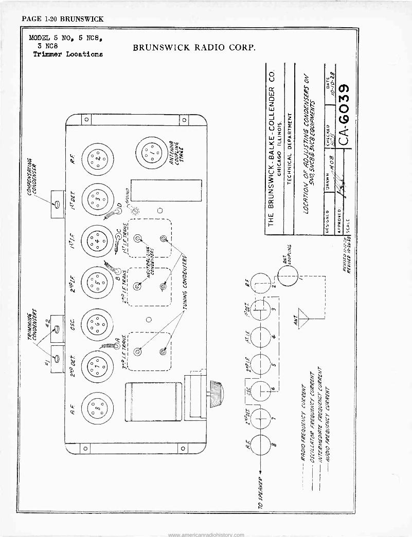
PAGE 1-20 BRUNSWICK
MODEL 5 NO, 5 NC8, 3 NC8
Trimmer Locations BRUNSWICK RADIO CORP.
o o
o
ti
r--
o o
R h
Ó U
w o z w J J
vi U ó
z w Y J
Q m á Y u
=
Cn z cc co
W 2
wN a0 O
0
` _
www.americanradiohistory.com
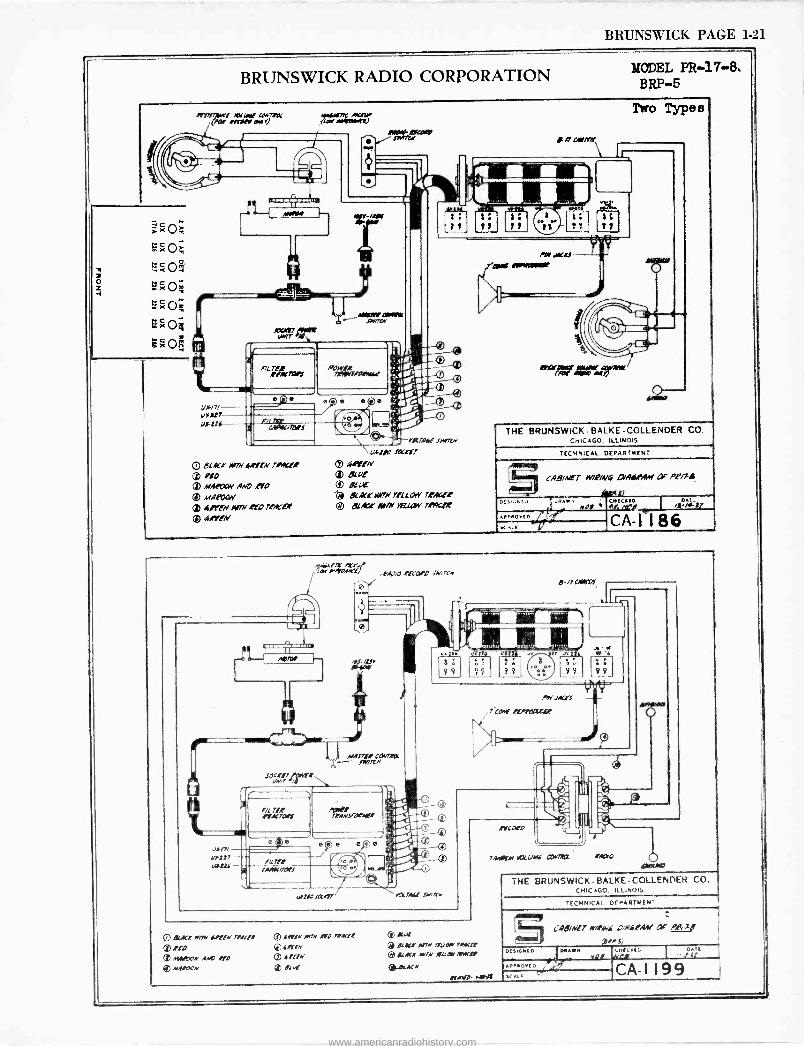
BRUNSWICK PAGE 1-21
BRUNSWICK RADIO CORPORATION
aefeiwt wee, cream OW eerie emir)
x Ñn7essart
ncRners
e1401d-MLaN nose/
lt _4111179P MOM Afire,
POW R
Fu ,7aes
BLAL'A' /417714,e'rrN motto ® P!O ® MAliXW AND 4, to m MARXIY
ogre, M%/ eta rl,KtX m EENeff[v
ewer., Jw7uv
u4200 ;duff m á,PrlN
BLuI p eteu[
QC,i,C wow razor', reArzC O Bcax Nfrn xqLcw row"'
MODEL PR -17-8t BRP-5
die,
11
»worm 4- - THE BRUNSWICK -BALKE -COLLENDER CO.
CHICAGO. ILLINOIS.
TECHNICAL DEPARTMENT
DES !GAT.,
APP NO
SCALE
CAB/iee-T W/Q/N4 dA1.191,ef CK O.P/J`a
L 1
JR ' CHECKED DAI_ MOP er.
CAA) 8 6,,-,.-,r
,nW4f7Y /C! -! i. .PÁ)iO.KCGKO iM/Cn
toC{rr FñErr 4N/r /
0 (id)
..o.
MA1fie
Pit lit rrACrafs
.ZfKr rrAN.afACf
r , - e
F/[7lt / I II 7.-- teere/raff o
UETeo f[KArr
99
rqcTAfl .nan.
Add. *rs 7W .!t/IrauW
Ip wud'r /I/71V jrrrN Mad e "to
A44100N AM7 KD ® AlAeVDN
® Jaw M7N ,fD emcee
Q ieYlN m ArLlN (I) r[Hr
p slue r[.K! MN '!UM' war r[ ACK 'WM X[[ax /IIIKNf
*weed'.
ti/OiD
7AritlrM /!iC UM[ coma' "A?'0
efAWe- 1-044
THE BRUNSWICK - BALKE -COLLENDER CO. CHIC+GO. ILLINOIS.
TECHNICAL DEPARTMENT
fAB/Nfr wnfwf ,^4A6,PAAI ai- ,044t, (er/ 5)
vrovEA0,k DESIGNED DRAWN
scAv
Mad CHECK. r ,..fi;t
CA -1199
www.americanradiohistory.com
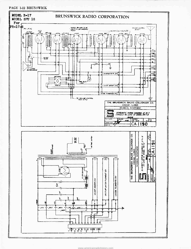
PAGE 1-22 BRUNSWICK
MODEL B-17 MOtEL SPIT 18 For
FR -17-43 AA .A:'3
Oa'A(/r 'ego
BRUNSWICK RADIO CORPORATION
' CONE urrnartf
>17
fdCORO
fA0i0
rivv[O /eM41r r0 dtf v710 wrr.Y .AEiMMK1 /rCIW
l',p,0 u7117
Q C4K'/7P07. (/(A7
AND vAlf CON7RY
THE BRUNSWICK-BALKE-COLLENDER CO. CMICAGO. ILLINOIS.
TECHNICAL DEPARTN[NT
SCAILAMT/C rvinwc AIIIRAW y' d1/7 C/aJS/J AS [/1f0 /N 449/S
dIMi) DESIGNED ONAIV r0 APPROVED
RC
CNIERID DATI O1. tffi'a I 44t11
CA -1 190
--- --"ail rr - MI
ri
N.
AJu
9.1 N
71 71
4
i
c+
Ú
www.americanradiohistory.com
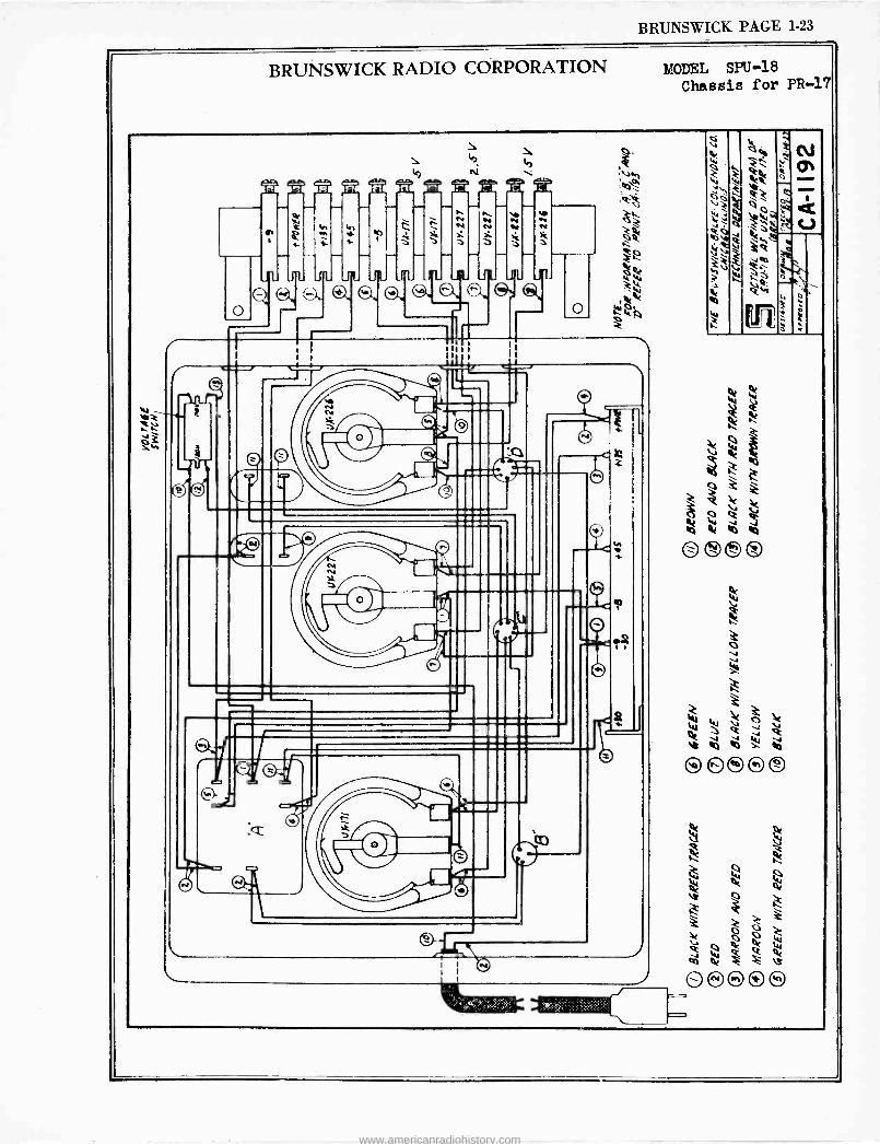
BRUNSWICK PAGE 1-23
BRUNSWICK RADIO CORPORATION MODEL SPU-18 Chassis for PR -17
CA
^V
Le
sup
.,r<,... ,:
W W o Q v
e d
O O O O O
www.americanradiohistory.com
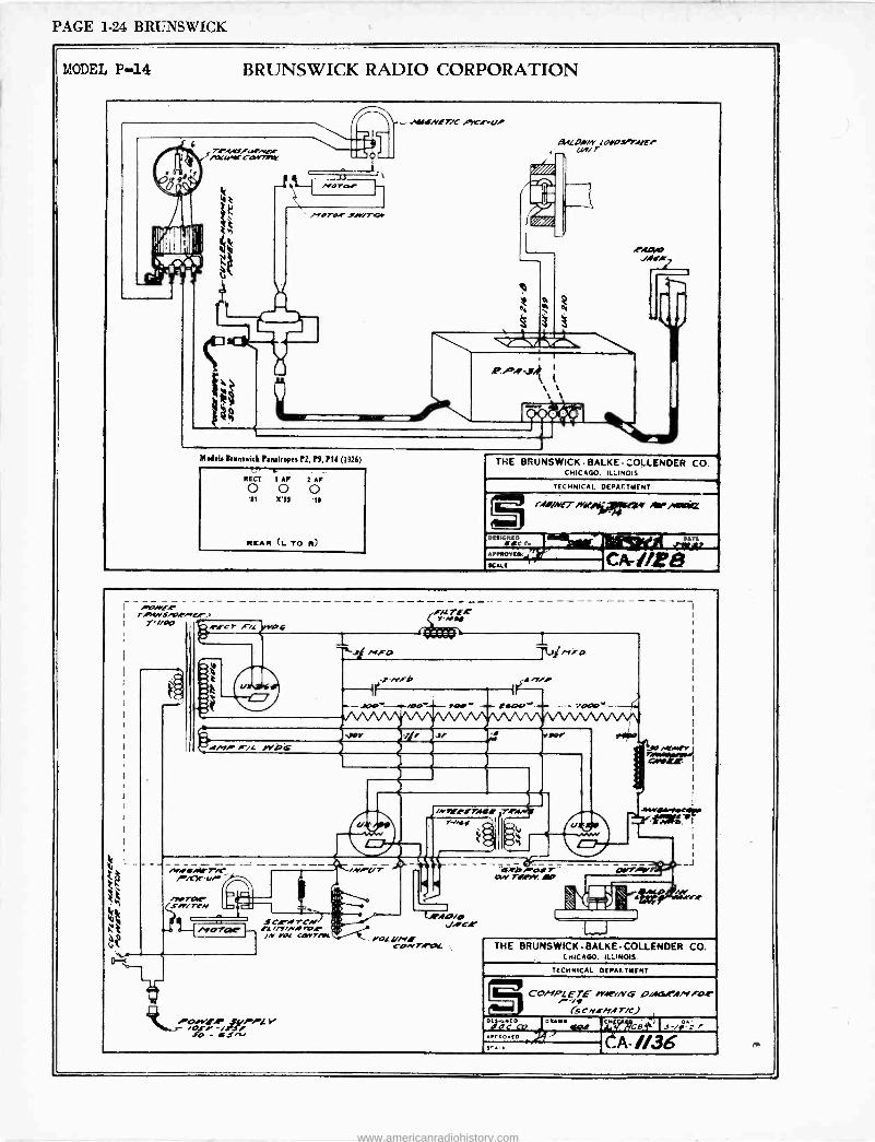
PAGE 1-24 BRUNSWICK
MODEL P-14 BRUNSWICK RADIO CORPORATION
+WfNIT/C PK.rua
T.r.t,ttfo,r.re".c rocrrrCw-nnr
111%
M[dal, Brumwick PanalroPeu P2, P9, PI/ (1926)
RECT 1 AP 2 AF
O O O n xºº m
REAR (L TO M)
S[LO.r/N lOrOS"."Arre UA/ r
THE BRUNSWICK - BALKE -COLLENDER CO. CHICAGO. ILLINOIS
TECHNICAL DEPAE.TMENT
/Asi.vErivsei ~Ague
DESIGNED r %f
s ArP[or[w1n A SCALE á r
ro/rf.r 7iElNt/13rNF! Y-// p,tfc7 FiL O
M.ef/,IrTiC -- - - - _ - - //2X'ar
f/L TEIr Y -NN
i
/Yo SC,rArCN ' ' L..10/O
rAC -- fa/n/.v.m.e AC /N rot cprr/Mc / roL ¡/Nl
lON7.r[7L.
io.º/E/r -AIRS/
v ofv r i JO - iJN
1
- ;4oc» -_
"a.eb"-arr 17N Tf,Ae AP
THE BRUNSWICK-BALKE-COLLENDER CO. CHICAGO. ILLINOIS
TECHNICAL DEPAr.TMENT
CO/`1PL ETE me/NG Oi.[.,t.[.YAo.r /q iSC NEWA T/fl
`2".;1"a7 aur.
APrGOv(D
,..,r ,A1/36
www.americanradiohistory.com
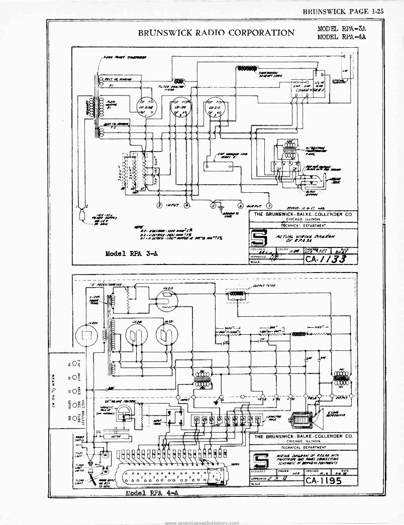
BRUNSWICK PAGE 1-25
BRUNSWICK RADIO CORPORATION MODEL RPA-3A MODEL RPA-4A
sew Asiffe Ne/00/4/4/401,
.fie..
/Aer-,fior Alen,'
O /O Ui yy
O
/1/ ~/Y me,/
7filKAIO(W dIOAfAfY G(Qf
e
Y /C
L41 /Je/ 11--1/O
J
o ísa IM/ /A/ 4w
LOAL'1ENorl!
SAY /MIIII OM/fI
1- OM/JM(1 A100 Ol(M'f fill-/lM/A71/ alld 9.,i -,r SMrf/ -/iA0-MAUI A/ AO-/ Atr7fr
Mode3. RPA 3-A
J/MN
ItM/(I- ,0.4.17 Ns*
BRUNSWICK - BALKE -COLLENDER CO CHICAGO. ILLINOIS
TTCHNICA', DEPACTM(N'
AC7LlA[ wi,riNf OYAs.IiRM OF ,Ci.t JA
o(sIcILCu ((AVM Af01, CHICMº.i/Pl i J../.01 1(
AISSH)Y(D
SI.E( CA- / /33
'O-Po/IN/MM/1!
f0-Alt(K /MVIMK
AtfifAY/fix-fiYrC
(r .ERw./
OWi um?'
.na Aor/L wirer(' fOJfU
d
-4
Nt
G`O 0 0 0 O O O O O O 0 0 O O O ' 1
l f f f 1 ! I 00 0 00 00 O.O 0000 0::. Ei/
AKO
CAAK//O(
THE BRUNSWICK - BALKE -COLLENDER CO CHICAGO. ILLINOIS.
TECHN'CAL DEPARTMENT
el/P/Ns 044449141 Joe .t/.,Eel w/JM MvA//orr MO WL CIIIMSCAaYf lCNfAN/C a( IONIII f1Y//AuëMl
DESIGNED
AMDVID .r x KALI
CHICHI( I
HAT(
CA- 1195 Model RPA 4-A
www.americanradiohistory.com
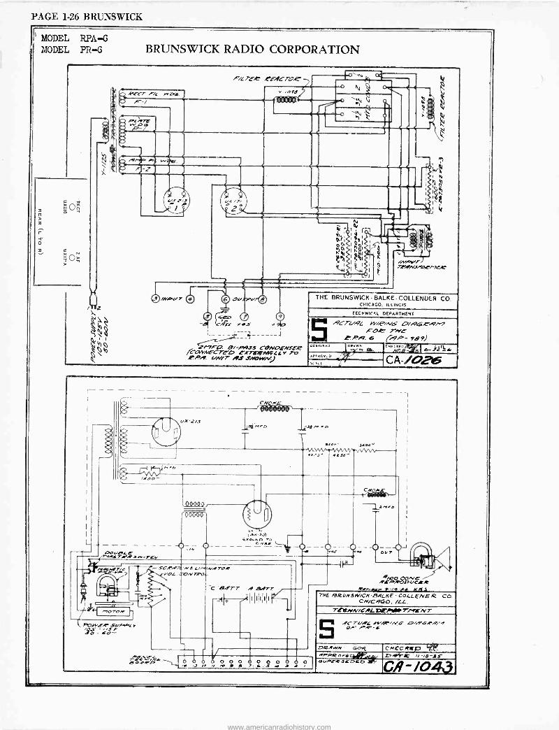
PAGE 1-26 BRUNSWICK
(' MODEL RPA-G y MODEL PR -G BRUNSWICK RADIO CORPORATION
Glla CÄS,- I fS
J
27 -7A -O. Bi -R456 CONOENSE.2 7C-04WECTE0 lX7ireri1RL L r TO .PPA !/N/T Ad sae1YN.J
THE BRUNSWICK -BALKE-COLLENDER CO. CHICAGO, ILLINOIS
TECHNICAL DEPARTMENT
,917-4,.9L rvi,Pin.6 L7i6 AM FO T/YC C.4/9. 6 ("51P- 989)
DESIGNED DRAWn
rvuor:D
SEALS
CRECRED NGB s l Z
CA -/0246
dle
.Sen-
15J' 4110'
7 c,
DOG,ZIC C tiAt, str.r-rw.rev
s- 1.,1T aaoA,o
c -es. V
FOwc.r r - s v
o - 60
rSCRA7ÿ'r C L /VW.I 7C,P YO[ T,pO
CNM
l'1io
O--Oour J ' }
C .B/1T7 A S9'T III,
....Er.k AS O,vTO O O O 0 0 0 0 G O O O O d 0
'O J /2/ g 1 e 7- cJ at -f 2 I
i00 (-IïNE i ,C6P,t'pOUCLR flr.k }-00-As kMi
TNE 9RUNSW/C/PBHLKE - COLLENE )2 CO. CN/C HGO, ILL.
T! @HN/CNL flEEYIAiP T/MCN T
5 .9CTUNL /1'.4.'/VC OF PT -4-
D2 NN C-Ort CNECAftD 7% nIPPRoYf44,02; D4,dr'L' 8uPlRSCDCD le' CAV043
www.americanradiohistory.com
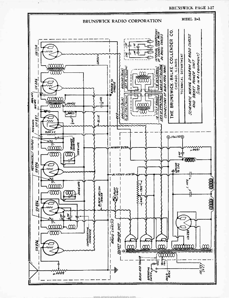
BRUNSWICK PAGE 1-27
BRUNSWICK RADIO CORPORATION
Jÿ F ^ 000OF
8
93h S'i .nMiv
1,
---OCOCCO
MODEL R-1
C)lnslnoc)
www.americanradiohistory.com
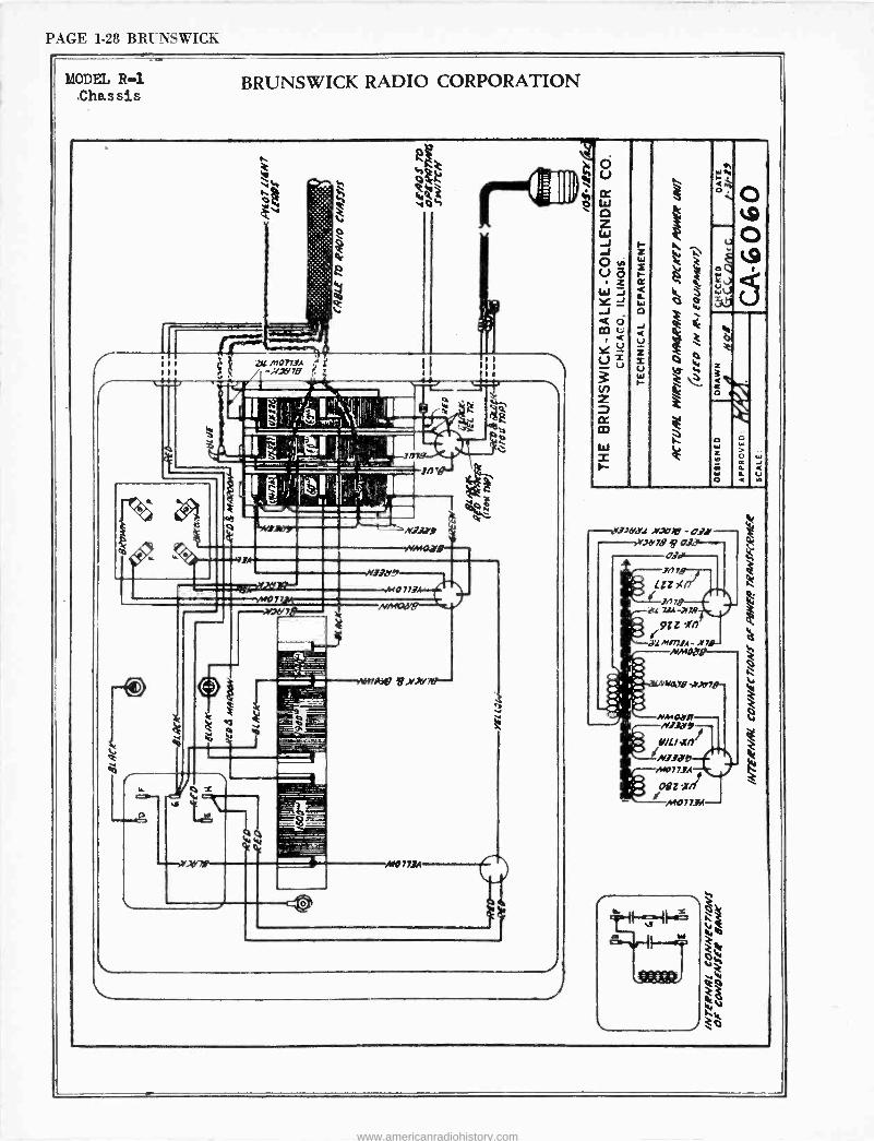
PAGE 1-28 BRUNSWICK
MODEL R.-1 .Chassis
BRUNSWICK RADIO CORPORATION
n
MD713A
$
.ßo171
s101704:47 1,>/),690-
_J
Aa 773A
i¡
e
J
'WU .ri10176' -031 Jd79fO
o.
Ná7B -.711Y7,
z
O
á
www.americanradiohistory.com
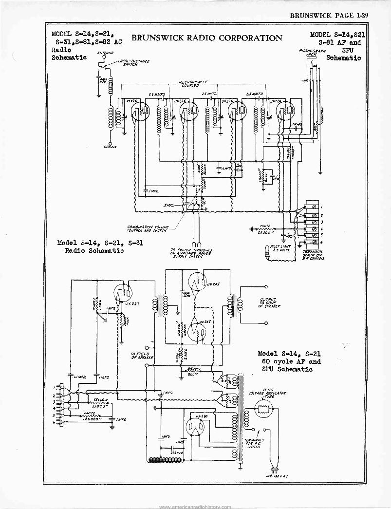
BRUNSWICK PAGE 1-29
MODEL S -14,S-21, BRUNSWICK RADIO CORPORATION S -31,S -81,S-82 AC
Radio Schematic
2
3
4
5
ANTENNA
I /LOCAI.O/STANCE SWITCH
C.t0uw0
COMBINATION k'0[ CME CONTEOL AND SWITCH
Model S-14, S-21, S-31 Radio Schematic
MECHANICAL L Y COUPLED
nn 70 SWITCH TEAM/WALS ON MPL/FIFA RNYIA'
SI/API Y CHASSIS
IMFO
IMFO
4---1H- VfAlFte
I/M4
J MF
WH/7E
zSOOO., ./ f0
MODEL S-14,521 S-81 AF and
PHONOGRAPH SP JACK
Sohemetio
00/00
I
iP/LO7l ANT z s voc rr
OUTPUT 70 CONE
OF SPEAKER
2
3
4
11 tic TERM/WAL S7K/P ON BA CHASSIS
r
Model S-14, S-21 60 oyole AF and SPU Schematic
TERM/HAL S FOR AC SWITCH
/00- ISO V AC
www.americanradiohistory.com
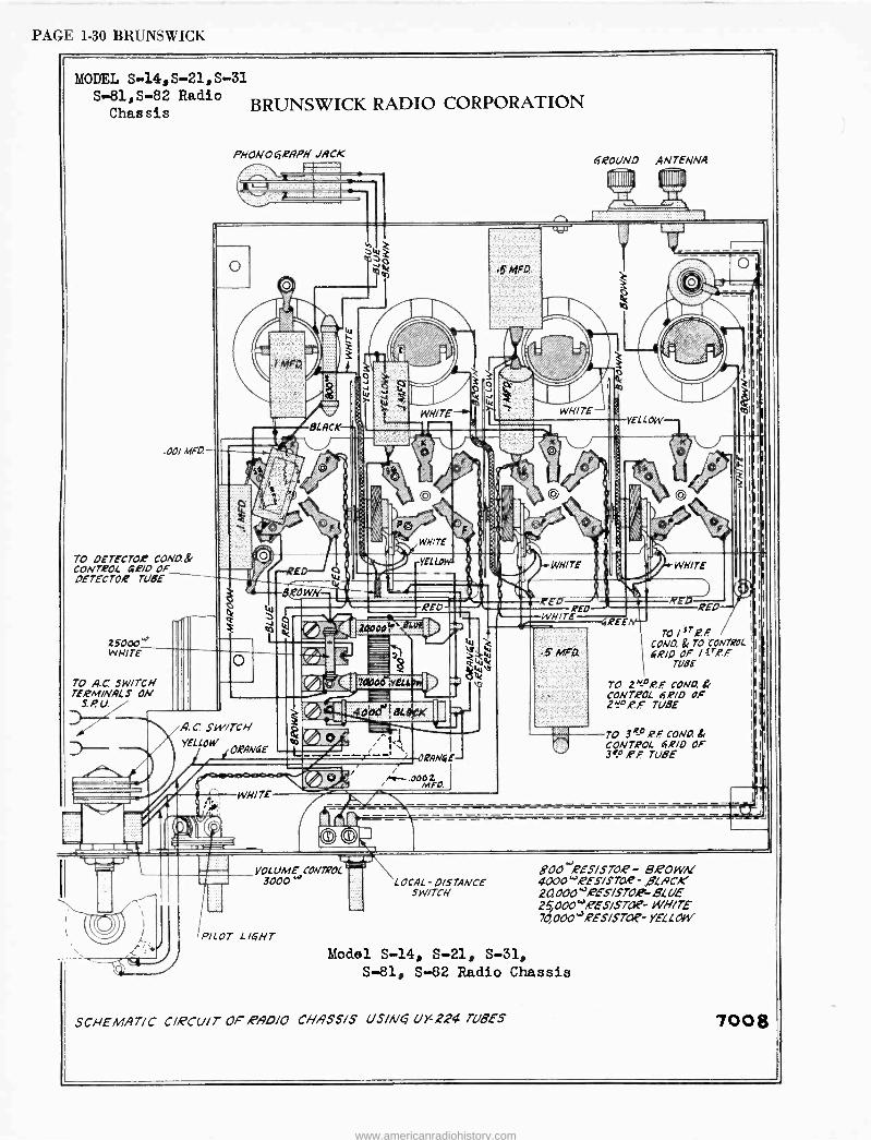
PAGE 1-30 BRUNSWICK
MODEL S -14,S-21,5-31 S -81,s-82 Radio
Chassis BRUNSWICK RADIO CORPORATION
00/ hfFO.
TO DETECTOE COLAD.& CONTROL 40/0 OF DETECTOR TUBE
25000 "' WHITE
70 AC. SWITCH TERMINALS ON
S.P. U.
1 d
PHONOGRAPH JACK
A C SWITCH YELLOW ORANGE
f
WH/TE
VOLUME CONTROL
3000°'
PICOT L /CHT
WHITE
RANG£-
LOCAL - DISTANCE SWITCH
r,
WHITE
WHITE É f0
(ROUND ANTENNA
YELLOW
4REE
IIIr
}
III sr I rl Tol ,PF/
COND. & TO CON7ROL I i I I
4R/0 OF /;r,PF IiII TUBE ill
TO Z NDR. .F CONO. Br 1
111
CONTROL 6E/42 OF I
I I I 2e° RP TUBE ÌII{
Ii+I TO 3 RD er CONO. S. I I i
CONTROL 6,E70 OF 3RD ,PF TUBE I
800 -j,eES/STaP - B.POwnI 4000",PES/STLi?- .BLACK 2GI000 "'R''ES/STO,R-BLUE 25, 000 "teES/STAP- WHITE 70,000 "'RES/STC7P- YELLOW
Model S-14, S-21, S-31, S-81, S-82 Radio Chassis
SCHEMATIC CIRCUIT OFRAD/O CHASSIS US/NCB !!Y-224 TUBES
I I
j
7008
www.americanradiohistory.com
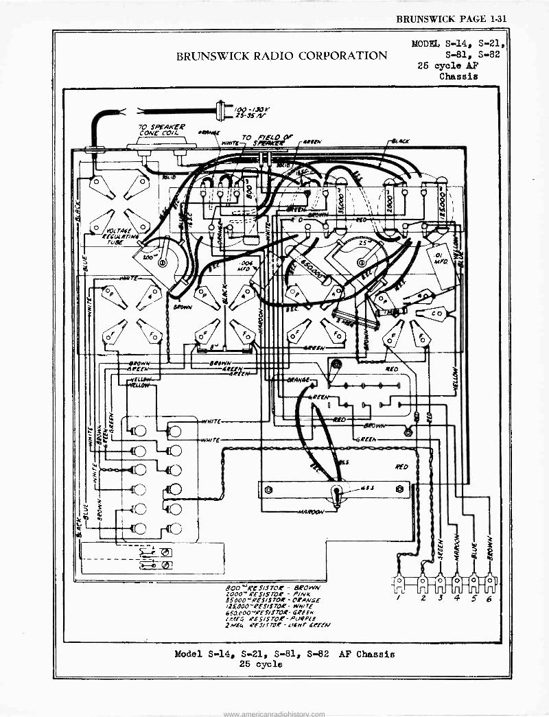
BRUNSWICK PAGE 1-31
IOWN erro.,
BRUNSWICK RADIO CORPORATION
Boo ",PESis70e - dPowN 20Oo-4ES/S7O, - PINK 35000- WS/ 3700 - OrAN4E /25000 -'PES/S7OR - iv/4/TE 650.00o`'A-ES/S7OR- 6,PfFn /rt4f:î .PES/S -PUQotE ¿Ive" 4fS/fTO,C - t/6Mr bPEEN
Model S-14, S-21, S-81, S-82 AF Chassis 25 cycle
MODEL S-14, S-21,
S-81, S-82 25 cycle AF
Chassis
www.americanradiohistory.com
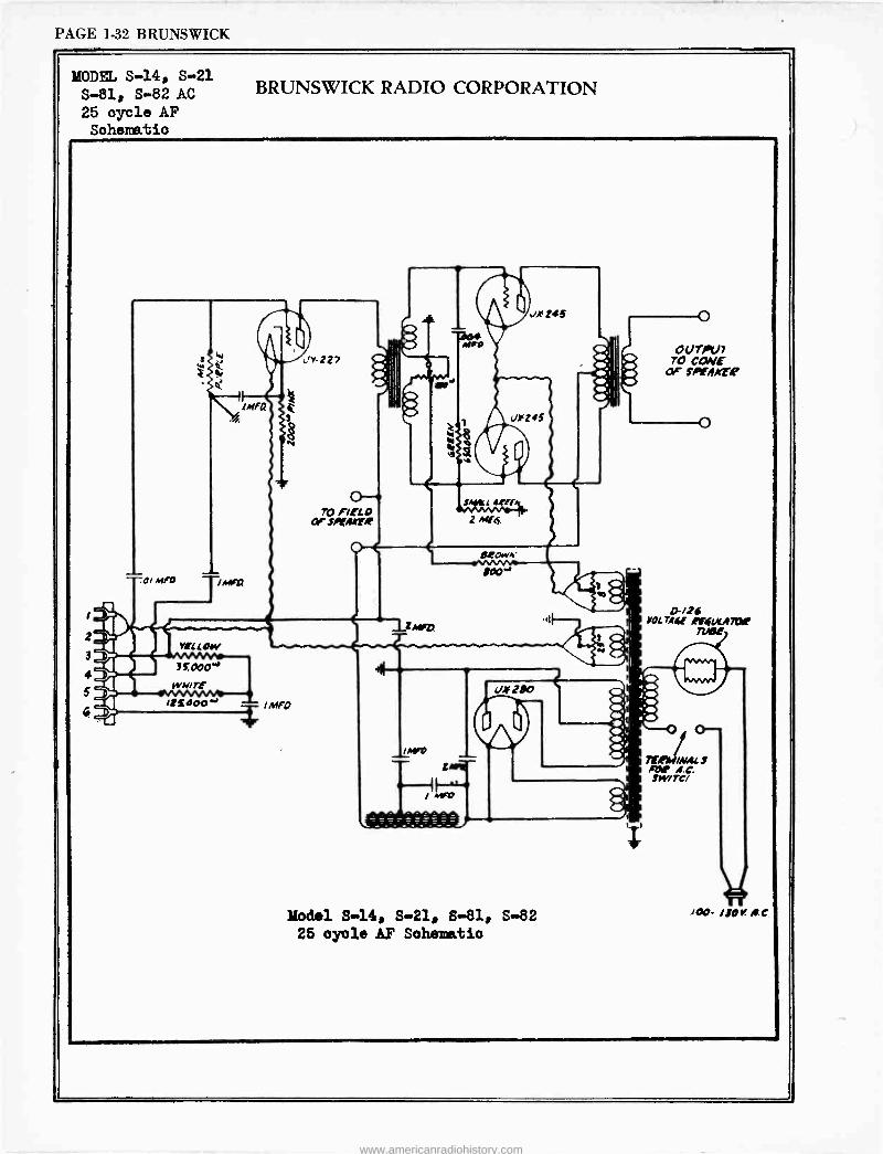
PAGE 1-32 BRUNSWICK
MODEL S-14, S-21 S-81, S-82 AC 25 cycle AF Schematic
BRUNSWICK RADIO CORPORATION
2
3
4
5
VLF( LOW
WK/TE
llxOOO w
r-227
70 F/EL D OF seAArAr
O
T iMfO
s.wcL 4A7
Model S-14, S-21, 8-81, S-82
26 oyole AF Sohematio
OUTPUT 70 CONE
Lae SPinfIttE
O-/26 VOLTA4f sfilfLKA7At
Met
7[refii«Az J roe 4.C. SW/TC/
)hi /OO- lIOY. II.0
www.americanradiohistory.com
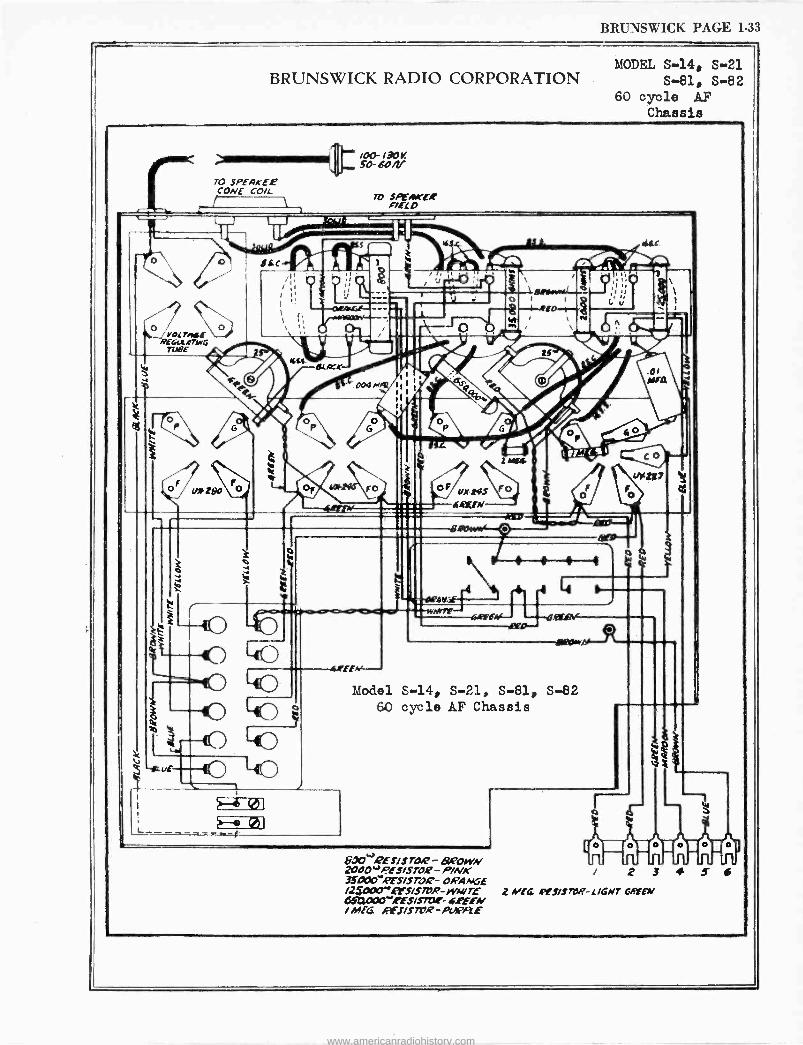
BRUNSWICK PAGE I-33
BRUNSWICK RADIO CORPORATION MODEL S-14, S-21
S-81, S-82 60 cycle AF
Chassis
TO SPEA,rE.E' CONE COIL
\ ti
/00-130K _ SO- 604i
IV SFEA1KEE FIELD
QS
3
i (/A* 280
0
Sic
Kif.
/ 10
J j . \ ` ;ii .
'v + 1
; ! , ' N 1 I ' _ / / ek
la P/4"1"1".1 a" ZMfi eX'
OMEN
o
tb
4
1
ts7
4
40 40 ( 4EEfN- ` Model S-14, S-21, S-81, S-82
60 cycle AP Chassis
g -,a uE---- 40 J L
01
600~'2E!'/S rOQ- 6LPOiev 2000"oES/514il- P/NK 33-00egEs/srOQ- ORANGE /zSoaoy ersa7öR-w/wrE ó6C3000-eES/S7QC- 4EEEN /MfG EIfS/SR7R-oilI1PRE
seezAvAi / 2 3 + S 6
2 NlG l'ES/STDVP- LIGHT MEN
www.americanradiohistory.com
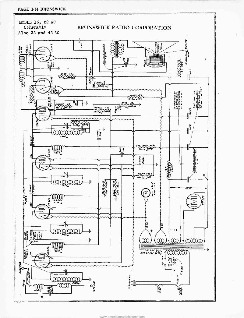
PAGE 1-34 BRUNSWICK
2
W
MODEL 15, 22 AC
Schematic Also 32 .and 42 AC
111
etz,
3/170 7160
r. `e $T 1 \* I ̂w
1
NAIOaO
/tffp A
7ZddAd 710
BRUNSWICK RADIO CORPORATION
ó
4w
ti `'
N
71Y.L1ry 7191.
r..,iFno009S7Y vAy9yL Ot U'
Á10777A AZL
/9EFWV 0b
8
Y
07 79äV7 A99/ 6LFF, j00
7N17W AISZ
iFFfy
it.
ti
C
M h
.4,09 ao! SIOEs NO1.-Sz ao! OtO£e
--A S -a.
AO94
www.americanradiohistory.com
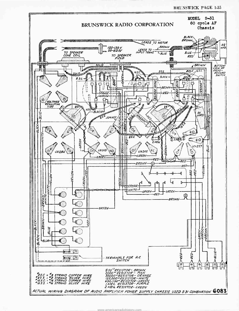
BRUNSWICK PAGE 1-35
u»280
BRUNSWICK RADIO CORPORATION
aQAWiE rNAROON
SLACK
BS .004MF0.
yREEN
WHITE
GQEEIV-
TERM/NHL S FOR A. C SWITCH
!KEEN
800 "'RESISTOR - BROWiV 8 w 2000 -2ES/STOR - P/NK BS.C. = B STRAND COPPER W/RE 35000''RESISTOR- 0.eAN4-E
#95. S. :°,5' STRAND SILVER W/1eE /25,0004'2E3/ST02-WHITE '/6S.C. ='/6 STRANO COPPER WIRE 650 000' RESISTOR-6,,PEEM 4/6 S. S. ='/6 STRAND SILVER WIRE / MEI. /FtSJSTOE- PURPLE
2 MEG. ROES/STO,P- 6/PEEN ACTUAL w/R/NCv DIAGRAM OF AUD/O ÑMPL/F/ER POWEP SUPPLY CRASS/5 USED 3.3/ COMB/A/47/ON 6083
MODEL S-31 60 oyole AF
Chassis
BLACK BROWN.
BLUE REO
IS KED
f REEN
BROWN
ÚY227
.02 MFO,
BOTTOM VIEW OF ,PAD/0 - FECOdO SWITCH
www.americanradiohistory.com

°
.
`
www.americanradiohistory.com
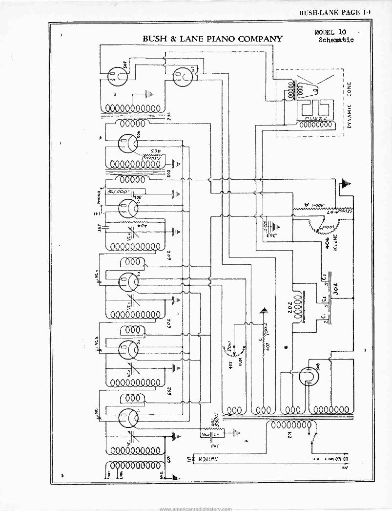
BUSH -LANE PAGE 1-1
BUSH & LANE PIANO COMPANY
e
o
röb-oZ)tr
017
QQQQ4Q444 , {u,,.
ZOO -it 1
1I111p x
J _
O- n
et N1
1110"
dX24210 Qp , N
%D 000'
lee
MODEL 10 Schemàtic
L
(or 001
--{pp
`y11CX YQN O
0-0"Zr
Et >
\_Q_QQ1114QSQ,N
0b6,
000400Q000,
1
1(11200 -MO v
d
3:-lpm,..
u
3
a
N O
1111111
rot
s N
7-V iioq O71'O11
9//
www.americanradiohistory.com
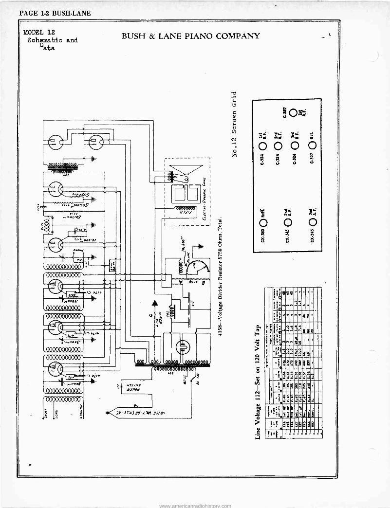
PAGE 1-2 BUSH -LANE
MODEL 12 Schematic and
ata
R
BUSH & LANE PIANO COMPANY
Qy9cAa.aaaor-
-z000 >GZ
cob 005"
i_y_ srrrpOaObOS
000OS
«';., oao'0/
Ova. á
y lY (}LY r 00D OZY OD®
# _.. J oL/b
000s
OOO00000000 iCzOOM00060`
2
,.,Goat
\00099(10400O,
'6bb60000000\
Ulti
Mar, o eoF
AUCI0000000
00000000000i
g
ootwoocr 073/J
Nil /Al I"
a,2,, s
31<nr-)7]I) 119.-t 74/ O//
Y es,* 8
o
A A Ñ
ca u c ó
O O O ñ
ärt íñ
an
X X X u u u
a i.. g- e..1
1 t .
1
Woe0 .g 11 1 1 .
:: rerere.i.4.. N 11
.
-e: :e
t+i) r r4 re P R
R 1
iti^'r;R4iß
d Eb.rere : .ei,o.
1 i
i -rerere.iñ+ '199°. ,,aG,,pp
.
.s RRRe8dd1
:.ññi{ryiñe '. .I N Ñ N á w N.Ì
;
I 'eYd
.. . 18' N
.s ,á .Ni :ii:ii
áoi áá á áñ
?al i x,:iägi.tikki
kk 5 .
:^! Q
e$áUiL; ,
ife .
www.americanradiohistory.com
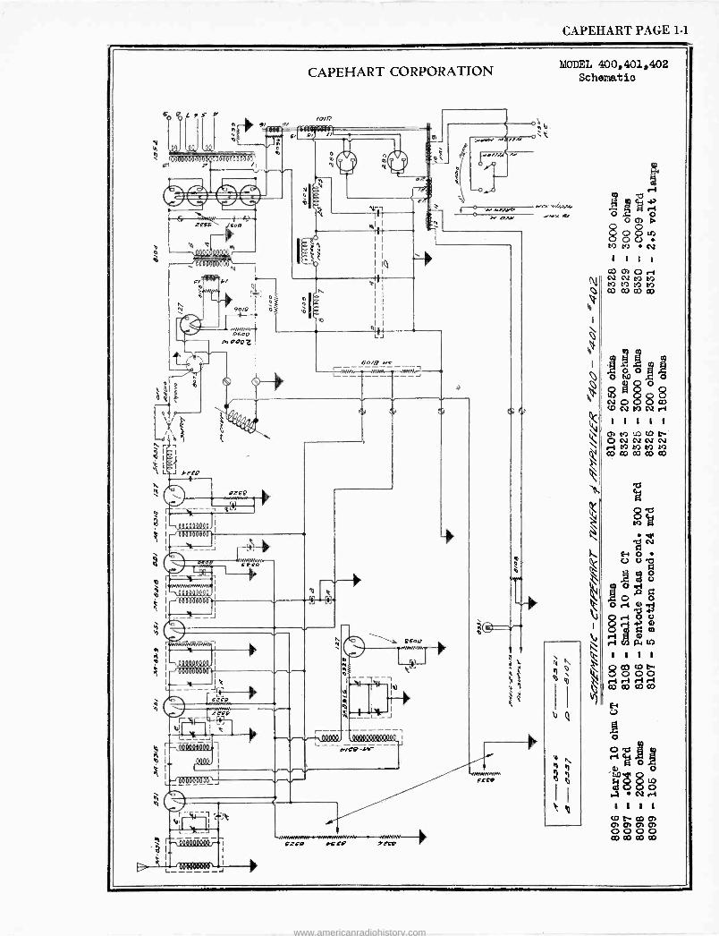
CAPEHART PAGE 1-1
,L r
o
I - 00000 doóloe000doe`
9/ / n 0
vv
a ZEF 9 té For:.
w Q
QQo
O I
S I ,000017900'
o
E/4" b/
90,9
1111111111
I
1.
9600 lAOooZ
ò
CAPEHART CORPORATION
/0/9
L/
o
N o N
1
JI+VN Mÿll I,we//J!}'! OI.°
-o-,0
+ o N .vJJ1' M olY
60/9 -err
r
9ZE9
6LEBPB
O I ll l 1J o
á 0000yoQQQ I
-l0000óD000}!
I. y I! 1FEo
I I <
e r ócooóeQoº, A
I out o I
L-,000000000,,,,
r-%4---1 - -,<
ó-00400QoJqr
I I
L J
9óo9
--,
M
1 1 -!'1. I I
i
000000MOWº 7J
FZFP CFC etF9
MODEL 400,401,402 Schenatio
Mm' JV
-W+wwwvn EFii
w b
www.americanradiohistory.com
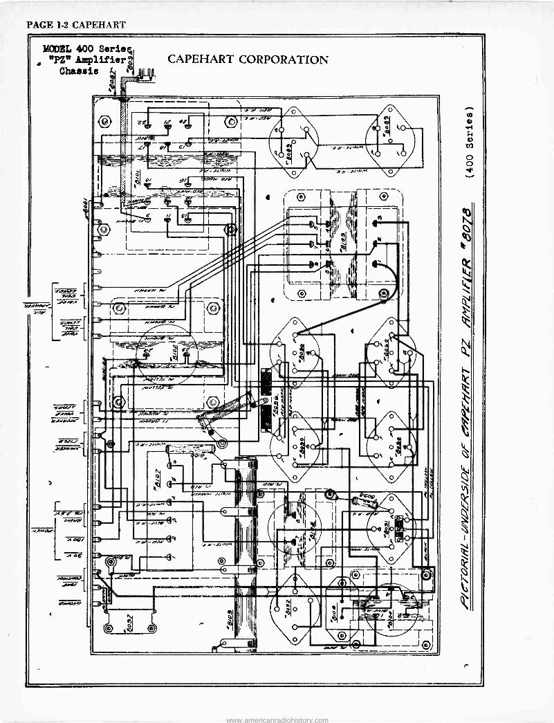
PAGE 1-2 CAPEHART
MODEL 400 Serien "PC Amplifier c
Chassis t 111 r MLA
rr
rsav7 >-.00.
ys,o,.
sanc77 7NJ
i2.A?A
ylJrv/r
r 9' k e,
oMCI,Md
:A OQ/
o6
ewe.12,Y4
CAPEHART CORPORATION
.`Ia77J.
J at? -J,iNM
'd >fiNM
www.americanradiohistory.com
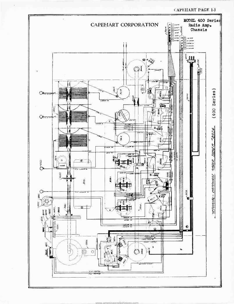
CAPEHART PAGE 1-3
CAPEHART CORPORATION MODEL 400 Seriez
-- Radio Amp.
I.
I I
Old
Chassis
Anse. Ar
o
.t,9
nee
Anew we .
IJ o
A.
9
17
c 14 . r~
;.. ,. o
NEK 'MWI
r
.11411+
I
OO
O t
a
a
O
a i....,.w.
o.
lee
www.americanradiohistory.com
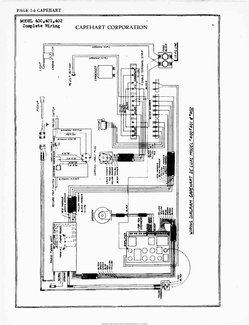
PAGE 14 CAPEHART
MODEL 400,401,402 Complete Wiring CAPEHART CORPORATION
NOON N/M1
NOON VN N1114
W
x W
e ==, Q }
V-14
J ü ÿW.iQ ii.aa04
o
e
e
1
www.americanradiohistory.com
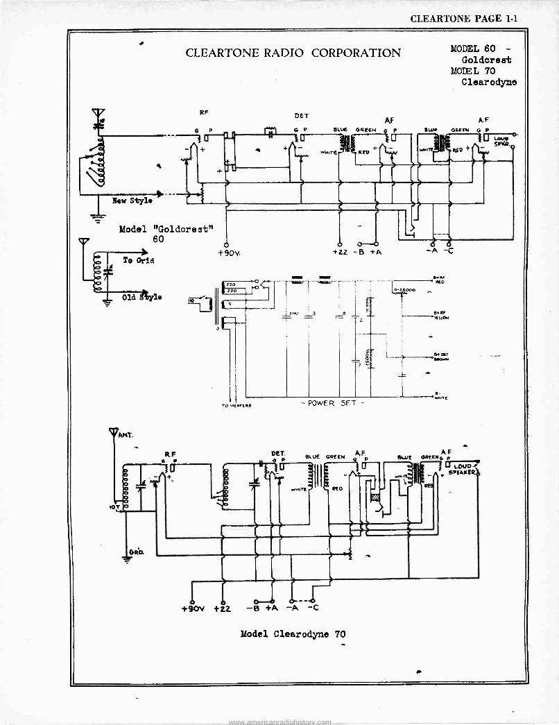
CLEARTONE PAGE 1-1
CLEARTONE RADIO CORPORATION
Model "Goldcrest"
t 90v.
©ANT.
GR0.
POwER 5F
DET BL UE GREEN AF
O P O lJ
A llk-/x ~J WNI'E REO
BUIE
MODEL 60 - Goldcrest
MODS. L 70 Clearodyne
A.F {Wb GREEN G P
-A -C
AF 6REEN4 p I
SPEAKERp
Ree
11 +90V +22 -13 +A -
Model Clearodyne 70
www.americanradiohistory.com
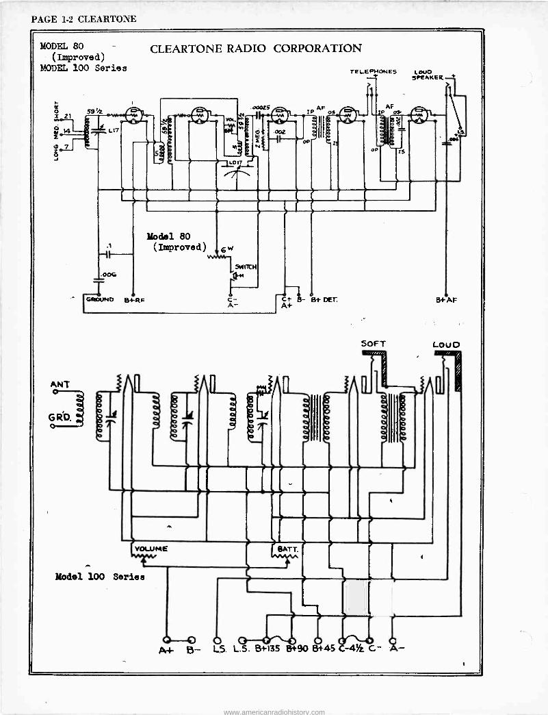
PAGE 1-2 CLEARTONE
MODEL 80 (Improved)
MODEL 100 Series
ot o
21 59'4 ow
7
L17
CLEARTONE RADIO CORPORATION
. o0025 sYhr.aEC
a ¢e $
W .002
u1 s N f AF P oS
TELEPHONES
op
AF IP OS -
a
$
IS
LOUO SPlAKER
.1
.0VV
T GROUND Bi -RP
Model 80 (Improved
o
o
D o
rn o
O o
o
[L
c+ 5- Bt DET. A+
z E
SOFT
r
Ó o o
8+AF
LOUD
VOLUME BATT.
Model 100 Series
0 -0 O q.}- B- L5. L.S. B+135 8+90 8+45 C-4iz, G-
www.americanradiohistory.com
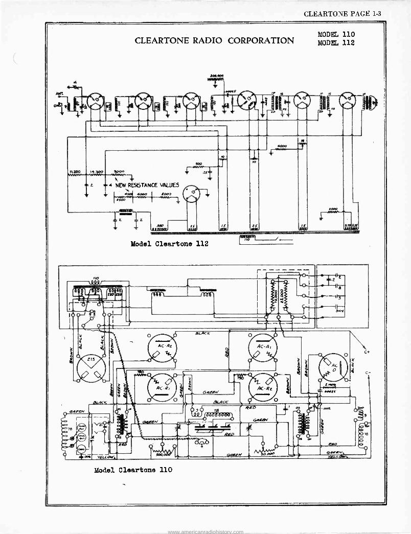
CLEARTONE PAGE 1-3
CLEARTONE RADIO CORPORATION
Model Cleartone 112
MODEL 110 MODEL 112
110
Model Cleartone 110
-OT
o1 , 1
2
f-,-*
www.americanradiohistory.com

-
kJ
e
www.americanradiohistory.com
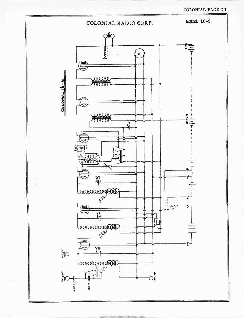
COLONIAL PAGE 1.1
COLONIAL RADIO CORP. MODEL 166
, , , , l
.-..1.11.1_-"t
T
T
pT
uT
1
.T
www.americanradiohistory.com
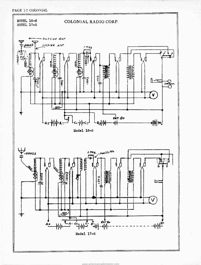
PAGE 1-2 COLONIAL
MODEL 16-5 MODEL 17-5
COLONIAL RADIO CORP.
CT OuTS/DE 4.yr
T400.25 1oe ,qnr
o o
.00025
o
. 4,1
.. o
oar Bt AIiIl- -' .IC BiI1 I -
C1 Model 16-5
o o o
A
a
I Mag.
I
i , .
AfIi----A- ++-,II- BC4IIE-III--- -- - - Model 17-5
o
www.americanradiohistory.com
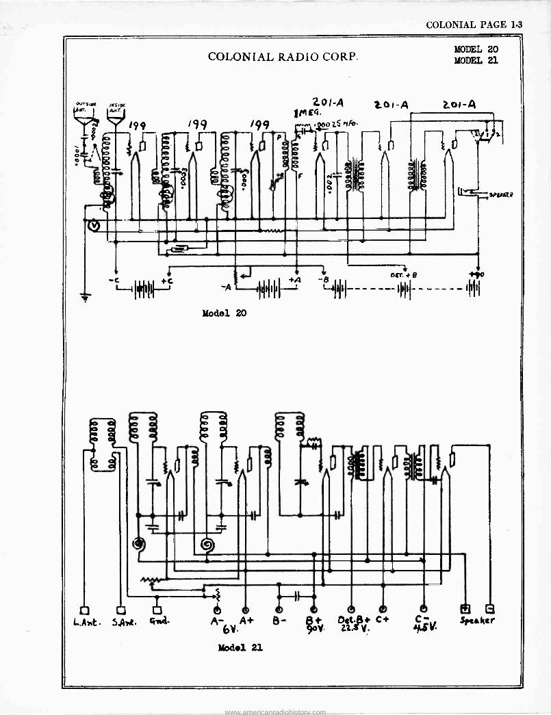
COLONIAL PAGE 1-3
«e*s,a óor
ò o o
X99
Q
COLONIAL RADIO CORP. MODEL 20 MODEL 21
gol -A top -A 2.oß -q M E4.
/99 Zs mis
e O e
Co
t
^J1O41 +°'1
Model 20
n II I-
t o b
L,Art SAyst 1.01 A - A+
Model 21
6
tar +e +90 -------- - - - - - hl I I
SP61(C$
d o. O22 S C+ CF-v Speaker
www.americanradiohistory.com
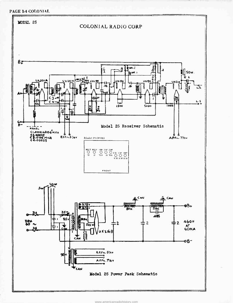
PAGE 1-4 COLONIAL
MODEL 25
VA NEL cl.000lwA0q r,lc t 000its o C.004_MIcA RFPILS1/4v c 400025
COLONIAL RADIO CORP
Model 25 Receiver Schematic
Model 25 (1926)
REGT REGT 1 RF 3 AF 2 RF
0 0 0 0 0 2 AF 1 AF DET '81 '81 '01A '10 '01A 0 0 0
0'99 O'99 099
FRONT
Model 25 Power Pack Schematic
AñFIt-.1Y2v
www.americanradiohistory.com
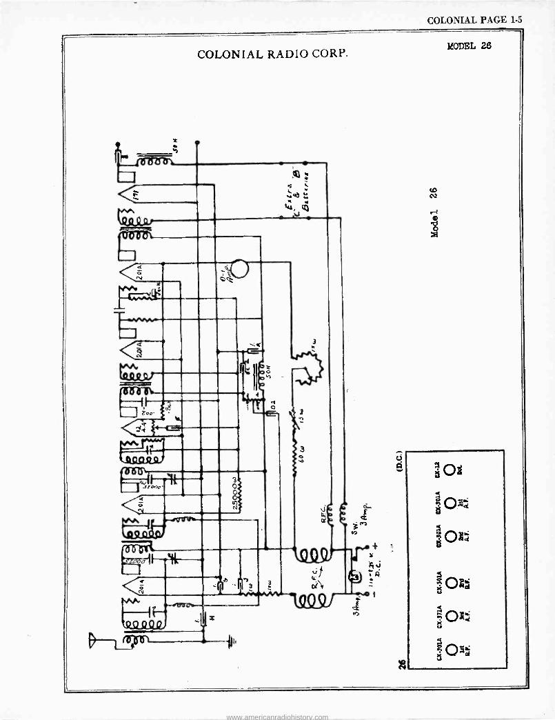
COLONIAL PAGE 1-5
COLONIAL RADIO CORP.
o
<rz-
op
C2v
1-6-ert ! 4 c
4900
3
MODEL 26
www.americanradiohistory.com
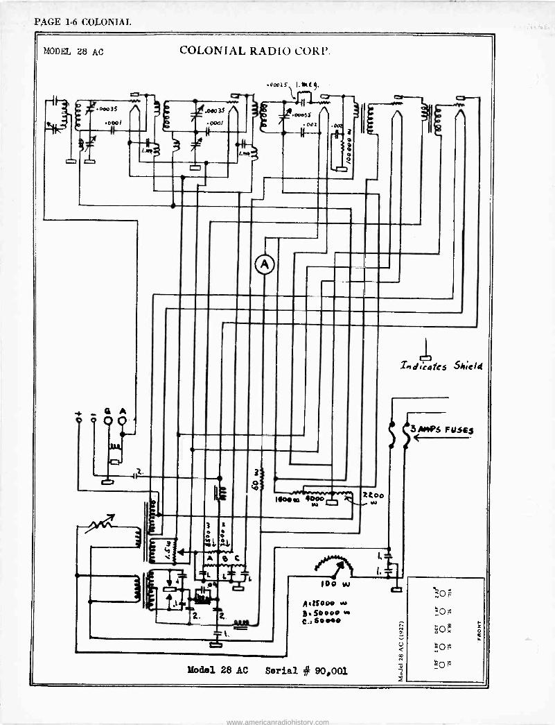
PAGE 1-6 COLONIAL
MODEL 28 AC
.0003S ^ 000!
COLONIAL RADIO CORP.
4.0A03S A 0001
72. 0003 S
oox ric
2
i.° Moo to 4o00
3
S
1.
L L
.4
x. z. _AA« á`.
U Ind (Cafes Shrel4
I.
10o w
drogo w S.S0000 C.:459100
Model 28 AC Serial # 90,001
3 mes F usFs
www.americanradiohistory.com
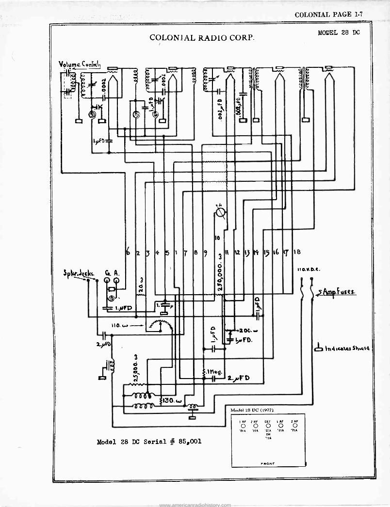
COLONIAL PAGE 1-7
COLONIAL RADIO CORP.
Model 28 DC Serial # 85,001
1 RF 2 RF DEr 1 AF 2 AF
0 0 0 0 0 'O1A '01A '01A 'CIA
OR '12A
F RONT
'71A
MODEL 28 DC
www.americanradiohistory.com
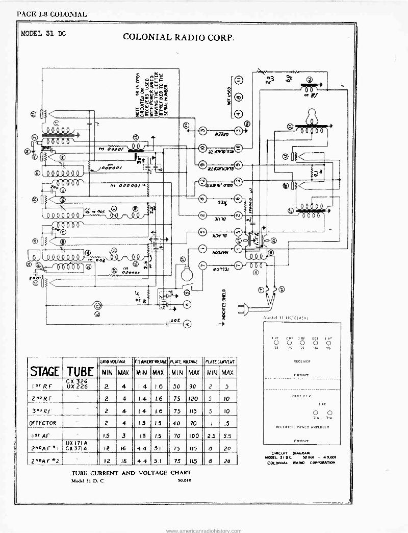
PAGE 1-8 COLONIAL
MODEL 31 DC COLONIAL RADIO CORP.
© [ <
(LO 01.0
®* Q
M ODOO/
G QQQQQQQ% s-nn\ o Q
O
00000/ , º
00=
11f op.> Op/ 4.
c'N N OD000,
oot
o
N)]yJ
V N¡ - .171r1D 0709 v 024
7n 7Q
0
M
© 1
11.2v7e v V `c i a bQ ^- AnaWrw a
M0772á
STAGE TUBE GIIOVOLTAGE FIE AMCNTVOLT« PLATE MIME PLATEUMW'
MIN. MAX. MIN MAX. MIN MAX MIN MAX
I ST RF CX 326 UX 226 2 4 1 .4 1.6 50 90 2 5
2"0RF 2 4 1.4 1.6 75 120 5 10 r 3"°RF 2 4- 1.4 1.6 75 115 5 IO
DETECTOR 2 4 1.3 1.5 40 70 I .5
1 ST Ar 1.5 3 1.3 1.5 70 100 2.5 5.5
2^OAr*I 1.1X 171A CX37IA It 16 4.4 51 75 115 a 20
2"0AF*2 12 16 4.4 5.1 75 11.5 6 20
TUBE CURRENT AND VOLTAGE CHART Model 31 D. C. 50.010
VLJcI 31 DC (192.11)
1 RF 2 RF ; RF DET I AF
O O O O O '26 '26 '26 '26 '26
RECEIVER
FRONT
PILOT 115 V.
2 AF
O O '7IA 71A
RECTIFIER. POWER AMPLIFIER
FRONT
C1RC.UIT 006RAM MCC. 31 OC 50.001 - 40,001
COLOfdML RAGA CORf`ORATgM
www.americanradiohistory.com
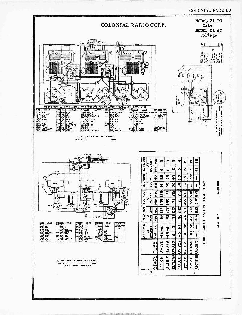
COLONIAL PAGE 1-9
COLONIAL RADIO CORP.
NOTE OR IT OPEN CWC(ATCO ON RECLINERS USED WITH POWER UNITS HAVING THE LETTER O PREFIXED TO THE SERIAL NUMBER.
COO( COLOR 717( .00C COLOR -)-1 Cmi- COLOR lAC6Dpt COLOR Y1?(EpQC camYtR [OK YIK 14-, BLACK 6CAC_II.9,{RIIfTI IA;IOC, LCL MD JUN'!l,'Iq. !unmet Nor (AICEN(DL.CPSMOCM JEaIBIV IG'6C, R..«
KMIrt SLUE
JOY, JPAC,Y, ICAI Al, DC,
GAUD GRIM
JUIW AL" X.
RED
REDCWMT[ '
+- Ipy2C, tux,RLACR
GKErt '
-
II.RR, IAA
YELLOW - '
CAKCNORKD ' '
RV, .31,-1/4'
NRCR
IL. IP, WMTL - At¡N, ELLC AM Sl,6L, wCt,C - riRL/1 Awx-RC, 2L,IC, 2C,II
MIRK .
50LRIII,BR, fl,t
WRIT OlN
-
(CM WN, IL -2E,
GREEN
REACH -
RLMC. RL'IC,
RED RID
JMM1 K;R, 1R,RC,
KD WTI
2TltR. 2(¡IRARTRtt
OWE ICM SE,°,'
(YCLLMrI OlA[R.KD74
CCM,1L¡`C CCABllllllC,
..
P[D ICM JIMM(,]I,
Rl¡11Cs .
EqMRi IIR,.X,
pK .
ME, YELLOW -
melt. IC, RLUC ACMdI.JL ' IM;t/, LFM, ' 1007. gem co 34J2 xCDC.
CdA.QACMTP WORRYÁ00,2L;6(,
CUO,Ct,P1, YELLOW weer(
DM ACM
6412C, XL Oli, REDIMITI -
E'J, ALI4IA
KumCA6 GREEN .
if -I 42LR1R
MM/DM GREEN
CCAA, JIV.
ÿ""'
1OP VIEW OF RADIO SET WIRING 11,4.1 II ix_ 39.O4
iSrzni{'e7.111Mw.t: , ORne . %. W.. áU' iü NNON, Y[LL1Mr
KAU34.0,
Mm Met
lK1MT! m1A1 r n ......
-1b' W EI,.
/1/.IGI 314, IA
ni ca``
N.It +C.vS
X.IA I! K M IK.t1. MtI I:R,
ILu
YEII IUR IIR1L GlRLAL, TI
101MI11 GRRN plf RNR lIt
41M
nMa.
- iWiCx,
' i L W R.Y(.
KR 1LM z,+ AM
IRA, ruxK AIR CIA
KO
Ili GQA KRAMrt '
,..DI ,prTl '
OAK RR KPANMrz Mm.
l. 111
M[. {IT
Illttt
1ry[¡IL
)ac HN,
14n .
KI KY NIrT[ R14M.
' (.t1AIM) K4/LILIIp. am ITp
W,.,4
N1L, - 1141I1t.
- MG1t,
KYIVK'1 I ,N.
-
BOTTOM VIEW OF RADIO SET WIRING AIMAI U DC )IM I
COLONIAL RA0,0 CORPORATION
MODEL 31 DC
Data ,
MODEL 31 AC Voltage
at a A+
2Ñ.
Lu Y U
Ì G) CA K% Kt N N 2 44 e po En in
á
r .(8 p
N
e É
Lo N
in N 0 e- º Ñ
opN
t E
in T Qc1 in
co O I O 0` C
pÑ
,
LLJ . OJ
E
J W.
ti;1 t8
N
i IA .1
IA
= tn' ,i
Il1
Ñ Ln
.2e O e
2 X1
in In
U1 In Ñ LeL
VI 4 Q e
re = e
QV
, <, E~ I ̀ 1 r...N Q +
EV
p U1
O 11
O ui
z f in _ in001 _ ° _ t0 4
e 'a
EO
I:
RJ
o
g Q V .
x ï - - - o - N 1!1
N Y)
-i Lf1 -i- U1 I 0 ifin. i I
W ?N
1--D
ti X
Ñ N X 0
Ñ N y-
0
N< N } 7
- Q r z
N 1
L1J C7 «zrC12
C!)
U-'
0=I
IL' e. Oi u<< N
IL
I U:
N
U:
Ai i.1)
)
w
oWt
v
www.americanradiohistory.com
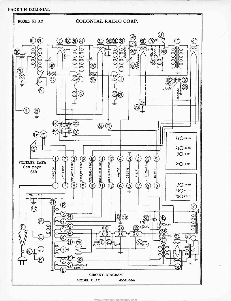
PAGE 1-10 COLONIAL
MODEL 31 AC COLONIAL RADIO CORP.
©© O ®0® ®O©
o
4118.
411.
4Mb - 2DOt3
4B,
431.
(4
.11
4/0
IX> - - 42oow
e ice
10
ó =o _
®Ll.7,4-134 ZC
o VOLTAGE DATA
See page ó 549 Y J
Q Z }
o
I 1
0
o
0 O .
4/0 - -
c) ei) cedl 2 © ®
3 L- ~
ó 6C 7 É ó ® A o 00
6C o
4I
411.
131,
Jai
9 l0 l'I I ® 3di ® SO
á I- H
W U o Y U F_
Z I=-1 Y U
OG ¢ <-7 2 W J ':--2.
Q ù m >è m 3 0Z m ...I U ci b ehp debo --Il I 3
4
25o(-)
;ÇO CX326
.740 CX 326
OC 327
;_0 C327
X170 CX.380
;30 CX371/
0 CX-371/
g Mf
IM.- 37,:cao,
3 7000w
8 Mf
CIRCUIT DIAGRAM
3 rod 0t.1
MODEL 31 AC 60001-5001
www.americanradiohistory.com
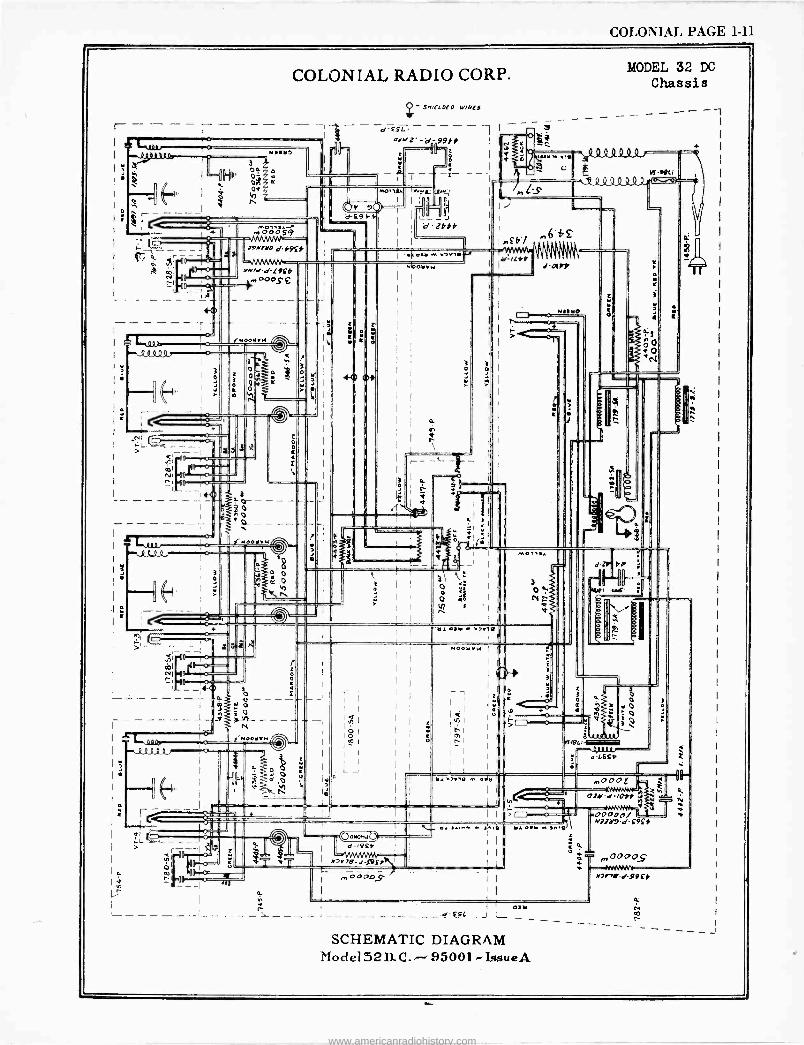
COLONIAL PAGE 1-11
fllh. óñ I I Od
o y7
.1 a ^
l'.; 4is-0I rAwd-d[9fb
NOOVvw Man1
_
.1
dl
COLONIAL RADIO CORP.
I
.41111 ,, ' IIL a1
! --
sn01
D=O- d"
or
-_d-£SLJ
Q - D W/nLS
-e-cg-C. - - .0drrZ-d11199f6
-p `
s osar ... rer,.
úhi
9 d -£9f -
OOMOMd. d -14Q.
I r2r79-d íOF1
,00005
Is
SCHEMATIC DIAGRAM Model 32 D. C. 95001 -IssueA
...,. .,. s o
MODEL 32 DC
Chassis
- -
7Nd-/pyf
00000/ -'= a17Y9-df9fi
r OOOOS`
r>nY-d-99f*
I
www.americanradiohistory.com
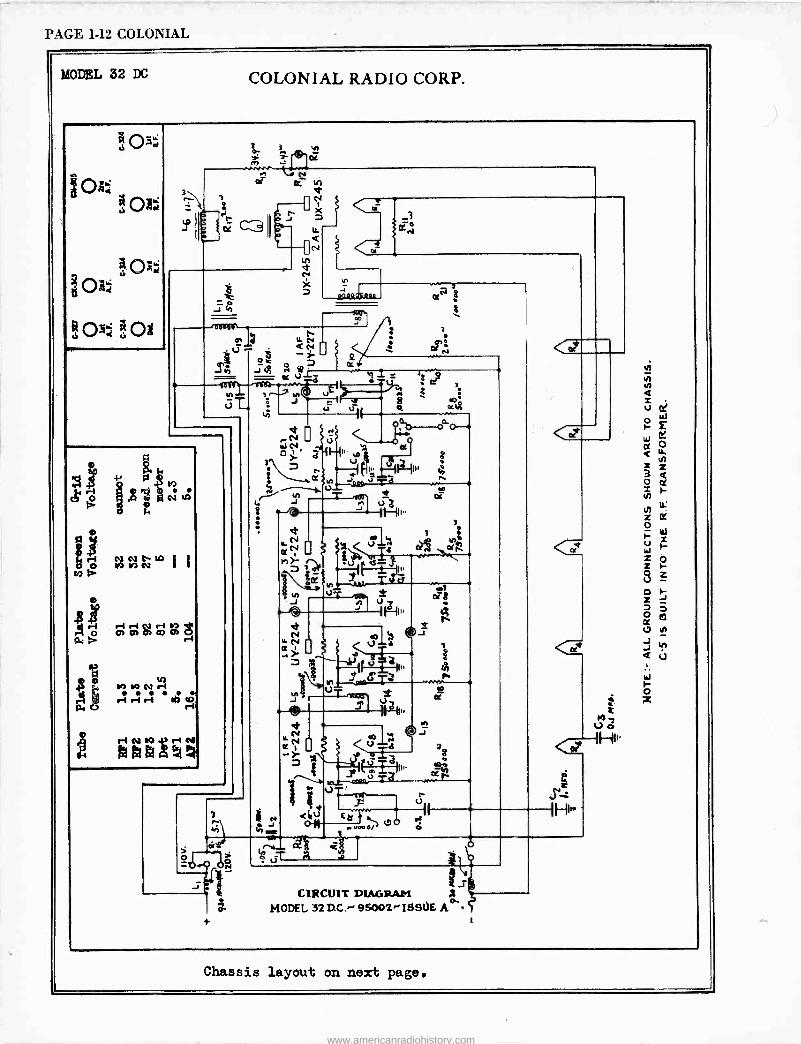
PAGE 1-12 COLONIAL
MODEL 32 DC COLONIAL RADIO CORP.
ó- T .. -
0. y{
o3 J ÿ J tit
& zie
,pQ M
C! tre
rl r -I Pt ri a ]C Of 01 O> CD Ob
Urb
19 1r) N r1 . . . . ri ri r1 IQ
A r nt M rt N
h
ó
e u
n
-J
± uö
! N O J h s
et
«N. rs $\éQ
u
h u
n t73
,;1+ Ou
a{ al
et oT8
<Lú oN
1Fß li'
M J U ~ d 'I â "
hi'
o ó
ó.T ¢S ó. A
CIRCUIT DIAGRAII MODEL 32 DC.-' 95002,- ISSOE Ae'
Chassis layout on next page.
www.americanradiohistory.com
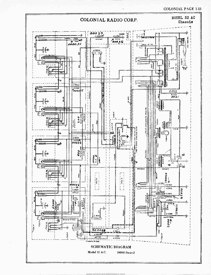
COLONIAL PAGE 1-13
L
o
.w.«
r-
o
COLONIAL RADIO CORP.
Q9Q9QSt
J
1111Ó lfE - alö
OCDO,SL
r 000 S7 MYM!
a d -r f d-L9ir lnuryp llwed
000,5 r r
NI rl
-a
L___.-
44.
d-01 rr r i
II
MODEL 32 AC Chassis
---- r-- ---------- ¡ IAy
I I ' +Lt I
--i MI a,,,e I lJ
i N o
I C
1_
l . o l'
d -99E r iiMob Q
i
ó00,9 C
et
p.T.o.N NI ,..-.,o 1 .,
_
t+
u
á .
_ _ L _ --
I
II f
d-99if
; C I. I 12 gL
I
.
(OOOSMnoaa£
C' o
II
I' -- a
O OOf
d-99rf
f
I C I > <
>c
t a
I I
I I
I I
I }1
A
I
3
a
ó o á
é .
t4,
3
3
o
DOO/
d
¢N3
N
4 m
v
pl
I. uT19 I
Ñ
-tote
I-_I 1
a l
r
I I
I I
I I
I I
I 1
I I
I I
; I
I I
I
r-
I
L_J
---f o
0.
oo
K
I Matt
r-- h nl
pl _ rle
IL -
iNdtlnd ! 03
el- MG* (d oNoxec
1 O I
I n L-____ ---_L_ ->
1
1
0000 uu Olt s-rort I 9r1 I -da; L 3ldund ! oit!
I 1
Ori J L_
SCHEMATIC DIAGRAM Model 32 A.C. 100001-lehue-J
iNM
IJ o :I
lru.`ilr u 7 d-f9tf
d-LEEf
a.
CI - X
ola
4
N1379
d191if I
ó-7e O « O
d-lOyf ñ MO 2/.
Ñ r
www.americanradiohistory.com
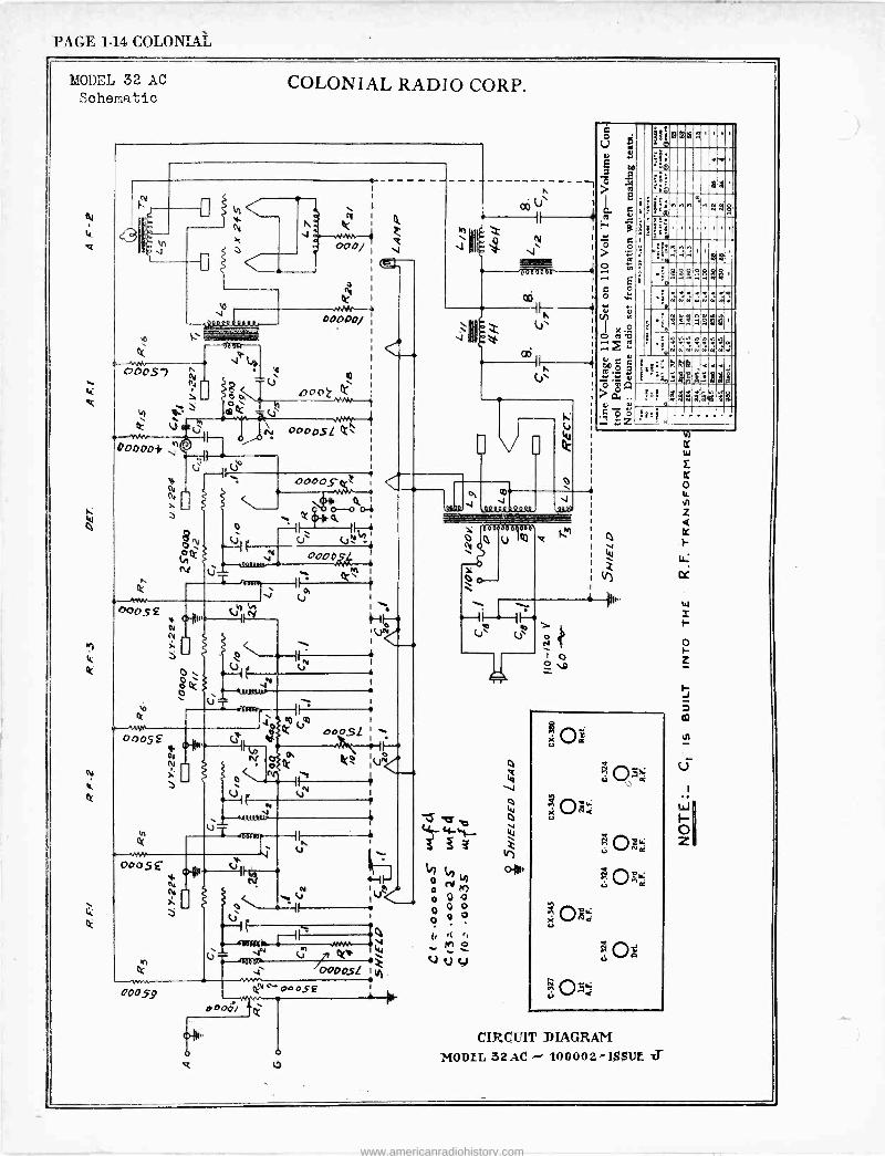
PAGE 1-14 COLONIAL
I+QOI)?L 32 AC
Schematic
a
4 Q
N r
COLONIAL RADIO CORP.
1
I N k e 0°0, V
k coos, `4
ú oú m
00000/
i-
m I 000r 0000017
c;
o Ó
ú
00°051 ,:r"
C6 U
1
II
Q6iñ- . Z V
I
. v`
I
st. o --o 01
I,T" IFy+ c..)` V2
0000
ti
T
00051 Oa
s
6
co um I
k 000$1 I
I
kº ¡UÑ
nÑ i V
ó k
0005£ N
i,
II ú
C
q J
In fV 0 N h
V IUwC 0 4 0 0
I 1 ó Q o
-1I le I i .ww(44 M ó wey 'Z V V y ., 0000sl 1 H
1
H
W
jºa á tit 6.4
J qatto
Úé d <V+
00
91{u4ñ18n'
i
' '' ,
t ®
? É
e R
a 4 a
6i+ nr ^8 R
H B
ö g Oie '
11
> .p°
2,á
c ó
a8 -'
.., 8R5
o ... i
.1; ' x
----1 . : n2 so Qi;
b° sä n:'N n
n:. 2,,, c l' re
u 73
g
6ñIiyyyyd++
« .
: 'e
a3daäá: >áA v
C' c :z gp
Oá
201 ONt i.l
e M ák a «
pe
ci O Má
9 Oà Oo
CIRCUIT DIAGRAM
MODIL 32AC r 100002-i$$Ur ZT
www.americanradiohistory.com
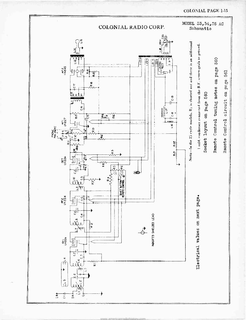
COLONIAL PAGE 1-15
COLONIAL RADIO CORP.
er
Ñá ,a pTpppT _ N N N Oty/ J J J J gOC
rrr 1.-^
e e {j
4
V
4
m
cr)
s/V-
-rvnr- CO
-vo -^cr/
oc
'V
n J
rjj
MODEL 33,34,35 AC Schematip
--e
J
www.americanradiohistory.com
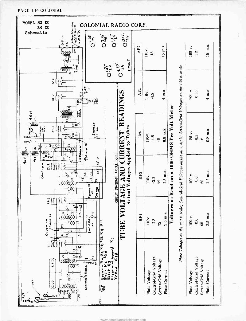
PAGE 1-16 COLONIAL
MODEL 33 DC 34 DC
Sohematio
e: COLONIAL RADIO CORP. 3
3 ä .o CO
"-º "" 1 ! MMMM'
a
Os I cr, J I
l z f000'
.M.oc
4_ U.. T Q+) Ctr) Qfsl W Nr O O O O
z (4- '3- a ° Ce
O O
^3
r- o N_ Z)-- 4t Io
-,ºcho, a>o =Y ñy á
A Ì o
aroHdi
aava4
o
3
Y
o
ooa
3
3ó 0 0 Ó o
3
o
á
3
KT, «,
'?II u u 11l
p I N rC y
o
o o N
r cc
f 0 3
M r 3 00000 a P +s (agri
r+rr . v - 0 err Zr
=WM Y
2
're
> M ti csi
> M
O O
www.americanradiohistory.com
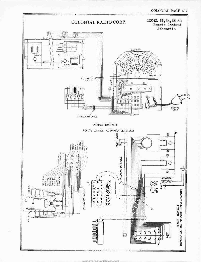
COLONIAL PAGE. 1-17
PILOT LICHT
DROWN BL E :L K GREEN
jLnsplsDaUro
AR00N o ;In01 SLATE
rtIV III?e» /`y RED
WHITE
O
o
o
3119
N33Mb
1-10317(1D
>
cc
33eN0Vi9
N13N0U7ö
COLONIAL RADIO CORP.
BROWN WEBTE
CD
7 CONDUCTO CABLE
MODEL 33,34,35 AC Remote Control
Schematic
BLACK WHITE
BLACK
11 / 5 CONDUCTOR CABLE
o
o
e/ E-
. . ON
W® fig RED NMiTEJ®
® ®
LUE BLUE N-
- WHIT BLACK
WIRING DIAGRAM
REMOTE -CONTROL AUTOMATIC -TUNING UNIT
ó
r (¢j
I
--++ 1`--r -4I`%
SHORTING LEAD
-o
A.0
www.americanradiohistory.com
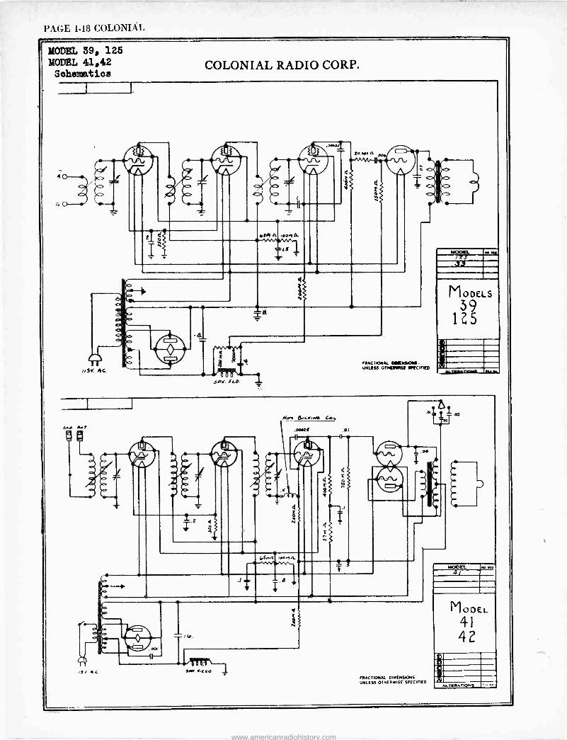
PAGE 1-18 COLONIAL
MODEL 399 125 MODEL 41942 äohemati©a
COLONIAL RADIO CORP.
6.rR Art
® ÇI
5 At
=ifo.
SIw IECO
e
MOM.. iZJ r.µ .33
MODELS
39 1Z5
i FRACTIONAL 0111110tSIONS- UNLISS OTNQMISE SPICIFI[O urnAr
FRACTIONAL DIMENSIONS UNLESS OTHERWISE SPECIFIED
www.americanradiohistory.com
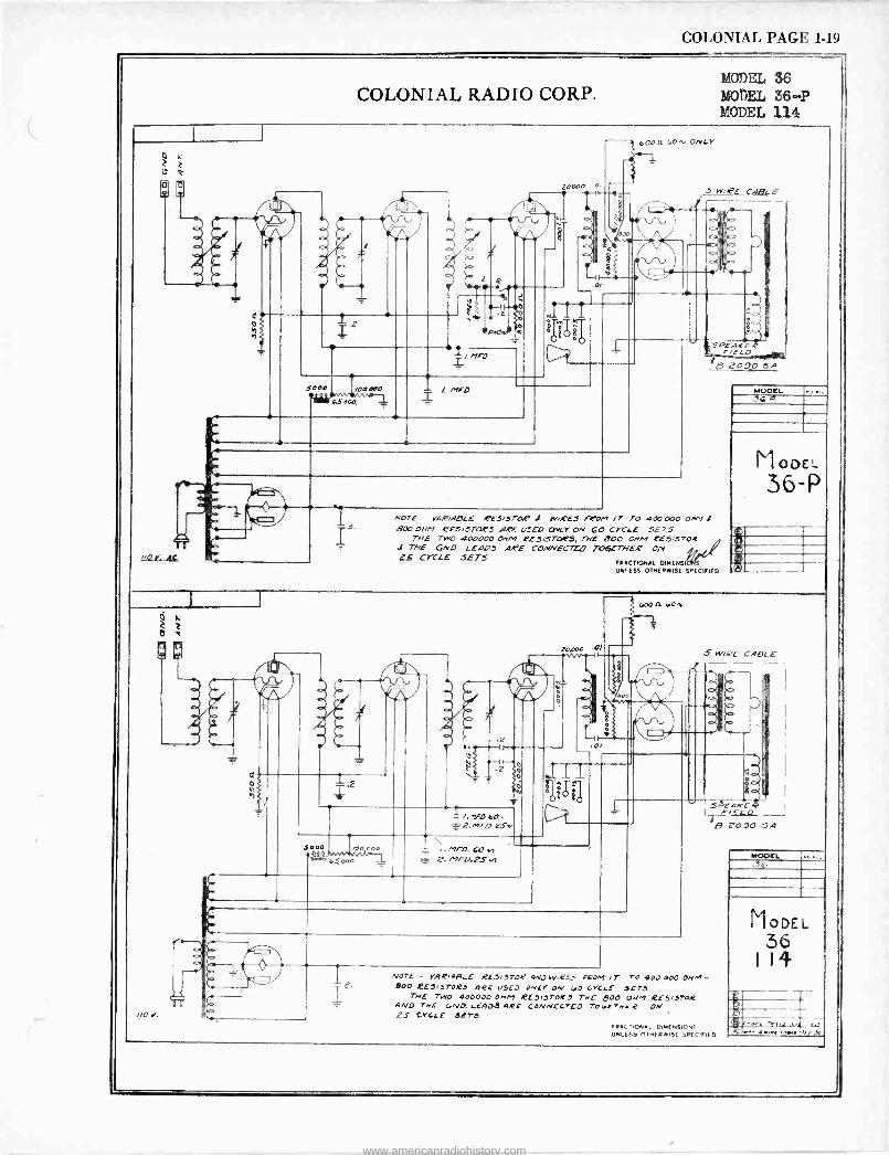
COLONIAL PAGE 1-19
COLONIAL RADIO CORP. MODEL 36 MODEL 36.-P MODEL 114
o
d o
0
2
5000 /00070 1i650Co
20000
II 0
2
t-4)
e- v
.0/
//0 Y. AC
NOTE VAR/ABLE RE5/5TOR J WIRES FeO,-, Jr TO 400000 0/1,16 BOO OHM RESISTORS ASE 01520 craY ON 60 CYCLE 5275
THE TWO 400000 0//M 5E5/STOOP5, THE 000 ONM ez5/5T0í THE GNO LE405 ARE CONNECTED TO6ETHE.e on, e. ,
LS CYCLE 5E75 FRACTIONAL DIMENSIDI(S UN' (SS OTHERWISE SPECIFIED
MODEL 36 P
M I ODE!
36-P
I 1
®
o
5000 oco0 ein f,vn/.n,/---1 vl,000
?2.MFO 2S
1\ /.MFO.(Oh 2. r7FU.25.4
20,000 .0/
e
S WIRE CARLE
NOTE - VAR14BLE REJ/1704 4N7 W'RG) 1-201.117- TO 400 000 OMM - Boo KEJ/5TOe5 4KE u5E0 ONL ON [00 LYCIE SETS
THE TWO 400000 051,1 RE5/5ToR1 722 8O0 ONM RE0/570R 4A/0 THE CVO. LE' D9 4RE CONNECTED robe-r./E.2 o ' ZS CGLE 5(75
X Od!J
.$JEAKe/Y F,E-LO
8 2090 SA
004C TIONAL DIMENSION' UNLESS SINERWISE SPECIFIED
MODEL
MODEL 36
H4
4. .nali '//t0
www.americanradiohistory.com

. ' !!1,..- lt 4,.°!M1rí?l%! y:`. r' i,
www.americanradiohistory.com
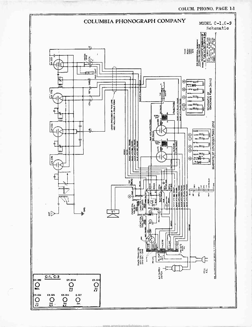
COLUM. PHONO. PAGE 1-1
COLUMBIA PHONOGRAPH COMPANY
á
L
CX3t10
0 Rect.
CX-326
0 1st R.F.
C-1. C-3 CX-371A CX 926
0 0 2nd 1st A.F A.F.
CX326 CX-326 C327
0 0 0 2nd ,
$. 9rFd Oet.
R.F. .
e
o
MODEL C -1,C-3 Sch©r.tati
VV d Vw ND s t Z
C
> º
www.americanradiohistory.com
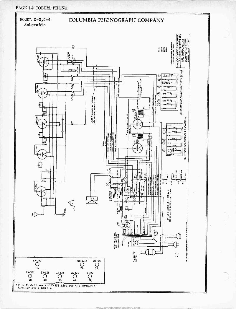
PAGE 1-2 COLUM. PHONO.
YODEL C -2,C-4 COLUMBIA PHONOGRAPH COMPANY Schematic
h
r-: T
21
a)
V
o
r
1
l
CX-380 CX-3714 CX326
o o o R. 2A. lA.
CX-326 CX-326 CX-326 CX-326 C-327 o o o o o 1R. 2R. 3R. 4R. B.
FRONT This Model Uses a CX-381 Also for the Dynamic Speaker Field Supply.
I I
a u. ae amo
1
e
an PP
0
O\ i.nv9='-"
V mn n3°li
Q--~3.19.1 `..`i
r^ -
i
a
EI"
a }º
www.americanradiohistory.com
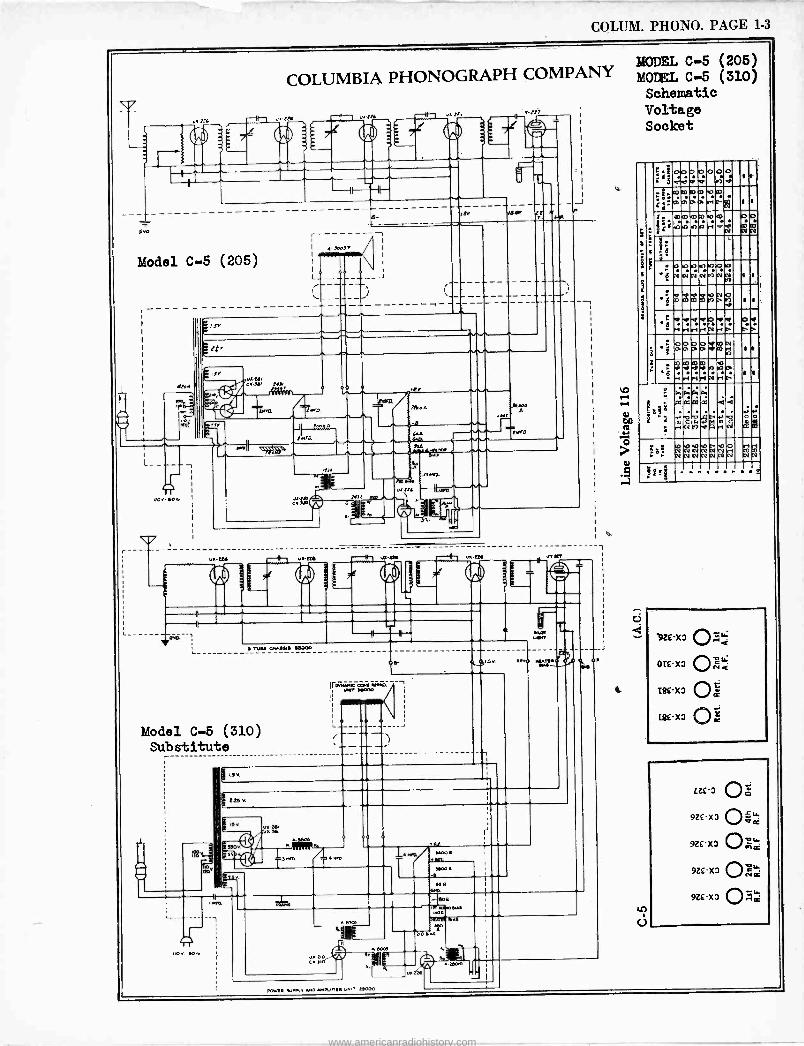
COLUM. PHONO. PAGE 1-3
GMD
i
1:e
COLUMBIA PHONOGRAPH COMPANY
-ir-, zx
tr)
-il 11-
Model C-5 (205)
L
4-
r
4. 30037
1
a-
1
av
_. u.ae,
C ase, n
r reI
or,
Err.,
N1t
Preen
CA
R.
31,
%.
1
""' LYr iKs 01 e 1
ó Taft CX.IMD eß000
Model C-5 (310) Substitute
1
9-
225v
sso0 33 o
50oó
g35. p3 CN -
35
U.S
/'r EDao
rab
1
O.
MODEL C-5 (206) MOTEL C-5 (310) Schematic Voltage Socket
(j
B
: f
S
4
f'.o0o0000 3 ctir á v .,7.;
2''0O.PPróP ii mmmn m 1 1
1.2.,"°')1:°'°C° j.plDhhl'1 d' O O mm
66YY N N
3: .8 ,. 0.n1n.n530.0
YNNNMNM I
' ; pvVO pp o
hro o
1 1 ..,
C
+
pdd'd'O MrlrlrNr.»; V O O V
Ce' O O UO,
O O PO V l0 VttDD g si 0 . . »
qc0loi d'd'd'd'9.OP rion Iy r
.c
ti ri 1 1 r i
as
'2'1' J57 C.
ºqFpwb r.FVtMaRr1Ñ
2'.. P7 CC i <
o 0ó
Ce
.. WVb.ONbO
'-',1223g..1cV
r14 cDD
c N N
3_g
SZ£'X 9
0i£ -X7
L8£X
t8£X7
In Ú
LZ£'3
9Z£ -X3
9Z£ -X3
9Z£X
9Z£ -X3
oN OC
o-1=
IbvF45.,.e.y AND .nOUfif4u D000
www.americanradiohistory.com
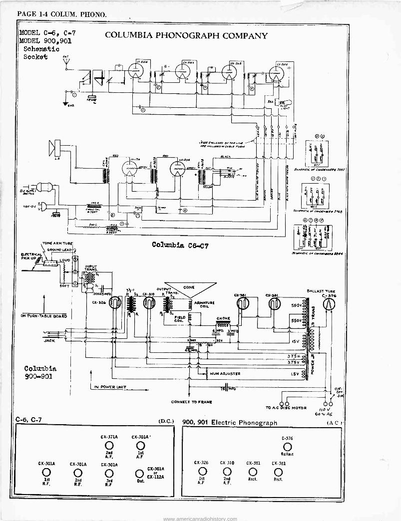
PAGE 1-4 COLUM. PHONO.
MODEL C-6, C-7 MODEL 900,901 Schematic Socket °47
EECTR PICK UP
L.
COLUMBIA PHONOGRAPH COMPANY
ftO
tran
D
: °
¿ka t'dea 05W OrlWa,rvt Aft /nrctuotO w GOLI eaeM
tLACR
TONE ARM TUBE'
GROUND LEAD
LOUD
SOFT
i ON TURNTABLE BOARD
JACK
Columbia 900-901
C -b, C-7
C3- 32.6.
INPUT TRANS.
ó Iooss 4
i5 II 3 .00025 MFD
Colmnbie. C6 -C7
OUTPUT
l 310 p TRANS Sl al
CONE
S. FIELD COIL
ARMATURE COIL
i 1101,
TED,
^ e4
CX 301
CHOKE
4 tea 3 M
T T v.
2
00
w J[,IlMI/C o<COr.0efN(t'X1/ Clt
O 00
SLr.MA.-.e a-Ce.otn'OTRf i.se
©00©
lid .r roer
RMrM/tK ai 4-ervantt¡I.M44
BALLAST TUBE CX 3011 C,- 376
550Ke 0
550
1 5 V
-.4 HUM ADJUSTER
3 375v. oa
3.75v a)
IN POWER UNIT
CONNECT TO FRAME
(D.C.)
CX-371A CX-301A'
O O 2nd 1st
A.F. A.F
CX-301A CX-301A CX-301A
O O O O CX-112A 1st 2nd 3rd Oet.
R.F. R.F. R.F
TO A.0 DISC MOTOR
900, 901 Electric Phonograph
!1OU 6o v A£
(A C
C-376
o Ballast
CX-326 CX 310 CX-381 CX-381
O O O O 1st 2nd Rect. Rect.
A.F A.F.
www.americanradiohistory.com
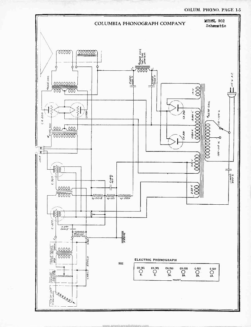
COLUM. PHONO. PAGE 1-5
COLUMBIA PHONOGRAPH COMPANY
o
0
v$
;rboGbo6orr
/
QQ9Q9 J
e )
U
zr ooiz zr ozi -u- o Eb
902
ro Yo
ó
ELECTRIC PHONOGRAPH
MODEL 902 Sahe12atic
o
h
CX-381 CX-361 CX-350 CX-350 C-327 C-327 oo o o o o R. R. 3A. 2A. 2A, 1A.
FRONT
www.americanradiohistory.com
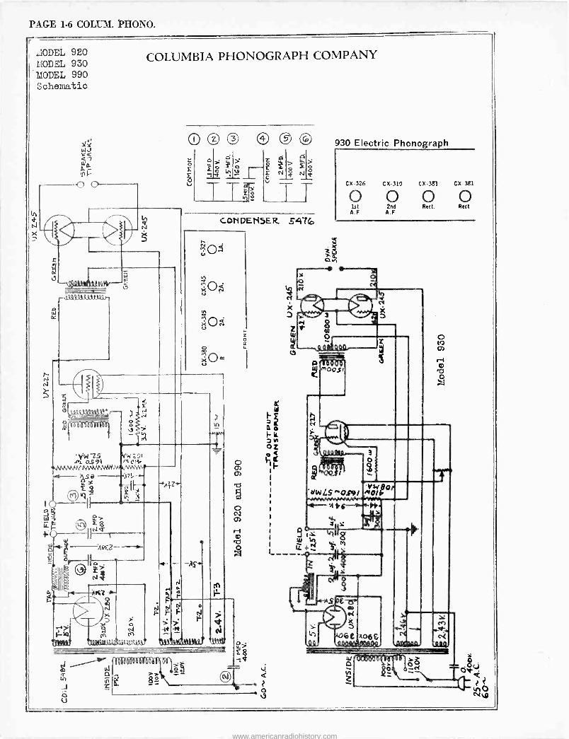
PAGE 1-6 COLUM. PHONO.
r
1.IODEL 920
MODEL EL 9 30
MODEL 990 Schematic
COLUMBIA PHONOGRAPH COMPANY
n34(1.9 41.4-9. 11144r
r
0 @ ® ®
COMPENSER. 547ro
o
01 ós91 Pi
4(k4Or
n VVV\A vry WWW-Mr.uAvw. M- --
F -w
Q U
i19EZ
i9i500DD6rá6i
ß
.Ai le.
-AS'
0.
h
te)
o
r.3
> 7 - v -11 if N
Qt,414i1te44J t1bfY
e
. o
930 Electric Phonograph
C 326 CX-310 CX.381 CX-381
1st 2nd Rect. Rest A.F A.F
e G v
m00$1
3 o
'dLs ""0.191""0.191ror w
:11ic-r+
91.4%r8 ' 4-4 `.
1L+
ß0o4. W
ó&
www.americanradiohistory.com
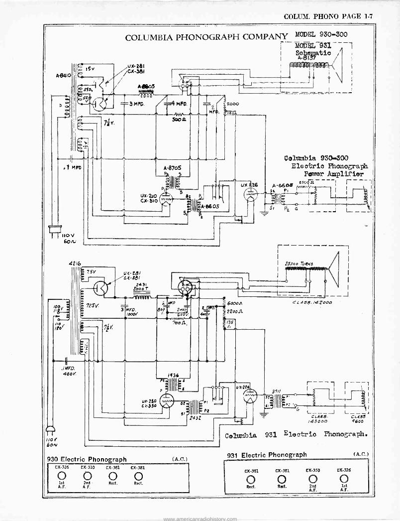
COLUM. PHONO PAGE 1-7
A$410
110 V 60/u
42 6
100 pOL:
o---. ne /1o
COLUMBIA PHONOGRAPH COMPANY MODEL 930-300
Í MODEL -932. - 7-1 Sleatic
ux-281 /Cx-381
E 75v Ç Q+
7
A1805
ux zel cx-3el
2431 S000T
r11eu0i
T3 0r0. 0
A-0608' Sa P
\ - -
Columbia 930300 Electric Phonograph
Power Amplifier :oodit----, r----
23",000 Weis 1
,
1--6 0 0 0
2 ¿çß
Jo°2.13- 600v
Lice* 4.eIv
o11,
6obO1L CLa33. /42000
22oo11
13S r-
9 /O 60rv
ta - 250
1434 a
-0000
. G PI sl? P2
2432
930 Electric Phonograph (A.C. )
37//
J
r--- i ----- I 1
I t I
'4G 1 1 1 I L_ ___ J L ---_J CLAS.S CLASS.
/43000 9600
Colwnbia 931 Electric Phonograph.
931 Electric Phonograph (A.C.) I
CX-326 CX-310 CX-381 CX-381
0 0 0 0 CX-381
o 1st 2nd Rect. Rect. A.F. A.F. Rect.
CX-381 CX-350 CX-326
o o o Rect. 2nd 1st
A.F. A.F.
www.americanradiohistory.com
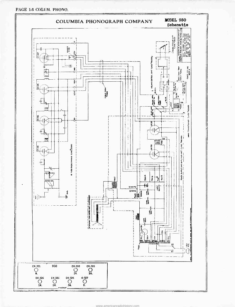
PAGE 1-8 COLUM. PHONO.
COLUMBIA PHONOGRAPH COMPANY
el
19
4
O '
ÓI
I
MODEL 950 Sohematio
I I
^J I> a o h I
L--- ---------J
r- --
$ H
a
rem »KU, Tl e(6
e
88
L- ------ ------J 1
CX-381 950 CX-350 CX-326
O o o R. 2A. lA.
CX-326 CX-326 CX-326 C-327
o o O o 1R. 2R. 3R. D.
FRONT
www.americanradiohistory.com
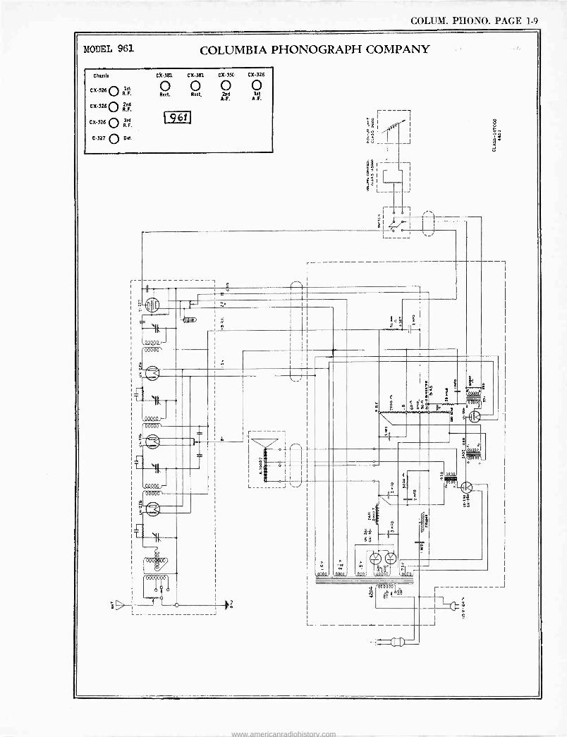
COLUM. PHONO. PAGE 1-9
MODEL 961 COLUMBIA PHONOGRAPH COMPANY
Chassis CX-381 CX.381 CX.35( CX-326
CX-326 O R F.
CX-326O 2nd F.
CX-326 O R. F.
C-327 O Det
Rect. Rect. 2nd Lt A.F. A.F.
g6! g
L- -J <+ .J
T
«
e
ººQQº
00000'
Ti
S
11,
,494 00000
1-
ººººQ)-- 00000`
L_
so 3 I
a
osoºº`
JAM-
> , -s+
J661 0000
J dado
3 ->s
www.americanradiohistory.com
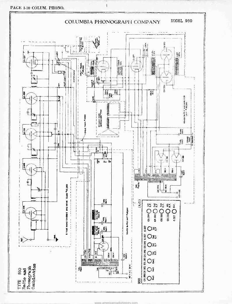
PAGE 1-10 COLUM. PHONO.
COLUMBIA PHONOGRAPH COMPANY
-71117161_
H/
r. T
>
e
e 5
i L
o ? I I
M 1
s ff
I
-
J
R> ->Q ^M M
q N
WIl.mi. tote QQQIl,4421.
-
MODEL 980
1
-t t- 1
7 J
o
ein
. $
www.americanradiohistory.com
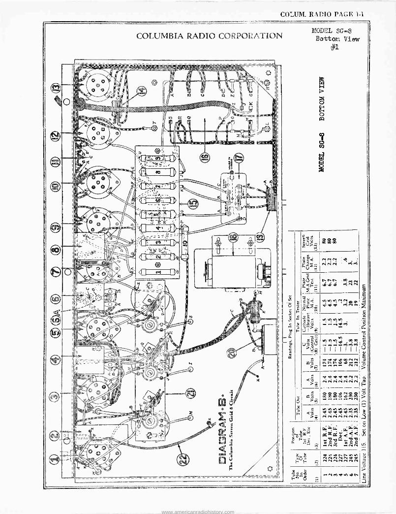
COLUM. RADIO PAGE 1-1
COLUMBIA RADIO CORPORATION
.'ti
.:., : ;. .rX... ':ä.': . s:' . '}' eí .+--N
e L.
l) p V Fz ce
MODEL SG -8 Bottom Vier
#i
O O O 00OOOo
-} -pye.DaONN n h tn O.O-- -- ...i.r.+.- NN
e reV VeepNN N N N N N N N
hutU'iefi un un un vr aP de d' 9' M eh N N N N N N N
ward'nnunh N N N N N@ V' N N N N N N N
.. N M 9PeA .D t,
www.americanradiohistory.com
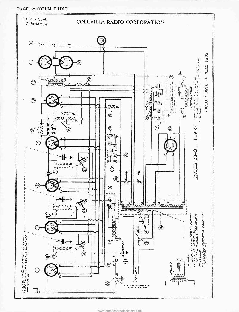
PAGE 1-2 COLUM. RADIO
COLUMBIA RADIO CORPORATION LODE', SC -43
Sc1iemazl.c
aöooóò
W
y1 I.1 L_ - _ _ _ _ J
I-
á L_ -I
QQº44QQo1 I- - - _áJ
tD
4
V r -ñtl
l7
r - iOIWT I
I$
a
r - - - - Z o W p
I k¡
L__ l
4
hl
I r 1 1' 0000000 I 1
r
L.
2 i ol - ól
ñ I
J
r
0001X 0!/7e4b[N37 00'Jfl A37%YA
www.americanradiohistory.com
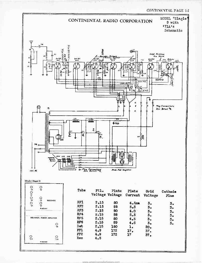
CONTINE1VTAL PAGE 1-I
C.
14
7,o.. AC
CONTINENTAL RADIO CORPORATION
v_ 2 F 2
to.
T pó ó
1 7.Ign°! LL
Model Slagel 9
n
ld RF t7 ss
LJ
4
ra,/aMSy R.
227 ,Soll;
Lr ¿If
e RP at
Oo01E} Mf 222 _----C- - -
<
I Mi.
t
L t,
XM
3-
n, e ae
PIT
4io1
o
S
o
3
e
If ul
.,.
,(1001SMf.
MODEL "Slagl 9 with
t71A's Schematic
L.ey. Aa,,.i.w. C.. le.,,.
ae.,M 711 1 L.e O.A.I.
/ L/D .- Off s-
11
150043
A
o o '27 '27
o '27
o o '27 '27 RECEIVER
o o '27 27
FRONT
RECTIFIER. POWER AMPLIFIER
o '80
o o '7iA '71A
FRONT
o' o, Phe C.et..egn:,. 3.a Oelv/ *T. /eY-PrM Aayl.fiee
o
7 PVe C...,,.cl'o,N 3.. .t.,.i 46
Tube Fil. Plate Plate Grid Cathode Voltage Voltage Current Voltage Plus
RF1 2.15 RF2 2.15 RF3 2.15 RF4 2.15 RF5 2.15 RF6 2.15 Det 2.15 PP1 4.9 PP2 4.9 Reo 4.5
80 4.5ma 3. 3. 88 5.3 3. 3. 80 4.0 3. 3. 88 5.3 3. 3. 80 4.5 3. 3. 89 4.6 3. 3.
180 1. 20. 172 17. 37. 172 17 37.
www.americanradiohistory.com
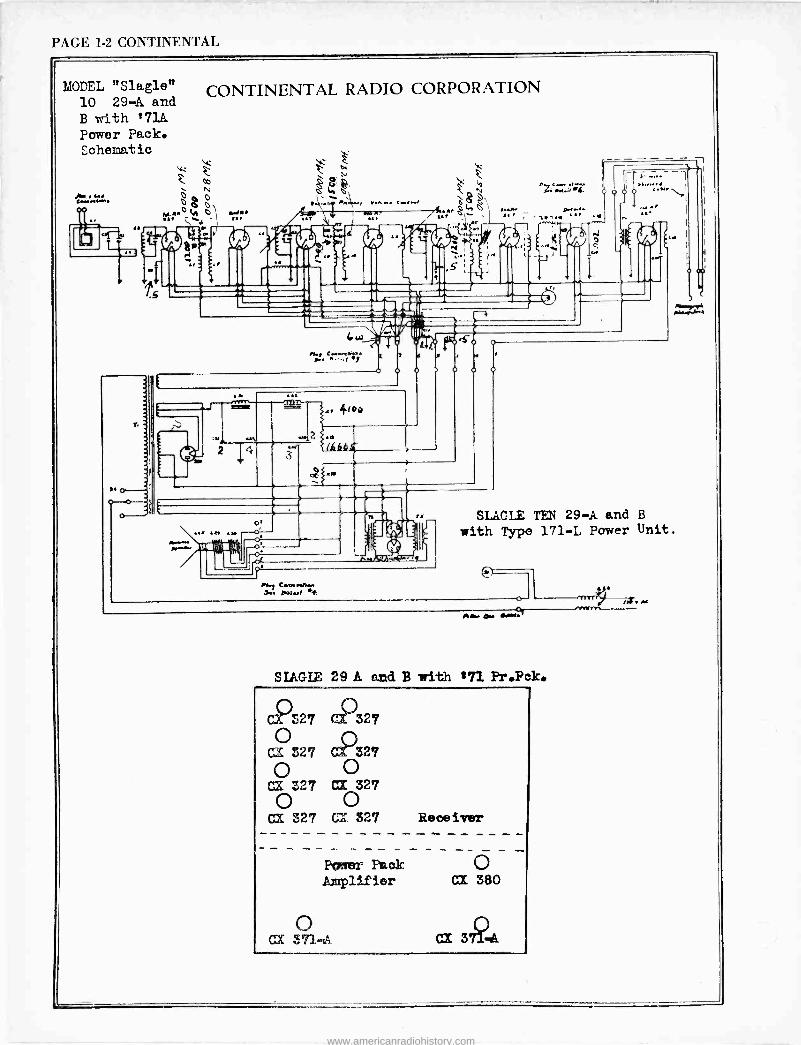
PAGE 1-2 CONTINENTAL
MODEL "Slagle" 10 29-A and B with 171A Power Pack. Schematic
CONTINENTAL RADIO CORPORATION
k Z. et
o Op
0
h..Ole (/I Ó r/w \l. - " t.1
Mal
or
-.
. YK... Crlwr
II.I Coe*. H. _..l
.1 IOp
lit 1
ey., C..s...Iwr. >+.'...l
cy <.. .r....
i.. r - lw ..r .
: ,:,:4.i
SLAGLE TEN 29-A and B with Type 171-L Power Unit.
Mr. ü.. ...a.
NAGLE 29 A end B with i71 Pr.Pek.
C..S27 327
Cl 527 C2325'
C ® CX Z27 CI 327
0 C) C;d 327 CX 327 Receiver
Ponter Paak O Amplifier Ca 380
() CX 371.tA
www.americanradiohistory.com
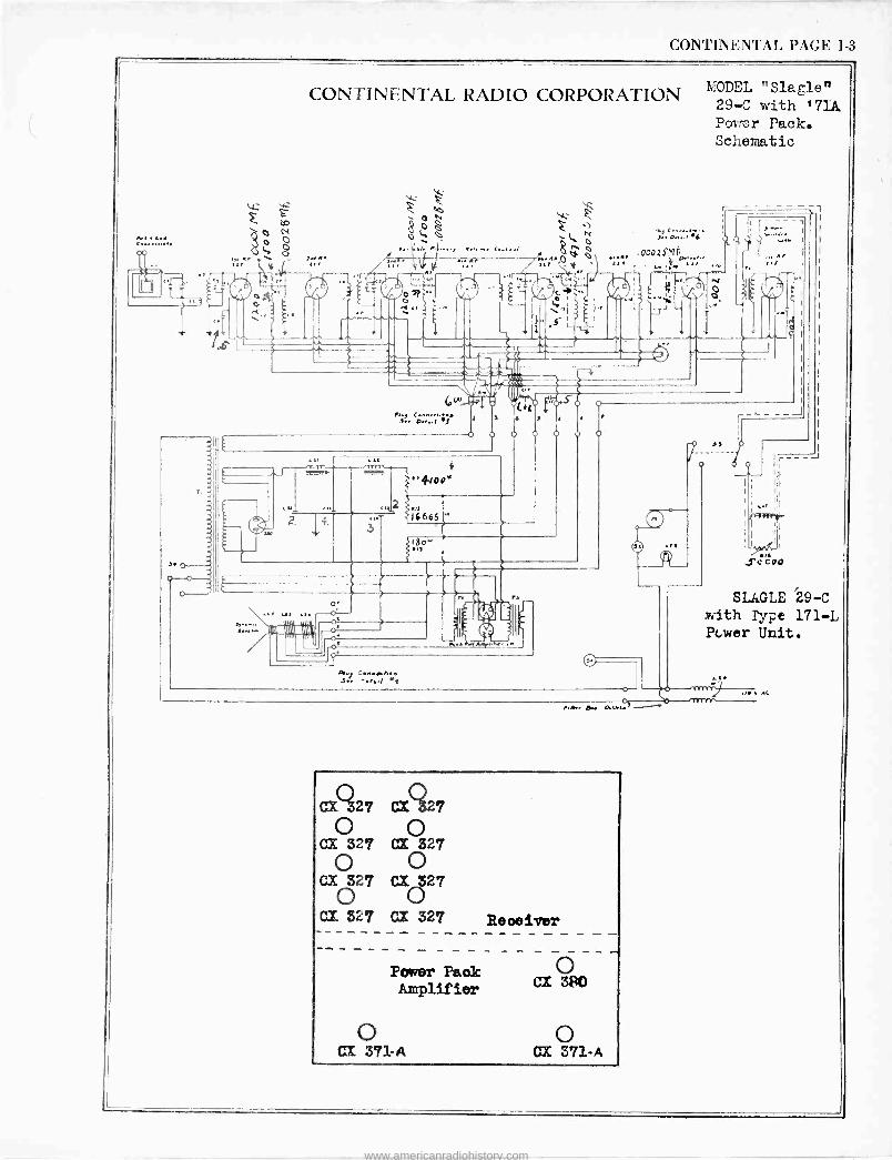
CONTINENTAL PAGE 1-3
sdz
z CA
Óo n o
t.7'.l
CONTINENTAL RADIO CORPORATION
].i A. l./
f-"--Zffla
A. MIAy. w
MR27 CZ ô27
o o CX 327 CX 327
o o CX O27 C%27
Cl 827 CX 327 Reoeivar
Power Paak Amplifier
o CX 380
0 o CI 371-A CX 371-A
MODEL "Slagle" 29-C with '71.1. Power Pack. Schematic
SLA.GLE '29-C with Type 171-L Pc.wer Unit.
. AC
www.americanradiohistory.com
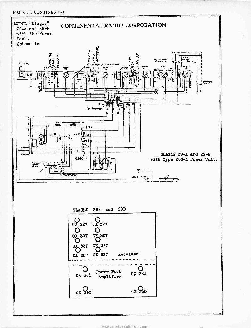
PAGE 1-1 CONTINENTAL
MODEL "Slagle" 29-A and 29-B with '50 Power
Pack. Schematic
CONTINENTAL RADIO CORPORATION
e p O N
0 hy 8
4 100
o.
ï tb FYI
4250L,
de, o.m....- a.. a. a
Q
.;;,. 7777,77..7
'-iTe. I. lti
A. CG
T O
SLAGLE 29A and 29B
SLAGLE 29-A and 29-B with Type 250-L Power Unit.
CX 527CX 327 0 o Cb827 CU27
Ce27 Cb4S 27
CX 327 CX 327 Receiver
o CX 381
Power Pack Amplifier
-
CX 381
CX 950 CX 350
www.americanradiohistory.com
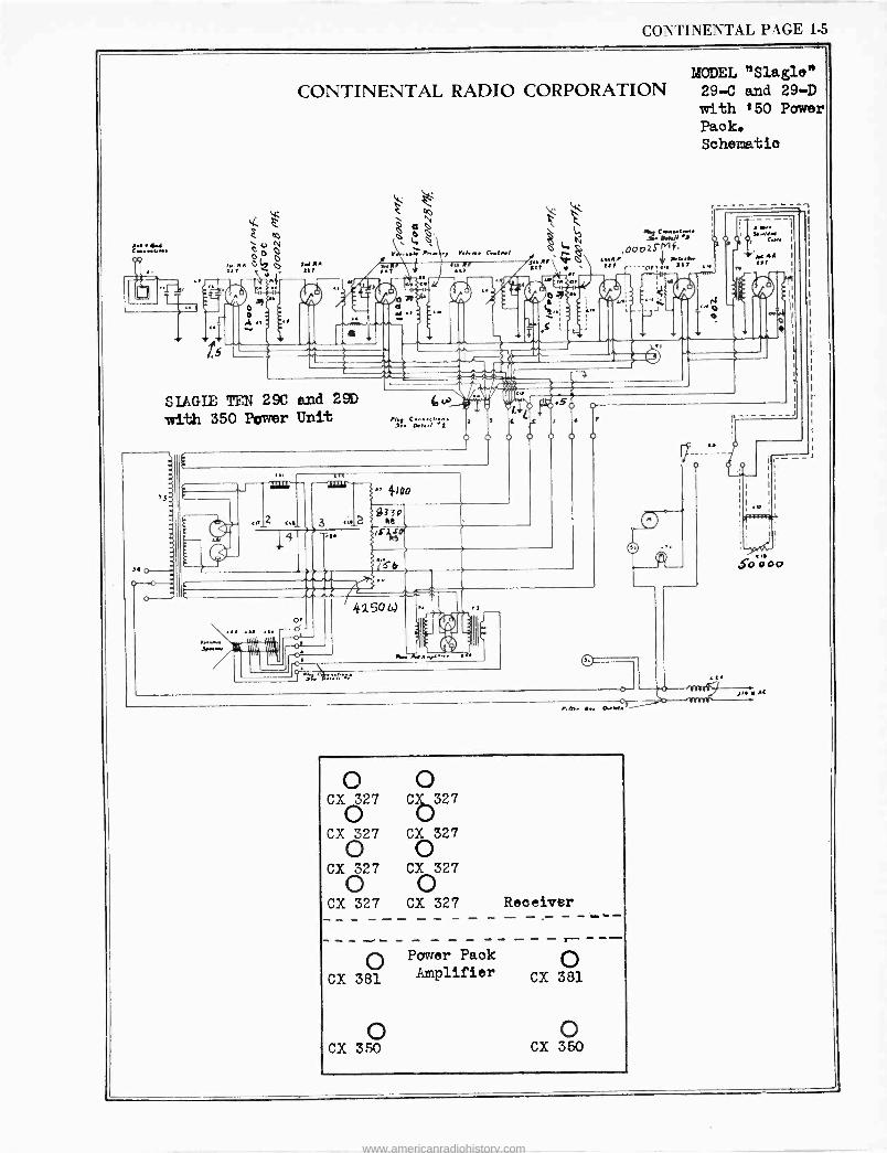
CONTINENTAL PAGE 1-5 L
I..a. fJ f...wY-.
t5
CONTINENTAL RADIO CORPORATION
L RR 141
Y.l.. C../../
SIAGIE TEN 29C and 29D
with 350 Power Unit
NIIIIUI
b ).. O.t..l .1
' ¢00
9330 ee
4-2s
42SO[.i
MODEL "Slagle" 29-C and 29-D with '50 Power Pack. Schematic
diej i:w/x 000zSMf
{4R. * if..fr tlf r .._ffs 117
..R.. I.. ...do'
V o CX() O327 Có327
CX627 Có327
CX 327 CX 327 o o
CX 327 CX 327 Receiver
O Power Pack
CX 381 Amplifier CX 381
CX 350 CX 350
1... / fW.
RIR S00o0
IL AC
www.americanradiohistory.com
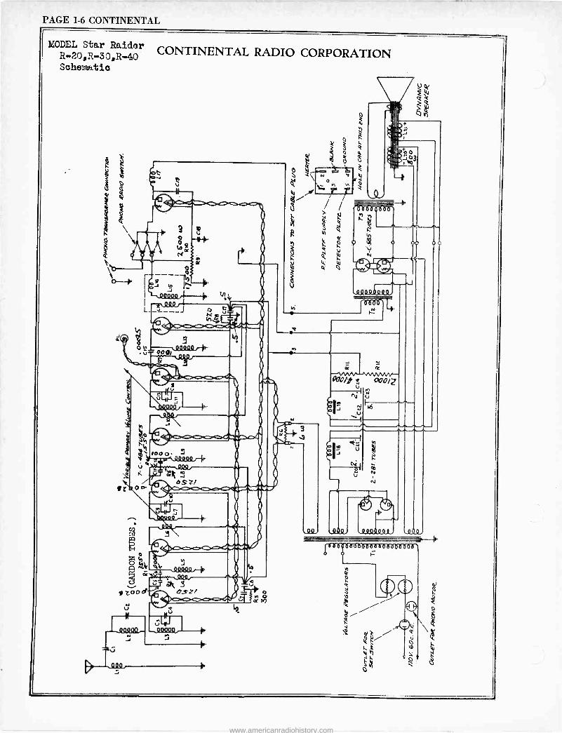
PAGE 1-6 CONTINENTAL
MODEL Star Raider R -20,R -30,R-40 CONTINENTAL RADIO CORPORATION Schematic
www.americanradiohistory.com
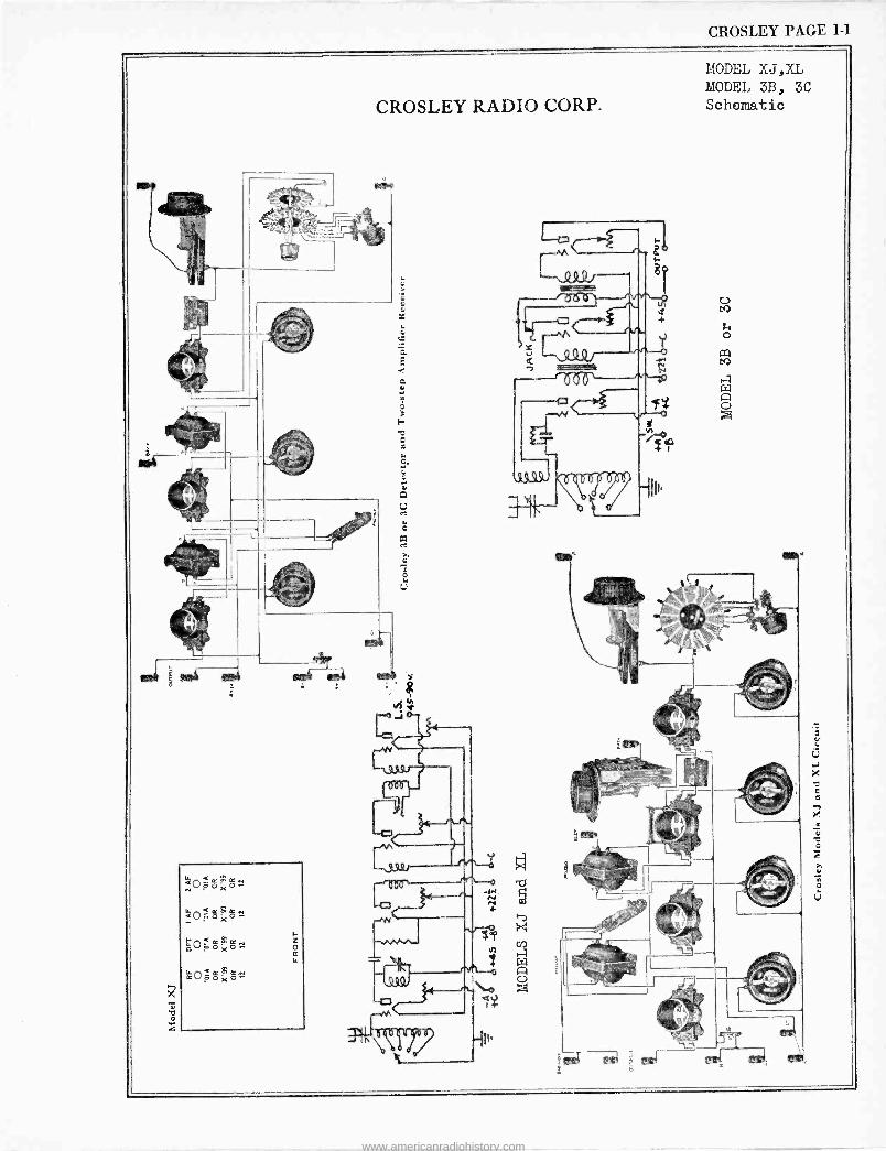
CROSLEY PAGE 1-1
www.americanradiohistory.com
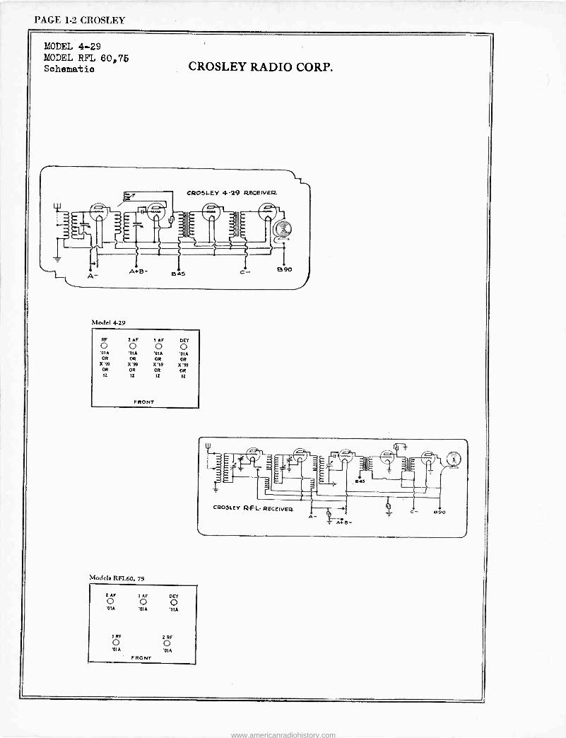
PAGE 1-2 CROSLEY
MODEL 4-29 MODEL RFL 60,76 Schematic CROSLEY RADIO CORP.
A -
C1:2O5LEY 4-29 RECEIVER
A+B- B 45 E590
Model 4-29
RF 2 AF I AF DET o 0 o o MA MA MA '01A OR OR OR OR
X'99 X'99 X'99 X'!9 OR OR OR OR 12 12 12 12
FRONT
Models RFL60, 75
2 AF IAF DET o 0 0 'OlA '01A '0IA
i RF 2RF o o '01A '01A
FRONT
www.americanradiohistory.com
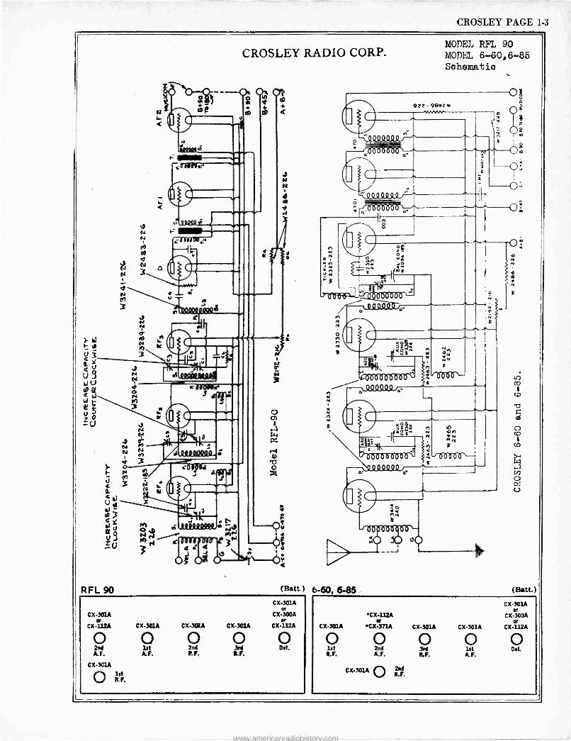
CROSLEY PAGE 1-3
9 N N d
RFL 90
z v
CROSLEY RADIO CORP.
-- Oi%Ul
d+ d m
c/D
IftQßle
àdïRlo.
NCQVQl
%DON
teel
O
1J
e
Ñ vta1
a rd MÑ +
1.4 dóIIrër-P 33 a r a
Oß 64 O -Ó
e+
(Batt.) 6-60, 6-85 CX-301A
or CX-301A CX-300A
or or CX112A CX-301A CX-301A CX-301A CX-112A
o o o o o 2nd lst 2nd 3rd Det. A.F. A.F. R.F. R. F.
CX-3C1A O lst R. F.
MODEL RIM 90 MODEL 6-60,6-85 Schematic
(satt. ) CX-301A
er 'CX-112A CX-300A
er er CX-301A CX-371A CX-301A CX-301A CX-112A
o o o o o lst 2nd 3rd 1st Det.
R.F. A.F. R.F. A.F.
CX-301A O 2nd R.F.
www.americanradiohistory.com
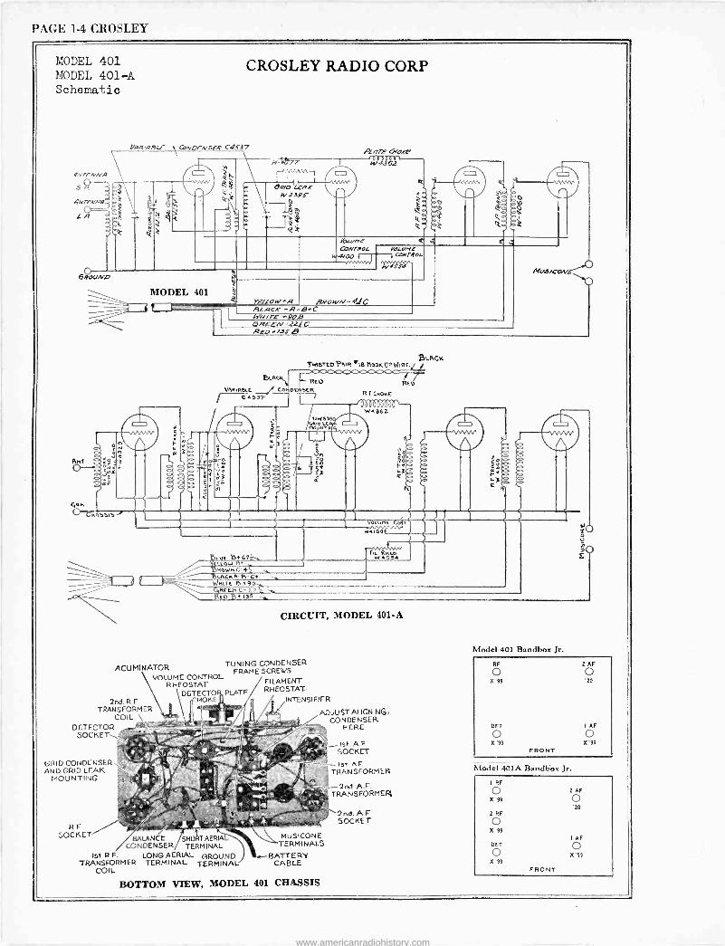
PAGE 1-4 CROSLEY
MODEL 401 MODEL 401-A Schematic
CROSLEY RADIO CORP
(/RR,RBLE \ CaNDENSER C4537
y n e e
Rn3
3
W -e77 o AprÈ Geode
Wí361
é3
4.D
/'ptLrC CONTROL
-woo f- -JJWNN
C ti
MODEL 401
YOLOHE CLWr?OL
YELLOW ^A BLACK -R-B.' row -m - 41C
WN/rE' í90B 6REEN -221 ReD /3SB
MU3/GONE
TRASTCD PRIR =1$ M00K UFWIRL
BLRos REO REO VAaNaut Çor DENSER -C45D I R F CMORE
CIRCUIT, MODEL 401-A
RHEOSTAT FILAMENT
DETECTOB,PLATE RHEOSTAT -
2nd. R F HOKE
TRANSFORMER COIL.
DETECTOR SOCKET
GRID CONDENSER AND GRID LEAK
MOUNTING
RF SOCKET
ACUMINATOR TUNING CONDENSER
VOLUME CONTROL FRAME SCREWS
BALANCE SHORT AERIAL CONDENSER TERMINAL
NTENSIFIER
ADJUST ALIGNING, CONDENSER
HERE
MUSICONE TERMINALS
1st R.F. LONG AERIAL GROUND BATTERY TRANSFORMER TRANSFORMER TERMINAL TERMINAL CABLE
COIL
Ist. A.F SOCKET
Ist AF TRANSFORMER
2nd. A.F. TRANSFORMER
2nd. A.F SOCKET
îQ
Model 401 Bandbox Jr.
RF
o X'99
DET
o X'99
FRONT
2 AF
o '20
I AF
o X'99
Model 401A Bandbox Jr.
I RF
o X'99
2 RF
o X'99
DET
o X'9º
FRONT
2 AF
o '20
AF
o X '9º
BOTTOM VIEW, MODEL 401 CHASSIS
www.americanradiohistory.com
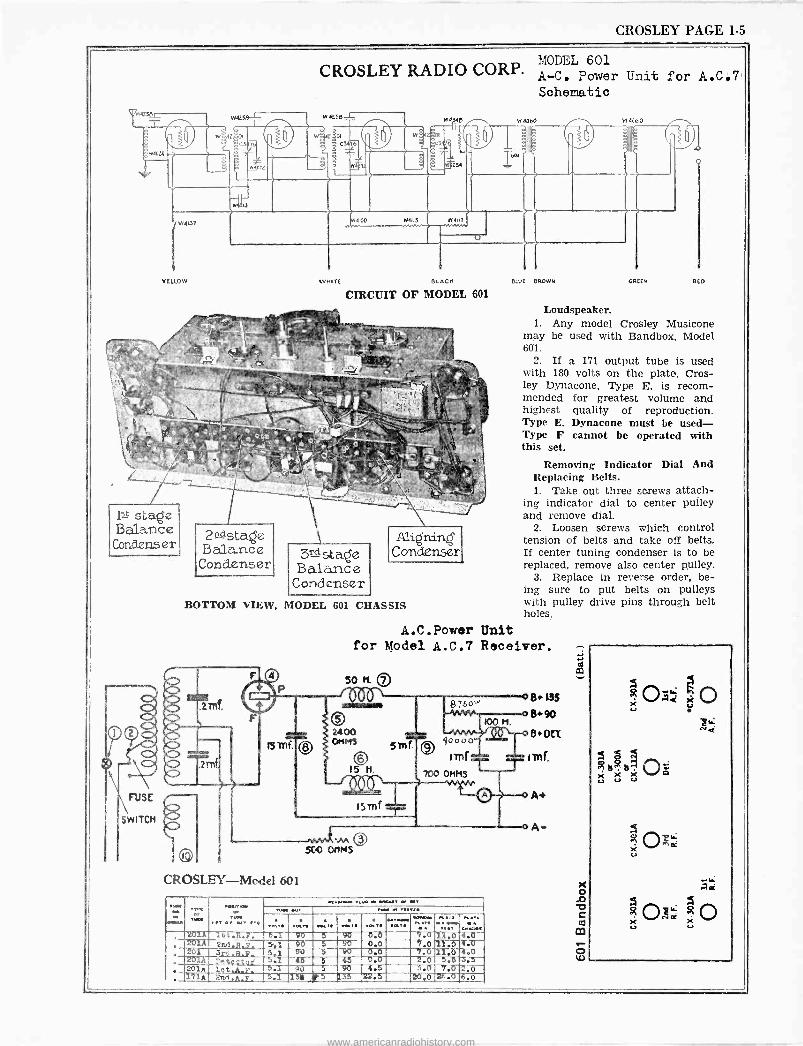
CROSLEY PAGE 1-5
155 stage Balance
Condenser
SWITCH
w Ee4z 4a
óC3[ib
2n1 -stage Balance Condenser
CROSLEY RADIO CORP. A - owl A -C. Power Unit for A.C.7 Schematic
WHITE BLACK
CIRCUIT OF MODEL 601
3Td stâge Balânce Condenser
Alighting' Condenser
BOTTOM VIEW, MODEL 601 CHASSIS
50H. 7O 10 N
O 2400 OHMS 5 m f.
© 15 H.
Ismf
StO OHMS
CROSLEY-Model 601
tt fir CI .t. M t.
_.......... . ..... _ IN ..r Pet MIR t
_ w O I. :. w..
w.l a . 201A IBt.R.. 5.1 90 5n 90 0.0 7.011.0 4.0 201A 2nd.R.H. 56,1 -40 5 90 0.0 7.0 11.0 4.0
, 201 33rO.B.p. 5.3 90 5 90 0.0 7.0 11.0 4.0 . 201A Detector 5 46 6 45 0.0 2.0 5.5 a.5
201A 1et..A.F. -5.1 9i) 5 90 4.5 5.0 7.0 2.0 171A 2aA.A.F. 5.1 154 5 4135 22.5 20.0-26.0 6.0
W 40óo W 4EbO
BWE BROWN GREEM QED
Loudspeaker. 1. Any model Crosley Musicone
may be used with Bandbox, Model 681.
2. If a 171 output tube is used with 180 volts on the plate, Cros - ley Dynacone, Type E, is recom- mended for greatest volume and highest quality of reproduction. Type E. Dynacone must be used - Type F cannot be operated with this set.
Removing Indicator Dial And Replacing Belts. 1. Take out three screws attach-
ing indicator dial to center pulley and remove dial.
2. Loosen screws which control tension of belts and take off belts. If center tuning condenser is to be replaced, remove also center pulley.
3. Replace in reverse order, be- ing sure to put belts on pulleys with pulley drive pins through belt holes.
www.americanradiohistory.com
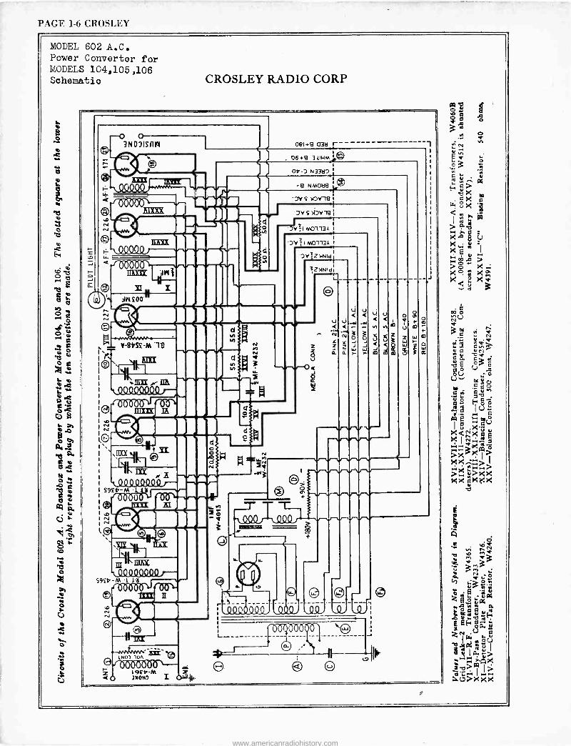
PAGE 1-6 CROSLEY
MODEL 602 A.C. Power Converter for MODELS 104,105 ,106 Schematics
o 3fflisnn
00000
S9£b M
59£9-M 1.16
CROSLEY RADIO CORP
u
3 O J J
www.americanradiohistory.com
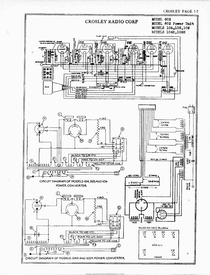
CROSLEY PAGE 1-7
COIR AORnCF 0/ yryd `Aaw[ coMRw04. PAidh
F
F
1
F
eco to ,Attw Co
CROSLEY RADIO CORP
Y[üGW IjAG W.2 razor,/ 1} A.C.
MODEL 602 MODEL 602 Power Unit MODELS 104,105,106 MODELS 104R,105R
hMR 1jA.G VIMt C.
BLACK S AC
Y.T
EEL
SLACK j AC.
-40
PINK TO U Y-227 YELLOW Tb UX-226 f
IRCUIT DIAGRAM OF MODELS 104, I051AND 106 POWER CONVERTER
-40 n n
l Q Qº QQQQ Q_Q Q.
nn BLACK TO UX-171
PINK TO UY -227
lQ I.-,--
CIRCUIT DIAGRAM OF MODELS 104RAND 105R POWER CONVERTER.
'0Y RIOA S'yO1g
VRIOA
'0 Y RIGA
SZIo!d
RIGA 06-0' E0
, OBT SIAN
C 'oe.e'WNM
i --------0000S - 2-
08E -X3 '20 09Z-XT1
'HOT v HOT
Model 602 (AC) Bandbox
2 RF ) RF DET I AF o o o o 16 16 '27 '?d
140T 6.0 V.
I RF 2 AF
o o '26 'T1
FRONT
T
www.americanradiohistory.com
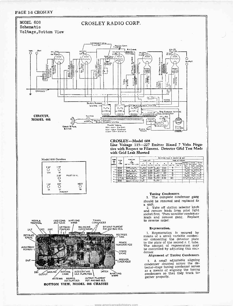
PAGE 1-8 CROSLEY
MODEL 608 Schematic Voltage,Bottom View
GM. AMT.
O O
Of-
uA.276 C.L 1tt
CROSLEY RADIO CORP.
U. {wtG . 1
CONDEM1tR Gana 71,15910 C°MT.
`le `I' 2
r'o.cxx 921
uy -t2.7 C+3
R.I. exact
"At *I.
dn
3 e
exat4 C}3 /
Torn .n.
t60.
ó
ti
u.x-171 W- 17 R
CttgsSlS
CIRCUIT, MODEL 608
CAKE 3714% Dí739
Model 608 Gembox
DIACK Ru66ER W4796
,WiTCN
W; HIACK RunER W4794
l'AF 1 RF
o o '71A '16
2 RF PILOT 6.0 V.
o '26
I AF PET REGT
o o o '26 '27 '6e
FRONT
MEROLA TERMINAL
LJ 5Ö02 W4794
F11`4 FKr3 F1Lr2 -.15Vÿ r-L6K- .r 5V-
100U0! AQAAAr flkRQt 1
W.1TtStñ 1.11I 1":1t11111111111 11 t
TUNING CONDNSRS
RF.TRANS- BALANCING Y R.F 61A.F FILAMENT
1' F. 'ET. 2RF. FORMERS COND NSERS t POT. AND BIAS RES 2 1
FR W CR 1Rqn S. 11.3V -Go- 71W6145 110V -t6. -71W5140 220 J- 25.- 71 W 9271
cRxo6eeta W 47 lGoSTRltoc0 6
- -- CtuS6r t6/
F1E-I
BMRCK.AED TAw<[R
qCK Cme.t 71 W 4996
-171440tr`
CROSLEY-Model 608 Line Voltage 115-227 Emitter Biased 7 Volts Nega- tive with Respect to Filament. Detector Gtid Test Made with Grid Leak Shorted
AMA« TM..1F
'owlet YMt .. OA/ _CAC
NADi.....W Al . V a Ic D.[ 0J. ..,.. 1.
VOLTA 00 .V VO.V r01... +ov. PLAO MA WAD Rd A
. 226 100.8.1. 1.55 120 1.45 115 7 5.5 9.0 S.5 226 2nd.R.F. 1.55 120 J..45 115 7 5.5 9.0 3.5
s 227 Detector 2.40 100 2.20 30 0 1.5 1.8 .3 226 1st.A.3'. 1.55 120 1.45 110 7 5.0 8.5 3.5
. 171A 2nd.A.7. 5.2 210 5.00 135 25 15.0 17.0 2.0 280 Rectifier 5.3 5.00
DEC PLATE CHOKE
AUDIOTRANS- FÜRMERS
zAF
GRID COND. KM.F.COND AND LEAK W4968
RECTIFIER TUBE
POWER TRANSFORMER
POWER CHOKE
MERSt1ON CONDENSER
12F. GROUND ANTENNA 31.50l112FAND SWTCH PUT CHOKE LA.E PLATE RES. »MEW4919
A TENNA 60.000.0. OUTPUT FILAMENT DEL PLATE 2E3. POT. AND NM RES -
BOTTOM VIEW, MODEL 608 CHASSIS
Tuning Condensers. 1. The complete condenser gang
should be removed and replaced as a unit.
2. Take off station selector knob and remove leads from pilot light socket first. Then unsolder condenser leads and remove gang. Replace in reverse order.
Regeneration. 1. Regeneration is secured by
means of a small variable conden- ser connecting the detector plate to the plate of the second r. f. tube. The amount of regeneration may be controlled by adjusting this coii- denser.
Alignment of Tuning Condensers
1. A small adjustable aligning condenser shunted across the de- tector -stage tuning condenser serves as a means of aligning the tuning condensers so that they track to- gether properly.
www.americanradiohistory.com
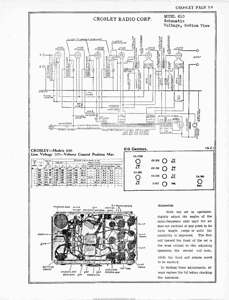
CROSLEY PAGE 1-9
q+ G
2
Af CX316
CNA.51
O. /42D C3-tvJ942r
N
SW/rCA0S590
CROSLEY RADIO CORP.
vAR/ACCE ONDENSE4
r2?6 ORCIf926
4vobe
vwsff3
) _4/otro
C4 W9949
9250R
G/-W19PG 44 71415085
.00021 MrP.
A/690CL' 04739C
4/W44E- 8G4CK42,4944,
CZ 000011
W4923--,222-
/ a4e4 rosi e -/4S--
P2WMrc-ec4CKR aORR
MODEL 610 Schematic Voltage, Bottom View
a W á ° ÿ: t
Q Y
MQb e4 COQCÑ326
' ,
r-9 44/ 0£44 gRL nee[ N4eeLt9eR
23/+ 802+ -235
11111111111111111111 I IIII111111I1111/11I111I 1iI11
POWCR TRANS FOR,+9E P 1/0V-60~ P/3 7/11,5898 I/O V- 2S-- P/4 7/W5922 210 25-- P45 7/W5926
CROSLEY-Models 610 - ,Line Voltage 115 -Volume Control Position Max
MO 14,
0
tees Of
TYc[
0
0114,10111. 9 . . á,.. [TG
«A.M. .Y. .Occ[ M KT Tv. uT
0..T. o.... TT. 9.,. iavp GT..O.[
o«TOY..[ c oYK lTc
49T:TBY..
...[ N[ cY[[Y Y. ®.«T , 228 1st Rt 1.66 166 1.66 160 13.0 - 6.0 8.0 3.0 -
226 2s6 O 1.68 1db 1.45 160 13.0 - 5.0 8.0 3.0 .
3. 226 3rd 97 1.55 165 1.66 160 13.0 6.0 8.0 3.0 - 227 Dot. 2.50 150 2.30 30 - 13.0 2.6 2.9 0,4 - 226 1st V 1.65 180 1.45 175 13.0 - 5 0 8 0 3 0 - 171A 202 AP 5.3 185 6.00 170 40.0 - 20.0 23.0 3.0 - 180 Rost. 6.6 - 5.00 -
610 Gembox,
IS/A tECX37/A
61Áw5512 SR 2532
C
D RUL'!L.
Z
caoaooóòdò -4.9V Sjri 4Jee
0394
22280 C+3I0
q
o OurPOr
N
(A.C.)
CX-371A
o 2ssd
A.F.
CX-326
1st A. F.
CX-326
C X-326
CX-326
C-327
® lst R.F.
O le R.F.
f 3rd `J R.F.
O Ott
R F TRANSFORMERS MERSNON CONS ux IIIA 1ól"F 92503.200 m FIL POT 2200 OHMS JI000 OHMS OHMS 1 Z3
Ist A.F RECTIFIER
OET TIME TRANS. SOCKET I GRID CONC.
UX226FIL. POT TM.F óM.F ANDGRID LEAK 0.625 ore 5 iOM.F 6000004 -Ms
Balancing.
With the set in operation, slightly adjust the angles of the radio -frequency coils until the set
does not oscillate at any point 'in its
wave length range or until the sensitivity is improved. The first
coil toward the front of the set is
the most critical to this adjusting operation, the second coil next
while the third coil seldom needs to be touched.
In making these adjustments, al- ways replace the lid before checking the operation.
www.americanradiohistory.com
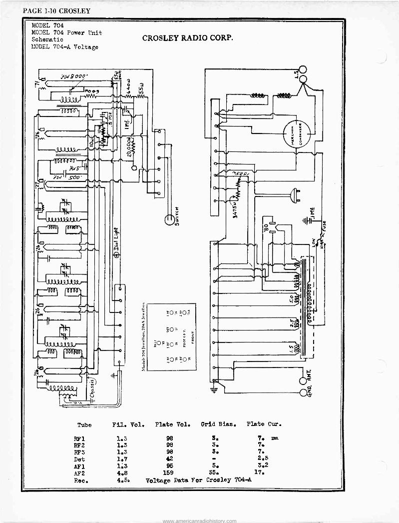
PA(;E 1-10 CROSLEY
MODEL 704 MODEL 704 Power Unit Schematic MODEL 704-A Voltage
CROSLEY RADIO CORP.
..)W2000 1Ñó
ego n9
kS .íW .$'Oo '
14, 1?3J1Q9t9t,---'
11, 112119,11,99J--
1' r51)
---43 t3 9JSI9 r- 111111
A~<
Q
)-1
<
óp
pm=C 2 s
1
H á
o <
If
o ;e)
Tube Fil. Vol. Plate Vol. Grid Bias. Plate Cur.
RF 1 1.3 98 3. 7. ma
RF2 1.3 98 3. 7.
RF3 1.3 98 3. 7.
Det 1.7 42 - 2.5
AF1 1.3 95 5. 3.2
AF2 4.8 159 35. 17.
Rec. 4.5. Voltage Data For Crosley 704-9A
0+-
www.americanradiohistory.com
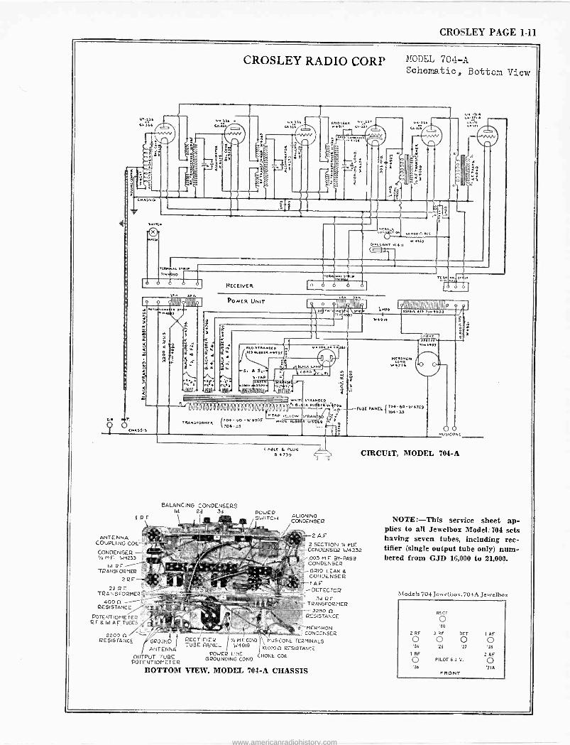
CROSLEY PAGE 1-11
o
CMASS S
CROSLEY RADIO CORP MODEL 704-A Schematic, Bottom View
1.. aaó uii9
Ì3
3
DIJO t aa) . .1n6 Ea lii /
nÇ'ROLA o W.O00AR[S.
w 4l3) //0.A1L}166,T
w4ii
uArA
TEAMWAL MRIP 31.1460
o o o o
o
C
,Fn
4o
4R T,
qOCMA6SIi
RF
ANTENNA COUPLING COIL
CONDENSER 1/e M E. W9233
Ill RE TRANSFORMER
2 RE.
2d R E TRANSFORMER
460 C1
RESISTANCE
POTENTIOMETER Q E O tat A.F TUBES
2200 fl RESISTANCE
OV@Ir
RECEIVER
YT ,P A
I.S ow,.6o
PoNER UNIT 13A. 23A
o dllli rmtN
e
wnc,q eJ
us'ece
1QIf'
fP
vb .iPf95
>.gro tl
1.'4919
5imiiinrannmim avow R[l iw1400
REOiTAAMeEP Ate RuS9ERwN9f
S. 6 Sr-. J.
S TAP RAW, ESIR/.Ot( a..
tJGSPYi?PPPDr 11fQP
VXMOSKS
CR o D
se
o
NCRMMOM
W47S4
1lfl'T1 nwlvl
- -- ---. wNc>E STRANDED
ÓböbööbööóbböbbaóbbbbOrÖÒbbbó'"DVEnRud9Fqw)96 f>04'60 -W4709 .a.-FOSE PANEL 7047S
P TAP YELLOW STRANG..
O n0RMER 0 W FEOS Mnir[ Ru89iA .4969 704-55 L- w
CABLO 6 PC06 B 4730
BALANCING CONDENSERS lat 2d 3d POWER
SWITCH
GROUND
ANTENNA OUTPUT TUBE
POTENTIOMETER
BOTTOM
RECTIFIER TUBE PANEL
ALIGNING CONDENSER
2 A.E
2 SECTION CONDENSER W4232
/.005 MYE BY-PASS CONDENSER
-GRID LEAK 8 CONDENSER
T-1 A.P --DETECTOR
CIRCUIT, MODEL 704-A
3d RE TRANSFORMER
3250 n RESISTANCE
bMRSNON CONDENSER
Y. Ì COWl MUSICONE TERMINALS W4919 110.000(1 RESISTANCE
POWER LINE CHOKE COIL GROUNDING COND
VIEW, MODEL 704-A CHASSIS
NOTE:-This service sheet ap- plies to all Jewelbox Model: 704 sets having seven tubes, including rec- tifier (single output tube only) num- bered from GJD 16,000 to 21,000.
Models 704 Jetvelbo .704A Jesvelbo.
RECT
O '80
2 RF 3 RF DET 1 AF
O O O O '26 '26 '27 '26
1 RF 2 AF
O PILOT 6.0 V. O '26 716
FRONT
www.americanradiohistory.com
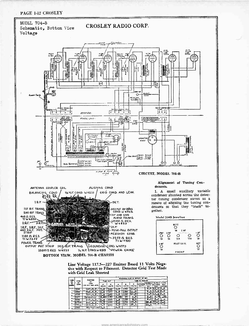
PAGE 1-12 CROSLEY
MODEL 704-B Schematic, Bottom View Voltage
CROSLEY RADIO CORP.
T
1
frA lag
e
ii
L--- PO/EC N,T
r
My
h
J fn
Ante inll.
á
1111111 Ile
i, ë.úo' :1'
t : - _w ii.A.,
(IinA,f,.o.,N^. 4.,,,,,,,,,,p,,r,r,,,,i1J- J,N fsJ II,I tJ-
./Y
«cum./ad 1tJJ
a,c¡t- 7-'JfY 0 b0r10
"P9 U CIRCUIT, MODEL 704-B
ANTENNA COUPLER COIL ALIGNING CONO.
BALANCING COND 1hM.F: CONO. W4233 GRID COPIO. ANO LEAK
1ST R.F. TRAN 2ND R.E TRANS.
4600 RES. 71W4895 2RF.
1RF. 2RS, 1A.F. ANC)2A.F. POT.
STRIP 11001. RES. 71W525-5
POWER.TRA S OUTPUT POT STRIP 3R.D F. TRANS. GROUNOI ONO. 1./4973
10.00011 RES W4921 '/zN.F OND.W4919 OWER. CHOKE
BOTTOM VIEW, MODEL 704-B CHASSIS
.003 MF. BY PASS COND. W 4922
15r AND 2ND AUDIO TRANS.
60.000 0. RES. W49 23
1A.F PUSH -PUL. OUTPUT
MERSHON GOND.
325012. RES. 71 W 4900
Alignment of Tuning' Con- densers. 1. A small auxiliary variable
condenser shunted across the detec- tor tuning condenser serves as a means of aligning the tuning con- densers so that they "track" to- gether.
Model 704B Jewelbox
RECT
O 2 AF 2Z2F 3 RF - - 1 AF
O o O o 0 '26 '26 '71A '71A '26
1 RF PILOT 6.0 V. PET
o o '26
FRONT '27
Line Voltage 117.5-227 Emitter Based 11 Volts Nega- tive with Respect to Filament. Detector Grid Test Made with Grid Leak Shorted
TW[
Oit. TT.(
TO.[
M4T,W OT
TV« I.T.O.,.O[T..[TO.
O[OO.MO...LK w .CO.[T O. OCT
TU.[ OUT TY« UI n.T[O VOLTSMt VOLT VOLT. O [
T
T. U«MALtlM[
MA CONO
.T[
246 let.R.F. 1.6 160 Z.5 'I50 21.0 .6.D 12.0 5.5 226 ?nd.R.F. 1.6 160 1.5 150 11.6` 6.5 13.4 6.9 226 3rd.R.F. 16 160 2.5 150 11.6' 6.5 13.4 6.9 2¡L'1 Detector 2:60150 3.25 30 0.6 2.2 2.75 .55 226 1st.A.F. 1.6. 220 1.5 320 9:6 6.2 13.0 1.8
.. .2.716 2nd.A.F. 5f3. 1E5 6.0 370 37.5' 20.0 23.0 3.0 171A -2nd.A.F. 5.3 185 -5.0 "i70 37.5- 80.0 °3.0,3.0
' 280 Rectifier/5.3 4.9
www.americanradiohistory.com
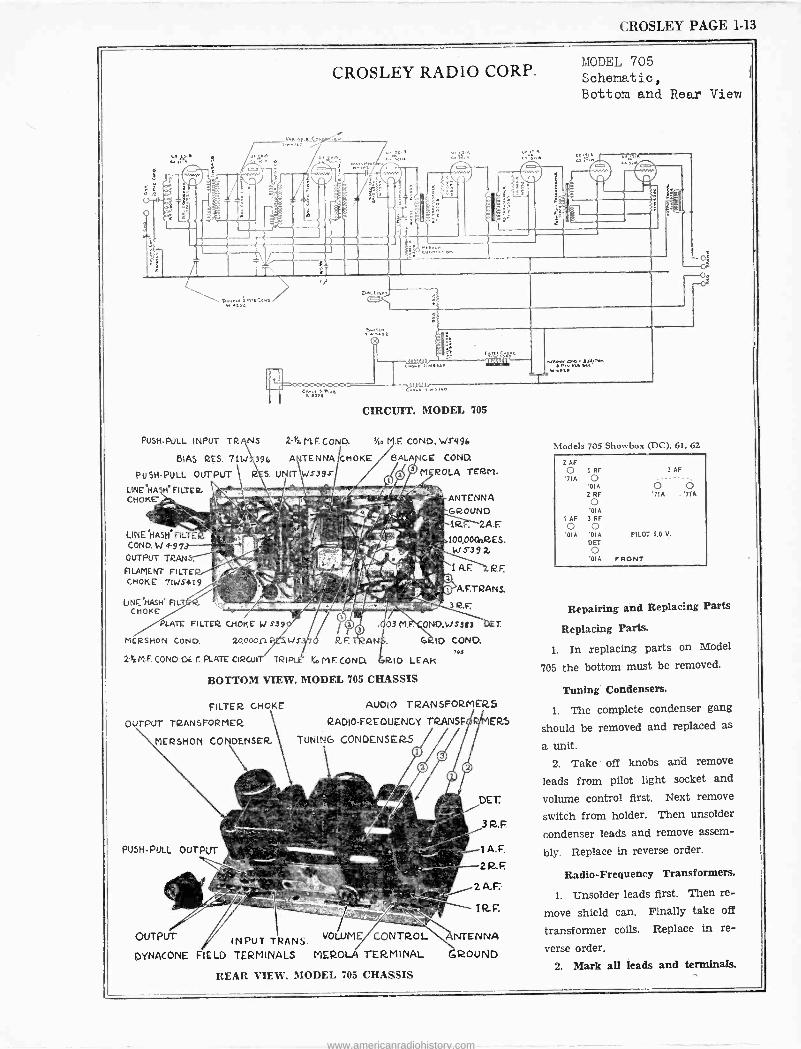
CROSLEY PAGE 1-13
CROSLEY RADIO CORP.
CIRCUIT. MODEL 705
PUSH-PULL INPUT TR NS 2-t. M.F. COND. VIA M.F. COND, WS496
BIAS RES. 71W 396 A TENNA CHOKE BALA CE COND.
PUSH-PULL OUTPUT
LINCHA H FILTER. CHOKE -
LINE HASH FILTE CONO. N 4-979 OUTPUT TRAN
FILAMENT FILTE CHOKE 71WS419
UNE HASH° FILT CHOKE
PLATE FILTER CHOKE W 3-39
MERSHON CoNO. 20.000.2
ti F. COND.DET. PLATE GIRCUI
RE AN
M ROLA TERM.
ANTENNA GROUND
2A.r 100,000n2ES. W.739 R.
lAF R.E
A.F.TRANS.
32.F.
ONO. W 6383
6 IO COND.
TRIP ieVLFCONO RID LEAR
BOTTOM VIEW, MODEL '705 CHASSIS
FILTER CHOKE
OUTPUT TRANSFORMER
MERSHOIV CONDENSER.
AUDIO TRANSFORMERS
RADIO -FREQUENCY TRANSF'. ERS
TUNING CONDENSERS
OUTPUT / INPUT TRANS. VOLUME CONTROL
DYNACONE FIELD TERMINALS MEROLA TERMINAL
REAR VIEW, MODEL 705 CHASSIS
DET.
3 R.F.
1A.F,
2R.F
2 A.F.
NTENNA
GROUND
MODEL 705 Schematic, Bottom and Rear View
Models 705 Showbox (DC), 61, 62
2 AF 0 1 RF 3AF '71A O - --
'01A 2 RF
0 '01A
I AF 3 RF
0 O '01A '01A
DET
O O '71A '71A
PILOT 6.0 V.
O '01A FRONT
Repairing and Replacing Parts
Replacing Parts.
1. In replacing parts on Model
705 the bottom must be removed.
Tuning Condensers.
1. The complete condenser gang
should be removed and replaced as
a unit. 2. Take off knobs and remove
leads from pilot light socket and
volume control first. Next remove
switch from holder. Then unsolder
condenser leads and remove assem-
bly. Replace in reverse order.
Radio -Frequency Transformers.
1. Unsolder leads first. Then re-
move shield can. Finally take off
transformer coils. Replace in re-
verse order.
2. Mark all leads and terminals.
www.americanradiohistory.com
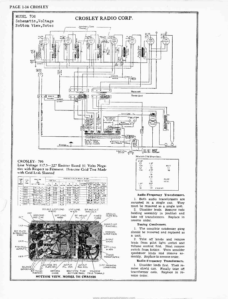
PAGE 1-14 CROSLEY
MODEL 706 Schematic,Voltage Bottom View,Notes
Aö v'
CROSLEY RADIO CORP.
u,
et
A
If
.0 :S
eA µe ..iD
1104.m 7100000
lliellillld^b, Il3
40 CI
RECEIVER
1:111M1941 :111111 PowElt UnIT
Cn,.ss.a
w A
.J5
c.,. Coro
4oS,ºwine e,W.c.iM e ..... .,
+A1au- ,?+-tA.e
( UN, l -c r e e{ AUJC.IOü' Ó
Il eel llll1111111111 1 I 1111111
neo. u- ,,..ei.°v
51
CROSLEY- 706 Line Voltage 117.5-227 Emitter Based 11 Volts Nega- tive with Respect to Filament. Detector Grid Test Made with Grid Leak Shorted
..... "27 12.3-375 226 let.R.F. 1.6 160 1.5 r50 11.0 6.5
226 2nd.R.F. 1.6 160 Ili 5 '150 I .0 6.5 13.4 6.9 t26 31,1.1.F. 1.6 '150 .5 --In 11.a- 6.5-13.4 6.9 127 Detector 2.50 150 2.2-5 0.9 2.2 2.75 .55 226 7ct.4.F. 1.6 220 1.5 "1-r40 9.6 6.2 8.01 a l'/1A 2nd,A,F, 5.3 -135 5.0 270 27.5- 20.e 25.0 3.0 171A 2nd.A.F. 5.3
5-.3 155 5.0 170 37.5 20t0 2.3.0 3.0
, '280 Hectilier 4.9 _'
PF. GRIDCOND.
DE, AND LEAK
1 A.F
DET. PLATE' BY-PA55 COND.
W 4922
22F
PU511-PULL OUTPUT
SqF
DOUBLE '/: h1.E COND. 1 n E COND. 2E ANC/1,4e W 4232 W 4015 BIAS 2E5.
Y:nFCOND. W49i9
RF ANDIA.E POWE2 FIL. POT. C108E
G"e.[ +.
325011 21 PLATE 2E5.
10,000 R 1 A.E PLATE 625.
NE25HON CONDENSER
OUTPUT CHOKE'
H,ECOND. W 4919
POWEq T2ANSPORnER
/ , ODOR DET. OUTPUT OUTPUT )1, ri Er GROUNDING BALANCE /,i //t PLATE 2E5 FIL. POT. SIAS. 2E-5. CONDE -N52-2
CONDENSER5 / 2.E TRANS- ANT RNA 2ECTIFIEE TUBE DYNACONE
F0211225 CHOKE AND FUSE PANEL FIE -LO TERMINALS
BOTTOM VIEW, MODEL 706 CDA'SSIS
w -0ó V.Mf
ilru.twe,.n_{°::4`. 2tCvto- IIeJti
Models 706 SI owboc,
2 AF
O 1 RF '71A 0 O '71 A
'26
2 RF
RECT
O '80 o
'26 3 RF
O PILOT '26
AF DU'
'26 O
O FRONT
6.0 V.
Audio -Frequency Transformers. 1. Both audio transformers are
mounted in a single can. They must be removed as a single unit.
2. Unsolder leads. Remove nuts holding assembly in position and take off transformers. Replace in reverse order.
Tuning Condensers. 1. The complete condenser gang
should be removed and replaced as a unit.
2. Take off ' knobs and remove leads from pilot light socket and volume control first. Next remove switch from holder. Then unsolder condenser leads and remove as- sembly. Replace in reverse order.
Radio -Frequency Transformers. 1. Unsolder leads first. Then re-
move shield can. Finally take off transformer coils. Replace in re- verse order.
www.americanradiohistory.com
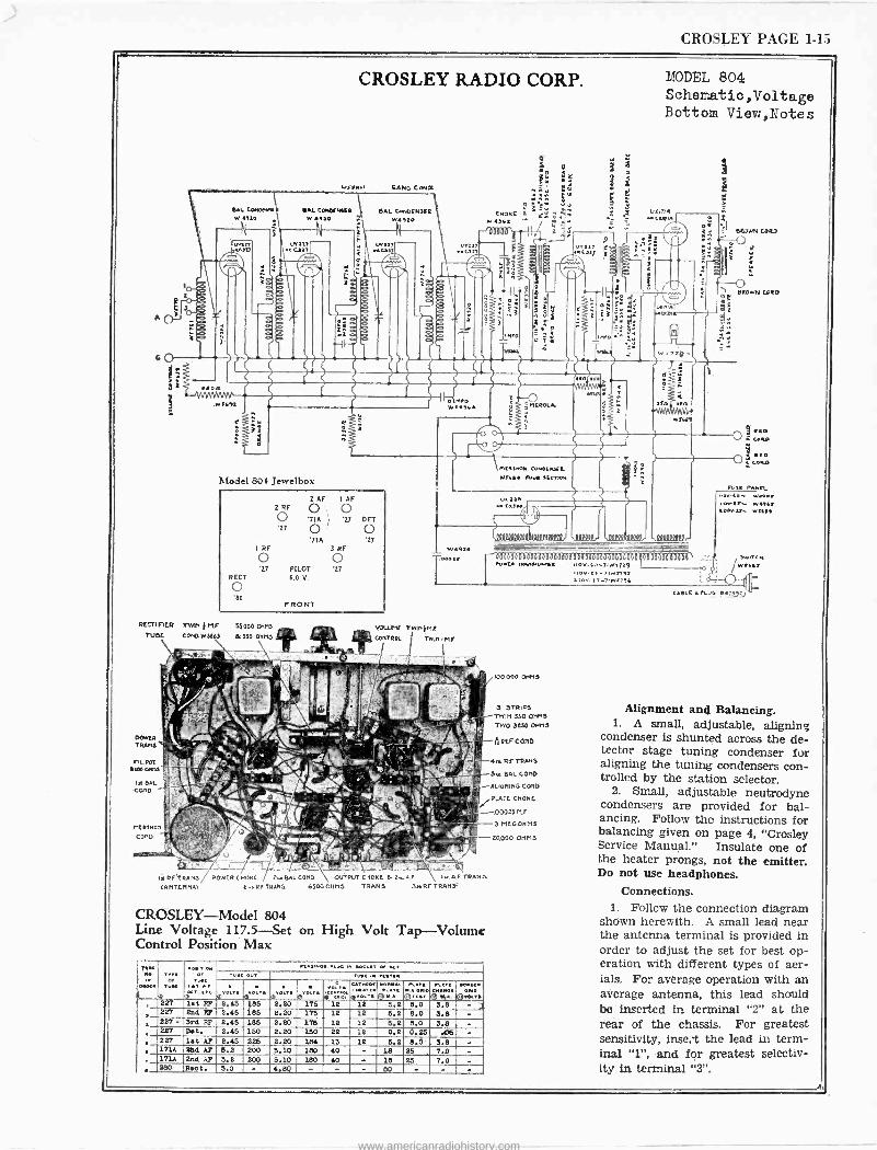
CROSLEY PAGE 1-15
CROSLEY RADIO CORP.
6L COHDFMtC WU. COMFM[i l SAL CeNOFN3F2 W e910 W 9a0 N4710
RECT
o '80
Mn, .. C)1T
'718 I RF 3 RF
'27 PILOT '27 6.0 V.
RECTIFIER DAY, t MF 50000 are TUSE COND W 556) IN 550 OHMS
Iv 2F TRANS (ANTENNAI
F RONT
ER CHORE 2.9. SAL CON(' OUTPUT C iOKE 8.8.Aí ... AF TRANS e.. RF TRANS '650008115 TRANS 3..RF TRANS]
CROSLEY-Model 804 Line Voltage 117.5 -Set on High Volt Tap -Volume Control Position Max
reMe
'e.ö. ..[
,..[ 01
.. .[I 00[..[.<
.[.,H<....< .. .[. ., MY ..[ OK. 11.1
0rO.T evo.. ® Oils or0., n
4o.oL9.0a- .. _q°O[ 0 N
í(r: K.,[
Cj.. K.[
® i}..®[O.,r o[[e .10
. 227 let RF -2.45 185 2.20 175 12 12 5.2 8.0 3.8 - ] 227 2414 RF 2.45 185 2.20 175 12 12 6.2 8.0 3.8 - 227 . 31r4 27 2.45 186 2.20 176 12 12 5.2 8.0 3.8 -.
227 Det. ' 2.45 150 2.20 1.50 22 12 0.2 0.25 .05 - 227 lot AF 2.45 225 2.20 184 13 12 5.2 8.0'. 3.8 - 1714 254 AF 5.2 200 5.10 180 40 - 18 25 7.0 -
, 171A 2nG AP 5.2 200 5.10 180 40 . 18 25 7.0 - 280 Ric t. 5.0 - 4.8Q - -
_
- 80 - - -
,MEA]HOM CONOtHXL WT.e. R.Y afC.pH
.af0 ..C[]W
MODEL 804 Schematic,Voltage Bottom View,Notes
ftºaaººaºººabººeº«00ºº0, ,ººaaº ºmºº, ,!MOW
700o3ana,,,, O.E an.Or<.,r
100.000 OHMS
3 3TR1PS TWIN 350 OH1,3 TWO SESO 014113
M.P CONO.
4n RS TRANS.
3,. 6AL.COND
ALIGNING COUD
PLATO CISOKC
.00025 MI
3 MEG.OHMS
20.000 OHMS
1 v O-T.T)19 e.ems
120. ]i -7.W.)96
Alignment and Balancing. 1. A small, adjustable, aligning
condenser is shunted across the de- tector stage tuning condenser fur aligning the tuning condensers con- trolled by the station selector.
2. Small, adjustable neutrodyne condensers are provided for bal- ancing. Follow the instructions for balancing given on page 4, "Crosley Service Manual." Insulate one of the heater prongs, not the emitter. Do not use headphones.
Connections. 1. Follow the connection diagram
shown herewith. A small lead near the antenna terminal is provided in order to adjust the set for best op- eration with different types of aer- ials. For average operation with an average antenna, this lead should be inserted in terminal "2" at the rear of the chassis. For greatest sensitivity, inset the lead in term- inal "1", and for greatest selectiv- ity in terminal "3".
www.americanradiohistory.com
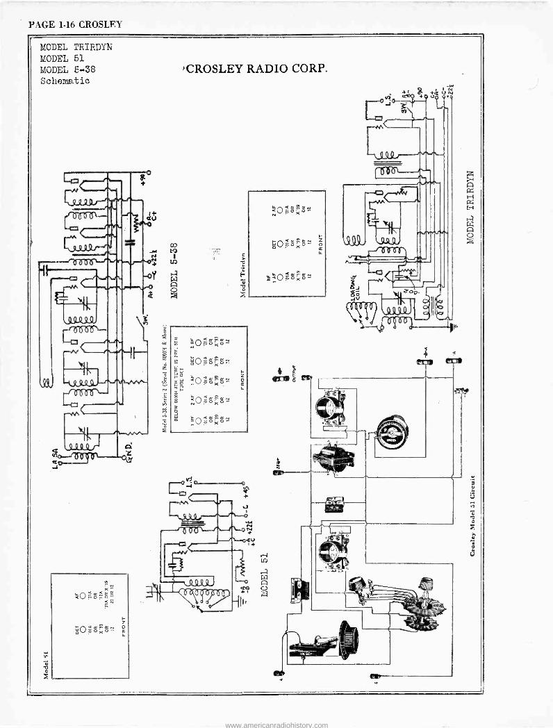
PAGE 1-16 CROSLEY
MODEL TRIRDYN MODEL 51 MODEL 5-38 Schematic
t
L.
Ctrtrtr\--
rj'A
R9 f-r
crz
Q ß ca
o--/o v co
x=
F Z
L,O-o <¢
°'
,,, OX o-
LL
au
elf
oo
z
-wd
Q + Q a N a
J ; 41
\109, --6aßa
y ä,
JV a \ºtuQ) d
iCROSLEY RADIO CORP.
`.. Ñ O 0 X p
<PN Z áoöoXo- o LT
CO o V< < ó m ó N X
Q
Q j
Ob
www.americanradiohistory.com
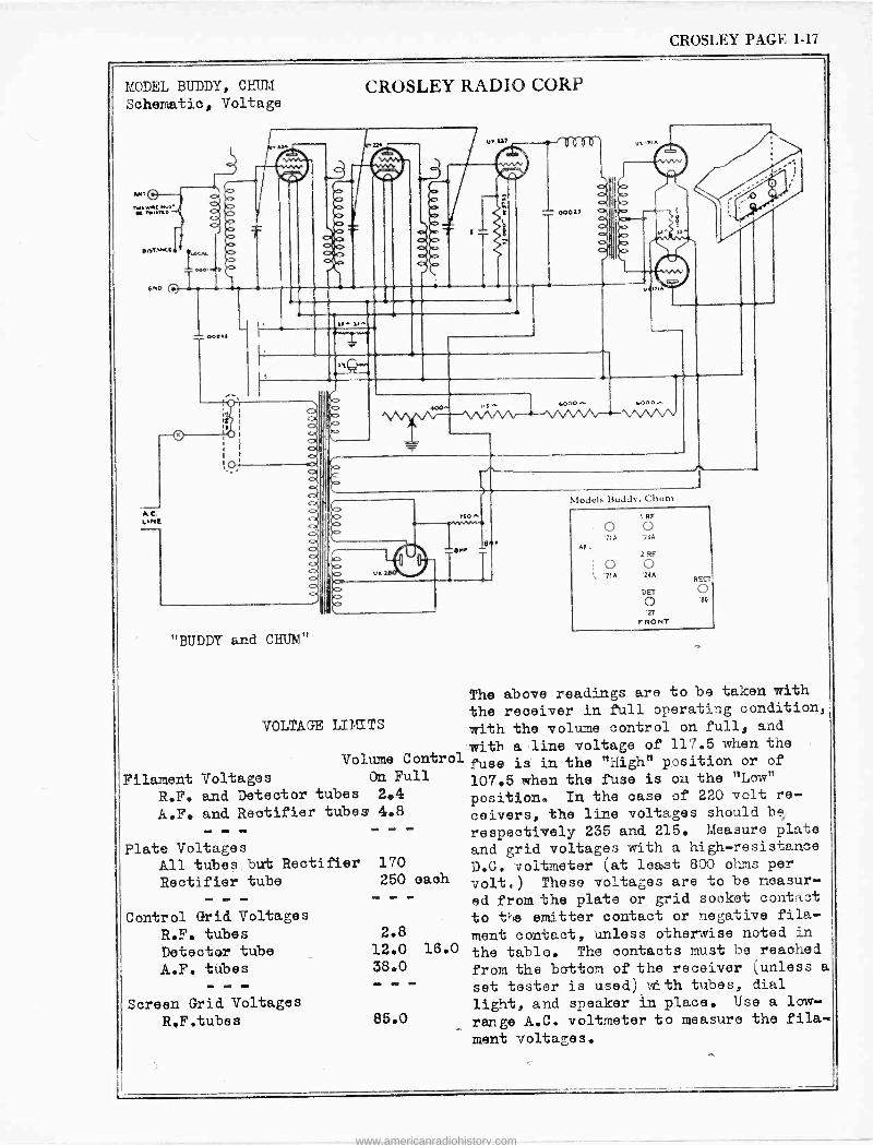
CROSLEY PAGE 1-17
MODEL BUDDY, CHUM Schematic, Voltage
"BUDDY and CHUM"
Filament R.F. A.F.
Voltages On Full
and Detector tubes 2.4
and Rectifier tubes 4.8
Plate Voltages All tubes but Rectifier 170
Rectifier tube 250 Iffl
Control Grid Voltages
R.F. tubes Detector tube A.F. tubes
we me «II
CROSLEY RADIO CORP
VOLTAGE LIMITS
Models Buddy, Chum
AF
1 RF
0 0 '71A '24A
2 RF
o o L '71A '24A
CET
0 '27
FRONT
REC'
o '80
The above readings are to be taken with
the receiver in full operating condition,
with the volume control on full, and
with a line voltage of 117.5 when the Volume Control fuse is in the "High" position or of
107.5 when the fuse is on the "Low" position. In the case of 220 volt re-
ceivers, the line voltages should be
respectively 235 and 215. Measure plate
and grid voltages with a high -resistance
D.C. voltmeter (at least 800 ohms per
volt.) These voltages are to be measur-
ed from the plate or grid socket contact
to the emitter contact or negative fila-
ment contact, unless otherwise noted in
the table. The contacts must be reaohed
from the bottom of the receiver (unless a
set tester is used) with tubes, dial
light, and speaker in place. Use a law -
range A.C. voltmeter to measure the fila-
ment voltages.
each
2.8
12.0 16.0
38.0
Screen Grid Voltages
R.F.tubes 85.0
www.americanradiohistory.com
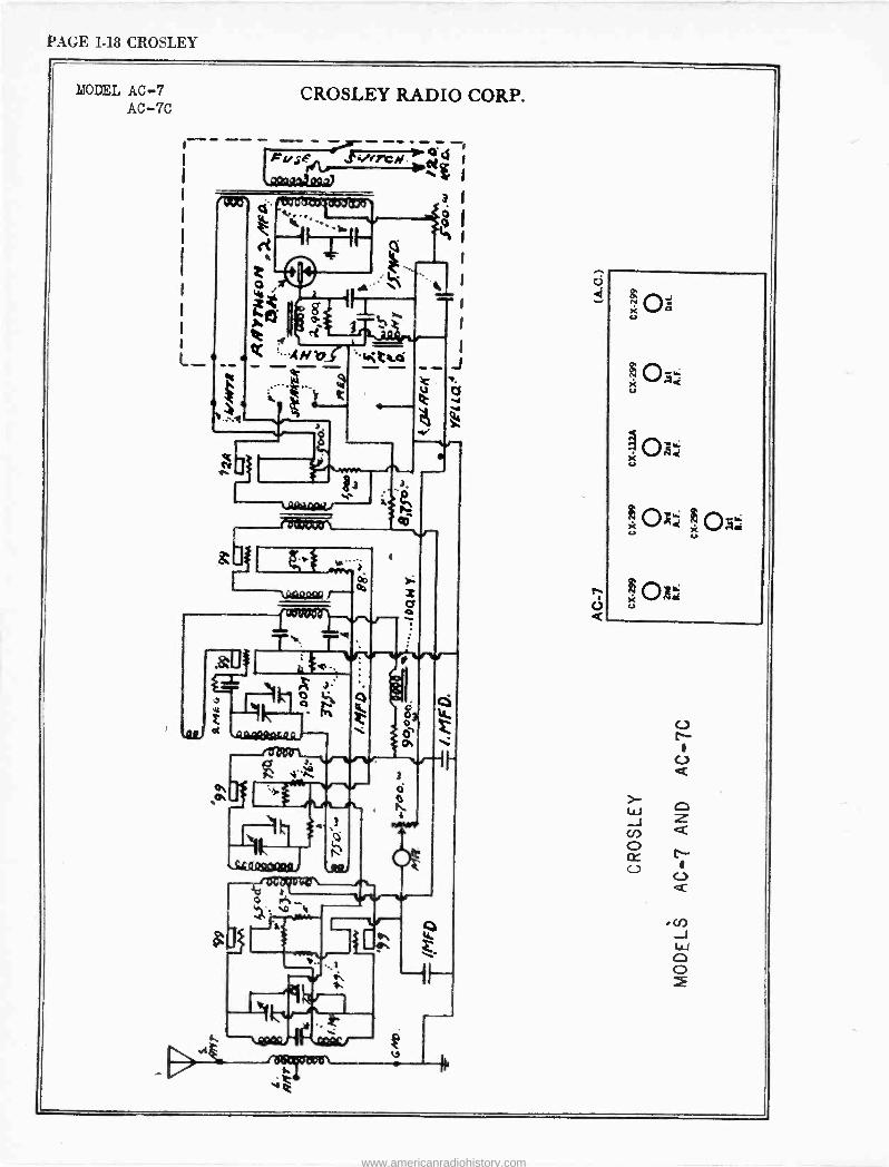
PAGE 1-18 CROSLEY
MODEL AC -7 AC -7C
CROSLEY RADIO CORP.
«/73Cy. :4c g
31 0 1
.1
Tentesnue ` ,
4- il--
6
*Nit mi
.. .....T.
L
d
rì . ó 4...
. rw%
3
O
_ Cf
3
ò
ti 4
Ot
1
1 Q
C)
X u
e oa u u
www.americanradiohistory.com
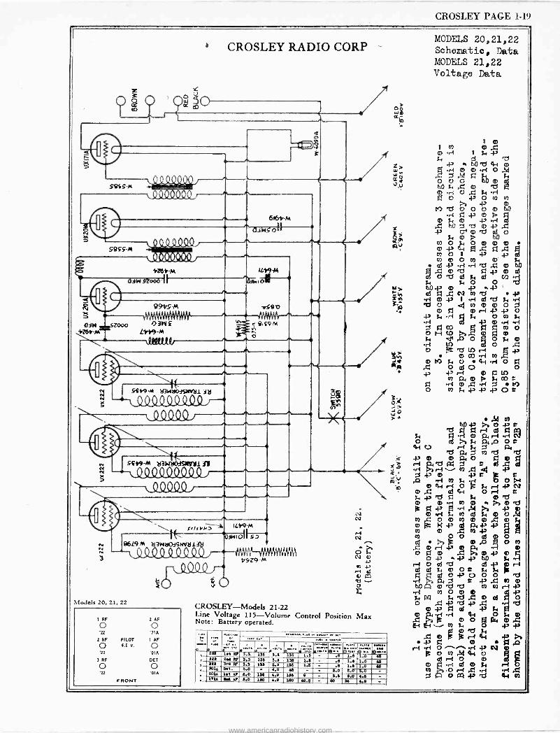
CROSLEY PAGE 1-19
l ¡ 3 0 oc to
d K
SQSS-M
S849-14
CROSLEY RADIO CORP --
/11111A iTO
1111//1
'WOO 1051-M
dW 000i I
616ó-M
^ aAWSoII
8916 -PA
IL19-M `w1 vS8 b
diws=sz000 0311£ iZbY M L1Y9-M \ MOM
0
ñ ß149-M
ò
1V I I 5s19-Á6 213WóO3SM1I111 jM fNV
1
l l^t 1/' 1^' l/' , 1;,CCC.)[./
1
.
541,9-M 2314110.3SNVy1 n (MOW7
- l 1L1U049
\i[ srtrM> IL19-M
1 aiw ol' 86L9 3W1iO3SM/M1
MAW-fIl1Y11IYIIYI qSZ9 M
Models 20, 21, 22
I RF 2 AF
o 7IA
2 RF PILOT I AF
O 6.0 V. o .22 'MA
3RF DEI
o o FRONT
CROSLEY-Models 21-22 Line Voltage 115 -Volume Control Position Max Note: Battery operated.
.
Hí'tN 3.-11e',]º Se1.e"®-5ec..w'~i. .e l.e .0 74.. ººe 204 47 3.3 130 3.2 336 1.0 - .5 i.e 1.o ,e 224 3rt Rl 3.3 135 4.1 145 1.5 - .e 1.e 1.0 te 604 Del L. 5.0 - .e td - - 1.0 6.0 3.0 - ºO1. 1.5 N 5.0 145 4.0 146 9 4.5 0.0 4.5 - 171A 111V 5.0 1e0 4.9 1e0 40.4 - eD M 4.0 -
MODELS 20,21,22 Schematic, Data MODELS 21,22 Voltage Data
o' W $
1 Ip
m 1-! I Ñ / b0 "^' 4-1 0) w.. .1--I Q) 0) .r{ ix.. ,S,j
cc w
1-..d1
ox, 0 f, . ID 'd R 0 ri O ,i'i N. r1 5 ° , -P m
M 'd O O U O) 60 rI -P In p p
z LO O' m 'd cd Oód
47 á
m -ñ 0 ,
I to 4 O m m f-1
d I3 .ri -H 2t .(ti m b0 6 óe e
>4 0 ,
A 4 f, s, O O Nm, _ m Tt fri LO «31 to m p Om
O gl 0 r1 i-' -N O -:., f, -ri
W f, O 0 f,
Titn f'vlo f,~dlO O f, m o
Ñ O T! LO r-1
O +
m CO -ri 00
J+ 0) !M f, O 4-1 rl O f Op ..g O 01 0 O +2 Á, o P fg-, CO . `- ri 0 .t ri d N) O 02 :y i-' 1' .1.3 O C
;ó: J,O
ç Y' V
co
Rq7 qr-i q r o ad 'a fm, P ó P
-}' ID m Ó rry,
P4 ryf
r-1 e Ctti W W mm rgz
{r ee
m ri~ 0
01 4-1 Ofy r tD
4>m.r-I co w Ps md
lie g 42 CD Ate
co Km á §n
m 7 {' m
0 y, O ° mpa1
,O 0 Ó oá
i7 Q> ri
.t: A m O iÿ O -N w 4342h0 g...-1 - os ,cs
. ß/ç -P . .g 0 b0 0) 'td 27 t7 co r1 .}'
$1orij,.e1-' ell ..g ceS 'd O
-P ó 0á
H H
Id
CO FO. O Ófkl{0 ' 4 .4.'
o g.0 r. Os i-. m{ - N O
P O 1T1 ,511 4i O ¡¡ cß ri O 0) g
d 4. ta
www.americanradiohistory.com
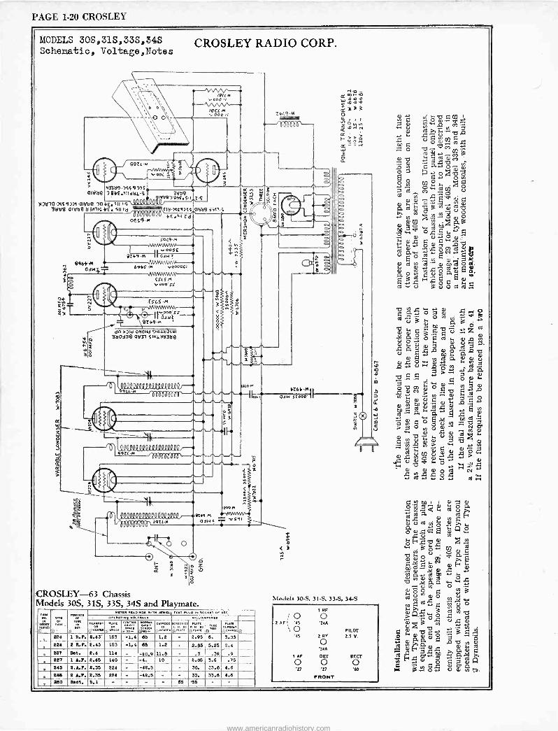
PAGE 1-20 CROSLEY
MODELS 30S,313,33S,34S Schematic, Voltage,Notes
CROSLEY RADIO CORP.
O
r --N sr- v 000 ,/
te EL M ,.000 1) Z4Lq.M
-"ÓbbCH-
/ 990óM
143389.75S 9 015
l OIVä9 )4144.51141111..53äV9
aiW9794£290 )IJv794Ss9339.0151J9 Su r.s 000gQQ9Q
3tlVB OroäB ä3A3iS46. SII i -d 03ëu7S£93SS 01968 .7,A,15
9964'4 6 0421.7 -
h 93
ó I ó
IIIII1114 O6S9-M
4E.Sa Ld
50L9.M
v005£ 9Z4946 IlaewT
./1MN1MvVNA 6945.M v000001
i
OSLO M v0oo sS
£SLS.M N G
vOOa S's c O II 03w0 9Z49.M
dn MOId OON110Hd 94+1193SNI 360138 01131 SIH1N6358
C 0
QP?Q222224300QQVpQi--* 9u -M Tercim, n
A
A
ó
A
S
e
10e00129QrQ220404QQQßr--9 9921.44dWIMUu0P--,,
QQDUa O(072¡70,00cO2P20Qg000,
»m7 -/A UU UO\ [91[.1(
I-
á
o
1099M
9249-M vS91 aW= T
z F
CROSLEY-63 Chassis Models 30S, 31S, 33S, 34S and Playmate.
s
M
ée[
224
PLUO ea 110C II 0
'[r ow
ró [.ry1
1 R.1. 2.43' (',io .r .
(ir r[
1.2 -
iáa
2.95 6.
224 2 R.?. 2.43 153 -1.4 65 1.2 2.55
227 Dot. 2.4 114 _
227 1 4.7. 2.45 140 - -10.9 -4.
11.6 10 2.95
245 2.6.1. 2.35
246 2 A.1. 2.35 224 -42.5 30.
lIj
3.03
5.25 2.4
.39. .9_ 3.6 .75
33.6 4.6 224 -42;5 30. 33.6 4.6
d
F1r
4Z64.M 0214 sLoOo
0 v ` C f!] ' Co r~ 0 0^ eN O a7 rvyw 1.,1._. o U
cd >r ..'4 2i 1Z " r. L3 40C OOO(/)cd..' 60 b M :1--1O ^ ...i 7jco.^ 1:1.. ce
=1O a..._,'O -.
i,"2.,
o ó ó 1
ó U7 ;., /-, O O la Mw..... U d Ñ j '^
CO' Qi y t0. . ¢) .^. . N p,m0 T13ha)ú ÿ y N 0 `il ..`n., 0
Cl.) ' p.13
a) r,.., cNd
6D ...a.
w 0 O Ú. Ó N- 0. O ..0O Q, ai a) n º,ó
.. y N.. C
CD 03 v) 0ì 4'2 a) g).2.-"-cd- O cÁ 0O d. icii 2A aO Ñ C U_ í0 O /] . O F ÿ G 1¡
fl O% I.04
C.S- U 3UOG03Ç
O Q Ñ /n
. S
C5 3 ÿ C1 3 y o2 z ú ó ; o á cd ,Q tn
O. U C CD ÿ2 ÿl ß. d
Ñ a) .0 OO w ÿ.O-, O.
c0.. í0n _ .4 U p .-mi
i.ì L1
b . L.. Ó 02 104
.b O
6l CV 0 O Q3 . 2 ~ > v1 0
á v)
Ñ 0 U .a -' S~-, a 2 a á
re tO
Q. ti " uJ a
© co Ô ÿ Z O " p"' 13i1 ú > 7 0 0, U ~ d al
""-C:$
C `n v U
'v..-. 0 .-. ÿ
R N> w 0--i O
cd Ci) 0 U s7 O>w
,gÚ Ñ O U ,.`-' y 0 û w c O 9r : a) a) a) CV
4...
-, +-, cdawi
Models 30-S. 31-S, 33-S, 34-S
I RF
; O 0 2 AF '45 24A
O PILOT '45 2 RF 2.5 V.
O 24A
I AF OCT RER O O O '27 '27 '00
FRONT
E. ,.[n, 00 I I a) .".7 a)
O m 77;4. ti cd cO
2 Tias 00Fa c.)) cd 05 '6' ; >s
n. á4.. `'F;Cv O > w > L. c6
vi
d d O x r: 5 o r4 a, d F c ti
...r ..., t. " ma)a)ai 4.Oy.S3 ú cn
O. Q O ''.
j°' ô O ..N 3
U 0 O m a)
[nG2.al -r ÿ Ó O Á.ó
U r4
O rn
U.-. ..0.
q 2 '17 -, ^ 3 5 A 0 0 0 0 0 3 = 0 ( a £-, Sl -a V) c0) ÿ coy' 0 a) 44 a3
a - á. ÿ P.
C'r
Fri'^ OC.O Ñ CF
F[I ii 41 O...i V 0 co ;7.
260 Root. 5.1 55 e5
www.americanradiohistory.com
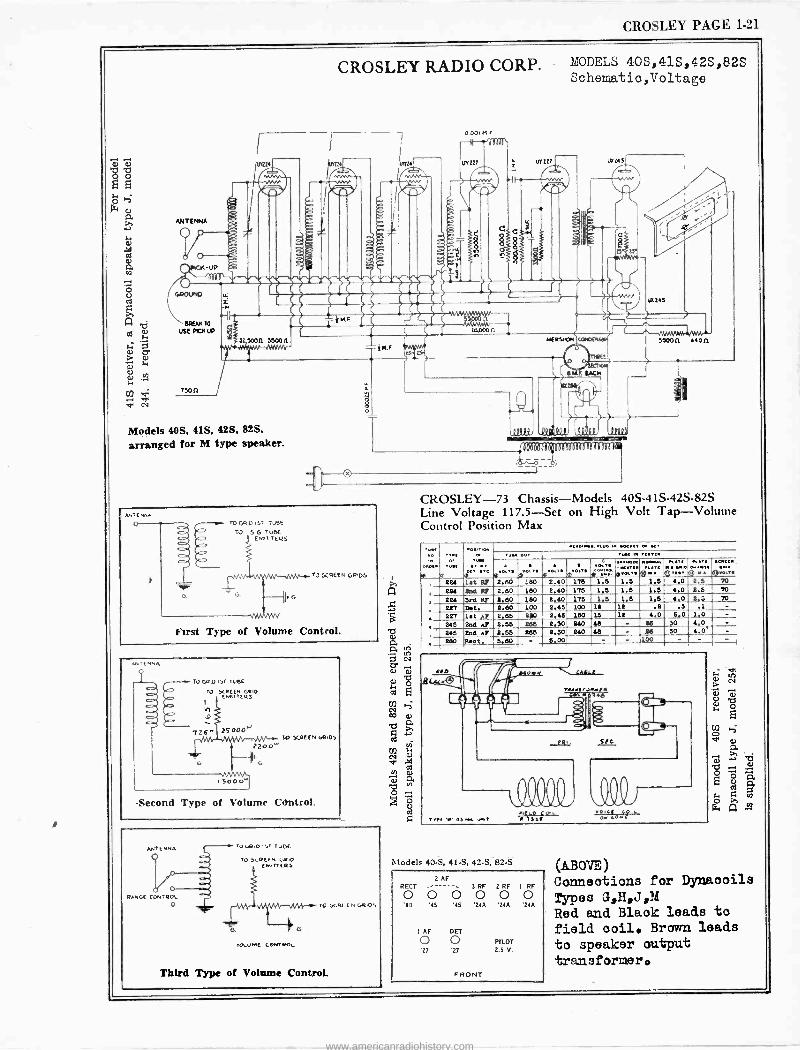
CROSLEY PAGE 1-21
ANTENNA
. O
7500
LL
n3
CROSLEY RADIO CORP. MODELS 40S,41S,42S,82S Schematic,Voltage
v/0
4111414tAb4sLa44b410 Mi.41.1186.11. a44aeak1
C0.000 n
OOOtMF
M drlil\ W227
C
urto UY245
3 5000 35008
Models 40S, 41S, 42S, 82S,
arranged for M type speaker.
y
i
n ENhA
2 zoo"' TO SCR[CNt7.0S
-Second Type of Volume Control.
21
92 245
3500(5 440(5
CROSLEY-73 Chassis -Models 40S -41S -42S -82S Line Voltage 117.5 -Set on High Volt Tap -Volume Control Position Max
IF V FIFE or
q:....a..°..01..11m.°...«....«;®. v.. °°. .. ,11,. L
CATFOOOl .. Q:.";°- 2.5 70
, 224 lit. R7 2.60 180 2.40 175 1.5 1.5 1.5 4.0 224 2nd R? 2.60 180 2.40 175 1,5 1.5 1.5 4.0 2.5 70 , 2ºA 3rd RF 2.60 180 2,40 175 1.5 1,5
15 1,5
.8 4.0
.3 2,5
.1 70
227 D.t. 2.60 100 2.45 100 12 - , 227 145 p7 2.65 2,0 2,45 160 15 12 4.0 5,0 1.0 - . 245 2nd Al 2.55 265 2.30 240 48 - 26 30 /i54__!_
- 245 2nd AT 2.55 265 8,30 240 48 - 26 30 4.0 280 R.ot. 5,60 - 5.00 - - 100 - - -
Models 40-S, 41-S, 42-S, 82-S
2 AF SECT ---- 3 RF 2 RF 1 RF 0 0 0 0
WOVE) Connections for Dynaooils
*c x50 EN C,.VOS 0 '80
0 '45 '45 '24A '24A '24A
Types G,H,J,M Red and Blaok leads to
1 AF DEI field °oil. Brawn leads ,OIV MC CONTROL 0
'27 0 '27
PfLOT 2.5 V.
to speaker output transformer,
Third Type of Volume ControL FRONT
www.americanradiohistory.com
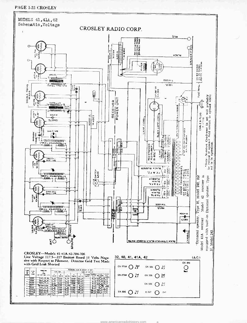
PAGE 1-22 CROSLEY
MODELS 41,41A,42 Schena.tic,Voltage
drl S-'---r 6001 '
5'34ryy 1rM wsñV
CROSLEY RADIO CORP.
7< w,a,., .c.r.
r-1
;: " 72ä1 w '!a 01400
JP 0407 1r9
3
º.
>e, 1 ,
o13aQoaaoanoo-, S+a m,t a1ua6l940 y - 0000 n QD10 r- --- /
w---- OSG+a.l -`W
2 S
V'S s 000 ;Stettin 06d---
í96tM11 tl7UtloJAN61Jd C9900/'J
w9 1.q
OOoe6lDOÒDOo01 $`JOSem4 a3u30/tiMr 1 ö --- Q.019/
1
O7GY M a.0 1V8
; .Id -., --
n
Mil Lo..J.Y1471M QJolttJ1s1y1D ZM111
tlWJ]VRAA DI
QO O
}m ea
bib
t d
:¿L Sd
A 39
",31' i.
V U
Cimommmid
CROSLEY-Models 41-41A-42-704-706 Line Voltage 117.5-227 Emitter Based 11 Volts Nega- tive with Respect to Filament. Detector Grid Test Made with Grid Leak Shorted
'. , -226
T26 let.R.p. 1.6 16o 1.5 130 11.0 0.3i2.0 53 2nd.R.P. 1.6 160 1.5 150 11.0 6.5 13.4 6.9 z16 3rd.q.F. 1.6 160 1.3 150 3 I.0 6.3 13.4 6.9 zTl Detector 2.50 110 2.25 30 0.0 2.2 2,__Z .56 , 326 let.A.F. 1.6 220 1.5 6.0
120 1-70
9.0 .37.5 -24.0
6.2 8.0 7.3.0
3-1:1 3 0 . 171A 2nd A.P. 5.3 183
171A 2nd.A.F. 5.3 185 5.0 'T70 '37.6 20.0 31.0 J.0 Z80 ltectlf ter 5,3 4.9
o a o U
a E
J
V
F Q
SS2SMil --VYV.ne.
V001'
nl9enn HJvle
'zvze `Y- d7Hefltl I
M7Y19 '8 C.3 T
i. e11e9na 4lrle bi ti N
S61MI( VOS
Cc«
S1 OQ
Y76rM N
92000
961M MJ991ld )tDYIQ-0301JVd1S X7Y16 V
32, 40, 41, 41A, 42
a
e
(A..0-)
0X -371A O 2nd A.F
CX.371A O 2nd A.F
CX-326 O 1s1
A.F
CX-326
CX-326
CX-326
C-327
O 1st R
O 2ad R.F
O 3e P !
O
CX- 380
www.americanradiohistory.com
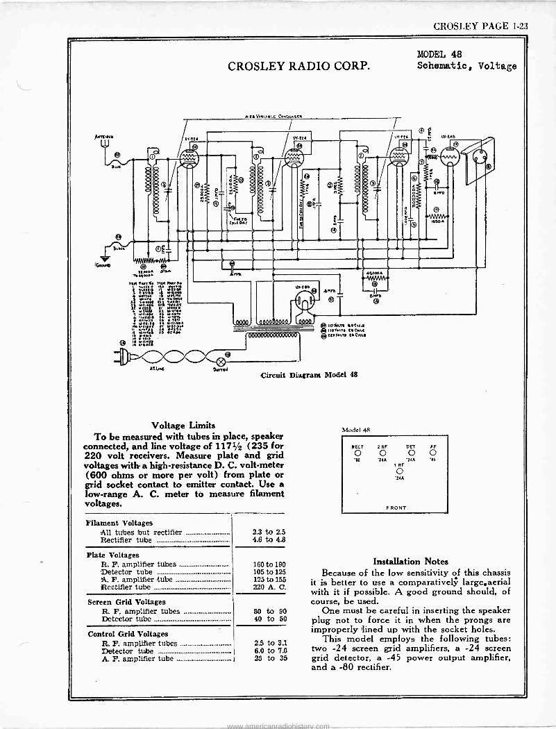
CROSLEY PAGE 1.23
A1ITLNJ4
V
1wJ v \
twee..
lGtoWw ewehmr:AZ---
uwe5 ®A
T0410005
CROSLEY RADIO CORP.
Alt t/ tl1AlLE COMpEN6[tl
I
t0
0090
VY-221
ä ®£
,GO00 0000
utteo
1 144 1
ent9 L
UY.224
460005
MODEL 48 Schematic, Voltage
o
U[-245
o .
1505
00000 (7007)000600
AC.LNC Nevi
110 41.76 40C1cL[ 1101e1T6 te CULE CCOo1Te t/ClcLt
Circuit Diagram Model 48
Voltage Limits To be measured with tubes in place, speaker
connected, and line voltage of 1171/2 (235 for 220 volt receivers. Measure plate and grid voltages with a high -resistance D. C. volt -meter (600 ohms or more per volt) from plate or grid socket contact to emitter contact. Use a low -range A. C. meter to measure filament voltages.
Filament Voltages All tubes but rectifier Rectifier tube
Plate Voltages R. F. amplifier tubes Detector tube A. F. amplifier tube Rectifier tube
Screen Grid Voltages R. F. amplifier tubes Detector tube
Control Grid Voltages R. F. amplifier tubes Detector tube A. F. amplifier tube
2.3 to 2.5 4.6 to 4.8
160 to 190 105 to 125 125 to 155 220 A. C.
80 to 90 40 to 50
2.5 to 3.1 6.0 to '7.0 25 to 35
Model 48
RECT
0 20
2 RF DET AF
O o 0 24A 24A `15
1 RF
o 244
FRONT
Installation Notes Because of the low sensitivity of this chassis
it is better to use a comparatively large.aerial with it if possible. A good ground should, of course, be used.
One must be careful in inserting the speaker plug not to force it in when the prongs are improperly lined up with the socket holes.
This model employs the following tubes: two -24 screen grid amplifiers, a -24 screen grid detector, a -45 power output amplifier, and a -80 rectifier.
www.americanradiohistory.com
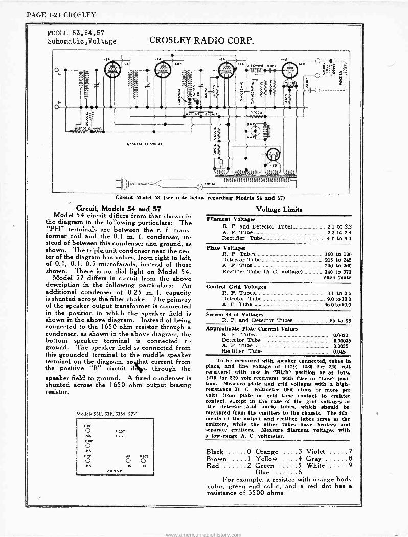
PAGE 1-24 CROSLEY
MODEL 53,54,57 Schematio,Voltage CROSLEY RADIO CORP.
Circuit Model 53 (see note below regarding
Circuit, Models 54 and 57 Model 54 circuit differs from that shown in
the diagram in the following particulars: The "PH" terminals are between the r. f. trans former coil and the 0.1 m. f. condenser, in- stead of between this condenser and ground, as shown. The triple unit condenser near the cen- ter of the diagram has values, from right to left, of 0.1, 0.1, 0.5 niicrofarads, instead of those shown. There is no dial light on Model 54.
Model 57 differs in circuit from the above description in the following particulars: An additional condenser of 0.25 m. f. capacity is shunted across the filter choke. The primary of the speaker output transformer is connected in the position in which the speaker field is shown in the above diagram. Instead of being connected to the 1650 ohm resistor through a condenser, as shown in the above diagram, the bottom speaker terminal is connected to ground. The speaker field is connected from this grounded terminal to the middle speaker terminal on the diagram, so at current from the positive "B" circuit H s through the speaker field to ground. A fixed condenser is shunted across the 1650 ohm output biasing resistor.
Modele 53E, 53F, 53M, 57V
Models 54 and 57)
Voltage Limits Filament Voltages
R. F. and Detector Tubes 2.1 to 2.3 A. F. Tube 2.2 to 2.4 Rectifier Tube 4.T to 4.3
Plate Voltages R. F. Tubes 160 to 180 Detector Tube 215 to 245 A. F. Tube . 230 to 260 Rectifier Tube (A. t2. Voltage) 340 to 370
each plate
Control Grid Voltages R. F. Tubes 3.1 to 3.5 Detector Tube 9.0 to 10.0 A. F. Tube 45.0 to 50.0
Screen Grid Voltages R. F. and Detector Tubes 85 to 95
Approximate Plate Current Values R. F. Tubes 0.0032 Detector Tube 0.00035 A. F. Tube 0.0335 Rectifier Tube 0.045
To be measured with speaker connected, tubes in place, and line voltage of 117y2 (235 for 220 volt receivers) with fuse in "High" position or of 1074 (215 for 220 volt receivers) with fuse in "Low', posi- tion. Measure plate and grid voltages with a high - resistance D. C. voltmeter (600 ohms or more per volt) from plate or grid tube contact to emitter contact, except in the case of the grid voltages of the detector . and audio tubes, which should be
measured from the emitters to the chassis. The fila- ments of the output and rectifier tubes serve as the
I RF
o 'z/A
2 RF
o
PILOT 2.5 V.
emitters, while the other tubes have heaters and separate emitters. Measure filament voltages with a low -range A. C. voltmeter.
'24A Black 0 Orange ....3 Violet 7 DET
o AF
o RECT
o Brown ....1 Yellow ....4 Gray .. 8 '24A '45 Red 2 Green 5 White 9
FRONT Blue 6 For example, a resistor with orange body
color, green end color, and a red dot has a resistance of 3500 ohms.
www.americanradiohistory.com
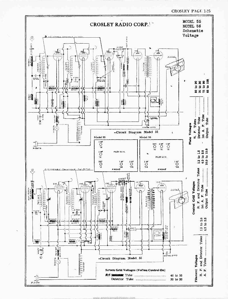
CROS LEY PAGE 1-25
Itt a&5 an 0 rat,
CROSLEY RADIO CORP.'
NC) a No.
ZrZ31
,
1 f1r
W 2.2 Y1 W 3.1G,
MOM
o
MODEL 55 MODEL 56 Schematic Voltage
16,
4010
e
e
-5 wr<A,,C 21,0
23t
a 4134
423 .14 0,711.37
64 Oea
1,
ISZ
e ' T,1 p
Sia.0-7733
rb.I/t37
Migir f0005.7753 1111
5)53700
Model 55
p -Circuit Diagram Model 55
Model 56
RF
o '32
2 RF PILOT to V.
o 32
DET 1 AF 23F 0 0
'32 I2A 7IA FRONT
poo
e 2
W4262
5)4 e
A
.02/831,
s
e
/12
DET 2 RF 1 RF
0 0 0 32 '32 '32
PILOT 0.0 V.
Z AF 1 AF
0 0 '7IA '1ZA
FRONT
111,9
a o
o
Jete ,eg
g. g a
gi 3
3
5 7:49/
W20/36 a n),0
-Circuit Diagram Model. 56
Screen Grid Voltages (Vorme Control On)
R -F 11/Willat Tube 40 to 55 Detector Tube 20 to 30
g l 01 14
. g 3.
O r.;
8
O 0 CI 412
O 0 4, CI 4 .t.
www.americanradiohistory.com
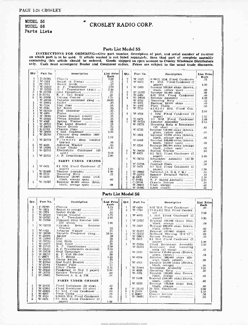
PAGE 1-26 CROSLEY
MODEL 55 MODEL 56 Parts Lists
CROSLEY RADIO CORP.
Parts List Model 55 INSTRUCTIONS FOR ORDERING -Give part number, description of part, and serial number of receiver
on which part is to be used. If article wanted is not listed separately, then that part of complete assembly containing this article should be ordered. Goods shipped on open account to Crosley Wholesale Distributors only. Cash must accompany Dealer and Consumer orders. Prices are subject to the usual trade discounts
Qty. Part No. Description List Price Each
Qty. Part No. Description 1
List Price Each
1 D-21761 5 W-7871
Chassis Socket (4 Prong)
2.00 .25
2 1
W-5382 W-6471
0.00025 Mfd. Fixed Condenser .35 0.1 Mfd. Fixed Condenser (2
5 2
1W-7874 W-21322
Socket Guide R. F. Transformer
.10 2.50 1 W-5469
paper) 1.00 Resistor 100.000 ohms (brown,
1 W-21323 R. F. Transformer (Ant.) ... 2.50 black, yellow spot) .60 3 W-21739 Grid Connectors .25 W-21237 Resistor 60,000 ohm .60 3 B-21174 R. F. Coil Shield .50 1 W-6434 0.02 Mfd. Fixed Condenser .60 1 W-20558
W-20536 Volume Control
j Variable condenser gang 1.75
18.00 1 W-20940
W-5713 Resistor Assembly 1.00 Mounting Strip .25
1 W-20981 Spider .30. W-4921 Resistor 10,000 ohms .60 1 W-7154 Dial Gear .15 i W-4362 Plate Choke .50 1 W-5596 Set Screw .05 1 W-7753 i 0.1-0.5-0.1 Mfd. Fixed Con- 1 W -5354D Dial Indicator .25 denser 2.00 1 W-4899 Pinion .35 i W-4013 11. Mfd. Fixed Condenser (2 1 W-20594 Pinion Bracket (inner) .15 paper) 1.35 1 W-20593 Pinion Bracket (outer) .15 i W-6471 0.1 Mfd. Fixed Condenser LOO 1 W-4907 Spring Washer .08 1 W-21754 Resistor Assembly 3.15 1 W-20722 Dial Light Bracket .25 W-21771 Mounting Strip & Resistance 1 W-20576 Power Switch .75 (45 ohm) .45 1 B-21762 Chassis Plate .15 W-5735 Resistor 150.000 ohms (brown, 1 W-20156 8 Mfd. Condenser 5.00 I green, yellow spot) 1 I W-21760 Filament drop resistor (400- W-4921 I Resistor 10,000 ohms (brown,
,60
370 ohms) 1.00 I black, orange spot) .60 1 W-21779 Filament drop resistor W-5469 Resistor 100,000 ohms (brown, bracket .10 black, yellow spot) .60 2 W-4435 Asbestos Washer .05 W-6704 Resistor 300,000 ohms (orange 1 W-20381 Filter Choke 3.25 black, yellow spot) .60 1 W-21292 Electrolytic Condenser (20 1 W-20630 Bottom Bracket .10
mid.) 2.00 1 W-6471 0.1 Mfd. Fixed Condenser (2 1 W-21752 A. F. Transformer 5.00
1 W-21751 paper)
Resistance Assembly (45-30 1.00
PARTS UNDER CHASSIS j ohms) .40 1 W-21798 Junction Block .10
1
1
W-6471
W-21109
j 0.1 Mid. Fixed Condenser (2 paper)
Resistor Assembly 1.Ó0
1.00
1
1
W-6471
W-20883
0.1 Mfd. Fixed Condenser (2 paper)
Terminal (A. G & P H.) 1.00 .50
W-5713 Mounting Strip .25 1 W-21763 Speaker Terminal Socket .40 W-5370 Ressitor 20,000 ohms (red, 1 B-6867 Cable 1.50
black, orange spot) .60 1 C-21581 R. F. Shield Assembly 1.25 1 W-21237 Resistor 60,000 ohms (blue,
black, orange spot) .60 1
1 C-20658 W-20167
Chassis Bottom Knob (large)
.50 .40
W-20482 Knob (small) .35
Parts List Model 56
Qty. Part No. Description List Price Qty. l Part No. Description 1 List Price 1 5
C-21900 W-7871
Chassis Socket (4 prong)
Each 1.75
.25 1 1
I
W-6434 W-7753 1
0.02 Mfd. Fixed Condenser .... 1.1-0.5-0.1 Mid. Fixed Conden-
Each .60
5 1
W-7874 W-20558
Socket Guide Volume Control
.10 1.75 1 W:4013
ser 1. Mid. Fixed Condenser (2
2.00
1
1 W-21752 W-21760
A. F. Transformer Filament Drop Resistor (400-
5.50 1 W-21237
paper) Resistor (00,000 ohms) Blue,
1.35
370 ohms) 1.00 black, orange .60 1 W-21779 Pilament Drop Resistor 1 W-5469 Resistor 100.000 ohms Brown, 2 W-4435
Bracket Asbestos Washer
.10
.05 1 W-21237 black, yellow
Resistor (60,000) ohms) .60
.60 1 W-20730 Variable Condenser Gang 18.00 3 W-21127 Stiffened Sleeving (3-8"x2") .05 1 1
W-20981 W-22093
Spider Dial
.30 .25
1 2
W-20873 W-6471
Bottom Bracket 0.1 Mid. Fixed Condenser (2 j
.10
1 W-22094 NV -20977
Dial Strip Dial Band
.25
.20 1 W-21895 paper)
Fixed Resistance Assembly 1.00 2.50
W-21322 R. F. Transformers 2.50 W-21771 Resistance and mounting 1 NV -21223 It. F. Transformers (antenna) 2.50 strip (45 ohms) .45 3 W-21739 Grid Connectors .25 W-5735 Resistor 150.000 ohms (Brown, 3 VJ -212.57 R. F. Coil Shields 50 green, yellow) .60 1 C-20871 R. F. Shield 1.25 W-6704 Resistor 300,000 ohms (Or- 1 1
W-20576 NV -22090
Power Switch Dial Light Bracket
.75
.25 W-4921 ange, black, yellow)
Resistor 10,000 ohms (Brown, .60
i
1 1 i
W-21901 W-20381 W-20156 W-21763
Chassis Plate Filter Choke Condenser (8 Mid. 2 paper) Speaker Terminal
.15 3.25 5.00
.40
1 W-21894 W-6028 NV -4921
black, orange) Resistance Assembly Mounting Strip Resistor (10,000 ohm Brown,
.60 2.35 .30
i W-20883 Terminal A. G. & PH. .50 black, orange .60 W-5469 Resistor (100,000 ohm) Brown,
PARTS UNDER CHASSIS black, yellow .60 W-5370 Resistor (20,000 ohm) Red,
1 W-21893 Fixed Resistance (30 ohm) .. .40 black, orange. .60 i 1
W-2189'2 W-20188
Fixed Resistance (45 ohm) .. 0.1 Mfd. Fixed Condenser ....
.40
.60 1
1 W-21292 B-21491
20 Mfd. Condenser Cable
2.00 1.50
1 NV -4362 Plate Choke .50 1 C-20872 Chassis Bottom .50 2 NV -4924 0.00025 Mfd. Fixed Condenser .35 2 W-20482 Knob (Small) .35 2 W-6471 0.1 Mid. Fixed Condenser (2 j
paper) 1.00
www.americanradiohistory.com
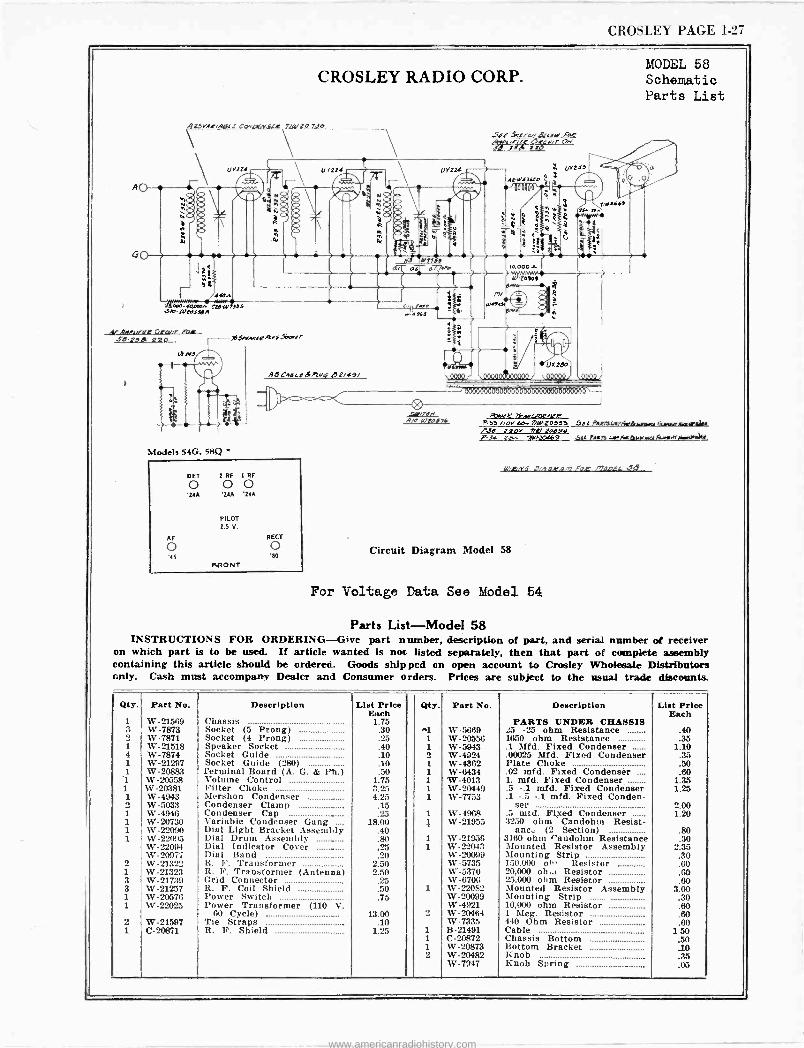
CROSLEY PAGE 1-27
AO
GO
CROSLEY RADIO CORP.
Z5YN,vA491 f CdLICKSLR !(1 D 9Jo
R '
1/Y224
¡ y /OOn
77000 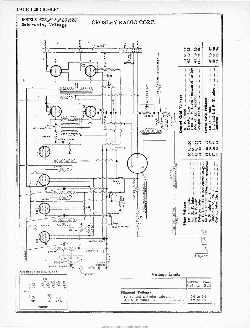
PAGE 1-28 CROSLEY
MODELS 60S,61S,62S,63S Schematic, Voltage
_ 30
: T
`^J
me" .03149i1
CROSLEY RADIO CORP.
/ 6612m V
W W ¢' m
0 00l 1
3 c3
e'er* rv
_,1 O
ION
I , II
BLS^' Ooo'051
L9E4M
0
i t
r rr,
-+ N
4
Cì6ßM V00009 0611,4
45L6M 03M100
N
41)
J19,129,9/9.2 4199M
4000
N
g L6L£62,3m9 M Q2
111111111 L6L9M 0QQ9
N
$$1LM r2
{ D ;
)-
1Lb9 M 03,11!1°'
11111111 Sß/L M 8964M a ;
I \ i , 0961 M \__ / / 2264M <
url 1 0I
'03100' ,?.>
J Ese. Voltage Limits
45L9M
Models 60-S, 6I -S, 62-S, 63-S
It49,+ oeN r'
WAVr- ILI M v9
I`
1264M V000'01
c>co
3
r
EVIL Al 691L M ó
1111111
W
M IU
22 O
.+ V1
N
A ya
BLOif)r1 CONN- +
1-1ó ó C- N CO CO O0
22.22 2222 OCOu7 V1 60NNr1 CO 0 W m CO N N CO
1 AF
2 AF - 7RF2RFIRF ; O O O O O O
'12A 'ZIA '7IA '22 '22 '22
j- DET
O O PILOT '12A '22 6.0 V.
5S.
l
Filament Voltages R. F. and Detector tubes All A. F. tubes
Volume Con- trol on Full
2.6 to 3.4 4.2 to 5.5
FRONT
www.americanradiohistory.com
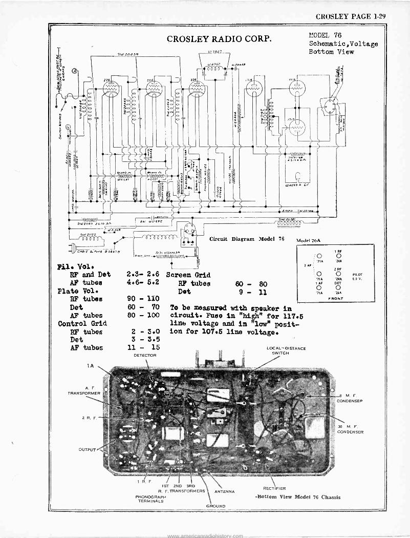
CROSLEY PAGE 1-29
Fil. Vol. RF and Det AF tubes
Flate Vol. RF tubes Det AF tubes
Control Grid
RF tubes Det AP tubes
MODEL 76 Schematic,Voltage Bottom View
j emro Ilmz0,1.
t6öoÖbto`
To be measured with speaker in circuit. Fuse in "high" for 117.5 lint, voltage and in "low" posit- ion for 107.5 line voltage.
IST 2ND 3RD R. F. TRANSFORMERS
PHONOGRAPH TERMINALS
www.americanradiohistory.com
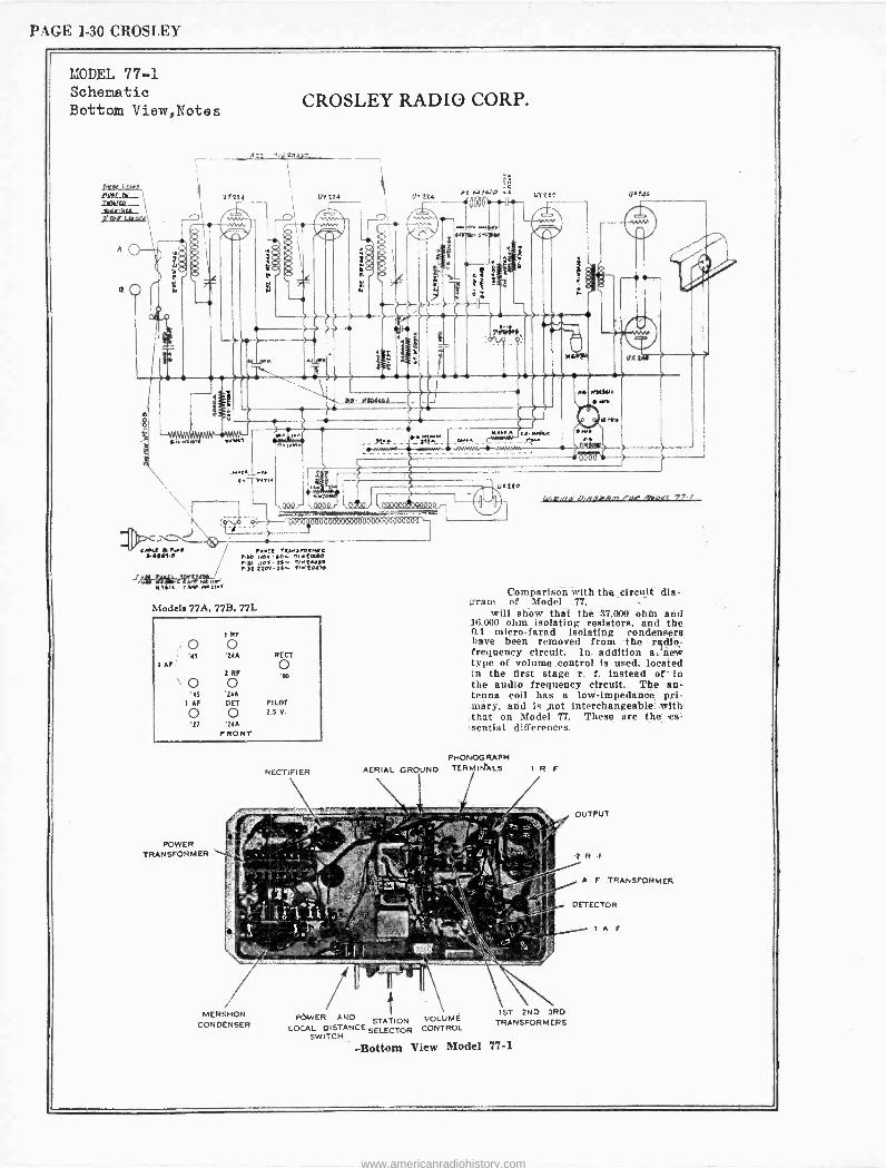
PAGE 1-30 CROSLEY
MODEL 77-1 Schematic Bottom View,Notes
Ltt+eu1 / rent Y4MarvenlL[ iN4-e nao ,IOY-f0.. lrtauo IY let-tt e/NtNN[ Iat it0-i .- ttofto
Klid JVY )ul[l tr_ , YM jttfÌtaM N[ite/
Models 77A, 77B, 77L
Comparison with the circuit dia- gram of Model 77,
will show that the 37,000 ohih and 111000 ohm isolating resistors, and the 0.1 micro -farad Isolating condensers have been removed from the radio -
frequency circuit. In. addition a.'new type of volume control is used. located in the first stage r. f. Instead of in the audio frequency circuit. The an- tenna coil has a low -impedance pri- mary, and is ,not interchangeable. with that on Model 77. These are the es- sential differences.
l('ïr POWER AND
1ST VOLUME STATION TRA
LOCAL DISTANCE SELECTOR CONTROL SWITCH
-Bottom View Model 77-1
www.americanradiohistory.com
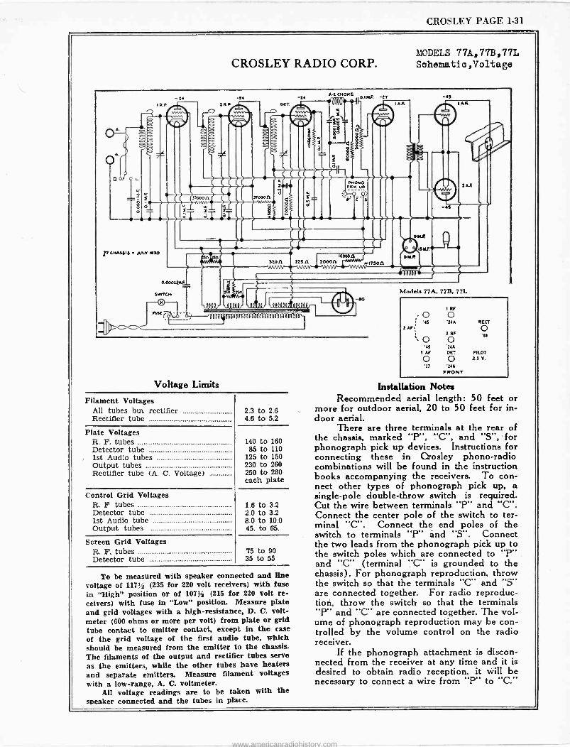
CROSLEY PAGE 1-31
MODELS 77A,7733,77L CROSLEY RADIO CORP. Schematic ,Voltage
A.
A
0.0
e
LL
T
I R. F.
1T CHASE 13 - JULY 430
-24
O. 000414.F
SlnrCn
01 Kr
32000a AFYWY
2 RR
U/
-24 DIET.
0.1
a
3 T000n ..eAfe
8
non
lul
t4
a
A.t CHOKE
225 A 2000n
C2
C
O.IIAF. -tT -45 IA.R
OKONO DICK Up
-4S
) ) )
/.1T50n
Voltage Limits
Filament Voltages All tubes but rectifier Rectifier tube
Plate Voltages R. F. tubes Detector tube
, 1st Audio tubes Output tubes Rectifier tube (A. C. Voltage)
Control Grid Voltages R. F tubes Detector tube 1st Audio tube Output tubes
Screen Grid Voltages R. F. tubes Detector tube
2.3 to 2.6 4.6 to 5.2
140 to 160 85 to 110
125 to 150 230 to 260 250 to 280 each plate
1.6 to 3.2 2.0 to 3.2 8.0 to 10.0 45. to 65.
75 to 90 35 to 55
To be measured with speaker connected and line voltage of 117Vó (235 for 220 volt receivers) with fuse in "High" position or of 1071A, (215 for 220 volt re- ceivers) with fuse in "Low" position. Measure plate and grid voltages with a high -resistance, D. C. volt- meter (600 ohms or more per volt) from plate or grid tube contact to emitter contact, except in the case of the grid voltage of the first audio tube, which should be measured from the emitter to the chassis. The filaments of the output and rectifier tubes serve as the emitters, while the other tubes have heaters and separate emitters. Measure filament voltages with a low -range, A. C. voltmeter.
All voltage readings are to be taken with the speaker connected and the tubes in place.
SKR
2AR
2AF
Models 77A, 77B, 77L
1 RF
, o o 2 AF
i 2 RF
` o o '15 *21A
i AF DE7 PILOT O 0 .2.5 Y.
27 21A FRONT
SECT
o .5.
Installation Notes Recommended aerial length: 50 feet or
more for outdoor aerial, 20 to 50 feet for in- door aerial.
There are three terminals at the rear of the chassis, marked "P", "C", and "S", ' for phonograph pick up devices. Instructions for connecting these in C,Qosley phono -radio combinations will be found in the instruction books accompanying the receivers. To con- nect other types of phonograph pick up, a single -pole double -throw switch is required. Cut the wire between terminals "P" and "C". Connect the center pole of the switch to ter- minal "C". Connect the end poles of the switch to terminals "P" and "S". Connect the two leads from the phonograph pick up to the switch poles which are connected to "P" and "C" (terminal "C' is grounded to the chassis). For phonograph reproduction, throw the switch so that the terminals "C" and "S" are connected together. For radio reproduc- tion, throw the switch so that the terminals "P" and "C" are connected together. The vol- ume of phonograph reproduction may be con- trolled by the volume control on the radio receiver.
If the phonograph attachment is discon- nected from the receiver at any time and it is desired to obtain radio reception, it will be necessary to connect a wire from "P" to "C."
www.americanradiohistory.com
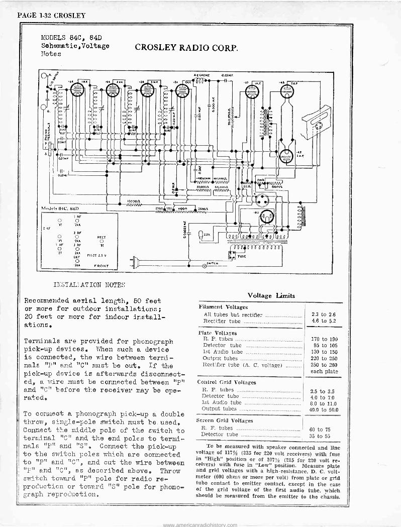
PAGE 1-32 CROSLEY
MODELS 84C, 84D Schematic,Voltage Notes
CROSLEY RADIO CORP.
Models 8442, 841)
2 AF
I RF o o 45 '21A
2 RF
o o IS '21A
1 AF 2 RF O o '27 '21A
DET
O 21A FRONT
REGT
o
PILOT 2.5 V
INSTALLATION NOTES
Recommended aerial length, 60 feet or more for outdoor installations; 20 feet or more for indoor install- ations.
Terminals are provided for phonograph pick-up devices. When such a device is connected, the wire between termi- nals "P" and "C" must be out. If the pick-up device is afterwards disconnect- ed, a wire must be connected between "P" and "C" before the receiver may be ope- rated.
To connect a phonograph pick-up a double throw, single -pole switch must be, used. Connect the middle pole of the switch to terminal "C" and the end poles to termi- nals "P" and "S". Connect the pick-up to the switch poles which are connected to "P" and "C", and cut the wire between "F" and "C", as described above. Throw switch toward "P" pole for radio re- production or toward "S" pole for phono- graph reproduction.
Voltage limits Filament Voltages
All tubes but rectifier Rectifier tube
Plate Voltages R. F. tubes Detector tube 1st Audio tube Output tubes Rectifier tube (A. C. voltage)
Control Grid Voltages R. F. tubes Detector tube 1st Audio tube Output tubes
Screen Grid Voltages R. F. tubes Detector tube
2.3 to 2.6 4.6 to 5.2
170 to 190 95 to 105
130 to 150 220 to 250 250 to 280 each plate
2.5 to 3.5 4.0 to 7.0 8.0 to 11.0 40.0 to 50.0
60 to 75 35 to 55
To be measured with speaker connected and line voltage of 1171/2 (235 for 220 volt receivers) with fuse in "High" position or of 1071/2 (215 for 220 volt re- ceivers) with fuse in "Low" position. Measure plate and grid voltages with a high -resistance, D. C. volt- meter (600 ohms or more per volt) from plate or grid tube contact to emitter contact, except in the case of the grid voltage of the first audio tube, which should be measured from the emitter to the chassis.
www.americanradiohistory.com
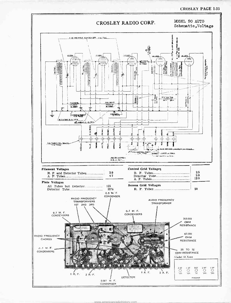
CROSLEY PAGE 1-33
CROSLEY RADIO CORP.
A\DVNitAßl.e CQNgéneRR 11WlaL 1
l,,. Mo.O
43.-Ma06e 0141M1$%
p ERh11tL IOwM
Filament Voltages R. F. and Detector Tubes A. F. Tubes
isn93 tAAPOD" a-,
MODEL 90 AUTO Schematic,Voltage
Control Grid Voltages 2.0 R. F. Tubes 4.7 Detector Tube
A. F. Tubes Plate Voltages
All Tubes but Detector 135 Detector Tube 221
CONDENSER RADIO FREQUENCY
TRANSFORMERS 1ST 2ND 3RD
0.1 M. F. CONDENSERS
RADIO FREQUENCY CHOKES
,D.1 M. F.
CONDENSERS
0.001 M. F.
CONDENSER
Screen Grid Voltages R. F. Tubes
0.1 M. F.
CONDENSERS
DETECTOR
AUDIO FREQUENCY TRANSFORMER
1 A.F. 2A.F.
2.5 3.0
12.0
300.000 / OHM RESISTANCE
6 0.000
OHM RESISTANCE
25 TO 32
OHM RESISTANCE
Model 90 Auto
2 AF 1 AF DET 2 RF 1 RF
'I2A '12A '27 .24A' '24A
FRONT
www.americanradiohistory.com
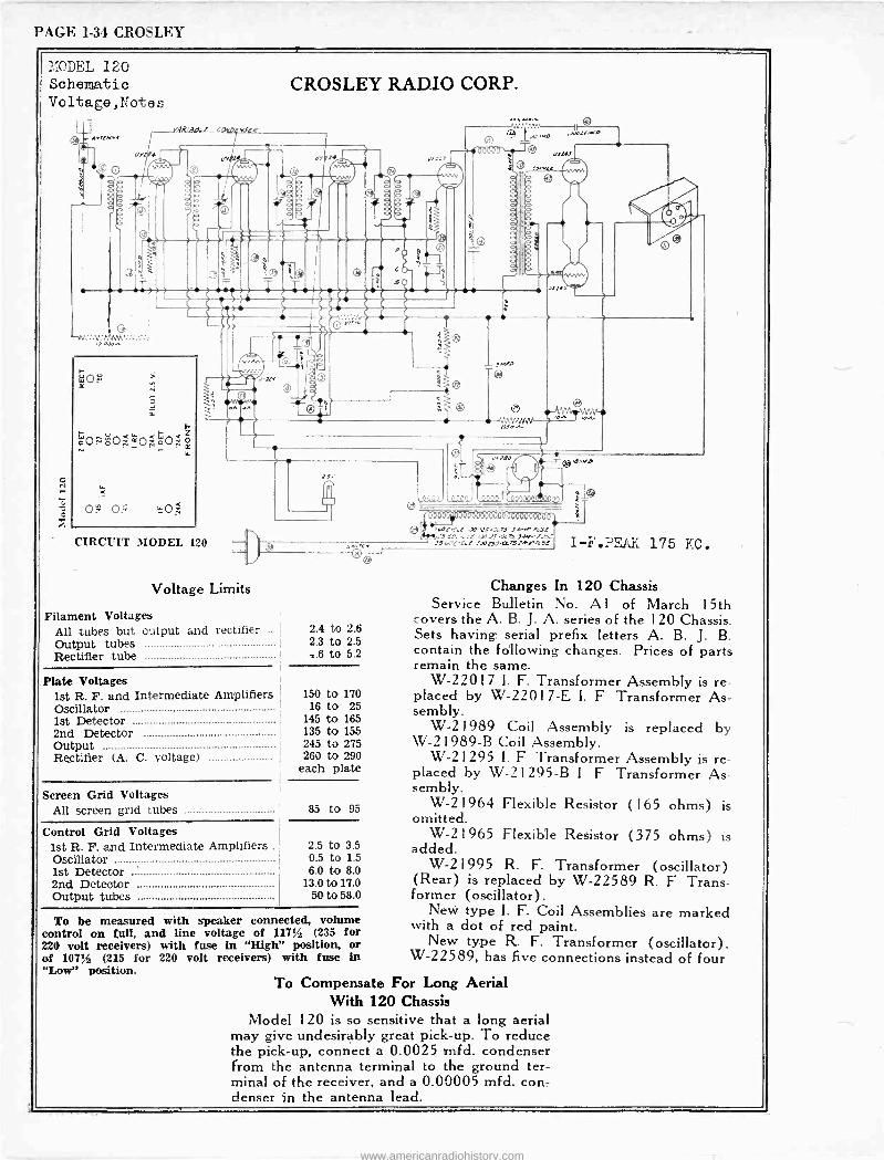
PAGE 1-34 CROSLEY T
MODEL 120 Schematic Voltage,tdote s
o
CROSLEY RADIO CORP.
raR.ar.f_scwo fiat -4'
Worn
CIRCUIT MODEL 120
rs.
Voltage Limits
Filament Voltages All tubes but output and Output tubes Rectifier tube
rectifier .. 2.4 to 2.6 2.3 to 2.5 .6 to 6.2
Plate Voltages 1st R. F. and Intermediate Amplifiers Oscillator 1st Detector 2nd Detector Output Rectifier (A. C. voltage)
Screen Grid Voltages All screen grid tubes
Control Grid Voltages 1st R. F. and Intermediate Amplifiers Oscillator 1st Detector 2nd Detector Output tubes
150 to 170 16 to 25
145 to 165 135 to 155 245 to 275 260 to 290
each plate
85 to 95
2.5 to 3.5 0.5 to 1.5 6.0 to 8.0
13.0 to 17.0 50 to 58.0
To be measured with speaker connected, volume control on full, and line voltage of 117% (235 for 220 volt receivers) with fuse in "High" position, or of 1071A (215 for 220 volt receivers) with fuse in "Low" position.
0000)
000.0ees OP. Vrrr 000000000 0: IC.C.f.AO. /ZS ro.n 3.o.H0 we
z3JOl.C.f x.:JR!)tMlJyofJL zSrIC.C.! l01JISOKL 31+Y JG I-F'.PF.AK 175 KC.
Changes In 120 Chassis Service Bulletin No. Al of March 15th
covers the A. B. J. A. series of the 120 Chassis. Sets having, serial prefix letters A. B. J. B. contain the following changes. Prices of parts remain the same.
W-2201 7 1. F. Transformer Assembly is re- placed by W-2201 7-E I. F Transformer As- sembly.
W-21989 Coil Assembly is replaced by W -21989-B Coil Assembly.
W-21295 I. F Transformer Assembly is re- placed by W -21295-B 1 F Transformer As- sembly.
W-2 1964 Flexible Resistor (165 ohms) is omitted.
W-21965 Flexible Resistor (375 ohms) is added.
W-21995 R. F. Transformer (oscillator) (Rear) is replaced by W-22589 R. F Trans- former (oscillator).
New type I. F. Coil Assemblies are marked with a dot of red paint.
New type R. F. Transformer (oscillator), W-22589, has five connections instead of four
To Compensate For Long Aerial With 120 Chassis
Model 120 is so sensitive that a long aerial may give undesirably great pick-up. To reduce the pick-up, connect a 0.0025 nnfd. condenser from the antenna terminal to the ground ter- minal of the receiver, and a 0.00005 mfd. con- denser in the antenna lead.
www.americanradiohistory.com
Related Documents