ORIGINAL ARTICLE Trochoidal milling: investigation of a new approach on uncut chip thickness modeling and cutting force simulation in an alternative path planning strategy Farbod Akhavan Niaki 1 & Abram Pleta 1 & Laine Mears 1 Received: 6 January 2018 /Accepted: 28 March 2018 # Springer-Verlag London Ltd., part of Springer Nature 2018 Abstract Trochoidal milling is an alternative tool path strategy which has been shown to increase productivity, improve tooling life, and reduce resultant cutting forces. While the advantages of trochoidal milling over conventional slot or shoulder milling were previously reported, the complexity of trochoid tool path makes developing an analytical force model highly complicated. In this work, a numerical algorithm to construct the uncut chip thickness model in trochoidal milling is introduced, which is based on the geometrical relation of self-intersection and cross-intersection points of the tool path curve. In addition, an extensive series of experiments is carried out in slot and trochoidal-milling operations in order to investigate the dependency of cutting pressure coefficients on tool path parameters and to develop a model to relate the two. Furthermore, the performance of the developed model for uncut chip thickness and the cutting pressure coefficients are evaluated in predicting cutting forces; it is shown that the model predicts the maximum cutting force in the feed direction and between all the testing sets with 8% total average error, while 17% total average error is observed in predicting maximum cutting force in the lateral direction. This demonstrates the potential of the proposed approach in offline simulation of the cutting forces which is a critical step in selecting proper tooling and process parameters to increase productivity of the cut. Keywords Trochoidal milling . Slot milling . Uncut chip thickness . Force modeling . Alternative tool path 1 Introduction Increasing productivity while preserving quality is a key factor in defining the profitability of any manufacturing processes. In past decades, particularly in the metal cutting domain, several approaches have been tested to minimize the loss and increase productivity rate [1]. High-speed ma- chining to increase material removal rate [2], model-based methods of controlling machine parameters to decrease idle time [3, 4], feed rate scheduling to optimize cycle time [5], and process condition monitoring to avoid unsched- uled downtime [6] are few examples targeting profitability in machining processes. Recently, with the rapid growth in advanced CAM software that facilitates CNC program- ming for complex structures, alternative path planning strategies have gained significant momentum within aero- space and energy industries. Trochoidal milling is one such alternative path plan that takes advantage of the superpo- sition of linear and circular revolution of the tool as a material removal strategy. The need for alternative tool path strategies such as tro- choidal milling has been emphasized by the aerospace and energy sectors where extensive use of difficult-to-machine materials such as titanium- or nickel-based alloys is essen- tial. The high strength and poor machinability of these alloys have a significant impact on tooling life and directly influence the quality of the machined part. While the tra- ditional method of reducing machine feed, depth of cut, or replacing the tool in the earlier stages of its life seems intuitive, these approaches adversely affect productivity and increase the machine downtime. Hence, alternative * Farbod Akhavan Niaki [email protected] Abram Pleta [email protected] Laine Mears [email protected] 1 International Center for Automotive Research, Clemson University, Greenville, SC 29607, USA The International Journal of Advanced Manufacturing Technology https://doi.org/10.1007/s00170-018-1967-0

Welcome message from author
This document is posted to help you gain knowledge. Please leave a comment to let me know what you think about it! Share it to your friends and learn new things together.
Transcript

ORIGINAL ARTICLE
Trochoidal milling: investigation of a new approach on uncut chipthickness modeling and cutting force simulation in an alternative pathplanning strategy
Farbod Akhavan Niaki1 & Abram Pleta1 & Laine Mears1
Received: 6 January 2018 /Accepted: 28 March 2018# Springer-Verlag London Ltd., part of Springer Nature 2018
AbstractTrochoidal milling is an alternative tool path strategy which has been shown to increase productivity, improve tooling life, andreduce resultant cutting forces. While the advantages of trochoidal milling over conventional slot or shoulder milling werepreviously reported, the complexity of trochoid tool path makes developing an analytical force model highly complicated. Inthis work, a numerical algorithm to construct the uncut chip thickness model in trochoidal milling is introduced, which is basedon the geometrical relation of self-intersection and cross-intersection points of the tool path curve. In addition, an extensive seriesof experiments is carried out in slot and trochoidal-milling operations in order to investigate the dependency of cutting pressurecoefficients on tool path parameters and to develop a model to relate the two. Furthermore, the performance of the developedmodel for uncut chip thickness and the cutting pressure coefficients are evaluated in predicting cutting forces; it is shown that themodel predicts the maximum cutting force in the feed direction and between all the testing sets with 8% total average error, while17% total average error is observed in predicting maximum cutting force in the lateral direction. This demonstrates the potentialof the proposed approach in offline simulation of the cutting forces which is a critical step in selecting proper tooling and processparameters to increase productivity of the cut.
Keywords Trochoidal milling . Slot milling . Uncut chip thickness . Force modeling . Alternative tool path
1 Introduction
Increasing productivity while preserving quality is a keyfactor in defining the profitability of any manufacturingprocesses. In past decades, particularly in the metal cuttingdomain, several approaches have been tested to minimizethe loss and increase productivity rate [1]. High-speed ma-chining to increase material removal rate [2], model-basedmethods of controlling machine parameters to decreaseidle time [3, 4], feed rate scheduling to optimize cycle time
[5], and process condition monitoring to avoid unsched-uled downtime [6] are few examples targeting profitabilityin machining processes. Recently, with the rapid growth inadvanced CAM software that facilitates CNC program-ming for complex structures, alternative path planningstrategies have gained significant momentum within aero-space and energy industries. Trochoidal milling is one suchalternative path plan that takes advantage of the superpo-sition of linear and circular revolution of the tool as amaterial removal strategy.
The need for alternative tool path strategies such as tro-choidal milling has been emphasized by the aerospace andenergy sectors where extensive use of difficult-to-machinematerials such as titanium- or nickel-based alloys is essen-tial. The high strength and poor machinability of thesealloys have a significant impact on tooling life and directlyinfluence the quality of the machined part. While the tra-ditional method of reducing machine feed, depth of cut, orreplacing the tool in the earlier stages of its life seemsintuitive, these approaches adversely affect productivityand increase the machine downtime. Hence, alternative
* Farbod Akhavan [email protected]
Abram [email protected]
Laine [email protected]
1 International Center for Automotive Research, Clemson University,Greenville, SC 29607, USA
The International Journal of Advanced Manufacturing Technologyhttps://doi.org/10.1007/s00170-018-1967-0

tool path strategies that increase robustness and extend toollife at more aggressive cutting conditions, such as trochoi-dal milling, allow for higher depth of cut or feed rates inorder to increase the productivity without sacrificing toollife or workpiece quality. Pleta et al. studied the perfor-mance of trochoidal milling in comparison to end millingin cutting IN738 nickel-based superalloys [7, 8]. In thesestudies, the resultant cutting force, tool wear, and surfaceroughness generated by trochoidal tool paths were com-pared to end-milling paths. Two metrics were introducedto compare the performance of trochoidal and end-millingcutting strategies: material removal per wear (representsproductivity) and material removal rate per wear (repre-sents efficiency). Uhlmann et al. studied the effect of tro-choidal milling on energy consumption and material re-moval rate in cutting Ti-6Al-4V alloy [9]. They concludedthat with 6% increase in effective power consumption,35% reduction in process time can be achieved usingtrochoidal-milling approach. Rauch et al. studied two as-pects of trochoidal milling: implementation on the CNCmachine and parameter selection to improve tool life[10]. In [11], the performance of trochoidal milling interms of cutting force and tool wear was investigated inmilling mold cavities. In another effort by Szaloki et al.,resultant force, surface roughness, and micro-geometricalerror were studied, and empirical relations were developedfor each parameter [12]. A modified tool path termed theepicycloid path inspired from the trochoidal path was in-troduced in [13], and machining force, vibration, and cycletime were experimentally compared to trochoidal-millingtool path. The authors in [13] concluded that epicycloidalmilling can increase the cycle time by 20% while higherforce and vibration adversely affect tool life.
Many articles published on this topic are mainly fo-cused on the advantages of trochoidal milling over tradi-tional milling strategies (e.g., slot or pocket) in terms ofcycle time, resultant force, and tooling life. While estab-lishing the benefits of alternative tool path plans is essen-tial to justify the potentials of trochoidal milling to replacethe traditional methods, a comprehensive study is not yetavailable on the mechanics and dynamics of trochoidalmilling. To the best of the authors’ knowledge, there arecurrently only two articles addressing the mechanics oftrochoidal milling. Otkur and Lazoglu published the firstarticle on chip thickness modeling and force simulation introchoidal milling [14]. In their work, they introduced aclosed form uncut chip thickness formulation based on thegeometry of the cut and further simulated the cutting forcein X and Y directions in trochoidal and double trochoidalmilling (where the circular downward revolution of thetool is followed by an upward revolution). In the secondarticle published by Kardes and Altintas, the trochoidaltool path was introduced with an alternative name,
circular milling [15], and the same approach of [14] wastaken to model the uncut chip thickness. In addition, thedynamic stability of the trochoidal milling was investigat-ed with frequency domain and time finite element analysisand the differences of the two approaches in predictingthe critical depth of cut to avoid chatter were highlighted.
Two major shortcomings exist in the methods describedin [14, 15]. First, in both articles, it was assumed the outermargin generated by the trochoidal tool path can be ap-proximated by a circular curve; it will be discussed laterin this article that the departure from this circular assump-tion can introduce significant error. Second, to simulate thecutting forces, both articles relied upon on the pre-existingvalues for tangential and radial cutting pressure coeffi-cients extracted from slot-milling experiments. However,there are essential differences in the mechanics of cuttingand chip generation between slot and trochoidal millingwhich will be highlighted in detail in this work. Based onthese shortcomings, the objective of this paper is defined as(1) introducing a new geometrical and generalized ap-proach based on constructing the chip area through inter-section points of the trochoid tool path without the assump-tion of circular outer margin; (2) investigating the effect oftrochoidal tool path and process parameters on cuttingpressure coefficients and highlighting the differences withtraditional milling strategy (i.e., slot milling); and (3) eval-uating the performance of the proposed modeling frame-work in predicting cutting forces during trochoidal milling.The organization of this work is as follows: the geometricalapproach will be introduced in Section 2 for single-toothand multi-tooth tools. In Section 3, the mechanistic forcemodel is given. The experimental setup and design of ex-periment are discussed in Section 4. The identification ofcutting pressure coefficients in trochoidal and slot-millingtests and dependency on tool path parameters are given inSection 5. In Section 6, the simulated force under differentcutting conditions is compared with experimentally mea-sured forces, and corresponding error is quantified; this isfollowed by conclusions and future direction discussion inSection 7.
2 Geometric approach for uncut chipthickness modeling in trochoidal tool path
2.1 Mathematical representation of trochoidal toolpath
The trochoidal tool path can be characterized with threeparameters: (1) rotational rate (θ̇ ), which represents therotational speed of the tool holder in RPM and clockwisedirection; (2) nutational rate (ϕ̇ ), which represents therevolutionary (or planetary) motion of the tool center in
Int J Adv Manuf Technol

rad/s and counterclockwise direction; and (3) step-overfeed rate (ν) in unit of mm/s and in Y direction whichrepresents the linear motion of the tool center. The com-bination of these three parameters shown in Eqs. (1) and(2) produces a trochoidal tool path, where, Rcp is radius ofthe tool center in mm, Rt is cutting tool radius in mm, t istime in second, and [Xt Yt]
T is the global coordinate of thecutter tip in the X–Y plane. Note that in mathematical society,the curve generated from Eqs. (1) and (2) is known asepitrochoidal curve [16]; however, in manufacturing society,it is widely known as trochoidal curve (a term used in the restof this paper).
The geometrical representation of trochoidal tool path isgiven in Fig. 1a. Unlike the general belief that the trochoi-dal tool path generates an approximately circular outermargin (termed outer lobe, in the rest of this article), theexistence of step-over feed rate (ν) in Eq. (2) generates askewed outer lobe. As shown in Fig. 1b, with advancementof the tool in the + Y direction, a larger deviation is pro-duced between the trochoidal outer lobe and circular pathassumption. By increasing θ̇ and decreasing ϕ̇, continuityand smoothness of the outer lobe will be improved.However, the assumption of a purely circular outer lobe
still remains invalid except in the case of very small step-over feed rates.
X t ¼ Rcpcos ϕ˙ t� � þ Rtcos −
2π60
θ˙ t� �
ð1Þ
Y t ¼ Rcpsin ϕ˙ t� � þ Rtsin −
2π60
θ˙ t� �
þ vt ð2Þ
Unlike traditional milling (e.g., shoulder or slot milling),where the geometry of each chip remains consistent through-out the cut, in trochoidal milling, each chip’s geometry isdifferent from every other due to combination of nutation(planetary motion) and step-over feed rates (linear motion).In addition, due to the mathematical complexity of Eqs. (1)and (2), a closed form solution for describing chip geometry isnot available. However, as shown in Fig. 2, where the toolpath for two consecutive nutations is shown, it is possible torepresent chip geometry if the coordinates of the intersectionpoints of the tool path curve are known. In Fig. 2, the firstnutation path is named previous path and the second nutationis named current path (which represents the current coordi-nate of the cutter). Knowing the self-intersecting and cross-
Fig. 1 Trochoidal tool path for single-flute cutter; a geometrical representation with tool rotation rate (θ̇) and nutation rate (ϕ̇), and b deviation betweentrochoidal and circular tool paths
Int J Adv Manuf Technol
intersecting points of the current and previous paths given inFig. 2b, the chip geometry can be constructed.
2.2 Numerical algorithm for identificationof intersection points
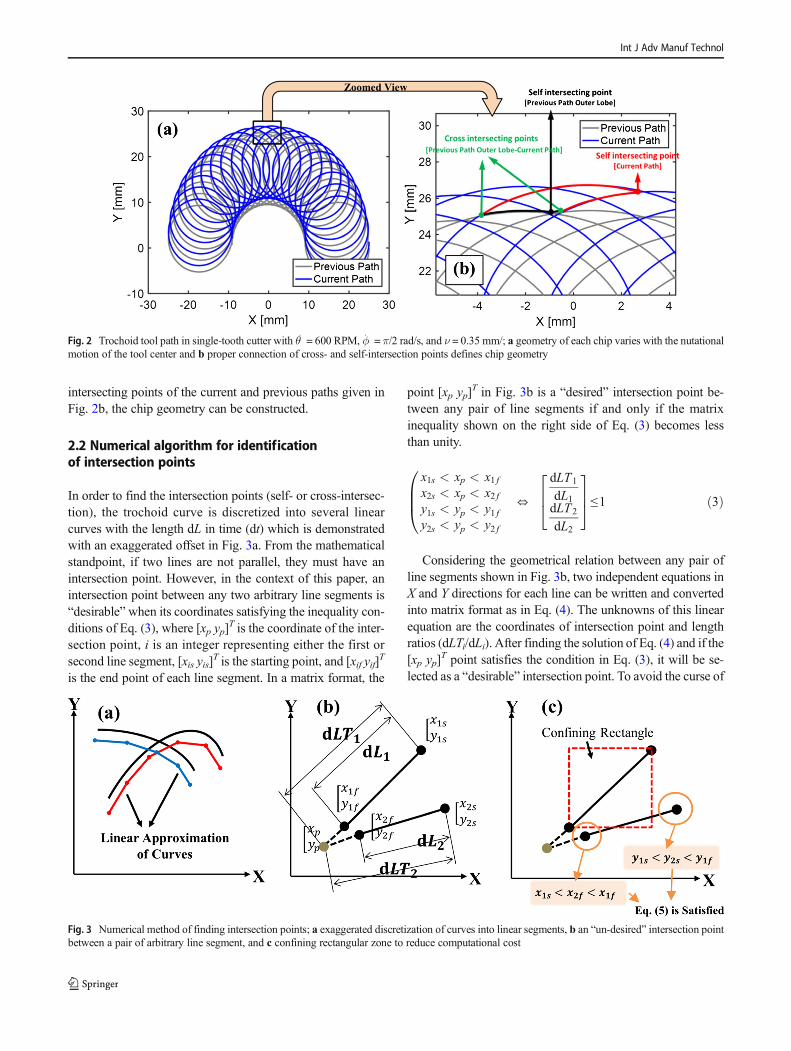
In order to find the intersection points (self- or cross-intersec-tion), the trochoid curve is discretized into several linearcurves with the length dL in time (dt) which is demonstratedwith an exaggerated offset in Fig. 3a. From the mathematicalstandpoint, if two lines are not parallel, they must have anintersection point. However, in the context of this paper, anintersection point between any two arbitrary line segments is“desirable”when its coordinates satisfying the inequality con-ditions of Eq. (3), where [xp yp]
T is the coordinate of the inter-section point, i is an integer representing either the first orsecond line segment, [xis yis]
T is the starting point, and [xif yif]T
is the end point of each line segment. In a matrix format, the
point [xp yp]T in Fig. 3b is a “desired” intersection point be-
tween any pair of line segments if and only if the matrixinequality shown on the right side of Eq. (3) becomes lessthan unity.
x1s < xp < x1 fx2s < xp < x2 fy1s < yp < y1 fy2s < yp < y2 f
0BB@ ⇔
dLT1
dL1dLT2
dL2
264
375≤1 ð3Þ
Considering the geometrical relation between any pair ofline segments shown in Fig. 3b, two independent equations inX and Y directions for each line can be written and convertedinto matrix format as in Eq. (4). The unknowns of this linearequation are the coordinates of intersection point and lengthratios (dLTi/dLi). After finding the solution of Eq. (4) and if the[xp yp]
T point satisfies the condition in Eq. (3), it will be se-lected as a “desirable” intersection point. To avoid the curse of
Fig. 2 Trochoid tool path in single-tooth cutter with θ̇ = 600 RPM, ϕ̇ = π/2 rad/s, and ν = 0.35 mm/; a geometry of each chip varies with the nutationalmotion of the tool center and b proper connection of cross- and self-intersection points defines chip geometry
Fig. 3 Numerical method of finding intersection points; a exaggerated discretization of curves into linear segments, b an “un-desired” intersection pointbetween a pair of arbitrary line segment, and c confining rectangular zone to reduce computational cost
Int J Adv Manuf Technol

dimensionality and improve the performance of this bruteforce algorithm, only the lines that satisfy the condition inEq. (5) will be selected. This inequality is equivalent to draw-ing a confining rectangular zone around a selected line seg-ment and check to see if the start and end points of the otherline belong to this zone or not (see Fig. 3c).
dLT1
dL1x1s−x1 f� � ¼ x1s−xp
� �dLT1
dL1y1s−y1 f
� �¼ y1s−yp
� �dLT2
dL2x2s−x2 f� � ¼ x2s−xp
� �dLT2
dL2y2s−y2 f
� �¼ y2s−yp
� �→
dLT1
dL1dLT2
dL2xpyp
2666664
3777775
¼x1s−x1 f 0 1 0y1s−y1 f 0 0 1
0 x2s−x2 f 1 00 y2s−y2 f 0 1
2664
3775−1 x1s
y1 fx2sy2 f
2664
3775 ð4Þ
x1s < x2s < x1 for
x1s < x2 f < x1 f
8<: and
y1s < y2s < y1 for
y1s < y2 f < y1 f
8<: ð5Þ
2.3 Chip geometry construction from intersectionpoints
Assuming a single-point cutter, the first step after findingall the intersection points is to construct the outer loberegion generated from self-intersecting points of the previ-ous tool path. Equation (6) is used to generate a push curveencompassing the outer lobe of the previous pass, where[Xc Yc]
T is the coordinate of the push curve. The self-intersecting points with the minimum distance to the pushcurve are selected and properly connected to construct theouter lobewhich is shown in Fig. 4. Note that, due to existenceof the term vt in Eq. (6), the push curve does not represent a
circular curve but it is rather a skewed circular curve in feeddirection.
X c ¼ Rcp þ Rt� �
cos ϕ˙ t� �
Yc ¼ Rcp þ Rt� �
Rcpsin ϕ˙ t� � þ vt
ð6Þ
The second step is to use the intersection algorithm to findthe cross-intersection points between the current path and theouter lobe. Here, the cross-intersection points are criticallyimportant since the chip geometry begins with these points(see the selected points in Fig. 2b). The third step is similarto the first step, but instead, it will be conducted to find theself-intersecting points of the current path. At this stage, all thecorner points of a chip are identified, and the geometry can beconstructed by proper connection of these points.
Considering from Fig. 5a, any chip geometry (e.g., chipnumber {N}) can be defined by three regions:
(1) Region 1 (R Nf g1 ), which is defined based on marching
from point A Nf g1 (cross-intersection point between the
outer lobe and the current path) to the point A Nf g22 (second
self-intersection point on the outer lobe of current path).(2) Region 2 (R Nf g
2 ), which is a partial region of R N−1f g1 ,
generated by the previous chip {N-1}, and is defined
based onmarching from pointA N−1f g1 to the point A N−1f g
2 .(3) Region 3 (R Nf g
3 ), which is defined based on marching
from point A Nf g1 to the point A N−1f g
1 on the outer lobe ofthe previous path.
Note that the points A Nf g22 and A N−1f g
2 have in fact the same
coordinates. For chip {N}, A Nf g22 is the second self-intersection
point (the first is denoted as A Nf g2 ) that defines R Nf g
1 , while
A N−1f g2 is the first self-intersection point of chip {N− 1} used
to define R Nf g2 . Following this algorithm, the exact geometry
of each chip can be constructed properly for single-tooth
Fig. 4 Constructing the outer lobe from previous tool path, a self-intersecting point identification, b selecting points closest to the push curve, and cconnecting points to construct outer lobe
Int J Adv Manuf Technol

cutters, and the thickness profile quantified. As demonstratedin Fig. 5b, uncut chip thickness is the perpendicular distanceof the points on R2 and R3 regions to the R1 region. Theassociated time for each chip is defined as the time the cutter
enters the chip through point A Nf g1 (start of the cut) with θ Nf g
sentering angle until the time the cutter exists within the
chip from point A Nf g22 with θ Nf g
e exiting angle. The identi-fied uncut chip area and the corresponding uncut chipthickness evolution in time are depicted in Fig. 5c–d for asingle-cutter tool.
2.4 Uncut chip thickness modeling of multi-toothand variable spacing tools
Without loss of generality, the method described inSection 2.3 can be extended to tools with multi- and/orvariable spacing cutters. The main difference of these with
the single-tooth scenario is that in the trochoidal path ofmulti-cutter tools, the outer lobe of the previous path isnot constructed through self-intersecting points. Since themotion of the first cutter is followed by the second cutterand so on, to construct the outer lobe, only cross-intersecting points are required to be identified betweeneach of the cutter paths. To better clarify this, the trochoidpath equation for a tool with three teeth and equal spacingis given in Eqs. (7) and (8), where parameter δ representsthe angular location of the cutter. As depicted in Fig. 6a,the outer lobe is constructed by connection of cross-intersecting points of each cutter path. To produce thechip geometry, the rotational direction of the tool playsan important role. As shown in Fig. 6b, with clockwiserotation of the tool, the R2 region of the first cutting edgeis generated based on the path of third cutting edge, theR2 region of the second cutting edge is generated based onthe path of the first cutting edge, and the R2 region of the
Fig. 5 Chip geometryconstruction in trochoidal milling;a identification of regions ofinterest, b uncut chip thicknesscalculation, c uncut chip areaconstruction, and d uncut chipthickness evolution with respectto time
Fig. 6 Trochoidal tooth path inthree-cutter tool with θ̇ =600 RPM, ϕ̇ = π/2 rad/s, and ν =0.35 mm/s. a Outer lobe is thecombination of cross-intersecting
points of each cutter, and b R Nf g2
of chip geometry for the firstcutting edge is generated from thethird cutting-edge path
Int J Adv Manuf Technol

third cutting edge is generated based on the path of thesecond cutting edge. To construct the chip geometry, thesame procedure as described in Section 2.3 should befollowed.
X t ¼ Rcpcos ϕ˙ t� �
þ Rtcos −2π
60θ˙ t − δ
� �where δ∈ 0;
2π
3;
4π
3
�
ð7Þ
Y t ¼ Rcp sin ϕ˙ t� �þ Rtsin −
2π60
θ˙ t−δ� �
þ vt where δ∈ 0;2π3;4π3
� ð8Þ
3 Cutting force calculation in trochoidalmilling
Using the uncut chip thickness modeling method de-scribed in Section 2.2, the uncut chip area at any timecan be calculated based on the product of uncut chipthickness, denoted as h(t), and axial depth of cut denotedas b in Eq. (9). Here, the function g(t) is “1” when thecutter is engaged in the cut and “0” in no-cut regions(see Eq. (10)). The semi-mechanistic cutting force modelin the tangential and radial directions is taken from [17]and is given in Eq. (11), where Kt and Kr are tangentialand radial cutting pressures, and Kte and Kre are edgecoefficients representing the sliding frictional force dueto tool wear. Having access to the instantaneous cutterangle θ{N}, the cutting forces from local coordinates areconverted to cutting forces in X–Y global coordinateswith the rotation matrix R in Eq. (12). The local andglobal coordinates and angle of rotation for an arbitrarychip are shown in Fig. 7. Note that the positive directionof the forces in X–Y coordinates is imposed by the pos-itive direction of the dynamometer.
A Nf g tð Þ ¼ bh Nf g tð Þg Nf g tð Þ ð9Þ
g Nf g tð Þ ¼ 1 when t Nf gs < t < t Nf g
e
0 when t < t Nf gs ; t > t Nf g
e
�ð10Þ
FT ¼ Ktbh Nf g tð Þg Nf g tð Þ þ KtebFR ¼ Krbh Nf g tð Þg Nf g tð Þ þ Kreb
ð11Þ
FX FY½ �T ¼−sin θ Nf g
� �−cos θ Nf g
� �−cos θ Nf g
� �sin θ Nf g
� �24
35 FT FR½ �T
ð12Þ
4 Experimental setup
The physical testing was performed on an Okuma MU-5000 V machine using a Kistler 9257B piezoelectric dyna-mometer with a sampling frequency of 2 kHz. As stated inSection 1, one of the objectives of this work is to investigatethe dependency of the cutting pressure coefficients on the toolpath. In other words, we are seeking the possibility to use slotor shoulder-milling tests to identify these coefficients and usethem in trochoidal milling in order to predict forces. To answerthis question, a comprehensive testing strategy was designedto compare slot milling (with full radial engagement) and tro-choidal milling. To preserve the stability of the cut, it wasdecided to use a two-flute indexable end mill for each slot-milling experiment.
The trochoidal-milling tests for identification of cuttingpressure coefficients were conducted with a single-fluteindexable end mill, while the tests designed for validatingthe accuracy of the uncut chip thickness model in predictingcutting forces were conducted with the same two-flute toolused in slot-milling tests. All of the experiments were carriedout with sharp (unused) Sandvik Coromill R390-11T308M-PM-1030 carbide insert with multilayer TiAlN coating andaxial depth of cut of 0.5 mm. The tooling utilized had a leadangle of 90°, an axial rake angle of 12.4°, and a radial rakeangle of 2.5°. To ensure the repeatability of the tests, all theexperiments were repeated three times.
While the capability of trochoidal milling is best put to usein cutting hard-to-machine materials such titanium- or nickel-based alloys, the excessive wear generation during machiningthese materials hinders validation of the proposed uncut chipthickness modeling strategy. Hence, it was decided to performall the testing on 7075-T6 aluminum to eliminate any toolwear effects on the results. Due to the minimal wear, thecutting-edge coefficients, Kte and Kre, in Eq. (11) are set equalto zero. As shown in Eqs. (1) and (2), the trochoidal tool pathis defined with three parameters: θ̇, ϕ̇, and ν. The parameter θ̇is understood by the CNC machine as rotational speed;
Fig. 7 Positive orientation of the cutting forces in in X–Y coordinates andangle of rotation θ{N}
Int J Adv Manuf Technol
however, parameters ϕ̇ and ν should be converted to machinefeed rate (fr) in mm/min in order to make G-code program-ming possible. The conversion is carried out by dividing thetool center travel (directly affected by parameters ϕ̇ and ν—see black curve in Fig. 1) to the time of travel. In this way,machine feed rate (fr) and feed per tooth ( f ) can be calculatedfor the trochoid tool path.
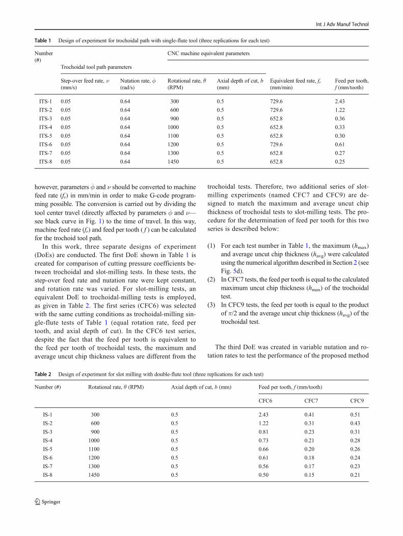
In this work, three separate designs of experiment(DoEs) are conducted. The first DoE shown in Table 1 iscreated for comparison of cutting pressure coefficients be-tween trochoidal and slot-milling tests. In these tests, thestep-over feed rate and nutation rate were kept constant,and rotation rate was varied. For slot-milling tests, anequivalent DoE to trochoidal-milling tests is employed,as given in Table 2. The first series (CFC6) was selectedwith the same cutting conditions as trochoidal-milling sin-gle-flute tests of Table 1 (equal rotation rate, feed pertooth, and axial depth of cut). In the CFC6 test series,despite the fact that the feed per tooth is equivalent tothe feed per tooth of trochoidal tests, the maximum andaverage uncut chip thickness values are different from the
trochoidal tests. Therefore, two additional series of slot-milling experiments (named CFC7 and CFC9) are de-signed to match the maximum and average uncut chipthickness of trochoidal tests to slot-milling tests. The pro-cedure for the determination of feed per tooth for this twoseries is described below:
(1) For each test number in Table 1, the maximum (hmax)and average uncut chip thickness (havg) were calculatedusing the numerical algorithm described in Section 2 (seeFig. 5d).
(2) In CFC7 tests, the feed per tooth is equal to the calculatedmaximum uncut chip thickness (hmax) of the trochoidaltest.
(3) In CFC9 tests, the feed per tooth is equal to the productof π/2 and the average uncut chip thickness (havg) of thetrochoidal test.
The third DoE was created in variable nutation and ro-tation rates to test the performance of the proposed method
Table 1 Design of experiment for trochoidal path with single-flute tool (three replications for each test)
Number(#)
CNC machine equivalent parameters
Trochoidal tool path parameters
Step-over feed rate, ν(mm/s)
Nutation rate, ϕ̇(rad/s)
Rotational rate, θ̇(RPM)
Axial depth of cut, b(mm)
Equivalent feed rate, fr(mm/min)
Feed per tooth,f (mm/tooth)
ITS-1 0.05 0.64 300 0.5 729.6 2.43
ITS-2 0.05 0.64 600 0.5 729.6 1.22
ITS-3 0.05 0.64 900 0.5 652.8 0.36
ITS-4 0.05 0.64 1000 0.5 652.8 0.33
ITS-5 0.05 0.64 1100 0.5 652.8 0.30
ITS-6 0.05 0.64 1200 0.5 729.6 0.61
ITS-7 0.05 0.64 1300 0.5 652.8 0.27
ITS-8 0.05 0.64 1450 0.5 652.8 0.25
Table 2 Design of experiment for slot milling with double-flute tool (three replications for each test)
Number (#) Rotational rate, θ̇ (RPM) Axial depth of cut, b (mm) Feed per tooth, f (mm/tooth)
CFC6 CFC7 CFC9
IS-1 300 0.5 2.43 0.41 0.51
IS-2 600 0.5 1.22 0.31 0.43
IS-3 900 0.5 0.81 0.23 0.31
IS-4 1000 0.5 0.73 0.21 0.28
IS-5 1100 0.5 0.66 0.20 0.26
IS-6 1200 0.5 0.61 0.18 0.24
IS-7 1300 0.5 0.56 0.17 0.23
IS-8 1450 0.5 0.50 0.15 0.21
Int J Adv Manuf Technol

of uncut chip thickness calculation in predicting forces. Asshown in Table 3, using the tests in the training set, a linearregression model between the identified cutting force co-efficients (Kt and Kr) and trochoidal parameters (ϕ̇ and θ̇ )will be developed. Later, the regression model will be usedin the testing set to find cutting pressure coefficients andcutting forces will be simulated using the method de-scribed in Sections 2 and 3. Note that all the experimentsin the testing set were conducted with a two-flute toolusing the rotational rates not used in developing the regres-sion model from the training set.
5 Identification of cutting pressurecoefficients
The objective of this section is to investigate if cuttingpressure coefficients extracted from the slot milling can
be used interchangeably for predicting forces in trochoidalmilling. The experiments used here are from Table 1 andTable 2, namely tests ITS-1–8 and tests IS-1–8. The cut-ting pressure coefficients Kt and Kr can be found by usingEq. (12) to convert measured cutting forces in the X and Ydirections into tangential and radial directions and thendividing FT and FR by the chip area (again, Kte and Kre
are considered zero as described in Section 4). An exam-ple of the measured cutting forces and simulated uncutchip thickness is shown in Fig. 8 for test ITS-1, wherecutting pressure coefficients are calculated by consideringten consecutive rotations of the tool. The same process isrepeated for slot-milling tests (IS-1–8). However, in thiscase, the chip area can be analytically described with thefunction bf sin(α(t)) where α is instantaneous cutter angle.Since all the tests in Table 2 have been carried out in fullradial engagement, the parameter α varies from 0° (enter-ing the cut) and 180° (exiting the cut).
Table 3 Design of experiment for evaluating uncut chip thickness model with single- and two-flute tools (three replications for each training set andone replication of testing set)
Number (#) Step-over feed rate, ν (mm/s) Nutation rate, ϕ̇ (rad/s) Rotational rate, θ̇ (RPM) Axial depth of cut, b (mm)
Training set (single-flute) TS-1 0.05 0.16 300 0.5
TS-2 0.05 0.32 300 0.5
TS-3 0.05 0.64 300 0.5
TS-4 0.05 0.16 600 0.5
TS-5 0.05 0.32 600 0.5
TS-6 0.05 0.64 600 0.5
TS-7 0.05 0.16 1200 0.5
TS-8 0.05 0.32 1200 0.5
TS-9 0.05 0.64 1200 0.5
Testing set (two-flute) TD-1 0.05 0.64 900 0.5
TD-2 0.05 0.64 1000 0.5
TD-3 0.05 0.64 1300 0.5
TD-4 0.05 0.64 1450 0.5
Fig. 8 Cutting pressure identification requires force measurement and chip area calculation—forces and corresponding chips are selected for ten toolrotations [hatched rectangle]; a measured cutting force in X–Y directions for test ITS-1, and b simulated uncut chip thickness for test ITS-1
Int J Adv Manuf Technol
5.1 Comparison of cutting force coefficients in slotand trochoidal milling
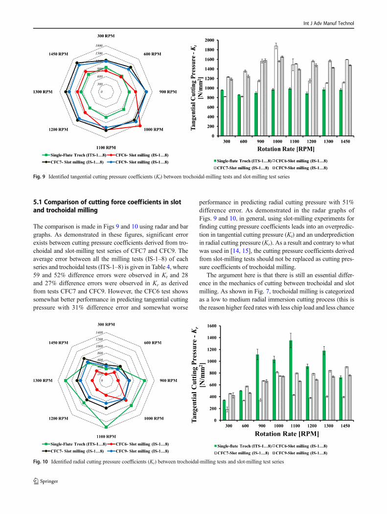
The comparison is made in Figs 9 and 10 using radar and bargraphs. As demonstrated in these figures, significant errorexists between cutting pressure coefficients derived from tro-choidal and slot-milling test series of CFC7 and CFC9. Theaverage error between all the milling tests (IS-1–8) of eachseries and trochoidal tests (ITS-1–8) is given in Table 4, where59 and 52% difference errors were observed in Kt and 28and 27% difference errors were observed in Kr as derivedfrom tests CFC7 and CFC9. However, the CFC6 test showssomewhat better performance in predicting tangential cuttingpressure with 31% difference error and somewhat worse
performance in predicting radial cutting pressure with 51%difference error. As demonstrated in the radar graphs ofFigs. 9 and 10, in general, using slot-milling experiments forfinding cutting pressure coefficients leads into an overpredic-tion in tangential cutting pressure (Kt) and an underpredictionin radial cutting pressure (Kr). As a result and contrary to whatwas used in [14, 15], the cutting pressure coefficients derivedfrom slot-milling tests should not be replaced as cutting pres-sure coefficients of trochoidal milling.
The argument here is that there is still an essential differ-ence in the mechanics of cutting between trochoidal and slotmilling. As shown in Fig. 7, trochoidal milling is categorizedas a low to medium radial immersion cutting process (this isthe reason higher feed rates with less chip load and less chance
Fig. 9 Identified tangential cutting pressure coefficients (Kt) between trochoidal-milling tests and slot-milling test series
Fig. 10 Identified radial cutting pressure coefficients (Kr) between trochoidal-milling tests and slot-milling test series
Int J Adv Manuf Technol
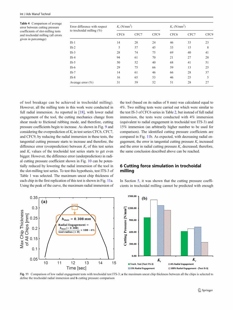
of tool breakage can be achieved in trochoidal milling).However, all the milling tests in this work were conducted infull radial immersion. As reported in [18], with lower radialengagement of the tool, the cutting mechanics change fromshear mode to frictional rubbing mode, and therefore, cuttingpressure coefficients begin to increase. As shown in Fig. 9 andconsidering the overprediction ofKt in test series CFC6, CFC7,and CFC9, by reducing the radial immersion in these tests, thetangential cutting pressure starts to increase and therefore, thedifference error (overprediction) between Kt of this test seriesand Kt values of the trochoidal test series starts to get evenbigger. However, the difference error (underprediction) in radi-al cutting pressure coefficient shown in Fig. 10 can be poten-tially reduced by lowering the radial immersion of the tool inthe slot-milling test series. To test this hypothesis, test ITS-3 ofTable 1 was selected. The maximum uncut chip thickness ofeach chip in the first replication of this test is shown in Fig. 11a.Using the peak of the curve, the maximum radial immersion of
the tool (based on its radius of 8 mm) was calculated equal to4%. Two milling tests were carried out which were similar tothe test IS-3 of CFC6 series in Table 2, but instead of full radialimmersion, the tests were conducted with 4% immersion(equivalent to radial engagement in trochoidal test ITS-3) and15% immersion (an arbitrarily higher number to be used forcomparison). The identified cutting pressure coefficients arecompared in Fig. 11b. As expected, with decreasing radial en-gagement, the error in tangential cutting pressure Kt increasedand the error in radial cutting pressure Kr decreased; therefore,the same conclusion described above can be reached.
6 Cutting force simulation in trochoidalmilling
In Section 5, it was shown that the cutting pressure coeffi-cients in trochoidal milling cannot be predicted with enough
Table 4 Comparison of averageerror between cutting pressurecoefficients of slot-milling testsand trochoidal milling (all errorsgiven in percentage)
Error difference with respectto trochoidal milling (%)
Kt (N/mm2) Kr (N/mm2)
CFC6 CFC7 CFC9 CFC6 CFC7 CFC9
IS-1 14 28 24 46 33 23
IS-2 5 57 45 33 15 8
IS-3 28 74 75 69 40 41
IS-4 94 61 70 21 27 28
IS-5 50 52 40 68 41 51
IS-6 29 75 66 59 13 25
IS-7 14 61 46 66 28 37
IS-8 16 65 53 46 25 5
Average error (%) 31 59 52 51 28 27
Fig. 11 Comparison of low radial engagement tests with trochoidal test ITS-3; a the maximum uncut chip thickness between all the chips is selected todefine the trochoidal radial immersion and b cutting pressure comparison
Int J Adv Manuf Technol
accuracy using conventional milling tests (slot milling withfull or partial radial engagement). As a result, a separate setof experiments with trochoidal tool path is needed to establishthe correlation of cutting pressure coefficients and tool path
parameters. The DoE used in this section was already shownin Table 3 (tests series TS-1–9) and contains nine experiments(with three replications) in varying rotation and nutation ratesas a training set with single-flute tool and four experiments
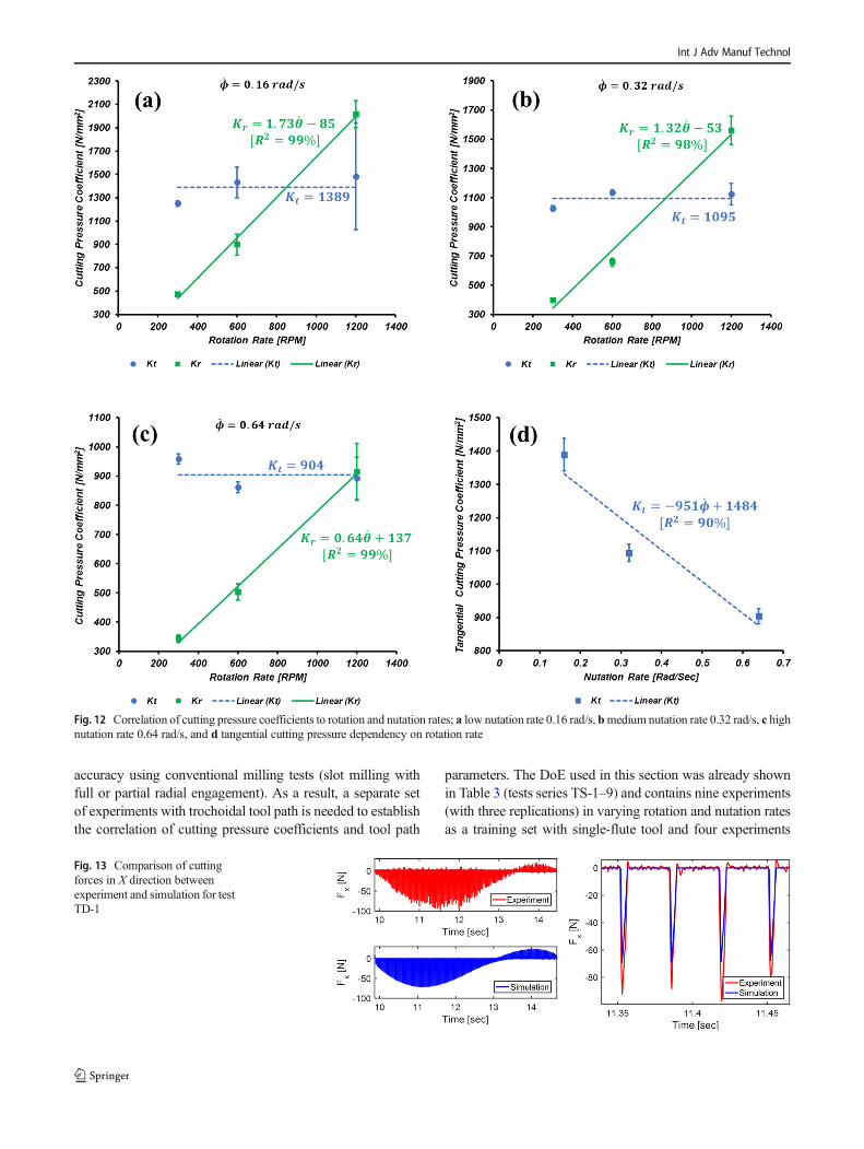
Fig. 12 Correlation of cutting pressure coefficients to rotation and nutation rates; a low nutation rate 0.16 rad/s, bmedium nutation rate 0.32 rad/s, c highnutation rate 0.64 rad/s, and d tangential cutting pressure dependency on rotation rate
Fig. 13 Comparison of cuttingforces in X direction betweenexperiment and simulation for testTD-1
Int J Adv Manuf Technol

with a two-flute tool as a testing set. The cutting pressurecoefficients are identified for the training set and a linear re-gression model was fitted for each coefficient as shown inFig. 12. From this, it is concluded that the tangential cuttingpressure (Kt) is independent of rotation rate (θ̇ ) but demon-strates a linear dependency on nutation rate (ϕ̇ ) (see Fig. 12d).The radial cutting pressure (Kr) is linearly correlated to bothrotation and nutation rates. The generalized linear regressionmodels fitted to each coefficient are given in Eqs. (13) and(14). Using these equations, with known trochoidal tool pathparameters, the cutting force coefficients, Kt and Kr, can beapproximated and used in the semi-mechanistic force modelof Eq. (11) to simulate cutting forces.
Kt ¼ − 951ϕ˙ þ 1484 R2 ¼ 90% � ð13Þ
Kr ¼ − 1062ϕ˙ þ θ˙ þ 557 R2 ¼ 67% � ð14Þ
6.1 Cutting force prediction in two-flute trochoidalmilling
The testing set (tests TD-1–4) of Table 3 was used to (1) testthe validity of the numerical uncut chip thickness calculationmethod described in Section 2 and (2) to investigate the accu-racy of the proposed regression model of cutting pressurecoefficients Eqs. (13) and (14) to simulate cutting forces introchoidal milling. In the testing set, the nutation rate was keptconstant (ϕ̇ = 0.64 rad/s) and the rotation rate was varied from900 to 1450 RPM. First, the cutting pressure coefficients were
calculated, and then Eqs. (11) and (12) were used to simulatethe cutting forces in X and Y directions. The comparison be-tween the simulated and experimental cutting forces of testTD-1 is shown in Figs. 13 and 14. Furthermore, this compar-ison for tests TD-2 to TD-4, where the force reaches its peakvalue, is given in Fig. 15, 16, and 17. To better quantify thesimulation error, it was decided to compare the simulatedforces in the X and Y directions to measured forces for tenchips in the region where force in X and Y directions reachesits peak value. The average error, standard deviation, andmaximum error are shown in Fig. 18 and also given inTable 5. In general, the approach taken in this article showsbetter performance in predicting cutting force in Y (feed) di-rection with total average error of 8% between all four testsand maximum observed error of 45% (in test TD-4), whilelarger error was observed in predicting force in X (lateral)direction with total average error of 17% and maximum ob-served error of 36% (in test TD-4).
7 Summary, conclusion, and future direction
The objectives of the this work were the following: (1) toinvestigate the dependency of the cutting pressure coefficientson tool path and quantify the correlation of cutting parametersin trochoidal milling (i.e., rotation and nutation rates) to thetangential and radial cutting pressure coefficients and (2) tostudy the accuracy in predicting cutting forces of a geometri-cal uncut chip thickness model based on the numericalintersection-finding algorithm. The results show that the
Fig. 14 Comparison of cuttingforces in Y direction betweenexperiment and simulation for testTD-1
Fig. 15 Comparison ofmaximumcutting forces in X and Y directionbetween experiment andsimulation for test TD-2
Int J Adv Manuf Technol
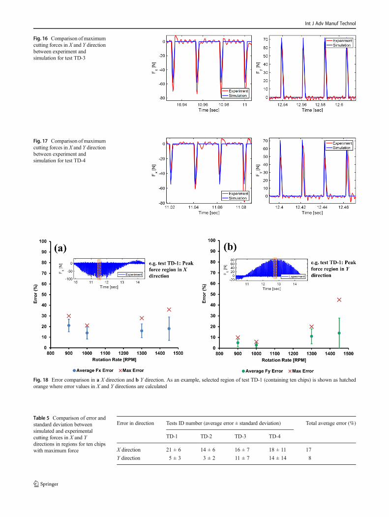
Fig. 17 Comparison ofmaximumcutting forces in X and Y directionbetween experiment andsimulation for test TD-4
Fig. 16 Comparison ofmaximumcutting forces in X and Y directionbetween experiment andsimulation for test TD-3
Fig. 18 Error comparison in a X direction and b Y direction. As an example, selected region of test TD-1 (containing ten chips) is shown as hatchedorange where error values in X and Y directions are calculated
Table 5 Comparison of error andstandard deviation betweensimulated and experimentalcutting forces in X and Ydirections in regions for ten chipswith maximum force
Error in direction Tests ID number (average error ± standard deviation) Total average error (%)
TD-1 TD-2 TD-3 TD-4
X direction 21 ± 6 14 ± 6 16 ± 7 18 ± 11 17
Y direction 5 ± 3 3 ± 2 11 ± 7 14 ± 14 8
Int J Adv Manuf Technol

cutting pressure coefficients are significantly affected by thetool path parameters; it was concluded that unlike the previ-ously published works on this subject where the cutting pres-sure coefficients were blindly taken from slot-milling tests, itis now apparent that these coefficients cannot be replaced asthe cutting pressure coefficients of trochoidal milling. Hence,a separate design of experimental study with explicit trochoi-dal tool path is required. Furthermore, it was shown that theproposed uncut chip thickness algorithm is capable ofpredicting cutting forces in lateral and feed directions. Toquantify the accuracy of the simulation, the maximum simu-lated force was compared with maximum measured forcefrom the dynamometer for ten chips in the region where forcein X and Y directions reached its peak. A total average error of8% was observed in simulating cutting force in the feed direc-tion and 17% total average error was observed in the lateraldirection. Further steps taken in this article are summarized asbelow:
& The numerical algorithm was designed based on findingself- and cross-intersection points of the trochoidal toolpath. A proper strategy was defined for connectingthe intersection points and constructing the chip area.Furthermore, the numerical algorithm was generalizedfor uncut chip thickness modeling of multi-tooth and/orvariable spacing cutting tools.
& A comprehensive DoE was designed to investigate thecutting pressure dependency on tool path and accuracyof force simulation. For cutting pressure extraction, 16tests with 3 replications (a total of 48 tests) were carriedout in slot milling using full radial engagement and tro-choidal milling. Moreover, 9 tests with 3 replications (27tests in total) were designed with a single-flute tool, andlinear regression was used to develop a model of trochoi-dal tool path parameters and cutting pressure coefficients.
& A DoE with four new tests was designed with a two-flutetool in various rotation rates. The developed linear regres-sion model was used to predict the cutting pressure coef-ficients which were integrated into the mechanistic forcemodel for simulating the cutting forces. Finally, the simu-lated cutting forces were compared with experimental re-sults and the corresponding error was reported.
In this article, the focus was solely given to the mechanicsof cutting in trochoidal milling. However, dynamic stability ofthis alternative milling strategy is yet another important stepfor developing a comprehensive knowledge base on this topic.Unlike conventional milling operations, where the enteringand exiting angle of the tool in the cut is consistent throughoutthe process, it is shown in this work that in trochoidal milling,these parameters vary as the tool marches in time and com-pletes a full nutation. Therefore, the stability diagram in tro-choidal milling evolves based on the location of the tool. This
can potentially be advantageous as the critical depth of cut willchange across the cut, possibly reducing the tendency to chat-ter. Investigation of this dynamic behavior of the cutting toolin a trochoidal tool path to identify chatter zone(s) and stabilitylimits is the future direction of this work which will be ad-dressed in a subsequent article.
Acknowledgments The authors would like to thank Mr. Douglas M.Schwarz of the University of Rochester for providing his source codefor finding intersection points.
Publisher’s Note Springer Nature remains neutral with regard to juris-dictional claims in published maps and institutional affiliations.
References
1. Djurdjanovic D, Mears L, Akhavan Niaki F, Ul Haq A, Li L (2017)State of the art review on process, system, and operations control inmodern manufacturing. J Manuf Sci Eng. https://doi.org/10.1115/1.4038074
2. Toh CK (2003) Tool life and tool wear during high-speed roughmilling using alternative cutter path strategies. Proc Inst Mech EngPart B J Eng Manuf 217:1295–1304
3. Landers RG, Ulsoy AG (2000) Model-based machining force con-trol. J Dyn Syst Meas Control 122:521–527
4. Denkena B, Flöter F (2012) Adaptive cutting force control on amilling machine with hybrid axis configuration. Procedia CIRP 4:109–114
5. Lee A-C, Lin M-T, Pan Y-R, Lin W-Y (2011) The feedrate sched-uling of NURBS interpolator for CNC machine tools. Comput Des43:612–628
6. Akhavan Niaki F, Michel M, Mears L (2016) State of health mon-itoring in machining: extended Kalman filter for tool wear assess-ment in turning of IN718 hard-to-machine alloy. SI NAMRC. JManuf Process 24(Part 2):361–369
7. Pleta A, Ulutan D, Mears L (2014) Investigation of trochoidal mill-ing in nickel-based superalloy inconel 738 and comparison withend milling. In: ASME 2014 International Manufacturing Scienceand Engineering Conference collocated with the JSME 2014International Conference on Materials and Processing and the42nd North American Manufacturing Research Conference.American Society of Mechanical Engineers, p V002T02A058-V002T02A058
8. Pleta A, Ulutan D, Mears L (2015) An investigation of alternativepath planning strategies for machining of nickel-based superalloys.Procedia Manuf 1:556–566. https://doi.org/10.1016/J.PROMFG.2015.09.032
9. Uhlmann E, Fürstmann P, Rosenau B, et al (2013) The potential ofreducing the energy consumption for machining TiAl6V4 by usinginnovative metal cutting processes. In: 11th Global Conference onSustainable Manufacturing. Berlin, pp 593–598
10. Rauch M, Duc E, Hascoet J-Y (2009) Improving trochoidal toolpaths generation and implementation using process constraintsmodelling. Int J Mach Tools Manuf 49:375–383. https://doi.org/10.1016/J.IJMACHTOOLS.2008.12.006
11. Shixiong W, Wei M, Bin L, Chengyong W (2016) Trochoidal ma-chining for the high-speed milling of pockets. J Mater ProcessTechnol 233:29–43. https://doi.org/10.1016/J.JMATPROTEC.2016.01.033
12. Szalóki I, Csuka S, Sipos S (2014) New test results in cycloid-forming trochoidal milling - Google Search. Acta Polytech Hung11:1–14
Int J Adv Manuf Technol

13. Salehi M, BlumM, Fath B, Akyol T, Haas R, Ovtcharova J (2016)Epicycloidal versus trochoidal milling-comparison of cutting force,tool tip vibration, and machining cycle time. Procedia CIRP 46:230–233. https://doi.org/10.1016/J.PROCIR.2016.04.001
14. Otkur M, Lazoglu I (2007) Trochoidal milling. Int J Mach ToolsManuf 47:1324–1332
15. Kardes N, Altintas Y (2007) Mechanics and dynamics of the circu-lar milling process. J Manuf Sci Eng 129:21. https://doi.org/10.1115/1.2345391
16. Lawrence JD (1972) A catalog of special plane curves. DoverPublications, Mineola
17. Tlusty J (2000) Manufacturing processes and equipment. Prentice-Hall
18. Rubeo MA, Schmitz TL (2016) Milling force modeling: a compar-ison of two approaches. Procedia Manuf 5:90–105
Int J Adv Manuf Technol
Related Documents