1 Triple Axis Gyro System Parameter Editor GTUNE User Guide GTUNE User Guide Japan Remote Control Co., Ltd. Apr. 2013 2nd Edition

Welcome message from author
This document is posted to help you gain knowledge. Please leave a comment to let me know what you think about it! Share it to your friends and learn new things together.
Transcript

1
Triple Axis Gyro System Parameter Editor GTUNE User Guide
GTUNE User Guide
Japan Remote Control Co., Ltd.
Apr. 2013
2nd Edition

2
Triple Axis Gyro System Parameter Editor GTUNE User Guide
Contents
Introduction ......................................................................................................................................... 3 Precautions .......................................................................................................................................... 3 Compatibility ....................................................................................................................................... 3 Running the Application ...................................................................................................................... 4 Connecting the TAGS01 ....................................................................................................................... 5
Configuration ................................................................................................................................... 5 Connection Sequence ...................................................................................................................... 6
General Configuration ......................................................................................................................... 7 Basic Menu Screen ........................................................................................................................... 7 Control Parameter Settings Screen .................................................................................................. 8 Gain Monitor Screen ...................................................................................................................... 10 Dead Band ...................................................................................................................................... 11 System Update Screen ................................................................................................................... 12 System Reset Screen ...................................................................................................................... 13
Control Parameter Setup ................................................................................................................... 14 Steps required ................................................................................................................................ 14 Effect of Each Parameter ............................................................................................................... 15
P Gain ......................................................................................................................................... 15 I Gain .......................................................................................................................................... 15 D Gain ........................................................................................................................................ 15 F.F. Gain (Feed Forward Gain) ................................................................................................... 16 HOLD Gain .................................................................................................................................. 16 CTRL Gain (Control Gain) ........................................................................................................... 16 A.C. Gain (Acceleration Control Gain) ........................................................................................ 16 A.C. Rate (Acceleration Control Rate) ........................................................................................ 17
Dead Band ......................................................................................................................................... 18 Confirming the Mode and Gain Settings using the Gain Monitor ..................................................... 19 System Update ................................................................................................................................... 20
This updates the TAGS01 firmware ............................................................................................... 20 Steps Required ............................................................................................................................... 20
System Reset ..................................................................................................................................... 21 Steps Required ............................................................................................................................... 21
Repairs and After-‐Sales Service ......................................................................................................... 22
3
Triple Axis Gyro System Parameter Editor GTUNE User Guide
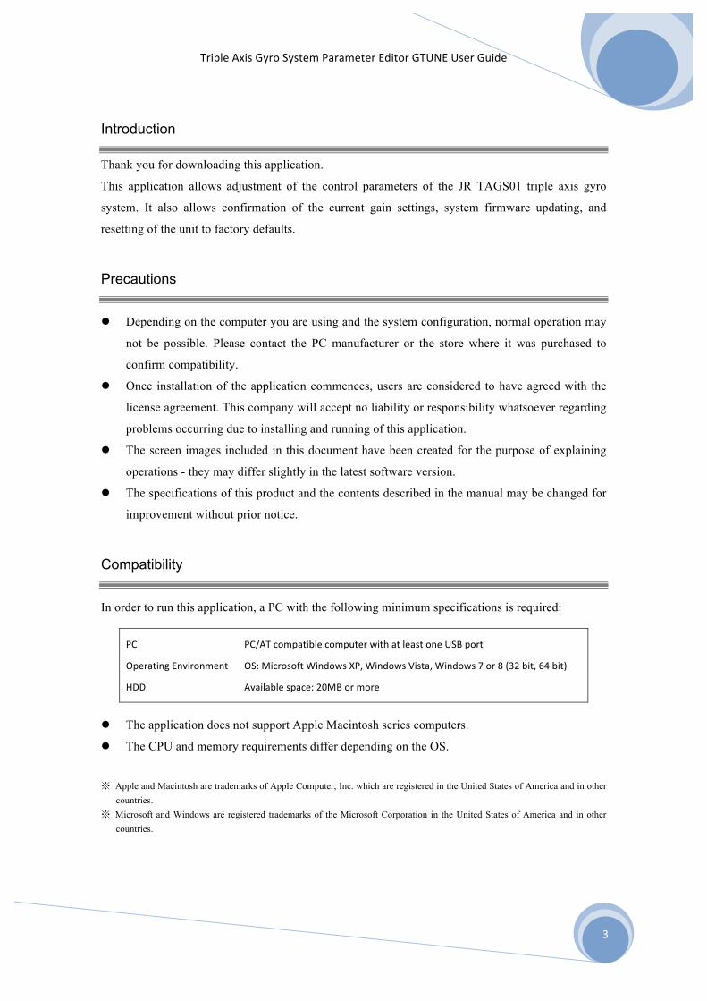
Introduction
Thank you for downloading this application.
This application allows adjustment of the control parameters of the JR TAGS01 triple axis gyro
system. It also allows confirmation of the current gain settings, system firmware updating, and
resetting of the unit to factory defaults.
Precautions
l Depending on the computer you are using and the system configuration, normal operation may
not be possible. Please contact the PC manufacturer or the store where it was purchased to
confirm compatibility.
l Once installation of the application commences, users are considered to have agreed with the
license agreement. This company will accept no liability or responsibility whatsoever regarding
problems occurring due to installing and running of this application.
l The screen images included in this document have been created for the purpose of explaining
operations - they may differ slightly in the latest software version.
l The specifications of this product and the contents described in the manual may be changed for
improvement without prior notice.
Compatibility
In order to run this application, a PC with the following minimum specifications is required:
PC PC/AT compatible computer with at least one USB port
Operating Environment OS: Microsoft Windows XP, Windows Vista, Windows 7 or 8 (32 bit, 64 bit)
HDD Available space: 20MB or more
l The application does not support Apple Macintosh series computers.
l The CPU and memory requirements differ depending on the OS.
※ Apple and Macintosh are trademarks of Apple Computer, Inc. which are registered in the United States of America and in other countries.
※ Microsoft and Windows are registered trademarks of the Microsoft Corporation in the United States of America and in other countries.
4
Triple Axis Gyro System Parameter Editor GTUNE User Guide
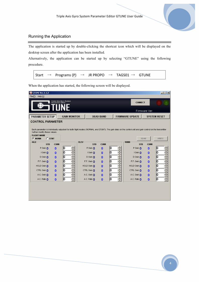
Running the Application
The application is started up by double-clicking the shortcut icon which will be displayed on the
desktop screen after the application has been installed.
Alternatively, the application can be started up by selecting “GTUNE” using the following
procedure.
Start → Programs (P) → JR PROPO → TAGS01 → GTUNE
When the application has started, the following screen will be displayed.

5
Triple Axis Gyro System Parameter Editor GTUNE User Guide
Connecting the TAGS01
Configuration
Connect the PC and the TAGS01 as shown in the figure below. Connection is also possible if the
TAGS01 is already mounted on the helicopter and connected to the servos and receiver.
Precautions ※ When the included USB cable is connected to the PC for the first time, a USB driver is installed.
Please wait for the driver installation to be completed prior to connecting the TAGS01. ※ The PC software allows changes to the TAGS01 regardless of whether or not the sensor is
connected. ※ The TAGS01 will connect to the PC regardless of whether it is receiving power from the receiver
battery or not. If the USB cable is connected when receiver power is not being supplied, operation will be carried out using power supplied from the USB. If a battery is connected, communications will be carried out using the battery as a power source.
※ The dedicated USB cable described below will be required to make the connection with the TAGS01. Operation is not be possible using a normal USB cable.
Triple Axis Gyro Dedicated USB Cable No.02612 GTUNE-‐ADP (Price ¥4,200 [¥4,000 without tax])
TAGS01 Dedicated USB Cable
[GTUNE-‐ADP]
6
Triple Axis Gyro System Parameter Editor GTUNE User Guide
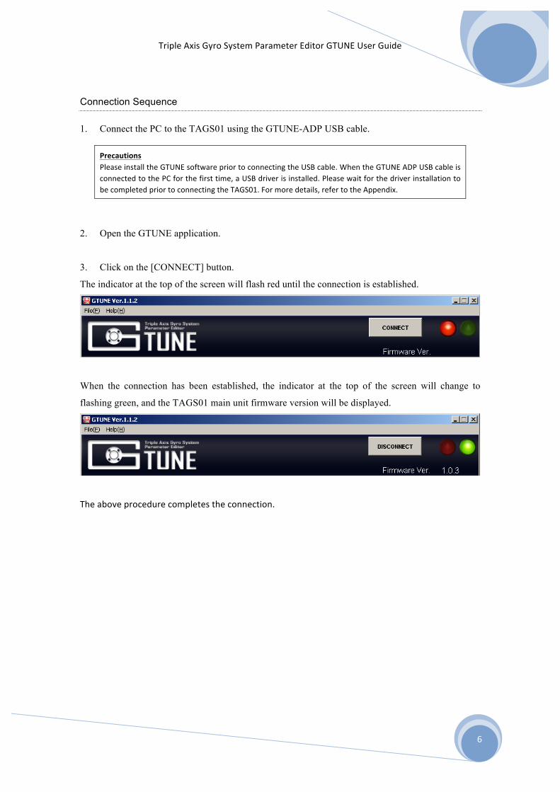
Connection Sequence
1. Connect the PC to the TAGS01 using the GTUNE-ADP USB cable.
Precautions Please install the GTUNE software prior to connecting the USB cable. When the GTUNE ADP USB cable is connected to the PC for the first time, a USB driver is installed. Please wait for the driver installation to be completed prior to connecting the TAGS01. For more details, refer to the Appendix.
2. Open the GTUNE application.
3. Click on the [CONNECT] button.
The indicator at the top of the screen will flash red until the connection is established.
When the connection has been established, the indicator at the top of the screen will change to
flashing green, and the TAGS01 main unit firmware version will be displayed.
The above procedure completes the connection.
7
Triple Axis Gyro System Parameter Editor GTUNE User Guide
General Configuration
Basic Menu Screen
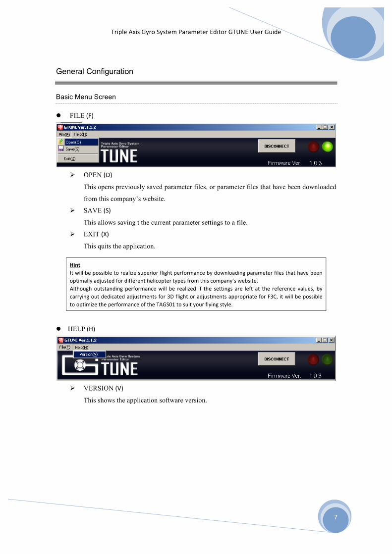
l FILE (F)
Ø OPEN (O)
This opens previously saved parameter files, or parameter files that have been downloaded
from this company’s website.
Ø SAVE (S)
This allows saving t the current parameter settings to a file.
Ø EXIT (X)
This quits the application.
Hint It will be possible to realize superior flight performance by downloading parameter files that have been optimally adjusted for different helicopter types from this company’s website. Although outstanding performance will be realized if the settings are left at the reference values, by carrying out dedicated adjustments for 3D flight or adjustments appropriate for F3C, it will be possible to optimize the performance of the TAGS01 to suit your flying style.
l HELP (H)
Ø VERSION (V)
This shows the application software version.

8
Triple Axis Gyro System Parameter Editor GTUNE User Guide
Control Parameter Settings Screen
※ The screen described above shows reference figures.
1. [READ] and [WRITE] Buttons
These buttons read the parameters recorded inside the TAGS01, or write the parameters that are
currently displayed on the screen to the TAGS01.
2. Flight Mode Toggle Buttons
These buttons switch between normal mode (NORM) settings (usually used for hovering), and
stunt mode (STNT) settings (usually used for stunt – 3D – aerobatics).
By switching the toggle buttons, the parameters corresponding to each mode will be
displayed.
2
3
4
1

9
Triple Axis Gyro System Parameter Editor GTUNE User Guide
3. Parameter Settings Dialog Box
This displays the control parameters corresponding to each of the AILE, ELEV, and RUDD
axes.
It is possible to change the parameter values using the increase/decrease arrows, or by directly
inputting numerical values.
Precautions Simply changing the numerical values that are input in the parameters column will not immediately update the values in the TAGS01. Be certain to click on the [WRITE] button to write the new settings to the TAGS01.
In order from left to right the [Reference Value] (Factory Default Setting), [Current TAGS01 Value],
and [Editing Value] are displayed. The example display shows the AILE P gain
Hint ※ Reference Value: This is the value when the product was shipped from the factory. It should be
utilized as a standard to show how far the value has been changed from the reference value. ※ Current TAGS01 Value: This is the value that is currently stored in the TAGS01. ※ Editing Value: This is the value that is currently being edited. The value can be increased or
decreased by matching the cursor to the value and changing the value up or down using the cursor keys.
4. Help Display
When the mouse cursor is moved to rest on top of each adjustment item name, an explanation
will be displayed showing the effect that changes to the parameter is likely to have on model
performance.
Hint It is possible to use the TAB key to move the cursor between each item in sequence. The cursor focus will be moved in the forward direction by pressing TAB, and in the reverse direction by pressing SHIFT+TAB.
Example display when the mouse cursor is moved on top of “P Gain”

10
Triple Axis Gyro System Parameter Editor GTUNE User Guide
Gain Monitor Screen
1. Gain Channel Input Monitor Display
This screen confirms whether or not input signals from the receiver are being received by each of the GAIN1, GAIN2, and GAIN3 channels of the TAGS01 main unit. In the situation where signals are being received, the corresponding channel name will be shown as an inverse display inside a greenish-‐yellow box. In the case where none of the channels are connected, “N/A” will be shown as an inverse display.
2. Gyro Gain Display This displays the total gain consisting of the gain set on the TAGS01 main unit dial and the gain from the transmitter (if a gain channel is connected). Further, if a GAIN input is being received from the receiver, normal/stunt mode will be displayed -‐ by switching the transmitter gain channel between the two modes, the different gain settings will be seen.
Precautions Because the Gain Monitor display response is updated while constantly monitoring the TAGS01 condition, the display will change slowly. When moving the dials on the TAGS01, carry out the operation slowly, since the display will be updated with a delay of several seconds following the adjustment of the dial.
1
2

11
Triple Axis Gyro System Parameter Editor GTUNE User Guide
Dead Band
5. [READ] and [WRITE] Buttons
These buttons read the dead band setting that is stored inside the TAGS01, or write the new set
value which is displayed on the screen.
2 1

12
Triple Axis Gyro System Parameter Editor GTUNE User Guide
System Update Screen
1. [SELECT] button
When the [SELECT] button is clicked, the File Selection dialog box will open. By choosing an
appropriate file and clicking on [OPEN (O)], TAGS01 system firmware update will commence.
Precaution During the update processing, do not disconnect the connection between the TAGS01 and the PC. If the connection is unintentionally disconnected, there will be a risk that the TAGS01 system will be unable to start up.
1

13
Triple Axis Gyro System Parameter Editor GTUNE User Guide
System Reset Screen
1. [RESET] button
This button is for initializing the TAGS01 settings (returning the settings to the condition they
were in when shipped from the factory).
Hint If parameters have been changed for the purpose of flight adjustment, this function can be used to easily return the parameters to their initial condition. When a reset is implemented, the currently stored parameters and other settings in the TAGS01 will all be cleared and returned to the reference (factory default) values, so be certain to save the parameters in a backup file before implementing the reset.
1

14
Triple Axis Gyro System Parameter Editor GTUNE User Guide
Control Parameter Setup
These parameters are used to carry out detailed adjustment of the flight feel and performance.
Steps required
Connect the TAGS01 with the PC
↓
Changing the Set Values as required
↓
Writing the Set Values
Precautions Do not change the control parameters by a large amount all at one time. If the flight characteristics are suddenly changed, the helicopter may become unflyable or dangerous. Change each parameter one by one, making small adjustments while confirming the flight behavior each time.
Confirm that the green colored indicator display is flashing.
Change the value using the cursor keys or by direct input from the keyboard.
Click on the [WRITE] button to write the new values to the TAGS01.
When the blue-colored current set value changes to the edited values, writing is complete.
15
Triple Axis Gyro System Parameter Editor GTUNE User Guide
Effect of Each Parameter
P Gain The Proportional (P) Gain changes servo output proportional to the sensed error. The higher the P
Gain, the larger the output for a given error.
If the P Gain values are made larger, the reaction speed for initial movement and stopping will
become more agile, and the rigidity when stopping will increase.
Caution The desired P Gain is effected by servo performance, helicopter weight, rotor blades and rotor rpm, etc Care is required because if the P Gain numerical values are made too large, instability and hunting will tend to occur.
I Gain
This is the gain which ‘locks’ the helicopter in a certain position. On the yaw axis, this is generally
called the tail lock gain.
If the Integral (I) Gain numerical values are increased, the resistance to disturbances such as wind
gusts will become stronger, which will increase the stability, and overall the helicopter will tend to
hold its position more rigidly.
The I Gain should be adjusted to the highest possible value while observing the helicopter behavior.
Caution If the I Gain is made too large, the helicopter will tend to oscillate, which will eventually cause hunting.
D Gain
The Derivative (D) Gain effects the helicopters behavior after a control input is suddenly released.
This Gain allows attenuation of the helicopter body tremor which is generated when the helicopter
has been stopped by a sudden movement of the control stick.
In the situation where the P Gain and I Gain have been made too large, the helicopter body may
oscillate if the sticks are operated by flicking them with your fingers. By increasing the D Gain, the
oscillation in the above situation will be reduced, and it will be possible to further increase the I
Gain.
Caution Care will be required, because if the D Gain is too large, small oscillations may continue, or the vibration of the helicopter may cause sudden and severe hunting to occur.

16
Triple Axis Gyro System Parameter Editor GTUNE User Guide
F.F. Gain (Feed Forward Gain)
When operating the sticks, this predicts the load in advance and applies a larger control throw in
order that the control travel will not be limited.
This is used in situations such as when you wish to slightly strengthen the control pickup around the
neutral position after carrying out overall optimum control settings using Dual Rate and Exponential.
By making the F.F Gain larger, the control pickup will become crisper.
HOLD Gain
This is the sensitivity for the length of time the helicopter tries to hold position.
Generally, it is equivalent to adjusting the weight of a virtual flybar. A higher Hold Gain leads to the
helicopter being more resistant to any change in position. This gain adjusts the time for maintaining
the hold of helicopter position that was obtained from the I Gain.
If the Hold Gain numerical value is made larger, the helicopter nose up tendency during high speed
horizontal flight will be reduced, and it will become easier to maintain position while hovering.
CTRL Gain (Control Gain)
The Control (CTRL) Gain adjusts the overall maximum rate of rotation of the helicopter by a control
input from the transmitter.
Unlike the other gains, the numerical value for the Control Gain is not a percentage, but instead
allows setting of the maximum value of the speed (angular speed, degrees per second) that the
helicopter is able to rotate in 1 second with maximal control stick travel.
Hint The rudder Control Gain reference value is 360 in normal mode, indicating that the helicopter body will rotate one time in one second at maximum control input. In stunt mode the rudder Control Gain reference value is more than two times greater than in normal mode. This higher value is set in order to make it easier to carry out pirouette-‐type aerial acrobatics.
A.C. Gain (Acceleration Control Gain)
This gain controls the acceleration of the helicopter in order to closely track control stick operation.
Acceleration is carried out at the maximum performance of the helicopter to most quickly reach the
indicated angular speed corresponding to the stick operation angle when the stick is operated.
At this time, the acceleration may be too swift for the servo performance, and stopping may not be
achieved in time and the point where the stick was released may be overshot. By making the A.C.
Gain large, the over-swift acceleration can be restricted so that smooth initial movement and
stopping can be achieved, making it possible to adjust stick tracking ability.

17
Triple Axis Gyro System Parameter Editor GTUNE User Guide
A.C. Rate (Acceleration Control Rate)
This allows adjustment of the time for controlling the helicopter body acceleration motion that has
been set using the A.C. Gain. When the rate is short, the stopping and the initial movement will be
implemented in a crisp and tight manner, but if the rate is too short the A.C. Gain effect will be
reduced and the movement will become over-sensitive.
On the other hand, although the initial movement and stopping will become smooth when the rate is
long, if the rate is too long the stopping will become weak and it will become difficult to stop at the
position where the stick was released.

18
Triple Axis Gyro System Parameter Editor GTUNE User Guide
Dead Band
An insensitive zone (dead band) can be set with regard to the signal from the receiver.
The dead band absorbs errors where there are minute oscillations in the signal pulse width from the
receiver, or when drift errors occur due to changes in the surrounding environmental temperature.
Accordingly, in the situation where there is a discrepancy in the input signal from the receiver
caused by temperature drift, it will be possible to prevent tilt from occurring in the swash by setting
an appropriate dead band.
The reference value is 3usec. This should be changed according to your preferences.

19
Triple Axis Gyro System Parameter Editor GTUNE User Guide
Confirming the Mode and Gain Settings using the Gain Monitor
This allows confirmation of the current flight mode and gyro gain.
The TAGS01 is provided with GAIN1, GAIN2, and GAIN3 channels in addition to the AILE, ELEV,
RUDD, and PIT channels. Although the roles of these gains will change according to how many
channels are connected to the receiver, in this screen each of these settings can be confirmed on one
screen.
Example Gain Display
Hint The above screen shows the situation where nothing is connected to the GAIN1, GAIN2 and GAIN3 channels. In this condition, only the normal flight mode gain values are in effect. Additionally, the gain settings can only be made by adjusting the gain dials on the TAGS01. If you wish to adjust the gain settings from the transmitter, connect the GAIN1, GAIN1+GAIN2, or GAIN1+GAIN2+GAIN3 connections as appropriate.

20
Triple Axis Gyro System Parameter Editor GTUNE User Guide
System Update
This updates the TAGS01 firmware
Steps Required
Connect the TAGS01 to the PC
↓
Selecting the new Firmware file
↓
Confirm Completion of the Update
When the file is selected, the update processing will start automatically.
During the processing, do not disconnect the connection between the TAGS01 and the PC.
When the update process finishes, the following confirmation dialog
box will appear:
After the update process has completed, please confirm
that the “Firmware Version” number has been renewed.
Confirm that the green colored indicator display is flashing.
Click on the [START UPDATE] button and select the file.

21
Triple Axis Gyro System Parameter Editor GTUNE User Guide
System Reset
It is possible to reset the TAGS01 settings to those that were set at the time the product was shipped
from the factory.
Steps Required
Connect the TAGS01 to the PC
↓
Carrying out the reset
By clicking on [OK] in the warning display described below, the reset procedure will start.
When the reset has finished, the dialog box below will be displayed.
Confirm that the green colored indicator display is flashing.
Click on the [RESET] button to reset the TAGS01.

22
Triple Axis Gyro System Parameter Editor GTUNE User Guide
Repairs and After-Sales Service
For further questions or inquiries please contact your local dealer or JR distributor in your
country.
Related Documents