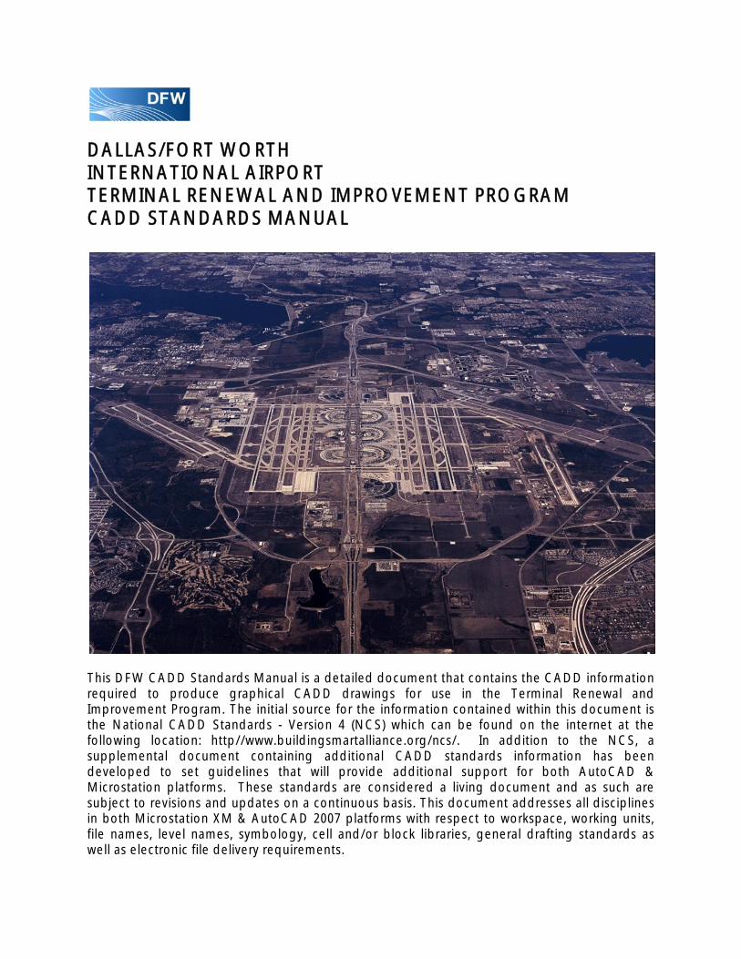
DALLAS/FORT WORTH INTERNATIONAL AIRPORT TERMINAL RENEWAL AND IMPROVEMENT PROGRAM CADD STANDARDS MANUAL This DFW CADD Standards Manual is a detailed document that contains the CADD information required to produce graphical CADD drawings for use in the Terminal Renewal and Improvement Program. The initial source for the information contained within this document is the National CADD Standards - Version 4 (NCS) which can be found on the internet at the following location: http//www.buildingsmartalliance.org/ncs/. In addition to the NCS, a supplemental document containing additional CADD standards information has been developed to set guidelines that will provide additional support for both AutoCAD & Microstation platforms. These standards are considered a living document and as such are subject to revisions and updates on a continuous basis. This document addresses all disciplines in both Microstation XM & AutoCAD 2007 platforms with respect to workspace, working units, file names, level names, symbology, cell and/or block libraries, general drafting standards as well as electronic file delivery requirements.

Welcome message from author
This document is posted to help you gain knowledge. Please leave a comment to let me know what you think about it! Share it to your friends and learn new things together.
Transcript
DALLAS/FORT WORTH INTERNATIONAL AIRPORT TERMINAL RENEWAL AND IMPROVEMENT PROGRAM CADD STANDARDS MANUAL
This DFW CADD Standards Manual is a detailed document that contains the CADD information required to produce graphical CADD drawings for use in the Terminal Renewal and Improvement Program. The initial source for the information contained within this document is the National CADD Standards - Version 4 (NCS) which can be found on the internet at the following location: http//www.buildingsmartalliance.org/ncs/. In addition to the NCS, a supplemental document containing additional CADD standards information has been developed to set guidelines that will provide additional support for both AutoCAD & Microstation platforms. These standards are considered a living document and as such are subject to revisions and updates on a continuous basis. This document addresses all disciplines in both Microstation XM & AutoCAD 2007 platforms with respect to workspace, working units, file names, level names, symbology, cell and/or block libraries, general drafting standards as well as electronic file delivery requirements.

CADD Standards Manual – July 1, 2011
AIRPORT DEVELOPMENT AND ENGINEERING Page 2 of 4 Terminal Renewal and Improvement Program
TABLE OF CONTENTS
1. INTRODUCTION Introduction ..................................................................................................................................................... 1
Purpose....................................................................................................................................................... 1
Source ......................................................................................................................................................... 1
Compliance ................................................................................................................................................ 1
Request for Variance ................................................................................................................................. 1
Procedures for Changes to this Manual .................................................................................................. 2
Proposed Change to CADD Standards Manual Form ........................................................................... 3
2. SOFTWARE REQUIREMENTS Introduction ................................................................................................................................................ 4
Software ...................................................................................................................................................... 4
Version ........................................................................................................................................................ 4
Submittals ................................................................................................................................................... 4
3. PROJECT ORGANIZATION Introduction ................................................................................................................................................ 5
Types of Drawing Files .............................................................................................................................. 5
Project Directory Structure ................................................................................................................... 6-8
DFW Civil Master Map Files (Microstation Base Files) ........................................................................... 9
Architectural Master Map Files (AutoCAD Base Files) ........................................................................ 10
File Naming Convention-Model Files ................................................................................................... 11
File Naming Convention-Sheet Files ..................................................................................................... 12
Sheet Numbering .................................................................................................................................... 13
File Naming Convention-Border Files ................................................................................................... 14
Available Border Files & Sheet Sizes ..................................................................................................... 15
Sheet Type Designators ......................................................................................................................... 16
CADD Standards Manual – July 1, 2011
AIRPORT DEVELOPMENT AND ENGINEERING Page 3 of 4 Terminal Renewal and Improvement Program
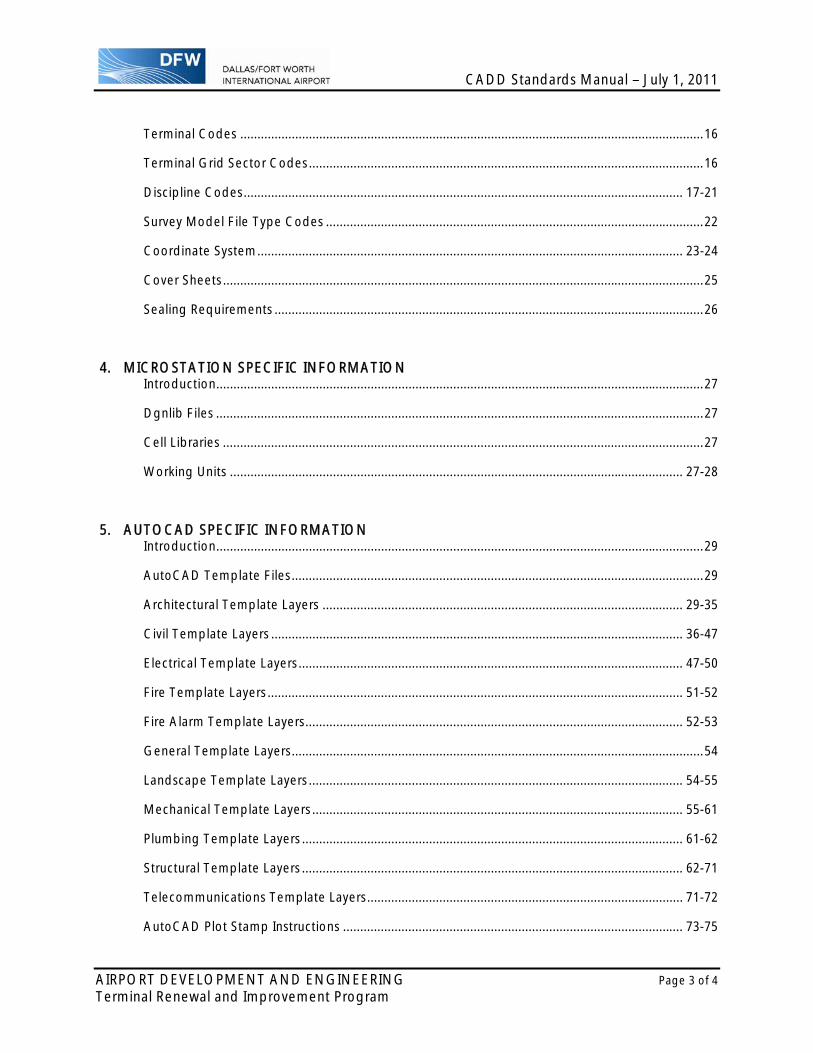
Terminal Codes ....................................................................................................................................... 16
Terminal Grid Sector Codes ................................................................................................................... 16
Discipline Codes ................................................................................................................................ 17-21
Survey Model File Type Codes .............................................................................................................. 22
Coordinate System ............................................................................................................................ 23-24
Cover Sheets ............................................................................................................................................ 25
Sealing Requirements ............................................................................................................................. 26
4. MICROSTATION SPECIFIC INFORMATION Introduction .............................................................................................................................................. 27
Dgnlib Files .............................................................................................................................................. 27
Cell Libraries ............................................................................................................................................ 27
Working Units .................................................................................................................................... 27-28
5. AUTOCAD SPECIFIC INFORMATION Introduction .............................................................................................................................................. 29
AutoCAD Template Files ........................................................................................................................ 29
Architectural Template Layers ......................................................................................................... 29-35
Civil Template Layers ........................................................................................................................ 36-47
Electrical Template Layers ................................................................................................................ 47-50
Fire Template Layers ......................................................................................................................... 51-52
Fire Alarm Template Layers .............................................................................................................. 52-53
General Template Layers ........................................................................................................................ 54
Landscape Template Layers ............................................................................................................. 54-55
Mechanical Template Layers ............................................................................................................ 55-61
Plumbing Template Layers ............................................................................................................... 61-62
Structural Template Layers ............................................................................................................... 62-71
Telecommunications Template Layers ............................................................................................ 71-72
AutoCAD Plot Stamp Instructions ................................................................................................... 73-75
CADD Standards Manual – July 1, 2011
AIRPORT DEVELOPMENT AND ENGINEERING Page 4 of 4 Terminal Renewal and Improvement Program
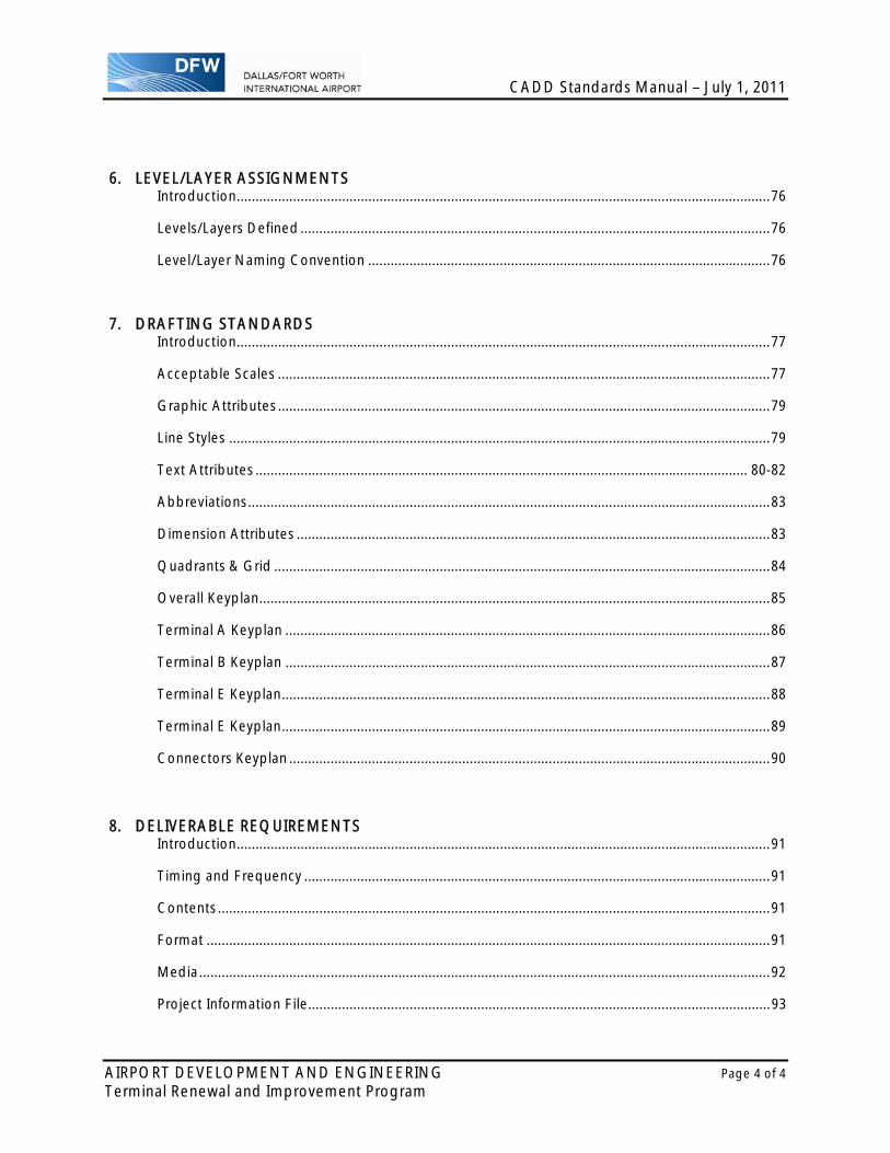
6. LEVEL/LAYER ASSIGNMENTS Introduction .............................................................................................................................................. 76
Levels/Layers Defined ............................................................................................................................. 76
Level/Layer Naming Convention ........................................................................................................... 76
7. DRAFTING STANDARDS Introduction .............................................................................................................................................. 77
Acceptable Scales ................................................................................................................................... 77
Graphic Attributes ................................................................................................................................... 79
Line Styles ................................................................................................................................................ 79
Text Attributes ................................................................................................................................... 80-82
Abbreviations ........................................................................................................................................... 83
Dimension Attributes .............................................................................................................................. 83
Quadrants & Grid .................................................................................................................................... 84
Overall Keyplan ........................................................................................................................................ 85
Terminal A Keyplan ................................................................................................................................. 86
Terminal B Keyplan ................................................................................................................................. 87
Terminal E Keyplan .................................................................................................................................. 88
Terminal E Keyplan .................................................................................................................................. 89
Connectors Keyplan ................................................................................................................................ 90
8. DELIVERABLE REQUIREMENTS Introduction .............................................................................................................................................. 91
Timing and Frequency ............................................................................................................................ 91
Contents ................................................................................................................................................... 91
Format ...................................................................................................................................................... 91
Media ........................................................................................................................................................ 92
Project Information File ........................................................................................................................... 93

CADD Standards Manual – July 1, 2011
AIRPORT DEVELOPMENT AND ENGINEERING Page 1 of 93 Terminal Renewal and Improvement Program
1. INTRODUCTION INTRODUCTION This CADD Standards Manual is a comprehensive document designed to be used along with the National Cad Standards Version 4 (NCS) for all work on the Terminal Renewal and Improvement Program (TRIP). Use of these two documents is required for the purpose of creating both Microstation and AutoCAD drawing files in a standard, concise and consistent format. Within this document are CADD Standards for all disciplines including, software requirements, project directory structure, file naming, level and/or layer naming, sheet numbering, cell and/or block libraries, general drafting standards and electronic file delivery requirements. PURPOSE This manual establishes specific requirements for the development, maintenance and delivery of all CADD files related to the TRIP design and construction projects for DFW International Airport. The purpose of the standards contained within this manual is to:
Provide a consistent and compatible electronic record of each project that can be recreated at a later date or referenced on future projects.
Ensure consistent file structure and format of all CADD files so that incorporation into the DFW Airport GIS can be achieved with as little effort as possible.
Aid the designers with the development of their designs utilizing other consultants’ work as efficiently as possible.
Facilitate the ease of use between disciplines as well as the understanding of graphical elements within the CADD files.
Ensure a consistent method of printing so that there is uniformity in the look of the sheets when printed.
SOURCE The basis for this document is the July 2003 edition of the DFW CADD Standards that were developed prior to the release of Microstation XM and did not include any standards or information for AutoCAD use. Additional source information was obtained from the NCS. COMPLIANCE Compliance with these standards is mandatory and subject to the individual consultant contracts. The consultant/contractor shall use these standards for all design work during the course of the project, file transfers between DFW & other consultants as well as for all files transmitted as record drawings upon completion of the project. Any modifications, deletions or variances to these standards will not be allowed without the permission of the DFW International Airport. REQUEST FOR VARIANCE It is recognized that variances or clarifications to these standards will be necessary. All requests for variances will be presented to the DFW International Airport prior to the use of said variance. All requests shall be submitted along with any substantiating documentation to the DFW International Airport.

CADD Standards Manual – July 1, 2011
AIRPORT DEVELOPMENT AND ENGINEERING Page 2 of 93 Terminal Renewal and Improvement Program
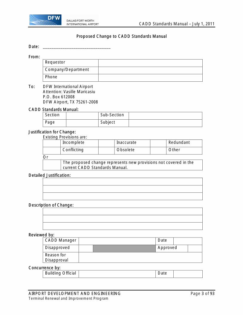
CHANGES TO THIS MANUAL Proposed changes to this manual should be documented on the attached form located at the end of this chapter and submitted to the DFW International Airport for consideration.
CADD Standards Manual – July 1, 2011
AIRPORT DEVELOPMENT AND ENGINEERING Page 3 of 93 Terminal Renewal and Improvement Program
Proposed Change to CADD Standards Manual
Date: _______________________________ From:
Requestor
Company/Department
Phone
To: DFW International Airport Attention: Vasille Maricasiu P.O. Box 612008 DFW Airport, TX 75261-2008
CADD Standards Manual: Section Sub-Section
Page Subject
Justification for Change: Existing Provisions are:
Incomplete Inaccurate Redundant
Conflicting Obsolete Other
Or The proposed change represents new provisions not covered in the
current CADD Standards Manual.
Detailed Justification:
Description of Change:
Reviewed by: CADD Manager Date
Disapproved Approved
Reason for Disapproval
Concurrence by: Building Official Date

CADD Standards Manual – July 1, 2011
AIRPORT DEVELOPMENT AND ENGINEERING Page 4 of 93 Terminal Renewal and Improvement Program
2. SOFTWARE REQUIREMENTS INTRODUCTION This chapter identifies the software packages currently used in the development, production and maintenance of all project documentation. The list shown below is considered current as of the date of printing. However, the consultant is required to confirm the software requirements with DFW Airport prior to commencing of any work. Failure to do so may result in document submittals being rejected by DFW Airport due to unacceptable formats. SOFTWARE Type Product Manufacturer FormatOperating System Windows XP Microsoft, Inc. Project Management
Skire Unifier Skire, Inc.
CADD Management
TBD TBD
CADD Software Microstation XMAutoCAD 2007 (or greater)
Bentley Systems, Inc. Autodesk
dgndwg
Civil Software Site Works (Select CADD) or Geopak
Bentley Systems, Inc. dgn, ttn
GIS Software MGE Suite Intergraph Corporation dgn, mgeSurvey Software InRoads Survey,
SiteWorks, Geopak (or select CAD versions of above)
Bentley Systems, Inc. dgn
Database Oracle, SQL or Access Oracle orMicrosoft, Inc.
mdb
Word Processing Word Microsoft, Inc. docxSpreadsheet Excel Microsoft, Inc. xlsx
VERSION In general, DFW Airport uses the latest versions of all software products. However, the consultant is required to confirm version prior to beginning project work. Again, failure to do so may result in document submittals being rejected by DFW Airport due to unacceptable formats. SUBMITTALS All electronic files submitted delivered to DFW Airport must be in the applicable format listed above in the version mandated by DFW Airport. Documents that do not meet this requirement will be rejected by DFW Airport and will not be accepted until these requirements are met.
CADD Standards Manual – July 1, 2011
AIRPORT DEVELOPMENT AND ENGINEERING Page 5 of 93 Terminal Renewal and Improvement Program
3. PROJECT ORGANIZATION INTRODUCTION This chapter defines the three types of drawing files, MASTER MAP FILES, MODEL FILES & SHEET FILES. It also defines the project directory structure, the file naming conventions for both Model and Sheet Files as well as the numbering of the final plotted sheets. TYPES OF DRAWING FILES There are three types of CADD files defined in this manual: Master Map Files (base files), Model files (reference files), and Sheet files (Master Files). The definitions of each are detailed below.
MASTER MAP FILES (BASE FILES) Master map files contain information regarding the current existing conditions, however users should field verify any and all information contained within these files prior to any design work. All Master Map files will be provided by the DFW Airport GIS. Any discrepancies should be brought to the attention of the DFW Airport GIS Manager. Note that all users are urged to inquire about current survey and construction activities prior to commencing design of any project within the DFW Airport.
MODEL FILES (REFERENCE FILES) Model files are drawn at true size (1:1) and contain the proposed work to be performed for the project. This includes all design information such as roads, utilities, runways, structures and building components such as columns, walls, windows, ductwork, piping, plans, elevations, sections, etc.
SHEET FILES (MASTER FILES) A Sheet File represents the final plotted CADD drawing file. Sheet files contain the notes, annotations, dimensions, call-outs, titles and other text required to convey the design to the contractor. Model files, including the border files, and Master files are referenced to the sheet files in order to create the final plotted sheets.
CADD Standards Manual – July 1, 2011
AIRPORT DEVELOPMENT AND ENGINEERING Page 6 of 93 Terminal Renewal and Improvement Program
PROJECT DIRECTORY STRUCTURE Each discipline will have its own Project Directory Structure. The ‘root’ directory will be the name of the discipline (IE. architectural, structural, etc.). Within this ‘root’ directory, the Primary Project directory name shall be TERMINAL RENEWAL AND IMPROVEMENT PROGRAM. Under the primary project directory will be a sub-directory for each Terminal, as well as one for the Baggage Link, one for Roadway, one for the Intermodal Transfer Center and one for Project Resource Files. TERMINAL RENEWAL AND IMPROVEMENT PROGRAM – contains the Project Information Files. PROJECT RESOURCE FILES – contains all of the CADD resource files for the project. TERMINAL A – contains all files for Terminal A TERMINAL B – contains all files for Terminal B TERMINAL C – contains all files for Terminal C TERMINAL E – contains all files for Terminal E BAGGAGE LINK L – contains all files for the Bag Link ROADWAY R – contains all files for the Roadways PHASING – contains Overall Phasing Files TRANSFER CENTER T – contains all files for the ITC COMMON – contains all the common reference files for the Airport
Note: For information regarding the Project Information Files, see Chapter 8. The Project Resource Files directory will have additional sub-directories as shown below. PROJECT RESOURCE FILES
o CADD STANDARDS – contains the CADD Standards for the project. o MICROSTATION - contains the required Microstation files for the project to
include seed files, border files, dgnlib files, color table, configuration files, resource files and any others as required.
o AUTOCAD – contains the required AutoCAD files for the project to include border files, template files, color table, configuration files, custom support files and any others as required.
Each Terminal Directory will have additional sub-directories as shown below. TERMINAL A
o DOCUMENTATION - contains the electronic version of all documentation required for the applicable terminal such as calculations, quantities and schedules.
o CADD FILES - contains all the CADD files required for use within the applicable terminal. This directory is subdivided into two main directories, one for Microstation & one for AutoCAD. Each of these sub-directories is further subdivided by discipline as shown below.
o SPECIFICATIONS - contains all required technical specifications. o MISCELLANEOUS - contains any miscellaneous files associated with the terminal. o ANIMATIONS - contains all animations and renderings associated with the
terminal.
CADD Standards Manual – July 1, 2011
AIRPORT DEVELOPMENT AND ENGINEERING Page 7 of 93 Terminal Renewal and Improvement Program
The CADD Files directory will have additional sub-directories as shown below.
CADD FILES o AUTOCAD REFERENCE FILES - contains all AutoCAD reference files for the terminal. SHEET FILES – contains all AutoCAD sheet files for the terminal.
o MICROSTATION REFERENCE FILES – contains all Microstation reference files for the terminal. SHEET FILES – contains all Microstation sheet files for the terminal.
All terminal reference files for AutoCAD will be located in the AUTOCAD > REFERENCE directory and will not be separated by discipline. All terminal reference files for Microstation will be located in the MICROSTATION > REFERENCE directory and will not be separated by discipline. Note that all common airport wide reference files will be located in the TERMINAL DEVELOPMENT PROGRAM > COMMON directory under either AutoCAD or Microstation depending on the type of file. All sheet files for AutoCAD will be located in the AUTOCAD > SHEET FILES directory. All sheet files for Microstation will be located in the MICROSTATION > SHEET FILES directory. The directory structure within the SHEET FILES directory as shown below is based on the Level One Discipline Designators as shown in the NCS USD-01.11. All sheet files will be located in their appropriate SHEET FILES directory previously described and subdivided as shown below.
SHEET FILES o (A) ARCHITECTURAL contains all Architectural sheet files. o (B) GEOTECHNICAL contains all the Geotechnical sheet files. o (C) CIVIL contains all the Civil sheet files. o (D) PROCESS contains all the Aircraft Fuel & Hydrant sheet files. o (E) ELECTRICAL contains all the Electrical sheet files. o (F) FIRE contains all the Fire Protection sheet files. o (G) GENERAL contains all the General sheet files. o (H) HAZARDOUS MATERIALS contains all the Haz Mat sheet files. o (I) INTERIORS contains all the Interior sheet files. o (L) LANDSCAPE contains all the Landscape sheet files. o (M) MECHANICAL contains all the Mechanical sheet files. o (O) OPERATIONS contains all the Operations sheet files. o (P) PLUMBING contains all the Plumbing sheet files. o (Q) EQUIPMENT contains all the Baggage Handling System sheet files. o (S) STRUCTURAL contains all the Structural sheet files. o (T) TELECOMMUNICATIONS contains all the IT Communications sheet files. o (V) SURVEY contains all the Survey sheet files. o (X) OTHER DISCIPLINES contains Other Discipline sheet files. o (Z) ADD / ALTERNATES contains Add / Alt sheet files.
The letters in parentheses (A) are Level One Discipline Designators and are shown here as a guide to the location of sheets within that discipline and are not part of the directory name. Note that the directories within the SHEET FILES may be subdivided by the consultant if required based on the Level 2 Discipline Designators as found in NCS on page UDS-01.29

CADD Standards Manual – July 1, 2011
AIRPORT DEVELOPMENT AND ENGINEERING Page 8 of 93 Terminal Renewal and Improvement Program
TERMINAL RENEWAL AND IMPROVEMENT PROGRAM
COMMON – contains all of the Airport wide reference files that are not unique to a terminal. These files will include all DFW Civil Master Map Files, Terminal Connectors, Airfield, and any others that may be required. These files will be further subdivided based on the type of file involved, one sub-directory for AutoCAD and one for Microstation.
CADD Standards Manual – July 1, 2011
AIRPORT DEVELOPMENT AND ENGINEERING Page 9 of 93 Terminal Renewal and Improvement Program
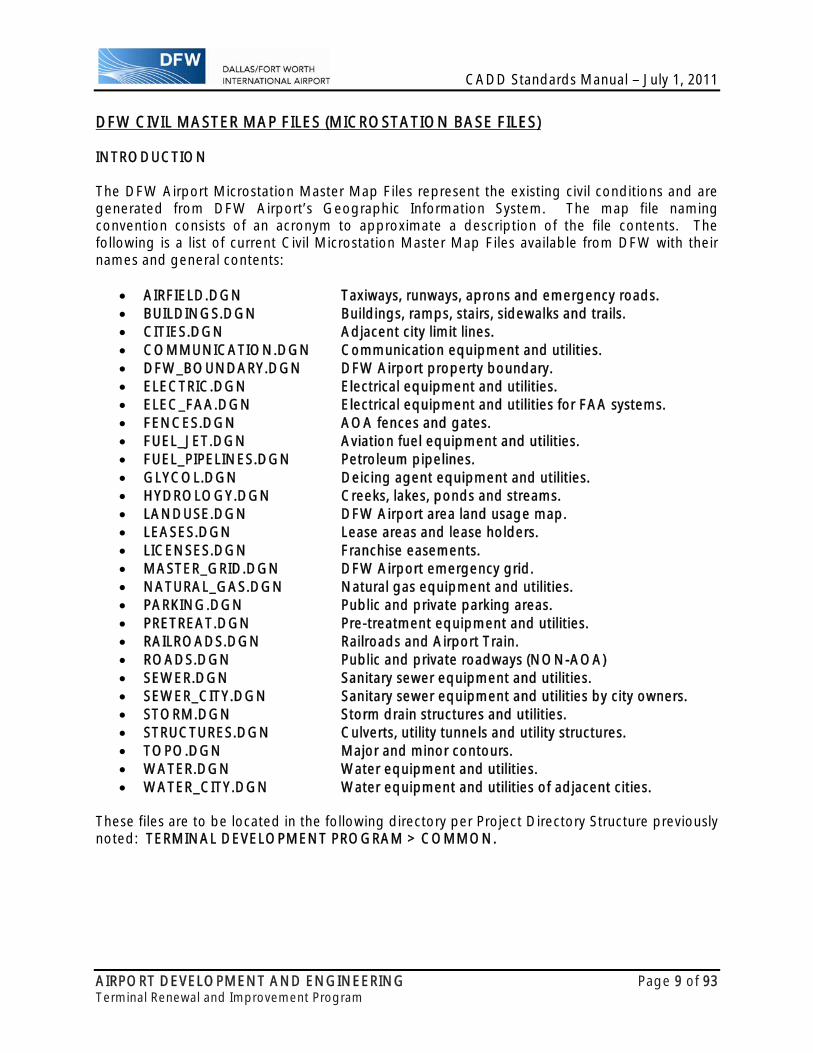
DFW CIVIL MASTER MAP FILES (MICROSTATION BASE FILES) INTRODUCTION The DFW Airport Microstation Master Map Files represent the existing civil conditions and are generated from DFW Airport’s Geographic Information System. The map file naming convention consists of an acronym to approximate a description of the file contents. The following is a list of current Civil Microstation Master Map Files available from DFW with their names and general contents:
AIRFIELD.DGN Taxiways, runways, aprons and emergency roads. BUILDINGS.DGN Buildings, ramps, stairs, sidewalks and trails. CITIES.DGN Adjacent city limit lines. COMMUNICATION.DGN Communication equipment and utilities. DFW_BOUNDARY.DGN DFW Airport property boundary. ELECTRIC.DGN Electrical equipment and utilities. ELEC_FAA.DGN Electrical equipment and utilities for FAA systems. FENCES.DGN AOA fences and gates. FUEL_JET.DGN Aviation fuel equipment and utilities. FUEL_PIPELINES.DGN Petroleum pipelines. GLYCOL.DGN Deicing agent equipment and utilities. HYDROLOGY.DGN Creeks, lakes, ponds and streams. LANDUSE.DGN DFW Airport area land usage map. LEASES.DGN Lease areas and lease holders. LICENSES.DGN Franchise easements. MASTER_GRID.DGN DFW Airport emergency grid. NATURAL_GAS.DGN Natural gas equipment and utilities. PARKING.DGN Public and private parking areas. PRETREAT.DGN Pre-treatment equipment and utilities. RAILROADS.DGN Railroads and Airport Train. ROADS.DGN Public and private roadways (NON-AOA) SEWER.DGN Sanitary sewer equipment and utilities. SEWER_CITY.DGN Sanitary sewer equipment and utilities by city owners. STORM.DGN Storm drain structures and utilities. STRUCTURES.DGN Culverts, utility tunnels and utility structures. TOPO.DGN Major and minor contours. WATER.DGN Water equipment and utilities. WATER_CITY.DGN Water equipment and utilities of adjacent cities.
These files are to be located in the following directory per Project Directory Structure previously noted: TERMINAL DEVELOPMENT PROGRAM > COMMON.

CADD Standards Manual – July 1, 2011
AIRPORT DEVELOPMENT AND ENGINEERING Page 10 of 93 Terminal Renewal and Improvement Program
ARCHITECTURAL MASTER MAP FILES (AUTOCAD BASE FILES) The AutoCAD Master Map Files represent the existing building conditions based on field surveys done by each sub consultant based on their discipline. These files were generated by individual sub consultants and have been recently updated to show the most current conditions. The following is a list of current AutoCAD Master Map file names and their general contents:
10TRIPAEXP01P0A.DWG ARCHITECTURAL, EXISTING PLAN, RAMP LEVEL, TERMINAL A 10TRIPAEXP02P0A.DWG ARCHITECTURAL, EXISTING PLAN, CONCOURSE LEVEL, TERMINAL A 10TRIPAEXP03P0A.DWG ARCHITECTURAL, EXISTING PLAN, LEVEL 3, TERMINAL A 10TRIPAEXP01P0B.DWG ARCHITECTURAL, EXISTING PLAN, RAMP LEVEL, TERMINAL B 10TRIPAEXP02P0B.DWG ARCHITECTURAL, EXISTING PLAN, CONCOURSE LEVEL, TERMINAL B 10TRIPAEXP03P0B.DWG ARCHITECTURAL, EXISTING PLAN, LEVEL 3, TERMINAL B 10TRIPAEXP00P0C.DWG ARCHITECTURAL, EXISTING PLAN, TUNNEL LEVEL, TERMINAL C 10TRIPAEXP01P0C.DWG ARCHITECTURAL, EXISTING PLAN, RAMP LEVEL, TERMINAL C 10TRIPAEXP02P0C.DWG ARCHITECTURAL, EXISTING PLAN, CONCOURSE LEVEL, TERMINAL C 10TRIPAEXP03P0C.DWG ARCHITECTURAL, EXISTING PLAN, LEVEL 3, TERMINAL C 10TRIPAEXP01P0M.DWG ARCHITECTURAL, EXISTING PLAN, RAMP LEVEL, A-B CONNECTOR 10TRIPAEXP02P0M.DWG ARCHITECTURAL, EXISTING PLAN, CONCOURSE LEVEL, A-B
CONNECTOR 10TRIPAEXP03P0M.DWG ARCHITECTURAL, EXISTING PLAN, LEVEL 3, A-B CONNECTOR 10TDPAEXP04P0M.DWG ARCHITECTURAL, EXISTING PLAN, LEVEL 4, A-B CONNECTOR 10TRIPAEXP01P0N.DWG ARCHITECTURAL, EXISTING PLAN, RAMP LEVEL, A-C CONNECTOR 10TRIPAEXP02P0N.DWG ARCHITECTURAL, EXISTING PLAN, CONCOURSE LEVEL, A-C
CONNECTOR 10TRIPAEXP08P0N.DWG ARCHITECTURAL, EXISTING PLAN, LEVEL 3, A-C CONNECTOR 10TRIPAEXP04P0N.DWG ARCHITECTURAL, EXISTING PLAN, LEVEL 4, A-C CONNECTOR LEVELS 5-7 10TRIPAEXP08P0N.DWG ARCHITECTURAL, EXISTING PLAN, LEVEL 8, A-C CONNECTOR 10TRIPAEXP09P0N.DWG ARCHITECTURAL, EXISTING PLAN, LEVEL 9, A-C CONNECTOR 10TRIPAEXP10P0N.DWG ARCHITECTURAL, EXISTING PLAN, LEVEL 10, A-C CONNECTOR 10TRIPAEXP01P0P.DWG ARCHITECTURAL, EXISTING PLAN, RAMP LEVEL, B-D CONNECTOR 10TRIPAEXP02P0P.DWG ARCHITECTURAL, EXISTING PLAN, CONCOURSE LEVEL, B-D
CONNECTOR 10TRIPAEXP03P0P.DWG ARCHITECTURAL, EXISTING PLAN, LEVEL 3, B-D CONNECTOR 10TRIPAEXP04P0P.DWG ARCHITECTURAL, EXISTING PLAN, LEVEL 4, B-D CONNECTOR
CADD Standards Manual – July 1, 2011
AIRPORT DEVELOPMENT AND ENGINEERING Page 11 of 93 Terminal Renewal and Improvement Program
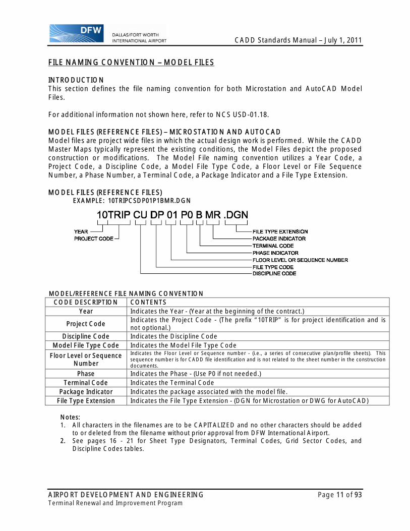
FILE NAMING CONVENTION – MODEL FILES INTRODUCTION This section defines the file naming convention for both Microstation and AutoCAD Model Files. For additional information not shown here, refer to NCS USD-01.18. MODEL FILES (REFERENCE FILES) – MICROSTATION AND AUTOCAD Model files are project wide files in which the actual design work is performed. While the CADD Master Maps typically represent the existing conditions, the Model Files depict the proposed construction or modifications. The Model File naming convention utilizes a Year Code, a Project Code, a Discipline Code, a Model File Type Code, a Floor Level or File Sequence Number, a Phase Number, a Terminal Code, a Package Indicator and a File Type Extension. MODEL FILES (REFERENCE FILES) EXAMPLE: 10TRIPCSDP01P1BMR.DGN
MODEL/REFERENCE FILE NAMING CONVENTION
CODE DESCRIPTION CONTENTS Year Indicates the Year - (Year at the beginning of the contract.)
Project Code Indicates the Project Code - (The prefix “10TRIP” is for project identification and is not optional.)
Discipline Code Indicates the Discipline Code Model File Type Code Indicates the Model File Type Code
Floor Level or Sequence Number
Indicates the Floor Level or Sequence number - (i.e., a series of consecutive plan/profile sheets). This sequence number is for CADD file identification and is not related to the sheet number in the construction documents.
Phase Indicates the Phase - (Use P0 if not needed.) Terminal Code Indicates the Terminal Code
Package Indicator Indicates the package associated with the model file. File Type Extension Indicates the File Type Extension - (DGN for Microstation or DWG for AutoCAD) Notes: 1. All characters in the filenames are to be CAPITALIZED and no other characters should be added
to or deleted from the filename without prior approval from DFW International Airport. 2. See pages 16 - 21 for Sheet Type Designators, Terminal Codes, Grid Sector Codes, and
Discipline Codes tables.

CADD Standards Manual – July 1, 2011
AIRPORT DEVELOPMENT AND ENGINEERING Page 12 of 93 Terminal Renewal and Improvement Program
FILE NAMING CONVENTION – SHEET FILES INTRODUCTION This section defines the file naming convention for both Microstation and AutoCAD Sheet Files. For additional information not shown here, refer to NCS USD-01.20. SHEET FILES A Sheet File represents the final plotted CADD drawing and is composed of Base Files to show the existing conditions, Model Files to show the proposed construction and a Border File along with general annotation placed in the Sheet File to complete the sheet. The Sheet File naming convention utilizes a Year Code, a Project Code, a Discipline Code, a Sheet Designator, a Level Indicator, a Grid Sector Code (or a Sheet Sequence number where applicable), a Phase Number, a Terminal Code, a Package Indicator and a File Type Extension. SHEET FILES (MASTER FILES) EXAMPLE STRUCTURE: 10TRIPAE12101AP1AMR.DGN EXAMPLE SITE: 10TRIPCU50001P0TMR.DGN
SHEET FILE NAMING CONVENTION
CODE DESCRIPTION CONTENTS Year Indicates the Year - (Year at the beginning of the contract.)
Project Code Indicates the Project Code - (The prefix “10TRIP” is for project identification and is not optional.)
Discipline Code Indicates the Discipline Code Sheet Designator Indicates the Sheet Type Designator
Level Indicator Indicates the Floor Level of the Sheet, it is to be “0” if it is not specific
Grid Sector Structures: Identifies the Grid Sector (101A), the first numeric being a Terminal Indicator. Non Plan Sheets: Identifies a sheet sequence number (1000), the first numeric being a Terminal Indicator. Site: Identifies a sheet sequence number (1000), the first numeric being a Terminal Indicator.
Phase Indicates the Phase - (Use P0 if not needed.) Terminal Code Indicates the Terminal Code
Package Indicator Indicates the package associated with the sheet file. File Type Extension Indicates the File Type Extension - (DGN for Microstation or DWG for AutoCAD) Notes: 1. All characters in the filenames are to be CAPITALIZED and no other characters should be added
to or deleted from the filename without prior approval from DFW International Airport. 2. See pages 16 - 21 for Sheet Type Designators, Terminal Codes, Grid Sector Codes, and
Discipline Codes tables.

CADD Standards Manual – July 1, 2011
AIRPORT DEVELOPMENT AND ENGINEERING Page 13 of 93 Terminal Renewal and Improvement Program
SHEET NUMBERING SHEET NUMBER VERSUS SHEET FILE NAME The sheet number that appears on finished plots will approximate the sheet file name. The sheet number uses the same Discipline Code, Sheet Designator, Level Indicator, Grid Sector Code and Package Indicator that are utilized in the sheet file naming conventions. Examples are shown below. EXAMPLE STRUCTURES SHEET:
Sheet File Name: 10TRIPAE12101AP1AMR.DGN Sheet Number: AE1-2-101A-MR
EXAMPLE SITES SHEET: Sheet File Name: 10TRIPCU50001P0TMR.DGN Sheet Number: CU5-0-0001-MR
SHEET NUMBER NAMING CONVENTIONCODE DESCRIPTION CONTENTS
Discipline Code Indicates the Discipline Code Sheet Designator Indicates the Sheet Type Designator
Separator Hyphen used as a separator Level Indicator Indicates the Floor Level of the Sheet, it is to be “0” if it is not specific
Separator Hyphen used as a separator
Grid Sector Structures: Identifies the Grid Sector (101A), the first numeric being a Terminal Indicator. Non Plan Sheets: Identifies a sheet sequence number (1000), the first numeric being a Terminal Indicator. Site: Identifies a sheet sequence number (1000), the first numeric being a Terminal Indicator.
Separator Hyphen used as a separator Package Indicator Indicates the package associated with the sheet. Notes: 1. All characters in the filenames are to be CAPITALIZED and no other characters should be added
to or deleted from the filename without prior approval from DFW International Airport. 2. See pages 16 - 21 for Sheet Type Designators, Terminal Codes, Grid Sector Codes, and
Discipline Codes tables.

CADD Standards Manual – July 1, 2011
AIRPORT DEVELOPMENT AND ENGINEERING Page 14 of 93 Terminal Renewal and Improvement Program
FILE NAMING CONVENTION - BORDER FILES INTRODUCTION This section defines the file naming convention for both Microstation and AutoCAD Border files. For additional information not shown here, refer to NCS USD-01.18. BORDER FILES Border files are project wide files used to create and print the sheets. The Border File naming convention utilizes a Year Code, a Project Code, a Software Code, a Border File Code, a Working Units Code, a Page Size Code, a Terminal Code, a Package Indicator and a File Type Extension. This file naming convention utilized for the Border Files is consistent with NCS and is further described below. BORDER FILES
EXAMPLE: 10TRIPGJBF01PCXMR.DGN
BORDER FILE NAMING CONVENTION
CODE DESCRIPTION CONTENTS Year Indicates the Year - (Year at the beginning of the contract.)
Project Code Indicates the Project Code - (The prefix “10TRIP” is for project identification and is not optional.)
Software Code Indicates the Software Code - (GJ indicates Microstation file, GK indicates AutoCAD file.)
Border File Code Indicates a Border File Code
Working Units Indicates the Working Units of the file - (Number 01 indicates a file with Civil Working Units. Number 02 indicates a file with Architectural Units.)
Page Size Code Indicates the Page Size Code - ( See Note 2 below) Terminal Code Indicates the Terminal Code
Package Indicator Indicates the package associated with the border file. File Type Extension Indicates the File Type Extension - (DGN for Microstation or DWG for AutoCAD)
Notes: 1. All characters in the filenames are to be CAPITALIZED and no other characters should be added
to or deleted from the filename without prior approval from DFW International Airport. 2. Page Size Codes are as follows and are shown in inches:
PA=8.5x11, PB=11x17, PC=17x22, PD=22x34, PE=30x42
CADD Standards Manual – July 1, 2011
AIRPORT DEVELOPMENT AND ENGINEERING Page 15 of 93 Terminal Renewal and Improvement Program
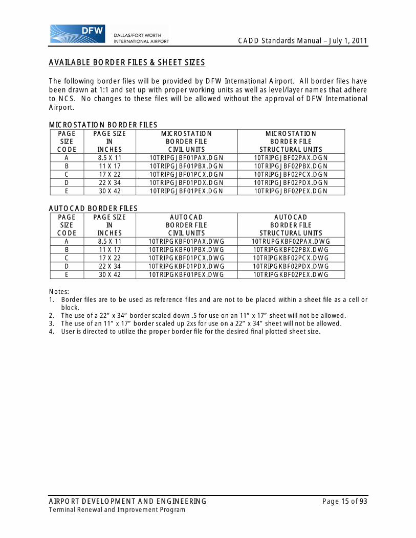
AVAILABLE BORDER FILES & SHEET SIZES The following border files will be provided by DFW International Airport. All border files have been drawn at 1:1 and set up with proper working units as well as level/layer names that adhere to NCS. No changes to these files will be allowed without the approval of DFW International Airport. MICROSTATION BORDER FILES
PAGE SIZE
CODE
PAGE SIZE IN
INCHES
MICROSTATIONBORDER FILE CIVIL UNITS
MICROSTATION BORDER FILE
STRUCTURAL UNITS A 8.5 X 11 10TRIPGJBF01PAX.DGN 10TRIPGJBF02PAX.DGN B 11 X 17 10TRIPGJBF01PBX.DGN 10TRIPGJBF02PBX.DGN C 17 X 22 10TRIPGJBF01PCX.DGN 10TRIPGJBF02PCX.DGN D 22 X 34 10TRIPGJBF01PDX.DGN 10TRIPGJBF02PDX.DGN E 30 X 42 10TRIPGJBF01PEX.DGN 10TRIPGJBF02PEX.DGN
AUTOCAD BORDER FILES
PAGE SIZE
CODE
PAGE SIZE IN
INCHES
AUTOCADBORDER FILE CIVIL UNITS
AUTOCAD BORDER FILE
STRUCTURAL UNITS A 8.5 X 11 10TRIPGKBF01PAX.DWG 10TRUPGKBF02PAX.DWG B 11 X 17 10TRIPGKBF01PBX.DWG 10TRIPGKBF02PBX.DWG C 17 X 22 10TRIPGKBF01PCX.DWG 10TRIPGKBF02PCX.DWG D 22 X 34 10TRIPGKBF01PDX.DWG 10TRIPGKBF02PDX.DWG E 30 X 42 10TRIPGKBF01PEX.DWG 10TRIPGKBF02PEX.DWG
Notes: 1. Border files are to be used as reference files and are not to be placed within a sheet file as a cell or
block. 2. The use of a 22” x 34” border scaled down .5 for use on an 11” x 17” sheet will not be allowed. 3. The use of an 11” x 17” border scaled up 2xs for use on a 22” x 34” sheet will not be allowed. 4. User is directed to utilize the proper border file for the desired final plotted sheet size.
CADD Standards Manual – July 1, 2011
AIRPORT DEVELOPMENT AND ENGINEERING Page 16 of 93 Terminal Renewal and Improvement Program
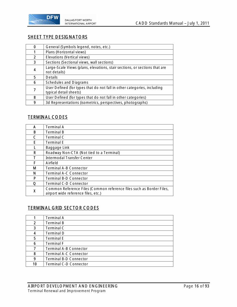
SHEET TYPE DESIGNATORS
0 General (Symbols legend, notes, etc.) 1 Plans (Horizontal views) 2 Elevations (Vertical views) 3 Sections (Sectional views, wall sections)
4 Large-Scale Views (plans, elevations, stair sections, or sections that are not details)
5 Details 6 Schedules and Diagrams
7 User Defined (for types that do not fall in other categories, including typical detail sheets)
8 User Defined (for types that do not fall in other categories) 9 3d Representations (isometrics, perspectives, photographs)
TERMINAL CODES
A Terminal A B Terminal B C Terminal C E Terminal E L Baggage Link R Roadway Non-CTA (Not tied to a Terminal) T Intermodal Transfer Center F Airfield M Terminal A-B Connector N Terminal A-C Connector P Terminal B-D Connector Q Terminal C-D Connector
X Common Reference Files (Common reference files such as Border Files, airport wide reference files, etc.)
TERMINAL GRID SECTOR CODES
1 Terminal A 2 Terminal B 3 Terminal C 4 Terminal D 5 Terminal E 6 Terminal F 7 Terminal A-B Connector 8 Terminal A-C Connector 9 Terminal B-D Connector 10 Terminal C-D Connector
CADD Standards Manual – July 1, 2011
AIRPORT DEVELOPMENT AND ENGINEERING Page 17 of 93 Terminal Renewal and Improvement Program
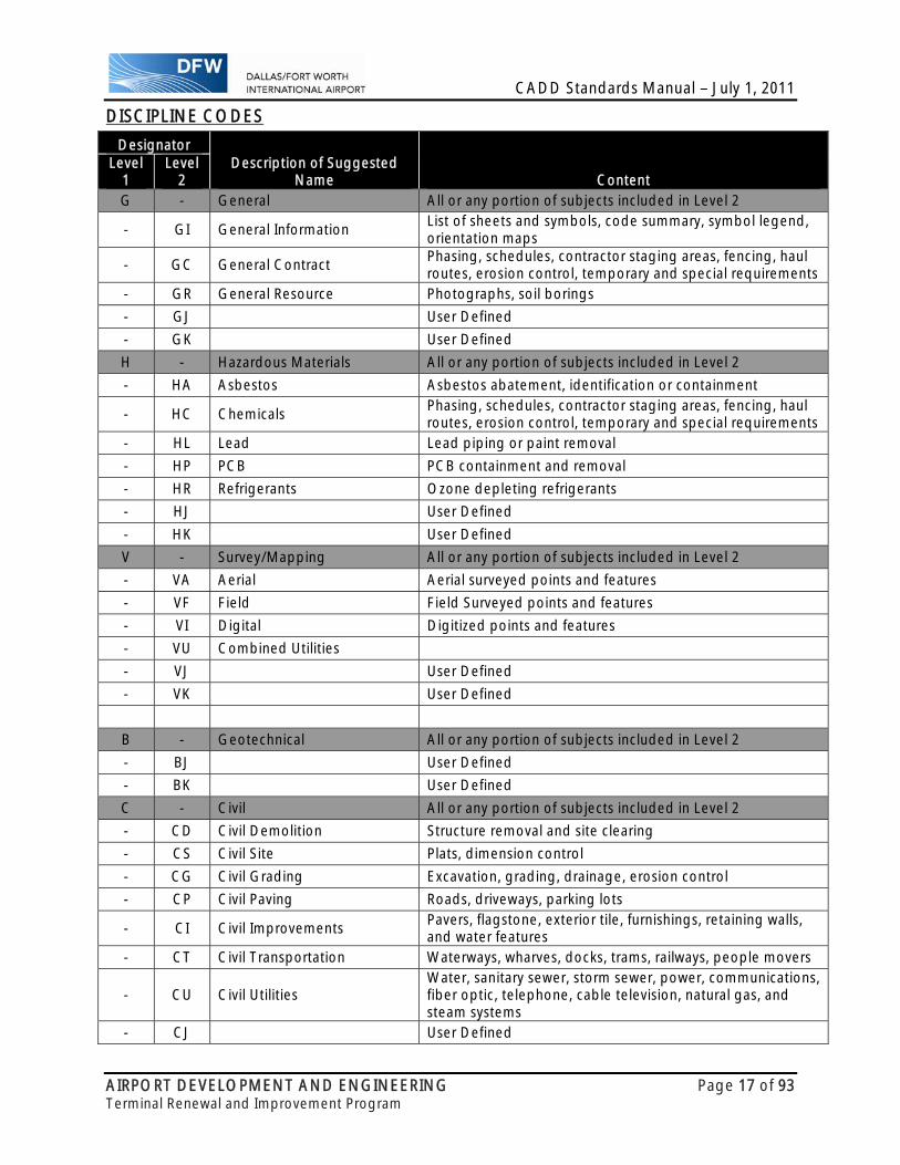
DISCIPLINE CODES
Designator Description of Suggested
Name Content Level
1 Level
2 G - General All or any portion of subjects included in Level 2
- GI General Information List of sheets and symbols, code summary, symbol legend, orientation maps
- GC General Contract Phasing, schedules, contractor staging areas, fencing, haul routes, erosion control, temporary and special requirements
- GR General Resource Photographs, soil borings
- GJ User Defined
- GK User Defined
H - Hazardous Materials All or any portion of subjects included in Level 2
- HA Asbestos Asbestos abatement, identification or containment
- HC Chemicals Phasing, schedules, contractor staging areas, fencing, haul routes, erosion control, temporary and special requirements
- HL Lead Lead piping or paint removal
- HP PCB PCB containment and removal
- HR Refrigerants Ozone depleting refrigerants
- HJ User Defined
- HK User Defined
V - Survey/Mapping All or any portion of subjects included in Level 2
- VA Aerial Aerial surveyed points and features
- VF Field Field Surveyed points and features
- VI Digital Digitized points and features
- VU Combined Utilities
- VJ User Defined
- VK User Defined
B - Geotechnical All or any portion of subjects included in Level 2
- BJ User Defined
- BK User Defined
C - Civil All or any portion of subjects included in Level 2
- CD Civil Demolition Structure removal and site clearing
- CS Civil Site Plats, dimension control
- CG Civil Grading Excavation, grading, drainage, erosion control
- CP Civil Paving Roads, driveways, parking lots
- CI Civil Improvements Pavers, flagstone, exterior tile, furnishings, retaining walls, and water features
- CT Civil Transportation Waterways, wharves, docks, trams, railways, people movers
- CU Civil Utilities Water, sanitary sewer, storm sewer, power, communications, fiber optic, telephone, cable television, natural gas, and steam systems
- CJ User Defined
CADD Standards Manual – July 1, 2011
AIRPORT DEVELOPMENT AND ENGINEERING Page 18 of 93 Terminal Renewal and Improvement Program
Designator Description of Suggested
Name Content Level
1 Level
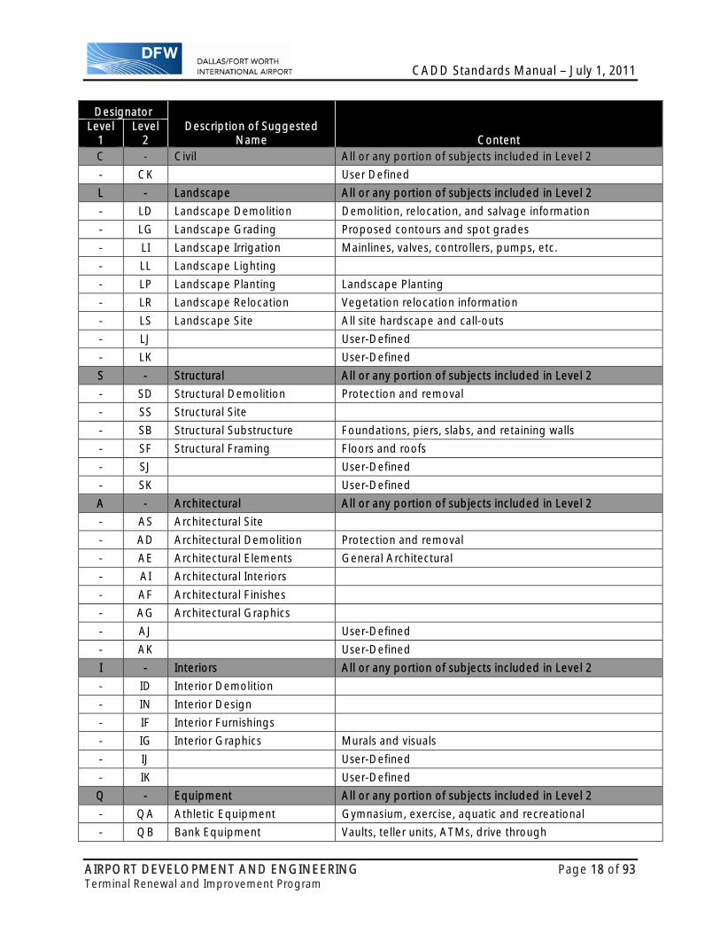
2 C - Civil All or any portion of subjects included in Level 2
- CK User Defined
L - Landscape All or any portion of subjects included in Level 2
- LD Landscape Demolition Demolition, relocation, and salvage information
- LG Landscape Grading Proposed contours and spot grades
- LI Landscape Irrigation Mainlines, valves, controllers, pumps, etc.
- LL Landscape Lighting
- LP Landscape Planting Landscape Planting
- LR Landscape Relocation Vegetation relocation information
- LS Landscape Site All site hardscape and call-outs
- LJ User-Defined
- LK User-Defined
S - Structural All or any portion of subjects included in Level 2
- SD Structural Demolition Protection and removal
- SS Structural Site
- SB Structural Substructure Foundations, piers, slabs, and retaining walls
- SF Structural Framing Floors and roofs
- SJ User-Defined
- SK User-Defined
A - Architectural All or any portion of subjects included in Level 2
- AS Architectural Site
- AD Architectural Demolition Protection and removal
- AE Architectural Elements General Architectural
- AI Architectural Interiors
- AF Architectural Finishes
- AG Architectural Graphics
- AJ User-Defined
- AK User-Defined
I - Interiors All or any portion of subjects included in Level 2
- ID Interior Demolition
- IN Interior Design
- IF Interior Furnishings
- IG Interior Graphics Murals and visuals
- IJ User-Defined
- IK User-Defined
Q - Equipment All or any portion of subjects included in Level 2
- QA Athletic Equipment Gymnasium, exercise, aquatic and recreational
- QB Bank Equipment Vaults, teller units, ATMs, drive through
CADD Standards Manual – July 1, 2011
AIRPORT DEVELOPMENT AND ENGINEERING Page 19 of 93 Terminal Renewal and Improvement Program
Designator Description of Suggested
Name Content Level
1 Level
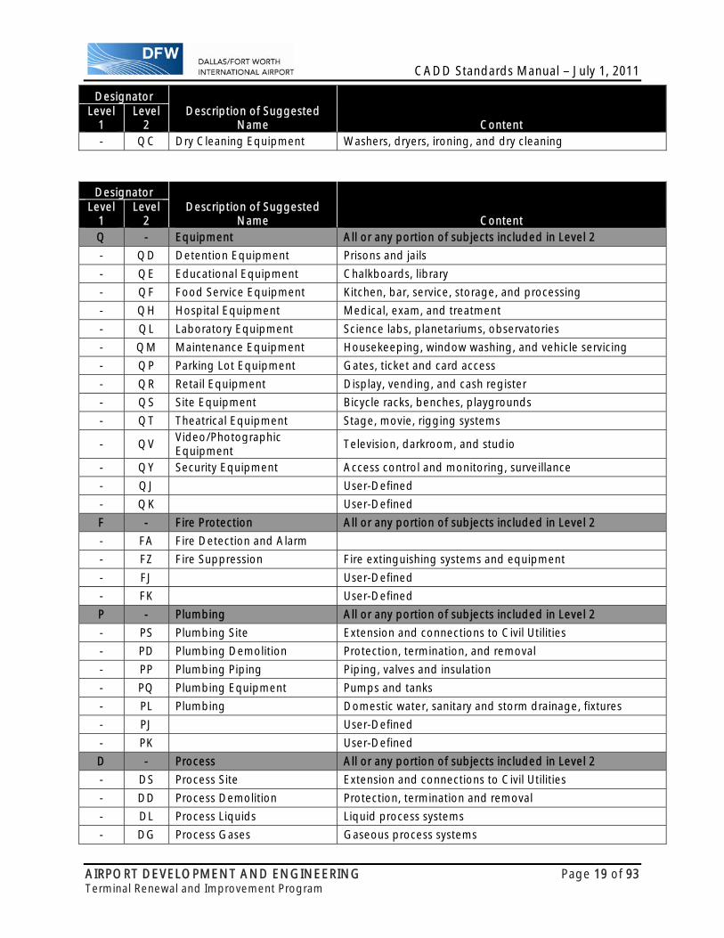
2 - QC Dry Cleaning Equipment Washers, dryers, ironing, and dry cleaning
Designator Description of Suggested
Name Content Level
1 Level
2 Q - Equipment All or any portion of subjects included in Level 2
- QD Detention Equipment Prisons and jails
- QE Educational Equipment Chalkboards, library
- QF Food Service Equipment Kitchen, bar, service, storage, and processing
- QH Hospital Equipment Medical, exam, and treatment
- QL Laboratory Equipment Science labs, planetariums, observatories
- QM Maintenance Equipment Housekeeping, window washing, and vehicle servicing
- QP Parking Lot Equipment Gates, ticket and card access
- QR Retail Equipment Display, vending, and cash register
- QS Site Equipment Bicycle racks, benches, playgrounds
- QT Theatrical Equipment Stage, movie, rigging systems
- QV Video/Photographic Equipment
Television, darkroom, and studio
- QY Security Equipment Access control and monitoring, surveillance
- QJ User-Defined
- QK User-Defined
F - Fire Protection All or any portion of subjects included in Level 2
- FA Fire Detection and Alarm
- FZ Fire Suppression Fire extinguishing systems and equipment
- FJ User-Defined
- FK User-Defined
P - Plumbing All or any portion of subjects included in Level 2
- PS Plumbing Site Extension and connections to Civil Utilities
- PD Plumbing Demolition Protection, termination, and removal
- PP Plumbing Piping Piping, valves and insulation
- PQ Plumbing Equipment Pumps and tanks
- PL Plumbing Domestic water, sanitary and storm drainage, fixtures
- PJ User-Defined
- PK User-Defined
D - Process All or any portion of subjects included in Level 2
- DS Process Site Extension and connections to Civil Utilities
- DD Process Demolition Protection, termination and removal
- DL Process Liquids Liquid process systems
- DG Process Gases Gaseous process systems

CADD Standards Manual – July 1, 2011
AIRPORT DEVELOPMENT AND ENGINEERING Page 20 of 93 Terminal Renewal and Improvement Program
Designator Description of Suggested
Name Content Level
1 Level
2 - DP Process Piping Piping, valves, insulation, tanks, pumps, etc.
- DQ Process Equipment Systems and equipment for thermal, electrical, materials handling, assembly and manufacturing, nuclear, power generation, chemical, refrigeration, and industrial processes
- DE Process Electrical Electrical exclusively associated with a process and not the facility
Designator Description of Suggested
Name Content Level
1 Level
2 D - Process All or any portion of subjects included in Level 2
- DI Process Instrumentation Instrumentation, measurement, recorders, devices and controllers (electrical and mechanical)
- DW Process Waters Piping, valves, system components, equipment
- DC Process Chemicals Piping, valves, system components, equipment
- DA Process Airs Piping, valves, system components, equipment
- DX Process Exhaust Ducting, piping, valves, system components, equipment
- DR Process Drains and Reclaims Piping, valves, system components, equipment
- DM Process HPM Gases Piping, valves, system components, equipment
- DY Process Slurry Piping, valves, system components, equipment
- DO Process Oil Piping, valves, system components, equipment
- DV Process Vacuum Piping, valves, system components, equipment
- DJ User-Defined
- DK User-Defined
M - Mechanical All or any portion of subjects included in Level 2
- MS Mechanical Site Utility tunnels and piping between facilities
- MDH Mechanical DemolitionHVAC/DUCTWORK
HVAC/Ductwork protection, termination, and removal
- MDP Mechanical Demolition Piping
Piping protection, termination, and removal
- MH Mechanical HVAC Ductwork, air devices and equipment
- MP Mechanical Piping Chilled and heating water, steam
- MI Mechanical Instrumentation Instrumentation and control
- MJ User-Defined
- MK User-Defined
E - Electrical All or any portion of subjects included in Level 2
- ES Electrical Site Utility tunnels, site lighting
- ED Electrical Demolition Protection, termination, and removal
- EP Electrical Power
- EL Electrical Lighting

CADD Standards Manual – July 1, 2011
AIRPORT DEVELOPMENT AND ENGINEERING Page 21 of 93 Terminal Renewal and Improvement Program
Designator Description of Suggested
Name Content Level
1 Level
2 - EI Electrical Instrumentation Controls, relays, instrumentation, and measurement devices
- ET Electrical Telecommunications
Telephone, network, voice and data cables
- EY Electrical Auxiliary Systems Alarms, nurse call, security, CCTV, PA, music, clock, and program
- EJ User-Defined
- EK User-Defined
T - Telecommunications All or any portion of subjects included in Level 2
- TA Audio Visual Cable, music, and CCTV systems
- TC Clock and Program Time generators and bell program systems
- TI Intercom Intercom and public address systems
- TM Monitoring Monitoring and alarm systems
Designator Description of Suggested
Name Content Level
1 Level
2 T - Telecommunications All or any portion of subjects included in Level 2
- TN Data Networks Network cabling and equipment
- TT Telephone Telephone systems, wiring, and equipment
- TY Security Access control and alarm systems
- TJ User-Defined
- TK User-Defined
R - Resource Data furnished without warrant as to accuracy
- RC Resource Civil Surveyor's information and existing Civil drawings
- RS Resource Structural Existing facility structural drawings
- RA Resource Architectural Existing facility architectural drawings
- RM Resource Mechanical Existing facility mechanical drawings
- RE Resource Electrical Existing facility electrical drawings
- RJ User-Defined
- RK User-Defined
X - Other Disciplines All or any portion of subjects included in Level 2
- XJ User-Defined
- XK User-Defined
Z - Contractor / Shop Drawings All or any portion of subjects included in Level 2
- ZJ User-Defined
- ZK User-Defined
O - Operations All or any portion of subjects included in Level 2
- OJ User-Defined
- OK User-Defined
CADD Standards Manual – July 1, 2011
AIRPORT DEVELOPMENT AND ENGINEERING Page 22 of 93 Terminal Renewal and Improvement Program
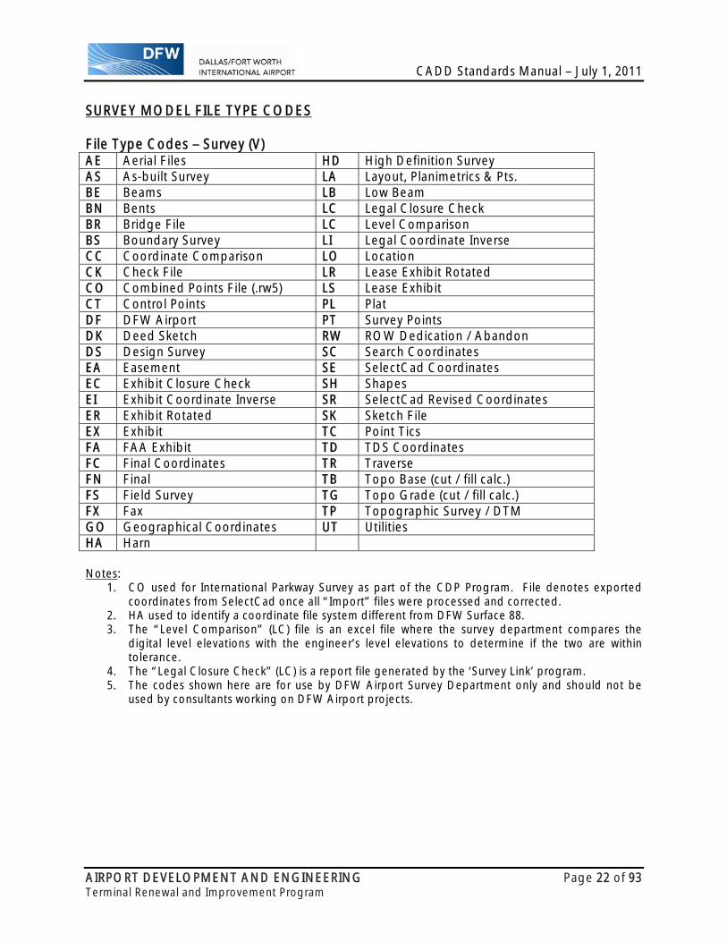
SURVEY MODEL FILE TYPE CODES File Type Codes – Survey (V) AE Aerial Files HD High Definition SurveyAS As-built Survey LA Layout, Planimetrics & Pts. BE Beams LB Low BeamBN Bents LC Legal Closure CheckBR Bridge File LC Level ComparisonBS Boundary Survey LI Legal Coordinate Inverse CC Coordinate Comparison LO LocationCK Check File LR Lease Exhibit RotatedCO Combined Points File (.rw5) LS Lease ExhibitCT Control Points PL PlatDF DFW Airport PT Survey PointsDK Deed Sketch RW ROW Dedication / Abandon DS Design Survey SC Search CoordinatesEA Easement SE SelectCad CoordinatesEC Exhibit Closure Check SH ShapesEI Exhibit Coordinate Inverse SR SelectCad Revised Coordinates ER Exhibit Rotated SK Sketch FileEX Exhibit TC Point TicsFA FAA Exhibit TD TDS CoordinatesFC Final Coordinates TR TraverseFN Final TB Topo Base (cut / fill calc.)FS Field Survey TG Topo Grade (cut / fill calc.) FX Fax TP Topographic Survey / DTM GO Geographical Coordinates UT UtilitiesHA Harn Notes:
1. CO used for International Parkway Survey as part of the CDP Program. File denotes exported coordinates from SelectCad once all “Import” files were processed and corrected.
2. HA used to identify a coordinate file system different from DFW Surface 88. 3. The “Level Comparison” (LC) file is an excel file where the survey department compares the
digital level elevations with the engineer’s level elevations to determine if the two are within tolerance.
4. The “Legal Closure Check” (LC) is a report file generated by the ‘Survey Link’ program. 5. The codes shown here are for use by DFW Airport Survey Department only and should not be
used by consultants working on DFW Airport projects.

CADD Standards Manual – July 1, 2011
AIRPORT DEVELOPMENT AND ENGINEERING Page 23 of 93 Terminal Renewal and Improvement Program
COORDINATE SYSTEM PRIMARY COORDINATE SYSTEM: This primary coordinate system is based on DFW Surface 88, a site-specific coordinate system for DFW International Airport. It was derived from NAD83 and developed using Intergraph’s MGE Coordinate System Operations (MCSO) software.
Description DFW Surface 88
Vertical Datum North American Vertical Datum 1988 Orthometric Average Undulation 0.000 ft
Spherical Model User Specified 20926146.325 ft Greenwich Offset 00:00:00.0000 d:m:s
Units and Format Latitude and Longitude d:m:s Northing and Easting ft Height ft
Coordinate System Lambert Conformal Conic
Longitude of Origin: -98:30:00.0000 Latitude of Origin: 31:40:00.0000 Standard Parallel 1 32:08:00.0000 Standard Parallel 2 33:58:00.0000 False Easting 2,000,000.0000 ft False Northing 6,000,000.0000 ft
Geodetic Datum North American 1983
Ellipsoid GRS80
Equatorial Radius 20925646.325 ft Polar Radius 20855486.595 ft Eccentricity 0.0818191910428158 Flattening 0.00335281068118232 Flattening Inverse 298.257222101

CADD Standards Manual – July 1, 2011
AIRPORT DEVELOPMENT AND ENGINEERING Page 24 of 93 Terminal Renewal and Improvement Program
SECONDARY COORDINATE SYSTEM: This secondary coordinate system is based on NAD83 and developed using Intergraph’s MGE Coordinate System Operations (MCSO) software. Description None
Vertical Datum North American Vertical Datum 1988 Orthometric Average Undulation 0.000 ft
Spherical Model User Specified 20926146.325 ft
Greenwich Offset 00:00:00.0000 d:m:s
Units and Format Latitude and Longitude d:m:s Northing and Easting ft Height ft
Coordinate System
State Plane Coordinate System 1983 4202 Texas North Central
Lambert Conformal Conic Longitude of Origin: -98:30:00.0000 Latitude of Origin: 31:40:00.0000 Standard Parallel 1 32:08:00.0000 Standard Parallel 2 33:58:00.0000 False Easting 1,968,503.9370 ft False Northing 6,561,679.7900 ft
Geodetic Datum North American 1983
Ellipsoid GRS80 Equatorial Radius 20925646.325 ft Polar Radius 20855486.595 ft Eccentricity 0.0818191910428158 Flattening 0.00335281068118232 Flattening Inverse 298.257222101
CADD Standards Manual – July 1, 2011
AIRPORT DEVELOPMENT AND ENGINEERING Page 25 of 93 Terminal Renewal and Improvement Program
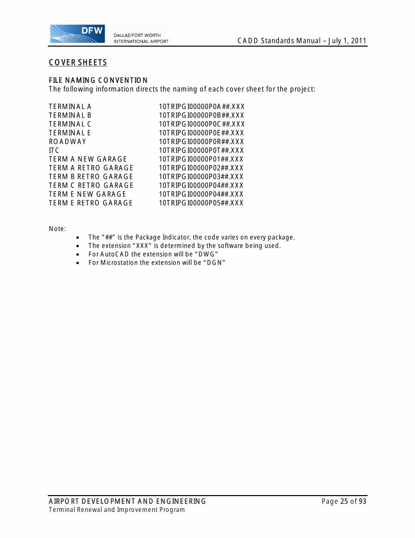
COVER SHEETS FILE NAMING CONVENTION The following information directs the naming of each cover sheet for the project: TERMINAL A 10TRIPGI00000P0A##.XXX TERMINAL B 10TRIPGI00000P0B##.XXX TERMINAL C 10TRIPGI00000P0C##.XXX TERMINAL E 10TRIPGI00000P0E##.XXX ROADWAY 10TRIPGI00000P0R##.XXX ITC 10TRIPGI00000P0T##.XXX TERM A NEW GARAGE 10TRIPGI00000P01##.XXX TERM A RETRO GARAGE 10TRIPGI00000P02##.XXX TERM B RETRO GARAGE 10TRIPGI00000P03##.XXX TERM C RETRO GARAGE 10TRIPGI00000P04##.XXX TERM E NEW GARAGE 10TRIPGI00000P04##.XXX TERM E RETRO GARAGE 10TRIPGI00000P05##.XXX Note:
The “##” is the Package Indicator, the code varies on every package. The extension “XXX” is determined by the software being used. For AutoCAD the extension will be “DWG” For Microstation the extension will be “DGN”
CADD Standards Manual – July 1, 2011
AIRPORT DEVELOPMENT AND ENGINEERING Page 26 of 93 Terminal Renewal and Improvement Program
SEALING REQUIREMENTS
PRELIMINARY SEALS
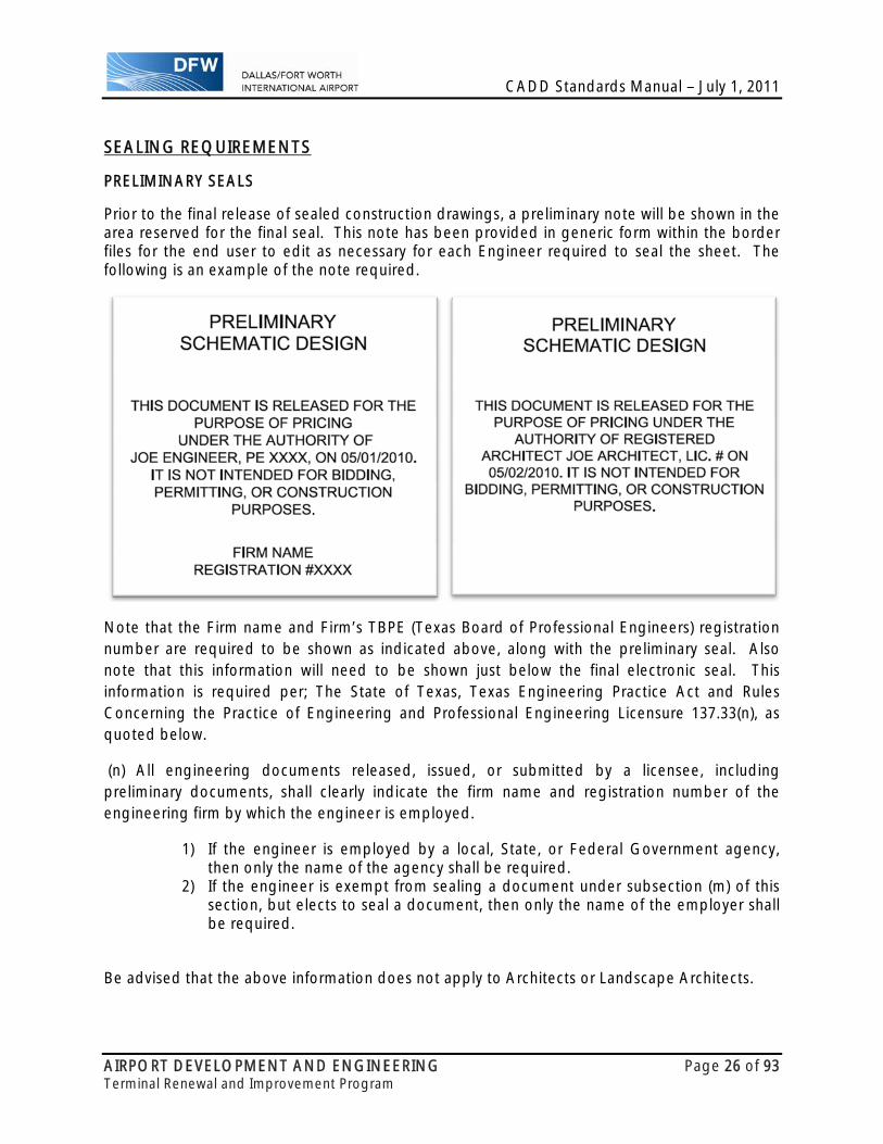
Prior to the final release of sealed construction drawings, a preliminary note will be shown in the area reserved for the final seal. This note has been provided in generic form within the border files for the end user to edit as necessary for each Engineer required to seal the sheet. The following is an example of the note required.
Note that the Firm name and Firm’s TBPE (Texas Board of Professional Engineers) registration number are required to be shown as indicated above, along with the preliminary seal. Also note that this information will need to be shown just below the final electronic seal. This information is required per; The State of Texas, Texas Engineering Practice Act and Rules Concerning the Practice of Engineering and Professional Engineering Licensure 137.33(n), as quoted below.
(n) All engineering documents released, issued, or submitted by a licensee, including preliminary documents, shall clearly indicate the firm name and registration number of the engineering firm by which the engineer is employed.
1) If the engineer is employed by a local, State, or Federal Government agency, then only the name of the agency shall be required.
2) If the engineer is exempt from sealing a document under subsection (m) of this section, but elects to seal a document, then only the name of the employer shall be required.
Be advised that the above information does not apply to Architects or Landscape Architects.

CADD Standards Manual – July 1, 2011
AIRPORT DEVELOPMENT AND ENGINEERING Page 27 of 93 Terminal Renewal and Improvement Program
4. MICROSTATION SPECIFIC INFORMATION INTRODUCTION This chapter discusses information specific to Microstation XM and the use of such.
DGNLIB FILES The following dgn.lib files will be provided and maintained by DFW Airport. These files were developed utilizing National CADD Standards and are used to establish a consistent level structure between all Microstation CADD files. These files will aid the user in maintaining a consistent look from sheet to sheet by establishing the symbology for each level within the dgn.lib file. Changes to these files require notification and approval of DFW Airport. In order for the airport to maintain one central dgn.lib file for each discipline, the Consultant is NOT authorized to make any changes to these files. A request for change or additions to these files can be made with the use of the form at the end of Chapter One. Any additional levels approved by DFW Airport will be placed in the ADDNLDGN.LIB file separate from all other dgn.lib files and reissued to the Consultant. In this manner, future updates to the NCS will not override additional levels and all Consultants will utilize the same level structure and symbology.
Dgnlib files to be added as developed.
This section defines the Microstation V8 concept of the Design Cube, Working Units and Global Origin. Use of the proper V8 Seed Files, provided with this document and as defined in Chapter 7 will ensure compatibility with the DFW Airport Design Cube.
DESIGN CUBE In the past, Microstation utilized a finite design cube that had 4,294,967,296 Positional Units (P.U.) or Units of Resolution (U.O.R.) in each axis (x, y & z). These points were divided up into a grid based on the Working Units. Since the size of the design cube was fixed, there was a tradeoff between decimal places and drawing size. The larger the drawing, the fewer decimal places were available, which affected the degree of accuracy within the drawing file.
Microstation V8 has a practically unlimited drawing cube that is still defined by the Working Units, only now every coordinate in the drawing cube is calculated and stored to a full double precision number, thereby increasing the degree of accuracy and allowing Microstation V8 to fully understand the Working Units. This also allows Microstation to reference together a drawing in feet with a drawing in meters without the user having to adjust the scale, position or global origin of either drawing.
WORKING UNITS Working Units are made up of Master Units, Sub Units and Positional Units expressed as MU:SU:PU and define the unit of measure in each Model File. Every Model File attached to a Sheet File has its own Working Units and each can be different.
Master Units (MU) are the largest units of the design cube. Typically set to Feet or Meters with a value of 1.
Sub Units (SU) are the second largest units of the design cube that divides the MU into smaller components. Typically set with a value of 12 to show inches or a value of 10 to show tenths of a foot.

CADD Standards Manual – July 1, 2011
AIRPORT DEVELOPMENT AND ENGINEERING Page 28 of 93 Terminal Renewal and Improvement Program
Positional Units (PU) are the smallest units of the design cube. The number of PU’s per SU determines the drawing’s precision and the size of the Design Cube. DFW Airport used 1000 PU’s for both Civil and Architectural Files.
The only Working Unit definitions that need to be defined with Microstation V8 are the Master Units and the Sub Units. The PU’s are built into Microstation V8 and are selectable from an option list. Again, the use of the proper V8 Seed File will ensure compatibility with all DFW design files. The Working Units and Unit Labels are preset within the DFW V8 Seed Files and should not be changed. To verify the correct settings, they are shown in the DGN File Settings dialog box as indicated below.
CADD Standards Manual – July 1, 2011
AIRPORT DEVELOPMENT AND ENGINEERING Page 29 of 93 Terminal Renewal and Improvement Program
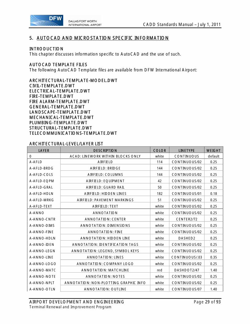
5. AUTOCAD AND MICROSTATION SPECIFIC INFORMATION INTRODUCTION This chapter discusses information specific to AutoCAD and the use of such. AUTOCAD TEMPLATE FILES The following AutoCAD Template files are available from DFW International Airport: ARCHITECTURAL-TEMPLATE-MODEL.DWT CIVIL-TEMPLATE.DWT ELECTRICAL-TEMPLATE.DWT FIRE-TEMPLATE.DWT FIRE ALARM-TEMPLATE.DWT GENERAL-TEMPLATE.DWT LANDSCAPE-TEMPLATE.DWT MECHANICAL-TEMPLATE.DWT PLUMBING-TEMPLATE.DWT STRUCTURAL-TEMPLATE.DWT TELECOMMUNICATIONS-TEMPLATE.DWT
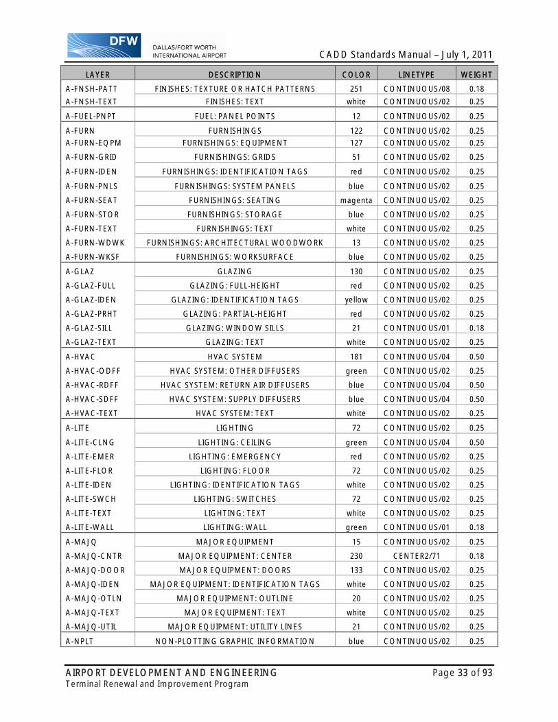
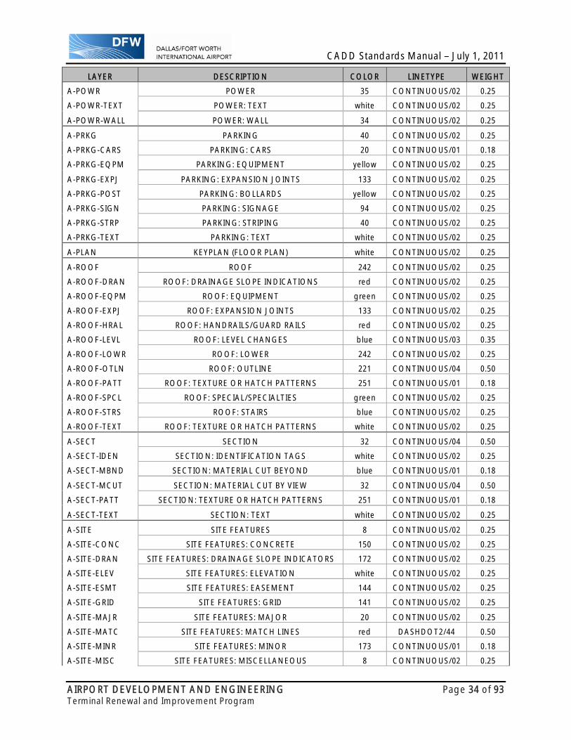
ARCHITECTURAL-LEVEL/LAYER LIST
LAYER DESCRIPTION COLOR LINETYPE WEIGHT
0 ACAD: LINEWORK WITHIN BLOCKS ONLY white CONTINUOUS default
A-AFLD AIRFIELD 114 CONTINUOUS/02 0.25
A-AFLD-BRDG AIRFIELD: BRIDGE 144 CONTINUOUS/02 0.25
A-AFLD-COLS AIRFIELD: COLUMNS 144 CONTINUOUS/02 0.25
A-AFLD-EQPM AIRFIELD: EQUIPMENT 42 CONTINUOUS/02 0.25
A-AFLD-GRAL AIRFIELD: GUARD RAIL 50 CONTINUOUS/02 0.25
A-AFLD-HDLN AIRFIELD: HIDDEN LINES 182 CONTINUOUS/01 0.18
A-AFLD-MRKG AIRFIELD: PAVEMENT MARKINGS 51 CONTINUOUS/02 0.25
A-AFLD-TEXT AIRFIELD: TEXT white CONTINUOUS/02 0.25
A-ANNO ANNOTATION white CONTINUOUS/02 0.25
A-ANNO-CNTR ANNOTATION: CENTER white CENTER2/72 0.25
A-ANNO-DIMS ANNOTATION: DIMENSIONS white CONTINUOUS/02 0.25
A-ANNO-FINE ANNOTATION: FINE white CONTINUOUS/02 0.25
A-ANNO-HDLN ANNOTATION: HIDDEN LINE white DASHED2 0.25
A-ANNO-IDEN ANNOTATION: IDENTIFICATION TAGS white CONTINUOUS/02 0.25
A-ANNO-LEGN ANNOTATION: LEGEND, SYMBOL KEYS white CONTINUOUS/02 0.25
A-ANNO-LINE ANNOTATION: LINES white CONTINUOUS/.03 0.35
A-ANNO-LOGO ANNOTATION: COMPANY LOGO white CONTINUOUS/02 0.25
A-ANNO-MATC ANNOTATION: MATCHLINE red DASHDOT2/47 1.40
A-ANNO-NOTE ANNOTATION: NOTES white CONTINUOUS/02 0.25
A-ANNO-NPLT ANNOTATION: NON-PLOTTING GRAPHIC INFO white CONTINUOUS/02 0.25
A-ANNO-OTLN ANNOTATION: OUTLINE white CONTINUOUS/07 1.40
CADD Standards Manual – July 1, 2011
AIRPORT DEVELOPMENT AND ENGINEERING Page 30 of 93 Terminal Renewal and Improvement Program
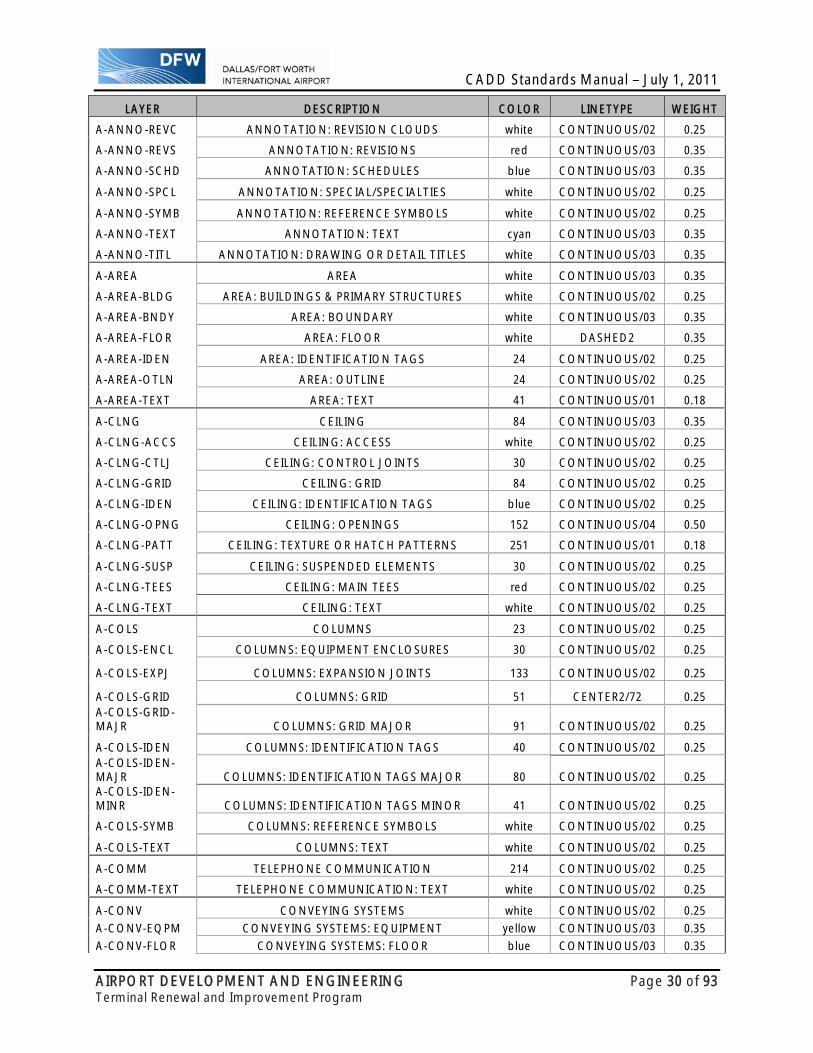
LAYER DESCRIPTION COLOR LINETYPE WEIGHT
A-ANNO-REVC ANNOTATION: REVISION CLOUDS white CONTINUOUS/02 0.25
A-ANNO-REVS ANNOTATION: REVISIONS red CONTINUOUS/03 0.35
A-ANNO-SCHD ANNOTATION: SCHEDULES blue CONTINUOUS/03 0.35
A-ANNO-SPCL ANNOTATION: SPECIAL/SPECIALTIES white CONTINUOUS/02 0.25
A-ANNO-SYMB ANNOTATION: REFERENCE SYMBOLS white CONTINUOUS/02 0.25
A-ANNO-TEXT ANNOTATION: TEXT cyan CONTINUOUS/03 0.35
A-ANNO-TITL ANNOTATION: DRAWING OR DETAIL TITLES white CONTINUOUS/03 0.35
A-AREA AREA white CONTINUOUS/03 0.35
A-AREA-BLDG AREA: BUILDINGS & PRIMARY STRUCTURES white CONTINUOUS/02 0.25
A-AREA-BNDY AREA: BOUNDARY white CONTINUOUS/03 0.35
A-AREA-FLOR AREA: FLOOR white DASHED2 0.35
A-AREA-IDEN AREA: IDENTIFICATION TAGS 24 CONTINUOUS/02 0.25
A-AREA-OTLN AREA: OUTLINE 24 CONTINUOUS/02 0.25
A-AREA-TEXT AREA: TEXT 41 CONTINUOUS/01 0.18
A-CLNG CEILING 84 CONTINUOUS/03 0.35
A-CLNG-ACCS CEILING: ACCESS white CONTINUOUS/02 0.25
A-CLNG-CTLJ CEILING: CONTROL JOINTS 30 CONTINUOUS/02 0.25
A-CLNG-GRID CEILING: GRID 84 CONTINUOUS/02 0.25
A-CLNG-IDEN CEILING: IDENTIFICATION TAGS blue CONTINUOUS/02 0.25
A-CLNG-OPNG CEILING: OPENINGS 152 CONTINUOUS/04 0.50
A-CLNG-PATT CEILING: TEXTURE OR HATCH PATTERNS 251 CONTINUOUS/01 0.18
A-CLNG-SUSP CEILING: SUSPENDED ELEMENTS 30 CONTINUOUS/02 0.25
A-CLNG-TEES CEILING: MAIN TEES red CONTINUOUS/02 0.25
A-CLNG-TEXT CEILING: TEXT white CONTINUOUS/02 0.25
A-COLS COLUMNS 23 CONTINUOUS/02 0.25
A-COLS-ENCL COLUMNS: EQUIPMENT ENCLOSURES 30 CONTINUOUS/02 0.25
A-COLS-EXPJ COLUMNS: EXPANSION JOINTS 133 CONTINUOUS/02 0.25
A-COLS-GRID COLUMNS: GRID 51 CENTER2/72 0.25 A-COLS-GRID-MAJR COLUMNS: GRID MAJOR 91 CONTINUOUS/02 0.25
A-COLS-IDEN COLUMNS: IDENTIFICATION TAGS 40 CONTINUOUS/02 0.25 A-COLS-IDEN-MAJR COLUMNS: IDENTIFICATION TAGS MAJOR 80 CONTINUOUS/02 0.25 A-COLS-IDEN-MINR COLUMNS: IDENTIFICATION TAGS MINOR 41 CONTINUOUS/02 0.25
A-COLS-SYMB COLUMNS: REFERENCE SYMBOLS white CONTINUOUS/02 0.25
A-COLS-TEXT COLUMNS: TEXT white CONTINUOUS/02 0.25
A-COMM TELEPHONE COMMUNICATION 214 CONTINUOUS/02 0.25
A-COMM-TEXT TELEPHONE COMMUNICATION: TEXT white CONTINUOUS/02 0.25
A-CONV CONVEYING SYSTEMS white CONTINUOUS/02 0.25
A-CONV-EQPM CONVEYING SYSTEMS: EQUIPMENT yellow CONTINUOUS/03 0.35
A-CONV-FLOR CONVEYING SYSTEMS: FLOOR blue CONTINUOUS/03 0.35

CADD Standards Manual – July 1, 2011
AIRPORT DEVELOPMENT AND ENGINEERING Page 31 of 93 Terminal Renewal and Improvement Program
LAYER DESCRIPTION COLOR LINETYPE WEIGHT
A-CONV-IDEN CONVEYING SYSTEMS: IDENTIFICATION TAGS 40 CONTINUOUS/02 0.25
A-CONV-MCUT CONVEYING SYSTEMS: MATERIAL CUT BY VIEW 253 HIDDEN2/21 0.18
A-CONV-OVHD CONVEYING SYSTEMS: OVERHEAD red CONTINUOUS/02 0.25
A-CONV-STRS CONVEYING SYSTEMS: ESCALATORS 142 CONTINUOUS/02 0.25
A-CONV-TEXT CONVEYING SYSTEMS: TEXT white CONTINUOUS/02 0.25
A-DETL DETAIL 24 CONTINUOUS/02 0.25
A-DETL-CLNG DETAIL: CEILING yellow CONTINUOUS/03 0.35
A-DETL-CSWK DETAIL: CASEWORK green CONTINUOUS/03 0.35
A-DETL-FLOR DETAIL: FLOOR blue CONTINUOUS/03 0.35
A-DETL-GENF DETAIL: GENERAL FEATURES 241 CONTINUOUS/01 0.18
A-DETL-GLAZ DETAIL: GLAZING blue CONTINUOUS/01 0.18
A-DETL-IDEN DETAIL: IDENTIFICATION TAGS white CONTINUOUS/02 0.25
A-DETL-MBND DETAIL: MATERIAL CUT BEYOND blue CONTINUOUS/01 0.18
A-DETL-MCUT DETAIL: MATERIAL CUT BY VIEW 32 CONTINUOUS/04 0.50
A-DETL-OTLN DETAIL: OUTLINES yellow CONTINUOUS/04 0.50
A-DETL-PATT DETAIL: TEXTURE OR HATCH PATTERN 251 CONTINUOUS/01 0.18
A-DETL-PIPE DETAIL: PIPING yellow CONTINUOUS/03 0.35
A-DETL-ROOF DETAIL: ROOF green CONTINUOUS/02 0.25
A-DETL-STRC DETAIL: STRUCTURES red CONTINUOUS/02 0.25
A-DETL-TEXT DETAIL: TEXT white CONTINUOUS/02 0.25
A-DETL-WALL DETAIL: WALL blue CONTINUOUS/01 0.18
A-DETL-XTRU DETAIL: EXTRUSION red CONTINUOUS/02 0.25
A-DOOR DOOR 133 CONTINUOUS/02 0.25
A-DOOR-FULL DOOR: FULL-HEIGHT yellow CONTINUOUS/03 0.35
A-DOOR-IDEN DOOR: IDENTIFICATION TAGS yellow CONTINUOUS/02 0.25
A-DOOR-PRHT DOOR: PARTIAL-HEIGHT red CONTINUOUS/03 0.35
A-DOOR-TEXT DOOR: TEXT white CONTINUOUS/02 0.25
A-DRAN DRAINAGE 182 CONTINUOUS/01 0.18
A-DRAN-TEXT DRAINAGE: TEXT white CONTINUOUS/02 0.25
A-ELEV ELEVATION 20 CONTINUOUS/03 0.35
A-ELEV-CSWK ELEVATION: CASEWORK green CONTINUOUS/02 0.25
A-ELEV-EXPJ ELEVATION: EXPANSION JOINT 133 CONTINUOUS/02 0.25
A-ELEV-FIXT ELEVATION: FIXTURES blue CONTINUOUS/02 0.25
A-ELEV-FNSH ELEVATION: FINISHES green CONTINUOUS/02 0.25
A-ELEV-GLAZ ELEVATION: GLAZING 130 CONTINUOUS/03 0.35
A-ELEV-IDEN ELEVATION: IDENTIFICATION TAGS blue CONTINUOUS/02 0.25
A-ELEV-JAMB ELEVATION: DOOR & WINDOW JAMBS 133 CONTINUOUS/02 0.25
A-ELEV-MBND ELEVATION: MATERIAL CUT BEYOND blue CONTINUOUS/01 0.18
A-ELEV-MCUT ELEVATION: MATERIAL CUT BY VIEW 32 CONTINUOUS/04 0.50
A-ELEV-OPNG ELEVATION: OPENINGS 32 CONTINUOUS/04 0.50
A-ELEV-OTLN ELEVATION: OUTLINES yellow CONTINUOUS/03 0.35

CADD Standards Manual – July 1, 2011
AIRPORT DEVELOPMENT AND ENGINEERING Page 32 of 93 Terminal Renewal and Improvement Program
LAYER DESCRIPTION COLOR LINETYPE WEIGHT
A-ELEV-PATT ELEVATION: TEXTURE OR HATCH PATTERN 251 CONTINUOUS/01 0.18
A-ELEV-SIGN ELEVATION: SIGNAGE red CONTINUOUS/02 0.25
A-ELEV-TEXT ELEVATION: TEXT white CONTINUOUS/02 0.25
A-EQPM EQUIPMENT 127 CONTINUOUS/02 0.25
A-EQPM-ACCS EQUIPMENT: ACCESS yellow CONTINUOUS/02 0.25
A-EQPM-CLNG EQUIPMENT: CEILING yellow CONTINUOUS/02 0.25
A-EQPM-FIXD EQUIPMENT: FIXED red CONTINUOUS/02 0.25
A-EQPM-IDEN EQUIPMENT: IDENTIFICATION TAGS yellow CONTINUOUS/02 0.25
A-EQPM-MOVE EQUIPMENT: MOVEABLE yellow CONTINUOUS/02 0.25
A-EQPM-ODFF EQUIPMENT: OTHER DIFFUSERS 9 CONTINUOUS/01 0.18
A-EQPM-TEXT EQUIPMENT: TEXT white CONTINUOUS/02 0.25
A-EVAC EVACUATION PLAN 12 CONTINUOUS/02 0.25
A-EVAC-EQPM EVACUATION PLAN: EQUIPMENT blue CONTINUOUS/01 0.18
A-EVAC-EXIT EVACUATION PLAN: EXIT red CONTINUOUS/02 0.25
A-EVAC-IDEN EVACUATION PLAN: IDENTIFICATION TAGS white CONTINUOUS/02 0.25
A-EVAC-RATE EVACUATION PLAN: RATINGS green CONTINUOUS/02 0.25
A-EVAC-TEXT EVACUATION PLAN: TEXT white CONTINUOUS/02 0.25
A-FLOR FLOOR 10 CONTINUOUS/02 0.25
A-FLOR-CSWK FLOOR: CASEWORK 41 CONTINUOUS/02 0.25
A-FLOR-EQPM FLOOR: EQUIPMENT blue CONTINUOUS/02 0.25
A-FLOR-EVTR FLOOR: ELEVATOR CARS & EQUIPMENT blue CONTINUOUS/03 0.35
A-FLOR-EXPJ FLOOR: EXPANSION JOINTS 133 CONTINUOUS/02 0.25
A-FLOR-FIXT FLOOR: FIXTURES green CONTINUOUS/02 0.25
A-FLOR-HRAL FLOOR: HANDRAILS/GUARD RAILS red CONTINUOUS/02 0.25
A-FLOR-IDEN FLOOR: IDENTIFICATION TAGS green CONTINUOUS/02 0.25
A-FLOR-LEVL FLOOR: LEVEL CHANGES yellow CONTINUOUS/03 0.35
A-FLOR-LOWR FLOOR: LOWER yellow CONTINUOUS/02 0.25
A-FLOR-OTLN FLOOR: OUTLINE 227 CONTINUOUS/02 0.25
A-FLOR-OVHD FLOOR: OVERHEAD 41 HIDDEN2/31 0.18
A-FLOR-PATT FLOOR: TEXTURE OR HATCH PATTERNS 251 CONTINUOUS/01 0.18
A-FLOR-RAIS FLOOR: RAISED green CONTINUOUS/02 0.25
A-FLOR-SIGN FLOOR: SIGNAGE red CONTINUOUS/02 0.25
A-FLOR-SPCL FLOOR: SPECAIL/SPECIALTIES green CONTINUOUS/02 0.25
A-FLOR-STRS FLOOR: STAIRS 142 CONTINUOUS/02 0.25
A-FLOR-TACC FLOOR: TOILET ACCESSORIES 11 CONTINUOUS/02 0.25
A-FLOR-TEXT FLOOR: TEXT white CONTINUOUS/02 0.25
A-FLOR-TPTN FLOOR: TOILET PARTITIONS red CONTINUOUS/02 0.25
A-FLOR-WDWK FLOOR: ARCHITECTURAL WOODWORK 63 CONTINUOUS/02 0.25
A-FNSH FINISHES 22 CONTINUOUS/01 0.18
A-FNSH-IDEN FINISHES: IDENTIFICATION TAGS white CONTINUOUS/02 0.25
CADD Standards Manual – July 1, 2011
AIRPORT DEVELOPMENT AND ENGINEERING Page 33 of 93 Terminal Renewal and Improvement Program
LAYER DESCRIPTION COLOR LINETYPE WEIGHT
A-FNSH-PATT FINISHES: TEXTURE OR HATCH PATTERNS 251 CONTINUOUS/08 0.18
A-FNSH-TEXT FINISHES: TEXT white CONTINUOUS/02 0.25
A-FUEL-PNPT FUEL: PANEL POINTS 12 CONTINUOUS/02 0.25
A-FURN FURNISHINGS 122 CONTINUOUS/02 0.25
A-FURN-EQPM FURNISHINGS: EQUIPMENT 127 CONTINUOUS/02 0.25
A-FURN-GRID FURNISHINGS: GRIDS 51 CONTINUOUS/02 0.25
A-FURN-IDEN FURNISHINGS: IDENTIFICATION TAGS red CONTINUOUS/02 0.25
A-FURN-PNLS FURNISHINGS: SYSTEM PANELS blue CONTINUOUS/02 0.25
A-FURN-SEAT FURNISHINGS: SEATING magenta CONTINUOUS/02 0.25
A-FURN-STOR FURNISHINGS: STORAGE blue CONTINUOUS/02 0.25
A-FURN-TEXT FURNISHINGS: TEXT white CONTINUOUS/02 0.25
A-FURN-WDWK FURNISHINGS: ARCHITECTURAL WOODWORK 13 CONTINUOUS/02 0.25
A-FURN-WKSF FURNISHINGS: WORKSURFACE blue CONTINUOUS/02 0.25
A-GLAZ GLAZING 130 CONTINUOUS/02 0.25
A-GLAZ-FULL GLAZING: FULL-HEIGHT red CONTINUOUS/02 0.25
A-GLAZ-IDEN GLAZING: IDENTIFICATION TAGS yellow CONTINUOUS/02 0.25
A-GLAZ-PRHT GLAZING: PARTIAL-HEIGHT red CONTINUOUS/02 0.25
A-GLAZ-SILL GLAZING: WINDOW SILLS 21 CONTINUOUS/01 0.18
A-GLAZ-TEXT GLAZING: TEXT white CONTINUOUS/02 0.25
A-HVAC HVAC SYSTEM 181 CONTINUOUS/04 0.50
A-HVAC-ODFF HVAC SYSTEM: OTHER DIFFUSERS green CONTINUOUS/02 0.25
A-HVAC-RDFF HVAC SYSTEM: RETURN AIR DIFFUSERS blue CONTINUOUS/04 0.50
A-HVAC-SDFF HVAC SYSTEM: SUPPLY DIFFUSERS blue CONTINUOUS/04 0.50
A-HVAC-TEXT HVAC SYSTEM: TEXT white CONTINUOUS/02 0.25
A-LITE LIGHTING 72 CONTINUOUS/02 0.25
A-LITE-CLNG LIGHTING: CEILING green CONTINUOUS/04 0.50
A-LITE-EMER LIGHTING: EMERGENCY red CONTINUOUS/02 0.25
A-LITE-FLOR LIGHTING: FLOOR 72 CONTINUOUS/02 0.25
A-LITE-IDEN LIGHTING: IDENTIFICATION TAGS white CONTINUOUS/02 0.25
A-LITE-SWCH LIGHTING: SWITCHES 72 CONTINUOUS/02 0.25
A-LITE-TEXT LIGHTING: TEXT white CONTINUOUS/02 0.25
A-LITE-WALL LIGHTING: WALL green CONTINUOUS/01 0.18
A-MAJQ MAJOR EQUIPMENT 15 CONTINUOUS/02 0.25
A-MAJQ-CNTR MAJOR EQUIPMENT: CENTER 230 CENTER2/71 0.18
A-MAJQ-DOOR MAJOR EQUIPMENT: DOORS 133 CONTINUOUS/02 0.25
A-MAJQ-IDEN MAJOR EQUIPMENT: IDENTIFICATION TAGS white CONTINUOUS/02 0.25
A-MAJQ-OTLN MAJOR EQUIPMENT: OUTLINE 20 CONTINUOUS/02 0.25
A-MAJQ-TEXT MAJOR EQUIPMENT: TEXT white CONTINUOUS/02 0.25
A-MAJQ-UTIL MAJOR EQUIPMENT: UTILITY LINES 21 CONTINUOUS/02 0.25
A-NPLT NON-PLOTTING GRAPHIC INFORMATION blue CONTINUOUS/02 0.25
CADD Standards Manual – July 1, 2011
AIRPORT DEVELOPMENT AND ENGINEERING Page 34 of 93 Terminal Renewal and Improvement Program
LAYER DESCRIPTION COLOR LINETYPE WEIGHT
A-POWR POWER 35 CONTINUOUS/02 0.25
A-POWR-TEXT POWER: TEXT white CONTINUOUS/02 0.25
A-POWR-WALL POWER: WALL 34 CONTINUOUS/02 0.25
A-PRKG PARKING 40 CONTINUOUS/02 0.25
A-PRKG-CARS PARKING: CARS 20 CONTINUOUS/01 0.18
A-PRKG-EQPM PARKING: EQUIPMENT yellow CONTINUOUS/02 0.25
A-PRKG-EXPJ PARKING: EXPANSION JOINTS 133 CONTINUOUS/02 0.25
A-PRKG-POST PARKING: BOLLARDS yellow CONTINUOUS/02 0.25
A-PRKG-SIGN PARKING: SIGNAGE 94 CONTINUOUS/02 0.25
A-PRKG-STRP PARKING: STRIPING 40 CONTINUOUS/02 0.25
A-PRKG-TEXT PARKING: TEXT white CONTINUOUS/02 0.25
A-PLAN KEYPLAN (FLOOR PLAN) white CONTINUOUS/02 0.25
A-ROOF ROOF 242 CONTINUOUS/02 0.25
A-ROOF-DRAN ROOF: DRAINAGE SLOPE INDICATIONS red CONTINUOUS/02 0.25
A-ROOF-EQPM ROOF: EQUIPMENT green CONTINUOUS/02 0.25
A-ROOF-EXPJ ROOF: EXPANSION JOINTS 133 CONTINUOUS/02 0.25
A-ROOF-HRAL ROOF: HANDRAILS/GUARD RAILS red CONTINUOUS/02 0.25
A-ROOF-LEVL ROOF: LEVEL CHANGES blue CONTINUOUS/03 0.35
A-ROOF-LOWR ROOF: LOWER 242 CONTINUOUS/02 0.25
A-ROOF-OTLN ROOF: OUTLINE 221 CONTINUOUS/04 0.50
A-ROOF-PATT ROOF: TEXTURE OR HATCH PATTERNS 251 CONTINUOUS/01 0.18
A-ROOF-SPCL ROOF: SPECIAL/SPECIALTIES green CONTINUOUS/02 0.25
A-ROOF-STRS ROOF: STAIRS blue CONTINUOUS/02 0.25
A-ROOF-TEXT ROOF: TEXTURE OR HATCH PATTERNS white CONTINUOUS/02 0.25
A-SECT SECTION 32 CONTINUOUS/04 0.50
A-SECT-IDEN SECTION: IDENTIFICATION TAGS white CONTINUOUS/02 0.25
A-SECT-MBND SECTION: MATERIAL CUT BEYOND blue CONTINUOUS/01 0.18
A-SECT-MCUT SECTION: MATERIAL CUT BY VIEW 32 CONTINUOUS/04 0.50
A-SECT-PATT SECTION: TEXTURE OR HATCH PATTERNS 251 CONTINUOUS/01 0.18
A-SECT-TEXT SECTION: TEXT white CONTINUOUS/02 0.25
A-SITE SITE FEATURES 8 CONTINUOUS/02 0.25
A-SITE-CONC SITE FEATURES: CONCRETE 150 CONTINUOUS/02 0.25
A-SITE-DRAN SITE FEATURES: DRAINAGE SLOPE INDICATORS 172 CONTINUOUS/02 0.25
A-SITE-ELEV SITE FEATURES: ELEVATION white CONTINUOUS/02 0.25
A-SITE-ESMT SITE FEATURES: EASEMENT 144 CONTINUOUS/02 0.25
A-SITE-GRID SITE FEATURES: GRID 141 CONTINUOUS/02 0.25
A-SITE-MAJR SITE FEATURES: MAJOR 20 CONTINUOUS/02 0.25
A-SITE-MATC SITE FEATURES: MATCH LINES red DASHDOT2/44 0.50
A-SITE-MINR SITE FEATURES: MINOR 173 CONTINUOUS/01 0.18
A-SITE-MISC SITE FEATURES: MISCELLANEOUS 8 CONTINUOUS/02 0.25
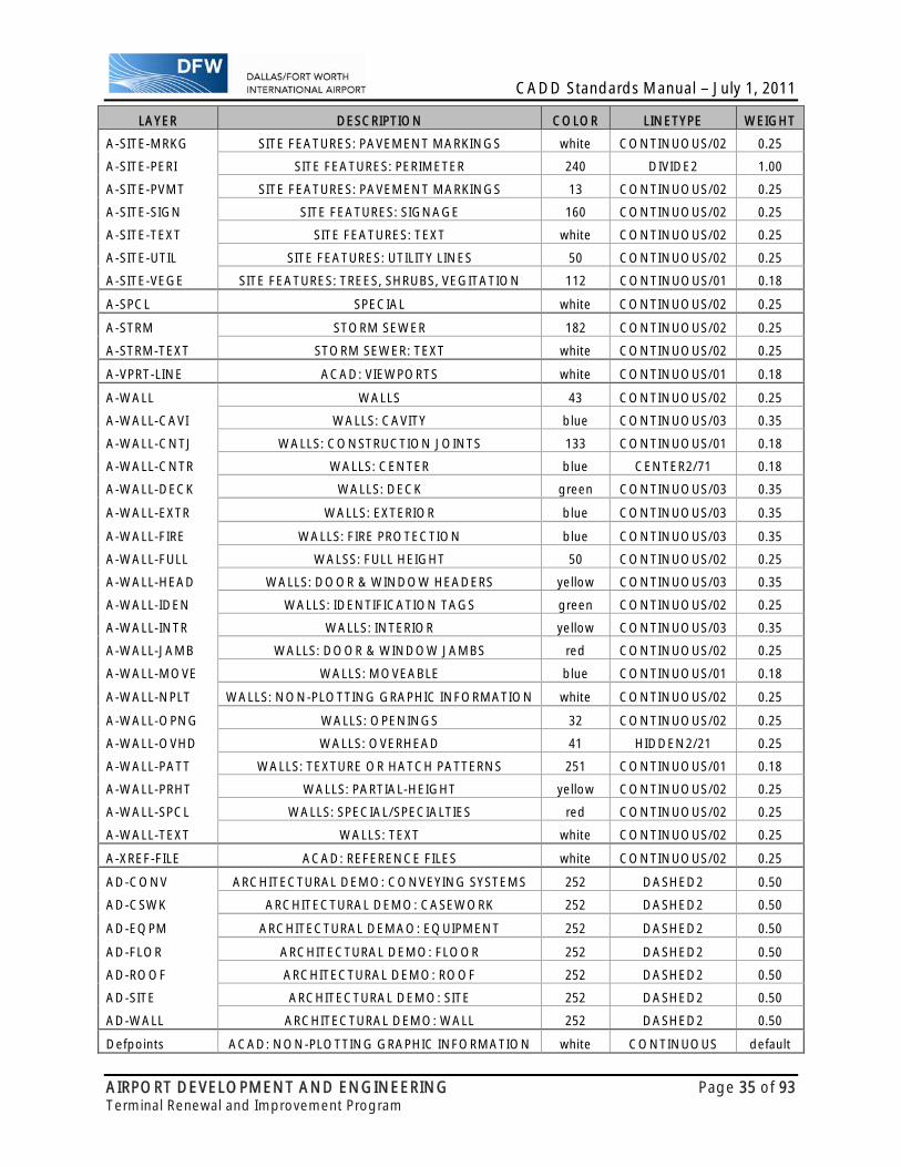
CADD Standards Manual – July 1, 2011
AIRPORT DEVELOPMENT AND ENGINEERING Page 35 of 93 Terminal Renewal and Improvement Program
LAYER DESCRIPTION COLOR LINETYPE WEIGHT
A-SITE-MRKG SITE FEATURES: PAVEMENT MARKINGS white CONTINUOUS/02 0.25
A-SITE-PERI SITE FEATURES: PERIMETER 240 DIVIDE2 1.00
A-SITE-PVMT SITE FEATURES: PAVEMENT MARKINGS 13 CONTINUOUS/02 0.25
A-SITE-SIGN SITE FEATURES: SIGNAGE 160 CONTINUOUS/02 0.25
A-SITE-TEXT SITE FEATURES: TEXT white CONTINUOUS/02 0.25
A-SITE-UTIL SITE FEATURES: UTILITY LINES 50 CONTINUOUS/02 0.25
A-SITE-VEGE SITE FEATURES: TREES, SHRUBS, VEGITATION 112 CONTINUOUS/01 0.18
A-SPCL SPECIAL white CONTINUOUS/02 0.25
A-STRM STORM SEWER 182 CONTINUOUS/02 0.25
A-STRM-TEXT STORM SEWER: TEXT white CONTINUOUS/02 0.25
A-VPRT-LINE ACAD: VIEWPORTS white CONTINUOUS/01 0.18
A-WALL WALLS 43 CONTINUOUS/02 0.25
A-WALL-CAVI WALLS: CAVITY blue CONTINUOUS/03 0.35
A-WALL-CNTJ WALLS: CONSTRUCTION JOINTS 133 CONTINUOUS/01 0.18
A-WALL-CNTR WALLS: CENTER blue CENTER2/71 0.18
A-WALL-DECK WALLS: DECK green CONTINUOUS/03 0.35
A-WALL-EXTR WALLS: EXTERIOR blue CONTINUOUS/03 0.35
A-WALL-FIRE WALLS: FIRE PROTECTION blue CONTINUOUS/03 0.35
A-WALL-FULL WALSS: FULL HEIGHT 50 CONTINUOUS/02 0.25
A-WALL-HEAD WALLS: DOOR & WINDOW HEADERS yellow CONTINUOUS/03 0.35
A-WALL-IDEN WALLS: IDENTIFICATION TAGS green CONTINUOUS/02 0.25
A-WALL-INTR WALLS: INTERIOR yellow CONTINUOUS/03 0.35
A-WALL-JAMB WALLS: DOOR & WINDOW JAMBS red CONTINUOUS/02 0.25
A-WALL-MOVE WALLS: MOVEABLE blue CONTINUOUS/01 0.18
A-WALL-NPLT WALLS: NON-PLOTTING GRAPHIC INFORMATION white CONTINUOUS/02 0.25
A-WALL-OPNG WALLS: OPENINGS 32 CONTINUOUS/02 0.25
A-WALL-OVHD WALLS: OVERHEAD 41 HIDDEN2/21 0.25
A-WALL-PATT WALLS: TEXTURE OR HATCH PATTERNS 251 CONTINUOUS/01 0.18
A-WALL-PRHT WALLS: PARTIAL-HEIGHT yellow CONTINUOUS/02 0.25
A-WALL-SPCL WALLS: SPECIAL/SPECIALTIES red CONTINUOUS/02 0.25
A-WALL-TEXT WALLS: TEXT white CONTINUOUS/02 0.25
A-XREF-FILE ACAD: REFERENCE FILES white CONTINUOUS/02 0.25
AD-CONV ARCHITECTURAL DEMO: CONVEYING SYSTEMS 252 DASHED2 0.50
AD-CSWK ARCHITECTURAL DEMO: CASEWORK 252 DASHED2 0.50
AD-EQPM ARCHITECTURAL DEMAO: EQUIPMENT 252 DASHED2 0.50
AD-FLOR ARCHITECTURAL DEMO: FLOOR 252 DASHED2 0.50
AD-ROOF ARCHITECTURAL DEMO: ROOF 252 DASHED2 0.50
AD-SITE ARCHITECTURAL DEMO: SITE 252 DASHED2 0.50
AD-WALL ARCHITECTURAL DEMO: WALL 252 DASHED2 0.50
Defpoints ACAD: NON-PLOTTING GRAPHIC INFORMATION white CONTINUOUS default

CADD Standards Manual – July 1, 2011
AIRPORT DEVELOPMENT AND ENGINEERING Page 36 of 93 Terminal Renewal and Improvement Program
CIVIL-LEVEL/LAYER LIST
LAYER DESCRIPTION COLOR LINETYPE WEIGHT
C-ALGN-DATA ALIGNMENT COORDINATES AND CURVE DATA 2 CONTINUOUS/02 0.25
C-ALGN-LINE ALIGNMENTS 4 DASHDOT2/42 0.25
C-ALGN-MAJR ALIGNMENT MAJOR STATIONING AND TICK MARKS 3 CONTINUOUS/02 0.25
C-ALGN-MARK ALIGNMENT TICK MARKS 2 CONTINUOUS/02 0.25
C-ALGN-MINR ALIGNMENT MINOR STATIONING AND TICK MARKS 5 CONTINUOUS/00 0.13
C-ALGN-STAT ALIGNMENT STATIONING AND TICK MARKS, ALIGNMENT PI'S 2 CONTINUOUS/02 0.25
C-ALGN-SYMB ALIGNMENT SYMBOLS (PIS) 5 CONTINUOUS/02 0.25
C-ALGN-TEXT ALIGNMENT TEXT, ANNOTATION WITH ASSOCIATED LEADERS 4 CONTINUOUS/02 0.25
C-ANNO-DIMS DIMENSIONS, TERMINATORS, DIMENSION TEXT 7 CONTINUOUS/00 0.13
C-ANNO-KEYN REFERENCE KEYNOTES WITH ASSOCIATED LEADERS 7 CONTINUOUS/00 0.13
C-ANNO-LEGN LEGENDS AND SYMBOLS KEYS 7 CONTINUOUS/00 0.13
C-ANNO-MASK TEXT/SHAPE MASK FOR USE WITH PHOTO BACKGROUNDS 16 CONTINUOUS/00 0.13
C-ANNO-MATC MATCH LINES 7 DASHDOT2/45 0.70
C-ANNO-NOTE GENERAL NOTES AND REMARKS 4 CONTINUOUS/02 0.25
C-ANNO-NPLT NON-PLOTTING GRAPHIC INFORMATION 1 CONTINUOUS/00 0.13
C-ANNO-PATT PATTERNING, POCHE, SHADING, AND HATCHING 9 CONTINUOUS/00 0.13
C-ANNO-RDME READ-ME INFORMATION 1 CONTINUOUS/00 0.13
C-ANNO-REVS REVISIONS 7 CONTINUOUS/03 0.35
C-ANNO-SCHD SCHEDULES 7 CONTINUOUS/00 0.13
C-ANNO-SYMB MISCELLANEOUS SYMBOLS 5 CONTINUOUS/00 0.13
C-ANNO-TEXT MISCELLANEOUS TEXT 7 CONTINUOUS/00 0.13
C-APRN-CNTR APRON CENTERLINES 3 CENTER2/72 0.25 C-APRN-CNTR-IDEN APRON CENTERLINE ANNOTATION 4 CONTINUOUS/02 0.25
C-APRN-GRND GROUNDING POINTS 4 CONTINUOUS/02 0.25
C-APRN-HOLD HOLDING POSITION MARKINGS 3 CONTINUOUS/01 0.18
C-APRN-IDEN AIRFIELD APRON - ANNOTATION 4 CONTINUOUS/02 0.25
C-APRN-MOOR MOORING POINTS 4 CONTINUOUS/02 0.25
C-APRN-MRKG APRON MARKINGS 7 CONTINUOUS/03 0.35
C-APRN-OTLN AIRFIELD APRON - OUTLINES 7 CONTINUOUS/03 0.35
C-APRN-SECU SECURITY ZONE MARKINGS 3 CONTINUOUS/01 0.18
C-APRN-SHLD SHOULDERS WITH ANNOTATION 4 CONTINUOUS/02 0.25 C-APRN-SHLD-MRKG SHOULDER STRIPES 4 CONTINUOUS/02 0.25
C-BLDG-DECK OUTDOOR DECKS (ATTACHED, NO ROOF OVERHEAD) 7 CONTINUOUS/03 0.35
C-BLDG-DOCK LOADING DOCKS 7 CONTINUOUS/03 0.35
C-BLDG-IDEN BUILDING AND OTHER STRUCTURE ANNOTATION 4 CONTINUOUS/02 0.25
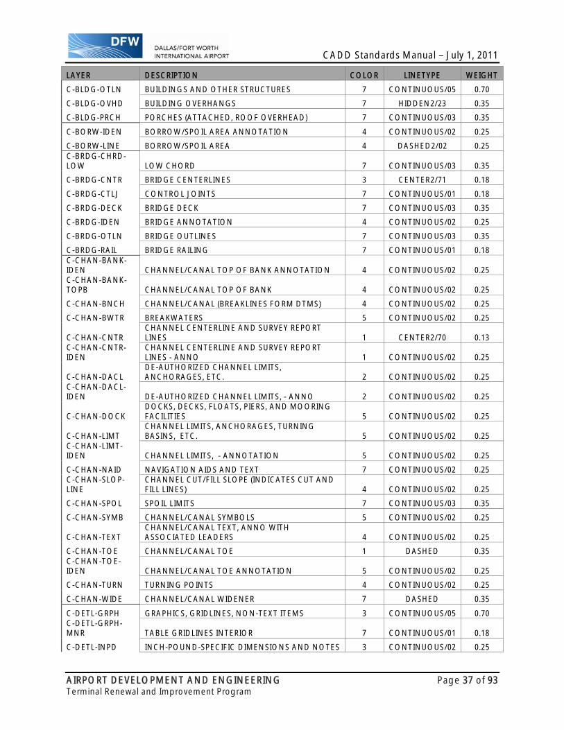
CADD Standards Manual – July 1, 2011
AIRPORT DEVELOPMENT AND ENGINEERING Page 37 of 93 Terminal Renewal and Improvement Program
LAYER DESCRIPTION COLOR LINETYPE WEIGHT
C-BLDG-OTLN BUILDINGS AND OTHER STRUCTURES 7 CONTINUOUS/05 0.70
C-BLDG-OVHD BUILDING OVERHANGS 7 HIDDEN2/23 0.35
C-BLDG-PRCH PORCHES (ATTACHED, ROOF OVERHEAD) 7 CONTINUOUS/03 0.35
C-BORW-IDEN BORROW/SPOIL AREA ANNOTATION 4 CONTINUOUS/02 0.25
C-BORW-LINE BORROW/SPOIL AREA 4 DASHED2/02 0.25 C-BRDG-CHRD-LOW LOW CHORD 7 CONTINUOUS/03 0.35
C-BRDG-CNTR BRIDGE CENTERLINES 3 CENTER2/71 0.18
C-BRDG-CTLJ CONTROL JOINTS 7 CONTINUOUS/01 0.18
C-BRDG-DECK BRIDGE DECK 7 CONTINUOUS/03 0.35
C-BRDG-IDEN BRIDGE ANNOTATION 4 CONTINUOUS/02 0.25
C-BRDG-OTLN BRIDGE OUTLINES 7 CONTINUOUS/03 0.35
C-BRDG-RAIL BRIDGE RAILING 7 CONTINUOUS/01 0.18 C-CHAN-BANK-IDEN CHANNEL/CANAL TOP OF BANK ANNOTATION 4 CONTINUOUS/02 0.25 C-CHAN-BANK-TOPB CHANNEL/CANAL TOP OF BANK 4 CONTINUOUS/02 0.25
C-CHAN-BNCH CHANNEL/CANAL (BREAKLINES FORM DTMS) 4 CONTINUOUS/02 0.25
C-CHAN-BWTR BREAKWATERS 5 CONTINUOUS/02 0.25
C-CHAN-CNTR CHANNEL CENTERLINE AND SURVEY REPORT LINES 1 CENTER2/70 0.13
C-CHAN-CNTR-IDEN
CHANNEL CENTERLINE AND SURVEY REPORT LINES - ANNO 1 CONTINUOUS/02 0.25
C-CHAN-DACL DE-AUTHORIZED CHANNEL LIMITS, ANCHORAGES, ETC. 2 CONTINUOUS/02 0.25
C-CHAN-DACL-IDEN DE-AUTHORIZED CHANNEL LIMITS, - ANNO 2 CONTINUOUS/02 0.25
C-CHAN-DOCK DOCKS, DECKS, FLOATS, PIERS, AND MOORING FACILITIES 5 CONTINUOUS/02 0.25
C-CHAN-LIMT CHANNEL LIMITS, ANCHORAGES, TURNING BASINS, ETC. 5 CONTINUOUS/02 0.25
C-CHAN-LIMT-IDEN CHANNEL LIMITS, - ANNOTATION 5 CONTINUOUS/02 0.25
C-CHAN-NAID NAVIGATION AIDS AND TEXT 7 CONTINUOUS/02 0.25 C-CHAN-SLOP-LINE
CHANNEL CUT/FILL SLOPE (INDICATES CUT AND FILL LINES) 4 CONTINUOUS/02 0.25
C-CHAN-SPOL SPOIL LIMITS 7 CONTINUOUS/03 0.35
C-CHAN-SYMB CHANNEL/CANAL SYMBOLS 5 CONTINUOUS/02 0.25
C-CHAN-TEXT CHANNEL/CANAL TEXT, ANNO WITH ASSOCIATED LEADERS 4 CONTINUOUS/02 0.25
C-CHAN-TOE CHANNEL/CANAL TOE 1 DASHED 0.35 C-CHAN-TOE-IDEN CHANNEL/CANAL TOE ANNOTATION 5 CONTINUOUS/02 0.25
C-CHAN-TURN TURNING POINTS 4 CONTINUOUS/02 0.25
C-CHAN-WIDE CHANNEL/CANAL WIDENER 7 DASHED 0.35
C-DETL-GRPH GRAPHICS, GRIDLINES, NON-TEXT ITEMS 3 CONTINUOUS/05 0.70 C-DETL-GRPH-MNR TABLE GRIDLINES INTERIOR 7 CONTINUOUS/01 0.18
C-DETL-INPD INCH-POUND-SPECIFIC DIMENSIONS AND NOTES 3 CONTINUOUS/02 0.25
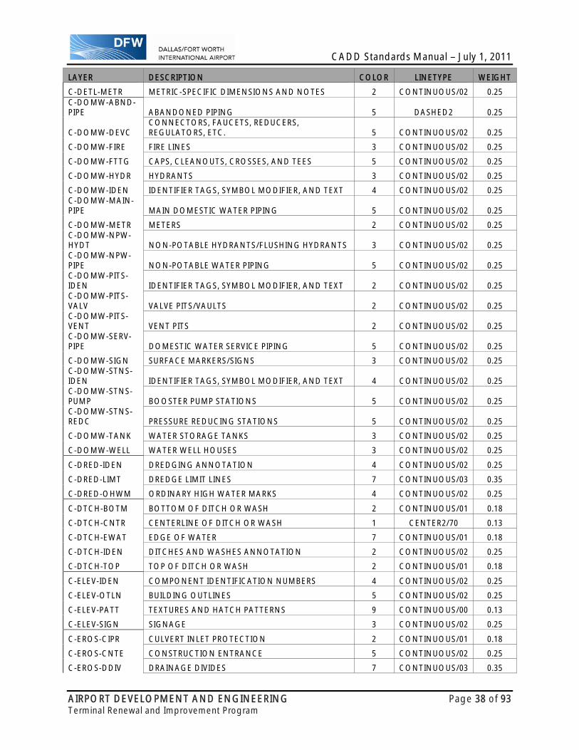
CADD Standards Manual – July 1, 2011
AIRPORT DEVELOPMENT AND ENGINEERING Page 38 of 93 Terminal Renewal and Improvement Program
LAYER DESCRIPTION COLOR LINETYPE WEIGHT
C-DETL-METR METRIC-SPECIFIC DIMENSIONS AND NOTES 2 CONTINUOUS/02 0.25 C-DOMW-ABND-PIPE ABANDONED PIPING 5 DASHED2 0.25
C-DOMW-DEVC CONNECTORS, FAUCETS, REDUCERS, REGULATORS, ETC. 5 CONTINUOUS/02 0.25
C-DOMW-FIRE FIRE LINES 3 CONTINUOUS/02 0.25
C-DOMW-FTTG CAPS, CLEANOUTS, CROSSES, AND TEES 5 CONTINUOUS/02 0.25
C-DOMW-HYDR HYDRANTS 3 CONTINUOUS/02 0.25
C-DOMW-IDEN IDENTIFIER TAGS, SYMBOL MODIFIER, AND TEXT 4 CONTINUOUS/02 0.25 C-DOMW-MAIN-PIPE MAIN DOMESTIC WATER PIPING 5 CONTINUOUS/02 0.25
C-DOMW-METR METERS 2 CONTINUOUS/02 0.25 C-DOMW-NPW-HYDT NON-POTABLE HYDRANTS/FLUSHING HYDRANTS 3 CONTINUOUS/02 0.25 C-DOMW-NPW-PIPE NON-POTABLE WATER PIPING 5 CONTINUOUS/02 0.25 C-DOMW-PITS-IDEN IDENTIFIER TAGS, SYMBOL MODIFIER, AND TEXT 2 CONTINUOUS/02 0.25 C-DOMW-PITS-VALV VALVE PITS/VAULTS 2 CONTINUOUS/02 0.25 C-DOMW-PITS-VENT VENT PITS 2 CONTINUOUS/02 0.25 C-DOMW-SERV-PIPE DOMESTIC WATER SERVICE PIPING 5 CONTINUOUS/02 0.25
C-DOMW-SIGN SURFACE MARKERS/SIGNS 3 CONTINUOUS/02 0.25 C-DOMW-STNS-IDEN IDENTIFIER TAGS, SYMBOL MODIFIER, AND TEXT 4 CONTINUOUS/02 0.25 C-DOMW-STNS-PUMP BOOSTER PUMP STATIONS 5 CONTINUOUS/02 0.25 C-DOMW-STNS-REDC PRESSURE REDUCING STATIONS 5 CONTINUOUS/02 0.25
C-DOMW-TANK WATER STORAGE TANKS 3 CONTINUOUS/02 0.25
C-DOMW-WELL WATER WELL HOUSES 3 CONTINUOUS/02 0.25
C-DRED-IDEN DREDGING ANNOTATION 4 CONTINUOUS/02 0.25
C-DRED-LIMT DREDGE LIMIT LINES 7 CONTINUOUS/03 0.35
C-DRED-OHWM ORDINARY HIGH WATER MARKS 4 CONTINUOUS/02 0.25
C-DTCH-BOTM BOTTOM OF DITCH OR WASH 2 CONTINUOUS/01 0.18
C-DTCH-CNTR CENTERLINE OF DITCH OR WASH 1 CENTER2/70 0.13
C-DTCH-EWAT EDGE OF WATER 7 CONTINUOUS/01 0.18
C-DTCH-IDEN DITCHES AND WASHES ANNOTATION 2 CONTINUOUS/02 0.25
C-DTCH-TOP TOP OF DITCH OR WASH 2 CONTINUOUS/01 0.18
C-ELEV-IDEN COMPONENT IDENTIFICATION NUMBERS 4 CONTINUOUS/02 0.25
C-ELEV-OTLN BUILDING OUTLINES 5 CONTINUOUS/02 0.25
C-ELEV-PATT TEXTURES AND HATCH PATTERNS 9 CONTINUOUS/00 0.13
C-ELEV-SIGN SIGNAGE 3 CONTINUOUS/02 0.25
C-EROS-CIPR CULVERT INLET PROTECTION 2 CONTINUOUS/01 0.18
C-EROS-CNTE CONSTRUCTION ENTRANCE 5 CONTINUOUS/02 0.25
C-EROS-DDIV DRAINAGE DIVIDES 7 CONTINUOUS/03 0.35

CADD Standards Manual – July 1, 2011
AIRPORT DEVELOPMENT AND ENGINEERING Page 39 of 93 Terminal Renewal and Improvement Program
LAYER DESCRIPTION COLOR LINETYPE WEIGHT
C-EROS-DVDK DIVERSION DIKE 7 CONTINUOUS/03 0.35
C-EROS-IDEN EROSION AND SEDIMENT CONTROL ANNOTATION 2 CONTINUOUS/02 0.25
C-EROS-INPR INLET PROTECTION 2 CONTINUOUS/01 0.18
C-EROS-SILT SILT FENCE 4 CONTINUOUS/02 0.25 C-EROS-SILT-CHCK SILT CHECK 4 CONTINUOUS/02 0.25 C-EROS-SILT-TRAP SILT TRAP 4 CONTINUOUS/02 0.25
C-FLHA-025Y 25 YEAR MARK 5 DIVIDE 0.25
C-FLHA-050Y 50 YEAR MARK 4 DASHED 0.25
C-FLHA-100Y 100 YEAR MARK 5 CONTINUOUS/02 0.25
C-FLHA-200Y 200 YEAR MARK 4 DASHED2 0.25
C-FLHA-500Y 500 YEAR MARK 5 CENTER2/72 0.25
C-FLHA-IDEN FLOOD HAZARD AREA ANNOTATION 4 CONTINUOUS/02 0.25
C-FLOD-BASE FLOODWALL BASE OF WALL 6 CONTINUOUS/03 0.35 C-FLOD-BASE-IDEN FLOODWALL BASE OF WALL ANNOTATION 6 CONTINUOUS/02 0.25
C-FLOD-CNTR FLOODWALL CENTERLINE 6 CENTER2/70 0.13 C-FLOD-CNTR-IDEN FLOODWALL CENTERLINE ANNOTATION 6 CONTINUOUS/02 0.25
C-FLOD-DRAN FLOODWALL TOE DRAIN 5 CONTINUOUS/02 0.25 C-FLOD-DRAN-IDEN FLOODWALL TOE DRAIN ANNOTATION 5 CONTINUOUS/02 0.25
C-FLOD-PILE FLOODWALL SHEET PILING 22 CONTINUOUS/03 0.35 C-FLOD-PILE-IDEN FLOODWALL SHEET PILING ANNOTATION 22 CONTINUOUS/02 0.25
C-FLOD-TOE FLOODWALL TOE OUTLINE 7 CONTINUOUS/02 0.25
C-FLOD-TOP FLOODWALL TOP OF WALL 4 CONTINUOUS/03 0.35 C-FLOD-TOP-IDEN FLOODWALL TOP OF WALL ANNOTATION 6 CONTINUOUS/02 0.25 C-FUEL-ABND-PIPE ABANDONED PIPING 5 DASHED2 0.25
C-FUEL-BERM BERMS FOR RETAINING FUEL IN CASE OF RUPTURE 5 CONTINUOUS/02 0.25
C-FUEL-DEFL-PIPE DEFUELING PIPING 5 CONTINUOUS/02 0.25
C-FUEL-DEVC AIR ELIMINATORS, FILTER STRAINERS, VENTS, VALVES 5 CONTINUOUS/02 0.25
C-FUEL-FLOW FLOW DIRECTION ARROWS 5 CONTINUOUS/02 0.25
C-FUEL-FTTG CAPS, CROSSES, AND TEES 5 CONTINUOUS/02 0.25
C-FUEL-IDEN IDENTIFIER TAGS, SYMBOL MODIFIER, AND TEXT 4 CONTINUOUS/02 0.25
C-FUEL-JBOX JUNCTION BOXES, MANHOLES, HANDHOLES, TEST BOXES 3 CONTINUOUS/02 0.25
C-FUEL-MAIN-PIPE MAIN FUEL PIPING 5 CONTINUOUS/02 0.25
C-FUEL-METR METERS 2 CONTINUOUS/02 0.25 C-FUEL-PITS-HYDT HYDRANT CONTROL PITS 2 CONTINUOUS/02 0.25 C-FUEL-PITS-IDEN IDENTIFIER TAGS, SYMBOL MODIFIER, AND TEXT 2 CONTINUOUS/02 0.25

CADD Standards Manual – July 1, 2011
AIRPORT DEVELOPMENT AND ENGINEERING Page 40 of 93 Terminal Renewal and Improvement Program
LAYER DESCRIPTION COLOR LINETYPE WEIGHT C-FUEL-PITS-VALV VALVE PITS 2 CONTINUOUS/02 0.25 C-FUEL-PITS-VENT VENT PITS 2 CONTINUOUS/02 0.25 C-FUEL-SERV-PIPE SERVICE PIPING 5 CONTINUOUS/02 0.25 C-FUEL-STNS-IDEN IDENTIFIER TAGS, SYMBOL MODIFIER, AND TEXT 4 CONTINUOUS/02 0.25 C-FUEL-STNS-PUMP BOOSTER PUMP STATIONS 5 CONTINUOUS/02 0.25
C-FUEL-TANK FUEL TANKS 2 CONTINUOUS/02 0.25
C-FUEL-TRCH FUEL LINE TRENCH 2 CONTINUOUS/02 0.25
C-GRAD-ALOW ALLOWABLE OVER DEPTH 5 CONTINUOUS/02 0.25
C-GRAD-BNCH BENCH CUT 5 CONTINUOUS/02 0.25
C-GRAD-DSGN DESIGN GRADE (PROPOSED) 2 CONTINUOUS/02 0.25
C-GRAD-EXCV EXCAVATION GRADE 7 CONTINUOUS/03 0.35
C-GRAD-EXST EXISTING GRADE, GROUND LINE 5 DASHED 0.25
C-GRAD-FNSH FINISHED GRADE 7 CONTINUOUS/03 0.35 C-GRAD-FNSH-PRP1 PROPOSED SURFACE #1 9 CONTINUOUS/02 0.25 C-GRAD-FNSH-PRP2 PROPOSED SURFACE #2 9 CONTINUOUS/02 0.25 C-GRAD-FNSH-PRP3 PROPOSED SURFACE #3 9 CONTINUOUS/02 0.25 C-GRAD-FNSH-PRP4 PROPOSED SURFACE #4 9 CONTINUOUS/02 0.25
C-GRAD-GTXL GEOTEXTILE PLACEMENT GRADE 3 CONTINUOUS/01 0.18
C-GRAD-IDEN GRADE ANNOTATION FOR CROSS SECTIONS AND PROFILES 4 CONTINUOUS/02 0.25
C-GRAD-REQD REQUIRED DEPTH 5 CONTINUOUS/02 0.25
C-GRAD-SCLN STABILITY CONTROL LINE 1 CENTER2/73 0.35
C-GRAD-WATR WATER SURFACE IN SECTION VIEW 4 CONTINUOUS/02 0.25
C-GRID-FRAM FRAME 7 CONTINUOUS/02 0.35
C-GRID-MAJR MAJOR GRID LINES 9 DOT2/12 0.25
C-GRID-MINR MINOR GRID LINES 9 DOT2/10 0.13
C-GRID-TEXT BORDER TEXT, ANNOTATION 4 CONTINUOUS/02 0.25
C-HELI-BLST BLAST PAD AND STOPWAY MARKINGS 3 CONTINUOUS/02 0.25
C-HELI-CNTR CENTERLINE MARKINGS 3 CENTER2/72 0.25
C-HELI-DISP DISPLACED THRESHOLD MARKINGS 3 CONTINUOUS/02 0.25
C-HELI-DIST FIXED DISTANCE MARKINGS 3 CONTINUOUS/02 0.25
C-HELI-IDEN HELIPORT NUMBERS AND LETTERS 4 CONTINUOUS/02 0.25
C-HELI-SHLD SHOULDER MARKINGS 5 CONTINUOUS/02 0.25
C-HELI-SIDE SIDE STRIPES 7 CONTINUOUS/03 0.35
C-HELI-TDZM TOUCHDOWN ZONE MARKERS 5 CONTINUOUS/02 0.25
C-HELI-THRS THRESHOLD MARKERS 5 CONTINUOUS/02 0.25 C-INDW-ABND-PIPE ABANDONED PIPING 5 DASHED2 0.25
C-INDW-DEVC GRIT CHAMBERS, METERS, FLUMES, VALVES, ETC. 5 CONTINUOU/02S 0.25

CADD Standards Manual – July 1, 2011
AIRPORT DEVELOPMENT AND ENGINEERING Page 41 of 93 Terminal Renewal and Improvement Program
LAYER DESCRIPTION COLOR LINETYPE WEIGHT
C-INDW-FLOW FLOW DIRECTION ARROWS 5 CONTINUOUS/02 0.25
C-INDW-FTTG CAPS AND CLEANOUTS 5 CONTINUOUS/02 0.25
C-INDW-IDEN IDENTIFIER TAGS, SYMBOL MODIFIER, AND TEXT 4 CONTINUOUS/02 0.25
C-INDW-JBOX JUNCTION BOXES AND MANHOLES 3 CONTINUOUS/02 0.25
C-INDW-LAGN LAGOONS 5 CONTINUOUS/02 0.25 C-INDW-LAGN-IDEN IDENTIFIER TAGS, SYMBOL MODIFIER, AND TEXT 5 CONTINUOUS/02 0.25 C-INDW-MAIN-PIPE MAIN INDUSTRIAL WASTE WATER PIPING 5 CONTINUOUS/02 0.25
C-INDW-PLNT TREATMENT PLANTS 5 CONTINUOUS/02 0.25 C-INDW-SERV-PIPE INDUSTRIAL WASTE WATER SERVICE PIPING 3 CONTINUOUS/02 0.25
C-INDW-SIGN SURFACE MARKERS/SIGNS 3 CONTINUOUS/02 0.25 C-INDW-STNS-IDEN IDENTIFIER TAGS, SYMBOL MODIFIER, AND TEXT 4 CONTINUOUS/02 0.25 C-INDW-STNS-LIFT LIFT STATIONS 5 CONTINUOUS/02 0.25
C-IRRG-EQPM IRRIGATION EQUIPMENT (E.G., CONTROLLERS, VALVES, ETC.) 5 CONTINUOUS/02 0.25
C-IRRG-IDEN IRRIGATION ANNOTATION 4 CONTINUOUS/02 0.25
C-IRRG-PIPE IRRIGATION PIPING 5 CONTINUOUS/02 0.25
C-IRRG-WELL IRRIGATION WELLS 2 CONTINUOUS/01 0.18 C-LEVE-BANK-IDEN LEVEE TOP OF BANK ANNOTATION 6 CONTINUOUS/01 0.18
C-LEVE-BERM LEVEE BERM OUTLINE 5 CONTINUOUS/02 0.25
C-LEVE-BNCH LEVEE BENCH DESIGN FEATURE LINES(BREAKLINES FORM DTMS) 6 CONTINUOUS/02 0.25
C-LEVE-BNCH-IDEN LEVEE BENCH ANNOTATION 4 CONTINUOUS/01 0.18
C-LEVE-BRRW BORROW LIMITS 7 CONTINUOUS/03 0.35
C-LEVE-CNTR LEVEE CENTERLINE 6 CENTER2/70 0.13 C-LEVE-CNTR-IDEN LEVEE CENTERLINE ANNOTATION 6 CONTINUOUS/02 0.25
C-LEVE-IDEN LEVEE ANNOTATION 4 CONTINUOUS/02 0.25
C-LEVE-OTLN LEVEE OUTLINE 7 CONTINUOUS/03 0.35
C-LEVE-SLOP LEVEE SLOPE INDICATOR WITH ANNOTATION 4 CONTINUOUS/02 0.25
C-LEVE-STAN LEVEE STATIONING 4 CONTINUOUS/02 0.25
C-LEVE-TOE LEVEE TOE 6 DASHED2 0.25 C-LEVE-TOE-IDEN LEVEE TOE ANNOTATION 6 CONTINUOUS/01 0.18
C-LEVE-TOPB LEVEE TOP OF BANK 4 CONTINUOUS/02 0.25 C-NGAS-ABND-PIPE ABANDONED PIPING 5 DASHED2 0.25
C-NGAS-DEVC HYDRANT FILL POINTS, LIGHTS, VENTS, MARKERS, ETC. 5 CONTINUOUS/02 0.25
C-NGAS-DEVC-IDEN IDENTIFIER TAGS, SYMBOL MODIFIER, AND TEXT 5 CONTINUOUS/02 0.25
C-NGAS-FLOW FLOW DIRECTION ARROWS 5 CONTINUOUS/02 0.25
C-NGAS-FTTG CAPS, CROSSES, AND TEES 5 CONTINUOUS/02 0.25

CADD Standards Manual – July 1, 2011
AIRPORT DEVELOPMENT AND ENGINEERING Page 42 of 93 Terminal Renewal and Improvement Program
LAYER DESCRIPTION COLOR LINETYPE WEIGHT
C-NGAS-IDEN IDENTIFIER TAGS, SYMBOL MODIFIER, AND TEXT 4 CONTINUOUS/02 0.25 C-NGAS-MAIN-PIPE MAIN NATURAL GAS PIPING 5 GAS_LINE 0.25
C-NGAS-METR METERS 2 CONTINUOUS/02 0.25 C-NGAS-PITS-IDEN IDENTIFIER TAGS, SYMBOL MODIFIER, AND TEXT 3 CONTINUOUS/02 0.25 C-NGAS-PITS-VALV VALVE PITS/BOXES 2 CONTINUOUS/02 0.25 C-NGAS-PITS-VENT VENT PITS 2 CONTINUOUS/02 0.25 C-NGAS-SERV-PIPE SERVICE PIPING 3 CONTINUOUS/02 0.25
C-NGAS-SIGN SURFACE MARKERS/SIGNS 3 CONTINUOUS/02 0.25 C-NGAS-STNS-IDEN IDENTIFIER TAGS, SYMBOL MODIFIER, AND TEXT 4 CONTINUOUS/02 0.25 C-NGAS-STNS-PUMP COMPRESSOR STATIONS 5 CONTINUOUS/02 0.25 C-NGAS-STNS-REDC REDUCING STATIONS 5 CONTINUOUS/02 0.25
C-NGAS-TANK TANKS 2 CONTINUOUS/02 0.18
C-OBST-AIRS AIRSPACE OBSTRUCTIONS 2 CONTINUOUS/02 0.25 C-OBST-AIRS-IDEN OBSTRUCTION ANNOTATION 4 CONTINUOUS/02 0.25
C-OVRN-CNTR CENTERLINES 3 CENTER2/71 0.18 C-OVRN-CNTR-IDEN CENTERLINE ANNOTATION 4 CONTINUOUS/02 0.25
C-OVRN-IDEN AIRFIELD OVERRUN AREA - ANNOTATION 4 CONTINUOUS/02 0.25
C-OVRN-OTLN AIRFIELD OVERRUN AREA - OUTLINES 7 CONTINUOUS/02 0.25 C-OVRN-SHLD-MRKG SHOULDER MARKINGS 7 CONTINUOUS/02 0.25
C-PADS-CNTR CENTERLINES 3 CENTER2/71 0.18 C-PADS-CNTR-IDEN CENTERLINE ANNOTATION 4 CONTINUOUS/02 0.25
C-PADS-IDEN PADS - ANNOTATION 4 CONTINUOUS/02 0.25
C-PADS-OTLN PAD - OUTLINES 7 CONTINUOUS/02 0.25
C-PADS-SHLD SHOULDERS WITH ANNOTATION 4 CONTINUOUS/01 0.18
C-PRKG-CARS GRAPHIC ILLUSTRATION OF CARS 4 CONTINUOUS/02 0.25
C-PRKG-CNTR PARKING LOT CENTERLINES 3 CENTER2/71 0.18 C-PRKG-CNTR-IDEN PARKING LOT CENTERLINE ANNOTATION 3 CONTINUOUS/01 0.18
C-PRKG-CURB CURBS AND GUTTERS 2 CONTINUOUS/02 0.25
C-PRKG-DRAN DRAINAGE SLOPE INDICATIONS 3 CONTINUOUS/02 0.25
C-PRKG-FIXT PARKING LOT FIXTURES (WHEEL STOPS, PARKING METERS) 176 CONTINUOUS/02 0.25
C-PRKG-FLNE FIRE LANES 3 CONTINUOUS/01 0.18
C-PRKG-IDEN PARKING LOT ANNOTATION 5 CONTINUOUS/02 0.25
C-PRKG-MRKG PAVEMENT MARKINGS 4 CONTINUOUS/02 0.25
C-PRKG-OTLN PARKING LOT OUTLINES 7 CONTINUOUS/03 0.35
C-PRKG-SIGN SIGNS 4 CONTINUOUS/02 0.25
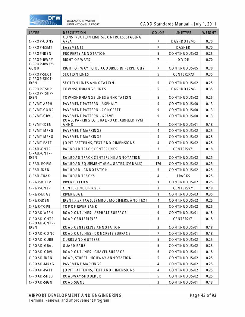
CADD Standards Manual – July 1, 2011
AIRPORT DEVELOPMENT AND ENGINEERING Page 43 of 93 Terminal Renewal and Improvement Program
LAYER DESCRIPTION COLOR LINETYPE WEIGHT
C-PROP-CONS CONSTRUCTION LIMITS/CONTROLS, STAGING AREA 7 DASHDOT2/45 0.70
C-PROP-ESMT EASEMENTS 7 DASHED 0.70
C-PROP-IDEN PROPERTY ANNOTATION 5 CONTINUOUS/02 0.25
C-PROP-RWAY RIGHT OF WAYS 7 DIVIDE 0.70 C-PROP-RWAY-ACQU RIGHT OF WAY TO BE ACQUIRED IN PERPETUITY 7 CONTINUOUS/05 0.70
C-PROP-SECT SECTION LINES 5 CENTER2/73 0.35 C-PROP-SECT-IDEN SECTION LINES ANNOTATION 5 CONTINUOUS/02 0.25
C-PROP-TSHP TOWNSHIP/RANGE LINES 5 DASHDOT2/43 0.35 C-PROP-TSHP-IDEN TOWNSHIP/RANGE LINES ANNOTATION 5 CONTINUOUS/02 0.25
C-PVMT-ASPH PAVEMENT PATTERN - ASPHALT 9 CONTINUOUS/00 0.13
C-PVMT-CONC PAVEMENT PATTERN - CONCRETE 9 CONTINUOUS/00 0.13
C-PVMT-GRVL PAVEMENT PATTERN - GRAVEL 9 CONTINUOUS/00 0.13
C-PVMT-IDEN ROAD, PARKING LOT, RAILROAD, AIRFIELD PVMT ANNO 4 CONTINUOUS/01 0.18
C-PVMT-MRKG PAVEMENT MARKINGS 4 CONTINUOUS/02 0.25
C-PVMT-MRKG PAVEMENT MARKINGS 4 CONTINUOUS/02 0.25
C-PVMT-PATT JOINT PATTERNS, TEXT AND DIMENSIONS 4 CONTINUOUS/02 0.25
C-RAIL-CNTR RAILROAD TRACK CENTERLINES 3 CENTER2/71 0.18 C-RAIL-CNTR-IDEN RAILROAD TRACK CENTERLINE ANNOTATION 3 CONTINUOUS/02 0.25
C-RAIL-EQPM RAILROAD EQUIPMENT (E.G., GATES, SIGNALS) 176 CONTINUOUS/02 0.25
C-RAIL-IDEN RAILROAD - ANNOTATION 5 CONTINUOUS/02 0.25
C-RAIL-TRAK RAILROAD TRACKS 4 TRACKS 0.25
C-RIVR-BOTM RIVER BOTTOM 1 CONTINUOUS/02 0.25
C-RIVR-CNTR CENTERLINE OF RIVER 3 CENTER2/71 0.18
C-RIVR-EDGE RIVER EDGE 1 CONTINUOUS/03 0.35
C-RIVR-IDEN IDENTIFIER TAGS, SYMBOL MODIFIERS, AND TEXT 4 CONTINUOUS/02 0.25
C-RIVR-TOPB TOP OF RIVER BANK 1 CONTINUOUS/02 0.25
C-ROAD-ASPH ROAD OUTLINES - ASPHALT SURFACE 9 CONTINUOUS/01 0.18
C-ROAD-CNTR ROAD CENTERLINES 3 CENTER2/71 0.18 C-ROAD-CNTR-IDEN ROAD CENTERLINE ANNOTATION 3 CONTINUOUS/01 0.18
C-ROAD-CONC ROAD OUTLINES - CONCRETE SURFACE 7 CONTINUOUS/01 0.18
C-ROAD-CURB CURBS AND GUTTERS 5 CONTINUOUS/02 0.25
C-ROAD-GRAL GUARD RAILS 5 CONTINUOUS/02 0.25
C-ROAD-GRVL ROAD OUTLINES - GRAVEL SURFACE 6 CONTINUOUS/01 0.18
C-ROAD-IDEN ROAD, STREET, HIGHWAY ANNOTATION 5 CONTINUOUS/02 0.25
C-ROAD-MRKG PAVEMENT MARKINGS 4 CONTINUOUS/02 0.25
C-ROAD-PATT JOINT PATTERNS, TEXT AND DIMENSIONS 4 CONTINUOUS/02 0.25
C-ROAD-SHLD ROADWAY SHOULDER 5 CONTINUOUS/02 0.25
C-ROAD-SIGN ROAD SIGNS 3 CONTINUOUS/01 0.18

CADD Standards Manual – July 1, 2011
AIRPORT DEVELOPMENT AND ENGINEERING Page 44 of 93 Terminal Renewal and Improvement Program
LAYER DESCRIPTION COLOR LINETYPE WEIGHT
C-ROAD-UPVD ROAD OUTLINES - UNPAVED SURFACE 2 CONTINUOUS/01 0.18
C-RRAP-GABN GABIONS 3 CONTINUOUS/01 0.18
C-RRAP-MATS ARTICULATED CONCRETE MATS 2 CONTINUOUS/01 0.18
C-RRAP-RVMT REVETMENTS 3 CONTINUOUS/01 0.18
C-RRAP-WEIR WEIRS 2 CONTINUOUS/01 0.18
C-RUNW-BLST BLAST PAD AND STOPWAY MARKINGS 3 CONTINUOUS/02 0.25
C-RUNW-CNTR CENTERLINES 3 CENTER2/71 0.18 C-RUNW-CNTR-MRKG CENTERLINE MARKINGS 3 CONTINUOUS/02 0.25
C-RUNW-DISP DISPLACED THRESHOLD MARKINGS 3 CONTINUOUS/02 0.25
C-RUNW-DIST FIXED DISTANCE MARKINGS 3 CONTINUOUS/02 0.25
C-RUNW-EDGE AIRFIELD RUNWAY EDGES 5 CONTINUOUS/02 0.25
C-RUNW-IDEN AIRFIELD RUNWAY ANNOTATION 4 CONTINUOUS/02 0.25
C-RUNW-SHLD SHOULDER MARKINGS 5 CONTINUOUS/02 0.25
C-RUNW-SIDE SIDE STRIPES 7 CONTINUOUS/02 0.25
C-RUNW-TDZM TOUCHDOWN ZONE MARKERS 5 CONTINUOUS/02 0.25
C-RUNW-THRS THRESHOLD MARKERS 5 CONTINUOUS/02 0.25
C-SECT-IDEN COMPONENT IDENTIFICATION NUMBERS 4 CONTINUOUS/02 0.25
C-SECT-MBND MATERIAL BEYOND SECTION CUT 1 CONTINUOUS/00 0.13
C-SECT-MCUT CUTS THROUGH ROADS, BUILDINGS, STRUCTURES, ETC. 7 CONTINUOUS/00 0.13
C-SECT-PATT TEXTURES AND HATCH PATTERNS 9 CONTINUOUS/02 0.13
C-SITE-BLIN SITE BREAKLINE 2 DASHED2 0.25
C-SITE-FENC FENCES 5 FENCELINE1 0.25 C-SITE-FENC-IDEN FENCE ANNOTATION 5 CONTINUOUS/02 0.25
C-SITE-IDEN SITE FEATURE ANNOTATION 5 CONTINUOUS/02 0.25
C-SITE-STRC STRUCTURES (BRIDGES, SHEDS, FOUNDATIONS, ETC.) 22 CONTINUOUS/02 0.25
C-SITE-STRS STAIRS AND RAMPS 5 CONTINUOUS/02 0.25
C-SITE-WALK WALKS, TRAILS AND BICYCLE PATHS 4 CONTINUOUS/02 0.25 C-SSWR-ABND-PIPE ABANDONED PIPING 5 DASHED2 0.25
C-SSWR-DEVC GREASE TRAPS, GRIT CHAMBERS, FLUMES, VALVES ETC. 5 CONTINUOUS/02 0.25
C-SSWR-DEVC-IDEN IDENTIFIER TAGS, SYMBOL MODIFIER, AND TEXT 5 CONTINUOUS/01 0.18
C-SSWR-FILT FILTRATION BEDS 2 CONTINUOUS/02 0.25 C-SSWR-FILT-IDEN IDENTIFIER TAGS, SYMBOL MODIFIER, AND TEXT 2 CONTINUOUS/02 0.25
C-SSWR-FLOW FLOW DIRECTION ARROWS 5 CONTINUOUS/02 0.25
C-SSWR-FTTG CAPS AND CLEANOUTS 5 CONTINUOUS/02 0.25
C-SSWR-IDEN IDENTIFIER TAGS, SYMBOL MODIFIER, AND TEXT 4 CONTINUOUS/02 0.25
C-SSWR-JBOX JUNCTION BOXES AND MANHOLES 3 CONTINUOUS/02 0.25 C-SSWR-JBOX-IDEN IDENTIFIER TAGS, SYMBOL MODIFIER, AND TEXT 3 CONTINUOUS/02 0.25

CADD Standards Manual – July 1, 2011
AIRPORT DEVELOPMENT AND ENGINEERING Page 45 of 93 Terminal Renewal and Improvement Program
LAYER DESCRIPTION COLOR LINETYPE WEIGHT
C-SSWR-LAGN LAGOONS 2 CONTINUOUS/02 0.25
C-SSWR-LEAC LEACH FIELD 2 CONTINUOUS/02 0.25 C-SSWR-MAIN-PIPE SANITARY SEWER PIPING 5 CONTINUOUS/02 0.25
C-SSWR-NITF NITRIFICATION DRAIN FIELDS 2 CONTINUOUS/02 0.25
C-SSWR-PLNT TREATMENT PLANTS 5 CONTINUOUS/02 0.25 C-SSWR-SERV-PIPE SANITARY SEWER SERVICE PIPING 3 CONTINUOUS/02 0.25
C-SSWR-SIGN SURFACE MARKERS/SIGNS 3 CONTINUOUS/02 0.25 C-SSWR-STNS-IDEN IDENTIFIER TAGS, SYMBOL MODIFIER, AND TEXT 4 CONTINUOUS/02 0.25 C-SSWR-STNS-PUMP BOOSTER PUMP STATIONS 5 CONTINUOUS/02 0.25
C-SSWR-TANK SEPTIC TANKS 2 CONTINUOUS/02 0.25 C-STRM-ABND-PIPE ABANDONED PIPING 5 DASHED2 0.25
C-STRM-AFFF AFFF LAGOON/DETENTION POND 2 CONTINUOUS/02 0.25
C-STRM-CHUT CHUTES AND CONCRETE EROSION CONTROL STRUCTURES 3 CONTINUOUS/02 0.25
C-STRM-CULV CULVERTS 2 CONTINUOUS/02 0.25
C-STRM-DEVC DOWNSPOUTS, FLUMES, OIL/WATER SEPARATORS, GATES 5 CONTINUOUS/02 0.25
C-STRM-FLOW FLOW DIRECTION ARROWS 5 CONTINUOUS/02 0.25
C-STRM-FMON FLOW MONITORING STATION 5 CONTINUOUS/02 0.25
C-STRM-FTTG CAPS AND CLEANOUTS 5 CONTINUOUS/02 0.25
C-STRM-HWAL HEADWALLS AND ENDWALLS 7 CONTINUOUS/03 0.35
C-STRM-IDEN IDENTIFIER TAGS, SYMBOL MODIFIER, AND TEXT 4 CONTINUOUS/02 0.25
C-STRM-INLT INLETS (CURB, SURFACE, AND CATCH BASINS) 2 CONTINUOUS/02 0.25
C-STRM-LAGN LAGOONS, PONDS, WATERSHEDS, AND BASINS 2 CONTINUOUS/02 0.25 C-STRM-MAIN-PIPE STORM SEWER PIPING 5 CONTINUOUS/02 0.25
C-STRM-MHOL MANHOLES 3 CONTINUOUS/02 0.25
C-STRM-ROOF ROOF DRAIN LINE 2 CONTINUOUS/02 0.25 C-STRM-SERV-PIPE STORM SEWER SERVICE PIPING 3 CONTINUOUS/02 0.25
C-STRM-SIGN SURFACE MARKERS/SIGNS 3 CONTINUOUS/02 0.25 C-STRM-STNS-IDEN IDENTIFIER TAGS, SYMBOL MODIFIER, AND TEXT 4 CONTINUOUS/02 0.25 C-STRM-STNS-PUMP PUMP STATIONS 5 CONTINUOUS/02 0.25 C-STRM-SUBS-PIPE SUBSURFACE DRAIN PIPING 2 CONTINUOUS/02 0.25
C-SURV-DATA SURVEY DATA (CONTROL POINTS OR MONUMENTS) 5 CONTINUOUS/02 0.25
C-SURV-IDEN SURVEY, BASELINE, AND CONTROL LINE ANNOTATION 5 CONTINUOUS/02 0.25
C-SURV-LINE SURVEY, BASELINE, AND CONTROL LINES 7 DASHED2 0.25
C-TAXI-CNTR CENTERLINES 3 CENTER2/71 0.18 C-TAXI-CNTR-IDEN CENTERLINE ANNOTATION 4 CONTINUOUS/02 0.25

CADD Standards Manual – July 1, 2011
AIRPORT DEVELOPMENT AND ENGINEERING Page 46 of 93 Terminal Renewal and Improvement Program
LAYER DESCRIPTION COLOR LINETYPE WEIGHT C-TAXI-CNTR-MRKG CENTERLINE MARKINGS 3 CONTINUOUS/01 0.18
C-TAXI-EDGE EDGE MARKINGS 7 CONTINUOUS/02 0.25
C-TAXI-HOLD HOLDING LINES 4 CONTINUOUS/02 0.25
C-TAXI-IDEN TAXIWAY - ANNOTATION 4 CONTINUOUS/02 0.25
C-TAXI-OTLN TAXIWAY - OUTLINES 7 CONTINUOUS/02 0.25
C-TAXI-SHLD SHOULDERS WITH ANNOTATION 4 CONTINUOUS/02 0.25 C-TOPO-BDRY-EXTR SURFACE EXTERIOR BOUNDARY 2 CONTINUOUS/00 0.13 C-TOPO-BDRY-INTR SURFACE INTERIOR BOUNDARY 3 DASHED2 0.13
C-TOPO-BKLN BREAKLINES 7 DASHDOT2/43 0.35 C-TOPO-BNDY-EXTR SURFACE EXTERIOR BOUNDARY 2 CONTINUOUS/00 0.13 C-TOPO-BNDY-INTR SURFACE INTERIOR BOUNDARY 3 DASHED2 0.13
C-TOPO-BORE BORING LOCATIONS AND TEXT 5 CONTINUOUS/02 0.25
C-TOPO-COOR COORDINATE GRID TEXT ANNOTATION 23 CONTINUOUS/02 0.25 C-TOPO-COOR-LALO LATITUDE AND LONGITUDE GRID TICKS 2 CONTINUOUS/01 0.18 C-TOPO-COOR-STAT STATE PLANE COORDINATE TICKS 2 CONTINUOUS/01 0.18 C-TOPO-COOR-UTM UTM COORDINATE TICKS 2 CONTINUOUS/01 0.18
C-TOPO-DTMO DTM OBSCURE AREA BOUNDARY 5 CONTINUOUS/02 0.25
C-TOPO-DTMP DTM POINTS 5 CONTINUOUS/02 0.25
C-TOPO-DTMT DTM TRIANGLES 22 CONTINUOUS/02 0.25
C-TOPO-MAJR TOPOGRAPHY MAJOR CONTOURS 4 CONTINUOUS/02 0.25 C-TOPO-MAJR-IDEN MAJOR CONTOURS - ANNOTATION 4 CONTINUOUS/02 0.25
C-TOPO-MINR TOPOGRAPHY MINOR CONTOURS 2 CONTINUOUS/01 0.18 C-TOPO-MINR-IDEN MINOR CONTOURS - ANNOTATION 2 CONTINUOUS/01 0.18
C-TOPO-SHAP INROADS GENERATED SHAPES/LINES 3 CONTINUOUS/01 0.18
C-TOPO-SHOR SHORELINES, LAND FEATURES, AND REFERENCES 7 CONTINUOUS/02 0.25 C-TOPO-SLOP-FILL CUT/FILL SLOPES 4 CONTINUOUS/02 0.25 C-TOPO-SLOP-IDEN CUT/FILL SLOPE, TOP/TOE SLOPE ANNOTATION 4 CONTINUOUS/02 0.25 C-TOPO-SLOP-TOPT TOP/TOE SLOPES 5 CONTINUOUS/02 0.25
C-TOPO-SOUN SOUNDINGS AND OVERBANKS 7 CONTINUOUS/00 0.13
C-TOPO-SPOT SPOT ELEVATIONS 4 CONTINUOUS/02 0.25 C-TOPO-SURF-PERI SURFACE PERIMETER 2 CONTINUOUS/00 0.13 C-TOPO-SURF-PONT SURFACE FEATURE POINTS 7 CONTINUOUS/01 0.18 C-TOPO-SURF-VOID SURFACE VOID REGION 3 CONTINUOUS/00 0.13
C-TOPO-WATR WATER LEVEL REFERENCE(LWRP, AFTER-GRADING LWRP, SWL, ETC) 7 DASHED 0.35

CADD Standards Manual – July 1, 2011
AIRPORT DEVELOPMENT AND ENGINEERING Page 47 of 93 Terminal Renewal and Improvement Program
LAYER DESCRIPTION COLOR LINETYPE WEIGHT
C-TRAF-IDEN AIRFIELD TRAFFIC AREA ANNOTATION 4 CONTINUOUS/02 0.25
C-TRAF-TYPA TYPE A TRAFFIC AREA 7 DASHDOT2/43 0.35
C-TRAF-TYPB TYPE B TRAFFIC AREA 7 DIVIDE 0.35
C-TRAF-TYPC TYPE C TRAFFIC AREA 7 CONTINUOUS/03 0.35
C-WETL-BOGS BOGS 5 CONTINUOUS/02 0.25
C-WETL-IDEN WETLAND ANNOTATION 4 CONTINUOUS/02 0.25
C-WETL-MRSH FRESH WATER MARSHES 33 CONTINUOUS/02 0.25 C-WETL-MRSH-SALT TIDAL SALTWATER MARSHES 33 CONTINUOUS/02 0.25 C-WETL-MRSH-TIDL TIDAL FRESHWATER MARSH 33 CONTINUOUS/02 0.25
C-WETL-PCSN POCOSINS 5 CONTINUOUS/02 0.25
C-WETL-PHOL VERNAL POOLS, PLAYAS, WET MEADOWS, WET PRAIRIES 5 CONTINUOUS/02 0.25
C-WETL-RPRN RIPARIAN FORESTED WETLANDS 33 CONTINUOUS/02 0.25
C-WETL-SLGH SLOUGHS 33 CONTINUOUS/02 0.25
C-WETL-SWMP SWAMPS 33 CONTINUOUS/02 0.25
ELECTRICAL- LEVEL/LAYER LIST LAYER DESCRIPTION COLOR LINETYPE WEIGHTE-AFLD-BCNS-IDEN
IDENTIFIER TAGS, SYMBOL MODIFIERS, AND TEXT 45 CONTINUOUS/03 0.35
E-AFLD-BCNS-MISC
MISCELLANEOUS NAVAIDS - WINDCONES AND BEACONS 45 CONTINUOUS/04 0.50
E-AFLD-BCNS-STRB STROBE BEACONS 45 CONTINUOUS/04 0.50 E-AFLD-CIRC-CTRL CONTROL AND MONITORING CIRCUITS 41 CONTINUOUS/04 0.50
E-AFLD-CIRC-IDEN CIRCUIT IDENTIFIER TAGS, SYMBOL MODIFIER, AND TEXT 4 CONTINUOUS/03 0.35
E-AFLD-CIRC-MULT MULTIPLE CIRCUITS 46 CONTINUOUS/04 0.50 E-AFLD-CIRC-SERS SERIES CIRCUITS 45 CONTINUOUS/04 0.50E-AFLD-DBNK DUCTBANKS 42 CONTINUOUS/04 0.50
E-AFLD-DEVC CAPACITORS, REGULATORS, MOTORS, BUSES, GENERATORS 46 CONTINUOUS/04 0.50
E-AFLD-JBOX JCT BOXES, PULL BOXES, MH’S, HANDHOLES, PEDESTALS 46 CONTINUOUS/04 0.50
E-AFLD-LITE-APPR APPROACH LIGHTS 45 CONTINUOUS/04 0.50E-AFLD-LITE-DIST DISTANCE AND ARRESTING GEAR MARKERS 45 CONTINUOUS/04 0.50E-AFLD-LITE-LANE HOVERLANE, TAXILANE, AND HELIPAD LIGHTS 45 CONTINUOUS/04 0.50E-AFLD-LITE-OBST OBSTRUCTION LIGHTS 45 CONTINUOUS/04 0.50E-AFLD-LITE-RUNW RUNWAY LIGHTS 45 CONTINUOUS/04 0.50 E-AFLD-LITE-SIGN TAXIWAY GUIDANCE SIGNS 45 CONTINUOUS/04 0.50E-AFLD-LITE-TAXI TAXIWAY LIGHTS 45 CONTINUOUS/04 0.50E-AFLD-LITE-THRS THRESHOLD LIGHTS 45 CONTINUOUS/04 0.50E-AFLD-VALT AIRFIELD LIGHTING VAULTS 45 CONTINUOUS/04 0.50E-ALRM-EQPM ALARM SYSTEM EQUIPMENT 45 CONTINUOUS/04 0.50
E-ALRM-IDEN IDENTIFIER TAGS, SYMBOL MODIFIERS, AND TEXT 4 CONTINUOUS/03 0.35
E-ANNO-DIMS WITNESS/EXTENSION LINES, DIM TERMINATORS, DIM TEXT 7 CONTINUOUS/01 0.18

CADD Standards Manual – July 1, 2011
AIRPORT DEVELOPMENT AND ENGINEERING Page 48 of 93 Terminal Renewal and Improvement Program
LAYER DESCRIPTION COLOR LINETYPE WEIGHT
E-ANNO-KEYN REFERENCE KEYNOTES WITH ASSOCIATED LEADERS 7 CONTINUOUS/01 0.18
E-ANNO-LEGN LEGENDS AND SYMBOLS KEYS 7 CONTINUOUS/01 0.18
E-ANNO-MASK TEXT/SHAPE MASK FOR USE WITH PHOTO BACKGROUNDS 16 CONTINUOUS/01 0.18
E-ANNO-MATC MATCH LINES 7 DASHDOT2/01 1.40E-ANNO-NOTE GENERAL NOTES AND GENERAL REMARKS 4 CONTINUOUS/03 0.35E-ANNO-NPLT NON-PLOTTING GRAPHIC INFORMATION 1 CONTINUOUS/01 0.18
E-ANNO-PATT PATTERNING, POCHE, SHADING, AND HATCHING 9 CONTINUOUS/01 0.18
E-ANNO-RDME READ-ME INFORMATION 1 CONTINUOUS/01 0.18E-ANNO-REDL REDLINES 3 CONTINUOUS/02 0.25E-ANNO-REVS REVISIONS 7 CONTINUOUS/04 0.50E-ANNO-SCHD SCHEDULES 7 CONTINUOUS/01 0.18E-ANNO-SYMB MISCELLANEOUS SYMBOLS 5 CONTINUOUS/01 0.18
E-ANNO-TEXT MISC TEXT AND CALLOUTS WITH ASSOCIATED LEADERS 7 CONTINUOUS/01 0.18
E-BELL-EQPM BELL SYSTEM EQUIPMENT 45 CONTINUOUS/04 0.50
E-BELL-IDEN IDENTIFIER TAGS, SYMBOL MODIFIERS, AND TEXT 4 CONTINUOUS/03 0.35
E-CABL-COAX COAX CABLE 42 DASHED2 0.50E-CABL-FIBR FIBER OPTICS CABLE 42 CONTINUOUS/04 0.50
E-CABL-IDEN IDENTIFIER TAGS, SYMBOL MODIFIERS, AND TEXT 4 CONTINUOUS/03 0.35
E-CABL-MULT MULTI-CONDUCTOR CABLE 42 CONTINUOUS/04 0.50E-CABL-TRAY CABLE TRAYS AND WIREWAYS 45 CONTINUOUS/04 0.50E-CATH-ANOD SACRIFICIAL ANODE SYSTEM 42 CONTINUOUS/04 0.50E-CATH-CURR IMPRESS CURRENT SYSTEM 42 CONTINUOUS/04 0.50
E-CATH-IDEN IDENTIFIER TAGS, SYMBOL MODIFIER, AND TEXT 42 CONTINUOUS/03 0.35
E-CATH-TEST TEST STATIONS 42 CONTINUOUS/04 0.50E-CATV-EQPM CABLE TV SYSTEM EQUIPMENT 45 CONTINUOUS/04 0.50
E-CATV-IDEN IDENTIFIER TAGS, SYMBOL MODIFIERS, AND TEXT 4 CONTINUOUS/03 0.35
E-CCTV-EQPM CLOSED-CIRCUIT TELEVISION SYSTEM EQUIPMENT 45 CONTINUOUS/04 0.50
E-CCTV-IDEN IDENTIFIER TAGS, SYMBOL MODIFIERS, AND TEXT 4 CONTINUOUS/03 0.35
E-CLOK-EQPM CLOCK SYSTEM EQUIPMENT 45 CONTINUOUS/04 0.50
E-CLOK-IDEN IDENTIFIER TAGS, SYMBOL MODIFIERS, AND TEXT 4 CONTINUOUS/03 0.35
E-COMM-EQPM OTHER COMMUNICATIONS DISTRIBUTION EQUIPMENT 46 CONTINUOUS/04 0.50
E-COMM-JBOX COMM JUNCTION BOXES, PULL BOXES, MANHOLES, ETC. 46 CONTINUOUS/04 0.50
E-COMM-OVHD OVERHEAD COMMUNICATIONS/TELEPHONELINES 7 HIDDEN2/24 0.50
E-COMM-OVHD-IDEN
IDENTIFIER TAGS, SYMBOL MODIFIER AND TEXT 7 CONTINUOUS/03 0.35
E-COMM-POLE POLES 45 CONTINUOUS/04 0.50E-COMM-POLE-GUYS GUYING EQUIPMENT 45 CONTINUOUS/04 0.50 E-COMM-POLE-IDEN
IDENTIFIER TAGS, SYMBOL MODIFIERS, AND TEXT 45 CONTINUOUS/03 0.35
E-COMM-UGND UNDERGROUND COMMUNICATIONS/TELEPHONE LINES 7 CONTINUOUS/04 0.50
E-COMM-UGND-IDEN
IDENTIFIER TAGS, SYMBOL MODIFIER AND TEXT 7 CONTINUOUS/03 0.35
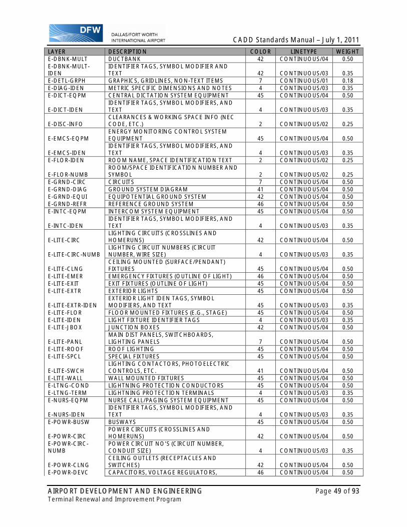
CADD Standards Manual – July 1, 2011
AIRPORT DEVELOPMENT AND ENGINEERING Page 49 of 93 Terminal Renewal and Improvement Program
LAYER DESCRIPTION COLOR LINETYPE WEIGHTE-DBNK-MULT DUCTBANK 42 CONTINUOUS/04 0.50E-DBNK-MULT-IDEN
IDENTIFIER TAGS, SYMBOL MODIFIER AND TEXT 42 CONTINUOUS/03 0.35
E-DETL-GRPH GRAPHICS, GRIDLINES, NON-TEXT ITEMS 7 CONTINUOUS/01 0.18E-DIAG-IDEN METRIC SPECIFIC DIMENSIONS AND NOTES 4 CONTINUOUS/03 0.35E-DICT-EQPM CENTRAL DICTATION SYSTEM EQUIPMENT 45 CONTINUOUS/04 0.50
E-DICT-IDEN IDENTIFIER TAGS, SYMBOL MODIFIERS, AND TEXT 4 CONTINUOUS/03 0.35
E-DISC-INFO CLEARANCES & WORKING SPACE INFO (NEC CODE, ETC.) 2 CONTINUOUS/02 0.25
E-EMCS-EQPM ENERGY MONITORING CONTROL SYSTEM EQUIPMENT 45 CONTINUOUS/04 0.50
E-EMCS-IDEN IDENTIFIER TAGS, SYMBOL MODIFIERS, AND TEXT 4 CONTINUOUS/03 0.35
E-FLOR-IDEN ROOM NAME, SPACE IDENTIFICATION TEXT 2 CONTINUOUS/02 0.25
E-FLOR-NUMB ROOM/SPACE IDENTIFICATION NUMBER AND SYMBOL 2 CONTINUOUS/02 0.25
E-GRND-CIRC CIRCUITS 7 CONTINUOUS/04 0.50E-GRND-DIAG GROUND SYSTEM DIAGRAM 41 CONTINUOUS/04 0.50E-GRND-EQUI EQUIPOTENTIAL GROUND SYSTEM 42 CONTINUOUS/04 0.50E-GRND-REFR REFERENCE GROUND SYSTEM 46 CONTINUOUS/04 0.50E-INTC-EQPM INTERCOM SYSTEM EQUIPMENT 45 CONTINUOUS/04 0.50
E-INTC-IDEN IDENTIFIER TAGS, SYMBOL MODIFIERS, AND TEXT 4 CONTINUOUS/03 0.35
E-LITE-CIRC LIGHTING CIRCUITS (CROSSLINES AND HOMERUNS) 42 CONTINUOUS/04 0.50
E-LITE-CIRC-NUMB LIGHTING CIRCUIT NUMBERS (CIRCUIT NUMBER, WIRE SIZE) 4 CONTINUOUS/03 0.35
E-LITE-CLNG CEILING MOUNTED (SURFACE/PENDANT) FIXTURES 45 CONTINUOUS/04 0.50
E-LITE-EMER EMERGENCY FIXTURES (OUTLINE OF LIGHT) 46 CONTINUOUS/04 0.50E-LITE-EXIT EXIT FIXTURES (OUTLINE OF LIGHT) 45 CONTINUOUS/04 0.50E-LITE-EXTR EXTERIOR LIGHTS 45 CONTINUOUS/04 0.50
E-LITE-EXTR-IDEN EXTERIOR LIGHT IDEN TAGS, SYMBOL MODIFIERS, AND TEXT 45 CONTINUOUS/03 0.35
E-LITE-FLOR FLOOR MOUNTED FIXTURES (E.G., STAGE) 45 CONTINUOUS/04 0.50E-LITE-IDEN LIGHT FIXTURE IDENTIFIER TAGS 4 CONTINUOUS/03 0.35E-LITE-JBOX JUNCTION BOXES 42 CONTINUOUS/04 0.50
E-LITE-PANL MAIN DIST PANELS, SWITCHBOARDS, LIGHTING PANELS 7 CONTINUOUS/04 0.50
E-LITE-ROOF ROOF LIGHTING 45 CONTINUOUS/04 0.50E-LITE-SPCL SPECIAL FIXTURES 45 CONTINUOUS/04 0.50
E-LITE-SWCH LIGHTING CONTACTORS, PHOTOELECTRIC CONTROLS, ETC. 41 CONTINUOUS/04 0.50
E-LITE-WALL WALL MOUNTED FIXTURES 45 CONTINUOUS/04 0.50E-LTNG-COND LIGHTNING PROTECTION CONDUCTORS 45 CONTINUOUS/04 0.50E-LTNG-TERM LIGHTNING PROTECTION TERMINALS 4 CONTINUOUS/03 0.35E-NURS-EQPM NURSE CALL/PAGING SYSTEM EQUIPMENT 45 CONTINUOUS/04 0.50
E-NURS-IDEN IDENTIFIER TAGS, SYMBOL MODIFIERS, AND TEXT 4 CONTINUOUS/03 0.35
E-POWR-BUSW BUSWAYS 45 CONTINUOUS/04 0.50
E-POWR-CIRC POWER CIRCUITS (CROSSLINES AND HOMERUNS) 42 CONTINUOUS/04 0.50
E-POWR-CIRC-NUMB
POWER CIRCUIT NO’S (CIRCUIT NUMBER, CONDUIT SIZE) 4 CONTINUOUS/03 0.35
E-POWR-CLNG CEILING OUTLETS (RECEPTACLES AND SWITCHES) 42 CONTINUOUS/04 0.50
E-POWR-DEVC CAPACITORS, VOLTAGE REGULATORS, 46 CONTINUOUS/04 0.50
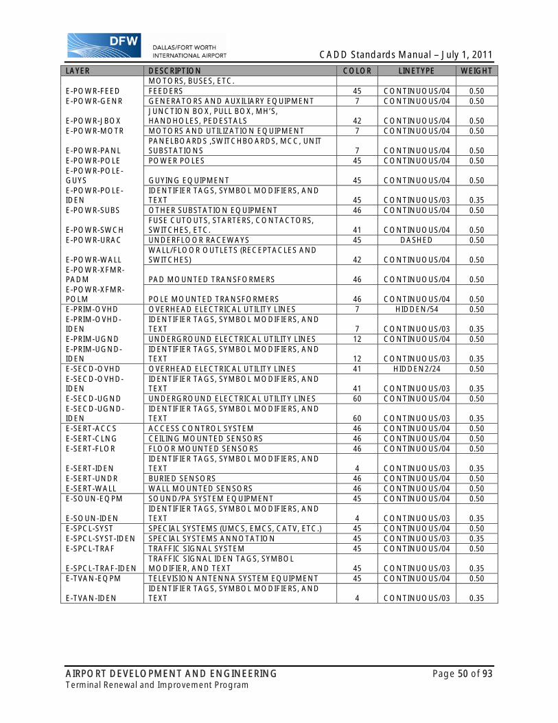
CADD Standards Manual – July 1, 2011
AIRPORT DEVELOPMENT AND ENGINEERING Page 50 of 93 Terminal Renewal and Improvement Program
LAYER DESCRIPTION COLOR LINETYPE WEIGHTMOTORS, BUSES, ETC.
E-POWR-FEED FEEDERS 45 CONTINUOUS/04 0.50E-POWR-GENR GENERATORS AND AUXILIARY EQUIPMENT 7 CONTINUOUS/04 0.50
E-POWR-JBOX JUNCTION BOX, PULL BOX, MH’S, HANDHOLES, PEDESTALS 42 CONTINUOUS/04 0.50
E-POWR-MOTR MOTORS AND UTILIZATION EQUIPMENT 7 CONTINUOUS/04 0.50
E-POWR-PANL PANELBOARDS ,SWITCHBOARDS, MCC, UNIT SUBSTATIONS 7 CONTINUOUS/04 0.50
E-POWR-POLE POWER POLES 45 CONTINUOUS/04 0.50E-POWR-POLE-GUYS GUYING EQUIPMENT 45 CONTINUOUS/04 0.50 E-POWR-POLE-IDEN
IDENTIFIER TAGS, SYMBOL MODIFIERS, AND TEXT 45 CONTINUOUS/03 0.35
E-POWR-SUBS OTHER SUBSTATION EQUIPMENT 46 CONTINUOUS/04 0.50
E-POWR-SWCH FUSE CUTOUTS, STARTERS, CONTACTORS, SWITCHES, ETC. 41 CONTINUOUS/04 0.50
E-POWR-URAC UNDERFLOOR RACEWAYS 45 DASHED 0.50
E-POWR-WALL WALL/FLOOR OUTLETS (RECEPTACLES AND SWITCHES) 42 CONTINUOUS/04 0.50
E-POWR-XFMR-PADM PAD MOUNTED TRANSFORMERS 46 CONTINUOUS/04 0.50 E-POWR-XFMR-POLM POLE MOUNTED TRANSFORMERS 46 CONTINUOUS/04 0.50 E-PRIM-OVHD OVERHEAD ELECTRICAL UTILITY LINES 7 HIDDEN/54 0.50E-PRIM-OVHD-IDEN
IDENTIFIER TAGS, SYMBOL MODIFIERS, AND TEXT 7 CONTINUOUS/03 0.35
E-PRIM-UGND UNDERGROUND ELECTRICAL UTILITY LINES 12 CONTINUOUS/04 0.50E-PRIM-UGND-IDEN
IDENTIFIER TAGS, SYMBOL MODIFIERS, AND TEXT 12 CONTINUOUS/03 0.35
E-SECD-OVHD OVERHEAD ELECTRICAL UTILITY LINES 41 HIDDEN2/24 0.50E-SECD-OVHD-IDEN
IDENTIFIER TAGS, SYMBOL MODIFIERS, AND TEXT 41 CONTINUOUS/03 0.35
E-SECD-UGND UNDERGROUND ELECTRICAL UTILITY LINES 60 CONTINUOUS/04 0.50E-SECD-UGND-IDEN
IDENTIFIER TAGS, SYMBOL MODIFIERS, AND TEXT 60 CONTINUOUS/03 0.35
E-SERT-ACCS ACCESS CONTROL SYSTEM 46 CONTINUOUS/04 0.50E-SERT-CLNG CEILING MOUNTED SENSORS 46 CONTINUOUS/04 0.50E-SERT-FLOR FLOOR MOUNTED SENSORS 46 CONTINUOUS/04 0.50
E-SERT-IDEN IDENTIFIER TAGS, SYMBOL MODIFIERS, AND TEXT 4 CONTINUOUS/03 0.35
E-SERT-UNDR BURIED SENSORS 46 CONTINUOUS/04 0.50E-SERT-WALL WALL MOUNTED SENSORS 46 CONTINUOUS/04 0.50E-SOUN-EQPM SOUND/PA SYSTEM EQUIPMENT 45 CONTINUOUS/04 0.50
E-SOUN-IDEN IDENTIFIER TAGS, SYMBOL MODIFIERS, AND TEXT 4 CONTINUOUS/03 0.35
E-SPCL-SYST SPECIAL SYSTEMS (UMCS, EMCS, CATV, ETC.) 45 CONTINUOUS/04 0.50E-SPCL-SYST-IDEN SPECIAL SYSTEMS ANNOTATION 45 CONTINUOUS/03 0.35E-SPCL-TRAF TRAFFIC SIGNAL SYSTEM 45 CONTINUOUS/04 0.50
E-SPCL-TRAF-IDEN TRAFFIC SIGNAL IDEN TAGS, SYMBOL MODIFIER, AND TEXT 45 CONTINUOUS/03 0.35
E-TVAN-EQPM TELEVISION ANTENNA SYSTEM EQUIPMENT 45 CONTINUOUS/04 0.50
E-TVAN-IDEN IDENTIFIER TAGS, SYMBOL MODIFIERS, AND TEXT 4 CONTINUOUS/03 0.35
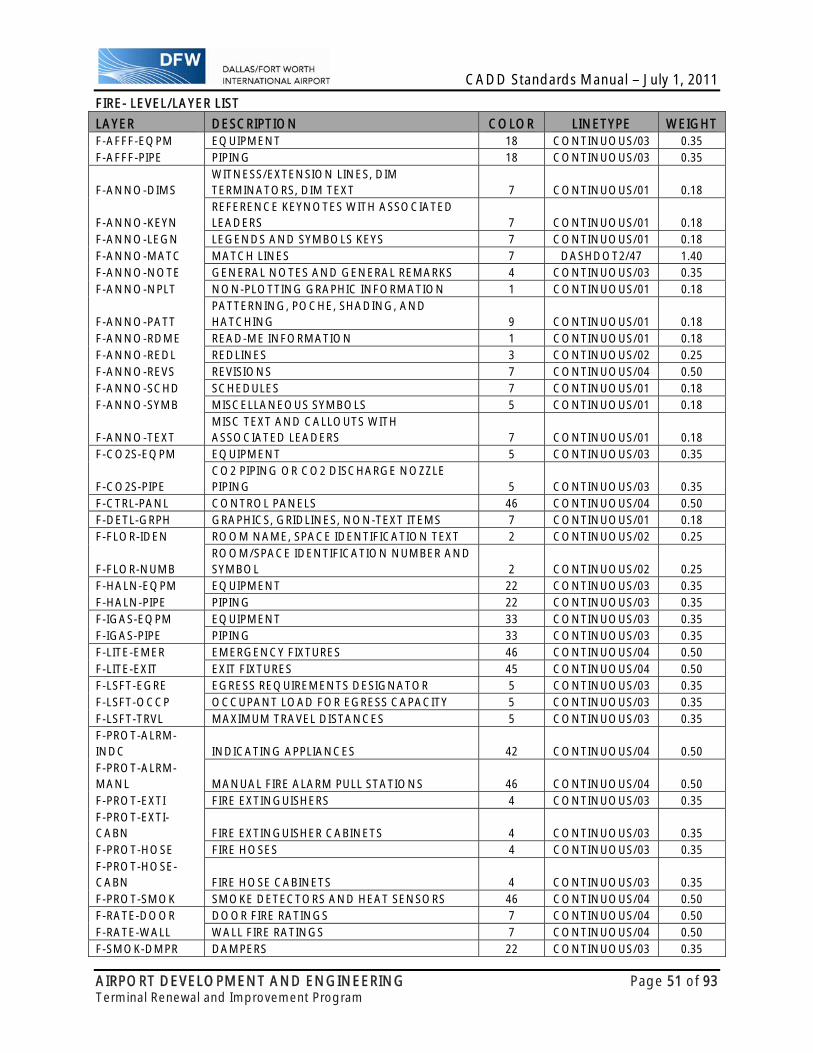
CADD Standards Manual – July 1, 2011
AIRPORT DEVELOPMENT AND ENGINEERING Page 51 of 93 Terminal Renewal and Improvement Program
FIRE- LEVEL/LAYER LIST
LAYER DESCRIPTION COLOR LINETYPE WEIGHT F-AFFF-EQPM EQUIPMENT 18 CONTINUOUS/03 0.35 F-AFFF-PIPE PIPING 18 CONTINUOUS/03 0.35
F-ANNO-DIMS WITNESS/EXTENSION LINES, DIM TERMINATORS, DIM TEXT 7 CONTINUOUS/01 0.18
F-ANNO-KEYN REFERENCE KEYNOTES WITH ASSOCIATED LEADERS 7 CONTINUOUS/01 0.18
F-ANNO-LEGN LEGENDS AND SYMBOLS KEYS 7 CONTINUOUS/01 0.18 F-ANNO-MATC MATCH LINES 7 DASHDOT2/47 1.40 F-ANNO-NOTE GENERAL NOTES AND GENERAL REMARKS 4 CONTINUOUS/03 0.35 F-ANNO-NPLT NON-PLOTTING GRAPHIC INFORMATION 1 CONTINUOUS/01 0.18
F-ANNO-PATT PATTERNING, POCHE, SHADING, AND HATCHING 9 CONTINUOUS/01 0.18
F-ANNO-RDME READ-ME INFORMATION 1 CONTINUOUS/01 0.18 F-ANNO-REDL REDLINES 3 CONTINUOUS/02 0.25 F-ANNO-REVS REVISIONS 7 CONTINUOUS/04 0.50 F-ANNO-SCHD SCHEDULES 7 CONTINUOUS/01 0.18 F-ANNO-SYMB MISCELLANEOUS SYMBOLS 5 CONTINUOUS/01 0.18
F-ANNO-TEXT MISC TEXT AND CALLOUTS WITH ASSOCIATED LEADERS 7 CONTINUOUS/01 0.18
F-CO2S-EQPM EQUIPMENT 5 CONTINUOUS/03 0.35
F-CO2S-PIPE CO2 PIPING OR CO2 DISCHARGE NOZZLE PIPING 5 CONTINUOUS/03 0.35
F-CTRL-PANL CONTROL PANELS 46 CONTINUOUS/04 0.50 F-DETL-GRPH GRAPHICS, GRIDLINES, NON-TEXT ITEMS 7 CONTINUOUS/01 0.18 F-FLOR-IDEN ROOM NAME, SPACE IDENTIFICATION TEXT 2 CONTINUOUS/02 0.25
F-FLOR-NUMB ROOM/SPACE IDENTIFICATION NUMBER AND SYMBOL 2 CONTINUOUS/02 0.25
F-HALN-EQPM EQUIPMENT 22 CONTINUOUS/03 0.35 F-HALN-PIPE PIPING 22 CONTINUOUS/03 0.35 F-IGAS-EQPM EQUIPMENT 33 CONTINUOUS/03 0.35 F-IGAS-PIPE PIPING 33 CONTINUOUS/03 0.35 F-LITE-EMER EMERGENCY FIXTURES 46 CONTINUOUS/04 0.50 F-LITE-EXIT EXIT FIXTURES 45 CONTINUOUS/04 0.50 F-LSFT-EGRE EGRESS REQUIREMENTS DESIGNATOR 5 CONTINUOUS/03 0.35 F-LSFT-OCCP OCCUPANT LOAD FOR EGRESS CAPACITY 5 CONTINUOUS/03 0.35 F-LSFT-TRVL MAXIMUM TRAVEL DISTANCES 5 CONTINUOUS/03 0.35 F-PROT-ALRM-INDC INDICATING APPLIANCES 42 CONTINUOUS/04 0.50 F-PROT-ALRM-MANL MANUAL FIRE ALARM PULL STATIONS 46 CONTINUOUS/04 0.50 F-PROT-EXTI FIRE EXTINGUISHERS 4 CONTINUOUS/03 0.35 F-PROT-EXTI-CABN FIRE EXTINGUISHER CABINETS 4 CONTINUOUS/03 0.35 F-PROT-HOSE FIRE HOSES 4 CONTINUOUS/03 0.35 F-PROT-HOSE-CABN FIRE HOSE CABINETS 4 CONTINUOUS/03 0.35 F-PROT-SMOK SMOKE DETECTORS AND HEAT SENSORS 46 CONTINUOUS/04 0.50 F-RATE-DOOR DOOR FIRE RATINGS 7 CONTINUOUS/04 0.50 F-RATE-WALL WALL FIRE RATINGS 7 CONTINUOUS/04 0.50 F-SMOK-DMPR DAMPERS 22 CONTINUOUS/03 0.35
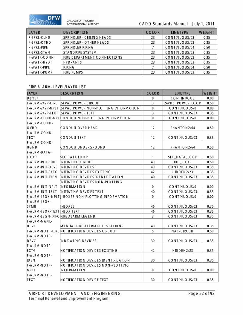
CADD Standards Manual – July 1, 2011
AIRPORT DEVELOPMENT AND ENGINEERING Page 52 of 93 Terminal Renewal and Improvement Program
LAYER DESCRIPTION COLOR LINETYPE WEIGHT F-SPKL-CLHD SPRINKLER - CEILING HEADS 23 CONTINUOUS/03 0.35 F-SPKL-OTHD SPRINKLER - OTHER HEADS 23 CONTINUOUS/03 0.35 F-SPKL-PIPE SPRINKLER PIPING 7 CONTINUOUS/04 0.50 F-SPKL-STAN STANDPIPE SYSTEM 23 CONTINUOUS/03 0.35 F-WATR-CONN FIRE DEPARTMENT CONNECTIONS 23 CONTINUOUS/03 0.35 F-WATR-HYDT HYDRANTS 23 CONTINUOUS/03 0.35 F-WATR-PIPE PIPING 7 CONTINUOUS/04 0.50 F-WATR-PUMP FIRE PUMPS 23 CONTINUOUS/03 0.35
FIRE ALARM- LEVEL/LAYER LIST
LAYER DESCRIPTION COLOR LINETYPE WEIGHTDefault 0 CONTINUOUS 0.00 F-ALRM-24VP-CIRC 24 VAC POWER CIRCUIT 3 24VDC_POWER_LOOP 0.50 F-ALRM-24VP-NPLT 24 VAC POWER NON-PLOTTING INFORMATION 0 CONTINUOUS/0 0.00 F-ALRM-24VP-TEXT 24 VAC POWER TEXT 3 CONTINUOUS/03 0.35 F-ALRM-COND-NPLTCONDUIT NON-PLOTTING INFORMATION 0 CONTINUOUS/0 0.00 F-ALRM-COND-OVHD CONDUIT OVER-HEAD 12 PHANTON2/64 0.50 F-ALRM-COND-TEXT CONDUIT TEXT 12 CONTINUOUS/03 0.35 F-ALRM-COND-UGND CONDUIT UNDERGROUND 12 PHANTON2/64 0.50 F-ALRM-DATA-LOOP SLC DATA LOOP 1 SLC_DATA_LOOP 0.50 F-ALRM-INIT-CIRC INITIATING CIRCUIT 40 IDC_LOOP 0.50 F-ALRM-INIT-DEVC INITIATING DEVICES 40 CONTINUOUS/03 0.35 F-ALRM-INIT-EXTG INITIATING DEVICES EXISTING 42 HIDDEN2/23 0.35 F-ALRM-INIT-IDEN INITIATING DEVICES IDENTIFICATION 40 CONTINUOUS/03 0.35
F-ALRM-INIT-NPLT INITIATING DEVICES NON-PLOTTING INFORMATION 0 CONTINUOUS/0 0.00
F-ALRM-INIT-TEXT INITIATING DEVICES TEXT 40 CONTINUOUS/03 0.35 F-ALRM-JBOX-NPLT J-BOXES NON-PLOTTING INFORMATION 0 CONTINUOUS/0 0.00 F-ALRM-JBOX-SYMB J-BOXES 46 CONTINUOUS/03 0.35 F-ALRM-JBOX-TEXT J-BOX TEXT 46 CONTINUOUS/03 0.35 F-ALRM-LEGN-INFOFIRE ALARM LEGEND 3 CONTINUOUS/03 0.35 F-ALRM-MANL-DEVC MANUAL FIRE ALARM PULL STATIONS 40 CONTINUOUS/03 0.35 F-ALRM-NOTF-CIRC NOTIFICATION DEVICES CIRCUIT 5 NAC-CIRCUIT 0.50 F-ALRM-NOTF-DEVC INDICATING DEVICES 30 CONTINUOUS/03 0.35 F-ALRM-NOTF-EXTG NOTIFICATION DEVICES EXISTING 42 HIDDEN2/23 0.35 F-ALRM-NOTF-IDEN NOTIFICATION DEVICES IDENTIFICATION 30 CONTINUOUS/03 0.35 F-ALRM-NOTF-NPLT
NOTIFICATION DEVICES NON-PLOTTING INFORMATION 0 CONTINUOUS/0 0.00
F-ALRM-NOTF-TEXT NOTIFICATION DEVICE TEXT 30 CONTINUOUS/03 0.35

CADD Standards Manual – July 1, 2011
AIRPORT DEVELOPMENT AND ENGINEERING Page 53 of 93 Terminal Renewal and Improvement Program
LAYER DESCRIPTION COLOR LINETYPE WEIGHTF-ALRM-PANL-CIRC PANEL EQUIPMENT CIRCUIT (CONT PNLS, AUX
PWR,) 1 VARIES 0.50
F-ALRM-PANL-EQPM
CONTROL PANELS, AUXILIARY POWER SUPPLY, ANNUNCIATOR 1 CONTINUOUS/03 0.35
F-ALRM-PANL-EXTG PANEL EQUIPMENT EXISTING 42 HIDDEN2/23 0.35 F-ALRM-PANL-IDEN PANEL EQUIPMENT IDENTIFICATION 1 CONTINUOUS/03 0.35
F-ALRM-PANL-NPLT PANEL EQUIPMENT NON-PLOTTING INFORMATION 0 CONTINUOUS/0 0.00
F-ALRM-PANL-TEXT PANEL EQUIPMENT TEXT 1 CONTINUOUS/03 0.35 F-ALRM-REVS-TEXT REVISION TEXT 4 CONTINUOUS/03 0.35 F-ALRM-SPKR-CIRC SPEAKER DEVICES CIRCUIT 4 SPEAKER 0.50 F-ALRM-SPKR-DEVC SPEAKER DEVICES 4 CONTINUOUS/03 0.35
F-ALRM-SPKR-NPLT SPEAKER DEVICES NON-PLOTTING INFORMATION 0 CONTINUOUS/0 0.00
F-ALRM-SPKR-TEXT SPEAKER DEVICES TEXT 4 CONTINUOUS/03 0.35 F-ALRM-ZONE FIRE ALARM ZONE 7 DASHED 0.70 F-ALRM-ZONE-NPLT
FIRE ALARM ZONE NON-PLOTTING INFORMATION 0 CONTINUOUS/0 0.00
F-ALRM-ZONE-TEXT FIRE ALARM ZONE TEXT 7 CONTINUOUS/03 0.35
F-ANNO-DIMS WITNESS/EXTENSION LINES, DIM TERMINATORS, DIM TEXT 0 CONTINUOUS/02 0.25
F-ANNO-KEYN REFERENCE KEYNOTES WITH ASSOCIATED LEADERS 0 CONTINUOUS/02 0.25
F-ANNO-MATC MATCH LINES 7 DASHDOT2/47 1.40 F-ANNO-NOTE GENERAL NOTES AND GENERAL REMARKS 4 CONTINUOUS/02 0.25 F-ANNO-NPLT NON-PLOTTING GRAPHIC INFORMATION 0 CONTINUOUS/0 0.00
F-ANNO-PATT PATTERNING, POCHE, SHADING, AND HATCHING 9 CONTINUOUS/01 0.18
F-ANNO-RDME READ-ME INFORMATION - NON-PLOTTING INFORMATION 7 CONTINUOUS/03 0.35
F-ANNO-SYMB MISCELLANEOUS SYMBOLS 6 CONTINUOUS/03 0.35
F-ANNO-TEXT MISCELLANEOUS TEXT AND CALLOUTS WITH ASSOCIATED LEADERS 6 CONTINUOUS/02 0.25
F-FLOR-IDEN ROOM NAME, SPACE IDENTIFICATION TEXT (COPIED FROM ARCH) 2 CONTINUOUS/02 0.25
F-FLOR-NUMB ROOM/SPACE ID NO. AND SYM (COPIED FROM ARCH) 2 CONTINUOUS/02 0.25
F-MECH-EQMP-NPLT
MECHANICAL EQUIPMENT NON-PLOTTING INFORMATION 0 CONTINUOUS/0 0.00
F-MECH-EQMP-SYMB MECHANICAL EQUIPMENT 4 DASHED 0.35 F-MECH-EQMP-TEXT MECHANICAL EQUIPMENT TEXT 4 CONTINUOUS/03 0.35 F-SMOK-DMPR DAMPERS 22 CONTINUOUS/03 0.35 F-VIEW-PORT-NPLT NON-PLOTTING VIEW PORT 0 CONTINUOUS/0 0.00 F-XREF XREFS 0 CONTINUOUS/0 0.00

CADD Standards Manual – July 1, 2011
AIRPORT DEVELOPMENT AND ENGINEERING Page 54 of 93 Terminal Renewal and Improvement Program
GENERAL- LEVEL/LAYER LIST
LAYER DESCRIPTION COLOR LINETYPE WEIGHT
G-ANNO-DIMS SHEET-SPECIFIC DIM LINES, DIM TERMINATORS, DIM TEXT 7 CONTINUOUS/01 0.18
G-ANNO-KEYN SHEET-SPECIFIC REFERENCE KEYNOTES WITH LEADERS 7 CONTINUOUS/01 0.18
G-ANNO-LEGN LEGENDS AND SYMBOLS KEYS 7 CONTINUOUS/01 0.18
G-ANNO-MASK TEXT/SHAPE MASK FOR USE WITH PHOTO BACKGROUNDS 16 CONTINUOUS/01 0.18
G-ANNO-MATC MATCH LINES 7 DASHDOT2/47 1.40
G-ANNO-NOTE SHEET-SPECIFIC NOTES AND GENERAL REMARKS 4 CONTINUOUS/03 0.35
G-ANNO-NPLT NON-PLOTTING GRAPHIC INFORMATION 1 CONTINUOUS/01 0.18
G-ANNO-PATT SHEET-SPEC PATTERNING, POCHE, SHADING, HATCHING 9 CONTINUOUS/01 0.18
G-ANNO-RDME READ-ME INFORMATION 1 CONTINUOUS/01 0.18
G-ANNO-REDL REDLINES 3 CONTINUOUS/02 0.25
G-ANNO-REVS REVISIONS 7 CONTINUOUS/04 0.50
G-ANNO-SCHD SCHEDULES 7 CONTINUOUS/01 0.18
G-ANNO-SYMB MISCELLANEOUS SYMBOLS 5 CONTINUOUS/03 0.35
G-ANNO-TEXT SHEET-SPECIFIC TEXT AND CALLOUTS WITH LEADERS 7 CONTINUOUS/01 0.18
G-ANNO-TTLB BORDER AND TITLEBLOCK LINEWORK 7 CONTINUOUS/01 0.18
G-ANNO-TTLB-GRID GRID LINES INSIDE BORDER 1 PHANTOM/61 0.18
G-COOR-LALO LATITUDE/LONGITUDE COORDINATE GRID TICKS 4 CONTINUOUS/02 0.25
G-COOR-LALO-IDEN LATITUDE/LONGITUDE COORDINATE TEXT 4 CONTINUOUS/02 0.25
G-COOR-STAT STATE PLANE COORDINATE GRID TICKS 4 DASHED 0.25
G-COOR-STAT-IDEN STATE PLANE COORDINATE TEXT 4 CONTINUOUS/02 0.25
G-GRID-COOR 7 CONTINUOUS/02 0.25
G-GRID-COOR-IDEN 7 CONTINUOUS/02 0.25
G-GRID-EXTR 1 CENTER2/71 0.18
G-GRID-IDEN 3 CONTINUOU/02S 0.25
G-PLAN-OTLN 5 CONTINUOUS/03 0.35
G-SITE-OTLN 5 CONTINUOUS/03 0.35 LANDSCAPE- LEVEL/LAYER LIST
LAYER DESCRIPTION COLOR LINETYPE WEIGHT
L-IRRG-EQPM EQUIPMENT (E.G., CONTROLLERS, VALVES, RPBPS, ETC.) 5 CONTINUOUS/03 0.35
L-IRRG-HEAD IRRIGATION HEADS, BUBBLERS, AND DRIP IRRIGATION EMITTERS 3 CONTINUOUS/02 0.25
L-IRRG-IDEN ANNOTATION 4 CONTINUOUS/03 0.35
L-IRRG-PIPE PIPING 5 CONTINUOUS/03 0.35
L-IRRG-SPKL SPRINKLERS 5 CONTINUOUS/03 0.35
L-PLNT-BEDS PLANTING BEDS (PERENNIAL AND ANNUAL BEDS) 5 CONTINUOUS/03 0.35
L-PLNT-BUSH BUSHES AND SHRUBS (E.G., EVERGREEN, DECIDUOUS, ETC.) 42 CONTINUOUS/04 0.50
L-PLNT-BUSH-LINE BUSH AND SHRUB LINE 42 CONTINUOUS/04 0.50
L-PLNT-CTNR CONTAINERS OR PLANTERS 3 CONTINUOUS/02 0.25
L-PLNT-GCVR GROUNDCOVER AND VINES 18 CONTINUOUS/03 0.35
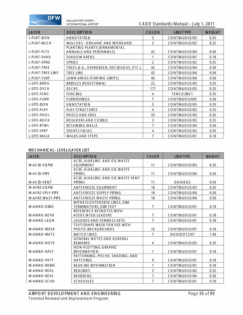
CADD Standards Manual – July 1, 2011
AIRPORT DEVELOPMENT AND ENGINEERING Page 55 of 93 Terminal Renewal and Improvement Program
LAYER DESCRIPTION COLOR LINETYPE WEIGHT L-PLNT-IDEN ANNOTATION 5 CONTINUOUS/03 0.35
L-PLNT-MLCH MULCHES - ORGANIC AND INORGANIC 2 CONTINUOUS/02 0.25
L-PLNT-PLTS PLANTING PLANTS (ORNAMENTAL ANNUALS AND PERENNIALS) 42 CONTINUOUS/04 0.50
L-PLNT-SHAD SHADOW AREAS 1 CONTINUOUS/01 0.18
L-PLNT-SPRG SPRIGS 2 CONTINUOUS/02 0.25
L-PLNT-TREE TREES (E.G., EVERGREEN, DECIDUOUS, ETC.) 42 CONTINUOUS/04 0.50
L-PLNT-TREE-LINE TREE LINE 42 CONTINUOUS/04 0.50
L-PLNT-TURF LAWN AREAS (TURFING LIMITS) 46 CONTINUOUS/04 0.50
L-SITE-BRDG BRIDGES (PEDESTRIAN) 22 CONTINUOUS/03 0.35
L-SITE-DECK DECKS 177 CONTINUOUS/03 0.35
L-SITE-FENC FENCING 4 FENCELINE1 0.35
L-SITE-FURN FURNISHINGS 7 CONTINUOU/04S 0.50
L-SITE-IDEN ANNOTATION 5 CONTINUOUS/03 0.35
L-SITE-PLAY PLAY STRUCTURES 4 CONTINUOUS/03 0.35
L-SITE-POOL POOLS AND SPAS 33 CONTINUOUS/03 0.35
L-SITE-ROCK BOULDERS AND COBBLE 3 CONTINUOUS/02 0.25
L-SITE-RTWL RETAINING WALLS 7 CONTINUOUS/04 0.50
L-SITE-SPRT SPORTS FIELDS 4 CONTINUOUS/03 0.35
L-SITE-WALK WALKS AND STEPS 7 CONTINUOUS/01 0.18
MECHANICAL- LEVEL/LAYER LIST
LAYER DESCRIPTION COLOR LINETYPE WEIGHT
M-ACID-EQPM ACID, ALKALINE, AND OIL WASTE EQUIPMENT 11 CONTINUOUS/03 0.35
M-ACID-PIPE ACID, ALKALINE, AND OIL WASTE PIPING 11 CONTINUOUS/04 0.50
M-ACID-VENT ACID, ALKALINE, AND OIL WASTE VENT PIPING 11 DASHED2 0.50
M-AFRZ-EQPM ANTI-FREEZE EQUIPMENT 18 CONTINUOUS/03 0.35
M-AFRZ-SPLY-PIPE ANTI-FREEZE SUPPLY PIPING 18 CONTINUOUS/04 0.50
M-AFRZ-WAST-PIPE ANTI-FREEZE WASTE PIPING 18 CONTINUOUS/04 0.50
M-ANNO-DIMS WITNESS/EXTENSION LINES, DIM TERMINATORS, DIM TEXT 7 CONTINUOUS/01 0.18
M-ANNO-KEYN REFERENCE KEYNOTES WITH ASSOCIATED LEADERS 7 CONTINUOUS/01 0.18
M-ANNO-LEGN LEGENDS AND SYMBOLS KEYS 7 CONTINUOUS/01 0.18
M-ANNO-MASK TEXT/SHAPE MASK FOR USE WITH PHOTO BACKGROUNDS 16 CONTINUOUS/01 0.18
M-ANNO-MATC MATCH LINES 7 DASHDOT2/47 1.40
M-ANNO-NOTE GENERAL NOTES AND GENERAL REMARKS 4 CONTINUOUS/03 0.35
M-ANNO-NPLT NON-PLOTTING GRAPHIC INFORMATION 1 CONTINUOUS/01 0.18
M-ANNO-PATT PATTERNING, POCHE, SHADING, AND HATCHING 9 CONTINUOUS/01 0.18
M-ANNO-RDME READ-ME INFORMATION 1 CONTINUOUS/01 0.18
M-ANNO-REDL REDLINES 3 CONTINUOUS/02 0.25
M-ANNO-REVS REVISIONS 7 CONTINUOUS/04 0.50
M-ANNO-SCHD SCHEDULES 7 CONTINUOUS/01 0.18

CADD Standards Manual – July 1, 2011
AIRPORT DEVELOPMENT AND ENGINEERING Page 56 of 93 Terminal Renewal and Improvement Program
LAYER DESCRIPTION COLOR LINETYPE WEIGHT
M-ANNO-SYMB MISCELLANEOUS SYMBOLS 5 CONTINUOUS/01 0.18
M-ANNO-TEXT MISCELLANEOUS TEXT AND CALLOUTS WITH LEADERS 7 CONTINUOUS/01 0.18
M-BRIN-EQPM BRINE SYSTEM EQUIPMENT 31 CONTINUOUS/03 0.35
M-BRIN-RETN-PIPE BRINE SYSTEM RETURN PIPING 31 CONTINUOUS/04 0.50
M-BRIN-SPLY-PIPE BRINE SYSTEM SUPPLY PIPING 21 CONTINUOUS/04 0.50
M-CHEM-EQPM CHEMICAL TREATMENT SYSTEM EQUIPMENT 31 CONTINUOUS/03 0.35
M-CHEM-RETN-PIPE CHEMICAL TREATMENT SYSTEM RETURN PIPING 31 CONTINUOUS/04 0.50
M-CHEM-SPLY-PIPE CHEMICAL TREATMENT SYSTEM SUPPLY PIPING 31 CONTINUOUS/04 0.50
M-CMPA-EQPM EQUIPMENT 34 CONTINUOUS/03 0.35
M-CMPA-PIPE PIPING 42 CONTINUOUS/04 0.50
M-CNDW-EQPM CONDENSER WATER SYSTEM EQUIPMENT 52 CONTINUOUS/03 0.35
M-CNDW-RETN-PIPE CONDENSER WATER SYSTEM RETURN PIPING 42 CONTINUOUS/04 0.50
M-CNDW-SPLY-PIPE CONDENSER WATER SYSTEM SUPPLY PIPING 32 CONTINUOUS/04 0.50
M-CONT-THER THERMOSTATS 3 CONTINUOUS/02 0.25
M-CONT-WIRE LOW VOLTAGE WIRING 3 DOT2/12 0.25
M-CVAL-BASE CULVERT VALVE MACHINERY BASE 4 CONTINUOUS/03 0.35
M-CVAL-BEAM CULVERT VALVE BEAMS 4 CONTINUOUS/03 0.35
M-CVAL-CYLD CULVERT VALVE MACHINERY CYLINDER 11 CONTINUOUS/03 0.35
M-CVAL-SEAL CULVERT VALVE SEALS 2 CONTINUOUS/03 0.35
M-CVAL-SKIN CULVERT VALVE SKIN PLATE 3 CONTINUOUS/03 0.35
M-CVAL-STIF STIFFENER PLATES, ANGLES, ETC. 7 CONTINUOUS/03 0.35
M-CVAL-TRUN CULVERT VALVE TRUNNION BEAM 5 CONTINUOUS/03 0.35
M-CWTR-CNDS-PIPE CONDENSATE PIPING 42 CONTINUOUS/04 0.50
M-CWTR-EQPM CHILLED WATER EQUIPMENT 41 CONTINUOUS/03 0.35
M-CWTR-RETN-PIPE CHILLED WATER RETURN PIPING 41 CONTINUOUS/04 0.50
M-CWTR-SPLY-PIPE CHILLED WATER SUPPLY PIPING 31 CONTINUOUS/04 0.50
M-DETL-GRPH GRAPHICS, GRIDLINES, NON-TEXT ITEMS 7 CONTINUOUS/01 0.18
M-DUAL-EQPM DUAL TEMPERATURE SYSTEM EQUIPMENT 46 CONTINUOUS/03 0.35
M-DUAL-RETN-PIPE DUAL TEMPERATURE SYSTEM RETURN PIPING 46 CONTINUOUS/04 0.50
M-DUAL-SPLY-PIPE DUAL TEMPERATURE SYSTEM SUPPLY PIPING 36 CONTINUOUS/04 0.50
M-DUST-DUCT DUST AND FUME DUCTWORK 45 CONTINUOUS/04 0.50
M-DUST-DUCT-CNTR DUST AND FUME DUCTWORK CENTERLINES 1 CENTER2/71 0.18
M-DUST-EQPM DUST AND FUME EQUIPMENT 45 CONTINUOUS/03 0.35
M-DUST-GRIL DUST AND FUME GRILLES 45 CONTINUOUS/03 0.35
M-ELEV-IDEN COMPONENT IDENTIFICATION NUMBERS 4 CONTINUOUS/03 0.35
M-ELEV-OTLN BUILDING OUTLINES 5 CONTINUOUS/03 0.35
M-ELEV-PATT TEXTURES AND HATCH PATTERNS 9 CONTINUOUS/01 0.18
M-EXHS-DUCT EXHAUST DUCTWORK 42 CONTINUOUS/04 0.50
M-EXHS-DUCT-CNTR EXHAUST DUCTWORK CENTERLINES 1 CENTER2/71 0.18

CADD Standards Manual – July 1, 2011
AIRPORT DEVELOPMENT AND ENGINEERING Page 57 of 93 Terminal Renewal and Improvement Program
LAYER DESCRIPTION COLOR LINETYPE WEIGHT
M-EXHS-EQPM EXHAUST EQUIPMENT 42 CONTINUOUS/03 0.35
M-EXHS-GRIL GRILLES 42 CONTINUOUS/03 0.35
M-FLOR-IDEN ROOM NAME, SPACE IDENTIFICATION TEXT 2 CONTINUOUS/02 0.25
M-FLOR-NUMB ROOM/SPACE IDENTIFICATION NUMBER AND SYMBOL 2 CONTINUOUS/02 0.25
M-FUEL-DIES-RETN DIESEL FUEL RETURN PIPING 46 CONTINUOUS/04 0.50
M-FUEL-DIES-SPLY DIESEL FUEL SUPPLY PIPING 46 CONTINUOUS/04 0.50
M-FUEL-DIES-VENT DIESEL FUEL VENT PIPING 46 CONTINUOUS/04 0.50
M-FUEL-EQPM EQUIPMENT 38 CONTINUOUS/03 0.35
M-FUEL-GGEP-LQPG LIQUID PETROLEUM GAS 66 CONTINUOUS/04 0.50
M-FUEL-OGEP-RETN RETURN OIL PIPING 46 CONTINUOUS/04 0.50
M-FUEL-OGEP-SPLY SUPPLY OIL PIPING 26 CONTINUOUS/04 0.50
M-FUEL-OGEP-VENT OIL PIPING VENT 45 CONTINUOUS/04 0.50
M-GLYC-EQPM GLYCOL SYSTEM EQUIPMENT 18 CONTINUOUS/03 0.35
M-GLYC-RETN-PIPE GLYCOL SYSTEM RETURN PIPING 18 CONTINUOUS/04 0.50
M-GLYC-SPLY-PIPE GLYCOL SYSTEM SUPPLY PIPING 28 CONTINUOUS/04 0.50
M-GTHP-EQPM GEOTHERMAL HEAT PUMP SYSTEM EQUIPMENT 45 CONTINUOUS/03 0.35
M-GTHP-RETN-PIPE GEOTHERMAL HEAT PUMP SYSTEM RETURN PIPING 45 CONTINUOUS/04 0.50
M-GTHP-SUPP-PIPE GEOTHERMAL HEAT PUMP SYSTEM SUPPLY PIPING 45 CONTINUOUS/04 0.50
M-HCSF-CYLD HYDRAULIC CYLINDERS 7 CONTINUOUS/03 0.35
M-HCSF-CYLD-PSTN HYDRAULIC CYLINDER PISTONS 1 CONTINUOUS/03 0.35
M-HCSF-CYLD-WEAR WEAR RINGS 2 CONTINUOUS/03 0.35
M-HCSF-EQPM HYDRAULIC SYSTEM EQUIPMENT 13 CONTINUOUS/03 0.35
M-HCSF-FTTG HOSE AND PIPE FITTINGS 7 CONTINUOUS/03 0.35
M-HCSF-HOSE HYDRAULIC HOSES 7 CONTINUOUS/03 0.35
M-HCSF-MOTR HYDRAULIC MOTORS AND ACTUATORS 7 CONTINUOUS/03 0.35
M-HCSF-OTLN OUTLINES OF MACHINERY 11 CONTINUOUS/03 0.35
M-HCSF-PUMP HYDRAULIC PUMPS AND PUMP MOTORS 7 CONTINUOUS/03 0.35
M-HCSF-RETN-PIPE HYDRAULIC SYSTEM RETURN PIPING 12 CONTINUOUS/04 0.50
M-HCSF-ROOM FLOOR, WALLS, ETC. THAT HYDRAULIC SYSTEM ATTACHES TO 1 CONTINUOUS/03 0.35
M-HCSF-SCHM-MISC MISCELLANEOUS SCHEMATIC FIGURES (COMMON LOCATION) 5 CONTINUOUS/03 0.35
M-HCSF-SPLY-PIPE HYDRAULIC SYSTEM SUPPLY PIPING 13 CONTINUOUS/04 0.50
M-HCSF-SUPT PIPE SUPPORTS, HANGERS, ETC. 6 CONTINUOUS/03 0.35
M-HCSF-VALV HYDRAULIC VALVES 5 CONTINUOUS/03 0.35
M-HCSF-VALV-CONT HYDRAULIC DIRECTIONAL CONTROL VALVES 5 CONTINUOUS/03 0.35
M-HCSF-VALV-FLOW FLOW CONTROL VALVES, CHECK VALVES, ETC. 5 CONTINUOUS/03 0.35
M-HCSF-VALV-PRES PRESSURE CONTROL VALVES: RELIEF VALVES, ETC. 5 CONTINUOUS/03 0.35
M-HCSF-VALV-SOFF HYDRAULIC SHUTOFF TYPE VALVES (BALL, GATE, ETC.) 5 CONTINUOUS/03 0.35
M-HCSW-DEVC STILLING WELLS, ANCHORS, ANCHOR GUIDES, RECTIFIERS, ETC. 5 CONTINUOUS/03 0.35
M-HCSW-DEVC-IDEN DEVICE IDENTIFIERS 5 CONTINUOUS/02 0.25
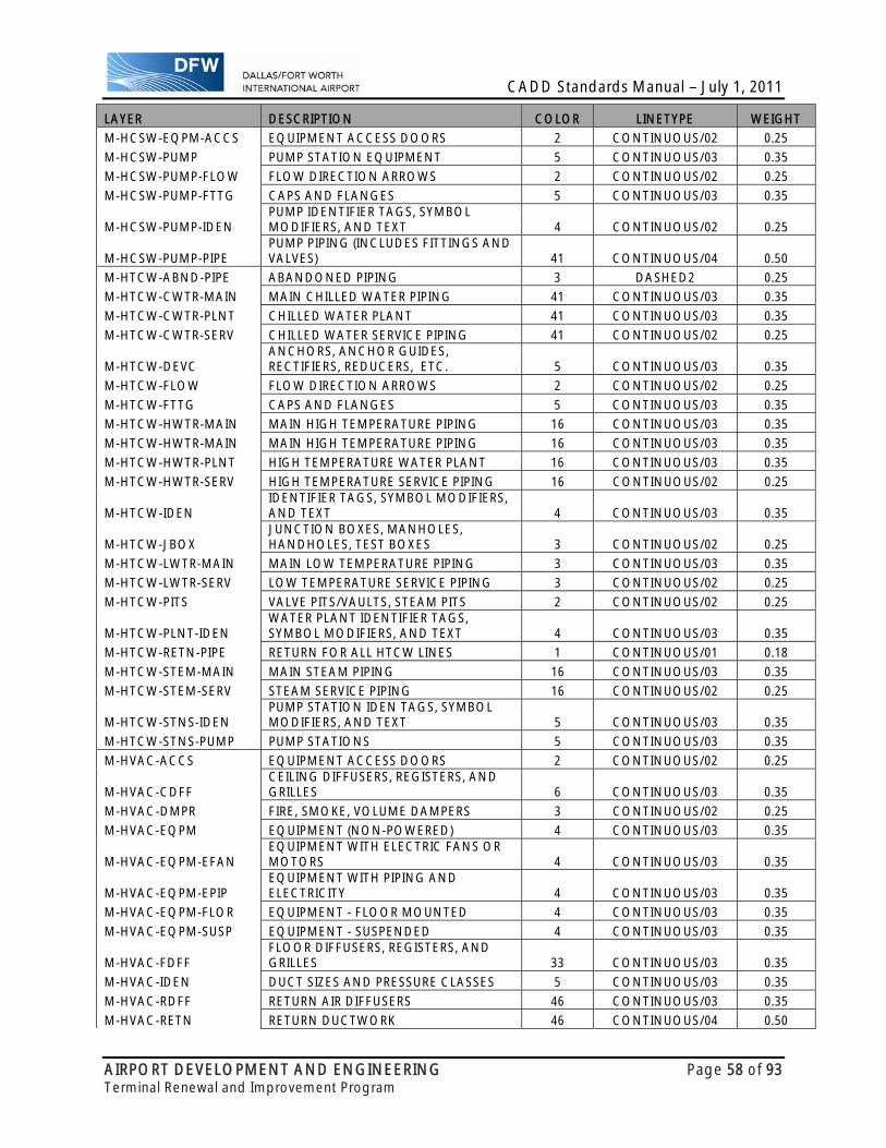
CADD Standards Manual – July 1, 2011
AIRPORT DEVELOPMENT AND ENGINEERING Page 58 of 93 Terminal Renewal and Improvement Program
LAYER DESCRIPTION COLOR LINETYPE WEIGHT
M-HCSW-EQPM-ACCS EQUIPMENT ACCESS DOORS 2 CONTINUOUS/02 0.25
M-HCSW-PUMP PUMP STATION EQUIPMENT 5 CONTINUOUS/03 0.35
M-HCSW-PUMP-FLOW FLOW DIRECTION ARROWS 2 CONTINUOUS/02 0.25
M-HCSW-PUMP-FTTG CAPS AND FLANGES 5 CONTINUOUS/03 0.35
M-HCSW-PUMP-IDEN PUMP IDENTIFIER TAGS, SYMBOL MODIFIERS, AND TEXT 4 CONTINUOUS/02 0.25
M-HCSW-PUMP-PIPE PUMP PIPING (INCLUDES FITTINGS AND VALVES) 41 CONTINUOUS/04 0.50
M-HTCW-ABND-PIPE ABANDONED PIPING 3 DASHED2 0.25
M-HTCW-CWTR-MAIN MAIN CHILLED WATER PIPING 41 CONTINUOUS/03 0.35
M-HTCW-CWTR-PLNT CHILLED WATER PLANT 41 CONTINUOUS/03 0.35
M-HTCW-CWTR-SERV CHILLED WATER SERVICE PIPING 41 CONTINUOUS/02 0.25
M-HTCW-DEVC ANCHORS, ANCHOR GUIDES, RECTIFIERS, REDUCERS, ETC. 5 CONTINUOUS/03 0.35
M-HTCW-FLOW FLOW DIRECTION ARROWS 2 CONTINUOUS/02 0.25
M-HTCW-FTTG CAPS AND FLANGES 5 CONTINUOUS/03 0.35
M-HTCW-HWTR-MAIN MAIN HIGH TEMPERATURE PIPING 16 CONTINUOUS/03 0.35
M-HTCW-HWTR-MAIN MAIN HIGH TEMPERATURE PIPING 16 CONTINUOUS/03 0.35
M-HTCW-HWTR-PLNT HIGH TEMPERATURE WATER PLANT 16 CONTINUOUS/03 0.35
M-HTCW-HWTR-SERV HIGH TEMPERATURE SERVICE PIPING 16 CONTINUOUS/02 0.25
M-HTCW-IDEN IDENTIFIER TAGS, SYMBOL MODIFIERS, AND TEXT 4 CONTINUOUS/03 0.35
M-HTCW-JBOX JUNCTION BOXES, MANHOLES, HANDHOLES, TEST BOXES 3 CONTINUOUS/02 0.25
M-HTCW-LWTR-MAIN MAIN LOW TEMPERATURE PIPING 3 CONTINUOUS/03 0.35
M-HTCW-LWTR-SERV LOW TEMPERATURE SERVICE PIPING 3 CONTINUOUS/02 0.25
M-HTCW-PITS VALVE PITS/VAULTS, STEAM PITS 2 CONTINUOUS/02 0.25
M-HTCW-PLNT-IDEN WATER PLANT IDENTIFIER TAGS, SYMBOL MODIFIERS, AND TEXT 4 CONTINUOUS/03 0.35
M-HTCW-RETN-PIPE RETURN FOR ALL HTCW LINES 1 CONTINUOUS/01 0.18
M-HTCW-STEM-MAIN MAIN STEAM PIPING 16 CONTINUOUS/03 0.35
M-HTCW-STEM-SERV STEAM SERVICE PIPING 16 CONTINUOUS/02 0.25
M-HTCW-STNS-IDEN PUMP STATION IDEN TAGS, SYMBOL MODIFIERS, AND TEXT 5 CONTINUOUS/03 0.35
M-HTCW-STNS-PUMP PUMP STATIONS 5 CONTINUOUS/03 0.35
M-HVAC-ACCS EQUIPMENT ACCESS DOORS 2 CONTINUOUS/02 0.25
M-HVAC-CDFF CEILING DIFFUSERS, REGISTERS, AND GRILLES 6 CONTINUOUS/03 0.35
M-HVAC-DMPR FIRE, SMOKE, VOLUME DAMPERS 3 CONTINUOUS/02 0.25
M-HVAC-EQPM EQUIPMENT (NON-POWERED) 4 CONTINUOUS/03 0.35
M-HVAC-EQPM-EFAN EQUIPMENT WITH ELECTRIC FANS OR MOTORS 4 CONTINUOUS/03 0.35
M-HVAC-EQPM-EPIP EQUIPMENT WITH PIPING AND ELECTRICITY 4 CONTINUOUS/03 0.35
M-HVAC-EQPM-FLOR EQUIPMENT - FLOOR MOUNTED 4 CONTINUOUS/03 0.35
M-HVAC-EQPM-SUSP EQUIPMENT - SUSPENDED 4 CONTINUOUS/03 0.35
M-HVAC-FDFF FLOOR DIFFUSERS, REGISTERS, AND GRILLES 33 CONTINUOUS/03 0.35
M-HVAC-IDEN DUCT SIZES AND PRESSURE CLASSES 5 CONTINUOUS/03 0.35
M-HVAC-RDFF RETURN AIR DIFFUSERS 46 CONTINUOUS/03 0.35
M-HVAC-RETN RETURN DUCTWORK 46 CONTINUOUS/04 0.50
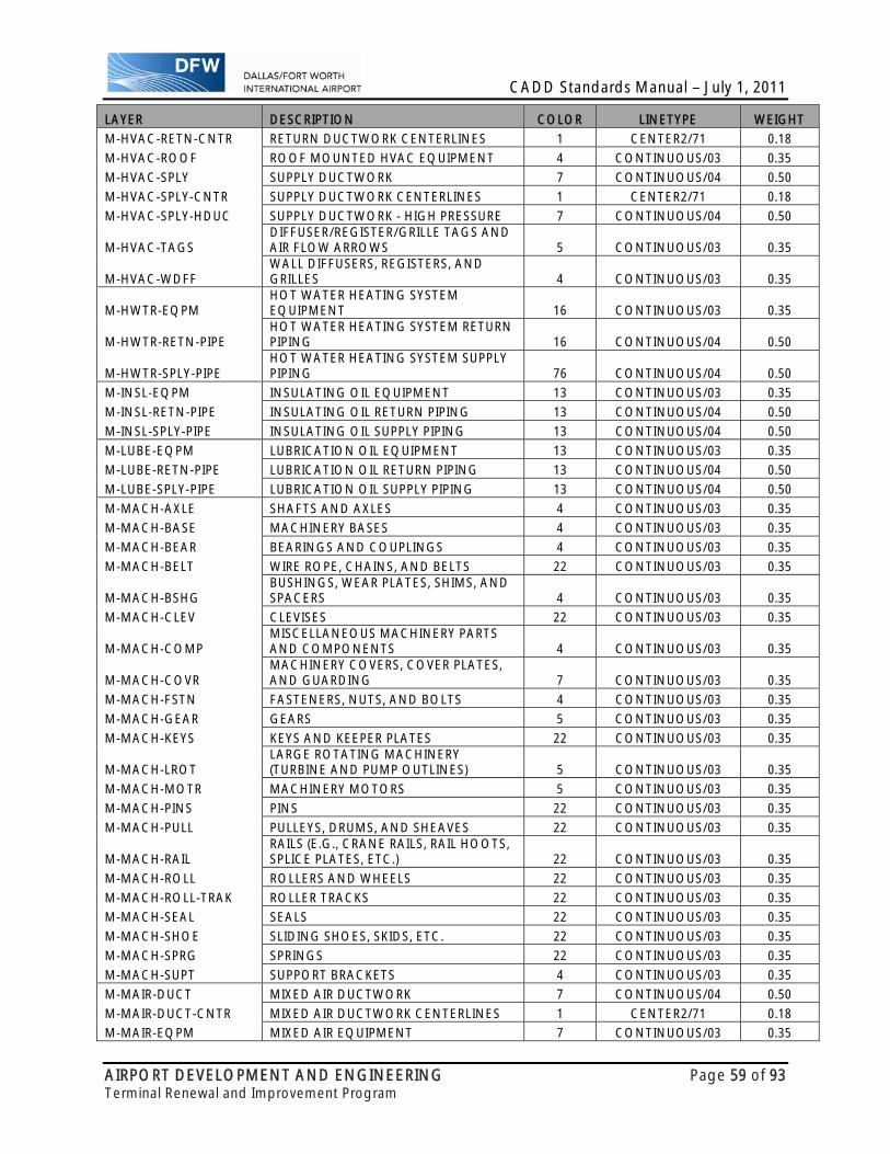
CADD Standards Manual – July 1, 2011
AIRPORT DEVELOPMENT AND ENGINEERING Page 59 of 93 Terminal Renewal and Improvement Program
LAYER DESCRIPTION COLOR LINETYPE WEIGHT
M-HVAC-RETN-CNTR RETURN DUCTWORK CENTERLINES 1 CENTER2/71 0.18
M-HVAC-ROOF ROOF MOUNTED HVAC EQUIPMENT 4 CONTINUOUS/03 0.35
M-HVAC-SPLY SUPPLY DUCTWORK 7 CONTINUOUS/04 0.50
M-HVAC-SPLY-CNTR SUPPLY DUCTWORK CENTERLINES 1 CENTER2/71 0.18
M-HVAC-SPLY-HDUC SUPPLY DUCTWORK - HIGH PRESSURE 7 CONTINUOUS/04 0.50
M-HVAC-TAGS DIFFUSER/REGISTER/GRILLE TAGS AND AIR FLOW ARROWS 5 CONTINUOUS/03 0.35
M-HVAC-WDFF WALL DIFFUSERS, REGISTERS, AND GRILLES 4 CONTINUOUS/03 0.35
M-HWTR-EQPM HOT WATER HEATING SYSTEM EQUIPMENT 16 CONTINUOUS/03 0.35
M-HWTR-RETN-PIPE HOT WATER HEATING SYSTEM RETURN PIPING 16 CONTINUOUS/04 0.50
M-HWTR-SPLY-PIPE HOT WATER HEATING SYSTEM SUPPLY PIPING 76 CONTINUOUS/04 0.50
M-INSL-EQPM INSULATING OIL EQUIPMENT 13 CONTINUOUS/03 0.35
M-INSL-RETN-PIPE INSULATING OIL RETURN PIPING 13 CONTINUOUS/04 0.50
M-INSL-SPLY-PIPE INSULATING OIL SUPPLY PIPING 13 CONTINUOUS/04 0.50
M-LUBE-EQPM LUBRICATION OIL EQUIPMENT 13 CONTINUOUS/03 0.35
M-LUBE-RETN-PIPE LUBRICATION OIL RETURN PIPING 13 CONTINUOUS/04 0.50
M-LUBE-SPLY-PIPE LUBRICATION OIL SUPPLY PIPING 13 CONTINUOUS/04 0.50
M-MACH-AXLE SHAFTS AND AXLES 4 CONTINUOUS/03 0.35
M-MACH-BASE MACHINERY BASES 4 CONTINUOUS/03 0.35
M-MACH-BEAR BEARINGS AND COUPLINGS 4 CONTINUOUS/03 0.35
M-MACH-BELT WIRE ROPE, CHAINS, AND BELTS 22 CONTINUOUS/03 0.35
M-MACH-BSHG BUSHINGS, WEAR PLATES, SHIMS, AND SPACERS 4 CONTINUOUS/03 0.35
M-MACH-CLEV CLEVISES 22 CONTINUOUS/03 0.35
M-MACH-COMP MISCELLANEOUS MACHINERY PARTS AND COMPONENTS 4 CONTINUOUS/03 0.35
M-MACH-COVR MACHINERY COVERS, COVER PLATES, AND GUARDING 7 CONTINUOUS/03 0.35
M-MACH-FSTN FASTENERS, NUTS, AND BOLTS 4 CONTINUOUS/03 0.35
M-MACH-GEAR GEARS 5 CONTINUOUS/03 0.35
M-MACH-KEYS KEYS AND KEEPER PLATES 22 CONTINUOUS/03 0.35
M-MACH-LROT LARGE ROTATING MACHINERY (TURBINE AND PUMP OUTLINES) 5 CONTINUOUS/03 0.35
M-MACH-MOTR MACHINERY MOTORS 5 CONTINUOUS/03 0.35
M-MACH-PINS PINS 22 CONTINUOUS/03 0.35
M-MACH-PULL PULLEYS, DRUMS, AND SHEAVES 22 CONTINUOUS/03 0.35
M-MACH-RAIL RAILS (E.G., CRANE RAILS, RAIL HOOTS, SPLICE PLATES, ETC.) 22 CONTINUOUS/03 0.35
M-MACH-ROLL ROLLERS AND WHEELS 22 CONTINUOUS/03 0.35
M-MACH-ROLL-TRAK ROLLER TRACKS 22 CONTINUOUS/03 0.35
M-MACH-SEAL SEALS 22 CONTINUOUS/03 0.35
M-MACH-SHOE SLIDING SHOES, SKIDS, ETC. 22 CONTINUOUS/03 0.35
M-MACH-SPRG SPRINGS 22 CONTINUOUS/03 0.35
M-MACH-SUPT SUPPORT BRACKETS 4 CONTINUOUS/03 0.35
M-MAIR-DUCT MIXED AIR DUCTWORK 7 CONTINUOUS/04 0.50
M-MAIR-DUCT-CNTR MIXED AIR DUCTWORK CENTERLINES 1 CENTER2/71 0.18
M-MAIR-EQPM MIXED AIR EQUIPMENT 7 CONTINUOUS/03 0.35
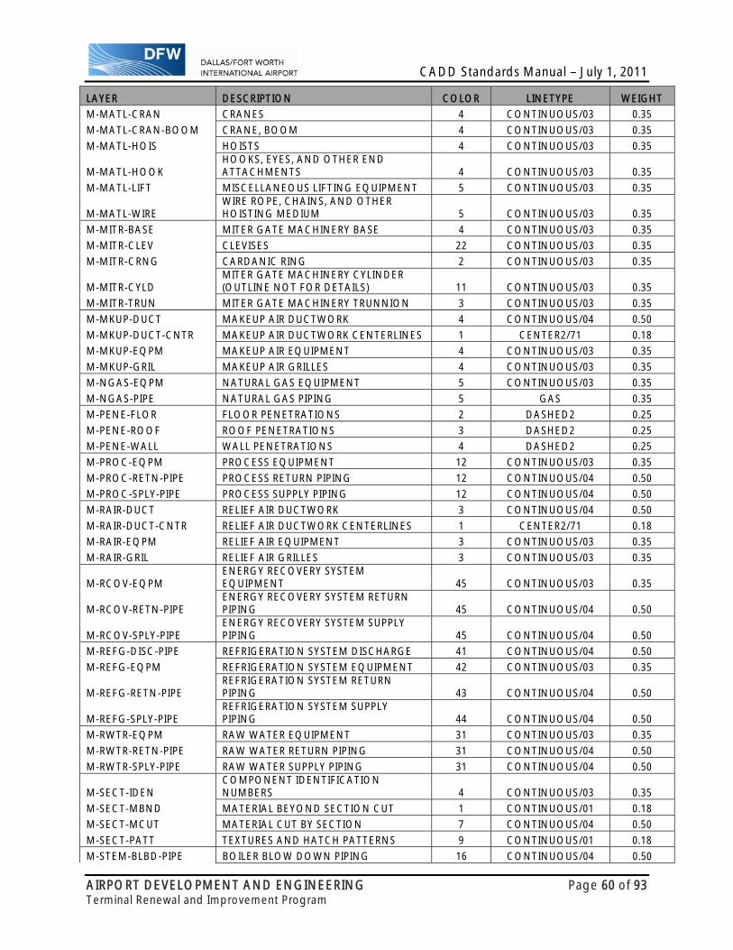
CADD Standards Manual – July 1, 2011
AIRPORT DEVELOPMENT AND ENGINEERING Page 60 of 93 Terminal Renewal and Improvement Program
LAYER DESCRIPTION COLOR LINETYPE WEIGHT
M-MATL-CRAN CRANES 4 CONTINUOUS/03 0.35
M-MATL-CRAN-BOOM CRANE, BOOM 4 CONTINUOUS/03 0.35
M-MATL-HOIS HOISTS 4 CONTINUOUS/03 0.35
M-MATL-HOOK HOOKS, EYES, AND OTHER END ATTACHMENTS 4 CONTINUOUS/03 0.35
M-MATL-LIFT MISCELLANEOUS LIFTING EQUIPMENT 5 CONTINUOUS/03 0.35
M-MATL-WIRE WIRE ROPE, CHAINS, AND OTHER HOISTING MEDIUM 5 CONTINUOUS/03 0.35
M-MITR-BASE MITER GATE MACHINERY BASE 4 CONTINUOUS/03 0.35
M-MITR-CLEV CLEVISES 22 CONTINUOUS/03 0.35
M-MITR-CRNG CARDANIC RING 2 CONTINUOUS/03 0.35
M-MITR-CYLD MITER GATE MACHINERY CYLINDER (OUTLINE NOT FOR DETAILS) 11 CONTINUOUS/03 0.35
M-MITR-TRUN MITER GATE MACHINERY TRUNNION 3 CONTINUOUS/03 0.35
M-MKUP-DUCT MAKEUP AIR DUCTWORK 4 CONTINUOUS/04 0.50
M-MKUP-DUCT-CNTR MAKEUP AIR DUCTWORK CENTERLINES 1 CENTER2/71 0.18
M-MKUP-EQPM MAKEUP AIR EQUIPMENT 4 CONTINUOUS/03 0.35
M-MKUP-GRIL MAKEUP AIR GRILLES 4 CONTINUOUS/03 0.35
M-NGAS-EQPM NATURAL GAS EQUIPMENT 5 CONTINUOUS/03 0.35
M-NGAS-PIPE NATURAL GAS PIPING 5 GAS 0.35
M-PENE-FLOR FLOOR PENETRATIONS 2 DASHED2 0.25
M-PENE-ROOF ROOF PENETRATIONS 3 DASHED2 0.25
M-PENE-WALL WALL PENETRATIONS 4 DASHED2 0.25
M-PROC-EQPM PROCESS EQUIPMENT 12 CONTINUOUS/03 0.35
M-PROC-RETN-PIPE PROCESS RETURN PIPING 12 CONTINUOUS/04 0.50
M-PROC-SPLY-PIPE PROCESS SUPPLY PIPING 12 CONTINUOUS/04 0.50
M-RAIR-DUCT RELIEF AIR DUCTWORK 3 CONTINUOUS/04 0.50
M-RAIR-DUCT-CNTR RELIEF AIR DUCTWORK CENTERLINES 1 CENTER2/71 0.18
M-RAIR-EQPM RELIEF AIR EQUIPMENT 3 CONTINUOUS/03 0.35
M-RAIR-GRIL RELIEF AIR GRILLES 3 CONTINUOUS/03 0.35
M-RCOV-EQPM ENERGY RECOVERY SYSTEM EQUIPMENT 45 CONTINUOUS/03 0.35
M-RCOV-RETN-PIPE ENERGY RECOVERY SYSTEM RETURN PIPING 45 CONTINUOUS/04 0.50
M-RCOV-SPLY-PIPE ENERGY RECOVERY SYSTEM SUPPLY PIPING 45 CONTINUOUS/04 0.50
M-REFG-DISC-PIPE REFRIGERATION SYSTEM DISCHARGE 41 CONTINUOUS/04 0.50
M-REFG-EQPM REFRIGERATION SYSTEM EQUIPMENT 42 CONTINUOUS/03 0.35
M-REFG-RETN-PIPE REFRIGERATION SYSTEM RETURN PIPING 43 CONTINUOUS/04 0.50
M-REFG-SPLY-PIPE REFRIGERATION SYSTEM SUPPLY PIPING 44 CONTINUOUS/04 0.50
M-RWTR-EQPM RAW WATER EQUIPMENT 31 CONTINUOUS/03 0.35
M-RWTR-RETN-PIPE RAW WATER RETURN PIPING 31 CONTINUOUS/04 0.50
M-RWTR-SPLY-PIPE RAW WATER SUPPLY PIPING 31 CONTINUOUS/04 0.50
M-SECT-IDEN COMPONENT IDENTIFICATION NUMBERS 4 CONTINUOUS/03 0.35
M-SECT-MBND MATERIAL BEYOND SECTION CUT 1 CONTINUOUS/01 0.18
M-SECT-MCUT MATERIAL CUT BY SECTION 7 CONTINUOUS/04 0.50
M-SECT-PATT TEXTURES AND HATCH PATTERNS 9 CONTINUOUS/01 0.18
M-STEM-BLBD-PIPE BOILER BLOW DOWN PIPING 16 CONTINUOUS/04 0.50

CADD Standards Manual – July 1, 2011
AIRPORT DEVELOPMENT AND ENGINEERING Page 61 of 93 Terminal Renewal and Improvement Program
LAYER DESCRIPTION COLOR LINETYPE WEIGHT
M-STEM-CNDS-PIPE CONDENSATE PIPING 42 CONTINUOUS/04 0.50
M-STEM-EQPM STEAM SYSTEM EQUIPMENT 16 CONTINUOUS/03 0.35
M-STEM-HPIP-PIPE HIGH PRESSURE STEAM PIPING 3 CONTINUOUS/04 0.50
M-STEM-LPIP-PIPE LOW PRESSURE STEAM PIPING 4 CONTINUOUS/04 0.50
M-STEM-MPIP-PIPE MEDIUM PRESSURE STEAM PIPING 5 CONTINUOUS/04 0.50
M-TAIR-DUCT TRANSFER AIR DUCTWORK 13 CONTINUOUS/04 0.50
M-TAIR-DUCT-CNTR TRANSFER AIR DUCTWORK CENTERLINES 1 CENTER2/71 0.18
M-TAIR-EQPM TRANSFER AIR EQUIPMENT 13 CONTINUOUS/03 0.35
PLUMBING- LEVEL/LAYER LIST
LAYER DESCRIPTION COLOR LINETYPE WEIGHT P-ANNO-DIMS DIM LINES, DIM TERMINATORS, DIM TEXT 7 CONTINUOUS/01 0.18
P-ANNO-KEYN REFERENCE KEYNOTES WITH ASSOCIATED LEADERS 7 CONTINUOUS/01 0.18
P-ANNO-LEGN LEGENDS AND SYMBOLS KEYS 7 CONTINUOUS/01 0.18
P-ANNO-MATC MATCH LINES 7 DASHDOT2/47 1.40
P-ANNO-NOTE GENERAL NOTES AND GENERAL REMARKS 4 CONTINUOUS/03 0.35
P-ANNO-NPLT NON-PLOTTING GRAPHIC INFORMATION 1 CONTINUOUS/01 0.18
P-ANNO-PATT PATTERNING, POCHE, SHADING, AND HATCHING 9 CONTINUOUS/01 0.18
P-ANNO-RDME READ-ME INFORMATION 1 CONTINUOUS/01 0.18
P-ANNO-REDL REDLINES 3 CONTINUOUS/02 0.25
P-ANNO-REVS REVISIONS 7 CONTINUOUS/04 0.50
P-ANNO-SCHD SCHEDULES 7 CONTINUOUS/01 0.18
P-ANNO-SYMB MISCELLANEOUS SYMBOLS 5 CONTINUOUS/01 0.18
P-ANNO-TEXT MISC TEXT AND CALLOUTS WITH ASSOCIATED LEADERS 7 CONTINUOUS/01 0.18
P-DETL-GRPH GRAPHICS, GRIDLINES, NON-TEXT ITEMS 7 CONTINUOUS/01 0.18
P-DOMW-CPIP COLD WATER PIPING 31 CONTINUOUS/04 0.50
P-DOMW-EQPM HOT AND COLD WATER EQUIPMENT 7 CONTINUOUS/03 0.35 P-DOMW-EQPM-ACCS EQUIPMENT ACCESS DOORS 18 CONTINUOUS/03 0.35
P-DOMW-FPIP DOMESTIC FILTERED WATER PIPING 42 CONTINUOUS/04 0.50
P-DOMW-HPIP HOT WATER PIPING 16 CONTINUOUS/04 0.50
P-DOMW-RISR HOT AND COLD WATER RISERS 2 DASHED2 0.25
P-FLOR-IDEN ROOM NAME, SPACE IDENTIFICATION TEXT 2 CONTINUOUS/02 0.25
P-FLOR-NUMB ROOM/SPACE IDENTIFICATION NUMBER AND SYMBOL 2 CONTINUOUS/02 0.25
P-LGAS-EQPM EQUIPMENT 38 CONTINUOUS/03 0.35
P-LGAS-PIPE PIPING 46 CONTINUOUS/04 0.50
P-MDGS-CAIR COMPRESSED AIR 42 CONTINUOUS/04 0.50
P-MDGS-EQPM EQUIPMENT 38 CONTINUOUS/03 0.35
P-MDGS-NITG NITROGEN PIPING 46 CONTINUOUS/04 0.50
P-MDGS-NOXG NITROUS OXIDE PIPING 46 CONTINUOUS/04 0.50
P-MDGS-OXYG PURE O2 PIPING 46 CONTINUOUS/04 0.50
P-MDGS-SAIR SCAVENGE AIR 46 CONTINUOUS/04 0.50
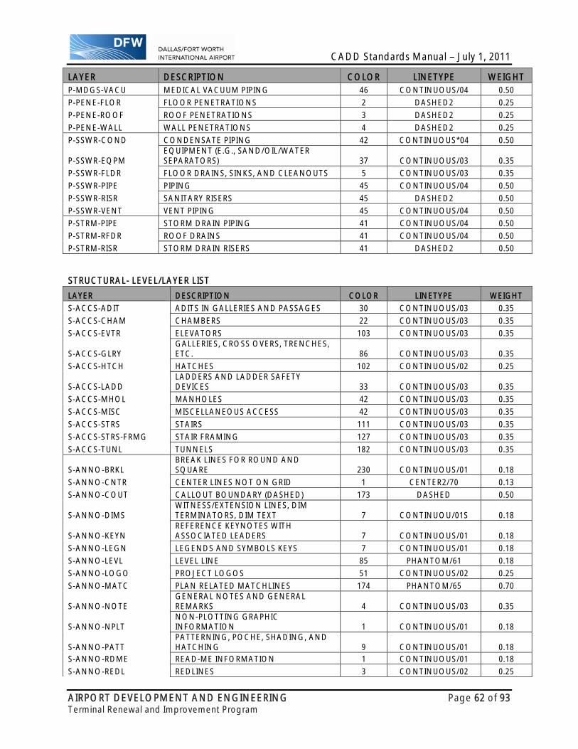
CADD Standards Manual – July 1, 2011
AIRPORT DEVELOPMENT AND ENGINEERING Page 62 of 93 Terminal Renewal and Improvement Program
LAYER DESCRIPTION COLOR LINETYPE WEIGHT P-MDGS-VACU MEDICAL VACUUM PIPING 46 CONTINUOUS/04 0.50
P-PENE-FLOR FLOOR PENETRATIONS 2 DASHED2 0.25
P-PENE-ROOF ROOF PENETRATIONS 3 DASHED2 0.25
P-PENE-WALL WALL PENETRATIONS 4 DASHED2 0.25
P-SSWR-COND CONDENSATE PIPING 42 CONTINUOUS*04 0.50
P-SSWR-EQPM EQUIPMENT (E.G., SAND/OIL/WATER SEPARATORS) 37 CONTINUOUS/03 0.35
P-SSWR-FLDR FLOOR DRAINS, SINKS, AND CLEANOUTS 5 CONTINUOUS/03 0.35
P-SSWR-PIPE PIPING 45 CONTINUOUS/04 0.50
P-SSWR-RISR SANITARY RISERS 45 DASHED2 0.50
P-SSWR-VENT VENT PIPING 45 CONTINUOUS/04 0.50
P-STRM-PIPE STORM DRAIN PIPING 41 CONTINUOUS/04 0.50
P-STRM-RFDR ROOF DRAINS 41 CONTINUOUS/04 0.50
P-STRM-RISR STORM DRAIN RISERS 41 DASHED2 0.50 STRUCTURAL- LEVEL/LAYER LIST
LAYER DESCRIPTION COLOR LINETYPE WEIGHT
S-ACCS-ADIT ADITS IN GALLERIES AND PASSAGES 30 CONTINUOUS/03 0.35
S-ACCS-CHAM CHAMBERS 22 CONTINUOUS/03 0.35
S-ACCS-EVTR ELEVATORS 103 CONTINUOUS/03 0.35
S-ACCS-GLRY GALLERIES, CROSS OVERS, TRENCHES, ETC. 86 CONTINUOUS/03 0.35
S-ACCS-HTCH HATCHES 102 CONTINUOUS/02 0.25
S-ACCS-LADD LADDERS AND LADDER SAFETY DEVICES 33 CONTINUOUS/03 0.35
S-ACCS-MHOL MANHOLES 42 CONTINUOUS/03 0.35
S-ACCS-MISC MISCELLANEOUS ACCESS 42 CONTINUOUS/03 0.35
S-ACCS-STRS STAIRS 111 CONTINUOUS/03 0.35
S-ACCS-STRS-FRMG STAIR FRAMING 127 CONTINUOUS/03 0.35
S-ACCS-TUNL TUNNELS 182 CONTINUOUS/03 0.35
S-ANNO-BRKL BREAK LINES FOR ROUND AND SQUARE 230 CONTINUOUS/01 0.18
S-ANNO-CNTR CENTER LINES NOT ON GRID 1 CENTER2/70 0.13
S-ANNO-COUT CALLOUT BOUNDARY (DASHED) 173 DASHED 0.50
S-ANNO-DIMS WITNESS/EXTENSION LINES, DIM TERMINATORS, DIM TEXT 7 CONTINUOU/01S 0.18
S-ANNO-KEYN REFERENCE KEYNOTES WITH ASSOCIATED LEADERS 7 CONTINUOUS/01 0.18
S-ANNO-LEGN LEGENDS AND SYMBOLS KEYS 7 CONTINUOUS/01 0.18
S-ANNO-LEVL LEVEL LINE 85 PHANTOM/61 0.18
S-ANNO-LOGO PROJECT LOGOS 51 CONTINUOUS/02 0.25
S-ANNO-MATC PLAN RELATED MATCHLINES 174 PHANTOM/65 0.70
S-ANNO-NOTE GENERAL NOTES AND GENERAL REMARKS 4 CONTINUOUS/03 0.35
S-ANNO-NPLT NON-PLOTTING GRAPHIC INFORMATION 1 CONTINUOUS/01 0.18
S-ANNO-PATT PATTERNING, POCHE, SHADING, AND HATCHING 9 CONTINUOUS/01 0.18
S-ANNO-RDME READ-ME INFORMATION 1 CONTINUOUS/01 0.18
S-ANNO-REDL REDLINES 3 CONTINUOUS/02 0.25

CADD Standards Manual – July 1, 2011
AIRPORT DEVELOPMENT AND ENGINEERING Page 63 of 93 Terminal Renewal and Improvement Program
LAYER DESCRIPTION COLOR LINETYPE WEIGHT
S-ANNO-REVC REVISION CLOUDS SHADED 12 CONTINUOUS/03 0.35
S-ANNO-REVS REVISION DELTA WITH NUMBER 7 CONTINUOUS/02 0.25
S-ANNO-SCHD SCHEDULES 7 CONTINUOUS/01 0.18
S-ANNO-SECT SECTION MARK LINEWORK AND TEXT 171 CONTINUOUS/02 0.25
S-ANNO-SYMB MISCELLANEOUS SYMBOLS 5 CONTINUOUS/01 0.18
S-ANNO-TEXT STANDARD TEXT FOR PLANS AND DETAILS 2 CONTINUOUS/02 0.25
S-ANNO-TITL DETAIL TITLE LINEWORK 133 CONTINUOUS/04 0.50
S-ANNO-TTLB TITLE BLOCKS AND BORDERS 231 CONTINUOUS/02 0.25
S-ANNO-XREF XREF INSERTION LAYER 7 CONTINUOUS/01 0.18
S-AREA-PATS EXISTING AREA HATCHING FILL SHADED 7 CONTINUOUS/03 0.35
S-BEAM-CNTR BEAM CENTERLINES 117 CENTER2/71 0.18
S-BEAM-LGAG LIGHT GAGE STEEL BEAM 7 CONTINUOUS/04 0.50
S-BEAM-PRIM CONTINUOUS BEAM/PRIMARY BEAM OF 2-WAY BEAM SYS 109 CONTINUOUS/04 0.50
S-BEAM-RBAR BEAM REBAR 1 CONTINUOUS/03 0.35
S-BEAM-SECD GIRDERS OR SECONDARY BEAMS OF TWO-WAY BEAM SYS 101 CONTINUOUS/03 0.35
S-BEAM-STEH STEEL BEAMS DASHED 7 DASHED 0.70
S-BEAM-STEL STEEL BEAMS & CMU LINTELS 7 CONTINUOUS/05 0.70
S-BEAM-WOOD WOOD FRAMING BEAMS 7 CONTINUOUS/04 0.50
S-BRAC-FRAH STEEL FRAME BRACING 7 DASHED 1.40
S-BRCG-DIAG DIAGONAL BRACING 25 CONTINUOUS/03 0.35
S-BRCG-HORZ HORIZONTAL BRACING 25 CONTINUOUS/03 0.35
S-BRCG-VERT VERTICAL BRACING 199 CONTINUOUS/03 0.35
S-BRDG-ABUT ABUTMENTS 42 CONTINUOUS/04 0.50
S-BRDG-ABUT-RBAR ABUTMENT REBAR 1 CONTINUOUS/03 0.35
S-BRDG-BEAR BRIDGE BEARING 88 CONTINUOUS/03 0.35
S-BRDG-BEAR-CNTR BRIDGE BEARING CENTERLINES 117 CENTER2/71 0.18
S-BRDG-BENT BENT CAP 2 CONTINUOUS/03 0.35
S-BRDG-BENT-CNTR CENTERLINE OF BENTS 117 CENTER2/71 0.18
S-BRDG-BENT-RBAR BENT CAP REBAR 1 CONTINUOUS/03 0.35
S-BRDG-CURB CURBS/SIDEWALKS ON STRUCTURE 4 CONTINUOUS/03 0.35
S-BRDG-DIAP DIAPHRAGMS 1 CONTINUOUS/03 0.35
S-BRDG-DIAP-RBAR DIAPHRAGM REBAR 1 CONTINUOUS/03 0.35
S-BRDG-DRAN DRAINS 22 CONTINUOUS/02 0.25
S-BRDG-FENC FENCING RAILS, FABRIC, SUPPORTS, AND GATES 2 FENCELINE1 0.25
S-BRDG-FEND FENDERS 220 CONTINUOUS/03 0.35
S-BRDG-GIRD GIRDERS 180 CONTINUOUS/03 0.35
S-BRDG-GIRD-CNTR GIRDER CENTERLINE 117 CENTER2/71 0.18
S-BRDG-HEAD HEADERS 247 CONTINUOUS/03 0.35
S-BRDG-PIER PIERS 42 CONTINUOUS/04 0.50
S-BRDG-STRG STRINGERS 101 CONTINUOUS/03 0.35
S-CCOL-CUT CONCRETE COLUMNS ABOVE SLAB 5 CONTINUOUS/04 0.50
S-CCOL-HIDD CONCRETE COLUMNS BELOW SLAB 192 HIDDEN2/53 0.35
S-CCOL-PATT COLUMN SHADING 252 CONTINUOUS/04 0.50
S-CCOL-PROJ CIP COLUMN 4 CONTINUOUS/03 0.35

CADD Standards Manual – July 1, 2011
AIRPORT DEVELOPMENT AND ENGINEERING Page 64 of 93 Terminal Renewal and Improvement Program
LAYER DESCRIPTION COLOR LINETYPE WEIGHT
S-CCUR-PROJ CURB EDGES ON PLAN 232 CONTINUOUS/03 0.35
S-CFRM-HIDD HIDDEN LINE FORMS ON PLAN 144 HIDDEN2/23 0.35
S-CFRM-PROJ CONCRETE FORMING EDGE ON PLAN 134 CONTINUOUS/04 0.50
S-COLS-CNTR COLUMN CENTERLINES/WORKING LINES 166 CENTER2/71 0.18
S-COLS-CONC CONCRETE COLUMNS ABOVE SLAB 7 CONTINUOU/04S 0.50
S-COLS-CONH CONCRETE COLUMNS BELOW SLAB 7 HIDDEN2/23 0.35
S-COLS-CONS COLUMN SHADING 7 CONTINUOU/04S 0.50
S-COLS-POST SHORT COLUMNS 74 CONTINUOUS/03 0.35
S-COLS-PREC CONCRETE COLUMNS ABOVE SLAB 7 CONTINUOUS/04 0.50
S-COLS-PRES COLUMN HATCHING FOR PRECAST 7 CONTINUOUS/01 0.18
S-COLS-PRIM PRIMARY COLUMNS 2 CONTINUOUS/03 0.35
S-COLS-RBAR COLUMN REBAR 1 CONTINUOUS/03 0.35
S-COLS-SECD SECONDARY COLUMNS 34 CONTINUOUS/03 0.35
S-COLS-STEB STEEL COLUMNS BELOW SLAB BUT NO HIDDEN 7 CONTINUOUS/01 0.18
S-COLS-STEH STEEL COLUMNS BELOW SLAB 7 HIDDEN2/21 0.18
S-COLS-STEL STEEL COLUMNS ABOVE SLAB 7 CONTINUOUS/02 0.25
S-COLS-WOOD WOOD COLUMN ABOVE SLAB 7 CONTINUOUS/04 0.50
S-COLS-WOOH WOOD COLUMN BELOW SLAB 7 HIDDEN2/23 0.35
S-CONC-BYND CONCRETE EDGE BEYOND 191 CONTINUOUS/02 0.25
S-CONC-EDGE CONCRETE EDGE 212 CONTINUOUS/03 0.35
S-CONC-HIDD CONCRETE EDGE HIDDEN 151 HIDDEN/52 0.25
S-CONC-PATS CONCRETE SHADING 7 CONTINUOUS/03 0.35
S-CONC-PATT CONCRETE HATCHING 30 CONTINUOUS/01 0.18
S-CONC-SECT CONCRETE EDGE IN SECTION 233 CONTINUOUS/04 0.50
S-CSLB-CTLJ SLAB CONTROL JOINTS 137 CONTINUOUS/02 0.25
S-CSLB-EXPJ SLAB EXPANSION JOINTS 90 CONTINUOUS/01 0.18
S-CSLB-PROJ SLAB EDGES ON PLAN 40 CONTINUOUS/04 0.50
S-CSLB-RBAR PLAN RELATED REBAR (NO PLINES) 152 CONTINUOUS/03 0.35
S-CSLB-SLOP SLAB SLOPE LINE 130 CONTINUOUS/01 0.18
S-CSLB-TEND PLAN RELATED TENDONS (NO PLINES) 94 CONTINUOUS/05 0.70
S-CURB-EDGE CURB EDGES ON PLAN 7 CONTINUOUS/03 0.35
S-CWAL-CUT CONCRETE WALL EDGE 153 CONTINUOUS/04 0.50
S-CWAL-HIDD CONCRETE WALL EDGE HIDDEN 125 HIDDEN2/23 0.35
S-CWAL-PATT WALL PATTERN SHADED 252 CONTINUOUS/02 0.25
S-CWAL-PROJ CIP WALL 162 CONTINUOUS/03 0.35
S-DECK-BRDG BRIDGE DECK 22 CONTINUOUS/03 0.35
S-DECK-BRDG-RBAR BRIDGE DECK REBAR 1 CONTINUOUS/03 0.35
S-DECK-EDGE DECK EDGES ON PLAN 7 CONTINUOUS/02 0.25
S-DECK-FLOR FLOOR DECK 186 CONTINUOUS/02 0.25
S-DECK-FLOR-OPNG FLOOR DECK OPENINGS 3 DASHED2 0.25
S-DECK-ROOF ROOF DECK 116 CONTINUOUS/02 0.25
S-DECK-ROOF-OPNG ROOF DECK OPENINGS 3 DASHED2 0.25
S-DEMO DEMO EXISTING EDGES 246 PHANTOM/63 0.35
S-DETL-GRPH GRAPHICS, GRIDLINES, NON-TEXT ITEMS 7 CONTINUOUS/01 0.18
S-DETL-IDEN DETAIL TITLE LARGE TEXT AND LINEWORK 7 CONTINUOUS/04 0.50

CADD Standards Manual – July 1, 2011
AIRPORT DEVELOPMENT AND ENGINEERING Page 65 of 93 Terminal Renewal and Improvement Program
LAYER DESCRIPTION COLOR LINETYPE WEIGHT
S-DETL-TEXT DETAIL TITLE SMALL TEXT 7 CONTINUOUS/02 0.25
S-DRAI-EDGH FOUNDATION DRAIN (SHADED) 7 DASHED 0.70
S-EDGE ARCHITECTURAL EDGES 7 PHANTOM2/61 0.18
S-EDGE-EXSE EXISTING EDGE IN PLAN OR DETAIL 7 DASHED2 0.25
S-EDGE-EXSH NEARLY HIDDEN EXISTING EDGES 7 HIDDEN2/22 0.25
S-EDGE-EXSS SHORT EXISTING EDGES 7 HIDDEN2/22 0.25
S-EROS-BARR VAPOR/CAPILLARY WATER BARRIERS 115 CONTINUOUS/02 0.25
S-EROS-GABN GABIONS 179 CONTINUOUS/02 0.25
S-EROS-PVMT SLOPE PAVING 179 CONTINUOUS/02 0.25
S-EROS-RRAP RIPRAP, STONE PROTECTION, JETTIES, BREAKWATERS 107 CONTINUOUS/02 0.25
S-EXST EXISTING EDGES 141 CONTINUOUS/02 0.25
S-EXST-PATT EXISTING AREA HATCHING FILL 185 CONTINUOUS/01 0.18
S-FABR-EMBD EMBEDDED METALS (FRAMING AROUND OPENINGS) 201 CONTINUOUS/03 0.35
S-FABR-HOIS HOIST STRUCTURES 183 CONTINUOUS/02 0.25
S-FABR-HOOK LINE HOOKS, LIFTING HOOKS, CHECK POSTS ETC. 183 CONTINUOUS/02 0.25
S-FABR-MOOR MOORING BITS, CHOCKS, RINGS 183 CONTINUOUS/03 0.35
S-FABR-PLAT PLATES 183 CONTINUOUS/03 0.35
S-FABR-TRSH TRASH RACKS, INTAKE SCREENS 183 CONTINUOUS/03 0.35
S-FLOR-OPNX OPENING X IN STRUCTURE 210 PHANTOM/60 0.13
S-FNDN-ANCH ANCHOR PILES, BLOCKS, STRANDS, DEADMEN, ANCHORS 182 CONTINUOUS/03 0.35
S-FNDN-CNTR FOUNDATION CENTERLINES 198 CENTER2/71 0.18
S-FNDN-CRTN CARTON FORMS 7 CONTINUOUS/02 0.25
S-FNDN-DRAN FOUNDATION DRAINAGE FEATURES AND OBJECTS 206 CONTINUOUS/02 0.25
S-FNDN-EDGE FOUNDATION EDGES 7 CONTINUOUS/04 0.50
S-FNDN-EDGH FOUNDATION EDGES HIDDEN 7 HIDDEN/53 0.35
S-FNDN-FTNG FOOTINGS 182 CONTINUOUS/03 0.35
S-FNDN-FTNG-RBAR FOOTING REBAR 1 CONTINUOUS/03 0.35
S-FNDN-GRBM GRADE BEAMS 36 CONTINUOUS/04 0.50
S-FNDN-HIDD FOUNDATION EDGES HIDDEN 105 HIDDEN/53 0.35
S-FNDN-PATS GRADE LEVEL SCREENED HATCHING 7 CONTINUOUS/00 0.13
S-FNDN-PCAP PILE CAPS 36 CONTINUOUS/03 0.35
S-FNDN-PEDS FOUNDATION PEDESTALS/PADS 190 CONTINUOUS/03 0.35
S-FNDN-PIEH PIER OBJECTS HIDDEN 7 HIDDEN/52 0.25
S-FNDN-PIER PIERS, DRILLED SHAFTS, CAISSONS 196 CONTINUOUS/04 0.50
S-FNDN-PILE PILES 166 CONTINUOUS/03 0.35
S-FNDN-PILH PILE OBJECTS 7 HIDDEN2/22 0.25
S-FNDN-PROJ FOUNDATION EDGES 193 CONTINUOUS/04 0.50
S-FNDN-RIBS RIBBED MAT FOUNDATION 36 CONTINUOUS/03 0.35
S-FNDN-TRMT FOUNDATION TREATMENT (GROUTING) 28 CONTINUOUS/03 0.35
S-FNDN-TUNL SERVICE TUNNEL/DUCT BANKS 182 CONTINUOUS/03 0.35
S-FSTN-ABLT ANCHOR BOLTS 86 CONTINUOUS/02 0.25
S-FSTN-MISC FASTENERS AND CONNECTIONS (NON-SPECIFIC) 35 CONTINUOUS/02 0.25
S-GATE-ANCH GATE ANCHORAGES 86 CONTINUOUS/02 0.25
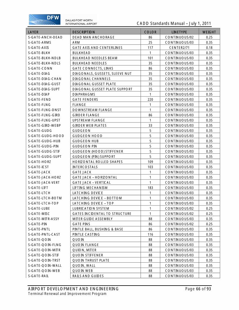
CADD Standards Manual – July 1, 2011
AIRPORT DEVELOPMENT AND ENGINEERING Page 66 of 93 Terminal Renewal and Improvement Program
LAYER DESCRIPTION COLOR LINETYPE WEIGHT
S-GATE-ANCH-DEAD DEAD MAN ANCHORAGE 86 CONTINUOUS/02 0.25
S-GATE-ARMS ARM 25 CONTINUOUS/03 0.35
S-GATE-AXIS GATE AXIS AND CENTERLINES 117 CENTER2/71 0.18
S-GATE-BLKH BULKHEAD 1 CONTINUOUS/03 0.35
S-GATE-BLKH-NDLB BULKHEAD NEEDLES BEAM 101 CONTINUOUS/03 0.35
S-GATE-BLKH-NDLS BULKHEAD NEEDLES 35 CONTINUOUS/03 0.35
S-GATE-CONN GATE CONNECTS, LINKS 86 CONTINUOUS/03 0.35
S-GATE-DIAG DIAGONALS, GUSSETS, SLEEVE NUT 35 CONTINUOUS/03 0.35
S-GATE-DIAG-CHAN DIAGONAL CHANNELS 35 CONTINUOUS/03 0.35
S-GATE-DIAG-GUST DIAGONAL GUSSET PLATE 35 CONTINUOUS/03 0.35
S-GATE-DIAG-SUPT DIAGONAL GUSSET PLATE SUPPORT 35 CONTINUOUS/03 0.35
S-GATE-DIAP DIAPHRAGMS 1 CONTINUOUS/03 0.35
S-GATE-FEND GATE FENDERS 220 CONTINUOUS/03 0.35
S-GATE-FLNG FLANGE 1 CONTINUOUS/03 0.35
S-GATE-FLNG-DNST DOWNSTREAM FLANGE 1 CONTINUOUS/03 0.35
S-GATE-FLNG-GIRD GIRDER FLANGE 86 CONTINUOUS/03 0.35
S-GATE-FLNG-UPST UPSTREAM FLANGE 1 CONTINUOUS/03 0.35
S-GATE-GIRD-WEBP GIRDER WEB PLATES 33 CONTINUOUS/03 0.35
S-GATE-GUDG GUDGEON 5 CONTINUOUS/03 0.35
S-GATE-GUDG-HOOD GUDGEON HOOD 5 CONTINUOUS/03 0.35
S-GATE-GUDG-HUB GUDGEON HUB 5 CONTINUOUS/03 0.35
S-GATE-GUDG-PIN GUDGEON PIN 5 CONTINUOUS/03 0.35
S-GATE-GUDG-STIF GUDGEON (HOOD) STIFFENER 5 CONTINUOUS/03 0.35
S-GATE-GUDG-SUPT GUDGEON (PIN) SUPPORT 5 CONTINUOUS/03 0.35
S-GATE-HORZ HORIZONTAL ROLLED SHAPES 109 CONTINUOUS/03 0.35
S-GATE-ICST INTERCOSTALS 103 CONTINUOUS/03 0.35
S-GATE-JACK GATE JACK 1 CONTINUOUS/03 0.35
S-GATE-JACK-HORZ GATE JACK – HORIZONTAL 1 CONTINUOUS/03 0.35
S-GATE-JACK-VERT GATE JACK – VERTICAL 1 CONTINUOUS/03 0.35
S-GATE-LIFT LIFTING MECHANISM 183 CONTINUOUS/03 0.35
S-GATE-LTCH LATCHING DEVICE 1 CONTINUOUS/03 0.35
S-GATE-LTCH-BOTM LATCHING DEVICE – BOTTOM 1 CONTINUOUS/03 0.35
S-GATE-LTCH-TOP LATCHING DEVICE – TOP 1 CONTINUOUS/03 0.35
S-GATE-LUBE LUBRICATION SYSTEM 1 CONTINUOUS/02 0.25
S-GATE-MISC GATES INCIDENTAL TO STRUCTURE 1 CONTINUOUS/02 0.25
S-GATE-MITR-ASSY MITER GUIDE ASSEMBLY 88 CONTINUOUS/03 0.35
S-GATE-PIN GATE PINS 86 CONTINUOUS/02 0.25
S-GATE-PNTL PINTLE BALL, BUSHING & BASE 86 CONTINUOUS/03 0.35
S-GATE-PNTL-CAST PINTLE CASTING 116 CONTINUOUS/03 0.35
S-GATE-QOIN QUOIN 88 CONTINUOUS/03 0.35
S-GATE-QOIN-FLNG QUOIN FLANGE 88 CONTINUOUS/03 0.35
S-GATE-QOIN-MITR QUION, MITER 88 CONTINUOUS/03 0.35
S-GATE-QOIN-STIF QUOIN STIFFENER 88 CONTINUOUS/03 0.35
S-GATE-QOIN-TRST QUOIN THRUST PLATE 88 CONTINUOUS/03 0.35
S-GATE-QOIN-WALL QUOIN, WALL 88 CONTINUOUS/03 0.35
S-GATE-QOIN-WEB QUOIN WEB 88 CONTINUOUS/03 0.35
S-GATE-RAIL RAILS AND GUIDES 88 CONTINUOUS/03 0.35
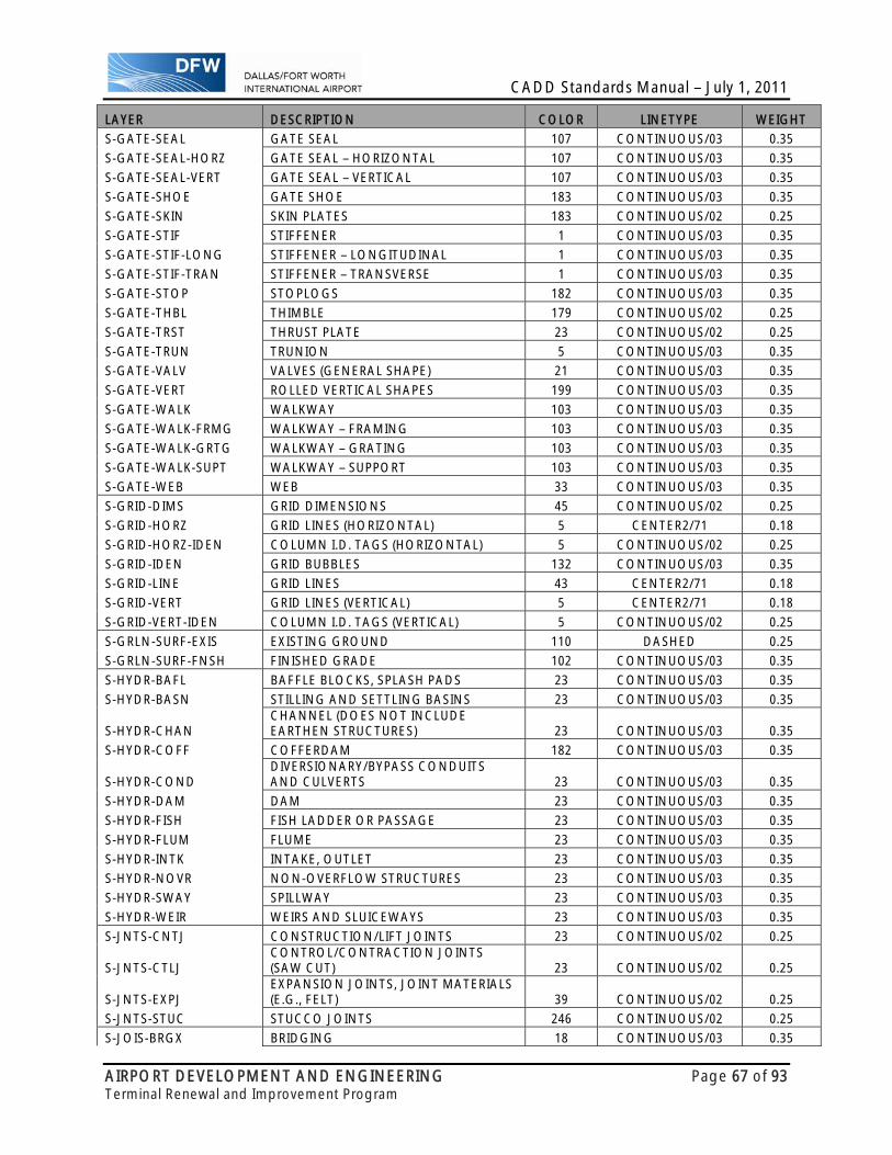
CADD Standards Manual – July 1, 2011
AIRPORT DEVELOPMENT AND ENGINEERING Page 67 of 93 Terminal Renewal and Improvement Program
LAYER DESCRIPTION COLOR LINETYPE WEIGHT
S-GATE-SEAL GATE SEAL 107 CONTINUOUS/03 0.35
S-GATE-SEAL-HORZ GATE SEAL – HORIZONTAL 107 CONTINUOUS/03 0.35
S-GATE-SEAL-VERT GATE SEAL – VERTICAL 107 CONTINUOUS/03 0.35
S-GATE-SHOE GATE SHOE 183 CONTINUOUS/03 0.35
S-GATE-SKIN SKIN PLATES 183 CONTINUOUS/02 0.25
S-GATE-STIF STIFFENER 1 CONTINUOUS/03 0.35
S-GATE-STIF-LONG STIFFENER – LONGITUDINAL 1 CONTINUOUS/03 0.35
S-GATE-STIF-TRAN STIFFENER – TRANSVERSE 1 CONTINUOUS/03 0.35
S-GATE-STOP STOPLOGS 182 CONTINUOUS/03 0.35
S-GATE-THBL THIMBLE 179 CONTINUOUS/02 0.25
S-GATE-TRST THRUST PLATE 23 CONTINUOUS/02 0.25
S-GATE-TRUN TRUNION 5 CONTINUOUS/03 0.35
S-GATE-VALV VALVES (GENERAL SHAPE) 21 CONTINUOUS/03 0.35
S-GATE-VERT ROLLED VERTICAL SHAPES 199 CONTINUOUS/03 0.35
S-GATE-WALK WALKWAY 103 CONTINUOUS/03 0.35
S-GATE-WALK-FRMG WALKWAY – FRAMING 103 CONTINUOUS/03 0.35
S-GATE-WALK-GRTG WALKWAY – GRATING 103 CONTINUOUS/03 0.35
S-GATE-WALK-SUPT WALKWAY – SUPPORT 103 CONTINUOUS/03 0.35
S-GATE-WEB WEB 33 CONTINUOUS/03 0.35
S-GRID-DIMS GRID DIMENSIONS 45 CONTINUOUS/02 0.25
S-GRID-HORZ GRID LINES (HORIZONTAL) 5 CENTER2/71 0.18
S-GRID-HORZ-IDEN COLUMN I.D. TAGS (HORIZONTAL) 5 CONTINUOUS/02 0.25
S-GRID-IDEN GRID BUBBLES 132 CONTINUOUS/03 0.35
S-GRID-LINE GRID LINES 43 CENTER2/71 0.18
S-GRID-VERT GRID LINES (VERTICAL) 5 CENTER2/71 0.18
S-GRID-VERT-IDEN COLUMN I.D. TAGS (VERTICAL) 5 CONTINUOUS/02 0.25
S-GRLN-SURF-EXIS EXISTING GROUND 110 DASHED 0.25
S-GRLN-SURF-FNSH FINISHED GRADE 102 CONTINUOUS/03 0.35
S-HYDR-BAFL BAFFLE BLOCKS, SPLASH PADS 23 CONTINUOUS/03 0.35
S-HYDR-BASN STILLING AND SETTLING BASINS 23 CONTINUOUS/03 0.35
S-HYDR-CHAN CHANNEL (DOES NOT INCLUDE EARTHEN STRUCTURES) 23 CONTINUOUS/03 0.35
S-HYDR-COFF COFFERDAM 182 CONTINUOUS/03 0.35
S-HYDR-COND DIVERSIONARY/BYPASS CONDUITS AND CULVERTS 23 CONTINUOUS/03 0.35
S-HYDR-DAM DAM 23 CONTINUOUS/03 0.35
S-HYDR-FISH FISH LADDER OR PASSAGE 23 CONTINUOUS/03 0.35
S-HYDR-FLUM FLUME 23 CONTINUOUS/03 0.35
S-HYDR-INTK INTAKE, OUTLET 23 CONTINUOUS/03 0.35
S-HYDR-NOVR NON-OVERFLOW STRUCTURES 23 CONTINUOUS/03 0.35
S-HYDR-SWAY SPILLWAY 23 CONTINUOUS/03 0.35
S-HYDR-WEIR WEIRS AND SLUICEWAYS 23 CONTINUOUS/03 0.35
S-JNTS-CNTJ CONSTRUCTION/LIFT JOINTS 23 CONTINUOUS/02 0.25
S-JNTS-CTLJ CONTROL/CONTRACTION JOINTS (SAW CUT) 23 CONTINUOUS/02 0.25
S-JNTS-EXPJ EXPANSION JOINTS, JOINT MATERIALS (E.G., FELT) 39 CONTINUOUS/02 0.25
S-JNTS-STUC STUCCO JOINTS 246 CONTINUOUS/02 0.25
S-JOIS-BRGX BRIDGING 18 CONTINUOUS/03 0.35

CADD Standards Manual – July 1, 2011
AIRPORT DEVELOPMENT AND ENGINEERING Page 68 of 93 Terminal Renewal and Improvement Program
LAYER DESCRIPTION COLOR LINETYPE WEIGHT
S-JOIS-BRIH JOIST BRIDGING 7 HIDDEN2/23 0.35
S-JOIS-GIRD JOIST GIRDERS 23 CONTINUOUS/04 0.50
S-JOIS-LGAG LIGHT GAGE STEEL JOIST 7 CONTINUOUS/03 0.35
S-JOIS-PERI PERIMETER CHANNEL OR RIM JOIST 183 CONTINUOUS/03 0.35
S-JOIS-PRIM PRIMARY JOISTS 103 CONTINUOUS/03 0.35
S-JOIS-SECD SECONDARY JOISTS 119 CONTINUOUS/03 0.35
S-JOIS-STEL STEEL JOIST 7 DIVIDE2 0.50
S-JOIS-TRIM PARTIAL LENGTH OR TRIMMER FLOOR JOIST 119 CONTINUOUS/03 0.35
S-JOIS-WOOD WOOD FRAMING JOIST 7 CONTINUOUS/03 0.35
S-LGAG-BYND LIGHT GAGE STEEL EDGE BEYOND 7 CONTINUOUS/01 0.18
S-LGAG-EDGE LIGHT GAGE STEEL EDGE 7 CONTINUOUS/02 0.25
S-LGAG-EDGH LIGHT GAGE STEEL EDGE HIDDEN 7 HIDDEN2/21 0.18
S-LGAG-PATT LIGHT GAGE STEEL HATCHING 7 CONTINUOUS/01 0.18
S-LGAG-SECT LIGHT GAGE STEEL EDGES IN SECTION 7 CONTINUOUS/03 0.35
S-MASN-BYND MASONRY EDGES BEYOND 31 CONTINUOUS/02 0.25
S-MASN-EDGE MASONRY EDGES 225 CONTINUOUS/03 0.35
S-MASN-EDGH MASONRY EDGES HIDDEN 7 HIDDEN/52 0.25
S-MASN-HIDD MASONRY EDGES HIDDEN 25 HIDDEN/52 0.25
S-MASN-PATS MASONRY LINEWORK SHADED 7 CONTINUOUS/03 0.35
S-MASN-PATT MASONRY HATCHING 86 CONTINUOUS/01 0.18
S-MASN-SECT MASONRY EDGE IN SECTION 126 CONTINUOUS/04 0.50
S-MFR-PART MANUFACTURED PARTS 242 CONTINUOUS/01 0.18
S-MWAL-CUT MASONRY WALL SECTION 52 CONTINUOUS/03 0.35
S-MWAL-HIDD MASONRY WALL EDGE HIDDEN 62 HIDDEN/52 0.25
S-MWAL-PATT MASONRY HATCH 34 CONTINUOUS/01 0.18
S-MWAL-PROJ MASONRY WALL EDGE 71 CONTINUOUS/02 0.25
S-NIC ARCHITECTURAL EDGES 214 PHANTOM2/61 0.18
S-OTLN-BLDG BUILDING OUTLINE 1 PHANTOM/62 0.25
S-OTLN-FLOR FLOOR OUTLINE 1 PHANTOM/62 0.25
S-OTLN-OPNG OPENINGS 1 PHANTOM/62 0.25
S-OTLN-ROOF ROOF 1 PHANTOM/62 0.25
S-OTLN-STRC MISC. STRUCTURES 1 PHANTOM/62 0.25
S-PADS-EQPM EQUIPMENT PADS 30 CONTINUOUS/03 0.35
S-PANS-EDGH PAN FORMING LINES ON PLAN 7 HIDDEN/52 0.25
S-PCOL-CUT PRECAST COLUMN SECTION 161 CONTINUOUS/04 0.50
S-PCOL-HIDD PRECAST COLUMN HIDDEN 165 HIDDEN2/23 0.35
S-PCOL-PATT COLUMN HATCHING FOR PRECAST 10 CONTINUOUS/01 0.18
S-PCOL-PROJ PRECAST COLUMN EDGE 172 CONTINUOUS/03 0.35
S-PIPE-CULV PRECAST/MANUFACTURED CULVERTS 13 CONTINUOUS/03 0.35
S-PLAT-FRMG PLATFORM FRAME/STRINGERS 101 CONTINUOUS/03 0.35
S-PLAT-GRTG PLATFORM GRATING 15 CONTINUOUS/02 0.25
S-PLAT-WALK PLATFORM WALKWAY 126 CONTINUOUS/03 0.35
S-PREC-BYND PRECAST EDGE BEYOND 70 CONTINUOUS/02 0.25
S-PREC-EDGE PRECAST EDGE 181 CONTINUOUS/03 0.35
S-PREC-EDGH CONCRETE EDGE HIDDEN 7 HIDDEN/52 0.25
S-PREC-HIDD PRECAST EDGE HIDDEN 143 HIDDEN/52 0.25
S-PREC-PATT PRECAST HATCHING 112 CONTINUOUS/03 0.35
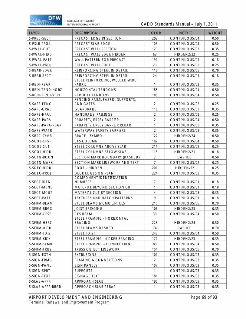
CADD Standards Manual – July 1, 2011
AIRPORT DEVELOPMENT AND ENGINEERING Page 69 of 93 Terminal Renewal and Improvement Program
LAYER DESCRIPTION COLOR LINETYPE WEIGHT
S-PREC-SECT PRECAST EDGE IN SECTION 202 CONTINUOUS/04 0.50
S-PSLB-PROJ PRECAST SLAB EDGE 103 CONTINUOUS/04 0.50
S-PWAL-CUT PRECAST WALL SECTION 123 CONTINUOUS/03 0.35
S-PWAL-HIDD PRECAST WALL EDGE HIDDEN 63 HIDDEN2/22 0.25
S-PWAL-PATT WALL PATTERN FOR PRECAST 190 CONTINUOUS/01 0.18
S-PWAL-PROJ PRECAST WALL EDGE 23 CONTINUOUS/02 0.25
S-RBAR-EDGE REINFORCING STEEL IN DETAIL 110 CONTINUOUS/05 0.70
S-RBAR-SECT REINFORCING STEEL IN DETAIL 24 CONTINUOUS/01 0.18
S-REIN-RBAR STEEL REINFORCING, WELDED WIRE FABRIC 1 CONTINUOUS/03 0.35
S-REIN-TEND-HORZ HORIZONTAL TENDONS 185 CONTINUOUS/04 0.50
S-REIN-TEND-VERT VERTICAL TENDONS 185 CONTINUOUS/04 0.50
S-SAFE-FENC FENCING RAILS, FABRIC, SUPPORTS, AND GATES 2 CONTINUOUS/02 0.25
S-SAFE-GRAL GUARDRAILS 116 CONTINUOUS/03 0.35
S-SAFE-HRAL HANDRAILS, RAILINGS 2 CONTINUOUS/02 0.25
S-SAFE-PARA PARAPET/JERSEY BARRIER 2 CONTINUOUS/04 0.50
S-SAFE-PARA-RBAR PARAPET/JERSEY BARRIER REBAR 1 CONTINUOUS/03 0.35
S-SAFE-WATR WATERWAY SAFETY BARRIERS 2 CONTINUOUS/03 0.35
S-SBRC-SYMB BRACE – SYMBOL 122 HIDDEN2/24 0.50
S-SCOL-CFSF CFS COLUMN 182 CONTINUOUS/04 0.50
S-SCOL-CUT STEEL COLUMNS ABOVE SLAB 211 CONTINUOUS/02 0.25
S-SCOL-HIDD STEEL COLUMNS BELOW SLAB 115 HIDDEN2/21 0.18
S-SCTN-BOUN SECTION MARK BOUNDARY (DASHED) 7 DASHED 0.50
S-SCTN-MARK SECTION MARK LINEWORK AND TEXT 7 CONTINUOUS/02 0.25
S-SDEC-HIDD ROOF – HIDDEN 201 HIDDEN/52 0.25
S-SDEC-PROJ DECK EDGES ON PLAN 224 CONTINUOUS/03 0.35
S-SECT-IDEN COMPONENT IDENTIFICATION NUMBERS 7 CONTINUOUS/01 0.18
S-SECT-MBND MATERIAL BEYOND SECTION CUT 1 CONTINUOUS/01 0.18
S-SECT-MCUT MATERIAL CUT BY SECTION 4 CONTINUOUS/03 0.35
S-SECT-PATT TEXTURES AND HATCH PATTERNS 9 CONTINUOUS/01 0.18
S-SFRM-BEAM STEEL BEAMS & CMU LINTELS 215 CONTINUOUS/05 0.70
S-SFRM-BRGX JOIST BRIDGING 106 HIDDEN2/23 0.35
S-SFRM-CFSF CFS BEAM 33 CONTINUOUS/04 0.50
S-SFRM-HBRC STEEL FRAMING - HORIZONTAL BRACING 223 HIDDEN2/24 0.50
S-SFRM-HIDD STEEL BEAMS DASHED 74 DASHED 0.70
S-SFRM-JOIS STEEL JOIST 243 CONTINUOUS/04 0.50
S-SFRM-KICK STEEL FRAMING - KICKER BRACING 170 HIDDEN2/23 0.35
S-SFRM-SYMB STEEL FRAMING – CONNECTION 83 CONTINUOUS/04 0.50
S-SFRM-TRUS TRUSS OBJECT LINEWORK 154 CONTINUOUS/05 0.70
S-SIGN-EXTN EXTRUSIONS 101 CONTINUOUS/03 0.35
S-SIGN-FRMG FRAMING & CONNECTIONS 2 CONTINUOUS/03 0.35
S-SIGN-PANL SIGN PANELS 107 CONTINUOUS/03 0.35
S-SIGN-SPRT SUPPORTS 1 CONTINUOUS/03 0.35
S-SIGN-TEXT SIGNAGE TEXT 181 CONTINUOUS/03 0.35
S-SLAB-APPR APPROACH SLAB 190 CONTINUOUS/03 0.35
S-SLAB-APPR-RBAR APPROACH SLAB REBAR 1 CONTINUOUS/03 0.35

CADD Standards Manual – July 1, 2011
AIRPORT DEVELOPMENT AND ENGINEERING Page 70 of 93 Terminal Renewal and Improvement Program
LAYER DESCRIPTION COLOR LINETYPE WEIGHT
S-SLAB-EDGE EDGE OF SLAB 190 CONTINUOUS/03 0.35
S-SLAB-EXPJ SLAB EXPANSION JOINTS 7 CONTINUOUS/01 0.18
S-SLAB-JOIN SLAB JOINT LINES ON PLAN (SHADED) 7 CONTINUOUS/05 0.70
S-SLAB-OPEN OPENING X IN STRUCTURE 7 PHANTOM2/61 0.18
S-SLAB-OPNG OPENINGS (AND DEPRESSIONS) 3 DASHED2 0.25
S-SLAB-RBAR SLAB REBAR 1 CONTINUOUS/03 0.35
S-SLAB-SECD SECOND POUR, SLAB CAP 190 CONTINUOUS/03 0.35
S-SLAB-SILL SILL 190 CONTINUOUS/03 0.35
S-SLAB-SLOP SLAB SLOPE LINE 7 CONTINUOUS/01 0.18
S-SLAB-STRI SLAB STRIP ZONES (SHADED) 7 HIDDEN/54 0.50
S-SLAB-TEND PLAN RELATED TENDONS (NO PLINES) 7 CONTINUOUS/05 0.70
S-SOIL-PATT GRADE HATCHING 95 CONTINUOUS/00 0.13
S-SOIL-SECT TOP OF EARTH 72 CONTINUOUS/04 0.50
S-SOIL-WTRP WATERPROOFING MEMBRANE 142 HIDDEN2/23 0.35
S-STEL-BYND STEEL EDGES BEYOND 20 CONTINUOUS/01 0.18
S-STEL-DECK STEEL DECK IN SECTION 7 CONTINUOUS/04 0.50
S-STEL-EDGE STEEL EDGE 117 CONTINUOUS/02 0.25
S-STEL-EDGH STEEL EDGES HIDDEN 7 HIDDEN2/22 0.25
S-STEL-PART STEEL MANUFACTURED PARTS 7 CONTINUOUS/01 0.18
S-STEL-PATT STEEL HATCHING 75 CONTINUOUS/01 0.18
S-STEL-SECT STEEL EDGES IN SECTION 111 CONTINUOUS/03 0.35
S-STEL-SYMB STEEL DECK IN SECTION 55 CONTINUOUS/04 0.50
S-STIF-LONG STIFFENERS – LONGITUDINAL 2 CONTINUOUS/03 0.35
S-STIF-TRAV STIFFENERS – TRANSVERSE 2 CONTINUOUS/03 0.35
S-TCOL-CUT WOOD COLUMN ABOVE SLAB 35 CONTINUOUS/04 0.50
S-TCOL-HIDD WOOD COLUMN BELOW SLAB 205 HIDDEN2/23 0.35
S-TFRM-BEAM WOOD FRAMING BEAMS 210 CONTINUOUS/04 0.50
S-TFRM-JOIS WOOD FRAMING JOIST 51 CONTINUOUS/03 0.35
S-TRUS-PRIM PRIMARY TRUSSES 7 CONTINUOUS/04 0.50
S-TRUS-SECD SECONDARY TRUSSES 5 CONTINUOUS/03 0.35
S-TRUS-STEL TRUSS OBJECT LINEWORK 7 CONTINUOUS/05 0.70
S-WALL-ABUT ABUTMENTS 42 CONTINUOUS/03 0.35
S-WALL-COFF CUTOFF WALL 86 CONTINUOUS/03 0.35
S-WALL-CONC CONCRETE WALL EDGE 7 CONTINUOUS/04 0.50
S-WALL-CONH CONCRETE WALL EDGE HIDDEN 7 HIDDEN2/23 0.35
S-WALL-CURT CURTAIN/BREAST WALL 196 CONTINUOUS/03 0.35
S-WALL-FULL WALL GOING TO THE TOP OF THE STRUCTURE 2 CONTINUOUS/03 0.35
S-WALL-GARD GUARD/GUIDE WALLS 196 CONTINUOUS/03 0.35
S-WALL-LOAD LOAD BEARING WALLS 2 CONTINUOUS/03 0.35
S-WALL-MASH MASONRY WALL EDGE HIDDEN 7 HIDDEN/52 0.25
S-WALL-MASN MASONRY WALL EDGE 7 CONTINUOUS/03 0.35
S-WALL-MASS MASONRY WALL HATCH SHADED 1 CONTINUOUS/01 0.18
S-WALL-MSE MECHANICALLY STABILIZED EARTH (MSE) WALL 196 CONTINUOUS/03 0.35
S-WALL-NONL NON-LOAD BEARING WALLS 196 CONTINUOUS/03 0.35
S-WALL-OPNX OPENING X IN WALL 210 PHANTOM2/60 0.13
S-WALL-PATS WALL PATTERN SHADED 7 CONTINUOUS/02 0.25
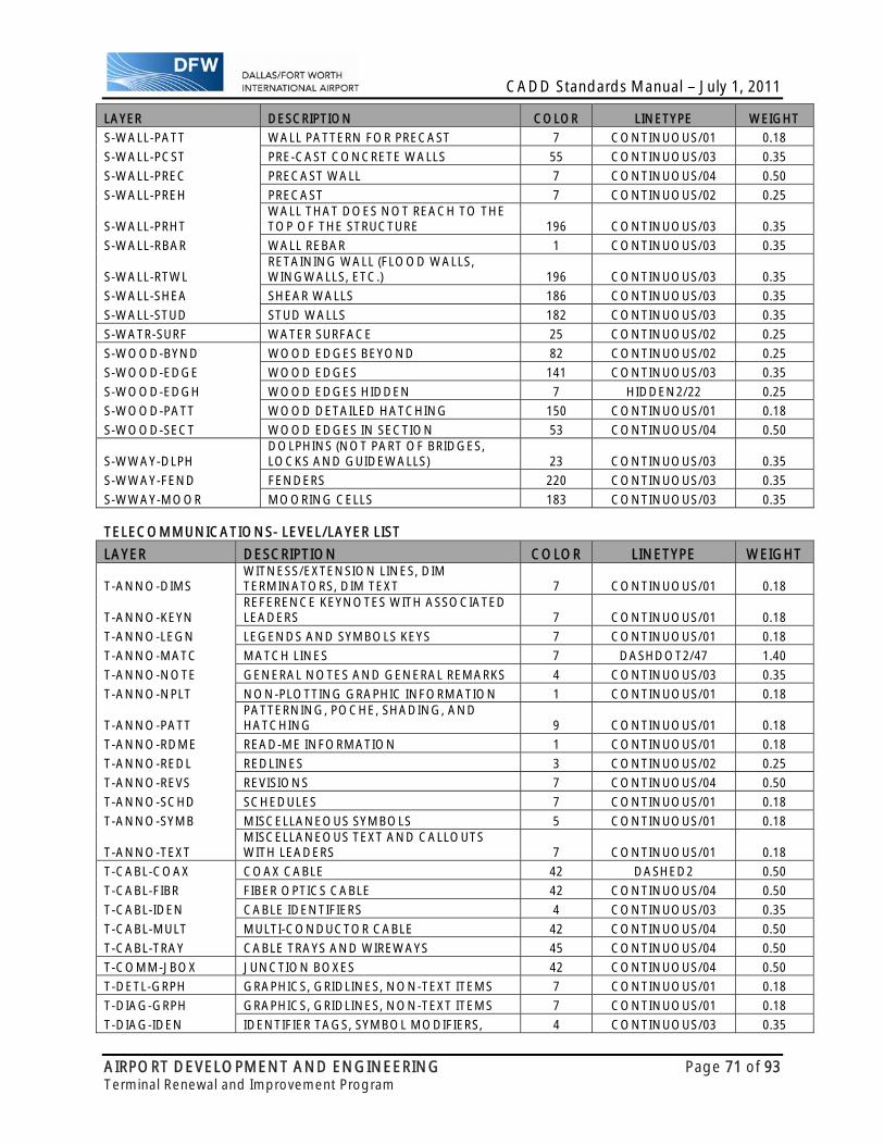
CADD Standards Manual – July 1, 2011
AIRPORT DEVELOPMENT AND ENGINEERING Page 71 of 93 Terminal Renewal and Improvement Program
LAYER DESCRIPTION COLOR LINETYPE WEIGHT
S-WALL-PATT WALL PATTERN FOR PRECAST 7 CONTINUOUS/01 0.18
S-WALL-PCST PRE-CAST CONCRETE WALLS 55 CONTINUOUS/03 0.35
S-WALL-PREC PRECAST WALL 7 CONTINUOUS/04 0.50
S-WALL-PREH PRECAST 7 CONTINUOUS/02 0.25
S-WALL-PRHT WALL THAT DOES NOT REACH TO THE TOP OF THE STRUCTURE 196 CONTINUOUS/03 0.35
S-WALL-RBAR WALL REBAR 1 CONTINUOUS/03 0.35
S-WALL-RTWL RETAINING WALL (FLOOD WALLS, WINGWALLS, ETC.) 196 CONTINUOUS/03 0.35
S-WALL-SHEA SHEAR WALLS 186 CONTINUOUS/03 0.35
S-WALL-STUD STUD WALLS 182 CONTINUOUS/03 0.35
S-WATR-SURF WATER SURFACE 25 CONTINUOUS/02 0.25
S-WOOD-BYND WOOD EDGES BEYOND 82 CONTINUOUS/02 0.25
S-WOOD-EDGE WOOD EDGES 141 CONTINUOUS/03 0.35
S-WOOD-EDGH WOOD EDGES HIDDEN 7 HIDDEN2/22 0.25
S-WOOD-PATT WOOD DETAILED HATCHING 150 CONTINUOUS/01 0.18
S-WOOD-SECT WOOD EDGES IN SECTION 53 CONTINUOUS/04 0.50
S-WWAY-DLPH DOLPHINS (NOT PART OF BRIDGES, LOCKS AND GUIDEWALLS) 23 CONTINUOUS/03 0.35
S-WWAY-FEND FENDERS 220 CONTINUOUS/03 0.35
S-WWAY-MOOR MOORING CELLS 183 CONTINUOUS/03 0.35 TELECOMMUNICATIONS- LEVEL/LAYER LIST
LAYER DESCRIPTION COLOR LINETYPE WEIGHT
T-ANNO-DIMS WITNESS/EXTENSION LINES, DIM TERMINATORS, DIM TEXT 7 CONTINUOUS/01 0.18
T-ANNO-KEYN REFERENCE KEYNOTES WITH ASSOCIATED LEADERS 7 CONTINUOUS/01 0.18
T-ANNO-LEGN LEGENDS AND SYMBOLS KEYS 7 CONTINUOUS/01 0.18
T-ANNO-MATC MATCH LINES 7 DASHDOT2/47 1.40
T-ANNO-NOTE GENERAL NOTES AND GENERAL REMARKS 4 CONTINUOUS/03 0.35
T-ANNO-NPLT NON-PLOTTING GRAPHIC INFORMATION 1 CONTINUOUS/01 0.18
T-ANNO-PATT PATTERNING, POCHE, SHADING, AND HATCHING 9 CONTINUOUS/01 0.18
T-ANNO-RDME READ-ME INFORMATION 1 CONTINUOUS/01 0.18
T-ANNO-REDL REDLINES 3 CONTINUOUS/02 0.25
T-ANNO-REVS REVISIONS 7 CONTINUOUS/04 0.50
T-ANNO-SCHD SCHEDULES 7 CONTINUOUS/01 0.18
T-ANNO-SYMB MISCELLANEOUS SYMBOLS 5 CONTINUOUS/01 0.18
T-ANNO-TEXT MISCELLANEOUS TEXT AND CALLOUTS WITH LEADERS 7 CONTINUOUS/01 0.18
T-CABL-COAX COAX CABLE 42 DASHED2 0.50
T-CABL-FIBR FIBER OPTICS CABLE 42 CONTINUOUS/04 0.50
T-CABL-IDEN CABLE IDENTIFIERS 4 CONTINUOUS/03 0.35
T-CABL-MULT MULTI-CONDUCTOR CABLE 42 CONTINUOUS/04 0.50
T-CABL-TRAY CABLE TRAYS AND WIREWAYS 45 CONTINUOUS/04 0.50
T-COMM-JBOX JUNCTION BOXES 42 CONTINUOUS/04 0.50
T-DETL-GRPH GRAPHICS, GRIDLINES, NON-TEXT ITEMS 7 CONTINUOUS/01 0.18
T-DIAG-GRPH GRAPHICS, GRIDLINES, NON-TEXT ITEMS 7 CONTINUOUS/01 0.18
T-DIAG-IDEN IDENTIFIER TAGS, SYMBOL MODIFIERS, 4 CONTINUOUS/03 0.35
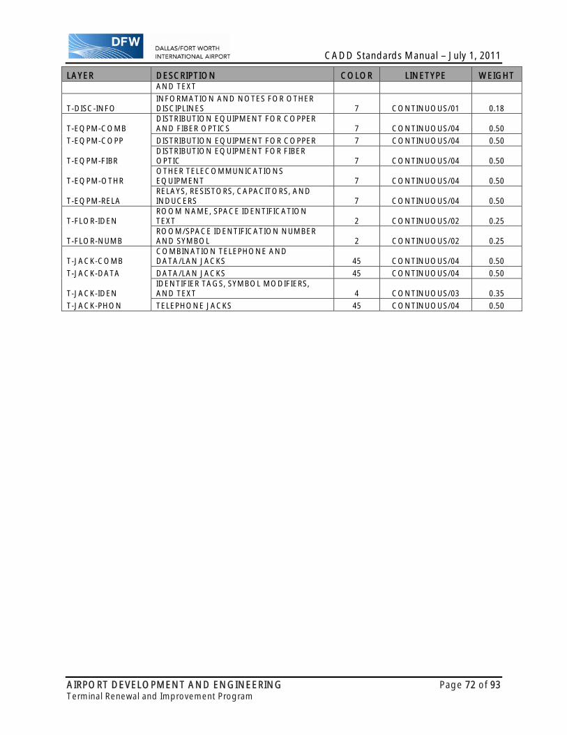
CADD Standards Manual – July 1, 2011
AIRPORT DEVELOPMENT AND ENGINEERING Page 72 of 93 Terminal Renewal and Improvement Program
LAYER DESCRIPTION COLOR LINETYPE WEIGHT AND TEXT
T-DISC-INFO INFORMATION AND NOTES FOR OTHER DISCIPLINES 7 CONTINUOUS/01 0.18
T-EQPM-COMB DISTRIBUTION EQUIPMENT FOR COPPER AND FIBER OPTICS 7 CONTINUOUS/04 0.50
T-EQPM-COPP DISTRIBUTION EQUIPMENT FOR COPPER 7 CONTINUOUS/04 0.50
T-EQPM-FIBR DISTRIBUTION EQUIPMENT FOR FIBER OPTIC 7 CONTINUOUS/04 0.50
T-EQPM-OTHR OTHER TELECOMMUNICATIONS EQUIPMENT 7 CONTINUOUS/04 0.50
T-EQPM-RELA RELAYS, RESISTORS, CAPACITORS, AND INDUCERS 7 CONTINUOUS/04 0.50
T-FLOR-IDEN ROOM NAME, SPACE IDENTIFICATION TEXT 2 CONTINUOUS/02 0.25
T-FLOR-NUMB ROOM/SPACE IDENTIFICATION NUMBER AND SYMBOL 2 CONTINUOUS/02 0.25
T-JACK-COMB COMBINATION TELEPHONE AND DATA/LAN JACKS 45 CONTINUOUS/04 0.50
T-JACK-DATA DATA/LAN JACKS 45 CONTINUOUS/04 0.50
T-JACK-IDEN IDENTIFIER TAGS, SYMBOL MODIFIERS, AND TEXT 4 CONTINUOUS/03 0.35
T-JACK-PHON TELEPHONE JACKS 45 CONTINUOUS/04 0.50

CADD Standards Manual – July 1, 2011
AIRPORT DEVELOPMENT AND ENGINEERING Page 73 of 93 Terminal Renewal and Improvement Program
AUTOCAD PLOT STAMP
The purpose of these instructions is to illustrate how to set up the Plot Stamp setting for your AutoCAD project. Please note that this set of instructions and figures were created using AutoCAD 2008.
1. In the AutoCAD command box type “plot” (shortcut: ctrl + p) and hit ENTER.
2. Add checkmark to “plot stamp on.” Ensure that the plot window matches Figure 1.
Figure 1
3. Select the “plot stamp settings” icon . Refer to Figure 1.

CADD Standards Manual – July 1, 2011
AIRPORT DEVELOPMENT AND ENGINEERING Page 74 of 93 Terminal Renewal and Improvement Program
4. In the Plot Stamp window, uncheck “Device name” and add checkmark to “Drawing name” and “Date and Time” box. Make sure these two options are the only ones selected. Ensure that the Plot Stamp window matches Figure 2. Click on the “Advanced” tab.
Figure 2

CADD Standards Manual – July 1, 2011
AIRPORT DEVELOPMENT AND ENGINEERING Page 75 of 93 Terminal Renewal and Improvement Program
5. In the Advanced Options window, change X offset to “1.1500”, Font to “Arial”, Orientation to “vertical”. Make sure Height reads “0.1250.” Add checkmark to “Single line plot stamp.” Ensure that the Advanced Options window matches Figure 3. Select the “OK” tab. Then, Select the “OK” tab on the Plot Stamp window and the main Plot window.
Figure 3
6. The Plot Stamp has now been setup.

CADD Standards Manual – July 1, 2011
AIRPORT DEVELOPMENT AND ENGINEERING Page 76 of 93 Terminal Renewal and Improvement Program
6. LEVEL/LAYER ASSIGNMENTS INTRODUCTION This chapter explains the use of levels/layers for model and sheet files as well as the conventions used to name the levels/ layers.
LEVELS DEFINED Regardless of the CADD software utilized to complete the design, the level/layer naming convention will follow the National Cad Standards, see NCS CLG-5. The information represented by individual levels is grouped into two primary types, model-specific information and sheet-specific information. The importance of a solid level/layer structure within a CADD file cannot be stressed enough. There are many reasons this is needed; first it allows the end user the flexibility to make changes efficiently and consistently, second it allows end users the ability to quickly determine what each element represents based on the level/layer it is placed.
MODEL SPECIFIC INFORMATION: It includes site, roads, building or other objects depicting existing and/or proposed conditions. This information is often shared among drawings. Examples include utilities, roads, runways, walls, doors, light fixtures, room numbers, etc.
SHEET SPECIFIC INFORMATION: May include, but is not limited to notes, annotations, annotative symbols and titles. This type of information is generally not shared between drawings.
LEVEL/LAYER NAMING CONVENTION All level/layer names must conform to NCS. Levels/Layers have been pre-established utilizing a specific dgn.lib file based on individual disciplines for Microstation and a specific template file based on individual disciplines for AutoCAD. These files aid the user in establishing a consistent level/layer structure as well as the symbology for each. These files will be provided and maintained by DFW Airport. Any and all modifications will conform to NCS and must be approved by DFW Airport prior to their use. Example level/layer name: AD-WALL-FULL-TEXT-1 Whereas: AD- Indicates the Discipline Code - spaces 1-3 (includes the hyphen) (see note 1 below) WALL- Indicates the Major Group Code – spaces 4-8 (includes the hyphen) (see note 5 below) FULL- Indicates the First Minor Group Code – spaces 9-13 (includes the hyphen) (see note 6 below) TEXT- Indicates the Second Minor Group Code – spaces 14-18 (includes the hyphen) (see note
6 below) 1 Indicates the Phase of Construction – space 19 (leave out if not required) Notes:
1. The order of these fields must be maintained and cannot be changed. 2. The Discipline Code will utilize the Level 2 Codes set by NCS for all level/layer names. 3. The Discipline Code and Major Group Codes are mandatory. The First and Second Minor Group
Codes are optional but should be used as much as possible. In the absence of one or both, underscores (_) must be used in place of the text in order to keep all level/layer names a consistent length.
4. For Level 2 Discipline Codes see NCS CLG-90. 5. For Major Group Codes see NCS CLG-94. 6. For Minor Group Codes see NCS CLG-98. 7. All characters within the level/layer names will be CAPITALIZED.

CADD Standards Manual – July 1, 2011
AIRPORT DEVELOPMENT AND ENGINEERING Page 77 of 93 Terminal Renewal and Improvement Program
7. DRAFTING STANDARDS INTRODUCTION This chapter supplements the information provided by NCS in Module 04. These two documents provide the basic drafting standards to be used in the creation of CADD documents for all DFW Airport projects.
ACCEPTABLE SCALES For acceptable commonly used standardized scales, see NCS USD-04.12. Any scale other than those shown in the NCS manual is not permitted and will not be accepted by DFW Airport.
Note that the use of any Metric scales will not be permitted.
Numerical Scales: For sheets where there is only one scale associated with a drawing, the scale will be noted in the title block as per the Architectural or Engineering scales shown in NCS USD-04.12. For sheets where there are multiple drawings shown, the term AS SHOWN will be noted in the title block and each drawing will show the scale of the individual detail. For drawings or details that are considered not to scale, they will be indicated as such either by the words NOT TO SCALE or by N.T.S.
Graphical Scales: Bar scales will be used on all sheets in order to allow the reduction or enlargement of plans while maintaining the ability to scale distances off of the sheet.
These bar scales will be graphical in nature as shown in NCS beginning on pg UDS-06.14, but will also show the scale in text form as indicated below under DETAIL TITLES. Also text should be added under the graphical bar scales that will indicate SCALE IN FEET. If there is a difference between the horizontal and vertical scales, both should be shown and the text HORIZONTAL SCALE IN FEET or VERTICAL SCALE IN FEET should be added. Examples are shown below:
NORTH ARROWS North arrows will be used on all sheets where required and will be shown as per NCS pg UDS-06.23. Example is shown below:
DETAIL TITLES All details will show an individual title as per NCS pg UDS-06.13. Example is shown below:
Note the Bar Scales, North Arrows and Detail Titles are included in the following files: for AutoCAD 10TRIPGRDG01-P0X.DWG, for Microstation TRIPCELLS.CEL

CADD Standards Manual – July 1, 2011
AIRPORT DEVELOPMENT AND ENGINEERING Page 78 of 93 Terminal Renewal and Improvement Program
GRAPHIC ATTRIBUTES In general, the graphic attributes, weights, styles and colors are defined by level within each individual discipline’s dgnlib files for Microstation or template files for AutoCAD. In the event that attributes are not assigned within these files or information is missing from these files, the user is directed to refer to NCS UDS-04.14.
Line Weights: Line weights shown below are for both Microstation and AutoCAD and will follow NCS UDS-04.14.
LINE WEIGHT DESCRIPTION
THICKNESS PER NCS IN
MM
THICKNESSPER NCS IN
INCHES
MICROSTATIONLINE WEIGHT
SETTING UTILIZATION
Extra Fine 0.13 0.0051 wt = 0 Extra fine detail which cannot be accomplished using a fine line.
Fine 0.18 0.0071 wt = 1 Material indications, surface marks, hatch lines, patterns.
Thin 0.25 0.0098 wt = 2
Text 0.100” or 3/32” Existing Topographic Features, break lines, hidden object lines, dotted lines, dashed lines, setback line, center lines, phantom lines, grid lines, schedule grid lines.
Medium 0.35 0.0138 wt = 3
Text 0.120” or 1/8” General Annotations & Dimensions, object lines, property lines, door and window elevations, architectural stroke terminators, schedule grid accent lines.
Wide 0.50 0.0197 wt = 4
Text 0.120 or 1/8” Sub titles & Column Heading, underlining, edges of interior and exterior elevations, cut lines, property lines, drawing block borders.
Extra Wide 0.70 0.0278 wt = 5
Text 0.240 or 1/4” Chart Titles, underlining, match lines, building footprints, title block borders, sheet borders, schedule outlines, object lines requiring special emphasis, elevation grade lines, top of grade lines.
XX Wide 1.00 0.0394 wt = 6
Text 0.240 or 1/4” Sheet Titles, Detail Titles, underlining, separating portions of designs, section cutting plane lines.
XXX Wide 1.40 0.0551 wt = 7 Border sheet outlines and cover sheet line work, revision clouds.
XXXX Wide 2.00 0.0787 wt = 8 Border sheet outlines and cover sheet line work.
Notes: 1. Thicknesses shown in inches were converted from the thickness in mm as shown in NCS UDS-
01.14 and rounded up to the 4th decimal place.

CADD Standards Manual – July 1, 2011
AIRPORT DEVELOPMENT AND ENGINEERING Page 79 of 93 Terminal Renewal and Improvement Program
Line Styles: Line styles shown below represent only the basic styles available in both Microstation and AutoCAD and do not reflect all line styles available. Users should employ basic drafting principles in the selection of line styles and wherever possible avoid the use of custom line styles. MICROSTATION
LINE CODE AUTOCAD LINETYPES DESCRIPTION USAGE
0 CONTINUOUS Continuous/Solid
Object lines, dimension lines,leader lines, extension lines, break lines
1
DOT, DOT2, DOTX2 Dotted
Connection points, other uses vary
2 HIDDEN2 Medium Dash Secondary object hidden lines
3 HIDDENX2 Long Dash Main object, hidden lines,existing elements
4 DASHDOT, DASHDOT2, DASHDOTX2 Dot Dash or Dash Dot Matchlines, other uses vary
5 HIDDEN Short Dash Detail hidden lines
6 PHANTOM, PHANTOM2, PHANTOMX2 Dash Dot or Phantom
Property lines, boundary limit lines, phantom lines
7 CENTER, CENTER2, CENTERX2
Long Dash Short Dash Long Dash Centerlines
Custom DASHED DASHED2 Long Dash Varies
Custom DIVDE DIVDED 2 Dash Dot Dot Dash Varies
Custom GAS_LINE GAS Dash Gas Dash Gas Lines
Custom TRACKS Tracks Rail Lines Custom FENCELINE1 Fence Line Fences
Color: All drawing files for both Microstation and AutoCAD are to be created using the color table information shown on page PG-7 within the National Cad Standards. All sheet drawings are to be plotted in black and white using the color numbers and RGB values shown on page PG-3 within the National Cad Standards. Colors have been assigned by level/layer within the Microstation DGNLIB files/AutoCAD Template files and should not be changed by the user. The following color tables have been established for use on the TRIP project and will be provided by DFW International Airport:
For Microstation, use TRIPMCOLOR.TBL For AutoCAD, use TRIPACOLOR.CTB
AUTOCAD - LTSCALE When in PAPERSPACE the LTSCALE should be one and the PSLTSCALE should be one.

CADD Standards Manual – July 1, 2011
AIRPORT DEVELOPMENT AND ENGINEERING Page 80 of 93 Terminal Renewal and Improvement Program
TEXT ATTRIBUTES The following are guidelines for the application of text strings and text nodes on all construction documents. The text sizes and weights are based on basic manual drafting principles utilizing Leroy text sizes.
Fonts: In order to ensure consistency between Consultants and their documents, the approved font for all construction documents will be a true type font “ARIAL”. However, for certain conditions such as presentation or conceptual graphics, other fonts may be more desirable. To ensure consistency only true type fonts will be allowed. The use of fonts in this manner will ensure consistency throughout the set of construction documents and eliminates the management of any specific resource files for Microstation or AutoCAD by DFW Airport. Text Size: The text sizes and weights shown below are based on basic manual drafting principles utilizing standard Leroy text sizes for Civil drawings as well as standard Architectural text sizes. No text smaller that 0.10” or 3/32” will be utilized in the development of any construction documents. With the exception of Cover Sheets, text larger than 0.250” or 1/4” will not be used in the development of any construction documents.
TEXT SIZES FOR CIVIL DRAWINGS PLOTTED SIZE
IN INCHES EQUIVALENT CADD
SETTING DESCRIPTION WEIGHT
0.100 Plot scale X .100 Existing Topographic Features 20.120 Plot scale X .120 General Annotations & Dimensions 30.120 Plot scale X .120 Sub-titles & Column Headings 40.240 Plot scale X .240 Chart Titles 50.240 Plot scale X .240 Detail Titles 60.240 Plot scale X .240 Sheet Titles 6
Weights shown are Microstation weights. For thicknesses associated with these weights, refer to LINE WEIGHTS previously described in this chapter. TEXT SIZES FOR ARCHITECTURAL & STRUCTURAL DRAWINGS
PLOTTED SIZE IN INCHES
EQUIVALENT CADD SETTING
DESCRIPTION WEIGHT
3/32” Plot scale X .0938 Existing Topographic Features 21/8” Plot scale X .1250 General Annotations & Dimensions 31/8” Plot scale X .1250 Sub-titles & Column Headings 41/4” Plot scale X .2500 Chart Titles 51/4” Plot scale X .2500 Detail Titles 61/4" Plot scale X .2500 Sheet Titles 6
Weights shown are Microstation weights. For thicknesses associated with these weights, refer to LINE WEIGHTS previously described in this chapter.
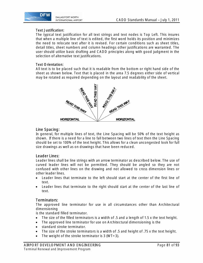
CADD Standards Manual – July 1, 2011
AIRPORT DEVELOPMENT AND ENGINEERING Page 81 of 93 Terminal Renewal and Improvement Program
Text Justification: The typical text justification for all text strings and text nodes is Top Left. This insures that when a multiple line of text is edited, the first word holds its position and minimizes the need to relocate text after it is revised. For certain conditions such as sheet titles, detail titles, sheet numbers and column headings other justifications are warranted. The user should utilize basic drafting and CADD principles along with good judgment in the selection of alternative text justifications.
Text Orientation: All text is to be placed such that it is readable from the bottom or right hand side of the sheet as shown below. Text that is placed in the area 7.5 degrees either side of vertical may be rotated as required depending on the layout and readability of the sheet.
Line Spacing: In general, for multiple lines of text, the Line Spacing will be 50% of the text height as shown. If there is a need for a line to fall between two lines of text then the Line Spacing should be set to 100% of the text height. This allows for a clean uncongested look for full size drawings as well as on drawings that have been reduced. Leader Lines: Leader lines shall be line strings with an arrow terminator as described below. The use of curved leader lines will not be permitted. They should be angled so they are not confused with other lines on the drawing and not allowed to cross dimension lines or other leader lines. Leader lines that terminate to the left should start at the center of the first line of
text. Leader lines that terminate to the right should start at the center of the last line of
text. Terminators: The approved line terminator for use in all circumstances other than Architectural dimensioning is the standard filled terminator. The size of the filled terminators is a width of .5 and a length of 1.5 x the text height. The approved line terminator for use on Architectural dimensioning is the standard stroke terminator. The size of the stroke terminators is a width of .5 and height of .75 x the text height. The weight of the stroke terminator is 3 (WT=3).
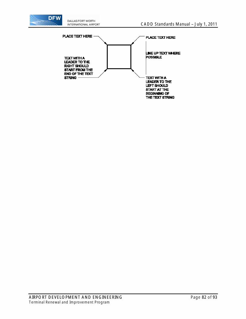
CADD Standards Manual – July 1, 2011
AIRPORT DEVELOPMENT AND ENGINEERING Page 82 of 93 Terminal Renewal and Improvement Program

CADD Standards Manual – July 1, 2011
AIRPORT DEVELOPMENT AND ENGINEERING Page 83 of 93 Terminal Renewal and Improvement Program
ABBREVIATIONS All words or terms shown on the sheets should be spelled completely and abbreviations should not to be used unless it is necessary to save space or for clarity. All abbreviations used must conform to NCS UDS-05.1 and be used as such consistently throughout the project. The use of obscure or undefined abbreviations should not be used in order to avoid confusion. If there is doubt or confusion regarding an abbreviation, spell it out. All abbreviations utilized for a specific discipline will be shown on a sheet entitled “Discipline Standard Abbreviations” where the word Discipline will be replaced with the appropriate discipline term. These sheets will be located at the beginning of the drawing package within the General subset after the cover sheet. (see NCS USD-01.6) DIMENSION ATTRIBUTES The following are guidelines for the application of dimensions on all construction documents. In general, these settings have been pre-established in the DFW TRIP Seed Files.
Terminators: The approved line terminator for dimensions on all construction documents is the standard filled terminator in the dimension settings. The size of the filled terminators is a width of .5 and length of 1.5 x the text height. Terminators for Architecture: The approved line terminator for dimensions on Architecture construction documents is the stroke terminator in the dimension settings. The size of the stroke terminators is a width of .5 and height of .75 x the text height. The weight of the stroke terminator is 3 (WT=3).
Dimensioning: Dimension text shall be placed with a justification of Center Bottom when placed on top of the center of the dimension line. When Dimension text is placed to the left of the extension line, outside of the area being dimensioned, it should have a justification of Right Bottom. When Dimension text is placed to the right of the extension line, outside of the area being dimensions, it should have a justification of Left Bottom. This will enable the revision of the text without the need to relocate it after revising. Line spacing shall be one half the text heights. For multiple lines of text, the line spacing should be increased to 100% of the text height (see Line Spacing section previously described).
Text may be placed above and below a dimension line, but never solely below. User should exercise basic proper drafting techniques in the display of all
dimensioning.

CADD Standards Manual – July 1, 2011
AIRPORT DEVELOPMENT AND ENGINEERING Page 84 of 93 Terminal Renewal and Improvement Program
QUADRANTS & GRID Quadrants: The Quadrants Key Plan map is to be used for the Concept package only. All work after that shall follow the DFW Airport Grid shown below.
Radial Grid & Key Plan: The KEY PLAN map shown on page 85 is to be used for all work beyond the Concept package to include the Design Development package as well as the Pricing package. This Key Plan is included in the appropriate border files and should be used to indicate the area encompassed by each sheet. User is instructed to shade the applicable area by copying the required elements into the sheet and creating a black filled shape to indicate the area of concern for each sheet. Each sector represents a sheet created at 1/16”=1’-0” scale. For other scales, adjust the shape accordingly. See pages 85 – 90 for grid illustrations.
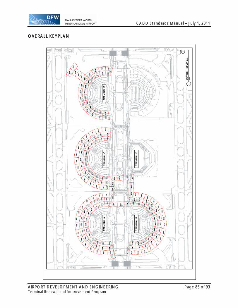
CADD Standards Manual – July 1, 2011
AIRPORT DEVELOPMENT AND ENGINEERING Page 85 of 93 Terminal Renewal and Improvement Program
OVERALL KEYPLAN
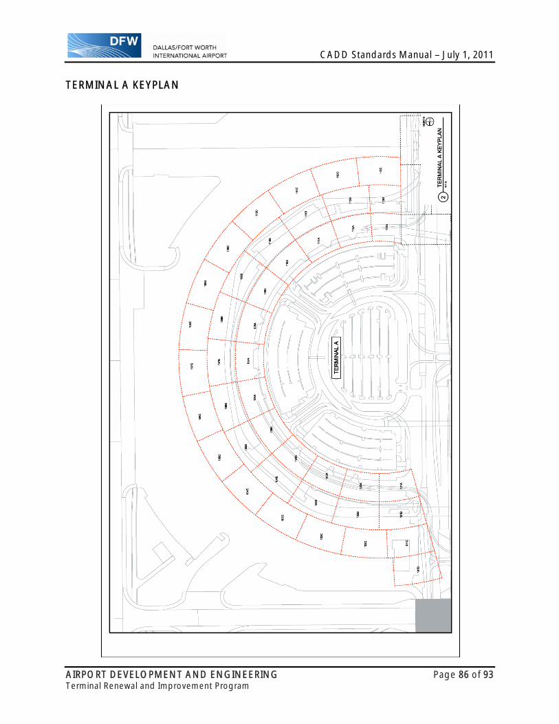
CADD Standards Manual – July 1, 2011
AIRPORT DEVELOPMENT AND ENGINEERING Page 86 of 93 Terminal Renewal and Improvement Program
TERMINAL A KEYPLAN
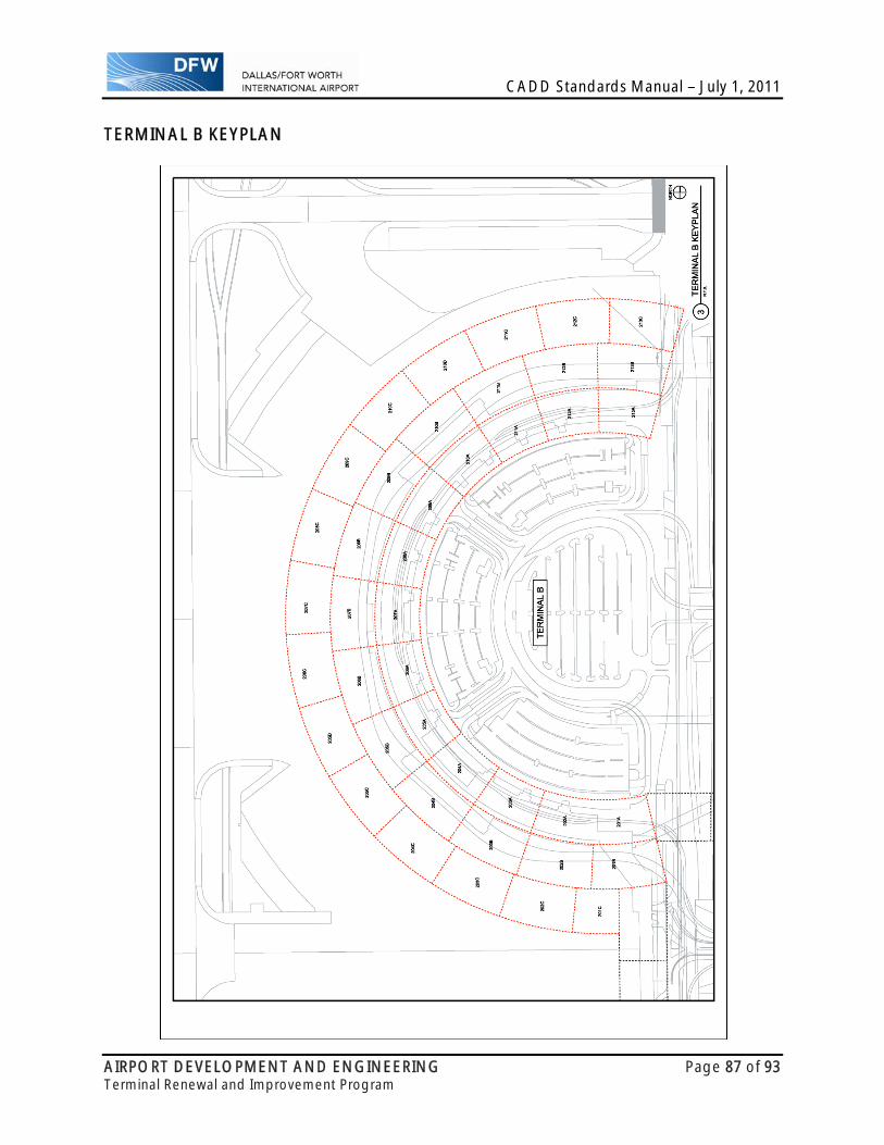
CADD Standards Manual – July 1, 2011
AIRPORT DEVELOPMENT AND ENGINEERING Page 87 of 93 Terminal Renewal and Improvement Program
TERMINAL B KEYPLAN

CADD Standards Manual – July 1, 2011
AIRPORT DEVELOPMENT AND ENGINEERING Page 88 of 93 Terminal Renewal and Improvement Program
TERMINAL C KEYPLAN
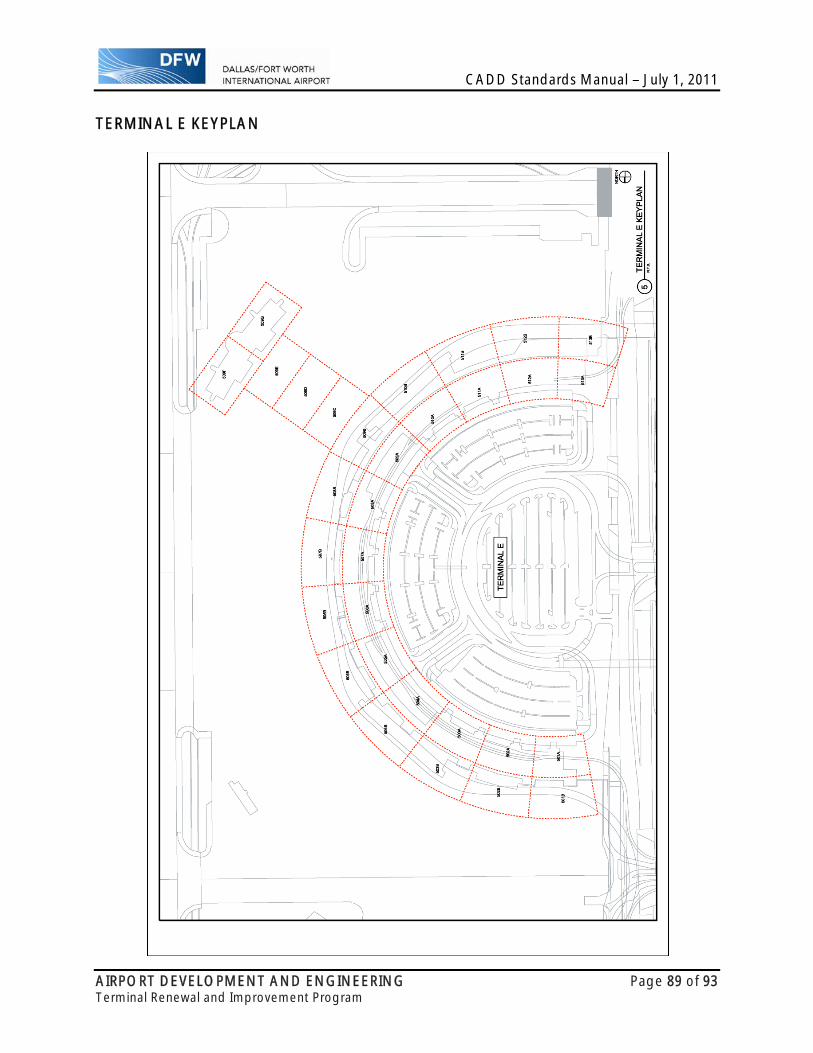
CADD Standards Manual – July 1, 2011
AIRPORT DEVELOPMENT AND ENGINEERING Page 89 of 93 Terminal Renewal and Improvement Program
TERMINAL E KEYPLAN
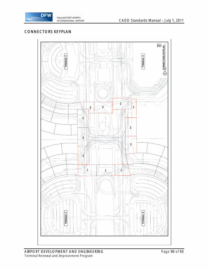
CADD Standards Manual – July 1, 2011
AIRPORT DEVELOPMENT AND ENGINEERING Page 90 of 93 Terminal Renewal and Improvement Program
CONNECTORS KEYPLAN
CADD Standards Manual – July 1, 2011
AIRPORT DEVELOPMENT AND ENGINEERING Page 91 of 93 Terminal Renewal and Improvement Program
8. DELIVERABLE REQUIREMENTS
INTRODUCTION This chapter identifies the requirements for all submittals to DFW International Airport. It includes details regarding electronic file submittals, what files are required for submittals, as well as the methods and media to be used in the submittal process. The intent of this electronic file submittal is to provide DFW International Airport all CADD files utilized in the development of a construction document package so that a complete archive of the entire project can be made for record and retention requirements as well as for future use and to aid DFW International Airport in updating the base map information required for inclusion into the DFW International Airport GIS.
TIMING AND FREQUENCY The timing and frequency of submittals is dependent on contractual obligations and the direction of DFW International Airport. Consultants are advised to allow ample time in order to assemble all required documentation in the required format for each submittal.
CONTENTS The consultant will include the following electronic files for each submittal:
Project Information File - Defined at the end of this chapter. Sheet Files (Master Files) – All sheet files used to produce the project drawing set. Model Files (Reference Files) – All design files that represent the design required to
produce the project drawing set. Master Map Files (Base Files) – All design files representing any changes to the DFW
CADD Master Maps as a result of the project in question will be contained in separate CADD files along with the referenced base files and will comply with the CADD Master Maps Standards in Chapter 27.
Resource Files – All resource and configuration files (i.e., pen tables, seed files) necessary for the use and production of the project design files.
Specifications Files – All Project specifications. Miscellaneous Files – Any Miscellaneous files associated with the project.
FORMAT All files included in any submittal must meet the software and file format requirements detailed in Chapter 2 under SOFTWARE REQUIREMENTS and must be delivered in the directory structure as shown in Chapter 3 under PROJECT DIRECTORY STRUCTURE. Any other format or directory structure will result in the rejection of the submittal and require the Consultant to resubmit at their expense. All AutoCAD files are to be saved down to a Native 2007 format in order to allow them to be opened by Microstation XM. Note that DXF file formats for any CADD files will not be accepted.

CADD Standards Manual – July 1, 2011
AIRPORT DEVELOPMENT AND ENGINEERING Page 92 of 93 Terminal Renewal and Improvement Program
MEDIA All electronic submittals & file transfers are to be written to a Recordable Compact Disc compatible with a standard FAT or NTFS file system. Files are to be placed on the CD uncompressed in the file format specified in these standards. The CD shall be delivered in a standard jewel case to DFW International Airport. The CD and the CD case shall be appropriately labeled.
Before a file is recorded onto the delivery media, the following procedures should be performed:
Remove all extraneous graphics outside the border area, and set the active parameters to a standard setting or to those settings in the seed file.
Make sure all reference files are attached without device or directory specifications. Include all files, both graphic and non-graphic, required for the project (color tables, pen
tables, Microstation Resource files or AutoCAD Custom Support files, plot files, etc.). Include any standard sheets (abbreviation sheets, standard symbol sheets, etc.)
necessary to reproduce a complete project.

CADD Standards Manual – July 1, 2011
AIRPORT DEVELOPMENT AND ENGINEERING Page 93 of 93 Terminal Renewal and Improvement Program
PROJECT INFORMATION FILE The Project Information File is a read only text file viewable in notepad and shall be included in the Project Root Directory, TERMINAL RENEWAL AND IMPROVEMENT PROGRAM.
The contents of this file shall contain the following information: PROJECT TITLE: Provided by the Consultant PROJECT DESCRIPTION: Provided by the Consultant DESIGN CONSULTANT: Provided by the Consultant CONTACT INFORMATION: Provided by the Consultant DESIGN CONTRACT NUMBER: Provided by the Consultant AIRPORT RESPONSIBLE DEPARTMENT: For DFW use AIRPORT PROJECT MANAGER: For DFW use AIRPORT CONSTRUCTION MANAGER: For DFW use ISSUE FOR BID DATE: For DFW use ISSUE FOR CONSTRUCTION DATE: For DFW use GENERAL CONTRACTOR: For DFW use CONTACT INFORMATION: For DFW use CONSTRUCTION CONTRACT NUMBER: For DFW use NOTICE TO PROCEED DATE: For DFW use PROJECT COMPLETION DATE: For DFW use RECORD DRAWINGS SUBMITTED: For DFW use ARCHIVE STATUS: For DFW use
In order to facilitate the use of multiple Project Information files by DFW International Airport, The following naming convention will be utilized. EXAMPLE: 10TRIPA-IF____C.TXT Whereas: 10 Indicates the Year – spaces 1-2 (year at beginning of the contract) TRIP Indicates the Project Code – spaces 3-6 (See Note 1 below) A- Indicates the Discipline Code – spaces 7-8 (includes the hyphen) (See Note 2 below) (Level 1 Discipline Designator shown, Level 2 Discipline Designator optional) IF Indicates this is an Information File – spaces 9-10 ____ 4 individual underscores to allow for additional description by DFW - spaces 11-14 C Indicates the Terminal Code – space 15 (See Note 3 below) . Period used to separate filename from extension – space 16 TXT Indicates the File Type Extension (Text File) – spaces 17-19
Notes: 1. The prefix “10TRIP” is for project identification and is not optional.
It must precede the filename established utilizing NCS UDS-01.18. 2. For Discipline Codes see NCS UDS-01.11. 3. Terminal Codes are as follows: X=Common Reference Files (Border Files, etc.)
A=Terminal A, B=Terminal B, C=Terminal C, E=Terminal E, L=Baggage Link, R=Roadway (not tied to a terminal), T=Intermodal Transfer Center, F=Airfield.
A Project Information Seed file entitled PRJINFO.TXT will be provided by DFW. Consultant is directed to save a copy and name the copy according to instruction provided above. Consultant is to provide the information required and submit this file along with the Consultant’s final submittal.
Related Documents