Triboelectrification induced UV emission from plasmon discharge Chang Bao Han 1,§ , Chi Zhang 1,§ , Jingjing Tian 1 , Xiaohui Li 1 , Limin Zhang 1 , Zhou Li 1 , and Zhong Lin Wang 1,2 ( ) 1 Beijing Institute of Nanoenergy and Nanosystems, Chinese Academy of Sciences, Beijing 100083, China 2 School of Material Science and Engineering, Georgia Institute of Technology, Atlanta, Georgia 30332, USA § These authors contributed equally to this work. Received: 20 September 2014 Revised: 1 November 2014 Accepted: 3 November 2014 © Tsinghua University Press and Springer-Verlag Berlin Heidelberg 2014 KEYWORDS triboelectrification, light emitting, plasma discharge, UV light, sterilization ABSTRACT UV is a high-energy electromagnetic radiation that has been widely used in industrial production and the scientific research domain. In this work, a deep UV light emission was obtained using triboelectrification induced plasma discharge without any extra power supply. By a mechanical friction between polymer and quartz glass, the triboelectric charges cause a changing electric field, which may bring plasma discharge of low pressure gas (Ar–Hg) and give out 253.7 nm irradiation. The UV light caused by continuous friction can excite a trichromatic phosphor and afford a bright white light emission. A UV sterilization experiment shows that ~98% of Escherichia coli can be killed in 30 min by UV irradiation, which reveals that a self-powered sterilization apparatus with good sterilization effect was fabricated. This work provides a novel design to fabricate a self- powered UV light emitting device using low-frequency mechanical friction and realizes the coupling of triboelectrification and plasma luminescence, which may further expand the application of UV light in special circumstances. 1 Introduction Deep ultraviolet (UV) light with wavelength ranging from 200 to 350 nm has high photon energy and thereby has been widely used in different fields, such as medical care [1, 2], biological detection [3, 4] and lithography [5–7]. Generally, a controllable UV source is obtained by means of a light emitting diode using transition irradiation of photons in wide-bandgap III–V nitride semiconductor materials (GaN, AlGaN or AlN) [8, 9]. Another method of UV light emission involves low-pressure gas discharge, in which a high- frequency voltage is necessary to cause a changing electric field for plasma discharge and result in UV light emission [10, 11]. The UV light produced by plasma discharge has the merits of large irradiation areas, high output power and low cost, but the need for a high-frequency power supply restricts its app- lication in portable devices. Therefore, harvesting mechanical energy to create high-energy UV irradiation will be of great significance. Previously, triboelectri- fication has been used to emit X-rays from the Nano Research DOI 10.1007/s12274-014-0634-5 Address correspondence to [email protected]

Welcome message from author
This document is posted to help you gain knowledge. Please leave a comment to let me know what you think about it! Share it to your friends and learn new things together.
Transcript

Triboelectrification induced UV emission from plasmon discharge
Chang Bao Han1,§, Chi Zhang1,§, Jingjing Tian1, Xiaohui Li1, Limin Zhang1, Zhou Li1, and Zhong Lin Wang1,2 () 1 Beijing Institute of Nanoenergy and Nanosystems, Chinese Academy of Sciences, Beijing 100083, China 2 School of Material Science and Engineering, Georgia Institute of Technology, Atlanta, Georgia 30332, USA § These authors contributed equally to this work.
Received: 20 September 2014
Revised: 1 November 2014
Accepted: 3 November 2014
© Tsinghua University Press
and Springer-Verlag Berlin
Heidelberg 2014
KEYWORDS
triboelectrification,
light emitting,
plasma discharge,
UV light,
sterilization
ABSTRACT
UV is a high-energy electromagnetic radiation that has been widely used in
industrial production and the scientific research domain. In this work, a deep UV
light emission was obtained using triboelectrification induced plasma discharge
without any extra power supply. By a mechanical friction between polymer and
quartz glass, the triboelectric charges cause a changing electric field, which may
bring plasma discharge of low pressure gas (Ar–Hg) and give out 253.7 nm
irradiation. The UV light caused by continuous friction can excite a trichromatic
phosphor and afford a bright white light emission. A UV sterilization experiment
shows that ~98% of Escherichia coli can be killed in 30 min by UV irradiation,
which reveals that a self-powered sterilization apparatus with good sterilization
effect was fabricated. This work provides a novel design to fabricate a self-
powered UV light emitting device using low-frequency mechanical friction and
realizes the coupling of triboelectrification and plasma luminescence, which may
further expand the application of UV light in special circumstances.
1 Introduction
Deep ultraviolet (UV) light with wavelength ranging
from 200 to 350 nm has high photon energy and
thereby has been widely used in different fields, such
as medical care [1, 2], biological detection [3, 4] and
lithography [5–7]. Generally, a controllable UV source
is obtained by means of a light emitting diode using
transition irradiation of photons in wide-bandgap
III–V nitride semiconductor materials (GaN, AlGaN
or AlN) [8, 9]. Another method of UV light emission
involves low-pressure gas discharge, in which a high-
frequency voltage is necessary to cause a changing
electric field for plasma discharge and result in UV
light emission [10, 11]. The UV light produced by
plasma discharge has the merits of large irradiation
areas, high output power and low cost, but the need
for a high-frequency power supply restricts its app-
lication in portable devices. Therefore, harvesting
mechanical energy to create high-energy UV irradiation
will be of great significance. Previously, triboelectri-
fication has been used to emit X-rays from the
Nano Research
DOI 10.1007/s12274-014-0634-5
Address correspondence to [email protected]

| www.editorialmanager.com/nare/default.asp
2 Nano Res.
interface of separating surfaces by contact friction
in insulating materials, and a possible explanation is
the localization or accumulation of tribocharges and
discharge [12–14]. Since X-rays can be induced by
triboelectrification this suggests that other forms of
high energy photon irradiation can be obtained using
mechanical energy.
Recently, an innovative technology—a triboelectric
nanogenerator (TENG)—has been extensively studied
and the mechanism of charge generation, distribution,
as well as transfer between the two materials had been
clarified [15–17]. A continuous contact or friction can
yield a high charge density [18–20] and form a strong
potential around the friction surface, which may
provide a new way to design voltage tuned/controlled
devices using tribocharges [21]. In this work, a deep
UV light emission was obtained using a triboelec-
trification induced plasma discharge. By means of a
low-frequency mechanical friction between polymer
and quartz glass, the changing electric field caused
by tribocharges can bring about plasma discharge of
low pressure gas (Ar–Hg) and gives out 253.7 nm
irradiation. The strong UV light not only can kill 98%
of bacteria in 30 min, but also excites a trichromatic
phosphor to give white light emission. This work
realizes the coupling of triboelectrification and plasma
luminescence, and provides a novel approach to a
mechanically driven UV source for imaging, detection,
sterilization and other applications without the need
for a power source.
2 Results and discussion
2.1 Theoretical and experimental analysis
According to the free-standing-triboelectric-layer based
TENG [22], when there is friction between two different
dielectric materials, such as polymer polytetra-
fluoroethylene (PTFE) and quartz galss, negative
tribocharges will be injected from the glass to the PTFE
surface while the positive tribocharges are left on the
surface of the glass according to electrostatic induction.
If the effective friction areas for PTFE are far less than
glass, the tribocharge density on PTFE is much larger
than on glass, as shown schematically in Fig. 1(a). In
consequence, this is equivalent to a charged plate
with net negative charge sliding along a plane. In
electrodynamics, a moving charge will induce
electromagnetic radiation in space, which means that
it can form a changing potential and electric field for
a fixed position. The changing electric field generated
by the friction of PTFE on glass can be exploited to
excite the plasma discharge for a low-pressure gas.
Schematics in Figs. 1(a) and 1(b) reveal the principle
underlying the discharge of UV light from the device.
A sealed quartz glass cavity filled with low-pressure
Ar–Hg was fixed and a relative friction was produced
between the PTFE film and the surface of glass cavity.
Here, the moving PTFE is regarded as a charged plate
for triboelectrification. When the PTFE slides, the
potential and electric field at a fixed point p beneath
the PTFE is heterogeneous and changes with time,
which is analogous to a changing electric field generated
by changing current. Based on the principle of plasma
discharge [23–26] the mercury atoms can be excited
by the changing electric field from the ground state
61S0 to the higher energy states 63P0,1,2 and 61P1
generating the resonance emission at 184.9 and 253.7 nm.
Therefore, a mechanical rubbing of the PTFE may yield
a continuous plasma UV luminescence in the glass
cavity.
To analyze the variation in potential, a charged plate
and slider (PTFE) with a triboelectric charge density
of sliding along the x direction on a plane was
fabricated and is shown in Fig. 2(a). The size of the
charged plate is l × l0 (l > l0) and it is moving with a
Figure 1 The principle of the UV light emitting device based
on triboelectrification and plasma discharge luminescence.
www.theNanoResearch.com∣www.Springer.com/journal/12274 | Nano Research
3 Nano Res.
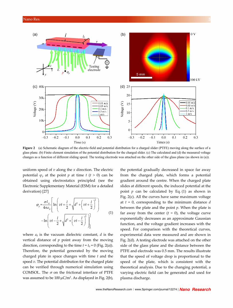
uniform speed of v along the x direction. The electric
potential ϕp at the point p at time t (t > 0) can be
obtained using electrostatics principled (see the
Electronic Supplementary Material (ESM) for a detailed
derivation) [27]
2
20
0
2
2
= ln4 2 2
ln2 2
p
l l lvt d vt
l lvt d vt
(1)
where 0 is the vacuum dielectric constant, d is the
vertical distance of p point away from the moving
direction, corresponding to the time t = t0 = 0 (Fig. 2(a)).
Therefore, the potential generated by the moving
charged plate in space changes with time t and the
speed v. The potential distribution for the charged plate
can be verified through numerical simulation using
COMSOL. The on the frictional interface of PTFE
was assumed to be 100 C/m2. As displayed in Fig. 2(b),
the potential gradually decreased in space far away
from the charged plate, which forms a potential
gradient around the centre. When the charged plate
slides at different speeds, the induced potential at the
point p can be calculated by Eq. (1) as shown in
Fig. 2(c). All the curves have same maximum voltage
at t = 0, corresponding to the minimum distance d
between the plate and the point p. When the plate is
far away from the center (t = 0), the voltage curve
exponentially decreases as an approximate Gaussian
function, and the voltage gradient increases with the
speed. For comparison with the theoretical curves,
experimental data were measured and are shown in
Fig. 2(d). A testing electrode was attached on the other
side of the glass plane and the distance between the
PTFE and electrode was 0.5 mm. The results illustrate
that the speed of voltage drop is proportional to the
speed of the plate, which is consistent with the
theoretical analysis. Due to the changing potential, a
varying electric field can be generated and used for
plasma discharge.
Figure 2 (a) Schematic diagram of the electric-field and potential distribution for a charged slider (PTFE) moving along the surface of aglass plane. (b) Finite element simulation of the potential distribution for the charged slider. (c) The calculated and (d) the measured voltagechanges as a function of different sliding speed. The testing electrode was attached on the other side of the glass plane (as shown in (a)).

| www.editorialmanager.com/nare/default.asp
4 Nano Res.
2.2 UV light emitting device
Using the variable electric field, a self-powered UV
light emitting device based on triboelectrification was
fabricated. A low-pressure Ar–Hg mixture was sealed
in a quartz glass discharge cavity and a PTFE film was
attached on the surface of the glass cavity and slid
with different speeds along the surface of the cavity.
When friction appears, a violet plasma radiation
was found under the friction interface (Fig. 3(a)). The
emission spectra, shown in Fig. 3(b), reveal that the
main peak is located at 253.7 nm, and has a full width
at half maximum of ~0.14 nm. According to the model
of low-pressure plasma discharge, a strong 253.7 nm
UV emission originates from the radiative transitions
of Hg atoms from the excited state of 63P1 to the
ground state of 61S0 [26]. Another peak (313 nm) is
also ascribed to the transitions to the resonance level 3P1 of Hg atoms. Other emission peaks, such as 750,
763 and 811 nm, are typical discharge from Ar [28].
In this device, the voltage and current between the
inductive electrode attached on the opposite surface
of the discharge cavity and ground were measured. A
discontinuous friction between PTFE and quartz glass
leads to a pulsed voltage and discharge current, which
are shown in Fig. 3(c). As depicted there, a discharge
current pulse and phase difference of ~/2 between
current and voltage were formed during the plasma
discharge. Because the discharge occurs between the
glass dielectrics, the glass can be viewed as a dielectric
barrier discharge (DBD) [25, 26]. In the DBD model, the
discharge circuit is equivalent to a parallel connection
of a gas gap capacitance and a resistance, in series
with a dielectric capacitance [23, 29]. The current peaks
are derived from the displacement current in the cavity.
When discharge occurs, the movement of ions from
the plasma towards the dielectric layer (quartz glass)
results in a displacement current, which is asynchronous
but superimposed with a capacitive current with a
phase difference between the current and voltage.
When the sliding speed increases, the discharge current
and the corresponding UV light intensity also increased
Figure 3 (a) A photograph of UV emission caused by friction between PTFE and the quartz cavity. (b) The corresponding UV emission spectra. (c) Measured voltage and discharge current curves. (d) The discharge current and UV luminescence intensity as a function of different rubbing speeds.

www.theNanoResearch.com∣www.Springer.com/journal/12274 | Nano Research
5 Nano Res.
as shown in Fig. 3(d). This result indicates that the
coupling between triboelectrification and plasma
discharge is an effective way to obtain a strong UV
emission.
2.3 White light emission
UV irradiation can be used as an excitation source to
realize visible light emission because of the high UV
photon energy. One of the most extensive applications
of UV irradiation is the fluorescent lamp [30]. A high-
frequency alternating current electric field can bring
about a discharge of low-pressure mercury vapor
leading to emission of UV light, which can excite a
fluorescent powder and give white light emission. In
our experiment, the UV device was introducused as
an excitation source to realize self-powered white
light emission. The glass cavity was filled with a low
pressure Ar–Hg mixture and a tricolour phosphor
coating was coated on the inner surface forming
fluorescent cavity. The triboelectric field is generated
by the friction beween a PTFE plate and the surface
of the fluorescent cavity resulting in triboluminescence.
Figure 4(a) shows the variation in luminescence
intensity as a function of the friction and sliding speeds.
At a low speed of 0.05 m/s, a marked luminescence
can be observed. When the sliding speed increases,
the luminescence intensity increases almost linearly.
Meanwhile, a fast reciprocating-friction with bare
hands can generate a bright and continuous white
emission (see the Movie in the ESM), which means
that a high frictional frequency contributes leads to
increased luminescence intensity by increasing the
frequency of the changing current electric field.
According to plasma discharge theory [23], the plasma
power is proportional to the discharge frequency and
determines the luminescence intensity; this is in
accordance with the experimental results. Figure 4(b)
shows the luminescent spectra of a commercial
fluorescent lamp (220 V, 50 Hz) compared with the
fluorescent cavity. The similar peak positions shows
that they have the same luminescence nature. The
notable luminescence demonstrates the feasibility of
our voltage tuned/controlled light-emitting device and
self-powered device.
2.4 UV sterilization
Ultraviolet rays have been used as a reliable and
environmentally-friendly sterilization method for
medical equipment or packaging of food for a long
time [31–34]. Due to the high energy, the chemical
bonds of deoxyribonucleic acid and chemical sub-
stances in cells can be broken or decomposed resulting
in bacteria death [33, 35, 36]. Compared with traditional
sterilization methods, such as heat, chemical solutions
or gases, UV sterilization have the advantages of low
temperatures, high efficiency and leaving no residues
on objects. In general, a power supply is necessary for
the generation of UV source. Herein, a self-powered
UV sterilization system, which can be operated
by consuming mechanical energy was fabricated.
A reciprocating friction at a frequency of 5 Hz was
employed to generate approximately continuous UV
Figure 4 (a) The luminescence intensity changes at different sliding speeds. The insets are photographs of the luminescence cavity at different speeds. (b) Comparison of the emission spectra for a fluorescent powder excited by triboelectrification induced UV light and a fluorescent lamp.

| www.editorialmanager.com/nare/default.asp
6 Nano Res.
irradiation. To test the sterilization properties,
Escherichia coli (E. coli) CICC 23657 were chosen as the
experimental targets and treated for 0–30 min by UV
irradiation. The results of sterilizing E. coli under
various conditions are shown in Fig. 5(a). It is obvious
that thousands of colonies can be observed in the
Petri dishes without UV radiation (Fig. 5(a), 0 min).
With the increase of radiation time, the colony counts
decrease markedly. The survival curve at different
UV irradiation times is shown in Fig. 5(b). The curve
approximates to an exponential decay and about 80%
of E. coli were eliminated after 10 min UV irradiation.
On average, a sterilization rate of ~98% can be reached
after 30 min treatment. This confirms the effective
sterilization obtained using our UV device driven by
mechanical movement rather than the consumption
of electrical power or chemical agents.
Figure 5 (a) Photographs of E. coli colonies under various radiation times. (b) Surviving rates of E. coli at different treatment times.
3 Conclusion
A simple UV light emitting device has been fabricated
based on triboelectrification and plasma discharge
luminescence. Continuous friction between PTFE and
quartz glass was proven to generate a changing electric
field in space and fast rubbing increases the potential
gradient, which can bring a low-pressure plasma
discharge and emit 253.7 nm UV light. Using the UV
irradiation, a trichromatic phosphor can be excited
and gives out white light, which is comparable to a
fluorescent lamp. The UV irradiation from the recipro-
cating mechanical friction at a low frequency was
also an effective sterilization agent, and ~98% of E.
coli can be killed. By coupling triboelectrification and
plasma luminescence, this work has expanded the
application of TENG as a voltage tuned/controlled
device. The result may provide a brand-new approach
to obtain deep UV light emission using low-frequency
mechanical friction in situations where there is no
power source, which opens a new applications of our
self-powered UV light emitting device.
4 Experimental section
4.1 Fabrication and characterization of the UV
emitting device
A quartz glass discharge cavity, filled with argon and
mercury vapor at a pressure of ~300 Pa was con-
structed to generate a plasma discharge. The vessel
wall of the cavity was 0.5 mm. A PTFE film (100 m
thickness) was attached on the surface of the cavity to
produce a direct friction with the surface of the quartz
glass cavity. The electrical properties in the sliding
mode were measured by a Stanford Research Systems
SR570 current pre-amp to record current and a Keithley
6514 electrometer to record voltage. The spectrum
distribution was detected by a spectrograph (HORIBA,
iHR550).
4.2 Preparation of sterilization device
E. coli CICC 23657 was diluted (10−6) by sterilized
0.9 wt.% NaCl solution and coated on sterilized LB
agar plates in Petri dishes, which were then separately
irradiated by the self-powed UV emission devices

www.theNanoResearch.com∣www.Springer.com/journal/12274 | Nano Research
7 Nano Res.
for 0, 10, 20 and 30 min, The distance between UV
discharge cavity and Petri dish was 5 mm. Then it was
incubated at 37 °C for 24 h to form bacterial colonies.
The slider (PTFE) was rubbed with the cavity by a
reciprocating motion at a frequency of 5 Hz.
Acknowledgements
The project is supported by the National Natural
Science Foundation of China (Nos. 51475099 and
51432005), the “Thousands Talents” program for Pioneer
Researchers and Innovative Teams, China, and Beijing
Municipal Committee of Science and Technology (Nos.
Z131100006013004 and Z131100006013005).
Electronic Supplementary Material: Supporting
information (the derivation of the formulae and video)
is available in the online version of this article at
http://dx.doi.org/10.1007/s12274-014-0634-5.
References
[1] Suh, H.; Lee, W. K.; Park, J. C.; Cho, B. K. Evaluation of
the degree of cross-linking in UV irradiated porcine valves.
Yonsei Med. J. 1999, 40, 159–165.
[2] Wolnicka-Glubisz, A.; Damsker, J.; Constant, S.; Corn, S.;
De Fabo, E.; Noonan, F. Deficient inflammatory response
to UV radiation in neonatal mice. J. Leukoc. Biol. 2007, 81,
1352–1361.
[3] Helmy, S. A.; El-Bedaiwy, H. M. Simultaneous determination
of paracetamol and methocarbamol in human plasma by
HPLC using UV detection with time programming: Applic-
ation to pharmacokinetic study. Drug Res. 2014, 64, 363–367.
[4] Furmaniak, P.; Kubalczyk, P.; Glowacki, R. Determination
of homocysteine thiolactone in urine by field amplified
sample injection and sweeping MEKC method with UV
detection. J. Chromatogr. B 2014, 961, 36–41.
[5] Roelkens, G.; Dumon, P.; Bogaerts, W.; Van Thourhout, D.;
Baets, R. Efficient silicon-on-insulator fiber coupler fabricated
using 248-nm-deep UV lithography. IEEE Photonics Technol.
Lett. 2005, 17, 2613–2615.
[6] Jung, G. Y.; Ganapathiappan, S.; Ohlberg, D. A. A.; Olynick,
D. L.; Chen, Y.; Tong, W. M.; Williams, R. S. Fabrication of
a 34 × 34 crossbar structure at 50 nm half-pitch by UV-based
nanoimprint lithography. Nano Lett. 2004, 4, 1225–1229.
[7] Lin, B. J. Deep UV lithography. J. Vac. Sci. Technol. 1975,
12, 1317–1320.
[8] Taniyasu, Y.; Kasu, M.; Makimoto, T. An aluminium nitride
light-emitting diode with a wavelength of 210 nanometres.
Nature 2006, 441, 325–328.
[9] Hirayama, H.; Yatabe, T.; Noguchi, N.; Kamata, N.
Development of 230–270 nm AlGaN-based deep-UV leds.
Electr. Commun. Jpn. 2010, 93, 24–33.
[10] Johnstone, R. W.; Foulds, I. G.; Parameswaran, M. Deep-UV
exposure of poly(methyl methacrylate) at 254 nm using
low-pressure mercury vapor lamps. J. Vac. Sci. Technol. B
2008, 26, 682–685.
[11] Beneking, C.; Anderer, P. Radiation efficiency of Hg-Ar
surface-wave discharges. J. Phys. D: Appl. Phys. 1992, 25,
1470–1482.
[12] Camara, C. G.; Escobar, J. V.; Hird, J. R.; Putterman, S. J.
Correlation between nanosecond X-ray flashes and stick-slip
friction in peeling tape. Nature 2008, 455, 1089–1092.
[13] Kneip, S. Applied physics: A stroke of X-ray. Nature 2011,
473, 455–456.
[14] Collins, A. L.; Camara, C. G.; Naranjo, B. B.; Putterman, S.
J.; Hird, J. R. Charge localization on a polymer surface
measured by triboelectrically induced X-ray emission. Phys.
Rev. B 2013, 88, 064202.
[15] Fan, F. R.; Lin, L.; Zhu, G.; Wu, W. Z.; Zhang, R.; Wang, Z.
L. Transparent triboelectric nanogenerators and self-powered
pressure sensors based on micropatterned plastic films. Nano
Lett. 2012, 12, 3109–3114.
[16] Wang, Z. L. Triboelectric nanogenerators as new energy
technology for self-powered systems and as active mechanical
and chemical sensors. ACS Nano 2013, 7, 9533–9557.
[17] Han, C. B.; Du, W. M.; Zhang, C.; Tang, W.; Zhang, L. M.;
Wang, Z. L. Harvesting energy from automobile brake in
contact and non-contact mode by conjunction of triboelec-
trication and electrostatic-induction processes. Nano Energy
2014, 6, 59–65.
[18] Horn, R. G.; Smith, D. T. Contact electrification and adhesion
between dissimilar materials. Science 1992, 256, 362–364.
[19] Zhu, G.; Zhou, Y. S.; Bai, P.; Meng, X. S.; Jing, Q. S.; Chen,
J.; Wang, Z. L. A shape-adaptive thin-film-based approach
for 50% high-efficiency energy generation through micro-
grating sliding electrification. Adv. Mater. 2014, 26, 3788–
3796.
[20] Zhang, C.; Tang, W.; Han, C. B.; Fan, F. R.; Wang, Z. L.
Theoretical comparison, equivalent transformation, and
conjunction operations of electromagnetic induction generator
and triboelectric nanogenerator for harvesting mechanical
energy. Adv. Mater. 2014, 26, 3580–3591.
[21] Zhang, C.; Tang, W.; Zhang, L. M.; Han, C. B.; Wang, Z. L.
Contact electrification field-effect transistor. ACS Nano 2014,
8, 8702–8709.

| www.editorialmanager.com/nare/default.asp
8 Nano Res.
[22] Wang, S. H.; Xie, Y. N.; Niu, S. M.; Lin, L.; Wang, Z. L.
Freestanding triboelectric-layer-based nanogenerators for
harvesting energy from a moving object or human motion
in contact and non-contact modes. Adv. Mater. 2014, 26,
2818–2824.
[23] Kogelschatz, U. Dielectric-barrier discharges: Their history,
discharge physics, and industrial applications. Plasma Chem.
Plasma Process. 2003, 23, 1–46.
[24] Fang, D. Y.; Huang, C. H. Modelling of low-pressure Ar+Hg
discharge with high electric current densities. J. Phys. D:
Appl. Phys. 1988, 21, 1490–1495.
[25] Xu, X. J.; Jie, Y. X. Kinetics of Ar-Hg plasma in dielectric
barrier discharge. Phys. Scr. 1995, 52, 603–606.
[26] Eliasson, B.; Gellert, B. Investigation of resonance and
excimer radiation from a dielectric barrier discharge in
mixtures of mercury and the rare gases. J. Appl. Phys. 1990,
68, 2026–2037.
[27] Jackson, J. D. Classical Electrodynamics, 3rd ed.; Wiley:
New York, 1998.
[28] Kim, J.; Jeong, J.; Jin, D.; Kim, H.; Han, S.; Kwon, G.;
Choi, E.; Cho, G. Longitudinal and transverse discharges
with mercury-rare and xenon gases. J. Phys. D: Appl. Phys.
2011, 44, 075202.
[29] Francke, K. P.; Rudolph, R.; Miessner, H. Design and
operating characteristics of a simple and reliable DBD reactor
for use with atmospheric air. Plasma Chem. Plasma Process.
2003, 23, 47–57.
[30] Loo, K. H.; Moss, G. J.; Tozer, R. C.; Stone, D. A.; Jinno, M.;
Devonshire, R. A dynamic collisional-radiative model of a
low-pressure mercury-argon discharge lamp: A physical
approach to modeling fluorescent lamps for circuit simulations.
IEEE Trans. Power Electron. 2004, 19, 1117–1129.
[31] Heise, M.; Neff, W.; Franken, O.; Muranyi, P.; Wunderlich, J.
Sterilization of polymer foils with dielectric barrier discharges
at atmospheric pressure. Plasma Polym. 2004, 9, 23–33.
[32] Kong, M. G.; Kroesen, G.; Morfill, G.; Nosenko, T.;
Shimizu, T.; van Dijk, J.; Zimmermann, J. L. Plasma medicine:
An introductory review. New J. Phys. 2009, 11, 115012.
[33] Delgado, A. A.; Schaaf, N. G. Dynamic ultraviolet sterilization
of different implant types. Int. J. Oral Maxillofac. Implants
1990, 5, 117–125.
[34] Hidaka, Y.; Kubota, K. Study on the sterilization of grain
surface using UV radiation—Development and evaluation
of UV irradiation equipment. Jarq-Jap. Agric. Res. Q. 2006,
40, 157–161.
[35] Norman, A. The nuclear role in the ultraviolet inactivation
of neurospora conidia. J. Cell. Comp. Physiol. 1954, 44, 1–10.
[36] Chadwick, C. A.; Potten, C. S.; Nikaido, O.; Matsunaga, T.;
Proby, C.; Young, A. R. The detection of cyclobutane thymine
dimers, (6-4) photolesions and the Dewar photoisomers in
sections of UV-irradiated human skin using specific antibodies,
and the demonstration of depth penetration effects. J.
Photochem. Photobiol. B: Biol. 1995, 28, 163–170.
Related Documents