International Journal of Multimedia and Ubiquitous Engineering Vol.12, No.1 (2017), pp.17-34 http://dx.doi.org/10.14257/ijmue.2017.12.1.02 ISSN: 1975-0080 IJMUE Copyright ⓒ 2017 SERSC Tree Based Localization Model for Line Following Robots Tanvir Ahmed 1 , Khandakar Mahbubul Islam 2 , Md. Faiz Ahmed 3 , Rakib Hossain 4 and Md. Mahbubur Rahman 5 Department of Computer Science & Engineering Bangladesh University of Business & Technology (BUBT) Dhaka, Bangladesh [email protected] 1 , [email protected] 2 , [email protected] 3 , [email protected] 4 , [email protected] 5 Abstract Today automated frameworks are broadly utilized as a part of the business specifically for assignments, for example, welding, painting and bundling. All of these automated systems are in the form of manipulators that carry out repetitive motion. For large scale transportation such robotics systems are not particularly practical and therefore automatic transportation systems have been developed either as numerically controlled systems like automatic warehouses or through use of automatic guided vehicles (AGVs). Almost all AGVs use a guide-path system where they track a buried Wire on the floor or utilize other forms of artificial landmarks. In this paper we design an algorithm for a line follower based service robot which could be applicable to various practical automation systems. Here, a new localization algorithm has been proposed to localize the mobile robot in an area. Various experiments show that the proposed algorithm could accurately evaluate the localization performance. It can be called using a web application. A SPI based wireless system has been used to send user command to robot and get data from robot. It has a sonar device through which it can detect obstacles and hold that position for a while. By using the gear motors the robot can able to move faster via following the line. It's extremely basic and simple to utilize. This gadget is practical, productive in utilizing force and easy to understand enough to make our day by day works less demanding. Keywords: Arduino, AGVs, SPI, RFID, Localization, LRF, IR sensor, Sonar sensor 1. Introduction Robotics is one of the quickest developing zones of research. It will contribute much to the future and has many promising properties. Nowadays, robotics is everywhere and is affecting our lives tremendously. Starting from computers and ending with space crafts. Humanity is getting more dependent on robots and every year there are thousands of researches and projects that add new contributions to science and engineering of robotics [1]. New algorithms that improve old techniques as well as new designs and new robots are presented continuously. The ultimate goal is to develop a fully automated machine with all its required sensors to sense its surroundings and make behavioral decision independently. Additionally, the machine that would work in a social environment should have also a reasonable size and behaviors based on perceived personality. Autonomous behavior is

Welcome message from author
This document is posted to help you gain knowledge. Please leave a comment to let me know what you think about it! Share it to your friends and learn new things together.
Transcript

International Journal of Multimedia and Ubiquitous Engineering
Vol.12, No.1 (2017), pp.17-34
http://dx.doi.org/10.14257/ijmue.2017.12.1.02
ISSN: 1975-0080 IJMUE
Copyright ⓒ 2017 SERSC
Tree Based Localization Model for Line Following Robots
Tanvir Ahmed1, Khandakar Mahbubul Islam
2, Md. Faiz Ahmed
3, Rakib Hossain
4
and Md. Mahbubur Rahman5
Department of Computer Science & Engineering
Bangladesh University of Business & Technology (BUBT)
Dhaka, Bangladesh
[email protected], [email protected]
2,
[email protected], [email protected]
4,
Abstract
Today automated frameworks are broadly utilized as a part of the business
specifically for assignments, for example, welding, painting and bundling. All of
these automated systems are in the form of manipulators that carry out repetitive
motion. For large scale transportation such robotics systems are not particularly
practical and therefore automatic transportation systems have been developed
either as numerically controlled systems like automatic warehouses or through
use of automatic guided vehicles (AGVs). Almost all AGVs use a guide-path
system where they track a buried Wire on the floor or utilize other forms of
artificial landmarks. In this paper we design an algorithm for a line follower
based service robot which could be applicable to various practical automation
systems. Here, a new localization algorithm has been proposed to localize the
mobile robot in an area. Various experiments show that the proposed algorithm
could accurately evaluate the localization performance. It can be called using a
web application. A SPI based wireless system has been used to send user
command to robot and get data from robot. It has a sonar device through which it
can detect obstacles and hold that position for a while. By using the gear motors
the robot can able to move faster via following the line. It's extremely basic and
simple to utilize. This gadget is practical, productive in utilizing force and easy to
understand enough to make our day by day works less demanding.
Keywords: Arduino, AGVs, SPI, RFID, Localization, LRF, IR sensor, Sonar sensor
1. Introduction
Robotics is one of the quickest developing zones of research. It will contribute much to
the future and has many promising properties. Nowadays, robotics is everywhere and is
affecting our lives tremendously. Starting from computers and ending with space crafts.
Humanity is getting more dependent on robots and every year there are thousands of
researches and projects that add new contributions to science and engineering of robotics
[1].
New algorithms that improve old techniques as well as new designs and new robots are
presented continuously. The ultimate goal is to develop a fully automated machine with
all its required sensors to sense its surroundings and make behavioral decision
independently.
Additionally, the machine that would work in a social environment should have also a
reasonable size and behaviors based on perceived personality. Autonomous behavior is

International Journal of Multimedia and Ubiquitous Engineering
Vol.12, No.1 (2017)
18 Copyright ⓒ 2017 SERSC
one of the most important aspects related to modern robotics. Localization and navigation
are part of automatic behavior and they are one of the most quickly developing fields of
robotics research presently [12].
1.1. Formal Definition
We can define robots as follows:
A: a machine that looks like a human being and performs various complex acts (as
walking or talking) of a human being; also : a similar but fictional machine whose lack of
capacity for human emotions is often emphasized.
B: an efficient insensitive person who functions automatically is known as robot.
Basically robots are some kind of device that automatically performs complicated
often repetitive tasks and they have a mechanism guided by automatic controls [12].
Figure 1. Robotics
1.2. Types of Robot
These days, robots do various assignments in numerous fields and the quantity of
employments depended to robots is becoming consistently. That is the reason as I would
like to think one of the most ideal routes how to partition robots into sorts is a division by
their application. As follows:
Industrial robots - Industrial robots will be robots utilized as a part of a modern
assembling environment. Generally these are enunciated arms particularly produced for
such applications as welding, material taking care of, painting and others. In the event that
we judge absolutely by application this sort could likewise incorporate some mechanized
guided vehicles and different robots.
Domestic or household robots - Robots utilized at home. This sort of robots
incorporates numerous entirely extraordinary gadgets, for example, mechanical vacuum
cleaners, automated pool cleaners, sweepers, canal cleaners and different robots that can
do distinctive tasks. Additionally, some reconnaissance and telepresence robots could be
viewed as family unit robots if utilized as a part of that environment.
Medical robots - Robots utilized as a part of prescription and therapeutic foundations.
As a matter of first importance surgery robots. Additionally, some mechanized guided
vehicles and perhaps lifting helpers.

International Journal of Multimedia and Ubiquitous Engineering
Vol.12, No.1 (2017)
Copyright ⓒ 2017 SERSC 19
Service robots - Robots that don't fall into different sorts by use. These could be
diverse information gathering robots, robots made to flaunt innovations, robots utilized
for research, and so on.
Military robots - Robots utilized as a part of military. This kind of robots incorporates
bomb transfer robots, distinctive transportation robots, observation rambles. Regularly
robots at first made for military purposes can be utilized as a part of law requirement,
pursuit and safeguard and other related fields.
Entertainment robots - These are robots utilized for amusement. This is an
exceptionally general classification. It begins with toy robots, for example, robosapien or
the running wake up timer and finishes with genuine heavyweights, for example,
explained robot arms utilized as movement test systems.
Space robots - I'd jump at the chance to single out robots utilized as a part of space as
a different sort. This sort would incorporate robots utilized on the International Space
Station, Canadarm that was utilized as a part of Shuttles, and additionally Mars
meanderers and different robots utilized as a part of space.
Hobby and competition robots - Robots that you make. Line adherents, sumo-bots,
robots made only for entertainment only and robots made for rivalry.
1.3. Robot Localization
Localization is a process that occurs inside the robot “brain” to locate the robot in a
previously known map. In other words, the map is already located in the robot memory
and is based on landmarks of the environment that the robot perceives. Robot uses sonar,
camera, Laser Range Finder (LRF) and stereo vision devices like Kinect to perceive the
environment. Using localization and sensors, robot will be able to detect its position like
x,y coordinates as well as its orientation in the map. Even the sensing for localization
process is not as easy as presented above because there are many types of sensors and a
sensor fusion are required in the process. As long as there are sensors, there are noise and
errors which cause uncertainty about all data produced by sensors. Always, without a
refining algorithm, the outcome of the process of locating the robot position will diverge.
In this case, if we need our robot to be in the hall room, after a while it will find itself in
the kitchen! Nevertheless, filters are used by the robot in order to figure out the best
estimation of its location and position. Methods of using a filter to refine signals coming
from the sensors in order to determine the robot’s position will be the main topic of this
thesis [2,13].
The issue of robot confinement comprises of answering the question Where am I?
From a robot's point of view. This means the robot has to stand out its location relative to
the environment. When we talk about location, pose, or position we mean then x and y
coordinates and heading direction of a robot in a global coordinate system. The
localization problem is a critical issue. It is a key part in numerous successful self-
sufficient robot frameworks. On the off chance that a robot does not know where it is with
respect to the earth, it is hard to choose what to do [3].
The robot will in all probability need at any rate some thought of where it is to have the
capacity to work and act effectively. By a few creators the robot confinement issue has
been expressed as the most basic issue to giving robots genuinely independent capacities
[13].

International Journal of Multimedia and Ubiquitous Engineering
Vol.12, No.1 (2017)
20 Copyright ⓒ 2017 SERSC
1.4. Robot Navigation
Navigation is the next step taken by the robot when it knows its position. Localization
is the main part here as the robot must know its position precisely while driving from
point to point [4]. The navigation scenario will be:
1. The robot knows its essential position.
2. Robot receives an order to go to a different position (or set this goal by himself)
3. Robot creates a trajectory step by step from its start point to its destination point.
This trajectory is first specified as a path in the map and then it is converted to
control commands for the robot.
4. Starts moving.
5. Keep localizing itself while moving as it has to calibrate itself every while.
2. Our Inspiration
Intelligent devices are becoming common in our daily life day by day. New ideas are
updating and new technologies are implementing to make these devices more robust and
cheap. That’s why the idea of using robots for daily works becoming popular.
Arduino is an open-source microcontroller in view of simple to-utilize equipment and
programming. Interfacing different gadgets with Arduino circuit sheets are making the
new developments for the robotics enterprises. In robotics, IR sensor is utilized for
identifying the shading objects, in spite of the fact that it works by utilizing a particular
light sensor to recognize a select light wavelength in the Infra-Red range. Ultrasonic or
sonar sensor is utilized for distinguishing the range amongst indoor and outside articles.
Ultrasonic or sonar sensors produce high recurrence sound waves and gauge the resound
which is recognized back by the sensor, measuring the time interim between sending the
flag and accepting the reverberate to decide the separation to a question [1].
Figure 2. SaviOne (Hotel Service Robot)
In our paper, we have discussed about a path finder robot with the obstacle detections,
the robot can be used for home or business applications. We have inspired about this
project from the line follower robot competitions and hotel service robot “SaviOne” built
by the company named “Savioke”. Now we can see these robots working in Starwood
chain hotel Aloft at Cupertino in California. They have named this robot as A.L.O [9].
International Journal of Multimedia and Ubiquitous Engineering
Vol.12, No.1 (2017)
Copyright ⓒ 2017 SERSC 21
3. Thesis Outline
3.1. Background Analysis
These days heaps of businesses utilizing numerous sorts of robots and every robot have
its own particular purposes. A few robots can move one place to another which takes after
a way. Toward the starting running a robot with an obscure way was excessively
troublesome then analysts have presented with a name way discoverer. A way discoverer
robot is essentially a robot intended to take after a line or way which is as of now
predefined and foreordained by the client. The way is as straightforward as a white or
dark hued line on the floor [8].
There are numerous explores about the way discovering robots one of these looks into
additionally said about way discovering robot is utilized as server administration; thought
of learning and this thought is utilized to explore through an impediment freeway from a
beginning position to a known objective position on the obscure environment.
Another way discoverer robot is additionally composed with the RFID based
application which comes from no express prerequisites and goes for client gathering to
achieve the objective inside a no well-known or absolutely obscure grounds range without
taking any assistance outside.
For a portion of the way discoverer utilized multi sensors to satisfy its principle targets.
In our venture we have executed multi sensors for conferring different works. For finding
the way and tailing it we have utilized the IR sensor by means of which distinguishes the
dark line on white surface with high differentiated shading. The one of the essential
sensor that we utilized is impediments sensor for the predefined and foreordained way
[10].
Essentially while taking after a way confront numerous sorts of impediments; to stay
away from or move these we require either picture preparing which can recognize the
articles through pictures or sonic sensors which can distinguish the range between the
items and the robot itself.
As per the insights it demonstrates that these days numerous robots are utilizing for
enterprises as well as helpful for the independent venture like eatery, workplaces, schools,
airplane terminal and so on spots and family unit purposes. For the family unit robots uses
are step by step expanding and before the end of the 2016 it will cross more than 15000
units.
Figure 3. Statistics of Household Robots
Well, this is our proposed model. It is very much similar to conventional model, but
the difference is in input seed & the arithmetic formula of generator.

International Journal of Multimedia and Ubiquitous Engineering
Vol.12, No.1 (2017)
22 Copyright ⓒ 2017 SERSC
3.2. Research Methodology
A large portion of enterprises are utilizing robots for some reasons way discoverer is
one of them. Particularly auto ventures and tech businesses are utilizing the way
discovering robot to finish the mass measure of works. As of late family unit robots are
being worked to serve as business or home applications as like server administration.
Numerous autos are working with the way discovering thoughts which can act naturally
drivable as like Google auto, Audi auto and Tesla auto, the possibility that result finding
the way and take after the way until it achieves its own objective.
These days path finding robot is utilizing as a part of Mars operations as to study the
earth on Mars. A few models have been presented in light of a change of strategies
alongside some limitation with each.
This research is fundamentally gone for actualizing the home or business applications
robots that is fit to serve any known territories. It can recognize obstacles to protests all
alone way. The entire theory is finished by utilizing the Arduino IDE where way
discoverer and impediments recognition is done and web application is worked to call the
robot close to a client area. To confirm the culmination of the venture we have tried the
sensors independently and consolidated with body for a few times to assess and idealizing
the more exactness we needed to change the body structure for a few times.
3.3. Implementation
The whole work is divided in to 3 major parts:
1. Mechanical part
2. Electrical part
3. Software part
On mechanical part we have deigned the body along Gear motors, sonar sensor and IR
sensor array.
On electrical part we have implemented the Arduino Uno along with the nRF24L01 RF
Board device and Mega along with the L293D Motor Controller and the nRF24L01 RF
Board device including the sensors.
Table 1. Body Parts
Name of Part Item Setup
Mechanical part
Body
Gear Motor
Sonar Sensor
IR Sensor Array
Electrical part
Arduino Uno
Arduino Mega
L293D Motor Controller
nRF24L01
LM2596 Step Down Module
Software part
Arduino IDE
NetBeans IDE
XAMPP(Apache/Mysql)
User Interface(Web based application)
At the end on software part we have designed the algorithms by using the Arduino
IDE, web application for the user interfaces so user can give command easily and a Java
program which relays user commend to the robot. The Java program & the web
application shares a common MySQL database. The system that we designed to handle 2
different works:
1. Path finder design

International Journal of Multimedia and Ubiquitous Engineering
Vol.12, No.1 (2017)
Copyright ⓒ 2017 SERSC 23
2. Robot monitoring
Robot End:
Figure 4. Mechanism of Robot End
User End:

International Journal of Multimedia and Ubiquitous Engineering
Vol.12, No.1 (2017)
24 Copyright ⓒ 2017 SERSC
Figure 5. Mechanism of User End
Both user end and robot end are connected via the Java application with nRF24L01
connection. By default when a user make a call from a location the Java application
forwards the command to the robot if it is idle. After connecting the robot will reach the
location by following its path; the robot will start to move forward, left, right or turn 180
degree by reading the IR sensor and considering the destination. On the path if there are
any obstacles detected by sonar sensor the bin will stop and wait until the obstacle object
moved from the path. As there are defined location, the robot will stop from which
location are being called by the user, rest of the locations will be ignored. After few
seconds the robot will start to move; if the robot gets another call from another user it will
respond to user as the same thing. After completing the task the robot will rest until it gets
any call.
Path Finder Control Design
Implementing the prototype is one of the biggest challenges in our project. There are
many reasons why it is not easy to implement one of them is perfecting the structure,
which helps the rest of the parts to hold. The second is to write the code and choose the
appropriate pin for the sensors. We have divided the implementation on two parts first is
Mega second is Uno [5].

International Journal of Multimedia and Ubiquitous Engineering
Vol.12, No.1 (2017)
Copyright ⓒ 2017 SERSC 25
Figure 6. Path Finder Control
On the first part we have used Arduino Mega along with the sonar sensor, IR sensor
and motor controller L293D. IR sensor take the analog reading of black and white color
for the path following and motor controller is connected with two motors which controls
the motors movements according to sensing of the path. If more than two IR sensor
detects black line colored position, it is selected as an intersection point. On the other
hand if sonar sensor is used for detecting the obstacles and the distance between the
obstacles and the moving objects. HC-SR04 ultrasonic sensor uses sonar to assume
distance to an object like bats or dolphins do. It offers excellent non-contact range
detection with high accuracy and stable readings in an easy-to-use package from 2cm to
400 cm or 1” to 13 feet. If sonar sensor detects any obstacles within its ranges two motors
will be stop until the obstacle is moved. An nRF24L01 RF board device is connected, so
that user can call the robot to user’s location via web application. The most important
benefits of using SPI based communication is easy to connect and can work on limited
areas.
International Journal of Multimedia and Ubiquitous Engineering
Vol.12, No.1 (2017)
26 Copyright ⓒ 2017 SERSC
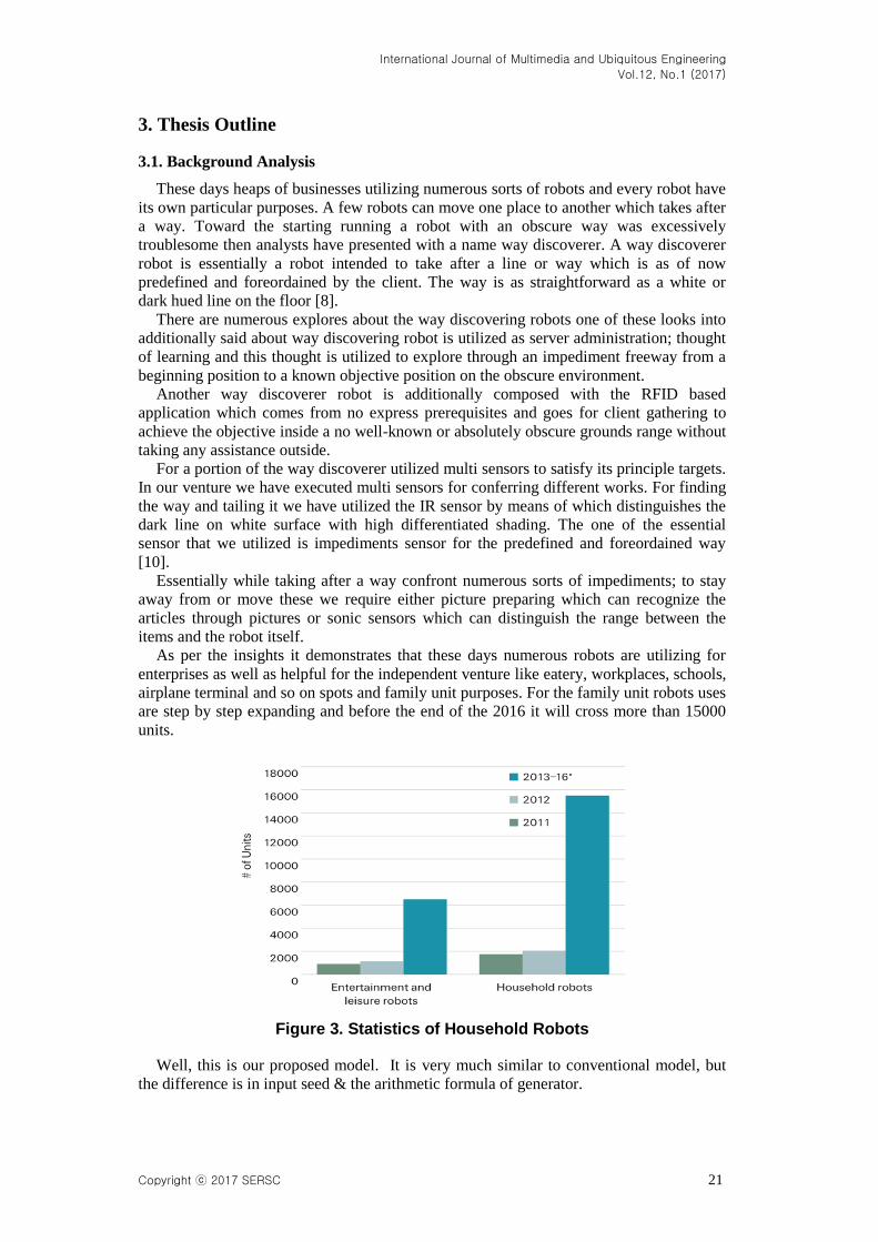
Base Station Design
On this part, we have connected an nRF24L01 RF board with Arduino Uno. A bread
board is used to connect the Arduino Uno’s 3.3V pin with a 10µF capacitor to power the
nRF24L01 RF board. After connecting all the devices the Arduino Uno is connected with
a computer using an USB cable. Then we run the Java application. The mechanism is
designed like this when user puts a command using the web application the command is
stored in a MySQL database. The Java application fetches the command from the
database and sends the data to the robot when the robot is idle [6].
Figure 7. Base Station
When the robot send its updated position after reaching an intersection point; the Java
application stores the data in a MySQL database. The web application uses the data to
show the robot’s position in the map. Users can see the robots position from the web
application’s map page any time.
3.4. Simulation & Analysis
Our main objective of this research is to provide an intelligent algorithm for line
following robots. That’s why we need to apply a physical survey and observe our
algorithm through a real robot simulation. In this connection here we use Arduino.
Our robot consist of an acrylic base with two gear motors, two compatible wheels, a
ball caster, and other accessories. We have used a Vero board for the 1st floor base of our
robot. There are many classifications of arduino. It is a microcontroller. The Arduino
board is the brain of the robot, as it will be running the software that will control all the
other parts [7]. The programming is done in this part.
Chassis Specification:
1. Dimensions: 7.72 in x 4.13 in x 0.12 in (19.6 cm x 10.5 cm x 0.3 cm)
2. Weight: 14.29 oz (405 g)
Vero Board Specification:
1. Dimensions: 20.5 cm x 9.5 cm

International Journal of Multimedia and Ubiquitous Engineering
Vol.12, No.1 (2017)
Copyright ⓒ 2017 SERSC 27
Figure 8. Accessories to Assemble
Prototype 1
We defined thesis scope and topic. We revised the topic, studied about its benefit and
work horizon and then we selected one from many. Three of the group members started
the research work. Meeting with the group member had been done on regular basis. We
discussed and made the working plans and basic diagrams. Based on the blueprint we
have done our first poster presentation and submitted a report including each and every
detail. We have designed the 1st prototype with less efficiency. The prototype was made
with two gear motors, one free wheel and IR sensor array. The idea that came across of
our mind with the 1st prototype is to provide service at restaurants, ground floor of hotels,
office floors and university building areas types of places. Our best concern was to make
the prototype good on line following.
Figure 9. First Prototype

International Journal of Multimedia and Ubiquitous Engineering
Vol.12, No.1 (2017)
28 Copyright ⓒ 2017 SERSC
Prototype 2
Here we started writing code to follow the line along with obstacle detection. We
bought all the equipment thought it was a troublesome job because the equipment are not
available everywhere. We start working on obstacle detecting basics with IR sensors. We
had to change the sensor because it wasn’t giving us the correct values. We changed few
of the components. On the 2nd
prototype we have designed the main board. We had
maintained the total heights and changed the IR sensor array height for the better
implementing of IR sensor. With the 2nd
prototype it will be much easier to move and can
able to detect obstacles pretty well. With 2nd
prototype our purpose was to make the robot
lighter, smaller and more responsive to the main objectives.
Figure 10. Second Prototype
Final Prototype
We had implemented everything on the 2nd
prototype including tested and debugged
the codes. We tested all the wheels wires running through the path and developed
intersection detecting algorithms. We changed the mechanical structure a bit for better
accommodation. We used different surface for testing our project for the perfections and
better performance. Our main problem was to run the line follower with better
performances. Later it worked after changing the height. For the wireless communication
we connected the nRF24L01 RF board with the Arduino Mega.
Figure 11. Final Prototype

International Journal of Multimedia and Ubiquitous Engineering
Vol.12, No.1 (2017)
Copyright ⓒ 2017 SERSC 29
After testing the robot we noted down the desired readings, checked the performances
and update the few lines of codes due to the environment changes.
All the description in the paper we tested all the wheels wires running through the path
and developed intersection detecting algorithm. We changed the mechanical structure a
bit. We connected the nRF24L01 RF board. After testing the robot we noted down the
desired readings.
Prototype of Base Station
For base station we designed a very simple setup. An Arduino Uno is connected with a
computer using USB cable. An nRF24L01 is connected with the Arduino Uno. At first we
used the Arduino Uno’s 3.3V power pin to power the nRF24L01. But it was not working
well because of the shaky power supply from the Arduino Uno. Then we connected a
10µF capacitor and it solved the problem. We have used a mini breadboard to connect the
capacitor with the nRF24L01. In open area the communication distance of the nRF24L01
is almost no loss within 55 meters.
Figure 12. Base Station
4. Outputs & Results
At first we have taken the individual test for each sensor, where all the sensors showed
the perfect results. At the beginning the IR sensor took the reading of the black and white
line analog readings, the sonar sensor gave the reading of the distances of the obstacles.
We have tested the path finder robot by changing the IR sensor array distance with the
surface. Firstly we kept the IR sensor array 3cm above the surface. Later we kept the IR
sensor array 1.5cm above the surface. At the end we kept the IR sensor array 1cm above
the surface. The testing for the three different distances between the IR sensor array and
the ground gave different outcomes. The sonar sensor is designed when any obstacles
object detects around 2-20 cm. The nRF24L01 also worked pretty well.

International Journal of Multimedia and Ubiquitous Engineering
Vol.12, No.1 (2017)
30 Copyright ⓒ 2017 SERSC
Average Filter Algorithm
It receives the sonar measurements and returns the average of the measurements.
Table 2. Average Filter Algorithm
AvgFilter
Function avg = AvgFilter(x)
persistent prevAvg k
persistent firstRun
if isempty(firstRun)
k = 1;
prevAvg = 0;
firstRun = 1;
end
alpha = (k -1) / k;
avg = alpha*prevAvg + (1 - alpha)*x;
prevAvg = avg;
k = k + 1;
GetMaxSonar Algorithm
It reads the sonar from a file that has a real data taken from the front sonar of the Bot.
Table 3. Get Max Sonar Algorithm
GetMaxSonar
function h = GetMaxSonar1()
%persistent son1 %
SonartAlt.mat
persistent k firstRun
if isempty(firstRun)
load Son1
k = 1;
firstRun = 1;
end
h = son1(k);
k = k + 1;
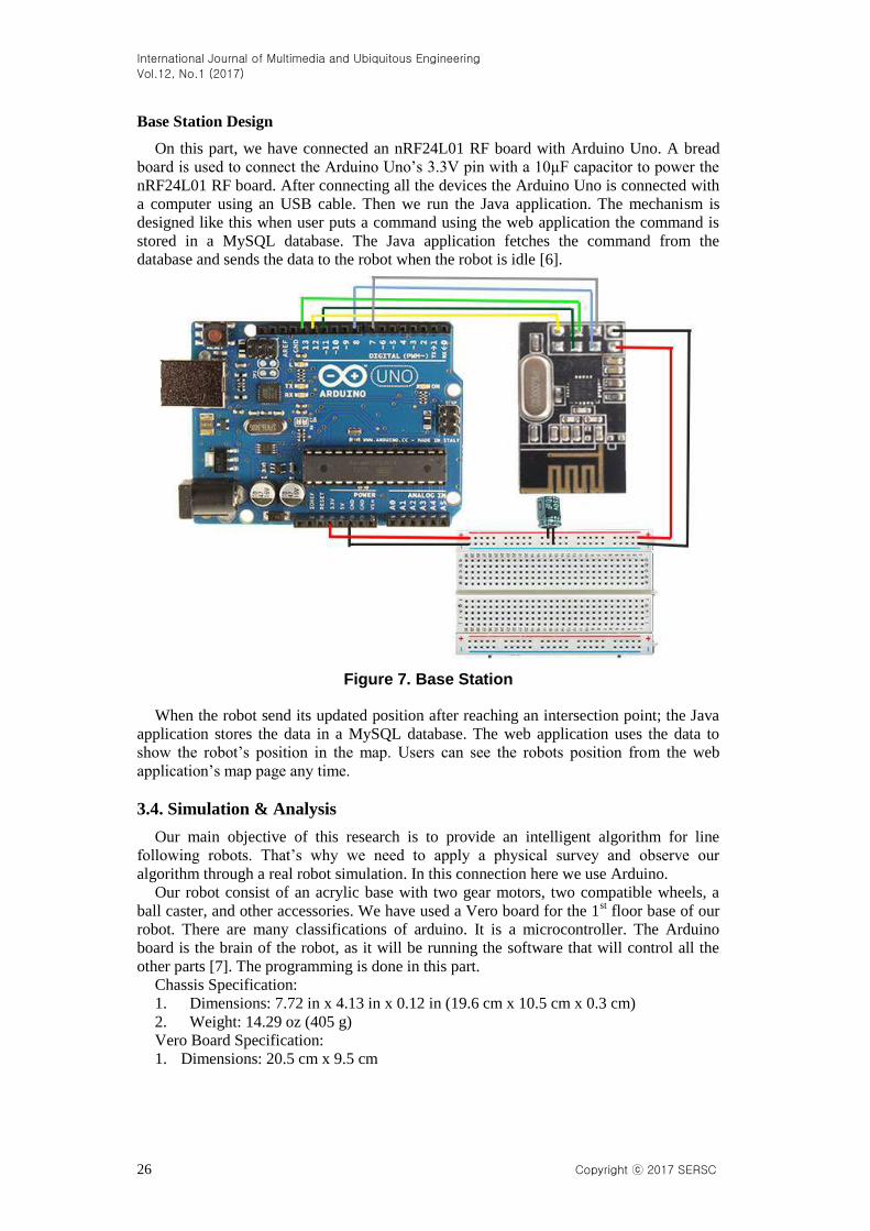
Result of Kalman Filer
As shown in GetMaxSonar and AvgFilter codes, the function simply adds random
values to the initial value and sends them as simulated measurements with noise. The
main code is shown in Figure 4.12. This code gets the measurements from Sonar1 and
Sonar2 and passes them to Kalman Filter algorithm. After getting the estimation, it will
show the results. Figure 4.13 shows the result of Kalman Filer that is used in this
example.
International Journal of Multimedia and Ubiquitous Engineering
Vol.12, No.1 (2017)
Copyright ⓒ 2017 SERSC 31
Table 4. Result of Kalman Filter
ResultKalman
dt = 0.2;
t = 0:dt:10;
Samples = length(t);
X = zeros(Samples, 1);
Z1 = zeros(Samples, 1);
Z2 = zeros(Samples, 1);
AVEZ = zeros(Samples, 1);
for k=1:Samples
z1 = GetSonar1();
z2 = GetSonar2();
AveZ = (z1+z2)/2;
D= Simple1DKalman(AveZ);
X(k) = volt;
Z1(k) = z1;
Z2(k) = z2;
AVEZ(k) = AveZ;
end
plot(t, X, 'o-')
hold on
plot(t, Z1, 'g:*')
plot(t, Z2, 'k:.')
plot(t, AVEZ, 'r:s')
title('Kalman Filter Estimation');
xlabel('Time(s)');
ylabel('Inche');
grid on
legend('Estimation','Measurements Z1', 'Measurements Z2' , 'Measurements Average');
Figure 13. Kalman Filter Output

International Journal of Multimedia and Ubiquitous Engineering
Vol.12, No.1 (2017)
32 Copyright ⓒ 2017 SERSC
Table 5. Accuracy Test
No of
Sensors Sensors
Accuracy Checking
Test 1 Test 2 Test 3
1 IR sensor
array
65%
(didn’t follow
the line)
70%
(detected the
black line well)
82%
(detected the black line
as expected)
2 Sonar
sensor
93%
(object detected
properly)
95%
(object detected
properly)
95.5%
(object detected
properly)
3 nRF24L01
88%
(data received &
sent properly)
94%
(data received
& sent
properly)
95%
(data received & sent
properly)
According to the analysis we have seen that all of our sensors and communication
device giving the perfect reading. For perfecting behavior of the robot we tested on 3
different environments. The sonar sensor gave 95.5% accuracy which means it can able to
detect any object that causes as obstacles to the path. IR sensors gave the 82% accuracy;
followed the line on three different distances with the surface and can successfully detect
the black line and intersection points. According to the analysis we have found that the
nRF24L01 sometimes make trouble in communication if it face shaky power supply. It is
best to use a capacitor to solve the problem.
5. Conclusions
In its current form robot is enough capable that it can follow any line. We must build a
robot that has light weight and fast, because points are awarded based upon the distance
covered and the speed of the overall robot. Therefore, we used two speed motors and high
sensitivity sensors circuits. Before making this kind of project it is required to relocate the
perfect resources and have best information about those parts. Though it has some
limitations on physical and mechanical parts but the simple robot is more effective and
profitable for people. Implementing this project based on path finder can make our life
easier. It can be modified and upgraded with new features and options regarding its
usability. This product is economically cheaper. It’s a step creating revolution
implementing robots in our household needs and needs of other places.
6. Future Direction
In future we can incorporate the new features in our project. These features will
enhance the usability of line following robot and enhance the angle of working sector.
Through image processing system we can train our robot to pick up something on its own.
Therefore voice synchronization will make the machine more flexible which will help us

International Journal of Multimedia and Ubiquitous Engineering
Vol.12, No.1 (2017)
Copyright ⓒ 2017 SERSC 33
to call the robot from a long distance and can able to communicate with robot via voice; it
is almost like talking with your own robot. Wireless control will conquer distance and
make it more efficient. In Future for recharging the battery it could be possibly to use the
wireless battery charger. Moreover this system could be more useful for the large
shopping mart, 5 star hotels, restaurants, airports and etc. in future we can implement this
system on vacuum cleaner, autonomous waiter. Most importantly after complete the
implementations for all these projects we can create and apply new learning algorithms
for the autonomous car by taking command from user which can drive self.
References
[1] C. Adams, Is 'dead reckoning' short for 'deduced reckoning’?, (2002).
[2] O. Q. Mohsin, “Mobile Robot Localization Based on Kalman Filter”, (2014).
[3] K. Arras and N. Tomatis, “Improving robustness and precision in mobile robot localization by using
laser range nding and monocularvision, Proceedings of the Third European Workshop on Advanced
Mobile Robots, Zurich, Switzerland, (1999).
[4] H. Baltzakis and P. Trahanias, “Hybrid mobile robot localization using switching state space models”,
Proceedings of the 2002 IEEE International Conference on Robotics and Automation. Washington D.C.,
USA, (2002).
[5] J. Borenstein, “Control and kinematic design of multi-degree-of-freedom robots with compliant
linkage”, IEEE Transactions on Robotics and Automation, (1995).
[6] J. Borenstein, H. Everett, L. Feng, and D. Wehe, “Mobile robot positioning: Sensors and techniques”,
Journal of Robotic Systems, vol. 14, no. 4, (1997).
[7] J. Borenstein and L. Feng, “Measurement and correction of systematic odometry errors in mobile
robots”, IEEE Transactions on Robotics and Automation, vol. 12, (1996).
[8] H. Bruyninkx, “Bayesian probability”, (2002).
[9] W. Burgard, D. Fox, D. Hennig, and T. Schmidt, “Estimating the absolute position of a mobile robot
using position probability grids”, Proceedings of the Fourteenth National Conference on Artificial
Intelligence, (1996).
[10] A. R. Cassandra, L. P. Kaelbling and J. A. Kurien, “Acting under uncertainty: Discrete bayesian models
for mobile robot navigation”, Proceedings of IEEE/RSJ International Conference on Intelligent Robots
and Systems, (1996).
[11] D. Floreano and J. Urzelai, “Evolutionary robots with on-line self-organization and behavioral fitness”,
Neural Networks, vol. 13, no. 4-5, (2000), pp. 431-443.
[12] P. Funes, B. Orme and E. Bonabeau, “Evolving emergent group behaviors for simple humans agents”,
In Banzhaf, W., Christaller, T., Dittrich, P., Kim, J. T., and Ziegler, J., editors, Advances in Artificial
Life. Proceedings of the 7th European Conference on Artificial Life (ECAL 2003), volume 2801 of
Lecture Notes in Artificial Intelligence, Berlin: Springer Verlag, (2013), pp. 76-89.
[13] S. Roumeliotis and G. Bekey, “Bayesian estimation and kalman filtering: A unied framework for mobile
robot localization”, Proceedings of IEEE International Conference on Robotics and Automation.
SanFrancisco, California, (2000).
Authors
Tanvir Ahmed, is a popular web application developer in
Bangladesh. He takes B.Sc. Engg. in CSE from Bangladesh
University of Business & Technology (BUBT), one of the topmost
private university of Bangladesh. He is a talented computer scientist.
Now he worked with a software company named RAMS ITECH as a
senior software engineer. His research interests are Internet Security,
Data mining, Web database, Artificial Intelligence & Image
processing.

International Journal of Multimedia and Ubiquitous Engineering
Vol.12, No.1 (2017)
34 Copyright ⓒ 2017 SERSC
Khandakar Mahbubul Islam, is a final year student of B.Sc. in
CSE from Bangladesh University of Business & Technology
(BUBT). He is a web developer and work as a freelance web app
developer. Now he is completing his final year project & thesis. His
research interests are Robotics, Data mining, Web database, Artificial
Intelligence & Image processing.
Faiz Ahamed, is a final year student of B.Sc. in CSE from
Bangladesh University of Business & Technology (BUBT), one of
the topmost private university of Bangladesh. He is a talented
software engineer of a software company named “iNiLABS”. Now
he is completing his final year project & thesis. His research interests
are Robotics, Data mining, Web database, Artificial Intelligence,
Cloud Computing & Security.
Rakib Hossain, is a final year student of B.Sc. in CSE from
Bangladesh University of Business & Technology (BUBT), one of
the topmost private university of Bangladesh. Now he is completing
his final year project & thesis. His research interests are Robotics,
Data mining, Web database, Artificial Intelligence, Cloud Computing
& Security.
Mahbubur Rahman, has been lecturing in CSE since mid of
2011, he received his B. Sc. Engg. in CSE from Patuakhali Science
and Technology University in 2011 and M.Sc. Engg. in CSE at
Bangladesh University of Engineering and Technology(BUET),
Bangladesh. He is now serving one of the top most private
Universities in Bangladesh named Bangladesh University of Business
and Technology (BUBT). His research interests are Digital Forensics,
Secure and Trustworthy Computing, Data mining, Graph theory,
Neural Network.
Related Documents