TRANSPORTATION RESEARCH RECORD 1095 79 Effect of Layer Slippage on Performance of Asphalt-Concrete Pa ve ments M. Y. SHAHIN, K. KIRCHNER, E. w. BLACKMON, AND HISAO TOMITA Stresses and strains that result from aircraft loading in an asphalt-concrete pavement section were computed by layered elastic theory. A fatigue model was used to estimate the life of the pavement. Variations In Interlayer slippage, layer thick- ness, asphalt stiffness, and pavement loading were shown to affect the life of the pavement. Layer slippage generates large tensile strains at the bottom of the slipped layer. Asphalt at either side of the slipped Interface distorts in different direc- tions, which propagates the layer slippage and further destroys the bond between the layers. Under vertical loading in a pave- ment in which slippage has occurred, Increasing the thickness of the slipped overlay decreases the fatigue life of the pavement until a thickness of 6 in. Is reached. High asphalt stiffness of thin overlays reduces the fatigue life of the pavement. Horizon- tal tangential loads cause the location of the maximum tensile strain in the pavement to shift to behind the wheel at the top of the overlay. If slippage has occurred, the horizontal load must be completely withstood by the top slipped layer. This leads to crescent cracks in slipped overlays. The effect ls smaller in stiffer layers. The influence of overlay thickness is minor in this case. A pavement in which interlayer slippage has occurred should be repaired by removing the slipped overlay and replacing it with a well-bonded overlay. Overlaying a second time requires a very large overlay to keep the tensile strains in the slipped overlay small. Slippage between pavement layers changes the stress distribu- tion within a pavement section, overstressing areas in the pavement and reducing performance. This paper provides the results of a study of interlayer slippage of airfield pavements. Stresses and strains in a pavement section that result from aircraft loading were computed by layered elastic theory. A fatigue model was used to estimate the life of the pavement. Variations in interlayer slippage, layer thickness, asphalt stiff- ness, and pavement loading were shown to affect the life of the pavement. The pavement section used, shown in Figure 1, was designed for a DC-9 aircraft assuming a fairly weak subgrade [Califor- nia bearing ratio (CBR) = 5]. The pavement was designed using FAA Advisory Circular 150/5320-6C, Airport Pavement Design and Evaluation (I) . A 2-in. asphalt-concrete overlay was added and assumed to slip by varying amounts over the original asphalt layer. M. Y. Shahin, K. Kirchner, and E. W. Blackmon, U.S. Army Con- struction Engineering Research Laboratory, P.O. Box 4005, Cham- paign, Ill. 61820-1305. H. Tomita, FAA, U.S. Department of Transpor- tation, APM-740, 800 Independence Avenue, S.W., Washington, D.C. 20591. AC OL 2" AC SUR 4 BASE 25 · SUB- co GRADE FIGURE 1 properties. E =VARIES E =VARIES CBR = 80 E = 7 5 .000 psi CBR = 5 , .... VARIABLE SLIPPAGE = E 7,500 psi Pavement section and COMPUTER MODEL To model the stresses, strains, and displacements in the asphalt- concrete pavement, the Shell Research computer program Bitu- men Structures Analysis in Roads (BISAR) (2) was used. This program uses elastic layer theory to analyze multilayered sys- tems subjected to vertical and horizontal multiple loadings. BISAR allows varying degrees of slippage between the layers by considering the relat,ive displacement of the layers to be proportional to the shear stress transferred across the layer interface. The degree of slippage that can be modeled ranges from no slippage to frictionless (complete) slippage. The abil- ity of BISAR to model the slipped layer condition with both horizontal and vertical loads made this program attractive for investigating interlayer slippage. FATIGUE MODEL A representative fatigue model that would take varying asphalt stiffnesses into consideration was desired. Two fatigue models, the French Shell model (3) and the Way model (4) met this criterion. The French Shell model was ultimately chosen because of its ability to incorporate asphalt properties in addi- tion to stiffness and because it is not specific to a given geographic area. The Way model is specific to Arizona. The French Shell model (or the Bonnaure, Gravois, and Udron model) uses three asphalt parameters to relate pavement life to the maximum horizontal tensile strain at the bottom of an asphalt layer using Equation 1: e = [(4.102) (PI) - 0.205(PI) (V) + (1.094)V - 2.707] (s- 0 · 36 ) N-o.z where e = maximum horizontal tensile strain; V = volumetric bitumen content of mix (%); (1)

Welcome message from author
This document is posted to help you gain knowledge. Please leave a comment to let me know what you think about it! Share it to your friends and learn new things together.
Transcript
TRANSPORTATION RESEARCH RECORD 1095 79
Effect of Layer Slippage on Performance of Asphalt-Concrete Pavements
M. Y. SHAHIN, K. KIRCHNER, E. w. BLACKMON, AND HISAO TOMITA
Stresses and strains that result from aircraft loading in an asphalt-concrete pavement section were computed by layered elastic theory. A fatigue model was used to estimate the life of the pavement. Variations In Interlayer slippage, layer thickness, asphalt stiffness, and pavement loading were shown to affect the life of the pavement. Layer slippage generates large tensile strains at the bottom of the slipped layer. Asphalt at either side of the slipped Interface distorts in different directions, which propagates the layer slippage and further destroys the bond between the layers. Under vertical loading in a pavement in which slippage has occurred, Increasing the thickness of the slipped overlay decreases the fatigue life of the pavement until a thickness of 6 in. Is reached. High asphalt stiffness of thin overlays reduces the fatigue life of the pavement. Horizontal tangential loads cause the location of the maximum tensile strain in the pavement to shift to behind the wheel at the top of the overlay. If slippage has occurred, the horizontal load must be completely withstood by the top slipped layer. This leads to crescent cracks in slipped overlays. The effect ls smaller in stiffer layers. The influence of overlay thickness is minor in this case. A pavement in which interlayer slippage has occurred should be repaired by removing the slipped overlay and replacing it with a well-bonded overlay. Overlaying a second time requires a very large overlay to keep the tensile strains in the slipped overlay small.
Slippage between pavement layers changes the stress distribution within a pavement section, overstressing areas in the pavement and reducing performance. This paper provides the results of a study of interlayer slippage of airfield pavements. Stresses and strains in a pavement section that result from aircraft loading were computed by layered elastic theory. A fatigue model was used to estimate the life of the pavement. Variations in interlayer slippage, layer thickness, asphalt stiffness, and pavement loading were shown to affect the life of the pavement.
The pavement section used, shown in Figure 1, was designed for a DC-9 aircraft assuming a fairly weak subgrade [California bearing ratio (CBR) = 5]. The pavement was designed using FAA Advisory Circular 150/5320-6C, Airport Pavement Design and Evaluation (I) . A 2-in. asphalt-concrete overlay was added and assumed to slip by varying amounts over the original asphalt layer.
M. Y. Shahin, K. Kirchner, and E. W. Blackmon, U.S. Army Construction Engineering Research Laboratory, P.O. Box 4005, Champaign, Ill. 61820-1305. H. Tomita, FAA, U.S. Department of Transportation, APM-740, 800 Independence Avenue, S.W., Washington, D.C. 20591.
A C OL 2"
AC SUR 4
BASE 25 ·
SUB- co GRADE
FIGURE 1 proper ties.
E =VARIES
E =VARIES
CBR = 80 E = 7 5 .000 psi
CBR = 5
, .... VARIABLE SLIPPAGE
= E 7,500 psi
Pavement section and
COMPUTER MODEL
To model the stresses, strains, and displacements in the asphaltconcrete pavement, the Shell Research computer program Bitumen Structures Analysis in Roads (BISAR) (2) was used. This program uses elastic layer theory to analyze multilayered systems subjected to vertical and horizontal multiple loadings. BISAR allows varying degrees of slippage between the layers by considering the relat,ive displacement of the layers to be proportional to the shear stress transferred across the layer interface. The degree of slippage that can be modeled ranges from no slippage to frictionless (complete) slippage. The ability of BISAR to model the slipped layer condition with both horizontal and vertical loads made this program attractive for investigating interlayer slippage.
FATIGUE MODEL
A representative fatigue model that would take varying asphalt stiffnesses into consideration was desired. Two fatigue models, the French Shell model (3) and the Way model (4) met this criterion. The French Shell model was ultimately chosen because of its ability to incorporate asphalt properties in addition to stiffness and because it is not specific to a given geographic area. The Way model is specific to Arizona.
The French Shell model (or the Bonnaure, Gravois, and Udron model) uses three asphalt parameters to relate pavement life to the maximum horizontal tensile strain at the bottom of an asphalt layer using Equation 1:
e = [(4.102) (PI) - 0.205(PI) (V) + (1.094)V - 2.707] (s-0·36) N-o.z
where
e = maximum horizontal tensile strain; V = volumetric bitumen content of mix (%);
(1)

80
PI = penetration index of binder in mix; S = stiffness modulus of mix (N/m2) (1 N/m2 = 1.45 x
1 o-4 psi); and N = pavement life, loading cycles.
Using V = 9.8 percent and Pl = 0, the model reduces to Equation 2:
N = 3.3 x 10⁴ (l/S)1·8 (l/e)5 (2)
Subgrade fatigue life was estimated using the vertical compressive strains on top of the subgrade with Equation 3, which was developed by the U.S. Army Corps of Engineers (5):
e = 5.511 x 10⁻³ [l/N0.1532] v (3)
where ev is the vertical compressive strain on the subgrade and N is pavement life, loading cycles.
FATIGUE LIFE
Pavement fatigue life is controlled by one of three strains located in the pavement structure: the vertical compressive strain on the top of the subgrade, the horizontal tensile strain at the bottom of the overlay, or the horizontal tensile strain at the bottom of the original asphalt layer. Strains at these locations can be used to determine the fatigue life of the subgrade, overlay, and original asphalt layer, respectively. The fatigue lives from these locations were compared to find the critical location in the pavement, which was indicated by the lowest fatigue life. This lowest fatigue life was assumed to control the structural life of the entire pavement.
EFFECT OF SLIPPAGE
Figure 2 shows the magnitudes of the horizontal strains in the pavement section directly under one DC-9 wheel for both frictionless slippage and full adhesion between the pavement layers. With no slippage, the maximum tensile strain in the section is located at the bottom surface of the original asphalt layer. If slippage is allowed below the overlay, t~nsile . strain also exists at the bottom surface of the overlay. This stram was found to be larger than the strain at the bottom of the existing asphait iayer.
Vertical strains below the centerline of the wheel were also investigated. If the top asphalt layer is allowed to slip over the original asphalt layer, the effective stiffness of the two layers decreases, surface loads are less distributed at the subgrade, and vertical compressive strains on the subgrade increase.
To illustrate the effect of varying degrees of slippage, the same problem was analyzed using different slip coefficients in the BISAR computer model. The slip coefficient (K) varies from 0, no slippage, to 1,000, total slippage. Figure 3 shows the increases in horizontal strain with increasing slippage at the bottom of the overlay. Several conclusions can be drawn from this graph:
1. At the bottom of the overlay the strain increases rapidly
TRANSPORTATION RESEARCH RECORD 1095
23,750 lb NO SLIP
:_:'. ..... ___ ·;~: ·<fu::· 400 ~ 0 -400
I I I I I ~11 I I I ' I I t I 1 I 1 I I I t
TENSION Ii COMPRESSION
\i \i
\i
I\ -----ii
'i
HORIZONTAL STRAIN X 1 Qb
FIGURE 2 Horizontal strain under centerline of a single DC-9 wheel.
near zero slippage and slowly near free slippage. This indicates that a small amount of slippage is all that is required to produce strains in the pavement that approach those of the free slippage case.
2. The bottom of the overlay goes into tension horizontally after very little slippage has taken place. Simultaneously, the top of the original asphalt layer develops a horizontal compressive strain, as shown in Figure 4. These differing strains that result from the slippage cause points in the pavement near each other (but on different sides of the interface) to distort in different directions. This further weakens the bond between the asphalt layers, allowing more slippage, which leads to higher strains.
For small amounts of slippage, the life of the original asphalt layer controls the life of the pavement, as shown in Figure 5. As the degree of slippage increases, the bottom of the overlay develops tensile strains that are larger than the strains at the bottom of the original asphalt layer. After this point the fatigue life of the overlay controls the pavement life.
The subgrade strains increase as increasing slippage allows the overlay and the original asphalt layer to act independently. Because two thinner layers are not as stiff as one layer of the
"' 0
>< z ~ "' f-
"'
4
~
0
· I 0
MAXIMUM STRAIN AT BOTTOM OF AC OL
500 1000
SLIP COEFFICIENT
FIGURE 3 Effect of interlayer slippage on maximum horizontal strains.

SHAHIN Ef AL.
AC OL
AC SURF
Uy
FIGURE 4 Distortion of adjacent elements across a slipping layer interface.
same overall thickness, the compressive vertical strain at the subgrade increases.
EFFECT OF OVERLAY THICKNESS
When interlayer slippage occurs, the fatigue life of a pavement is reduced because of the development of large tensile strains at the bottom of the overlay. Strains and corresponding fatigue lives at critical points in the pavement were investigated for different overlay thicknesses to find the effect of overlay thickness and slippage on payment life.
Figure 6 shows the estimated fatigue lives of the overlay and the original asphalt surface layer for various overlay thicknesses. The subgrade strains are not controlling. With free slippage allowed, increasing the overlay thickness decreases the overlay life until a thickness of 6 in. is reached. At overlay thicknesses larger than 6 in. the life of the pavement increases slightly. At an overlay thickness of 10 in. the life of the pavement still has not increased above the life of the pavement with an unslipped 2-in. overlay.
In the free slippage case, the overlay acts indepepdently of the rest of the pavement system. Figure 7 shows a comparison of the deflections at the pavement surface and at the bottom of the overlay for various overlay thicknesses. The deflections vary linearly with overlay thickness at large thicknesses. For
ui c.. w a: Cl g 106
Ol c.) Cl
105 .__...__.__.__.___.__..__,___..__.__,
0 500 1000 SLIP COEFFICIENT
FIGURE 5 Pavement life with varying interlayer slippage.
1010 FULL SLIP ui
c.. w a: 0 (§ ...J Ol c.) 0
103 1 5
AC OL THICKNESS (inches)
FIGURE 6 Effect of overlay thickness on the fatigue life of a pavement with interlayer slippage.
81
10
smaller overlay thicknesses (1 to 3 in.) thickness has very little effect on deflection. As the overlay increases in thickness, the structure becomes stiffer and resists more of the deflection caused by the applied load. The deflection resisted per inch of overlay will increase until the overlay thickness reaches 3 in., which causes an increase in the vertical compressive strain relative to that present at an overlay thickness of 1 in. This increase in vertical compressive strain increases the horizontal tensile strains in the asphalt overlay. At the same time, the horizontal tensile strains at the bottom of the overlay are also increasing because of bending. The horizontal strains due to vertical compression peak at an overlay thickness of 3 in.; those due to bending are maximum at 6 in. where the deflection of the pavement becomes inversely proportional to the overlay thickness, as is shown in Figure 7. With overlays larger than 6 in., the reduced deflections lead to smaller strains and an increasing fatigue life.
If complete bonding is present between the asphalt layers, overlays thicker than 2 in. will always increase the life of the pavement. This is not true when overlay slippage is present. When overlay slippage occurs, the overlay thickness must be large to restore a reasonable life to the pavement.
EFFECT OF ASPHALT STIFFNESS
The modulus of the 2-in. asphalt overlay was held constant at 500,000 psi while the 4-in. original asphalt layer modulus was
FULL SLIP
60
55
50'--~~~~~..__~~~~~-'-~~~~--'
1 4 7
AC OL THICKNESS (inches)
FIGURE 7 Pavement deflection at overlay top and bottom with varying overlay thickness.
10
82
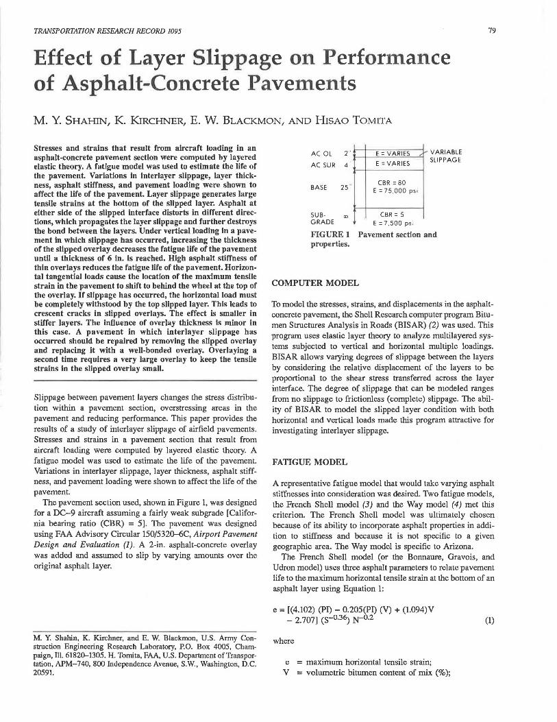
varied from 250,000 to 1,000,000 psi and vice versa. Both cases were analyzed with interlayer slippage.
The effect of varying the original asphalt surface layer modulus while holding the overlay modulus constant at 500,000 psi is shown in Figure 8. The tensile strains at the bottom of the overlay control the pavement life as the original layer modulus increases to 500,000 psi . These strains are decreasing while the overlay modulus is constant, so the pavement life increases. Above 500,000 psi, the strains at the bottom of the original layer control the pavement life. These strains are decreasing as the layer stiffem, but the modulus increase causes the struin multiplier in the fatigue equation to decrease at a faster rate, yielding a reduction in pavement life.
10000 FULL SLIP
C/J a_ UJ a: E AC OL=SOO KSI 0 1000 (§ (')
~ ....J >< a>
8 100
250 500 750 1000
E AC SUR (ksi)
FIGURE 8 Pavement life with changing asphalt surface layer modulus.
The effect of varying the overlay modulus from 250,000 to 1,000,000 psi while holding the original layer constant at 500,000 psi is shown in Figure 9. At all values of overlay modulus, the strains at the bottom of the overlay control the pavement life. These strains decrease as the modulus increases, but the fatigue model multiplier decreases faster, causing a reduction in pavement life. The highest pavement lives in the cases examined were obtained with an overlay modulus of either 250,000 or 500,000 psi and an original surface layer modulus of 500,000 psi.
VARYING BOTH OVERLAY THICKNESS AND MODULUS
The behavior of pavement life with varying overlay thickness is similar for any single pavement modulus under vertical
ui i so ....---------:F""U'."'."L.,...l ""'s"""u""p-. a_ UJ a:
~§ 160 0 >< ....J
a> 0 0
100
E AC S UR~ soo KS I
250 500 750 100
E AC OL (ks i)
FIGURE 9 Pavement Ille with varying overlay modulus.
ui a_ UJ a: 0 105 (§ ....J
a>
8
TRANSPORTATION RESEARCH RECORD 1095
'-- -------10 4 '--------------1
2 3 4 5 6 7 8 9 10
AC OL THICKNE SS (in)
FIGURE 10 Effuct of overlay thickness and moduius on pavement fatigue life.
loading when interlayer slippage is present. The pavement life decreases as the overlay thickness increases from 2 in. to a thickness of between 4 and 6 in., after which the life begins to increase. Figure 10 shows the effect of varying both the overlay thickness and the modulus. In general, pavement moduli that perform well as thin overlays do not perform as well at higher overlay thicknesses, and vice versa.
At low overlay thicknesses of 2 or 3 in., increasing the overlay modulus decreases the pavement life as was discussed earlier. At these thin overlay thicknesses, where the overlay reacts with constant strain behavior, the strains generated in the pavement decrease as the modulus of the asphalt concrete increases. However, higher modulus asphalt concrete is more susceptible to fatigue, and pavement fatigue life decreases .
As the overlay behavior switches from constant strain behavior to a constant stress response between 3 and 4 in. of overlay thickness, the effect of varying the overlay modulus on pavement life reverses. Above 4 in., an increase in overlay stiffness decreases the induced strains enough Lo offset the increased fatigue susceptibility, which increases pavement life.
EFFECT OF HORIZONTAL LOADS
Pavements are usually designed only for vertical loads, but horizontal loads also act on the top pavement surface. Horizontal loads are applied to the pavement surface when aircraft stop or turn. The magnitude of the horizontal load is determined by the coefficient of fric~ion between the tire and the pavement,
i
1\ ,, I ' I I
I I / I
I I \
' ',
T
FULL SLIP P = 23750 lbs STRAIN Al OL
TOP
' ',, T= P/ 2 .... .... ... , _., ..
~ ... ,,\ T = 0 \ _ ... ---'
\'"······~·········· ··· ·······~~"'. _.....~::.:::-:-.:-.:-·····--···---·--· -3 -'--------------~
FIGURE 11 Strains generated at overlay surface by an applied shear load.

SHAHIN ET AL.
• II II , , I' I I I I < 12 ,' \ z .~ / I I ' T = 0 5P FULL SLIP
ONz_E ' /\ \ · ' ·~ \
P = 23750 lbs STRAIN AT OL TOP
ii~"1 ,, \ ' o,_o / \ \T=0.7P
:I: Vl :::. 6 '~',,,
~' 0
T= 0.3P -~~;,, ""'--=--
-2~~~~~~~~~~~~~~~~~~
FIGURE 12 Strain magnitude at overlay surface with varying shear load.
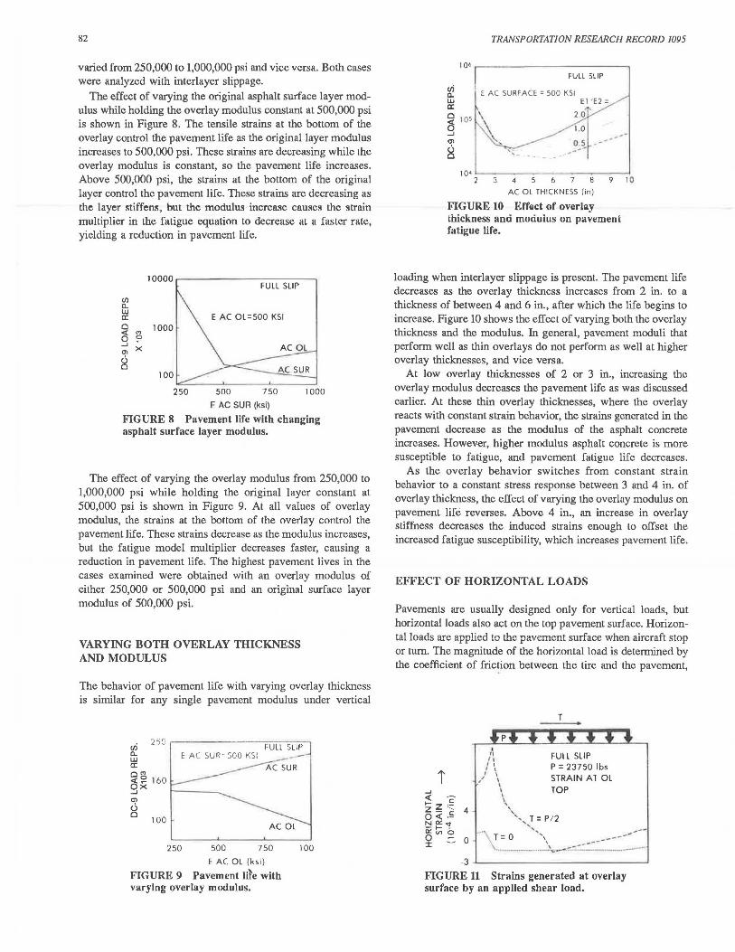
which will vary with pavement and tire conditions up to a limiting value of 0.8 (6). For this investigation a horizontal shear force of one-half the vertical load (0.5P) was assumed except where otherwise specified. The addition of a horizontal load will increase the critical stresses and strains in a pavement and will shift the location of the maximum strain from the center of the loaded area to the side of the loaded area opposite the direction of applied shear.
Figure 11 shows the distribution of the maximum horizontal strains in the top surface of the overlay along a cross section through the wheel imprint both with and without a horizontal load applied in the direction of travel for a single DC-9 wheel load. The modulus of each asphalt layer was 250,000 psi. The radius of the contact area is 7.1 in. The addition of the horizontal force generates very large tensile strains of 1.22 x 10⁻³ in./ in. at the top of the overlay behind the wheel. This is three to four times as large as typical fatigue-generated strains that are on the order of 3 x 10⁻⁴ to 4 x 10⁻⁴ in./in.
Figure 12 shows the effect of changing the magnitude of the horizontal load applied at the pavement surface from 0.3P to 0.7P, where Pis the applied vertical load. The magnitude of the maximum strain increases linearly from 0.766 x 10⁻³ to 1.64 x 10⁻³ as the horizontal load increases from 0.3P to 0. 7P. The magnitude of the applied horizontal load is the single most important determinant of the magnitude of the critical strains in the pavement.
The maximum horizontal strains on the top surface of the overlay with and without interlayer slippage are compared in
i 13 ~-lL-'-lL..--1--"~..___.._---'.__ .......... ___,
1, /1
/ \ P = 23750 lbs / 1\ 1 T = 11875 lbs
6 /'\ \ STRAIN AT OL
/ \ ', TOP
~'',,,\ FULLS~!'----------' '\ ----'--.-- NO SLIP_ ......... -... '"'-~ ------
-5 .L-~~~~~~~~~~~--'
FIGURE 13 Effect of interlayer slippage on surface strain.
i ' " " , ,
T
FULL SLIP . \ I l
8 / ' ........ ~""'
P = 23750 lbs T= P/2 < c:
I- ·-z Z '- c:
0 < ·- 4 N<><"' ii ti; b 0 :::. :I: 0
;'\ " .... -.--.. I '\ ~ .............. ,_..
. ..-/ ', BOTTOM OL SURFACE ....... ,, .. --" __ ... ----\-op-;~ SURFACE
_3 ,__~~~~~~~~~~~--'
FIGURE 14 Strains generated at the top and bottom of the overlay by applied shear load.
83
Figure 13. The strains are critical (0.855 x 10⁻³ in./in.) even with full adhesion between the layers, and they increase by almost 50 percent to 1.24 x 10⁻³ in./in. when the layers slip. Therefore, when analyzing a loading with an applied horizontal force, the maximum horizontal strains at the top asphalt surface should be checked in addition to the usual controlling strains, even when interlayer slippage is not present.
Figure 14 shows the strains at both the top surface of the overlay and the bottom of the overlay. The strains are lower at the bottom of the overlay, and the location of maximum strain has shifted to inside the wheel imprint. Cracks will initiate at the top of the overlay where the strains are the greatest. The cracks will propagate at an angle through the overlay to the location of maximum strain at the overlay bottom, giving an angled crack through the overlay.
Increasing the stiffness of the overlay when a horizontal force is applied reduces the magnitude of the maximum strain at both the top and the bottom surfaces of the overlay, as shown in Figures 15 and 16, respectively. The stiffer structure has less variation in strain values; the strain profile is flatter and lower. The stiffer layer is more sensitive to fatigue, but the magnitude of the induced strain decreases rapidly with increasing overlay stiffness, so pavement life will increase.
To investigate further the distribution of the maximum tensile strains and their directions, a grid of points was analyzed at the top surface of the overlay for a DC-9 aircraft with a horizontal shear force applied in the direction of travel. The horizontal force was again assumed to be one-half the vertical
0
FULL SLIP P = 23750 lbs T= 11875 lbs E AC SUR= 500 ksi STRAIN AT OL TOP
·,,0.5 • • •• , __ .,....---·,. ... N .....
1.0 '-... _ ..... -
·~-~ .... ----· --··--.. ~---·' .----
-3 ~~~~~~~~~~~~~~~~~~
FIGURE 15 Effect of overlay modulus on surface strains from shear loading.

84
T
FULL SLIP P= 23750 lbs T= 11875 lbs
El/E2= E AC SUR=500 ksi STRAIN AT OL BOTTOM
0
· 3 '--~~~~~~~~~~~~~~~~~
FIGURE 16 Effect of overlay modulus on strains at overlay bottom from shear loading.
load (0.5P). Figure 17 shows the directions of the principal tensile strains on the pavement surface. The length of the arrows indicates the magnitude of the strain. The greatest tensile strain is immediately behind the wheel imprint from the direction of the applied horizontal load.
The tensile strains along the edge of the contact area are all of the same magnitude, which can lead to progressive failure around the back edge of the contact area. A tensile failure in the overlay at the point of maximum strain would prevent stress from being transferred from the tire contact area to the area behind the wheel. This would cause a redistribution of the stress and strain at adjacent points along the edge of the contact area. Because these points are already approaching failure strain, the additional redistributed stress will cause failure at these points. This cycle of redistribution of stresses and failure of the top surface along the edge of the contact surface leads to a curved crack in the overlay. If the overlay is not properly bonded to the asphalt below, the overlay moves, which opens the crack. This behavior agrees with observed "crescent cracks" that have occurred in pavements in which the overlay has slipped, such as those shown in Figure 18. The strains generated by horizontal loads are high enough to result in significantly reduced pavement life even when interlayer slippage is not present.
Changing ihe direction of ihe horizontai ioad wiii rotate the directions of the observed strains. The relative positions of the
FULL SLIP + P = 23750 lbs
t MAX
STRAIN 1.2
Xl0-3
FIGURE 17 Principal maximum normal tensile strains in pavement plane of wheel imprint from shear load.
TRANSPORTATION RESEARCH RECORD 1095
FIGURE 18 Typical crescent-shaped slippage cracks.
strains do no change. In all cases investigated, the maximum strain was always 180 degrees from the direction of the applied horizontal force, just outside the wheel imprint.
REPAIR ALTERNATIVES
If overlay slippage has been detected, two alternatives exist for repair: either add a second overlay or remove the existing slipped overlay and replace it with an overlay that is properly bonded to the lower asphalt layer. Various second overlay thicknesses were assumed in the investigation of the first alternative. Stresses and strains under a DC-9 wheel were calculated and the fatigue lives of both overlays, the original asphalt layer, and the subgrade were computed.
Figure 19 shows the effect of the top overlay thickness on the fatigue life of the pavement. The curves have the same general shapes as the curves in Figure 6, in which the thickness of a single overlay was varied, because the two overlays do not slip with respect to each other but act as one layer. The bottom (existing) overlay has the lowest fatigue life and therefore controls the life of the entire pavement. It is not until the second overlay thickness is 12 in. thick that the fatigue life of the bottom overlay approaches that of the original pavement, which consisted of a 2-in. overlay without slip over a 4-in. original asphalt layer.
A cost comparison of adding a 12-in. asphalt overlay and replacing a 2-in. overlay is unnecessary. The cost of 12 in. of
107
~ 106 AC SECOND Ol
0 < 0 .....i
10" °' u 0
104 2 4 6 8 10 12
SECOND OL THICKNESS (inches)
FIGURE 19 Effect of second overlay thickness on pavement fatigue life (first overlay slipped).

SHAHIN EI' AL.
asphalt, along with the details required to make pavement elevations match those of existing pavements, obviously exceeds the cost of removing a slipped 2-in. overlay and replacing it with a well-bonded overlay.
SUMMARY
Layer slippage causes a redistribution of stresses and strains within a pavement. Large tensile strains occur at the bottom of the slipped layer. Asphalt at either side of the slipped interface distorts in different directions, which helps to propagate the layer slippage and further destroy the bond between the layers.
Under vertical loading in a pavement in which slippage has occurred, tensile strains due to asphalt fatigue become larger as the thickness of the slipped layer increases to about 6 in. After the slipped layer becomes larger than the underlying asphalt layer, the tensile strains gradually decrease.
High asphalt stiffness of thin overlays reduces the fatigue life of the pavement when layer slippage is present under vertical loading. This is due to stiffer materials having a lower fatigue tolerance for a given strain. For thin overlays, this decrease outweighs any advantage from the stiffer layer producing lower tensile strains.
Horizontal tangential loads cause a tensile strain behind the wheel at the top of the overlay. If the horizontal load is large enough, this strain will be the maximum tensile strain in the pavement. If slippage has occurred, the horizontal load must be completely withstood by the top slipped layer. This leads to crescent cracks in slipped overlays. The effect is smaller in stiffer layers.
When horizontal loading is present, regardless of the slippage condition, the overlays should have stiffnesses greater than or equal to 500,000 psi. The effect of overlay thickness is minor in this case; a thicker overlay gives a slightly lower strain.
Overall, a modulus of 500,000 psi would be the best compromise. If interlayer slippage is probable, a thin overlay would
85
maximize the fatigue life in the case with no horizontal loading. A thin overlay would require the least material in areas where horizontal loading will be present. These areas will have a short pavement life and will need frequent resurfacing.
A pavement with a slipped overlay should be repaired by removing the slipped overlay and replacing it with a wellbonded overlay. Overlaying a second time requires a very large overlay to keep the tensile strains in the slipped overlay small.
ACKNOWLEDGMENTS
This paper is the result of research sponsored by the FAA, U.S. Department of Transportation, to determine the effect of asphalt layer slippage on airfield pavement management.
REFERENCES
1. Airport Pavement Design and Evaluation. Advisory Circular 150/5320-6C. FAA, U.S. Department of Transportation, Dec. 1978.
2. BJSAR User's Manual (abbreviated version). Koninklijke/ShellLaboratorium, Amsterdam, The Netherlands, 1978.
3. F. Bonnaure, A. Gavois, and J. Udron. A New Method for Predicting the Fatigue Life of Bituminous Mixes. Proc., Association of Asphalt Paving Technologists, Vol. 49, 1980, pp. 499-529.
4. G. Way. Asphalt Properties and Their Relationship to Pavement Performance in Arizona. Proc., Association of Asphalt Paving Technologists. Vol. 47, 1978, pp. 49--69.
5. T. Y. Chou. Analysis of Subgrade Rutting in Flexible Airfield Pavements. In Transportation Research Record 616, TRB, National Research Council, Washington, D.C., 1976, pp. 44-48.
6. E. S. Barber. Shear Loads on Pavements. Proc., !st International Conference on Structural Design of Asphalt Pavements, University of Michigan, Ann Arbor, 1962, pp. 354-357.
Publication of this paper sponsored by Committee on Flexible Pavements.
The views of the authors do not purport lo reflect the position of the Department of the Army or the Department of Defense.
Related Documents


![Partially Speci ed Channels: The TLS 1.3 Record Layer ... · The TLS 1.3 standard [30], whose record layer mechanism is the subject of this paper, contains numerous \SHOULDs", \SHOULD](https://static.cupdf.com/doc/110x72/6052b6e3ec91165d3254ebf7/partially-speci-ed-channels-the-tls-13-record-layer-the-tls-13-standard-30.jpg)