Lloyd George Acoustics PO Box 717 Hillarys WA 6923 T: 9401 7770 www.lgacoustics.com.au Transportation Noise Assessment Hammond Road Duplication – Branch Circus to Bartram Road Reference: 19055001-01.docx Prepared for: City of Cockburn Version: 1, Version Date: 26/08/2020 Document Set ID: 9671640

Welcome message from author
This document is posted to help you gain knowledge. Please leave a comment to let me know what you think about it! Share it to your friends and learn new things together.
Transcript

Lloyd George Acoustics PO Box 717
Hillarys WA 6923
T: 9401 7770
www.lgacoustics.com.au
Transportation Noise Assessment
Hammond Road Duplication – Branch Circus to Bartram Road
Reference: 19055001-01.docx
Prepared for: City of Cockburn
Version: 1, Version Date: 26/08/2020Document Set ID: 9671640

Report: 19055001‐01.docx
Lloyd George Acoustics Pty Ltd ABN: 79 125 812 544
PO Box 717 Hillarys WA 6923
www.lgacoustics.com.au
T: 9401 7770
Contacts Daniel Lloyd Terry George Matt Moyle Olivier Mallié Ben Hillion
E:
M:
0439 032 844
0400 414 197
0412 611 330
0439 987 455
0457 095 555
Date: Rev Description Prepared By Verified
09‐Aug‐19 ‐ Issued to Client as Draft Terry George Olivier Mallié
17‐Sep‐19 0 Noise walls included. Terry George ‐
This report has been prepared in accordance with the scope of services described in the contract or
agreement between Lloyd George Acoustics Pty Ltd and the Client. The report relies upon data, surveys,
measurements and results taken at or under the particular times and conditions specified herein. Any
findings, conclusions or recommendations only apply to the aforementioned circumstances and no greater
reliance should be assumed or drawn by the Client. Furthermore, the report has been prepared solely for
use by the Client, and Lloyd George Acoustics Pty Ltd accepts no responsibility for its use by other parties.
Version: 1, Version Date: 26/08/2020Document Set ID: 9671640

Lloyd George Acoustics
Table of Contents 1 INTRODUCTION ________________________________________________________________ 1
2 CRITERIA _____________________________________________________________________ 2
3 METHODOLOGY ________________________________________________________________ 3
3.1 Site Measurements ______________________________________________________________ 3
3.2 Noise Modelling ________________________________________________________________ 4
3.2.1 Ground Topography & Road Design ______________________________________________ 4
3.2.2 Traffic Data ________________________________________________________________ 4
3.2.3 Ground Attenuation __________________________________________________________ 5
3.2.4 Parameter Conversion ________________________________________________________ 5
4 RESULTS _____________________________________________________________________ 6
4.1 Noise Monitoring _______________________________________________________________ 6
4.2 Noise Modelling ________________________________________________________________ 8
4.2.1 Existing Scenario ____________________________________________________________ 8
4.2.2 No Build Scenario ___________________________________________________________ 11
4.2.3 Build Scenario _____________________________________________________________ 12
5 ASSESSMENT _________________________________________________________________ 16
6 CONCLUSION _________________________________________________________________ 17
List of Tables Table 2‐1 Outdoor Noise Criteria ________________________________________________________ 2
Table 3‐1 Noise Relationship Between Different Road Surfaces________________________________ 4
Table 3‐2 Traffic Information Used in the Modelling for Hammond Road ________________________ 5
Table 4‐1 Measured Average Noise Levels – 14 Gandossi Court _______________________________ 6
Table 4‐2 Measured Average Noise Levels – 16 Muirfield Avenue ______________________________ 6
Table 4‐3 Model Calibration ____________________________________________________________ 8
Table 4‐4 Predicted LAeq(Day) Noise Levels: Existing Scenario ___________________________________ 8
Table 4‐5 Predicted LAeq(Day) Noise Levels: No Build Scenario _________________________________ 11
Table 4‐6 Predicted LAeq(Day) Noise Levels: Build Scenario ____________________________________ 12
Table 5‐1 Areas Considered For Noise Mitigation __________________________________________ 16
Table 6‐1 Predicted LAeq(Day) Noise Levels With Proposed Wall and Noise Reduction _______________ 18
Version: 1, Version Date: 26/08/2020Document Set ID: 9671640
Lloyd George Acoustics
List of Figures Figure 1‐1 Road Project Locality_________________________________________________________ 1
Figure 3‐1 14 Gandossi Court ___________________________________________________________ 3
Figure 3‐2 16 Muirfield Avenue _________________________________________________________ 3
Figure 4‐1 Noise Monitoring Results: 14 Gandossi Court _____________________________________ 7
Figure 4‐2 Noise Monitoring Results: 16 Muirfield Avenue ___________________________________ 7
Figure 4‐3 Noise Contour Plot: Existing Scenario __________________________________________ 10
Figure 4‐4 Noise Contour Plot: No Build Scenario __________________________________________ 14
Figure 4‐5 Noise Contour Plot: Build Scenario _____________________________________________ 15
Figure 6‐1 Proposed Noise Walls _______________________________________________________ 20
Appendices A Proposed Road Design
B Terminology
Version: 1, Version Date: 26/08/2020Document Set ID: 9671640

Lloyd George Acoustics
Reference: 19055001‐01.docx Page 1
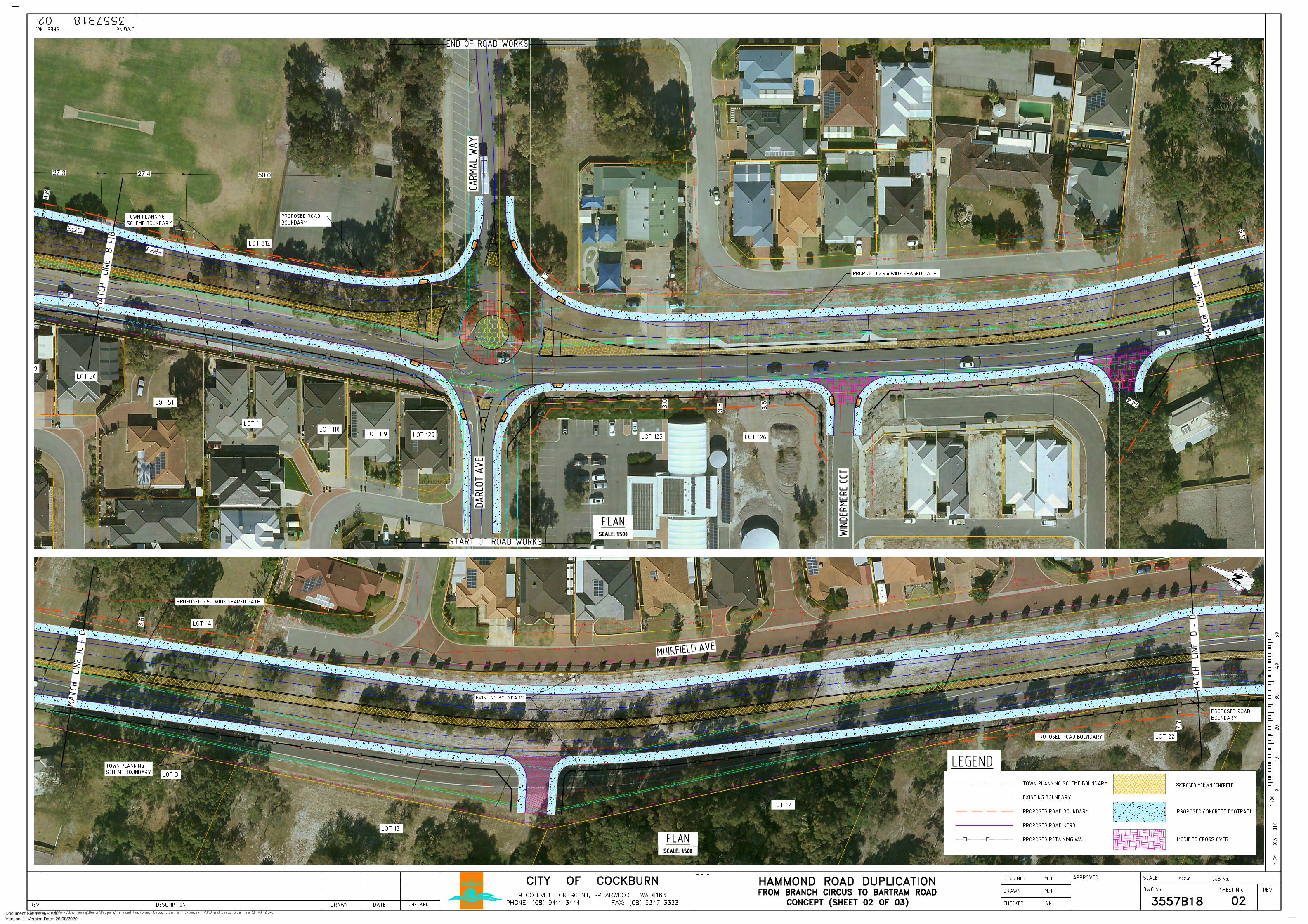
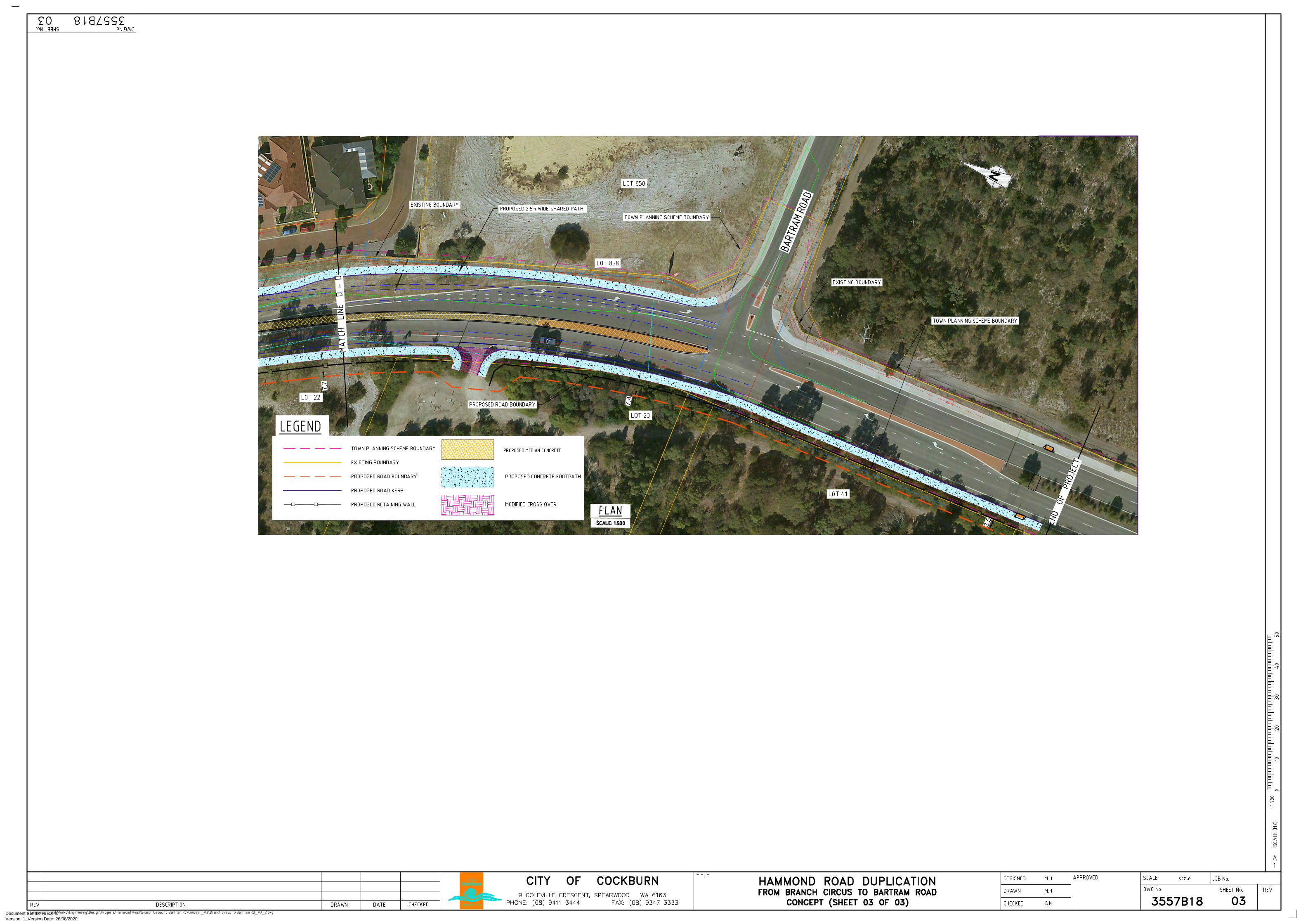
1 INTRODUCTION City of Cockburn is proposing a duplication of Hammond Road, between Branch Circus and Bartram
Road, located as shown in Figure 1‐1. In this section, Hammond Road is single carriageway, with one
lane in each direction. North of Branch Circus, the road is dual carriageway, with two lanes in each
direction up until Beeliar Drive. Similarly, south of Bartram Road is also dual carriageway, two lanes
in each direction until Russell Road. The proposed road design is provided in Appendix A.
Figure 1-1 Road Project Locality
This report considers the potential road traffic noise impacts associated with the duplication, in
accordance with State Planning Policy 5.4 Road and Rail Transport Noise and Freight Considerations
in Land Use Planning. The scope involved:
Quantification of existing noise levels by noise monitoring at two locations;
Setting up a noise model for existing conditions and calibrating against the noise monitoring
(Existing Scenario);
Use the calibrated noise model and modify for future traffic volumes on the existing road
(No Build Scenario); and
Use the calibrated noise model and modify for future traffic volumes on the proposed road
design (Build Scenario).
Appendix B contains a description of some of the terminology used throughout this report.
Version: 1, Version Date: 26/08/2020Document Set ID: 9671640

Lloyd George Acoustics
Reference: 19055001‐01.docx Page 2
2 CRITERIA The criteria relevant to this assessment is the State Planning Policy 5.4 Road and Rail Transport
Noise and Freight Considerations in Land Use Planning (hereafter referred to as the Policy) produced
by the Western Australian Planning Commission (WAPC). The objectives in the Policy are to:
Protect people from unreasonable levels of transport noise by establishing a standardised
set of criteria to be used in the assessment of proposals;
Protect major transport corridors and freight operations from incompatible urban
encroachment;
Encourage best practice design and construction standards for new development proposals
and new or redevelopment transport infrastructure proposals;
Facilitate the development and operation of an efficient freight network; and
Facilitate the strategic co‐location of freight handling facilities.
For a major redevelopment, practicable noise management and mitigation measures should be
considered, having regard to –
The existing transport noise levels;
The likely change in noise emissions resulting from the proposal; and
The nature and scale of the works and potential for noise amelioration.
When considering the noise levels, the Policy’s outdoor noise criteria, shown below in Table 2‐1, can
be used for some guidance. These criteria apply for new road projects rather than
upgrades/modifications and at any point 1‐metre from a ground floor habitable façade of a noise
sensitive premises.
Table 2-1 Outdoor Noise Criteria
Period Target Limit
Day (6am to 10pm) 55 dB LAeq(Day) 60 dB LAeq(Day)
Night (10pm to 6am) 50 dB LAeq(Night) 55 dB LAeq(Night)
Note: The 5 dB difference between the target and limit is referred to as the margin.
Version: 1, Version Date: 26/08/2020Document Set ID: 9671640

Lloyd George Acoustics
Reference: 19055001‐01.docx Page 3
3 METHODOLOGY Noise measurements and modelling have been undertaken in accordance with the requirements of
the Policy as described in Section 3.1 and Section 3.2.
3.1 Site Measurements
Noise monitoring was undertaken at two (2) locations between 21 July to 30 July 2019 in order to:
Quantify the existing noise levels;
Determine the differences between different acoustic parameters (LA10,18hour, LAeq(Day) and
LAeq(Night)); and
Calibrate the noise model for existing conditions.
The instruments used were ARL Ngara Type noise data loggers as follows:
1. Ngara 8780F6 at 14 Gandossi Court, Success (refer Figure 3‐1); and
2. Ngara 87803e at 16 Muirfield Avenue, Success (refer Figure 3‐2).
Each microphone was 1.4 metres above ground level with the logger programmed to record hourly
LA1, LA10, LA90, and LAeq levels. The instruments comply with the requirements of Australian Standard
2702‐1984 Acoustics – Methods for the Measurement of Road Traffic Noise. The loggers were field
calibrated before and after the measurement session and found to be accurate to within +/‐ 1 dB.
Lloyd George Acoustics also holds current laboratory calibration certificate for the loggers.
Figure 3-1 14 Gandossi Court Figure 3-2 16 Muirfield Avenue
The noise data collected was verified by inspection and professional judgement. Where hourly data
was considered atypical, an estimated value was inserted.
Version: 1, Version Date: 26/08/2020Document Set ID: 9671640

Lloyd George Acoustics
Reference: 19055001‐01.docx Page 4
3.2 Noise Modelling
The computer programme SoundPLAN 8.1 was utilised incorporating the Calculation of Road Traffic
Noise (CoRTN) algorithms, modified to reflect Australian conditions. The modifications included the
following:
Vehicles were separated into heavy (Austroads Class 3 upwards) and non‐heavy (Austroads
Classes 1 & 2) with non‐heavy vehicles having a source height of 0.5 metres above road level
and heavy vehicles having two sources, at heights of 1.5 metres and 3.6 metres above road
level, to represent the engine and exhaust respectively. By splitting the noise source into
three, allows for less barrier attenuation for high level sources where barriers are to be
considered.
Note that a ‐8.0 dB correction is applied to the exhaust and ‐0.8 dB to the engine (based on
Transportation Noise Reference Book, Paul Nelson, 1987), so as to provide consistent results
with the CoRTN algorithms for the no barrier scenario;
An adjustment of ‐1.7 dB has been applied to the LAeq(Day) levels where noise levels are
predicted to a facade, based on the findings of An Evaluation of the U.K. DoE Traffic Noise
Prediction; Australian Road Research Board, Report 122 ARRB – NAASRA Planning Group
(March 1983).
Predictions are made at heights of 1.4 m above ground floor level and at 1.0 metre from an assumed
building facade, resulting in a + 2.5 dB correction due to reflected noise.
Various input data are included in the modelling such as ground topography, road design, traffic
volumes etc. These model inputs are discussed in the following sections.
3.2.1 Ground Topography & Road Design
General topography is on file from previous projects based on Landgate data. This data also
contained building outlines for existing properties. This was checked against aerial photography and
updated as necessary. Single storey houses are modelled as 3.5 metres high and double storey
houses at 7.0 metres high.
The road design information was provided by City of Cockburn via email on 1 August 2019.
3.2.2 Traffic Data
Traffic data includes:
Road Surface – The noise relationship between different road surface types is shown in
Table 3‐1.
Table 3-1 Noise Relationship Between Different Road Surfaces
Chip Seal Asphalt
14mm 10mm 5mm Dense Graded
Novachip Stone Mastic
Open Graded
+3.5 dB +2.5 dB +1.5 dB 0.0 dB ‐0.2 dB ‐1.5 dB ‐2.5 dB
Version: 1, Version Date: 26/08/2020Document Set ID: 9671640

Lloyd George Acoustics
Reference: 19055001‐01.docx Page 5
The existing road surface is dense graded asphalt and is assumed to be the same in the
future.
Vehicle Speed – The existing and future posted speeds are generally 70km/hr. North of
Branch Circus the posted speed is 60 km/hr. A school zone (2.30pm to 4.00pm
40 km/hr) exists between Makjanich Place and Windermere Circuit.
Traffic Volumes – Existing (2016) and forecast (2031) traffic volumes were provided by
Main Roads WA (Clare Yu, Traffic Modelling Analyst, Reference: #41260, dated 01
August 2019). A validation plot was also provided allowing the Main Roads WA traffic
volume model to be calibrated. Table 3‐2 provides the traffic volume input data in the
model.
Table 3-2 Traffic Information Used in the Modelling for Hammond Road
Section
Scenario
Existing ‐ 2016 Future ‐ 2031
Northbound Southbound Northbound Southbound
North of Branch Circus 3500 (8) 3100 (6) 5900 (8) 6600 (6)
South of Branch Circus 3500 (8) 3100 (6) 5900 (8) 6600 (6)
South of Bartram Road 5000 (8) 4700 (6) 4000 (7) 4200 (8)
Notes:
1. Numbers shown in brackets are % heavy vehicles obtained direct from ROM plots.
3.2.3 Ground Attenuation
The ground attenuation has been assumed to be 0.0 (0%) for the road and 0.5 (50%) elsewhere.
Note 0.0 represents hard reflective surfaces such as water and 1.00 represents absorptive surfaces
such as grass.
3.2.4 Parameter Conversion
The CoRTN algorithms used in the SoundPlan modelling package were originally developed to
calculate the LA10,18hour noise level. The WAPC Policy however uses LAeq(Day) and LAeq(Night). The
relationship between the parameters varies depending on the composition of traffic on the road
(volumes in each period and percentage heavy vehicles).
As noise monitoring was undertaken, the relationship between the parameters is based on the
results of the monitoring – refer Section 4.1.
Version: 1, Version Date: 26/08/2020Document Set ID: 9671640

Lloyd George Acoustics
Reference: 19055001‐01.docx Page 6
4 RESULTS 4.1 Noise Monitoring The results of the noise monitoring are summarised in Table 4‐1 and Table 4‐2 and shown
graphically in Figure 4‐1 and Figure 4‐2 for 14 Gandossi Court and 16 Muirfield Avenue respectively.
Table 4-1 Measured Average Noise Levels – 14 Gandossi Court
Date
Average Weekday Noise Level, dB
LA10,18hour LAeq,24hour LAeq (Day) LAeq (Night)
Monday 22 July 2019 59.5 56.8 58.2 51.4
Tuesday 23 July 2019 59.6 56.7 58.1 50.9
Wednesday 24 July 2019 60.1 57.5 58.9 50.7
Thursday 25 July 2019 58.7 56.6 58.0 50.7
Friday 26 July 2019 59.1 56.1 57.6 49.7
Monday 29 July 2019 57.8 55.1 56.3 50.6
Weekday Average 59.1 56.5 57.8 50.7
Table 4-2 Measured Average Noise Levels – 16 Muirfield Avenue
Date
Average Weekday Noise Level, dB
LA10,18hour LAeq,24hour LAeq (Day) LAeq (Night)
Monday 22 July 2019 61.2 58.9 60.3 52.6
Tuesday 23 July 2019 61.0 58.0 59.5 50.5
Wednesday 24 July 2019 61.0 58.3 59.8 50.6
Thursday 25 July 2019 60.9 59.0 60.6 50.8
Friday 26 July 2019 60.9 58.0 59.6 49.8
Monday 29 July 2019 59.6 57.0 58.3 51.8
Weekday Average 60.8 58.2 59.7 51.0
The results indicate that the LAeq(Night) is around 8 dB less than the LAeq(Day) so that the LAeq(Day)
parameter will determine compliance or otherwise. As such, the focus of this report will be the
LAeq(Day) noise levels.
Version: 1, Version Date: 26/08/2020Document Set ID: 9671640

Lloyd George Acoustics
Reference: 19055001‐01.docx Page 7
Figure 4-1 Noise Monitoring Results: 14 Gandossi Court
Figure 4-2 Noise Monitoring Results: 16 Muirfield Avenue
Version: 1, Version Date: 26/08/2020Document Set ID: 9671640
Lloyd George Acoustics
Reference: 19055001‐01.docx Page 8
4.2 Noise Modelling
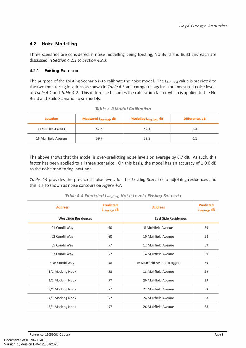
Three scenarios are considered in noise modelling being Existing, No Build and Build and each are
discussed in Section 4.2.1 to Section 4.2.3.
4.2.1 Existing Scenario
The purpose of the Existing Scenario is to calibrate the noise model. The LAeq(Day) value is predicted to
the two monitoring locations as shown in Table 4‐3 and compared against the measured noise levels
of Table 4‐1 and Table 4‐2. This difference becomes the calibration factor which is applied to the No
Build and Build Scenario noise models.
Table 4-3 Model Calibration
Location Measured LAeq(Day), dB Modelled LAeq(Day), dB Difference, dB
14 Gandossi Court 57.8 59.1 1.3
16 Muirfield Avenue 59.7 59.8 0.1
The above shows that the model is over‐predicting noise levels on average by 0.7 dB. As such, this
factor has been applied to all three scenarios. On this basis, the model has an accuracy of ± 0.6 dB
to the noise monitoring locations.
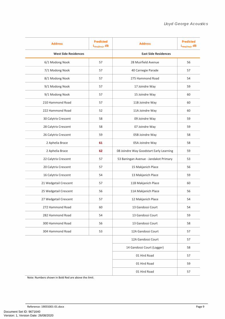
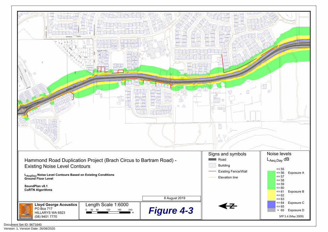
Table 4‐4 provides the predicted noise levels for the Existing Scenario to adjoining residences and
this is also shown as noise contours on Figure 4‐3.
Table 4-4 Predicted LAeq(Day) Noise Levels: Existing Scenario
Address Predicted LAeq(Day), dB
Address Predicted LAeq(Day), dB
West Side Residences East Side Residences
01 Condil Way 60 8 Muirfield Avenue 59
03 Condil Way 60 10 Muirfield Avenue 58
05 Condil Way 57 12 Muirfield Avenue 59
07 Condil Way 57 14 Muirfield Avenue 59
09B Condil Way 58 16 Muirfield Avenue (Logger) 59
1/1 Modong Nook 58 18 Muirfield Avenue 59
2/1 Modong Nook 57 20 Muirfield Avenue 59
3/1 Modong Nook 57 22 Muirfield Avenue 58
4/1 Modong Nook 57 24 Muirfield Avenue 58
5/1 Modong Nook 57 26 Muirfield Avenue 58
Version: 1, Version Date: 26/08/2020Document Set ID: 9671640
Lloyd George Acoustics
Reference: 19055001‐01.docx Page 9
Address Predicted LAeq(Day), dB
Address Predicted LAeq(Day), dB
West Side Residences East Side Residences
6/1 Modong Nook 57 28 Muirfield Avenue 56
7/1 Modong Nook 57 40 Carnegie Parade 57
8/1 Modong Nook 57 275 Hammond Road 54
9/1 Modong Nook 57 17 Joindre Way 59
9/1 Modong Nook 57 15 Joindre Way 60
210 Hammond Road 57 11B Joindre Way 60
222 Hammond Road 52 11A Joindre Way 60
30 Calytrix Crescent 58 09 Joindre Way 59
28 Calytrix Crescent 58 07 Joindre Way 59
26 Calytrix Crescent 59 05B Joindre Way 58
2 Aphelia Brace 61 05A Joindre Way 58
2 Aphelia Brace 62 08 Joindre Way Goodstart Early Learning 59
22 Calytrix Crescent 57 53 Baningan Avenue ‐ Jandakot Primary 53
20 Calytrix Crescent 57 15 Makjanich Place 56
16 Calytrix Crescent 54 13 Makjanich Place 59
21 Wedgetail Crescent 57 11B Makjanich Place 60
25 Wedgetail Crescent 56 11A Makjanich Place 56
27 Wedgetail Crescent 57 12 Makjanich Place 54
272 Hammond Road 60 13 Gandossi Court 54
282 Hammond Road 54 13 Gandossi Court 59
300 Hammond Road 56 13 Gandossi Court 58
304 Hammond Road 53 12A Gandossi Court 57
12A Gandossi Court 57
14 Gandossi Court (Logger) 58
01 Hird Road 57
01 Hird Road 59
01 Hird Road 57
Note: Numbers shown in Bold Red are above the limit.
Version: 1, Version Date: 26/08/2020Document Set ID: 9671640
Lloyd George AcousticsPO Box 717HILLARYS WA 6923(08) 9401 7770
RO
AD
5
NU
E
CR
ES
GRANDE
HAMMOND
R
OAD
HIR
DR
OA
D
BANINGAN AVENUE
HAMMONDROAD
ROAD
1R
OA
D1
ROAD 1
ROAD
2
CH
ER
NIS
S C
T
MA
RR
AB
OO
R P
LAC
E
FELPHAM COURT
ALA
BA
ST
ER
DR
IVE
89
10
1112
13
14
15
23
33
456
7
1
16
17
19
208001
29
2122
23
2425
30
31
32
26
27
28
399
404
406
106
466
123
122
4740
8000
395
248
249
250
261
262
263
265
264
266
267
268
269
270
271
272
273
274
275
276
277
8004
Length Scale 1:60000 30 60 120 180 240
m
Hammond Road Duplication Project (Brach Circus to Bartram Road) -Existing Noise Level Contours
LAeq(Day) Noise Level Contours Based on Existing ConditionsGround Floor Level
SoundPlan v8.1CoRTN Algorithms
Figure 4-3
Noise levelsLAeq,Day dB
<= 55<= 56 Exposure A<= 57 <= 58 <= 59 <= 60 <= 61 Exposure B<= 62<= 63<= 64 Exposure C<= 65> 65 Exposure D
SPP 5.4 (May 2009)
Signs and symbolsRoad
Building
Existing Fence/Wall
Elevation line
8 August 2019
Version: 1, Version Date: 26/08/2020Document Set ID: 9671640

Lloyd George Acoustics
Reference: 19055001‐01.docx Page 11
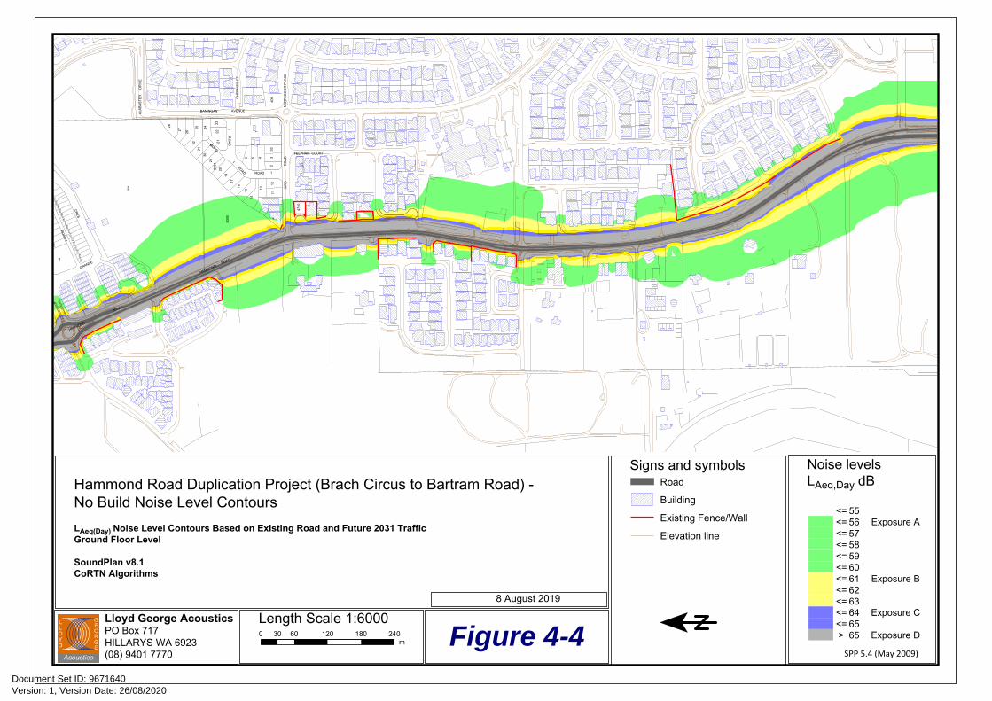
4.2.2 No Build Scenario
The No Build Scenario assumes the existing road carries the 2031 traffic volumes. The outcome
shows the increase in noise level as a result of increased traffic volumes only and represents the
noise that will be present if the project does not occur, assuming the current road can carry the
projected number of vehicles. The results are provided in Table 4‐5 and Figure 4‐4.
Table 4-5 Predicted LAeq(Day) Noise Levels: No Build Scenario
Address Predicted LAeq(Day), dB
Address Predicted LAeq(Day), dB
West Side Residences East Side Residences
01 Condil Way 63 8 Muirfield Avenue 61
03 Condil Way 62 10 Muirfield Avenue 61
05 Condil Way 60 12 Muirfield Avenue 61
07 Condil Way 59 14 Muirfield Avenue 61
09B Condil Way 61 16 Muirfield Avenue (Logger) 62
1/1 Modong Nook 60 18 Muirfield Avenue 61
2/1 Modong Nook 60 20 Muirfield Avenue 61
3/1 Modong Nook 59 22 Muirfield Avenue 60
4/1 Modong Nook 59 24 Muirfield Avenue 60
5/1 Modong Nook 60 26 Muirfield Avenue 60
6/1 Modong Nook 59 28 Muirfield Avenue 59
7/1 Modong Nook 59 40 Carnegie Parade 60
8/1 Modong Nook 59 275 Hammond Road 57
9/1 Modong Nook 60 17 Joindre Way 62
9/1 Modong Nook 60 15 Joindre Way 62
210 Hammond Road N/A 11B Joindre Way 62
222 Hammond Road 53 11A Joindre Way 62
30 Calytrix Crescent 60 09 Joindre Way 62
28 Calytrix Crescent 60 07 Joindre Way 62
26 Calytrix Crescent 61 05B Joindre Way 61
2 Aphelia Brace 64 05A Joindre Way 61
2 Aphelia Brace 65 08 Joindre Way Goodstart Early Learning 62
22 Calytrix Crescent 60 53 Baningan Avenue ‐ Jandakot Primary 56
20 Calytrix Crescent 59 15 Makjanich Place 58
16 Calytrix Crescent 56 13 Makjanich Place 62
Version: 1, Version Date: 26/08/2020Document Set ID: 9671640

Lloyd George Acoustics
Reference: 19055001‐01.docx Page 12
Address Predicted LAeq(Day), dB
Address Predicted LAeq(Day), dB
West Side Residences East Side Residences
21 Wedgetail Crescent 59 11B Makjanich Place 62
25 Wedgetail Crescent 58 11A Makjanich Place 59
27 Wedgetail Crescent 59 12 Makjanich Place 56
272 Hammond Road 62 13 Gandossi Court 57
282 Hammond Road 57 13 Gandossi Court 62
300 Hammond Road 59 13 Gandossi Court 61
304 Hammond Road 55 12A Gandossi Court 60
12A Gandossi Court 60
14 Gandossi Court (Logger) 61
01 Hird Road 60
01 Hird Road 62
01 Hird Road 60
Note: Numbers shown in Bold Red are above the limit.
Note that the existing residence at 210 Hammond Road is to be demolished and a Medical Centre
constructed. Residential apartments will also form part of the new development, however if these
are affected by road traffic noise, this will be the developers responsibility by way of facade
upgrades and the like.
4.2.3 Build Scenario
The Build Scenario represents the future traffic volumes on the proposed road design. The results
are provided in Table 4‐6 and Figure 4‐5.
Table 4-6 Predicted LAeq(Day) Noise Levels: Build Scenario
Address Predicted LAeq(Day), dB
Address Predicted LAeq(Day), dB
West Side Residences East Side Residences
01 Condil Way 61 8 Muirfield Avenue 61
03 Condil Way 61 10 Muirfield Avenue 60
05 Condil Way 59 12 Muirfield Avenue 61
07 Condil Way 59 14 Muirfield Avenue 62
09B Condil Way 60 16 Muirfield Avenue (Logger) 63
1/1 Modong Nook 60 18 Muirfield Avenue 63
2/1 Modong Nook 59 20 Muirfield Avenue 63
Version: 1, Version Date: 26/08/2020Document Set ID: 9671640

Lloyd George Acoustics
Reference: 19055001‐01.docx Page 13
Address Predicted LAeq(Day), dB
Address Predicted LAeq(Day), dB
West Side Residences East Side Residences
3/1 Modong Nook 59 22 Muirfield Avenue 63
4/1 Modong Nook 59 24 Muirfield Avenue 63
5/1 Modong Nook 59 26 Muirfield Avenue 63
6/1 Modong Nook 59 28 Muirfield Avenue 62
7/1 Modong Nook 59 40 Carnegie Parade 62
8/1 Modong Nook 59 275 Hammond Road 58
9/1 Modong Nook 59 17 Joindre Way 64
9/1 Modong Nook 59 15 Joindre Way 64
210 Hammond Road N/A 11B Joindre Way 64
222 Hammond Road 53 11A Joindre Way 64
30 Calytrix Crescent 60 09 Joindre Way 63
28 Calytrix Crescent 60 07 Joindre Way 63
26 Calytrix Crescent 60 05B Joindre Way 63
2 Aphelia Brace 62 05A Joindre Way 62
2 Aphelia Brace 63 08 Joindre Way Goodstart Early Learning 63
22 Calytrix Crescent 58 53 Baningan Avenue ‐ Jandakot Primary 56
20 Calytrix Crescent 57 15 Makjanich Place 58
16 Calytrix Crescent 56 13 Makjanich Place 61
21 Wedgetail Crescent 57 11B Makjanich Place 61
25 Wedgetail Crescent 56 11A Makjanich Place 58
27 Wedgetail Crescent 57 12 Makjanich Place 56
272 Hammond Road 59 13 Gandossi Court 58
282 Hammond Road 55 13 Gandossi Court 63
300 Hammond Road 56 13 Gandossi Court 61
304 Hammond Road 54 12A Gandossi Court 58
12A Gandossi Court 61
14 Gandossi Court (Logger) 60
01 Hird Road 60
01 Hird Road 62
01 Hird Road 60
Note: Numbers shown in Bold Red are above the limit.
Version: 1, Version Date: 26/08/2020Document Set ID: 9671640
Lloyd George AcousticsPO Box 717HILLARYS WA 6923(08) 9401 7770
RO
AD
5
NU
E
CR
ES
GRANDE
HAMMOND
R
OAD
HIR
DR
OA
D
BANINGAN AVENUE
HAMMONDROAD
ROAD
1R
OA
D1
ROAD 1
ROAD
2
CH
ER
NIS
S C
T
MA
RR
AB
OO
R P
LAC
E
FELPHAM COURT
ALA
BA
ST
ER
DR
IVE
89
10
1112
13
14
15
23
33
456
7
1
16
17
19
208001
29
2122
23
2425
30
31
32
26
27
28
399
404
406
106
466
123
122
4740
8000
395
248
249
250
261
262
263
265
264
266
267
268
269
270
271
272
273
274
275
276
277
8004
Length Scale 1:60000 30 60 120 180 240
m
Hammond Road Duplication Project (Brach Circus to Bartram Road) -No Build Noise Level Contours
LAeq(Day) Noise Level Contours Based on Existing Road and Future 2031 TrafficGround Floor Level
SoundPlan v8.1CoRTN Algorithms
Figure 4-4
Noise levelsLAeq,Day dB
<= 55<= 56 Exposure A<= 57 <= 58 <= 59 <= 60 <= 61 Exposure B<= 62<= 63<= 64 Exposure C<= 65> 65 Exposure D
SPP 5.4 (May 2009)
Signs and symbolsRoad
Building
Existing Fence/Wall
Elevation line
8 August 2019
Version: 1, Version Date: 26/08/2020Document Set ID: 9671640

Lloyd George AcousticsPO Box 717HILLARYS WA 6923(08) 9401 7770
RO
AD
5
NU
E
CR
ES
GRANDE
HAMMOND
R
OAD
HIR
DR
OA
D
BANINGAN AVENUE
HAMMONDROAD
ROAD
1R
OA
D1
ROAD 1
ROAD
2
CH
ER
NIS
S C
T
MA
RR
AB
OO
R P
LAC
E
FELPHAM COURT
ALA
BA
ST
ER
DR
IVE
89
10
1112
13
14
15
23
33
456
7
1
16
17
19
208001
29
2122
23
2425
30
31
32
26
27
28
399
404
406
106
466
123
122
4740
8000
395
248
249
250
261
262
263
265
264
266
267
268
269
270
271
272
273
274
275
276
277
8004
Length Scale 1:60000 30 60 120 180 240
m
Hammond Road Duplication Project (Brach Circus to Bartram Road) -Build Noise Level Contours
LAeq(Day) Noise Level Contours Based on Future Road and Future 2031 TrafficGround Floor Level
SoundPlan v8.1CoRTN Algorithms
Figure 4-5
Noise levelsLAeq,Day dB
<= 55<= 56 Exposure A<= 57 <= 58 <= 59 <= 60 <= 61 Exposure B<= 62<= 63<= 64 Exposure C<= 65> 65 Exposure D
SPP 5.4 (May 2009)
Signs and symbolsRoad
Building
Existing Fence/Wall
Elevation line
9 August 2019
Version: 1, Version Date: 26/08/2020Document Set ID: 9671640
Lloyd George Acoustics
Reference: 19055001‐01.docx Page 16
5 ASSESSMENT For a road upgrade, SPP 5.4 states that practicable noise management and mitigation measures
should be considered, having regard to –
The existing transport noise levels;
The likely change in noise emissions resulting from the proposal; and
The nature and scale of the works and potential for noise amelioration.
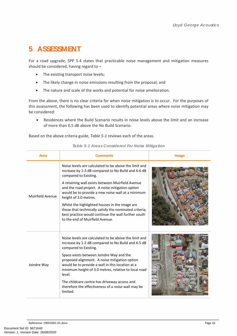
From the above, there is no clear criteria for when noise mitigation is to occur. For the purposes of
this assessment, the following has been used to identify potential areas where noise mitigation may
be considered:
Residences where the Build Scenario results in noise levels above the limit and an increase
of more than 0.5 dB above the No Build Scenario.
Based on the above criteria guide, Table 5‐1 reviews each of the areas.
Table 5-1 Areas Considered For Noise Mitigation
Area Comments Image
Muirfield Avenue
Noise levels are calculated to be above the limit and increase by 1‐3 dB compared to No Build and 4‐6 dB compared to Existing.
A retaining wall exists between Muirfield Avenue and the road project. A noise mitigation option would be to provide a new noise wall at a minimum height of 3.0 metres.
Whilst the highlighted houses in the image are those that technically satisfy the nominated criteria, best practice would continue the wall further south to the end of Muirfield Avenue.
Joindre Way
Noise levels are calculated to be above the limit and increase by 1‐2 dB compared to No Build and 4‐5 dB compared to Existing.
Space exists between Joindre Way and the proposed alignment. A noise mitigation option would be to provide a wall in this location at a minimum height of 3.0 metres, relative to local road level.
The childcare centre has driveway access and therefore the effectiveness of a noise wall may be limited.
Version: 1, Version Date: 26/08/2020Document Set ID: 9671640

Lloyd George Acoustics
Reference: 19055001‐01.docx Page 17
Area Comments Image
Gandossi Court
Noise levels are calculated to be above the limit and increase by 1 dB compared to the No Build and 4 dB compared to Existing.
Whilst only 1 residence qualifies according to the nominated criteria, best practice would consider noise mitigation for all residences adjoining the road on Makjanich Place and Gandossi Court.
Again, a noise wall may be practicable in this area, minimum 2.4 metres high, relative to the road design at the proposed location.
In each of the above, noise control put forward is in the form of noise walls. The modelling assumes
the road surface is to remain unchanged (dense graded asphalt). This could be improved to stone
mastic or open graded asphalt for reduced noise levels. The advantage of this approach is the noise
reduction is achieved at all houses, however maintenance costs may be higher than that of noise
walls.
It should be noted that there are other houses that have not been specifically assessed as part of
this study, as they are relatively new and therefore noise mitigation would have been part of the
development approvals process in the form of architectural upgrades. Such locations would be:
Savant Grover;
Jandari Mews
Volta Way;
2 Coojong Link; and
Windemere Circuit.
6 CONCLUSION To satisfy the requirements of the State Planning Policy 5.4 Road and Rail Transport Noise and
Freight Considerations in Land Use Planning, Table 5‐1 provides areas where noise mitigation is
recommended where in each case, construction of a noise wall is considered practicable. The
recommended heights are 2.4 to 3.0 metres, either relative to the proposed road or local road
levels, depending on circumstances. Where a noise wall is to be provided, it is to be minimum
15kg/m2 surface mass with no gaps.
Version: 1, Version Date: 26/08/2020Document Set ID: 9671640

Lloyd George Acoustics
Reference: 19055001‐01.docx Page 18
The three proposed walls are described as follows:
Wall 1 – Proposed to range in height from 3.0 metres to 4.5 metres at the southern end,
relative to the provided design strings at the location shown in Figure 6‐1. The residences
are elevated compared to the proposed road and a retaining wall exists alongside the local
road. City of Cockburn prefers not to modify the existing retaining wall. As such, the
proposed wall is shown to follow the road design, although in reality may be built alongside
the existing retaining wall to be determined in detailed design. The retaining wall increases
towards the southern end, hence so too does the noise wall. Development to the south (Lot
858 Baningnan Avenue, Success) is expected to be providing their own wall and/or
architectural packages). Total wall length is 330 metres with an approximate area of
1100m2.
Wall 2 – Proposed to be 3.0 metres high, relative to the local road as shown in Figure 6‐1,
noting the residences are elevated above the local and proposed road. Total wall length is
139 metres with a total area of approximately 420m2.
Wall 3 – Proposed to be 2.4 metres high, relative to the provided design strings at the
location shown in Figure 6‐1, noting the road is elevated compared to the residences. Total
wall length is 212 metres with a total area of approximately 510m2.
A limestone noise wall has an indicative cost of $120/m2, being around $240,000 for all 3 walls.
Table 6‐1 provides the predicted noise levels at the three wall locations and the noise reduction
provided.
Table 6-1 Predicted LAeq(Day) Noise Levels With Proposed Wall and Noise Reduction
Address Predicted LAeq(Day), dB Noise reduction
Wall 1
8 Muirfield Avenue 58 2.8
10 Muirfield Avenue 56 4.4
12 Muirfield Avenue 54 6.6
14 Muirfield Avenue 54 7.1
16 Muirfield Avenue (Logger) 55 7.8
18 Muirfield Avenue 55 8.2
20 Muirfield Avenue 55 8.2
22 Muirfield Avenue 54 8.7
24 Muirfield Avenue 55 8.7
26 Muirfield Avenue 55 8.4
28 Muirfield Avenue 54 7.9
40 Carnegie Parade 56 5.6
Version: 1, Version Date: 26/08/2020Document Set ID: 9671640

Lloyd George Acoustics
Reference: 19055001‐01.docx Page 19
Address Predicted LAeq(Day), dB Noise reduction
Wall 2
17 Joindre Way 62 2.4
15 Joindre Way 58 6.5
11B Joindre Way 57 7.5
11A Joindre Way 56 7.8
09 Joindre Way 55 8.0
07 Joindre Way 56 7.8
05B Joindre Way 54 8.4
05A Joindre Way 58 4.6
Wall 3
15 Makjanich Place 55 3.8
13 Makjanich Place 55 6.2
11B Makjanich Place 55 6.6
11A Makjanich Place 52 6.0
12 Makjanich Place 51 4.8
13 Gandossi Court 52 5.7
13 Gandossi Court 54 8.3
13 Gandossi Court 54 7.7
12A Gandossi Court 52 6.4
12A Gandossi Court 56 5.1
14 Gandossi Court (Logger) 55 4.7
Noise Reduction is the difference between Future Build (Table 4‐6) and with Future Build with Noise Walls
Version: 1, Version Date: 26/08/2020Document Set ID: 9671640

Lloyd George AcousticsPO Box 717HILLARYS WA 6923(08) 9401 7770
3.0
3.33.6
3.94.2
4.5
3.0
2.4
HIR
DR
OA
DM
AR
RA
BO
OR
PLA
CE
FELPHAM COURT
106
466
123
122
4740
Length Scale 1:39920 20 40 80 120 160
m
Hammond Road Duplication Project (Brach Circus to Bartram Road) -Indicative Noise Walls (Heights continuous from left to right)
Wall 1 (Southern End) - 3.0 metre to 4.5 metres high relative to proposed road designWall 2 (Middle) - 3.0 metres high relative to local road levelWall 3 (Northern End) - 2.4 metres high relative to proposed road design
SoundPlan v8.1
Figure 6-1
Signs and symbolsRoad
Building
Proposed Wall
Elevation line
17 September 2019
Version: 1, Version Date: 26/08/2020Document Set ID: 9671640

Lloyd George Acoustics
Appendix A
Proposed Road Design
Version: 1, Version Date: 26/08/2020Document Set ID: 9671640

WC
W
W
C
W
W
C
W
W
C
W
WC
W
WC
W
WC
W
WC
W
WC
W
WC S
WC S
WC S
WC S
WC S
W
C
S
W
C
S
W
C
S
W
C
S
W
C
S
W
C
S
W
C
S
W
C
S
W
C
S
W
C
S
W
C
S
W
C
S
WC S
WC S
WC S
WC S
WC S
WC
S
WC
S
WC
S
WC
S
WC T
WC T
WC T
WC T
WC T
WC T
WC T
WC T
WC T
WC T
WC T
WC T
WC T
WC T
WC T
WC T
WC T
WC T
WC T
WC T
W
C
T
W
C
T
WC
T
WC
T
WC
T
WC
T
WC S
WC S
WC S
WC S
WC S
WC S
WC S
WC
S
WC
S
WC
S
WC W
WC W
WC W
WC W
WC W
WC W
WC W
WC W
WC W
WC W
WC W
WC W
WC W
WC W
WC W
WC W
WC W
WC W
WC W
WC W
WC W
WC W
WC WWC W
MP G
MP G
MP G
MP G
MP G
MP G
MP G
MP G
MP G
MP G
MP G
MP G
MP G
MP G
MP G
MP G
MP G
MP G
MP G
MP G
MP G
MP GMP G
WC W
WC W
WC W
WC W
WC W
WC W
WC W
WC W
WC W
WC W
WC W
WC W
WC W
WC W
WC W
WC W
WC W
WC W
WC W
WC W
WC W
WC W
WC WWC W
WP LV
WP LV
WP
LV
WP HV
WP HV
WP
H
V
W
P
H
V
W
P
H
V
WP HV
WP HV
WP HV
WP HV
WP HV
WP HV
WP LV
WP LV
WP LV
WP LV
WP LV
WP LV
WP
LV
WP
LV
WP LV
WP LV
WP LVWP LV
WP LV
WP LV
WP LV
WP
LV
W
P
L
V
W
P
L
V
WP LV
WP LV
WP LV
WP LV
WP LV
WP LV
T DT D
T D
T D
T D
T D
T D
T D
T DT D
T DT DT DT DT DT DT DT DT D
T D
T D
T D
T FT F
T F
T F
T F
T F
T F
T F
T F
T FT FT FT FT FT FT FT FT F
T F
T F
T F
STAR
T O
F P
ROJE
CT
MATC
H L
INE
A -
A
2.4
1.7
1.8692
1.9945
1.2603
10.8
5.4
18.0
27.3
WC
W
WC
W
WC
W
WC
S
WC
S
W
C
S
WC S WC S WC S
WC
S
WC
S
WC
S
WC
S
WC
S
WC
S
WC
S
WC
S
W
C
T
WC
W
WC
W
WC
W
WC S
WC S
WC S
WC S
WC S
WC S
WC S
WC S
W
C S
W
C S
W
C S
W
C S
W
C S
W
C
S
W
C
S
W
C
S
W
C
S
W
C
S
W
C
S
WC
S
W
C
W
W
C
W
W
C
W
W
C
W
W
C
W
W
C
W
WC WWC W
WC WWC W
WC WWC W
WC WWC W
WC W
WC WWC W
WC W
WC W
W
C
W
W
C
W
W
C
W
W
C
W
W
C
W
M
P
G
M
P
G
M
P
G
M
P
G
MP GMP G
MP GMP G
MP G
MP GMP G
MP GMP G
MP G
MP GMP G
MP G
MP G
M
P
G
M
P
G
M
P
G
MP
G
MP
G
MP
G
W
C
W
W
C
W
W
C
W
W
C
W
WC W
WC WWC W
WC WWC W
WC WWC W
WC WWC W
WC W
WC WWC W
WC WWC W
W
C
W
W
C
W
W
C
W
W
C
W
W
P
H
V
WP
H
V
WP
H
V
W
P
H
V
W
P
L
V
W
P
L
V
W
P
L
V
W
P
L
V
WP L
V
WP L
V
WP
H
V
W
P L
V
WP LV
WP LV
WP LV
WP LV
WP LV
WP
LV
W
P
L
V
WP
LV
WP LV
T
D
T
D
T
D
T
D
T D
T DT D
T D
T DT D
T DT D
T D
T DT D
T DT D
T
D
T
D
T
D
T
D
T
D
T
F
T
F
T
F
T F
T FT F
T F
T FT F
T FT F
T F
T FT F
T FT F
T
F
T
F
T
F
T
F
T
F
MATC
H L
INE
A -
A
MATC
H L
INE
B -
B
2
.
4
2
.8
4.0
4
.6
4.4
1
.
7
CockburnCity of
wetlands to waves
Version: 1, Version Date: 26/08/2020Document Set ID: 9671640
AutoCAD SHX Text
LOT 8004
AutoCAD SHX Text
LOT 329
AutoCAD SHX Text
LOT 8007
AutoCAD SHX Text
LOT 8004
AutoCAD SHX Text
LOT 50
AutoCAD SHX Text
LOT 7
AutoCAD SHX Text
LOT 30
AutoCAD SHX Text
LOT 6
AutoCAD SHX Text
LOT 22
AutoCAD SHX Text
LOT 21
AutoCAD SHX Text
LOT 49
AutoCAD SHX Text
LOT 29
AutoCAD SHX Text
BRANCH CIRCUS
AutoCAD SHX Text
BRANCH CIRCUS
AutoCAD SHX Text
COOJONG LINK
AutoCAD SHX Text
HIRD RD
AutoCAD SHX Text
APHELIA BR
AutoCAD SHX Text
SCALE: 1:500
AutoCAD SHX Text
PLAN
AutoCAD SHX Text
SCALE: 1:500
AutoCAD SHX Text
PLAN
AutoCAD SHX Text
PROPOSED 2.5m WIDE SHARED PATH
AutoCAD SHX Text
PROPOSED 2.5m WIDE SHARED PATH
AutoCAD SHX Text
PROPOSED ROAD BOUNDARY
AutoCAD SHX Text
TOWN PLANNING SCHEME BOUNDARY
AutoCAD SHX Text
EXISTING BOUNDARY
AutoCAD SHX Text
TOWN PLANNING SCHEME BOUNDARY
AutoCAD SHX Text
A
AutoCAD SHX Text
1
AutoCAD SHX Text
SCALE (HZ)
AutoCAD SHX Text
REV
AutoCAD SHX Text
DATE
AutoCAD SHX Text
DESCRIPTION
AutoCAD SHX Text
CHECKED
AutoCAD SHX Text
50
AutoCAD SHX Text
40
AutoCAD SHX Text
0
AutoCAD SHX Text
10
AutoCAD SHX Text
20
AutoCAD SHX Text
30
AutoCAD SHX Text
1:500
AutoCAD SHX Text
APPROVED
AutoCAD SHX Text
CHECKED
AutoCAD SHX Text
DRAWN
AutoCAD SHX Text
DESIGNED
AutoCAD SHX Text
SHEET No.
AutoCAD SHX Text
JOB No.
AutoCAD SHX Text
DWG No.
AutoCAD SHX Text
SCALE
AutoCAD SHX Text
REV
AutoCAD SHX Text
TITLE
AutoCAD SHX Text
PHONE: (08) 9411 3444 FAX: (08) 9347 3333
AutoCAD SHX Text
9 COLEVILLE CRESCENT, SPEARWOOD WA 6163
AutoCAD SHX Text
CITY OF COCKBURN
AutoCAD SHX Text
DWG No.
AutoCAD SHX Text
SHEET No.
AutoCAD SHX Text
DRAWN
AutoCAD SHX Text
S.M
AutoCAD SHX Text
01
AutoCAD SHX Text
3557B18
AutoCAD SHX Text
CONCEPT (SHEET 01 OF 03)
AutoCAD SHX Text
FROM BRANCH CIRCUS TO BARTRAM ROAD
AutoCAD SHX Text
HAMMOND ROAD DUPLICATION
AutoCAD SHX Text
M.H
AutoCAD SHX Text
M.H
AutoCAD SHX Text
01
AutoCAD SHX Text
scale
AutoCAD SHX Text
3557B18
AutoCAD SHX Text
LOT 8
AutoCAD SHX Text
LOT 812
AutoCAD SHX Text
EXISTING BOUNDARY
AutoCAD SHX Text
PROPOSED ROAD BOUNDARY
AutoCAD SHX Text
PROPOSED BARRIER/RETAINING WALL
AutoCAD SHX Text
PROPOSED CONCRETE FOOTPATH
AutoCAD SHX Text
TOWN PLANNING SCHEME BOUNDARY
AutoCAD SHX Text
EXISTING BOUNDARY
AutoCAD SHX Text
PROPOSED ROAD BOUNDARY
AutoCAD SHX Text
PROPOSED ROAD KERB
AutoCAD SHX Text
PROPOSED RETAINING WALL
AutoCAD SHX Text
PROPOSED MEDIAN CONCRETE
AutoCAD SHX Text
LEGEND
AutoCAD SHX Text
MODIFIED CROSS OVER
0
.
8
7
6
3
W
C W
W
C W
WC
W
W
C
W
W
C
W
W
C
W
W
C
W
W
C
W
W
C
W
W
C
W
W
C
W
W
C W
W
C W
WC
W
WC WWC WWC W
WC
W
WC
W
W
C
W
W
C
W
W
C
W
W
C
W
W
C
W
W
C
W
W
C
S
W
C
S
WC S
W
C
S
W
C
S
W
C
S
W
C
S
WC S
WC S
WC S
W
C S
W
C S
W
C S
W
C S
W
C
S
W
C
S
W
C
S
W
C
S
W
C
S
W
C
S
W
C
S
W
C
S
WC
S
WC
S
W
C
W
W
C
W
W
C
W
W
C
W
W
C
W
W
C
W
W
C
W
W
C
W
W
C
W
W
C
W
W
C
W
W
C
W
W
C
W
W
C
W
W
C
W
W
C
W
W
C
W
W
C
W
W
C
W
W
C
W
W
C
W
W
C
W
W
C
W
W
C
W
H
P
G
H
P
G
H
P
G
H
P
G
H
P
G
H
P
G
H
P
G
H
P
G
H
P
G
HP GHP G
HP G
H
P
G
H
P
G
H
P
G
H
P
G
H
P
G
H
P
G
H
P
G
H
P
G
H
P
G
H
P
G
H
P
G
HP
G
W
C
W
W
C
W
W
C
W
W
C
W
W
C
W
W
C
W
W
C
W
W
C
W
W
C
W
W
C
W
W
C
W
W
C
W
W
C
W
W
C
W
W
C
W
W
C
W
W
C
W
W
C
W
W
C
W
W
C
W
W
C
W
W
C
W
W
C
W
W
C
W
WP
LV
W
P
L
V
W
P
L
V
W
P
L
V
W
P
L
V
W
P
L
V
W
P
L
V
W
P
L
V
W
P
L
V
W
P
L
V
W
P
L
V
W
P
L
V
W
P
L
V
W
P
L
V
W
P
L
V
W
P
L
V
W
P
L
V
W
P L
V
W
P
L
V
WP LV
WP
LV
W
P L
V
W
P L
V
WP
LV
W
P
LV
W
P
LV
W
P
LV
W
P
LV
W
P
LV
WP
H
V
W
P
LV
W
P
LV
W
P
LV
W
P
LV
W
P
LV
WP
LV
WP
LV
WP
LV
WP LVWP LV
W
P
L
V
W
P L
V
W
P
L
V
W
P
L
V
T
F
T
F
T
F
T
F
T
F
T
F
T
F
T
F
T
F
T
F
T
F
T
F
T
F
T
F
T
F
T
F
T F
T F
T
F
T
F
T
F
T
F
T
F
T
F
T
F
T
F
T
F
T
F
T
F
T
F
T
F
T
F
T
F
T
F
T
F
T
F
T
F
T
F
T
F
T
F
T
F
T
F
T
F
MATC
H L
INE
C -
C
7.7
3.5
MATC
H L
INE
D -
D
1.5164
27.3
27.4
50.0
WC
W
WC
W
WC
W
WC
W
WC
W
WC
W
WC
W
WC
W
WC
W
WC
W
WC
W
WC
W
WC
W
WC
W
WC
W
WC
W
WC
W
W
C
W
W
C
W
W
C
W
WC
W
WC
W
WC
W
WC
W
WC
W
WC
W
WC W
WC W
WC WWC W
W
C
W
W
C
W
WC
W
WC
W
WC
W
WC
S
WC
S
WC
S
WC S
WC S
WC S
WC S
WC
S
WC
S
W
C
S
W
C
S
W
C
S
W
C
S
W
C S
W
C S
WC
S
WC
S
WC S
W
C
W
W
C
W
W
C
W
W
C
W
W
C
W
W
C
W
W
C
W
W
C
W
W
C
W
W
C
W
WC W
WC W
WC W
WC W
WC W
WC W
WC W
WC W
WC W
WC W
WC W
WC W
W
C
W
W
C
W
W
C
W
M
P
G
M
P
G
M
P
G
M
P
G
M
P
G
M
P
G
M
P
G
M
P
G
M
P
G
MP G
MP G
MP G
MP
G
MP
G
MP
G
MP
G
MP
G
MP
G
M
P
G
MP
G
MP
G
HP G
HP G
HP G
HP G
HP G
HP G
HP G
H
P
G
H
P
G
H
P
G
W
C
W
W
C
W
W
C
W
W
C
W
W
C
W
W
C
W
W
C
W
W
C
W
W
C
W
W
C
W
WC W
WC W
WC W
WC W
WC W
WC W
WC W
WC W
WC W
WC W
WC W
WC W
W
C
W
W
C
W
W
C
W
W
P
H
V
WP HV
WP HV
WP
H
V
W
P
L
V
W
P
L
V
WP LV
WP LV
WP LV
WP LV
WP LV
WP
LV
WP LV
WP
LV
WP LV
WP LV
WP
LV
W
P LV
W
P
LV
WP
LV
WP
LV
W
P
L
V
W
P
L
V
W
P
L
V
W
P
L
V
W
P
L
V
W
P
L
V
W
P LV
WP
LV
W
P H
V
WP
HV
WP LV
T
D
T
D
T
D
T
D
T
D
T
D
T
D
T
D
T
D
T F
T F
T F
T F
T F
T F
T F
T F
T F
T F
T F
T F
T F
T
F
T
F
T
F
T F
T
F
T
F
T
F
T F
T F
T F
T F
T F
T F
T F
T F
T F
T F
T F
T F
T
F
T
F
T
F
T
F
T
F
T
F
T
F
T
F
T
F
T
F
MATC
H L
INE
C -
C
START OF ROAD WORKS
END OF ROAD WORKS
MATC
H L
INE
B -
B
3.0
3
.
1
4
.6
3.5
3.5
3
.5
1
4
.
4
CockburnCity of
wetlands to waves
3.0397
3.0416
Version: 1, Version Date: 26/08/2020Document Set ID: 9671640
AutoCAD SHX Text
LOT 22
AutoCAD SHX Text
LOT 12
AutoCAD SHX Text
LOT 13
AutoCAD SHX Text
LOT 3
AutoCAD SHX Text
LOT 14
AutoCAD SHX Text
LOT 125
AutoCAD SHX Text
LOT 126
AutoCAD SHX Text
LOT 120
AutoCAD SHX Text
LOT 119
AutoCAD SHX Text
LOT 118
AutoCAD SHX Text
LOT 1
AutoCAD SHX Text
LOT 51
AutoCAD SHX Text
LOT 50
AutoCAD SHX Text
LOT 49
AutoCAD SHX Text
LOT 812
AutoCAD SHX Text
CARMAL WAY
AutoCAD SHX Text
DARLOT AVE
AutoCAD SHX Text
WINDERMERE CCT
AutoCAD SHX Text
MUIRFIELD AVE
AutoCAD SHX Text
SCALE: 1:500
AutoCAD SHX Text
PLAN
AutoCAD SHX Text
SCALE: 1:500
AutoCAD SHX Text
PLAN
AutoCAD SHX Text
PROPOSED 2.5m WIDE SHARED PATH
AutoCAD SHX Text
PROPOSED 2.5m WIDE SHARED PATH
AutoCAD SHX Text
PROPOSED ROAD BOUNDARY
AutoCAD SHX Text
PROPOSED ROAD BOUNDARY
AutoCAD SHX Text
A
AutoCAD SHX Text
1
AutoCAD SHX Text
SCALE (HZ)
AutoCAD SHX Text
REV
AutoCAD SHX Text
DATE
AutoCAD SHX Text
DESCRIPTION
AutoCAD SHX Text
CHECKED
AutoCAD SHX Text
50
AutoCAD SHX Text
40
AutoCAD SHX Text
0
AutoCAD SHX Text
10
AutoCAD SHX Text
20
AutoCAD SHX Text
30
AutoCAD SHX Text
1:500
AutoCAD SHX Text
APPROVED
AutoCAD SHX Text
CHECKED
AutoCAD SHX Text
DRAWN
AutoCAD SHX Text
DESIGNED
AutoCAD SHX Text
SHEET No.
AutoCAD SHX Text
JOB No.
AutoCAD SHX Text
DWG No.
AutoCAD SHX Text
SCALE
AutoCAD SHX Text
REV
AutoCAD SHX Text
TITLE
AutoCAD SHX Text
PHONE: (08) 9411 3444 FAX: (08) 9347 3333
AutoCAD SHX Text
9 COLEVILLE CRESCENT, SPEARWOOD WA 6163
AutoCAD SHX Text
CITY OF COCKBURN
AutoCAD SHX Text
DWG No.
AutoCAD SHX Text
SHEET No.
AutoCAD SHX Text
DRAWN
AutoCAD SHX Text
S.M
AutoCAD SHX Text
02
AutoCAD SHX Text
3557B18
AutoCAD SHX Text
CONCEPT (SHEET 02 OF 03)
AutoCAD SHX Text
FROM BRANCH CIRCUS TO BARTRAM ROAD
AutoCAD SHX Text
HAMMOND ROAD DUPLICATION
AutoCAD SHX Text
M.H
AutoCAD SHX Text
M.H
AutoCAD SHX Text
02
AutoCAD SHX Text
scale
AutoCAD SHX Text
3557B18
AutoCAD SHX Text
TOWN PLANNING SCHEME BOUNDARY
AutoCAD SHX Text
TOWN PLANNING SCHEME BOUNDARY
AutoCAD SHX Text
PROPOSED ROAD BOUNDARY
AutoCAD SHX Text
EXISTING BOUNDARY
AutoCAD SHX Text
PROPOSED CONCRETE FOOTPATH
AutoCAD SHX Text
TOWN PLANNING SCHEME BOUNDARY
AutoCAD SHX Text
EXISTING BOUNDARY
AutoCAD SHX Text
PROPOSED ROAD BOUNDARY
AutoCAD SHX Text
PROPOSED ROAD KERB
AutoCAD SHX Text
PROPOSED RETAINING WALL
AutoCAD SHX Text
PROPOSED MEDIAN CONCRETE
AutoCAD SHX Text
LEGEND
AutoCAD SHX Text
MODIFIED CROSS OVER
2
.
0
8
3
2
T
F
T
F
T
F
T
F
T
F
T
F
T
F
T
F
W
C W
W
C W
W
C W
W
C W
W
C W
W
C W
W
C W
WC
W
WC
W
WC
W
WC
W
WC
W
WC
W
WC
W
W
C
W
W
C
W
H
P
G
H
P
G
HP
G
HP
G
HP
G
HP
G
HP
G
HP
G
H
P
GH
P
G
H
P
G
H
P
G
H
P
G
H
P
G
H
P
G
H
P
G
H
P
G
H
P
G
H
P
G
W
C
W
H
P
G
H
P
G
H
P
G
W
P
H
V
W
P
H
V
W
P
H
V
W
P
H
V
W
P
H
V
W
P
H
V
W
P
H
V
W
P
H
V
W
P
H
V
W
P
H
V
W
P
H
V
W
P
H
V
W
P
L
V
W
P
L
V
W
P
L
V
W
P
L
V
WP
LV
WP
LV
WP
LV
W
P
LV
W
P
LV
WP
H
V
W
P
LV
W
P
LV
WP
HV
WP
HV
WP
HV
WP
HV
WP
LV
WP
LV
WP
LV
WP
LV
W
P
L
V
W
P
L
V
W
P
L
V
W
P
L
V
W
P
L
V
W
P
L
V
W
P
L
V
T
F
T F
T F
T F
T F
T F
T F
T F
T
F
T
F
T
F
T
F
T
F
T
F
END
OF P
ROJECT
7.7
7
.4
3
.
5
MATC
H L
INE
D -
D
CockburnCity of
wetlands to waves
Version: 1, Version Date: 26/08/2020Document Set ID: 9671640
AutoCAD SHX Text
LOT 22
AutoCAD SHX Text
LOT 858
AutoCAD SHX Text
LOT 23
AutoCAD SHX Text
LOT 41
AutoCAD SHX Text
A
AutoCAD SHX Text
1
AutoCAD SHX Text
SCALE (HZ)
AutoCAD SHX Text
REV
AutoCAD SHX Text
DATE
AutoCAD SHX Text
DESCRIPTION
AutoCAD SHX Text
CHECKED
AutoCAD SHX Text
50
AutoCAD SHX Text
40
AutoCAD SHX Text
0
AutoCAD SHX Text
10
AutoCAD SHX Text
20
AutoCAD SHX Text
30
AutoCAD SHX Text
1:500
AutoCAD SHX Text
APPROVED
AutoCAD SHX Text
CHECKED
AutoCAD SHX Text
DRAWN
AutoCAD SHX Text
DESIGNED
AutoCAD SHX Text
SHEET No.
AutoCAD SHX Text
JOB No.
AutoCAD SHX Text
DWG No.
AutoCAD SHX Text
SCALE
AutoCAD SHX Text
REV
AutoCAD SHX Text
TITLE
AutoCAD SHX Text
PHONE: (08) 9411 3444 FAX: (08) 9347 3333
AutoCAD SHX Text
9 COLEVILLE CRESCENT, SPEARWOOD WA 6163
AutoCAD SHX Text
CITY OF COCKBURN
AutoCAD SHX Text
DWG No.
AutoCAD SHX Text
SHEET No.
AutoCAD SHX Text
DRAWN
AutoCAD SHX Text
S.M
AutoCAD SHX Text
03
AutoCAD SHX Text
3557B18
AutoCAD SHX Text
CONCEPT (SHEET 03 OF 03)
AutoCAD SHX Text
FROM BRANCH CIRCUS TO BARTRAM ROAD
AutoCAD SHX Text
HAMMOND ROAD DUPLICATION
AutoCAD SHX Text
M.H
AutoCAD SHX Text
M.H
AutoCAD SHX Text
03
AutoCAD SHX Text
scale
AutoCAD SHX Text
3557B18
AutoCAD SHX Text
PROPOSED 2.5m WIDE SHARED PATH
AutoCAD SHX Text
BARTRAM ROAD
AutoCAD SHX Text
SCALE: 1:500
AutoCAD SHX Text
PLAN
AutoCAD SHX Text
LOT 858
AutoCAD SHX Text
TOWN PLANNING SCHEME BOUNDARY
AutoCAD SHX Text
EXISTING BOUNDARY
AutoCAD SHX Text
PROPOSED ROAD BOUNDARY
AutoCAD SHX Text
TOWN PLANNING SCHEME BOUNDARY
AutoCAD SHX Text
EXISTING BOUNDARY
AutoCAD SHX Text
PROPOSED CONCRETE FOOTPATH
AutoCAD SHX Text
TOWN PLANNING SCHEME BOUNDARY
AutoCAD SHX Text
EXISTING BOUNDARY
AutoCAD SHX Text
PROPOSED ROAD BOUNDARY
AutoCAD SHX Text
PROPOSED ROAD KERB
AutoCAD SHX Text
PROPOSED RETAINING WALL
AutoCAD SHX Text
PROPOSED MEDIAN CONCRETE
AutoCAD SHX Text
LEGEND
AutoCAD SHX Text
MODIFIED CROSS OVER

Lloyd George Acoustics
Appendix B
Terminology
Version: 1, Version Date: 26/08/2020Document Set ID: 9671640

Lloyd George Acoustics
Reference: 19055001‐01.docx Page B1
The following is an explanation of the terminology used throughout this report.
Decibel (dB)
The decibel is the unit that describes the sound pressure and sound power levels of a noise source. It
is a logarithmic scale referenced to the threshold of hearing.
A‐Weighting
An A‐weighted noise level has been filtered in such a way as to represent the way in which the
human ear perceives sound. This weighting reflects the fact that the human ear is not as sensitive to
lower frequencies as it is to higher frequencies. An A‐weighted sound level is described as LA dB.
L1
An L1 level is the noise level which is exceeded for 1 per cent of the measurement period and is
considered to represent the average of the maximum noise levels measured.
L10
An L10 level is the noise level which is exceeded for 10 per cent of the measurement period and is
considered to represent the “intrusive” noise level.
L90
An L90 level is the noise level which is exceeded for 90 per cent of the measurement period and is
considered to represent the “background” noise level.
Leq
The Leq level represents the average noise energy during a measurement period.
LA10,18hour
The LA10,18 hour level is the arithmetic average of the hourly LA10 levels between 6.00 am and midnight.
The CoRTN algorithms were developed to calculate this parameter.
LAeq,24hour
The LAeq,24 hour level is the logarithmic average of the hourly LAeq levels for a full day (from midnight to
midnight).
LAeq,8hour / LAeq (Night)
The LAeq (Night) level is the logarithmic average of the hourly LAeq levels from 10.00 pm to 6.00 am on
the same day.
LAeq,16hour / LAeq (Day)
The LAeq (Day) level is the logarithmic average of the hourly LAeq levels from 6.00 am to 10.00 pm on the
same day. This value is typically 1‐3 dB less than the LA10,18hour.
Satisfactory Design Sound Level
The level of noise that has been found to be acceptable by most people for the environment in
question and also to be not intrusive.
Maximum Design Sound Level
The level of noise above which most people occupying the space start to become dissatisfied with
the level of noise.
Version: 1, Version Date: 26/08/2020Document Set ID: 9671640

Lloyd George Acoustics
Reference: 19055001‐01.docx Page B2
Chart of Noise Level Descriptors
Austroads Vehicle Class
Typical Noise Levels
Version: 1, Version Date: 26/08/2020Document Set ID: 9671640
Related Documents