TCSC 1068 March 2008 Transport of Radioactive Material Code of Practice Leakage tests on packages for transport of radioactive materials Produced by the Transport Container Standardisation Committee

Welcome message from author
This document is posted to help you gain knowledge. Please leave a comment to let me know what you think about it! Share it to your friends and learn new things together.
Transcript
TCSC 1068 March 2008
Transport of Radioactive Material
Code of Practice
Leakage tests on packages for transport of radioactive materials
Produced by the Transport Container Standardisation Committee

TCSC 1068 March 2008
Authors This Code of Practice has been prepared by the Transport Container Standardisation Committee. The Committee comprised:
AWE plc British Nuclear Group (Magnox Electric) British Energy Generation ltd GE Healthcare Ltd International Nuclear Services Magnox Electric plc NDA RWMD NUKEM Limited Reviss Services (UK) Ltd Rolls-Royce Power Engineering plc Safeguard International Solutions Studsvik UKAEA
Terms of Reference, TCSC: Examine the requirements for the safe transport of radioactive material with a view to standardisation and, as appropriate, produce and maintain guidance in the form of Standards documentation.
Publisher TCSC
Special Note The information embodied in this document has been compiled and agreed by the TCSC. Neither the TCSC members nor their parent organisations shall be liable for any detrimental consequences resulting from following the recommendations in the document. Comments and suggestions relating to the improvement of this Code of Practice should be addressed to the current TCSC Secretariat: Chairman: Mr R W T Sievwright Secretary: Mr N A Carr
NDA - RWMD Curie Avenue Harwell Didcot Oxon OX11 0RH
Transport Container Standardisation Committee 2008
The content of this document is the property of the TCSC and may not without the express written consent
of the TCSC be copied in whole or in part or passed to a third party or used for any purpose other than that for which it is supplied.
TCSC 1068 March 2008
i
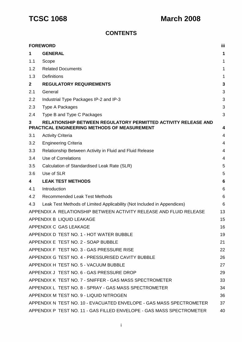
CONTENTS
FOREWORD iii
1 GENERAL 1
1.1 Scope 1
1.2 Related Documents 1
1.3 Definitions 1
2 REGULATORY REQUIREMENTS 3
2.1 General 3
2.2 Industrial Type Packages IP-2 and IP-3 3
2.3 Type A Packages 3
2.4 Type B and Type C Packages 3
3 RELATIONSHIP BETWEEN REGULATORY PERMITTED ACTIVITY RELEASE AND
PRACTICAL ENGINEERING METHODS OF MEASUREMENT 4
3.1 Activity Criteria 4
3.2 Engineering Criteria 4
3.3 Relationship Between Activity in Fluid and Fluid Release 4
3.4 Use of Correlations 4
3.5 Calculation of Standardised Leak Rate (SLR) 5
3.6 Use of SLR 5
4 LEAK TEST METHODS 6
4.1 Introduction 6
4.2 Recommended Leak Test Methods 6
4.3 Leak Test Methods of Limited Applicability (Not Included in Appendices) 6
APPENDIX A RELATIONSHIP BETWEEN ACTIVITY RELEASE AND FLUID RELEASE 13
APPENDIX B LIQUID LEAKAGE 15
APPENDIX C GAS LEAKAGE 16
APPENDIX D TEST NO. 1 - HOT WATER BUBBLE 19
APPENDIX E TEST NO. 2 - SOAP BUBBLE 21
APPENDIX F TEST NO. 3 - GAS PRESSURE RISE 22
APPENDIX G TEST NO. 4 - PRESSURISED CAVITY BUBBLE 26
APPENDIX H TEST NO. 5 - VACUUM BUBBLE 27
APPENDIX J TEST NO. 6 - GAS PRESSURE DROP 29
APPENDIX K TEST NO. 7 - SNIFFER - GAS MASS SPECTROMETER 33
APPENDIX L TEST NO. 8 - SPRAY - GAS MASS SPECTROMETER 34
APPENDIX M TEST NO. 9 - LIQUID NITROGEN 36
APPENDIX N TEST NO. 10 - EVACUATED ENVELOPE - GAS MASS SPECTROMETER 37
APPENDIX P TEST NO. 11 - GAS FILLED ENVELOPE - GAS MASS SPECTROMETER 40
TCSC 1068 March 2008
ii
APPENDIX Q TEST NO. 12 - BACK PRESSURISATION - GAS MASS SPECTROMETER 43
APPENDIX R TEST NO. 13 - HYGROSCOPIC CRYSTALS 45
APPENDIX S CONVERSION TABLES 47
APPENDIX T SPECIFICATION OF STANDARD LEAK RATE FOR CONTAINMENT VESSELS 49
APPENDIX U TYPICAL EXISTING TEST POINTS 52
APPENDIX V EXAMPLES OF CALCULATION FOR ALLOWABLE LEAKAGE, STANDARDISED LEAK RATE (SLR) AND TEST GAS LEAK RATE 55
APPENDIX W INTERSPACE VOLUME MEASUREMENT 58
TCSC 1068 March 2008
iii
FOREWORD
The International Atomic Agency (IAEA) Regulations for the Safe Transport of Radioactive Material No. TS-R-1 1996 Edition (As Amended 2003) specify permitted release of radioactivity under normal and accident conditions, in terms of activity per unit time, for packaging used to transport radioactive material. Generally it is not practicable to measure activity release directly. The normal method used is to relate activity release to fluid leakage, for which many leakage test procedures are available. The appropriate procedure will depend on its sensitivity and its application to a specific package. This Code of Practice, which describes methods for demonstrating that radioactive material
packages comply with the containment requirements of the IAEA, was first issued in April 1988, against the International Atomic Energy Agency (IAEA) Regulations for the Safe Transport of Radioactive Materials (Safety Series 6), as a ‘provisional’ document for use by organisations, within the nuclear industry, subscribing to the document. In September 1991 the TCSC incorporated minor changes, arising from users comments, and issued it as the February 1992 edition changing the document’s status from ‘provisional’ to ‘approved’. The document was further revised to reflect changes to the IAEA Transport Regulations in 1996. The document has now been updated and issued in line with the International Organisation for Standardisation, Safe transport of radioactive materials – Leakage testing on packages, ISO 12807.

TCSC 1068 March 2008
1
1 GENERAL
1.1 Scope
1.1.1 The Code of Practice describes methods for showing that radioactive material packages
comply with the containment requirements of the IAEA Transport Regulations (Ref. 1); hereinafter referred to as the Regulations. Where appropriate the Regulation paragraph number is quoted in square [brackets].
1.1.2 The Code states the regulatory containment requirements in terms of Permitted Activity
Release.
1.1.3 The Code gives guidance on:
a) Means of determining the standard of gas leak tightness required to meet the
Permitted Activity Release rates. b) Recommended leak test methods appropriate to the standard of leak tightness
required.
c) Means of defining and calculating a Standardised Leak Rate, which enables the
Leak Rate determined by any vessel under test conditions to be referred to standard conditions. This facilitates inter-comparison of test methods, equipment and leak tightness of vessels which may all use different gases and test conditions.
d) Recommended leak test procedures (Appendices).
1.2 Related Documents
1.2.1 International Atomic Energy Agency, IAEA Safety Standards Series, Regulations for the Safe Transport of Radioactive Material No. TS-R-1 1996 Edition (As Amended 2003).
1.2.2 International Atomic Energy Agency, IAEA Safety Standards Series, Advisory Material for
the IAEA Regulations for the Safe Transport of Radioactive Material Safety Guide, No. TS-G-1.1 (ST-2) 2002.
1.2.3 BS EN 60068-2-17:1995 (IEC 60068-2-17:1994) Environmental testing, Test methods, Test Q – Sealing.
1.2.4 American Vacuum Society Standard AVS 2.1 – Calibration of Leak Detectors of the Mass Spectrometer Type.
1.2.5 NASA-N69-38843 – Leakage Testing Handbook.
1.2.6 International Organisation for Standardisation, Safe transport of radioactive materials – Leakage testing on packages, ISO 12807.
1.2.7 American National Standards Institute, American National Standard for Radioactive
Materials – Leakage Tests on Packages for Shipment, ANSI N14.5-1997.
1.3 Definitions
For the purposes of the Code, the definitions given in the IAEA Regulations apply, with the following additions:
TCSC 1068 March 2008
2
1.3.1 Authority. The term “Authority” refers to the member organisation of the Transport Container Standardisation Committee utilising this Code of Practice.
1.3.2 Bar. The unit of pressure equal to 1x10⁵ pascals.
1.3.3 Bar cm3. The quantity of dry gas of volume 1 cm3 at a pressure of one bar.
1.3.4 Becquerel (Bq) or Curie (Ci). The unit of radioactivity. One Bq is defined as one nuclear
disintegration per second. One Ci is 3.7x10¹⁰ Bq. One terabecquerel (TBq) is 1012 Bq.
1.3.5 Calibrated Leak. A leak device which provides a known mass rate of flow for a specific gas under specific conditions.
1.3.6 Containment. The component(s) of the packaging specified by the designer as intended to retain the radioactive material during transport.
1.3.7 Leak Rate. Quantifies any breach in a containment with known temperature and upstream and downstream pressures.
1.3.8 Permitted Activity Release. The maximum activity permitted by the regulations to be
released from a containment system. It is related to the potential hazard of the radionuclides, and is specified for a particular time interval.
1.3.9 Specific Activity. The activity of the radionuclide per unit mass of that nuclide.
1.3.10 Standardised Leak Rate (SLR). The Leak Rate (evaluated under known conditions) normalised to reference conditions of air (at 25oC) leaking from an upstream pressure of
1x10⁵ Pa (1 bar) and a downstream pressure of 0 Pa (0 bar).
Convenient units are Pa.m3/s (bar cm3/s) SLR.
1.3.11 Standard Temperature and Pressure (STP). A temperature of 0oC (273K) and a
pressure of 1.013x10⁵ Pa (1.013 bar).
NOTE: The SI unit for gas flow is “pascal cubic metre per second (Pa.m3/s)”. The derived
unit bar cm3/s is still widely used in the UK and is also used in this Code of Practice as it conforms to common practice; throughout the text, both units are shown where appropriate.

TCSC 1068 March 2008
3
2 REGULATORY REQUIREMENTS
2.1 General
2.1.1 The design of packages may be demonstrated as meeting the relevant requirements of the Regulations, by subjecting prototypes or samples of a particular design, to physical and mechanical environmental tests.
2.1.2 Following the application of these tests, it is necessary to demonstrate that the integrity of
the containment has been maintained to the required degree. This demonstration requires some form of contents leakage test.
2.1.3 The package containment requirements will be related to equivalent fluid leakage rates. These rates will be designated as the maximum permissible leakage rates, determined according to Section 3 of this Code.
2.1.4 The package maximum permissible leakage rates will be for a total package test, or a summation of individual leakage rates for multiple entries if the package contains more than one entry.
2.1.5 QA systems will be required for the maintenance of test methods, test recording, and calibration of apparatus used in testing.
2.2 Industrial Type Packages IP-2 and IP-3
2.2.1 Industrial type packages must retain their contents when subjected to Free Drop Test [722] and Stacking Test [723]. No leakage criterion is specified [622(a)], [627(c)(i)] and [628(b)(i)].
2.3 Type A Packages
2.3.1 Type A design must prevent loss of dispersal of radioactive contents under normal conditions of transport [646(a)], [648(a)] and [649]. No leakage criterion is specified.
2.4 Type B and Type C Packages
2.4.1 Type B designs must meet the relevant requirements [656(a) and 656(b)] and Type C
designs must meet the relevant requirements [669(a) and 669(b)] for Permitted Activity
Release as shown in Table 1.
TABLE 1 – Permitted Activity Release
Conditions Type B and Type C
After tests for normal conditions After tests for accident conditions
A2 x 10-6/hour A2 in one week, or A2 x 10 in one week for krypton 85
NOTE: A2 values in TBq for radionuclides are given in Table 1 of the Regulations.
TCSC 1068 March 2008
4
3 RELATIONSHIP BETWEEN REGULATORY PERMITTED ACTIVITY RELEASE AND
PRACTICAL ENGINEERING METHODS OF MEASUREMENT
3.1 Activity Criteria
3.1.1 Containment performance is specified in terms of Permitted Activity Release measured
in TBq (see Table 1, Section 2.4).
3.1.2 It is generally impracticable to obtain direct measurement in these units, therefore an
alternative fluid Leak Rate method is normally used.
3.2 Engineering Criteria
3.2.1 To specify activity release in fluid Leak Rate terms, a relationship between the activity release and fluid leakage is required.
The physical state of the activity must be established, i.e. particulate, liquid or gaseous.
i) For liquids and gases, leakage calculations can be carried out using established fluid flow formulae.
ii) For particulate material, no practicable calculation method exists except by assuming that the solid matter behaves as an aerosol in a gaseous environment, or as a homogeneous liquid.
These assumptions give over-estimates of particulate release. If data on particle size is available, this could be used in conjunction with actual tests data on the transmission of solids through small openings (Ref. 2) to determine minimum leakage path size and therefore leakage rate. However, particulate matter would not be expected to leak from a seal having a
Standardised Leak Rate not greater than 1x10⁻⁶ Pa m3/s = 1x10⁻⁵ bar cm3/s. This figure has been determined from a number of pessimistic assumptions. The figure may be relaxed if particle size and range are known; see IAEA TS-G-1.1 paragraph 656.12.
3.3 Relationship Between Activity in Fluid and Fluid Release
3.3.1 To relate activity release to fluid release, the concentration of the activity in the transmitting fluid has to be established.
From this, and the Regulatory Permitted Activity Release, the permitted fluid release can be derived. This can apply to a single radionuclide, mixtures of radionuclides with different activity concentrations and to mixtures of radionuclides in elements.
Appendix A describes the relationship between Permitted Activity Release and fluid release.
3.4 Use of Correlations
3.4.1 The equations in Appendix A give the relationship between Permitted Activity Release and fluid release.
The equations in Appendices B and C give the correlation between liquid-to-liquid, gas-to-
gas and gas-to-liquid Leak Rates. These correlations must be used with caution. The correlations are valid provided that: (a) The flow mode for the two sets of conditions under consideration remain the same;

TCSC 1068 March 2008
5
(b) they account for effects of temperature and pressure on the leaking medium but not on leakage path geometry.
Therefore, generally, the equations apply only when: (c) pressure and temperature conditions for both media are the same; (d) these conditions do not affect leakage path geometry significantly.
3.5 Calculation of Standardised Leak Rate (SLR)
3.5.1 When the Leak Rate has been determined for a containment vessel, the SLR may be calculated using the equations in Appendices B and C.
3.6 Use of SLR
3.6.1 Specification for leak-tightness of a containment vessel
The leak-tightness of a containment vessel is determined by measuring the Leak Rate of a test fluid (normally gas) leaking to or from a contained volume under known conditions of
temperature, upstream pressure and downstream pressure. If the SLR is determined from
this Leak Rate, a numerical value for the leak-tightness of the vessel is obtained which can be compared with the results of other leak tests using different methods and test conditions
for the same vessel. The SLR can also be used to directly compare the leak-tightness of
different vessels. Such comparisons are only meaningful, if either the Leak Rate is determined under identical conditions, or referred to standardised conditions such as
specified in the definition of SLR.
3.6.2 Acceptance criteria for Leak Tests
The calculations in Appendices A, B and C show how the maximum permissible Leak Rate
can be determined, for a containment vessel loaded with specified radioactive contents and subjected to defined conditions of temperature, upstream pressure and downstream pressure likely to occur under normal or accident conditions of transport, and which would
produce maximum leakage. If the SLR is calculated corresponding to this maximum
permissible Leak Rate, this establishes an acceptance criterion for leak testing, in terms which are not specific to a particular leak test method or condition. This is useful for specifying acceptance criterion in operating procedures or certificates, e.g.
“For the specified contents, the acceptance criterion for the post loading leak
test on the containment vessel is 1 x 10⁻⁶ Pa m3/s = 1x10⁻⁵ bar cm3/s SLR.”
3.6.3 Comparison of sensitivity of leak test methods
Section 4 indicates practical leak testing techniques for measuring the leakage tightness of packages. The various leak test methods which may be used, involve the use of different gases under different conditions (especially upstream pressure and downstream pressure). The
sensitivity of a leak test method for testing a particular containment vessel, depends on both the basic sensitivity of the method and the test volume of the vessel.
When any particular leak test is considered for a containment vessel, the minimum Leak
Rate which is measurable can be determined; this is the sensitivity of that test method with that vessel. In order to compare leak test methods, it is necessary to determine the sensitivity under identical conditions or standardised conditions. It is recommended that
the sensitivity be calculated and specified in terms of SLR.
TCSC 1068 March 2008
6
4 LEAK TEST METHODS
4.1 Introduction
4.1.1 Practical leak testing techniques for measuring the leak-tightness of packages have been reviewed with particular reference to those listed in ANSI N14.5; BS EN 60068-2-17:1995, Test Q – Sealing,; AVS 2.1 Rev. 1973; NSAS-N69-38843 and IAEA TS-G-1.1 Section VII. Of the sixteen methods reviewed, thirteen are regarded as having continued value, and the remaining three as being of limited applicability and not recommended for use.
4.1.2 Detailed procedures have been developed for the thirteen methods recommended, with emphasis on the factors relevant to particular types of container. The three methods of limited applicability are now considered to be superseded by the recommended methods. However, these methods may be useful for particular situations and are noted below for completeness.
4.2 Recommended Leak Test Methods
4.2.1 Recommended methods of leak testing are listed, with diagrammatic representation, in Table 2 in increasing order of sensitivity. The table summarises the test method, nominal sensitivity and applicability of each method, and is intended to be used as a guide when choosing a test method for a particular container.
4.2.2 These test methods are fully described in Appendices D to R. The test methods give a detailed description of how each test should be performed. For quantitative test,
procedures are given for calculating the numerical Leak Rate, both under test conditions
and normalised to standard conditions (to give the Standardised Leak Rate - SLR). Information is also given to test point connections (Appendix U), test precautions, applicability and hazards.
4.3 Leak Test Methods of Limited Applicability (Not Included in Appendices)
4.3.1 Hydraulic test
The test procedure involves filling the container cavity with water, and pressurising it either hydraulically or pneumatically. Leakage is determined by visual inspection for escaping water. The test is qualitative and will only reveal a gross leak.
4.3.2 Parjo test
This test is a method for testing double ‘O’ ring seals in low pressure, constant volume
containments such as glove boxes. The method requires a special, but simple, glass apparatus. The test procedure involves pressurising the containment cavity with air to a low pressure, and connecting the special apparatus to the interspace of the double ‘O’ ring seal. Any air leakage past the inner ‘O’ ring seal produces an air stream which passes into the apparatus where it can be accurately measured by the movement of a soap bubble in a glass tube. The method is not considered to be practical for use in the transport container environment, because the apparatus is delicate and is more suitable for laboratory conditions.

TCSC 1068 March 2008
7
4.3.3 Weight increase of immersed container
The test procedure involves accurately weighing the container before and after immersion in water. The water is pressurised during the test to provide a pressure drive for in-leakage of water into the container cavity. The method is primarily applicable for use with small containers or capsules and, although quantitative, normally has a very low sensitivity.
4.3.4 Simulated contents
This is a technique sometimes used during drop testing. Powder, with a simulated size and weight distribution to the anticipated vessel active contents, is placed within the vessel prior to the drop test and searched for outside, post drop. This technique can also be used for water filled vessels by searching for water leakage after the drop. This is not a quantitative method of leakage detection but can be used to indicate no loss of relevant contents during the drop test, providing representative material can be used. Fluoroscein dye is normally used to enhance the detection of leakage.
TCSC 1068 March 2008
8
TABLE 2 - Summary of leakage tests
HOT WATERHOTWATER
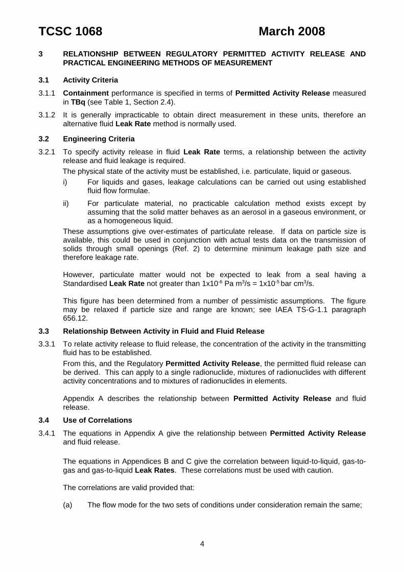
Test No. 1 (Appendix D)
Hot Water Bubble The method involves submerging the test item in hot water, which raises the internal pressure. A leak produces a stream of bubbles.
This method applies to small test items, usually without pressure tap connections. It can be used in the field without sophisticated equipment. Nominal maximum test sensitivity = 10-4Pa m3/s = 10-3 bar cm3/s SLR
Pressure
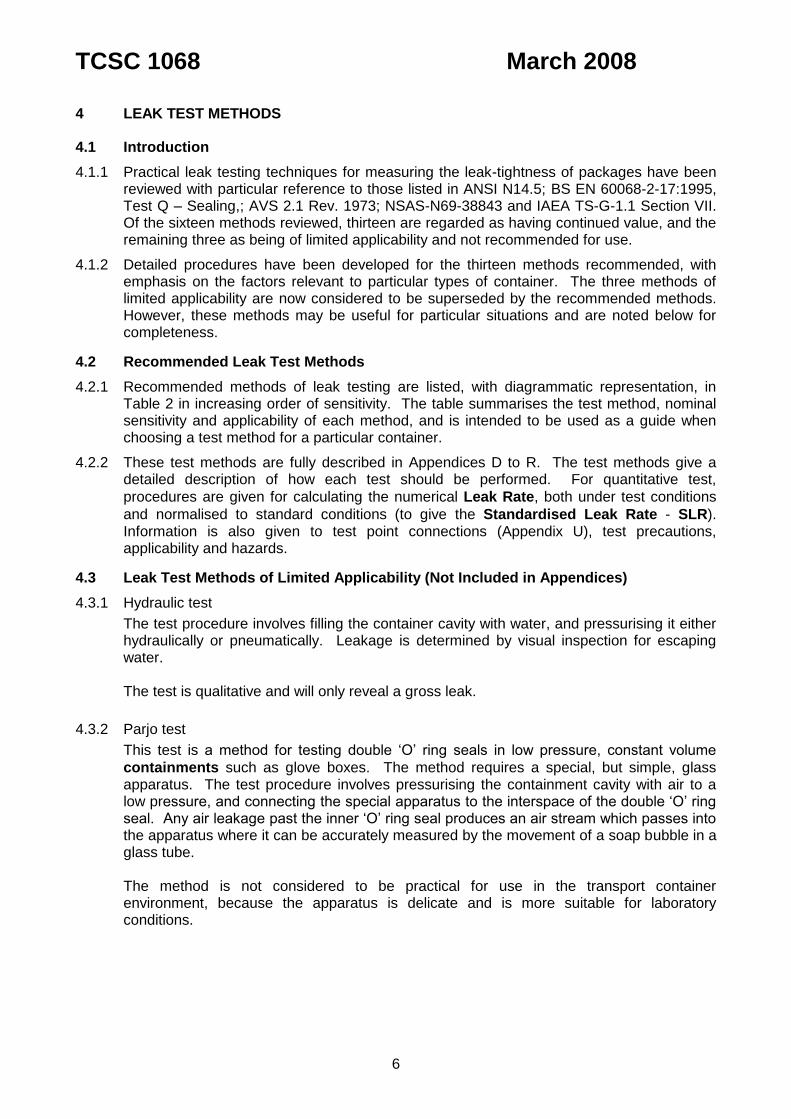
Test No. 2 (Appendix E)
Soap Bubble The method involves pressurising the test item, and coating the surface with a soap film. A leak produces a soap bubble on the surface.
This method applies to containers with pressure tap connections, and is qualitative. The required pressure within the cavity may be obtained by the vapourisation of solid carbon dioxide crystals. Nominal test sensitivity = 10-4Pa m3/s = 10-3 bar cm3/s) SLR
Vacuum
Test No. 3 (Appendix F)
Gas Pressure Rise The method involves evacuating the test cavity to 0.1 bar, or less and measuring a pressure rise during a specified test period.
The method applies to test items with pressure tap connections. Test sensitivity is inversely proportional to the test volume. Test results should be interpreted to allow for testing an item under pressure. Nominal test sensitivity = 10-5Pa m3/s = 10-4 bar cm3/s SLR.
Pressure
Test No. 4 (Appendix G)
Pressurised Cavity Bubble This method involves pressurising the test item, and immersing in water, glycol or isopropyl alcohol. A leak produces a stream of bubbles.
This method applies to containers with pressure tap connections, or where the pressure required within the cavity may be obtained by the vapourisation of solid carbon dioxide. Nominal test sensitivity = 10-4Pa m3/s = 10-3 bar cm3/s SLR

TCSC 1068 March 2008
9
HOT WATER
Vacuum
Test No. 5 (Appendix H)
Vacuum Bubble The method involves producing a vacuum above the liquid in which the test item is submerged. A leak is indicated by a stream of bubbles.
This method is suitable for welded capsules and small resealable items. The method can be used for sources or containers with void volumes greater than 10mm3. The size of the test item is limited only by the size of vacuum vessel. Nominal test sensitivity = 10-6Pa m3/s = 10-5 bar cm3/s SLR
Pressure
Test No. 6 (Appendix J)
Gas Pressure Drop The method involves pressurising the test item cavity, or interspace, and measuring the pressure drop. The sensitivity of the method is inversely proportional to the test volume.
The method is particularly useful for testing double ‘O’ ring seals, where the small interspace volume makes the method most sensitive, and the primary seal of the cavity does not have to be broken. Nominal test sensitivity = 10-7Pa m3/s = 10-6 bar cm3/s) SLR
TRACER GAS
DETECTOR
Test No. 7 (Appendix K)
Sniffer - Gas Mass Spectrometer The method involves pressurising the test item to 1 bar with the test gas. A leak is detected by moving a probe (connected to a gas mass spectrometer) across areas that are likely to leak.
The method, which is qualitative only, is best used on large test items where the area of potential leak, e.g. a weld or seal is clearly visible. There must be some facility for pressurising (with test gas) the inside of the weld or seal to 1 bar. Nominal test sensitivity = 10-7 to 10-9 Pa m3/s = 10-6 to 10-8 bar cm3/s SLR

TCSC 1068 March 2008
10
DETECTOR
VACUUM
Test No. 8 (Appendix L)
Spray-Gas Mass Spectrometer The method involves evacuating a test item connected to a mass spectrometer and spraying the test gas over the surface.
The method, which is qualitative only, can be used for testing part finished vessels provided that one side of a potential leak can be evacuated and the other side is easily accessible with a supply of test gas. Nominal test sensitivity = 10-7 to 10-9 Pa m3/s = 10-6
to 10-8 bar cm3/s SLR
LIQUEFIED N2
WARM LIQUID
Test No. 9 (Appendix M)
Liquid Nitrogen The method involves submerging small sealed test items in liquid nitrogen, and subsequently submerging them in warm methanol. A leak produces a stream of bubbles.
The method is ideal for small sealed capsules with an internal void volume of at least 2mm3. It is important that these capsules can withstand the thermal shock of being placed into liquid nitrogen at 77K. Nominal test sensitivity = 10-8 Pa m3/s = 10-7 bar cm3/s SLR
TCSC 1068 March 2008
11
TRACER GAS
DETECTOR
VACUUM
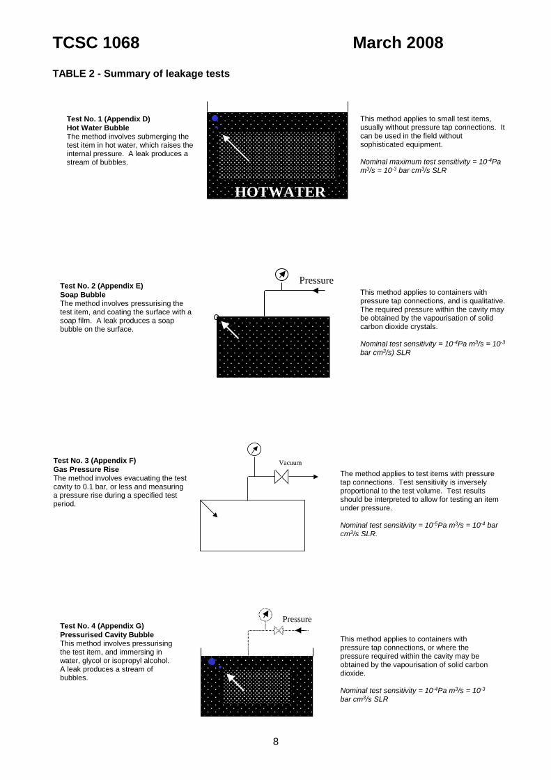
Test No. 10 (Appendix N)
Evacuated Envelope - Gas Mass
Spectrometer The method involves pressurising the test item with test gas, and subsequently placing it in a vacuum chamber connected to a mass spectrometer.
The method is ideal for small test items which have a replaceable seal. Where several seals are used (e.g. a double ‘O’ ring enclosure) the procedure can be applied to each seal in turn. Nominal test sensitivity = 10-9 Pa m3/s = 10-8 bar cm3/s SLR
TRACER GAS
DETECTOR
VACUUM
Test No. 11 (Appendix P)
Gas Filled Envelope - Gas Mass
Spectrometer The method involves evacuating the test item connected to a mass spectrometer and surrounding the item in an envelope filled with a test gas.
The method is suitable for large test items which have a replaceable seal. Where several seals are used (e.g. a double 'O’ ring closure) the procedure can be applied to each seal in turn. Nominal test sensitivity = 10-9 Pa m3/s = 10-8 bar cm3/s SLR
TRACER GAS
TRACER GAS
DETECTOR
VACUUM
Test No. 12 (Appendix Q)
Back Pressurisation - Gas Mass
Spectrometer The method involves externally pressurising the test item in an envelope of the test gas (usually He) for a period of time and subsequently placing the item in an evacuated envelope connected to a mass spectrometer.
The method is ideal for welded capsules from the very small up to the limit of the pressurising chamber. The internal void volume of the test item should be at least 10mm3. Considering the cost of the equipment and the care with which the procedure must be carried out, this method can only be of use in a laboratory. Nominal test sensitivity = 10-7 to 10-11 Pa m3/s = 10-6 to 10-10 bar cm3/s SLR

TCSC 1068 March 2008
12
WATER
CRYSTALS
Test No. 13 (Appendix R)
Hygroscopic Crystals The method involves placing hygroscopic crystals in the test item, which is then submerged in water. The mass of water in-leakage is determined by weighing the crystals before and after the test.
The water in-leakage test method can be used for the regulatory water immersion test for fissile materials packages. Nominal test sensitivity = 10-5 g/s of water can be detected
TCSC 1068 March 2008
13
APPENDIX A RELATIONSHIP BETWEEN ACTIVITY RELEASE AND FLUID RELEASE
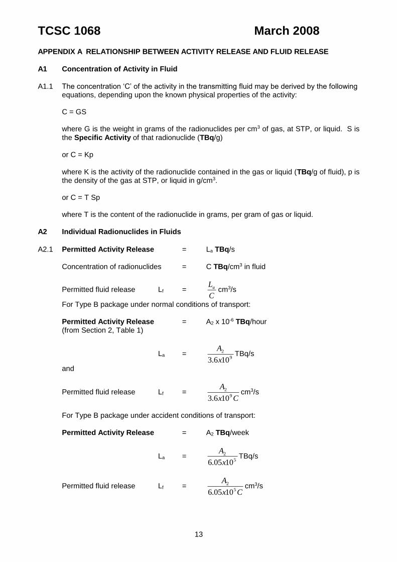
A1 Concentration of Activity in Fluid
A1.1 The concentration ‘C’ of the activity in the transmitting fluid may be derived by the following
equations, depending upon the known physical properties of the activity: C = GS where G is the weight in grams of the radionuclides per cm3 of gas, at STP, or liquid. S is
the Specific Activity of that radionuclide (TBq/g) or C = Kp
where K is the activity of the radionuclide contained in the gas or liquid (TBq/g of fluid), p is the density of the gas at STP, or liquid in g/cm3.
or C = T Sp where T is the content of the radionuclide in grams, per gram of gas or liquid.
A2 Individual Radionuclides in Fluids
A2.1 Permitted Activity Release = La TBq/s
Concentration of radionuclides = C TBq/cm3 in fluid
Permitted fluid release Lf = C
La cm3/s
For Type B package under normal conditions of transport:
Permitted Activity Release = A2 x 10-6 TBq/hour (from Section 2, Table 1)
La = 9
2
106.3 x
ATBq/s
and
Permitted fluid release Lf = Cx
A9
2
106.3cm3/s
For Type B package under accident conditions of transport:
Permitted Activity Release = A2 TBq/week
La = 5
2
1005.6 x
ATBq/s
Permitted fluid release Lf = Cx
A5
2
1005.6cm3/s
TCSC 1068 March 2008
14
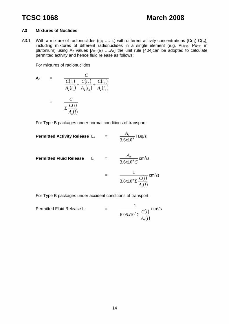
A3 Mixtures of Nuclides
A3.1 With a mixture of radionuclides (i1i2……in) with different activity concentrations {C(i1) C(in)]
including mixtures of different radionuclides in a single element (e.g. Pu238, Pu241 in plutonium) using A2 values [A2 (i1) ….A2] the unit rule [404]can be adopted to calculate permitted activity and hence fluid release as follows:
For mixtures of radionuclides
A2 =
n
n
iA
iC
iA
iC
iA
iC
C
222
2
12
1
= iA
iC
C
2
For Type B packages under normal conditions of transport:
Permitted Activity Release La = 9
2
106.3 x
ATBq/s
Permitted Fluid Release Lf = Cx
A9
2
106.3cm3/s
= iA
iCx
2
9106.3
1
cm3/s
For Type B packages under accident conditions of transport:
Permitted Fluid Release Lf = iA
iCx
2
51005.6
1
cm3/s
TCSC 1068 March 2008
15
APPENDIX B LIQUID LEAKAGE
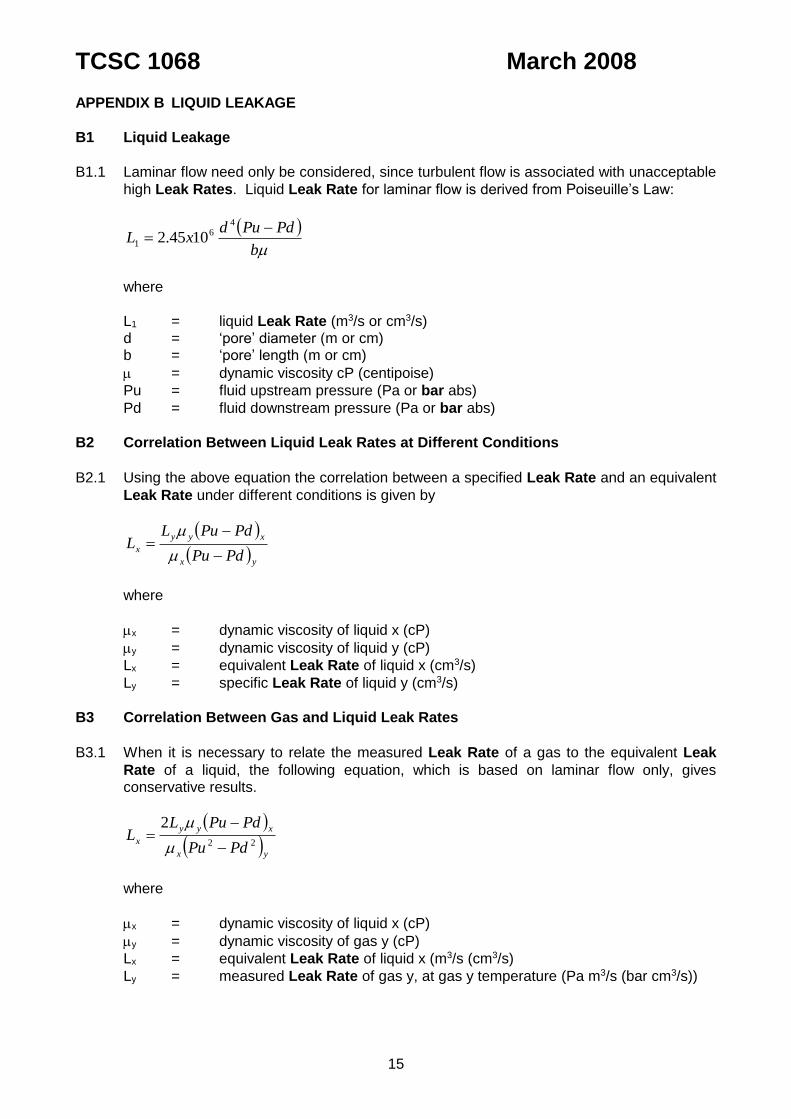
B1 Liquid Leakage
B1.1 Laminar flow need only be considered, since turbulent flow is associated with unacceptable
high Leak Rates. Liquid Leak Rate for laminar flow is derived from Poiseuille’s Law:
b
PdPudxL
46
1 1045.2
where
L1 = liquid Leak Rate (m3/s or cm3/s) d = ‘pore’ diameter (m or cm) b = ‘pore’ length (m or cm)
= dynamic viscosity cP (centipoise)
Pu = fluid upstream pressure (Pa or bar abs)
Pd = fluid downstream pressure (Pa or bar abs)
B2 Correlation Between Liquid Leak Rates at Different Conditions
B2.1 Using the above equation the correlation between a specified Leak Rate and an equivalent
Leak Rate under different conditions is given by
yx
xyy
xPdPu
PdPuLL
where
x = dynamic viscosity of liquid x (cP)
y = dynamic viscosity of liquid y (cP)
Lx = equivalent Leak Rate of liquid x (cm3/s)
Ly = specific Leak Rate of liquid y (cm3/s)
B3 Correlation Between Gas and Liquid Leak Rates
B3.1 When it is necessary to relate the measured Leak Rate of a gas to the equivalent Leak
Rate of a liquid, the following equation, which is based on laminar flow only, gives conservative results.
yx
xyy
xPdPu
PdPuLL
22
2
where
x = dynamic viscosity of liquid x (cP)
y = dynamic viscosity of gas y (cP)
Lx = equivalent Leak Rate of liquid x (m3/s (cm3/s)
Ly = measured Leak Rate of gas y, at gas y temperature (Pa m3/s (bar cm3/s))
TCSC 1068 March 2008
16
APPENDIX C GAS LEAKAGE
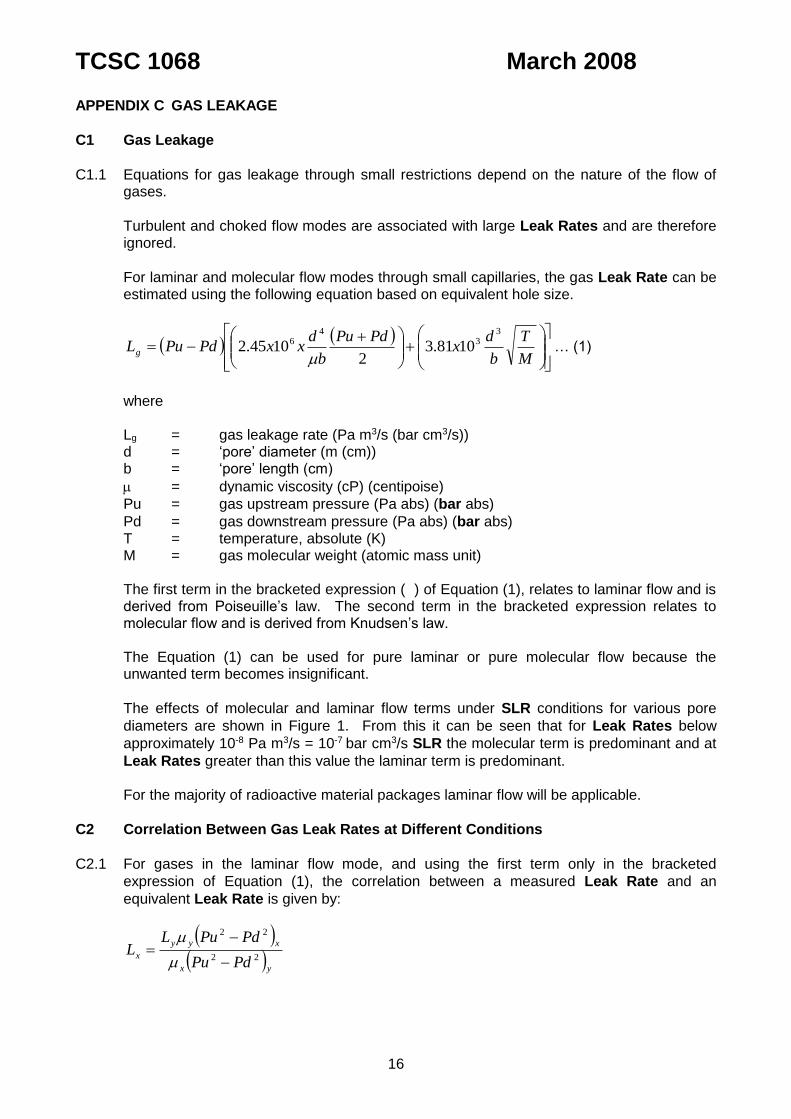
C1 Gas Leakage
C1.1 Equations for gas leakage through small restrictions depend on the nature of the flow of
gases.
Turbulent and choked flow modes are associated with large Leak Rates and are therefore ignored.
For laminar and molecular flow modes through small capillaries, the gas Leak Rate can be estimated using the following equation based on equivalent hole size.
M
T
b
dx
PdPu
b
dxxPdPuLg
33
46 1081.3
21045.2
… (1)
where Lg = gas leakage rate (Pa m3/s (bar cm3/s)) d = ‘pore’ diameter (m (cm)) b = ‘pore’ length (cm)
= dynamic viscosity (cP) (centipoise)
Pu = gas upstream pressure (Pa abs) (bar abs)
Pd = gas downstream pressure (Pa abs) (bar abs) T = temperature, absolute (K) M = gas molecular weight (atomic mass unit) The first term in the bracketed expression ( ) of Equation (1), relates to laminar flow and is
derived from Poiseuille’s law. The second term in the bracketed expression relates to molecular flow and is derived from Knudsen’s law.
The Equation (1) can be used for pure laminar or pure molecular flow because the
unwanted term becomes insignificant.
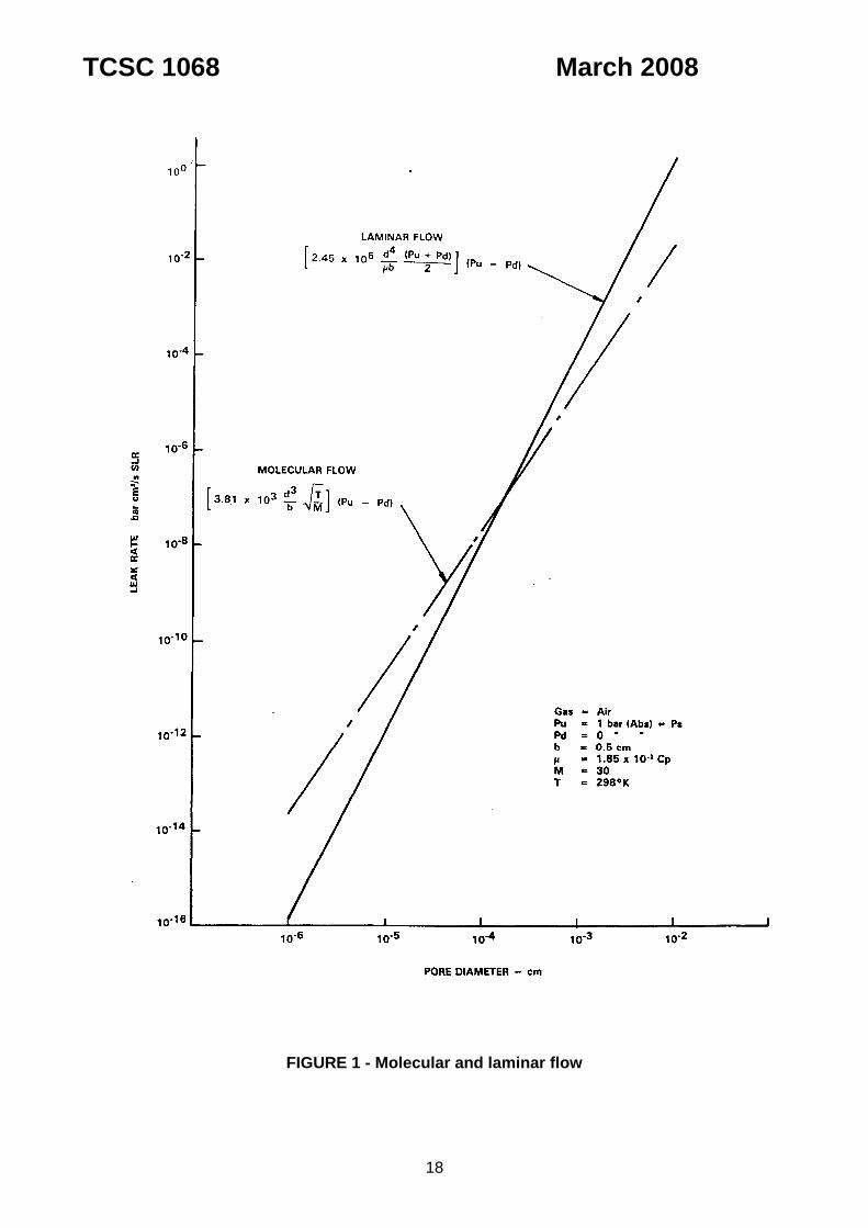
The effects of molecular and laminar flow terms under SLR conditions for various pore
diameters are shown in Figure 1. From this it can be seen that for Leak Rates below
approximately 10-8 Pa m3/s = 10-7 bar cm3/s SLR the molecular term is predominant and at
Leak Rates greater than this value the laminar term is predominant. For the majority of radioactive material packages laminar flow will be applicable.
C2 Correlation Between Gas Leak Rates at Different Conditions
C2.1 For gases in the laminar flow mode, and using the first term only in the bracketed
expression of Equation (1), the correlation between a measured Leak Rate and an
equivalent Leak Rate is given by:
yx
xyy
xPdPu
PdPuLL
22
22
TCSC 1068 March 2008
17
where
x = dynamic viscosity of gas x (cP)
y = dynamic viscosity of gas y (cP)
Lx = equivalent Leak Rate of gas x (Pa m3/s (bar cm3/s))
Ly = measured Leak Rate of gas y (Pa m3/s (bar cm3/s))
For gases in the molecular flow mode and using the second term only, the bracketed expression
of Equation (1) the correlation between a measured Leak Rate and an equivalent Leak Rate is given by:
y
x
xy
Yxyx
PdPu
PdPu
MT
MTLL
where
Lx = equivalent Leak Rate of gas x, at temperature Tx (Pa m3/s (bar cm3/s))
Ly = measured Leak Rate of gas y at temperature Ty (Pa m3/s (bar cm3/s)) Mx = molecular weight of gas x (atomic mass unit) My = molecular weight of gas y (atomic mass unit).
C2.2 Permeation
When using elastomeric seals some leakage occurs as permeation leakage. Normally this is small compared to the level of acceptable bypass leakage. The permeation rate is proportional to the driving pressure but varies with the gases involved, the seal material, and the temperature. Where permeation leakage of radioactive gases can be a significant part of the total activity leakage due account of it should be taken. Particular care should be taken when relating SLR leakages to high pressure / high temperature conditions.
TCSC 1068 March 2008
18
FIGURE 1 - Molecular and laminar flow
TCSC 1068 March 2008
19
APPENDIX D TEST NO. 1 - HOT WATER BUBBLE
D1 Applicability of the Method
D1.1 This method applies to small test items (usually without pressure tap connections) that can
conveniently be lifted in and out of a tank having access for close observation of the water surface.
D2 Leak Rate Indication
D2.1 Individual leaks are indicated by air bubble streams through the water.
D3 Test Sensitivity
D3.1 The test gives a qualitative result, with an absence of bubbles through the water indicating
a Leak Rate less than 1x10⁻⁴ Pa m3/s = 1x10⁻³ bar cm3/s SLR (Standardised Leak Rate). The minimum void volume necessary is 40 mm3.
D4 Test Method
D4.1 Immerse the test item at room temperature in water at 90C. Submerge the test item, or feature to be tested, in a suitable tank such that it is covered by at least 50mm of water.
D4.2 Using good lighting, observe closely for any stream of bubbles. D4.3 The duration of the test must be long enough for the test item and its air volume to be
heated by the water. The time that the test item should remain in the hot water must be determined by calculation or test. Normally, for small items (dimensions of a few centimetres), an immersion time of 5 minutes is sufficient, but larger items may require about 30 minutes.
D4.4 Air bubbles may stream for a few seconds and then cease. Such streams could be caused
by air trapped by the test item and do not necessarily indicate leaks.
D5 Calculation of Leak Rate
D5.1 Individual Leak Rates as small as 1x10⁻⁵ Pa m3/s =1x10⁻⁴ bar cm3/s SLR can be detected under favourable conditions. However, problems such as poor visibility of certain areas and clogging of crack type leaks by the liquid bath occur in practice. Also, there may be several leaks, each too small to observe. The test method is quantitative only with the
absence of bubbles indicating a Leak Rate less than 1x10⁻⁴ Pa m3/s = 1x10⁻³ bar cm3/s
SLR.
D6 Advantages and Disadvantages
D6.1 Dirty or uneven surfaces, bolts or trapped air between, for example, the test item surface
and the first seal tend to give rise to spurious bubbles which could be confused with true readings.

TCSC 1068 March 2008
20
D7 Hazards
D7.1 Safety spectacles or a shield should be used to protect the operator from the possibility of
the test item rupturing, spraying hot water.

TCSC 1068 March 2008
21
APPENDIX E TEST NO. 2 - SOAP BUBBLE
E1 Applicability of the Method
E1.1 This method applied to containers with pressure tap connections, or where the pressure
required within the cavity may be obtained by the vapourisation of solid carbon dioxide crystals.
E2 Leak Rate Indication
E2.1 Individual leaks are indicated by gas bubbles forming in a liquid soap solution that has
been brushed over the outer surface of the container.
E3 Test Sensitivity
E3.1 The test gives a qualitative result, with an absence of bubbles through the soap indicating a
Leak Rate of less than 1x10⁻⁴ Pa m3/s = 1x10⁻³ bar cm3/s SLR.
E4 Test Method
E4.1 Where an internal pressure is to be generated by the vapourisation of solid CO2 crystals
placed within the cavity before sealing, then a quantity of two grams per litre of cavity
volume will produce an increase in pressure of 1x10⁵ Pa = 1 bar.
E4.2 Pressurise the container cavity to 2x10⁵ Pa = 2 bar (abs), or specified test pressure, with a suitable gas and leave pressurised for a period of 15 minutes.
E4.3 Brush or coat the container features to be tested with liquid soap solution, taking care to
flood or bridge all joints or possible leakage areas. E4.4 Observe closely for any formation of bubbles.
E5 Calculation of Leak Rate
E5.1 This test method is qualitative only - the absence of bubbles forming through the soap
being indicative of a Leak Rate less than 1x10⁻⁴ Pa m3/s = 1 x 10⁻³ bar cm3/s SLR.
E6 Advantages and Disadvantages
E6.1 This method is similar to the pressurised cavity bubble test, but is not restricted by the size
or weight of the container. Where seals are not readily accessible or joint gaps are such that they cannot be bridged or flooded, this method becomes unreliable.
E7 Hazards
E7.1 When generating pressure by means of CO2 crystals, care must be taken not to exceed
the correct amount of carbon dioxide crystals needed to produce the required internal pressure, or dangerous overpressures may occur.
E7.2 Consideration must be given to the risks that could be connected with opening a
pressurised container on completion of the leak test.
TCSC 1068 March 2008
22
APPENDIX F TEST NO. 3 - GAS PRESSURE RISE
F1 Applicability of the Method
F1.1 This procedure is ideal for small test volumes, and in particular double ‘O’ ring seals where
the small interspace volume makes the method most sensitive.
F2 Leak Rate Indication
F2.1 The Leak Rate is indicated by a pressure rise over a given period of time from a known initial pressure and for a particular ambient temperature and pressure.
F3 Test Sensitivity
F3.1 The sensitivity is dependent mainly upon the test volume, test duration and the accuracy to
which pressure can be measured (typically 1x10⁻⁴ Pa = 1x10⁻³ bar). The method is well
suited to measuring Leak Rates in the range 1x10⁻⁷ to 1x10⁻² Pa m3/s = 1x10⁻⁶ to 1x10⁻¹
bar cm3/s SLR.
F4 Test Method
F4.1 Check the calibration of the pressure indicator and adjust if necessary. F4.2 If practicable thoroughly clean the vessel, inside and out (with cleaning solvent). This will
not be possible with large, or, containers containing radioactive material. Make sure the ‘O’ ring interfaces are free from dust, fibres, etc. Clean ‘O’ rings making sure they are free of dust, fibres etc.
The presence of dust, fibres, etc. on ‘O’ rings and ‘O’ ring interfaces can introduce large
leakage paths. F4.3 Before the test, the vessel as well as the test equipment should ideally be at thermal
equilibrium. If large variations are possible the initial and final temperatures should be measured and used in equation (i) in paragraph F5.1.
F4.4 Using an absolute pressure indicator note the atmospheric pressure. F4.5 Connect the pressure indicator to the test equipment. Fit blanking plugs to the test
equipment and evacuate to a given pressure P1. F4.6 The pressure P1 will normally be reached in a few seconds, but a 5 minute pumping period
is recommended to remove any moisture that may be present in the test equipment. The duration of the test is a major factor in determining sensitivity. The equations of paragraph F5 should be used to estimate the duration of the test required to achieve the required sensitivity, which basically is inversely proportional to the test volume.
F4.7 After the test period (typically 5 minutes) note the final pressure P2.
F4.8 The pressure rise P2 - P1 will be within the calculated permitted Leak Rate for the test equipment to be utilised on the test volume.
F4.9 Connect the pressure indicator and the equipment to the test vessel and evacuate the test
volume to a given pressure, nominally Pd. Isolate the test volume. Check that the full interspace volume is being evacuated, i.e. that passages are not blocked. This is indicated

TCSC 1068 March 2008
23
by the rate at which the pressure falls. An absolute test is to measure the interspace volume before carrying out the test, see Appendix W for typical procedure.
F4.10 The pressure will rise rapidly, until a pressure is reached which is above the vapour
pressure of water at the ambient temperature. When this occurs, the test may begin (typically 5 minutes). Note initial pressure Pd.
F4.11 If the pressure indicator shows erratic readings, then excessive water vapour is likely to be
present at the sensing head. In this case re-evacuate the system and recommence the test period.
F4.12 After the test period, note the final pressure Pf. The pressure rise is Pf - Pd. F4.13 Automated equipment can be used to carry out the operations outlined above F4.13 Where containers are loaded under water due precautions should be taken to ensure that residual water, outside the seals, does not affect the validity of the subsequent leak test by causing water blocking of bypass leaks.
F5 Determination of Standardised Leak Rate
F5.1 Determination of Leak Rate at test conditions
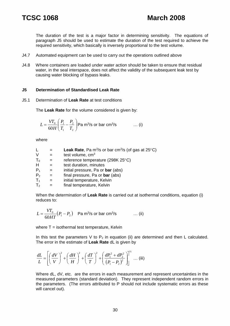
The Leak Rate for the volume considered is given by:
1
1
2
20
60 T
P
T
P
H
VTL Pa m3/s or bar cm3/s … (i)
where
L = Leak Rate, Pa m3/s or bar cm3/s (of dry air at 25C) V = interspace test volume cm3
To = reference temperature of dry air. To = 298 K (25C) H = test duration, mins
P1 = initial pressure, Pa or bar (abs)
P2 = final pressure, Pa or bar (abs) T1 = initial temperature, Kelvin T2 = final temperature, Kelvin
Where the determination of Leak Rate is carried out at isothermal conditions, equation (i) reduces to:
12
0
60PP
HT
VTL Pa m3/s or bar cm3/s … (ii)
where T = isothermal test temperature, Kelvin In the test the parameters V to P2 in equation (ii) are determined and then L calculated.
The error in the estimate of Leak Rate dL is given by:
½
2
12
2
1
2
2
222
PP
dPdP
T
dT
H
dH
V
dV
L
dL … (iii)
TCSC 1068 March 2008
24
Where dL, dV, etc. are the errors in each measurement, and represent uncertainties in the
measured parameters (standard deviation). They represent independent, random errors in the parameters. The errors attributed to P should not include systematic errors as these will cancel out.
The maximum Leak Rate is La = L + dL. The value of dL may be found from equation (iii) above or from information supplied by the
measuring instrument manufacturers or, in the absence of data, assuming a figure for dL. The figure for dL can vary depending upon the type of instruments used and the value of L
being measured or calculated. The figure for dL can be quite large in comparison with L when working near to the sensitivity limits of the instrumentation.
F5.2 Calculation of Standardised Leak Rate
The SLR may be obtained by using the equations below for a Leak Rate in the laminar region (i.e. between 1x10⁻⁷ to 1x10⁻² Pa m3/s air or 1x10⁻⁶ to 1x10⁻¹ bar cm3/s air).
2222 / aasssaas PdPuPdPuLL Pa m3/s or bar cm3/s SLR …(iv)
where
Ls = Standardised Leak Rate, Pa m3/s or bar cm3/s SLR
La = calculated maximum Leak Rate of air, Pa m3/s or bar cm3/s (at 25C; calculated at F5.1).
Pua = upstream pressure of air under test conditions, Pa or bar (abs)
Pus = upstream pressure of air under standard conditions, 1x10⁵ Pa or 1.0 bar (abs)
Pda = downstream pressure of air under test conditions, 1x10⁵ Pa or 1.0 bar (abs)
Pds = downstream pressure of air at standard conditions, 0.0 Pa or 0.0 bar (abs)
a = dynamic viscosity of air (at measured test temperature, i.e. T for isothermal conditions; (T1 + T2)/2 for non-isothermal conditions, see F5.1), cP
s = dynamic viscosity of air (at standard temperature, 298K) cP F5.3 Notes on calculations F5.3.1 Equations (iii) and (iv) above must be used with caution. They account for the effects of
temperature and pressure on leaking fluids, but not on leakage path geometry. For example, if a system normally operates at pressure Pt, the results of a leak test to 0.1 Pt would be subjected to less strain.
F5.3.2 Generally these equations apply when pressure and temperature conditions for both fluids
are similar, and when these conditions do not effect leakage path geometry significantly. F5.4 Permeation When using elastomer seals the effect of permeation should be checked and, if necessary,
due allowance made in determining the acceptable leak test standard. See Section C2.2.
F6 Advantages and Disadvantages
TCSC 1068 March 2008
25
F6.1 The test equipment used to carry out the test, normally requires at least a further two seals
apart from the seals being tested. The results of the test give the SLR across all the seals.
Hence the procedure gives an overestimate of SLR for the vessel seals. If a test sensitivity
of the order of 1x10⁻⁷ Pa m3/s or 1x10⁻⁶ bar cm3/s SLR is required, the leak tightness of test equipment seals may decide the sensitivity of the test.
F6.2 If the procedure is used in test work (e.g. testing before and after drop tests) at least one of
the seals of the test equipment will have to be broken and later re-sealed. F6.3 An observed pressure rise during the test period, could be due to surface outgassing,
evaporation of liquid, or air in-leakage. Since it is not possible to differentiate between these sources it is conservatively assumed that all the observed pressure rise is due to in-leakage of air.
F7 Hazards
F7.1 Hazards are those found when working with vacuum equipment.

TCSC 1068 March 2008
26
APPENDIX G TEST NO. 4 - PRESSURISED CAVITY BUBBLE
G1 Applicability of the Method
G1.1 This method applies to containers with pressure tap connections or where the pressure
required within the cavity may be obtained by the vapourisation of solid carbon dioxide crystals.
G2 Leak Rate Indication
G2.1 Individual leaks are indicated by gas bubbles streams through the test liquid which is
usually water although other liquids such as glycol or isopropyl alcohol may be used for greater sensitivity.
G3 Test Sensitivity
G3.1 The test gives a qualitative result, with an absence of bubbles through the water indicating
a Leak Rate of less than1x10-4 Pa m3/s = 1 x 10⁻³ bar cm3/s SLR.
G4 Test Method
G4.1 Where an internal pressure is to be generated by the vapourisation of solid CO2 crystals
placed within the cavity before sealing, then a quantity of 2 grams per litre of cavity volume
will produce an increase in pressure of 1x10⁵ Pa = 1 bar.
G4.2 Pressurise the container cavity to 2x10⁵ Pa = 2 bar (abs), or specified test pressure with a suitable gas, and leave pressurised for a period of 15 minutes.
G4.3 Submerge the container, or feature to be tested, in a suitable tank such that it is covered
by at least 50mm of water. G4.4 Observe closely for continuous stream of bubbles.
G5 Calculation of Leak Rate
G5.1 This test method is qualitative only - the absence of a stream of bubbles being indicative of
a Leak Rate less than 1x10⁻⁴ Pa m3/s = 1x10⁻³ bar cm3/s SLR.
G6 Advantages and Disadvantages
G6.1 This method applies generally to small containers that can conveniently be lifted in and out
of a suitable tank which can provide a clear view of the container or water surface during testing.
G7 Hazards
G7.1 When generating pressure by means of CO2 crystals, care must be taken not to exceed
the correct amount of carbon dioxide crystals needed to produce the required internal pressure or dangerous overpressures may occur.
G7.2 Consideration must be given to the risks that could be connected with opening a
pressurised container on completion of the leak test.
TCSC 1068 March 2008
27
APPENDIX H TEST NO. 5 - VACUUM BUBBLE
H1 Applicability of the Method
H1.1 This method can be used for sources, or small containers with void volumes greater than
10mm3.
H2 Leak Rate Indication
H2.1 A leak is indicated by a stream of bubbles through the test liquid - water; isopropyl alcohol;
or glycol.
H3 Test Sensitivity
H3.1 The test gives a qualitative result, with sensitivity dependent on the conditions of the
surface, and the type of test liquid used. An absence of bubbles indicates a Leak Rate of
less than 1x10⁻⁶ Pa m3/s = 1x10⁻⁵ bar cm3/s SLR if the test liquid is isopropyl alcohol or
glycol; and less than 1x10⁻⁵ Pa m3/s = 1x10⁻⁴ bar cm3/s SLR if the test liquid is water. The minimum internal void volumes are 10mm3 when isopropyl alcohol or glycol are used, and 40mm3 when water is employed.
H4 Test Method
H4.1 Ensure there is enough clear liquid, in a transparent vacuum chamber, to cover the source
or container by at least 50mm. H4.2 Place a sharp edged object into the test liquid, and reduce the pressure to approximately
15 kPa = 0.15 bar. Allow the air which has been absorbed into the liquid to ‘boil’ out for several minutes, until the activity ceases.
H4.3 Ensure the surface of the source or container to be tested is as clean and dry as possible. H4.4 Place the test sample into the vacuum chamber in such a way as to make the area most
likely to leak (e.g. the weld, seal or window) easily visible.
H4.5 Reduce the pressure to 15 – 25 kPa = 0.15 - 0.25 bar absolute, and observe closely for bubbles for at least two minutes.
H4.6 If a sample has to be re-tested immediately it should first be heated gently to 100C, and held there for at least two minutes, to ensure that any liquid caught in a leak is driven out.
H5 Advantages and Disadvantages
H5.1 Corroded or pitted surfaces; protruding bolts or screws; or air trapped between the surface
of a container and its first seal, will all tend to give rise to spurious bubbles, which can be confused with a true reading.
H6 Hazards
H6.1 If alcohol is used there is a danger of fire. H6.2 Safety spectacles or a shield must be used to protect the operator and others in the same
workplace from an imploding vacuum chamber.

TCSC 1068 March 2008
28
TCSC 1068 March 2008
29
APPENDIX J TEST NO. 6 - GAS PRESSURE DROP
J1 Applicability of the Method
J1.1 This procedure is ideal for small test volumes.
J2 Leak Rate Indication
J2.1 The Leak Rate is indicated by a pressure drop over a given period of time from a known initial pressure and for a particular ambient temperature and pressure.
J3 Test Sensitivity
J3.1 The sensitivity is dependent mainly upon the test volume, test duration and the accuracy to
which pressure can be measured (typically 100 Pa = 1x10⁻³ bar using a pressure
transducer). The method is well suited to measuring Leak Rates in the range 1x10⁻⁷ to
1x10⁻² Pa m3/s = 1x10⁻⁶ to 1x10⁻¹ bar cm3/s SLR. Additionally, those tests carried out from a higher initial pressure will give a higher sensitivity.
J4 Test Method
J4.1 Check the calibration of the pressure indicator and adjust if necessary. J4.2 If practicable thoroughly clean the vessel, inside and out (with cleaning solvent). . This will
not be possible with large, or, containers containing radioactive material. Make sure the ‘O’ ring interfaces are free from dust, fibres, etc. Clean ‘O’ rings making sure they are free of dust, fibres, etc .
The presence of dust, fibres, etc. on ‘O’ rings and ‘O’ ring interfaces can introduce large
leakage paths. J4.3 Before the test, the vessel as well as the test equipment should ideally be at thermal
equilibrium. Where this is not achieved temperature compensation should be applied, see J4.6.
J4.5 Connect the pressure indicator to a test point and pressurise the test volume with gas (e.g.
nitrogen or clean dry air) to a given pressure nominally P1 and disconnect pressurising connection. (Note: check that the full interspace volume is being pressurised, i.e. that passages are not blocked. . An absolute test is to measure the interspace volume before carrying out the pressure drop test, see Appendix W for typical procedure). After pressurising the test volume, but before beginning the test, the gas in the test volume must come into thermal equilibrium with the walls of the volume. When the test volume is pressurised, the temperature of the gas increases due to compression. During a ‘waiting’ period (typically 10-30 minutes depending upon the volume pressurised) the pressure falls. This is due mainly to gas uptake into the seals, seal movement (at higher pressures) and the cooling of the gas at constant volume. After the ‘waiting’ period, any further pressure drop is attributable to gas leakage.
J4.6 After the ‘waiting’ period note the initial pressure P1 in the test volume. After a ‘test period’
(typically 30 minutes), note the final pressure P2. Ideally the test should be carried out at isothermal conditions. If not, the temperatures of the interspace and test equipment should be measured and included in the calculation in J5.1. It should be noted that uncompensated changes of temperature can significantly effect test sensitivity.
TCSC 1068 March 2008
30
The duration of the test is a major factor in determining sensitivity. The equations of
paragraph J5 should be used to estimate the duration of the test required to achieve the required sensitivity, which basically is inversely proportional to the test volume.
J4.7 Automated equipment can be used to carry out the operations outlined above J4.8 Where containers are loaded under water action should be taken to ensure that residual
water, in the seal interspace, does not affect the validity of the subsequent leak test by causing water blocking of bypass leaks.
J5 Determination of Standardised Leak Rate
J5.1 Determination of Leak Rate at test conditions
The Leak Rate for the volume considered is given by:
2
2
1
10
60 T
P
T
P
H
VTL Pa m3/s or bar cm3/s … (i)
where
L = Leak Rate, Pa m3/s or bar cm3/s (of gas at 25C) V = test volume, cm3
T0 = reference temperature (298K 25C) H = test duration, minutes
P1 = initial pressure, Pa or bar (abs)
P2 = final pressure, Pa or bar (abs) T1 = initial temperature, Kelvin T2 = final temperature, Kelvin
When the determination of Leak Rate is carried out at isothermal conditions, equation (i) reduces to:
21
0
60PP
HT
VTL Pa m3/s or bar cm3/s … (ii)
where T = isothermal test temperature, Kelvin In this test the parameters V to P2 in equation (ii) are determined and then L calculated.
The error in the estimate of Leak Rate dL is given by
½
2
21
2
2
2
1
222
PP
dPdP
T
dT
H
dH
V
dV
L
dL … (iii)
Where dL, dV, etc. are the errors in each measurement and represent uncertainties in the
measured parameters (standard deviation). They represent independent random errors in the parameters. (The errors attributed to P should not include systematic errors as these will cancel out).
TCSC 1068 March 2008
31
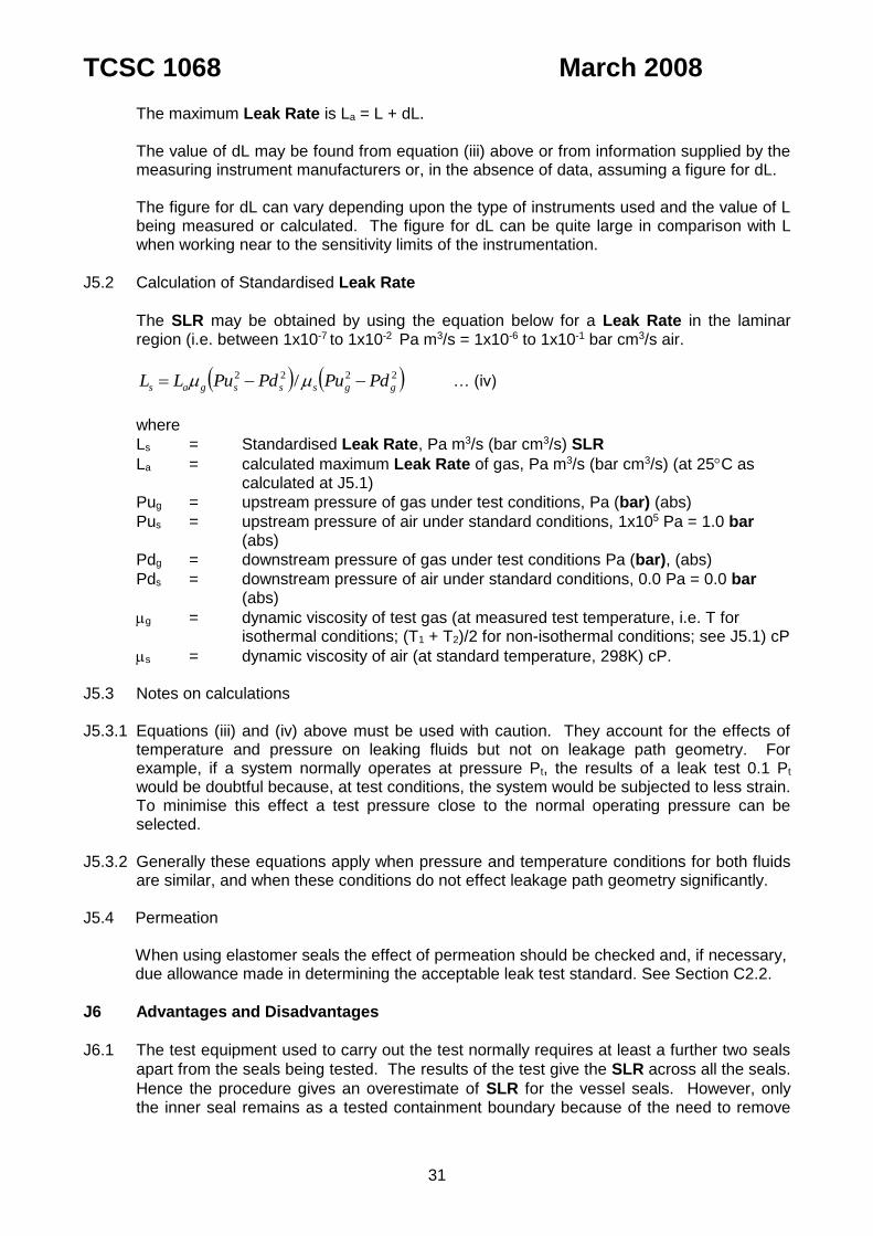
The maximum Leak Rate is La = L + dL. The value of dL may be found from equation (iii) above or from information supplied by the
measuring instrument manufacturers or, in the absence of data, assuming a figure for dL. The figure for dL can vary depending upon the type of instruments used and the value of L
being measured or calculated. The figure for dL can be quite large in comparison with L when working near to the sensitivity limits of the instrumentation.
J5.2 Calculation of Standardised Leak Rate
The SLR may be obtained by using the equation below for a Leak Rate in the laminar region (i.e. between 1x10⁻⁷ to 1x10⁻² Pa m3/s = 1x10⁻⁶ to 1x10⁻¹ bar cm3/s air.
2222 / ggsssgas PdPuPdPuLL … (iv)
where
Ls = Standardised Leak Rate, Pa m3/s (bar cm3/s) SLR
La = calculated maximum Leak Rate of gas, Pa m3/s (bar cm3/s) (at 25C as calculated at J5.1)
Pug = upstream pressure of gas under test conditions, Pa (bar) (abs)
Pus = upstream pressure of air under standard conditions, 1x10⁵ Pa = 1.0 bar (abs)
Pdg = downstream pressure of gas under test conditions Pa (bar), (abs)
Pds = downstream pressure of air under standard conditions, 0.0 Pa = 0.0 bar (abs)
g = dynamic viscosity of test gas (at measured test temperature, i.e. T for isothermal conditions; (T1 + T2)/2 for non-isothermal conditions; see J5.1) cP
s = dynamic viscosity of air (at standard temperature, 298K) cP. J5.3 Notes on calculations J5.3.1 Equations (iii) and (iv) above must be used with caution. They account for the effects of
temperature and pressure on leaking fluids but not on leakage path geometry. For example, if a system normally operates at pressure Pt, the results of a leak test 0.1 Pt would be doubtful because, at test conditions, the system would be subjected to less strain. To minimise this effect a test pressure close to the normal operating pressure can be selected.
J5.3.2 Generally these equations apply when pressure and temperature conditions for both fluids
are similar, and when these conditions do not effect leakage path geometry significantly. J5.4 Permeation When using elastomer seals the effect of permeation should be checked and, if necessary,
due allowance made in determining the acceptable leak test standard. See Section C2.2.
J6 Advantages and Disadvantages
J6.1 The test equipment used to carry out the test normally requires at least a further two seals
apart from the seals being tested. The results of the test give the SLR across all the seals.
Hence the procedure gives an overestimate of SLR for the vessel seals. However, only the inner seal remains as a tested containment boundary because of the need to remove
TCSC 1068 March 2008
32
the test equipment and remake the seal on the interspace test point connection. If a test sensitivity of the order of 1x10⁻⁷ Pa m3/s = 1x10⁻⁶ bar cm3/s is required, the leak-tightness of test equipment seals may decide the sensitivity of the test. To give maximum sensitivity the test equipment volume should be as low as possible.
J6.2 If the procedure is used in the test work (e.g. testing before and after drop tests) at least
one of the seals of the test equipment will have to be broken and later re-sealed. J6.3 High pressure will increase the test sensitivity but there are disadvantages. The ‘O’ rings
may move giving unreliable results and also the cavity could become pressurised. In a container with double O-ring seals and a testable interspace, the inner of the two seals will generally be considered to be the containment boundary. The use of a high test pressure should be avoided, as this may displace the containment seal inwards within its groove, away from the position it may naturally take up when resisting out-leakage of radioactive contents. In extreme cases the seal may lose contact with the groove inside diameter, thus affecting leak path geometry. Before specifying high test pressures, the designer needs to be satisfied that bulk seal movement will not occur.
J7 Hazards J7.1 As the test volume is pressurised, care must be taken to ensure that the vessel will not be
dangerously stressed as failure due to gas pressurisation can be ‘explosive’ and extremely hazardous. Test volume would typically be pressurised over a range of pressures depending on the operating conditions

TCSC 1068 March 2008
33
APPENDIX K TEST NO. 7 - SNIFFER - GAS MASS SPECTROMETER
K1 Applicability of the Method
K1.1 This procedure is best used on large containers or, sources where the area of potential
leak, e.g. a weld or seal, is clearly visible. There must be some facility for pressurising the
inside of the weld or seal, preferably to 1x10⁵ Pa = 1 bar helium.
K2 Leak Rate Indication
K2.1 The Leak Rate is given by a multi-range gauge Mass Spectrometer Leak Detector (MSLD), which measures the total leakage by detecting a concentration of helium. The
spectrometer is calibrated with a Calibrated leak, typically 1x10⁻⁹ Pa m3/s = 1x10⁻⁸ bar cm3/s.
K3 Test Sensitivity
K3.1 The sensitivity is dependent upon the machine, typically in the range 1x10⁻⁷ to 1x10⁻⁹ Pa
m3/s = 1x10⁻⁶ to 1x10⁻⁸ bar cm3/s SLR and upon other factors outlined in Section K5.
K4 Test Method
K4.1 Ensure all surfaces are clean and dry, as any foreign matter or moisture may temporarily
block a leak. K4.2 Connect the sniffer probe to the calibrated MSLD, and evacuate the equipment.
K4.3 Fill the source or container to 1x10⁵ Pa = 1 bar absolute with commercially available helium.
K4.4 Slowly move the probe across the likely areas for a leak, e.g. welds and seals, taking care
to keep the tip as close to the surface as possible, and the probe perpendicular to the surface.
K5 Advantages and Disadvantages
K5.1 The use of Gas Mass Spectrometer requires an experienced operator.
K5.2 The Leak Rate registered by the sniffer probe is likely to be one or more orders of
magnitude lower than the true Leak Rate. This may decide the lower limit of the sensitivity. This test method is qualitative only.
K5.3 There are battery powered portable units available, but they tend to be less sensitive.
K6 Hazards
K6.1 Obey normal laboratory precautions.

TCSC 1068 March 2008
34
APPENDIX L TEST NO. 8 - SPRAY - GAS MASS SPECTROMETER
L1 Applicability of the Method
L1.1 This procedure can be used for testing part finished capsules or seals in containers,
provided that one side of a potential leak can be evacuated, and the other side is easily accessible with a supply of helium.
L2 Leak Rate Indication
L2.1 The Leak Rate is given by a multi-range gauge Mass Spectrometer Leak Detector (MSLD), which measures the total leakage by detecting a concentration of helium. The
spectrometer is calibrated with a Calibrated leak, typically 1x10⁻⁹ Pa m3/s = 1x10⁻⁸ bar cm3/s.
L3 Test Sensitivity
L3.1 The sensitivity is dependent on the machine, typically in the range of 1x10⁻⁷ to 1x10⁻⁹ Pa
m3/s = 10-6 to 10-8 bar cm3/s SLR.
L4 Test Method
L4.1 Check and adjust the calibration of the MSLD using a known leak. L4.2 Ensure all surfaces are clean and dry, as any foreign matter or moisture may temporarily
block a leak. L4.3 Attach the component or seal to the MSLD via vacuum tight connections. L4.4 Evacuate the assembly and check the background helium. L4.5 If the assembly fails to evacuate properly, clean and reseal the components and try again.
If the assembly still fails then check for a gross leak by another method, e.g. the vacuum bubble.
L4.6 Using a rubber tube held 2-3cm from the surfaces, blow helium over the entire assembly.
The flow rate should be of the order of 10 litres/min, and the helium purity is not critical. L4.7 Check for leakage. L4.8 If a leak is found it can be quantified by holding the rubber tube directly above it, and
waiting until the gauge needle steadies.
L5 Advantages and Disadvantages
L5.1 When a leak has been detected, it can be located with reasonable accuracy by attaching a
fine nozzle to the helium supply tube, and then spraying over the suspect area. The leak should only register when the fine jet of helium passes over it. This is a useful technique as it can also confirm that the leak detected is not in any of the vacuum connections.
L5.2 There appears to be little relationship between the helium flow and the size of leak
detected. This suggests that this area of the test is not very operator sensitive. This test method is qualitative only.

TCSC 1068 March 2008
35
L6 Hazards
L6.1 Make certain all connections are firmly clamped to prevent nozzle on tube being blown off. L6.2 The wearing of safety spectacles is strongly recommended. L6.3 Particular care must be exercised when operating high pressure gas cylinders. Always
ensure the reducing valve is working correctly and never point the probe at persons.
TCSC 1068 March 2008
36
APPENDIX M TEST NO. 9 - LIQUID NITROGEN
M1 Applicability of the Method
M1.1 This process is ideal for small sealed sources with an internal void volume of at least
2mm3. It is important that these sources can withstand the thermal shock of being placed into liquid nitrogen at 77K.
M2 Leak Rate Indication
M2.1 A leak is indicated by a stream of small bubbles through the test liquid, methanol in this
case.
M3 Test Sensitivity
M3.1 If no bubbles are observed the Leak Rate is less than 1x10⁻⁸ Pa m3/s = 1x10⁻⁷ bar cm3/s
SLR.
M4 Test Method
M4.1 Ensure that the source is clean and dry, and that the liquid nitrogen is clear and free from
ice. M4.2 Place source in a Dewar flask of liquid nitrogen for at least 5 minutes, until the liquid stops
boiling. M4.3 Remove the sample, and immediately place it in a transparent vessel containing sufficient
methanol to cover the source to a depth of at least 50mm. The source should be placed in the liquid in such a way that the area most likely to leak (e.g. the weld or window) is clearly visible.
M4.4 Observe for at least 2 minutes. M4.5 Should the source require retesting it should first be warmed to room temperature.
M5 Advantages and Disadvantages
M5.1 This test is most useful for small sealed sources whose small internal void volume makes
them unsuitable for the helium pressurisation test. M5.2 It is not suitable for sources with weak components, see M6.2.
M6 Hazards
M6.1 Liquid nitrogen should be handled with the greatest care. The operator should wear heavy
gloves and face visor at all times. M6.2 The methanol test tank should be adequately shielded in case the source becomes
dangerously over pressurised and disintegrates.
TCSC 1068 March 2008
37
APPENDIX N TEST NO. 10 - EVACUATED ENVELOPE - GAS MASS SPECTROMETER
N1 Applicability of Method
N1.1 This procedure is ideal for small test vessels which have a replaceable seal. Where
several seals are used (e.g. where a double ‘O’ ring closure is used) the procedure can be applied to each seal in turn.
N1.2 As helium is the most common test gas, helium is assumed to be the test gas in this
procedure.
N2 Leak Rate Indication
N2.1 The Leak Rate is given by a Mass Spectrometer Leak Detector (MSLD), which measures the total leakage by detecting a concentration of helium. The spectrometer is calibrated
with a Calibrated leak typically 1x10⁻⁹ Pa m3/s = 1x10⁻⁸ bar cm3/s He.
N3 Test Sensitivity
N3.1 The sensitivity is dependent upon the machine (typically in the range 1x10⁻⁷ to 1x10-11 Pa
m3/s = 1x10⁻⁶ to 1x10⁻¹⁰ bar cm3/s SLR). The accuracy is limited by the uncertainty of the
partial pressure of the contained helium (typically 1x10⁵ Pa = 1 bar).
N4 Test Method
N4.1 Check and adjust if necessary the calibration of the MSLD using a Calibrated leak. N4.2 If practicable thoroughly clean the vessel, inside and out (with cleaning solvent). Make
sure the ‘O’ ring interfaces are free from dust, fibres, etc. Clean ‘O’ rings making sure they are free of dust, etc..
The presence of dust, fibres, etc. on ‘O’ rings and ‘O’ ring interfaces can introduce large
leakage paths.
For Leak Rates smaller than 1x10⁻⁷ Pa m3/s = 1x10⁻⁶ bar cm3/s SLR, wetting of the vessel (e.g. with cleaning fluid) before the leak test should be avoided whenever possible. When wetting cannot be avoided, the vessel should be dried thoroughly before the leak test.
N4.3 Ensure that the test chamber is ‘free’ from helium contamination. The background helium
Leak Rate should be low compared with the test pass level. Make sure the vessel is ‘free’ from helium contamination. If the presence of helium from a
containment vessel is suspected, clean the vessel thoroughly with cleaning solvent. N4.4 Evacuate the test chamber connected to the MSLD. Test for helium contamination.
Ensure any helium contamination is ‘small’. N4.5 Helium purge vessel, with the vessel held in an inverted position to trap the helium, and
immediately fit the lid. Care must be taken to ensure that the contained volume is fully purged with helium and
that it is closed quickly thus trapping in virtually pure helium at atmospheric pressure.

TCSC 1068 March 2008
38
N4.6 Place the vessel in the test chamber attached to the MSLD, evacuate the chamber and test for helium leakage.
N4.7 Check after the Leak Rate measurement that helium is present in the vessel. N4.8 Care must be taken with ‘rubber’ ‘O’ rings. Permeation of helium through these types of
seals can be a problem. A knowledge of the permeation characteristics of the seal
material is necessary if Leak Rates less than approximately 1x10⁻⁷ Pa m3/s = 1x10⁻⁶ bar cm3/s He are required (depending upon ‘O’ ring type and dimensions). Ensure that the duration of the test is not long enough for the ‘O’ ring(s) to become saturated with helium during the test.
N4.9 Leak test procedures with Leak Rate sensitivities of <1x10⁻⁷ Pa m3/s = <1x10⁻⁶ bar cm3/s He, require a well trained operator.
N5 Calculation of Standardised Leak Rate
N5.1 Determination of Leak Rate at test conditions.
MSLD’s give a direct reading of helium Leak Rate and are usually calibrated in units of atm cm3/s He (1% greater than bar cm3/s He) or mbar 1/s He (equivalent to 0.1 Pa m3/s = 1 bar
cm3/s He). Some MSLD’s give Leak Rates in “air equivalent”. This involves multiplying
the “air equivalent” Leak Rate by approximately 2.65 to obtain a helium Leak Rate. This factor is only valid in the molecular flow regime, i.e. <1x10⁻⁸ Pa m3/s = <1x10⁻⁷ bar cm3/s He.
N5.2 Calculation of Standardised Leak Rate.
The SLR is calculated from the following.
For a helium Leak Rate <1x10⁻⁸ Pa m3/s = <1x10⁻⁷ bar cm3/s He,
hhaaahhahs PdPuPdPuMTMTLL //½
For a helium Leak Rate > 1x10⁻⁸ Pa m3/s = >1x10⁻⁷ bar cm3/s He
2222 / hhaaahhs PdPuPdPuLL
where
Ls = Standardised Leak Rate, Pa m3/s or bar cm3/s SLR
Lh = measured Leak Rate of helium at temperature ThK, Pa m3/s or bar cm3/s He
Pua = upstream pressure of air, 1.013x10⁵ Pa = 1.013 bar (abs)
Puh = upstream partial pressure of helium, Pa or bar (abs)
Pda = downstream pressure of air, 0.0 Pa = 0.0 bar (abs)
Pdh = downstream partial pressure of helium Pa or bar (abs)
a = dynamic viscosity of air, at temperature Ta (cP)
h = dynamic viscosity of helium at temperature Th (cP) Ma = air molecular mass weight, atomic mass units Mh = helium molecular mass weight, atomic mass units Ta = temperature of air, 298K Th = temperature of helium, K
TCSC 1068 March 2008
39
N6 Advantages and Disadvantages
N6.1 This procedure is very convenient for prototype and manufacturing leak tests on small re-
sealable vessels which are small enough to fit inside an evacuated envelope.
N6.2 The method can indicate Leak Rates down to approximately 1x10-11 Pa m3/s = 1x10⁻¹⁰ bar cm3/s He.
N6.3 One disadvantage of the test, apart from the helium permeation characteristics of rubber
‘O’ rings, is the fact that the helium is generally based on the assumption that the helium
leakage is from a volume at 1x10⁵ Pa = 1 bar helium against a helium vacuum.
N6.4 Leak test procedures with Leak Rate sensitivities of <1x10⁻⁷ Pa m3/s = <1x10⁻⁶ bar cm3/s He require a well trained operator.
N.6.5 Permeation When using elastomer seals the effect of permeation should be checked and, if necessary,
due allowance made in determining the acceptable leak test standard. See Section C2.2.
N7 Hazards
N7.1 Hazards are those found when working with vacuum equipment.
TCSC 1068 March 2008
40
APPENDIX P TEST NO. 11 - GAS FILLED ENVELOPE - GAS MASS SPECTROMETER
P1 Applicability of Method
P1.1 This procedure is ideal for large test vessels which have a replaceable seal. Where
several seals are used (e.g. where a double ‘O’ ring closure is used) the procedure can be applied to each seal in turn.
P1.2 As helium is the most common test gas, helium is assumed to be the test gas in this
procedure.
P2 Leak Rate Indication
P2.1 The Leak Rate is given by a Mass Spectrometer Leak Detector (MSLD) which measures the total leakage by detecting a concentration of helium. The spectrometer is calibrated
with a Calibrated leak typically with leak rate of 1x10⁻⁹ Pa m3/s = 1x10⁻⁸ bar cm3/s He.
P3 Test Sensitivity
P3.1 The sensitivity is dependent upon the machine (typically in the range 1x10⁻⁷ to 1x10-11 Pa
m3/s = 1x10⁻⁶ to 1x10⁻¹⁰ bar cm3/s SLR). The accuracy is limited by the uncertainty of the
pressure of the contained helium (typically 1x10⁵ Pa = 1 bar).
P4 Test Method
P4.1 Check and adjust if necessary the calibration of the MSLD using a Calibrated leak. P4.2 If practicable thoroughly clean the vessel, inside and out (with cleaning solvent). This will
not be possible with large,cavities or containers containing radioactive matrial. Make sure the ‘O’ ring interfaces are free from dust, fibres, etc. Clean ‘O’ rings making
sure they are free of dust, fibres, etc. The presence of dust, fibres, etc. on ‘O’ rings and ‘O’ ring interfaces can introduce large
leakage paths. P4.3 Connect the MSLD to the vessel inner volume. Evacuate the vessel and ensure helium
contamination is 'small’. The background helium Leak Rate should be low compared with the test pass level.
P4.4 Place envelope around vessel (still connected to MSLD) and seal. Purge envelope with
helium to atmospheric pressure and test for helium leakage. Care must be taken to ensure that the envelope is fully purged with helium, that it contains
helium at 1x10⁵ Pa = 1 bar absolute and that the helium is retained in the envelope at a
pressure of 1x10⁵ Pa = 1 bar.
P4.5 Check after the Leak Rate measurement that helium is present in the envelope. P4.6 Care must be taken with ‘rubber’ ‘O’ rings. Permeation of helium through this type of seal
can be a problem. A knowledge of the permeation characteristics is necessary if Leak
Rates less than approximately 1x10⁻⁷ Pa m3/s = 1x10⁻⁶ bar cm3/s He are required (depending upon ‘O’ ring type and dimensions). Ensure that the duration of the test is not long enough for the ‘O’ ring(s) to become ‘saturated’ with helium during the test.
TCSC 1068 March 2008
41
P4.7 Leak test procedures with Leak Rate of <1x10⁻⁷ Pa m3/s = 1x10⁻⁶ bar cm3/s He requires a well trained operator.
P5 Calculation of Standardised Leak Rate
P5.1 Determination of Leak Rate at test conditions
MSLDs give a direct reading of helium Leak Rate and are usually caliibrated in units of atm cm3/s He (1% greater than bar cm3/s He) or mbar 1/s He (equivalent to bar cm3/s He).
Some MSLDs give Leak Rates in ‘air equivalent’. This involves multiplying the ‘air
equivalent’ Leak Rate by approximately 2.65 to obtain a helium Leak Rate. This factor is only valid in the molecular flow regime, i.e. <1x10⁻⁸ Pa m3/s = 1x10⁻⁷ bar cm3/s He.
P5.2 Calculation of Standardised Leak Rate
The SLR is calculated from the following.
For a helium Leak Rate <1x10⁻⁸ Pa m3/s = 10-7 bar cm3/s He
hhaaahhahs PdPuPdPuMTMTLL //½
For a helium Leak Rate >1x10⁻⁸ Pa m3/s = 10-7 bar cm3/s He
2222 / hhaaahhs PdPuPdPuLL
where
Ls = Standardised Leak Rate, Pa m3/s or bar cm3/s SLR
Lh = measured Leak Rate of helium at temperature Th K, Pa m3/s or bar cm3/s He
Pua = upstream partial pressure of air, 1x10⁵ Pa = 1.0 bar (abs)
Puh = upstream partial pressure of helium, Pa or bar (abs)
Pda = downstream partial pressure of air, 0.0 Pa = 0.0 bar (abs)
Pdh = downstream partial pressure of helium, Pa or bar (abs)
a = dynamic viscosity of air, at temperature Ta (cP)
h = dynamic viscosity of helium, at temperature Th (cP) Mh = helium molecular mass weight, atomic mass units Ma = air molecular mass weight, atomic mass units Ta = temperature of air 298K Th = temperature of helium, K
P6 Advantages and Disadvantages
P6.1 This procedure is very convenient for prototype and manufacturing leak tests for vessels
too large to put in an evacuated chamber (for leak testing by evacuated envelope test), but which can be encased in an external envelope by constructing a ‘tent’ around the vessel.
P6.2 The method can indicate Leak Rates down to approximately 1x10-11 Pa m3/s = 1x10⁻¹⁰ bar cm3/s He.
P6.3 One disadvantage of the test, apart from the helium permeation characteristics of ‘rubber’
‘O’ rings, is the fact that the helium pressure in the envelope may not be known. The Leak
Rate of helium is based on the assumption that the helium leakage is from an envelope at
TCSC 1068 March 2008
42
1x105 = 1 bar helium against a vacuum. In instances where a flexible tent is constructed around the container, scrupulous attention must be paid to sealing all joints with tape to minimise He leakage and the possible ingress of air. In nested containers where a gas-tight boundary exists around the containment system then this requirement is readily achieved. In all cases it is the partial pressure of He that needs to be maintained at 1x10⁵ Pa (1 bar). For a simple tented boundary then clearly the bag will be at atmospheric pressure and therefore nees to be purged and wholly He filled. In the case of a rigid envelope there may be the option to add He to an existing air fill thereby raising the total pressure to 2x10⁵ Pa (2 bar) will ensure the partial pressure of He is at 1x10⁵ Pa (1 bar).
P6.4 Leak test procedures with Leak Rate sensitivities of <1x10⁻⁷ Pa m3/s = 10-6 bar cm3/s He, require a well trained operator.
P6.5 Permeation When using elastomer seals the effect of permeation should be checked and, if necessary,
due allowance made in determining the acceptable leak test standard. See Section C2.2.
P7 Hazards
P7.1 No pressurisation hazard exists if helium pressure of approximately 1x10⁵ Pa = 1 bar is used. If the test method is used with higher helium pressures, in order to increase the sensitivity of the test, then care should be taken.
P7.2 Helium is an asphyxiant, so care need to be taken when working with large volumes.
Other hazards are those found when working with vacuum equipment.
TCSC 1068 March 2008
43
APPENDIX Q TEST NO. 12 - BACK PRESSURISATION - GAS MASS SPECTROMETER
Q1 Applicability of the Method
Q1.1 This process is ideal for sealed sources, and containers from the very small up to the limit
of the size of the test chambers, provided the internal void volume is at least 10mm3.
Q2 Leak Rate Indication
Q2.1 The Leak Rate is given by a multi-range gauge Mass Spectrometer Leak Detector (MSLD), which measures the total leakage by detecting a concentration of helium. The
spectrometer is calibrated with a Calibrated leak, typically 1x10⁻⁹ Pa m3/s = 1x10⁻⁸ bar cm3/s He.
Q3 Test Sensitivity
Q3.1 The test sensitivity is dependent upon the machine, typically in the range 1x10⁻⁷ to 1x10-11
Pa m3/s = 1x10⁻⁶ to 1x10⁻¹⁰ bar cm3/s SLR, and by the amount of helium absorbed onto the surface of the source or container. The accuracy is limited by the uncertainty of the helium pressure in the void volume, the time of pressurisation, and the time between pressurisation and testing. All these factors mitigate against which would otherwise be a
very accurate procedure. The reading obtained for the Leak Rate is largely qualitative.
Q4 Test Method
Q4.1 Calculate the internal free void volume in mm3 from the drawing. Q4.2 Note the condition of the surface - is it smooth or pitted. If the sample has been exposed
to very high temperature, this could produce a pitted surface. Q4.3 The background values for surface helium are taken to be 5x10⁻⁹ Pa m3/s = 5x10⁻⁸ bar
cm3/s for smooth surfaces, and 4x10⁻⁸ Pa m3/s = 4x10⁻⁷ bar cm3/s for pitted surfaces. Q4.4 From Table 3 decide upon the “bombing” time required. When more than one source or
container is being tested use the longest time applicable. Q4.5 Ensure sources or containers are as clean and dry as possible. Place them in the
“bombing” chamber for the prescribed length of time with a helium pressure of 34x105 Pa = 34 bar. Always handle the samples with forceps or similar remote handling tools.
Q4.6 Check and adjust the calibration of the MSLD using a known reference leak. Q4.7 Allow up to 5 minutes after the “bombing” for the surfaces of the samples to de-gas, and
then test them for leakage on the MSLD within 25 minutes of ending the pressurisation.
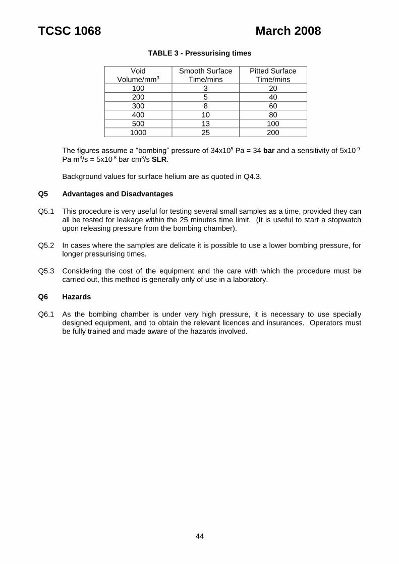
TCSC 1068 March 2008
44
TABLE 3 - Pressurising times
Void Volume/mm3
Smooth Surface Time/mins
Pitted Surface Time/mins
100 3 20
200 5 40
300 8 60
400 10 80
500 13 100
1000 25 200
The figures assume a “bombing” pressure of 34x105 Pa = 34 bar and a sensitivity of 5x10⁻⁹
Pa m3/s = 5x10⁻⁸ bar cm3/s SLR. Background values for surface helium are as quoted in Q4.3.
Q5 Advantages and Disadvantages
Q5.1 This procedure is very useful for testing several small samples as a time, provided they can
all be tested for leakage within the 25 minutes time limit. (It is useful to start a stopwatch upon releasing pressure from the bombing chamber).
Q5.2 In cases where the samples are delicate it is possible to use a lower bombing pressure, for
longer pressurising times. Q5.3 Considering the cost of the equipment and the care with which the procedure must be
carried out, this method is generally only of use in a laboratory.
Q6 Hazards
Q6.1 As the bombing chamber is under very high pressure, it is necessary to use specially
designed equipment, and to obtain the relevant licences and insurances. Operators must be fully trained and made aware of the hazards involved.

TCSC 1068 March 2008
45
APPENDIX R TEST NO. 13 - HYGROSCOPIC CRYSTALS
R1 Applicability of the Method
R1.1 This is a method for determining the Leak Rate of water into a containment system and is commonly applied to containers for fissile materials as satisfying the regulatory requirements for a water immersion test.
R2 Leak Rate Indication
R2.1 Apart from any actual visible water in the container cavity, a change of colour of the
anhydrous copper sulphate indicates the presence of water, with a great colour change indicating an increased quantity of moisture absorbed, and the weighing of both the
calcium chloride and the copper sulphate present gives a quantitative Leak Rate indication.
R3 Test Sensitivity
R3.1 The sensitivity of this test is time dependent. Based on an 8 hour test period a Leak Rate of less than 10-5 g/s of water can be detected.
R4 Test Method
R4.1 Fill two small pots with weighed quantities of anhydrous copper sulphate and calcium
chloride respectively. Use 5g of each per litre of free volume within the container to be tested. Pots should be sealed immediately after filling.
R4.2 Place the pots inside the container to be tested, remove the pot seals and seal the
container as for transport, as quickly as possible. R4.3 Immerse the container in water in accordance with the test requirements. R4.4 After removing the container from the water, open it, and re-seal the pots as quickly as
possible. R4.5 Re-weight the pots.
R5 Calculation of Standardised Leak Rate
R5.1 The water in-leakage rate is calculated by adding the additional weight of water collected
by the powder to the weight of any actual water present in the container cavity after the water immersion test and dividing it by the time duration of the test period.
R5.2 An immediate indication of whether significant quantities of water have been absorbed by
the crystals can be obtained by comparing the intensity of the blue colour of the copper sulphate crystals with a sample left in the “laboratory” for the same time as the test time.
R6 Advantages and Disadvantages
R6.1 The time interval between weighing the crystals and sealing the pot in the container cavity
should be kept to a minimum, with the pot being kept closed until the last moment to prevent the ingress of moisture. The same applies during the reverse procedure after the water immersion test [or preliminary trial].
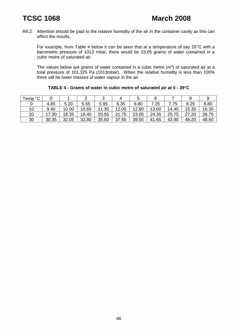
TCSC 1068 March 2008
46
R6.2 Attention should be paid to the relative humidity of the air in the container cavity as this can affect the results.
For example, from Table 4 below it can be seen that at a temperature of say 25C with a barometric pressure of 1013 mbar, there would be 23.05 grams of water contained in a cubic metre of saturated air.
The values below are grams of water contained in a cubic metre (m3) of saturated air at a
total pressure of 101,325 Pa (1013mbar). When the relative humidity is less than 100% there will be lower masses of water vapour in the air.
TABLE 4 - Grams of water in cubic metre of saturated air at 0 - 39C
Temp C 0 1 2 3 4 5 6 7 8 9
0 4.85 5.20 5.55 5.95 6.35 6.80 7.25 7.75 8.25 8.80
10 9.40 10.00 10.65 11.35 12.05 12.80 13.60 14.45 15.35 16.30
20 17.30 18.35 19.40 20.55 21.75 23.05 24.35 25.75 27.20 28.75
30 30.35 32.05 33.80 35.60 37.55 39.55 41.65 43.90 46.20 48.60
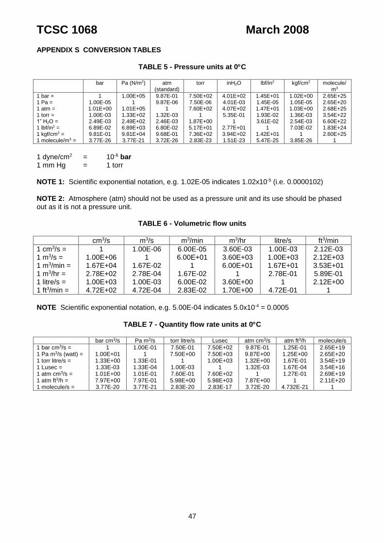
TCSC 1068 March 2008
47
APPENDIX S CONVERSION TABLES
TABLE 5 - Pressure units at 0C
bar Pa (N/m2) atm
(standard) torr inH2O lbf/in2 kgf/cm2 molecule/
m3
1 bar = 1 1.00E+05 9.87E-01 7.50E+02 4.01E+02 1.45E+01 1.02E+00 2.65E+25 1 Pa = 1.00E-05 1 9.87E-06 7.50E-06 4.01E-03 1.45E-05 1.05E-05 2.65E+20 1 atm = 1.01E+00 1.01E+05 1 7.60E+02 4.07E+02 1.47E+01 1.03E+00 2.68E+25 1 torr = 1.00E-03 1.33E+02 1.32E-03 1 5.35E-01 1.93E-02 1.36E-03 3.54E+22 1” H2O = 2.49E-03 2.49E+02 2.46E-03 1.87E+00 1 3.61E-02 2.54E-03 6.60E+22 1 lbf/in2 = 6.89E-02 6.89E+03 6.80E-02 5.17E+01 2.77E+01 1 7.03E-02 1.83E+24 1 kgf/cm2 = 9.81E-01 9.81E+04 9.68E-01 7.36E+02 3.94E+02 1.42E+01 1 2.60E+25 1 molecule/m3 = 3.77E-26 3.77E-21 3.72E-26 2.83E-23 1.51E-23 5.47E-25 3.85E-26 1
1 dyne/cm2 = 10-6 bar 1 mm Hg = 1 torr
NOTE 1: Scientific exponential notation, e.g. 1.02E-05 indicates 1.02x10⁻⁵ (i.e. 0.0000102)
NOTE 2: Atmosphere (atm) should not be used as a pressure unit and its use should be phased out as it is not a pressure unit.
TABLE 6 - Volumetric flow units
cm3/s m3/s m3/min m3/hr litre/s ft3/min
1 cm3/s = 1 1.00E-06 6.00E-05 3.60E-03 1.00E-03 2.12E-03 1 m3/s = 1.00E+06 1 6.00E+01 3.60E+03 1.00E+03 2.12E+03 1 m3/min = 1.67E+04 1.67E-02 1 6.00E+01 1.67E+01 3.53E+01 1 m3/hr = 2.78E+02 2.78E-04 1.67E-02 1 2.78E-01 5.89E-01 1 litre/s = 1.00E+03 1.00E-03 6.00E-02 3.60E+00 1 2.12E+00 1 ft3/min = 4.72E+02 4.72E-04 2.83E-02 1.70E+00 4.72E-01 1
NOTE Scientific exponential notation, e.g. 5.00E-04 indicates 5.0x10-4 = 0.0005
TABLE 7 - Quantity flow rate units at 0C
bar cm3/s Pa m3/s torr litre/s Lusec atm cm3/s atm ft3/h molecule/s
1 bar cm3/s = 1 1.00E-01 7.50E-01 7.50E+02 9.87E-01 1.25E-01 2.65E+19 1 Pa m3/s (watt) = 1.00E+01 1 7.50E+00 7.50E+03 9.87E+00 1.25E+00 2.65E+20 1 torr litre/s = 1.33E+00 1.33E-01 1 1.00E+03 1.32E+00 1.67E-01 3.54E+19 1 Lusec = 1.33E-03 1.33E-04 1.00E-03 1 1.32E-03 1.67E-04 3.54E+16 1 atm cm3/s = 1.01E+00 1.01E-01 7.60E-01 7.60E+02 1 1.27E-01 2.69E+19 1 atm ft3/h = 7.97E+00 7.97E-01 5.98E+00 5.98E+03 7.87E+00 1 2.11E+20 1 molecule/s = 3.77E-20 3.77E-21 2.83E-20 2.83E-17 3.72E-20 4.732E-21 1

TCSC 1068 March 2008
48
TABLE 8 - Leak Rate units 25C
Standardised Leak Rate
(SLR)
Mass
Spectrometer
Gas pressure
drop
Gas pressure
drop
Gas pressure
rise
bar cm3/sPa
m3/s (bar
cm3/s) air
Pa m3/s
(watt) air
bar cm3/sPa
m3/s (bar
cm3/s)
helium
bar cm3/sPa
m3/s (bar
cm3/s)
air
bar cm3/sPa
m3/s (bar
cm3/s)
air
bar cm3/sPa
m3/s (bar
cm3/s)
air
Upstream pressure (Pu) 1 bar 1.0E+05 Pa 1 bar 2 bar 10 bar 0 bar
Downstream pressure (Pd) 0 bar 0 Pa 0 bar 1 bar 1 bar 1 bar
Standardised Leak Rate (SLR)
bar cm3/sPa m3/s (bar cm3/s) air
Pu = 1 bar Pd = 0 bar 1 1.00E-01 9.30E-01 3.00E+00 1.00E+02 1
Pa m3/s (watt) air
Pu = 1.0E+05 Pa Pd = 0 Pa 1.00E+01 1 9.30E+00 3.00E+01 1.00E+03 1.00E+01
Mass Spectrometer
bar cm3/sPa m3/s (bar cm3/s)
helium
Pu = 1 bar Pd = 0 bar 1.08E+00 1.08E-01 1 3.23E+00 1.06E+02 1.08E+00
Gas Pressure Drop
bar cm3/sPa m3/s (bar cm3/s) air
Pu = 2 Pd = 1 bar 3.30E-01 3.30E-02 3.10E-01 1 3.30E+01 3.30E-01
bar cm3/sPa m3/s (bar cm3/s) air
Pu = 10 bar Pd = 1 Bar 1.00E-02 1.00E-03 9.4E-03 3.30E-02 1 1.00E-02
Gas Pressure Rise
bar cm3/sPa m3/s (bar cm3/s) air
Pu = 0 bar Pd = 1 bar 1 1.00E-01 9.30E-01 3.0E+00 1.00E+02 1
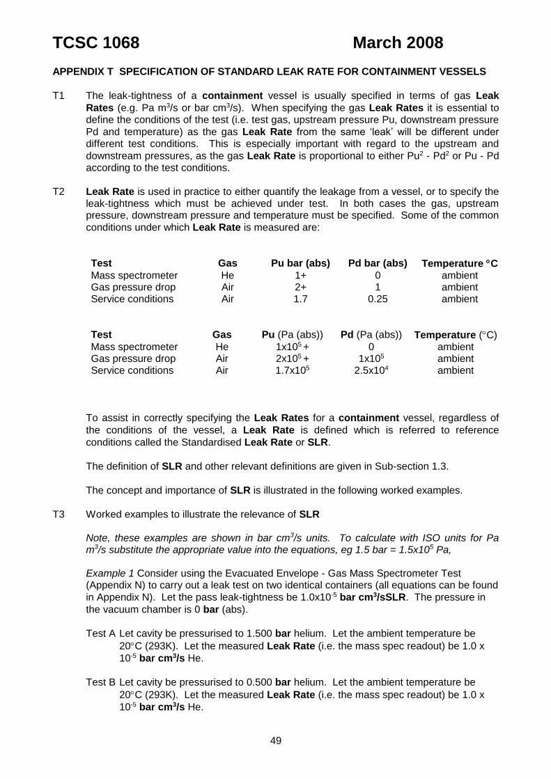
TCSC 1068 March 2008
49
APPENDIX T SPECIFICATION OF STANDARD LEAK RATE FOR CONTAINMENT VESSELS
T1 The leak-tightness of a containment vessel is usually specified in terms of gas Leak
Rates (e.g. Pa m3/s or bar cm3/s). When specifying the gas Leak Rates it is essential to define the conditions of the test (i.e. test gas, upstream pressure Pu, downstream pressure
Pd and temperature) as the gas Leak Rate from the same ‘leak’ will be different under different test conditions. This is especially important with regard to the upstream and
downstream pressures, as the gas Leak Rate is proportional to either Pu2 - Pd2 or Pu - Pd according to the test conditions.
T2 Leak Rate is used in practice to either quantify the leakage from a vessel, or to specify the leak-tightness which must be achieved under test. In both cases the gas, upstream pressure, downstream pressure and temperature must be specified. Some of the common
conditions under which Leak Rate is measured are:
Test Gas Pu bar (abs) Pd bar (abs) Temperature C Mass spectrometer He 1+ 0 ambient Gas pressure drop Air 2+ 1 ambient Service conditions Air 1.7 0.25 ambient
Test Gas Pu (Pa (abs)) Pd (Pa (abs)) Temperature (C) Mass spectrometer He 1x10⁵ + 0 ambient Gas pressure drop Air 2x10⁵ + 1x10⁵ ambient Service conditions Air 1.7x10⁵ 2.5x10⁴ ambient
To assist in correctly specifying the Leak Rates for a containment vessel, regardless of
the conditions of the vessel, a Leak Rate is defined which is referred to reference
conditions called the Standardised Leak Rate or SLR.
The definition of SLR and other relevant definitions are given in Sub-section 1.3.
The concept and importance of SLR is illustrated in the following worked examples.
T3 Worked examples to illustrate the relevance of SLR Note, these examples are shown in bar cm3/s units. To calculate with ISO units for Pa
m3/s substitute the appropriate value into the equations, eg 1.5 bar = 1.5x10⁵ Pa,
Example 1 Consider using the Evacuated Envelope - Gas Mass Spectrometer Test (Appendix N) to carry out a leak test on two identical containers (all equations can be found
in Appendix N). Let the pass leak-tightness be 1.0x10⁻⁵ bar cm3/sSLR. The pressure in
the vacuum chamber is 0 bar (abs).
Test A Let cavity be pressurised to 1.500 bar helium. Let the ambient temperature be
20C (293K). Let the measured Leak Rate (i.e. the mass spec readout) be 1.0 x
10-5 bar cm3/s He.
Test B Let cavity be pressurised to 0.500 bar helium. Let the ambient temperature be
20C (293K). Let the measured Leak Rate (i.e. the mass spec readout) be 1.0 x
10-5 bar cm3/s He.
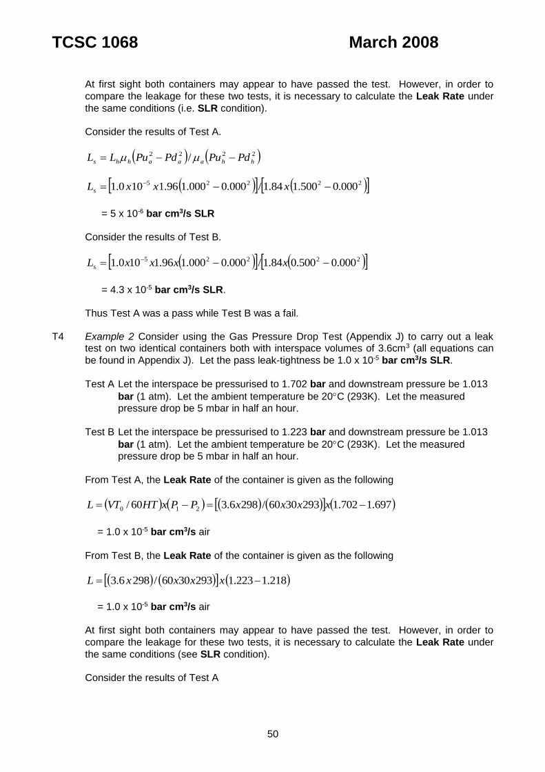
TCSC 1068 March 2008
50
At first sight both containers may appear to have passed the test. However, in order to
compare the leakage for these two tests, it is necessary to calculate the Leak Rate under
the same conditions (i.e. SLR condition). Consider the results of Test A.
2222 / hhaaahhs PdPuPdPuLL
22225 000.0500.184.1/000.0000.196.1100.1 xxxLs
= 5 x 10⁻⁶ bar cm3/s SLR Consider the results of Test B.
22225 000.0500.084.1/000.0000.196.1100.1 xxxxLs
= 4.3 x 10⁻⁵ bar cm3/s SLR. Thus Test A was a pass while Test B was a fail. T4 Example 2 Consider using the Gas Pressure Drop Test (Appendix J) to carry out a leak
test on two identical containers both with interspace volumes of 3.6cm3 (all equations can
be found in Appendix J). Let the pass leak-tightness be 1.0 x 10⁻⁵ bar cm3/s SLR.
Test A Let the interspace be pressurised to 1.702 bar and downstream pressure be 1.013
bar (1 atm). Let the ambient temperature be 20C (293K). Let the measured pressure drop be 5 mbar in half an hour.
Test B Let the interspace be pressurised to 1.223 bar and downstream pressure be 1.013
bar (1 atm). Let the ambient temperature be 20C (293K). Let the measured pressure drop be 5 mbar in half an hour.
From Test A, the Leak Rate of the container is given as the following
697.1702.12933060/2986.360/ 210 xxxxPPxHTVTL
= 1.0 x 10⁻⁵ bar cm3/s air
From Test B, the Leak Rate of the container is given as the following
218.1223.12933060/2986.3 xxxxL
= 1.0 x 10⁻⁵ bar cm3/s air At first sight both containers may appear to have passed the test. However, in order to
compare the leakage for these two tests, it is necessary to calculate the Leak Rate under
the same conditions (see SLR condition). Consider the results of Test A
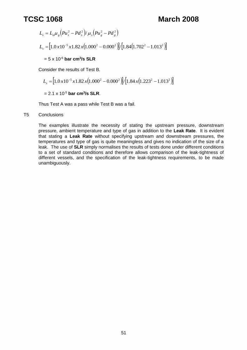
TCSC 1068 March 2008
51
2222 / ggsssgas PdPuPdPuLL
22225 013.1702.184.1/000.0000.182.1100.1 xxxLs
= 5 x 10⁻⁶ bar cm3/s SLR Consider the results of Test B.
22225 013.1223.184.1/000.0000.182.1100.1 xxxxLs
= 2.1 x 10⁻⁵ bar cm3/s SLR. Thus Test A was a pass while Test B was a fail. T5 Conclusions The examples illustrate the necessity of stating the upstream pressure, downstream
pressure, ambient temperature and type of gas in addition to the Leak Rate. It is evident
that stating a Leak Rate without specifying upstream and downstream pressures, the temperatures and type of gas is quite meaningless and gives no indication of the size of a
leak. The use of SLR simply normalises the results of tests done under different conditions to a set of standard conditions and therefore allows comparison of the leak-tightness of different vessels, and the specification of the leak-tightness requirements, to be made unambiguously.

TCSC 1068 March 2008
52
APPENDIX U TYPICAL EXISTING TEST POINTS
FIGURE 2. Typical irradiated fuel flask lid leak test point

TCSC 1068 March 2008
53
FIGURE 3. Typical test point with blanking plate
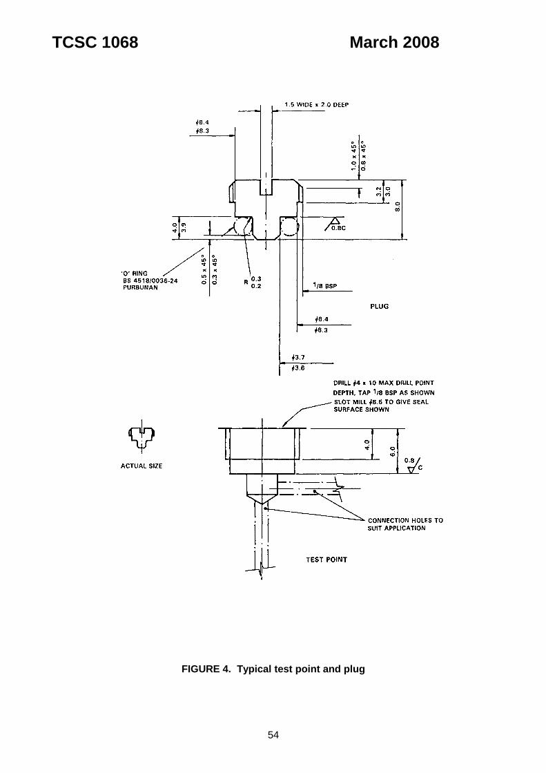
TCSC 1068 March 2008
54
FIGURE 4. Typical test point and plug
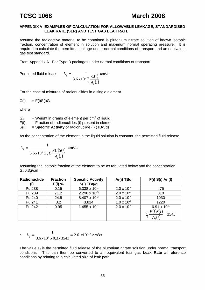
TCSC 1068 March 2008
55
APPENDIX V EXAMPLES OF CALCULATION FOR ALLOWABLE LEAKAGE, STANDARDISED
LEAK RATE (SLR) AND TEST GAS LEAK RATE Assume the radioactive material to be contained is plutonium nitrate solution of known isotopic fraction, concentration of element in solution and maximum normal operating pressure. It is required to calculate the permitted leakage under normal conditions of transport and an equivalent gas test standard. From Appendix A. For Type B packages under normal conditions of transport
Permitted fluid release iA
iCx
L
i
f
2
9106.3
1
cm3/s
For the case of mixtures of radionuclides in a single element C(i) = F(i)S(i)Ge
where Ge = Weight in grams of element per cm3 of liquid F(i) = Fraction of radionuclides (i) present in element
S(i) = Specific Activity of radionuclide (i) (TBq/g) As the concentration of the element in the liquid solution is constant, the permitted fluid release
iA
iSiFGx
L
ie
f
2
9106.3
1
cm3/s
Assuming the isotopic fraction of the element to be as tabulated below and the concentration Ge 0.3g/cm3.
Radionuclide
(i)
Fraction
F(i) %
Specific Activity
S(i) TBq/g
A2(i) TBq F(i) S(i) A2 (I)
Pu 238 0.15 6.338 x 10⁻¹ 2.0 x 10⁻⁴ 475
Pu 239 71.2 2.298 x 10⁻³ 2.0 x 10⁻⁴ 818
Pu 240 24.5 8.407 x 10⁻³ 2.0 x 10⁻⁴ 1030
Pu 241 3.2 3.814 1.0 x 10⁻² 1220
Pu 242 0.95 1.455 x 10⁻⁴ 2.0 x 10⁻⁴ 6.91 x 10⁻¹
35432
iA
iSiF
i
13
91061.2
35433.0106.3
1 xxxx
L f cm3/s
The value Lf is the permitted fluid release of the plutonium nitrate solution under normal transport
conditions. This can then be converted to an equivalent test gas Leak Rate at reference conditions by relating to a calculated size of leak path.
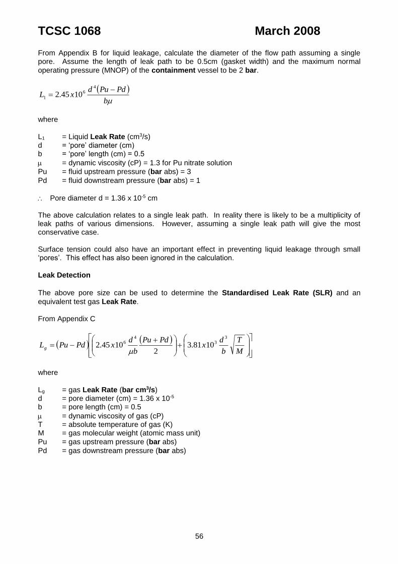
TCSC 1068 March 2008
56
From Appendix B for liquid leakage, calculate the diameter of the flow path assuming a single pore. Assume the length of leak path to be 0.5cm (gasket width) and the maximum normal
operating pressure (MNOP) of the containment vessel to be 2 bar.
b
PdPudxL
46
1 1045.2
where
L1 = Liquid Leak Rate (cm3/s) d = ‘pore’ diameter (cm) b = ‘pore’ length (cm) = 0.5
= dynamic viscosity (cP) = 1.3 for Pu nitrate solution
Pu = fluid upstream pressure (bar abs) = 3
Pd = fluid downstream pressure (bar abs) = 1
Pore diameter d = 1.36 x 10⁻⁵ cm The above calculation relates to a single leak path. In reality there is likely to be a multiplicity of leak paths of various dimensions. However, assuming a single leak path will give the most conservative case. Surface tension could also have an important effect in preventing liquid leakage through small ‘pores’. This effect has also been ignored in the calculation.
Leak Detection
The above pore size can be used to determine the Standardised Leak Rate (SLR) and an
equivalent test gas Leak Rate. From Appendix C
M
T
b
dx
PdPu
b
dxPdPuLg
33
46 1081.3
21045.2
where
Lg = gas Leak Rate (bar cm3/s) d = pore diameter (cm) = 1.36 x 10⁻⁵ b = pore length (cm) = 0.5
= dynamic viscosity of gas (cP) T = absolute temperature of gas (K) M = gas molecular weight (atomic mass unit)
Pu = gas upstream pressure (bar abs)
Pd = gas downstream pressure (bar abs)

TCSC 1068 March 2008
57
For SLR:
Pu = 1 bar = Ps
Pd = 0 bar
= 1.85 x 10⁻² cP for air at 25C
T = 25C = 298K M = 30
30
298
5.0
1036.11081.3
2
01
5.01085.1
1036.11045.201
353
2
456 x
xxxx
xxxLg
Lg = 6.50 x 10⁻¹¹ bar cm3/s = 6.50x10⁻¹² Pa m3/s SLR.
This is the standard to which the package containment will require to be tested. Testing to such a high standard of leak tightness will require techniques such as helium mass spectrometry. Assuming the helium test gas to be at a pressure equal to the operating pressure of the
containment system, the test Leak Rate can be determined. For example, assume:
Pu = 3 bar
Pd = 1 bar = Ps
= 2.19 x 10⁻² cP for helium at 25C
T = 25C = 298K M = 4
4
298
5.0
1036.11081.3
2
13
5.01019.2
1036.11045.213
353
2
456 x
xxxx
xxxLg
= 1.80 x 10⁻¹⁰ bar cm3/s = 1.80x10⁻¹¹ Pa m3/s
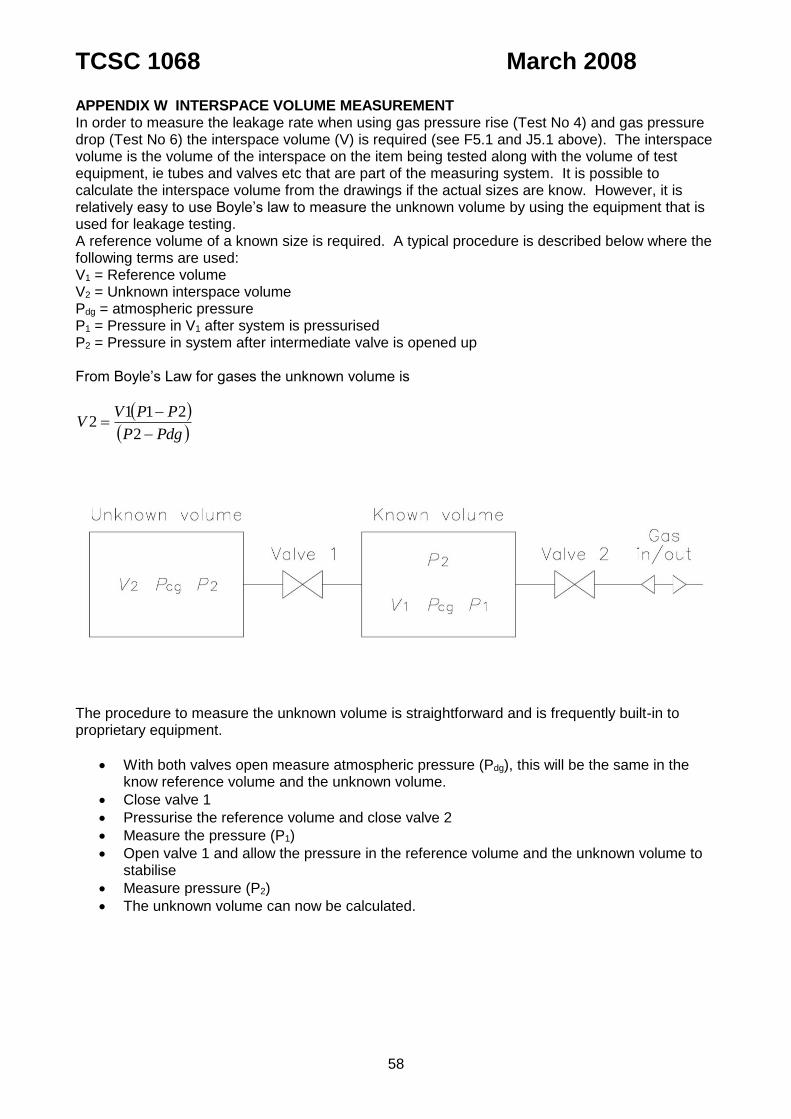
TCSC 1068 March 2008
58
APPENDIX W INTERSPACE VOLUME MEASUREMENT In order to measure the leakage rate when using gas pressure rise (Test No 4) and gas pressure drop (Test No 6) the interspace volume (V) is required (see F5.1 and J5.1 above). The interspace volume is the volume of the interspace on the item being tested along with the volume of test equipment, ie tubes and valves etc that are part of the measuring system. It is possible to calculate the interspace volume from the drawings if the actual sizes are know. However, it is relatively easy to use Boyle’s law to measure the unknown volume by using the equipment that is used for leakage testing. A reference volume of a known size is required. A typical procedure is described below where the following terms are used: V1 = Reference volume V2 = Unknown interspace volume Pdg = atmospheric pressure P1 = Pressure in V1 after system is pressurised P2 = Pressure in system after intermediate valve is opened up From Boyle’s Law for gases the unknown volume is
PdgP
PPVV
2
2112
The procedure to measure the unknown volume is straightforward and is frequently built-in to proprietary equipment.
With both valves open measure atmospheric pressure (Pdg), this will be the same in the know reference volume and the unknown volume.
Close valve 1
Pressurise the reference volume and close valve 2
Measure the pressure (P1)
Open valve 1 and allow the pressure in the reference volume and the unknown volume to stabilise
Measure pressure (P2)
The unknown volume can now be calculated.

TCSC 1068 March 2008
59
BIBLIOGRAPHY
Ref. Description
1. International Atomic Energy Agency, IAEA Safety Standards Series, Regulations for the
Safe Transport of Radioactive Material No. TS-R-1 1996 Edition (As Amended 2003). 2. ANDERSON, J.A. Correlation between measured gas leaks and possible losses of
contents from radioactive materials packagings. (Proceedings of PATRAM 83, New Orleans, La, USA).
Related Documents