3-1 ©2019 Raj Jain Washington University in St. Louis http://www.cse.wustl.edu/~jain/cse473-19/ Transport Layer: Transport Layer: TCP and UDP TCP and UDP Raj Jain Raj Jain Washington University in Saint Louis Saint Louis, MO 63130 [email protected] Audio/Video recordings of this lecture are available on-line at: http://www.cse.wustl.edu/~jain/cse473-19/

Welcome message from author
This document is posted to help you gain knowledge. Please leave a comment to let me know what you think about it! Share it to your friends and learn new things together.
Transcript

3-1©2019 Raj JainWashington University in St. Louis http://www.cse.wustl.edu/~jain/cse473-19/
Transport Layer: Transport Layer: TCP and UDPTCP and UDP
Raj JainRaj JainWashington University in Saint Louis
Saint Louis, MO [email protected]
Audio/Video recordings of this lecture are available on-line at:http://www.cse.wustl.edu/~jain/cse473-19/

3-2©2019 Raj JainWashington University in St. Louis http://www.cse.wustl.edu/~jain/cse473-19/
OverviewOverview
Transport Layer Design Issues: Multiplexing/DemultiplexingReliable Data TransferFlow controlCongestion control
UDPTCP
Header format, connection management, checksumCongestion Control
Note: This class lecture is based on Chapter 3 of the textbook (Kurose and Ross) and the figures provided by the authors.

3-3©2019 Raj JainWashington University in St. Louis http://www.cse.wustl.edu/~jain/cse473-19/
Transport Layer Design IssuesTransport Layer Design Issues
1. Transport Layer Functions2. Multiplexing and Demultiplexing3. Error Detection: Checksum4. Flow Control5. Efficiency Principle6. Error Control: Retransmissions
Overview

3-4©2019 Raj JainWashington University in St. Louis http://www.cse.wustl.edu/~jain/cse473-19/
Transport LayerTransport Layer
Transport = End-to-End Services Services required at source and destination systemsNot required on intermediate hops
ApplicationTransportNetworkDatalinkPhysical
NetworkDatalinkPhysical
NetworkDatalinkPhysical
ApplicationTransportNetworkDatalinkPhysical
End System Router Router End System
3-5©2019 Raj JainWashington University in St. Louis http://www.cse.wustl.edu/~jain/cse473-19/
Transport Layer FunctionsTransport Layer Functions1. Multiplexing and demultiplexing: Among
applications and processes at end systems2. Error detection: Bit errors3. Loss detection: Lost packets due to buffer overflow
at intermediate systems (Sequence numbers and acks)
4. Error/loss recovery: Retransmissions5. Flow control: Ensuring receiver has buffers6. Congestion Control: Ensuring network has capacityNot all transports provide all functions

3-6©2019 Raj JainWashington University in St. Louis http://www.cse.wustl.edu/~jain/cse473-19/
Protocol LayersProtocol Layers
Top-Down approach
Internetwork
Host to Network
IP
Application
Transport
HTTP
TCP
FTP SMTP
UDP
Physical
Ethernet Wi-FiPoint-to-Point
Coax Fiber Wireless
P2P DNS Skype
3-7©2019 Raj JainWashington University in St. Louis http://www.cse.wustl.edu/~jain/cse473-19/
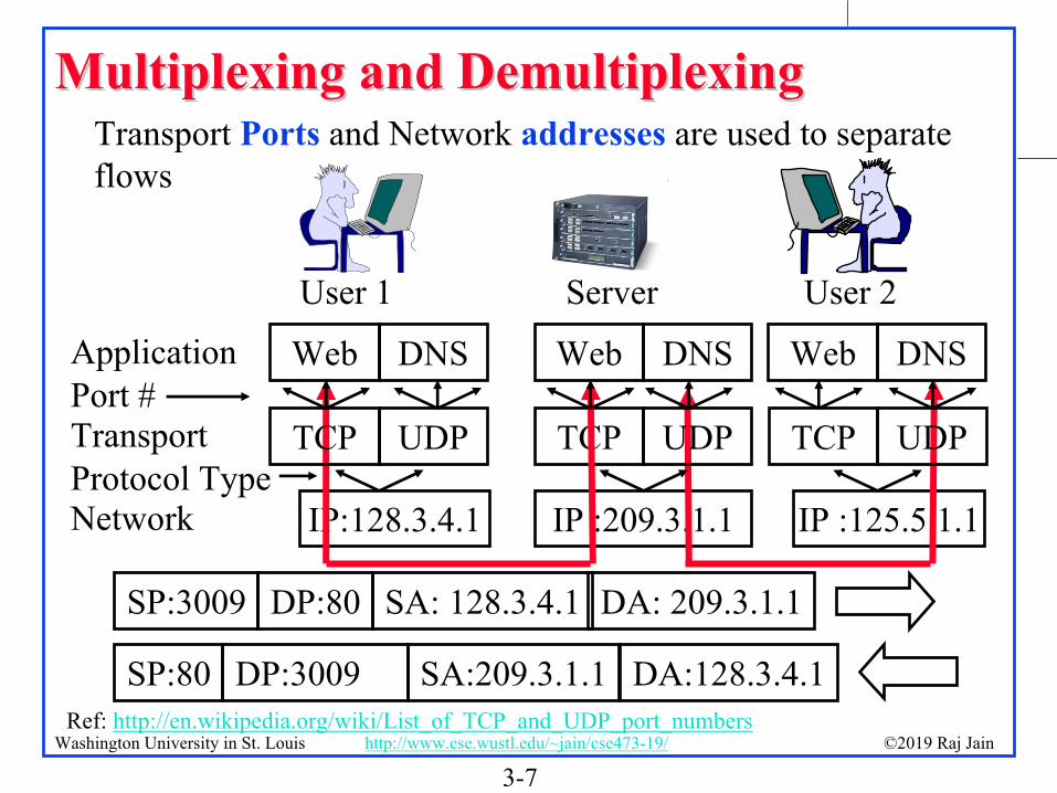
Multiplexing and Multiplexing and DemultiplexingDemultiplexingTransport Ports and Network addresses are used to separate flows
IP:128.3.4.1
Web
TCP
IP :209.3.1.1 IP :125.5.1.1
User 1 Server User 2
DNSApplication
Transport
Network
UDP
Web DNS Web DNS
TCP UDP TCP UDPPort #
Protocol Type
SP:3009 DP:80 SA: 128.3.4.1 DA: 209.3.1.1
SP:80 DP:3009 SA:209.3.1.1 DA:128.3.4.1Ref: http://en.wikipedia.org/wiki/List_of_TCP_and_UDP_port_numbers

3-8©2019 Raj JainWashington University in St. Louis http://www.cse.wustl.edu/~jain/cse473-19/
User Datagram Protocol (UDP)User Datagram Protocol (UDP)Connectionless end-to-end serviceProvides multiplexing via portsError detection (Checksum) optional. Applies to pseudo-header (same as TCP) and UDP segment. If not used, it is set to zero.No error recovery (no acks). No retransmissions.Used by network management, DNS, Streamed multimedia(Applications that are loss tolerant, delay sensitive, or have their own reliability mechanisms)
SourcePort
DestPort
Check-sumLength
16b 16b 16b Size in bits16b

3-9©2019 Raj JainWashington University in St. Louis http://www.cse.wustl.edu/~jain/cse473-19/
Error Detection: ChecksumError Detection: ChecksumCyclic Redundancy Check (CRC): Powerful but generally requires hardwareChecksum: Weak but easily done in software
Example: 1's complement of 1’s complement sum of 16-bit words with overflow wrapped around
At receiver the sum is all 1’s and the checksum is zero.
1 1 1 1 0 0 1 1 0 0 1 1 0 0 1 1 01 1 1 0 1 0 1 0 1 0 1 0 1 0 1 0 1
1 1 0 1 1 1 0 1 1 1 0 1 1 1 0 1 1
1 1 0 1 1 1 0 1 1 1 0 1 1 1 1 0 01 0 1 0 0 0 1 0 0 0 1 0 0 0 0 1 1
wraparound
sumchecksum

3-10©2019 Raj JainWashington University in St. Louis http://www.cse.wustl.edu/~jain/cse473-19/
11’’s Complements Complement2’s Complement: -ve of a number is complement+1
1 = 0001 -1 = 11112 = 0010 -2 = 11100 = 0000 -0 = 0000
1’s complement: -ve of a number is it’s complement1 = 0001 -1 = 11102 = 0010 -2 = 11010 = 0000 -0 = 1111
2’s Complement sum: Add with carry. Drop the final carry, if any.6-7 = 0110 + (-0111) = 0110 + 1001 = 1111 => -11’s complement sum: Add with carry. Add end-around carry back to sum
6-7 = 0110 + (-0111) = 0110+1000 = 1110 => -1Complement of 1’s complement sum: 0001Checksum: At the transmitter: 0110 1000, append 0001At the receiver: 0110 1000 0001 compute checksum of the full packet
= complement of sum = complement of 1111 = 0000Ref: https://en.wikipedia.org/wiki/Ones%27_complement

3-11©2019 Raj JainWashington University in St. Louis http://www.cse.wustl.edu/~jain/cse473-19/
Homework 3AHomework 3A
Consider the following two 16-bit words: ABCD 1234A. What is the checksum as computed by the senderB. Add your answer of Part A to the end of the packet
and show how the receiver will compute the checksum of the received three 16-bit words and confirm that there are no errors.
C. Now assume that the first bit of the packet is flipped due to an error. Repeat Part B at the receiver. Is the error detected?
3-12©2019 Raj JainWashington University in St. Louis http://www.cse.wustl.edu/~jain/cse473-19/
UDP: SummaryUDP: Summary
1. UDP provides flow multiplexing using port #s2. UDP optionally provides error detection using the
checksum3. UDP does not have error or loss recovery
mechanism

3-13©2019 Raj JainWashington University in St. Louis http://www.cse.wustl.edu/~jain/cse473-19/
Flow ControlFlow ControlFlow Control Goals: 1.Sender does not flood the receiver, 2.Maximize throughput
AckPkt 1
AckPkt 2
AckPkt 3
Sender Receiver Sender ReceiverStop and Wait Flow Control Window Flow Control
Throughput = Throughput =L/R
RTT+L/RW L/R
RTT+L/R
Large RTT Low Thruput
L/RRTT L= Packet Length
R= Link bit Rate
Ref: Textbook Section 3.4.2Section 3.4.2
3-14©2019 Raj JainWashington University in St. Louis http://www.cse.wustl.edu/~jain/cse473-19/
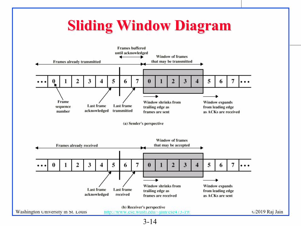
Sliding Window DiagramSliding Window Diagram

3-15©2019 Raj JainWashington University in St. Louis http://www.cse.wustl.edu/~jain/cse473-19/
Stop and Wait Flow ControlStop and Wait Flow Control
first bit transmitted, t = 0
Sender Receiver
RTT
last bit transmitted, t = L / R
First bit arrivesLast bit arrives, send ACK
ACK arrives, send next packet, t = RTT + L / R
U =L / R
RTT + L / R=
12 + 12tprop+tframe
tframe=
Here, = tprop/tframe

3-16©2019 Raj JainWashington University in St. Louis http://www.cse.wustl.edu/~jain/cse473-19/
Sliding Window Protocol EfficiencySliding Window Protocol Efficiency
Data
Ack
tframe
tprop
U=W tframe
2tprop+tframe
=
W2+1
1 if W>2+1
Here, = tprop/tframe
W=1 Stop and Wait
3-17©2019 Raj JainWashington University in St. Louis http://www.cse.wustl.edu/~jain/cse473-19/
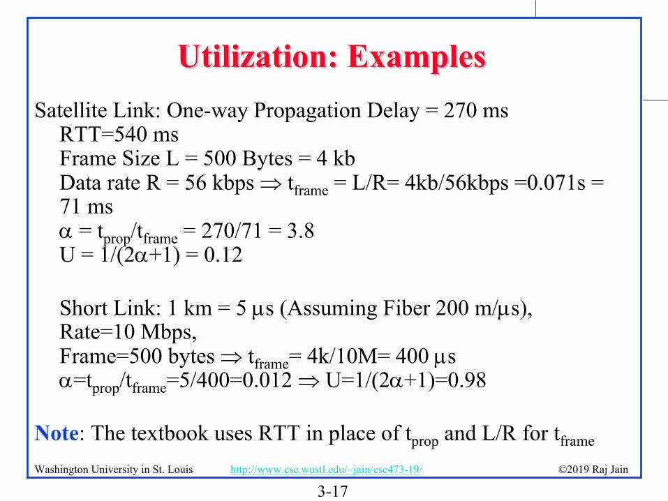
Utilization: ExamplesUtilization: ExamplesSatellite Link: One-way Propagation Delay = 270 ms
RTT=540 msFrame Size L = 500 Bytes = 4 kbData rate R = 56 kbps tframe = L/R= 4kb/56kbps =0.071s = 71 ms = tprop/tframe = 270/71 = 3.8U = 1/(2+1) = 0.12
Short Link: 1 km = 5 s (Assuming Fiber 200 m/s), Rate=10 Mbps, Frame=500 bytes tframe= 4k/10M= 400 s=tprop/tframe=5/400=0.012 U=1/(2+1)=0.98
Note: The textbook uses RTT in place of tprop and L/R for tframe

3-18©2019 Raj JainWashington University in St. Louis http://www.cse.wustl.edu/~jain/cse473-19/
Effect of Window SizeEffect of Window Size
U
Larger window is better for larger

3-19©2019 Raj JainWashington University in St. Louis http://www.cse.wustl.edu/~jain/cse473-19/
Efficiency PrincipleEfficiency Principle
For all protocols, the maximum utilization (efficiency) is a non-increasing function of
MaxUtilization
Not Possible
Protocol 1Protocol 2
Best possible
=tprop
tframe
=Distance/Speed of SignalBits Transmitted /Bit rate
=Distance Bit rateBits Transmitted Speed of Signal
3-20©2019 Raj JainWashington University in St. Louis http://www.cse.wustl.edu/~jain/cse473-19/
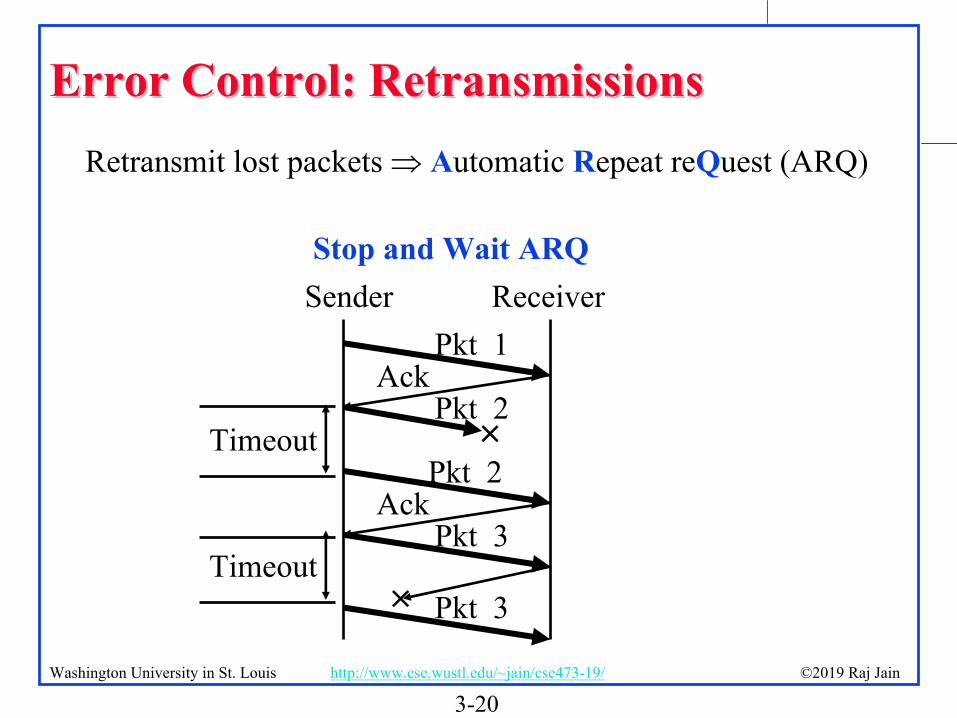
Error Control: RetransmissionsError Control: RetransmissionsRetransmit lost packets Automatic Repeat reQuest (ARQ)
AckPkt 1
Pkt 2
AckPkt 3
Sender ReceiverStop and Wait ARQ
Timeout
Timeout
Pkt 2
Pkt 3

3-21©2019 Raj JainWashington University in St. Louis http://www.cse.wustl.edu/~jain/cse473-19/
GoGo--BackBack--N ARQN ARQ
Receiver does not cache out-of-order framesSender has to go back and retransmit all frames after the lost frame
RcvrSender
1
Nack 11
01
2
2
3
3

3-22©2019 Raj JainWashington University in St. Louis http://www.cse.wustl.edu/~jain/cse473-19/
Selective Repeat ARQSelective Repeat ARQ
Receiver caches out-of-order framesSender retransmits only the lost frameAlso known as selective reject ARQ
RcvrSender
1
Nack 11
01
2
4
3
5

3-23©2019 Raj JainWashington University in St. Louis http://www.cse.wustl.edu/~jain/cse473-19/
Selective Repeat: Window SizeSelective Repeat: Window Size
01234567
0Ack
Sequence number space > 2 window sizeWindow size < 2n-1
Timeout

3-24©2019 Raj JainWashington University in St. Louis http://www.cse.wustl.edu/~jain/cse473-19/
Performance: Maximum UtilizationPerformance: Maximum Utilization
Stop and Wait Flow Control: U = 1/(1+2)Window Flow Control:
Stop and Wait ARQ: U = (1-P)/(1+2)Go-back-N ARQ:
Selective Repeat ARQ:
U = 1 W> 2+1
W/(2+1) W< 2+1{
U = (1-P)/(1+2P) W> 2+1
W(1-P)/[(2+1)(1-P+WP)] W< 2+1{U =
(1-P) W> 2+1
W(1-P)/(2+1) W< 2+1{
P = Probability of Loss

3-25©2019 Raj JainWashington University in St. Louis http://www.cse.wustl.edu/~jain/cse473-19/
Performance ComparisonPerformance Comparison1.0
0.8
0.6
0.4
0.2
0.00.1 1 10 100 1000
Util
izat
ion
Stop-and-wait
W= 127 Go-back-N
W=7 Go-back-N & W= 7 Selective-repeat
W= 127 Selective-repeat
More bps or longer distance

3-26©2019 Raj JainWashington University in St. Louis http://www.cse.wustl.edu/~jain/cse473-19/
Transport Layer Design IssuesTransport Layer Design Issues
1. Multiplexing/demultiplexing by a combination of source and destination IP addresses and port numbers.
2. Window flow control is better for long-distance or high-speed networks
3. Longer distance or higher speed Larger Larger window is better
4. Stop and and wait flow control is ok for short distance or low-speed networks
5. Selective repeat is better than stop and wait ARQOnly slightly better than go-back-N

3-27©2019 Raj JainWashington University in St. Louis http://www.cse.wustl.edu/~jain/cse473-19/
Homework 3BHomework 3BProblem 19 on page 302 of the textbook:Consider the GBN protocol with a sender window size of 3 and a sequence number
range of 1,024. Suppose that at time t, the next in-order packet that the receiver is expecting has a sequence number of k. Assume that the medium does not reorder messages. Answer the following questions:
A. What are the possible sets of sequence numbers insdie the sender’s window at time t? Justify your answer.
B. What are all possible values of the ACK field in all possible messages currently propagating back to the sender at time t? Justify your answer.
Window Flow Control:C. How big window (in number of packets) is required for the channel utilization to be
greater than 60% on a cross-country link of 4000 km running at 20 Mbps using 1 kByte packets?
Efficiency Principle:D. Ethernet V1 access protocol was designed to run at 10 Mbps over 2.5 Km using 1500
byte packets. This same protocol needs to be used at 100 Mbps at the same efficiency. What distance can it cover if the frame size is not changed?

3-28©2019 Raj JainWashington University in St. Louis http://www.cse.wustl.edu/~jain/cse473-19/
TCPTCP
1. TCP Header Format, Options, Checksum2. TCP Connection Management3. Round Trip Time Estimation4. Principles of Congestion Control5. Slow Start Congestion Control
Overview
3-29©2019 Raj JainWashington University in St. Louis http://www.cse.wustl.edu/~jain/cse473-19/
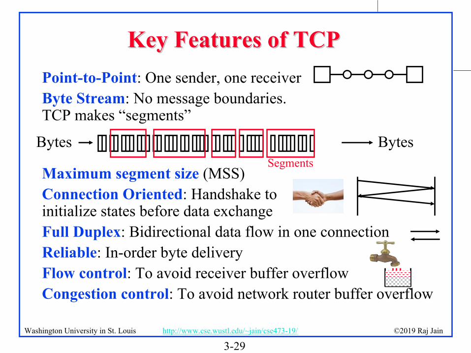
Key Features of TCPKey Features of TCPPoint-to-Point: One sender, one receiverByte Stream: No message boundaries. TCP makes “segments”
Maximum segment size (MSS)Connection Oriented: Handshake to initialize states before data exchangeFull Duplex: Bidirectional data flow in one connectionReliable: In-order byte deliveryFlow control: To avoid receiver buffer overflowCongestion control: To avoid network router buffer overflow
Bytes BytesSegments

3-30©2019 Raj JainWashington University in St. Louis http://www.cse.wustl.edu/~jain/cse473-19/
TCPTCPTransmission Control ProtocolKey Services:
Send: Please send when convenient Data stream push: Destination TCP, please deliver it immediately to the receiving application. Source TCP, please send it now. Set on last packet of an application message.Urgent data signaling: Destination TCP, please give this urgent data to the user out-of-band. Generally used for CTRL-C.

3-31©2019 Raj JainWashington University in St. Louis http://www.cse.wustl.edu/~jain/cse473-19/
TCP Segment Format (Cont)TCP Segment Format (Cont)
Source Port Dest PortSeq NoAck No
DataOffset WindowResvd
Checksum UrgentOptions
Data
U A P R S F
16b 16b
Pad

3-32©2019 Raj JainWashington University in St. Louis http://www.cse.wustl.edu/~jain/cse473-19/
TCP Header FieldsTCP Header Fields
Source Port (16 bits): Identifies source user processDestination Port (16 bits)21 = FTP, 23 = Telnet, 53 = DNS, 80 = HTTP, ...Sequence Number (32 bits): Sequence number of the first byte in the segment. If SYN is present, this is the initial sequence number (ISN) and the first data byte is ISN+1.Ack number (32 bits): Next byte expectedData offset (4 bits): Number of 32-bit words in the headerReserved (6 bits)

3-33©2019 Raj JainWashington University in St. Louis http://www.cse.wustl.edu/~jain/cse473-19/
TCP Header (Cont)TCP Header (Cont)Control (6 bits):Urgent pointer field significant,
Ack field significant, Push function, Reset the connection, Synchronize the sequence numbers, No more data from sender
Window (16 bits): Will accept [Ack] to [Ack]+[window]-1
ACKURG PSH RST SYN FIN

3-34©2019 Raj JainWashington University in St. Louis http://www.cse.wustl.edu/~jain/cse473-19/
TCP Header (Cont)TCP Header (Cont)Checksum (16 bits): covers the segment plus a pseudo header. Includes the following fields from IP header: source and dest adr, protocol, segment length. Protects from IP misdelivery.Urgent pointer (16 bits): Points to the byte following urgent data. Lets receiver know how much data it should deliver right away out-of-band.Options (variable): Max segment size (does not include TCP header, default 536 bytes), Window scale factor, Selective Ack permitted, Timestamp, No-Op, End-of-options

3-35©2019 Raj JainWashington University in St. Louis http://www.cse.wustl.edu/~jain/cse473-19/
TCP OptionsTCP Options
End of Options: Stop looking for further optionNo-op: Ignore this byte. Used to align the next option on a 4-byte word boundaryMax Segment Size (MSS): Does not include TCP header
Kind Length Meaning0 1 End of Valid options in header1 1 No-op2 4 Maximum Segment Size3 3 Window Scale Factor8 10 Timestamp

3-36©2019 Raj JainWashington University in St. Louis http://www.cse.wustl.edu/~jain/cse473-19/
TCP ChecksumTCP ChecksumChecksum is the 16-bit one's complement of the one's complement sum of a pseudo header of information from the IP header, the TCP header, and the data, padded with zero octets at the end (if necessary) to make a multiple of two octets.Checksum field is filled with zeros initiallyTCP length (in octet) is not transmitted but used in calculations. Efficient implementation in RFC1071.
Source Adr Dest. Adr Zeros Protocol TCP Length
TCP Header TCP data32 32 8 8 16
3-37©2019 Raj JainWashington University in St. Louis http://www.cse.wustl.edu/~jain/cse473-19/
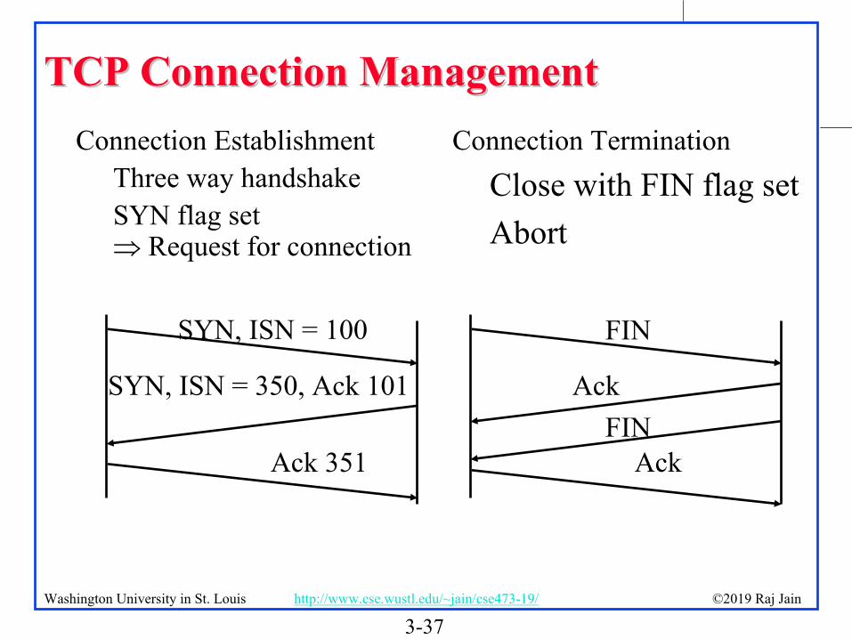
TCP Connection ManagementTCP Connection ManagementConnection Establishment
Three way handshakeSYN flag set Request for connection
SYN, ISN = 100
SYN, ISN = 350, Ack 101
Ack 351
Connection TerminationClose with FIN flag setAbort
FINAck
Ack
FIN

3-38©2019 Raj JainWashington University in St. Louis http://www.cse.wustl.edu/~jain/cse473-19/
Example RTT estimation:Example RTT estimation:RTT: gaia.cs.umass.edu to fantasia.eurecom.fr
100
150
200
250
300
350
1 8 15 22 29 36 43 50 57 64 71 78 85 92 99 106time (seconnds)
RTT
(mill
iseco
nds)
SampleRTT Estimated RTT
3-39©2019 Raj JainWashington University in St. Louis http://www.cse.wustl.edu/~jain/cse473-19/
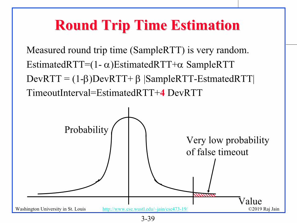
Round Trip Time EstimationRound Trip Time EstimationMeasured round trip time (SampleRTT) is very random. EstimatedRTT=(1- )EstimatedRTT+ SampleRTTDevRTT = (1-)DevRTT+ |SampleRTT-EstmatedRTT|TimeoutInterval=EstimatedRTT+4 DevRTT
Value
ProbabilityVery low probability of false timeout
3-40©2019 Raj JainWashington University in St. Louis http://www.cse.wustl.edu/~jain/cse473-19/
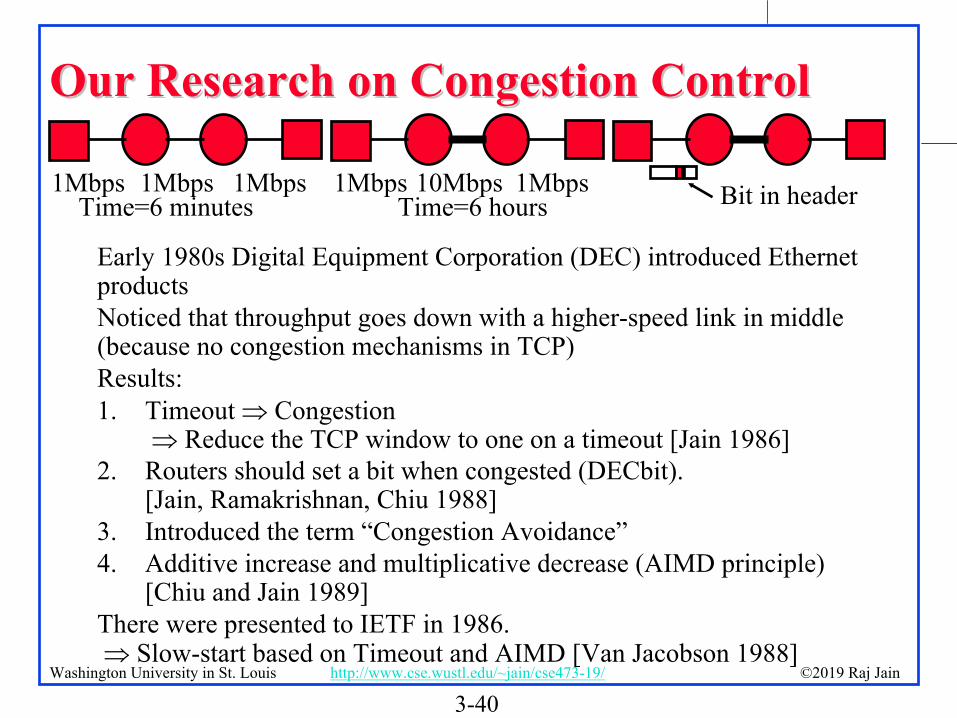
Our Research on Congestion ControlOur Research on Congestion Control
Early 1980s Digital Equipment Corporation (DEC) introduced Ethernet productsNoticed that throughput goes down with a higher-speed link in middle (because no congestion mechanisms in TCP)Results:1. Timeout Congestion
Reduce the TCP window to one on a timeout [Jain 1986]2. Routers should set a bit when congested (DECbit).
[Jain, Ramakrishnan, Chiu 1988]3. Introduced the term “Congestion Avoidance”4. Additive increase and multiplicative decrease (AIMD principle)
[Chiu and Jain 1989]There were presented to IETF in 1986. Slow-start based on Timeout and AIMD [Van Jacobson 1988]
1Mbps 1Mbps 1MbpsTime=6 minutes
1Mbps 10Mbps 1MbpsTime=6 hours Bit in header
3-41©2019 Raj JainWashington University in St. Louis http://www.cse.wustl.edu/~jain/cse473-19/
Slow Start Congestion ControlSlow Start Congestion ControlWindow = Flow control avoids receiver overrunNeed congestion control to avoid network overrunThe sender maintains two windows: Credits from the receiverCongestion window from the networkCongestion window is always less than the receiver windowStarts with a congestion window (CWND) of 1 max segment size (MSS) Do not disturb existing connections too much.Increase CWND by 1 MSS every time an ack is receivedAssume CWND is in bytes
3-42©2019 Raj JainWashington University in St. Louis http://www.cse.wustl.edu/~jain/cse473-19/
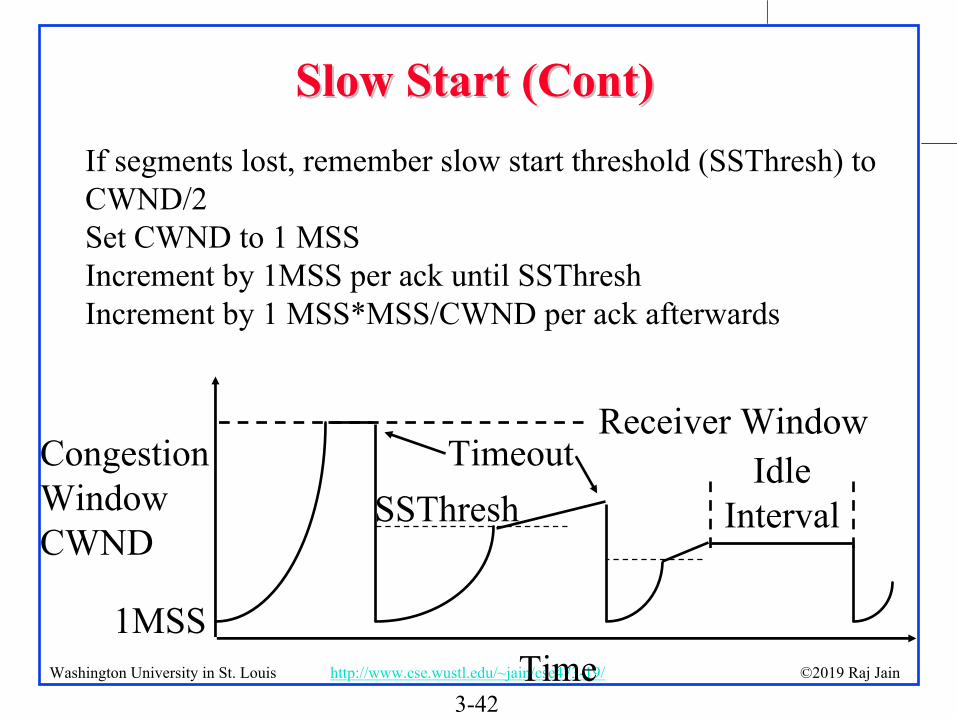
Slow Start (Cont)Slow Start (Cont)If segments lost, remember slow start threshold (SSThresh) to CWND/2Set CWND to 1 MSSIncrement by 1MSS per ack until SSThreshIncrement by 1 MSS*MSS/CWND per ack afterwards
Time
CongestionWindowCWND
Receiver WindowIdle
Interval
Timeout
1MSS
SSThresh

3-43©2019 Raj JainWashington University in St. Louis http://www.cse.wustl.edu/~jain/cse473-19/
Slow Start (Cont)Slow Start (Cont)At the beginning, SSThresh = Receiver windowAfter a long idle period (exceeding one round-trip time), reset the congestion window to one.If CWND is W MSS, W acks are received in one round trip.Below SSThresh, CWND is increased by 1MSS on every ack CWND increases to 2W MSS in one round trip CWND increases exponentially with timeExponential growth phase is also known as “Slow start” phaseAbove SSThresh, CWND is increased by MSS/CWND on every ack CWND increases by 1 MSS in one round trip CWND increases linearly with timeThe linear growth phase is known as “congestion avoidance”phase

3-44©2019 Raj JainWashington University in St. Louis http://www.cse.wustl.edu/~jain/cse473-19/
AIMD PrincipleAIMD PrincipleAdditive Increase, Multiplicative DecreaseW1+W2 = Capacity Efficiency,
W1=W2 Fairness(W1,W2) to (W1+W,W2+W) Linear increase (45 line)(W1,W2) to (kW1,kW2) Multiplicative decrease (line through origin)
CapacityW1W2
C
FairEfficient
Ref: D. Chiu and Raj Jain, "Analysis of the Increase/Decrease Algorithms for Congestion Avoidance in Computer Networks," Journal of Computer Networks and ISDN, Vol. 17, No. 1, June 1989, pp. 1-14, http://www.cse.wustl.edu/~jain/papers/cong_av.htm

3-45©2019 Raj JainWashington University in St. Louis http://www.cse.wustl.edu/~jain/cse473-19/
Fast RetransmitFast RetransmitOptional – implemented in TCP Reno(Earlier version was TCP Tahoe) Duplicate Ack indicates a lost/out-of-order segmentOn receiving 3 duplicate acks (4th ack for the same segment):
Enter Fast Recovery modeRetransmit missing segmentSet SSThresh=CWND/2Set CWND=SSThresh+3 MSSEvery subsequent duplicate ack: CWND=CWND+1MSS
When a new ack (not a duplicate ack) is receivedExit fast recoverySet CWND=SSTHRESH
3-46©2019 Raj JainWashington University in St. Louis http://www.cse.wustl.edu/~jain/cse473-19/
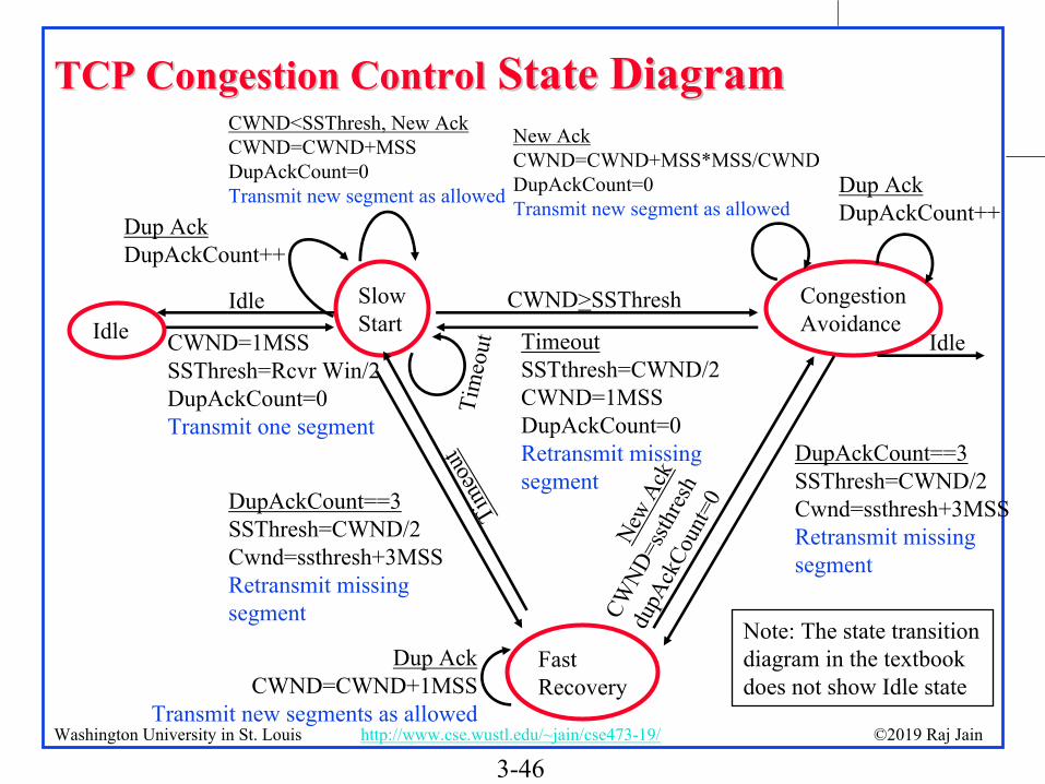
TCP Congestion ControlTCP Congestion Control State DiagramState Diagram
SlowStart
CongestionAvoidance
FastRecovery
Dup AckDupAckCount++
CWND<SSThresh, New AckCWND=CWND+MSSDupAckCount=0Transmit new segment as allowed
CWND=1MSSSSThresh=Rcvr Win/2DupAckCount=0Transmit one segment
DupAckCount==3SSThresh=CWND/2Cwnd=ssthresh+3MSSRetransmit missing segment
TimeoutSSTthresh=CWND/2CWND=1MSSDupAckCount=0Retransmit missing segment
Dup AckDupAckCount++
Dup AckCWND=CWND+1MSS
Transmit new segments as allowed
DupAckCount==3SSThresh=CWND/2Cwnd=ssthresh+3MSSRetransmit missing segment
Tim
eout
Tim
eout
New
Ack
CWND
=ssth
resh
dupA
ckCo
unt=
0
New AckCWND=CWND+MSS*MSS/CWNDDupAckCount=0Transmit new segment as allowed
Idle Idle
Idle
Note: The state transition diagram in the textbook does not show Idle state
CWND>SSThresh

3-47©2019 Raj JainWashington University in St. Louis http://www.cse.wustl.edu/~jain/cse473-19/
TCP Average ThroughputTCP Average Throughput
Average Throughput =
Here, P = Probability of Packet loss
Note 1: The formula is an approximation which does not apply at P=0 or P=1. At P=1, the throughput is zero. At P=0, the throughput is min{1, (Receiver Window/RTT)}Note 1: The textbook uses L for probability of packet loss but it was used earlier for length of packets.
1.22 MSS
RTT P

3-48©2019 Raj JainWashington University in St. Louis http://www.cse.wustl.edu/~jain/cse473-19/
Explicit Congestion Notification (ECN)Explicit Congestion Notification (ECN)Explicit congestion notification (ECN) is based on our DECbitresearch. Two bits in IP Header:
00: Transport is not capable of ECN (e.g., UDP)01: Transport is capable of ECN10: Transport is capable of ECN11: Congestion experienced (CE)
When a router encounters congestion, instead of dropping the datagram, it marks the two bits as “11” congestion experienced
Transport
NetworkDatalink
Transport
NetworkDatalinkECN11
ECE1
CWR1
Application Application
3-49©2019 Raj JainWashington University in St. Louis http://www.cse.wustl.edu/~jain/cse473-19/
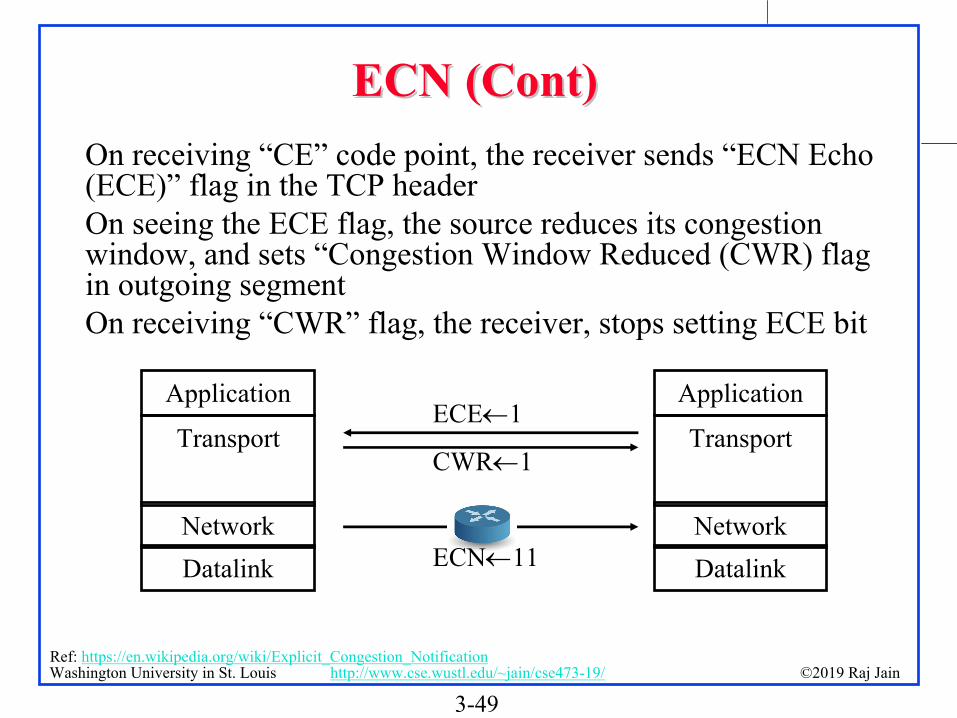
ECN (Cont)ECN (Cont)On receiving “CE” code point, the receiver sends “ECN Echo (ECE)” flag in the TCP headerOn seeing the ECE flag, the source reduces its congestion window, and sets “Congestion Window Reduced (CWR) flag in outgoing segmentOn receiving “CWR” flag, the receiver, stops setting ECE bit
Transport
NetworkDatalink
Transport
NetworkDatalinkECN11
ECE1
CWR1
Application Application
Ref: https://en.wikipedia.org/wiki/Explicit_Congestion_Notification

3-50©2019 Raj JainWashington University in St. Louis http://www.cse.wustl.edu/~jain/cse473-19/
TCP: SummaryTCP: Summary
1. TCP uses port numbers for multiplexing2. TCP provides reliable full-duplex connections.3. TCP is stream based and has window flow control4. Slow-start congestion control works on timeout5. Explicit congestion notification works using ECN
bits

3-51©2019 Raj JainWashington University in St. Louis http://www.cse.wustl.edu/~jain/cse473-19/
Homework 3CHomework 3CConsider Figure below. Assuming TCP Reno is the protocol experiencing the behavior shown above, answer the following questions. In all cases, you should provide a short discussion justifying your answer.
TCP Window Size
05
1015202530354045
0 5 10 15 20 25 30Transmission Round
CW
ND
Round CWND1 12 23 44 85 166 327 338 349 35
10 3611 3712 3813 3914 4015 4116 4217 2118 2219 2320 2421 2522 2623 124 225 426 8

3-52©2019 Raj JainWashington University in St. Louis http://www.cse.wustl.edu/~jain/cse473-19/
Homework 3C (Cont)Homework 3C (Cont)A. Identify the interval of time when TCP slow start is operating.B. Identify the intervals of time when TCP congestion avoidance is operating.C. After the 16th transmission round, is segment loss detected by a triple duplicate ACK or by a timeout?D. After the 22nd transmission round, is segment loss detected by a triple duplicate ACK or by a timeout?E. What is the initial value of ssthresh at the first transmission round?F .What is the value of ssthresh at the 18th transmission round?G. What is the value of ssthresh at the 24th transmission round?

3-53©2019 Raj JainWashington University in St. Louis http://www.cse.wustl.edu/~jain/cse473-19/
Homework 3C (Cont)Homework 3C (Cont)H. During what transmission round is the 70th segment sent?I. Assuming a packet loss is detected after the 26th round by the receipt of a triple duplicate ACK, what will be the values of the congestion window size and of ssthresh?J. Suppose TCP Tahoe is used (instead of TCP Reno), and assume that triple duplicate ACKs are received at the 16th
round. What are the ssthresh and the congestion window size at the 19th round?K. Again suppose TCP Tahoe is used, and there is a timeout event at the end of 22nd round. How many packets have been sent out from 17th round till 22nd round, inclusive?

3-54©2019 Raj JainWashington University in St. Louis http://www.cse.wustl.edu/~jain/cse473-19/
SummarySummary
1. Multiplexing/demultiplexing by a combination of source and destination IP addresses and port numbers.
2. Longer distance or higher speed Larger Larger window is better
3. Window flow control is better for long-distance or high-speed networks
4. UDP is connectionless and simple. No flow/error control. Has error detection.
5. TCP provides full-duplex connections with flow/error/congestion control.

3-55©2019 Raj JainWashington University in St. Louis http://www.cse.wustl.edu/~jain/cse473-19/
Lab 3: Reliable Transport ProtocolOverviewIn this laboratory programming assignment, you will be writing the sending and receiving transport-level code for
implementing a simple reliable data transfer protocol. There are two versions of this lab, the Alternating-Bit-Protocol version and the Go-Back-N version. This lab should be fun since your implementation will differ very little from what would be required in a real-world situation.
Since you probably don't have standalone machines (with an OS that you can modify), your code will have to execute in a simulated hardware/software environment. However, the programming interface provided to your routines, i.e., the code that would call your entities from above and from below is very close to what is done in an actual UNIX environment. (Indeed, the software interfaces described in this programming assignment are much more realistic that the infinite loop senders and receivers that many texts describe). Stopping/starting of timers are also simulated, and timer interrupts will cause your timer handling routine to be activated.
The routines you will writeThe procedures you will write are for the sending entity (A) and the receiving entity (B). Only unidirectional
transfer of data (from A to B) is required. Of course, the B side will have to send packets to A to acknowledge (positively or negatively) receipt of data. Your routines are to be implemented in the form of the procedures described below. These procedures will be called by (and will call) procedures that I have written which emulate a network environment. The overall structure of the environment is shown in Figure Lab.3-1 (structure of the emulated environment):
The unit of data passed between the upper layers and your protocols is a message, which is declared as:struct msg { char data[20];};This declaration, and all other data structure and emulator routines, as well as stub routines (i.e., those you are to
complete) are in the file, prog2.c, described later. Your sending entity will thus receive data in 20-byte chunks from layer5; your receiving entity should deliver 20-byte chunks of correctly received data to layer5 at the receiving side.
3-56©2019 Raj JainWashington University in St. Louis http://www.cse.wustl.edu/~jain/cse473-19/
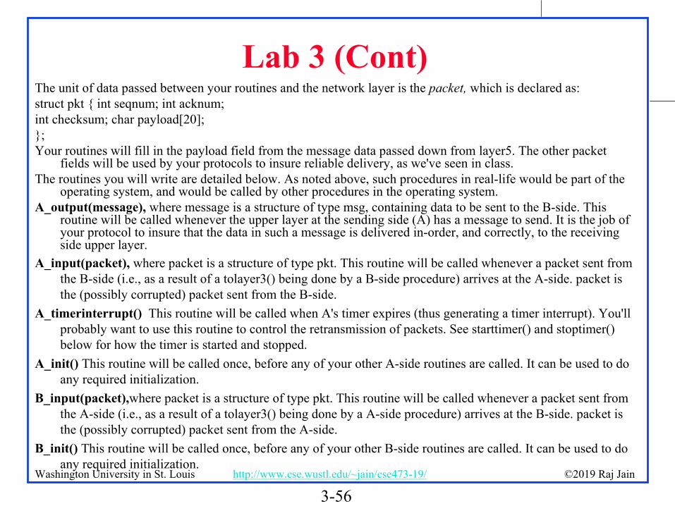
Lab 3 (Cont)The unit of data passed between your routines and the network layer is the packet, which is declared as:struct pkt { int seqnum; int acknum;int checksum; char payload[20];};Your routines will fill in the payload field from the message data passed down from layer5. The other packet
fields will be used by your protocols to insure reliable delivery, as we've seen in class.The routines you will write are detailed below. As noted above, such procedures in real-life would be part of the
operating system, and would be called by other procedures in the operating system.A_output(message), where message is a structure of type msg, containing data to be sent to the B-side. This
routine will be called whenever the upper layer at the sending side (A) has a message to send. It is the job of your protocol to insure that the data in such a message is delivered in-order, and correctly, to the receiving side upper layer.
A_input(packet), where packet is a structure of type pkt. This routine will be called whenever a packet sent from the B-side (i.e., as a result of a tolayer3() being done by a B-side procedure) arrives at the A-side. packet is the (possibly corrupted) packet sent from the B-side.
A_timerinterrupt() This routine will be called when A's timer expires (thus generating a timer interrupt). You'll probably want to use this routine to control the retransmission of packets. See starttimer() and stoptimer() below for how the timer is started and stopped.
A_init() This routine will be called once, before any of your other A-side routines are called. It can be used to do any required initialization.
B_input(packet),where packet is a structure of type pkt. This routine will be called whenever a packet sent from the A-side (i.e., as a result of a tolayer3() being done by a A-side procedure) arrives at the B-side. packet is the (possibly corrupted) packet sent from the A-side.
B_init() This routine will be called once, before any of your other B-side routines are called. It can be used to do any required initialization.

3-57©2019 Raj JainWashington University in St. Louis http://www.cse.wustl.edu/~jain/cse473-19/
Lab 3 (Cont)Software InterfacesThe procedures described above are the ones that you will write. I have written the following routines which can
be called by your routines:starttimer(calling_entity,increment), where calling_entity is either 0 (for starting the A-side timer) or 1 (for
starting the B side timer), and increment is a float value indicating the amount of time that will pass before the timer interrupts. A's timer should only be started (or stopped) by A-side routines, and similarly for the B-side timer. To give you an idea of the appropriate increment value to use: a packet sent into the network takes an average of 5 time units to arrive at the other side when there are no other messages in the medium.
stoptimer(calling_entity), where calling_entity is either 0 (for stopping the A-side timer) or 1 (for stopping the B side timer).
tolayer3(calling_entity,packet), where calling_entity is either 0 (for the A-side send) or 1 (for the B side send), and packet is a structure of type pkt. Calling this routine will cause the packet to be sent into the network, destined for the other entity.
tolayer5(calling_entity,message), where calling_entity is either 0 (for A-side delivery to layer 5) or 1 (for B-side delivery to layer 5), and message is a structure of type msg. With unidirectional data transfer, you would only be calling this with calling_entity equal to 1 (delivery to the B-side). Calling this routine will cause data to be passed up to layer 5.
3-58©2019 Raj JainWashington University in St. Louis http://www.cse.wustl.edu/~jain/cse473-19/
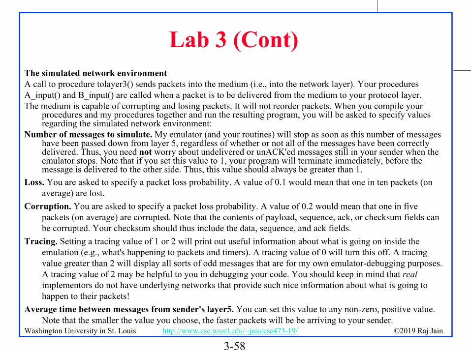
Lab 3 (Cont)The simulated network environmentA call to procedure tolayer3() sends packets into the medium (i.e., into the network layer). Your proceduresA_input() and B_input() are called when a packet is to be delivered from the medium to your protocol layer.The medium is capable of corrupting and losing packets. It will not reorder packets. When you compile your
procedures and my procedures together and run the resulting program, you will be asked to specify values regarding the simulated network environment:
Number of messages to simulate. My emulator (and your routines) will stop as soon as this number of messages have been passed down from layer 5, regardless of whether or not all of the messages have been correctly delivered. Thus, you need not worry about undelivered or unACK'ed messages still in your sender when the emulator stops. Note that if you set this value to 1, your program will terminate immediately, before the message is delivered to the other side. Thus, this value should always be greater than 1.
Loss. You are asked to specify a packet loss probability. A value of 0.1 would mean that one in ten packets (on average) are lost.
Corruption. You are asked to specify a packet loss probability. A value of 0.2 would mean that one in five packets (on average) are corrupted. Note that the contents of payload, sequence, ack, or checksum fields can be corrupted. Your checksum should thus include the data, sequence, and ack fields.
Tracing. Setting a tracing value of 1 or 2 will print out useful information about what is going on inside the emulation (e.g., what's happening to packets and timers). A tracing value of 0 will turn this off. A tracing value greater than 2 will display all sorts of odd messages that are for my own emulator-debugging purposes. A tracing value of 2 may be helpful to you in debugging your code. You should keep in mind that real implementors do not have underlying networks that provide such nice information about what is going to happen to their packets!
Average time between messages from sender's layer5. You can set this value to any non-zero, positive value. Note that the smaller the value you choose, the faster packets will be be arriving to your sender.

3-59©2019 Raj JainWashington University in St. Louis http://www.cse.wustl.edu/~jain/cse473-19/
Lab 3 (Cont)The Alternating-Bit-Protocol Version of this lab.You are to write the procedures, A_output(),A_input(),A_timerinterrupt(),A_init(),B_input(), and B_init() which
together will implement a stop-and-wait (i.e., the alternating bit protocol, which we referred to as rdt3.0 in the text) unidirectional transfer of data from the A-side to the B-side. Your protocol should use both ACK and NACK messages.
You should choose a very large value for the average time between messages from sender's layer5, so that your sender is never called while it still has an outstanding, unacknowledged message it is trying to send to the receiver. I'd suggest you choose a value of 1000. You should also perform a check in your sender to make sure that when A_output() is called, there is no message currently in transit. If there is, you can simply ignore (drop) the data being passed to the A_output() routine.
You should put your procedures in a file called prog2.c. You will need the initial version of this file, containing the emulation routines we have writen for you, and the stubs for your procedures. You can obtain thisprogram from http://gaia.cs.umass.edu/kurose/transport/prog2.c.
This lab can be completed on any machine supporting C. It makes no use of UNIX features. (You can simply copy the prog2.c file to whatever machine and OS you choose).
We recommend that you should hand in a code listing, a design document, and sample output. For your sample output, your procedures might print out a message whenever an event occurs at your sender or receiver (a message/packet arrival, or a timer interrupt) as well as any action taken in response. You might want to hand in output for a run up to the point (approximately) when 10 messages have been ACK'ed correctly at the receiver, a loss probability of 0.1, and a corruption probability of 0.3, and a trace level of 2. You might want to annotate your printout with a colored pen showing how your protocol correctly recovered from packet loss and corruption.
Make sure you read the "helpful hints" for this lab following the description of the Go_Back-N version of this lab.

3-60©2019 Raj JainWashington University in St. Louis http://www.cse.wustl.edu/~jain/cse473-19/
Lab 3 (Cont)The Go-Back-N version of this lab.You are to write the procedures, A_output(),A_input(),A_timerinterrupt(),A_init(),B_input(), and B_init() which
together will implement a Go-Back-N unidirectional transfer of data from the A-side to the B-side, with a window size of 8. Your protocol should use both ACK and NACK messages. Consult the alternating-bit-protocol version of this lab above for information about how to obtain the network emulator.
We would STRONGLY recommend that you first implement the easier lab (Alternating Bit) and then extend your code to implement the harder lab (Go-Back-N). Believe me - it will not be time wasted! However, some new considerations for your Go-Back-N code (which do not apply to the Alternating Bit protocol) are:
A_output(message), where message is a structure of type msg, containing data to be sent to the B-side.Your A_output() routine will now sometimes be called when there are outstanding, unacknowledged messages in
the medium - implying that you will have to buffer multiple messages in your sender. Also, you'll also need buffering in your sender because of the nature of Go-Back-N: sometimes your sender will be called but it won't be able to send the new message because the new message falls outside of the window.
Rather than have you worry about buffering an arbitrary number of messages, it will be OK for you to have some finite, maximum number of buffers available at your sender (say for 50 messages) and have your sender simply abort (give up and exit) should all 50 buffers be in use at one point (Note: using the values given below, this should never happen!) In the ``real-world,'' of course, one would have to come up with a more elegant solution to the finite buffer problem!
A_timerinterrupt() This routine will be called when A's timer expires (thus generating a timer interrupt). Remember that you've only got one timer, and may have many outstanding, unacknowledged packets in the medium, so you'll have to think a bit about how to use this single timer.

3-61©2019 Raj JainWashington University in St. Louis http://www.cse.wustl.edu/~jain/cse473-19/
Lab 3 (Cont)Consult the Alternating-bit-protocol version of this lab above for a general description of what you might want to
hand in. You might want to hand in output for a run that was long enough so that at least 20 messages were successfully transfered from sender to receiver (i.e., the sender receives ACK for these messages) transfers, a loss probability of 0.2, and a corruption probability of 0.2, and a trace level of 2, and a mean time between arrivals of 10. You might want to annotate parts of your printout with a colored pen showing how your protocol correctly recovered from packet loss and corruption.

3-62©2019 Raj JainWashington University in St. Louis http://www.cse.wustl.edu/~jain/cse473-19/
Lab 3 (Cont)Helpful Hints and the likeChecksumming. You can use whatever approach for checksumming you want. Remember that the sequence
number and ack field can also be corrupted. We would suggest a TCP-like checksum, which consists of the sum of the (integer) sequence and ack field values, added to a character-by-character sum of the payload field of the packet (i.e., treat each character as if it were an 8 bit integer and just add them together).
Note that any shared "state" among your routines needs to be in the form of global variables. Note also that any information that your procedures need to save from one invocation to the next must also be a global (or static) variable. For example, your routines will need to keep a copy of a packet for possible retransmission. It would probably be a good idea for such a data structure to be a global variable in your code. Note, however, that if one of your global variables is used by your sender side, that variable should NOT be accessed by the receiving side entity, since in real life, communicating entities connected only by a communication channel can not share global variables.
There is a float global variable called time that you can access from within your code to help you out with your diagnostics msgs.
START SIMPLE. Set the probabilities of loss and corruption to zero and test out your routines. Better yet, design and implement your procedures for the case of no loss and no corruption, and get them working first. Then handle the case of one of these probabilities being non-zero, and then finally both being non-zero.
Debugging. We'd recommend that you set the tracing level to 2 and put LOTS of printf's in your code while your debugging your procedures.
Random Numbers. The emulator generates packet loss and errors using a random number generator. Our past experience is that random number generators can vary widely from one machine to another. You may need to modify the random number generation code in the emulator we have suplied you. Our emulation routines have a test to see if the random number generator on your machine will work with our code. If you get an error message:
It is likely that random number generation on your machine is different from what this emulator expects. Please take a look at the routine jimsrand() in the emulator code. Sorry.
then you'll know you'll need to look at how random numbers are generated in the routine jimsrand(); see the comments in that routine.

3-63©2019 Raj JainWashington University in St. Louis http://www.cse.wustl.edu/~jain/cse473-19/
Optional Homework 3DOptional Homework 3D
Try but do not submit.A TCP entity opens a connection and uses slow start.
Approximately how many round-trip times are required before TCP can send N segments.
CWND=1
CWND=2
CWND=4
Hint:

3-64©2019 Raj JainWashington University in St. Louis http://www.cse.wustl.edu/~jain/cse473-19/
AcronymsAcronymsACK ACKnowledgementAIMD Additive increase and multiplicative decrease ARQ Automatic Repeat RequestCE Congestion ExperiencedCRC Cyclic Redundancy Check CWND Congestion WindowCWR Congestion Window Reduced DA Destination AddressDEC Digital Equipment CorporationDECbit DEC's bit based congestion schemeDevRTT Deviation of RTTDNS Domain Name SystemDP Destination PortECE Explicit Congestion ExperiencedECN Explicit Congestion NotificationFIN Final

3-65©2019 Raj JainWashington University in St. Louis http://www.cse.wustl.edu/~jain/cse473-19/
Acronyms (Cont) Acronyms (Cont)FTP File Transfer ProtocolGBN Go-Back NHTTP Hyper-Text Transfer ProtocolIETF Internet Engineering Task ForceIP Internet ProtocolISN Initial Sequence NumberkB Kilo-ByteMSS Maximum segment size PBX Private Branch ExchangePSH PushRFC Request for CommentsRM Resource Management RST ResetRTT Round-Trip TimeSA Source AddressSACK Selective Acknolowledgement

3-66©2019 Raj JainWashington University in St. Louis http://www.cse.wustl.edu/~jain/cse473-19/
Acronyms (Cont) Acronyms (Cont)SMTP Simple Mail Transfer ProtocolSP Source PortSSThresh Slow Start ThresholdSYN SynchronizationSYNACK SYN AcknowledgementTCP Transmission Control ProtocolUDP User Datagram ProtocolURG UrgentVCI Virtual Circuit Identifiers

3-67©2019 Raj JainWashington University in St. Louis http://www.cse.wustl.edu/~jain/cse473-19/
Scan This to Download These SlidesScan This to Download These Slides
Raj Jainhttp://rajjain.com
http://www.cse.wustl.edu/~jain/cse473-19/i_3tcp.htm

3-68©2019 Raj JainWashington University in St. Louis http://www.cse.wustl.edu/~jain/cse473-19/
Related Modules
Video Podcasts of Prof. Raj Jain's Lectures, https://www.youtube.com/channel/UCN4-5wzNP9-ruOzQMs-8NUw
CSE473S: Introduction to Computer Networks (Fall 2011), https://www.youtube.com/playlist?list=PLjGG94etKypJWOSPMh8Azcgy5e_10TiDw
CSE 570: Recent Advances in Networking (Spring 2013) https://www.youtube.com/playlist?list=PLjGG94etKypLHyBN8mOgwJLHD2FFIMGq5
CSE 567: The Art of Computer Systems Performance Analysishttps://www.youtube.com/playlist?list=PLjGG94etKypJEKjNAa1n_1X0bWWNyZcof
CSE571S: Network Security (Spring 2011), https://www.youtube.com/playlist?list=PLjGG94etKypKvzfVtutHcPFJXumyyg93u
Related Documents