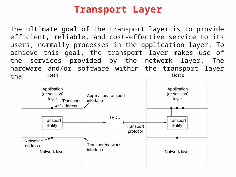
Transport Layer The ultimate goal of the transport layer is to provide efficient, reliable, and cost-effective service to its users, normally processes in the application layer. To achieve this goal, the transport layer makes use of the services provided by the network layer. The hardware and/or software within the transport layer that does the work is called the transport entity.

Welcome message from author
This document is posted to help you gain knowledge. Please leave a comment to let me know what you think about it! Share it to your friends and learn new things together.
Transcript
Transport Layer
The ultimate goal of the transport layer is to provide efficient, reliable, and cost-effective service to its users, normally processes in the application layer. To achieve this goal, the transport layer makes use of the services provided by the network layer. The hardware and/or software within the transport layer that does the work is called the transport entity.

Position of transport layer
© Dr. Ayman Abdel-Hamid, CS4254 Spring 2006
3TCP
Transport Layer
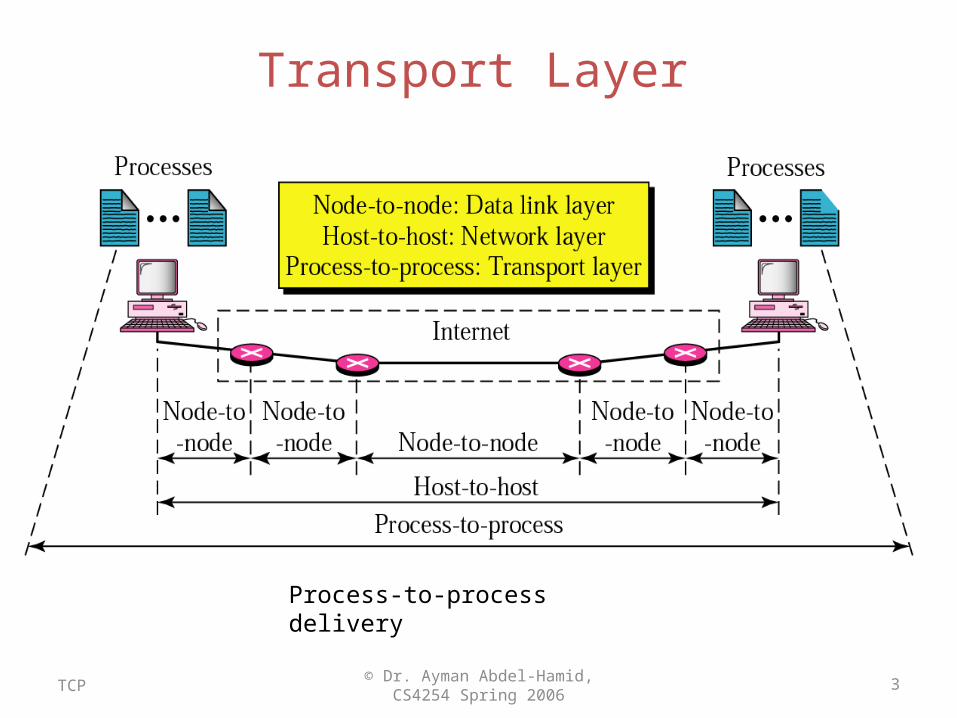
Process-to-process delivery

The bottom four layers can be seen as the transport service provider, whereas the upper layer(s) are the transport service user.
To allow users to access the transport service, the transport layer must provide some operations to application programs, that is, a transport service interface. Each transport service has its own interface.
The transport service is similar to the network service, but there are also some important differences. The main difference is that the network service is intended to model the service offered by real networks, warts and all. Real networks can lose packets, so the network service is generally unreliable. The (connection-oriented) transport service, in contrast, is reliable.
A second difference between the network service and transport service is whom the services are intended for. The network service is used only by the transport entities. Few users write their own transport entities, and thus few users or programs ever see the bare network service. In contrast, many programs see the transport primitives. Consequently, the transport service must be convenient and easy to use.
Services Provided to the Upper Layers

Transport Service Primitives
The primitives for a simple transport service.
The nesting of TPDUs, packets, and frames.
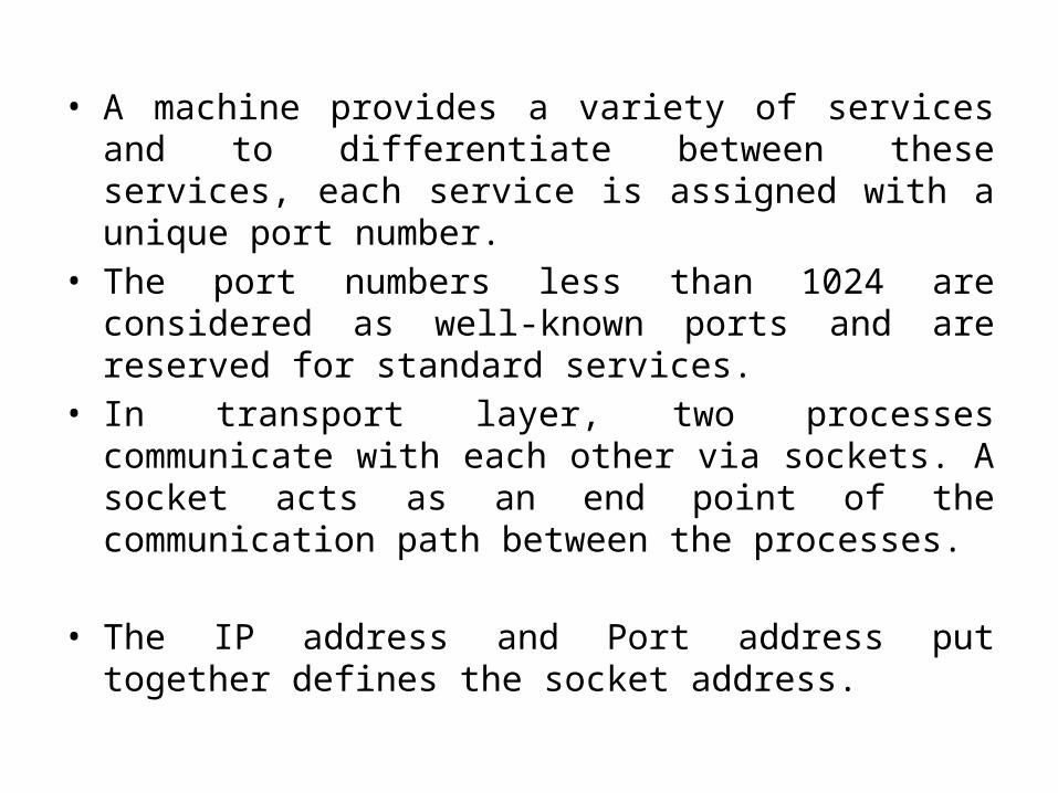
• A machine provides a variety of services and to differentiate between these services, each service is assigned with a unique port number.
• The port numbers less than 1024 are considered as well-known ports and are reserved for standard services.
• In transport layer, two processes communicate with each other via sockets. A socket acts as an end point of the communication path between the processes.
• The IP address and Port address put together defines the socket address.
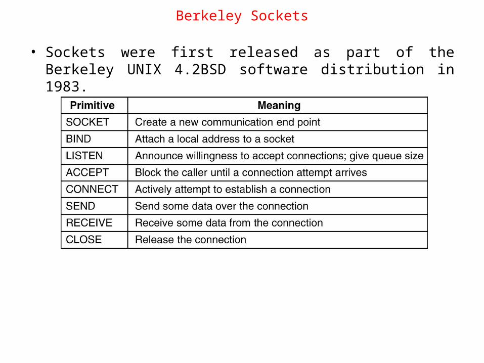
• Sockets were first released as part of the Berkeley UNIX 4.2BSD software distribution in 1983.
Berkeley Sockets

Elements of Transport ProtocolsThe transport service is implemented by a transport protocol used between the two transport entities.
Though the transport protocols resemble the Data Link Protocols, significant differences are present due to the major dissimilarities between the environments in which the two protocols operate.
A physical channel exists in DLL, where as it is replaced by the entire subnet for Transport Layer
No explicit addressing of destinations is required in DLL, where it is required for Transport layer
A final difference between the data link and transport layers is one of amount rather than of kind. Buffering and flow control are needed in both layers, but the presence of a large and dynamically varying number of connections in the transport layer may require a different approach than we used in the data link layer
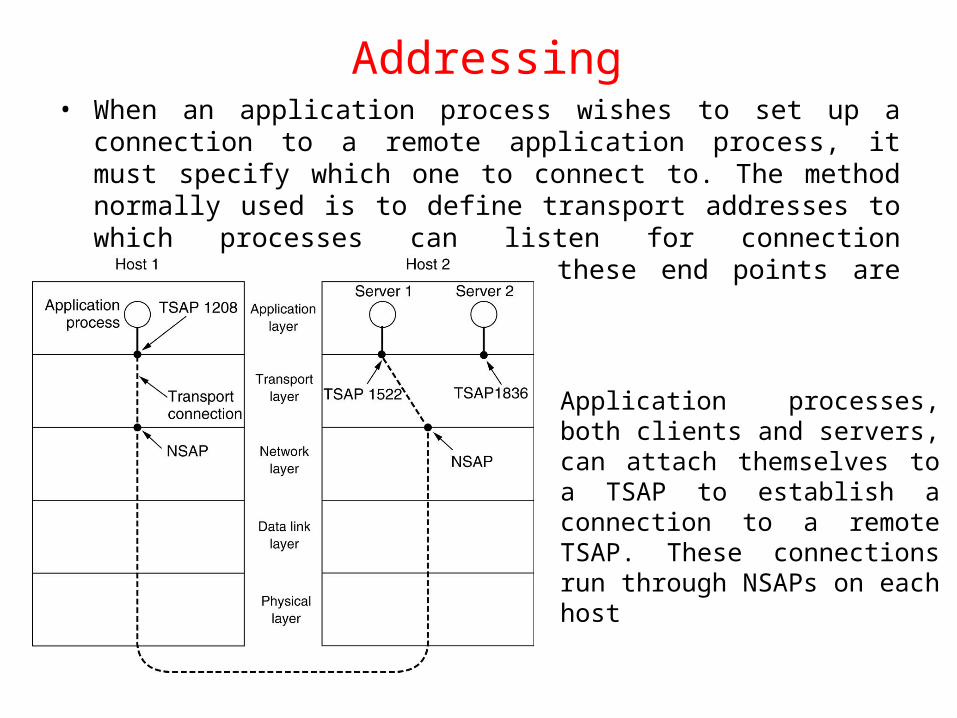
Addressing• When an application process wishes to set up a connection to a remote
application process, it must specify which one to connect to. The method normally used is to define transport addresses to which processes can listen for connection requests. In the Internet, these end points are called ports.
Application processes, both clients and servers, can attach themselves to a TSAP to establish a connection to a remote TSAP. These connections run through NSAPs on each host

initial connection protocol
Instead of every conceivable server listening at a well-known TSAP, each machine that wishes to offer services to remote users has a special process server that acts as a proxy for less heavily used servers. It listens to a set of ports at the same time, waiting for a connection request. This server is called inetd on UNIX systems…….
Connection Establishment
The problem with a simple communication request & communication accepted exchange is that the network can lose, store, and duplicate packets. This behavior causes serious complications.
The Crux of the problem is the existence of delayed duplicates. Various ways to attack the problem are:
Using a throw-away transport address
Give each connection a connection identifier
A mechanism to kill off aged packets
Restricted subnet design
Hop Counter
Time Stamping

Connection Establishment (3)
Three protocol scenarios for establishing a connection using a three-way handshake. CR denotes CONNECTION REQUEST. (a) Normal operation, (b) Old CONNECTION REQUEST appearing out of nowhere. (c) Duplicate CONNECTION REQUEST and duplicate ACK.

Connection Release
Abrupt disconnection with loss of data.

Connection Release
Four protocol scenarios for releasing a connection. (a) Normal case of a three-way handshake. (b) final ACK lost.
6-14, a, b
Four protocol scenarios for releasing a connection. (a) Normal case of a three-way handshake. (b) final ACK lost.

Connection Release
(c) Response lost. (d) Response lost and subsequent DRs lost.
6-14, c,d
Flow Control and Buffering
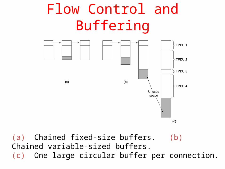
(a) Chained fixed-size buffers. (b) Chained variable-sized buffers. (c) One large circular buffer per connection.
• The optimum trade-off between source buffering and destination buffering depends on the type of traffic carried by the connection. For low-bandwidth bursty traffic, such as that produced by an interactive terminal the sender must retain a copy of the TPDU until it is acknowledged.
• On the other hand, for file transfer and other high-bandwidth traffic, it is better if the receiver does dedicate a full window of buffers, to allow the data to flow at maximum speed.
• Thus, for low-bandwidth bursty traffic, it is better to buffer at the sender, and for high bandwidth smooth traffic, it is better to buffer at the receiver.

Multiplexing
If only one network address is available on a host, all transport connections on that machine have to use it. When a TPDU comes in, some way is needed to tell which process to give it to. This situation is called upward multiplexing.
Multiplexing can also be useful in the transport layer for another reason. Suppose, for example, that a subnet uses virtual circuits internally and imposes a maximum data rate on each one. If a user needs more bandwidth than one virtual circuit can provide, a way out is to open multiple network connections and distribute the traffic among them on a round-robin basis, called downward multiplexing.
UDP• The User Datagram Protocol (UDP) is a transport layer
protocol defined for use with the IP network layer protocol. It is defined by RFC 768 written by John Postel. It provides a best-effort datagram service to an End System (IP host).
• The service provided by UDP is an unreliable service that provides no guarantees for delivery and no protection from duplication. The simplicity of UDP reduces the overhead from using the protocol and the services may be adequate in many cases.
• UDP provides a minimal, unreliable, best-effort, message-passing transport to applications and upper-layer protocols
Introduction to UDP
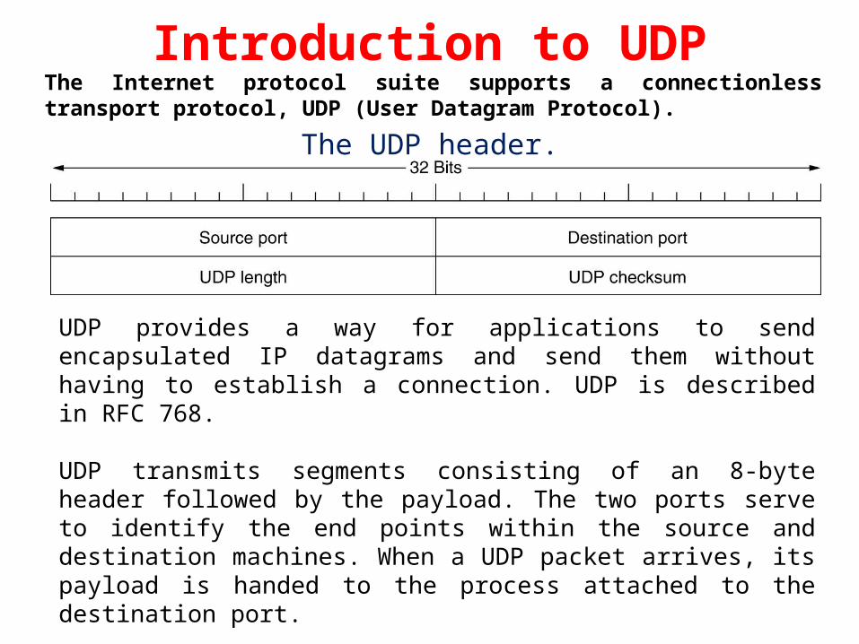
The UDP header.
UDP provides a way for applications to send encapsulated IP datagrams and send them without having to establish a connection. UDP is described in RFC 768.
UDP transmits segments consisting of an 8-byte header followed by the payload. The two ports serve to identify the end points within the source and destination machines. When a UDP packet arrives, its payload is handed to the process attached to the destination port.
The source port is primarily needed when a reply must be sent back to the source. The UDP length field includes the 8-byte header and the data.
The Internet protocol suite supports a connectionless transport protocol, UDP (User Datagram Protocol).
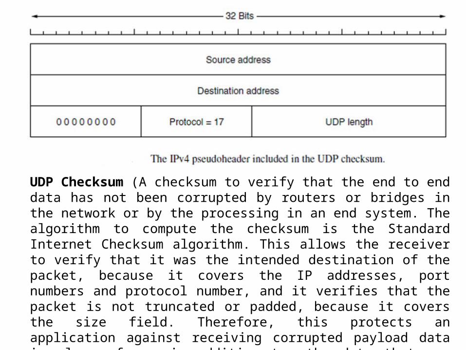
UDP Checksum (A checksum to verify that the end to end data has not been corrupted by routers or bridges in the network or by the processing in an end system. The algorithm to compute the checksum is the Standard Internet Checksum algorithm. This allows the receiver to verify that it was the intended destination of the packet, because it covers the IP addresses, port numbers and protocol number, and it verifies that the packet is not truncated or padded, because it covers the size field. Therefore, this protects an application against receiving corrupted payload data in place of, or in addition to, the data that was sent. In the cases where this check is not required, the value of 0x0000 is placed in this field, in which case the data is not checked by the receiver.
Remote Procedure Call
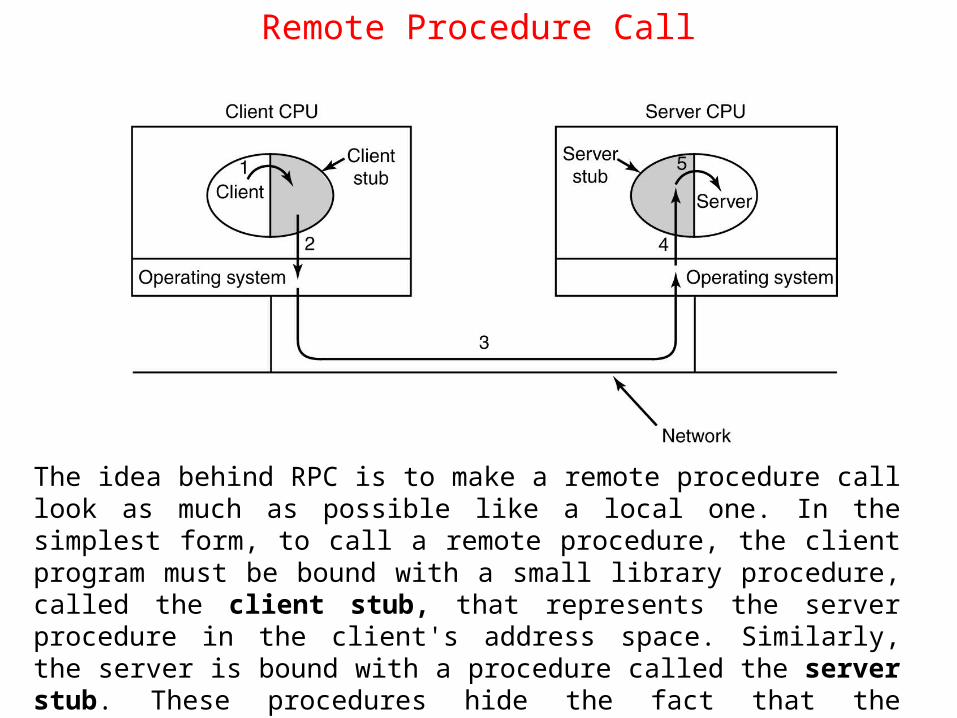
The idea behind RPC is to make a remote procedure call look as much as possible like a local one. In the simplest form, to call a remote procedure, the client program must be bound with a small library procedure, called the client stub, that represents the server procedure in the client's address space. Similarly, the server is bound with a procedure called the server stub. These procedures hide the fact that the procedure call from the client to the server is not local.
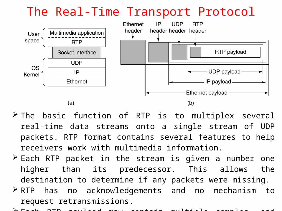
The Real-Time Transport Protocol
The basic function of RTP is to multiplex several real-time data streams onto a single stream of UDP packets. RTP format contains several features to help receivers work with multimedia information.
Each RTP packet in the stream is given a number one higher than its predecessor. This allows the destination to determine if any packets were missing.
RTP has no acknowledgements and no mechanism to request retransmissions. Each RTP payload may contain multiple samples, and they may be coded any
way that the application wants.

The RTP header.
version (V): 2 bits: This field identifies the version of RTP. The version is 2 upto RFC 1889. padding (P): 1 bit: If the padding bit is set, the packet contains one or more additional padding octets at the end which are not part of the payload.Xtension (X): 1 bit: If the extension bit is set, the fixed header is followed by exactly one header extension

• CSRC count (CC): 4 bits: The CSRC count contains the number of CSRC identifiers that follow the fixed header.
• marker (M): 1 bit: Marker bit is used by specific applications to serve a purpose of its own. Used to mark the start of a video frame, start of a word in audio channel.
• payload type (PT): 7 bits: This field identifies the format (e.g. encoding) of the RTP payload and determines its interpretation by the application.
• sequence number: 16 bits: The sequence number increments by one for each RTP data packet sent, and may be used by the receiver to detect packet loss and to restore packet sequence.
• timestamp: 32 bits: The Timestamp is produced by the stream’s source to note when the first sample in the packet was made. This value can help reduce timing variability called jitter at the receiver by decoupling the playback from the packet arrival time.
• SSRC: 32 bits: The SSRC field identifies the synchronization source. It is the method used to multiplex and demultiplex data streams onto a single stream of UDP packets
• CSRC list: 0 to 15 items, 32 bits each: The CSRC list identifies the contributing sources for the payload contained in this packet.
Real-time Transport Control Protocol• RTP has a little sister protocol called RTCP (Realtime Transport
Control Protocol). • It handles feedback, synchronization, and the user interface
but does not transport any data. The first function can be used to provide feedback on delay, jitter, bandwidth, congestion, and other network properties to the sources
• RTCP also handles interstream synchronization. The problem is that different streams may use different clocks, with different granularities and different drift rates. RTCP can be used to keep them in sync.
• RTCP provides a way for naming the various sources (e.g., in ASCII text). This information can be displayed on the receiver's screen to indicate who is talking at the moment.

The Internet Transport Protocols: TCP
• TCP (Transmission Control Protocol) was specifically designed to provide a reliable end-to-end byte stream over an unreliable internetwork.
• TCP was formally defined in RFC 793.
• The IP layer gives no guarantee that datagrams will be delivered properly, so it is up to TCP to time out and retransmit them as need be. Datagrams that do arrive may well do so in the wrong order; it is also up to TCP to reassemble them into messages in the proper sequence. In short, TCP must furnish the reliability that most users want and that IP does not provide.
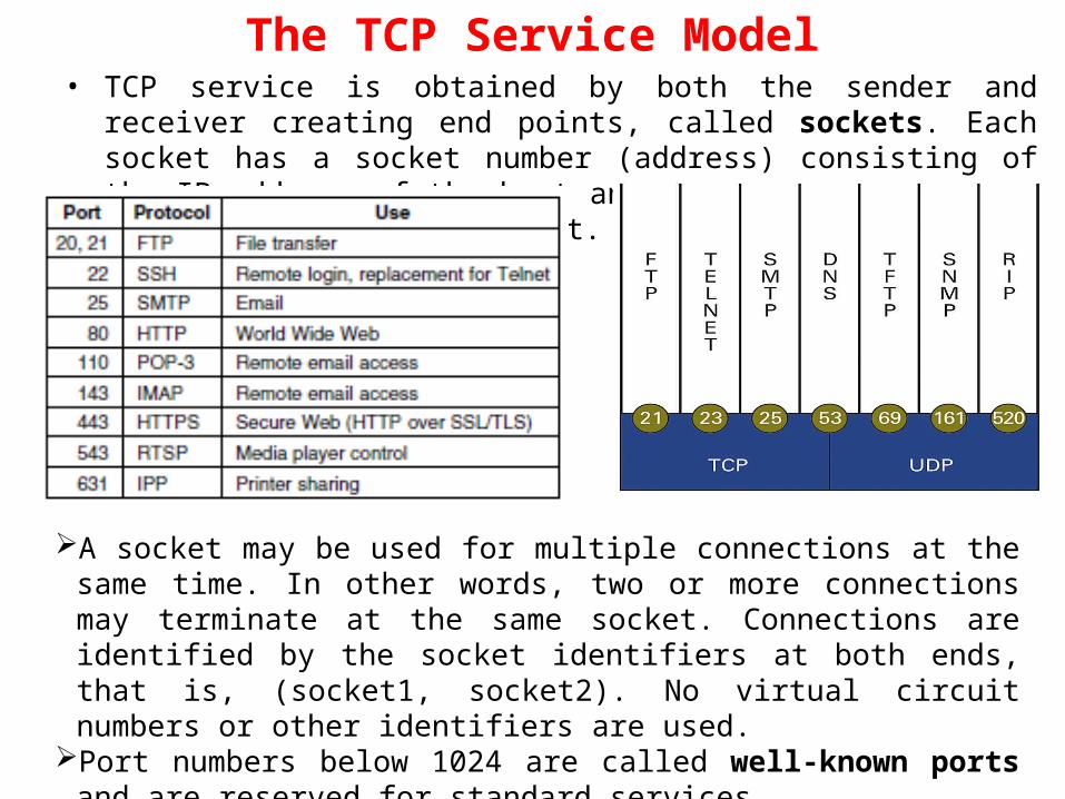
The TCP Service Model• TCP service is obtained by both the sender and receiver creating end points,
called sockets. Each socket has a socket number (address) consisting of the IP address of the host and a 16-bit number local to that host, called a port.
A socket may be used for multiple connections at the same time. In other words, two or more connections may terminate at the same socket. Connections are identified by the socket identifiers at both ends, that is, (socket1, socket2). No virtual circuit numbers or other identifiers are used.
Port numbers below 1024 are called well-known ports and are reserved for standard services

29
TCP Protocol
• Provides a reliable, in-order, byte stream abstraction:– Recover lost packets and detect/drop duplicates– Detect and drop corrupted packets– Preserve order in byte stream, no “message boundaries”– Full-duplex: bi-directional data flow in same connection
• Flow and congestion control: – Flow control: sender will not overwhelm receiver– Congestion control: sender will not overwhelm the network– Sliding window flow control– Send and receive buffers– Congestion control done via adaptive flow control window size
socketlayer
TCPsend buffer
applicationwrites data
TCPreceive buffer
socketlayer
applicationreads data
data segment
ACK segment
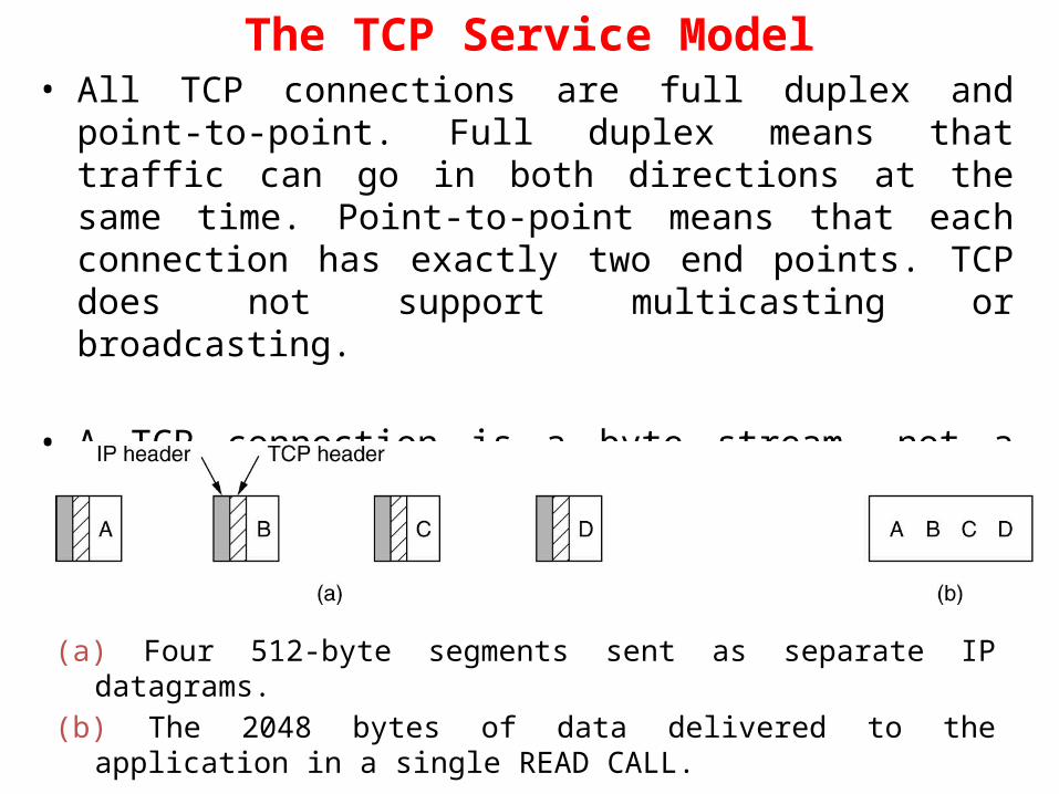
• All TCP connections are full duplex and point-to-point. Full duplex means that traffic can go in both directions at the same time. Point-to-point means that each connection has exactly two end points. TCP does not support multicasting or broadcasting.
• A TCP connection is a byte stream, not a message stream. Message boundaries are not preserved end to end.
The TCP Service Model
(a) Four 512-byte segments sent as separate IP datagrams.(b) The 2048 bytes of data delivered to the application in a single READ CALL.
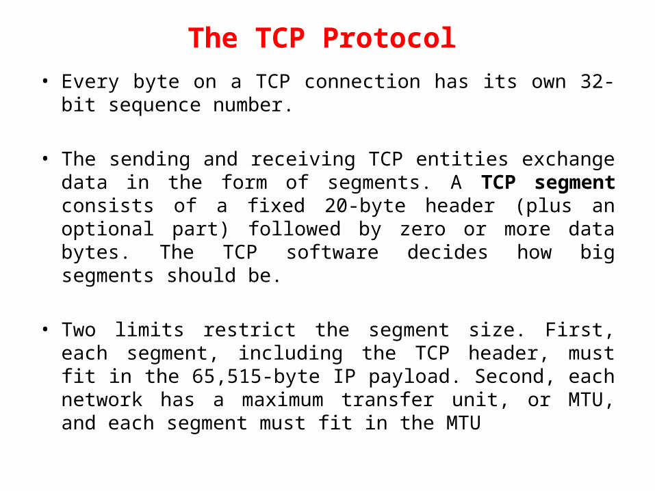
• Every byte on a TCP connection has its own 32-bit sequence number.
• The sending and receiving TCP entities exchange data in the form of segments. A TCP segment consists of a fixed 20-byte header (plus an optional part) followed by zero or more data bytes. The TCP software decides how big segments should be.
• Two limits restrict the segment size. First, each segment, including the TCP header, must fit in the 65,515-byte IP payload. Second, each network has a maximum transfer unit, or MTU, and each segment must fit in the MTU
The TCP Protocol
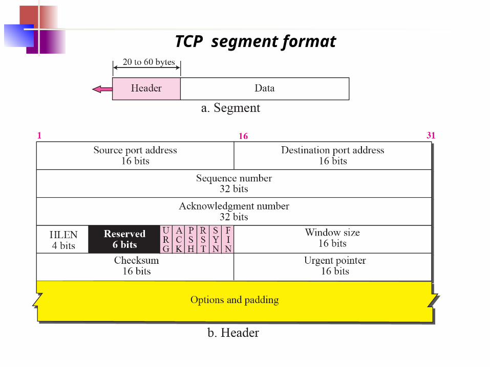
TCP segment format

The TCP Segment Header
TCP Header.

• The Source port and Destination port fields identify the local end points of the connection. A port plus its host's IP address forms a 48-bit unique end point. The source and destination end points together identify the connection.
• This connection identifier is called a 5 tuple because it consists of five pieces of information: the protocol (TCP), source, IP and source port, and destination IP and destination port.
• The Sequence number and Acknowledgement number fields perform their usual functions. The latter specifies the next byte expected, not the last byte correctly received. Both are 32 bits long because every byte of data is numbered in a TCP stream.
• The TCP header length tells how many 32-bit words are contained in the TCP header.
• Next comes a 4-bit field that is not used.
• CWR and ECE are used to signal congestion when ECN (Explicit Congestion Notification) is used. ECE is set to signal an ECN-Echo to a TCP sender to tell it to slow down when the TCP receiver gets a congestion indication from the network. CWR is set to signal Congestion Window Reduced from the TCP sender to the TCP receiver so that it knows the sender has slowed down and can stop sending the ECN-Echo.
• URG is set to 1 if the Urgent pointer is in use. The Urgent pointer is used to indicate a byte offset from the current sequence number at which urgent data are to be found.
• The ACK bit is set to 1 to indicate that the Acknowledgement number is valid.
• The PSH bit indicates PUSHed data. The receiver is hereby kindly requested to deliver the data to the application upon arrival and not buffer it until a full buffer has been received.
• The RST bit is used to abruptly reset a connection that has become confused due to a host crash or some other reason.
• The SYN bit is used to establish connections. The connection request has SYN = 1 and ACK = 0. The connection reply does bear an acknowledgement, however, so it has SYN = 1 and ACK = 1.
• The FIN bit is used to release a connection. It specifies that the sender has no more data to transmit.

• Flow control in TCP is handled using a variable-sized sliding window. The Window size field tells how many bytes may be sent starting at the byte acknowledged.
• A Checksum is also provided for extra reliability. It checksums the header, the data, and a conceptual pseudoheader in exactly the same way as UDP.
• The Options field provides a way to add extra facilities not covered by the regular header. Many options have been defined and several are commonly used.– A widely used option is the one that allows each host to specify the
MSS (Maximum Segment Size) it is willing to accept.– The timestamp option carries a timestamp sent by the sender and
echoed by the receiver.– The SACK (Selective ACKnowledgement) option lets a receiver tell a
sender the ranges of sequence numbers that it has received
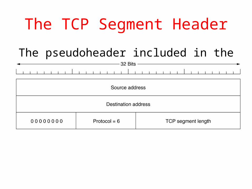
The TCP Segment Header
The pseudoheader included in the TCP checksum.

TCP Connection Establishment
• Connections are established in TCP by means of the three-way handshake. To establish a connection, one side, say, the server, passively waits for an incoming connection by executing the LISTEN and ACCEPT primitives.
• The other side, say, the client, executes a CONNECT primitive, specifying the IP address and port to which it wants to connect, the maximum TCP segment size it is willing to accept, and optionally some user data (e.g., a password). The CONNECT primitive sends a TCP segment with the SYN bit on and ACK bit off and waits for a response.
• When this segment arrives at the destination, the TCP entity there checks to see if there is a process that has done a LISTEN on the port given in the Destination port field. If not, it sends a reply with the RST bit on to reject the connection.
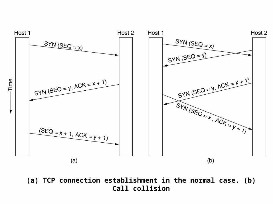
(a) TCP connection establishment in the normal case. (b) Call collision
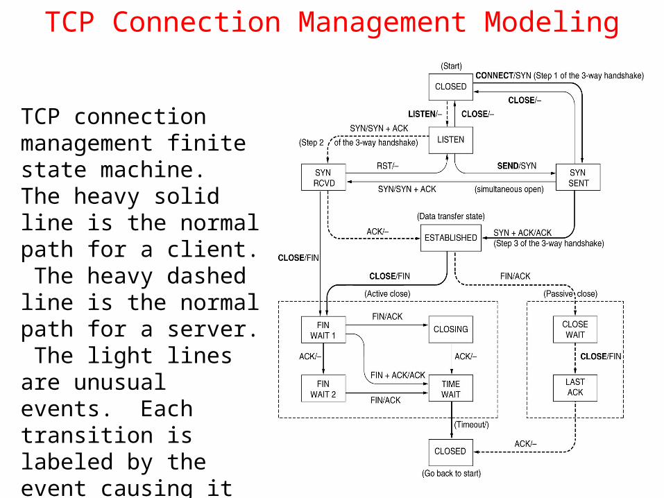
TCP Connection Management Modeling
TCP connection management finite state machine. The heavy solid line is the normal path for a client. The heavy dashed line is the normal path for a server. The light lines are unusual events. Each transition is labeled by the event causing it and the action resulting from it, separated by a slash.

TCP Transmission Policy
Window management in TCP.
Window probe is a packet sent by the sender, who can send a 1-byte segment to force the receiver to reannounce the next byte expected and the window size.
Delayed acknowledgements is an optimization, where the idea is to delay acknowledgementsand window updates for up to 500 msec in the hope of acquiring some data on which to hitch a free ride.

TCP Transmission Policy
Nagle’s algorithm is a way to reduce the bandwidth wastage by a sender that sends multiple short packets (e.g., 41-byte packets containing 1 byte of data).
when data come into the sender in small pieces, just send the first piece and buffer all the rest until the first piece is acknowledged. Then send all the buffered data in one TCP segment and start buffering again until the next segment is acknowledged.
Silly window syndrome is a problem that occurs when data are passed to the sending TCP entity in large blocks, but an interactive application on the receiving side reads data only 1 byte at a time.
• Clark’s solution is to prevent the receiver from sending a window update for 1 byte. Instead, it is forced to wait until it has a decent amount of space available and advertise that instead.
• Nagle’s algorithm and Clark’s solution to the silly window syndrome are complementary. Nagle was trying to solve the problem caused by the sending application delivering data to TCP a byte at a time. Clark was trying to solve the problem of the receiving application sucking the data up from TCP a byte at a time.
• Both solutions are valid and can work together. The goal is for the sender not to send small segments and the receiver not to ask for them.
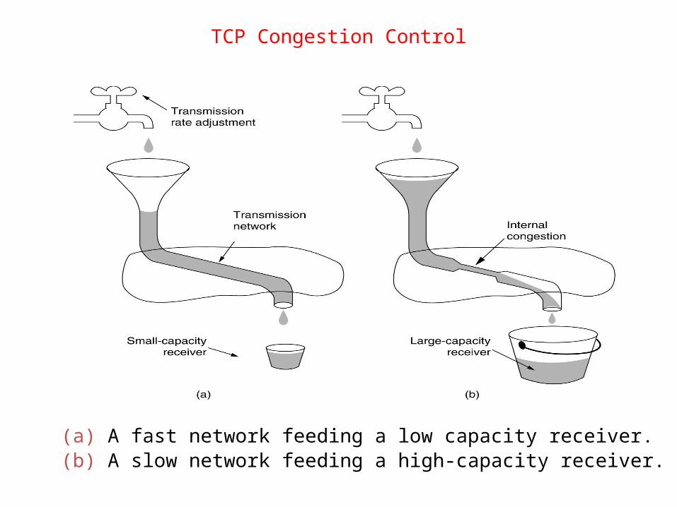
TCP Congestion Control
(a) A fast network feeding a low capacity receiver.(b) A slow network feeding a high-capacity receiver.

• To deal with the two problems of receivers capacity and network capacity, each sender maintains two windows: the window the receiver has granted and a second window, the congestion window.
• Each reflects the number of bytes the sender may transmit. The number of bytes that may be sent is the minimum of the two windows.
• When a connection is established, the sender initializes the congestion window to the size of the maximum segment in use on the connection. It then sends one maximum segment. Each burst acknowledged doubles the congestion window.
• The congestion window keeps growing exponentially until either a timeout occurs or the receiver's window is reached. This algorithm is called slow start.
• Internet congestion control algorithm uses a third parameter, the threshold, initially 64 KB, in addition to the receiver and congestion windows. When a timeout occurs, the threshold is set to half of the current congestion window, and the congestion window is reset to one maximum segment.
TCP Congestion Control

TCP Congestion Control
An example of the Internet congestion algorithm.

• Retransmission timer: When a segment is sent, a retransmission timer is started. If the segment is acknowledged before the timer expires, the timer is stopped. If, on the other hand, the timer goes off before the acknowledgement comes in, the segment is retransmitted (and the timer started again).
• Persistence timer is designed to prevent a deadlock situation where, the sender keeps waiting for a window update from the receiver, which is lost. When the persistence timer goes off, the sender transmits a probe to the receiver. The response to the probe gives the window size.
• Keepalive timer: When a connection has been idle for a long time, the keepalive timer may go off to cause one side to check whether the other side is still there. If it fails to respond, the connection is terminated.
TCP Timer Management
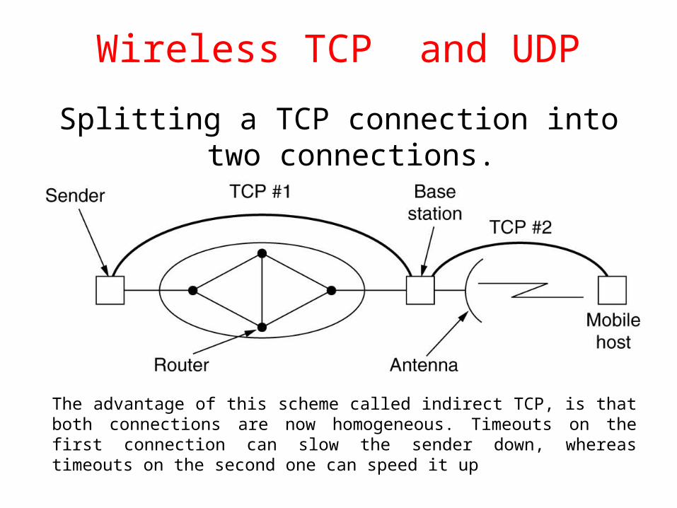
Wireless TCP and UDP
Splitting a TCP connection into two connections.
The advantage of this scheme called indirect TCP, is that both connections are now homogeneous. Timeouts on the first connection can slow the sender down, whereas timeouts on the second one can speed it up

Transactional TCP (T/TCP)
(a) RPC using normal TPC.(b) RPC using T/TCP.

Future
• Another proposal is SCTP (Stream Control Transmission Protocol). Its features include message boundary preservation, multiple delivery modes (e.g., unordered delivery), multihoming (backup destinations), and selective acknowledgements
Related Documents