Transparent U-based Verication of MUML Models by Christopher Gerking

Welcome message from author
This document is posted to help you gain knowledge. Please leave a comment to let me know what you think about it! Share it to your friends and learn new things together.
Transcript
Transparent Uppaal-based Veri�cation of
MechatronicUML Models
by
Christopher Gerking

Fakultät für Elektrotechnik, Informatik und MathematikHeinz Nixdorf Institut und Institut für InformatikFachgebiet So�waretechnikZukun�smeile 133102 Paderborn
Transparent Uppaal-based
Veri�cation of MechatronicUML
Models
Master’s ThesisSubmitted to the Software Engineering Research Group
in Partial Ful�llment of the Requirements for theDegree of
Master of Science
byChristopher Gerking
Grevestraße 733102 Paderborn
Thesis Supervisor:Prof. Dr. Wilhelm Schäfer
andProf. Dr. Gregor Engels
Paderborn, May 2013

Declaration
(Translation from German)
I hereby declare that I prepared this thesis entirely on my own and have not usedoutside sources without declaration in the text. Any concepts or quotations applicableto these sources are clearly attributed to them. This thesis has not been submitted inthe same or substantially similar version, not even in part, to any other authority forgrading and has not been published elsewhere.
Original Declaration Text in German:
Erklärung
Ich versichere, dass ich die Arbeit ohne fremde Hilfe und ohne Benutzung anderer alsder angegebenen Quellen angefertigt habe und dass die Arbeit in gleicher oder ähn-licher Form noch keiner anderen Prüfungsbehörde vorgelegen hat und von dieser alsTeil einer Prüfungsleistung angenommen worden ist. Alle Ausführungen, die wörtlichoder sinngemäß übernommen worden sind, sind als solche gekennzeichnet.
City, Date Signature
v

Contents
1 Introduction 1
1.1 Problem . . . . . . . . . . . . . . . . . . . . . . . . . . . . . . . . . . . 21.2 Objective . . . . . . . . . . . . . . . . . . . . . . . . . . . . . . . . . . . 41.3 Approach . . . . . . . . . . . . . . . . . . . . . . . . . . . . . . . . . . . 41.4 Structure . . . . . . . . . . . . . . . . . . . . . . . . . . . . . . . . . . . 5
2 Basics 7
2.1 Model-Driven Software Development . . . . . . . . . . . . . . . . . . . 72.2 Timed Automata . . . . . . . . . . . . . . . . . . . . . . . . . . . . . . . 112.3 Temporal Logic . . . . . . . . . . . . . . . . . . . . . . . . . . . . . . . 172.4 Timed Model Checking . . . . . . . . . . . . . . . . . . . . . . . . . . . 202.5 MechatronicUML . . . . . . . . . . . . . . . . . . . . . . . . . . . . . 232.6 Goal Question Metric . . . . . . . . . . . . . . . . . . . . . . . . . . . . 31
3 Related Work 33
3.1 Transforming MechatronicUML to External Formalisms . . . . . . . 333.2 Transforming External Formalisms to Uppaal . . . . . . . . . . . . . . 373.3 Transparent Veri�cation . . . . . . . . . . . . . . . . . . . . . . . . . . 453.4 Interim Conclusion . . . . . . . . . . . . . . . . . . . . . . . . . . . . . 47
4 MechatronicUML to Uppaal Transformation 49
4.1 Overview . . . . . . . . . . . . . . . . . . . . . . . . . . . . . . . . . . . 494.2 Normalization of Deadlines . . . . . . . . . . . . . . . . . . . . . . . . . 564.3 Normalization of Composite Transitions . . . . . . . . . . . . . . . . . 584.4 Normalization of Hierarchical States . . . . . . . . . . . . . . . . . . . . 614.5 MechatronicUML to Uppaal Migration . . . . . . . . . . . . . . . . . 70
5 Uppaal to MechatronicUML Trace Transformation 89
5.1 Traces . . . . . . . . . . . . . . . . . . . . . . . . . . . . . . . . . . . . . 895.2 Requirements . . . . . . . . . . . . . . . . . . . . . . . . . . . . . . . . 915.3 Transformation Approach . . . . . . . . . . . . . . . . . . . . . . . . . 925.4 Modeling Uppaal Concrete Traces . . . . . . . . . . . . . . . . . . . . . 925.5 Real-Time Statechart Zone Graphs . . . . . . . . . . . . . . . . . . . . . 955.6 Inverse Resolution of Traceability Links . . . . . . . . . . . . . . . . . . 975.7 Clock Valuations and Variable Bindings . . . . . . . . . . . . . . . . . . 985.8 Asynchronous Message Exchange . . . . . . . . . . . . . . . . . . . . . 99
vii
Contents
6 Implementation 101
6.1 Meta-Modeling . . . . . . . . . . . . . . . . . . . . . . . . . . . . . . . . 1026.2 Model-To-Model Transformation . . . . . . . . . . . . . . . . . . . . . . 1026.3 Model-to-Text Transformation . . . . . . . . . . . . . . . . . . . . . . . 1056.4 Parsing . . . . . . . . . . . . . . . . . . . . . . . . . . . . . . . . . . . . 1066.5 Visualization . . . . . . . . . . . . . . . . . . . . . . . . . . . . . . . . . 106
7 Evaluation 107
7.1 De�nition . . . . . . . . . . . . . . . . . . . . . . . . . . . . . . . . . . 1077.2 Data Collection . . . . . . . . . . . . . . . . . . . . . . . . . . . . . . . 1107.3 Interpretation . . . . . . . . . . . . . . . . . . . . . . . . . . . . . . . . 1107.4 Threats to Validity . . . . . . . . . . . . . . . . . . . . . . . . . . . . . . 112
8 Conclusion 115
8.1 Summary . . . . . . . . . . . . . . . . . . . . . . . . . . . . . . . . . . . 1158.2 Insights . . . . . . . . . . . . . . . . . . . . . . . . . . . . . . . . . . . . 1168.3 Outlook . . . . . . . . . . . . . . . . . . . . . . . . . . . . . . . . . . . . 117
A Trace Visualization 119
B CD Contents 121
Bibliography 123
viii
List of Figures
1.1 Vehicle-to-Vehicle Communication in an Overtaking Scenario . . . . . 21.2 MechatronicUML Component Instance Con�guration . . . . . . . . . 31.3 Transformation Approach between MechatronicUML and Uppaal . . 5
2.1 Timed Automaton . . . . . . . . . . . . . . . . . . . . . . . . . . . . . . 132.2 Uppaal Timed Automata . . . . . . . . . . . . . . . . . . . . . . . . . . 152.3 Hierarchical Timed Automaton . . . . . . . . . . . . . . . . . . . . . . 162.4 MechatronicUML Vehicle Component . . . . . . . . . . . . . . . . . . 242.5 MechatronicUML Component Instance Con�guration . . . . . . . . . 242.6 MechatronicUML Coordination Protocol . . . . . . . . . . . . . . . . 252.7 MechatronicUML Real-Time Statechart . . . . . . . . . . . . . . . . . 262.8 Relative Deadline Inside a Real-Time Statechart . . . . . . . . . . . . . 272.9 Entry-Action Inside a Real-Time Statechart . . . . . . . . . . . . . . . . 282.10 Entry-/ and Exit-Point Inside a Real-Time Statechart . . . . . . . . . . . 29
3.1 Asynchronous Message Exchange Automata for hugo/RT . . . . . . . 393.2 CIF Transformation Approach [BCN+09] . . . . . . . . . . . . . . . . . 41
4.1 Overtaking Coordination Protocol . . . . . . . . . . . . . . . . . . . . . 504.2 Role Real-Time Statecharts . . . . . . . . . . . . . . . . . . . . . . . . . 514.3 Di�erent Veri�cation Use Cases . . . . . . . . . . . . . . . . . . . . . . 534.4 Action Steps of the Transformation from MechatronicUML to Uppaal 554.5 Schematic Representation of the Normalization Step for Deadlines . . . 574.6 Normalization of Deadlines . . . . . . . . . . . . . . . . . . . . . . . . . 574.7 Schematic Representation of the Normalization Step for Composite
Transitions . . . . . . . . . . . . . . . . . . . . . . . . . . . . . . . . . . 594.8 Normalization of Composite Transitions . . . . . . . . . . . . . . . . . 604.9 Schematic Representation of the Normalization Step for Hierarchical
States . . . . . . . . . . . . . . . . . . . . . . . . . . . . . . . . . . . . . 624.10 Normalization of Hierarchical States . . . . . . . . . . . . . . . . . . . . 634.11 Normalization of Hierarchical States . . . . . . . . . . . . . . . . . . . . 664.12 Join Trees of Composite State noOvertaking . . . . . . . . . . . . . . . 674.13 Bundled Representation of the Flattened Real-Time Statecharts . . . . . 704.14 Uppaal Network of Timed Automata Meta-Model . . . . . . . . . . . . 714.15 Uppaal Timed Automata Templates . . . . . . . . . . . . . . . . . . . . 734.16 Representation of Clock Instances . . . . . . . . . . . . . . . . . . . . . 754.17 Representation of Operations . . . . . . . . . . . . . . . . . . . . . . . . 77
ix
List of Figures
4.18 Di�erent Approaches of Representing Asynchronous Message Exchange 784.19 Transmission Time Clocks . . . . . . . . . . . . . . . . . . . . . . . . . 794.20 Dispatching an Asynchronous Message inside an Uppaal Template . . 814.21 Generic Asynchronous Message Exchange Template . . . . . . . . . . . 814.22 Consuming an Asynchronous Message inside an Uppaal Template . . 844.23 Asynchronous Message Exchange Runtime Example . . . . . . . . . . . 86
5.1 Uppaal Overtaking Snapshot . . . . . . . . . . . . . . . . . . . . . . . . 905.2 Action Steps of the MechatronicUML Trace Generation . . . . . . . . 925.3 Snapshot inside an Uppaal Trace . . . . . . . . . . . . . . . . . . . . . 935.4 Uppaal Trace Meta-Model . . . . . . . . . . . . . . . . . . . . . . . . . 945.5 Real-Time Statechart Snapshot inside a Linear Zone Graph . . . . . . . 955.6 Real-Time Statechart Zone Graph Meta-Model . . . . . . . . . . . . . . 965.7 Inverse Resolution of Traceability Links . . . . . . . . . . . . . . . . . . 985.8 Reproduction of Uppaal Traces by Real-Time Statechart Zone Graphs . 99
6.1 Action Steps of the Veri�cation and Associated Technologies . . . . . . 1016.2 Meta-Model Dependencies . . . . . . . . . . . . . . . . . . . . . . . . . 1026.3 Model-to-Model Transformation Structure . . . . . . . . . . . . . . . . 103
7.1 Case Study Real-Time Statecharts . . . . . . . . . . . . . . . . . . . . . 1087.2 Exemplary Non-Progressive Snapshot . . . . . . . . . . . . . . . . . . . 1117.3 Exemplary Incomplete Trace Snapshot . . . . . . . . . . . . . . . . . . 112
A.1 Liveness Trace Visualized by Graphviz . . . . . . . . . . . . . . . . . . 119
x
List of Tables
7.1 Case Study Models . . . . . . . . . . . . . . . . . . . . . . . . . . . . . 1087.2 Veri�cation Properties . . . . . . . . . . . . . . . . . . . . . . . . . . . 1087.3 Re�nement of the Semantics Preservation Goal for theMechatronicUML
to Uppaal Transformation . . . . . . . . . . . . . . . . . . . . . . . . . 1097.4 Re�nement of the Semantics Preservation Goal for theUppaal toMecha-
tronicUML Trace Transformation . . . . . . . . . . . . . . . . . . . . 1097.5 Data Collection Hypotheses and Results . . . . . . . . . . . . . . . . . . 110
xi

1 Introduction
Nowadays, software is ubiquitous in mechatronic systems like cars or other vehicles.It realizes the information processing in complex control loops involving sensor andactuator technology. We are faced with the environmental impacts of software interms of comfort functions related to information, entertainment, and safety. Impres-sive indicators for today’s role of software in automotive systems are numbers like 100electronic control units per car [EZK+13], running one gigabyte of software [PBKS07]with 100 million lines of code [Mös10] in order to provide up to 2000 individual func-tions [Bro06]. 90 percent of today’s innovations in the automotive industry stem fromelectronics including software [HMG11].
Due to the inherent connection of mechatronic systems to real-world physical pro-cesses, software systems face hard real-time requirements, i.e. software must react toexternal stimuli within speci�c time bounds. Along with the exponential rise of soft-ware in the automotive industry [PBKS07], the consequences of unsatis�ed real-timerequirements tend to be increasingly drastic. To avoid costs from contractual penalties,or even loss of human life, safety-critical computer systems require the guaranteed ab-sence of errors in the software they are running [Sto96]. A plain testing of systemsunder certain selected conditions is therefore inappropriate in the domain of mecha-tronics. Instead, there is a pressing need for reliable veri�cation techniques that coverthe entire real-time behavior under all possible conditions.
Beside the ongoing trend towards real-time computing, today’s systems are in-creasingly distributed and networked. An amount of 2500 signals [Alb04] exchangedon top of �ve bus systems per car [Bro06] gives evidence for the rising importanceof interaction. However, this trend is not limited to single systems, but involvesan increasing information exchange between di�erent autonomous systems for co-ordination purposes [SW07]. Hence, such networked systems act as systems of sys-
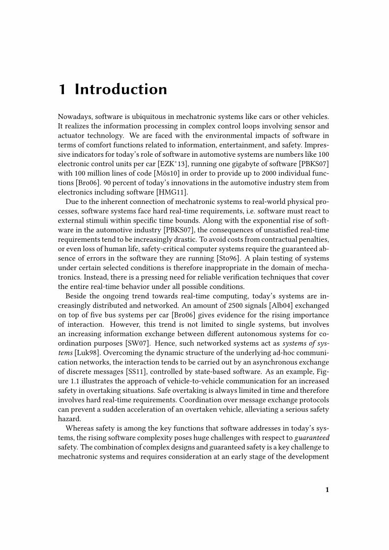
tems [Luk98]. Overcoming the dynamic structure of the underlying ad-hoc communi-cation networks, the interaction tends to be carried out by an asynchronous exchangeof discrete messages [SS11], controlled by state-based software. As an example, Fig-ure 1.1 illustrates the approach of vehicle-to-vehicle communication for an increasedsafety in overtaking situations. Safe overtaking is always limited in time and thereforeinvolves hard real-time requirements. Coordination over message exchange protocolscan prevent a sudden acceleration of an overtaken vehicle, alleviating a serious safetyhazard.
Whereas safety is among the key functions that software addresses in today’s sys-tems, the rising software complexity poses huge challenges with respect to guaranteed
safety. The combination of complex designs and guaranteed safety is a key challenge tomechatronic systems and requires consideration at an early stage of the development
1
1. Introduction
Figure 1.1: Vehicle-to-Vehicle Communication in an Overtaking Scenario
process. Model-driven design [Sch06] is a promising approach towards this combi-nation. Relying on reusable models as abstract domain-speci�c design elements, themanageability of the overall design improves drastically. In addition, due to the for-mal characteristics of models, formal veri�cation techniques are applicable to provethe compliance with speci�c requirements. Model checking [CGP00] is a prominentformal veri�cation technique that operates on the model level, exhaustively hedginga system against corner case design errors.
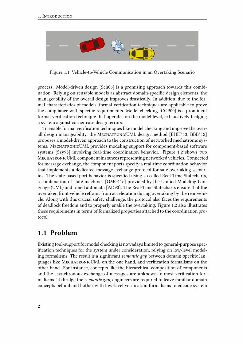
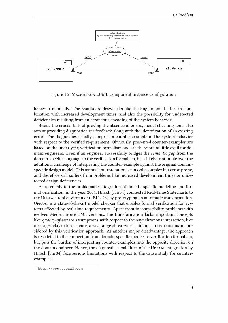
To enable formal veri�cation techniques like model checking and improve the over-all design manageability, the MechatronicUML design method [EHH+13; BBB+12]proposes a model-driven approach to the construction of networked mechatronic sys-tems. MechatronicUML provides modeling support for component-based softwaresystems [Szy98] involving real-time coordination behavior. Figure 1.2 shows twoMechatronicUML component instances representing networked vehicles. Connectedfor message exchange, the component ports specify a real-time coordination behaviorthat implements a dedicated message exchange protocol for safe overtaking scenar-ios. The state-based port behavior is speci�ed using so called Real-Time Statecharts,a combination of state machines [OMG11c] provided by the Uni�ed Modeling Lan-guage (UML) and timed automata [AD90]. The Real-Time Statecharts ensure that theovertaken front vehicle refrains from acceleration during overtaking by the rear vehi-cle. Along with this crucial safety challenge, the protocol also faces the requirementsof deadlock freedom and to properly enable the overtaking. Figure 1.2 also illustratesthese requirements in terms of formalized properties attached to the coordination pro-tocol.
1.1 Problem
Existing tool-support for model checking is nowadays limited to general-purpose spec-i�cation techniques for the system under consideration, relying on low-level model-ing formalisms. The result is a signi�cant semantic gap between domain-speci�c lan-guages like MechatronicUML on the one hand, and veri�cation formalisms on theother hand. For instance, concepts like the hierarchical composition of componentsand the asynchronous exchange of messages are unknown to most veri�cation for-malisms. To bridge the semantic gap, engineers are required to leave familiar domainconcepts behind and bother with low-level veri�cation formalisms to encode system
2
1.1 Problem
:front
v1 : Vehicle
:rear
rear front
:Overtaking
v2 : Vehicle
A[] not deadlock
A[] rear.overtaking implies front.noAcceleration
E<> rear.overtaking
Figure 1.2: MechatronicUML Component Instance Con�guration
behavior manually. The results are drawbacks like the huge manual e�ort in com-bination with increased development times, and also the possibility for undetectedde�ciencies resulting from an erroneous encoding of the system behavior.
Beside the crucial task of proving the absence of errors, model checking tools alsoaim at providing diagnostic user feedback along with the identi�cation of an existingerror. The diagnostics usually comprise a counter-example of the system behaviorwith respect to the veri�ed requirement. Obviously, presented counter-examples arebased on the underlying veri�cation formalism and are therefore of little avail for do-main engineers. Even if an engineer successfully bridges the semantic gap from thedomain-speci�c language to the veri�cation formalism, he is likely to stumble over theadditional challenge of interpreting the counter-example against the original domain-speci�c design model. This manual interpretation is not only complex but error-prone,and therefore still su�ers from problems like increased development times or unde-tected design de�ciencies.
As a remedy to the problematic integration of domain-speci�c modeling and for-mal veri�cation, in the year 2004, Hirsch [Hir04] connected Real-Time Statecharts tothe Uppaal1 tool environment [BLL+96] by prototyping an automatic transformation.Uppaal is a state-of-the-art model checker that enables formal veri�cation for sys-tems a�ected by real-time requirements. Apart from incompatibility problems withevolved MechatronicUML versions, the transformation lacks important conceptslike quality-of-service assumptions with respect to the asynchronous interaction, likemessage delay or loss. Hence, a vast range of real-world circumstances remains uncon-sidered by this veri�cation approach. As another major disadvantage, the approachis restricted to the connection from domain-speci�c models to veri�cation formalism,but puts the burden of interpreting counter-examples into the opposite direction onthe domain engineer. Hence, the diagnostic capabilities of the Uppaal integration byHirsch [Hir04] face serious limitations with respect to the cause study for counter-examples.
1http://www.uppaal.com
3
1. Introduction
1.2 Objective
The objective of this thesis is to integrate the Uppaal model checker with Mecha-tronicUML in a transparent way. Transparency refers to the option for Mecha-tronicUML domain engineers to remain unaware of the formal veri�cation details,still obtaining accurate and meaningful veri�cation results including counter-examples.
We focus on redesigning the transformation approach by Hirsch [Hir04] for today’sstate of the MechatronicUML design method. In addition, we explicitly address thepresentation of counter-examples at the MechatronicUML level, saving domain en-gineers from the need for a manual interpretation of formal veri�cation details againstdomain-speci�c concepts. We therefore alleviate the necessity to make contact withthe underlying veri�cation formalism at all, and therefore prevent engineers from theneed to understand how the formalism relates to domain-speci�c concepts.
A well-structured evaluation will enable conclusions with respect to the goal of se-mantics preservation for our connections between MechatronicUML and Uppaal.By improving the analyzability of MechatronicUML-based models on top of a trans-parent Uppaal model checking, the overall goal of this thesis is to promote the matu-rity of end products in the context of the MechatronicUML design method.
1.3 Approach
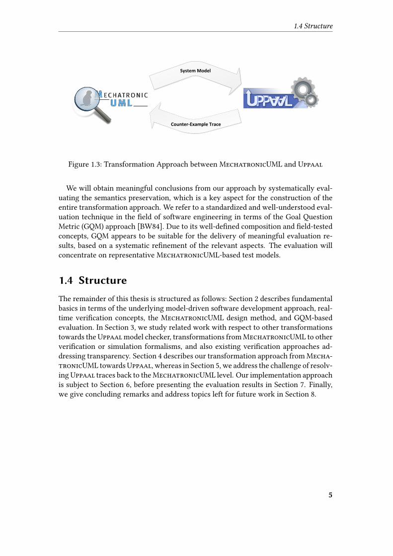
This thesis tackles the problems described in Section 1.1 by enabling Uppaal-basedmodel checking forMechatronicUML in a transparent way. Similar to Hirsch [Hir04],we aim at a model transformation that automatically converts MechatronicUML-based system models to a format suitable for o�hand veri�cation by Uppaal, as de-picted in Figure 1.3. A transparent integration of Uppaal into MechatronicUML re-quires a certain accuracy of the veri�cation results, i.e. the transformation should pre-serve the semantics of the initial MechatronicUML-based design model. The seam-less Uppaal interoperability will comprise a chain of numerous transformation steps,conceptually aligning the formalisms step by step.
The transformation from MechatronicUML towards Uppaal gives rise to an au-tomatic model checking. Counter-examples generated by Uppaal have the form ofa trace, i.e. a sequence of behavioral runtime snapshots towards the violation of aspeci�ed requirement. In order to establish transparency of the veri�cation from theviewpoint of MechatronicUML domain engineers, our approach is to align the traceswith the original MechatronicUML language elements. We therefore introduce asecond transformation for traces back towards MechatronicUML, as also shown inFigure 1.3. We address this transformation challenge by resolving Uppaal-speci�ctrace elements towards their corresponding MechatronicUML elements in the orig-inal design model, generating a trace representation which is familiar to the domainengineer. As an obvious prerequisite for this strategy, we have to ensure traceability
of the initial transformation from MechatronicUML towards Uppaal.
4
1.4 Structure
Counter-Example Trace
System Model
Figure 1.3: Transformation Approach between MechatronicUML and Uppaal
We will obtain meaningful conclusions from our approach by systematically eval-uating the semantics preservation, which is a key aspect for the construction of theentire transformation approach. We refer to a standardized and well-understood eval-uation technique in the �eld of software engineering in terms of the Goal QuestionMetric (GQM) approach [BW84]. Due to its well-de�ned composition and �eld-testedconcepts, GQM appears to be suitable for the delivery of meaningful evaluation re-sults, based on a systematic re�nement of the relevant aspects. The evaluation willconcentrate on representative MechatronicUML-based test models.
1.4 Structure
The remainder of this thesis is structured as follows: Section 2 describes fundamentalbasics in terms of the underlying model-driven software development approach, real-time veri�cation concepts, the MechatronicUML design method, and GQM-basedevaluation. In Section 3, we study related work with respect to other transformationstowards theUppaalmodel checker, transformations fromMechatronicUML to otherveri�cation or simulation formalisms, and also existing veri�cation approaches ad-dressing transparency. Section 4 describes our transformation approach from Mecha-tronicUML towardsUppaal, whereas in Section 5, we address the challenge of resolv-ingUppaal traces back to theMechatronicUML level. Our implementation approachis subject to Section 6, before presenting the evaluation results in Section 7. Finally,we give concluding remarks and address topics left for future work in Section 8.
5


2 Basics
This section introduces fundamental basics which are relevant in the scope of thisthesis. As our basic engineering paradigm, we describe the model-driven softwaredevelopment approach in Section 2.1. Section 2.2 introduces timed automata as a ba-sic modeling formalism. In Section 2.3, we address the formalization of real-time re-quirements. Based on the above formalisms, we capture the approach of timed modelchecking in Section 2.4. The MechatronicUML design method is subject to explana-tion in Section 2.5, whereas the �nal Section 2.6 captures our Goal Question Metricevaluation method.
2.1 Model-Driven So�ware Development
The concept of a model [Sta73] refers to an abstract representation of some real-worldentity. Its key concepts are listed below:
• Abstraction is the approach of creating an entity’s representation in such a way,that it reduces to speci�c essential attributes, leaving out non-essential attributesof the original.
• Essentiality of an attribute is not given a priori, but depends on a certain in-tended task. Despite the abstraction of speci�c attributes, the pragmatics of amodel with respect to this task must still be given.
• Pragmatics with respect to a task are ensured by retaining a certain correspon-
dence, i.e. a model must substitute its original under speci�c conditions.
In general, models contribute to the solution of problems. Abstraction enables sim-pli�ed reasoning about problems and aids the construction of solutions. In order toestablish pragmatics, the correspondence between model and its original must ensurethat the solution obtained from the abstract model is also a valid solution to the orig-inal.
2.1.1 Model-Based So�ware Development
Focusing on the domain of software engineering, challenging problems are basicallyconcerned with the construction of software systems. Modeling software systems con-stitutes a prescriptive [Sta73] approach, since the original system only emerges fromits abstract representation. We refer to the following de�nition with respect to therole of models in software engineering:
7
2. Basics
De�nition 2.1 (Model) “A model is an abstract representation of a system’s structure,
function or behavior” [SV06, p. 18].
Abstraction actually has a long tradition in software engineering, since new tech-nologies tend to abstract from the complexity of preliminary ones. In the presence ofabstraction, the problem of software construction merely corresponds to transform-ing an abstract software speci�cation into a concrete software system running on aspeci�c platform. A platform provides speci�c computing capabilities as a foundationfor concrete software systems. As opposed to models, that basically serve for problemdescription, a platform is said to reside “in the solution space” [SV06, p. 59]. The appli-cation of the model concepts to software engineering led to the notion of model-based
software development. An application implies some solution strategy to transforman abstract model into a concrete software system. Nowadays, the UML family of di-agram types [OMG11c] forms the basis of most model-based software developmentapproaches.
2.1.2 Automatization
Combining model concepts with computing is quite obvious, since computers allowreasoning to be automatized. Automatization gives rise to reuse of existing solutionstrategies, i.e. enables the automatic construction of solutions to speci�c problems.
In particular, this pertains to the transformation task from an abstract model to aconcrete software system mentioned in Section 2.1.1. New technologies often stillrely on the proven e�ectiveness of their predecessors by automatically transformingabstract speci�cations into more concrete speci�cations of software systems. Conse-quently, we identify automatization as a key principle of model-driven software de-velopment, as opposed to approaches termed model-based. Connected to a certainplatform by means of an automatic transformations, a model acts as “central arti-fact” [SV06, p. 79] in model-driven software development.
2.1.3 Domain-Specific Languages
Beside the automatization aspect, approaches termed model-driven di�er from model-based techniques by a shift in the underlying domain.
De�nition 2.2 (Domain) A domain is “a bounded �eld of interest or knowledge” [SV06,
p. 56].
Paradigms like high-level programming languages or UML [OMG11c] are still closelylinked to the domain of computing as such. Although the aforementioned approachesprovide software solutions for a wide range of application domains, responsible en-gineers are restricted to general-purpose speci�cation techniques. We refer to thechallenge of expressing domain concepts adequately by means of general-purpose lan-guages as semantic gap.
8
2.1 Model-Driven Software Development
In contrast, model-driven software development [SV06] focuses on the use of domain-
speci�c languages for the speci�cation of software systems. Hence, transformationsproduce concrete software solutions from domain-speci�c models and thus bridge thesemantic gap. Schmidt [Sch06] describes the use of domain-speci�c modeling lan-guages in combination with transformation engines and generators as key aspects ofmodel-driven software development.
Domain-speci�c languages enable the explicit speci�cation of abstract solution stra-tegies developed by domain experts, and also reuse of these strategies via automatictransformations. By bridging the semantic gap between speci�c domains on the onehand, and computing platforms on the other hand, the usage of domain-speci�c lan-guages constitutes another key principle in model-driven software development.
2.1.4 Meta-Modeling
In order to automatize transformations by means of computers, the speci�cations tobe transformed must be machine-readable, i.e. formal with respect to some meta-speci�cation. Relying on models, meta-modeling describes the approach of providingthe meta-speci�cation for models in terms of another model. This so calledmeta-model
acts as model of a domain, including its elements and construction rules. It de�nesthe set of valid constructable models as instances of the meta-model, i.e. sentencesof a domain-speci�c modeling language. Hence, a meta-model gives rise to a type-instance-relationship with models. The essential components of a meta-model are
• an abstract syntax, de�ning domain elements and construction rules, and
• static semantics, giving a meaning to models without considering them in someexecution context1.
In the scope of a domain-speci�c modeling language, the above meta-model con-cepts are linked to at least one concrete syntax, de�ning how to express models in aconcrete manner, and dynamic semantics, charged with semantics de�nition fotr mod-els during execution.
2.1.5 Model Transformation
Section 2.1.2 emphasized the essential role of automatic transformations with respectto reuse of existing solution strategies. Stahl and Völter describe the task of transfor-mations as to “map models to the respective next level” [SV06, p. 21] on the way tosome platform. Hence, to solve the problem of transforming models to a platform, it
1This de�nition of static semantics is in accordance with the notes of Harel and Rumpe in [HR04].Stahl and Völter [SV06] put static semantics on a level with additional syntax constraints referredto as “context conditions" [HR04, p. 65]. However, adhering to this de�nition would lead to theinconsistency that “static semantics belong to the syntax rather than to the semantics of a lan-guage” [SV06, p. 58].
9
2. Basics
may also be desirable to engage with existing solution strategies. This approach im-plies the transformation of models into other models, traversing various intermediatemodeling levels on the way to a platform.
De�nition 2.3 (Model Transformation) Model transformations “take one or more
source models as input and produce one or more target models as output, while following
a set of transformation rules” [SK03, pp. 42-43].
Noteworthy, although the above de�nition describes n-way transformations [CH06]with an arbitrary number of models on both sides, it also covers the typical case of a1:1 transformation with single source/target models. The most common scenario is anexogenous [MCG05] model transformation which carries out a change in the underly-ing modeling language, i.e. source and target meta-model di�er. Focusing on programtransformation in general, Visser addresses the same concept as translation [Vis01].However, it is also possible to specify endogenous [MCG05] transformations wheresource and target meta-model are the same. Speaking in terms of Visser’s programtransformation terminology, the approach corresponds to a rephrasing [Vis01]. Arephrasing that reduces the amount of syntax features in use is known as normal-
ization [Vis01]. Another speci�c type of rephrasing aims at an equivalent meaningof source and target models, i.e. despite syntactical di�erences, the semantics of theunderlying modeling language assigns an equivalent meaning to both. We refer tothis characteristic as semantics preservation, whereas the associated transformation ap-proach is known as refactoring [OJ90; Opd92]. Another speci�c type of model rephras-ing is a so called in-place transformation [CH03] where source and target model are thesame, i.e. the transformation manipulates an existing model. An important distinctionis made according to the way that target models are provided:
Model-to-Model is the approach of providing target models in terms of their ab-stract syntax. Hence, a model-to-model transformation preserves the model as-pect in terms of platform-independence and explicitly speci�ed structures.
Model-to-Text is the approach of providing target models in terms of some concretetextual syntax. By engaging with platform-speci�c text formats, a model-to-texttransformation weakens the model aspect.
Czarnecki and Helsen [CH06] identify a relevant quality characteristic for modeltransformations in terms of traceability. It refers to the ability of transformations torecord a relationship between source and target model elements during execution, andprovide access to these trace records later on.
2.1.6 Model-Driven Architecture
The model-driven architecture (MDA) [OMG03] is a paradigm for the model-drivensoftware development provided by the Object Management Group (OMG). Its major
10
2.2 Timed Automata
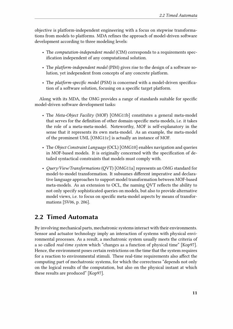
objective is platform-independent engineering with a focus on stepwise transforma-tions from models to platforms. MDA re�nes the approach of model-driven softwaredevelopment according to three modeling levels:
• The computation-independent model (CIM) corresponds to a requirements spec-i�cation independent of any computational solution.
• The platform-independent model (PIM) gives rise to the design of a software so-lution, yet independent from concepts of any concrete platform.
• The platform-speci�c model (PSM) is concerned with a model-driven speci�ca-tion of a software solution, focusing on a speci�c target platform.
Along with its MDA, the OMG provides a range of standards suitable for speci�cmodel-driven software development tasks:
• The Meta-Object Facility (MOF) [OMG11b] constitutes a general meta-modelthat serves for the de�nition of other domain-speci�c meta-models, i.e. it takesthe role of a meta-meta-model. Noteworthy, MOF is self-explanatory in thesense that it represents its own meta-model. As an example, the meta-modelof the prominent UML [OMG11c] is actually an instance of MOF.
• The Object Constraint Language (OCL) [OMG10] enables navigation and queriesin MOF-based models. It is originally concerned with the speci�cation of de-tailed syntactical constraints that models must comply with.
• Query/View/Transformations (QVT) [OMG11a] represents an OMG standard formodel-to-model transformation. It subsumes di�erent imperative and declara-tive language approaches to support model transformation between MOF-basedmeta-models. As an extension to OCL, the naming QVT re�ects the ability tonot only specify sophisticated queries on models, but also to provide alternativemodel views, i.e. to focus on speci�c meta-model aspects by means of transfor-mations [SV06, p. 206].
2.2 Timed Automata
By involving mechanical parts, mechatronic systems interact with their environments.Sensor and actuator technology imply an interaction of systems with physical envi-ronmental processes. As a result, a mechatronic system usually meets the criteria ofa so called real-time system which “changes as a function of physical time” [Kop97].Hence, the environment poses certain restrictions on the time that the system requiresfor a reaction to environmental stimuli. These real-time requirements also a�ect thecomputing part of mechatronic systems, for which the correctness “depends not onlyon the logical results of the computation, but also on the physical instant at whichthese results are produced” [Kop97].
11
2. Basics
Focusing on a model-driven engineering of real-time systems for the purpose offormal veri�cation against real-time requirements, an appropriate modeling formal-ism is required. Mechatronic systems meet the criteria of reactive systems: they are“repeatedly prompted by the outside world and their role is to continuously respondto external inputs” [HP85, p. 479]. Hence, approaches building on the classical �niteautomata formalism come into play. Finite automata are state-based in the sense thatthey describe a system’s behavior by a sequence of inputs from an alphabet Σ, leadingto state transitions within the state space S.
2.2.1 Dense-Time Model
As a crucial limitation, �nite automata do not consider temporal information aboutthe occurrence of inputs, and are not capable of expressing an e�ect of time on thesystem behavior. Hence, classical �nite automata are not su�cient for the modelingof real-time systems due to the lack of a concept of time.
Real-time systems require a modeling concept for physical time as a continuousmagnitude. Relying on a dense-time model [AD90], the time of an event occurrenceis a real number τi ∈ R. A system’s behavior becomes expressible by a sequence oftimed words (σ, τ), associating strictly monotonically increasing time values τi ∈ Rwith the input events σi ∈ Σ.
2.2.2 Formalism
Considering real-time systems as a “function of physical time” [Kop97], the occurrencetimes of input events are of importance with respect to the system behavior. In adense-time model, the occurrence times τi must be considered with respect to statetransitions. However, constraining a state transition by a direct comparison involvingthe value τi is non-intuitive, as in most real-time applications, not the concrete timevalue is of importance, but rather the time elapsed since another preceding input eventoccurred.
The timed automata formalism [AD90] extends �nite automata and introduces theconcept of clocks to allow this more �exible way of specifying timed behavior. A clockis a continuously increasing real-valued variable, which is, however, resettable duringstate transitions. A timed automaton can include a �nite set of clocks that increase atthe same rate from the system start. The value of a clock is always the time elapsedsince its last reset, respectively since the system start if it was never reset. From thetime when being reset during a state transition, a clock value represents the amountof time elapsed since this reset, which is equivalent to the time elapsed since the oc-currence of a speci�c input event that triggered the resetting state transition.
By comparing clock values with constants, a state transition can specify a clockconstraint. A clock constraint expresses a temporal dependency of the state transi-tion with respect to other past state transitions which were responsible for resettingcertain clocks. A transition can only �re if its clock constraint is ful�lled, i.e. all spec-i�ed clocks adopt a time value that lies within their speci�ed intervals. The bounds
12
2.2 Timed Automata
of intervals correspond to a rational number from the set Q, whereas this set is of-ten restricted to N. Intervals can be left- or right-bounded, whereas the comparisonoperators ≤ and < enable both closed and open intervals.
The original de�nition of timed automata [AD90] was later extended to supportalso clock constraints for states [AFH91], so called invariants. As an intuitive way offorcing execution progress, a system may only stay in a speci�c state as long as itsinvariant is ful�lled. A state transition is required to take place before the invariantbecomes unful�lled. For a formal de�nition, we refer to a version of timed automataextended by state invariants [Alu99].
De�nition 2.4 (Timed Automaton) A timed automaton A is a tuple
〈L,L0,Σ, X, I, E〉, where
• L is a �nite set of locations,
• L0 ⊆ L is a set of initial locations,
• Σ is a �nite set of labels,
• X is a �nite set of clocks,
• I is a mapping that labels each location s with some clock constraint in Φ(X), and
• E ⊆ L× Σ× 2X × Φ(X)× L is a set of switches.
A switch 〈s, a, ϕ, λ, s′〉 represents an edge from location s to location s′ on symbol a. ϕis a clock constraint overX that speci�es when the switch is enabled, and the set λ ⊆ Xgives the clocks to be reset with this switch.
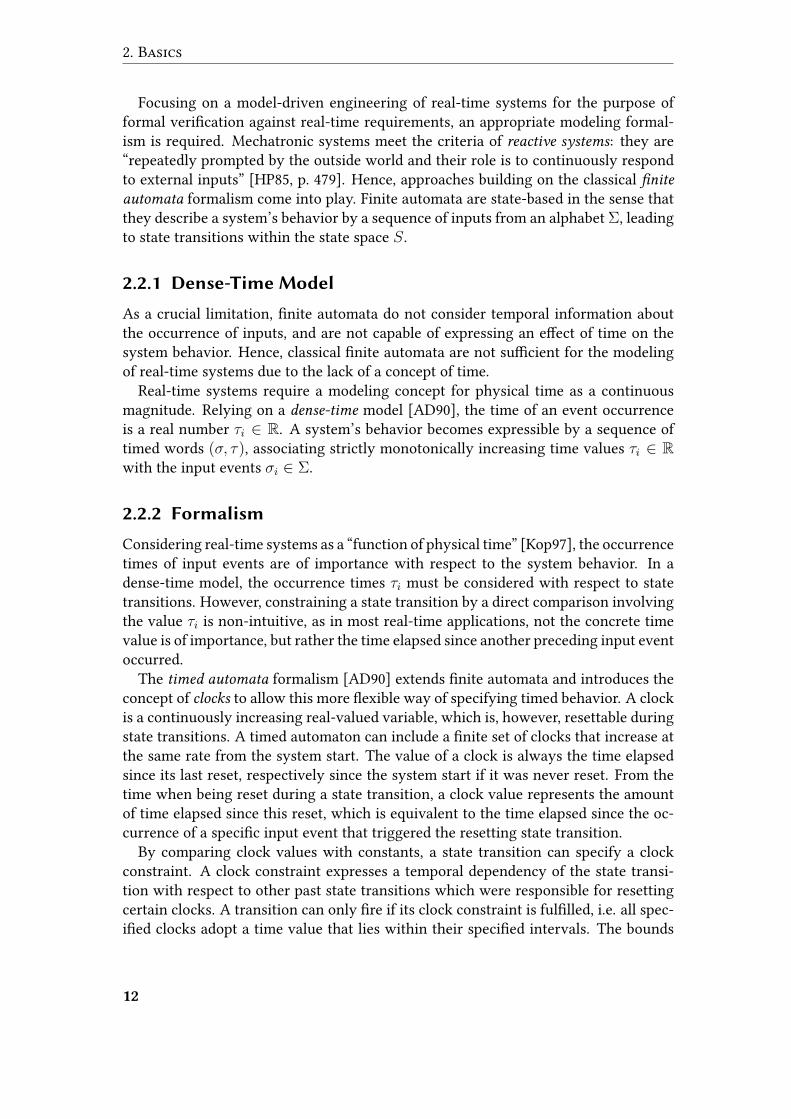
Figure 2.1 shows an exemplary timed automaton modeling a vehicle. After switch-ing to the overtaking location, an invariant in combination with a guard label ensureovertaking to �nish after two time units.
overtaking
c <= 2
idle
c = 0
c >= 2
Figure 2.1: Timed Automaton
13

2. Basics
2.2.3 Uppaal Timed Automata
Enabling formal modeling of real-time systems, timed automata give rise to an appli-cation of formal veri�cation techniques. The timed automata used within the real-time veri�cation tool Uppaal are not restricted to a single timed automaton. Instead,Uppaal supports modeling of concurrent real-time systems by means of a parallelcomposition of timed automata.
Consisting of locations and edges, timed automata in Uppaal specify a unique ini-tial location in contrast to De�nition 2.4. As a syntactic extension, Uppaal supportsso called urgent locations in which no time is allowed to pass. An urgent location isequivalent to an ordinary location that resets an auxiliary clock on all its incomingedges and restricts this clock’s time value to not exceed 0 as its invariant. Further-more, Uppaal introduces another semantic extension in terms of so called committed
locations, which are urgent but have strict precedence over ordinary locations withrespect to the execution of outgoing edges.
Although Uppaal relies on a dense-time model, it only supports the speci�cation ofinteger values, which a�ects also clock constraints. As another extension of classicaltimed automata, Uppaal supports integer- or boolean-based data variables, which arealso part of the overall system state space. Both clocks and data variables can bereferenced as part of state invariants or guards of edges.
Synchronization
A network of timed automataA1| . . . |An is de�ned as the parallel composition of timedautomata Ai [Pet99]. The composition via the synchronization function | gives rise torestrictions on the autonomous, interleaving execution of timed automata. Data vari-ables and also clocks can be either private to a single automaton, or globally sharedbetween all automata of a network as part of the synchronization function |. Synchro-nization also applies to edges, since a state transition in one timed automaton maybe indivisible from a second state transition in a parallel timed automaton, and viceversa. The edges may only be executed in combination and simultaneously.
The synchronization function applied for Uppaal networks of timed automata isinspired by the parallel composition operator de�ned as part of the Calculus of Com-
municating Systems (CSS) [Mil89]. Unlike parallel compositions of classical timed au-tomata [AD90], Uppaal supports point-to-point synchronization on top of the hand-
shaking (or synchronous message passing) approach [BK08]. Hence, not all timed au-tomata of a network are required to participate in a synchronization. Handshakingrefers to a synchronizing execution of two edges in two timed automata Ai and Aj ,which is restricted to a common input symbol σ ∈ Σi ∩ Σj . Based on the theory ofchannel systems [BK08], σ is referred to as channel
2, and the state transitions to besynchronized are distinguished between sender and receiver. The sender transitionof a handshake synchronization via channel σ is labelled σ!, whereas σ? denotes the
2Conceptually, Uppaal channels are of size zero, which enforces synchronization between sender andreceiver due to the absence of bu�ering capacity.
14

2.2 Timed Automata
complementary receiving transition. Figure 2.2 shows two Uppaal timed automatathat synchronize in order to ensure safe overtaking.
overtaking
c <= 2overtake!
c = 0
c >= 2
idle
(a) Rear Vehicle Automaton
noAcceleration
c <= 2overtake?
c = 0
c >= 2
idle
(b) Front Vehicle Automaton
Figure 2.2: Uppaal Timed Automata
In order to enable synchronization between more than two participating automata,channels can be declared as broadcasting. A timed automaton executing an edge la-belled σ! synchronizes with all other timed automata that provide an edge labelledσ? outgoing from their currently active locations. Using broadcast synchronization,however, no receivers are required at all to perform the sending synchronization, i.e.the edge labelled σ! may also �re in isolation.
Template Instantiation
Unlike classical approaches, Uppaal distinguishes between templates for timed au-tomata, and the actual process instantiations resulting from those templates. Onlythe latter ones represent a particular system at runtime. By this distinction, Uppaalprovides an e�cient means towards a compact modeling for systems composed ofnumerous equal subsystems with common attributes and behavior, di�ering in theirparametrization only. Such systems are expressible by modeling a single timed au-tomaton template that gives rise to multiple process instantiations, which form theactual network of timed automata. Focusing on the formal modeling of software sys-tems, this is a prominent use case, since modern object-oriented programming relieson a similar distinction between a class and its instance objects.
2.2.4 Hierarchical Timed Automata
Formalisms like timed automata encode the current situation that a system resides inby means of a single state. This technique is practical for primitive systems with asingle encoded aspect. However, it leads to a drastic increase in the number of states
15
2. Basics
and state transitions if numerous aspects require encoding in complex system mod-els. The result is an individual state for each possible combination of relevant aspects,and also a huge number of state transitions representing each and every slight changein the overall system state. In general, this blowup is unavoidable when it comes tomodel checking, since all possible combinations of aspects must be explored. How-ever, it unnecessarily complicates the modeling task, where an explicit speci�cationof concurrency and re�nement is desirable.
One remedy is decoupling of autonomous behavior by modeling concurrency ex-plicitly, as applied for Uppaal networks of timed automata. An unaddressed problemremains in terms of re�nement of abstract high-level aspects by more �ne-grainedlow-level aspects. Hierarchical modeling is a common means to increase manageabil-ity of models by considering re�nement explicitly.
Composition
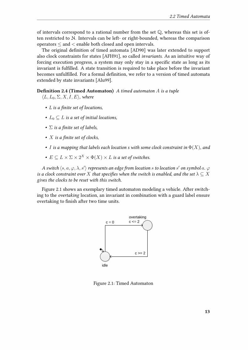
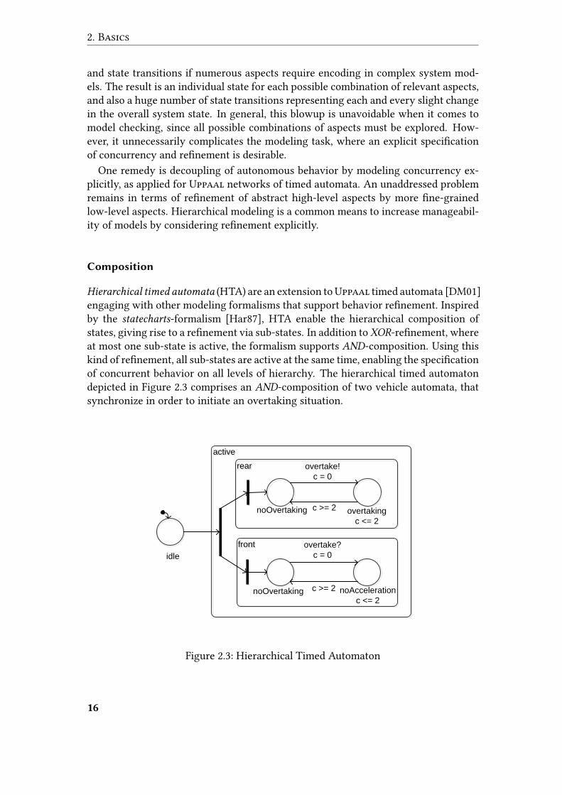
Hierarchical timed automata (HTA) are an extension toUppaal timed automata [DM01]engaging with other modeling formalisms that support behavior re�nement. Inspiredby the statecharts-formalism [Har87], HTA enable the hierarchical composition ofstates, giving rise to a re�nement via sub-states. In addition to XOR-re�nement, whereat most one sub-state is active, the formalism supports AND-composition. Using thiskind of re�nement, all sub-states are active at the same time, enabling the speci�cationof concurrent behavior on all levels of hierarchy. The hierarchical timed automatondepicted in Figure 2.3 comprises an AND-composition of two vehicle automata, thatsynchronize in order to initiate an overtaking situation.
activeactive
rearrear
noOvertaking overtaking
c <= 2
frontfront
noOvertaking noAcceleration
c <= 2
idle
overtake?
c = 0
c >= 2
overtake!
c = 0
c >= 2
Figure 2.3: Hierarchical Timed Automaton
16
2.3 Temporal Logic
To specify the control �ow in case of hierarchical state re�nement, HTA introducespeci�c pseudo-states. On the one hand, an entry serves as target for edges originatingexternally to a hierarchical state, providing a connection to its internal sub-states.Hence, an entry constitutes an activation of a hierarchical state and gives rise to are�nement of the control �ow (forking it in case of an AND-state). The hierarchicaltimed automaton in Figure 2.3 comprises an entry that activates the hierarchical activelocation and forks the control �ow.
On the other hand, an exit is a designated pseudo-state that constitutes the endingof a re�ned control �ow (which was forked in case of an AND-state). Exits act astarget for edges originating internally to a hierarchical states and provide an externalconnection. They represent the deactivation of the parent hierarchical state and, incase of an AND-state, also the joining of the forked control �ow.
Fla�ening
Considering the hierarchical composition as a reduction technique operating on themodeling level only, HTA were equipped with a �attening algorithm [DM01]. Given asingle HTA, the algorithm expands the hierarchical composition to obtain a semanti-cally equivalent network of non-hierarchical timed automata as an input to Uppaal’sveri�cation engine. Basically, the algorithm maps the contents of every hierarchicalstate to an individual timed automaton, extended by an additional idle location rep-resenting the case that the hierarchical state is itself inactive. Thus, the approachencodes the hierarchical composition by means of a parallel composition.
2.3 Temporal Logic
Modeling reactive systems (especially real-time systems) gives rise to their veri�ca-tion against formally speci�ed requirements. Along with state changes of reactive sys-tems during execution, the truth value of certain propositions about a system variesover time. Propositional logic, which assigns a constant truth value to propositions,is therefore not capable of specifying requirements for reactive systems adequately.
The application of temporal logic [RU71] for the speci�cation of requirements aimsat overcoming the limitation of constant truth values. Temporal logic considers the“time dependence” [Pnu77] of propositions, i.e. enables truth contents varying overtime. It enables references to a proposition’s future (or past) truth values and thespeci�cation of a “relative order” [BK08] of particular truth assignments. In doing so,temporal logic supports the speci�cation of requirements with respect to the tempo-ral evolution of truth content. Temporal logic formulas allow the quanti�cation ofpropositions over points in time, considering their truth contents within (not neces-sarily bounded) time intervals. Dedicated temporal operators provide references tofuture truth values and quanti�cation over these:
Next: XΦ is true if the formula Φ is true in the next state.
17
2. Basics
Globally: GΦ is true if the formula Φ is true in all future states.
Future: FΦ is true if the formula Φ is true in some future state.
Until: Φ1UΦ2 is true if the formula Φ1 is true in all future states before the propositionΦ2 is eventually true in some future state.
Temporal logic distinguishes between two types of expressible properties [Lam77].On the one hand, a safety property corresponds to a formula that excludes harmful sit-uations in all future states relying on the globally operator. A typical safety propertyis the restriction for an overtaken vehicle to refrain from acceleration until overtakingis terminated. On the other hand, a liveness property corresponds to a formula thatrequires a desired situation to occur in some future states by means of the future op-erator. As an example, the requirement that overtaking is possible at all correspondsto a liveness property.
Two basic types of temporal logic exist, which “di�er according to how they handlebranching in the underlying computation tree” [CD88]:
Linear Time Logic supports references to future truth values, without considerationof the di�erent branches that a system may operate on. Hence, this type oftemporal logic is linear in the sense that it abstracts from branching. Instead,semantics are de�ned in terms of all possible execution paths, abstracting fromthe structure of the computation tree that these paths traverse.
Branching Time Logic also enables future truth value references, but additionallyrequires quanti�cation over branches. Hence, this type of temporal logic explic-itly considers branching as a structural property of the underlying computationtree. Consequently, its semantics operate on the structure of the computationtree itself.
2.3.1 Computation Tree Logic
Uppaal’s veri�cation engine supports requirements based on the Computation Tree
Logic (CTL) [EC82] which is a branching time logic. Hence, we focus on CTL speci-�cation throughout this thesis. Basically, the set of CTL formulas is an extension ofpropositional formulas over some set of atoms P by path quanti�ers E and A, repre-senting existential and universal quanti�cation over paths.
De�nition 2.5 (CTL Syntax) CTL formulas are de�ned by the following grammar for
state formulas Φ [EC82]:
Φ ::= p | Φ1 ∧ Φ2 | ¬Φ | Eϕ | Aϕ where
• p ∈ P and
18
2.3 Temporal Logic
• ϕ is a path formula.
Path formulas ϕ are de�ned by the following grammar:
ϕ ::= XΦ | Φ1UΦ2 where Φ,Φ1, and Φ2 are state formulas.
The above de�nition considers the temporal operators X and U as fundamental,deriving G and F according to the following equivalences3:
EFΦ ≡ E(true U Φ) (2.1)AFΦ ≡ A(true U Φ) (2.2)EGΦ ≡ ¬AF¬Φ (2.3)AGΦ ≡ ¬EF¬Φ (2.4)
Our exemplary safety requirement from Section 2.3 corresponds to the CTL prop-erty AG overtaking → noAcceleration, where overtaking and noAcceleration representpropositions from the set P . The exemplary liveness requirement can be expressed bythe formula EF overtaking.
Syntactically, CTL is an extension of the Linear Temporal Logic (LTL) due to theaddition of path quanti�ers. However, caused by the di�erences in terms of semanticinterpretation, both types of logic are in fact incomparable with respect to their ex-pressivity [CD88; KV98]. There is, however, a branching time temporal logic calledCTL* that subsumes both CTL and LTL [EH86].
2.3.2 Timed Computation Tree Logic
Temporal logic is said to be “time-abstract” since it only supports the relative order-ing of truth assignments over time [BK08]. In doing so, it abstracts from the concretetiming during the evolution of truth content. Hence, classical temporal logic is notcapable of specifying requirements for real-time systems, where concrete time con-straints underlying a dense-time model need to be expressed.
As a remedy, Alur et al. proposed a real-time extension of CTL called Timed Com-
putation Tree Logic (TCTL) [ACD90], which supports concrete time constraints for thespeci�ed relative ordering. Noteworthy, TCTL di�ers from CTL in terms of the miss-ing X operator. The reason is that, due to the explicit assumption of a dense-timemodel, a unique next state does not exist. We refer to a version of the TCTL in whichclock values can be directly referenced within formulas. The requirement that over-taking must not last longer than two time units can be expressed by referencing theclock c within the TCTL formula AG ¬ (overtaking ∧ c>2).
To take full advantage of this approach, so called speci�cation clocks represent ad-ditional auxiliary clock variables within TCTL formulas [HNSY92]. A so called freeze
3Strictly speaking, also the combination AX is non-fundamental since it can be derived by AXΦ ≡¬EX¬Φ.
19
2. Basics
quanti�cation z. of a speci�cation clock z saves the point in time of a speci�ed truthassignment. A frozen speci�cation clock gives rise to time constraints referring to thefrozen clock value, restricting later (or earlier) truth assignments in the clock’s scope.This enables the speci�cation of non-local requirements in the sense that they involvetemporal dependencies reaching beyond one single temporal operator [AH92].
De�nition 2.6 (TCTL Syntax) TCTL formulas Φ are de�ned by the following gram-
mar [HNSY92]:
Φ ::= p | x+ c ≤ y + d | ¬Φ | Φ1 ∨ Φ2 | EΦ1UΦ2 | AΦ1UΦ2 | z.Φ for
• propositions p ∈ P ,
• clocks x, y ∈ C ,
• speci�cation clocks z ∈ Cφ ⊆ C ,
• and non-negative integer constants c, d ∈ N.
The formalization of requirements in Uppaal is based on TCTL formulas. The tem-poral operators G and F correspond to the Uppaal operators [] and 〈〉. As a restric-tion of the original TCTL syntax, Uppaal does not support nested path quanti�ers,i.e. quanti�cation over branches is limited to the root level of a formula. The onlyexception is Uppaal’s additional - -> operator. A formula p - -> q corresponds to theformula A[] (p imply A<> q). All nested formulas are restricted to so called state proper-
ties, consisting of time and data constraints, as well as activity constraints with respectto certain locations. Time constraints are expressible by a direct reference to the valueof a clock in the underlying network of timed automata. A clock local to a certain pro-cess is referenced by the statement process.clock. Uppaal does not support additionalspeci�cation clocks. The activity of a certain location for a process is expressible viathe statement process.location. Besides references to clocks, Uppaal also enables itsdata variables to be part of state properties, whereas a local variable is referenced byprocess.variable. As a speci�c feature, the deadlock statement enables the speci�cationof execution progress requirements. In its negated form not deadlock, the statementexpresses the requirement of a well-de�ned successor state.
2.4 Timed Model Checking
Model checking [CE82] is the process of checking whether a temporal logic formulaΦ is modelled by a transition system M , i.e. whether M |= Φ holds. It answers thequestion whether the modelM of a reactive system meets its speci�cation in terms ofthe formula Φ. Compared against other veri�cation approaches, key characteristics ofmodel checking are 1.) operation on the model level rather than testing a real system,2.) automatic conclusion rather than carrying out a manual prove, and 3.) exhaustivestate space exploration rather than simulation of only some execution paths.
20
2.4 Timed Model Checking
A basic approach towards model checking transition systems M against CTL for-mulas Φ was proposed by Clarke et al. [CES86]. It is carried out by labelling each stateof M with the set of sub-formulas it ful�lls. Starting with sub-formulas of size 1 (i.e.atomic propositions), the algorithm successively considers formulas with increasingsize and derives their compliance for each state from the existing information aboutsmaller formulas. Finally, the overall question M |= Φ corresponds to the complianceof an initial state of M with the complete formula Φ.
Extending the approach towards model checking of real-time systems, a problemarises in terms of the dense-time model. It gives rise to an in�nite state-space, since onthe one hand, in�nitely small amounts of time can elapse, whereas on the other hand,no upper bound for clock values is given. Hence, a �nite transition system cannot beeasily constructed. Consequently, there is no o�hand application of the original CTLmodel checking which operates on a �nite transition system.
2.4.1 Clock Regions
A technique to obtain a �nite representation of the in�nite state space for real-timesystems was �rst reported by Dill [Dil90]. Since for timed automata, time constraintsonly refer to natural number constants, a real-time system behaves in an equal mannerfor two situations if
• the referenced system state is identical,
• the integral values of all clocks are identical, and
• the ordering of the fractional parts of all clocks are identical.
The fractional ordering is important with respect to the sequence in which transi-tions get enabled over time. The above observations allow for the partitioning of allclock valuations ν : C → R into equivalence classes [ν], i.e. a system behaves in anequal manner given a common state and two clock valuations ν1, ν2 ∈ [ν], i.e. ν1 ∼= ν2.
The set of equivalence classes [ν] is still in�nite due to lack of an explicit upperbound for clock values. Nevertheless, it holds that once a clock exceeds the greatestconstant it is compared to as part of some clock constraint, its concrete time value doesnot a�ect the system behavior. Hence, ν1 ∼= ν2 also holds for two clock valuations if inboth cases, all clocks exceed these individual constants. Due to this observation, thereexists a maximum equivalence class consisting of all clock valuations that comply withthis condition. Hence, the overall number of equivalence classes is �nite.
As a result, the equivalence classes [ν] give rise to a �nite number of so called re-
gions 〈s, [ν]〉, consisting of a state s and an equivalence class [ν]. The abstraction of thein�nite number of clock valuations by �nitely many regions enables the constructionof a transition system that refers to regions as states. Consequently, two kinds of statetransitions exist:
21
2. Basics
1. Elapsing of time during the activity of one state s in the underlying timed au-tomaton corresponds to a transition 〈s, [ν]〉 → 〈s, [ν ′]〉 where [ν ′] is the directsuccessor of [ν].
2. A state transition s → s′ in the underlying timed automaton corresponds to atransition 〈s, [ν]〉 → 〈s′, [ν ′]〉 where [ν ′] is obtained from [ν] by considering thetime constraint and clock resets of s→ s′ as well as the invariant of s′.
Since the set of transitions described above is also �nite, the constructed transitionsystem gives rise to an application of the CTL model checking procedure by Clarkeet al. [CES86]. Hence, TCTL model checking reduces to CTL model checking by ab-stracting the in�nite number of clock valuations by �nitely many regions.
2.4.2 Clock Zones
When abstracting the behavior of a real-time system by means of clock regions, theirnumber grows exponentially. Hence, the approach described in Section 2.4.1 facesproblems in terms of e�ciency. To overcome the huge amount of regions, Alur etal. [ACH+92] applied a minimization algorithm to the construction of the �nite tran-sition system.
The approach is based on the observation that the partitioning into equivalenceclasses is unnecessarily �ne-grained. Below the constructed upper bound, each andevery integral clock value gives rise to individual equivalence classes. Hence, theremay be distinct equivalence classes that are still equivalent in terms of the underlyingsystem behavior, because their represented clock valuations ful�ll the same set of clockconstraints.
Alur et al. generalize the concept of regions, such that the equivalence classes reachbeyond an interval bounded by two contiguous integral clock values. In more de-tail, they minimize the constructed �nite transition system by uni�cation of multipleequivalence classes representing a so called zone. A zone is the set of all clock valu-ations that ful�ll a certain set of clock constraints, and therefore enable certain statetransitions. For a region 〈s, Z〉, the zone Z corresponds to the maximal set of clockvaluations under which s may be active and under which certain state transitions areenabled. Hence, Z encodes the state invariant of s as well as time constraints of spe-ci�c state transitions originating from s which are considered enabled. Technically, azone Z corresponds to the solution space to a system of linear inequalities over clockvalues.
The resulting �nite transition system consisting of states 〈s, Z〉 is called zone graph.As described in Section 2.4.1, its transitions correspond either to the elapsing of time,or to an explicit state transition in the underlying timed automaton. The minimizationby means of zones is also applied for timed model checking in Uppaal [BY04].
22
2.5 MechatronicUML
2.5 MechatronicUML
Mechatronics is a multidisciplinary engineering domain that combines mechanicaland electrical aspects with controlling and computing. Hence, the design of mecha-tronic systems inherently comprises software development tasks, with the particular-ity that software is embedded in a diverse system context. The interaction of softwarewith mechanical, electrical, or control devices gives rise to speci�c characteristics ofsoftware systems in the domain of mechatronics.
Today’s mechatronic systems are increasingly distributed to various autonomoussub-systems, which are interconnected for coordination purposes by means of asyn-chronous communication. Moreover, due to the fact that systems comprise sensor andactuator technology, this coordination behavior is a�ected by environmental real-timerequirements. Other characteristics of mechatronic systems like self-recon�gurationas response to environmental circumstances are out of the scope of this thesis.
Due to the above characteristics, the software part of mechatronic systems exhibitsa highly domain-speci�c nature, which requires a certain recognition during design.However, model-based approaches like the UML [OMG11c] aim at a general purposedesign of arbitrary software systems. Especially due to the speci�c combination ofinterconnectedness and real-time coordination behavior, the UML design approach islikely to fail in the context of mechatronics due to its inability to manage the designof complex systems.
Striving towards a model-driven design of mechatronic systems with an increaseddesign manageability, the MechatronicUML design method [BBB+12] proposes vari-ous domain-speci�c modeling languages as extensions to the UML.MechatronicUMLsupports structural as well as behavioral models as abstract design elements. It pro-vides transformations towards simulation platforms like MATLAB/Simulink [HPR+12]and Dymola/Modelica [Wol11] and also gives rise to formal veri�cation techniques.
2.5.1 Components
MechatronicUML adopts the approach of component-based development of soft-ware [Szy98]. Its principles are encapsulation of functionality with high cohesioninto reusable components, and low coupling between single components in order toavoid spreading changes.
Coupling refers to a public accessibility of a component’s functionality to othercomponents via ports. Interaction between components corresponds to connectors
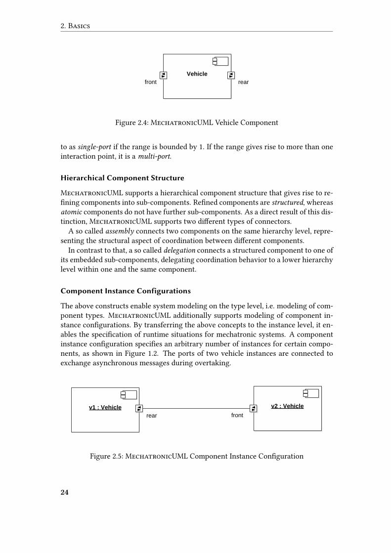
between two ports. MechatronicUML distinguishes ports according to the type ofinteraction: discrete ports enable an asynchronous exchange of discrete messages,whereas continuous ports specify a continuous data �ow. The component in Figure2.4 represents a vehicle with two discrete ports that carry out message exchange inovertaking scenarios.
A property of discrete ports is their cardinality concept. Unlike other types of ports,which represent a single point of interaction, the number of interaction points repre-sented by a discrete port is variable within a speci�ed range. A discrete port is referred
23
2. Basics
Vehicle
rearfront
Figure 2.4: MechatronicUML Vehicle Component
to as single-port if the range is bounded by 1. If the range gives rise to more than oneinteraction point, it is a multi-port.
Hierarchical Component Structure
MechatronicUML supports a hierarchical component structure that gives rise to re-�ning components into sub-components. Re�ned components are structured, whereasatomic components do not have further sub-components. As a direct result of this dis-tinction, MechatronicUML supports two di�erent types of connectors.
A so called assembly connects two components on the same hierarchy level, repre-senting the structural aspect of coordination between di�erent components.
In contrast to that, a so called delegation connects a structured component to one ofits embedded sub-components, delegating coordination behavior to a lower hierarchylevel within one and the same component.
Component Instance Configurations
The above constructs enable system modeling on the type level, i.e. modeling of com-ponent types. MechatronicUML additionally supports modeling of component in-stance con�gurations. By transferring the above concepts to the instance level, it en-ables the speci�cation of runtime situations for mechatronic systems. A componentinstance con�guration speci�es an arbitrary number of instances for certain compo-nents, as shown in Figure 1.2. The ports of two vehicle instances are connected toexchange asynchronous messages during overtaking.
v1 : Vehicle
rear front
v2 : Vehicle
Figure 2.5: MechatronicUML Component Instance Con�guration
24

2.5 MechatronicUML
A component instance con�guration also implies a concretization with respect tothe cardinality concept of discrete ports by attaching a concrete number of so calledsub-port instances of a discrete port to a component instance. A single-port supportsat most one sub-port instance and only enables 1:1 communication of a componentinstance over one connector instance. A multi-port gives rise to numerous sub-portinstances and enables 1:n interaction of one component instance with n other compo-nent instances over n connector instances.w
2.5.2 Coordination Protocols
MechatronicUML’s discrete ports enable the asynchronous exchange of discrete mes-sages via connectors in order to coordinate di�erent components. This gives rise tothe speci�cation of entire protocols for coordination purposes, carried out by succes-sive message exchange via assemblies. MechatronicUML considers such coordina-
tion protocols autonomously from the underlying component structure, enabling pro-tocol reuse in di�erent settings. A coordination protocol abstracts from the concreteassembly it represents, considering the essential behavior of the connected ports interms of so called roles. Figure 2.6 depicts an instantiation of an coordination protocolto ensure safe overtaking of the front vehicle by the rear vehicle.
v2 : Vehicle
:front
v1 : Vehicle
:rear
rear front
:Overtaking
Figure 2.6: MechatronicUML Coordination Protocol
A role that corresponds to a multi-port is termed multi-role. A component’s behav-ior comprises the message exchange of all roles that correspond to its ports. Rolesspecify their concrete message exchange behavior in terms of Real-Time Statecharts,which are described in the subsequent section. Dziwok et al. specify numerous recur-ring patterns for coordination protocols in [DBHT12].
2.5.3 Real-Time Statecharts
Coordination protocols correspond to well-de�ned sequences of sent/received mes-sages, whereas the messages to be sent are highly depending on the messages re-ceived before. A state-based behavior is very suitable to describe such complex mes-sage exchange sequences. However, classical �nite automata su�er from the inability
25
2. Basics
to represent orthogonal and re�ned behavior adequately, and therefore appear inap-propriate in the context of MechatronicUML.
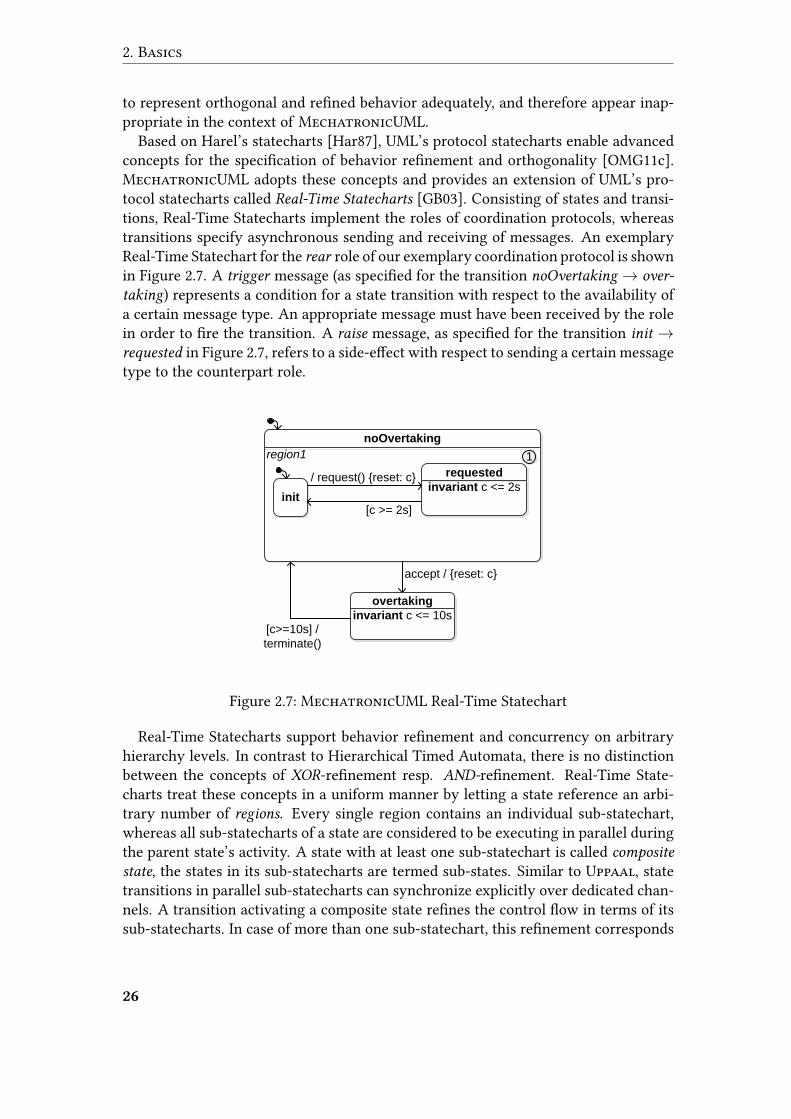
Based on Harel’s statecharts [Har87], UML’s protocol statecharts enable advancedconcepts for the speci�cation of behavior re�nement and orthogonality [OMG11c].MechatronicUML adopts these concepts and provides an extension of UML’s pro-tocol statecharts called Real-Time Statecharts [GB03]. Consisting of states and transi-tions, Real-Time Statecharts implement the roles of coordination protocols, whereastransitions specify asynchronous sending and receiving of messages. An exemplaryReal-Time Statechart for the rear role of our exemplary coordination protocol is shownin Figure 2.7. A trigger message (as speci�ed for the transition noOvertaking→ over-
taking) represents a condition for a state transition with respect to the availability ofa certain message type. An appropriate message must have been received by the rolein order to �re the transition. A raise message, as speci�ed for the transition init →requested in Figure 2.7, refers to a side-e�ect with respect to sending a certain messagetype to the counterpart role.
noOvertaking
requested
invariant c <= 2s
accept / {reset: c}
region1
init
/ request() {reset: c}
[c >= 2s]
1
overtaking
invariant c <= 10s[c>=10s] /
terminate()
Figure 2.7: MechatronicUML Real-Time Statechart
Real-Time Statecharts support behavior re�nement and concurrency on arbitraryhierarchy levels. In contrast to Hierarchical Timed Automata, there is no distinctionbetween the concepts of XOR-re�nement resp. AND-re�nement. Real-Time State-charts treat these concepts in a uniform manner by letting a state reference an arbi-trary number of regions. Every single region contains an individual sub-statechart,whereas all sub-statecharts of a state are considered to be executing in parallel duringthe parent state’s activity. A state with at least one sub-statechart is called composite
state, the states in its sub-statecharts are termed sub-states. Similar to Uppaal, statetransitions in parallel sub-statecharts can synchronize explicitly over dedicated chan-nels. A transition activating a composite state re�nes the control �ow in terms of itssub-statecharts. In case of more than one sub-statechart, this re�nement corresponds
26
2.5 MechatronicUML
to a fork. A transition that deactivates a composite state coarsens the control �owagain. If there is more than one sub-statechart, this coarsening corresponds to a join.
As a limitation of UML’s protocol statecharts, their concept of time is in�exible inthe sense that it only supports the speci�cation of absolute points of time for statetransitions, or delaying of state transitions by a certain amount of time relative tothe activation of the source state. Real-Time Statecharts enable more sophisticatedreal-time behavior by combining UML with timed automata concepts. A Real-TimeStatechart is provided with numerous clock variables that measure the time since theirlast reset. As for timed automata, clock values can restrict state transitions as well asthe activity of certain states via invariants.
Deadlines
Timed automata specify state transitions dependent on clock values, however rely onthe assumption that a state transition is executed without consuming time. Hence,a �ring transition leads to an immediate state change. This concept is inappropriatefor real-time systems that tend to carry out complex time-consuming computationsduring state transitions [Lee09]. Real-Time Statecharts give rise to the explicit speci-�cation of time-consuming state transitions by means of deadlines.
• An absolute deadline speci�es a time interval restricted by bounds on certainclock values, in which a state transition must complete.
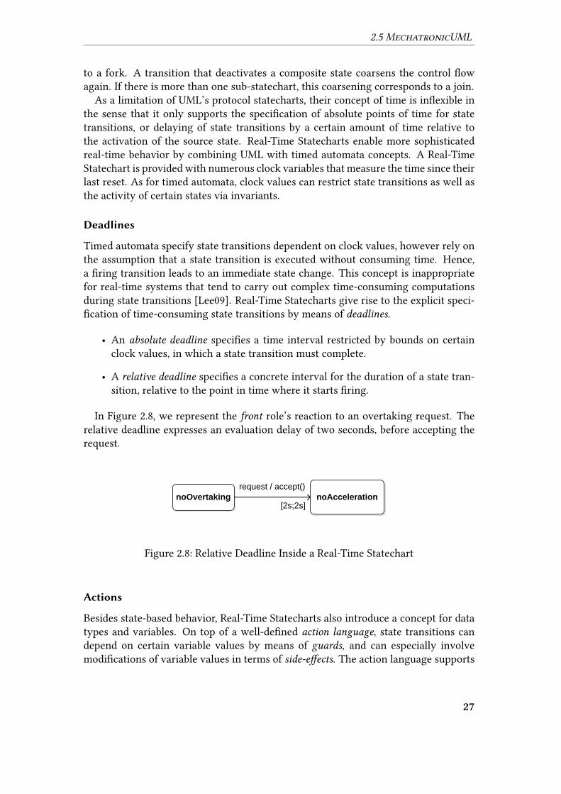
• A relative deadline speci�es a concrete interval for the duration of a state tran-sition, relative to the point in time where it starts �ring.
In Figure 2.8, we represent the front role’s reaction to an overtaking request. Therelative deadline expresses an evaluation delay of two seconds, before accepting therequest.
noOvertaking[2s;2s]
noAcceleration
request / accept()
Figure 2.8: Relative Deadline Inside a Real-Time Statechart
Actions
Besides state-based behavior, Real-Time Statecharts also introduce a concept for datatypes and variables. On top of a well-de�ned action language, state transitions candepend on certain variable values by means of guards, and can especially involvemodi�cations of variable values in terms of side-e�ects. The action language supports
27
2. Basics
encapsulation of behavior into parametrizable operations. Additionally, Real-TimeStatecharts enable the speci�cation of actions which are executed along with certainevents speci�c to states:
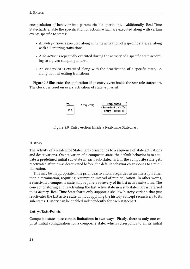
• An entry-action is executed along with the activation of a speci�c state, i.e. alongwith all entering transitions.
• A do-action is repeatedly executed during the activity of a speci�c state accord-ing to a given sampling interval.
• An exit-action is executed along with the deactivation of a speci�c state, i.e.along with all exiting transitions.
Figure 2.8 illustrates the application of an entry-event inside the rear role statechart.The clock c is reset on every activation of state requested.
requested
invariant c <= 2s
entry / {reset: c}init
/ request()
Figure 2.9: Entry-Action Inside a Real-Time Statechart
History
The activity of a Real-Time Statechart corresponds to a sequence of state activationsand deactivations. On activation of a composite state, the default behavior is to acti-vate a prede�ned initial sub-state in each sub-statechart. If the composite state getsreactivated after it was deactivated before, the default behavior corresponds to a reini-tialization.
This may be inappropriate if the prior deactivation is regarded as an interrupt ratherthan a termination, requiring resumption instead of reinitialization. In other words,a reactivated composite state may require a recovery of its last active sub-states. Theconcept of storing and reactivating the last active state in a sub-statechart is referredto as history. Real-Time Statecharts only support a shallow history variant, that justreactivates the last active state without applying the history concept recursively to itssub-states. History can be enabled independently for each statechart.
Entry-/Exit-Points
Composite states face certain limitations in two ways. Firstly, there is only one ex-plicit initial con�guration for a composite state, which corresponds to all its initial
28
2.5 MechatronicUML
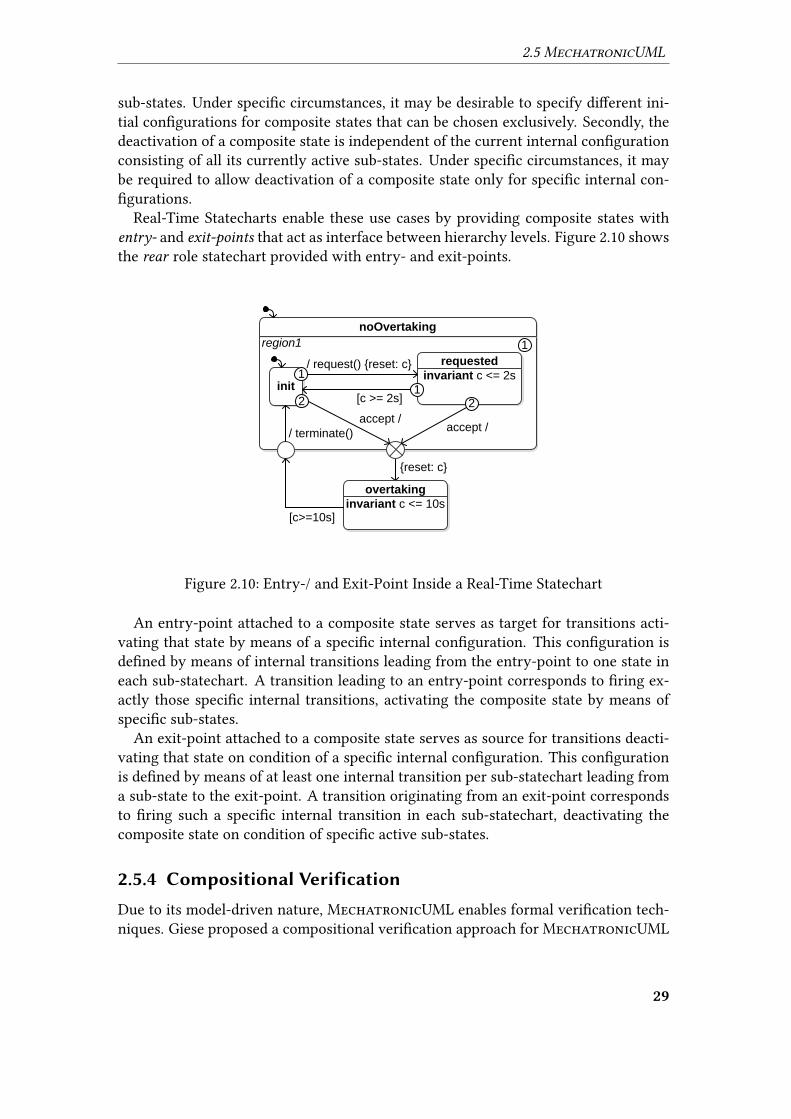
sub-states. Under speci�c circumstances, it may be desirable to specify di�erent ini-tial con�gurations for composite states that can be chosen exclusively. Secondly, thedeactivation of a composite state is independent of the current internal con�gurationconsisting of all its currently active sub-states. Under speci�c circumstances, it maybe required to allow deactivation of a composite state only for speci�c internal con-�gurations.
Real-Time Statecharts enable these use cases by providing composite states withentry- and exit-points that act as interface between hierarchy levels. Figure 2.10 showsthe rear role statechart provided with entry- and exit-points.
noOvertaking
{reset: c}
region1 1
overtaking
invariant c <= 10s[c>=10s]
requested
invariant c <= 2sinit
/ request() {reset: c}
[c >= 2s]
accept // terminate()
accept /
122
1
Figure 2.10: Entry-/ and Exit-Point Inside a Real-Time Statechart
An entry-point attached to a composite state serves as target for transitions acti-vating that state by means of a speci�c internal con�guration. This con�guration isde�ned by means of internal transitions leading from the entry-point to one state ineach sub-statechart. A transition leading to an entry-point corresponds to �ring ex-actly those speci�c internal transitions, activating the composite state by means ofspeci�c sub-states.
An exit-point attached to a composite state serves as source for transitions deacti-vating that state on condition of a speci�c internal con�guration. This con�gurationis de�ned by means of at least one internal transition per sub-statechart leading froma sub-state to the exit-point. A transition originating from an exit-point correspondsto �ring such a speci�c internal transition in each sub-statechart, deactivating thecomposite state on condition of speci�c active sub-states.
2.5.4 Compositional Verification
Due to its model-driven nature, MechatronicUML enables formal veri�cation tech-niques. Giese proposed a compositional veri�cation approach for MechatronicUML
29
2. Basics
in [Gie03]. The approach operates on a given component instance con�guration andenables the veri�cation of speci�c safety properties. According to its compositionalstrategy, the approach is underlying the divide-and-conquer concept: a component in-stance con�guration is not veri�ed in its entirety, but is split into sub-parts which areveri�able on their own.
More precisely, the compositional veri�cation approach proposes the decomposi-tion of a component instance con�guration into coordination protocols and compo-nents, and the veri�cation of safety properties on these smaller system elements. Af-ter veri�cation, the approach ensures semantic validity of the veri�cation results bymeans of a syntactically correct re-composition of protocols and components. Theapproach tackles the exploration problem for huge state spaces by means of compo-sition, focusing on scalability with respect to system size. The major compositionalveri�cation steps are the following:
1. The �rst step corresponds to an isolated veri�cation of the single coordinationprotocols against certain safety properties, i.e. properties concerning all execu-tion paths. In addition, verifying also the absence of deadlocks enables advancedreasoning in the subsequent steps.
2. Subsequently, the approach composes coordination protocol instances withoutintroducing interdependency between roles. Consequently, due to the indepen-dence, all properties and the deadlock-freedom veri�ed in the �rst step are stillvalid after the composition.
3. This next step considers interdependency between roles. The interdependencyarises from the fact that a component instance’s concrete behavior may extendthe composed role behavior in terms of interactions between ports. However, ifit is guaranteed that the extended composition corresponds to a restriction of theexecution paths considered before, then all pre-veri�ed safety-properties stillhold and the extended behavior is a valid re�nement. Under speci�c conditions,the re�nement validity check corresponds to a check for deadlock-freedom ofthe extended role composition [BBB+12], which ensures that no previously con-sidered path may result in a deadlock due to the interaction.
4. Finally, component instances are veri�ed against certain safety properties inisolation, disregarding coordination behavior between di�erent component in-stances. The veri�ed properties may now refer to interdependency between dif-ferent roles of one component, e.g. synchronous activity of certain states. Dueto the disregarded coordination behavior, the set of execution paths consideredin this step comprises the paths that the overall system may actually operateon. Hence, safety properties veri�ed in this �nal step are valid for the overallsystem.
Obviously, steps 1. and 2. comprise typical veri�cation tasks against safety prop-erties, which can be carried out by means of model checking techniques. Also the
30
2.6 Goal Question Metric
re�nement check in step 3. corresponds to a veri�cation task with respect to deadlock-freedom. Hence, MechatronicUML’s compositional veri�cation approach involvesspeci�c model checking use cases that correspond to the aforementioned veri�cationsteps.
2.6 Goal �estion Metric
Model-driven approaches apply engineering techniques to the domain of softwaredevelopment, motivating the notion of software engineering. Standardized and sys-tematic software development raises a need for a quality measurement approach thatmeets these engineering requirements.
The Goal Question Metric (GQM) approach is a means to derive project-speci�coperational quality models, designed to enable quality measurement in the domain ofsoftware engineering [BW84]. It follows a top-down paradigm and is based on there�nement of quality models in a stepwise, goal-driven manner. In the presence oferror-proneness, GQM is a systematic approach to enable numerous tasks [SB99]:
• planning of resource requirements before a project starts
• evaluating the quality of products or processes
• process improvements on top of adaptation and re�nement
• feedback with respect to the progress of a project
2.6.1 GQM Model
GQM suggests the development of quality models according to three hierarchy lev-els [BCR94]:
1. The conceptual level is concerned with the de�nition of major project goals. Anessential aspect to be speci�ed is the object of measurement, which can be aproduct, process or resource. The level furthermore comprises a statement re-garding the measurement purpose and the concrete issue under consideration.The conceptual level comprises a speci�cation of the viewpoint from whichquality measurement should take place.
2. The operational level constitutes a re�nement of the goals speci�ed on the �rstlevel. Re�nement corresponds to the derivation of questions that characterizethe object of measurement in terms of the pertaining quality attribute and de-scribe under which aspect its quality can be measured from the speci�ed view-point.
3. The quantitative level takes the role of re�ning the derived questions in terms ofconcrete quantitative metrics. These metrics enable the answering of the speci-�ed questions in a quantitative manner. Metrics can be objective, i.e. depend on
31
2. Basics
the object of measurement only, or subjective, i.e. depending also on a certainviewpoint.
2.6.2 GQM Process
The GQM approach also proposes a measurement process consisting of four phases[SB99]. The process is not based on the pre-existence of a GQM model, but rathergives rise to the de�nition of such a model in a dedicated phase.
1. The planning phase corresponds to the development of a project plan with re-spect to a certain software development project under consideration.
2. The de�nition phase is concerned with the development of a GQM model in-cluding goals, questions, and metrics. Additionally, this phase produces mea-surement expectations, so called hypotheses, which highly a�ect the later inter-pretation of measurement results.
3. During the data collection phase, data concerning the object of measurement iscollected as an input to the measurement process.
4. During the interpretation phase, metrics are evaluated based on the collectedinput data, producing measurement results. Measurement hypotheses enablethe assessment of the result in terms of the overall goals.
32
3 Related Work
We discuss related work from three di�erent areas. Section 3.1 focuses on transfor-mations from MechatronicUML to external veri�cation and simulation formalisms,whereas Section 3.2 covers transformations from other real-time formalisms towardsUppaal. Finally, in Section 3.3, we consider related work that emphasizes a certaintransparency with respect to formal details of the veri�cation.
3.1 Transforming MechatronicUML to External
Formalisms
In this section, we are interested in transformations from MechatronicUML to ex-ternal formalisms for the purpose of veri�cation or simulation. These transformationsmay provide reusable concepts for the translation of speci�c MechatronicUML fea-tures as the asynchronous message exchange, quality-of-service assumptions, or hi-erarchy towards Uppaal. The veri�cation approaches captured in Sections 3.1.1 to3.1.3 are basically orthogonal to our approach. However, none of the contributionsemphasizes transparency of the underlying veri�cation formalism, e.g. by providingMechatronicUML-speci�c veri�cation feedback or simplifying the speci�cation ofveri�cation properties from the viewpoint of MechatronicUML engineers. The sim-ulation approaches discussed in Sections 3.1.4 and 3.1.5 address a more downstreamphase of the design process, testing the integration of continuous aspects into thediscrete state-based model that was formally veri�ed before.
3.1.1 Uppaal
We described the underlying formalism of the Uppaal model checker in Section 2.2.3.Hirsch connected Real-Time Statecharts to Uppaal’s veri�cation engine in [Hir04].The transformation relies on the Hierarchical Timed Automata (HTA) formalism in-troduced in Section 2.2.4 for an intermediate representation. Based on the HTA for-malism, the Vanilla tool [DM01] carries out the �nal transformation into �at Uppaaltimed automata as described in Section 2.2.4.
The transformation of Real-Time Statecharts into HTA maps composite states, or-thogonality, and synchronizations to their associated HTA constructs. Additionally, itperforms normalizations with respect to state entry-, do-, and exit-events, deadlines,transition priorities, history, �nal states, and asynchronous message exchange. How-ever, the transformation lacks concepts for the execution of entry- and exit-events incase of composite transitions that activate or deactivate a certain state indirectly. The
33
3. Related Work
representation of asynchronous message exchange [Hir04, pp. 55-56] does not con-sider quality-of-service assumptions like message delay or message loss. The trans-formation of �nal states [Hir04, p. 63] prevents the identi�cation of deadlocks duringveri�cation, since an active �nal state in its normalized form always involves an en-abled transition.
Hirsch also proposes the concept of background model checking [Hir04, pp. 86-88]to automatically provide live veri�cation results whenever a designed model changes.Whereas this approach implies a certain transparency of the Uppaal veri�cation, itonly addresses the visualization of plain veri�cation results like success or failure,and does not aim at the presentation of traces leading to counter-examples. Obviously,background model checking relies on fast veri�cation feedback, whereas performanceis not of primary relevance in the scope of this thesis. Still, we identify the requiredperformance analysis and further activities towards background model checking as aninteresting topic for future work.
A serious transparency barrier to the Uppaal integration by Hirsch is the usage ofVanilla as a third-party tool, which raises issues with respect to the traceability (cf.Section 2.1.5) of the overall model transformation. Since Vanilla acts as black box withrespect to the concrete executed transformation rules, the integration of the tool intoa fully transparent veri�cation approach seems unpromising.
Hirsch focuses on e�cient strategies to verify non-local properties [HG03] that gobeyond the compositional veri�cation approach discussed in Section 2.5.4. Such prop-erties exceed the scope of one coordination protocol by comprising message exchangebetween more than two components. Although this use case is not of primary inter-est in the scope of this thesis, we identify the veri�cation of non-local properties as arelevant requirement to be considered during our transformation design.
3.1.2 RAVEN
RAVEN1 [Ruf01] is a real-time model checker that accepts �at �nite transition sys-tems extended by time, so called I/O interval structures. Model checking in RAVENis symbolic, i.e. it encodes the state-space in an implicit manner via Binary DecisionDiagrams (BDD). As a major restriction, I/O interval structures are not able to specifyclocks.
In contrast to MechatronicUML and Uppaal that rely on a dense-time model asdiscussed in Section 2.2.1, the underlying model of time in RAVEN is discrete. RA-VEN enables the speci�cation of veri�cation properties using a timed variant of theCTL described in Section 2.3.1 called Clocked CTL (CCTL). Communication betweenprocesses modelled as I/O interval structures is limited to exporting and importing ofdata signals. States carry valuations of exported signals, whereas state transitions maydepend on the values of imported signals. The concept of synchronization betweentransitions is unknown to RAVEN. However, RAVEN emphasizes diagnostics with re-
1Real-Time Analyzing and Veri�cation Environment
34

3.1 Transforming MechatronicUML to External Formalisms
spect to identi�ed counter-examples by providing a wave-form browser that traces theevolution of signals over time in a visual fashion.
Stecker developed an integration of Real-Time Statecharts and RAVEN in [Ste05]based on a transformation towards I/O interval structures. To overcome the lack ofclocks and the inability to specify complex measurements of time, dedicated automataare introduced that encode clocks by means of discrete signals [Ste05, pp. 34-37].These automata ensure the elapsing of time by repeatedly adjusting dedicated datasignals, and also represent clock resets. Since I/O interval structures have no notionof hierarchy, the transformation addresses a representation of composite states bymeans of orthogonality [Ste05, pp. 37-41].
The transformation approach also covers synchronization between transitions, andaims at encoding the ability to synchronize over a certain channel by means of signalexport/import [Ste05, pp. 19-28]. Obviously, the e�ort to represent synchronizationis much greater compared to a target formalism like Uppaal, which supports o�handsynchronization.
Since RAVEN does not enable asynchronous message exchange as well, this conceptgives rise to another complex transformation aspect [Ste05, pp. 29-34]. The informa-tion whether a message of a certain type is available is encoded via dedicated countersignals that represent the current bu�er status. Since quality-of-service assumptionsabout the asynchronous transmission remain unconsidered, every dispatched messagegets immediately delivered.
3.1.3 PHAVer
PHAVer2 [Fre05] is a veri�cation tool for hybrid systems that combine discrete statechanges with continuous behavior. PHAVer operates on �at hybrid I/O automata thatembed di�erential equations into discrete states. It performs polyhedral computa-tions to explore the state space of the underlying system. In contrast to usual modelchecking approaches that enable queries in terms of temporal logic formulas, PHAVerperforms a reachability analysis that yields a plain enumeration of the reachable sys-tem states. Hence, obtaining concrete veri�cation results with respect to temporalrequirements still requires a signi�cant manual e�ort. Additionally, PHAVer does notprovide any traces.
Dorociak developed a transformation from MechatronicUML to hybrid I/O au-tomata as an input to PHAVer in [Dor08]. More precisely, the approach focuses onthe representation of hybrid recon�guration charts [GBSO04]. These diagrams extendReal-Time Statecharts by recon�guration behavior between di�erent continuous con-trol strategies. The transformation encodes clocks by means of dedicated continuousvariables that are subject to di�erential equations. Whereas hybrid I/O automata sup-port synchronization labels on transitions, the transformation addresses the task ofencoding asynchronous communication, but does not consider any quality-of-service
assumptions. Dorociak also addresses the need to establish a transparent veri�cation2Polyhedral Hybrid Automaton Verifyer
35
3. Related Work
by indicating the veri�cation result at the level of the Fujaba tool [Dor08, pp. 68-69].However, this transparency challenge is complicated by the fact that PHAVer providesplain reachability �ndings instead of a concrete veri�cation result.
3.1.4 Modelica
The Modelica modeling language is an object-oriented approach for the speci�cationof physical systems. Similar to the CIF approach discussed in Section 3.2.5, Modelicaaims at the exchange and reuse of models based on a unique formalism. In combinationwith the StateGraph2 library, Modelica enables modeling of discrete state-based be-havior. The modeling and simulation environment Dymola
3 provides well-establishedtool support for the creation and execution of Modelica models.
A transformation fromMechatronicUML to Modelica was originally developed byWolf [Wol11]. Pohlmann et al. present the underlying extensions to the StateGraph2
library in [PDS+12]. Due to Modelica’s object-oriented nature, it enables o�hand rep-resentation of hierarchical states and transition priorities in Real-Time Statecharts,whereas the underlying di�erences between shallow and deep history in Mecha-tronicUML and Modelica give rise to small adaptations [Wol11, pp. 66-67]. Stateentry-, do-, and exit-events can be represented with manageable e�ort by means ofalgorithmic code [Wol11, pp. 49-52,56-57]. Clocks are considered relative to the over-all execution time [Wol11, pp. 47-48]. The transformation encodes synchronous andasynchronous communication among statecharts by means of explicit connectors be-tween the a�ected transitions. These connectors carry out the required data exchange.After transmission, asynchronous messages and their parameters are bu�ered by ded-icated queues before the consumption by the receiver Real-Time Statechart.
The di�erence between formal veri�cation approaches on the one hand, and simula-tion of Modelica models on the other hand, gives rise to certain behavioral restrictionsfor speci�c syntactic features. As an example, enabled transitions �re without resid-ing in the source state, which corresponds to an urgent behavior. State invariantsdo not force any execution progress, but rather give rise to an abnormal terminationof the simulation if an active state’s invariant is violated [Wol11, p. 53]. The aboverestrictions correspond to an underapproximation of the execution traces originallyspeci�ed, which is a valid practice for simulations.
Addressing StateGraph2’s inability to form transition cycles that do not consumeany time, the transformation to Modelica aims at identifying and eliminating suchcycles. The elimination is carried out by inserting additional delaying transitions,such that time is forced to pass throughout the cycle. Although the induced delay isvery small, this technique implies modi�cations of the speci�ed real-time behavior,which is an unacceptable practice in case of formal veri�cation.
3Dynamic Modeling Laboratory
36
3.2 Transforming External Formalisms to Uppaal
3.1.5 MATLAB/Simulink
MATLAB4 is an environment for mathematical computations. Its toolboxes Simulinkand State�ow o�er modeling support for block diagrams combining continuous data�ow with discrete state-based behavior. The MATLAB toolchain enables visual simu-lation as well as code generation for target platforms.
Heinzemann et al. present an approach of connecting MechatronicUML to MAT-LAB/Simulink in [HPR+12]. Pines extends the Simulink transformation by structuralrecon�guration in [Pin12]. Previous work by Steinke [Ste07] addresses the transfor-mation of hybrid recon�guration charts as mentioned in Section 3.1.3.
WhereasMechatronicUML’s component structure enables o�hand representationin terms of Simulink block diagrams, Real-Time Statecharts are transformed to hierar-chical State�ow charts. Similar to the Modelica integration described in Section 3.1.4,the Simulink transformation encodes clocks relative to the overall simulation time.
A certain e�ort is spent on the representation of asynchronous message commu-nication by means of data exchange. Simulink does not provide o�hand means tobu�er received data, which is crucial to the asynchronous communication in Mecha-tronicUML. Hence, a dedicated infrastructure at the Simulink level carries out typicallink layer tasks concerned with the dispatching and delivering of discrete messagesusing continuous data exchange. At this point, the approach explicitly tackles mes-sage loss by means of an acknowledge mechanism, sending a message again if thereis no acknowledgement of receipt. Hence, the transformation does not only representquality-of-service characteristics, but explicitly addresses the emergent shortcomings.In doing so, the generated Simulink models meet crucial requirements for a straightapplication to target hardware as one of Simulink’s key features. Since message lossactually occurs in real systems, abstracting from the system’s reaction only in terms ofa plain transmission delay would make the approach inapplicable to target hardware.
3.2 Transforming External Formalisms to Uppaal
In this section, we focus on the representation of di�erent real-time modeling for-malisms at the level of Uppaal. We restrict ourselves to systematic, reusable trans-formation approaches, disregarding manual ad hoc mappings of individual case studymodels. We are particularly interested in the way that other formalisms and transfor-mations cope with speci�c characteristics of the MechatronicUML design method,such as hierarchical, component-based modeling, dense real-time behavior, asynchro-nous message exchange, and quality-of-service assumptions. We only refer to theseconcepts if they are particularly supported by an approach. We also investigate thesigni�cance of transparency, i.e. we discuss which Uppaal transformations are inte-grated to a transparent veri�cation procedure.
4Matrix Laboratory
37
3. Related Work
3.2.1 hugo/RT
The real-time veri�cation tool hugo/RT5 was proposed by Knapp et al. in [KMR02].hugo/RT relies on hierarchical UML state machines as the underlying behavior for-malism, whereas requirements are also subject to graphical modeling via UML inter-action diagrams. The approach connects to di�erent model checking tools that carryout the actual veri�cation, Uppaal among them.
For veri�cation, the UML interaction diagrams that encode the requirements aretranslated into dedicated observer automata that interact with the speci�ed systemand identify violations. The transformation from hierarchical UML state machinestowards Uppaal does not only introduce a bu�ering mechanism for asynchronouscommunication, but also considers a crucial quality-of-service assumption in terms ofthe message latency in the underlying network [KMR02]. A message bu�er automa-ton with a �rst-in-�rst-out logic for two event types e1 and e2 is depicted in Figure3.1(a) [KMR02]. For instance, event e1 may be received from the network by synchro-nizing with a dedicated network automaton on channel e1FromNet. The receivingstate machine automaton may consume a message via synchronization on channele1Dispatch. The automaton does not maintain its level of performance in case of abu�er over�ow, switching to the dedicated Over�ow location instead.
Figure 3.1(b) [KMR02] shows the associated network automaton that induces a cer-tain maximum delay for the message type e1. Buckets are available for at most twotransferred messages, representing the �ll level of these buckets via four locations.The location names in Figure 3.1(b) encode the �ll level of the two buckets: location00 represents an empty network, whereas Over�ow is reached after receiving anotherevent in location 11. Noteworthy, the modeled network faces a �xed maximum ca-pacity. By associating dedicated clocks with pending messages, the automaton en-sures a maximum transmission delay denoted by ∆. The network automaton does notnecessarily preserve the order of sent messages, which is, however, a crucial assump-tion for MechatronicUML [Kri13]. Kriger also identi�ed the need for a minimumtransmission delay, the possibility of message loss, and alternative over�ow strate-gies that maintain the message exchange service, which are unconsidered conceptsfor hugo/RT.
hugo/RT addresses transparency of the Uppaal veri�cation procedure not only byencoding requirements at the UML level, but also by transforming identi�ed counter-examples traces back to the UML. Nowadays, the hugo/RT approach mainly su�ersfrom stagnating development. In addition, due to its general purpose modeling ap-proach, it di�ers from the domain-speci�c MechatronicUML method in terms ofmissing support for structural component-based modeling and the integration of con-tinuous system aspects.
5http://www.pst.informatik.uni-muenchen.de/projekte/hugo/
38
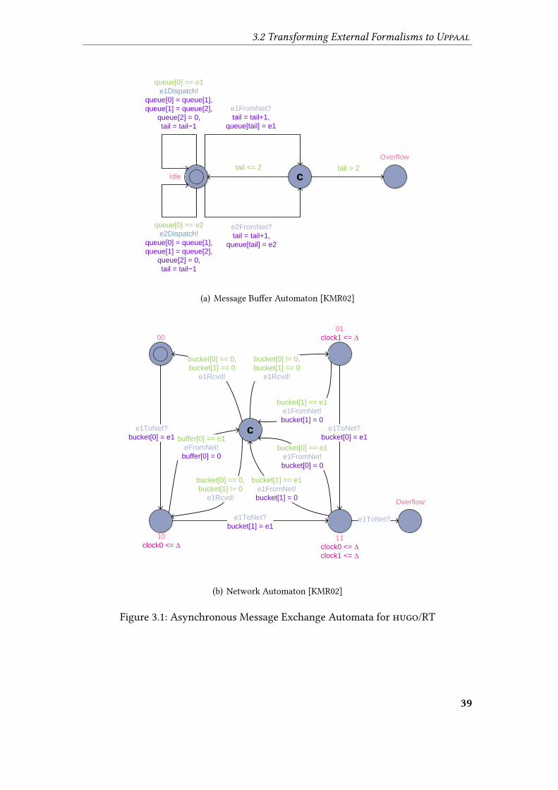
3.2 Transforming External Formalisms to Uppaal
e1FromNet?
tail = tail+1,
queue[tail] = e1
Idle ctail <= 2
Overflow
queue[0] == e1
e1Dispatch!
queue[0] = queue[1],
queue[1] = queue[2],
queue[2] = 0,
tail = tail−1
queue[0] == e2
e2Dispatch!
queue[0] = queue[1],
queue[1] = queue[2],
queue[2] = 0,
tail = tail−1
e2FromNet?
tail = tail+1,
queue[tail] = e2
tail > 2
(a) Message Bu�er Automaton [KMR02]
10
clock0 <= ∆
Overflow
e1ToNet?
bucket[0] = e1c
buffer[0] == e1
eFromNet!
buffer[0] = 0
bucket[0] == 0,
bucket[1] != 0
e1Rcvd!
e1ToNet?
bucket[1] = e1
bucket[1] == e1
e1FromNet!
bucket[1] = 0
bucket[0] == e1
e1FromNet!
bucket[0] = 0
e1ToNet?
bucket[0] = e1
bucket[0] == 0,
bucket[1] == 0
e1Rcvd!
bucket[0] != 0,
bucket[1] == 0
e1Rcvd!
bucket[1] == e1
e1FromNet!
bucket[1] = 0
e1ToNet?
11
clock0 <= ∆
clock1 <= ∆
01
clock1 <= ∆00
(b) Network Automaton [KMR02]
Figure 3.1: Asynchronous Message Exchange Automata for hugo/RT
39
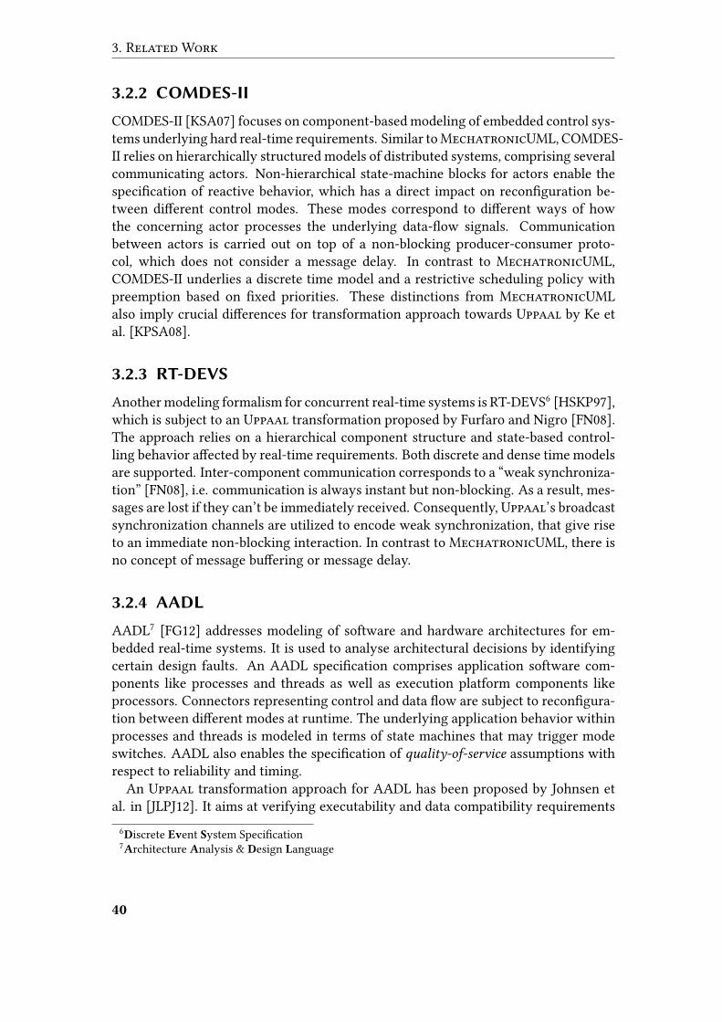
3. Related Work
3.2.2 COMDES-II
COMDES-II [KSA07] focuses on component-based modeling of embedded control sys-tems underlying hard real-time requirements. Similar toMechatronicUML, COMDES-II relies on hierarchically structured models of distributed systems, comprising severalcommunicating actors. Non-hierarchical state-machine blocks for actors enable thespeci�cation of reactive behavior, which has a direct impact on recon�guration be-tween di�erent control modes. These modes correspond to di�erent ways of howthe concerning actor processes the underlying data-�ow signals. Communicationbetween actors is carried out on top of a non-blocking producer-consumer proto-col, which does not consider a message delay. In contrast to MechatronicUML,COMDES-II underlies a discrete time model and a restrictive scheduling policy withpreemption based on �xed priorities. These distinctions from MechatronicUMLalso imply crucial di�erences for transformation approach towards Uppaal by Ke etal. [KPSA08].
3.2.3 RT-DEVS
Another modeling formalism for concurrent real-time systems is RT-DEVS6 [HSKP97],which is subject to an Uppaal transformation proposed by Furfaro and Nigro [FN08].The approach relies on a hierarchical component structure and state-based control-ling behavior a�ected by real-time requirements. Both discrete and dense time modelsare supported. Inter-component communication corresponds to a “weak synchroniza-tion” [FN08], i.e. communication is always instant but non-blocking. As a result, mes-sages are lost if they can’t be immediately received. Consequently, Uppaal’s broadcastsynchronization channels are utilized to encode weak synchronization, that give riseto an immediate non-blocking interaction. In contrast to MechatronicUML, there isno concept of message bu�ering or message delay.
3.2.4 AADL
AADL7 [FG12] addresses modeling of software and hardware architectures for em-bedded real-time systems. It is used to analyse architectural decisions by identifyingcertain design faults. An AADL speci�cation comprises application software com-ponents like processes and threads as well as execution platform components likeprocessors. Connectors representing control and data �ow are subject to recon�gura-tion between di�erent modes at runtime. The underlying application behavior withinprocesses and threads is modeled in terms of state machines that may trigger modeswitches. AADL also enables the speci�cation of quality-of-service assumptions withrespect to reliability and timing.
An Uppaal transformation approach for AADL has been proposed by Johnsen etal. in [JLPJ12]. It aims at verifying executability and data compatibility requirements
6Discrete Event System Speci�cation
7Architecture Analysis & Design Language
40
3.2 Transforming External Formalisms to Uppaal
in the presence of concurrency. The transformation considers models for applicationsoftware as well as the execution platform, and is described in terms of formal rules.However, as a crucial limitation, it supports only a subset of AADL restricted to syn-chronous data interaction.
3.2.5 Compositional Interchange Format
The Compositional Interchange Format (CIF) addresses interoperability problems be-tween di�erent coexisting modeling formalisms for hybrid real-time systems [BRSR07].By representing continuous variables in terms of di�erential equations, CIF’s hybridcharacteristics go beyond the scope of MechatronicUML. The basic intent of CIFis to overcome a variety of bilateral transformations between di�erent modeling for-malisms. Instead, transformations are intended to rely on CIF for an intermediaterepresentation as depicted in Figure 3.2 [BCN+09]. Hence, the approach focuses onreusable transformation steps, reducing the e�ort to establish interoperability betweendi�erent formalisms for modeling, simulation, analysis, or veri�cation.
Figure 3.2: CIF Transformation Approach [BCN+09]
At the core of CIF is the concept of (originally non-hierarchical) hybrid interchange
automata as generic modeling formalism, enabling the speci�cation of discrete state-based behavior along with discrete and continuous variables, urgent behavior, andsynchronizations. By providing interchange automata with formal semantics, CIF fo-cuses on proven semantics preservation for its model transformations. Although en-
41
3. Related Work
abling interactions between automata, there is no explicit support for asynchronousmessage exchange in CIF, which is a crucial feature in MechatronicUML. Extensionsto CIF described in [BCN+09] give rise to a compositional veri�cation approach for CIFmodels. Another extension of CIF introduces the concept of hierarchical states, alongwith a hierarchy elimination procedure [BNBC10; Fon11; ABB+11]. Such normaliza-tions at the level of CIF are a crucial element of the overall transformation frameworkdeveloped for CIF [HSHS11].
A semantics-preserving model transformation from CIF to Uppaal has been pro-posed by Nadales Agut et al. in [NRS+11]. It considers only a subset of CIF in terms of“parallel composition, unidirectional communication via channels, shared variables,clocks, and restricted forms of urgency” [NRS+11, p. 12497]. Hence, a transformationfrom MechatronicUML to Uppaal via CIF seems unpromising due to the missingsupport for concepts like hierarchical states or asynchronous message exchange. Inadditional, the integration of CIF as an intermediate representation raises questionsin terms of traceability (cf. section 2.1.5) and a transparent integration of Uppaal.However, given future support for the entire range of MechatronicUML languageconstructs, the CIF could actually overcome a co-existence of numerous transforma-tions for MechatronicUML as presented in Section 3.1.
3.2.6 MoDeST
MoDeST8 [DHKK01] is a text-based modeling language for stochastic real-time sys-tems. Its major focus is on connecting one formalism to various analysis techniques,like e.g. model checking based on timed automata models. A transformation for acertain MoDeST subset to Uppaal has been presented by Bogdoll et al. in [BDHH12].Noteworthy, speci�c extensions to Uppaal were carried out in order to make the for-malisms compatible. These alignments pertain to constructs like time constraints andsynchronization [BDHH12]. By integrating model transformation and model check-ing in one tool namedmctau, the approach aims at a transparent integration of Uppaalas the underlying veri�cation engine. The tool translates properties speci�ed at theMoDeST level towards Uppaal, but does not relate identi�ed counter-examples backto the original MoDeST-based model.
3.2.7 DSEIR
Similar to the CIF and MoDeST approaches presented in Sections 3.2.5 and 3.2.6, DSEIR9
focuses on interoperability between di�erent modeling formalisms in the context ofembedded systems [BBG+10]. Central to the approach is the philosophy of paralleliz-ing application development, platform development, and deployment. Based on theintermediate representation DSEIR, models from these contexts can be transformedtowards analysis and veri�cation formalisms.
8Modeling and Description Language for Stochastic Timed Systems
9Design-Space Exploration Intermediate Representation
42

3.2 Transforming External Formalisms to Uppaal
For the application level modeling, DSEIR relies on plain task graph modeling ex-tended by parameters, timing requirements, and speci�c precedence rules that de-scribe temporal interdependencies between the completion and enabling of tasks. Incontrast to MechatronicUML, there is no support for concrete behavior speci�ca-tion. For the representation of the underlying computation platform, DSEIR relies ona plain declaration of the comprised resources, abstracting from the concrete natureof speci�c resources and also from resource interdependencies.
Tool support for the transformation of DSEIR speci�cations towards formalisms likeUppaal is part of theOctopus DSE toolset. Beside typical veri�cation tasks, Uppaal en-ables schedule optimizations based on the representation of tasks as timed automata.
3.2.8 Timed π-Calculus
The π-Calculus [Mil93] is a process algebra that enables modeling for concurrent com-municating processes. In [BK12], Barakat and Kowalewski present a real-time exten-sion referred to as πτ that addresses mobile telecommunication protocols. Embeddedto LATEX documents, πτ speci�cations can be parsed and transformed to Uppaal XML�les. The integration is part of the SimPiCal toolkit, which also comprises visualiza-tion, simulation, and debugging. TheUppaal transformation faces speci�c compatibil-ity issues in terms of using prioritized synchronization channels, that prevent deadlockchecks in Uppaal [BK12]. Additionally, πτ relies on memorizing timer values, whichis unsupported by Uppaal. To overcome the latter limitation, a dedicated compati-bility mode exists that encodes time by means of integer values instead of clocks inUppaal. This approximation clearly weakens the aspect of semantics preservation forthe transformation of πτ to Uppaal, separating it from the scope of this thesis.
3.2.9 Function Block Diagrams
A common �eld of application for Uppaal are function block diagrams that serve asmodels for controllers. The approach presented by de Assis Barbosa et al. in [AGS+07;SAG+08] addresses the transformation of such diagrams for safety instrumented sys-
tems towards Uppaal. Based on the synthesis of timed automata models, the UppaalTRON extension enables a consistency check between speci�cation in terms of func-tion block diagrams, and the resulting implementation for programmable logic con-trollers. The transformed function block diagrams comprise well-known logical gatesas well as time elements that impose a delay between input and output of functions. Asan important di�erence to Uppaal and also MechatronicUML, the approach oper-ates on logical time instead of real-time [AGS+07], which also requires an appropriateencoding at the Uppaal level.
The approach presented by Soliman et al. in [STF12] addresses function block di-agrams complying to the IEC 61131 standard for programmable logic controllers. Asopposed to the above purpose of checking trace equivalence by Uppaal TRON, theUppaal transformation proposed here addresses simulation and veri�cation against
43
3. Related Work
safety properties. The underlying transformation rules between function block dia-grams and Uppaal are speci�ed formally [STF12].
An automatic veri�cation tool chain for Continuous Function Charts has been pro-posed by Wardana et al. in [WFV09]. It comprises an Uppaal transformation andaddresses model checking of distributed control systems like process industry plants.
3.2.10 POOSL
POOSL10 enables modeling of concurrent communicating systems. It relies on a hierar-chical clustering of processes, whereas asynchronous message exchange between pro-cesses is a�ected by transmission delays. Focusing on performance analysis for motioncontrol systems, a transformation from POOSL to Uppaal has been proposed by Xinget al. in [XTL+10]. The approach relies on formal veri�cation to overcome plain es-timation results, which are inadequate for the performance analysis in safety-criticalenvironments. Uppaal’s model checking engine enables the prediction of worst-caselatencies using the RapidIO data communication standard. The ports that trigger themessage exchange are provided with message bu�ers underlying a �rst-in-�rst-out
logic. By verifying worst-case latencies, Uppaal aids the deployment of motion con-trol functionality among multiple processors. The proposed integration of POOSL andUppaal provides dedicated transformation patterns, describing the underlying map-ping strategy for speci�c constructs.
3.2.11 SystemC
In the �eld of hardware-software co-design, SystemC [Gro02] constitutes a prominentmodeling language and simulation environment. SystemC speci�cations comprise nu-merous communicating processes underlying an integer-valued model of time. Sys-temC supports structural modeling in terms of modules and ports. The transformationtool STATE11 for SystemC models towards Uppaal was �rst proposed by Herber et al.in [HFG08], representing each SystemC function by means of an Uppaal timed au-tomaton template.
A remaining challenge to the Uppaal transformation was given in terms of non-blocking event exchange during inter-process communication. The Transaction LevelModeling (TLM) standard, providing an intermediate abstraction level for SystemCmodeling, enables this functionality on top of so called payload event queues (PEQ). Anextended version of the Uppaal transformation for SystemC and TLM was presentedby Herber et al. in [HPG11]. Representing the deferred execution of callback functions,multiple noti�cations of one and the same event must be handled simultaneously byUppaal. Although operating on a di�erent abstraction level, a very similar challengeof realizing asynchronous message exchange at the level of Uppaal exists in the scopeof this thesis.10Parallel Object-Oriented Speci�cation Language
11SystemC to Timed Automata Transformation Engine
44
3.3 Transparent Veri�cation
3.3 Transparent Verification
Whereas the previous sections presented a variety of transformation approaches start-ing from MechatronicUML models or targeting Uppaal, we now address the aspectof transparency. The transformation approaches towards Uppaal described in Section3.2 are mostly semi-transparent in the sense that they only provide automatic means totransfer domain-speci�c models into representations suitable for o�hand veri�cation.
We are additionally interested in veri�cation approaches that prevent users fromthe burden of mapping the veri�cation results back to the domain-speci�c model. Ourfocus is on domain-speci�c control �ow modeling formalisms, and on approaches thatdo not only translate model checking results to a di�erent representation, but actuallyestablish a connection from these results to the original design model.
3.3.1 Arcade
Barber et al. identify two main barriers for a transparent model checking [BGH01]:the translation barrier as tackled by the Uppaal transformation approaches discussedabove, and the interpretation barrier, emerging from the need to “interpret the resultsof model checking and relate these results back [. . . ] in a meaningful way (thus allow-ing for the correction of property violations [. . . ])” [BGH01, p. 342].
The Arcade12 tool addresses both barriers in a system architecture domain. Whereasarchitectural models are transformed towards the Promela input language of the SPINmodel checker, an Architectural Trace Diagram (ATD) is obtainable for an identi-�ed counter-example. This trace diagram depicts a sequence of runtime interactionsand state changes between concurrent architectural components, thus ensuring trans-parency by means of a domain-speci�c visualization of the veri�cation results. Al-though this approach is very similar to the intention of this thesis, MechatronicUMLconstitutes a larger scale domain-speci�c modeling language by speci�cally focusingon mechatronics.
3.3.2 Back-Annotation via Change-Driven Model
Transformations
Hegedüs et al. characterize back-annotation as “the reverse model transformationproblem to derive corresponding source design model information from the resultsof a formal analysis carried out on a target model" [HBRV10, p. 146]. The authorspropose a mechanism for the back-annotation of execution traces that exploits thetraceability concept (cf. Section 2.1.5) of the underlying model transformation engine.The approach matches the single steps of the formal-level trace against the operationalsemantics rules of the veri�cation language. In response to a matched rule, its e�ectsare recognized and reproduced at the domain level via change-driven model transfor-
mations in order to construct the domain-speci�c trace. Hence, the involved matching12Architecture Analysis Dynamic Environment
45
3. Related Work
operations require the operational semantics of the formal veri�cation language to bespeci�ed in terms of model transformation rules.
Although previous work towards the formalization of MechatronicUML seman-tics via graph transformation rules exists [HSE10], this approach constitutes a signi�-cant overhead since the operational semantics are already encoded in the veri�cationengine that generates the formal trace.
3.3.3 Generic Back-Tracing Algorithm
Combemale et al. propose an algorithm that addresses the problem of tracing an ex-ecution back to a certain domain model [CGR11]. The algorithm provides a genericsolution for arbitrary modeling languages with execution semantics de�nable overstate sequences, that may also be non-deterministic. Whereas these characteristics donot contradict MechatronicUML, the back-tracing algorithm does actually performa state-space exploration on its own. Whereas this task typically goes to dedicatedveri�cation engines, the approach enables validated back-tracing of arbitrary execu-tions that must not necessarily result from formal veri�cation (e.g. user-de�ned tracemodels). However, an exploration of the state-space requires an implementation alongthe lines of operational semantics. Since MechatronicUML lacks formally speci�edsemantics in its latest version, the back-tracing algorithm is not an option in the scopeof this thesis.
3.3.4 TopCased
In [ZCP12], Zalila et al. present a recent concept of bridging gaps between domain-speci�c modeling languages and veri�cation formalisms. Integrated to theTopCased13
environment, it addresses the transformation of domain-speci�c system models andveri�cation properties to a formal level, as well as the transformation of counter-example traces into the opposite direction. The authors enrich static meta-models withdedicated runtime-oriented meta-models, enabling the representation of veri�cationproperties and runtime traces on the domain-speci�c as well as the formal level. Theydemonstrate the approach by transforming process models to time petri nets, whichare subject to model checking by the TINA14 toolbox. A temporal extension of theOCL described in Section 2.1.6 serves for the speci�cation of the veri�cation proper-ties. In contrast to this thesis, the approach does not focus on the traceability conceptfor model transformations (cf. Section 2.1.5) in order to transform traces back to thedomain.
13Toolkit in Open Source for Critical Applications & Systems Development
14Time Petri Net Analyzer
46

3.4 Interim Conclusion
3.3.5 Uppaal PORT
PORT15 is a standalone extension of theUppaal environment for the domain of embed-ded systems [HCM+08]. It is based on the component modeling language SaveCCM
16
designed for vehicle applications [HÅCT04]. Similar to MechatronicUML’s compo-nent modeling approach, SaveCCM supports hierarchical component structures withtimed automata controlling the behavior of the atomic components. Data ports andtrigger ports carry out data �ow and control �ow between components. Once trig-gered, the execution of the underlying timed automata a�ects the exchanged data, ortriggers other components. SaveCCM considers certain quality-of-service characteris-tics with respect to reliability and timing behavior of port connections [CHP06].Uppaal PORT acts as backend for the SAVE-IDE17 that provides graphical model-
ing and simulation, as well as veri�cation for the Uppaal-conforming TCTL subsetdescribed in Section 2.3.2. By analyzing the hierarchical component structure withouttransformations to standard Uppaal networks of timed automata, the tool achieveso�hand transparency of the veri�cation process. Results are produced at the domain-speci�c level of SaveCCM and thus do not require back-translation to some originalformat. As an important di�erence to MechatronicUML, which focuses on concur-rent component behavior, Uppaal PORT components trigger each other explicitly viadedicated trigger ports. Whereas PORT provides high-level concepts like hierarchicalcomponent modeling for complex systems, the underlying behavior in terms of non-hierarchical timed automata is not sophisticated. Additionally, Uppaal PORT lacksfull-�edged support for asynchronous message exchange due to the absence of mes-sage bu�ering [CHP06].
3.4 Interim Conclusion
The target formalisms for MechatronicUML transformations described in Section3.1 are located on di�erent abstraction levels compared to Uppaal. The RAVEN modelchecker su�ers from its discrete-time model and missing support for clocks and syn-chronizations, imposing a huge transformation e�ort towards Uppaal. Whereas these�aws do not apply to the hybrid veri�cation tool PHAVer, its missing support for tem-poral logic formulas implies a signi�cant additional e�ort to obtain meaningful veri�-cation results. The simulation-oriented approaches of Modelica and MATLAB/Simulinkexceed the low-level modeling support of Uppaal considerably. In addition, the trans-formations imply restrictions of MechatronicUML’s semantic scope, which is notacceptable for the formal veri�cation with Uppaal.
In Section 3.2, we identi�ed numerous formalisms with transformations towardsUppaal. Most approaches di�er from MechatronicUML by aspects like a discretetime model, platform-speci�c speci�cation, or general purpose concepts. The CIF,
15Partial Order Reduction Techniques
16SaveComp Component Model
17SaveCCM Integrated Development Environment
47

3. Related Work
COMDES-II, AADL, and RT-DEVS approaches come closest to MechatronicUMLby integrating continuous controlling with discrete state-based behavior. Only thePOOSL, hugo/RT, and SystemC transformations provide solutions with respect toasynchronous communication a�ected by transmission delays and bu�ering.
Finally, the transparent veri�cation approaches discussed in Section 3.3 also di�erfrom this thesis due to various reasons. In particular, the transformation approachesdescribed in Sections 3.3.2 and 3.3.3 both rely on the formal speci�cation of operationalsemantics.
Nevertheless, several transformation concepts described above appear relevant inthe scope of this thesis. We refer to hugo/RT’s representation of asynchronous mes-sage exchange [KMR02]. However, we adhere to the MechatronicUML quality-of-
service assumptions and bu�ering characteristics recently identi�ed by Kriger [Kri13],e.g. preserving the order of sent messages at receiver side. Instead of integrating theVanilla tool for the purpose of hierarchy elimination, we apply only the underlyingconcept as described in Section 2.2.4, focusing on traceability of our transformationtowards Uppaal. We utilize the established traceability to relate Uppaal’s counter-examples back to the original MechatronicUML design, as proposed for the back-annotation approach described in Section 3.3.2 [HSE10]. In general, we apply model-driven techniques towards the representation of counter-examples, comprising dedi-cated runtime-oriented meta-models similar to the TopCased approach [ZCP12].
48
4 MechatronicUML to Uppaal
Transformation
In this section, we propose a model transformation from MechatronicUML to theUppaal model checker. The transformation utilizes MechatronicUML’s modelingformalism characteristics to establish formal veri�cation by means of Uppaal. Hence,we address the user needs to obtain guaranteed veri�cation results against formallyspeci�ed requirements in an automatic fashion. Uppaal is our chosen model checkingenvironment due to its strong support for e�cient timed model checking (cf. Section2.4) against a subset of the TCTL introduced in Section 2.3.2.
As described in Section 3.1.1, the approach by Hirsch [Hir04] constitutes initialwork towards the challenge of connecting Real-Time Statecharts to Uppaal. It com-prises the hierarchy �attening approach by David and Möller [DM01] discussed inSection 2.2.4, and partially the asynchronous message exchange approach by Knappet al. [KMR02], which was subject to Section 3.2.1. In comparison to this thesis, themain di�erence is our focus on transparent integration of Uppaal. Achieved by anadditional transformation for detected traces back to MechatronicUML, we focus ondomain-speci�c cause study with respect to identi�ed counter-examples, thus aimingat an improved analyzability. The trace transformation is subject to the forthcomingSection 5. Throughout this section, we rely on concepts from the Uppaal integra-tion by Hirsch [Hir04], the hierarchy �attening by David and Möller [DM01], and theasynchronous message exchange concepts by Knapp et al. [KMR02] whenever useful.
In the subsequent Section 4.1, we give a basic overview of our transformation ap-proach. We will also introduce a running example from the �eld of vehicle overtakingthat serves for explanation purposes. In the forthcoming Sections 4.2 to 4.5, we de-scribe speci�c transformation steps on the way from MechatronicUML to Uppaal.
4.1 Overview
This section focuses on a high-level description of our transformation approach fromMechatronicUML to Uppaal. For illustration purposes, we introduce a concrete ex-ample in the subsequent Section 4.1.1, naming relevant veri�cation use cases in Section4.1.2. Important quality characteristics in the scope of our transformation are subjectto consideration in Section 4.1.3. We identify challenging aspects to be translated to-wards Uppaal in Section 4.1.4, before describing our overall transformation approachin Section 4.1.5.
49
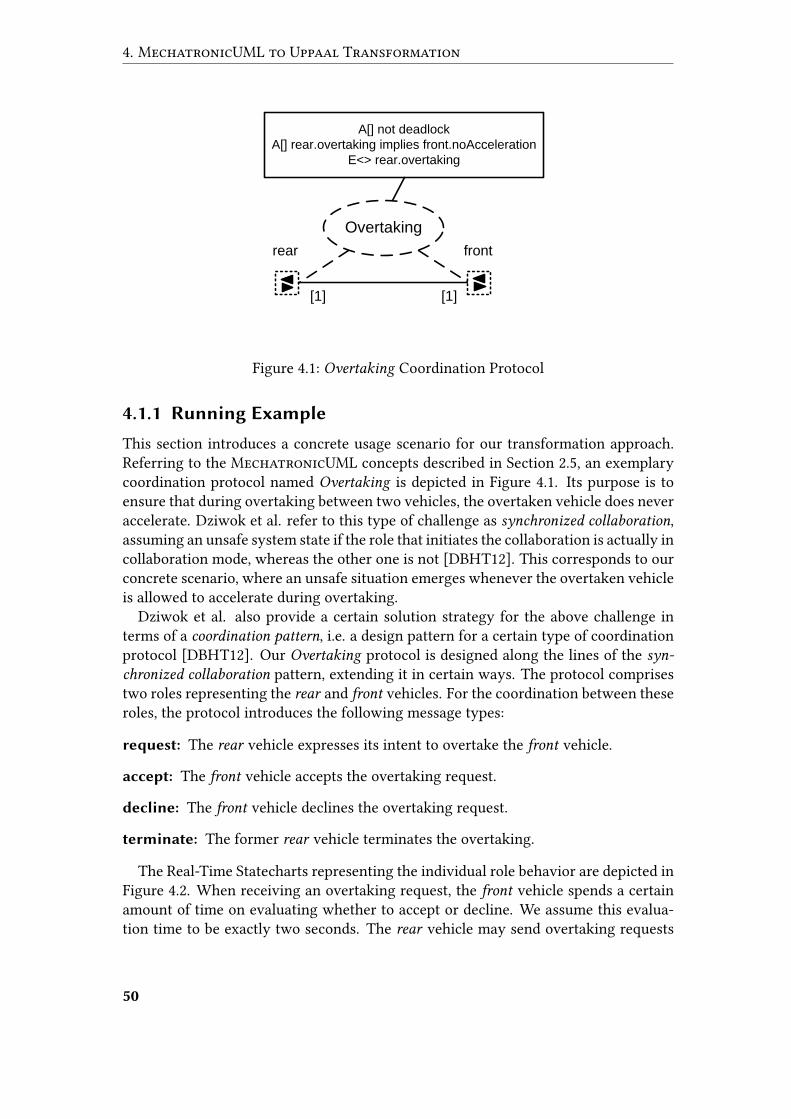
4. MechatronicUML to Uppaal Transformation
rear front
[1] [1]
Overtaking
A[] not deadlock
A[] rear.overtaking implies front.noAcceleration
E<> rear.overtaking
Figure 4.1: Overtaking Coordination Protocol
4.1.1 Running Example
This section introduces a concrete usage scenario for our transformation approach.Referring to the MechatronicUML concepts described in Section 2.5, an exemplarycoordination protocol named Overtaking is depicted in Figure 4.1. Its purpose is toensure that during overtaking between two vehicles, the overtaken vehicle does neveraccelerate. Dziwok et al. refer to this type of challenge as synchronized collaboration,assuming an unsafe system state if the role that initiates the collaboration is actually incollaboration mode, whereas the other one is not [DBHT12]. This corresponds to ourconcrete scenario, where an unsafe situation emerges whenever the overtaken vehicleis allowed to accelerate during overtaking.
Dziwok et al. also provide a certain solution strategy for the above challenge interms of a coordination pattern, i.e. a design pattern for a certain type of coordinationprotocol [DBHT12]. Our Overtaking protocol is designed along the lines of the syn-
chronized collaboration pattern, extending it in certain ways. The protocol comprisestwo roles representing the rear and front vehicles. For the coordination between theseroles, the protocol introduces the following message types:
request: The rear vehicle expresses its intent to overtake the front vehicle.
accept: The front vehicle accepts the overtaking request.
decline: The front vehicle declines the overtaking request.
terminate: The former rear vehicle terminates the overtaking.
The Real-Time Statecharts representing the individual role behavior are depicted inFigure 4.2. When receiving an overtaking request, the front vehicle spends a certainamount of time on evaluating whether to accept or decline. We assume this evalua-tion time to be exactly two seconds. The rear vehicle may send overtaking requests
50
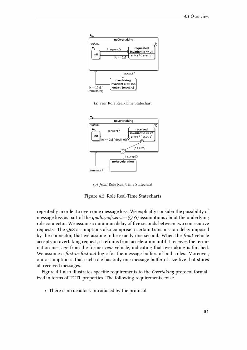
4.1 Overview
noOvertaking
requested
invariant c <= 2s
entry / {reset: c}
accept /
region1
init
/ request()
[c >= 2s]
1
overtaking
invariant c <= 10s
entry / {reset: c}[c>=10s] /
terminate()
(a) rear Role Real-Time Statechart
noOvertaking
received
invariant c <= 2s
entry / {reset: c}
/ accept()
region1
init
request /
[c >= 2s] / decline()
1
noAcceleration
terminate /
[c >= 2s]
2
1
(b) front Role Real-Time Statechart
Figure 4.2: Role Real-Time Statecharts
repeatedly in order to overcome message loss. We explicitly consider the possibility ofmessage loss as part of the quality-of-service (QoS) assumptions about the underlyingrole connector. We assume a minimum delay of �ve seconds between two consecutiverequests. The QoS assumptions also comprise a certain transmission delay imposedby the connector, that we assume to be exactly one second. When the front vehicleaccepts an overtaking request, it refrains from acceleration until it receives the termi-nation message from the former rear vehicle, indicating that overtaking is �nished.We assume a �rst-in-�rst-out logic for the message bu�ers of both roles. Moreover,our assumption is that each role has only one message bu�er of size �ve that storesall received messages.
Figure 4.1 also illustrates speci�c requirements to the Overtaking protocol formal-ized in terms of TCTL properties. The following requirements exist:
• There is no deadlock introduced by the protocol.
51
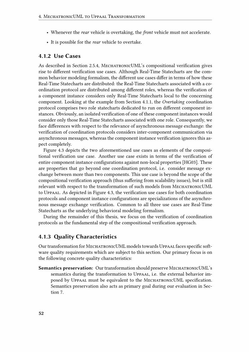
4. MechatronicUML to Uppaal Transformation
• Whenever the rear vehicle is overtaking, the front vehicle must not accelerate.
• It is possible for the rear vehicle to overtake.
4.1.2 Use Cases
As described in Section 2.5.4, MechatronicUML’s compositional veri�cation givesrise to di�erent veri�cation use cases. Although Real-Time Statecharts are the com-mon behavior modeling formalism, the di�erent use cases di�er in terms of how theseReal-Time Statecharts are distributed: the Real-Time Statecharts associated with a co-ordination protocol are distributed among di�erent roles, whereas the veri�cation ofa component instance considers only Real-Time Statecharts local to the concerningcomponent. Looking at the example from Section 4.1.1, the Overtaking coordinationprotocol comprises two role statecharts dedicated to run on di�erent component in-stances. Obviously, an isolated veri�cation of one of these component instances wouldconsider only those Real-Time Statecharts associated with one role. Consequently, weface di�erences with respect to the relevance of asynchronous message exchange: theveri�cation of coordination protocols considers inter-component communication viaasynchronous messages, whereas the component instance veri�cation ignores this as-pect completely.
Figure 4.3 depicts the two aforementioned use cases as elements of the composi-tional veri�cation use case. Another use case exists in terms of the veri�cation ofentire component instance con�gurations against non-local properties [HG03]. Theseare properties that go beyond one coordination protocol, i.e. consider message ex-change between more than two components. This use case is beyond the scope of thecompositional veri�cation approach (thus su�ering from scalability issues), but is stillrelevant with respect to the transformation of such models from MechatronicUMLto Uppaal. As depicted in Figure 4.3, the veri�cation use cases for both coordinationprotocols and component instance con�gurations are specializations of the asynchro-nous message exchange veri�cation. Common to all three use cases are Real-TimeStatecharts as the underlying behavioral modeling formalism.
During the remainder of this thesis, we focus on the veri�cation of coordinationprotocols as the fundamental step of the compositional veri�cation approach.
4.1.3 �ality Characteristics
Our transformation forMechatronicUML models towardsUppaal faces speci�c soft-ware quality requirements which are subject to this section. Our primary focus is onthe following concrete quality characteristics:
Semantics preservation: Our transformation should preserveMechatronicUML’ssemantics during the transformation to Uppaal, i.e. the external behavior im-posed by Uppaal must be equivalent to the MechatronicUML speci�cation.Semantics preservation also acts as primary goal during our evaluation in Sec-tion 7.
52
4.1 Overview
Fujaba
Verify
Asynchronous Message Exchange
MECHATRONICUML
Engineer
Verify
Coordination Protocol
Verify
Component Instance
Verify
Component Instance Configuration
Verify
Real-Time Statecharts
Compositional
Verification
<<include>>
<<include>>
Figure 4.3: Di�erent Veri�cation Use Cases
Uppaal interoperability: The target model representation must enable o�hand pro-cessing by Uppaal, which relies on an XML-based input �le format.
Transformation traceability: Focusing on a reverse transformation for counter-example traces back from Uppaal to MechatronicUML, traceability (cf. Sec-tion 2.1.5) of the initial model transformation towards Uppaal is an essentialrequirement.
In the following, we describe relevant quality characteristics for the transformationfrom MechatronicUML to Uppaal that play a minor part:
Flexibility w.r.t. compositional verification: MechatronicUML’s compositionalveri�cation approach gives rise to various veri�cation use cases stated in Section4.1.2, corresponding to di�erent types of MechatronicUML model elements toanalyze. We focus on a certain �exibility of our transformation with respect tothese use cases.
Verification performance: The runtime of the transformation towards Uppaal, aswell as the model checking time required by Uppaal are both indicators for theoverall veri�cation performance. Whereas e�ciency plays a vital role in modelchecking, we address functional requirements of the transformation �rst, andthus do not primarily focus on the veri�cation performance.
Modularity: By composing our transformation and distributing it across multiplemodules, we support reuse of speci�c transformation aspects in di�erent set-tings. We therefore aim at reducing the transformation e�ort towards otherveri�cation or simulation platforms (cf. Section 3.1).
4.1.4 Transformation Aspects
Uppaal provides a general-purpose veri�cation engine, underlying fundamental mod-eling concepts for real-time reactive systems. In doing so, its range of modeling func-tions di�ers from MechatronicUML in terms of two basic issues:
53
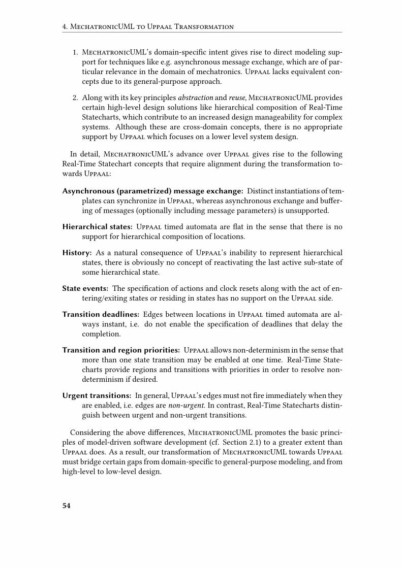
4. MechatronicUML to Uppaal Transformation
1. MechatronicUML’s domain-speci�c intent gives rise to direct modeling sup-port for techniques like e.g. asynchronous message exchange, which are of par-ticular relevance in the domain of mechatronics. Uppaal lacks equivalent con-cepts due to its general-purpose approach.
2. Along with its key principles abstraction and reuse, MechatronicUML providescertain high-level design solutions like hierarchical composition of Real-TimeStatecharts, which contribute to an increased design manageability for complexsystems. Although these are cross-domain concepts, there is no appropriatesupport by Uppaal which focuses on a lower level system design.
In detail, MechatronicUML’s advance over Uppaal gives rise to the followingReal-Time Statechart concepts that require alignment during the transformation to-wards Uppaal:
Asynchronous (parametrized) message exchange: Distinct instantiations of tem-plates can synchronize in Uppaal, whereas asynchronous exchange and bu�er-ing of messages (optionally including message parameters) is unsupported.
Hierarchical states: Uppaal timed automata are �at in the sense that there is nosupport for hierarchical composition of locations.
History: As a natural consequence of Uppaal’s inability to represent hierarchicalstates, there is obviously no concept of reactivating the last active sub-state ofsome hierarchical state.
State events: The speci�cation of actions and clock resets along with the act of en-tering/exiting states or residing in states has no support on the Uppaal side.
Transition deadlines: Edges between locations in Uppaal timed automata are al-ways instant, i.e. do not enable the speci�cation of deadlines that delay thecompletion.
Transition and region priorities: Uppaal allows non-determinism in the sense thatmore than one state transition may be enabled at one time. Real-Time State-charts provide regions and transitions with priorities in order to resolve non-determinism if desired.
Urgent transitions: In general, Uppaal’s edges must not �re immediately when theyare enabled, i.e. edges are non-urgent. In contrast, Real-Time Statecharts distin-guish between urgent and non-urgent transitions.
Considering the above di�erences, MechatronicUML promotes the basic princi-ples of model-driven software development (cf. Section 2.1) to a greater extent thanUppaal does. As a result, our transformation of MechatronicUML towards Uppaalmust bridge certain gaps from domain-speci�c to general-purpose modeling, and fromhigh-level to low-level design.
54

4.1 Overview
MECHATRONICUML to UPPAAL Transformation
MECHATRONICUML Rephrasing UPPAAL Translation
An
alys
is L
evel
Des
ign
Lev
el
MECHATRONICUML Model
DeadlineNormalization
<<M2M>>
Composite Transition
Normalization<<M2M>>
Hierarchy Normalization
<<M2M>>
Migration<<M2M>>
XML Synthesis<<M2T>>
UPPAAL XML File
Figure 4.4: Action Steps of the Transformation from MechatronicUML to Uppaal
4.1.5 Transformation Approach
To address the challenges described in Section 4.1.4, we apply a pipelining approach oftransforming a MechatronicUML-based model to Uppaal in an incremental manner.As depicted in Figure 4.4, we introduce a chain of sub-transformations that handledistinct transformation aspects. Referring to the model-driven software developmentparadigm discussed in Section 2.1, we apply its underlying transformation concept notfor a connection to a speci�c platform, but to integrate with a dedicated veri�cationtool in terms of the Uppaal model checker.
More precisely, we consider the migration fromMechatronicUML toUppaal as anindividual translation aspect (cf. Section 2.1.5) to be carried out by a model-to-modeltransformation towards the end of the chain. Prior to that, we align the formalismswith respect to the incompatible Real-Time Statechart aspects introduced in Section4.1.4. We carry out these adjustments by means of rephrasing model-to-model trans-formations (cf. Section 2.1.5) at the level of MechatronicUML. These initial transfor-mation steps meet the criteria of both normalization (reducing the amount of syntacticfeatures) and refactoring (preserving the semantics).
We declare an amount of three refactoring normalization steps to be carried out bymodel-to-model transformations at the level of MechatronicUML. We do not applythe concept of in-place transformation (cf. Section 2.1.5), since users are usually inter-ested in leaving source models unchanged. The aspects we consider are (1) deadlines,(2) transitions originating from composite states, and (3) hierarchical states. Onlythe subsequent model-to-model transformation performs the migration from Mecha-tronicUML to Uppaal, relying on an Uppaal-speci�c target meta-model. Finally, theUppaal-based model is subject to a serialization process. It synthesizes a text �le thatcomplies with Uppaal’s XML-based input format.
For the normalization of deadlines, we will apply a concept by Giese and Burmesteroriginally presented in [GB03], and later applied by Hirsch [Hir04]. Our hierarchy nor-
55
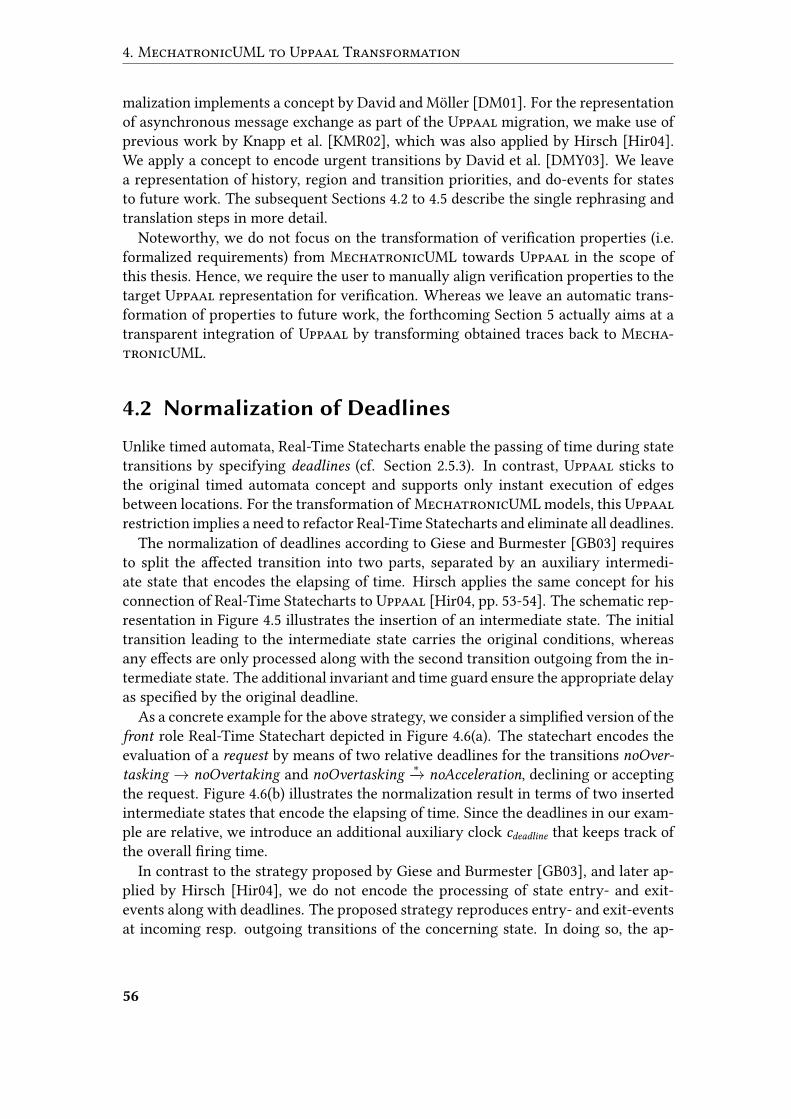
4. MechatronicUML to Uppaal Transformation
malization implements a concept by David and Möller [DM01]. For the representationof asynchronous message exchange as part of the Uppaal migration, we make use ofprevious work by Knapp et al. [KMR02], which was also applied by Hirsch [Hir04].We apply a concept to encode urgent transitions by David et al. [DMY03]. We leavea representation of history, region and transition priorities, and do-events for statesto future work. The subsequent Sections 4.2 to 4.5 describe the single rephrasing andtranslation steps in more detail.
Noteworthy, we do not focus on the transformation of veri�cation properties (i.e.formalized requirements) from MechatronicUML towards Uppaal in the scope ofthis thesis. Hence, we require the user to manually align veri�cation properties to thetarget Uppaal representation for veri�cation. Whereas we leave an automatic trans-formation of properties to future work, the forthcoming Section 5 actually aims at atransparent integration of Uppaal by transforming obtained traces back to Mecha-tronicUML.
4.2 Normalization of Deadlines
Unlike timed automata, Real-Time Statecharts enable the passing of time during statetransitions by specifying deadlines (cf. Section 2.5.3). In contrast, Uppaal sticks tothe original timed automata concept and supports only instant execution of edgesbetween locations. For the transformation of MechatronicUML models, this Uppaalrestriction implies a need to refactor Real-Time Statecharts and eliminate all deadlines.
The normalization of deadlines according to Giese and Burmester [GB03] requiresto split the a�ected transition into two parts, separated by an auxiliary intermedi-ate state that encodes the elapsing of time. Hirsch applies the same concept for hisconnection of Real-Time Statecharts to Uppaal [Hir04, pp. 53-54]. The schematic rep-resentation in Figure 4.5 illustrates the insertion of an intermediate state. The initialtransition leading to the intermediate state carries the original conditions, whereasany e�ects are only processed along with the second transition outgoing from the in-termediate state. The additional invariant and time guard ensure the appropriate delayas speci�ed by the original deadline.
As a concrete example for the above strategy, we consider a simpli�ed version of thefront role Real-Time Statechart depicted in Figure 4.6(a). The statechart encodes theevaluation of a request by means of two relative deadlines for the transitions noOver-tasking → noOvertaking and noOvertasking
∗−→ noAcceleration, declining or acceptingthe request. Figure 4.6(b) illustrates the normalization result in terms of two insertedintermediate states that encode the elapsing of time. Since the deadlines in our exam-ple are relative, we introduce an additional auxiliary clock cdeadline that keeps track ofthe overall �ring time.
In contrast to the strategy proposed by Giese and Burmester [GB03], and later ap-plied by Hirsch [Hir04], we do not encode the processing of state entry- and exit-events along with deadlines. The proposed strategy reproduces entry- and exit-eventsat incoming resp. outgoing transitions of the concerning state. In doing so, the ap-
56
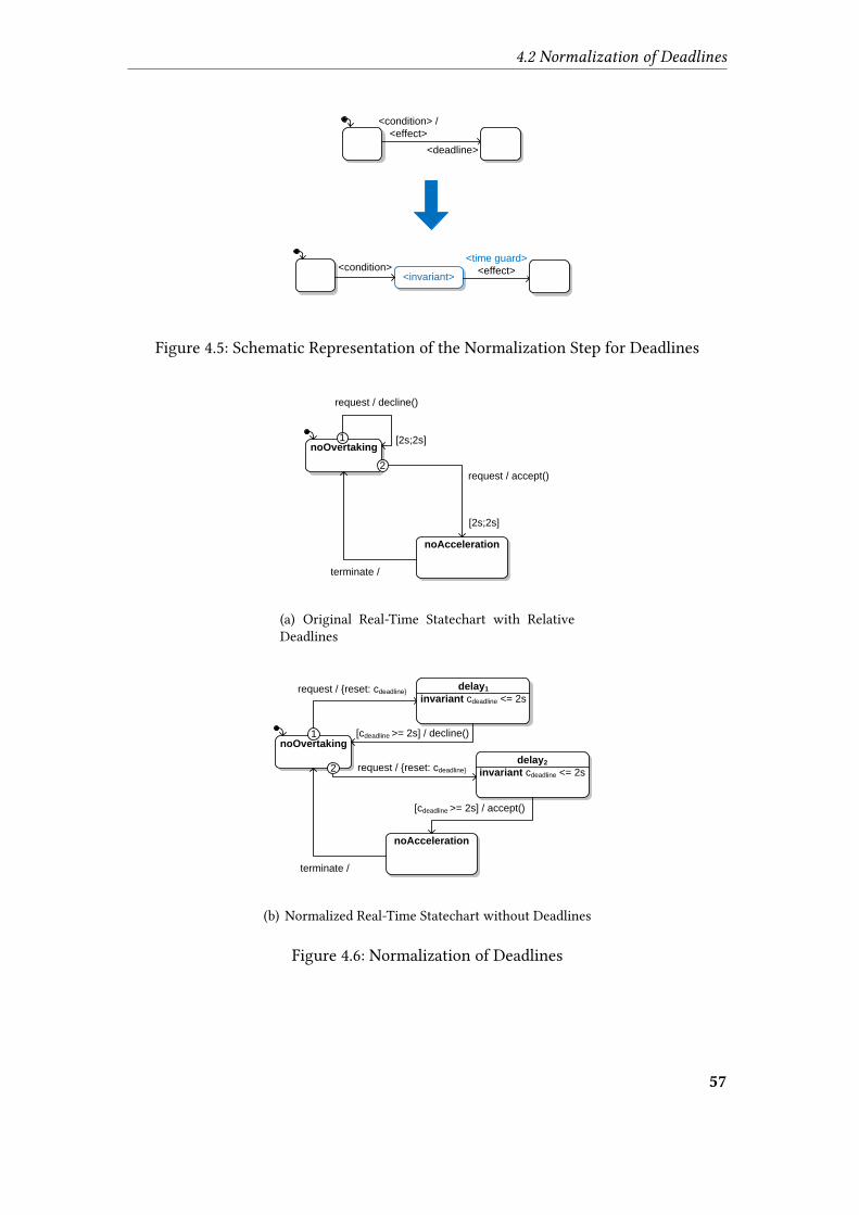
4.2 Normalization of Deadlines
<deadline>
<invariant>
<time guard>
<effect><condition>
<condition> /
<effect>
Figure 4.5: Schematic Representation of the Normalization Step for Deadlines
noOvertaking
request / decline()
noAcceleration
terminate /
[2s;2s]
request / accept()
[2s;2s]
1
2
(a) Original Real-Time Statechart with RelativeDeadlines
noOvertaking
request / {reset: cdeadline}
noAcceleration
terminate /
delay1
invariant cdeadline <= 2s
[cdeadline >= 2s] / decline()
delay2
invariant cdeadline <= 2srequest / {reset: cdeadline}
[cdeadline >= 2s] / accept()
2
1
(b) Normalized Real-Time Statechart without Deadlines
Figure 4.6: Normalization of Deadlines
57
4. MechatronicUML to Uppaal Transformation
proach does not consider the fact that state activation and deactivation may also hap-pen implicitly without �ring direct incoming or outgoing transitions. On the one hand,a state may be activated by a composite transition leading to one of its super-states,whereas on the other hand, deactivation may be triggered by a composite transitionoutgoing from one of its super-states. We therefore handle the execution of stateentry- and exit-events as part of the hierarchy elimination for Real-Time Statechartsdescribed in the forthcoming Section 4.4.
4.3 Normalization of Composite Transitions
The forthcoming Section 4.4 describes the refactoring of Real-Time Statecharts withthe aim of �attening hierarchical states. We will apply a �attening concept by Davidand Möller [DM01] that operates on the Hierarchical Timed Automata formalism in-troduced in Section 2.2.4. Applying the approach to MechatronicUML’s Real-TimeStatecharts, we focus on reducing its complexity by not considering composite transi-tions explicitly, i.e. transitions connecting to composite states. Instead, we make useof the circumstance that a composite transition can be rolled out in terms of multipleordinary transitions, which enables us to eliminate composite transitions by meansof a dedicated normalization step. As a result, we obtain a reduced complexity of theforthcoming hierarchy normalization. Speaking in terms of Real-Time Statecharts, itwill consider only transitions connecting to simple (i.e. non-hierarchical) states andentry- or exit-points.
Basically, a transition connecting to a composite state is an abbreviation for possiblynumerous transitions connecting to speci�c sub-states. More precisely, a transitionleading to a composite state activates all its direct initial sub-states, i.e. representsan entry-point with an outgoing transition to each of these. A transition originatingfrom a composite state is independent from its sub-states, i.e. it represents an exit-point with an incoming transition from every single sub-state.
We carry out the required normalization by expanding the above abbreviations forcomposite transitions. Hence, we introduce entry- and exit-points in order to enabletransitions to connect to speci�c sub-states explicitly. Figure 4.7 illustrates the basicnormalization strategy for incoming and outgoing composite transitions. Noteworthy,the direct sub-states of a composite state can be composite states as well, i.e. requirein-depth application of the normalization approach.
4.3.1 Incoming Composite Transitions
A transition leading to a composite state activates all its direct and indirect sub-stateswhich are considered initially active. We obtain the set of states which are initiallyactive on activation of a state S by starting with the singleton {S}, recursively addingthe initial sub-states of each element to the set itself. The set of initially active stateson execution of the composite transition overtaking → noOvertaking in Figure 4.8(a)is {noOvertaking, init}.
58

4.3 Normalization of Composite Transitions
Figure 4.7: Schematic Representation of the Normalization Step for CompositeTransitions
To represent the activation of all initially active states, we attach an additional entry-point per composite transition to each composite state in our set. The only compositestate in our exemplary set is noOvertaking. We connect these additional entry-pointsby transitions, such that on activation of a composite state via the additional entry-point, it delegates to all its sub-states that are part of our set.
If such a sub-state is simple, the transition leads to the sub-state itself as depictedfor state init in Figure 4.8(b). If a sub-state is in turn a composite state, the transition’starget is the composite state’s additional entry-point.
4.3.2 Outgoing Composite Transitions
A transition originating from a composite state �res independently from its currentlyactive sub-states. Hence, the set of states that requires deactivation is simply the com-posite state itself including all its direct and indirect sub-states. Referring to the ex-ample from Figure 4.8(a), our state set for the transition noOvertaking→ overtaking is{noOvertaking, init, requested}.
To encode the deactivation, we attach an additional exit-point to each compositestate in our set. We connect these additional exit-points by transitions, connectingto a composite state’s exit-point from all its sub-states. If a sub-state is simple, theaccording transition’s source is the state itself. This is the case for the states idle andrequested in Figure 4.8(b). If some sub-state is composite itself, the according transitionoriginates from this state’s additional exit-point.
59
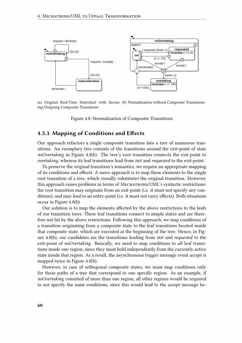
4. MechatronicUML to Uppaal Transformation
noOvertaking
request / decline()
noAcceleration
terminate /
[2s;2s]
request / accept()
[2s;2s]
1
2
(a) Original Real-Time Statechart with Incom-ing/Outgoing Composite Transitions
noOvertaking
{reset: c}
region1 1
overtaking
invariant c <= 10s[c>=10s]
1
requested
invariant c <= 2sinit
/ request() {reset: c}
[c >= 2s]
accept // terminate()
accept /
122
1
(b) Normalization without Composite Transitions
Figure 4.8: Normalization of Composite Transitions
4.3.3 Mapping of Conditions and E�ects
Our approach refactors a single composite transition into a tree of numerous tran-sitions. An exemplary tree consists of the transitions around the exit-point of statenoOvertaking in Figure 4.8(b). The tree’s root transition connects the exit-point toovertaking, whereas its leaf transitions lead from init and requested to the exit-point.
To preserve the original transition’s semantics, we require an appropriate mappingof its conditions and e�ects. A naive approach is to map these elements to the singleroot transition of a tree, which visually substitutes the original transition. However,this approach raises problems in terms of MechatronicUML’s syntactic restrictions:the root transition may originate from an exit-point (i.e. it must not specify any con-ditions), and may lead to an entry-point (i.e. it must not carry e�ects). Both situationsoccur in Figure 4.8(b)
Our solution is to map the elements a�ected by the above restrictions to the leafsof our transition trees. These leaf transitions connect to simple states and are there-fore not hit by the above restrictions. Following this approach, we map conditions ofa transition originating from a composite state to the leaf transitions located insidethat composite state, which are executed at the beginning of the tree. Hence, in Fig-ure 4.8(b), our candidates are the transitions leading from init and requested to theexit-point of noOvertaking. Basically, we need to map conditions to all leaf transi-tions inside one region, since they must hold independently from the currently activestate inside that region. As a result, the asynchronous trigger message event accept ismapped twice in Figure 4.8(b).
However, in case of orthogonal composite states, we must map conditions onlyfor those paths of a tree that correspond to one speci�c region. As an example, ifnoOvertaking consisted of more than one region, all other regions would be requiredto not specify the same conditions, since this would lead to the accept message be-
60
4.4 Normalization of Hierarchical States
ing awaited more than once to trigger the deactivation of state noOvertaking. SinceMechatronicUML applies joint exiting of orthogonal regions, all other regions areimplicitly a�ected by the conditions that one region speci�es for the deactivation. Wechose the highest-priority region of an orthogonal composite state to be responsiblefor the mapping of conditions.
Analogously, we represent the e�ects of a transition leading to a composite state atthe leaf transitions inside that state, which are executed at the end of the tree. As anexample, the transition connecting the entry-point in Figure 4.8(b) to state init raisesthe terminate message event. Again, we charge only the highest priority region ofan orthogonal composite state with the mapping of e�ects. Since there is only oneinitially active state per region, the e�ects will be mapped to exactly one transition.
4.3.4 Prioritization of Additional Transitions
The above normalization strategy introduces a certain amount of additional transi-tions within Real-Time Statecharts. To ensure semantics preservation, the prioritiesof these transitions need to be set accordingly.
In MechatronicUML, transitions originating from composite states have prece-dence over lower-level transitions originating from a sub-state [BBB+12, p. 35]. InFigure 4.8(a), the transition noOvertaking→ overtaking has precedence over requested→ init if both are enabled. To encode this precedence relation when eliminating com-posite transitions, the additional generated transitions starting at simple states mustobtain a higher priority than any pre-existing user-de�ned transitions. In Figure 4.8(b),this strategy leads to the new maximum priority 2 for the new transitions connectingthe states init and requested to the exit-point. In addition, higher-level composite tran-sitions must obtain a higher priority than lower-level composite transitions.
We ensure these results by mapping composite transitions in a speci�c order, suc-cessively increasing the maximum priority among all transitions originating from thesame simple state. We map lower-level composite transitions �rst, and process tran-sitions on the same hierarchy level by increasing priority. Hence, we ensure that thehighest-level composite transitions will obtain the �nal maximum priority.
For additional transitions starting at an entry-point, we simply apply the priorityof its target region. This strategy ensures locally unique priorities, since the regionpriorities are assumed to be locally unique as well, and there is never more than onevertex per region that an entry-point connects to. New transitions originating fromexit-points will always obtain the priority 1, since exit-points do not support morethan one outgoing transition.
4.4 Normalization of Hierarchical States
As described in Section 2.2, Uppaal supports only �at timed automata with non-hierarchical states. Multiple timed automata can, however, be executed in parallelas part of a network of timed automata. To be able to verify Real-Time Statecharts
61

4. MechatronicUML to Uppaal Transformation
Figure 4.9: Schematic Representation of the Normalization Step for Hierarchical States
using Uppaal, we apply a �attening concept by David and Möller originally proposedin [DM01] which is based on three transformation phases. We carry out this con-cept at the level of MechatronicUML, i.e. apply it in terms of another refactoringnormalization step that reproduces Real-Time Statecharts semantically equivalent.
4.4.1 Phase 1: Construction of flat Real-Time Statecharts
The basic approach is to represent hierarchy by means of orthogonality: a dedicatedinitial phase maps each (embedded or non-embedded) composition of exclusive statesto an individual �at automaton. Hence, automata arise from the topmost states aswell as from every embedded set of sub-states. Transferring the approach to Mecha-tronicUML, the initial phase transforms each embedded or non-embedded Real-TimeStatechart to a �at standalone Real-Time Statechart. Figure 4.9 illustrates this ap-proach, yielding an orthogonal composition of the �at Real-Time Statecharts.
Idle States
Given the basic approach of refactoring hierarchy into orthogonality, the major chal-lenge is to represent the case that some embedded composition of states is idle dueto the embedding parent state being inactive. David and Möller solve this problem byappending speci�c idle states to each �at automaton they generate. The activity of anidle state represents the case that none of the a�ected states is active due to the parentstate being itself inactive.
As a concrete example, we consider the hierarchical Real-Time Statechart from Fig-ure 4.10(a), nesting two Real-Time Statecharts. The resulting parallel compositionconsisting of two �at Real-Time Statecharts is depicted in Figures 4.10(b) and 4.10(c).
62

4.4 Normalization of Hierarchical States
noOvertaking
requested
invariant c <= 2s
region1
init
/ request() {reset: c}
[c >= 2s]
1
/ terminate()
overtaking
invariant c <= 10s[c>=10s]
(a) Extract of the Original Hierarchical Real-TimeStatechart
noOvertaking
overtaking
invariant c <= 10s
enterrear!
c
[c>=10s]
(b) Flat Real-Time Stat-echart Representing theHigher Level
requested
invariant c <= 2sinit
/ request() {reset: c} {trigger1-=1, trigger0+=1}
[c >= 2s] / {trigger1+=1, trigger0-=1}
idle
enterrear? / terminate() {trigger1+=1}
(c) Flat Real-Time Statechart Representing the Lower Level
Figure 4.10: Normalization of Hierarchical States
Here, the states init and requested are supplemented by a speci�c idle state in order torepresent the case that noOvertaking is inactive.
Auxiliary Synchronization
The parallelized composition of automata must ensure that some composite state isconsidered active if and only if a speci�c number of sub-states is active. For instance,noOvertaking is active if and only if one of its sub-states is also active. To ensure com-pliance with this consistency rule, the activation and deactivation of composite statesare carried out on top of speci�c auxiliary synchronization channels, named enter andexit in our example. On activation or deactivation of a composite state, synchroniza-tions on these channels ensure consistency by synchronizing two transitions. One
63
4. MechatronicUML to Uppaal Transformation
transition corresponds to a transition originally inside the composite state, whereasthe other one represents an outer transition.
As an example, the transitions overtaking ∗−→ noOvertaking in Figure 4.10(b) are in-divisible from the transition idle → init due to the synchronization on channel en-ter. The synchronization causes the state init to be activated on every activation ofstate noOvertaking. The approach ensures non-interruptible activation of compositestates by relying on so called committed states as an extension to Real-Time State-charts. This special type of state implies a) progress without passing of time, and b)precedence over other ordinary transitions. An exemplary committed state is part ofthe chain overtaking
∗−→ noOvertaking in Figure 4.10(b). Analogously, the deactivationof the composite state noOvertaking corresponds to the transitions noOvertaking
∗−→overtaking, which synchronize on channel exit.
The above approach of synchronizing an outer transition with exactly one innertransition works only in case of one embedded region. Orthogonal composite stateswith more than one region require a more sophisticated process of activation anddeactivation, since more than one region must participate. David and Möller pro-vide a solution in terms of an additional automaton for each orthogonal compositestate, that is in charge of delegating the activation and deactivation to all embeddedregions [DM01]. Projecting this concept to MechatronicUML, each orthogonal com-posite state gives rise to an additional �at Real-Time Statechart.
History
MechatronicUML supports the speci�cation of shallow history inside Real-TimeStatecharts [BBB+12, pp. 38-39]. This concept allows to automatically restore the lastactive sub-state con�guration on reactivation of a composite state. As a natural conse-quence of Uppaal’s missing support for hierarchy, it does also not provide any historymechanism. Thus, history in Real-Time Statecharts must be subject to normalizationin order to represent the desired behavior at the level of Uppaal. David et al. givean outline of a mapping approach for history towards Uppaal in [DMY03, p. 26].Wedisregard history for the current state of our transformation towardsUppaal. Prospec-tive support for history could be part of the hierarchy normalization, or carried outin terms of another standalone normalization step. However, any implementation re-quires certain clari�cations with respect to clocks and variables local to the respectiveReal-Time Statechart. It is currently unclear whether the values of clocks or variablesare subject to history as well, i.e. should be restored or not.
Kicko�
The �attening approach by David and Möller [DM01] comprises a dedicated kicko�
automaton. This automaton is necessary since the generated idle states act as ini-tial states [DM01, p. 17]. Hence, an activation of all initially active states must takeplace before the system actually starts to run. A kicko� automaton comprises a chainof edges that provide synchronizations over speci�c enter channels. These synchro-
64
4.4 Normalization of Hierarchical States
nizations trigger the activation of the topmost states. The edges inside the kicko�
automaton are connected via committed states, i.e. the activation takes place directlyafter the system start without consuming time.
Applying the �attening approach by David and Möller [DM01] to Real-Time State-charts, we refrain from the above initialization procedure carried out at runtime. In-stead, we identify exactly those sets that are initially active and declare them as initialinside their parent Real-Time Statecharts. Hence, our approach weakens the state-ment that all idle states are initially active: this only holds for embedded Real-TimeStatecharts which are actually inactive at the beginning of the execution.
4.4.2 Phase 2: Handling Composite State Deactivation
Transitions may only deactivate composite states via exit-points under speci�c condi-tions. These conditions basically correspond to the activity of speci�c sub-states thatconnect to the respective exit-point. For example, the composite state noOvertaking
in Figure 4.11(a) may be deactivated via the exit-point if one of the sub-states init orrequested is active, since both connect to the exit-point. Complexity arises in termsof “cascades” [DM01] of exit-points, i.e. exit-points connecting to other exit-points,resulting in chains of transitions between exit-points over multiple hierarchy levels.Cascading exits can drastically increase the number of sub-state con�gurations thatenable the deactivation of a composite state via an exit-point, since every hierarchylevel corresponds to a re�nement. We apply the basic approach for the representa-tion of composite state deactivation by David and Möller [DM01], who address thedistinctiveness of the issue in terms of a dedicated second phase of their �atteningalgorithm.
Every sub-state con�guration that enables composite state deactivation is basicallycharacterized by the activity of speci�c simple, i.e. non-hierarchical states on the low-est hierarchy level. On our example, the relevant simple states are init and requested.The activity of certain simple states enables certain connected exit-points, just as bothinit and requested enable the deactivation via the exit-point in Figure 4.11(a). In caseof a cascade, enabled exit-points may enable other exit-points according to their tran-sition connections. Finally, this may lead to one enabled exit-point which is at the endof a cascade of exit-points, i.e. which does not connect to another exit-point. Davidand Möller refer to this as the root exit-point [DM01]. Obviously, the exit-point ofstate noOvertaking is the root exit-point in our example, since it connects to a simplestate.
Join Trees
There is a pressing need to identify exactly those sub-state con�gurations that enabledeactivation of a composite state via a certain root exit-point. We adopt a concept byDavid and Möller to keep track of these sub-state con�gurations in terms of so calledjoin trees [DM01]. Basically, a join tree is a data structure to represent speci�c sub-state con�gurations that enable a composite state deactivation via some exit-point. For
65
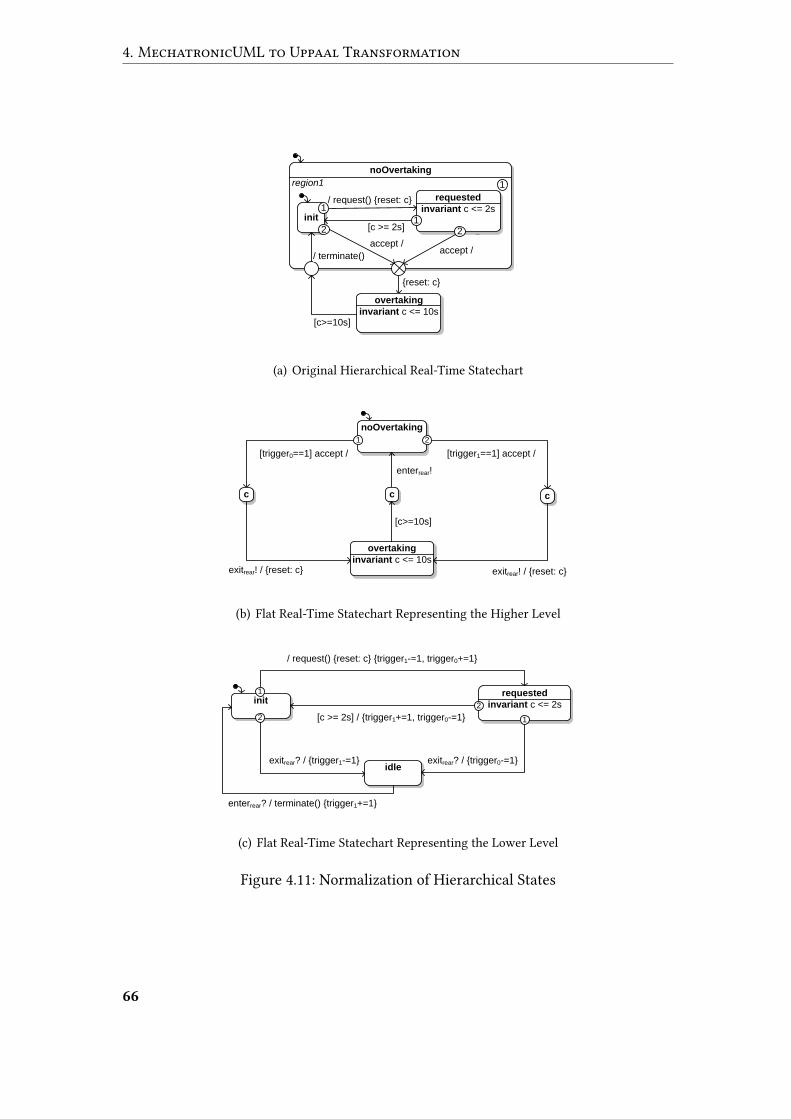
4. MechatronicUML to Uppaal Transformation
noOvertaking
{reset: c}
region1 1
overtaking
invariant c <= 10s[c>=10s]
1
requested
invariant c <= 2sinit
/ request() {reset: c}
[c >= 2s]
accept // terminate()
accept /
122
1
(a) Original Hierarchical Real-Time Statechart
noOvertaking
[trigger1==1] accept /[trigger0==1] accept /
overtaking
invariant c <= 10s
1 2
cc
exitrear! / {reset: c}exitrear! / {reset: c}
enterrear!
c
[c>=10s]
(b) Flat Real-Time Statechart Representing the Higher Level
requested
invariant c <= 2sinit
/ request() {reset: c} {trigger1-=1, trigger0+=1}
[c >= 2s] / {trigger1+=1, trigger0-=1}
2
1
idleexitrear? / {trigger0-=1}
enterrear? / terminate() {trigger1+=1}
exitrear? / {trigger1-=1}
2 1
(c) Flat Real-Time Statechart Representing the Lower Level
Figure 4.11: Normalization of Hierarchical States
66
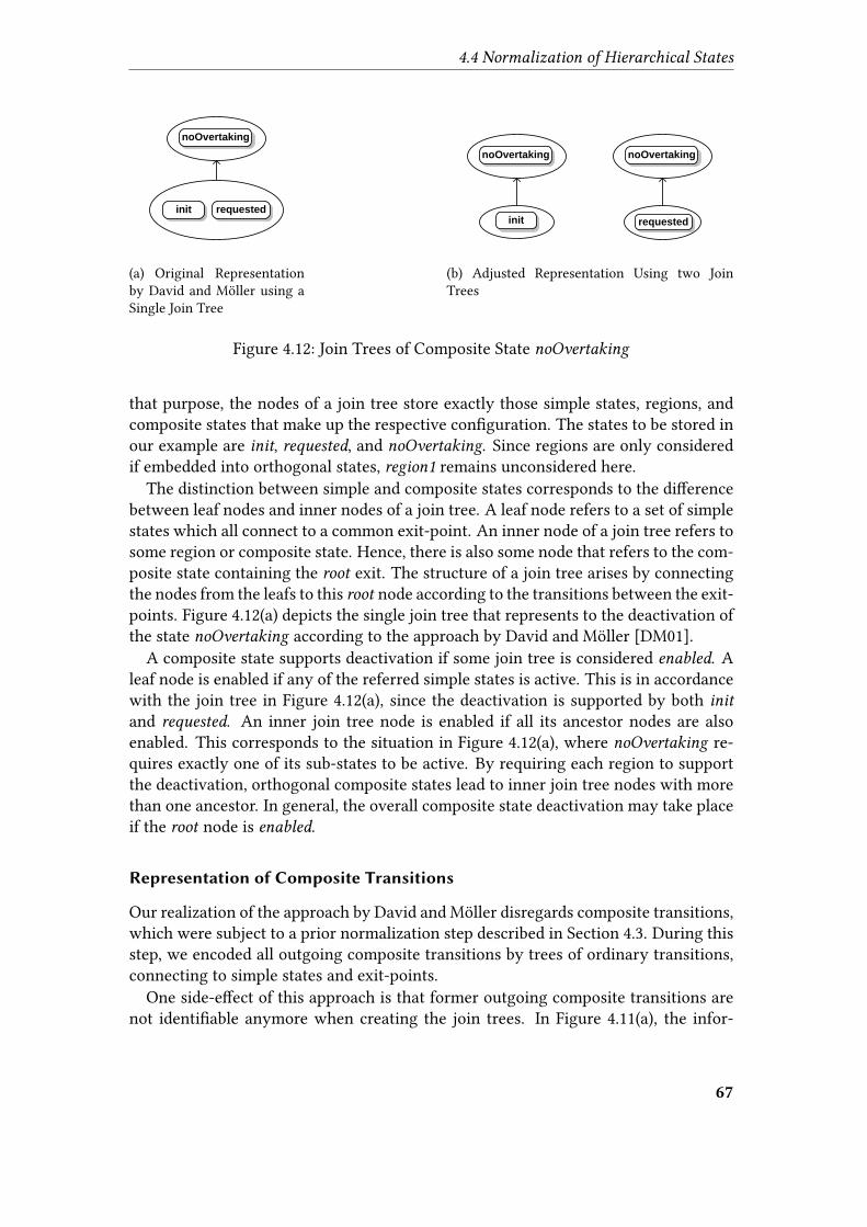
4.4 Normalization of Hierarchical States
noOvertaking
init requested
(a) Original Representationby David and Möller using aSingle Join Tree
noOvertaking
init requested
noOvertaking
(b) Adjusted Representation Using two JoinTrees
Figure 4.12: Join Trees of Composite State noOvertaking
that purpose, the nodes of a join tree store exactly those simple states, regions, andcomposite states that make up the respective con�guration. The states to be stored inour example are init, requested, and noOvertaking. Since regions are only consideredif embedded into orthogonal states, region1 remains unconsidered here.
The distinction between simple and composite states corresponds to the di�erencebetween leaf nodes and inner nodes of a join tree. A leaf node refers to a set of simplestates which all connect to a common exit-point. An inner node of a join tree refers tosome region or composite state. Hence, there is also some node that refers to the com-posite state containing the root exit. The structure of a join tree arises by connectingthe nodes from the leafs to this root node according to the transitions between the exit-points. Figure 4.12(a) depicts the single join tree that represents to the deactivation ofthe state noOvertaking according to the approach by David and Möller [DM01].
A composite state supports deactivation if some join tree is considered enabled. Aleaf node is enabled if any of the referred simple states is active. This is in accordancewith the join tree in Figure 4.12(a), since the deactivation is supported by both init
and requested. An inner join tree node is enabled if all its ancestor nodes are alsoenabled. This corresponds to the situation in Figure 4.12(a), where noOvertaking re-quires exactly one of its sub-states to be active. By requiring each region to supportthe deactivation, orthogonal composite states lead to inner join tree nodes with morethan one ancestor. In general, the overall composite state deactivation may take placeif the root node is enabled.
Representation of Composite Transitions
Our realization of the approach by David and Möller disregards composite transitions,which were subject to a prior normalization step described in Section 4.3. During thisstep, we encoded all outgoing composite transitions by trees of ordinary transitions,connecting to simple states and exit-points.
One side-e�ect of this approach is that former outgoing composite transitions arenot identi�able anymore when creating the join trees. In Figure 4.11(a), the infor-
67

4. MechatronicUML to Uppaal Transformation
mation that the transitions leading to the exit-point stem from the same compositetransition is not explicitly available.
As a consequence, we can’t easily apply the e�cient representation of multiple sim-ple states inside one single leaf node as depicted in Figure 4.12(a). The reason for thisinability is that the transitions connecting these states to the respective exit-point canin general specify di�erent conditions, which leads to serious di�erences between thenumerous sub-state con�gurations. In Figure 4.11(a), the transitions connecting thestates init and requested to the exit-point could easily specify di�erent trigger mes-sages, which would make it impossible to consider them in terms of a common jointree node. The information that they do actually not specify di�erent conditions (sinceboth arise from the same composite transition) is not explicitly available anymore dueto the prior normalization of composite transitions.
To support the general case of di�erent conditions along with the transitions leadingto the exit-point, we refrain from the e�cient representation that comprises multiplesimple states. Instead, we introduce numerous join trees with single-state leaf nodes,as depicted in Figure 4.12(b).
Trigger Variables
So far, join trees only encoded the di�erent sub-state con�gurations that enable com-posite state deactivation. A remaining challenge is to detect whether a composite statecan be deactivated (i.e. whether some root exit is considered enabled) on the automa-ton level.
David and Möller rely on so called trigger variables to tackle this problem [DM01].A trigger variable acts as an indicator for whether a composite state supports deacti-vation in its current internal sub-state con�guration. Each trigger variable representsexactly one of the join trees created before, i.e. the trigger variable’s value encodeswhether the root node is enabled. In order to do so, a variable keeps track of the sim-ple states inside the join tree being active or not, increasing the variable value on allincoming transitions and decreasing it on all outgoing transitions. In our example, thevariable trigger0 keeps track of whether requested is active or not. The incoming andoutgoing transitions of requested update trigger0 accordingly.
Only if requested is active (i.e. trigger0 is 1), noOvertaking can be exited via a chainof transitions noOvertaking ∗−→ overtaking. Such a chain of transitions comprises thedeactivations of all composite states and regions inside the join tree. It makes useof synchronizations on designated exit channels. The composite state noOvertaking
is the only one that requires deactivation in our example, whereas multiple a�ectedstates or regions would increase the length of the transition chain. Basically, the �rsttransition of the chain speci�es all conditions for the overall deactivation, whereasthe �nal transition carries out any speci�ed e�ects [DMY03]. As for the activationprocess, the usage of committed states ensures a non-interruptible deactivation.
68

4.4 Normalization of Hierarchical States
Bundled Representation of Flat Real-Time Statecharts
Noteworthy, our hierarchy normalization does not produce entirely �at Real-TimeStatecharts. We rather bundle multiple �at Real-Time Statecharts inside a commonorthogonal parent state, which is the only state in its Real-Time Statechart. This strat-egy enables us to
• store variables and operations as part of the common parent Real-Time State-chart in order to make them accessible from di�erent �at sub-statecharts,
• store synchronization channels as part of the common parent state, since thesechannels inherently serve for the synchronization of di�erent �at sub-statecharts,and to
• provide a single Real-Time Statechart that acts as top-level behavior speci�ca-tion for behavioral elements like coordination protocol roles.
The Real-Time Statechart in Figure 4.13 carries out the tasks mentioned above.It stores the shared trigger variables that are accessed by the �at sub-statecharts.The container state rear stores the auxiliary enter and exit synchronization channels,whereas the entire Real-Time Statechart acts as behavior of the rear role.
4.4.3 Phase 3: Avoiding Synchronization between Exclusive
Transitions
The usage of synchronization channels leaves room for loosely coupled transitions:the pairs of transitions that actually synchronize at runtime are unknown at designtime. This is caused by the fact that one channel gives rise to numerous pairs of tran-sitions, each of these specifying complementary synchronizations.
Among these may be transition pairs that can actually never synchronize. The rea-son is that, although specifying complementary synchronizations on the same chan-nel, the transitions can never �re at the same time. This situation applies to transi-tions on di�erent hierarchy levels, with a sub-state relation between the source statesof both transitions, i.e. the source state of one transition is a direct or indirect sub-state of the other transition’s source state. Hence, the outer transition represents adeactivation of its composite source state, whereas the inner transition retains the ac-tivity of the same composite state. Obviously, such pairs of transitions can never �resimultaneously, and thus can never be subject to synchronization.
A hierarchical state composition considers this restriction implicitly, since joiningboth transitions would violate crucial assumptions about a composite state being ac-tive if and only if a certain amount of sub-states being active as well. However, sincethe �attening procedure refactors hierarchy into orthogonality, the relation between acomposite state and its sub-states gets lost [DM01]. Hence, the above restriction mustbe explicitly considered in order to avoid unintended synchronizations.
69
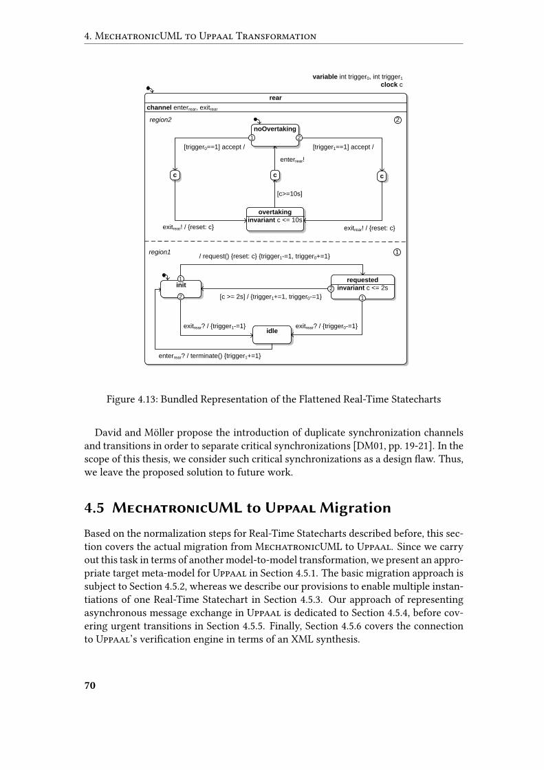
4. MechatronicUML to Uppaal Transformation
rear
region2 2
noOvertaking
[trigger1==1] accept /[trigger0==1] accept /
overtaking
invariant c <= 10s
1 2
cc
exitrear! / {reset: c}exitrear! / {reset: c}
enterrear!
c
[c>=10s]
requested
invariant c <= 2sinit
/ request() {reset: c} {trigger1-=1, trigger0+=1}
[c >= 2s] / {trigger1+=1, trigger0-=1}
2
1
idleexitrear? / {trigger0-=1}
enterrear? / terminate() {trigger1+=1}
exitrear? / {trigger1-=1}
2
region1 1
variable int trigger0, int trigger1
clock c
channel enterrear, exitrear
1
Figure 4.13: Bundled Representation of the Flattened Real-Time Statecharts
David and Möller propose the introduction of duplicate synchronization channelsand transitions in order to separate critical synchronizations [DM01, pp. 19-21]. In thescope of this thesis, we consider such critical synchronizations as a design �aw. Thus,we leave the proposed solution to future work.
4.5 MechatronicUML to Uppaal Migration
Based on the normalization steps for Real-Time Statecharts described before, this sec-tion covers the actual migration from MechatronicUML to Uppaal. Since we carryout this task in terms of another model-to-model transformation, we present an appro-priate target meta-model for Uppaal in Section 4.5.1. The basic migration approach issubject to Section 4.5.2, whereas we describe our provisions to enable multiple instan-tiations of one Real-Time Statechart in Section 4.5.3. Our approach of representingasynchronous message exchange in Uppaal is dedicated to Section 4.5.4, before cov-ering urgent transitions in Section 4.5.5. Finally, Section 4.5.6 covers the connectionto Uppaal’s veri�cation engine in terms of an XML synthesis.
70
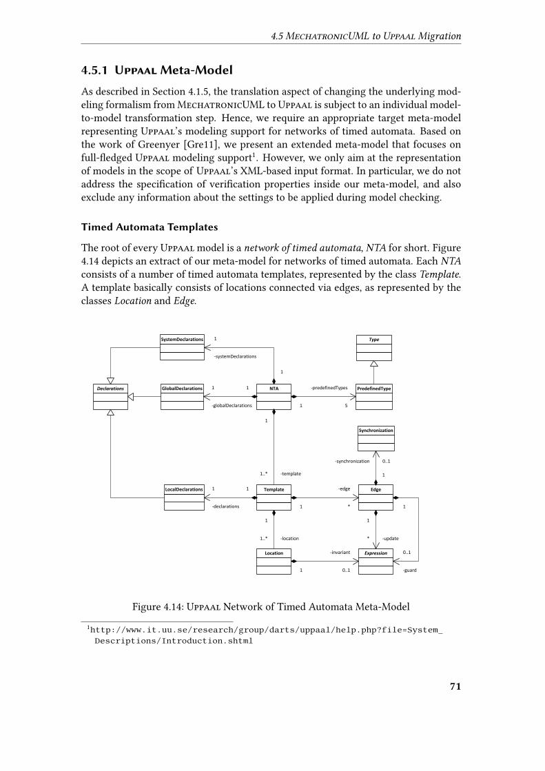
4.5 MechatronicUML to Uppaal Migration
4.5.1 Uppaal Meta-Model
As described in Section 4.1.5, the translation aspect of changing the underlying mod-eling formalism from MechatronicUML to Uppaal is subject to an individual model-to-model transformation step. Hence, we require an appropriate target meta-modelrepresenting Uppaal’s modeling support for networks of timed automata. Based onthe work of Greenyer [Gre11], we present an extended meta-model that focuses onfull-�edged Uppaal modeling support1. However, we only aim at the representationof models in the scope of Uppaal’s XML-based input format. In particular, we do notaddress the speci�cation of veri�cation properties inside our meta-model, and alsoexclude any information about the settings to be applied during model checking.
Timed Automata Templates
The root of every Uppaal model is a network of timed automata, NTA for short. Figure4.14 depicts an extract of our meta-model for networks of timed automata. Each NTA
consists of a number of timed automata templates, represented by the class Template.A template basically consists of locations connected via edges, as represented by theclasses Location and Edge.
SystemDeclarations Type
GlobalDeclarations
LocalDeclarations
Declarations NTA PredefinedType
Template Edge
Synchronization
Location Expression
1
-systemDeclarations
1
1
-globalDeclarations
1
1
-predefinedTypes
5
1
-template1..*
1
-declarations
1
1
-edge
*
1
-synchronization 0..1
1
-update*
1
-guard
0..1
1
-location1..*
1
-invariant
0..1
Figure 4.14: Uppaal Network of Timed Automata Meta-Model
1http://www.it.uu.se/research/group/darts/uppaal/help.php?file=System_Descriptions/Introduction.shtml
71
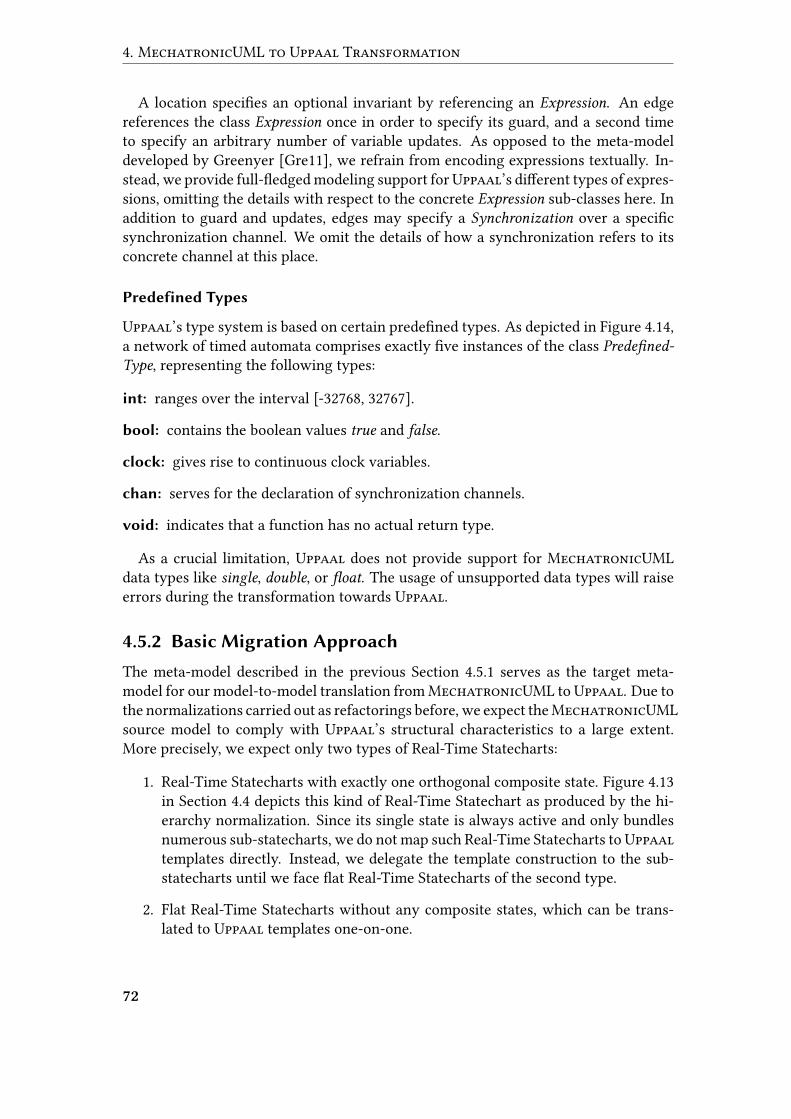
4. MechatronicUML to Uppaal Transformation
A location speci�es an optional invariant by referencing an Expression. An edgereferences the class Expression once in order to specify its guard, and a second timeto specify an arbitrary number of variable updates. As opposed to the meta-modeldeveloped by Greenyer [Gre11], we refrain from encoding expressions textually. In-stead, we provide full-�edged modeling support forUppaal’s di�erent types of expres-sions, omitting the details with respect to the concrete Expression sub-classes here. Inaddition to guard and updates, edges may specify a Synchronization over a speci�csynchronization channel. We omit the details of how a synchronization refers to itsconcrete channel at this place.
Predefined Types
Uppaal’s type system is based on certain prede�ned types. As depicted in Figure 4.14,a network of timed automata comprises exactly �ve instances of the class Prede�ned-Type, representing the following types:
int: ranges over the interval [-32768, 32767].
bool: contains the boolean values true and false.
clock: gives rise to continuous clock variables.
chan: serves for the declaration of synchronization channels.
void: indicates that a function has no actual return type.
As a crucial limitation, Uppaal does not provide support for MechatronicUMLdata types like single, double, or �oat. The usage of unsupported data types will raiseerrors during the transformation towards Uppaal.
4.5.2 Basic Migration Approach
The meta-model described in the previous Section 4.5.1 serves as the target meta-model for our model-to-model translation from MechatronicUML to Uppaal. Due tothe normalizations carried out as refactorings before, we expect theMechatronicUMLsource model to comply with Uppaal’s structural characteristics to a large extent.More precisely, we expect only two types of Real-Time Statecharts:
1. Real-Time Statecharts with exactly one orthogonal composite state. Figure 4.13in Section 4.4 depicts this kind of Real-Time Statechart as produced by the hi-erarchy normalization. Since its single state is always active and only bundlesnumerous sub-statecharts, we do not map such Real-Time Statecharts to Uppaaltemplates directly. Instead, we delegate the template construction to the sub-statecharts until we face �at Real-Time Statecharts of the second type.
2. Flat Real-Time Statecharts without any composite states, which can be trans-lated to Uppaal templates one-on-one.
72
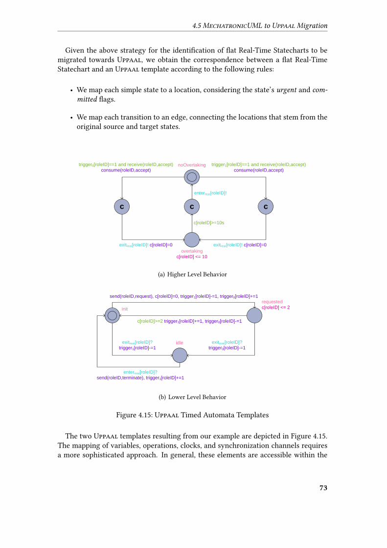
4.5 MechatronicUML to Uppaal Migration
Given the above strategy for the identi�cation of �at Real-Time Statecharts to bemigrated towards Uppaal, we obtain the correspondence between a �at Real-TimeStatechart and an Uppaal template according to the following rules:
• We map each simple state to a location, considering the state’s urgent and com-
mitted �ags.
• We map each transition to an edge, connecting the locations that stem from theoriginal source and target states.
trigger1[roleID]==1 and receive(roleID,accept)
consume(roleID,accept)
trigger0[roleID]==1 and receive(roleID,accept)
consume(roleID,accept)
exitrear[roleID]! c[roleID]=0exitrear[roleID]! c[roleID]=0
enterrear[roleID]!
c[roleID]>=10s
noOvertaking
c c c
overtaking
c[roleID] <= 10
(a) Higher Level Behavior
send(roleID,request), c[roleID]=0, trigger1[roleID]-=1, trigger0[roleID]+=1
c[roleID]>=2 trigger1[roleID]+=1, trigger0[roleID]-=1
exitrear[roleID]?
trigger0[roleID]-=1
enterrear[roleID]?
send(roleID,terminate), trigger1[roleID]+=1
exitrear[roleID]?
trigger1[roleID]-=1
init
requested
c[roleID] <= 2
idle
(b) Lower Level Behavior
Figure 4.15: Uppaal Timed Automata Templates
The two Uppaal templates resulting from our example are depicted in Figure 4.15.The mapping of variables, operations, clocks, and synchronization channels requiresa more sophisticated approach. In general, these elements are accessible within the
73
4. MechatronicUML to Uppaal Transformation
declaring state or Real-Time Statechart and all sub-statecharts. Hence, when map-ping �at Real-Time Statecharts to templates, we require shared access to the afore-mentioned elements from di�erent templates. Hence, we map these elements to theGlobalDeclarations of our target NTA. By globalizing the aforementioned elements,we comply with the Uppaal translation approach by David and Möller describedin [DM01]. As an example, c refers to a global clock in Figure 4.15.
4.5.3 Instantiating Real-Time Statecharts
MechatronicUML distinguishes between type-level and instance-level. This corre-sponds to Uppaal’s approach of creating timed automata templates, and deriving pro-cess instantiations from these templates. On instantiation of a process from an Uppaaltimed automaton template, each locally declared element (e.g. variable or clock) is in-stantiated as well. However, as described in Section 4.5.2, all elements declared locallyto some Real-Time Statechart are globalized by our transformation, i.e. mapped tothe GlobalDeclarations of the target NTA. As a result, such elements are not subjectto Uppaal’s instantiation policy anymore. Instead, only one global instance exists forevery element.
Hence, we face a serious limitation of the Uppaal translation approach by Davidand Möller [DM01], which relies on the assumption that each template is “instanti-ated exactly once” [DMY03, p. 24]. Consequently, this translation approach is onlyappropriate for systems with singleton instantiations, such that the globalized ele-ments are accessed by at most one process per template. In general, the assumption ofsingleton instantiations is incompatible with MechatronicUML. As described in Sec-tion 2.5, the concept of multi-roles and multi-ports gives rise to multiple behavioralelement instances running the same Real-Time Statechart. Obviously, by retainingthe MechatronicUML formalism during our prior transformation steps described inSections 4.2 to 4.4, the same problem did not occur before.
Reproducing Element Declarations via Arrays
Our solution strategy is to modify the global declaration of the aforementioned ele-ments at the Uppaal level to support more than one runtime instance. Consequently,we declare variables, clocks, and synchronization channels as multi-valued arrays
rather than singletons. More precisely, we add an arti�cial array dimension to eachdeclaration, i.e. we reproduce every element once for each relevant Real-Time State-chart instance. In addition, we parametrize generated Uppaal templates with integer-based identi�ers that represent speci�c Real-Time Statechart instances. On access tovariables, clocks, or synchronization channels, the Uppaal templates use their indi-vidual identi�ers as an index to the multi-valued element declarations. Based on thistechnique, templates refer to concrete designated elements from global arrays, e.g.choose a concrete clock from a globally declared array of clocks.
As an example, we refer to the values of clock c in Figure 4.15. A distinct instanceof c exists for each behavioral element instance running the declaring Real-Time Stat-
74

4.5 MechatronicUML to Uppaal Migration
clock c;
(a) Original Local Clock Dec-laration
clock c[5];
(b) Translated Global ClockDeclaration
Figure 4.16: Representation of Clock Instances
echart. As shown in Figure 4.16, we assume an amount of �ve instances and encodethese circumstances by declaring c as a global array of clocks. Every template access-ing its designated clock value uses a speci�c identi�er as an index to the global clockarray c. This practice is observable for the guard at the edge requested→ init in Figure4.15(b).
Di�erent processes that are part of the same behavioral element instance obtain acommon identi�er value on instantiation. As an example, a single runtime instanceof the coordination protocol role rear corresponds to two process instantiations ofthe templates in Figure 4.15 with a common roleID value. For the representation ofa second rear instance, we would instantiate the same two templates with a di�erentroleID value.
As a drawback of this approach, we must be aware of the relevant number of Real-Time Statechart instances when generating the entire NTA model. This limitation iscaused by the fact that the number of instances determines the size of the dimensionthat we attach to each element declaration. We must �x this dimension since Uppaaldoes not support arrays with a variable size. As an example, the declaration in Figure4.16(b) supports at most �ve instances of the respective Real-Time Statechart.
Di�erent Declaration Levels
MechatronicUML gives rise to another di�culty with respect to the aforementionedapproach of indexing elements via arrays. Let us consider e.g. two instances of onemulti-port, whereas the multi-port’s role statechart introduces a certain variable. Atruntime, the two resulting Real-Time Statechart instances access di�erent instancesof this variable. However, if the common component statechart introduces anothervariable, then both Real-Time Statechart instances refer to the same instance of thisvariable. Consequently, two Real-Time Statecharts might have access to distinct in-stances of one variable, sharing a second variable instance at the same time. Hence,by distinguishing between elements declared either at the level of ports/roles, or atthe level of components, MechatronicUML raises a need for at least two identi�ersspeci�ed per template instantiation in Uppaal. Depending on the level on which anelement is declared, the templates must specify either their component instance iden-ti�er, or their port/role instance identi�er as an index to the respective arrays of ele-ments. Continuing the above example of two instances of one multi-port, the resulting
75
4. MechatronicUML to Uppaal Transformation
Uppaal templates would specify a common component instance identi�er, but distinctport/role instance identi�ers. For the example in Figure 4.15, we assume that there isno embedding component statechart. Hence, roleID is the only speci�ed identi�er inthis case.
Representing Operations
So far, we omitted the representation of operations declared in Real-Time Statecharts.Just as for elements like variables, clocks, and synchronization channels, our approachis to declare operations as global Uppaal functions in order to make them accessiblefrom multiple templates.
However, we assume that an operation may directly refer to the local variables thatare accessible in its declaring Real-Time Statechart. Hence, we need to qualify everyfunction for references to exactly those variable instances that apply to the callingReal-Time Statechart instance. We achieve this by attaching additional parametersto each declared function. These parameters correspond exactly to the two types ofidenti�ers discussed above: one identi�er represents the component instance, the sec-ond one identi�es the calling port or role instance. The exemplary operation calcu-
lateOvertakingDistance in Figure 4.17(a) originally comes without parameters, but ac-cesses speci�c variables that are assumed to be declared within the operation’s parentrole statechart.
When calling some function, a template passes its two identi�er values as additionalarguments. We adjust every function’s body, such that these special arguments areagain used as an index into the global arrays of variables. Thus, we ensure that on eachcall, a function accesses exactly those variable instances associated with the callingReal-Time Statechart. As an example, note the usage of the roleID parameter as anindex to to all variable references in Figure 4.17.
4.5.4 Asynchronous Message Exchange
Communication between distinct Uppaal processes is restricted to synchronizationsor globally shared variables.
In the mechatronics domain, concurrent systems tend to communicate via an asyn-chronous exchange of discrete messages, i.e. a sender does not block until a message isreceived, whereas messages are bu�ered at receiver side until their consumption. Anarbitrary amount of receiver message bu�ers with individual sizes is possible, whereasdedicated strategies exist for the access to bu�ers as well as for the case of a bu�erover�ow. Messages can get delayed, transposed, lost, or corrupted due to environ-mental e�ects on the underlying transmission medium. MechatronicUML providesexplicit modeling support for such quality-of-service (QoS) assumptions for the con-nector between the single roles of a coordination protocol, focusing on message lossor delay. For a single coordination protocol role, Kriger identi�ed the common usecases of exactly one shared message bu�er for all message types, or an exclusive mes-
76
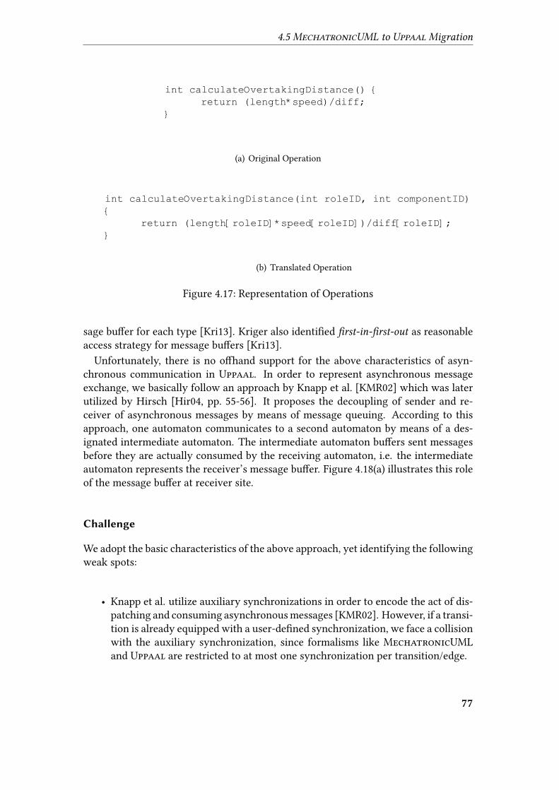
4.5 MechatronicUML to Uppaal Migration
int calculateOvertakingDistance() {
return (length*speed)/diff;
}
(a) Original Operation
int calculateOvertakingDistance(int roleID, int componentID)
{
return (length[roleID]*speed[roleID])/diff[roleID];
}
(b) Translated Operation
Figure 4.17: Representation of Operations
sage bu�er for each type [Kri13]. Kriger also identi�ed �rst-in-�rst-out as reasonableaccess strategy for message bu�ers [Kri13].
Unfortunately, there is no o�hand support for the above characteristics of asyn-chronous communication in Uppaal. In order to represent asynchronous messageexchange, we basically follow an approach by Knapp et al. [KMR02] which was laterutilized by Hirsch [Hir04, pp. 55-56]. It proposes the decoupling of sender and re-ceiver of asynchronous messages by means of message queuing. According to thisapproach, one automaton communicates to a second automaton by means of a des-ignated intermediate automaton. The intermediate automaton bu�ers sent messagesbefore they are actually consumed by the receiving automaton, i.e. the intermediateautomaton represents the receiver’s message bu�er. Figure 4.18(a) illustrates this roleof the message bu�er at receiver site.
Challenge
We adopt the basic characteristics of the above approach, yet identifying the followingweak spots:
• Knapp et al. utilize auxiliary synchronizations in order to encode the act of dis-patching and consuming asynchronous messages [KMR02]. However, if a transi-tion is already equipped with a user-de�ned synchronization, we face a collisionwith the auxiliary synchronization, since formalisms like MechatronicUMLand Uppaal are restricted to at most one synchronization per transition/edge.
77
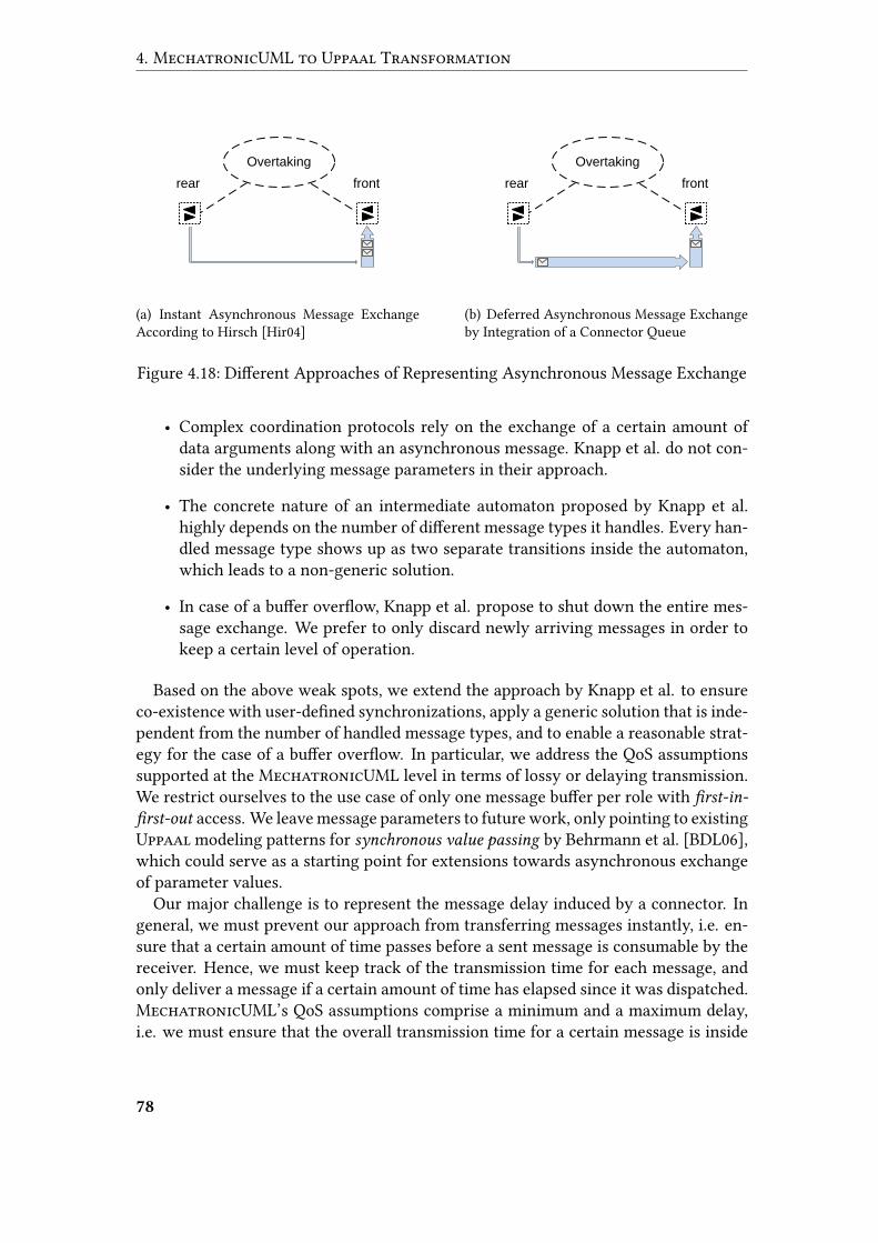
4. MechatronicUML to Uppaal Transformation
rear front
Overtaking
(a) Instant Asynchronous Message ExchangeAccording to Hirsch [Hir04]
rear front
Overtaking
(b) Deferred Asynchronous Message Exchangeby Integration of a Connector Queue
Figure 4.18: Di�erent Approaches of Representing Asynchronous Message Exchange
• Complex coordination protocols rely on the exchange of a certain amount ofdata arguments along with an asynchronous message. Knapp et al. do not con-sider the underlying message parameters in their approach.
• The concrete nature of an intermediate automaton proposed by Knapp et al.highly depends on the number of di�erent message types it handles. Every han-dled message type shows up as two separate transitions inside the automaton,which leads to a non-generic solution.
• In case of a bu�er over�ow, Knapp et al. propose to shut down the entire mes-sage exchange. We prefer to only discard newly arriving messages in order tokeep a certain level of operation.
Based on the above weak spots, we extend the approach by Knapp et al. to ensureco-existence with user-de�ned synchronizations, apply a generic solution that is inde-pendent from the number of handled message types, and to enable a reasonable strat-egy for the case of a bu�er over�ow. In particular, we address the QoS assumptionssupported at the MechatronicUML level in terms of lossy or delaying transmission.We restrict ourselves to the use case of only one message bu�er per role with �rst-in-
�rst-out access. We leave message parameters to future work, only pointing to existingUppaal modeling patterns for synchronous value passing by Behrmann et al. [BDL06],which could serve as a starting point for extensions towards asynchronous exchangeof parameter values.
Our major challenge is to represent the message delay induced by a connector. Ingeneral, we must prevent our approach from transferring messages instantly, i.e. en-sure that a certain amount of time passes before a sent message is consumable by thereceiver. Hence, we must keep track of the transmission time for each message, andonly deliver a message if a certain amount of time has elapsed since it was dispatched.MechatronicUML’s QoS assumptions comprise a minimum and a maximum delay,i.e. we must ensure that the overall transmission time for a certain message is inside
78
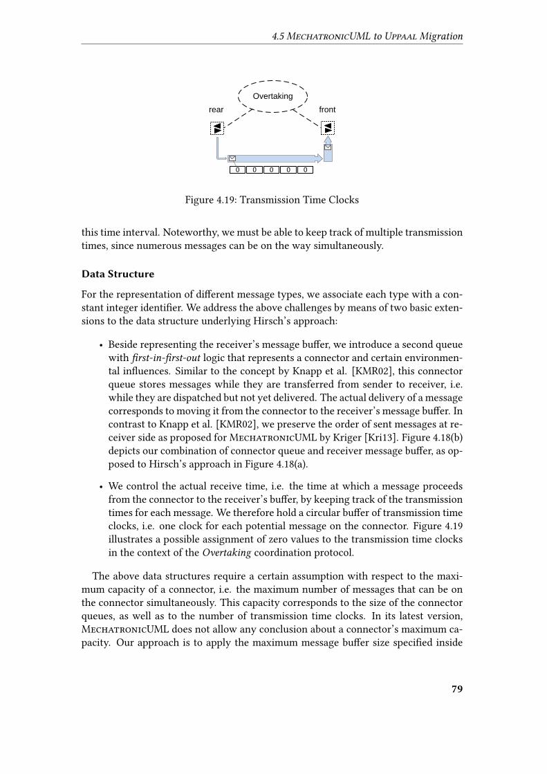
4.5 MechatronicUML to Uppaal Migration
rear front
Overtaking
0 0 0 0 0
Figure 4.19: Transmission Time Clocks
this time interval. Noteworthy, we must be able to keep track of multiple transmissiontimes, since numerous messages can be on the way simultaneously.
Data Structure
For the representation of di�erent message types, we associate each type with a con-stant integer identi�er. We address the above challenges by means of two basic exten-sions to the data structure underlying Hirsch’s approach:
• Beside representing the receiver’s message bu�er, we introduce a second queuewith �rst-in-�rst-out logic that represents a connector and certain environmen-tal in�uences. Similar to the concept by Knapp et al. [KMR02], this connectorqueue stores messages while they are transferred from sender to receiver, i.e.while they are dispatched but not yet delivered. The actual delivery of a messagecorresponds to moving it from the connector to the receiver’s message bu�er. Incontrast to Knapp et al. [KMR02], we preserve the order of sent messages at re-ceiver side as proposed for MechatronicUML by Kriger [Kri13]. Figure 4.18(b)depicts our combination of connector queue and receiver message bu�er, as op-posed to Hirsch’s approach in Figure 4.18(a).
• We control the actual receive time, i.e. the time at which a message proceedsfrom the connector to the receiver’s bu�er, by keeping track of the transmissiontimes for each message. We therefore hold a circular bu�er of transmission timeclocks, i.e. one clock for each potential message on the connector. Figure 4.19illustrates a possible assignment of zero values to the transmission time clocksin the context of the Overtaking coordination protocol.
The above data structures require a certain assumption with respect to the maxi-mum capacity of a connector, i.e. the maximum number of messages that can be onthe connector simultaneously. This capacity corresponds to the size of the connectorqueues, as well as to the number of transmission time clocks. In its latest version,MechatronicUML does not allow any conclusion about a connector’s maximum ca-pacity. Our approach is to apply the maximum message bu�er size speci�ed inside
79
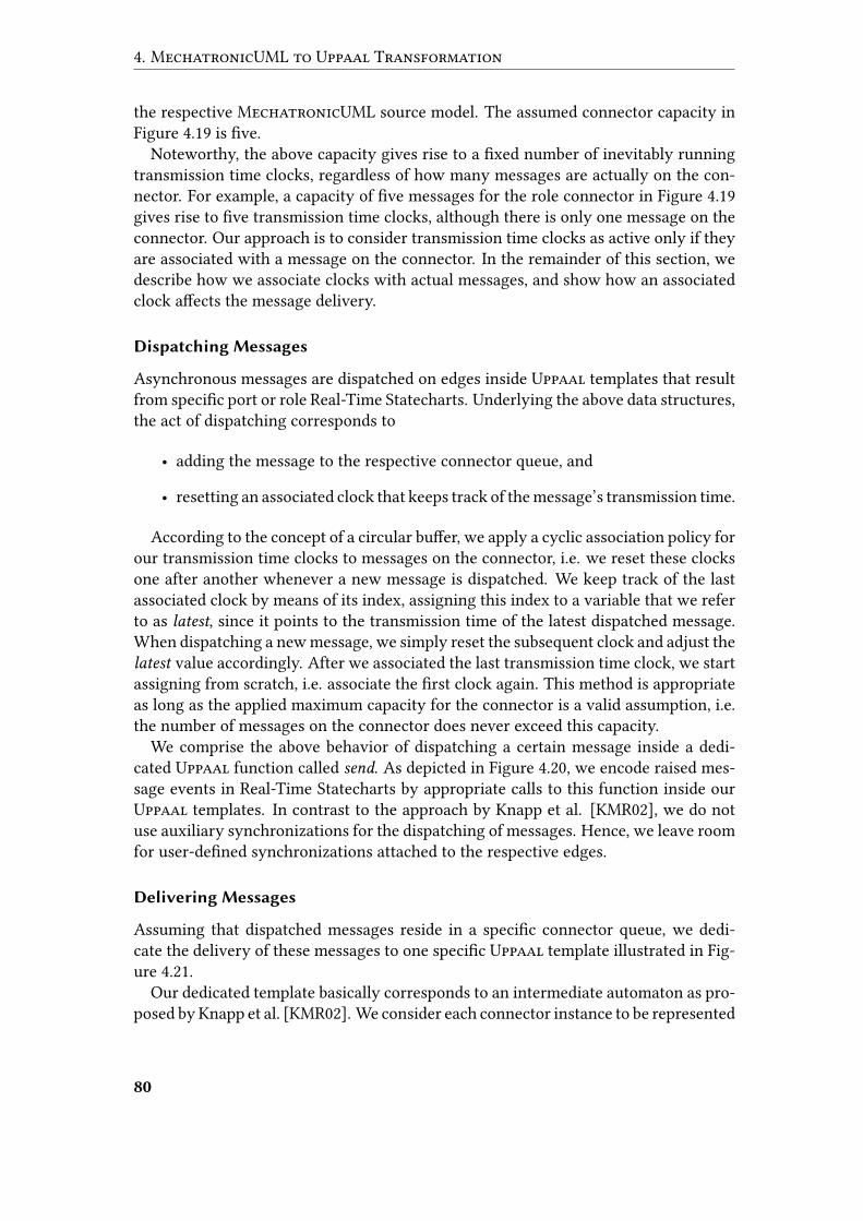
4. MechatronicUML to Uppaal Transformation
the respective MechatronicUML source model. The assumed connector capacity inFigure 4.19 is �ve.
Noteworthy, the above capacity gives rise to a �xed number of inevitably runningtransmission time clocks, regardless of how many messages are actually on the con-nector. For example, a capacity of �ve messages for the role connector in Figure 4.19gives rise to �ve transmission time clocks, although there is only one message on theconnector. Our approach is to consider transmission time clocks as active only if theyare associated with a message on the connector. In the remainder of this section, wedescribe how we associate clocks with actual messages, and show how an associatedclock a�ects the message delivery.
Dispatching Messages
Asynchronous messages are dispatched on edges inside Uppaal templates that resultfrom speci�c port or role Real-Time Statecharts. Underlying the above data structures,the act of dispatching corresponds to
• adding the message to the respective connector queue, and
• resetting an associated clock that keeps track of the message’s transmission time.
According to the concept of a circular bu�er, we apply a cyclic association policy forour transmission time clocks to messages on the connector, i.e. we reset these clocksone after another whenever a new message is dispatched. We keep track of the lastassociated clock by means of its index, assigning this index to a variable that we referto as latest, since it points to the transmission time of the latest dispatched message.When dispatching a new message, we simply reset the subsequent clock and adjust thelatest value accordingly. After we associated the last transmission time clock, we startassigning from scratch, i.e. associate the �rst clock again. This method is appropriateas long as the applied maximum capacity for the connector is a valid assumption, i.e.the number of messages on the connector does never exceed this capacity.
We comprise the above behavior of dispatching a certain message inside a dedi-cated Uppaal function called send. As depicted in Figure 4.20, we encode raised mes-sage events in Real-Time Statecharts by appropriate calls to this function inside ourUppaal templates. In contrast to the approach by Knapp et al. [KMR02], we do notuse auxiliary synchronizations for the dispatching of messages. Hence, we leave roomfor user-de�ned synchronizations attached to the respective edges.
Delivering Messages
Assuming that dispatched messages reside in a speci�c connector queue, we dedi-cate the delivery of these messages to one speci�c Uppaal template illustrated in Fig-ure 4.21.
Our dedicated template basically corresponds to an intermediate automaton as pro-posed by Knapp et al. [KMR02]. We consider each connector instance to be represented
80
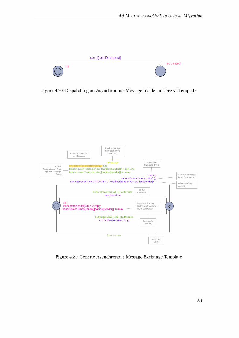
4.5 MechatronicUML to Uppaal Migration
send(roleID,request)
initrequested
Figure 4.20: Dispatching an Asynchronous Message inside an Uppaal Template
i:Message
check(connectors(sender),i) and
transmissionTimes[sender][earliest[sender]] >= min and
transmissionTimes[sender][earliest[sender]] <= max
tmp=i,
remove(connectors[sender],i),
earliest[sender] == CAPACITY-1 ? earliest[sender]=0 : earliest[sender]++
idle
connectors[sender].tail > 0 imply
transmissionTimes[sender][earliest[sender]] <= maxc
buffers[receiver].tail >= bufferSize
overflow=true
buffers[receiver].tail < bufferSize
add(buffers[receiver],tmp)
loss == true
Message
Loss
Successful
Delivery
Buffer
Overflow
Nondeterministic
Message Type
SelectionCheck Connector
for Message
Check
Transmission Time
against Message
Delay
Memorize
Message Type
Remove Message
From Connector
Adjust earliest
Variable
Invariant Forcing
Release of Message
from Connector
Figure 4.21: Generic Asynchronous Message Exchange Template
81
Stefan
Hervorheben
wenn ungleich null, könnte das auch funktionieren check(connectors[sender],i) check returns true if i is at head einfacher: prüfe ob im head des connectors eine nachricht ist (not null), wenn ja prüfe ob diese im intervall ist
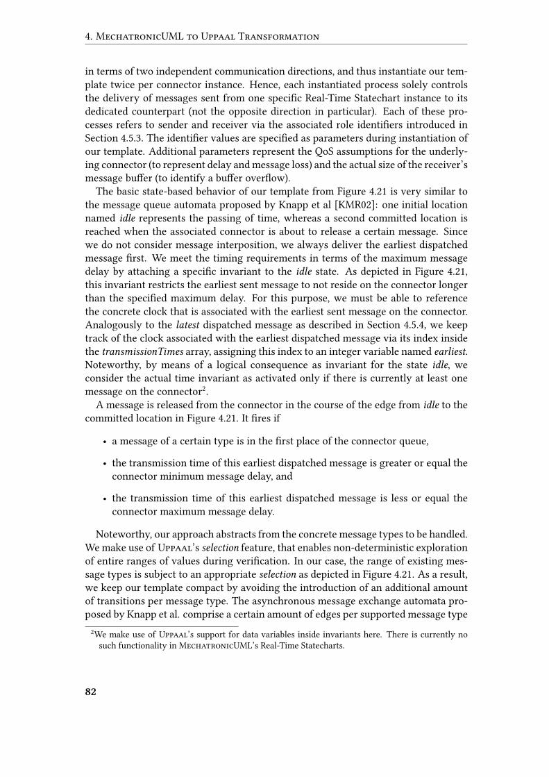
4. MechatronicUML to Uppaal Transformation
in terms of two independent communication directions, and thus instantiate our tem-plate twice per connector instance. Hence, each instantiated process solely controlsthe delivery of messages sent from one speci�c Real-Time Statechart instance to itsdedicated counterpart (not the opposite direction in particular). Each of these pro-cesses refers to sender and receiver via the associated role identi�ers introduced inSection 4.5.3. The identi�er values are speci�ed as parameters during instantiation ofour template. Additional parameters represent the QoS assumptions for the underly-ing connector (to represent delay and message loss) and the actual size of the receiver’smessage bu�er (to identify a bu�er over�ow).
The basic state-based behavior of our template from Figure 4.21 is very similar tothe message queue automata proposed by Knapp et al [KMR02]: one initial locationnamed idle represents the passing of time, whereas a second committed location isreached when the associated connector is about to release a certain message. Sincewe do not consider message interposition, we always deliver the earliest dispatchedmessage �rst. We meet the timing requirements in terms of the maximum messagedelay by attaching a speci�c invariant to the idle state. As depicted in Figure 4.21,this invariant restricts the earliest sent message to not reside on the connector longerthan the speci�ed maximum delay. For this purpose, we must be able to referencethe concrete clock that is associated with the earliest sent message on the connector.Analogously to the latest dispatched message as described in Section 4.5.4, we keeptrack of the clock associated with the earliest dispatched message via its index insidethe transmissionTimes array, assigning this index to an integer variable named earliest.Noteworthy, by means of a logical consequence as invariant for the state idle, weconsider the actual time invariant as activated only if there is currently at least onemessage on the connector2.
A message is released from the connector in the course of the edge from idle to thecommitted location in Figure 4.21. It �res if
• a message of a certain type is in the �rst place of the connector queue,
• the transmission time of this earliest dispatched message is greater or equal theconnector minimum message delay, and
• the transmission time of this earliest dispatched message is less or equal theconnector maximum message delay.
Noteworthy, our approach abstracts from the concrete message types to be handled.We make use of Uppaal’s selection feature, that enables non-deterministic explorationof entire ranges of values during veri�cation. In our case, the range of existing mes-sage types is subject to an appropriate selection as depicted in Figure 4.21. As a result,we keep our template compact by avoiding the introduction of an additional amountof transitions per message type. The asynchronous message exchange automata pro-posed by Knapp et al. comprise a certain amount of edges per supported message type
2We make use of Uppaal’s support for data variables inside invariants here. There is currently nosuch functionality in MechatronicUML’s Real-Time Statecharts.
82
4.5 MechatronicUML to Uppaal Migration
[KMR02]. Whereas our approach reduces the transformation complexity, i.e. the e�ortto generate an appropriate intermediate automaton, the usage of the selection featureis not expected to have any positive impact on the veri�cation runtime. We considerthe feature as a syntactic shortcut only, comprising numerous sets of transitions thatwere represented explicitly by Knapp et al. [KMR02]. The selection feature can notovercome the need to explore all possible values individually during veri�cation.
When releasing a message from the connector during the edge from idle to thecommitted location, we memorize the concrete message type, remove the messagefrom the connector queue, and also update the earliest index such that it points tothe transmission time of the next dispatched message. Analogously to the updatestrategy described in Section 4.5.4, we carry out this update by simply pointing tothe subsequent transmission time clock, respectively to the �rst of these clocks afterreaching the last one.
As a response to releasing a message from the connector, we distinguish betweenthree cases for the return from the committed location to the idle location. Each casecorresponds to an edge from the committed location back to idle in Figure 4.21:
• The message is delivered successfully, i.e. moved from the connector queue tothe receiver’s message bu�er. As an obvious prerequisite, there must be freespace inside the bu�er.
• If the above prerequisite for a successful delivery is violated, i.e. if there is nofree space in the receiver’s message bu�er, we face a bu�er over�ow. Instead ofcancelling the whole message exchange by switching to a dedicated error loca-tion [KMR02], we only discard the pending message and indicate the incidentby means of a dedicated over�ow variable. Speci�ed in veri�cation properties,this variable enables diagnostics with respect to bu�er over�ows. We leave anyalternative over�ow strategies to future work.
• Regardless of whether there is free space inside the receiver’s message bu�eror not, a message can get lost during transmission (if the connector is declaredlossy as part of its QoS assumptions). Hence, if our process is parametrized toenable message loss, this third case gives rise to a well-de�ned discarding of thedispatched message.
In contrast to Knapp et al. [KMR02], we encapsulate the logic of checking the pres-ence of a certain message on the connector, removing a message from the connec-tor, and adding a message to the receiver’s bu�er inside dedicated Uppaal functions.These functions, named check, remove, and add, are referenced by the edges of theintermediate automaton in Figure 4.21.
Consuming Messages
Asynchronous messages are consumed by transitions inside Real-Time Statecharts.Analogously to the dispatching of raised messages, we avoid the usage of auxiliary
83

4. MechatronicUML to Uppaal Transformation
receive(roleID,accept)
consume(roleID,accept)
noOvertaking
c
overtaking
Figure 4.22: Consuming an Asynchronous Message inside an Uppaal Template
synchronizations to encode the consumption of messages, leaving room for user-de�ned synchronizations. Instead, we address the tasks of checking for a certain mes-sage and removing it from the message bu�er by means of dedicated functions.
In accordance with the work of Kriger [Kri13], we assume message bu�ers to un-derlie the same �rst-in-�rst-out logic that holds for connectors. Hence, a Real-TimeStatechart can only �re a transition if the speci�ed trigger message is in the �rst placeof the receiver’s message bu�er. As a result, we use a common data structure for bothconnector queues and message bu�ers, and also make use of the existing function-ality to check for the presence of a message and remove it if available. We accessthis functionality via dedicated convenience functions named receive and consume, asillustrated in Figure 4.22.
Runtime Example
In this section, we give a concrete example for an asynchronous message exchange be-tween roles at runtime. We consider the communication direction from a rear vehicleto a front vehicle during overtaking, assuming a message delay of one second inducedby the lossy role connector. The front vehicle’s receiver message bu�er can store upto three messages, whereas the capacity of the connector queue is �ve. Consequently,we face an amount of �ve transmission time clocks.
In Figure 4.23(a), after an operation time of 30 seconds, the rear vehicle dispatchesan overtaking request. The �rst transmission time clock (index 0) is associated withthe request message as depicted in Figure 4.23(b), i.e. it is reset to 0. Hence, at t=31 inFigure 4.23(c), the associated clock value of 1 indicates that the underlying messagedelay has passed. However, we assume a message loss that prevents the request frombeing delivered.
84
4.5 MechatronicUML to Uppaal Migration
Thus, at t=35 in Figure 4.23(d), the rear vehicle dispatches a second request. Again,we associate a certain transmission time clock with this message. Based on the cyclicassociation policy, we now reset the second transmission time clock to 0 as Figure4.23(e) illustrates. This time, delayed by the connector for one second, we assume thatthe message is delivered successfully at t=36 in Figure 4.23(f). Based on an urgentbehavior, Figure 4.23(g) depicts the immediate consumption of the request by the frontvehicle’s role statechart.
4.5.5 Urgency
Real-Time Statecharts distinguish between urgent and non-urgent transitions. Onlythe latter type is allowed to refrain from �ring, whereas urgent transitions are requiredto �re immediately when being enabled.Uppaal also distinguishes between urgent and non-urgent edges, but provides less
�exibility by handling urgency on the level of synchronization channels. Urgent edgescorrespond to those that synchronize over some channel which is declared as urgent.
We apply an approach to encode urgent transitions by means of a dedicated ur-gent synchronization channel [DMY03], referred to as hurry according to Behrmannet al. [BDL06]. However, additional synchronizations over this dedicated channel canonly provide urgency for transitions that do not carry a user-de�ned synchroniza-tion yet. For all transitions that already carry some synchronization, we investigatewhether we can safely declare the a�ected channel as urgent. This is the case if thechannel is exclusively accessed by urgent transitions. For the opposite case that noneof the transitions referencing a certain channel is urgent, we obviously declare thechannel as non-urgent. David et al. describe a more sophisticated approach of han-dling synchronization channels accessed by both urgent and non-urgent transitionsin [DMY03]. We leave the application of this approach to future work, consideringthis kind of hybrid synchronization channel as a modeling �aw.
4.5.6 XML Synthesis
The translation described in Section 4.5 produces Uppaal-speci�c representations ofMechatronicUML models. Due to the fact that all prior steps were model-to-modeltransformations, we face a last minor interoperability challenge insofar that Uppaalrelies on a text-based input format, underlying a speci�c document type de�nition3.
Continuing the approach by Greenyer [Gre11], we ensure Uppaal interoperabil-ity by means of an appropriate XML synthesis. This model-to-text transformationis charged with the XML serialization of a given network of timed automata. Therespective generator relies on a designated template engine for model-to-text trans-formations, and operates on a model instance of the Uppaal meta-model describedin Section 4.5.1. We leave out further details at this point, referring the reader toGreenyer [Gre11] for the original concept.
3http://www.it.uu.se/research/group/darts/uppaal/flat-1_1.dtd
85
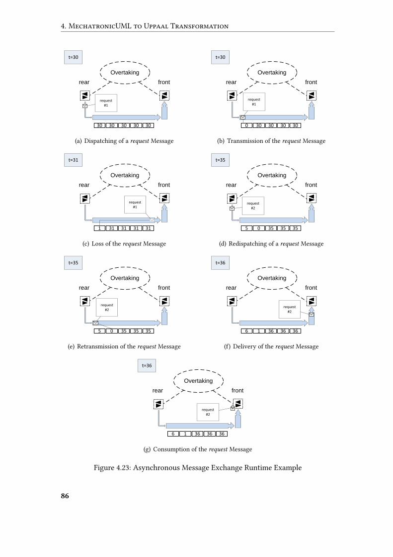
4. MechatronicUML to Uppaal Transformation
rear front
Overtaking
30 30 30 30 30
t=30
request #1
(a) Dispatching of a request Message
rear front
Overtaking
0 30 30 30 30
t=30
request #1
(b) Transmission of the request Message
rear front
Overtaking
1 31 31 31 31
t=31
request #1
(c) Loss of the request Message
rear front
Overtaking
5 0 35 35 35
t=35
request #2
(d) Redispatching of a request Message
rear front
Overtaking
5 0 35 35 35
t=35
request #2
(e) Retransmission of the request Message
rear front
Overtaking
6 1 36 36 36
t=36
request #2
(f) Delivery of the request Message
rear front
Overtaking
6 1 36 36 36
t=36
request #2
(g) Consumption of the request Message
Figure 4.23: Asynchronous Message Exchange Runtime Example
86
4.5 MechatronicUML to Uppaal Migration
Our overall model transformation towards Uppaal XML forms a basis for automa-tized model checking in the context of MechatronicUML. We refer to the forthcom-ing Section 6.2.2 for technical details on our integration of Uppaal’s model checkingengine into the chain of model transformations. Obviously, model checking requiresan appropriate veri�cation property to verify. In our case, veri�cation properties mustbe given in a format that matches the generated Uppaal network of timed automata,which is the representation used for model checking. Obviously, MechatronicUMLengineers are rather interested in specifying properties from their domain-speci�cviewpoint. In the current state of our veri�cation approach, this transparency bar-rier remains unaddressed, i.e. domain engineers are required to make contact withUppaal’s TCTL-based properties. Support for MechatronicUML-speci�c veri�ca-tion properties, and a transformation towards Uppaal TCTL should be subject to fu-ture work.
87

5 Uppaal to MechatronicUML Trace
Transformation
Relying on the model transformation described in the previous Section 4, domain en-gineers are in a position to translate their MechatronicUML design models into aformat suitable for o�hand model checking by Uppaal. Given the appropriate UppaalTCTL properties, the combination of model transformation and model checking en-ables automatic conclusions about the compliance of MechatronicUML-based mod-els with certain domain requirements. Once the Uppaal model checking identi�esthe violation of a speci�ed property, it provides user feedback in terms of a counter-example. The representation of counter-examples is based on the generated Uppaaltimed automata, which are unknown to MechatronicUML domain engineers thatrely on the automatic transformation towards Uppaal. As a consequence, a complexmanual interpretation of the counter-examples may involve drastic process delays, oreven lead to undetected errors due to interpretation mistakes. In order to increase thetransparency of the underlying veri�cation formalism, this section focuses on a trans-formation of Uppaal counter-examples back to the design level of MechatronicUML.
5.1 Traces
Focusing on safety properties, Uppaal ideally detects compliance throughout the en-tire state space. Plain status information about the successful veri�cation are alreadyof great use for domain engineers, since they provide a positive feedback with respectto design decisions. However, in the presence of rising software complexity and hardreal-time requirements, design errors tend to occur frequently. In case of a propertyviolation identi�ed by Uppaal, plain status information about the failure do not allowany conclusions with respect to the root cause of the de�ciency.
As a remedy, model checkers like Uppaal enrich their veri�cation results by meansof witnesses, i.e. they present a detected scenario that violates a speci�ed safety prop-erty. Uppaal does not only provide a single runtime snapshot as a counter-example,but comes up with a trace of snapshots from the initial situation to the violation. Figure5.1 shows an exemplary trace snapshot, representing a counter-example against thecrucial safety requirement that an overtaken vehicle must not accelerate. Obviously,the trace snapshot involves the generated Uppaal timed automata templates depictedin Figure 4.15 on page 73, and also two process instantiations of the asynchronousmessage exchange template in Figure 4.21 on page 81. The active locations depictedin red imply that the rear vehicle is overtaking, but the front vehicle may accelerate
89
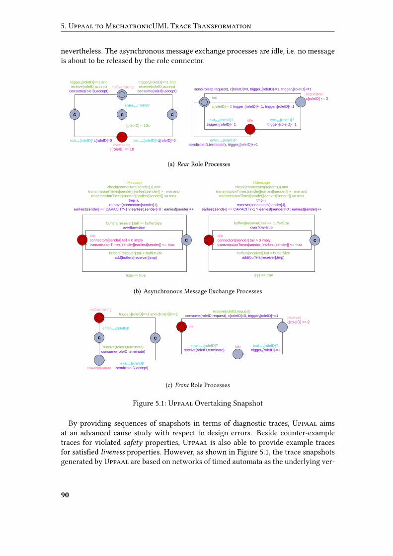
5. Uppaal to MechatronicUML Trace Transformation
nevertheless. The asynchronous message exchange processes are idle, i.e. no messageis about to be released by the role connector.
trigger1[roleID]==1 and
receive(roleID,accept)
consume(roleID,accept)
trigger0[roleID]==1 and
receive(roleID,accept)
consume(roleID,accept)
exitrear[roleID]! c[roleID]=0exitrear[roleID]! c[roleID]=0
enterrear[roleID]!
c[roleID]>=10s
noOvertaking
c c c
overtaking
c[roleID] <= 10
send(roleID,request), c[roleID]=0, trigger1[roleID]-=1, trigger0[roleID]+=1
c[roleID]>=2 trigger1[roleID]+=1, trigger0[roleID]-=1
exitrear[roleID]?
trigger0[roleID]-=1
enterrear[roleID]?
send(roleID,terminate), trigger1[roleID]+=1
exitrear[roleID]?
trigger1[roleID]-=1
initrequested
c[roleID] <= 2
idle
(a) Rear Role Processes
i:Message
check(connectors(sender),i) and
transmissionTimes[sender][earliest[sender]] >= min and
transmissionTimes[sender][earliest[sender]] <= max
tmp=i,
remove(connectors[sender],i),
earliest[sender] == CAPACITY-1 ? earliest[sender]=0 : earliest[sender]++
idle
connectors[sender].tail > 0 imply
transmissionTimes[sender][earliest[sender]] <= maxc
buffers[receiver].tail >= bufferSize
overflow=true
buffers[receiver].tail < bufferSize
add(buffers[receiver],tmp)
loss == true
(b) Asynchronous Message Exchange Processes
trigger3[roleID]==1 and c[roleID]>=2
exitfront[roleID]!
send(roleID,accept)
enterfront[roleID]!
receive(roleID,terminate)
consume(roleID,terminate)
noOvertaking
c c
noAcceleration
receive(roleID,request)
consume(roleID,request), c[roleID]=0, trigger3[roleID]+=1
exitfront[roleID]?
trigger3[roleID]-=1
enterfront[roleID]?
receive(roleID,terminate)
init
received
c[roleID] <= 2
idle
(c) Front Role Processes
Figure 5.1: Uppaal Overtaking Snapshot
By providing sequences of snapshots in terms of diagnostic traces, Uppaal aimsat an advanced cause study with respect to design errors. Beside counter-exampletraces for violated safety properties, Uppaal is also able to provide example tracesfor satis�ed liveness properties. However, as shown in Figure 5.1, the trace snapshotsgenerated by Uppaal are based on networks of timed automata as the underlying ver-
90
5.2 Requirements
i�cation formalism. Obviously, we face huge di�erences between the representationof Uppaal traces and the original MechatronicUML-based design. These di�erencescomprise a change from domain-speci�c modeling to the veri�cation formalism, andare strengthened by structural di�erences resulting from the normalization steps forReal-Time Statecharts described in Sections 4.2 to 4.4. Due to these di�erences, thepresented traces are of little avail for domain engineers, who are rather interested ina familiar representation of traces from their domain-speci�c viewpoint.
Hence, there is a pressing need to transform traces back towards the originalMecha-tronicUML design. By providing a trace transformation, we aim at an improvedtransparency of the Uppaal model checking, preventing domain engineers from theneed to become familiar with the underlying veri�cation formalism and its relation todomain-speci�c concepts. By reducing the cause study e�orts, we address the problemof drastic business process delays caused by abstruse counter-examples. We also ad-dress the vulnerability of a manual interpretation against undetected human mistakes,tackling the possibility of serious failures inside real systems.
5.2 Requirements
Similar to our prior transformation towards Uppaal described in Section 4, semanticspreservation acts as our major requirement for the transformation of Uppaal tracesback towards MechatronicUML. We address the seamless representation of runtimesnapshots for Real-Time Statecharts as the underlying behavior modeling language.Our primary focus is on the exact representation of the active states inside Real-TimeStatecharts.
We also identify the secondary requirement of extracting the values of clocks anddata variables for each trace snapshot. Focusing on the asynchronous message ex-change, another secondary requirement is the representation of messages inside bu�ersor connectors. Whereas the latter two requirements are out of the scope of this thesis,they may be a topic for future work.
In addition to sequences of runtime snapshots, Uppaal supports a trace representa-tion technique focusing on the sequence of interactions occurring at runtime, similarto UML sequence diagrams [OMG11c]. In the absence of sophisticated studies on theconcrete preferences of domain engineers, we leave a realization to future work.
The related work discussed in Section 3.3 does not provide a complete basis for ourtrace transformation. Similar to the TopCased approach described in Section 3.3.4,we aim at a model-driven solution based on dedicated meta-modeling concepts. How-ever, in contrast to other approaches, we refrain from a formal encoding of the un-derlying semantics for Uppaal or MechatronicUML. Whereas no formal semanticsare currently available for MechatronicUML, Uppaal’s semantics are already oper-ationalized in terms of its timed model checking procedure, such that the e�ort ofan additional encoding should be avoidable. We rely on the traceability of our ini-tial transformation towards Uppaal in order to establish a correspondence between
91
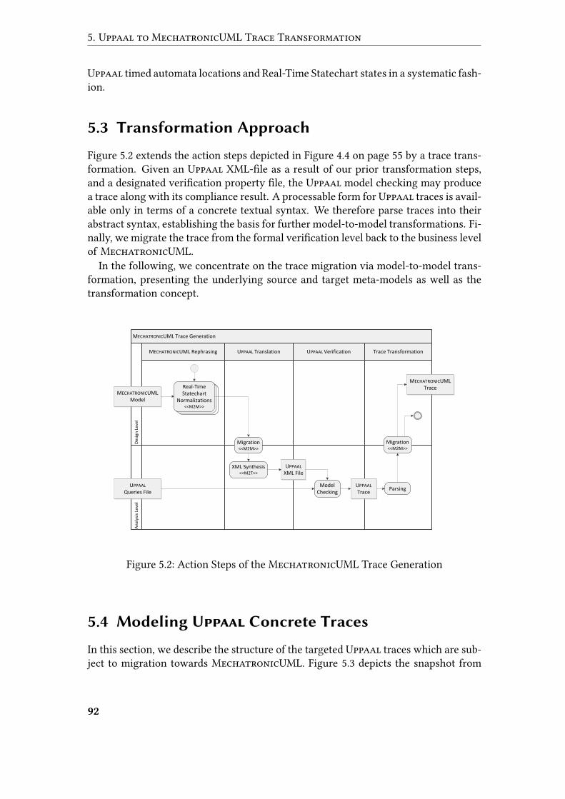
5. Uppaal to MechatronicUML Trace Transformation
Uppaal timed automata locations and Real-Time Statechart states in a systematic fash-ion.
5.3 Transformation Approach
Figure 5.2 extends the action steps depicted in Figure 4.4 on page 55 by a trace trans-formation. Given an Uppaal XML-�le as a result of our prior transformation steps,and a designated veri�cation property �le, the Uppaal model checking may producea trace along with its compliance result. A processable form for Uppaal traces is avail-able only in terms of a concrete textual syntax. We therefore parse traces into theirabstract syntax, establishing the basis for further model-to-model transformations. Fi-nally, we migrate the trace from the formal veri�cation level back to the business levelof MechatronicUML.
In the following, we concentrate on the trace migration via model-to-model trans-formation, presenting the underlying source and target meta-models as well as thetransformation concept.
MECHATRONICUML Trace Generation
MECHATRONICUML Rephrasing UPPAAL VerificationUPPAAL Translation Trace Transformation
An
alys
is L
evel
Des
ign
Lev
el
Real-TimeStatechart
Normalizations<<M2M>>
Real-TimeStatechart
Normalizations<<M2M>>
MECHATRONICUML Model
Migration<<M2M>>
XML Synthesis<<M2T>>
UPPAAL XML File
UPPAAL Queries File
UPPAAL Trace
Model Checking
MECHATRONICUML Trace
Migration<<M2M>>
Parsing
Real-TimeStatechart
Normalizations<<M2M>>
Figure 5.2: Action Steps of the MechatronicUML Trace Generation
5.4 Modeling Uppaal Concrete Traces
In this section, we describe the structure of the targeted Uppaal traces which are sub-ject to migration towards MechatronicUML. Figure 5.3 depicts the snapshot from
92
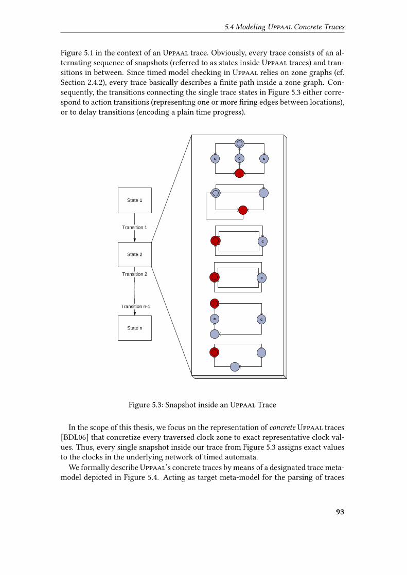
5.4 Modeling Uppaal Concrete Traces
Figure 5.1 in the context of an Uppaal trace. Obviously, every trace consists of an al-ternating sequence of snapshots (referred to as states inside Uppaal traces) and tran-sitions in between. Since timed model checking in Uppaal relies on zone graphs (cf.Section 2.4.2), every trace basically describes a �nite path inside a zone graph. Con-sequently, the transitions connecting the single trace states in Figure 5.3 either corre-spond to action transitions (representing one or more �ring edges between locations),or to delay transitions (encoding a plain time progress).
State 2
State 1
Transition 1
State n
Transition n-1
Transition 2
c c c
c
c
c c
Figure 5.3: Snapshot inside an Uppaal Trace
In the scope of this thesis, we focus on the representation of concrete Uppaal traces[BDL06] that concretize every traversed clock zone to exact representative clock val-ues. Thus, every single snapshot inside our trace from Figure 5.3 assigns exact valuesto the clocks in the underlying network of timed automata.
We formally describeUppaal’s concrete traces by means of a designated trace meta-model depicted in Figure 5.4. Acting as target meta-model for the parsing of traces
93
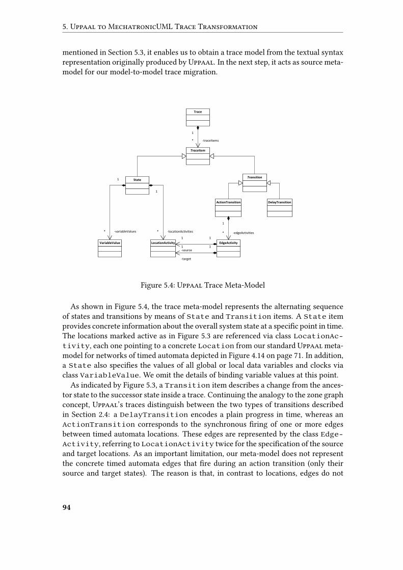
5. Uppaal to MechatronicUML Trace Transformation
mentioned in Section 5.3, it enables us to obtain a trace model from the textual syntaxrepresentation originally produced by Uppaal. In the next step, it acts as source meta-model for our model-to-model trace migration.
Trace
TraceItem
StateTransition
VariableValue LocationActivity
ActionTransition DelayTransition
EdgeActivity
1
-edgeActivities*
1
-source
1
1
-target
1
1
-locationActivities*
1
-variableValues*
1
-traceItems*
Figure 5.4: Uppaal Trace Meta-Model
As shown in Figure 5.4, the trace meta-model represents the alternating sequenceof states and transitions by means of State and Transition items. A State itemprovides concrete information about the overall system state at a speci�c point in time.The locations marked active as in Figure 5.3 are referenced via class LocationAc-tivity, each one pointing to a concrete Location from our standard Uppaal meta-model for networks of timed automata depicted in Figure 4.14 on page 71. In addition,a State also speci�es the values of all global or local data variables and clocks viaclass VariableValue. We omit the details of binding variable values at this point.
As indicated by Figure 5.3, a Transition item describes a change from the ances-tor state to the successor state inside a trace. Continuing the analogy to the zone graphconcept, Uppaal’s traces distinguish between the two types of transitions describedin Section 2.4: a DelayTransition encodes a plain progress in time, whereas anActionTransition corresponds to the synchronous �ring of one or more edgesbetween timed automata locations. These edges are represented by the class Edge-Activity, referring to LocationActivity twice for the speci�cation of the sourceand target locations. As an important limitation, our meta-model does not representthe concrete timed automata edges that �re during an action transition (only theirsource and target states). The reason is that, in contrast to locations, edges do not
94
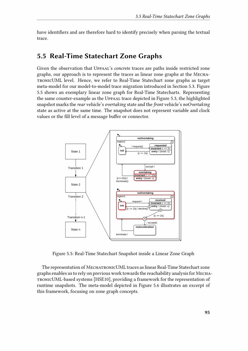
5.5 Real-Time Statechart Zone Graphs
have identi�ers and are therefore hard to identify precisely when parsing the textualtrace.
5.5 Real-Time Statechart Zone Graphs
Given the observation that Uppaal’s concrete traces are paths inside restricted zonegraphs, our approach is to represent the traces as linear zone graphs at the Mecha-tronicUML level. Hence, we refer to Real-Time Statechart zone graphs as targetmeta-model for our model-to-model trace migration introduced in Section 5.3. Figure5.5 shows an exemplary linear zone graph for Real-Time Statecharts. Representingthe same counter-example as the Uppaal trace depicted in Figure 5.3, the highlightedsnapshot marks the rear vehicle’s overtaking state and the front vehicle’s noOvertakingstate as active at the same time. The snapshot does not represent variable and clockvalues or the �ll level of a message bu�er or connector.
State 2
State 1
Transition 1
State n
Transition n-1
Transition 2
noOvertaking
requested
invariant c <= 2s
entry / {reset: c}
accept /
region1
init
/ request()
[c >= 2s]
1
overtaking
invariant c <= 10s
entry / {reset: c}[c>=10s] /
terminate()
noOvertaking
received
invariant c <= 2s
entry / {reset: c}
/ accept()
region1
init
request /
[c >= 2s] / decline()
1
noAcceleration
terminate /
[c >= 2s]
2
1
Figure 5.5: Real-Time Statechart Snapshot inside a Linear Zone Graph
The representation of MechatronicUML traces as linear Real-Time Statechart zonegraphs enables us to rely on previous work towards the reachability analysis forMecha-tronicUML-based systems [HSE10], providing a framework for the representation ofruntime snapshots. The meta-model depicted in Figure 5.6 illustrates an excerpt ofthis framework, focusing on zone graph concepts.
95
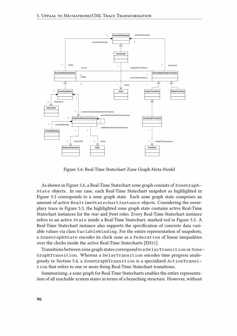
5. Uppaal to MechatronicUML Trace Transformation
ReachabilityGraph
ZoneGraph
ReachabilityGraphState ReachabilityGraphTransition
ZoneGraphState
VariableBinding
Federation
RealtimeStatechartInstance
RealtimeStatechart State
Clock ActionTransition DelayTransition
ZoneGraphTransition
Transition
-reachabilityGraph
1
-transitions*
-reachabilityGraph
1
-states*
1
-containedToplevelStatechartInstances*
1
-federation1
1
-variableBindings*
-parentRealtimeStatechartInstance
1
-subRealtimeStatechartInstances
*
*
-firedRTSCTransitions*
*
-instanceOf1
*
-active1
*
-clocks*
-source
1
-outgoingTransitions
*-target
1
-incomingTransitions
*
Figure 5.6: Real-Time Statechart Zone Graph Meta-Model
As shown in Figure 5.6, a Real-Time Statechart zone graph consists of ZoneGraph-State objects. In our case, each Real-Time Statechart snapshot as highlighted inFigure 5.5 corresponds to a zone graph state. Each zone graph state comprises anamount of active RealtimeStatechartInstance objects. Considering the exem-plary trace in Figure 5.5, the highlighted zone graph state contains active Real-TimeStatechart instances for the rear and front roles. Every Real-Time Statechart instancerefers to an active State inside a Real-Time Statechart, marked red in Figure 5.5. AReal-Time Statechart instance also supports the speci�cation of concrete data vari-able values via class VariableBinding. For the entire representation of snapshots,a ZoneGraphState encodes its clock zone as a Federation of linear inequalitiesover the clocks inside the active Real-Time Statecharts [EH11].
Transitions between zone graph states correspond to aDelayTransition orZone-GraphTransition. Whereas a DelayTransition encodes time progress analo-gously to Section 5.4, a ZoneGraphTransition is a specialized ActionTransi-tion that refers to one or more �ring Real-Time Statechart transitions.
Summarizing, a zone graph for Real-Time Statecharts enables the entire representa-tion of all reachable system states in terms of a branching structure. However, without
96
5.6 Inverse Resolution of Traceability Links
any branches, it also serves for the representation of linear graphs that only focus onone possible �nite execution path. Moreover, the representation of clock zones as lin-ear inequalities also supports the special case of equalities, i.e. serves for the speci�ca-tion of concrete clock values. Consequently, zone graphs for Real-Time Statecharts aresuitable for the representation of Uppaal’s concrete traces at the MechatronicUMLlevel. Only the representation of messages inside bu�ers or connectors would requireslight extensions.
5.6 Inverse Resolution of Traceability Links
Given a concrete Uppaal trace as an instance of the meta-model introduced in Section5.4, the remaining challenge is to transform this trace into a linear zone graph forReal-Time Statecharts as described in Section 5.5. As indicated by the meta-modelin Figure 5.4, Uppaal’s traces specify references to timed automata locations that areconsidered active. The key to our challenge lies in relating these locations to activestates inside Real-Time Statecharts, i.e. associating every location with the originalstate that it emerged from during our prior transformation towards Uppaal.
Our approach is to utilize the concept of traceability for model transformationsintroduced in Section 2.1.5. We therefore require our transformation from Mecha-tronicUML towards Uppaal to store so called traceability links between source andtarget model elements, i.e. Real-Time Statechart states and Uppaal locations in ourcase. These links enable us to resolve the particular source model element that a giventarget model element emerged from. In our case, we resolve Uppaal locations to-wards the original states inside Real-Time Statecharts. Considering the resolve di-rection from target to source model of our Uppaal transformation, we refer to thistechnique as inverse resolution.
In our case, complexity arises due to the fact that we carried out a stepwise transfor-mation as described in Section 4. The MechatronicUML source model elements arenot mapped to theUppaal target model elements directly, but via numerous intermedi-ate model elements that result from the normalization steps for Real-Time Statecharts.Figure 5.7 illustrates the mapping trace for the exemplary noOvertaking state of therear role, traversing three intermediate representations during the transformation to-wards an Uppaal timed automaton location. As also shown in Figure 5.7, we tacklethe traceability challenge by means of an incremental inverse resolution, i.e. resolvemodel elements recursively to obtain an element of the original MechatronicUMLdesign model.
During the inverse resolution, we abstract from the concrete number of intermedi-ate models to bridge. Instead, we stop the recursion whenever we face an element ofthe original MechatronicUML input model. By not considering the concrete numberof intermediate models, we ensure independence from any modi�cations to the trans-formation work�ow from MechatronicUML towards Uppaal. As long as traceabilitybetween the single model elements is given, the inverse resolution approach does notrequire adaptations, which clearly reduces the maintainability e�orts.
97
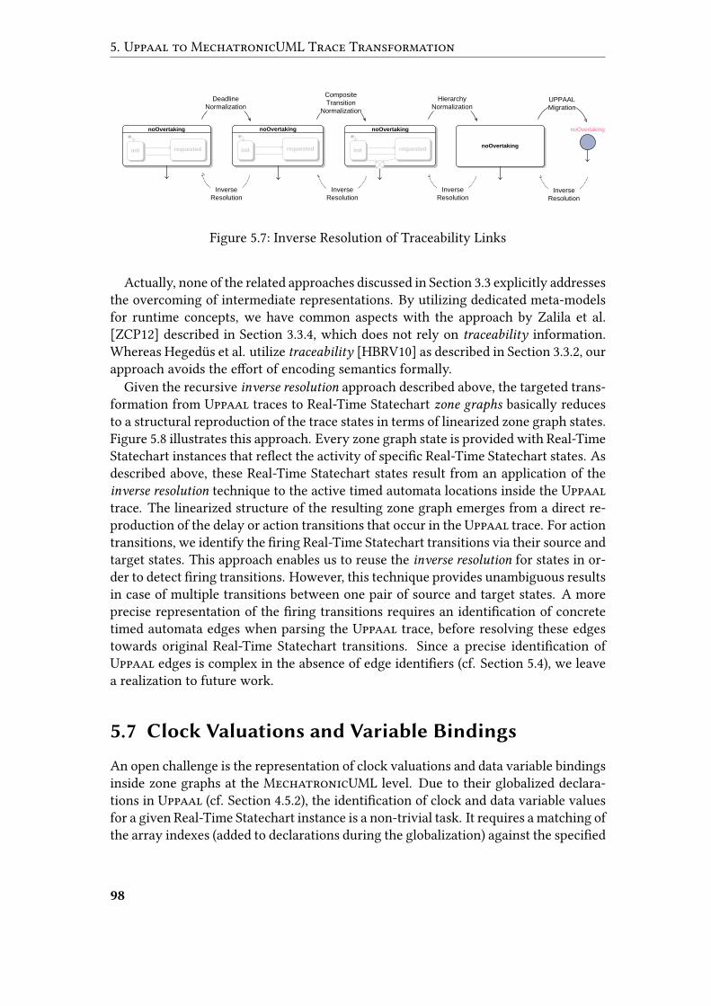
5. Uppaal to MechatronicUML Trace Transformation
noOvertaking
Inverse
Resolution
Inverse
Resolution
Inverse
Resolution
Deadline
Normalization
Composite
Transition
Normalization
Hierarchy
NormalizationUPPAAL
Migration
Inverse
Resolution
noOvertakingnoOvertaking
requestedinit
noOvertaking
requestedinit requestedinitnoOvertaking
Figure 5.7: Inverse Resolution of Traceability Links
Actually, none of the related approaches discussed in Section 3.3 explicitly addressesthe overcoming of intermediate representations. By utilizing dedicated meta-modelsfor runtime concepts, we have common aspects with the approach by Zalila et al.[ZCP12] described in Section 3.3.4, which does not rely on traceability information.Whereas Hegedüs et al. utilize traceability [HBRV10] as described in Section 3.3.2, ourapproach avoids the e�ort of encoding semantics formally.
Given the recursive inverse resolution approach described above, the targeted trans-formation from Uppaal traces to Real-Time Statechart zone graphs basically reducesto a structural reproduction of the trace states in terms of linearized zone graph states.Figure 5.8 illustrates this approach. Every zone graph state is provided with Real-TimeStatechart instances that re�ect the activity of speci�c Real-Time Statechart states. Asdescribed above, these Real-Time Statechart states result from an application of theinverse resolution technique to the active timed automata locations inside the Uppaaltrace. The linearized structure of the resulting zone graph emerges from a direct re-production of the delay or action transitions that occur in the Uppaal trace. For actiontransitions, we identify the �ring Real-Time Statechart transitions via their source andtarget states. This approach enables us to reuse the inverse resolution for states in or-der to detect �ring transitions. However, this technique provides unambiguous resultsin case of multiple transitions between one pair of source and target states. A moreprecise representation of the �ring transitions requires an identi�cation of concretetimed automata edges when parsing the Uppaal trace, before resolving these edgestowards original Real-Time Statechart transitions. Since a precise identi�cation ofUppaal edges is complex in the absence of edge identi�ers (cf. Section 5.4), we leavea realization to future work.
5.7 Clock Valuations and Variable Bindings
An open challenge is the representation of clock valuations and data variable bindingsinside zone graphs at the MechatronicUML level. Due to their globalized declara-tions in Uppaal (cf. Section 4.5.2), the identi�cation of clock and data variable valuesfor a given Real-Time Statechart instance is a non-trivial task. It requires a matching ofthe array indexes (added to declarations during the globalization) against the speci�ed
98
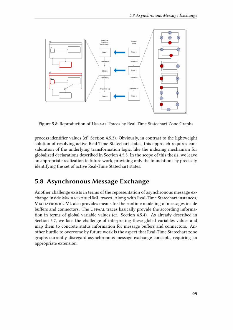
5.8 Asynchronous Message Exchange
State 2
State 1
Transition 1
State n
Transition n-1
Transition 2
c c c
c
c
c c
State 1
Transition 1
State n
Transition n-1
Transition 2
State 2
Real-Time
Statechart
Zone Graph
UPPAAL
Trace
Figure 5.8: Reproduction of Uppaal Traces by Real-Time Statechart Zone Graphs
process identi�er values (cf. Section 4.5.3). Obviously, in contrast to the lightweightsolution of resolving active Real-Time Statechart states, this approach requires con-sideration of the underlying transformation logic, like the indexing mechanism forglobalized declarations described in Section 4.5.3. In the scope of this thesis, we leavean appropriate realization to future work, providing only the foundations by preciselyidentifying the set of active Real-Time Statechart states.
5.8 Asynchronous Message Exchange
Another challenge exists in terms of the representation of asynchronous message ex-change inside MechatronicUML traces. Along with Real-Time Statechart instances,MechatronicUML also provides means for the runtime modeling of messages insidebu�ers and connectors. The Uppaal traces basically provide the according informa-tion in terms of global variable values (cf. Section 4.5.4). As already described inSection 5.7, we face the challenge of interpreting these global variables values andmap them to concrete status information for message bu�ers and connectors. An-other hurdle to overcome by future work is the aspect that Real-Time Statechart zonegraphs currently disregard asynchronous message exchange concepts, requiring anappropriate extension.
99

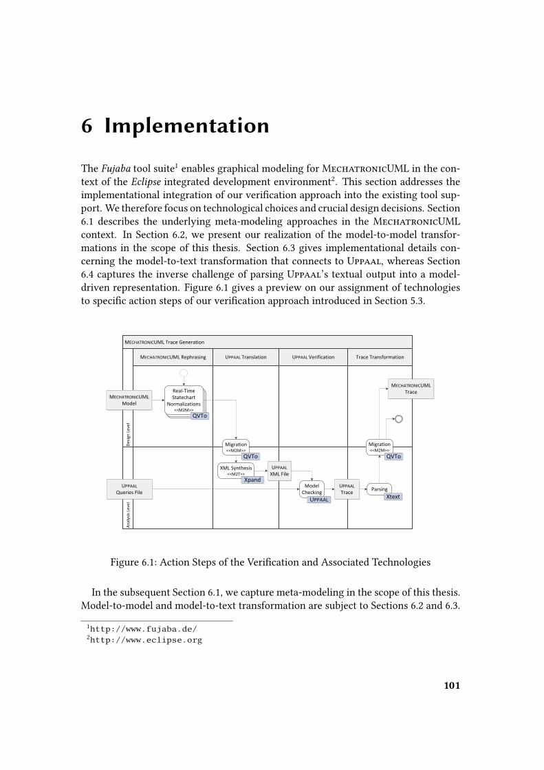
6 Implementation
The Fujaba tool suite1 enables graphical modeling for MechatronicUML in the con-text of the Eclipse integrated development environment2. This section addresses theimplementational integration of our veri�cation approach into the existing tool sup-port. We therefore focus on technological choices and crucial design decisions. Section6.1 describes the underlying meta-modeling approaches in the MechatronicUMLcontext. In Section 6.2, we present our realization of the model-to-model transfor-mations in the scope of this thesis. Section 6.3 gives implementational details con-cerning the model-to-text transformation that connects to Uppaal, whereas Section6.4 captures the inverse challenge of parsing Uppaal’s textual output into a model-driven representation. Figure 6.1 gives a preview on our assignment of technologiesto speci�c action steps of our veri�cation approach introduced in Section 5.3.
MECHATRONICUML Trace Generation
MECHATRONICUML Rephrasing UPPAAL VerificationUPPAAL Translation Trace Transformation
An
alys
is L
evel
Des
ign
Lev
el
Real-TimeStatechart
Normalizations<<M2M>>
Real-TimeStatechart
Normalizations<<M2M>>
MECHATRONICUML Model
Migration<<M2M>>
XML Synthesis<<M2T>>
UPPAAL XML File
UPPAAL Queries File
UPPAAL Trace
Model Checking
MECHATRONICUML Trace
Migration<<M2M>>
Parsing
Real-TimeStatechart
Normalizations<<M2M>>
QVTo
QVTo QVTo
Xtext
Xpand
UPPAAL
Figure 6.1: Action Steps of the Veri�cation and Associated Technologies
In the subsequent Section 6.1, we capture meta-modeling in the scope of this thesis.Model-to-model and model-to-text transformation are subject to Sections 6.2 and 6.3.
1http://www.fujaba.de/2http://www.eclipse.org
101
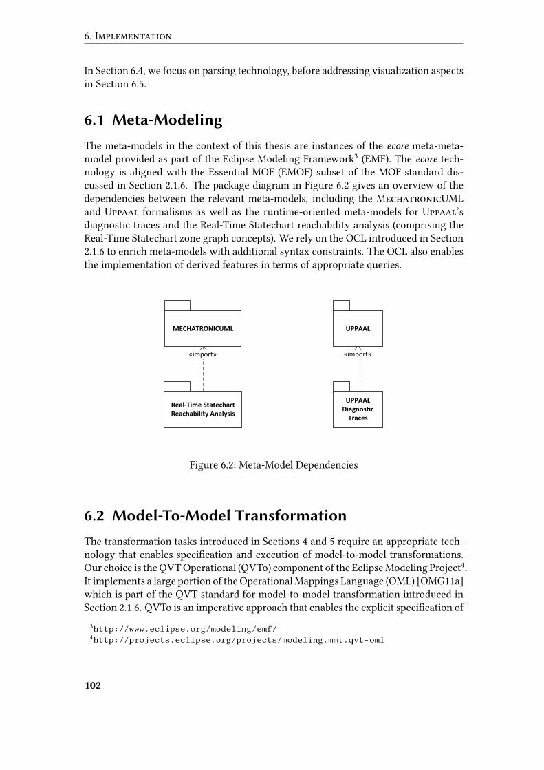
6. Implementation
In Section 6.4, we focus on parsing technology, before addressing visualization aspectsin Section 6.5.
6.1 Meta-Modeling
The meta-models in the context of this thesis are instances of the ecore meta-meta-model provided as part of the Eclipse Modeling Framework3 (EMF). The ecore tech-nology is aligned with the Essential MOF (EMOF) subset of the MOF standard dis-cussed in Section 2.1.6. The package diagram in Figure 6.2 gives an overview of thedependencies between the relevant meta-models, including the MechatronicUMLand Uppaal formalisms as well as the runtime-oriented meta-models for Uppaal’sdiagnostic traces and the Real-Time Statechart reachability analysis (comprising theReal-Time Statechart zone graph concepts). We rely on the OCL introduced in Section2.1.6 to enrich meta-models with additional syntax constraints. The OCL also enablesthe implementation of derived features in terms of appropriate queries.
MECHATRONICUML UPPAAL
UPPAAL Diagnostic
Traces
Real-Time Statechart Reachability Analysis
«import» «import»
Figure 6.2: Meta-Model Dependencies
6.2 Model-To-Model Transformation
The transformation tasks introduced in Sections 4 and 5 require an appropriate tech-nology that enables speci�cation and execution of model-to-model transformations.Our choice is the QVT Operational (QVTo) component of the Eclipse Modeling Project4.It implements a large portion of the Operational Mappings Language (OML) [OMG11a]which is part of the QVT standard for model-to-model transformation introduced inSection 2.1.6. QVTo is an imperative approach that enables the explicit speci�cation of
3http://www.eclipse.org/modeling/emf/4http://projects.eclipse.org/projects/modeling.mmt.qvt-oml
102
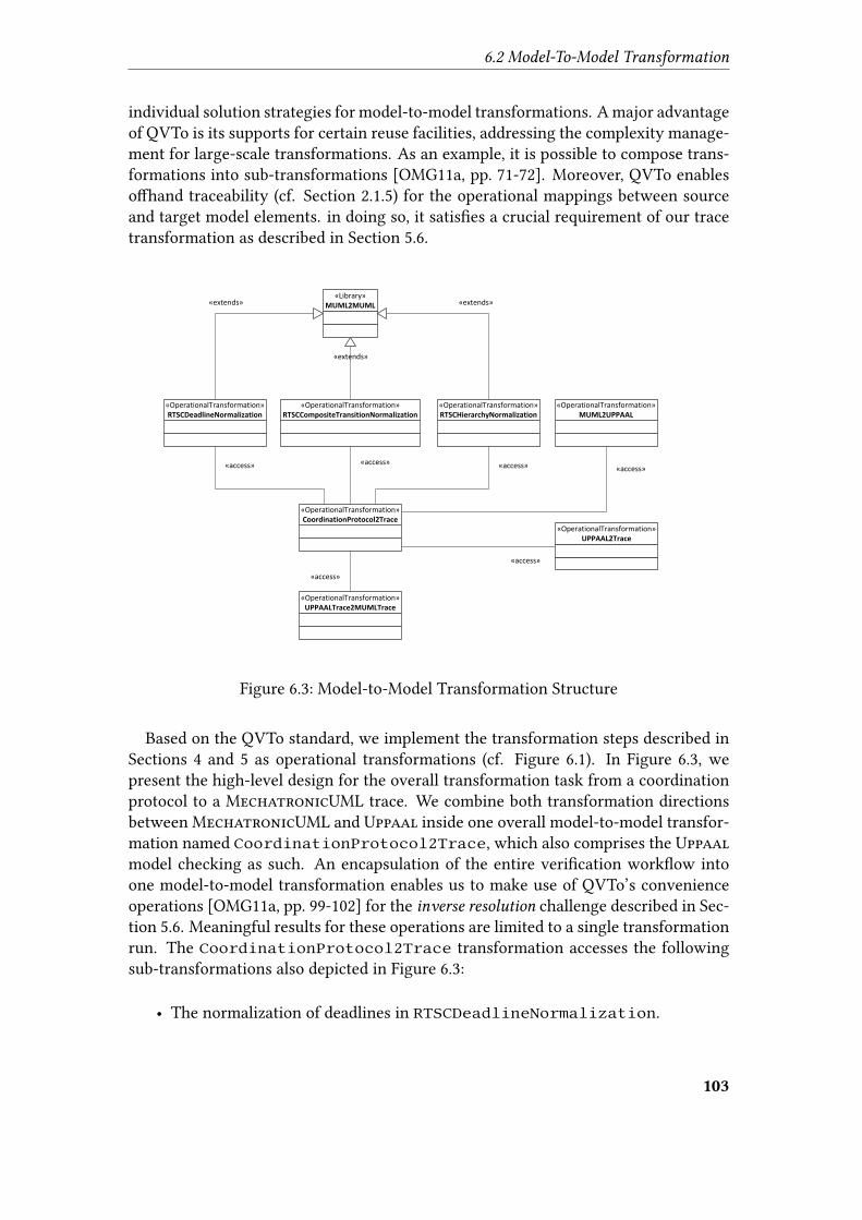
6.2 Model-To-Model Transformation
individual solution strategies for model-to-model transformations. A major advantageof QVTo is its supports for certain reuse facilities, addressing the complexity manage-ment for large-scale transformations. As an example, it is possible to compose trans-formations into sub-transformations [OMG11a, pp. 71-72]. Moreover, QVTo enableso�hand traceability (cf. Section 2.1.5) for the operational mappings between sourceand target model elements. in doing so, it satis�es a crucial requirement of our tracetransformation as described in Section 5.6.
«OperationalTransformation»RTSCDeadlineNormalization
«OperationalTransformation»RTSCCompositeTransitionNormalization
«OperationalTransformation»RTSCHierarchyNormalization
«OperationalTransformation»MUML2UPPAAL
«OperationalTransformation»UPPAALTrace2MUMLTrace
«Library»MUML2MUML«extends»
«extends»
«extends»
«access» «access» «access» «access»
«access»
«access»
«OperationalTransformation»UPPAAL2Trace
«OperationalTransformation»CoordinationProtocol2Trace
Figure 6.3: Model-to-Model Transformation Structure
Based on the QVTo standard, we implement the transformation steps described inSections 4 and 5 as operational transformations (cf. Figure 6.1). In Figure 6.3, wepresent the high-level design for the overall transformation task from a coordinationprotocol to a MechatronicUML trace. We combine both transformation directionsbetween MechatronicUML and Uppaal inside one overall model-to-model transfor-mation named CoordinationProtocol2Trace, which also comprises the Uppaalmodel checking as such. An encapsulation of the entire veri�cation work�ow intoone model-to-model transformation enables us to make use of QVTo’s convenienceoperations [OMG11a, pp. 99-102] for the inverse resolution challenge described in Sec-tion 5.6. Meaningful results for these operations are limited to a single transformationrun. The CoordinationProtocol2Trace transformation accesses the followingsub-transformations also depicted in Figure 6.3:
• The normalization of deadlines in RTSCDeadlineNormalization.
103
6. Implementation
• The normalization of composite transitions in RTSCCompositeTransition-Normalization.
• The normalization of hierarchical states in RTSCHierarchyNormalization.
• The migration from MechatronicUML to Uppaal in MUML2UPPAAL.
• The migration of the Uppaal trace to MechatronicUML in UPPAALTrace2-MUMLTrace.
We refer to the forthcoming Section 6.2.1 for an explanation of the special role thatthe MUML2MUML library takes within our transformation design. The connection toand from Uppaal is subject to the UPPAAL2Trace transformation which is capturedin Section 6.2.2.
6.2.1 Encapsulation of Normalization Logic
The three normalization steps for Real-Time Statecharts play a special role in the coop-eration of model-to-model transformations: by transforming only particular aspects, acertain amount of Real-Time Statechart features remains una�ected during each nor-malization. Since we refrain from in-place transformation (cf. Section 2.1.5), each nor-malization generates an unchanged reproduction with respect to most features. Tech-nically speaking, our target models are deep copies of the source models to a large ex-tent. As a result, there is a signi�cant overlap between the single normalization steps,since each produces a target model which is largely (but not entirely) unchanged incomparison to the source model.
Keeping up with this observation, we encapsulate the functionality of reproducinga MechatronicUML model into a shared QVTo library named MUML2MUML. All ournormalizations import and extend this library as depicted in Figure 6.3, utilizing itsbasic reproduction functionality for MechatronicUML models. However, since thesource models are never meant to be copied entirely, the transformations overridededicated mapping operations of the MUML2MUML library. In doing so, they carry outspeci�c changes on the target model in comparison to the source model.
6.2.2 Uppaal Integration
The UPPAAL2Trace transformation depicted in Figure 6.3 is charged with a seam-less integration of Uppaal’s text-based input and output formats into the work�ow ofmodel-to-model transformations, i.e. it bridges the gaps between abstract syntax usedfor model-to-model transformations and Uppaal’s concrete textual syntaxes. Givenan abstract syntax representation for a network of timed automata, the transforma-tion’s task is to provide another abstract syntax representation of the trace providedby Uppaal. It comprises the following action steps, which are also depicted in Figure6.1:
104
6.3 Model-to-Text Transformation
• Triggering the model-to-text transformation to obtain Uppaal’s XML-based in-put format.
• Running the Uppaal model checking against a single property in a speci�edqueries �le.
• Parsing a possible trace into its abstract syntax.
Hence, the UPPAAL2Trace transformation externalizes its model-to-model trans-formation task to the textual syntax level in order to interact with Uppaal. The exe-cution of the above steps is carried out by means of a dedicated QVT black-box library[OMG11a] implemented in Java5. For model checking, the implementation connectsto Uppaal’s command line tool verifyta by means of the command in Listing 6.1. Weuse Uppaal in its current release version 4.0.13.
Listing 6.1: Uppaal Model Checking Command
v e r i f y t a −q −s −t 1 <model > <query >
The variables <model> and <query> represent paths to the Uppaal XML �le andthe according queries �le that contains the relevant veri�cation property (cf. Figure6.1). The options -q and -s suppress user feedback as the summary of active options,or a progress indicator during model checking. These information are irrelevant whenusing Uppaal in an automatic work�ow, since they do not contribute to the �nal ver-i�cation results. For the same reason, they are also not expected by our parser forUppaal traces. The -t1 option delivers the shortest available trace with respect tothe number of contained steps.
We refer to the forthcoming Sections 6.3 and 6.4 for the technological details ofconnecting to and from Uppaal via its speci�c textual input and output formats.
6.3 Model-to-Text Transformation
To ensure o�hand interoperability of our approach with Uppaal, we require an XMLsynthesis for networks of timed automata as described in the previous Section 4.5.6.As depicted in Figure 6.1, we use the Xpand
6 template language for the speci�ca-tion of an appropriate model-to-text transformation, running on top of a dedicatedtemplate engine. Noteworthy, we use a non-standard technology with respect to theMDA approach introduced in Section 2.1.6. The MOF standard actually speci�es itsown dedicated language in terms of the MOF Model to Text Transformation Language[OMG08]. Our approach of usingXpand is grounded in the previous work by Greenyer[Gre11]. Actually, the Xtend
7 language has been recently suggested as a successor toXpand, giving rise to a future replacement.
5http://www.java.com6http://wiki.eclipse.org/Xpand7http://www.eclipse.org/xtend/
105
6. Implementation
6.4 Parsing
Uppaal’s command line tool verifyta provides veri�cation results and traces textually.To obtain a trace representation based on the meta-model described in Section 5.4, werequire an appropriate syntactic analysis carried out by a parser.
As shown in Figure 6.1, we rely on the Xtext8 language development framework forthis challenge. Given a textual speci�cation of Uppaal’s diagnostic traces in termsof an appropriate grammar, Xtext is able to generate the according ecore meta-modeland parser. Hence, the meta-model for Uppaal traces described in Section 5.4 actuallyemerged from a grammar description and the Xtext generator technology. WhereasXtext also provides advanced textual editing support for domain-speci�c languages,our approach utilizes only the generation of meta-model and parser.
6.5 Visualization
The trace transformation described in Section 5 provides aMechatronicUML-speci�ctrace model given in terms of an abstract syntax. This model-driven representationleaves room for �exible visualizations on top of dedicated visual syntaxes. However, incontrast to the trace visualizations in Section 5.5, the current state of our visualizationdiverges from the concrete visual syntax of Real-Time Statecharts. Instead, we rely onthe Graphviz9 tool in order to generate diagrammatic representations for Real-TimeStatechart zone graphs. The resulting visualization is based on a textual enumerationof the active Real-Time Statechart states for each trace snapshot, and also di�erenti-ates between delay and action transitions in the trace. We refer to Appendix A for anexemplary visualization.
8http://www.eclipse.org/Xtext/9http://www.graphviz.org/
106
7 Evaluation
The evaluation of the contributions within this thesis are carried out in terms of theGoal Question Metric (GQM) approach described in Section 2.6. Following the GQMprocess de�ned by Solingen and Berghout in [SB99], we �rst address the de�nitionof goals, questions, and metrics in Section 7.1. The following Section 7.2 captures thedata collection phase, wheres the interpretation of the evaluation results is dedicatedto Section 7.3. In Section 7.4, we discuss threats to the validity of our �ndings.
7.1 Definition
In the subsequent sections, we de�ne the basics of our evaluation process. In Sections7.1.1 and 7.1.2, we introduce the case study models and veri�cation properties that theevaluation operates on.
7.1.1 Case Study Models
We gather an amount of seven case study models from the context of vehicle overtak-ing for evaluation purposes. Focusing on the Overtaking coordination protocol fromSection 4.1.1, we introduce a fundamental version that comprises non-hierarchicalReal-Time Statecharts free of composite transitions, entry-/exit-points, and entry-events. Figure 7.1 depicts these simpli�ed Real-Time Statecharts. The quality-of-
service assumptions regarding the role connector are optimistic, i.e. we assume instantand lossless delivery of messages.
Based on this fundamental version of the Overtaking protocol, we obtain six morevariants by systematically adding 1.) a deadline to represent the front role’s delay forthe evaluation of a request message, 2.) hierarchical states with entry-/exit-points, 3.)composite transitions, 4.) entry-events for clock resets, 5.) message delay, and �nally6.) message loss. Table 7.1 comprises these di�erent variants.
7.1.2 Verification Properties
We refer to three di�erent veri�cation properties already introduced in Section 4.1.1 todemonstrate the integration of Uppaal’s veri�cation engine with MechatronicUML.The properties cover the safety and liveness types described in Section 2.3. Table 7.2comprises these relevant veri�cation properties. The safety property R1 makes useof Uppaal’s deadlock statement to express the need for a well-de�ned successor state
107
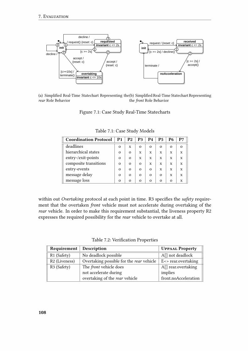
7. Evaluation
requested
invariant c <= 2s
accept /
{reset: c}
init
/ request() {reset: c}
[c >= 2s]
overtaking
invariant c <= 10s
[c>=10s] /
terminate()
accept /
{reset: c}
21
2
1
decline /
decline /
3
3
(a) Simpli�ed Real-Time Statechart Representing therear Role Behavior
received
invariant c <= 2sinit
request / {reset: c}
[c >= 2s] / decline()
noAcceleration
terminate /
[c >= 2s] /
accept()
2
1
(b) Simpli�ed Real-Time Statechart Representingthe front Role Behavior
Figure 7.1: Case Study Real-Time Statecharts
Table 7.1: Case Study ModelsCoordination Protocol P1 P2 P3 P4 P5 P6 P7
deadlines o x o o o o ohierarchical states o o x x x x xentry-/exit-points o o x x x x xcomposite transitions o o o x x x xentry-events o o o o x x xmessage delay o o o o o x xmessage loss o o o o o o x
within out Overtaking protocol at each point in time. R3 speci�es the safety require-ment that the overtaken front vehicle must not accelerate during overtaking of therear vehicle. In order to make this requirement substantial, the liveness property R2expresses the required possibility for the rear vehicle to overtake at all.
Table 7.2: Veri�cation PropertiesRequirement Description Uppaal Property
R1 (Safety) No deadlock possible A[] not deadlockR2 (Liveness) Overtaking possible for the rear vehicle E<> rear.overtakingR3 (Safety) The front vehicle does A[] rear.overtaking
not accelerate during impliesovertaking of the rear vehicle front.noAcceleration
108

7.1 De�nition
7.1.3 GQM Model
We now present the concrete GQM model that serves for evaluation purposes in thescope of this thesis. We re�ne two goals related to semantics preservation into ques-tions and metrics. The Tables 7.3 and 7.4 describe this re�nement for the di�erentsemantics preservation goals. We refer to the forthcoming Section 7.2 for the associ-ated hypotheses, i.e. expected outcomes for each metric. Future works may also focuson the evaluation of other quality characteristics in the scope of this thesis named inSection 4.1.3.
Table 7.3: Re�nement of the Semantics Preservation Goal for the MechatronicUMLto Uppaal TransformationGoal Purpose Ensure
Issue semantics preservation ofObject the MechatronicUML to Uppaal transformationViewpoint from the MechatronicUML engineer’s viewpoint
Question Q1 Does the transformation terminate in a well-de�ned manner?Metric M1 Severity values indicated by the transformation diagnostics for P1 to P7Question Q2 Does the target model comply with Uppaal’s syntax?Metric M2 EMF validity values on the generated Uppaal models for P1 to P7
M3 Number of validation errors indicated by Uppaal for P1 to P7Question Q3 Does the transformation preserve satis�ed safety properties?Metric M4 Uppaal veri�cation result for requirement R1 on P1 to P7
M5 Uppaal veri�cation result for requirement R3 on P1 to P7Question Q4 Does the transformation preserve satis�ed liveness properties?Metric M6 Uppaal veri�cation result for requirement R2 on P1 to P7
Table 7.4: Re�nement of the Semantics Preservation Goal for the Uppaal to Mecha-tronicUML Trace Transformation
Goal Purpose EnsureIssue semantics preservation ofObject the Uppaal to MechatronicUML trace transformationViewpoint from the MechatronicUML engineer’s viewpoint
Question Q6 Does the transformation avoid too �ne-grained traces?Metric M7 Number of non-progressive states
in the liveness traces for R2 on P1 to P7Question Q7 Does the transformation provide complete traces?Metric M8 Number of states with unfoundedly absent Real-Time Statecharts
in the liveness traces for requirement R2 on P1 to P7
109
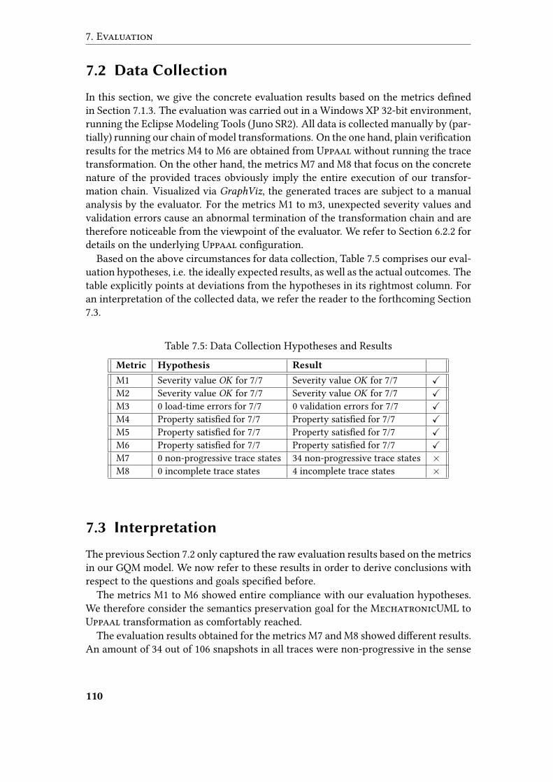
7. Evaluation
7.2 Data Collection
In this section, we give the concrete evaluation results based on the metrics de�nedin Section 7.1.3. The evaluation was carried out in a Windows XP 32-bit environment,running the Eclipse Modeling Tools (Juno SR2). All data is collected manually by (par-tially) running our chain of model transformations. On the one hand, plain veri�cationresults for the metrics M4 to M6 are obtained from Uppaal without running the tracetransformation. On the other hand, the metrics M7 and M8 that focus on the concretenature of the provided traces obviously imply the entire execution of our transfor-mation chain. Visualized via GraphViz, the generated traces are subject to a manualanalysis by the evaluator. For the metrics M1 to m3, unexpected severity values andvalidation errors cause an abnormal termination of the transformation chain and aretherefore noticeable from the viewpoint of the evaluator. We refer to Section 6.2.2 fordetails on the underlying Uppaal con�guration.
Based on the above circumstances for data collection, Table 7.5 comprises our eval-uation hypotheses, i.e. the ideally expected results, as well as the actual outcomes. Thetable explicitly points at deviations from the hypotheses in its rightmost column. Foran interpretation of the collected data, we refer the reader to the forthcoming Section7.3.
Table 7.5: Data Collection Hypotheses and ResultsMetric Hypothesis Result
M1 Severity value OK for 7/7 Severity value OK for 7/7 XM2 Severity value OK for 7/7 Severity value OK for 7/7 XM3 0 load-time errors for 7/7 0 validation errors for 7/7 XM4 Property satis�ed for 7/7 Property satis�ed for 7/7 XM5 Property satis�ed for 7/7 Property satis�ed for 7/7 XM6 Property satis�ed for 7/7 Property satis�ed for 7/7 XM7 0 non-progressive trace states 34 non-progressive trace states ×M8 0 incomplete trace states 4 incomplete trace states ×
7.3 Interpretation
The previous Section 7.2 only captured the raw evaluation results based on the metricsin our GQM model. We now refer to these results in order to derive conclusions withrespect to the questions and goals speci�ed before.
The metrics M1 to M6 showed entire compliance with our evaluation hypotheses.We therefore consider the semantics preservation goal for the MechatronicUML toUppaal transformation as comfortably reached.
The evaluation results obtained for the metrics M7 and M8 showed di�erent results.An amount of 34 out of 106 snapshots in all traces were non-progressive in the sense
110
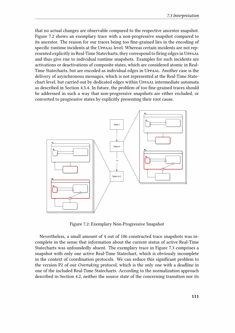
7.3 Interpretation
that no actual changes are observable compared to the respective ancestor snapshot.Figure 7.2 shows an exemplary trace with a non-progressive snapshot compared toits ancestor. The reason for our traces being too �ne-grained lies in the encoding ofspeci�c runtime incidents at the Uppaal level. Whereas certain incidents are not rep-resented explicitly in Real-Time Statecharts, they correspond to �ring edges inUppaaland thus give rise to individual runtime snapshots. Examples for such incidents areactivations or deactivations of composite states, which are considered atomic in Real-Time Statecharts, but are encoded as individual edges in Uppaal. Another case is thedelivery of asynchronous messages, which is not represented at the Real-Time State-chart level, but carried out by dedicated edges within Uppaal intermediate automataas described in Section 4.5.4. In future, the problem of too �ne-grained traces shouldbe addressed in such a way that non-progressive snapshots are either excluded, orconverted to progressive states by explicitly presenting their root cause.
State m
State 1
State m+1
~2
1
2
1
Figure 7.2: Exemplary Non-Progressive Snapshot
Nevertheless, a small amount of 4 out of 106 constructed trace snapshots was in-complete in the sense that information about the current status of active Real-TimeStatecharts was unfoundedly absent. The exemplary trace in Figure 7.3 comprises asnapshot with only one active Real-Time Statechart, which is obviously incompletein the context of coordination protocols. We can reduce this signi�cant problem tothe version P2 of our Overtaking protocol, which is the only one with a deadline inone of the included Real-Time Statecharts. According to the normalization approachdescribed in Section 4.2, neither the source state of the concerning transition nor its
111
7. Evaluation
target state are active when the transition �res. As a result, none of the original statesin the a�ected Real-Time Statechart was considered active at that time, which led tothe entire omission of such a statechart in speci�c trace snapshots. For future work,we propose support for �ring transitions as part of MechatronicUML runtime snap-shots. Based on this feature, incomplete traces could be enriched to represent currently�ring transitions and to provide status information for all active Real-Time Statecharts.
State m
State 1
State m+1
2
1
2
1
Figure 7.3: Exemplary Incomplete Trace Snapshot
Despite the above limitations, we consider the semantics preservation goal for ourtrace transformation as reached under the restrictions discussed in Section 5. On theone hand, non-progressive snapshots are basically a negligible problem of too muchprovided information. On the other hand, we could reduce the occurrence of incom-plete snapshots to the usage of deadlines in Real-Time Statecharts.
7.4 Threats to Validity
We draw attention to the fact that the present form of our transformation fromMecha-tronicUML to Uppaal omits speci�c Real-Time Statechart features like history, re-gion and transition priorities, asynchronous message parameters, or do-events. Thesefeatures are either disregarded by our transformation (e.g. priorities), or entirely ex-cluded from our evaluation models. Consequently, the semantics preservation assess-ments are valid only as long as these features are either absent or e�ectless duringtransformation or model checking.
112
7.4 Threats to Validity
We also restricted ourselves to the veri�cation of di�erent variants for one spe-ci�c MechatronicUML coordination protocol, disregarding other relevant veri�ca-tion use cases stated in Section 4.1.2. Hence, our conclusions with respect to seman-tics preservation are valid only for the initial stage of the compositional veri�cationapproach [Gie03]. The veri�cation of components or entire component instance con-�gurations may a�ect the evaluation validity.
For our trace transformation, we omitted the representation of runtime character-istics like variable and clock values or the current status of message bu�ers and con-nectors. Hence, traces that explicitly require such information to enable appropriatecause study are serious threats to the validity of our evaluation approach.
In general, we only considered a small amount of evaluation models with represen-tative syntactic characteristics. MechatronicUML gives rise to an in�nite amount ofpossible models, comprising a variety of other syntactic combinations that were notconsidered during our evaluation. The validity of our evaluation results is thereforerestricted to the speci�c characteristics of our evaluation models. A formal proof ofthe semantics preservation under all circumstances is desirable, but currently impossi-ble due to the absence of complete formal semantics for MechatronicUML. However,more sophisticated re�nements of evaluation goals with an increased number of ques-tions and metrics could actually reduce the validity restrictions.
113


8 Conclusion
This �nal section is dedicated to conclusions and perspectives in the context of thisthesis. In Section 8.1, we recap our approach towards transparency for the Uppaalmodel checking from the viewpoint of MechatronicUML engineers. Section 8.2 cap-tures relevant insights gained from our approach. Finally, Section 8.3 discusses possi-ble future extensions to our work.
8.1 Summary
In the context of safety-critical mechatronic systems, we addressed the pressing needfor the integration of reliable formal veri�cation techniques. We focused on a trans-parent Uppaal-based model checking in the scope of the MechatronicUML designmethod for networked mechatronic systems, emphasizing reduced cause study e�ortsin case of identi�ed counter-examples to formal requirements.
Similar to the prior work by Hirsch [Hir04], we addressed this objective in terms ofa semantics-preserving transformation towards the timed model checker Uppaal. Weapplied the model-driven engineering paradigm to establish a chain of model transfor-mations, enabling the transformation and veri�cation of 1:1 coordination protocols asthe basic step of the compositional veri�cation approach by Giese [Gie03]. Our trans-formations align the underlying modeling formalism in a stepwise and traceable man-ner, standing out from the work by Hirsch [Hir04] in terms of the focus on traceability.Before accomplishing the actual migration from MechatronicUML to Uppaal, wenormalize the involved Real-Time Statecharts with respect to incompatible languageconstructs. In contrast to Hirsch [Hir04], we explicitly represent quality-of-serviceassumptions about the asynchronous message exchange in Uppaal. We enabled thetranslation to Uppaal for an important subset of MechatronicUML’s language con-structs in the scope of coordination protocols, providing the underlying concepts and aprototypical implementation. However, we do not ensure full semantics preservationby omitting certain MechatronicUML features as message parameters, priorities, orhistory.
We exceeded the prior scope of the work by Hirsch [Hir04] in order to ensure acertain transparency of the Uppaal model checking, reducing the e�ort for Mecha-tronicUML domain engineers to receive meaningful veri�cation results. We thereforeprovide a transformation for concrete Uppaal traces back to the MechatronicUMLdesign level, representing traces as linear zone graphs for Real-Time Statecharts. Weapplied a rather lightweight inverse resolution approach to associate active timed au-tomata locations with their corresponding Real-Time Statechart states, utilizing the
115
8. Conclusion
traceability of the prior transformations. Our prototypical implementation focuses onthe representation of active Real-Time Statechart states and leaves the more sophis-ticated extraction of runtime information about clocks, variables, and asynchronousmessages to future work.
We assessed quality characteristics of our transformations along the lines of theGQM evaluation method. Our evaluation results against dedicatedMechatronicUML-based models from the context of vehicle overtaking revealed promising results withrespect to the achieved semantics preservation.
8.2 Insights
Our evaluation yielded promising insights with respect to our transformation ap-proach from MechatronicUML to Uppaal for coordination protocols. Referring tothe veri�cation results obtained for our designated MechatronicUML evaluationmodels, no semantic deviation with respect to the checked safety and liveness proper-ties could be identi�ed. Still, it is the missing support for the entire range of Mecha-tronicUML language constructs that separates us from an overall semantics preser-vation. Noteworthy, the omission of MechatronicUML’s priorities for regions andtransitions results in an over-approximation of the system behavior during theUppaalmodel checking. This does not invalidate safety properties proven correctly, but mayintroduce false negatives in terms of unfounded counter-examples. We provided cer-tain extensibility foundations to enable future support for omitted language constructs.Our stepwise transformation approach (considering only dedicated aspects duringeach step), as well as our arrangements for multiple instantiations of Real-Time Stat-echarts described in Section 4.5.3 both contribute to an increased maintainability. De-spite the above limitations, we established a fundamental stage of the compositionalveri�cation approach [Gie03] by providing coordination protocols with Uppaal modelchecking support.
Focusing on the representation of Uppaal traces by means of MechatronicUMLconcepts, our evaluation of the semantics preservation revealed a certain need for ad-ditional e�orts. The generated MechatronicUML traces turned out to be irritatingfor domain engineers due to the absence of considerable progress between consecutiveruntime snapshots. In rare cases related to deadlines, we even detected the possibilityof incomplete traces that exclude certain active Real-Time Statecharts. In addition tothese weak spots, the presented MechatronicUML traces currently su�er from miss-ing information about runtime values for clocks and data variables, and also aboutthe current status of message bu�ers and connectors. Considering the importanceof real-time message exchange in today’s mechatronic systems, we regard this as aserious limitation that certainly needs to be addressed by future work. In addition,our trace presentation does not rely on MechatronicUML’s concrete syntax for Real-Time Statecharts. Whereas this aspect clearly weakens the overall transparency of theveri�cation from the viewpoint of domain engineers, the underlying runtime-orientedmeta-models for MechatronicUML give rise to a straightforward integration of more
116
8.3 Outlook
sophisticated visual syntax representations. Despite the above shortcomings, our ap-proach of relating Uppaal timed automata locations and Real-Time Statechart statesvia inverse resolution proved the traceability of our initial transformation fromMecha-tronicUML to Uppaal.
In general, our methodology is not restricted to theMechatronicUML design methodor to an Uppaal-based veri�cation. State-based modeling languages from other do-mains might capture our model-driven approach, establishing traceable connectionsto appropriate analysis techniques that provide user-feedback based on runtime snap-shots.
8.3 Outlook
The most obvious extensions to this thesis are related to a full-�edged support forthe entire range of MechatronicUML’s language constructs, including parametrizedmessage exchange, numerous message bu�ers per role, history and do-events insideReal-Time Statecharts, or synchronization channels accessed by both urgent and non-urgent transitions. A future consideration of priorities for regions and transitionscould prevent over-approximations of the speci�ed behavior during theUppaalmodelchecking. Focusing on the compositional veri�cation approach by Giese [Gie03], dif-ferent starting points for our transformation other than coordination protocols arepossible and should be enabled. Based on these extensions, the semantics preserva-tion aspect of our model transformations should be subject to a more sophisticatedevaluation, assessing their long-term maturity to exclude the possibility of incorrectveri�cation feedback resulting from transformation errors.
A major transparency barrier remains in terms of veri�cation properties that stillrequire a manual encoding against the automatically generated Uppaal-based systemspeci�cation. As a remedy, we propose the de�nition of a domain-speci�c language forveri�cation properties in the context of the MechatronicUML design method. Rely-ing on the proven traceability of our Uppaal transformation, the MechatronicUML-speci�c properties could be aligned and translated towards Uppaal as well. In com-bination with the domain-speci�c representation of traces, the translation of domain-speci�c veri�cation properties gives rise to an advanced level of transparency.
Another possible extension are alternative concepts for the representation of Mecha-tronicUML runtime traces. For instance, Uppaal supports the trace visualizationalong the lines of UML sequence diagrams [OMG11c]. Positive impacts on the accep-tance by domain engineers are still to be studied.
On the technological level, our model-to-text transformation towards Uppaal iscurrently based on non-standardized tooling with respect to the OMG’s MDA. Animplementation of the MOF Model to Text Transformation Language, or the novelXtend language, are candidates for alternative realizations.
An advanced approach towards veri�cation has been proposed by Hirsch [Hir04] interms of background model checking, providing live veri�cation results to domain en-gineers whenever the designed model changes. Although yet unevaluated, our subjec-
117
8. Conclusion
tive impressions concerning performance of our veri�cation approach are promising,such that we consider an undemanded background model checking possible withoutdelaying design activities. In this context, we also call attention to Uppaal’s optionsof externalizing the veri�cation to a high-performance remote server. Furthermore,Uppaal provides dedicated reduction techniques to increase the model checking e�-ciency. An integration of these features could help to tackle any considerable perfor-mance issues with background model checking.
Given an advanced maturity of our transformation approach in the future, it may en-able the semantic anchoring [CSN05] of MechatronicUML by means of Uppaal net-works of timed automata, providing the current version of MechatronicUML withformal translational semantics.
118
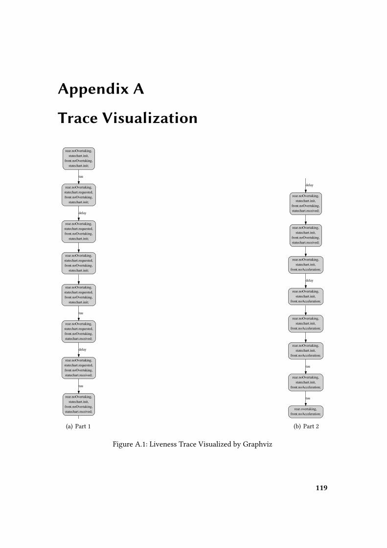
Appendix A
Trace Visualization
rear.noOvertaking,statechart.init,
front.noOvertaking,statechart.init;
rear.noOvertaking,statechart.requested,front.noOvertaking,
statechart.init;
tau
rear.noOvertaking,statechart.requested,front.noOvertaking,
statechart.init;
delay
rear.noOvertaking,statechart.requested,front.noOvertaking,
statechart.init;
rear.noOvertaking,statechart.requested,front.noOvertaking,
statechart.init;
rear.noOvertaking,statechart.requested,front.noOvertaking,statechart.received;
tau
rear.noOvertaking,statechart.requested,front.noOvertaking,statechart.received;
delay
rear.noOvertaking,statechart.init,
front.noOvertaking,statechart.received;
tau
rear.noOvertaking,statechart.init,
front.noOvertaking,statechart.received;
delay
rear.noOvertaking,statechart.init,
front.noOvertaking,statechart.received;
rear.noOvertaking,statechart.init,
front.noAcceleration;
rear.noOvertaking,statechart.init,
front.noAcceleration;
delay
rear.noOvertaking,statechart.init,
front.noAcceleration;
rear.noOvertaking,statechart.init,
front.noAcceleration;
rear.noOvertaking,statechart.init,
front.noAcceleration;
tau
rear.overtaking,front.noAcceleration;
tau
(a) Part 1
rear.noOvertaking,statechart.init,
front.noOvertaking,statechart.init;
rear.noOvertaking,statechart.requested,front.noOvertaking,
statechart.init;
tau
rear.noOvertaking,statechart.requested,front.noOvertaking,
statechart.init;
delay
rear.noOvertaking,statechart.requested,front.noOvertaking,
statechart.init;
rear.noOvertaking,statechart.requested,front.noOvertaking,
statechart.init;
rear.noOvertaking,statechart.requested,front.noOvertaking,statechart.received;
tau
rear.noOvertaking,statechart.requested,front.noOvertaking,statechart.received;
delay
rear.noOvertaking,statechart.init,
front.noOvertaking,statechart.received;
tau
rear.noOvertaking,statechart.init,
front.noOvertaking,statechart.received;
delay
rear.noOvertaking,statechart.init,
front.noOvertaking,statechart.received;
rear.noOvertaking,statechart.init,
front.noAcceleration;
rear.noOvertaking,statechart.init,
front.noAcceleration;
delay
rear.noOvertaking,statechart.init,
front.noAcceleration;
rear.noOvertaking,statechart.init,
front.noAcceleration;
rear.noOvertaking,statechart.init,
front.noAcceleration;
tau
rear.overtaking,front.noAcceleration;
tau
(b) Part 2
Figure A.1: Liveness Trace Visualized by Graphviz
119

Appendix B
CD Contents
• PDF version of this thesis
• Uppaal meta-model PDF document (cf. Section 4.5.1)
• Eclipse workspace (including all relevant plugins in the context of the Uppaalveri�cation for MechatronicUML, and also the seven evaluation models intro-duced in Section 7.1.1.
121


Bibliography
[ABB+11] Damian Nadales Agut, Bert van Beek, Harsh Beohar, Pieter Cuijpers,and Jasper Fonteijn. “The hierarchical compositional interchange for-mat.” In: Proceedings of the 9th international conference on Formal Methods
for Components and Objects. FMCO’10. Graz, Austria: Springer-Verlag,2011, pp. 316–335. isbn: 978-3-642-25270-9.
[ACD90] Rajeev Alur, Costas Courcoubetis, and David L. Dill. “Model-Checkingfor Real-Time Systems.” In: Fifth Annual IEEE Symposium on Logic in
Computer Science. Proceedings. (Philadelphia, June 4–7, 1990). Los Alami-tos: IEEE Computer Society, 1990, pp. 414–425. isbn: 978-0-8186-2073-7.
[ACH+92] Rajeev Alur, Costas Courcoubetis, Nicolas Halbwachs, David L. Dill, andHoward Wong-Toi. “Minimization of Timed Transition Systems.” In:CON-CUR ’92. Proceedings. Third International Conference on ConcurrencyTheory (Stony Brook, Aug. 24–27, 1992). Ed. by Rance Cleaveland. Lec-ture Notes in Computer Science 630. Berlin and Heidelberg: Springer,1992, pp. 340–354. isbn: 978-3-540-55822-4.
[AD90] Rajeev Alur and David L. Dill. “Automata For Modeling Real-Time Sys-tems.” In: Automata, Languages and Programming. Proceedings. 17th In-ternational Colloquium, ICALP90 (Warwick, July 6–20, 1990). Ed. by Mi-chael Paterson. Lecture Notes in Computer Science 443. Berlin and Hei-delberg: Springer, 1990, pp. 322–335. isbn: 978-3-540-52826-5.
[AFH91] Rajeev Alur, Tomás Feder, and Thomas A. Henzinger. “The Bene�ts ofRelaxing Punctuality.” In: Proceedings of the Tenth Annual ACM Sympo-
sium on Principles of Distributed Computing. (Montreal, Aug. 19–21, 1991).Ed. by Luigi Logrippo. New York: ACM, 1991, pp. 139–152. isbn: 978-0-89791-439-0.
[AGS+07] Luiz Paulo de Assis Barbosa, Kyller Gorgônio, Leandro Dias da Silva, An-tonio Marcus Nogueira Lima, and Angelo Perkusich. “On the automaticgeneration of timed automata models from ISA 5.2 diagrams.” In: Emerg-
ing Technologies and Factory Automation, 2007. ETFA. IEEE Conference on.2007, pp. 406–412.
[AH92] Rajeev Alur and Thomas A. Henzinger. “Logics and Models of Real Time.A Survey.” In: Real-Time. Theory in Practice. Proceedings. REX Workshop(Mook, June 3–7, 1991). Ed. by Jacobus W. de Bakker, Cornelis Huizing,Willem P. de Roever, and Grzegorz Rozenberg. Lecture Notes in Com-
123
Bibliography
puter Science 600. Berlin and Heidelberg: Springer, 1992, pp. 74–106.isbn: 978-3-540-55564-3.
[Alb04] Amos Albert. “Comparison of Event-Triggered and Time-Triggered Con-cepts with Regard to Distributed Control Systems.” In: Embedded World
2004. (Nürnberg). WEKA Fachzeitschriften-Verlag GmbH, 2004, pp. 235–253.
[Alu99] Rajeev Alur. “Timed Automata.” In: Computer Aided Veri�cation. 11th In-
ternational Conference, CAV’99. Proceedings. (Trento, July 6–10, 1999).Ed. by Nicolas Halbwachs and Doron Peled. Lecture Notes in ComputerScience 1633. Berlin and Heidelberg: Springer, 1999, pp. 8–22. isbn: 978-3-540-66202-0.
[BBB+12] Ste�en Becker, Christian Brenner, Christopher Brink, Stefan Dziwok, Re-nate Lö�er, Christian Heinzemann, Uwe Pohlmann, Wilhelm Schäfer,Julian Suck, and Oliver Sudmann. The MechatronicUML Design Method.
Process, Syntax, and Semantics. Tech. rep. tr-ri-12-326. Version 0.3. Soft-ware Engineering Group, Heinz Nixdorf Institute, University of Pader-born, Aug. 17, 2012.
[BBG+10] Twan Basten, Emiel Benthum, Marc Geilen, Martijn Hendriks, Fred Hou-ben, Georgeta Igna, Frans Reckers, Sebastian Smet, Lou Somers, EgbertTeeselink, Nikola Trčka, Frits Vaandrager, Jacques Verriet, Marc Voorho-eve, and Yang Yang. “Model-Driven Design-Space Exploration for Em-bedded Systems. The Octopus Toolset.” In: Leveraging Applications of For-mal Methods, Veri�cation, and Validation. Ed. by Tiziana Margaria andBernhard Ste�en. Lecture Notes in Computer Science 6415. Berlin andHeidelberg: Springer, 2010, pp. 90–105. isbn: 978-3-642-16557-3.
[BCN+09] D.A. van Beek, P. Collins, D.E. Nadales Agut, J.E. Rooda, and R.R.H. Schif-felers. “New Concepts in the Abstract Format of the Compositional Inter-change Format.” In: 3rd IFAC Conference on Analysis and Design of Hybrid
Systems. (Zaragoza). Ed. by A. Giua, C. Mahulea, M. Silva, and J. Zaytoon.2009, pp. 250–255.
[BCR94] Victor R. Basili, Gianluigi Caldiera, and H. Dieter Rombach. “The GoalQuestion Metric Approach.” In: Encyclopedia of Software Engineering. Ed.by John J. Marciniak. New York: Wiley, 1994.
[BDHH12] Jonathan Bogdoll, Alexandre David, Arnd Hartmanns, and Holger Her-manns. “mctau. Bridging the Gap between Modest andUppaal.” In:Model
Checking Software. Ed. by Alastair Donaldson and David Parker. Vol. 7385.Lecture Notes in Computer Science. Berlin and Heidelberg: Springer, 2012,pp. 227–233. isbn: 978-3-642-31758-3.
[BDL06] Gerd Behrmann, Alexandre David, and Kim G. Larsen.ATutorial onUppaal.Version 4.0. Department of Computer Science, Aalborg University. 2006.
124
Bibliography
[BGH01] K. Suzanne Barber, Thomas Graser, and Jim Holt. “Providing early feed-back in the development cycle through automated application of modelchecking to software architectures.” In: Automated Software Engineering,
2001. ASE 2001. Proceedings. 16th Annual International Conference on.2001, pp. 341–345.
[BK08] Christel Baier and Joost-Pieter Katoen. Principles ofModel Checking. Cam-bridge: MIT Press, 2008. isbn: 978-0-262-02649-9.
[BK12] Kamal Barakat and Stefan Kowalewski. “Modeling and Veri�cation ofNetwork Protocol Specs using Timed Pi-Calculus.” In: Ultra Modern Te-
lecommunications and Control Systems and Workshops (ICUMT). 2012 4th
International Congress on. 2012, pp. 884–891.[BLL+96] Johan Bengtsson, Kim Guldstrand Larsen, Fredrik Larsson, Paul Petters-
son, and Wang Yi. “Uppaal. A Tool Suite for Automatic Veri�cation ofReal-Time Systems.” In: Hybrid Systems. Vol. 3: Veri�cation and Control.Proceedings of the DIMACS/SYCON Workshop. (New Brunswick, Oct. 22–25, 1995). Ed. by Rajeev Alur, Thomas A. Henzinger, and Eduardo D.Sontag. Lecture Notes in Computer Science 1066. Berlin and Heidelberg:Springer, Oct. 1996, pp. 232–243. isbn: 978-3-540-61155-4.
[BNBC10] Harsh Beohar, D. E. Nadales Agut, Dirk A. van Beek, and Pieter J. L. Cui-jpers. “Hierarchical states in the Compositional Interchange Format.” In:SOS. Proceedings Seventh Workshop on Structural Operational Semantics.Ed. by Luca Aceto and Pawel Sobocinski. EPTCS 32. 2010, pp. 42–56.
[Bro06] Manfred Broy. “Challenges in automotive software engineering.” In: ICSE.28th International Conference on Software Engineering (Shanghai, May 20–28, 2006). Ed. by Leon J. Osterweil, H. Dieter Rombach, and Mary LouSo�a. ACM, 2006, pp. 33–42. isbn: 978-1-59593-375-1.
[BRSR07] D.A. Beek, M.A. Reniers, R.R.H. Schi�elers, and J.E. Rooda. “Foundationsof a Compositional Interchange Format for Hybrid Systems.” In: HybridSystems. Computation and Control. Ed. by Alberto Bemporad, AntonioBicchi, and Giorgio Buttazzo. Lecture Notes in Computer Science 4416.Springer Berlin Heidelberg, 2007, pp. 587–600. isbn: 978-3-540-71492-7.
[BW84] Victor R. Basili and David M. Weiss. “A Methodology for Collecting ValidSoftware Engineering Data.” In: IEEE Transactions on Software Engineer-
ing 10.6 (Nov. 1984), pp. 728–738.[BY04] Johan Bengtsson and Wang Yi. “Timed Automata. Semantics, Algorithms
and Tools.” In: Lectures on Concurrency and Petri Nets. Advances in Petri
Nets. Ed. by Jörg Desel, Wolfgang Reisig, and Grzegorz Rozenberg. Lec-ture Notes in Computer Science 3098. Springer, 2004, pp. 87–124. isbn:978-3-540-22261-3.
125
Bibliography
[CD88] Edmund M. Clarke and I. A. Draghicescu. “Expressibility results for linear-time and branching-time logics.” In: REXWorkshop. Linear Time, Branch-
ing Time and Partial Order in Logics and Models for Concurrency. Proceed-ings. School/Workshop (Noordwijkerhout, May 30–June 3, 1988). Ed. byJ. W. de Bakker, Willem P. de Roever, and Grzegorz Rozenberg. LectureNotes in Computer Science 354. Berlin and Heidelberg: Springer, 1988,pp. 428–437. isbn: 978-3-540-51080-2.
[CE82] Edmund M. Clarke and E. Allen Emerson. “Design and Synthesis of Syn-chronization Skeletons Using Branching-Time Temporal Logic.” In: Logicof Programs. Workshop (Yorktown Heights, May 1981). Ed. by DexterKozen. Lecture Notes in Computer Science 131. Springer, 1982, pp. 52–71.isbn: 978-3-540-11212-9.
[CES86] Edmund M. Clarke, E. Allen Emerson, and A. Prasad Sistla. “AutomaticVeri�cation of Finite-State Concurrent Systems Using Temporal LogicSpeci�cations.” In:ACMTransactions on Programming Languages and Sys-
tems 8.2 (1986), pp. 244–263.[CGP00] Edmund M. Clarke, Orna Grumberg, and Doron A. Peled. Model Check-
ing. Cambridge and London: MIT Press, 2000. isbn: 978-0-262-03270-4.[CGR11] Benoît Combemale, Laure Gonnord, and Vlad Rusu. “A Generic Tool
for Tracing Executions Back to a DSML’s Operational Semantics.” In:ECMFA. Modelling Foundations and Applications. Proceedings. 7th Eu-ropean Conference, ECMFA 2011 (Birmingham, June 6–9, 2011). Ed. byRobert B. France, Jochen Malte Küster, Behzad Bordbar, and Richard F.Paige. Lecture Notes in Computer Science 6698. Springer, 2011, pp. 35–51. isbn: 978-3-642-21469-1.
[CH03] Krzysztof Czarnecki and Simon Helsen. “Classi�cation of Model Trans-formation Approaches.” In:OOPSLA’03Workshop onGenerative Techniques
in the Context of Model-Driven Architecture. (Anaheim, Oct. 27, 2003).2003.
[CH06] Krzysztof Czarnecki and Simon Helsen. “Feature-Based Survey of ModelTransformation Approaches.” In: IBM Systems Journal 45.3 (2006): Model-
Driven Software Development, pp. 621–646.[CHP06] Jan Carlson, John Håkansson, and Paul Pettersson. “SaveCCM. An Ana-
lysable Component Model for Real-Time Systems.” In: Electronic Notes inTheoretical Computer Science 160 (2006), pp. 127–140.
[CSN05] Kai Chen, Janos Sztipanovits, and Sandeep Neema. “Toward a seman-tic anchoring infrastructure for domain-speci�c modeling languages.” In:Proceedings of the 5th ACM international conference on Embedded soft-
ware. EMSOFT ’05. (Jersey City). New York: ACM, 2005, pp. 35–43. isbn:978-1-59593-091-0.
126
Bibliography
[DBHT12] Stefan Dziwok, Kathrin Bröker, Christian Heinzemann, and Matthias Ti-chy. A Catalog of Real-Time Coordination Patterns for Advanced Mecha-
tronic Systems. Tech. rep. tr-ri-12-319. Software Engineering Group, HeinzNixdorf Institute, University of Paderborn, Feb. 2012.
[DHKK01] Pedro R. D’Argenio, Holger Hermanns, Joost-Pieter Katoen, and Ric Kla-ren. “MoDeST. A Modelling and Description Language for StochasticTimed Systems.” In: PAPM-PROBMIV. Process Algebra and Probabilistic
Methods, Performance Modeling and Veri�cation. Proceedings. Joint Inter-national Workshop, PAPM-PROBMIV 2001 (Aachen, Sept. 12–14, 2001).Ed. by Luca de Alfaro and Stephen Gilmore. Lecture Notes in ComputerScience 2165. Springer, 2001, pp. 87–104. isbn: 978-3-540-42556-4.
[Dil90] David L. Dill. “Timing Assumptions and Veri�cation of Finite-State Con-current Systems.” In: Automatic Veri�cation Methods for Finite State Sys-
tems. Proceedings. International Workshop (Grenoble, June 12–14, 1989).Ed. by Joseph Sifakis. Lecture Notes in Computer Science 407. Berlin andHeidelberg: Springer, 1990, pp. 197–212. isbn: 978-3-540-52148-8.
[DM01] Alexandre David and M. Oliver Möller. “From Huppaal to Uppaal. ATranslation from Hierarchical Timed Automata to Flat Timed Automata.”In: BRICS Report Series RS-01-11 (2001).
[DMY03] Alexandre David, M. Oliver Möller, and Wang Yi. Veri�cation of UML
Statechart with Real-Time Extensions. Tech. rep. 2003-009. Department ofInformation Technology, Uppsala University, 2003.
[Dor08] Rafał Dorociak. “Hybride Veri�kation von Mechatronic UML Modellendurch Integration des Modelcheckers PHAVer.” German. BA Thesis. Soft-ware Engineering Group, University of Paderborn, Jan. 2008.
[EC82] E. Allen Emerson and Edmund M. Clarke. “Using Branching Time Tem-poral Logic to Synthesize Synchronization Skeletons.” In: Science of Com-
puter Programming 2.3 (1982), pp. 241–266.[EH11] Tobias Eckardt and Christian Heinzemann. “Providing Timing Computa-
tions for FUJABA.” In: Proceedings of the 8th International Fujaba Days(Tartu). May 2011.
[EH86] E. Allen Emerson and Joseph Y. Halpern. “"Sometimes" and "Not Never"revisited. On branching versus linear time temporal logic.” In: Journal ofthe ACM 33.1 (Jan. 1986), pp. 151–178.
[EHH+13] Tobias Eckardt, Christian Heinzemann, Stefan Henkler, Martin Hirsch,Claudia Priesterjahn, and Wilhelm Schäfer. “Modeling and Verifying Dy-namic Communication Structures based on Graph Transformations.” In:Computer Science - Research and Development 28.1 (Feb. 2013). Ed. by Gre-gor Engels and Markus Luckey, pp. 3–22.
127
Bibliography
[EZK+13] Emeka Eyisi, Zhenkai Zhang, Xenofon Koutsoukos, Joseph Porter, Ga-bor Karsai, and Janos Sztipanovits. “Model-Based Control Design andIntegration of Cyberphysical Systems. An Adaptive Cruise Control CaseStudy.” In: Journal of Control Science and Engineering (2013).
[FG12] Peter H. Feiler and David P. Gluch. Model-Based Engineering with AADL.
An Introduction to the SAE Architecture Analysis and Design Language.SEI series in software engineering. Addison-Wesley, 2012. isbn: 978-0-321-88894-5.
[FN08] Angelo Furfaro and Libero Nigro. “Embedded Control Systems Designbased on RT-DEVS and Temporal Analysis using Uppaal.” In: IMCSIT.
Proceedings of the International Multiconference on Computer Science and
Information Technology. IMCSIT 2008 (Wisla, Oct. 20–22, 2008). IEEE,2008, pp. 601–608. isbn: 978-83-60810-14-9.
[Fon11] Jasper Fonteijn. “AND/OR superstate re�nement in Hierarchical Compo-sitional Interchange Format.” MA thesis. Eindhoven University of Tech-nology, Department of Mechanical Engineering, Systems EngineeringGroup, Mar. 22, 2011.
[Fre05] Goran Frehse. “PHAVer. Algorithmic Veri�cation of Hybrid Systems PastHyTech.” In: Hybrid Systems. Computation and Control. Proceedings. 8thInternational Workshop, HSCC 2005 (Zurich, Mar. 9–11, 2005). Ed. byManfred Morari and Lothar Thiele. Lecture Notes in Computer Science3414. Springer, 2005, pp. 258–273. isbn: 978-3-540-22261-3.
[GB03] Holger Giese and Sven Burmester. Real-Time Statechart Semantics. Tech.rep. tr-ri-03-239. Software Engineering Group, University of Paderborn,June 2003.
[GBSO04] Holger Giese, Sven Burmester, Wilhelm Schäfer, and Oliver Oberschelp.“Modular Design and Veri�cation of Component-Based Mechatronic Sys-tems with Online-Recon�guration.” In: SIGSOFT FSE. Proceedings of the
12th ACM SIGSOFT International Symposium on Foundations of Software
Engineering. FSE 2004. (Newport Beach). Ed. by Richard N. Taylor andMatthew B. Dwyer. ACM Press, 2004, pp. 179–188. isbn: 978-1-58113-855-9.
[Gie03] Holger Giese. A Formal Calculus for the Compositional Pattern-Based De-
sign of Correct Real-Time Systems. Tech. rep. tr-ri-03-240. Software Engi-neering Group, Universiy of Paderborn, July 2003.
[Gre11] Joel Greenyer. “Scenario-based Design of Mechatronic Systems.” PhDthesis. Software Engineering Group, Heinz Nixdorf Institute, Universityof Paderborn, Oct. 2011.
[Gro02] Thorsten Grotker. System Design with SystemC. Norwell: Kluwer Aca-demic Publishers, 2002. isbn: 978-1-4020-7072-3.
128

Bibliography
[HÅCT04] Hans Hansson, Mikael Åkerholm, Ivica Crnkovic, and Martin Törngren.“SaveCCM. A Component Model for Safety-Critical Real-Time Systems.”In: EUROMICRO. 30th EUROMICRO Conference 2004 (Rennes, Aug. 31–Sept. 3, 2004). IEEE Computer Society, 2004, pp. 627–635. isbn: 978-0-7695-2199-2.
[Har87] David Harel. “Statecharts. A Visual Formalism for Complex Systems.” In:Science of Computer Programming 8.3 (1987), pp. 231–274.
[HBRV10] Ábel Hegedüs, Gábor Bergmann, István Ráth, and Dániel Varró. “Back-annotation of Simulation Traces with Change-Driven Model Transfor-mations.” In: SEFM. 8th IEEE International Conference on Software Engi-
neering and Formal Methods. SEFM 2010 (Pisa, Sept. 13–18, 2010). Ed. byJosé Luiz Fiadeiro, Stefania Gnesi, and Andrea Maggiolo-Schettini. IEEEComputer Society, 2010, pp. 145–155. isbn: 978-0-7695-4153-2.
[HCM+08] John Håkansson, Jan Carlson, Aurelien Monot, Paul Pettersson, and Da-vor Slutej. “Component-Based Design and Analysis of Embedded Sys-tems with Uppaal PORT.” In: 6th International Symposium on Automated
Technology for Veri�cation and Analysis. Ed. by Sungdeok Cha, Jin-YoungChoi, Moonzoo Kima, Insup Lee, and Mahesh Viswanathan. Springer,Oct. 2008, pp. 252–257.
[HFG08] Paula Herber, Joachim Fellmuth, and Sabine Glesner. “Model checkingSystemC designs using timed automata.” In: Proceedings of the 6th IEEE/
ACM/IFIP international conference onHardware/Software codesign and sys-
tem synthesis. (Atlanta, GA, USA). CODES+ISSS ’08. New York, NY, USA:ACM, 2008, pp. 131–136. isbn: 978-1-60558-470-6.
[HG03] Martin Hirsch and Holger Giese. Towards the Incremental Model Checking
of Complex Real-Time UML Models. Tech. rep. tr-ri-04-247. University ofPaderborn, Oct. 2003, pp. 9–12.
[Hir04] Martin Hirsch. “E�zientes Model Checking von UML-RT Modellen undRealtime Statecharts mit Uppaal.” German. Diploma Thesis. SoftwareEngineering Group, University of Paderborn, 2004.
[HMG11] Rajeshwari Hegde, Geetishree Mishra, and K.S. Gurumurthy. “An Insightinto the Hardware and Software Complexity of ECUs in Vehicles.” In: Ad-vances in Computing and Information Technology. Ed. by David C. Wyld,Michal Wozniak, Nabendu Chaki, Natarajan Meghanathan, and Dhina-haran Nagamalai. Communications in Computer and Information Sci-ence 198. Berlin and Heidelberg: Springer, 2011, pp. 99–106. isbn: 978-3-642-22554-3.
[HNSY92] Thomas A. Henzinger, Xavier Nicollin, Joseph Sifakis, and Sergio Yovine.“Symbolic Model Checking for Real-time Systems.” In: Seventh Annual
Symposium on Logic in Computer Science. (Santa Cruz, June 22–25, 1992).
129
Bibliography
Los Alamitos: IEEE Computer Society, 1992, pp. 394–406. isbn: 978-0-8186-2735-4.
[HP85] David Harel and Amir Pnueli. “On the Development of Reactive Systems.”In: Logics and Models of Concurrent Systems. Proceedings of the NATOAdvanced Study Institute. (La Colle-sur-Loup, Oct. 8–19, 1984). Ed. byKrzysztof R. Apt. Nato ASI Series F: Computer And Systems Sciences13. Berlin, Heidelberg, and New York: Springer, 1985, pp. 477–498. isbn:978-0-387-15181-6.
[HPG11] Paula Herber, Marcel Pockrandt, and Sabine Glesner. “Transforming Sys-temC Transaction Level Models into Uppaal Timed Automata.” In: ACM/
IEEE Ninth International Conference on Formal Methods and Models for
Codesign. IEEE Computer Society, 2011, pp. 161–170. isbn: 978-1-4577-0117-7.
[HPR+12] Christian Heinzemann, Uwe Pohlmann, Jan Rieke, Wilhelm Schäfer, Oli-ver Sudmann, and Matthias Tichy. “Generating Simulink and State�owModels From Software Speci�cations.” In: International Design Confer-
ence. DESIGN 2012. (Dubrovnik, May 21–24, 2012). 2012, pp. 475–484.[HR04] David Harel and Bernhard Rumpe. “Meaningful Modeling. What’s the
Semantics of "Semantics"?” In: Computer 37.10 (2004), pp. 64–72.[HSE10] Christian Heinzemann, Julian Suck, and Tobias Eckardt. “Reachability
Analysis on Timed Graph Transformation Systems.” In: Electronic Com-
munications of the EASST 32 (2010): Proceedings of the Fourth InternationalWorkshop on Graph-Based Tools (GraBaTs 2010).
[HSHS11] Dennis Hendriks, Ramon R.H. Schi�elers, Martin Hüfner, and ChristianSonntag. “A Transformation Framework for the Compositional Inter-change Format for Hybrid Systems.” In: Proceedings of the 18th IFACWorld
Congress. (Milano, Aug. 28–Sept. 2, 2011). 2011, pp. 12509–12514. isbn:978-3-902661-93-7.
[HSKP97] Joon Sung Hong, Hae-Sang Song, Tag Gon Kim, and Kyu Ho Park. “AReal-Time Discrete Event System Speci�cation Formalism for SeamlessReal-Time Software Development.” In: Discrete Event Dynamic Systems
7.4 (1997), pp. 355–375. issn: 0924-6703.[JLPJ12] Andreas Johnsen, Kristina Lundqvist, Paul Pettersson, and Omar Jara-
dat. “Automated Veri�cation of AADL-Speci�cations Using Uppaal.” In:Proceedings of the 14th IEEE International Symposium on High Assurance
Systems Engineering (HASE). IEEE Computer Society Press, Oct. 2012,pp. 130–138.
130
Bibliography
[KMR02] Alexander Knapp, Stephan Merz, and Christopher Rauh. “Model Check-ing Timed UML State Machines and Collaborations.” In: Proceedings ofthe 7th International Symposium on Formal Techniques in Real-Time and
Fault-Tolerant Systems. Co-sponsored by IFIP WG 2.2. FTRTFT ’02. Sprin-ger, 2002, pp. 395–416. isbn: 978-3-540-44165-6.
[Kop97] Hermann Kopetz. Real-Time Systems. Design Principles for Distributed Em-
beddedApplications. Kluwer International Series in Engineering and Com-puter Science 395. Norwell: Kluwer, 1997. isbn: 978-0-7923-9894-3.
[KPSA08] Xu Ke, Paul Pettersson, Krysztof Sierszecki, and Christo Angelov. “Veri-�cation of COMDES-II Systems Using Uppaal with Model Transforma-tion.” In: Embedded and Real-Time Computing Systems and Applications,
2008. RTCSA ’08. 14th IEEE International Conference on. 2008, pp. 153–160.
[Kri13] Artur Kriger. “Modellierung von Konnektor- und Nachrichtenpu�ereigen-schaften in MechatronicUML.” German. BA Thesis. Software Engineer-ing Group, Heinz Nixdorf Institute, University of Paderborn, 2013.
[KSA07] Xu Ke, Krzysztof Sierszecki, and Christo Angelov. “COMDES-II. A Component-Based Framework for Generative Development of Distributed Real-TimeControl Systems.” In: RTCSA. (Daegu, Aug. 21–24, 2007). IEEE ComputerSociety, 2007, pp. 199–208.
[KV98] Orna Kupferman and Moshe Y. Vardi. “Freedom, Weakness, and Deter-minism. From Linear-Time to Branching-Time.” In: Thirteenth Annual
IEEE Symposium on Logic in Computer Science. Proceedings. (Indianapo-lis, June 21–24, 1998). Los Alamitos: IEEE Computer Society, 1998, pp. 81–92. isbn: 978-0-8186-8506-4.
[Lam77] Leslie Lamport. “Proving the Correctness of Multiprocess Programs.” In:IEEE Transactions on Software Engineering 3.2 (Mar. 1977), pp. 125–143.
[Lee09] Edward A. Lee. “Computing Needs Time.” In:Communications of the ACM
52.5 (May 2009): Security in the Browser, pp. 70–79.[Luk98] Stephen J. Lukasik. “Systems, systems of systems, and the education of
engineers.” In: AI EDAM 12.01 (Jan. 1998), pp. 55–60.[MCG05] Tom Mens, Krzysztof Czarnecki, and Pieter van Gorp. “A Taxonomy of
Model Transformations.” In: Language Engineering for Model-Driven Soft-
ware Development. (Feb. 29–Mar. 5, 2004). Ed. by Jean Bézivin and ReikoHeckel. Dagstuhl Seminar Proceedings 04101. 2005.
[Mil89] Robin Milner. Communication and concurrency. In collab. with CharlesAntony Richard Hoare. Prentice Hall International Series in ComputerScience. New York: Prentice Hall, 1989. isbn: 978-0-13-115007-2.
131
Bibliography
[Mil93] Robin Milner. “The Polyadic Π−Calculus. a Tutorial.” In: Logic and Al-gebra of Speci�cation. Ed. by Friedrich L. Bauer, Wilfried Brauer, and Hel-mut Schwichtenberg. Vol. 94. NATO ASI Series. Berlin and Heidelberg:Springer, 1993, pp. 203–246. isbn: 978-3-642-63448-2.
[Mös10] Jürgen Mössinger. “Software in Automotive Systems.” In: IEEE Software
27.2 (2010). Ed. by Michiel van Genuchtenn and Les Hatton, pp. 92–94.[NRS+11] Damian Esteban Nadales Agut, Michel Reniers, Ramon R.H. Schi�elers,
Kenneth Yrke Jörgensen, and Bert van Beek. “A Semantic-PreservingTransformation from the Compositional Interchange Format to Uppaal.”In: Proceedings of the 18th IFACWorld Congress. (Milano, Aug. 28–Sept. 2,2011). 2011, pp. 12496–12502.
[OJ90] William F. Opdyke and Ralph E. Johnson. “Refactoring. An Aid in Design-ing Application Frameworks and Evolving Object-Oriented Systems.” In:Proceedings of 1990 Symposium on Object-Oriented Programming Empha-
sizing Practical Applications. (Poughkeepsie). 1990.[OMG03] OMG. MDA Guide. formal/2003-06-01. Version 1.0.1. June 12, 2003. (Vis-
ited on 05/16/2013).[OMG08] OMG. MOF Model to Text Transformation Language. OMG Available Spec-
i�cation. formal/2008-01-16. Version 1.0. Jan. 2008. url: http://www.omg.org/spec/MOFM2T/1.0/ (visited on 05/16/2013).
[OMG10] OMG. Object Constraint Language. formal/2010-02-01. Version 2.2. Feb.2010. url: http://www.omg.org/spec/OCL/2.2/ (visited on05/16/2013).
[OMG11a] OMG. Meta Object Facility (MOF) 2.0 Query/View/Transformation Speci-
�cation. formal/2011-01-01. Version 1.1. Jan. 2011. url: http://www.omg.org/spec/QVT/1.1/ (visited on 05/16/2013).
[OMG11b] OMG. OMG Meta Object Facility (MOF) Core Speci�cation. formal/2011-08-07. Version 2.4.1. Aug. 2011. url: http://www.omg.org/spec/MOF/2.4.1/ (visited on 05/16/2013).
[OMG11c] OMG.Uni�edModeling Language. OMGUML. Superstructure. formal/2011-08-06. Version 2.4.1. Aug. 2011. url: http://www.omg.org/spec/UML/2.4.1/Superstructure/ (visited on 05/16/2013).
[Opd92] William F. Opdyke. “Refactoring Object-Oriented Frameworks.” PhD the-sis. University of Illinois at Urbana-Champaign, 1992.
[PBKS07] Alexander Pretschner, Manfred Broy, Ingolf H. Krüger, and Thomas Stau-ner. “Software Engineering for Automotive Systems. A Roadmap.” In:Future of software engineering. FoSE 2007. International Conference onSoftware Engineering, ISCE 2007 (Minneapolis, May 23–25, 2007). Ed. byLionel C. Briand and Alexander L. Wolf. 2007, pp. 55–71.
132

Bibliography
[PDS+12] Uwe Pohlmann, Stefan Dziwok, Julian Suck, Boris Wolf, Chia Choon Loh,and Matthias Tichy. “A Modelica Library for Real-Time CoordinationModeling.” In: Proceedings of the 9th International MODELICA Confer-
ence. (Munich, Sept. 3–5, 2012). DLR - Robotics and Mechatronics Center,Modelica Association. Linköping University Electronic Press, Linköpingsuniversitet, 2012, pp. 365–374. isbn: 978-91-7519-826-2.
[Pet99] Paul Pettersson. “Modelling and Veri�cation of Real-time Systems Us-ing Timed Automata. Theory and Practice.” PhD thesis. Department ofComputer Systems, Uppsala University, Feb. 1999.
[Pin12] Andrey Pines. “Transformation von rekon�gurierbarenMechatronicUML-Modellen nach MATLAB/Simulink.” BA Thesis. Software EngineeringGroup, Heinz Nixdorf Institute, University of Paderborn, July 2012.
[Pnu77] Amir Pnueli. “The Temporal Logic of Programs.” In: FOCS. 18th AnnualSymposium on Foundations of Computer Science (Providence, Oct. 31–Nov. 2, 1977). Washington D.C. and Los Alamitos: IEEE Computer Soci-ety, 1977, pp. 46–57.
[RU71] Nicholas Rescher and Alasdair Urquhart. Temporal Logic. Library of ExactPhilosophy. Wien: Springer, 1971. isbn: 978-0-387-80995-3.
[Ruf01] Jürgen Ruf. “RAVEN. Real-Time Analyzing and Veri�cation Environment.”In: Journal on Universal Computer Science 7.1 (2001), pp. 89–104.
[SAG+08] Leandro Dias da Silva, Luiz Paulo de Assis Barbosa, Kyller Gorgônio, An-gelo Perkusich, and Antonio Marcus Nogueira Lima. “On the automaticgeneration of timed automata models from Function Block Diagrams forsafety instrumented systems.” In: Industrial Electronics, 2008. IECON 2008.34th Annual Conference of IEEE. 2008, pp. 291–296.
[SB99] Rini van Solingen and Egon Berghout. The Goal/Question/Metric Method.
A Practical Guide for Quality Improvement of Software Development. Lon-don: McGraw-Hill, 1999. isbn: 978-0-07-709553-6.
[Sch06] Douglas C. Schmidt. “Model-Driven Engineering.” In:Computer 39.2 (Feb.2006). Ed. by Douglas C. Schmidt, pp. 25–31.
[SK03] Shane Sendall and Wojtek Kozaczynski. “Model Transformation. The Heartand Soul of Model-Driven Software Development.” In: IEEE Software 20.5(2003), pp. 42–45.
[SS11] Sarmad Sohaib and Daniel K. C. So. “Asynchronous Cooperative Proto-cols for Inter-vehicle Communications.” In: Advances in Vehicular Net-
working Technologies. Ed. by Miguel Almeida. InTech, Apr. 2011, pp. 29–44. isbn: 978-953-307-241-8.
[Sta73] Herbert Stachowiak. Allgemeine Modelltheorie. German. Wien and NewYork: Springer, 1973. isbn: 978-3-211-81106-1.
133
Bibliography
[Ste05] Alexander Stecker. “Model Checking von Real-Time Statecharts mit RA-VEN.” German. Studienarbeit. Software Engineering Group, Universityof Paderborn, Feb. 2005.
[Ste07] Andrea Steinke. “Integration Hybrider Rekon�gurationscharts mit Mat-lab/ Simulink-Modellen.” German. Diploma Thesis. Software Engineer-ing Group, University of Paderborn, Sept. 2007.
[STF12] Doaa Soliman, Kleanthis Thramboulidis, and Georg Frey. “Transforma-tion of Function Block Diagrams to Uppaal timed automata for the veri-�cation of safety applications.” In: Annual Reviews in Control 36.2 (2012),pp. 338–345.
[Sto96] Neil R. Storey. Safety Critical Computer Systems. Harlow and Boston:Addison-Wesley Longman, 1996. isbn: 978-0-201-42787-5.
[SV06] Thomas Stahl and Markus Völter. Model-Driven Software Development.
Technology, Engineering, Management. In collab. with Jorn Bettin, ArnoHaasse, and Simon Helsen. Trans. from the German by Bettina Stock�eth.With a forew. by Krysztof Czarnecki. Chichester: Wiley, 2006. isbn: 978-0-470-02570-3.
[SW07] Wilhelm Schäfer and Heike Wehrheim. “The Challenges of Building Ad-vanced Mechatronic Systems.” In: Future of Software Engineering 2007.29th International Conference on Software Engineering (Minneapolis,May 23–25, 2007). Ed. by Lionel C. Briand and Alexander L. Wolf. Wash-ington D.C.: IEEE Computer Society, 2007, pp. 72–84. isbn: 978-0-7695-2829-8.
[Szy98] Clemens A. Szyperski. Component Software. Beyond Object-Oriented Pro-
gramming. Boston: Addison-Wesley Longman, 1998. isbn: 978-0-201-17888-3.
[Vis01] Eelco Visser. “A Survey of Strategies in Program Transformation Sys-tems.” In: Electronic Notes in Theoretical Computer Science 57 (2001): WRS
2001, 1st International Workshop on Reduction Strategies in Rewriting and
Programming. Ed. by Bernhard Gramlich and Salvador Lucas, pp. 109–143.
[WFV09] Awang N.I. Wardana, Jens Folmer, and Birgit Vogel-Heuser. “Automaticprogram veri�cation of continuous function chart based on model check-ing.” In: Industrial Electronics, 2009. IECON ’09. 35th Annual Conference of
IEEE. 2009, pp. 2422–2427.[Wol11] Boris Wolf. “Automatische Transformation von Modellen der Mecha-
tronicUML nach Modelica.” German. MA thesis. Software EngineeringGroup, Heinz Nixdorf Institute, University of Paderborn, Nov. 2011.
134

Bibliography
[XTL+10] Jiansheng Xing, B.D. Theelen, Rom Langerak, Jaco van de Pol, Jan Tret-mans, and J.P.M. Voeten. “From POOSL to Uppaal. Transformation andQuantitative Analysis.” In: Tenth International Conference on Application
of Concurrency to System Design. ACSD 2010. Ed. by L. Gomes, V. Kho-menko, and J.M. Fernandes. Los Alamitos: IEEE Computer Society Press,June 2010, pp. 47–56.
[ZCP12] Faiez Zalila, Xavier Crégut, and Marc Pantel. “Leveraging Formal Veri�-cation Tools for DSML Users. A Process Modeling Case Study.” In: ISoLA(2). Leveraging Applications of Formal Methods, Veri�cation and Valida-
tion. Proceedings, Part II. Applications and Case Studies - 5th Interna-tional Symposium, ISoLA 2012 (Heraklion, Crete, Oct. 15–18, 2012). Ed.by Tiziana Margaria and Bernhard Ste�en. Lecture Notes in ComputerScience 7610. Springer, 2012, pp. 329–343. isbn: 978-3-642-34031-4.
135
Related Documents