Transparent Electroluminescent (EL) Displays Adi Abileah, Kari Harkonen, Arto Pakkala and Gerald Smid WWW.PLANAR.COM Americas Sales Planar Systems, Inc. 1195 NW Compton Drive Beaverton, Oregon 97006-1992 USA Phone 1-866-PLANAR1 (1-866-752-6271) Fax 1-503-748-4662 Email [email protected] www.planar.com/reseller Europe and Asia-Pacific Sales Planar Systems, Inc. 1195 NW Compton Drive Beaverton, Oregon 97006-1992 USA Phone 1-866-PLANAR1 (1-866-752-6271) Fax 1-503-748-4662 Email [email protected] www.planar.com/reseller January 10, 2008 ©2003 Planar Systems, Inc. Planar is a registered trademark of Planar Systems, Inc. Printed in USA. Technical information in this document subject to change without notice. Rev 6.5 Abstract This report covers the design and applications of transparent electroluminescent (EL) displays. The display emits amber color light (typical 110 cd/m2) in both front and back directions. The panel has transmission (85%) close to that of a pane of glass. It can be used as an overlay on other information displays, such as automotive gauges and posters. It can also be used with negative optics as projected from far away. The panel can be made as a curved surface, or any other predefined shape, including holes. There are many applications that this exciting new technology can fit.

Welcome message from author
This document is posted to help you gain knowledge. Please leave a comment to let me know what you think about it! Share it to your friends and learn new things together.
Transcript

Transparent Electroluminescent
(EL) Displays Ad i Abi le ah, K ar i Harko ne n, A rto P akk al a and Gerald S mid
WWW.PLANAR.COM
Amer i ca s Sa le s P l a n a r S y s t e m s , I n c . 1195 NW Compton Drive
Beaverton, Oregon 97006-1992 USA
Phone 1-866-PLANAR1 (1-866-752-6271)
Fax 1-503-748-4662
Email [email protected]
www.planar.com/reseller
Eur ope an d As i a - Pac i f i c Sa le s P l a n a r S y s t e m s , I n c . 1195 NW Compton Drive
Beaverton, Oregon 97006-1992 USA
Phone 1-866-PLANAR1 (1-866-752-6271)
Fax 1-503-748-4662
Email [email protected]
www.planar.com/reseller
January 10, 2008
©2003 Planar Systems, Inc. Planar is a registered trademark of Planar Systems, Inc. Pr inted in USA.
Technical information in this document subject to change without notice. Rev 6.5
Abstract
This report covers the design and applications of transparent electroluminescent
(EL) displays. The display emits amber color light (typical 110 cd/m2) in both front
and back directions. The panel has transmission (85%) close to that of a pane of
glass. It can be used as an overlay on other information displays, such as
automotive gauges and posters. It can also be used with negative optics as
projected from far away. The panel can be made as a curved surface, or any other
predefined shape, including holes. There are many applications that this exciting
new technology can fit.

Introduction to Transparent Electroluminescent Technology
Non-transparent inorganic thin film electroluminescent (TFEL) technology was developed in the mid-1980’s,
mainly by Planar Systems and Finlux, - which was later acquired by Planar. Sharp in Japan was also a primary
developer of TFEL. In the late 90’s Denso Corporation started to produce transparent EL displays for automotive
applications.
Conventional non-transparent TFEL technology incorporates thin layers of phosphors that are emitting light
under strong electrical fields. The typical phosphor used is ZnS:Mn. The voltages are supplied between cross
electrodes, in which the front electrode is transparent. The common material used for the transparent electrode
is Indium Tin Oxide (ITO). The rear electrode of conventional EL displays is made of metal. An advantage of
having metal behind the illuminating layer is that it can capture a lot of the light that the phosphors are emitting
to the back side. This concept is very good for indoor applications, and can increase the light output almost by a
factor of x2. For outdoor applications the rear electrodes are causing a major problem, since they are like a mirror
and reflect a lot of the ambient light. This is reducing the contrast ratio of the display. A new type of proprietary
light absorbing electrodes was developed by Planar to solve this problem. This technology is called Integral
Contrast Enhancement (ICE, or ICEBright™).
Figure 1 – Samples of transparent EL, ICEBright™ EL and Multi-color EL displays
At that time, TFEL technology was the dominant type of flat panel display, and is still used for many applications.
Most people are familiar with the heart monitors in hospitals that have an amber color. Many of the first laptops
incorporated TFEL panels as well. During the years, the LCD technology became more advanced and overcame
some of its limitations. While EL had a significant cost advantage before, LCD has also become more cost
competitive.
Transparent E lectro luminescent (EL) Displays : Page 2

Today many applications that need robust displays, operating instantly in extreme environments of
temperatures, vibrations, and wide viewing angles, are still using TFEL panels. TFEL, despite its limitation in color
range, continues to be the technology of choice for many demanding display applications.
Figure 2 - Examples of transparent EL display. A mirror surfaced EL display is in the background
In this paper we will explore new TFEL developments, where the rear electrodes are replaced with transparent
material to make the whole panel totally transparent. An example is shown in Figures 1 and 2. This development
has many potential applications, which cannot be accomplished with non-emitting displays, such as LCDs.
Transparent E lectro luminescent (EL) Displays : Page 3

Transparent Electroluminescent Display Design
St andard Thi n F i lm E L display d esig n
Thin Film Electroluminescent (TFEL) displays are based on depositing insulating layers and light emitting
phosphor layer between transparent and metal electrodes as shown in Figure 3. Typically a thin film EL display is
built on 1.1 mm thick soda lime glass substrate (size 195 mm x 265 mm) and encapsulated with 1.1 mm thick
cover glass. The specific method developed and being manufactured by Planar Systems is the Atomic Layer
Deposition (ALD). This method gives very uniform, well controlled and pin-hole free thin film layers, and
extremely robust insulating films.
Figure 3 - Thin film electroluminescent (TFEL) display in matrix display configuration
Light is generated by exciting Mn atoms in ZnS phosphor with electrons moved by the applied AC voltage (Figure
4). The exciting voltage can be sinusoidal or pulse waveform. It is applied in a multiplexing method between the
column electrode on one side, and the row electrode on the other side of the phosphor (Figure 5). Each time
when the voltage surpasses the nominal threshold voltage of about 200 V, a short light pulse with less than 1 ms
decay time constant is generated and thus brightness is roughly proportional to the driving frequency.
ZnS
+
_
Mn
e_
Mn
Figure 4 - Light emission by exciting Mn atoms with electrons in ZnS phosphor
Transparent E lectro luminescent (EL) Displays : Page 4

In typical matrix display applications driving frequency can be up to 250 Hz. In seven-segments type of displays
(direct driving without multiplexing) even higher frequencies are used. The high voltage pulses are generated by
the driving electronics of a TFEL display. The display power interface is typically 5 and/or 12 Vdc for easy system
design.
Vcp
1
10
WriteVoltage
ModulationVoltage
130 V
Vm
Vw
Cp
Bright n
e ss
Figure 5 - Driving a matrix electroluminescent display with AC voltage
Standard EL display is using ZnS:Mn as the phosphor layer and the resulting light emission spectrum is yellow
(Figure 6) with a peak at about 580nm. Some other colors could also be developed depending on the color
requirements, by changing the phosphor type.
Figure 6 - EL phosphor (ZnS:Mn) light output spectrum
Due to the true solid state structure, various beneficial characteristics are achieved. Electroluminescent (EL)
displays are extremely rugged with wide temperature range (-50 C…+85 C, limited by the driving electronics), long
lifetime > 100,000 hrs, wide viewing angle (> 160 degrees), rapid display response within the full temperature
range (< 1 ms) and good contrast.
Transparent E lectro luminescent (EL) Displays : Page 5

0.0 %10.0 %20.0 %30.0 %40.0 %50.0 %60.0 %70.0 %80.0 %90.0 %
100.0 %
0 10000 20000 30000 40000 50000 60000 70000 80000 90000 100000Operating Hours
Rel
ativ
e Lu
min
ous
Figure 7 – Luminance stability of TFEL display (actual use)
Transparent E L disp lay t echnology
Transparent electroluminescent displays are constructed using the standard EL display structure by replacing the
metal rear electrode with a transparent electrode (e.g. ITO) and removing the rest of the non-transparent layers
from the display structure. In order to maximize transmission, there is a need to match the layers index of
refraction to the adjacent layers. The schematic cross section structure is shown in Figure 7.
Protective ITO electrode
lectrode ITO e
InsulatorZnS:Mn Insulato
Substrate Figure 8 - Schematic cross section of transparent TFEL
The other important parameter in optimizing the layers of transparent EL is reducing the “halo effect,” which is
caused by internal reflections when the layers index is not matched. This is also called light piping in optical
systems. The light reflected is bouncing between the layers, and finally escapes by scattering effect down-stream
away from the emitting pixel. This effect is mostly noticeable in transparent EL, but can be controlled. The criteria
for measuring the effect are the distance from the pixel at which there is no visible light escaping, when looking
with a microscope. As shown below, we were able to reduce the range of the halo effect by optimizing the layers
and switching to a non-scattering phosphor. Another method to reduce the halo is to coat the outer surfaces with
anti-reflecting materials (AR-coating).
Another important topic is the need to make the phosphor layer smooth to minimize scattering of light. During
the initial development phase standard phosphors were used and the transmission was only about 75%. A
development of smoother phosphor films improved the transmission to 84%.
Transparent E lectro luminescent (EL) Displays : Page 6

There is a great complexity to make the electrodes transparent, while maintaining high conductivity similar to the
metal electrodes. During the development of this project, there were several steps to get proper parameters.
Higher conductivity is also a key parameter to reliability of the panel under severe environmental tests, including
extended operation under high temperatures.
The transparent display driving electronics is similar to the standard EL displays. The interconnection to the edge
electrode pads can be done for example by using tape automated bonding (TAB) for column drivers and heat seal
to PCB to connect the SMT packaged row drivers. Also other interconnection schemes can be considered.
Test Results and Optical Behavior
A good demonstrator of the transparent TFEL technology was a quarter VGA (320 x 240) display with row and
column pitch of 0.360-mm and total electrode fill factor of 74% 3. This display was driven with a split screen
architecture, in which the display is multiplexed as two separate 120 line displays. 160 output TCP (Tape Carrier
Package) drivers on separate PCBs are interconnected to the transparent display by using flexible PCB for the
interconnection. The same technology is used for interconnecting the panel to the row drivers. The logic circuits,
the dc/dc converters and the circuitry needed to generate the voltage pulses for driving the TFEL panel are located
on a separate circuit board connected to driver boards with a flat cable. A photo of this panel is shown in Figure 8.
The transmission behaviour of this panel is shown in Figure 9.
Figure 9 - A quarter-VGA transparent electroluminescent display
Transparent E lectro luminescent (EL) Displays : Page 7

0
25
50
75
100
450 500 550 600 650
Wavelenght (nm)
Tran
smis
sion
(%)
Figure 10 - The transmission spectrum of the quarter VGA display panel
The three major types of phosphor processes were labelled: (a) Standard (scattering), (b) Mid-scattering, and Non-
scattering. Table 1 is a summary of the main optical properties achieved with the three different ZnS:Mn recipes
implemented on quarter-VGA displays.
Standard Mid-
scatteringNon-
scattering
Diffuse reflectance 1.73 0.82 0.32 %
Specular reflectance 7.6 7.4 9.0 %
Transmission 75.1 85.0 84.0 %
Halo contrast 10.64 15.50 16.07
Halo half length 19.5 21.4 14.6 pixels
OFF-luminance 0.32 0.23 0.35 Cd/m2
ON-luminance 155.7 124.4 109.1 Cd/m2
1/8 ON -luminance 171.5 150.1 127.9 Cd/m2
Contrast ratio at 0 lx 488.16 604.11 321.39
Contrast ratio at 500 lx 51.57 82.28 129.70
Contrast ratio at 1500 lx 19.12 31.00 59.81
Contrast ratio at 25000 lx 2.13 2.90 5.28
Contrast ratio at 50000 lx 1.56 1.95 3.15
Lattice contrast 1.3 1.1 1.0
Power @25% pixels on 8.2 8.1 11.1 W
Table 1 - Optical characteristics of a transparent EL display with 3 phosphor recipes @ 247 Hz
The table above illustrates a significant improvement of the transmission for the non-scattering phosphor relative
to the standard process (84% vs. 75%). Further improvement in the overall transmission could be achieved by anti-
reflection coating on both outside surfaces of glasses. This can add about 7.5% to the transmission. The new non-
scattering process also lowered the diffused reflectivity (0.3% vs. 1.7%) and has less scattered light from lit pixels
Transparent E lectro luminescent (EL) Displays : Page 8

(halo half length reduced from 20 to 15 pixels). However, there is some loss of luminance relative to the standard
process (109 vs. 156-cd/m2). Nevertheless, due to lower reflections, the high ambient contrast ratio at 50000 Lux
(4647 fC – outdoor conditions) improved from 1.6:1 to 3.1:1. The high ambient behavior is plotted in Figure 12.
1
10
100
1000
0 10000 20000 30000 40000 50000 60000
High Ambient (Lux)
CR
StandardMid-scatteringNon-scattering
Figure 11 - High ambient contrast ratio (CR) of three recipes of transparent EL displays
A contrast ratio (CR) above 2:1 is easily legible, and above 3:1 is very comfortably readable for alpha-numeric
characters. At outdoor conditions, it is most important to reduce diffused reflections as much as possible. As
mentioned, further improvement can be done with anti-reflection (AR) coatings on the outer surfaces.
The appearance of the non-scattering is much improved compared to the standard process. Although the
luminance at darkroom is lower, the halo effect is reduced and the high ambient contrast ratio (CR) increased. A
small study of human factors was done in parallel. This study was a cognitive evaluation where the user reaction
times for the changing information on the display was tested. In the tests for a specific application the first
generation transparent EL panels showed that the luminance was too high under typical office conditions. And
the surprise was that the reaction times to changing information of the panel improved under higher illumination
conditions.
Another system was constructed for human subjective evaluation of the display readability. A group of observers
evaluated the three display types shown in Table I. In all selected measures, the new non-scattering display type
was found more pleasant and more readable than the first-generation scattering display type.
Potential applications for transparent EL displays
Transparent displays find use in applications where space is at constraint and there is a need to provide the users
with a dual set of information. For example the idea to use a transparent TFEL display in front of the analogue
meters in the car dashboard has been known for some years 1
Transparent E lectro luminescent (EL) Displays : Page 9
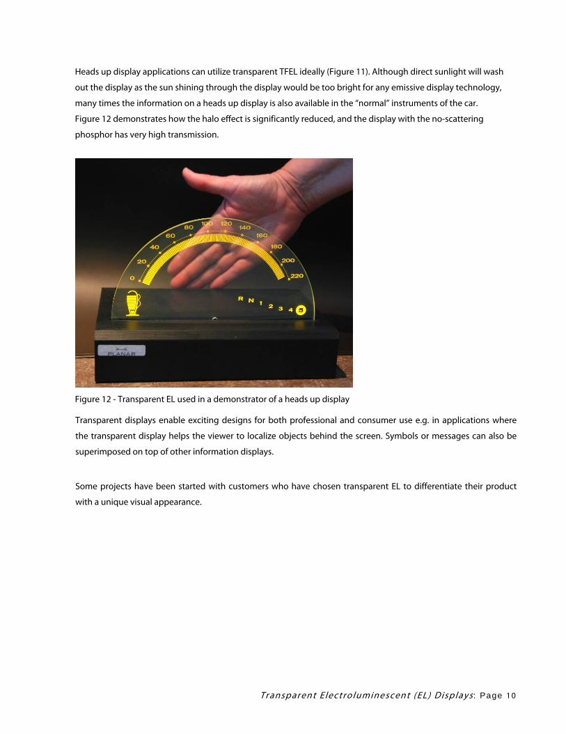
Heads up display applications can utilize transparent TFEL ideally (Figure 11). Although direct sunlight will wash
out the display as the sun shining through the display would be too bright for any emissive display technology,
many times the information on a heads up display is also available in the “normal” instruments of the car.
Figure 12 demonstrates how the halo effect is significantly reduced, and the display with the no-scattering
phosphor has very high transmission.
Figure 12 - Transparent EL used in a demonstrator of a heads up display Transparent displays enable exciting designs for both professional and consumer use e.g. in applications where
the transparent display helps the viewer to localize objects behind the screen. Symbols or messages can also be
superimposed on top of other information displays.
Some projects have been started with customers who have chosen transparent EL to differentiate their product
with a unique visual appearance.
Transparent E lectro luminescent (EL) Displays : Page 1 0

In Figure 13 we see the transparent display with a mirror behind it, which can give new options and optical effects
for potential uses.
Figure 13 - Transparent TFEL display with a front surface mirror provides new options and effects
Engineers and designers can take advantage of the ability of the TFEL glass to withstand high temperatures (up to
600 °C) to bend the glass in a curved surface after the display has been processed. This also opens possibilities to
process the TFEL display, without protective glass, in the customer’s premises at high temperatures. In Figure 14
we have examples of prototypes of new concepts that were made to show the flexibility.
Figure 14 - Demonstration of curved transparent electroluminescent display
Transparent E lectro luminescent (EL) Displays : Page 1 1

Figure 15 is showing that the transparent display can be embedded in other materials, such as silicone, which can
produce uniquely shaped and watertight displays.
Figure 15 - Prototypes of transparent EL displays showing volume structure displays
Summary
TFEL technology provides unique opportunities to realize a transparent, rugged and reliable light emitting graphic
display that maintains excellent readability both in extreme temperatures and in different lighting conditions.
Transparent thin film EL is an intriguing display technology with many potential applications.
We explored the basic design characteristics; the key parameters to achieve good optical behavior are optimized
thin film layers and non-scattering phosphors. ALD thin film deposition technology provides the robust insulating
layers to allow the use of transparent ITO electrodes on top of the device structure. With the improved non-
scattering film, the high ambient contrast ratio improved to a good legible level at ~ 50000 Lux, and the
transmission improved to 84%.
Applications for transparent display technology include automotive overlay displays, gaming, home appliances
and any other application where there is a need for superposition of information on other displays. The ability to
make the transparent displays on curved surfaces or contract them in a volumetric transparent set-up gives
additional dimension to product and equipment designers. Other unique features of the solid state structure of
TFEL displays are the possibility to drill holes in it and the availability of radius bends.
Transparent E lectro luminescent (EL) Displays : Page 1 2

References
1. P.M. Knoll, B. Herzog, R. Sybrichs, Electronics Displays 97 Konferenzband, ISBN: 3-924651-54-X, p. 65 (1997)
2. Technical Report – Denso Technology 2001 – Instrument Clusters http://www.globaldenso.com/TECHNOLOGY/tec-report/2001/pdf/T2001_S19.pdf
3. Mika Antikainen, Juhani Haaranen, Jorma Honkala, Marja Lahonen, Veli-Matti Liias, Arto Pakkala, Tuomas Pitkanen, Erkki Soininen, and Runar Tornqvist, “Transparent Emissive Thin-Film Electroluminescent Display”, SID 00 DIGEST, p. 885, (2000)
4. S. Kanda, “Reduction of Halo in Transparent Electroluminescent (EL) Display”, SID 00 DIGEST, p.881, (2000)
Transparent E lectro luminescent (EL) Displays : Page 1 3
Related Documents


![Atomic Layer Deposition on Self-Assembled … › pdfs › 44930 › InTech-Atomic...electroluminescent (TFEL) flat panel displays. [1]- [7] Several types of materials including metals](https://static.cupdf.com/doc/110x72/5f2709250d3bcf062f3b3457/atomic-layer-deposition-on-self-assembled-a-pdfs-a-44930-a-intech-atomic.jpg)
