© Burns Engineering Transmitters and Indicators for Temperature Measurement Transmitters and Indicators for Temperature Measurement Bill Bergquist, Sr. Applications Engineer Jeff Wigen, National Account Manager Jeff Bill 2 © Burns Engineering Transmitters and Indicators for Temperature Measurement What is a temperature transmitter? Why use a transmitter? Transmitter selection • Ambient conditions • Accuracy • Location • Indicators • Options • Communication types • Wireless Installation • Protection from EMI/RFI • Ambient temperature limits • Rail mount vs. head mount Calibration • Matched calibration Specifications • Accuracy and other performance characteristics Troubleshooting What we’ll discuss today Transmitters and indicators turned out to be a bigger topic than I thought when I began preparation for this presentation. What follows is information on the topics on which I get the most questions. 3 © Burns Engineering Transmitters and Indicators for Temperature Measurement An electronic device that converts the input from an RTD, thermocouple, or other temperature measuring device to a current output. Analog • Converts a temperature measurement from an RTD or thermocouple to an analog value which is typically 4 - 20 mA of electrical current. Uses potentiometers to adjust output. Smart • A smart or intelligent transmitter is an analog or digital device combined with a processing unit and a communication interface. • Software or a communicator is used to calibrate and set functions. What is a Temperature Transmitter?

Welcome message from author
This document is posted to help you gain knowledge. Please leave a comment to let me know what you think about it! Share it to your friends and learn new things together.
Transcript
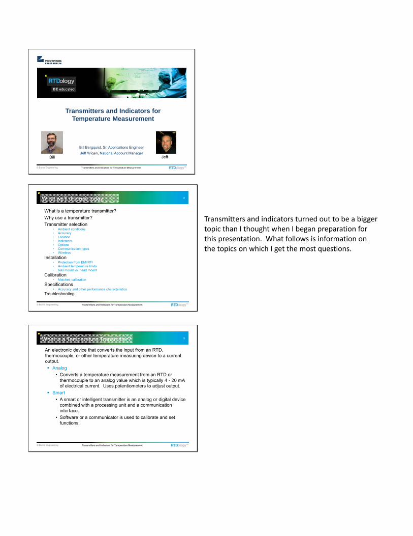
© Burns Engineering Transmitters and Indicators for Temperature Measurement
Transmitters and Indicators for Temperature Measurement
Bill Bergquist, Sr. Applications EngineerJeff Wigen, National Account Manager
Jeff Bill
2
© Burns Engineering Transmitters and Indicators for Temperature Measurement
What is a temperature transmitter?Why use a transmitter?Transmitter selection
• Ambient conditions• Accuracy• Location• Indicators• Options• Communication types• Wireless
Installation• Protection from EMI/RFI• Ambient temperature limits• Rail mount vs. head mount
Calibration• Matched calibration
Specifications• Accuracy and other performance characteristics
Troubleshooting
What we’ll discuss today
Transmitters and indicators turned out to be a bigger topic than I thought when I began preparation for this presentation. What follows is information on the topics on which I get the most questions.
3
© Burns Engineering Transmitters and Indicators for Temperature Measurement
An electronic device that converts the input from an RTD, thermocouple, or other temperature measuring device to a current output.
Analog• Converts a temperature measurement from an RTD or
thermocouple to an analog value which is typically 4 - 20 mA of electrical current. Uses potentiometers to adjust output.
Smart• A smart or intelligent transmitter is an analog or digital device
combined with a processing unit and a communication interface.
• Software or a communicator is used to calibrate and set functions.
What is a Temperature Transmitter?
4
© Burns Engineering Transmitters and Indicators for Temperature Measurement
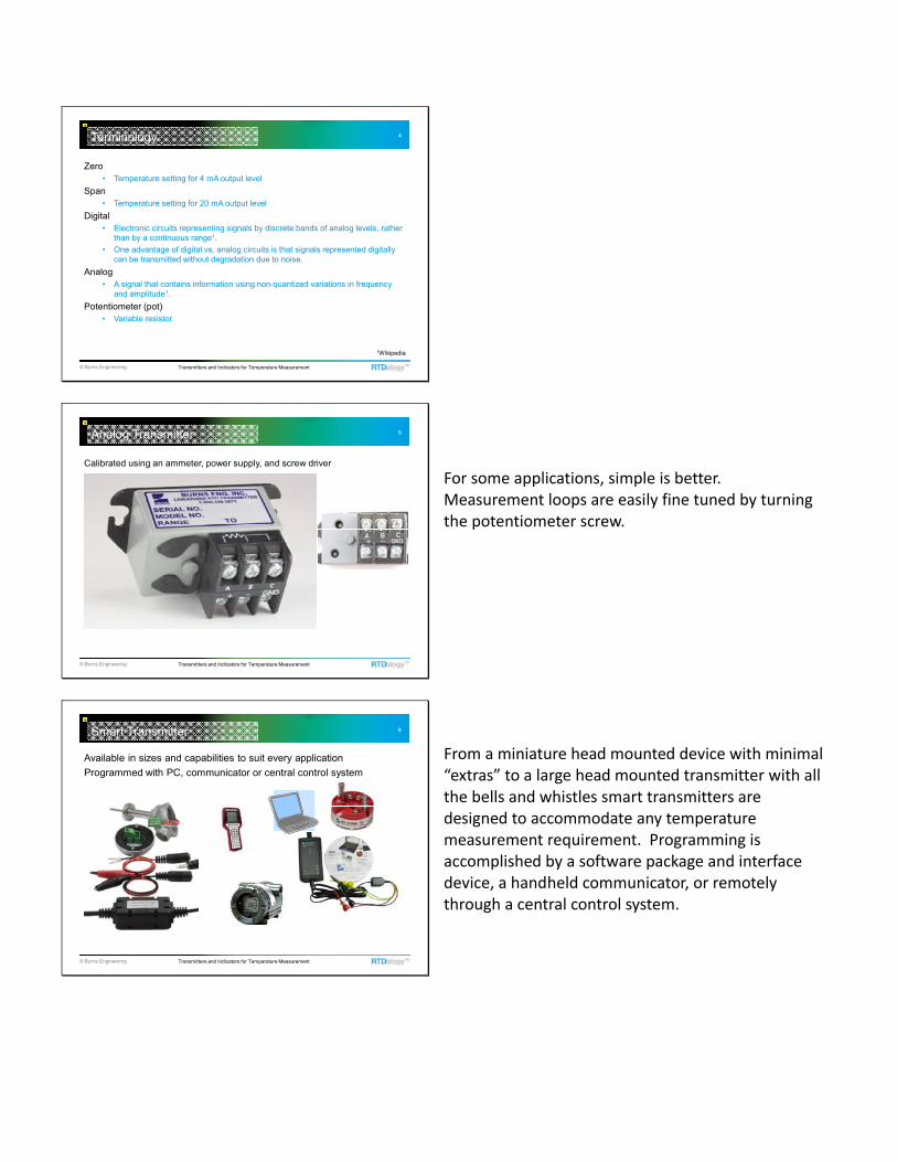
Zero• Temperature setting for 4 mA output level
Span• Temperature setting for 20 mA output level
Digital• Electronic circuits representing signals by discrete bands of analog levels, rather
than by a continuous range1.• One advantage of digital vs. analog circuits is that signals represented digitally
can be transmitted without degradation due to noise.Analog
• A signal that contains information using non-quantized variations in frequency and amplitude1.
Potentiometer (pot)• Variable resistor
Terminology
1Wikipedia
5
© Burns Engineering Transmitters and Indicators for Temperature Measurement
Analog Transmitter
Calibrated using an ammeter, power supply, and screw driver
For some applications, simple is better. Measurement loops are easily fine tuned by turning the potentiometer screw.
6
© Burns Engineering Transmitters and Indicators for Temperature Measurement
Available in sizes and capabilities to suit every applicationProgrammed with PC, communicator or central control system
Smart Transmitter
From a miniature head mounted device with minimal “extras” to a large head mounted transmitter with all the bells and whistles smart transmitters are designed to accommodate any temperature measurement requirement. Programming is accomplished by a software package and interface device, a handheld communicator, or remotely through a central control system.

7
© Burns Engineering Transmitters and Indicators for Temperature Measurement
Improve measurement accuracy• Avoid lead wire error• Transmitter output is more accurate than most direct input cards on
controllers• Linearize the non-linear sensor measurement• Delay measurement – useful for environmental storage chambers
More robust signal over long distances
Local indication of temperature
Help protect measurement from electrical interferenceSensor leads act like an antenna for RFI/EMI. Transmitter circuitry is design to filter this noise. Mount transmitter as close as possible to the sensor. Especially important for thermocouples.
Why Use a Transmitter?
Controllers, PLCs, and other devices have options to take a temperature measurement signal directly from a thermocouple or RTD so why use a transmitter? There are several good reasons to include a transmitter in your measurement loop. One of the most important is to minimize the sensor lead length to the controller. Leads act as an antenna picking up interference from EMI/RFI, static, and other stray electrical noise. Thermocouples are especially susceptible to this because of their low voltage output.
8
© Burns Engineering Transmitters and Indicators for Temperature Measurement
Standardize on a single input type for controllersAdd more functionality to the measurement point
Hot Backup®
Differential measurementMultiple inputAveragingRemote communicationAllows for fine tuning of measurement systemSensor diagnostics – monitors the sensor for indications of impending failure
Why Use a Transmitter?
Some manufacturers offer features that monitor the sensor health and send an alert that maintenance is needed. Others will automatically switch to a backup sensor if the primary sensor fails. Other common features are multiple sensor inputs to perform differential temperature measurement or averaging of several points.
9
© Burns Engineering Transmitters and Indicators for Temperature Measurement
Lead Wire Error with RTDs
2 wire connection adds lead resistance in series with PRT element
One important reason to use a transmitter is to help eliminate lead wire error in an RTD circuit. Following is a discussion on the effect of lead resistance in RTDs. Two wire circuits simply add the lead resistance to the sensing element resulting in very large errors. These should not be used for any measurement that requires high accuracy.

10
© Burns Engineering Transmitters and Indicators for Temperature Measurement
Lead Wire Error with RTDs
3 wire connection relies on all 3 leads having equal resistance
A three wire circuit will add no error if each of the three legs have the same resistance. Unfortunately, in the real world, there is a difference and that causes an error. Adding a transmitter at the sensor location eliminates the lead error.
11
© Burns Engineering Transmitters and Indicators for Temperature Measurement
Lead Wire Error with RTDs
4 wire connection eliminates error
The current potential method or 4 wire circuit is the most accurate and has no lead wire error associated with it. Here there’s a trade‐off between running a 4 conductor cable to take the signal directly to a controller, or add a transmitter and use less expensive 2 conductor cable for the 4‐20 mA current. A rule of thumb is if the sensor to controller distance is over 250ft then it is a good idea to add a transmitter.
12
© Burns Engineering Transmitters and Indicators for Temperature Measurement
Analog• Inexpensive• Simple calibration• Easily adjusted to match sensor calibration at end points (zero
and span) or a single intermediate point
Transmitter Selection
Analog or Smart is the first decision to make when selecting a transmitter. Decide if the extra features of a smart transmitter will be needed for your application or if a simple analog device will do. Calibration of an analog transmitter is usually very simple requiring a power supply, ammeter, and screwdriver.

13
© Burns Engineering Transmitters and Indicators for Temperature Measurement
SmartWide price rangeNumerous options Communications
• HART, Fieldbus, Profibus• Local• Remote
Ability to match sensor to transmitter using multiple calibration points or an interpolation equation such as the Calendar van Dusen
Transmitter Selection
If a smart transmitter is desired then you will need to wade through the myriad of options available. Here size does matter in that the larger devices have more options and are more expensive. The two pictured above are identical except that one has HART communications capability and the other does not. Both will mount in most connection heads and have several setup options available. Programming is through a software/interface package or for the HART version a handheld communicator can be used.
14
© Burns Engineering Transmitters and Indicators for Temperature Measurement
WirelessNetwork typeSecurityReliabilityMounting location – may require line-of-sight to receiver
Transmitter Selection
Wireless transmitters are growing in popularity and manufacturers are sorting through all the communications possibilities and are settling a few configurations. Some of the factors to consider are which network type will work best for you, security, and reliability. We have all had a cell phone call drop out or a laptop PC wireless internet connection disconnect unexpectedly and those are concerns if using a wireless transmitter to control a process.
15
© Burns Engineering Transmitters and Indicators for Temperature Measurement
Head mounted
Installation
Mounting the transmitter is determined by ambient conditions, accessibility to read the indicator, or hazardous atmospheres.

16
© Burns Engineering Transmitters and Indicators for Temperature Measurement
Installation
Typical wiring connections for a 4 wire RTD to a head mounted loop powered transmitter
• Power is 24 VDC
17
© Burns Engineering Transmitters and Indicators for Temperature Measurement
Integrated into the sensor housing
Installation
Transmitter location
Transmitters can be integrated into the sensor housing to create a compact package for restricted space locations.
18
© Burns Engineering Transmitters and Indicators for Temperature Measurement
High density located in remote panel
Rail Mount
If several measurement points are located close together a panel or rail mount transmitter may be a good solution. Several can be installed in a very small space.

19
© Burns Engineering Transmitters and Indicators for Temperature Measurement
Remote mounted• Wall mount or pipe mount
Installation
Ambient conditions can sometimes dictate the location of a transmitter. High or low temperatures may damage the electronics or indicator requiring that the transmitter be mounted close by on a pipe or wall mount.
20
© Burns Engineering Transmitters and Indicators for Temperature Measurement
Hazardous locations – FM, CSA, ATEX, IECEx
Intrinsically safe installation
Installation
Hazardous atmospheres will require specially rated enclosures and sensor assemblies.
21
© Burns Engineering Transmitters and Indicators for Temperature Measurement
LED Indicator
Works well in low light conditionsCan be difficult to read in bright light
Indicators are LED or LCD and the selection depends on where it will be used. LEDs are generally difficult to read in bright light but are easily read in low light. Opposite is true for LCD indicators.

22
© Burns Engineering Transmitters and Indicators for Temperature Measurement
Works well in bright lightMay require backlight to read in low light conditions
LCD Indicator
23
© Burns Engineering Transmitters and Indicators for Temperature Measurement
Other considerations
Ambient temperature• Most are limited to -40°C to 85°C to protect the electronics –
indicators have more limited range• Accuracy is affected by the ambient temperature
Vibration• Remote mount may be necessary
Sanitary wash-down• Corrosion resistant coatings and waterproof heads
Safety Instrumented System (SIS)• Requires safety certified transmitter
Installation
24
© Burns Engineering Transmitters and Indicators for Temperature Measurement
Other considerationsBattery power
• Useful for remote locations
Installation
Battery powered transmitters/indicators are useful for remote locations or where a local indication of temperature is required. Batteries typically last 2 years or more.

25
© Burns Engineering Transmitters and Indicators for Temperature Measurement
Generally a relatively low cost method to dramatically improve measurement accuracy.
Sensor is calibrated and that information is used to set the transmitter output.
Requires calibration of the RTDAnalog transmitter allows setting of Zero and span temperatures or one intermediate pointSmart transmitter - Full calibration with coefficients over service range for smart transmitters with curve matching capability
Matched Calibration
At a minimum, the RTD resistance is checked in a temperature bath at the zero and span temperatures. Those resistance values are used to adjust the transmitter output. For those transmitters that have curve fitting capability, a full calibration of the RTD is performed and the resulting coefficients are entered into the transmitter.
26
© Burns Engineering Transmitters and Indicators for Temperature Measurement
InterchangeabilityInterchangeability refers to the “closeness of agreement” between an actual R vs. T relationship and a predefined R vs. T relationship.
Terminology
The largest sensor error is the interchangeability. Matching the sensor calibration to a transmitter will eliminate about 85% of the error. ASTM E1137 and IEC 60751 are the two most commonly used standards that define a nominal R vs. T relationship for RTDs. All sensors are manufactured with 0°C as the starting point. Variations in sensors result in the tolerance increasing as the temperature diverges from 0°C.
27
© Burns Engineering Transmitters and Indicators for Temperature Measurement
-4
-3
-2
-1
0
1
2
3
4
-300 -200 -100 0 100 200 300 400 500 600 700 800
Temperature (°C)
Tole
ranc
e (±
°C)
IEC Class B
ASTM Grade B
IEC Class A ASTM Grade A
ASTM Grade A
IEC Class A
ASTM Grade B
IEC Class B
Interchangeability
Note that the ASTM standard has slightly tighter tolerances for the two grades of sensors. All RTDs are built with the tightest tolerance at 0°C and as the temperature diverges from 0°C the tolerance increases. The vertical line on the graph represents 0°C and the tolerance on the y axis is expressed in ± °C from nominal.
28
© Burns Engineering Transmitters and Indicators for Temperature Measurement
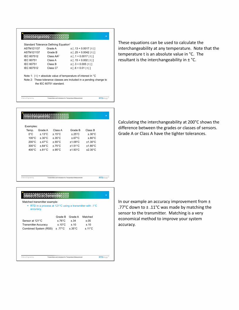
Standard Tolerance Defining Equation¹ASTM E1137 Grade A ± [ .13 + 0.0017 | t | ]ASTM E1137 Grade B ± [ .25 + 0.0042 | t | ]IEC 607512 Class AA2 ± [ .1 + 0.0017 | t | ]IEC 60751 Class A ± [ .15 + 0.002 | t | ]IEC 60751 Class B ± [ .3 + 0.005 | t | ]IEC 607512 Class C2 ± [ .6 + 0.01 | t | ]
Note 1: | t | = absolute value of temperature of interest in °CNote 2: These tolerance classes are included in a pending change to
the IEC 60751 standard.
Interchangeability
These equations can be used to calculate the interchangeability at any temperature. Note that the temperature t is an absolute value in °C. The resultant is the interchangeability in ± °C.
29
© Burns Engineering Transmitters and Indicators for Temperature Measurement
Examples:Temp. Grade A Class A Grade B Class B
0°C ±.13°C ±.15°C ±.25°C ±.30°C100°C ±.30°C ±.35°C ±.67°C ±.80°C200°C ±.47°C ±.55°C ±1.09°C ±1.30°C300°C ±.64°C ±.75°C ±1.51°C ±1.80°C400°C ±.81°C ±.95°C ±1.93°C ±2.30°C
Interchangeability
Calculating the interchangeability at 200°C shows the difference between the grades or classes of sensors. Grade A or Class A have the tighter tolerances.
30
© Burns Engineering Transmitters and Indicators for Temperature Measurement
Matched transmitter example:RTD in a process at 121°C using a transmitter with .1°C accuracy.
Grade B Grade A MatchedSensor at 121°C ±.76°C ±.34 ±.05Transmitter Accuracy ±.10°C ±.10 ±.10Combined System (RSS) ± .77°C ±.35°C ±.11°C
Match RTD to Transmitter
In our example an accuracy improvement from ± .77°C down to ± .11°C was made by matching the sensor to the transmitter. Matching is a very economical method to improve your system accuracy.

31
© Burns Engineering Transmitters and Indicators for Temperature Measurement
Analog transmitter potentiometers are used to make adjustments to the zero and span.
Match RTD to Transmitter
32
© Burns Engineering Transmitters and Indicators for Temperature Measurement
Software is used for smart transmitter setup
Match RTD to Transmitter
33
© Burns Engineering Transmitters and Indicators for Temperature Measurement
Match RTD to Transmitter

34
© Burns Engineering Transmitters and Indicators for Temperature Measurement
Match RTD to Transmitter
This screen shot shows a typical smart transmitter setup for entering the calibration coefficients and temperature coefficient from a calibrated RTD.
35
© Burns Engineering Transmitters and Indicators for Temperature Measurement
Callendar-Van Dusen Equation
Matched Calibration
T = temperature (°C)R = resistance at temperature TR0 = resistance at the ice pointα = constant (gives the linear approximation to the R vs. T curve)δ= constantβ= constant (b = 0 when T is >0°C)The actual values for the coefficients,α, δ, and β are determined by testing the RTD at four temperatures and solving the equations.
R/Ro = 1 + α [T - δ (T/100 - 1)- β (T/100 - 1) (T/100)3 ]
The CVD equation is used in a lot of smart transmitters to interpolate between calibration points. IPTS‐68 is still used for industrial applications because it is simpler to apply and still gives acceptable accuracy for numerous processes.
36
© Burns Engineering Transmitters and Indicators for Temperature Measurement
Insulation resistanceElectrical resistance between the sensing circuit and the metallic sheath of a PRT – should be at least 200 megohms at 20°C
Matched Calibration
An important first electrical check that should be performed as part of any calibration. If the sensor is out of spec a repeatable calibration cannot be performed.

37
© Burns Engineering Transmitters and Indicators for Temperature Measurement
Using an Ice Bath, check resistance at 0°C
Matched Calibration
If the sensor passes the IR check then a check in an ice bath should be performed. Crushed ice made with purified water is packed into an insulated container. Purified water is added to fill in the gaps. If the ice floats, you have added too much water. Adding a stirring feature to keep the water flowing around the ice minimizes temperature gradients within the bath. Each probe should be immersed at least 4”. Do not use the probe to beat a hole in the ice. You may damage the sensing element. Use a scrap probe or similar rod to form the holes.
38
© Burns Engineering Transmitters and Indicators for Temperature Measurement
• Use a high accuracy meter• Reading should be 100 ± 0.12 ohms for Class B and 100 ± 0.06 ohms for
Class A per the ASTM E 1137 or IEC 60751 standards• Outside this range and the probe should be replaced
Matched Calibration
If the probe does not meet the resistance tolerance it should be replaced. There is not any reliable and cost effective method to repair it. Save the sensor for recycling! There is $$ worth of platinum in each probe. Save it up for a department lunch.
39
© Burns Engineering Transmitters and Indicators for Temperature Measurement
Equipment used
Matched Calibration
Some of the equipment required for matching an RTD to a transmitter. ‐Software and interface for PC programmable transmitters ‐Decade box and ammeter for analog transmitters with adjustment potentiometers.

40
© Burns Engineering Transmitters and Indicators for Temperature Measurement
Accuracy specifications – vary by manufacturer in how they are stated
Specifications
Manufacturers seem to have many different ways to report transmitter performance. Here are three that range from simple to complex. Be careful when comparing devices to insure you get the performance you need.
41
© Burns Engineering Transmitters and Indicators for Temperature Measurement
Corroded terminals can cause high resistance in the leads
3-wire circuits are susceptible – accuracy depends on each conductor having exactly the same resistance
• Terminals clean and tight• Terminal block clean and dry, secured to head• Wires are tinned, or terminated with spade lug
4-wire circuits also compensate for some poor maintenance• Compensate fully for all lead wire resistance in the circuit
Troubleshooting
As with anything eventually a transmitter will fail and some trouble shooting is necessary to see if it is an installation problem or if the device has failed.
42
© Burns Engineering Transmitters and Indicators for Temperature Measurement
The good and bad
Troubleshooting
Conductive dust inside head
High quality connecters, spade lugs, or tinned leads are good methods to connect a transmitter to a sensor. The connection head shown in the lower right corner had a lot of electrically conductive dust in it that caused some electrical leakage between the terminals resulting in a bad temperature reading.

43
© Burns Engineering Transmitters and Indicators for Temperature Measurement
Wires connected securely with no stray strands
Troubleshooting
A stray wire strand can easily short the terminals together on a transmitter or terminal block.
44
© Burns Engineering Transmitters and Indicators for Temperature Measurement
Most common failure mode is due to voltage spikes such as from welders and lightning• Causes output to lock. No response from the transmitter when the input
resistance is varied.
Troubleshooting
© Burns Engineering Transmitters and Indicators for Temperature Measurement
Questions?
Contact us at 800-328-3871 or visit www.burnsengineering.com
Thank you for attending!
Related Documents