Citation: Fahad, A.K.; Ruan, C.; Nazir, R.; Hassan, B. Transmissive Polarizer Metasurfaces: From Microwave to Optical Regimes. Nanomaterials 2022, 12, 1705. https:// doi.org/10.3390/nano12101705 Academic Editor: José Antonio Sánchez-Gil Received: 14 April 2022 Accepted: 12 May 2022 Published: 17 May 2022 Publisher’s Note: MDPI stays neutral with regard to jurisdictional claims in published maps and institutional affil- iations. Copyright: © 2022 by the authors. Licensee MDPI, Basel, Switzerland. This article is an open access article distributed under the terms and conditions of the Creative Commons Attribution (CC BY) license (https:// creativecommons.org/licenses/by/ 4.0/). nanomaterials Review Transmissive Polarizer Metasurfaces: From Microwave to Optical Regimes Ayesha Kosar Fahad 1 , Cunjun Ruan 1,2, * , Rabia Nazir 3 and Bilal Hassan 4 1 School of Electronics and Information Engineering, Beihang University, Beijing 100191, China; [email protected] 2 Beijing Key Laboratory for Microwave Sensing and Security Applications, Beihang University, Beijing 100191, China 3 Faculty of Electrical Engineering, University of Engineering and Technology, Lahore 100191, Pakistan; [email protected] 4 Department of Electrical Engineering and Computer Science, Khalifa University of Science and Technology, Abu Dhabi 127788, United Arab Emirates; [email protected] * Correspondence: [email protected] Abstract: Metasurfaces, a special class of metamaterials, have recently become a rapidly growing field, particularly for thin polarization converters. They can be fabricated using a simple fabrication process due to their smaller planar profile, both in the microwave and optical regimes. In this paper, the recent progress in MSs for linear polarization (LP) to circular polarization (CP) conversion in transmission mode is reviewed. Starting from history, modeling and the theory of MSs, uncontrollable single and multiple bands and LP-to-CP conversions, are discussed and analyzed. Moreover, detailed reconfigurable MS-based LP-to-CP converters are presented. Further, key findings on the state-of-the- arts are discussed and tabulated to give readers a quick overview. Finally, a conclusion is drawn by providing opinions on future developments in this growing research field. Keywords: MSs; polarization converters; polarizers; multiband transmissions; configurable converters 1. Introduction According to Huygen’s principle [1], each infinitesimally small area of a confined surface has an associated secondary-field source. This means that fields around the sur- rounding secondary-field sources can be controlled by either changing the source or by changing the electromagnetic properties of the confined surface. It depends upon whether one is interested in the transmitted properties of the confined surface or reflected properties or both. Thus, any desirable properties can be achieved by the proper design of such surfaces. This process is often termed as shaping electromagnetic waves. By shaping, we mean either amplitude shaping or polarization shaping. Dielectric lenses, metallic mirrors, and reflectors are widely known for shaping electromagnetic waves in optics and microwave antenna engineering [2,3]. However, both solutions for shaping are bulky and often have considerable size, weight, and volume even in a millimeter-wave band. Another way to shape electromagnetic waves into or out of the confined surface is to split the surface into multiple elements, each having a polarizable inclusion with specifically selected parameters. This concept, which had been used in reflect and transmit arrays [4,5] was applied to Fresnel and chirped lenses, and frequency-selective surfaces [6]. Recent progress in metamaterials (MMs) revealed that there exists a profound and sophisticated class of materials that can shape electromagnetic waves by a design of sub- wavelength inclusions arranged in densely packed 3D structures. Such inclusions owing to specific electric and magnetic polarizations can control transmitted and reflected fields which in turn offer intriguing opportunities for microwave, millimeter, and optical re- gions [7–9]. However, these materials suffer from several disadvantages. Firstly, fabrication Nanomaterials 2022, 12, 1705. https://doi.org/10.3390/nano12101705 https://www.mdpi.com/journal/nanomaterials

Welcome message from author
This document is posted to help you gain knowledge. Please leave a comment to let me know what you think about it! Share it to your friends and learn new things together.
Transcript

Citation: Fahad, A.K.; Ruan, C.;
Nazir, R.; Hassan, B. Transmissive
Polarizer Metasurfaces: From
Microwave to Optical Regimes.
Nanomaterials 2022, 12, 1705. https://
doi.org/10.3390/nano12101705
Academic Editor: José Antonio
Sánchez-Gil
Received: 14 April 2022
Accepted: 12 May 2022
Published: 17 May 2022
Publisher’s Note: MDPI stays neutral
with regard to jurisdictional claims in
published maps and institutional affil-
iations.
Copyright: © 2022 by the authors.
Licensee MDPI, Basel, Switzerland.
This article is an open access article
distributed under the terms and
conditions of the Creative Commons
Attribution (CC BY) license (https://
creativecommons.org/licenses/by/
4.0/).
nanomaterials
Review
Transmissive Polarizer Metasurfaces: From Microwave toOptical RegimesAyesha Kosar Fahad 1, Cunjun Ruan 1,2,* , Rabia Nazir 3 and Bilal Hassan 4
1 School of Electronics and Information Engineering, Beihang University, Beijing 100191, China;[email protected]
2 Beijing Key Laboratory for Microwave Sensing and Security Applications, Beihang University,Beijing 100191, China
3 Faculty of Electrical Engineering, University of Engineering and Technology, Lahore 100191, Pakistan;[email protected]
4 Department of Electrical Engineering and Computer Science, Khalifa University of Science and Technology,Abu Dhabi 127788, United Arab Emirates; [email protected]
* Correspondence: [email protected]
Abstract: Metasurfaces, a special class of metamaterials, have recently become a rapidly growingfield, particularly for thin polarization converters. They can be fabricated using a simple fabricationprocess due to their smaller planar profile, both in the microwave and optical regimes. In this paper,the recent progress in MSs for linear polarization (LP) to circular polarization (CP) conversion intransmission mode is reviewed. Starting from history, modeling and the theory of MSs, uncontrollablesingle and multiple bands and LP-to-CP conversions, are discussed and analyzed. Moreover, detailedreconfigurable MS-based LP-to-CP converters are presented. Further, key findings on the state-of-the-arts are discussed and tabulated to give readers a quick overview. Finally, a conclusion is drawn byproviding opinions on future developments in this growing research field.
Keywords: MSs; polarization converters; polarizers; multiband transmissions; configurable converters
1. Introduction
According to Huygen’s principle [1], each infinitesimally small area of a confinedsurface has an associated secondary-field source. This means that fields around the sur-rounding secondary-field sources can be controlled by either changing the source or bychanging the electromagnetic properties of the confined surface. It depends upon whetherone is interested in the transmitted properties of the confined surface or reflected propertiesor both. Thus, any desirable properties can be achieved by the proper design of suchsurfaces. This process is often termed as shaping electromagnetic waves. By shaping,we mean either amplitude shaping or polarization shaping. Dielectric lenses, metallicmirrors, and reflectors are widely known for shaping electromagnetic waves in opticsand microwave antenna engineering [2,3]. However, both solutions for shaping are bulkyand often have considerable size, weight, and volume even in a millimeter-wave band.Another way to shape electromagnetic waves into or out of the confined surface is to splitthe surface into multiple elements, each having a polarizable inclusion with specificallyselected parameters. This concept, which had been used in reflect and transmit arrays [4,5]was applied to Fresnel and chirped lenses, and frequency-selective surfaces [6].
Recent progress in metamaterials (MMs) revealed that there exists a profound andsophisticated class of materials that can shape electromagnetic waves by a design of sub-wavelength inclusions arranged in densely packed 3D structures. Such inclusions owingto specific electric and magnetic polarizations can control transmitted and reflected fieldswhich in turn offer intriguing opportunities for microwave, millimeter, and optical re-gions [7–9]. However, these materials suffer from several disadvantages. Firstly, fabrication
Nanomaterials 2022, 12, 1705. https://doi.org/10.3390/nano12101705 https://www.mdpi.com/journal/nanomaterials

Nanomaterials 2022, 12, 1705 2 of 21
of bulk MM is very complex, particularly when they lie in the optical region, as it requiresbulk MM to be 3D nanostructures. Moreover, wave propagation in metamaterials covers asubstantial distance, therefore, they encounter high ohmic losses.
Recently, it was realized that 2D metamaterials can be a more profound type ofmetamaterial, having the ability to shape/control electromagnetic waves. They have beentermed MSs (MS). They can have subwavelength inclusions to tailor electric and magneticfields, to control transmitted and reflected fields. They are ideal candidates for many novelmicrowave and optical devices.
The basic properties of MSs are defined by their elementary subwavelength patterns,which result in unusual resonant behavior. Importantly, MSs are patterned with subwave-length structures, so homogeneous or nearly homogenous MSs transmit and reflect planewaves. Since MSs are thin structured and 2D in nature, they are less lossy and easier tofabricate. Another major advantage of using MSs is their easier integration with existingmicrowave and nanophotonics systems. Several factors influencing the applications andproperties of MSs are the type of structure/pattern, their mutual/cross-couplings betweenadjacent cells, and the substrate used. The most attractive feature of the MS is its abilityto control reflected and transmitted fields, which makes it highly effective for certain ap-plications and replaces conventional bulky equipment. There have been excellent reviewarticles on MSs covering theory, fundamentals and applications [10–14] and their complexfabrication [12]. For example, Zhao et al. reviewed optical fiber-integrated MSs for appli-cations, such as telecommunication, sensing, imaging, and biomedicine [10]. Hollowayet al. focused on the development in recent years of such MSs from microwave to opticalregimes [11]. Su et al. reviewed the fabrication and applications of MSs [12]. Glybovskiet al. reviewed different types of MSs for a broad range of the operational wavelengths forwavefront shaping, lenses, and polarization transformation [13]. In this review paper, wefocus on a special application of the MS, i.e., polarization conversion. This conversion usingMS can be categorized into three main types: transmission-based, reflection-based anddual functional (both transmission and reflection). Figure 1 depicts the functionality of MSfor polarization conversion. Figure 1a shows transmission-based polarization conversion,where incident linear polarization is converted into transmitted circular polarization. Inthis scenario, we termed MS as MS-T. Figure 1b shows the polarization conversion phe-nomenon using reflection-based MS. We termed this as MS-R. In Figure 1c, it is shown thatMS performs polarization conversion for both transmitted and reflected waves. We termedsuch an MS as MS-T/R.
Nanomaterials 2022, 12, x FOR PEER REVIEW 2 of 22
which in turn offer intriguing opportunities for microwave, millimeter, and optical re-
gions [7–9]. However, these materials suffer from several disadvantages. Firstly, fabrica-
tion of bulk MM is very complex, particularly when they lie in the optical region, as it
requires bulk MM to be 3D nanostructures. Moreover, wave propagation in metamaterials
covers a substantial distance, therefore, they encounter high ohmic losses.
Recently, it was realized that 2D metamaterials can be a more profound type of met-
amaterial, having the ability to shape/control electromagnetic waves. They have been
termed MSs (MS). They can have subwavelength inclusions to tailor electric and magnetic
fields, to control transmitted and reflected fields. They are ideal candidates for many novel
microwave and optical devices.
The basic properties of MSs are defined by their elementary subwavelength patterns,
which result in unusual resonant behavior. Importantly, MSs are patterned with subwave-
length structures, so homogeneous or nearly homogenous MSs transmit and reflect plane
waves. Since MSs are thin structured and 2D in nature, they are less lossy and easier to
fabricate. Another major advantage of using MSs is their easier integration with existing
microwave and nanophotonics systems. Several factors influencing the applications and
properties of MSs are the type of structure/pattern, their mutual/cross-couplings between
adjacent cells, and the substrate used. The most attractive feature of the MS is its ability to
control reflected and transmitted fields, which makes it highly effective for certain appli-
cations and replaces conventional bulky equipment. There have been excellent review ar-
ticles on MSs covering theory, fundamentals and applications [10–14] and their complex
fabrication [12]. For example, Zhao et al. reviewed optical fiber-integrated MSs for appli-
cations, such as telecommunication, sensing, imaging, and biomedicine [10]. Holloway et
al. focused on the development in recent years of such MSs from microwave to optical
regimes [11]. Su et al. reviewed the fabrication and applications of MSs [12]. Glybovski et
al. reviewed different types of MSs for a broad range of the operational wavelengths for
wavefront shaping, lenses, and polarization transformation [13]. In this review paper, we
focus on a special application of the MS, i.e., polarization conversion. This conversion us-
ing MS can be categorized into three main types: transmission-based, reflection-based and
dual functional (both transmission and reflection). Figure 1 depicts the functionality of
MS for polarization conversion. Figure 1a shows transmission-based polarization conver-
sion, where incident linear polarization is converted into transmitted circular polarization.
In this scenario, we termed MS as MS-T. Figure 1b shows the polarization conversion phe-
nomenon using reflection-based MS. We termed this as MS-R. In Figure 1c, it is shown
that MS performs polarization conversion for both transmitted and reflected waves. We
termed such an MS as MS-T/R.
(a) (b) (c)
Figure 1. Selected polarization conversion functionalities of MS: (a)Transmissive polarization con-
version (b) Reflective polarization conversion (c) transmissive and reflective polarization conver-
sion.
Figure 1. Selected polarization conversion functionalities of MS: (a) Transmissive polarization con-version (b) Reflective polarization conversion (c) Transmissive and reflective polarization conversion.
In this report, we describe advances in the field of transmissive MSs based polarizationconverters and their uses in shaping electromagnetic waves. Importantly, some key findingshighlighting single band, wideband and multiband polarization conversion using MSs
Nanomaterials 2022, 12, 1705 3 of 21
are discussed. Moreover, pattern selection for the desired operation has been discussed.Several controlling methods for polarization conversion are discussed and future directionsfor fundamental research and applications are identified.
2. Why Polarization Conversion Is Required
Amplitude and polarization direction can characterize any electromagnetic wave.This polarization direction represents the direction of oscillations an electromagnetic wavecarries while it passes through the medium. The polarization state of an electromagnetic cancontrol electromagnetic waves in many ways, e.g., polarization rotation and polarizationconversion, often termed polarization transformation. The term ‘polarization conversion’means the conversion of one form of polarization into another (linear polarization (LP) tocircular polarization (CP)). Polarization converters have enormous applications, dependingupon the operating region they are being used. They are used from microwave to opticalregions, depending upon the applications that need CP.
In microwave and millimeter-wave communications, the polarization selection ofthe antenna highly depends on the application and medium. In such a case, polarizationmismatch, Faraday’s rotation by the ionosphere, and multipath fading significantly disturband degrade the performance of the channel. Therefore, CP waves are mostly used forcommand guidance, global navigation systems (GNS), and satellite communication systemsbecause of their better performance than LP waves for their lower sensitivity toward themultipath fading and Faraday’s rotation. CP waves can be generated or transformed usinga polarization conversion phenomenon. The former has many disadvantages, e.g., theCP horn antenna is cascaded with a polarizer, such as a screw circular polarizer [15,16],a built-in dielectric-based polarizer which makes these antennas costly and complicated.Moreover, CP antennas, once designed and fabricated, can only perform as CP antennas.On the contrary, CP waves obtained from the conversion phenomenon allow antennas toperform as LP antennas as well. Moreover, the LP antennas are simpler to design.
The terahertz (THz) band, lying between 300 GHz to 3 THz of the electromagneticspectrum, has been investigated in numerous applications, such as bio-imaging, spec-troscopy, environmental surveillance, biochemical, and pharmaceutical sciences [17–19].Circular polarized THz waves are used in biomedical imagining due to the different chi-rality of biomolecules for CP THz beams. Similarly, they are used in biosensing and drugdelivery [17,20]. Therefore, LP-to-CP converters in THz technology, which are termedquarter-wave plates (QWPs), are very important for THz systems and advancements intheir performance can have a significant impact on existing THz systems’ performance.
3. History and Modeling of MSs
Before further discussion, we clarify here that those planar 2D arrays whose peri-odicity is not smaller than operating wavelengths will not be called MSs here, becausethe term ‘MS’ is associated with cells whose periodicity is smaller than a wavelength.Here, the wavelength is a term used for λfreespace. Mesh and wire-based structures havebeen extensively explored for antenna systems to realize polarizers, which were basedon averaged boundary conditions and, later, the first homogenization theory of artificialelectromagnetic surfaces emerged. Frequency selective surfaces (FSS) are another typeof planar array which exhibit resonant type transmission and reflection characteristics.Dipole and aperture based FSS have been employed for microwave filters operating withplane waves.
MSs were termed nano-islands in the starting period of their explorations in theoptical region. Their modeling was carried out using oblate spheroids [21–23] to studytheir different characteristics, such as frequency and polarization selectivity. For most ofthe applications, the only electric response was not sufficient, therefore, an accompanyingmagnetic response was required to be considered in MS [24,25]. The homogenization modelof MS presented by [26–28] does not cover bi-anisotropic MS. Such MSs have been targetedfor polarization controlling applications for chiral [29,30] and omega type anisotropicity [31].

Nanomaterials 2022, 12, 1705 4 of 21
Chiral bi-anisotropic MSs for polarization conversions take advantage of inclusions whichare polarized by electric or magnetic fields. For such MSs, simultaneous parallel electricor magnetic fields can exist. Another type is the omega type inclusions, where electric ormagnetic dipoles are directly orthogonal to each other due to applied electric or magneticfields only. These inclusions also help in achieving polarization conversion.
Unlike the reviews [11–34] which described several MSs for different applications,we aim to create a link between single and multiband MSs for polarization conversionapplications in microwave and optical regimes. MS excitation can be modeled as an incidentplane wave with wave numbers K1,2, and wave impedance η1,2. Modeling of MS can becarried out using two approaches, the surface susceptibility approach and the equivalentcircuit approach. The former approach has a disadvantage, as in some bi-anisotropic MSs’surface susceptibility has no physical meaning [14]. Whereas the latter provides an insideto physical procedures. Nonetheless, the common thing is both models characterize MS asa homogeneous sheet. In the surface susceptibility approach, MS can be represented byelectric and dipole moments [35].
→P = εχee
−→Eav +
√εµχem
−→Hav (1)
→M = χmm
−→Hav +
√εµχme
−→Eav (2)
where χee, χmm, χem and χme are the electric/magnetic susceptibilities describing theresponse to electric/magnetic excitations, and ‘av’ denotes average fields on both sidesof MSs. The above equations can be used to solve many boundary value problems forMSs. As discussed before, the solution for MSs under the susceptibility approach has someshortcomings, such as no physical insight in some cases.
Alternatively, MSs can be modeled using an equivalent circuit approach. Let usconsider a plane wave striking MS either from medium 1 or medium 2, as shown inFigure 2. We can simulate/measure r1, r2, and ‘t’, assuming that ‘t’ remains the same for anincident wave from medium 1 or medium 2 as MSs are reciprocal. Using the homogeneoussheet model of MSs described by [36], we can retrieve r1, r2, and ‘t’. Using transmissionline modeling of two-port passive and reciprocal devices, MS can be represented by anequivalent T-circuit with two series impedances Z1, Z2, and a shunt admittance Y. Usingr1, r2, and ‘t’, Z1, Z2, and Y can be calculated for the MS [14]. Detailed modeling work hasalready been carried out [37]. Modeling is out of the scope of this review, therefore we willnot discuss its details.
Nanomaterials 2022, 12, x FOR PEER REVIEW 4 of 22
different characteristics, such as frequency and polarization selectivity. For most of the
applications, the only electric response was not sufficient, therefore, an accompanying
magnetic response was required to be considered in MS [24,25]. The homogenization
model of MS presented by [26–28] does not cover bi-anisotropic MS. Such MSs have been
targeted for polarization controlling applications for chiral [29,30] and omega type aniso-
tropicity [31]. Chiral bi-anisotropic MSs for polarization conversions take advantage of
inclusions which are polarized by electric or magnetic fields. For such MSs, simultaneous
parallel electric or magnetic fields can exist. Another type is the omega type inclusions,
where electric or magnetic dipoles are directly orthogonal to each other due to applied
electric or magnetic fields only. These inclusions also help in achieving polarization con-
version.
Unlike the reviews [11–34] which described several MSs for different applications,
we aim to create a link between single and multiband MSs for polarization conversion
applications in microwave and optical regimes. MS excitation can be modeled as an inci-
dent plane wave with wave numbers K1, 2, and wave impedance η1,2. Modeling of MS can
be carried out using two approaches, the surface susceptibility approach and the equiva-
lent circuit approach. The former approach has a disadvantage, as in some bi-anisotropic
MSs’ surface susceptibility has no physical meaning [14]. Whereas the latter provides an
inside to physical procedures. Nonetheless, the common thing is both models characterize
MS as a homogeneous sheet. In the surface susceptibility approach, MS can be represented
by electric and dipole moments [35].
�� = 𝜺𝝌𝒆𝒆 𝑬𝒂𝒗 + √𝜺𝝁𝝌𝒆𝒎 𝑯𝒂𝒗
(1)
�� = 𝝌𝒎𝒎 𝑯𝒂𝒗 + √𝜺𝝁𝝌𝒎𝒆 𝑬𝒂𝒗
(2)
Where 𝝌𝒆𝒆 , 𝝌𝒎𝒎 , 𝝌𝒆𝒎 and 𝝌𝒎𝒆 are the electric/magnetic susceptibilities describing the
response to electric/magnetic excitations, and ‘av’ denotes average fields on both sides of
MSs. The above equations can be used to solve many boundary value problems for MSs.
As discussed before, the solution for MSs under the susceptibility approach has some
shortcomings, such as no physical insight in some cases.
Alternatively, MSs can be modeled using an equivalent circuit approach. Let us con-
sider a plane wave striking MS either from medium 1 or medium 2, as shown in Figure 2.
We can simulate/measure r1, r2, and ‘t’, assuming that ‘t’ remains the same for an incident
wave from medium 1 or medium 2 as MSs are reciprocal. Using the homogeneous sheet
model of MSs described by [36], we can retrieve r1, r2, and ‘t’. Using transmission line
modeling of two-port passive and reciprocal devices, MS can be represented by an equiv-
alent T-circuit with two series impedances Z1, Z2, and a shunt admittance Y. Using r1, r2,
and ‘t’, Z1, Z2, and Y can be calculated for the MS [14]. Detailed modeling work has already
been carried out [37]. Modeling is out of the scope of this review, therefore we will not
discuss its details.
Figure 2. MS structured as an interface between two homogeneous isotropic media. Figure 2. MS structured as an interface between two homogeneous isotropic media.
For incident oblique waves, if MS has non-zero electromagnetic susceptibility, sus-ceptibilities χee, χem, and χmm are independent of the incident angles. In this case, threeequivalent circuit parameters Z1, Z2, and admittance Y can be represented in terms of scalarsusceptibilities [14].
Nanomaterials 2022, 12, 1705 5 of 21
Metasheets are a class of MSs based on uni-layered substrate. They can be furtherclassified into electric metasheets and magneto-electric metasheets. Electric metasheetsare those metasheets which only have electric polarization when an incident electric fieldis applied. Such sheets are single metallic patterned over the substrate and/or havemetal ground. They can be described through a few equivalent parameters. For example,a metasheet based on metal gratings can be described by grid impedance, whereas ametasheet based on planar array patches over the ground can be described as surfaceimpedance [38]. Applied electric field on such sheets does not produce induced currentloops inside them, being extremely thin layered dielectric sheets to act as an equivalentsheet of magnetic surface current. Examples are graphene sheets, single metallic layeredsheets, such as dense wires and strip grids, etc. As the incident electric field producesonly electric dipole moments, FSS can also be considered as a metasheet because FSS alsohas just an electric response, as they require having frequency-selective transmission andreflection. FSS can be categorized as the patterns which can be equalized as inductances,such as inductive thin wires or strips; capacitances, such as an array of patches, and theone which has both inductances and capacitive behavior.
If MSs have a non-zero but still negligible thickness as compared to the wavelength,electric current loops arise inside the MSs even if they are not closed. Usually, MS has bothelectric and magnetic currents. Induced electric currents on the MS are comprised of twoparts: symmetric and asymmetric currents concerning the middle plane. The asymmetricelectric current in each unit cell gives rise to magnetic surface currents. In spite of advancedfunctionalities in MSs, control over transmission and reflection properties still need tobe explored. This needs the induction of independent electric and magnetic currents. Inbi-anisotropic MSs, incident electric or magnetic polarization will provide induction of bothelectric and magnetic fields. Most generic relations for these induced electric and magneticfields are [14]: [
JeJm
]=
[Yee YemYme Ymm
].[
EincHinc
](3)
where Je and Jm are equivalent electric and magnetic current densities, Yee, Ymm, Yem andYme are corresponding admittances to χee, χmm, χem and χme. As mentioned previously, ofthe three types of MSs, reflection-based MSs—also called impenetrable MS—are describedby surface admittance. Therefore, to consider this, let us consider a case of patches (ca-pacitive array) whose impedance is presented by Zp = 1
jwC . The wave penetrating frompatches passes through the substrate and is reflected by the ground plate. The substrateacts as a small transmission line of thickness ‘d’ and wave impedance η2, whose impedanceis Zd = jwL. Thus, the surface impedance of this MS turns out to be Zd || Zp. Hence, thissheet can be characterized by an impedance of homogeneous MS. Here, ‘d’ behaves as aneffective magnetic response which induces magnetic surface currents [39]. This concept isextended in Section 6.1, where it presents the concept of polarization conversion, though intransmission mode, where the ground plate will not be present to allow transmission.
Frequency-selective filtering is a widely used operation in the microwave and opti-cal regions of communication systems. FSS is used in this regard due to its very goodtransmission characteristics. They have a wide range of applications, such as splitters,duplexers, and radomes. They can achieve bandpass and bandstop properties dependingupon the size, type, and shape of patches and substrate material. A detailed descriptionof the calculations of FSS behavior can be found in [40,41]. Nonetheless, FSS requires theunit cell to be at least half a wavelength, although it may operate at multi-resonancesas well. However, if inclusion dimensions are changed to the subwavelength scale insuch a way that inclusions still have resonant behavior, MSs can replace FSS [42]. It hasseveral advantages, such as miniaturization, and lower sensitivity to the plane wave’sangle of incidence. Another major attraction is for limited space, where more units fitthe area [43], which is very useful for applications that have limited space, e.g., radomes.Complex shaped frequency-selective MSs can be designed for required applications byusing independent inductive and capacitive elements, e.g., refs. [44,45] used this concept

Nanomaterials 2022, 12, 1705 6 of 21
by introducing lumped on-chip elements realizable in the microwave region. Another ap-proach is to use patches for neighboring capacitive and inductive cells [46]. It is importantto mention that, at these resonances, the structure provides very high electric polarizability.For the multiband operation of such frequency-selective MSs, one possible way is to usetwo complementary structures with the same periodicity on each side of the MS so thattwo parallel resonances can exist [47]. Another approach is to use the same geometry andshape different sizes according to the required multiple frequencies both present on a unitcell [45]. This concept can be applied to multiband polarization converters as well.
Having discussed simpler cases of achieving transmission curves/reflection curves,we move to the requirement of different phase responses or, in other terms, phase controlof microwave and optical waves. To have such a response, one needs to have a magneticresponse in addition to the electric response. In this case, when an incident wave strikes MSfrom one side, the structure can be designed for desired operations, such as phase-shiftingand optical activity.
4. Polarization Manipulation Using MSs
As discussed in Section 2, the polarization of electromagnetic waves possesses a veryimportant role in radio and optical communication systems. They have been designed andexplored for applications, such as dual-polarized radars, fiber optic communications, andMIMO systems. These devices are called polarization manipulators. Their most importanttype of polarization is a linear polarization wave which can be rotated from one polarizationdirection to another, converted from one state to another, or selected depending upon theirpolarization state for reflection or transmission.
Polarization rotators are also termed polarization twisters or twist-polarizers. Initially,they were used for satellite ground stations in dual-polarized antennas [48]. In optoelec-tronics applications, they are used for displays [49]. Optical activity of natural materials asobserved in the Nicol prism, the lenses of polarized sunglasses and proteins are found to beweaker [49], which means rotation of polarization plane per wavelength is low. ThereforeMSs are advantageous in this manner. Polarization rotators were designed for the first timeusing dense wire grids with a multilayer structure whose wire rotates from one layer toanother [48,50]. They can be designed in such a way that they miniaturize the return losses.However, such devices only work for a particular linear polarization. Chirality in the opti-cal regime was reported in [51]; the device shows the rotation of 250◦/λ. Similarly, anotherpolarization rotator was reported [52] which had only λ/30 thickness and consisted of acomplementary split-ring resonator (SRR). MSs can also be employed to possibly engineerthe sensitivity to polarization states, such as linear or circular. Devices in line with suchproperties to improve the properties of microwave antennas were proposed [53,54]. Thesedevices control circular polarization, as they allow for one form of circularly polarizedwaves, termed circularly polarized selective surfaces (CPSS). These surfaces are furthercategorized as symmetric and asymmetric CPSSs where the symmetric allows one type ofCP wave to transmit through them, irrespective of the direction.
Polarization manipulation has also been explored for non-contact Hall measurementsby the magneto-optic effect, where [55,56] study the chiral molecular structure of proteinsand DNA [57,58]. One of the most important functions of MSs under polarization manipu-lation is linear polarization to circular polarization conversion (LP-to-CP conversion) intransmission mode. In addition to many applications of LP-to-CP converters in opticalregimes [59], these converters are being used in microwave and millimeter-wave systems,including imaging systems and reflectors [60,61].
5. Theory of Polarization Conversion
The basic concept for polarization converters is to use a combination of capacitive andinductive guides. Several such structures have been realized through anisotropic metalsheets [62–64]. MS-based polarization converters can be used in line with this concept, i.e.,transmitted co-polarized and cross-polarized components should have the same amplitude,

Nanomaterials 2022, 12, 1705 7 of 21
however, should be 90◦ phase distinct. MSs consisting of the meandered pattern aredesigned in such a way that they behave as inductance if the applied tangential electricfield is parallel to the strips and as capacitances if the electric field is perpendicular tothe strips.
For the detailed operation of the LP-to-CP converter, let us consider a plane incident
electric field−→Exi and
−→Eyi with x-polarization and y-polarizations, respectively. Ignoring
the reflection losses and considering MS as an ideal transmissive polarization converter,−→Exi and
−→Eyi waves traveling in ‘+z’ are applied on MS. Transmitted waves
−→Exo and
−→Eyo can be expressed in terms of transmission coefficients, as shown in Equation (4).Here, ‘xo’ and ‘yo’ represent outgoing waves corresponding to the incident x-polarizedand y-polarized waves, respectively. These transmitted waves can be represented in terms
of the transmission matrix ‘T’ for−→Exo and
−→Eyo , as shown in Equation (4). −→Exo
−→Eyo
= T
−→Exi−→Eyi
=
−→txx−→txy
−→tyx
−→tyy
−→Exi−→Eyi
(4)
Where,−→Exi = Exi
→ex = Eoe−jKz→ex (5)
Combining magnitude and phase responses of Equations (4) and (5): −→Exo−→Eyo
=
[|txx|ej∅xx
∣∣txy∣∣ej∅xy∣∣tyx
∣∣ej∅yx∣∣tyy
∣∣ej∅yy
] −→Exi−→Eyi
=
[|txx|ej∅xx
∣∣txy∣∣ej∅xy∣∣tyx
∣∣ej∅yx∣∣tyy
∣∣ej∅yy
][Eoe−jKz→ex
Eoe−jKz→ey
](6)
where, txx and txy are transmission coefficients for co and cross-polarization components,respectively, for incident x-polarized wave; ∅xx, ∅xy are the corresponding phases. Simi-larly, tyx,∅yx and tyy,∅yy are the transmission coefficient and phase for the transmitted x-and y-polarized waves for the incident y-polarized waves, respectively. |txx|,
∣∣txy∣∣, ∣∣tyx
∣∣,∣∣tyy∣∣ can be computed as shown in Equation (7):
|txx| =|Exo||Exi|
,∣∣txy
∣∣ = ∣∣Eyo∣∣
|Exi|,∣∣tyx
∣∣ = |Exo|∣∣Eyi∣∣ , ∣∣tyy
∣∣ = ∣∣Eyo∣∣∣∣Eyi∣∣ (7)
Here, we are considering that the incident wave is an x-polarized wave. Transmittedwaves will have two orthogonal parts: one in phase with the incident wave (txx,∅xx) andthe other is orthogonal to it, also called the cross-polarization component here (txy,∅xy).Magnitudes for these transmitted waves will vary over frequency ranges. However, inthe band of interest, if these transmission coefficients become comparable in magnitudeand ±90◦ apart in their phases, i.e., |txx|≈
∣∣txy∣∣ and ∅d = ∅xy −∅xx = 2nπ ±π/2; where
n = 0,±1, ±2 . . . is an integer. A transmitted wave will be called a circularly polarizedwave. Transmission conversion performance for the transmitted wave in the microwaveand milliemeter region is usually described by the axial ratio (AR) which can be defined inEquation (8) as [65]:
AR =
∣∣∣txx
∣∣∣2 + ∣∣txy∣∣2 +√a∣∣∣txx
∣∣∣2 + ∣∣txy∣∣2 −√a
1/2
(8)
where ‘a’ can be calculated from Equation (9) as [65]:
a =∣∣∣txx
∣∣∣4 + ∣∣txy∣∣4 + 2|txx|2
∣∣txy∣∣2cos(2∅d) (9)

Nanomaterials 2022, 12, 1705 8 of 21
As mentioned previously for ideal polarization conversion, |txx| =∣∣txy
∣∣ and ∅d =∅xx−∅xy = 2nπ±π/2. In this case, the outgoing wave will be perfect circularly polarizedand AR will be 1 (0 dB). Most of the systems allow AR in the range of 0~3 dB. However, ahigher value of AR indicated that the transmitted wave will be slightly elliptical.
For THz and the optical region, the performance of transmitted polarized wave iscalculated using stokes parameters, as in Equations (10)–(13) [66]:
I = |txx|2 +∣∣txy
∣∣2 (10)
Q = |txx|2 −∣∣txy
∣∣2 (11)
U = 2 ∗ |txx|∣∣txy
∣∣cos(∅d) (12)
V = 2 ∗ |txx|∣∣txy
∣∣sin(∅d) (13)
As compared to the axial ratio in microwave and millimeter bands, in THz andoptics regimes, ellipticity depicts the polarization of the outgoing wave, calculated asEllipticity = V/I. Ideally, ellipticity as ‘−1′ and ‘+1′ depicts that the transmitted wave isan RHCP wave and LHCP wave, respectively. However, a value close to ±1 is consideredto be acceptable. This analysis is essentially the same as the AR analysis for perfect circularpolarization conversion. It is essentially just two different terminologies for microwavesand light waves.
Traditionally, the design of a polarizer (LP-to-CP converter) involves the equivalentcircuits modeling of patterned MSs in combination with electromagnetic simulations.Values of equivalent circuit elements are obtained that fulfill the design conditions forco- and cross-polarizations, whereas EM simulations are used to find the correspondingvalues of circuit parameters. Of course, this is valid for polarizer designs in the microwaveregime only. Another design approach comes into play when the circuit model does notallow standard design procedures. This design involves optimization which is applied toequivalent circuits. Most of the designs consider an incident wave tilted at 45◦ concerningcell periodicity. In this way, two independent models for each polarization are considered.Thus, the transmissive polarizer design involves the synthesis process of two differentMS-based filters, while the required phase shift between them should be 90◦. Therefore,most of the designs for MS-based LP-to-CP converters involve dual diagonal symmetricstructures. Thus, such structures make it possible to describe the unit cell for two incidentlinear polarizations. For the equivalent circuit approach, the cell is analyzed with a newunit cell that exhibits two symmetries in both the horizontal and vertical planes, thus, theirelectrical responses at normal incidence do not generate vertical components. Hence, theyare decoupled and can be treated as independent.
6. Review of Recent Progress of MSs Based Polarization Conversion
Reflection-based polarization converters are out of the scope of this review paper.Here, we present advancements in transmission-based linear to circular polarization con-verters using MSs from microwave to optical regimes. Transmission properties of MSs arecategorized into amplitude control and phase control. Phase control methods are adoptedfor polarization rotation and conversion properties. Figure 3 shows the schematic flowchartfor the review of MSs, specifically focusing only on transmission-based linear to circularpolarization conversion.

Nanomaterials 2022, 12, 1705 9 of 21Nanomaterials 2022, 12, x FOR PEER REVIEW 9 of 22
Figure 3. Scheme for the article.
6.1. Single Band Transmissive MS-Based Converters
MS was firstly used by Zhu et al. in 2013 [67] as a single-band polarizer. They pro-
posed a singly layered structure whose each unit cell comprises a rectangular loop and a
diagonal microstrip, as shown in Figure 4a. With the help of a diagonal strip, the pattern
on the MS realized a diagonal symmetric structure. They could achieve around 9% band-
width for a 3dB operation of the axial ratio. However, the performance of the polarizer for
oblique incidences was not good enough as the polarizer remained stable for only 10°
oblique incidences. One year later, Martinez-Lopez et al. [68] proposed four-layered split
rings bisected by a metal strip based structure, as shown in Figure 4b, to realize LP-to-CP
conversion. They used ring resonators instead of the square resonators as used by Zhu et
al., because of the good reflection properties at the resonant frequency. They used a slant
incident wave (tilted to 45°) to the x-axis so that if the incident wave could be decomposed
into two orthogonal components, they could face different structures along the x and y
axes. Since the structure was based on four layers, the fabrication of the design was com-
plex, where they used acrylic glass frames as spacers to ensure the required distance.
Metal dowel pins were used to align the elements of the layers. Due to the multiple lay-
ered structures, the bandwidth was improved to about 31%. Since the structure was based
on a circular ring, the polarizer was relatively stable over 25° oblique incidences.
Figure 3. Scheme for the article.
6.1. Single Band Transmissive MS-Based Converters
MS was firstly used by Zhu et al. in 2013 [67] as a single-band polarizer. They proposeda singly layered structure whose each unit cell comprises a rectangular loop and a diagonalmicrostrip, as shown in Figure 4a. With the help of a diagonal strip, the pattern on theMS realized a diagonal symmetric structure. They could achieve around 9% bandwidthfor a 3dB operation of the axial ratio. However, the performance of the polarizer foroblique incidences was not good enough as the polarizer remained stable for only 10◦
oblique incidences. One year later, Martinez-Lopez et al. [68] proposed four-layered splitrings bisected by a metal strip based structure, as shown in Figure 4b, to realize LP-to-CPconversion. They used ring resonators instead of the square resonators as used by Zhuet al. because of the good reflection properties at the resonant frequency. They used a slantincident wave (tilted to 45◦) to the x-axis so that if the incident wave could be decomposedinto two orthogonal components, they could face different structures along the x and y axes.Since the structure was based on four layers, the fabrication of the design was complex,where they used acrylic glass frames as spacers to ensure the required distance. Metaldowel pins were used to align the elements of the layers. Due to the multiple layeredstructures, the bandwidth was improved to about 31%. Since the structure was based on acircular ring, the polarizer was relatively stable over 25◦ oblique incidences.
In later years, significant advancements in operational bandwidth were reported usingsimpler structures [69,70]. For example, Baena et al. proposed an LP-to-CP converterbased on self-complementary zigzag MSs [70]. The structure consists of a bi-layeredsurface. The unit cell of the structure consisted of a zigzag metallic pattern, which acts asequivalent capacitances for incident horizontal polarization, whereas, for incident verticalpolarization, it acts as equivalent inductive units. Such a structure proved to achieve verywide operational bandwidths for numerical simulations (70%); however, experimentally,they could achieve around a 40% axial ratio bandwidth.

Nanomaterials 2022, 12, 1705 10 of 21Nanomaterials 2022, 12, x FOR PEER REVIEW 10 of 22
(a) (b)
(c) (d)
(e) (f)
Figure 4. Different multi-layered single-band MSs (a) for linear to RHCP converter [67], (b) four-
layered linear to circular polarization converter [68], (c) bi-layered polarization converter [69], (d)
bi-layered zigzag structure, Reprinted, with permission [70], (e) bi-layered Babinet-inverted MSs
[71], (f) Fano-resonant Si-MSs [72].
In later years, significant advancements in operational bandwidth were reported us-
ing simpler structures [69,70]. For example, Baena et al. proposed an LP-to-CP converter
based on self-complementary zigzag MSs [70]. The structure consists of a bi-layered sur-
face. The unit cell of the structure consisted of a zigzag metallic pattern, which acts as
equivalent capacitances for incident horizontal polarization, whereas, for incident vertical
polarization, it acts as equivalent inductive units. Such a structure proved to achieve very
wide operational bandwidths for numerical simulations (70%); however, experimentally,
they could achieve around a 40% axial ratio bandwidth.
Several research groups reported wideband polarization converters using square
rings enclosed in different patterned structures [73–76]. This is due to the interesting prop-
erty of the square ring as a wideband filtering structure without polarization conversion
Figure 4. Different multi-layered single-band MSs (a) for linear to RHCP converter [67],(b) four-layered linear to circular polarization converter [68], (c) bi-layered polarization converter [69],(d) bi-layered zigzag structure, Reprinted, with permission [70], (e) bi-layered Babinet-invertedMSs [71], (f) Fano-resonant Si-MSs [72].
Several research groups reported wideband polarization converters using square ringsenclosed in different patterned structures [73–76]. This is due to the interesting property ofthe square ring as a wideband filtering structure without polarization conversion [77]. Mostof the work reported used square ring based unit cells to achieve wideband polarizationconversion performance. Transmissive MS-based polarizers (called quarter waveplates)have been reported in the optical regime as well. They used Babinet-inverted or siliconMSs based on Fano-resonances. Babinet-inverted MSs have been an attractive researchfield because of their ultra-thin properties and maximum transmission efficiency at reso-nance [78]. Wang et al. reported polarizers based on cross-shaped metallic cross apertureswith unequal lengths to support two orthogonal resonant modes in the THz range [71].

Nanomaterials 2022, 12, 1705 11 of 21
By selecting proper suitable lengths of the apertures, equal transmission amplitudes, and90◦ phase differences were observed. Table 1 enlists the key findings for a few MS-basedLP-to-CP converters in transmission mode.
Table 1. State-of-the-art single-band MS-T-based LP-to-CP converters.
Ref OperatingFrequency
OperatingBandwidth
No. of MetallicLayers
AngularStability
[67] 2.45 GHz 9% 1 10
[68] 31 34% 4 25
[69] 14.05 60% 2 -
[70] 9 70% (numerical),40% (experimental) 2 25
[79] 3 5% 1 -
[73] 15.3 40% 3 -
[74] 9.38 37.3% 2 75◦
[80] 8.9 11% 2 ±30◦
[75] 29.5 7.4% 3 -
[76] 1205 43.9% 2 -
[71] 870 - 2 -
[72] λ = 4.55 µm - 2 -
In order to describe polarization conversion using equivalent circuit theory, ref. [81]introduced a new unit cell, as shown in Figure 5a,b. It can be seen that the unit cell inFigure 5b can be seen as that in Figure 5c once the diagonal strips are removed. Incidentwave ‘E’ can be divided into two orthogonal components as E1 and E2, as shown inFigure 5b,c. The equivalent circuit theory can be applied by superposition, using diagonalstrips removed and with diagonal strips. The structure in Figure 5c is symmetric in bothplanes. With the diagonal strips along E2, equivalent inductances will appear and willproduce a phase difference between two orthogonal components. The length and width ofthe strip can be optimized to achieve a 90◦ phase difference between the two orthogonaltransmitted waves, resulting in transmitted circular polarized waves.
Nanomaterials 2022, 12, x FOR PEER REVIEW 12 of 22
Figure 5. Equivalent circuit approach for polarization conversion operation (a)array for MS-based
LP-to-CP conversion [81], (b) new unit cell [81] and (c) new unit cell with diagonal strips removed
[81].
6.2. Multiband Transmissive MS-Based Polarization Converters
Multiband operation of communication systems to merge multiple systems into a
single one has resulted in a reduction in size, cost, and complexities. A multiband circular
polarization operation is a challenging task. A way to meet the challenge is through multi-
band circularly polarized (CP) antennas, such as multi-feed, helical, spiral, and shared
aperture antennas [82–84]. Multiband CP waves can alternatively be obtained using multi-
band LP-to-CP converters. This solution is particularly attractive at high frequencies be-
cause of the complex feeding structures associated with CP antennas. There has been an
increasing trend towards multi-functional polarization conversion devices [85,86] in the
microwave regime. In this way, multiple systems can be merged to miniaturize the sys-
tems. However, multiband LP-to-CP converters generally operate over a narrow range of
frequencies and have low stabilities over oblique incidences.
The design principle for multiband and multi-functional polarization converters is
essentially the same as those of the single-band polarization converters, i.e., a given LP
incident wave, when transmitted through an MS with a 90° phase difference between two
orthogonal components, converts the incident linear wave into a CP wave, however, this
time, in multiple bands [65]. Either a systematic equivalent circuit design approach has
been proposed to design such multiband converters [65,87] or a step-by-step design
guideline in an EM simulator can be followed [88–92]. For the multiband operation of such
converters, one possible way is to use multiple resonant structures with the same perio-
dicity on each side of the MS so that two multiple resonances can exist. Another approach
is to use the same geometry and shape different sizes according to the required multiple
frequencies both present on a unit cell. This concept was used in multiband converters.
Only asymmetric elements based unit cells along the x- and y-axes can result in the trans-
mission of orthogonal components. Therefore, an anisotropic MS can be the right choice
for such converters. The split rings have been proven to be a very good candidate for such
multiband converters [65,87,89,91–93]. These splits react differently to two orthogonal LP
fields and their mutual couplings between their ends play an important role in achieving
opposite handedness for the transmitted CP waves. Either a design operation using the
equivalent element extraction can be followed [65,87,93], or step-by-step design guide-
lines using an EM simulator can be used to design such converters [88,89,94].
This design technique for multi-resonant structures was used by Zeng et al. in [86] to
obtain dual-band polarization conversion operation. The structure is a four-metallic lay-
ered structure and consists of a cascaded structure of split-ring resonators and metallic
patches divided by a metallic strip. The amount of 31% and 13% bandwidths were
Figure 5. Equivalent circuit approach for polarization conversion operation (a)array for MS-basedLP-to-CP conversion [81], (b) new unit cell [81] and (c) new unit cell with diagonal strips removed [81].

Nanomaterials 2022, 12, 1705 12 of 21
6.2. Multiband Transmissive MS-Based Polarization Converters
Multiband operation of communication systems to merge multiple systems into asingle one has resulted in a reduction in size, cost, and complexities. A multiband circularpolarization operation is a challenging task. A way to meet the challenge is throughmultiband circularly polarized (CP) antennas, such as multi-feed, helical, spiral, andshared aperture antennas [82–84]. Multiband CP waves can alternatively be obtained usingmultiband LP-to-CP converters. This solution is particularly attractive at high frequenciesbecause of the complex feeding structures associated with CP antennas. There has beenan increasing trend towards multi-functional polarization conversion devices [85,86] inthe microwave regime. In this way, multiple systems can be merged to miniaturize thesystems. However, multiband LP-to-CP converters generally operate over a narrow rangeof frequencies and have low stabilities over oblique incidences.
The design principle for multiband and multi-functional polarization converters isessentially the same as those of the single-band polarization converters, i.e., a given LPincident wave, when transmitted through an MS with a 90◦ phase difference betweentwo orthogonal components, converts the incident linear wave into a CP wave, however,this time, in multiple bands [65]. Either a systematic equivalent circuit design approachhas been proposed to design such multiband converters [65,87] or a step-by-step designguideline in an EM simulator can be followed [88–92]. For the multiband operation ofsuch converters, one possible way is to use multiple resonant structures with the sameperiodicity on each side of the MS so that two multiple resonances can exist. Anotherapproach is to use the same geometry and shape different sizes according to the requiredmultiple frequencies both present on a unit cell. This concept was used in multibandconverters. Only asymmetric elements based unit cells along the x- and y-axes can result inthe transmission of orthogonal components. Therefore, an anisotropic MS can be the rightchoice for such converters. The split rings have been proven to be a very good candidate forsuch multiband converters [65,87,89,91–93]. These splits react differently to two orthogonalLP fields and their mutual couplings between their ends play an important role in achievingopposite handedness for the transmitted CP waves. Either a design operation using theequivalent element extraction can be followed [65,87,93], or step-by-step design guidelinesusing an EM simulator can be used to design such converters [88,89,94].
This design technique for multi-resonant structures was used by Zeng et al. in [86]to obtain dual-band polarization conversion operation. The structure is a four-metalliclayered structure and consists of a cascaded structure of split-ring resonators and metallicpatches divided by a metallic strip. The amount of 31% and 13% bandwidths were obtainedfor the two bands of operation under the provision of 25◦ oblique incidences. A similarconcept was used by Naseri et al., however, the structure was a tri-layered structure andthe bandwidth of operation was just 2.5% and 1.7% [88,93]. The concept of multi-resonantstructures within the same periodicity was used by Wang et al. using Jerusalem-crossMSs to obtain a dual-band LP-to-CP converter in Ku- and Ka-bands [85]. They couldachieve 13% and 10% bandwidths for both bands of operation. Figure 6 shows the differentmultiband polarization converters with experimental setups.
It is important to mention here, however, that MS-based LC-to-PC converters in themicrowave and THz regimes have different fabrication processes, characterization, andapplications. Nevertheless, the design principle remains the same, i.e., an anisotropicstructure resulting in co- and cross-polarized components having the same transmissionvalue but a phase difference of 90◦. Table 2 enlists the key findings for the state-of-the-arttransmission-based multiband LP-to-CP converters. Split circular ring-based structureswere used by [89,91,92], where either multiple-sized rings were used for multiple oper-ations [81,91,92] or the concept of a cascading band reject and bandpass filter to realizemultiband operation was used [89]. Table 2 enlists the key summarized findings for thestate-of-the-art multiband transmissive polarization converters.

Nanomaterials 2022, 12, 1705 13 of 21
Nanomaterials 2022, 12, x FOR PEER REVIEW 13 of 22
obtained for the two bands of operation under the provision of 25° oblique incidences. A
similar concept was used by Naseri et al., however, the structure was a tri-layered struc-
ture and the bandwidth of operation was just 2.5% and 1.7% [88,93]. The concept of multi-
resonant structures within the same periodicity was used by Wang et al. using Jerusalem-
cross MSs to obtain a dual-band LP-to-CP converter in Ku- and Ka-bands [85]. They could
achieve 13% and 10% bandwidths for both bands of operation. Figure 6 shows the differ-
ent multiband polarization converters with experimental setups.
(a) (b)
(c) (d)
Figure 6. Multiband polarization converters; (a) 3D printed setup to hold the horn and
polarizer (Reprinted, with permission, [88]; (b) quasi-optical measurement setup for
dual-band converter (Reprinted, with permission, [93]; (c) sample sheet for dual-band
LP-to-converter [84]; (d) free-space measurement system used in [81].
It is important to mention here, however, that MS-based LC-to-PC converters in the
microwave and THz regimes have different fabrication processes, characterization, and
applications. Nevertheless, the design principle remains the same, i.e., an anisotropic
structure resulting in co- and cross-polarized components having the same transmission
value but a phase difference of 90°. Table 2 enlists the key findings for the state-of-the-art
transmission-based multiband LP-to-CP converters. Split circular ring-based structures
were used by [89,91,92], where either multiple-sized rings were used for multiple opera-
tions [81,91,92] or the concept of a cascading band reject and bandpass filter to realize
multiband operation was used [89]. Table 2 enlists the key summarized findings for the
state-of-the-art multiband transmissive polarization converters.
Table 2. State-of-the-art transmission-based multiband MS-based LP-to-CP converters.
Ref Operating
Frequencies
Operating
Bandwidth
No. of
Metallic
Layers
Angular Stability Orthogonality
[65] 7.6, 13 31.6, 13.8 4 25 same
Figure 6. Multiband polarization converters; (a) 3D printed setup to hold the horn and polarizer(Reprinted, with permission, [88]; (b) quasi-optical measurement setup for dual-band converter(Reprinted, with permission, [93]; (c) sample sheet for dual-band LP-to-converter [84]; (d) free-spacemeasurement system used in [81].
Table 2. State-of-the-art transmission-based multiband MS-based LP-to-CP converters.
Ref OperatingFrequencies
OperatingBandwidth
No. ofMetallicLayers
AngularStability Orthogonality
[65] 7.6, 13 31.6, 13.8 4 25 same
[87] 18.95, 28.5 13.1, 10.5 2 20 orth
[88,93] 19.95, 29.75 2.5, 1.7 3 30 orth
[89] 17.8, 36.5 25, 16.4 2 - orth
[91] 20.6, 29.71 5.56, 3.97 2 orth
[92] 9.5, 12.5 4.2,6 3 55 orth
[94] 0.73, 1.33 24%, 30% 1 -
[81] 8.45, 28.4,38.8
27.22, 21.2,17.5 2 25 orth
For the characterization and measurements of these multiple band LP-to-CP converters,usually, multiple antennas are used due to the unavailability of a single wideband antennacovering both/all operating bands. The distance between the antennas and the polarizershould satisfy the far-field condition, which is given by the following, to obtain an accuratemeasurement result: where d f ≥ 2 D2
λ , D is the largest dimension of the antenna, and λ isthe minimum free-space wavelength. Most of the polarizers are characterized in a far-fieldregion [65,81,91]. However, these multiband polarizers can be placed in the near radiativefield as well [89,92].

Nanomaterials 2022, 12, 1705 14 of 21
6.3. Reconfigurable Transmissive MS Based Converters
Polarization conversion from MSs can be achieved by designing a pattern providinga certain distribution of electric and magnetic fields. Therefore, these operations arehighly dependent on the pattern/structure of the unit cell, dielectric substrate and metalliclayers material. Once fabricated, it becomes difficult to adjust the resonance frequencyor properties. Single-band MS operations for LP-to-CP conversions present limitations interms of the bandwidth and frequency of operation. This is because the intrinsic propertiesof resonating cells (LC resonators) vary as the frequency and bandwidth of operationsare changed. For multiple frequency band operations, controllable MSs become essential.This not only helps in the reconfigurability of MS-based LP-to-CP converters but also canintegrate multiple functionalities into a single MS. Tunability can be introduced by someexternal stimulus control mechanisms, such as controllable circuit elements, state-changingand structural changing.
Control through controllable circuit elements mostly requires varactor diodes [95–97].Tuning methods using structural change and state change can cover microwave to optical re-gions. However, the third method is only applicable to the microwave region. State changecontrol can be employed by using substrates, such as ferrites [98], semiconductors [99] orphase changing materials [100]. Structural change can exist by using microfluidic [101],gravitational field [102] or microelectromechanical (MEMS) systems [103]. Next, we willdiscuss each controlling method one by one.
6.3.1. Controllability through Circuit Elements
The tunability of MSs was experimentally demonstrated with meta-atoms controlledby external knobs involving varactor or pin diodes in these meta-atoms. Each unit can becontrolled by applying an appropriate voltage to the diode.
There have been interesting controlling circuit elements for the MS-based polarizationconverters. For example, a switchable LP-to-CP converter based on MS was proposedby Li et al., where controllability can be achieved by changing the states of double PINdiodes [104]. Incident LP waves can be converted into CP waves whose handedness isdetermined by the state of PIN diodes waves. Diagonal asymmetry in the unit cell of thepolarizer is loaded with PIN diodes (SMP 1345-079LF). Figure 7a shows the unit cell forthe proposed polarization converter. Top and bottom rings are fabricated on each layerso that biasing by DC power can be done easily. The orientation of the slots of top andbottom rings is varied (vertical and horizontal, respectively). The biasing of PIN diodes isdone by pairs of DC lines shown on the left of Figure 7a. Incident LP waves are convertedto CP waves when the PIN diodes of the top ring and bottom rings are in different states.A similar concept was used by Ma et al., who converted the incident LP wave into thetransmitted CP wave by using a double-layered active MS. The structure works by tuningthe working states of the PIN diodes in its unit cells [105]. Figure 7b shows the unit cellof the polarizer. Figure 7c–e show three states of the polarizer. In state 1, as shown inFigure 7c, diodes 1 and 3 are switched on, while diodes 2 and 4 are off. In state 2, diodes1 and 3 are shut off while diodes 2 and 4 are switched on, which is shown in Figure 7d.Lastly, in state 3, as shown in Figure 7e, all the four diodes are switched on, leading tocross-polarization conversion.
A similar design consisting of active MSs based on voltage-controlled varactor diodeswas proposed by Tao et al. [106], where the transmission response from the MS was tailoredby the varactor diode; it behaved as a multi-functional polarization conversion. Whenan LP wave is made incident on the MS, it becomes converted to a CP one. Dual-bandoperation is realized in a single voltage configuration, resulting in transmitted orthogonalCP waves within two bands of operation. Moreover, in a single voltage configuration, twocircular polarized waves with different handedness can be obtained at different frequenciesby varying the applied voltage along the MS. When PIN diodes are on, MS operates inreflection mode and reflects the incident wave with the same polarization. Thus, different

Nanomaterials 2022, 12, 1705 15 of 21
circuit elements can be used to achieve controllability in polarization conversion andmulti-functional operations.
Nanomaterials 2022, 12, x FOR PEER REVIEW 15 of 22
rings is varied (vertical and horizontal, respectively). The biasing of PIN diodes is done
by pairs of DC lines shown on the left of Figure 7a. Incident LP waves are converted to CP
waves when the PIN diodes of the top ring and bottom rings are in different states. A
similar concept was used by Ma et al., who converted the incident LP wave into the trans-
mitted CP wave by using a double-layered active MS. The structure works by tuning the
working states of the PIN diodes in its unit cells [105]. Figure 7b shows the unit cell of the
polarizer. Figure 7c–e show three states of the polarizer. In state 1, as shown in Figure 7c,
diodes 1 and 3 are switched on, while diodes 2 and 4 are off. In state 2, diodes 1 and 3 are
shut off while diodes 2 and 4 are switched on, which is shown in Figure 7d. Lastly, in state
3, as shown in Figure 7e, all the four diodes are switched on, leading to cross-polarization
conversion.
(a) (b)
(c) (d) (e)
(f) (g) (h)
Figure 7. (a) DC circuit diagram for polarization control and unit cell of the polarizer (Reprinted,
with permission [104]); (b) unit cell of the active MS with side view of the top layer and dielectric
substrate (c) state 1 (d) state 2 (e) state 3. (f) Equivalent scheme for state 1; (g) equivalent scheme for
state 2 (h) Equivalent scheme for state 3 [105].
A similar design consisting of active MSs based on voltage-controlled varactor diodes
was proposed by Tao et al. [106], where the transmission response from the MS was tai-
lored by the varactor diode; it behaved as a multi-functional polarization conversion.
When an LP wave is made incident on the MS, it becomes converted to a CP one. Dual-
band operation is realized in a single voltage configuration, resulting in transmitted or-
thogonal CP waves within two bands of operation. Moreover, in a single voltage config-
uration, two circular polarized waves with different handedness can be obtained at dif-
ferent frequencies by varying the applied voltage along the MS. When PIN diodes are on,
MS operates in reflection mode and reflects the incident wave with the same polarization.
Figure 7. (a) DC circuit diagram for polarization control and unit cell of the polarizer (Reprinted,with permission [104]); (b) unit cell of the active MS with side view of the top layer and dielectricsubstrate (c) state 1 (d) state 2 (e) state 3. (f) Equivalent scheme for state 1; (g) equivalent scheme forstate 2 (h) Equivalent scheme for state 3 [105].
6.3.2. Controllability through State Change
Another mechanism to control MSs for their LP-to-CP conversion is based on differentmaterials, such as graphene. This is a 2D layered material based on carbon atoms arrangedin a honeycomb lattice and has excellent electrical properties, which can help in controllingthe interaction between light and matter. Graphene layers placed on the top of the insulatorhave proved to exhibit strong plasmonic behavior [107]. Guo et al. proposed a graphene-based LP-to-CP converter in transmission mode [108]. The phase difference betweentransmitted orthogonal waves can be controlled by varying the Fermi level of the graphene.Starting from conceptual diagram for controlling the polarization state of the outgoingwave using the Fermi energy level, the unit cell is designed and the phase differencebetween transmitted co- and cross-polarization components is controlled by varying Fermienergy levels. Similarly, Zhang et al. used graphene to dynamically regulate the operatingband in the THz regime by controlling the Fermi energy of the graphene sheets [109]. Thepolarizer performs over 2.64–3.29 THz (21.92%) in the case of Ef = 0.1 eV. Figure 8a showsthe periodic array configuration and corresponding controllability in the band of operationin Figure 8b.
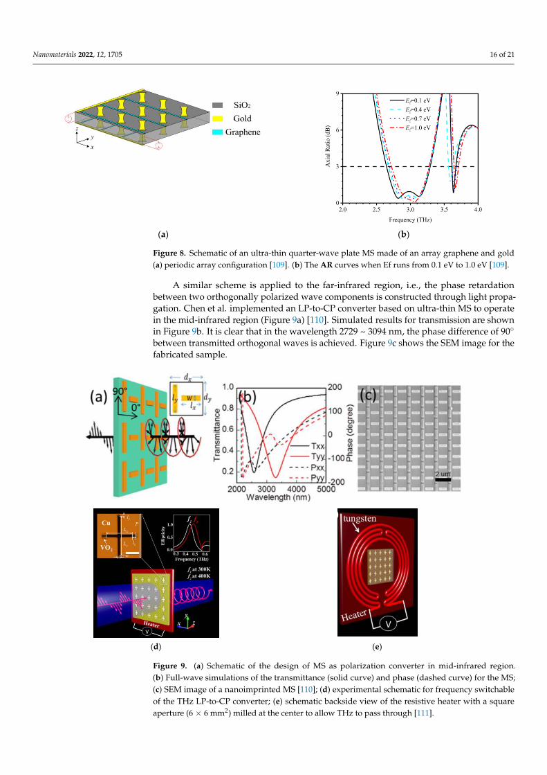
Nanomaterials 2022, 12, 1705 16 of 21
Nanomaterials 2022, 12, x FOR PEER REVIEW 16 of 22
Thus, different circuit elements can be used to achieve controllability in polarization con-
version and multi-functional operations.
6.3.2. Controllability through State Change
Another mechanism to control MSs for their LP-to-CP conversion is based on differ-
ent materials, such as graphene. This is a 2D layered material based on carbon atoms ar-
ranged in a honeycomb lattice and has excellent electrical properties, which can help in
controlling the interaction between light and matter. Graphene layers placed on the top
of the insulator have proved to exhibit strong plasmonic behavior [107]. Guo et al. pro-
posed a graphene-based LP-to-CP converter in transmission mode [108]. The phase dif-
ference between transmitted orthogonal waves can be controlled by varying the Fermi
level of the graphene. Starting from conceptual diagram for controlling the polarization
state of the outgoing wave using the Fermi energy level, the unit cell is designed and the
phase difference between transmitted co- and cross-polarization components is controlled
by varying Fermi energy levels. Similarly, Zhang et al. used graphene to dynamically reg-
ulate the operating band in the THz regime by controlling the Fermi energy of the gra-
phene sheets [109]. The polarizer performs over 2.64–3.29 THz (21.92%) in the case of Ef =
0.1 eV. Figure 8a shows the periodic array configuration and corresponding controllability
in the band of operation in Figure 8b.
(a) (b)
Figure 8. Schematic of an ultra-thin quarter-wave plate MS made of an array graphene and gold (a)
periodic array configuration [109]. (b) The AR curves when Ef runs from 0.1 eV to 1.0 eV [109].
A similar scheme is applied to the far-infrared region, i.e., the phase retardation be-
tween two orthogonally polarized wave components is constructed through light propa-
gation. Chen et al. implemented an LP-to-CP converter based on ultra-thin MS to operate
in the mid-infrared region (Figure 9a) [110]. Simulated results for transmission are shown
in Figure 9b. It is clear that in the wavelength 2729 ~ 3094 nm, the phase difference of 90°
between transmitted orthogonal waves is achieved. Figure 9c shows the SEM image for
the fabricated sample.
Figure 8. Schematic of an ultra-thin quarter-wave plate MS made of an array graphene and gold(a) periodic array configuration [109]. (b) The AR curves when Ef runs from 0.1 eV to 1.0 eV [109].
A similar scheme is applied to the far-infrared region, i.e., the phase retardationbetween two orthogonally polarized wave components is constructed through light propa-gation. Chen et al. implemented an LP-to-CP converter based on ultra-thin MS to operatein the mid-infrared region (Figure 9a) [110]. Simulated results for transmission are shownin Figure 9b. It is clear that in the wavelength 2729 ~ 3094 nm, the phase difference of 90◦
between transmitted orthogonal waves is achieved. Figure 9c shows the SEM image for thefabricated sample.
Nanomaterials 2022, 12, x FOR PEER REVIEW 17 of 22
(d) (e)
Figure 9. (a) Schematic of the design of MS as polarization converter in mid-infrared region. (b) Full-
wave simulations of the transmittance (solid curve) and phase (dashed curve) for the MS; (c) SEM
image of a nanoimprinted MS [110]; (d) experimental schematic for frequency switchable of the THz
LP-to-CP converter; (e) schematic backside view of the resistive heater with a square aperture (6 × 6
mm2) milled at the center to allow THz to pass through [111].
In another exemplary work, Wang et al. proposed a switchable ultra-thin terahertz
LP-to-CP converter by hybridizing a phase change material, vanadium dioxide (VO2),
with an MS, as shown in Figure 9d. Meta transition for VO2 changes the operational fre-
quency from 0.468 THz to 0.502 THz. MS performs transmissive linear to circular polari-
zation conversion at two stated operational frequencies. They fabricated MS using pulsed
laser deposition (PLD) on a c-cut sapphire substrate using a metallic vanadium target in
an oxidizing background. Further, iron milling was used to pattern cross-shaped resona-
tors. Figure 9e shows a resistive heater with a square aperture, which was milled at the
center to vary the temperature controlled by an external voltage source.
6.3.3. Controllability Using Structural Change
Several other controlling factors for LP-to-CP converters could be microfluidic MSs
[112], as shown in Figure 10a; where, three different polarization states (LHCP, RHCP,
LP) are obtained by microfluidic injection through different channels. Such a type of con-
trol is very useful for applications requiring a large number of diodes as tunable or MSs
[113]. As seen in Figure 10a, when microfluidic is injected into the upper channel only, the
outgoing wave is LHCP and vice versa is done for RHCP.
Figure 9. (a) Schematic of the design of MS as polarization converter in mid-infrared region.(b) Full-wave simulations of the transmittance (solid curve) and phase (dashed curve) for the MS;(c) SEM image of a nanoimprinted MS [110]; (d) experimental schematic for frequency switchableof the THz LP-to-CP converter; (e) schematic backside view of the resistive heater with a squareaperture (6 × 6 mm2) milled at the center to allow THz to pass through [111].

Nanomaterials 2022, 12, 1705 17 of 21
In another exemplary work, Wang et al. proposed a switchable ultra-thin terahertzLP-to-CP converter by hybridizing a phase change material, vanadium dioxide (VO2), withan MS, as shown in Figure 9d. Meta transition for VO2 changes the operational frequencyfrom 0.468 THz to 0.502 THz. MS performs transmissive linear to circular polarizationconversion at two stated operational frequencies. They fabricated MS using pulsed laserdeposition (PLD) on a c-cut sapphire substrate using a metallic vanadium target in anoxidizing background. Further, iron milling was used to pattern cross-shaped resonators.Figure 9e shows a resistive heater with a square aperture, which was milled at the center tovary the temperature controlled by an external voltage source.
6.3.3. Controllability Using Structural Change
Several other controlling factors for LP-to-CP converters could be microfluidic MSs [112],as shown in Figure 10a; where, three different polarization states (LHCP, RHCP, LP) areobtained by microfluidic injection through different channels. Such a type of control is veryuseful for applications requiring a large number of diodes as tunable or MSs [113]. As seenin Figure 10a, when microfluidic is injected into the upper channel only, the outgoing waveis LHCP and vice versa is done for RHCP.
Nanomaterials 2022, 12, x FOR PEER REVIEW 18 of 22
(a) (b)
Figure 10. (a) MS-based polarizer with microfluidic channels (Reprinted, with permission [112]);
(b) fabricated prototype (Reprinted, with permission [112]).
Some new controlling parameters could be gravity, as achieved by [102], and MEMS
[114]; however, these controlling options have not been explored yet in transmissive MS-
based LP-to-CP converters.
7. Conclusions
In this paper, MSs are classified based on their operational modes, where their trans-
mission mode for polarization conversion applications is discussed in detail. A brief his-
tory of MSs and advancements in their modeling approach is presented. Further, detailed
theories for polarization conversion and design strategies are discussed.
The authors have only focused on transmissive MSs for polarization conversion. To
review all the functionalities of transmissive MSs, or to discuss both transmissive and re-
flective MSs is possible but hardly constructive. Our observation of the trends of trans-
missive MSs for LP-to-CP converters can be concluded as the first trend of miniaturization
and easy-to-fabricate MSs. The second trend is a multiband operation to facilitate the
merging of multiple systems together. Design ideas from microwave MSs have been trans-
ferred to optical MSs but less frequent, and vice versa. The third trend is the controllability
of MSs using structural change, and the state change of controllable electric components.
It is hoped that the present review will help to establish a link between the advancements
in MSs and polarization conversion performance in microwave and optical regimes. The
authors also suggest new possibilities to control/tailor polarization conversion perfor-
mance using gravity [102] and MEMS [114], as these fields have not been explored for
transmission mode LP-to-CP converters.
Author Contributions: Conceptualization, A.K.F. and C.R.; formal analysis, A.K.F., C.R. and R.N.;
resources, C.R.; writ-ing—original draft preparation, A.K.F.; writing—review and editing, A.K.F.,
C.R., R.N. and B.H.; visualization, B.H.; supervision, C.R.; project administration, C.R.; funding ac-
quisition, C.R. All authors have read and agreed to the published version of the manuscript.
Funding: This research was funded by the National Natural Science Foundation of China, grant
number 61831001, the High-Level Talent Introduction Project of Beihang University, grant number
ZG216S1878 and the Youth-Top-Talent Support Project of Beihang University, grant number
ZG226S1821.
Conflicts of Interest: The authors declare no conflict of interest.
References
1. Huygens, C. Traité de la lumière; Gauthier-Villars: Leyden, The Netherlands, 1690.
2. Jones, E. Paraboloid reflector and hyperboloid lens antennas. Trans. IRE Prof. Group Antennas Propag. 1954, 2, 119–127.
Figure 10. (a) MS-based polarizer with microfluidic channels (Reprinted, with permission [112]);(b) fabricated prototype (Reprinted, with permission [112]).
Some new controlling parameters could be gravity, as achieved by [102], and MEMS [114];however, these controlling options have not been explored yet in transmissive MS-basedLP-to-CP converters.
7. Conclusions
In this paper, MSs are classified based on their operational modes, where their trans-mission mode for polarization conversion applications is discussed in detail. A brief historyof MSs and advancements in their modeling approach is presented. Further, detailedtheories for polarization conversion and design strategies are discussed.
The authors have only focused on transmissive MSs for polarization conversion. Toreview all the functionalities of transmissive MSs, or to discuss both transmissive and reflec-tive MSs is possible but hardly constructive. Our observation of the trends of transmissiveMSs for LP-to-CP converters can be concluded as the first trend of miniaturization andeasy-to-fabricate MSs. The second trend is a multiband operation to facilitate the mergingof multiple systems together. Design ideas from microwave MSs have been transferredto optical MSs but less frequent, and vice versa. The third trend is the controllability ofMSs using structural change, and the state change of controllable electric components. It ishoped that the present review will help to establish a link between the advancements inMSs and polarization conversion performance in microwave and optical regimes. The au-thors also suggest new possibilities to control/tailor polarization conversion performance
Nanomaterials 2022, 12, 1705 18 of 21
using gravity [102] and MEMS [114], as these fields have not been explored for transmissionmode LP-to-CP converters.
Author Contributions: Conceptualization, A.K.F. and C.R.; formal analysis, A.K.F., C.R. and R.N.;resources, C.R.; writing—original draft preparation, A.K.F.; writing—review and editing, A.K.F., C.R.,R.N. and B.H.; visualization, B.H.; supervision, C.R.; project administration, C.R.; funding acquisition,C.R. All authors have read and agreed to the published version of the manuscript.
Funding: This research was funded by the National Natural Science Foundation of China, grantnumber 61831001, the High-Level Talent Introduction Project of Beihang University, grant num-ber ZG216S1878 and the Youth-Top-Talent Support Project of Beihang University, grant numberZG226S1821.
Conflicts of Interest: The authors declare no conflict of interest.
References1. Huygens, C. Traité de La lumière; Gauthier-Villars: Leyden, The Netherlands, 1690.2. Jones, E. Paraboloid reflector and hyperboloid lens antennas. Trans. IRE Prof. Group Antennas Propag. 1954, 2, 119–127. [CrossRef]3. Born, M.; Wolf, E. Principles of Optics: Electromagnetic Theory of Propagation, Interference and Diffraction of Light; Elsevier: Singapore, 2013.4. Hsu, S.H.; Han, C.; Huang, J.; Chang, K. An offset linear-array-fed Ku/Ka dual-band reflectarray for planet cloud/precipitation
radar. IEEE Trans. Antennas Propag. 2007, 55, 3114–3122. [CrossRef]5. Ryan, C.G.; Chaharmir, M.R.; Shaker, J.R.B.J.; Bray, J.R.; Antar, Y.M.; Ittipiboon, A. A wideband transmitarray using dual-resonant
double square rings. IEEE Trans. Antennas Propag. 2010, 58, 1486–1493. [CrossRef]6. Li, M.; Al-Joumayly, M.A.; Behdad, N. Broadband true-time-delay microwave lenses based on miniaturized element frequency
selective surfaces. IEEE Trans. Antennas Propag. 2012, 61, 1166–1179. [CrossRef]7. Ali, A.; Mitra, A.; Aïssa, B. Metamaterials and Metasurfaces: A Review from the Perspectives of Materials, Mechanisms and
Advanced Metadevices. Nanomaterials 2022, 12, 1027. [CrossRef]8. Cai, W.; Chettiar, U.K.; Kildishev, A.V.; Shalaev, V.M.; Milton, G.W. Nonmagnetic cloak with minimized scattering. Appl. Phys.
Lett. 2007, 91, 111105. [CrossRef]9. Pendry, J.B.; Schurig, D.; Smith, D.R. Controlling electromagnetic fields. Science 2006, 312, 1780–1782. [CrossRef]10. Zhao, Q.; Yuan, W.; Qu, J.; Cheng, Z.; Peng, G.-D.; Yu, C. Optical Fiber-Integrated Metasurfaces: An Emerging Platform for
Multiple Optical Applications. Nanomaterials 2022, 12, 793. [CrossRef]11. Holloway, C.L.; Kuester, E.F.; Gordon, J.A.; O’Hara, J.; Booth, J.; Smith, D.R. An overview of the theory and applications of
Metasurfaces: The two-dimensional equivalents of metamaterials. IEEE Antennas Propag. Mag. 2012, 54, 10–35. [CrossRef]12. Su, V.C.; Chu, C.H.; Sun, G.; Tsai, D.P. Advances in optical MSs: Fabrication and applications. Opt. Express 2018, 26, 13148–13182.
[CrossRef]13. Glybovski, S.B.; Tretyakov, S.A.; Belov, P.A.; Kivshar, Y.S.; Simovski, C.R. Metasurfaces: From microwaves to visible. Phys. Rep.
2016, 634, 1–72. [CrossRef]14. Ren, J.; Leung, K.W. Generation of high-purity millimeter-wave orbital angular momentum modes using horn antenna: Theory
and implementation. arXiv 2017, arXiv:1710.00035.15. Wang, Y.Z.; Wang, P.L.; Lin, M. Design and experiment of X-Band circularly polarized antenna. Electron. Meas. Tech. 2010, 33,
26–29.16. Yang, C.; Zhu, X.W.; Liu, P.; Hong, W.; Feng, H.; Shi, Y.A. Circularly Polarized Horn Antenna Based on an FSS Polarization
Converter. IEEE Antennas Wirel. Propag. Lett. 2019, 19, 277–281. [CrossRef]17. Jepsen, P.U.; Cooke, D.G.; Koch, M. Terahertz spectroscopy and imaging–Modern techniques and applications. Laser Photonics
Rev. 2011, 5, 124–166. [CrossRef]18. Katletz, S.; Pfleger, M.; Pühringer, H.; Mikulics, M.; Vieweg, N.; Peters, O.; Scherger, B.; Scheller, M.; Koch, M.; Wiesauer,
K. Polarization sensitive terahertz imaging: Detection of birefringence and optical axis. Opt. Express 2012, 20, 23025–23035.[CrossRef]
19. Vollmer, F.; Arnold, S. Whispering-gallery-mode biosensing: Label-free detection down to single molecules. Nat. Methods 2008, 5,591–596. [CrossRef]
20. Tonouchi, M. Cutting-edge terahertz technology. Nat. Photonics 2007, 1, 97–105. [CrossRef]21. Yoshida, S.; Yamaguchi, T.; Kinbara, A. Changes of the optical properties of aggregated silver films after deposition. J. Opt. Soc.
Am. 1971, 61, 463–469. [CrossRef]22. Yamaguchi, T.; Yoshida, S.; Kinbara, A. Optical effect of the substrate on the anomalous absorption of aggregated silver films.
Thin Solid Film. 1974, 21, 173–187. [CrossRef]23. Gajdardziska-Josifovska, M.; McPhedran, R.C.; Cockayne, D.J.; McKenzie, D.R.; Collins, R.E. Silver–magnesium fluoride cermet
films. 1: Preparation and microstructure. Appl. Opt. 1989, 28, 2736–2743. [CrossRef] [PubMed]24. Senior, T. Combined resistive and conductive sheets. IEEE Trans. Antennas Propag. 1985, 33, 577–579. [CrossRef]
Nanomaterials 2022, 12, 1705 19 of 21
25. Simovski, C.R.; Ermutlu, M.E.; Sochava, A.A.; Tretyakov, S.A. Magnetic properties of novel high impedance surfaces. IET Microw.Antennas Propag. 2007, 1, 190–197. [CrossRef]
26. Kuester, E.F.; Mohamed, M.A.; Piket-May, M.; Holloway, C.L. Averaged transition conditions for electromagnetic fields at ametafilm. IEEE Trans. Antennas Propag. 2003, 51, 2641–2651. [CrossRef]
27. Holloway, C.L.; Mohamed, M.A.; Kuester, E.F.; Dienstfrey, A. Reflection and transmission properties of a metafilm: With anapplication to a controllable surface composed of resonant particles. IEEE Trans. Electromagn. Compat. 2005, 47, 853–865.[CrossRef]
28. Li, X. New Resonances, Gratings, and Slow-Wave Structures Based on 2D Periodic Structures. Ph.D. Thesis, University ofCalifornia, Los Angeles, CA, USA, 2018.
29. Hendry, E.; Mikhaylovskiy, R.V.; Barron, L.D.; Kadodwala, M.; Davis, T.J. Chiral electromagnetic fields generated by arrays ofnanoslits. Nano Lett. 2012, 12, 3640–3644. [CrossRef]
30. Papakostas, A.; Potts, A.; Bagnall, D.M.; Prosvirnin, S.L.; Coles, H.J.; Zheludev, N.I. Optical manifestations of planar chirality.Phys. Rev. Lett. 2003, 90, 107404. [CrossRef]
31. Niemi, T.; Karilainen, A.O.; Tretyakov, S.A. Synthesis of polarization transformers. IEEE Trans. Antennas Propag. 2013, 61,3102–3111. [CrossRef]
32. Yu, N.; Capasso, F. Flat optics with designer Metasurfaces. Nat. Mater. 2014, 13, 139–150. [CrossRef]33. Li, G.; Zhang, S.; Zentgraf, T. Nonlinear photonic Metasurfaces. Nat. Rev. Mater. 2017, 2, 17010. [CrossRef]34. Chen, W.T.; Zhu, A.Y.; Capasso, F. Flat optics with dispersion-engineered Metasurfaces. Nat. Rev. Mater. 2020, 5, 604–620.
[CrossRef]35. Sandeep, S.; Jin, J.M.; Caloz, C. Finite-element modeling of MSs with generalized sheet transition conditions. IEEE Trans. Antennas
Propag. 2017, 65, 2413–2420. [CrossRef]36. Albooyeh, M.; Alaee, R.; Rockstuhl, C.; Simovski, C. Revisiting substrate-induced bianisotropy in Metasurfaces. Phys. Rev. B 2015,
91, 195304. [CrossRef]37. Yan, M. Metal–insulator–metal light absorber: A continuous structure. J. Opt. 2013, 15, 025006. [CrossRef]38. Kontorovich, M.I.; Petrunkin, V.Y.; Yesepkina, N.A.; Astrakhan, M.I. The coefficient of reflection of a plane electromagnetic wave
from a plane wire mesh. Radio Eng. Electron. Phys. 1962, 7, 222–231.39. Tretyakov, S. Analytical Modeling in Applied Electromagnetics; Artech House: London, UK; Norwood, MA, USA, 2003.40. Vardaxoglou, J.C. Frequency Selective Surfaces: Analysis and Design; Research Studies Press: Boston, MA, USA, 1997.41. Munk, B.A. Frequency Elective Surfaces: Theory and Design; John Wiley & Sons: Hoboken, NJ, USA, 2000.42. Sarabandi, K.; Behdad, N. A frequency selective surface with miniaturized elements. IEEE Trans. Antennas Propag. 2007, 55,
1239–1245. [CrossRef]43. Chiu, C.N.; Chang, K.P. A novel miniaturized-element frequency selective surface having a stable resonance. IEEE Antennas Wirel.
Propag. Lett. 2009, 8, 1175–1177. [CrossRef]44. Bayatpur, F.; Sarabandi, K. Multipole spatial filters using metamaterial-based miniaturized-element frequency-selective surfaces.
IEEE Trans. Microw. Theory Tech. 2008, 56, 2742–2747. [CrossRef]45. Xu, R.R.; Zong, Z.Y.; Wu, W. Low-frequency miniaturized dual-band frequency selective surfaces with close band spacing. Microw.
Opt. Technol. Lett. 2009, 51, 1238–1240. [CrossRef]46. Behdad, N. Miniaturized-element frequency selective surfaces (MEFSS) using sub-wavelength periodic structures. In Proceedings
of the 2008 IEEE Radio and Wireless Symposium, Orlando, FL, USA, 22–24 January 2008; IEEE: New York, NY, USA, 2008; pp.347–350.
47. Hu, X.D.; Zhou, X.L.; Wu, L.S.; Zhou, L.; Yin, W.Y. A miniaturized dual-band frequency selective surface (FSS) with closed loopand its complementary pattern. IEEE Antennas Wirel. Propag. Lett. 2009, 8, 1374–1377.
48. Amitay, N.; Saleh, A.A.M. Broad-band wide-angle quasi-optical polarization rotators. IEEE Trans. Antennas Propag. 1983, 31,73–76. [CrossRef]
49. Plum, E.; Zhou, J.; Dong, J.; Fedotov, V.A.; Koschny, T.; Soukoulis, C.M.; Zheludev, N.I. Metamaterial with negative index due tochirality. Phys. Rev. B 2009, 79, 035407. [CrossRef]
50. Torres, R.P.; Catedra, M.F. Analysis and design of a two-octave polarization rotator for microwave frequency. IEEE Trans. AntennasPropag. 1993, 41, 208–213. [CrossRef]
51. Zhao, Y.; Belkin, M.A.; Alù, A. Twisted optical metamaterials for planarized ultrathin broadband circular polarizers. Nat. Commun.2012, 3, 870. [CrossRef]
52. Ye, Y.; He, S. 90◦ polarization rotator using a bilayered chiral metamaterial with giant optical activity. Appl. Phys. Lett. 2010, 96, 203501.[CrossRef]
53. Morin, G.A. A Circular Polarization Selective Surface Made of Resonant Helices; Defence Research Establishment Ottawa (Ontario):Ottawa, ON, Canada, 1995.
54. Quddus, A.U.; Abedi, S.; Evans, B.G.; Tafazolli, R. Blind multiple access interference suppression in a land mobile satellite fadingchannel. In Proceedings of the 2003 5th European Personal Mobile Communications Conference, Glasgow, UK, 22–25 April 2003.
55. Hofmann, T.; Schade, U.; Herzinger, C.M.; Esquinazi, P.; Schubert, M. Terahertz magneto-optic generalized ellipsometry usingsynchrotron and blackbody radiation. Rev. Sci. Instrum. 2006, 77, 063902. [CrossRef]

Nanomaterials 2022, 12, 1705 20 of 21
56. Parks, B.; Spielman, S.; Orenstein, J. High-frequency Hall effect in the normal state of YBa2Cu3O7. Phys. Rev. B Condens. Matter1997, 56, 115–117. [CrossRef]
57. Yamamoto, K.; Kabir, M.H.; Tominaga, K. Terahertz time-domain spectroscopy of sulfur-containing biomolecules. J. Opt. Soc. Am.B 2005, 22, 2417–2426. [CrossRef]
58. Woodward, R.M.; Cole, B.E.; Wallace, V.P.; Pye, R.J.; Arnone, D.D.; Linfield, E.H.; Pepper, M. Terahertz pulse imaging in reflectiongeometry of human skin cancer and skin tissue. Phys. Med. Biol. 2002, 47, 3853–3863. [CrossRef]
59. Strikwerda, A.C.; Fan, K.; Tao, H.; Pilon, D.V.; Zhang, X.; Averitt, R.D. Comparison of birefringent electric split-ring resonator andmeanderline structures as quarter-wave plates at terahertz frequencies. Opt. Express 2009, 17, 136–149. [CrossRef]
60. Dietlein, C.; Luukanen, A.; Popovi, Z.; Grossman, E. A W-band polarization converter and isolator. IEEE Trans. Antennas Propag.2007, 55, 1804–1809. [CrossRef]
61. Doumanis, E.; Goussetis, G.; Gomez-Tornero, J.L.; Cahill, R.; Fusco, V. Anisotropic impedance surfaces for linear to circularpolarization conversion. IEEE Trans. Antennas Propag. 2011, 60, 212–219. [CrossRef]
62. Lerner, D. A wave polarization converter for circular polarization. IEEE Trans. Antennas Propag. 1965, 13, 3–7. [CrossRef]63. Young, L.; Robinson, L.; Hacking, C. Meander-line polarizer. IEEE Trans. Antennas Propag. 1973, 21, 376–378. [CrossRef]64. Brand, G.F. The strip grating as a circular polarizing beamsplitter. Int. J. Infrared Millim. Waves 2002, 23, 1271–1285. [CrossRef]65. Wang, H.B.; Cheng, Y.J. Single-layer dual-band linear-to-circular polarization converter with wide axial ratio bandwidth and
different polarization modes. IEEE Trans. Antennas Propag. 2019, 67, 4296–4301. [CrossRef]66. He, J.; Xie, Z.; Wang, S.; Wang, X.; Kan, Q.; Zhang, Y. Terahertz polarization modulator based on Metasurface. J. Opt. 2015, 17, 105107.
[CrossRef]67. Zhu, H.L.; Cheung, S.W.; Chung, K.L.; Yuk, T.I. Linear-to-circular polarization conversion using Metasurface. IEEE Trans.
Antennas Propag. 2013, 61, 4615–4623. [CrossRef]68. Martinez-Lopez, L.; Rodriguez-Cuevas, J.; Martinez-Lopez, J.I.; Martynyuk, A.E. Cascaded circular-polarisation-selective surface
based on bisected split rings. Electron. Lett. 2014, 50, 1335–1336. [CrossRef]69. Li, Y.; Zhang, J.; Qu, S.; Wang, J.; Zheng, L.; Pang, Y.; Xu, Z.; Zhang, A. Achieving wide-band linear-to-circular polarization
conversion using ultra-thin bi-layered Metasurfaces. J. Appl. Phys. 2015, 117, 044501. [CrossRef]70. Baena, J.D.; Glybovski, S.B.; del Risco, J.P.; Slobozhanyuk, A.P.; Belov, P.A. Broadband and thin linear-to-circular polarizers based
on self-complementary zigzag Metasurfaces. IEEE Trans. Antennas Propag. 2017, 65, 4124–4133. [CrossRef]71. Wang, D.; Gu, Y.; Gong, Y.; Qiu, C.W.; Hong, M. An ultrathin terahertz quarter-wave plate using planar babinet-inverted
Metasurface. Opt. Express 2015, 23, 11114–11122. [CrossRef] [PubMed]72. Wu, C.; Arju, N.; Kelp, G.; Fan, J.A.; Dominguez, J.; Gonzales, E.; Tutuc, E.; Brener, I.; Shvets, G. Spectrally selective chiral silicon
Metasurfaces based on infrared Fano resonances. Nat. Commun. 2014, 5, 3892. [CrossRef] [PubMed]73. Lin, B.Q.; Guo, J.X.; Huang, B.G.; Fang, L.B.; Chu, P.; Liu, X.W. Wideband linear-to-circular polarization conversion realized by a
transmissive anisotropic Metasurface. Chin. Phys. B 2018, 27, 054204. [CrossRef]74. Lin, B.Q.; Guo, J.; Wang, Y.; Wang, Z.; Huang, B.; Liu, X. A wide-angle and wide-band circular polarizer using a bi-layer
Metasurface. Prog. Electromagn. Res. 2018, 161, 125–133. [CrossRef]75. Lin, C.; Ge, Y.; Bird, T.S.; Liu, K. Circularly polarized horns based on standard horns and a Metasurface polarizer. IEEE Antennas
Wirel. Propag. Lett. 2018, 17, 480–484. [CrossRef]76. Fahad, A.K.; Ruan, C.; Chen, K. A wideband terahertz transmissive polarization manipulator based on Metasurfaces. Electronics
2019, 8, 1068. [CrossRef]77. Ghosh, S.; Srivastava, K.V. An equivalent circuit model of FSS-based metamaterial absorber using coupled line theory. IEEE
Antennas Wirel. Propag. Lett. 2014, 14, 511–514. [CrossRef]78. Meinzer, N.; Barnes, W.L.; Hooper, I.R. Plasmonic meta-atoms and Metasurfaces. Nat. Photonics 2014, 8, 889. [CrossRef]79. Akgol, O.; Unal, E.; Altintas, O.; Karaaslan, M.; Karadag, F.; Sabah, C. Design of MS polarization converter from linearly polarized
signal to circularly polarized signal. Optik 2018, 161, 12–19. [CrossRef]80. Guo, Z.; Cao, X.; Gao, J.; Yang, H.; Jidi, L. A novel composite transmission Metasurface with dual functions and its application in
microstrip antenna. J. Appl. Phys. 2020, 127, 115103. [CrossRef]81. Fahad, A.K.; Ruan, C.; Ali, S.A.; Nazir, R.; Haq, T.U.; Ullah, S.; He, W. Triple-wide-band Ultra-thin Metasheet for transmission
polarization conversion. Sci. Rep. 2020, 10, 8810. [CrossRef] [PubMed]82. Florencio, R.; Boix, R.R.; Encinar, J.A. Fast and accurate MoM analysis of periodic arrays of multilayered stacked rectangular
patches with application to the design of reflectarray antennas. IEEE Trans. Antennas Propag. 2015, 63, 2558–2571. [CrossRef]83. Zou, W.M.; Qu, S.W.; Yang, S. A low profile dual-band dual-polarized shared-aperture antenna. In Proceedings of the 2017
International Applied Computational Electromagnetics Society Symposium (ACES), Firenze, Italy, 26–30 March 2017; IEEE: NewYork, NY, USA, 2017; pp. 1–2.
84. Zhang, J.F.; Cheng, Y.J.; Ding, Y.R.; Bai, C.X. A dual-band shared-aperture antenna with large frequency ratio, high aperture reuseefficiency, and high channel isolation. IEEE Trans. Antennas Propag. 2018, 67, 853–860. [CrossRef]
85. Wang, S.Y.; Liu, W.; Geyi, W. Dual-band transmission polarization converter based on planar-dipole pair frequency selectivesurface. Sci. Rep. 2018, 8, 3791. [CrossRef] [PubMed]
86. Khan, M.I.; Khalid, Z.; Tahir, F.A. Linear and circular-polarization conversion in X-band using anisotropic Metasurface. Sci. Rep.2019, 9, 4552. [CrossRef]

Nanomaterials 2022, 12, 1705 21 of 21
87. Zeng, Q.; Ren, W.; Zhao, H.; Xue, Z.; Li, W. Dual-band transmission-type circular polariser based on frequency selective surfaces.IET Microw. Antennas Propag. 2018, 13, 216–222. [CrossRef]
88. Naseri, P.; Matos, S.A.; Costa, J.R.; Fernandes, C.A.; Fonseca, N.J. Dual-band dual-linear-to-circular polarization converter intransmission mode application to $ K/Ka $-band satellite communications. IEEE Trans. Antennas Propag. 2018, 66, 7128–7137.[CrossRef]
89. Fahad, A.K.; Ruan, C.; Nazir, R.; Haq, T.U.; He, W. Dual-Band Ultrathin Meta-Array for Polarization Conversion in Ku/Ka-BandWith Broadband Transmission. IEEE Antennas Wirel. Propag. Lett. 2020, 19, 856–860. [CrossRef]
90. Fahad, A.K.; Ruan, C.; Nazir, R.; Saleem, M.; Haq, T.U.; Ullah, S.; He, W. Ultra-thin metasheet for dual-wide-band linear tocircular polarization conversion with wide-angle performance. IEEE Access 2020, 8, 163244–163254. [CrossRef]
91. Sofi, M.A.; Saurav, K.; Koul, S.K. Frequency-Selective Surface-Based Compact Single Substrate Layer Dual-Band Transmission-Type Linear-to-Circular Polarization Converter. IEEE Trans. Microw. Theory Tech. 2020, 68, 4138–4149. [CrossRef]
92. Liu, K.; Wang, G.; Cai, T.; Li, T. Dual-band transmissive circular polarization generator with high angular stability. Opt. Express2020, 28, 14995–15005. [CrossRef] [PubMed]
93. Naseri, P.; Costa, J.R.; Matos, S.A.; Fernandes, C.A.; Hum, S.V. Equivalent circuit modeling to design a dual-band dual linear-to-circular polarizer surface. IEEE Trans. Antennas Propag. 2020, 68, 5730–5735. [CrossRef]
94. Nouman, M.T.; Hwang, J.H.; Jang, J.H. Ultrathin terahertz quarter-wave plate based on split ring resonator and wire gratinghybrid Metasurface. Sci. Rep. 2016, 6, 39062. [CrossRef] [PubMed]
95. Turpin, J.P.; Bossard, J.A.; Morgan, K.L.; Werner, D.H.; Werner, P.L. Reconfigurable and tunable metamaterials: A review of thetheory and applications. Int. J. Antennas Propag. 2014, 2014, 429837. [CrossRef]
96. Sievenpiper, D.F.; Schaffner, J.H.; Song, H.J.; Loo, R.Y.; Tangonan, G. Two-dimensional beam steering using an electrically tunableimpedance surface. IEEE Trans. Antennas Propag. 2003, 51, 2713–2722. [CrossRef]
97. Sievenpiper, D.F. Forward and backward leaky wave radiation with large effective aperture from an electronically tunabletextured surface. IEEE Trans. Antennas Propag. 2005, 53, 236–247. [CrossRef]
98. Yong-Jun, Y.; Yong-Jun, H.; Guang-Jun, W.; Jing-Ping, Z.; Hai-Bin, S.; Gordon, O. Tunable broadband metamaterial absorberconsisting of ferrite slabs and a copper wire. Chin. Phys. B 2012, 21, 038501. [CrossRef]
99. Chen, H.T.; Padilla, W.J.; Zide, J.M.; Gossard, A.C.; Taylor, A.J.; Averitt, R.D. Active terahertz metamaterial devices. Nature 2006,444, 597–600. [CrossRef]
100. Kats, M.; Sharma, D.; Lin, J.; Genevet, P.; Blanchard, R.; Yang, Z.; Qazilbash, M.M.; Basov, D.N.; Ramanathan, S.; Capasso, F.Ultra-thin perfect absorber employing a tunable phase change material. Appl. Phys. Lett. 2012, 101, 221101. [CrossRef]
101. Zhu, W.M.; Song, Q.H.; Liu, A.Q.; Tsai, D.P.; Cai, H.; Shen, Z.X.; Huang, R.F.; Ting, S.K.; Liang, Q.X.; Liu, H.Z.; et al. A randomaccess reconfigurable metamaterial and a tunable flat lens. arXiv 2014, arXiv:1406.2757.
102. Zeng, L.; Zhang, H.F.; Liu, G.B.; Huang, T. A three-dimensional Linear-to-Circular polarization converter tailored by the gravityfield. Plasmonics 2019, 14, 1347–1355. [CrossRef]
103. Debogovic, T.; Bartolic, J.; Perruisseau-Carrier, J. Dual-polarized partially reflective surface antenna with MEMS-based beamwidthreconfiguration. IEEE Trans. Antennas Propag. 2013, 62, 228–236. [CrossRef]
104. Li, W.; Gao, S.; Cai, Y.; Luo, Q.; Sobhy, M.; Wei, G.; Xu, J.; Li, J.; Wu, C.; Cheng, Z. Polarization-reconfigurable circularly polarizedplanar antenna using switchable polarizer. IEEE Trans. Antennas 2017, 65, 4470–4477. [CrossRef]
105. Ma, X.; Pan, W.; Huang, C.; Pu, M.; Wang, Y.; Zhao, B.; Cui, J.; Wang, C.; Luo, X. An active metamaterial for polarizationmanipulating. Adv. Opt. Mater. 2014, 2, 945–949. [CrossRef]
106. Tao, Z.; Wan, X.; Pan, B.C.; Cui, T.J. Reconfigurable conversions of reflection, transmission, and polarization states using activeMetasurface. Appl. Phys. Lett. 2017, 110, 121901. [CrossRef]
107. Yan, H.; Li, X.; Chandra, B.; Tulevski, G.; Wu, Y.; Freitag, M.; Zhu, W.; Avouris, P.; Xia, F. Tunable infrared plasmonic devicesusing graphene/insulator stacks. Nat. Nanotechnol. 2012, 7, 330–334. [CrossRef]
108. Guo, T.; Argyropoulos, C. Broadband polarizers based on graphene Metasurfaces. Opt. Lett. 2016, 41, 5592–5595. [CrossRef]109. Zhang, H.F.; Zeng, L.; Liu, G.B.; Huang, T. Tunable linear-to-circular polarization converter using the graphene transmissive
Metasurface. IEEE Access 2019, 7, 158634–158642. [CrossRef]110. Chen, W.; Tymchenko, M.; Gopalan, P.; Ye, X.; Wu, Y.; Zhang, M.; Murray, C.B.; Alu, A.; Kagan, C.R. Large-area nanoimprinted
colloidal Au nanocrystal-based nanoantennas for ultrathin polarizing plasmonic Metasurfaces. Nano Lett. 2015, 15, 5254–5260.[CrossRef]
111. Wang, D.; Zhang, L.; Gu, Y.; Mehmood, M.Q.; Gong, Y.; Srivastava, A.; Jian, L.; Venkatesan, T.; Qiu, C.-W.; Hong, M. Switchableultrathin quarter-wave plate in terahertz using active phase-change MS. Sci. Rep. 2015, 5, 15020. [CrossRef] [PubMed]
112. Naqvi, A.H.; Lim, S. Microfluidically polarization-switchable Metasurfaced antenna. IEEE Antennas Wirel. Propag. Lett. 2018, 17,2255–2259. [CrossRef]
113. Mak, K.M.; Lai, H.W.; Luk, K.M.; Ho, K.L. Polarization reconfigurable circular patch antenna with a C-shaped. IEEE Trans.Antennas Propag. 2016, 65, 1388–1392. [CrossRef]
114. Yu, H.; Cao, X.; Gao, J.; Yang, H.; Jidi, L.; Han, J.; Li, T. Design of a wideband and reconfigurable polarization converter using amanipulable Metasurface. Opt. Mater. Express 2018, 8, 3373–3381. [CrossRef]
Related Documents