TRANSMISSION LINE & SUBSTATION PROJECTS COMPANY: ENTERGY SERVICES, INC. CUSTOMER: ARKANSAS ELECTRIC COOPERATIVE CORP (AECC) FACILITIES STUDY EJO NO. F4PPAR0525 Facility Study: T017 TRANSMISSION SERVICE FACILITIES STUDY OASIS# 77494473 System Impact Study: S001 Revision: 0 Rev Issue Date Description of Revision Prepared By Approved By A 3/1/13 Shell to team for input KC/IK AH B 3/21/13 Submitted for Construction input KC/IK AH C 4/1/13 Assembled for JET vote KC/IK AH 0 4/9/13 JET comments incorporated KC/IK AH

Welcome message from author
This document is posted to help you gain knowledge. Please leave a comment to let me know what you think about it! Share it to your friends and learn new things together.
Transcript
TRANSMISSION LINE & SUBSTATION PROJECTS
COMPANY: ENTERGY SERVICES, INC.
CUSTOMER: ARKANSAS ELECTRIC COOPERATIVE CORP (AECC)
FACILITIES STUDY
EJO NO. F4PPAR0525
Facility Study: T017
TRANSMISSION SERVICE FACILITIES STUDY
OASIS# 77494473
System Impact Study: S001
Revision: 0
Rev Issue Date
Description of Revision Prepared
By Approved
By
A 3/1/13 Shell to team for input KC/IK AH
B 3/21/13 Submitted for Construction input KC/IK AH
C 4/1/13 Assembled for JET vote KC/IK AH
0 4/9/13 JET comments incorporated KC/IK AH

AECC OASIS 77494473 Facilities Study
2
TABLE OF CONTENTS
1.0 PROJECT SUMMARY ........................................................................... 4
1.1 Background and Project Need ................................................................................. 4
1.2 Scope Summary ....................................................................................................... 4
1.2.1 2013-2017 Approved Entergy Construction Plan Projects......................... 4
1.2.2 Upgrade the Haskell-Woodlawn Switching Station 115 kV Transmission Line 4
1.2.3 Upgrade the Hot Springs-Butterfield 115kV Transmission Line ................. 5
1.2.4 Upgrade the Butterfield-Haskell 115 kV Transmission Line ....................... 5
1.2.5 Upgrade the Carpenter Dam-Malvern South 115 kV Transmission Line ... 5
1.2.6 Upgrade the Arklahoma-Tigre Bay Sw. Station 115 kV Transmission Line 5
1.2.7 Upgrade the Tigre Bay Sw. Station-Panther Valley Switching Station 115 kV Transmission Line ............................................................................................ 6
1.2.8 Upgrade the Panther Valley Sw. Station-Fountain Lake 115 kV transmission line ................................................................................................... 6
1.2.9 Hot Springs EHV Substation: Replace two 115 kV autotransformer breakers ................................................................................................................ 6
1.2.10 Financial Rights for Supplemental Upgrades ........................................... 6
1.3 Cost Summary.......................................................................................................... 6
1.4 Schedule Summary .................................................................................................. 7
1.5 Automatic Generation Control .................................................................................. 7
2.0 SAFETY REQUIREMENTS .................................................................... 7
3.0 GENERAL ASSUMPTIONS ................................................................... 7
4.0 SCOPE OF WORK ................................................................................. 9
4.1 Upgrade the Haskell - Woodlawn Sw. Station 115 kV Transmission Line (936.1) ... 9
4.1.1 Haskell to Woodlawn Tap Point Rebuild.................................................. 10
4.1.2 Woodlawn Tap Point to Woodlawn switching station Reconductor ........ 11
Safety consideration and risks during construction: ..................................................... 14
Long lead Delivery Items: ............................................................................................. 14
4.2 Upgrade the Hot Springs-Butterfield 115 kV Transmission Line (936.1) ................ 15
Hot Springs-Butterfield Reconductor/ Rebuild ..................................................... 15
4.3 Upgrade the Butterfield-Haskell 115 kV Transmission Line (936.1) ....................... 18
Butterfield to Haskell Reconductor/ Rebuild ........................................................ 18
4.4 Upgrade the Carpenter Dam-Malvern South 115 kV Transmission Line (969) ...... 21
Carpenter Dam-Malvern South Rebuild .............................................................. 21
4.5 Upgrade the Arklahoma-Tigre Bay Switching Station 115 kV Transmission Line .. 24

AECC OASIS 77494473 Facilities Study
3
4.6 Upgrade the Tigre Bay Sw. Station-Panther Valley Switching Station 115 kV Transmission Line ............................................................................................... 25
4.7 Upgrade the Panther Valley Switching Station-Fountain Lake 115 kV Transmission Line ..................................................................................................................... 26
4.8 Hot Springs EHV Substation: Replace Two 115 kV Autotransformer Breakers ..... 27
Construction Sequencing and Special Issues .............................................................. 28
4.8 Butterfield Switching station ................................................................................... 31
4.10 Carpenter Dam Substation ................................................................................. 35
5.0 COST .................................................................................................... 37
6.0 UPGRADE CLASSIFICATION ............................................................. 37
7.0 SCHEDULE .......................................................................................... 38
8.0 RISK ASSESSMENT ............................................................................ 40
9.0 CONFIRMED RESERVATIONS ........................................................... 41
10.0 PRE-888 TRANSACTIONS ................................................................ 46
11.0 STUDY QUEUE .................................................................................. 48
12.0 ATTACHMENTS ................................................................................. 49
12.1 Table of Acronyms ............................................................................................... 49
12.2 Substation one lines ............................................................................................. 49

AECC OASIS 77494473 Facilities Study
4
1.0 PROJECT SUMMARY
1.1 Background and Project Need
The purpose of this Facilities Study is to determine the availability of transfer capability across Entergy’s transmission system from Entergy (EES) to Entergy (EES) to evaluate the Arkansas Electric Cooperative Corp (AECC) request for 660 MW of yearly network transmission service. The time period for this transfer is from 9/1/2017 until 9/1/2037. The direction of the transaction is EES to EES. The study was performed on the latest available 2017-2024 winter and 2018-2024 summer peak seasonal models using PSS/E and MUST software by Power Technologies Incorporated (PTI).
The facilities study identifies any transmission constraints resulting from the requested power transfer. The facilities study also includes cost estimates to correct any transmission constraints.
1.2 Scope Summary
The Facilities Study has identified some transmission constraints.
1.2.1 2013-2017 Approved Entergy Construction Plan Projects
The following project is approved in the 2013-2017 Entergy Construction Plan. This project is required to be in-service prior to the start of transmission service.
• Benton N.-Benton S.: Construct new 115 kV line – Expected ISD Summer 2013.
• Sheridan South 500 kV upgrade: Mabelvale 500 kV substation (replace 3 breakers, 13 switches, and 2 line traps) – Expected ISD Summer 2014.
1.2.2 Upgrade the Haskell-Woodlawn Switching Station 115 kV Transmission Line
The Haskell-Woodlawn Sw. Station 115 kV transmission line overloads for the loss of the Sheridan-Magnet Cove 500 kV or Sheridan-Mabelvale 500 kV transmission line. It is required that the Haskell-Woodlawn Sw. Station 115 kV transmission line and all associated line equipment be upgraded from a capacity of 159 MVA to at least 240 MVA. The proposed upgrade rating is 261 MVA.
The Haskell-Woodlawn 115 kV transmission line upgrade has been committed to by a previously confirmed transmission service request for this same customer (OASIS #76583976). However, the proposed capacity of this upgrade in the previous study (OASIS #76583976) was 217 MVA. As noted above, this study requires a proposed capacity of 261 MVA. Therefore, this required upgrade would satisfy both transmission service requests (OASIS #77494473 and OASIS #76583976) if this request (OASIS #77494473) is confirmed.

AECC OASIS 77494473 Facilities Study
5
The amount of capacity created by this upgrade is 102MW, and the customer’s use of the capacity created is 75MW.
1.2.3 Upgrade the Hot Springs-Butterfield 115kV Transmission Line
The Hot Springs-Butterfield 115 kV transmission line overloads for the loss of the Sheridan-Magnet Cove 500 kV transmission line. It is required that the Hot Springs-Butterfield 115 kV transmission line and all associated line equipment be upgraded from a capacity of 239 MVA to at least 273 MVA. The proposed upgrade rating is 320 MVA.
The amount of capacity created by this upgrade is 81MW, and the customer’s use of the capacity created is 38W.
1.2.4 Upgrade the Butterfield-Haskell 115 kV Transmission Line
The Butterfield-Haskell 115 kV transmission line overloads for the loss of the Sheridan-Magnet Cove 500 kV transmission line. It is required that the Butterfield-Haskell 115 kV transmission line and all associated line equipment be upgraded from a capacity of 239 MVA to at least 266 MVA. The proposed upgrade rating is 320 MVA.
The amount of capacity created by this upgrade is 81MW, and the customer’s use of the capacity created is 31MW.
1.2.5 Upgrade the Carpenter Dam-Malvern South 115 kV Transmission Line
The Carpenter Dam-Malvern South 115 kV transmission line overloads for the loss of the Sheridan-Magnet Cove 500 kV transmission line. It is required that the Carpenter Dam-Malvern South 115 kV transmission line and all associated line equipment be upgraded from a capacity of 111 MVA to at least 121 MVA. The proposed upgrade rating is 176 MVA.
The amount of capacity created by this upgrade is 65MW, and the customer’s use of the capacity created is 11MW
1.2.6 Upgrade the Arklahoma-Tigre Bay Sw. Station 115 kV Transmission
Line
The Arklahoma-Tigre Bay Sw. Station 115 kV transmission line overloads for the loss of the Sheridan-Magnet Cove 500 kV transmission line. It is required that the Arklahoma-Tigre Bay Sw. Station 115 kV transmission line and all associated line equipment be upgraded from a capacity of 201 MVA to at least 211 MVA.
Review of the facilities studies workbook noted in section 4.5 indicates a revision is necessary to the workbook, and this upgrade is not needed.

AECC OASIS 77494473 Facilities Study
6
1.2.7 Upgrade the Tigre Bay Sw. Station-Panther Valley Switching Station 115 kV Transmission Line
The Tigre Bay Sw. Station-Panther Valley Sw. Station 115 kV transmission line overloads for the loss of the Sheridan-Magnet Cove 500 kV transmission line. It is required that the Tigre Bay Sw. Station-Panther Valley Sw. Station 115 kV transmission line and all associated line equipment be upgraded from a capacity of 201 MVA to at least 210 MVA.
Review of the facilities studies workbook noted in section 4.6 indicates a revision is necessary to the workbook, and this upgrade is not needed.
1.2.8 Upgrade the Panther Valley Sw. Station-Fountain Lake 115 kV
transmission line
The Panther Valley Sw. Station-Fountain Lake 115 kV transmission line overloads for the loss of the Sheridan-Magnet Cove 500 kV transmission line. It is required that the Panther Valley Sw. Station-Fountain Lake 115 kV transmission line and all associated line equipment be upgraded from a capacity of 201 MVA to at least 210 MVA.
Review of the facilities studies workbook noted in section 4.7 indicates a revision is necessary to the workbook, and this upgrade is not needed.
1.2.9 Hot Springs EHV Substation: Replace two 115 kV autotransformer
breakers
The Hot Springs-Arklahoma 115 kV transmission line overloads for the loss of the Hot Springs 500/115 kV autotransformer. Replacement of breakers B1501 and B1502 to increase their fault interrupting capability would allow the 115 kV bus tie to be closed, and thus, alleviate this constraint. This project is proposed in the 2013-2017 Entergy Construction Plan with an expected ISD of Summer 2013.
1.2.10 Financial Rights for Supplemental Upgrades
No FFR payments are required.
1.3 Cost Summary
The estimated total project cost is $27,293,613. This includes AFUDC and does not include Tax Gross Up which may apply if and where applicable. The estimate includes AFUDC and it will be waived should customer elect to make prepayment. The project cost is in 2013 dollars without any escalation. The ICT has assigned $561,557 as Base Plan upgrades and $26,732,056 as Supplemental Upgrade based on Attachment T of Entergy’s Open Access Transmission Tariff (OATT).

AECC OASIS 77494473 Facilities Study
7
1.4 Schedule Summary
The start of transfer is from 9/1/2017. Construction to alleviate all constraints would be completed by 10/27/2017 provided approval to proceed with the project is granted by 1 October 2013. Since the gap is only two months, after the development of project execution plan, it is likely that 1 Sept 2017 date can be achieved by scheduling tasks in more details.
1.5 Automatic Generation Control
Not applicable.
2.0 SAFETY REQUIREMENTS
Safety is a priority with Entergy. Safety will be designed into substations and lines. The designs will be done with the utmost safety of personnel in mind for construction, operation, and maintenance of the equipment. All employees working directly or indirectly for Entergy shall adhere to all rules and regulations outlined within the Entergy Safety manual. Entergy requires safety to be the highest priority for all projects. All Entergy and Contract employees must follow all applicable safe work procedures.
3.0 GENERAL ASSUMPTIONS
• Sufficient time will be allowed in approving the project enabling Entergy to prepare a
Project Execution Plan (PEP) and be able to complete the project, as per outlined in the schedule described provided below.
• Assumptions have been made in developing estimates without performing site visits, surveys, and soil borings. During PEP, these tasks will be completed and could have an impact on estimates and schedule.
• All costs above represent good faith estimates in escalated dollars based on 2013 rates, and could change considerably after development of a detailed PEP.
• Relay settings and RTU configurations details need to be specified during PEP stage, such as equipment and schemes for pilot protections.
• System changes will be modeled in ASPEN. Relay Impact Analysis will be performed by a settings engineer during PEP stage to identify requirements for relay/CT replacement, and settings revisions at the local and remote stations in the area. For example, affected elements include Z2, Z3, and ground over current settings, and so on. Some obsolete relays may need to be replaced.
• Communicate the project and protection coordination with nuclear, generation plants, load customers and other interconnected utilities, as appropriate.
• Comply with PRC-001, PRC-023 and relevant procedures, standards and guidelines, as appropriate. o PRC-001 protection coordination between transmission and generation could
affect the following stations � Blakely Dam � Carpenter Dam
AECC OASIS 77494473 Facilities Study
8
� Lake Catherine Plant � Remmel Dam
o Any affected stations should be notified per PRC-001. o The increase in MVA limit of the line conductor could affect PRC-023 requirements
between the following stations: � Woodlawn-Hot Springs 115kV � Carpenter Dam-Woodward 115kV � Cheetah-Arklahoma 115kV
• New RTU configurations or revisions will be necessary for stations where new equipment is installed or equipment replacement takes place. For example, there may be a need to map the additional points from a new or different relay.
• N-1 outage process and MISO modeling will be performed during PEP development.
AECC OASIS 77494473 Facilities Study
9
4.0 SCOPE OF WORK
4.1 Upgrade the Haskell - Woodlawn Sw. Station 115 kV Transmission Line (936.1)
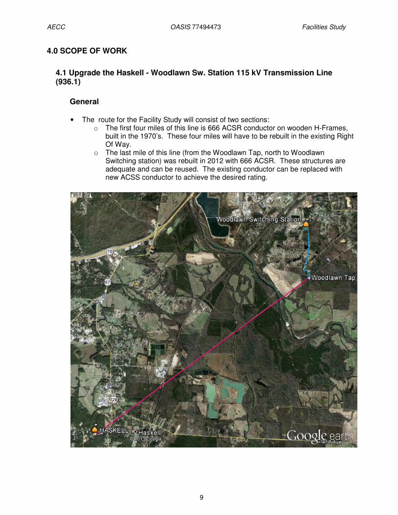
General • The route for the Facility Study will consist of two sections:
o The first four miles of this line is 666 ACSR conductor on wooden H-Frames, built in the 1970’s. These four miles will have to be rebuilt in the existing Right Of Way.
o The last mile of this line (from the Woodlawn Tap, north to Woodlawn Switching station) was rebuilt in 2012 with 666 ACSR. These structures are adequate and can be reused. The existing conductor can be replaced with new ACSS conductor to achieve the desired rating.

AECC OASIS 77494473 Facilities Study
10
Transmission Line Data
Line Capacity MVA
Existing Line Rating 154
Required Line Rating (Minimum) – 1205A
240
Proposed Line Rating (based on Equipment to be installed)
261
Affected line length in miles 5.04
4.1.1 Haskell to Woodlawn Tap Point Rebuild • Provide a single circuit 115kV line from the Woodlawn Tap Point to Woodlawn switching
station, approximately 4.1 miles.
• The line will consist of single pole delta configuration structures.
• New topographical surveying will be required to support the design of this line.
• Soil borings will also be required.
• The route is in existing Right of Way.
• No new ROW will have to be procured.
Structures and Foundations • All structures will be estimated as steel poles.
• 35 Single Pole Delta Braced Post Steel Structures
• One (1) Three Pole Dead End guyed Steel Structure
• Soil Borings do not exist. It is assumed that all poles will be direct embedded. The deadend poles are assumed to be backfilled with concrete, the remainder to be backfilled with crushed rock. It is assumed that rock will be encountered on 40 percent of the structures, requiring rock drilling.
Conductor and Insulators • The conductor installed will be about 60,000 pounds (4.1 miles) of 666 ACSS. This is
rated for 1312 Amps, or 261 MVA at 115 kV.
• This segment will utilize 15 dead end insulators, and 105 braced post insulators. All insulators will be compression type polymer insulators with corona rings.
Shield Wire • The segment will use 24,550 feet of OPGW fiber.
• It is assumed that Avian protection will be required. Spacing will be approximately fifteen (15’) feet between diverters.
Removals • Remove 37 – wooden 2 pole H structures.

AECC OASIS 77494473 Facilities Study
11
• Remove 111 - insulators.
• Remove 60,000 pounds of 666 ACSR wire.
• Remove 24,550 feet of OPGW fiber.
4.1.2 Woodlawn Tap Point to Woodlawn switching station Reconductor
• The west circuit of the existing structures of this circuit will be reconductored with 666 ACSS conductor. This will allow the segment to be rated at 261 MVA.
• The existing structures and foundations are adequate to provide both support and clearance for the new conductor.
Conductor and Insulators • The conductor installed will be about 15,000 pounds (0.99 miles) of 666 ACSS. This is
rated for 1312 Amps, or 261 MVA at 115 kV.
• The polymer insulators will be reused, but 18 new compression deadends and 18 new suspension shoes will be required.
Shield Wire • No additional shield wire is required. OPGW fiber is already installed.
• Avian protection will remain on the existing shield wire. Removals • Remove 15,000 lbs of 666 ACSR wire.
Environmental Permitting Based on provided information related to routing, proposed construction efforts and desk-top analyses, the following efforts for environmental permitting, related activities and associated costing are provided. • Assume that the T-line currently exist as double-poled H-structures that will be
removed and replaced with single-pole structures resulting in a reduction in the overall number of poles with a wider span between poles than does currently exist.
• Assume the existing line is approximately 5.25 miles in length (4.25 miles of single circuit and 1.0 mile of double circuit single pole.
• Assume the Entergy T-line exists within its own 100 ft. right-of-way (ROW) and will be rebuilt within the same with no new ROW being required.
• Assume that no Federal connectivity exists within the scope of the project and as such, no compliance with the National Environmental Policy Act (NEPA) will be required.
• Agency consultation would include US Fish & Wildlife Service (USFWS), Arkansas Department of Environmental Quality (ADEQ), Arkansas Historic Preservation Program (State Historic Preservation Office-SHPO), National Resource Conservation Service (NRCS), USACE and the Arkansas Game and Fish Commission (AGFC). Archeological/historical sites have been identified in near proximity to the Saline River in another recent project (Benton North to Benton South). Threatened and endangered mussel species have also been documented to occur in nearby reaches of the Saline River. As such, special attention to these resources will likely be required by the governing agencies. While construction is expected to occur within
AECC OASIS 77494473 Facilities Study
12
the existing ROW, these concerns will need to be addressed and agency approval will be required.
• Based on desk-top analysis of area-specific topographic, aerial and USFWS wetland status maps for Arkansas, the landscape of the proposed T-line rebuild has been identified to include area agriculture, pasture and timber practices. Close proximity and/or crossing of the existing T-line to mapped jurisdictional wetlands and/or streams includes the Saline River and an associated finger, Dodson Creek, four un-named tributaries to Dodson Creek, a large tributary to Dotted Lake, three un-named tributaries to Trace Creek, three fingers of Trace Creek and a large pond near the Wright Chapel area offer the potential of construction impacts. Performance of on-the-ground surveys to fully determine the extent, potential impacts and Best Management Practices (BMPs) concerned with jurisdictional wetlands and/or other waters of the US (WOUS) will be required. The United States Army Corps of Engineers (USACE) has a nationwide permit (NW-12) available for utility line activities that includes utility line substations and foundations for overhead utility line towers, poles and anchors. The nature of the efforts to secure a nationwide permit may include field survey and delineation, delineation report, consultation with Clean Water Act (CWA) commenting agencies, development of a Wetland Impact Mitigation Plan (including the negotiation of credits with an approved mitigation bank) if required and the preparation and submittal of the permit application to the USACE. Since this is an existing line upgrade that will not include new ROW and/or related permanent impacts (dredging or filling) mitigation cost is not anticipated or included within this cost estimate.
• Construction Planning Support could include Constructability Review to assess site conditions requiring special consideration during the development of best management practices (BMPs) or regulatory permitting from the County government or the Arkansas Highway Transportation Department. It could include the review of stream crossings and consideration for all-weather access based on hydrological calculations of watershed size, topography, land use, etc. Ecologically/geographically sensitive areas will be identified and clearly marked. .
• Arkansas Department of Environmental Quality (ADEQ) requires compliance with applicable regulations for coverage under the Construction Storm Water General NPDES Permit. It includes the development and implementation of the Notice of Intent (NOI) and the Storm Water Pollution Prevention Plan (SWPPP) to provide a site-specific description of the best management practices to prevent contamination of the site storm flows from potential pollutants associated with construction activities. The plan also outlines implementation, inspection and maintenance requirements.
• Routine inspection and monitoring required by NPDES Construction Storm Water General Permit for the SWPPP. This will include review of BMPs and permit monitoring requirements, travel to construction site once per 7 days and preparing inspection reports. It will identify incidents of non-compliance and associated conditions, recommendations for corrective actions, their status and effectiveness including assessment of proper installation and maintenance.
• Installation of Best Management Practices (BMPs) in accordance with SWPPP. Migratory Bird Treaty Act protection covers most bird species found in the project area. Construction to (Avian Powerline Interaction Committee (APLIC) standards as described in Entergy’s Avian Protection Plan. Review of the area indicates concerns for wintering waterfowl and other water birds utilizing the habitats associated with the 14 water body crossings. At a minimum, 25 % of length of the ROW could be
AECC OASIS 77494473 Facilities Study
13
impacted total to approximately 1.3 miles. Bird collision protection is recommended for these areas at a placement of 1/15ft. of line length. Installation will occur during construction when the lines are clipped in.
• Concern exist that MITC (methyl isothiocyanate) tubes could be present as a pole treatment for the poles that will be removed. If so identified, that portion of the pole containing the MITC tube will be cut and properly disposed of prior to pole removal by the public. This is typically captured as a construction cost for demo and rebuild. No costing is provided for this effort.
• Contracting support for additional site visits above those noted as SWPPP inspections to develop more detailed erosion/sediment controls to be included in contract specifications prepared by Entergy. This will include any additional or modified BMPs in revisions of the SWPPP site maps and will support Entergy during the contracting process and after Entergy has selected the BMP installation contractor.
• Actions performed necessary to terminate the NPDES permit upon completion of construction and stabilization associated with the project. This will include photo documentation, delivery of all project documentation, and preparation of Notice of Termination (NOT) with signatures for submittal to the regulatory authority.
*This projection excludes costing for wetland mitigation as noted above. If the route remains within the existing ROW, no new ROW is required, only temporary impacts exist as identified and no clearing is involved (only some tree-trimming.
*The above estimate has been included in the overall project costs. Construction Methodology:
• Based on discussions with SOC, it is assumed that an outage will most likely not be granted for more than 6 weeks at a time. This means that some of the t-line re-builds will need to be constructed in three different outages. This will add substantial cost and time to the project.
• Construction has been asked to be prepared at all times return the line to service in a short amount of time (10 hours), the line will have to be rebuilt one structure at a time and cost and construction time will increase.
• In order to reconductor the double circuit section, both the Woodlawn-Haskell and Woodlawn to Bauxite lines must be in an outage. It is assumed that both lines can be in an outage at the same time. If an outage on both lines simultaneously is not granted, cost will increase as hot work may be required. Regardless, timing of construction will be critical and will be dictated by the periods of time in which Transmission Planning can operate the grid with both lines out of service.
• Regulations and internal policies will require that Abnormal Protection System Requests (APS) be submitted and approved before outages are approved for any transmission line work that could affect relay protection.
• Construction will likely begin at Haskell and the single section of line will be rebuilt. After this section is rebuilt, the double circuit section will be rebuilt.
• Parts of this line lie in low areas that can tend to flood in seasons of high water. Should the construction fall within flooded periods, cost will increase as different and/or additional equipment will be required, as well as increased Storm Water Pollution Prevention Plan costs.
AECC OASIS 77494473 Facilities Study
14
• Due to the fact that the area is known to flood occasionally, track equipment will be specified by Construction for this project.
• The SWPPP measures will be installed prior to mobilizing a transmission line crew. • After line construction is complete, SWPPP measures must be removed and the
Right-Of-Way restored to original conditions or stabilized to meet ADEQ requirements
Outage Planning
After project approval, outages will be submitted to TOC. The chances of obtaining the line outage approval during extreme cold or hot conditions are minimal. However, it is anticipated that the transmission line construction will be performed during spring or fall. This will enhance the ability to obtain the necessary outages. There could be some difficulty in obtaining simultaneous outages for the double-circuit portion of line that is approximately 1-mile in length. This section will need careful planning and construction timing to fall within a window that will allow an outage simultaneously on the Woodlawn-Haskell and Woodlawn-Bauxite 115kV transmission lines. Based on discussion with the SOC, it will be difficult to even get 6 week outages for the Woodlawn to Hot Springs branch or Fountain Lake to Panther Valley section.
Safety consideration and risks during construction:
All Entergy safety rules will be observed and practiced during construction. EPZ techniques will be required during the entire transmission line construction. Risks associated with the transmission line cut-in include outage submittal and approval, weather conditions, and progress of the substation construction.
Long lead Delivery Items:
• Poles -22 weeks • Conductors – 25 weeks • Insulators – 20 weeks
Relay Settings:
See relay settings comments in 4.3.

AECC OASIS 77494473 Facilities Study
15
4.2 Upgrade the Hot Springs-Butterfield 115 kV Transmission Line (936.1)
General The Hot Springs-Butterfield 115 kV transmission line overloads for the loss of the Sheridan-Magnet Cove 500 kV transmission line. It is required that the Hot Springs-Butterfield 115 kV transmission line and all associated line equipment be upgraded from a capacity of 239 MVA to at least 273 MVA.
• The affected line is approximately 3.69 miles. • Line and line equipment at both terminals would need to be rated at a minimum of
1371 amps (273 MVA @ 115 kV).
Line Capacity MVA
Existing Line Rating 239
Required Line Rating (Minimum) – 1371A
273
Proposed Line Rating (based on Equipment to be installed)
320
Affected line length in miles 3.7
Hot Springs-Butterfield Reconductor/ Rebuild • The existing line will be reconductored with 954 ACSS Conductor.
• The existing line is supported on the North side of single pole vertical configuration double circuit structures. These structures also support line 968.1 which bypasses Butterfield sub and proceeds towards Malvern North Switching Station. The existing structures are of adequate class to support the new conductor, but approximately six structures will require replacement in order to maintain standard design clearances at the full rating of the new conductor.
• New ground surveying will be required to verify the accuracy of the existing LIDAR (Light Detection and Ranging) surveys with regard to new obstructions.
• Soil borings will not be required. The new structures will be at the same location as the replaced structures.
• The route is in existing Right of Way.
• No new ROW will have to be procured.
Structures and Foundations • All structures will be estimated as steel poles.
• Approximately six single pole double circuit vertical Braced Post Steel Structures will need to be replaced in order to maintain standard ground clearances.

AECC OASIS 77494473 Facilities Study
16
• The existing borings show good soils which will allow directly embedded foundations, backfilled with crushed rock. There is some shale on the Hot Springs end of the line, which may complicate excavation.
Conductor and Insulators • The conductor installed will be about 75,000 pounds (3.7 miles) of 954 ACSS. This is
rated for 1607 Amps, or 320 MVA at 115 kV.
• The polymer insulators will be reused, but 24 new compression deadends and 90 new suspension shoes will be required.
Shield Wire • No additional shield wire is required. OPGW fiber is already installed.
• It is assumed that Avian protection will be required on this segment. Spacing will be approximately fifteen (15’) feet between diverters.
Removals • Remove 6 – directly embedded steel poles. • Remove 70,000 pounds of 1272 ACSR conductor.
Long Delivery Items
Quantity Material Description *Lead Time
(weeks) 60,000 # 954 ACSS Conductor 25
Relay Settings
See relay settings comments in 4.3.
Construction methodology
• Based on discussions with SOC, it is assumed that an outage will most likely not be granted for more than 6 weeks at a time. This means that some of the t-line re-builds will need to be constructed in three different outages. This will add substantial cost and time to the project.
• Construction has been asked to be prepared at all times return the line to service in a short amount of time (10 hours), the line will have to be rebuilt one structure at a time and cost and construction time will increase.
• In order to reconductor the double circuit section, both the Hot Springs to Butterfield and Hot Springs to Malvern North lines must be in an outage. It is assumed that both lines can be in an outage at the same time. If an outage on both lines simultaneously is not granted, cost will increase as hot work may be required. Regardless, timing of construction will be critical and will be dictated by the periods of time in which Transmission Planning can operate the grid with both lines out of service.
• Regulations and internal policies will require that Abnormal Protection System Requests (APS) be submitted and approved before outages are approved for any transmission line work that could affect relay protection.

AECC OASIS 77494473 Facilities Study
17
• Parts of this line lie in low areas that can tend to flood in seasons of high water. Should the construction fall within flooded periods, cost will increase as different and/or additional equipment will be required, as well as increased Storm Water Pollution Prevention Plan costs.
• Due to the fact that the area is known to flood occasionally, track equipment will be specified by Construction for this project.
• The SWPPP measures will be installed prior to mobilizing a transmission line crew. • After line construction is complete, SWPPP measures must be removed and the
Right-Of-Way restored to original conditions or stabilized to meet ADEQ requirements

AECC OASIS 77494473 Facilities Study
18
4.3 Upgrade the Butterfield-Haskell 115 kV Transmission Line (936.1)
General The Butterfield-Haskell 115 kV transmission line overloads for the loss of the Sheridan-Magnet Cove 500 kV transmission line. It is required that the Butterfield-Haskell 115 kV transmission line and all associated line equipment be upgraded from a capacity of 239 MVA to at least 266 MVA.
• The affected line is approximately 11.09 miles. • Line and line equipment at both terminals would need to be rated at a minimum of
1335 amps (266 MVA @ 115 kV).
Line Capacity MVA
Existing Line Rating 239
Required Line Rating (Minimum) – 1335A
266
Proposed Line Rating (based on Equipment to be installed)
320
Affected line length in miles 11.09
Butterfield to Haskell Reconductor/ Rebuild • The existing line will be reconductored with 954 ACSS Conductor.
• For approximately the first ten spans, the line is supported on the North side of single pole vertical configuration double circuit structures. These structures also support line 968.1 which then branches off towards Malvern North Switching Station. The remainder of the line is constructed of concrete single-pole delta structures. The existing structures are of adequate class to support the new conductor, but approximately twenty structures will require replacement in order to maintain standard design clearances at the full rating of the new conductor.
• New ground surveying will be required to verify the accuracy of the existing LIDAR surveys with regard to new obstructions.
• Soil borings will not be required. The new structures will be at the same location as the replaced structures.
• The route is in existing Right of Way.
• No new ROW will have to be procured.
Structures and Foundations • All structures will be estimated as concrete poles.
• Approximately one (1) Single Pole double circuit vertical Braced Post Steel Structure and 19 Single pole single circuit delta braced post structures will need to be replaced in order to maintain standard ground clearances.

AECC OASIS 77494473 Facilities Study
19
• The existing borings show good soils which will allow directly embedded foundations, backfilled with crushed rock.
Conductor and Insulators • The conductor installed will be about 220,000 pounds (11.1 miles) of 954 ACSS. This is
rated for 1607 Amps, or 320 MVA at 115 kV.
• The polymer insulators will be reused, but 33 new compression deadends and 360 new suspension shoes will be required.
Shield Wire • No additional shield wire is required. OPGW fiber is already installed.
• It is assumed that Avian protection will not be added to this segment, since it does not pass near water or through expansive open areas.
Removals • Remove 20 – directly embedded concrete poles. • Remove 70,000 pounds of 1272 ACSR conductor.
Long Delivery Items
Quantity Material Description *Lead Time
(weeks) 60,000 # 954 ACSS Conductor 25
Relay Settings
• Revise ASPEN model. • If reconductoring results in a change of line impedance greater than 5%, revise zone
impedance reaches at Hot Springs and Woodlawn Substations. • Review and revise overcurrent relay settings at Hot Springs and Woodlawn as
necessary. • Apply PRC-023 requirements. • Review and revise zone 2 and 3 for the following transmission lines if necessary:
o Mabelvale—Woodlawn 115kV o River Ridge—Woodlawn 115kV o Arklahoma—Hot Springs 115kV Line #1 o Arklahoma—Hot Springs 115kV Line #3 o Woodward—Hot Springs 115kV
• Provide on/off site technical support during construction. • Complete “AS-BUILT” process for all relay settings issued.
Construction methodology
• Based on discussions with SOC, it is assumed that an outage will most likely not be granted for more than 6 weeks at a time. This means that some of the t-line re-builds will need to be constructed in three different outages. This will add substantial cost and time to the project.

AECC OASIS 77494473 Facilities Study
20
• Construction has been asked to be prepared at all times return the line to service in a short amount of time (10 hours), the line will have to be rebuilt one structure at a time and cost and construction time will increase.
• In order to reconductor the double circuit section, both the Butterfield to Haskell and Hot Springs to Malvern North lines must be in an outage. It is assumed that both lines can be in an outage at the same time. If an outage on both lines simultaneously is not granted, cost will increase as hot work may be required. Regardless, timing of construction will be critical and will be dictated by the periods of time in which Transmission Planning can operate the grid with both lines out of service.
• Regulations and internal policies will require that Abnormal Protection System Requests (APS) be submitted and approved before outages are approved for any transmission line work that could affect relay protection.
• Parts of this line lie in low areas that can tend to flood in seasons of high water. Should the construction fall within flooded periods, cost will increase as different and/or additional equipment will be required, as well as increased Storm Water Pollution Prevention Plan costs.
• Due to the fact that the area is known to flood occasionally, track equipment will be specified by Construction for this project.
• The SWPPP measures will be installed prior to mobilizing a transmission line crew. • After line construction is complete, SWPPP measures must be removed and the
Right-Of-Way restored to original conditions or stabilized to meet ADEQ requirements

AECC OASIS 77494473 Facilities Study
21
4.4 Upgrade the Carpenter Dam-Malvern South 115 kV Transmission Line (969)
General
The Carpenter Dam-Malvern South 115 kV transmission line overloads for the loss of the Sheridan-Magnet Cove 500 kV transmission line. It is required that the Carpenter Dam-Malvern South 115 kV transmission line and all associated line equipment be upgraded from a capacity of 111 MVA to at least 121 MVA.
• The new line will be approximately 13.40 miles. • Line and line equipment at both terminals would need to be rated at a minimum of
608 amps (121 MVA @ 115 kV).
Line Capacity MVA
Existing Line Rating 111
Required Line Rating (Minimum) – 608A
121
Proposed Line Rating (based on Equipment to be installed)
176
Affected line length in miles 13.4
Carpenter Dam-Malvern South Rebuild
• Provide a single circuit 115kV line from the Carpenter Dam to the Malvern South
substation, approximately 13.4 miles.
• The line will consist of single pole delta configuration structures.
• New topographical surveying will be required to support the design of this line.
• Soil borings will also be required.
• The route is in existing Right of Way.
• No new ROW will have to be procured.
Structures and Foundations • All structures will be estimated as steel poles.
• 115 Single Pole Delta Braced Post Steel Structures
• Five Three Pole Dead End guyed Steel Structure
• Soil borings do not exist. It is assumed that all poles will be direct embedded. The deadend poles are assumed to be backfilled with concrete, the remainder to be backfilled with crushed rock. It is assumed that rock will be encountered on 40 percent of the structures, requiring rock drilling.
Conductor and Insulators

AECC OASIS 77494473 Facilities Study
22
• The conductor installed will be about 190,000 pounds (13.4 miles) of 666 ACSR. This is rated for 882 Amps, or 176 MVA at 115 kV.
• This segment will utilize 42 dead end insulators, and 330 braced post insulators. All insulators will be compression type polymer insulators with corona rings.
Shield Wire • The segment will use 92,000 feet of OPGW fiber.
• It is assumed that Avian protection will be required on one fourth of the line. Spacing will be approximately fifteen (15’) feet between diverters.
Removals • Remove 116 – wooden pole H structures.
• Remove 370 - insulators.
• Remove 100,000 pounds of 397ACSR wire.
• Remove 180,000 feet of steel shield wire.
Relay Settings
• PRC-001: Carpenter Dam • PRC-001: Blakely Dam • Revise ASPEN model. • If reconductoring results in a change of line impedance greater than 5%, revise zone
impedance reaches at Carpenter Dam and Woodward Substations. • Review and revise overcurrent relay settings at Carpenter Dam and Woodward as
necessary. • Apply PRC-023 requirements. • Review and revise zone 2 and 3 for the following transmission lines if necessary:
o Hot Springs—Carpenter Dam 115kV o Arklahoma—Carpenter Dam 115kV o Blakely Dam—Carpenter Dam 115kV o Stuttgart Ricuskey--Woodward 115kV o Pine Bluff Dierks--Woodward 115kV o White Bluff—Woodward 115kV Line #1 o White Bluff—Woodward 115kV Line #2 o Hot Springs—Woodward 115kV o Degray SPA—Woodward 115kV o Fordyce—Woodward 115kV o Monticello East—Woodward 115kV o Pine Bluff South—Woodward 115kV
• Provide on/off site technical support during construction. • Complete “AS-BUILT” process for all relay settings issued.
Construction Methodology
• Based on discussions with SOC, it is assumed that an outage will most likely not be granted for more than 6 weeks at a time. This means that some of the t-line re-builds will need to be constructed in three different outages. This will add substantial cost and time to the project.

AECC OASIS 77494473 Facilities Study
23
• Construction has been asked to be prepared at all times return the line to service in a short amount of time (10 hours), the line will have to be rebuilt one structure at a time and cost and construction time will increase.
• Regulations and internal policies will require that Abnormal Protection System Requests (APS) be submitted and approved before outages are approved for any transmission line work that could affect relay protection.
• Parts of this line lie in low areas that can tend to flood in seasons of high water. Should the construction fall within flooded periods, cost will increase as different and/or additional equipment will be required, as well as increased Storm Water Pollution Prevention Plan costs.
• Due to the fact that the area is known to flood occasionally, track equipment will be specified by Construction for this project.
• The SWPPP measures will be installed prior to mobilizing a transmission line crew. • After line construction is complete, SWPPP measures must be removed and the
Right-Of-Way restored to original conditions or stabilized to meet ADEQ requirements
AECC OASIS 77494473 Facilities Study
24
4.5 Upgrade the Arklahoma-Tigre Bay Switching Station 115 kV Transmission Line
General
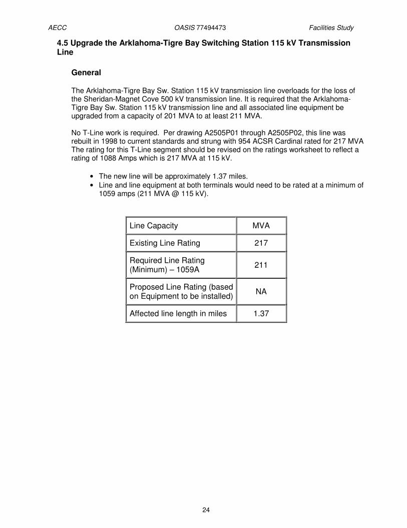
The Arklahoma-Tigre Bay Sw. Station 115 kV transmission line overloads for the loss of the Sheridan-Magnet Cove 500 kV transmission line. It is required that the Arklahoma-Tigre Bay Sw. Station 115 kV transmission line and all associated line equipment be upgraded from a capacity of 201 MVA to at least 211 MVA. No T-Line work is required. Per drawing A2505P01 through A2505P02, this line was rebuilt in 1998 to current standards and strung with 954 ACSR Cardinal rated for 217 MVA The rating for this T-Line segment should be revised on the ratings worksheet to reflect a rating of 1088 Amps which is 217 MVA at 115 kV.
• The new line will be approximately 1.37 miles. • Line and line equipment at both terminals would need to be rated at a minimum of
1059 amps (211 MVA @ 115 kV).
Line Capacity MVA
Existing Line Rating 217
Required Line Rating (Minimum) – 1059A
211
Proposed Line Rating (based on Equipment to be installed)
NA
Affected line length in miles 1.37
AECC OASIS 77494473 Facilities Study
25
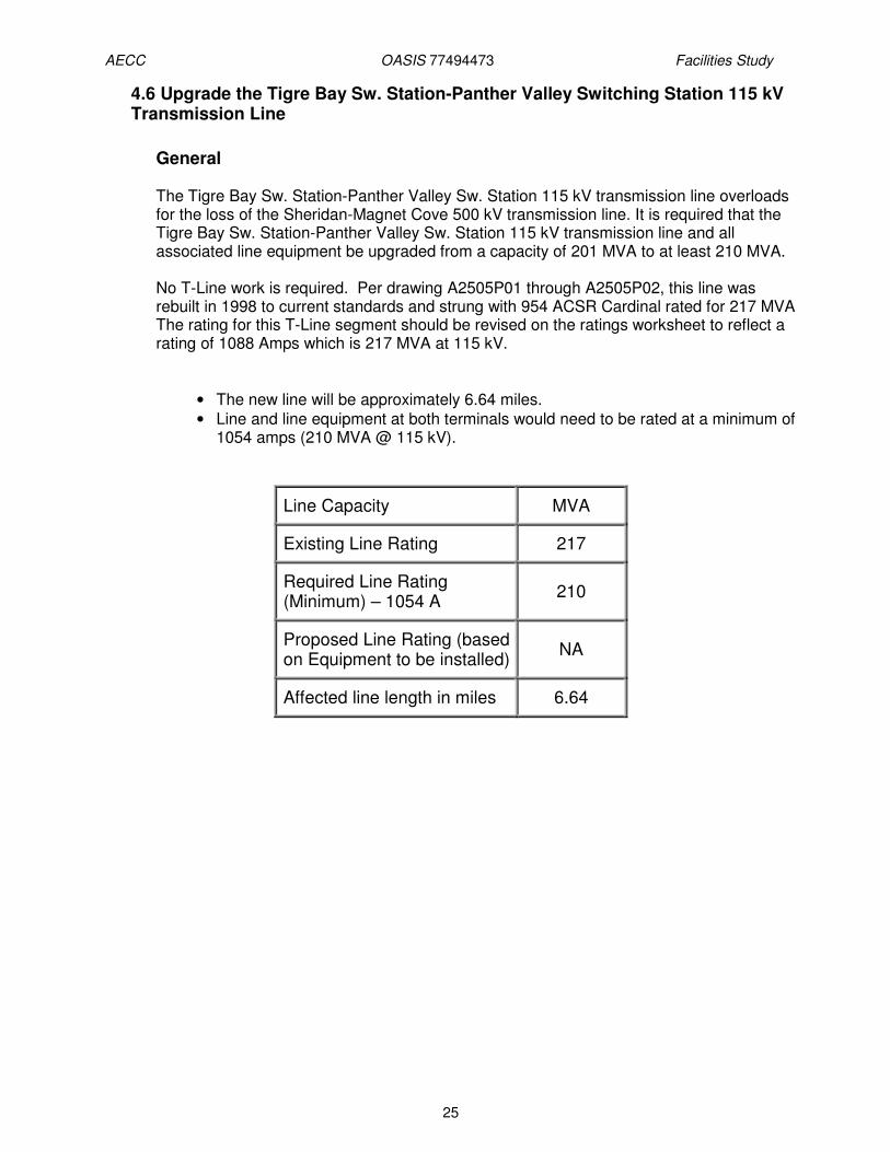
4.6 Upgrade the Tigre Bay Sw. Station-Panther Valley Switching Station 115 kV Transmission Line
General
The Tigre Bay Sw. Station-Panther Valley Sw. Station 115 kV transmission line overloads for the loss of the Sheridan-Magnet Cove 500 kV transmission line. It is required that the Tigre Bay Sw. Station-Panther Valley Sw. Station 115 kV transmission line and all associated line equipment be upgraded from a capacity of 201 MVA to at least 210 MVA. No T-Line work is required. Per drawing A2505P01 through A2505P02, this line was rebuilt in 1998 to current standards and strung with 954 ACSR Cardinal rated for 217 MVA The rating for this T-Line segment should be revised on the ratings worksheet to reflect a rating of 1088 Amps which is 217 MVA at 115 kV.
• The new line will be approximately 6.64 miles. • Line and line equipment at both terminals would need to be rated at a minimum of
1054 amps (210 MVA @ 115 kV).
Line Capacity MVA
Existing Line Rating 217
Required Line Rating (Minimum) – 1054 A
210
Proposed Line Rating (based on Equipment to be installed)
NA
Affected line length in miles 6.64

AECC OASIS 77494473 Facilities Study
26
4.7 Upgrade the Panther Valley Switching Station-Fountain Lake 115 kV Transmission Line
General The Panther Valley Sw. Station-Fountain Lake 115 kV transmission line overloads for the loss of the Sheridan-Magnet Cove 500 kV transmission line. It is required that the Panther Valley Sw. Station-Fountain Lake 115 kV transmission line and all associated line equipment be upgraded from a capacity of 201 MVA to at least 210 MVA.
No T-Line work is required. Per drawing A2505P01 through A2505P02, this line was rebuilt in 1998 to current standards and strung with 954 ACSR Cardinal rated for 217 MVA The rating for this T-Line segment should be revised on the ratings worksheet to reflect a rating of 1088 Amps which is 217 MVA at 115 kV.
• The new line will be approximately 3.35 miles • Line and line equipment at both terminals would need to be rated at a minimum of
1054 amps (210 MVA @ 115 kV).
Line Capacity MVA
Existing Line Rating 217
Required Line Rating (Minimum) – 1054A
210
Proposed Line Rating (based on Equipment to be installed)
NA
Affected line length in miles 3.35
.

AECC OASIS 77494473 Facilities Study
27
4.8 Hot Springs EHV Substation: Replace Two 115 kV Autotransformer Breakers
General
The Hot Springs-Arklahoma 115 kV transmission line overloads for the loss of the Hot Springs 500/115 kV autotransformer. Replacement of breakers B1501 and B1502 to increase their fault interrupting capability would allow the 115 kV bus tie to be closed, and thus, alleviate this constraint. Hot Spring EHV SS breakers B1501 and B1502 should be upgraded to 63kA breakers. This project is proposed in the 2013-2017 Entergy Construction Plan with an expected ISD of Summer 2013. Site All site preparation resulting in ground disturbance must implement best management practices (BMPs) to prevent sediment from going off-site. No construction activities will be allowed outside the existing substation fence due to a Native American cultural feature located adjacent to the substation. Any construction activities outside the existing fence line will require a Phase I Environmental Site Impact (ESI) study and a State Historic Preservation Office (SHPO) permit prior to any construction activities.
Foundations • Install approximately 120 ft of 3” PVC conduits. Four, 3” PVC conduits will be
installed from each breaker to the nearest manhole location.
• Disturbed areas with be filled with 6” of crushed rock.
Electrical • Disconnect and remove existing circuit breakers B1501 and B1502.
• Cut existing anchor bolts flush with top of breaker foundations.
• Install new 63kA breakers and fasten them to the existing foundations using hilti bolts.
• Reconnect existing above ground “pigtails” to new breakers.
• Remove existing above ground conduits and install new above ground conduits to the breakers.
• New jumpers will be triple 954 ACSR jumpers to get to a 3000A rating. The 3000A jumpers are needed so that the conductors themselves are not the limiting element in the corresponding bays.
Relay • Current project (expected ISD: May 2013) will complete relay design on this project.
No further relay work will be needed.
Relay Settings • Revise settings if required based on selection of new CT ratios.
Communications and SCADA • Reconfigure for any additional alarms.

AECC OASIS 77494473 Facilities Study
28
CONSTRUCTION MANAGEMENT PLAN
Construction Sequencing and Special Issues
The overall proposed construction sequence, and associated issues/assumptions, can be summarized as follows:
• All construction will take place on Company’s property.
• Work will be taking place near energized transmission lines during all phases of construction. All contractors, both electrical and non-electrical, should be aware of published guidelines for maintaining clearance (different for electrical vs. non-electrical workers).
• All construction activities will be managed by Company personnel.
• Foundation construction inside the fence will be contracted out. This work will either be bid out or assigned to an approved vendor.
• It is currently assumed that a majority of Substation Electrical and Relay construction will be contracted out since Asset Management may have inadequate in-house resources available to support this project. AM will be given first right-of-refusal for this work. At a minimum, AM will still need to be involved in final checkout and commissioning of all Relay equipment.
• Substation Electrical construction may be covered by a Contract Inspector, or Operations Coordinators. Relay construction coordination will be covered by in-house personnel.
• Construction schedule will follow the project schedule.
Construction Plan
Site:
• Receive and review site package.
• Prepare bid package and bid project for site work.
• Evaluate and award bid.
• Contractor to perform site work.
Foundations/Conduits/Grounding:
• Receive and review foundation package.
• Prepare bid package and bid project for foundation work.
• To avoid outages for foundation work the foundations need to be spread footer if possible, but if they are not of this type then outages may be needed to get drilling machinery in the station.
• Evaluate and award bid.
• Contractor to perform foundation work.
Electrical:
• Receive and review electrical package.
• Prepare bid package and bid project for electrical work.
• If the shield wire is removed lightning masts need to be put up in their place.
AECC OASIS 77494473 Facilities Study
29
• Evaluate and award bid.
• Contractor to perform electrical work.
• Review and walk-down for in-service connections.
Relay:
• Review relay installation plan.
• Receive and review relay plan.
• The relay designer needs to verify if the PT inputs to the relays or the DC sources to relays in existing control house are daisy chained. If this is the case then this can be remedied during the operating bus outage that will be taken during the electrical construction, but a supplementary design package may be required.
• Prepare bid package and bid project for wiring work.
• Evaluate and award bid. Schedule resources for relay installation and testing.
• Review power connections tie-in.
• Review phasing/testing for in-service tie in.
Other:
• Material coordination, disposition, and return.
• Hazards Identification.
• Review and address safety/working clearances.
• Review and submit as-built drawings.
• Close out project
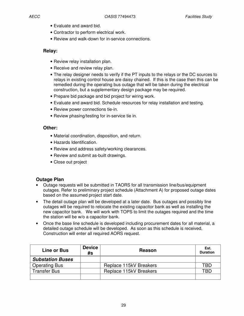
Outage Plan • Outage requests will be submitted in TAORS for all transmission line/bus/equipment
outages. Refer to preliminary project schedule (Attachment A) for proposed outage dates based on the assumed project start date.
• The detail outage plan will be developed at a later date. Bus outages and possibly line outages will be required to relocate the existing capacitor bank as well as installing the new capacitor bank. We will work with TOPS to limit the outages required and the time the station will be w/o a capacitor bank.
• Once the base line schedule is developed including procurement dates for all material, a detailed outage schedule will be developed. As soon as this schedule is received, Construction will enter all required AORS request.
Line or Bus Device
#s Reason
Est. Duration
Substation Buses
Operating Bus Replace 115kV Breakers TBD Transfer Bus Replace 115kV Breakers TBD

AECC OASIS 77494473 Facilities Study
30
ROW, PERMITTING, and ENVIRONMENTAL COMPLIANCE PLANS Permitting & Environmental
• Less than one (1) acre of ground disturbance is anticipated during construction activities for this project during; therefore, a Stormwater Pollution Prevention Permit (SWPPP) will not be required. However, the implementation of best management practices (BMPs) will be required to prevent any sediment from reaching an unnamed tributary located 100-foot to the southwest. Sediment fences must be placed down gradient of the construction areas inside the existing substation fence along the site perimeter.
• No construction activities will be allowed outside the existing substation fence since a historic site is located adjacent to the substation, i.e., a Native American site. Additional permits would be required before any such activities could occur outside the existing substation property.
• All new electrical equipment installed during this project will strictly follow avian protection standards as set forth in Entergy’s Substation Wildlife Manual.
Special Safety Considerations during Construction and Site Visits
• There are no known safety and environmental hazards that are known or expected to be present.
• There is no hot work planned. • Outages will be closely coordinated with the TOC, SOC and DOC. • A part-time on-site safety inspector may be used during this project

AECC OASIS 77494473 Facilities Study
31
4.8 Butterfield Switching station
General
• Need to replace line disconnect switches B3317 and B8617and through bus – from 1200A to a minimum of 1,371A.
Site • No site work required. Foundations • No site work required.
Electrical • Remove two (2) existing 115kV, 1200A Line Switches. • Remove existing 115kV operation bus. • Install two (2) 115kV, 2000A Vertical Break Line Switches motor operated, with
quick break attachment and ground switch. • Install bundle 954 KCMIL ACSR operation bus. • Install jumpers, fittings and other miscellaneous materials to support the complete
installation and safe operation. • Install above ground conduits.
Relay Design
• Purchase and install one (1) MOS-2 (motor operated switch) Panel at Butterfield for switch B3317 (to Haskell) and switch B8617 (to Hot Springs EHV).
• Run new cables from motor ops to panel.
Long Delivery Items
Quantity Material Description *Lead Time
(weeks)
2 Install two (2) 115kV, 2000A Vertical Break Line Switches motor operated, with quick break attachment and ground switch.
20
1 MOS-2 Panel 12-14
Construction methodology The overall proposed construction sequence, and associated issues/assumptions, can be summarized as follows:
• All construction will take place on Company’s property. • Work will be taking place near energized transmission lines during all phases of
construction. All contractors, both electrical and non-electrical, should be aware of published guidelines for maintaining clearance (different for electrical vs. non-electrical workers).
• A mobile transformer or switch will be required to complete construction.

AECC OASIS 77494473 Facilities Study
32
• All construction activities will be managed by Company personnel. • Foundation construction inside the fence will be contracted out. This work will
either be bid out or assigned to an approved vendor. • It is currently assumed that a majority of Substation Electrical and Relay
construction will be contracted out since Asset Management (AM) may have inadequate in-house resources available to support this project. AM will be given first right-of-refusal for this work. At a minimum, AM will still need to be involved in final checkout and commissioning of all Relay equipment.
• Substation Electrical construction may be covered by a Contract Inspector, or Operations Coordinators. Relay construction coordination will be covered by in-house personnel.
• Construction schedule will follow the project schedule.
Construction Plan
Electrical:
• Receive and review electrical package. • Prepare bid package and bid project for electrical work. • If the shield wire is removed lightning masts need to be put up in their place. • Evaluate and award bid. • Contractor to perform electrical work. • Review and walk-down for in-service connections.
Relay:
• Review relay installation plan. • Receive and review relay plan. • The relay designer needs to verify if the PT inputs to the relays or the DC sources
to relays in existing control house are daisy chained. If this is the case then this can be remedied during the operating bus outage that will be taken during the electrical construction, but a supplementary design package may be required.
• Prepare bid package and bid project for wiring work. • Evaluate and award bid. Schedule resources for relay installation and testing. • Review power connections tie-in. • Review phasing/testing for in-service tie in.
Other:
• Material coordination, disposition, and return. • Hazards Identification. • Review and address safety/working clearances. • Review and submit as-built drawings. • Close out project
Outage Planning
• An outage will be required on the high voltage bus. • A mobile transformer or switch will be required to complete construction.
AECC OASIS 77494473 Facilities Study
33
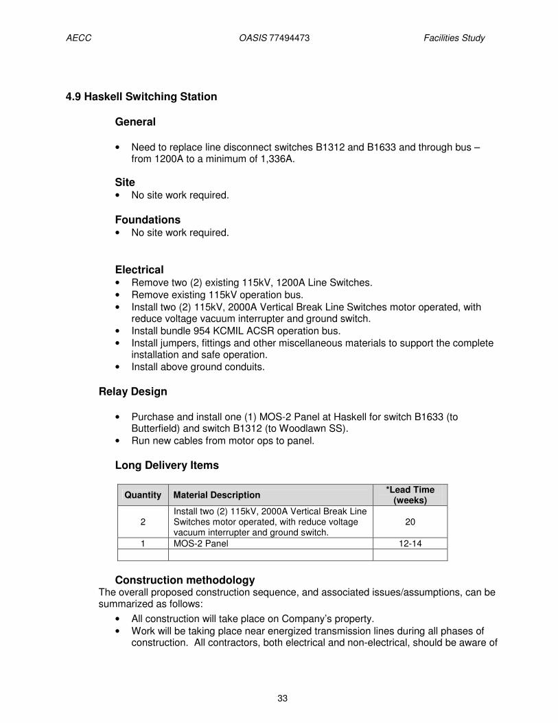
4.9 Haskell Switching Station
General
• Need to replace line disconnect switches B1312 and B1633 and through bus – from 1200A to a minimum of 1,336A.
Site • No site work required. Foundations • No site work required.
Electrical • Remove two (2) existing 115kV, 1200A Line Switches. • Remove existing 115kV operation bus. • Install two (2) 115kV, 2000A Vertical Break Line Switches motor operated, with
reduce voltage vacuum interrupter and ground switch. • Install bundle 954 KCMIL ACSR operation bus. • Install jumpers, fittings and other miscellaneous materials to support the complete
installation and safe operation. • Install above ground conduits.
Relay Design
• Purchase and install one (1) MOS-2 Panel at Haskell for switch B1633 (to Butterfield) and switch B1312 (to Woodlawn SS).
• Run new cables from motor ops to panel.
Long Delivery Items
Quantity Material Description *Lead Time
(weeks)
2 Install two (2) 115kV, 2000A Vertical Break Line Switches motor operated, with reduce voltage vacuum interrupter and ground switch.
20
1 MOS-2 Panel 12-14
Construction methodology
The overall proposed construction sequence, and associated issues/assumptions, can be summarized as follows:
• All construction will take place on Company’s property. • Work will be taking place near energized transmission lines during all phases of
construction. All contractors, both electrical and non-electrical, should be aware of
AECC OASIS 77494473 Facilities Study
34
published guidelines for maintaining clearance (different for electrical vs. non-electrical workers).
• A mobile transformer or switch will be required to complete construction. • All construction activities will be managed by Company personnel. • Foundation construction inside the fence will be contracted out. This work will
either be bid out or assigned to an approved vendor. • It is currently assumed that a majority of Substation Electrical and Relay
construction will be contracted out since Asset Management may have inadequate in-house resources available to support this project. AM will be given first right-of-refusal for this work. At a minimum, AM will still need to be involved in final checkout and commissioning of all Relay equipment.
• Substation Electrical construction may be covered by a Contract Inspector, or Operations Coordinators. Relay construction coordination will be covered by in-house personnel.
• Construction schedule will follow the project schedule.
Construction Plan
Electrical:
• Receive and review electrical package. • Prepare bid package and bid project for electrical work. • If the shield wire is removed lightning masts need to be put up in their place. • Evaluate and award bid. • Contractor to perform electrical work. • Review and walk-down for in-service connections.
Relay:
• Review relay installation plan. • Receive and review relay plan. • The relay designer needs to verify if the PT inputs to the relays or the DC sources to
relays in existing control house are daisy chained. If this is the case then this can be remedied during the operating bus outage that will be taken during the electrical construction, but a supplementary design package may be required.
• Prepare bid package and bid project for wiring work. • Evaluate and award bid. Schedule resources for relay installation and testing. • Review power connections tie-in. • Review phasing/testing for in-service tie in.
Other:
• Material coordination, disposition, and return. • Hazards Identification. • Review and address safety/working clearances. • Review and submit as-built drawings. • Close out project
Outage Planning • An outage will be required on the high voltage bus. • A mobile transformer or switch will be required to complete construction.
AECC OASIS 77494473 Facilities Study
35
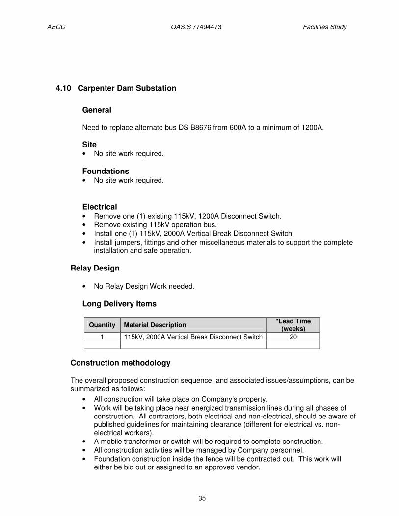
4.10 Carpenter Dam Substation
General
Need to replace alternate bus DS B8676 from 600A to a minimum of 1200A. Site • No site work required. Foundations • No site work required.
Electrical • Remove one (1) existing 115kV, 1200A Disconnect Switch. • Remove existing 115kV operation bus. • Install one (1) 115kV, 2000A Vertical Break Disconnect Switch. • Install jumpers, fittings and other miscellaneous materials to support the complete
installation and safe operation.
Relay Design
• No Relay Design Work needed.
Long Delivery Items
Quantity Material Description *Lead Time
(weeks)
1 115kV, 2000A Vertical Break Disconnect Switch 20
Construction methodology The overall proposed construction sequence, and associated issues/assumptions, can be summarized as follows:
• All construction will take place on Company’s property. • Work will be taking place near energized transmission lines during all phases of
construction. All contractors, both electrical and non-electrical, should be aware of published guidelines for maintaining clearance (different for electrical vs. non-electrical workers).
• A mobile transformer or switch will be required to complete construction. • All construction activities will be managed by Company personnel. • Foundation construction inside the fence will be contracted out. This work will
either be bid out or assigned to an approved vendor.
AECC OASIS 77494473 Facilities Study
36
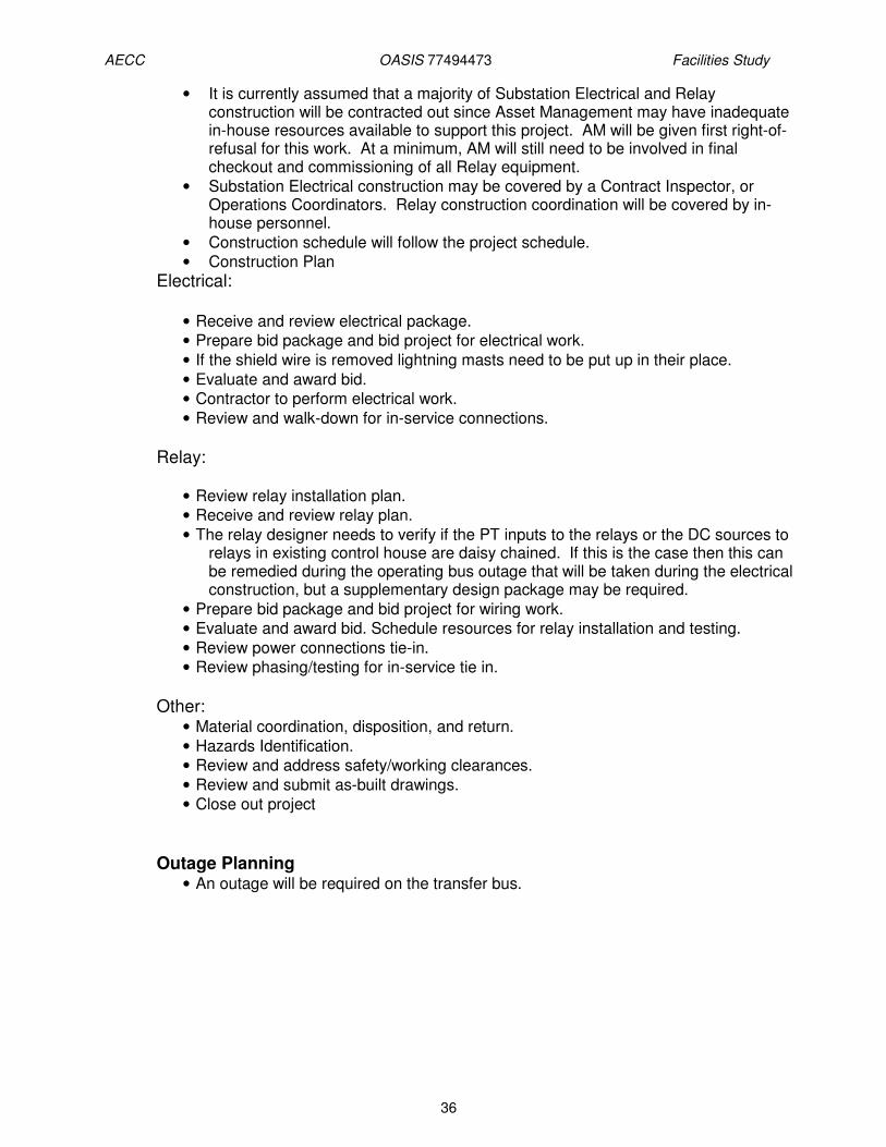
• It is currently assumed that a majority of Substation Electrical and Relay construction will be contracted out since Asset Management may have inadequate in-house resources available to support this project. AM will be given first right-of-refusal for this work. At a minimum, AM will still need to be involved in final checkout and commissioning of all Relay equipment.
• Substation Electrical construction may be covered by a Contract Inspector, or Operations Coordinators. Relay construction coordination will be covered by in-house personnel.
• Construction schedule will follow the project schedule. • Construction Plan
Electrical:
• Receive and review electrical package. • Prepare bid package and bid project for electrical work. • If the shield wire is removed lightning masts need to be put up in their place. • Evaluate and award bid. • Contractor to perform electrical work. • Review and walk-down for in-service connections.
Relay:
• Review relay installation plan. • Receive and review relay plan. • The relay designer needs to verify if the PT inputs to the relays or the DC sources to
relays in existing control house are daisy chained. If this is the case then this can be remedied during the operating bus outage that will be taken during the electrical construction, but a supplementary design package may be required.
• Prepare bid package and bid project for wiring work. • Evaluate and award bid. Schedule resources for relay installation and testing. • Review power connections tie-in. • Review phasing/testing for in-service tie in.
Other:
• Material coordination, disposition, and return. • Hazards Identification. • Review and address safety/working clearances. • Review and submit as-built drawings. • Close out project
Outage Planning • An outage will be required on the transfer bus.

AECC OASIS 77494473 Facilities Study
37
5.0 COST
The ICT has reviewed and determined whether each required upgrade will be considered a Base Plan Upgrade or a Supplemental Upgrade. For more information on cost responsibility for Base Plan and Supplemental Upgrades, see Attachment T to Entergy’s OATT. The costs shown in the table include all applicable overheads and AFUDC, but do not include tax gross up. Entergy incurs a tax liability proportional to the amount of customer contributions.
2012 2013 2014 2015 2016 2017 Total
Direct $ 75 $ 491,862 $ 1,674,600 $ 10,183,091 $ 6,927,276 $ 5,036,761 $24,313,665
Indirect $ 26 $ 69,594 $ 204,922 $ 1,133,762 $ 781,383 $ 790,261 $ 2,979,948
Total $ 101 $ 561,456 $ 1,879,521 $ 11,316,854 $ 7,708,659 $ 5,827,022 $27,293,613
6.0 UPGRADE CLASSIFICATION
The ICT has reviewed and determined whether each required upgrade will be considered a Supplemental Upgrade. For more information on cost responsibility for Base Plan and Supplemental Upgrades, see Attachment T to Entergy’s OATT.
Task Total Cost Base Plan Supplemental FFR Payment Section(s)
Upgrade Haskell to Woodlawn line
$ 4,978,989
$ 4,978,989
4.1
Upgrade Hot Springs to Butterfield Line
$ 2,512,532
$ 2,512,532
4.2
Upgrade Butterfield to Haskell Line
$ 5,709,229
$ 5,709,229
4.3
Carpenter Dam to Malvern South Line
$ 12,733,004
$ 12,733,004
4.4
Arklahoma to Tigre Bay Line
$0 $0 4.5
Tigre Bay to Panther Valley Line
$0 $0 4.6
Panther Valley to Fountain Lake Line
$0 $0 4.7
Hot Springs EHV Substation
$ 561,557
$ 561,557
4.8
Butterfield Switching Station
$ 329,174
$ 329,174
4.9
Haskell Switching Station
$ 342,921
$ 342,921
4.10
Carpenter Dam Substation
$ 123,207
$ 123,207
4.11
Total: $ 27,293,613 $ 561,557 $ 26,732,056

AECC OASIS 77494473 Facilities Study
38
7.0 SCHEDULE
A detailed schedule will be prepared subsequent to customer approval to proceed with the project. Based on the task duration schedules listed below, the overall project in-service date is projected to be November 2017. This assumes customer approval to proceed with the development of PEP by October 2013.
* During line outages, work at Hot Springs, Haskell, Butterfield and
Carpenter Dam will be completed.
Summary: Completed by
Commence design for Hot Springs EHV Substation 12/10/2012
Commence Hot Springs EHV Substation construction 4/1/2013
Submit facility Study 5/19/2013
Hot Springs EHV SS construction completed 5/31/2013
Customer + FP/WOs Approval 10/30/2013
Complete PEP 4/30/2014
Customer approval + Revised FP approval 5/30/2014 Commence design/Notification to agencies working on existing ROW/SWPPP 6/30/2014
Order Substation and line material 8/30/2014
Issue design packages for SS and lines & go for bids 12/30/2014 Award construction contracts / Receive all SS and line material + SWPPP & clearance from owners/agencies to commence construction 2/28/2015
Commence Substations & Line Construction (starting Haskell-Woodlawn Line) and other lines and Substations to follow 3/2/2015
Complete Haskell to Woodlawn line and Substation 10/30/2015
Complete Hot Springs to Butterfield line and Substation 12/11/2015
Complete Haskell to Butterfield line and Substation 10/14/2016
Complete Malvern S to Carpenter Dam line and Substation 10/27/2017
Arklahoma-Tigre Bay Sw. Station Line No work is required
Tigre Bay Sw. Station-Panther Valley Sw. Station Line No work is required
Panther Valley Sw. Station-Fountain Lake Line No work is required
Notes to Duration Schedules:
• Pre-existing scheduled line outages may prevent the commencement of work. Scheduled outages cannot be confirmed until a firm construction schedule is submitted.
• All construction work requiring outages will be performed during off-peak load season. Line outages will be discussed with the SOC and TOC and the assumption is made that line outages will be executed as planned. However, last minute denial of outages by the SOC/TOC along with resulting schedule delay is possible.
• Design and Construction resources are available when required. • Different resource is used for each design, so all designs start at same time.

AECC OASIS 77494473 Facilities Study
39
• Transmission Line and Substation projects will begin subsequent to completion of Definition phase preparing PEP and having customer approval to proceed with the design/procurement and construction
• This schedule does not account for adverse weather conditions. • Schedule durations are high level estimates at this time. A detailed schedule will be
prepared upon project approval. • Scheduling assumption and completion dates for the project:
o All wood structures will be disposed of by either awarding to landowners or
disposed of as regular creosote waste-no specially treated wood. o ROW is accessible by conventional means, no special equipment or extensive
matting. ROW is maintained to the extent clearing is not necessary and no reseeding will be warranted.
o Baseline or preferential contractors will be used eliminating the time required to competitively bid.

AECC OASIS 77494473 Facilities Study
40
8.0 RISK ASSESSMENT
Risk Comment Impact
Material costs steel & Equipment Rising steel, copper, fuel and other market conditions could greatly affect estimated cost.
****
Storm-water plan implementation
Best guess on SWPPP creation, implementation and monitoring can vary greatly dependant on outcome of environmental study.
**
Weather & Equipment Lead Times
Unexpected delays on material lead times, unusually inclement weather will impact schedule but might impact AFUDC costs as well.
**
Wetland mitigation Undetermined until environmental analysis is complete.
***
Outages may not be available
Preliminary schedule only considers general outage constraints. Specific project schedule may be delayed by days, weeks or months dependant on system conditions. Delays of months = increased project costs.
**
Scope based on design assumptions which may change
Varied impact on cost and schedule. ***
*-low impact to cost, ** - moderate impact to cost, ***- high impact to cost, **** - very high

AECC OASIS 77494473 Facilities Study
41
9.0 CONFIRMED RESERVATIONS
OASIS PSE MW Begin End 569011 Entergy Services, Inc. (EMO) 242 3/1/2000 1/1/2014
759196 Entergy Services, Inc. (EMO) 143 1/1/2001 1/1/2021
759294 East Texas Electric Cooperative 31 1/1/2001 1/1/2018
1096986 Tennessee Valley Authority 73 9/1/2003 9/1/2013
1099991 (renewal) City Water & Light, Jonesboro 83 1/1/2010 1/1/2016
1099997 (renewal) City Water & Light, Jonesboro 168 1/1/2010 1/1/2016
1105665 Entergy Services, Inc. (EMO) 236 2/1/2003 2/1/2016
1105666 Entergy Services, Inc. (EMO) 91 2/1/2003 2/1/2027
1105668 Entergy Services, Inc. (EMO) 77 2/1/2003 2/1/2027
1126821 Entergy Services, Inc. (EMO) 101 5/1/2004 5/1/2029
1151106 Entergy Services, Inc. (EMO) 20 6/1/2010 6/1/2029
1168061 Entergy Services, Inc. (EMO) 80 8/1/2004 2/1/2028
1168408 Entergy Services, Inc. (EMO) 247 8/1/2004 2/1/2028
1289686 (delist) Entergy Services, Inc. (EMO) 1 6/1/2007 6/1/2030
1294132 Entergy Services, Inc. (EMO) 526 1/1/2006 1/1/2035
1309874 (renewal) East Texas Electric Cooperative 75 1/1/2009 1/1/2017
1309875 (renewal) East Texas Electric Cooperative 50 1/1/2009 1/1/2017
1309876 (renewal) East Texas Electric Cooperative 50 1/1/2009 1/1/2017
1356328 Muni Energy Agcy of Miss 40 6/1/2010 6/1/2040
1373643 City of Conway 25 3/1/2010 3/1/2040
1375299 Louisiana Generating LLC 11 3/1/2006 3/1/2013
1375559 CLECO Power LLC (Gen) 675 12/1/2006 12/1/2016
1380484 Osceola Light & Power 9 9/1/2009 9/1/2039
1381398 Constellation Energy Commodities Grp. 34 1/1/2006 1/1/2036
1381400 Constellation Energy Commodities Grp. 34 1/1/2006 1/1/2036
1381404 Constellation Energy Commodities Grp. 17 1/1/2006 1/1/2036
1381406 Constellation Energy Commodities Grp. 17 1/1/2006 1/1/2036
1383852 Arkansas Electric Cooperative Corp. 550 1/1/2007 1/1/2017
1385158 NRG Power Marketing 13 10/1/20070 10/1/2027
1387272 CLECO Power LLC (Gen) 11 4/1/2006 4/1/2016
1401985 Constellation Energy Commodities Grp. 42 8/1/2006 8/1/2036
1410022 Constellation Energy Commodities Grp. 60 3/1/2010 3/1/2040
1422708 (delist) Entergy Services, Inc. (EMO) 1 1/1/2007 1/1/2027
1425495 East Texas Electric Cooperative 50 3/1/2010 3/1/2045
1442453 NRG Power Marketing 320 6/1/2007 6/1/2026
1449495 Entergy Services, Inc. (EMO) 322 6/1/2009 6/1/2059
1460876 Aquila Networks-MPS 75 3/1/2009 3/1/2029
1460878 Aquila Networks-MPS 75 3/1/2009 3/1/2029
1460879 Aquila Networks-MPS 75 3/1/2009 3/1/2029
1460881 Aquila Networks-MPS 75 3/1/2009 3/1/2029
1460898 Louisiana Energy & Power Authority 3 1/1/2009 1/1/2030
1460899 Louisiana Energy & Power Authority 5 1/1/2009 1/1/2030
1461442 Louisiana Energy & Power Authority 12 1/1/2009 1/1/2030
1464028 East Texas Electric Cooperative 168 1/1/2010 1/1/2040
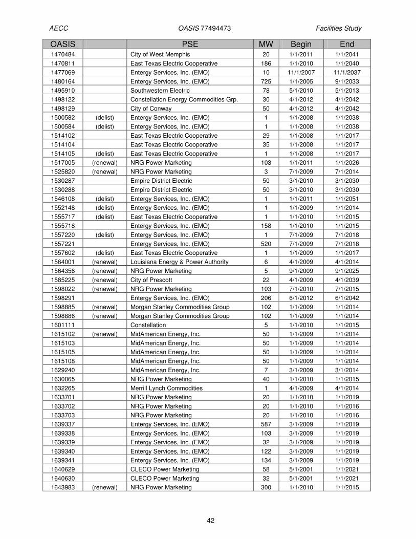
AECC OASIS 77494473 Facilities Study
42
OASIS PSE MW Begin End 1470484 City of West Memphis 20 1/1/2011 1/1/2041
1470811 East Texas Electric Cooperative 186 1/1/2010 1/1/2040
1477069 Entergy Services, Inc. (EMO) 10 11/1/2007 11/1/2037
1480164 Entergy Services, Inc. (EMO) 725 1/1/2005 9/1/2033
1495910 Southwestern Electric 78 5/1/2010 5/1/2013
1498122 Constellation Energy Commodities Grp. 30 4/1/2012 4/1/2042
1498129 City of Conway 50 4/1/2012 4/1/2042
1500582 (delist) Entergy Services, Inc. (EMO) 1 1/1/2008 1/1/2038
1500584 (delist) Entergy Services, Inc. (EMO) 1 1/1/2008 1/1/2038
1514102 East Texas Electric Cooperative 29 1/1/2008 1/1/2017
1514104 East Texas Electric Cooperative 35 1/1/2008 1/1/2017
1514105 (delist) East Texas Electric Cooperative 1 1/1/2008 1/1/2017
1517005 (renewal) NRG Power Marketing 103 1/1/2011 1/1/2026
1525820 (renewal) NRG Power Marketing 3 7/1/2009 7/1/2014
1530287 Empire District Electric 50 3/1/2010 3/1/2030
1530288 Empire District Electric 50 3/1/2010 3/1/2030
1546108 (delist) Entergy Services, Inc. (EMO) 1 1/1/2011 1/1/2051
1552148 (delist) Entergy Services, Inc. (EMO) 1 1/1/2009 1/1/2014
1555717 (delist) East Texas Electric Cooperative 1 1/1/2010 1/1/2015
1555718 Entergy Services, Inc. (EMO) 158 1/1/2010 1/1/2015
1557220 (delist) Entergy Services, Inc. (EMO) 1 7/1/2009 7/1/2018
1557221 Entergy Services, Inc. (EMO) 520 7/1/2009 7/1/2018
1557602 (delist) East Texas Electric Cooperative 1 1/1/2009 1/1/2017
1564001 (renewal) Louisiana Energy & Power Authority 6 4/1/2009 4/1/2014
1564356 (renewal) NRG Power Marketing 5 9/1/2009 9/1/2025
1585225 (renewal) City of Prescott 22 4/1/2009 4/1/2039
1598022 (renewal) NRG Power Marketing 103 7/1/2010 7/1/2015
1598291 Entergy Services, Inc. (EMO) 206 6/1/2012 6/1/2042
1598885 (renewal) Morgan Stanley Commodities Group 102 1/1/2009 1/1/2014
1598886 (renewal) Morgan Stanley Commodities Group 102 1/1/2009 1/1/2014
1601111 Constellation 5 1/1/2010 1/1/2015
1615102 (renewal) MidAmerican Energy, Inc. 50 1/1/2009 1/1/2014
1615103 MidAmerican Energy, Inc. 50 1/1/2009 1/1/2014
1615105 MidAmerican Energy, Inc. 50 1/1/2009 1/1/2014
1615108 MidAmerican Energy, Inc. 50 1/1/2009 1/1/2014
1629240 MidAmerican Energy, Inc. 7 3/1/2009 3/1/2014
1630065 NRG Power Marketing 40 1/1/2010 1/1/2015
1632265 Merrill Lynch Commodities 1 4/1/2009 4/1/2014
1633701 NRG Power Marketing 20 1/1/2010 1/1/2019
1633702 NRG Power Marketing 20 1/1/2010 1/1/2016
1633703 NRG Power Marketing 20 1/1/2010 1/1/2016
1639337 Entergy Services, Inc. (EMO) 587 3/1/2009 1/1/2019
1639338 Entergy Services, Inc. (EMO) 103 3/1/2009 1/1/2019
1639339 Entergy Services, Inc. (EMO) 32 3/1/2009 1/1/2019
1639340 Entergy Services, Inc. (EMO) 122 3/1/2009 1/1/2019
1639341 Entergy Services, Inc. (EMO) 134 3/1/2009 1/1/2019
1640629 CLECO Power Marketing 58 5/1/2001 1/1/2021
1640630 CLECO Power Marketing 32 5/1/2001 1/1/2021
1643983 (renewal) NRG Power Marketing 300 1/1/2010 1/1/2015

AECC OASIS 77494473 Facilities Study
43
OASIS PSE MW Begin End 1643984 (renewal) NRG Power Marketing 100 9/1/2010 9/1/2015
1644155 CLECO Power Marketing 9 4/1/2009 5/1/2016
1644215 NRG Power Marketing 83 1/1/2010 1/1/2025
1644908 CLECO Power Marketing 41 5/1/2009 5/1/2018
1648049 (delist) Entergy Services, Inc. (EMO) 1 6/1/2010 6/1/2013
1648050 Entergy Services, Inc. (EMO) 100 6/1/2010 6/1/2013
1655366 Missouri Joint Municipal 6 10/1/2009 10/1/2014
1658087 Entergy Services (SPO) 1 6/1/2012 6/1/2042
1658088 SMEPA 21 6/1/2012 6/1/2042
1659388 NRG Power Marketing 25 1/1/2011 1/1/2016
1665288 Merrill Lynch Commodities 15 1/1/2011 1/1/2017
1665492 (renewal) Merrill Lynch Commodities 16 11/1/2009 11/1/2014
1665493 (renewal) Merrill Lynch Commodities 4 11/1/2009 11/1/2014
1665899 Ameren Energy, Inc. 75 9/1/2009 9/1/2014
1668165 Entergy Services (SPO) 600 1/1/2013 1/1/2043
1669126 (renewal) Cargill Power Markets, LLC 103 1/1/2011 1/1/2016
1669127 (renewal) Cargill Power Markets, LLC 103 1/1/2011 1/1/2016
1676674 NRG Power Marketing 100 1/1/2011 1/1/2020
1676675 NRG Power Marketing 100 1/1/2011 1/1/2020
1677749 Entergy Services, Inc. (EMO) 1 1/1/2013 1/1/2015
1679179 (renewal) NRG Power Marketing 100 1/1/2011 1/1/2016
1679181 (renewal) NRG Power Marketing 100 1/1/2011 1/1/2016
1685869 (renewal) Muni Energy Agcy of Miss 19 1/1/2010 1/1/2018
1689499 Missouri Joint Municipal 3 9/1/2009 9/1/2014
1690613 NRG Power Marketing 25 1/1/2011 1/1/2016
1694305 Entergy Services (SPO) 15 5/1/2010 5/1/2020
1694306 Entergy Services (SPO) 30 5/1/2010 5/1/2020
73454527 Hope Water & Light 10 10/1/2009 10/1/2032
73457918 South Miss Electric Power Assoc. 180 10/1/2009 10/1/2014
73573797 (renewal) American Electric Power 45 1/1/2011 1/1/2029
73586299 (renewal) American Electric Power 6 1/1/2011 1/1/2029
73595626 NRG Power Marketing 13 1/1/2012 1/1/2017
73724303 Arkansas Electric Cooperative Corp. 104 1/1/2010 1/1/2015
73741113 (renewal) Entergy Services, Inc. (EMO) 150 5/1/2010 5/1/2020
73741122 (renewal) Entergy Services, Inc. (EMO) 135 5/1/2010 5/1/2020
73820650 MOWR 5 3/1/2010 3/1/2040
73884547 MOWR 35 8/1/2010 8/1/2040
73884558 MOWR 40 8/1/2010 8/1/2040
73942862 (renewal) Muni Energy Agcy of Miss 13 6/1/2010 6/1/2015
73970673 Cargill Power Markets, LLC 40 1/1/2012 1/1/2016
73987480 South Miss Electric Power Assoc. 100 5/1/2010 5/1/2040
73987507 South Miss Electric Power Assoc. 180 6/1/2010 6/1/2015
73990804 South Miss Electric Power Assoc. 100 5/1/2010 5/1/2040
74001787 NRG Power Marketing 100 1/1/2011 1/1/2016
74001895 NRG Power Marketing 100 1/1/2011 1/1/2016
74001897 NRG Power Marketing 22 1/1/2011 1/1/2016
74001904 NRG Power Marketing 28 1/1/2011 1/1/2016
74001930 NRG Power Marketing 42 8/1/2006 8/1/2036
74001931 NRG Power Marketing 60 3/1/2010 3/1/2040

AECC OASIS 77494473 Facilities Study
44
OASIS PSE MW Begin End 74001934 NRG Power Marketing 60 4/1/2012 4/1/2042
74233619 WRGS 15 4/1/2012 4/1/2017
74233670 (delist) Entergy Services, Inc. (EMO) 1 8/1/2012 1/1/2038
74236787 NRG Power Marketing 75 6/1/2012 6/1/2017
74236794 NRG Power Marketing 100 6/1/2012 6/1/2017
74236798 NRG Power Marketing 100 6/1/2012 6/1/2017
74305315 NRG Power Marketing 10 1/1/2014 1/1/2017
74305339 NRG Power Marketing 10 1/1/2013 1/1/2023
74356639 NRG Power Marketing 103 1/1/2011 1/1/2016
74356652 NRG Power Marketing 206 6/1/2012 6/1/2017
74356666 NRG Power Marketing 50 1/1/2013 1/1/2014
74408208 Louisiana Energy & Power Authority 13 9/1/2010 9/1/2015
74408225 Louisiana Energy & Power Authority 45 9/1/2010 9/1/2015
74514903 Entergy Services, Inc. (EMO) 20 6/1/2013 6/1/2029
74514911 Entergy Services, Inc. (EMO) 101 6/1/2013 6/1/2029
74691007 NRG Power Marketing 60 1/1/2013 1/1/2018
74728415 Brazos Electric Cooperative 100 1/1/2012 1/1/2017
74777205 (renewal) NRG Power Marketing 300 1/1/2013 1/1/2033
74777208 (renewal) NRG Power Marketing 300 1/1/2015 1/1/2035
74789476 (delist) Entergy Services, Inc. (EMO) 1 1/1/2012 1/1/2016
74829975 (renewal) CLECO Power LLC (Gen) 35 1/1/2011 1/1/2016
74835023 AECI / APM 103 1/1/2012 1/1/2017
74881866 (renewal) NRG Power Marketing 8 3/1/2011 3/1/2021
74899933 Entergy Services (SPO) 322 2/1/2011 2/1/2041
74899954 (delist) Entergy Services, Inc. (EMO) 1 2/1/2012 2/1/2014
74899956 Entergy Services, Inc. (EMO) 100 2/1/2012 2/1/2014
74899968 (delist) Entergy Services, Inc. (EMO) 1 1/1/2013 1/1/2015
74899969 (delist) Entergy Services, Inc. (EMO) 1 1/1/2012 1/1/2015
74899972 (delist) Entergy Services (SPO) 1 1/1/2015 1/1/2045
74899974 (delist) Entergy Services (SPO) 1 1/1/2015 1/1/2045
74899976 (delist) Entergy Services (SPO) 1 1/1/2015 1/1/2045
74899980 Entergy Services (SPO) 584 1/1/2015 1/1/2045
74899988 (delist) Entergy Services (SPO) 1 6/1/2012 6/1/2042
74899989 Entergy Services (SPO) 485 6/1/2012 6/1/2042
74901827 (delist) Entergy Services, Inc. (EMO) 1 2/1/2011 2/1/2041
74958042 NRG Power Marketing 34 1/1/2006 1/1/2036
74958045 NRG Power Marketing 34 1/1/2006 1/1/2036
74958047 NRG Power Marketing 17 1/1/2006 1/1/2036
74958048 NRG Power Marketing 17 1/1/2006 1/1/2036
75207302 (renewal) Entergy Services, Inc. (EMO) 1 7/1/2011 7/1/2016
75259845 South Miss Electric Power Assoc. 2 4/1/2012 1/1/2040
75265640 (renewal) South Miss Electric Power Assoc. 75 6/1/2011 6/1/2016
75299243 AECI 103 1/1/2012 1/1/2017
75342276 Cargill Power Markets 202 12/1/2012 12/1/2017
75460486 MOWR 103 4/1/2012 4/1/2037
75495258 (renewal) NRG Power Marketing 13 1/1/2017 1/1/2019
75564309 ETEC 50 5/1/2014 5/1/2044
75826033 CPWM 600 4/1/2014 4/1/2033
76120007 renewal CLECO Power Marketing 10 10/1/2012 10/1/2017

AECC OASIS 77494473 Facilities Study
45
OASIS PSE MW Begin End 76234876 Entergy Services (SPO) 1 6/1/2012 6/1/2042
76234879 Entergy Services (SPO) 194 6/1/2012 6/1/2042
76234889 Entergy Services (SPO) 256 1/1/2016 1/1/2043
76234897 Entergy Services (SPO) 35 1/1/2016 1/1/2043
76234904 Entergy Services (SPO) 1 6/1/2012 6/1/2042
76234916 Entergy Services (SPO) 140 6/1/2012 6/1/2042
76234922 Entergy Services (SPO) 1 5/1/2013 5/1/2042
76234951 Entergy Services (SPO) 5 5/1/2013 5/1/2042
76234980 Entergy Services (SPO) 1 1/1/2014 1/1/2043 76234993 76235000 76235003 Entergy Services (SPO) 475 1/1/2014 1/1/2043
76238089 Entergy Services (SPO) 20 1/1/2014 1/1/2043
76280552 (delist) Entergy Services (SPO) 1 6/1/2012 6/1/2042
76280558 (delist) Entergy Services (SPO) 1 5/1/2013 5/1/2042
76336174 (redirect) NRG Power Marketing 206 6/1/2013 6/1/2017
76449800 Arkansas Electric Cooperative Corp.
275 1/1/2013 1/1/2014
300 1/1/2014 1/1/2015
320 1/1/2015 1/1/2017
76449828 Arkansas Electric Cooperative Corp.
80 1/1/2013 1/1/2014
82 1/1/2014 1/1/2015
84 1/1/2015 1/1/2016
86 1/1/2016 1/1/2017
76513126 (delist) Constellation Energy Commodities Grp. 1 1/1/2012 1/1/2017
76513148 (delist) Constellation Energy Commodities Grp. 1 1/1/2012 1/1/2017
76513215 EWOM 60 11/1/2009 11/1/2014
76513304 (renewal) EWOM 60 11/1/2014 11/1/2019
76523750 SRMPA 180 6/1/2012 6/1/2018
76523753 SRMPA 30 6/1/2012 6/1/2016
76523754 EWOM 45 6/1/2012 6/1/2016
76533177 EWOM 25 4/1/2009 4/1/2014
76533260 (renewal) EWOM 25 4/1/2014 4/1/2019
76583976 Arkansas Electric Cooperative Corp. 660 9/1/2012 9/1/2017
76744580 (deferral) South Miss Electric Power Assoc. 2 1/1/2013 1/1/2040
76767669 NRG Power Marketing 103 6/1/2013 6/1/2017
76794133 NRG Power Marketing 1 1/1/2014 1/1/2022
76794134 NRG Power Marketing 1 1/1/2014 1/1/2022
76794135 NRG Power Marketing 1 1/1/2014 1/1/2022
76794138 NRG Power Marketing 1 1/1/2014 1/1/2022
76794140 NRG Power Marketing 309 1/1/2014 1/1/2019
76794150 NRG Power Marketing 1 1/1/2014 1/1/2019
76794151 NRG Power Marketing 309 1/1/2014 1/1/2019
76794321 NRG Power Marketing 10 1/1/2013 1/1/2025
76975184 Entergy Services (SPO) 28 1/1/2013 1/1/2033
76999226 SWCC 78 5/1/2013 5/1/2018
77020374 (renewal) Tennessee Valley Authority 73 9/1/2013 9/1/2023
77065320 (renewal) Entergy Services (SPO) 10 7/1/2012 7/1/2013
77161524 Entergy Services (SPO) 495 1/1/2014 1/1/2017

AECC OASIS 77494473 Facilities Study
46
OASIS PSE MW Begin End 77176931 NRG Power Marketing 525 6/1/2014 6/1/2024
10.0 PRE-888 TRANSACTIONS
OASIS # PSE MW Begin End
1332606 East Texas Electric Cooperative 55 1/1/2006 1/1/2017
1412155 Entergy Services, Inc. (EMO) 1718 1/1/2007 1/1/2038
1412156 Entergy Services, Inc. (EMO) 741 1/1/2007 1/1/2038
1412158 Entergy Services, Inc. (EMO) 1867 1/1/2007 1/1/2038
1412160 Entergy Services, Inc. (EMO) 1142 1/1/2007 1/1/2038
1412161 Entergy Services, Inc. (EMO) 59 1/1/2007 1/1/2038
1412162 Entergy Services, Inc. (EMO) 148 1/1/2007 1/1/2038
1412163 Entergy Services, Inc. (EMO) 194 1/1/2007 1/1/2038
1412164 Entergy Services, Inc. (EMO) 1157 1/1/2007 1/1/2038
1412165 Entergy Services, Inc. (EMO) 1219 1/1/2007 1/1/2038
1412166 Entergy Services, Inc. (EMO) 683 1/1/2007 1/1/2038
1412167 Entergy Services, Inc. (EMO) 140 1/1/2007 1/1/2038
1412168 Entergy Services, Inc. (EMO) 456 1/1/2007 1/1/2038
1412169 Entergy Services, Inc. (EMO) 739 1/1/2007 1/1/2038
1412170 Entergy Services, Inc. (EMO) 183 1/1/2007 1/1/2038
1412171 Entergy Services, Inc. (EMO) 64 1/1/2007 1/1/2038
1412172 Entergy Services, Inc. (EMO) 870 1/1/2007 1/1/2038
1412173 Entergy Services, Inc. (EMO) 129 1/1/2007 1/1/2038
1412174 Entergy Services, Inc. (EMO) 140 1/1/2007 1/1/2038
1412175 Entergy Services, Inc. (EMO) 130 1/1/2007 1/1/2038
1412176 Entergy Services, Inc. (EMO) 65 1/1/2007 1/1/2038
1412177 Entergy Services, Inc. (EMO) 947 1/1/2007 1/1/2038
1412178 Entergy Services, Inc. (EMO) 61 1/1/2007 1/1/2038
1412179 Entergy Services, Inc. (EMO) 304 1/1/2007 1/1/2038
1412180 Entergy Services, Inc. (EMO) 351 1/1/2007 1/1/2038
1412181 Entergy Services, Inc. (EMO) 692 1/1/2007 1/1/2038
1412182 Entergy Services, Inc. (EMO) 1641 1/1/2007 1/1/2038
1412183 Entergy Services, Inc. (EMO) 433 1/1/2007 1/1/2038
1412184 Entergy Services, Inc. (EMO) 1926 1/1/2007 1/1/2038
1412185 Entergy Services, Inc. (EMO) 946 1/1/2007 1/1/2038
1412186 Entergy Services, Inc. (EMO) 1233 1/1/2007 1/1/2038
1498278 Entergy Services, Inc. (EMO) 75 8/1/2007 1/1/2017
1498281 Entergy Services, Inc. (EMO) 86 8/1/2007 1/1/2017
1498283 Entergy Services, Inc. (EMO) 68 8/1/2007 1/1/2017
1498284 Entergy Services, Inc. (EMO) 78 8/1/2007 1/1/2017
1498285 Entergy Services, Inc. (EMO) 11 8/1/2007 1/1/2044
1498286 Entergy Services, Inc. (EMO) 69 8/1/2007 1/1/2044
1498287 Entergy Services, Inc. (EMO) 14 8/1/2007 1/1/2044
1528114 Entergy Services, Inc. (EMO) 1523 1/1/2008 1/1/2038
1528115 Entergy Services, Inc. (EMO) 1039 1/1/2008 1/1/2038
1528116 Entergy Services, Inc. (EMO) 1834 1/1/2008 1/1/2038
76120467 Renewal Entergy Services, inc. (EMO) 61 1/1/2038 1/1/2045
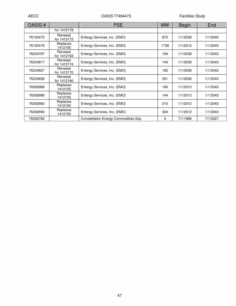
AECC OASIS 77494473 Facilities Study
47
OASIS # PSE MW Begin End for 1412178
76120472 Renewal
for 1412172 Entergy Services, inc. (EMO) 870 1/1/2038 1/1/2045
76120479 Replaces 1412155
Entergy Services, Inc. (EMO) 1738 1/1/2012 1/1/2045
76234797 Renewal
for 1412163 Entergy Services, Inc. (EMO) 194 1/1/2038 1/1/2043
76234817 Renewal
for 1412174 Entergy Services, Inc. (EMO) 140 1/1/2038 1/1/2043
76234827 Renewal
for 1412170 Entergy Services, Inc. (EMO) 183 1/1/2038 1/1/2043
76234836 Renewal
for 1412180 Entergy Services, Inc. (EMO) 351 1/1/2038 1/1/2043
76292988 Replaces 1412155
Entergy Services, Inc. (EMO) 190 1/1/2012 1/1/2043
76292990 Replaces 1412155
Entergy Services, Inc. (EMO) 144 1/1/2012 1/1/2043
76292992 Replaces 1412155
Entergy Services, Inc. (EMO) 210 1/1/2012 1/1/2043
76292993 Replaces 1412155
Entergy Services, Inc. (EMO) 324 1/1/2012 1/1/2043
76528782 Constellation Energy Commodities Grp. 5 7/1/1988 7/1/2027

AECC OASIS 77494473 Facilities Study
48
11.0 STUDY QUEUE
OASIS # PSE MW Begin End 74846159 AEPM 65 1/1/2015 1/1/2020
75206836 ETEC 125 1/1/2015 1/1/2020
76744419 SMEPA 280 1/1/2014 1/1/2025 SPP 74240998_1004_
1007_1231_1265 AEP 20-116 1/1/2011 1/1/2020
76902738 CPWM 80 1/1/2013 1/1/2018
77272292 Entergy Services (SPO) 9 1/1/2013 1/1/2033
77272300 Entergy Services (SPO) 4 1/1/2013 1/1/2033
77289977 NRG Power Marketing 1 6/1/2014 6/1/2024
77289995 NRG Power Marketing 309 6/1/2014 6/1/2024
77289999 NRG Power Marketing 1 6/1/2014 6/1/2024
77290002 NRG Power Marketing 309 6/1/2014 6/1/2024
77355706 Horizon Wind 100 1/1/2015 1/1/2020

AECC OASIS 77494473 Facilities Study
49
12.0 ATTACHMENTS
12.1 Table of Acronyms
Acronym Description ACSR Aluminum Conductor Steel Reinforced ACSS Aluminum Conductor Steel Supported ADEQ Arkansas Department of Environmental Quality ADSS All dielectric self supporting AFUDC Allowance for Funds Used During Construction ATC Available Transfer Capability BAB Bus air break CYDS Cubic Yards EES Entergy Control Area EHV Extra-High Voltage ERIS Energy Resource Interconnection Service ICT Independent Coordinator of Transmission IPO Independent Pole operated JSA Job Safety analysis KCMIL Kilo circular mil kV Kilo-Volt MCM (M) Thousand Circular Mils MCOV Maximum Continuous operating voltage MDOT Mississippi Department of Transportation MVA Mega-Volt Amp MW Mega-Watt NPDES National Pollution Discharge Elimination System NOI Notice of Intent NRIS Network Resource Interconnection Service OASIS Online Access and Same-time Information System OATT Open Access Transmission Tariff POD Point of Delivery POR Point of Receipt SES Steam Electric Station SOC System Operations Center SHV Super High Voltage SW Switch Station TOC Transmission Operations Center
12.2 Substation one lines
Attached pdf files
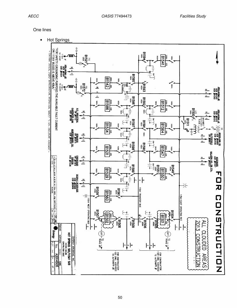
AECC OASIS 77494473 Facilities Study
50
One lines
• Hot Springs

AECC OASIS 77494473 Facilities Study
51
• Haskell

AECC OASIS 77494473 Facilities Study
52
• Butterfield
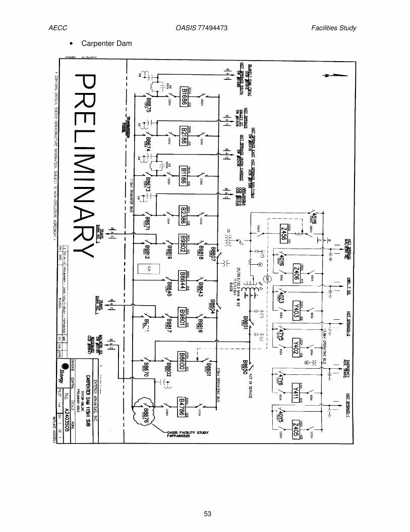
AECC OASIS 77494473 Facilities Study
53
• Carpenter Dam
Related Documents