Transmission Media / Channels

Transmission Media / Channels. Introduction Provides the connection between the transmitter and receiver. 1.Pair of wires – carry electric signal. 2.Optical.
Dec 23, 2015
Welcome message from author
This document is posted to help you gain knowledge. Please leave a comment to let me know what you think about it! Share it to your friends and learn new things together.
Transcript

Transmission Media / Channels
Transmission Media / Channels
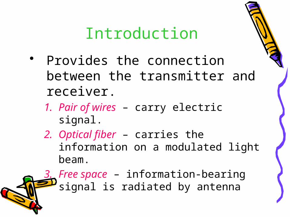
Introduction
• Provides the connection between the transmitter and receiver.1. Pair of wires – carry electric signal.2. Optical fiber – carries the information
on a modulated light beam.3. Free space – information-bearing signal
is radiated by antenna

Cont’d...
• Signal transmission problem additive noise – generated internally by
components used to implement the communication system.
Interference from other users of the channel.

Cont’d...
• Minimizing noise effects – Increasing the power of transmitted
signal.• Constraint
– Limited power level – Channel bandwidth availability

Cont’d...
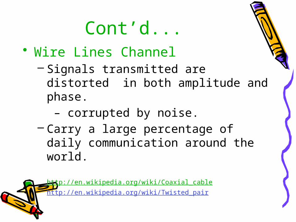
Cont’d...• Wire Lines Channel
– Signals transmitted are distorted in both amplitude and phase. – corrupted by noise.
– Carry a large percentage of daily communication around the world.
http://en.wikipedia.org/wiki/Coaxial_cablehttp://en.wikipedia.org/wiki/Twisted_pair
Cont’d...
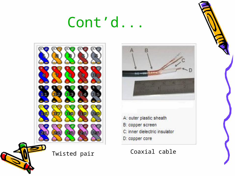
Twisted pair Coaxial cable
Cont’d...• Fiber Optics Channel
– Low signal attenuation– Highly reliable photonic devices– Large bandwidth available– Services : voice, data facsimile and video– Tx – light source
(e.g. LED, laser)– Rx – photodiode– Noise source : photodiodes & amplifiers
http://en.wikipedia.org/wiki/Fiber_optics

Cont’d...
Cont’d...
• Wireless Electromagnetic Channels– Electromagnetic energy is coupled
to the propagation medium by antenna (radiator)
– Antenna size & configuration – Frequency of operation
– Efficient radiation – antenna longer than 1/10 λ
Cont’d...
• Example A radio station transmitting in AM
frequency band, fc = 1MHz, λ = 300 m,
requires antenna at least 30 m.
Cont’d...
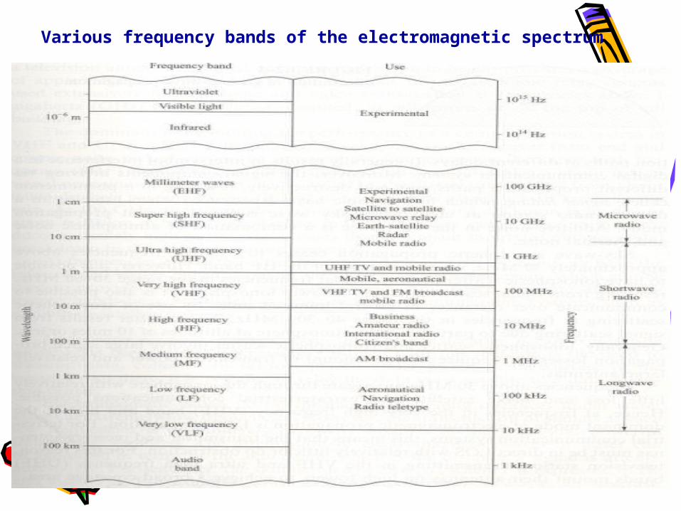
Various frequency bands of the electromagnetic spectrum
Cont’d...
• Mode of propagation of EM waves
i. Ground-wave propagationii. Sky-wave propagationiii. Line-of-sight (LOS)
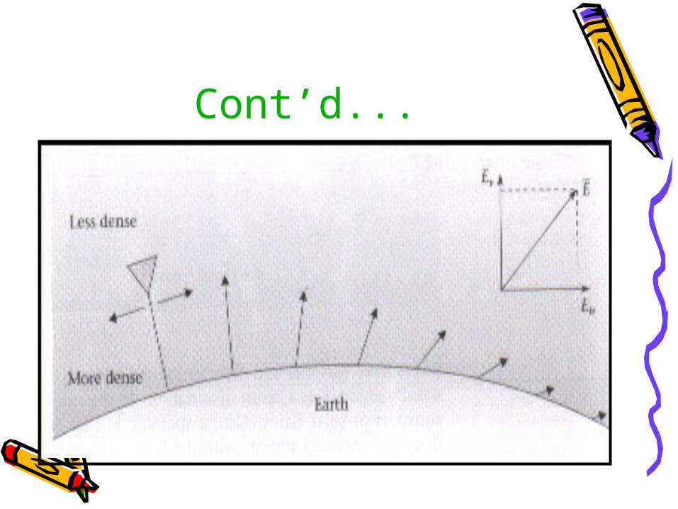
GROUND-WAVE PROPAGATION
• Surface-wave propagation• Dominant mode of propagation• Frequency band: 0.3 – 3 MHz• Applications: AM broadcasting,
maritime radio broadcasting• Disturbances for signal
transmission: atmospheric noise, man-made
noise, thermal noise.
Cont’d...

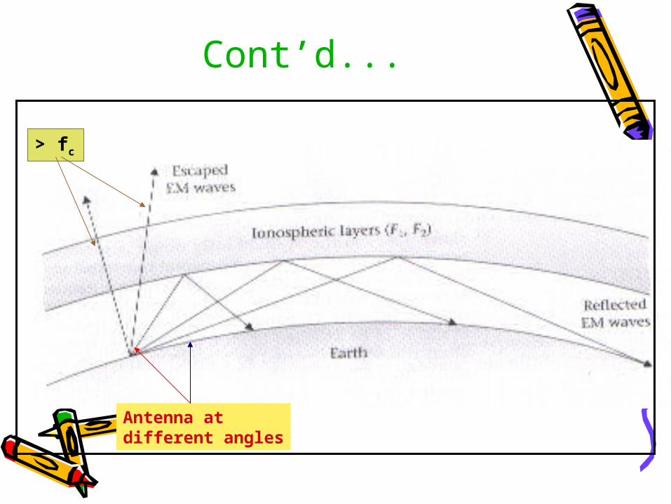
SKY-WAVE PROPAGATION
• Transmitted signals being reflected from ionosphere
• Frequency : above 30 MHz• Little loss• Problem : Signal Multipath• Application : Satellite
communications
Cont’d...
Antenna at different angles
> fc
LINE-OF-SIGHT (LOS) PROPAGATION
• VHF band and higher• Limited by curvature of earth• Problem : Thermal noise (Rx front end)
Cosmic noise (pick-up by antenna)
• Application: A TV antenna mounted on a tower of 300 m height to provide a broad coverage area (67km)

Cont’d...
Cont’d...• Underwater acoustic channels
– EM waves do not propagate over long distances under water except at extremely low frequencies
– Expensive – because of the large and powerful transmitters required
– Problem : Attenuation – skin depth

Cont’d...• Multipath channel – signals
reflections from the surface and the bottom of the sea.
• Noise : ambient ocean acoustic noise,
man-made acoustic noise

END OF PART 2END OF PART 2
Related Documents