MAKE OF VEHICLE: Iveco TYPE: Stralis AS eco460 PISTON DISPLACEMENT: 10.300 cc NUMBER OF VALVES: 4 /cil. ENGINE NUMBER: F3A TRANSMISSION EUROTRONIC VERSION CNG / LNG VSI-2.0 INJECTION SYSTEM: Unit Injector MODEL YEAR: 2011 LOCATION SYSTEM STICKER n.a. ENGINE SET NUMBER 321/110001 DATE : 2014-07-08 MANUAL NR: 076/370002 Copyright © Prins Autogassystemen B.V. 2013 VERSION NR : 2014-07-08 DB

Welcome message from author
This document is posted to help you gain knowledge. Please leave a comment to let me know what you think about it! Share it to your friends and learn new things together.
Transcript

MAKE OF VEHICLE: Iveco TYPE: Stralis AS eco460 PISTON DISPLACEMENT: 10.300 cc NUMBER OF VALVES: 4 /cil. ENGINE NUMBER: F3A TRANSMISSION EUROTRONIC VERSION CNG / LNG VSI-2.0 INJECTION SYSTEM: Unit Injector MODEL YEAR: 2011 LOCATION SYSTEM STICKER n.a. ENGINE SET NUMBER 321/110001
DATE : 2014-07-08 MANUAL NR: 076/370002
Copyright © Prins Autogassystemen B.V. 2013 VERSION NR : 2014-07-08 DB

1
TABLE OF CONTENTS
Required equipment / tools / materials for installing a complete system.............................................. 2 Diagram ............................................................................................................................................ 3 Approval numbers ............................................................................................................................. 4 Mounting and connection points ........................................................................................................ 5 Mounting the AFC ............................................................................................................................. 6 24V DC – 12V DC Converter ............................................................................................................. 7 Converter connections ....................................................................................................................... 8 System fuse + diagnosis connector.................................................................................................... 9 CAN wiring ........................................................................................................................................ 9 Switch ............................................................................................................................................. 10 Wiring loom route. ........................................................................................................................... 11 Loom routing ................................................................................................................................... 11 Installing the MAP hoses ................................................................................................................. 12 Gas injector pipes ............................................................................................................................ 13 Electrical diagram ............................................................................................................................ 16 Electrical connections ...................................................................................................................... 17 RPM module ................................................................................................................................... 18 Boost brake out cable ...................................................................................................................... 19 EGT sensor ..................................................................................................................................... 20 Installation of the torque limiter ........................................................................................................ 21 Electrical connections ...................................................................................................................... 23 Mounting of the injector rail .............................................................................................................. 24 Hose lengths ................................................................................................................................... 25 Lock-off valve CNG ......................................................................................................................... 26 Reducer .......................................................................................................................................... 27 Lock-off and reducer LNG................................................................................................................ 28 Water connection ............................................................................................................................ 29 Filter unit ......................................................................................................................................... 30 Mounting the RPM module .............................................................................................................. 31 Check list after installation ............................................................................................................... 32

PAGINA 2 076/370002 Iveco Stralis AS 450 Copyright © Prins Autogassystemen B.V. 2014 VERSIE NR : DB
2
Required equipment / tools / materials for installing a complete system
- Complete workshop toolbox ( wrenches, screwdrivers, cutters, pliers, ratchet, sockets ) - Car lift - Portable computer : operating on Windows 98,W2000 or XP.
Internal memory : 16 Mb or more Memory HD space : 5MB Screen : 256 colours, advise colours 16 bits or more Com port : 1 free COM port 1 or COM port 2 with a 9 or 25 pins connector
- Vehicle fuel system scan tool or OBD scan tool Prins ( part nr. 099/99928 ) - Exhaust gas analyser - Multimeter - Oscilloscope - Prins VSI diagnostic software - Prins VSI serial interface - Prins VSI break out box - Torque wrench ( 10Nm ) - Portable light - Assortment drill bits 4 to 12 mm - Assortment cutters ( ø 20, 30, 50, 70 mm ) - Round file - Portable drill or pneumatic drill - Threading device ( male M6x1, M8x1, M10x1 ) - Pipe-flaring tool ( for 6 and 8 mm copper pipe ) - Air gun - Vacuum cleaner - Hot air gun - Allan spanner for inlet couplings 3,5mm ( part nr. 099//9970 ) - Soldering iron, soldering tin - Wire-stripping pliers - Adhesive tape - Adhesive sealant - Thread locking compound - Anti-corrosion agent / black body coating - Gas leak detection device or foam leak spray - Shrink sleeves - Engine coolant - - Bending tool 6 mm - Bending tool 12 mm - Pipe cutter stainless steel - Cutter wheel - Mounting saddle CNG tank valve - Pre-assemble tool 6 mm - Pre-assembly tool 12 mm - Sealant Wurth -
Vehicle check
- Check the vehicle drivability on diesel - Check the fuel system for error codes ( scan tool )

PAGINA 3 076/370002 Iveco Stralis AS 450 Copyright © Prins Autogassystemen B.V. 2014 VERSIE NR : DB
3
Diagram

PAGINA 4 076/370002 Iveco Stralis AS 450 Copyright © Prins Autogassystemen B.V. 2014 VERSIE NR : DB
4
Approval numbers
Regulator CNG E4-110R-000092
Lock off valve CNG E13-110R-000095
Filter unit T1 / T2 Prins : LPG E4-67R-010096 CNG E4-110R-000028
Injector Keihin :LPG E4-67R-010092 CNG E4-110R-000020
Computer VSI-4 / 6 Prins: LPG E4-67R-010098 CNG E4-110R-000083
CNG hoses Tubithor : LPG E13-67R-010145 CNG E13-110R-000017 Rubia : LPG E4-67R-010068
CNG E4-110R-000003

PAGINA 5 076/370002 Iveco Stralis AS 450 Copyright © Prins Autogassystemen B.V. 2014 VERSIE NR : DB
5
Mounting and connection points
A : Reducer G : 24VDC-12VDC converter
B : Filter unit H : ECT sensor
C : Injector rail I : CAN high / low
D : RPM module J : Diagnose connector
E : Boost sensor brake out cable K : AFC
F : Water connection
A
B C
A
C
D
E
F
F H

PAGINA 6 076/370002 Iveco Stralis AS 450 Copyright © Prins Autogassystemen B.V. 2014 VERSIE NR : DB
6
Mounting the AFC
Locate the VSI 2 AFC in its original bracket behind the bottom cover on passenger side.
Take the two can wires out of the 5 pole connector (ST25) and place them in the two pole connector from the Prins set.
K
I

PAGINA 7 076/370002 Iveco Stralis AS 450 Copyright © Prins Autogassystemen B.V. 2014 VERSIE NR : DB
7
24V DC – 12V DC Converter
The 24 volt power supply 30 + from the vehicle should carry a 10 amp. fuse.
Place the fuse when all the wiring is done.!
Even when running on 100 % diesel the Prins AF C needs the power supply 12 volt To transfer the boost sensor signal.
PAGINA 8 076/370002 Iveco Stralis AS 450 Copyright © Prins Autogassystemen B.V. 2014 VERSIE NR : DB
8
Converter connections
Red is + 30 Green is +15 (ignition) to grey of the Prins loom.
For Iveco it is allowed to connect 24 volt + 15 to the ignition wire pin 7.
Take a free position in the fuse box to connect the plus 24 volt.
Main ground bolt in the cabin front plate (1) Place the converter in the number 2 spot in its original bracket.
1 2

PAGINA 9 076/370002 Iveco Stralis AS 450 Copyright © Prins Autogassystemen B.V. 2014 VERSIE NR : DB
9
System fuse + diagnosis connector
The system fuses are placed on the left side of body computer (several free positions available pic. 1) The diagnose connector is placed in the vehicle service box on the motor tunnel. (pic. 2)
Picture 1 Picture 2
CAN wiring
1. The blue-yellow wire(CAN HI VSI 2) to the white wire on pin 2 (CAN HI) of the vehicle.
2. The blue wire (CAN-LO VSI 2) to the green wire pin 1 (CAN-LO) of the vehicle.
Location passenger side (floor panel)
Connector ST 25
J

PAGINA 10 076/370002 Iveco Stralis AS 450 Copyright © Prins Autogassystemen B.V. 2014 VERSIE NR : DB
10
Switch
The fuel switch is placed in a blind panel. Check if the switch is good visible for the driver.
Drill a Ø8.2 hole in an un-used switch cover and push the fuel switch in.

PAGINA 11 076/370002 Iveco Stralis AS 450 Copyright © Prins Autogassystemen B.V. 2014 VERSIE NR : DB
11
Wiring loom route.
Remove the cover from the wall connectors on the right side of the cab.
Remove the bottom part from position A wall connector. Run the chassis part of the loom through the hole and fill it with silicone sealant afterwards. Strap the loom to a solid body part.
Loom routing
Run the Prins loom over the right side cabin joint and strap it to the existing wiring. Straps should be placed each 20 cm.
A

PAGINA 12 076/370002 Iveco Stralis AS 450 Copyright © Prins Autogassystemen B.V. 2014 VERSIE NR : DB
12
Installing the MAP hoses
MAP connections:
The set up needs two map connections to the intake . Those two 6.8 mm holes should be drilled next to the bracket for injector 4,5 and 6.
See Picture below. Tap a M 8 x 1.25 mm thread in the 6.8 mm holes and mount the Map inserts with the Prins sealant.

PAGINA 13 076/370002 Iveco Stralis AS 450 Copyright © Prins Autogassystemen B.V. 2014 VERSIE NR : DB
13
Gas injector pipes
To bring gas into the engine, injector pipes need to be mounted in the bottom of the inlet manifold. The injector pipes will be connected to the injectors with a hose, later in this manual. As first holes in the inlet
manifold must be drilled for the injector pipes.
To drill 6 holes for the gas pipes in the bottom of the intake manifold, the following parts need to be disassembled.
Intake pipe between the cylinder head and the intercooler
Compressor cooling ducts.
Air compressor, steering pump, air and oil ducts (beware of the small o-ring between compressor and engine)
Generator (leave electrical connections)
Bracket with engine on/off switches
Reservoir steering fluid.
Mark positions of the holes before drilling and make sure that the holes will line up with the intake ports of the cylinder head. Look at the pictures below for the location of the holes. Drill the 6 holes in the intake manifold of the cylinder head. After drilling, remove debris from the manifold using a vacuum cleaner.
Cylinder 1 Cylinder 2
Cylinder 3 Cylinder 4

PAGINA 14 076/370002 Iveco Stralis AS 450 Copyright © Prins Autogassystemen B.V. 2014 VERSIE NR : DB
14
Cylinder 5 Cylinder 6
Positioning
Position the gas injector pipes in a correct angle to direct the gas into the intake runner of the cylinder head. Mount the pipes with a bonded seal, washer and self locking nut. Check with a mirror the position
and angle of the pipes. Clean the inside of the intake manifold!
Install a hose with more than enough length to each injector pipe and mark them with a colour. Write the colours and the corresponding cylinder numbers on paper. Double check if the pinch clamps are positioned
correctly and completely squeezed Be sure that no particles enter the combustion chamber of the engine!

PAGINA 15 076/370002 Iveco Stralis AS 450 Copyright © Prins Autogassystemen B.V. 2014 VERSIE NR : DB
15
Always check if the pipes are correctly placed in the intended inlet port shown in the picture above. The tip
of each injector pipe should point approximately 10 mm in the inlet runner of the cylinder. Incorrect placed pipes will lead to serious engine damage!

PAGINA 16 076/370002 Iveco Stralis AS 450 Copyright © Prins Autogassystemen B.V. 2014 VERSIE NR : DB
16
Electrical diagram

PAGINA 17 076/370002 Iveco Stralis AS 450 Copyright © Prins Autogassystemen B.V. 2014 VERSIE NR : DB
17
Electrical connections
Wire number / code Wire colour Connection
1 ground battery -31
brown Connect together with the ' 0V ground ‘ output of the converter to ground nr.2 with a ring terminal.
32 ground battery sense -31
brown Connect together with the ' 0V ground ‘ output of the converter to ground nr.2 with a ring terminal.
44 +12V ecu +30
red Connect to the '+13,6V' output of the converter. Do not place the fuse in the holder before having completed the installation of the LPG system.
13 +12V battery sense +30
red Connect to the '+13,6V' output of the converter, together with VSI wire 44 +12V ecu.
7 +ignition Switched battery+ +15
grey-white Connect to a contact switched ( +15 ) power Wire location : under fuse box panel, nr.3.
MAP sensor connector For measuring the inlet manifold pressure ( MAP ).
19 AD4 ( MAP ) blue MAP sensor connector, pin 4
27 +5V sensor red MAP sensor connector, pin 3
37 sensor ground brown MAP sensor connector, pin 1
CAN
70 CAN LOW twisted
blue Wire colour : Wire location :
51 CAN HIGH twisted
blue-yellow Wire colour : Wire location :

PAGINA 18 076/370002 Iveco Stralis AS 450 Copyright © Prins Autogassystemen B.V. 2014 VERSIE NR : DB
18
RPM module
RPM module For measuring the engine speed.
ground brown RPM module connector, pin 1
5 +12V switched red RPM module connector, pin 2
8 RPM engine speed purple-white RPM module connector, pin 4

PAGINA 19 076/370002 Iveco Stralis AS 450 Copyright © Prins Autogassystemen B.V. 2014 VERSIE NR : DB
19
Boost brake out cable
To simulate the boost signal to the diesel ecu it is necessary to mount a boost sensor brake out cable.
This cable will lead the turbo pressure sensor voltage to the Prins AFC .
The Prins AFC will simulate the signal and send it back to the diesel ECU when the truck is running on Dieselblend.
When the truck is running on diesel only the boost sensor signal is transferred direct without adjustments.
This means that the Prins AFC always needs a correct power supply to transfer this signal, even when the
truck is running on diesel only !
The brake out boost sensor loom will plug into the sensor and into the trucks original sensor connector. The two pole connector should run to the Prins wiring loom.
Pin 1 of the two pole super seal connector to AD 1 of the Prins loom Pin 2 of the two pole super seal connector to Simulation 1 of the Prins loom

PAGINA 20 076/370002 Iveco Stralis AS 450 Copyright © Prins Autogassystemen B.V. 2014 VERSIE NR : DB
20
EGT sensor
As wiring for the EGT sensor a 9000 long cable with connector is added to the Prins kit. For the moment
the wiring has to be inserted into the main connector to the AFC. Pin 20, 29 and 79 as shown above.
Wrap the cable to sensor in heat reflecting foil from the Prins kit. See picture.

PAGINA 21 076/370002 Iveco Stralis AS 450 Copyright © Prins Autogassystemen B.V. 2014 VERSIE NR : DB
21
Installation of the torque limiter
For this application its necessary to install a torque limiter in the in the diesel protocol of the vehicle.
The programming of the limiter is done with the Iveco diagnostic tool EASY.
After installation of the Prins system it is possible to read the parameter : engine reference torque.
For a LPG application the limiter should be set at 85 % of the reference torque from that specific engine !
For a CNG and LNG application the limiter should be set 75 % of the reference torque of that specific engine !
The steps to go through with EASY are shown in the next pages :

PAGINA 22 076/370002 Iveco Stralis AS 450 Copyright © Prins Autogassystemen B.V. 2014 VERSIE NR : DB
22
Double check the values which are programmed !
For example the Cursor 10 420 horse engine reference torque is 2083 Nm.
For a CNG/LNG setting the 75% value will be 1562 Nm.
For a LPG setting the 85% value will be 1770 Nm.
This means the truck will run on PTO mode 3 when the gas system is active. This will be shown in the instrument cluster as EDC 3.
To activate the torque limiter, connector ST14A pin 20 should be connected to ground. ST14A is a 21 pole connector found on the passenger side in the right bottom corner.
The switched ground wire pin 22 from the Prins loom should be connected to pin 20 from the Interface connector of the vehicle (ST 14 A).
PAGINA 23 076/370002 Iveco Stralis AS 450 Copyright © Prins Autogassystemen B.V. 2014 VERSIE NR : DB
23
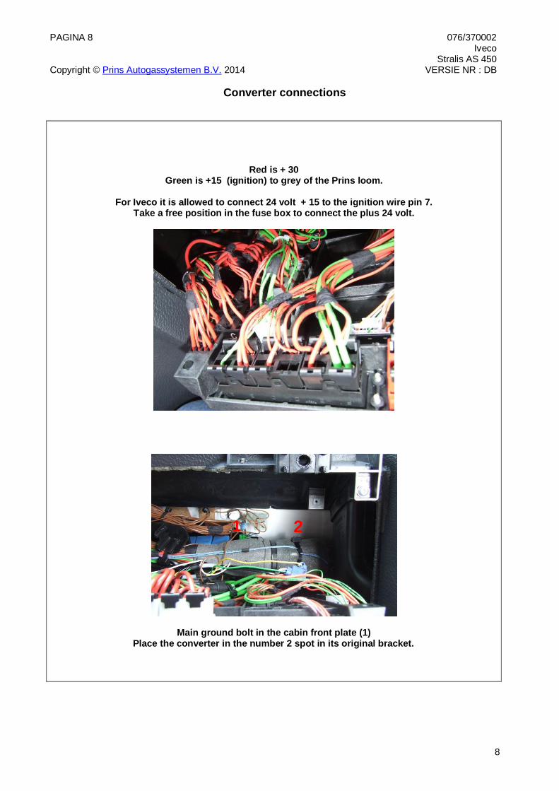
Electrical connections
Optional Phase sensor
1-32 Battery ground brown Sensor connector, pin 1
121 Phase sensor white-yellow Sensor connector, pin 2
57 +12V fuel switched red Sensor connector, pin 3 / Optional Torque limiter relay pin
Optional
10 simulation 2 green-black Insulate not used wires.
25 simulation 1 green-red Insulate not used wires.
17 AD2 green Insulate not used wires.
18 AD1 blue Insulate not used wires.
29 +5V sensor PU1 red Insulate not used wires.
30 +5V sensor PU2 red Insulate not used wires.
22 ground switched 1 brown Optional Torque limiter relay, Insulate if not used.
43 + GAS injectors red-white Insulate not used wires.
Injector rail connectors:
98 –GAS INJ 1 106 +GAS INJ 1
white-yellow red
Connector VSI-injector cylinder 1. ( front side )
99 –GAS INJ 2 107 +GAS INJ 2
green-yellow red
Connector VSI-injector cylinder 2.
100 –GAS INJ 3 108 +GAS INJ 3
pink-yellow red
Connector VSI-injector cylinder 3.
82 –GAS INJ 4 90 +GAS INJ 4
blue-yellow red
Connector VSI-injector cylinder 4.
83 –GAS INJ 5 91 +GAS INJ 5
grey-yellow red
Connector VSI-injector cylinder 5.
84 –GAS INJ 6 92 +GAS INJ 6
brown-yellow red
Connector VSI-injector cylinder 6.
Filter Unit
35 ground brown connector, pin 1
14 T-gas grey connector, pin 2
9 +5V sensor red connector, pin 3
16 Psys green connector, pin 4

PAGINA 24 076/370002 Iveco Stralis AS 450 Copyright © Prins Autogassystemen B.V. 2014 VERSIE NR : DB
24
Mounting of the injector rail
The kit will hold several stainless brackets to mount the reducer, gas rails and filter unit. The bracket for cylinder 1-3 is mounted with the bolts of front lifting eye of the engine.
The bracket for cylinder 4-6 is mounted with three M10 bolts in the thread holes behind the steering oil
tank. It is necessary to turn the injectors in one of the gas rails.
All the connector of both rails should be in the same directions.
Adjusting the Injector rail :
Take apart one of the rails by undoing the two M8 nuts. Separate one of the injectors from the rail and twist the other two in the opposite direction.
Put the third injector back in the rail in the same position as the other two. Put the metal strip back and torque the nuts with a load of 2.5 Nm.
Place both rails in the brackets and connect the rubber gas hoses to the cylinder head inserts.
For length of the hoses see the table. Double check if the pinch clamps are positioned correctly and completely squeezed.

PAGINA 25 076/370002 Iveco Stralis AS 450 Copyright © Prins Autogassystemen B.V. 2014 VERSIE NR : DB
25
Hose lengths
Nr. Hose
(Ø..mm) From component To component Hose length
(cm)
1 16 Reducer Prins filter unit 190cm
2 11 Prins filter unit VSI injector rail 80cm
3 11 Prins filter unit VSI injector rail 80cm
4
5 5 Manifold Reducer MAP 40cm
6 5 Manifold Reducer PRV 40cm
9 8 engine coolant outlet Coolant reducer 200cm
10 8 engine coolant inlet Coolant reducer 200cm

PAGINA 26 076/370002 Iveco Stralis AS 450 Copyright © Prins Autogassystemen B.V. 2014 VERSIE NR : DB
26
Lock-off valve CNG
The lock off valve for the CNG conversions will hold two Double Ferrule line connectors for 6 mm stainless fuel line.
The manometer also holds a pressure sensor which commands the LEDs in the switch
to show tank content to the driver.
The manometer will only show tank pressure when the valve is opened.
The manometer is mounted with a copper ring for sealing. This ring will also allow to turn the manometer in the correct position.
Mount the Lock-off valve to a solid part of the vehicle.
The manometer should be visible for the driver when the cab is in the driving position.

PAGINA 27 076/370002 Iveco Stralis AS 450 Copyright © Prins Autogassystemen B.V. 2014 VERSIE NR : DB
27
Reducer
The reducer is mounted to the right main chassis beam with the special bracket from the Prins set.
Water connections : W
There is no water in or out direction.
Gas output to gas filter: G
Map connections: M
The top MAP connection should hold a 5 mm rubber hose and a 11.9 mm ear clamp. The rest of the 5 mm rubber hoses should be mounted with a 12.8 mm ear clamp.
W
W
G M
M

PAGINA 28 076/370002 Iveco Stralis AS 450 Copyright © Prins Autogassystemen B.V. 2014 VERSIE NR : DB
28
Lock-off and reducer LNG
For a LNG application it is necessary to connect the lock-off and the reducer with 12 mm stainless fuel lines.
For LNG the lock-off valve will not hold a manometer but a tank pressure sensor. The sensor is mounted with the special thread reducer from the Prins set.
The extension cable from the set
should be used to connect the sensor to the Prins main loom.
Cut the 4 pole super seal connector from the extension loom. A 4 pole Bosch female connector is attached to the extension loom.
Green from the sensor connector to pin 4 of the Bosch connector to pin 19 of the AFC. Red from the sensor connector to pin 3 of the Bosch connector to pin 27 of the AFC.
Brown from the sensor connector to pin 1 of the Bosch connector to pin 37 of the AFC.
The pins 19, 27 and 37 are in the 4 pole male Bosch connector with the bleu label in the Prins main loom.
The hoses should be connected just as in the CNG situations.

PAGINA 29 076/370002 Iveco Stralis AS 450 Copyright © Prins Autogassystemen B.V. 2014 VERSIE NR : DB
29
Water connection
.
Drill a 10.5 mm hole in one of the plugs on the left front of the cylinderhead and cut a M12x1.5 thread so that this plug can hold the ECT sensor.
The other plug is removed from the cylinder head and a M16 x 1.5 water pipe is placed in the plugs position.
The second water connection is drilled in the water pump housing as shown in the picture above. Drill 10.5 mm and cut M12 x 1.5 thread in the cast iron housing.
Connect the reducer with two 8 mm water hoses.

PAGINA 30 076/370002 Iveco Stralis AS 450 Copyright © Prins Autogassystemen B.V. 2014 VERSIE NR : DB
30
Filter unit
Drill 4 holes 7 mm using the stainless bracket as a model. Position the stainless bracket as high as possible on the starter button bracket of the engine.
Run the gas hoses on top of the bracket and fasten them with tie straps . Check that the hoses are not touching the hot air compressor line.

PAGINA 31 076/370002 Iveco Stralis AS 450 Copyright © Prins Autogassystemen B.V. 2014 VERSIE NR : DB
31
Mounting the RPM module
RPM module met with rpm loom.
Drill a 4 mm hole in the flat boss of the gear cover of the engine and cut a M 5x1 thread.
Mount the module with a M 5x12 bolt.
The brake out wiring loom RPM is a plug in, in the original cam sensor, the module and in the Prins main loom.

PAGINA 32 076/370002 Iveco Stralis AS 450 Copyright © Prins Autogassystemen B.V. 2014 VERSIE NR : DB
32
Check list after installation
When working on the truck, beware of moving / rotating parts in the engine compartment! Beware of the pressure! See manometer!
1. Remove the protection connector from the diagnostic connector and connect the serial interface
wire and run the Prins diagnostic software from your laptop. Turn the ignition key in the accessory position. 2. When commissioning the Dieselblend system, you must “activate” the Prins AFC. AFC means Alternative Fuel Controller. ( Prins ECU ) When the Prins AFC has not been activated, it will keep generating error code . To activate the Prins AFC click the activate button at the right top corner in page diagnostic. 3. Check in info/calibration whether the program in the Prins AFC matches with the
vehicle.
4. Let the engine run warm on diesel >60°C. Check if the reducer heats up.
Check the incoming signals: Engine load
Engine speed signal (RPM), Engine coolant temperature (T-ECT), Gas temperature (T-GAS), Torque mode
Manifold Absolute Pressure signal (MAP) System pressure (P-sys). Blending allowed
Push the switch and let the system switch over to Dieselblend In page service it is possible to activate blending under idle conditions and read the P-sys. Adjust the P- sys to the value found in the page info/calibration.(LPG only) 5. Check the torque limiter (if installed) for correct operation when the Diesel-Blend system is switch on. Running on diesel fuel only there should not be any limiting at all. ( engine load up to 100% ) In the blend mode the engine load should show the set value under max. load-power request. Test drive the vehicle to check ! 6. The system will switch over to Blend as soon as the temperature of the coolant (T-ECT)
becomes higher than the parameter T-min ( 40 degrees) set and when the TSO-cold time is expired.
7. Check all components and connections for any gas leakage from cylinder to filler and from
cylinder to injector coupling. (use a leak detector device or a detection spray) 8 Check the Diesel-Blend system for error codes and solve these, if required. Remove the diagnostic cable and place the protection connector on the AFC
communication connector.
9. Test drive the vehicle and check the driveability on Dieselblend and diesel. Check the gear select behaviour if the truck is equipped with an automatic gear change box.
Related Documents