chapter chapter 3 3 Transmission Basics and Networking Media Transmission Basics and Networking Media After reading this chapter and completing the exercises, you will be able to: • Explain basic data transmission concepts, including full duplexing, attenuation, latency, and noise • Describe the physical characteristics of coaxial cable, STP, UTP, and fiber-optic media • Compare the benefits and limitations of different networking media • Explain the principles behind and uses for serial connector cables • Identify wiring standards and the best practices for cabling buildings and work areas 73

Welcome message from author
This document is posted to help you gain knowledge. Please leave a comment to let me know what you think about it! Share it to your friends and learn new things together.
Transcript

chapterchapter33
Transmission Basicsand Networking MediaTransmission Basicsand Networking Media
After reading this chapter and completing theexercises, you will be able to:
• Explain basic data transmission concepts, including full duplexing,attenuation, latency, and noise
• Describe the physical characteristics of coaxial cable, STP, UTP, andfiber-optic media
• Compare the benefits and limitations of different networkingmedia
• Explain the principles behind and uses for serial connector cables
• Identify wiring standards and the best practices for cablingbuildings and work areas
73

Just as highways and streets provide the foundation for automobile travel, networkingmedia provide the physical foundation of data transmission. Media are the physicalor atmospheric paths that signals follow. The first networks transmitted data over thickcoaxial cables. Today, when not transmitted through the air, as in wireless networks, datais commonly transmitted over a type of cable that resembles telephone cords. It’s sheathedin flexible plastic and contains twisted copper wire inside. For long-distance networkconnections, fiber-optic cable is preferred. And more and more, organizations are sendingsignals through the atmosphere to form wireless networks, which are covered in Chapter 8.Because networks are always evolving and demanding greater speed, versatility, and reliabil-ity, networking media change rapidly.
I was working for a company whose building was being gutted for renovations. TheIT people told the architect about a problem with one of the planned data connec-tions. One cabling run was going to be 105 meters—a problem, since the Institute ofElectrical and Electronics Engineers (IEEE) recommends that cabling runs be limited to100 meters to prevent problems with a network. The architect was concerned aboutthe IT department’s suggestion that he install an additional wiring closet to shortenthe cabling run, given that it would cost another $2,000.
Our new network was going to be a switched Ethernet network, meaning that ourconnectivity devices would be switches rather than hubs. After some investigationand learning more details of the proposed network, a networking faculty memberfrom a local college and I met with the architect and the Director of IT. We explainedthat the 100-meter cabling limitation is only a problem for older networks that relyon hubs. With a newer switched environment, we might see some slight loss ofspeed for the end user with a 105-meter cabling run, but it would be fairly small.
We offered two options: We could put a repeater between the switch and the enduser to shorten the cabling run, or we could allow the cabling run to go over 100meters. Using free software available over the Internet, we ran simulations for eachscenario to see what sort of loss we had. We determined that, at worst, the userwould see about a 5 percent drop in the speed of the network in each case.
The institution decided to go with the longer cabling run. We’ve done some testson the user’s work station subsequent to building the network and found that thereduction in throughput is even less than 5 percent. So with some free software anda little knowledge of modern network technology, we were able to save the institu-tion the cost of a $2,000 dollar wiring closet.
Michael QaissauneeBrookdale Community College
On the JobOn the Job
74 Chapter 3

33
Network problems often occur at or below the Physical layer. Therefore, understanding thecharacteristics of various networking media is critical to designing and troubleshooting net-works. You also need to know how data is transmitted over the media. This chapter dis-cusses physical networking media and the details of data transmission. You’ll learn what ittakes to make data transmission dependable and how to correct some common transmissionproblems.
Transmission BasicsIn data networking, the term transmit means to issue signals along a network medium such asa cable. Transmission refers to either the process of transmitting or the progress of signalsafter they have been transmitted. In other words, you could say, “My NIC transmitted a mes-sage, but because the network is slow, the transmission took 10 seconds to reach the server.”In fact, NICs both transmit and receive signals, which means they are a type of transceiver.
Long ago, people transmitted information across distances via smoke or fire signals. Needlessto say, many different methods of data transmission have evolved since that time. The trans-mission techniques in use on today’s networks are complex and varied. In the followingsections, you will learn about some fundamental characteristics that define today’s data trans-mission. In later chapters, you will learn about more subtle and specific differences betweentypes of data transmission.
Analog and Digital SignalingOne important characteristic of data transmission is the type of signaling involved. On a datanetwork, information can be transmitted via one of two signaling methods: analog or digital.
Computers generate and interpret digital signals as electrical current, the pressure of which ismeasured in volts. The strength of an electrical signal is directly proportional to its voltage.Thus, when network engineers talk about the strength of a signal, they often refer to the sig-nal’s voltage. After being generated, signals travel over copper cabling as electrical current.Over fiber-optic cable, they travel as light pulses. And through the atmosphere, they travelas electromagnetic waves.
Analog data signals are also generated as voltage. However, in analog signals, voltage variescontinuously and appears as a wavy line when graphed over time, as shown in Figure 3-1.
An analog signal, like other waveforms, is characterized by four fundamental properties:amplitude, frequency, wavelength, and phase. A wave’s amplitude is a measure of its strengthat any given point in time. On a wave graph, the amplitude is the height of the wave at anypoint in time. In Figure 3-1, for example, the wave has an amplitude of 5 volts at .25 seconds,an amplitude of 0 volts at .5 seconds, and an amplitude of −5 volts at .75 seconds.
Whereas amplitude indicates an analog wave’s strength, frequency is the number of timesthat a wave’s amplitude cycles from its starting point, through its highest amplitude and itslowest amplitude, and back to its starting point over a fixed period of time. Frequency isexpressed in cycles per second, or hertz (Hz), named after German physicist Heinrich Hertz,who experimented with electromagnetic waves in the late nineteenth century. For example, inFigure 3-1 the wave cycles to its highest then lowest amplitude and returns to its starting pointonce in 1 second. Thus, the frequency of that wave would be 1 cycle per second, or 1 Hz—which, as it turns out, is an extremely low frequency.
Transmission Basics 75

Frequencies used to convey speech over telephone wires fall in the 300 to 3300 Hz range.Humans can hear frequencies between 20 and 20,000 Hz. An FM radio station may use afrequency between 850,000 Hz (or 850 kHz) and 108,000,000 Hz (or 108 MHz) to transmitits signal through the air. You will learn more about radio frequencies used in networkinglater in this chapter.
The distance between corresponding points on a wave’s cycle—for example, between onepeak and the next—is called its wavelength. Wavelengths can be expressed in meters or feet.A wave’s wavelength is inversely proportional to its frequency. In other words, the higher thefrequency, the shorter the wavelength. For example, a radio wave with a frequency of1,000,000 cycles per second (1 MHz) has a wavelength of 300 meters, while a wave with afrequency of 2,000,000 Hz (2 MHz) has a wavelength of 150 meters.
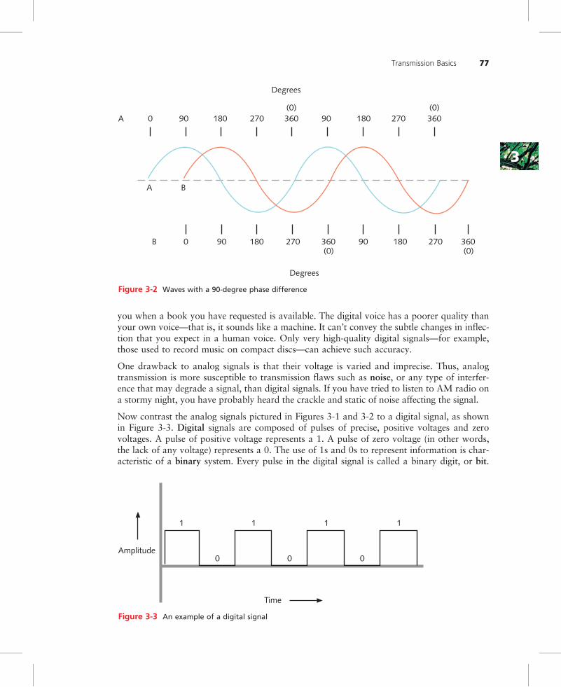
The term phase refers to the progress of a wave over time in relationship to a fixed point.Suppose two separate waves have identical amplitudes and frequencies. If one wave starts atits lowest amplitude at the same time the second wave starts at its highest amplitude, thesewaves will have different phases. More precisely, they will be 180 degrees out of phase(using the standard assignment of 360 degrees to one complete wave). Had the second wavealso started at its lowest amplitude, the two waves would be in phase. Figure 3-2 illustrateswaves with identical amplitudes and frequencies whose phases are 90 degrees apart.
One benefit to analog signals is that, because they are more variable than digital signals, theycan convey greater subtleties with less energy. For example, think of the difference betweenyour voice and a digital voice, such as the automated service that some libraries use to notify
Voltage (V)
Amplitude
– 5V
5
4
3
2
1
.25 .5 .75 1 2 3
Time(sec)
Figure 3-1 An example of an analog signal
76 Chapter 3
33
you when a book you have requested is available. The digital voice has a poorer quality thanyour own voice—that is, it sounds like a machine. It can’t convey the subtle changes in inflec-tion that you expect in a human voice. Only very high-quality digital signals—for example,those used to record music on compact discs—can achieve such accuracy.
One drawback to analog signals is that their voltage is varied and imprecise. Thus, analogtransmission is more susceptible to transmission flaws such as noise, or any type of interfer-ence that may degrade a signal, than digital signals. If you have tried to listen to AM radio ona stormy night, you have probably heard the crackle and static of noise affecting the signal.
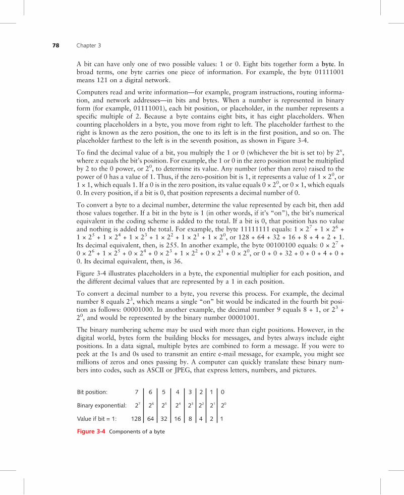
Now contrast the analog signals pictured in Figures 3-1 and 3-2 to a digital signal, as shownin Figure 3-3. Digital signals are composed of pulses of precise, positive voltages and zerovoltages. A pulse of positive voltage represents a 1. A pulse of zero voltage (in other words,the lack of any voltage) represents a 0. The use of 1s and 0s to represent information is char-acteristic of a binary system. Every pulse in the digital signal is called a binary digit, or bit.
A 0 90 180 270 360 90 180 270 360
Degrees
B 0 90 180 270 360 90 180 270 360
Degrees
BA
(0) (0)
(0) (0)
Figure 3-2 Waves with a 90-degree phase difference
Time
Amplitude
1
0
1
0
1
0
1
Figure 3-3 An example of a digital signal
Transmission Basics 77
A bit can have only one of two possible values: 1 or 0. Eight bits together form a byte. Inbroad terms, one byte carries one piece of information. For example, the byte 01111001means 121 on a digital network.
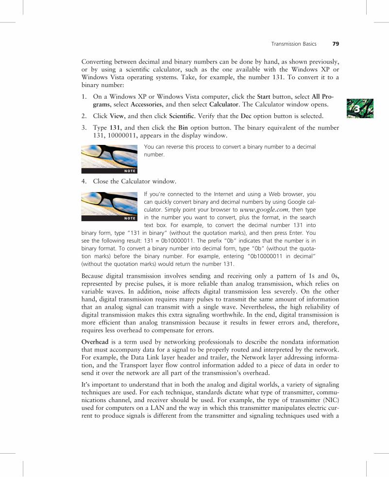
Computers read and write information—for example, program instructions, routing informa-tion, and network addresses—in bits and bytes. When a number is represented in binaryform (for example, 01111001), each bit position, or placeholder, in the number represents aspecific multiple of 2. Because a byte contains eight bits, it has eight placeholders. Whencounting placeholders in a byte, you move from right to left. The placeholder farthest to theright is known as the zero position, the one to its left is in the first position, and so on. Theplaceholder farthest to the left is in the seventh position, as shown in Figure 3-4.
To find the decimal value of a bit, you multiply the 1 or 0 (whichever the bit is set to) by 2x,where x equals the bit’s position. For example, the 1 or 0 in the zero position must be multipliedby 2 to the 0 power, or 20, to determine its value. Any number (other than zero) raised to thepower of 0 has a value of 1. Thus, if the zero-position bit is 1, it represents a value of 1 × 20, or1 × 1, which equals 1. If a 0 is in the zero position, its value equals 0 × 20, or 0 × 1, which equals0. In every position, if a bit is 0, that position represents a decimal number of 0.
To convert a byte to a decimal number, determine the value represented by each bit, then addthose values together. If a bit in the byte is 1 (in other words, if it’s “on”), the bit’s numericalequivalent in the coding scheme is added to the total. If a bit is 0, that position has no valueand nothing is added to the total. For example, the byte 11111111 equals: 1 × 27 + 1 × 26 +1 × 25 + 1 × 24 + 1 × 23 + 1 × 22 + 1 × 21 + 1 × 20, or 128 + 64 + 32 + 16 + 8 + 4 + 2 + 1.Its decimal equivalent, then, is 255. In another example, the byte 00100100 equals: 0 × 27 +0 × 26 + 1 × 25 + 0 × 24 + 0 × 23 + 1 × 22 + 0 × 21 + 0 × 20, or 0 + 0 + 32 + 0 + 0 + 4 + 0 +0. Its decimal equivalent, then, is 36.
Figure 3-4 illustrates placeholders in a byte, the exponential multiplier for each position, andthe different decimal values that are represented by a 1 in each position.
To convert a decimal number to a byte, you reverse this process. For example, the decimalnumber 8 equals 23, which means a single “on” bit would be indicated in the fourth bit posi-tion as follows: 00001000. In another example, the decimal number 9 equals 8 + 1, or 23 +20, and would be represented by the binary number 00001001.
The binary numbering scheme may be used with more than eight positions. However, in thedigital world, bytes form the building blocks for messages, and bytes always include eightpositions. In a data signal, multiple bytes are combined to form a message. If you were topeek at the 1s and 0s used to transmit an entire e-mail message, for example, you might seemillions of zeros and ones passing by. A computer can quickly translate these binary num-bers into codes, such as ASCII or JPEG, that express letters, numbers, and pictures.
Value if bit = 1: 128 64 32 16 8 4 2 1
Binary exponential: 27 26 25 24 23 22 21 20
Bit position: 7 6 5 4 3 2 1 0
Figure 3-4 Components of a byte
78 Chapter 3
33
Converting between decimal and binary numbers can be done by hand, as shown previously,or by using a scientific calculator, such as the one available with the Windows XP orWindows Vista operating systems. Take, for example, the number 131. To convert it to abinary number:
1. On a Windows XP or Windows Vista computer, click the Start button, select All Pro-grams, select Accessories, and then select Calculator. The Calculator window opens.
2. Click View, and then click Scientific. Verify that the Dec option button is selected.
3. Type 131, and then click the Bin option button. The binary equivalent of the number131, 10000011, appears in the display window.
You can reverse this process to convert a binary number to a decimalnumber.
4. Close the Calculator window.
If you’re connected to the Internet and using a Web browser, youcan quickly convert binary and decimal numbers by using Google cal-culator. Simply point your browser to www.google.com, then typein the number you want to convert, plus the format, in the searchtext box. For example, to convert the decimal number 131 into
binary form, type “131 in binary” (without the quotation marks), and then press Enter. Yousee the following result: 131 = 0b10000011. The prefix “0b” indicates that the number is inbinary format. To convert a binary number into decimal form, type “0b” (without the quota-tion marks) before the binary number. For example, entering “0b10000011 in decimal”(without the quotation marks) would return the number 131.
Because digital transmission involves sending and receiving only a pattern of 1s and 0s,represented by precise pulses, it is more reliable than analog transmission, which relies onvariable waves. In addition, noise affects digital transmission less severely. On the otherhand, digital transmission requires many pulses to transmit the same amount of informationthat an analog signal can transmit with a single wave. Nevertheless, the high reliability ofdigital transmission makes this extra signaling worthwhile. In the end, digital transmission ismore efficient than analog transmission because it results in fewer errors and, therefore,requires less overhead to compensate for errors.
Overhead is a term used by networking professionals to describe the nondata informationthat must accompany data for a signal to be properly routed and interpreted by the network.For example, the Data Link layer header and trailer, the Network layer addressing informa-tion, and the Transport layer flow control information added to a piece of data in order tosend it over the network are all part of the transmission’s overhead.
It’s important to understand that in both the analog and digital worlds, a variety of signalingtechniques are used. For each technique, standards dictate what type of transmitter, commu-nications channel, and receiver should be used. For example, the type of transmitter (NIC)used for computers on a LAN and the way in which this transmitter manipulates electric cur-rent to produce signals is different from the transmitter and signaling techniques used with a
Transmission Basics 79
satellite link. While not all signaling methods are covered in this book, you will learn aboutthe most common methods used for data networking.
Data ModulationData relies almost exclusively on digital transmission. However, in some cases the type ofconnection your network uses may be capable of handling only analog signals. For example,telephone lines are designed to carry analog signals. If you connect to your ISP’s network viaa telephone line, the data signals issued by your computer must be converted into analogform before they get to the phone line. Later, they must be converted back into digital formwhen they arrive at the ISP’s access server. A modem accomplishes this translation. The wordmodem reflects this device’s function as a modulator/demodulator—that is, it modulates digi-tal signals into analog signals at the transmitting end, then demodulates analog signals intodigital signals at the receiving end.
Data modulation is a technology used to modify analog signals to make them suitable forcarrying data over a communication path. In modulation, a simple wave, called a carrierwave, is combined with another analog signal to produce a unique signal that gets transmit-ted from one node to another. The carrier wave has preset properties (including frequency,amplitude, and phase). Its purpose is to help convey information; in other words, it’s only amessenger. Another signal, known as the information or data wave, is added to the carrierwave. When the information wave is added, it modifies one property of the carrier wave(for example, the frequency, amplitude, or phase). The result is a new, blended signal thatcontains properties of both the carrier wave and added data. When the signal reaches its des-tination, the receiver separates the data from the carrier wave.
Modulation can be used to make a signal conform to a specific pathway, as in the case ofFM (frequency modulation) radio, in which the data must travel along a particular fre-quency. In frequency modulation, the frequency of the carrier signal is modified by the appli-cation of the data signal. In AM (amplitude modulation), the amplitude of the carrier signalis modified by the application of the data signal. Modulation may also be used to issue mul-tiple signals to the same communications channel and prevent the signals from interferingwith one another. Figure 3-5 depicts an unaltered carrier wave, a data wave, and the com-bined wave as modified through frequency modulation. Later in this book, you will learnabout networking technologies, such as DSL, that make use of modulation.
Simplex, Half-Duplex, and DuplexData transmission, whether analog or digital, may also be characterized by the direction inwhich the signals travel over the media. In cases in which signals may travel in only one direc-tion, the transmission is considered simplex. An example of simplex communication is a foot-ball coach calling out orders to his team through a megaphone. In this example, the coach’svoice is the signal, and it travels in only one direction—away from the megaphone’s mouthpieceand toward the team. Simplex is sometimes called one-way, or unidirectional, communication.
In half-duplex transmission, signals may travel in both directions over a medium but in onlyone direction at a time. Half-duplex systems contain only one channel for communication,and that channel must be shared for multiple nodes to exchange information. For example, awalkie-talkie or an apartment’s intercom system that requires you to press a “talk” button toallow your voice to be transmitted uses half-duplex transmission. If you visit a friend’s apart-ment building, you press the “talk” button to send your voice signals to his apartment. When
2.1
80 Chapter 3

33
your friend responds, he presses the “talk” button in his apartment to send his voice signal inthe opposite direction over the wire to the speaker in the lobby where you wait. If you pressthe “talk” button while he’s talking, you will not be able to hear his voice transmission. In asimilar manner, some networks operate with only half-duplex capability.
When signals are free to travel in both directions over a medium simultaneously, the trans-mission is considered full-duplex. Full-duplex may also be called bidirectional transmissionor, sometimes, simply duplex. When you call a friend on the telephone, your connection isan example of a full-duplex transmission because your voice signals can be transmitted toyour friend at the same time your friend’s voice signals are transmitted in the opposite direc-tion to you. In other words, both of you can talk and hear each other simultaneously.
Figure 3-6 compares simplex, half-duplex, and full-duplex transmissions.
Full-duplex transmission is also used on data networks. For example, modern Ethernet net-works are capable of full-duplex. In this situation, full-duplex transmission uses multiplechannels on the same medium. A channel is a distinct communication path between nodes,much as a lane is a distinct transportation path on a freeway. Channels may be separatedeither logically or physically. You will learn about logically separate channels in the next sec-tion. An example of physically separate channels occurs when one wire within a networkcable is used for transmission while another wire is used for reception. In this example, eachseparate wire in the medium allows half-duplex transmission. When combined in a cable,
Volts
TimeFMwave:
Volts
TimeCarrierwave:
Volts
TimeInformationwave:
Figure 3-5 A carrier wave modified through frequency modulation
2.1
Transmission Basics 81

they form a medium that provides full-duplex transmission. Full-duplex capability increasesthe speed with which data can travel over a network. In some cases—for example, when pro-viding telephone service over the Internet—full-duplex data networks are a requirement.
Many network devices, such as modems and NICs, allow you to specify whether the deviceshould use half- or full-duplex communication. It’s important to know what type of transmis-sion a network supports before installing network devices on that network. If you configure acomputer’s NIC to use full-duplex while the rest of the network is using half-duplex, forexample, that computer will not be able to communicate on the network.
MultiplexingA form of transmission that allows multiple signals to travel simultaneously over onemedium is known as multiplexing. To carry multiple signals, the medium’s channel is logi-cally separated into multiple smaller channels, or subchannels. Many different types of multi-plexing are available, and the type used in any given situation depends on what the media,transmission, and reception equipment can handle. For each type of multiplexing, a devicethat can combine many signals on a channel, a multiplexer (mux), is required at the transmit-ting end of the channel. At the receiving end, a demultiplexer (demux) separates the com-bined signals and regenerates them in their original form. Networks rely on multiplexing toincrease the amount of data that can be transmitted in a given time span over a givenbandwidth.
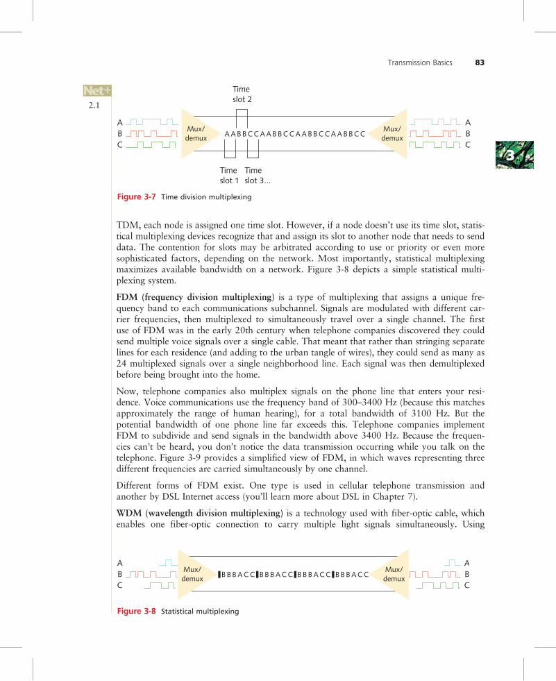
One type of multiplexing, TDM (time division multiplexing), divides a channel into multipleintervals of time, or time slots. It then assigns a separate time slot to every node on the networkand, in that time slot, carries data from that node. For example, if five stations are connectedto a network over one wire, five different time slots are established in the communicationschannel. Workstation A may be assigned time slot 1, workstation B time slot 2, workstation Ctime slot 3, and so on. Time slots are reserved for their designated nodes regardless of whetherthe node has data to transmit. If a node does not have data to send, nothing is sent during itstime slot. This arrangement can be inefficient if some nodes on the network rarely send data.Figure 3-7 shows a simple TDM model.
Statistical multiplexing is similar to time division multiplexing, but rather than assigning aseparate slot to each node in succession, the transmitter assigns slots to nodes according topriority and need. This method is more efficient than TDM, because in statistical multiplex-ing time slots are unlikely to remain empty. To begin with, in statistical multiplexing, as in
DataTransmitter Receiver
Simplex
OR
DataTransmitter Receiver
Half-duplex
DataReceiver Transmitter
AND
DataTransmitter Receiver
Full-duplex
DataReceiver Transmitter
Figure 3-6 Simplex, half-duplex, and full-duplex transmission
2.1
2.1
82 Chapter 3
33
TDM, each node is assigned one time slot. However, if a node doesn’t use its time slot, statis-tical multiplexing devices recognize that and assign its slot to another node that needs to senddata. The contention for slots may be arbitrated according to use or priority or even moresophisticated factors, depending on the network. Most importantly, statistical multiplexingmaximizes available bandwidth on a network. Figure 3-8 depicts a simple statistical multi-plexing system.
FDM (frequency division multiplexing) is a type of multiplexing that assigns a unique fre-quency band to each communications subchannel. Signals are modulated with different car-rier frequencies, then multiplexed to simultaneously travel over a single channel. The firstuse of FDM was in the early 20th century when telephone companies discovered they couldsend multiple voice signals over a single cable. That meant that rather than stringing separatelines for each residence (and adding to the urban tangle of wires), they could send as many as24 multiplexed signals over a single neighborhood line. Each signal was then demultiplexedbefore being brought into the home.
Now, telephone companies also multiplex signals on the phone line that enters your resi-dence. Voice communications use the frequency band of 300–3400 Hz (because this matchesapproximately the range of human hearing), for a total bandwidth of 3100 Hz. But thepotential bandwidth of one phone line far exceeds this. Telephone companies implementFDM to subdivide and send signals in the bandwidth above 3400 Hz. Because the frequen-cies can’t be heard, you don’t notice the data transmission occurring while you talk on thetelephone. Figure 3-9 provides a simplified view of FDM, in which waves representing threedifferent frequencies are carried simultaneously by one channel.
Different forms of FDM exist. One type is used in cellular telephone transmission andanother by DSL Internet access (you’ll learn more about DSL in Chapter 7).
WDM (wavelength division multiplexing) is a technology used with fiber-optic cable, whichenables one fiber-optic connection to carry multiple light signals simultaneously. Using
ABC
Mux/demux
ABC
Mux/demuxB B B A C C B B B A C C B B B A C C B B B A C C
Figure 3-8 Statistical multiplexing
Timeslot 1
Timeslot 3...
Timeslot 2
ABC
Mux/demux
ABC
Mux/demuxA A B B C C A A B B C C A A B B C C A A B B C C
Figure 3-7 Time division multiplexing
2.1
Transmission Basics 83

WDM, a single fiber can transmit as many as 20 million telephone conversations at one time.WDM can work over any type of fiber-optic cable.
In the first step of WDM, a beam of light is divided into up to 40 different carrier waves,each with a different wavelength (and, therefore, a different color). Each wavelength repre-sents a separate transmission channel capable of transmitting up to 10 Gbps. Beforetransmission, each carrier wave is modulated with a different data signal. Then, through avery narrow beam of light, lasers issue the separate, modulated waves to a multiplexer. Themultiplexer combines all of the waves, in the same way that a prism can accept light beamsof different wavelengths and concentrate them into a single beam of white light. Next,another laser issues this multiplexed beam to a strand of fiber within a fiber-optic cable. Thefiber carries the multiplexed signals to a receiver, which is connected to a demultiplexer. Thedemultiplexer acts as a prism to separate the combined signals according to their differentwavelengths (or colors). Then, the separate waves are sent to their destinations on the net-work. If the signal risks losing strength between the multiplexer and demultiplexer, an ampli-fier might be used to boost it. Figure 3-10 illustrates WDM transmission.
The form of WDM used on most modern fiber-optic networks is DWDM (dense wavelengthdivision multiplexing). In DWDM, a single fiber in a fiber-optic cable can carry between 80and 160 channels. It achieves this increased capacity because it uses more wavelengths forsignaling. In other words, there is less separation between the usable carrier waves inDWDM than there is in the original form of WDM. Because of its extraordinary capacity,
Wavelength division multiplexer
Demultiplexer
A
B
C
D
A
B
C
D
Figure 3-10 Wavelength division multiplexing
A
Frequencymodulated signals Multiplexer Demultiplexer
B
C
A
B
C
Figure 3-9 Frequency division multiplexing
2.1
84 Chapter 3

33
DWDM is typically used on high-bandwidth or long-distance WAN links, such as the con-nection between a large ISP and its (even larger) network service provider.
Relationships Between NodesSo far you have learned about two important characteristics of data transmission: the type ofsignaling (analog or digital) and the direction in which the signal travels (simplex, half-duplex, full-duplex, or multiplex). Another important characteristic is the number of sendersand receivers, as well as the relationship between them. In general, data communications mayinvolve a single transmitter with one or more receivers, or multiple transmitters with one ormore receivers. The remainder of this section introduces the most common relationshipsbetween transmitters and receivers.
When a data transmission involves only one transmitter and one receiver, it is considered apoint-to-point transmission. An office building in Dallas exchanging data with another officein St. Louis over a WAN connection is an example of point-to-point transmission. In thiscase, the sender only transmits data that is intended to be used by a specific receiver.
By contrast, point-to-multipoint transmission involves one transmitter and multiple receivers.Point-to-multipoint arrangements can be separated into two types: broadcast and nonbroadcast.Broadcast transmission involves one transmitter and multiple, undefined receivers. For exam-ple, a TV station indiscriminately transmitting a signal from its tower to thousands of homeswith TV antennas uses broadcast transmission. A broadcast transmission sends data to anyand all receivers, without regard for which receiver can use it. Broadcast transmissions arefrequently used on both wired and wireless networks because they are simple and quick. Theyare used to identify certain nodes, to send data to certain nodes (even though every node iscapable of picking up the transmitted data, only the destination node will actually do it), andto send announcements to all nodes.
When more tailored data transfer is desired, a network might use nonbroadcast point-to-multipoint transmission. In this scenario, a node issues signals to multiple, defined recipi-ents. For example, a network administrator could schedule the LAN transmission of aninstructional video which only she and all of her team’s workstations could receive.
Figure 3-11 contrasts point-to-point and point-to-multipoint transmissions.
Throughput and BandwidthThe data transmission characteristic most frequently discussed and analyzed by networkingprofessionals is throughput. Throughput is the measure of how much data is transmittedduring a given period of time. It may also be called capacity or bandwidth (though as youwill learn, bandwidth is technically different from throughput). Throughput is commonlyexpressed as a quantity of bits transmitted per second, with prefixes used to designate differ-ent throughput amounts. For example, the prefix kilo combined with the word bit (as in kilo-bit) indicates 1000 bits per second. Rather than talking about a throughput of 1000 bits persecond, you typically say the throughput was 1 kilobit per second (1 Kbps). Table 3-1 sum-marizes the terminology and abbreviations used when discussing different throughputamounts. As an example, a residential broadband Internet connection might be rated for amaximum throughput of 1.544 Mbps. A fast LAN might transport up to 10 Gbps of data.Contemporary networks commonly achieve throughputs of 10 Mbps, 100 Mbps, 1 Gbps,
2.1
2.1
2.1
Transmission Basics 85

or higher. Applications that require significant throughput include videoconferencing andtelephone signaling. By contrast, instant messaging and e-mail, for example, require muchless throughput.
Be careful not to confuse bits and bytes when discussing throughput.Although data storage quantities are typically expressed in multiplesof bytes, data transmission quantities (in other words, throughput)are more commonly expressed in multiples of bits per second. Whenrepresenting different data quantities, a small b represents bits, while
a capital B represents bytes. To put this into context, a modem may transmit data at 56.6 Kbps(kilobits per second); a data file may be 56 KB (kilobytes) in size. Another difference betweendata storage and data throughput measures is that in data storage the prefix kilo means 2 tothe 10th power, or 1024, not 1000.
Often, the term bandwidth is used interchangeably with throughput, and in fact, this maybe the case on the Network+ certification exam. Bandwidth and throughput are similar
Table 3-1 Throughput measures
Quantity Prefix Complete example Abbreviation1 bit per second n/a 1 bit per second bps
1000 bits per second kilo 1 kilobit per second Kbps
1,000,000 bits per second mega 1 megabit per second Mbps
1,000,000,000 bits per second giga 1 gigabit per second Gbps
1,000,000,000,000 bits per second tera 1 terabit per second Tbps
Point-to-pointtransmission
Broadcasttransmission
Figure 3-11 Point-to-point versus broadcast transmission
2.1
86 Chapter 3

33
concepts, but strictly speaking, bandwidth is a measure of the difference between the highestand lowest frequencies that a medium can transmit. This range of frequencies, which isexpressed in Hz, is directly related to throughput. For example, if the FCC told you thatyou could transmit a radio signal between 870 and 880 MHz, your allotted bandwidth (liter-ally, the width of your frequency band) would be 10 MHz.
Baseband and BroadbandBaseband is a transmission form in which (typically) digital signals are sent through directcurrent (DC) pulses applied to the wire. This direct current requires exclusive use of thewire’s capacity. As a result, baseband systems can transmit only one signal, or one channel,at a time. Every device on a baseband system shares the same channel. When one node istransmitting data on a baseband system, all other nodes on the network must wait for thattransmission to end before they can send data. Baseband transmission supports half-duplexing, which means that computers can both send and receive information on the samelength of wire. In some cases, baseband also supports full duplexing.
Ethernet is an example of a baseband system found on many LANs. In Ethernet, each deviceon a network can transmit over the wire—but only one device at a time. For example, if youwant to save a file to the server, your NIC submits your request to use the wire; if no otherdevice is using the wire to transmit data at that time, your workstation can go ahead. If thewire is in use, your workstation must wait and try again later. Of course, this retrying pro-cess happens so quickly that you don’t even notice the wait.
Broadband is a form of transmission in which signals are modulated as radiofrequency (RF)analog waves that use different frequency ranges. Unlike baseband, broadband technologydoes not encode information as digital pulses.
As you may know, broadband transmission is used to bring cable TV to your home. Yourcable TV connection can carry at least 25 times as much data as a typical baseband system(like Ethernet) carries, including many different broadcast frequencies on different channels.In traditional broadband systems, signals travel in only one direction—toward the user. Toallow users to send data as well, cable systems allot a separate channel space for the user’stransmission and use amplifiers that can separate data the user issues from data the networktransmits. Broadband transmission is generally more expensive than baseband transmissionbecause of the extra hardware involved. On the other hand, broadband systems can spanlonger distances than baseband.
In the field of networking, some terms have more than one meaning, depending on their con-text. Broadband is one of those terms. The broadband described in this chapter is the trans-mission system that carries RF signals across multiple channels on a coaxial cable, as used bycable TV. This definition was the original meaning of broadband. However, broadband hasevolved to mean any of several different network types that use digital signaling to transmitdata at very high transmission rates.
Transmission FlawsBoth analog and digital signals are susceptible to degradation between the time they areissued by a transmitter and the time they are received. One of the most common transmissionflaws affecting data signals is noise.
2.1
2.1
Transmission Basics 87

Noise As you learned earlier, noise is any undesirable influence that may degrade or dis-tort a signal. Many different types of noise may affect transmission. A common source ofnoise is EMI (electromagnetic interference), or waves that emanate from electrical devicesor cables carrying electricity. Motors, power lines, televisions, copiers, fluorescent lights,manufacturing machinery, and other sources of electrical activity (including a severe thunder-storm) can cause EMI. One type of EMI is RFI (radiofrequency interference), or electromag-netic interference caused by radio waves. (Often, you’ll see EMI referred to as EMI/RFI.)Strong broadcast signals from radio or TV towers can generate RFI. When EMI noise affectsanalog signals, this distortion can result in the incorrect transmission of data, just as if staticprevented you from hearing a radio station broadcast. However, this type of noise affectsdigital signals much less. Because digital signals do not depend on subtle amplitude or fre-quency differences to communicate information, they are more apt to be readable despitedistortions caused by EMI noise.
Another form of noise that hinders data transmission is cross talk. Cross talk occurs when asignal traveling on one wire or cable infringes on the signal traveling over an adjacent wireor cable. When cross talk occurs between two cables, it’s called alien cross talk. When itoccurs between wire pairs near the source of a signal, it’s known as NEXT (near end crosstalk). One potential cause of NEXT is an improper termination—for example, one in whichwire insulation has been damaged or wire pairs have been untwisted too far.
If you’ve ever been on the phone and heard the conversation on your second line in thebackground, you have heard the effects of cross talk. In this example, the current carryinga signal on the second line’s wire imposes itself on the wire carrying your line’s signal, asshown in Figure 3-12. The resulting noise, or cross talk, is equal to a portion of the secondline’s signal. Cross talk in the form of overlapping phone conversations is bothersome, butdoes not usually prevent you from hearing your own line’s conversation. In data networks,however, cross talk can be extreme enough to prevent the accurate delivery of data.
In addition to EMI and cross talk, less obvious environmental influences, including heat, canalso cause noise. In every signal, a certain amount of noise is unavoidable. However, engi-neers have designed a number of ways to limit the potential for noise to degrade a signal.One way is simply to ensure that the strength of the signal exceeds the strength of thenoise. Proper cable design and installation are also critical for protecting against noise’seffects. Note that all forms of noise are measured in decibels (dB).
Cable
Wire transmitting signal
Cross talk
Wires affectedby cross talk
Figure 3-12 Cross talk between wires in a cable
2.1
4.7
88 Chapter 3

33
Attenuation Another transmission flaw is attenuation, or the loss of a signal’s strengthas it travels away from its source. Just as your voice becomes fainter as it travels farther, sodo signals fade with distance. To compensate for attenuation, both analog and digital sig-nals are boosted en route. However, the technology used to boost an analog signal is differ-ent from that used to boost a digital signal. Analog signals pass through an amplifier, anelectronic device that increases the voltage, or strength, of the signals. When an analog sig-nal is amplified, the noise that it has accumulated is also amplified. This indiscriminateamplification causes the analog signal to worsen progressively. After multiple amplifications,an analog signal may become difficult to decipher. Figure 3-13 shows an analog signal dis-torted by noise and then amplified once.
When digital signals are repeated, they are actually retransmitted in their original form,without the noise they might have accumulated previously. This process is known as regen-eration. A device that regenerates a digital signal is called a repeater. Figure 3-14 shows adigital signal distorted by noise and then regenerated by a repeater.
Amplifiers and repeaters belong to the Physical layer of the OSI model. Both are used toextend the length of a network. Because most networks are digital, however, they typicallyuse repeaters.
0
Voltage Noise
Amplifier
Figure 3-13 An analog signal distorted by noise and then amplified
0
Volts Noise Repeater
Figure 3-14 A digital signal distorted by noise and then repeated
4.7
2.1
4.7
Transmission Basics 89

Latency In an ideal world, networks could transmit data instantaneously between senderand receiver, no matter how great the distance between the two. However, in the real worldevery network is subjected to a delay between the transmission of a signal and its eventualreceipt. For example, when you press a key on your computer to save a file to a networkserver, the file’s data must travel through your NIC, the network wire, one or more connec-tivity devices, more cabling, and the server’s NIC before it lands on the server’s hard disk.Although electrons travel rapidly, they still have to travel, and a brief delay takes placebetween the moment you press the key and the moment the server accepts the data. Thisdelay is called latency.
The length of the cable involved affects latency, as does the existence of any intervening con-nectivity device, such as a router. Different devices affect latency to different degrees. Forexample, modems, which must modulate both incoming and outgoing signals, increase aconnection’s latency far more than hubs, which simply repeat a signal. The most commonway to measure latency on data networks is by calculating a packet’s RTT (round triptime), or the length of time it takes for a packet to go from sender to receiver, then backfrom receiver to sender. RTT is usually measured in milliseconds.
Latency causes problems only when a receiving node is expecting some type of communica-tion, such as the rest of a data stream it has begun to accept. If that node does not receivethe rest of the data stream within a given time period, it assumes that no more data is com-ing. This assumption may cause transmission errors on a network. When you connect multi-ple network segments and thereby increase the distance between sender and receiver, youincrease the network’s latency. To constrain the latency and avoid its associated errors,each type of cabling is rated for a maximum number of connected network segments, andeach transmission method is assigned a maximum segment length.
Common Media CharacteristicsNow that you are familiar with data-signaling characteristics, you are ready to learnmore about the physical and atmospheric paths that these signals traverse. When decidingwhich kind of transmission media to use, you must match your networking needs with thecharacteristics of the media. This section describes the characteristics of several types of phy-sical media, including throughput, cost, size and scalability, connectors, and noise immu-nity. The medium used for wireless transmission, the atmosphere, is discussed in detail inChapter 8.
ThroughputPerhaps the most significant factor in choosing a transmission method is its throughput. Allmedia are limited by the laws of physics that prevent signals from traveling faster than thespeed of light. Beyond that, throughput is limited by the signaling and multiplexing techni-ques used in a given transmission method. Using fiber-optic cables allows faster throughputthan copper or wireless connections. Noise and devices connected to the transmissionmedium can further limit throughput. A noisy circuit spends more time compensating forthe noise and, therefore, has fewer resources available for transmitting data.
2.1
4.5
90 Chapter 3

33
CostThe precise costs of using a particular type of cable or wireless connection are often difficultto pinpoint. For example, although a vendor might quote you the cost-per-foot for new net-work cabling, you might also have to upgrade some hardware on your network to use thattype of cabling. Thus, the cost of upgrading your media would actually include more thanthe cost of the cabling itself. Not only do media costs depend on the hardware that alreadyexists in a network, but they also depend on the size of your network and the cost of laborin your area (unless you plan to install the cable yourself). The following variables can allinfluence the final cost of implementing a certain type of media:
• Cost of installation—Can you install the media yourself, or must you hire contractorsto do it? Will you need to move walls or build new conduits or closets? Will you needto lease lines from a service provider?
• Cost of new infrastructure versus reusing existing infrastructure—Can you use existingwiring? In some cases, for example, installing all new Category 6 UTP wiring may notpay off if you can use existing Category 5 UTP wiring. If you replace only part of yourinfrastructure, will it be easily integrated with the existing media?
• Cost of maintenance and support—Reuse of an existing cabling infrastructure does notsave any money if it is in constant need of repair or enhancement. Also, if you use anunfamiliar media type, it may cost more to hire a technician to service it. Will you beable to service the media yourself, or must you hire contractors to service it?
• Cost of a lower transmission rate affecting productivity—If you save money by reusingexisting slower lines, are you incurring costs by reducing productivity? In other words,are you making staff wait longer to save and print reports or exchange e-mail?
• Cost of obsolescence—Are you choosing media that may become passing fads, requir-ing rapid replacement? Will you be able to find reasonably priced connectivity hard-ware that will be compatible with your chosen media for years to come?
Noise ImmunityAs you learned earlier, noise can distort data signals. The extent to which noise affects a sig-nal depends partly on the transmission media. Some types of media are more susceptible tonoise than others. The type of media least susceptible to noise is fiber-optic cable, because itdoes not use electric current, but light waves, to conduct signals.
On most networks, noise is an ever-present threat, so you should take measures to limit itsimpact on your network. For example, install cabling well away from powerful electromag-netic forces. If your environment still leaves your network vulnerable, choose a type of trans-mission media that helps to protect the signal from noise. For example, wireless signals aremore apt to be distorted by EMI/RFI than signals traveling over a cable. It is also possibleto use antinoise algorithms to protect data from being corrupted by noise. If these measuresdon’t ward off interference, in the case of wired media, you may need to use a metal conduit,or pipeline, to contain and further protect the cabling.
Now that you understand data transmission and the factors to consider when choosing atransmission medium, you are ready to learn about different types of transmission media. Toqualify for Network+ certification, you must know the characteristics and limitations of eachtype of media, how to install and design a network with each type, how to troubleshoot net-working media problems, and how to provide for future network growth with each option.
2.1
Common Media Characteristics 91

Size and ScalabilityThree specifications determine the size and scalability of networking media: maximum nodesper segment, maximum segment length, and maximum network length. In cabling, each ofthese specifications is based on the physical characteristics of the wire and the electrical char-acteristics of data transmission. The maximum number of nodes per segment depends onattenuation and latency. Each device added to a network segment causes a slight increase inthe signal’s attenuation and latency. To ensure a clear, strong, and timely signal, you mustlimit the number of nodes on a segment.
The maximum segment length depends on attenuation and latency plus the segment type. Anetwork can include two types of segments: populated and unpopulated. A populated seg-ment is a part of a network that contains end nodes. For example, a switch connecting usersin a classroom is part of a populated segment. An unpopulated segment, also known as alink segment, is a part of the network that does not contain end nodes, but simply connectstwo networking devices such as routers.
Segment lengths are limited because after a certain distance, a signal loses so much strengththat it cannot be accurately interpreted. The maximum distance a signal can travel and stillbe interpreted accurately is equal to a segment’s maximum length. Beyond this length, dataloss is apt to occur. As with the maximum number of nodes per segment, maximum segmentlength varies between different cabling types. The same principle of data loss applies to max-imum network length, which is the sum of the network’s segment lengths.
Connectors and Media ConvertersConnectors are the pieces of hardware that connect the wire to the network device, be it a fileserver, workstation, switch, or printer. Every networking medium requires a specific kind ofconnector. The type of connectors you use will affect the cost of installing and maintaining thenetwork, the ease of adding new segments or nodes to the network, and the technical expertiserequired to maintain the network. The connectors you are most likely to encounter on modernnetworks are illustrated throughout this chapter and shown together in Appendix C.
Connectors are specific to a particular media type, but that doesn’t prevent one networkfrom using multiple media. Some connectivity devices are designed to accept more than onetype of media. If you are working with a connectivity device that can’t, you can integratethe two media types by using media converters. A media converter is a piece of hardwarethat enables networks or segments running on different media to interconnect and exchangesignals. For example, suppose a segment leading from your company’s data center to agroup of workstations uses fiber-optic cable, but the workgroup hub can only accept twistedpair (copper) cable. In that case, you could use a media converter to interconnect the hubwith the fiber-optic cable. The media converter completes the physical connection and alsoconverts the electrical signals from the copper cable to light wave signals that can traverse thefiber-optic cable, and vice versa. Such a media converter is shown in Figure 3-15.
The terms wire and cable are used synonymously in some situations.Strictly speaking, however, wire is a subset of cabling, because thecabling category may also include fiber-optic cable, which is almostnever called wire. The exact meaning of the term wire depends oncontext. For example, if you said, in a somewhat casual way, “We
had 6 gigs of data go over the wire last night,” you would be referring to whatever transmis-sion media helped carry the data—whether fiber, radio waves, coax, or UTP.
2.2
3.1
92 Chapter 3

33
Coaxial CableCoaxial cable, called “coax” for short, was the foundation for Ethernet networks in the 1970sand remained a popular transmission medium for many years. Over time, however, twistedpair and fiber-optic cabling have replaced coax in modern LANs. If you work on long-established networks or cable systems, however, you might have to work with coaxial cable.
Coaxial cable consists of a central metal core (often copper) surrounded by an insulator, abraided metal shielding, called braiding or shield, and an outer cover, called the sheath orjacket. Figure 3-16 depicts a typical coaxial cable. The core may be constructed of one solidmetal wire or several thin strands of metal wire. The core carries the electromagnetic signal,and the braided metal shielding acts as both a shield against noise and a ground for the signal.The insulator layer usually consists of a plastic material such as PVC (polyvinyl chloride) orTeflon. It protects the core from the metal shielding, because if the two made contact, thewire would short-circuit. The sheath, which protects the cable from physical damage, may bePVC or a more expensive, fire-resistant plastic.
2.2
3.1
2.1
Conducting core
Insulation (PVC, Teflon)
Braided shielding
Sheath
Figure 3-16 Coaxial cable
Figure 3-15 Copper wire-to-fiber media converter
Coaxial Cable 93

Because of its shielding, most coaxial cable has a high resistance to noise. It can also carrysignals farther than twisted pair cabling before amplification of the signals becomes nec-essary (although not as far as fiber-optic cabling). On the other hand, coaxial cable is moreexpensive than twisted pair cable because it requires significantly more raw materials tomanufacture.
Coaxial cabling comes in hundreds of specifications, although you are likely to see only twoor three types of coax in use on data networks. All types have been assigned an RG specifica-tion number. (RG stands for radio guide, which is appropriate because coaxial cabling is usedto guide radio frequencies in broadband transmission.) The significant differences between thecable types lie in the materials used for their shielding and conducting cores, which in turninfluence their transmission characteristics, such as impedance (or the resistance that contri-butes to controlling the signal, as expressed in ohms), attenuation, and throughput. Each typeof coax is suited to a different purpose. When discussing the size of the conducting core in acoaxial cable, we refer to its American Wire Gauge (AWG) size. The larger the AWG size,the smaller the diameter of a piece of wire. Following is a list of coaxial cable specificationsused with data networks:
• RG-6—A type of coaxial cable that is characterized by an impedance of 75 ohms andcontains an 18 AWG conducting core. The core is usually made of solid copper. RG-6coaxial cables are used, for example, to deliver broadband cable Internet service andcable TV, particularly over long distances. If a service provider such as Comcast orCharter supplies you with Internet service, the cable entering your home is RG-6.
• RG-8—A type of coaxial cable characterized by a 50-ohm impedance and a 10 AWGcore. RG-8 provided the medium for the first Ethernet networks, which followed thenow-obsolete 10Base-5 standard. The 10 represents its maximum potential throughputof 10 Mbps, the Base stands for baseband transmission, and the 5 represents itsmaximum segment length of 500 meters. As you’ll learn, all Ethernet standards estab-lished by IEEE follow a similar naming convention. 10Base-5 is also known asThicknet. You will never find Thicknet on new networks, but you might find it onolder networks.
• RG-58—A type of coaxial cable characterized by a 50-ohm impedance and a 24 AWGcore. RG-58 was a popular medium for Ethernet LANs in the 1980s. With a smallerdiameter than RG-8, RG-58 is more flexible and easier to handle and install. Its core istypically made of several thin strands of copper. The Ethernet standard that relies onRG-58 coax is 10Base-2, with the 10 representing its data transmission rate of10 Mbps, the Base representing the fact that it uses baseband transmission, and the2 representing its maximum segment length of 185 meters (or roughly 200). Because itis thinner than Thicknet cables, it is also called Thinnet. Like Thicknet, Thinnet isalmost never used on modern networks, although you might encounter it on networksinstalled in the 1980s.
• RG-59—A type of coaxial cable characterized by a 75-ohm impedance and a 20 or 22AWG core, usually made of braided copper. Less expensive but suffering from greaterattenuation than the more common RG-6 coax, RG-59 is still used for relatively shortconnections, for example, when distributing video signals from a central receiver tomultiple monitors within a building.
The two coaxial cable types commonly used in networks today, RG-6 and RG-59, can ter-minate with one of two connector types: an F-type connector or a BNC connector. F-type
2.1
2.2
94 Chapter 3

33
connectors attach to coaxial cable so that the pin in the center of the connector is the con-ducting core of the cable. Therefore, F-type connectors require that the cable contain a solidmetal core. After being attached to the cable by crimping or compression, connectors arethreaded and screw together like a nut and bolt assembly. A male F-type connector, orplug, attached to coax is shown in Figure 3-17. A corresponding female F-type connector,or jack, would be coupled with the male connector. F-type connectors are most often usedwith RG-6 cables.
BNC stands for Bayonet Neill-Concelman, a term that refers to both a style of connection andits two inventors. (Sometimes the term British Naval Connector is also used.) A BNC connec-tor is crimped, compressed, or twisted onto a coaxial cable. It connects to another BNCconnector via a turning and locking mechanism—this is the bayonet coupling referencedin its name. Unlike an F-type connector, male BNC connectors do not use the central conduct-ing core of the coax as part of the connection, but provide their own conducting pin. BNCwas once the standard for connecting coaxial-based Ethernet segments. Today, though,you’re more likely to find BNC connectors used with RG-59 coaxial cable. Less commonly,they’re also used with RG-6. Figure 3-18 shows a BNC connector that is not attached to acable.
When sourcing connectors for coaxial cable, you need to specify thetype of cable you are using. For instance, when working with RG-6coax, choose an F-type connector made specifically for RG-6 cables.That way, you’ll be certain that the connectors and cable share thesame impedance rating. If impedance ratings don’t match, data
errors will result and network performance will suffer.
Next, you will learn about a medium you are more likely to find on modern LANs, twistedpair cable.
2.1
2.2
Figure 3-17 F-type connector
Coaxial Cable 95

Twisted Pair CableTwisted pair cable consists of color-coded pairs of insulated copper wires, each with a diame-ter of 0.4 to 0.8 mm (approximately the diameter of a straight pin). Every two wires aretwisted around each other to form pairs, and all the pairs are encased in a plastic sheath, asshown in Figure 3-19. The number of pairs in a cable varies, depending on the cable type.
The more twists per foot in a pair of wires, the more resistant the pair will be to cross talk.Higher-quality, more expensive twisted pair cable contains more twists per foot. The numberof twists per meter or foot is known as the twist ratio. Because twisting the wire pairs moretightly requires more cable, however, a high twist ratio can result in greater attenuation. For
Two pairs
Four pairs
Figure 3-19 Twisted pair cable
Figure 3-18 BNC connector
2.1
2.2
2.1
96 Chapter 3

33
optimal performance, cable manufacturers must strike a balance between minimizing crosstalk and reducing attenuation.
Because twisted pair is used in such a wide variety of environments and for a variety of pur-poses, it comes in hundreds of different designs. These designs vary in their twist ratio, thenumber of wire pairs that they contain, the grade of copper used, the type of shielding (if any),and the materials used for shielding, among other things. A twisted pair cable may containfrom 1 to 4200 wire pairs. Modern networks typically use cables that contain four wire pairs,in which one pair is dedicated to sending data and another pair is dedicated to receiving data.
In 1991, two standards organizations, the TIA/EIA, finalized their specifications for twistedpair wiring in a standard called “TIA/EIA 568.” Since then, this body has continually revisedthe international standards for new and modified transmission media. Its standards now covercabling media, design, and installation specifications. The TIA/EIA 568 standard dividestwisted pair wiring into several categories. The types of twisted pair wiring you will hearabout most often are Cat (category) 3, 4, 5, 5e, 6, and 6e, and Cat 7. All of the categorycables fall under the TIA/EIA 568 standard. Modern LANs use Cat 5 or higher wiring.
Twisted pair cable is relatively inexpensive, flexible, and easy to install, and it can span a sig-nificant distance before requiring a repeater (though not as far as coax). Twisted pair cableeasily accommodates several different topologies, although it is most often implemented instar or star-hybrid topologies. Furthermore, twisted pair can handle the faster networkingtransmission rates currently being employed. Due to its wide acceptance, it will probably con-tinue to be updated to handle the even faster rates that will emerge in the future. All twistedpair cable falls into one of two categories: STP (shielded twisted pair) or UTP (unshieldedtwisted pair).
STP (Shielded Twisted Pair)STP (shielded twisted pair) cable consists of twisted wire pairs that are not only individuallyinsulated, but also surrounded by a shielding made of a metallic substance such as foil. SomeSTP use a braided copper shielding. The shielding acts as a barrier to external electromag-netic forces, thus preventing them from affecting the signals traveling over the wire insidethe shielding. It also contains the electrical energy of the signals inside. The shielding may begrounded to enhance its protective effects. The effectiveness of STP’s shield depends on thelevel and type of environmental noise, the thickness and material used for the shield, thegrounding mechanism, and the symmetry and consistency of the shielding. Figure 3-20depicts an STP cable.
UTP (Unshielded Twisted Pair)UTP (unshielded twisted pair) cabling consists of one or more insulated wire pairs encasedin a plastic sheath. As its name implies, UTP does not contain additional shielding for thetwisted pairs. As a result, UTP is both less expensive and less resistant to noise than STP.Figure 3-21 depicts a typical UTP cable.
Earlier, you learned that the TIA/EIA consortium designated standards for twisted pair wir-ing. To manage network cabling, you need to be familiar with the standards for use on mod-ern networks, particularly Cat 3 and Cat 5 or higher:
• Cat 3 (Category 3)—A form of UTP that contains four wire pairs and can carry up to10 Mbps of data with a possible bandwidth of 16 MHz. Cat 3 has typically been used
2.1
2.1
2.1
Twisted Pair Cable 97

for 10-Mbps Ethernet or 4-Mbps token ring networks. Where it remains, networkadministrators are replacing their existing Cat 3 cabling with Cat 5 or better cabling toaccommodate higher throughput.
• Cat 4 (Category 4)—A form of UTP that contains four wire pairs and can support upto 16 Mbps throughput. Uncommon on new networks, Cat 4 may be found on older16 Mbps token ring or 10 Mbps Ethernet networks. It is guaranteed for signals ashigh as 20 MHz and provides more protection against cross talk and attenuation thanCat 3.
• Cat 5 (Category 5)—A form of UTP that contains four wire pairs and supports upto 1000 Mbps throughput and a 100-MHz signal rate. Figure 3-22 depicts a typicalCat 5 UTP cable with its twisted pairs untwisted, allowing you to see their matchedcolor coding. For example, the wire that is colored solid orange is twisted aroundthe wire that is part orange and part white to form the pair responsible for trans-mitting data.
Foil shielding
Braided coppershielding
Jacket/sheath
Fourtwistedpairs
Figure 3-20 STP cable
Figure 3-21 UTP cable
2.1
98 Chapter 3

33
It can be difficult to tell the difference between four-pair Cat 3cables and four-pair Cat 5 or Cat 5e cables. However, some visualclues can help. On Cat 5 cable, the jacket is usually stamped withthe manufacturer’s name and cable type, including the Cat 5 specifi-cation. A cable whose jacket has no markings is more likely to be
Cat 3. Also, pairs in Cat 5 cables have a significantly higher twist ratio than pairs in Cat 3cables. Although Cat 3 pairs might be twisted as few as three times per foot, Cat 5 pairs aretwisted at least 12 times per foot. Other clues, such as the date of installation (old cable ismore likely to be Cat 3), looseness of the jacket (Cat 3’s jacket is typically looser than Cat5’s), and the extent to which pairs are untwisted before a termination (Cat 5 can tolerateonly a small amount of untwisting) are also helpful, though less definitive.
• Cat 5e (Enhanced Category 5)—A higher-grade version of Cat 5 wiring that containshigh-quality copper, offers a high twist ratio, and uses advanced methods for reducingcross talk. Cat 5e can support a signaling rate as high as 350 MHz, more than triplethe capability of regular Cat 5.
• Cat 6 (Category 6)—A twisted pair cable that contains four wire pairs, each wrappedin foil insulation. Additional foil insulation covers the bundle of wire pairs, and a fire-resistant plastic sheath covers the second foil layer. The foil insulation provides excel-lent resistance to cross talk and enables Cat 6 to support a 250-MHz signaling rateand at least six times the throughput supported by regular Cat 5.
• Cat 6e (Enhanced Category 6)—A higher-grade version of Cat 6 wiring that reducesattenuation and cross talk, and allows for potentially exceeding traditional networksegment length limits. Cat 6e is capable of a 550 MHz signaling rate and can reliablytransmit data at multi-Gigabit per second rates.
• Cat 7 (Category 7)—A twisted pair cable that contains multiple wire pairs, each sur-rounded by its own shielding, then packaged in additional shielding beneath thesheath. Although standards have not yet been finalized for Cat 7, cable supply compa-nies are selling it, and some organizations are installing it. One advantage to Cat 7cabling is that it can support signal rates up to 1 GHz. However, it requires different
Figure 3-22 A Cat 5 UTP cable with pairs untwisted
2.1
Twisted Pair Cable 99

connectors than other versions of UTP because its twisted pairs must be more isolatedfrom each other to ward off cross talk. Because of its added shielding, Cat 7 cabling isalso larger and less flexible than other versions of UTP cable. Cat 7 is uncommon onmodern networks, but it will likely become popular as the final standard is releasedand network equipment is upgraded.
Technically, because Cat 6 and Cat 7 contain wires that are individually shielded, they arenot unshielded twisted pair. Instead, they are more similar to shielded twisted pair.
UTP cabling may be used with any one of several IEEE Physical layer networking standardsthat specify throughput maximums of 10, 100, 1000, and even 10,000 Mbps. These stan-dards are described in detail in Chapter 5.
Comparing STP and UTPSTP and UTP share several characteristics. The following list highlights their similarities anddifferences:
• Throughput—STP and UTP can both transmit data at 10 Mbps, 100 Mbps, 1 Gbps,and 10 Gbps, depending on the grade of cabling and the transmission method in use.
• Cost—STP and UTP vary in cost, depending on the grade of copper used, the categoryrating, and any enhancements. Typically, STP is more expensive than UTP because itcontains more materials and it has a lower demand. It also requires grounding, whichcan lead to more expensive installation. High-grade UTP, can be expensive too, how-ever. For example, Cat 6e costs more per foot than Cat 5 cabling.
• Connector—STP and UTP use RJ-45 (Registered Jack 45) modular connectors anddata jacks, which look similar to analog telephone connectors and jacks. However,telephone connections follow the RJ-11 (Registered Jack 11) standard. Figure 3-23shows a close-up of an RJ-45 connector for a cable containing four wire pairs. Forcomparison, this figure also shows a traditional RJ-11 phone line connector. All typesof Ethernet that rely on twisted pair cabling use RJ-45 connectors.
2.1
2.2
2.12.1
Figure 3-23 RJ-45 and RJ-11 connectors
2.1
100 Chapter 3

33
• Noise immunity—Because of its shielding, STP is more noise resistant than UTP. Onthe other hand, signals transmitted over UTP may be subject to filtering and balancingtechniques to offset the effects of noise.
• Size and scalability—The maximum segment length for both STP and UTP is 100 m,or 328 feet, on Ethernet networks that support data rates from 1 Mbps to 10 Gbps.These accommodate a maximum of 1024 nodes. (However, attaching so many nodesto a segment is very impractical, as it would slow traffic and make management nearlyimpossible.)
Terminating Twisted Pair CableImagine you have been sent to one of your employer’s remote offices and charged withupgrading all the old Cat 3 patch cables in a data closet with new, Cat 6 patch cables. Apatch cable is a relatively short (usually between 3 and 25 feet) length of cabling with con-nectors at both ends. Based on the company’s network documentation, you brought 50 pre-made cables with RJ-45 plugs on both ends, which you purchased from an online cablevendor. At the remote location, however, you discover that its data closet actually contains60 patch cables that need replacing. No additional premade cables are available at thatoffice, and you don’t have time to order more. Luckily, you have brought your networkingtool kit with spare RJ-45 plugs and a spool of Cat 6 cable. Knowing how to properly termi-nate Cat 6 cables allows you to make all the new patch cables you need and complete yourwork. Even if you are never faced with this situation, it’s likely that at some point you willhave to replace an RJ-45 connector on an existing cable. This section describes how to termi-nate twisted pair cable.
Proper cable termination is a basic requirement for two nodes on a network to communicate.Beyond that, however, poor terminations can lead to loss or noise—and consequently,errors—in a signal. Closely following termination standards, then, is critical. TIA/EIA hasspecified two different methods of inserting twisted pair wires into RJ-45 plugs: TIA/EIA568A and TIA/EIA 568B. Functionally, there is no difference between the standards. Youonly have to be certain that you use the same standard on every RJ-45 plug and jack onyour network, so that data is transmitted and received correctly. Figure 3-24 depicts pinnumbers and assignments (or pinouts) for the TIA/EIA 568A standard when used on anEthernet network. Figure 3-25 depicts pin numbers and assignments for the TIA/EIA 568Bstandard. (Although networking professionals commonly refer to wires in Figures 3-24 and3-25 as transmit and receive, their original T and R designations stand for Tip and Ring,terms that come from early telephone technology but are irrelevant today.)
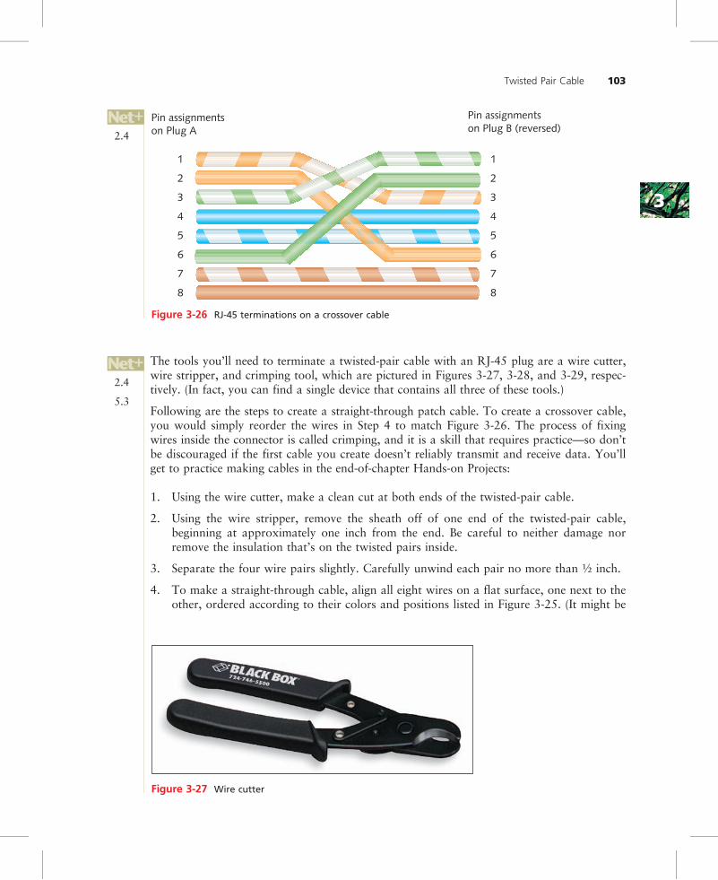
If you terminate the RJ-45 plugs at both ends of a patch cable identically, following one ofthe TIA/EIA 568 standards, you will create a straight-through cable. A straight-throughcable is so named because it allows signals to pass “straight through” from one end to theother. This is the type used to connect a workstation to a hub or router, for example. How-ever, in some cases you may want to reverse the pin locations of some wires—for example,when you want to connect two workstations without using a connectivity device or whenyou want to connect two hubs through their data ports. This can be accomplished throughthe use of a crossover cable, a patch cable in which the termination locations of the transmitand receive wires on one end of the cable are reversed, as shown in Figure 3-26. In thisexample, the TIA/EIA 568B standard is used on the left side, whereas the TIA/EIA 568Astandard is used on the right side. Notice that only pairs 2 and 3 are switched, becausethose are the pairs sending and receiving data.
2.1
2.2
2.4
2.1
Twisted Pair Cable 101
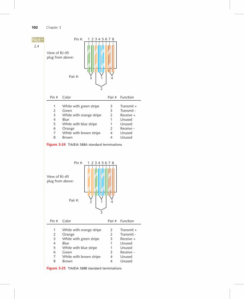
Pin # Color Pair # Function
1 White with green stripe 3 Transmit +2 Green 3 Transmit -3 White with orange stripe 2 Receive +4 Blu 1e Unused5 White with blue stripe 1 Unused6 Orange 2 Receive -7 White with brown stripe 4 Unused8 Brown 4 Unused
Pin #:
View of RJ-45plug from above:
Pair #:
2
3 1 4
1 2 3 5 6 7 84
Figure 3-24 TIA/EIA 568A standard terminations
Pin # Color Pair # Function
1 White with orange stripe 2 Transmit +2 Orange 2 Transmit -3 White with green stripe 3 Receive +4 Blu 1e Unused5 White with blue stripe 1 Unused6 Green 3 Receive -7 White with brown stripe 4 Unused8 Brown 4 Unused
Pin #:
View of RJ-45plug from above:
Pair #:
3
2 1 4
1 2 3 5 6 7 84
Figure 3-25 TIA/EIA 568B standard terminations
2.4
102 Chapter 3
33
The tools you’ll need to terminate a twisted-pair cable with an RJ-45 plug are a wire cutter,wire stripper, and crimping tool, which are pictured in Figures 3-27, 3-28, and 3-29, respec-tively. (In fact, you can find a single device that contains all three of these tools.)
Following are the steps to create a straight-through patch cable. To create a crossover cable,you would simply reorder the wires in Step 4 to match Figure 3-26. The process of fixingwires inside the connector is called crimping, and it is a skill that requires practice—so don’tbe discouraged if the first cable you create doesn’t reliably transmit and receive data. You’llget to practice making cables in the end-of-chapter Hands-on Projects:
1. Using the wire cutter, make a clean cut at both ends of the twisted-pair cable.
2. Using the wire stripper, remove the sheath off of one end of the twisted-pair cable,beginning at approximately one inch from the end. Be careful to neither damage norremove the insulation that’s on the twisted pairs inside.
3. Separate the four wire pairs slightly. Carefully unwind each pair no more than ½ inch.
4. To make a straight-through cable, align all eight wires on a flat surface, one next to theother, ordered according to their colors and positions listed in Figure 3-25. (It might be
Figure 3-27 Wire cutter
Pin assignmentson Plug A
Pin assignmentson Plug B (reversed)
1
2
3
4
5
6
7
8
1
2
3
4
5
6
7
8
Figure 3-26 RJ-45 terminations on a crossover cable
2.4
5.3
2.4
Twisted Pair Cable 103

helpful first to “groom”—or pull steadily across the length of—the unwound section ofeach wire to straighten it out and help it stay in place.)
5. Keeping the wires in order and in line, gently slide them all the way into their positionsin the RJ-45 plug.
6. After the wires are fully inserted, place the RJ-45 plug in the crimping tool and pressfirmly to crimp the wires into place. (Be careful not to rotate your hand or the wire asyou do this, otherwise only some of the wires will be properly terminated.) Crimpingcauses the internal RJ-45 pins to pierce the insulation of the wire, thus creating contactbetween the two conductors.
7. Now remove the RJ-45 connector from the crimping tool. Examine the end and seewhether each wire appears to be in contact with the pin. It may be difficult to tell simplyby looking at the connector. The real test is whether your cable will successfully trans-mit and receive signals.
8. Repeat Steps 2 through 7 for the other end of the cable. After completing Step 7 for theother end, you will have created a straight-through patch cable.
Even after you feel confident making your own cables, it’s a good idea to verify that they cantransmit and receive data at the necessary rates using a cable tester. Cable testing is discussedin Chapter 13, Troubleshooting Network Problems.
In this section you’ve learned about twisted pair wiring, the most common network transmis-sion medium in use today. The next section describes a transmission medium that, due to itsmany advantages, is enjoying ever-growing popularity.
Figure 3-28 Wire stripper
Figure 3-29 Crimping tool
2.4
5.3
104 Chapter 3

33
Fiber-Optic CableFiber-optic cable, or simply fiber, contains one or several glass or plastic fibers at its center, orcore. Data is transmitted via pulsing light sent from a laser (in the case of 1- and 10-Gigabittechnologies) or an LED (light-emitting diode) through the central fibers. Surrounding thefibers is a layer of glass or plastic called cladding. The cladding has a different density fromthe glass or plastic in the strands. It reflects light back to the core in patterns that varydepending on the transmission mode. This reflection allows the fiber to bend around cornerswithout diminishing the integrity of the light-based signal. Outside the cladding, a plasticbuffer protects the cladding and core. Because the buffer is opaque, it also absorbs any lightthat might escape. To prevent the cable from stretching, and to protect the inner core further,strands of Kevlar (a polymeric fiber) surround the plastic buffer. Finally, a plastic sheath cov-ers the strands of Kevlar. Figure 3-30 shows a fiber-optic cable with multiple, insulated fibers.
Like twisted pair and coaxial cabling, fiber-optic cabling comes in a number of different varie-ties, depending on its intended use and the manufacturer. For example, fiber-optic cables usedto connect the facilities of large telephone and data carriers may contain as many as 1000fibers and be heavily sheathed to prevent damage from extreme environmental conditions. Atthe other end of the spectrum, fiber-optic patch cables for use on LANs may contain only twostrands of fiber and be pliable enough to wrap around your hand.
However, all fiber cable variations fall into two categories: single-mode and multimode.
SMF (Single-Mode Fiber)SMF (single-mode fiber) uses a narrow core (less than 10 microns in diameter) throughwhich light generated by a laser travels over one path, reflecting very little. Because it reflectslittle, the light does not disperse as the signal travels along the fiber. This continuity allowssingle-mode fiber to accommodate the highest bandwidths and longest distances (withoutrequiring repeaters) of all network transmission media. Single-mode fiber may be used toconnect a carrier’s two facilities. However, it costs too much to be considered for use on
Figure 3-30 A fiber-optic cable
2.1
2.1
Fiber-Optic Cable 105

typical LANs and WANs. Figure 3-31 depicts a simplified version of how signals travel oversingle-mode fiber.
MMF (Multimode Fiber)MMF (multimode fiber) contains a core with a larger diameter than single-mode fiber(between 50 and 115 microns in diameter; the most common size is 62.5 microns) overwhich many pulses of light generated by a laser or LED travel at different angles. It is com-monly found on cables that connect a router to a switch or a server on the backbone of anetwork. Figure 3-32 depicts a simplified view of how signals travel over multimode fiber.
Because of its reliability, fiber is currently used primarily as a cable that connects the manysegments of a network. Fiber-optic cable provides the following benefits over copper cabling:
• Extremely high throughput
• Very high resistance to noise
• Excellent security
• Ability to carry signals for much longer distances before requiring repeaters than cop-per cable
• Industry standard for high-speed networking
The most significant drawback to the use of fiber is that covering a certain distance withfiber-optic cable is much more expensive than using twisted pair cable. Also, fiber-opticcable requires special equipment to splice, which means that quickly repairing a fiber-optic
Cladding Core
Single-mode fiber
Laser
Figure 3-31 Transmission over single-mode fiber-optic cable
Multimode fiber
CladdingCore
Laser
Figure 3-32 Transmission over multimode fiber-optic cable
2.1
2.1
106 Chapter 3

33
cable in the field (given little time or resources) can be difficult. Fiber’s characteristics aresummarized in the following list:
• Throughput—Fiber has proved reliable in transmitting data at rates that can reach 100gigabits (or 100,000 megabits) per second per channel. (Rates demanded by most net-works are lower, however.) Fiber’s amazing throughput is partly due to the physics oflight traveling through glass. Unlike electrical pulses traveling over copper, the lightexperiences virtually no resistance. Therefore, light-based signals can be transmitted atfaster rates and with fewer errors than electrical pulses. In fact, a pure glass strand canaccept up to 1 billion laser light pulses per second. Its high throughput capabilitymakes it suitable for network backbones and for serving applications that generate agreat deal of traffic, such as video or audio conferencing.
• Cost—Fiber-optic cable is the most expensive transmission medium. Because of itscost, most organizations find it impractical to run fiber to every desktop. Not only isthe cable itself more expensive than copper cabling, but fiber-optic NICs and hubs cancost as much as five times more than NICs and hubs designed for UTP networks. Inaddition, hiring skilled fiber cable installers costs more than hiring twisted pair cableinstallers.
• Connector—With fiber cabling, you can use any of 10 different types of connectors.Figures 3-33, 3-34, 3-35, and 3-36 show four of the most common connector types:the ST (straight tip), SC (subscriber connector or standard connector), LC (localconnector), and MT-RJ (mechanical transfer registered jack). Each of these connec-tors can be obtained for single-mode or multimode fiber-optic cable. Existing fibernetworks typically use ST or SC connectors. However, LC and MT-RJ connectorsare used on the very latest fiber-optic technology. LC and MT-RJ connectors arepreferable to ST and SC connectors because of their smaller size, which allows for ahigher density of connections at each termination point. The MT-RJ connector isunique because it contains two strands of multimode fiber in a single ferrule, whichis a short tube within a connector that encircles the fiber and keeps it properlyaligned. With two strands in each ferrule, a single MT-RJ connector provides for aduplex signaling.
Figure 3-33 ST (straight tip) connector
2.1
2.2
2.1
Fiber-Optic Cable 107

• Noise immunity—Because fiber does not conduct electrical current to transmit signals,it is unaffected by EMI. Its impressive noise resistance is one reason why fiber can spansuch long distances before it requires repeaters to regenerate its signal.
• Size and scalability—Depending on the type of fiber-optic cable used, segment lengthsvary from 150 to 40,000 meters. This limit is due primarily to optical loss, or thedegradation of the light signal after it travels a certain distance away from its source(just as the light of a flashlight dims after a certain number of feet). Optical lossaccrues over long distances and grows with every connection point in the fiber net-work. Dust or oil in a connection (for example, from people handling the fiber whilesplicing it) can further exacerbate optical loss.
Figure 3-34 SC (subscriber connector or standard connector)
Figure 3-35 LC (local connector)
Figure 3-36 MT-RJ (mechanical transfer-register jack) connector
2.1
2.2
2.1
108 Chapter 3

33
DTE (Data Terminal Equipment) and DCE (Data Circuit-Terminating Equipment) Connector Cables
So far you have learned about the kinds of physical media used between connectivity devicesand with nodes on a LAN or WAN. This section describes some common cable types used toconnect DTE (data terminal equipment) and DCE (data circuit-terminating equipment)found on a network. DTE refers to any end-user device, such as a workstation, terminal(essentially a monitor with little or no independent data-processing capability), or a console(for example, the user interface for a router). DCE refers to a device, such as a multiplexer ormodem, that processes signals. Importantly, DCE also supplies a clock signal to synchronizetransmission between DTE and DCE. Most connectivity devices, such as routers and switches,can be configured to act as DTE or DCE, depending on the context in which they’re used.
DTE and DCE are connected through special, typically short, cables, that attach to the equip-ment’s serial interface. Serial refers to a style of data transmission in which the pulses that rep-resent bits follow one another along a single transmission line. In other words, they are issuedsequentially, not simultaneously. A serial cable is one that carries serial transmissions. Severaltypes of serial cables exist.
EIA/TIA has codified a popular serial data transmission method known as RS-232 (Recom-mended Standard 232). This Physical layer standard specifies, among other things, signal volt-age and timing, plus the characteristics of compatible interfaces. Different connector typescomply with this standard, including RJ-45 connectors, DB-9 connectors, and DB-25 connec-tors. You are already familiar with RJ-45 plugs. Figures 3-37 and 3-38 illustrate male DB-9and DB-25 connectors, respectively. Notice that the arrangement of the pins on both connec-tors resembles a sideways letter D. Also notice that a DB-9 connector contains 9 contactpoints and a DB-25 connector contains 25.
You might connect a workstation (DTE) and an external modem (DCE) using RS-232. Thiswas its primary use for many years. However, as an administrator on today’s networks,you’re more likely to use an RS-232 connection between a PC and a router to make your PCact as a console for configuring and managing that router. In fact, a higher-end routerdesigned for use in your data center (not the kind of router you’d use at home) usually
Figure 3-37 DB-9 connector
2.1
2.2
2.1
DTE (Data Terminal Equipment) and DCE (Data Circuit-Terminating Equipment) Connector Cables 109

comes with an RS-232-compatible cable. The serial interface on the back of the connectivitydevice is often labeled “Console.” (This is not to say that a serial cable is the only way of con-necting to a router for configuring and managing it. However, if the router is brand new orfor some other reason lacks an IP address, you need to access it directly, and not via a net-work connection.)
You can find RS-232 cables with different types of connectors at either end. For example,many Cisco routers come with a console port that’s RJ-45 compliant. If you wanted to con-nect such a router to your laptop’s DB-9 serial port, you could find an RS-232 cable with anRJ-45 plug on one end and a DB-9 plug on the other.
The fact that a serial cable terminates in an RJ-45 connector doesnot mean it will work if plugged into a device’s RJ-45 Ethernet port!When using a serial cable with an RJ-45 connector, be certain toplug it into the appropriate serial interface.
In addition to using different connector types, the termination points on RS-232 cables can bearranged in various ways, depending on the cable’s purpose. Earlier you learned about the dif-ference between straight-through and crossover cables in the context of terminating twistedpair cables. An RS-232 cable, whether it uses DB-9, DB-25 or RJ-45 connectors, can also bestraight-through. You also have the option of reversing the transmit and receive pins on oneend, thereby making it into a crossover cable. Among other things, you could use such acrossover cable to directly connect two routers via their serial interfaces.
Yet another type of cable is a rollover cable (or rolled over cable). In a rollover cable, theusual wire positions are exactly reversed in one of the two RJ-45 terminations. (Imagine youwere making a cable according to the steps described earlier in this chapter and flipped oneend upside-down before inserting it into the RJ-45 jack.) Rollover cables are mainly used toconnect a console to a connectivity device, such as a router. Do not confuse them with cross-over cables, which reverse the transmit and receive pairs (pinouts 1, 2, 3 and 6) from one endof a cable to the other.
You’ll learn more about the connectivity devices, such as routers and switches, that use DTEand DCE connector cables in Chapter 6. The following section describes how to arrange phys-ical networking media between end users and connectivity devices on a LAN or WAN.
Figure 3-38 DB-25 connector
2.2
2.4
2.1
2.2
110 Chapter 3
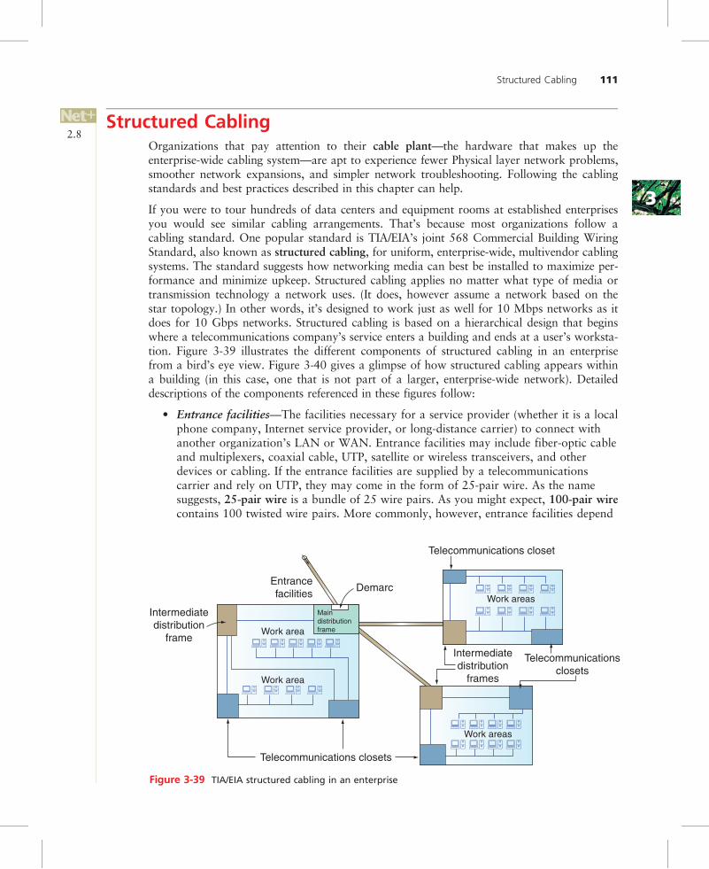
33
Structured CablingOrganizations that pay attention to their cable plant—the hardware that makes up theenterprise-wide cabling system—are apt to experience fewer Physical layer network problems,smoother network expansions, and simpler network troubleshooting. Following the cablingstandards and best practices described in this chapter can help.
If you were to tour hundreds of data centers and equipment rooms at established enterprisesyou would see similar cabling arrangements. That’s because most organizations follow acabling standard. One popular standard is TIA/EIA’s joint 568 Commercial Building WiringStandard, also known as structured cabling, for uniform, enterprise-wide, multivendor cablingsystems. The standard suggests how networking media can best be installed to maximize per-formance and minimize upkeep. Structured cabling applies no matter what type of media ortransmission technology a network uses. (It does, however assume a network based on thestar topology.) In other words, it’s designed to work just as well for 10 Mbps networks as itdoes for 10 Gbps networks. Structured cabling is based on a hierarchical design that beginswhere a telecommunications company’s service enters a building and ends at a user’s worksta-tion. Figure 3-39 illustrates the different components of structured cabling in an enterprisefrom a bird’s eye view. Figure 3-40 gives a glimpse of how structured cabling appears withina building (in this case, one that is not part of a larger, enterprise-wide network). Detaileddescriptions of the components referenced in these figures follow:
• Entrance facilities—The facilities necessary for a service provider (whether it is a localphone company, Internet service provider, or long-distance carrier) to connect withanother organization’s LAN or WAN. Entrance facilities may include fiber-optic cableand multiplexers, coaxial cable, UTP, satellite or wireless transceivers, and otherdevices or cabling. If the entrance facilities are supplied by a telecommunicationscarrier and rely on UTP, they may come in the form of 25-pair wire. As the namesuggests, 25-pair wire is a bundle of 25 wire pairs. As you might expect, 100-pair wirecontains 100 twisted wire pairs. More commonly, however, entrance facilities depend
��
��
��������
��������
�� �� ��
�� �� �� ��
�� �� �� ��
��������
Intermediatedistribution
frameIntermediatedistribution
frames
Telecommunicationsclosets
Telecommunications closets
Telecommunications closet
Entrancefacilities
Work area
Work areas
Work areas
Work area
Demarc
Maindistributionframe
Figure 3-39 TIA/EIA structured cabling in an enterprise
2.8
Structured Cabling 111

on fiber-optic cable. The entrance facility designates where the telecommunicationsservice provider accepts responsibility for the (external) connection. The point of divi-sion between the service provider’s network and the internal network is also known asthe demarcation point (or demarc).
• MDF (main distribution frame)—Also known as the main cross-connect, the firstpoint of interconnection between an organization’s LAN or WAN and a service provi-der’s facility. An MDF typically includes connectivity devices, such as switches androuters, and media, such as fiber-optic cable, capable of the greatest throughput.Often, it also houses an organization’s main servers. In an enterprise-wide network,equipment in an MDF connects to equipment housed in another building’s IDF. Some-times the MDF is simply known as the computer room or equipment room.
• Cross-connect facilities—The points where circuits interconnect with other circuits. Forexample, when an MDF accepts UTP from a service provider, the wire pairs terminateat a punch-down block. A punch-down block is a panel of data receptors into whichtwisted pair wire is inserted, or punched down, to complete a circuit. Punch-downblocks were for many years the standard method of terminating telephone circuits,
Telecommunicationscloset
Entrancefacilities
Main distributionframe
Verticalcross-connect
Horizontalwiring
Workarea
Figure 3-40 TIA/EIA structured cabling in a building
2.8
112 Chapter 3
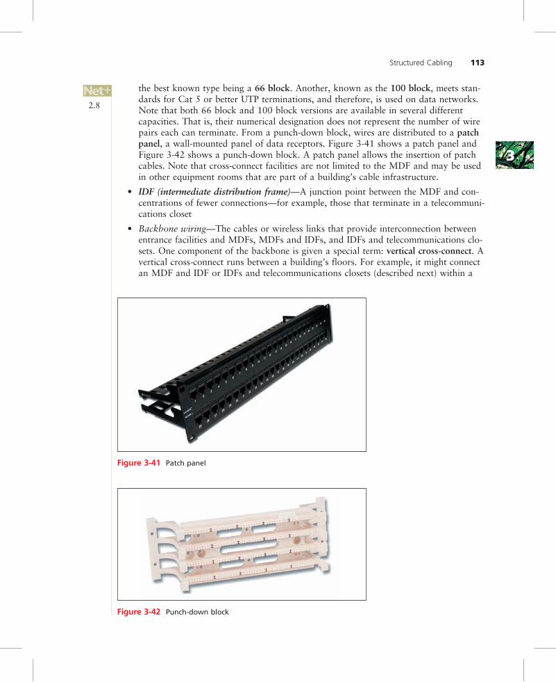
33
the best known type being a 66 block. Another, known as the 100 block, meets stan-dards for Cat 5 or better UTP terminations, and therefore, is used on data networks.Note that both 66 block and 100 block versions are available in several differentcapacities. That is, their numerical designation does not represent the number of wirepairs each can terminate. From a punch-down block, wires are distributed to a patchpanel, a wall-mounted panel of data receptors. Figure 3-41 shows a patch panel andFigure 3-42 shows a punch-down block. A patch panel allows the insertion of patchcables. Note that cross-connect facilities are not limited to the MDF and may be usedin other equipment rooms that are part of a building’s cable infrastructure.
• IDF (intermediate distribution frame)—A junction point between the MDF and con-centrations of fewer connections—for example, those that terminate in a telecommuni-cations closet
• Backbone wiring—The cables or wireless links that provide interconnection betweenentrance facilities and MDFs, MDFs and IDFs, and IDFs and telecommunications clo-sets. One component of the backbone is given a special term: vertical cross-connect. Avertical cross-connect runs between a building’s floors. For example, it might connectan MDF and IDF or IDFs and telecommunications closets (described next) within a
Figure 3-41 Patch panel
Figure 3-42 Punch-down block
2.8
Structured Cabling 113

building. The TIA/EIA standard designates distance limitations for backbones of vary-ing cable types, as specified in Table 3-2. On modern networks, backbones are usuallycomposed of fiber-optic or UTP cable.
• Telecommunications closet—Also known as a “telco room,” it contains connectivityfor groups of workstations in its area, plus cross-connections to IDFs or, in smallerorganizations, an MDF. Large organizations may have several telco rooms per floor,but the TIA/EIA standard specifies at least one per floor. Telecommunications closetstypically house patch panels, punch-down blocks, and connectivity devices for a workarea. Because telecommunications closets are usually small, enclosed spaces, goodcooling and ventilation systems are important to maintaining a constant temperature.
• Horizontal wiring—This is the wiring that connects workstations to the closest tele-communications closet. TIA/EIA recognizes three possible cabling types for horizontalwiring: STP, UTP, or fiber-optic cable. The maximum allowable distance for horizon-tal wiring is 100 m. This span includes 90 m to connect a data jack on the wall to thetelecommunications closet plus a maximum of 10 m to connect a workstation to thedata jack on the wall. Figure 3-43 depicts a horizontal wiring configuration.
• Work area—An area that encompasses all patch cables and horizontal wiring neces-sary to connect workstations, printers, and other network devices from their NICs tothe telecommunications closet. The TIA/EIA standard calls for each wall jack to con-tain at least one voice and one data outlet, as pictured in Figure 3-44. Realistically,
Workstation
Data jack
Workstation
Data jack
Workstation
Data jack
Telecommunicationscloset
Cross-connect
90 m<10 m
<10 m
<10 m
90 m
90 m
Figure 3-43 Horizontal wiring
Table 3-2 TIA/EIA specifications for backbone cabling
Cable type
Cross-connects totelecommunicationscloset
MDF or IDF totelecommunicationscloset
Cross-connects toIDF or MDF
UTP 800 m(voice specification)
500 m 300 m
Single-mode fiber 3000 m 500 m 1500 m
Multimode fiber 2000 m 500 m 1500 m
2.8
114 Chapter 3
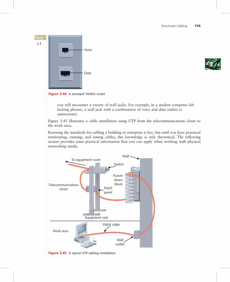
33
you will encounter a variety of wall jacks. For example, in a student computer lablacking phones, a wall jack with a combination of voice and data outlets isunnecessary.
Figure 3-45 illustrates a cable installation using UTP from the telecommunications closet tothe work area.
Knowing the standards for cabling a building or enterprise is key, but until you have practicedterminating, running, and testing cables, this knowledge is only theoretical. The followingsection provides some practical information that you can apply when working with physicalnetworking media.
Voice
Data
Figure 3-44 A standard TIA/EIA outlet
SwitchTo equipment room
Patchpanel
Punch-downblock
Equipment rack
Walloutlet
Patch cable
Work area
Telecommunicationscloset
Wall
Figure 3-45 A typical UTP cabling installation
2.8
Structured Cabling 115
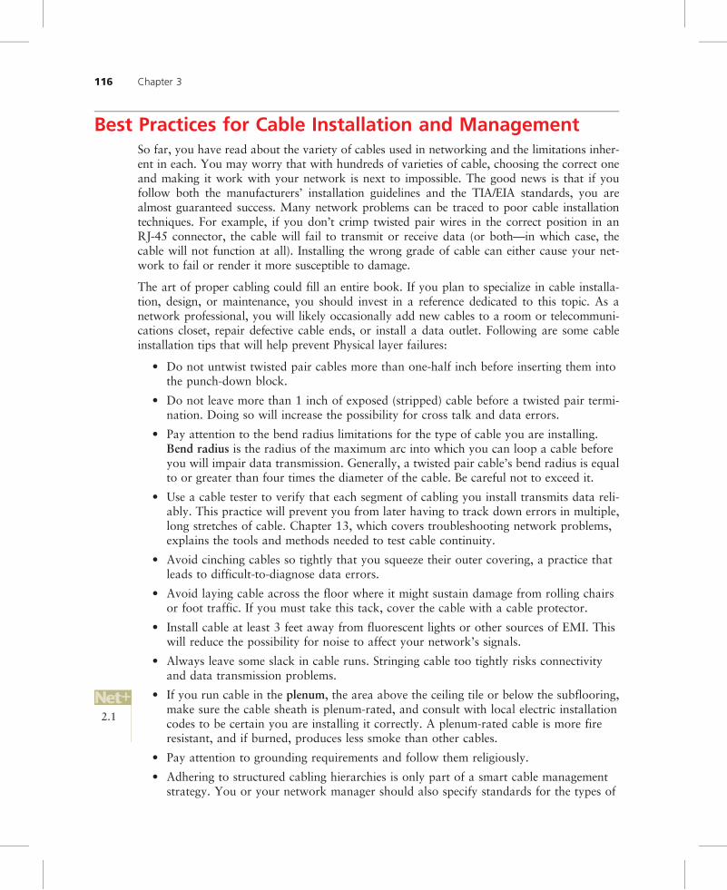
Best Practices for Cable Installation and ManagementSo far, you have read about the variety of cables used in networking and the limitations inher-ent in each. You may worry that with hundreds of varieties of cable, choosing the correct oneand making it work with your network is next to impossible. The good news is that if youfollow both the manufacturers’ installation guidelines and the TIA/EIA standards, you arealmost guaranteed success. Many network problems can be traced to poor cable installationtechniques. For example, if you don’t crimp twisted pair wires in the correct position in anRJ-45 connector, the cable will fail to transmit or receive data (or both—in which case, thecable will not function at all). Installing the wrong grade of cable can either cause your net-work to fail or render it more susceptible to damage.
The art of proper cabling could fill an entire book. If you plan to specialize in cable installa-tion, design, or maintenance, you should invest in a reference dedicated to this topic. As anetwork professional, you will likely occasionally add new cables to a room or telecommuni-cations closet, repair defective cable ends, or install a data outlet. Following are some cableinstallation tips that will help prevent Physical layer failures:
• Do not untwist twisted pair cables more than one-half inch before inserting them intothe punch-down block.
• Do not leave more than 1 inch of exposed (stripped) cable before a twisted pair termi-nation. Doing so will increase the possibility for cross talk and data errors.
• Pay attention to the bend radius limitations for the type of cable you are installing.Bend radius is the radius of the maximum arc into which you can loop a cable beforeyou will impair data transmission. Generally, a twisted pair cable’s bend radius is equalto or greater than four times the diameter of the cable. Be careful not to exceed it.
• Use a cable tester to verify that each segment of cabling you install transmits data reli-ably. This practice will prevent you from later having to track down errors in multiple,long stretches of cable. Chapter 13, which covers troubleshooting network problems,explains the tools and methods needed to test cable continuity.
• Avoid cinching cables so tightly that you squeeze their outer covering, a practice thatleads to difficult-to-diagnose data errors.
• Avoid laying cable across the floor where it might sustain damage from rolling chairsor foot traffic. If you must take this tack, cover the cable with a cable protector.
• Install cable at least 3 feet away from fluorescent lights or other sources of EMI. Thiswill reduce the possibility for noise to affect your network’s signals.
• Always leave some slack in cable runs. Stringing cable too tightly risks connectivityand data transmission problems.
• If you run cable in the plenum, the area above the ceiling tile or below the subflooring,make sure the cable sheath is plenum-rated, and consult with local electric installationcodes to be certain you are installing it correctly. A plenum-rated cable is more fireresistant, and if burned, produces less smoke than other cables.
• Pay attention to grounding requirements and follow them religiously.
• Adhering to structured cabling hierarchies is only part of a smart cable managementstrategy. You or your network manager should also specify standards for the types of
2.1
116 Chapter 3

33
cable used by your organization and maintain a list of approved cabling vendors. Keepa supply room stocked with spare parts so that you can easily and quickly replacedefective parts.
• Create documentation for your cabling plant, including the locations, installationdates, lengths, and grades of installed cable. Label every data jack, punch-down block,and connector. Use color-coded cables for different purposes (cables can be purchasedin a variety of sheath colors). For example, you might want to use pink for patchcables, green for horizontal wiring, and gray for vertical (backbone) wiring. Be certainto document your color schemes.
• Keep your cable plant documentation in a centrally accessible location and be certainto update it as you change the network. The more you document, the easier it will beto move or add cable segments.
• Finally, create a plan for expanding your cabling plant. For example, if your organiza-tion is rapidly enlarging, consider replacing your backbone with fiber and leave plentyof space in your telecommunications closets for more racks.
Chapter Summary■ Information can be transmitted via two methods: analog or digital. Analog signals are
continuous waves that result in variable and inexact transmission. Digital signals arebased on electrical or light pulses that represent information encoded in binary form.
■ In half-duplex transmission, signals can travel in both directions over a medium but inonly one direction at a time. When signals can travel in both directions over a mediumsimultaneously, the transmission is considered full-duplex.
■ A form of transmission that allows multiple signals to travel simultaneously over onemedium is known as multiplexing. In multiplexing, the single medium is logically sep-arated into multiple channels, or subchannels.
■ Throughput is the amount of data that the medium can transmit during a given periodof time. Throughput is usually measured in bits per second and depends on the physi-cal nature of the medium.
■ Baseband is a form of transmission in which digital signals are sent through directcurrent pulses applied to the wire. Baseband systems can transmit only one signal, orone channel, at a time. Broadband, on the other hand, uses modulated analog fre-quencies to transmit multiple signals over the same wire.
■ Noise is interference that distorts an analog or digital signal. It may be caused by elec-trical sources, such as power lines, fluorescent lights, copiers, and microwave ovens, orby broadcast signals.
■ Analog and digital signals both suffer attenuation, or loss of signal, as they travel far-ther from their sources. To compensate, analog signals are amplified, and digital sig-nals are regenerated through repeaters.
■ Every network is susceptible to a delay between the transmission of a signal and itsreceipt. This delay is called latency. The length of the cable contributes to latency, asdoes the presence of any intervening connectivity device.
Chapter Summary 117
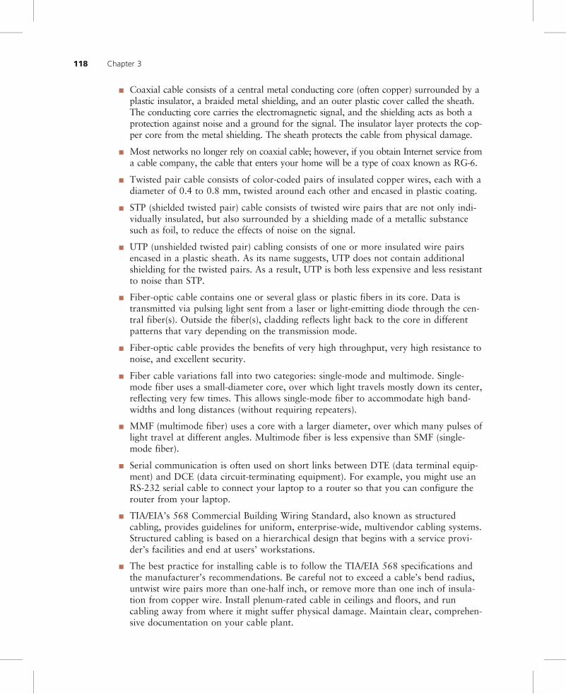
■ Coaxial cable consists of a central metal conducting core (often copper) surrounded by aplastic insulator, a braided metal shielding, and an outer plastic cover called the sheath.The conducting core carries the electromagnetic signal, and the shielding acts as both aprotection against noise and a ground for the signal. The insulator layer protects the cop-per core from the metal shielding. The sheath protects the cable from physical damage.
■ Most networks no longer rely on coaxial cable; however, if you obtain Internet service froma cable company, the cable that enters your home will be a type of coax known as RG-6.
■ Twisted pair cable consists of color-coded pairs of insulated copper wires, each with adiameter of 0.4 to 0.8 mm, twisted around each other and encased in plastic coating.
■ STP (shielded twisted pair) cable consists of twisted wire pairs that are not only indi-vidually insulated, but also surrounded by a shielding made of a metallic substancesuch as foil, to reduce the effects of noise on the signal.
■ UTP (unshielded twisted pair) cabling consists of one or more insulated wire pairsencased in a plastic sheath. As its name suggests, UTP does not contain additionalshielding for the twisted pairs. As a result, UTP is both less expensive and less resistantto noise than STP.
■ Fiber-optic cable contains one or several glass or plastic fibers in its core. Data istransmitted via pulsing light sent from a laser or light-emitting diode through the cen-tral fiber(s). Outside the fiber(s), cladding reflects light back to the core in differentpatterns that vary depending on the transmission mode.
■ Fiber-optic cable provides the benefits of very high throughput, very high resistance tonoise, and excellent security.
■ Fiber cable variations fall into two categories: single-mode and multimode. Single-mode fiber uses a small-diameter core, over which light travels mostly down its center,reflecting very few times. This allows single-mode fiber to accommodate high band-widths and long distances (without requiring repeaters).
■ MMF (multimode fiber) uses a core with a larger diameter, over which many pulses oflight travel at different angles. Multimode fiber is less expensive than SMF (single-mode fiber).
■ Serial communication is often used on short links between DTE (data terminal equip-ment) and DCE (data circuit-terminating equipment). For example, you might use anRS-232 serial cable to connect your laptop to a router so that you can configure therouter from your laptop.
■ TIA/EIA’s 568 Commercial Building Wiring Standard, also known as structuredcabling, provides guidelines for uniform, enterprise-wide, multivendor cabling systems.Structured cabling is based on a hierarchical design that begins with a service provi-der’s facilities and end at users’ workstations.
■ The best practice for installing cable is to follow the TIA/EIA 568 specifications andthe manufacturer’s recommendations. Be careful not to exceed a cable’s bend radius,untwist wire pairs more than one-half inch, or remove more than one inch of insula-tion from copper wire. Install plenum-rated cable in ceilings and floors, and runcabling away from where it might suffer physical damage. Maintain clear, comprehen-sive documentation on your cable plant.
118 Chapter 3

33
Key Terms1 gigabit per second (Gbps) 1,000,000,000 bits per second.
1 kilobit per second (Kbps) 1000 bits per second.
1 megabit per second (Mbps) 1,000,000 bits per second.
1 terabit per second (Tbps) 1,000,000,000,000 bits per second.
100 block Part of an organization’s cross-connect facilities, a type of punch-down blockdesigned to terminate Cat 5 or better twisted pair wires.
100 pair wire UTP supplied by a telecommunications carrier that contains 100 wire pairs.
10Base-2 See Thinnet.
10Base-5 See Thicknet.
25 pair wire UTP supplied by a telecommunications carrier that contains 25 wire pairs.
66 block Part of an organization’s cross-connect facilities, a type of punch-down blockused for many years to terminate telephone circuits. It does not meet Cat 5 or betterstandards, and so it is infrequently used on data networks.
alien cross talk EMI interference induced on one cable by signals traveling over a nearbycable.
AM (amplitude modulation) A modulation technique in which the amplitude of the carriersignal is modified by the application of a data signal.
American Wire Gauge See AWG.
amplifier A device that boosts, or strengthens, an analog signal.
amplitude A measure of a signal’s strength.
amplitude modulation See AM.
analog A signal that uses variable voltage to create continuous waves, resulting in aninexact transmission.
attenuation The extent to which a signal has weakened after traveling a given distance.
AWG (American Wire Gauge) A standard rating that indicates the diameter of a wire, suchas the conducting core of a coaxial cable.
bandwidth A measure of the difference between the highest and lowest frequencies that amedium can transmit.
baseband A form of transmission in which digital signals are sent through direct currentpulses applied to a wire. This direct current requires exclusive use of the wire’s capacity, sobaseband systems can transmit only one signal, or one channel, at a time. Every device on abaseband system shares a single channel.
bend radius The radius of the maximum arc into which you can loop a cable before youwill cause data transmission errors. Generally, a twisted pair cable’s bend radius is equal toor greater than four times the diameter of the cable.
binary A system founded on using 1s and 0s to encode information.
bit (binary digit) A bit equals a single pulse in the digital encoding system. It may haveonly one of two values: 0 or 1.
Key Terms 119

BNC (Bayonet Neill-Concelman, or British Naval Connector) A standard for coaxial cableconnectors named after its coupling method and its inventors.
BNC connector A coaxial cable connector type that uses a twist-and-lock (or bayonet) styleof coupling. It may be used with several coaxial cable types, including RG-6 and RG-59.
braiding A braided metal shielding used to insulate some types of coaxial cable.
broadband A form of transmission in which signals are modulated as radiofrequencyanalog pulses with different frequency ranges. Unlike baseband, broadband technology doesnot involve binary encoding. The use of multiple frequencies enables a broadband system tooperate over several channels and, therefore, carry much more data than a baseband system.
broadcast A transmission that involves one transmitter and multiple, undefined receivers.
byte Eight bits of information. In a digital signaling system, broadly speaking, one bytecarries one piece of information.
cable plant The hardware that constitutes the enterprise-wide cabling system.
capacity See throughput.
Cat Abbreviation for the word category when describing a type of twisted pair cable. Forexample, Category 3 unshielded twisted pair cable may also be called Cat 3.
Cat 3 (Category 3) A form of UTP that contains four wire pairs and can carry up to 10Mbps, with a possible bandwidth of 16 MHz. Cat 3 has typically been used for 10-MbpsEthernet or 4-Mbps token ring networks. Network administrators are gradually replacing Cat3 cabling with Cat 5 to accommodate higher throughput. Cat 3 is less expensive than Cat 5.
Cat 4 (Category 4) A form of UTP that contains four wire pairs and can support up to 16-Mbps throughput. Cat 4 may be used for 16-Mbps token ring or 10-Mbps Ethernetnetworks. It is guaranteed for data transmission up to 20 MHz and provides moreprotection against cross talk and attenuation than Cat 1, Cat 2, or Cat 3.
Cat 5 (Category 5) A form of UTP that contains four wire pairs and supports up to 100-Mbps throughput and a 100-MHz signal rate.
Cat 5e (Enhanced Category 5) A higher-grade version of Cat 5 wiring that contains high-quality copper, offers a high twist ratio, and uses advanced methods for reducing cross talk.Enhanced Cat 5 can support a signaling rate of up to 350 MHz, more than triple thecapability of regular Cat 5.
Cat 6 (Category 6) A twisted pair cable that contains four wire pairs, each wrapped in foilinsulation. Additional foil insulation covers the bundle of wire pairs, and a fire-resistantplastic sheath covers the second foil layer. The foil insulation provides excellent resistance tocross talk and enables Cat 6 to support a signaling rate of 250 MHz and at least six timesthe throughput supported by regular Cat 5.
Cat 6e (Enhanced Category 6) A higher-grade version of Cat 6 wiring that further reducesattenuation and cross talk and allows for potentially exceeding traditional network segmentlength limits. Cat 6e is capable of a 550-MHz signaling rate and can reliably transmit dataat multi-gigabit per second rates.
Cat 7 (Category 7) A twisted pair cable that contains multiple wire pairs, each separatelyshielded then surrounded by another layer of shielding within the jacket. Cat 7 can supportup to a 1-GHz signal rate. But because of its extra layers, it is less flexible than other formsof twisted pair wiring.
120 Chapter 3

33
Category 3 See Cat 3.
Category 4 See Cat 4.
Category 5 See Cat 5.
Category 6 See Cat 6.
Category 7 See Cat 7.
channel A distinct communication path between two or more nodes, much like a lane is adistinct transportation path on a freeway. Channels may be separated either logically (as inmultiplexing) or physically (as when they are carried by separate wires).
cladding The glass or plastic shield around the core of a fiber-optic cable. Claddingreflects light back to the core in patterns that vary depending on the transmission mode.This reflection allows fiber to bend around corners without impairing the light-basedsignal.
coaxial cable A type of cable that consists of a central metal conducting core, which mightbe solid or stranded and is often made of copper, surrounded by an insulator, a braidedmetal shielding, called braiding, and an outer cover, called the sheath or jacket. Coaxialcable, called “coax” for short, was the foundation for Ethernet networks in the 1980s.Today it’s used to connect cable Internet and cable TV systems.
conduit The pipeline used to contain and protect cabling. Conduit is usually made from metal.
connectors The pieces of hardware that connect the wire to the network device, be it a fileserver, workstation, switch, or printer.
core The central component of a cable designed to carry a signal. The core of a fiber-opticcable, for example, consists of one or several glass or plastic fibers. The core of a coaxialcopper cable consists of one large or several small strands of copper.
crossover cable A twisted pair patch cable in which the termination locations of thetransmit and receive wires on one end of the cable are reversed.
cross talk A type of interference caused by signals traveling on nearby wire pairs infringingon another pair’s signal.
data circuit-terminating equipment See DCE.
data terminal equipment See DTE.
DB-9 connector A type of connector with nine pins that’s commonly used in serialcommunication that conforms to the RS-232 standard.
DB-25 connector A type of connector with 25 pins that’s commonly used in serialcommunication that conforms to the RS-232 standard.
DCE (data circuit-terminating equipment) A device, such as a multiplexer or modem, thatprocesses signals. DCE supplies a clock signal to synchronize transmission between DTEand DCE.
demarcation point (demarc) The point of division between a telecommunications servicecarrier’s network and a building’s internal network.
demultiplexer (demux) A device that separates multiplexed signals once they are receivedand regenerates them in their original form.
dense wavelength division multiplexing See DWDM.
Key Terms 121
digital As opposed to analog signals, digital signals are composed of pulses that can have avalue of only 1 or 0.
DTE (data terminal equipment) Any end-user device, such as a workstation, terminal(essentially a monitor with little or no independent data-processing capability), or a console(for example, the user interface for a router).
duplex See full-duplex.
DWDM (dense wavelength division multiplexing) A multiplexing technique used oversingle-mode or multimode fiber-optic cable in which each signal is assigned a differentwavelength for its carrier wave. In DWDM, little space exists between carrier waves in orderto achieve extraordinary high capacity.
electromagnetic interference See EMI.
EMI (electromagnetic interference) A type of interference that may be caused by motors,power lines, televisions, copiers, fluorescent lights, or other sources of electrical activity.
enhanced Category 5 See Cat 5e.
enhanced Category 6 See Cat 6e.
entrance facilities The facilities necessary for a service provider (whether it is a localphone company, Internet service provider, or long-distance carrier) to connect with anotherorganization’s LAN or WAN.
F-type connector A connector used to terminate coaxial cable used for transmittingtelevision and broadband cable signals.
FDM (frequency division multiplexing) A type of multiplexing that assigns a uniquefrequency band to each communications subchannel. Signals are modulated with differentcarrier frequencies, then multiplexed to simultaneously travel over a single channel.
ferrule A short tube within a fiber-optic cable connector that encircles the fiber strand andkeeps it properly aligned.
fiber-optic cable A form of cable that contains one or several glass or plastic fibers in itscore. Data is transmitted via pulsing light sent from a laser or light-emitting diode (LED)through the central fiber (or fibers). Fiber-optic cables offer significantly higher throughputthan copper-based cables. They may be single-mode or multimode and typically use wave-division multiplexing to carry multiple signals.
FM (frequency modulation) A method of data modulation in which the frequency of thecarrier signal is modified by the application of the data signal.
frequency The number of times that a signal’s amplitude changes over a fixed period oftime, expressed in cycles per second, or hertz (Hz).
frequency division multiplexing See FDM.
frequency modulation See FM.
full-duplex A type of transmission in which signals may travel in both directions over amedium simultaneously. May also be called, simply, “duplex.”
half-duplex A type of transmission in which signals may travel in both directions over amedium, but in only one direction at a time.
hertz (Hz) A measure of frequency equivalent to the number of amplitude cycles per second.
122 Chapter 3

33
IDF (intermediate distribution frame) A junction point between the MDF andconcentrations of fewer connections—for example, those that terminate in atelecommunications closet.
impedance The resistance that contributes to controlling an electrical signal. Impedance ismeasured in ohms.
intermediate distribution frame See IDF.
latency The delay between the transmission of a signal and its receipt.
LC (local connector) A connector used with single-mode or multimode fiber-optic cable.
link segment See unpopulated segment.
Local connector See LC.
main cross-connect See MDF.
main distribution frame See MDF.
MDF (main distribution frame) Also known as the main cross-connect, the first point ofinterconnection between an organization’s LAN or WAN and a service provider’s facility.
mechanical transfer-registered jack See MT-RJ.
media converter A device that enables networks or segments using different media tointerconnect and exchange signals.
MMF (multimode fiber) A type of fiber-optic cable that contains a core with a diameterbetween 50 and 100 microns, through which many pulses of light generated by a light-emitting diode (LED) travel at different angles.
modem A device that modulates analog signals into digital signals at the transmitting endfor transmission over telephone lines, and demodulates digital signals into analog signals atthe receiving end.
modulation A technique for formatting signals in which one property of a simple carrierwave is modified by the addition of a data signal during transmission.
MT-RJ (mechanical transfer-registered jack) A connector used with single-mode ormultimode fiber-optic cable.
multimode fiber See MMF.
multiplexer (mux) A device that separates a medium into multiple channels and issuessignals to each of those subchannels.
multiplexing A form of transmission that allows multiple signals to travel simultaneouslyover one medium.
near end cross talk See NEXT.
NEXT (near end cross talk) Cross talk, or the impingement of the signal carried by one wireonto a nearby wire, that occurs between wire pairs near the source of a signal.
noise The unwanted signals, or interference, from sources near network cabling, such aselectrical motors, power lines, and radar.
nonbroadcast point-to-multipoint transmission A communications arrangement in whicha single transmitter issues signals to multiple, defined recipients.
Key Terms 123
optical loss The degradation of a light signal on a fiber-optic network.
overhead The nondata information that must accompany data in order for a signal to beproperly routed and interpreted by the network.
patch cable A relatively short section (usually between 3 and 25 feet) of cabling withconnectors on both ends.
patch panel A wall-mounted panel of data receptors into which cross-connect patch cablesfrom the punch-down block are inserted.
phase A point or stage in a wave’s progress over time.
plenum The area above the ceiling tile or below the subfloor in a building.
point-to-point A data transmission that involves one transmitter and one receiver.
point-to-multipoint A communications arrangement in which one transmitter issues signalsto multiple receivers. The receivers may be undefined, as in a broadcast transmission, ordefined, as in a nonbroadcast transmission.
populated segment A network segment that contains end nodes, such as workstations.
punch-down block A panel of data receptors into which twisted pair wire is inserted, orpunched down, to complete a circuit.
radiofrequency interference See RFI.
Recommended Standard 232 See RS-232.
regeneration The process of retransmitting a digital signal. Regeneration, unlikeamplification, repeats the pure signal, with none of the noise it has accumulated.
registered jack 11 See RJ-11.
registered jack 45 See RJ-45.
repeater A device used to regenerate a signal.
RFI (radiofrequency interference) A kind of interference that may be generated bybroadcast signals from radio or TV towers.
RG-6 A type of coaxial cable with an impedance of 75 ohms and that contains an 18 AWGcore conductor. RG-6 is used for television, satellite, and broadband cable connections.
RG-8 A type of coaxial cable characterized by a 50-ohm impedance and a 10 AWG core.RG-8 provided the medium for the first Ethernet networks, which followed the now-obsolete 10Base-5 standard.
RG-58 A type of coaxial cable characterized by a 50-ohm impedance and a 24 AWG core.RG-58 was a popular medium for Ethernet LANs in the 1980s, used for the now-obsolete10Base-2 standard.
RG-59 A type of coaxial cable characterized by a 75-ohm impedance and a 20 or 22 AWGcore, usually made of braided copper. Less expensive but suffering greater attenuation thanthe more common RG-6 coax, RG-59 is used for relatively short connections.
RJ-11 (registered jack 11) The standard connector used with unshielded twisted paircabling (usually Cat 3 or Level 1) to connect analog telephones.
RJ-45 (registered jack 45) The standard connector used with shielded twisted pair andunshielded twisted pair cabling.
124 Chapter 3

33
rollover cable A type of cable in which the terminations on one end are exactly the reverseof the terminations on the other end. It is used for serial connections between routers andconsoles or other interfaces.
round trip time See RTT.
RS-232 (Recommended Standard 232) A Physical layer standard for serial communications,as defined by EIA/TIA.
RTT (round trip time) The length of time it takes for a packet to go from sender to receiver,then back from receiver to sender. RTT is usually measured in milliseconds.
SC (subscriber connector or standard connector) A connector used with single-mode ormultimode fiber-optic cable.
serial A style of data transmission in which the pulses that represent bits follow one anotheralong a single transmission line. In other words, they are issued sequentially, not simultaneously.
serial cable A cable, such as an RS-232 type, that permits serial data transmission.
sheath The outer cover, or jacket, of a cable.
shield See braiding.
shielded twisted pair See STP.
simplex A type of transmission in which signals may travel in only one direction over amedium.
single-mode fiber See SMF.
SMF (single-mode fiber) A type of fiber-optic cable with a narrow core that carries lightpulses along a single path data from one end of the cable to the other end. Data can betransmitted faster and for longer distances on single-mode fiber than on multimode fiber.However, single-mode fiber is more expensive.
ST (straight tip) A connector used with single-mode or multimode fiber-optic cable.
standard connector See SC.
statistical multiplexing A method of multiplexing in which each node on a network isassigned a separate time slot for transmission, based on the node’s priority and need.
STP (shielded twisted pair) A type of cable containing twisted-wire pairs that are not onlyindividually insulated, but also surrounded by a shielding made of a metallic substance suchas foil.
straight-through cable A twisted pair patch cable in which the wire terminations in bothconnectors follow the same scheme.
straight tip See ST.
structured cabling A method for uniform, enterprise-wide, multivendor cabling systemsspecified by the TIA/EIA 568 Commercial Building Wiring Standard. Structured cabling isbased on a hierarchical design using a high-speed backbone.
subchannel One of many distinct communication paths established when a channel ismultiplexed or modulated.
subscriber connector See SC.
Key Terms 125
TDM (time division multiplexing) A method of multiplexing that assigns a time slot in theflow of communications to every node on the network and, in that time slot, carries datafrom that node.
telecommunications closet Also known as a “telco room,” the space that containsconnectivity for groups of workstations in a defined area, plus cross-connections to IDFs or,in smaller organizations, an MDF. Large organizations may have severaltelecommunications closets per floor, but the TIA/EIA standard specifies at least one perfloor.
Thicknet An IEEE Physical layer standard for achieving a maximum of 10-Mbpsthroughput over coaxial copper cable. Thicknet is also known as 10Base-5. Its maximumsegment length is 500 meters, and it relies on a bus topology.
thickwire Ethernet See Thicknet.
thin Ethernet See Thinnet.
Thinnet An IEEE Physical layer standard for achieving 10-Mbps throughput over coaxialcopper cable. Thinnet is also known as 10Base-2. Its maximum segment length is 185meters, and it relies on a bus topology.
throughput The amount of data that a medium can transmit during a given period of time.Throughput is usually measured in megabits (1,000,000 bits) per second, or Mbps. Thephysical nature of every transmission media determines its potential throughput.
time division multiplexing See TDM.
transceiver A device that transmits and receives signals.
transmission In networking, the application of data signals to a medium or the progress ofdata signals over a medium from one point to another.
transmit To issue signals to the network medium.
twist ratio The number of twists per meter or foot in a twisted pair cable.
twisted pair A type of cable similar to telephone wiring that consists of color-coded pairsof insulated copper wires, each with a diameter of 0.4 to 0.8 mm, twisted around each otherand encased in plastic coating.
unpopulated segment A network segment that does not contain end nodes, such asworkstations. Unpopulated segments are also called link segments.
unshielded twisted pair See UTP.
UTP (unshielded twisted pair) A type of cabling that consists of one or more insulated wirepairs encased in a plastic sheath. As its name implies, UTP does not contain additionalshielding for the twisted pairs. As a result, UTP is both less expensive and less resistant tonoise than STP.
vertical cross-connect Part of a network’s backbone that supplies connectivity between abuilding’s floors. For example, vertical cross-connects might connect an MDF and an IDF orIDFs and telecommunications closets within a building.
volt The measurement used to describe the degree of pressure an electrical current exertson a conductor.
voltage The pressure (sometimes informally referred to as the strength) of an electricalcurrent.
126 Chapter 3

33
wavelength The distance between corresponding points on a wave’s cycle. Wavelength isinversely proportional to frequency.
wavelength division multiplexing See WDM.
WDM (wavelength division multiplexing) A multiplexing technique in which each signalon a fiber-optic cable is assigned a different wavelength, which equates to its ownsubchannel. Each wavelength is modulated with a data signal. In this manner, multiplesignals can be simultaneously transmitted in the same direction over a length of fiber.
Review Questions1. What is different about the method used to boost a digital signal’s strength, compared
with the method of boosting an analog signal’s strength?
a. A digital signal requires an amplifier, which introduces noise into the signal, andan analog signal requires a repeater, which retransmits the signal in its originalform.
b. A digital signal requires a repeater, which increases the strength of both the signaland the noise it has accumulated, and an analog signal requires an amplifier, whichretransmits the signal in its original form.
c. A digital signal requires an amplifier, which increases the strength of both the noiseand the signal, and an analog signal requires a repeater, which retransmits the sig-nal in its original form.
d. A digital signal requires a repeater, which retransmits the signal in its original form,and an analog signal requires an amplifier, which increases the strength of both thesignal and the noise it has accumulated.
2. Which of the following decimal numbers corresponds to the binary number 00000111?
a. 3
b. 5
c. 7
d. 9
3. A wave with which of the following frequencies would have the shortest wavelength?
a. 10 MHz
b. 100 MHz
c. 1 GHz
d. 100 GHz
4. What is the origin of the word modem?
a. Modifier/demodifier
b. Modulator/demodulator
c. Modulator/decoder
d. Multiplexer/demultiplexer
Review Questions 127

5. With everything else being equal, which of the following transmission techniques iscapable of the greatest throughput?
a. Simplex
b. Half-duplex
c. Full-duplex
d. All techniques transmit data at equally high throughputs.
6. In addition to some types of data networks, which of the following use half-duplexcommunication?
a. Telephones
b. Walkie-talkies
c. Television broadcast towers
d. Satellite Internet connections
7. In wavelength division multiplexing, two modulated signals are guaranteed to differ inwhat characteristic?
a. Throughput
b. Phase
c. Amplitude
d. Color
8. Which of the following can increase latency on a network?
a. An EMI source, such as fluorescent lighting
b. The use of full-duplex transmission
c. Adding 50 meters to the length of the network
d. The use of multiple protocols
9. You are helping to install a cable broadband system in your friend’s home. She wants tobring the signal from where the service provider’s cable enters the house to a room onanother floor, which means you have to attach a new cable to the existing one. Whattype of cable should this be?
a. RG-6
b. RG-8
c. RG-58
d. RG-59
10. What part of a cable protects it against environmental damage?
a. Sheath
b. Braiding
c. Plenum
d. Cladding
128 Chapter 3
33
11. With everything else being equal, a network using which of the following UTP types willsuffer the most cross talk?
a. Cat 3
b. Cat 5
c. Cat 5e
d. Cat 7
12. What are two advantages of using twisted pair cabling over coaxial cabling on anetwork?
a. Twisted pair cable is more reliable.
b. Twisted pair cable is less expensive.
c. Twisted pair cable is more resistant to noise.
d. Twisted pair cable is more resistant to physical damage.
e. Twisted pair cable is required for modern transmission standards.
13. Which of the following problems could be solved by using a crossover cable?
a. You’re missing a patch cable, but need to connect a workstation to a switch.
b. You’re missing a connectivity device, but need to exchange data between twolaptops.
c. You’re missing a serial cable, but need to configure a new router using your laptop.
d. You’re missing a repeater, but need to extend a network segment.
14. Which of the following network transmission media offers the highest potentialthroughput over the longest distances?
a. UTP
b. STP
c. MMF
d. SMF
15. In which of the following network links might you use SC connectors?
a. A coaxial connection between a cable modem and a server
b. A UTP connection between a workstation and a hub
c. A wireless connection between a handheld computer and a desktop computer
d. A fiber-optic connection between a server and router.
16. What type of fiber-optic cable is used most frequently on LANs?
a. Multithreaded fiber
b. Twisted fiber
c. Single-mode fiber
d. Multimode fiber
Review Questions 129

17. What is the purpose of cladding in a fiber-optic cable?
a. It protects the inner core from damage.
b. It reflects the signal back to the core.
c. It shields the signal from EMI.
d. It concentrates the signal and helps keep it from fading.
18. Which of the following is a potential drawback to using fiber-optic cable for LANs?
a. It is expensive.
b. It cannot handle high-bandwidth transmissions.
c. It can carry transmissions using only TCP/IP.
d. It is not yet an accepted standard for high-speed networking.
19. In what part of a structured cabling system would you find users’ desktop computers?
a. Telco room
b. MDF
c. IDF
d. Work area
20. You’ve just received a new Cisco router for your data center, and it came with a roll-over cable. What can you do with this cable?
a. Make a connection from the router’s console port to your laptop’s serial port andconfigure the router from your laptop.
b. Make a connection from the router’s Ethernet port to a port on the patch panel inthe telecommunications closet to establish connectivity for workstations in a workarea.
c. Make a connection from the router’s Ethernet port to the Ethernet port on yourlaptop to configure the router.
d. Make a connection from the router’s console port to another router’s console portto daisy-chain the routers.
21. What is the maximum distance specified in the structured cabling standard for a hori-zontal wiring subsystem?
a. 10 m
b. 90 m
c. 100 m
d. 200 m
22. Which of the following can occur as a result of improper cable termination?
a. Cross talk
b. Noise
c. Data errors
d. All of the above
130 Chapter 3

33
23. If your MDF contains a 66 block, the type of cable terminating at that punch-downblock is probably what?
a. UTP designed for telephone signaling
b. UTP designed for 100 Mbps Ethernet
c. UTP designed for 1 Gbps Ethernet
d. Fiber-optic cable
24. Your campuswide WAN is experiencing slow Internet response times. When you callyour Internet service provider to ask if they can troubleshoot the problem from theirend, they warn you that their responsibilities end at the demarc. What do theymean?
a. They will not diagnose problems beyond your organization’s MDF.
b. They will not diagnose problems beyond your organization’s entrance facilities.
c. They will not diagnose problems beyond your organization’s IDF.
d. They will not diagnose problems beyond your organization’s telco rooms.
25. What is the maximum amount you should untwist twisted pair wires before insertingthem into connectors?
a. ¼ inch
b. ½ inch
c. 1 inch
d. 2 inches
Hands-On Projects
Project 3-1Previously in this chapter you learned about how to terminate UTP in RJ-45plugs. In this project, you will practice putting an RJ-45 connector on a twistedpair cable, and then use the cable to connect a workstation to the network.
For this project, you will need a wire cutter, a wire stripper, and a crimping tool, which are picturedin Figures 3-26, 3-27, and 3-28, respectively. You’ll also need a 5-foot length of Cat 5 (or better)UTP, at least two RJ-45 connectors, and a simple client/server network (for example, a WindowsXP client connecting to a wall jack or hub as part of a Windows Server 2003 network, or a Linuxworkstation similarly connecting to a UNIX server) that you have verified works with a reliabletwisted pair cable.
1. Follow the steps for adding an RJ-45 connector to UTP as described in this chapter’s“Terminating Twisted Pair Cable” section to make a straight-through cable. Follow thepinouts shown in Figure 3-24 for the TIA/EIA 586B standard.
2. Use your newly created patch cable to connect your workstation to the network. Canyou log on? Can you open a file?
5.3
Hands-On Projects 131

3. If you cannot communicate reliably with the network, try the process again, beginningat Step 1. (You have to recut the wires; otherwise, they will not properly connect withthe RJ-45 connector.) Continue until you can reliably log on to the network using thepatch cable you have made.
Project 3-2As you learned in this chapter, it is sometimes useful to connect two compu-ters directly, rather than go through a traditional network, as you did in theprevious project. In this project you will make a crossover cable and use it to
connect two workstations. For this project, you will need one workstation running the Windows XPor Windows Vista operating system and one server running the Windows Server 2003 or WindowsServer 2008 operating system. Both must contain functioning NICs. You will also need a crimpingtool, a wire stripper, a wire cutter, a 5-foot length of Cat 5 (or better) UTP, and two RJ-45 connec-tors. To rule out unrelated network connectivity issues when testing your homemade cable, also havea known good Cat 5 or better patch cable handy.
1. On one end of your Cat 5 UTP cable, install an RJ-45 connector by following the stepsdescribed in this chapter’s “Terminating Twisted Pair Cable” section.
2. On the opposite end of the same cable, install an RJ-45 connector in a similar manner,but reverse the locations of the transmit and receive wires. Refer to Figure 3-25 for avisual representation of the crossover cable’s RJ-45 terminations.
3. Now that your crossover cable is complete, insert one of the cable’s RJ-45 connectorsinto the workstation’s NIC and the other RJ-45 connector into the server’s NIC.
4. To test whether your cable works, from the workstation, attempt to view your networkconnections. To do this from a Windows XP or Windows Vista workstation, for exam-ple, click the Start button, then select My Network Places. You should see the icon foryour server. If the server isn’t evident, your cable might be faulty—or your network con-nection might not work for other reasons. Replace your homemade cable with a knowngood Cat 5 or better patch cable to see if you get the same result. If you can see an iconfor your server using the known good patch cable, it is probably safe to assume yourhomemade cable is flawed. In that case, start over.
5. Double-click the server icon and log on to the server.
6. Once you have logged on, copy a file from your workstation to the server to verify thatthe connection is sound.
Project 3-3Early in this chapter, you learned that the majority of network problemscan be traced to its Physical layer components. One potential hazard is a dam-aged UTP cable. This can happen from misuse (for example, tugging too hard
on the cable to make it reach between devices) or by accident (for example, while installing newequipment racks and pinching a cable between the rack’s metal sides). In this project, you will exper-iment with damaged cables. For this project, you will need a crossover cable, such as the one youcreated in Project 3-2. You will also need a workstation running the Windows XP or WindowsVista operating system capable of connecting to a server running the Windows Server 2003 or Server
2.4
4.7
5.3
5.3
132 Chapter 3
33
2008 operating system. On the server, a large, shareable program, such as Adobe Photoshop, shouldbe installed for access by workstation users. Finally, you will also need a utility knife and astopwatch.
1. Connect the workstation and server using the crossover cable. Verify that you can logon to the server from the Windows XP or Windows Vista workstation.
2. Try to run a large application, such as Adobe Photoshop, from the server, starting thestopwatch timer as you do so. When the application is completely loaded into yourworkstation’s memory, stop the timer. Note how long it took for the application to beserved to your workstation.
3. Close the application on your workstation.
4. With your hands approximately 2 feet apart, grab a section of the UTP cable and pullas hard as you can—if possible, until the sheath begins to stretch.
5. From the workstation, attempt once more to open the large application on the server,restarting your stopwatch as you do so. When the application is completely loaded intoyour workstation’s memory, stop the timer. Did this process take longer than it did inStep 2?
6. In another attempt to damage the cable, take the utility knife and scrape it along theside of the UTP cable until it has perforated the sheath, entered the wire’s insulation,and at least nicked some of the twisted pairs inside.
7. Repeat Step 5. Did the time required to load the application change? Did the applicationeven load? If not, what type of error message did your workstation receive?
Case Projects
Case Project 3-1You have been asked to design the entire cabling system for a medical instru-ment manufacturer’s new central warehouse. The company already has threebuildings within two city blocks, and the warehouse will be its fourth build-ing. Currently, the buildings run on separate networks, but the companywould like to be able to exchange data among them. For example, the QualityControl Department in building 1 would like to be able to access servers inthe Research Department in building 2. In addition, the Sales Departmentin building 3 wants to conduct video training sessions for its representativesin the field via the Internet. Next door, in the warehouse, 50 shipping andpacking personnel in the Fulfillment Department will be riding up and downthe aisles on forklifts pulling inventory off the shelves on a daily basis. Whatkind of transmission media would you recommend for each different buildingand department of the medical instrument company and why? What type ofmedia would you recommend using to connect the buildings and why? Finally,what kind of media should the company request from its ISP for connectingthe corporate WAN to the Internet?
2.1
2.4
4.7
Case Projects 133

Case Project 3-2While you were gathering information to recommend transmission media forthe medical instrument manufacturer, you noticed that some of the telcorooms were in disarray. For one thing you notice sloppy cable terminations.Further, cables are pulled tightly around the corners of racks and intertwined.You also suspect that the horizontal wiring spans exceed TIA/EIA 568 recom-mendations. And to top it off, cables, ports on connectivity devices, and datajacks aren’t labeled. However, the company’s network manager tells you sheand her staff don’t have time to attend to these oversights. What can you sayto convince her that the minor oversights could have a significant impact?What do you consider the single most important reason to pay attention tofaulty terminations and excessive horizontal wiring spans? Why is it criticalto label patch cables, ports, and data jacks?
Case Project 3-3Thanks to your persuasive skills, the medical instrument company took a fewdays to improve its cable management practices. That’s fortunate, becausenow, several months later, it has just won a huge contract and its networkwill expand. The brand-new warehouse is busy with activity. The inventoryshelves are being stocked to the ceiling. Nearby, machines that carry merchan-dise along a conveyor belt are working nonstop. However, the company has anew problem: since production has stepped up, several inventory specialists inthe warehouse are complaining that occasionally their handheld computerswill not connect to the network or that they suddenly lose their connection.It’s especially frustrating because more personnel than ever are trying to usethe network. What could be causing the handheld computers to experienceintermittent connectivity problems? What can you do to rule out the possibil-ity that the handheld computers are simply faulty?
4.7
2.8
134 Chapter 3
Related Documents