RELIABILITY | RESILIENCE | SECURITY Transmission Availability Data System Reporting Training 101 October 2020

Welcome message from author
This document is posted to help you gain knowledge. Please leave a comment to let me know what you think about it! Share it to your friends and learn new things together.
Transcript

RELIABILITY | RESILIENCE | SECURITY
Transmission Availability Data
System Reporting
Training 101
October 2020
RELIABILITY | RESILIENCE | SECURITY2
• TADS 101 Learning Objectives Background
In Service State / TADS Reportable
Outage Types: Automatic vs Operational and Momentary vs Sustained
Cause Codes: Initiating (ICC) and Sustained (SCC)
Fault Types
Outage Modes
Outage ID and Event ID Codes
Test your knowledge
101 TADS

RELIABILITY | RESILIENCE | SECURITY
Transmission Availability Data
System Reporting
Training 101 - Background
October 2020

RELIABILITY | RESILIENCE | SECURITY2
• TADS 101 Learning Objectives Background
In Service State / TADS Reportable
Outage Types: Automatic vs Operational and Momentary vs Sustained
Cause Codes: Initiating (ICC) and Sustained (SCC)
Fault Types
Outage Modes
Outage ID and Event ID Codes
Test your knowledge
101 TADS
RELIABILITY | RESILIENCE | SECURITY3
• Short videos: NERC: https://vimeopro.com/nerclearning/nerc-
essentials/video/428527772
TADS: https://vimeopro.com/nerclearning/introduction-to-tads/video/456215739
Overviews of NERC and TADS

RELIABILITY | RESILIENCE | SECURITY4
• All NERC registered Transmission Owners (TOs) who own the following Bulk Electric System elements: AC Circuits (Overhead and Underground)
Transformers* with ≥ 100 kV secondary voltage
AC/DC Back-to-Back Converters
DC Circuits (Overhead and Underground)
*Generator Step-up Transformers are excluded from TADS reporting
Who needs to report TADS?
RELIABILITY | RESILIENCE | SECURITY5
• Basic Company Information (Forms 1.x)
• Inventory Information (Forms 2.x and 3.x)
• Event Information (Form 5)
• Automatic Outage Information (Forms 4.x)
• Non-Automatic Outage Information (Forms 6.x)
What is being collected through TADS?

RELIABILITY | RESILIENCE | SECURITY6
TADS Website: NERC and Regional Entities contacts
Regional Entity (RE) Contacts
NERC [email protected]
MRO Jake Bernhagen
NPCC Rafael Sahiholamal
RF John Idzior
SERC Nick DePompei
Texas RE [email protected]
WECC [email protected]
RELIABILITY | RESILIENCE | SECURITY7
• TADS Website
• The menu provides useful information such as TADS News,
Regional contacts,
TADS Data Reporting Instructions (DRI),
Related Links, and
Dashboards
TADS Website

RELIABILITY | RESILIENCE | SECURITY8
• Always check the NERC website for the most recent versions!!
• TADS DRI
• TADS Bulk Upload Workbook
TADS Website: Key Documents and Related Links

RELIABILITY | RESILIENCE | SECURITY9
• Chair: Dan King (Ameren), Vice Chair: John Idzior (RF)
• Group Purpose: Implement a uniform approach to reporting and measuring transmission availability, performance, and other related reliability data. To meet this purpose, the TADSUG makes recommendations on four key subjects: 1. The type of transmission availability data that TOs report to NERC;
2. A single process for collecting such data that avoids duplication of effort;
3. Transmission availability and performance metrics that are calculated from the reported data; and
4. Guidelines for release of data and metrics.
• Contact [email protected] to be added to the TADSWG mailing list (there is no obligation if you monitor)
TADS User Group (TADSUG)


RELIABILITY | RESILIENCE | SECURITY
In Service State / TADS
Reportable
October 2020

RELIABILITY | RESILIENCE | SECURITY4
• AC Transformer A bank comprised of three single-phase transformers or a single three-
phase transformer. A Transformer is bound by its associated switching or interrupting devices.
Transformer A is bound by the breaker and disconnect switch.
Transformer A is Not in Service if either the breaker or disconnect switch is open.
Transformer B is bound by breakers on the high and low side.
Transformer B is Not in Service if either breaker is open
AC Transformer Definition
Transformer A Transformer B

RELIABILITY | RESILIENCE | SECURITY5
• AC Circuit A set of AC overhead or underground three-phase conductors that are
bound by AC Substations.
Note: Radial circuits which are BES elements are to be included in AC Circuits.
The boundary of an AC Circuit extends to the transmission side of an AC Substation.
A circuit breaker, Transformer, and their associated disconnect switches are not considered part of the AC Circuit, but they are defined, instead, as part of the AC Substation.
AC Circuit Definition

RELIABILITY | RESILIENCE | SECURITY6
Determination: Is it an Automatic Outage?

RELIABILITY | RESILIENCE | SECURITY7
• Automatic Outage: An outage that results from the automatic operation of a switching device,
causing an Element to change from an In-Service State to a not In-Service State.
o Single-pole (phase) tripping followed by successful AC single-pole (phase) reclosing is not an Automatic Outage.
• In-Service State: An Element that is energized and connected at all its terminals to the
system.
Automatic Outage

RELIABILITY | RESILIENCE | SECURITY8
• Momentary Outage: An Automatic Outage with an Outage Duration less than one minute.
o If the circuit recloses and trips again within less than a minute of the initial outage, it is only considered one outage. The circuit would need to remain in service for longer than one minute between the breaker operations to be considered as two outages.
• Sustained Outage: An Automatic Outage with an Outage Duration of a minute or greater.
Momentary or Sustained

RELIABILITY | RESILIENCE | SECURITY9
• In Service State
An Element that is energized and connected at all its terminals to the system .
o AC Circuit A-B is not in service in this example because it is not energized and it is not connected to terminal A and terminal B
In Service State Definition
Substation A
AC Circuit A-B
Substation B

RELIABILITY | RESILIENCE | SECURITY10
• In Service State An Element that is energized and connected at all its terminals to the
system.
o AC Circuit A-B is not in service in this example because even though it is energized it is not connected at terminal B
In Service State Definition
Substation A
AC Circuit A-B
Substation B

RELIABILITY | RESILIENCE | SECURITY11
• In Service State
An Element that is energized and connected at all its terminals to the system.
o AC Circuit A-B is not in service in this example because even though it is energized it is not connected at terminal B
In Service State Definition
Substation A
AC Circuit A-B
Substation B
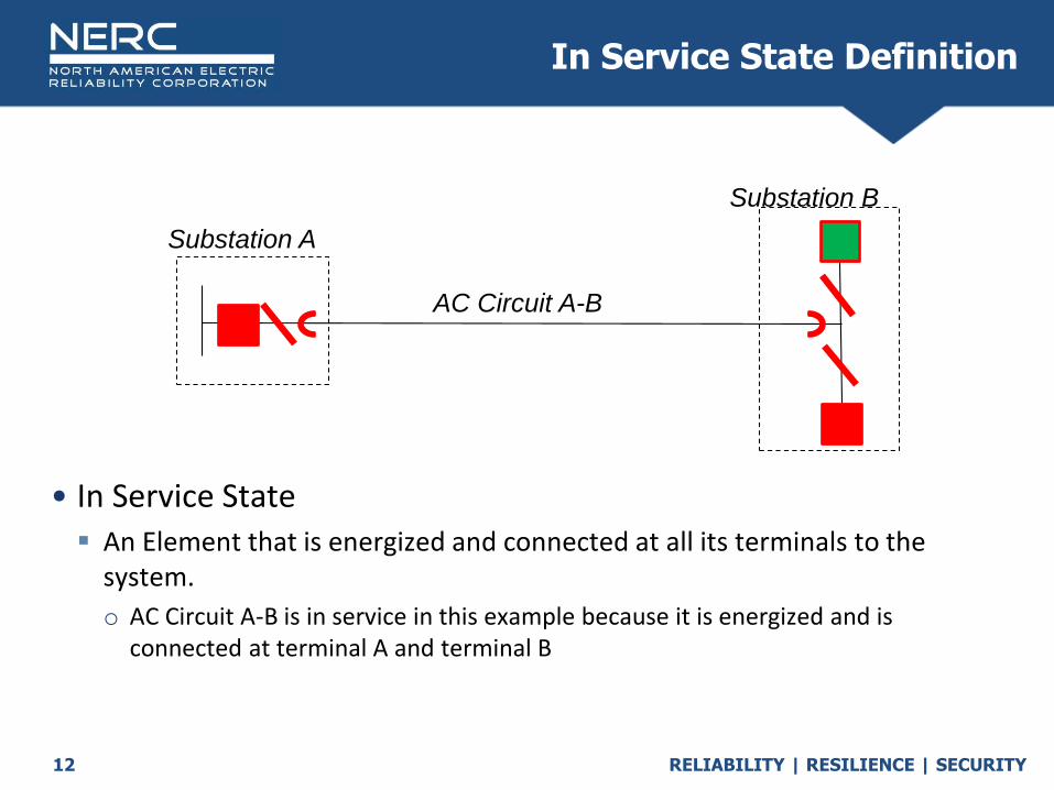
RELIABILITY | RESILIENCE | SECURITY12
• In Service State
An Element that is energized and connected at all its terminals to the system.
o AC Circuit A-B is in service in this example because it is energized and is connected at terminal A and terminal B
In Service State Definition
Substation A
AC Circuit A-B
Substation B
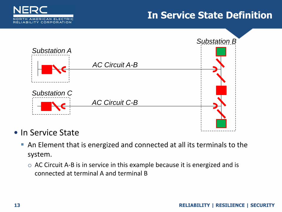
RELIABILITY | RESILIENCE | SECURITY13
• In Service State An Element that is energized and connected at all its terminals to the
system.
o AC Circuit A-B is in service in this example because it is energized and is connected at terminal A and terminal B
In Service State Definition
Substation A
AC Circuit A-B
Substation B
Substation C
AC Circuit C-B

RELIABILITY | RESILIENCE | SECURITY14
• Transformer B experiences a fault. The fault is interrupted by the breakers on AC circuit A and Transformer B. After the disconnect switch is opened AC Circuit A is automatically restored within a minute. AC Circuit A reports a momentary outage
AC Circuit A returns to an in service state per the multi terminal tapped transformer exclusion
Transformer B reports an outage - is not in service
In-Service State Example
230 kV
AC Circuit A
230/115kV
Transformer B
230 kV

RELIABILITY | RESILIENCE | SECURITY15
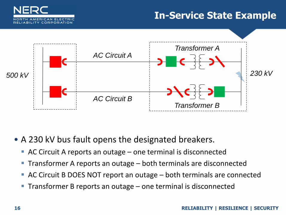
• AC Circuit A is bound by the two breakers
Transformer A is bound by a breaker and a disconnect switch
AC Circuit B is bound by a breaker and a disconnect switch
Transformer B is bound by a breaker and a disconnect switch
In-Service State Example
230 kV
AC Circuit A
AC Circuit B
Transformer A
Transformer B
500 kV
RELIABILITY | RESILIENCE | SECURITY16
• A 230 kV bus fault opens the designated breakers. AC Circuit A reports an outage – one terminal is disconnected
Transformer A reports an outage – both terminals are disconnected
AC Circuit B DOES NOT report an outage – both terminals are connected
Transformer B reports an outage – one terminal is disconnected
In-Service State Example
230 kV
AC Circuit A
AC Circuit B
Transformer A
Transformer B
500 kV
RELIABILITY | RESILIENCE | SECURITY17
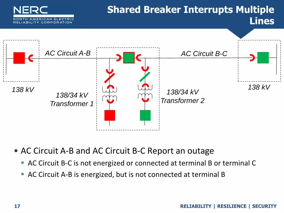
• AC Circuit A-B and AC Circuit B-C Report an outage
AC Circuit B-C is not energized or connected at terminal B or terminal C
AC Circuit A-B is energized, but is not connected at terminal B
Shared Breaker Interrupts Multiple Lines
138 kV
AC Circuit B-C
138 kV 138/34 kV
Transformer 2138/34 kV
Transformer 1
AC Circuit A-B

RELIABILITY | RESILIENCE | SECURITY18
• If a Wind Farm Radial circuit is owned by a GO, the circuit is not reportable to TADS GO cannot be forced to register as TO
• WF Radial Circuit 1 and WF Radial Circuit 2 are in service in these examples
Radial connection to Wind Farm
138/4 kV
GSU
138 kVWF Radial Circuit 2
G
WF Radial
Circuit 1138/4 kV
GSU
G

RELIABILITY | RESILIENCE | SECURITY19
• Transformers are classified as TADS reportable based on their lower or secondary voltage classification. Transformers with secondary or lower winding voltages greater than 100kV, or are included in the BES through the inclusion criteria are reportable.
• Once a transformer has been classified as reportable, it is entered into the inventory based on its high side or primary winding voltage class.
• Examples: A 500kV to 230kV transformer would be entered into TADS as a 400-599kV
A 500kV to 138kV transformer would be entered into TADS as a 400-599kV
A 500kV to 765kV transformer would be entered into TADS as a 600-799kV
A 345kV to 69kV transformer would not be reported into TADS
Do I report my transformer based off of low side or high side?
RELIABILITY | RESILIENCE | SECURITY20
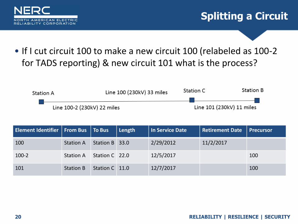
• If I cut circuit 100 to make a new circuit 100 (relabeled as 100-2 for TADS reporting) & new circuit 101 what is the process?
Splitting a Circuit
Element Identifier From Bus To Bus Length In Service Date Retirement Date Precursor
100 Station A Station B 33.0 2/29/2012 11/2/2017
100-2 Station A Station C 22.0 12/5/2017 100
101 Station B Station C 11.0 12/7/2017 100


RELIABILITY | RESILIENCE | SECURITY
Outage TypesAutomatic vs Operational
Sustained vs Momentary
October 2020

RELIABILITY | RESILIENCE | SECURITY23
Momentary Outage vs Sustained Outage

RELIABILITY | RESILIENCE | SECURITY24
• Momentary Outage : An Automatic Outage with an Outage Duration less
than one (1) minute. If the circuit recloses and trips again within less than a minute of the initial outage, it is only considered one outage. The circuit would need to remain in service for longer than one minute between the breaker operations to be considered as two outages. Only 200kV and above Elements have reportable momentary outages.
Example 1: Lightning causes a two terminal line to trip. One terminal recloses successfully, the Transmission Operator must manually reclose the remote end. This is completed successfully at 53 seconds following the trip. This would be considered a Momentary Outage.
Example 2: Lightning causes a two terminal line to trip. Both terminals automatically reclose successfully. After 25 seconds, a new Lightning strike occurs and trips the line a 2nd time. Following the 2nd trip, both terminals again reclose successfully. This is considered a single momentary outage for NERC TADS reporting(1).
In both cases, the line must be returned to its pre-trip In-Service State to end the outage. The outage doesn’t end when one terminal is closed.
(1) From the perspective of NERC TADS reporting, this is considered a single momentary outage. This may require reporting as two separate events under other programs or processes.
Momentary vs Sustained

RELIABILITY | RESILIENCE | SECURITY25
• Sustained Outage(2): An Automatic Outage with an Outage Duration of a
minute or greater.
Example 1: A Tree falls on a two terminal line and both ends trip and lock out. It takes a tree crew 24 hours to respond and remove the tree. This is a sustained outage.
Example 2: Lightning strikes a two terminal line and both ends trip. One terminal successfully auto recloses. The second terminal fails to auto reclose. The Transmission Operator is able to manually reclose the line 4 minutes after the trip. This is considered a sustained outage.
In both cases, the line must be returned to its pre-trip In-Service State to end the outage. The outage doesn’t end when one terminal is closed.
(2) The TADS definition of Sustained Outage is different from the NERC Glossary of Term Used in Reliability Standards definition of Sustained Outage that is presently only used in FAC-003-1. The glossary defines a Sustained Outage as: “The deenergized condition of a transmission line resulting from a fault or disturbance following an unsuccessful automatic reclosing sequenceand/or unsuccessful manual reclosing procedure.” The definition is inadequate for TADS reporting for two reasons. First, it has no time limit that would distinguish a Sustained Outage from a Momentary Outage. Second, for a circuit with no automatic reclosing, the outage would not be “counted” if the TO has a successful manual reclosing under the glossary definition.
Momentary vs Sustained
RELIABILITY | RESILIENCE | SECURITY26
Automatic OutagesForm 4.X

RELIABILITY | RESILIENCE | SECURITY27
• An outage that results from the automatic operation of a switching device, causing an Element to change from an In-Service State to a not In-Service State. Single-pole tripping followed by successful AC single-pole (phase) reclosing
is not an Automatic Outage.
Automatic Outage

RELIABILITY | RESILIENCE | SECURITY28
Data Collected for Automatic Outages is as follows:
Automatic Outage Data
Table 4.1: Data for Elements That Had an Automatic Outage
Column Forms 4.1-4.4 Descriptor
A The Outage ID Code assigned to the outage. This is assigned by the TO. See Appendix A for the definition of Outage ID Code. For any given TO, over multiple years, webTADS requires the TO entered Form 4.x Outage ID to be used only once on an Automatic Outage (on Form 4.x).
B The Event ID Code associated with the outage. This is assigned by the TO on Form 5.0. See Appendix A for the definition of Event ID Code. The Event ID Code used on Form 4.x must be pre-defined on Form 5.0.
C A TO defined unique Element Identifier. See column A in Table 3.1 for details.
The descriptions that follow use defined terms that the TO should become familiar with. Definitions of defined terms are located in Appendix A and they will not be repeated here. Most data fields have drop-down menus. They each describe various facets of the outage.
D The Fault Type (if any) for each circuit Outage, input from a drop-down menu.

RELIABILITY | RESILIENCE | SECURITY29
Automatic Outage Data
Table 4.1: Data for Elements That Had an Automatic Outage
Column Forms 4.1-4.4 Descriptor
E The Outage Initiation Code, input from a drop-down menu.
F The Outage Start Time. This may be local time or UTC time. WebTADS will offer a choice of time zones, with UTC being the default. This applies whether the data is entered directly into webTADS or bulk-uploaded via XML files (created either from an Excel workbook or directly by the TO). WebTADS will convert all non-UTC times to UTC and store the time as UTC within webTADS.
G The Outage Time Zone. The Time Zone of the reported Outage.
H The Outage Duration expressed as hours and minutes. Momentary Outages will enter a “0” (zero). A zero entry in column M tells the reviewer that the outage was Momentary. See instructions in Section 4.1 below for outages that continue beyond the end of the reporting year. Note that the format is a text field and requires a colon (“:”) be entered between the hours and minutes. Enter 860 hours and 20 min. as 860:20. If the colon is absent, the entry will be interpreted as “hours.” If the Outage Duration exceeds the number of hours remaining in the year (based upon the Outage Start Time), the data will be rejected and an error notice provided. If the previous entry of “860:20” were entered as 86020, it would be read as 86,020 hours and rejected.

RELIABILITY | RESILIENCE | SECURITY30
Automatic Outage Data
Table 4.1: Data for Elements That Had an Automatic Outage
Column Forms 4.1-4.4 Descriptor
I The Initiating Cause Code, input from a drop-down menu. All Outages must supply an Initiating cause code.
J The Sustained Cause Code, input from a drop-down menu. This only applies to Sustained Outages.For Momentary Outages, enter “NA-Momentary.”
K The Outage Mode, input from a drop-down menu.
L The Outage Continuation Flag described whether the outages started and ended within thereporting year or not. The flag is explained in a footnote on the data form as well as in Appendix A where the term is fully defined.
Outages that span across quarters in the same year should not use this flag. Instead, TOs should update the outage duration during each quarter until the outage ends.
RELIABILITY | RESILIENCE | SECURITY31
Operational OutagesForm 6.X
RELIABILITY | RESILIENCE | SECURITY32
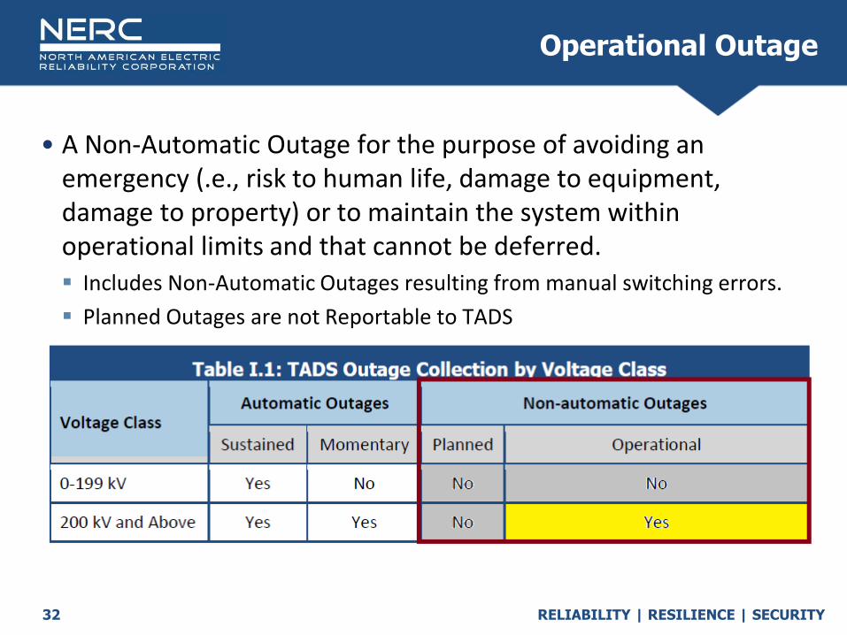
• A Non-Automatic Outage for the purpose of avoiding an emergency (.e., risk to human life, damage to equipment, damage to property) or to maintain the system within operational limits and that cannot be deferred. Includes Non-Automatic Outages resulting from manual switching errors.
Planned Outages are not Reportable to TADS
Operational Outage
RELIABILITY | RESILIENCE | SECURITY33
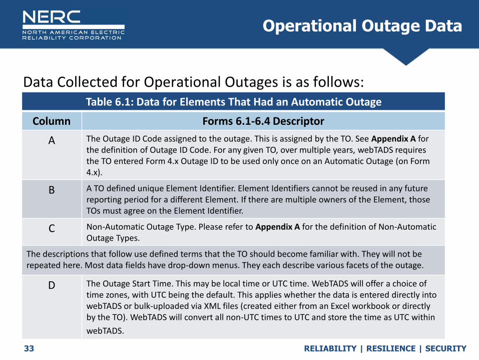
Data Collected for Operational Outages is as follows:
Operational Outage Data
Table 6.1: Data for Elements That Had an Automatic Outage
Column Forms 6.1-6.4 Descriptor
A The Outage ID Code assigned to the outage. This is assigned by the TO. See Appendix A for the definition of Outage ID Code. For any given TO, over multiple years, webTADS requires the TO entered Form 4.x Outage ID to be used only once on an Automatic Outage (on Form 4.x).
B A TO defined unique Element Identifier. Element Identifiers cannot be reused in any future reporting period for a different Element. If there are multiple owners of the Element, those TOs must agree on the Element Identifier.
C Non-Automatic Outage Type. Please refer to Appendix A for the definition of Non-Automatic Outage Types.
The descriptions that follow use defined terms that the TO should become familiar with. They will not be repeated here. Most data fields have drop-down menus. They each describe various facets of the outage.
D The Outage Start Time. This may be local time or UTC time. WebTADS will offer a choice of time zones, with UTC being the default. This applies whether the data is entered directly into webTADS or bulk-uploaded via XML files (created either from an Excel workbook or directly by the TO). WebTADS will convert all non-UTC times to UTC and store the time as UTC within
webTADS.

RELIABILITY | RESILIENCE | SECURITY34
Operational Outage Data
Table 6.1: Data for Elements That Had an Automatic Outage
Column Forms 6.1-6.4 Descriptor
E The Outage Time Zone. The Time Zone of the reported Outage.
F The Outage Duration expressed as hours and minutes. Momentary Outages will enter a “0” (zero) in this field since we round to the nearest minute. A zero entry in column M tells the reviewer that the outage was Momentary. See instructions in Section 4.1 below for outages that continue beyond the end of the reporting year. Note that the format is a text field and requires a colon (“:”) be entered between the hours and minutes. Enter 860 hours and 20 min. as 860:20. If the colon is absent, the entry will be interpreted as “hours.” If the Outage Duration exceeds the number of hours remaining in the year (based upon the Outage Start Time), the data will be rejected and an error notice provided. If the previous entry of “860:20” were entered as 86020, it would be read as 86, 020 hours and rejected.
G Operational Outages enter “NA”.
H The Operational Cause Code, input from a drop-down menu. This only applies to Operational Outages.
I The Outage Continuation Flag described whether the outages stated and ended within the reporting year or not. The flag is explained in a footnote on the data form as well as in Appendix A where the term is fully defined.

RELIABILITY | RESILIENCE | SECURITY35
• Emergency: Use for Operational Outages that are taken for the purpose of avoiding risk to human life, damage to equipment, damage to property, or similar threatening consequences.
• System Operating Limit Mitigation, excluding System Voltage Limit Mitigation: Use for Operational Outages taken to keep the transmission system within System Operating Limits, except for System Voltage Limit Mitigation. The term “System Operating Limit” is defined in the NERC Glossary of Terms Used in Reliability Standards and is excerpted:
The value (such as MW, MVar, Amperes, Frequency or Volts) that satisfies the most limiting of the prescribed operating criteria for a specified system configuration to ensure operation within acceptable reliability criteria. System Operating Limits are based upon certain operating criteria. These include, but are not limited to:
o Facility Ratings (Applicable pre- and post-Contingency equipment or facility ratings)
o Transient Stability Ratings (Applicable pre- and post-Contingency Stability Limits)
o Voltage Stability Ratings (Applicable pre- and post-Contingency Voltage Stability)
Operational Outage Cause Codes

RELIABILITY | RESILIENCE | SECURITY36
• System Voltage Limit Mitigation: Use for Operational Outages taken to maintain the voltage on the transmission system within desired levels (i.e., voltage control).
This also includes actions taken in response to System Voltage Limits (Pre and Post Contingent Voltage Limits)
• Human Error: Use for manual switching errors and any operation that is caused by personnel during on-site maintenance, testing, inspection, construction, or commissioning activities.
Example 1 - An employee intends to open breaker 1 to outage circuit A. However, he operates the wrong control handle and opens breaker 3 and outages circuit B.
Example 2 - An employee is testing a relay and, as a result, unintentionally operates a breaker, placing the circuit into a not In-Service State. This would also include interruptions when an electrician is working in the switchhouse and accidently shorts out a circuit and trips a breaker.
• Other Operational Outage: Use for Operational Outages for reasons not included in the above list.
Operational Outage Cause Codes


RELIABILITY | RESILIENCE | SECURITY
Outage Initiation Codes
October 2020

RELIABILITY | RESILIENCE | SECURITY39
• This is not the Initiating cause code
• The Outage Initiation Codes describe where an Automatic Outage was initiated on the power system. Element-Initiated Outage
o An Automatic Outage of a TADS Element that is initiated on or within the TADS Element that is outaged.
Other Element-Initiated Outage
o An Automatic Outage of an TADS Element that is initiated by another TADS Element and not by the TADS Element that is outaged. (Note: Only used for TADS Elements)
AC Substation-Initiated Outage
o An Automatic Outage of a TADS Element that is initiated on or within AC Substation facilities. (Note: By the definition of “AC Substation” in Section A, Protection System Equipment is not part of the AC Substation; it is therefore included in “Protection System-Initiated Outage.” Only used for TADS Element.)
Initiation Code

RELIABILITY | RESILIENCE | SECURITY40
AC/DC Terminal-Initiated Outage
o An Automatic Outage of a TADS Element that is initiated on or within AC/DC Terminal facilities. (Note: By the definition of “AC/DC Terminal” in Section A, Protection System Equipment is not part of the DC Terminal; it is therefore included in “Protection System-Initiated Outage.” Only used for TADS Element.)
Protection System-Initiated Outage
o An Automatic Outage of a TADS Element that is initiated on or within the Protection System. (Note: This includes Automatic Outages due to the failure of a Protection System element initiated by protection equipment (including, but not limited to: incorrect protection settings, wiring errors, miscoordination, Protection System related Human Error, etc.) causing the protection system to misoperate. Only used for TADS Element.)
Other Facility-Initiated Outage
o An Automatic Outage that is initiated on or within other facilities. “Other facilities” include any facilities not includable in any other Outage Initiation Code. (Note: An Automatic Outage initiated on a Transformer that is not a TADS Element is considered an AC Substation or an AC/DC Terminal-Initiated Outage since the Transformer would be considered part of an AC Substation or AC/DC Terminal.)
Initiation Code

RELIABILITY | RESILIENCE | SECURITY41
Outage Initiation Code Examples
• Example 1
A Transformer, which is an Element, is outaged. Is its outage an Element-Initiated Outage or an AC Substation-Initiated Outage? It depends. If the outage initiated on or within the Element (e.g., an internal fault or a cracked insulator that caused a fault), the outage is Element-Initiated, even though the Transformer is in a Substation. However, if the Transformer outage was not due to the Transformer itself but due, for example, to a failed circuit breaker, it is AC Substation-Initiated.
• Example 2
An AC Circuit, which is an Element, has an outage that was initiated by a non-TADS Element AC Circuit. The Element outage is Other Facility-Initiated.
• Example 3
An AC Circuit Outage was initiated by an Element Transformer outage. The AC Circuit Outage is Other Element-Initiated.
• Example 4
An AC Circuit Outage was initiated by an non-Element Transformer outage. The AC Circuit Outage is Other Facility-Initiated.
Outage Initiation Example from TADS Definitions

RELIABILITY | RESILIENCE | SECURITY42
• Fault #1 on Bus 2A: Initiation Code = ‘AC Substation Initiated’
• Fault #2: Initiation Code = ‘Element Initiated’
• Fault #3: Initiation Code = ‘AC Substation Initiated’
• Fault #4: Initiation Code = ‘AC Substation Initiated’
• Fault #5: Initiation Code = ‘Element Initiated’
Ring Bus Examples
RELIABILITY | RESILIENCE | SECURITY43
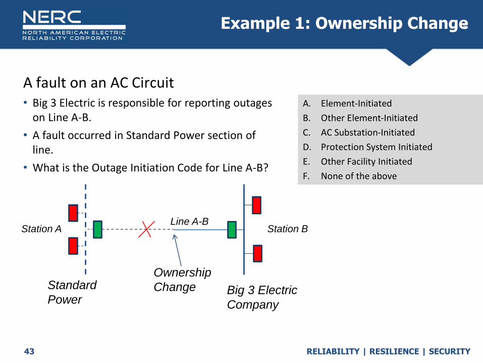
A fault on an AC Circuit• Big 3 Electric is responsible for reporting outages
on Line A-B.
• A fault occurred in Standard Power section of line.
• What is the Outage Initiation Code for Line A-B?
Q
A. Element-Initiated
B. Other Element-Initiated
C. AC Substation-Initiated
D. Protection System Initiated
E. Other Facility Initiated
F. None of the above
Example 1: Ownership Change
Big 3 Electric
Company
Line A-BStation A Station B
Standard
Power
Ownership
Change
RELIABILITY | RESILIENCE | SECURITY44
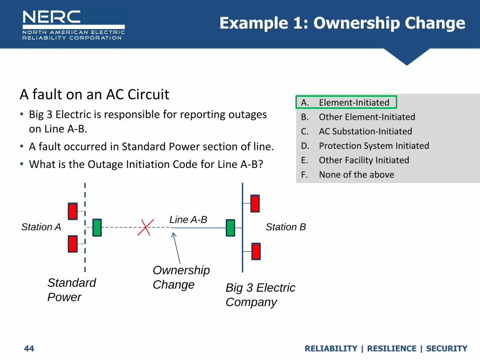
A fault on an AC Circuit• Big 3 Electric is responsible for reporting outages
on Line A-B.
• A fault occurred in Standard Power section of line.
• What is the Outage Initiation Code for Line A-B?
Q
A. Element-Initiated
B. Other Element-Initiated
C. AC Substation-Initiated
D. Protection System Initiated
E. Other Facility Initiated
F. None of the above
Example 1: Ownership Change
Big 3 Electric
Company
Line A-BStation A Station B
Standard
Power
Ownership
Change

RELIABILITY | RESILIENCE | SECURITY45
Bus Fault• A fault occurs on the bus at Station B.
• What is the Outage Initiation Code for Line A-B?
Q
A. Element-Initiated
B. Other Element-Initiated
C. AC Substation-Initiated
D. Protection System Initiated
E. Other Facility Initiated
F. None of the above
Example 2
Station A Station B
Line A-B

RELIABILITY | RESILIENCE | SECURITY46
Bus Fault• A fault occurs on the bus at Station B.
• What is the Outage Initiation Code for Line A-B?
Q
A. Element-Initiated
B. Other Element-Initiated
C. AC Substation-Initiated
D. Protection System Initiated
E. Other Facility Initiated
F. None of the above
Example 2
Station A Station B
Line A-B

RELIABILITY | RESILIENCE | SECURITY47
A fault on AC Circuit ‘A-X’• What is the Outage Initiation Code for Line X-B?
Q
A. Element-Initiated
B. Other Element-Initiated
C. AC Substation-Initiated
D. Protection System Initiated
E. Other Facility Initiated
F. None of the above
Example 3

RELIABILITY | RESILIENCE | SECURITY48
A fault on AC Circuit ‘A-X’• What is the Outage Initiation Code for Line X-B?
Q
A. Element-Initiated
B. Other Element-Initiated
C. AC Substation-Initiated
D. Protection System Initiated
E. Other Facility Initiated
F. None of the above
Example 3
RELIABILITY | RESILIENCE | SECURITY49
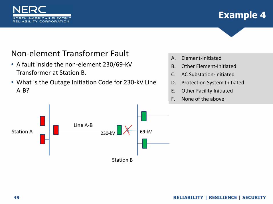
Non-element Transformer Fault• A fault inside the non-element 230/69-kV
Transformer at Station B.
• What is the Outage Initiation Code for 230-kV Line A-B?
Q
A. Element-Initiated
B. Other Element-Initiated
C. AC Substation-Initiated
D. Protection System Initiated
E. Other Facility Initiated
F. None of the above
Example 4
RELIABILITY | RESILIENCE | SECURITY50
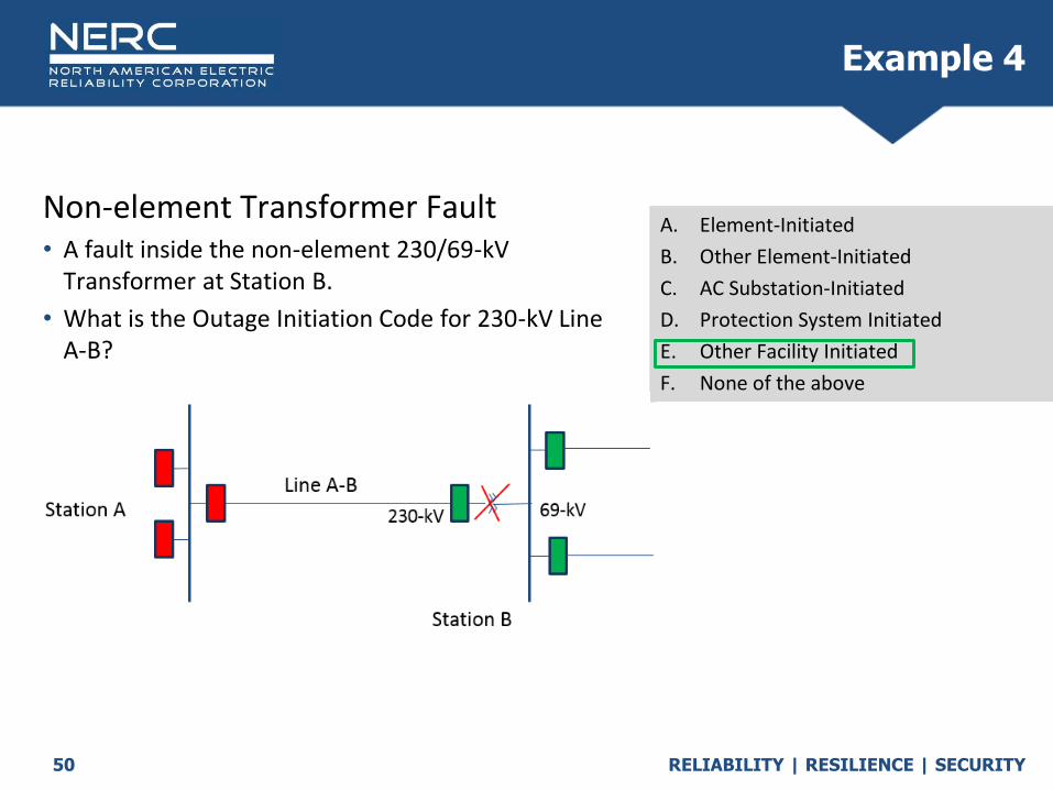
Non-element Transformer Fault• A fault inside the non-element 230/69-kV
Transformer at Station B.
• What is the Outage Initiation Code for 230-kV Line A-B?
Q
A. Element-Initiated
B. Other Element-Initiated
C. AC Substation-Initiated
D. Protection System Initiated
E. Other Facility Initiated
F. None of the above
Example 4

RELIABILITY | RESILIENCE | SECURITY51
Human Error• An employee turns the wrong handle and
accidently opens the breaker at Station B on Line A-B.
• What is the Outage Initiation Code for Line A-B
Q
A. Element-Initiated
B. Other Element-Initiated
C. AC Substation-Initiated
D. Protection System Initiated
E. Other Facility Initiated
F. None of the above
Station A
Station B
Line A-B
Example 5
RELIABILITY | RESILIENCE | SECURITY52
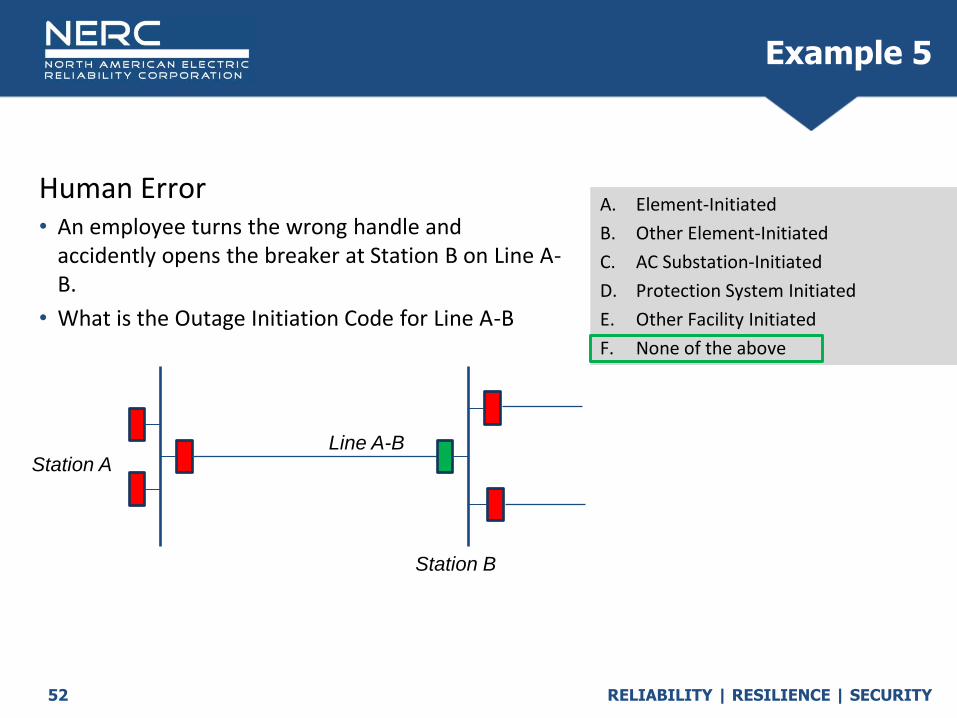
Human Error• An employee turns the wrong handle and
accidently opens the breaker at Station B on Line A-B.
• What is the Outage Initiation Code for Line A-B
Q
A. Element-Initiated
B. Other Element-Initiated
C. AC Substation-Initiated
D. Protection System Initiated
E. Other Facility Initiated
F. None of the above
Station A
Station B
Line A-B
Example 5

RELIABILITY | RESILIENCE | SECURITY53
A fault occurs on Line A-B• The breaker on Line B-C erroneously opens due to
relays having the wrong settings.
• What is the Outage Initiation Code for Line B-C?
Q
A. Element-Initiated
B. Other Element-Initiated
C. AC Substation-Initiated
D. Protection System Initiated
E. Other Facility Initiated
F. None of the above
Station A
Station B
Line A-B
Line B-C
Example 6

RELIABILITY | RESILIENCE | SECURITY54
A fault occurs on Line A-B• The breaker on Line B-C erroneously opens due
to relays having the wrong settings.
• What is the Outage Initiation Code for Line B-C?
Q
A. Element-Initiated
B. Other Element-Initiated
C. AC Substation-Initiated
D. Protection System Initiated
E. Other Facility Initiated
F. None of the above
Station A
Station B
Line A-B
Line B-C
Example 6

RELIABILITY | RESILIENCE | SECURITY
Cause Codes: Initiating (ICC)
and Sustained (SCC)
October 2020

RELIABILITY | RESILIENCE | SECURITY56
Initiating Cause Codes (ICC)

RELIABILITY | RESILIENCE | SECURITY57
• The Initiating Cause Code describes the initiating cause of the outage.
• The Sustained Cause Code describes the cause that describes the sustained cause of the outage which contributed to the longest duration. How to interpret “contributed to the longest duration”:
o Suppose that lightning caused a conductor to break (“Failed AC Circuit Equipment”) and that the breaker for the circuit failed (“Failed AC Substation Equipment’).
– If the conductor was repaired before the circuit breaker, then “Failed AC Substation Equipment” is the Sustained Cause Code since the circuit breaker outage contributed to the longest duration.
– However, if the circuit breaker was repaired before the conductor, then “Failed AC Circuit Equipment” is the Sustained Cause Code.
Initiating and Sustained Cause Codes

RELIABILITY | RESILIENCE | SECURITY58
o Weather, excluding lightning
o Lightning
o Environmental
o Fire
o Contamination
o Foreign interference
o Vandalism, terrorism, malicious acts
o Vegetation
Which Cause Code to Pick
o Human error
o Failed AC Substation equipment
o Failed Protection System equipment
o Failed AC Circuit equipment
o Failed DC Circuit equipment
o Failed AC/DC Terminal equipment
o Power system condition
o Unknown
o Other
• When analyzing event…
Examine each Element independently
Ask “Why did the interrupting device operate?”

RELIABILITY | RESILIENCE | SECURITY59
A lightning strike on an AC Circuit.
What is the Initiating Cause Code? A. Lightning
B. Failed AC Circuit equipment
C. Weather, excl. lightning
D. Foreign Interference
Example 1
Station A Station BLine A-B
RELIABILITY | RESILIENCE | SECURITY60
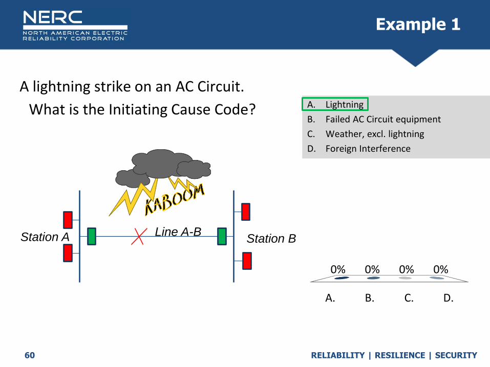
A lightning strike on an AC Circuit.
What is the Initiating Cause Code?
A. B. C. D.
0% 0% 0% 0%
A. Lightning
B. Failed AC Circuit equipment
C. Weather, excl. lightning
D. Foreign Interference
Example 1
Station A Station BLine A-B
RELIABILITY | RESILIENCE | SECURITY61
A lightning strike on an AC Circuit. Big 3 Electric is the reporting entity for Line A-B.
What Initiating Cause Code should Big 3 Electric report for interruption that didn’t occur on their equipment?
Q
A. Lightning
B. Failed Protection System Equipment
C. Foreign Interference
D. Other
Example 2: Ownership Change
Big 3
Electric Co.
Line A-BStation A Station B
Standard
Power
Ownership
Change

RELIABILITY | RESILIENCE | SECURITY62
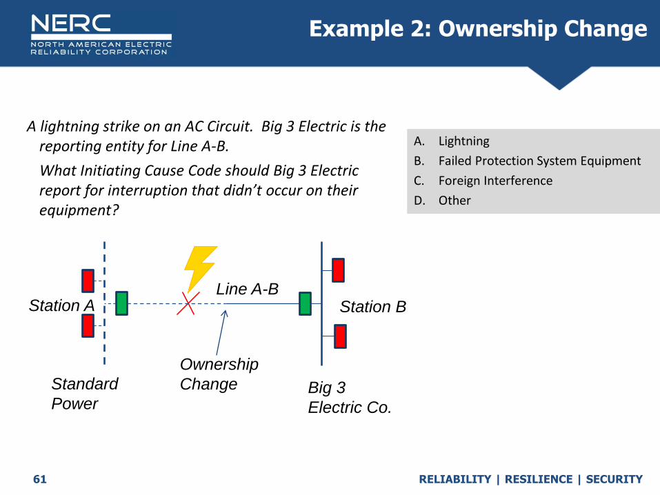
A lightning strike on an AC Circuit. Big 3 Electric is the reporting entity for Line A-B.
What Initiating Cause Code should Big 3 Electric report for interruption that didn’t occur on their equipment?
Q
A. Lightning
B. Failed Protection System Equipment
C. Foreign Interference
D. Other
Example 2: Ownership Change
Big 3
Electric Co.
Line A-BStation A Station B
Standard
Power
Ownership
Change

RELIABILITY | RESILIENCE | SECURITY63
A sleeve failure occurs on Line #1 and the conductor breaks and falls into underbuilt Line #2.
(The Initiating Cause Code for Line #1 is Failed AC Circuit Equipment.)
What is the Initiating Cause Code for Line #2?
(Does it matter if different companies own the lines.)
Q
A. Failed AC Circuit Equipment
B. Foreign Interference
C. Lightning
D. Other
Example 3: Underbuilt
Station A Station BLine #1
Line #2
(Underbuilt)
RELIABILITY | RESILIENCE | SECURITY64
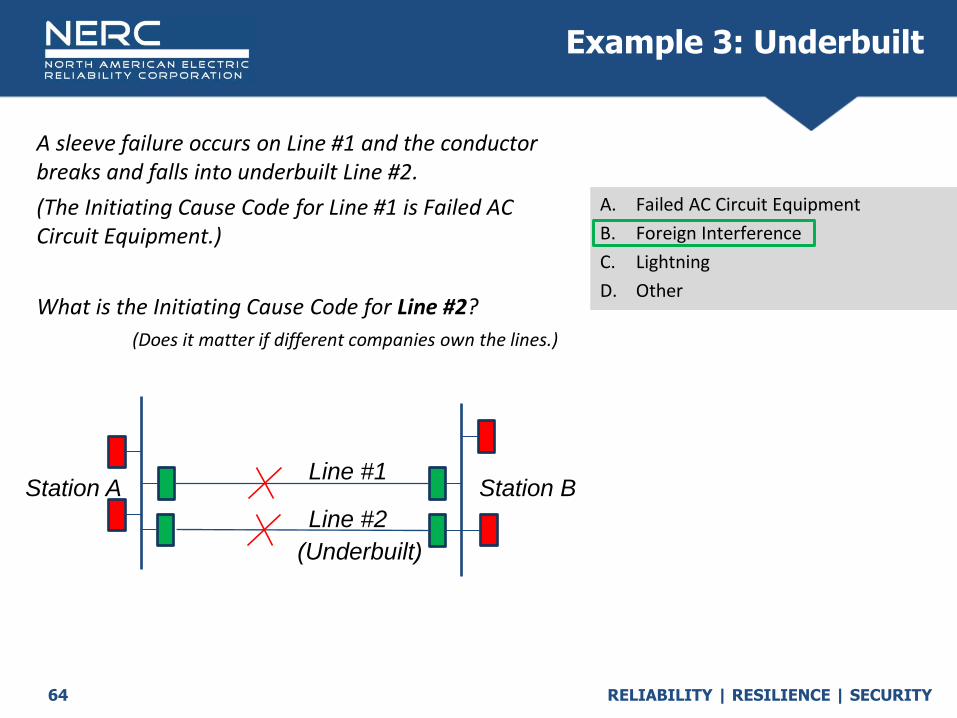
A sleeve failure occurs on Line #1 and the conductor breaks and falls into underbuilt Line #2.
(The Initiating Cause Code for Line #1 is Failed AC Circuit Equipment.)
What is the Initiating Cause Code for Line #2?
(Does it matter if different companies own the lines.)
Q
A. Failed AC Circuit Equipment
B. Foreign Interference
C. Lightning
D. Other
Example 3: Underbuilt
Station A Station BLine #1
Line #2
(Underbuilt)

RELIABILITY | RESILIENCE | SECURITY65
Lightning struck Line A-C and a breaker failed to open due to breaker issue.
(The Initiating Cause Code for Line A-C is Lightning.)
What is the Initiating Cause Code for TL-1, TL-2, TL-3, TL-4?
Q
A. Other
B. Lightning
C. Weather, excl. lightning
D. Failed Substation Equipment
Example 4: Breaker fails to clear fault
RELIABILITY | RESILIENCE | SECURITY66
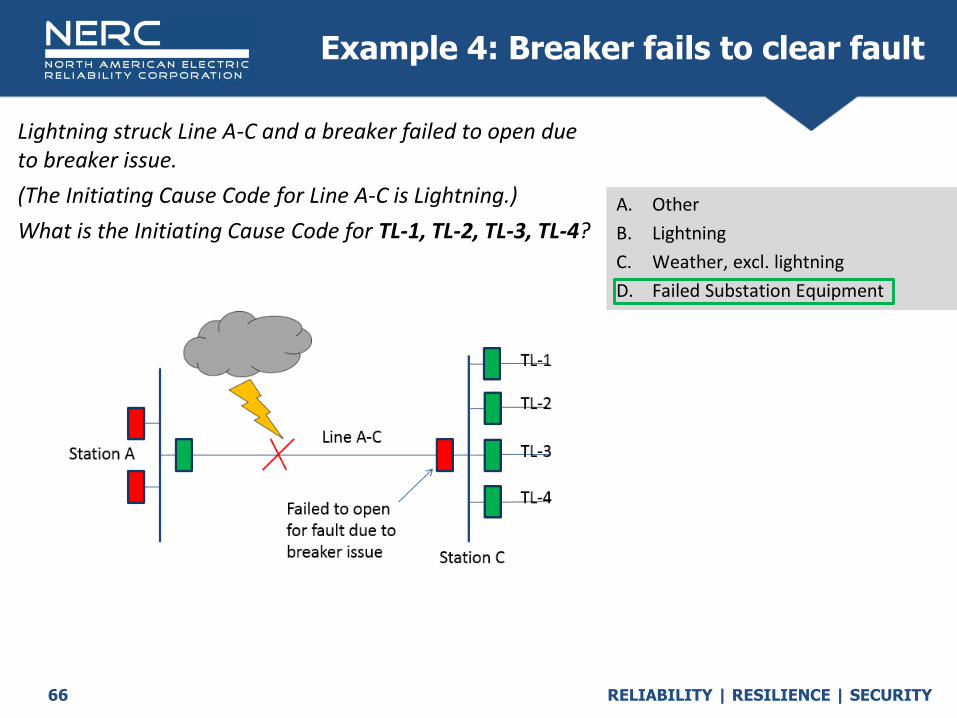
Lightning struck Line A-C and a breaker failed to open due to breaker issue.
(The Initiating Cause Code for Line A-C is Lightning.)
What is the Initiating Cause Code for TL-1, TL-2, TL-3, TL-4?
Q
A. Other
B. Lightning
C. Weather, excl. lightning
D. Failed Substation Equipment
Example 4: Breaker fails to clear fault
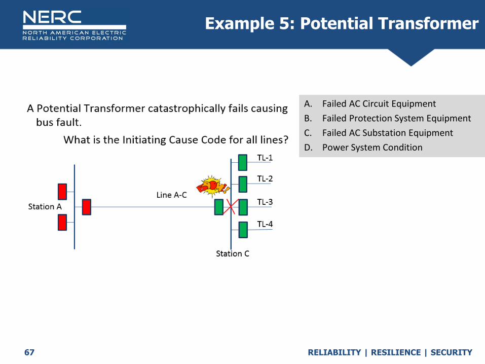
RELIABILITY | RESILIENCE | SECURITY67
Q
A. Failed AC Circuit Equipment
B. Failed Protection System Equipment
C. Failed AC Substation Equipment
D. Power System Condition
Example 5: Potential Transformer

RELIABILITY | RESILIENCE | SECURITY68
Q
A. Failed AC Circuit Equipment
B. Failed Protection System Equipment
C. Failed AC Substation Equipment
D. Power System Condition
Example 5: Potential Transformer

RELIABILITY | RESILIENCE | SECURITY69
Failed line capacitor voltage transformer (CCVT or CVT) secondary fails causing voltage loss to relay resulting in a breaker to open on TL-3.
What is the Initiating Cause Code for TL-3?
Q
A. Failed AC Circuit Equipment
B. Failed Protection System Equipment
C. Failed AC Substation Equipment
D. Power System Condition
Example 6: Potential Transformer

RELIABILITY | RESILIENCE | SECURITY70
Failed line capacitor voltage transformer (CCVT or CVT) secondary fails causing voltage loss to relay resulting in a breaker to open on TL-3.
What is the Initiating Cause Code for TL-3?
Q
A. Failed AC Circuit Equipment
B. Failed Protection System Equipment
C. Failed AC Substation Equipment
D. Power System Condition
Example 6: Potential Transformer

RELIABILITY | RESILIENCE | SECURITY71
Breaker fails to clear lightning fault on 69-kV system
Again, consider why the breaker for the Element opened.
What is the Initiating Cause Code for Line A-C?
Q
A. Lightning
B. Foreign Interference
C. Failed AC Substation Equipment
D. Failed Protection System Equipment
Example 7: Non-BES Faults

RELIABILITY | RESILIENCE | SECURITY72
Breaker fails to clear lightning fault on 69-kV system
Again, consider why the breaker for the Element opened.
What is the Initiating Cause Code for Line A-C?
Q
A. Lightning
B. Foreign Interference
C. Failed AC Substation Equipment
D. Failed Protection System Equipment
Example 7: Non-BES Faults

RELIABILITY | RESILIENCE | SECURITY73
Human Error: Automatic OutageInterruptions with Faults Examples
Human Error: Automatic Outages caused by any incorrect action traceable to employees and or contractors for companies operating, maintaining, and or providing assistance to the Transmission Owner will be identified and reported in this category.
Station A Station BLine A-B
Human Error Automatic Outage Examples (Form 4.X) Not Human Error Examples
• Electrician hangs ground on wrong (energized) line.• Operator accidently closes ground switch on line.• Contractor cuts tree into energized line.• Company or contractor bucket-truck contacts line.
• Employee flying a kite on his day off and it contacts 230-kV line is NOT Human Error (Foreign Interference).
• Customer or distribution company bucket truck contacts line (Foreign Interference).

RELIABILITY | RESILIENCE | SECURITY74
• Line A-B has lightning strike and the Line B-C relay ‘overtrips’ for fault on another line due to: Wrong settings, Wiring error, or Switch in wrong position
Line A-B would have an initiating cause of Lightning and Line B-C would have an initiating cause of Human Error
Example 7: Human Error: Automatic Outage
Protection System; No Fault Examples
Station A
Station B
Line A-B
Line B-C
Station C

RELIABILITY | RESILIENCE | SECURITY75
A control house roof leak causes water to drip on a relay and causes the relay to operate opening a breaker.
A. Weather, excl. Lightning
B. Failed Protection System Equipment
C. Foreign Interference
D. Human Error – Form 4.1
What is the Initiating Cause Code?
Example 7: Human Error: Automatic Outage
Protection System; No Fault Examples

RELIABILITY | RESILIENCE | SECURITY76
A control house roof leak causes water to drip on a relay and causes the relay to operate opening a breaker.
A. Weather, excl. Lightning
B. Failed Protection System Equipment
C. Foreign Interference
D. Human Error – Form 4.1
What is the Initiating Cause Code?
Example 7: Human Error: Automatic Outage
Protection System; No Fault Examples
RELIABILITY | RESILIENCE | SECURITY77
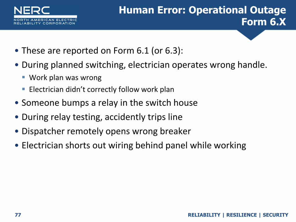
• These are reported on Form 6.1 (or 6.3):
• During planned switching, electrician operates wrong handle. Work plan was wrong
Electrician didn’t correctly follow work plan
• Someone bumps a relay in the switch house
• During relay testing, accidently trips line
• Dispatcher remotely opens wrong breaker
• Electrician shorts out wiring behind panel while working
Human Error: Operational Outage Form 6.X

RELIABILITY | RESILIENCE | SECURITY78
Sustained Cause Codes (SCC)

RELIABILITY | RESILIENCE | SECURITY79
• A sustained outage is an automatic outage with an outage duration of a minute or greater.
• The Sustained Cause Code describes the cause that contributed to the longest duration of the outage.
• For Sustained Cause, consider what caused the ‘longest duration’ of the outage to the Element.
Sustained Cause Code
RELIABILITY | RESILIENCE | SECURITY80
• Most of the time if the Initiating Cause is one of these, then the Sustained Cause will be different, probably failed equipment (emphasis on ‘most’)… Weather, excluding lightning
Lightning
Environmental
Fire
Vandalism, terrorism, malicious acts
• Remember, consider what caused the ‘longest duration’ of the outage to the Element or “what did you have to fix?”
Sustained Cause Code

RELIABILITY | RESILIENCE | SECURITY81
• Most of the time if the Initiating Cause is one of these, then the Sustained Cause will be the same (emphasis on ‘most’)… Failed AC Substation equipment
Failed Protection System equipment
Failed AC Circuit equipment
Failed DC Circuit equipment
Failed AC/DC Terminal equipment
Power system condition
Unknown
Other
• Remember, consider what caused the ‘longest duration’ of the outage to the Element or “what did you have to fix?”
Sustained Cause Code

RELIABILITY | RESILIENCE | SECURITY82
• Note, If you code a sustained outage as Initiating cause unknown, sustained cause unknown
Initiating cause other, sustained cause other
• You may be contacted by your regional entity to provide additional details.
Sustained Cause Code

RELIABILITY | RESILIENCE | SECURITY83
• If the Initiating Cause is one of these, then the Sustained Cause could be anything … Contamination
Foreign interference
Vegetation
Human error
• Remember, consider what caused the ‘longest duration’ of the outage to the Element.
Sustained Cause Code
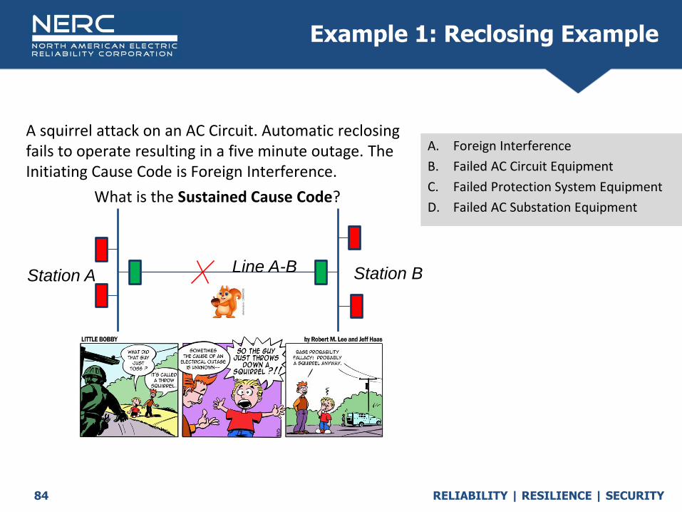
RELIABILITY | RESILIENCE | SECURITY84
A squirrel attack on an AC Circuit. Automatic reclosing fails to operate resulting in a five minute outage. The Initiating Cause Code is Foreign Interference.
What is the Sustained Cause Code?
Q
A. Foreign Interference
B. Failed AC Circuit Equipment
C. Failed Protection System Equipment
D. Failed AC Substation Equipment
Example 1: Reclosing Example
Station A Station BLine A-B
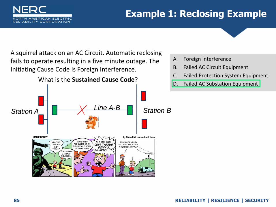
RELIABILITY | RESILIENCE | SECURITY85
A squirrel attack on an AC Circuit. Automatic reclosing fails to operate resulting in a five minute outage. The Initiating Cause Code is Foreign Interference.
What is the Sustained Cause Code?
Q
A. Foreign Interference
B. Failed AC Circuit Equipment
C. Failed Protection System Equipment
D. Failed AC Substation Equipment
Example 1: Reclosing Example
Station A Station BLine A-B

RELIABILITY | RESILIENCE | SECURITY86
A tornado destroys a transmission tower on an AC Circuit resulting in a five day outage. The Initiating Cause Code is Weather.
What is the Sustained Cause Code?
Q
A. Lightning
B. Weather, excl. lightning
C. Other
D. Failed AC Circuit Equipment
Example 2: “Weather-Weather”? Example
Station A Station BLine A-B

RELIABILITY | RESILIENCE | SECURITY87
A tornado destroys a transmission tower on an AC Circuit resulting in a five day outage. The Initiating Cause Code is Weather.
What is the Sustained Cause Code?
Q
A. Lightning
B. Weather, excl. lightning
C. Other
D. Failed AC Circuit Equipment
Example 2: “Weather-Weather”? Example
Station A Station BLine A-B
RELIABILITY | RESILIENCE | SECURITY88
• Other examples where the sustained cause code would be Failed AC Circuit equipment: Fire destroys transmission pole
Hurricane destroys transmission tower
Car hits transmission pole
Employee accidently saws down transmission pole rather than tree
Alien spacecraft crashes into transmission line
Sustained Cause Code Examples Other Failed AC Circuit equipment

RELIABILITY | RESILIENCE | SECURITY89
Now for something completely different
RELIABILITY | RESILIENCE | SECURITY90
Vegetation(Exceptions)
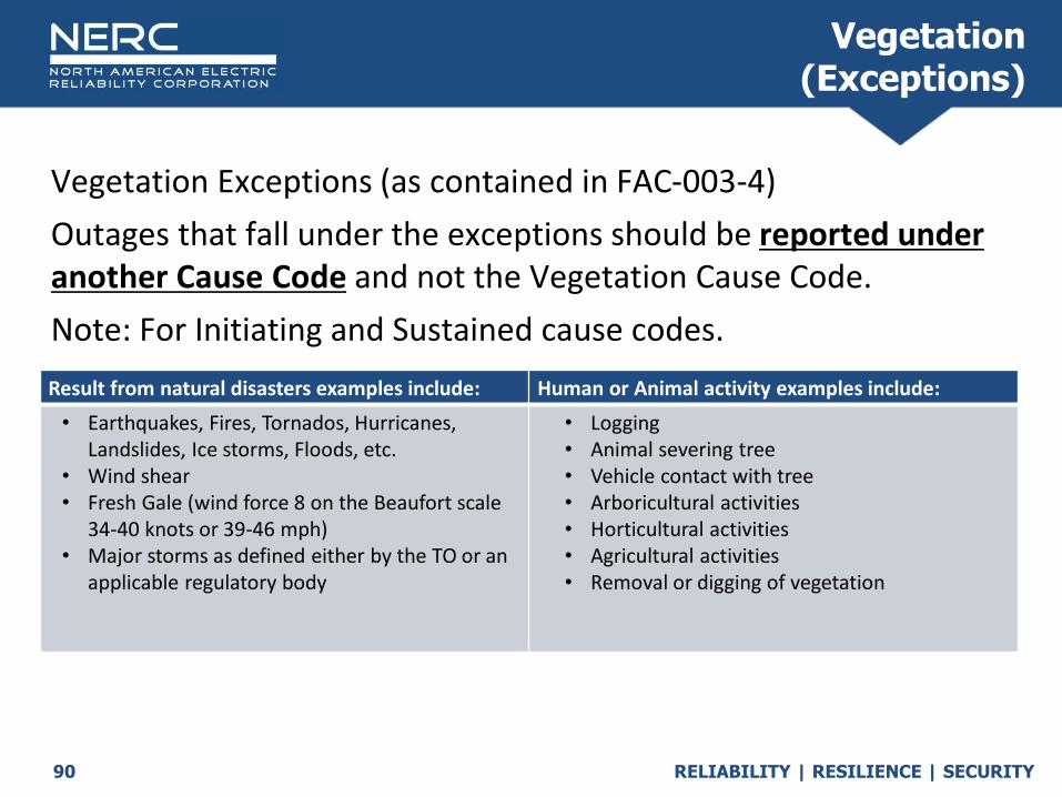
Vegetation Exceptions (as contained in FAC-003-4)
Outages that fall under the exceptions should be reported under another Cause Code and not the Vegetation Cause Code.
Note: For Initiating and Sustained cause codes.
Result from natural disasters examples include: Human or Animal activity examples include:
• Earthquakes, Fires, Tornados, Hurricanes, Landslides, Ice storms, Floods, etc.
• Wind shear• Fresh Gale (wind force 8 on the Beaufort scale
34-40 knots or 39-46 mph)• Major storms as defined either by the TO or an
applicable regulatory body
• Logging• Animal severing tree• Vehicle contact with tree• Arboricultural activities• Horticultural activities• Agricultural activities• Removal or digging of vegetation
RELIABILITY | RESILIENCE | SECURITY91
A tree in the right-of-way, falls on a sunny, calm day into the transmission line. The tree is leaning into the conductor, but no equipment damage. It takes three hours to remove the tree. The Initiating Cause Code is Vegetation.
What is the Sustained Cause Code?
Q
A. Unknown
B. Vegetation
C. Failed AC Circuit Equipment
D. Foreign interference
Example 3: Vegetation Example
Station A Station BLine A-B

RELIABILITY | RESILIENCE | SECURITY92
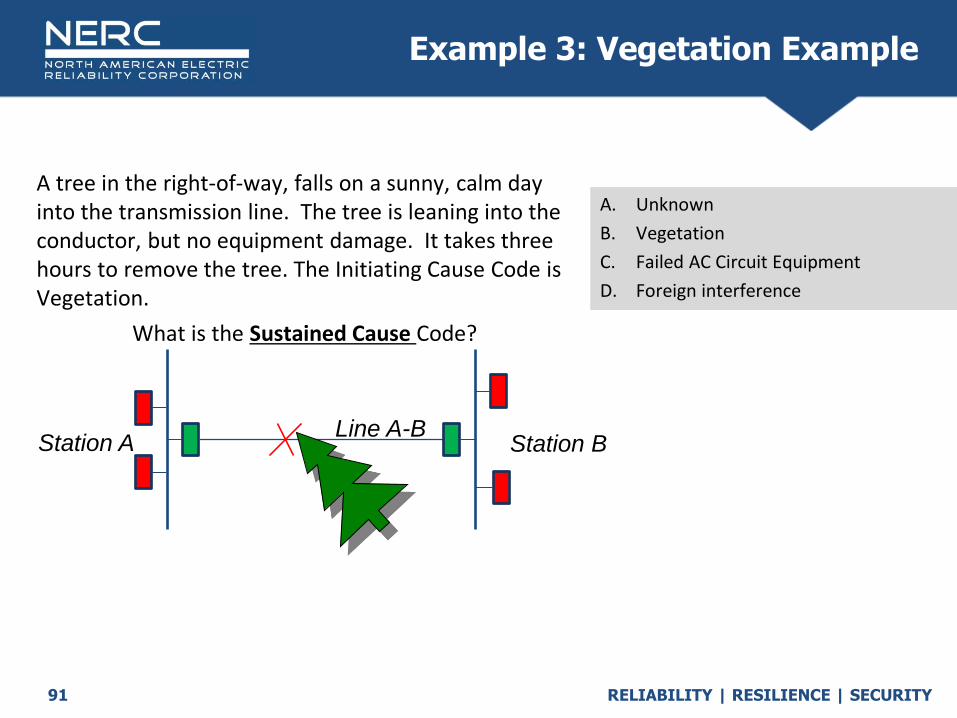
A tree in the right-of-way, falls on a sunny, calm day into the transmission line. The tree is leaning into the conductor, but no equipment damage. It takes three hours to remove the tree. The Initiating Cause Code is Vegetation.
What is the Sustained Cause Code?
Q
A. Unknown
B. Vegetation
C. Failed AC Circuit Equipment
D. Foreign interference
Example 3: Vegetation Example
Station A Station BLine A-B
RELIABILITY | RESILIENCE | SECURITY93
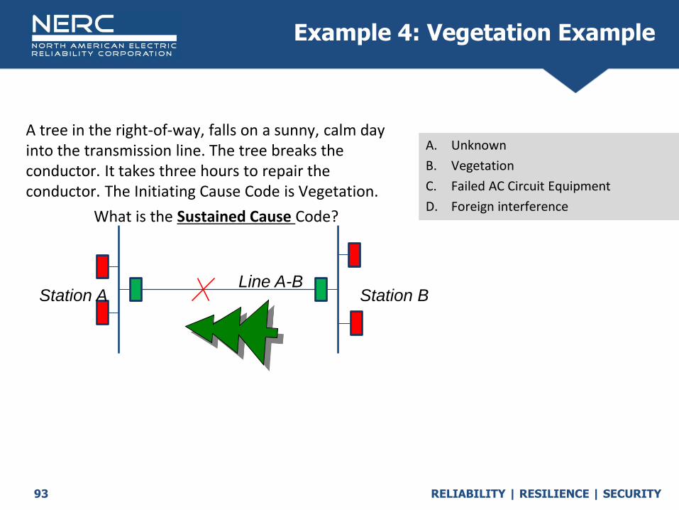
A tree in the right-of-way, falls on a sunny, calm day into the transmission line. The tree breaks the conductor. It takes three hours to repair the conductor. The Initiating Cause Code is Vegetation.
What is the Sustained Cause Code?
Q
A. Unknown
B. Vegetation
C. Failed AC Circuit Equipment
D. Foreign interference
Example 4: Vegetation Example
Station A Station BLine A-B

RELIABILITY | RESILIENCE | SECURITY94
A tree in the right-of-way, falls on a sunny, calm day into the transmission line. The tree breaks the conductor. It takes three hours to repair the conductor. The Initiating Cause Code is Vegetation.
What is the Sustained Cause Code?
Q
A. Unknown
B. Vegetation
C. Failed AC Circuit Equipment
D. Foreign interference
Example 4: Vegetation Example
Station A Station BLine A-B

RELIABILITY | RESILIENCE | SECURITY95
A tree is cut into the energized line by utility personnel, breaking the conductor. It takes three hours to repair the conductor. The Initiating Cause Code is Human Error (Form 4.1).
What is the Sustained Cause Code?
Q
A. Unknown
B. Vegetation
C. Failed AC Circuit Equipment
D. Foreign interference
Example 5: Vegetation Example
Station A Station BLine A-B
RELIABILITY | RESILIENCE | SECURITY96
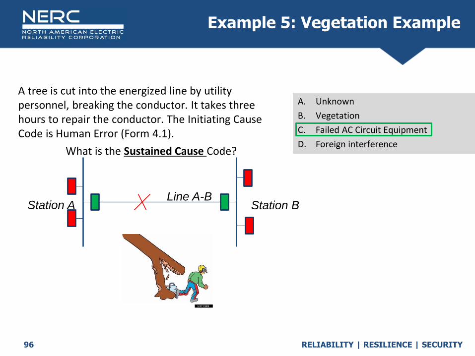
A tree is cut into the energized line by utility personnel, breaking the conductor. It takes three hours to repair the conductor. The Initiating Cause Code is Human Error (Form 4.1).
What is the Sustained Cause Code?
Q
A. Unknown
B. Vegetation
C. Failed AC Circuit Equipment
D. Foreign interference
Example 5: Vegetation Example
Station A Station BLine A-B

RELIABILITY | RESILIENCE | SECURITY97
A tree is cut into the energized line by your utility employee, conductor doesn’t break, leans into line. It takes three hours to remove the tree. The Initiating Cause Code is Human Error (Form 4.1).
What is the Sustained Cause Code?
Q
A. Human Error
B. Vegetation
C. Failed AC Circuit Equipment
D. Foreign interference
Station A Station BLine A-B
Not vegetation because of exception under vegetation, Nothing broke so not Failed equipment, Not Foreign Interference because of exception.
Example 6: Vegetation Example

RELIABILITY | RESILIENCE | SECURITY98
A tree is cut into the energized line by your utility employee, conductor doesn’t break, leans into line. It takes three hours to remove the tree. The Initiating Cause Code is Human Error (Form 4.1).
What is the Sustained Cause Code?
Q
A. Human Error
B. Vegetation
C. Failed AC Circuit Equipment
D. Foreign interference
Station A Station BLine A-B
Not vegetation because of exception under vegetation, Nothing broke so not Failed equipment, Not Foreign Interference because of exception.
Example 6: Vegetation Example

RELIABILITY | RESILIENCE | SECURITY99
A tree off the right-of-way, falls during a storm into the transmission line. The tree is leaning into the conductor, but is not damaged. It takes three hours to remove the tree.
What is the Initiating Cause Code?
Q
A. Vegetation
B. Foreign Interference
C. Weather, excl. Lightning
D. Failed AC Circuit Equipment
Example 7: Vegetation Example
Station A Station BLine A-B

RELIABILITY | RESILIENCE | SECURITY100
A tree off the right-of-way, falls during a storm into the transmission line. The tree is leaning into the conductor, but is not damaged. It takes three hours to remove the tree.
What is the Initiating Cause Code?
Q
A. Vegetation
B. Foreign Interference
C. Weather, excl. Lightning
D. Failed AC Circuit Equipment
Example 7: Vegetation Example
Station A Station BLine A-B


RELIABILITY | RESILIENCE | SECURITY
Fault Types
October 2020

RELIABILITY | RESILIENCE | SECURITY104
Fault Type
• The descriptor of the fault, if any, associated with each Automatic Outage of an Element.
1. No fault
2. Phase-to-phase fault (P-P)
3. Single phase-to-ground fault (P-G)
4. Phase-to-phase-to-ground (P-P-G), 3P, or 3P-G fault
5. Unknown fault type NOTE for TADS purposes the Fault Type chosen should:
o Be based on TO best judgment of what occurred
• Represent the worst impact on system dynamic stability

RELIABILITY | RESILIENCE | SECURITY105
• If an Element has an Automatic Outage and its Outage Initiation Code is:
• Element-Initiated - report Fault Type 1-5 as appropriate.
• Other Element-Initiated - report Fault Type 1, No fault the Fault Type will be reported for the other Element that initiated the
outage
• AC Substation-Initiated or AC/DC Terminal Initiated - If fault occurred on BES AC equipment report Fault Type 2-5 as
appropriate.
If a fault did not occur OR if a fault occurred on non-BES AC equipment report type 1, No fault.
• Other Facility-Initiated or Protection System-Initiated - report Fault Type 1, No fault.
Fault Type

RELIABILITY | RESILIENCE | SECURITY106
• No Fault: An outage occurs and no electrical short circuit was present to cause the outage on the element being reported. Over/Under voltage, overload, RAS schemes, Dependent Mode outages,
Protection System component failures would be coded as no fault.
• A BES 500kV line tripped because of incorrect relay settings during a 3 phase fault on a 230kV line a bus away. The outage record for the 500kV line would be selected as no fault.
No Fault, Fault Type
RELIABILITY | RESILIENCE | SECURITY107
• This fault occurs when a single phase conductor short circuits to the earth (ground) neutral point. Typical targets would include Ground, Neutral, Ground Inst, Z1 G, Carrier
Ground, Z2 G, Ground Time, etc. However if any multi-phase or phase pair targets are indicated this would not be a single phase to ground fault.
• Bird contamination on a bottom phase of a vertical constructed circuit causes a flash from the bottom line conductor to tower. Relay targets were Ground Inst and Carrier Ground.
Single phase to ground fault (P-G)
RELIABILITY | RESILIENCE | SECURITY108
• This fault type occurs when any two phase wires short circuit to each other without contacting the earth ground plain or the third phase in the circuit. Typical targets could be AB, BC, CA, Zone 1 Phase, Zone 2 Phase, A and B
Time, B and C Time, C and A Time. If any ground targets are indicated, it is not a Phase to Phase fault.
• A tree branch breaks cleanly from the tree and falls into two phase wires on a horizontal circuit.
Phase to Phase fault (P-P)
RELIABILITY | RESILIENCE | SECURITY109
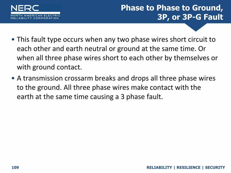
• This fault type occurs when any two phase wires short circuit to each other and earth neutral or ground at the same time. Or when all three phase wires short to each other by themselves or with ground contact.
• A transmission crossarm breaks and drops all three phase wires to the ground. All three phase wires make contact with the earth at the same time causing a 3 phase fault.
Phase to Phase to Ground, 3P, or 3P-G Fault

RELIABILITY | RESILIENCE | SECURITY110
• In instances where the fault type changes over the duration of the fault, the fault type should be reported as the most egregious option.
• As an example; a fault initiates as a single phase to ground then evolves into a two phase to ground fault. The fault should be reported as a two phase to ground fault.
Selecting Fault Type for Evolving Fault

RELIABILITY | RESILIENCE | SECURITY111
• Fault recorder/Digital Relay records While not always available, records from remote stations could indicate
which phases were involved and provide the best information for determining fault type.
• Relay Targets While usually available, may be cumbersome to evaluate when multiple
events have occurred before the targets are obtained from a station.
• Patrol Results When relay targets or fault records are not available, patrol results can tell
what the fault type was based on damage reports or repairs made.
Best methods to determine fault type
RELIABILITY | RESILIENCE | SECURITY112
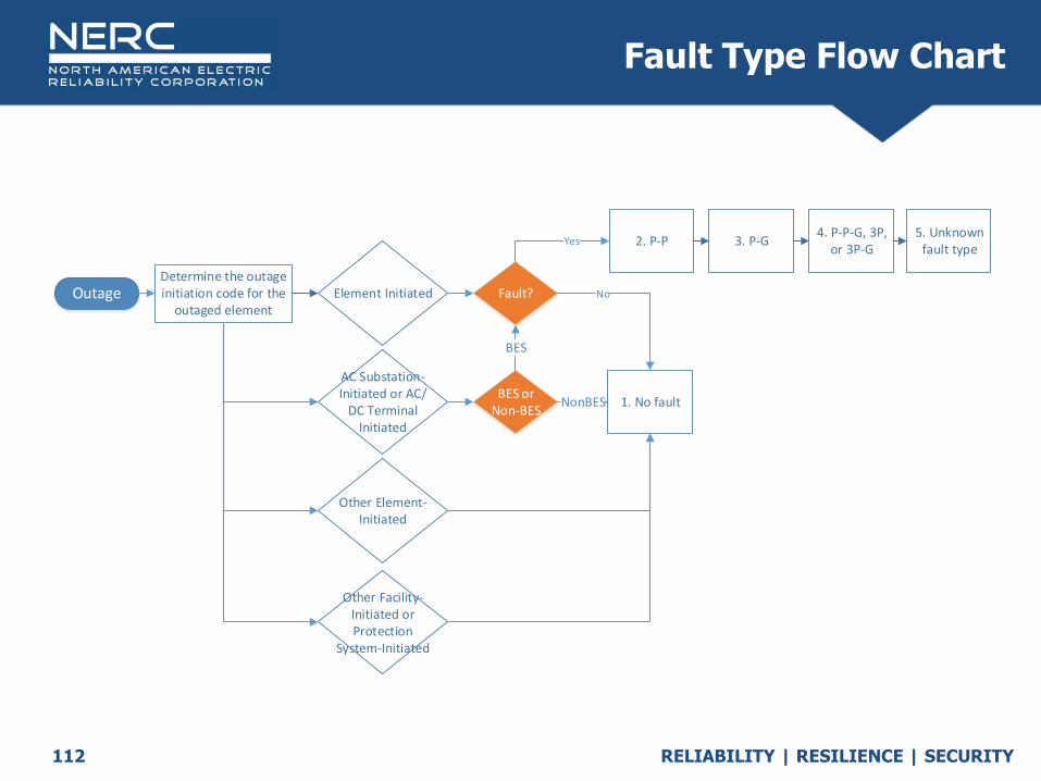
Fault Type Flow Chart
Determine the outage initiation code for the
outaged elementElement Initiated
Other Element-Initiated
AC Substation-Initiated or AC/
DC Terminal Initiated
Other Facility-Initiated or Protection
System-Initiated
1. No fault
2. P-P 3. P-G4. P-P-G, 3P,
or 3P-G 5. Unknown
fault type
BES or Non-BES
Fault?Outage
NonBES
Yes
BES
No
RELIABILITY | RESILIENCE | SECURITY113
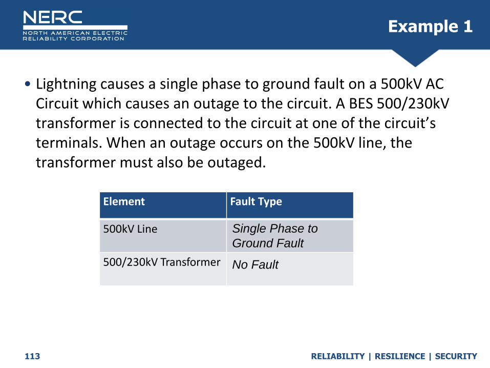
• Lightning causes a single phase to ground fault on a 500kV AC Circuit which causes an outage to the circuit. A BES 500/230kV transformer is connected to the circuit at one of the circuit’s terminals. When an outage occurs on the 500kV line, the transformer must also be outaged.
Example 1
Element Fault Type
500kV Line
500/230kV Transformer
Single Phase to
Ground Fault
No Fault
RELIABILITY | RESILIENCE | SECURITY114
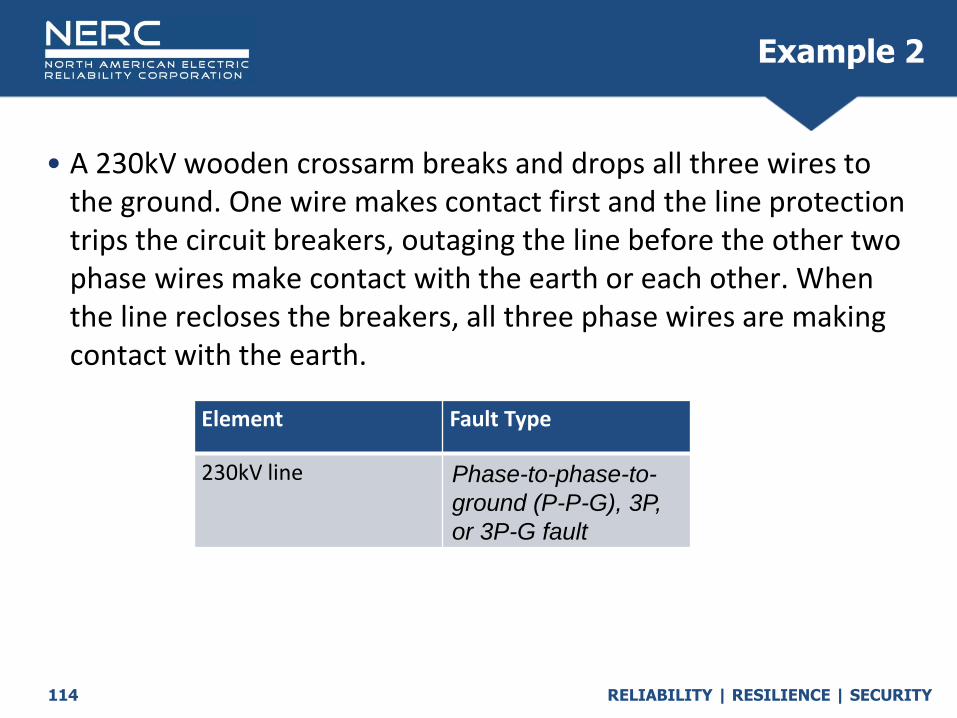
• A 230kV wooden crossarm breaks and drops all three wires to the ground. One wire makes contact first and the line protection trips the circuit breakers, outaging the line before the other two phase wires make contact with the earth or each other. When the line recloses the breakers, all three phase wires are making contact with the earth.
Example 2
Element Fault Type
230kV line Phase-to-phase-to-
ground (P-P-G), 3P,
or 3P-G fault
RELIABILITY | RESILIENCE | SECURITY115
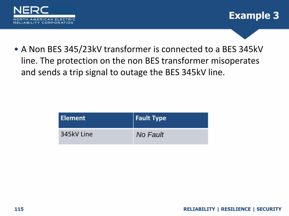
• A Non BES 345/23kV transformer is connected to a BES 345kV line. The protection on the non BES transformer misoperatesand sends a trip signal to outage the BES 345kV line.
Example 3
Element Fault Type
345kV Line No Fault

RELIABILITY | RESILIENCE | SECURITY116
• A 500kV line has an A-G fault and trips out the A phase portion of the circuit, however the remaining phase B and C remained energized. The A phase pole successfully reclosed after 10 seconds. This only pertains to single pole tripping.
Example 4
Element Fault Type
Single pole outages are not
reportable.
RELIABILITY | RESILIENCE | SECURITY
Outage Modes
October 2020

RELIABILITY | RESILIENCE | SECURITY119
• The Outage Mode Code describes whether an Automatic Outage is related to other Automatic Outages. Single Mode Outage
Dependent Mode Initiating Outage
Dependent Mode Outage
Common Mode Outage
Common Mode Initiating Outage
Outage Mode

RELIABILITY | RESILIENCE | SECURITY120
Outage Mode CodeOutage Mode Decision Tree
TADS Outage
Was this the result of another
TADS or non-TADS outage?
Any other related TADS
outages at the same time?
Did this cause another TADS
outage?
Any other related TADS outages not
caused by this one?
Dependent Mode Single Mode Common ModeCommon Mode
InitiatingDependent Mode
Initiating
No Yes Yes
NoYesNoNoYes

RELIABILITY | RESILIENCE | SECURITY121
Outage Mode CodeSingle Mode Outage
An Automatic Outage of a single Element that occurred independent of any other Automatic Outages (if any).

RELIABILITY | RESILIENCE | SECURITY122
Outage Mode CodeCommon Mode
One of two or more Automatic Outages with the same Initiating Cause Code and where the outages are not consequences of each other and occur nearly simultaneously (i.e., within cycles or seconds of one another).
• Bus Fault
TL-1
TL-2
TL-3
TL-4
Station A
Line A-C
Station C

RELIABILITY | RESILIENCE | SECURITY123
Outage Mode CodeCommon Mode
One of two or more Automatic Outages with the same Initiating Cause Code and where the outages are not consequences of each other and occur nearly simultaneously (i.e., within cycles or seconds of one another).
• Single ‘Cause’ (Lighting, Tornado, etc.), near simultaneous: Do they share tower (River Crossing?) – Common Mode Are they in close proximity, share ROW – Common Mode
TL-C1
TL-C2
TL-C3
TL-C4
Station A
TL-A2
Station C
TL-D2
TL-D1
Station D
TL-A1
TL-A3

RELIABILITY | RESILIENCE | SECURITY124
• Two or more outages
• One outage can be non-Element; hence not all Dependent Mode outages will have an associated Dependent Mode Initiating Outage
• Dependent Mode Outage must be a result of another outage.
• Initiating Outage: Single Element: Dependent Mode Initiating Outage
Multiple Elements with same Cause at the same time and not consequences of each other: Common Mode Initiating Outage
• Resulting Outage: Single Element: Dependent Mode Outage
Multiple Elements with same Cause at the same time and not consequences of each other: Common Mode Outage
Multiple Elements with same Cause at the same time and are consequences of each other: Dependent Mode Outage
Outage Mode CodeDependent Mode
RELIABILITY | RESILIENCE | SECURITY125
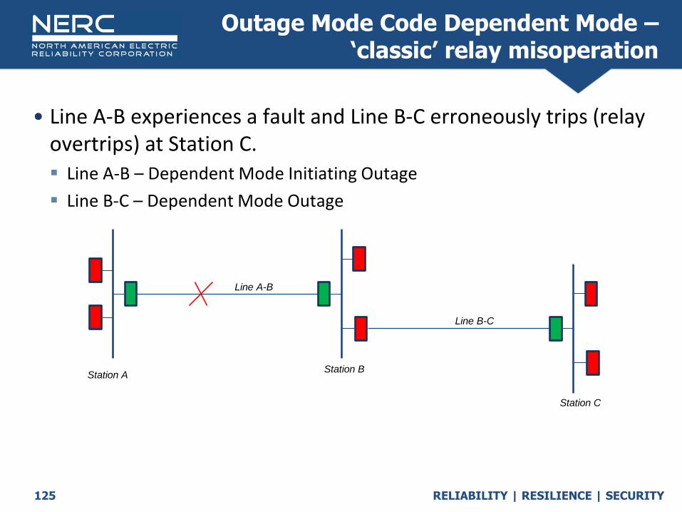
• Line A-B experiences a fault and Line B-C erroneously trips (relay overtrips) at Station C. Line A-B – Dependent Mode Initiating Outage
Line B-C – Dependent Mode Outage
Outage Mode Code Dependent Mode –‘classic’ relay misoperation
Station AStation B
Line A-B
Line B-C
Station C
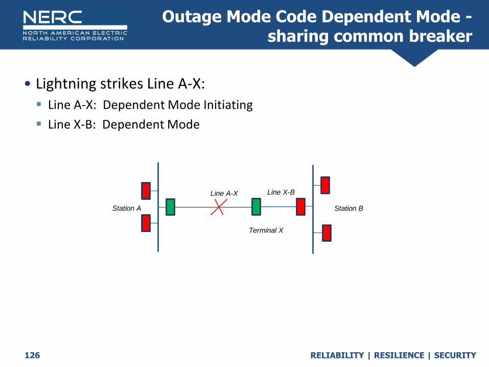
RELIABILITY | RESILIENCE | SECURITY126
• Lightning strikes Line A-X: Line A-X: Dependent Mode Initiating
Line X-B: Dependent Mode
Outage Mode Code Dependent Mode -sharing common breaker
Station BStation A
Terminal X
Line X-BLine A-X

RELIABILITY | RESILIENCE | SECURITY127
• Breaker at Terminal X trips due to low SF6 gas: Line A-X: Common mode
Line X-B: Common mode
Outage Mode Code Common Mode -sharing common breaker
Station BStation A
Terminal X
Line X-BLine A-X

RELIABILITY | RESILIENCE | SECURITY128
Lightning strikes Line A-B and Line C-D a few seconds apart. They don’t share ROW or any equipment. All lines are BES elements.
What is the Outage Mode Code for Line A-B?
A. Single Mode Outage
B. Dependent Mode Initiating Outage
C. Dependent Mode Outage
D. Common Mode Outage
E. Common Mode Initiating Outage
Example 1a:Two Interruptions During a Storm
Station C
Station A Station B
Line A-B
Line B-C
Station D
Line C-D
+ 2 seconds
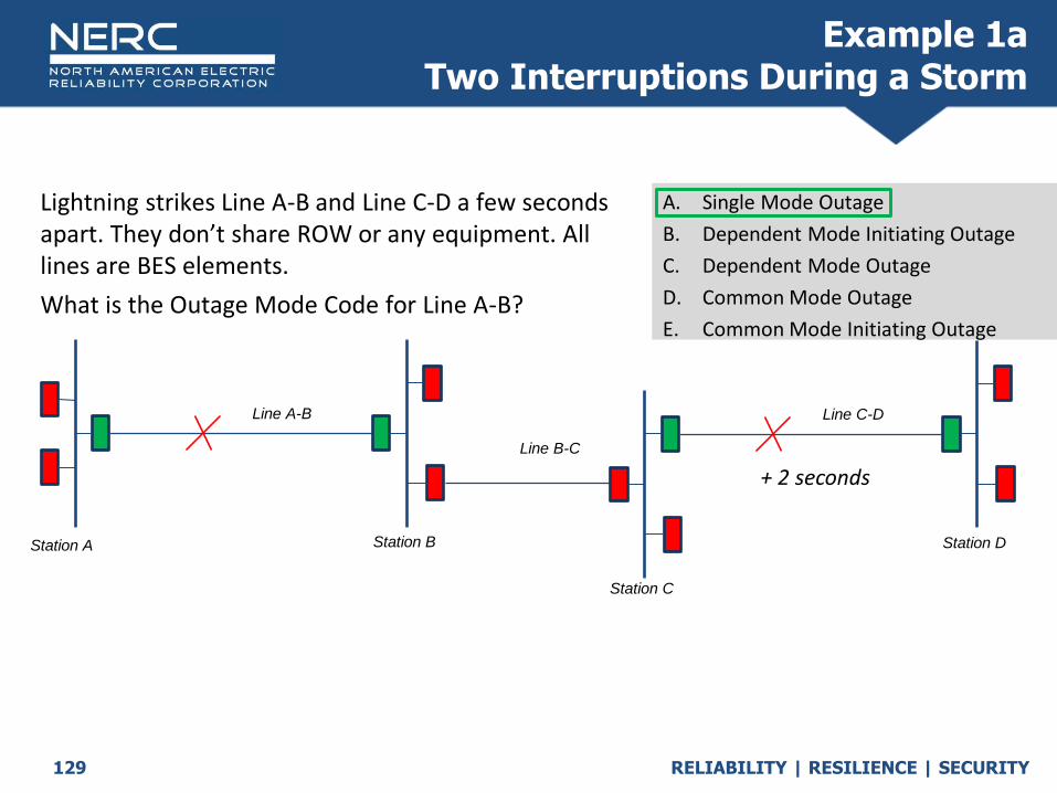
RELIABILITY | RESILIENCE | SECURITY129
Lightning strikes Line A-B and Line C-D a few seconds apart. They don’t share ROW or any equipment. All lines are BES elements.
What is the Outage Mode Code for Line A-B?
A. Single Mode Outage
B. Dependent Mode Initiating Outage
C. Dependent Mode Outage
D. Common Mode Outage
E. Common Mode Initiating Outage
Example 1aTwo Interruptions During a Storm
Station C
Station A Station B
Line A-B
Line B-C
Station D
Line C-D
+ 2 seconds

RELIABILITY | RESILIENCE | SECURITY130
Lightning strikes Line A-B and Line C-D a few seconds apart. They don’t share ROW or any equipment. All lines are BES elements.
What is the Outage Mode Code for Line C-D?
A. Single Mode Outage
B. Dependent Mode Initiating Outage
C. Dependent Mode Outage
D. Common Mode Outage
E. Common Mode Initiating Outage
Example 1bTwo Interruptions During a Storm
Station C
Station A Station B
Line A-B
Line B-C
Station D
Line C-D
+ 2 seconds

RELIABILITY | RESILIENCE | SECURITY131
Lightning strikes Line A-B and Line C-D a few seconds apart. They don’t share ROW or any equipment. All lines are BES elements.
What is the Outage Mode Code for Line C-D?
Q
A. Single Mode Outage
B. Dependent Mode Initiating Outage
C. Dependent Mode Outage
D. Common Mode Outage
E. Common Mode Initiating Outage
Example 1bTwo Interruptions During a Storm
Station C
Station A Station B
Line A-B
Line B-C
Station D
Line C-D
+ 2 seconds

RELIABILITY | RESILIENCE | SECURITY132
Station A Station B
Line A-B
Line B-C
Station D
Line C-D
Station C
Fault on Line B-C. Two separate relay issues (Protection System) at Station A and Station D. All lines are BES elements.
What is the Outage Mode Code for Line B-C?
A. Single Mode Outage
B. Dependent Mode Initiating Outage
C. Dependent Mode Outage
D. Common Mode Outage
E. Common Mode Initiating Outage
Example 2aTwo Interruptions During a Storm
RELIABILITY | RESILIENCE | SECURITY133
Station A Station B
Line A-B
Line B-C
Station D
Line C-D
Station C
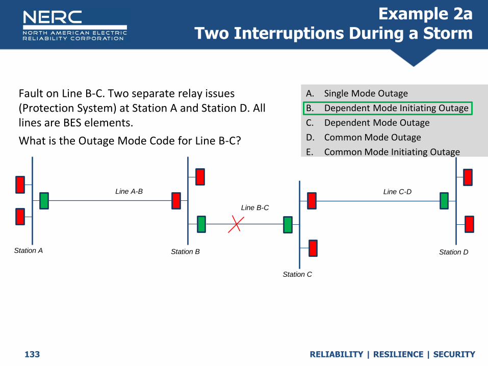
Fault on Line B-C. Two separate relay issues (Protection System) at Station A and Station D. All lines are BES elements.
What is the Outage Mode Code for Line B-C?
A. Single Mode Outage
B. Dependent Mode Initiating Outage
C. Dependent Mode Outage
D. Common Mode Outage
E. Common Mode Initiating Outage
Example 2aTwo Interruptions During a Storm

RELIABILITY | RESILIENCE | SECURITY134
Station A Station B
Line A-B
Line B-C
Station D
Line C-D
Station C
Fault on Line B-C. Two separate relay issues (Protection System) at Station A and Station D. All lines are BES elements.
What is the Outage Mode Code for Line A-B?
A. Single Mode Outage
B. Dependent Mode Initiating Outage
C. Dependent Mode Outage
D. Common Mode Outage
E. Common Mode Initiating Outage
Example 2bTwo Interruptions During a Storm

RELIABILITY | RESILIENCE | SECURITY135
Station A Station B
Line A-B
Line B-C
Station D
Line C-D
Station C
Fault on Line B-C. Two separate relay issues (Protection System) at Station A and Station D. All lines are BES elements.
What is the Outage Mode Code for Line A-B?
A. Single Mode Outage
B. Dependent Mode Initiating Outage
C. Dependent Mode Outage
D. Common Mode Outage
E. Common Mode Initiating Outage
Example 2bTwo Interruptions During a Storm

RELIABILITY | RESILIENCE | SECURITY136
Station A Station B
Line A-B
Line B-C
Station D
Line C-D
Station C
Fault on Line B-C. Two separate relay issues (Protection System) at Station A and Station D. All lines are BES elements.
What is the Outage Mode Code for Line C-D?
A. Single Mode Outage
B. Dependent Mode Initiating Outage
C. Dependent Mode Outage
D. Common Mode Outage
E. Common Mode Initiating Outage
Example 2cTwo Interruptions During a Storm
RELIABILITY | RESILIENCE | SECURITY137
Station A Station B
Line A-B
Line B-C
Station D
Line C-D
Station C
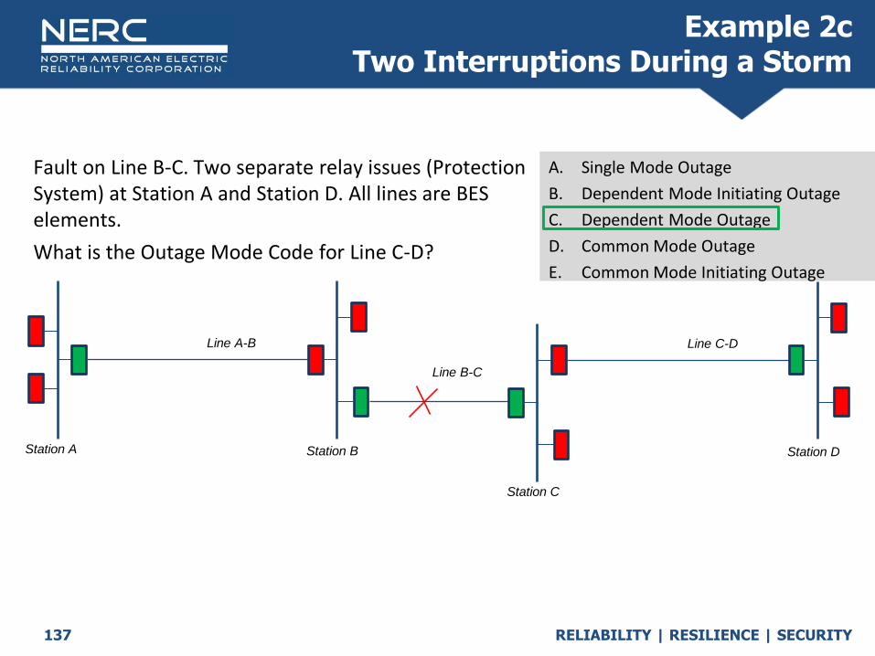
Fault on Line B-C. Two separate relay issues (Protection System) at Station A and Station D. All lines are BES elements.
What is the Outage Mode Code for Line C-D?
A. Single Mode Outage
B. Dependent Mode Initiating Outage
C. Dependent Mode Outage
D. Common Mode Outage
E. Common Mode Initiating Outage
Example 2cTwo Interruptions During a Storm

RELIABILITY | RESILIENCE | SECURITY138
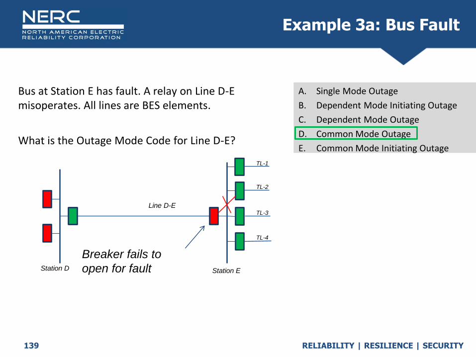
Bus at Station E has fault. A relay on Line D-E misoperates. All lines are BES elements.
What is the Outage Mode Code for Line D-E?
Q
A. Single Mode Outage
B. Dependent Mode Initiating Outage
C. Dependent Mode Outage
D. Common Mode Outage
E. Common Mode Initiating Outage
Example 3a: Bus Fault
Breaker fails to
open for fault
TL-1
TL-2
TL-3
TL-4
Station D
Line D-E
Station E
RELIABILITY | RESILIENCE | SECURITY139
Bus at Station E has fault. A relay on Line D-E misoperates. All lines are BES elements.
What is the Outage Mode Code for Line D-E?
Q
A. Single Mode Outage
B. Dependent Mode Initiating Outage
C. Dependent Mode Outage
D. Common Mode Outage
E. Common Mode Initiating Outage
Example 3a: Bus Fault
Breaker fails to
open for fault
TL-1
TL-2
TL-3
TL-4
Station D
Line D-E
Station E
RELIABILITY | RESILIENCE | SECURITY140
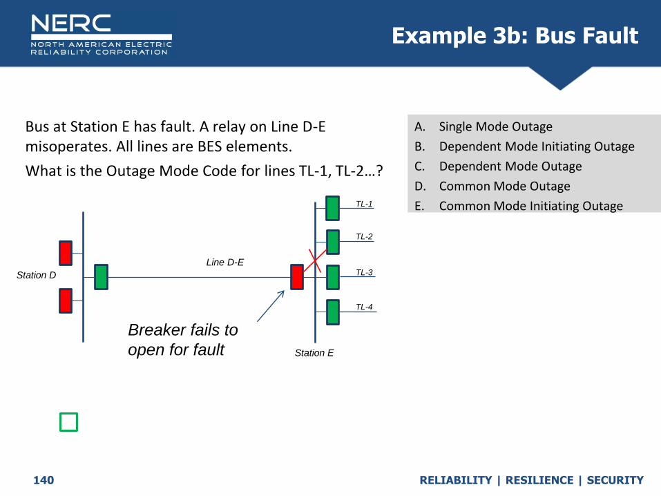
Bus at Station E has fault. A relay on Line D-E misoperates. All lines are BES elements.
What is the Outage Mode Code for lines TL-1, TL-2…?
Q
A. Single Mode Outage
B. Dependent Mode Initiating Outage
C. Dependent Mode Outage
D. Common Mode Outage
E. Common Mode Initiating Outage
Example 3b: Bus Fault
Breaker fails to
open for fault
TL-1
TL-2
TL-3
TL-4
Station D
Line D-E
Station E

RELIABILITY | RESILIENCE | SECURITY141
Bus at Station E has fault. A relay on Line D-E misoperates. All lines are BES elements.
What is the Outage Mode Code for lines TL-1, TL-2…?
Q
A. Single Mode Outage
B. Dependent Mode Initiating Outage
C. Dependent Mode Outage
D. Common Mode Outage
E. Common Mode Initiating Outage
Example 3b: Bus Fault
Breaker fails to
open for fault
TL-1
TL-2
TL-3
TL-4
Station D
Line D-E
Station E


RELIABILITY | RESILIENCE | SECURITY
Outage ID and Event ID
Codes
October 2020

RELIABILITY | RESILIENCE | SECURITY144
• A unique alphanumeric identifier assigned by the Transmission Owner (TO) to identify the reported outage of an Element.
• The Outage ID code is assigned by the TO
• Can be alphanumeric
• Must be unique across years (can’t use the ID “Outage 1” in 2016 and then again in 2017)
• Examples: ACRO-YYYY-00000, INYY-00, YYYY_00000, or 00000 (where the number is usually from the entities outage system)
Outage ID Code

RELIABILITY | RESILIENCE | SECURITY145
• Momentary Outage: An Automatic Outage with an Outage Duration less than one minute.
o If the circuit recloses and trips again within less than a minute of the initial outage, it is only considered one outage. The circuit would need to remain in service for longer than one minute between the breaker operations to be considered as two outages.
• Sustained Outage: An Automatic Outage with an Outage Duration of a minute or greater.
Momentary or Sustained
RELIABILITY | RESILIENCE | SECURITY146
• Event Identification (ID) Code - A unique alphanumeric identifier assigned by the TO to an Event. 1. An Event associated with a Single Mode Outage will have just one Event
ID Code.
2. Each outage in a related set of two or more outages (e.g., Dependent Mode, Dependent Mode Initiating, Common Mode or Common Mode Initiating) shall be given the same Event ID Code.
Event ID should typically not be linked to multiple Single Mode Outages.
Correct examples include:
o One Single Mode Outage; One Dependent Mode - Initiating and One or Multiple
o Dependent Mode Outages; One Common Mode – Initiating and Multiple
o Common Mode Outages; Two or more Common Mode Outages
Event ID would not include multiple separate trip and reclose due to weather caused galloping conductors
Event Definition

RELIABILITY | RESILIENCE | SECURITY147
• Event ID Codes must be created on Form 5 before outages can be entered on Form 4.x.
• An Event associated with a Single Mode Outage will have one Event ID Code.
• Each outage in a related set of two or more outages (e.g., Dependent Mode, Dependent Mode Initiating, Common Mode, Common Mode Initiating) shall be given the same Event ID Code.
• For outages within a single TO, the TO assigns its own Event ID Code.
Event ID Code

RELIABILITY | RESILIENCE | SECURITY148
• webTADS tracks each TO’s Event ID codes over multiple years and does not permit the same Event ID to be used twice by any given TO.
• Any pattern of alphanumeric characters may be used on Form 5 to define the Event ID code. Example: 1-2017 or A-2017
• Each year a new Form 4.x Outage ID Code is required, however, for outages due to an Event which started in the prior year, the prior year Form 5 Event ID code must be used on the current year Form 4.x.
Event ID Code

RELIABILITY | RESILIENCE | SECURITY149
• Click on Transmission (TADS)
• Select Forms
• Select Event ID Codes 5.0
Event ID Code New
OATI Proprietary Notice: All OATI products and services listed are trademarks and service marks of Open Access Technology International, Inc. All rights reserved.
RELIABILITY | RESILIENCE | SECURITY150
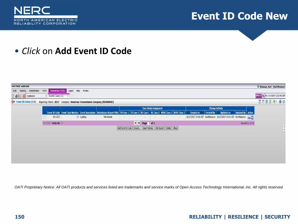
• Click on Add Event ID Code
Event ID Code New
OATI Proprietary Notice: All OATI products and services listed are trademarks and service marks of Open Access Technology International, Inc. All rights reserved.

RELIABILITY | RESILIENCE | SECURITY151
• Enter unique Event ID Code
Event ID Code New
OATI Proprietary Notice: All OATI products and services listed are trademarks and service marks of Open Access Technology International, Inc. All rights reserved.

RELIABILITY | RESILIENCE | SECURITY152
• Select correct Event Type Number
Event ID Code New
OATI Proprietary Notice: All OATI products and services listed are trademarks and service marks of Open Access Technology International, Inc. All rights reserved.

RELIABILITY | RESILIENCE | SECURITY153
• Enter brief Description
• Disturbance Report
• Click on Enter
Event ID Code New
OATI Proprietary Notice: All OATI products and services listed are trademarks and service marks of Open Access Technology International, Inc. All rights reserved.

RELIABILITY | RESILIENCE | SECURITY154
• https://www.oe.netl.doe.gov/OE417/Form/Home.aspx
Event ID Code New

RELIABILITY | RESILIENCE | SECURITY155
• Click on OK
Event ID Code New
Case Study
Assignment:
Allows the TO, RE or
NERC to checkmark
multiple events and
then filter based on
selected events for a
special report e.g.
Polar Vortex report
Note: Events have to be
manually unchecked after
case study is complete.
OATI Proprietary Notice: All OATI products and services listed are trademarks and service marks of Open Access Technology International, Inc. All rights reserved.

RELIABILITY | RESILIENCE | SECURITY156
• A new Event ID Code is created
Event ID Code New
OATI Proprietary Notice: All OATI products and services listed are trademarks and service marks of Open Access Technology International, Inc. All rights reserved.

RELIABILITY | RESILIENCE | SECURITY157
• Click on Edit to modify existing Event Code ID
Event ID Code Edit
OATI Proprietary Notice: All OATI products and services listed are trademarks and service marks of Open Access Technology International, Inc. All rights reserved.

RELIABILITY | RESILIENCE | SECURITY158
• Modify data as needed
• Click on Modify
Event ID Code Edit
OATI Proprietary Notice: All OATI products and services listed are trademarks and service marks of Open Access Technology International, Inc. All rights reserved.

RELIABILITY | RESILIENCE | SECURITY159
• Click on OK
Event ID Code Edit
OATI Proprietary Notice: All OATI products and services listed are trademarks and service marks of Open Access Technology International, Inc. All rights reserved.
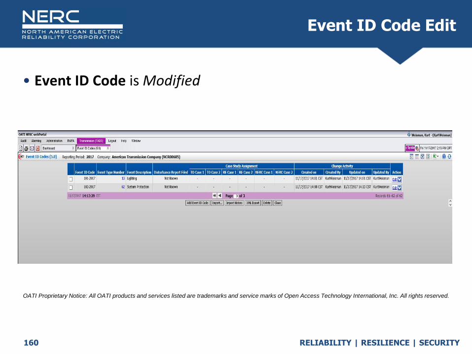
RELIABILITY | RESILIENCE | SECURITY160
• Event ID Code is Modified
Event ID Code Edit
OATI Proprietary Notice: All OATI products and services listed are trademarks and service marks of Open Access Technology International, Inc. All rights reserved.

RELIABILITY | RESILIENCE | SECURITY161
• TOs (or Regional Entities) coordinate a unique NERC wide (NMU) Event ID code on Form 5 if outages affect two or more Reporting TO’s. NMUs are only for automatic outages where multiple reporting TOs are entering data on 4.X forms. Open Form 5
Click the Filter Options Icon on the right hand side of the screen
In the Filtering Options menu click the Company drop down menu and select “NERC Event ID Codes”
Click Apply
Event ID Code NMU
OATI Proprietary Notice: All OATI products and services listed are trademarks and service marks of Open Access Technology International, Inc. All rights reserved.

RELIABILITY | RESILIENCE | SECURITY162
• Click “Add Event ID Code” to create the next NMU number
• Fill out the form and share the NMU with the other effected TOs NOTE: The Event ID Code, Event Type number and event description will be
public to any TO in TADS but the TO information will remain confidential.
Event ID Code NMU
OATI Proprietary Notice: All OATI products and services listed are trademarks and service marks of Open Access Technology International, Inc. All rights reserved.
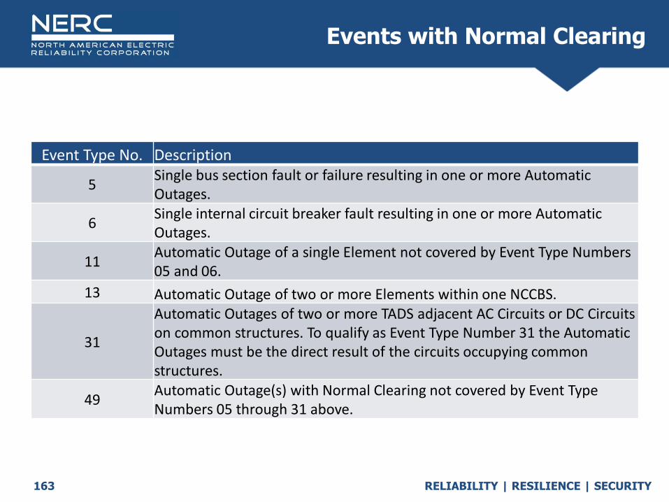
RELIABILITY | RESILIENCE | SECURITY163
Events with Normal Clearing
Event Type No. Description
5Single bus section fault or failure resulting in one or more Automatic Outages.
6Single internal circuit breaker fault resulting in one or more Automatic Outages.
11Automatic Outage of a single Element not covered by Event Type Numbers 05 and 06.
13 Automatic Outage of two or more Elements within one NCCBS.
31
Automatic Outages of two or more TADS adjacent AC Circuits or DC Circuits on common structures. To qualify as Event Type Number 31 the Automatic Outages must be the direct result of the circuits occupying common structures.
49Automatic Outage(s) with Normal Clearing not covered by Event Type Numbers 05 through 31 above.

RELIABILITY | RESILIENCE | SECURITY164
Event Type – Normal Clearing
Event Type Determination
Normal or Abnormal clearing
NormalEvent Type 05
Bus section fault or failure
Event Type 06Single internal circuit
breaker faultYesType 05 or 06
Event Type 11Single mode or
dependent mode outage ONLY
Event Type 13Automatic outage of two or more elements within one
NCCBS
Type 11 or 13
No
Event Type 31Automatic outage of two or more TADS adjacent AC/DC
circuits on common structures
Yes
Type 31
No
Yes
Type 49
No
Event Type 49Other Normal Clearing
event not covered by type 05-31
Yes
Abnormal
4.X Dependent mode initiating outage or Dependent mode outage

RELIABILITY | RESILIENCE | SECURITY165
Events with Abnormal Clearing
Event Type No. Description
60Breaker Failure: One or more Automatic Outages with Delayed Fault Clearing due to a circuit breaker being stuck, slow to open or failure to interrupt current.
61
Dependability (failure to operate): One or more Automatic Outages with Delayed Fault Clearing due to failure of a single Protection System (primary or secondary backup) under either of these conditions: a. failure to initiate the isolation of a faulted power system Element as designed, or within its designed operating time, or b. In the absence of a fault, failure to operate as intended within its designed operating time. (Item b is a very rare type of event.)
62
Security (unintended operation): One or more Automatic Outages caused by improper operation (e.g. overtrip) of a Protection System resulting in isolating one or more TADS Elements it is not intended to isolate, either during a fault or in the absence of a fault.
90 Automatic Outage(s) with Abnormal Clearing not covered above.

RELIABILITY | RESILIENCE | SECURITY166
Event Type – Abnormal Clearing
Event Type Determination
Normal or Abnormal clearing
NormalAbnormalType 60
Event Type 60Breaker failure: Automatic Outages
experienced Delayed Clearing due to one or more circuit Breaker Failures
Type 61 or 62 Event Type 61
Dependability (failure to operate)Event Type 62
Security (false or undesirable operation)
Type 90Event Type 90
Other Abnormal Clearing event not covered by type 60-62
Yes
No
Yes
No
Yes

RELIABILITY | RESILIENCE | SECURITY167
Normal Clearing Event Type Numbers
Which of these isn’t an actual event code?Event Type Number Descriptions: Events with Normal Clearing
Choice Event Type No. Description
A 5 Single bus section fault or failure resulting in one or more Automatic Outages.
B 6 Single internal circuit breaker fault resulting in one or more Automatic Outages.
C 11Automatic Outage of a single Element not covered by Event Type Numbers 05 and 06.
D 13 Automatic Outage of two or more Elements within one NCCBS.
E 21 Automatic Outage of two or more Elements within two NCCBS.
F 31
Automatic Outages of two or more TADS adjacent AC Circuits or DC Circuits on common structures. To qualify as Event Type Number 31 the Automatic Outages must be the direct result of the circuits occupying common structures.
G 49Automatic Outage(s) with Normal Clearing not covered by Event Type Numbers 05 through 31 above.

RELIABILITY | RESILIENCE | SECURITY168
Normal Clearing Event Type Numbers
Which of these isn’t an actual event code?Event Type Number Descriptions: Events with Abnormal Clearing
Choice Event Type No. Description
A 60Breaker Failure: One or more Automatic Outages with Delayed Fault Clearing due to a circuit breaker being stuck, slow to open or failure to interrupt current.
B 61
Dependability (failure to operate): One or more Automatic Outages with Delayed Fault Clearing due to failure of a single Protection System (primary or secondary backup) under either of these conditions: a. failure to initiate the isolation of a faulted power system Element as designed, or within its designed operating time, or b. In the absence of a fault, failure to operate as intended within its designed operating time. (Item b is a very rare type of event.)
C 62
Security (unintended operation): One or more Automatic Outages caused by improper operation (e.g. overtrip) of a Protection System resulting in isolating one or more TADS Elements it is not intended to isolate, either during a fault or in the absence of a fault.
D 63Bus Failure: Improper operation of a Protections System resulting in a Single Bus section interruption.
E 90 Automatic Outage(s) with Abnormal Clearing not covered above.
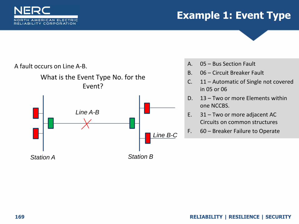
RELIABILITY | RESILIENCE | SECURITY169
What is the Event Type No. for the Event?
A. 05 – Bus Section Fault
B. 06 – Circuit Breaker Fault
C. 11 – Automatic of Single not covered in 05 or 06
D. 13 – Two or more Elements within one NCCBS.
E. 31 – Two or more adjacent AC Circuits on common structures
F. 60 – Breaker Failure to Operate
A fault occurs on Line A-B.
Station A Station B
Line A-B
Line B-C
Example 1: Event Type

RELIABILITY | RESILIENCE | SECURITY170
What is the Event Type No. for the Event?
A. 05 – Bus Section Fault
B. 06 – Circuit Breaker Fault
C. 11 – Automatic of Single not covered in 05 or 06
D. 13 – Two or more Elements within one NCCBS.
E. 31 – Two or more adjacent AC Circuits on common structures
F. 60 – Breaker Failure to Operate
A fault occurs on Line A-B.
Station A Station B
Line A-B
Line B-C
Example 1: Event Type

RELIABILITY | RESILIENCE | SECURITY171
What is the Event Type No. for the Event?
A. 05 – Bus Section Fault
B. 06 – Circuit Breaker Fault
C. 11 – Automatic of Single not covered in 05 or 06
D. 13 – Two or more Elements within one NCCBS.
E. 31 – Two or more adjacent AC Circuits on common structures
F. 60 – Breaker Failure to Operate
A fault on AC Circuit ‘A-X’.
Example 2: Event Type
Station A Station B
Terminal X
Line X-BLine A-X

RELIABILITY | RESILIENCE | SECURITY172
What is the Event Type No. for the Event?
A. 05 – Bus Section Fault
B. 06 – Circuit Breaker Fault
C. 11 – Automatic of Single not covered in 05 or 06
D. 13 – Two or more Elements within one NCCBS.
E. 31 – Two or more adjacent AC Circuits on common structures
F. 60 – Breaker Failure to Operate
A fault on AC Circuit ‘A-X’.
Example 2: Event Type
Station A Station B
Terminal X
Line X-BLine A-X

RELIABILITY | RESILIENCE | SECURITY173
What is the Event Type No. for the Event?
A. 05 – Bus Section Fault
B. 06 – Circuit Breaker Fault
C. 11 – Automatic of Single not covered in 05 or 06
D. 31 – Two or more adjacent AC Circuits on common structures
E. 60 – Breaker Failure to Operate
F. 61 – Dependability – Failure to Operate
Tornado destroys a rivers crossing tower shared by 3 lines.
Example 3: Event Type
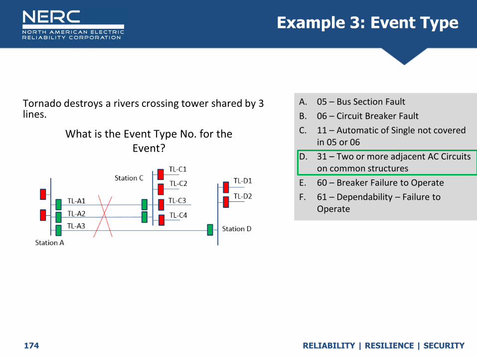
RELIABILITY | RESILIENCE | SECURITY174
What is the Event Type No. for the Event?
A. 05 – Bus Section Fault
B. 06 – Circuit Breaker Fault
C. 11 – Automatic of Single not covered in 05 or 06
D. 31 – Two or more adjacent AC Circuits on common structures
E. 60 – Breaker Failure to Operate
F. 61 – Dependability – Failure to Operate
Tornado destroys a rivers crossing tower shared by 3 lines.
Example 3: Event Type

RELIABILITY | RESILIENCE | SECURITY
Test Your Knowledge
October 2020
RELIABILITY | RESILIENCE | SECURITY177
TADS Test Your Knowledge
Related Documents