TRANSIT RAPID TRANSIT SYSTEM EXTENSIONS COMPENDIUM OF DESIGN CRITERIA VOLUME III AERIAL GUIDEWAY DESIGN CRITERIA CHAPTER 4 ELECTRICAL DESIGN CRITERIA INTERIM RELEASE REV 1 OCTOBER 30, 2008 PROGRAM MANAGEMENT CONSULTANT

Welcome message from author
This document is posted to help you gain knowledge. Please leave a comment to let me know what you think about it! Share it to your friends and learn new things together.
Transcript

TRANSIT
RAPID TRANSIT SYSTEM EXTENSIONS COMPENDIUM OF DESIGN CRITERIA
VOLUME III AERIAL GUIDEWAY DESIGN CRITERIA
CHAPTER 4
ELECTRICAL DESIGN CRITERIA
INTERIM RELEASE REV 1
OCTOBER 30, 2008
PROGRAM MANAGEMENT CONSULTANT

– Intentionally Left Blank –


TRANSIT
VOLUME III – AERIAL GUIDEWAY CHAPTER 4 – ELECTRICAL INTERIM RELEASE REV 1
– Intentionally Left Blank –

TRANSIT
VOLUME III – AERIAL GUIDEWAY CHAPTER 4 – ELECTRICAL INTERIM RELEASE REV 1
DOCUMENT REVISION RECORD
ISSUE NO. DATE REVISION DESCRIPTIONS
0 5-8-07 Interim Release
1 10-30-08 Revisions to incorporate MIC-EH design specifications that have been adopted by MDT.
ISSUE NO. SECTIONS CHANGED
1 4.05.1.1 Corrosion Control -Scope- (grammar correction)
4.05.1.2 Corrosion Control -Scope- included other utilities within list
4.05.2.3 Corrosion Control -Electrical Equipment - FRE only for Traction Power.
4.05.3.1.A.1 Corrosion Control - Stray Current Corrosion Control - Stray Current Control – (grammar correction)
4.05.3.1.A.5a&b Corrosion Control - Stray Current Corrosion Control - Stray Current Control
4.05.3.1.B.3 Corrosion Control - Stray Current Corrosion Control - Stray Current Control – (formatting correction)
4.05.3.2.F Corrosion Control - Stray Current Corrosion Control – Utilities – (formatting correction)
4.05.5.2 Corrosion Control - Test Stations - Ground Fault Monitoring Stations
4.06.1 Systems-Facilities Interface Raceway - Scope
4.06.2.9.B Systems-Facilities Interface Raceway - Physical Relationships - Wayside Facilities
4.06.2.10.B Systems-Facilities Interface Raceway - Physical Relationships - Raceway Transitional Areas
4.06.3.2.C Systems-Facilities Interface Raceway - Physical Installation - Construction Guidelines - Traction Power Pullboxes
4.06.4.3.C Systems-Facilities Interface Raceway -Materials of Construction-Application of Raceway-Cableway
4.06.5.2.A Systems-Facilities Interface Raceway -Raceway Identification Methods - Raceway Designations

TRANSIT
VOLUME III – AERIAL GUIDEWAY CHAPTER 4 – ELECTRICAL INTERIM RELEASE REV 1
ISSUE NO. SECTIONS CHANGED
4.06.5.2.C Systems-Facilities Interface Raceway -Raceway Identification Methods - Raceway Designations
Figures 4-1a - Single Guideway Structure, Grounding and Stray Current Diagram; 4-1b - Dual Track Guideway Structure, Grounding and Stray Current Diagram; 4-1c - Guideway Sructure, Grounding and Stray Current Notes; 4-2 - Column Mounted Stray Current Test Box Rev. 1; 4-7 - Sections & Details; 4-8 - Sections & Details, Rev 1

TRANSIT
VOLUME III – AERIAL GUIDEWAY i CHAPTER 4 – ELECTRICAL INTERIM RELEASE REV 1
VOLUME III - GUIDEWAY DESIGN CRITERIA
CHAPTER 4 - ELECTRICAL DESIGN CRITERIA
REVISION 1 Table of Contents Page No.
4.01 GENERAL............................................................................................................ 1 4.01.1 PURPOSE ..................................................................................................... 1 4.01.2 BASIC GOALS.............................................................................................. 1 4.01.3 SCOPE .......................................................................................................... 1 4.01.4 INTERFACE DEFINITION AND CONTROL.................................................. 2 4.01.5 CODES, STANDARDS AND REGULATIONS.............................................. 3 4.01.6 RESERVED ................................................................................................... 4
4.02 ELECTRICAL SYSTEMS..................................................................................... 5 4.03 FACILITIES SUPERVISORY CONTROL, STATUS AND ALARM
REQUIREMENTS................................................................................................. 7 4.04 GROUNDING AND LIGHTNING PROTECTION ................................................. 9
4.04.1 SCOPE .......................................................................................................... 9 4.04.2 OBJECTIVE ................................................................................................ 10 4.04.3 ABNORMAL CONDITIONS ........................................................................ 10 4.04.4 GROUNDING ELECTRODE SYSTEM........................................................ 11
4.04.4.1 Main Line Facilities............................................................................... 11 4.04.5 TRACTION POWER GROUNDING............................................................. 14
4.04.5.1 General ................................................................................................ 14 4.04.6 SECONDARY POWER DISTRIBUTION SYSTEM GROUNDING .............. 17
4.04.6.1 General ................................................................................................ 17 4.04.7 GROUNDING NETWORKS......................................................................... 19
4.04.7.1 Signal Grounding Networks.................................................................. 19 4.04.7.2 Chassis Grounding Network................................................................. 19 4.04.7.3 Guideway Grounding ........................................................................... 20 4.04.7.4 Fences ................................................................................................. 22
4.04.8 LIGHTNING PROTECTION......................................................................... 23 4.05 CORROSION CONTROL................................................................................... 25
4.05.1 SCOPE ........................................................................................................ 25 4.05.2 CONTROL OF ATMOSPHERIC CORROSION........................................... 25
4.05.2.1 Materials of Construction...................................................................... 26 4.05.2.2 Coatings ............................................................................................... 26 4.05.2.3 Electrical Equipment ............................................................................ 28 4.05.2.4 General Construction ........................................................................... 29
4.05.3 STRAY CURRENT CORROSION CONTROL............................................. 29 4.05.3.1 Stray Current Control ........................................................................... 30 4.05.3.2 Utilities ................................................................................................. 33
4.05.4 CATHODIC PROTECTION ......................................................................... 35

TRANSIT
VOLUME III – AERIAL GUIDEWAY ii CHAPTER 4 – ELECTRICAL INTERIM RELEASE REV 1
4.05.4.1 Introduction .......................................................................................... 35 4.05.4.2 Galvanic Anodes .................................................................................. 35 4.05.4.3 Impressed Current System................................................................... 35
4.05.5 TEST STATIONS......................................................................................... 38 4.05.5.1 Test Boxes Installations ....................................................................... 38 4.05.5.2 Ground Fault Monitoring Stations......................................................... 39
4.05.6 CORROSION CONTROL OF MECHANICAL EQUIPMENT....................... 39 4.05.7 MISCELLANEOUS ITEMS.......................................................................... 39
4.05.7.1 Communication, Power and Control Cables......................................... 39 4.06 SYSTEMS-FACILITIES INTERFACE RACEWAY............................................. 41
4.06.1 SCOPE ........................................................................................................ 41 4.06.2 PHYSICAL RELATIONSHIP ....................................................................... 42
4.06.2.1 General ................................................................................................ 42 4.06.2.2 Guideways ........................................................................................... 45 4.06.2.3 Ancillary Spaces................................................................................... 47 4.06.2.4 Platform and Under-Platform Areas ..................................................... 50 4.06.2.5 Concourse Area ................................................................................... 50 4.06.2.6 Station Attendant's Booth/Console....................................................... 51 4.06.2.7 Traction Power Substation ................................................................... 51 4.06.2.8 Gap Tie Stations .................................................................................. 53 4.06.2.9 Wayside Facilities ................................................................................ 55 4.06.2.10 Raceway Transitional Areas................................................................. 57
4.06.3 PHYSLCAL INSTALLATION ...................................................................... 58 4.06.3.1 General ................................................................................................ 58 4.06.3.2 Construction Guidelines ....................................................................... 58
4.06.4 MATERIALS OF CONSTRUCTION ............................................................ 61 4.06.4.1 General ................................................................................................ 61 4.06.4.2 Material Nomenclature ......................................................................... 61 4.06.4.3 Application of Raceway........................................................................ 61
4.06.5 RACEWAY IDENTIFICATION METHODS.................................................. 63 4.06.5.1 General ................................................................................................ 63 4.06.5.2 Raceway Designations......................................................................... 63 4.06.5.3 Raceway Schedules............................................................................. 65
APPENDIX A ................................................................................................................ 67

TRANSIT
VOLUME III – AERIAL GUIDEWAY 1 CHAPTER 4 – ELECTRICAL INTERIM RELEASE REV 1
4.01 GENERAL 4.01.1 PURPOSE
These criteria describe the design requirements for the supply of electric
power, grounding, lightning protection, stray current and corrosion control,
and supervisory subsystems for all the facilities of the Metrorail Rapid Transit
System Extension. Station related facilities are covered in other criteria.
Supplementing these criteria are the MDT drawings of existing facilities.
4.01.2 BASIC GOALS 4.01.2.1 The design shall:
A. Provide for safe, economical, reliable and continuous operation of the
entire system.
B. Promote uniformity and standardization in design and equipment
compatible with existing installations and equipment, and compliant with
all codes and applicable regulations.
C. Facilitate installation, operation and maintenance of the equipment.
4.01.3 SCOPE 4.01.3.1 The following shall be included in the guideway electrical system scope:
A. The electrical power and control requirements for the Metrorail electrical
systems.
B. Supervisory requirements (controls, monitoring and alarms) for facilities
equipment and interfacing of such facilities' supervisory requirements
with the overall Supervisory, Control and Data Acquisition (SCADA)

TRANSIT
VOLUME III – AERIAL GUIDEWAY 2 CHAPTER 4 – ELECTRICAL INTERIM RELEASE REV 1
system. Communications, Security, CCTV, fire alarms and intrusion
detection are covered under other design criteria sections.
C. The criteria for design of grounding and lightning protection for the
Metrorail extension equipment and facilities. These criteria apply to all
aerial, below grade, and at grade fixed facilities and equipment and to
rail, fences, and wayside equipment.
D. Requirements for corrosion control for the rapid transit facilities and for
monitoring, controlling and minimizing stray currents.
E. Raceway system for systemwide equipment along the guideway.
F. Systems/Facilities Interface Raceway requirements.
4.01.4 INTERFACE DEFINITION AND CONTROL The facilities electrical subsystem interfaces with a number of other MDT
subsystems. In every case of subsystem to subsystem interface (for
example, Traction Power Substation/Passenger Station Interface) the
interface will be defined, controlled and changed only by the Designer, and
must be approved by MDT.
Section 4.06, Systems/Facilities Interface Raceway defines these interfaces
to a great extent. Electrical subsystem interfaces will be defined and
controlled during the design process by the Designer. For each phase of the
design process, the plans and specifications must be submitted to MDT for
review.

TRANSIT
VOLUME III – AERIAL GUIDEWAY 3 CHAPTER 4 – ELECTRICAL INTERIM RELEASE REV 1
4.01.5 CODES, STANDARDS AND REGULATIONS 4.01.5.1 The current adopted version of codes, standards and regulations shall apply, and
unless otherwise directed, all addenda, interim supplements, revisions and
ordinances by the respective code body shall also apply. Where conflicts exist
between these requirements, the more stringent requirement shall take
precedence, unless otherwise directed by MDT.
• National Electrical Code (NEC)
• National Electric Safety Code (NESC)
• Ordinances of the City of Miami, Miami-Dade County and other
Authorities Having Jurisdiction (AHDs)
• American National Standards Institute (ANSI)
• National Electric Manufacturers Association (NEMA)
• Institute of Electrical and Electronic Engineers (IEEE)
• Insulated Cable Engineers Association (ICEA)
• The Occupational Safety and Health Act (OSHA)
• Florida Building Code (FBC)
• Lightning Protection Code (NFPA No. 780)
• National Association of Corrosion Engineers (NACE International)
• Standard for Fixed Guideway Transit and Passenger Rail Systems
(NFPA 130)
• National Fire Alarm Code (NFPA No. 72)
• Life Safety Code (NFPA 101)
• American Society for Testing and Materials (ASTM)
• Certified Ballast Manufacturers Association (CBM)
• Underwriters' Laboratories, Inc. (UL)
• Miami-Dade County Fire Prevention and Safety Code

TRANSIT
VOLUME III – AERIAL GUIDEWAY 4 CHAPTER 4 – ELECTRICAL INTERIM RELEASE REV 1
• National Electrical Testing Association (NETA)
• Federal Transportation Administration Safety and Security
Standards
• American Disabilities Act (ADA)
4.01.6 RESERVED

TRANSIT
VOLUME III – AERIAL GUIDEWAY 5 CHAPTER 4 – ELECTRICAL INTERIM RELEASE REV 1
4.02 ELECTRICAL SYSTEMS Electrical Systems which are not applicable to Guideways are covered in
other design criteria within this compendium.

TRANSIT
VOLUME III – AERIAL GUIDEWAY 6 CHAPTER 4 – ELECTRICAL INTERIM RELEASE REV 1
– Intentionally Left Blank –

TRANSIT
VOLUME III – AERIAL GUIDEWAY 7 CHAPTER 4 – ELECTRICAL INTERIM RELEASE REV 1
4.03 FACILITIES SUPERVISORY CONTROL, STATUS AND ALARM REQUIREMENTS Facilities Supervisory Control, Status and Alarm requirements which are not
applicable to Guideways are covered in other criteria within this compendium.
TRANSIT
VOLUME III – AERIAL GUIDEWAY 8 CHAPTER 4 – ELECTRICAL INTERIM RELEASE REV 1
– Intentionally Left Blank –

TRANSIT
VOLUME III – AERIAL GUIDEWAY 9 CHAPTER 4 – ELECTRICAL INTERIM RELEASE REV 1
4.04 GROUNDING AND LIGHTNING PROTECTION 4.04.1 SCOPE 4.04.1.1 This section identifies the requirements for the design of the grounding and
lightning protection systems throughout the Metrorail extension areas.
4.04.1.2 Facilities covered by these grounding and lightning protection criteria include the
following:
A. Passenger stations including Electrical Equipment Rooms, Train Control
and Communications Rooms, concourses, pedestrian overpasses,
parking lots, parking structures and other areas in the station confines;
B. Traction Power Substations;
C. Gap Tie Stations;
D. Roadway and Bridge Structures;
E. Guideways.
4.04.1.3 The following equipment items, although not housed in a facility indicated above,
are also covered by these criteria:
A. Wayside train control equipment, signal lines and raceways;
B. Traction power equipment (Blue Light Stations with ETS buttons);
C. Wayside telephone equipment, telephones, pull boxes, raceways and
other miscellaneous communication equipment;
D. Rails and switch machines;
E. Wayside raceway and facilities.
F. Corrosion Control Test Stations.
G. Motor Operated Switches
H. Bumping Posts
I. Derailer (if applicable)
TRANSIT
VOLUME III – AERIAL GUIDEWAY 10 CHAPTER 4 – ELECTRICAL INTERIM RELEASE REV 1
Contact Rail, Cover board, Insulators, Cables, Etc are covered in Volume VII,
Chapter 2, Contact Rail and Cover Board Design Criteria.
4.04.2 OBJECTIVE 4.04.2.1 The grounding and lightning protection systems shall be designed:
A. To protect persons, equipment, facilities and systems against the
hazards posed by voltages that occur in the system under all operating
and fault conditions;
B. To provide a path to ground for discharge of lightning strokes;
C. To reduce electromagnetic interference;
D. To reduce corrosion from stray currents;
E. To provide a low impedance path to ground to facilitate the operation of
over current protection devices on ground faults.
F. To mitigate any induced voltages from overhead power lines.
4.04.3 ABNORMAL CONDITIONS 4.04.3.1 The design of grounding systems in various facilities shall consider the following
hazardous conditions:
A. Primary and secondary distribution systems ground fault.
B. Switching surges.
C. Electrical equipment faults.
D. Direct lightning stroke on any of the facilities.
E. Contact rail ground fault.
F. Fallen power lines across the tracks, structures, wayside equipment, and
security & metallic ornamental fencing.
G. Touch potential (accessible to patrons) voltage between the passenger
vehicle and any nearby grounded metal surfaces, also to include the
TRANSIT
VOLUME III – AERIAL GUIDEWAY 11 CHAPTER 4 – ELECTRICAL INTERIM RELEASE REV 1
potential difference between the running rails and any grounded metal
surface on the guideway, such as the cable tray.
4.04.4 GROUNDING ELECTRODE SYSTEM 4.04.4.1 Main Line Facilities
A. The grounding electrode system for Passenger Stations, Traction Power
Substations and Gap Tie Stations shall consist of a network of
electrically interconnected ground rods, counterpoise, ground grids and
grounding risers designed to obtain a maximum of five ohms resistance
to ground and to minimize step and touch potentials to the level
indicated in IEEE-80 throughout the facility during both normal and
abnormal conditions. The system shall also be capable of dissipating
fault currents to ground for that period of time required for the operation
of the protective devices within the power system. The design of the
grounding electrode system shall be in accordance with NEC Section
250 and IEEE standards utilizing the values of soil resistivity for the
specific site. Resistivity will be determined by the Section Designer with
a minimum of two (2) tests per site to be conducted by the Designer.
B. Ground rods shall be 3/4 inch diameter copper-clad steel and at least 10
feet long. Ground rods shall be installed in accordance with NEC
Section 250.
C. Bare stranded copper ground wire shall be buried without kinks and with
approximately 20 percent slack to form the grounding electrode
configuration (counterpoise and ground grid). Buried ground conductors
shall be installed a minimum of three feet below the final (finished) grade
unless the buried ground conductors are installed beneath concrete

TRANSIT
VOLUME III – AERIAL GUIDEWAY 12 CHAPTER 4 – ELECTRICAL INTERIM RELEASE REV 1
slabs and/or structural footings. The ground conductors shall be
installed in trenches six inches below final excavation for two feet
outside the boundaries of the structure, measuring from outside face of
the exterior walls. In addition, in the event that shallow spread footings
(structural foundations) are utilized, buried ground conductors shall be
installed in trenches six inches below the bottom of the footing
excavation when within five feet or below of said footings. All buried
bare stranded or insulated copper ground wire connections at each
crossover points or taps shall be exothermically welded and coated with
brush applied protective mastic.
D. Counterpoise shall consist of a buried bare stranded copper ground wire
interconnected with driven ground rods surrounding the perimeter of the
facility to which grounding risers and lightning down conductors shall be
connected.
E. Ground grid shall be placed beneath the unit substations and where
required. The ground grid shall consist of horizontal bare stranded
copper ground wire, interconnected with the counterpoise to form a
square mesh. The square mesh shall be spaced at minimum intervals of
10 feet. Driven ground rods shall be connected to the grid in the
peripheral ground network as determined by the design to provide the
required resistance, typically 5 ohms or less.
F. Grounding risers shall be insulated copper wire in nonmetallic conduit
connecting equipment to the grounding electrode system with an
allowance of 10 percent slack. The conductor shall be sized to avoid
fusing under the maximum fault current for that equipment. Grounding

TRANSIT
VOLUME III – AERIAL GUIDEWAY 13 CHAPTER 4 – ELECTRICAL INTERIM RELEASE REV 1
riser shall be exothermically welded to the grounding electrode system
at a node where a ground rod is located. The grounding electrode
conductor shall be sized in accordance with N.E.C. Section 250 for
electrical equipment.
The structural steel rebars in the Electrical Equipment Room, the Train
Control and Communication Room, the Traction Power Substation and
the Gap Tie Station floor shall be tack welded at the four corners of each
room and at approximately six feet intervals to form a square grid. The
structural steel rebar grids shall be connected to the facility grounding
electrode system at two diagonally opposite corners, using No. 4/0 AWG
insulated copper wire in a nonmetallic conduit.
H. Elevators shall be grounded in accordance with the requirements of
applicable elevator codes and the National Electrical Code.
I. At a convenient point close to a wall within electrical manholes, a 10 foot
long ground rod shall be driven (before the manhole is poured) so that
the top of the rod is approximately four inches above the manhole floor.
When precast concrete manholes are used, the top of the rod may be
below the floor and a No. 4/0 AWG copper conductor shall be extended
from the rod into the manhole through a watertight penetration in the wall
or floor.
J. Metallic utility pipe lines (including water lines) shall be bonded to the
ground grid network at the point nearest to where the pipes enter and
leave the facility and shall be electrically continuous inside the facilities.
The pipe bond shall be on the building side of the insulating joint.

TRANSIT
VOLUME III – AERIAL GUIDEWAY 14 CHAPTER 4 – ELECTRICAL INTERIM RELEASE REV 1
There shall be no connection between electrical equipment and any utility line
(including water) for the purpose of grounding the equipment. All metallic
incoming utility piping shall be provided with dielectric sections
immediately inside the building wall to electrically isolate the ground grid
from the external piping system.
K. Ground bonds above ground surface shall be made with non-reversible
compression ground clamps or with exothermic welds. Exothermic
welds are the preferred method. When bonding copper grounding wire to
dissimilar metal, the mechanical connection surface areas shall have a
no-ox grease application When outdoors, direct buried or in a highly
humid, corrosive atmosphere, all compression and/or exothermic weld
connections, taps, and crossover points shall be covered by waterproof
brush applied mastic coating.
4.04.5 TRACTION POWER GROUNDING 4.04.5.1 General
A. To reduce the stray currents that can cause corrosion to underground
metal pipes and structures, the dc traction power system and the
running rails will be isolated from ground. The secondary side of the
traction power rectifier transformers and rectifiers output connections to
the cathode breakers and isolating disconnect switches shall not be
grounded. The running rails shall be fixed in place with insulating rail
fixation devices which, under normal design conditions, will provide a
high resistance to ground The track switches and all special track work
shall include insulating members and parts such that the insulation of the
rails from any grounded metal surfaces, any isolated structural steel and
TRANSIT
VOLUME III – AERIAL GUIDEWAY 15 CHAPTER 4 – ELECTRICAL INTERIM RELEASE REV 1
the concrete guideway deck shall not be degraded. The following
acceptable criteria are as follows:
1. Single Track (2 rails Direct Fixation Track) - 500 ohms/1000 feet.
2. Grade Crossings (2 rails Direct Fixation Track) - 500 ohms/1000
feet
3. Special Track Work (2 rails Direct Fixation Track) - 500
ohms/1000 feet
4. Yard Tracks (2 rails Ballasted Track) – 100 ohms/1000 feet
At time of construction and acceptance of new track sections, the
acceptable measured values shall be twice the above values.
B. Prior to the rail to ground testing the Corrosion Engineer shall make a
visual inspection of the area to ensure the area is ready for testing. All
discrepancies shall be repaired prior to testing. Rail to ground testing
shall be accomplished using two calibrated multimeters such as the
Fluke 177 True RMS Multimeter or equivalent and as approved by the
Corrosion Engineer. A charged 12 volt battery with appropriate test
lead shall be used. The test procedure shall be approved by the
Corrosion Engineer.
C. All embedded tracks, if any, shall be installed using a rail boot. During
the installation of the rail boot the corrosion engineer will visual inspect
the boot and perform rail-to-ground tests after installation to verify that
no damage to the rail boot has occurred during the installation process.
D. Reserved
TRANSIT
VOLUME III – AERIAL GUIDEWAY 16 CHAPTER 4 – ELECTRICAL INTERIM RELEASE REV 1
E. Enclosures of traction power transformers and ac switchgear shall be
grounded to the Traction Power ground electrode system through two
separate risers for each piece of equipment.
F. The rectified dc traction power output, feeders, contact rails and running
rails shall be insulated from ground.
G. All metallic equipment enclosures, except rectifier assemblies and dc
switchgear, shall be grounded. The rectifier and dc switchgear
enclosures shall be completely isolated from ground as indicated below.
A distance of five feet or more shall be maintained between the
grounded surfaces and the ungrounded rectifier and dc switchgear
enclosures.
H. An insulated floor surface covering (epoxy ,or other equivalent insulating
material) shall be provided around and under all ungrounded enclosures
in the Traction Power Substations and Gap Tie Stations and shall extend
five feet beyond the enclosures on all sides. Walls which are within five
feet of ungrounded cabinets shall be covered with insulating material to
a height of six feet.
I. As defined in within the Volume VII System Equipment, Chapter 1,
Traction Powert Design Criteria, the rectifier assemblies and the dc
switchgear enclosures shall be insulated from the transformer case, from
each other and from any other grounded metal. An insulation failure
between the live bus and the rectifier enclosure shall be detected by
means of a ground relay device 64/64G which will trip and lock out the
ac feeder breaker and main dc breaker for the faulted rectifier assembly.

TRANSIT
VOLUME III – AERIAL GUIDEWAY 17 CHAPTER 4 – ELECTRICAL INTERIM RELEASE REV 1
The relay shall also provide a visible warning at the substation with
alarm indication transmitted to Central Control. In the event that floor
surface covering insulation fails from the enclosure to ground, a visible
warning shall be given at the substation, with alarm indication
transmitted to Central Control. Similarly, an insulation failure between
the positive bus and the dc switchgear enclosure shall be detected by
means of a ground relay, device 164/164G, which will trip and lock out
both dc main breakers and all dc feeder breakers and also provide a
visible warning at the substation with alarm indication transmitted to
Central Control. In the event that floor surface covering insulation fails
from the enclosure to ground, a visible warning shall be given at the
substation, with alarm indication transmitted to Central Control.
4.04.6 SECONDARY POWER DISTRIBUTION SYSTEM GROUNDING 4.04.6.1 General
A. For the ac power distribution system , all electrical system neutrals,
raceways, and electrical equipment frames shall be completely and
effectively grounded as required by NEC Article 250 and as described
hereinafter.
B. At the passenger stations, each of the two unit substations "A" and "B"
shall be grounded to the facility grounding electrode system through two
separate risers and the transformer neutrals shall be connected to one
of the risers with a removable jumper.
C. All raceways shall contain an electrically continuous green colored
insulated grounding conductor. The conductor shall be connected to all
TRANSIT
VOLUME III – AERIAL GUIDEWAY 18 CHAPTER 4 – ELECTRICAL INTERIM RELEASE REV 1
ground buses, metallic pull and junction boxes, and equipment
enclosures.
D. All metallic conduits shall be electrically continuous and grounded
utilizing ground bushings at each end connected but not limited to
ground buses and plates, equipment enclosures, and receptacle ground
terminals except as noted for Traction Power equipment.
E. Conduits containing branch circuits shall have a green colored insulated
equipment grounding conductor run inside the same conduit as the
branch circuit conductors. Grounding conductors shall be properly
sized.
F. Motor frames shall have an insulated equipment grounding conductor
carried inside the same conduit as the phase conductors.
G. Receptacles shall be grounded to their outlet boxes by means of a
grounding conductor from the green terminal on the receptacle to a
grounding screw and the continuous insulated grounding conductor.
H. Lighting fixtures not attached directly to the raceway system (flexible
conduit or chain hangers are considered not to be direct attachment)
shall be grounded by means of green-colored insulated conductor of the
same size as the power conductors supplying the fixture. This
grounding conductor shall be in the flexible conduit or shall be an
integral portion of the flexible cord supplying the fixture. Ground
continuity shall be maintained across sections of flexible conduit by
means of an insulated grounding conductor terminated at each end by

TRANSIT
VOLUME III – AERIAL GUIDEWAY 19 CHAPTER 4 – ELECTRICAL INTERIM RELEASE REV 1
means of approved grounding connectors attached to fixed portions of
the raceway system, continuous grounding conductor and equipment.
I. Dry type transformers (480-208Y/120 volt) used for secondary power
shall have their neutrals grounded to a single riser from the ground grid.
4.04.7 GROUNDING NETWORKS 4.04.7.1 Signal Grounding Networks
The Train Control and Communications Rooms shall be provided with two
wall mounted signal ground plates; one for Train Control and one for
communications.
The Traction Power Substations and Gap-Tie Stations shall be provided with
one signal ground plate. The signal ground plate shall be connected to the
facility grounding electrode system at a node where a ground rod is located
by means of a 500 kcmil AWG insulated copper conductor in a nonmetallic
conduit riser. All equipment equipped with signal grounding terminals shall
have those terminals bonded to this ground plate.
4.04.7.2 Chassis Grounding Network
The Train Control and Communications Rooms shall be provided with two
chassis ground plates; one for Train Control equipment and one for
Communications equipment. Each wall of the Electrical Equipment Rooms,
Traction Power Substations and Gap-Tie Stations shall be provided with a
chassis ground plate. The enclosure of each piece of electrical equipment,
device and panel board shall be bonded to the chassis grounding network. All
metallic conduits, tubing, the supports and all normally non current carrying
metal parts, including structural steel support members shall be electrically

TRANSIT
VOLUME III – AERIAL GUIDEWAY 20 CHAPTER 4 – ELECTRICAL INTERIM RELEASE REV 1
continuous and shall be connected to the facility grounding network. The
chassis grounding network shall be connected to the facility grounding
electrode system.
4.04.7.3 Guideway Grounding
Guideway grounding shall be designed to the following criteria;
A. Guideway structural steel shall not be part of the Metrorail grounding
system. The Guideway structural steel shall be protected and isolated
from the ground system whenever possible. Any special conditions or
exceptions must be approved by MDT. The guideway structural steel
shall have stubs or conductors installed for measurements of stray
currents and voltages. See Figures 4-1 through 4-7 within Appendix A
for details.
B. Each metallic box or housing for wayside telephone, blue light station ,
signal light, pull box, and junction box which are connected to only
nonmetallic conduits, shall be grounded to the nearest grounding system
by means of a green-colored insulated conductor run with the branch
circuit or control wires. The green-insulated ground wire shall be
electrically continuous and bonded to the ground bus. All sections of
metallic hand rail and cable tray on aerial guideway, and manhole
ground rod on at-grade guideway shall also be bonded to the ground
bus.
C. Systems less than 600 volts shall be grounded using the metallic conduit
as follows:
1. On aerial guideway: Metallic conduits shall be electrically
continuous and bonded to the guideway’s 4/0 ground conductor.

TRANSIT
VOLUME III – AERIAL GUIDEWAY 21 CHAPTER 4 – ELECTRICAL INTERIM RELEASE REV 1
2. On at-grade guideway: Metallic conduits shall be electrically
continuous, provided with a grounding bushing and bonded to the
manhole ground rod.
D. Each pull box for systems over 600 volts (except dc traction power) shall
be separately connected to the nearest grounding source with a No. 4/0
bare copper ground wire. Sections of metallic conduit not terminating in
pull boxes or other enclosures shall be provided with a grounding
bushing at one end and bonded to the nearest grounding source.
Metallic conduit terminating in manholes shall be provided with a
grounding bushing at both ends and bonded to the manhole ground rod.
E. All metal walkways, cable ways (inbound cableway and outbound
cableway), metallic handrails, and metallic conduits on the aerial
structures shall be made electrically continuous and grounded. Each
section of the cableways shall be bonded to the adjacent one with a No.
4/0 AWG bare copper ground conductor. At every support column that
contains a grounding conductor, the cableway shall be connected to the
grounding conductor at the nearest point. The grounding conductor
shall be a No. 4/0 AWG insulated copper ground wire in one inch PVC
conduit embedded in the girder support columns. In the vicinity of each
traction power substation located under an aerial guideway and each
passenger station, the grounding conductor shall be connected directly
to the ground grid system of the above-mentioned facilities. All other
grounding conductors shall be connected to one or more ground rods. If
more than one ground rod is installed in an array configuration, the
ground rods shall be interconnected with a No. 4/0 AWG conductor.

TRANSIT
VOLUME III – AERIAL GUIDEWAY 22 CHAPTER 4 – ELECTRICAL INTERIM RELEASE REV 1
F. Conductors installed within support columns shall be epoxy sealed to
prevent water intrusion, vandalism and/or theft.
G. Grounding conductors shall not exceed 200 feet in length before
connection to a ground rod.
H. Guideway and column structural steel shall be electrically isolated with
no exposed metal and no connection to the grounding system.
The reinforcing steel of girder shall be bonded together at both ends of each
girder section. At each end of the girder, the reinforcing steel shall be
brought out and bonded to the cableway by means of 4/0 AWG copper
conductor, thus maintaining the continuity of the guideway structure.
I. The aerial grounding system shall be designed with the same materials
and techniques specified in Section 4.04.4.1 and as shown in Figure 4-1
and 4-2 in Appendix A.
4.04.7.4 Fences
All metal fences shall be grounded. At each gate, a buried bare stranded
copper ground wire shall be installed to connect the fence to the gate.
Fences for electrical substations shall be bonded to the substation ground
grid system at intervals not exceeding 20 feet. A minimum of four bonded
connections shall be provided. All mechanical connection shall be made
using a high grade stainless steel or a brass alloy material. This includes all
associated hardware.

TRANSIT
VOLUME III – AERIAL GUIDEWAY 23 CHAPTER 4 – ELECTRICAL INTERIM RELEASE REV 1
4.04.8 LIGHTNING PROTECTION 4.04.8.1 Adequate lightning protection shall be provided for all new work. Lightning
protection systems and equipment shall be designed to provide protection for
persons, equipment, facilities and electrical systems against the hazards posed
by lightning related currents and voltages.
Lightning protection systems shall be required for at-grade and aerial
passenger stations and parking structures that are outside the zone of
protection provided by nearby structures.
Lightning protection shall also be required for the aerial guideway sections at
all locations that are outside the zone of protection provided by nearby
structures.
The design of the lightning protection system and the placement of air
terminals and conductors shall meet the requirements of the Lightning
Protection Code, NFPA No. 780 and the Master Labeled Lightning Protection
System, UL 96A.
The lightning down conductors shall be connected to the facility grounding
electrode system (ground grid) via the outside counterpoise. Roof conductors
shall be bare copper stranded wire. Down conductors shall be No. 4/0 AWG
(insulated for guideways, bare for stations) copper stranded wire in properly
sized nonmetallic conduit. Typically, the air terminals will have 1/2 inch
minimum diameter and be made of solid copper. Air terminals shall extend at
least 10 inches above the object being protected, but not more than 24
inches, and shall be provided at all corners and 20 feet on centers along the
TRANSIT
VOLUME III – AERIAL GUIDEWAY 24 CHAPTER 4 – ELECTRICAL INTERIM RELEASE REV 1
roof perimeter. The Designer shall investigate alternative, code compliant
aesthetically oriented solutions and review them with MDT.
Parking structures exceeding 50 feet in width shall have a 1/4 inch by one
inch copper bar embedded in the concrete roof slab where center roof cable
runs would normally be placed. The copper bar shall be installed with the top
face exposed flush with the top of concrete and be connected to the perimeter
conductors at each end. Additional copper bars shall be installed and
connected between center run copper bars and perimeter conductors at
intervals not exceeding 150 feet. Air terminals along the roof perimeter and
down conductors shall be installed as described in the preceding paragraph.
The location, elevation and spacing of air terminals on the aerial guideway
section shall be designed to provide adequate protection taking into
consideration the zone of protection provided by the adjacent structures.
The positioning of air terminals and the routing of roof and down conductors
shall consider the appearance of the facility and lightning protection
requirements. Air terminals shall be located on the roof parapet or at the edge
of roof as applicable. The protection offered by structural features shall be
used to full advantage in designing the lightning protection system.
TRANSIT
VOLUME III – AERIAL GUIDEWAY 25 CHAPTER 4 – ELECTRICAL INTERIM RELEASE REV 1
4.05 CORROSION CONTROL 4.05.1 SCOPE 4.05.1.1 This section defines requirements for corrosion control systems for the facilities of
the Metrorail Extension. Personnel engaged in the testing and supervision of
corrosion control for the system shall have the following minimum qualifications:
NACE International Certified as a Corrosion Technologist. The corrosion person
shall have a minimum of five years experience in the testing of mass transit
facilities and equipment and other corrosion control knowledge. All equipment
used for corrosion control testing shall have a current calibration sticker.
4.05.1.2 The corrosion control systems within the facilities include:
A. Control of Atmospheric Corrosion;
B. Stray Current Corrosion Control;
C. Cathodic Protection;
D. Test Stations;
E. Corrosion Control of Mechanical Equipment;
F. Water Distribution Systems and Sanitary Sewer Systems
G. Electrical Distribution Systems.
H. Natural Gas Distribution Systems and Hazardous Material Distribution
Systems.
I. Other Utilities and Miscellaneous Items.
4.05.2 CONTROL OF ATMOSPHERIC CORROSION All exposed above grade structures shall be protected from corrosion
because of the South Florida coastal marine environment. Protection shall be
achieved by proper material selection and suitable coatings to minimize
maintenance, maximize material life and preserve function and appearance of

TRANSIT
VOLUME III – AERIAL GUIDEWAY 26 CHAPTER 4 – ELECTRICAL INTERIM RELEASE REV 1
the materials exposed to the high humidity, salt contamination, high
temperature, direct sunlight (UV exposure) and high annual rainfall.
4.05.2.1 Materials of Construction
A. Concrete Structures
See Structural Design Criteria - Station - Volume II, Chapter 3 and
Structural Design Criteria - Guideway - Volume III, Chapter 3. If Epoxy
Coated rebar or other epoxy coated structural materials are used, the
corrosion engineer will make a visual inspection of the epoxy coating
prior to concrete pour to ensure that there are no areas that are
damaged or not coated with epoxy. This inspection is required for field
pours and for pre-cast concrete operations.
B. Structural Steel
See Structural Design Criteria - Station-Volume II, Chapter 3 and
Structural Design Criteria - Guideway-Volume III, Chapter 3.
C. Exposed cast iron structures shall be coated to preserve appearance.
Aluminum structures shall be anodized and have a seal coat on the
anodizing. Anodizing film thickness shall be 0.8 mil minimum. Stainless
steel structures shall be either type 316 stainless or equivalent in
corrosion resistance to type 316 stainless. Copper base alloys shall be
used only in protected enclosures. Zinc containing copper base alloys
shall not be used.
4.05.2.2 Coatings
Inorganic - base, zinc - rich protective coatings or equivalent shall be used for
protection of carbon steel. Manufacturers of protective and appearance thin
TRANSIT
VOLUME III – AERIAL GUIDEWAY 27 CHAPTER 4 – ELECTRICAL INTERIM RELEASE REV 1
film coatings or paints shall furnish performance test data prior to acceptance
of the coating. Tests shall be conducted in accordance with ASTM or Federal
Test Method 141a Specifications. Typical performance criteria shall be as
follows:
A. The coating, when applied, shall cure to a uniform smooth surface, free
of runs, sags, bubbling, dusting, streaks, wrinkling, pinholing, haze,
cratering, orange-peel, blushing, floating, mottling or other surface
defects.
B. Adhesion, ASTM D2197
Adhesion strength should be not less than 2.0 kilograms.
C. Impact Resistance, ASTM D2794
Impact resistance should be not less than 10 inch pounds.
D. Abrasion Resistance, ASTM D658
The abrasion coefficient should be not less than 200.
E. Weathering, ASTM D1014
Test panels should be exposed for six months at a site in Miami or test
data near Miami certified. Panels should be exposed at a 45 degree
angle, facing south.
1) Gloss Retention, ASTM D523 (appearance coatings) – Gloss
deterioration should be no less than 10 points when measured with
a 60 degree gloss-meter.
2) Color Retention, ASTM D1535 (appearance coatings) - Color
should not change after six months.

TRANSIT
VOLUME III – AERIAL GUIDEWAY 28 CHAPTER 4 – ELECTRICAL INTERIM RELEASE REV 1
3) Chalking Resistance, ASTM D659 (appearance coatings) -Coatings
should have a rating not lower than eight when tested according to
ASTM D659.
4) General Appearance - Coatings should show no evidence of
corrosion beyond 1/64 - inch from the scribe (ASTM D1654) and no
evidence of blistering (ASTM 714), checking (ASTM 660), cracking
(ASTM 661) or flaking (ASTM 772).
F. Water Immersion Test, ASTM D870
Coatings should show no change in appearance after being subjected to
this test.
G. Salt Spray Test, ASTM Bl17
Coatings subjected to a five percent sodium chloride fog at 95¼F for 500
hours should show no disbondment and no more than 0.10 inch
blistering from the scribe.
If any of the above tests have already been conducted for a certain coating,
there is no need to repeat the particular tests Proof that the test was
conducted and the certified test results will suffice.
4.05.2.3 Electrical Equipment
Electrical equipment such as control panels, switchgear, etc., shall be
enclosed in cabinets provided with heaters or in air conditioned cabinets or
located in air conditioned environments. Electrical motors shall be totally
enclosed or heated when not in use to prevent condensation. Junction boxes

TRANSIT
VOLUME III – AERIAL GUIDEWAY 29 CHAPTER 4 – ELECTRICAL INTERIM RELEASE REV 1
containing terminal strips shall be weatherproof. All steel raceways, including
cableways, shall be zinc coated. Use of FRE conduits is recommended
where feasible. Schedule 80 PVC is also acceptable where use of PVC is
permitted and conduit is encased in concrete. PVC is not permitted for use
with traction power feeder or return cables, only FRE is permitted for traction
power dc cable applications. Where underground metal conduits are
required, they shall have an outer coating of polyvinyl chloride or epoxy. All
hardware shall be zinc coated or stainless steel.
4.05.2.4 General Construction
Assemblies with more than one type of metal, except for the bimetallic (steel-
aluminum composite) contact rail, shall not be used unless the metals can be
isolated with non-conducting gaskets. Crevices shall be avoided. Crevice
areas shall be properly sealed with suitable caulking compound or continuous
weld beads.
For galvanizing of steel members and steel structures, see the Structural
Design Criteria of this volume.
4.05.3 STRAY CURRENT CORROSION CONTROL Measures shall be taken to minimize stray currents and to provide means for
monitoring any such currents in affected structures and utilities' facilities in the
proximity of the Transit System facilities. Stray current control measures will
be designed and specified by the extension Designer.
For examples of stray current control measures to be implemented, see
Figure 4-1 through 4-7 in Appendix A.

TRANSIT
VOLUME III – AERIAL GUIDEWAY 30 CHAPTER 4 – ELECTRICAL INTERIM RELEASE REV 1
4.05.3.1 Stray Current Control
The following measures shall be taken for stray current control:
A. Minimizing Stray Currents
The following measures shall be taken to minimize stray currents:
1) The dc traction power system of the Metrorail Extension shall be
ungrounded in accordance with Section 4.04, Grounding and
Lightning Protection Criteria. See also; Design Criteria, Volume
VII, System Equipment, Chapters 1 – Traction Power Installation,
Chapter 2, Contact Rail and Coverboard, and Chapter 3, Traction
Power Equipment.
2) All running rails and special track work within the Transit System
shall be supported on insulated rail supports in accordance with
Section 4.04, Grounding and Lightning Protection Criteria. A “1”
inch clearance between the bottom of the running rails and top of
the ballast shall be maintained to mitigate stray currents.
3) Electrical Resistance and Impedance Test.
This test shall be conducted as per the track specification for direct
fixation.
4) The construction of aerial structures shall provide electrical isolation
between the superstructure and substructure in accordance with
Volume III- Guideways, Chapter 3, Structural Design Criteria. All
structural steel shall be isolated from the grounding system. Where
structures are to be attached to the guideway, insulated anchors
shall be used to provide electrical isolation. All metal equipment

TRANSIT
VOLUME III – AERIAL GUIDEWAY 31 CHAPTER 4 – ELECTRICAL INTERIM RELEASE REV 1
mounted to the guideway shall also have insulating pads to avoid
contact of the grounded metallic structures to the guideway.
The Plinth pads shall be designed to use non-conductive
reinforcements. See Figure 4 -1 through 4-7 in Appendix A for
examples and details of the plinth pad and guideway materials and
construction.
No grounded metal structures shall come in direct contact with the
guideway surface or the guideway’s structural steel.
5) Operation of an isolated traction power system results in some
potential difference between rail and ground. In order to minimize
this rail to ground voltage and to protect the transit personnel and
patrons, the following precautions shall be taken:
a) Inbound and Outbound running rails shall be cross bonded as
indicated in Section 4.06, Systems-Facilities Interface
Raceway Criteria. Cross bonding shall be done at no greater
than every 1500 feet of track length. Locations of cross bonds
shall be coordinated with the train control design to avoid
affecting the train control signals within the running rails.
b) Station platform shall be insulated and all non-insulated
metallic grounded items shall be out of the normal reach of a
passenger while touching a vehicle body.
B. Monitoring Stray Currents

TRANSIT
VOLUME III – AERIAL GUIDEWAY 32 CHAPTER 4 – ELECTRICAL INTERIM RELEASE REV 1
The following measures shall be taken to provide means of monitoring
stray currents:
1) Recording voltmeters shall be installed at each traction power
substation to monitor track-to-earth potentials.
2) Metallic elements of all new, relocated, or replaced utilities or pipes
associated with construction of the Transit System shall be made
electrically continuous. Test wires shall be installed for future
testing. This does not apply to guideway drains and station roof
drains above ground.
3) Permanent steel piles shall be bonded to achieve electrical
continuity and test wires shall be installed for future testing.
Test stations shall be installed so that stray currents may be
measured before and after the Transit System is in operation. See
Section 4.05.5 and Figures 4-1 through 4-7 in Appendix A for a
description of the test box installation and connections. The test
boxes shall be used for monitoring stray currents in the piers, the
guideway structure and the grounding system.
C. Controlling Stray Currents
If excessive stray currents are measured during final acceptance testing
or initial operation of the System Extensions, action must be taken to
identify the source. The corrective measures required to eliminate the
source will be determined, and necessary corrective action will be taken
to correct the reason(s) for the stray current condition. Excessive stray
currents are those which, as shown by engineering studies, have
TRANSIT
VOLUME III – AERIAL GUIDEWAY 33 CHAPTER 4 – ELECTRICAL INTERIM RELEASE REV 1
significant detrimental effects on utilities or the MDT System facilities.
Corrective measures may include cleaning of insulators, replacement of
faulty insulated rail supports, or removal of debris and any accidental
grounds paths in the dc traction power system.
No stray current mitigation bonds shall be installed unless no other
reasonable corrective measures are available. Mitigation bond
installations must be pre-approved by MDT.
4.05.3.2 Utilities
Metallic utilities pipes and reinforced concrete pipes (except those for
flammable fuel, electric and communications lines, and others specifically
excluded by their owners) crossing or within the Transit System right-of-way
shall have corrosion monitoring facilities as described below.
A. Water Lines
Sections of new metallic water lines constructed within the Transit
System right-of-way shall be bonded together for electrical continuity
and have test wires attached for future testing. Where new metallic
water lines cross under a Transit System structure, a test station shall be
provided on each structure.
Sections of casings shall also be bonded together where new metallic
lines are installed inside a metallic casing. The casing and the water line
shall be monitored separately. The metallic casing shall be insulated
from the metallic water pipe by providing casing insulators and insulating
casing seals. Individual test leads shall be attached to the pipe and to
the casing and brought to separate test stations.

TRANSIT
VOLUME III – AERIAL GUIDEWAY 34 CHAPTER 4 – ELECTRICAL INTERIM RELEASE REV 1
When a split metallic casing is installed around an existing metallic water
line because of construction of the Transit System, the casing and the
existing line shall both be bonded and isolated electrically. Individual
test leads shall be attached to the pipe and to the casing and brought to
separate test stations.
B. Sewer Pipes
New reinforced concrete and metallic pipes for storm, combined, and
sanitary sewers located within the Transit Yard Facility shall be bonded.
A test station shall be installed to facilitate future work
C. Fire Protection Lines and Water Service Lines
Transit System fire protection lines and water service lines constructed
of steel and installed in earth shall be coated and provided with cathodic
protection. No special external corrosion control measures shall be
provided for cast or ductile iron piping except for electrical insulating
sleeves to isolate from building wall and dielectric insulation inside the
station.
D. Sprinkler System Inspection
The Designer will specify that any sprinkler system installed adjacent to
the tracks are to be adjusted and inspected to prevent water spray over
track insulating materials, or water run off saturating the track area.
Water saturation will lower the rail-to-ground resistance for that area of
track.
E. Protective Coatings

TRANSIT
VOLUME III – AERIAL GUIDEWAY 35 CHAPTER 4 – ELECTRICAL INTERIM RELEASE REV 1
All insulating fittings shall be coated to assure the continued
effectiveness of the insulating joint. Buried dielectric insulating joints
shall be encapsulated in hot-applied coal tar pipeline enamel or
equivalent. Dielectric insulating joints which will be exposed to the
atmosphere within buildings or vaults shall be coated with a coal tar
epoxy. Buried steel pipes shall have a hot-applied coal tar enamel
protective coating system.
F. Bonding of Reinforcement
Within each guideway segment, the metal reinforcing bars of the
structure shall be made electrically continuous, but isolated from the
grounding system. See Figures 4-1 through 4-7 in Appendix A for
details.
4.05.4 CATHODIC PROTECTION 4.05.4.1 Introduction
All buried steel pressure piping, including hydraulic elevator cylinders and
storage tanks shall be cathodically protected to prevent corrosion. Cathodic
protection shall be provided by galvanic anodes or an impressed current
system.
4.05.4.2 Galvanic Anodes
Galvanic anodes shall be used on short piping sections or in areas where
interference with other structures might result from the use of impressed
current systems.
4.05.4.3 Impressed Current System
A. General

TRANSIT
VOLUME III – AERIAL GUIDEWAY 36 CHAPTER 4 – ELECTRICAL INTERIM RELEASE REV 1
Impressed current systems shall consist of ac to dc transformers,
rectifiers, chromium bearing silicon iron anodes placed in suitable soil,
and wiring to connect the rectifiers to the structures and the anodes.
Rectifiers shall be selected following completion of construction of
structures concerned. Current requirements shall be determined on the
site after anodes and wiring has been installed.
B. Insulation
To restrict current flow to structures requiring protection, the structures
shall be isolated from other underground metals, such as reinforcing
steel, by physical separation, or by suitable dielectric insulation.
Care must be taken to prevent insulated protected structures which are
electrically isolated from contacting unprotected metallic structures.
Dielectric materials shall be carefully installed, and shall be inspected
after installation to ensure their effectiveness. In general, dielectric
materials shall be installed so as to be accessible after backfilling. If this
is not practical, test wires shall be extended at or above grade terminal
to facilitate testing. When piping enters a building, the piping shall be
isolated from reinforcing steel, masonry, concrete, etc., by a non-
conducting sleeve of plastic, or a metal sleeve with an insulating
modular seal. A flange or union shall be located immediately inside the
building for the installation of dielectric materials. These points shall be
accessible for inspection and repair. Where it is necessary to
interconnect dissimilar metals underground, dielectric insulation shall be
installed at the connecting point. All buried insulating fittings shall be

TRANSIT
VOLUME III – AERIAL GUIDEWAY 37 CHAPTER 4 – ELECTRICAL INTERIM RELEASE REV 1
coated. Coating of above grade insulating fittings shall be done with coal
tar epoxy, so as not to short circuit the insulator.
C. Bonding
If a buried structure, such as a pipeline, is to be cathodically protected, it
shall be electrically continuous. Some types of piping have mechanical
joints with high resistance, or no metallic contact between joints.
Insulated copper cables or steel straps shall be welded or brazed across
any joints in ferrous piping systems which may otherwise have poor
electrical conductance. Bonds may also be required between adjacent or
crossing piping systems to allow protection of several systems from the
same current source. Drain bonds shall be installed on any structure
which may be subject to interference effects.
D. Casings
Casings are often used to mechanically protect buried pipelines from
high external loading. In general, they should not be used unless
absolutely necessary or specified by local authorities. If extra
mechanical strength is actually needed, it is recommended to use higher
strength steel or heavier wall coated and cathodically protected pipe,
designed to withstand anticipated external loads without any casing.
When casings must be used, install bare unless coating is specified by
utility owner or MDT, with pipeline casing insulators and end seals to
electrically insulate the casing from coated carrier pipe. Sections of
casings shall be bonded together. Provide permanent test leads on
casing and carrier pipe. Test casing to carrier pipe resistance before and
after carrier pipe is welded into the rest of the line.

TRANSIT
VOLUME III – AERIAL GUIDEWAY 38 CHAPTER 4 – ELECTRICAL INTERIM RELEASE REV 1
E. Coordination of Cathodic Protection Design
The design of cathodic protection systems for Transit System facilities
will be coordinated with local utility owners by the Designer
F. Foreign Structures
When foreign structures are adjacent to protected structures within the
Transit right-of-way, test wires shall be attached to both structures to
facilitate testing. Details and location of test stations on foreign
structures shall be approved by that structure's owner or his corrosion
engineer.
4.05.5 TEST STATIONS Test boxes shall be installed at test station locations to facilitate inspection of
the system.
4.05.5.1 Test Boxes Installations
See Figure 4-1 through 4-7 in Appendix A for examples of the test box
installation and connections for the guideway test box and for the pier test
box.
• The guideway test box shall contain a wire or stub which is
electrically bonded only to the isolated guideway structural
steel.
• The pier test box shall contain a wire bonded to the pier
structural steel. The insulated wire shall be coiled and stored
within the box.

TRANSIT
VOLUME III – AERIAL GUIDEWAY 39 CHAPTER 4 – ELECTRICAL INTERIM RELEASE REV 1
• The pier test box shall also contain the grounding conductor
with a jumper bar which can be opened to make stray current
measurement tests within the grounding conductor. Note that
the pier test wire stored within the test box shall have no
connection to the grounding conductor.
4.05.5.2 Reserved
4.05.6 CORROSION CONTROL OF MECHANICAL EQUIPMENT In addition to corrosion control requirements of this section, see also Chapter
5, Mechanical Design Criteria of this volume.
4.05.7 MISCELLANEOUS ITEMS 4.05.7.1 Communication, Power and Control Cables
Traction power, train control, communication and other system cabling shall
conform to the respective system design criteria section(s) which address
cabling for these systems.
To mitigate cable damage caused by temperature cycling, all cabling installed
outside of buildings in cable trays, troughs, conduits and/or duct banks shall
be suitable for direct burial or duct installations in all wet and dry locations.
Insulations shall be heat, moisture and chemical resistant, mechanically
rugged zero halogenated compound type.
When tested in accordance with ICEA and UL requirements, the low smoke,
non halogenated, flame resistant thermoplastic polyolefin (TPPO) jacket shall
meet or exceeds the guaranteed values of ICEA, ASTM and NEC
requirements. Lead sheathed cables shall not be used.

TRANSIT
VOLUME III – AERIAL GUIDEWAY 40 CHAPTER 4 – ELECTRICAL INTERIM RELEASE REV 1
At the discretion of the Designer and warranted by the design, cabling with
shielding can be specified.
Refer to the respective subsystem design criteria for more specific cable
requirements for each subsystem.
4.05.7.2 Non-metallic Materials
Where metallic and non-metallic materials are completely acceptable
alternatives for the same service, preference shall be given to use of the
nonmetallic material.
In specific cases where metallic conduit must be used for direct earth burial
application, it shall be galvanized steel. Galvanized steel conduits embedded
in concrete shall be electrically continuous.
Where non-metallic conduits are used, both underground and above ground,
they must be protected by a minimum of 3 inches of concrete covering.
Concrete protection of above ground non-metallic conduits extending up the
Metrorail piers shall extend to 8 feet above grade.

TRANSIT
VOLUME III – AERIAL GUIDEWAY 41 CHAPTER 4 – ELECTRICAL INTERIM RELEASE REV 1
4.06 SYSTEMS-FACILITIES INTERFACE RACEWAY 4.06.1 SCOPE
This section identifies the raceway requirements including size, material,
quantity, location, and contractor responsibility for all the 'Systems-Facilities
Interface Raceways throughout the Metrorail extension. Interface raceway
systems are to be designed in compliance with the latest issue of the National
Electrical Code, except where otherwise noted. Interface raceway shall be
consistent with the existing Metrorail design. Where variations are necessary,
they should be identified and brought to the attention of MDT, along with the
Designer’s recommendation, as early as possible for a prompt resolution.
This document addresses the Systems Facilities Interface Raceway
requirements for the following:
• Train Control
• Emergency Power
• Blue Light Stations with Emergency Trip Buttons (ETS)
• Traction Power Installation
• Telephone Subsystems
• Radio Subsystems
• Closed Circuit Television Subsystem
• Fare Collection
• Intercommunication Subsystem
• Public Address Subsystem
• Fire Alarm System
• SCADA Subsystem
• Fiber Optic Cable Transmission Subsystem

TRANSIT
VOLUME III – AERIAL GUIDEWAY 42 CHAPTER 4 – ELECTRICAL INTERIM RELEASE REV 1
• Power Feeders (480/277V, 208/120V)
• Primary Power (13.2 KV)
• Variable Message Sign System
• Access Control and Intrusion subsystems
• Other miscellaneous MDT subsystems
4.06.2 PHYSICAL RELATIONSHIP 4.06.2.1 General
This subsection describes in general the physical and functional relationships
between different areas throughout the Metrorail extension. This information
used in conjunction with the existing MDT Drawings and other applicable
system design criteria should enable the Section Designer to design the
raceway according to the requirements of all the applicable systems.
Raceway requirements discussed here are in addition to the many raceway
requirements which are an inherent part of station electrical power,
communication and control cable raceway design.
Each station will have many Systems-Facilities Interface raceway
requirements which are related to indication and control device wiring routed
from the Input/Output modules of the PLC based SCADA system to
equipment throughout the station. These general locations are to be
identified and specified during the design process.
The Train Control & Communications (TC&C) Room housing the Metrorail
Communications Network, Train Control, CCTV, SCADA and other systems
contain a variety of equipment and cable termination facilities which require a
large number of cables entering and leaving various areas within the station.
While each station will have a unique physical arrangement, the Section

TRANSIT
VOLUME III – AERIAL GUIDEWAY 43 CHAPTER 4 – ELECTRICAL INTERIM RELEASE REV 1
Designers are advised to utilize the cableways communications systems
compartment or place several convenient-to-the-devices junction boxes within
the station much in the same manner suggested in paragraph 4.06.2.3.A.3.
For cables and conductors routed within the Rapid Transit System
susceptible to interference, galvanized rigid steel raceway or properly
shielded cables shall be specified to adequately shield those signals. It is
expected that the majority of sensitive cabling will be between the Train
Control and Communications Room and other locations. As a normal part of
the design process, it can be expected the raceway distribution will change
and evolve to it final design during the design and review phases. Systems
most likely to have their own raceway distribution are described in paragraph
4.06.2.3.
Conduits or other types of raceways entering areas described below need to
be routed to their destination by the most direct means with a minimum of
conduit bends or transitions (see paragraph 4.06.2.3). In specified cases
where conduits penetrate initial construction (i.e., foundation, floor slab,
ballast, sub-ballast, pads) into areas in which finishing is designed for future
construction by a separate contractor, the conduit layout must be sufficiently
clear as to purpose and destination to preclude conduit mismatches.
Station columns shall be used to route communications and other
miscellaneous systems conduits from the platform to the cableway
"communications" section. On columns where there are drain pipes, only one
conduit shall be installed adjacent to the drain pipe. The conduit shall be used
for the lightning protection down conductor from the roof. To the maximum

TRANSIT
VOLUME III – AERIAL GUIDEWAY 44 CHAPTER 4 – ELECTRICAL INTERIM RELEASE REV 1
extent possible, conduits in public areas shall be concealed and aesthetics
shall be taken into consideration.
For Stage 1, the maximum available conduit space in station columns where
there is no drain pipe is 4-1/2 inches diameter in the center of the column.
For the extension design, the Designer shall confirm conduit space is
available within the center of the support columns. Separate conduits shall be
provided for platform and concourse lighting (normal and emergency),
platform receptacles and miscellaneous systems, as described above.
Conduits may be spread around the reinforcing steel bars in accordance with
structural requirements.
Installation of spare conduits throughout the station for future use is
encouraged. For systems related equipment installations within the station
which are not clearly defined at the time, or in cases of planning for future
installations, a general rule is to provide one conduit to the location for power
and a separate conduit for communications cables or control wiring.
This document and MDT Drawings of the existing system and other
documents related to various systemwide contracts will indicate physical
relationships between equipment requiring conduit as well as other conduit
interfaces. Even though the rationale may not always be readily evident, the
prescribed relationships should be maintained. In cases where the
relationship and interfaces cannot be confirmed by the designer, timely
clarification from MDT should be sought to avoid design and/or construction
errors.

TRANSIT
VOLUME III – AERIAL GUIDEWAY 45 CHAPTER 4 – ELECTRICAL INTERIM RELEASE REV 1
The remainder of subsection 4.06.2 is intended to highlight major raceway
requirements throughout the transit system. Any conflicts between this
document and existing MDT documents or standards should be brought to
the attention of MDT by the Designer, along with the Designer’s
recommendation, for resolution by MDT.
4.06.2.2 Guideways
A. Aerial Single Guideway Two-Track Configuration: In the aerial single
guideway two-track configuration, two 21 inch wide by 6 inch deep
cableways shall be provided. They shall be located on top of the deck
and at the center of the guideway on tangent and flat curves and shall
extend longitudinally the full length of the guideway. The northbound and
southbound track cableways shall be divided into two compartments with
metal barriers separating the compartments. The compartments are for
routing cables for the following systems:
A. Train Control
B. Communications.
The cableway configuration shall be as indicated in the MDT drawings of
the existing system. Two two inch conduits shall be installed under the
girder flange adjacent to the cableway as indicated for Gap Tie Station
power and ETS power and control.
Pull boxes shall be installed at accessible locations for ease of
maintenance of the ETS power and control system cables from below
the guideway.

TRANSIT
VOLUME III – AERIAL GUIDEWAY 46 CHAPTER 4 – ELECTRICAL INTERIM RELEASE REV 1
B. Aerial Separate Guideway Single-Track Configuration. In the aerial
separate guideway single-track configuration, a 27 inch wide by 6 inch
deep cableway with cover and structural steel support bracket attached
to the guideway girder flange shall be provided and located adjacent to
the running rail on the side opposite from the contact rail. This
configuration occurs at the guideways adjacent to and into passenger
stations and special track work areas. The cableway shall be divided
into three compartments with metal barriers for routing cables for the
following systems:
A. Train Control
B. Communications
C. Power to Gap Tie stations and ETS power and control.
C. Special Aerial Guideway Sections
At special aerial guideway sections such as cross-overs, pocket-tracks,
and turn-backs, cableway transitions shall be made to locate the
cableway under the special.
D. At-Grade Guideway Configurations
Underground, concrete-encased duct banks shall be provided for cable
runs required for train control, communication, traction power and 480
volt power feeder.
Transition from aerial cableways to underground duct banks shall be
made via column mounted conduits routed into manholes at both ends
of the at-grade sections.

TRANSIT
VOLUME III – AERIAL GUIDEWAY 47 CHAPTER 4 – ELECTRICAL INTERIM RELEASE REV 1
4.06.2.3 Ancillary Spaces
A. Train Control and Communications Room:
1) The Train Control and Communications Room will be the focal point
for the equipment, wire and cable support for station system
communications (MDT Communications Network), Train Control,
Supervisory Control and Data Acquisition (SCADA), CCTV, PA,
Fire & Intrusion, and other systems including the UPS and the
feeders (208/120V) from the Electrical Equipment Room to the
Train Control and Communications Room to support the systems.
The Train Control and Communications Room will house the
equipment cabinets for these systems.
Raceways terminating within this room must be stubbed-up, routed
or terminated. All raceways must be labeled. Spare raceways
must contain a pull rope and be sealed. Raceway design shall be
validated during the station and line section design and review
process.
2) Typical raceway destinations from the TC & C Room will include
but not limited to:
• Wayside Blue Light Stations with Emergency Trip Buttons
(for indications to PLC)
• Parking Structures
• Traction Power Substation
• Gap Tie Stations
• Electrical Equipment Room
• Mechanical Equipment Room

TRANSIT
VOLUME III – AERIAL GUIDEWAY 48 CHAPTER 4 – ELECTRICAL INTERIM RELEASE REV 1
• Platform Areas
• Concourse Areas
• Station Attendant's Booth
• Station Supervisor/Dispatcher Booth
• Fire Alarm System Devices
• Telephone and Communication Equipment and Devices
• Wayside Duct Banks (at-grade)
• Wayside Cableways and conduits (aerial)
• UPS Battery Room
• Next train out and start signs for terminal stations
• ADA compliant signage and audio messages
• Grounding Equipment
• Security Devices
• Revenue Room & Employee Lounge
3) The Train Control and Communications Room will contain an
electrical panel dedicated to supplying power to CCTV cameras
located at various areas within the station. When these power loads
are concentrated in certain sections of a station, the cableway
miscellaneous systems compartment and/or larger conduits may be
specified from the Train Control and Communications Room to a
readily accessible, convenient-to-the-loads junction box. Smaller
branch circuit empty conduits shall then be extended from this
junction box to the specific loads. Drawings submitted by the
Designer will be reviewed and commented on by MDT during the
design and review phases. In all station designs, the same method
shall be used for control circuit conduits routed to the Electrical
Equipment Room.

TRANSIT
VOLUME III – AERIAL GUIDEWAY 49 CHAPTER 4 – ELECTRICAL INTERIM RELEASE REV 1
4) For CCTV cameras and other low voltage equipment, use of a
composite cable for both low voltage power (NEC Class II) and
signal within the same cable is acceptable. Where other than low
voltage is utilized, separate conduits and cables shall be provided
for the signal and power
B. Electrical Equipment Room
1) Systems-Facilities conduits are required from the Electrical
Equipment Room to the Train Control and Communications Room
Panel to supply 3 phase 120/208V power to the UPS and electronic
equipment within the Train Control and Communications room.
2) Conduits in duct bank are required from the Electrical Equipment
Room to the Traction Power Substation for the following:
• 480/277V, three phase, four wire power feeder to supply
all the auxiliary power requirements in the Traction Power
Substation facility.
• 13.2KV primary feeders to the unit substations in the
Electrical Equipment Room from the Traction Power
Substation primary distribution switchgear.
3) Conduits are required from the Supervisory Control Interface
Terminal Cabinet (SCITC) located in the Electrical Equipment
Room to the PLC Input/Output interfaces at the SCADA system

TRANSIT
VOLUME III – AERIAL GUIDEWAY 50 CHAPTER 4 – ELECTRICAL INTERIM RELEASE REV 1
cabinets within the TC&C room for remote control, monitoring
and/or alarms.
4.06.2.4 Platform and Under-Platform Areas
As noted in paragraph 4.06.2.1 several raceway distribution systems shall be
used within the station leading to several systems equipment and devices.
Two 2' -3" x 6" deep cableways shall be located in the under-platform areas of
the passenger stations from which empty conduits shall be run to equipment
and devices on the station platforms and on the guideway to provide for
communication, train control, supervisory control, CCTV, P.A. Subsystem,
Fire and Intrusion Status, Alarm cables and other miscellaneous cables.
Passenger station facility related conduits for lighting, receptacles and
miscellaneous power shall not be run through or from the cableways to the
devices.
4.06.2.5 Concourse Area
As indicated in paragraph 4.06.2.1, several empty spare raceway distribution
subsystems may be designed within the concourse area leading to several
subsystems equipment and devices such as CCTV, P.A., VMS subsystems,
Fire and Intrusion Status and Alarms, telephones etc. Station design
submittals will be reviewed by MDT so that raceway design may evolve over
the design process. See MDT drawings of existing systems and stations for
reference.
Fare collection system raceways shall extend from a power panel in the TC
&C Room to the fare collection area(s) within the station for power and

TRANSIT
VOLUME III – AERIAL GUIDEWAY 51 CHAPTER 4 – ELECTRICAL INTERIM RELEASE REV 1
communications circuits. Raceways for fare collection equipment control shall
be served by raceways from the Station Attendant's Booth (if installed) to the
fare gates and fare vendors. The number of fare collection equipment units
and raceway configuration will be determined by the Designer. Raceway
capacity shall be provided for future fare collection equipment as defined
during the station design phase and shall be made compatible with the under
floor raceway configuration. Refer to Volume VII, Chapter 4, Fare Collection
System Integration and Volume II, Chapter 1, Station Architectural, Section
1.10 of the Design Criteria Compendium.
4.06.2.6 Station Attendant's Booth/Console
Where station attendant's booth or console will be provided , raceways shall
be provided from the Station Attendant's Booth or console location to the
Train Control and Communications Room, Electrical Equipment Room, fare
gates, CCTV subsystem, P.A. subsystem, elevator/machine room, escalator
machine space, transfer machines, mechanical equipment room and change
dispensers. Adequate raceways shall be provided to support the equipment
typically installed within an attendant’s booth, giving MDT the option of
installing either an attendant’s booth or simply a console with lesser
capabilities at the time of station construction. This configuration will provide
MDT with the capabilities of upgrading to an attendant’s booth at a later time,
if needed.
4.06.2.7 Traction Power Substation
Systems-Facilities raceways are required from the Traction Power Substation
to the adjoining underground duct bank or to the aerial guideway for the
following applications, depending upon the location of the Traction Power
Substation.

TRANSIT
VOLUME III – AERIAL GUIDEWAY 52 CHAPTER 4 – ELECTRICAL INTERIM RELEASE REV 1
Based on the Metrorail Stage 1 design, the following is a list of conduits
typically required. For the extensions, the actual quantities and sizes are
design dependant and are to be determined by the Designer.
For example, where the Traction Power Substation is located away from the
guideway;
• Four 2" conduits for the SCADA system
• Three 2" conduits for communications.
• Two 2" conduits for emergency trip circuits.
• Sixteen (dependant upon design) 4" conduits for traction power
positive feeder cables.
• Eight (dependant upon design) 4" conduits for traction power
negative return cables from impedance bonds to negative bus
box.
• Two 2" conduits - spare.
Where the Traction Power Substation is located below the aerial guideway:
• Two 2'-3" x 6" deep cableways from the Traction Power
Substation to the cableways atop the aerial guideway structure.
• Sixteen (dependant upon design) 4" conduits for traction power
positive feeder cables.
• Eight (dependant upon design) 4" conduits for traction power
negative return cables from impedance bonds to negative bus
box.

TRANSIT
VOLUME III – AERIAL GUIDEWAY 53 CHAPTER 4 – ELECTRICAL INTERIM RELEASE REV 1
See Volume VII, Systemwide Equipment, Chapter 1, Traction Power
Equipment, Chapter 2 Contact Rail and Protective Coverboard, and Chapter
3, Traction Power Installation Hardware for additional electrical power related
conduit criteria. See also MDT drawings of existing systems and stations for
reference.
4.06.2.8 Gap Tie Stations
Systems-Facilities raceways are required from the Gap Tie Station to the
adjoining underground duct bank or to the aerial guideway for the following
applications, dependant upon the location of the Gap Tie Station. The
following is a list of conduits typically required. The actual quantities and sizes
are design dependant and are to be determined by the Designer.
Where the Gap Tie Station is located away from the guideway:
• Two 2" conduits for the SCADA system
• Three 2" conduits for communications.
• One 2" conduit for relaying.
• Two 2" conduits for emergency trip circuits.
• One 2" conduit for auxiliary power feeder.
• Two 2" conduits - spare.
• Sixteen (dependant upon design) 4" conduits for traction power
positive feeder connection to contact rail from Gap Tie Station
for a crossover. Twenty (dependant upon design) 4" conduits
for traction power positive feeder connection to contact rail of a
Gap Tie Station for a pocket track.
Where the Gap Tie Station is located below the aerial guideway:

TRANSIT
VOLUME III – AERIAL GUIDEWAY 54 CHAPTER 4 – ELECTRICAL INTERIM RELEASE REV 1
• Two 2'-3" x 6" deep cableways from the Gap Tie Station to the
cableways under the aerial guideway structure for 35'-10"
(Verify distances are coordinated with latest structure
drawings) to configuration or two 1'-9" x 6" deep cableways
from the Gap Tie Station to the cableways and 2-2" conduits
for emergency trip circuits and 480 volt power feeder under the
aerial guideway structure for 14'-0" (Verify distances are
coordinated with latest structure drawings) to configuration.
• Sixteen (dependant upon design) 4" conduits for traction power
positive feeder connection to contact rail from Gap Tie Station
for an aerial crossover.
• Twenty (dependant upon design) 4" conduits for traction power
positive feeder connection to contact rail from Gap Tie Station
for an aerial pocket track.
For additional power related conduit criteria, See:
• Volume VII, Systemwide Equipment, Chapter 1, Traction
Power Equipment,
• Chapter 2 Contact Rail and Protective Coverboard with figures
depicting rail electrification and feeder arrangements for
special trackwork areas, and
• Chapter 3, Traction Power Installation Hardware.
See also MDT drawings of existing systems and stations for reference.

TRANSIT
VOLUME III – AERIAL GUIDEWAY 55 CHAPTER 4 – ELECTRICAL INTERIM RELEASE REV 1
4.06.2.9 Wayside Facilities
A. Wayside raceway design involves a variety of sizes and relationships to
other wayside facilities. The pull box, conduit body, trough, manhole or
handhole is the key to the successful installation of system cables.
Hence, close coordination between the Systems and Facilities design is
required. However, the following general guidance shall be used as
applicable in the design of underground duct banks or aerial raceways:
1) Distances between at-grade manholes, handholes or pull boxes
shall be evaluated based on such factors as; accessibility,
conductor size, number and length which will affect pull tension,
continuous conductor length requirements versus splice
requirements, etc.
2) Other pull boxes, handholes and manholes shall be generally
spaced 450 feet maximum on centers except where required for
connection to the wayside equipment and devices.
3) Selected wayside duct bank details, pull boxes, manholes and
handholes locations shall be submitted within the plans and
specifications package as part of the design submittal and review
process
B. The cableways on the aerial guideway structure and manholes or
handholes on the at-grade guideways shall be designed and submitted
within the plans and specifications package as part of the design
submittal and review process. The following are some typical
requirements of wayside equipment and conduit installation from the

TRANSIT
VOLUME III – AERIAL GUIDEWAY 56 CHAPTER 4 – ELECTRICAL INTERIM RELEASE REV 1
cableway for aerial structures, and from manholes or handholes for at-
grade sections, to the wayside equipment:
1) Blue Light Station/Emergency Trip Stations
• Two 2" conduits for emergency trip control circuit and
Location indication light. (Blue light.)
• One 3/4" conduit for emergency communication to central
control facility. (In Yard, Yard Control Tower)
• One 3/4" conduit for a telephone jack connection for
communication by the maintenance people.
All of the above three conduits shall be routed from the emergency
trip station.
2) Train Control Circuits
Stub-ups from the manholes/handholes (for at-grade guideways) or
from the cableways (for aerial guideways) shall be run to the outer
edges and/or to the center of the trackways. Exact positions of the
conduit stub-ups depend upon the nature of the trackway and
wayside devices at each specific location.
3) Cross-Bond Connections
Provisions shall be made in the aerial guideway structure for a
metal trough or four 4" conduit runs from one track across to the
other at impedance bond locations. For at-grade sections, conduits
shall be run underground from one track across to the other.

TRANSIT
VOLUME III – AERIAL GUIDEWAY 57 CHAPTER 4 – ELECTRICAL INTERIM RELEASE REV 1
4.06.2.10 Raceway Transitional Areas
A. General
Raceway transitional areas are those areas in which physical provisions
must be made to facilitate the routing of cables from wayside duct banks
or cableways to the station raceway system or from the wayside
raceway system to the Traction Power Substation, Gap Tie Station,
wayside equipment or Central Control Facility. Also, physical provisions
are required when two types of wayside raceway configurations must be
joined together such as at-grade duct banks with aerial cableway
system.
B. Aerial to At-Grade Transitions
Conduits entering the at-grade manhole and the cables entering the pull
box from the aerial cableways shall be aligned in a manner consistent
with conduit and cable bending criteria. Also, transitions in pull boxes
and manholes shall separate the power (120/208 - 277/480 volt) and
Train Control and Communications cables by means of metal barriers.
NEC and other applicable codes for power and communications cable
installation within conduits are to be followed.
C. Guideway to Passenger Station Transitions
Cableways on the aerial structure running into a station area shall enter
the Train Control and Communications Room at four separate locations
using cableway fittings.
D. Aerial Transitions at Special Trackwork Sections
Cableways running surface-mounted on the aerial structure shall be
transitioned through cutouts in the girder slab at both ends of the special

TRANSIT
VOLUME III – AERIAL GUIDEWAY 58 CHAPTER 4 – ELECTRICAL INTERIM RELEASE REV 1
trackwork section and shall be run suspended along the full length of the
special trackwork section.
4.06.3 PHYSlCAL INSTALLATION 4.06.3.1 General
This subsection outlines acceptable methods of raceway design and
installation. Conduits shall be sized not to exceed fill ratio as specified by
NEC. In general, conduits shall be 3/4 inch or larger. ½ inch conduit is
acceptable for small diameter low voltage communication and CCTV cables.
4.06.3.2 Construction Guidelines
A. Visibility Provisions for Station Areas
1) Public Areas
Raceways shall be concealed from public view. Where allowance
must be made for future floor-mounted equipment, under floor
raceways with flush-with-the-floor covers shall be employed. Also,
flush mounted junction boxes with supporting conduit maybe used
for certain communication equipment. On parking structures,
conduits joining lighting fixtures to a double tee shall be run
exposed; conduits in between double tees shall be run concealed in
the beams. Some passenger station equipment design installation
standards (e.g., Fare Collection Equipment) will provide more
specific guidance. However, the basic design objective shall be to
minimize both the visual impact of exposed raceways in public
areas and tripping hazards that would exist with stub-ups for future
equipment in public or non-public areas.
2) Non-Public Areas

TRANSIT
VOLUME III – AERIAL GUIDEWAY 59 CHAPTER 4 – ELECTRICAL INTERIM RELEASE REV 1
In general, all raceways in the Electrical Equipment Rooms,
Mechanical Equipment Rooms, service areas, Train Control and
Communications Rooms, Traction Power Substations, and Gap Tie
Stations shall be installed exposed mounted on the walls or
supported from the ceiling.
3) Conduit Emergence
Embedded nonmetallic conduits shall be converted to galvanized
PVC- coated rigid steel (GRS) before emerging from their
protective cover. As noted in the preceding paragraphs, in some
cases concealed conduits should be terminated in flush mounted
junction or outlet boxes rather than providing for the complete
emergence of a conduit.
B. Conduit Bending
Conduit bending shall be in accordance with the National Electrical Code
minimum bending radius, with the following exceptions:
1) Unless otherwise noted, a conduit run shall have no more than the
equivalent of three 90 degree bends (270 degrees total) between
an outlet or service point and pull box, manhole, handhole or outlet
box.
2) All traction power feeder conduits shall have a minimum bending
radius of 36 inches for four inch conduit and 18 inches for two inch
conduit.
3) All wayside cableways entering the Train Control and
Communications Rooms, Traction Power Substations, Gap Tie
TRANSIT
VOLUME III – AERIAL GUIDEWAY 60 CHAPTER 4 – ELECTRICAL INTERIM RELEASE REV 1
Stations, manholes, pull boxes, etc., including vertical and
horizontal fittings, shall have a minimum bending radius of 24
inches. All wayside concrete embedded conduits entering the Train
Control and Communications Rooms or any wayside facility
building, shall have a minimum bending radius of 36 inches.
Where space limitations preclude the minimum radii, conduits shall
terminate in a bushed pull box having a minimum length equal to
eight times the conduit diameter.
4) Special care and considerations shall be given to fiber optic cable
handling and installations. Industry standards and manufacturer’s
recommendations shall be followed.
HDPE innerduct shall be installed within the raceways and conduits
before the fiber optic cable is installed.
A fiber cable management system shall be provided to protect the
fiber cables, jumpers and patch cables.
C. Traction Power Pull-Boxes
Traction power pull-boxes shall be provided. Where the curvature of the
conduit bends exceeds 270 degrees between the conduit termination
point in the substation or Gap Tie Station and the conduit termination
point at the running rails or contact rail, or when the maximum value per
cable pulling tension and sidewall pressure exceeds manufacturers
recommendations.
D. Drainage

TRANSIT
VOLUME III – AERIAL GUIDEWAY 61 CHAPTER 4 – ELECTRICAL INTERIM RELEASE REV 1
Duct banks, conduits and cableways require adequate drainage to
prevent entrapment of water. Cableway bottoms shall be equipped with
adequate drain holes with screening to prevent insect intrusion. Duct
banks shall be designed with a slope towards a manhole, handhole or
pull box from which provisions shall be made for drainage. Duct bank
invert elevations shall be indicated on the drawings. Where continuous
drainage from a pull box or manhole is not cost effective, provisions shall
be made to enable the use of a permanent or portable sump pump for
efficiently pumping out the water.
4.06.4 MATERIALS OF CONSTRUCTION 4.06.4.1 General
All materials, in general, shall be listed, inspected and approved by the
Underwriter's Laboratories and shall bear the UL label where labeling service
is available.
4.06.4.2 Material Nomenclature
The following nomenclature shall be used on contract drawings to identify
conduit materials:
• PVC - Schedule 80 polyvinyl chloride conduit
• GRS - Galvanized rigid steel conduit
• PVC.GRS - PVC - coated galvanized rigid steel conduit
• FRE – Fiberglass Reinforced Epoxy conduits
The material and extent of use of each material shall be shown on the
contract drawings.
4.06.4.3 Application of Raceway
A. Schedule 80 PVC Conduit (PVC)
TRANSIT
VOLUME III – AERIAL GUIDEWAY 62 CHAPTER 4 – ELECTRICAL INTERIM RELEASE REV 1
Schedule 80 PVC conduit shall be used non-encased in certain
underground and ground floor slabs and for all concrete encased
conduits except as noted. The concrete envelope shall provide a 3 inch
minimum outer protective cover on the top, bottom and side of the duct
bank.
B. Galvanized Rigid Steel Conduit (GRS)
Metallic conduits shall be avoided whenever possible. Where the design
does require metallic conduits, GRS conduit shall be used.
GRS conduit shall be used as the transition from concrete encased PVC
conduits to above grade, exposed conduits. The transition to GRS shall
be made before the conduit emerges from the encasement.
As an alternative to concrete encased non-metallic conduit, PVC coated
Galvanized Rigid Steel conduit may be used whenever a train control or
communication conduit (two inches or less) is used underground,
directly buried within the guideway boundaries.
C. Cableway
Cableways shall be used on all aerial guideway structures as the main
raceway support system for train control, communications, and
supervisory control.
All surface-mounted cableways, except those in the under-platform
areas of passenger stations, and those under special trackwork
guideways, i.e., pocket track, cross-overs and turnback tracks, shall be
provided with nonskid, embossed pattern type surface covers which will
be used as a walkway.
TRANSIT
VOLUME III – AERIAL GUIDEWAY 63 CHAPTER 4 – ELECTRICAL INTERIM RELEASE REV 1
MDT prefers the use of non-metallic materials on the guideway
especially in areas of the Traction Power feeders.
The Designer shall investigate the use of non-metallic cableways and
present the results to MDT with a recommendation. MDT will provide
direction on the cableway.
If metal cableways are used, they shall be rigid steel, hot dip galvanized
after fabrication and compartmentalized with metal barriers.
4.06.5 RACEWAY IDENTIFICATION METHODS 4.06.5.1 General
This subsection describes the raceway identification requirements for all the
Systems-Facilities Interface Raceways. The identification methods outlined
here shall be on the basis of function rather than the physical location.
4.06.5.2 Raceway Designations
A. The purpose for which a raceway has been included shall be denoted
through the use of one of the notations below. These notations shall be
used as a prefix for raceways (conduits, cableways, etc.), which serve
as a feeder or homerun raceway. These raceways shall be numbered
and included in the raceway schedule as described below.
For purposes of these criteria, a feeder or homerun raceway is any
raceway which has at least one end terminated within the Train Control
and Communications Room, Electrical Equipment Room, Traction
Power Substation, Gap Tie Station, Central Control facility or other

TRANSIT
VOLUME III – AERIAL GUIDEWAY 64 CHAPTER 4 – ELECTRICAL INTERIM RELEASE REV 1
physical locations in a given facility design. Systemwide raceways
which are not homerun raceways shall be identified in the plan drawings
with the raceway symbol spaced along the line. Notations for raceway
designations are:
Power Feeder F (480/277 or 208/120V)
Miscellaneous M
Communication C
Fare Collection FC
Fire Alarm FA
Intrusion Alarm IA (Security)
Primary Power (13.2KV) PP
Public Address Subsystem PA
Uninterruptible Power Supply UPS
Traction Power Positive Feeder TPP
Traction Power Negative Feeder TPN
Cable Transmission Subsystem (Obsolete) CTS (Do not use –
Superseded by Metrorail Communications Network - MCN)
Metrorail Communications Network MCN
Train Control TC
Closed Circuit Television Subsystem CCTV
Supervisory Control Subsystem (SCADA) SC

TRANSIT
VOLUME III – AERIAL GUIDEWAY 65 CHAPTER 4 – ELECTRICAL INTERIM RELEASE REV 1
Emergency Trip Station ETS
Door Lock Control DLC
Fare Gate Control FGC
Data Transmission Subsystem (Obsolete) DTS (Do not use –
Superseded by SCADA/PLC system)
B. A second letter shall be added to the communication raceways (e.g.,
CA) not used as homerun raceways.
PABX CP
Patron Assist Telephone CA
Public Pay Telephone CX
Emergency Telephones CE
Elevator Intercom EI
C. These designations shall be used throughout the system. The suffixes
IN and OUT shall be used to denote conduits serving the duct bank
inbound towards a passenger station and outbound away from a
passenger station, respectively.
4.06.5.3 Raceway Schedules
Individual raceway schedules shall be prepared for each of the subsystems
indicated in paragraph 4.06.5.2.A. Raceway schedule shall include the
following information:
• Raceway Designation

TRANSIT
VOLUME III – AERIAL GUIDEWAY 66 CHAPTER 4 – ELECTRICAL INTERIM RELEASE REV 1
• Raceway From
• Raceway To
• Raceway Size
• Raceway Type
An additional column shall be provided in the raceway schedule against each
raceway to enter the cable description information that will be provided later.
TRANSIT
VOLUME III – AERIAL GUIDEWAY 67 CHAPTER 4 – ELECTRICAL INTERIM RELEASE REV 1
APPENDIX A

TRANSIT
VOLUME III – AERIAL GUIDEWAY 68 CHAPTER 4 – ELECTRICAL INTERIM RELEASE REV 1
– Intentionally Left Blank –

Figure No:
4-1
Guideway StructureGrounding and Stray Current Diagram
Soundwall/handrailattachmentSee Detail 5No electricalconnectionsto structuralsteel.
Ground rod array
Vertical column reinf. bar
Electrically isolate superstructurefrom columns
Cableway and handrail, ifmetallic, connect to ground bus.
Electrically isolatecableway and handrailattachments to theguideway fromguideway structuralsteel. (See Detail 4 & 5)
Steel collector barwithin superstructureat expansion joint
Lightning protectionas required-both sides
Contact RailLightning Arrestor
#4/0 Insulated softdrawn copper conductorlongitudinally run for grounding & lightning protection
No connection to structural steel
#4/0 grounding conductor
See Detail 6 forreturn rail lightningconnection
Insulated copper test wirecoiled in box with noconnection to downconductor
Flexible jointfor conduit
Flush mounted fiberglasstest box (See Figure 4-2)
8’(Typ.)
Removable jumper bar
Non-metallic conduitwith epoxy filled ends
#4/0 Insulated softdrawncopper conductor
Elevation
General Notes:Information provided here is diagramatic and is intended to showbasic system design. System designer shall provide systems thatcomply with applicable requirements.
Grounding and stray current details as shown are typical at everyguideway column.
Not to Scale
SuperstructureTest BoxSee Section B
Proposed finish grade
SUPERCEDED
SEE
FIGURES
4-1a
THROUGH
4-1c
, Rev
. 1
SUPERCEDED
SEE
FIGURES
4-1a
THROUGH
4-1c
, Rev
. 1

Figure No:
4-1a
Single Track Guideway StructureGrounding and Stray Current Diagram
Rev. 1
Soundwall/handrailattachmentSee Detail 5No electricalconnectionsto structuralsteel.
Ground rod array A(Note 1)
Vertical column reinf. bar
Electrically isolatesuperstructurefrom columns
Cableway and handrail, ifmetallic, connect to ground bus.
Electrically isolatecableway and handrailattachments to theguideway fromguideway structuralsteel. (See Detail 4 & 5)
Steel collector barwithin superstructureat expansion joint
Lightning protectionas required-both sides
Contact RailLightning ArrestorSee Detail 7 for positivefeeder lightning connection.
#4/0 Insulated softdrawn copper conductorlongitudinally run for grounding & guideway lightning protection
No connection to structural steel
#4/0 grounding conductor
See Detail 6 forreturn rail lightningconnection
Insulated copper test wirecoiled in box with noconnection to downconductor
Flexible jointsfor conduit
Flush mounted fiberglasstest box (See Figure 4-2)
8’(Typ.)
Removable jumperbar
1” Non-metallic conduitswith epoxy filled ends
#4/0 Insulated softdrawncopper conductors
Elevation
SuperstructureTest BoxSee Section B
Proposedfinish grade
Ground rod array B(Note 1)
Not to Scale
See Notes (Figure 4-1c)
Note 4
Note 5
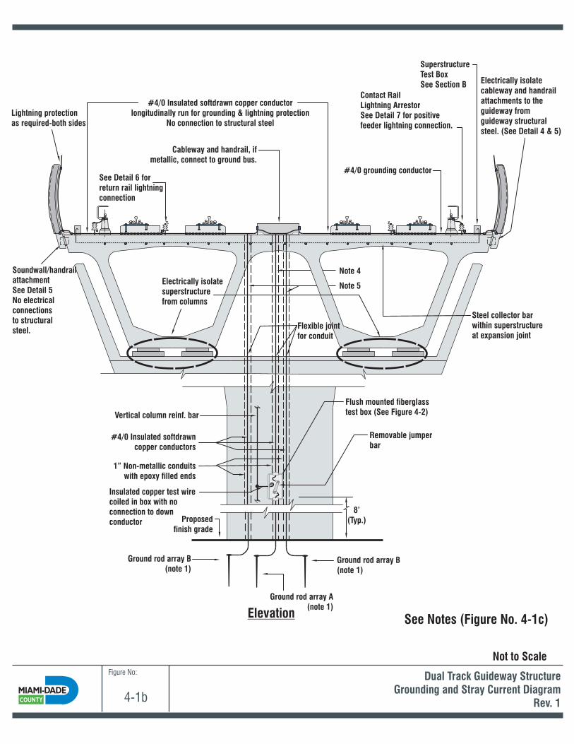
Figure No:
4-1b
Dual Track Guideway StructureGrounding and Stray Current Diagram
Rev. 1
See Notes (Figure No. 4-1c)
Note 4
Note 5
Ground rod array A(note 1)
SuperstructureTest BoxSee Section B
Soundwall/handrailattachmentSee Detail 5No electricalconnectionsto structuralsteel.
Ground rod array B(note 1)
Vertical column reinf. bar
Electrically isolatesuperstructurefrom columns
Cableway and handrail, ifmetallic, connect to ground bus.
Electrically isolatecableway and handrailattachments to theguideway fromguideway structuralsteel. (See Detail 4 & 5)
Steel collector barwithin superstructureat expansion joint
Lightning protectionas required-both sides
Contact RailLightning ArrestorSee Detail 7 for positivefeeder lightning connection.
#4/0 Insulated softdrawn copper conductorlongitudinally run for grounding & lightning protection
No connection to structural steel
#4/0 grounding conductorSee Detail 6 forreturn rail lightningconnection
Insulated copper test wirecoiled in box with noconnection to downconductor
Flexible jointfor conduit
Flush mounted fiberglasstest box (See Figure 4-2)
8’(Typ.)
Removable jumperbar
1” Non-metallic conduitswith epoxy filled ends
#4/0 Insulated softdrawncopper conductors
Elevation
Proposedfinish grade
Ground rod array B(note 1)
Not to Scale

Notes:
1. Ground rod array A and ground rod array B are independent ground systems.
2. Information provided here is diagramatic and is intended to show basic system design.System designer shall provide systems that comply with applicable requirements.
Separationof ground rod arrays to be determined by the system designer in accordance withapplicable codes, during final design. The ground rod systems must be sufficientlyspaced apart from one another to minimize the transference of voltage from one system toanother during conduction periods - defined as the “zone of influence”. The systemdesigner shall calculate the zone of influence and transference voltage, utilizing factorssuch as the soil resistivity between ground rods, the level of current assumed flowing intothe grounding systems and the resistivity of the grounding systems.
3. The calculation and design of the ground systems shall include the requirements fromNFPA-780, whereby the lightning protection down conductors and ground rod system aremade as short and straight line as possible. Therefore, the traction power surgeprotection grounding systems would be separated from the lightning protection groundingsystems to the fullest extend possible, but within reason from a cost point of view and witha constraint that it must remain within the MDT ROW boundaries.
4. Down conductor from lightning rods and other metallic elements on guideway deck.
5. Down conductor(s) from positive feeder and negative return lightning arrestors. SeeFigure 4-8 for connection details.
6. Grounding and stray current details as shown are typical at every guideway column.
Figure No:
4-1c
Guideway StructureGrounding and Stray Current Notes
Rev. 1
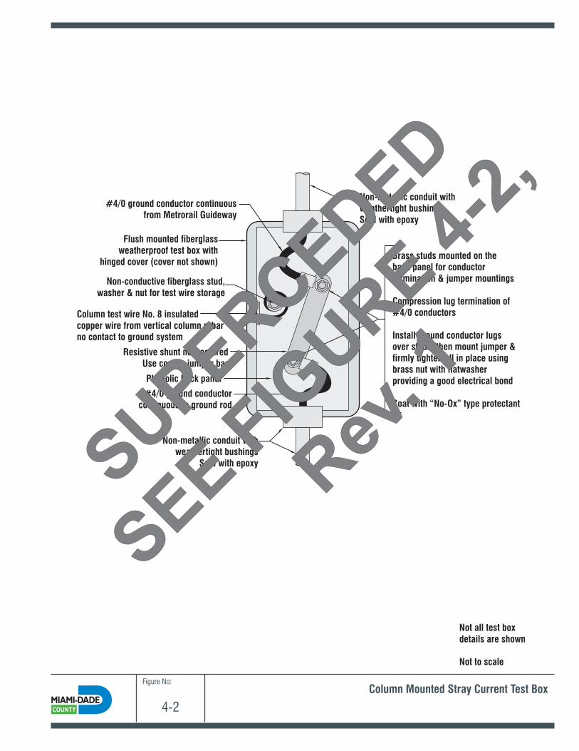
Figure No:
4-2
Column Mounted Stray Current Test Box
Non-metallic conduit withweathertight bushings
Seal with epoxy
Non-metallic conduit withweathertight bushingsSeal with epoxy
#4/0 ground conductorcontinuous to ground rod
#4/0 ground conductor continuousfrom Metrorail Guideway
Resistive shunt not requiredUse copper jumper bar
Flush mounted fiberglassweatherproof test box with
hinged cover (cover not shown)Brass studs mounted on theback panel for conductortermination & jumper mountings
Compression lug termination of#4/0 conductors
Install ground conductor lugsover studs, then mount jumper &firmly tighten all in place usingbrass nut with flatwasherproviding a good electrical bond
Coat with “No-Ox” type protectant
Phenolic back panel
Non-conductive fiberglass stud,washer & nut for test wire storage
Column test wire No. 8 insulatedcopper wire from vertical column rebarno contact to ground system
Not all test boxdetails are shown
Not to scale
SUPERCEDED
SEE
FIGURE
4-2,
Rev
. 1
SUPERCEDED
SEE
FIGURE
4-2,
Rev
. 1

Figure No:
4-2
Column Mounted Stray Current Test BoxRev. 1
Non-metallic conduit withweathertight bushings
Seal with epoxy
Non-metallic conduit withweathertight bushingsSeal with epoxy
#4/0 ground conductorcontinuous to ground rod
#4/0 ground conductor continuousfrom Metrorail Guideway
Resistive shunt not requiredUse copper jumper bar
Flush mounted fiberglassweatherproof test box with
hinged cover (cover not shown)
Brass studs mounted on theback panel for conductortermination & jumper mountings
Compression lug termination of#4/0 conductors
Install ground conductor lugsover studs, then mount jumper &firmly tighten all in place usingbrass nut with flatwasherproviding a good electrical bond
Coat with “No-Ox” type protectant
Phenolic back panel
Non-conductive fiberglass stud,washer & nut for test wire storage
Column test wire No. 8 insulatedcopper wire from vertical column rebarno contact to ground system
Not all test boxdetails are shown
Not to scale
Gold Test Nut (Goldnut)(Note 1)
1” Insulated Test Link Assembly(Note 1)
Notes:1. Refer to American Railway Engineering and Maintenance-of-Way Association (AREMA) C&S
Manual Part 14.1.15 for details.

Figure No:
4-3
Sections & DetailsStandard Guideway Superstructure & Piers
C PierL C PierL
C PierL C PierL
Simple Span
Multi-Span Continuous
Expansion Joint
SuperstructureTest Boxes
SuperstructureTest Boxes
SuperstructureTest Boxes
Expansion Joint
Not All Details are Shown
Expansion Joint *
* *
*
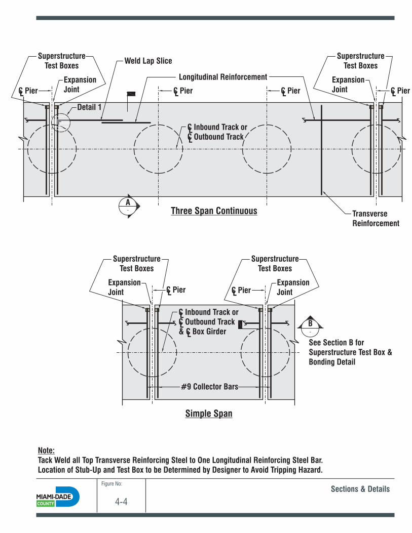
Figure No:
4-4
Sections & Details
Detail 1
C Pier
C Pier C Pier
L
L L
C Pier
A
B
C Inbound Track orC Outbound Track
ExpansionJoint
Weld Lap Slice
TransverseReinforcement
Longitudinal Reinforcement
ExpansionJoint
See Section B forSuperstructure Test Box &Bonding Detail
Note:Tack Weld all Top Transverse Reinforcing Steel to One Longitudinal Reinforcing Steel Bar.Location of Stub-Up and Test Box to be Determined by Designer to Avoid Tripping Hazard.
C Inbound Track orC Outbound Track& C Box Girder
#9 Collector Bars
L
L
L
L
LL
C PierL C PierL
Three Span Continuous
Simple Span
ExpansionJoint
ExpansionJoint
SuperstructureTest Boxes
SuperstructureTest Boxes
SuperstructureTest Boxes
SuperstructureTest Boxes

Figure No:
4-5
Sections & Details
Section A
C ExpansionJoint
Test Stubin Non-Metallic Box
No Electrical Continuity Across Segments
L
Transverse Reinforcing Bar
Weld a Stub-UpReinforcement Pieceto the Test Box
LongitudinalReinforcing Bar
Superstructure Test Box & Bonding DetailSection B
Detail 2
Detail 2 - Plinth Pad Reinforcement Bars
Use Only Non-ConductiveReinforcement Bars inPlinth Pad

Figure No:
4-6
Sections & Details
C
#9 Collector Bar
#9 Collector Bar#4 Connector Bar
Weld
Weld
#4 Connector BarTop SlabLongitudinalReinforcing
Top SlabLongitudinalReinforcing
Detail 1 Plan View C

Figure No:
4-7
Sections & Details
Detail 4 - Cabletray Attachment Example
Detail 5 - Non-Conductive Inserts
Detail 6 - Return Rail Lightning Arrestors
Use Non-Conductive Insertsfor Handrail & NoisewallAttachment to Top SlabMinimum 2” Clearanceto Reinforcing Steel
Use Non-ConductiveAnchors and/or Bushings
Cabletray
750 mcm Conductors Return Railto Negative Return Bus
Negative Return Bus on Guideway
#4/0 Conductor toLightning Down Conductor
2” Min. ClearanceAnchor to Reinforcing Steel
Lightning ArrestorSUPERCEDED
SEE FIGURES 4-8
SUPERCEDED
SEE FIGURES 4-8

Figure No:
4-8
Sections & DetailsRev. 1
Detail 6 - Return Rail Lightning Arrestors
750 kcmil Conductors Return Railto Negative Return Bus
Negative Return Bus on Guideway
#4/0 Conductor toLightning Down Conductor(Note 1)
Lightning Arrestor
#4/0 Conductor toLightning Down Conductor(Note 1)
Lightning Arrestor
(2) 777 kcmil conductorsfor positive jumpers
Contact Rail
Detail 7 -Positive Feeder Lightning Arrestor Installation Detail
Note:1. The ground conductors from the lightning arrestors protecting the positive feeders and negative return are typically connected to a single
ground its own conduit down to the ground array.conductor before entering
Related Documents