: cl yz./1 ' TRANSIT FACILITY DESIGN GUIDE Conducted for: Capital Metropolitan Transportation Authority Authors: Supervisor: June1988 -._J<athryn __ Stephen Banks Antonio Gonzalez Luis Hernandez Allen Hoffman Dr. C. Michael Walton Theunis Kruger Michael Ouimet Robert Spillar Darlene Szlama Andrew Wimsatt

Welcome message from author
This document is posted to help you gain knowledge. Please leave a comment to let me know what you think about it! Share it to your friends and learn new things together.
Transcript
: cl yz./1 '
TRANSIT FACILITY DESIGN GUIDE
Conducted for: Capital Metropolitan Transportation Authority
Authors:
Supervisor:
June1988
-._J<athryn Alb~ee __ Stephen Banks Antonio Gonzalez Luis Hernandez Allen Hoffman
Dr. C. Michael Walton
Theunis Kruger Michael Ouimet Robert Spillar Darlene Szlama Andrew Wimsatt

TRANSIT FACILITY DESIGN GUIDE
by
Kathryn Albee Stephen Banks
Antonio Gonzalez Luis Hernandez Allen Hoffman
Theunis Kruger Michael Ouimet Robert Spillar
Darlene Szlama Andrew Wimsatt
supervised by
C. Michael Walton
conducted for
Capital Metropolitan Transportation Authority
by the
CENTER FOR TRANSPORTATION RESEARCH
THE UNIVERSITY OF TEXAS AT AUSTIN
June 1988
This document is disseminated under the sponsorship of the Urban Mass Transportation Administration, Department of Transportation, and the United States government assumes no liabilities for its content or use thereof.
The contents of this report reflect the views of the authors, who are responsible for the facts and the accuracy of the data presented herein. The contents do not necessarily reflect the official views or policies of the Capital Metropolitan Transportation Authority. This report does not constitute a standard, specification, or regulation.
There was no invention or discovery conceived or first actually reduced to practice in the course of or under this contract, including any art, method, process, machine, manufacture, design or composition of matter, or any new and useful improvement thereof, or any variety of plant which is or may be patentable under the patent laws of the United States of America or any foreign country.
ACKNOWLEDGEMENTS
The participants of this study are indebted to a number of individuals and organizations who
contributed to this effort by providing information, guidance, reports and general assistance to our
inquiries.
In order to develop a better understanding of the needs and requirements desired in a transit facility
planning and design guide, a seminar series was formed consisting of invited community leaders,
practicing professionals, and managers. The following individuals participated in the series representing a
variety of interests, viewpoints, and expertise deemed important to our charge. To each we offer our
gratitude for their service to this project (in order of attendance):
Sally Shipman, Council member, City of Austin, 8 February 1988 Matthew Krisel & James Alvis, Page Southerland, & Page, 10 February 1988 Allen Brecher, Assist. Director of Transportation & Public, Services, City of Austin, 17 February 1988 Viola Brown, Training Supervisor, Capital Metro, 22 February 1988 Len Brandrup, Barton-Aschman Assoc. Inc., 7 March 1988 Mike Aulick & Chuck Terry, Planning & Growth Management, City of Austin. 9 March 1988 George Zapalac, Office of Land Development Services, City of Austin, 23 March 1988 Bob Liverman, Trammell Crow Company, 30 March 1988 Terry Watson, DST (chair, Transportation Task Group & member, Integration Committee- AustinPian), 4 April1988 Tom Jenkins, Parsons, Brinckerhoff, Quade & Douglas, Inc, 6 April1988 Larry Kilbride & Virgil Hedwall, Barton Creek Mall, 13 April 1988
In addition we wish to recognize the following individuals who assisted members of the project team
with particular aspects of our charge relative to their operation:
E. B. Baker, Rebekah Baines Johnson Center, Austin, Texas E. W. Kramp, Hancock Center, Austin, Texas
A survey was conducted in order to gain insight into similar initiatives performed by others. The
following individuals and their respective organizations were helpful and to whom we wish to express our
appreciation (in alphabetical order):
Alameda Contra Costa Transit District Paul Bay, Metropolitan Transit Authority of Harris County; Houston, Texas Donald Bloomfield, Metropolitan Transportation Authority; New York, New York Frank Colletti, Massachusetts Bay Transportation Authority; Boston, Mass. Dallas Area Rapid Transit Richard Dawson,. Washington Metro Area Transit Authority; Washington, D.C. Bobby Dye, Texas State Department of Highways and Public Transportation; Austin, Texas Dale Hardy, City of Phoenix Transit System; Phoenix, Arizona Deborah Kaufman, Regional Transportation; Denver, Colorado
iii
Bill Lieberman, Metropolitan Transportation Development Board; San Diego, California Jim Lightbody, Santa Clara County;Santa Clara, California Kerrville Bus Company Jim Maslonka, Southeastern Michigan Transportation Authority; Detroit, Michigan
We wish to express our appreciation to the representatives of Capital Metro for the opportunity to
pursue this study. Specifically, the project team would like to thank the following staff members for their
assistance and guidance: Sharon Brown, Celia Goldstucker, Eric Harris, and Marty Minkoff. Without the
technical assistance and professional services of Ms. Vicki Urbanek, Administrative Assistant to Dr. C.
Michael Walton, Mr. Derek Caballero, Artist, and Ms. Brenda Ziser, Librarian, this project would have been
disadvantaged.
Without the commitment of time and resources for all those we have acknowledged our project would
have been greatly impaired. These commitments are fundamental to any project of similar challenges.
Kathryn Albee Stephen Banks Antonio Gonzalez Luis Hernandez Allen Hoffman Theunis Kruger Michael Ouimet Robert Spillar Darlene Szlama Andrew Wimsatt
C. Michael Watton
iv

PREFACE
The objective of the "Transit Facility Design Guide" is to provide a resource document to assist, through
proper facility design, in integrating transit considerations into new and existing land use developments.
The document, which focuses on engineering design criteria and pertinent guidelines, addresses the
following subject areas: design vehicle characteristics, geometric and pavement design, the physical
components comprising transit facilities, and transit facility development.
This report, supported by Capital Metropolitan Transportation Authority (Capital Metro), was the product of
the graduate students participating in the graduate course entitled "Transportation Planning:
Methodologies and Techniques" (CE 391J- Spring 1988). The students, from the Graduate Program in
Community and Regional Planning and Civil Engineering (Transportation), were responsible for all aspects
of this study including preparation of the final report.
The study process, involving the ten graduate students under the supervision of Dr. C. Michael Walton,
consisted of four major tasks:
Identification and survey of transit operations in areas similar to the metropolitan area of Austin, areas known for their transit service, and areas of special interest
Seminar series consisting of invited speakers representing community leaders, engineers and architects, developers, mall managers, transit professionals, and related professionals
Development of an annotated bibliography used for reference and guidance
Development and implementation of a study plan reflected in the report
c. Michael wanon May 15, 1988
v
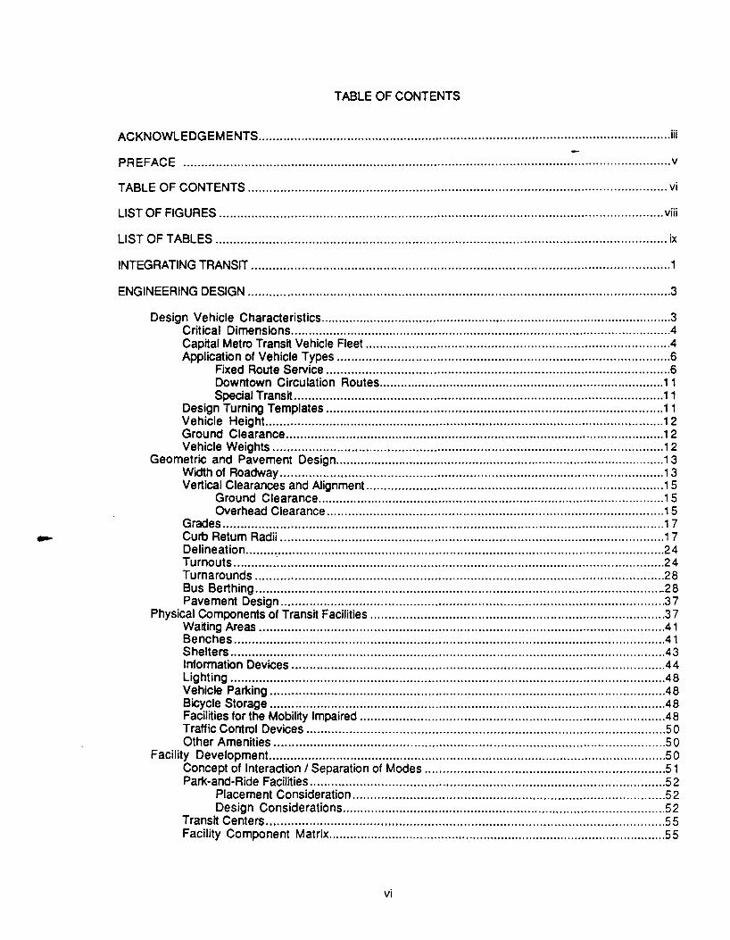
TABLE OF CONTENTS
ACKNOWLEDGEMENTS .................................................................................................................... iii
PREFACE ........................................................................................................................ oo ...... oo·····ov
TABLE OF CONTENTS .................................................................................................................... 0 vi
LIST OF FIGURES ............................................................................................................................ viii
LIST OF TABLES .............................................................................................................................. ix
INTEGRATING TRANSIT ..................................................................................................................... 1
ENGINEERING DESIGN ...................................................................................................................... 3
Design Vehicle Characteristics .................................................................................................... 3 Critical Dimensions ............................................................................................................ 4 Capital Metro Transit Vehicle Fleet .................................................................................... 04 Application of Vehicle Types ............................................................................................. 6
Fixed Route Service ................................................................................................ 6 Downtown Circulation Routes ................................................................................. 11 Special Transit ....................................................................................................... 11
Design Turning Templates .............................................................................................. 11 Vehicle Height. ............................................................................................................... 12 Ground Clearance ........................................................................................................... 12 Vehicle Weights ............................................................................................................. 1 2
Geometric and Pavement Design ............................................................................................. o1 3 Width of Roadway ........................................................................................................... 1 3 Vertical Clearances and Alignment ................................................................................... 15
Ground Clearance .................................................................................................. 1 5 Overhead Clearance ............................................................................................ 0 01 5
Grades ........................................................................................................................... 17 Curb Return Radii ........................................................................................................... 1 7 Delineation ..................................................................................................................... 2 4 Turnouts ............ ~ ........................................................................................................... 2 4 Turnarounds .................................................................................................................. 28 Bus Berthing ................................................................................................................ -28 Pavement Design ........................................................................................................... 3 7
Physical Components of Transit Facilities .................................................................................. 3 7 Waiting Areas ................................................................................................................. 41 Benches ........................................................................................................................ 41 Shelters ......................................................................................................................... 4 3 Information Devices ....................................................................................................... 044 Lighting ........................................................................................................................ 048 Vehicle Parking .............................................................................................................. 48 Bicycle Storage .............................................................................................................. 4 8 Facilities for the Mobility Impaired .................................................................................... .48 Traffic Control Devices .................................................................................................... 50 Other Amenities ............................................................................................................. 50
Facility Development. ............................................................................................................... 50 Concept of Interaction I Separation of Modes ................................................................... 51 Park-and-Ride Facilities ................................................................................................... 52
Placement Consideration ....................................................................................... 52 Design Considerations ........................................................................................... 52
Transit Centers ............................................................................................................... 55 Facility Component Matrix ................................................................................................ 55
vi
CONCLUSION ..........................................•...................................................................................... 61
REFERENCES .............................................................................................................................. R·1
APPENDIX ................................................................................................................................... A·1
GLOSSARY .................................................................................................................................. G-1
ANNOTATED BIBLIOGRAPHY ........................................................................................................ B-1
vii

1 2 3 4 5 6 7 8 9 10 11 12 13 14 15 16 17 18 19 20 21 22 23 24 25 26 27 28 29 30 31 32 33 34 35 36
37 38
LIST OF FIGURES
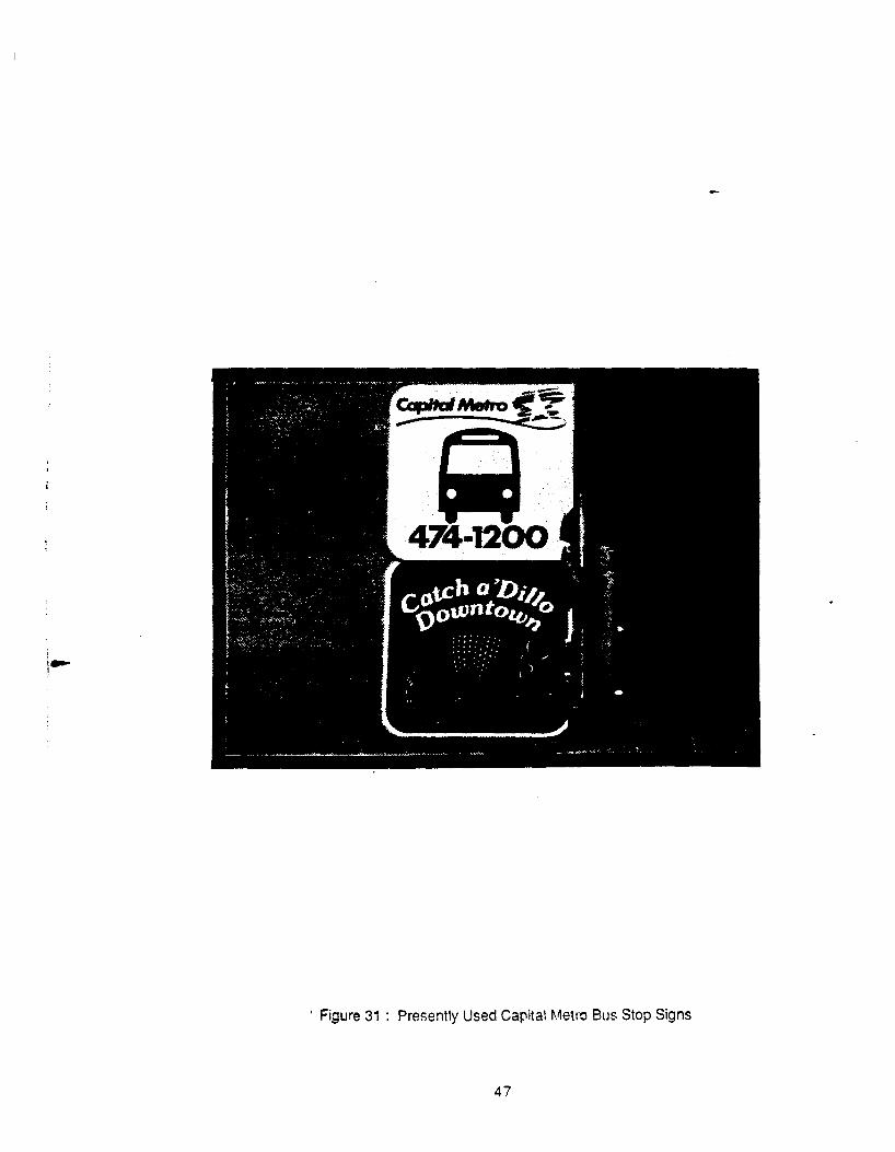
Inadequate Ground Clearances .............................................................................. 5 Forty Foot Gillig ...................................................................................................... 9 The 'Dillo ............................................................................................................... 9 Over-the-Road Coach ......................................................................................... 0 1 0 Thirty-Two Foot Special Transit Vehicle ................................................................ 0 1 0 Design Criteria for Vertical Curves ......................................................................... 1 6 Examples of Adequate and Inadequate Overhead Clearance ................................. 1 8 Curb Returns for Forty Foot Bus Design Vehicle ................................................... 0 2 0 Curb Return for Articulated Bus Design Vehicle ..................................................... 21 Curb Return for 'Dillo Bus Design Vehicle .............................................................. 22 Compound Curb Return· Alternate Design .......................................................... 0 23 Driveway Curb Returns ................ o ........ o .................................................... o ... o .. oooo25 Near Side and Far Side Bus Stop Turnouts ............................................................ 26 Mid-Block Bus Turnout ........ oooooo ........... o .. ooo .............. o ... o ....................................... 27 Mid-Block Turnout for Thirty Foot Design Vehicle ................................................... 29 Mid-Block Bus Turnout Adjacent to Bike Lane ....................................................... 30 Bus Turnout Located After Free Right Turn ........................................................... 31 Counter-Clockwise Turnaround Located to the Left.. ............................................. 32 Counter-Clockwise Turnaround Located to the Right.. ........................................... 33 Minimum Lengths for Parallel Berths ..................................................................... 34 Parallel Berths Located on the Street.. .................................................................. 3 5 Normal Lengths for Parallel Berths ....................................................................... 0 3 6 Sawtooth Berthso.o .... o.oo ..................... o ................... o.o ....................................... oooo38 Commonly Used City of Austin Pavement Designs ................................................. 39 City of Austin • 120 Foot Concrete Pavement Bus Stop .......................................... 4 0 Typical Curb Ramp ............................................................................................... 4 2 Presently Used Capital Metro Bus Shelter ............................................................ .4 5 Bus Shelter on The University of Texas Campus .................................................... 45 Bus Shelter located at 11th Street and Congress ................................................... 4 6 Capital Metro Park-and-Ride Facilityooooo .................................... o.o ............. o ..... o ....... 46 Presently Used Capital Metro Bus Stop Signs ........................................................ 4 7 Typical Bicycle Racks and Lockers ........................................................................ 49 Illustrated Concept of Separation and Interaction of Modes ..................................... 53 Typical Park-and-Ride Layout ............................................................................... 56 Bus Awning at Capital Metro Park-and-Ride Facility: U.S. 183 and Lamar Blvd .......... 57 Bus Passenger Shelter at Capital Metro Park-and-Ride Facility: U.S. 183 ................ 57
and Lamar Blvd. Park-and-Ride Placement and Layout Design Options ........................................... 58 A Typical Transit Center Site Layout.. .................................................................... 59
viii

LIST OF TABLES
1 Critical Dimensions of Design Vehicles .................................................................... 7 2 Transit Vehicles Arranged by Function .................................................................... S 3 Minimum Road Widths .......................................................................................... 14 4 Facility Component Matrix ..................................................................................... 60
ix

INTEGRATING TRANSIT
The Capital Metropolitan Transportation Authority (Capital Metro) is a regional transn authority serving
Austin, Texas and several surrounding communities. A major goal of Capital Metro is to improve the
provision, and increase the patronage, of its public transportation system. The Transit Facility Design
Guide document is one means by which Capital Metro is attempting to increase and improve the role of
public transit in the Austin area. The guidelines provide the citizen and developer with information
concerning the general and technical aspects of integrating public transportation into new and existing
developments.
The advantages of a well-integrated transit system are many. A well-integrated transit system gives
the individual a convenient, alternate form of transportation for work trips, especially into and within the
Central Business District or CBD (Ref 18). For the citizen who has no other means of transportation, a
well-integrated system allows that individual to interact wnh the cny at-large, thus expanding that person's
economic and social interaction within the city.
The benefits to the entire community are directly related to those experienced by the individual
citizen. With a well-integrated transit system, the labor pool within the city expands due to the greater
mobility of the individual worker. A well-integrated system also provides the city wnh a convenient, safe
and economical transportation system to offer visitors. Conventions may be better serviced thus
encouraging more use of the city's convention facilities, bringing in outside revenue. Another advantage
in having a well-integrated public transportation system is that valuable real estate in the Central Business
District can be utilized for buildings rather than for parking facilities. With the increased demand for
downtown real estate, the efficient use of downtown space will depend on the provision of a well
integrated public transportation system.
The benefits to the developer may be less recognizable than those explained above. The primary
benefit realized by the developer is an expanded available market. Because a well-integrated transit
system provides mobility to a sector of the society often neglected by modern retail, housing, and
entertainment markets, the developer offering an integrated project will prom by patronage from these
sectors. A secondary, but no less important benefit realized by the developer is the recognition
received for contributing to the community. A voluntary inclusion of integrated transit facilities in new
developments is a strong gesture to the community on behalf of the developer.
This document provides general standards and criteria for facilities, and amenities associated with
transit integration. It is emphasized that these standards and criteria should be applied in the context of
site specific designs as various sites may require specific design modifications. One of the most important
design criteria is the design vehicle. The characteristics of four different design vehicles are presented.
Developers should be aware that the integration requirements could change with thejntroduction of new
vehicles to the Capital Metro fleet and it is therefore necessary for the developer to work closely with
Capital Metro in any design process.
Selection of the design vehicle criteria will directly impact the selection of the standards and
guidelines set forth in the road and pavement design section. The emphasis again is on general
standards, and site specific constraints. For example, soil conditions and types should be designed for on
a site-by-site basis. There are many guidelines which apply in general terms to all types of developments,
and developers can use the guidelines presented to project the number and cost of the features
necessary for the successful integration of public transit.
Integration of design vehicle and pavement guidelines into developments is important, but the
integration of public transit should also consider architectural and physical amenities which make the
integration functional in human terms. These guidelines are presented in terms of their inclusion into all
types of developments, and transit facilities such as transit centers or Park-and-Ride terminals. While
there may be some site specific constraints connected to individual projects, these design criteria are
generally applicable to all types of developments.
In conclusion, it is hoped that this handbook will answer many important questions about transit
integration. It is also hoped that the book will encourage further integration efforts in the future. The
citizen and developer is reminded that integrating transit into new and existing urban development
symbolizes a partnership between the community and development industry. Such a partnership can be
a positive commitment to the people of the greater Austin area.
2
ENGINEERING DESIGN
Engineering design, as defined in this document, is the physical design and placement of the transit
related facilities and roadway. It is the purpose of this document to provide both specific design
information and general design considerations that should be addressed if transit operation within a
development is to be successful.
The engineering design chapter begins with a section on the development of the design vehicle.
Three design vehicles can adequately represent the specific types of current bus service. These vehicles
are the 40 ft. bus, the 'Dillo, and a special transit vehicle for the mobility impaired. Design turning
templates are provided for each of these three design vehicles. An additional design vehicle, the
articulated bus, was included in the template set; however, Capital Metro does not have any plans for
obtaining such vehicles. (Note: The designer should consult Capital Metro for appropriate vehicle
application on a site-specific basis.)
The following two sections are the predominant sections relating to the actual design of the physical
components. The section entitled "Geometric and Pavement Design" addresses the physical design of
the roadway and bus related facilities while the section entitled "Physical Components and Amenities"
addresses the design and placement considerations of the transit related facilities that are not a portion of
the travel way.
The purpose of the final section of this chapter, which is entitled "Facility Development", is to present
the reader with the concepts behind the development of transit facilities. This section begins with a
discussion on the interaction and separation of the different mode types present within a transit facility.
The development of individual facility types, from bus stops to transit centers, is also addressed. A facility
component matrix is included as a summary of the types of amenities that should be considered when
designing these transit facilities.
DESIGN VEHICLE CHARACTERISTICS
In order to determine the design criteria for the space that a vehicle occupies during a maneuver, it is
necessary to determine the characteristics of the critical vehicle most likely to use a specific facility. These
characteristics include the horizontal plane area described by the vehicle when turning, referred to as the
swept path, the height of the vehicle, its ground clearance and other dimensions determining the
minimum vertical alignment of the road surface, which the vehicle can negotiate. The axle loads of the
vehicle also serve as an input to the pavement design process.
3

Crjtjcal Dimensions
When a vehicle negotiates a turn, its rear wheels do not follow the exact path of the front wheels. The
rear wheels track inwards of the path traced by the front wheels and are thus said to "offtrack". The front
and rear corners of the vehicle may also sweep outside the path tracked by the wheels. The amount of
offtracking varies directly with the wheelbase of the vehicle and inversely with the radius of the turn (Ref.
21 ). The degree of turn, speed and turning ability of the vehicle, the latter a function of the design of the
steering mechanisms, also affect the area required for the vehicle to maneuver. Other factors such as the
inflation and condition of the tires; pavement conditions; superelevation of the roadway; driver ability and
wind direction and strength, may also play a role, but usually only to a negligible extent at low speeds .
. The height of the unloaded vehicle, from its highest point to the ground, is the critical dimension
determining required vertical clearances. The ground clearance of the vehicle in combination with its
wheelbase, and front and rear overhang, determines the approach angle, rollover angle and departure
angle. These dimensions are critical in determining the absolute maximum allowable changes in roadway
grades, where no gradual transition between grades are used, for the vehicle body not to scrape the road
surface. This is illustrated in Fig. 1.
Capital Metro Transit Vehicle Fleet
At the beginning of 1988, the fleet owned by Capital Metro totalled 230 vehicles. This fleet comprises
a variety of vehicle types used in a variety of applications. It is not practical to select a single critical vehicle
to be used in the planning and design of transit facilities, since:
- particular types of developments may only be served by specific vehicle types, and
- the fleet may possibly in future be supplemented by additional types, including larger or smaller
vehicles.
In addition to the regular fleet, Capital Metro also contracts with a private firm to operate over-the-road
motor coaches, primarily to serve outlying Park-and-Ride facilities. These are 40ft., 3-axled vehicles of the
type most often used for intercity services.
The possibility that Capital Metro may in the future acquire larger vehicles, or tl'lat the type of vehicle
used on a certain route may change, should be considered when designing facilities which will have a
relatively long life. Distinction should be made between :
- components included which can easily be changed to accommodate larger vehicles (e.g.
pavement markings ) and
4

Figure 1 : Inadequate Ground Clearances
5

- components which may be impossible or very difficult and costly to adjust to suit a different size
of vehicle (e.g. right of way, pavement strength).
It will be noted from the design turning templates included in the Appendix that an articulated bus
requires a maneuvering area only marginally larger than the 40ft. bus, despite having a wider swept path.
Also, from Table 1 it may be noted that the axle weights of an articulated bus are less than that of the 40ft.
Gillig vehicle.
Vehicles currently in use are included in Table 2, by size and function. Table1 lists the critical
dimensions of the selected design vehicles (40ft. bus, special template, 30ft. single unit truck/bus (S.U.),
and articulated bus). Photographs of some of the vehicles referred to above are shown in Figs. 2, 3, 4 and
5.
A~~licatjon of vehjcle Ty~es
It is necessary to consider the critical vehicle most likely to use the transit facilities, when planning or
designing a development with the intent to integrate transit.
Fjxed Route Seryjce. If articulated buses were to be included in the fleet, they will most probably be
exclusively used for fixed route services. The articulated bus could, therefore, become the critical design
vehicle for the design of:
- turnouts and stops on streets classified as major collectors or arterials,
- major collectors and arterial streets themselves, all transit facilities that will generate large
numbers of riders, such as major Park-and-Bide locations, transit centers or transfer locations.
However, since Capital Metro does not plan on acquiring articulated buses in the foreseeable future, the
40 ft. long, 102 in. wide bus can be considered as the most critical of the larger buses for design
purposes. The use of the articulated bus as the design vehicle is left as an option to the designer.
It should be noted, however, that the largest design vehicle is not necessarily the most critical vehicle.
For example, the physical requirements of the trolley lookalike, or 'Dillo, may be more critical, in some
cases, even in comparison with the 40 ft. bus or articulated bus design vehicles. It is therefore
recommended that design layouts be checked against this vehicle's requirements.
In principle, radii and maneuvering space should be provided such that vehicles never have to use
opposing lanes or areas other than the specifically designated lanes. This should, without exception,
6

D
E
I~ A 8 c ---1
Critical Dimensions 40Ft. Bus 'Dillo 30Ft. Bus Articulated Bus A. Rear Overhang 8' 8' 6' 9' 5"
B. Wheelbase 25' 21' 4" 20' 24' rear 18' front
c. Front Overhang 7' 3' 10" 4' 8' 6"
D. Height 1 0' (Gillig) 10' 7" 13' 6" 1 0' 4" (typical) 11' 4" (intercity)
E. Width 8' 6" 8' 6" 8' 6" 8' 6"
Gross** Vehicle Weight 39,600 lbs. - - 53,600 lbs. (typical)
Gross** Axle Weights Front 14,600 lbs. - - 15,700 Center - - 19,400 Rear 25,000 lbs. - - 18,500
**Gross weight refers to weight of bus with passengers.
Table 1 : Critical Dimensions of Design Vehicles
7
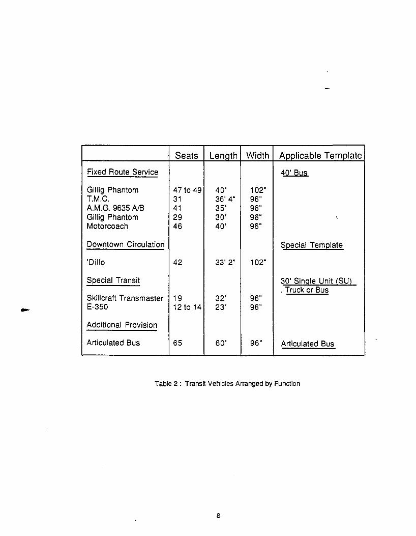
Seats Lenath Width Applicable Template
Fixed Route Service 40' Bus
Gillig Phantom 47 to 49 40' 102" T.M.C. 31 36' 4" 96" A.M.G. 9635 AlB 41 35' 96" Gillig Phantom 29 30' 96" ' Motorcoach 46 40' 96"
Downtown Circulation Special Template
'Dillo 42 33' 2" 1 02"
Special Transit 30' Single Unit {SU} . Truck or Bus
Skillcraft Transmaster 19 32' 96" E-350 12 to 14 23' 96"
Additional Provision
Articulated Bus 65 60' 96" Articulated Bus
Table 2 : Transit Vehicles Arranged by Function
8

Figure 2: Forty Foot Gillig
Figure 3 : The 'Dillo
9

Figure 4: Over-the-Road Coach
Figure 5 : Thirty-Two Foot Special Transit Vehicle
10

apply to all public streets and heavily travelled areas, such as parking and access areas of large
developments. In cases where space is restricted, where less vehicle and pedestriatttraffic is expected
and no other options are available, some encroachment may be necessary. In such situations, the
developer should consult with Capital Metro.
powntown Circulation Routes. Capital Metro currently uses the 'Dillo buses on downtown circulation
routes and routes to serve some Park-and-Ride lots close to the Austin Central Business District (CBD).
These vehicles are also used for certain special events. The 'Dillos complement the regular fleet in an
interesting way and can be considered as an attraction of the city. Planners of developments close to or in
the Austin CBD should note the application of the 'Dillo service as this may, in many instances, be the only
form of public transit that will serve a development in the mentioned areas. It will be noted that the 'Dillos
have particular swept path requirements, due to its poor turning ability and long wheelbase, despite a
relatively short body, and that they thus require special attention.
Specjal Transit. The most significant use of special transit vehicles by Capital Metro is for a demand
responsive service for mobility impaired persons. The vehicles used are equipped with special doors and
wheelchair lifting equipment for this application. Although the most commonly used vehicles are 23ft. 3
in. and 23ft. long vans with seating capacity of 12 to 14, a 32 ft. long bus with 19 seats is also used. The
smaller van has a swept path close to that of the standard passenger car design vehicle. The Special
Transit Service (STS) division uses a 40 ft. bus in a line haul mode to provide service to mobility impaired
persons, but is unlikely that this vehicle will be used within the circulation areas of developments.
Developments, where special transit may be required, such as senior citizen homes, hospitals,
centers for mobility impaired persons, schools, colleges etc., should provide space for at least the 30 ft.
design bus. This will accommodate the 32 ft. Vehicle (see Fig. 5 ), which is the largest special transit
vehicle likely to be used within the circulation areas of developments. Where facilities are on a main transit
line, the designer may want to accommodate larger vehicles.
Design Turning Templates
A number of design turning templates, to various scales, are included in the Appendix. These cover:
- the 40 ft. design bus,
- the 30ft. single unit (SU) design truck or bus,
- the Trolley looka:ike 'Dille, and
- the articulated design bus.
1 1
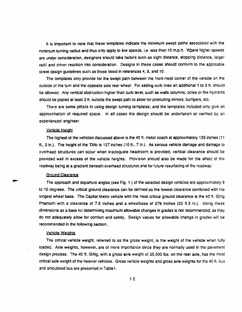
It is important to note that these templates indicate the minimum swept paths associated with the
minimum turning radius and thus only apply to low speeds, i.e. less than 10 m.p.h. W.bere higher speeds
are under consideration, designers should take factors such as sight distance, stopping distance, larger
radii and driver reaction into consideration. Designs in these cases should conform to the applicable
street design guidelines such as those listed in references 4, 9, and 10.
The templates only provide for the swept path between the front-most corner of the vehicle on the
outside of the turn and the opposite side rear wheel. For setting curb lines an additional 1 to 2 ft. should
be allowed. Any vertical obstruction higher than curb level, such as walls columns, poles or fire hydrants
should be placed at least 2ft. outside the swept path to allow for protruding mirrors, bumpers, etc.
There are some pitfalls in using design turning templates, and the templates included only give an
approximation of required space. In all cases the design should be undertaken or verified by an
experienced engineer.
Yehjcle Hejght
The highest of the vehicles discussed above is the 40ft. motor coach at approximately 135 inches (1 1
ft., 3 in.). The height of the 'Dillo is 127 inches (10ft., 7 in.). As serious vehicle damage and damage to
overhead structures can occur when inadequate headroom is provided, vertical clearance should be
provided well in excess of the vehicle heights. Provision should also be made for the effect of the
roadway being at a gradient beneath overhead structures and for future resurfacing of the roadway.
Ground Clearance
The approach and departure angles (see Fig. 1 ) of the selected design vehicles are approximately 9
to 1 0 degrees. The critical ground clearance can be defined as the lowest clearance combined with the
longest wheel base. The Capital Metro vehicle with the most critical ground clearance is the 40 ft. Gillig
Phantom with a clearance of 7.5 inches and a wheelbase of 279 inches (23 ft.3 in.). Using these
dimensions as a base for determining maximum allowable changes in grades is not recommended, as they
do not adequately allow for comfort and safety. Design values for allowable change in grades will be
recommended in the following section.
Yehjcle Wejghts
The critical vehicle weight, referred to as the gross weight, is the weight of the vehicle when fully
loaded. Axle weights, however, are of more importance since they are normally used in the pavement
design process. The 40ft. Gillig, with a gross axle weight of 25,000 lbs. on the rear axle, has the most
critical axle weight of the heavier vehicles. Gross vehicle weights and gross axle weights for the 40 ft. bus
and articulated bus are presented in Table1.
1 2

GEOMETRIC AND PAVEMENT DESIGN
This section presents design information applicable to the various geometric and pavement elements
of bus routes. In order for transit to be effectively integrated into a development, the potential transit
routes must be physically compatible with the transit vehicles using that route. This means that street
widths, clearances, curb returns, and grades must be designed to accommodate these vehicles rather
than the smaller, less critical, passenger car. Facilities such as turnouts, turnarounds, and berthing areas,
which are used exclusively by quses, must obviously be designed for geometric compatibility with the
transit vehicle expected to use these facilities. The pavement structure should also be properly designed
to handle the heavier bus loading that occurs along the route, and in particular, at the facilities intended for
exclusive bus use.
The design elements of this section are generally based on the properties of the 40 ft. design vehicle
which is the largest and most commonly used transit vehicle in the current Capital Metro fleet. In some
cases, however, the transit vehicle using a certain facility may be smaller than the 40ft. design bus and the
facility should, therefore, be designed for the applicable vehicle. In such cases, the turning radius
templates and vehicle dimensions supplied in the Appendix should be used to modify the basic designs
presented in this section.
Width of Roadway
The roadway is defined as the paved area within the right-of-way ordinarily used for vehicular traffic
movement. With curbs and gutters, the pavement width is measured from face-of-curb to face-of-curb;
without standard curbs and gutters, pavement width is measured from the edge of the pavement,
excluding any required shoulders or ribbon curbs. It is the purpose of this section to address the roadway
width requirements necessary for proper bus operation (Ref. 9).
The required width of roadway is primarily a function of street classification. There are basically three
types of through streets which are known as: local, collector, and arterial streets. For operational and
safety reasons, bus traffic should be restricted to collector and arterial streets; however, in existing
developments it may be necessary to include local streets in a bus route. If a new development is properly
planned to include transit, the bus routes can be located exclusively on collector and arterial streets.
The width of a roadway must be designed to handle the largest vehicle expected to frequent that
roadway. In Table 2 , it is seen that the maximum width of a Capital Metro transit vehicle is 102 inches (8.5
ft.). Since the American Association of State Highway and Transportation Officials (AASHTO) design
vehicles for both buses and large trucks are 8.5 ft. wide (Ref. 4), the road width values presented within
this policy manual can be considered as representative of the widths required to accommodate the current
Capital Metro fleet. Table 3 presents the AASHTO minimum widths for the local, urban collector, and
1 3

Road Lane Additional Auto Parking Width Classification Width (As Needed)
Local 11' (Min) 7' (Residential Areas) * 12' (Pre f) 9' (Commercial and Industrial Areas)
Urban Collector 11' (Min) 7' - 1 0' (Residential Areas) * 12' (Pref) 8' - 1 0' (Commercial and Industrial
Areas) **
Urban Arterial 12' Restricted
* Provided as needed on one or both sides of roadway ** Usually provided on both sides of roadway
..... Roadway .. ..... p
Parking Traffic Traffic Parking Lane (s) Lane (s)
..... .. ..... ... - ... - ... p p ~ p
6------------d Drawing Not
To Scale
Table 3 : Minimum Road Widths
14
**

urban arterial streets. Guidelines and standards used and required by the relevant local government, such
as the City of Austin's Transportation Criteria Manual (Ref. 9) should be consulted _!or specific design
information.
Vertjcal Clearances and Alignment
If large transit vehicles are to navigate the streets of a development, the roadways must be designed
with adequate vertical and lateral clearances to accommodate these large vehicles. Vertical clearances
pertain to ground and overhead clearances while lateral clearances pertain to road widths and curb radii.
Road widths and curb radii are addressed in separate sections of this chapter. The purpose of this section
is to make the street designer aware of the need for adequate ground and overhead clearances on routes
where large transit vehicles are expected to operate.
Ground Clearance. Problems with ground clearances occur when there is a sharp change in grade
resulting in a "bump" or "dip" in the road (see Fig. 1 ). The abrupt change from a positive (uphill) to
negative (downhill) grade combined with the long wheel base of the 40 ft. transit coach can cause the
undercarriage of the vehicle to scrape the pavement surface. Similarly, the sharp change from a negative
to positive grade combined with the overall length of the bus, the wheel base, and the momentum of the
moving vehicle, can cause the front bumper of the vehicle to scrape the pavement.
These problems with ground clearance may be avoided if the crest vertical curves and the sag vertical
curves are properly designed. AASHTO policy, which is contained in A Policy on Geometric pesign of
Highways and Street 1984, or the "Green Book", states that vertical curves should be parabolic curves of
adequate length to provide minimum stopping sight distance at all points along the curve. Detailed
guidelines for design of vertical curves are presented on pages 303-317 of the "Green Book". The curve
lengths required for stopping sight distance can be calculated using the formula and values presented in
Fig. 6. Curves calculated and designed in this manner are more than adequate in providing sufficient
ground clearance.
Overhead Clearance. Overhead clearance must be supplied so that damage to tall vehicles and
overhead structures is avoided. The amount of clearance required on a roadway is usually a function of
the type of roadway. On freeways and other major facilities that serve large trucks, the AASHTO "Green
Book" recommends an absolute minimum clearance of 14 ft. 6 in. and a desirable minimum clearance of 16
ft. 6 in. These minimum clearance values, which are based on the maximum allowable vehicle height plus
1 ft., should also be applied to arterials that connect these major facilities.
Collector streets and local streets are not required to maintain such high clearances; however, it is
desirable to maintain these clearances since collectors do experience some truck traffic as do local streets
(e.g. moving vans).
1 5

Crest Vertical Curve Sag Vertical Curve
Design Speed Crest Vertical Sag Vertical {mph} Curves {Kc) Curves {Ks)
20 10 20 25 20 30 30 30 40 35 50 50 40 80 70 45 120 90 50 160 110 55 220 130 60 310 160 65 400 180 70 540 220
Length of Crest Vertical Curve : Lc = Kc * A
Length of Sag Vertical Curve : Ls = Ks * A
Absolute Minimum Length of Curve : Lmin = 3 * V
where A = Algebraic Difference in Grade (%) V =Design Speed of Roadway {mph)
Figure 6 : Design Criteria for Vertical Curves (Ref 4)
16

Clearances in areas other than the public streets should be high enough to accommodate the tallest
vehicle expected to navigate the area. In many cases this vehicle is the transit vehicle. The tallest vehicle
in the current Capital Metro fleet is the 40 ft. Gillig coach with a height of 11 ft. 3 in. Adequate overhead
clearance of 1 ft. above the vehicle must be available so that objects such as tree limbs, overhead signs,
and awnings extending over a transit route or bus facility are avoided. Therefore, on level ground the
distance between the overhead structure and the ground should be a minimum of 12 ft. 3 in.
In certain situations, however, more that 1 ft. clearance may be desired. Figure 7 illustrates the
potential need for additional clearance on sloping roadways. Additional clearance should also be allowed
for future roadway resurfacing. It should be noted that speed bumps are not desired within the travel
paths of buses.
Grades
Road grades refer to the positive (uphill) and negative (downhill) slopes that a vehicle must negotiate.
With increasing length and angle of positive grades, the vehicle experiences an increasing loss of speed
and overall operating efficiency. If the street contains a substantial amount of bus and truck traffic, these
slower moving vehicles may have an adverse effect on the capacity of the street. Similarly, a maximum
negative slope is required as a means to maintain safe bus operations by controlling the speed and
momentum of these large vehicles. Therefore, the City of Austin's Transportation Crjterja Manual
recommends a maximum grade of 6-8% on those streets expected to carry bus traffic.
Curb Return Radii
Properly designed intersections which allow easy and efficient transit access are essential for transit
integration. Properly designed intersections not only reduce bus/auto conflicts at heavily used
intersections but also increase bus operating speeds, reduce travel time, and, improve bus rider comfort
(Ref. 31 ). Major intersections which should be designed using transit design standards include, collector
collector intersections, collector-arterial intersections, and arterial-arterial intersections.
When designing for transit use, the designer must examine the constraints which transit use places
on the intersection design. The following are some of the more important design constraints which
should be considered (Ref. 22 and 31):
- bus turning radius,
- angle of intersection,
- width and number of lanes on intersecting streets,
- allowable bus encroachment into adjacent or opposing lanes,
1 7

Adequate Overhead Clearance
Inadequate Overhead Clearance Due To Roadway Gradient
Figure 7 : Examples of Adequate and Inadequate Overhead Clearance
18
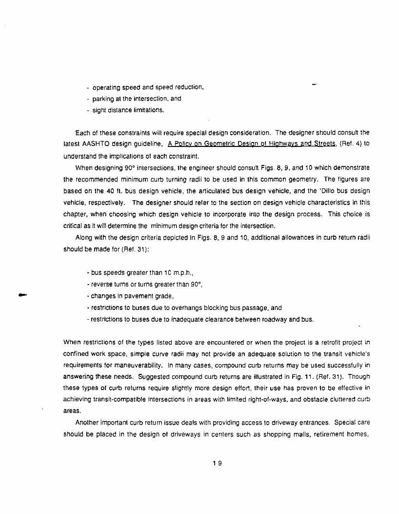
- operating speed and speed reduction,
- parking at the intersection, and
- sight distance lim~ations.
Each of these constraints will require special design consideration. The designer should consult the
latest AASHTO design guideline, A Policy on Geometric Qesign of Highways and Streets, (Ref. 4) to
understand the implications of each constraint.
When designing 90° intersections, the engineer should consult Figs. 8, 9, and 10 which demonstrate
the recommended minimum curb turning radii to be used in this common geometry. The figures are
based on the 40 ft. bus design vehicle, the articulated bus design vehicle, and the 'Dille bus design
vehicle, respectively. The designer should refer to the section on design vehicle characteristics in this
chapter, when choosing which design vehicle to incorporate into the design process. This choice is
critical as it will determine the minimum design criteria for the intersection.
Along with the design criteria depicted in Figs. 8, 9 and 10, additional allowances in curb return radii
should be made for (Ref. 31):
- bus speeds greater than 10 m.p.h.,
-reverse tums or turns greater than 90°,
- changes in pavement grade,
- restrictions to buses due to overhangs blocking bus passage, and
- restrictions to buses due to inadequate clearance between roadway and bus.
When restrictions of the types listed above are encountered or when the project is a retrofit project in
confined work space, simple curve radii may not provide an adequate solution to the transit vehicle's
requirements for maneuverability. In many cases, compound curb returns may be used successfully in
answering these needs. Suggested compound curb returns are illustrated in Fig. 11. (Ref. 31). Though
these types of curb returns require slightly more design effort, their use has proven to be effective in
achieving transit-compatible intersections in areas with limited right-of-ways, and obstacle cluttered curb
areas.
Another important curb return issue deals with providing access to driveway entrances. Special care
should be placed in the design of driveways in centers such as shopping malls, retirement homes,
1 9

Parking
-- --Parking
Refer to the City of Austin's Transportation Criteria Manual
for absolute minimum requirements.
Figure 8 : Curb Returns tor Forty Foot Bus Design Vehicle (Ref. 24)
20

Parking
::. :<·
Parking
R =35ft
Refer to the City of Austin's Transportation Criteria Manual
for absolute minimum requirements.
Figure 9 : Curb Return for Articulated Bus Design Vehicle
21
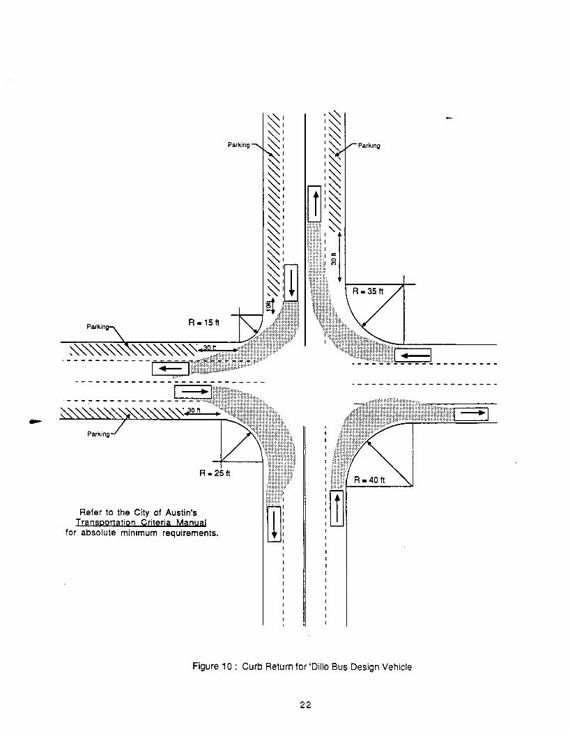
R • 15ft
Refer to the City of Austin's Transportation Criterja Manual
for absolute minimum requirements.
Parking
Figure 10 : Curb Return for 'Dille Bus Design Vehicle
22

Case 1
Case 2
PaM<•na n;,~.,.. X n;,tanc• V
Case1 Before Turn 25ft 5011
Case2 None 5011 lOft
AllOt Tum 3511 25ft -.a ... ~
Parking
Case3
Refer to the City of Austin's Transportation Crjterja Manual
for absolute minimum requirements.
Figure 11 : Compound Curb Return - Alternate Design (Ref. 31)
23

schools, etc. so that transit vehicles servicing these facilities will be compatible. Typical suggested
driveway designs are illustrated in Figure 12 (Ref. 22).
Oeljneatjon
Transit facilities should be conspicuously marked so as to separate the transit facility from the adjacent
traffic and parking lanes. Pavement markings and signs regulating traffic and parking should conform to
the Texas Manual on Uniform Traffic Control Deyjces for Streets and Highways. The relevant local
authority must also approve such signs and markings.
Turnouts
. A bus turnout is a bus stop that is recessed in a curbed area away from the main traffic lanes of a
roadway (Ref. 22). The main advantage of turnouts is that they separate stopped transit vehicles from
moving traffic, thereby, reducing traffic congestion due to queuing. Such turnouts should allow buses to
stop, load, and accelerate with little effect on through traffic. They are important especially in areas of high
traffic volume, where congestion could be a problem if a bus stops in the main lanes of traffic; however,
the driver may find it difficult to reenter the traffic stream of a high volume street. They can also be
important where bus volumes and loading volumes are high. General rules of thumb concerning the use
of bus turnouts are (Ref. 28):
- Curb parking is not allowed, especially during the peak hour.
- Five hundred (500) vehicles travel in the curb lane during the peak hour.
- Two-lane road with no designated curb parking.
- One hundred (1 00) buses per day and 1 0 to 15 buses carrying a total of 400 to 600 passengers
in the peak hour traverse the street.
- The average dwell time is more than 1 0 seconds per stop.
- Right-of-way width is adequate to allow construction of the turnout without adversely affecting
sidewalk pedestrian flow.
Figure 13 shows bus turnout designs, based on the standard 40 ft. bus, at nearside and farside
locations of arterial street intersections (adapted from Ref. 28). Figure 14 shows the mid-block turnout
design parameters (adapted from Ref. 19).
In order to reduce conflicts with traffic, a combination of the nearside and farside turnouts shown in
Fig.13 should be used when the intersection is signalized and more than 250 right turns are made by
traffic during the peak hour (Ref. 28). In this case, the farside turnout should function as the actual bus
24

I I
t t 40' R 40' R t t 40' R
/ " No Parking
___ ._ =t2~ ____ .__ __ _
I I
t t t t 30'R
\& 30' 'i LiJJ
32' _.___
• No Parking
1 0' Parking Lane
Note: Parking should be prohibited for 30' where buses make a right-turn and heavy vehicle movement occurs or is anticipated.
Refer to the City of Austin's Transportation Criteria Manual
for absolute minimum requirements.
Figure 12: Driveway Curb Returns (Ref. 22)
25
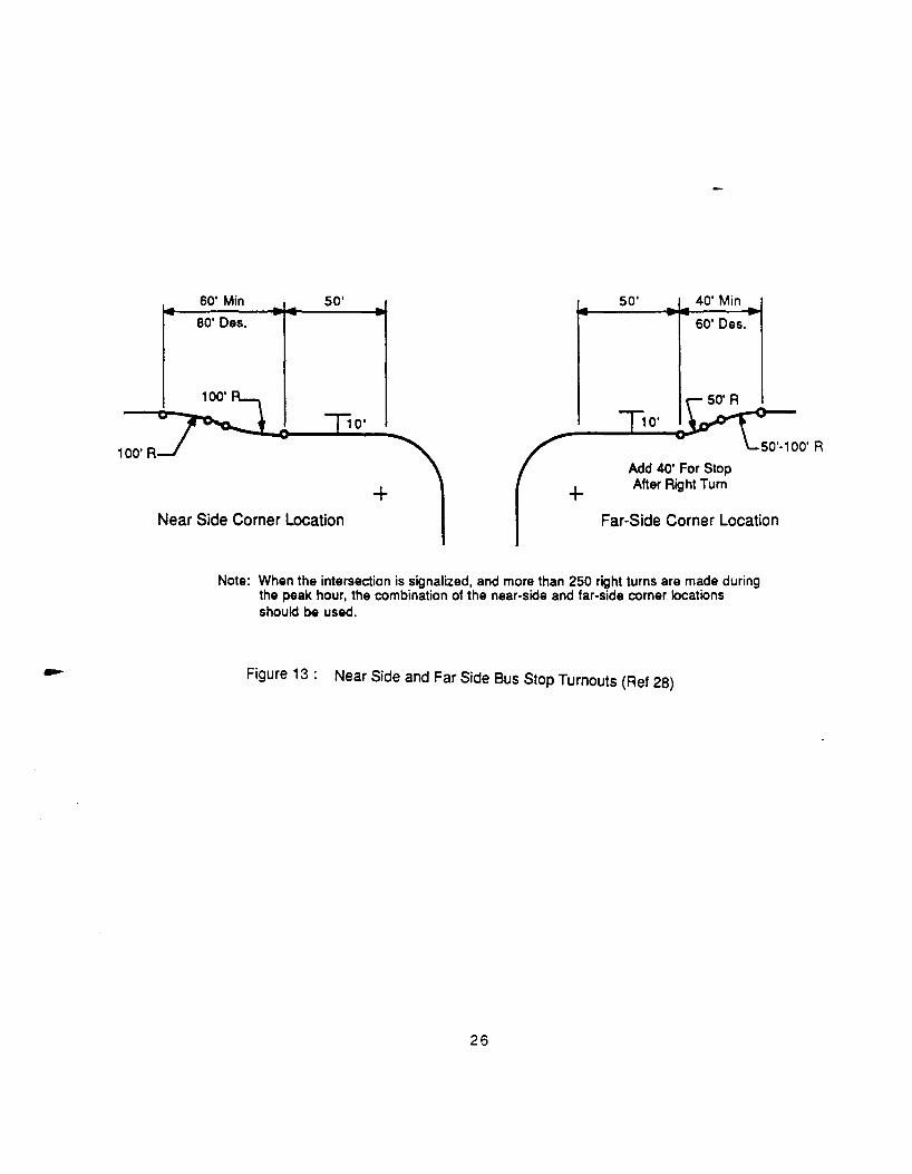
100' A
60' Min 50'
eo· Des.
+ + Near Side Comer Location
50' 40' Min
60' Des.
Add 40' For Stop After Right Turn
Far-Side Corner Location
Note: When the intersection is signalized, and more than 250 right turns are made during the peak hour, the combination of the near-side and far-side corner locations should be used.
Figure 13 : Near Side and Far Side Bus Stop Turnouts (Ref 28)
26
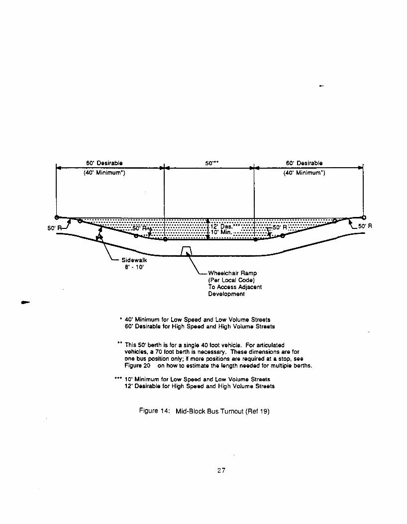
50'
60' Desirable
(40' Minimum*)
so···
Wheelchair Ramp (Per Local Code) To Access Adjacent Development
• 40' Minimum for Low Speed and Low Volume Streets 60' Desirable for High Speed and High Volume Streets
60' Desirable
(40' Minimum*)
•• This 50' berth is for a single 40 foot vehicle. For articulated vehicles, a 70 foot berth is necessary. These dimensions are for one bus position only; if more positions are required at a stop, see Figure 20 on how to estimate the length needed for multiple berths.
••• 1 0' Minimum for Low Speed and Low Volume Streets 12' Desirable for High Speed and High Volume Streets
Figure 14: Mid-Block Bus Turnout (Ref 19)
27
stop with the nearside turnout providing an area for buses to exit the traffic stream and enter the farside
stop.
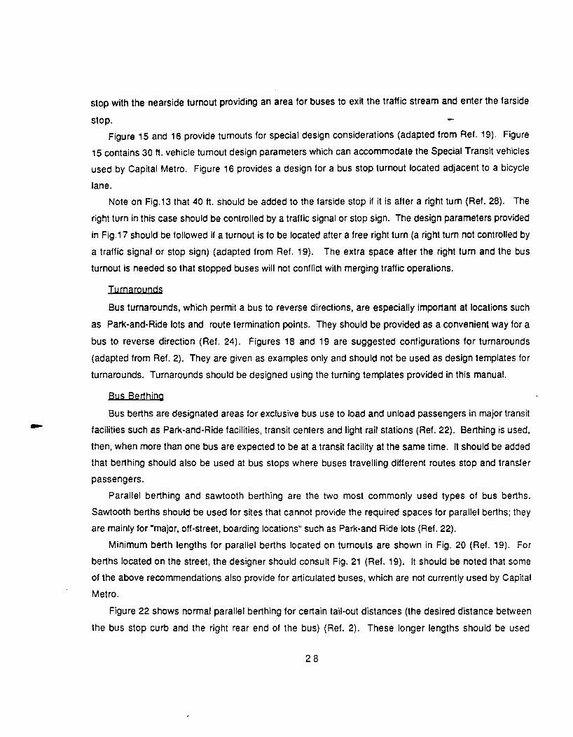
Figure 15 and 16 provide turnouts for special design considerations (adapted from Ref. 19). Figure
15 contains 30ft. vehicle turnout design parameters which can accommodate the Special Transit vehicles
used by Capital Metro. Figure 16 provides a design for a bus stop turnout located adjacent to a bicycle
lane.
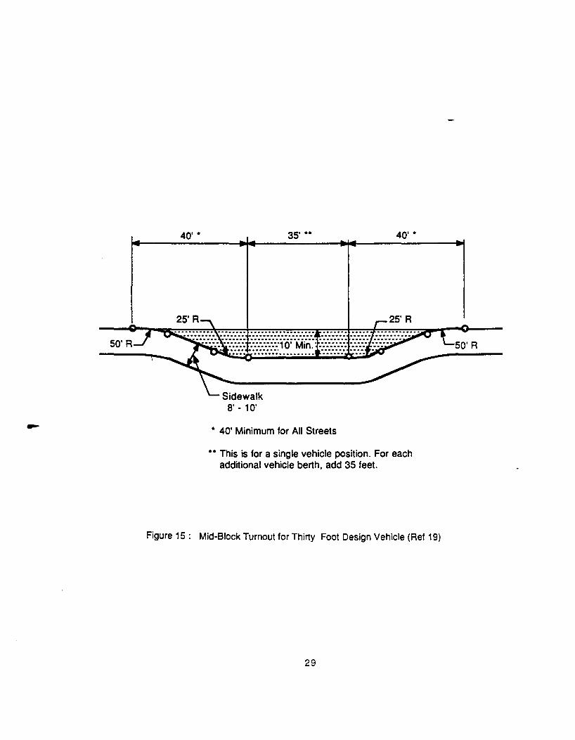
Note on Fig.13 that 40ft. should be added to the farside stop if it is after a right turn (Ref. 28). The
right turn in this case should be controlled by a traffic signal or stop sign. The design parameters provided
in Fig.17 should be followed if a turnout is to be located after a free right turn (a right turn not controlled by
a traffic signal or stop sign) (adapted from Ref. 19). The extra space after the right turn and the bus
turnout is needed so that stopped buses will not conflict with merging traffic operations.
Turnarounds
Bus turnarounds, which permit a bus to reverse directions, are especially important at locations such
as Park-and-Ride lots and route termination points. They should be provided as a convenient way for a
bus to reverse direction (Ref. 24). Figures 18 and 19 are suggested configurations for turnarounds
(adapted from Ref. 2). They are given as examples only and should not be used as design templates for
turnarounds. Turnarounds should be designed using the turning templates provided in this manual.
Bus Berthina
Bus berths are designated areas for exclusive bus use to load and unload passengers in major transit
facilities such as Park-and-Ride facilities, transit centers and light rail stations (Ref. 22). Berthing is used,
then, when more than one bus are expected to be at a transit facility at the same time. It should be added
that berthing should also be used at bus stops where buses travelling different routes stop and transier
passengers.
Parallel berthing and sawtooth berthing are the two most commonly used types of bus berths.
Sawtooth berths should be used for sites that cannot provide the required spaces for parallel berths; they
are mainly for "major, off-street, boarding locations" such as Park-and Ride lots (Ref. 22).
Minimum berth lengths for parallel berths located on turnouts are shown in Fig. 20 (Ref. 19). For
berths located on the street, the designer should consult Fig. 21 (Ref. 19). It should be noted that some
of the above recommendations also provide for articulated buses, which are not currently used by Capital
Metro.
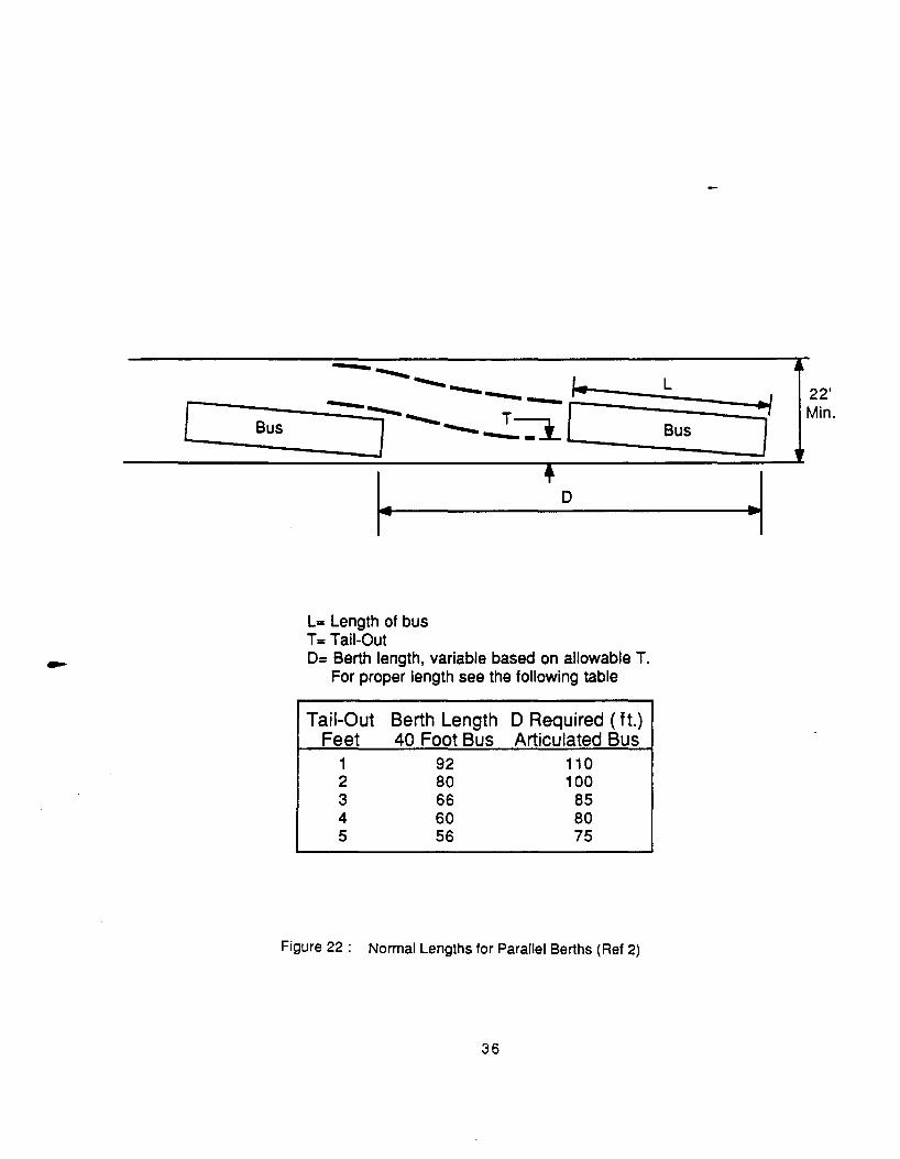
Figure 22 shows normal parallel berthing for certain tail-out distances (the desired distance between
the bus stop curb and the right rear end of the bus) (Ref. 2). These longer lengths should be used
28
40' • 35' •• 40' •
* 40' Minimum for All Streets
•• This is for a single vehicle position. For each additional vehicle berth, add 35 feet.
Figure 15 : Mid-Block Turnout for Thirty Foot Design Vehicle (Ref 19)
29

8'. 10'
so·· 50'
Wheelchair Ramp (Per Local Code} To Access Adjacent Development
• 60' Desirable For All Streets With Adjacent Bike Lanes
Figure 16 : Mid-Block Bus Turnout Adjacent to Bike Lane (Ref 19}
30
so··
Island (Length Varies)
Right Tum Lane Merge Lane (Length Varies) (Length Varies) 50' r 60' 50' ••
Bus Stop Zone I
• 40' Minimum for Low Speed and Low Volume Streets Z . 60' Desirable for High Speed and High Volume Streets Bus Stop Sign
•• This 50' berth is for a single 40 foot vehicle. For articulated vehicles, a 70 foot berth is necessary. These dimensions are for one bus position only; If more positions are required at a stop, see F"~gure 20 on how to estimate the length needed for multiple berths.
Figure 17 : Bus Turnout Located After Free Right Turn (Ref 19)
31
Not To Scale

Not to Scale
68' t t
I .. 2a· ~I Figure 18 : Counter-Clockwise Turnaround Located to the Left (Ref 2)
32

99'
Not to Scale
I. .. I 20'
Figure 19 : Counter-Clockwise Turnaround Located to the Right (Ref 2)
33
in .... ....

60' 40'
50' 80' 50'
First Position Second Position (Layover)
Third Position (Passthrough)
To determine the dimensions for a bus turnout with multiple berths:
- The first position should be 50 feet long for 40 foot vehicles (70 feet for articulated vehicles).
- For each additional passthrough bus, 50 feet should be added (70 feet for articulated vehicles).
- For each additonal layover bus, 80 feet should be added (1 00 feet for articulated vehicles).
Figure 20 : Minimum Lengths for Parallel Berths (Ref 19)
34
60'

60'
40' (Transition)
60' 50' 50' 60'
40' First Second 40' Transition Position Position Transition
First
(Pass-through)
50' 50' 80' 60' . ... . .. Position Second Third Position 40'
Position (Layover) (Transition}
(Passthrough}
To determine the dimensions for a bus turnout with multiple berths:
-The first position should be 50 feet long for 40 foot vehicles (70 feet for articulated vehicles}.
-For each additional passthrough bus, 50 feet should be added (70 feet for articulated vehicles}.
-For each additional layover bus, 80 feet should be added (100 feet for articulated buses}.
Figure 21 : Parallel Berths Located on the Street (Ref 19}
35
[ Bus
-- ----....___ ~ ------r--.2~[
~ L= Length of bus T= Tail-Out
D
D= Berth length, variable based on allowable T. For proper length see the following table
Tail-Out Berth Length D Required (ft.) Feet 40 Foot Bus Articulated Bus
1 92 110 2 80 100 3 66 85 4 60 80 5 56 75
Figure 22 : Normal Lengths for Parallel Berths (Ref 2)
36
L 22'
J Min. Bus
~

whenever possible. Note that for tail-out distances of 2 ft., berth lengths of 80 ft. are recommended for
standard 40 ft. buses.
Finally, Fig. 23 shows plan views and dimensions for sawtooth berths (Ref. 2).
It is recommended that minimum berthing spaces of 50 ft. and bus layover berth lengths of at least 80
ft. should be provided in parallel berthing. Also, wherever possible, the normal berth lengths shown in
Fig. 22 should be used. Figure 23 is the recommended design for sawtooth berths.
Pavement Qesign
The design of a proper pavement structure is as critical to the success of a transit facility as any other
component. An improperly designed pavement could be very expensive to maintain over time.
Pavement design must take into account the following factors:
- the soil type,
- the soil's support capacity,
- the magnitude and the frequency of the bus and other traffic loads that will service the area, and
- the strength of the pavement materials.
The soils in the Austin area vary widely, including swelling clays and limestone stratifications. Soil tests
for the area of the development will contribute to a successful facility. Table1 contains the critical axle
loads of some of the bus types used by Capital Metro. The engineer should, nevertheless, confirm the
types of buses that will serve the development.
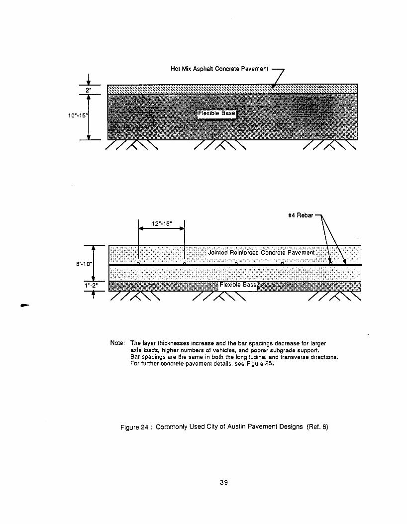
The City of Austin uses a range of pavement designs when pavements at bus stops are reconstructed
(Ref. 6). These designs, which are examples only, are depicted in Fig. 24 and Fig. 25. It is recommended -
that pavements be designed in accordance with the City of Austin's Computerized Pavement Design
program (Ref. 6). Information pertaining to these programs may be found in the City of Austin's
Transoortation Criteria Manual.
Concrete is recommended over asphalt in the pavement design, because concrete better withstands
the shearing forces induced by bus acceleration and deceleration. Concrete also does not deteriorate
due to spilled fuel from the buses. A factor to consider, however, is the location of utility lines in a
development. Lines directly beneath concrete pads can be expensive to repair.
PHYSICAL COMPONENTS OF TRANSIT FACILITIES
The provision of well designed transit facilities can significantly contribute to the passengers' safety,
comfort and convenience as well as to the efficiency of the transit service provided. In general, when
37
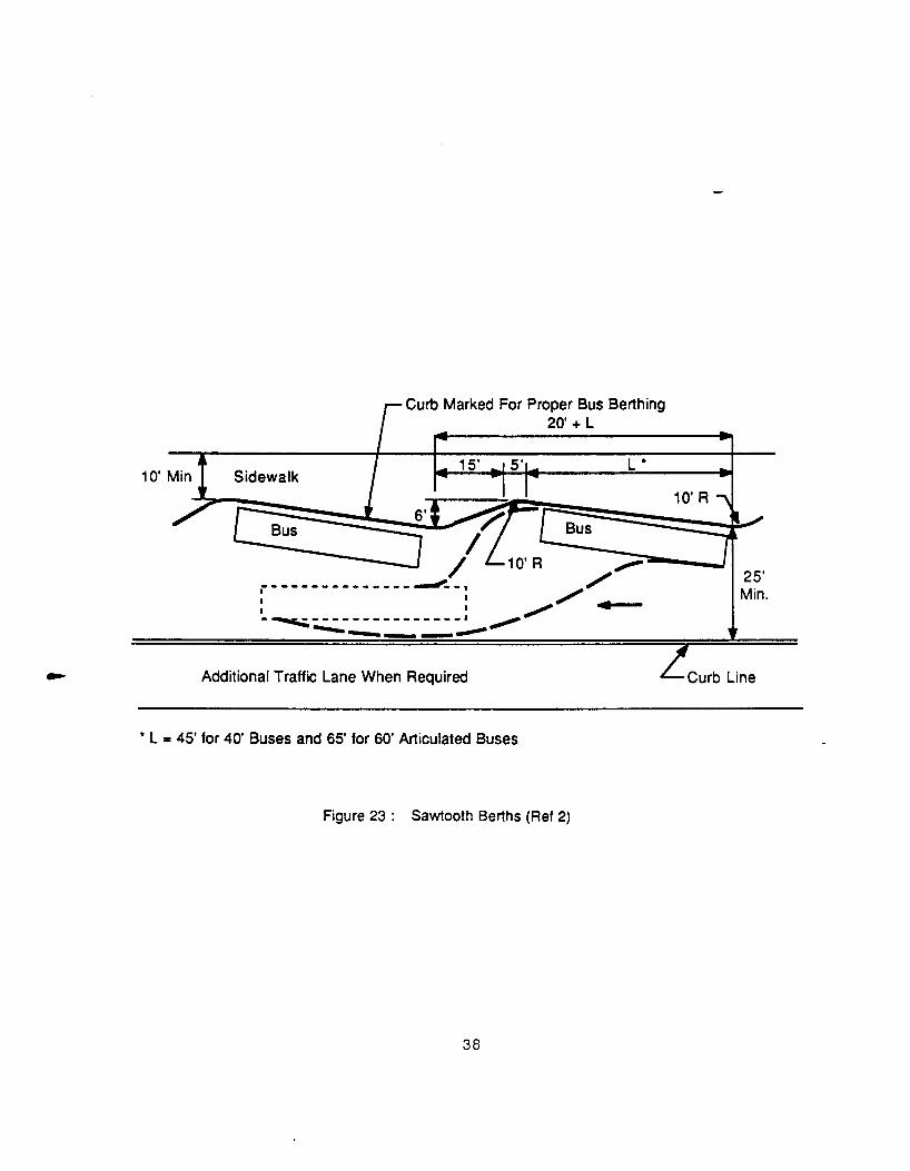
Curb Marked For Proper Bus Berthing 20' + L
Sidewalk 15' L *
~ I
I ,-----------------~-, , : I /..,__ I I /
-~---------------· ~ --------Additional Traffic Lane When Required Zcurb Line
* L = 45' for 40' Buses and 65' for 60' Articulated Buses
Figure 23 : Sawtooth Berths (Ref 2)
38
2"
1 0"-15"
1"-2"
•
Hot Mix Asphalt Concrete Pavement
Note: The layer thicknesses increase and the bar spacings decrease for larger axle loads, higher numbers of vehicles, and poorer subgrade support. Bar spacings are the same in both the longitudinal and transverse directions. For further concrete pavement details, see Figure 25.
Figure 24: Commonly Used City of Austin Pavement Designs (Ref. 6)
39

40'
Joints with Fiberboard
#4 Rebar
40' 40'
A = 12" to 1 5" Spacing 8 = 24 • Spacing ~..I_· -----lila· to 1 o· Jointed Reinforced Concrete Paveme~t C = 18" Min., 30 • Preferred
Note: The layer thicknesses increase and the rebar spacings (A) decrease for larger axle loads, higher numbers of vehicles, and poorer subgrade support.
Rebars and dowels placed at mid-depth.
Figure 25 : City of Austin - 120 Foot Concrete Pavement Bus Stop (Ref. 6)
40

designing the various components of a transit facility, the following should be the objectives in the design
and placement of those components:
- maximizing passenger safety, comfort and convenience,
- optimizing transit operational efficiency and passenger attractiveness,
- minimizing initial cost and long-term maintenance costs, and
- minimizing negative effects on traffic operations and impact on the environment.
In all cases where physical work is undertaken within public right-of-way, the approval of the relevant
local authority and/or the Texas State Department of Highways and Public Transportation, as applicable,
should be obtained.
Watting Areas
Waiting areas should preferably be accessible via paved walkways, while the waiting area itself should be
paved to minimize discomfort due to muddy or dusty conditions. Waiting area pavement design should be
of the same design as walkways. Pavement should be large enough to accommodate all waiting and
unloading passengers, and to connect the curb line to shelters, benches or other amenities. It should
preferably be long enough to extend from the front door of the bus to beyond the rear door of the last bus
in a queue.
In practice it will be found that the minimum design criteria to facilitate use by mobility impaired persons
will be more than adequate to serve other passengers. These include:
- a 12ft. minimum clear space at the bus door to accommodate loading by wheelchair lifts,
- curb ramps and non-skid textured surfaces,
- a maximum curb height of 10 inches,
- a maximum surface cross slope of 4% for the ramp, and
- a maximum surface slope of 2% for the paved watting area or shelter pad.
A typical curb ramp configuration used by the City of Austin is shown in Fig. 26.
Benches
Benches can also add to the transit patrons' comfort. While certain guidelines are applicable,
individual designs can be fitted to surroundings and special requirements. Almost all bus stops can
benefit from a bench.
4 1
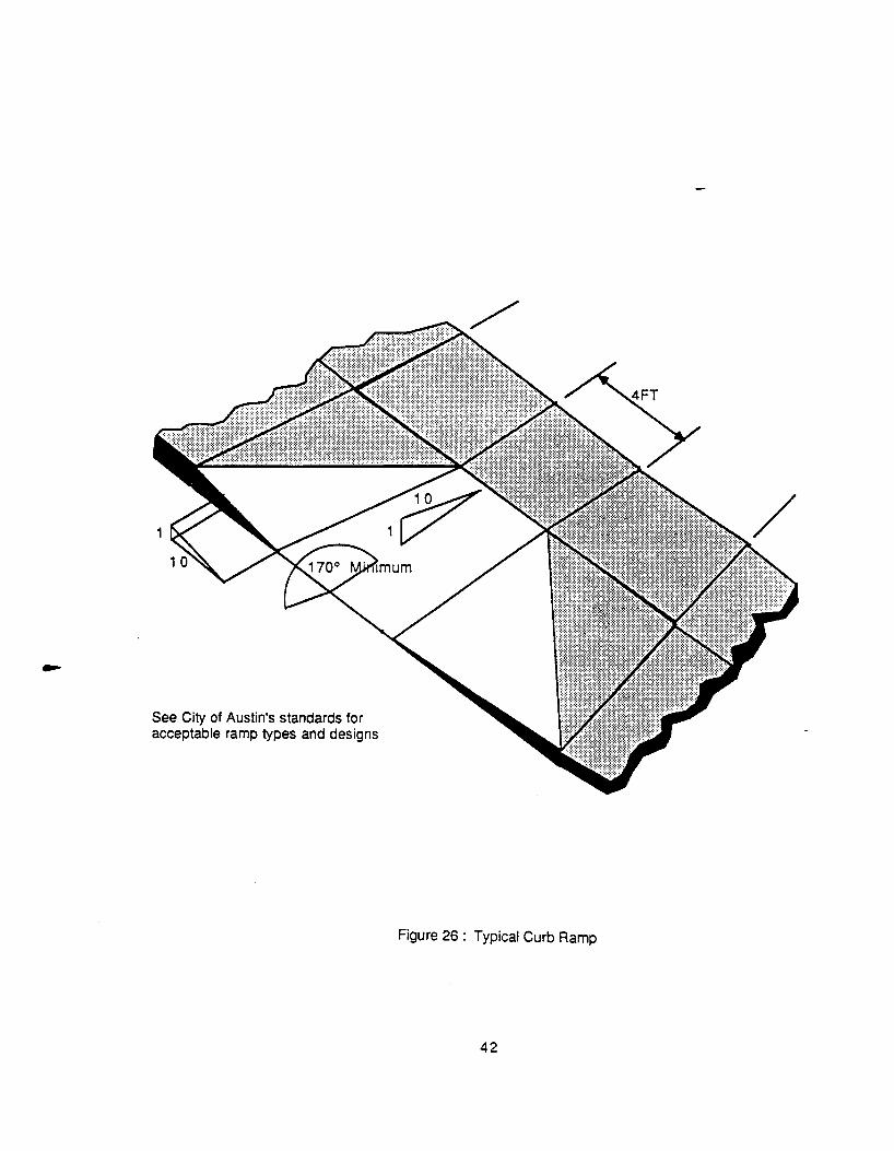
See City of Austin's standards for acceptable ramp types and designs
Figure 26: Typical Curb Ramp
42
Benches should be placed on concrete pads, with a slope of no more than 2%, and should face the
street. Benches should be placed no closer than 7 ft. from the forward end of any bus stop, to remove it
from passenger loading and unloading areas. The area should be w&ll drained with a concrete pad
preferably provided. At least 4 ft. of space should be provided at the front or back and at least on one side
of the bench for pedestrian movement and wheelchair access. In areas of heavy pedestrian movement
this should be increased to a minimum of 6ft.. Benches should be placed at least 3ft. behind curb lines to
provide space for passengers getting off the bus or waiting to board, and to provide protection for waiting
persons from passing vehicles and opening bus doors. For the convenience and visibility of passengers,
the bench should not be placed farther than 12 to 15 ft. from the curb line where the bus stops.
Benches are usually designed to seat 3 to 4 persons. Materials and design should be chosen to
provide durability, resistance to weather and vandalism, and easy and inexpensive maintenance. Sharp
protrusions should be avoided. Rounded seats not protected by a shelter should include drainage holes
to prevent accumulation of rain water.
The developer should consult with Capital Metro in regard to the inclusion and type of benches at a
particular site.
Shelters
Shelters to protect waiting passengers from the elements enhance the safety, security and comfort of
transit users. Free standing shelters are most often used, but shelters incorporated into other buildings
should also be considered. Shelters can also be designed to fit in with the landscape and the
surrounding style of architecture.
Shelters should be provided wherever a significant number of transit patrons wait for buses. Exis0ng
guidelines require 30 persons per day for placement of a shelter by Capital Metro. It is obvious, however,
that the provision of shelters demonstrates benefits irrespective of the number of passengers. Special
consideration should be given to areas frequented by children, senior citizens, or mobility impaired
persons. The proximity of alternative locations where shelter is provided should also be considered when
deciding on the provision of a shelter.
In order to provide an adequate area for pedestrian circulation, including wheelchair space, the shelter
should not be placed less than 4 ft. from the curb line and a space a minimum of 4 ft. wide should be
provided on at least one side of the shelter. In addition, a clear area of 12 ft., measured from the curb,
should be provided in front or to the side of the shelter to accommodate loading by. wheelchair lifts. To
provide visibility for waiting patrons and bus drivers, during day or night conditions, the shelter should be
placed no further than 15ft. from the curb. It is extremely important, however, that shelters are not placed
43

in a manner that obscures the sight lines of the traffic. The following factors should also be considered in
establishing the specific location of a shelter:
- adequate lighting,
- adequate drainage,
- ease of maintenance and cleaning, and
- positioning close to bus entrance doors.
The design of shelters should suit climatic conditions. The type of shelter currently used by Capital
Metro, consisting of a solid back wall and roof unit, a concrete floor and two transparent sidewalls, suits
conditions found in the Austin area. This type of shelter is illustrated in Fig. 27. The transparent sidewalls
allows light to enter and make it possible for waiting patrons and bus drivers to see each other. Alternate
bus shelter designs also found in the Austin area are illustrated in Figs. 28, 29, and 30.
The cost and ease of maintenance, as well as resistance to vandalism, should be taken into account
when designing a shelter and selecting materials. Wooden components should be adequately treated to
prevent weathering and all metal components should be corrosion resistant. All protruding parts should
be rounded to prevent injury to transit users and passing pedestrians.
The developer should consult with Capital Metro in regard to the inclusion and type of shelters at a
particular site.
Information Qevices
Clear communication with transit patrons enhances the ease and comfort of transit use and support the
goal of increasing ridership. Information devices used include: bus stop signs, schedule displays and
map displays. Bus stops in the Austin area should be clearly marked using standard CapHal Metro bus
stop signs. Bus stop signs are the simplest information device and should be placed at every bus stop at a
minimum height of 7 ft. from the ground •. facing the oncoming vehicles. They could include the route
number and a telephone number for further information. Maps and schedule displays are often located
behind a transparent cover in an aluminium or wooden frame attached to bus shelters or bus stop post.
Information devices should be placed so as to be clearly visible and easy to access. It should not obscure
sight lines, or impede on pedestrian waiting and movement areas. In all cases materials should be vandal
resistant and easy to maintain. Currently used Capital Metro bus stop signs are shown in Fig. 31.
44

Figure 27 : Presently Used Capital Metro Bus Shelter
Figure 28 : Bus Shelter on The University of Texas Campus
45

Figure 29 : Bus Shelter located at 11th Street and Congress
Figure 30 : Capital Metro Park-and-Ride Facility
46
' Figure 31 : Presently Used Capital Metro Bus Stop Signs
47

Lighting
The lighting of transit facilities provides security, comfort and visibility. Although the provision of
illumination at all facilities is strongly recommended, it may not be practical or feasible in all cases. The
following placement considerations are suggested:
- Illumination from nearby or integrated building can be taken into account when deciding on
whether to provide lighting.
- Higher priority should be given to areas regarded as less safe and less secure and at locations
frequented by children and senior citizens.
- Even if lighting is not initially provided, some provisions for future lighting should be made, such
as to verify availability of electricity supply and provide ducting.
Vehicle Parking.
Passenger vehicle parking should be provided in transit trip origination areas such as Park-and-Ride
facilities and transit centers, and can also be provided at high volume suburban bus stops. The size of the
facility depends on the design volume, the available land area, and the size and number of other parking
lots in the area. The facility should be designed for self-parking. The layout and design of the parking
areas should conform to accepted standards and the requirements of the relevant local authority.
Bicycle Storage
Bicycle storage facilities should be provided at high volume suburban bus stops, Park-and-Ride
facilities and at transit centers. Bicycle storage facilities can either be in the form of bicycle racks or bicycle
lockers located on asphalt or concrete pads. Both cases require a minimum allowance of 9.5 ft. for
maneuvering space. Figure 32 shows typical bicycle storage facilities.
Facilities for the Mobility lmoaired
Requirements for providing ease of access for mobility impaired persons have largely been covered in
previous sections of this chapter. In general, provision for the mobility impaired requires:
- the provision of skid resistant pavements,
- the provision of curb ramps,
- restriction to gradients to be below 4 %,
48

Figure 32 : Typical Bicycle Racks and Lockers
49

- barrier free areas,
- reservation of parking bays closest to the facility,
- adequate space to accommodate wheelchairs in all public areas, and
- information displays, such as maps or schedules should be placed low enough to be readable
by a person in a wheel chair.
Additional information is available from Capital Metro's Special Transit Services Division.
Traffic Control Deyjces
All traffic signs associated with transit facilities, such as those to indicate parking restrictions,
pedestrian crossings, warning signs, etc., should conform first to the Texas Manual of Unjform Traffic
Control Deyjces (Ref. 26) and then to the national Manual of UnHorm Traffic Control Deyjces (Ref. 32) and
should be coordinated with the appropriate local authority.
Other Amenjtjes
Amenities other than those already mentioned can also be used to enhance the comfort and safety of
transit users, and make transit more attractive. Such amenities could include: rest rooms, newsstands,
public phones, police and fire alarms, information kiosks and vending machines.
The decision to include such amenities will depend on the specHic location, local needs, patronage,
the proximity of similar amenities, security, and economic and operational considerations. Trash
receptacles should be provided at all major transit stops and passenger waiting areas.
In all cases, the following should be considered when placing these amenities:
- adequate pedestrian waiting and circulation space as stated in past sections,
- adequate space for movement by mobility impaired persons,
- drainage requirements,
- clear sight lines for traffic,
- ease and economy of maintenance, and
- space clearance for passing vehicles, i.e., 3ft. curb clearance.
FACILITY DEVELOPMENT
The process of planning and designing a transit facility will, in essence, comprise the selection and
placement of the physical components discussed above, in a way to enhance the attractiveness, safety
and efficiency of the total facility. Underlying this is the central concept of interaction between the transit
50

vehicles and passengers and the separation of various modes of transport found in and around the transit
facility. Modes in this context include transit vehicles, private automobiles, pedes~ans and bicycles.
Transit facilities may be areas of high activity and conflict between the modes, making careful planning
essential.
Concept of Interaction I Separation of Modes
The location of interaction between buses and passengers is at the bus stop, discussed at length in
previous sections. Transit patrons should be able to reach bus stops as unhindered as possible. In the
same way buses should reach and depart from bus stops,while not causing a danger or impedance to
other modes, and while operating at a high level of efficiency.
The following general guidelines apply to transit facilities incorporated into developments, whether
retrofitted or planned from the outset:
- Bus stop areas should be located as close to streets as possible to minimize on-site travel and to
minimize conflicts between modes.
- In heavily travelled areas the use of exclusive roadways and stopping areas for buses are
highly recommended.
- Separate access points to developments for various modes should be provided to reduce
conflict and enhance operational efficiency. Modes in this context include :automobiles,
transit, pedestrians, and bicycles.
-Where access points from public streets to developments are separated by mode, they should
be clearly designated and well spaced to avoid conflict and confusion. Points of egress onto
public streets should be designed so as to avoid unnecessary obstruction of sight, conflict,
and weaving maneuvers between modes.
- Transit facilities should be located so that pedestrians have direct access between the transit
facility and the origin and destination of pedestrian trips (e.g. shopping center, employment,
parking), and without unnecessarily having to cross roadways or areas used by transit
vehicles. Where pedestrians do have to cross areas used by other modes it should only be at
clearly demarcated locations, fitted with the necessary traffic control and warning devices,
such as painted crosswalks, warning signs or traffic signals.
- Exclusive pedestrian walking ways should be provided as far as possible. A Coefficient of
Directness ( C =[designated walking path distance] I [straight line distance]) is often used to
assist in the planning of Park-and-Ride and similar facilities. It is suggested that the coefficient
of directness not exceed 1.2 , with 1.4 considered as a maximum (Ref. 36). In all cases the
51

distance to be traversed by mobility impaired persons should be minimized. This will, for
instance, include the parking spaces closest to the transit facility being reserved for mobility
impaired persons.
Some of the above concepts are illustrated in Fig. 33.
Park-and-Bide Facilities
Park-and-Bide facilities are special transit stations expressly for the use of patrons transferring from
alternate transportation modes to the Capital Metro system. These parking facilities are provided primarily
to encourage express bus ridership. They are usually located in the suburban residential community to
attract daily commuters and to minimize access distances.
Placement Consideration. Park-and-Bide facilities should be located at sites that are highly visible and
easily accessible to the commuter. These facilities should be located adjacent to major arterials and
highways, outside points of significant urban congestion. Park-and-Bide facilities should be located more
than 3 to 4 miles from the activity center being served, in order to make the bus part the major portion of
the patron's trip (Ref. 36). The impact on the surrounding land uses and the availability of real estate will
also impact the location of the Park-and-Bide facility.
Two general approaches can be used in designing Park-and-Bide facilities. One alternative is to
provide new facilities specifically designed to serve exclusively as a Park-and-Bide terminal. The second
alternative is to share unused portions of existing parking lots as the parking area for the Park-and-Bide
service. Sites commonly used as joint-use arrangement are shopping centers, movie theaters, and
sporting facilities.
Both of the alternatives listed above have their advantages and disadvantages. The shared lot option
is faster to implement and less costly. Due to the low capital requirements, joint-use lots can be used to
test travel demands. If demand is inadequate, the service can quickly be terminated. If the demand is
substantial, a more extensive facility can be considered. The exclusive lot option, because it is planned in
advance, can provide better access and circulation patterns. The planned facility will be able to
incorporate space for future expansion and for excess parking needs.
Oesign Considerations. The potential demand for the Park-and-Bide facility will be the basic design
criteria. The facility should be designed to accommodate a demand of approximately 10 percent greater
than the estimated average daily demand (Ref. 36).
Certain operational and design features of the Park-and-Bide facility limit the desirable lot size. The
minimum lot size must be justified by the level of demand experienced at the site. The maximum desirable
lot size is constrained by walking distances, bus headways, and market-area characteristics. Maximum lot
52

Controlled Intersection with Pedestrian Crosswalks
Public Roadway
Exclusive
...... . . ·····~···············································································
~~Bus~\ 'i ®!/ t 'I Exclusive Bus :
Entrance and Bay l
Bike Parking-r-r~·t--.:~~!.!!~ . . .
. >-' ca: ;r;: "0• ca• o: a:: u: ·-. 1)· ::J: c..: . . . . . . . .
Bikeway -1-~~
I
Large Center: Mall, Hospital, etc l~
:~ :~
. l~ . 1.....---------'
~ Define Lines of Direct Access to Project
Figure 33 : Illustrated Concept of Separation and Interaction of Modes
53

sizes of 700 to BOO parking spaces and minimum lot sizes of 200 parking spaces are recommended (Ref.
36). To maximize the efficiency of the lot, right angle parking is recommended. Parki~ spaces should be
9 ft. by 20 ft. for full size cars. At least one parking space per 40, for the first 150 spaces, and for every 100
spaces thereafter, should be provided for the mobility impaired. The mobility impaired parking spaces
should have a minimum width of 11 ft. (Ref. 4).
Park-and-Ride facilities are normally used by large numbers of patrons and vehicles and planning
should be directed towards minimizing conflicts between vehicles and pedestrians. When planning
internal site layout to minimize conflict, the following activities should be treated in the given priority order
(Ref. 4}:
-bus loading and unloading,
- other vehicles off-loading passengers,
- bicycle parking,
- mobility impaired parking, and
- all day parking.
Park-and-Ride entrance and exit lanes should be designed to minimize automobile and bus conflicts.
Exclusive bus entrance and exit lanes are preferred but not essential if less than 12 buses serve the
facility during the peak hour. An adequate number of traffic lanes should be provided at all entrance and
exits to accommodate the expected number of vehicles, the local traffic conditions, and the site
configuration.
The passenger loading area of the Park-and-Ride facility can be located either within or on the
periphery of the lot. The loading location on the periphery will minimize the real estate requirements and
reduce the number of conflicts between autos and buses. The time required for the bus to serve the
facility may also be reduced. The average walking distance for patrons from parking slots to the loading
area is, however, increased. The prime advantage of a loading area within the lot is that this average
walking distance is greatly reduced. As a consequence, however the circulation of buses through the
facility becomes much more complex. The potential for bus and auto conflicts will also increase as the
buses must now circulate through the lot. Careful planning should be implemented when considering
either of these designs. The design criteria should follow the standards for berthing areas described
earlier in this chapter.
The "Kiss-and-Ride" patronage is represented by those persons who are dropped off by a driver at
the Park-and-Ride facility in the morning and picked up again in the afternoon. Approximately 10 percent
54

of the total number of vehicles using a Park-and-Ride lot could be Kiss-and-Ride vehicles. The average
waiting time for a Kiss-and-Ride vehicle is from 6 to 10 minutes. Kiss-and-Ride spaces should be signed in
a manner that will assure their use as short-duration parking spaces. Space for Kiss-and-Ride vehicles
should be provided for approximately 1 to 1.5 percent of the lot capacity.
Principal passenger waiting areas should be provided with shelters, benches, route information, trash
receptacles and, if possible, public telephones. Bicycle storage facilities may be provided and should be
placed near the bus loading area. Amenities such as newsstands, vending machines, rest rooms and
mailboxes can also be provided to increase the comfort of users. All lots should be provided with lighting.
Park-and-Ride signs should be placed at the entrances to the facility so that they are clearly visible to
approaching vehicles. For large Park-and-Ride facilities, information signs along highway ramps, arterial
intersections and major feeder roads are recommended to adequately guide potential users.
Figure 34 shows a typical Park-and-Ride facility layout. while Fig.37 illustrates some placement
considerations. Fig. 35 and 36 are examples of the bus and passenger shelter currently provided at the
U.S. 183 and Lamar Blvd. Park-and-Ride facility in Austin.
Transit Centers
A transit center is a major transit facility which is designated to accommodate a variety of transit
functions including passenger loading and unloading, transfers, driver breaks, bus layovers, Park-and
Ride operations, etc. Depending on the demand and level of service, a transit center may include an
enclosed building , complete with restrooms, benches, phones and various other service amenities.
Usually transit centers are only appropriate for large scale developments like regional shopping
centers, large office and commercial developments, universities and similar high activity centers. Bus
access routes to and from the transit center should meet all geometrical design standards for bus design
vehicles. Although transit needs and functions vary from location to location, a general design guideline
for such a facility is to provide transit vehicles with ingress to and egress from the transit center, separated
from automobile traffic. Passenger waiting areas should provide amenities similar to those at Park-and
Ride facilities. A typical Transit center layout is shown in Fig 38.
Facility Comoonent Matrix
Table 4 summarizes what design components should be considered for specific types of transit
facilities. This table should be helpful for the engineer designing transit facilities.
The Matrix is designed to provide a list of minimum design components required for each type of
transit facility. It will be beneficial if components to be included and design criteria are confirmed with
Capital Metro at an early stage in the planning process.
55
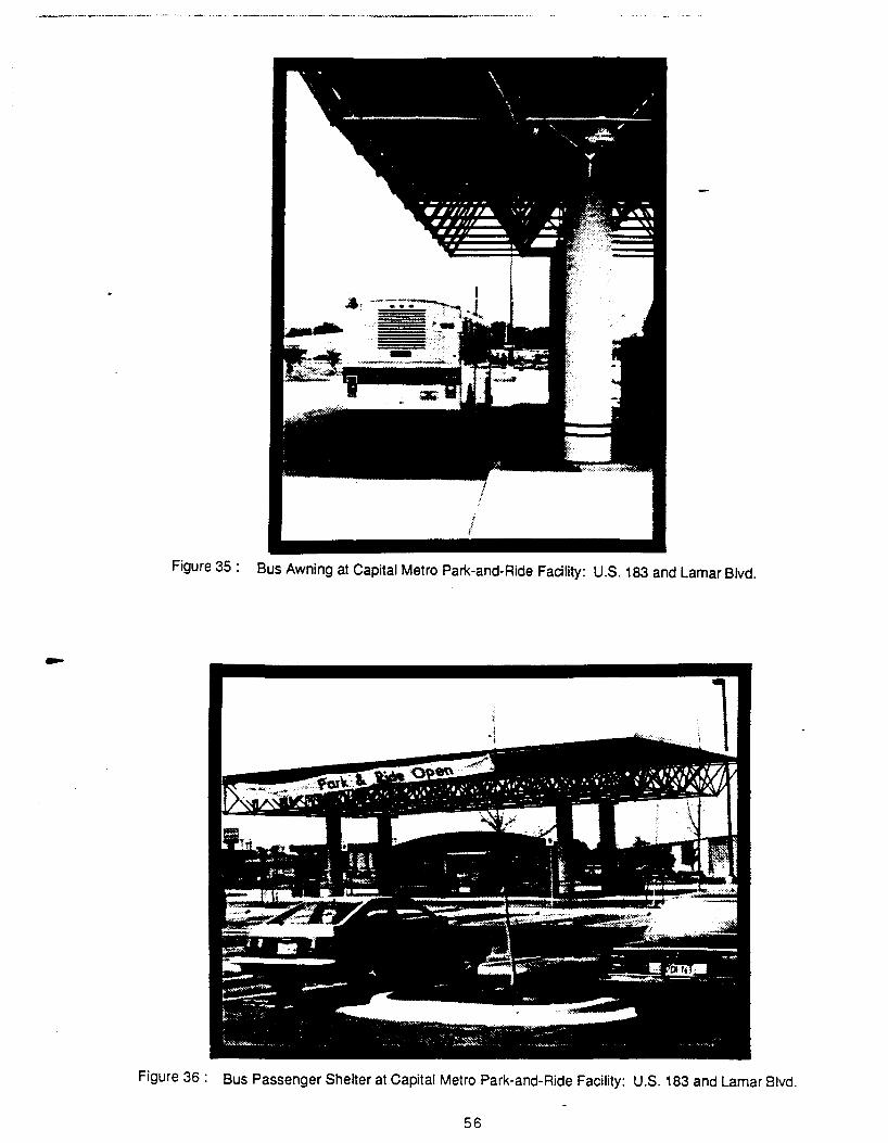
Figure 35 : Bus Awning at Capital Metro Park-and-Ride Facility: U.S. 183 and Lamar Blvd.
Figure 36: Bus Passenger Shelter at Capital Metro Park-and-Ride Facility: U.S. 183 and Lamar Blvd.
56

Park Ride t
Crosswalk .__ Taxi & Auto Dropoff Crosswalk
~ t Bicycle Racks {:Bus Shelters & Lockers DO DOD
Bus Turnout Exit+-- Entry .____
Roadway ~( 7 ___. ... Bus Turnout
Raised Curb or Stripe
Figure 34 : Typical Park-and-Ride Layout
57
I I
I I I I -t- t- -1- -i I I I I I I I I I I I I
One Adjacent Street
I I
I I I I - +- -; -1- +- -I
I I I I I I I I I I I I I I
1-,-T-rl I
I I I I I I I
1--J-.l-L-1 1 I I I 1
I I(
I I I I
I )1
One Adjacent Street
-~- T -~-1 -1 I I I I
--1- +-II I I I I I L __ l __ l
c:::J
Two Adjacent Streets
~--- T-- -1 1--- i-- -1 I ,--- .1---1 1 I I -------1 I I 1--- -t-- -1
Two Adjacent Streets Freeway Interchange Area
,----,-- -1
\--- _,-- -1 \ u \- - - l..- - _j \ I I ,--- T-- -~
L-- -t-- -1
Freeway Interchange Area
Legend
••• Street
Bus Circulation
- -- - Auto Circulation
c:::J Passenger Waiting Area
Figure 37 : Park-and-Ride Placement and Layout Design Options
58

Kll
Roadway
Figure 38 : A Typical Transit Center Site Layout
59

Facilities
Bus Transfer Stops Locations
* *
* • • • 0 0 0 0
• • • • 0 0 0 0
* 0 0 0 0 0
e Essential 0 Beneficial
Park and Ride
0
• • • • • • 0
• • 0 0
Transit Centers
0
• • • • • • 0
• • • 0
* Beneficial in Some Situations
Table 4: Facility Component Matrix
60
ComQonents Turnouts
Turnarounds
Berthing
Passenger Waiting Areas
Shelters
Benches
Information Devices
Handicapped Facilities
Bicycle Racks
Lighting
Vehicle Parking
Restrooms
Snackbars/Newsstands
CONCLUSION
Capital Metro has the ability to coordinate the integration of public transit into new and existing
development, but the actual integration of public transit can only result from active participation and
cooperation among Capital Metro, city government, developers, and the citizens of the Capital Metro
service area.
The key to successful transit integration is the inclusion of transit related planning into the initial phase
of any project design. The analysis of transit integration feasibility during the initial phases of project
planning permits the most comprehensive evaluation of whether transit integration can benefit a specific
project and the community. If it is determined that transit integration is feasible, then the site plan and
building design can incorporate the necessary design and construction elements from the preliminary
design phase, and avoid the expensive process of retrofitting a development.
The "Transit Facility Design Guide" attempts to aid the process of transit integration by providing the
appropriate facility design information necessary to assist the developer. While the transit handbook is
comprehensive in scope, it is not intended to replace specific site design planning.
Site specific design should be developed in cooperation with city regulations and Capital Metro
guidelines, and should take into account the potential for changes in vehicle design and project
expansion, and site specific constraints. Project planners and developers are strongly encouraged to
address questions to Capital Metro during the initial stages of planning a facility. The early discussions will
enhance the opportunity to develop a successful transit related project. The greater the number of transit
integration projects along a given corridor, the more likely that Capital Metro can provide efficient and
economic public transportation for the entire Capital Metro service area.
6 1

REFERENCES
1. Alameda Contra Costa Transit District, Guide for Including Public Transjt in Land Use Planning,
Oakland: Research and Planning Department Alameda Contra Costa Transit District, March 1983.
2. Alameda Contra Costa Transit District, Transit Facilities Standards Manual Oakland: Research and
Planning Department Alameda Contra Costa Transit District, March 1983.
3. American Association of State and Highway Transportation Officials, A Gujde for Qesign Q.1
Pavement Structures. Washington D.C. 1986.
4. American Association of State Highway and Transportation Officials, A Policy on Geometric Qesign
of Highways and Streets, Washington D.C., 1984.
5. Baker, E.B., Rebekah Baines Johnson Center. Austin, Texas. Interview, March 30, 1988.
6. Barba, Leon. Street and Bridge Division, City of Austin. Interview, April 1, 1988.
7. Bushell, Chris and Peter Stonham, eds., Janes Urban Transportation Systems 2nd.Edition.
London: Janes Publishing Co. Ltd., 1983.
8. Cervera, Robert, Suburban Gridlock. New Jersey Center for Urban Policy Research, Brunswick,
New Jersey, 1986.
9. City of Austin, Texas, Transportation Crjteria Manual. Austin, June1988.
10. City of Austin, Texas, Street Design Standards. Austin, 1986.
11. City of Austin, 1980 Census Reports. Department of Planning and GroW1h Management, Austin,
1986.
12. City of Seattle, Metro Transportation Facility Design Guidelines, Seattle: City of Metropolitan
Seat11e, April 1985.
13. Donnelly, Wayne. Jones Lang Wooton. Austin, Texas. Interview, April14, 1988.
R-1
14. Greater Bridgeport Transit District, Joint Development and Fixed Route Bus Systems: Experience
jn Bridgeport Connecticut. Washington D.C.: Departmentof Transportation- Government Printing
Office, January 1985.
15. Kilbride, Larry and Virgil Hedwell. Barton Creek Mall. Austin, Texas. Interview, April13, 1988.
16. Kramp, E.W .. Hancock Center, Austin, Texas. Interview, March 30, 1988.
17. Lave, Charles A., ed., Urban Transit: The Prjyate Challenge to Public Transportation. Cambridge:
Ballinger Publishing Company, 1985.
18. Orange County Transit District, Consideration of Transit jn Project Developmet, Orange County:
Orange County Transit District, 1982.
19. Orange County Transit District, Design Guidelines for Bus Facjlities 2nd Edition. Orange County:
Orange County Transit District, November 1987.
20. Pushkarev, Boris S., and Jeffrey N. Zupan, Urban Densities for Public Transportation, Springfield:
National Technical Information Services, 1976.
21. Rajappan, S.M. and M.C. Walton, An Assessment of The Operantional Impact of Larger and Wider
Combjnatjon Vehicles on the Geometry of Diamond Interchanges Center for Transportation
Research, University of Texas at Austin, 1986.
22. Sacramento Regional Transit, Resign Guidelines for Bus and Light Rail Facilities Sacramento:
Sacramento Regional Transit, October 1987.
23. Schneider, Michael J. and Rober C. Schaevitz. Private Investments in Public Transit Presented at
the Annual Meeting of the American Society of Civil Engineers, Anaheim, California, October
1987.
24. Southeastern Michigan Transportation Authority, Designing for Transit: A TransitOesign Criteria
and Standards Manual. Detroit: Southeastern Michigan Transportation Authority, April 1982.
R-2
25. iexas State Department of Highways and Public Transportation, Highway Desjgn Division
Operations and Procedures ManuaL Austin, 1986.
26. Texas State Department of Highways and Public Transportation, Texas Manual of Uniform Traffic
Control Qevices. Austin, 1980.
27. Texas State Department of Highways and Public Transportation, Vehicle Turning Characteristics
for Use in Geometric Qesign, Highway Design Division: Austin 1987.
28. Transportation Research Board, National Cooperative Highway Research Program Report no.
1.5..5....."Bus Use of Highways Planning and Design Guidelines". Washington D.C.: Transportation
Research Board National Research Council, 1975.
29. Transportation Research Board, Natjonal Cooperative Transit Research and Qeyelopment
Proaram Report no. 12 "Strategies to Implement Benefit-Sharing for Fixed-Transit Facilities".
Washington D.C.: Transportation Research Board,1985.
30. Transportation Research Board, Transportation and Land Use on Major Activity Centers.
Washington D.C.: Transportation Research Board, 1982.
31. Tri-County Metropolitan Transportation District of Oregon, Planning with Transit Land Use and
Transportation Planning Coordination. Portland: Tri-County Metropolitan Transportation District of
Oregon, 1979.
32. U.S. Department of Transporatation, Manual of Uniform Traffic Control pevices. Washington D.C.:
Goverment Printing Office, 1978.
33. U.S. Department of Transportation, Streets for Pedestrians and Transit: Examples of Transit Malls
jn the U,S. Washington D.C.: Government Printing Office, 1972.
34. U.S. Department of Transportation, Transportation Planning Qata for Urbanjzed Areas.
Washington D.C.: Government Printing Office, 1987.
35. Transportation Research Board, Quick Response Urban Travel Estimation TechniQues and
Transferable Parameters-Users Guide. Washington D.C.: Transportation Research Board.
R-3

36. Texas Transportation Institute, Research Report 205-3 "Design Guidlines for Park-and-Ride
Facilities". Texas A&M University, September 1978.
37. Pushkarev, Boris S. and Jeffrey N. Zupan, Public Transportation and Land Use Policy.
Bloomingington: Indiana University Press, 1977.
38. Texas Transportation Institute, Report 339-7 "Procedures for Estimating Park-and-Ride Demand
in Large Texas Cities". Texas A&M University, February 1987.
39. Livermore, Bob. Trammell Crow Company. Austin, Texas. Interview, Spring 1988.
40. Zapalac, George. Office of Land Development Services, City of Austin. Interview, Spring 1988.
41. U.S. Department of Transportation, New Directions in Urban Transportation, Washington D.C.:
Government Printing Office, November 1985.
42. Bloomfield, Donald. New York Metropolitan Transit Agency. Interview, Spring 1988.
43. Callies and Frelich, Cases and Materials in Land Use. West Publishing Company, St. Paul,
Minnesota, 1986.
44. AustinPian Incentive Committee, "Draft Incentive Report". Unpublished, Austin, February 1988.
45. Johnson, Gregory, Private Development Station Improvements, Urban and Mass Transit Agency
Symposium, New Orleans, March 1988.
46. Institute of Traffic Engineers, Trip Generation, Vol. 3. Institute of Traffic Engineers, Washington D. C., 1983.
47.Urban Land Institute, "Joint Development: Making the Real Estate-Transit Connection: Executive Summary". Urban Land Institute, Washington D.C., 1979.
48. Jenkins, Tom. Parsons, Brinkerhoff, Quaid, and Douglas, Interview, Spring, 1988.
NOTE: Several of the references listed above are not specifically mentioned in the text.
R-4

APPENDIX
DESIGN TURNING TEMPLATES (Scales 1"=20'; 1"=40'; 1"=50'; 1"=100')
Articulated Bus· 40 ft. Bus· 30ft. Bus or Truck· 'Dillo Bus ..
·Reprinted from Ref 27 . .. Produced using the TXTOM computer program (Ref 27)
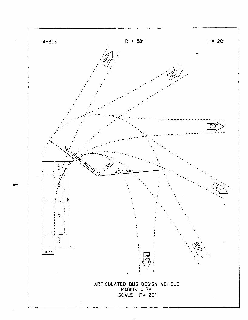
A-BUS
I I
I
1/ 1/
/
l,t ;
I I
I
I I I
;;,
A'
1 I ~ I
I I
I
I
/
~I I
I I
I
I
I
I I
R = 38' , .. = 20' I
I
~ I
I / I
I I I / I
I I I
I I
I I I
I I I
I I I I
I I
I I I I /
I I
I I /
I I
I I /
I_._.
-----------------------,., ..... _ -- - - - --- / ,/
~~r ;~:-------
I
I
/
' ' " ~ _, ____ _ ----------------~ ~
-... -- ,'-..... ------- ' .........
\
\
\
\
-,
\
I
\
\
\ \
I \
' ' '
\
\
\
\ ..... - ,,
\
\
' ' \I I'
'
'
' \
\
' \ \
\ \
\
\ \
\
' '
ARTICULATED BUS DESIGN VEHICLE RADIUS = 38'
SCALE I"= 20'
\ \
' '
'
' \
....
' '
.... '

A-BUS
' , ' . .
' '
' ' ' '
'
'
:
.· .· .·
:
R = 38'
~. :
:' .·· . . ' . :
:
.·
.··
.·
----~~.It\ .........
~,:..=-'........-; • ' - •• ' ' I '_ .
'I \
.~: ' . ' . . . ' . . . ' .
-- --
'
.· -~
....... ··~~·-~_ ...... ··
'
.·
-.
-. -. ·- ·- -. -.. .... .. ..
..... .. ........... ...... .. ··---~--.... ~, ·.
' ' '
' \~\ . ' . '
\\ '\
ARTICULATED BUS DESIGN VEHICLE RADIUS = 38'
SCALE 1• = 40'
r= 40'

A-BUS
..
R = 38'
ARTICULATED BUS DESIGN VEHICLE RADIUS = 38'
SCALE I" = 50'
A-4
I"= 50'
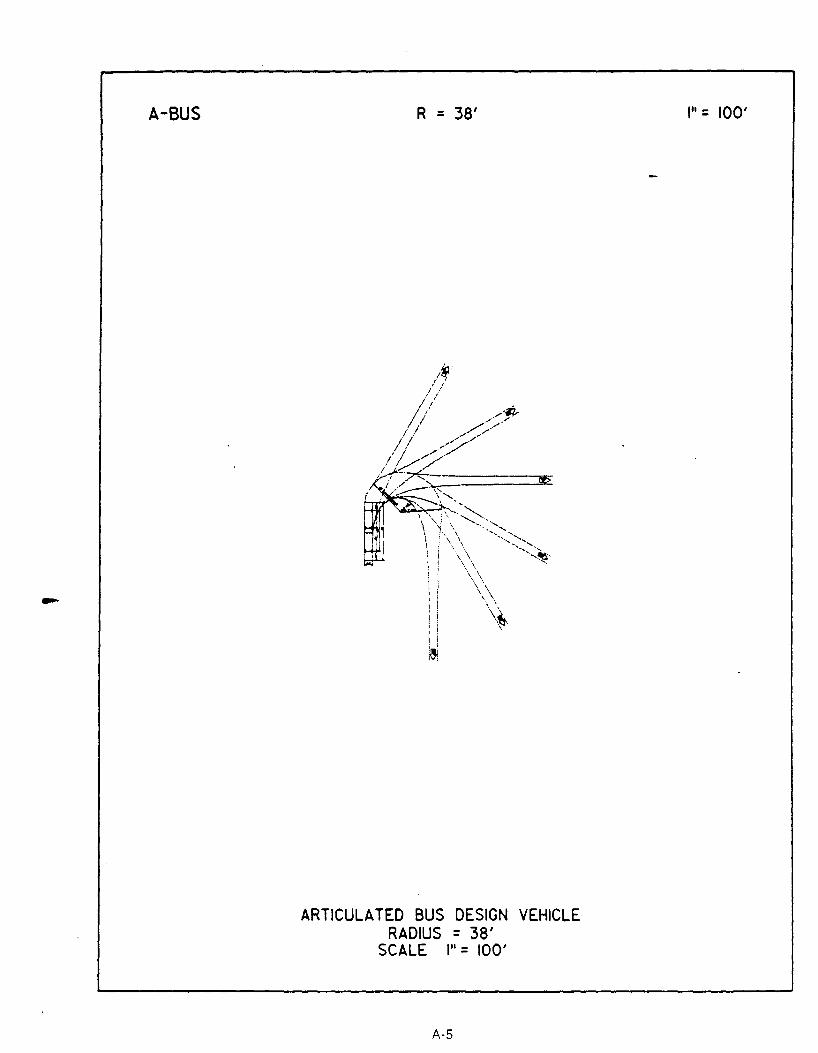
A-BUS R = 38'
i i ; ! : \
i i ~
ARTICULATED BUS DESIGN VEHICLE RADIUS = 38'
SCALE I" = 100'
A-5
I"= 100'

BUS
I
I
I I
I I
"' "' I "' I., " I I-' I
'/ I , I I
I I I
I I
I
I
I
I
I
I
I /
I
I
I
I ~
I I
I
I I
I
I I
I I
I
I
I
R
,/1.(1,/ ,/:Y: I I
I I
I
I
I I
_ .......... ---- ----.#"'
42' I"= 20'
-----... I
I I
;-..... ---- ------- ------------------I
" ... " I
----~---~ ... ~ ...
' '
' ... ~ ~ ----- ~-,--
I
I
' ' ' '' ' ...
' \ \
\
\
BUS DESIGN VEHICLE RADIUS 42'
SCALE I" = 20'
A-6
--------------------... ... ...
\
\
\
'I \ I \
I ' \ \
I
I I I
\ \
\
\
\
\ I
I \ \
\ ~\ \ ~ \
\ 0 \ \ 0 '
\ \
' I
•·'
\

BUS
' I
' '
:
'
' ' ' ' '
/ ,'
: :
: I I ~,'"' •',"'
, ,-'!'!,.. .. "'~ .. ·--/ •"" ,
' . ' •,."' I
'• ·' ·' ,:' /
/
:
..
' '
.'
' '
R
@'' ' ' / '
' .'
,' ,'
•'
.· •' -·
.·
' '
.·
•'
'
42'
.·· ,·· .·
.
' '
.
.
.. .. .. •' •'
..
.• .·· .··
·. '•
' t· .... ...,
:~-'0 : . ' ' '
'
' '
BUS DESIGN VEHICLE RADIUS = 42'
SCALE , .. = 40'
A-7
·.
I"= 40'
·-. ·. ·.
··-.. , ______ ~--
'•,

BUS R = 42'
~· ' .
' . :0: : : : :
BUS DESIGN VEHICLE RADIUS = 42'
SCALE 1 .. = 50'
··. · .. •.
· .. ~·· ... ·.... .. ... ·... .. .. · ..
I": 50'
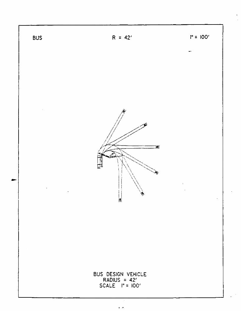
BUS R = 42'
BUS DESIGN VEHICLE RADIUS = 42'
SCALE I" = 100'
I"= 100'
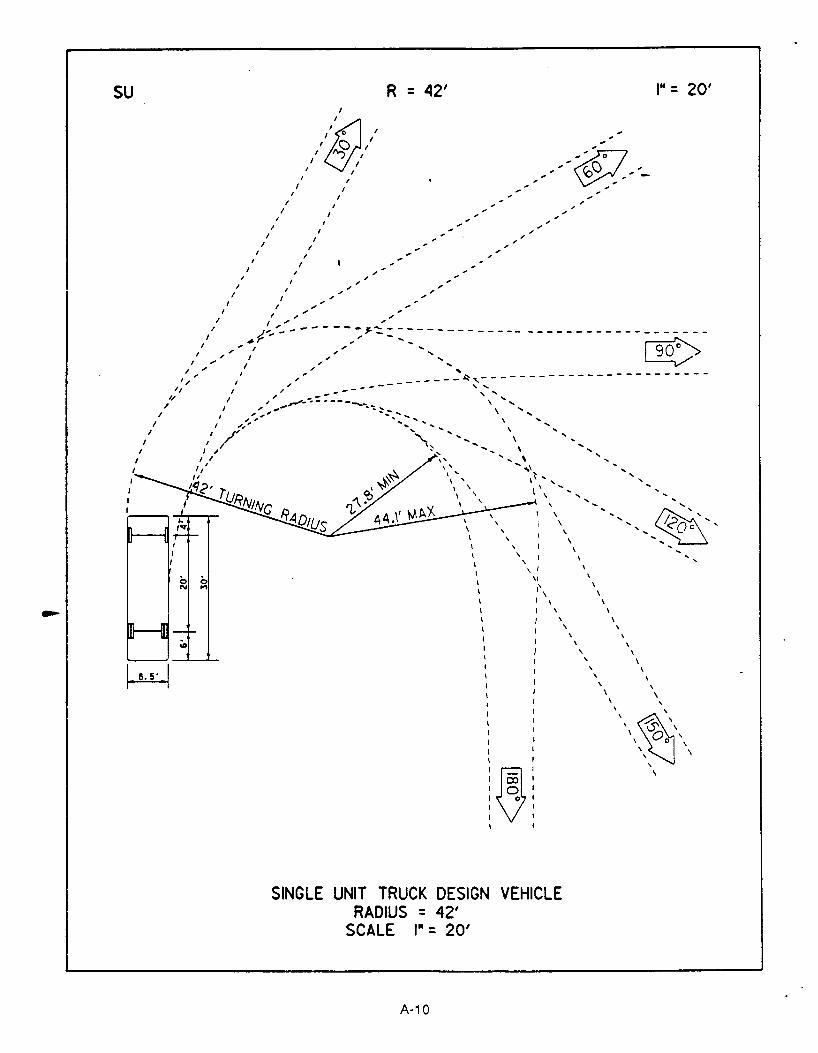
su
I
I
I
I
I I
,, II
l,t ,
I
I I
I
I
I
I
I I
I I
I
I
I
I
I I
I
I I
., ., I / _,
I,' -I I
I ,!"... --~r
_,"" I
" I _, I "
I
I
" "
R = 42'
--- j:."':::,---------.,
" "
" -...
, •• = 20'
" " , " -----~~,------------------------.. ---- '' I
I " -- .. -- ' ' \ ',
\ ...... \ ',
\ ...
,' ,.. ... ,..,--------~ ........ _ ","' ........... ....
I "' .... ," '..,"'" ' """'
I /'~ '""" I '' I ,; ,
... .... .... I I
1,' II
.... .... ... ... ...
llf<'
I
I I
0 0 N ,.,
\
I \ ' I ' \
\1
I I' \
\ I ' I
\ \
\
\ \
\
...
' \ \
\ \
\
I ' \
.~ I
SINGLE UNIT TRUCK DESIGN VEHICLE RADIUS = 42'
SCALE 1 .. = 20'
A-1 0
\
\ \
\
' ' \
\
\ \
' \ ' '
\ ~--' ~ \ \ 0 ' ' 0 '
\ \
' ' \

su
' /
' .' / '
/ ' . , : '
' .
' , '
'
' , . '
' '
' '
'
' ' , '
' '
' '
' '
' ' ' '
' ' ' ' '
R = 42'
@/ /
' : / ' ' , ' . ' . , .
' ' ' ' ' ' ,/' ,'
:
/ / '
.·
.·
I I ,,"'
,/· ~-~::::- -- ~...:;~:·.-. ---.-----.-----.----.--- .. ----.-----.---------.-----------, .. ' , .. , .. : ,,...... ........... ~
.;:·· ,',' , .... "'' , .. __ .... ---· __ :!'.~~: ... ---· ---- ... --------- ... ---- .. --- .......................... ---· ·--- .. --,'. ,/ , .. ; .. .,-•-·---.....~,eo.... ', ....... ..
,' :/·~· · .... ~.... ..... '' ......... ,' .'I ....... '"'"'..,..,, \ "',,
I ~~/ •:,", ...... ~ "' .... ,
' '.. ,..... .. ... \ •, ,., ........ ... ....... ' ' \, ....... .. ...
.......... .. .......... '\ ..... .... ... ......
\, ................ ... .... .. .. .. .....
', ............... ·-' ' '
'
\ -~
·----... __ .. :-.·-~--' .
' :J;: ' ' ' ' ' ' . ' ' '
' ' '
'
' '
' ' ' '
' ' ' ' '
' ' '
. '
'
' ' ' ' ' .
\ ~\ ' . ' ' \ .
' . '\ '
SINGLE UNIT TRUCK DESIGN VEHICLE RADIUS = 42'
SCALE 1• = 40'
A-11
-. ·-
I"= 40'

su R = 42'
\
\
l ' ' ' ' ' '
l j~j ' ' ' ' ' '
SINGLE UNIT TRUCK DESIGN VEHICLE RADIUS = 42'
SCALE I" = 50'
A-12
I"= 50'

su R = 42'
SINGLE UNIT TRUCK DESIGN VEHICLE RADIUS = 42'
SCALE I"= 100'
A-13
111 = 100'
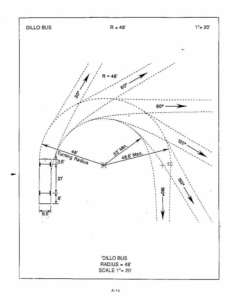
DILLO BUS
;
, , I
I I I I
I I
'!' ,'/ I I
I 0 1
~ ,' ..
I I
R =48' 1 "= 20'
I I
I
I I , I , '""'-- - --- - -,.,.,.;_:----""~- , - ----------,~ ' -------------, I , ------
goo --)llr.a.-... 1 _,"' I '~ '
I , I , " ,,.. ,' ," ' ... ,:" I ,,.' ------------=------..r.;-----------------------
1; , .. ... _,..ro- ----- --- " .. ,' ,' ,,', . , , ----:. ~ .... ' ' ..... ' I I ,:' - ...... '-. \
I I J" ' \ I I I, ', '..,..
I I ; ' ', I II '-,. '..,
I I I ''
II II ,, ,
2f
IDILLO BUS RADIUS= 48'
SCALE 1 "= 20'
A-1 4
I
I I
' '
.-. CD 0
0
~
... ... ...
' J ' I \ I \
I '
... .... ...
' ' ' ~'
... ' ... ..
~0 '
'\ \\' ' ' \ ' \ \
\ ' \ \
' ' ' ' ' ' ' ' \ ' ' '
\ '

DILLO BUS R = 48'
'DILLO BUS RADIUS= 48'
SCALE 1 "= 40'
A-15
1 "= 40'

DILLO BUS R ""48'
'DILLO BUS RADIUS= 48'
SCALE 1 "= 50'
A-16
1 "= 50'
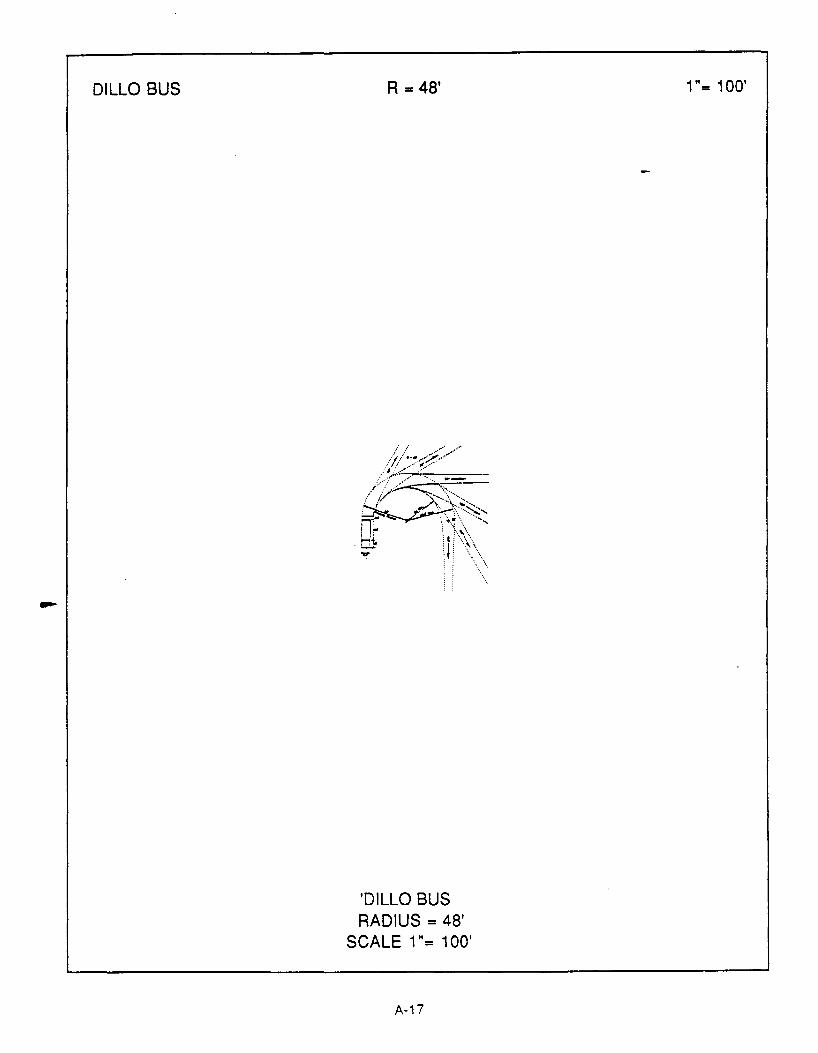
DILLO BUS R • 48'
'DILLO BUS RADIUS= 48'
SCALE 1 "= 1 00'
A-17
1 "= 1 00'

GLOSSARY
Angle of Intersection-The angle or angles at which two or more streets meet to form anjntersectior.
Arterial Street-
Articulated Bus-
Streets that generally move high volumes of traffic for great distances, and at
relatively high speeds.
An extended bus usually 60 to 70 feet in length which consists of two hinged or
joined units.
Bus Encroachment- The movement of a bus into an adjacent or opposing lane of traffic during a turning
maneuver.
Collector Streets- Collect traffic from other streets, serving as the most direct route to an arterial or
another collector street. The five types are: residential, neighborhood, commercial,
industrial, and primary.
Curb Return-
Design Speed-
Design Vehicle-
Grades-
Inbound Lane-
Local Street-
The curved section of curb used at street intersections in joining straight sections of
the curb.
The operating speed determined for the design of the specific physical features of a
highway, street, or development.
A selected hypothetical motor vehicle, the dimensions and operating characteristics
of which are used in highway and street development design.
The change in elevation between two points along the vertical alignment of a
roadway. Usually expressed as the change per 100 feet or percent.
A lane of traffic leading into an intersection.
Are intended primarily to serve traffic within a neighborhood or within a limited district.
Local streets are not continuous through several districts.
G-1

Offtracking-
Outbound Lane-
Queue-
Swept Path·
Travel Mode-
Turnarounds-
Turning Radius-
Turnouts-
The different path taken by the rear wheels in relation to the front wheels while
turning. The line of this curve is closer to the curb return the curve made by the front
wheels.
A lane of traffic leading away from an intersection
A line or file of waiting vehicles.
The area of the path covered by a vehicle making a turning maneuver. The radial
distance between the turning paths of the outer front wheel and the inner rear
wheel.
The form of transportation used to accomplish a trip. In an urban commuter context
the three primary travel modes are rail, bus, and private automobile.
A area in which a vehicle can perform a 180 degree turn.
The radius of the circle traced by the outer front wheel of a vehicle making a turn.
The resulting measurement is strongly dependent on the steering characteristics,
operating speed, and length of the wheelbase of a vehicle.
A special lane of limited length apart from through traffic lanes provided for the use of
vehicles making stops of short duration.
Weaving Maneuvers-The crossing of traffic streams moving in the same general direction accomplished by
merging and diverging.
G-2

ANNOTATED BIBLIOGRAPHY
Alameda Contra Costa Transit District, Guide for Including Public TransU jn Land Use Planning,
Oakland: Research and Planning Department Alameda Contra Costa Transit District, March 1983.
A guideline on the inclusion of "public transportation perspective" in development. The
purpose of the booklet is to indicate the benefits derived from including public transit in the
planning process. It considers the effect on transit that population densUies, traffic generators,
parking policies, transit orientation, transit corridors, and transit funding methods have.
Alameda Contra Costa Transit District, Transit Facilities Standards Manual Oakland: Research and
Planning Department Alameda Contra Costa Transit District, March 1983.
The purpose of the standards manual is to develop uniform policies and standards for the
design, construction, and operation of various transit related improvements. The document aims
to encourage the inclusion of transit related facilities with other street improvement projects. The
report includes information on design vehicles, geometric design standards, operational
standards, structural standards, and guidelines on planning and site selection.
American Association of State and Highway Transportation Officials, A Guide for Oesjgn of Pavement
Structures, Washington D.C. 1986.
This guide presents design factors, procedures and rehabilitation techniques for flexible
(asphalt concrete) and rigid (portland cement concrete) pavements. The guide is used by many
state highway agencies, including the Texas State Department of Highways and Public
Transportation, in their pavement design procedures.
American Association of State Highway and Transportation Officials, A Policy on Geometric Qesi&Jn of
Highways and Streets. Washington D.C., 1984.
The "Green Book" discusses the design policies for streets and highways. The primary
sections are: highway functions, design controls and criteria, elements of design, cross section
elements, local roads and streets, collector roads and streets, rural and urban arterials, freeways,
at grade intersections and grade separations, and interchanges.
AustinPian Incentive Committee, "Draft Incentive Report". Unpublished, Austin, February 1988.
Describes examples of incentives to the private sector in exchange for the provision of
specific public benefits. The emphasis is on incentives used in local land development.
B-1
Bushell, Chris and Peter Stonham, eds., Janes Urban Transoortation Systems 2nd.Edition.
London: Janes Publishing Co. Ltd., 1983.
A catalog of public transit vehicles, transit systems, maintenance systems, equipment and
consultants of the world. Includes manufacturer's addresses and some specifications.
Callies and Frelich, Cases and Materials in Land Use. West Publishing Company, St. Paul, Minnesota,
1986.
Covers classic zoning cases with summaries and comments. Includes a section on the legality
of public/private partnerships and tax laws affecting joint development.
Cervero, Robert, Suburban Gridlock, New Jersey Center for Urban Policy Research, Brunswick, New
Jersey, 1986.
Examines steps taken by municipalities to enlist the support of private interests in both
reducing employee trip making and financing area wide improvements. The study is national in
scope with detailed case studies and in depth insights into suburban traffic problems.
City of Austin, Texas, Policy on Geometrjc Roadway Design, Austin, 1987.
Sets forth specific design criteria for each type of street category and highways, and also
presents alternative design criteria for developments located in watershed districts. Also
discusses the design criteria for intersection design. Other areas for which design criteria are
presented are: medians, turn lanes, driveways, pavement markings, signing, bikeways, and
sidewalks.
City of Austin, Texas, Street Design Standards Austin, 1986.
Collection of short reports, memos, and letters that provide general and technical data
required for transit facilities in Austin. The information includes a section with the definitions of
transit related terms, the classification of streets, and street design criteria by classification. Also
includes sections on turning radii, swept paths, and the bus dimensions of the current Capital
Metro inventory.
City of Austin, 1980 Census Reports Department of Planning and Growth Management, Austin,
1986.
1980 demographic census data presented both by individual census tracts, and and for the
City of Austin as a unit.
8-2

City of Seattle, Metro Transportation Facility Design Guidelines, Seattle: City of Metropolitan Seattle,
April1985.
A short manual discussing policies, guidelines, and basic design criteria for five basic areas:
vehicle specifications and needs, transfer and destination points, high occupancy vehicle
facilities, bus stops, and passenger information facilities. Included in the manual are turning
templates for the critical design vehicle used in Seattle (a 60 foot articulated bus); figures of transit
passenger shelters and information signs, and plan views of three types of bus stop areas: near
side, far side, and mid block bus stops. Includes an extensive bibliography.
Greater Bridgeport Transit District, Joint Development and Fjxed Route Bus Systems: Experience jn
Bridgeport Connecticut. Washington D.C.: Department of Transportation -Government Printing
Office, January 1985.
Department of Transportation report number DOT-1-81-4. A case study of the experience of
Bridgeport, Connecticut in its efforts to stimulate community and economic development in
cooperation with fixed-route bus service. The report specifically looks at integrating commercial
centers with the bus service and discusses innovative transit financing approaches as well as links
between development and transit.
Institute of Traffic Engineers, Trip Generation, Vol. 3, Institute of Traffic Engineers, Washington, D.C.
1983.
The standard reference for estimating the number of vehicle trips generated from
development. Based upon extensive national surveys and statistical analysis.
Johnson, Gregory, Prjvate Development Station Improvements, Urban Mass Transportation Agency,
Symposium, New Orleans, March 1988.
Describes New York Metropolitan Transit Authority's zoning ordinances which mandate
private transit provisions for mid-town manhattan. Discusses Zoning with and without incentives.
Lave, Charles A., ed., Urban Transit: The Private Challenge to Public Transportation. Cambridge:
Ballinger Publishing Company, 1985.
A look at privatization of public transportation services and operations. Explores options that
can help transit do more with what is available and increase competition to provide alternative
choices in service to attract more riders.
Orange County Transit District, Consideration of Transit in Project oevelopment. Orange County:
Orange County Transit District, 1982.
B-3
--
Brief history of Orange County transit system. Discusses benefits to everyone involved. Lists
special considerations for including transit with development.
Orange County Transit District, Qesian Guidelines for Bus Facilities 2nd Edition. Orange County:
Orange County Transit District, November 1987.
This document was prepared for the purpose of providing uniform guidelines and design
considerations for the design and placement of bus facilities and amenities in Orange County,
California. The following six areas were considered in the preparation of this document: 1) basic
bus operations, 2) current engineering practices in Orange County, 3) standards used by other
transit operators, 4) amenities necessary for attracting and maintaining ridership, 5) possible
benefits to participating developers, and 6) improvement compatibility with existing road uses.
Typical designs are provided for the following facilities and amenities: 1) pedestrian
accessways, 2) bus turnouts, 3) bus stops, 4) bus shelters, 5) bus benches, 6) bus stop signs, 7)
park-and-ride facilities, and 8) transit centers. Current bus fleet dimensions are provided along
with bus turning radii and recommended road grades.
Pushkarev, Boris S. and Jeffrey N. Zupan, Public Transportation and Land Use Policy.
Bloomingington: Indiana University Press, 1977.
A thorough overview of public transportation systems and how these systems are impacted
by land use. Information provided includes the demand for transit services, the role of density,
operating and capital costs, operating conditions, and the matching of supply and demand
densities. The book also defines eight modes of public transportation, and dedicates a major
portion of the book to rail transit.
Pushkarev, Boris S., and Jeffrey N. Zupan, Urban Densities for Public Transportation, Springfield:
National Technical Information Services, 1976.
Examines the suitability of different urban densities to eight modes of public transit including
dial-a-bus, local bus and express bus, and the effects of densities on user habits. Operating and
capital costs are examined. Residential development density is explored in terms of public transit
service along with other forms of density and development.
Rajappan, S.M. and C.M. Walton, An Assessment of The Operational Impact of Larger and Wider
Combination Vehicles on the Geometry of Diamond Interchanges Center for Transportation
Research, University of Texas at Austin, 1986.
Assesses the impact that Long Combination Vehicles would have on the geometric design of
interchanges, with a special emphasis on diamond interchanges. Proposes general pavement
B-4

width requirements necessary for diamond interchanges to accommodate the turning maneuvers
of Long Combination Vehicles.
Sacramento Regional Transit, Desjgn Guidelines for Bus and Light Rail Fac;nues, Sacramento:
Sacramento Regional Transit, October 1987.
An extensive design handbook, detailing the steps necessary for successful transit
development integration. The report addresses many key areas of the integration process. It
begins by studying overall project design, incorporating ideas of access, location , and density
and how these characteristics effect transit circulation. The report also outlines design criteria for
bus stops, turnouts,shelters, benches, berths, layover areas, and turnarounds. The report gives
geometric requirements for bus turning radii, maximum grades, and exclusive bus lanes. Also
included in the report is information on traffic signals, park-and-ride facilities, transit centers, and
light rail. In conclusion, the report describes design guidelines for bicycle storage facilities and
information signs. Included in the appendix are a glossary of transit terms, a chart of design
vehicle specifications, and a list of references.
Schneider, Michael J. and Rober C. Schaevitz. Private Investments in Public Transtt Presented at the
Annual Meeting of the American Society of Civil Engineers, Anaheim, California, October 1987.
This paper describes and analyzes the emerging roles of private sector contributions to transit
finance and management. Nine projects are described. Project areas are Tampa, Los Angeles,
Denver, Houston, New York, Boston, Atlantic City, the Dulles Corridor, and the Hudson
Waterfront in New Jersey.
Southeastern Michigan Transportation Authority, Designing tor Transit: A Transit Design Criteria and
Standards Manual. Detroit: Southeastern Michigan Transportation Authority, April1982.
This manual is designed for a broad audience. Part 1 addresses the ordinary citizen., while
Part 2 is for the technical expert. Major sections include: "Transit and the Community", and
"Technical Design Standards, and Criteria". Included is a glossary of terms and a transit checklist.
Attractive manual with well designed illustrations and numerous photographs.
Texas State Department of Highways and Public Transportation, Highway Design Division Ooerations
and Procedures Manual Austin, 1986.
This manual provides guidelines and standards for preparation of right-of-way and
construction of highways and associated facilities.
B-5

Texas State Department of Highways and Public Transportation, Texas Manual of Unjform Traffjc
Comrot Deyjces. Austin, 1980.
Adopted from the National Manual of Uniform Traffic Control Devices and expanded to include
the specific requirement of the State of Texas. All traffic control devices pla~d by the state and
local authorities are required to conform to the manual and its specifications.
Texas State Department of Highways and Public Transportation, Vehicle Turnina Characteristics for
Use jn Geometric Design, Highway Design Division: Austin 1987.
This document discusses the Texas Truck Offtracking Model (TXTOM) a model that simulates
the offtracking characteristics of a vehicle or vehicle combinations making a turn. The document
includes templates to various scales of the offtracking characteristics of the AASHTO design
vehicles.
Texas Transportation Institute, Report 339-7 "Procedures for Estimating Park-and-Ride Demand in
Large Texas Cities". Texas A&M University, February 1987.
This manual provides guidelines for estimating the ridership demands that can be generated
by the location of Park-and-Ride lots. The key to location is the existence of potential transit riders
upstream of the projected Park-and-Ride location.
Texas Transportation Institute, Research Report 205-3 "Design Guidelines for Park-and-Ride
Facilities". Texas A&M University, September 1978.
This report presents guidelines for designing bus Park-and-Ride facilities. Specifically,
guidelines are developed for: 1 )locating Park-and Ride lots; 2) determining the desired size of a
Park-and-Ride lot; 3) evaluating the capacity of selected design components of the lot; and 4)
establishing the physical layout of the parking area.
Transportation Research Board, National Cooperative Highway Research Program Report no. 155,
"Bus Use of Highways Planning and Design Guidelines". Washington D.C.: Transportation
Research Board National Research Council, 1975.
Guidelines for planning and designing preferential bus facilities in relation to freeways,
arterials and terminals. Contains general guidelines on the design characteristics for each type of
treatment discussed.
Transportation Research Board, National Cooperative Transit Research and Development Program
Report no, 12. "Strategies to Implement Benefit-Sharing for Fixed-Transit Facilities". Washington
D.C.: Transportation Research Board, 1985.
B-6
Summarizes important findings from seven case studies involving benefit-sharing practices
among transit agencies. Identifies benefit-sharing opportunities, costs and benefits; transit
agency experiences with benefit sharing strategies; and analysis techniques for use on different
types of benefit-sharing strategies. Recommendations for implementing benefit-sharing
techniques are also reviewed.
Transportation Research Board, Quick Response Urban Travel Estimation Techniques and
Transferable Parameters-Users Guide Washington D.C.: Transportation Research Board.
Provides guidelines and methods to quickly conduct travel demand forecasts for urbanized
areas. Contains information regarding the estimation of trip generation, mode split, and
distribution.
Transportation Research Board, Transportation and Land Use on Major Activity Centers. Washington
D.C.: Transportation Research Board, 1982.
Discusses shaping a suburban activity center through transit and pedestrian incentives, land
use changes in suburban clusters and corridors, defining regional employment centers and
impacts of CBD fare-free transit on retail sales.
Tri-County Metropolitan Transportation District of Oregon, Plannjng with Transjt Land Use and
Transportatjon Planning Coordination. Portland: Tri-County Metropolitan Transportation District of
Oregon, 1979.
An extensive manual covering many pertinent subjects with regards to transit integration into
the development arena. The report is divided into seven sections including topics on Tri-Met
organization and planning techniques, transit policy, transit science, regulations regarding
development and transit in the Tri- County area, ride sharing advantages, and transit facility design
and maintenance. The report also includes a worksheet used to determine wither a particular
project is compatible with transit.
Urban Land Institute, "Joint Development: Making the Real Estate-Transit Connection: Executive
Summary". Washington, D.C., Urban Land Institute, 1979.
Explores alternatives and benefits of joint development linked to public transportation. Types
of arrangements and how they are made are discussed along with how transit planning can help
joint development projects work. Looks at how communities can use transit to guide
development.
B-7

U.S. Department of Transportation, Manual of Uniform Traffic Control Qeyjces Washington D.C.:
Government Printing Office, 1978.
Extensively covers all traffic control devices including all signs, markings, and devices.
Includes all technical specifications, placement considerations, and warrants.
U.S. Department of Transportation, New Qirections jn Urban Transportation, Washington D.C.:
Government Printing Office, November 1985.
Contract number TX-06-0036, under direction of Rice Center. Details the numerous
relationships which have emerged between the public and private sectors to provide transit
facilities. Looks at why these relationships came about and who the participants are.
U.S. Department of Transportation, Streets for Pedestrians and Transit· Examples of Transit Malls in
the U.S. Washington D.C.: Government Printing Office, 1972.
A study focusing on transit malls that incorporate regular bus routes into their design. The
study includes an overview of development, existing transportation facilities, and the existing
political and economic climate of the community.
U.S. Department of Transportation, Transportation Planning Qata for Urbanized~ Washington
D.C.: Government Printing Office, 1987.
Provides transportation information for major urbanized cities in the United States based upon
data collected from the 1980 Census.
8-8
Related Documents