TRANSIT Entry Installation Guide This device complies with part 15 of the FCC rules. Operation is subject to the following conditions: (1) This device may not cause harmful interference, and (2) this device must accept any interference that may cause undesired operation. 2007-06-20 Part # : 5268605 This information is furnished for guidance, and with no guarantee as to its accuracy or completeness; its publication conveys no license under any patent or other right, nor does the publisher assume liability for any consequence of its use; specifications and availability of goods mentioned in it are subject to change without notice; it is not to be reproduced in any way, in whole or in part, without the written consent of the publisher. © Nedap IDEAS, P.O. Box 103, NL-7140 AC GROENLO Page 1 of 27

Welcome message from author
This document is posted to help you gain knowledge. Please leave a comment to let me know what you think about it! Share it to your friends and learn new things together.
Transcript

TRANSIT Entry Installation Guide
This device complies with part 15 of the FCC rules. Operation is subject to the following conditions: (1) This device may not cause
harmful interference, and (2) this device must accept any interference that may cause undesired operation.
2007-06-20 Part # : 5268605 This information is furnished for guidance, and with no guarantee as to its accuracy or completeness; its publication conveys no license under any patent or other right, nor does the publisher assume liability for any consequence of its use; specifications and availability of goods mentioned in it are subject to change without notice; it is not to be reproduced in any way, in whole or in part, without the written consent of the publisher. © Nedap IDEAS, P.O. Box 103, NL-7140 AC GROENLO Page 1 of 27

TRANSIT Entry
CONTENTS
CONTENTS............................................................................................................................................. 2 1 INTRODUCTION .......................................................................................................................... 3
1.1 PRODUCT DESCRIPTION .............................................................................................. 3 1.2 OPTIONAL CARD TECHNOLOGY READER INTERFACE ...................................... 3
2 INSTALLATION............................................................................................................................. 4 2.1 SAFETY PRECAUTIONS.................................................................................................. 4 2.2 MOUNTING INSTRUCTIONS........................................................................................ 4 2.3 ADJUSTABLE MOUNTING BRACKET......................................................................... 5 2.4 OPENING THE SERVICE COVER .................................................................................. 6 2.5 INSTALLING AN OPTIONAL INTERFACE BOARD.................................................. 7
2.5.1 AVAILABLE INTERFACE BOARDS ................................................................ 7 2.5.2 INSTALLATION PROCEDURE ........................................................................ 8
3 CONNECTIONS ............................................................................................................................ 9 3.1 POWER SUPPLY .............................................................................................................10 3.2 COMMUNICATION .......................................................................................................11
3.2.1 RS232 CONNECTION.....................................................................................11 3.2.2 RS422 CONNECTION.....................................................................................12 3.2.3 WIEGAND, MAGSTRIPE, BARCODE CONNECTION .............................13 3.2.4 USB CONNECTION .........................................................................................14
3.3 DIGITAL I/O .....................................................................................................................15 3.3.1 RELAY OUTPUT................................................................................................15 3.3.2 READ DISABLE INPUT....................................................................................16 3.3.3 GENERAL PURPOSE INPUTS .......................................................................17 3.3.4 GENERAL PURPOSE OUTPUTS...................................................................18 3.3.5 TAMPER SWITCH.............................................................................................19
4 DIP-SWITCH SETTINGS ...........................................................................................................20 4.1 RANGE BEEPER ON / OFF ...........................................................................................20 4.2 RS232 / RS422 SELECTION.........................................................................................20 4.3 UNUSED SW1-3 AND SW1-4.....................................................................................20
5 LED INDICATIONS ....................................................................................................................21 6 FREQUENCY SELECTION ........................................................................................................22 7 READ RANGE CONTROL (SQUELCH) .................................................................................23
7.1 PRINCIPLE ........................................................................................................................23 7.2 READ RANGE ADJUSTING..........................................................................................23
8 IDENTIFICATION .......................................................................................................................24 8.1 STANDARD OPERATING PROCEDURE...................................................................24 8.2 USING THE MTR MODULE..........................................................................................24
9 FIRMWARE UPGRADE .............................................................................................................25 A TECHNICAL SPECIFICATIONS...............................................................................................26 B PART NUMBERS.........................................................................................................................27
© Nedap IDEAS, P.O. Box 103, NL-7140 AC GROENLO Page 2 of 27

TRANSIT Entry
1 INTRODUCTION 1.1 PRODUCT DESCRIPTION
Nedap’s handsfree access solution represents the latest in technology for secure handsfree doors access and other RFID applications. TRANSIT Entry combines the convenience of traditional door automation with the security of restricted areas. It makes a perfect fit to any door or vehicle gate environment where handsfree access is required. The system reads at distances up to 4 meter (12 feet) reliable and consistently. This has great appeal to people, especially in situations where it is inconvenient to use their hands when presenting an ID badge when accessing a door, but where high security needs to be maintained. Moreover it offers handsfree vehicle access to gated areas. Vehicles are identified at a range up to 4 meters (12 feet), without the hassle of having to open the window to present a card. The handsfree access system is made up of a TRANSIT Entry reader and a transponder. TRANSIT Entry readers are installed next to a door or gate. A long range transponder visible in line of sight of the reader will be identified at distances up to 4 meter (12 feet). 1.2 OPTIONAL CARD TECHNOLOGY READER INTERFACE
The TRANSIT Entry reader also features an optional optional proximity and ISO compliant smartcard interface. This Multi-Technology Reader Module (MTR) enables the reader to read standard proximity cards and smartcard CSN. This also allows the reader to operate with existing credentials when presented to the face of the reader. The MTR supports the following card technologies:
• 120-125kHz: HID prox, Nedap and EM read-only.
• 13.56MHz: HID iClass CSN, MIFARE, LEGIC Advant UID, ISO14443A and ISO15693.
© Nedap IDEAS, P.O. Box 103, NL-7140 AC GROENLO Page 3 of 27

TRANSIT Entry
2 INSTALLATION 2.1 SAFETY PRECAUTIONS
The following safety precautions should be observed during normal use, service and repair.
• The TRANSIT Entry must be connected with safety ground.
• The TRANSIT Entry may only be installed and serviced by qualified service personnel.
• Disconnect the power supply before removing or installing any parts.
• To be sure of safety, do not modify or add anything to the TRANSIT Entry other than mentioned in this installation guide or indicated by NEDAP N.V.
2.2 MOUNTING INSTRUCTIONS
The TRANSIT Entry can be mounted to any surface, including directly to metal. Locate an appropriate position. Use the upper two keyholes (K) to mount the reader. Open the service cover to secure the reader using the two lower mounting positions (L). See the picture below for details about the dimensions and the locations of the mounting positions.
L
service cover
K
200mm (7.87") 47mm (1.85")
220m
m (8
.66"
)
108mm (4.25")
35m
m
171m
m (6
.73"
) (1
.38"
)
63mm (2.48")
4.5mm (.17")
∅5mm(.20")
∅4.5mm(.17")
rear view front view side view Figure 1: TRANSIT Entry reader dimensions
© Nedap IDEAS, P.O. Box 103, NL-7140 AC GROENLO Page 4 of 27
TRANSIT Entry
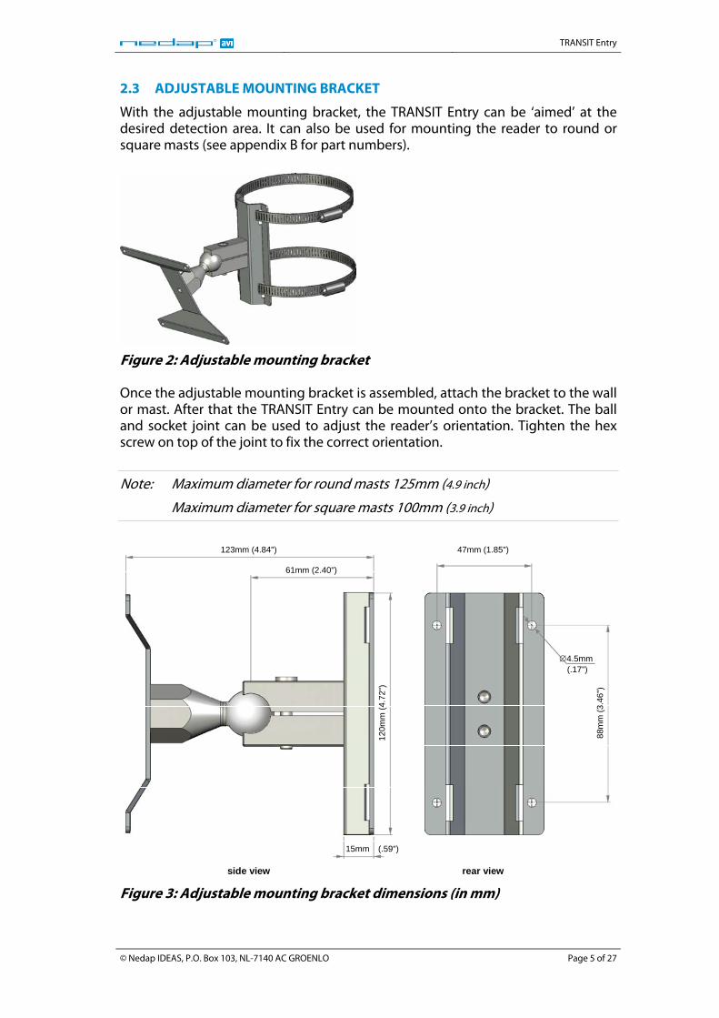
2.3 ADJUSTABLE MOUNTING BRACKET
With the adjustable mounting bracket, the TRANSIT Entry can be ‘aimed’ at the desired detection area. It can also be used for mounting the reader to round or square masts (see appendix B for part numbers).
Figure 2: Adjustable mounting bracket Once the adjustable mounting bracket is assembled, attach the bracket to the wall or mast. After that the TRANSIT Entry can be mounted onto the bracket. The ball and socket joint can be used to adjust the reader’s orientation. Tighten the hex screw on top of the joint to fix the correct orientation.
Note: Maximum diameter for round masts 125mm (4.9 inch)
Maximum diameter for square masts 100mm (3.9 inch)
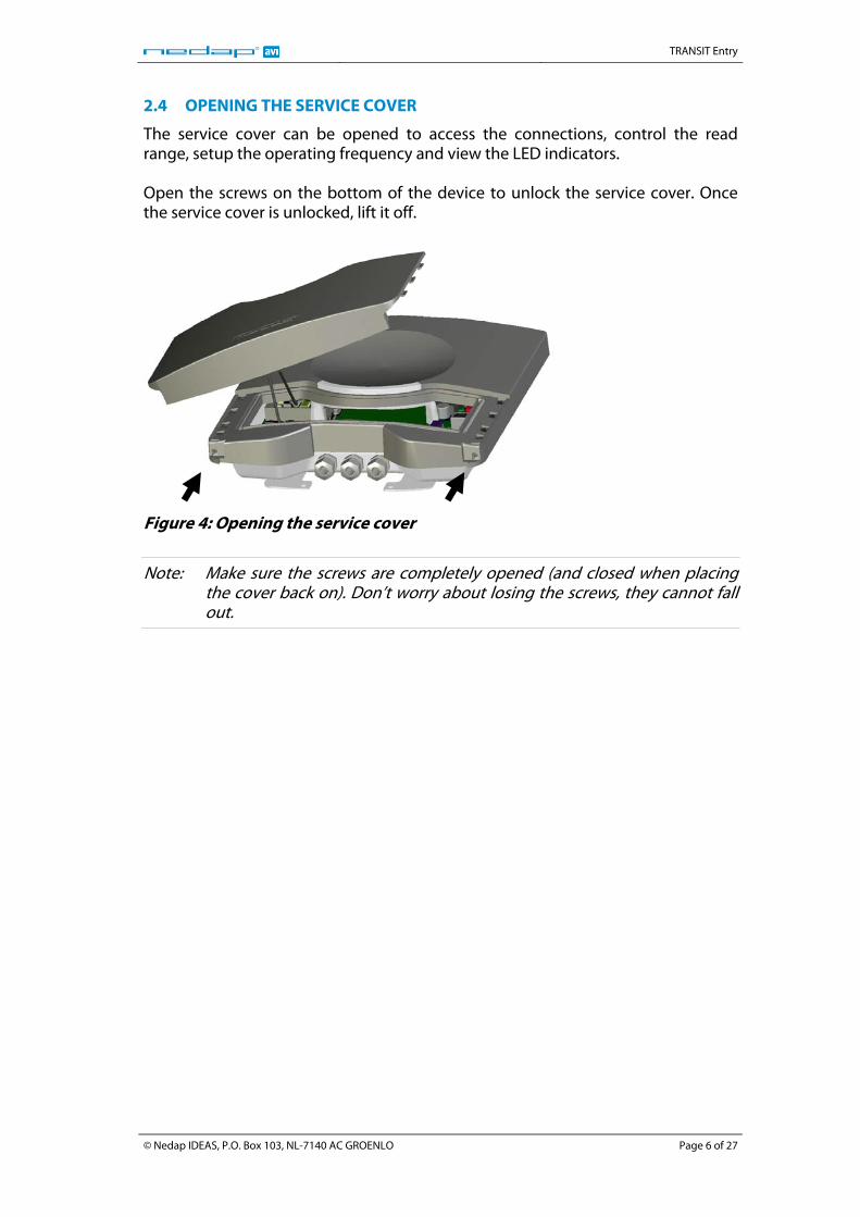
123mm (4.84") 47mm (1.85")
61mm (2.40")
120m
m (4
.72"
)
15mm (.59")
88m
m (3
.46"
)
side view rear view
∅4.5mm (.17")
Figure 3: Adjustable mounting bracket dimensions (in mm)
© Nedap IDEAS, P.O. Box 103, NL-7140 AC GROENLO Page 5 of 27
TRANSIT Entry
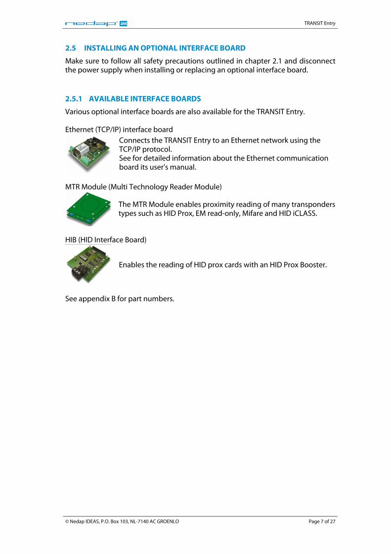
2.4 OPENING THE SERVICE COVER
The service cover can be opened to access the connections, control the read range, setup the operating frequency and view the LED indicators. Open the screws on the bottom of the device to unlock the service cover. Once the service cover is unlocked, lift it off.
Figure 4: Opening the service cover
Note: Make sure the screws are completely opened (and closed when placing the cover back on). Don’t worry about losing the screws, they cannot fall out.
© Nedap IDEAS, P.O. Box 103, NL-7140 AC GROENLO Page 6 of 27
TRANSIT Entry
2.5 INSTALLING AN OPTIONAL INTERFACE BOARD
Make sure to follow all safety precautions outlined in chapter 2.1 and disconnect the power supply when installing or replacing an optional interface board. 2.5.1 AVAILABLE INTERFACE BOARDS
Various optional interface boards are also available for the TRANSIT Entry. Ethernet (TCP/IP) interface board
Connects the TRANSIT Entry to an Ethernet network using the TCP/IP protocol. See for detailed information about the Ethernet communication board its user's manual.
MTR Module (Multi Technology Reader Module)
The MTR Module enables proximity reading of many transponders types such as HID Prox, EM read-only, Mifare and HID iCLASS.
HIB (HID Interface Board)
Enables the reading of HID prox cards with an HID Prox Booster.
See appendix B for part numbers.
© Nedap IDEAS, P.O. Box 103, NL-7140 AC GROENLO Page 7 of 27
TRANSIT Entry
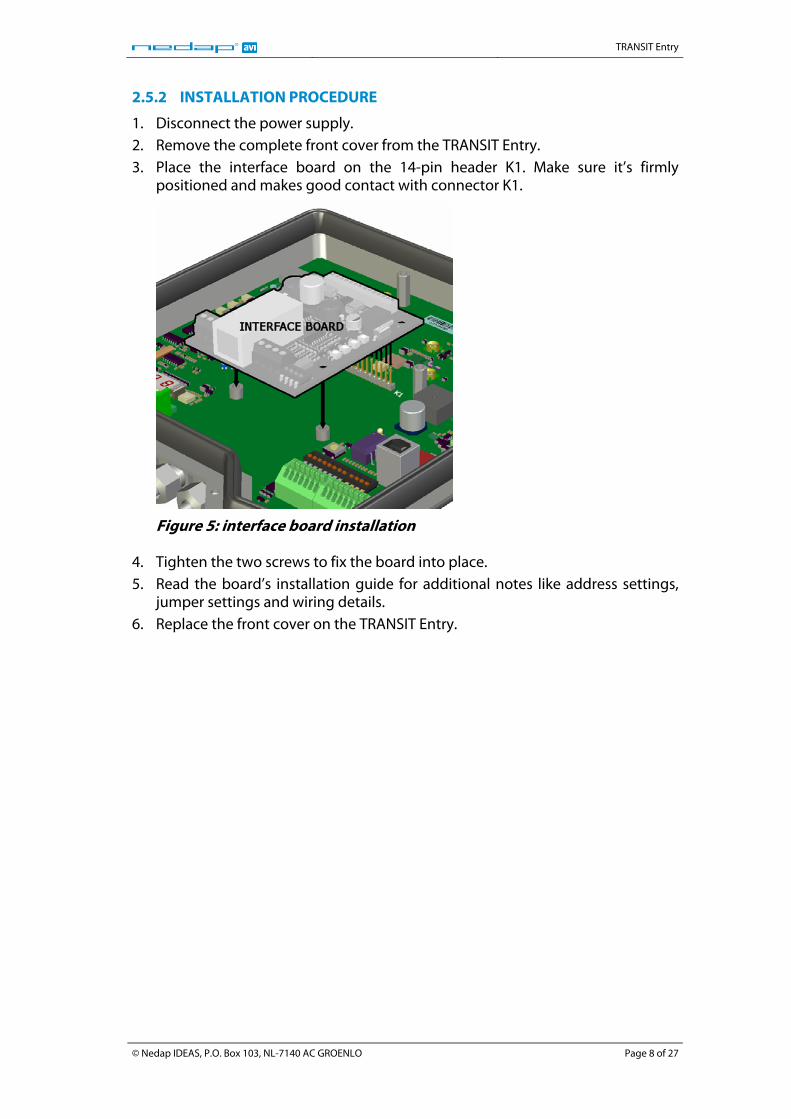
2.5.2 INSTALLATION PROCEDURE
1. Disconnect the power supply. 2. Remove the complete front cover from the TRANSIT Entry. 3. Place the interface board on the 14-pin header K1. Make sure it’s firmly
positioned and makes good contact with connector K1.
Figure 5: interface board installation
4. Tighten the two screws to fix the board into place. 5. Read the board’s installation guide for additional notes like address settings,
jumper settings and wiring details. 6. Replace the front cover on the TRANSIT Entry.
© Nedap IDEAS, P.O. Box 103, NL-7140 AC GROENLO Page 8 of 27
TRANSIT Entry
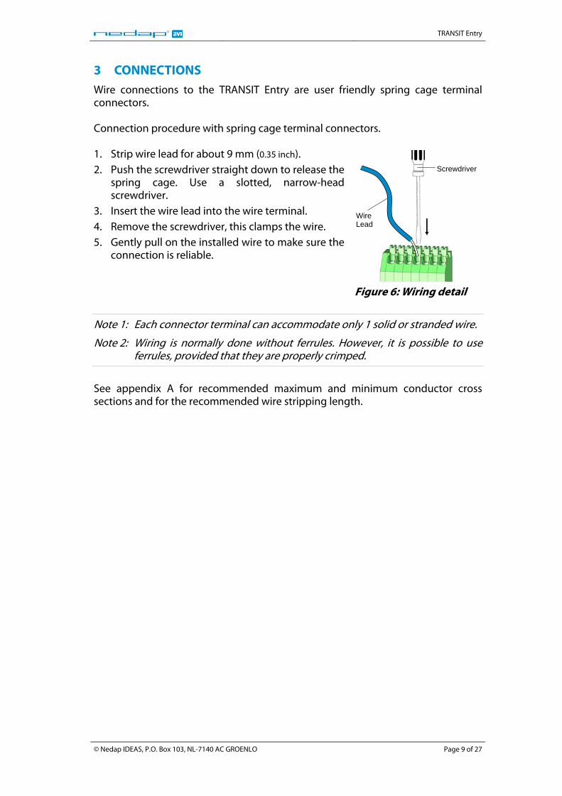
3 CONNECTIONS Wire connections to the TRANSIT Entry are user friendly spring cage terminal connectors. Connection procedure with spring cage terminal connectors. 1. Strip wire lead for about 9 mm (0.35 inch). 2. Push the screwdriver straight down to release the
spring cage. Use a slotted, narrow-head screwdriver.
3. Insert the wire lead into the wire terminal. 4. Remove the screwdriver, this clamps the wire. 5. Gently pull on the installed wire to make sure the
connection is reliable.
Wire Lead
Screwdriver
Figure 6: Wiring detail
Note 1: Each connector terminal can accommodate only 1 solid or stranded wire.
Note 2: Wiring is normally done without ferrules. However, it is possible to use ferrules, provided that they are properly crimped.
See appendix A for recommended maximum and minimum conductor cross sections and for the recommended wire stripping length.
© Nedap IDEAS, P.O. Box 103, NL-7140 AC GROENLO Page 9 of 27
TRANSIT Entry
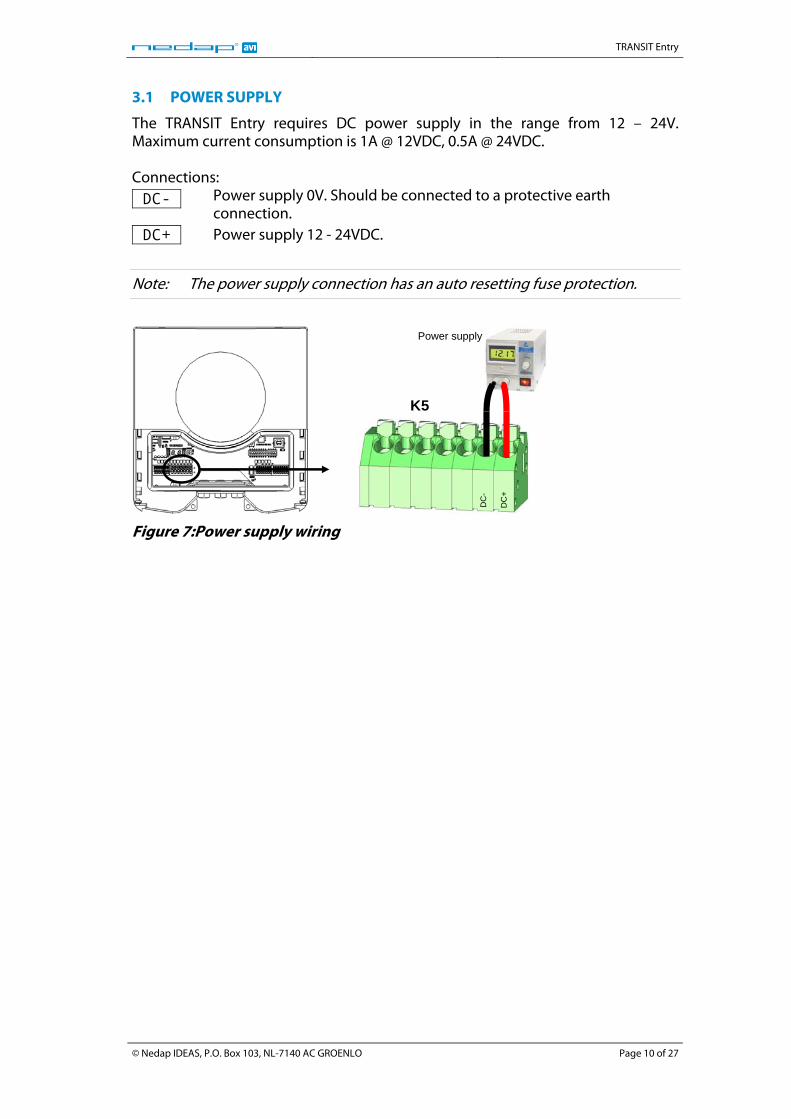
3.1 POWER SUPPLY
The TRANSIT Entry requires DC power supply in the range from 12 – 24V. Maximum current consumption is 1A @ 12VDC, 0.5A @ 24VDC. Connections: DC- Power supply 0V. Should be connected to a protective earth
connection. DC+ Power supply 12 - 24VDC.
Note: The power supply connection has an auto resetting fuse protection.
DC
+
DC
-
K5
Power supply
Figure 7:Power supply wiring
© Nedap IDEAS, P.O. Box 103, NL-7140 AC GROENLO Page 10 of 27
TRANSIT Entry
3.2 COMMUNICATION
3.2.1 RS232 CONNECTION
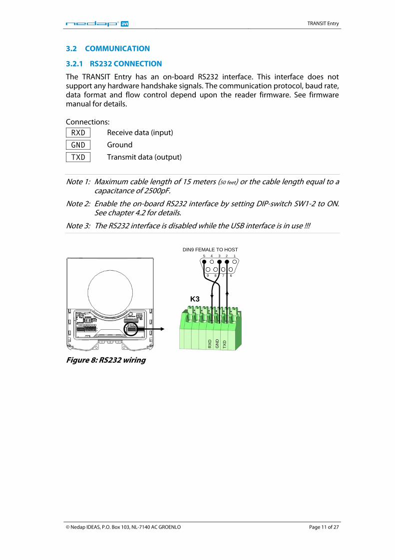
The TRANSIT Entry has an on-board RS232 interface. This interface does not support any hardware handshake signals. The communication protocol, baud rate, data format and flow control depend upon the reader firmware. See firmware manual for details. Connections: RXD Receive data (input)
GND Ground
TXD Transmit data (output)
Note 1: Maximum cable length of 15 meters (50 feet) or the cable length equal to a capacitance of 2500pF.
Note 2: Enable the on-board RS232 interface by setting DIP-switch SW1-2 to ON. See chapter 4.2 for details.
Note 3: The RS232 interface is disabled while the USB interface is in use !!!
TXD
GN
D
RX
D
K3
DIN9 FEMALE TO HOST12345
6789
Figure 8: RS232 wiring
© Nedap IDEAS, P.O. Box 103, NL-7140 AC GROENLO Page 11 of 27
TRANSIT Entry
3.2.2 RS422 CONNECTION
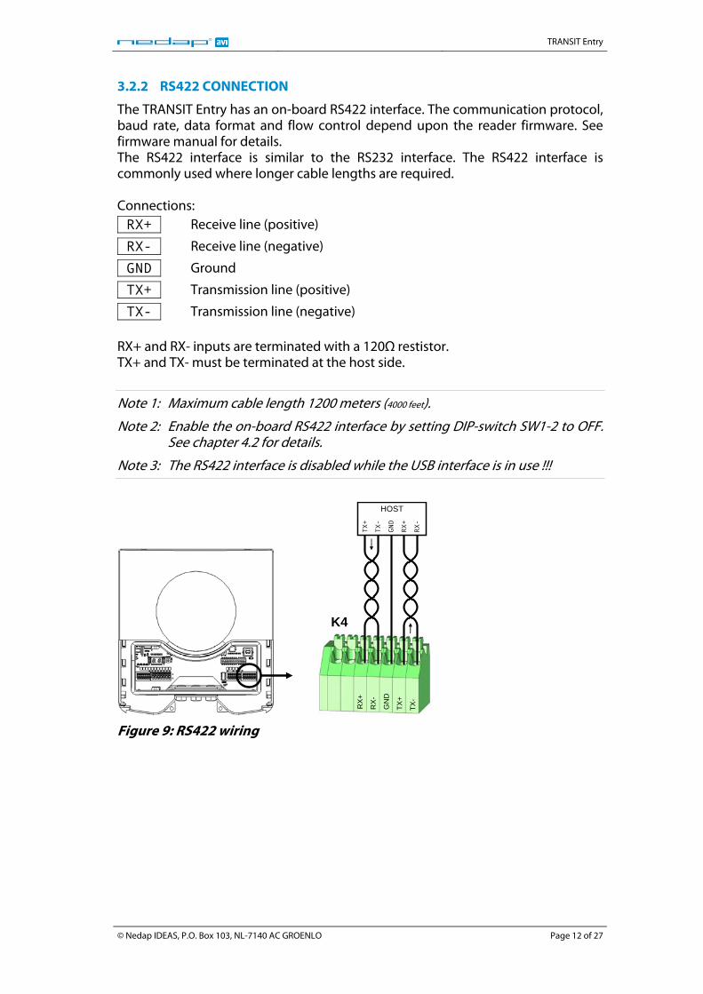
The TRANSIT Entry has an on-board RS422 interface. The communication protocol, baud rate, data format and flow control depend upon the reader firmware. See firmware manual for details. The RS422 interface is similar to the RS232 interface. The RS422 interface is commonly used where longer cable lengths are required. Connections: RX+ Receive line (positive)
RX- Receive line (negative)
GND Ground
TX+ Transmission line (positive)
TX- Transmission line (negative) RX+ and RX- inputs are terminated with a 120Ω restistor. TX+ and TX- must be terminated at the host side.
Note 1: Maximum cable length 1200 meters (4000 feet).
Note 2: Enable the on-board RS422 interface by setting DIP-switch SW1-2 to OFF. See chapter 4.2 for details.
Note 3: The RS422 interface is disabled while the USB interface is in use !!!
TX-
TX+
GN
D
RX
-
RX+
K4
TX-
TX+
GND
RX+
RX-
HOST
Figure 9: RS422 wiring
© Nedap IDEAS, P.O. Box 103, NL-7140 AC GROENLO Page 12 of 27
TRANSIT Entry
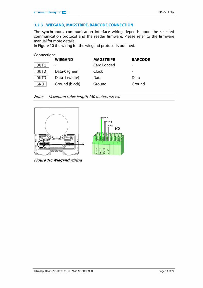
3.2.3 WIEGAND, MAGSTRIPE, BARCODE CONNECTION
The synchronous communication interface wiring depends upon the selected communication protocol and the reader firmware. Please refer to the firmware manual for more details. In Figure 10 the wiring for the wiegand protocol is outlined. Connections: WIEGAND MAGSTRIPE BARCODE OUT1 - Card Loaded -
OUT2 Data-0 (green) Clock -
OUT3 Data-1 (white) Data Data
GND Ground (black) Ground Ground
Note: Maximum cable length 150 meters (500 feet)
GN
D
OU
T3
OU
T2
K2
OU
T1
GND
DATA-1
DATA-0
Figure 10: Wiegand wiring
© Nedap IDEAS, P.O. Box 103, NL-7140 AC GROENLO Page 13 of 27
TRANSIT Entry
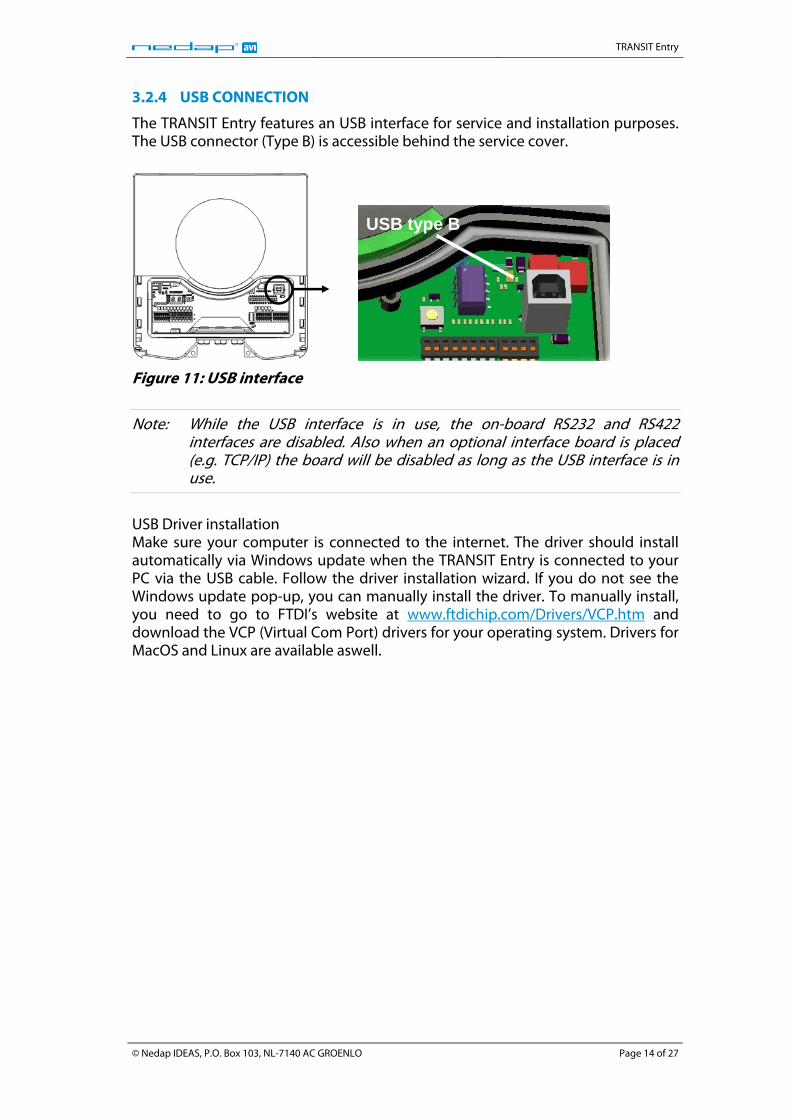
3.2.4 USB CONNECTION
The TRANSIT Entry features an USB interface for service and installation purposes. The USB connector (Type B) is accessible behind the service cover.
USB type B
Figure 11: USB interface
Note: While the USB interface is in use, the on-board RS232 and RS422 interfaces are disabled. Also when an optional interface board is placed (e.g. TCP/IP) the board will be disabled as long as the USB interface is in use.
USB Driver installation Make sure your computer is connected to the internet. The driver should install automatically via Windows update when the TRANSIT Entry is connected to your PC via the USB cable. Follow the driver installation wizard. If you do not see the Windows update pop-up, you can manually install the driver. To manually install, you need to go to FTDI’s website at www.ftdichip.com/Drivers/VCP.htm and download the VCP (Virtual Com Port) drivers for your operating system. Drivers for MacOS and Linux are available aswell.
© Nedap IDEAS, P.O. Box 103, NL-7140 AC GROENLO Page 14 of 27
TRANSIT Entry
3.3 DIGITAL I/O
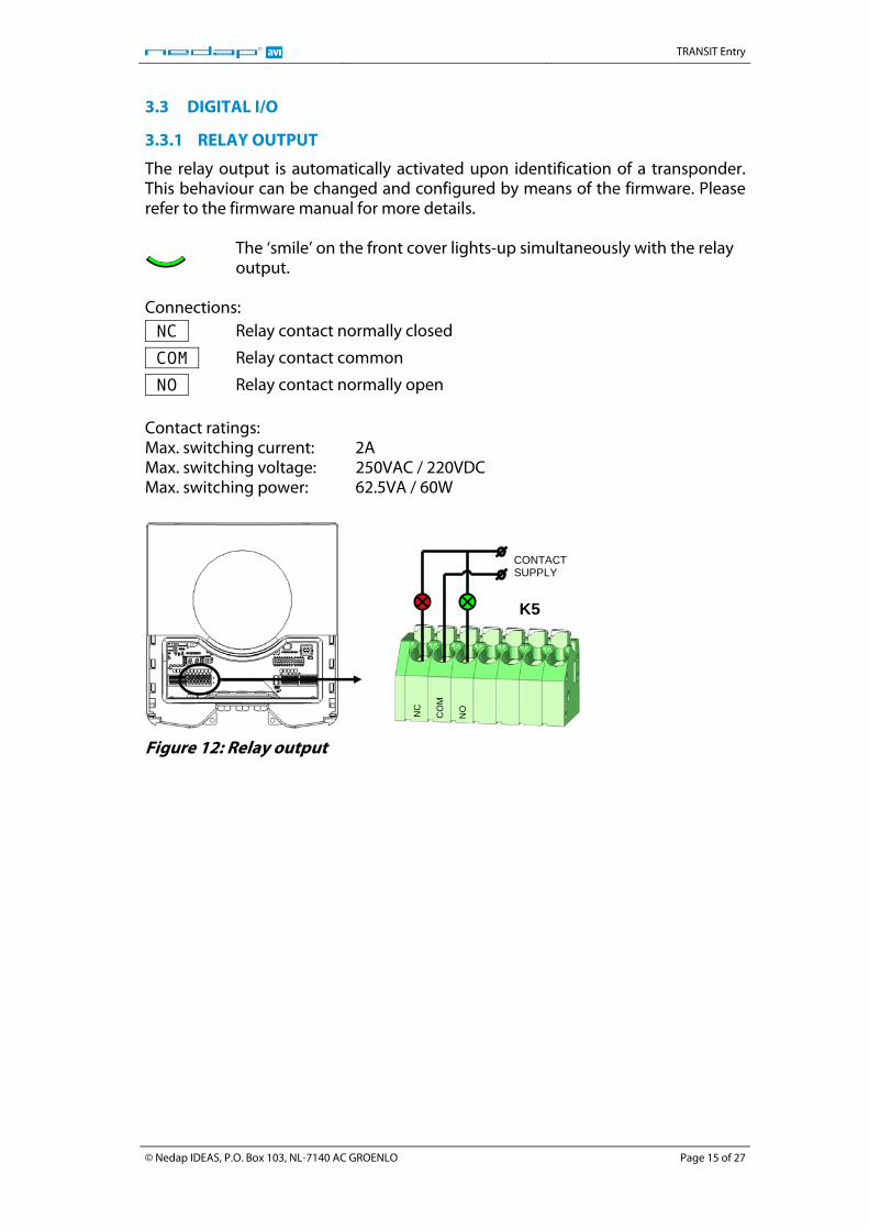
3.3.1 RELAY OUTPUT
The relay output is automatically activated upon identification of a transponder. This behaviour can be changed and configured by means of the firmware. Please refer to the firmware manual for more details.
The ‘smile’ on the front cover lights-up simultaneously with the relay output.
Connections: NC Relay contact normally closed
COM Relay contact common
NO Relay contact normally open Contact ratings: Max. switching current: 2A Max. switching voltage: 250VAC / 220VDC Max. switching power: 62.5VA / 60W
NO
CO
M
NC
K5
CONTACT SUPPLY
Figure 12: Relay output
© Nedap IDEAS, P.O. Box 103, NL-7140 AC GROENLO Page 15 of 27
TRANSIT Entry
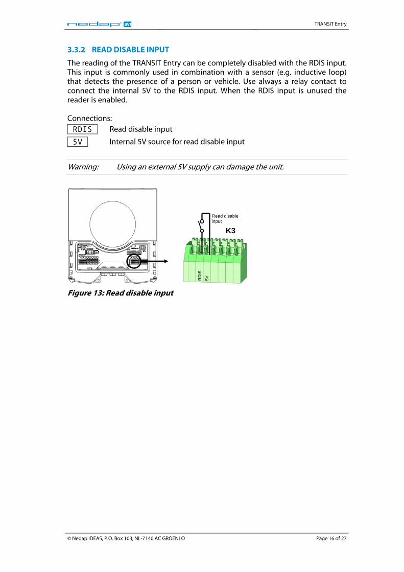
3.3.2 READ DISABLE INPUT
The reading of the TRANSIT Entry can be completely disabled with the RDIS input. This input is commonly used in combination with a sensor (e.g. inductive loop) that detects the presence of a person or vehicle. Use always a relay contact to connect the internal 5V to the RDIS input. When the RDIS input is unused the reader is enabled. Connections: RDIS Read disable input
5V Internal 5V source for read disable input
Warning: Using an external 5V supply can damage the unit.
5V
RD
IS
K3
Read disable input
Figure 13: Read disable input
© Nedap IDEAS, P.O. Box 103, NL-7140 AC GROENLO Page 16 of 27
TRANSIT Entry
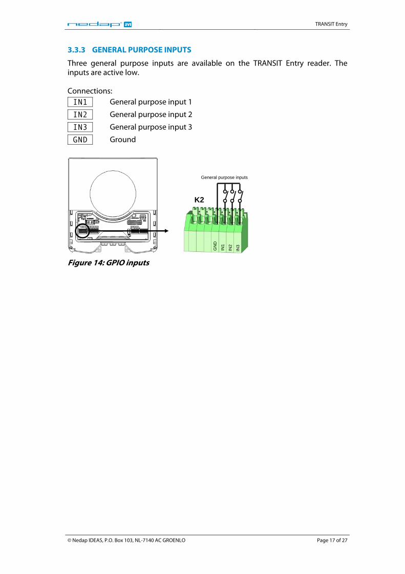
3.3.3 GENERAL PURPOSE INPUTS
Three general purpose inputs are available on the TRANSIT Entry reader. The inputs are active low. Connections: IN1 General purpose input 1
IN2 General purpose input 2
IN3 General purpose input 3
GND Ground
IN3
IN2
IN1
GN
D
K2
General purpose inputs
Figure 14: GPIO inputs
© Nedap IDEAS, P.O. Box 103, NL-7140 AC GROENLO Page 17 of 27
TRANSIT Entry
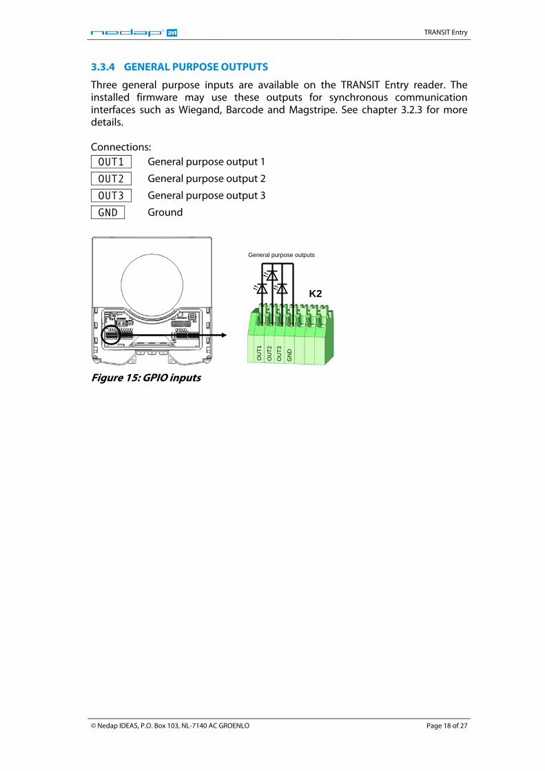
3.3.4 GENERAL PURPOSE OUTPUTS
Three general purpose inputs are available on the TRANSIT Entry reader. The installed firmware may use these outputs for synchronous communication interfaces such as Wiegand, Barcode and Magstripe. See chapter 3.2.3 for more details. Connections: OUT1 General purpose output 1
OUT2 General purpose output 2
OUT3 General purpose output 3
GND Ground
G
ND
OU
T3
OU
T2
OU
T1
K2
General purpose outputs
Figure 15: GPIO inputs
© Nedap IDEAS, P.O. Box 103, NL-7140 AC GROENLO Page 18 of 27
TRANSIT Entry
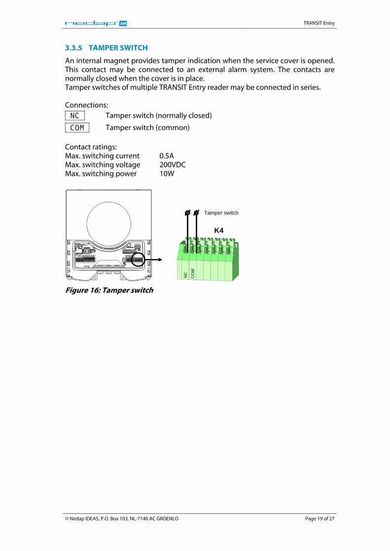
3.3.5 TAMPER SWITCH
An internal magnet provides tamper indication when the service cover is opened. This contact may be connected to an external alarm system. The contacts are normally closed when the cover is in place. Tamper switches of multiple TRANSIT Entry reader may be connected in series. Connections: NC Tamper switch (normally closed)
COM Tamper switch (common) Contact ratings: Max. switching current 0.5A Max. switching voltage 200VDC Max. switching power 10W
CO
M
NC
K4
Tamper switch
Figure 16: Tamper switch
© Nedap IDEAS, P.O. Box 103, NL-7140 AC GROENLO Page 19 of 27
TRANSIT Entry
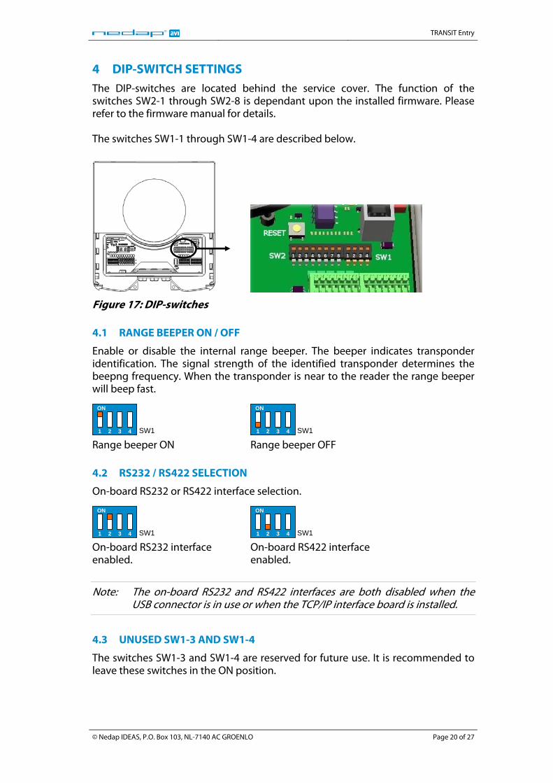
4 DIP-SWITCH SETTINGS The DIP-switches are located behind the service cover. The function of the switches SW2-1 through SW2-8 is dependant upon the installed firmware. Please refer to the firmware manual for details. The switches SW1-1 through SW1-4 are described below.
1 2 3 4 5 6 7 8 1 2 3 4
Figure 17: DIP-switches 4.1 RANGE BEEPER ON / OFF
Enable or disable the internal range beeper. The beeper indicates transponder identification. The signal strength of the identified transponder determines the beepng frequency. When the transponder is near to the reader the range beeper will beep fast. ON
1 2 3 4 SW1 Range beeper ON
ON
1 2 3 4 SW1 Range beeper OFF
4.2 RS232 / RS422 SELECTION
On-board RS232 or RS422 interface selection. ON
1 2 3 4 SW1 On-board RS232 interface enabled.
ON
1 2 3 4 SW1 On-board RS422 interface enabled.
Note: The on-board RS232 and RS422 interfaces are both disabled when the USB connector is in use or when the TCP/IP interface board is installed.
4.3 UNUSED SW1-3 AND SW1-4
The switches SW1-3 and SW1-4 are reserved for future use. It is recommended to leave these switches in the ON position.
© Nedap IDEAS, P.O. Box 103, NL-7140 AC GROENLO Page 20 of 27
TRANSIT Entry
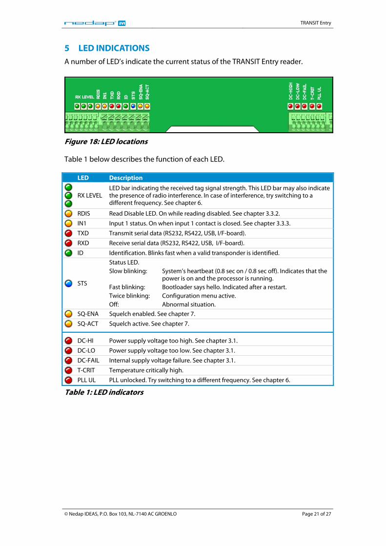
5 LED INDICATIONS A number of LED’s indicate the current status of the TRANSIT Entry reader.
Figure 18: LED locations Table 1 below describes the function of each LED. LED Description
RX LEVEL LED bar indicating the received tag signal strength. This LED bar may also indicate the presence of radio interference. In case of interference, try switching to a different frequency. See chapter 6.
RDIS Read Disable LED. On while reading disabled. See chapter 3.3.2.
IN1 Input 1 status. On when input 1 contact is closed. See chapter 3.3.3.
TXD Transmit serial data (RS232, RS422, USB, I/F-board).
RXD Receive serial data (RS232, RS422, USB, I/F-board).
ID Identification. Blinks fast when a valid transponder is identified.
STS
Status LED. Slow blinking: System’s heartbeat (0.8 sec on / 0.8 sec off). Indicates that the
power is on and the processor is running. Fast blinking: Bootloader says hello. Indicated after a restart. Twice blinking: Configuration menu active. Off: Abnormal situation.
SQ-ENA Squelch enabled. See chapter 7.
SQ-ACT Squelch active. See chapter 7.
DC-HI Power supply voltage too high. See chapter 3.1.
DC-LO Power supply voltage too low. See chapter 3.1.
DC-FAIL Internal supply voltage failure. See chapter 3.1.
T-CRIT Temperature critically high.
PLL UL PLL unlocked. Try switching to a different frequency. See chapter 6.
Table 1: LED indicators
© Nedap IDEAS, P.O. Box 103, NL-7140 AC GROENLO Page 21 of 27
TRANSIT Entry
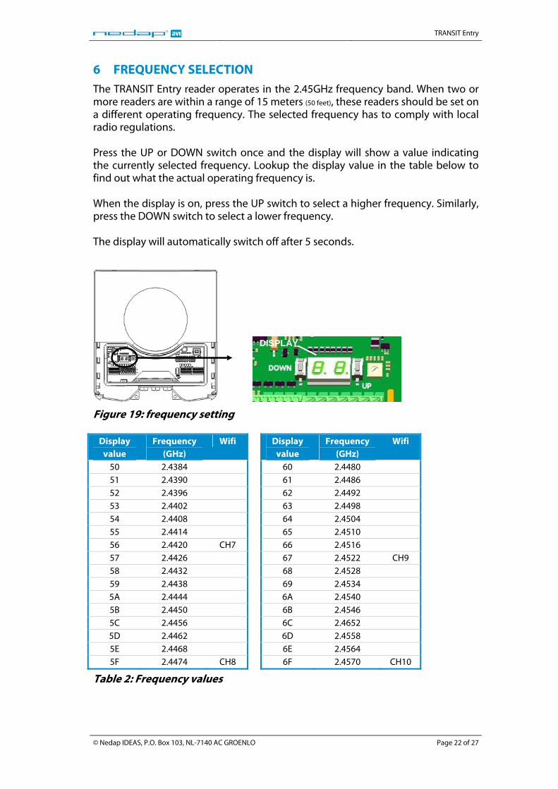
6 FREQUENCY SELECTION The TRANSIT Entry reader operates in the 2.45GHz frequency band. When two or more readers are within a range of 15 meters (50 feet), these readers should be set on a different operating frequency. The selected frequency has to comply with local radio regulations. Press the UP or DOWN switch once and the display will show a value indicating the currently selected frequency. Lookup the display value in the table below to find out what the actual operating frequency is. When the display is on, press the UP switch to select a higher frequency. Similarly, press the DOWN switch to select a lower frequency. The display will automatically switch off after 5 seconds.
DISPLAY
Figure 19: frequency setting
Display value
Frequency (GHz)
Wifi Display value
Frequency (GHz)
Wifi
50 2.4384 60 2.4480 51 2.4390 61 2.4486 52 2.4396 62 2.4492 53 2.4402 63 2.4498 54 2.4408 64 2.4504 55 2.4414 65 2.4510 56 2.4420 CH7 66 2.4516 57 2.4426 67 2.4522 CH9 58 2.4432 68 2.4528 59 2.4438 69 2.4534 5A 2.4444 6A 2.4540 5B 2.4450 6B 2.4546 5C 2.4456 6C 2.4652 5D 2.4462 6D 2.4558 5E 2.4468 6E 2.4564 5F 2.4474 CH8 6F 2.4570 CH10
Table 2: Frequency values
© Nedap IDEAS, P.O. Box 103, NL-7140 AC GROENLO Page 22 of 27

TRANSIT Entry
7 READ RANGE CONTROL (SQUELCH)
7.1 PRINCIPLE
The read range of the TRANSIT Entry can be controlled with the embedded squelch function. The squelch references the received signal strength against the squelch level setting. When the received signal strength is below the squelch level no identification is possible. The received signal strength becomes higher when the transponder approaches the reader. When the received signal strength exceeds the squelch level the transponder will be identified.
Distance
Rec
eive
d si
gnal
stre
ngth
0 m 5 m
max read range for this level
squelch level setting
Transponder signal < squelch level: no read
Transponder signal > squelch level: read
Squelch level
Transponder signal
Figure 20: Squelch principle 7.2 READ RANGE ADJUSTING
SQ-LVL potentiometer completely clockwise: Maximum read range (squelch disabled).
SQ-LVL potentiometer completely counter-clockwise: Minimum read range.
SQ-LVL
SQ-ACTSQ-ENA
Figure 21: Squelch level setting Two LEDs indicate the status of the squelch. When the squelch is enabled (potentiometer SQ-LVL not completely clockwise) LED SQ-ENA will be on. LED SQ-ACT is on when the transponder signal is below the squelch level (red area in Figure 20). In chapter 5 all LED indicators are described.
© Nedap IDEAS, P.O. Box 103, NL-7140 AC GROENLO Page 23 of 27
TRANSIT Entry
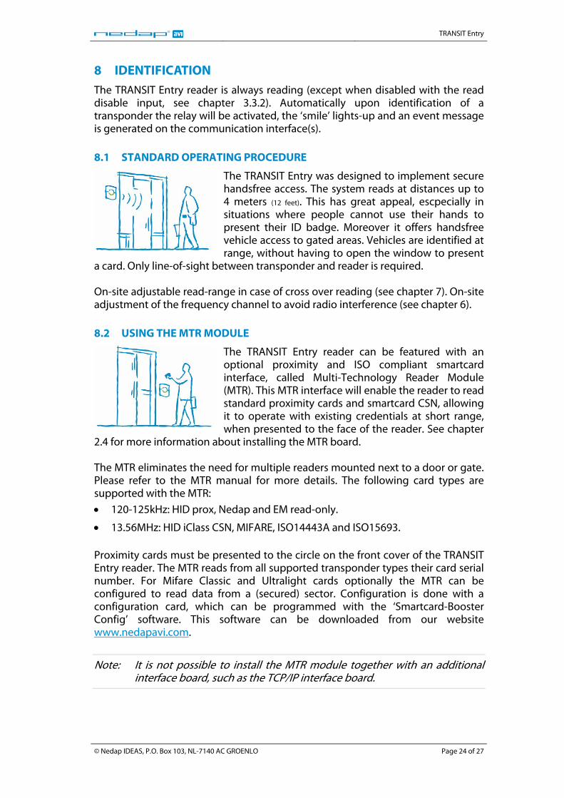
8 IDENTIFICATION The TRANSIT Entry reader is always reading (except when disabled with the read disable input, see chapter 3.3.2). Automatically upon identification of a transponder the relay will be activated, the ‘smile’ lights-up and an event message is generated on the communication interface(s). 8.1 STANDARD OPERATING PROCEDURE
The TRANSIT Entry was designed to implement secure handsfree access. The system reads at distances up to 4 meters (12 feet). This has great appeal, escpecially in situations where people cannot use their hands to present their ID badge. Moreover it offers handsfree vehicle access to gated areas. Vehicles are identified at range, without having to open the window to present
a card. Only line-of-sight between transponder and reader is required. On-site adjustable read-range in case of cross over reading (see chapter 7). On-site adjustment of the frequency channel to avoid radio interference (see chapter 6). 8.2 USING THE MTR MODULE
The TRANSIT Entry reader can be featured with an optional proximity and ISO compliant smartcard interface, called Multi-Technology Reader Module (MTR). This MTR interface will enable the reader to read standard proximity cards and smartcard CSN, allowing it to operate with existing credentials at short range, when presented to the face of the reader. See chapter
2.4 for more information about installing the MTR board. The MTR eliminates the need for multiple readers mounted next to a door or gate. Please refer to the MTR manual for more details. The following card types are supported with the MTR:
• 120-125kHz: HID prox, Nedap and EM read-only.
• 13.56MHz: HID iClass CSN, MIFARE, ISO14443A and ISO15693. Proximity cards must be presented to the circle on the front cover of the TRANSIT Entry reader. The MTR reads from all supported transponder types their card serial number. For Mifare Classic and Ultralight cards optionally the MTR can be configured to read data from a (secured) sector. Configuration is done with a configuration card, which can be programmed with the ‘Smartcard-Booster Config’ software. This software can be downloaded from our website www.nedapavi.com.
Note: It is not possible to install the MTR module together with an additional interface board, such as the TCP/IP interface board.
© Nedap IDEAS, P.O. Box 103, NL-7140 AC GROENLO Page 24 of 27
TRANSIT Entry
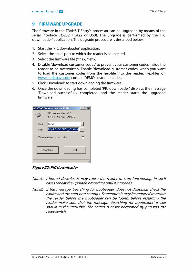
9 FIRMWARE UPGRADE The firmware in the TRANSIT Entry’s processor can be upgraded by means of the serial interface (RS232, RS422 or USB). The upgrade is performed by the ‘PIC downloader’ application. The upgrade procedure is described below. 1. Start the ‘PIC downloader’ application. 2. Select the serial port to which the reader is connected. 3. Select the firmware file (*.hex, *.ehx). 4. Disable ‘download customer codes’ to prevent your customer codes inside the
reader to be overwritten. Enable ‘download customer codes’ when you want to load the customer codes from the hex-file into the reader. Hex-files on www.nedapavi.com contain DEMO customer codes.
5. Click ‘Download’ to start downloading the firmware. 6. Once the downloading has completed ‘PIC downloader’ displays the message
‘Download successfully completed’ and the reader starts the upgraded firmware.
Figure 22: PIC downloader
Note1: Aborted downloads may cause the reader to stop functioning. In such cases repeat the upgrade procedure until it succeeds.
Note2: If the message ‘Searching for bootloader’ does not disappear check the cables and the com-port settings. Sometimes it may be required to restart the reader before the bootloader can be found. Before restarting the reader make sure that the message ‘Searching for bootloader’ is still shown in the statusbar. The restart is easily performed by pressing the reset-switch.
© Nedap IDEAS, P.O. Box 103, NL-7140 AC GROENLO Page 25 of 27
TRANSIT Entry
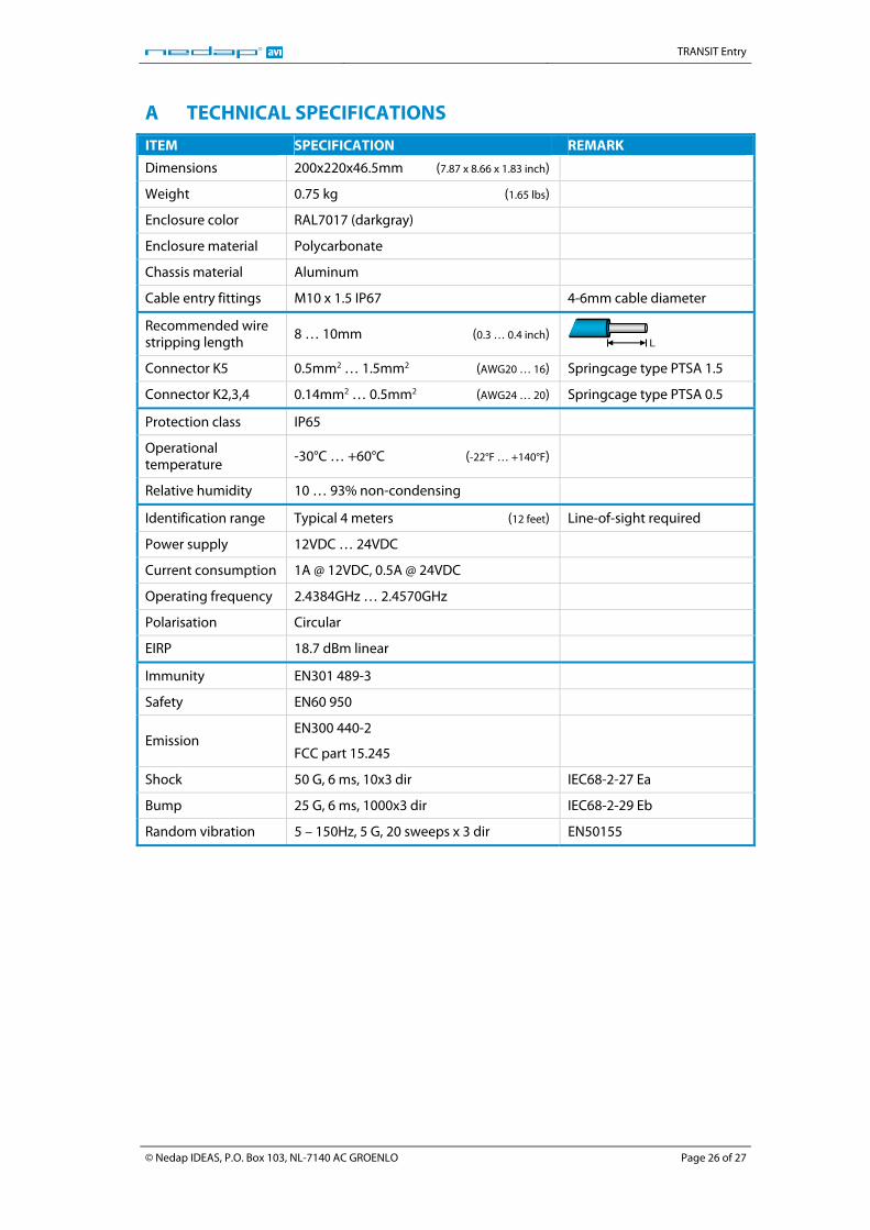
A TECHNICAL SPECIFICATIONS
ITEM SPECIFICATION REMARK
Dimensions 200x220x46.5mm (7.87 x 8.66 x 1.83 inch)
Weight 0.75 kg (1.65 lbs)
Enclosure color RAL7017 (darkgray)
Enclosure material Polycarbonate
Chassis material Aluminum
Cable entry fittings M10 x 1.5 IP67 4-6mm cable diameter
Recommended wire stripping length
8 … 10mm (0.3 … 0.4 inch)
L
Connector K5 0.5mm2 … 1.5mm2 (AWG20 … 16) Springcage type PTSA 1.5
Connector K2,3,4 0.14mm2 … 0.5mm2 (AWG24 … 20) Springcage type PTSA 0.5
Protection class IP65
Operational temperature
-30°C … +60°C (-22°F … +140°F)
Relative humidity 10 … 93% non-condensing
Identification range Typical 4 meters (12 feet) Line-of-sight required
Power supply 12VDC … 24VDC
Current consumption 1A @ 12VDC, 0.5A @ 24VDC
Operating frequency 2.4384GHz … 2.4570GHz
Polarisation Circular
EIRP 18.7 dBm linear
Immunity EN301 489-3
Safety EN60 950
Emission EN300 440-2
FCC part 15.245
Shock 50 G, 6 ms, 10x3 dir IEC68-2-27 Ea
Bump 25 G, 6 ms, 1000x3 dir IEC68-2-29 Eb
Random vibration 5 – 150Hz, 5 G, 20 sweeps x 3 dir EN50155
© Nedap IDEAS, P.O. Box 103, NL-7140 AC GROENLO Page 26 of 27
TRANSIT Entry
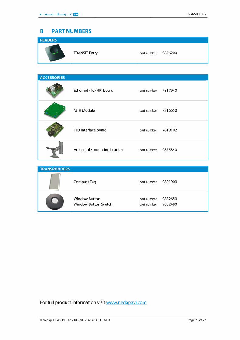
B PART NUMBERS
READERS
TRANSIT Entry part number: 9876200
ACCESSORIES
Ethernet (TCP/IP) board part number: 7817940
MTR Module part number: 7816650
HID interface board part number: 7819102
Adjustable mounting bracket part number: 9875840
TRANSPONDERS
Compact Tag part number: 9891900
Window Button Window Button Switch
part number: 9882650 part number: 9882480
For full product information visit www.nedapavi.com
© Nedap IDEAS, P.O. Box 103, NL-7140 AC GROENLO Page 27 of 27
Related Documents