Larnaca, Cyprus TRANSFORMER TEST VAN TransLAB-5

Welcome message from author
This document is posted to help you gain knowledge. Please leave a comment to let me know what you think about it! Share it to your friends and learn new things together.
Transcript
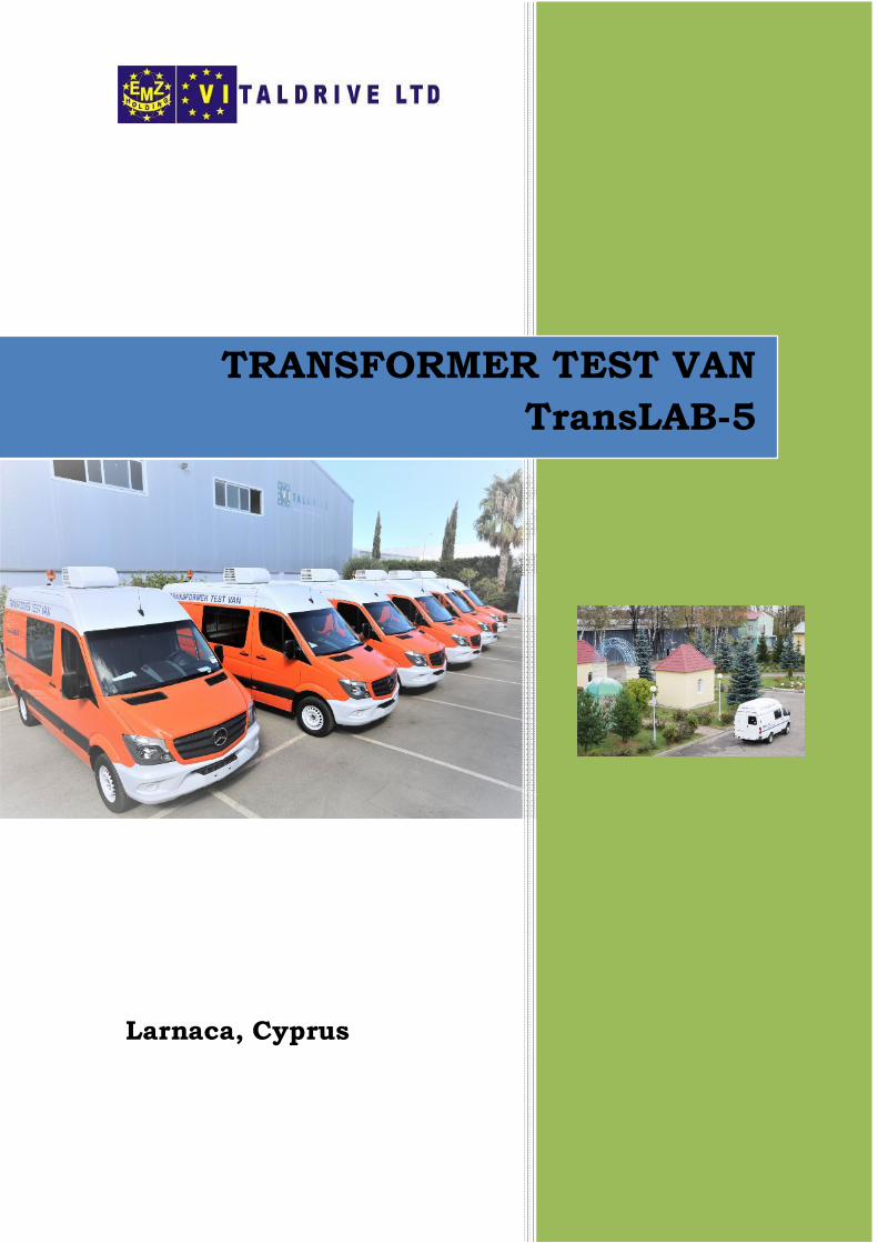
Larnaca, Cyprus
TRANSFORMER TEST VANTransLAB-5
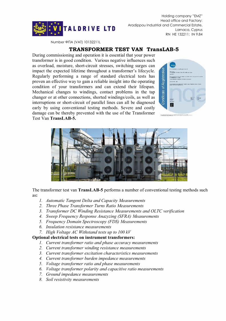
TRANSFORMER TEST VAN TransLAB-5During commissioning and operation it is essential that your powertransformer is in good condition. Various negative influences suchas overload, moisture, short-circuit stresses, switching surges canimpact the expected lifetime throughout a transformer’s lifecycle.Regularly performing a range of standard electrical tests hasproven an effective way to gain a reliable insight into the operatingcondition of your transformers and can extend their lifespan.Mechanical changes to windings, contact problems in the tapchanger or at other connections, shorted windings/coils, as well asinterruptions or short-circuit of parallel lines can all be diagnosedearly by using conventional testing methods. Severe and costlydamage can be thereby prevented with the use of the TransformerTest Van TransLAB-5.
The transformer test van TransLAB-5 performs a number of conventional testing methods suchas:
1. Automatic Tangent Delta and Capacity Measurements2. Three Phase Transformer Turns Ratio Measurements3. Transformer DC Winding Resistance Measurements and OLTC verification4. Sweep Frequency Response Anazyzing (SFRA) Measurements5. Frequency Domain Spectroscopy (FDS) Measurements6. Insulation resistance measurements7. High Voltage AC Withstand tests up to 100 kV
Optional electrical tests on instrument transformers:1. Current transformer ratio and phase accuracy measurements2. Current transformer winding resistance measurements3. Current transformer excitation characteristics measurements4. Current transformer burden impedance measurements5. Voltage transformer ratio and phase measurements6. Voltage transformer polarity and capacitive ratio measurements7. Ground impedance measurements8. Soil resistivity measurements
Number ФПА (VAT) 10132211L
Holding company ”EMZ”Head office and Factory:
Aradippou Industrial and Commercial Estate,Larnaca, Cyprus
RN HE 132211; IN 9.84

With the help of our transformer test van TransLAB-5 you can easily carry out work ontransformers and determine all their parameters. After testing is complete, the power transformercan also be safely demagnetized.
View of TransLAB-5
A. MAIN EQUIPMENT
The entire operation control of the mobile transformer test van is performed from the operatorarea. Direct access to equipment interface is granted via a sophisticated touch screen panelcomputer.The equipment is ergonomically integrated in the test van in order to make it esthetic appealingas well as functional to maintain. Each unit can be easily removed from its position and theoperator can use it in the field, independently.The installed equipment is a modular system and the operator can perform many more tests thanthose required using the same installed equipment. Besides, the design of the test van is allowingend users to expand the testing capability by using additional modules which can be easilyinstalled inside. A transparent separation wall allows the operator to have complete andcontinuous visibility of the technical area. All operation modes, techniques and safety controlare fully integrated in the system and permit the following:
· safety system control: door locks, internal/external emergency stop buttons, safety keyswitch, step voltage control - ground to vehicle chassis, external safety box, overvoltageand over current protection;
· control and visual identification that the test van is connected properly to the mainssupply;
· selection of operating modes via changeover safety switch;· control of power to the equipment
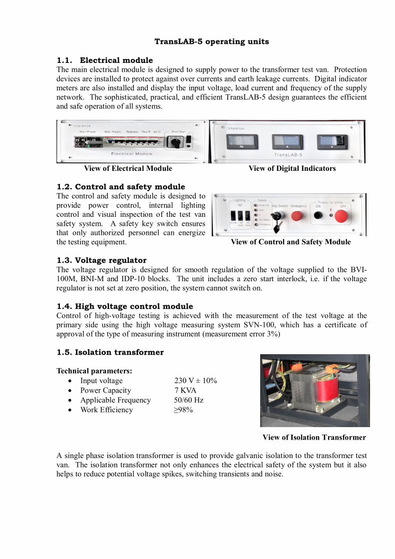
TransLAB-5 operating units
1.1. Electrical moduleThe main electrical module is designed to supply power to the transformer test van. Protectiondevices are installed to protect against over currents and earth leakage currents. Digital indicatormeters are also installed and display the input voltage, load current and frequency of the supplynetwork. The sophisticated, practical, and efficient TransLAB-5 design guarantees the efficientand safe operation of all systems.
View of Electrical Module View of Digital Indicators
1.2. Control and safety moduleThe control and safety module is designed toprovide power control, internal lightingcontrol and visual inspection of the test vansafety system. A safety key switch ensuresthat only authorized personnel can energizethe testing equipment. View of Control and Safety Module
1.3. Voltage regulatorThe voltage regulator is designed for smooth regulation of the voltage supplied to the BVI-100M, BNI-M and IDP-10 blocks. The unit includes a zero start interlock, i.e. if the voltageregulator is not set at zero position, the system cannot switch on.
1.4. High voltage control moduleControl of high-voltage testing is achieved with the measurement of the test voltage at theprimary side using the high voltage measuring system SVN-100, which has a certificate ofapproval of the type of measuring instrument (measurement error 3%)
1.5. Isolation transformer
Technical parameters:· Input voltage 230 V ± 10%· Power Capacity 7 KVA· Applicable Frequency 50/60 Hz· Work Efficiency ≥98%
View of Isolation Transformer
A single phase isolation transformer is used to provide galvanic isolation to the transformer testvan. The isolation transformer not only enhances the electrical safety of the system but it alsohelps to reduce potential voltage spikes, switching transients and noise.

Layout diagram of testing equipment in the main control panel
Testrano 600
CP TD1 located at
Franeo 800 HV area
Computer
Dirana
Insulation Tester C.A 6555
The touch screen panel computer allows the interaction with all the installed equipment in thetransformer test van. The installed Primary Test Manager (PTM) software assists the operators intesting and assessing their assets in accordance with applicable international IEEE and IECstandards and guidelines, while keeping testing time to a minimum. All test and assessmentresults are automatically stored in a structured and easily accessible database. The softwareautomatically generates reports including all asset-related information and performed tests. Thisprovides a comprehensive overview of the test object, test results and assessment. The operatorscan easily adapt test reports, for example, by choosing from different types of result tables anddiagrams and by providing comments on every test. Furthermore, it is possible to incorporatecompany logos, photos and other test results. The reports can easily be exported in MicrosoftWord, Microsoft Excel and PDF format.
2. TESTRANO 600 Multi-Functional Three-Phase Test System
TESTRANO 600 is the most advanced, three-phase test system which supports all commonelectrical tests on power transformers. Compared to conventional single-phase test sets thethree-phase capabilities of the unit offer several advantages such as: one setup can be used toperform various tests, the rewiring effort is significantly reduced, testing time can be cut down toa third of the time, increased safety as less trips up and down are needed.
Connection sequence TESTRANO 600 to transformer *TESTRANO 600 One System – Multiple Tests

The TESTRANO 600 provides you with a convenient way of testing to gain a comprehensiveinsight into the condition of every part of your power transformer. It can be operated usingTESTRANO TouchControl on the integrated display, or by using the Primary TestingManagerTM software on a computer. This makes it ideal for routine and diagnostic testing onsite or during factory acceptance tests (FAT).
* Primary Testing ManagerTM software * Primary Testing ManagerTM customized reporting
Results are automatically stored and organized in the database on your PC and are available foranalysis and reporting. Each test can be automatically assessed according to internationalstandards and guidelines or based on your individual limit values. The measurement result can bevisualized in tables and plots for easy review and assessment. Additionally, they can becompared with previous results and historical trends, allowing further in-depth analysis.Technical Specifications:OutputsHV & LV Outputs - PowerFrequency DC or 15Hz…599HzPower Vmains P30s Pcontinuous
>100Vrms 1500W 1000W>190Vrms 4000W 2400W
HV & LV Outputs - VoltageSource Range Imax,continuous Imax,30s3-phase AC (rms) 0…230V (LN) 100mArms 12A
0…80V (LN) 16A 20A0…40V (LN) 33A 40A
1-phase AC (rms) 0…240V 16A 20A0…120V 33A 40A
3-phase DC 0…±113V 16A0…±56 33A
1-phase DC 0…±340V 16A0…±170V 33A
HV & LV Outputs - CurrentSource Range Vmax,continuous3-phase DC 0…±33A 56V
0…±16A 113V
1-phase DC 0…±100A 56V0…±33A 170V0…±50A 113V0…±16A 340V

3-phase AC (RMS) 0…33 A(LN) 40V0…16 A (LN) 80V
1-phase AC (RMS) 0…100 A 40 V0…33 A 120 V0…50 A 180 V0…16 A 240 V
On-Load Tap Changer Input/OutputVoltage 300 VRMSAccuracy AC (50 / 60 Hz) / DC 0.07 % rd + 0.07 % rangeCurrent clamp input 3 VRMSTap up/down switch Current: 300 mAcontinuous, 9 A for 0.7 s
Voltage: 300 VRMS
InputsHV & LV Inputs – VoltageInput Range AccuracyAC (RMS) 0…..300 mV 0.01 % rd + 0.003 % range
0…..3 V 0.01 % rd + 0.003 % range0…..30 V 0.01 % rd + 0.003 % range0…..300 V 0.012 % rd + 0.003 % range
DC 0…..42.4 mV 0.022 % rd + 0.032 % range0…..424 mV 0.01 % rd + 0.017 % range0…..4.24 V 0.007 % rd + 0.012 % range0…..42.4 V 0.01 % rd + 0.017 % range0…..424 V 0.007 % rd + 0.012 % range
HV & LV Inputs – CurrentInput Range AccuracyAC (RMS) 0 ... 4 ARMS 0.036 % rd + 0.0033 % range
0 ... 40 ARMS 0.023 % rd + 0.013 % range
DC 0 ... 0.56 ADC 0.1 % rd + 0.023 % range0 ... 5.6 ADC 0.037 % rd + 0.026 % range0 ... 56 ADC 0.008 % rd + 0.01 % range
Combined ValuesDC Resistance MeasurementCurrent Range Accuracy30 ADC 1 ... 10 Ω 0.037 % rd + 0.017 % range
0.1 ... 1 Ω 0.04 % rd + 0.027 % range0.01 ... 0.1 Ω 0.033 % rd + 0.017 % range0.001 ... 0.01 Ω 0.037 % rd + 0.027 % range0.0001 ... 0.001 Ω 0.05 % rd + 0.043 % range
3 ADC 10 ... 100 Ω 0.1 % rd + 0.18 % range1 ... 10 Ω 0.1 % rd + 0.267 % range0.1 ... 1 Ω 0.1 % rd + 0.18 % range
Ratio MeasurementRange Accuracy1:1 ... 10 0.03 % rd + 0.043 % range1:10 ... 100 0.027 % rd + 0.043 % range1:100 ... 1000 0.027 % rd + 0.043 % range1:1000 ... 10 000 0.027 % rd + 0.043 % range
Power SpecificationsVoltage Nominal: 100V … 240VAC
Permitted: 85V … 264VACFrequency Nominal: 50 Hz / 60 Hz
Permitted: 45 … 65 HzPower Fuse Automatic circuit breaker with magnetic overcurrent tripping at I
> 16APowerConsumption
Continuous: < 3.5 KWPeak: < 5.0 KW
Environmental ConditionsTemperature: Operating: -10oC...+55oC
Storage: -30oC...+70oCRelative Humidity 5% … 95%, non-condensingMaximum Altitude Operating: 2000 m up to 5000 m
Storage: 12000 m
Mechanical DataDimensions 580 x 386 x 229 mm (WxHxD)Weight Device without display: 19.5 kg
Equipment ReliabilityShock IEC / EN 60068-2-27, 15 g / 11 ms, half-sinusoid, each axisVibration IEC / EN 60068-2-6, frequency range from 10 Hz to 150 Hz,
continuous acceleration 2 g (20 m⁄s2 / 65 ft ⁄s2), 10 cycles peraxis
Features:· True three-phase power transformer test set· Powerful device with 3 x 33 A DC or 400 V AC· Reduced wiring effort as same wiring can be used for different tests· Automatic tap changer control and measurement, no accessory required
Fast and reliable demagnetization of transformer’s core
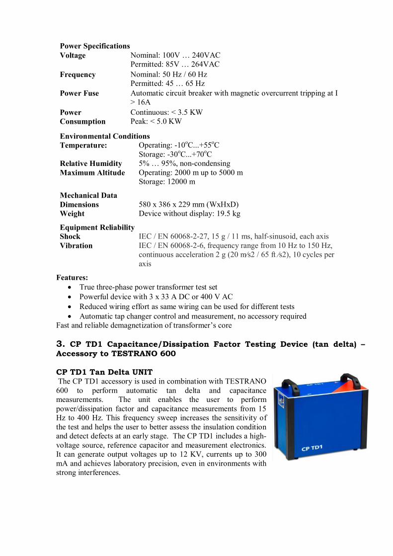
3. CP TD1 Capacitance/Dissipation Factor Testing Device (tan delta) –Accessory to TESTRANO 600
CP TD1 Tan Delta UNIT The CP TD1 accessory is used in combination with TESTRANO600 to perform automatic tan delta and capacitancemeasurements. The unit enables the user to performpower/dissipation factor and capacitance measurements from 15Hz to 400 Hz. This frequency sweep increases the sensitivity ofthe test and helps the user to better assess the insulation conditionand detect defects at an early stage. The CP TD1 includes a high-voltage source, reference capacitor and measurement electronics.It can generate output voltages up to 12 KV, currents up to 300mA and achieves laboratory precision, even in environments withstrong interferences.
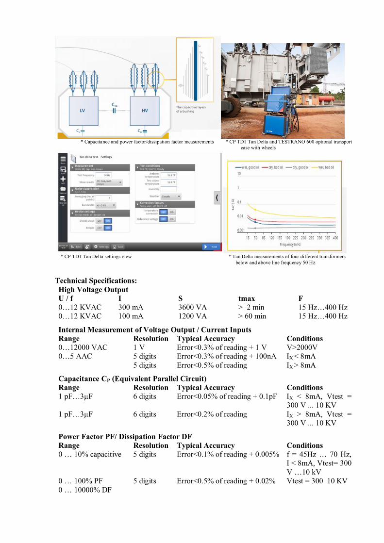
* Capacitance and power factor/dissipation factor measurements * CP TD1 Tan Delta and TESTRANO 600 optional transport case with wheels
* CP TD1 Tan Delta settings view * Tan Delta measurements of four different transformers below and above line frequency 50 Hz
Technical Specifications:High Voltage OutputU / f I S tmax F0…12 KVAC 300 mA 3600 VA > 2 min 15 Hz…400 Hz0…12 KVAC 100 mA 1200 VA > 60 min 15 Hz…400 Hz
Internal Measurement of Voltage Output / Current InputsRange Resolution Typical Accuracy Conditions0…12000 VAC 1 V Error<0.3% of reading + 1 V V>2000V0…5 AAC 5 digits Error<0.3% of reading + 100nA IX < 8mA
5 digits Error<0.5% of reading IX > 8mA
Capacitance CP (Equivalent Parallel Circuit)Range Resolution Typical Accuracy Conditions1 pF…3µF 6 digits Error<0.05% of reading + 0.1pF IX < 8mA, Vtest =
300 V ... 10 KV1 pF…3µF 6 digits Error<0.2% of reading IX > 8mA, Vtest =
300 V ... 10 KV
Power Factor PF/ Dissipation Factor DFRange Resolution Typical Accuracy Conditions0 … 10% capacitive 5 digits Error<0.1% of reading + 0.005% f = 45Hz … 70 Hz,
I < 8mA, Vtest= 300V …10 kV
0 … 100% PF0 … 10000% DF
5 digits Error<0.5% of reading + 0.02% Vtest = 300 10 KV
Mechanical DataDimensions 450x330x220 mm (WxHxD)Weight 25 kg
Features:· Testing at variable frequencies for better condition diagnosis· Excellent suppression of mains frequency interference fields· Wider frequency range for more sensitivity (15 Hz to 400 Hz)
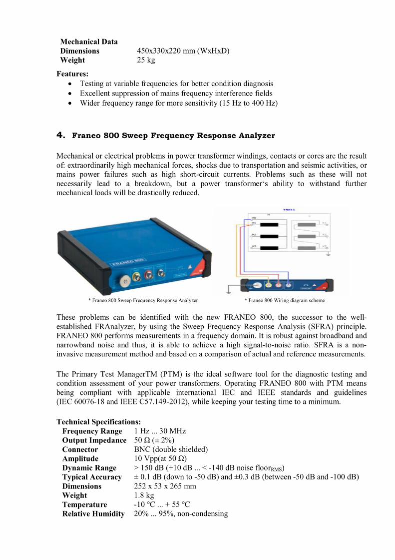
4. Franeo 800 Sweep Frequency Response Analyzer
Mechanical or electrical problems in power transformer windings, contacts or cores are the resultof: extraordinarily high mechanical forces, shocks due to transportation and seismic activities, ormains power failures such as high short-circuit currents. Problems such as these will notnecessarily lead to a breakdown, but a power transformer‘s ability to withstand furthermechanical loads will be drastically reduced.
* Franeo 800 Sweep Frequency Response Analyzer * Franeo 800 Wiring diagram scheme
These problems can be identified with the new FRANEO 800, the successor to the well-established FRAnalyzer, by using the Sweep Frequency Response Analysis (SFRA) principle.FRANEO 800 performs measurements in a frequency domain. It is robust against broadband andnarrowband noise and thus, it is able to achieve a high signal-to-noise ratio. SFRA is a non-invasive measurement method and based on a comparison of actual and reference measurements.
The Primary Test ManagerTM (PTM) is the ideal software tool for the diagnostic testing andcondition assessment of your power transformers. Operating FRANEO 800 with PTM meansbeing compliant with applicable international IEC and IEEE standards and guidelines(IEC 60076-18 and IEEE C57.149-2012), while keeping your testing time to a minimum.
Technical Specifications:Frequency Range 1 Hz ... 30 MHzOutput Impedance 50 Ω (± 2%)Connector BNC (double shielded)Amplitude 10 Vpp(at 50 Ω)Dynamic Range > 150 dB (+10 dB ... < -140 dB noise floorRMS)Typical Accuracy ± 0.1 dB (down to -50 dB) and ±0.3 dB (between -50 dB and -100 dB)Dimensions 252 x 53 x 265 mmWeight 1.8 kgTemperature -10 °C ... + 55 °CRelative Humidity 20% ... 95%, non-condensing
Features:· Wide dynamic measuring range (>150 dB)· Reproducible results thanks to innovative connection technique, based on IEC 60076-18,
Method 1· Guided workflow for test set-up, execution and assessment for easy analysis without
expert knowledge· Fast measurement times due to intelligent sweep algorithm
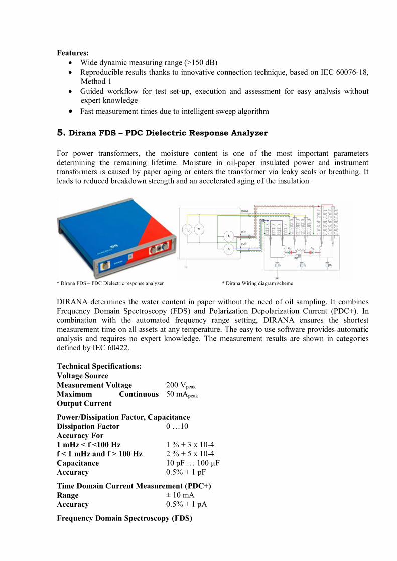
5. Dirana FDS – PDC Dielectric Response Analyzer
For power transformers, the moisture content is one of the most important parametersdetermining the remaining lifetime. Moisture in oil-paper insulated power and instrumenttransformers is caused by paper aging or enters the transformer via leaky seals or breathing. Itleads to reduced breakdown strength and an accelerated aging of the insulation.
* Dirana FDS – PDC Dielectric response analyzer * Dirana Wiring diagram scheme
DIRANA determines the water content in paper without the need of oil sampling. It combinesFrequency Domain Spectroscopy (FDS) and Polarization Depolarization Current (PDC+). Incombination with the automated frequency range setting, DIRANA ensures the shortestmeasurement time on all assets at any temperature. The easy to use software provides automaticanalysis and requires no expert knowledge. The measurement results are shown in categoriesdefined by IEC 60422.
Technical Specifications:Voltage SourceMeasurement Voltage 200 VpeakMaximum ContinuousOutput Current
50 mApeak
Power/Dissipation Factor, CapacitanceDissipation Factor 0 …10Accuracy For1 mHz < f <100 Hzf < 1 mHz and f > 100 Hz
1 % + 3 x 10-42 % + 5 x 10⁻⁴
Capacitance 10 pF … 100 µFAccuracy 0.5% + 1 pF
Time Domain Current Measurement (PDC+)Range ± 10 mAAccuracy 0.5% ± 1 pA
Frequency Domain Spectroscopy (FDS)
Measurement Voltage 200 VpeakMeasurement Current ± 50 mApeak
Frequency RangesFDS Frequency Range 5 kHZ … 10 µHzFDS+PDC Frequency Range 5 kHz … 10 µHzPDC Frequency Range 100 mHz … 10 µHz
Typical Measuring Time (FDS+PDC)1 kHz … 1 mHz 9 minutes1 kHz … 100 µHz 15 – 54 minutes1 kHz … 10 µHz 30 minutes – 1 hour and 44 minutes
Mechanical Data / Supply VoltageDimensions 260x50x265 mm (WxHxD)Weight 2.3 kgSupply Voltage 85 V … 265 VFrequency 50 … 60 Hz
Environmental ConditionsOperating Temperature -10oC … +55oCRelative Humidity 20% … 95 %, non-condensingAir-Pressure 70 kPa … 106 kPa
Features:· Non-invasive moisture determination in the paper insulation· Automated software for easy analysis without expert knowledge· Shortest measurement time by combination of revolutionary FDS and PDC+ and
automatic frequency range determination· Applicable to all oil-paper or ester-paper insulated assets
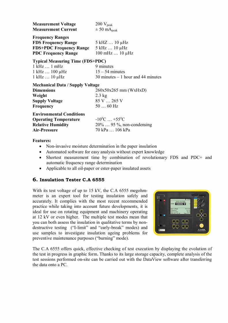
6. Insulation Tester C.A 6555
With its test voltage of up to 15 kV, the C.A 6555 megohm-meter is an expert tool for testing insulation safely andaccurately. It complies with the most recent recommendedpractice while taking into account future developments, it isideal for use on rotating equipment and machinery operatingat 12 kV or even higher. The multiple test modes mean thatyou can both assess the insulation in qualitative terms by non-destructive testing (“I-limit” and “early-break” modes) anduse samples to investigate insulation ageing problems forpreventive maintenance purposes (“burning” mode).
The C.A 6555 offers quick, effective checking of test execution by displaying the evolution ofthe test in progress in graphic form. Thanks to its large storage capacity, complete analysis of thetest sessions performed on-site can be carried out with the DataView software after transferringthe data onto a PC.
Technical Specifications:Test Voltages Ranges 500V: 10 kΩ to 2 TΩ
1000V: 10 kΩ to 4 TΩ2500V: 10 kΩ to 10 TΩ5000V: 10 kΩ to 15 TΩ10000V: 10 kΩ to 25 TΩ15000V: 10 kΩ to 30 TΩ
Fixed Test Voltages 500, 1000, 2500, 5000, 10000, 15000Variable Test Voltages 40V – 15000V, 3 presettable voltage valuesAdjustment Incrementfor Variable Voltages
Variable:40-15KV Step: 40V-1KV:10V1KV-15KV:100V
Ramp Mode 3 presettable ramps: start voltage/endvoltage/duration
Ramp ConfigurationRange
40-1100V / 500-15000V
Step Mode Up to 10 steps (value and durationconfigurable for each step)
VoltageMeasurementAfter Test
AC:0-2500V / DC: 0-4000V
CapacitanceMeasurement
0.001-9.999 µF / 10.00-49.99 µF
Leakage CurrentMeasurement
0 – 8 mA
Discharge AfterTest
Yes / Automatic
I-limit Programmable: 0.2-5mAEarly-Break di/dt
Additional TestStop Modes
Timer Up to 99 minutes 59 secondsBurning Mode Burning Constant testingRatio Calculation PI, DAR, DDCalculation of Rat ref. To
Yes
MeasurementDisplay Filter
3 filters with 3 possible time-constant
Graphs onDisplay
R(t)+u(t);i(t);i(u)
Storage 256 recordings, 80000 points: R, U, I anddate
Communication Optically isolated port for USB and RS232links
PC Software DataviewPower Supply NiMH rechargeable batteries, 8x 1.2 V /
4,000 mAh, charging by external voltage:90-260 V 50/60 Hz
Battery Charging Battery charging possible while performinginsulation measurements
Electrical Safety 1000 V CAT IV – IEC 61010-1 and IEC61557
EMC, MechanicalProtection,Altitude
EN 61326-1, IP54, 3000m
Dimensions 340x300x200 mm (LxWxH)Weight 6.2 kg
Features:· Wide measurement range· Fixed or programmable test voltage from 40V to 15 KV· 5mA max. charging current· Automation ratio calculation· Multiple test modes· 3 filters to optimize measurement stability· Calculation of R at a reference temperature· Optically-isolated USB communication for transfer onto PC and report generation with
DataView software
B. PORTABLE EQUIPMENT
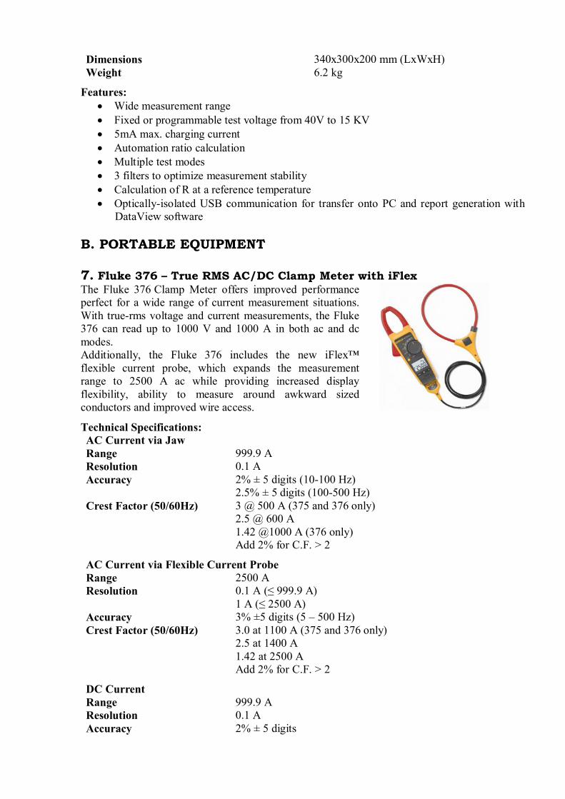
7. Fluke 376 – True RMS AC/DC Clamp Meter with iFlexThe Fluke 376 Clamp Meter offers improved performanceperfect for a wide range of current measurement situations.With true-rms voltage and current measurements, the Fluke376 can read up to 1000 V and 1000 A in both ac and dcmodes.Additionally, the Fluke 376 includes the new iFlex™flexible current probe, which expands the measurementrange to 2500 A ac while providing increased displayflexibility, ability to measure around awkward sizedconductors and improved wire access.
Technical Specifications:AC Current via JawRange 999.9 AResolution 0.1 AAccuracy 2% ± 5 digits (10-100 Hz)
2.5% ± 5 digits (100-500 Hz)Crest Factor (50/60Hz) 3 @ 500 A (375 and 376 only)
2.5 @ 600 A1.42 @1000 A (376 only)Add 2% for C.F. > 2
AC Current via Flexible Current ProbeRange 2500 AResolution 0.1 A (≤ 999.9 A)
1 A (≤ 2500 A)Accuracy 3% ±5 digits (5 – 500 Hz)Crest Factor (50/60Hz) 3.0 at 1100 A (375 and 376 only)
2.5 at 1400 A1.42 at 2500 AAdd 2% for C.F. > 2
DC CurrentRange 999.9 AResolution 0.1 AAccuracy 2% ± 5 digits
AC VoltageRange 1000 VResolution 0.1 V (<600V)
1 V (<1000V)Accuracy 1.5% ± 5 digits (20 – 500 Hz)
DC VoltageRange 1000 VResolution 0.2 V (<600V)
1 V (<1000V)Accuracy 1% ± 5 digits
mV dcRange 500 mVResolution 0.1 mVAccuracy 1% ± 5 digits
Frequency via JawRange 5.0 - 500.0 HzResolution 0.1 HzAccuracy 0.5% ± 5 digitsTrigger Level 5 – 10 Hz, ≥10 A
10 – 100 Hz, ≥5 A100 – 500 Hz, ≥10 A
Frequency via Flexible Current ProbeRange 5.0 - 500.0 HzResolution 0.1 HzAccuracy 0.5% ± 5 digitsTrigger Level 5 – 20 Hz, ≥25 A
20 – 100 Hz, ≥20 A100 – 500 Hz, ≥25 A
ResistanceRange 60 kΩResolution 0.1 Ω (≤ 600 Ω)
1Ω (≤ 6000 Ω)10 Ω (≤ 60 kΩ)
Accuracy 1% ± 5 digits
CapacitanceRange 1000 µFResolution 0.1 μF (≤ 100 μF)
1 μ F (≤ 1000 μF)Accuracy 1% ± 5 digits
Size 246x83x43mmWeight 388mJaw Opening 34mmOperating Temperature 10°C to +50°COperating Humidity ≤ 90% RH (at 10°C to 30°C)
≤ 75% RH (at 30°C to 40°C)≤ 45% RH (at 40°C to 50°C)
Features:· iFlex flexible current probe expands the measurement range to 2500 A AC
· CAT IV 600 V, CAT III 1000 V· True RMS AC voltage and current for accurate measurements on non-linear signals· Min, max, average and inrush recording to capture variations automatically· Integrated low pass filter and state of the art signal processing allows for use in
noisy electrical environments while providing stable readings· Proprietary inrush measurement technology to filter out noise and capture motor
starting current exactly as the circuit protection sees it· Ergonomic design fits in your hand and can be used while wearing protective
equipment· Large, easy to read backlight display automatically sets the correct measurement
range so you do not need to change the switch positions while taking ameasurement
C. OPTIONAL EQUIPMENT
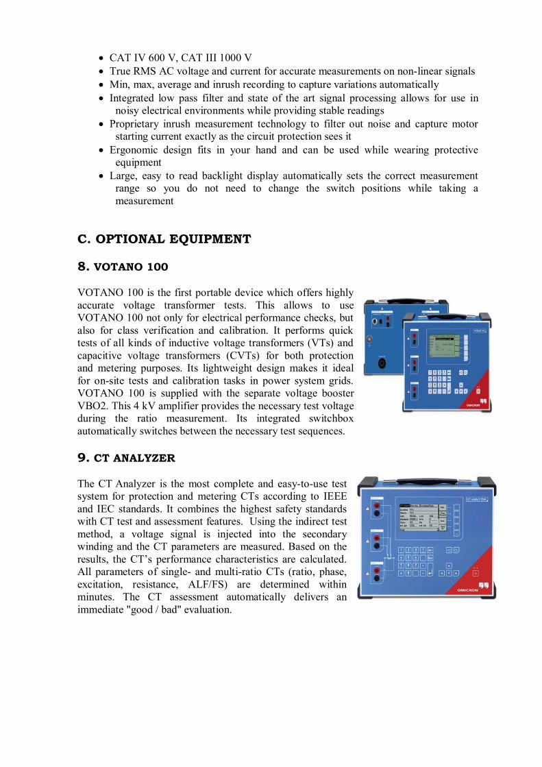
8. VOTANO 100
VOTANO 100 is the first portable device which offers highlyaccurate voltage transformer tests. This allows to useVOTANO 100 not only for electrical performance checks, butalso for class verification and calibration. It performs quicktests of all kinds of inductive voltage transformers (VTs) andcapacitive voltage transformers (CVTs) for both protectionand metering purposes. Its lightweight design makes it idealfor on-site tests and calibration tasks in power system grids.VOTANO 100 is supplied with the separate voltage boosterVBO2. This 4 kV amplifier provides the necessary test voltageduring the ratio measurement. Its integrated switchboxautomatically switches between the necessary test sequences.
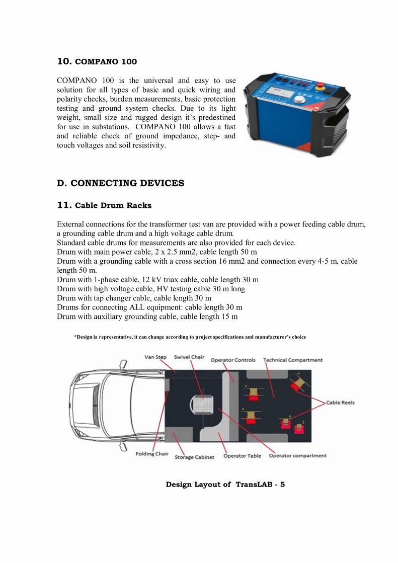
9. CT ANALYZER
The CT Analyzer is the most complete and easy-to-use testsystem for protection and metering CTs according to IEEEand IEC standards. It combines the highest safety standardswith CT test and assessment features. Using the indirect testmethod, a voltage signal is injected into the secondarywinding and the CT parameters are measured. Based on theresults, the CT’s performance characteristics are calculated.All parameters of single- and multi-ratio CTs (ratio, phase,excitation, resistance, ALF/FS) are determined withinminutes. The CT assessment automatically delivers animmediate "good / bad" evaluation.
10. COMPANO 100
COMPANO 100 is the universal and easy to usesolution for all types of basic and quick wiring andpolarity checks, burden measurements, basic protectiontesting and ground system checks. Due to its lightweight, small size and rugged design it’s predestinedfor use in substations. COMPANO 100 allows a fastand reliable check of ground impedance, step- andtouch voltages and soil resistivity.
D. CONNECTING DEVICES
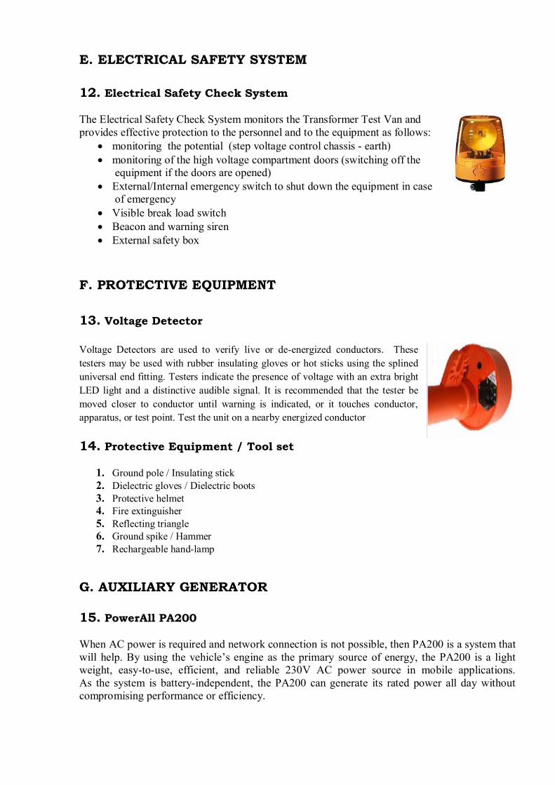
11. Cable Drum Racks
External connections for the transformer test van are provided with a power feeding cable drum,a grounding cable drum and a high voltage cable drum.Standard cable drums for measurements are also provided for each device.Drum with main power cable, 2 x 2.5 mm2, cable length 50 mDrum with a grounding cable with a cross section 16 mm2 and connection every 4-5 m, cablelength 50 m.Drum with 1-phase cable, 12 kV triax cable, cable length 30 mDrum with high voltage cable, HV testing cable 30 m longDrum with tap changer cable, cable length 30 mDrums for connecting ALL equipment: cable length 30 mDrum with auxiliary grounding cable, cable length 15 m
*Design ia representative, it can change according to project specifications and manufacturer’s choice
Design Layout of TransLAB - 5
E. ELECTRICAL SAFETY SYSTEM
12. Electrical Safety Check System
The Electrical Safety Check System monitors the Transformer Test Van andprovides effective protection to the personnel and to the equipment as follows:
· monitoring the potential (step voltage control chassis - earth)· monitoring of the high voltage compartment doors (switching off the
equipment if the doors are opened)· External/Internal emergency switch to shut down the equipment in case
of emergency· Visible break load switch· Beacon and warning siren· External safety box
F. PROTECTIVE EQUIPMENT
13. Voltage Detector
Voltage Detectors are used to verify live or de-energized conductors. Thesetesters may be used with rubber insulating gloves or hot sticks using the splineduniversal end fitting. Testers indicate the presence of voltage with an extra brightLED light and a distinctive audible signal. It is recommended that the tester bemoved closer to conductor until warning is indicated, or it touches conductor,apparatus, or test point. Test the unit on a nearby energized conductor
14. Protective Equipment / Tool set
1. Ground pole / Insulating stick2. Dielectric gloves / Dielectric boots3. Protective helmet4. Fire extinguisher5. Reflecting triangle6. Ground spike / Hammer7. Rechargeable hand-lamp
G. AUXILIARY GENERATOR
15. PowerAll PA200
When AC power is required and network connection is not possible, then PA200 is a system thatwill help. By using the vehicle’s engine as the primary source of energy, the PA200 is a lightweight, easy-to-use, efficient, and reliable 230V AC power source in mobile applications.As the system is battery-independent, the PA200 can generate its rated power all day withoutcompromising performance or efficiency.
Technical Specifications:Rated Voltage 230 VRated Current 30 ARated power 7350 VARated Frequency 50/60 HzConstruction Class 1Cabinet Black powder coated steelDimensions 393 x 183 x 160mmWeight 6.5 kg
Features:· Continuously rated – generate power all day with no need to refuel· Light weight – typically 87% lower than a generator, increasing available payload· Less space requirement – typically 98% less volume than a generator· Low engine revs (typically 1250 rpm) to reduce fuel consumption and clean exhaust emissions· CE marked and fully EMC compliant
H. Vehicle
16. Chassis: Iveco Daily, Mercedes Sprinter, VW crafter etc.
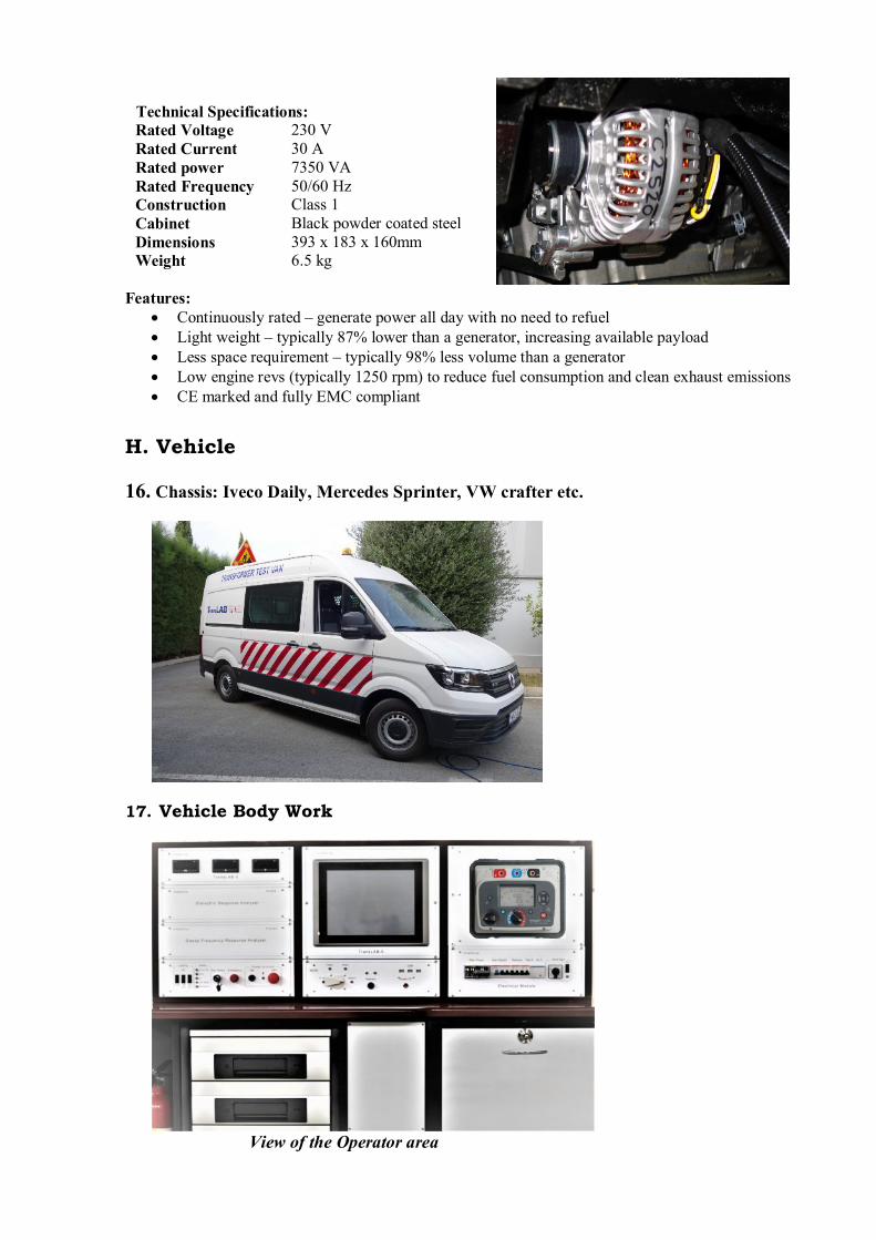
17. Vehicle Body Work
View of the Operator area

The test van is designed to be easy to operate and service. It is equipped with high qualityinsulated wall panelling and air conditioning. The body is divided into technical and operatorcompartments separated by a partition wall. The technical compartment includes all thenecessary tools and equipment for carrying out testing and inspections. Safety is an importantfeature of the test vans and hence all equipment is properly mounted and secured for transit.
View of drawer installation for TESTRANO 600
The operator compartment provides a pleasant environment to work in with more room andplenty of storage. It is equipped with cabinetry and workbenches that increase the operators’efficiency and productivity.
View of the Technical area
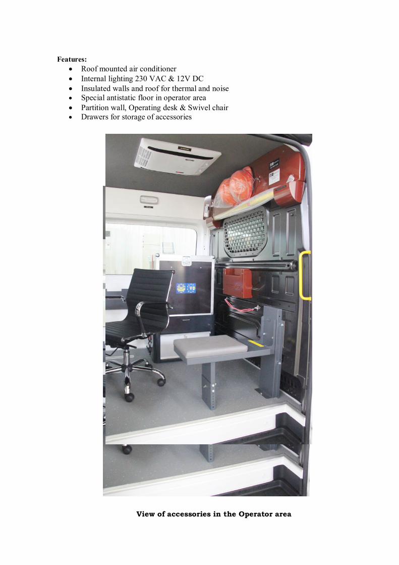
Features:· Roof mounted air conditioner· Internal lighting 230 VAC & 12V DC· Insulated walls and roof for thermal and noise· Special antistatic floor in operator area· Partition wall, Operating desk & Swivel chair· Drawers for storage of accessories
View of accessories in the Operator area
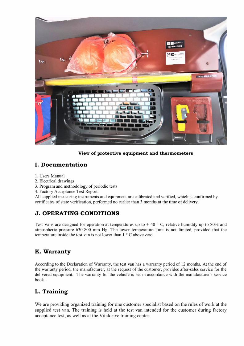
View of protective equipment and thermometers
I. Documentation
1. Users Manual2. Electrical drawings3. Program and methodology of periodic tests4. Factory Acceptance Test ReportAll supplied measuring instruments and equipment are calibrated and verified, which is confirmed bycertificates of state verification, performed no earlier than 3 months at the time of delivery.
J. OPERATING CONDITIONS
Test Vans are designed for operation at temperatures up to + 40 ° С, relative humidity up to 80% andatmospheric pressure 630-800 mm Hg. The lower temperature limit is not limited, provided that thetemperature inside the test van is not lower than 1 ° C above zero.
K. Warranty
According to the Declaration of Warranty, the test van has a warranty period of 12 months. At the end ofthe warranty period, the manufacturer, at the request of the customer, provides after-sales service for thedelivered equipment. The warranty for the vehicle is set in accordance with the manufacturer's servicebook.
L. Training
We are providing organized training for one customer specialist based on the rules of work at thesupplied test van. The training is held at the test van intended for the customer during factoryacceptance test, as well as at the Vitaldrive training center.
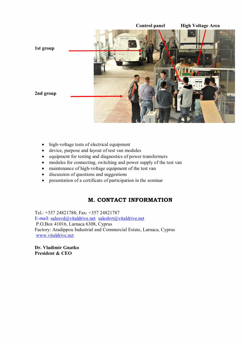
Control panel High Voltage Area
1st group
2nd group
· high-voltage tests of electrical equipment· device, purpose and layout of test van modules· equipment for testing and diagnostics of power transformers· modules for connecting, switching and power supply of the test van· maintenance of high-voltage equipment of the test van· discussion of questions and suggestions· presentation of a certificate of participation in the seminar
M. CONTACT INFORMATION
Tel.: +357 24821788; Fax: +357 24821787E-mail: [email protected] [email protected] P.O.Box 41016, Larnaca 6308, CyprusFactory: Aradippou Industrial and Commercial Estate, Larnaca, Cypruswww.vitaldrive.net
Dr. Vladimir GnatkoPresident & CEO
Related Documents