Relion ® 650 SERIES Transformer protection RET650 Version 1.1 IEC Product guide

Welcome message from author
This document is posted to help you gain knowledge. Please leave a comment to let me know what you think about it! Share it to your friends and learn new things together.
Transcript

Relion® 650 SERIES
Transformer protection RET650Version 1.1 IECProduct guide
Contents
1. 650 series overview............................................................. 3
2. Application............................................................................. 3
3. Available functions...............................................................8
4. Differential protection...................................................... 13
5. Current protection............................................................. 14
6. Voltage protection............................................................. 15
7. Frequency protection........................................................16
8. Secondary system supervision....................................... 16
9. Control.................................................................................. 16
10. Logic..................................................................................... 17
11. Monitoring.......................................................................... 18
12. Metering..............................................................................20
13. Human Machine interface.............................................. 20
14. Basic IED functions...........................................................21
15. Station communication...................................................21
16. Hardware description......................................................22
17. Connection diagrams......................................................24
18. Technical data....................................................................25
19. Ordering..............................................................................50
Disclaimer
The information in this document is subject to change without notice and should not be construed as a commitment by ABB Power Grids. ABB Power
Grids assumes no responsibility for any errors that may appear in this document. Drawings and diagrams are not binding.
© Copyright 2011 ABB Power Grids. All rights reserved.
Trademarks
ABB and Relion are registered trademarks of the ABB Group. All other brand or product names mentioned in this document may be trademarks or
registered trademarks of their respective holders.
Transformer protection RET650 1MRK 504 127-BEN BVersion 1.1 IEC
2 ABB Power Grids
1. 650 series overviewGUID-420ACE74-2F34-4991-8DA3-967843F6BFFF v1
The 650 series IEDs provide optimum 'off-the-shelf',ready-to-use solutions. It is configured with completeprotection functionality and default parameters to meetthe needs of a wide range of applications for generationtransmission and sub-transmission grids.
The 650 series IEDs include:• Complete ready-made solutions optimized for a wide
range of applications for generation, transmission andsub-transmission grids.
• Support for user-defined names in the local languagefor signal and function engineering.
• Minimized parameter setting based on default valuesand ABB's new global base value concept. You onlyneed to set those parameters specific to your ownapplication, such as the line data.
• GOOSE messaging for horizontal communication.• Extended HMI functionality with 15 dynamic three-
color-indication LEDs per page, on up to three pages,and configurable push-button shortcuts for differentactions.
• Programmable LED text-based labels.• Settable 1A/5A -rated current inputs.
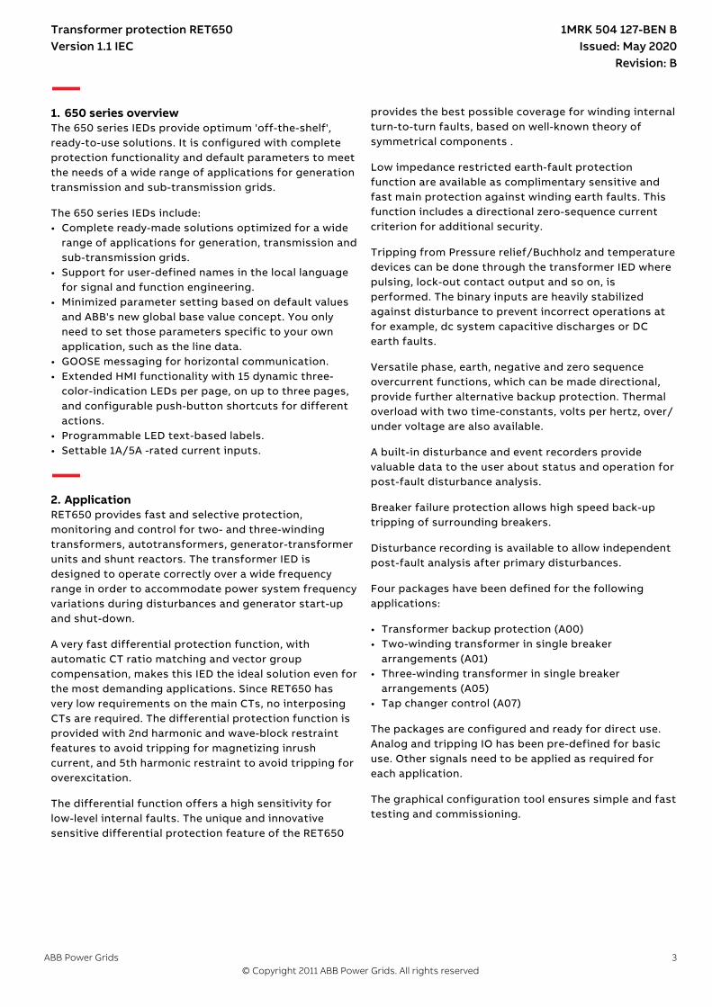
2. ApplicationM16637-3 v6
RET650 provides fast and selective protection,monitoring and control for two- and three-windingtransformers, autotransformers, generator-transformerunits and shunt reactors. The transformer IED isdesigned to operate correctly over a wide frequencyrange in order to accommodate power system frequencyvariations during disturbances and generator start-upand shut-down.
A very fast differential protection function, withautomatic CT ratio matching and vector groupcompensation, makes this IED the ideal solution even forthe most demanding applications. Since RET650 hasvery low requirements on the main CTs, no interposingCTs are required. The differential protection function isprovided with 2nd harmonic and wave-block restraintfeatures to avoid tripping for magnetizing inrushcurrent, and 5th harmonic restraint to avoid tripping foroverexcitation.
The differential function offers a high sensitivity forlow-level internal faults. The unique and innovativesensitive differential protection feature of the RET650
provides the best possible coverage for winding internalturn-to-turn faults, based on well-known theory ofsymmetrical components .
Low impedance restricted earth-fault protectionfunction are available as complimentary sensitive andfast main protection against winding earth faults. Thisfunction includes a directional zero-sequence currentcriterion for additional security.
Tripping from Pressure relief/Buchholz and temperaturedevices can be done through the transformer IED wherepulsing, lock-out contact output and so on, isperformed. The binary inputs are heavily stabilizedagainst disturbance to prevent incorrect operations atfor example, dc system capacitive discharges or DCearth faults.
Versatile phase, earth, negative and zero sequenceovercurrent functions, which can be made directional,provide further alternative backup protection. Thermaloverload with two time-constants, volts per hertz, over/under voltage are also available.
A built-in disturbance and event recorders providevaluable data to the user about status and operation forpost-fault disturbance analysis.
Breaker failure protection allows high speed back-uptripping of surrounding breakers.
Disturbance recording is available to allow independentpost-fault analysis after primary disturbances.
SEMOD51222-5 v5.1.1
Four packages have been defined for the followingapplications:
• Transformer backup protection (A00)• Two-winding transformer in single breaker
arrangements (A01)• Three-winding transformer in single breaker
arrangements (A05)• Tap changer control (A07)
The packages are configured and ready for direct use.Analog and tripping IO has been pre-defined for basicuse. Other signals need to be applied as required foreach application.
The graphical configuration tool ensures simple and fasttesting and commissioning.
Transformer protection RET650Version 1.1 IEC
1MRK 504 127-BEN BIssued: May 2020
Revision: B
ABB Power Grids 3© Copyright 2011 ABB Power Grids. All rights reserved
T2W PDIF
87T 3Id/I
T2W PDIF
87T 3Id/I
CC RBRF
50BF 3I> BF
CC RBRF
50BF 3I> BF
CC RBRF
50BF 3I> BF
CC RBRF
50BF 3I> BF
OC4 PTOC
50/51 3I>
OC4 PTOC
50/51 3I>
OC4 PTOC
50/51 3I>
OC4 PTOC
50/51 3I>
CC RPLD
52PD PD
CC RPLD
52PD PD
EF4 PTOC
51N IN>
EF4 PTOC
51N IN>
CC RPLD
52PD PD
CC RPLD
52PD PD
TR PTTR
49 Ith
TR PTTR
49 Ith
C MSQI
Meter.
C MSQI
Meter.
V MMXU
Meter.
V MMXU
Meter.
C MMXU
Meter.
C MMXU
Meter.
CV MMXN
Meter.
CV MMXN
Meter.
TCS SCBR
Cond
TCS SCBR
Cond
TCS SCBR
Cond
TCS SCBR
Cond
SPVN ZBAT
Cond
SPVN ZBAT
Cond
UV2 PTUV
27 U<
UV2 PTUV
27 U<
OV2 PTOV
59 U>
OV2 PTOV
59 U>
PH PIOC
50 3I>>
PH PIOC
50 3I>>
TR PTTR
49 Ith
TR PTTR
49 Ith
REF PDIF
87N IdN/I
REF PDIF
87N IdN/I
Other configured functions
REF PDIF
87N IdN/I
REF PDIF
87N IdN/I
EF4 PTOC
51N/67N IN>
EF4 PTOC
51N/67N IN>
DRP RDRE
Mont.
DRP RDRE
Mont.
YY
Y
Y
ROV2 PTOV
59N 3U0>
ROV2 PTOV
59N 3U0>
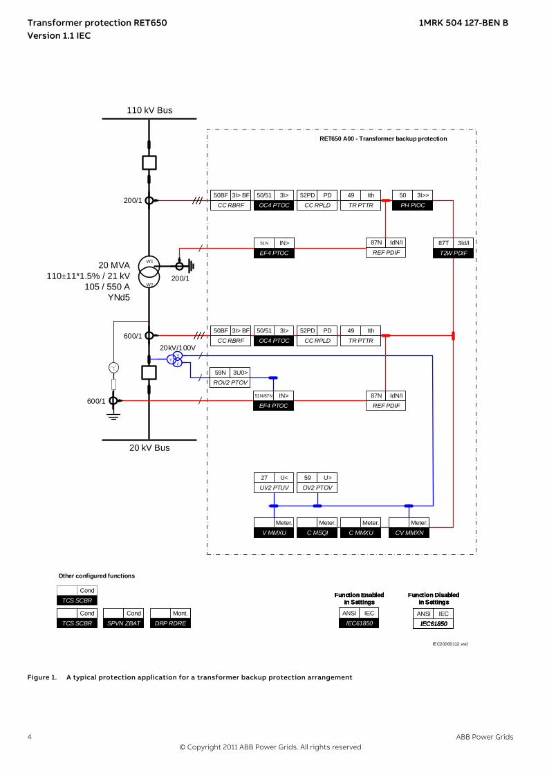
RET650 A00 - Transformer backup protection
20 MVA
110±11*1.5% / 21 kV
105 / 550 A
YNd5
20 kV Bus
110 kV Bus
200/1
600/1
20kV/100V
200/1
600/1
IEC61850
ANSI IEC
IEC61850
ANSI IEC
Function Enabled in Settings
IEC61850
ANSI IEC
Function Enabled in Settings
IEC61850
ANSI IEC
IEC61850
ANSI IEC
Function Disabled in Settings
IEC61850
ANSI IEC
Function Disabled in Settings
IEC61850
ANSI IEC
Function Enabled in Settings
IEC61850
ANSI IEC
Function Disabled in Settings
W1
W2
IEC20000112.vsd
IEC20000112 V1 EN-US
Figure 1. A typical protection application for a transformer backup protection arrangement
Transformer protection RET650 1MRK 504 127-BEN BVersion 1.1 IEC
4 ABB Power Grids© Copyright 2011 ABB Power Grids. All rights reserved

T2W PDIF
87T 3Id/I
CC RBRF
50BF 3I> BF
CC RBRF
50BF 3I> BF
OC4 PTOC
50/51 3I>
OC4 PTOC
51/67 3I>
CC RPLD
52PD PD
EF4 PTOC
51N IN>
CC RPLD
52PD PDTR PTTR
49 Ith
C MSQI
Meter.V MMXU
Meter.C MMXU
Meter.CV MMXN
Meter.
TCS SCBR
Cond
TCS SCBR
Cond
SPVN ZBAT
Cond
TR8 ATCC
90 U
TCM YLTC
84
UV2 PTUV
27 U<OV2 PTOV
59 U>
PH PIOC
50 3I>>TR PTTR
49 Ith
REF PDIF
87N IdN/I
Other configured functions
REF PDIF
87N IdN/IEF4 PTOC
51N/67N IN>
DRP RDRE
Mont.
YY
¨
ROV2 PTOV
59N 3U0>
RET650 A01 - 2 Winding Transformer protection 10AI (8I+2U)
20 MVA110±11*1.5% / 21 kV
105 / 550 AYNd5
20 kV Bus
110 kV Bus
200/1
600/120kV/100V
200/1
600/1
IEC61850
ANSI IEC
Function Enabled in Settings
IEC61850
ANSI IEC
Function Disabled in Settings
W1
W2
IEC09000645-2-en.vsdIEC09000645 V2 EN-US
Figure 2. A typical protection application for a two-winding transformer in single breaker arrangement
Transformer protection RET650 1MRK 504 127-BEN BVersion 1.1 IEC
ABB Power Grids 5© Copyright 2011 ABB Power Grids. All rights reserved

RET650 A05 - 3 Winding Transformer protection 20AI 2*(6I+4U)
W1
T3W PDIF
87T 3Id/I
CC RBRF
50BF 3I> BF
CC RBRF
50BF 3I> BF
OC4 PTOC
50/51 3I>
OC4 PTOC
51/67 3I>
CC RPLD
52PD PDCC RBRF
50BF 3I> BF
CC RPLD
52PD PD
EF4 PTOC
51N IN>
CC RPLD
52PD PD
TR PTTR
49 Ith
TR PTTR
49 Ith
V MSQI
Meter.C MSQI
Meter.V MMXU
Meter.C MMXU
Meter.CV MMXN
Meter.
V MSQI
Meter.C MSQI
Meter.V MMXU
Meter.C MMXU
Meter.CV MMXN
Meter.
TCS SCBR
Cond
TCS SCBR
Cond
TCS SCBR
Cond
SPVN ZBAT
Cond
TR8 ATCC
90 U
TCM YLTC
84
UV2 PTUV
27 U<OV2 PTOV
59 U>
PH PIOC
50 3I>>TR PTTR
49 Ith
REF PDIF
87N IdN/I
Other configured functions
REF PDIF
87N IdN/I
REF PDIF
87N IdN/I
OEX PVPH
24 U/f>
OC4 PTOC
51/67 3I>
EF4 PTOC
51N/67N IN>
EF4 PTOC
51N/67N IN>
DRP RDRE
Mont.
CV MMXN
Meter.
YY
¨
ROV2 PTOV
59N 3UO>
35 kV Bus
110 kV Bus
10 kV Bus
IEC61850
ANSI IEC
Function Enabled in Settings
IEC61850
ANSI IEC
Function Disabled in Settings
Transformer Data:40/40/15 MVA
110±11*1.5% / 36.75 / 10.5 kV210/628/825 A
YNyn0d5
110kV/100V
300/1
1000/1
800/1
800/1
300/1
10kV/100V
35kV/100V
1000/1W3 W2
IEC09000646-2-en.vsdIEC09000646 V2 EN-US
Figure 3. A typical protection application for a three-winding transformer in single breaker arrangement
Transformer protection RET650 1MRK 504 127-BEN BVersion 1.1 IEC
6 ABB Power Grids© Copyright 2011 ABB Power Grids. All rights reserved
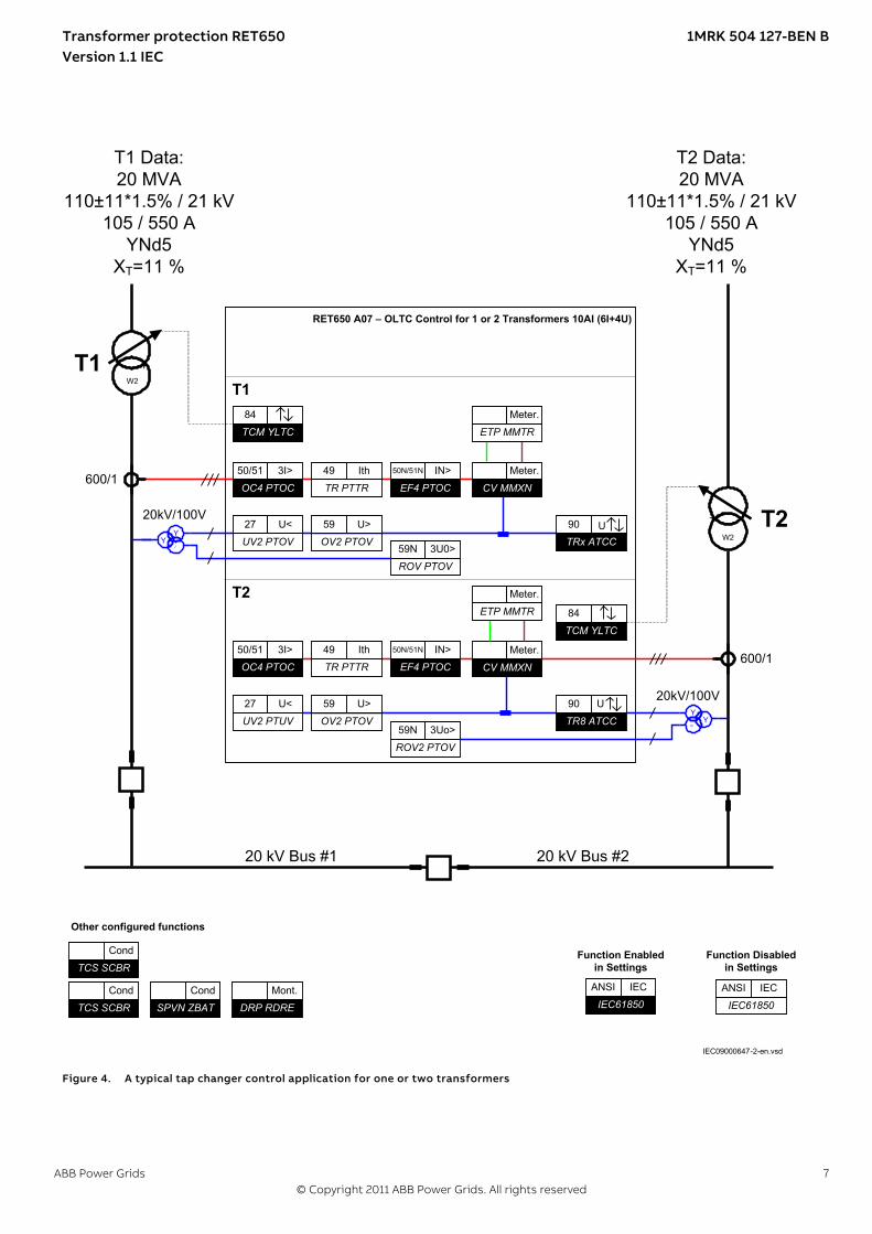
RET650 A07 – OLTC Control for 1 or 2 Transformers 10AI (6I+4U)
TR PTTR
49 IthEF4 PTOC
50N/51N IN>CV MMXN
Meter.
T1
OC4 PTOC
50/51 3I>
ETP MMTR
Meter.
ROV PTOV
59N 3U0>
T2TRx ATCC
90 UUV2 PTOV
27 U<OV2 PTOV
59 U>
TR PTTR
49 IthEF4 PTOC
50N/51N IN>
CV MMXN
Meter.OC4 PTOC
50/51 3I>
ETP MMTR
Meter.
ROV2 PTOV
59N 3Uo>TR8 ATCC
90 UUV2 PTUV
27 U<OV2 PTOV
59 U>
T1
T2
YY
°
YY
°
TCM YLTC
84
TCM YLTC
84
TCS SCBR
Cond
TCS SCBR
Cond
SPVN ZBAT
Cond
Other configured functions
DRP RDRE
Mont.
T1 Data:20 MVA
110±11*1.5% / 21 kV105 / 550 A
YNd5XT=11 %
T2 Data:20 MVA
110±11*1.5% / 21 kV105 / 550 A
YNd5XT=11 %
20 kV Bus #1 20 kV Bus #2
IEC61850
ANSI IEC
Function Enabled in Settings
IEC61850
ANSI IEC
Function Disabled in Settings
600/1
20kV/100V
600/1
20kV/100V
W2
W2
IEC09000647-2-en.vsdIEC09000647 V2 EN-US
Figure 4. A typical tap changer control application for one or two transformers
Transformer protection RET650 1MRK 504 127-BEN BVersion 1.1 IEC
ABB Power Grids 7© Copyright 2011 ABB Power Grids. All rights reserved
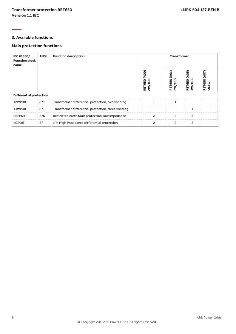
3. Available functions
Main protection functionsGUID-35C75FDE-9C6C-44CE-8BDB-6CCB9541EDFE v2.1.1
IEC 61850/Function blockname
ANSI Function description Transformer
RET
650
(A0
0)
2W/1
CB
RET
650
(A0
1)2W
/1C
B
RET
650
(A0
5)3W
/1C
B
RET
650
(A0
7)O
LTC
Differential protection
T2WPDIF 87T Transformer differential protection, two winding 1 1
T3WPDIF 87T Transformer differential protection, three winding 1
REFPDIF 87N Restricted earth fault protection, low impedance 2 2 3
HZPDIF 87 1Ph High impedance differential protection 2 2 2
Transformer protection RET650 1MRK 504 127-BEN BVersion 1.1 IEC
8 ABB Power Grids© Copyright 2011 ABB Power Grids. All rights reserved
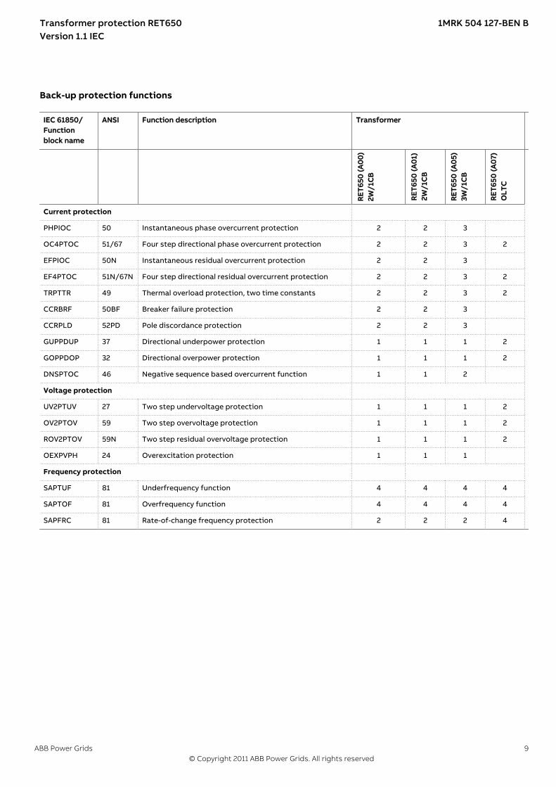
Back-up protection functionsGUID-47D5EAC9-5F4A-4A3D-B813-4E50A2BCCDC3 v2.1.1
IEC 61850/Functionblock name
ANSI Function description Transformer
RET
650
(A0
0)
2W/1
CB
RET
650
(A0
1)2W
/1C
B
RET
650
(A0
5)3W
/1C
B
RET
650
(A0
7)O
LTC
Current protection
PHPIOC 50 Instantaneous phase overcurrent protection 2 2 3
OC4PTOC 51/67 Four step directional phase overcurrent protection 2 2 3 2
EFPIOC 50N Instantaneous residual overcurrent protection 2 2 3
EF4PTOC 51N/67N Four step directional residual overcurrent protection 2 2 3 2
TRPTTR 49 Thermal overload protection, two time constants 2 2 3 2
CCRBRF 50BF Breaker failure protection 2 2 3
CCRPLD 52PD Pole discordance protection 2 2 3
GUPPDUP 37 Directional underpower protection 1 1 1 2
GOPPDOP 32 Directional overpower protection 1 1 1 2
DNSPTOC 46 Negative sequence based overcurrent function 1 1 2
Voltage protection
UV2PTUV 27 Two step undervoltage protection 1 1 1 2
OV2PTOV 59 Two step overvoltage protection 1 1 1 2
ROV2PTOV 59N Two step residual overvoltage protection 1 1 1 2
OEXPVPH 24 Overexcitation protection 1 1 1
Frequency protection
SAPTUF 81 Underfrequency function 4 4 4 4
SAPTOF 81 Overfrequency function 4 4 4 4
SAPFRC 81 Rate-of-change frequency protection 2 2 2 4
Transformer protection RET650 1MRK 504 127-BEN BVersion 1.1 IEC
ABB Power Grids 9© Copyright 2011 ABB Power Grids. All rights reserved
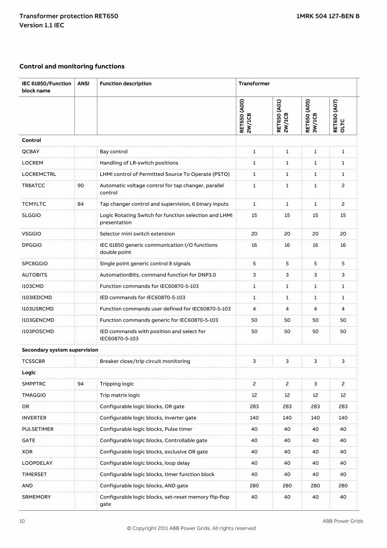
Control and monitoring functionsGUID-C4EC0541-2883-4185-90AB-BAEB25A5E249 v2.1.1
IEC 61850/Functionblock name
ANSI Function description Transformer
RET
650
(A0
0)
2W/1
CB
RET
650
(A0
1)2W
/1C
B
RET
650
(A0
5)3W
/1C
B
RET
650
(A0
7)O
LTC
Control
QCBAY Bay control 1 1 1 1
LOCREM Handling of LR-switch positions 1 1 1 1
LOCREMCTRL LHMI control of Permitted Source To Operate (PSTO) 1 1 1 1
TR8ATCC 90 Automatic voltage control for tap changer, parallelcontrol
1 1 1 2
TCMYLTC 84 Tap changer control and supervision, 6 binary inputs 1 1 1 2
SLGGIO Logic Rotating Switch for function selection and LHMIpresentation
15 15 15 15
VSGGIO Selector mini switch extension 20 20 20 20
DPGGIO IEC 61850 generic communication I/O functionsdouble point
16 16 16 16
SPC8GGIO Single point generic control 8 signals 5 5 5 5
AUTOBITS AutomationBits, command function for DNP3.0 3 3 3 3
I103CMD Function commands for IEC60870-5-103 1 1 1 1
I103IEDCMD IED commands for IEC60870-5-103 1 1 1 1
I103USRCMD Function commands user defined for IEC60870-5-103 4 4 4 4
I103GENCMD Function commands generic for IEC60870-5-103 50 50 50 50
I103POSCMD IED commands with position and select forIEC60870-5-103
50 50 50 50
Secondary system supervision
TCSSCBR Breaker close/trip circuit monitoring 3 3 3 3
Logic
SMPPTRC 94 Tripping logic 2 2 3 2
TMAGGIO Trip matrix logic 12 12 12 12
OR Configurable logic blocks, OR gate 283 283 283 283
INVERTER Configurable logic blocks, Inverter gate 140 140 140 140
PULSETIMER Configurable logic blocks, Pulse timer 40 40 40 40
GATE Configurable logic blocks, Controllable gate 40 40 40 40
XOR Configurable logic blocks, exclusive OR gate 40 40 40 40
LOOPDELAY Configurable logic blocks, loop delay 40 40 40 40
TIMERSET Configurable logic blocks, timer function block 40 40 40 40
AND Configurable logic blocks, AND gate 280 280 280 280
SRMEMORY Configurable logic blocks, set-reset memory flip-flopgate
40 40 40 40
Transformer protection RET650 1MRK 504 127-BEN BVersion 1.1 IEC
10 ABB Power Grids© Copyright 2011 ABB Power Grids. All rights reserved
IEC 61850/Functionblock name
ANSI Function description Transformer
RET
650
(A0
0)
2W/1
CB
RET
650
(A0
1)2W
/1C
B
RET
650
(A0
5)3W
/1C
B
RET
650
(A0
7)O
LTC
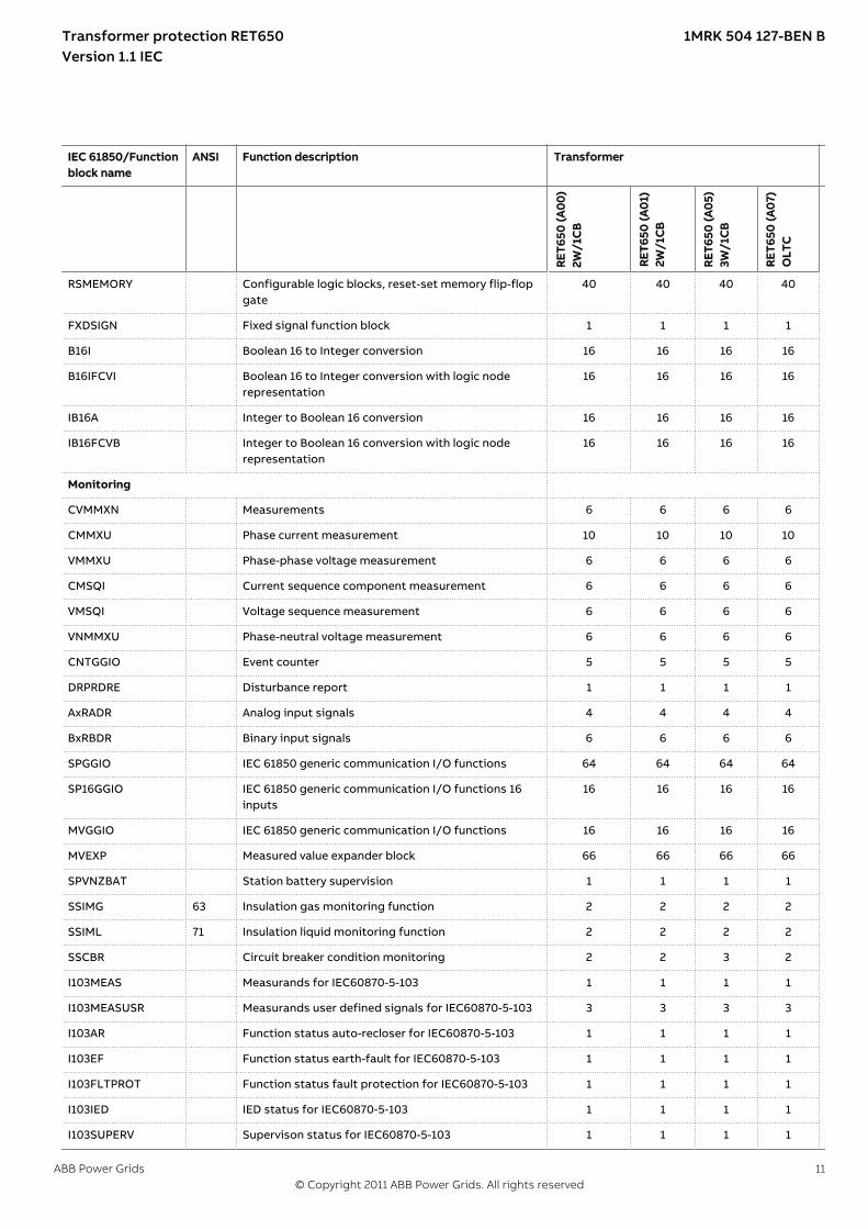
RSMEMORY Configurable logic blocks, reset-set memory flip-flopgate
40 40 40 40
FXDSIGN Fixed signal function block 1 1 1 1
B16I Boolean 16 to Integer conversion 16 16 16 16
B16IFCVI Boolean 16 to Integer conversion with logic noderepresentation
16 16 16 16
IB16A Integer to Boolean 16 conversion 16 16 16 16
IB16FCVB Integer to Boolean 16 conversion with logic noderepresentation
16 16 16 16
Monitoring
CVMMXN Measurements 6 6 6 6
CMMXU Phase current measurement 10 10 10 10
VMMXU Phase-phase voltage measurement 6 6 6 6
CMSQI Current sequence component measurement 6 6 6 6
VMSQI Voltage sequence measurement 6 6 6 6
VNMMXU Phase-neutral voltage measurement 6 6 6 6
CNTGGIO Event counter 5 5 5 5
DRPRDRE Disturbance report 1 1 1 1
AxRADR Analog input signals 4 4 4 4
BxRBDR Binary input signals 6 6 6 6
SPGGIO IEC 61850 generic communication I/O functions 64 64 64 64
SP16GGIO IEC 61850 generic communication I/O functions 16inputs
16 16 16 16
MVGGIO IEC 61850 generic communication I/O functions 16 16 16 16
MVEXP Measured value expander block 66 66 66 66
SPVNZBAT Station battery supervision 1 1 1 1
SSIMG 63 Insulation gas monitoring function 2 2 2 2
SSIML 71 Insulation liquid monitoring function 2 2 2 2
SSCBR Circuit breaker condition monitoring 2 2 3 2
I103MEAS Measurands for IEC60870-5-103 1 1 1 1
I103MEASUSR Measurands user defined signals for IEC60870-5-103 3 3 3 3
I103AR Function status auto-recloser for IEC60870-5-103 1 1 1 1
I103EF Function status earth-fault for IEC60870-5-103 1 1 1 1
I103FLTPROT Function status fault protection for IEC60870-5-103 1 1 1 1
I103IED IED status for IEC60870-5-103 1 1 1 1
I103SUPERV Supervison status for IEC60870-5-103 1 1 1 1
Transformer protection RET650 1MRK 504 127-BEN BVersion 1.1 IEC
ABB Power Grids 11© Copyright 2011 ABB Power Grids. All rights reserved

IEC 61850/Functionblock name
ANSI Function description Transformer
RET
650
(A0
0)
2W/1
CB
RET
650
(A0
1)2W
/1C
B
RET
650
(A0
5)3W
/1C
B
RET
650
(A0
7)O
LTC
I103USRDEF Status for user defined signals for IEC60870-5-103 20 20 20 20
Metering
PCGGIO Pulse counter logic 16 16 16 16
ETPMMTR Function for energy calculation and demand handling 3 3 3 3
Designed to communicateGUID-22F345AB-6250-40E7-9B80-36EA4D8EDA62 v2.2.1
IEC 61850/Functionblock name
ANSI Function description Transformer
RET
650
(A0
0)
2W/1
CB
RET
650
(A0
1)2W
/1C
B
RET
650
(A0
5)3W
/1C
B
RET
650
(A0
7)O
LTC
Station communication
IEC 61850 communication protocol, LAN1 1 1 1 1
DNP3.0 for TCP/IP communication protocol, LAN1 1 1 1 1
IEC61870-5-103 IEC60870-5-103 serial communication via ST 1 1 1 1
GOOSEINTLKRCV Horizontal communication via GOOSE for interlocking 59 59 59 59
GOOSEBINRCV GOOSE binary receive 4 4 4 4
GOOSEVCTRCONF GOOSE VCTR configuration for send and receive 1 1 1 1
VCTRSEND Voltage control sending block for GOOSE 1 1 1 1
GOOSEVCTRRCV Voltage control receiving block for GOOSE 3 3 3 3
GOOSEDPRCV GOOSE function block to receive a double point value 32 32 32 32
GOOSEINTRCV GOOSE function block to receive an integer value 32 32 32 32
GOOSEMVRCV GOOSE function block to receive a mesurand value 16 16 16 16
GOOSESPRCV GOOSE function block to receive a single point value 64 64 64 64
Transformer protection RET650 1MRK 504 127-BEN BVersion 1.1 IEC
12 ABB Power Grids© Copyright 2011 ABB Power Grids. All rights reserved
Basic IED functionsGUID-1DA8FC6E-D726-407B-84D3-0796B00D636F v2
IEC 61850/Functionblock name
Function description
Basic functions included in all products
INTERRSIG Self supervision with internal event list 1
SELFSUPEVLST Self supervision with internal event list 1
SNTP Time synchronization 1
TIMESYNCHGEN Time synchronization 1
DTSBEGIN, DTSEND,TIMEZONE
Time synchronization, daylight saving 1
IRIG-B Time synchronization 1
SETGRPS Setting group handling 1
ACTVGRP Parameter setting groups 1
TESTMODE Test mode functionality 1
CHNGLCK Change lock function 1
TERMINALID IED identifiers 1
PRODINF Product information 1
PRIMVAL Primary system values 1
SMAI_20_1-12 Signal matrix for analog inputs 2
3PHSUM Summation block 3 phase 12
GBASVAL Global base values for settings 6
ATHSTAT Authority status 1
ATHCHCK Authority check 1
FTPACCS FTP access with password 1
DOSFRNT Denial of service, frame rate control for front port 1
DOSLAN1 Denial of service, frame rate control for LAN1 1
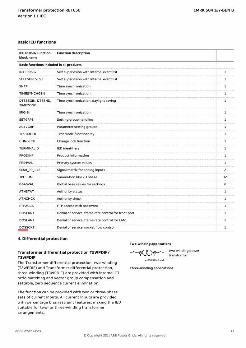
DOSSCKT Denial of service, socket flow control 1
4.
Differential protection
Transformer differential protection T2WPDIF/T3WPDIF
M16104-3 v9
The Transformer differential protection, two-winding(T2WPDIF) and Transformer differential protection,three-winding (T3WPDIF) are provided with internal CTratio matching and vector group compensation andsettable, zero sequence current elimination.
The function can be provided with two or three-phasesets of current inputs. All current inputs are providedwith percentage bias restraint features, making the IEDsuitable for two- or three-winding transformerarrangements.
Two-winding applications
xx05000048.vsdIEC05000048 V1 EN-US
two-winding powertransformer
Three-winding applications
Transformer protection RET650 1MRK 504 127-BEN BVersion 1.1 IEC
ABB Power Grids 13© Copyright 2011 ABB Power Grids. All rights reserved

xx05000052.vsdIEC05000052 V1 EN-US
three-windingpower transformerwith all threewindings connected
xx05000049.vsdIEC05000049 V1 EN-US
three-windingpower transformerwith unconnecteddelta tertiarywinding
Figure 5. CT group arrangement fordifferential protection and otherprotections
The setting facilities cover for applications of thedifferential protection to all types of powertransformers and auto-transformers with or withoutload tap changer as well as for shunt reactors or andlocal feeders within the station. An adaptive stabilizingfeature is included for heavy through-faults.
Stabilization is included for inrush currents as well as foroverexcitation condition. Adaptive stabilization is alsoincluded for system recovery inrush and CT saturationfor external faults. A high set unrestrained differentialcurrent protection is included for a very high speedtripping at a high internal fault currents.
An innovative sensitive differential protection feature,based on the theory of symmetrical components, offersthe best possible coverage for power transformerwinding turn-to-turn faults.
Restricted earth fault protection REFPDIFRestricted earth fault protection, low impedance REFPDIF
M13047-3 v7
Restricted earth-fault protection, low-impedancefunction (REFPDIF) can be used on all directly or low-impedance earthed windings. The REFPDIF function canprovide higher sensitivity (down to 5%) and higherspeed as it measures each winding individually and thusdoes not need inrush stabilization.
The low-impedance function is a percentage biasedfunction with an additional zero sequence currentdirectional comparison criterion. This gives excellentsensitivity and stability for through faults. The functionallows use of different CT ratios and magnetizingcharacteristics on the phase and neutral CT cores andmixing with other functions and protection IEDs on thesame cores.
1Ph High impedance differential protection HZPDIFM13071-3 v7
The 1Ph High impedance differential protection HZPDIFfunction can be used when the involved CT cores havethe same turn ratio and similar magnetizing
characteristics. It utilizes an external summation of thecurrents in the interconnected CTs and a series resistorand a voltage dependent resistor externally to the IED.
HZPDIF can be used as high impedance REF protection.
5. Current protection
Instantaneous phase overcurrent protection PHPIOCM12910-3 v7
The instantaneous three phase overcurrent function hasa low transient overreach and short tripping time toallow use as a high set short-circuit protection function.
Four step phase overcurrent protection OC4PTOCM12846-3 v8
The four step phase overcurrent protection functionOC4PTOC has an inverse or definite time delayindependent for step 1 and 4 separately. Step 2 and 3are always definite time delayed.
All IEC and ANSI time delayed characteristics areavailable.
The directional function is voltage polarized withmemory. The function can be set to be directional ornon-directional independently for each of the steps.
Instantaneous residual overcurrent protectionEFPIOC
M12701-3 v8
The Instantaneous residual overcurrent protectionEFPIOC has a low transient overreach and short trippingtimes to allow use for instantaneous earth-faultprotection, with the reach limited to less than typicaleighty percent of the transformer impedance atminimum source impedance. EFPIOC can be configuredto measure the residual current from the three-phasecurrent inputs or the current from a separate currentinput. EFPIOC can be blocked by activating the inputBLOCK.
Four step residual overcurrent protection EF4PTOCM13667-3 v10
The four step residual overcurrent protection (EF4PTOC)has a settable inverse or definite time delayindependent for step 1 and 4 separately. Step 2 and 3are always definite time delayed.
All IEC and ANSI time delayed characteristics areavailable.
The directional function is voltage polarized, currentpolarized or dual polarized.
EF4PTOC can be set directional or non-directionalindependently for each of the steps.
A second harmonic blocking can be set individually foreach step.
Transformer protection RET650 1MRK 504 127-BEN BVersion 1.1 IEC
14 ABB Power Grids© Copyright 2011 ABB Power Grids. All rights reserved

Thermal overload protection, two time constantTRPTTR
M13243-3 v7
If a power transformer or generator reaches very hightemperatures the equipment might be damaged. Theinsulation within the transformer/generator will haveforced ageing. As a consequence of this the risk ofinternal phase-to-phase or phase-to-earth faults willincrease. High temperature will degrade the quality ofthe transformer/generator insulation.
The thermal overload protection estimates the internalheat content of the transformer/generator(temperature) continuously. This estimation is made byusing a thermal model of the transformer/generatorwith two time constants, which is based on currentmeasurement.
Two warning levels are available. This enables actions inthe power system to be done before dangeroustemperatures are reached. If the temperature continuesto increase to the trip value, the protection initiates atrip of the protected transformer/generator.
Breaker failure protection CCRBRFM11550-6 v8
Breaker failure protection (CCRBRF) ensures fast back-up tripping of surrounding breakers in case the ownbreaker failure to open. CCRBRF can be current based,contact based, or an adaptive combination of these twoprinciples.
A current check with extremely short reset time is usedas check criterion to achieve a high security againstunnecessary operation.
A contact check criteria can be used where the faultcurrent through the breaker is small.
Breaker failure protection (CCRBRF) current criteria canbe fulfilled by one or two phase currents, or one phasecurrent plus residual current. When those currentsexceed the user defined settings, the function isactivated. These conditions increase the security of theback-up trip command.
CCRBRF function can be programmed to give a three-phase re-trip of the own breaker to avoid unnecessarytripping of surrounding breakers at an incorrectinitiation due to mistakes during testing.
Pole discordance protection CCRPLDM13269-3 v9
Circuit breakers and disconnectors can end up with thepoles in different positions (close-open), due toelectrical or mechanical failures. This can cause negativeand zero sequence currents which cause thermal stresson rotating machines and can cause unwantedoperation of zero sequence or negative sequencecurrent functions.
Normally the own breaker is tripped to correct such asituation. If the situation persists the surroundingbreakers should be tripped to clear the unsymmetricalload situation.
The pole discordance function operates based oninformation from the circuit breaker logic withadditional criteria from unsymmetrical phase currentswhen required.
Directional over/underpower protection GOPPDOP/GUPPDUP
SEMOD175421-4 v4
The directional over-/under-power protectionGOPPDOP/GUPPDUP can be used wherever a high/lowactive, reactive or apparent power protection oralarming is required. The functions can alternatively beused to check the direction of active or reactive powerflow in the power system. There are a number ofapplications where such functionality is needed. Someof them are:
• detection of reversed active power flow• detection of high reactive power flow
Each function has two steps with definite time delay.Reset times for both steps can be set as well.
Negative sequence based overcurrent functionDNSPTOC
GUID-CFD34404-5934-41EE-8AAC-A5FD2B9B4E33 v2
Negative sequence based overcurrent function(DNSPTOC) is typically used as sensitive earth-faultprotection of power lines, where incorrect zerosequence polarization may result from mutual inductionbetween two or more parallel lines.
Additionally, it is applied in applications on undergroundcables, where zero sequence impedance depends on thefault current return paths, but the cable negativesequence impedance is practically constant.
The directional function is current and voltage polarized.The function can be set to forward, reverse or non-directional independently for each step.
DNSPTOC protects against all unbalanced faultsincluding phase-to-phase faults. The minimum startcurrent of the function must be set to above the normalsystem unbalance level in order to avoid unintentionalfunctioning.
6. Voltage protection
Two step undervoltage protection UV2PTUVM13789-3 v7
Undervoltages can occur in the power system duringfaults or abnormal conditions. Two step undervoltageprotection (UV2PTUV) function can be used to opencircuit breakers to prepare for system restoration at
Transformer protection RET650 1MRK 504 127-BEN BVersion 1.1 IEC
ABB Power Grids 15© Copyright 2011 ABB Power Grids. All rights reserved

power outages or as long-time delayed back-up toprimary protection.
UV2PTUV has two voltage steps, where step 1 is settableas inverse or definite time delayed. Step 2 is alwaysdefinite time delayed.
Two step overvoltage protection OV2PTOVM13798-3 v7
Overvoltages may occur in the power system duringabnormal conditions such as sudden power loss, tapchanger regulating failures, open line ends on long linesetc.
OV2PTOV has two voltage steps, where step 1 can be setas inverse or definite time delayed. Step 2 is alwaysdefinite time delayed.
OV2PTOV has an extremely high reset ratio to allowsettings close to system service voltage.
Two step residual overvoltage protection ROV2PTOVM13808-3 v7
Residual voltages may occur in the power system duringearth faults.
Two step residual overvoltage protection ROV2PTOVfunction calculates the residual voltage from the three-phase voltage input transformers or measures it from asingle voltage input transformer fed from an open deltaor neutral point voltage transformer.
ROV2PTOV has two voltage steps, where step 1 can beset as inverse or definite time delayed. Step 2 is alwaysdefinite time delayed.
Overexcitation protection OEXPVPHM13319-3 v7
When the laminated core of a power transformer orgenerator is subjected to a magnetic flux densitybeyond its design limits, stray flux will flow into non-laminated components not designed to carry flux andcause eddy currents to flow. The eddy currents cancause excessive heating and severe damage toinsulation and adjacent parts in a relatively short time.The function has settable inverse operating curves andindependent alarm stages.
7. Frequency protection
Underfrequency protection SAPTUFM13349-3 v7
Underfrequency occurs as a result of lack of generationin the network.
Underfrequency protection SAPTUF is used for loadshedding systems, remedial action schemes, gas turbinestartup and so on.
SAPTUF is provided with an undervoltage blocking.
Overfrequency protection SAPTOFM14953-3 v7
Overfrequency protection function SAPTOF is applicablein all situations, where reliable detection of highfundamental power system frequency is needed.
Overfrequency occurs at sudden load drops or shuntfaults in the power network. Close to the generatingplant, generator governor problems can also cause overfrequency.
SAPTOF is used mainly for generation shedding andremedial action schemes. It is also used as a frequencystage initiating load restoring.
SAPTOF is provided with an undervoltage blocking.
Rate-of-change frequency protection SAPFRCM14965-3 v7
Rate-of-change frequency protection function (SAPFRC)gives an early indication of a main disturbance in thesystem. SAPFRC can be used for generation shedding,load shedding and remedial action schemes. SAPFRC candiscriminate between positive or negative change offrequency.
SAPFRC is provided with an undervoltage blocking.
8. Secondary system supervision
Breaker close/trip circuit monitoring TCSSCBRGUID-EE8A480D-59AB-423D-9567-317A111EF846 v7
The trip circuit supervision function TCSSCBR isdesigned to supervise the control circuit of the circuitbreaker. The invalidity of a control circuit is detected byusing a dedicated output contact that contains thesupervision functionality.
The function operates after a predefined operating timeand resets when the fault disappears.
9. Control
Bay control QCBAYM13447-3 v4
The Bay control QCBAY function is used together withLocal remote and local remote control functions is usedto handle the selection of the operator place per bay.QCBAY also provides blocking functions that can bedistributed to different apparatuses within the bay.
Local remote LOCREM /Local remote controlLOCREMCTRL
M17086-3 v4
The signals from the local HMI or from an external local/remote switch are applied via the function blocksLOCREM and LOCREMCTRL to the Bay control (QCBAY)function block. A parameter in function block LOCREM isset to choose if the switch signals are coming from thelocal HMI or from an external hardware switchconnected via binary inputs.
Transformer protection RET650 1MRK 504 127-BEN BVersion 1.1 IEC
16 ABB Power Grids© Copyright 2011 ABB Power Grids. All rights reserved
Voltage control TR8ATCC, TCMYLTCM5864-3 v5
Automatic voltage control for tap changer, TR8ATCC andTap changer control and supervision, 6 binary inputsTCMYLTC are used for control of power transformerswith a motor driven load tap changer. The functionsprovide automatic regulation of the voltage on thesecondary side of transformers or alternatively on a loadpoint further out in the network.
Control of a single transformer, as well as control of upto two transformers within a single RET650, or parallelcontrol of up to four transformers in two separateRET650 is possible. Note that the last alternative isachieved by using the GOOSE interbay communicationon the IEC 61850-8-1 protocol. For parallel control ofpower transformers, three alternative methods areavailable, the master-follower method, the circulatingcurrent method and the reverse reactance method.
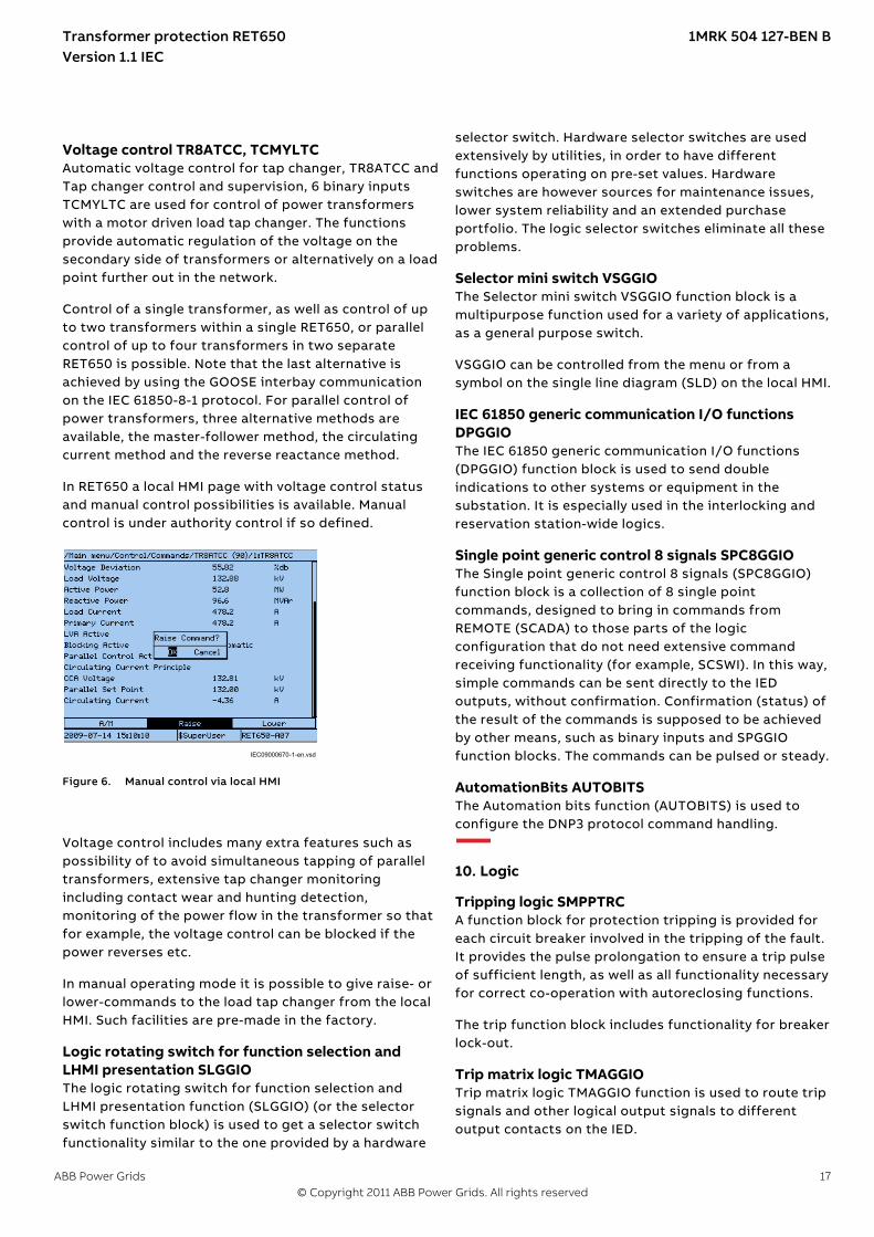
In RET650 a local HMI page with voltage control statusand manual control possibilities is available. Manualcontrol is under authority control if so defined.
IEC09000670-1-en.vsdIEC09000670 V1 EN-US
Figure 6. Manual control via local HMI
Voltage control includes many extra features such aspossibility of to avoid simultaneous tapping of paralleltransformers, extensive tap changer monitoringincluding contact wear and hunting detection,monitoring of the power flow in the transformer so thatfor example, the voltage control can be blocked if thepower reverses etc.
In manual operating mode it is possible to give raise- orlower-commands to the load tap changer from the localHMI. Such facilities are pre-made in the factory.
Logic rotating switch for function selection andLHMI presentation SLGGIO
SEMOD114908-4 v6
The logic rotating switch for function selection andLHMI presentation function (SLGGIO) (or the selectorswitch function block) is used to get a selector switchfunctionality similar to the one provided by a hardware
selector switch. Hardware selector switches are usedextensively by utilities, in order to have differentfunctions operating on pre-set values. Hardwareswitches are however sources for maintenance issues,lower system reliability and an extended purchaseportfolio. The logic selector switches eliminate all theseproblems.
Selector mini switch VSGGIOSEMOD158756-5 v5
The Selector mini switch VSGGIO function block is amultipurpose function used for a variety of applications,as a general purpose switch.
VSGGIO can be controlled from the menu or from asymbol on the single line diagram (SLD) on the local HMI.
IEC 61850 generic communication I/O functionsDPGGIO
SEMOD55850-5 v3
The IEC 61850 generic communication I/O functions(DPGGIO) function block is used to send doubleindications to other systems or equipment in thesubstation. It is especially used in the interlocking andreservation station-wide logics.
Single point generic control 8 signals SPC8GGIOSEMOD176462-4 v5
The Single point generic control 8 signals (SPC8GGIO)function block is a collection of 8 single pointcommands, designed to bring in commands fromREMOTE (SCADA) to those parts of the logicconfiguration that do not need extensive commandreceiving functionality (for example, SCSWI). In this way,simple commands can be sent directly to the IEDoutputs, without confirmation. Confirmation (status) ofthe result of the commands is supposed to be achievedby other means, such as binary inputs and SPGGIOfunction blocks. The commands can be pulsed or steady.
AutomationBits AUTOBITSSEMOD158591-5 v4
The Automation bits function (AUTOBITS) is used toconfigure the DNP3 protocol command handling.
10. Logic
Tripping logic SMPPTRCM12275-3 v4
A function block for protection tripping is provided foreach circuit breaker involved in the tripping of the fault.It provides the pulse prolongation to ensure a trip pulseof sufficient length, as well as all functionality necessaryfor correct co-operation with autoreclosing functions.
The trip function block includes functionality for breakerlock-out.
Trip matrix logic TMAGGIOM15321-3 v7
Trip matrix logic TMAGGIO function is used to route tripsignals and other logical output signals to differentoutput contacts on the IED.
Transformer protection RET650 1MRK 504 127-BEN BVersion 1.1 IEC
ABB Power Grids 17© Copyright 2011 ABB Power Grids. All rights reserved
TMAGGIO output signals and the physical outputs allowsthe user to adapt the signals to the physical trippingoutputs according to the specific application needs.
Configurable logic blocksM11396-4 v9
A number of logic blocks and timers are available for theuser to adapt the configuration to the specificapplication needs.
• OR function block.
• INVERTER function blocks that inverts the inputsignal.
• PULSETIMER function block can be used, for example,for pulse extensions or limiting of operation ofoutputs.
• GATE function block is used for whether or not asignal should be able to pass from the input to theoutput.
• XOR function block.
• LOOPDELAY function block used to delay the outputsignal one execution cycle.
• TIMERSET function has pick-up and drop-out delayedoutputs related to the input signal. The timer has asettable time delay.
• AND function block.
• SRMEMORY function block is a flip-flop that can set orreset an output from two inputs respectively. Eachblock has two outputs where one is inverted. Thememory setting controls if the block should be resetor return to the state before the interruption, after apower interruption. Set input has priority.
• RSMEMORY function block is a flip-flop that can resetor set an output from two inputs respectively. Eachblock has two outputs where one is inverted. Thememory setting controls if the block should be resetor return to the state before the interruption, after apower interruption. Reset input has priority.
Boolean 16 to Integer conversion B16ISEMOD175725-4 v3
Boolean 16 to integer conversion function (B16I) is usedto transform a set of 16 binary (logical) signals into aninteger.
Boolean 16 to Integer conversion with logic noderepresentation B16IFCVI
SEMOD175781-4 v4
Boolean 16 to integer conversion with logic noderepresentation function (B16IFCVI) is used to transforma set of 16 binary (logical) signals into an integer.
Integer to Boolean 16 conversion IB16ASEMOD158373-5 v3
Integer to boolean 16 conversion function (IB16A) isused to transform an integer into a set of 16 binary(logical) signals.
Integer to Boolean 16 conversion with logic noderepresentation IB16FCVB
SEMOD158421-5 v4
Integer to boolean conversion with logic noderepresentation function (IB16FCVB) is used to transforman integer to 16 binary (logic) signals.
IB16FCVB function can receive remote values overIEC61850 depending on the operator position input(PSTO).
11. Monitoring
Measurements CVMMXN, CMMXU, VNMMXU,VMMXU, CMSQI, VMSQI
M12024-3 v6
The measurement functions are used to get on-lineinformation from the IED. These service values make itpossible to display on-line information on the local HMIand on the Substation automation system about:
• measured voltages, currents, frequency, active,reactive and apparent power and power factor
• primary and secondary phasors• current sequence components• voltage sequence components
Event counter CNTGGIOM13407-3 v6
Event counter (CNTGGIO) has six counters which areused for storing the number of times each counter inputhas been activated.
Disturbance report DRPRDREM12153-3 v7
Complete and reliable information about disturbances inthe primary and/or in the secondary system togetherwith continuous event-logging is accomplished by thedisturbance report functionality.
Disturbance report DRPRDRE, always included in the IED,acquires sampled data of all selected analog input andbinary signals connected to the function block that is,maximum 40 analog and 96 binary signals.
The Disturbance report functionality is a common namefor several functions:
• Event list• Indications• Event recorder• Trip value recorder• Disturbance recorder
Transformer protection RET650 1MRK 504 127-BEN BVersion 1.1 IEC
18 ABB Power Grids© Copyright 2011 ABB Power Grids. All rights reserved

The Disturbance report function is characterized bygreat flexibility regarding configuration, startingconditions, recording times, and large storage capacity.
A disturbance is defined as an activation of an input tothe AxRADR or BxRBDR function blocks, which are set totrigger the disturbance recorder. All signals from startof pre-fault time to the end of post-fault time will beincluded in the recording.
Every disturbance report recording is saved in the IED inthe standard Comtrade format. The same applies to allevents, which are continuously saved in a ring-buffer.The local HMI is used to get information about therecordings. The disturbance report files may beuploaded to PCM600 for further analysis using thedisturbance handling tool.
Event list DRPRDREM12412-6 v6
Continuous event-logging is useful for monitoring thesystem from an overview perspective and is acomplement to specific disturbance recorder functions.
The event list logs all binary input signals connected tothe Disturbance report function. The list may contain upto 1000 time-tagged events stored in a ring-buffer.
Indications DRPRDREM12030-3 v4
To get fast, condensed and reliable information aboutdisturbances in the primary and/or in the secondarysystem it is important to know, for example binarysignals that have changed status during a disturbance.This information is used in the short perspective to getinformation via the local HMI in a straightforward way.
There are three LEDs on the local HMI (green, yellow andred), which will display status information about the IEDand the Disturbance report function (trigged).
The Indication list function shows all selected binaryinput signals connected to the Disturbance reportfunction that have changed status during a disturbance.
Event recorder DRPRDREM12033-3 v7
Quick, complete and reliable information aboutdisturbances in the primary and/or in the secondarysystem is vital, for example, time-tagged events loggedduring disturbances. This information is used fordifferent purposes in the short term (for examplecorrective actions) and in the long term (for examplefunctional analysis).
The event recorder logs all selected binary input signalsconnected to the Disturbance report function. Eachrecording can contain up to 150 time-tagged events.
The event recorder information is available for thedisturbances locally in the IED.
The event recording information is an integrated part ofthe disturbance record (Comtrade file).
Trip value recorder DRPRDREM12128-3 v6
Information about the pre-fault and fault values forcurrents and voltages are vital for the disturbanceevaluation.
The Trip value recorder calculates the values of allselected analog input signals connected to theDisturbance report function. The result is magnitudeand phase angle before and during the fault for eachanalog input signal.
The trip value recorder information is available for thedisturbances locally in the IED.
The trip value recorder information is an integrated partof the disturbance record (Comtrade file).
Disturbance recorder DRPRDREM12156-3 v7
The Disturbance recorder function supplies fast,complete and reliable information about disturbances inthe power system. It facilitates understanding systembehavior and related primary and secondary equipmentduring and after a disturbance. Recorded information isused for different purposes in the short perspective (forexample corrective actions) and long perspective (forexample functional analysis).
The Disturbance recorder acquires sampled data fromselected analog- and binary signals connected to theDisturbance report function (maximum 40 analog and96 binary signals). The binary signals available are thesame as for the event recorder function.
The function is characterized by great flexibility and isnot dependent on the operation of protection functions.It can record disturbances not detected by protectionfunctions.
The disturbance recorder information for the last 100disturbances are saved in the IED and the local HMI isused to view the list of recordings.
Measured value expander block MVEXPSEMOD52450-4 v5
The current and voltage measurements functions(CVMMXN, CMMXU, VMMXU and VNMMXU), current andvoltage sequence measurement functions (CMSQI andVMSQI) and IEC 61850 generic communication I/Ofunctions (MVGGIO) are provided with measurementsupervision functionality. All measured values can besupervised with four settable limits: low-low limit, lowlimit, high limit and high-high limit. The measure valueexpander block has been introduced to enabletranslating the integer output signal from themeasuring functions to 5 binary signals: below low-lowlimit, below low limit, normal, above high-high limit orabove high limit. The output signals can be used as
Transformer protection RET650 1MRK 504 127-BEN BVersion 1.1 IEC
ABB Power Grids 19© Copyright 2011 ABB Power Grids. All rights reserved
conditions in the configurable logic or for alarmingpurpose.
Station battery supervision SPVNZBATGUID-D435B51F-8B7F-472D-90E6-3257FFDC0570 v1
The station battery supervision function SPVNZBAT isused for monitoring battery terminal voltage.
SPVNZBAT activates the start and alarm outputs whenthe battery terminal voltage exceeds the set upper limitor drops below the set lower limit. A time delay for theovervoltage and undervoltage alarms can be setaccording to definite time characteristics.
In the definite time (DT) mode, SPVNZBAT operatesafter a predefined operate time and resets when thebattery undervoltage or overvoltage conditiondisappears.
Insulation gas monitoring function SSIMGGUID-0692CD0D-F33E-4370-AC91-B216CAAAFC28 v2
Insulation gas monitoring function (SSIMG) is used formonitoring the circuit breaker condition. Binaryinformation based on the gas pressure in the circuitbreaker is used as input signals to the function. Inaddition, the function generates alarms based onreceived information.
Insulation liquid monitoring function SSIMLGUID-3B1A665F-60A5-4343-85F4-AD9C066CBE8D v2
Insulation liquid monitoring function (SSIML) is used formonitoring the circuit breaker condition. Binaryinformation based on the oil level in the circuit breakeris used as input signals to the function. In addition, thefunction generates alarms based on receivedinformation.
Circuit breaker monitoring SSCBRGUID-E1FD74C3-B9B6-4E11-AA1B-7E7F822FB4DD v6
The circuit breaker condition monitoring function SSCBRis used to monitor different parameters of the circuitbreaker. The breaker requires maintenance when thenumber of operations has reached a predefined value.The energy is calculated from the measured inputcurrents as a sum of Iyt values. Alarms are generatedwhen the calculated values exceed the thresholdsettings.
The function contains a blocking functionality. It ispossible to block the function outputs, if desired.
12. Metering
Pulse counter logic PCGGIOM13394-3 v6
Pulse counter (PCGGIO) function counts externallygenerated binary pulses, for instance pulses comingfrom an external energy meter, for calculation of energyconsumption values. The pulses are captured by the BIO(binary input/output) module and then read by thePCGGIO function. A scaled service value is available overthe station bus.
Function for energy calculation and demandhandling ETPMMTR
SEMOD153641-8 v5
Outputs from the Measurements (CVMMXN) functioncan be used to calculate energy consumption. Active aswell as reactive values are calculated in import andexport direction. Values can be read or generated aspulses. Maximum demand power values are alsocalculated by the function.
13. Human Machine interface
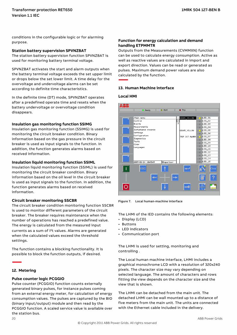
Local HMIAMU0600442 v7
GUID-23A12958-F9A5-4BF1-A31B-F69F56A046C7 V2 EN-US
Figure 7. Local human-machine interface
The LHMI of the IED contains the following elements:• Display (LCD)• Buttons• LED indicators• Communication port
The LHMI is used for setting, monitoring andcontrolling .
GUID-CABB3689-DEA5-4611-A492-13B3D6632846 v2
The Local human machine interface, LHMI includes agraphical monochrome LCD with a resolution of 320x240pixels. The character size may vary depending onselected language. The amount of characters and rowsfitting the view depends on the character size and theview that is shown.
The LHMI can be detached from the main unit. Thedetached LHMI can be wall mounted up to a distance offive meters from the main unit. The units are connectedwith the Ethernet cable included in the delivery.
Transformer protection RET650 1MRK 504 127-BEN BVersion 1.1 IEC
20 ABB Power Grids© Copyright 2011 ABB Power Grids. All rights reserved
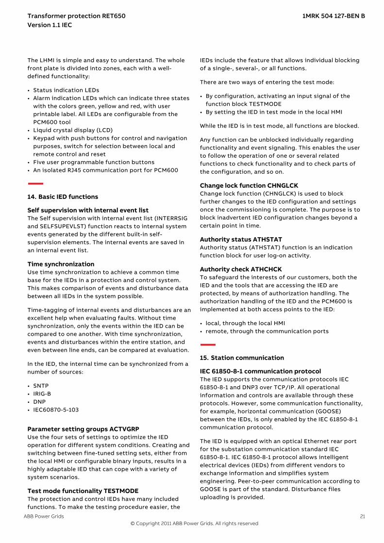
The LHMI is simple and easy to understand. The wholefront plate is divided into zones, each with a well-defined functionality:
• Status indication LEDs• Alarm indication LEDs which can indicate three states
with the colors green, yellow and red, with userprintable label. All LEDs are configurable from thePCM600 tool
• Liquid crystal display (LCD)• Keypad with push buttons for control and navigation
purposes, switch for selection between local andremote control and reset
• Five user programmable function buttons• An isolated RJ45 communication port for PCM600
14. Basic IED functions
Self supervision with internal event listM11399-3 v4
The Self supervision with internal event list (INTERRSIGand SELFSUPEVLST) function reacts to internal systemevents generated by the different built-in self-supervision elements. The internal events are saved inan internal event list.
Time synchronizationGUID-057C610F-C070-4EA6-B2C9-3C49F33B2F7C v2
Use time synchronization to achieve a common timebase for the IEDs in a protection and control system.This makes comparison of events and disturbance databetween all IEDs in the system possible.
Time-tagging of internal events and disturbances are anexcellent help when evaluating faults. Without timesynchronization, only the events within the IED can becompared to one another. With time synchronization,events and disturbances within the entire station, andeven between line ends, can be compared at evaluation.
In the IED, the internal time can be synchronized from anumber of sources:
• SNTP• IRIG-B• DNP• IEC60870-5-103
Parameter setting groups ACTVGRPM12006-6 v3
Use the four sets of settings to optimize the IEDoperation for different system conditions. Creating andswitching between fine-tuned setting sets, either fromthe local HMI or configurable binary inputs, results in ahighly adaptable IED that can cope with a variety ofsystem scenarios.
Test mode functionality TESTMODEM11407-3 v4
The protection and control IEDs have many includedfunctions. To make the testing procedure easier, the
IEDs include the feature that allows individual blockingof a single-, several-, or all functions.
There are two ways of entering the test mode:
• By configuration, activating an input signal of thefunction block TESTMODE
• By setting the IED in test mode in the local HMI
While the IED is in test mode, all functions are blocked.
Any function can be unblocked individually regardingfunctionality and event signaling. This enables the userto follow the operation of one or several relatedfunctions to check functionality and to check parts ofthe configuration, and so on.
Change lock function CHNGLCKGUID-00784FC0-B39D-462D-854B-AAF62626DD0A v1
Change lock function (CHNGLCK) is used to blockfurther changes to the IED configuration and settingsonce the commissioning is complete. The purpose is toblock inadvertent IED configuration changes beyond acertain point in time.
Authority status ATHSTATSEMOD158529-5 v4
Authority status (ATHSTAT) function is an indicationfunction block for user log-on activity.
Authority check ATHCHCKSEMOD117051-23 v3
To safeguard the interests of our customers, both theIED and the tools that are accessing the IED areprotected, by means of authorization handling. Theauthorization handling of the IED and the PCM600 isimplemented at both access points to the IED:
• local, through the local HMI• remote, through the communication ports
15. Station communication
IEC 61850-8-1 communication protocolM14787-3 v6
The IED supports the communication protocols IEC61850-8-1 and DNP3 over TCP/IP. All operationalinformation and controls are available through theseprotocols. However, some communication functionality,for example, horizontal communication (GOOSE)between the IEDs, is only enabled by the IEC 61850-8-1communication protocol.
The IED is equipped with an optical Ethernet rear portfor the substation communication standard IEC61850-8-1. IEC 61850-8-1 protocol allows intelligentelectrical devices (IEDs) from different vendors toexchange information and simplifies systemengineering. Peer-to-peer communication according toGOOSE is part of the standard. Disturbance filesuploading is provided.
Transformer protection RET650 1MRK 504 127-BEN BVersion 1.1 IEC
ABB Power Grids 21© Copyright 2011 ABB Power Grids. All rights reserved

Disturbance files are accessed using the IEC 61850-8-1protocol. Disturbance files are available to any Ethernetbased application via FTP in the standard Comtradeformat. Further, the IED can send and receive binaryvalues, double point values and measured values (forexample from MMXU functions), together with theirquality, using the IEC 61850-8-1 GOOSE profile. The IEDmeets the GOOSE performance requirements fortripping applications in substations, as defined by theIEC 61850 standard. The IED interoperates with otherIEC 61850-compliant IEDs, tools, and systems andsimultaneously reports events to five different clientson the IEC 61850 station bus.
The event system has a rate limiter to reduce CPU load.The event channel has a quota of 10 events/second. Ifthe quota is exceeded the event channel transmission isblocked until the event changes is below the quota, noevent is lost.
All communication connectors, except for the front portconnector, are placed on integrated communicationmodules. The IED is connected to Ethernet-basedcommunication systems via the fibre-optic multimodeLC connector (100BASE-FX).
The IED supports SNTP and IRIG-B time synchronizationmethods with a time-stamping resolution of 1 ms.
• Ethernet based: SNTP and DNP3• With time synchronization wiring: IRIG-B
The IED supports IEC 60870-5-103 time synchronizationmethods with a time stamping resolution of 5 ms.
Table 1. Supported communication interface and protocolalternatives
Interfaces/Protocols
Ethernet100BASE-FX LC
ST connector
IEC 61850-8-1 ●
DNP3 ●
IEC 60870-5-103 ●
● = Supported
Horizontal communication via GOOSE forinterlocking
GUID-92ECE152-892C-4214-95DE-B92718689434 v2
GOOSE communication can be used for exchanginginformation between IEDs via the IEC 61850-8-1 stationcommunication bus. This is typically used for sendingapparatus position indications for interlocking orreservation signals for 1-of-n control. GOOSE can also beused to exchange any boolean, integer, double point andanalog measured values between IEDs.
DNP3 protocolGUID-54A54716-23BD-4E7C-8245-DE2B4C75E8DC v1
DNP3 (Distributed Network Protocol) is a set ofcommunications protocols used to communicate databetween components in process automation systems.For a detailed description of the DNP3 protocol, see theDNP3 Communication protocol manual.
IEC 60870-5-103 communication protocolM11874-3 v3
IEC 60870-5-103 is an unbalanced (master-slave)protocol for coded-bit serial communication exchanginginformation with a control system, and with a datatransfer rate up to 38400 bit/s. In IEC terminology, aprimary station is a master and a secondary station is aslave. The communication is based on a point-to-pointprinciple. The master must have software that caninterpret IEC 60870-5-103 communication messages.
16. Hardware description
Layout and dimensionsIP14539-1 v1
Mounting alternativesM16079-3 v6
The following mounting alternatives are available (IP40protection from the front):
• 19” rack mounting kit• Wall mounting kit• Flush mounting kit• 19" dual rack mounting kit
See ordering for details about available mountingalternatives.
Transformer protection RET650 1MRK 504 127-BEN BVersion 1.1 IEC
22 ABB Power Grids© Copyright 2011 ABB Power Grids. All rights reserved

Flush mounting the IEDGUID-C8BEC79C-FF1B-4FEA-936E-EB19877D6CF8 v1
H
I
K
J
C
F
G
B
A
ED
IEC09000672.ai
IEC09000672 V1 EN-US
Figure 8. Flush mounting the IED into a panel cut-out
A 240 mm G 21.55 mm
B 21.55 mm H 220 mm
C 227 mm I 265.9 mm
D 228.9 mm J 300 mm
E 272 mm K 254 mm
F ∅6 mm
A
B
C
IEC09000673.ai
IEC09000673 V1 EN-US
Figure 9. Flush mounted IED
A 222 mm
B 27 mm
C 13 mm
Rack mounting the IEDGUID-A12870EB-5DA7-4B3B-9AED-B2D9F259B6B3 v1
A C
B
E
D
IEC09000676.ai
IEC09000676 V1 EN-US
Figure 10. Rack mounted IED
A 224 mm + 12 mm with ring-lug connector
B 25.5 mm
C 482.6 mm (19")
D 265.9 mm (6U)
E 13 mm
A
BC
E
D
IEC09000677.ai
IEC09000677 V1 EN-US
Figure 11. Two rack mounted IEDs side by side
A 224 mm + 12 mm with ring-lug connector
B 25.5 mm
C 482.6 mm (19")
D 13 mm
E 265.9 mm (6U)
Transformer protection RET650 1MRK 504 127-BEN BVersion 1.1 IEC
ABB Power Grids 23© Copyright 2011 ABB Power Grids. All rights reserved
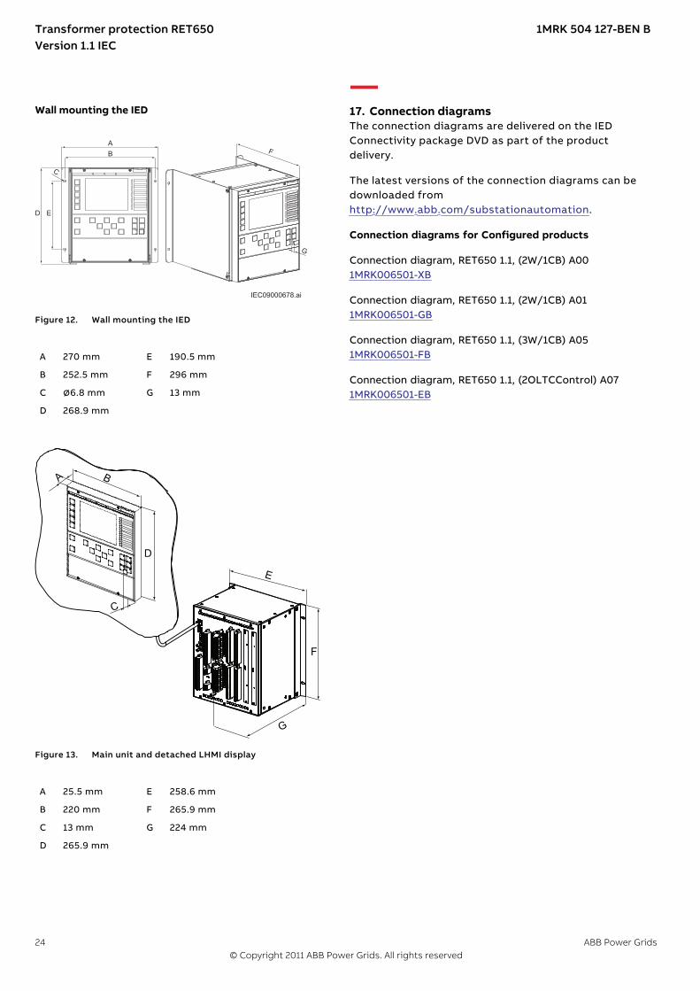
Wall mounting the IEDGUID-5EE62F6C-F0F4-4C01-897A-DF27BCDE07BF v2
C
F
G
B
A
ED
IEC09000678.ai
IEC09000678 V1 EN-US
Figure 12. Wall mounting the IED
A 270 mm E 190.5 mm
B 252.5 mm F 296 mm
C ∅6.8 mm G 13 mm
D 268.9 mm
GUID-5C185EAC-13D0-40BD-8511-58CA53EFF7DE V1 EN-US
Figure 13. Main unit and detached LHMI display
A 25.5 mm E 258.6 mm
B 220 mm F 265.9 mm
C 13 mm G 224 mm
D 265.9 mm
17. Connection diagramsGUID-72A67452-D1F2-44C9-9172-05160EDFEC5D v2.2.1
The connection diagrams are delivered on the IED Connectivity package DVD as part of the product delivery.
The latest versions of the connection diagrams can be downloaded fromhttp://www.abb.com/substationautomation.
Connection diagrams for Configured products
Connection diagram, RET650 1.1, (2W/1CB) A00 1MRK006501-XB
Connection diagram, RET650 1.1, (2W/1CB) A01 1MRK006501-GB
Connection diagram, RET650 1.1, (3W/1CB) A05 1MRK006501-FB
Connection diagram, RET650 1.1, (2OLTCControl) A07 1MRK006501-EB
Transformer protection RET650 1MRK 504 127-BEN BVersion 1.1 IEC
24 ABB Power Grids© Copyright 2011 ABB Power Grids. All rights reserved

18. Technical data
GeneralIP11376-1 v2M10993-1 v3
Definitions
Reference value The specified value of an influencing factor to which are referred the characteristics of the equipment
Nominal range The range of values of an influencing quantity (factor) within which, under specified conditions, the equipment meetsthe specified requirements
Operative range The range of values of a given energizing quantity for which the equipment, under specified conditions, is able toperform its intended functions according to the specified requirements
Energizing quantities, rated values and limitsIP15765-1 v2
Analog inputsGUID-80AA04F6-C989-4E8A-81C0-1A9A7458ADCC v4
Table 2. Energizing inputs
Description Value
Rated frequency 50/60 Hz
Operating range Rated frequency ± 5 Hz
Current inputs Rated current, In 0.1/0.5 A1) 1/5 A2)
Thermal withstand capability:
• Continuously 4 A 20 A
• For 1 s 100 A 500 A
• For 10 s 20 A 100 A
Dynamic current withstand:
• Half-wave value 250 A 1250 A
Input impedance <100 mΩ <20 mΩ
Voltage inputs Rated voltage, Un 100 V AC/ 110 V AC/ 115 V AC/ 120 V AC
Voltage withstand:
• Continuous 420 V rms
• For 10 s 450 V rms
Burden at rated voltage <0.05 VA
1) Residual current2) Phase currents or residual current
Transformer protection RET650 1MRK 504 127-BEN BVersion 1.1 IEC
ABB Power Grids 25© Copyright 2011 ABB Power Grids. All rights reserved
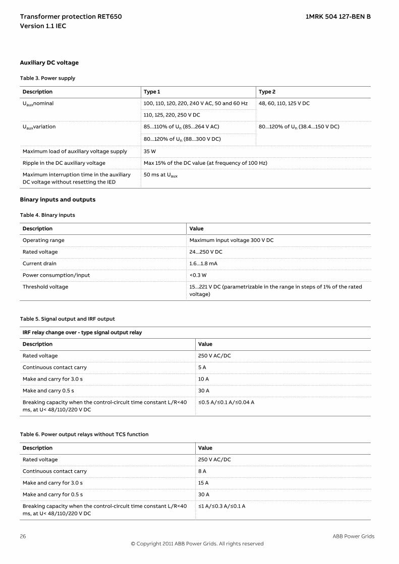
Auxiliary DC voltageIP15843-1 v1GUID-B8B53053-FE79-47B1-AEDB-904B91B54175 v3
Table 3. Power supply
Description Type 1 Type 2
Uauxnominal 100, 110, 120, 220, 240 V AC, 50 and 60 Hz 48, 60, 110, 125 V DC
110, 125, 220, 250 V DC
Uauxvariation 85...110% of Un (85...264 V AC) 80...120% of Un (38.4...150 V DC)
80...120% of Un (88...300 V DC)
Maximum load of auxiliary voltage supply 35 W
Ripple in the DC auxiliary voltage Max 15% of the DC value (at frequency of 100 Hz)
Maximum interruption time in the auxiliaryDC voltage without resetting the IED
50 ms at Uaux
Binary inputs and outputsIP15844-1 v1GUID-247871FB-80C1-4D7F-B860-9E98BBEC9E23 v2
Table 4. Binary inputs
Description Value
Operating range Maximum input voltage 300 V DC
Rated voltage 24...250 V DC
Current drain 1.6...1.8 mA
Power consumption/input <0.3 W
Threshold voltage 15...221 V DC (parametrizable in the range in steps of 1% of the ratedvoltage)
GUID-CAD6026E-BF75-487E-BA91-CEF705FB65DB v2
Table 5. Signal output and IRF output
IRF relay change over - type signal output relay
Description Value
Rated voltage 250 V AC/DC
Continuous contact carry 5 A
Make and carry for 3.0 s 10 A
Make and carry 0.5 s 30 A
Breaking capacity when the control-circuit time constant L/R<40ms, at U< 48/110/220 V DC
≤0.5 A/≤0.1 A/≤0.04 A
GUID-F773051A-F50F-4B12-8CB3-88936A687FDC v3
Table 6. Power output relays without TCS function
Description Value
Rated voltage 250 V AC/DC
Continuous contact carry 8 A
Make and carry for 3.0 s 15 A
Make and carry for 0.5 s 30 A
Breaking capacity when the control-circuit time constant L/R<40ms, at U< 48/110/220 V DC
≤1 A/≤0.3 A/≤0.1 A
Transformer protection RET650 1MRK 504 127-BEN BVersion 1.1 IEC
26 ABB Power Grids© Copyright 2011 ABB Power Grids. All rights reserved

Table 7. Power output relays with TCS function
Description Value
Rated voltage 250 V DC
Continuous contact carry 8 A
Make and carry for 3.0 s 15 A
Make and carry for 0.5 s 30 A
Breaking capacity when the control-circuit time constant L/R<40ms, at U< 48/110/220 V DC
≤1 A/≤0.3 A/≤0.1 A
Control voltage range 20...250 V DC
Current drain through the supervision circuit ~1.0 mA
Minimum voltage over the TCS contact 20 V DC
GUID-D31978A8-DD9B-43C6-B066-57DBBF4EF2F4 v4
Table 8. Ethernet interfaces
Ethernet interface Protocol Cable Data transfer rate
LAN/HMI port (X0)1) - CAT 6 S/FTP or better 100 MBits/s
LAN1 (X1) TCP/IP protocol Fibre-optic cable with LCconnector
100 MBits/s
1) Only available for the external HMI option.
Table 9. Fibre-optic communication link
Wave length Fibre type Connector Permitted path attenuation1) Distance
1300 nm MM 62.5/125 μmglass fibre core
LC <8 dB 2 km
1) Maximum allowed attenuation caused by connectors and cable together
Table 10. X4/IRIG-B interface
Type Protocol Cable
Screw terminal, pin row header IRIG-B Shielded twisted pair cableRecommended: CAT 5, Belden RS-485 (9841- 9844) or Alpha Wire(Alpha 6222-6230)
Table 11. Serial rear interface
Type Counter connector
Serial port (X9) Optical serial port, type ST for IEC 60870-5-103
Influencing factorsIP15846-1 v1GUID-59B01F47-1193-4243-B78C-EC6149CFA107 v12
Table 12. Degree of protection of flush-mounted IED
Description Value
Front side IP 40
Rear side, connection terminals IP 20
Transformer protection RET650 1MRK 504 127-BEN BVersion 1.1 IEC
ABB Power Grids 27© Copyright 2011 ABB Power Grids. All rights reserved
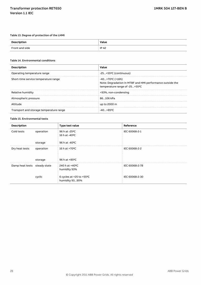
Table 13. Degree of protection of the LHMI
Description Value
Front and side IP 42
GUID-8D1EE1BB-C9EF-4184-BB4D-AB32B86DBFCE v2
Table 14. Environmental conditions
Description Value
Operating temperature range -25...+55ºC (continuous)
Short-time service temperature range -40...+70ºC (<16h)Note: Degradation in MTBF and HMI performance outside thetemperature range of -25...+55ºC
Relative humidity <93%, non-condensing
Atmospheric pressure 86...106 kPa
Altitude up to 2000 m
Transport and storage temperature range -40...+85ºC
Table 15. Environmental tests
Description Type test value Reference
Cold tests operation storage
96 h at -25ºC16 h at -40ºC 96 h at -40ºC
IEC 60068-2-1
Dry heat tests operation storage
16 h at +70ºC 96 h at +85ºC
IEC 60068-2-2
Damp heat tests steady state cyclic
240 h at +40ºChumidity 93% 6 cycles at +25 to +55ºChumidity 93...95%
IEC 60068-2-78 IEC 60068-2-30
Transformer protection RET650 1MRK 504 127-BEN BVersion 1.1 IEC
28 ABB Power Grids© Copyright 2011 ABB Power Grids. All rights reserved

Type tests according to standardsIP15778-1 v1GUID-2794AAD0-DBFE-476D-BAD1-A8D0ECFE9C9C v3
Table 16. Electromagnetic compatibility tests
Description Type test value Reference
100 kHz and 1 MHz burst disturbance test IEC 61000-4-18IEC 60255-22-1, level 3
• Common mode 2.5 kV
• Differential mode 1.0 kV
Electrostatic discharge test IEC 61000-4-2IEC 60255-22-2, level 4
• Contact discharge 8 kV
• Air discharge 15 kV
Radio frequency interference tests
• Conducted, common mode 10 V (emf), f=150 kHz...80 MHz IEC 61000-4-6IEC 60255-22-6, level 3
• Radiated, amplitude-modulated 20 V/m (rms), f=80...1000 MHz andf=1.4...2.7 GHz
IEC 61000-4-3IEC 60255-22-3, level 3
Fast transient disturbance tests IEC 61000-4-4IEC 60255-22-4, class A
• Communication ports 2 kV
• Other ports 4 kV
Surge immunity test IEC 61000-4-5IEC 60255-22-5, level 3/2
• Communication 1 kV line-to-earth
• Other ports 2 kV line-to-earth, 1 kV line-to-line
Power frequency (50 Hz) magnetic field IEC 61000-4-8, level 5
• 3 s 1000 A/m
• Continuous 100 A/m
Power frequency immunity test• Common mode
• Differential mode
300 V rms 150 V rms
IEC 60255-22-7, class AIEC 61000-4-16
Voltage dips and short interruptions Dips:40%/200 ms70%/500 msInterruptions:0-50 ms: No restart0...∞ s : Correct behaviour at power down
IEC 60255-11IEC 61000-4-11
Electromagnetic emission tests EN 55011, class AIEC 60255-25
• Conducted, RF-emission (mainsterminal)
0.15...0.50 MHz < 79 dB(µV) quasi peak< 66 dB(µV) average
0.5...30 MHz < 73 dB(µV) quasi peak< 60 dB(µV) average
Transformer protection RET650 1MRK 504 127-BEN BVersion 1.1 IEC
ABB Power Grids 29© Copyright 2011 ABB Power Grids. All rights reserved
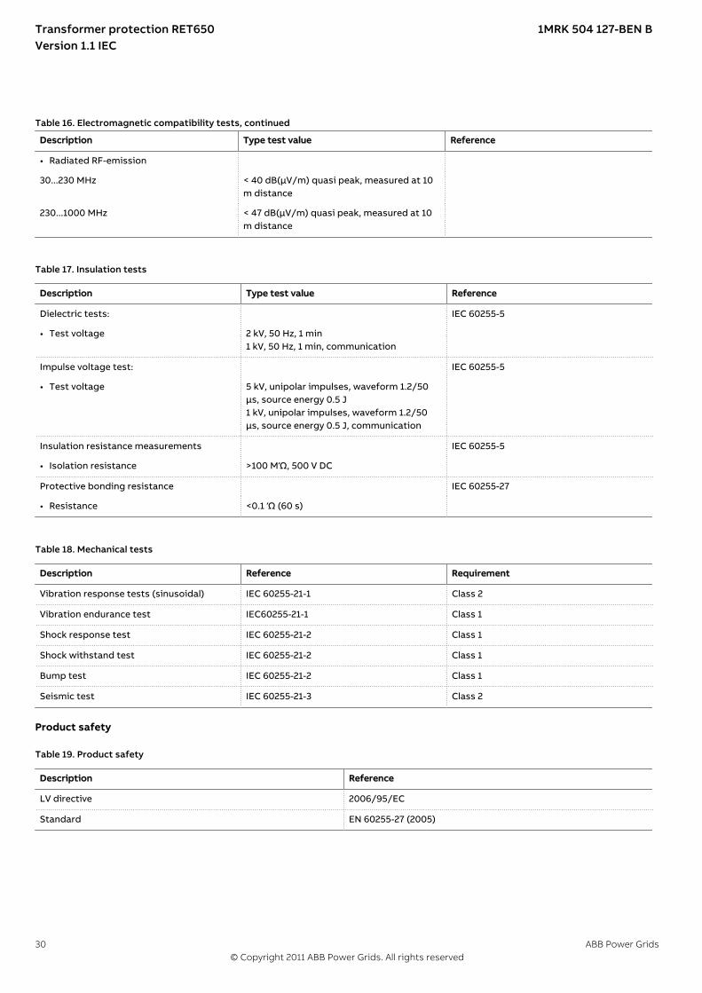
Table 16. Electromagnetic compatibility tests, continued
Description Type test value Reference
• Radiated RF-emission
30...230 MHz < 40 dB(µV/m) quasi peak, measured at 10m distance
230...1000 MHz < 47 dB(µV/m) quasi peak, measured at 10m distance
GUID-83755DD7-E73B-442B-A0DF-87D648F7CF01 v2
Table 17. Insulation tests
Description Type test value Reference
Dielectric tests: IEC 60255-5
• Test voltage 2 kV, 50 Hz, 1 min1 kV, 50 Hz, 1 min, communication
Impulse voltage test: IEC 60255-5
• Test voltage 5 kV, unipolar impulses, waveform 1.2/50μs, source energy 0.5 J1 kV, unipolar impulses, waveform 1.2/50μs, source energy 0.5 J, communication
Insulation resistance measurements IEC 60255-5
• Isolation resistance >100 MΏ, 500 V DC
Protective bonding resistance IEC 60255-27
• Resistance <0.1 Ώ (60 s)
GUID-F98A61B6-B290-43E5-BDF7-96FE3300F28E v2
Table 18. Mechanical tests
Description Reference Requirement
Vibration response tests (sinusoidal) IEC 60255-21-1 Class 2
Vibration endurance test IEC60255-21-1 Class 1
Shock response test IEC 60255-21-2 Class 1
Shock withstand test IEC 60255-21-2 Class 1
Bump test IEC 60255-21-2 Class 1
Seismic test IEC 60255-21-3 Class 2
Product safetyGUID-2AA791D9-FA91-4F1F-A31D-64412575CE81 v8
Table 19. Product safety
Description Reference
LV directive 2006/95/EC
Standard EN 60255-27 (2005)
Transformer protection RET650 1MRK 504 127-BEN BVersion 1.1 IEC
30 ABB Power Grids© Copyright 2011 ABB Power Grids. All rights reserved

EMC complianceGUID-9B1F0C9F-664E-41C8-ADA3-4376E096A9C9 v4
Table 20. EMC compliance
Description Reference
EMC directive 2004/108/EC
Standard EN 50263 (2000)EN 60255-26 (2007)
Transformer protection RET650 1MRK 504 127-BEN BVersion 1.1 IEC
ABB Power Grids 31© Copyright 2011 ABB Power Grids. All rights reserved
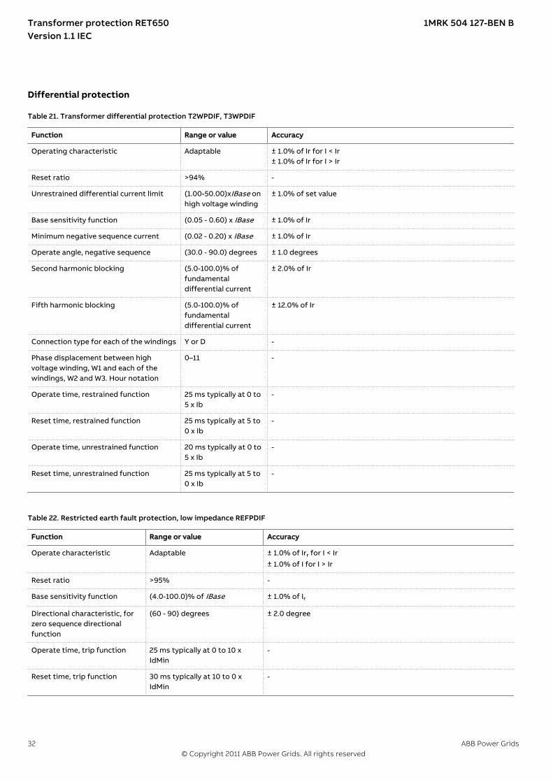
Differential protectionM13046-1 v6
Table 21. Transformer differential protection T2WPDIF, T3WPDIF
Function Range or value Accuracy
Operating characteristic Adaptable ± 1.0% of Ir for I < Ir± 1.0% of Ir for I > Ir
Reset ratio >94% -
Unrestrained differential current limit (1.00-50.00)xIBase onhigh voltage winding
± 1.0% of set value
Base sensitivity function (0.05 - 0.60) x IBase ± 1.0% of Ir
Minimum negative sequence current (0.02 - 0.20) x IBase ± 1.0% of Ir
Operate angle, negative sequence (30.0 - 90.0) degrees ± 1.0 degrees
Second harmonic blocking (5.0-100.0)% offundamentaldifferential current
± 2.0% of Ir
Fifth harmonic blocking (5.0-100.0)% offundamentaldifferential current
± 12.0% of Ir
Connection type for each of the windings Y or D -
Phase displacement between highvoltage winding, W1 and each of thewindings, W2 and W3. Hour notation
0–11 -
Operate time, restrained function 25 ms typically at 0 to5 x Ib
-
Reset time, restrained function 25 ms typically at 5 to0 x Ib
-
Operate time, unrestrained function 20 ms typically at 0 to5 x Ib
-
Reset time, unrestrained function 25 ms typically at 5 to0 x Ib
-
M13062-1 v7
Table 22. Restricted earth fault protection, low impedance REFPDIF
Function Range or value Accuracy
Operate characteristic Adaptable ± 1.0% of Irr for I < Ir± 1.0% of I for I > Ir
Reset ratio >95% -
Base sensitivity function (4.0-100.0)% of IBase ± 1.0% of Ir
Directional characteristic, forzero sequence directionalfunction
(60 - 90) degrees ± 2.0 degree
Operate time, trip function 25 ms typically at 0 to 10 xIdMin
-
Reset time, trip function 30 ms typically at 10 to 0 xIdMin
-
Transformer protection RET650 1MRK 504 127-BEN BVersion 1.1 IEC
32 ABB Power Grids© Copyright 2011 ABB Power Grids. All rights reserved
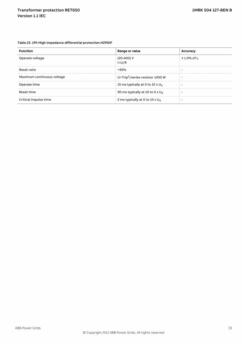
M13081-1 v5
Table 23. 1Ph High impedance differential protection HZPDIF
Function Range or value Accuracy
Operate voltage (20-400) VI=U/R
± 1.0% of Ir
Reset ratio >95% -
Maximum continuous voltage U>Trip2/series resistor ≤200 W -
Operate time 15 ms typically at 0 to 10 x Ud -
Reset time 90 ms typically at 10 to 0 x Ud -
Critical impulse time 2 ms typically at 0 to 10 x Ud -
Transformer protection RET650 1MRK 504 127-BEN BVersion 1.1 IEC
ABB Power Grids 33© Copyright 2011 ABB Power Grids. All rights reserved
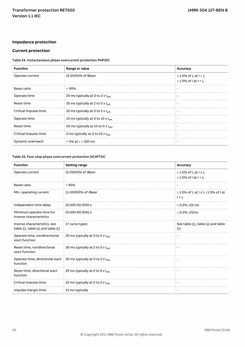
Impedance protection
Current protectionIP11400-1 v1M12336-1 v5
Table 24. Instantaneous phase overcurrent protection PHPIOC
Function Range or value Accuracy
Operate current (5-2500)% of lBase ± 1.0% of Ir at I £ Ir± 1.0% of I at I > Ir
Reset ratio > 95% -
Operate time 20 ms typically at 0 to 2 x Iset -
Reset time 35 ms typically at 2 to 0 x Iset -
Critical impulse time 10 ms typically at 0 to 2 x Iset -
Operate time 10 ms typically at 0 to 10 x Iset -
Reset time 45 ms typically at 10 to 0 x Iset -
Critical impulse time 2 ms typically at 0 to 10 x Iset -
Dynamic overreach < 5% at t = 100 ms -
M12342-1 v6
Table 25. Four step phase overcurrent protection OC4PTOC
Function Setting range Accuracy
Operate current (5-2500)% of lBase ± 1.0% of Ir at I ≤ Ir± 1.0% of I at I > Ir
Reset ratio > 95% -
Min. operating current (1-10000)% of lBase ± 1.0% of Ir at I ≤ Ir ±1.0% of I atI > Ir
Independent time delay (0.000-60.000) s ± 0.5% ±25 ms
Minimum operate time forinverse characteristics
(0.000-60.000) s ± 0.5% ±25ms
Inverse characteristics, seetable 61, table 62 and table 63
17 curve types See table 61, table 62 and table63
Operate time, nondirectionalstart function
20 ms typically at 0 to 2 x Iset -
Reset time, nondirectionalstart function
30 ms typically at 2 to 0 x Iset -
Operate time, directional startfunction
30 ms typically at 0 to 2 x Iset -
Reset time, directional startfunciton
25 ms typically at 2 to 0 x Iset -
Critical impulse time 10 ms typically at 0 to 2 x Iset -
Impulse margin time 15 ms typically -
Transformer protection RET650 1MRK 504 127-BEN BVersion 1.1 IEC
34 ABB Power Grids© Copyright 2011 ABB Power Grids. All rights reserved

M12340-2 v4
Table 26. Instantaneous residual overcurrent protection EFPIOC
Function Range or value Accuracy
Operate current (1-2500)% of lBase ± 1.0% of Ir at I £ Ir± 1.0% of I at I > Ir
Reset ratio > 95% -
Operate time 20 ms typically at 0 to 2 x Iset -
Reset time 30 ms typically at 2 to 0 x Iset -
Critical impulse time 10 ms typically at 0 to 2 x Iset -
Operate time 10 ms typically at 0 to 10 x Iset -
Reset time 40 ms typically at 10 to 0 x Iset -
Critical impulse time 2 ms typically at 0 to 10 x Iset -
Dynamic overreach < 5% at t = 100 ms -
M15223-1 v7
Table 27. Four step residual overcurrent protection EF4PTOC
Function Range or value Accuracy
Operate current (1-2500)% of lBase ± 1.0% of Ir at I £ Ir± 1.0% of I at I > Ir
Reset ratio > 95% -
Operate current for directionalcomparison
(1–100)% of lBase ± 1.0% of Ir
Min. operating current (1-10000)% of lBase ± 1.0% of Ir at I < Ir ± 1.0% of I atI < Ir
Minimum operate time forinverse characteristics
(0.000-60.000) s ± 0.5% ± 25 ms
Timers (0.000-60.000) s ± 0.5% ±25 ms
Inverse characteristics, seetable 61, table 62 and table 63
17 curve types See table 61, table 62 and table63
Minimum polarizing voltage (1–100)% of UBase ± 0.5% of Ur
Minimum polarizing current (2-100)% of IBase ±1.0% of Ir
Real part of source Z used forcurrent polarization
(0.50-1000.00) W/phase -
Imaginary part of source Zused for current polarization
(0.50–3000.00) W/phase -
Operate time, non-directionalstart function
30 ms typically at 0.5 to 2 x Iset -
Reset time, non-directionalstart function
30 ms typically at 2 to 0.5 x Iset -
Operate time, directional startfunction
30 ms typically at 0,5 to 2 x IN -
Reset time, directional startfunction
30 ms typically at 2 to 0,5 x IN -
Transformer protection RET650 1MRK 504 127-BEN BVersion 1.1 IEC
ABB Power Grids 35© Copyright 2011 ABB Power Grids. All rights reserved
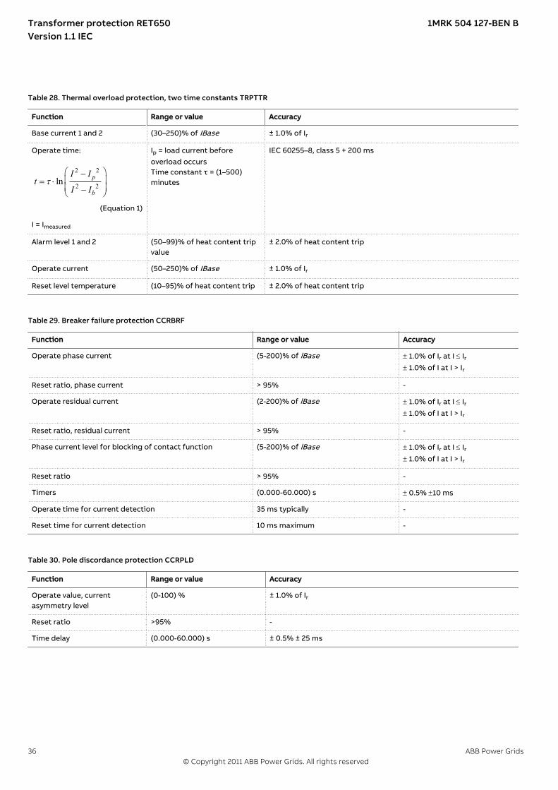
M13266-2 v4
Table 28. Thermal overload protection, two time constants TRPTTR
Function Range or value Accuracy
Base current 1 and 2 (30–250)% of IBase ± 1.0% of Ir
Operate time:
2 2
2 2ln p
b
I It
I It
æ ö-ç ÷= ×ç ÷-è ø
EQUATION1356 V1 EN-US (Equation 1)
I = Imeasured
Ip = load current beforeoverload occursTime constant τ = (1–500)minutes
IEC 60255–8, class 5 + 200 ms
Alarm level 1 and 2 (50–99)% of heat content tripvalue
± 2.0% of heat content trip
Operate current (50–250)% of IBase ± 1.0% of Ir
Reset level temperature (10–95)% of heat content trip ± 2.0% of heat content trip
M12353-1 v5
Table 29. Breaker failure protection CCRBRF
Function Range or value Accuracy
Operate phase current (5-200)% of lBase ± 1.0% of Ir at I £ Ir± 1.0% of I at I > Ir
Reset ratio, phase current > 95% -
Operate residual current (2-200)% of lBase ± 1.0% of Ir at I £ Ir± 1.0% of I at I > Ir
Reset ratio, residual current > 95% -
Phase current level for blocking of contact function (5-200)% of lBase ± 1.0% of Ir at I £ Ir± 1.0% of I at I > Ir
Reset ratio > 95% -
Timers (0.000-60.000) s ± 0.5% ±10 ms
Operate time for current detection 35 ms typically -
Reset time for current detection 10 ms maximum -
M13279-1 v5
Table 30. Pole discordance protection CCRPLD
Function Range or value Accuracy
Operate value, currentasymmetry level
(0-100) % ± 1.0% of Ir
Reset ratio >95% -
Time delay (0.000-60.000) s ± 0.5% ± 25 ms
Transformer protection RET650 1MRK 504 127-BEN BVersion 1.1 IEC
36 ABB Power Grids© Copyright 2011 ABB Power Grids. All rights reserved
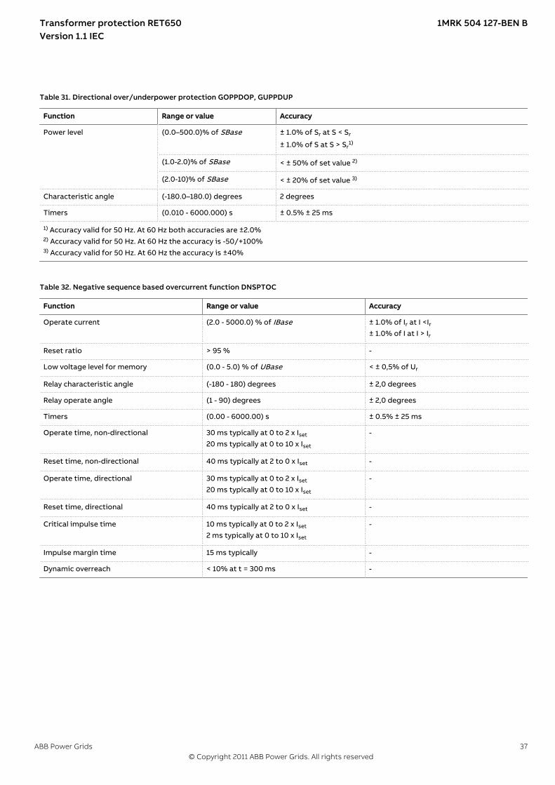
SEMOD175152-2 v4
Table 31. Directional over/underpower protection GOPPDOP, GUPPDUP
Function Range or value Accuracy
Power level (0.0–500.0)% of SBase ± 1.0% of Sr at S < Sr
± 1.0% of S at S > Sr1)
(1.0-2.0)% of SBase < ± 50% of set value 2)
(2.0-10)% of SBase < ± 20% of set value 3)
Characteristic angle (-180.0–180.0) degrees 2 degrees
Timers (0.010 - 6000.000) s ± 0.5% ± 25 ms
1) Accuracy valid for 50 Hz. At 60 Hz both accuracies are ±2.0%2) Accuracy valid for 50 Hz. At 60 Hz the accuracy is -50/+100%3) Accuracy valid for 50 Hz. At 60 Hz the accuracy is ±40%
GUID-D69015D7-192B-45DE-A67A-96F582CF09C0 v2
Table 32. Negative sequence based overcurrent function DNSPTOC
Function Range or value Accuracy
Operate current (2.0 - 5000.0) % of IBase ± 1.0% of Ir at I <Ir± 1.0% of I at I > Ir
Reset ratio > 95 % -
Low voltage level for memory (0.0 - 5.0) % of UBase < ± 0,5% of Ur
Relay characteristic angle (-180 - 180) degrees ± 2,0 degrees
Relay operate angle (1 - 90) degrees ± 2,0 degrees
Timers (0.00 - 6000.00) s ± 0.5% ± 25 ms
Operate time, non-directional 30 ms typically at 0 to 2 x Iset
20 ms typically at 0 to 10 x Iset
-
Reset time, non-directional 40 ms typically at 2 to 0 x Iset -
Operate time, directional 30 ms typically at 0 to 2 x Iset
20 ms typically at 0 to 10 x Iset
-
Reset time, directional 40 ms typically at 2 to 0 x Iset -
Critical impulse time 10 ms typically at 0 to 2 x Iset
2 ms typically at 0 to 10 x Iset
-
Impulse margin time 15 ms typically -
Dynamic overreach < 10% at t = 300 ms -
Transformer protection RET650 1MRK 504 127-BEN BVersion 1.1 IEC
ABB Power Grids 37© Copyright 2011 ABB Power Grids. All rights reserved
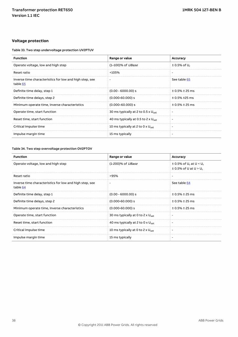
Voltage protectionIP14271-1 v1M13290-1 v6
Table 33. Two step undervoltage protection UV2PTUV
Function Range or value Accuracy
Operate voltage, low and high step (1–100)% of UBase ± 0.5% of Ur
Reset ratio <105% -
Inverse time characteristics for low and high step, seetable 65
- See table 65
Definite time delay, step 1 (0.00 - 6000.00) s ± 0.5% ± 25 ms
Definite time delays, step 2 (0.000-60.000) s ± 0.5% ±25 ms
Minimum operate time, inverse characteristics (0.000–60.000) s ± 0.5% ± 25 ms
Operate time, start function 30 ms typically at 2 to 0.5 x Uset -
Reset time, start function 40 ms typically at 0.5 to 2 x Uset -
Critical impulse time 10 ms typically at 2 to 0 x Uset -
Impulse margin time 15 ms typically -
M13304-1 v5
Table 34. Two step overvoltage protection OV2PTOV
Function Range or value Accuracy
Operate voltage, low and high step (1-200)% of UBase ± 0.5% of Ur at U < Ur
± 0.5% of U at U > Ur
Reset ratio >95% -
Inverse time characteristics for low and high step, seetable 64
- See table 64
Definite time delay, step 1 (0.00 - 6000.00) s ± 0.5% ± 25 ms
Definite time delays, step 2 (0.000-60.000) s ± 0.5% ± 25 ms
Minimum operate time, Inverse characteristics (0.000-60.000) s ± 0.5% ± 25 ms
Operate time, start function 30 ms typically at 0 to 2 x Uset -
Reset time, start function 40 ms typically at 2 to 0 x Uset -
Critical impulse time 10 ms typically at 0 to 2 x Uset -
Impulse margin time 15 ms typically -
Transformer protection RET650 1MRK 504 127-BEN BVersion 1.1 IEC
38 ABB Power Grids© Copyright 2011 ABB Power Grids. All rights reserved

M13317-2 v5
Table 35. Two step residual overvoltage protection ROV2PTOV
Function Range or value Accuracy
Operate voltage, step 1 (1-200)% of UBase ± 0.5% of Ur at U < Ur
± 0.5% of U at U > Ur
Operate voltage, step 2 (1–100)% of UBase ± 0.5% of Ur at U < Ur
± 0.5% of U at U > Ur
Reset ratio >95% -
Inverse time characteristics for low and high step, seetable 66
- See table 66
Definite time setting, step 1 (0.00–6000.00) s ± 0.5% ± 25 ms
Definite time setting, step 2 (0.000–60.000) s ± 0.5% ± 25 ms
Minimum operate time for step 1 inverse characteristic (0.000-60.000) s ± 0.5% ± 25 ms
Operate time, start function 30 ms typically at 0 to 2 x Uset -
Reset time, start function 40 ms typically at 2 to 0 x Uset -
Critical impulse time 10 ms typically at 0 to 2 x Uset -
Impulse margin time 15 ms typically -
M13338-2 v5
Table 36. Overexcitation protection OEXPVPH
Function Range or value Accuracy
Operate value, start (100–180)% of (UBase/frated) ± 0.5% of U
Operate value, alarm (50–120)% of start level ± 0.5% of Ur at U ≤ Ur
± 0.5% of U at U > Ur
Operate value, high level (100–200)% of (UBase/frated) ± 0.5% of U
Curve type IEEE
2
(0.18 ):
( 1)k
IEEE tM
×=
-
EQUATION1319 V1 EN-US (Equation 2)
where M = (E/f)/(Ur/fr)
Class 5 + 40 ms
Minimum time delay forinverse function
(0.000–60.000) s ± 0.5% ± 25 ms
Alarm time delay (0.000–60.000) s ± 0.5% ± 25 ms
Transformer protection RET650 1MRK 504 127-BEN BVersion 1.1 IEC
ABB Power Grids 39© Copyright 2011 ABB Power Grids. All rights reserved
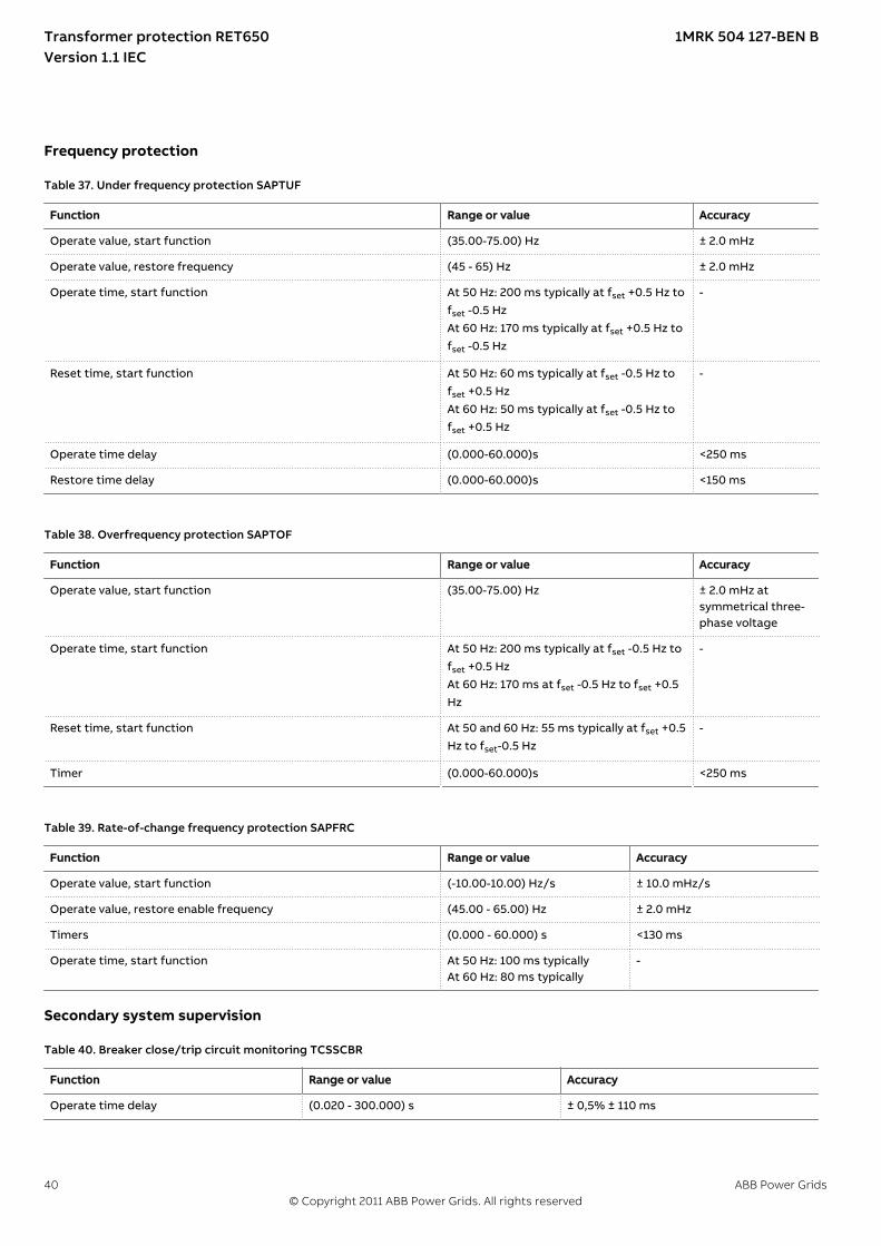
Frequency protectionIP15754-1 v2M13360-1 v7
Table 37. Under frequency protection SAPTUF
Function Range or value Accuracy
Operate value, start function (35.00-75.00) Hz ± 2.0 mHz
Operate value, restore frequency (45 - 65) Hz ± 2.0 mHz
Operate time, start function At 50 Hz: 200 ms typically at fset +0.5 Hz tofset -0.5 HzAt 60 Hz: 170 ms typically at fset +0.5 Hz tofset -0.5 Hz
-
Reset time, start function At 50 Hz: 60 ms typically at fset -0.5 Hz tofset +0.5 HzAt 60 Hz: 50 ms typically at fset -0.5 Hz tofset +0.5 Hz
-
Operate time delay (0.000-60.000)s <250 ms
Restore time delay (0.000-60.000)s <150 ms
M14964-1 v7
Table 38. Overfrequency protection SAPTOF
Function Range or value Accuracy
Operate value, start function (35.00-75.00) Hz ± 2.0 mHz atsymmetrical three-phase voltage
Operate time, start function At 50 Hz: 200 ms typically at fset -0.5 Hz tofset +0.5 HzAt 60 Hz: 170 ms at fset -0.5 Hz to fset +0.5Hz
-
Reset time, start function At 50 and 60 Hz: 55 ms typically at fset +0.5Hz to fset-0.5 Hz
-
Timer (0.000-60.000)s <250 ms
M14976-1 v5
Table 39. Rate-of-change frequency protection SAPFRC
Function Range or value Accuracy
Operate value, start function (-10.00-10.00) Hz/s ± 10.0 mHz/s
Operate value, restore enable frequency (45.00 - 65.00) Hz ± 2.0 mHz
Timers (0.000 - 60.000) s <130 ms
Operate time, start function At 50 Hz: 100 ms typicallyAt 60 Hz: 80 ms typically
-
Secondary system supervisionIP11402-1 v1GUID-CF26761C-55B8-41EF-B140-651F7F116003 v2
Table 40. Breaker close/trip circuit monitoring TCSSCBR
Function Range or value Accuracy
Operate time delay (0.020 - 300.000) s ± 0,5% ± 110 ms
Transformer protection RET650 1MRK 504 127-BEN BVersion 1.1 IEC
40 ABB Power Grids© Copyright 2011 ABB Power Grids. All rights reserved

ControlIP11404-1 v2SEMOD175215-2 v5
Table 41. Voltage control TR8ATCC, TCMYLTC
Function Range or value Accuracy
Transformer reactance on ATCC side (0.1–200.0)Ω, primary -
Time delay for lower command when fast step down mode isactivated
(1.0–100.0) s -
Voltage control set voltage (85.0–120.0)% of UB2 ±0.5% of Ur
Outer voltage deadband (0.2–9.0)% of UB2 ± 5,0% of set value
Inner voltage deadband (0.1–9.0)% of UB2 ± 5,0% of set value
Upper limit of busbar voltage (80–180)% of UB2 ± 0.5% of Ur
Lower limit of busbar voltage (70–120)% of UB2 ± 0.5% of Ur
Undervoltage block level (0–120)% of UB2 ± 0.5% of Ur
Time delay (long) for automatic control commands (3–1000) s ± 0.5% ± 110 ms
Time delay (short) for automatic control commands (1–1000) s ± 0.5% ± 110 ms
Minimum operating time in inverse mode (3–120) s ± 0.5% ± 110 ms
Line resistance (0.00–150.00)Ω, primary -
Line reactance (-150.00–150.00)Ω, primary -
Load voltage adjustment constants (-20.0–20.0)% of UB2 ± 5,0% of set value
Load voltage auto correction (-20.0–20.0)% of UB2 ± 5,0% of set value
Overcurrent block level (0–250)% of IBase ± 1.0% of Ir at I≤Ir± 1.0% of I at I>Ir
Level for number of counted raise/lower within one hour (0–30) operations/hour -
Level for number of counted raise/lower within 24 hours (0–100) operations/day -
Time window for hunting alarm (1–120) minutes -
Hunting detection alarm, max operations/window (3–30) operations/window -
Alarm level of active power in forward and reverse direction (-9999.99–9999.99) MW ± 1.0% of Sr
Alarm level of reactive power in forward and reverse direction (-9999.99–9999.99) MVAr ± 1.0% of Sr
Time delay for alarms from power supervision (1–6000) s ± 0.5% ± 110 ms
Tap position for lowest and highest voltage (1–63) -
Type of code conversion Binary, BCD, Gray, ContactPerTap -
Time after position change before the value is accepted (1–60) s ± 0.5% ± 25 ms
Tap changer constant time-out (1–120) s ± 0.5% ± 25 ms
Raise/lower command output pulse duration (0.5–10.0) s ± 0.5% ± 25 ms
Transformer protection RET650 1MRK 504 127-BEN BVersion 1.1 IEC
ABB Power Grids 41© Copyright 2011 ABB Power Grids. All rights reserved

Scheme communication
LogicIP11406-1 v1M12380-1 v4
Table 42. Tripping logic SMPPTRC
Function Range or value Accuracy
Trip action 3-ph -
Timers (0.000-60.000) s ± 0.5% ± 10 ms
M11443-1 v6
Table 43. Configurable logic blocks
Logic block Quantity with cycle time Range or value Accuracy
5 ms 20 ms 100 ms
AND 60 60 160 - -
OR 60 60 160 - -
XOR 10 10 20 - -
INVERTER 30 30 80 - -
SRMEMORY 10 10 20 - -
RSMEMORY 10 10 20 - -
GATE 10 10 20 - -
PULSETIMER 10 10 20 (0.000–90000.000) s ± 0.5% ± 25 ms
TIMERSET 10 10 20 (0.000–90000.000) s ± 0.5% ± 25 ms
LOOPDELAY 10 10 20
MonitoringIP11408-1 v1M12386-1 v6
Table 44. Measurements CVMMXN
Function Range or value Accuracy
Voltage (0.1-1.5) ×Ur ± 0.5% of Ur at U£Ur
± 0.5% of U at U > Ur
Connected current (0.2-4.0) × Ir ± 0.5% of Ir at I £ Ir± 0.5% of I at I > Ir
Active power, P 0.1 x Ur< U < 1.5 x Ur
0.2 x Ir < I < 4.0 x Ir
± 1.0% of Sr at S ≤ Sr
± 1.0% of S at S > Sr
1)
Reactive power, Q 0.1 x Ur< U < 1.5 x Ur
0.2 x Ir < I < 4.0 x Ir
± 1.0% of Sr at S ≤ Sr
± 1.0% of S at S > Sr
1)
Apparent power, S 0.1 x Ur < U < 1.5 x Ur
0.2 x Ir< I < 4.0 x Ir
± 1.0% of Sr at S ≤ Sr
± 1.0% of S at S > Sr
Apparent power, S Three phasesettings
cos phi = 1 ± 0.5% of S at S > Sr
± 0.5% of Sr at S ≤ Sr
Power factor, cos (φ) 0.1 x Ur < U < 1.5 x Ur
0.2 x Ir< I < 4.0 x Ir
< 0.02 2)
1) Accuracy valid for 50 Hz. At 60 Hz both accuracies are ±2.0%2) Accuracy valid for 50 Hz. At 60 Hz the accuracy is <0.04.
Transformer protection RET650 1MRK 504 127-BEN BVersion 1.1 IEC
42 ABB Power Grids© Copyright 2011 ABB Power Grids. All rights reserved
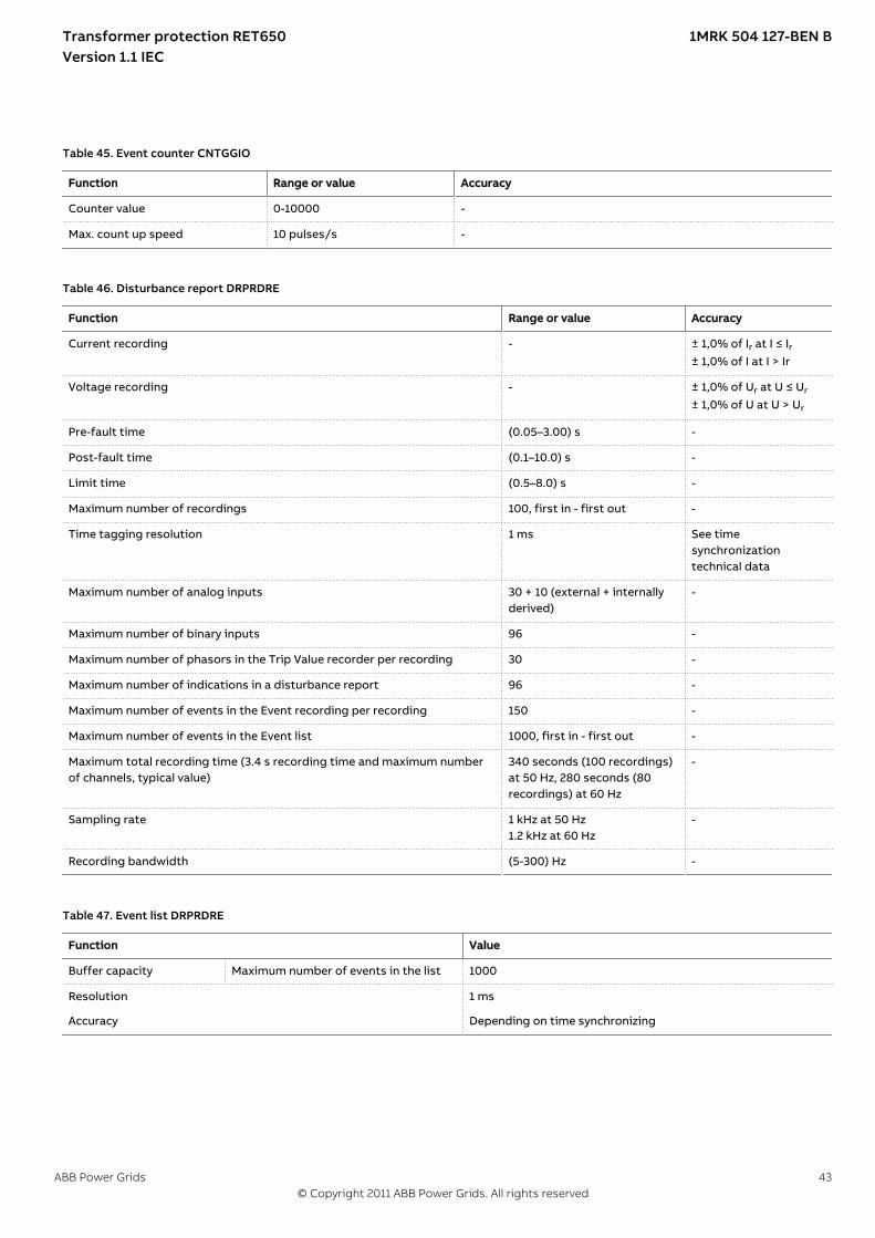
M13416-1 v4
Table 45. Event counter CNTGGIO
Function Range or value Accuracy
Counter value 0-10000 -
Max. count up speed 10 pulses/s -
M12760-1 v6
Table 46. Disturbance report DRPRDRE
Function Range or value Accuracy
Current recording - ± 1,0% of Ir at I ≤ Ir± 1,0% of I at I > Ir
Voltage recording - ± 1,0% of Ur at U ≤ Ur
± 1,0% of U at U > Ur
Pre-fault time (0.05–3.00) s -
Post-fault time (0.1–10.0) s -
Limit time (0.5–8.0) s -
Maximum number of recordings 100, first in - first out -
Time tagging resolution 1 ms See timesynchronizationtechnical data
Maximum number of analog inputs 30 + 10 (external + internallyderived)
-
Maximum number of binary inputs 96 -
Maximum number of phasors in the Trip Value recorder per recording 30 -
Maximum number of indications in a disturbance report 96 -
Maximum number of events in the Event recording per recording 150 -
Maximum number of events in the Event list 1000, first in - first out -
Maximum total recording time (3.4 s recording time and maximum numberof channels, typical value)
340 seconds (100 recordings)at 50 Hz, 280 seconds (80recordings) at 60 Hz
-
Sampling rate 1 kHz at 50 Hz1.2 kHz at 60 Hz
-
Recording bandwidth (5-300) Hz -
M12700-1 v3
Table 47. Event list DRPRDRE
Function Value
Buffer capacity Maximum number of events in the list 1000
Resolution 1 ms
Accuracy Depending on time synchronizing
Transformer protection RET650 1MRK 504 127-BEN BVersion 1.1 IEC
ABB Power Grids 43© Copyright 2011 ABB Power Grids. All rights reserved

M13765-1 v3
Table 48. Indications DRPRDRE
Function Value
Buffer capacity Maximum number of indications presented for single disturbance 96
Maximum number of recorded disturbances 100
M12702-1 v3
Table 49. Event recorder DRPRDRE
Function Value
Buffer capacity Maximum number of events in disturbance report 150
Maximum number of disturbance reports 100
Resolution 1 ms
Accuracy Depending on timesynchronizing
M13747-1 v3
Table 50. Trip value recorder DRPRDRE
Function Value
Buffer capacity
Maximum number of analog inputs 30
Maximum number of disturbance reports 100
M12384-1 v4
Table 51. Disturbance recorder DRPRDRE
Function Value
Buffer capacity Maximum number of analog inputs 40
Maximum number of binary inputs 96
Maximum number of disturbance reports 100
Maximum total recording time (3.4 s recording time and maximumnumber of channels, typical value)
340 seconds (100 recordings) at 50 Hz280 seconds (80 recordings) at 60 Hz
GUID-F633E33E-D602-4C21-8E39-2EBC8DA19863 v2
Table 52. Station battery supervision SPVNZBAT
Function Range or value Accuracy
Lower limit for the battery terminal voltage (60-140) % of Ubat ± 1.0% of set battery voltage
Reset ratio, lower limit <105 % -
Upper limit for the battery terminal voltage (60-140) % of Ubat ± 1.0% of set battery voltage
Reset ratio, upper limit >95 % -
Timers (0.000-60.000) s ± 0.5% ± 110 ms
Transformer protection RET650 1MRK 504 127-BEN BVersion 1.1 IEC
44 ABB Power Grids© Copyright 2011 ABB Power Grids. All rights reserved
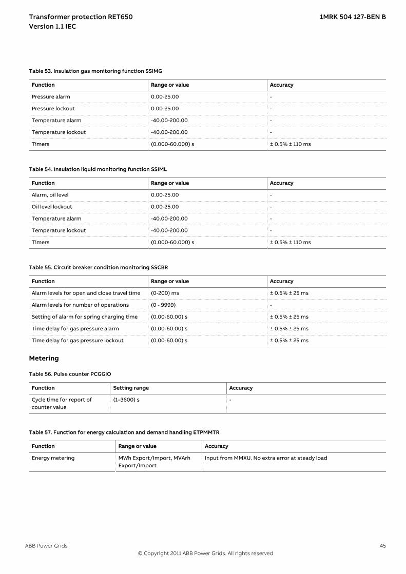
GUID-F034B396-6600-49EF-B0A5-8ED96766A6A0 v2
Table 53. Insulation gas monitoring function SSIMG
Function Range or value Accuracy
Pressure alarm 0.00-25.00 -
Pressure lockout 0.00-25.00 -
Temperature alarm -40.00-200.00 -
Temperature lockout -40.00-200.00 -
Timers (0.000-60.000) s ± 0.5% ± 110 ms
GUID-83B0F607-D898-403A-94FD-7FE8D45C73FF v2
Table 54. Insulation liquid monitoring function SSIML
Function Range or value Accuracy
Alarm, oil level 0.00-25.00 -
Oil level lockout 0.00-25.00 -
Temperature alarm -40.00-200.00 -
Temperature lockout -40.00-200.00 -
Timers (0.000-60.000) s ± 0.5% ± 110 ms
GUID-B6799420-D726-460E-B02F-C7D4F1937432 v2
Table 55. Circuit breaker condition monitoring SSCBR
Function Range or value Accuracy
Alarm levels for open and close travel time (0-200) ms ± 0.5% ± 25 ms
Alarm levels for number of operations (0 - 9999) -
Setting of alarm for spring charging time (0.00-60.00) s ± 0.5% ± 25 ms
Time delay for gas pressure alarm (0.00-60.00) s ± 0.5% ± 25 ms
Time delay for gas pressure lockout (0.00-60.00) s ± 0.5% ± 25 ms
MeteringIP14296-1 v1M13404-2 v4
Table 56. Pulse counter PCGGIO
Function Setting range Accuracy
Cycle time for report ofcounter value
(1–3600) s -
SEMOD153707-2 v4
Table 57. Function for energy calculation and demand handling ETPMMTR
Function Range or value Accuracy
Energy metering MWh Export/Import, MVArhExport/Import
Input from MMXU. No extra error at steady load
Transformer protection RET650 1MRK 504 127-BEN BVersion 1.1 IEC
ABB Power Grids 45© Copyright 2011 ABB Power Grids. All rights reserved

HardwareIP15796-1 v1
IEDSEMOD53385-1 v1GUID-59B01F47-1193-4243-B78C-EC6149CFA107 v12
Table 58. Degree of protection of flush-mounted IED
Description Value
Front side IP 40
Rear side, connection terminals IP 20
Table 59. Degree of protection of the LHMI
Description Value
Front and side IP 42
DimensionsGUID-33B28FB3-7FCF-4DEC-A194-C79D725805D6 v4
Table 60. Dimensions
Description Value
Width 220 mm
Height 265.9 mm (6U)
Depth 249.5 mm
Weight box <10 kg (6U)
Weight LHMI 1.3 kg (6U)
Inverse time characteristicsIP15797-1 v2M12388-1 v6
Table 61. ANSI Inverse time characteristics
Function Range or value Accuracy
Operating characteristic:
( )1= + ×
-
æ öç ÷ç ÷è ø
P
At B k
I
EQUATION1249-SMALL V1 EN-US
I = Imeasured/Iset
k = (0.05-999) in steps of 0.01 unless otherwise stated -
ANSI Extremely Inverse A=28.2, B=0.1217, P=2.0 ANSI/IEEE C37.112,class 5 + 40 ms
ANSI Very inverse A=19.61, B=0.491, P=2.0
ANSI Normal Inverse A=0.0086, B=0.0185, P=0.02, tr=0.46
ANSI Moderately Inverse A=0.0515, B=0.1140, P=0.02
ANSI Long Time Extremely Inverse A=64.07, B=0.250, P=2.0
ANSI Long Time Very Inverse A=28.55, B=0.712, P=2.0
ANSI Long Time Inverse k=(0.05-999) in steps of 0.01A=0.086, B=0.185, P=0.02
Transformer protection RET650 1MRK 504 127-BEN BVersion 1.1 IEC
46 ABB Power Grids© Copyright 2011 ABB Power Grids. All rights reserved

Table 62. IEC Inverse time characteristics
Function Range or value Accuracy
Operating characteristic:
( )1= ×
-
æ öç ÷ç ÷è ø
P
At k
I
EQUATION1251-SMALL V1 EN-US
I = Imeasured/Iset
k = (0.05-999) in steps of 0.01 -
IEC Normal Inverse A=0.14, P=0.02 IEC 60255-151, class 5 +40 ms
IEC Very inverse A=13.5, P=1.0
IEC Inverse A=0.14, P=0.02
IEC Extremely inverse A=80.0, P=2.0
IEC Short time inverse A=0.05, P=0.04
IEC Long time inverse A=120, P=1.0
Table 63. RI and RD type inverse time characteristics
Function Range or value Accuracy
RI type inverse characteristic
1
0.2360.339
= ×
-
t k
IEQUATION1137-SMALL V1 EN-US
I = Imeasured/Iset
k = (0.05-999) in steps of 0.01 IEC 60255-151, class 5 +40 ms
RD type logarithmic inversecharacteristic
5.8 1.35= - ×æ öç ÷è ø
tI
Ink
EQUATION1138-SMALL V1 EN-US
I = Imeasured/Iset
k = (0.05-999) in steps of 0.01 IEC 60255-151, class 5 +40 ms
Transformer protection RET650 1MRK 504 127-BEN BVersion 1.1 IEC
ABB Power Grids 47© Copyright 2011 ABB Power Grids. All rights reserved
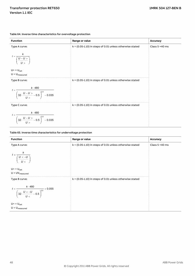
SEMOD116978-2 v4
Table 64. Inverse time characteristics for overvoltage protection
Function Range or value Accuracy
Type A curve:
=- >
>
æ öç ÷è ø
tk
U U
UEQUATION1436-SMALL V1 EN-US
U> = Uset
U = Umeasured
k = (0.05-1.10) in steps of 0.01 unless otherwise stated Class 5 +40 ms
Type B curve:
2.0
480
32 0.5 0.035
=×
- >× - -
>
æ öç ÷è ø
tk
U U
UEQUATION1437-SMALL V1 EN-US
k = (0.05-1.10) in steps of 0.01 unless otherwise stated
Type C curve:
3.0
480
32 0.5 0.035
=×
- >× - -
>
æ öç ÷è ø
tk
U U
UEQUATION1438-SMALL V1 EN-US
k = (0.05-1.10) in steps of 0.01 unless otherwise stated
Table 65. Inverse time characteristics for undervoltage protection
Function Range or value Accuracy
Type A curve:
=< -
<
æ öç ÷è ø
kt
U U
UEQUATION1431-SMALL V1 EN-US
U< = Uset
U = UVmeasured
k = (0.05-1.10) in steps of 0.01 unless otherwise stated Class 5 +40 ms
Type B curve:
2.0
4800.055
32 0.5
×= +
< -× -
<
æ öç ÷è ø
kt
U U
UEQUATION1432-SMALL V1 EN-US
U< = Uset
U = Umeasured
k = (0.05-1.10) in steps of 0.01 unless otherwise stated
Transformer protection RET650 1MRK 504 127-BEN BVersion 1.1 IEC
48 ABB Power Grids© Copyright 2011 ABB Power Grids. All rights reserved
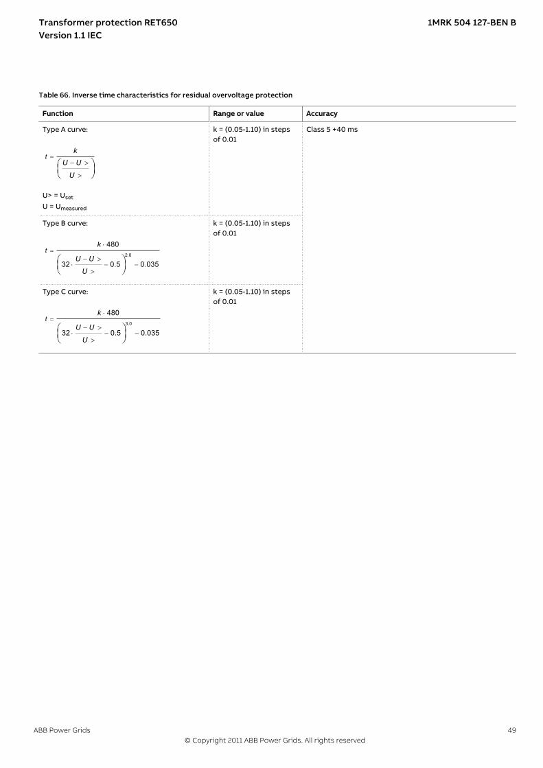
Table 66. Inverse time characteristics for residual overvoltage protection
Function Range or value Accuracy
Type A curve:
=- >
>
æ öç ÷è ø
tk
U U
UEQUATION1436-SMALL V1 EN-US
U> = Uset
U = Umeasured
k = (0.05-1.10) in stepsof 0.01
Class 5 +40 ms
Type B curve:
2.0
480
32 0.5 0.035
=×
- >× - -
>
æ öç ÷è ø
tk
U U
UEQUATION1437-SMALL V1 EN-US
k = (0.05-1.10) in stepsof 0.01
Type C curve:
3.0
480
32 0.5 0.035
=×
- >× - -
>
æ öç ÷è ø
tk
U U
UEQUATION1438-SMALL V1 EN-US
k = (0.05-1.10) in stepsof 0.01
Transformer protection RET650 1MRK 504 127-BEN BVersion 1.1 IEC
ABB Power Grids 49© Copyright 2011 ABB Power Grids. All rights reserved
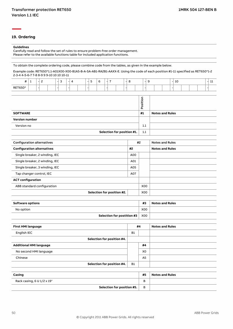
19. OrderingGUID-F6A0B4E0-28C8-41A0-9029-F5050E6D7DF8 v2.1.1
GuidelinesCarefully read and follow the set of rules to ensure problem-free order management.Please refer to the available functions table for included application functions.
To obtain the complete ordering code, please combine code from the tables, as given in the example below.
Example code: RET650*1.1-A01X00-X00-B1A5-B-A-SA-AB1-RA2B1-AAXX-E. Using the code of each position #1-11 specified as RET650*1-22-3-4 4-5-6-7 7-8 8-9 9 9-10 10 10 10-11
# 1 - 2 - 3 - 4 - 5 6 - 7 - 8 - 9 - 10 - 11
RET650* - - - - - - - - -
Posi
tion
SOFTWARE #1 Notes and Rules
Version number
Version no 1.1
Selection for position #1. 1.1
Configuration alternatives #2 Notes and Rules
Configuration alternatives #2 Notes and Rules
Single breaker, 2 winding, IEC A00
Single breaker, 2 winding, IEC A01
Single breaker, 3 winding, IEC A05
Tap changer control, IEC A07
ACT configuration
ABB standard configuration X00
Selection for position #2. X00
Software options #3 Notes and Rules
No option X00
Selection for postition #3 X00
First HMI language #4 Notes and Rules
English IEC B1
Selection for position #4.
Additional HMI language #4
No second HMI language X0
Chinese A5
Selection for position #4. B1
Casing #5 Notes and Rules
Rack casing, 6 U 1/2 x 19" B
Selection for position #5. B
Transformer protection RET650 1MRK 504 127-BEN BVersion 1.1 IEC
50 ABB Power Grids© Copyright 2011 ABB Power Grids. All rights reserved

Mounting details with IP40 of protection from the front #6 Notes and Rules
No mounting kit included X
Rack mounting kit for 6 U 1/2 x 19" A
Wall mounting kit for 6U 1/2 x 19" D
Flush mounting kit for 6U 1/2 x 19" E
Wall mounting bracket 6U 1/2 x 19" G
Selection for position #6.
Connection type for Power supply, Input/output and Communicationmodules
#7 Notes and Rules
Compression terminals S
Ringlug terminals R
Power supply
Slot position:
pPS
M
100-240V AC, 110-250V DC, 9BO A
48-125V DC, 9BO B
Selection for position #7.
Human machine interface #8 Notes and Rules
Local human machine interface, OL3000, IEC6U 1/2 x 19", Basic
A
Detached LHMI
No detached mounting of LHMI X0
Detached mounting of LHMI incl. Ethernet cable, 1m B1
Detached mounting of LHMI incl. Ethernet cable, 2m B2
Detached mounting of LHMI incl. Ethernet cable, 3m B3
Detached mounting of LHMI incl. Ethernet cable, 4m B4
Detached mounting of LHMI incl. Ethernet cable, 5m B5
Selection for position #8. A
Connection type for Analog modules #9 Notes and Rules
Compression terminals S
Ringlug terminals R
Analog system
Slot position: p2
Transformer module, 6I + 4U, 1/5A, 100/220V A1 Only in A05 and A07
Transformer module, 8I + 2U, 1/5A, 100/220V A2 Only in A00 and A01
Slot position: p4
Analog input module, 6I + 4U, 1/5A, 100/220V B1 Only in A05
Selection for position #9.
Transformer protection RET650 1MRK 504 127-BEN BVersion 1.1 IEC
ABB Power Grids 51© Copyright 2011 ABB Power Grids. All rights reserved

Binary input/output module #10 Notes and Rules
Slot position (rear view) p3
p4 p5
p6
Available slots in 1/2 case p3 and p4 not available for A05.Positions used by AIM.
No board in slot X X X X
Binary input/output module 9 BI, 3 NO Trip, 5 NO Signal, 1 COSignal
A A A A
Selection for position #10. A A p5 and p6 optional only for A01 and A07p5 and p6 = A for A05
X X X X Only for A00
Communication and processing module #11 Notes and Rules
Slot position (rear view)
pC
OM
14BI, IRIG-B, Ethernet, LC, ST B
Selection for position #11. B
AccessoriesIP15151-1 v1GUID-0C8E1FEC-F79F-4754-9946-ADECE1F9AA79 v2
Rack mounting kit for 2 x 6U 1/2 x 19" 1KHL400240R0001
External resistor unitSEMOD120228-4 v6
High impedance resistor unit 1-ph with resistor and voltage dependent resistor for20-100V operating voltage
1 2RK795101-MA
High impedance resistor unit 1-ph with resistor and voltage dependent resistor for100-400V operating voltage
1 2 RK795101-CB
Configuration and monitoring toolsIP15162-1 v2M15042-3 v2
Front connection cable between LCD-HMI and PC 1MRK 001 665-CA
SEMOD131414-4 v2
LED Label special paper A4, 1 pc 1MRK 002 038-CA
LED Label special paper Letter, 1 pc 1MRK 002 038-DA
ManualsGUID-E0003A6F-7D15-4D7B-BD0B-DF55688C71EE v2
Note: One (1) IED Connect CD containing user documentation (Operation manual, Technicalmanual, Installation manual, Commissioning manual, Application manual, Communicationprotocol manual, DNP, Communication protocol manual, IEC61850, Communication protocolmanual, IEC60870-5-103, Type test certificate, Engineering manual and Point list manual, DNP3,Connectivity packages and LED label template is always included for each IED.
Rule: Specify additional quantity of IED Connect CD requested
User documentation 1MRK 003 500-AA
Transformer protection RET650 1MRK 504 127-BEN BVersion 1.1 IEC
52 ABB Power Grids© Copyright 2011 ABB Power Grids. All rights reserved
Quantity :
Quantity :
Quantity :
Quantity :
Quantity :
Quantity :
Quantity :
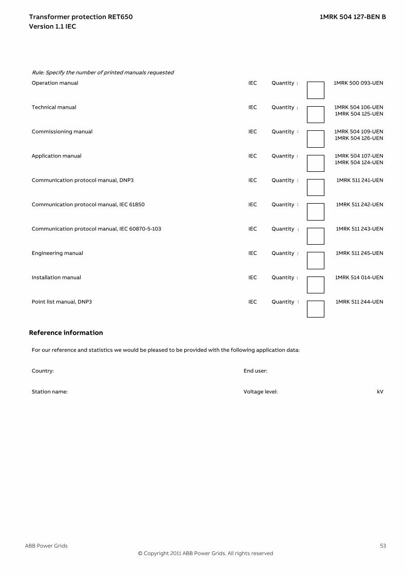
Rule: Specify the number of printed manuals requested
Operation manual 1MRK 500 093-UEN
Technical manual 1MRK 504 106-UEN1MRK 504 125-UEN
Commissioning manual 1MRK 504 109-UEN1MRK 504 126-UEN
Application manual 1MRK 504 107-UEN1MRK 504 124-UEN
Communication protocol manual, DNP3 1MRK 511 241-UEN
Communication protocol manual, IEC 61850 1MRK 511 242-UEN
Communication protocol manual, IEC 60870-5-103 1MRK 511 243-UEN
Engineering manual 1MRK 511 245-UEN
Installation manual 1MRK 514 014-UEN
Point list manual, DNP3 1MRK 511 244-UEN
Reference informationM2175-3 v4
For our reference and statistics we would be pleased to be provided with the following application data:
Country: End user:
Station name: Voltage level: kV
Transformer protection RET650 1MRK 504 127-BEN BVersion 1.1 IEC
ABB Power Grids 53© Copyright 2011 ABB Power Grids. All rights reserved
IEC Quantity :
IEC Quantity :
IEC Quantity :
IEC Quantity :
IEC Quantity :
IEC Quantity :
IEC Quantity :
IEC Quantity :
IEC Quantity :
IEC Quantity :

Related documentsGUID-DEA16B32-29D9-40B2-BC9F-12F3AEA90245 v3
Documents related to RET650 Identity number
Application manual 1MRK 504 124-UEN
Technical manual 1MRK 504 125-UEN
Commissioning manual 1MRK 504 126-UEN
Product Guide, configured 1MRK 504 127-BEN
Type test certificate 1MRK 504 127-TEN
650 series manuals Identity number
Communication protocol manual, DNP3 1MRK 511 241-UEN
Communication protocol manual, IEC 61850 1MRK 511 242-UEN
Communication protocol manual, IEC 60870-5-103 1MRK 511 243-UEN
Point list manual, DNP3 1MRK 511 244-UEN
Engineering manual 1MRK 511 245-UEN
Operation manual 1MRK 500 093-UEN
Installation manual 1MRK 514 014-UEN
Transformer protection RET650 1MRK 504 127-BEN BVersion 1.1 IEC
54 ABB Power Grids© Copyright 2011 ABB Power Grids. All rights reserved

55
ABB Power Grids Sweden ABGrid Automation ProductsSE-721 59 Västerås, SwedenPhone +46 (0) 10 738 00 00
https://www.abb.com/protection-control
© Copyright 2011 ABB Power Grids.All rights reserved.
Scan this QR code to visit our website
1MR
K 5
04
127
-BE
N
Related Documents