energize - April 2009 - Page 26 TRANSMISSION When faults do occur, there is a need to identify the type and location of the fault rapidly, thus reducing downtime. This places great importance on diagnostic testing and the interpretation of results. Oil testing methods Dissolved gas analysis (DGA), furans and oil quality tests are very well established and have proved to be a valuable tool in transformer fault diagnosis. Dissolved gas analysis There are a number of different DGA techniques such as IEC, Roger’s Ratios, IEEE, etc. that have been used with great success. These methods suffer from drawbacks like their inability to determine a normal operating transformer and returning of codes with no diagnosis. Howeve r, DGA does give warning of a developing fault that can prompt further investigation. Oil quality indicators Oil quality indicators such as moisture (from which relative saturation is calculated), acidity, dielectric strength and interfacial tension are excellent indicators of ageing oil. Poor results normally result in purification and/or regeneration of the transformer oil and it some cases oil replacement. Paper condition indicator The concentrations of paper degradation product 2-furfural (2FAL) provide an indication of the condition of the paper. However, there are a number of factors that influence the concentration and stability of furanic compounds such as temperature, type of paper used, oil tr eatment, etc. The conventional method is to convert the 2FAL value to a degree of polymerization (DP) by applying the Chendong equation which can be used to provide a general sense of the average DP based on the 2-furfural content. However, it is always best to have some DP data for a given population to verify the relationship. The rate of increase in furans between samples is also a strong indicator of paper ageing. Electrical tests The following electrical tests are used to determine the condition of the transformer: Power Factor and Capacitance on windings and bushings This test is used to assess the condition of the oil and cellulose in terms of moisture, carbonization, etc. The advantage of this method is that it identifies the winding (HV or LV) that has a possible problem. Ratio test This test is performed at 10 kV with a capacitor and is very effective in the detection of turn-to-turn or partial turn-to-turn failure when compared to other lower voltage (typically 380 V) ratio measurements. Experience has shown that Transformer failures within Southern Africa by L Moodley , K Govender and Y Chinaboo, Doble Engineering Africa The unexpected failure of a power transformer can result in a very large forced outage cost and there is a need to detect and locate suspect units rather than wait for failure. Condition Test Dielectric DGA, furans, winding insulation, ratio, insulation resistance Thermal DGA, exciting currents, DC winding resistance and IR scanning Mechanical SFRA, impedance, capacitance Table 1: Transformer assessment tests. Fig. 1: HV to MV winding response. Fig. 3: Flash marks on fixed contacts and collector rings. Fig. 2: Blue phase tapping leads and broken cleats.

Welcome message from author
This document is posted to help you gain knowledge. Please leave a comment to let me know what you think about it! Share it to your friends and learn new things together.
Transcript

8/7/2019 Transformer failures in Southern Africa
http://slidepdf.com/reader/full/transformer-failures-in-southern-africa 1/4energize - April 2009 - Page 26
TRANSMISSION
When faults do occur, there is a need
to identify the type and location of the
fault rapidly, thus reducing downtime. This
places great importance on diagnostic
testing and the interpretation of results.
Oil testing methods
Dissolved gas analysis (DGA), furans andoil quality tests are very well established
and have proved to be a valuable tool in
transformer fault diagnosis.
Dissolved gas analysis
There are a number of different DGA
techniques such as IEC, Roger’s Ratios,
IEEE, etc. that have been used with great
success. These methods suffer f rom
drawbacks like their inability to determine a
normal operating transformer and returning
of codes with no diagnosis. However, DGA
does give warning of a developing fault
that can prompt further investigation.
Oil quality indicators
Oil quality indicators such as moisture (from
which relative saturation is calculated),
acidity, dielectric strength and interfacial
tension are excellent indicators of ageing
oil. Poor results normally result in purification
and/or regeneration of the transformer oil
and it some cases oil replacement.
Paper condition indicator
The concentrations of paper degradation
product 2-furfural (2FAL) provide an
indication of the condition of the paper.
However, there are a number of factors that
influence the concentration and stability of
furanic compounds such as temperature,
type of paper used, oil treatment, etc. The
conventional method is to convert the 2FAL
value to a degree of polymerization (DP)
by applying the Chendong equation which
can be used to provide a general sense
of the average DP based on the 2-furfural
content. However, it is always best to have
some DP data for a given population to
verify the relationship. The rate of increase
in furans between samples is also a strong
indicator of paper ageing.
Electrical tests
The following electrical tests are used
to determine the cond i t ion of the
transformer:
Power Factor and Capacitance on
windings and bushings
This test is used to assess the condition of
the oil and cellulose in terms of moisture,
carbonization, etc. The advantage of this
method is that it identifies the winding (HV
or LV) that has a possible problem.
Ratio test
This test is performed at 10 kV wi tha capacitor and is very effective in
the detection of turn-to-turn or partial
turn-to-turn failure when compared to
other lower voltage (typically 380 V) ratio
measurements. Experience has shown that
Transformer failures within
Southern Africaby L Moodley, K Govender and Y Chinaboo, Doble Engineering Africa
The unexpected failure of a power transformer can result in a very large forced outage cost and there is a need to detect and locate suspect
units rather than wait for failure.
Condition Test
Dielectric DGA, furans, winding insulation, ratio, insulation
resistance
Thermal DGA, exciting currents, DC winding resistance
and IR scanning
Mechanical SFRA, impedance, capacitance
Table 1: Transformer assessment tests.
Fig. 1: HV to MV winding response.
Fig. 3: Flash marks on fixed contacts
and collector rings.
Fig. 2: Blue phase tapping leads
and broken cleats.
8/7/2019 Transformer failures in Southern Africa
http://slidepdf.com/reader/full/transformer-failures-in-southern-africa 2/4
TRANSMISSION
energize - April 2009 - Page 28
low voltage ratio tests would not stress the
insulation to a point were an inherent fault
would be detected. If this fault remains
undetected and the transformer is returned
to service at a system voltage much higherthan 380 V the transformer may fail on a
turn to turn fault.
Excitation current test
This test is used to determine the condition of
the magnetic circuit and the tap-changer.
It is performed on all tap positions to
identify a pattern in the currents. It is
performed at high voltages (typically at
10 kV) as excitation current testing hasproven to be ineffective in detecting core
related problems at low voltages.
Insulation resistance test
This test is used to determine the condition
of the insulation under the influence of
a DC voltage. Measurements are from
windings to ground and core to ground.
DC winding resistance rest
This test is used to determine bad or loose
connections on tap changers, bushings,
broken strands, shorted turns and highresistance contacts.
Impedance measurements
This test measures the short ci rcui t
impedance on a t rans former as a
3-phase equivalent. Measured values
are compared to nameplate values to
assess the mechanical condition of the
transformer in terms of winding deformation
and core displacement.
Sweep frequency response analysis (SFRA)
This test passes a range of frequencies
(between 10 Hz to 2 MHz) through the
transformer and then calculates the
transfer function. From these responses the
mechanical condition can be assessed.
Transformer assessment
The t ransformer’s condit ion can be
accurately assessed by evaluating the
transformer’s thermal, dielectric and
mechanical condit ion. This can be
effectively done by considering the
electrical and chemical tests. Table 1
indicates the tests that determine the
transformers condition.
Case study 1
On 19 February 2007, a 275/132 kV, 315 MVA
3-phase auto transformer, manufactured
in 1982, tripped on differential protection
(red and blue phases), main tank and
tap change pressure. At the initial site
inspection, the blue phase pressure relief
plate was found to have been blown out
from the diverter head cover. The main
tank pressure relief valve had operated.
No other external damage was visible.
Diagnostic tests and internal inspections
were performed.
Diagnostic test results
l Power factor and capacitance test:
Capacitances compared well with
historical results and were not indicative
of a problem. Winding power factor
test showed a significant increase from
the historical results. This is expected
as the result of the main tank pressure
relief operation.
l Exci tat ion current test : The tests
performed after the transformer had
tripped indicated problems on the
blue phase. When compared to
historical test results, the blue phase
exciting currents had increased by
an average of 47%, indicating a tap-changer or short circuit problem.
l Ratio test: From the ratios measured,
the blue phase had a number of taps
not within acceptable limits. All of the
electrical tests indicated a failure in the
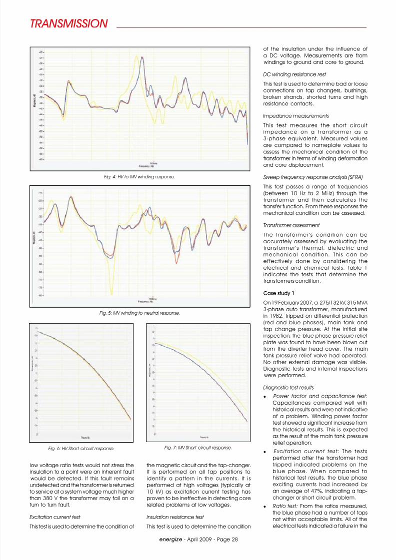
Fig. 4: HV to MV winding response.
Fig. 5: MV winding to neutral response.
Fig. 6: HV Short circuit response. Fig. 7: MV Short circuit response.
8/7/2019 Transformer failures in Southern Africa
http://slidepdf.com/reader/full/transformer-failures-in-southern-africa 3/4
TRANSMISSION
energize - April 2009 - Page 29
tap-changer. This was clearly evident
from the initial site inspection.
l SFRA tests: The SFRA results are given in
Fig. 1. The HV to MV winding open circui t
test shows a significant difference
in the blue phase compared to the
other two phases. This is a result of a
possible shorted turn, which has theeffect of creating an imbalance in the
reluctance on one of the core limbs,
producing this characteristic change
in low frequency response. Excitation
current and ratio tests supported this
diagnosis. However, there is also a
variance on the blue phase when
compared to the other phases in
the mid-to-high frequency range,
which indicates winding deformation.
This variance warranted an internal
inspection.
Conclusions from test results
All the electrical tests pointed to a problempossibly limited to the tap-changer. However,
the SFRA indicated clear winding/lead
deformation on the blue phase. This was the
result for the main tank pressure operating.
Internal inspection
The internal inspection revealed the
following:
l Diverter: When removed from the
transformer, the diverter was found
to have a blown out pressure relief
plate (incorporated in the head cover
casting), and burnt flexible lead which
connects metal parts to the common
contacts which connect to the take-off
terminal.
l Internal inspection of selector: The
blue-phase selector revealed that the
moving contacts were connected to
terminals 5 and 6 whereas these are
on terminals 6 and 7 on red and white
phases, and there were severe burn
marks due to flashover and arcing of
fixed contacts and collector rings. See
Fig. 2.
l Windings in main tank: Blue phase
tapping leads and cleats had severe
distortion of the tapping leads external
to the windings, due to fault currentforces, and paper insulation damage
(Fig. 3). The condition of the MV winding
could not be inspected. Numerous
cleats and bolts were dislodged and
broken and had fallen to the bottom
of the transformer.
Conclusion
It was clear that the tap-changer had
faulted. If the fault was restricted to the
tap-changer, repairs would have been
undertaken on site. This could have surely
resulted in a further failure as a result of
the tap-changer lead movement and
damage to the windings as indicated by the SFRA. The transformer is due to be de-
tanked and inspected in the factory.
Case study 2
A 132 /88 /6 ,6 kV au to t rans fo rmer ,
manufactured in 1982, and rated at
60 MVA underwent its routine maintenance
tests.
Diagnostic tests performed
l Power factor and capacitance test:
The power factor and capacitance testresults were within acceptable limits.
l Ratio test: The ratio test results were
within acceptable limits.
l Excitation current test: The excitationcurrents were within acceptabletests.
l SFRA test : The results are given inFigs. 4, 5, 6 and 7. The HV to MV winding open circuit response shows
clear variances on the middle phase
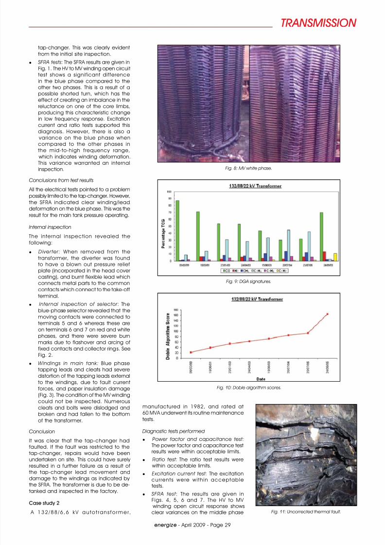
Fig. 8: MV white phase.
Fig. 9: DGA signatures.
Fig. 10: Doble algorithm scores.
Fig. 11: Uncorrected thermal fault.
8/7/2019 Transformer failures in Southern Africa
http://slidepdf.com/reader/full/transformer-failures-in-southern-africa 4/4
TRANSMISSION
energize - April 2009 - Page 30
at frequencies between 20 kHz and
400 kHz when compared to the other
two phases, indicating hoop buckling.
The MV winding to neutral open circuit
response shows similar frequency shiftson the white phase at frequencies
between 20 kHz and 400 kHz, indicating
deformation in the MV windings. The HV
and MV short circuit response revealed
no resistance or impedance change
between the phases. The MV short
circuit test revealed a resistance and
impedance change when compared
to the other phases, a clear indication
that the deformation is restricted to the
MV winding.
Conclusion
The transformer was internally inspected
and the MV winding had clear indicationsof winding deformation in the form of
hoop buckling. This is shown in Fig. 8. In
this case SFRA proved to be the only test
that could detect this type of fault as
all other electrical and oil tests gave no
indication.
Case study 3
A 1 3 2 / 8 8 / 2 2 kV a u t o t ra n s f o rm e r ,
manufactured in 1982, and rated at
160 MVA tripped on 31 July 2005 on
differential protection and restricted earth
fault.
Diagnostic tests performed: DGA
The results are shown in Fig 9. The Doble
Algorithm results are shown in Fig 10. From
1999 until 2005 the transformer experienced
a localized thermal fault. This is signified by
the high levels of ethylene and significant
levels of methane and ethane. A DGA
signature of this pattern indicates a core
and frame to earth circulating current. The
transformer experienced a dielectric fault
on 24 September 2005. This is indicated
by the levels of hydrogen and acetylene.
The root cause of the transformer failure
was the uncorrected thermal fault that was
present since 1999.
Doble algorithm
Doble has developed an algorithm to
mimic the key gas response and give
a single number to track the change in
pattern. This uses the key gas method to
present DGA used by IEEE method. The
relative proportions of the combustible
gases CO, H2, CH
4, C
2H
4, C
2H
6and C
2H
2
are displayed as a bar chart to illustratethe gas signature. This method is used
to investigate and illustrate the clear
difference that exists between "normal"
and "abnormal" results. The DGA score
reflects the seriousness of the signature.
DGA results for normal transformers would
be expected to return a score of no
more than about 30, whereas a core
circulating current would rate about 60
and more serious problems would score
around 100.
In this case study it is clear that the Doble
algorithm identified the fault many years
before the failure, and also indicates asteady increase in the scoring, which
indicates a worsening condition.
Internal inspection
After the analysis of the DGA test results,
an internal inspection was performed. The
results are shown in Fig. 11.
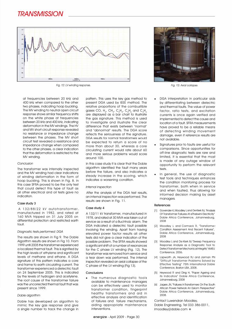
Case study 4
A 132/11 kV transformer, manufactured in
1978, and rated at 30 MVA was taken out of
service as a result of a Buchholz alarm. The
DGA indicated a dielectric fault possible
involving the winding. Apart from havingelevated power factor results all other
tests did not give a clear indication of the
possible problem. The SFRA results showed
a significant shift of a number of resonances
for the C phase LV winding (Fig. 12). The
transformer was removed from service and
a tear down was performed. The internal
inspection revealed an axial collapse of the
C phase of the LV winding (Fig 13).
Conclusions
l The numerous d iagnos t ic too l s
available to maintenance managers
can be effectively used to monitor
transformer condit ion, f ingerprint
healthy t ransformers and aid in
effective analysis and identification
of failures and failure mechanisms,
aiding appropriate maintenance
interventions.
Fig. 13: Axial collapse.
l DGA interpretation in particular aids
by differentiating between dielectric
and thermal faults. The value of power
factor, rat io tests, and excitat ion
currents is once again verified andimplemented to detect the cause and
location of a fault. SFRA measurements
have proved to be a reliable means
of detect ing winding movement
damage, even if reference results are
not available.
l Signatures prior to faults are useful for
comparisons. Since opportunities for
off-line diagnostic tests are rare and
limited, it is essential that the most
is made of any outage window of
opportunity to perform the relevant
tests.
l In general, the use of diagnost ic
test tools and techniques enhances
the condition monitoring process for
transformer, both when in service
and when faulted, thus allowing for
informed decision making by asset
managers.
References
[1] Govender K, Moodley L and De Klerk BJ, “Analysis
Of Transformer Failures At eThekwini Electricity”
Doble Africa Conference, Johannesburg,
2008
[2] Moodley L and Cormack R, “Transforme r
Condition Assessment And Recent Failures”,Doble Africa Conference, Johannesburg,
2008
[3] Moodley L and De Klerk BJ “Sweep Frequency
Response Analysis as a Diagnostic Tool to
Detect Transformer Mechanical Integrity” AMEU
Conference, 2006.
[4] Lapworth JA, Heywood RJ and Jarman PN
“Difficult Transformer Problems Solved by
Effective Testing” 75th International Doble
Conference, Boston USA, 2008.
[5] Heywood R and Ding H, “Paper Ageing and
its Indicators” Doble Africa Conference,
Johannesburg, 2008
[6] Jagers JN, “Failures In Transformers On The South
African Power Network An Eskom Perspective”Doble Africa Conference, Johannesburg,
2008.
Contact Luwendran Moodley,
Doble Engineering, Tel 033 386-0011,
Fig. 12: LV winding response.
Related Documents