Transfemoral endovascular aortic graft placement Timothy A. M. Chuter, BM, BS, Richard M. Green, MD, Kenneth Ouriel, MD, William M. Fiore, MD, and James A. DeWeese, MD, Rochester, N.Y. Purpose: The purpose of this study was to develop an endovascular system for transfemoral placement of straight aortic grafts and bifurcated aortoiliac grafts. Methods: Both types of graft consist of barbed, self-expanding stents attached to a woven polyester fabric. Survival studies of straight-graft function were performed in six large mongrd dogs. Digital subtraction fluoroscopic equipment was used to guide insertion and record angiograms at 0, 1, and 3 months. Bifurcated grafts were inserted in an additional eight dogs, four with distal stents and four without. Straight grafts were inserted into six cadaveric aortas (five atherosclerotic and one aneurysmal; age 68.7 + 5.7 years) to assess stent attachment. Results: Angiograms obtained immediately after straight-graft insertion showed placement to be within 4.6 + 1.6 mm of the intended level. Follow-up angiograms at 1 and 3 months showed no migration, no leakage, and patency of all six grafts. After bifurcated graft insertion there were no angiographic signs ofperigraft leakage, with or without distal stents. The mean force required to displace straight grafts 10 mm from their original position in cadaveric aortas was 1388 + 127g. Conclusion: These preliminary results show that straight and bifurcated endovascular grafts can be positioned accurately and securely in the abdominal aorta. (J VASC SURG 1993;18:185-97.) Endovascular repair of aortic aneurysms is now feasible because of advances in vascular imaging, catheter delivery systems, and arterial stenting. A graft can be introduced through a remote artery and anchored to nondilated vessels at the ends of an aneurysm to provide protection against rupture and a conduit for distal perfusion. Graft attachment must be accurate, secure, and hemostatic, both proximally and distally. The com- bination of graft and introducer must be small enough for retrograde insertion through the femoral 'tory. The system should have sufficient flexibility to traverse the often-tortuous iliac vessels. Endovascular systems have been used to repair small traumatic aneurysms in animals, but these From the Section of Vascular Surgery, Universityof Rochester, Rochester, N.Y. Supported in part by grants from Cook Catheter, Inc., Bloom- ington, Ind. Presented at the Sixth Annual Meeting of the Eastern Vascular Society,New York:,N.Y., April 30-May 3, 1992. Reprint requests: Tim Chuter, BM, BS, Department of Surgery, Strong Memorial Hospital, 601 Elmwood Ave., Box SURG, Rochester, NY 14624. Copyright © 1993 by The Society for Vascular Surgery and InternationalSociel~ T for CardiovascularSurgery,North Amer- ican Chapter. 0741-5214/93/$1.00 + .10 24/6/42587 models lacked the more challenging features of human aneurysms. 1,2 Some promising initial results have been reported with a balloon-expandable system in humans, a This report describes our initial laboratory expe- rience with an endovascular delivery system ~ for straight and bifurcated grafts that was designed specifically to meet the demands of clinical use. MATERIAL AND METHODS The technique ofendovascular graft insertion was studied in dogs. Graft attachment was assessed further in human cadaveric aortas. Apparatus The two systems of endovascular grafting used in these studies represent different stages in the evolu- tion of the technique. Several components were changed in the interval between the straight and bifurcated graft insertions, and several have changed since then. Differences between these systems also reflect the more exacting requirements for bilateral distal limb placement and stenting. Straight grafts. Straight grafts were constructed *Patent held by Timothy A. M. Chuter. 185

Welcome message from author
This document is posted to help you gain knowledge. Please leave a comment to let me know what you think about it! Share it to your friends and learn new things together.
Transcript
Transfemoral endovascular aortic graft placement Timothy A. M. Chuter , BM, BS, Richard M. Green, MD, Kenne th Ouriel, MD, Will iam M. Fiore, MD, and James A. DeWeese, MD, Rochester, N.Y.
Purpose: The purpose of this study was to develop an endovascular system for transfemoral placement of straight aortic grafts and bifurcated aortoiliac grafts. Methods: Both types of graft consist of barbed, self-expanding stents attached to a woven polyester fabric. Survival studies of straight-graft function were performed in six large mongrd dogs. Digital subtraction fluoroscopic equipment was used to guide insertion and record angiograms at 0, 1, and 3 months. Bifurcated grafts were inserted in an additional eight dogs, four with distal stents and four without. Straight grafts were inserted into six cadaveric aortas (five atherosclerotic and one aneurysmal; age 68.7 + 5.7 years) to assess s t e n t attachment. Results: Angiograms obtained immediately after straight-graft insertion showed placement to be within 4.6 + 1.6 mm of the intended level. Follow-up angiograms at 1 and 3 months showed no migration, no leakage, and patency of all six grafts. After bifurcated graft insertion there were no angiographic signs ofperigraft leakage, with or without distal stents. The mean force required to displace straight grafts 10 mm from their original position in cadaveric aortas was 1388 + 127g. Conclusion: These preliminary results show that straight and bifurcated endovascular grafts can be positioned accurately and securely in the abdominal aorta. (J VASC SURG 1993;18:185-97.)
Endovascular repair of aortic aneurysms is now feasible because of advances in vascular imaging, catheter delivery systems, and arterial stenting. A graft can be introduced through a remote artery and anchored to nondilated vessels at the ends of an aneurysm to provide protection against rupture and a conduit for distal perfusion.
Graft attachment must be accurate, secure, and hemostatic, both proximally and distally. The com- bination of graft and introducer must be small enough for retrograde insertion through the femoral
'tory. The system should have sufficient flexibility to traverse the often-tortuous iliac vessels.
Endovascular systems have been used to repair small traumatic aneurysms in animals, but these
From the Section of Vascular Surgery, University of Rochester, Rochester, N.Y.
Supported in part by grants from Cook Catheter, Inc., Bloom- ington, Ind.
Presented at the Sixth Annual Meeting of the Eastern Vascular Society, New York:, N.Y., April 30-May 3, 1992.
Reprint requests: Tim Chuter, BM, BS, Department of Surgery, Strong Memorial Hospital, 601 Elmwood Ave., Box SURG, Rochester, NY 14624.
Copyright © 1993 by The Society for Vascular Surgery and International Sociel~ T for Cardiovascular Surgery, North Amer- ican Chapter.
0741-5214/93/$1.00 + .10 24/6/42587
models lacked the more challenging features of human aneurysms. 1,2 Some promising initial results have been reported with a balloon-expandable system in humans, a
This report describes our initial laboratory expe- rience with an endovascular delivery system ~ for straight and bifurcated grafts that was designed specifically to meet the demands of clinical use.
M A T E R I A L AND M E T H O D S
The technique ofendovascular graft insertion was studied in dogs. Graft attachment was assessed further in human cadaveric aortas.
Apparatus
The two systems of endovascular grafting used in these studies represent different stages in the evolu- tion of the technique. Several components were changed in the interval between the straight and bifurcated graft insertions, and several have changed since then. Differences between these systems also reflect the more exacting requirements for bilateral distal limb placement and stenting.
Straight grafts. Straight grafts were constructed
*Patent held by Timothy A. M. Chuter.
185
JOURNAL OF VASCULAR SURGERY 186 Chuter et al. August 1993
Guid
le wire
B a r b
Graft - -
Stent--
Carrier
A
barb Introducer
~ Hemostatic s e a l
Injection port
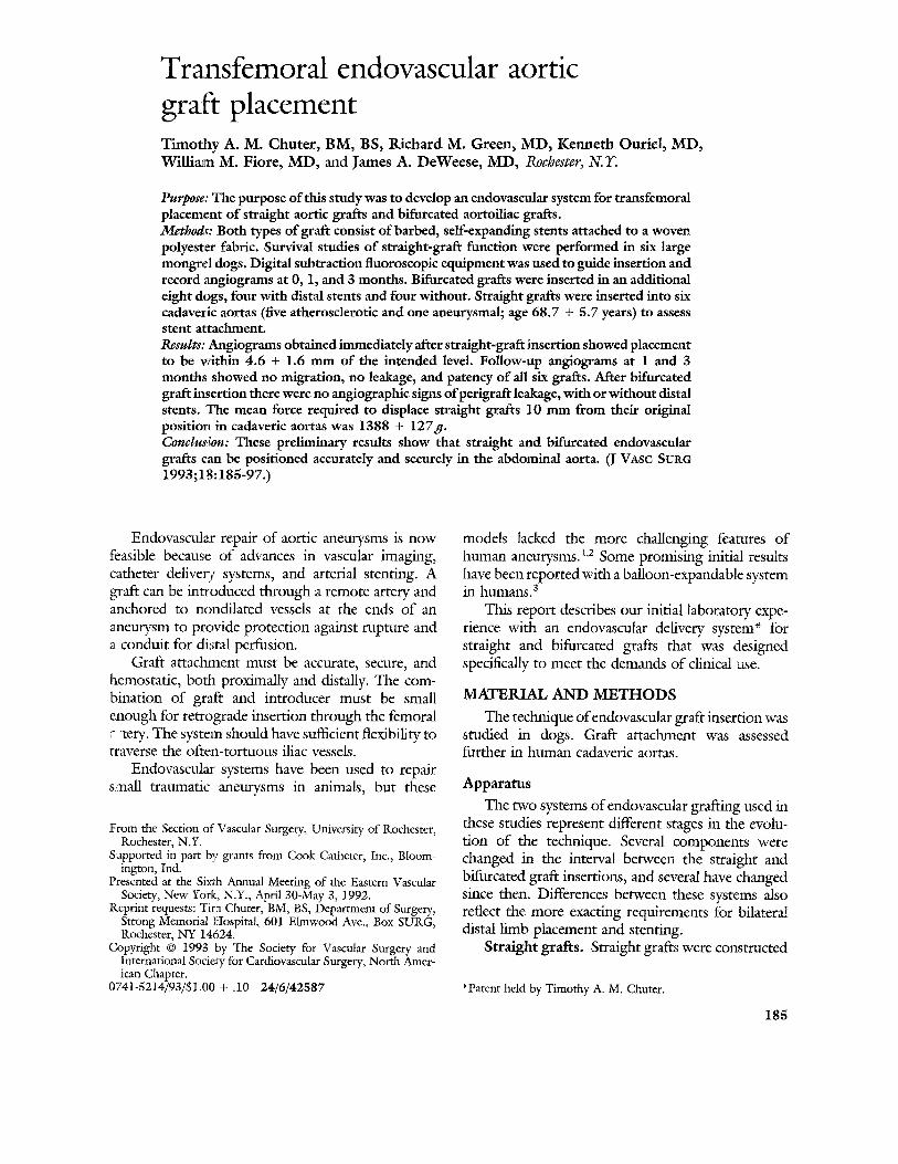
Fig. 1. A, Straight graft mounted on central carrier shows stems protruding from graft orifices. B, Proximal stent of straight graft and attachment to central carrier. C, Delivery system during insertion shows how dilator head combines with introducer sheath to create smooth, featureless external profile.
of the heavy, crimped fabric used in conventional aortic bypass grafts. The fabric was cut and sutured into tubes with the crimps nmning longitudinally to provide an element of transverse elasticity. Three stents occupied the lumen of the graft: one in the middle and one protruding from each end (Fig. 1,A). Stents measured 23 mm in length and 20 mm in diameter i n their nondeformed state. At normal canine aortic diameters (approximately 9 mm)
stents exerted a constant outward force, which served to press the graft and the barbs against the' aortic wall. The stent at the cranial end of the graft carried four barbs to enhance attachment to the aorta.
The narrow portion of a central carrier traversed the lumen of the graft. Splits in the catheter of the central carrier were traversed by short loops of monofilament suture, which connected stents at both
JOURNAL OF VASCULAR SURGERY Volume 18, Nmnber 2 C h u t e r et al. 187
ends of the graft to a guide wire in the lumen of the carrier (Fig. 1,B). As long as the guide wire remained within the lumen of the delivery system, the loops could not retract and the graft remained attached to the central carrier. Removal of the guide wire released the graft.
The graft, its stents, and the carrier were com- pressed into an introducer sheath, before insertion. A dilation at the distal end of the carrier matched the diameter of the sheath orifice. With the sheath in place around the terminal dilation, the apparatus had a smooth external prone (Fig. 1, C). A seal at the outer end of the sheath ensured hemostasis.
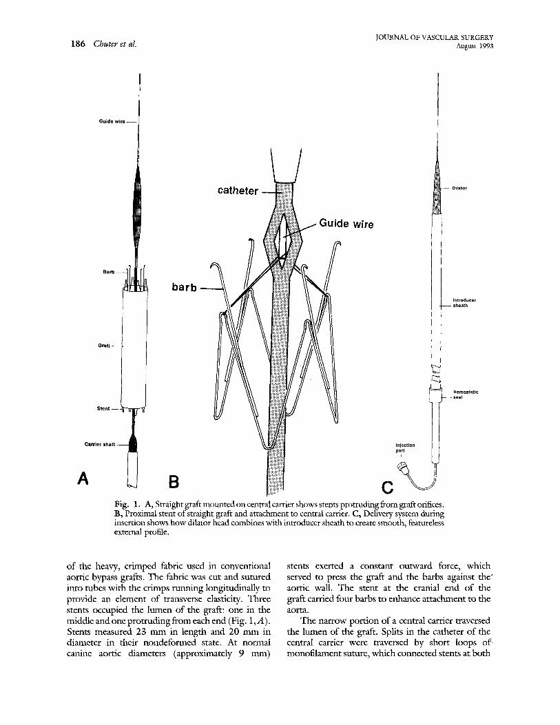
Bifurcated grafts. Bifurcated grafts (13 mm by 6 mm) were constructed of thin, uncrimped, woven polyester. Two lines of very fine gold chain ran the length of the 1eft limb of file graft. These served as radiopaque markers, indicating the axial orientation ,~ 2 the graft limb. Only one stent was attached to the graft before insertion. This stent carried small coils on 6 of its 12 limbs, to which the proximal orifice of the graft was sutured. The outer angles of the stent carried Caudally directed barbs (Fig. 2).
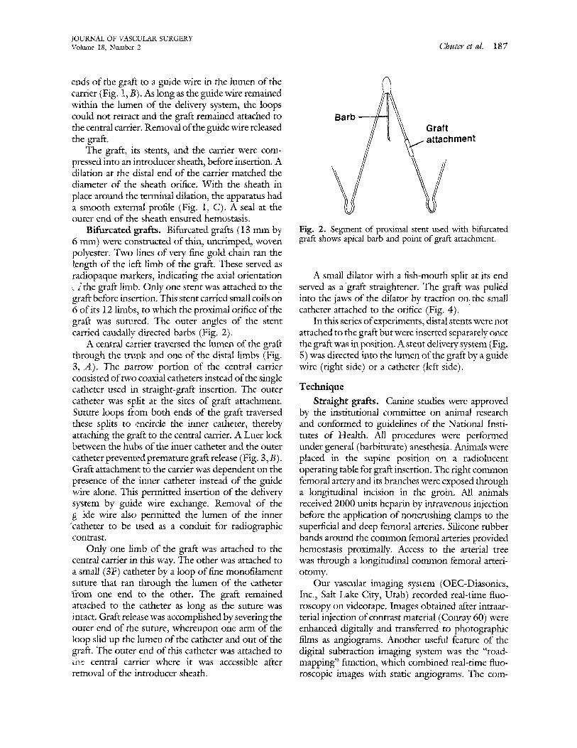
A central carrier traversed the lumen of the graft through the mink and one of the distal limbs (Fig. 3, A). The narrow portion of the central carrier consisted of two coaxial catheters instead of the single catheter used in straight-graft insertion. The outer catheter was split at the sites of graft attachment. ,Suture loops from both ends of the graft traversed these splits to ,encircle the inner catheter, thereby attaching the graft to the central carrier. A Luer lock between the hubs of the inner catheter and the outer catheter prevented premature graft release (Fig. 3, B). Graft attachmenl: to the carrier was dependent on the presence of the inner catheter instead of the guide wire alone. This permitted insertion of the delivery system by guide wire exchange. Removal of the g ide wire also permitted the lumen of the inner °catheter to be used as a conduit for radiographic contrast.
Only one limb of the graft was attached to the central carrier in this way. The other was attached to a small (3F) catheter by a loop of free monofilament suture that ran through the lumen of the catheter t"rom one end to the other. The graft remained attached to the catheter as long as the suture was intact. Graft release was accomplished by severing the outer end of the suture, whereupon one arm of the loop slid up the lumen of the catheter and out of the graft. The outer end of this catheter was attached to file central carrier where it was accessible after removal of the innroducer sheath.
Barb ~ Graft ~ ~ ~hment
Fig. 2. Segment of proximal stent used with bifurcated graft shows apical barb and point of graft attachment.
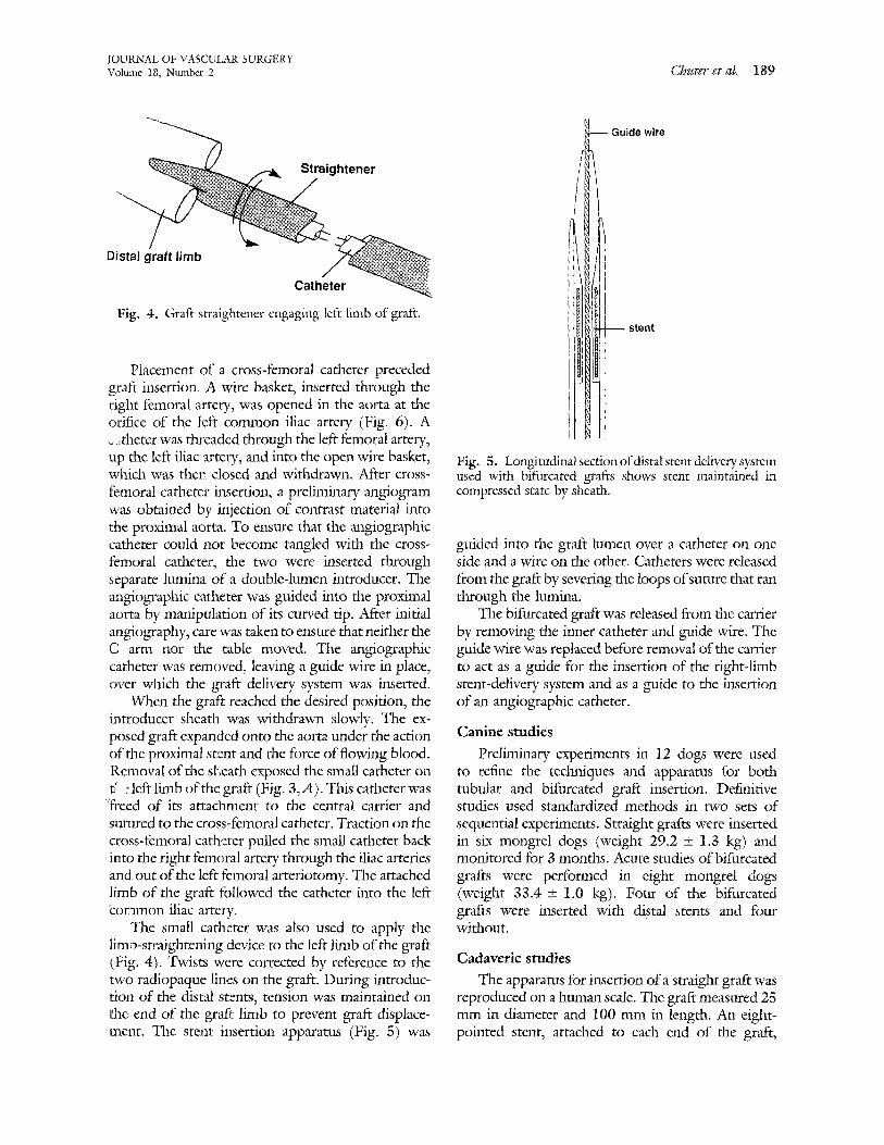
A small dilator with a fish-mouth split at its end served as a graft straightener. The graft was pulled into the jaws of the dilator by traction on the small catheter attached to the orifice (Fig. 4).
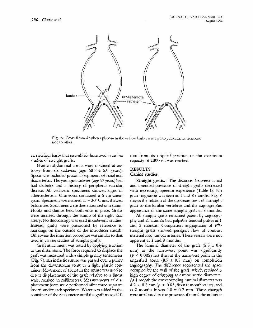
In this series of experiments, distal stents were not attached to the graft but were inserted separately once the graft was in position. A stent delivery system (Fig. 5) was directed into the lumen of the graft by a guide wire (right side) or a catheter (left side).
Technique
Straight grafts. Canine studies were approved by the institutional committee on animal research and conformed to guidelines of the National Insti- tutes of Health. All procedures were performed under general (barbiturate) anesthesia. Animals were placed in the supine position on a radiolucent operating table for graft insertion. The right common femoral artery and its branches were exposed through a longitudinal incision in the groin. All animals received 2000 units heparin by intravenous injection before the application of noncrushing clamps to the superficial and deep femoral arteries. Silicone rubber bands around the common femoral arteries provided hemostasis proximally. Access to the arterial tree was through a longitudinal common femoral arteri- otomy.
Our vascular imaging system (OEC-Diasonics, Inc., Salt Lake City, Utah) recorded real-time fluo- roscopy on videotape. Images obtained after intraar- terial injection of contrast material (Conray 60) were enhanced digitally and transferred to photographic films as angiograms. Another useful feature of the digital subtraction imaging system was the "road- mapping" function, which combined real-time fluo- roscopic images with static angiograms. The corn-
JOURNAL OF VASCULAR SURGERY 188 Chuter et al. August 1993
Guide wire
graft limb
I ~ Inner catheter
Carrier
Suture loop
A l l a
Luer lock connector
jection port
de wire
Fig. 3. A, Bifurcated graft mounted on central carrier shows catheter used to control left limb. B, Outer end of central carrier used in bifurcated graft insertions shows locking inner and outer catheters.
posite image facilitated guidance of the apparatus through the vascular tree.
After initial angiography the delivery system was inserted to a predetermined position within the aorta, where the graft was released. Fluoroscopic visualiza- tion was relatively easy because most of the apparatus was radiopaque. Bony landmarks served as reference points for graft placement. The object was to position the proximal (upstream) stent at the caudal end of the third lumbar vertebra. The position of the prosthesis was controlled by manipulation of the central carrier, as the introducer sheath was withdrawn slowly. Expansion of the distal stent was taken as a sign that graft extrusion was complete. Removal of the guide wire released the graft from the central carrier, which was removed. Arteriography was repeated before closure of the femoral artery.
Angiograms were obtained at i and 3 months by
intraarterial injection of contrast material through an angiographic catheter introduced percutaneously. Angiographic measurements of distance were cali- brated by reference to the known length of sten~. The ability of a graft to isolate the adjacent segment ~ of aortic wall from the circulation was assessed by examining angiograms for opacification of aortic branches in the region of the graft. Visualization of lumbar or middle sacral arteries was indicative of leakage of contrast material, either through the walls of the graft or between the ends of the graft and the' aorta.
Bifurcated grafts. Placement, straightening, and stenting of the left limb of bifurcated grafts required some additional maneuvers. In this series of experi- ments access to the left femoral artery was obtained by direct surgical exposure and longitudinal arteri:: otomy.
JOURNAL OF VASCULAR SURGERY Volume 18, Ntm~ber 2 Chuter et al. 189
Straightener
ide wire
Distal graft limb
Catheter
Fig. 4. Graft straightener engaging left limb of graft. stent
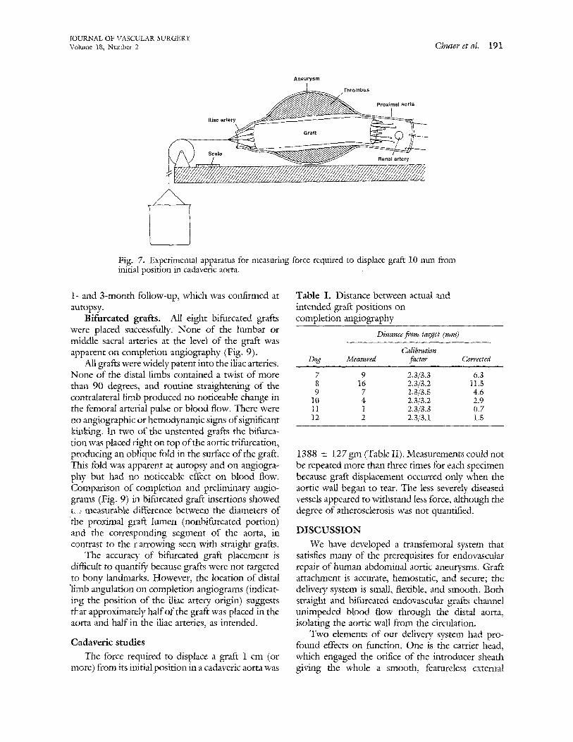
PJacement of a cross-femoral catheter preceded graft insertion. A wire basket, inserted through the right femoral artery, was opened in the aorta at the orifice of the left common iliac artery (Fig. 6). A ,~ ,theter was threaded through the left femoral artery, up the left iliac artery, and into the open wire basket, which was ther~ closed and withdrawn. After cross- femoral cathete:: insertion, a prelimina W angiogram "was obtained by injection of contrast material into 1:he proximal aorta. To ensure that the angiographic catheter could not become tangled with the cross- femoral catheter, the two were inserted through separate lumina of a double-lumen introducer. The angiographic catheter was guided into the proximal aorta by manipulation of its curved tip. After initial angiography, care was taken to ensure that neither the C arm nor the table moved. The angiographic catheter was removed, leaving a guide wire in place, over which the graft delivery system was inserted.
When the graft reached the desired position, the introducer sheath was withdrawn slowly. The ex- posed graft expanded onto the aorta under the action of the proximal stent and the force of flowing blood. Removal of the sl~eath exposed the small catheter on t' : left limb of the graft (Fig. 3,A). This catheter was :freed of its attachment to the central carrier and sul~red to the cross-femoral catheter. Traction on the cross-femoral catheter pulled the small catheter back into the right femoral artery through the iliac arteries and out of the left femoral arteriotomy. The attached limb of the graft fallowed the catheter into the left ~ommon iliac artery.
The small catheter was also used to apply the limb-straightening device to the left limb of the graft (Fig. 4). Twists were corrected by reference to the two radiopaque lines on the graft. During introduc- tion of the distal stents, tension was maintained on ehe end of the gra_fir limb to prevent graft displace- ment. The stent insertion apparatus (Fig. 5) was
Fig. 5. Longitudinalsecdon of distal stent delivery system used with bifurcated grafts shows stent maintained in compressed state by sheath.
guided into the graft lumen over a catheter on one side and a wire on the other. Catheters were released from the graft by severing the loops of suture that ran through the lumina.
The bifurcated graft was released from the carrier by removing the inner catheter and guide wire. The guide wire was replaced before removal of the carrier to act as a guide for the insertion of the right-limb stent-delivery system and as a guide to the insertion of an angiographic catheter.
Canine studies
Preliminary experiments in 12 dogs were used to refine the techniques and apparatus for both tubular and bifurcated graft insertion. Definitive studies used standardized methods in two sets o£ sequential experiments. Straight grafts were inserted in six mongrel dogs (weight 29.2 + 1.3 kg) and monitored for 3 months. Acute studies of bifurcated grafts were performed in eight mongrel dogs (weight 33.4 +_ 1.0 kg). Four of the bifurcated grafts were inserted with distal stents and four without.
Cadaveric studies
The apparatus for insertion of a straight graft was reproduced on a human scale. The graft measured 25 mm in diameter and 100 mm in length. An eight- pointed stent, attached to each end of the graft,
190 Chuter et al. IOURNAL OF VASCULAR SURGERY August 1993
S
basket
7
ross femoral ~ / - c a t h e t e r / ~
Fig. 6. Cross-femoral catheter placement shows how basket was used to pull catheter from one side to other.
carried four barbs that resembled those used in canine studies of straight grafts.
Human abdominal aortas were obtained at au- topsy from six cadavers (age 68.7 +--6.0 years). Specimens included proximal segments of renal and iliac arteries. The youngest cadaver (age 47 years) had had diabetes and a history of peripheral vascular disease. All cadaveric specimens showed signs of atherosclerosis. One aorta contained a 6 cm aneu- rysm. Specimens were stored at - 20 ° C and thawed before use. Specimens were then mounted on a stand. Hooks and damps held both ends in place. Grafts were inserted through the stump of the right iliac artery. No fluoroscopy was used in cadaveric studies. Instead, grafts were positioned by reference to markings on the outside of the introducer sheath. Otherwise the insertion procedure was similar to that used in canine studies of straight grafts.
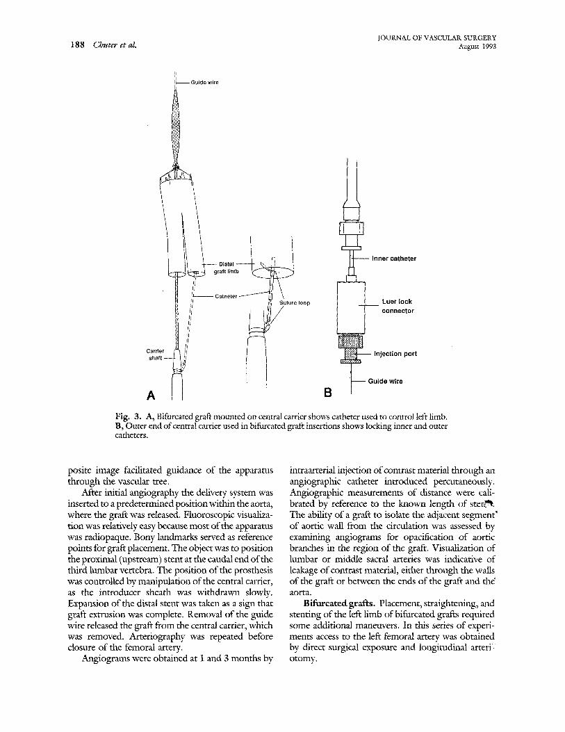
Graft attachment was tested by applying traction to the distal stent. The force required to displace the graft was measured with a simple gravity tensometer (Fig. 7). An inelastic suture was passed over a pulley from the downstream stent to a light plastic con- tainer. Movement of a knot in the suture was used to detect displacement of the graft relative to a linear scale, marked in millimeters. Measurements of dis- placement force were performed after three separate insertions for each specimen. Water was added to the container of the tensometer until the graft moved 10
mm from its original position or the maximum capacity of 2000 ml was reached.
RESULTS Canine studies
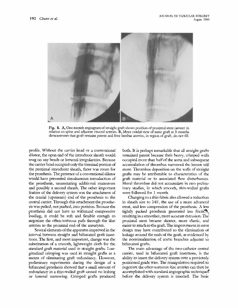
Straight grafts. The distances between actual and intended positions of straight grafts decreased with increasing operator experience (Table I). No graft migration was seen at 1 and 3 months. Fig. 8 shows the relation of the upstream stent of a straight graft to the lumbar vertebrae and the angiographic appearance of the same straight graft at 3 months.
All straight grafts remained patent by angiogra- phy and all animals had palpable femoral pulses at 1 and 3 months. Completion angiograms of e ~ straight grafts showed perigraft flow of contrast material into lumbar arteries. These vessels were not apparent at 1 and 3 months.
The luminal diameter of the graft (5.5 +_ 0.4 ram) at the narrowest point was significantly (p < 0.005) less than at the narrowest point in the ungrafted aorta (8.7 +-0.5 mm) on completiofi angiography. The difference represented the space occupied by the wall of the graft, which retained a high degree of crimping at canine aortic diameters. At 1 month the corresponding luminal diameter was 4.2 _+ 0.3 mm (p < 0.05, from 0-monthvalue), and at 3 months it was 4.8 +_ 0.7 ram. These change~ were attributed to the presence of mural thrombus at
j'OUKNAL OF VASCULAR SURGERY Volume 18, Nmnber 2 Chuter et eL 191
Aneurysm
~ T h r o m b u s Proximal aorta
lilac a r t ~
~,~ ~:,/.....~ ~ Renal artery
Fig. 7. Experimental apparatus for measuring force required to displace graft 10 mm from initial position in cadaveric aorta.
1- and 3-month follow-up, which was confirmed at autopsy.
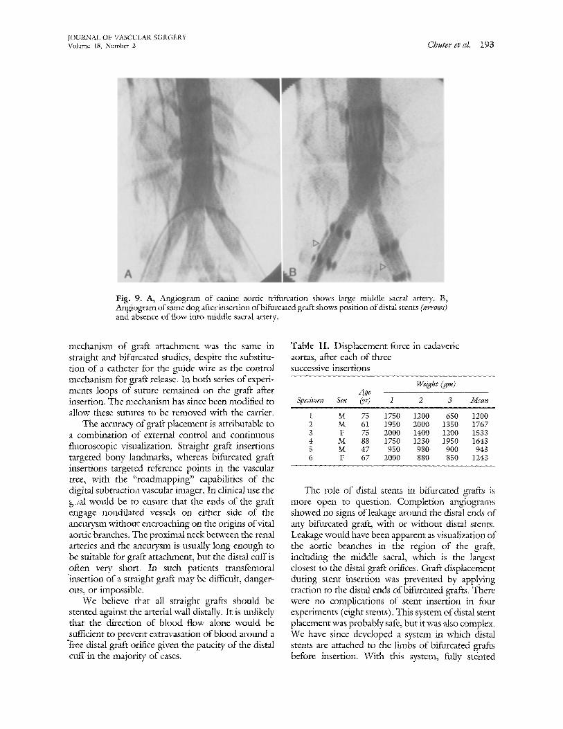
Bifurcated grafts. All eight bifurcated grafts were placed successfully. None of the lmnbar or middle sacral arteries at the level of the graft was apparent on completion angiography (Fig. 9).
All grafts were widely patent into the iliac arteries. None of the distal limbs contained a twist of more than 90 degrees, and routine straightening of the contralateral limb produced no noticeable change in the femoral arterial pulse or blood flow. There were no angiographic or hemodynamic signs of significant kinking. In two of the unstented grafts the bifurca- tion was placed ~.'ight on top of the aortic trifurcation, producing an oblique fold in the surface of the graft. This fold was apparent at autopsy and on angiogra- phy but had no noticeable effect on blood flow. Comparison of completion and preliminary angio- grams (Fig. 9) in bifurcated graft insertions showed r_., measurable difference between the diameters of the proximal graft lumen (nonbifurcated portion) and the corresponding segment of the aorta, in contrast to the ¢:arrowing seen with straight grafts.
The accuracy of bifurcated graft placement is difficult to quantify because grafts were not targeted to bony landmarks. However, the location of distal ~limb angulation on completion angiograms (indicat- ing the position of the iliac artery origin) suggests thLat approximately half of the graft was placed in the aorta and half in the iliac arteries, as intended.
Cadaveric studies
The force required to displace a graft 1 cm (or more) from its initial position in a cadaveric aorta was
Table I. Distance between actual and intended graft positions on completion angiography
Distance from target (ram)
Calibration Dog Measured factor Corfected
7 9 2.3/3.3 6.3 8 16 2.3/3.2 I1.5 9 7 2.3/3.5 4.6
10 4 2.3[3,2 2.9 11 1 2,3/3.3 0.7 12 2 2.3/3.1 1.5
1388 _ 127 gm (Table II). Measurements could not be repeated more than three times for each specimen because graft displacement occurred only when the aortic wall began to tear. The less severely diseased vessels appeared to withstand less force, although the degree of atherosclerosis was not quantified.
DISCUSSION
We have developed a transfemoral system that satisfies many of the prerequisites for endovascular repair of human abdominal aortic aneurysms. Graft attachment is accurate, hemostatic, and secure; the delivery system is small, flexible, and smooth. Both straight and bifurcated endovascular grafts channel unimpeded blood flow through the distal aorta, isolating the aortic wall from the circulation.
Two elements of our delivery system had pro- found effects on function. One is the carrier head, which engaged the orifice of the introducer sheath giving the whole a smooth, featureless external
192 Chuter et al. JOURNAL OF VASCULAR SURGERY August 1993
Fig. 8. A, One-month angiogram of straight graft shows position of proximal stent (arrow) in relation to spine and adjacent visceral arteries. B, More caudal view of same graft at 3 months demonstrates that graft remains patent and four lumbar arteries, in region of graft, do not fill.
profile. Without the carrier head or a conventional dilator, the open end of the introducer sheath would snag on any bends or lumenal irregularities. Because the carrier head occupied only the terminal portion of the proximal introducer sheath, there was room for the prosthesis. The presence of a conventional dilator would have prevented simultaneous introduction of the prosthesis, necessitating additional maneuvers and possibly a second sheath. The other important feature of the delivery system was the attachment of the cranial (upstream) end of the prosthesis to the central carrier. Through this attachment the prosthe- sis was pulled, not pushed, into position. Because the prosthesis did not have to withstand compressive loading, it could be soft and flexible enough to negotiate the often-tortuous path through the iliac arteries to the proximal end of the aneurysm.
Several elements of the apparatus improved in the interval between straight and bifurcated graft inser- tions. The first, and most important, change was the substitution of a smooth, lightweight cloth for the standard graft material used in straight grafts. Lon- gitudinal crimping was used in straight grafts as a means of eliminating graft redundancy. However, preliminary experiments during the design of a bifilrcated prosthesis showed that a small amount of redundancy in a thin-walled graft caused no leaking or luminal narrowing. Crimped grafts produced
both. It is perhaps remarkable that all straight grafts remained patent because their heavy, crimped walls occupied more than half of the aorta and subsequent accumulation of thrombus narrowed the lumen still more. Thrombus deposition on the walls of straight grafts may be attributable to characteristics of the graft material or to associated flow disturbances. Mural thrombus did not accumulate in two prelim- inary studies, in which smooth, thin-walled grafts were followed for I month.
Changing to a thin fabric also allowed a reduction in sheath size to 14F, the use of a more advanced stent, and less compression of the prosthesis. A less tightly packed prosthesis generated less fricti~, resulting in a smoother, more accurate extrusion. The ~ proximal stent became shorter, more elastic, and easier to attach to the graft. The improvement in stent design may have contributed to the elimination of leakage around the ends of the graft, as evidenced by the nonvisualization of aortic branches adjacent to bifurcated grafts.
The main advantage of the two-catheter central carrier, used in bifurcated graft insertions, is the ability to insert the delivery system over a previously positioned guide wire. The manipulation required to negotiate the often-tortuous iliac arteries can then be accomplished with standard angiographic techniqueg" before the delivery system is inserted. The basic
JOURNAL OF V'ASCULAR SURGERY Volume 18, Nmnbcr 2 Chuter et cd. 193
Fig. 9. A, Angiogram of canine aortic trifurcation shows large middle sacral artery. B, Angiogram of same dog after insertion of bifurcated graft shows position of distal srents (arrows) and absence of flow' into middle sacral artery.
mechanism of graft attachment was the same in straight and bifurcated studies, despite the substitu- i:ion of a catheter for the guide wire as the control mechanism for graft release. In both series of experi- ments loops of suture remained on the graft after insertion. The mechanism has since been modified to allow these sutures to be removed with the carrier.
The accuracy of graft placement is attributable to a combination of external control and continuous fluoroscopic visualization. Stra ight graft insertions targeted bony landmarks, whereas bifurcated graft insertions targeted reference points in the vascular tree, with the ":roadmapping" capabilities of the digital subtraction vascular imager. In clinical use the b-;al would be to ensure that the ends of the graft engage nondilated vessels on either side of the ~Leurysm withoul> encroaching on the origins of vital aortic branches. The proximal neck between the renal arteries and the aRaeurysm is usually long enough to be suitable for graft attachment, but the distal cuff is often very short. In such patients transfemoral "insertion o f a straight graft may be difficnk, danger- ous, or impossible.
We believe that all straight grafts should be stented against the arterial wall distally. It is unlikely that the direction of blood flow alone would be sufficient to prevent extravasation of blood around a "Free distal grfft orifice given the paucity of the distal cuff in the majority of cases.
Table II . Displacement force in cadaveric aortas, after each of three successive insertions
Weight (gin) Age
Specimen Sex (yr) l 2 3 Mean
1 M 75 1750 1200 650 1200 2 M 61 1950 2 0 0 0 1350 1767 3 F 75 2 0 0 0 1400 1200 1533 4 M 88 1750 1230 1950 1643 5 M 47 950 980 900 943 6 F 67 2000 880 850 1243
The role of distal stents in bifurcated grafts is more open to question. Completion angiograms showed no signs of leakage around the distal ends of any bifurcated graft, with or without distal stents. Leakage would have been apparent as visualization of the aortic branches in the region of the graft, including the middle sacral, which is the largest closest to the distal graft orifices. Graft displacement during stent insertion was prevented by applying traction to the distal ends of bifurcated grafts. There were no complications of stent insertion in four experiments (eight stents). This system of distal stent placement was probably safe, but it was also complex. We have since developed a system in which distal stents are attached to the limbs of bifurcated grafts before insertion. With this system, fully stinted
JOURNAL OF VASCULAR SURGERY 194 Chuter et aI. August 1993
bifurcated grafts are deployed with the same series of maneuvers as for unstented grafts.
Our initial concern that barbs would not pene- trate the typical elderly diseased aorta was not borne out. Straight grafts were found to attach securely to the walls of cadaver aortas, which contained athero- sclerosis, calcification, and luminal debris. Indeed, the force required to displace a graft experimentally (1388 + 127 gm) was far more than the expected stresses. For example, the sheer force on a 20 mm by 100 mm tubular graft is less than 1 gm, assuming that the graft is held in dose apposition to the aortic wall by low-profile stents and flow remains laminar. 4
All our grafts were constructed of woven polyes- ter, which is known to be strong and durable. A lightweight knitted construction was avoided be- cause the very fine yarns and loose knits necessary to achieve a low volume might predispose to progres- sive dilation, 5 It is doubtful that the aneurysm wall can be relied on to generate a high-pressure environ- ment around the graft and thereby limit transmural pressure.
Suitable candidates for endovascular repair of aortic aneurysm would be selected on the basis of preliminary angiography and cross-sectional imag- ing. Specific contraindications would include supra- renal extension of the aneurysm and iliac occlusive disease. Angiographic evidence that inferior mesen- teric flow is an indispensable source of intestinal perfusion would be another contraindication to endovascular repair, because the endovascular tech- nique does not offer the oppommity to restore flow through the inferior mesenteric artery. The inability to reimplant the inferior mesenteric artery has special implications for graft selection when the bifurcated technique is used. Ideally internal iliac arterial flow should be maintained as a source of intestinal and spinal perfusion.
Any instrumentation of an aneurysm risks injury to mural thrombus and plaque, which might frag- ment and embolize to distal arteries. The risk of mural injury has been minimized by using a delivery system with a smooth, tapered external profile and a tip that is guided through the iliac arteries and the aneurysm over a wire. The relatively low incidence of embolism after angiography alone suggests that mural thrombus is smoother and less prone to fragmentation than it appears at operation. More- over, the risk of embolism is transitory because the thrombus lining an aneurysm cannot enter the circulation once the graft is in place.
The eventual indications for straight and bifur- cated grafts will depend largely on the architecture of the distal cuff and the effect of mural thrombus on graft attachment. Compared with conventional sur- gical repair, endovascular techniques require longer segments of nondilated aorta for graft attachment, particularly at the distal end. Examination of corre- sponding angiographic and tomographic studies reveals that mural thrombus often produces long cylindric segments of lumen at both ends of the aneurysm, even when the outer wall of the aneurysm extends from the renal arteries to the aortic bifurca- tion. However, a reliance on mural thrombus for hemostatic graft attachment is probably not war- ranted in early clinical studies. Bifurcated grafts will be required in most cases, because the distal cuff is rarely long enough to permit straight graft repair by endovascular means.
With this system, at least one femoral artery m u ~ be exposed. The delivery system is too large (5.5 mm) to be introduced percutaneously. The other femoral artery was also exposed in this series of bifurcated graft insertions. However, the small catheters and sheaths inserted on that side could easily pass through a percutaneously placed sheath.
The main advantages of the transfemoral ap- proac h to aortic aneurysm repair are the avoidance of abdominal operation and general anesthesia. A uni- lateral femoral artery dissection done under local anesthesia is clearly less of an insult than conventional repair. The potential benefit is particularly clear for patients in whom the morbidity, mortality, and expense of conventional treatment are high. 6'7 Many recent advances in surgery and interventional radiol- ogy represent a trend toward less invasive treatment. These preliminary results confirm that a less invasive alternative to the treatment of aortic aneurysm is feasible.
REFERENCES 1. Mirich D, Wright KC, Wallace S, et al. Percutaneously placed
endovas~alar grafts for aortic aneurysms: feasibility study. Radiology 1989;170:1033-7.
2. Inoue K, Htay T, Kida M, Fujiwara H. Percutaneous implan- tation of aortic endovascular graft for created aneurysm: ani- mal experiment [Abstract]. Ciroalation 1991;84(suppl):II- 421.
3. Parodi JC, Palmaz JC, Barone l iD. Transfemoral intralunfinal graft implantation for abdominal aortic aneurysms, Ann Vase Surg 1991;5:491-9.
4. Paul JP, Barbenel JC. Biomechanics. In: Ray CD, ed. Medical engineering. 1st ed. Chicago: Year Book Medical Publishers, 1974:213.
JOUKNAL OF VASCULAR SURGERY Volume 18, Number 2 Chuter et aI. 195
5. Descotes J, Brudon JR, Zabot JM, et al. The neoarrery: myth or reality? Study of seventy-nine explanted arterial prostheses. Chimrgie 1989;115:58-65.
6. Ouriel K, Geary K, Green RM, Fiore WM, Geary rE, DeWeese JA. Factors determining survival after raptured aortic aneurysm: rite hospital, the surgeon, and the patient. J Vase SURG 1990;1 1:493-6.
7. Breckwoldt WL, Mackey WC, O'Donnell TF Jr. The economic implications of high-risk abdominal aortic aneurysms. J VASe SUV, G 1991;13:798-804.
Submitted May 4, 1992; accepted Sept. 11, 1992.
D I S C U S S I O N
Dr. Luis ,4.. Queral (Baltimore, Md.). It is not often that we wimess work whose content is both visionary and revolutionary. We have heard described an approach that could radically change the way we have done things for the past 35 years. Transfemoral endolmninaI replacement of the aorta is bog1 feasible and logical. There is no question .,~ my mind that this form of aortic replacement will soon become a reality, and I am very happy that surgeons are at the forefront of this development.
You are to be congratulated for your immvativeness and courage. Dr. Cohen, along with other members o f the Program Committee, is to be congratulated for selecting this work. A regional vascular society is taking a dear-cut lead in being the venue for such progressive work. We are establishing the pace and an example for the more conservative national societies in the presentation of our most innovative work.
I am not sure about the deployment of this device. To my understanding, it seems like a Greenfield filter (Med- itech, Boston Sdentific Corp., Watertown, Mass.), where the sheath is pullecl back and the device is deployed; would you comment on this?
Would you also comment on the blood loss during the procedure and how long it took to accomplish both the bifurcated graft and the tube grafts.
H o w diNcatlt was it to remove this device when the dogs were sacriticed? This is important inasmuch as I can foresee cases whereby this will have to be done when the k..rson is still alive., in the case of a failure.
Are the stents really necessary distally? Last, what are your future plans for controlled Food
and Drug Administration-approved studies in very high- risk patients.
Most of you are aware that endoluminal replacement of the abdominal aorta has already been accomplished in humans by our col~ieague and friend Dr. John Parodi of Buenos Aires, Argentina. Some of this work was published in the Annals of Vascular Surgery. My partner, Dr. Criado, actually scrubbed in with Dr. Parodi on two of these cases.
Dr. F. J, Criado (Baltimore, Md.). I have been fortunate enough to have been involved in this work from the beginning. The l]rst clinical case was done in Buenos
Aires in September 1990. This followed a very extensive animal experience of several years. I can tell you, after having been involved in two or three cases, that I cannot help but be very impressed with the results. To see some of these patients have a flag dinner the day of the operation and go home the next morning is very impressive, to say the least.
So far, Dr. Parodi has done 12 clinical cases in humans, and the work is progressing. The technique is being developed and improved. Clearly a lot of problems, actual and potential, remain, and this is going to require further refinements and developments.
Several complications of a noncritical nature have occurred, but there are many others that no doubt are going to develop sooner or later. The two most critical issues appear to be the transfemoral transluminal access to the lumen of the aorta through femoral and iliac arteries. The delivery system is clearly the most crucial aspect o f this whole thing.
The second crucial aspect revolves around the anchor- ing of the graft, particularly in the proximal portion of the aorta at the upper neck. This technique, the one I am showing you right now, involves the use of a Palmaz-type endovascular stent, but I am not sure what the ultimate technique is going to be once this becomes common clinical practice. We can discuss some of these details, if you are interested, a little later.
As surgeons, I think we better realize that unless we change our attitude and not make the same mistakes that were made 25 years ago resulting in the loss of the angioplasty field to nonsurgical hands, this is going to happen to us again. The m~o important issues are that we have to learn catheter skills. After aft, this whole field of catheter interventions was developed by surgeons in the first place. Believe me, you do not become an interven- tionist in a 2-day tutorial, .although we used to offer a 2-day tutorial in our institute.
The second point is, if we are going to be involved in sophisticated endovascular work, vanguard operations, we had better get good x-ray imaging, fluoroscopy, and angiography in the operating room. In other words, we are going to have to duplicate the kind of equipment and
JOURNAL OF VASCULAR SURGERY 196 Chuter et al. August 1993
fadliries that our nonsurgical colleagues have had for 25 years.
What type of stent did you use? Have you thought of the possibility of using something other than a stent as an anchor for the graft? After all, we are talking about a stent, but the purpose of this device is not stenting; it is anchoring. Certainly a different device may be better and easier to use in the future.
Finally, it seems that all of these techniques are going to have to involve a very thin-walled graft. Is there a concern with dilatation and the integrity of the graft in general for the long term?
Dr. Timothy A. M. Chuter. Before going on to answer spedfic questions, I think it will be helpful if I comment briefly on the main differences between our apparatus and that used by Dr. Parodi.
One fundamental difference is the type of stent. We used barbed self-expanding stents (of the Gianturco type), and I think we demonstrated that these stents attached themselves securely to the wall of a diseased aorta. The stents used by Parodi (the Pahnaz stent) are balloon expanded and not barbed. Forcible balloon expansion embeds the stent in the arterial wall, but I wonder whether this attachment will remain secure if the aorta dilates. Another difference relates to the use of distal stents with straight grafts. When one studies the morphologic charac- teristics of the human infrarenal aortic aneurysm, the distal cuff is often found to be very short. I would be surprised if hemostatic graft attachment is possible without a distal stent. We have considered alternatives to the use of a stent for hemostatic graft attachment, but none seemed satisfac- tory.
Our grafts were constructed of woven Dacron, which is known to be strong and stable. I would be more concerned about the long-term durability of our grafts had we used a knitted fabric.
I agree with Dr. Criado that vascular surgeons should prepare to be involved in the widespread clinical applica- tion of endovascular techniques such as this. I think that the necessary catheter skills are much easier to learn than the skills required for standard surgery. No one need feel intimidated by the interventionalists.
We elected to use an open approach to the femoral arteries. The human version of our delivery system has a 16F introducer sheath. I would be loathe to insert such a large device percutaneously.
The short video is comprised of fluoroscopic images from two insertion procedures. The first uses a straight graft and the second a bifurcated graft to repair canine models of aortic aneurysm, Initial angiograms show the shape and position of the model aneurysm. Delivery system insertion, graft extrusion, delivery system removal, and completion angiograms are shown to illustrate the simplic- ity of the procedure, the flexibility of the delivery system, and the lack of any leakage into the aneurysm once the graft is in place. Videos of the second procedure show the additional maneuvers involved ~ bifurcated graft insertion,
which include cross-femoral catheter placement and translocation of the left limb of the graft. Again com- pletion angiograms demonstrate the lack of leakage or kinking.
Dr. Criado. In the current Parodi experience, it is true that the distal end of the graft needs to be stented as well. One patient was found to have continuing pulsatility in the aneurysrn because of reflux and required a secondary stent implantation, so he is now doing this almost routinely, placing a stent above and below.
Dr. Ronald L. Nath (Medford, Mass.). We know from human experience that even ligation and exclusion of aneurysms wilt result in some cases of rupture because when we clamp the proximal and distal ends there is still tremendous inflow from the open lumbar vessels and other accessory vessels. It would seem that placing the endovas- cular prosthesis, even with proximal and distal stents, does not address the issue of accessory flow and might conceiv- ably run into the same problem of delayed rupture as we have with exclusion and ligation. Absence of distal stents i~ the lilac arteries logically would seem not to address th}~ problem, because even though you can inject into the aorta proximally and demonstrate nonvisualization of the inflow vessels such as your middle sacral, they may still be open because you "bypassed" them rather than actually throm- bosed them or excluded them.
Dr. Henry D. Berkowitz (Philadelphia, Pa.), What fastening technique is used to anchor the graft to the aortic wall? It is interesting, because if you do have a good anchoring device that works intraluminally, it would also be suitable for doing a fast proximal anastomosis during surgery.
I think the presentation is marred by your simplistic demonstration of secure fixation to the proximal aortic wall. I think a tangential pulsatile force is more likely to disrupt the proximal aortic anastomosis than is a longitu- dinal force. You really need a more sophisticated test to determine whether there is secure fixation at the proximal anastomosis.
Dr. Bauer E. Sumpio (New Haven, Conn.). Do you have any histologic findings on the vessel wall around the stents? Is there any medial wall necrosis! Does it see~, dangerous to pass these big catheters through an aneurys fri:.~ What is the potential for embolism and rupture?
Dr. Chuter. Dr. Nath is right that endovascular methods of aneurysm repair may not occlude the lumbar arteries. Long-term patency will depend on the blood flow generated by pressure gradients between these vessels. I think that most will thrombose, These theoretic consider- ations together with the results of nonresective surgery leak us to expect that rupture will be a rare event after endovascular aneurysm repair.
We have no histologic results from this study, but there is extensive histologic evidence that Gianmrco stents of the type used in this study produce no degeneration or erosion of the recipient vessel.
We shared Dr. Sumpio's concern about the potential
1OURNAL OF VASCULAR SURGERY Volume 18, Nuraber 2 Ghuter et al. 197
for embolism and aneurysm rupture. We made the ap- paratus smoo~h and flexible to minimize the risk of mural injury. The infrequent occurrence of embolic complications from angiography suggests that our initial insertion of a guide wire carries a low risk of embolism. We used the stiff wire to guide the tip of the delivery system through the aneurysm. This makes perforation most unlikely and also helps to minimize mural trauma. The bifurcated device may be more prone to embolism because insertion involves more intraaordc manipulation.
In answer to the commentary from Dr. Berkowitz. Our graft was anchored by barbed self-expanding stents. The
cadavcric study was designed to determine whether the barbs would penetrate the walls of atherosclerotic human aortas enough to prevent displacement. Clearly they did. We did not attempt to mimic the forces caused by pulsatile blood flow, which vary in direction and magnitude. Nonetheless, I think that intermittent radial forces are unlikely to produce graft displacement. On the contrary, such forces are more likely to work the barbs into the aortic wall and improve attachment, because self-expanding stents exert a continuous outward force. Moreover, displacement force was several orders of magnitude greater than any axial force generated by blood flow.
BOUND VOLUMES AVAILABLE TO SUBSCRIBERS
Bound volumes of the JOtJRNAL OF VASCULAR SURGERY for 1993 are available to sub- scribers only. They may be purchased from the publisher at a cost of $69.00 for domestic, $89.83 for Canadian, and $85.00 for international subscribers for Vol. 17 (January to June) and Vol. 18 (July to December). Price includes shipping charges. Each bound volume contains a subject and author index, and all advertising is removed. Copies are shipped within 60 days after publication of the last issue in the volume. The binding is durable buckram with the journal name, volume number, and year stamped in gold on the spine. Payment must accompany all orders. Contact Subscription Services, Mosby, 11830 Westline Industrial Dr., St. Louis, MO 63146-3318, USA. In the United States call toll free (800)325-4177, ext. 4351. In Missouri or foreign countries call (314)453-4351.
Subscriptions must be in force to qualify. Bound volumes are not available in place of a regular JOURNAL subscription.
Related Documents


