XC 95 TUH3B060ACV3VA, TDH3B060ACV3VA TUH3B080ACV3VA, TDH3B080ACV3VA TUH3C100ACV4VA, TDH3C100ACV4VA TUH3D120ACV5VA, TDH3D120ACV5VA Direct or Non-Direct Vent with Variable Speed Blower Variable Speed Inducer PUB. NO. 22-1806-03 UPFLOW TUH3-AC-V UPFLOW/HORIZONTAL TDH3-AC-V DOWNFLOW DOWNFLOW/HORIZONTAL Communicating Only Upflow/Horizontal Left Downflow/Horizontal Right Direct/Non-Direct Vent 3 Stage Gas Furnace with Variable Speed Inducer

Welcome message from author
This document is posted to help you gain knowledge. Please leave a comment to let me know what you think about it! Share it to your friends and learn new things together.
Transcript
XC 95TUH3B060ACV3VA, TDH3B060ACV3VATUH3B080ACV3VA, TDH3B080ACV3VATUH3C100ACV4VA, TDH3C100ACV4VATUH3D120ACV5VA, TDH3D120ACV5VADirect or Non-Direct Vent withVariable Speed BlowerVariable Speed Inducer
PUB. NO. 22-1806-03
UPFLOW
TUH3-AC-V
UPFLOW/HORIZONTAL
TDH3-AC-V
DOWNFLOW
DOWNFLOW/HORIZONTAL
Communicating OnlyUpflow/Horizontal LeftDownflow/Horizontal RightDirect/Non-Direct Vent3 Stage Gas Furnace withVariable Speed Inducer
2 Pub. No. 22-1806-03
GeneralFeatures
© 2008 Trane U.S. Inc. All Rights Reserved
3 STAGE OPERATIONThe new 3 stage modulating gasvalves provides longer heating cyclesfor more consistent heating comfort.Modulates down to 40% (45% for theTUH3D120) of the normal firing rates,saving energy, while at the same timeproviding maximum homeownercomfort.
COMFORT CONTROLComfortlink IITM Communicatingfurnace design, offers plug and play– walk away installation. Assuresthe entire heating and airconditioning system is set up in theproper modes to optimize theengineered performance of thematched system installed.
NATURAL GAS MODELSCentral Heating furnace designs arecertified by the American Gas Associa-tion for both natural and L.P. gas. Limitsetting and rating data were estab-lished and approved under standardrating conditions using American Na-tional Standards Institute standards.
SAFE OPERATIONThe Integrated System Control hassolid state devices, which continuouslymonitor for presence of flame, whenthe system is in the heating mode ofoperation. Dual solenoid combinationgas valve and regulator provide addi-tional safety.
QUICK HEATINGDurable, cycle tested, heavy gaugealuminized steel heat exchangerquickly transfers heat to provide warmconditioned air to the structure. Lowenergy power vent blower, to in-crease efficiency and provide apositive discharge of gas fumes to theoutside.
BURNERSMultiport Inshot burners will give yearsof quiet and efficient service. All mod-els can be converted to L.P. gaswithout changing burners.
INTEGRATED SYSTEM CONTROLExclusively designed operational pro-gram provides total control of furnacelimit sensors, blowers, gas valve,flame control and includes self diag-nostics for ease of service. Alsocontains connection points for EACand Humidifier.
AIR DELIVERYThe variable speed blower motor hassufficient airflow for most heating andcooling requirements and will switchfrom heating to cooling speeds on de-mand from room thermostat. Theblower door safety switch will preventor terminate furnace operation whenthe blower door is removed.
SECONDARY HEAT EXCHANGERThe XC95 has a special type 29-4C™stainless steel secondary heatexchanger to reclaim heat from fluegases which would normally be lost.
STYLINGHeavy gauge steel and “wrap-around” cabinet construction isused in the cabinet with baked-onenamel finish for strength and beauty.The heat exchanger section of the cab-inet is completely lined with foil facedfiberglass insulation. This results inquiet and efficient operation due to theexcellent acoustical and insulatingqualities of fiberglass. Built-in bottompan and alternate bottom, left or rightside return air connection provision.
FEATURES AND GENERALOPERATIONThe XC95 High Efficiency Gas Furnac-es utilize an Adaptive Heat Up SiliconNitride Hot Surface Ignition system,which eliminates the waste of a con-stant burning pilot. The integratedsystem control lights the main burnersupon a demand for heat from the roomthermostat. Complete front service ac-cess.a. Low energy power venterb. Vent proving pressure switch.
3Pub. No. 22-1806-03
Contents
General Features 2
Features and Benefits 4Standard Equipment 4Optional Equipment 5
General Data 6-7TUH3B060ACV3VA 6TUH3B080ACV3VA 6TUH3C100ACV4VA 6TUH3D120ACV5VA 6TDH3B060ACV3VA 7TDH3B080ACV3VA 7TDH3C100ACV4VA 7TDH3D120ACV5VA 7
Performance Data 8-19Venting Tables 20Electrical Data 21-24Field Wiring 25-26Dimensions 27-28
4 Pub. No. 22-1806-03
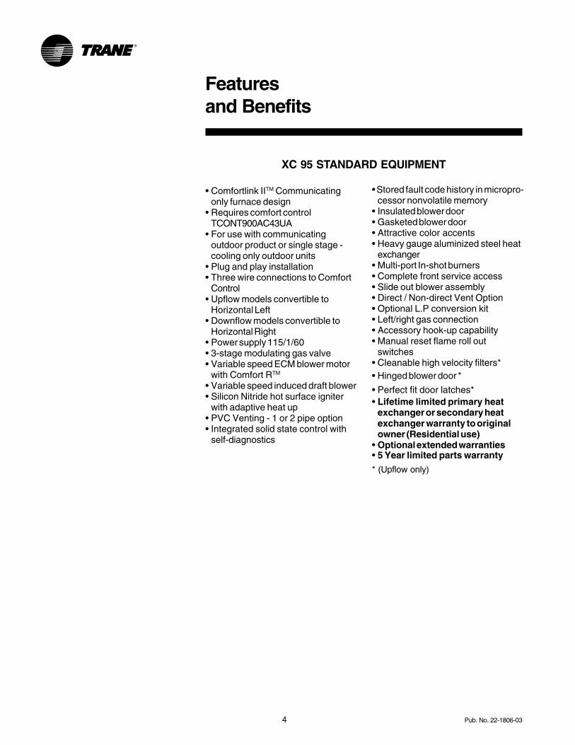
XC 95 STANDARD EQUIPMENT
Featuresand Benefits
• Comfortlink IITM Communicatingonly furnace design
• Requires comfort controlTCONT900AC43UA
• For use with communicatingoutdoor product or single stage -cooling only outdoor units
• Plug and play installation• Three wire connections to Comfort
Control• Upflow models convertible to
Horizontal Left• Downflow models convertible to
Horizontal Right• Power supply 115/1/60• 3-stage modulating gas valve• Variable speed ECM blower motor
with Comfort RTM
• Variable speed induced draft blower• Silicon Nitride hot surface igniter
with adaptive heat up• PVC Venting - 1 or 2 pipe option• Integrated solid state control with
self-diagnostics
• Stored fault code history in micropro-cessor nonvolatile memory
• Insulated blower door• Gasketed blower door• Attractive color accents• Heavy gauge aluminized steel heat
exchanger• Multi-port In-shot burners• Complete front service access• Slide out blower assembly• Direct / Non-direct Vent Option• Optional L.P conversion kit• Left/right gas connection• Accessory hook-up capability• Manual reset flame roll out
switches• Cleanable high velocity filters*• Hinged blower door *
• Perfect fit door latches*• Lifetime limited primary heat
exchanger or secondary heatexchanger warranty to originalowner (Residential use)
• Optional extended warranties• 5 Year limited parts warranty
* (Upflow only)
5Pub. No. 22-1806-03
Featuresand Benefits
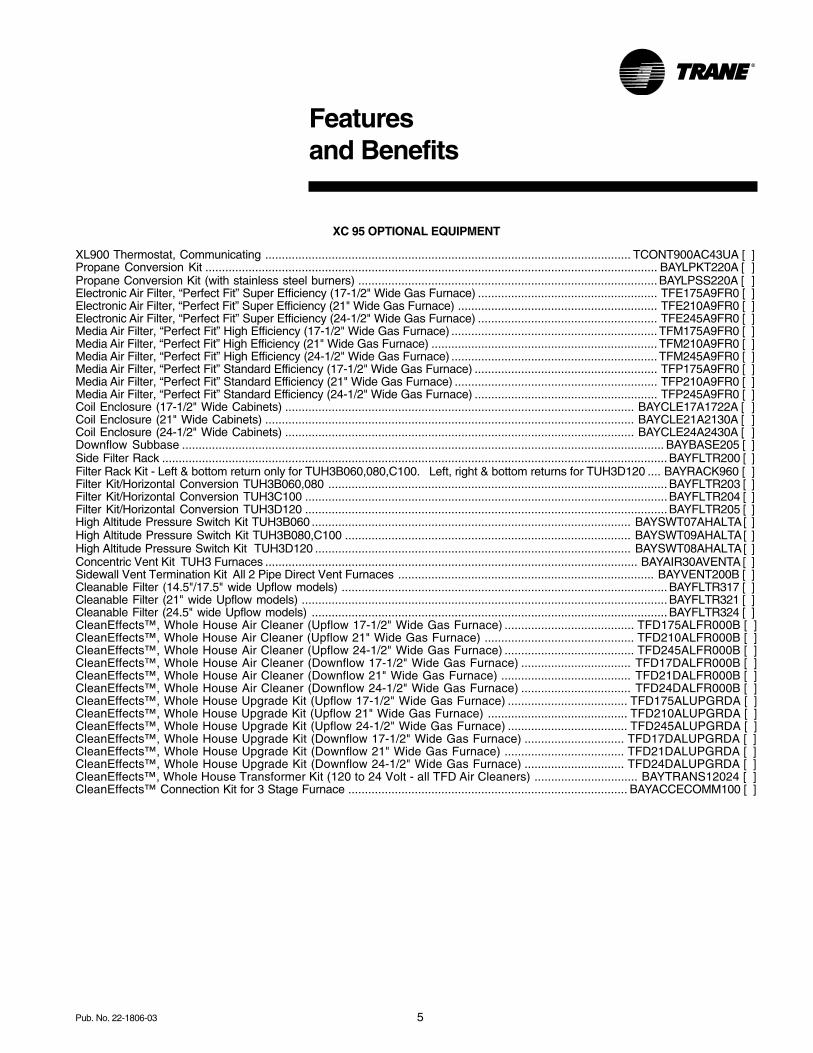
XC 95 OPTIONAL EQUIPMENT
XL900 Thermostat, Communicating .............................................................................................................. TCONT900AC43UA [ ]Propane Conversion Kit ........................................................................................................................................ BAYLPKT220A [ ]Propane Conversion Kit (with stainless steel burners) .......................................................................................... BAYLPSS220A [ ]Electronic Air Filter, “Perfect Fit” Super Efficiency (17-1/2" Wide Gas Furnace) ...................................................... TFE175A9FR0 [ ]Electronic Air Filter, “Perfect Fit” Super Efficiency (21" Wide Gas Furnace) ............................................................ TFE210A9FR0 [ ]Electronic Air Filter, “Perfect Fit” Super Efficiency (24-1/2" Wide Gas Furnace) ...................................................... TFE245A9FR0 [ ]Media Air Filter, “Perfect Fit” High Efficiency (17-1/2" Wide Gas Furnace) .............................................................. TFM175A9FR0 [ ]Media Air Filter, “Perfect Fit” High Efficiency (21" Wide Gas Furnace) .................................................................... TFM210A9FR0 [ ]Media Air Filter, “Perfect Fit” High Efficiency (24-1/2" Wide Gas Furnace) .............................................................. TFM245A9FR0 [ ]Media Air Filter, “Perfect Fit” Standard Efficiency (17-1/2" Wide Gas Furnace) ....................................................... TFP175A9FR0 [ ]Media Air Filter, “Perfect Fit” Standard Efficiency (21" Wide Gas Furnace) ............................................................. TFP210A9FR0 [ ]Media Air Filter, “Perfect Fit” Standard Efficiency (24-1/2" Wide Gas Furnace) ....................................................... TFP245A9FR0 [ ]Coil Enclosure (17-1/2" Wide Cabinets) ......................................................................................................... BAYCLE17A1722A [ ]Coil Enclosure (21" Wide Cabinets) ............................................................................................................... BAYCLE21A2130A [ ]Coil Enclosure (24-1/2" Wide Cabinets) ......................................................................................................... BAYCLE24A2430A [ ]Downflow Subbase ................................................................................................................................................. BAYBASE205 [ ]Side Filter Rack ........................................................................................................................................................ BAYFLTR200 [ ]Filter Rack Kit - Left & bottom return only for TUH3B060,080,C100. Left, right & bottom returns for TUH3D120 .... BAYRACK960 [ ]Filter Kit/Horizontal Conversion TUH3B060,080 ...................................................................................................... BAYFLTR203 [ ]Filter Kit/Horizontal Conversion TUH3C100 .............................................................................................................BAYFLTR204 [ ]Filter Kit/Horizontal Conversion TUH3D120 .............................................................................................................BAYFLTR205 [ ]High Altitude Pressure Switch Kit TUH3B060 ................................................................................................ BAYSWT07AHALTA [ ]High Altitude Pressure Switch Kit TUH3B080,C100 ...................................................................................... BAYSWT09AHALTA [ ]High Altitude Pressure Switch Kit TUH3D120 ............................................................................................... BAYSWT08AHALTA [ ]Concentric Vent Kit TUH3 Furnaces ................................................................................................................ BAYAIR30AVENTA [ ]Sidewall Vent Termination Kit All 2 Pipe Direct Vent Furnaces ............................................................................. BAYVENT200B [ ]Cleanable Filter (14.5"/17.5" wide Upflow models) .................................................................................................. BAYFLTR317 [ ]Cleanable Filter (21" wide Upflow models) .............................................................................................................. BAYFLTR321 [ ]Cleanable Filter (24.5" wide Upflow models) ........................................................................................................... BAYFLTR324 [ ]CleanEffects™, Whole House Air Cleaner (Upflow 17-1/2" Wide Gas Furnace) ....................................... TFD175ALFR000B [ ]CleanEffects™, Whole House Air Cleaner (Upflow 21" Wide Gas Furnace) ............................................. TFD210ALFR000B [ ]CleanEffects™, Whole House Air Cleaner (Upflow 24-1/2" Wide Gas Furnace) ....................................... TFD245ALFR000B [ ]CleanEffects™, Whole House Air Cleaner (Downflow 17-1/2" Wide Gas Furnace) ................................. TFD17DALFR000B [ ]CleanEffects™, Whole House Air Cleaner (Downflow 21" Wide Gas Furnace) ....................................... TFD21DALFR000B [ ]CleanEffects™, Whole House Air Cleaner (Downflow 24-1/2" Wide Gas Furnace) ................................. TFD24DALFR000B [ ]CleanEffects™, Whole House Upgrade Kit (Upflow 17-1/2" Wide Gas Furnace) .................................... TFD175ALUPGRDA [ ]CleanEffects™, Whole House Upgrade Kit (Upflow 21" Wide Gas Furnace) .......................................... TFD210ALUPGRDA [ ]CleanEffects™, Whole House Upgrade Kit (Upflow 24-1/2" Wide Gas Furnace) .................................... TFD245ALUPGRDA [ ]CleanEffects™, Whole House Upgrade Kit (Downflow 17-1/2" Wide Gas Furnace) .............................. TFD17DALUPGRDA [ ]CleanEffects™, Whole House Upgrade Kit (Downflow 21" Wide Gas Furnace) .................................... TFD21DALUPGRDA [ ]CleanEffects™, Whole House Upgrade Kit (Downflow 24-1/2" Wide Gas Furnace) .............................. TFD24DALUPGRDA [ ]CleanEffects™, Whole House Transformer Kit (120 to 24 Volt - all TFD Air Cleaners) ............................... BAYTRANS12024 [ ]CleanEffects™ Connection Kit for 3 Stage Furnace .................................................................................... BAYACCECOMM100 [ ]
6 Pub. No. 22-1806-03
GeneralData
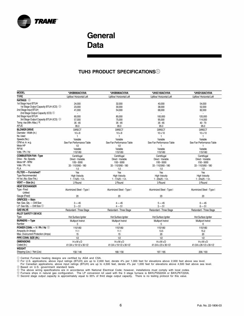
TUH3 PRODUCT SPECIFICATIONS1
MODELTYPERATINGS 21st Stage Input BTUH
1st Stage Output Capacity BTUH (ICS) 32nd Stage Input BTUH
2nd Stage Output Capacity (ICS) 63rd Stage Input BTUH
3rd Stage Output Capacity BTUH (ICS) 3Temp. rise (Min.-Max.) °F.AFUEBLOWER DRIVEDiameter - Width (In.)No. UsedSpeeds (No.)CFM vs. in. w.g.Motor HPR.P.M.Volts / Ph / HzCOMBUSTION FAN - TypeDrive - No. SpeedsMotor HP - RPMVolts / Ph / HzFLAFILTER — Furnished?Type RecommendedHi Vel. (No.-Size-Thk.)VENT — Size (in.)HEAT EXCHANGERType -Fired
-UnfiredGauge (Fired)ORIFICES — MainNat. Gas. Qty. — Drill SizeL.P. Gas Qty. — Drill Size 5GAS VALVEPILOT SAFETY DEVICETypeBURNERS — TypeNumberPOWER CONN. — V / Ph / Hz 4Ampacity (In Amps)Max. Overcurrent Protection (Amps)PIPE CONN. SIZE (IN.)DIMENSIONSCrated (In.)WEIGHTShipping (Lbs.) / Net (Lbs)
*UH3B080ACV3VAUpflow/ Horizontal Left
32,00030,00054,000
-80,00075,00035 - 6595.0
DIRECT10 x 8
1Variable
See Fan Performance Table1/2
Variable115/1/60
CentrifugalDirect - Variable
1/50 - 500033 - 110/3/60 - 180
1.0Yes
High Velocity1 - 17x25 - 1 in.
2 Round
Aluminized Steel - Type I
20
4 — 454 — 51
Redundant - Three Stage
Hot Surface IgniterMultiport Inshot
4115/1/60
11.1151/2
H x W x D41-3/4 x 19-1/2 x 30-1/2
168 / 156
*UH3B060ACV3VAUpflow/ Horizontal Left
24,00023,00041,000
-60,00057,00035 - 6595.0
DIRECT10 x 8
1Variable
See Fan Performance Table1/2
Variable115/1/60
CentrifugalDirect - Variable
1/50 - 500033 - 110/3/60 - 180
1.0Yes
High Velocity1 - 17x25 - 1 in.
2 Round
Aluminized Steel - Type I
20
3 — 453 — 51
Redundant - Three Stage
Hot Surface IgniterMultiport Inshot
3115/1/60
11.1151/2
H x W x D41-3/4 x 19-1/2 x 30-1/2
158 / 146
*UH3C100ACV4VAUpflow/ Horizontal Left
40,00038,00068,000
-100,00095,00035 - 6595.0
DIRECT10 x 10
1Variable
See Fan Performance Table1
Variable115/1/60
CentrifugalDirect - Variable
1/50 - 500033 - 110/3/60 - 180
1.0Yes
High Velocity1 - 20x25 - 1 in.
3 Round
Aluminized Steel - Type I
20
5 — 455 — 51
Redundant - Three Stage
Hot Surface IgniterMultiport Inshot
5115/1/60
13.5201/2
H x W x D41-3/4 x 23 x 30-1/2
197 / 185
*UH3D120ACV5VAUpflow/ Horizontal Left
54,00052,00082,000
-120,000114,00040 - 7095.0
DIRECT10 x 10
1Variable
See Fan Performance Table1
Variable115/1/60
CentrifugalDirect - Variable
1/50 - 500033 - 110/3/60 - 180
1.0Yes
High Velocity1 - 24x25 - 1 in.
3 Round
Aluminized Steel - Type I
20
6 — 456 — 51
Redundant - Three Stage
Hot Surface IgniterMultiport Inshot
6115/1/60
15.2201/2
H x W x D41-3/4 x 26-1/2 x 30-1/2
206 / 193
1 Central Furnace heating designs are certified by AGA and CSA.2 For U.S. applications, above input ratings (BTUH) are up to 2,000 feet, derate 4% per 1,000 feet for elevations above 2,000 feet above sea level.
For Canadian applications, above input ratings (BTUH) are up to 4,500 feet, derate 4% per 1,000 feet for elevations above 4,500 feet above sea level.3 Based on U.S. government standard tests.4 The above wiring specifications are in accordance with National Electrical Code; however, installations must comply with local codes.5 Furnace ships in natural gas configuration. The LP conversion kit used with the 3 stage furnace is BAYLPSS220A or BAYLPKT220A.6 Second stage output capacity is approximately equal to 65% of third stage output capacity. There is no testing protocol for this value.
7Pub. No. 22-1806-03
GeneralData
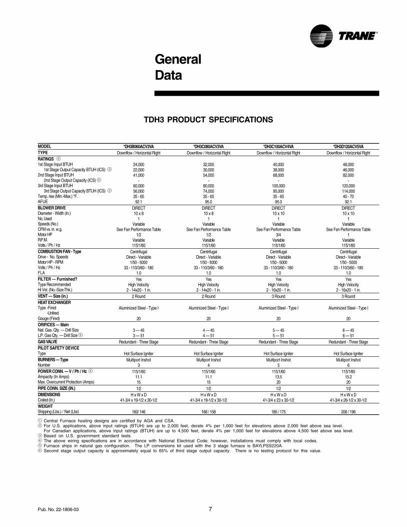
TDH3 PRODUCT SPECIFICATIONS
MODELTYPERATINGS 21st Stage Input BTUH
1st Stage Output Capacity BTUH (ICS) 32nd Stage Input BTUH
2nd Stage Output Capacity (ICS) 63rd Stage Input BTUH
3rd Stage Output Capacity BTUH (ICS) 3Temp. rise (Min.-Max.) °F.AFUEBLOWER DRIVEDiameter - Width (In.)No. UsedSpeeds (No.)CFM vs. in. w.g.Motor HPR.P.M.Volts / Ph / HzCOMBUSTION FAN - TypeDrive - No. SpeedsMotor HP - RPMVolts / Ph / HzFLAFILTER — Furnished?Type RecommendedHi Vel. (No.-Size-Thk.)VENT — Size (in.)HEAT EXCHANGERType -Fired
-UnfiredGauge (Fired)ORIFICES — MainNat. Gas. Qty. — Drill SizeL.P. Gas Qty. — Drill Size 5GAS VALVEPILOT SAFETY DEVICETypeBURNERS — TypeNumberPOWER CONN. — V / Ph / Hz 4Ampacity (In Amps)Max. Overcurrent Protection (Amps)PIPE CONN. SIZE (IN.)DIMENSIONSCrated (In.)WEIGHTShipping (Lbs.) / Net (Lbs)
*DH3C080ACV3VADownflow / Horizontal Right
32,00030,00054,000
-80,00074,00035 - 6595.0
DIRECT10 x 8
1Variable
See Fan Performance Table1/2
Variable115/1/60
CentrifugalDirect - Variable
1/50 - 500033 - 110/3/60 - 180
1.0Yes
High Velocity2 - 14x20 - 1 in.
2 Round
Aluminized Steel - Type I
20
4 — 454 — 51
Redundant - Three Stage
Hot Surface IgniterMultiport Inshot
4115/1/60
11.1151/2
H x W x D41-3/4 x 19-1/2 x 30-1/2
168 / 158
*DH3D120ACV5VADownflow / Horizontal Right
48,00046,00082,000
-120,000114,00040 - 7092.1
DIRECT10 x 10
1Variable
See Fan Performance Table1
Variable115/1/60
CentrifugalDirect - Variable
1/50 - 500033 - 110/3/60 - 180
1.0Yes
High Velocity2 - 16x20 - 1 in.
3 Round
Aluminized Steel - Type I
20
6 — 456 — 51
Redundant - Three Stage
Hot Surface IgniterMultiport Inshot
6115/1/60
15.2201/2
H x W x D41-3/4 x 26-1/2 x 30-1/2
206 / 196
*DH3C100ACV4VADownflow / Horizontal Right
40,00038,00068,000
-100,00095,00035 - 6595.0
DIRECT10 x 10
1Variable
See Fan Performance Table3/4
Variable115/1/60
CentrifugalDirect - Variable
1/50 - 500033 - 110/3/60 - 180
1.0Yes
High Velocity2 - 16x20 - 1 in.
3 Round
Aluminized Steel - Type I
20
5 — 455 — 51
Redundant - Three Stage
Hot Surface IgniterMultiport Inshot
5115/1/60
13.5201/2
H x W x D41-3/4 x 23 x 30-1/2
185 / 175
*DH3B060ACV3VADownflow / Horizontal Right
24,00022,00041,000
-60,00056,00035 - 6592.1
DIRECT10 x 8
1Variable
See Fan Performance Table1/2
Variable115/1/60
CentrifugalDirect - Variable
1/50 - 500033 - 110/3/60 - 180
1.0Yes
High Velocity2 - 14x20 - 1 in.
2 Round
Aluminized Steel - Type I
20
3 — 453 — 51
Redundant - Three Stage
Hot Surface IgniterMultiport Inshot
3115/1/60
11.1151/2
H x W x D41-3/4 x 19-1/2 x 30-1/2
160/ 146
1 Central Furnace heating designs are certified by AGA and CSA.2 For U.S. applications, above input ratings (BTUH) are up to 2,000 feet, derate 4% per 1,000 feet for elevations above 2,000 feet above sea level.
For Canadian applications, above input ratings (BTUH) are up to 4,500 feet, derate 4% per 1,000 feet for elevations above 4,500 feet above sea level.3 Based on U.S. government standard tests.4 The above wiring specifications are in accordance with National Electrical Code; however, installations must comply with local codes.5 Furnace ships in natural gas configuration. The LP conversions kit used with the 3 stage furnace is BAYLPSS220A.6 Second stage output capacity is approximately equal to 65% of third stage output capacity. There is no testing protocol for this value.
8 Pub. No. 22-1806-03
0.1 0.3 0.5 0.7 0.9
CFM 446 575 590 608 611
Temp. Rise 46 36 35 34 34
Watts 44 82 115 154 191
CFM 543 637 647 665 668
Temp. Rise 38 32 32 31 31
Watts 51 93 130 171 211
CFM 622 705 715 729 731
Temp. Rise 33 29 29 28 28
Watts 63 108 148 191 234
CFM 727 795 804 815 815
Temp. Rise 28 26 26 25 25
Watts 84 132 176 223 268
CFM 619 695 717 727 733
Temp. Rise 50 45 43 43 42
Watts 63 106 150 193 236
CFM 710 780 789 801 801
Temp. Rise 44 40 39 39 39
Watts 80 128 171 217 262
CFM 819 874 882 890 888
Temp. Rise 38 35 35 35 35
Watts 107 158 205 255 303
CFM 939 978 985 989 984
Temp. Rise 33 32 31 31 31
Watts 145 200 251 304 355
CFM 937 968 977 985 984
Temp. Rise 55 53 53 52 53
Watts 136 193 241 295 343
CFM 985 1017 1024 1027 1021
Temp. Rise 52 51 50 50 51
Watts 162 218 272 325 377
CFM 1117 1130 1136 1134 1126
Temp. Rise 46 46 45 46 46
Watts 219 279 338 392 449
CFM 1292 1280 1285 1278 1201
Temp. Rise 40 40 40 40 43
Watts 317 383 448 501 508
Heating
3rd Stage
Low 900
Medium Low 1010
Medium** 1130
High 1290
Heating
2nd
Stage
Low 680
Medium Low 760
Medium** 860
High 970
610
Medium** 620
High 770
He
ati
ng
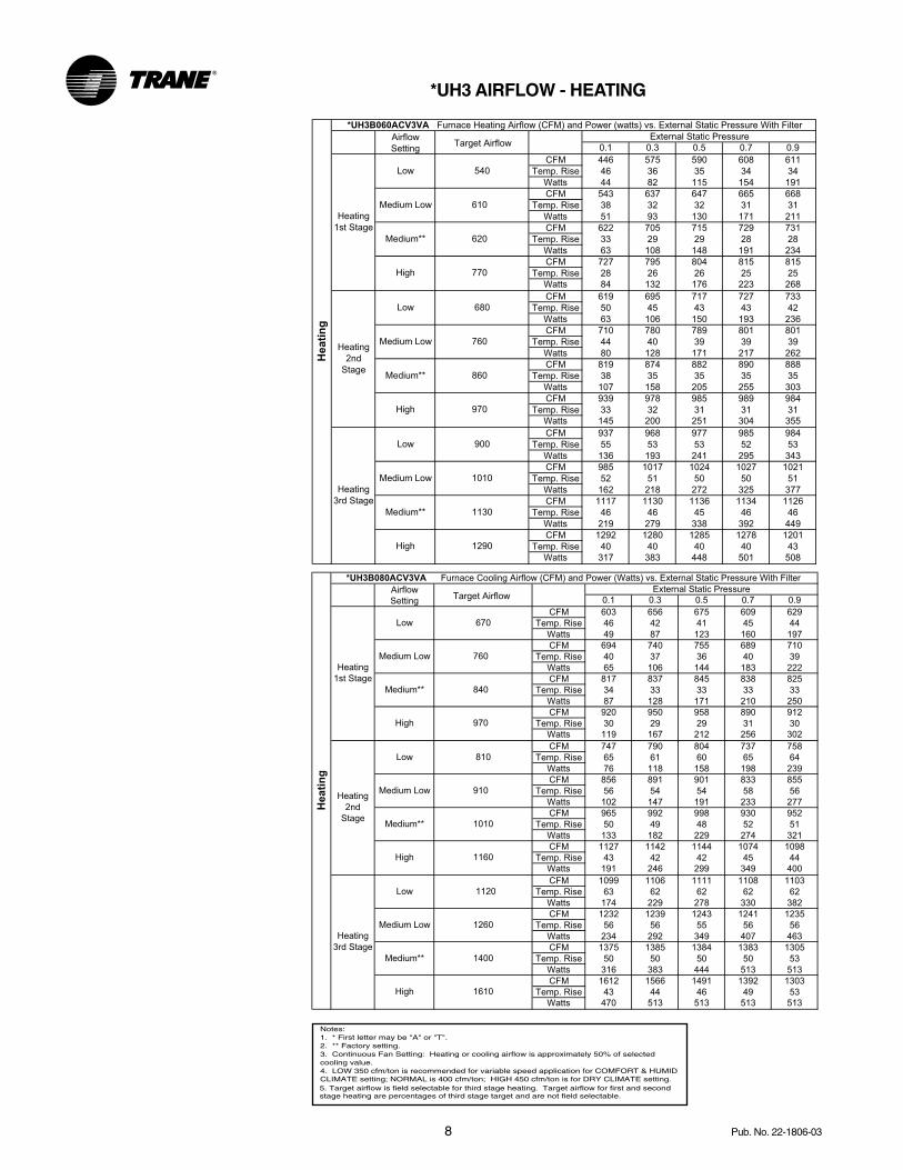
*UH3B060ACV3VA Furnace Heating Airflow (CFM) and Power (watts) vs. External Static Pressure With Filter
Airflow
Setting
External Static Pressure
Heating
1st Stage
Low 540
Medium Low
Target Airflow
0.1 0.3 0.5 0.7 0.9
CFM 603 656 675 609 629
Temp. Rise 46 42 41 45 44
Watts 49 87 123 160 197
CFM 694 740 755 689 710
Temp. Rise 40 37 36 40 39
Watts 65 106 144 183 222
CFM 817 837 845 838 825
Temp. Rise 34 33 33 33 33
Watts 87 128 171 210 250
CFM 920 950 958 890 912
Temp. Rise 30 29 29 31 30
Watts 119 167 212 256 302
CFM 747 790 804 737 758
Temp. Rise 65 61 60 65 64
Watts 76 118 158 198 239
CFM 856 891 901 833 855
Temp. Rise 56 54 54 58 56
Watts 102 147 191 233 277
CFM 965 992 998 930 952
Temp. Rise 50 49 48 52 51
Watts 133 182 229 274 321
CFM 1127 1142 1144 1074 1098
Temp. Rise 43 42 42 45 44
Watts 191 246 299 349 400
CFM 1099 1106 1111 1108 1103
Temp. Rise 63 62 62 62 62
Watts 174 229 278 330 382
CFM 1232 1239 1243 1241 1235
Temp. Rise 56 56 55 56 56
Watts 234 292 349 407 463
CFM 1375 1385 1384 1383 1305
Temp. Rise 50 50 50 50 53
Watts 316 383 444 513 513
CFM 1612 1566 1491 1392 1303
Temp. Rise 43 44 46 49 53
Watts 470 513 513 513 513
External Static Pressure
Heating
1st Stage
Low 670
Medium Low 760
Medium** 840
High 970
Heating
2nd
Stage
Low 810
Medium Low 910
Medium** 1010
High 1160
He
ati
ng
*UH3B080ACV3VA Furnace Cooling Airflow (CFM) and Power (Watts) vs. External Static Pressure With Filter
Airflow
Setting
Heating
3rd Stage
Low 1120
Medium Low 1260
Medium** 1400
High 1610
Target Airflow
*UH3 AIRFLOW - HEATING
Notes:1. * First letter may be "A" or "T".2. ** Factory setting.3. Continuous Fan Setting: Heating or cooling airflow is approximately 50% of selected cooling value.4. LOW 350 cfm/ton is recommended for variable speed application for COMFORT & HUMIDCLIMATE setting; NORMAL is 400 cfm/ton; HIGH 450 cfm/ton is for DRY CLIMATE setting.5. Target airflow is field selectable for third stage heating. Target airflow for first and second stage heating are percentages of third stage target and are not field selectable.
9Pub. No. 22-1806-03
0.1 0.3 0.5 0.7 0.9
CFM 788 806 810 804 792
Temp. Rise 45 44 43 44 44
Watts 91 132 172 212 250
CFM 880 896 899 892 879
Temp. Rise 40 39 39 39 40
Watts 109 152 195 237 277
CFM 1010 1023 1023 1016 1002
Temp. Rise 35 34 34 35 35
Watts 139 185 232 279 322
CFM 1077 1089 1088 1080 1066
Temp. Rise 32 32 32 32 32
Watts 157 205 254 304 349
CFM 951 966 967 960 947
Temp. Rise 65 64 64 64 65
Watts 124 169 214 259 301
CFM 1061 1073 1072 1064 1051
Temp. Rise 58 57 57 58 59
Watts 153 200 249 297 342
CFM 1217 1226 1223 1214 1199
Temp. Rise 51 50 50 51 51
Watts 203 255 309 363 413
CFM 1298 1305 1300 1291 1276
Temp. Rise 47 47 47 48 48
Watts 234 289 346 403 456
CFM 1333 1339 1334 1324 1309
Temp. Rise 66 66 66 66 67
Watts 249 305 363 421 476
CFM 1486 1489 1481 1471 1454
Temp. Rise 59 59 59 60 60
Watts 322 384 448 513 576
CFM 1701 1699 1687 1676 1658
Temp. Rise 52 52 52 52 53
Watts 453 526 599 672 752
CFM 1813 1810 1795 1783 1765
Temp. Rise 49 49 49 49 50
Watts 536 617 694 772 864
Heati
ng
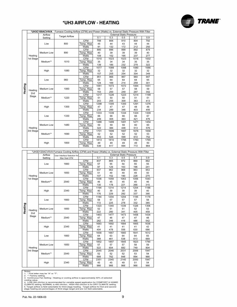
*UH3C100ACV4VA Furnace Cooling Airflow (CFM) and Power (Watts) vs. External Static Pressure With Filter
Airflow
Setting
External Static Pressure
Heating
1st Stage
Low 800
Medium Low 890
Medium** 1010
High 1080
Heating
2nd
Stage
Low 960
Medium Low 1060
Medium** 1220
High 1300
Heating
3rd Stage
Low 1330
Medium Low 1480
Medium** 1690
High 1800
Target Airflow
0.1 0.3 0.5 0.7 0.9
CFM 837 865 872 869 862
Temp. Rise 57 55 54 55 55
Watts 87 129 163 196 241
CFM 937 962 968 963 953
Temp. Rise 51 49 49 49 50
Watts 107 152 190 228 275
CFM 1036 1059 1063 1056 1043
Temp. Rise 46 45 45 45 46
Watts 130 178 221 266 315
CFM 1194 1214 1214 1204 1188
Temp. Rise 40 39 39 39 40
Watts 176 229 282 337 390
CFM 1184 1204 1204 1195 1179
Temp. Rise 58 57 57 57 58
Watts 172 225 278 332 385
CFM 1323 1340 1339 1326 1306
Temp. Rise 52 51 51 52 53
Watts 222 280 341 405 459
CFM 1463 1477 1473 1458 1434
Temp. Rise 47 46 47 47 48
Watts 282 346 416 486 542
CFM 1683 1692 1684 1665 1636
Temp. Rise 41 41 41 41 42
Watts 404 478 556 630 686
CFM 1658 1667 1660 1641 1612
Temp. Rise 64 63 64 64 65
Watts 388 461 538 613 669
CFM 1852 1857 1845 1823 1790
Temp. Rise 57 57 57 58 59
Watts 522 604 682 749 804
CFM 2045 2046 2031 2006 1947
Temp. Rise 52 52 52 53 54
Watts 689 782 848 894 966
CFM 2351 2345 2140 2050 1947
Temp. Rise 45 45 49 51 54
Watts 966 966 966 966 966
He
ati
ng
*UH3D120ACV5VA Furnace Cooling Airflow (CFM) and Power (Watts) vs. External Static Pressure With Filter
Airflow
SettingUser Interface Selection for
Max Heat CFM
External Static Pressure
Heating
1st Stage
Low 1660
Medium Low 1850
Medium** 2040
High 2340
Heating
2nd
Stage
Low 1660
Medium Low 1850
Medium** 2040
High 2340
Heating
3rd Stage
Low 1660
Medium Low 1850
Medium** 2040
High 2340
*UH3 AIRFLOW - HEATING
Notes:1. * First letter may be "A" or "T".2. ** Factory setting.3. Continuous Fan Setting: Heating or cooling airflow is approximately 50% of selected cooling value.4. LOW 350 cfm/ton is recommended for variable speed application for COMFORT & HUMIDCLIMATE setting; NORMAL is 400 cfm/ton; HIGH 450 cfm/ton is for DRY CLIMATE setting.5. Target airflow is field selectable for third stage heating. Target airflow for first and second stage heating are percentages of third stage target and are not field selectable.
10 Pub. No. 22-1806-03
0.1 0.3 0.5 0.7 0.9
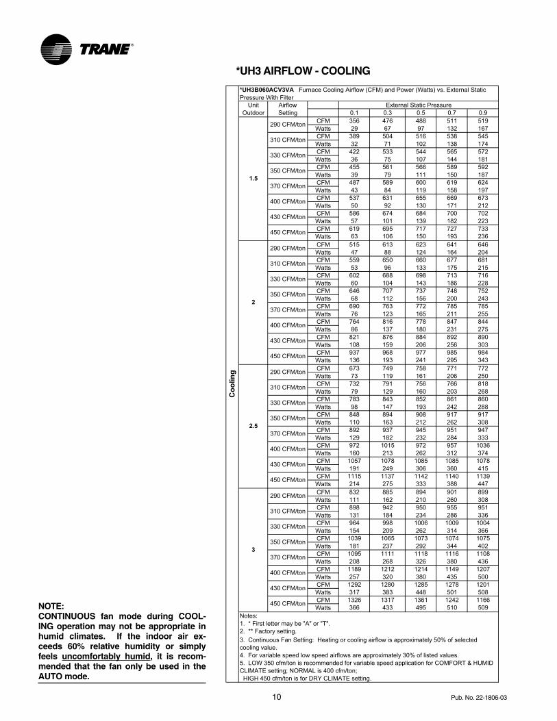
CFM 356 476 488 511 519
Watts 29 67 97 132 167
CFM 389 504 516 538 545
Watts 32 71 102 138 174
CFM 422 533 544 565 572
Watts 36 75 107 144 181
CFM 455 561 566 589 592
Watts 39 79 111 150 187
CFM 487 589 600 619 624
Watts 43 84 119 158 197
CFM 537 631 655 669 673
Watts 50 92 130 171 212
CFM 586 674 684 700 702
Watts 57 101 139 182 223
CFM 619 695 717 727 733
Watts 63 106 150 193 236
CFM 515 613 623 641 646
Watts 47 88 124 164 204
CFM 559 650 660 677 681
Watts 53 96 133 175 215
CFM 602 688 698 713 716
Watts 60 104 143 186 228
CFM 646 707 737 748 752
Watts 68 112 156 200 243
CFM 690 763 772 785 785
Watts 76 123 165 211 255
CFM 764 816 778 847 844
Watts 86 137 180 231 275
CFM 821 876 884 892 890
Watts 108 159 206 256 303
CFM 937 968 977 985 984
Watts 136 193 241 295 343
CFM 673 749 758 771 772
Watts 73 119 161 206 250
CFM 732 791 756 766 818
Watts 79 129 160 203 268
CFM 783 843 852 861 860
Watts 98 147 193 242 288
CFM 848 894 908 917 917
Watts 110 163 212 262 308
CFM 892 937 945 951 947
Watts 129 182 232 284 333
CFM 972 1015 972 957 1036
Watts 160 213 262 312 374
CFM 1057 1078 1085 1085 1078
Watts 191 249 306 360 415
CFM 1115 1137 1142 1140 1139
Watts 214 275 333 388 447
CFM 832 885 894 901 899
Watts 111 162 210 260 308
CFM 898 942 950 955 951
Watts 131 184 234 286 336
CFM 964 998 1006 1009 1004
Watts 154 209 262 314 366
CFM 1039 1065 1073 1074 1075
Watts 181 237 292 344 402
CFM 1095 1111 1118 1116 1108
Watts 208 268 326 380 436
CFM 1189 1212 1214 1149 1207
Watts 257 320 380 435 500
CFM 1292 1280 1285 1278 1201
Watts 317 383 448 501 508
CFM 1326 1317 1361 1242 1166
Watts 366 433 495 510 509
4. For variable speed low speed airflows are approximately 30% of listed values.
5. LOW 350 cfm/ton is recommended for variable speed application for COMFORT & HUMID
CLIMATE setting; NORMAL is 400 cfm/ton;
HIGH 450 cfm/ton is for DRY CLIMATE setting.
Notes:
1. * First letter may be "A" or "T".
2. ** Factory setting.
3. Continuous Fan Setting: Heating or cooling airflow is approximately 50% of selected
cooling value.
*UH3B060ACV3VA Furnace Cooling Airflow (CFM) and Power (Watts) vs. External Static
Pressure With Filter
450 CFM/ton
3
290 CFM/ton
310 CFM/ton
330 CFM/ton
350 CFM/ton
370 CFM/ton
400 CFM/ton
430 CFM/ton
450 CFM/ton
430 CFM/ton
450 CFM/ton
2.5
290 CFM/ton
310 CFM/ton
330 CFM/ton
350 CFM/ton
370 CFM/ton
400 CFM/ton
430 CFM/ton
400 CFM/ton
430 CFM/ton
450 CFM/ton
2
290 CFM/ton
310 CFM/ton
330 CFM/ton
350 CFM/ton
370 CFM/ton
400 CFM/ton
Co
olin
g
Unit
Outdoor
Airflow
Setting
External Static Pressure
1.5
290 CFM/ton
310 CFM/ton
330 CFM/ton
350 CFM/ton
370 CFM/ton
NOTE:CONTINUOUS fan mode during COOL-ING operation may not be appropriate inhumid climates. If the indoor air ex-ceeds 60% relative humidity or simplyfeels uncomfortably humid, it is recom-mended that the fan only be used in theAUTO mode.
*UH3 AIRFLOW - COOLING
11Pub. No. 22-1806-03
0.1 0.3 0.5 0.7 0.9
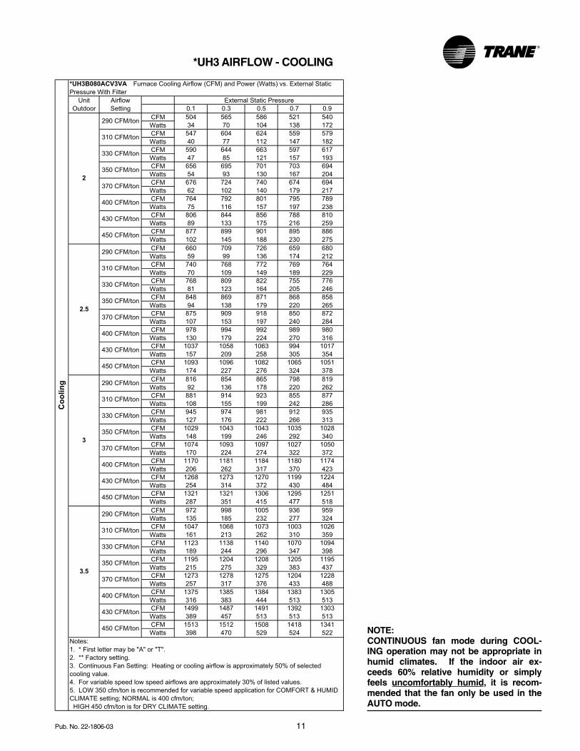
CFM 504 565 586 521 540
Watts 34 70 104 138 172
CFM 547 604 624 559 579
Watts 40 77 112 147 182
CFM 590 644 663 597 617
Watts 47 85 121 157 193
CFM 656 695 701 703 694
Watts 54 93 130 167 204
CFM 676 724 740 674 694
Watts 62 102 140 179 217
CFM 764 792 801 795 789
Watts 75 116 157 197 238
CFM 806 844 856 788 810
Watts 89 133 175 216 259
CFM 877 899 901 895 886
Watts 102 145 188 230 275
CFM 660 709 726 659 680
Watts 59 99 136 174 212
CFM 740 768 772 769 764
Watts 70 109 149 189 229
CFM 768 809 822 755 776
Watts 81 123 164 205 246
CFM 848 869 871 868 858
Watts 94 138 179 220 265
CFM 875 909 918 850 872
Watts 107 153 197 240 284
CFM 978 994 992 989 980
Watts 130 179 224 270 316
CFM 1037 1058 1063 994 1017
Watts 157 209 258 305 354
CFM 1093 1096 1082 1065 1051
Watts 174 227 276 324 378
CFM 816 854 865 798 819
Watts 92 136 178 220 262
CFM 881 914 923 855 877
Watts 108 155 199 242 286
CFM 945 974 981 912 935
Watts 127 176 222 266 313
CFM 1029 1043 1043 1035 1028
Watts 148 199 246 292 340
CFM 1074 1093 1097 1027 1050
Watts 170 224 274 322 372
CFM 1170 1181 1184 1180 1174
Watts 206 262 317 370 423
CFM 1268 1273 1270 1199 1224
Watts 254 314 372 430 484
CFM 1321 1321 1306 1295 1251
Watts 287 351 415 477 518
CFM 972 998 1005 936 959
Watts 135 185 232 277 324
CFM 1047 1068 1073 1003 1026
Watts 161 213 262 310 359
CFM 1123 1138 1140 1070 1094
Watts 189 244 296 347 398
CFM 1195 1204 1208 1205 1195
Watts 215 275 329 383 437
CFM 1273 1278 1275 1204 1228
Watts 257 317 376 433 488
CFM 1375 1385 1384 1383 1305
Watts 316 383 444 513 513
CFM 1499 1487 1491 1392 1303
Watts 389 457 513 513 513
CFM 1513 1512 1508 1418 1341
Watts 398 470 529 524 522
4. For variable speed low speed airflows are approximately 30% of listed values.
5. LOW 350 cfm/ton is recommended for variable speed application for COMFORT & HUMID
CLIMATE setting; NORMAL is 400 cfm/ton;
HIGH 450 cfm/ton is for DRY CLIMATE setting.
Notes:
1. * First letter may be "A" or "T".
2. ** Factory setting.
3. Continuous Fan Setting: Heating or cooling airflow is approximately 50% of selected
cooling value.
Unit
Outdoor
Airflow
Setting
External Static Pressure
290 CFM/ton
310 CFM/ton
330 CFM/ton
2
350 CFM/ton
370 CFM/ton
400 CFM/ton
430 CFM/ton
450 CFM/ton
2.5
290 CFM/ton
310 CFM/ton
330 CFM/ton
350 CFM/ton
370 CFM/ton
400 CFM/ton
430 CFM/ton
450 CFM/ton
3
290 CFM/ton
310 CFM/ton
330 CFM/ton
350 CFM/ton
370 CFM/ton
400 CFM/ton
430 CFM/ton
450 CFM/ton
3.5
290 CFM/ton
310 CFM/ton
330 CFM/ton
370 CFM/ton
400 CFM/ton
430 CFM/ton
450 CFM/ton
*UH3B080ACV3VA Furnace Cooling Airflow (CFM) and Power (Watts) vs. External Static
Pressure With Filter
Co
olin
g
350 CFM/ton
*UH3 AIRFLOW - COOLING
NOTE:CONTINUOUS fan mode during COOL-ING operation may not be appropriate inhumid climates. If the indoor air ex-ceeds 60% relative humidity or simplyfeels uncomfortably humid, it is recom-mended that the fan only be used in theAUTO mode.
12 Pub. No. 22-1806-03
0.1 0.3 0.5 0.7 0.9
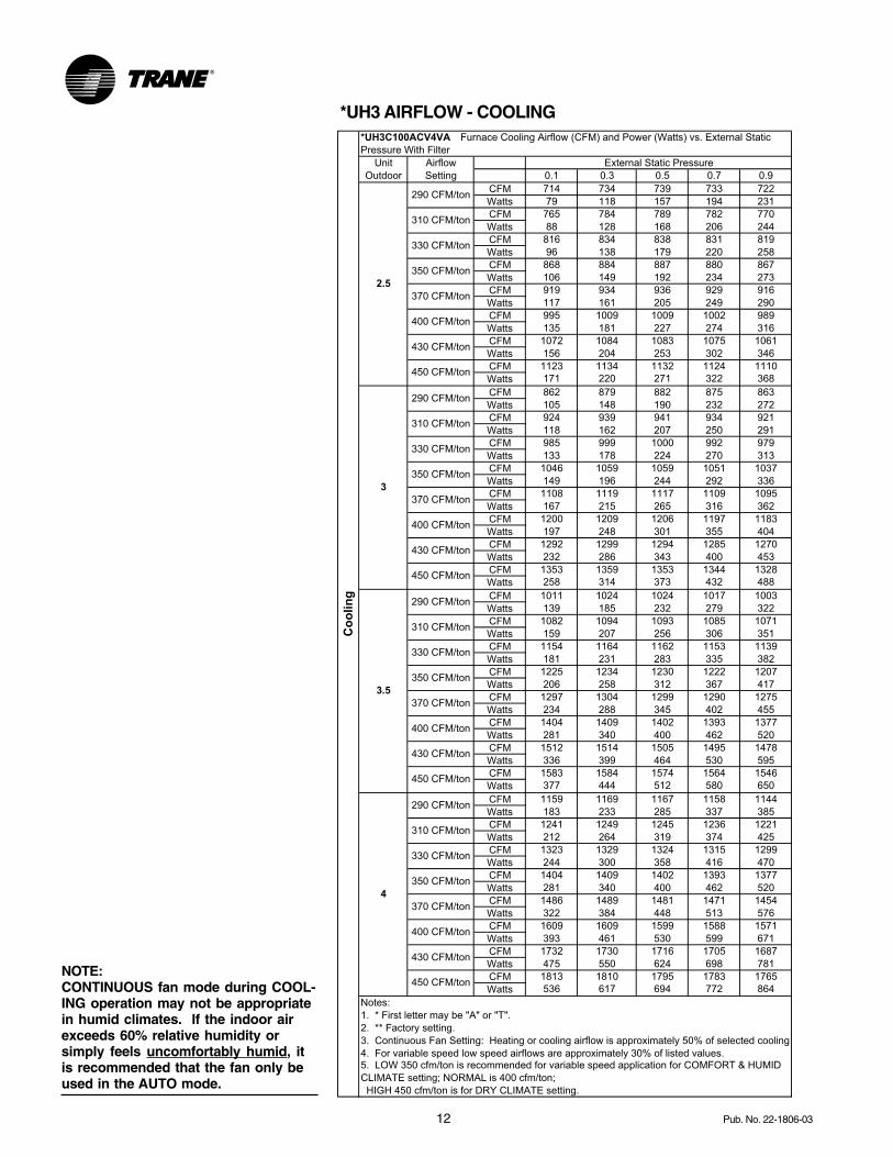
CFM 714 734 739 733 722
Watts 79 118 157 194 231
CFM 765 784 789 782 770
Watts 88 128 168 206 244
CFM 816 834 838 831 819
Watts 96 138 179 220 258
CFM 868 884 887 880 867
Watts 106 149 192 234 273
CFM 919 934 936 929 916
Watts 117 161 205 249 290
CFM 995 1009 1009 1002 989
Watts 135 181 227 274 316
CFM 1072 1084 1083 1075 1061
Watts 156 204 253 302 346
CFM 1123 1134 1132 1124 1110
Watts 171 220 271 322 368
CFM 862 879 882 875 863
Watts 105 148 190 232 272
CFM 924 939 941 934 921
Watts 118 162 207 250 291
CFM 985 999 1000 992 979
Watts 133 178 224 270 313
CFM 1046 1059 1059 1051 1037
Watts 149 196 244 292 336
CFM 1108 1119 1117 1109 1095
Watts 167 215 265 316 362
CFM 1200 1209 1206 1197 1183
Watts 197 248 301 355 404
CFM 1292 1299 1294 1285 1270
Watts 232 286 343 400 453
CFM 1353 1359 1353 1344 1328
Watts 258 314 373 432 488
CFM 1011 1024 1024 1017 1003
Watts 139 185 232 279 322
CFM 1082 1094 1093 1085 1071
Watts 159 207 256 306 351
CFM 1154 1164 1162 1153 1139
Watts 181 231 283 335 382
CFM 1225 1234 1230 1222 1207
Watts 206 258 312 367 417
CFM 1297 1304 1299 1290 1275
Watts 234 288 345 402 455
CFM 1404 1409 1402 1393 1377
Watts 281 340 400 462 520
CFM 1512 1514 1505 1495 1478
Watts 336 399 464 530 595
CFM 1583 1584 1574 1564 1546
Watts 377 444 512 580 650
CFM 1159 1169 1167 1158 1144
Watts 183 233 285 337 385
CFM 1241 1249 1245 1236 1221
Watts 212 264 319 374 425
CFM 1323 1329 1324 1315 1299
Watts 244 300 358 416 470
CFM 1404 1409 1402 1393 1377
Watts 281 340 400 462 520
CFM 1486 1489 1481 1471 1454
Watts 322 384 448 513 576
CFM 1609 1609 1599 1588 1571
Watts 393 461 530 599 671
CFM 1732 1730 1716 1705 1687
Watts 475 550 624 698 781
CFM 1813 1810 1795 1783 1765
Watts 536 617 694 772 864
4. For variable speed low speed airflows are approximately 30% of listed values.5. LOW 350 cfm/ton is recommended for variable speed application for COMFORT & HUMID
CLIMATE setting; NORMAL is 400 cfm/ton;
HIGH 450 cfm/ton is for DRY CLIMATE setting.
Notes:
1. * First letter may be "A" or "T".
2. ** Factory setting.
3. Continuous Fan Setting: Heating or cooling airflow is approximately 50% of selected cooling
Unit
Outdoor
Co
olin
g
*UH3C100ACV4VA Furnace Cooling Airflow (CFM) and Power (Watts) vs. External Static
Pressure With Filter
Airflow
Setting
External Static Pressure
2.5
290 CFM/ton
310 CFM/ton
330 CFM/ton
350 CFM/ton
370 CFM/ton
400 CFM/ton
430 CFM/ton
450 CFM/ton
3
290 CFM/ton
310 CFM/ton
330 CFM/ton
350 CFM/ton
370 CFM/ton
400 CFM/ton
430 CFM/ton
450 CFM/ton
3.5
290 CFM/ton
310 CFM/ton
330 CFM/ton
350 CFM/ton
370 CFM/ton
400 CFM/ton
430 CFM/ton
450 CFM/ton
4
290 CFM/ton
310 CFM/ton
330 CFM/ton
350 CFM/ton
370 CFM/ton
400 CFM/ton
430 CFM/ton
450 CFM/ton
*UH3 AIRFLOW - COOLING
NOTE:CONTINUOUS fan mode during COOL-ING operation may not be appropriatein humid climates. If the indoor airexceeds 60% relative humidity orsimply feels uncomfortably humid, itis recommended that the fan only beused in the AUTO mode.
13Pub. No. 22-1806-03
0.1 0.3 0.5 0.7 0.9
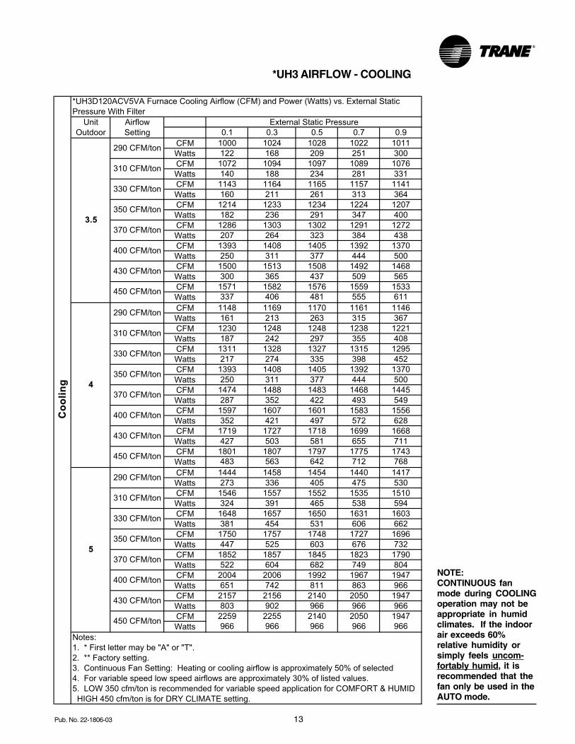
CFM 1000 1024 1028 1022 1011
Watts 122 168 209 251 300
CFM 1072 1094 1097 1089 1076
Watts 140 188 234 281 331
CFM 1143 1164 1165 1157 1141
Watts 160 211 261 313 364
CFM 1214 1233 1234 1224 1207
Watts 182 236 291 347 400
CFM 1286 1303 1302 1291 1272
Watts 207 264 323 384 438
CFM 1393 1408 1405 1392 1370
Watts 250 311 377 444 500
CFM 1500 1513 1508 1492 1468
Watts 300 365 437 509 565
CFM 1571 1582 1576 1559 1533
Watts 337 406 481 555 611
CFM 1148 1169 1170 1161 1146
Watts 161 213 263 315 367
CFM 1230 1248 1248 1238 1221
Watts 187 242 297 355 408
CFM 1311 1328 1327 1315 1295
Watts 217 274 335 398 452
CFM 1393 1408 1405 1392 1370
Watts 250 311 377 444 500
CFM 1474 1488 1483 1468 1445
Watts 287 352 422 493 549
CFM 1597 1607 1601 1583 1556
Watts 352 421 497 572 628
CFM 1719 1727 1718 1699 1668
Watts 427 503 581 655 711
CFM 1801 1807 1797 1775 1743
Watts 483 563 642 712 768
CFM 1444 1458 1454 1440 1417
Watts 273 336 405 475 530
CFM 1546 1557 1552 1535 1510
Watts 324 391 465 538 594
CFM 1648 1657 1650 1631 1603
Watts 381 454 531 606 662
CFM 1750 1757 1748 1727 1696
Watts 447 525 603 676 732
CFM 1852 1857 1845 1823 1790
Watts 522 604 682 749 804
CFM 2004 2006 1992 1967 1947
Watts 651 742 811 863 966
CFM 2157 2156 2140 2050 1947
Watts 803 902 966 966 966
CFM 2259 2255 2140 2050 1947
Watts 966 966 966 966 966
350 CFM/ton
450 CFM/ton
370 CFM/ton
400 CFM/ton
430 CFM/ton
450 CFM/ton
5
290 CFM/ton
310 CFM/ton
330 CFM/ton
370 CFM/ton
400 CFM/ton
430 CFM/ton
4
290 CFM/ton
310 CFM/ton
330 CFM/ton
350 CFM/ton
430 CFM/ton
450 CFM/ton
370 CFM/ton
400 CFM/ton
3.5
290 CFM/ton
Notes:
310 CFM/ton
330 CFM/ton
350 CFM/ton
*UH3D120ACV5VA Furnace Cooling Airflow (CFM) and Power (Watts) vs. External Static
Pressure With Filter
5. LOW 350 cfm/ton is recommended for variable speed application for COMFORT & HUMID
HIGH 450 cfm/ton is for DRY CLIMATE setting.
Co
oli
ng
1. * First letter may be "A" or "T".
2. ** Factory setting.
3. Continuous Fan Setting: Heating or cooling airflow is approximately 50% of selected
4. For variable speed low speed airflows are approximately 30% of listed values.
Unit
Outdoor
Airflow
Setting
External Static Pressure
*UH3 AIRFLOW - COOLING
NOTE:CONTINUOUS fanmode during COOLINGoperation may not beappropriate in humidclimates. If the indoorair exceeds 60%relative humidity orsimply feels uncom-fortably humid, it isrecommended that thefan only be used in theAUTO mode.
14 Pub. No. 22-1806-03
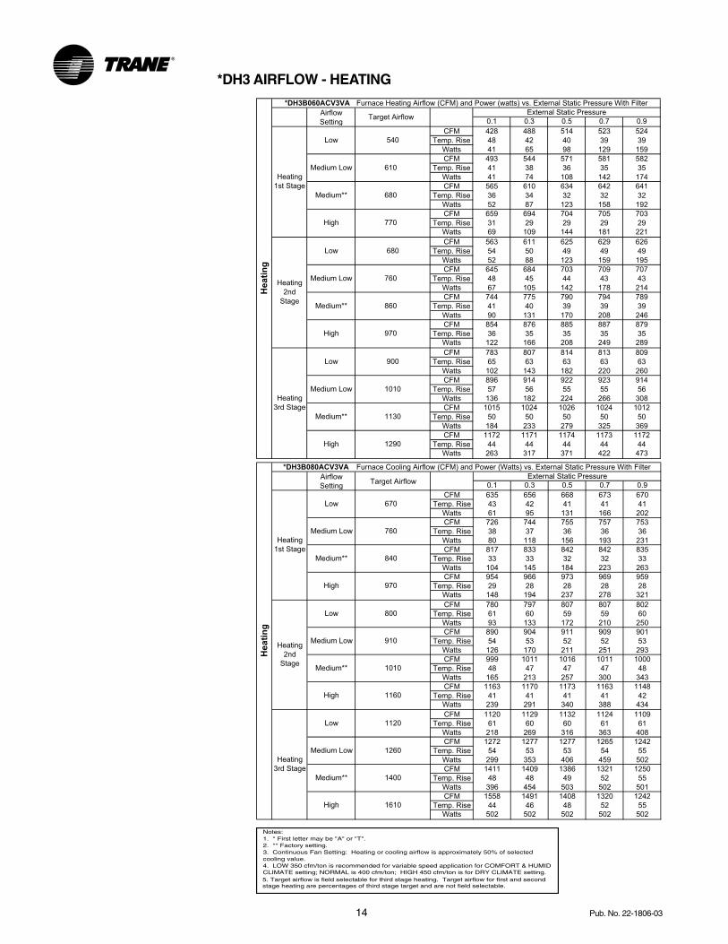
0.1 0.3 0.5 0.7 0.9
CFM 428 488 514 523 524
Temp. Rise 48 42 40 39 39
Watts 41 65 98 129 159
CFM 493 544 571 581 582
Temp. Rise 41 38 36 35 35
Watts 41 74 108 142 174
CFM 565 610 634 642 641
Temp. Rise 36 34 32 32 32
Watts 52 87 123 158 192
CFM 659 694 704 705 703
Temp. Rise 31 29 29 29 29
Watts 69 109 144 181 221
CFM 563 611 625 629 626
Temp. Rise 54 50 49 49 49
Watts 52 88 123 159 195
CFM 645 684 703 709 707
Temp. Rise 48 45 44 43 43
Watts 67 105 142 178 214
CFM 744 775 790 794 789
Temp. Rise 41 40 39 39 39
Watts 90 131 170 208 246
CFM 854 876 885 887 879
Temp. Rise 36 35 35 35 35
Watts 122 166 208 249 289
CFM 783 807 814 813 809
Temp. Rise 65 63 63 63 63
Watts 102 143 182 220 260
CFM 896 914 922 923 914
Temp. Rise 57 56 55 55 56
Watts 136 182 224 266 308
CFM 1015 1024 1026 1024 1012
Temp. Rise 50 50 50 50 50
Watts 184 233 279 325 369
CFM 1172 1171 1174 1173 1172
Temp. Rise 44 44 44 44 44
Watts 263 317 371 422 473
Heati
ng
*DH3B060ACV3VA Furnace Heating Airflow (CFM) and Power (watts) vs. External Static Pressure With Filter
Airflow
SettingTarget Airflow
External Static Pressure
Heating
1st Stage
Low 540
Medium Low 610
Medium** 680
High 770
Heating
2nd
Stage
Low 680
Medium Low 760
Medium** 860
High 970
Heating
3rd Stage
Low 900
Medium Low 1010
Medium** 1130
High 1290
0.1 0.3 0.5 0.7 0.9
CFM 635 656 668 673 670
Temp. Rise 43 42 41 41 41
Watts 61 95 131 166 202
CFM 726 744 755 757 753
Temp. Rise 38 37 36 36 36
Watts 80 118 156 193 231
CFM 817 833 842 842 835
Temp. Rise 33 33 32 32 33
Watts 104 145 184 223 263
CFM 954 966 973 969 959
Temp. Rise 29 28 28 28 28
Watts 148 194 237 278 321
CFM 780 797 807 807 802
Temp. Rise 61 60 59 59 60
Watts 93 133 172 210 250
CFM 890 904 911 909 901
Temp. Rise 54 53 52 52 53
Watts 126 170 211 251 293
CFM 999 1011 1016 1011 1000
Temp. Rise 48 47 47 47 48
Watts 165 213 257 300 343
CFM 1163 1170 1173 1163 1148
Temp. Rise 41 41 41 41 42
Watts 239 291 340 388 434
CFM 1120 1129 1132 1124 1109
Temp. Rise 61 60 60 61 61
Watts 218 269 316 363 408
CFM 1272 1277 1277 1265 1242
Temp. Rise 54 53 53 54 55
Watts 299 353 406 459 502
CFM 1411 1409 1386 1321 1250
Temp. Rise 48 48 49 52 55
Watts 396 454 503 502 501
CFM 1558 1491 1408 1320 1242
Temp. Rise 44 46 48 52 55
Watts 502 502 502 502 502
Medium** 1400
High 1610
1120
Medium Low 1260
High 1160
He
ati
ng
*DH3B080ACV3VA Furnace Cooling Airflow (CFM) and Power (Watts) vs. External Static Pressure With Filter
Airflow
Setting
Heating
3rd Stage
Low
Heating
2nd
Stage
Low 800
Medium Low 910
Medium** 1010
Medium** 840
High 970
External Static Pressure
Heating
1st Stage
Low 670
Medium Low 760
Target Airflow
*DH3 AIRFLOW - HEATING
Notes:1. * First letter may be "A" or "T".2. ** Factory setting.3. Continuous Fan Setting: Heating or cooling airflow is approximately 50% of selected cooling value.4. LOW 350 cfm/ton is recommended for variable speed application for COMFORT & HUMIDCLIMATE setting; NORMAL is 400 cfm/ton; HIGH 450 cfm/ton is for DRY CLIMATE setting.5. Target airflow is field selectable for third stage heating. Target airflow for first and second stage heating are percentages of third stage target and are not field selectable.
15Pub. No. 22-1806-03
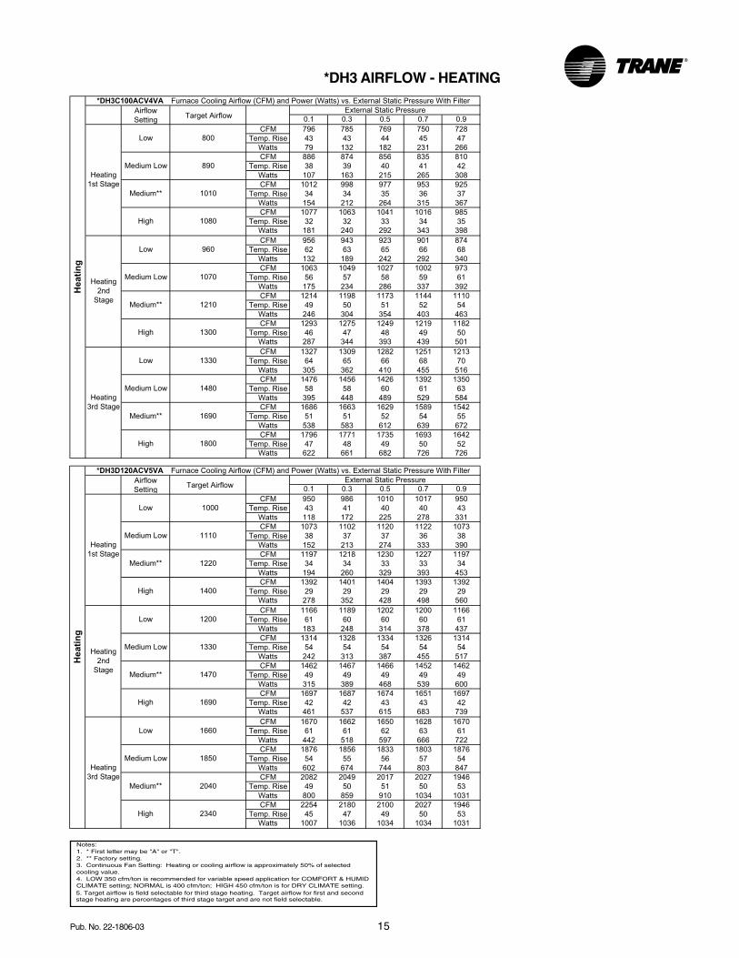
*DH3 AIRFLOW - HEATING
0.1 0.3 0.5 0.7 0.9
CFM 796 785 769 750 728
Temp. Rise 43 43 44 45 47
Watts 79 132 182 231 266
CFM 886 874 856 835 810
Temp. Rise 38 39 40 41 42
Watts 107 163 215 265 308
CFM 1012 998 977 953 925
Temp. Rise 34 34 35 36 37
Watts 154 212 264 315 367
CFM 1077 1063 1041 1016 985
Temp. Rise 32 32 33 34 35
Watts 181 240 292 343 398
CFM 956 943 923 901 874
Temp. Rise 62 63 65 66 68
Watts 132 189 242 292 340
CFM 1063 1049 1027 1002 973
Temp. Rise 56 57 58 59 61
Watts 175 234 286 337 392
CFM 1214 1198 1173 1144 1110
Temp. Rise 49 50 51 52 54
Watts 246 304 354 403 463
CFM 1293 1275 1249 1219 1182
Temp. Rise 46 47 48 49 50
Watts 287 344 393 439 501
CFM 1327 1309 1282 1251 1213
Temp. Rise 64 65 66 68 70
Watts 305 362 410 455 516
CFM 1476 1456 1426 1392 1350
Temp. Rise 58 58 60 61 63
Watts 395 448 489 529 584
CFM 1686 1663 1629 1589 1542
Temp. Rise 51 51 52 54 55
Watts 538 583 612 639 672
CFM 1796 1771 1735 1693 1642
Temp. Rise 47 48 49 50 52
Watts 622 661 682 726 726
External Static Pressure
Heating
1st Stage
Low 800
Medium Low 890
Medium** 1010
High 1080
Heating
2nd
Stage
Low 960
Medium Low 1070
Medium** 1210
High 1300
He
ati
ng
*DH3C100ACV4VA Furnace Cooling Airflow (CFM) and Power (Watts) vs. External Static Pressure With Filter
Airflow
Setting
Heating
3rd Stage
Low 1330
Medium Low 1480
Medium** 1690
High 1800
Target Airflow
0.1 0.3 0.5 0.7 0.9
CFM 950 986 1010 1017 950
Temp. Rise 43 41 40 40 43
Watts 118 172 225 278 331
CFM 1073 1102 1120 1122 1073
Temp. Rise 38 37 37 36 38
Watts 152 213 274 333 390
CFM 1197 1218 1230 1227 1197
Temp. Rise 34 34 33 33 34
Watts 194 260 329 393 453
CFM 1392 1401 1404 1393 1392
Temp. Rise 29 29 29 29 29
Watts 278 352 428 498 560
CFM 1166 1189 1202 1200 1166
Temp. Rise 61 60 60 60 61
Watts 183 248 314 378 437
CFM 1314 1328 1334 1326 1314
Temp. Rise 54 54 54 54 54
Watts 242 313 387 455 517
CFM 1462 1467 1466 1452 1462
Temp. Rise 49 49 49 49 49
Watts 315 389 468 539 600
CFM 1697 1687 1674 1651 1697
Temp. Rise 42 42 43 43 42
Watts 461 537 615 683 739
CFM 1670 1662 1650 1628 1670
Temp. Rise 61 61 62 63 61
Watts 442 518 597 666 722
CFM 1876 1856 1833 1803 1876
Temp. Rise 54 55 56 57 54
Watts 602 674 744 803 847
CFM 2082 2049 2017 2027 1946
Temp. Rise 49 50 51 50 53
Watts 800 859 910 1034 1031
CFM 2254 2180 2100 2027 1946
Temp. Rise 45 47 49 50 53
Watts 1007 1036 1034 1034 1031
External Static Pressure
Heating
1st Stage
Low 1000
Medium Low 1110
Medium**
High
Heating
2nd
Stage
Low
Medium Low
Medium**
High 1690
He
ati
ng
*DH3D120ACV5VA Furnace Cooling Airflow (CFM) and Power (Watts) vs. External Static Pressure With Filter
Airflow
Setting
Heating
3rd Stage
Low 1660
Medium Low 1850
Medium** 2040
High 2340
1220
1330
1470
1200
1400
Target Airflow
Notes:1. * First letter may be "A" or "T".2. ** Factory setting.3. Continuous Fan Setting: Heating or cooling airflow is approximately 50% of selected cooling value.4. LOW 350 cfm/ton is recommended for variable speed application for COMFORT & HUMIDCLIMATE setting; NORMAL is 400 cfm/ton; HIGH 450 cfm/ton is for DRY CLIMATE setting.5. Target airflow is field selectable for third stage heating. Target airflow for first and second stage heating are percentages of third stage target and are not field selectable.

16 Pub. No. 22-1806-03
0.1 0.3 0.5 0.7 0.9
CFM 272 388 423 436 442
Watts 24 52 82 111 141
CFM 353 415 449 461 466
Watts 26 55 86 116 146
CFM 383 443 475 487 491
Watts 29 59 90 121 152
CFM 413 472 503 512 513
Watts 32 62 96 126 157
CFM 443 498 527 538 540
Watts 35 67 99 132 163
CFM 487 535 557 564 562
Watts 40 73 107 141 173
CFM 532 580 605 614 614
Watts 47 81 116 150 183
CFM 563 611 625 629 626
Watts 52 88 123 159 195
CFM 468 520 549 559 561
Watts 38 70 104 136 169
CFM 507 557 583 593 593
Watts 43 77 111 145 177
CFM 547 594 618 627 626
Watts 49 84 119 153 187
CFM 585 633 647 648 647
Watts 56 93 129 165 203
CFM 627 667 688 694 692
Watts 63 100 137 173 208
CFM 686 716 725 727 725
Watts 76 115 151 189 228
CFM 746 777 792 796 790
Watts 90 131 170 209 247
CFM 783 807 814 813 809
Watts 102 143 182 220 260
CFM 612 653 675 682 680
Watts 60 97 133 169 204
CFM 662 699 718 724 721
Watts 70 109 146 183 219
CFM 711 745 761 766 762
Watts 82 121 160 198 235
CFM 763 785 790 793 786
Watts 95 136 174 212 252
CFM 811 837 848 851 844
Watts 109 151 192 232 271
CFM 894 907 914 914 905
Watts 134 178 221 262 303
CFM 960 974 978 978 967
Watts 161 208 252 297 339
CFM 1012 1021 1025 1028 1023
Watts 182 231 279 324 369
CFM 756 786 800 804 799
Watts 93 134 173 212 250
CFM 816 841 852 855 848
Watts 110 153 194 234 273
CFM 876 896 904 906 897
Watts 130 174 216 258 299
CFM 941 953 961 959 954
Watts 151 198 242 285 328
CFM 995 1006 1009 1007 996
Watts 175 223 269 314 358
CFM 1085 1087 1091 1092 1090
Watts 216 265 316 365 412
CFM 1172 1171 1174 1173 1172
Watts 263 317 371 422 473
CFM 1227 1227 1231 1234 1207
Watts 299 356 412 467 502
4. For variable speed low speed airflows are approximately 30% of listed values.
5. LOW 350 cfm/ton is recommended for variable speed application for COMFORT & HUMID
CLIMATE setting; NORMAL is 400 cfm/ton;
HIGH 450 cfm/ton is for DRY CLIMATE setting.
Notes:
1. * First letter may be "A" or "T".
2. ** Factory setting.
3. Continuous Fan Setting: Heating or cooling airflow is approximately 50% of selected
cooling value.
Co
oli
ng
Unit
Outdoor
Airflow
Setting
External Static Pressure
1.5
290 CFM/ton
310 CFM/ton
330 CFM/ton
350 CFM/ton
370 CFM/ton
400 CFM/ton
430 CFM/ton
450 CFM/ton
2
290 CFM/ton
310 CFM/ton
330 CFM/ton
350 CFM/ton
370 CFM/ton
400 CFM/ton
430 CFM/ton
450 CFM/ton
2.5
290 CFM/ton
310 CFM/ton
330 CFM/ton
350 CFM/ton
370 CFM/ton
400 CFM/ton
430 CFM/ton
450 CFM/ton
3
290 CFM/ton
310 CFM/ton
330 CFM/ton
350 CFM/ton
370 CFM/ton
400 CFM/ton
430 CFM/ton
450 CFM/ton
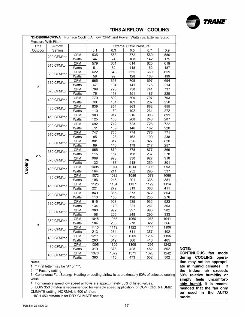
*DH3B060ACV3VA Furnace Cooling Airflow (CFM) and Power (Watts) vs. External Static
Pressure With Filter
*DH3 AIRFLOW - COOLING
NOTE:CONTINUOUS fan mode during COOL-ING operation may not be appropriate inhumid climates. If the indoor air ex-ceeds 60% relative humidity or simplyfeels uncomfortably humid, it is recom-mended that the fan only be used in theAUTO mode.
17Pub. No. 22-1806-03
0.1 0.3 0.5 0.7 0.9
CFM 535 558 572 580 580
Watts 44 74 108 142 175
CFM 579 601 614 620 619
Watts 51 82 118 152 187
CFM 622 643 655 660 659
Watts 58 92 128 163 199
CFM 665 697 705 697 694
Watts 67 104 141 175 214
CFM 709 728 738 741 737
Watts 76 113 151 187 225
CFM 779 802 809 797 793
Watts 90 131 169 207 250
CFM 839 854 863 862 855
Watts 110 152 192 231 272
CFM 903 917 916 906 891
Watts 125 168 208 248 287
CFM 692 712 723 726 722
Watts 72 109 146 182 220
CFM 747 765 774 776 771
Watts 85 123 162 199 238
CFM 801 817 826 827 820
Watts 99 140 179 217 257
CFM 855 870 878 877 869
Watts 115 157 198 237 278
CFM 909 923 930 927 918
Watts 132 177 218 259 301
CFM 1005 1014 1014 1003 993
Watts 164 211 252 295 337
CFM 1072 1082 1086 1078 1065
Watts 196 246 291 336 381
CFM 1126 1134 1137 1129 1114
Watts 221 272 319 366 411
CFM 849 865 873 872 864
Watts 113 156 196 235 276
CFM 915 928 935 932 923
Watts 134 179 221 261 303
CFM 980 992 997 993 982
Watts 158 205 248 290 333
CFM 1045 1055 1060 1053 1041
Watts 184 233 278 322 366
CFM 1110 1119 1122 1114 1100
Watts 213 264 311 357 402
CFM 1211 1208 1209 1202 1195
Watts 260 312 366 418 465
CFM 1305 1309 1309 1295 1242
Watts 319 373 428 482 502
CFM 1370 1372 1371 1320 1242
Watts 360 415 473 502 502
4. For variable speed low speed airflows are approximately 30% of listed values.5. LOW 350 cfm/ton is recommended for variable speed application for COMFORT & HUMID
CLIMATE setting; NORMAL is 400 cfm/ton;
HIGH 450 cfm/ton is for DRY CLIMATE setting.
Notes:
1. * First letter may be "A" or "T".
2. ** Factory setting.3. Continuous Fan Setting: Heating or cooling airflow is approximately 50% of selected cooling
value.
*DH3B080ACV3VA Furnace Cooling Airflow (CFM) and Power (Watts) vs. External Static
Pressure With Filter
Co
olin
g
450 CFM/ton
370 CFM/ton
400 CFM/ton
430 CFM/ton
3
290 CFM/ton
310 CFM/ton
330 CFM/ton
350 CFM/ton
430 CFM/ton
450 CFM/ton
350 CFM/ton
370 CFM/ton
400 CFM/ton
450 CFM/ton
2.5
290 CFM/ton
310 CFM/ton
330 CFM/ton
2
350 CFM/ton
370 CFM/ton
400 CFM/ton
430 CFM/ton
310 CFM/ton
330 CFM/ton
Unit
Outdoor
Airflow
Setting
External Static Pressure
290 CFM/ton
*DH3 AIRFLOW - COOLING
NOTE:CONTINUOUS fan modeduring COOLING opera-tion may not be appropri-ate in humid climates. Ifthe indoor air exceeds60% relative humidity orsimply feels uncomfort-ably humid, it is recom-mended that the fan onlybe used in the AUTOmode.
18 Pub. No. 22-1806-03
0.1 0.3 0.5 0.7 0.9
CFM 723 713 699 682 661
Watts 58 109 157 204 234
CFM 773 763 747 729 707
Watts 72 125 174 222 256
CFM 823 812 795 776 753
Watts 87 141 192 241 279
CFM 873 861 843 823 798
Watts 103 158 210 260 302
CFM 923 910 892 870 844
Watts 120 177 229 279 325
CFM 998 984 964 940 912
Watts 148 206 258 309 360
CFM 1072 1058 1036 1011 981
Watts 179 238 290 341 396
CFM 1122 1107 1084 1058 1026
Watts 201 260 312 362 420
CFM 868 856 839 818 794
Watts 101 157 208 258 299
CFM 928 915 896 874 849
Watts 122 179 231 281 327
CFM 988 974 954 931 903
Watts 144 202 254 305 356
CFM 1047 1033 1012 987 958
Watts 169 227 279 330 384
CFM 1107 1092 1070 1044 1013
Watts 195 253 305 356 413
CFM 1197 1181 1157 1128 1095
Watts 237 296 346 395 455
CFM 1287 1269 1243 1213 1177
Watts 284 341 390 436 498
CFM 1347 1329 1301 1269 1232
Watts 317 373 420 465 526
CFM 1013 999 978 954 926
Watts 154 212 265 315 367
CFM 1082 1068 1046 1020 990
Watts 184 242 294 345 401
CFM 1152 1137 1113 1086 1054
Watts 215 274 325 375 434
CFM 1222 1206 1181 1152 1118
Watts 250 308 358 406 467
CFM 1292 1274 1248 1218 1182
Watts 286 344 392 439 500
CFM 1397 1378 1349 1316 1277
Watts 346 401 446 489 548
CFM 1501 1481 1451 1415 1373
Watts 411 463 503 541 595
CFM 1571 1550 1518 1481 1437
Watts 457 507 543 577 625
CFM 1157 1142 1118 1091 1058
Watts 218 276 328 377 436
CFM 1237 1220 1195 1166 1131
Watts 257 315 365 413 474
CFM 1317 1299 1272 1241 1204
Watts 300 357 405 450 512
CFM 1397 1378 1349 1316 1277
Watts 346 401 446 489 548
CFM 1476 1456 1426 1392 1350
Watts 395 448 489 529 584
CFM 1596 1575 1542 1504 1460
Watts 474 523 558 591 636
CFM 1716 1693 1658 1617 1569
Watts 560 604 631 726 726
CFM 1796 1771 1735 1693 1642
Watts 622 661 682 726 726
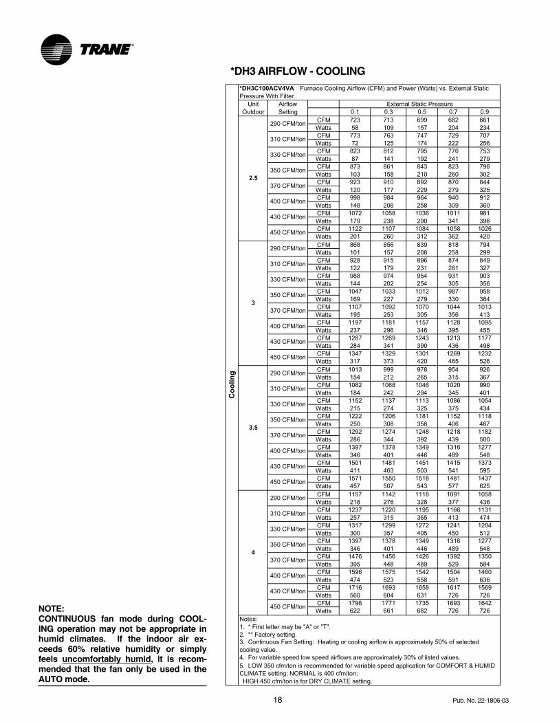
4. For variable speed low speed airflows are approximately 30% of listed values.
5. LOW 350 cfm/ton is recommended for variable speed application for COMFORT & HUMID
CLIMATE setting; NORMAL is 400 cfm/ton;
HIGH 450 cfm/ton is for DRY CLIMATE setting.
Notes:
1. * First letter may be "A" or "T".
2. ** Factory setting.
3. Continuous Fan Setting: Heating or cooling airflow is approximately 50% of selected
cooling value.
Unit
Outdoor
Airflow
Setting
External Static Pressure
290 CFM/ton
310 CFM/ton
330 CFM/ton
2.5
350 CFM/ton
370 CFM/ton
400 CFM/ton
430 CFM/ton
450 CFM/ton
3
290 CFM/ton
310 CFM/ton
330 CFM/ton
350 CFM/ton
370 CFM/ton
400 CFM/ton
430 CFM/ton
450 CFM/ton
3.5
290 CFM/ton
310 CFM/ton
330 CFM/ton
350 CFM/ton
370 CFM/ton
400 CFM/ton
430 CFM/ton
450 CFM/ton
4
290 CFM/ton
310 CFM/ton
330 CFM/ton
370 CFM/ton
400 CFM/ton
430 CFM/ton
450 CFM/ton
*DH3C100ACV4VA Furnace Cooling Airflow (CFM) and Power (Watts) vs. External Static
Pressure With Filter
Co
olin
g
350 CFM/ton
*DH3 AIRFLOW - COOLING
NOTE:CONTINUOUS fan mode during COOL-ING operation may not be appropriate inhumid climates. If the indoor air ex-ceeds 60% relative humidity or simplyfeels uncomfortably humid, it is recom-mended that the fan only be used in theAUTO mode.
19Pub. No. 22-1806-03
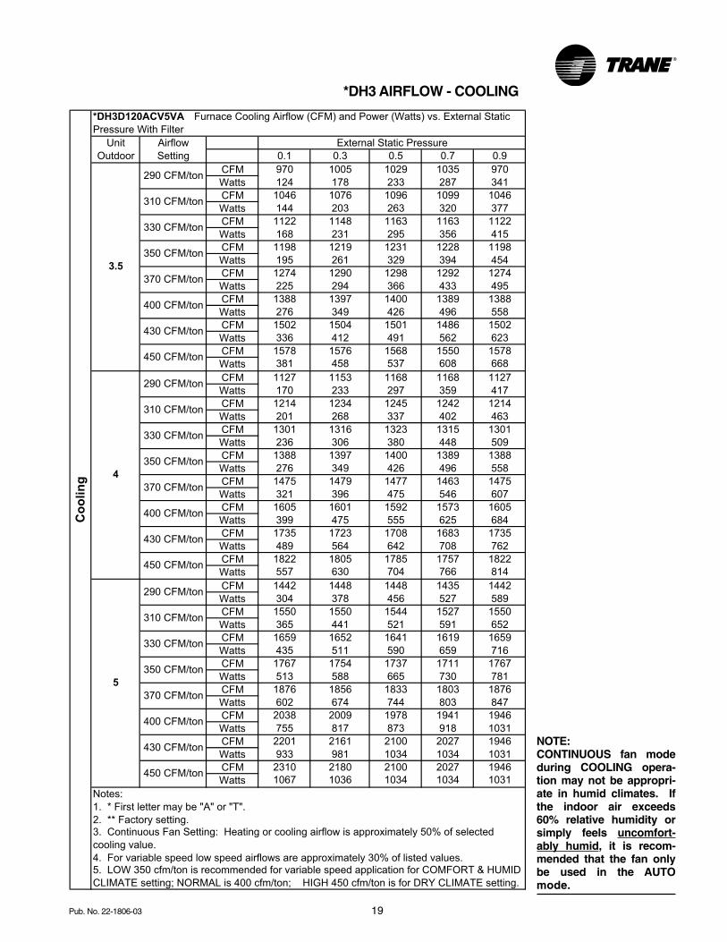
*DH3 AIRFLOW - COOLING
0.1 0.3 0.5 0.7 0.9
CFM 970 1005 1029 1035 970
Watts 124 178 233 287 341
CFM 1046 1076 1096 1099 1046
Watts 144 203 263 320 377
CFM 1122 1148 1163 1163 1122
Watts 168 231 295 356 415
CFM 1198 1219 1231 1228 1198
Watts 195 261 329 394 454
CFM 1274 1290 1298 1292 1274
Watts 225 294 366 433 495
CFM 1388 1397 1400 1389 1388
Watts 276 349 426 496 558
CFM 1502 1504 1501 1486 1502
Watts 336 412 491 562 623
CFM 1578 1576 1568 1550 1578
Watts 381 458 537 608 668
CFM 1127 1153 1168 1168 1127
Watts 170 233 297 359 417
CFM 1214 1234 1245 1242 1214
Watts 201 268 337 402 463
CFM 1301 1316 1323 1315 1301
Watts 236 306 380 448 509
CFM 1388 1397 1400 1389 1388
Watts 276 349 426 496 558
CFM 1475 1479 1477 1463 1475
Watts 321 396 475 546 607
CFM 1605 1601 1592 1573 1605
Watts 399 475 555 625 684
CFM 1735 1723 1708 1683 1735
Watts 489 564 642 708 762
CFM 1822 1805 1785 1757 1822
Watts 557 630 704 766 814
CFM 1442 1448 1448 1435 1442
Watts 304 378 456 527 589
CFM 1550 1550 1544 1527 1550
Watts 365 441 521 591 652
CFM 1659 1652 1641 1619 1659
Watts 435 511 590 659 716
CFM 1767 1754 1737 1711 1767
Watts 513 588 665 730 781
CFM 1876 1856 1833 1803 1876
Watts 602 674 744 803 847
CFM 2038 2009 1978 1941 1946
Watts 755 817 873 918 1031
CFM 2201 2161 2100 2027 1946
Watts 933 981 1034 1034 1031
CFM 2310 2180 2100 2027 1946
Watts 1067 1036 1034 1034 1031
4. For variable speed low speed airflows are approximately 30% of listed values.5. LOW 350 cfm/ton is recommended for variable speed application for COMFORT & HUMID
CLIMATE setting; NORMAL is 400 cfm/ton; HIGH 450 cfm/ton is for DRY CLIMATE setting.
Notes:
1. * First letter may be "A" or "T".
2. ** Factory setting.3. Continuous Fan Setting: Heating or cooling airflow is approximately 50% of selected
cooling value.
Unit
Outdoor
Airflow
Setting
External Static Pressure
290 CFM/ton
310 CFM/ton
330 CFM/ton
3.5
350 CFM/ton
370 CFM/ton
400 CFM/ton
430 CFM/ton
450 CFM/ton
4
290 CFM/ton
310 CFM/ton
330 CFM/ton
350 CFM/ton
370 CFM/ton
400 CFM/ton
430 CFM/ton
450 CFM/ton
5
290 CFM/ton
310 CFM/ton
330 CFM/ton
350 CFM/ton
370 CFM/ton
400 CFM/ton
430 CFM/ton
450 CFM/ton
*DH3D120ACV5VA Furnace Cooling Airflow (CFM) and Power (Watts) vs. External Static
Pressure With Filter
Co
oli
ng
NOTE:CONTINUOUS fan modeduring COOLING opera-tion may not be appropri-ate in humid climates. Ifthe indoor air exceeds60% relative humidity orsimply feels uncomfort-ably humid, it is recom-mended that the fan onlybe used in the AUTOmode.
20 Pub. No. 22-1806-03
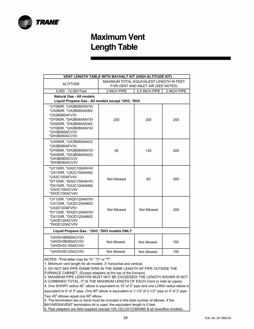
Maximum VentLength Table
ALTITUDE
5,000 - 12,000 Feet
Natural Gas - All modelsLiquid Propane Gas - All models except *UH3, *DH3
Liquid Propane Gas - *UH3, *DH3 models ONLY
2 INCH PIPE 2.5 INCH PIPE 3 INCH PIPE
*UY060R, *UH2B060A9V3V*UX060R, *UX2B060A9362*UX2B060AFV3V
200 200 200*DY060R, *DH2B060A9V3V*DX060R, *DX2B060A9362*UY080R, *UH2B080A9V3V
*UX080R, *UX2B080A9422*UX2B080AFV3V
50 120 200*DY080R, *DH2B080A9V3V*DX080R, *DX2B080A9422
*UY100R, *UH2C100A9V4V*UX100R, *UX2C100A9482*UX2C100AFV4V
Not Allowed 60 200*DY100R, *DH2C100A9V4V*DX100R, *DX2C100A9482
*UY120R, *UH2D120A9V5V*UX120R, *UX2D120A9602*UX2D120AFV5V Not Allowed
Not Allowed
Not Allowed
Not Allowed
200
150
Not Allowed Not Allowed 100
*DY120R, *DH2D120A9V5V*DX120R, *DX2D120A9602
*UH3B060ACV3V
*UH3B080ACV3V
*UH3C100ACV4V
*UH3D120ACV5V
*DH3B060ACV3V
*DH3B080ACV3V
*DH3C100ACV4V
*DH3D120ACV5V
MAXIMUM TOTAL EQUIVALENT LENGTH IN FEET FOR VENT AND INLET AIR (SEE NOTES)
VENT LENGTH TABLE WITH BAYHALT KIT (HIGH ALTITUDE KIT)
2. DO NOT MIX PIPE DIAMETERS IN THE SAME LENGTH OF PIPE OUTSIDE THE FURNACE CABINET, (Except adapters at the top of the furnace).3. MAXIMUM PIPE LENGTHS MUST NOT BE EXCEEDED! THE LENGTH SHOWN IS NOT A COMBINED TOTAL, IT IS THE MAXIMUM LENGTH OF EACH (Vent or inlet air pipes).
5. The termination tee or bend must be included in the total number of elbows. If the BAYAIR30AVENT termination kit is used, the equivalent length is 0 feet.
1. Minimum vent length for all models: 3' horizontal and vertical.
6. Pipe adapters are field supplied (except 100,120,UX1C06A960 & all downflow models).
NOTES: *First letter may be "A", "C" or "T"
4. One SHORT radius 90o elbow is equivalent to 10' of 3" pipe and one LONG radius elbow is
equivalent to 6' of 3" pipe. One 90o elbow is equivalent to 7-1/2' of 2-1/2" pipe or 5' of 2' pipe.
Two 45o elbows equal one 90o elbow.
*UH/DH3B060ACV3V*UH/DH3B080ACV3V*UH/DH3C100ACV4V
*UH/DH3D120ACV5V
21Pub. No. 22-1806-03
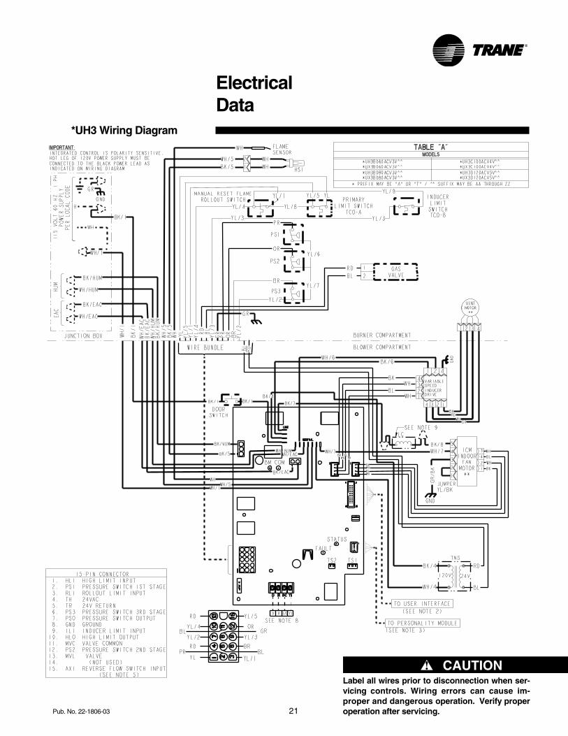
ElectricalData
*UH3 Wiring Diagram
▲ CAUTION!Label all wires prior to disconnection when ser-vicing controls. Wiring errors can cause im-proper and dangerous operation. Verify properoperation after servicing.
22 Pub. No. 22-1806-03
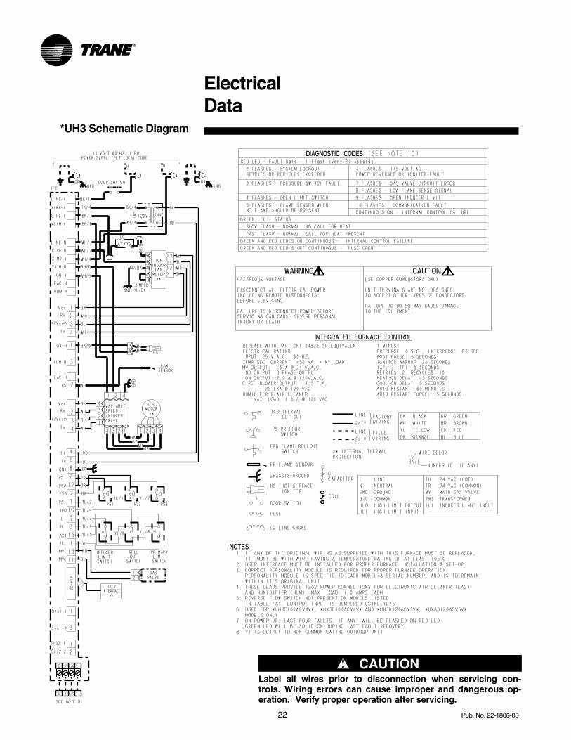
ElectricalData
*UH3 Schematic Diagram
▲ CAUTION!Label all wires prior to disconnection when servicing con-trols. Wiring errors can cause improper and dangerous op-eration. Verify proper operation after servicing.
23Pub. No. 22-1806-03
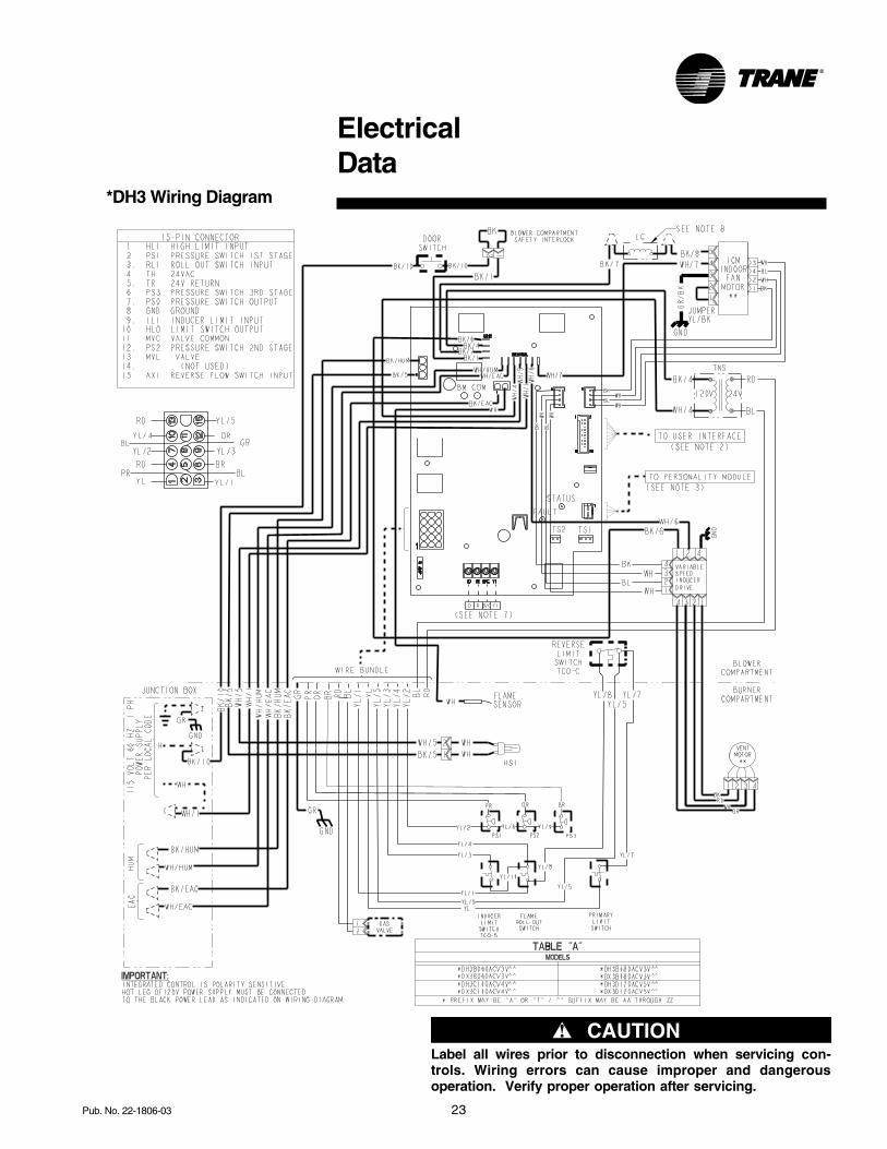
*DH3 Wiring Diagram
▲ CAUTION!Label all wires prior to disconnection when servicing con-trols. Wiring errors can cause improper and dangerousoperation. Verify proper operation after servicing.
ElectricalData
24 Pub. No. 22-1806-03
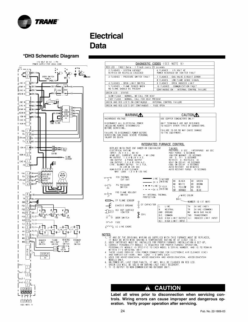
*DH3 Schematic Diagram
▲ CAUTION!Label all wires prior to disconnection when servicing con-trols. Wiring errors can cause improper and dangerous op-eration. Verify proper operation after servicing.
ElectricalData
25Pub. No. 22-1806-03
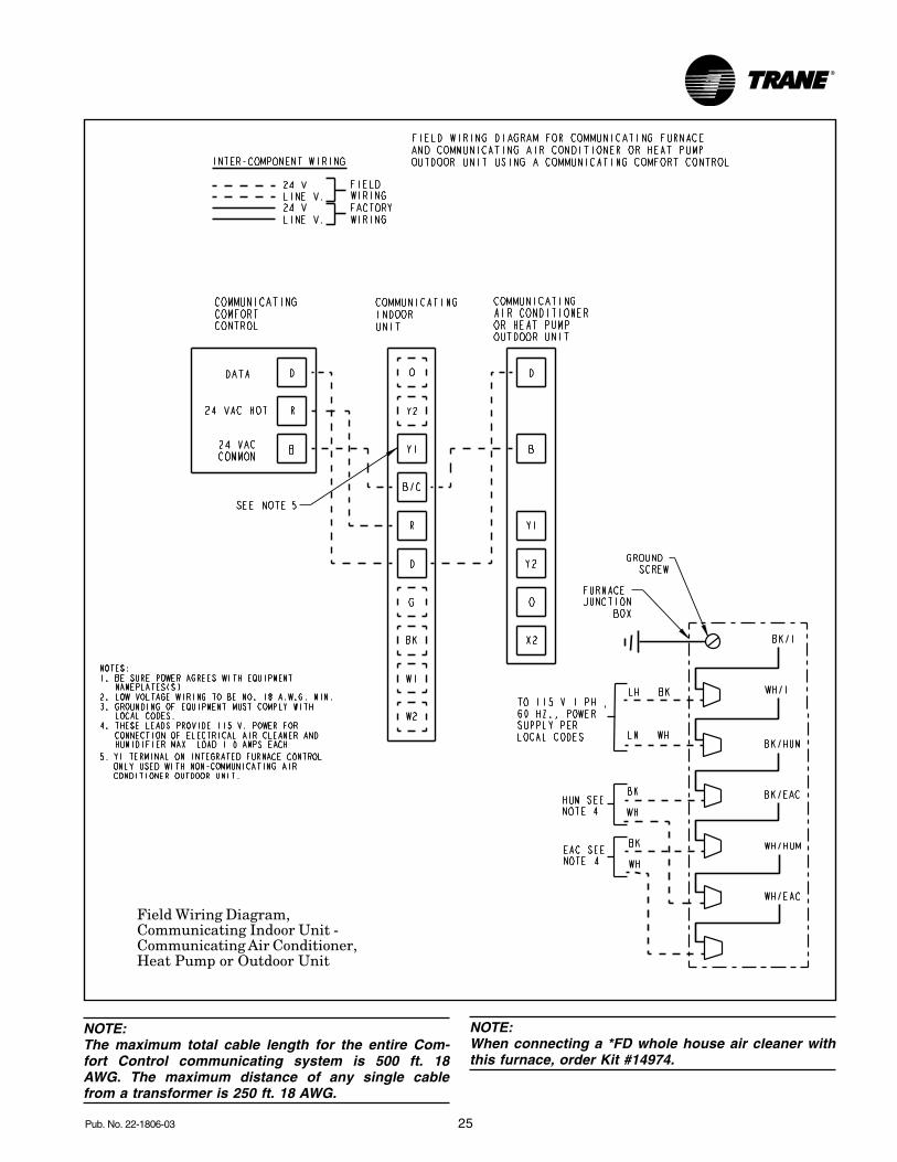
NOTE:The maximum total cable length for the entire Com-fort Control communicating system is 500 ft. 18AWG. The maximum distance of any single cablefrom a transformer is 250 ft. 18 AWG.
Field Wiring Diagram,Communicating Indoor Unit -Communicating Air Conditioner,Heat Pump or Outdoor Unit
NOTE:When connecting a *FD whole house air cleaner withthis furnace, order Kit #14974.
26 Pub. No. 22-1806-03
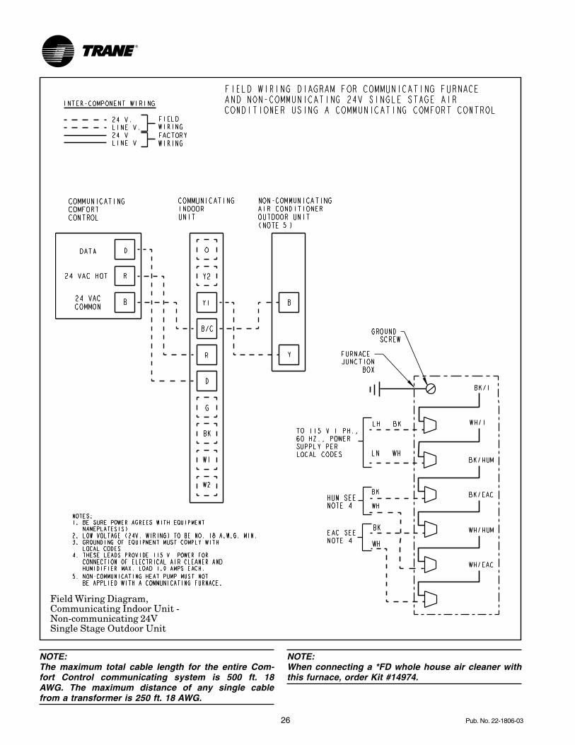
Field Wiring Diagram,Communicating Indoor Unit -Non-communicating 24VSingle Stage Outdoor Unit
NOTE:When connecting a *FD whole house air cleaner withthis furnace, order Kit #14974.
NOTE:The maximum total cable length for the entire Com-fort Control communicating system is 500 ft. 18AWG. The maximum distance of any single cablefrom a transformer is 250 ft. 18 AWG.
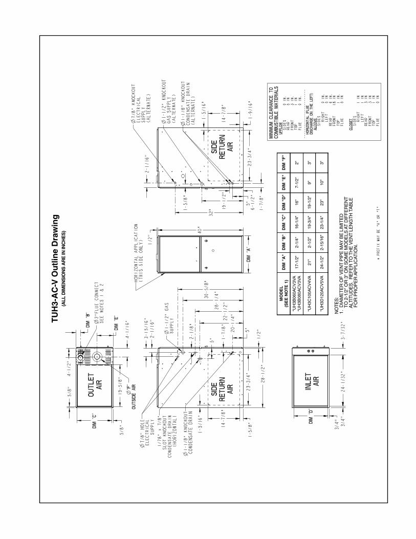
NO
TES
:1
.D
IAM
ET
ER
OF
VE
NT
PIP
E M
AY
BE
LIM
ITE
D
TO
2-1
/2"
OR
3"
ON
SO
ME
MO
DE
LS A
T D
IFF
ER
EN
T
ALT
ITU
DE
S.
RE
FE
R T
O T
HE
VE
NT
LEN
GT
H T
AB
LE
FO
R P
RO
PE
R A
PP
LIC
AT
ION
.
TU
H3-
AC
-V O
utl
ine
Dra
win
g(A
LL D
IME
NS
ION
S A
RE
IN IN
CH
ES
)
MO
DE
L(S
EE
NO
TE
1)
DIM
"A
"D
IM "
B"
DIM
"C
"D
IM "
D"
DIM
"E
"D
IM "
F"
*UH
3B06
0AC
V3V
A*U
H3B
080A
CV
3VA
17-1
/2"
2-1/
4"16
-1/4
"16
"7-
1/2"
2"
*UH
3C10
0AC
V4V
A21
"2-
1/2"
19-3
/4"
19-1
/2"
9"3"
*UH
3D12
0AC
V5V
A24
-1/2
"2-
15/1
6"23
-1/4
"23
"10
"3"
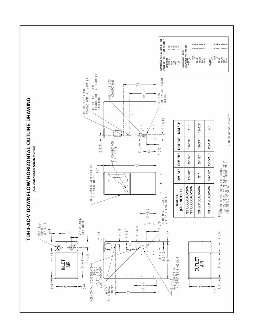
TD
H3-
AC
-V D
OW
NF
LO
W/H
OR
IZO
NTA
L O
UTL
INE
DR
AW
ING
(ALL
DIM
EN
SIO
NS
AR
E IN
INC
HE
S)
MO
DE
L(S
EE
NO
TE
1)
DIM
"A
"D
IM "
B"
DIM
"C
"D
IM "
D"
*DH
3B06
0AC
V3V
A*D
H3B
080A
CV
3VA
17-1
/2"
2-1/
4"16
-1/4
"16
"
*DH
3C10
0AC
V4V
A21
"2-
1/2"
19-3
/4"
19-1
/2"
*DH
3D12
0AC
V5V
A24
-1/2
"2-
15/1
6"23
-1/4
"23
"
29Pub. No. 22-1806-03
Notes
Trane has a policy of continuous product and product data improvement and it reserves the right tochange design and specifications without notice.
Trane6200 Troup HighwayTyler, TX 75707www.trane.com
Related Documents