Variable Refrigerant Flow (VRF) Air Source Heat Pump and Heat Recovery Outdoor Units 4TVH*/4TVR* February 2015 VRF-PRC008B-EN Product Catalog

Welcome message from author
This document is posted to help you gain knowledge. Please leave a comment to let me know what you think about it! Share it to your friends and learn new things together.
Transcript
Variable Refrigerant Flow (VRF)
Air Source Heat Pump and Heat Recovery
Outdoor Units
4TVH*/4TVR*
February 2015 VRF-PRC008B-EN
Product Catalog
© 2015Trane All rights reserved VRF-PRC008B-EN
Introduction
Trane® VRF variable refrigerant systems are efficient, effective, reliable heating and coolingsolutions you can trust. When VRF is the right solution for your application,Trane® will help youensure it's the best solution.VRF is well suited for historic buildings without existing ductwork, aswell as schools and mid-rise office buildings with multiple interior spaces and diverse occupancyrates.
Trane® VRF systems are designed for exceptional energy efficiency, offering industry leadingperformance up to 33 IEER and 32 SCHE.Trane® VRF utilizes inverter compressors (some modelfeature dual compressors) with vapor injection for improved performance and comfort.
Systems are available for both heat pump and simultaneous heating and cooling operation. Bothfeature individual zone control to provide individual occupant comfort.The simultaneous heatingand cooling models offer the ability to heat and cool adjacent zones, intelligently exchangingenergy between them through strategically located mode control units.
Indoor units are available in a wide variety of configurations and capacities, allowing architects theflexibility to satisfy almost any design requirement.
Trane® offers a complete line-up of controls to complete your VRF installation.These range fromeasy to use individual zone controls, to centralized systems for building monitoring and control,as well as optional BACnet® connectivity for centralizedTrane®Tracer™ integration.
Best of all, yourTrane®VRF™ system is supported by theTrane® nationwide network of sales andservice offices.
Copyright
This document and the information in it are the property ofTrane, and may not be used orreproduced in whole or in part without written permission.Trane reserves the right to revise thispublication at any time, and to make changes to its content without obligation to notify any personof such revision or change.
Trademarks
All trademarks referenced in this document are the trademarks of their respective owners.
Revision History
VRF-PRC008B-EN (17 February 2015)
• AHRI-1230 ratings updated and now include larger capacity systems previously not covered.
• Low ambient heating range expanded from -4°F to -13°F.
Table of Contents
Introduction . . . . . . . . . . . . . . . . . . . . . . . . . . . . . . . . . . . . . . . . . . . . . . . . . . . . . . 2
Table of Contents . . . . . . . . . . . . . . . . . . . . . . . . . . . . . . . . . . . . . . . . . . . . . . . . . . 3
System Features . . . . . . . . . . . . . . . . . . . . . . . . . . . . . . . . . . . . . . . . . . . . . . . . 4
Model Number Descriptions . . . . . . . . . . . . . . . . . . . . . . . . . . . . . . . . . . . . . . . . . 5
Products . . . . . . . . . . . . . . . . . . . . . . . . . . . . . . . . . . . . . . . . . . . . . . . . . . . . . . . . . 6
Controls . . . . . . . . . . . . . . . . . . . . . . . . . . . . . . . . . . . . . . . . . . . . . . . . . . . . . . . . . 7
Accessories . . . . . . . . . . . . . . . . . . . . . . . . . . . . . . . . . . . . . . . . . . . . . . . . . . . . . . . 8
Product Specifications . . . . . . . . . . . . . . . . . . . . . . . . . . . . . . . . . . . . . . . . . . . . . 10
Outdoor Units . . . . . . . . . . . . . . . . . . . . . . . . . . . . . . . . . . . . . . . . . . . . . . . . . 10
Operation Limit - Outdoor Units . . . . . . . . . . . . . . . . . . . . . . . . . . . . . . . . . . . . . 30
Defrosting Correction Factor . . . . . . . . . . . . . . . . . . . . . . . . . . . . . . . . . . . . . 31
Electrical Wiring Diagrams - Outdoor Units . . . . . . . . . . . . . . . . . . . . . . . . . . . 32
Sound Levels - Outdoor Units . . . . . . . . . . . . . . . . . . . . . . . . . . . . . . . . . . . . . . 38
NC Curves . . . . . . . . . . . . . . . . . . . . . . . . . . . . . . . . . . . . . . . . . . . . . . . . . . . . 38
Sound Power . . . . . . . . . . . . . . . . . . . . . . . . . . . . . . . . . . . . . . . . . . . . . . . . . . 40
NR Curves . . . . . . . . . . . . . . . . . . . . . . . . . . . . . . . . . . . . . . . . . . . . . . . . . . . . 40
Cycle Diagrams . . . . . . . . . . . . . . . . . . . . . . . . . . . . . . . . . . . . . . . . . . . . . . . . . . 42
Parts of Outdoor Unit (HP) . . . . . . . . . . . . . . . . . . . . . . . . . . . . . . . . . . . . . . . 42
Parts of Outdoor Unit (HR) . . . . . . . . . . . . . . . . . . . . . . . . . . . . . . . . . . . . . . . 45
Dimensional Drawings . . . . . . . . . . . . . . . . . . . . . . . . . . . . . . . . . . . . . . . . . . . . 48
Heat Pump/Heat Recovery . . . . . . . . . . . . . . . . . . . . . . . . . . . . . . . . . . . . . . . 48
VRF-PRC008B-EN 3
4 VRF-PRC008B-EN
System Features
• Individual modules are available as standard heat pump or simultaneous heating and cooling(heat recovery) configuration; units can be combined as double or triple modules for largercapacity requirements.
• 3rd generation compressor technology features all inverter compressors for superior efficiencyand reliability
• Asymmetric scroll is designed to minimize frictional loss
• Dual inverter compressors (available in many models) are designed to equally share load forhigher reliability
• Improved vapor injection system increases refrigerant flow rate up to 20% for superior heatingperformance
• Intercooler uses a plate heat exchanger for improved heating and cooling efficiency
• 8,400 RPM (maximum speed) compressor assures quick start cooling and heating performance
• Auto oil balancing eliminates the need for an oil balancing pipe
• Compressor inverter drives are liquid cooled for improved reliability
• Longer pipe lengths are the result of large oil storage capacity and low oil circulation rate
• Total harmonic distortion is reduced through adaptive sine wave control
• Refrigerant pump down and pump out facilitates maintenance and repair
• Automatic refrigerant balancing between indoor units optimize refrigerant distribution forbetter comfort and performance
• Optional quiet operation mode for reduced sound levels at night
• Auto snow blowing function removes accumulated snow when conditions require it
• Special hydrophilic heat exchanger coating minimizes frost build up on the outdoor coils andfacilitates the defrost cycle.
• Anti-corrosion finish provides added protection in harsh environments
• Four and six port mode control units are light and compact. Distributed installation flexibilityprovides superior performance during simultaneous heating and cooling operation.
• Trane® VRF systems feature self-diagnosis, including system monitoring and error codereporting
Model Number Descriptions
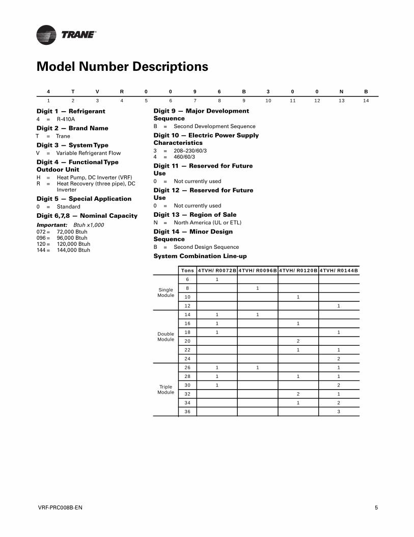
Digit 1 — Refrigerant4 = R-410A
Digit 2 — Brand NameT = Trane
Digit 3 — SystemTypeV = Variable Refrigerant Flow
Digit 4 — FunctionalTypeOutdoor UnitH = Heat Pump, DC Inverter (VRF)R = Heat Recovery (three pipe), DC
Inverter
Digit 5 — Special Application0 = Standard
Digit 6,7,8 — Nominal CapacityImportant: Btuh x1,000072 = 72,000 Btuh096 = 96,000 Btuh120 = 120,000 Btuh144 = 144,000 Btuh
4 T V R 0
1 2 3 4 5
VRF-PRC008B-EN
0 9 6 B 3
6 7 8 9 1
Digit 9 — Major DevelopmentSequenceB = Second Development Sequence
Digit 10 — Electric Power SupplyCharacteristics3 = 208–230/60/34 = 460/60/3
Digit 11 — Reserved for FutureUse0 = Not currently used
Digit 12 — Reserved for FutureUse0 = Not currently used
Digit 13 — Region of SaleN = North America (UL or ETL)
Digit 14 — Minor DesignSequenceB = Second Design Sequence
System Combination Line-up
Tons 4TVH/R0072B 4TVH/R009
Single Module
6 1
8 1
10
12
Double Module
14 1 1
16 1
18 1
20
22
24
Triple Module
26 1 1
28 1
30 1
32
34
36
0 0 N B
0 11 12 13 14
6B 4TVH/R0120B 4TVH/R0144B
1
1
1
1
2
1 1
2
1
1 1
2
2 1
1 2
3
5
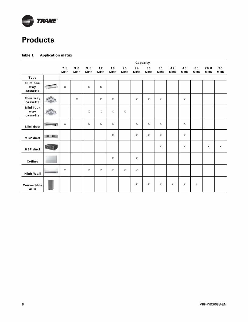
Products
Table 1. Application matrix
Capacity
7.5 MBh
9.0 MBh
9.5 MBh
12 MBh
18 MBh
20 MBh
24 MBh
30 MBh
36 MBh
42MBh
48 MBh
60MBh
76.8 MBh
96 MBh
Type
Slim one way
cassetteX X X
Four way cassette
X X X X X X X
Mini four way
cassette X X X X
Slim ductX X X X X X X X
MSP ductX X X X X
HSP ductX X X X
CeilingX X
High WallX X X X X X
Convertible AHU
X X X X X X
6 VRF-PRC008B-EN
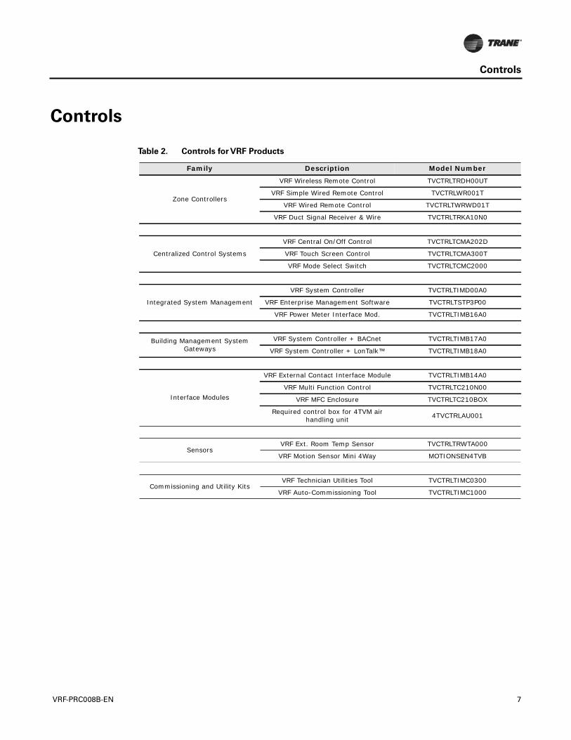
Controls
Controls
Table 2. Controls for VRF Products
Family Description Model Number
Zone Controllers
VRF Wireless Remote Control TVCTRLTRDH00UT
VRF Simple Wired Remote Control TVCTRLWR001T
VRF Wired Remote Control TVCTRLTWRWD01T
VRF Duct Signal Receiver & Wire TVCTRLTRKA10N0
Centralized Control Systems
VRF Central On/Off Control TVCTRLTCMA202D
VRF Touch Screen Control TVCTRLTCMA300T
VRF Mode Select Switch TVCTRLTCMC2000
Integrated System Management
VRF System Controller TVCTRLTIMD00A0
VRF Enterprise Management Software TVCTRLTSTP3P00
VRF Power Meter Interface Mod. TVCTRLTIMB16A0
Building Management System Gateways
VRF System Controller + BACnet TVCTRLTIMB17A0
VRF System Controller + LonTalk™ TVCTRLTIMB18A0
Interface Modules
VRF External Contact Interface Module TVCTRLTIMB14A0
VRF Multi Function Control TVCTRLTC210N00
VRF MFC Enclosure TVCTRLTC210BOX
Required control box for 4TVM air handling unit 4TVCTRLAU001
SensorsVRF Ext. Room Temp Sensor TVCTRLTRWTA000
VRF Motion Sensor Mini 4Way MOTIONSEN4TVB
Commissioning and Utility KitsVRF Technician Utilities Tool TVCTRLTIMC0300
VRF Auto-Commissioning Tool TVCTRLTIMC1000
VRF-PRC008B-EN 7
Accessories
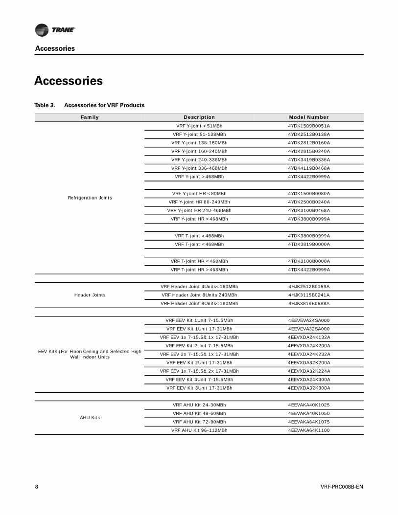
Accessories
Table 3. Accessories for VRF Products
Family Description Model Number
Refrigeration Joints
VRF Y-joint <51MBh 4YDK1509B0051A
VRF Y-joint 51-138MBh 4YDK2512B0138A
VRF Y-joint 138-160MBh 4YDK2812B0160A
VRF Y-joint 160-240MBh 4YDK2815B0240A
VRF Y-joint 240-336MBh 4YDK3419B0336A
VRF Y-joint 336-468MBh 4YDK4119B0468A
VRF Y-joint >468MBh 4YDK4422B0999A
VRF Y-joint HR <80MBh 4YDK1500B0080A
VRF Y-joint HR 80-240MBh 4YDK2500B0240A
VRF Y-joint HR 240-468MBh 4YDK3100B0468A
VRF Y-joint HR >468MBh 4YDK3800B0999A
VRF T-joint >468MBh 4TDK3800B0999A
VRF T-joint <468MBh 4TDK3819B0000A
VRF T-joint HR <468MBh 4TDK3100B0000A
VRF T-joint HR >468MBh 4TDK4422B0999A
Header Joints
VRF Header Joint 4Units<160MBh 4HJK2512B0159A
VRF Header Joint 8Units 240MBh 4HJK3115B0241A
VRF Header Joint 8Units<160MBh 4HJK3819B0998A
EEV Kits (For Floor/Ceiling and Selected High Wall Indoor Units
VRF EEV Kit 1Unit 7-15.5MBh 4EEVEVA24SA000
VRF EEV Kit 1Unit 17-31MBh 4EEVEVA32SA000
VRF EEV 1x 7-15.5& 1x 17-31MBh 4EEVXDA24K132A
VRF EEV Kit 2Unit 7-15.5MBh 4EEVXDA24K200A
VRF EEV 2x 7-15.5& 1x 17-31MBh 4EEVXDA24K232A
VRF EEV Kit 2Unit 17-31MBh 4EEVXDA32K200A
VRF EEV 1x 7-15.5& 2x 17-31MBh 4EEVXDA32K224A
VRF EEV Kit 3Unit 7-15.5MBh 4EEVXDA24K300A
VRF EEV Kit 3Unit 17-31MBh 4EEVXDA32K300A
AHU Kits
VRF AHU Kit 24-30MBh 4EEVAKA40K1025
VRF AHU Kit 48-60MBh 4EEVAKA40K1050
VRF AHU Kit 72-90MBh 4EEVAKA64K1075
VRF AHU Kit 96-112MBh 4EEVAKA64K1100
8 VRF-PRC008B-EN
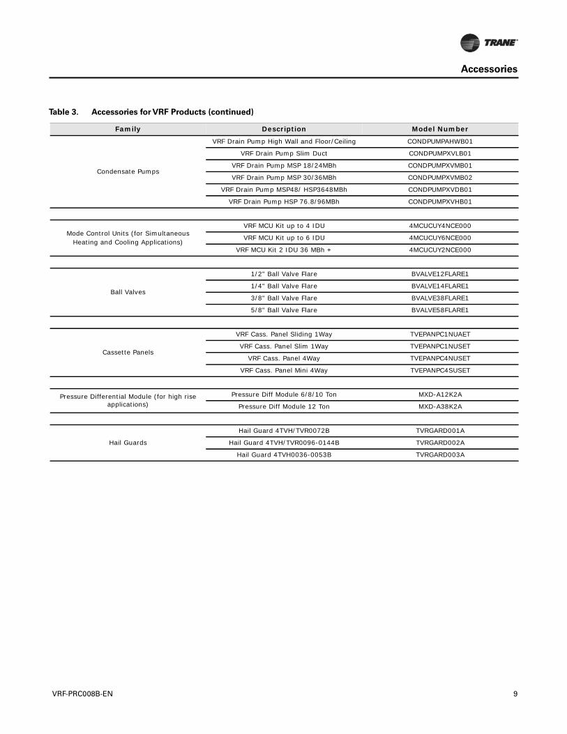
Accessories
Condensate Pumps
VRF Drain Pump High Wall and Floor/Ceiling CONDPUMPAHWB01
VRF Drain Pump Slim Duct CONDPUMPXVLB01
VRF Drain Pump MSP 18/24MBh CONDPUMPXVMB01
VRF Drain Pump MSP 30/36MBh CONDPUMPXVMB02
VRF Drain Pump MSP48/ HSP3648MBh CONDPUMPXVDB01
VRF Drain Pump HSP 76.8/96MBh CONDPUMPXVHB01
Mode Control Units (for Simultaneous Heating and Cooling Applications)
VRF MCU Kit up to 4 IDU 4MCUCUY4NCE000
VRF MCU Kit up to 6 IDU 4MCUCUY6NCE000
VRF MCU Kit 2 IDU 36 MBh + 4MCUCUY2NCE000
Ball Valves
1/2" Ball Valve Flare BVALVE12FLARE1
1/4" Ball Valve Flare BVALVE14FLARE1
3/8" Ball Valve Flare BVALVE38FLARE1
5/8" Ball Valve Flare BVALVE58FLARE1
Cassette Panels
VRF Cass. Panel Sliding 1Way TVEPANPC1NUAET
VRF Cass. Panel Slim 1Way TVEPANPC1NUSET
VRF Cass. Panel 4Way TVEPANPC4NUSET
VRF Cass. Panel Mini 4Way TVEPANPC4SUSET
Pressure Differential Module (for high rise applications)
Pressure Diff Module 6/8/10 Ton MXD-A12K2A
Pressure Diff Module 12 Ton MXD-A38K2A
Hail Guards
Hail Guard 4TVH/TVR0072B TVRGARD001A
Hail Guard 4TVH/TVR0096-0144B TVRGARD002A
Hail Guard 4TVH0036-0053B TVRGARD003A
Table 3. Accessories for VRF Products (continued)
Family Description Model Number
VRF-PRC008B-EN 9
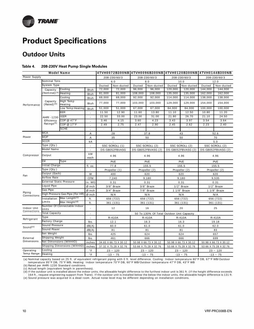
Product Specifications
Outdoor Units
Table 4. 208-230V Heat Pump Single Modules
Model Name 4TVH0072B300NB 4TVH0096B300NB 4TVH0120B300NB 4TVH0144B300NBPower Supply 208-230/60/3 208-230/60/3 208-230/60/3 208-230/60/3
Performance
Nominal Tons 6.0 8.0 10.0 12.0System Type Ducted Non-ducted Ducted Non-ducted Ducted Non-ducted Ducted Non-ducted
Capacity(Nominal)(a)
Cooling Btuh 72,000 72,000 96,000 96,000 120,000 120,000 144,000 144,000Heating Btuh 81,000 81,000 108,000 108,000 135,000 135,000 162,000 162,000
Capacity(Rated)(b)
Cooling Btuh 69,000 69,000 92,000 92,000 114,000 114,000 138,000 138,000High Temp Heating Btuh 77,000 77,000 103,000 103,000 129,000 129,000 154,000 154,000
Low Temp Heating Btuh 51,000 51,000 67,000 67,000 84,000 84,000 100,000 100,000
AHRI -1230 Efficiency Ratings(b)
EER - 11.50 12.90 11.60 13.80 11.10 12.50 10.80 11.20IEER - 22.50 33.00 23.00 31.00 21.80 26.70 21.10 24.50COP @ 47°F - 3.46 4.15 3.60 4.23 3.43 3.97 3.54 3.64COP @ 17°F - 2.49 2.75 2.47 2.90 2.45 2.62 2.23 2.40SCHE - - - - - - - - -
PowerMCA A 28 37.8 43 52.6MOP A 35 50 50 70SCCR kA - - - 5.0
Compressor
Type (Qty.) - SSC SCROLL (1) SSC SCROLL (2) SSC SCROLL (2) SSC SCROLL (2)Model Name - DS-GB052FBVASG DS-GB052FBVASG (2) DS-GB052FBVASG (2) DS-GB052FBVASG (2)
Output kW each
4.96 4.96 4.96 4.96
Oil Type - PVE PVE PVE PVEInitial Charge fl. oz. 77.8 155.5 155.5 155.5
Fan
Type (Qty.) - Propeller (1) Propeller (2) Propeller (2) Propeller (2)Output (Each) W 400 620 620 620Airflow Rate CFM 7,240 9,180 9,180 9,535External Static Pressure In. WG 0.31 0.31 0.31 0.31
Piping Connections
Liquid Pipe Ø inch 3/8" Braze 3/8" Braze 1/2" Braze 1/2" BrazeGas Pipe Ø inch 3/4" Braze 7/8" Braze 1 1/8" Braze 1 1/8" BrazeHigh Pressure Gas Pipe (For HR) Ø inch N/A N/A N/A N/AInstallation Limits
Max Length(c) ft. 656 (722) 656 (722) 656 (722) 656 (722)Max Height(d) ft. 361 (131) 361 (131) 361 (131) 361 (131)
Indoor Unit Connections
Number Of Connectable Indoor Units - 12 16 20 25
Total Capacity - 50 To 130% Of Total Outdoor Unit Capacity
RefrigerantType - R-410A R-410A R-410A R-410AFactory Charge lbs. 12.1 16.3 16.3 19.18
Sound(e) Sound Pressure dB(A) 60.0 61.0 61.0 62.0Sound Power dB(A) 81 81 81 83
External Dimensions
Net Weight lbs. 425 624 624 657Shipping Weight lbs. 461 666 666 699Net Dimensions (WXHXD) inches 34.65 X 66.73 X 30.12 50.98 X 66.73 X 30,12 50.98 X 66.73 X 30,12 50.98 X 66.73 X 30.12Shipping Dimensions (WXHXD) inches 37.32 X 75.28 X 32.76 53.66 X 75.28 X 32.76 53.66 X 75.28 X 32.76 53.66 X 75.28 X 32.76
Operating Temp Range
Cooling °F 23 ~ 120 23 ~ 120 23 ~ 120 23 ~ 120Heating °F -13 ~ 75 -13 ~ 75 -13 ~ 75 -13 ~ 75
(a) Nominal capacity based on 25 ft. of equivalent refrigerant piping with 0 ft. level difference. Cooling: Indoor temperature 80°F DB, 67°F WB/Outdoor temperature 95°F DB, 75°F WB. Heating: Indoor temperature 70°F DB, 60°F WB/Outdoor temperature 47°F DB, 43°F WB
(b) Rated per AHRI-1230 Standard conditions.(c) Actual length (equivalent length in parenthesis).(d) If the outdoor unit is installed above the indoor units, the allowable height difference to the furthest indoor unit is 361 ft. (If the height difference exceeds
164 ft., request engineering support from Trane). If the outdoor unit is installed below the below the indoor units, the allowable height difference is 131 ft.(e) Sound pressure was acquired in a dead room. Actual noise level may be different depending on installation conditions.
10 VRF-PRC008B-EN
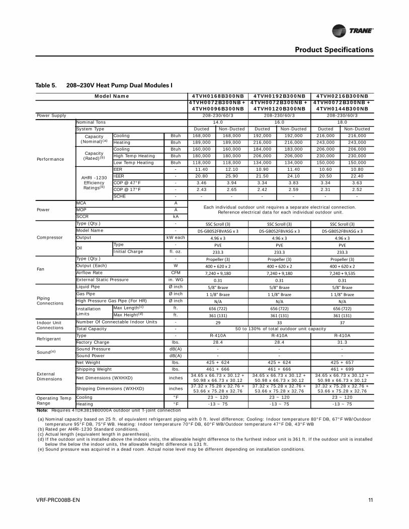
Product Specifications
Table 5. 208~230V Heat Pump Dual Modules I
Model Name 4TVH0168B300NB 4TVH0192B300NB 4TVH0216B300NB4TVH0072B300NB + 4TVH0096B300NB
4TVH0072B300NB + 4TVH0120B300NB
4TVH0072B300NB + 4TVH0144B300NB
Power Supply 208-230/60/3 208-230/60/3 208-230/60/3
Performance
Nominal Tons 14.0 16.0 18.0System Type Ducted Non-Ducted Ducted Non-Ducted Ducted Non-Ducted
Capacity(Nominal)(a)
Cooling Btuh 168,000 168,000 192,000 192,000 216,000 216,000Heating Btuh 189,000 189,000 216,000 216,000 243,000 243,000
Capacity(Rated)(b)
Cooling Btuh 160,000 160,000 184,000 183,000 206,000 206,000High Temp Heating Btuh 180,000 180,000 206,000 206,000 230,000 230,000Low Temp Heating Btuh 118,000 118,000 134,000 134,000 150,000 150,000
AHRI -1230 Efficiency Ratings(b)
EER - 11.40 12.10 10.90 11.40 10.60 10.80IEER - 20.80 25.90 21.50 24.10 20.50 22.40COP @ 47°F - 3.46 3.94 3.34 3.83 3.34 3.63COP @ 17°F - 2.43 2.65 2.42 2.59 2.31 2.52SCHE - - - - - - -
PowerMCA A
Each individual outdoor unit requires a separate electrical connection. Reference electrical data for each individual outdoor unit.MOP A
SCCR kA
Compressor
Type (Qty.) - SSC Scroll (3) SSC Scroll (3) SSC Scroll (3)Model Name - DS-GB052FBVASG x 3 DS-GB052FBVASG x 3 DS-GB052FBVASG x 3Output kW each 4.96 x 3 4.96 x 3 4.96 x 3
OilType - PVE PVE PVEInitial Charge fl. oz. 233.3 233.3 233.3
Fan
Type (Qty.) - Propeller (3) Propeller (3) Propeller (3)Output (Each) W 400 + 620 x 2 400 + 620 x 2 400 + 620 x 2Airflow Rate CFM 7,240 + 9,180 7,240 + 9,180 7,240 + 9,535External Static Pressure in. WG 0.31 0.31 0.31
Piping Connections
Liquid Pipe Ø inch 5/8" Braze 5/8" Braze 5/8" BrazeGas Pipe Ø inch 1 1/8" Braze 1 1/8" Braze 1 1/8" BrazeHigh Pressure Gas Pipe (For HR) Ø inch N/A N/A N/AInstallation Limits
Max Length(c) ft. 656 (722) 656 (722) 656 (722)Max Height(d) ft. 361 (131) 361 (131) 361 (131)
Indoor Unit Connections
Number Of Connectable Indoor Units - 29 33 37Total Capacity - 50 to 130% of total outdoor unit capacity
RefrigerantType - R-410A R-410A R-410AFactory Charge lbs. 28.4 28.4 31.3
Sound(e) Sound Pressure dB(A) - - -Sound Power dB(A) - - -
External Dimensions
Net Weight lbs. 425 + 624 425 + 624 425 + 657Shipping Weight lbs. 461 + 666 461 + 666 461 + 699
Net Dimensions (WXHXD) inches 34.65 x 66.73 x 30.12 +50.98 x 66.73 x 30.12
34.65 x 66.73 x 30.12 +50.98 x 66.73 x 30.12
34.65 x 66.73 x 30.12 +50.98 x 66.73 x 30.12
Shipping Dimensions (WXHXD) inches 37.32 x 75.28 x 32.76 +53.66 x 75.28 x 32.76
37.32 x 75.28 x 32.76 +53.66 x 75.28 x 32.76
37.32 x 75.28 x 32.76 +53.66 x 75.28 x 32.76
Operating Temp Range
Cooling °F 23 ~ 120 23 ~ 120 23 ~ 120Heating °F -13 ~ 75 -13 ~ 75 -13 ~ 75
Note: Requires 4TDK3819B0000A outdoor unit T-joint connection
(a) Nominal capacity based on 25 ft. of equivalent refrigerant piping with 0 ft. level difference; Cooling: Indoor temperature 80°F DB, 67°F WB/Outdoor temperature 95°F DB, 75°F WB. Heating: Indoor temperature 70°F DB, 60°F WB/Outdoor temperature 47°F DB, 43°F WB
(b) Rated per AHRI-1230 Standard conditions.(c) Actual length (equivalent length in parenthesis).(d) If the outdoor unit is installed above the indoor units, the allowable height difference to the furthest indoor unit is 361 ft. If the outdoor unit is installed
below the below the indoor units, the allowable height difference is 131 ft.(e) Sound pressure was acquired in a dead room. Actual noise level may be different depending on installation conditions.
VRF-PRC008B-EN 11
Product Specifications
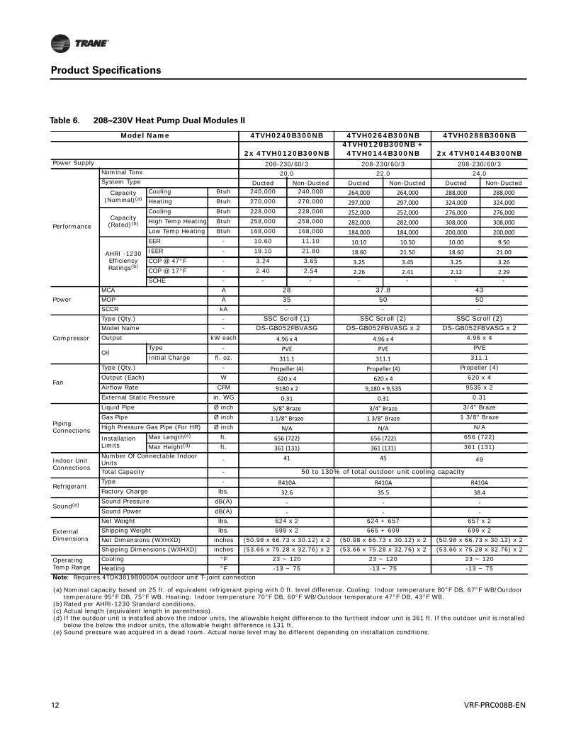
Table 6. 208~230V Heat Pump Dual Modules II
Model Name 4TVH0240B300NB 4TVH0264B300NB 4TVH0288B300NB
2x 4TVH0120B300NB4TVH0120B300NB +4TVH0144B300NB 2x 4TVH0144B300NB
Power Supply 208-230/60/3 208-230/60/3 208-230/60/3
Performance
Nominal Tons 20.0 22.0 24.0System Type Ducted Non-Ducted Ducted Non-Ducted Ducted Non-Ducted
Capacity(Nominal)(a)
Cooling Btuh 240,000 240,000 264,000 264,000 288,000 288,000Heating Btuh 270,000 270,000 297,000 297,000 324,000 324,000
Capacity(Rated)(b)
Cooling Btuh 228,000 228,000 252,000 252,000 276,000 276,000High Temp Heating Btuh 258,000 258,000 282,000 282,000 308,000 308,000Low Temp Heating Btuh 168,000 168,000 184,000 184,000 200,000 200,000
AHRI -1230 Efficiency Ratings(b)
EER - 10.60 11.10 10.10 10.50 10.00 9.50IEER - 19.10 21.80 18.60 21.50 18.60 21.00COP @ 47°F - 3.24 3.65 3.25 3.45 3.25 3.26COP @ 17°F - 2.40 2.54 2.26 2.41 2.12 2.29SCHE - - - - - - -
PowerMCA A 28 37.8 43MOP A 35 50 50SCCR kA - - -
Compressor
Type (Qty.) - SSC Scroll (1) SSC Scroll (2) SSC Scroll (2)Model Name - DS-GB052FBVASG DS-GB052FBVASG x 2 DS-GB052FBVASG x 2Output kW each 4.96 x 4 4.96 x 4 4.96 x 4
OilType - PVE PVE PVEInitial Charge fl. oz. 311.1 311.1 311.1
Fan
Type (Qty.) - Propeller (4) Propeller (4) Propeller (4)Output (Each) W 620 x 4 620 x 4 620 x 4Airflow Rate CFM 9180 x 2 9,180 + 9,535 9535 x 2External Static Pressure in. WG 0.31 0.31 0.31
Piping Connections
Liquid Pipe Ø inch 5/8" Braze 3/4" Braze 3/4" BrazeGas Pipe Ø inch 1 1/8" Braze 1 3/8" Braze 1 3/8" BrazeHigh Pressure Gas Pipe (For HR) Ø inch N/A N/A N/A
Installation Limits
Max Length(c) ft. 656 (722) 656 (722) 656 (722)Max Height(d) ft. 361 (131) 361 (131) 361 (131)
Indoor Unit Connections
Number Of Connectable Indoor Units - 41 45 49
Total Capacity - 50 to 130% of total outdoor unit cooling capacity
RefrigerantType - R410A R410A R410AFactory Charge lbs. 32.6 35.5 38.4
Sound(e) Sound Pressure dB(A) - - -Sound Power dB(A) - - -
External Dimensions
Net Weight lbs. 624 x 2 624 + 657 657 x 2Shipping Weight lbs. 699 x 2 665 + 699 699 x 2Net Dimensions (WXHXD) inches (50.98 x 66.73 x 30.12) x 2 (50.98 x 66.73 x 30.12) x 2 (50.98 x 66.73 x 30.12) x 2Shipping Dimensions (WXHXD) inches (53.66 x 75.28 x 32.76) x 2 (53.66 x 75.28 x 32.76) x 2 (53.66 x 75.28 x 32.76) x 2
Operating Temp Range
Cooling °F 23 ~ 120 23 ~ 120 23 ~ 120Heating °F -13 ~ 75 -13 ~ 75 -13 ~ 75
Note: Requires 4TDK3819B0000A outdoor unit T-joint connection
(a) Nominal capacity based on 25 ft. of equivalent refrigerant piping with 0 ft. level difference. Cooling: Indoor temperature 80°F DB, 67°F WB/Outdoor temperature 95°F DB, 75°F WB. Heating: Indoor temperature 70°F DB, 60°F WB/Outdoor temperature 47°F DB, 43°F WB.
(b) Rated per AHRI-1230 Standard conditions.(c) Actual length (equivalent length in parenthesis).(d) If the outdoor unit is installed above the indoor units, the allowable height difference to the furthest indoor unit is 361 ft. If the outdoor unit is installed
below the below the indoor units, the allowable height difference is 131 ft.(e) Sound pressure was acquired in a dead room. Actual noise level may be different depending on installation conditions.
12 VRF-PRC008B-EN
Product Specifications
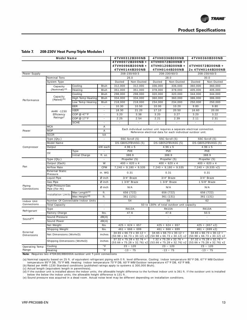
Table 7. 208-230V Heat PumpTriple Modules I
Model Name 4TVH0312B300NB 4TVH0336B300NB 4TVH0360B300NB4TVH0072B300NB + 4TVH0096B300NB + 4TVH0144B300NB
4TVH0072B300NB + 4TVH0120B300NB + 4TVH0144B300NB
4TVH0072B300NB + 2x 4TVH0144B300NB
Power Supply 208-230/60/3 208-230/60/3 208-230/60/3
Performance
Nominal Tons 26.0 28.0 30.0System Type Ducted Non-Ducted Ducted Non-Ducted Ducted Non-Ducted
Capacity(Nominal)(a)
Cooling Btuh 312,000 312,000 336,000 336,000 360,000 360,000Heating Btuh 351,000 351,000 378,000 378,000 405,000 405,000
Capacity(Rated)(b)
Cooling Btuh 298,000 298,000 320,000 320,000 344,000 344,000High Temp Heating Btuh 334,000 334,000 360,000 360,000 386,000 386,000Low Temp Heating Btuh 218,000 218,000 234,000 234,000 250,000 250,000
AHRI -1230 Efficiency Ratings2
EER - 10.30 10.50 10.00 10.20 9.80 9.80IEER - 18.30 21.20 17.10 20.50 16.60 20.00COP @ 47°F - 3.20 3.38 3.20 3.27 3.20 3.22COP @ 17°F - 2.25 2.54 2.21 2.39 2.11 2.31SCHE - - - - - - -
Power MCA A
Each individual outdoor unit requires a separate electrical connection. Reference electrical data for each individual outdoor unit.MOP A
SCCR kA
Compressor
Type (Qty.) - SSC Scroll (5) SSC Scroll (5) SSC Scroll (5)Model Name - DS-GB052FBVASG (5) DS-GB052FBVASG (5) DS-GB052FBVASG (5)Output kW each 4.96 x 5 4.96 x 5 4.96 x 5
OilType - PVE PVE PVEInitial Charge fl. oz. 388.9 388.9 388.9
Fan
Type (Qty.) - Propeller (5) Propeller (5) Propeller (5)Output (Each) W 400 + 620 x 4 400 + 620 x 4 400 + 620 x 4Airflow Rate CFM 7,240 + 9,180 + 9,535 7,240 + 9,180 + 9,535 7,240 + (9,535 x2)External Static Pressure in. WG 0.31 0.31 0.31
Piping Connections
Liquid Pipe Ø inch 3/4" Braze 3/4" Braze 3/4" BrazeGas Pipe Ø inch 1 3/8" Braze 1 3/8" Braze 1 5/8" BrazeHigh Pressure Gas Pipe (For Hr) Ø inch N/A N/A N/A
Installation LimitsMax Length(c) ft. 656 (722) 656 (722) 656 (722)Max Height(d) ft. 361 (131) 361 (131) 361 (131)
Indoor Unit Connections
Number Of Connectable Indoor Units - 54 58 62Total Capacity - 50 to 130% of total outdoor unit capacity
RefrigerantType - R410A R410A R410AFactory Charge lbs. 47.6 47.6 50.5
Sound(e) Sound Pressure dB(A) - - -Sound Power dB(A) - - -
External Dimensions
Net Weight lbs. 425 + 624 + 657 425 + 624 + 657 425 + (657 x2)Shipping Weight lbs. 461 + 666 + 699 461 + 666 + 699 461 + (699 x2)
Net Dimensions (WxHxD) inches 34.65 x 66.73 x 30.12 +(50.98 x 66.73 x 30.12) x2
34.65 x 66.73 x 30.12 +(50.98 x 66.73 x 30.12) x2
34.65 x 66.73 x 30.12 +(50.98 x 66.73 x 30.12) x2
Shipping Dimensions (WxHxD) inches 37.32 x 75.28 x 32.76 +(53.66 x 75.28 x 32.76) x2
7.32 x 75.28 x 32.76 +(53.66 x 75.28 x 32.76) x2
37.32 x 75.28 x 32.76 +(53.66 x 75.28 x 32.76) x2
Operating Temp Range
Cooling °F 23 ~ 120 23 ~ 120 23 ~ 120Heating °F -13 ~ 75 -13 ~ 75 -13 ~ 75
Note: Requires two 4TDK3819B0000A outdoor unit T-joint connections
(a) Nominal capacity based on 25 ft. of equivalent refrigerant piping with 0 ft. level difference. Cooling: Indoor temperature 80°F DB, 67°F WB/Outdoor temperature 95°F DB, 75°F WB. Heating: Indoor temperature 70°F DB, 60°F WB/Outdoor temperature 47°F DB, 43°F WB.
(b) Rated per AHRI-1230 Standard conditions (published ratings apply to systems ≤ 300,000 Btuh).(c) Actual length (equivalent length in parenthesis).(d) If the outdoor unit is installed above the indoor units, the allowable height difference to the furthest indoor unit is 361 ft. If the outdoor unit is installed
below the below the indoor units, the allowable height difference is 131 ft..(e) Sound pressure was acquired in a dead room. Actual noise level may be different depending on installation conditions.
VRF-PRC008B-EN 13
Product Specifications
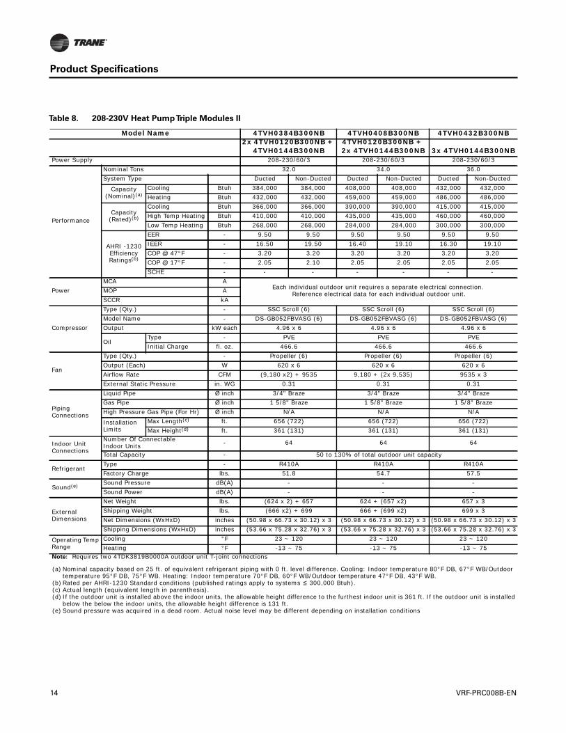
Table 8. 208-230V Heat PumpTriple Modules II
Model Name 4TVH0384B300NB 4TVH0408B300NB 4TVH0432B300NB2x 4TVH0120B300NB +
4TVH0144B300NB4TVH0120B300NB + 2x 4TVH0144B300NB 3x 4TVH0144B300NB
Power Supply 208-230/60/3 208-230/60/3 208-230/60/3
Performance
Nominal Tons 32.0 34.0 36.0System Type Ducted Non-Ducted Ducted Non-Ducted Ducted Non-Ducted
Capacity(Nominal)(a)
Cooling Btuh 384,000 384,000 408,000 408,000 432,000 432,000Heating Btuh 432,000 432,000 459,000 459,000 486,000 486,000
Capacity(Rated)(b)
Cooling Btuh 366,000 366,000 390,000 390,000 415,000 415,000High Temp Heating Btuh 410,000 410,000 435,000 435,000 460,000 460,000Low Temp Heating Btuh 268,000 268,000 284,000 284,000 300,000 300,000
AHRI -1230 Efficiency Ratings(b)
EER - 9.50 9.50 9.50 9.50 9.50 9.50IEER - 16.50 19.50 16.40 19.10 16.30 19.10COP @ 47°F - 3.20 3.20 3.20 3.20 3.20 3.20COP @ 17°F - 2.05 2.10 2.05 2.05 2.05 2.05SCHE - - - - - - -
Power MCA A
Each individual outdoor unit requires a separate electrical connection. Reference electrical data for each individual outdoor unit.MOP A
SCCR kA
Compressor
Type (Qty.) - SSC Scroll (6) SSC Scroll (6) SSC Scroll (6)Model Name - DS-GB052FBVASG (6) DS-GB052FBVASG (6) DS-GB052FBVASG (6)Output kW each 4.96 x 6 4.96 x 6 4.96 x 6
OilType - PVE PVE PVEInitial Charge fl. oz. 466.6 466.6 466.6
Fan
Type (Qty.) - Propeller (6) Propeller (6) Propeller (6)Output (Each) W 620 x 6 620 x 6 620 x 6Airflow Rate CFM (9,180 x2) + 9535 9,180 + (2x 9,535) 9535 x 3External Static Pressure in. WG 0.31 0.31 0.31
Piping Connections
Liquid Pipe Ø inch 3/4" Braze 3/4" Braze 3/4" BrazeGas Pipe Ø inch 1 5/8" Braze 1 5/8" Braze 1 5/8" BrazeHigh Pressure Gas Pipe (For Hr) Ø inch N/A N/A N/A
Installation Limits
Max Length(c) ft. 656 (722) 656 (722) 656 (722)Max Height(d) ft. 361 (131) 361 (131) 361 (131)
Indoor Unit Connections
Number Of Connectable Indoor Units - 64 64 64
Total Capacity - 50 to 130% of total outdoor unit capacity
RefrigerantType - R410A R410A R410AFactory Charge lbs. 51.8 54.7 57.5
Sound(e) Sound Pressure dB(A) - - -Sound Power dB(A) - - -
External Dimensions
Net Weight lbs. (624 x 2) + 657 624 + (657 x2) 657 x 3Shipping Weight lbs. (666 x2) + 699 666 + (699 x2) 699 x 3Net Dimensions (WxHxD) inches (50.98 x 66.73 x 30.12) x 3 (50.98 x 66.73 x 30.12) x 3 (50.98 x 66.73 x 30.12) x 3Shipping Dimensions (WxHxD) inches (53.66 x 75.28 x 32.76) x 3 (53.66 x 75.28 x 32.76) x 3 (53.66 x 75.28 x 32.76) x 3
Operating Temp Range
Cooling °F 23 ~ 120 23 ~ 120 23 ~ 120Heating °F -13 ~ 75 -13 ~ 75 -13 ~ 75
Note: Requires two 4TDK3819B0000A outdoor unit T-joint connections
(a) Nominal capacity based on 25 ft. of equivalent refrigerant piping with 0 ft. level difference. Cooling: Indoor temperature 80°F DB, 67°F WB/Outdoor temperature 95°F DB, 75°F WB. Heating: Indoor temperature 70°F DB, 60°F WB/Outdoor temperature 47°F DB, 43°F WB.
(b) Rated per AHRI-1230 Standard conditions (published ratings apply to systems ≤ 300,000 Btuh).(c) Actual length (equivalent length in parenthesis).(d) If the outdoor unit is installed above the indoor units, the allowable height difference to the furthest indoor unit is 361 ft. If the outdoor unit is installed
below the below the indoor units, the allowable height difference is 131 ft.(e) Sound pressure was acquired in a dead room. Actual noise level may be different depending on installation conditions
14 VRF-PRC008B-EN
Product Specifications
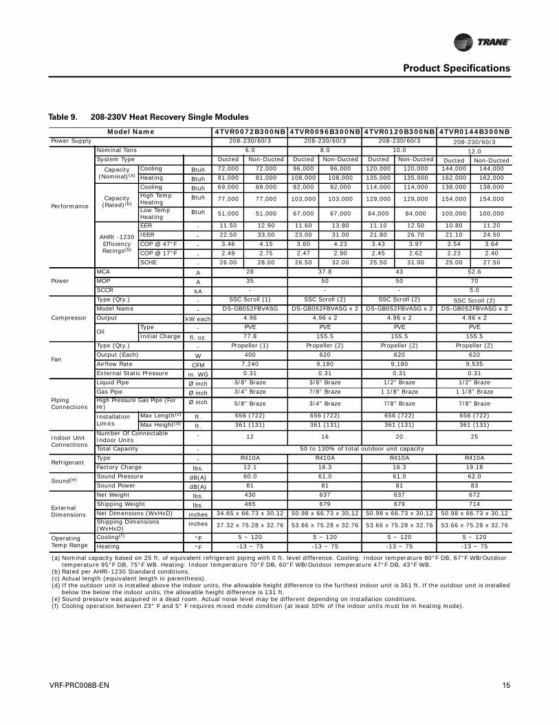
Table 9. 208-230V Heat Recovery Single Modules
Model Name 4TVR0072B300NB 4TVR0096B300NB 4TVR0120B300NB 4TVR0144B300NBPower Supply 208-230/60/3 208-230/60/3 208-230/60/3 208-230/60/3
Performance
Nominal Tons 6.0 8.0 10.0 12.0System Type Ducted Non-Ducted Ducted Non-Ducted Ducted Non-Ducted Ducted Non-Ducted
Capacity(Nominal)(a)
Cooling Btuh 72,000 72,000 96,000 96,000 120,000 120,000 144,000 144,000Heating Btuh 81,000 81,000 108,000 108,000 135,000 135,000 162,000 162,000
Capacity(Rated)(b)
Cooling Btuh 69,000 69,000 92,000 92,000 114,000 114,000 138,000 138,000High Temp Heating
Btuh 77,000 77,000 103,000 103,000 129,000 129,000 154,000 154,000
Low Temp Heating
Btuh 51,000 51,000 67,000 67,000 84,000 84,000 100,000 100,000
AHRI -1230 Efficiency Ratings(b)
EER - 11.50 12.90 11.60 13.80 11.10 12.50 10.80 11.20IEER - 22.50 33.00 23.00 31.00 21.80 26.70 21.10 24.50COP @ 47°F - 3.46 4.15 3.60 4.23 3.43 3.97 3.54 3.64COP @ 17°F - 2.49 2.75 2.47 2.90 2.45 2.62 2.23 2.40SCHE - 26.00 28.00 26.50 32.00 25.50 31.00 25.00 27.50
Power MCA A 28 37.8 43 52.6MOP A 35 50 50 70SCCR kA - - - 5.0
Compressor
Type (Qty.) - SSC Scroll (1) SSC Scroll (2) SSC Scroll (2) SSC Scroll (2)Model Name - DS-GB052FBVASG DS-GB052FBVASG x 2 DS-GB052FBVASG x 2 DS-GB052FBVASG x 2Output kW each 4.96 4.96 x 2 4.96 x 2 4.96 x 2
OilType - PVE PVE PVE PVEInitial Charge fl. oz. 77.8 155.5 155.5 155.5
Fan
Type (Qty.) - Propeller (1) Propeller (2) Propeller (2) Propeller (2)Output (Each) W 400 620 620 620Airflow Rate CFM 7,240 9,180 9,180 9,535External Static Pressure in. WG 0.31 0.31 0.31 0.31
Piping Connections
Liquid Pipe Ø inch 3/8" Braze 3/8" Braze 1/2" Braze 1/2" BrazeGas Pipe Ø inch 3/4" Braze 7/8" Braze 1 1/8" Braze 1 1/8" BrazeHigh Pressure Gas Pipe (For Hr)
Ø inch 5/8" Braze 3/4" Braze 7/8" Braze 7/8" Braze
Installation Limits
Max Length(c) ft. 656 (722) 656 (722) 656 (722) 656 (722)Max Height(d) ft. 361 (131) 361 (131) 361 (131) 361 (131)
Indoor Unit Connections
Number Of Connectable Indoor Units
- 12 16 20 25
Total Capacity - 50 to 130% of total outdoor unit capacity
RefrigerantType - R410A R410A R410A R410AFactory Charge lbs. 12.1 16.3 16.3 19.18
Sound(e) Sound Pressure dB(A) 60.0 61.0 61.0 62.0Sound Power dB(A) 81 81 81 83
External Dimensions
Net Weight lbs. 430 637 637 672Shipping Weight lbs. 465 679 679 714Net Dimensions (WxHxD) inches 34.65 x 66.73 x 30.12 50.98 x 66.73 x 30,12 50.98 x 66.73 x 30,12 50.98 x 66.73 x 30.12Shipping Dimensions (WxHxD)
inches 37.32 x 75.28 x 32.76 53.66 x 75.28 x 32.76 53.66 x 75.28 x 32.76 53.66 x 75.28 x 32.76
Operating Temp Range
Cooling(f) °F 5 ~ 120 5 ~ 120 5 ~ 120 5 ~ 120Heating °F -13 ~ 75 -13 ~ 75 -13 ~ 75 -13 ~ 75
(a) Nominal capacity based on 25 ft. of equivalent refrigerant piping with 0 ft. level difference. Cooling: Indoor temperature 80°F DB, 67°F WB/Outdoor temperature 95°F DB, 75°F WB. Heating: Indoor temperature 70°F DB, 60°F WB/Outdoor temperature 47°F DB, 43°F WB.
(b) Rated per AHRI-1230 Standard conditions.(c) Actual length (equivalent length in parenthesis).(d) If the outdoor unit is installed above the indoor units, the allowable height difference to the furthest indoor unit is 361 ft. If the outdoor unit is installed
below the below the indoor units, the allowable height difference is 131 ft.(e) Sound pressure was acquired in a dead room. Actual noise level may be different depending on installation conditions.(f) Cooling operation between 23° F and 5° F requires mixed mode condition (at least 50% of the indoor units must be in heating mode).
VRF-PRC008B-EN 15
Product Specifications
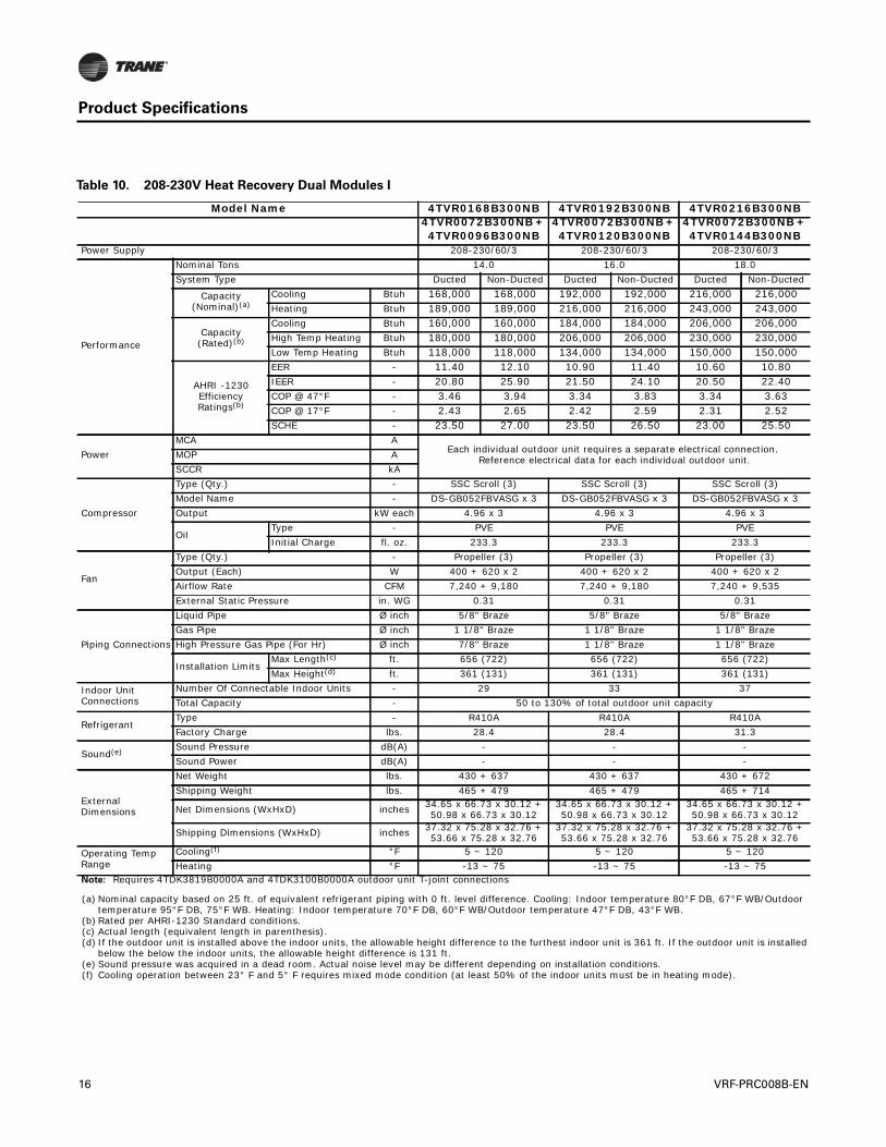
Table 10. 208-230V Heat Recovery Dual Modules I
Model Name 4TVR0168B300NB 4TVR0192B300NB 4TVR0216B300NB4TVR0072B300NB + 4TVR0096B300NB
4TVR0072B300NB + 4TVR0120B300NB
4TVR0072B300NB + 4TVR0144B300NB
Power Supply 208-230/60/3 208-230/60/3 208-230/60/3
Performance
Nominal Tons 14.0 16.0 18.0System Type Ducted Non-Ducted Ducted Non-Ducted Ducted Non-Ducted
Capacity(Nominal)(a)
Cooling Btuh 168,000 168,000 192,000 192,000 216,000 216,000Heating Btuh 189,000 189,000 216,000 216,000 243,000 243,000
Capacity(Rated)(b)
Cooling Btuh 160,000 160,000 184,000 184,000 206,000 206,000High Temp Heating Btuh 180,000 180,000 206,000 206,000 230,000 230,000Low Temp Heating Btuh 118,000 118,000 134,000 134,000 150,000 150,000
AHRI -1230 Efficiency Ratings(b)
EER - 11.40 12.10 10.90 11.40 10.60 10.80IEER - 20.80 25.90 21.50 24.10 20.50 22.40COP @ 47°F - 3.46 3.94 3.34 3.83 3.34 3.63COP @ 17°F - 2.43 2.65 2.42 2.59 2.31 2.52SCHE - 23.50 27.00 23.50 26.50 23.00 25.50
Power MCA A
Each individual outdoor unit requires a separate electrical connection. Reference electrical data for each individual outdoor unit.MOP A
SCCR kA
Compressor
Type (Qty.) - SSC Scroll (3) SSC Scroll (3) SSC Scroll (3)Model Name - DS-GB052FBVASG x 3 DS-GB052FBVASG x 3 DS-GB052FBVASG x 3Output kW each 4.96 x 3 4.96 x 3 4.96 x 3
OilType - PVE PVE PVEInitial Charge fl. oz. 233.3 233.3 233.3
Fan
Type (Qty.) - Propeller (3) Propeller (3) Propeller (3)Output (Each) W 400 + 620 x 2 400 + 620 x 2 400 + 620 x 2Airflow Rate CFM 7,240 + 9,180 7,240 + 9,180 7,240 + 9,535External Static Pressure in. WG 0.31 0.31 0.31
Piping Connections
Liquid Pipe Ø inch 5/8" Braze 5/8" Braze 5/8" BrazeGas Pipe Ø inch 1 1/8" Braze 1 1/8" Braze 1 1/8" BrazeHigh Pressure Gas Pipe (For Hr) Ø inch 7/8" Braze 1 1/8" Braze 1 1/8" Braze
Installation LimitsMax Length(c) ft. 656 (722) 656 (722) 656 (722)Max Height(d) ft. 361 (131) 361 (131) 361 (131)
Indoor Unit Connections
Number Of Connectable Indoor Units - 29 33 37Total Capacity - 50 to 130% of total outdoor unit capacity
RefrigerantType - R410A R410A R410AFactory Charge lbs. 28.4 28.4 31.3
Sound(e) Sound Pressure dB(A) - - -Sound Power dB(A) - - -
External Dimensions
Net Weight lbs. 430 + 637 430 + 637 430 + 672Shipping Weight lbs. 465 + 479 465 + 479 465 + 714
Net Dimensions (WxHxD) inches 34.65 x 66.73 x 30.12 +50.98 x 66.73 x 30.12
34.65 x 66.73 x 30.12 +50.98 x 66.73 x 30.12
34.65 x 66.73 x 30.12 +50.98 x 66.73 x 30.12
Shipping Dimensions (WxHxD) inches 37.32 x 75.28 x 32.76 +53.66 x 75.28 x 32.76
37.32 x 75.28 x 32.76 +53.66 x 75.28 x 32.76
37.32 x 75.28 x 32.76 +53.66 x 75.28 x 32.76
Operating Temp Range
Cooling(f) °F 5 ~ 120 5 ~ 120 5 ~ 120Heating °F -13 ~ 75 -13 ~ 75 -13 ~ 75
Note: Requires 4TDK3819B0000A and 4TDK3100B0000A outdoor unit T-joint connections
(a) Nominal capacity based on 25 ft. of equivalent refrigerant piping with 0 ft. level difference. Cooling: Indoor temperature 80°F DB, 67°F WB/Outdoor temperature 95°F DB, 75°F WB. Heating: Indoor temperature 70°F DB, 60°F WB/Outdoor temperature 47°F DB, 43°F WB.
(b) Rated per AHRI-1230 Standard conditions.(c) Actual length (equivalent length in parenthesis).(d) If the outdoor unit is installed above the indoor units, the allowable height difference to the furthest indoor unit is 361 ft. If the outdoor unit is installed
below the below the indoor units, the allowable height difference is 131 ft.(e) Sound pressure was acquired in a dead room. Actual noise level may be different depending on installation conditions.(f) Cooling operation between 23° F and 5° F requires mixed mode condition (at least 50% of the indoor units must be in heating mode).
16 VRF-PRC008B-EN
Product Specifications
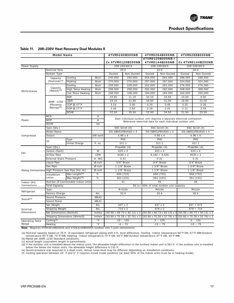
Table 11. 208~230V Heat Recovery Dual Modules II
Model Name 4TVR0240B300NB 4TVR0264B300NB 4TVR0288B300NB
2x 4TVR0120B300NB4TVR0120B300NB + 4TVR0144B300NB 2x 4TVR0144B300NB
Power Supply 208-230/60/3 208-230/60/3 208-230/60/3
Performance
Nominal Tons 20.0 22.0 24.0System Type Ducted Non-Ducted Ducted Non-Ducted Ducted Non-Ducted
Capacity(Nominal)(a)
Cooling Btuh 240,000 240,000 264,000 264,000 288,000 288,000Heating Btuh 270,000 270,000 297,000 297,000 324,000 324,000
Capacity(Rated)(b)
Cooling Btuh 228,000 228,000 252,000 252,000 276,000 276,000High Temp Heating Btuh 258,000 258,000 282,000 282,000 308,000 308,000Low Temp Heating Btuh 168,000 168,000 184,000 184,000 200,000 200,000
AHRI -1230 Efficiency Ratings(b)
EER - 10.60 11.10 10.10 10.50 10.00 9.50IEER - 19.10 21.80 18.60 21.50 18.60 21.00COP @ 47°F - 3.24 3.65 3.25 3.45 3.25 3.26COP @ 17°F - 2.40 2.54 2.26 2.41 2.12 2.29SCHE - 22.50 25.50 22.00 24.50 21.50 23.50
Power MCA A
Each individual outdoor unit requires a separate electrical connection. Reference electrical data for each individual outdoor unit.MOP A
SCCR kA
Compressor
Type (Qty.) - SSC Scroll (4) SSC Scroll (4) SSC Scroll (4)Model Name - DS-GB052FBVASG x 4 DS-GB052FBVASG x 4 DS-GB052FBVASG x 4Output kW each 4.96 x 4 4.96 x 4 4.96 x 4
OilType - PVE PVE PVEInitial Charge fl. oz. 311.1 311.1 311.1
Fan
Type (Qty.) - Propeller (4) Propeller (4) Propeller (4)Output (Each) W 620 x 4 620 x 4 620 x 4Airflow Rate CFM 9180 x 2 9,180 + 9,535 9535 x 2External Static Pressure in. WG 0.31 0.31 0.31
Piping Connections
Liquid Pipe Ø inch 5/8" Braze 3/4" Braze 3/4" BrazeGas Pipe Ø inch 1 1/8" Braze 1 3/8" Braze 1 3/8" BrazeHigh Pressure Gas Pipe (For Hr) Ø inch 1 1/8" Braze 1 1/8" Braze 1 1/8" Braze
Installation Limits
Max Length(c) ft. 656 (722) 656 (722) 656 (722)Max Height(d) ft. 361 (131) 361 (131) 361 (131)
Indoor Unit Connections
Number Of Connectable Indoor Units - 41 45 49Total Capacity - 50 to 130% of total outdoor unit capacity
RefrigerantType - R-410A R410A R410AFactory Charge lbs. 32.6 32.6 35.5
Sound(e) Sound Pressure dB(A) - - -Sound Power dB(A) - - -
External Dimensions
Net Weight lbs. 637 x 2 637 x 2 637 + 672Shipping Weight lbs. 714 x 2 679 x 2 679 + 714Net Dimensions (WxHxD) inches (50.98 x 66.73 x 30.12) x 2 (50.98 x 66.73 x 30.12) x 2 (50.98 x 66.73 x 30.12) x 2Shipping Dimensions (WxHxD) inches (53.66 x 75.28 x 32.76) x 2 (53.66 x 75.28 x 32.76) x 2 (53.66 x 75.28 x 32.76) x 2
Operating Temp Range
Cooling(f) °F 23 ~ 120 5 ~ 120 5 ~ 120Heating °F -4 ~ 75 -13 ~ 75 -13 ~ 75
Note: Requires 4TDK3819B0000A and 4TDK3100B0000A outdoor unit T-joint connections
(a) Nominal capacity based on 25 ft. of equivalent refrigerant piping with 0 ft. level difference. Cooling: Indoor temperature 80°F DB, 67°F WB/Outdoor temperature 95°F DB, 75°F WB. Heating: Indoor temperature 70°F DB, 60°F WB/Outdoor temperature 47°F DB, 43°F WB.
(b) Rated per AHRI-1230 Standard conditions.(c) Actual length (equivalent length in parenthesis).(d) If the outdoor unit is installed above the indoor units, the allowable height difference to the furthest indoor unit is 361 ft. If the outdoor unit is installed
below the below the indoor units, the allowable height difference is 131 ft.(e) Sound pressure was acquired in a dead room. Actual noise level may be different depending on installation conditions.(f) Cooling operation between 23° F and 5° F requires mixed mode condition (at least 50% of the indoor units must be in heating mode).
VRF-PRC008B-EN 17
Product Specifications
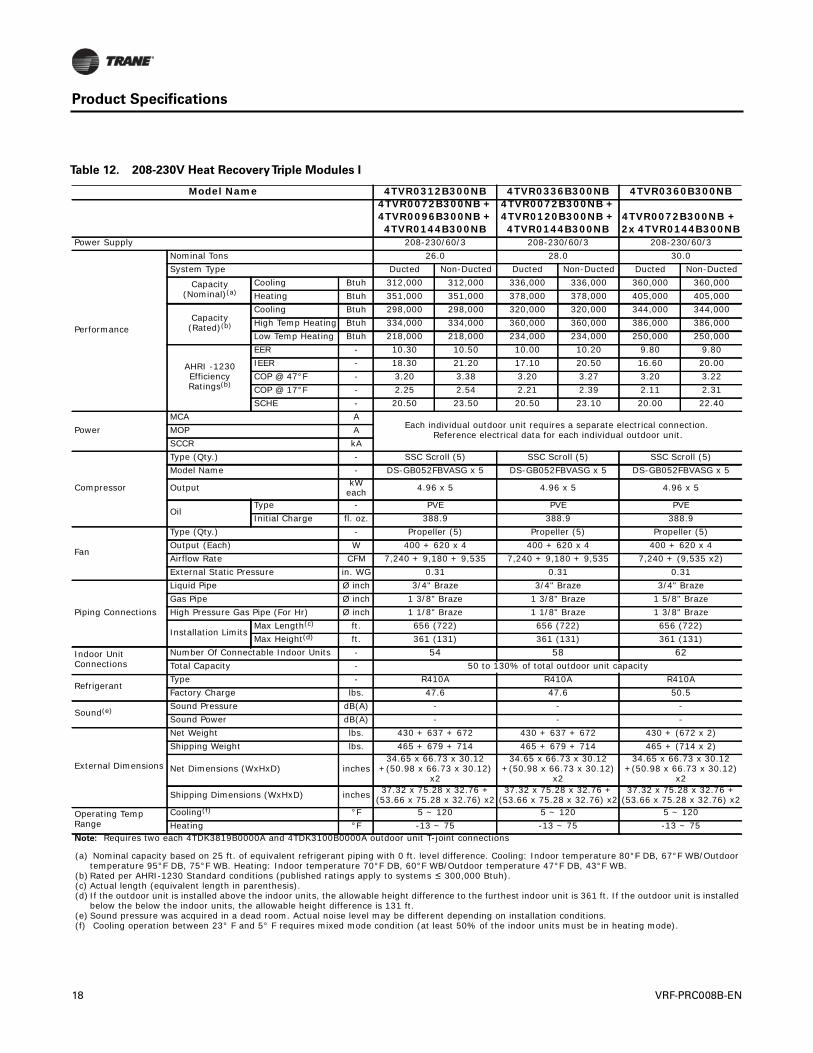
Table 12. 208-230V Heat RecoveryTriple Modules I
Model Name 4TVR0312B300NB 4TVR0336B300NB 4TVR0360B300NB4TVR0072B300NB + 4TVR0096B300NB + 4TVR0144B300NB
4TVR0072B300NB + 4TVR0120B300NB + 4TVR0144B300NB
4TVR0072B300NB + 2x 4TVR0144B300NB
Power Supply 208-230/60/3 208-230/60/3 208-230/60/3
Performance
Nominal Tons 26.0 28.0 30.0System Type Ducted Non-Ducted Ducted Non-Ducted Ducted Non-Ducted
Capacity(Nominal)(a)
Cooling Btuh 312,000 312,000 336,000 336,000 360,000 360,000Heating Btuh 351,000 351,000 378,000 378,000 405,000 405,000
Capacity(Rated)(b)
Cooling Btuh 298,000 298,000 320,000 320,000 344,000 344,000High Temp Heating Btuh 334,000 334,000 360,000 360,000 386,000 386,000Low Temp Heating Btuh 218,000 218,000 234,000 234,000 250,000 250,000
AHRI -1230 Efficiency Ratings(b)
EER - 10.30 10.50 10.00 10.20 9.80 9.80IEER - 18.30 21.20 17.10 20.50 16.60 20.00COP @ 47°F - 3.20 3.38 3.20 3.27 3.20 3.22COP @ 17°F - 2.25 2.54 2.21 2.39 2.11 2.31SCHE - 20.50 23.50 20.50 23.10 20.00 22.40
PowerMCA A
Each individual outdoor unit requires a separate electrical connection. Reference electrical data for each individual outdoor unit.MOP A
SCCR kA
Compressor
Type (Qty.) - SSC Scroll (5) SSC Scroll (5) SSC Scroll (5)Model Name - DS-GB052FBVASG x 5 DS-GB052FBVASG x 5 DS-GB052FBVASG x 5
Output kW each 4.96 x 5 4.96 x 5 4.96 x 5
OilType - PVE PVE PVEInitial Charge fl. oz. 388.9 388.9 388.9
Fan
Type (Qty.) - Propeller (5) Propeller (5) Propeller (5)Output (Each) W 400 + 620 x 4 400 + 620 x 4 400 + 620 x 4Airflow Rate CFM 7,240 + 9,180 + 9,535 7,240 + 9,180 + 9,535 7,240 + (9,535 x2)External Static Pressure in. WG 0.31 0.31 0.31
Piping Connections
Liquid Pipe Ø inch 3/4" Braze 3/4" Braze 3/4" BrazeGas Pipe Ø inch 1 3/8" Braze 1 3/8" Braze 1 5/8" BrazeHigh Pressure Gas Pipe (For Hr) Ø inch 1 1/8" Braze 1 1/8" Braze 1 3/8" Braze
Installation LimitsMax Length(c) ft. 656 (722) 656 (722) 656 (722)Max Height(d) ft. 361 (131) 361 (131) 361 (131)
Indoor Unit Connections
Number Of Connectable Indoor Units - 54 58 62Total Capacity - 50 to 130% of total outdoor unit capacity
RefrigerantType - R410A R410A R410AFactory Charge lbs. 47.6 47.6 50.5
Sound(e) Sound Pressure dB(A) - - -Sound Power dB(A) - - -
External Dimensions
Net Weight lbs. 430 + 637 + 672 430 + 637 + 672 430 + (672 x 2)Shipping Weight lbs. 465 + 679 + 714 465 + 679 + 714 465 + (714 x 2)
Net Dimensions (WxHxD) inches34.65 x 66.73 x 30.12
+(50.98 x 66.73 x 30.12) x2
34.65 x 66.73 x 30.12 +(50.98 x 66.73 x 30.12)
x2
34.65 x 66.73 x 30.12 +(50.98 x 66.73 x 30.12)
x2
Shipping Dimensions (WxHxD) inches 37.32 x 75.28 x 32.76 + (53.66 x 75.28 x 32.76) x2
37.32 x 75.28 x 32.76 + (53.66 x 75.28 x 32.76) x2
37.32 x 75.28 x 32.76 + (53.66 x 75.28 x 32.76) x2
Operating Temp Range
Cooling(f) °F 5 ~ 120 5 ~ 120 5 ~ 120Heating °F -13 ~ 75 -13 ~ 75 -13 ~ 75
Note: Requires two each 4TDK3819B0000A and 4TDK3100B0000A outdoor unit T-joint connections
(a) Nominal capacity based on 25 ft. of equivalent refrigerant piping with 0 ft. level difference. Cooling: Indoor temperature 80°F DB, 67°F WB/Outdoor temperature 95°F DB, 75°F WB. Heating: Indoor temperature 70°F DB, 60°F WB/Outdoor temperature 47°F DB, 43°F WB.
(b) Rated per AHRI-1230 Standard conditions (published ratings apply to systems ≤ 300,000 Btuh).(c) Actual length (equivalent length in parenthesis).(d) If the outdoor unit is installed above the indoor units, the allowable height difference to the furthest indoor unit is 361 ft. If the outdoor unit is installed
below the below the indoor units, the allowable height difference is 131 ft.(e) Sound pressure was acquired in a dead room. Actual noise level may be different depending on installation conditions.(f) Cooling operation between 23° F and 5° F requires mixed mode condition (at least 50% of the indoor units must be in heating mode).
18 VRF-PRC008B-EN

Product Specifications
Table 13. 208-230V Heat RecoveryTriple Modules II
Model Name 4TVR0384B300NB 4TVR0408B300NB 4TVR0432B300NB2x 4TVR0120B300NB + 4TVR0144B300NB
4TVR0120B300NB + 2x 4TVR0144B300NB 3x 4TVR0144B300NB
Power Supply 208-230/60/3 208-230/60/3 208-230/60/3
Performance
Nominal Tons 32.0 34.0 36.0System Type Ducted Non-Ducted Ducted Non-Ducted Ducted Non-Ducted
Capacity(Nominal)(a)
Cooling Btuh 384,000 384,000 408,000 408,000 432,000 432,000Heating Btuh 432,000 432,000 459,000 459,000 486,000 486,000
Capacity(Rated)(b)
Cooling Btuh 366,000 366,000 390,000 390,000 415,000 415,000High Temp Heating Btuh 410,000 410,000 435,000 435,000 460,000 460,000Low Temp Heating Btuh 268,000 268,000 284,000 284,000 300,000 300,000
AHRI -1230 Efficiency Ratings(b)
EER - 9.50 9.50 9.50 9.50 9.50 9.50IEER - 16.50 19.50 16.40 19.10 16.30 19.10COP @ 47°F - 3.20 3.20 3.20 3.20 3.20 3.20COP @ 17°F - 2.05 2.10 2.05 2.05 2.05 2.05SCHE - 16.50 23.00 19.00 22.00 19.00 21.50
PowerMCA A
Each individual outdoor unit requires a separate electrical connection. Reference electrical data for each individual outdoor unit.MOP A
SCCR kA
Compressor
Type (Qty.) - SSC Scroll (6) SSC Scroll (6) SSC Scroll (6)Model Name - DS-GB052FBVASG x 6 DS-GB052FBVASG x 6 DS-GB052FBVASG x 6Output kW each 4.96 x 6 4.96 x 6 4.96 x 6
OilType - PVE PVE PVEInitial Charge fl. oz. 466.6 466.6 466.6
Fan
Type (Qty.) - Propeller (6) Propeller (6) Propeller (6)Output (Each) W 620 x 6 620 x 6 620 x 6Airflow Rate CFM (9,180 x2) + 9535 9,180 + (2x 9,535) 9535 x 3External Static Pressure in. WG 0.31 0.31 0.31
Piping Connections
Liquid Pipe Ø inch 3/4" Braze 3/4" Braze 3/4" BrazeGas Pipe Ø inch 1 5/8" Braze 1 5/8" Braze 1 5/8" BrazeHigh Pressure Gas Pipe (For Hr) Ø inch 1 3/8" Braze 1 3/8" Braze 1 3/8" Braze
Installation LimitsMax Length(c) ft. 656 (722) 656 (722) 656 (722)Max Height(d) ft. 361 (131) 361 (131) 361 (131)
Indoor Unit Connections
Number Of Connectable Indoor Units - 64 64 64Total Capacity - 50 to 130% of total outdoor unit capacity
RefrigerantType - R410A R410A R410AFactory Charge lbs. 51.8 54.7 57.5
Sound(e) Sound Pressure dB(A) - - -Sound Power dB(A) - - -
External Dimensions
Net Weight lbs. (637 x 2) + 672 (637 x 2) + 672 672 x 2Shipping Weight lbs. (679 x 2) + 714 (679 x2) + 714 714 x 2Net Dimensions (WxHxD) inches (50.98 x 66.73 x 30.12) x 3 (50.98 x 66.73 x 30.12) x 3 (50.98 x 66.73 x 30.12) x 3Shipping Dimensions (WxHxD) inches (53.66 x 75.28 x 32.76) x 3 (53.66 x 75.28 x 32.76) x 3 (53.66 x 75.28 x 32.76) x 3
Operating Temp Range
Cooling(f) °F 5 ~ 120 5 ~ 120 5 ~ 120Heating °F -13 ~ 75 -13 ~ 75 -13 ~ 75
Note: Requires two each 4TDK3819B0000A and 4TDK3100B0000A outdoor unit T-joint connections
(a) Nominal capacity based on 25 ft. of equivalent refrigerant piping with 0 ft. level difference. Cooling: Indoor temperature 80°F DB, 67°F WB/Outdoor temperature 95°F DB, 75°F WB. Heating: Indoor temperature 70°F DB, 60°F WB/Outdoor temperature 47°F DB, 43°F WB.
(b) Rated per AHRI-1230 Standard conditions (published ratings apply to systems < 300,000 Btuh).(c) Actual length (equivalent length in parenthesis).(d) If the outdoor unit is installed above the indoor units, the allowable height difference to the furthest indoor unit is 361 ft. If the outdoor unit is installed
below the below the indoor units, the allowable height difference is 131 ft.(e) Sound pressure was acquired in a dead room. Actual noise level may be different depending on installation conditions.(f) Cooling operation between 23° F and 5° F requires mixed mode condition (at least 50% of the indoor units must be in heating mode).
VRF-PRC008B-EN 19
Product Specifications
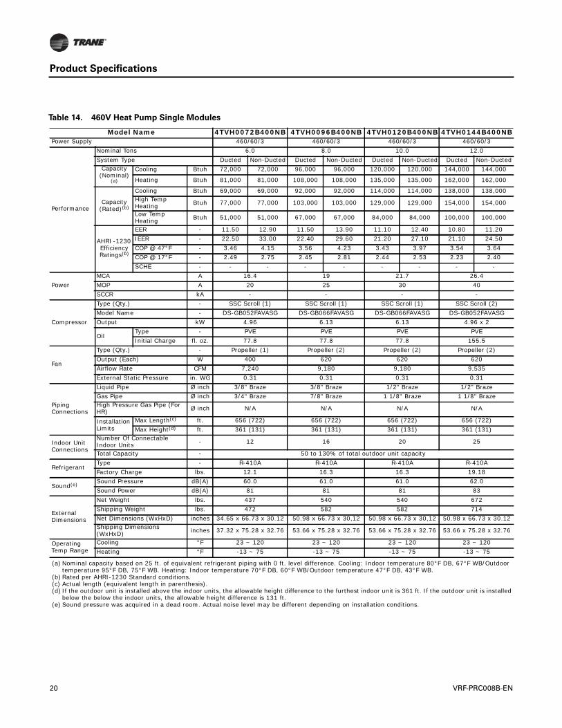
Table 14. 460V Heat Pump Single Modules
Model Name 4TVH0072B400NB 4TVH0096B400NB 4TVH0120B400NB 4TVH0144B400NBPower Supply 460/60/3 460/60/3 460/60/3 460/60/3
Performance
Nominal Tons 6.0 8.0 10.0 12.0System Type Ducted Non-Ducted Ducted Non-Ducted Ducted Non-Ducted Ducted Non-Ducted
Capacity(Nominal)
(a)
Cooling Btuh 72,000 72,000 96,000 96,000 120,000 120,000 144,000 144,000
Heating Btuh 81,000 81,000 108,000 108,000 135,000 135,000 162,000 162,000
Capacity(Rated)(b)
Cooling Btuh 69,000 69,000 92,000 92,000 114,000 114,000 138,000 138,000High Temp Heating Btuh 77,000 77,000 103,000 103,000 129,000 129,000 154,000 154,000
Low Temp Heating Btuh 51,000 51,000 67,000 67,000 84,000 84,000 100,000 100,000
AHRI -1230 Efficiency Ratings(b)
EER - 11.50 12.90 11.50 13.90 11.10 12.40 10.80 11.20IEER - 22.50 33.00 22.40 29.60 21.20 27.10 21.10 24.50COP @ 47°F - 3.46 4.15 3.56 4.23 3.43 3.97 3.54 3.64COP @ 17°F - 2.49 2.75 2.45 2.81 2.44 2.53 2.23 2.40SCHE - - - - - - - - -
Power MCA A 16.4 19 21.7 26.4MOP A 20 25 30 40SCCR kA - - - -
Compressor
Type (Qty.) - SSC Scroll (1) SSC Scroll (1) SSC Scroll (1) SSC Scroll (2)Model Name - DS-GB052FAVASG DS-GB066FAVASG DS-GB066FAVASG DS-GB052FAVASGOutput kW 4.96 6.13 6.13 4.96 x 2
OilType - PVE PVE PVE PVEInitial Charge fl. oz. 77.8 77.8 77.8 155.5
Fan
Type (Qty.) - Propeller (1) Propeller (2) Propeller (2) Propeller (2)Output (Each) W 400 620 620 620Airflow Rate CFM 7,240 9,180 9,180 9,535External Static Pressure in. WG 0.31 0.31 0.31 0.31
Piping Connections
Liquid Pipe Ø inch 3/8" Braze 3/8" Braze 1/2" Braze 1/2" BrazeGas Pipe Ø inch 3/4" Braze 7/8" Braze 1 1/8" Braze 1 1/8" BrazeHigh Pressure Gas Pipe (For HR) Ø inch N/A N/A N/A N/A
Installation Limits
Max Length(c) ft. 656 (722) 656 (722) 656 (722) 656 (722)Max Height(d) ft. 361 (131) 361 (131) 361 (131) 361 (131)
Indoor Unit Connections
Number Of Connectable Indoor Units - 12 16 20 25
Total Capacity - 50 to 130% of total outdoor unit capacity
RefrigerantType - R-410A R-410A R-410A R-410AFactory Charge lbs. 12.1 16.3 16.3 19.18
Sound(e) Sound Pressure dB(A) 60.0 61.0 61.0 62.0Sound Power dB(A) 81 81 81 83
External Dimensions
Net Weight lbs. 437 540 540 672Shipping Weight lbs. 472 582 582 714Net Dimensions (WxHxD) inches 34.65 x 66.73 x 30.12 50.98 x 66.73 x 30,12 50.98 x 66.73 x 30,12 50.98 x 66.73 x 30.12Shipping Dimensions (WxHxD) inches 37.32 x 75.28 x 32.76 53.66 x 75.28 x 32.76 53.66 x 75.28 x 32.76 53.66 x 75.28 x 32.76
Operating Temp Range
Cooling °F 23 ~ 120 23 ~ 120 23 ~ 120 23 ~ 120Heating °F -13 ~ 75 -13 ~ 75 -13 ~ 75 -13 ~ 75
(a) Nominal capacity based on 25 ft. of equivalent refrigerant piping with 0 ft. level difference. Cooling: Indoor temperature 80°F DB, 67°F WB/Outdoor temperature 95°F DB, 75°F WB. Heating: Indoor temperature 70°F DB, 60°F WB/Outdoor temperature 47°F DB, 43°F WB.
(b) Rated per AHRI-1230 Standard conditions.(c) Actual length (equivalent length in parenthesis).(d) If the outdoor unit is installed above the indoor units, the allowable height difference to the furthest indoor unit is 361 ft. If the outdoor unit is installed
below the below the indoor units, the allowable height difference is 131 ft.(e) Sound pressure was acquired in a dead room. Actual noise level may be different depending on installation conditions.
20 VRF-PRC008B-EN
Product Specifications
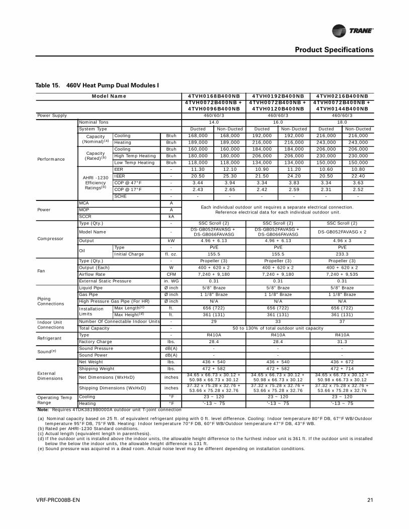
Table 15. 460V Heat Pump Dual Modules I
Model Name 4TVH0168B400NB 4TVH0192B400NB 4TVH0216B400NB4TVH0072B400NB + 4TVH0096B400NB
4TVH0072B400NB + 4TVH0120B400NB
4TVH0072B400NB + 4TVH0144B400NB
Power Supply 460/60/3 460/60/3 460/60/3
Performance
Nominal Tons 14.0 16.0 18.0System Type Ducted Non-Ducted Ducted Non-Ducted Ducted Non-Ducted
Capacity(Nominal)(a)
Cooling Btuh 168,000 168,000 192,000 192,000 216,000 216,000Heating Btuh 189,000 189,000 216,000 216,000 243,000 243,000
Capacity(Rated)(b)
Cooling Btuh 160,000 160,000 184,000 184,000 206,000 206,000High Temp Heating Btuh 180,000 180,000 206,000 206,000 230,000 230,000Low Temp Heating Btuh 118,000 118,000 134,000 134,000 150,000 150,000
AHRI -1230 Efficiency Ratings(b)
EER - 11.30 12.10 10.90 11.20 10.60 10.80IEER - 20.50 25.30 21.50 24.20 20.50 22.40COP @ 47°F - 3.44 3.94 3.34 3.83 3.34 3.63COP @ 17°F - 2.43 2.65 2.42 2.59 2.31 2.52SCHE - - - - - - -
PowerMCA A
Each individual outdoor unit requires a separate electrical connection. Reference electrical data for each individual outdoor unit.MOP A
SCCR kA
Compressor
Type (Qty.) - SSC Scroll (2) SSC Scroll (2) SSC Scroll (2)
Model Name - DS-GB052FAVASG + DS-GB066FAVASG
DS-GB052FAVASG + DS-GB066FAVASG DS-GB052FAVASG x 2
Output kW 4.96 + 6.13 4.96 + 6.13 4.96 x 3
OilType - PVE PVE PVEInitial Charge fl. oz. 155.5 155.5 233.3
Fan
Type (Qty.) - Propeller (3) Propeller (3) Propeller (3)Output (Each) W 400 + 620 x 2 400 + 620 x 2 400 + 620 x 2Airflow Rate CFM 7,240 + 9,180 7,240 + 9,180 7,240 + 9,535External Static Pressure in. WG 0.31 0.31 0.31
Piping Connections
Liquid Pipe Ø inch 5/8" Braze 5/8" Braze 5/8" BrazeGas Pipe Ø inch 1 1/8" Braze 1 1/8" Braze 1 1/8" BrazeHigh Pressure Gas Pipe (For HR) Ø inch N/A N/A N/A
Installation Limits
Max Length(c) ft. 656 (722) 656 (722) 656 (722)Max Height(d) ft. 361 (131) 361 (131) 361 (131)
Indoor Unit Connections
Number Of Connectable Indoor Units - 29 33 37Total Capacity - 50 to 130% of total outdoor unit capacity
RefrigerantType - R410A R410A R410AFactory Charge lbs. 28.4 28.4 31.3
Sound(e) Sound Pressure dB(A) - - -Sound Power dB(A) - - -
External Dimensions
Net Weight lbs. 436 + 540 436 + 540 436 + 672Shipping Weight lbs. 472 + 582 472 + 582 472 + 714
Net Dimensions (WxHxD) inches 34.65 x 66.73 x 30.12 +50.98 x 66.73 x 30.12
34.65 x 66.73 x 30.12 +50.98 x 66.73 x 30.12
34.65 x 66.73 x 30.12 +50.98 x 66.73 x 30.12
Shipping Dimensions (WxHxD) inches 37.32 x 75.28 x 32.76 +53.66 x 75.28 x 32.76
37.32 x 75.28 x 32.76 +53.66 x 75.28 x 32.76
37.32 x 75.28 x 32.76 +53.66 x 75.28 x 32.76
Operating Temp Range
Cooling °F 23 ~ 120 23 ~ 120 23 ~ 120Heating °F '-13 ~ 75 '-13 ~ 75 '-13 ~ 75
Note: Requires 4TDK3819B0000A outdoor unit T-joint connection
(a) Nominal capacity based on 25 ft. of equivalent refrigerant piping with 0 ft. level difference. Cooling: Indoor temperature 80°F DB, 67°F WB/Outdoor temperature 95°F DB, 75°F WB. Heating: Indoor temperature 70°F DB, 60°F WB/Outdoor temperature 47°F DB, 43°F WB.
(b) Rated per AHRI-1230 Standard conditions.(c) Actual length (equivalent length in parenthesis).(d) If the outdoor unit is installed above the indoor units, the allowable height difference to the furthest indoor unit is 361 ft. If the outdoor unit is installed
below the below the indoor units, the allowable height difference is 131 ft.(e) Sound pressure was acquired in a dead room. Actual noise level may be different depending on installation conditions.
VRF-PRC008B-EN 21
Product Specifications
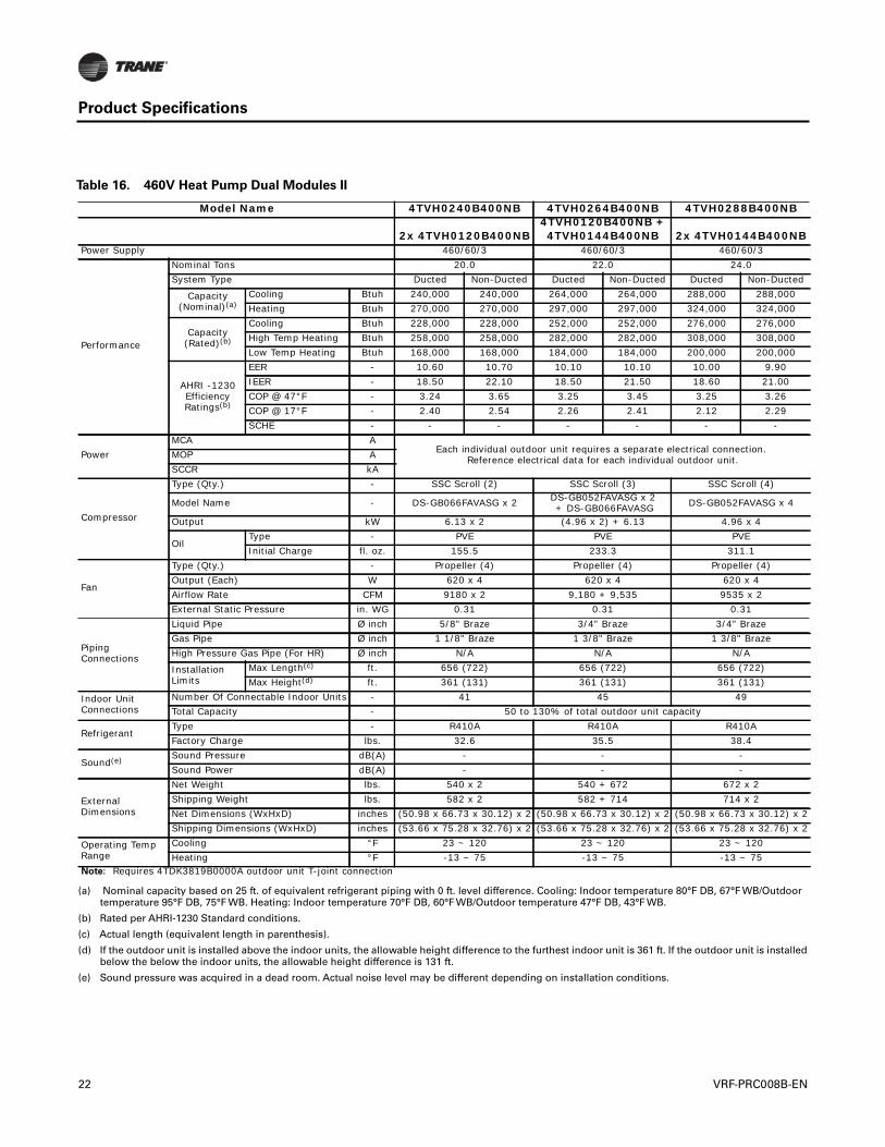
Table 16. 460V Heat Pump Dual Modules II
Model Name 4TVH0240B400NB 4TVH0264B400NB 4TVH0288B400NB
2x 4TVH0120B400NB4TVH0120B400NB + 4TVH0144B400NB 2x 4TVH0144B400NB
Power Supply 460/60/3 460/60/3 460/60/3
Performance
Nominal Tons 20.0 22.0 24.0System Type Ducted Non-Ducted Ducted Non-Ducted Ducted Non-Ducted
Capacity(Nominal)(a)
Cooling Btuh 240,000 240,000 264,000 264,000 288,000 288,000Heating Btuh 270,000 270,000 297,000 297,000 324,000 324,000
Capacity(Rated)(b)
Cooling Btuh 228,000 228,000 252,000 252,000 276,000 276,000High Temp Heating Btuh 258,000 258,000 282,000 282,000 308,000 308,000Low Temp Heating Btuh 168,000 168,000 184,000 184,000 200,000 200,000
AHRI -1230 Efficiency Ratings(b)
EER - 10.60 10.70 10.10 10.10 10.00 9.90IEER - 18.50 22.10 18.50 21.50 18.60 21.00COP @ 47°F - 3.24 3.65 3.25 3.45 3.25 3.26COP @ 17°F - 2.40 2.54 2.26 2.41 2.12 2.29SCHE - - - - - - -
PowerMCA A
Each individual outdoor unit requires a separate electrical connection. Reference electrical data for each individual outdoor unit.MOP A
SCCR kA
Compressor
Type (Qty.) - SSC Scroll (2) SSC Scroll (3) SSC Scroll (4)
Model Name - DS-GB066FAVASG x 2 DS-GB052FAVASG x 2 + DS-GB066FAVASG DS-GB052FAVASG x 4
Output kW 6.13 x 2 (4.96 x 2) + 6.13 4.96 x 4
OilType - PVE PVE PVEInitial Charge fl. oz. 155.5 233.3 311.1
Fan
Type (Qty.) - Propeller (4) Propeller (4) Propeller (4)Output (Each) W 620 x 4 620 x 4 620 x 4Airflow Rate CFM 9180 x 2 9,180 + 9,535 9535 x 2External Static Pressure in. WG 0.31 0.31 0.31
Piping Connections
Liquid Pipe Ø inch 5/8" Braze 3/4" Braze 3/4" BrazeGas Pipe Ø inch 1 1/8" Braze 1 3/8" Braze 1 3/8" BrazeHigh Pressure Gas Pipe (For HR) Ø inch N/A N/A N/A
Installation Limits
Max Length(c) ft. 656 (722) 656 (722) 656 (722)Max Height(d) ft. 361 (131) 361 (131) 361 (131)
Indoor Unit Connections
Number Of Connectable Indoor Units - 41 45 49Total Capacity - 50 to 130% of total outdoor unit capacity
RefrigerantType - R410A R410A R410AFactory Charge lbs. 32.6 35.5 38.4
Sound(e) Sound Pressure dB(A) - - -Sound Power dB(A) - - -
External Dimensions
Net Weight lbs. 540 x 2 540 + 672 672 x 2Shipping Weight lbs. 582 x 2 582 + 714 714 x 2Net Dimensions (WxHxD) inches (50.98 x 66.73 x 30.12) x 2 (50.98 x 66.73 x 30.12) x 2 (50.98 x 66.73 x 30.12) x 2Shipping Dimensions (WxHxD) inches (53.66 x 75.28 x 32.76) x 2 (53.66 x 75.28 x 32.76) x 2 (53.66 x 75.28 x 32.76) x 2
Operating Temp Range
Cooling °F 23 ~ 120 23 ~ 120 23 ~ 120Heating °F -13 ~ 75 -13 ~ 75 -13 ~ 75
Note: Requires 4TDK3819B0000A outdoor unit T-joint connection
(a) Nominal capacity based on 25 ft. of equivalent refrigerant piping with 0 ft. level difference. Cooling: Indoor temperature 80°F DB, 67°F WB/Outdoortemperature 95°F DB, 75°F WB. Heating: Indoor temperature 70°F DB, 60°F WB/Outdoor temperature 47°F DB, 43°F WB.
(b) Rated per AHRI-1230 Standard conditions.
(c) Actual length (equivalent length in parenthesis).
(d) If the outdoor unit is installed above the indoor units, the allowable height difference to the furthest indoor unit is 361 ft. If the outdoor unit is installedbelow the below the indoor units, the allowable height difference is 131 ft.
(e) Sound pressure was acquired in a dead room. Actual noise level may be different depending on installation conditions.
22 VRF-PRC008B-EN
Product Specifications
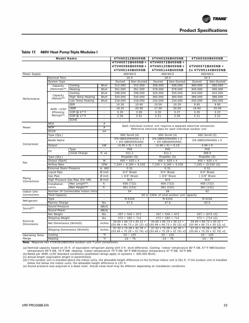
Table 17. 460V Heat PumpTriple Modules I
Model Name 4TVH0312B400NB 4TVH0336B400NB 4TVH0360B400NB4TVH0072B400NB + 4TVH0096B400NB + 4TVH0144B400NB
4TVH0072B400NB + 4TVH0120B400NB + 4TVH0144B400NB
4TVH0072B400NB + 2x 4TVH0144B400NB
Power Supply 460/60/3 460/60/3 460/60/3
Performance
Nominal Tons 26.0 28.0 30.0System Type Ducted Non-Ducted Ducted Non-Ducted Ducted Non-Ducted
Capacity(Nominal)(a)
Cooling Btuh 312,000 312,000 336,000 336,000 360,000 360,000Heating Btuh 351,000 351,000 378,000 378,000 405,000 405,000
Capacity(Rated)(b)
Cooling Btuh 298,000 298,000 320,000 320,000 344,000 344,000High Temp Heating Btuh 334,000 334,000 360,000 360,000 386,000 386,000Low Temp Heating Btuh 218,000 218,000 234,000 234,000 250,000 250,000
AHRI -1230 Efficiency Ratings(b)
EER - 10.30 10.60 10.00 10.20 9.80 9.80IEER - 18.10 20.90 17.00 20.50 16.60 20.00COP @ 47°F - 3.20 3.38 3.20 3.27 3.20 3.22COP @ 17°F - 2.25 2.51 2.21 2.39 2.11 2.31SCHE - - - - - - -
PowerMCA A
Each individual outdoor unit requires a separate electrical connection. Reference electrical data for each individual outdoor unit.MOP A
SCCR kA
Compressor
Type (Qty.) - SSC Scroll (4) SSC Scroll (4) SSC Scroll (5)
Model Name - DS-GB052FAVASG x 3 + DS-GB066FAVASG
DS-GB052FAVASG x 3 + DS-GB066FAVASG DS-GB052FAVASG x 5
Output kW (4.96 x 3) + 6.13 (4.96 x 3) + 6.13 4.96 x 5
OilType - PVE PVE PVEInitial Charge fl. oz. 311.1 311.1 388.9
Fan
Type (Qty.) - Propeller (5) Propeller (5) Propeller (5)Output (Each) W 400 + 620 x 4 400 + 620 x 4 400 + 620 x 4Airflow Rate CFM 7,240 + 9,180 + 9,535 7,240 + 9,180 + 9,535 7,240 + (9,535 x2)External Static Pressure in. WG 0.31 0.31 0.31
Piping Connections
Liquid Pipe Ø inch 3/4" Braze 3/4" Braze 3/4" BrazeGas Pipe Ø inch 1 3/8" Braze 1 3/8" Braze 1 5/8" BrazeHigh Pressure Gas Pipe (For HR) Ø inch N/A N/A N/AInstallation Limits
Max Length(c) ft. 656 (722) 656 (722) 656 (722)Max Height(d) ft. 361 (131) 361 (131) 361 (131)
Indoor Unit Connections
Number Of Connectable Indoor Units - 54 58 62Total Capacity - 50 to 130% of total outdoor unit capacity
RefrigerantType - R-410A R-410A R-410AFactory Charge lbs. 47.6 47.6 50.5
Sound(e) Sound Pressure dB(A) - - -Sound Power dB(A) - - -
External Dimensions
Net Weight lbs. 437 + 540 + 672 437 + 540 + 672 437 + (672 x2)Shipping Weight lbs. 472 + 582 + 714 472 + 582 + 714 472 + (714 x2)
Net Dimensions (WxHxD) inches 34.65 x 66.73 x 30.12 +(50.98 x 66.73 x 30.12) x2
34.65 x 66.73 x 30.12 +(50.98 x 66.73 x 30.12) x2
34.65 x 66.73 x 30.12 +(50.98 x 66.73 x 30.12) x2
Shipping Dimensions (WxHxD) inches 37.32 x 75.28 x 32.76 +(53.66 x 75.28 x 32.76) x2
37.32 x 75.28 x 32.76 +(53.66 x 75.28 x 32.76) x2
37.32 x 75.28 x 32.76 +(53.66 x 75.28 x 32.76) x2
Operating Temp Range
Cooling °F 23 ~ 120 23 ~ 120 23 ~ 120Heating °F -13 ~ 75 -13 ~ 75 -13 ~ 75
Note: Requires two 4TDK3819B0000A outdoor unit T-joint connections
(a) Nominal capacity based on 25 ft. of equivalent refrigerant piping with 0 ft. level difference. Cooling: Indoor temperature 80°F DB, 67°F WB/Outdoor temperature 95°F DB, 75°F WB. Heating: Indoor temperature 70°F DB, 60°F WB/Outdoor temperature 47°F DB, 43°F WB.
(b) Rated per AHRI-1230 Standard conditions (published ratings apply to systems < 300,000 Btuh).(c) Actual length (equivalent length in parenthesis).(d) If the outdoor unit is installed above the indoor units, the allowable height difference to the furthest indoor unit is 361 ft. If the outdoor unit is installed
below the below the indoor units, the allowable height difference is 131 ft.(e) Sound pressure was acquired in a dead room. Actual noise level may be different depending on installation conditions.
VRF-PRC008B-EN 23
Product Specifications
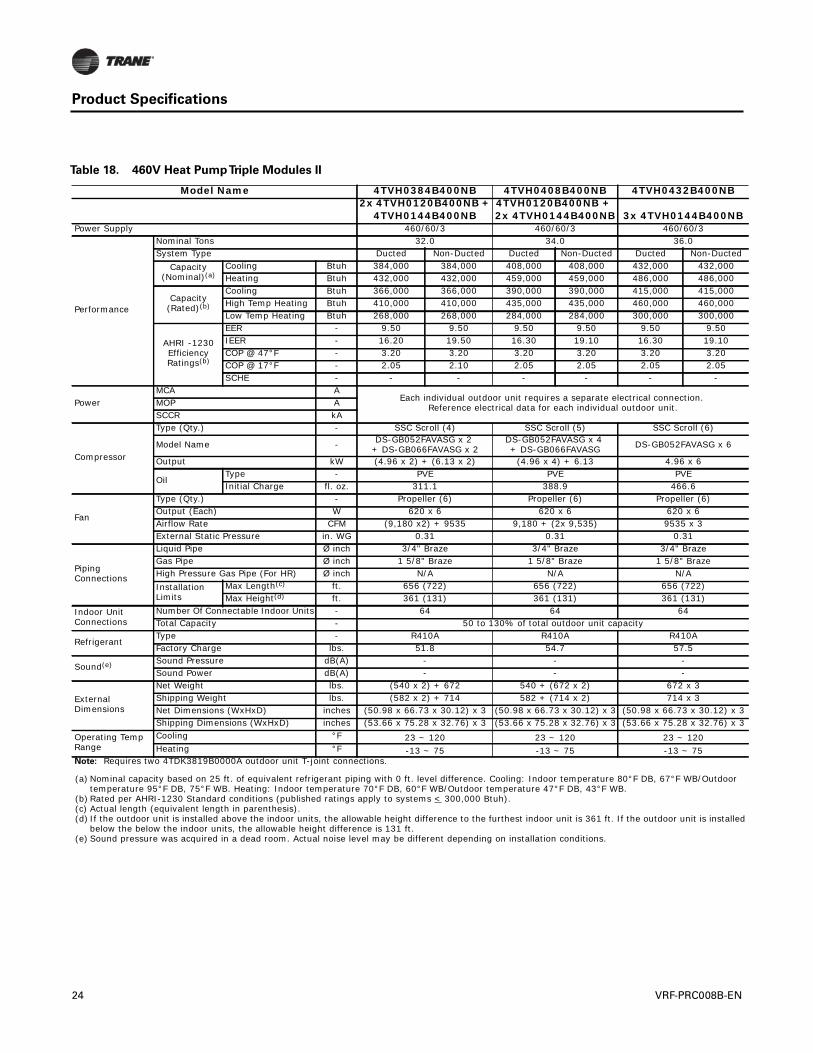
Table 18. 460V Heat PumpTriple Modules II
Model Name 4TVH0384B400NB 4TVH0408B400NB 4TVH0432B400NB2x 4TVH0120B400NB +
4TVH0144B400NB4TVH0120B400NB + 2x 4TVH0144B400NB 3x 4TVH0144B400NB
Power Supply 460/60/3 460/60/3 460/60/3
Performance
Nominal Tons 32.0 34.0 36.0System Type Ducted Non-Ducted Ducted Non-Ducted Ducted Non-Ducted
Capacity(Nominal)(a)
Cooling Btuh 384,000 384,000 408,000 408,000 432,000 432,000Heating Btuh 432,000 432,000 459,000 459,000 486,000 486,000
Capacity(Rated)(b)
Cooling Btuh 366,000 366,000 390,000 390,000 415,000 415,000High Temp Heating Btuh 410,000 410,000 435,000 435,000 460,000 460,000Low Temp Heating Btuh 268,000 268,000 284,000 284,000 300,000 300,000
AHRI -1230 Efficiency Ratings(b)
EER - 9.50 9.50 9.50 9.50 9.50 9.50IEER - 16.20 19.50 16.30 19.10 16.30 19.10COP @ 47°F - 3.20 3.20 3.20 3.20 3.20 3.20COP @ 17°F - 2.05 2.10 2.05 2.05 2.05 2.05SCHE - - - - - - -
PowerMCA A
Each individual outdoor unit requires a separate electrical connection. Reference electrical data for each individual outdoor unit.MOP A
SCCR kA
Compressor
Type (Qty.) - SSC Scroll (4) SSC Scroll (5) SSC Scroll (6)
Model Name - DS-GB052FAVASG x 2 + DS-GB066FAVASG x 2
DS-GB052FAVASG x 4 + DS-GB066FAVASG DS-GB052FAVASG x 6
Output kW (4.96 x 2) + (6.13 x 2) (4.96 x 4) + 6.13 4.96 x 6
OilType - PVE PVE PVEInitial Charge fl. oz. 311.1 388.9 466.6
Fan
Type (Qty.) - Propeller (6) Propeller (6) Propeller (6)Output (Each) W 620 x 6 620 x 6 620 x 6Airflow Rate CFM (9,180 x2) + 9535 9,180 + (2x 9,535) 9535 x 3External Static Pressure in. WG 0.31 0.31 0.31
Piping Connections
Liquid Pipe Ø inch 3/4" Braze 3/4" Braze 3/4" BrazeGas Pipe Ø inch 1 5/8" Braze 1 5/8" Braze 1 5/8" BrazeHigh Pressure Gas Pipe (For HR) Ø inch N/A N/A N/AInstallation Limits
Max Length(c) ft. 656 (722) 656 (722) 656 (722)Max Height(d) ft. 361 (131) 361 (131) 361 (131)
Indoor Unit Connections
Number Of Connectable Indoor Units - 64 64 64Total Capacity - 50 to 130% of total outdoor unit capacity
RefrigerantType - R410A R410A R410AFactory Charge lbs. 51.8 54.7 57.5
Sound(e) Sound Pressure dB(A) - - -Sound Power dB(A) - - -
External Dimensions
Net Weight lbs. (540 x 2) + 672 540 + (672 x 2) 672 x 3Shipping Weight lbs. (582 x 2) + 714 582 + (714 x 2) 714 x 3Net Dimensions (WxHxD) inches (50.98 x 66.73 x 30.12) x 3 (50.98 x 66.73 x 30.12) x 3 (50.98 x 66.73 x 30.12) x 3Shipping Dimensions (WxHxD) inches (53.66 x 75.28 x 32.76) x 3 (53.66 x 75.28 x 32.76) x 3 (53.66 x 75.28 x 32.76) x 3
Operating Temp Range
Cooling °F 23 ~ 120 23 ~ 120 23 ~ 120Heating °F -13 ~ 75 -13 ~ 75 -13 ~ 75
Note: Requires two 4TDK3819B0000A outdoor unit T-joint connections.
(a) Nominal capacity based on 25 ft. of equivalent refrigerant piping with 0 ft. level difference. Cooling: Indoor temperature 80°F DB, 67°F WB/Outdoor temperature 95°F DB, 75°F WB. Heating: Indoor temperature 70°F DB, 60°F WB/Outdoor temperature 47°F DB, 43°F WB.
(b) Rated per AHRI-1230 Standard conditions (published ratings apply to systems < 300,000 Btuh).(c) Actual length (equivalent length in parenthesis).(d) If the outdoor unit is installed above the indoor units, the allowable height difference to the furthest indoor unit is 361 ft. If the outdoor unit is installed
below the below the indoor units, the allowable height difference is 131 ft.(e) Sound pressure was acquired in a dead room. Actual noise level may be different depending on installation conditions.
24 VRF-PRC008B-EN
Product Specifications
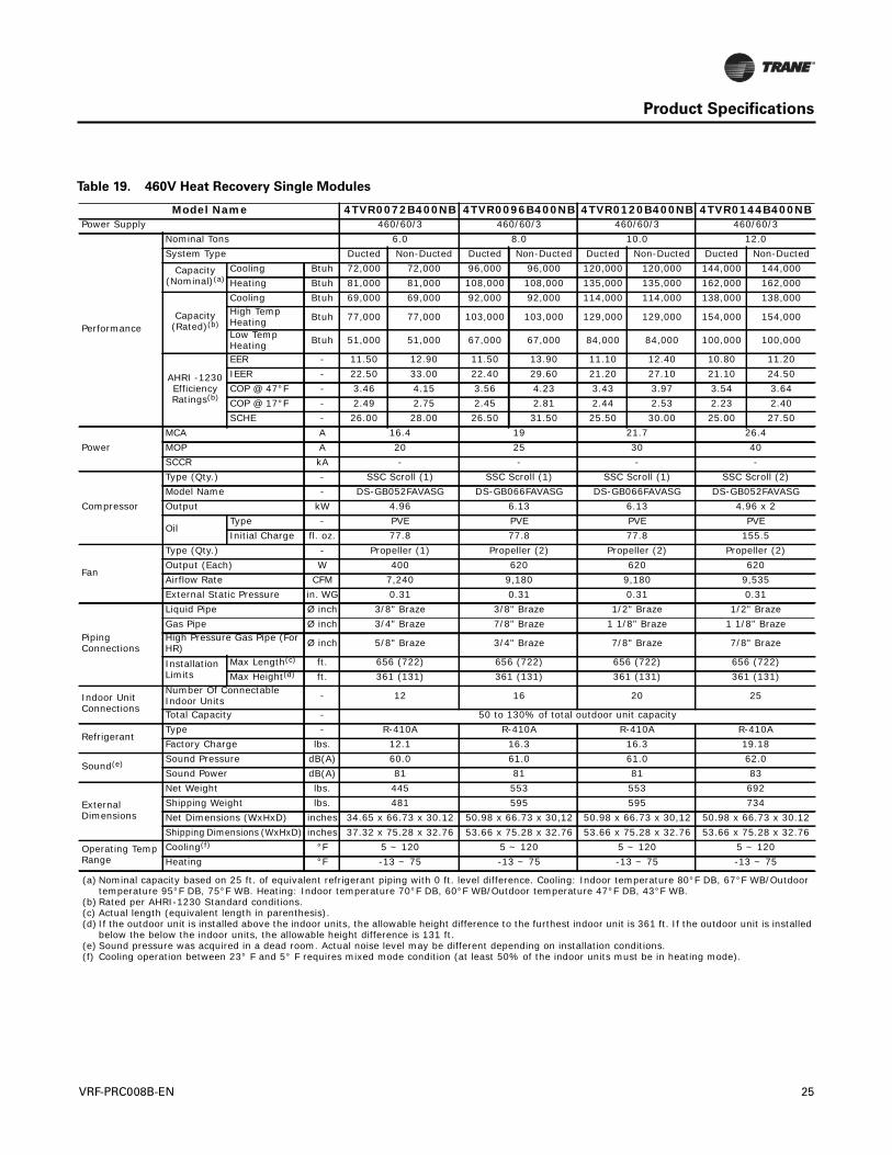
Table 19. 460V Heat Recovery Single Modules
Model Name 4TVR0072B400NB 4TVR0096B400NB 4TVR0120B400NB 4TVR0144B400NBPower Supply 460/60/3 460/60/3 460/60/3 460/60/3
Performance
Nominal Tons 6.0 8.0 10.0 12.0System Type Ducted Non-Ducted Ducted Non-Ducted Ducted Non-Ducted Ducted Non-Ducted
Capacity(Nominal)(a)
Cooling Btuh 72,000 72,000 96,000 96,000 120,000 120,000 144,000 144,000Heating Btuh 81,000 81,000 108,000 108,000 135,000 135,000 162,000 162,000
Capacity(Rated)(b)
Cooling Btuh 69,000 69,000 92,000 92,000 114,000 114,000 138,000 138,000High Temp Heating Btuh 77,000 77,000 103,000 103,000 129,000 129,000 154,000 154,000
Low Temp Heating Btuh 51,000 51,000 67,000 67,000 84,000 84,000 100,000 100,000
AHRI -1230 Efficiency Ratings(b)
EER - 11.50 12.90 11.50 13.90 11.10 12.40 10.80 11.20IEER - 22.50 33.00 22.40 29.60 21.20 27.10 21.10 24.50COP @ 47°F - 3.46 4.15 3.56 4.23 3.43 3.97 3.54 3.64COP @ 17°F - 2.49 2.75 2.45 2.81 2.44 2.53 2.23 2.40SCHE - 26.00 28.00 26.50 31.50 25.50 30.00 25.00 27.50
PowerMCA A 16.4 19 21.7 26.4MOP A 20 25 30 40SCCR kA - - - -
Compressor
Type (Qty.) - SSC Scroll (1) SSC Scroll (1) SSC Scroll (1) SSC Scroll (2)Model Name - DS-GB052FAVASG DS-GB066FAVASG DS-GB066FAVASG DS-GB052FAVASGOutput kW 4.96 6.13 6.13 4.96 x 2
OilType - PVE PVE PVE PVEInitial Charge fl. oz. 77.8 77.8 77.8 155.5
Fan
Type (Qty.) - Propeller (1) Propeller (2) Propeller (2) Propeller (2)Output (Each) W 400 620 620 620Airflow Rate CFM 7,240 9,180 9,180 9,535External Static Pressure in. WG 0.31 0.31 0.31 0.31
Piping Connections
Liquid Pipe Ø inch 3/8" Braze 3/8" Braze 1/2" Braze 1/2" BrazeGas Pipe Ø inch 3/4" Braze 7/8" Braze 1 1/8" Braze 1 1/8" BrazeHigh Pressure Gas Pipe (For HR) Ø inch 5/8" Braze 3/4" Braze 7/8" Braze 7/8" Braze
Installation Limits
Max Length(c) ft. 656 (722) 656 (722) 656 (722) 656 (722)Max Height(d) ft. 361 (131) 361 (131) 361 (131) 361 (131)
Indoor Unit Connections
Number Of Connectable Indoor Units - 12 16 20 25
Total Capacity - 50 to 130% of total outdoor unit capacity
RefrigerantType - R-410A R-410A R-410A R-410AFactory Charge lbs. 12.1 16.3 16.3 19.18
Sound(e) Sound Pressure dB(A) 60.0 61.0 61.0 62.0Sound Power dB(A) 81 81 81 83
External Dimensions
Net Weight lbs. 445 553 553 692Shipping Weight lbs. 481 595 595 734Net Dimensions (WxHxD) inches 34.65 x 66.73 x 30.12 50.98 x 66.73 x 30,12 50.98 x 66.73 x 30,12 50.98 x 66.73 x 30.12Shipping Dimensions (WxHxD) inches 37.32 x 75.28 x 32.76 53.66 x 75.28 x 32.76 53.66 x 75.28 x 32.76 53.66 x 75.28 x 32.76
Operating Temp Range
Cooling(f) °F 5 ~ 120 5 ~ 120 5 ~ 120 5 ~ 120Heating °F -13 ~ 75 -13 ~ 75 -13 ~ 75 -13 ~ 75
(a) Nominal capacity based on 25 ft. of equivalent refrigerant piping with 0 ft. level difference. Cooling: Indoor temperature 80°F DB, 67°F WB/Outdoor temperature 95°F DB, 75°F WB. Heating: Indoor temperature 70°F DB, 60°F WB/Outdoor temperature 47°F DB, 43°F WB.
(b) Rated per AHRI-1230 Standard conditions.(c) Actual length (equivalent length in parenthesis).(d) If the outdoor unit is installed above the indoor units, the allowable height difference to the furthest indoor unit is 361 ft. If the outdoor unit is installed
below the below the indoor units, the allowable height difference is 131 ft.(e) Sound pressure was acquired in a dead room. Actual noise level may be different depending on installation conditions.(f) Cooling operation between 23° F and 5° F requires mixed mode condition (at least 50% of the indoor units must be in heating mode).
VRF-PRC008B-EN 25
Product Specifications
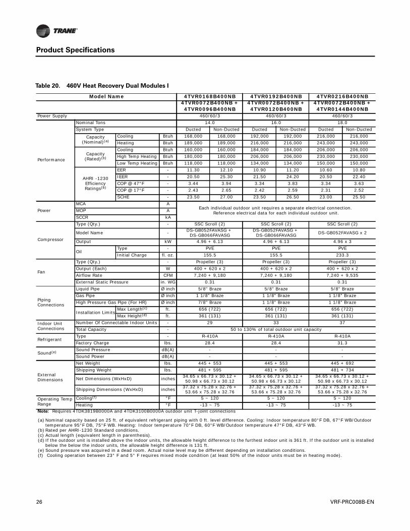
Table 20. 460V Heat Recovery Dual Modules I
Model Name 4TVR0168B400NB 4TVR0192B400NB 4TVR0216B400NB4TVR0072B400NB + 4TVR0096B400NB
4TVR0072B400NB + 4TVR0120B400NB
4TVR0072B400NB + 4TVR0144B400NB
Power Supply 460/60/3 460/60/3 460/60/3
Performance
Nominal Tons 14.0 16.0 18.0System Type Ducted Non-Ducted Ducted Non-Ducted Ducted Non-Ducted
Capacity(Nominal)(a)
Cooling Btuh 168,000 168,000 192,000 192,000 216,000 216,000Heating Btuh 189,000 189,000 216,000 216,000 243,000 243,000
Capacity(Rated)(b)
Cooling Btuh 160,000 160,000 184,000 184,000 206,000 206,000High Temp Heating Btuh 180,000 180,000 206,000 206,000 230,000 230,000Low Temp Heating Btuh 118,000 118,000 134,000 134,000 150,000 150,000
AHRI -1230 Efficiency Ratings(b)
EER - 11.30 12.10 10.90 11.20 10.60 10.80IEER - 20.50 25.30 21.50 24.20 20.50 22.40COP @ 47°F - 3.44 3.94 3.34 3.83 3.34 3.63COP @ 17°F - 2.43 2.65 2.42 2.59 2.31 2.52SCHE - 23.50 27.00 23.50 26.50 23.00 25.50
PowerMCA A
Each individual outdoor unit requires a separate electrical connection. Reference electrical data for each individual outdoor unit.MOP A
SCCR kA
Compressor
Type (Qty.) - SSC Scroll (2) SSC Scroll (2) SSC Scroll (2)
Model Name - DS-GB052FAVASG + DS-GB066FAVASG
DS-GB052FAVASG + DS-GB066FAVASG DS-GB052FAVASG x 2
Output kW 4.96 + 6.13 4.96 + 6.13 4.96 x 3
OilType - PVE PVE PVEInitial Charge fl. oz. 155.5 155.5 233.3
Fan
Type (Qty.) - Propeller (3) Propeller (3) Propeller (3)Output (Each) W 400 + 620 x 2 400 + 620 x 2 400 + 620 x 2Airflow Rate CFM 7,240 + 9,180 7,240 + 9,180 7,240 + 9,535External Static Pressure in. WG 0.31 0.31 0.31
Piping Connections
Liquid Pipe Ø inch 5/8" Braze 5/8" Braze 5/8" BrazeGas Pipe Ø inch 1 1/8" Braze 1 1/8" Braze 1 1/8" BrazeHigh Pressure Gas Pipe (For HR) Ø inch 7/8" Braze 1 1/8" Braze 1 1/8" Braze
Installation LimitsMax Length(c) ft. 656 (722) 656 (722) 656 (722)Max Height(d) ft. 361 (131) 361 (131) 361 (131)
Indoor Unit Connections
Number Of Connectable Indoor Units - 29 33 37Total Capacity - 50 to 130% of total outdoor unit capacity
RefrigerantType - R-410A R-410A R-410AFactory Charge lbs. 28.4 28.4 31.3
Sound(e) Sound Pressure dB(A) - - -Sound Power dB(A) - - -
External Dimensions
Net Weight lbs. 445 + 553 445 + 553 445 + 692Shipping Weight lbs. 481 + 595 481 + 595 481 + 734
Net Dimensions (WxHxD) inches 34.65 x 66.73 x 30.12 +50.98 x 66.73 x 30.12
34.65 x 66.73 x 30.12 +50.98 x 66.73 x 30.12
34.65 x 66.73 x 30.12 +50.98 x 66.73 x 30.12
Shipping Dimensions (WxHxD) inches 37.32 x 75.28 x 32.76 +53.66 x 75.28 x 32.76
37.32 x 75.28 x 32.76 +53.66 x 75.28 x 32.76
37.32 x 75.28 x 32.76 +53.66 x 75.28 x 32.76
Operating Temp Range
Cooling(f) °F 5 ~ 120 5 ~ 120 5 ~ 120Heating °F -13 ~ 75 -13 ~ 75 -13 ~ 75
Note: Requires 4TDK3819B0000A and 4TDK3100B0000A outdoor unit T-joint connections
(a) Nominal capacity based on 25 ft. of equivalent refrigerant piping with 0 ft. level difference. Cooling: Indoor temperature 80°F DB, 67°F WB/Outdoor temperature 95°F DB, 75°F WB. Heating: Indoor temperature 70°F DB, 60°F WB/Outdoor temperature 47°F DB, 43°F WB.
(b) Rated per AHRI-1230 Standard conditions.(c) Actual length (equivalent length in parenthesis).(d) If the outdoor unit is installed above the indoor units, the allowable height difference to the furthest indoor unit is 361 ft. If the outdoor unit is installed
below the below the indoor units, the allowable height difference is 131 ft.(e) Sound pressure was acquired in a dead room. Actual noise level may be different depending on installation conditions.(f) Cooling operation between 23° F and 5° F requires mixed mode condition (at least 50% of the indoor units must be in heating mode).
26 VRF-PRC008B-EN
Product Specifications
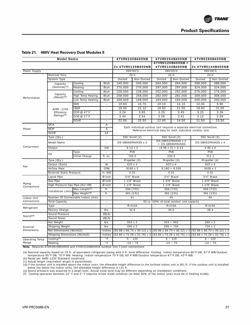
Table 21. 460V Heat Recovery Dual Modules II
Model Name 4TVR0240B400NB 4TVR0264B400NB 4TVR0288B400NB
2x 4TVR0120B400NB4TVR0120B400NB + 4TVR0144B400NB 2x 4TVR0144B400NB
Power Supply 460/60/3 460/60/3 460/60/3
Performance
Nominal Tons 20.0 22.0 24.0System Type Ducted Non-Ducted Ducted Non-Ducted Ducted Non-Ducted
Capacity(Nominal)(a)
Cooling Btuh 240,000 240,000 264,000 264,000 288,000 288,000Heating Btuh 270,000 270,000 297,000 297,000 324,000 324,000
Capacity(Rated)(b)
Cooling Btuh 228,000 228,000 252,000 252,000 276,000 276,000High Temp Heating Btuh 258,000 258,000 282,000 282,000 308,000 308,000Low Temp Heating Btuh 168,000 168,000 184,000 184,000 200,000 200,000
AHRI -1230 Efficiency Ratings(b)
EER - 10.60 10.70 10.10 10.10 10.00 9.90IEER - 18.50 22.10 18.50 21.50 18.60 21.00COP @ 47°F - 3.24 3.65 3.25 3.45 3.25 3.26COP @ 17°F - 2.40 2.54 2.26 2.41 2.12 2.29SCHE - 22.50 25.50 22.00 24.50 21.50 23.50
PowerMCA A
Each individual outdoor unit requires a separate electrical connection. Reference electrical data for each individual outdoor unit.MOP A
SCCR kA
Compressor
Type (Qty.) - SSC Scroll (2) SSC Scroll (3) SSC Scroll (4)
Model Name - DS-GB066FAVASG x 2 DS-GB052FAVASG x 2 + DS-GB066FAVASG DS-GB052FAVASG x 4
Output kW 6.13 x 2 (4.96 x 2) + 6.13 4.96 x 4
OilType - PVE PVE PVEInitial Charge fl. oz. 155.5 233.3 311.1
Fan
Type (Qty.) - Propeller (4) Propeller (4) Propeller (4)Output (Each) W 620 x 4 620 x 4 620 x 4Airflow Rate CFM 9180 x 2 9,180 + 9,535 9535 x 2External Static Pressure in. WG 0.31 0.31 0.31
Piping Connections
Liquid Pipe Ø inch 5/8" Braze 3/4" Braze 3/4" BrazeGas Pipe Ø inch 1 1/8" Braze 1 3/8" Braze 1 3/8" BrazeHigh Pressure Gas Pipe (For HR) Ø inch 1 1/8" Braze 1 1/8" Braze 1 1/8" Braze
Installation LimitsMax Length(c) ft. 656 (722) 656 (722) 656 (722)Max Height(d) ft. 361 (131) 361 (131) 361 (131)
Indoor Unit Connections
Number Of Connectable Indoor Units - 41 45 49Total Capacity - 50 to 130% of total outdoor unit capacity
RefrigerantType - R-410A R-410A R-410AFactory Charge lbs. 32.6 35.5 38.4
Sound(e) Sound Pressure dB(A) - - -Sound Power dB(A) - - -
External Dimensions
Net Weight lbs. 553 x 2 553 + 692 692 x 2Shipping Weight lbs. 595 x 2 595 + 734 734 x 2Net Dimensions (WxHxD) inches (50.98 x 66.73 x 30.12) x 2 (50.98 x 66.73 x 30.12) x 2 (50.98 x 66.73 x 30.12) x 2Shipping Dimensions (WxHxD) inches (53.66 x 75.28 x 32.76) x 2 (53.66 x 75.28 x 32.76) x 2 (53.66 x 75.28 x 32.76) x 2
Operating Temp Range
Cooling(f) °F 5 ~ 120 5 ~ 120 5 ~ 120Heating °F -13 ~ 75 -13 ~ 75 -13 ~ 75
Note: Requires 4TDK3819B0000A and 4TDK3100B0000A outdoor unit T-joint connections
(a) Nominal capacity based on 25 ft. of equivalent refrigerant piping with 0 ft. level difference. Cooling: Indoor temperature 80°F DB, 67°F WB/Outdoor temperature 95°F DB, 75°F WB. Heating: Indoor temperature 70°F DB, 60°F WB/Outdoor temperature 47°F DB, 43°F WB.
(b) Rated per AHRI-1230 Standard conditions.(c) Actual length (equivalent length in parenthesis).(d) If the outdoor unit is installed above the indoor units, the allowable height difference to the furthest indoor unit is 361 ft. If the outdoor unit is installed
below the below the indoor units, the allowable height difference is 131 ft.(e) Sound pressure was acquired in a dead room. Actual noise level may be different depending on installation conditions.(f) Cooling operation between 23° F and 5° F requires mixed mode condition (at least 50% of the indoor units must be in heating mode).
VRF-PRC008B-EN 27
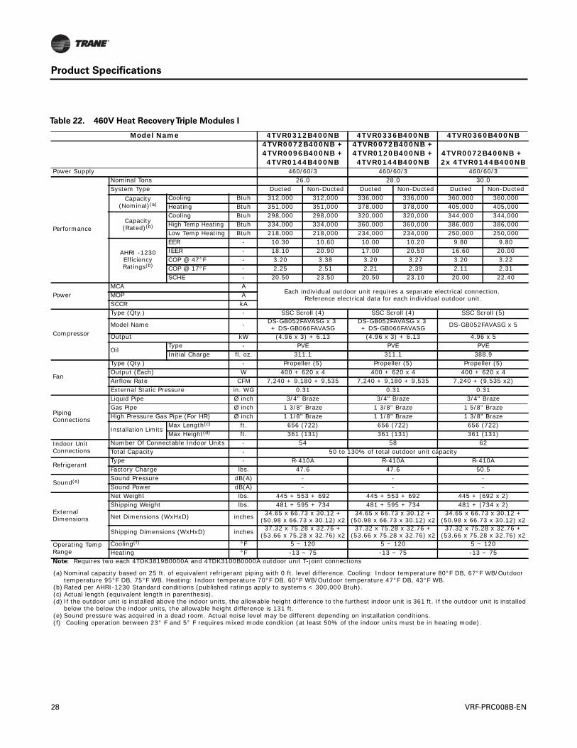
Product Specifications
Table 22. 460V Heat RecoveryTriple Modules I
Model Name 4TVR0312B400NB 4TVR0336B400NB 4TVR0360B400NB4TVR0072B400NB + 4TVR0096B400NB + 4TVR0144B400NB
4TVR0072B400NB + 4TVR0120B400NB + 4TVR0144B400NB
4TVR0072B400NB + 2x 4TVR0144B400NB
Power Supply 460/60/3 460/60/3 460/60/3
Performance
Nominal Tons 26.0 28.0 30.0System Type Ducted Non-Ducted Ducted Non-Ducted Ducted Non-Ducted
Capacity(Nominal)(a)
Cooling Btuh 312,000 312,000 336,000 336,000 360,000 360,000Heating Btuh 351,000 351,000 378,000 378,000 405,000 405,000
Capacity(Rated)(b)
Cooling Btuh 298,000 298,000 320,000 320,000 344,000 344,000High Temp Heating Btuh 334,000 334,000 360,000 360,000 386,000 386,000Low Temp Heating Btuh 218,000 218,000 234,000 234,000 250,000 250,000
AHRI -1230 Efficiency Ratings(b)
EER - 10.30 10.60 10.00 10.20 9.80 9.80IEER - 18.10 20.90 17.00 20.50 16.60 20.00COP @ 47°F - 3.20 3.38 3.20 3.27 3.20 3.22COP @ 17°F - 2.25 2.51 2.21 2.39 2.11 2.31SCHE - 20.50 23.50 20.50 23.10 20.00 22.40
PowerMCA A
Each individual outdoor unit requires a separate electrical connection. Reference electrical data for each individual outdoor unit.MOP A
SCCR kA
Compressor
Type (Qty.) - SSC Scroll (4) SSC Scroll (4) SSC Scroll (5)
Model Name - DS-GB052FAVASG x 3 + DS-GB066FAVASG
DS-GB052FAVASG x 3 + DS-GB066FAVASG DS-GB052FAVASG x 5
Output kW (4.96 x 3) + 6.13 (4.96 x 3) + 6.13 4.96 x 5
OilType - PVE PVE PVEInitial Charge fl. oz. 311.1 311.1 388.9
Fan
Type (Qty.) - Propeller (5) Propeller (5) Propeller (5)Output (Each) W 400 + 620 x 4 400 + 620 x 4 400 + 620 x 4Airflow Rate CFM 7,240 + 9,180 + 9,535 7,240 + 9,180 + 9,535 7,240 + (9,535 x2)External Static Pressure in. WG 0.31 0.31 0.31
Piping Connections
Liquid Pipe Ø inch 3/4" Braze 3/4" Braze 3/4" BrazeGas Pipe Ø inch 1 3/8" Braze 1 3/8" Braze 1 5/8" BrazeHigh Pressure Gas Pipe (For HR) Ø inch 1 1/8" Braze 1 1/8" Braze 1 3/8" Braze
Installation LimitsMax Length(c) ft. 656 (722) 656 (722) 656 (722)Max Height(d) ft. 361 (131) 361 (131) 361 (131)
Indoor Unit Connections
Number Of Connectable Indoor Units - 54 58 62Total Capacity - 50 to 130% of total outdoor unit capacity
RefrigerantType - R-410A R-410A R-410AFactory Charge lbs. 47.6 47.6 50.5
Sound(e) Sound Pressure dB(A) - - -Sound Power dB(A) - - -
External Dimensions
Net Weight lbs. 445 + 553 + 692 445 + 553 + 692 445 + (692 x 2)Shipping Weight lbs. 481 + 595 + 734 481 + 595 + 734 481 + (734 x 2)
Net Dimensions (WxHxD) inches 34.65 x 66.73 x 30.12 +(50.98 x 66.73 x 30.12) x2
34.65 x 66.73 x 30.12 +(50.98 x 66.73 x 30.12) x2
34.65 x 66.73 x 30.12 +(50.98 x 66.73 x 30.12) x2
Shipping Dimensions (WxHxD) inches 37.32 x 75.28 x 32.76 +(53.66 x 75.28 x 32.76) x2
37.32 x 75.28 x 32.76 +(53.66 x 75.28 x 32.76) x2
37.32 x 75.28 x 32.76 +(53.66 x 75.28 x 32.76) x2
Operating Temp Range
Cooling(f) °F 5 ~ 120 5 ~ 120 5 ~ 120Heating °F -13 ~ 75 -13 ~ 75 -13 ~ 75
Note: Requires two each 4TDK3819B0000A and 4TDK3100B0000A outdoor unit T-joint connections
(a) Nominal capacity based on 25 ft. of equivalent refrigerant piping with 0 ft. level difference. Cooling: Indoor temperature 80°F DB, 67°F WB/Outdoor temperature 95°F DB, 75°F WB. Heating: Indoor temperature 70°F DB, 60°F WB/Outdoor temperature 47°F DB, 43°F WB.
(b) Rated per AHRI-1230 Standard conditions (published ratings apply to systems < 300,000 Btuh).(c) Actual length (equivalent length in parenthesis).(d) If the outdoor unit is installed above the indoor units, the allowable height difference to the furthest indoor unit is 361 ft. If the outdoor unit is installed
below the below the indoor units, the allowable height difference is 131 ft.(e) Sound pressure was acquired in a dead room. Actual noise level may be different depending on installation conditions.(f) Cooling operation between 23° F and 5° F requires mixed mode condition (at least 50% of the indoor units must be in heating mode).
28 VRF-PRC008B-EN

Product Specifications
Table 23. 460V Heat RecoveryTriple Modules II
Model Name 4TVR0384B400NB 4TVR0408B400NB 4TVR0432B400NB2x 4TVR0120B400NB +
4TVR0144B400NB4TVR0120B400NB + 2x 4TVR0144B400NB 3x 4TVR0144B400NB
Power Supply 460/60/3 460/60/3 460/60/3
Performance
Nominal Tons 32.0 34.0 36.0System Type Ducted Non-Ducted Ducted Non-Ducted Ducted Non-Ducted
Capacity(Nominal)(a)
Cooling Btuh 384,000 384,000 408,000 408,000 432,000 432,000Heating Btuh 432,000 432,000 459,000 459,000 486,000 486,000
Capacity(Rated)(b)
Cooling Btuh 366,000 366,000 390,000 390,000 415,000 415,000High Temp Heating Btuh 410,000 410,000 435,000 435,000 460,000 460,000Low Temp Heating Btuh 268,000 268,000 284,000 284,000 300,000 300,000
AHRI -1230 Efficiency Ratings(b)
EER - 9.50 9.50 9.50 9.50 9.50 9.50IEER - 16.20 19.50 16.30 19.10 16.30 19.10COP @ 47°F - 3.20 3.20 3.20 3.20 3.20 3.20COP @ 17°F - 2.05 2.10 2.05 2.05 2.05 2.05SCHE - 19.50 23.00 19.00 22.00 19.00 21.50
PowerMCA A
Each individual outdoor unit requires a separate electrical connection. Reference electrical data for each individual outdoor unit.MOP A
SCCR kA
Compressor
Type (Qty.) - SSC Scroll (4) SSC Scroll (5) SSC Scroll (6)
Model Name - DS-GB052FAVASG x 2 + DS-GB066FAVASG x 2
DS-GB052FAVASG x 4 + DS-GB066FAVASG DS-GB052FAVASG x 6
Output kW (4.96 x 2) + (6.13 x 2) (4.96 x 4) + 6.13 4.96 x 6
OilType - PVE PVE PVEInitial Charge fl. oz. 311.1 388.9 466.6
Fan
Type (Qty.) - Propeller (6) Propeller (6) Propeller (6)Output (Each) W 620 x 6 620 x 6 620 x 6Airflow Rate CFM (9,180 x2) + 9535 9,180 + (2x 9,535) 9535 x 3External Static Pressure in. WG 0.31 0.31 0.31
Piping Connections
Liquid Pipe Ø inch 3/4" Braze 3/4" Braze 3/4" BrazeGas Pipe Ø inch 1 5/8" Braze 1 5/8" Braze 1 5/8" BrazeHigh Pressure Gas Pipe (For HR) Ø inch 1 3/8" Braze 1 3/8" Braze 1 3/8" Braze
Installation Limits
Max Length(c) ft. 656 (722) 656 (722) 656 (722)Max Height(d) ft. 361 (131) 361 (131) 361 (131)
Indoor Unit Connections
Number Of Connectable Indoor Units - 64 64 64Total Capacity - 50 to 130% of total outdoor unit capacity
RefrigerantType - R-410A R-410A R-410AFactory Charge lbs. 51.8 54.7 57.5
Sound(e) Sound Pressure dB(A) - - -Sound Power dB(A) - - -
External Dimensions
Net Weight lbs. 553 + (692 x 2) 553 + (692 x 2) 692 x 3Shipping Weight lbs. 595 + (734 x 2) 595 + (734 x 2) 734 x 3Net Dimensions (WxHxD) inches (50.98 x 66.73 x 30.12) x 3 (50.98 x 66.73 x 30.12) x 3 (50.98 x 66.73 x 30.12) x 3Shipping Dimensions (WxHxD) inches (53.66 x 75.28 x 32.76) x 3 (53.66 x 75.28 x 32.76) x 3 (53.66 x 75.28 x 32.76) x 3
Operating Temp Range
Cooling(f) °F 5 ~ 120 5 ~ 120 5 ~ 120Heating °F -13 ~ 75 -13 ~ 75 -13 ~ 75
Note: Requires two each 4TDK3819B0000A and 4TDK3100B0000A outdoor unit T-joint connections
(a) Nominal capacity based on 25 ft. of equivalent refrigerant piping with 0 ft. level difference. Cooling: Indoor temperature 80°F DB, 67°F WB/Outdoor temperature 95°F DB, 75°F WB. Heating: Indoor temperature 70°F DB, 60°F WB/Outdoor temperature 47°F DB, 43°F WB.
(b) Rated per AHRI-1230 Standard conditions.(c) Actual length (equivalent length in parenthesis).(d) If the outdoor unit is installed above the indoor units, the allowable height difference to the furthest indoor unit is 361 ft. If the outdoor unit is installed
below the below the indoor units, the allowable height difference is 131 ft.(e) Sound pressure was acquired in a dead room. Actual noise level may be different depending on installation conditions.(f) Cooling operation between 23° F and 5° F requires mixed mode condition (at least 50% of the indoor units must be in heating mode).
VRF-PRC008B-EN 29
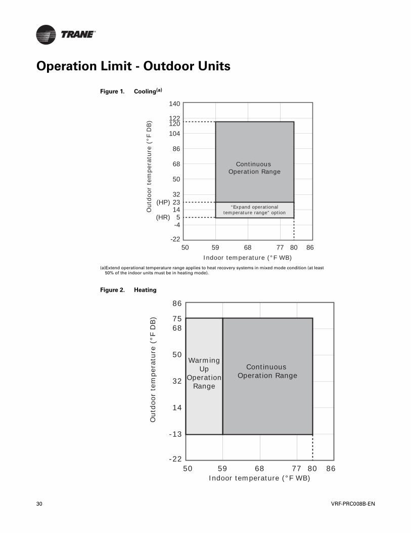
Operation Limit - Outdoor Units
Figure 1. Cooling(a)
(a)Extend operational temperature range applies to heat recovery systems in mixed mode condition (at least50% of the indoor units must be in heating mode).
Figure 2. Heating
50 59 68 77 80 86
140
122
104
86
68
50
14
-4
23(HP)
(HR) 5
120
-22
32
Continuous Operation Range
“Expand operationaltemperature range” option
Indoor temperature (°F WB)
Out
door
tem
pera
ture
(°F
DB)
50 59 68 77 80 86
86
6875
50
14
-13
-22
32
Continuous Operation Range
Indoor temperature (°F WB)
Out
door
tem
pera
ture
(°F
DB)
WarmingUp
OperationRange
30 VRF-PRC008B-EN
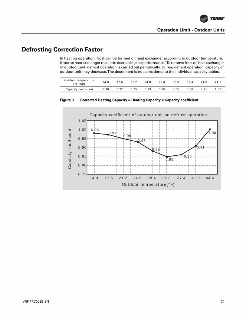
Operation Limit - Outdoor Units
Defrosting Correction Factor
In heating operation, frost can be formed on heat exchanger according to outdoor temperature.(frost on heat exchanger results in decreasing the performance.)To remove frost on heat exchangerof outdoor unit, defrost operation is carried out periodically. During defrost operation, capacity ofoutdoor unit may decrease.The decrement is not considered to the individual capacity tables.
Outdoor temperature(°F, WB)
14.0 17.6 21.2 24.8 28.4 32.0 37.4 41.0 44.6
Capacity coefficient 0.98 0.97 0.95 0.93 0.88 0.85 0.86 0.91 1.00
Figure 3. Corrected Heating Capacity = Heating Capacity x Capacity coefficient
1.05Capacity coefficient of outdoor unit on defrost operation
Outdoor temperature(°F)
Cap
acity
coef
ficie
nt 1.00
0.95
0.90
0.85
0.80
0.7514.0
0.980.97
0.950.93
0.88
0.850.86
0.91
1.00
17.6 21.2 24.8 28.4 32.0 37.4 41.0 44.6
VRF-PRC008B-EN 31
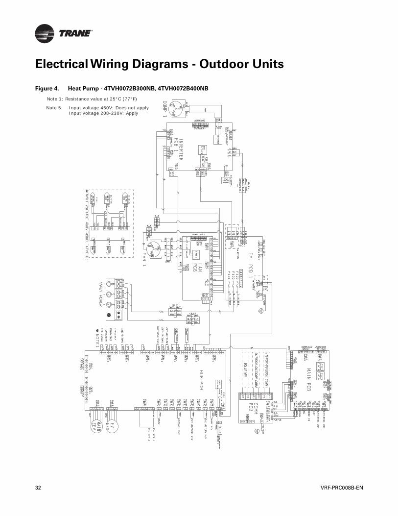
Electrical Wiring Diagrams - Outdoor Units
Figure 4. Heat Pump - 4TVH0072B300NB, 4TVH0072B400NB
Note 1: Resistance value at 25°C (77°F)
Note 5: Input voltage 460V: Does not apply Input voltage 208-230V: Apply
32 VRF-PRC008B-EN
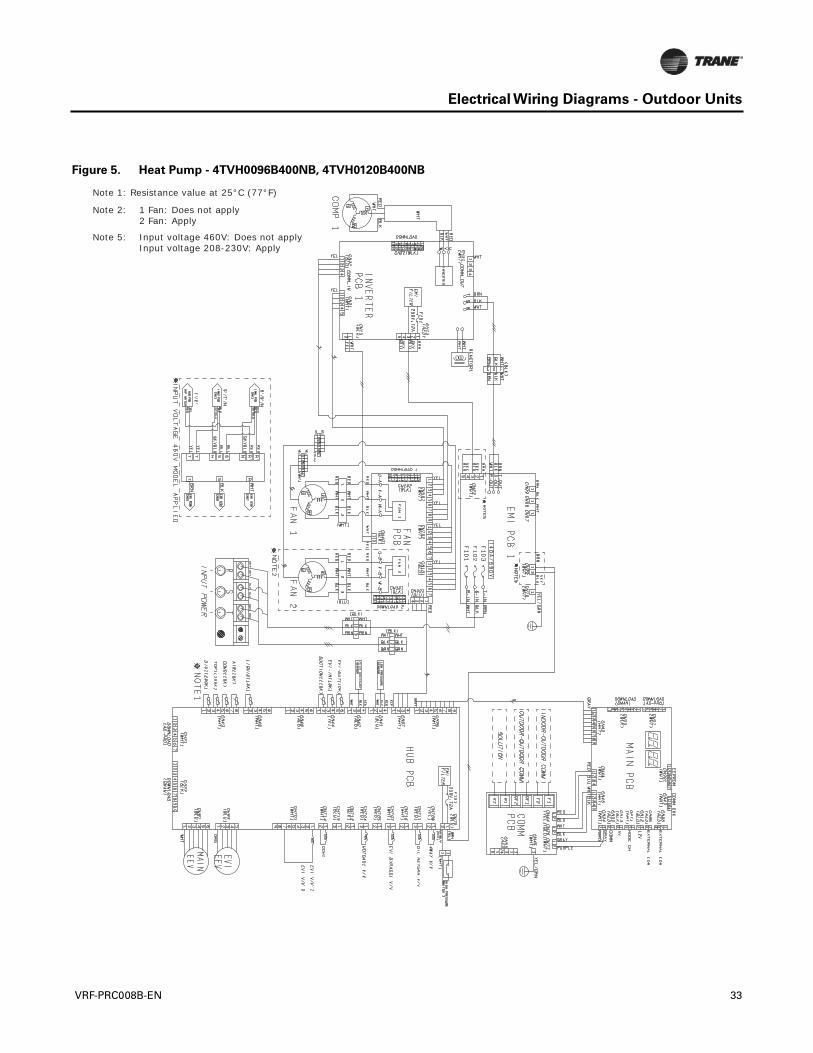
Electrical Wiring Diagrams - Outdoor Units
Figure 5. Heat Pump - 4TVH0096B400NB, 4TVH0120B400NB
Note 1: Resistance value at 25°C (77°F)
Note 2: 1 Fan: Does not apply 2 Fan: Apply
Note 5: Input voltage 460V: Does not apply Input voltage 208-230V: Apply
VRF-PRC008B-EN 33
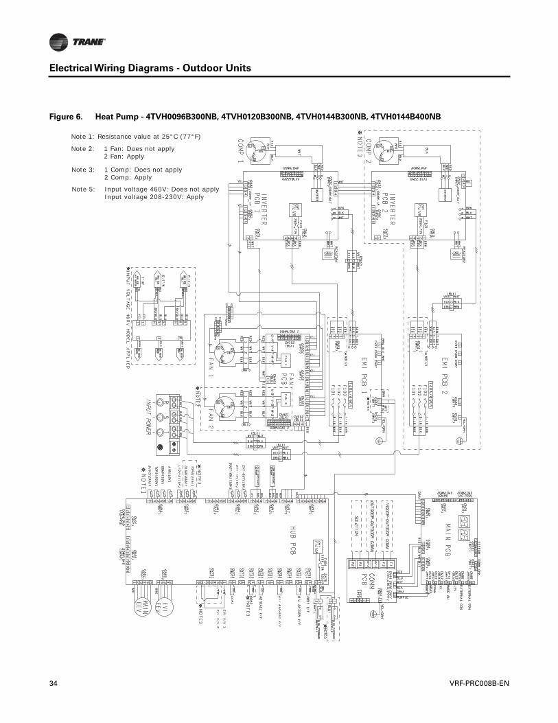
Electrical Wiring Diagrams - Outdoor Units
Figure 6. Heat Pump - 4TVH0096B300NB, 4TVH0120B300NB, 4TVH0144B300NB, 4TVH0144B400NB
Note 1: Resistance value at 25°C (77°F)
Note 2: 1 Fan: Does not apply 2 Fan: Apply
Note 5: Input voltage 460V: Does not apply Input voltage 208-230V: Apply
Note 3: 1 Comp: Does not apply 2 Comp: Apply
34 VRF-PRC008B-EN
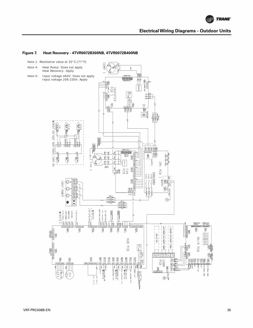
Electrical Wiring Diagrams - Outdoor Units
Figure 7. Heat Recovery - 4TVR0072B300NB, 4TVR0072B400NB
Note 1: Resistance value at 25°C (77°F)
Note 4: Heat Pump: Does not apply Heat Recovery: Apply
Note 5: Input voltage 460V: Does not apply Input voltage 208-230V: Apply
VRF-PRC008B-EN 35
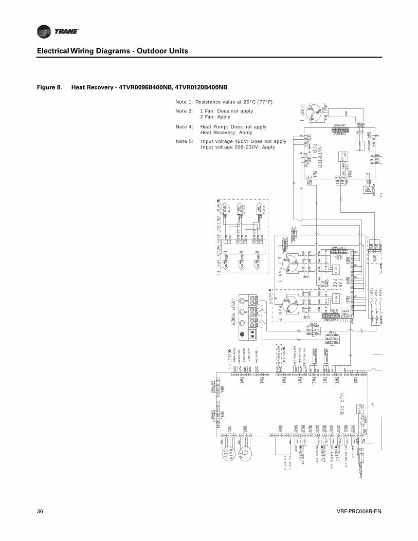
Electrical Wiring Diagrams - Outdoor Units
Figure 8. Heat Recovery - 4TVR0096B400NB, 4TVR0120B400NB
Note 1: Resistance value at 25°C (77°F)
Note 2: 1 Fan: Does not apply 2 Fan: Apply
Note 5: Input voltage 460V: Does not apply Input voltage 208-230V: Apply
Note 4: Heat Pump: Does not apply Heat Recovery: Apply
36 VRF-PRC008B-EN
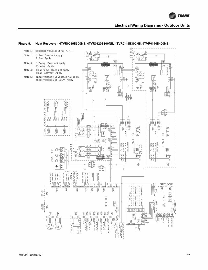
Electrical Wiring Diagrams - Outdoor Units
Figure 9. Heat Recovery - 4TVR0096B300NB, 4TVR0120B300NB, 4TVR0144B300NB, 4TVR0144B400NB
Note 1: Resistance value at 25°C (77°F)
Note 2: 1 Fan: Does not apply 2 Fan: Apply
Note 5: Input voltage 460V: Does not apply Input voltage 208-230V: Apply
Note 3: 1 Comp: Does not apply 2 Comp: Apply
Note 4: Heat Pump: Does not apply Heat Recovery: Apply
VRF-PRC008B-EN 37
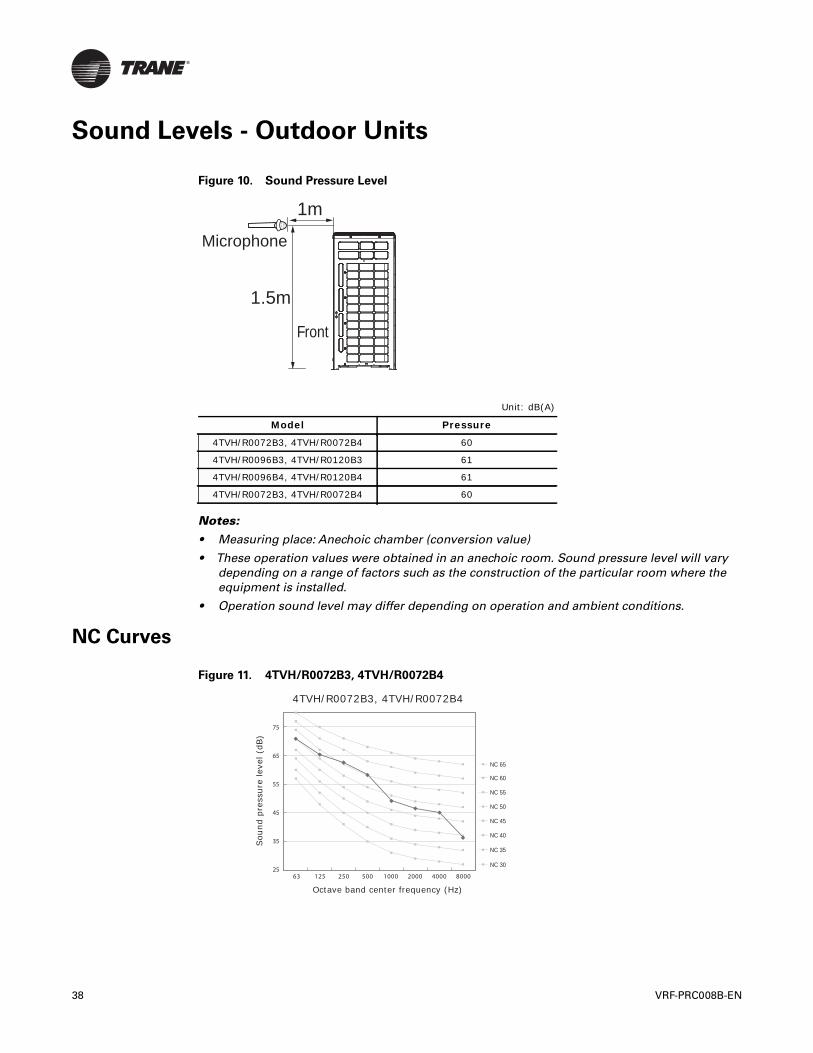
Sound Levels - Outdoor Units
Notes:
• Measuring place: Anechoic chamber (conversion value)
• These operation values were obtained in an anechoic room. Sound pressure level will varydepending on a range of factors such as the construction of the particular room where theequipment is installed.
• Operation sound level may differ depending on operation and ambient conditions.
NC Curves
Figure 10. Sound Pressure Level
Unit: dB(A)
Model Pressure
4TVH/R0072B3, 4TVH/R0072B4 60
4TVH/R0096B3, 4TVH/R0120B3 61
4TVH/R0096B4, 4TVH/R0120B4 61
4TVH/R0072B3, 4TVH/R0072B4 60
1m
1.5m
Microphone
Front
Figure 11. 4TVH/R0072B3, 4TVH/R0072B4
63 125 250 500 1000 2000 4000 8000 25
35
45
55
65
75
NC 65
NC 60
NC 55
NC 50
NC 45
NC 40
NC 35
NC 30
4TVH/R0072B3, 4TVH/R0072B4
Octave band center frequency (Hz)
Sou
nd p
ress
ure
leve
l (dB
)
38 VRF-PRC008B-EN
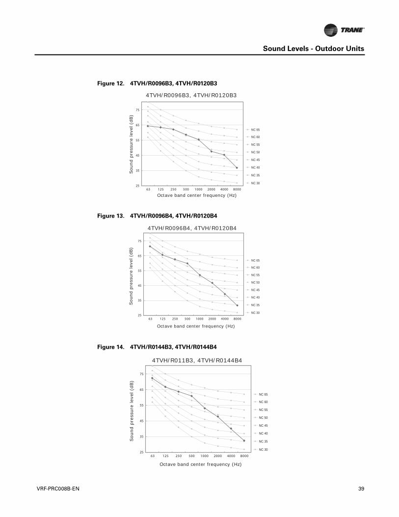
Sound Levels - Outdoor Units
Figure 12. 4TVH/R0096B3, 4TVH/R0120B3
Figure 13. 4TVH/R0096B4, 4TVH/R0120B4
Figure 14. 4TVH/R0144B3, 4TVH/R0144B4
63 125 250 500 1000 2000 4000 8000 25
35
45
55
65
75
NC 65
NC 60
NC 55
NC 50
NC 45
NC 40
NC 35
NC 30
4TVH/R0096B3, 4TVH/R0120B3
Octave band center frequency (Hz)
Sou
nd p
ress
ure
leve
l (dB
)
63 125 250 500 1000 2000 4000 8000 25
35
45
55
65
75
NC 65
NC 60
NC 55
NC 50
NC 45
NC 40
NC 35
NC 30
4TVH/R0096B4, 4TVH/R0120B4
Octave band center frequency (Hz)
Sou
nd p
ress
ure
leve
l (dB
)
63 125 250 500 1000 2000 4000 8000 25
35
45
55
65
75
NC 65
NC 60
NC 55
NC 50
NC 45
NC 40
NC 35
NC 30
4TVH/R011B3, 4TVH/R0144B4
Octave band center frequency (Hz)
Sou
nd p
ress
ure
leve
l (dB
)
VRF-PRC008B-EN 39
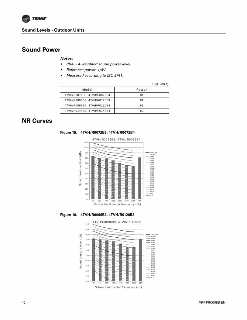
Sound Levels - Outdoor Units
Sound Power
Notes:
• dBA = A-weighted sound power level.
• Reference power: 1pW
• Measured according to ISO 3741.
NR Curves
Unit: dB(A)
Model Power
4TVH/R0072B3, 4TVH/R0072B4 81
4TVH/R0096B3, 4TVH/R0120B3 81
4TVH/R0096B4, 4TVH/R0120B4 81
4TVH/R0144B3, 4TVH/R0144B4 83
Figure 15. 4TVH/R0072B3, 4TVH/R0072B4
Figure 16. 4TVH/R0096B3, 4TVH/R0120B3
0.0
10.0
20.0
30.0
40.0
50.0
60.0
70.0
80.0
90.0
100.0
110.0
125 250 500 1000 2000 4000 8000 dBA
Power (dB)NR 100NR 95NR 90NR 85NR 80NR 75NR 70NR 65NR 60NR 55NR 50NR 45NR 40NR 35NR 30NR 25NR 20NR 15NR 10NR 5NC 0
4TVH/R0072B3, 4TVH/R0072B4
Octave band center frequency (Hz)
Sou
nd p
ress
ure
leve
l (dB
)
0.0
10.0
20.0
30.0
40.0
50.0
60.0
70.0
80.0
90.0
100.0
110.0
125 250 500 1000 2000 4000 8000 dBA
Power (dB)NR 100NR 95NR 90NR 85NR 80NR 75NR 70NR 65NR 60NR 55NR 50NR 45NR 40NR 35NR 30NR 25NR 20NR 15NR 10NR 5NC 0
4TVH/R0096B3, 4TVH/R0120B3
Octave band center frequency (Hz)
Sou
nd p
ress
ure
leve
l (dB
)
40 VRF-PRC008B-EN
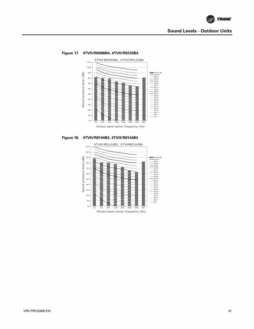
Sound Levels - Outdoor Units
Figure 17. 4TVH/R0096B4, 4TVH/R0120B4
Figure 18. 4TVH/R0144B3, 4TVH/R0144B4
0.0
10.0
20.0
30.0
40.0
50.0
60.0
70.0
80.0
90.0
100.0
110.0
125 250 500 1000 2000 4000 8000 dBA
Power (dB)NR 100NR 95NR 90NR 85NR 80NR 75NR 70NR 65NR 60NR 55NR 50NR 45NR 40NR 35NR 30NR 25NR 20NR 15NR 10NR 5NC 0
4TVH/R0096B4, 4TVH/R0120B4
Octave band center frequency (Hz)
Sou
nd p
ress
ure
leve
l (dB
)
0.0
10.0
20.0
30.0
40.0
50.0
60.0
70.0
80.0
90.0
100.0
110.0
125 250 500 1000 2000 4000 8000 dBA
Power (dB)NR 100NR 95NR 90NR 85NR 80NR 75NR 70NR 65NR 60NR 55NR 50NR 45NR 40NR 35NR 30NR 25NR 20NR 15NR 10NR 5NC 0
4TVH/R0144B3, 4TVHR0144B4
Octave band center frequency (Hz)
Sou
nd p
ress
ure
leve
l (dB
)
VRF-PRC008B-EN 41
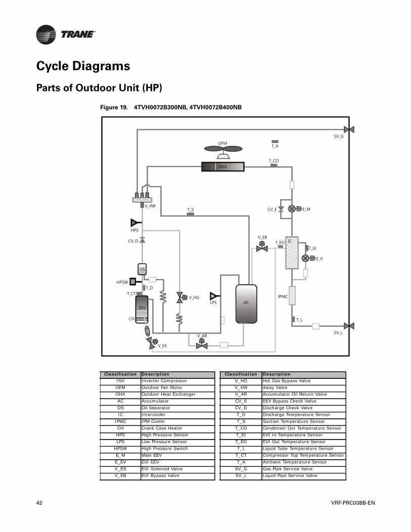
Cycle Diagrams
Parts of Outdoor Unit (HP)
Figure 19. 4TVH0072B300NB, 4TVH0072B400NB
Classification Description Classification DescriptionINV Inverter Compressor V_HG Hot Gas Bypass ValveOFM Outdoor Fan Motor V_4W 4way ValveOHX Outdoor Heat Exchanger V_AR Accumulator Oil Return ValveAC Accumulator CV_E EEV Bypass Check ValveOS Oil Separator CV_D Discharge Check ValveIC Intercooler T_D Discharge Temperature Sensor
IPMC IPM Cooler T_S Suction Temperature SensorCH Crank Case Heater T_CO Condenser Out Temperature SensorHPS High Pressure Sensor T_EI EVI In Temperature SensorLPS Low Pressure Sensor T_EO EVI Out Temperature Sensor
HPSW High Pressure Switch T_L Liquid Tube Temperature SensorE_M Main EEV T_CT Compressor Top Temperature SensorE_EV EVI EEV T_A Ambient Temperature SensorV_ES EVI Solenoid Valve SV_G Gas Pipe Service ValveV_EB EVI Bypass Valve SV_L Liquid Pipe Service Valve
42 VRF-PRC008B-EN
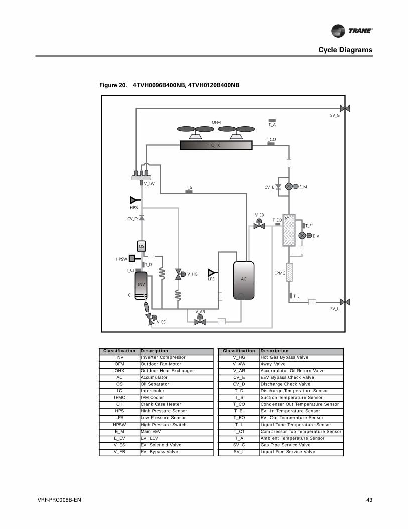
Cycle Diagrams
Figure 20. 4TVH0096B400NB, 4TVH0120B400NB
Classification Description Classification DescriptionINV Inverter Compressor V_HG Hot Gas Bypass ValveOFM Outdoor Fan Motor V_4W 4way ValveOHX Outdoor Heat Exchanger V_AR Accumulator Oil Return ValveAC Accumulator CV_E EEV Bypass Check ValveOS Oil Separator CV_D Discharge Check ValveIC Intercooler T_D Discharge Temperature Sensor
IPMC IPM Cooler T_S Suction Temperature SensorCH Crank Case Heater T_CO Condenser Out Temperature SensorHPS High Pressure Sensor T_EI EVI In Temperature SensorLPS Low Pressure Sensor T_EO EVI Out Temperature Sensor
HPSW High Pressure Switch T_L Liquid Tube Temperature SensorE_M Main EEV T_CT Compressor Top Temperature SensorE_EV EVI EEV T_A Ambient Temperature SensorV_ES EVI Solenoid Valve SV_G Gas Pipe Service ValveV_EB EVI Bypass Valve SV_L Liquid Pipe Service Valve
VRF-PRC008B-EN 43
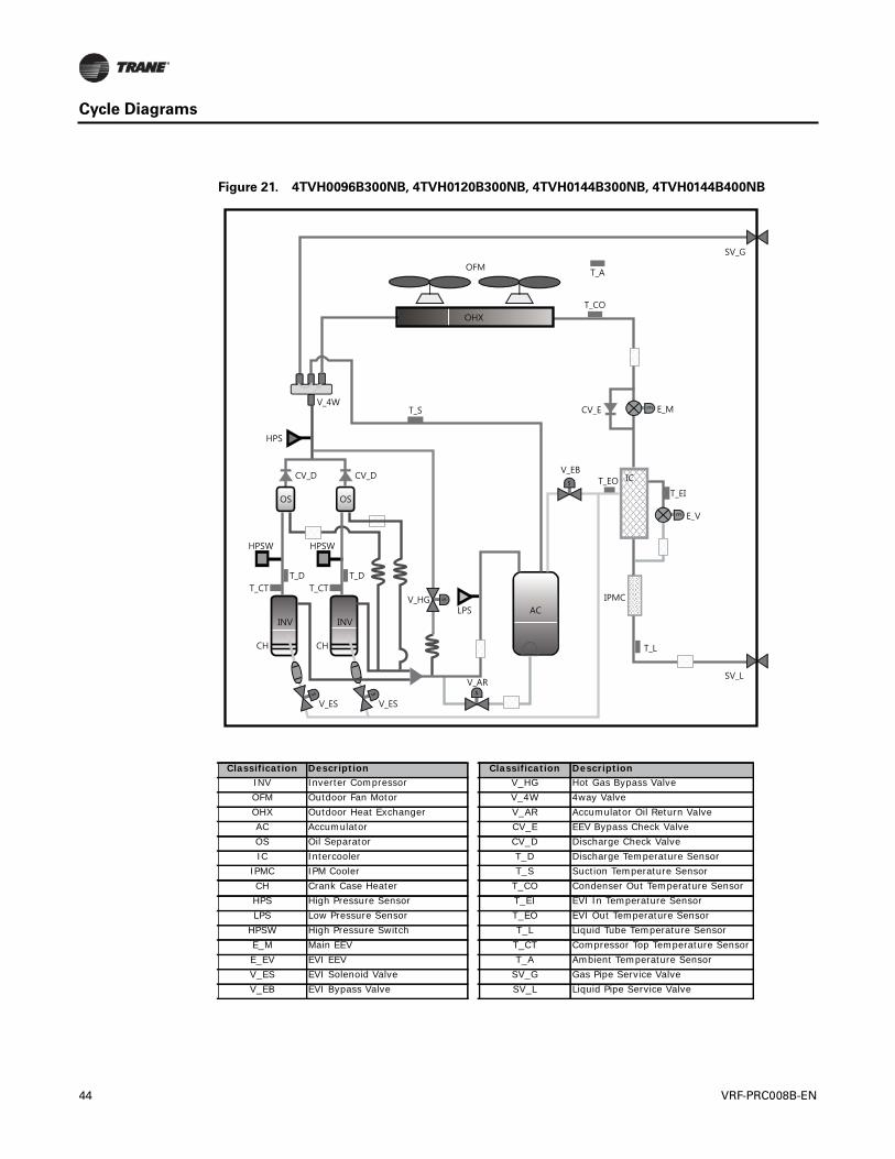
Cycle Diagrams
Figure 21. 4TVH0096B300NB, 4TVH0120B300NB, 4TVH0144B300NB, 4TVH0144B400NB
Classification Description Classification DescriptionINV Inverter Compressor V_HG Hot Gas Bypass ValveOFM Outdoor Fan Motor V_4W 4way ValveOHX Outdoor Heat Exchanger V_AR Accumulator Oil Return ValveAC Accumulator CV_E EEV Bypass Check ValveOS Oil Separator CV_D Discharge Check ValveIC Intercooler T_D Discharge Temperature Sensor
IPMC IPM Cooler T_S Suction Temperature SensorCH Crank Case Heater T_CO Condenser Out Temperature SensorHPS High Pressure Sensor T_EI EVI In Temperature SensorLPS Low Pressure Sensor T_EO EVI Out Temperature Sensor
HPSW High Pressure Switch T_L Liquid Tube Temperature SensorE_M Main EEV T_CT Compressor Top Temperature SensorE_EV EVI EEV T_A Ambient Temperature SensorV_ES EVI Solenoid Valve SV_G Gas Pipe Service ValveV_EB EVI Bypass Valve SV_L Liquid Pipe Service Valve
44 VRF-PRC008B-EN
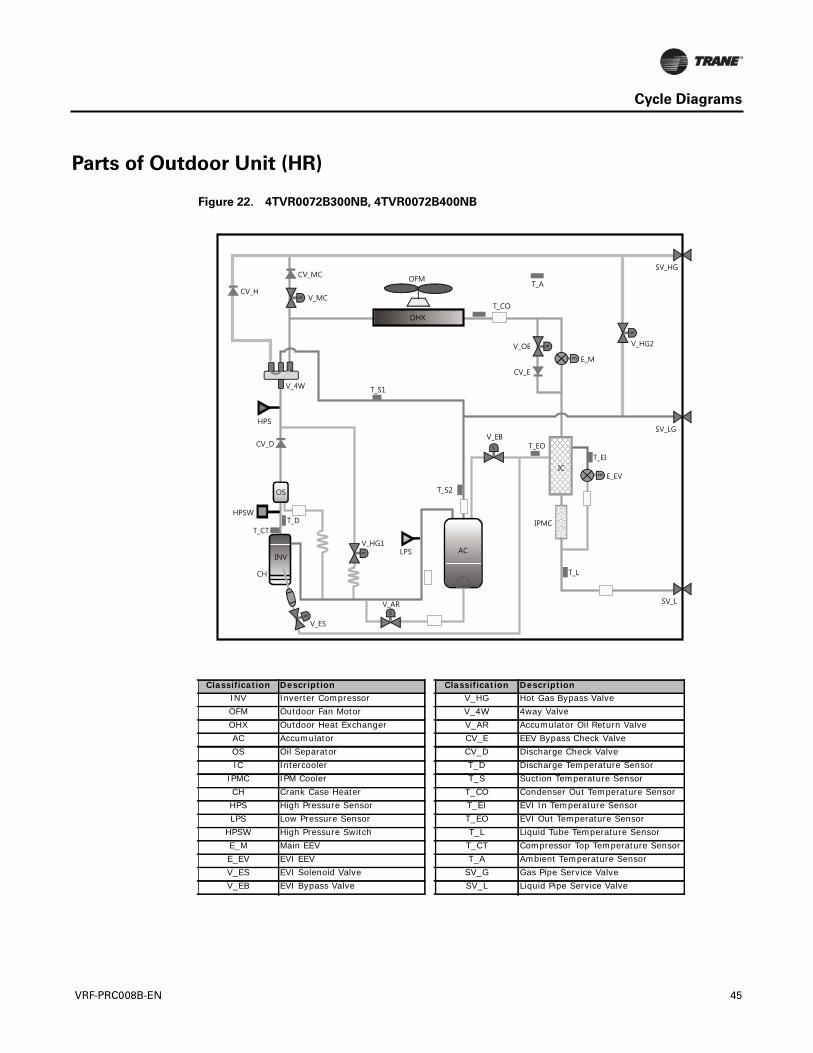
Cycle Diagrams
Parts of Outdoor Unit (HR)
Figure 22. 4TVR0072B300NB, 4TVR0072B400NB
Classification Description Classification DescriptionINV Inverter Compressor V_HG Hot Gas Bypass ValveOFM Outdoor Fan Motor V_4W 4way ValveOHX Outdoor Heat Exchanger V_AR Accumulator Oil Return ValveAC Accumulator CV_E EEV Bypass Check ValveOS Oil Separator CV_D Discharge Check ValveIC Intercooler T_D Discharge Temperature Sensor
IPMC IPM Cooler T_S Suction Temperature SensorCH Crank Case Heater T_CO Condenser Out Temperature SensorHPS High Pressure Sensor T_EI EVI In Temperature SensorLPS Low Pressure Sensor T_EO EVI Out Temperature Sensor
HPSW High Pressure Switch T_L Liquid Tube Temperature SensorE_M Main EEV T_CT Compressor Top Temperature SensorE_EV EVI EEV T_A Ambient Temperature SensorV_ES EVI Solenoid Valve SV_G Gas Pipe Service ValveV_EB EVI Bypass Valve SV_L Liquid Pipe Service Valve
VRF-PRC008B-EN 45
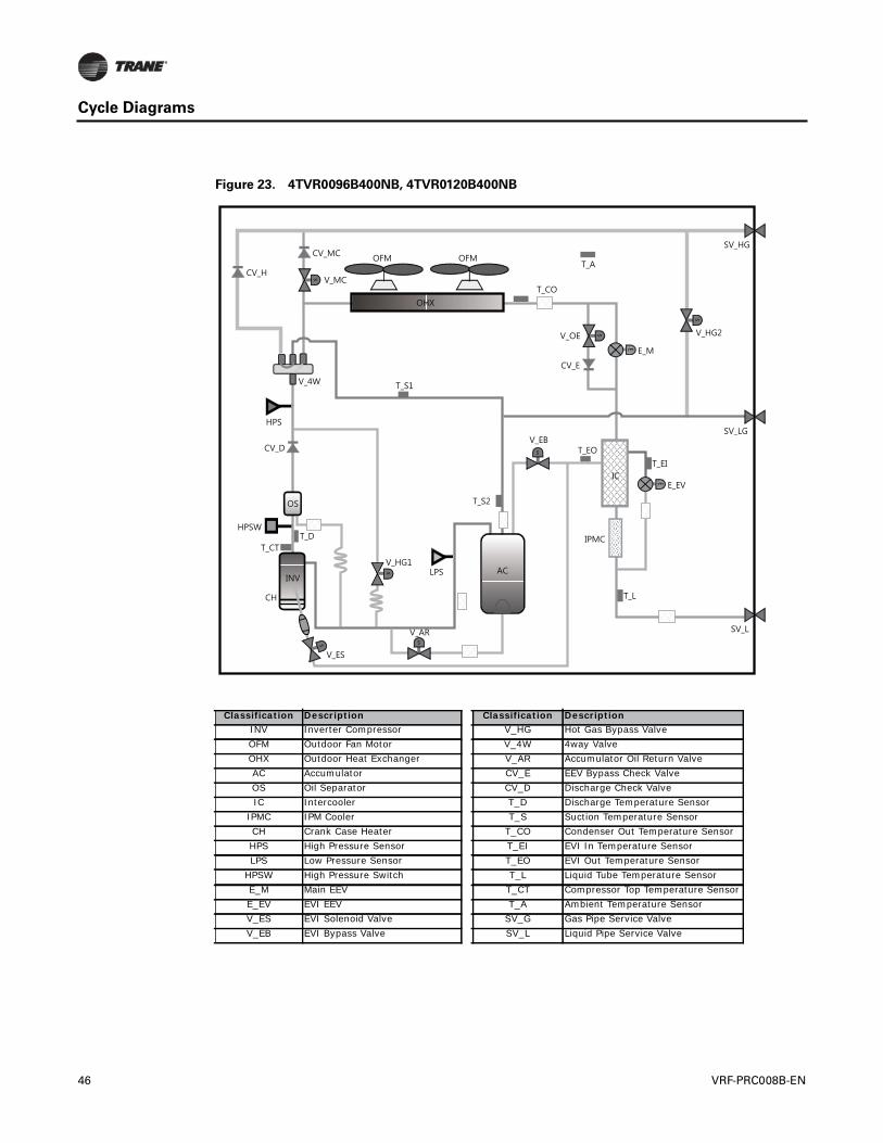
Cycle Diagrams
Figure 23. 4TVR0096B400NB, 4TVR0120B400NB
Classification Description Classification DescriptionINV Inverter Compressor V_HG Hot Gas Bypass ValveOFM Outdoor Fan Motor V_4W 4way ValveOHX Outdoor Heat Exchanger V_AR Accumulator Oil Return ValveAC Accumulator CV_E EEV Bypass Check ValveOS Oil Separator CV_D Discharge Check ValveIC Intercooler T_D Discharge Temperature Sensor
IPMC IPM Cooler T_S Suction Temperature SensorCH Crank Case Heater T_CO Condenser Out Temperature SensorHPS High Pressure Sensor T_EI EVI In Temperature SensorLPS Low Pressure Sensor T_EO EVI Out Temperature Sensor
HPSW High Pressure Switch T_L Liquid Tube Temperature SensorE_M Main EEV T_CT Compressor Top Temperature SensorE_EV EVI EEV T_A Ambient Temperature SensorV_ES EVI Solenoid Valve SV_G Gas Pipe Service ValveV_EB EVI Bypass Valve SV_L Liquid Pipe Service Valve
46 VRF-PRC008B-EN
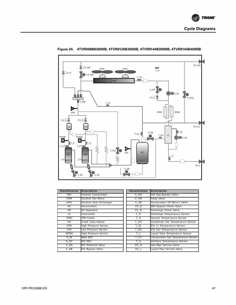
Cycle Diagrams
Figure 24. 4TVR0096B300NB, 4TVR0120B300NB, 4TVR0144B300NB, 4TVR0144B400NB
Classification Description Classification DescriptionINV Inverter Compressor V_HG Hot Gas Bypass ValveOFM Outdoor Fan Motor V_4W 4way ValveOHX Outdoor Heat Exchanger V_AR Accumulator Oil Return ValveAC Accumulator CV_E EEV Bypass Check ValveOS Oil Separator CV_D Discharge Check ValveIC Intercooler T_D Discharge Temperature Sensor
IPMC IPM Cooler T_S Suction Temperature SensorCH Crank Case Heater T_CO Condenser Out Temperature SensorHPS High Pressure Sensor T_EI EVI In Temperature SensorLPS Low Pressure Sensor T_EO EVI Out Temperature Sensor
HPSW High Pressure Switch T_L Liquid Tube Temperature SensorE_M Main EEV T_CT Compressor Top Temperature SensorE_EV EVI EEV T_A Ambient Temperature SensorV_ES EVI Solenoid Valve SV_G Gas Pipe Service ValveV_EB EVI Bypass Valve SV_L Liquid Pipe Service Valve
VRF-PRC008B-EN 47
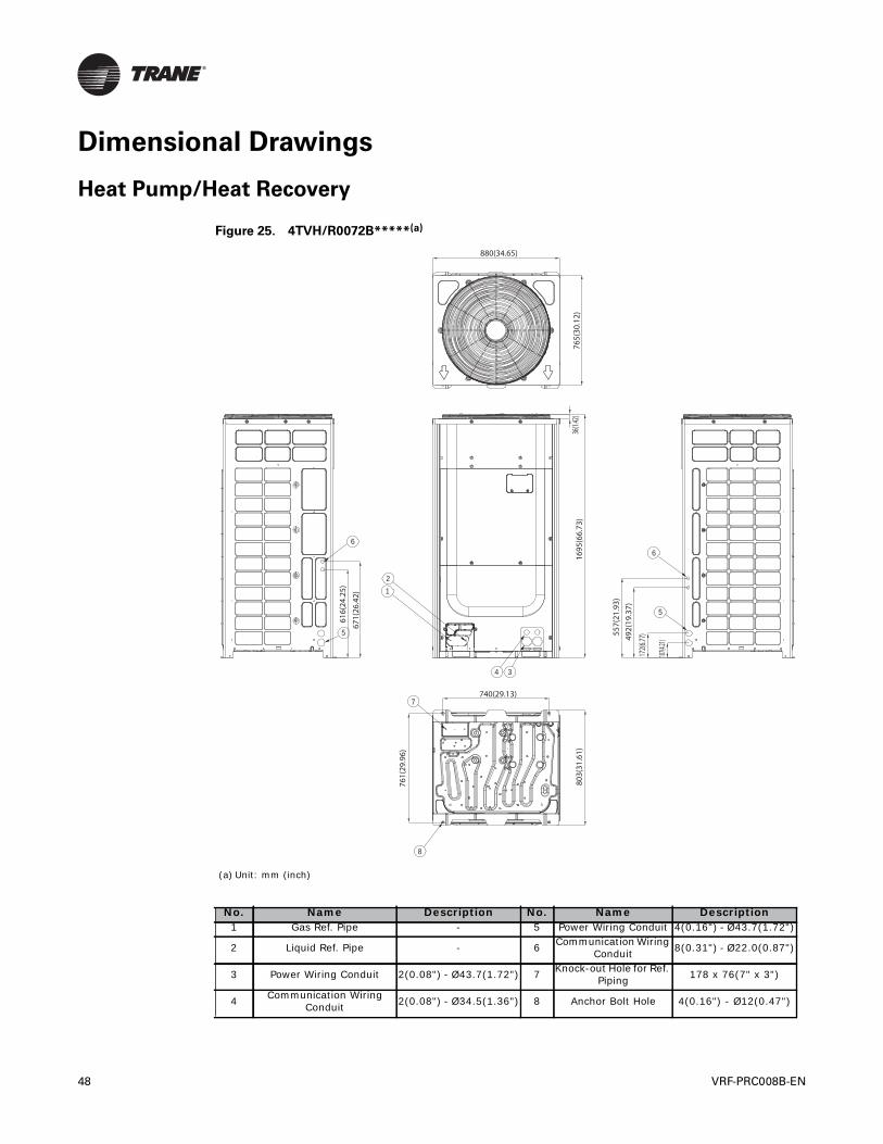
Dimensional Drawings
Heat Pump/Heat Recovery
Figure 25. 4TVH/R0072B*****(a)
(a) Unit: mm (inch)
No. Name Description No. Name Description1 Gas Ref. Pipe - 5 Power Wiring Conduit 4(0.16") - Ø43.7(1.72")
2 Liquid Ref. Pipe - 6 Communication Wiring Conduit 8(0.31") - Ø22.0(0.87")
3 Power Wiring Conduit 2(0.08") - Ø43.7(1.72") 7 Knock-out Hole for Ref. Piping 178 x 76(7" x 3")
4 Communication Wiring Conduit 2(0.08") - Ø34.5(1.36") 8 Anchor Bolt Hole 4(0.16") - Ø12(0.47")
1
5
6
6
5
2
34
7
8
880(34.65)
765(
30.1
2)36
(1.42
)16
95(6
6.73
)
616(
24.2
5)
671(
26.4
2)
761(
29.9
6)
803(
31.6
1)
557(
21.9
3)49
2(19
.37)
172(6
.77)
107(4.2
1)
740(29.13)
48 VRF-PRC008B-EN
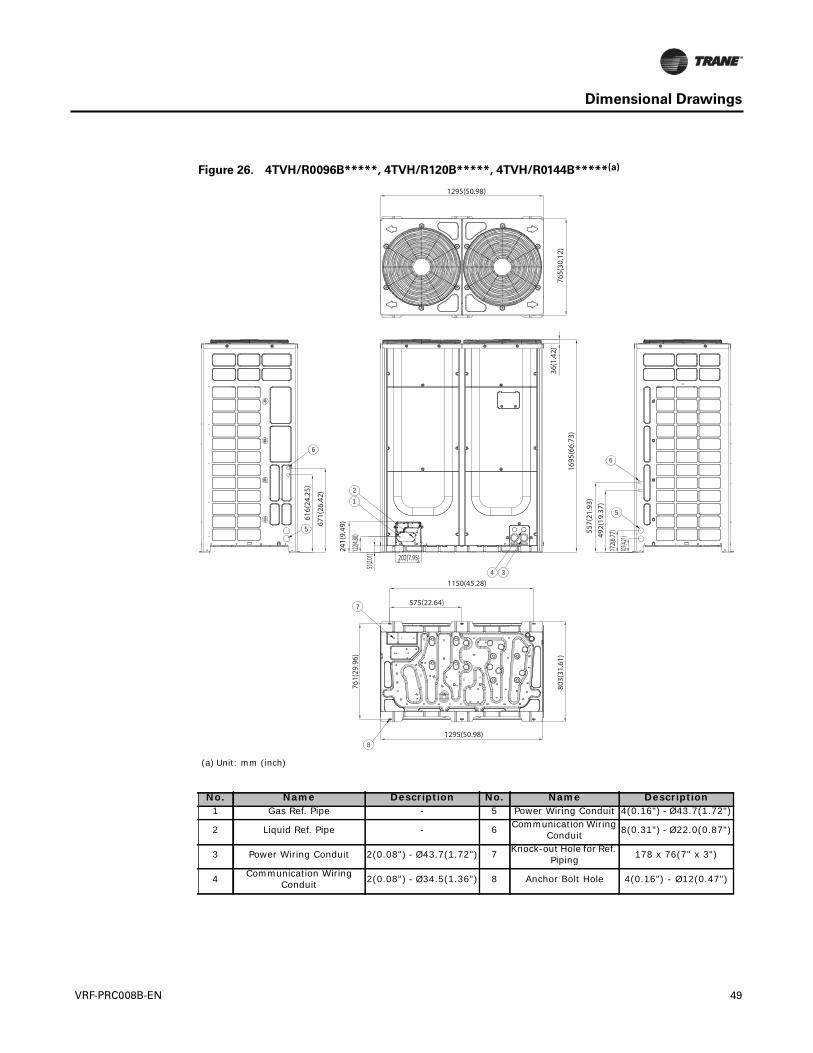
Dimensional Drawings
Figure 26. 4TVH/R0096B*****, 4TVH/R120B*****, 4TVH/R0144B*****(a)
(a) Unit: mm (inch)
No. Name Description No. Name Description1 Gas Ref. Pipe - 5 Power Wiring Conduit 4(0.16") - Ø43.7(1.72")
2 Liquid Ref. Pipe - 6 Communication Wiring Conduit 8(0.31") - Ø22.0(0.87")
3 Power Wiring Conduit 2(0.08") - Ø43.7(1.72") 7 Knock-out Hole for Ref. Piping 178 x 76(7" x 3")
4 Communication Wiring Conduit 2(0.08") - Ø34.5(1.36") 8 Anchor Bolt Hole 4(0.16") - Ø12(0.47")
2
1
6
5
7
8
6
5
4 3
1295(50.98)
765(
30.1
2)36
(1.4
2)
1695
(66.
73)
616(
24.2
5)
671(
26.4
2)
1150(45.28)
575(22.64)
1295(50.98)
803(
31.6
1)
761(
29.9
6)
241(
9.49
)
202(7.95)
122(4
.80)
51(2.0
1)
557(
21.9
3)49
2(19
.37)
172(6
.77)
107(4.2
1)
VRF-PRC008B-EN 49


Trane optimizes the performance of homes and buildings around the world. A business of Ingersoll Rand, the leader increating and sustaining safe, comfortable and energy efficient environments,Trane offers a broad portfolio of advancedcontrols and HVAC systems, comprehensive building services, and parts. For more information, visit www.Trane.com.
Trane has a policy of continuous product and product data improvement and reserves the right to change design and specifications without notice.
We are committed to using environmentally
conscious print practices that reduce waste.
Variable Refrigerant Flow (VRF) Multi-Split AC and HPAHRI Standard 1230
© 2015Trane All rights reserved
VRF-PRC008B-EN 17 Feb 2015
Supersedes VRF-PRC008-EN (31 July 2013)
Related Documents